
Rogue (2021) - Automobile NISSAN - Free user manual and instructions
Find the device manual for free Rogue (2021) NISSAN in PDF.


| Product Type | Automobile |
| Brand | Nissan |
| Model | Rogue (2021) |
| Year | 2021 |
| Number of Pages | 594 |
| Language | English |
| Fuel Type | Regular Unleaded |
| Engine | 2.5L Inline-4 Gas |
| Transmission | CVT (Continuously Variable) |
| Drivetrain | FWD or AWD |
| Seating Capacity | 5 |
| Cargo Volume (behind 1st row) | 74.1 cu ft |
| Fuel Economy (city/highway) | 27/35 mpg (FWD) |
| Safety Features | ProPILOT Assist, Automatic Emergency Braking, Blind Spot Warning, Rear Cross Traffic Alert, Lane Departure Warning |
| Dimensions (L x W x H) | 183.9 in x 72.4 in x 66.5 in |
| Wheelbase | 106.5 in |
| Curb Weight | 3,454 - 3,605 lbs (depending on drivetrain) |
| Towing Capacity | 1,350 lbs (with appropriate equipment) |
| Recommended Maintenance Interval | Every 5,000 miles or as indicated by the vehicle |
| Warranty | 3 years/36,000 miles basic, 5 years/60,000 miles powertrain |
| Manual Format | PDF available for download |
Frequently Asked Questions - Rogue (2021) NISSAN
User questions about Rogue (2021) NISSAN
0 question about this device. Answer the ones you know or ask your own.
Ask a new question about this device
Download the instructions for your Automobile in PDF format for free! Find your manual Rogue (2021) - NISSAN and take your electronic device back in hand. On this page are published all the documents necessary for the use of your device. Rogue (2021) by NISSAN.
USER MANUAL Rogue (2021) NISSAN
OWNER'S MANUAL and MAINTENANCE INFORMATION
For your safety, read carefully and keep in this vehicle.
OWNER'SMANUALSUPPLEMENT
The information contained within this supplement revises or addstothefollowing information in the 2021 Nissan Rogue Owner's Manual:
- "VehicleSettings"sectionofthe"InstrumentsandControls"section.
- "WIPERANDWASHERSWITCH"sectionofthe"InstrumentsandControls"section.
- "Unlockingdoors"sectionofthe"INTELLIGENTKEYOPERATION(modelswithrequestswitch)"sectionofthe"Pre-drivingchecksandadjustments"section.
Readcarefullyandkeepinthevehicle.
Printing:August2021
PublicationNo.SU21EA1T33U0

VehicleSettings
The vehiclesettingsallowstheuserto changethesettingsforthefollowing menus:
•PowerBackDoor(ifsoequipped)
•Lighting
- Locking
•Wipers
-DrivingPosition(ifsoequipped)
•RearDoorAlert
The vehicle settings can be changed using the scrolldial ①.
PowerBackDoor(ifsoequipped):
This allows usertournthepowerliftgate ONorOFF.
Lighting:
The "Lighting" menuhasthefollowingoptions:
- WelcomeHeadlight
Thewelcomelightingcanbesettobe ONorOFF. Usethescrolldial ① toturn thisfeatureONorOFF.
•AutoRoomLamp
TheinteriorlightcanbesettoONorOFF. Usethescrolidial ① toturnthisfeature ONorOFF.
•AccentLighting(ifsoequipped)
ThebrightnessoftheAccentLighting canbeadjusted.Usethescrolldial ① to selectthebrightness.
•AutoHeadlight
ThesensitivityoftheIntelligentAuto Headlightcanbeadjusted.Usethescroll dial ⏻ toselecttherequiredsensitivity. Thefollowingoptionsareavailable:
-Turnonearliest
-Turnonearlier
-Turnonstandard
-Turnonlater
•LightOffDelay
The duration of the automatic head-lightscan be changed from 0 to 180 seconds. Use the crolldial ① to changethe duration.
Locking:
TypeA
The "Locking" menuhasthefollowingoptions:
- Ext. DoorSwitch(ifsoequipped) Whenthisitemisturnedon,therequest switchonthedoorisactivated. Use the scroll dial ① to activateor deactivate thisfunction.
- SelectiveUnlock(ifsoequipped)
When this item is turned on, and the door handlerequestswitchispushed,only thecorrespondingdoorisunlocked.All thedoors canbe unlockedif thedoor handlerequestswitchispushedagain within1minute.Whenthisitemisturned tooff,allthedoorsswillbeunlockedwhen the door handle request switch is pushed once. Use the scroll dial ① to activateordeactivatethisfunction.
•AutoDoorUnlock
The "AutoDoorUnlock" feature allows usertocustomizetheautodoorunlock options. Usethescrolldial ① tochange themode.
-ShifttoP
-IGNOFF
-OFF
•Hornbeepsonlock(ifsoequipped)
When this item is turned on, the horn will chirp and the hazard indicators will flash twice when locking the vehicle with the Intelligent Key. Use the cross-crolle dial to activate or deactivate this function.
WIPERANDWASHERSWITCH
TypeB:
The "Locking" menuhasthefollowingoptions:
- Ext. DoorSwitch (Ifsoequipped) Whenthisitemisturnedon, therequest switchonthedoorisactivated. Use the scrolldial ① toactivateordeactivate thisfunction.
- SelectiveUnlock(ifsoequipped) Whenthisitemisturnedon,andthedor handlerequestswitchonthedriver's sidedoorortheliftgaterequestswitchis pushed,onlythecorrespondingdoor/ liftgateisunlocked.Allthedoorscanbe unlockedifthesamerequestswitchis pushedagainwithin1minute.Whenthis itemisturnedtooff,allthedoorswillbe unlockedwhentherequestswitchis pushedonce.Usethescrolldial ① to activateordeactivatethisfunction.
•AutoDoorUnlock The "AutoDoorUnlock" feature allows usertocustomizetheautodoorunlock options. Usethescrolldial ① tochange themode. --ShifttoP --IGNOFF --OFF
•Hornbeepsonlock(ifsoequipped)
When this itemisturnedon, the horn will chirp and the hazard indicators will flash twice when locking the vehicle with the Intelligent Key. Use the cross-crolle dial to activate or deactivate this function.

WARNING
Infreezingtemperaturesthewasher solutionmayfreezeonthewindshield and obscureyourvisionwhichmay leadtoanaccident.Warmthewindshieldwiththedefrosterbeforeyou washthewindshield.

CAUTION
- Iftheignitionswitchisplacedinthe OFFpositionwhilethewiperoperates,thewipermaynotoperatethe next timethe ignition switchis placedintheONposition.Ifthisoccurs,movethelevertotheotherpositiontooperatethewiperagain.
- Donotoperatethewashercontinuouslyformorethan30seconds.
-Donotoperatethewasherifthereservoirtankisempty.
- Do not fill the windshield-washer reservoirwithwasherfluidconcentratesatfullstrength.Somemethyl alcoholbasedwasherfluidconcentratesmay permanently stainthe grilleifspilledwhilefillingthewasher reservoirtank.
- Pre-mixwasherfluidconcentrates withwatertothemanufacturer's recommended levelsbeforepouring the fluidintothewindowwasherreservoirtank.Donotusethewindow washerreservoirtanktomixthe washerfluidconcentrateandwater.
NOTE:
Ifthewindshieldwiperoperationisinterruptedbysnoworice,thewipermay stopmovingtoprotectitsmotor.Ifthis occurs,turnthewiperswitchtotheOFF positionandremovethesnoworicethat isonaroundthewiperarms.inapproximately1minute,turntheswitchon againtooperatethewiper.
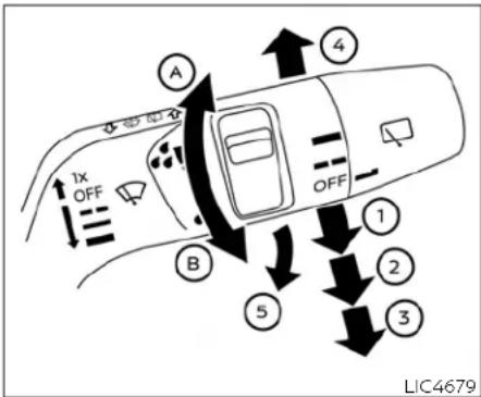
Pushtheleverdowntooperatethewiper atthefollowingspeed:
① Intermittent—intermittentoperation can be adjusted by turning the knob toward Ⓐ (faster) or Ⓑ (slower). Also, the intermittent operations speed varies in accordance with the vehicles speed. (Example, when the vehicles speed is high, the intermittent operations speed will be faster.)
② Low—continuousslowspeedoperation
③ High — continuous high speed operation
Pushtheleverup ④ tohaveonesweep operationofthewiper.
Pullthelevertowardyou ⑤ tooperatethe washer. Thewiperwillalsooperateseveral times.
NOTE:
TheSpeedDependent feature maybe disabled. For additional information, refer to "Vehicle Settings" in the "Instruments and controls" section of this manual.
WARNING
Donot operatethe windshieldwiper whilethewiperarmispulledup.The wiperarmmaybedamaged.
INTELLIGENTKEYOPERATION (modelswithrequestswitch)
Youcanlockorunlockthedoorswithout takingthekeyoutfromyourpocketorbag.
whenyoucarrytheIntelligentKeywithyou, youcanlockorunlockalldoorsbypushing thedoorhandlerequestswitch Ⓐ (located onthefrontandreardoors)orliftgatere- questswitch Ⓑ withintherangeofoperation.
Whenyoulockorunlockthedoors,thehazardindicatorwillflashandtheoutsidechimewillsoundasaconfirmation.Fordetails,see"Settinghazardindicatorandhornmode"inthissection.
Welcomelightfunction
When you unlock the doors orthelift gate, the day timer running lights, parking lights and that all lights will illuminate for a period of time. The welcome light function can be disabled. For information about disabling the welcome light function, see "Vehicle Settings" in the "Instruments and controls" section of this manual.
Lockingdoors
- PushtheparkbuttontoengagetheP (Park)position.Placetheignitionswitch intheOFFpositionandmakesureyou carrytheIntelligentKeywithyou.
2.Closealldoors.
-
Pushthedoorhandlerequestswitch ortheliftgaterequestswitch while carryingtheIntelligentKeywithyou.
-
Alldoorsandtheliftgatewilllock.
-
The hazard indicator lights flashtwice and the outside buzzersoundstwice.
NOTE:
-Requestswitchesforalldoorscanbe deactivated when the "Ext. Door Switch"isturnedoffintheVehicleSettingsofthevehicleinformation display.Foradditionalinformation,see "VehicleSettings"inthe"Instruments andcontrols"sectionofthismanual.
- Doors lock withthedoor handlere-questswitchwhiletheignitionswitch isnotintheOFFposition.
- Doorsdonotlockbypushingthedriver'sdoorhandlerequestswitchwhile the driver's door is open. However, doorslockwiththemechanicalkey evenifanydoorisopen.
- Doorsdonotlockwiththedoorhandle requestswitchwiththeIntelligentKey insidethevehicleandabeepsoundsto warnyou.However,whenanIntelligent Keyisinsidethevehicle,doorscanbe lockedwithanotherIntelligentKey.
CAUTION
- Afterlockingthedoorsusingtherequest switch, makesure that the doorhavebeensecurelylockedby operating thedoorhandles orthe liftgateopenerswitch.
- Whenlockingthedoorsusingthere- questswitch,makesuretohavethe IntelligentKeyin yourpossession beforeoperatingtherequestswitch topreventthe Intelligent Keyfrom beingleftinthevehicle.
- The request switch is operational onlywhentheIntelligentKeyhas beendetectedbytheIntelligentKey system.
Unlockingdoors
TypeA:
- Pushthedoorhandlerequestswitch ① ortheliftgaterequestswitch ② while carryingtheIntelligentKeywithyou.
- The hazard indicator flashes once and outside chimes sounds once. The corresponding door orthelift gate will unlock
- Pushtherequestswitchagainwithin1 minute.
- The hazard indicator flashes once and outside chimes sounds once again. All the doors and the lift gate will unlock.
Alldoorswillbelockedautomaticallyunlessoneofthefollowingoperationsisperformedwithin1minuteafterpushingtherequestswitchwhilethedoorsarelocked. •Openinganydoor.
- Pushingtheignitionswitch.
During this 1-minute time period, if the UNLOCK button on the Intelligent Key is pushed, all doors will be locked automatically after another 1 minute.
NOTE:
The unlocking operation can be changed in selective unlock in the Vehicle Settings of the vehicle information display. For additional information, see "Vehicle Settings" in the "Instruments and controls" section of this manual.
TypeB:
- Pushthedoorhandlerequestswitch ortheliftgaterequestswitch while carryingtheIntelligentKeywithyou.
- The hazard indicator flashes once and outside chimes sounds once.
- Whenthedriver'sdoorhandlerequest switchortheliftgaterequestswitchis pushed:
The corresponding doorortheliftgate will unlock.
- whentheotherdoorhandlerequest switchispushed:
Alldoorsandtheliftgatewillunlock.
- Pushthedriver'sdoorhandlerequest switchortheliftgaterequestswitch againwithin1minute.
- The hazard indicator flashes once and outside chimes sounds once again. All the doors and the lift gate will unlock.
Alldoorswillbelockedautomaticallyunlessoneofthefollowingoperationsisperformedwithin1minuteafterpushingtherequestswitchwhilethedoorsarelocked.
- Openinganydoor.
- Pushingtheignitionswitch.
During this 1-minute time period, if the UNLOCK button on the Intelligent Key is pushed, all doors will be locked automatically after another 1 minute.
NOTE:
The unlocking operation can be changed in "Selective Unlock" under the Vehicle Setting of the vehicle information display. For additional information, see "Vehicle Settings" in the "Instruments and controls" section of this manual.
CALIFORNIAPROPOSITION 65WARNING

WARNING
Operating, servicing and maintaining passenger vehicle or off-highway motor vehicle can expose outochemicals including engine exhaust, carbon monoxide, phthalates, and lead, which are known to the State of Californiatocause cancer and birth defect for other reproductive harm. To minimize exposure, avoid breathing exhaust, donotidle the engine except as necessary, service your vehicle in well-ventilated area and wear gloves or wash your hands frequently when servicing your vehicle. Form more information got on www.P65Warnings.ca.gov/passenger-vehicle.
Foreword
This manual was prepared to help you understand the operation and maintenance of your vehicle so that you may enjoy many miles of driving pleasure. Please read through this manual before operating your vehicle.
AseparateWarranty Information Booklet explains details about the warranties coveringyourvehicle.Additionally,a separateCustomerCare/LemonLaw Booklet(U.S.only)willexplainhowto resolveanyconcernsyoumayhave with your vehicle, as well as clarify your rightsunderyourstate'slemonlaw.
In addition to factory installed options, your vehicle may also be equipped with additional accessories installed by NISSAN or by your NISSAN dealer prior to delivery. It is important that you familiarize yourself with all disclosures, warnings, cautions and instructions concerning proper use of such accessories prior to operating the vehicle and/or accessory. It is recommended you see a NISSAN dealer for details concerning the particular accessories with which your vehicle is equipped.
Your NISSAN dealer knows your vehicle best. When you require any service or have any questions, we will be glad to assist you with the extensive resources available to us.
READ FIRST — THEN DRIVE SAFELY Before driving your vehicle, read your Owner's Manual carefully. This will ensure familiarity with controls and maintenance requirements, assisting you in the safe operation of your vehicle.

WARNING
IMPORTANT SAFETY INFORMATION REMINDERS!
Follow theseimportant driving rules to help ensure asafe and comfortable trip for you and your passengers!
- NEVERdriveundertheinfluence ofalcoholordrugs.
- ALWAYSObservepostedspeed limitsandneverdrivetoofast forconditions.
- ALWAYS give your full attention to driving and avoid using vehicle features or taking other actions that could distract you.
- ALWAYSuseyourseatbeltsand appropriatechildrestraintsystems.Pre-teenchildrenshould beseatedintherearseat.
• ALWAYS provide information about the proper use of vehicle
safetyfeaturestoallooccupants ofthevehicle. •ALWAYSreviewthisOwner'sManualforimportantsafetyinformation.
On-pavementandoff-road driving
Thisvehiclewillhandleandmaneuver differentlyfromanordinarypassenger carbecauseithasahighercenterof gravity.Aswithothervehicleswith featuresofthistype,failuretooperate thisvehiclecorrectlymayresultinloss ofcontroloranaccident.Besureto read"Avoidingcollisionandrollover" and"Drivingsafetyprecautions"inthe "5.Startinganddriving"sectionofthis manual.
MODIFICATIONOFYOURVEHICLE
This vehicles should not be modified. Modification could affect its performance, safety, durability, and may even violate governmental regulations. In addition, damage or performance problems resulting from modification may not be recovered under NISSAN warranties.

WARNING
InstallinganaftermarketOn-Board Diagnostic(OBD)plug-indevicethat usestheportduringnormaldriving, forexampleremoteinsurancecompanymonitoring,remotevehiclediagnostics,telematicsorengine reprogramming,maycauseinterferenceordamagetovehiclesystems. Wedonotrecommendorendorse theuseofanyaftermarketOBD plug-indevices,unlessspecifically approvedbyNISSAN.Thevehicle warrantymaynotcoverdamage causedbyanyaftermarketplug-in device.
WHEN READING THE MANUAL
Thismanualincludesinformationforall featuresandequipmentavailableon thismodel.Featuresandequipmentin yourvehiclemayvarydependingon model,trimlevel,optionsselected,order,dateofproduction,regionoravailability. Therefore,you may find informationaboutfeaturesorequipmentthatarenotincludedorinstalled onyourvehicle.
All information, specifications and illustrations in this manual are those in effect at the time of printing. NISSAN reserves the right to change specifications, performance, design or component suppliers without notice and without obligation. From time to time, NISSAN may update or revise this manual to provide Owners with the most accurate information currently available. Please carefully read and retain with this manual all revision updates sent to you by NISSAN to ensure you have access to accurate and up-to-date information regarding your vehicle. Current versions of vehicle Owner's Manuals and any updates can also be found in the Owner section of the NISSAN website at https://owners.nissanusa.com/nowners/navigation/manualsGuide. If you have questions concerning any information in your Owner's Manual, contact
NISSAN Consumer Affairs. See the NISSAN CUSTOMER CARE PROGRAM page in this Owner's Manual for contact information.
IMPORTANT INFORMATION ABOUT THIS MANUAL
You will see various symbols in this manual. They are used in the following ways:

WARNING
Thisisusedtoindicatethepresence ofahazardthatcouldcausedeathor seriouspersonalinjury.Toavoidor reducetherisk,theproceduresmust befollowedprecisely.

CAUTION
Thisisusedtoindicatethepresence ofahazardthatcouldcauseminor ormoderatepersonalinjuryordamagetoyourvehicle.Toavoidor reducetherisk,theproceduresmust befollowedcarefully.

those above call attention to an item in the illustration.
CALIFORNIA PERCHLORATE ADVISORY
Somevehicleparts,suchaslithium batteries,maycontainperchloratematerial.Thefollowingadvisoryisprovided:"PerchlorateMaterial-special handlingmayapply,seewww.dtsc.ca. gov/hazardouswaste/perchlorate."
If you see the symbol above, it means "Do notdothis" or "Donotletthishappen".


If you see a symbol similar to those above in an illustration, it means the arrow points to the front of the vehicle.


Arrows in an illustration that are similar those above indicate movement or action.


© 2020 NISSAN MOTOR CO., LTD.
toAll rights reserved. No part of this Owner's Manual may be reproduced or stored in a retrieval system, or transmitted in any form, or by any means, electronic, mechanical, photocopying, recording or otherwise, without the prior written permission of Nissan Motor Co., Ltd.
NISSANCUSTOMERCAREPROGRAM
NISSANCARES...
Both NISSAN and your NISSAN dealer are dedicated to serving all your automotive needs. Your satisfaction with your vehicle and your NISSAN dealer are our primary concerns. Your NISSAN dealer is always available to assist you with all your automobile sales and service needs.
However, if there is something that your NISSAN dealer cannot assist you with or you would like to provide NISSAN directly with comments or questions, please contact the NISSAN Consumer Affairs Department using our toll-free number:
ForU.S.customers
1-800-NISSAN-1
(1-800-647-7261)
ForCanadiancustomers
1-800-387-0122
The Consumer Affairs Department will ask for the following information:
-Your name, address, and telephone number
●Vehicle identification number (attached to the top of the instrument panel on the driver's side)
- Date of purchase
●Current odometer reading
●Your NISSAN dealer's name
-Your comments or questions
OR
You can write to NISSAN with the information at:
ForU.S.customers
NissanNorthAmerica, Inc.
ConsumerAffairsDepartment
P.O.Box685003
Franklin,TN37068-5003
orviae-mailat:
nnaconsumeraffairs@nissan-usa.
com
ForCanadiancustomers
NissanCanadaInc.
5290OrbitorDrive
Mississauga,OntarioL4W4Z5
orviae-mailat:
information.centre@nissancana-
da.com
If you prefer, visit us at:
www.nissanusa.com(for U.S. customers)
or
www.nissan.ca(for Canadian customers)
We appreciate your interest in NISSAN and thank you for buying a quality NISSAN vehicle.
Tableof Contents
| Illustratedtableofcontents | 0 |
| Safety—Seats,seatbeltsandsupplementalrestraint system | 1 |
| Instrumentsandcontrols | 2 |
| Pre-drivingchecksandadjustments | 3 |
| Monitor,heater,airconditioner,audioandphone systems | 4 |
| Startinganddriving | 5 |
| Incaseofemergency | 6 |
| Appearanceandcare | 7 |
| Do-it-yourself | 8 |
| Maintenanceandschedules | 9 |
| Technicalandconsumerinformation | 10 |
| Index | 11 |
Ollustratedtableofcontents
Seats,seatbeltsandSupplementalRestraint
System(SRS)....0-2
Exteriorfront 0-3
Exteriorrear....0-4
Passengercompartment....0-5
Cockpit....0-6
Instrumentpanel....0-7
Metersandgauges....0-8
Modelswithanalogmeterand colordisplay....0-8
Modelswithfull-screendisplay....0-9
Enginecompartment....0-10
PR25DDenginemodel....0-10
KR15DDTenginemodel....0-11
Warningandindicatorlights....0-12
SEATS, SEATBELTSANDSUPPLEMENTAL RESTRAINTSYSTEM(SRS)

- Supplemental front-impact air bags (P.1-47)
- Front passenger air bag status light (P.1-55)
- Occupant classification sensors (weight sensors) (P.1-47)
-
Front central seat-mounted side-impact supplemental air bag* (P.1-47)
-
Seat belts (P.1-14)
- Head restraints/headrests (P.1-10)
- Roof-mounted curtain side-impact and rollover supplemental air bags (P.1-47)
- Rear armrest (P.1-9)
- Rear outboard seat-mounted side-impact supplemental air bags (P.1-47)
0-2 Illustratedtableofcontents
- Driver and front passenger supplemental knee air bags (P.1-47)
- Front seats (P.1-4)
- Front seat-mounted side-impact supplemental air bags* (P.1-47)
- Seat belt pretensioners (P.1-66)
- Rear seats (P.1-7)
— Child restraints (P.1-24)
-
LATCH (Lower Anchors and Tethers for CHILDREN) system (for rear seats) (P.1-26)
-
Child restraint anchor points (for top tether strap) (P.1-43)
: if so equipped
EXTERIORFRONT

-
Hood (P.3-22)
-
Windshield wiper and washer
— Switch operation (P.2-54)
Window washer fluid (P.8-13)
-
Front camera* (P.2-61, P.5-44, P.5-47, P.5-52, P.5-66, P.5-85, P.5-122)
-
Moonroof* (P.2-85)
-
Power windows (P.2-82)
-
Side turn signal light* (P.2-64)
-
Sonar sensors (center and corner) * — Sonar system (P.5-162)
-
Front view camera* (P.4-9)
-
Fog lights* (P.2-64)
-
Headlights and turn signal lights (P.2-57)
-
Sonar sensors (side) 4
— Sonar system (P.5-162)
- Tires
— Wheels and tires (P.8-31, P.10-10)
- Spare tire (P.6-3)
— Tire Pressure Monitoring System (TPMS) (P.2-18, P.5-6)
-
Outside mirrors (P.3-35)
-
Side view camera* (P.4-9)
-
Doors
- Keys (P.3-3)
— Door locks (P.3-5)
- Intelligent Key system (P.3-7)
- Security system (P.2-52)
- Remote engine start* (P.3-19)
*: if so equipped
EXTERIORREAR

- Rear window defroster (P.2-57)
- Rear window wiper and washer
- Switch operation (P.2-55)
— Window washer fluid (P.8-13) - High-mounted stop light (P.8-28)
- Antenna (P.4-38)
- Roof rack* (P.2-81)
0-4 Illustratedtableofcontents
- Sonar sensors (center and corner)
— Sonar system* (P.5-162)
— Rear Sonar System (RSS) * (P.5-168)
— Rear Automatic Braking (RAB) (P.5-143)
- Liftgate (P.3-23)
— Intelligent Key system* (P.3-7) -
Rear view camera* (P.4-2, P.4-9)
-
Rear combination light (P.8-28)
-
Sonar sensors (side) *
— Rear Automatic Braking (RAB) (P.5-143)
— Sonar system (P.5-162)
- Fuel-filler door (P.3-29)
— Fuel information (P.10-5) - Child safety rear door locks (P.3-7)
*: if so equipped
PASSENGERCOMPARTMENT

- Inside mirror (P.3-33)
- Sunglasses holder (P.2-78)
- Map lights (P.2-88)
Microphone** - Moonroof switch* (P.2-85)
- Emergency Call (SOS) button* (P.2-72)
-
Sun visors (P.3-32)
-
Room light* (P.2-88)
- Rear personal lights* (P.2-89)
- Coat hooks (P.2-79)
- Rear cup holders (P.2-73)
- Cargo light (P.2-89)
-
Power window switch (P.2-82)
-
Outside mirror control switch (driver's side) (P.3-35)
- Power door lock switches (P.3-6)
- Memory seat switches (driver's side)* (P.3-37)
- Lower console tray (P.2-78)
- Front cup holders (P.2-73)
-
Console box (P.2-78)
-
Power outlet (P.2-68)
- USB (Universal Serial Bus) charging connector* (P.2-69)
-
Heated rear seat switches* (P.2-65)
— Rear temperature control* (P.4-36) -
Cargo area
— Power outlet (P. 2-68)
- Adjustable luggage floor* (P.2-75)
— Single luggage board* (P.2-75)
— Luggage hooks (P.2-80)
- Cargo cover* (P.2-80)
- Spare tire (P.6-5)
: if so equipped
**: Refer to the separate NissanConnect® Owner's Manual (if so equipped).
COCKPIT

- Steering Assist switch* (models with Pro-PILOT Assist) (P.2-67, P.5-85)
- Head Up Display (HUD) switch* (P.2-49)
- Headlight and turn signal switch (P.2-57)/Fog light switch* (P.2-64)
- Paddle shifters (P.5-23)
- Steering-wheel-mounted controls (left side)
0-6 Illustratedtableofcontents
-
Audio control**
— Vehicle information display control (P.2-23) -
Steering wheel (P.3-31)
— Horn (P.2-65) - Wiper and washer switch (P.2-54)
- Steering-wheel-mounted controls (right
side)
— Cruise control switches* (P.5-83)
— ProPILOT Assist switch* (P.5-85, P.5-52, P.5-66)
— Bluetooth® Hands-Free Phone System switches**
— Voice Recognition system switch**
— Siri® Eyes Free**
-
Hazard indicator flasher switch (P.6-2)
-
Shift lever
— Continuously Variable Transmission (CVT) (P.5-19)
- Instrument brightness control (P.2-11)
- Power liftgate switch* (P.3-23)
- Push-button ignition switch (P.5-14)
- Parking brake switch (P.5-25)
- Automatic brake hold switch (P.5-28)
- Drive Mode Selector (P.5-31)
*: if so equipped
**: See the separate NissanConnect® Owner's Manual (if so equipped).
INSTRUMENT PANEL
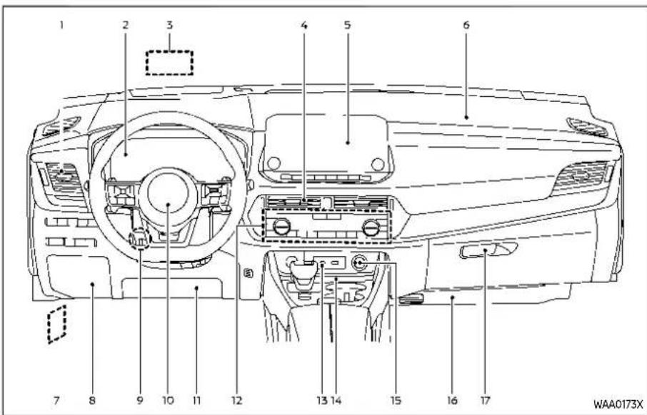
- Side ventilator (P.4-25)
- Meters and gauges (P.2-5)/Clock (P.2-48)
- Head Up Display (HUD) 4 (P.2-49)
- Center ventilator (P.4-25)
- Audio system** or navigation system**
— RearView Monitor 4 (P.4-2) - Intelligent Around View® Monitor*
(P.4-9)
- Bluetooth® Hands-Free Phone System**
- Front passenger supplemental air bag (P.1-47)
- Hood release handle (P.3-22)
-
Fuse box cover (P.8-24)
-
Tilt and telescopic steering lock lever (P.3-31)
- Driver supplemental front-impact air bag (P.1-47)
- Driver supplemental knee air bag (P.1-47)
- Heater and air conditioner control (P.4-26) — Defroster switch (P.2-57)
- Heated seat switches* (P.2-65)
- Heated steering wheel switch* (P.2-65)
- USB (Universal Serial Bus) connection ports**
- Wireless charger* (P.2-70)
- Power outlet (P.2-68)
- Front passenger supplemental knee air bag (P.1-47)
- Glove box (P.2-77)
*: if so equipped
**: See the separate NissanConnect® Owner's Manual (if so equipped).
METERSANDGAUGES
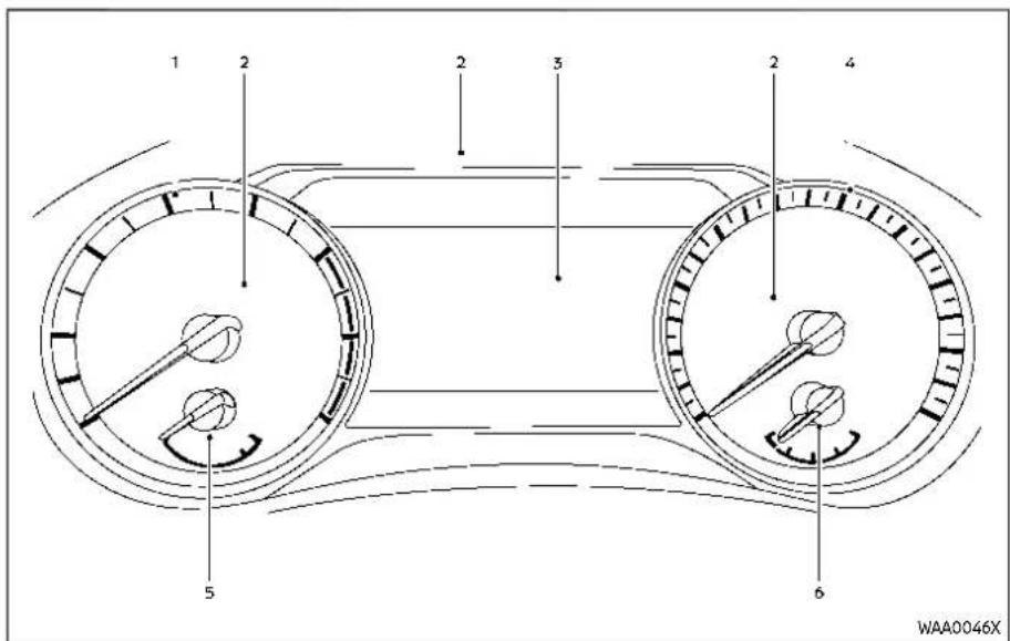
MODELS WITH ANALOG METER AND COLOR DISPLAY
- Tachometer (P.2-9)
- Warning and indicator lights (P.2-13)
-
Vehicle information display (P.2-22)
— Odometer (P.2-8) -
Speedometer (P.2-8)
- Engine coolant temperature gauge (P.2-9)
- Fuel gauge (P.2-10)
0-8 Illustratedtableofcontents

- Tachometer (P.2-9)
- Vehicle information display (P.2-22) — Odometer (P.2-8)
- Warning and indicator lights (P.2-13)
- Speedometer (P.2-8)
- Engine coolant temperature gauge (P.2-9)
- Fuel gauge (P.2-10)
MODELS WITH FULL-SCREEN DISPLAY
The view of the meter screen can be changed. (See "Changing the meter screen view (models with full-screen display)" (P.2-23).)
ENGINECOMPARTMENT
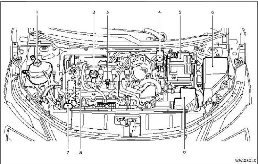
PR25DD ENGINE MODEL
- Engine coolant reservoir (P.8-6)
- Engine oil filler cap (P.8-8)
- Engine oil dipstick (P.8-8)
- Brake fluid reservoir (P.8-12)
- Battery (P.8-15)
- Fuse/fusible link box (P.8-22)
0-10 Illustratedtableofcontents
- Window washer fluid reservoir (P.8-13)
- Drive belt (P.8-17)
- Air cleaner (P.8-19)
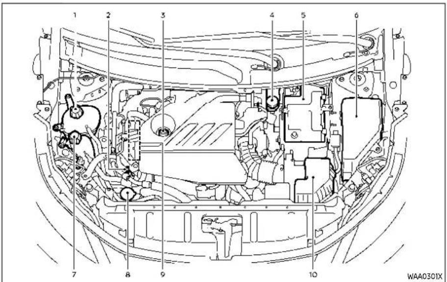
KR15DDT ENGINE MODEL
- Engine coolant reservoir (P.8-6)
- Engine oil dipstick (P.8-8)
- Engine oil filler cap (P.8-8)
- Brake fluid reservoir (P.8-12)
- Battery (P.8-15)
-
Fuse/fusible link box (P.8-22)
-
Intercooler coolant reservoir (P.8-6)
- Window washer fluid reservoir (P.8-13)
- Drive belt (P.8-17)
- Air cleaner (P.8-19)
WARNINGANDINDICATORLIGHTS
| Red light | Name | Page |
BRAKE | Brake warning light | 2-14 |
| Charge warning light | 2-15 | |
 | Electric shift control system warning light | 2-15 |
PARK | Electronic parking brake warning light | 2-15 |
 | Engine oil pressure warning light | 2-15 |
| [B4YA] | Hands OFF warning light (If so equipped) | 2-16 |
| Master warning light | 2-16 | |
 | Seat belt warning light | 2-16 |
| Supplemental air bag warning light | 2-16 |
| Yellow light | Name | Page |
| Anti-lock Braking System (ABS) warning light | 2-17 | |
| Automatic Emergency Braking (AEB) system OFF warning light | 2-17 | |
| Electric power steering warning light | 2-17 | |
| Electronic parking brake system warning light | 2-18 | |
| Low tire pressure warning light | 2-18 | |
| Malfunction Indicator Light (MIL) | 2-19 | |
| Master warning light | 2-20 | |
| Rear Automatic Braking (RAB) system OFF warning light | 2-20 | |
| Slip indicator light | 2-20 | |
| Vehicle Dynamic Control (VDC) off indicator light | 2-20 |
| Other light | Name | Page |
| Automatic brake hold indicator light (white) | 2-21 | |
| Automatic brake hold indicator light (green) | 2-21 | |
| Exterior light indicator | 2-21 | |
| Front fog light indicator light (If so equipped) | 2-21 | |
| High beam assist indicator light | 2-21 | |
| High beam indicator light | 2-21 | |
| Turn signal/hazard indicator lights | 2-21 |
1 Safety—Seats, seatbeltsandsupplementalrestraintsystem
Seats 1-3
Frontseats....1-4
Rearseats....1-7
Armrest....1-9
Headrestraints/headrests....1-10
Adjustablehead
restraint/headrestcomponents....1-11
Non-adjustablehead
restraint/headrestcomponents....1-1 1
Remove....1-11
Install....1-12
Adjust....1-12
Seatbelts....1-14
Precautionsonseatbeltusage....1-14
Seatbeltwarninglightandchime....1-16
Pregnantwomen....1-17
Injuredpersons....1-17
Three-pointtypeseatbeltwithretractor.....1-17
Seatbeltextenders....1-20
Seatbeltmaintenance....1-21
Childsafety....1-21
Infants....1-22
Smallchildren....1-22
Largerchildren....1-22
Childrestraints....1-24
Precautionsonchildrestraints....1-24
LowerAnchorsandTethersforChildren
Rear-facingchildrestraintinstallation
usingLATCH....1-31
Rear-facingchildrestraintinstallation
usingtheseatbelts....1-33
Forward-facingchildrestraintinstallation
usingLATCH....1-36
Forward-facingchildrestraintinstallation
usingtheseatbelts....1-39
Boosterseats....1-44
SupplementalRestraintSystem(SRS)....1-47
PrecautionsonSRS....1-47
NISSANAdvancedAirBagSystem
(frontseats)....1-53
Driverandfrontpassengersupplemental
kneeairbag....1-62
Front,frontcentral,rearoutboard
seat-mountedside-impactsupplemental
airbagandroof-mountedcurtain
side-impactandrolloversupplementalair
bagsystems....1-64
Seatbeltswithpretensioners(frontand
rearoutboardseats)....1-66
Supplementalairbagwarninglabels....1-67
Supplementalairbagwarninglight....1-67
Repairandreplacementprocedure....1-68
SEATS


SSS0133

WARNING
- Donotrideinamovingvehicle whentheseatbackisreclined. This can be dangerous. The shoulderbeltwillnotbeagainst yourbody.inanaccident,you couldbethrownintoitandre- ceiveneckorotherseriousinjurs- Youcouldalsoslideunder thelapbeltandreceiveserious internalinjuries.
- Forthemosteeffectiveprotection whenthevehicleisinmotion,the seatshouldbeupright.Alwayssit
wellbackanduprightintheseat withbothfeetonthefloor and adjusttheseatproperly.See "Precautionsonseatbeltusage" (P.1-14).
- Afteradjustment, gentlyrockin theseattomakesureitissecurelylocked.
- Donotleavechildrenunattended insidethevehicle.Theycould unknowinglyactivateswitches orcontrols.Unattendedchildren couldbecomeinvolvedinserious accidents.
●Tohelpavoidriskofinjuryor deaththroughunintendedoperationofthevehicleand/orits systems,donotleavechildren, peoplewhorequiretheassistanceofothersorpetsunattended in your vehicle. Additionally,thetemperatureinsideaclosedvehicleonawarm daycanquicklybecomehigh enoughtocauseasignificantrisk ofinjuryordeathtopeopleand pets.
- Donotadjustthedriver'sseat whiledrivingsofullattentionmay begiventovehicleoperation.The seatmaymovesuddenly and couldcauselossofcontrolof thevehicle.
- Theseatbackshouldnotbere-clinedanymorethanneededfor comfort.Seatbeltsaremostef- fectivewhenthepassengersits wellbackandstraightupinthe seat.Iftheseatbackisreclined, theriskofslidingunderthelap belt and being injured is in- creased.

CAUTION
Whenadjustingtheseatpositions, besurenottocontactanymoving partstoavoidpossibleinjuriesand/ordamage.
FRONT SEATS
Your vehicle seats can be adjusted in manual or power operation. For additional information about adjusting the seats, refer to the steps outlined in this section.
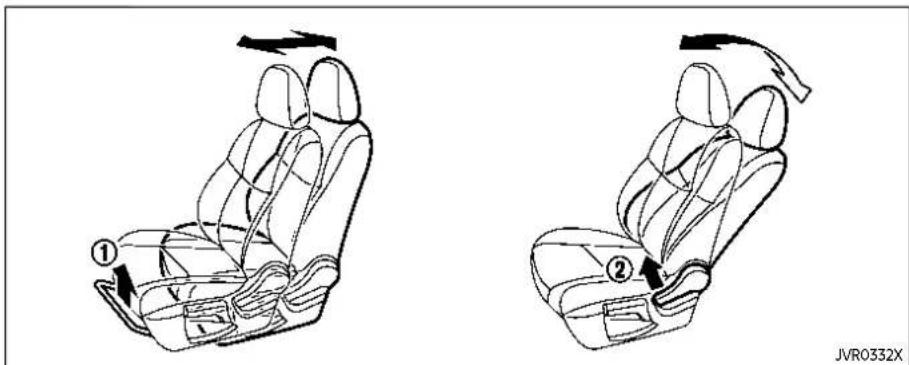
Front manual seat adjustment
Forwardandbackward:
- Pull up the adjusting lever ①
- Slide the seat to the desired position.
- Release the adjusting lever to lock the seat in position.
different sizes to help obtain the proper seat belt fit. (See "Seat belts" (P.1-14).)
The seatback may be reclined to allow occupants to rest when the vehicle is parked.
Reclining:
- Pull up the adjusting lever ②
- Tilt the seatback to the desired position.
- Release the adjusting lever to lock the seatback in position.
The reclining feature allows the adjustment of the seatback for occupants of
1-4 Safety—Seats, seat belts and supplemental restraintsystem

See "Memory seat" (P.3-37) for the seat position memory function (if so equipped).
Seatlifter(ifsoequipped):
Pull up or push down the adjusting lever to adjust the seat height until the desired position is achieved.
Front power seat adjustment
Operatingtips:
- The power seat motor has an auto-reset overload protection circuit. If the motor stops during the seat adjustment, wait 30 seconds, then reactivate the switch.
- To avoid discharge of the battery, do not operate the power seats for a long period of time when the engine is not running.
Safety—Seats,seatbeltsandsupplementalrestraintsystem1-5

Forwardandbackward:
Move forward or backward the adjusting switch ① to the desired position.
Reclining:
Move forward or backward the adjusting switch ② to the desired position.
The reclining feature allows the adjustment of the seatback for occupants of different sizes to help obtain the proper seat belt fit. (See "Seat belts" (P.1-14).)
The seatback may be reclined to allow occupants to rest when the vehicle is parked.

Seatlifter(ifsoequipped):
Move the switch as shown to adjust the angle of the front portion or height of the seat.
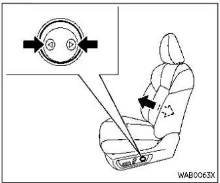
Lumbar support (if so equipped)
The lumbar support feature provides lower back support to the driver.
Push the switch as shown to adjust the seat lumbar area until the desired position is achieved.
NOTE:
Themotorofthelumbarsupportwill continuetorunwhiletheswitchis pushedevenafterfulltravelinboth directionsisachieved.
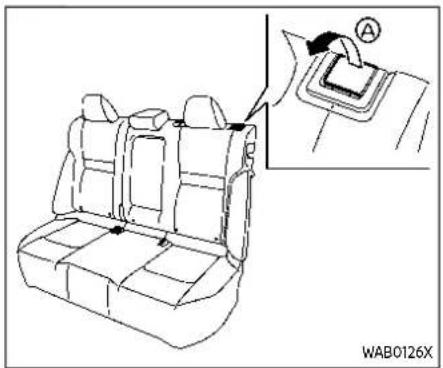
REAR SEATS
Reclining (if so equipped)
- Pull up the lever Ⓐ
- Tilt the seatback backward. It is reclined slightly.
- Release the lever to lock the seatback in position.
Folding
Beforefoldingtherearseats
- Secure the outer seat belt on the seat belt hook. (See "Seat belt hook" (P.1-20).)
- If the rear seat is equipped with the head restraints/headrests, slide the front seat forward to make enough room behind the seat so that the rear seatback can be folded flat.
- Remove drink containers from the rear cup holder.
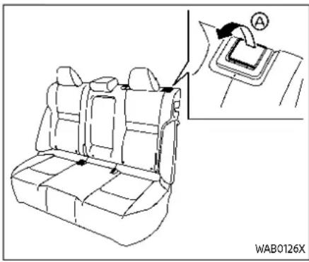
Tofolddowntheseatback
- Pull up the lever Ⓐ and fold the seat-back flat.

- Pull the lever (if so equipped) located on the side of the luggage area.
Toreturntheseatback
To return the seatback to a seating position, raise the seatback until it latches in place.
When returning the seatback, make sure that the seat belts are not interfering with the seatback latch mechanism.

WARNING
- Neverallowanyonetorideinthe cargoareaorontherearseats
whentheyareinthefold-down position.Inacollision,people ridingintheseareaswithout properrestraintsaremorelikely tobeseriouslyinjuredorkilled.
- Donotallowpeopletorideinany areaofyourvehiclethatisnot equippedwithseatsandseat belts.Besureveryoneinyour vehicleisinaseatandusinga seatbeltproperly.
- Donotallowmorethanone persontousethesameseatbelt.
- Donotfolddowntherearseats whenoccupantsareintherear seatareaoranyluggageisonthe rearseats.
—Makesurethattheseatpath isclearbeforemovingthe seat.
—Becarefulnottoallowhands orfeettogetcaughtor pinchedintheseat.
●Headrestraints/headrestsshould beadjustedproperlyastheymay providesignificantprotection againstinjuryinanaccident.Alwaysreplaceandadjustthem properlyiftheyhavebeenremovedforanyreason.
- If the head restraints/headrests are removed for any reason, they should be securely stored to prevent them from causing injury to passengers or damage to the vehicle in case of sudden braking or an accident.
- When returning these at back to the upright position, be certain they are completely secured in the latched position. If they are not completely secured, passengers maybe injured in an accidentors sudden stop.
•Properlysecureallcargotohelp preventitfromslidingorshifting. Donotplacecargohigherthan theseatbacks.Inasuddenstop orcollision,unsecuredcargo couldcausepersonalinjury.

WARNING
- Afteradjustment, gentlyrockin theseattomakesureitisse-curelylocked.
- Donotrideinamovingvehicle whentheseatbackisreclined. This can be dangerous. The shoulderbeltwillnotbeagainst
yourbody.Inanaccident,you couldbethrownintoitandreceiveneckorotherseriousinjuries.Youcouldalsoslideunder thelapbeltandreceiveserious internalinjuries.
- Forthemosteeffectiveprotection whenthevehicleisinmotion,the seatshouldbeupright.Alwayssit wellbackanduprightintheseat withbothfeetonthefloorand adjusttheseatbeltproperly.(See "Precautionsonseatbeltusage" (P.1-14).)

Rearseats
ARMREST
Pull the armrest down as shown.
HEADRESTRAINTS/HEADRESTS

WARNING
Headrestraint/headrestsupplement theothervehiclesafetysystems. Theymayprovideadditionalprotectionagainstinjuryincertainrearend collisions.Adjustable head restraints/headrestsmustbeadjusted properly,asspecifiedinthissection. Checktheadjustmentaftersomeone elseusetheseat.Donotattach anythingtotheheadrestraint/headreststalksorremovetheheadrestraint/headrest.Donotusetheseat iftheheadrestraint/headresthas beenremoved.Iftheheadrestraint/headrestwasremoved,reinstalland properlyadjusttheheadrestraint/headrestbeforeanoccupantuses theseatingposition.Failureretofollow theseinstructionscanreducethe effectivenesssoftheheadrestraint/headrest.Thismayincreasetherisk ofseriousinjuryordeathinacollision.
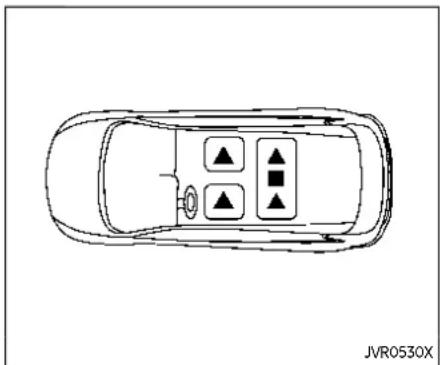
The illustration shows the seating positions equipped with head restraint/head-rest.
▲ Indicates the seating position is equipped with a head restraint.
■ Indicates the seating position is equipped with a headrest.
+ Indicates the seating position is not equipped with a head restraint or head-rest.
-Your vehicle is equipped with a head restraint/headrest that may be integrated, adjustable or non-adjustable.
- Adjustable head restraints/headrests have multiple notches along the stalk to lock them in a desired adjustment
position.
●The non-adjustable head restraints/headrests have a single locking notch to secure them to the seat frame.
●Proper Adjustment:
- For the adjustable type, align the head restraint/headrest so the center of your ear is approximately level with the center of the head restraint/headrest.
- If your ear position is still higher than the recommended alignment, place the head restraint/headrest at the highest position.
- If the head restraint/headrest has been removed, ensure that it is re-installed and locked in place before riding in that designated seating position.

ADJUSTABLE HEAD RESTRAINT/ HEADREST COMPONENTS
- Removable head restraint/headrest
- Multiple notches
- Lock knob
- Stalks
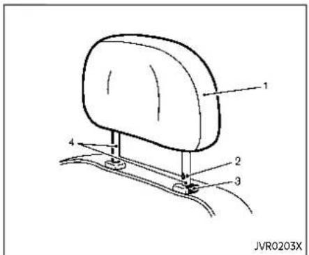
NON-ADJUSTABLE HEAD RE-STRAINT/HEADREST COMPONENTS
- Removable head restraint/headrest
- Single notch
- Lock knob
- Stalks

REMOVE
Use the following procedure to remove the head restraint/headrest.
- Pull the head restraint/headrest up to the highest position.
- Push and hold the lock knob.
- Remove the head restraint/headrest from the seat.
- Store the head restraint/headrest properly in a secure place so it is not loose in the vehicle.
- Reinstall and properly adjust the head restraint/headrest before an occupant uses the seating position.
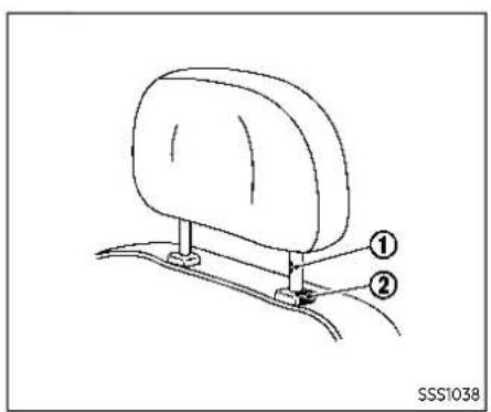
INSTALL
- Align the head restraint/headrest stalks with the holes in the seat. Make sure that the head restraint/headrest is facing the correct direction. The stalk with the adjustment notch ① must be installed in the hole with the lock knob ②.
- Push and hold the lock knob and push the head restraint/headrest down.
- Properly adjust the head restraint/headrest before an occupant uses the seating position.
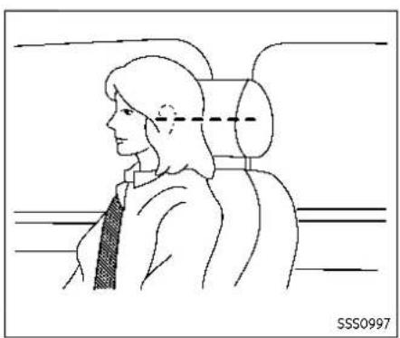
ADJUST
Foradjustableheadrestraint/headrest
Adjust the head restraint/headrest so the center is level with the center of your ears. If your ear position is still higher than the recommended alignment, place the head restraint/headrest at the highest position.

Fornon-adjustableheadrestraint/headrest
Make sure the head restraint/headrest is positioned so the lock knob is engaged in the notch before riding in that designated seating position.
1-12 Safety—Seats, seatbeltsandsupplementalrestraintsystem
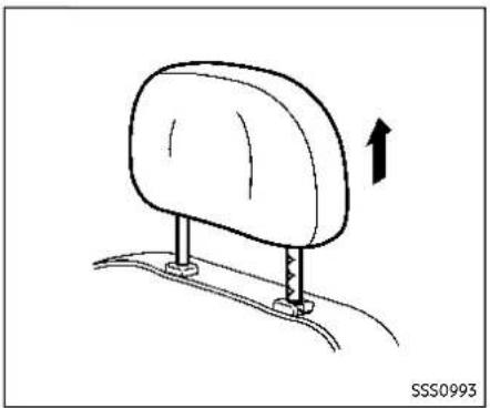

Raise
To raise the head restraint/headrest, pull it up.
Make sure the head restraint/headrest is positioned so the lock knob is engaged in the notch before riding in that designated seating position.
Lower
To lower, push and hold the lock knob and push the head restraint/headrest down.
Make sure the head restraint/headrest is positioned so the lock knob is engaged in the notch before riding in that designated seating position.
SEATBELTS
PRECAUTIONS ON SEAT BELT USAGE
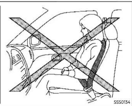
If you are wearing your seat belt properly adjusted, and you are sitting upright and well back in your seat with both feet on the floor, your chances of being injured or killed in an accident and/or the severity of injury may be greatly reduced. NISSAN strongly encourages you and all of your passengers to buckle up every time you drive, even if your seating position includes a supplemental air bag.
Most U.S. states and Canadian provinces or territories specify that seat belts beworn at all times when a vehicle is being driven.


1-14 Safety—Seats, seatbeltsandsupplementalrestraintsystem


WARNING
- Everypersonwhodrivesorrides inthisvehicleshoulduseaseat beltataltimes. Childrenshould beproperlyrestrainedintherear seatand,ifappropriate,inachild restraint.
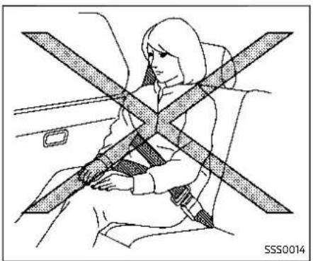
•Theseatbeltshouldbeproperly adjustedtoasnugfit.Failureto dosomayreducetheeffectivenessoftheentirerestraintsystemandincreasethechanceor severityofinjuryinanaccident. Seriousinjuryordeathcanoccur iftheseatbeltisnotwornproperly.
●Alwaysroutetheshoulderbelt overyourshoulderandacross yourchest.Neverputthebelt behindyourback,underyour armoracrossyourneck.Thebelt shouldbeawayfromyourface andneck,butnotfallingoffyour shoulder. -
Positionthelapbeltaslowand snugaspossibleAROUNDTHE HIPS,NOTTHEWAIST.Alapbelt worntoohighcouldincreasethe riskofinternalinjuriesinan accident.
-
Besuretheseatbelttongueis securelyfastenedtotheproper buckle.
- Donotweartheseatbeltinside outortwisted.Doingsomay reduceitseffectiveness.
- Donotallowmorethanone persontousethesameseatbelt.
●Nevercarrymorepeopleinthe vehiclethanthereareseatbelts. - If theseatbeltwarninglight glows continuously while the ignitionisturned ON with all doors closed and all seat belts fastened, it may indicate an function in the system. Havethe system checked. It is recommended you visit a NISSAN dealer for this service.
-
Nochangesshouldbemadeto theseatbeltsystem. Forexample, donotmodifytheseatbelt, addmaterial, or install devices that may changetheseatbelt routingortension. Doingsomay affect the operation of theseat beltsystem. Modifying ortampering with theseatbeltsystem may result in serious personal injury.
-
Onceaseatbeltpretensionerhas activated, it cannot be reused and must bereplaced together with theretractor. It is recommended you visit a NISSAN dealer for this service.
- Allseatbeltassemblies, including retractors and attaching hardware, should be inspected after any collision. It is recommended you visit a NISSAN dealer for this service. NISSAN recommend that all seat belt assemblies in use during a collision bereplaced unless the collision was minor and the belt shown no damage and continueto operate properly. Seat belt assemblies not in use during collisions should also be inspected and replaced if either damage or improper operation is noted.
- All childrestraints and attaching hardwares should be inspected after anycollision. Always follow therestraint manufacturer's inspection instructions and replacement recommendations. The childrestraints should be placed if they are damaged.

JVR0575X
SEAT BELT WARNING LIGHT AND CHIME
The driver and front passenger seats are equipped with an enhanced seat belt reminder function. If your vehicle is equipped with an enhanced seat belt reminder function, a visual and audible alert will operate if a driver or front passenger seat belt is unbuckled at speeds of approximately 10 MPH (15 km/h) or more under the following conditions:
- If the driver seat belt is not fastened.
- The front passenger's seat belt is not fastened and the seat is occupied by a passenger for 7 seconds after the
ignition switch is placed in the ON position.
- The front passenger's seat belt is not fastened and objects or external force on the passenger seat change the seat belt reminder classification to "occupied".
The seat belt warning light will flash under the conditions shown above until the necessary seat belt is securely fastened.
A warning chime will sound for approximately 95 seconds or until one of the following conditions is met:
●The unbuckled front passenger's seat belt is securely fastened.
●The seat belt reminder function in the front passenger seat no longer detects that the front passenger seat is occupied.
- The ignition switch is turned off.
The below situations could result in the seat belt warning light being illuminated and the chime sounding, even with no occupant present in the passenger seat:
●Heavy objects placed on the seat.
- Someone pushing or pulling on the front passenger seat.
●An object placed under the front a passenger seat.
- An object placed between the seat cushion and center console or between the seat cushion and the door.
- An object hanging on the seat or placed in the seatback pocket.
●A child restraint or other object pressing against the rear of the seatback. The rear seats may be equipped with a seat belt warning in the vehicle information display. (See "11. Rear seat belt warning" (P.2-35).)
PREGNANT WOMEN
NISSAN recommends that pregnant women use seat belts. The seat belt should be worn snug, and always position the lap belt as low as possible around the hips, not the waist. Place the shoulder belt over your shoulder and across your chest. Never put the lap/shoulder belt over your abdominal area. Contact your doctor for specific recommendations.
INJURED PERSONS
NISSAN recommends that injured persons use seat belts, depending on the injury. Check with your doctor for specific recommendations.
THREE-POINT TYPE SEAT BELT WITH RETRACTOR

WARNING
- Everypersonwhodrivesorrides inthisvehicleshoulduseaseat beltataltimes.Childrenshould beintherearseatsandinan appropriaterestraint.
- Donotrideinamovingvehicle whentheseatbackisreclined. This can be dangerous. The shoulderbeltwillnotbeagainst yourbody.Inanaccident,you couldbethrownintoitandreceiveneckorotherseriousinjuries.Youcouldalsoslideunder thelapbeltandreceiveserious internalinjuries.
- Forthemosteeffectiveprotection whenthevehicleisinmotion,the seatshouldbeupright.Alwayssit wellbackanduprightintheseat withbothfeetonthefloorand adjusttheseatbeltproperly.
- Donotallowchildrentoplaywith theseatbelts.MostseatingpositionsareequippedwithAutomaticLockingRetractor(ALR) modeseatbelts.Iftheseatbelt
becomes wrapped around a child'sneckwiththeALRmode activated,thechildcanbeseriouslyinjuredorkillediftheseat beltretractsandbecomestight. Thiscanoccurevenifthevehicle isparked.Unbuckletheseatbelt toreleasethechild.Iftheseat beltcannotbeunbuckledoris alreadyunbuckled,releasethe childbycuttingtheseatbeltwith asuitabletool(suchasaknifeor scissors)toreleasetheseatbelt.
Fastening the seat belts
- Adjust the seat. (See "Seats" (P.1-3).)
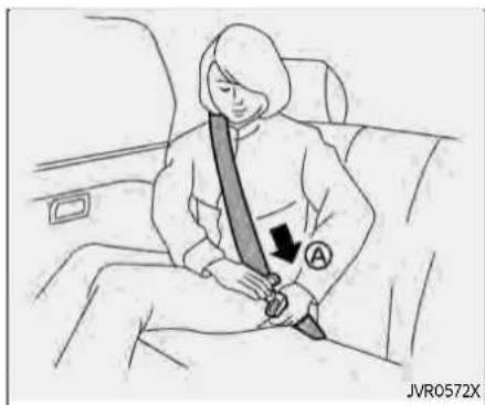
-
Slowly pull the seat belt out of the retractor and insert the tongue into the buckle Ⓐ until you hear and feel the latch engage.
-
Theretractorisdesignedtolock duringasuddenstoporonimpact.Aslowpullingmotionpermitsthebelttomoveandallows yousomefreedomofmovement intheseat.
- If theseatbelt cannot be pulled from its fully retracted position, firmly pull the belt and release it. Thensmoothly pull the belt out of theretractor.
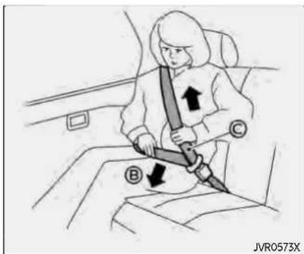
- Position the lap belt portion lowand snugonthehips as shown.
- Pull the shoulder belt portion toward the retractor to take up extra slack. Be sure the shoulder belt is routed over your shoulder and across your chest.
The three-point seat belts in the front passenger seat and the rear seating positions have two modes of operation:
●Emergency Locking Retractor (ELR)
●Automatic Locking Retractor (ALR)
The Emergency Locking Retractor (ELR) mode allows the seat belt to extend and retract to allow the driver and passengers some freedom of movement in the seat.
The ELR locks the seat belt when the vehicle slows down rapidly or during certain impacts.
The Automatic Locking Retractor (ALR) mode (child restraint mode) locks the seat belt for child restraint installation.
When ALR mode is activated the seat belt cannot be extended again until the seat belt tongue is detached from the buckle and fully retracted. The seat belt returns to the ELR mode after the seat belt fully retracts. For additional information, see "Child restraints" (P.1-24).
The ALRmodeshouldbeusedonly for childrestraintinstallation.Duringnormalseatbeltusebyanoccupant,the ALRmodeshouldnotbeactivated.Ifit isactivated,itmaycauseuncomfortableseatbelttension.Itcanalsochange theoperationofthefrontpassengerair bag.

WARNING
When fastening theseatbelts, be certain that seatbacks are completely secured in the elatched position. If they are not completely secured, passengers maybe injured in an accident or sudden stop.

Unfastening the seat belts
To unfasten the seat belt, push the button on the buckle ① The seat belt automatically retracts.
Checking seat belt operation
Seat belt retractors are designed to lock seat belt movement by two separate methods:
- When the belt is pulled quickly from the retractor.
- When the vehicle slows down rapidly. To increase your confidence in the seat belts, check the operation as follows:
- Grasp the shoulder belt and pull forward quickly. The retractor should lock and restrict further belt movement.
If the retractor does not lock during this check, get the system checked. It is recommended you visit a NISSAN dealer for this service, or to learn more about seat belt operation.

Shoulder belt height adjustment (for front seats)
The shoulder belt anchor height should be adjusted to the position best for you. (See "Precautions on seat belt usage" (P.1-14).)
To adjust, pull the adjustment button ① and then move the shoulder belt anchor to the desired position ② , so that the belt passes over the center of the shoulder. The belt should be away from your face and neck, but not falling off of your shoulder. Release the adjustment button to lock the shoulder belt anchor into position.
The range of height adjustment of the
Safety—Seats,seatbeltsandsupplementalrestraintsystem1-19
shoulder belt may vary depending on the model.

WARNING
- Afteradjustment,releasethead-justmentbuttonandtrytomove theshoulderbeltanchorupand downtomakesureitissecurely fixedinposition.
- Theshoulderbeltanchorheight shouldbeadjustedtothepositionbestforyou.Failureretodoso mayreducetheeffectiveness of theentirerestrainsystem and increasethechanceorseverity of injuryinanaccident.
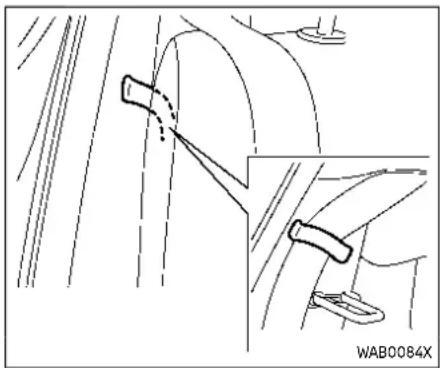
Seat belt hook
When the seat belt is not in use and when folding down the rear seats, hook the rear outer seat belts on the seat belt hooks.

WARNING
Beforefoldinguptherearseats, ensuretheseatbeltsarenotobstructingtherearseatbacklatches toavoiddamagetotheseatbelt webbing.
SEAT BELT EXTENDERS
If, because of body size or driving position, it is not possible to properly fit the lap/shoulder belt and fasten it, an extender that is compatible with the installed seat belts is available that can be purchased. The extender adds approximately 8 in (200 mm) of length and may be used for either the driver or front passenger seating position. It is recommended you visit a NISSAN dealer for assistance with purchasing an extender if an extender is required.

WARNING
- It is recommended that only NISSANseatbeltextenders, made by the same company which madetheoriginalequipmentseat belts, be used with NISSANseat belts.
- Adultsandchildrenwhocanuse thestandardseatbeltshouldnot useanextender.Suchunnecessaryusecouldresultinserious personalinjuryintheeventofan accident.
- Neveruseseatbeltextendersto installchildrestraints.Ifthechild restraintisnotsecuredproperly,
CHILDSAFETY
thechildcouldbeseriouslyin- juredorkilledinacollisionora suddenstop.
SEAT BELT MAINTENANCE
- Tocleantheseatbeltwebbing,apply a mild soap solution or any solution recommended for cleaning upholstery or carpets. Then wipe with a cloth and allow the seat belts to dry in the shade. Do not allow the seat belts to retract until they are completely dry.
- Ifdirtbuildsupintheshoulderbelt guide of the seat belt anchors, the seat belts may retract slowly. Wipe the shoulder belt guide with a clean, dry cloth.
- Periodicallychecktoseethatthe seatbeltandthemetalcomponents, such as buckles, tongues, retractors, flexible wires and anchors, work properly. If loose parts, deterioration, cuts or other damage on the webbing is found, the entire seat belt assembly should be replaced.

WARNING
Donotallowchildrentoplaywiththe seatbelts.Mostseatingpositionsare equippedwithAutomaticLocking Retractor(ALR)modeseatbelts.If theseatbeltbecomeswrapped aroundachild'sneckwiththeALR modeactivated,thechildcan be seriouslyinjuredorkillediftheseat beltretractsandbecomestight.This canocurevenifthevehicleis parked.Unbuckletheseatbeltto releasethechild.Iftheseatbeltcan notbeunbuckledorisalreadyun-buckled,releasethechildbycutting theseatbeltwithasuitabletool (suchasaknifeorscissors)to releasetheseatbelt.
Childrenneedadultstohelpprotect them.
Theyneedtobeproperlyrestrained.
In addition to the general information in this manual, child safety information is available from many other sources, including doctors, teachers, government traffic safety offices, and community organizations. Every child is different, so be sure to learn the best way to transport your child.
There are three basic types of child restraint systems:
●Rear-facing child restraint
●Forward-facing child restraint
- Booster seat
The proper restraint depends on the child's size. Generally, infants up to about 1 year and less than 20 lbs (9 kg) should be placed in rear-facing child restraints. Forward-facing child restraints are available for children who outgrow rear-facing child restraints and are at least 1 year old. Booster seats are used to help position a vehicle lap/shoulder belt on a child who can no longer use a forward-facing child restraint.

WARNING
Infantsandchildrenneedspecial protection. The vehicle's seat belts may not fit them properly. The shoulder belt may cometo close to the face or neck. Thelap belt may not fit over their small hip bones. In an accident, anim properly fitting seat belt could cause serious or fatal injury. Always use appropriate child restraints.
All U.S. states and Canadian provinces or
Safety—Seats, seatbeltsandsupplementalrestraintsystem1-21
territories require the use of approved child restraints for infants and small children. See "Child restraints" (P.1-24).
A child restraint may be secured in the vehicle by using either the LATCH (Lower Anchors and Tethers for CHildren) system or with the vehicle seat belt. See "Child restraints" (P.1-24) for more information.
NISSANrecommendsthatallpre-teens andchildrenberestrainedintherear seat.Studieshowthatchildrenare saferwhenproperlyrestrainedinthe rearseatthaninthefrontseat.
Thisisespeciallyimportantbecause yourvehiclehasasupplementalrestraintsystem(Airbagsystem)forthe frontpassenger.See"Supplemental RestraintSystem(SRS)("P.1-47).
INFANTS
Infants up to at least 1 year old should be placed in a rear-facing child restraint. NISSAN recommends that infants be placed in child restraints that comply with Federal Motor Vehicle Safety Standards or Canadian Motor Vehicle Safety Standards. You should choose a child restraint that fits your vehicle and always follow the manufacturer's instructions for installation and use.
SMALL CHILDREN
Children that are over 1 year old and weigh at least 20 lbs (9 kg) should remain in a rear-facing child restraint as long as possible up to the height or weight limit of the child restraint. Children who out-grow the height or weight limit of the rear-facing child restraint and are at least 1 year old should be secured in a forward-facing child restraint with a harness. Refer to the manufacturer's instructions for minimum and maximum weight and height recommendations. NISSAN recommends that small children be placed in child restraints that comply with Federal Motor Vehicle Safety Standards or Canadian Motor Vehicle Safety Standards. You should choose a child restraint that fits your vehicle and always follow the manufacturer's instructions for installation and use.
LARGER CHILDREN
Children should remain in a forward-facing child restraint with a harness until they reach the maximum height or weight limit allowed by the child restraint manufacturer.
Once a child outgrows the height or weight limit of the harness-equipped forward-facing child restraint, NISSAN recommends that the child be placed in a commercially available booster seat to
obtain proper seat belt fit. For a seat belt to fit properly, the booster seat should raise the child so that the shoulder belt is properly positioned across the chest and the top, middle portion of the shoulder. The shoulder belt should not cross the neck or face and should not fall off the shoulder. The lap belt should lie snugly across the lower hips or upper thighs, not the abdomen.
A booster seat can only be used in seating positions that have a three-point type seat belt. The booster seat should fit the vehicle seat and have a label certifying that it complies with Federal Motor Vehicle Safety Standards or Canadian Motor Vehicle Safety Standards.
A booster seat should be used until the child can pass the seat belt fit test below:
- Are the child's back and hips against the vehicle seatback?
- Is the child able to sit without slouching?
- Do the child's knees bend easily over the front edge of the seat with feet flat on the floor?
-
Can the child safely wear the seat belt (lap belt low and snug across the hips and shoulder belt across mid-chest and shoulder)?
-
Is the child able to use the properly adjusted head restraint/headrest?
- Will the child be able to stay in position for the entire ride?

seriouslyinjuredorkilledinasudden stoporcollision.
If you answered no to any of these questions, the child should remain in a booster seat using a three-point type seat belt.
NOTE:
Lawsinsomecommunitiesmayfollow differentguidelines.Checklocaland stateregulationstoconfirmyourchild isusingthecorrectrestraintsystem beforetraveling.

WARNING
Neverletachildstandorkneelon anyseatanddonotallowachildin thecargoarea.Thechildcouldbe
Safety—Seats, seatbeltsandsupplementalrestraintsystem1-23
CHILDRESTRAINTS


PRECAUTIONS ON CHILD RESTRAINTS

WARNING
●Failuretofollowthewarnings andinstructionsforproperuse andinstallationofchildrestraints couldresultinserious injuryor deathofachildorotherpassengersinasuddenstoporcollision:
—The child restraint must be used and installed properly. Always follow a llof the child restraint manufacturer's instructions for installation and use.
—Infantsandchildrenshould neverbeheldonanyone's lap. Eventhestrongestadult cannotresisttheforcesofa collision.
—Donotputaseatbeltaround bothachildandanotherpassenger.
—NISSANrecommendsthatall childrestraintsbeinstalledin therearseat.Studieshow thatchildrenaresaferwhen properlyrestrainedintherear
seatthaninthefrontseat. If you must install a forward-facing child restraint in the front seat, see "Forward-facing child restraint installation using these seat belts" (P.1-39).
—EvenwiththeNISSANAdvancedAirBagSystem,never installarear-facingchildrestraintinthefrontseat.An inflatingairbagcouldseriouslyinjureorkillachild.A rear-facing child restraint mustonlybeusedintherear seat.
—Besuretopurchaseachild restraintthatwillfitthechild andvehicle.Somechildren-straintsmaynotfitproperly inyourvehicle.
—Childrestraintanchoragesare designedtowithstandonly thoseloadsimposedbycorrectlyfittedchildrestraints. Undernocircumstancesare theytobeusedtoattach adultseatbelts,or other itemsorequipmenttothe vehicle.Doingsocoulddamagethechildrestraintanchorages.Thechildrestraint
will not be properly installed using the damaged anchorage, and child could be seriously injured or killed a collision.
—Neverusetheanchorpoints for adultseatbeltsorharnesses.
—Achildrestraintwithatop tetherstrapshouldnotbe usedinthefrontpassenger seat.
—Keepseatbacksasuprightas possibleafterfittingthechild restraint.
-Infantsandchildrenshould alwaysbeplacedinanappropriatechildrestraintwhilein thevehicle.
- Whenthechildrestraintisnotin use, keepitsecured with the LATCHsystemoraseatbelt. In a sudden stop or collision, loose object scan injure occupants or damage the vehicle.

CAUTION
Achildrestraintinaclosedvehicle canbecomeveryhot.Checkthe seatingsurfaceandbucklesbefore placingachildinthechildrestraint.
This vehicle is equipped with a universal child restraint anchor system, referred to as the LATCH (Lower Anchors and Tethers for CHildren) system. Some child restraints include rigid or webbing-mounted attachments that can be connected to these anchors.
For details, see "Lower Anchors and Tethers for CHildren (LATCH) system" (P.1-26).
If you do not have a LATCH compatible child restraint, the vehicle seat belts can be used.
Several manufacturers offer child restraints for infants and small children of various sizes. When selecting any child restraint, keep the following points in mind:
- Choose only a restraint with a label certifying that it complies with Federal Motor Vehicle Safety Standard 213 or Canadian Motor Vehicle Safety Standard 213.
- Check the child restraint in your vehicle to be sure it is compatible with the vehicle's seat and seat belt system.
- If the child restraint is compatible with your vehicle, place your child in the child restraint and check the various adjustments to be sure the child restraint is compatible with your child. Choose a child restraint that is designed for your child's height and weight. Always follow all recommended procedures.
- If the combined weight of the child and child restraint is less than 65 lbs (29.5 kg), you may use either the LATCH anchors or the seat belt to install the child restraint (not both at the same time).
- If the combined weight of the child and child restraint is greater than 65 lbs (29.5 kg), use the vehicle's seat belt (not the lower anchors) to install the child restraint.
- Be sure to follow the child restraint manufacturer's instructions for installation.
AllU.S. states and Canadian provinces orterritories require that infants and small children berestrained in an approved child restraint at all times while the vehicle is being operated. Canadian
Safety—Seats, seatbeltsandsupplementalrestraintsystem1-25
lawrequiresthetoptetherstrapon forward-facingchildrestraintsbese-curedtothedesignatedanchorpoint onthevehicle.

LATCHsystemanchorlocation
Lower Anchors and Tethers for CHildren (LATCH) SYSTEM
Your vehicle is equipped with special anchor points that are used with LATCH system compatible child restraints. This system may also be referred to as the ISOFIX or ISOFIX compatible system. With this system, you do not have to use a vehicle seat belt to secure the child restraint unless the combined weight of the child and child restraint exceeds 65 lbs (29.5 kg). If the combined weight of the child and child restraint is greater than 65 lbs (29.5 kg), use the vehicle's seat belt (not the lower anchors) to install the child restraint. Be sure to follow the child restraint manufacturer's instructions for installation.
The LATCH anchor points can be used to install child restraints in either of the rear outboard seating positions or in the center rear seating position. Please refer to the following section of this Owner's Manual for specific information about installing a child restraint in the center rear seating position using the LATCH anchors.

CAUTION
StorethelooseLATCHcovers(for example,intheconsolebox)where theywillnotgetdamagedtoavoid losingthem.(See"Consolebox"(P.2-78).)
LATCH lower anchor

WARNING
Failuretofollowthewarningsand instructionsforproperuseandin-stallationofchildrestraintscould resultinseriousinjuryordeathofa childorotherpassengersinasuddenstoporcollision:
- OnlyattachLATCHsystemcompatiblechildrestraintstothe LowerAnchorsshownintheillustration.Foradditionalinformation, refer to the following sections of this Owner's Manual for installation guidance.
- AttachLATCHsystemcompatible childrestraintsonlyatthelocationsshownintheillustration.
- Inspecttheloweranchorsbyin-sertingyourfingersintothelow-eranchorarea.Feeltomakesure therearenoobstructionsover theanchorssuchasseatbelt webbingorseatkushionmaterial. Thechildrestraintwillnotbe secured properlyifthelower anchorsareobstructed.
- Childrestraintanchorages are designedtowithstandonlythose loadsimposedbycorrectlyfitted childrestraints.Undernocircumstancesaretheytobeusedto attachadultseatbelts,orother itemsorequipmenttothevehicle.Doingsocoulddamagethe childrestraintchorages.The childrestraintwillnotbeproperly installedusingthedamagedanchorage,andachildcouldbe seriouslyinjuredorkilledina
collision.
LATCH lower anchor location The LATCH lower anchor points are provided to install child restraints in the rear seats. Donotattempttoinstallchild restraintsinthecenterandleftout-boardseatingpositionssimultaneously usingtheLATCHloweranchors.
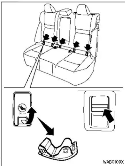
LATCHloweranchorcoverremoval
The LATCH lower anchor points are located under covers labelled ISOFIX at the bottom of the rear seat cushions. To access a LATCH lower anchor point, insert your finger into the cover and pull the cover off.

CAUTION
StorethelooseLATCHcovers(for example,intheconsolebox)where theywillnotgetdamagedtoavoid losingthem.(See"Consolebox"(P.2-78).)
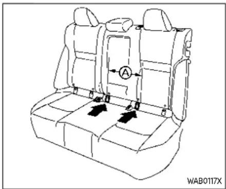
LATCH in the center rear seating position
A 5th LATCH anchor can be found between the outboard LATCH anchor pairs. It is specifically designed to be used together with the inboard LATCH anchor on the driver's side, in order to install a CRS in the rear center seating position.
These anchors utilize standard LATCH anchor spacing, Ⓐ of 11.02 in (280mm).

WARNING
NeverattachtwoCRSattachments tothesameLATCHanchor.Thismay overloadtheanchorinacollision, whichcouldincreasetheriskofthe occupant'sseriousinjuryordeath.
WheninstallingtheCRSinthecenter rearseatingpositionwiththein-boardLATCHanchors,becarefulto ensureanyoccupantorCRSinthe outboardseatingpositionsisproperlyrestrainedusingthevehicleseat beltandthereisnointerferencewith thecenterCRSinstallation.Ifthe outboardoccupantscannotbeproperlyrestrained,considerusingthe vehicleseatbelttorestraintheCRS inthecenterseatingposition,or movingtheCRStoanotherposition instead.
WheninstallingaCRSinthecenter seatingposition,usetheseatback reclinefeaturetoaligntheleftand rightsidesoftheseatback,creating oneevenlyreclinedsurface.Never installaCRSinthecenterseating positionwhenonepartoftheseat backisfurtherreclinedthanthe other.Thismaycreateanunstable surfaceonwhichtoinstalltheCRS.
Failuretoevenlyreclinetheseat backsbeforeCRSinstallationcould increasetheriskoftheoccupant's seriousinjuryordeath.Rememberto re-checkthattheCRSisproperly installedanytimetheseatsare reclinedoradjusted.

OK
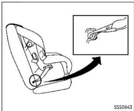
LATCHwebbing-mountedattachment
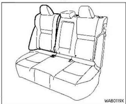
NG(theseatbackreclineisnotaligned)
Installing child restraint LATCH lower anchor attachments
LATCH compatible child restraints include two rigid or webbing-mounted attachments that can be connected to two anchors located at certain seating positions in your vehicle. With this system, you do not have to use a vehicle seat belt to secure the child restraint. Check your child restraint for a label stating that it is compatible with LATCH. This information may also be in the instructions provided by the child restraint manufacturer.
Safety—Seats, seatbeltsandsupplementalrestraintsystem1-29
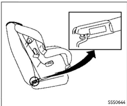
LATCHrigid-mountedattachment
When installing a child restraint, carefully read and follow the instructions in this manual and those supplied with the child restraint.
Top tether anchor

WARNING
Properlysecurecargoanddonot allowittacontactthetoptether strapwhenitisattachedtothetoptetheranchor.Cargothatisnot properlysecuredorcargothatcontactsthetoptetherstrapmaydamagethetoptetherstrapduringa
1-30 Safety—Seats, seat belts and supplemental restraintsystem
collision.Ifthecargocover(ifso equipped)contactsthetoptether strapwhenitisattachedtothetop tetheranchor,removethecargo coverfromthevehicle.Ifthecargo coverisnotremoved,itmaydamage thetoptetherstrapduringacollision.Yourchildcouldbeseriously injuredorkilledinacollisionifthe childrestrainttoptetherstrapis damaged.

Top tether anchor point locations

WARNING
Childrestraintanchoragesaredesignedtowithstandonlythoseloads imposedbycorrectlyfittedchild restraints.Undernocircumstances aretheytobeusedtoattachadult seatbelts,orotheritemsorequipmenttothevehicle.Doingsocould damage the child restraint anchorages.Thechildrestraintwillnot beproperlyinstalledusingthedamagedanchorage,andachildcould beseriouslyinjuredorkilledina
collision.
Anchor points are located on the back side of the seatbacks.
If a child restraint has a top tether strap, must be used when installing with the LATCH lower anchor attachments or seat belts as instructed by the child restraint manufacturer.
If you have any questions when installing atoptetherstrapchildrestraint on therearseat, it is recommended you visit a NISSAN dealer forth this service.
REAR-FACING CHILD RESTRAINT INSTALLATION USING LATCH
For additional information, refer to all Warnings and Cautions in the "Child Safety" and "Child restraints" sections before installing a child restraint.
Do not use the lower anchors if the combined weight of the child and the child restraint exceeds 65 lbs (29.5 kg). If the combined weight of the child and the child restraint is greater than 65 lbs (29.5 kg), use the vehicle's seat belt (not the lower anchors) to install the child restraint. Be sure to follow the child restraint manufacturer's instructions for installation.
Follow these steps to install a rear-facing child restraint using the LATCH system:
- Position the child restraint on the seat. Always follow the child restraint manufacturer's instructions.

Rear-facingweb-mounted—step2
- Secure the child restraint anchor attachments to the LATCH lower anchors. Check to make sure the LATCH attachment is properly attached to the lower anchors.

Rear-facingrigid-mounted-step2
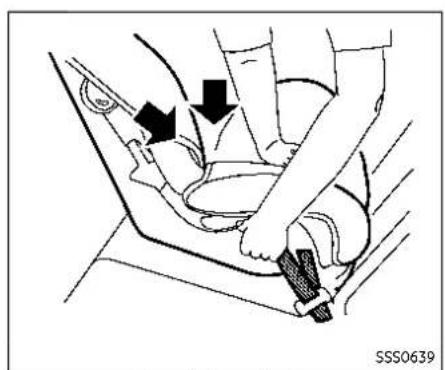
Rear-facing-step3
- For child restraints that are equipped with webbing-mounted attachments, remove any additional slack from the anchor attachments. Press downward and rearward firmly in the center of the child restraint with your hand to compress the vehicle seat cushion and seatback while tightening the webbing of the anchor attachments.
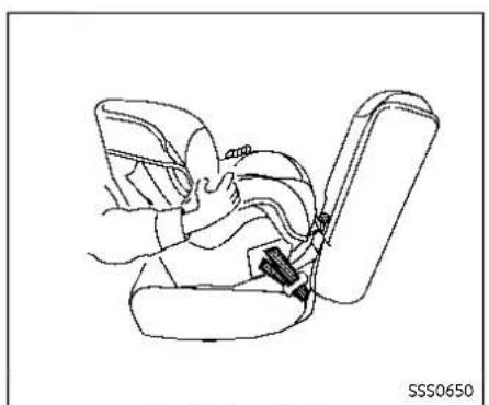
Rear-facing-step4
- After attaching the child restraint, test it before you place the child in it. Push it from side to side while holding the child restraint near the LATCH attachment path. The child restraint should not move more than 1 inch (25 mm), from side to side. Try to tug it forward and check to see if the LATCH attachment holds the restraint in place. If the restraint is not secure, tighten the LATCH attachment as necessary, or put the restraint in another seat and test it again. You may need to try a different child restraint or try installing by using the vehicle seat belt (if applicable). Not all child restraints fit
1-32 Safety—Seats, seat belts and supplemental restraintsystem
in all types of vehicles.
5. Check to make sure the child restraint is properly secured prior to each use. the child restraint is loose, repeat steps 1 through 4.
REAR-FACING CHILD RESTRAINT INSTALLATION USING THE SEAT fBELTS

WARNING
Thethree-pointseatbeltwithAutomaticLockingRetractor(ALR)must beusedwheninstallingachildrestraint.FailureretousetheALRmode willresultinthechildrestraintnot beingproperlysecured.Therestraint couldtipoverorbelooseandcause injurytoachildinasuddenstopor collision.
For additional information, refer to all Warnings and Cautions in the "Child safety" and "Child restraints" sections before installing a child restraint.
Do not use the lower anchors if the combined weight of the child and the child restraint exceeds 65 lbs (29.5 kg). If the combined weight of the child and the child restraint is greater than 65 lbs (29.5 kg), use the vehicle's seat belt (not the lower anchors) to install the child restraint. Be sure to follow the child restraint manufacturer's instructions for installation.
Follow these steps to install a rear-facing child restraint using the vehicle seat belts in the rear seats:
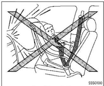
Rear-facing-step1
1. Childrestraintsforinfantsmustbe usedintherear-facingdirectionand thereforemustnotbeusedinthe frontseat.Position the child restraint on the seat. Always follow the restraint manufacturer's instructions.

Rear-facing-step2
2. Route the seat belt tongue through the child restraint and insert it into the buckle until you hear and feel the latch engage. Be sure to follow the child restraint manufacturer's instructions for belt routing.

Rear-facing-step3
3. Pull the shoulder belt until the belt is fully extended. At this time, the seat belt retractor is in the Automatic Locking Retractor (ALR) mode (child restraint mode). It reverts to the Emergency Locking Retractor (ELR) mode when the seat belt is fully retracted.
1-34 Safety—Seats, seatbeltsandsupplementalrestraintsystem
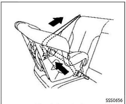
Rear-facing-step4
4. Allow the seat belt to retract. Pull up on the shoulder belt to remove any slack in the belt.
Rear-facing-step5
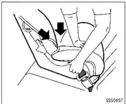
5. Remove any additional slack from the seat belt; press downward and rearward firmly in the center of the child restraint to compress the vehicle seat cushion and seatback while pulling up on the seat belt.

Rear-facing-step6
6. After attaching the child restraint, test it before you place the child in it. Push it from side to side while holding the child restraint near the seat belt path. The child restraint should not move more than 1 inch (25 mm), from side to side. Try to tug it forward and check to see if the belt holds the restraint in place. If the restraint is not secure, tighten the seat belt as necessary, or put the restraint in another seat and test it again. You may need to try a different child restraint. Not all child restraints fit in all types of vehicles.
7. Check to make sure that the child restraint is properly secured prior to
Safety—Seats, seatbeltsandsupplementalrestraintsystem1-35
each use. If the seat belt is not locked, FORWARD-FACING CHILD RE-repeat steps 1 through 6.
After the child restraint is removed and the seat belt fully retracted, the ALR mode (child restraint mode) is canceled.
For additional information, refer to all Warnings and Cautions in the "Child safety" and "Child restraints" sections before installing a child restraint.
Do not use the lower anchors if the combined weight of the child and the child restraint exceeds 65 lbs (29.5 kg). If the combined weight of the child and the child restraint is greater than 65 lbs (29.5 kg), use the vehicle's seat belt (not the lower anchors) to install the child restraint. Be sure to follow the child restraint manufacturer's instructions for installation.
Follow these steps to install a forward-facing child restraint using the LATCH system:
- Position the child restraint on the seat. Always follow the child restraint manufacturer's instructions.

Forward-facingweb-mounted-step2
- Secure the child restraint anchor attachments to the LATCH lower anchors. Check to make sure the LATCH attachment is properly attached to the lower anchors.
If the child restraint is equipped with a top tether strap, route the top tether strap and secure the tether strap to the tether anchor point. See "Installing top tether strap" (P.1-38). Do not install child restraints that require the use of a top tether strap in seating positions that do not have a top tether anchor.
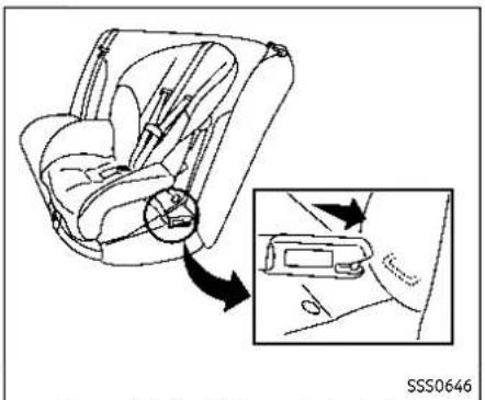
Forward-facingrigid-mounted-step2
- The back of the child restraint should be secured against the vehicle seat-back.
If necessary, adjust or remove the head restraint/headrest to obtain the correct child restraint fit. If the head restraint/headrest is removed, store it in a secure place. Besuretoreinstall theheadrestraint/headrestwhen thechildrestraintisremoved.See
"Head restraints/headrests" (P.1-10) for head restraint/headrest adjustment information.
If the seating position does not have an adjustable head restraint/headrest and it is interfering with the proper
child restraint fit, try another seating position or a different child restraint.

Forward-facing-step4
-
For child restraints that are equipped with webbing-mounted attachments, remove any additional slack from the anchor attachments. Press downward and rearward firmly in the center of the child restraint with your knee to compress the vehicle seat cushion and seatback while tightening the webbing of the anchor attachments.
-
Tighten the tether strap according to the manufacturer's instructions to remove any slack.

Forward-facing-step6
-
After attaching the child restraint, test it before you place the child in it. Push it from side to side while holding the child restraint near the LATCH attachment path. The child restraint should not move more than 1 inch (25 mm), from side to side. Try to tug it forward and check to see if the LATCH attachment holds the restraint in place. If the restraint is not secure, tighten the LATCH attachment as necessary, or put the restraint in another seat and test it again. You may need to try a different child restraint. Not all child restraints fit in all types of vehicles.
-
Check to make sure the child restraint is properly secured prior to each use. If the child restraint is loose, repeat steps 1 through 6.
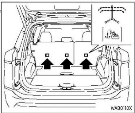
Installing top tether strap

WARNING
- Childrestraintanchorages are designed to withstand only those loads imposed by correctly fitted childrestraints. Undernocircumstances are they to be used to attach adult seat belts, or other items are equipment to the vehicle. Doings could damage the childrestraint anchorages. The childrestraint will not be properly installed using the damaged anchorage, and child could be
1-38 Safety—Seats, seatbeltsandsupplementalrestraintsystem
seriouslyinjuredorkilledina collision.
- Donothookthetoptetherstrap ontheseatbackcarpet.Besureto usethetetheranchorpointto securethetoptetherstrap.
The child restraint top tether strap must be used when installing forward-facing child restraint with the LATCH lower anchor attachments.
First, secure the child restraint with the LATCH lower anchors.
- Remove the head restraint/headrest and store it in a secure place. Be sure to reinstall the head restraint/headrest when the child restraint is removed. See "Head restraints/headrests" (P.1-10) for head restraint/headrest adjustment, removal and Installation Information.
- Position the top tether strap as shown.
- Secure the top tether strap to the tether anchor point as shown.
- Refer to the appropriate child restraint installation procedure steps in this section before tightening the tether strap.
If you have any questions when installing atoptetherstrap, it is recommended that you visit a NISSAN dealer forthisservice.
FORWARD-FACING CHILD RE-STRAINT INSTALLATION USING THE SEAT BELTS

WARNING
Thethree-pointseatbeltwithAutomaticLockingRetractor(ALR)must beusedwheninstallingachildrestraint.FailuretousetheALRmode willresultinthe child restraint not beingproperlysecured.Therestraint couldtipoverorbelooseandcause injurytoachildinasuddenstopor collision.Also,itcanchangethe operationofthefrontpassengerair bag.See"Frontpassengerairbag andstatuslight"(P.1-55).
For additional information, refer to all Warnings and Cautions in the "Child safety" and "Child restraints" sections before installing a child restraint.
Do not use the lower anchors if the combined weight of the child and the child restraint exceeds 65 lbs (29.5 kg). If the combined weight of the child and the child restraint is greater than 65 lbs (29.5 kg), use the vehicle's seat belt (not the lower anchors) to install the child restraint. Be sure to follow the child re-
straint manufacturer's instructions for installation.
Follow these steps to install a forward-facing child restraint using the vehicle seat belt in the rear seats or in the front passenger seat:

Forward-facing(frontpassengerseat)—step1
-
If you must install child restraint in the front seat, it should be placed in a forward-facing direction only. Movethese at to there are most position. Child restraints for infants must be used in there are facing direction and, therefore, must not be used in the front seat.
-
Position the child restraint on the seat. Always follow the child restraint manufacturer's instructions.
The back of the child restraint should be secured against the vehicle seat-back.
If necessary, adjust or remove the head restraint/headrest to obtain the
correct child restraint fit. If the head restraint/headrest is removed, store it in a secure place. Besuretoreinstall theheadrestraint/headrestwhen thechildrestraintisremoved.See
"Head restraints/headrests" (P.1-10) for head restraint/headrest adjustment, removal and installation information.
If the seating position does not have an adjustable head restraint/headrest and it is interfering with the proper child restraint fit, try another seating position or a different child restraint.
1-40 Safety—Seats, seatbeltsandsupplementalrestraintsystem

Forward-facing-step3
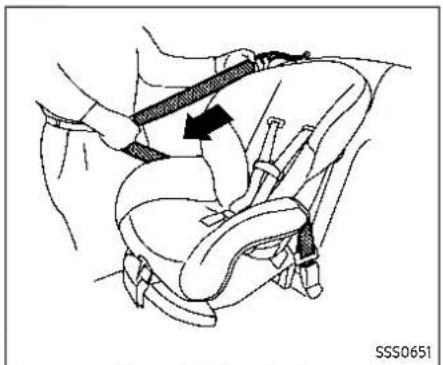
Forward-facing-step4

Forward-facing-step5
-
Route the seat belt tongue through the child restraint and insert it into the buckle until you hear and feel the latch engage. Be sure to follow the child restraint manufacturer's instructions for belt routing. If the child restraint is equipped with a top tether strap, route the top tether strap and secure the tether strap to the tether anchor point (rear seat installation only). See "Installing top tether strap" (P.1-43). Do not install child restraints that require the use of a top tether strap in seating positions that do not have a top tether anchor.
-
Pull the shoulder belt until the belt is fully extended. At this time, the seat belt retractor is in the Automatic Locking Retractor (ALR) mode (child restraint mode). It reverts to Emergency Locking Retractor (ELR) mode when the seat belt is fully retracted.
-
Allow the seat belt to retract. Pull up on the shoulder belt to remove any slack in the belt.
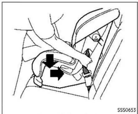
Forward-facing-step6
- Remove any additional slack from the seat belt; press downward and rearward firmly in the center of the child restraint with your knee to compress the vehicle seat cushion and seatback while pulling up on the seat belt.
- Tighten the tether strap according to the manufacturer's instructions to remove any slack.

Forward-facing-step8
- After attaching the child restraint, test it before you place the child in it. Push it from side to side while holding the child restraint near the seat belt path. The child restraint should not move more than 1 inch (25 mm), from side to side. Try to tug it forward and check to see if the belt holds the restraint in place. If the restraint is not secure, tighten the seat belt as necessary, or put the restraint in another seat and test it again. You may need to try a different child restraint. Not all child restraints fit in all types of vehicles.
- Check to make sure the child restraint is properly secured prior to each use. If
the seat belt is not locked, repeat steps 2 through 8.
1-42 Safety—Seats, seatbeltsandsupplementalrestraintsystem
PASSENGER AIR BAG
JVR0192X
Forward-facing-step10
- If the child restraint is installed in the front passenger seat, place the ignition switch in the ON position. The front passenger air bag status light should illuminate. If this light is no illuminated, see "Front passenger air bag and status light" (P.1-55). Move the child restraint to another seating position. Have the system checked. It is recommended you visit a NISSAN dealer for this service.
After the child restraint is removed and the seat belt is fully retracted, the ALR mode (child restraint mode) is canceled.

Installing top tether strap

WARNING
- Childrestraintanchorages are designedtowithstandonlythose loadsimposedbycorrectlyfitted childrestraints.Undernocircumstancesaretheytobeusedto attachadultseatbelts,orother itemsorequipmenttothevehicle.Doingsocoulddamagethe childrestraintanchorages.The childrestraintwillnotbeproperly installedusingthedamagedanchorage,andachildcouldbe
seriouslyinjuredorkilledina collision.
- Donothookthetoptetherstrap ontheseatbackcarpet.Besureto usethetetheranchorpoint to securethetoptetherstrap.
The child restraint top tether strap must be used when installing forward-facing child restraint with the seat belts.
First, secure the child restraint with the seat belt.
- Remove the head restraint/headrest and store it in a secure place. Be sure to reinstall the head restraint/headrest when the child restraint is removed. See "Head restraints/headrests" (P.1-10) for head restraint/headrest adjustment, removal and installation information.
- Position the top tether strap as shown.
- Secure the top tether strap to the tether anchor point as shown.
- Refer to the appropriate child restraint installation procedure steps in this section before tightening the tether strap.
If you have any questions when instal-
lingatoptetherstrap,itisrecommendedyouvisitaNISSANdealerfor thisservice.
BOOSTER SEATS
For additional information on installing a booster seat in your vehicle, follow the instructions outlined in this section.
Precautions on booster seats

WARNING
Ifaboosterseatandseatbeltarenot usedproperly,theriskofachild beinginjuredorkilledinasudden stoporcollisiongreatlyincreases:
- Makesuretheshoulderportionof thebeltisawayfromthechild's faceandneckandthelapportion ofthebeltdoesnotcrossthe stomach.
●Makesuretheshoulderbeltisnot behindthechildorunderthe child'sarm. - Aboosterseatmustonlybe installedinaseatingpositionthat hasalap/shoulderbelt.
Booster seats of various sizes are offered by several manufacturers. When selecting any booster seat, keep the following points in mind:
- Choose only a booster seat with a label certifying that it complies with Federal Motor Vehicle Safety Standard 213 or Canadian Motor Vehicle Safety Standard 213.
- Check the booster seat in your vehicle to be sure it is compatible with the vehicle's seat and seat belt system.


- Make sure the child's head will be properly supported by the booster seat or vehicle seat. The seatback must be at or above the center of the child's ears. For example, if a low back booster seat ① is chosen, the vehicle seatback must be at or above the center of the child's ears. If the seatback is lower than the center of the child's ears, a high back booster seat ② should be used.
- If the booster seat is compatible with your vehicle, place your child in the booster seat and check the various adjustments to be sure the booster seat is compatible with your child. Always follow all recommended procedures.

AllU.S.statesandCanadianprovinces orterritoriesrequirethatinfantsand smallchildrenberestrainedinanapprovedchildrestraintataltimeswhile thevehicleisbeingoperated.
The instructions in this section apply to booster seat installation in the rear seats or the front passenger seat.
Booster seat installation

WARNING
Toavoidinjurytochild, donotuse the lap/shoulder belt Automatic Locking Retractor (ALR) mod when using abooster seat with these at belts.
For additional information, refer to all Warnings and Cautions in the "Child safety", "Child restraints" and "Booster seats" sections earlier in this section before installing a child restraint.
Follow these steps to install a booster seat in the rear seat or in the front passenger seat:
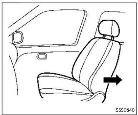
- Ifyoumustinstallaboosterseatin thefrontseat, movetheseattothe rearmostposition.
- Position the booster seat on the seat. Only place it in a forward-facing direction. Always follow the booster seat manufacturer's instructions.

Frontpassengerposition
- The booster seat should be positioned on the vehicle seat so that it is stable. If necessary, adjust or remove the head restraint/headrest to obtain the correct booster seat fit. If the head restraint/headrest is removed, store it in a secure place. Besuretoreinstall theheadrestraint/headrestwhen theboosterseatisremoved.See "Head restraints/headrests" (P.1-10) for head restraint/headrest adjustment, removal and installation information. If the head restraint/headrest of the seating position is interfering with the proper booster seat fit, try another
seating position or a different booster seat.
- Position the lap portion of the seat belt low and snug on the child's hips. Be sure to follow the booster seat manufacturer's instructions for adjusting the seat belt routing.
- Pull the shoulder belt portion of the seat belt toward the retractor to take up extra slack. Be sure the shoulder belt is positioned across the top, middle portion of the child's shoulder. Be sure to follow the booster seat manufacturer's instructions for adjusting the seat belt routing.
- Follow the warnings, cautions and instructions for properly fastening a seat belt shown in "Seat belts" (P.1-14).
PASSENGER AIR BAG
JVR0192X
- If the booster seat is installed in the front passenger seat, place the ignition switch in the ON position. The front passenger air bag status light may or may not illuminate depending on the size of the child and the type of booster seat used. See "Front passenger air bag and status light" (P.1-55).
SUPPLEMENTALRESTRAINTSYSTEM(SRS)
PRECAUTIONS ON SRS
This SRS section contains important information concerning the following systems:
- Driver and front passenger supplemental front-impact air bag (NISSAN Advanced Air Bag System)
- Driver and front passenger supplemental knee air bag
- Front seat-mounted side-impact supplemental air bag
- Rear outboard seat-mounted side-impact supplemental air bag
- Front central seat-mounted side-impact supplemental air bag (if so equipped)
●Roof-mounted curtain side-impact and rollover supplemental air bag - Seat belt with pretensioner (front and rear outboard seats)
Supplementalfront-impactairbagsys-
tem:The NISSAN Advanced Air Bag System can help cushion the impact force to the head and chest of the driver and front passenger in certain frontal collisions.
Driverandfrontpassengersupplementalkneeairbagsystem: This system can help cushion the impact force to the driver's and front passenger's knees in certain collisions.
Frontseat-mountedside-impactsup- plementalairbagsystem:This system can help cushion the impact force to the chest and pelvic area of the driver and front passenger in certain side impact collisions. The side air bag is designed to inflate on the side where the vehicle is impacted.
Rearoutboardseat-mountedside-impactsupplementalairbagsystem:This system can help cushion the impact force to the chest and pelvic area of the rear outboard seat passengers in certain side-impact collisions. The side air bags are designed to inflate on the side where the vehicle is impacted.
Frontcentralseat-mountedside-impact supplemental airbag (ifso
equipped): This system can help cushion the impact force to the head area of the driver and front passenger in certain side-impact collisions. The front central side-impact air bag is designed to inflate in the front central area where the vehicle is impacted.
Roof-mountedcurtainside-impact and rolloversupplementalairbagsystem:
This system can help cushion the impact force to the heads of occupants in front and rear outboard seating positions in certain side impact or rollover collisions. In a side-impact, the curtain air bags are
Safety—Seats, seatbeltsandsupplementalrestraintsystem1-47
designed to inflate on the side where the vehicle is impacted. In a rollover, the curtain air bags on both sides are designed to inflate. Under both side-impact and rollover situations, the curtain air bags will remain inflated for a short period of time.
These supplemental restraint systems are designed to supplement the crash protection provided by the driver, passenger and rear outboard seat belts and are not as substitute for them. Seat belts should always be correctly worn and the occupant seated a suitable distance away from the steering wheel, instrument panel and door finishers. (See "Seat belts" (P.1-14) for instructions and precautions on seat belt usage.)
Thesupplementalairbagsoperateonly whentheignitionswitchisintheON position.
AftertheignitionisplacedintheON position,thesupplementalairbag warninglightilluminates.Thesupplementalairbagwarninglightwillturn offafterabout7secondsifthesystems areoperational.
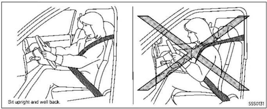
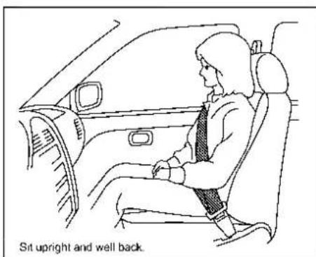


WARNING
- Thefrontairbagsordinarilywill notinflateintheeventofaside impact,rearimpact,rollover,or lowerseverityfrontalcollision. Alwayswearyourseatbeltsto helpreducetheriskorseverity of injuryinvariouskindsofaccidents.
- Thefrontpassengerairbagand passengerkneeairbagwillnot inflateifthefrontpassengerair bagstatuslightislit.See"Front passengerairbagandstatus light"(P.1-55).
•Theseatbeltsandthefrontair bagsaremosteffectivewhenyou aresittingwellbackandupright intheseatwithbothfeetonthefloor.Thefrontairbagsinflate withgreatforce.Evenwiththe NISSANAdvancedAirBagSystem, ifyouareunrestrained,leaning forward,sittingsidewaysorout ofpositioninanyway,youareat greaterriskofinjuryordeathina crash.Youmayalsoreceiveseriousorfatalinjuriesfromthe frontairbagifyouareupagainst itwhenitininflates.Alwayssitback
against theseatback and as far- away as practical from the steering wheel or instrument panel. Always properly us these at belts.
- Thedriverandfrontpassenger seatbeltbucklesareequipped withsensorsthatdetectifthe seatbeltsarefastened.TheAdvancedAirBagSystemmonitors theseverityofacollisionandseat beltusagetheninflatestheair bagsasneeded.Failureretoprop- erlywearseatbeltscanincrease theriskorseverityofinjuryinan accident.
- The frontpassengerseatis equipped with occupant classifications sensors (weightsensors) that turn the frontpassengerair bag and frontpassengerkneeair bag OFF fundersome conditions. Thesesensors are only used in this seat. Failure to be properly seated and wearing these seat belt can increase the risk severity of injury in an accident. See "Frontpassengerairbag and statuslight" (P.1-55).
- Keephandsontheoutsideofthe steeringwheel.Placingthemin-sidethesteeringwheelrimcould
increasetheriskthattheyare injuredifthefrontairbagin-flates.
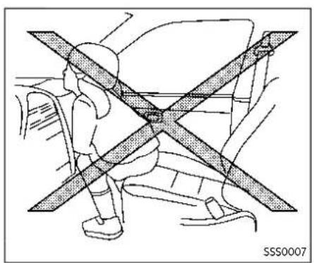


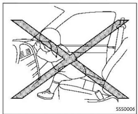


1-50 Safety—Seats, seat belts and supplemental restraintsystem

WARNING
●Neverletchildrenrideunrestrainedorextendtheirhandsor faceoutofthewindow.Donot attempttoholdtheminyourlap orarms.Someexamplesofdangerous riding positions are shownintheillustrations.
- Childrenmaybeseverelyinjured orkilledwhenthefrontairbags, sideairbagsorcurtainairbags inflateiftheyarenotproperly restrained.Pre-teensandchildrenshould be properly restrained in therearseat, if possible.
- EvenwiththeNISSANAdvanced AirBagSystem,neverinstalla rear-facingchildrestraintinthe frontseat.Aninflatingfrontair bagcouldseriouslyinjureorkill yourchild.See"Childrestraints" (P.1-24)fordetails.
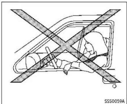
Donotleanagainstdoorsorwindows.
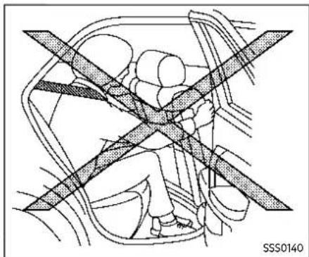

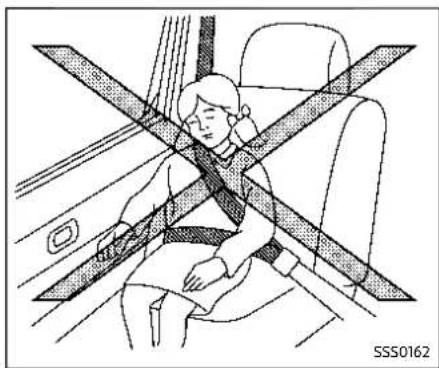
Safety—Seats, seatbeltsandsupplementalrestraintsystem1-51
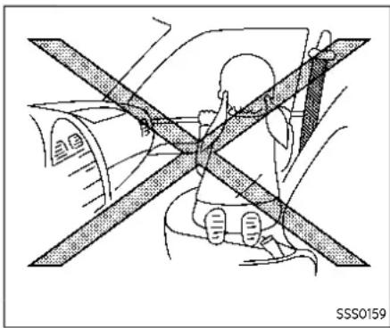

WARNING
Front, frontcentralandrearout-boardseat-mountedside-impact supplementalairbagsandroof-mountedcurtainside-impact and rolloversupplementalairbags:
- Thesideairbagsordinarilywill notinflateintheeventofa frontalimpact,rearimpact,roll-overorlowerseveritysidecollision.Alwayswearyourseatbelts tohelpreducetheriskorseverity ofinjuryinvariouskindsofaccidents.
- Thecurtainairbagsordinarilywill notinflateintheeventofafront impact,rearimpact,orlower severitysidecollision.Always wearyourseatbeltstohelp reducetheriskorseverity of injuryinvariouskindsofaccidents.
- Theseatbelts,thesideairbags andcurtainairbagsaremost effectivewhenyouaresitting wellbackanduprightintheseat. Thesideairbagsandcurtainair bagsinflatewithgreatforce.Do notallowanyonetoplacetheir hand,legorfacenearthesideair bagsonthesideoftheseatback ofthefrontandrearseatornear thesideroofrails.Donotallow anyonesittinginthefrontseats orrearoutboardseatstoextend theirhandoutofthewindowor leanagainstthedoor.Someexamplesofdangerousridingpositionsareshownintheprevious illustrations.
- Whensittingintherearseat,do notholdontotheseatbackofthe frontseat.Ifthesideairbags inflate,youmaybeseriouslyinjured.Beespeciallycarefulwith children,whoshouldalwaysbe
properlyrestrained.Someexamplesofdangerousridingpositions are shown in the illustrations.
- Donotuseseatcoversonthe frontandrearseatbacks.They mayinterferewithsideairbag inflation.

- Supplemental front-impact air bag modules (NISSAN Advanced Air Bags)
- Occupant classification system control unit
- Air bag Control Unit (ACU)
- Occupant classification sensors (weight sensors)
- Front seat-mounted side-impact supple-
mental air bag modules
- Roof-mounted curtain side-impact and rollover supplemental air bag inflators
- Roof-mounted curtain side-impact and rollover supplemental air bag modules
- Crash zone sensor
-
Driver and front passenger supplemental knee air bags
-
Front door pressure sensors (driver's side shown; front passenger side similar)
- Lap outer pretensioners (front seats)
- Seat belt with pretensioners (front seats)
- Front central seat-mounted side-impact supplemental air bag (if so equipped)
- Satellite sensors (driver's side shown; front passenger side similar)
- Rear outboard seat-mounted side-impact supplemental air bag modules
- Seat belt with pretensioners (rear outboard seats)
NISSAN ADVANCED AIR BAG SYSTEM (front seats)

WARNING
Toensureproperoperationofthe passenger'sAdvancedAirBagsystem, please observe the following items.
- Donotallowa passenger inthe rearseattopushor pullonthe seatbackpocket.
- Donotplaceheavyloads heavier than 9.1lbs(4kg)ontheseat-back, head restraint or in the seatback pocket.
• Make sure nothing is pressing against therearoftheseatback,
suchasachildrestraintinstalled intherearseatoranobject storedonthefloor.
- Makesurethatthereisnoobject placedunderthefrontpassenger seat.
- Makesurethatthereisnoobject placedbetweentheseatcushion andcenterconsoleorbetween theseatcushionandthedoor.
- Besurethatthefrontpassenger seatdoesnotcontacttherear seat,instrumentpanel,etc.,orthe headrestraintdoesnotcontact thereof.
- Donotpositionthefrontpassengerseatsoitcontactstherear seat.Ifthefrontseatdoescontacttherearseat,theairbag systemmaydetermineasensor malfunctionhasoccurredandthe frontpassengerairbagstatus lightmayilluminateandthesupplementalairbagwarninglight mayflash.
•Ifaforwardfacingchildrestraint isinstalledinthefrontpassenger seat,donotpositionthefront passengerseatsothechildrestraintcontactstheinstrument panel.Ifthechildrestraintdoes
contacttheinstrumentpanel,the systemmaydeterminetheseatis occupiedandthepassengerair bagandfrontpassengerkneeair bagmaydeployinacollision. Alsothefrontpassengerairbag statuslightmaynotilluminate. See"Childrestraints"(P.1-24)for informationaboutinstallingand usingchildrestraints.
- Confirmtheoperatingcondition withthefrontpassengerairbag statuslight.
- Ifyounoticethatthefrontpassengerairbagstatuslightisnot operatingasdescribedinthis section,itisrecommendedyou visitaNISSANdealertocheckthe passengerseatAdvancedAirBag System.
- Until you have confirmed with your dealer that your passenger seat Advanced Air Bag is working properly, position the occupants in there are seating positions.
This vehicle is equipped with the NISSAN Advanced Air Bag System for the driver and front passenger seats. This system is designed to meet certification requirements under U.S. regulations. It is also permitted in Canada. Alloftheinforma-
tion, cautions and warnings in this manual apply and must be followed.
The driver supplemental front-impact air bag is located in the center of the steering wheel. The passenger supplemental front-impact air bag is mounted in the instrument panel above the glove box. The front air bags are designed to inflate in higher severity frontal collisions, although they may inflate if the forces in another type of collision are similar to those of a higher severity frontal impact. They may not inflate in certain frontal collisions. Vehicle damage (or lack of it) is not always an indication of proper front air bag operation.
The NISSAN Advanced Air Bag System has dual stage air bag inflators. The system monitors information from the Air bag Control Unit (ACU), seat belt buckle sensors and the occupant classification sensors (weight sensors). Inflator operation is based on the severity of a collision and seat belt usage for the driver. For the front passenger, the occupant classification sensors are also monitored. Based on information from the sensors, only one front air bag may inflate in a crash, depending on the crash severity and whether the front occupants are belted or unbelted. Additionally, the front passenger air bag and front passenger knee
air bag may be automatically turned OFF under some conditions, depending on the information provided by the occupant classification sensors. If the front passenger air bag and front passenger knee air bag are OFF, the front passenger air bag status light will be illuminated. (See "Front passenger air bag and status light" (P.1-55) for further details.) One front air bag inflating does not indicate improper performance of the system.
If you have any questions about your air bag system, it is recommended you visit a NISSAN dealer to obtain information about the system. If you are considering modification of your vehicle due to a disability, you may also contact NISSAN. Contact information is contained in the front of this Owner's Manual.
When a front air bag inflates, a fairly loud noise may be heard, followed by release of smoke. This smoke is not harmful and does not indicate a fire. Care should be taken not to inhale it, as it may cause irritation and choking. Those with a history of a breathing condition should get fresh air promptly.
Front air bags, along with the use of seat belts, help to cushion the impact force on the head and chest of the front occupants. They can help save lives and reduce serious injuries. However, an inflating front air bag may cause facial abrasions or other injuries. Front air bags, other than the driver's and front passenger's knee air bags, do not provide restraint to the lower body.
Even with NISSAN Advanced Air Bags, seat belts should be correctly worn and the driver and passenger seated upright as far as practical away from the steering wheel or instrument panel. The front air bags inflate quickly in order to help protect the front occupants. Because of this, the force of the front air bag inflating can increase the risk of injury if the occupant is too close to, or is against, the air bag module during inflation.
The front air bags deflate quickly after a collision.
Thefrontairbagsoperateonlywhen theignitionswitchisintheONposition. AftertheignitionisplacedintheON position,thesupplementalairbag warninglightilluminates.Thesupplementalairbagwarninglightwillturn offafterabout7secondsifthesystem isoperational.
PASSENGER AIR BAG

JVR0192X
Frontpassengerairbagstatuslight
Front passenger air bag and status light

WARNING
Thefrontpassengerairbag and frontpassengerkneeairbag are designed to automatically turn OFF undersome conditions. Read this section carefully to learn how it operates. Proper use of these seat, seat belt and child restraints is necessary for most effective protection. Failure to follow all instructions in this manual concern
Safety—Seats, seatbeltsandsupplementalrestraintsystem1-55
ingtheuseofseats,seatbeltsand childrestraintscanincreasetherisk orseverityofinjuryinanaccident.
Statuslight:
The front passenger seat is equipped with occupant classification sensors (weight sensors) that turn the front passenger air bag and front passenger knee air bag on or off depending on the weight applied to the front passenger seat. The status of the front passenger air bag and front passenger knee air bag (ON or OFF) is indicated by the front passenger air bag status light which is located on the map light. After the ignition switch is placed in the ON position, the front passenger air bag status light illuminates for about 7 seconds and then turns off or remains illuminated depending on the front passenger seat occupied status. The light operates as follows:
| CONDITIONDESCRIPTION | PASSENGERAIRBAG INDICATORLIGHT( ) | FRONTPASSENGERAIRBAGAND FRONTPASSENGERKNEEAIRBAG STATUS | |
| Empty Empty front passenger seat ON (illuminated) | INHIBITED | ||
| Nobody/Somebody | Bag or Child or Child Restraint or Small Adult in front passenger seat | ON (illuminated) | INHIBITED |
| Adult Adult in the front passenger seat OFF (dark) | ACTIVATED | ||
Safety—Seats, seatbeltsandsupplementalrestraintsystem1-57
In addition to the above, certain objects placed on the front passenger seat may also cause the light to operate as described above depending on their weight. For additional information related to the normal operation and troubleshooting of this occupant classification sensor system, please refer to "Normal operation" (P.1-59) and "Troubleshooting" (P.1-60) in this section.
Frontpassengerairbag:
The front passenger air bag is designed to automatically turn OFF when the vehicle is operated under some conditions as described below as permitted by U.S. regulations. If the front passenger air bag is OFF, it will not inflate in a crash. T driver air bag and other air bags in your vehicle are not part of this system.
The purpose of the regulation is to help reduce the risk of injury or death from an inflating air bag to certain front passenger seat occupants, such as children, by requiring the air bag to be automatically turned OFF. Certain sensors are used to meet the requirements.
The occupant classification sensor in this vehicle is a weight sensor. It is designed to detect an occupant and objects on the seat by weight. For example, if a child is in the front passenger seat, the Advanced Air Bag System is designed to turn the passenger air bag OFF in accordance with the regulations. Also, if a child restraint of the type specified in the regulations is on the seat, its weight and the child's weight can be detected and cause the air bag to turn OFF.
Front passenger seat adult occupants who are properly seated and using the seat belt as outlined in this manual should not cause the passenger air bag and front passenger knee air bag to be automatically turned OFF. For small adults it may be turned OFF, however, if the occupant takes his/her weight off the seat cushion (for example, by not sitting upright, by sitting on an edge of the seat, or by otherwise being out of position), this could cause the sensors to turn the air bag OFF. Always be sure to be seated and wearing the seat belt properly for the most effective protection by the seat belt and supplemental air bag.
NISSAN recommends that pre-teens and children be properly restrained in a rear seat. NISSAN also recommends that appropriate child restraints and booster seats be properly installed in a rear seat. of this is not possible, the occupant classification sensors are designed to operate as described above to turn the front passenger air bag and front passenger knee air bag OFF for specified child restraints as required by the regulations. Failing to properly secure child restraints and to use the Automatic Locking Retractor (ALR) mode (child restraint mode) may allow the restraint to tip or move in an accident or sudden stop. This can also result in the passenger air bag and front passenger knee air bag inflating in a crash instead of being OFF. (See "Child restraints" (P.1-24) for proper use and installation.)
If the front passenger seat is not occupied, the passenger air bag and front passenger knee air bag are designed not to inflate in a crash. However, heavy objects placed on the seat could result in air bag inflation, because of the object's weight detected by the occupant classification sensors. Other conditions could also result in air bag inflation, such as if a child is standing on the seat, or if two children are on the seat, contrary to the instructions in this manual. Always be sure that you and all vehicle occupants are seated and restrained properly.
Using the front passenger air bag status light, you can monitor when the front passenger air bag and front passenger knee air bag are automatically turned OFF.
If an adult occupant is in the seat but the
front passenger air bag status light is illuminated (indicating that the front passenger air bag and front passenger knee air bag are OFF), it could be that the person is a small adult, or is not sitting on the seat properly.
If a child restraint must be used in the front seat, the front passenger air bag status light may or may not be illuminated, depending on the size of the child and the type of child restraint being used. If the front passenger air bag status light is not illuminated (indicating that the air bag might inflate in a crash), it could be that the child restraint or seat belt is not being used properly. Make sure that the child restraint is installed properly, the seat belt is used properly and the occupant is positioned properly. If the front passenger air bag status light is not illuminated, reposition the occupant or child restraint in a rear seat.
If the front passenger air bag status light will not illuminate even though you believe that the child restraint, the seat belts and the occupant are properly positioned, it is recommended that you take your vehicle to a NISSAN dealer. A NISSAN dealer can check the system status by using a special tool. However, until you have confirmed with your dealer that your air bag is working properly, reposition the occupant or child restraint in a rear seat.
The NISSAN Advanced Air Bag System and front passenger air bag status light will take a few seconds to register a change in the passenger seat status. This is normal system operation and does not indicate a malfunction.
If a malfunction occurs in the front passenger air bag system, the supplemental air bag warning light, located in the meters and gauges area, will illuminated (blinking or steadily lit). Have the system checked. It is recommended you visit a NISSAN dealer for this service.
Normaloperation:
In order for the occupant classification sensor system to classify the front passenger based on weight, please follow the precautions and steps outlined below:
Precautions:
-
Make sure that there are no objects weighing over 9.1 lbs (4 kg) hanging on the seat or placed in the seatback pocket.
●Make sure that a child restraint or other object is not pressing against the rear of the seatback.
●Make sure that a rear passenger is not pushing or pulling on the back of the front passenger seat. -
Make sure that the front passenger seat or seatback is not forced back against an object on the seat or floor behind it.
●Make sure that there is no object placed under the front passenger seat.
●Make sure that the front passenger seat head restraint does not contact the roof when adjusting the front passenger seat.
Steps:
- Adjust the seat as outlined. (See "Seats" (P.1-3).) Sit upright, leaning against the seatback, and centered on the seat cushion with your feet comfortably extended to the floor.
- Make sure there are no objects on your lap.
- Fasten the seat belt as outlined. (See "Seat belts" (P.1-14).) Front passenger seat belt buckle status is monitored by the occupant classification system, and is used as an input to determine occupancy status. So, it is highly recommended that the front passenger fasten their seat belt.
-
Remain in this position for 30 seconds allowing the system to classify the front passenger before the vehicle is put into motion.
-
Ensure proper classification by checking the front passenger air bag status light.
NOTE:
This vehicle's occupant classification sensorsystem generally keeps the classification locked during driving, so it is important that you confirm that the frontpassenger is properly classified prior to driving. However, the occupant classifications sensor system may recalculate the weight of the occupant under some conditions (both while driving and when stopped), so the frontpassenger seat occupant should continue to remain seated as outlined above.
Troubleshooting:
If you think the front passenger air bag status light is incorrect:
- If the light is ON with an adult occupying the front passenger seat:
- Occupant is a small adult — the front passenger air bag status light is functioning as intended. The front passenger air bag and front passenger knee air bag are suppressed.
However, if the occupant is not a small adult, then this may be due to the following conditions that may be interfering with the weight sensors:
- Occupant is not sitting upright, leaning against the seatback, and centered on the seat cushion with his/her feet comfortably extended to the floor.
●A child restraint or other object pressing against the rear of the seatback.
●A rear passenger pushing or pulling on the back of the front passenger seat.
- Forcing the front seat or seatback against an object on the seat or floor behind it.
●An object placed under the front passenger seat.
●An object placed between the seat cushion and center console or between the seat cushion and the door.
If the vehicle is moving, please come to a stop when it is safe to do so. Check and correct any of the above conditions. Restart the vehicle and wait 1 minute.
NOTE:
Asystemcheckwillbeperformedduringwhichthefrontpassengerairbagstatuslightwillremainlitforabout7secondsinitially.
If the light is still ON after this, the person should be advised not to ride in the front passenger seat and the vehicle should be checked as soon as possible. It is recom-
mended you visit a NISSAN dealer for this service.
- If the light is OFF with a small adult, child or child restraint occupying the front passenger seat. This may be due to the following conditions that may be interfering with the weight sensors:
- Small adult or child is not sitting upright, leaning against the seatback, and centered on the seat cushion with his/her feet comfortably extended to the floor.
- The child restraint is not properly installed, as outlined. (See "Child restraints" (P.1-24).)
●An object weighing over 9.1 lbs (4 kg) hanging on the seat or placed in the seatback pocket.
●A child restraint or other object pressing against the rear of the seatback.
●A rear passenger pushing or pulling on the back of the front passenger seat.
- Forcing the front seat or seatback against an object on the seat or floor behind it.
●An object placed under the front passenger seat.
●An object placed between the seat cushion and center console.
●The front passenger seat head restraint contacting the roof.
If the vehicle is moving, please come to a stop when it is safe to do so. Check and correct any of the above conditions. Restart the vehicle and wait 1 minute.
NOTE:
Asystemcheckwillbeperformedduringwhichthefrontpassengerairbagstatuslightwillremainlitforabout7secondsinitially.
If the light is still OFF after this, the small adult, child or child restraint should be repositioned in the rear seat and it is recommended that the vehicle should be checked by a NISSAN dealer as soon as possible.
- If the light is OFF with no front passenger and no objects on the front passenger seat, the vehicle should be checked as soon as possible. It is recommended you visit a NISSAN dealer for this service.
Other supplemental front-impact air bag precautions

WARNING
- Donotplaceanyobjectsonthe steeringwheelpadoronthe instrumentpanel.Also,donot
placeanyobjectsbetweenany occupantandthesteeringwheel orinstrumentpanel.Suchobjects maybecomedangerousprojectilesandcauseinjuryifthefront airbagsinflate.
- Donotplaceobjectswithsharp edgesontheseat.Also,donot placeheavyobjectsontheseat thatwillleavepermanentimpressionsintheseat.Suchobjects candamagetheseatoroccupant classificationsensors(weight sensors).Thiscanaffecttheoperationoftheairbagsystemand resultinseriouspersonalinjury.
- Donotusewateroracidiccleaners(hotsteamcleaners)onthe seat. This candamagetheseator occupantclassificationsensors. This can also affect the operation of the airbagsystem and result in serious personal injury.
- Immediatelyafterinflation,severalfrontairbagsystemcomponentswillbehot.Donottouch them;youmayseverelyburn yourself.
• Nounauthorizedchangesshould bemadetoanycomponentsor wiringofthesupplementalair
bagsystem. This is to prevent accidental inflation of the supplemental air bag, or damage to the supplemental air bagsystem.
- Do not make unauthorized changestoyourvehicle'selectricalsystem,suspensionsystemor frontendstructure.Thiscould affectproperoperationofthe frontairbagsystem.
- Tamperingwiththefrontairbag systemmayresultinseriouspersonalinjury.Tamperingincludes changestothesteeringwheel andtheinstrumentpanelassemblybyplacingmaterialoverthe steeringwheelpadandabovethe instrumentpanelorbyinstalling additionaltrimmaterialaround theairbagsystem.
- Removingormodifyingthefront passengerseatmayaffectthe functionoftheairbagsystem andresultinseriouspersonal injury.
- Modifyingortamperingwiththe frontpassengerseatmayresult inseriouspersonalinjury. For example, donotchgethefront seatsbyplacingmaterialonthe seatcushionorbyinstallingad-
ditionaltrimmaterial,suchas seatcovers,ontheseatthatis notspecificallydesignedtoassureproperairbagoperation. Additionally,donotstowany objectsunderthefrontpassengerseatortheseatkushionand seatback.Suchobjectsmayinterferewiththeproperoperationof theoccupantclassificationsensors.
- Nounauthorizedchangesshould bemadetoanycomponentsor wiringoftheseatbeltsystem. Thismayaffectthefrontairbag system.Tamperingwiththeseat beltsystemmayresultinserious personalinjury.
-Itisrecommendedyouvisita NISSANdealerforworkonand aroundthefrontairbag.Itisalso recommendedyouvisitaNISSAN dealerforinstallationofelectrical equipment.TheSupplemental RestraintSystem(SRS)wiring harnesses*shouldnotbemodifiedordisconnected.Unauthorizedelectricaltestequipment andprobingdevicesshouldnot beusedontheairbagsystem.
- Acracked windshield should be replaced immediately by a qualified repair facility. Acracked windshield could affect the function of the supplemental airbag system.
*The SRSwiringharnessconnectorsare yellowandorangeforeasyidentification.
When selling your vehicle, we request that you inform the buyer about the front air bag system and guide the buyer to the appropriate sections in this Owner's Manual.
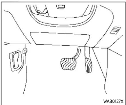
Driver'sside
DRIVER AND FRONT PASSENGER SUPPLEMENTAL KNEE AIR BAG
The knee air bag is located in the knee bolster, on the driver's and front passenger's sides. Alloftheinformation,cautionsandwarningsinthismanualapply andmustbefollowed.The knee air bag is designed to inflate in higher severity frontal collisions, although it may inflate if the forces in another type of collision are similar to those of a higher severity frontal impact. It may not inflate in certain collisions.
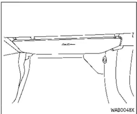
Frontpassenger'sside
Vehicle damage (or lack of it) is not always an indication of proper knee air bag operation.
When the knee air bag inflates, a fairly loud noise may be heard, followed by release of smoke. This smoke is not harmful and does not indicate a fire. Care should be taken not to inhale it, as it may cause irritation and choking. Those with a history of a breathing condition should get fresh air promptly.
The knee air bag helps to cushion the impact force on the knees of the driver and front passenger. It can help reduce serious injuries. However, an inflating knee air bag may cause abrasions or
other injuries. The knee air bag provides restraint to the lower body.
The knee air bag inflates quickly in order to help protect the occupants. Because of this, the force of the knee air bag inflating can increase the risk of injury if the occupant is too close to, or is against, this air bag module during inflation. The knee air bag will deflate quickly after the collision is over OR the knee air bag will remain inflated for a short time.
Thekneeairbagoperatesonlywhen theignitionswitchisplacedintheON position.
Afterplacingtheignitionswitchinthe ONposition,thesupplementalairbag warninglightilluminates.Thesupplementalairbagwarninglightwillturn ofafterabout7secondsifthesystem isoperational.

WARNING
- Donotplaceanyobjectsbetween thekneebolsterandthedriver's orfrontpassenger'sseat.Such objectsmaybecomedangerous projectilesandcauseinjuryifa kneeairbaginflates.
- Rightafterinflation,thekneeair bagsystemcomponentswillbe hot.Donottouchthem;youmay severelyburnyourself.
- Nounauthorizedchangesshould bemadetoanycomponentsor wiringofthekneeairbagsystem. Thisistopreventdamagetoor accidentalinflationoftheknee airbagsystem.
- Do not make unauthorized changestoyourvehicle'selectricalsystemorsuspensionsystem. This could affect properoperationofthekneeairbagsystem.
- Tamperingwiththekneeairbag systemmayresultinseriouspersonalinjury. Forexample, donot changethedriverorfrontpassengerkneebolsterorinstall additionaltrimmaterialaround thekneeairbag.
- Itisrecommendedthatyouvisita NISSANdealerforworkonand aroundthekneeairbag.Itisalso recommendedthatyouvisita NISSANdealerforinstallationof electricalequipment.TheSRS wiringharnesses*shouldnotbe modifiedordisconnected.Unauthorizedelectricaltestequip-
mentandprobingdevicesshould notbeusedonthekneeairbag system.
*The SRSwiringharnessorconnectors are yellowororangeforeasyidentification.
When selling your vehicle, we request that you inform the buyer about the knee air bag system and guide the buyer to the appropriate sections in this manual.

FRONT, FRONT CENTRAL*, REAR OUTBOARD SEAT-MOUNTED SIDE-IMPACT SUPPLEMENTAL AIR BAG AND ROOF-MOUNTED CURTAIN SIDE-IMPACT AND ROLLOVER SUPPLEMENTAL AIR BAG SYSTEMS
*: if so equipped
The side air bags are located in the outside of the seatback of the front and rear seats. The front central side air bag (so equipped) is located in the inside of the seatback of the driver's seat. The curtain air bags are located in the side roof rails.
Alloftheinformation,cautionsand warningsinthismanualapplyandmust
befollowed. The side air bags and curtain air bags are designed to inflate in higher severity side collisions, although they may inflate if the forces in another type of collision are similar to those of a higher severity side impact. They are designed to inflate on the side where the vehicle is impacted. They may not inflate in certain side collisions.
Curtain air bags are also designed to inflate in certain types of rollover collisions or near rollovers. As a result, certain vehicle movements (for example, during severe off-roading) may cause the curtain air bags to inflate.
Vehicle damage (or lack of it) is not always an indication of proper side air bag and curtain air bag operation.
When the side air bags and curtain air bags inflate, a fairly loud noise may be heard, followed by release of smoke. This smoke is not harmful and does not indicate a fire. Care should be taken not to inhale it, as it may cause irritation and choking. Those with a history of a breathing condition should get fresh air promptly.
Side air bags, along with the use of seat belts, help to cushion the impact force on the chest and pelvic area of the front and rear outboard occupants. Front central side air bag, along with the use of seat
belts, helps to cushion the impact force on the head area of the front occupants. Curtain air bags help to cushion the impact force to the head and chest area of occupants in the front and rear outboard seating positions. They can help save lives and reduce serious injuries. However, an inflating side air bag or curtain air bag may cause abrasions or other injuries. Side air bags and curtain air bags do not provide restraint to the lower body.
The seat belts should be correctly worn and the driver, front passenger and rear outboard occupants seated upright as far as practical away from the side air bags. Rear seat passengers should be seated as far away as practical from the door finishers and side roof rails. The side air bags and curtain air bags inflate quickly in order to help protect the occupants. Because of this, the force of the side air bags and curtain air bags inflating can increase the risk of injury if the occupant is too close to, or is against, these air bag modules during inflation. The side air bags will deflate quickly after the collision is over. The front central side air bag and curtain air bags will remain inflated for a short time.
Thesideairbagsandcurtainairbags operateonlywhentheignitionswitchis
intheONposition.
Afterplacingtheignitionswitchinthe ONposition,thesupplementalairbag warninglightilluminates.Thesupplementalairbagwarninglightwillturn offafterabout7secondsifthesystems areoperational.

WARNING
- Donotplaceanyobjectsnearthe seatbackofthefrontandrear seats.Also,donotplaceany objects(anumbrella,bag,etc.) betweenthefrontandreardoor finisher,thecenterconsole,and thefrontandrearseats.Such objectsmaybecomedangerous projectilesandcauseinjuryifa sideairbaginflates.
- Rightafterinflation,seversalside airbagandcurtainairbagsystemcomponentswillbehot.Do nottouchthem;youmayseverely burnyourself.
- Nounauthorizedchangesshould bemadetoanycomponentsor wiringofthesideairbagand curtainairbagsystems. Thisisto preventdamagetooraccidental inflationofthesideairbagand
curtainairbagsystems.
- Do not make unauthorized changestoyourvehicle'selectricalsystem,suspensionsystemor sidepanel.Thiscouldaffectproperoperationofthesideairbag andcurtainairbagsystems.
- Tamperingwiththesideairbag systemmayresultinseriouspersonalinjury.Forexample,donot changethefrontandrearseats byplacingmaterialneartheseat-backsorbyinstallingadditional trimmaterial,suchasseatcovers,aroundthesideairbag.
- Removingormodifyingthefront andrearpassengerseatmay affectthefunctionoftheairbag systemandresultinseriouspersonalinjury.
- litisrecommendedyouvisita NISSANdealerforworkonand aroundthesideairbagand curtainairbag.itisalsorecommendedyouvisitaNISSANdealer forinstallationofelectricalequipment. The Supplemental Restraint System (SRS) wiring harnesses*shouldnotbemodifiedordisconnected.Unauthorizedelectricaltestequipment
andprobingdevicesshouldnot beusedonthesideairbagor curtainairbagsystems.
*The SRSwiringharness connectors are yellow and orange foreasy identification.
When selling your vehicle, we request that you inform the buyer about the side air bag and curtain air bag systems and guide the buyer to the appropriate sections in this Owner's Manual.
SEAT BELTS WITH PRETENSIONERS (front and rear outboard seats)

WARNING
- Thepretensionerscannotbereusedafteractivation. They must bereplacedtogetherwiththe retractorandbuckleasaunit.
- If the vehicle becomes involved in a collision but a pretensioner is not activated, besureto have the pretensioner system checked and, if necessary, repaired. It is recommended you visit a NISSAN dealer forth this service.
•Nounauthorizedchangesshould bemadetoanycomponentsor
wiringofthepretensionersystem. This is to prevent damage to or accidental activation of the pretensioners. Tampering with the pretensionersystem may result in serious personal injury.
-Itisrecommendedyouvisita NISSANdealerforworkonand aroundthepretensionersystem. Itisalsorecommendedyouvisita NISSANdealerforinstallationof electricalequipment.Unauthorizedelectricaltestequipment andprobingdevicesshouldnot beusedonthepretensionersystem.
- If you need to dispose of a pre-tensioner or scrap the vehicle, it is recommended you visit a NISSAN dealer for this service. Correct pretensioner disposals procedures are set forth in the appropriate NISSAN Service Manual. Incorrect disposal procedures could cause personal injury.
The pretensioner system may activate with the supplemental air bag system in certain types of collisions. Working with the seat belt retractor, it helps tighten the seat belt when the vehicle becomes involved in certain types of collisions, helping to restrain front and rear outboard seat occupants.
The pretensioner is encased with the seat belt retractor. These seat belts are used the same way as conventional seat belts. When a pretensioner activates, smoke is released and a loud noise may be heard. The smoke is not harmful and does not indicate a fire. Care should be taken not to inhale it, as it may cause irritation and choking. Those with a history of a breathing condition should get fresh air promptly.
After pretensioner activation, load limiters allow the seat belt to release webbing (if necessary) to reduce forces against the chest.
The supplemental air bag warning light is used to indicate malfunctions in the pretensioner system. See "Supplemental air bag warning light" (P.1-67). If the operation of the supplemental air bag warning light indicates there is a malfunction, have the system checked. It is recommended you visit a NISSAN dealer for this service.
When selling your vehicle, we request that you inform the buyer about the pretensioner system and guide the buyer to the appropriate sections in this Owner's Manual.
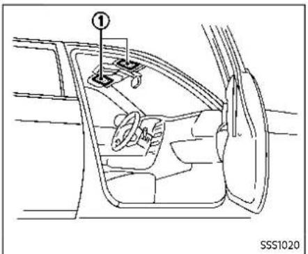
SUPPLEMENTAL AIR BAG WARNING LABELS
Warning labels about the supplemental front-impact air bag system are placed in the vehicle as shown in the illustration.
① SRS air bag
The warning labels are located on the surface of the sun visors.

WARNING
Donotusearear-facingchildre- straintonaseatprotectedbyanair baginfrontofit.Iftheairbag
deploys, it may cause serious injury or death.

SUPPLEMENTAL AIR BAG WARNING LIGHT
The supplemental air bag warning light, displaying ⚙ in the instrument panel, monitors the circuits for the air bag systems, pretensioners and all related wiring.
When the ignition switch is in the ON position, the supplemental air bag warning light illuminates for about 7 seconds and then turns off. This means the system is operational.
If any of the following conditions occur, the air bag and/or pretensioner systems need servicing:
●The supplemental air bag warning light remains on after approximately 7 seconds.
●The supplemental air bag warning light flashes intermittently.
- The supplemental air bag warning light does not come on at all. Under these conditions, the air bag and/or pretensioner systems may not operate properly. They must be checked and repaired. It is recommended you visit a NISSAN dealer for this service.

WARNING
If the supplemental airbag warning lightison, it could mean that the front airbag, knee airbag, side air bag, curtain airbag and/or preten- sionersystems will not operate in an accident. To help avoid injury to yourself others, have your vehicle checked as soon as possible. It is recommended you visit a NISSAN dealer forth this service.
REPAIR AND REPLACEMENT PROCEDURE
The front air bags, knee air bags, side air bags, curtain air bags and pretensioners are designed to activate on a one-time-only basis. As a reminder, unless it is damaged, the supplemental air bag warning light will remain illuminated after inflation has occurred. These systems should be repaired and/or replaced as soon as possible. It is recommended you visit a NISSAN dealer for this service. When maintenance work is required on the vehicle, the front air bags, knee air bags, side air bags, curtain air bags and pretensioners and related parts should be pointed out to the person performing the maintenance. The ignition switch should always be in the OFF position when working under the hood or inside the vehicle.

WARNING
- Onceafrontairbag,kneeairbag, sideairbagorcurtainairbaghas inflated,theairbagmodulewill notfunctionagainandmustbe replaced.Additionally,theactivatedpretensionersmustalso bereplaced.Theairbagmodule
andpretensionersshouldbereplaced.ItisrecommendedyouvisitaNISSANdealerforthiservice.However,theairbagmodulesandpretensionersystemcannotberepaired.
- Thefrontairbag, kneeairbag, sideairbag and curtainairbag systems, and pretensionersystem should be inspected if there is any damage to the frontendor side portion of the vehicle. It is recommended you visit a NISSAN dealer for this service.
- If you need to dispose of as supplemental air bag or pretensioner or scrap the vehicle, it is recommended by visiting NISSAN dealer. Corrects supplemental air bag and pretensionersystem disposals procedures are set forth in the appropriate NISSAN Service Manual. Incorrect disposals procedures could cause personal injury.
- If there is an impact to your vehicle from any direction, your Occupant Classification Sensor (OCS) should be checked to verify its still functioning correctly. It is recommended that you visit a NISSAN dealer for this service. The OCS should be checked even
ifnoairbagsdeployasaresultof theimpact.FailureretoverifyproperOCSfunctionmayresultinan improperairbagdeploymentresultingininjuryordeath.
Safety—Seats, seatbeltsandsupplementalrestraintsystem1-69
MEMO
1-70 Safety—Seats, seatbeltsandsupplementalrestraintsystem
2Instrumentsandcontrols
Cockpit 2-3
Instrumentpanel....2-4
Metersandgauges 2-5
Modelswithanalogmeterand colordisplay....2-5
Modelswithfull-screendisplay....2-6
Speedometerandodometer....2-8
Tachometer 2-9
Enginecoolanttemperaturegauge....2-9
Fuelgauge....2-10
Instrumentbrightnesscontrol....2-11
ContinuouslyVariableTransmission(CVT)
positionindicator....2-11
ECODriveReport....2-11
VariableCompressionTurbo(if soequipped)....2-12
Warninglights, indicatorlights and
audiblereminders....2-13
Checkinglights....2-14
Warning/indicatorlights(red)....2-14
Warning/indicatorlights(yellow)......2-17
Warning/indicatorlights(other)......2-21
Audiblereminders....2-22
Vehicleinformationdisplay 2-22
Changingthemeterscreenview (modelswithfull-screendisplay)....2-23
Howtousethevehicle
informationdisplay....2-23
Startupdisplay 2-23
Settings....2-24
Vehicleinformationdisplaywarnings
andindicators....2-34
Tripcomputer....2-46
Clockandoutsideairtemperature....2-48
HeadUpDisplay(HUD)(ifsoequipped)......2-49
HowtousetheHUD....2-51
DriverAssistance/Navigation/Traffic
Sign/Audio/TEL/SMSlinking....2-52
Securitysystems....2-52
VehicleSecuritySystem(ifsoequipped).....2-52
NISSANVehicleImmobilizerSystem....2-53
Wiperandwasherswitch....2-54
Windshieldwiperandwasheroperation.....2-55
Rearwindowwiperand
washeroperation....2-55
Rearwindowandoutsidemirror
(ifsoequipped)defrosterswitch....2-57
Headlightandturnsignalswitch....2-57
Headlightswitch....2-57
Turnsignalswitch....2-64
Foglightswitch(ifsoequipped)....2-64
Horn....2-65
Heatedsteeringwheel(ifsoequipped)....2-65
Heatedseats(ifsoequipped)....2-65
Operationwithswitch....2-66
SteeringAssistswitch(modelswith
ProPILOTAssist)....2-67
RearDoorAlert....2-67
Poweroutlets 2-68
USB(UniversalSerialBus)charging
connector(ifsoequipped)....2-69
Wirelesscharger(ifsoequipped)....2-70
EmergencyCall(SOS)button(if
soequipped)....2-72
Emergencysupport 2-72
Storage 2-73
Cupholders....2-73
Softbottleholders....2-74
Singleluggageboard(ifsoequipped)....2-75
Adjustableluggagefloor(ifsoequipped).....2-75
Glovebox....2-77
Consolebox 2-78
Lowerconsoletray....2-78
Sunglassesholder....2-78
Cardholder 2-79
Coathooks....2-79
Cargocover(ifsoequipped)....2-80
Luggagehooks....2-80
Roofrack(ifsoequipped)....2-81
Windows....2-82
Powerwindows....2-82
Moonroof(ifsoequipped)....2-85
Automaticmoonroofandsunshade....2-85
Interiorlights....2-87
Interiorlightswitch....2-88
Maplights....2-88
Roomlights(ifsoequipped)......2-88
Rearpersonallights(ifsoequipped)....2-89
Vanitymirrorlight 2-89
Cargolight....2-89
COCKPIT

- Steering Assist switch* (models with Pro-PILOT Assist)
- Head Up Display (HUD) switch*
- Headlight and turn signal switch/Fog light switch*
- Paddle shifters
-
Steering-wheel-mounted controls (left side)
-
Audio control**
-
Vehicle information display control
-
Steering wheel
Horn
- Wiper and washer switch
-
Steering-wheel-mounted controls (right side)
-
Cruise control switches*
- ProPILOT Assist switch*
- Bluetooth® Hands-Free Phone System switches**
— Voice Recognition system switch** -
Siri® Eyes Free**
-
Hazard indicator flasher switch
-
Shift lever
— Continuously Variable Transmission (CVT)
- Instrument brightness control
- Power liftgate switch*
- Push-button ignition switch
- Parking brake switch
- Automatic brake hold switch
- Drive Mode Selector
*: if so equipped
**: See the separate NissanConnect® Owner's Manual (if so equipped).
Instrumentsandcontrols2-3
INSTRUMENTPANEL
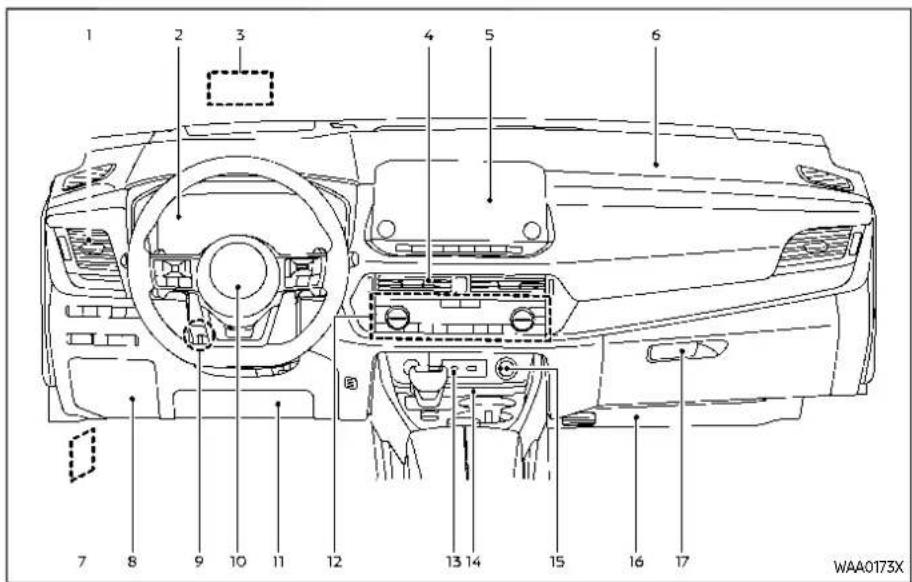
- Side ventilator
- Meters and gauges/Clock
- Head Up Display (HUD) 4
- Center ventilator
- Audio system** or navigation system**
- RearView Monitor*
- Intelligent Around View® Monitor*
— Bluetooth® Hands-Free Phone System**
- Front passenger supplemental air bag
- Hood release handle
- Fuse box cover
- Tilt and telescopic steering lock lever
- Driver supplemental front-impact air bag
2-4 Instrumentsandcontrols
- Driver supplemental knee air bag
-
Heater and air conditioner control
-
Defroster switch
— Heated seat switches* -
Heated steering wheel switch*
-
USB (Universal Serial Bus) connection ports**
-
Wireless charger*
- Power outlet
- Front passenger supplemental knee air bag
- Glove box
*: if so equipped
**: See the separate NissanConnect® Owner's Manual (if so equipped).
METERSANDGAUGES
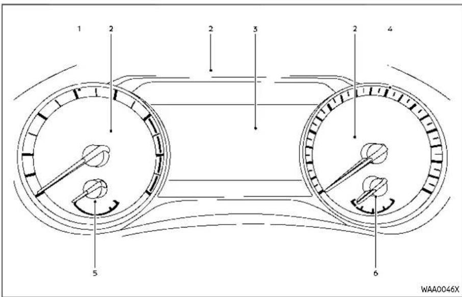
- Tachometer
- Warning and indicator lights
- Vehicle information display — Odometer
- Speedometer
- Engine coolant temperature gauge
- Fuel gauge
MODELS WITH ANALOG METER AND COLOR DISPLAY

CAUTION
- Forcleaning, use as soft cloth, dampened with water. Never use a rough cloth, alcohol, benzine, thinner or any kind of solventor papertowel with a chemical cleaning agent. They will scratch or caused discoloration to the helens.
- Donotsprayanyliquidsuchas wateronthemeterlens.Spraying liquidmaycausethesystemto malfunction.
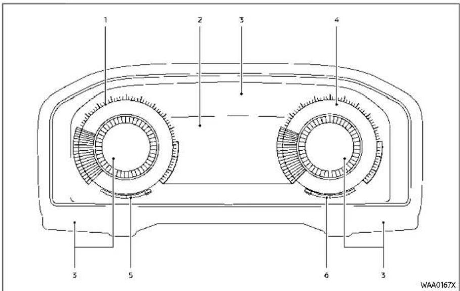
- Tachometer
- Vehicle information display — Odometer
- Warning and indicator lights
- Speedometer
- Engine coolant temperature gauge
- Fuel gauge
2-6 Instrumentsandcontrols
MODELS WITH FULL-SCREEN DISPLAY

CAUTION
- Forcleaning, use as soft cloth, dampened with water. Never use a rough cloth, alcohol, benzine, thinner or any kind of solvent or papertowel with a chemical cleaning agent. They will scratch or caused discoloration to the helens.
- Donotsprayanyliquidsuchas wateronthemeterlens.Spraying liquidmaycausethesystemto malfunction.
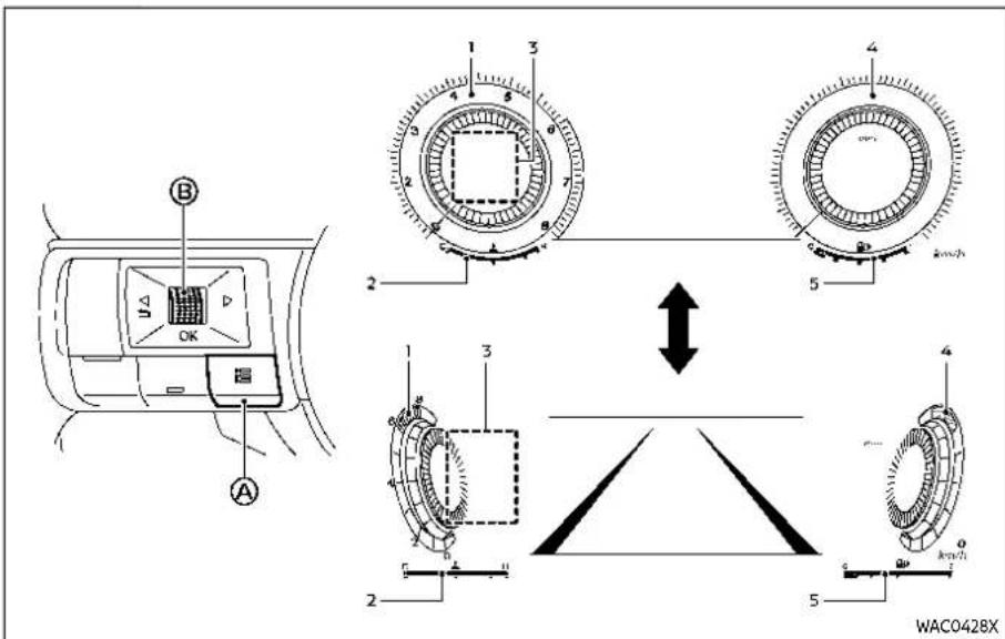
- Tachometer
- Engine coolant temperature gauge
- Personal Display
- Speedometer
- Fuel gauge
Changing the meter screen view (models with full-screen display)
For models with full-screen display, the meter screen view can be changed to expand the vehicle information display area.
To change the meter screen view:
- Push the control switch Ⓐ on the left side of the steering wheel. "Shortcut Menu" appears on the vehicle information display area.
- Select "Change Meter View" by rotating the scroll dial Ⓐ and push it to change the view.

Example
SPEEDOMETER AND ODOMETER
Speedometer
The speedometer indicates vehicle speed in miles per hour (MPH) and kilometers per hour (km/h).

Example
Distance to empty (dte)/Odometer
Distancetoempty(dte):
The distance to empty (dt) provides an estimation of the distance that can be driven before refueling. The dt is constantly being calculated, based on the amount of fuel in the fuel tank and the actual fuel consumption.
The display is updated every 30 seconds. The dte mode includes a low range warning feature. If the fuel level is low, the warning is displayed on the screen. When the fuel level drops even lower, the dte display will change to “----”.
- If the amount of fuel added is small, the display just before the ignition switch is placed in the OFF position may continue to be displayed.
- When driving uphill or rounding curves, the fuel in the tank shifts, which may momentarily change the display.
Odometer:
The odometer ② is displayed in the vehicle information display to display the total distance the vehicle has been driven.
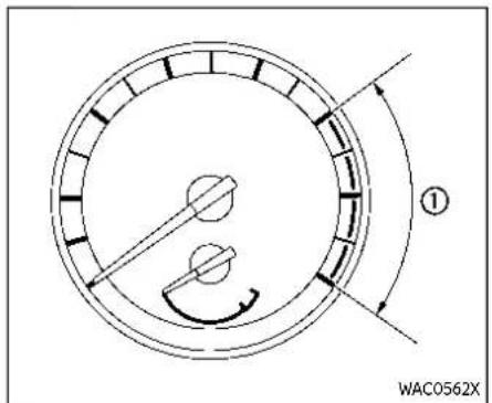
Example
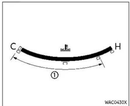
Full-screenmodel
TACHOMETER
The tachometer indicates engine speed in revolutions per minute (RPM). Donotrev theengineintotheredzone ①.

CAUTION
Whenenginespeedapproachesthe redzone, shifttoahighergearor reduceenginespeed. Operating the engineintheredzonemaycause seriousenginedamage.
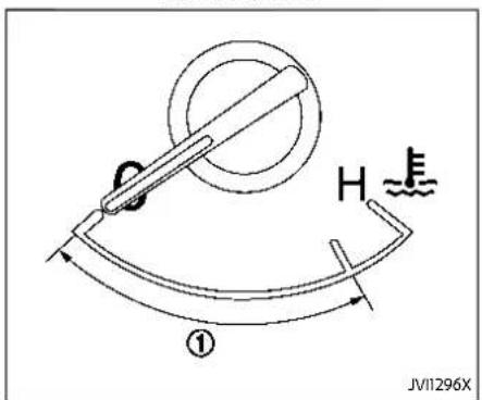
Analogmodel
ENGINE COOLANT TEMPERATURE GAUGE
The engine coolant temperature gauge indicates the engine coolant temperature.
The engine coolant temperature is normal when the gauge needle points within the zone ① shown in the illustration.
The engine coolant temperature will vary with the outside air temperature and driving conditions.

CAUTION
- If the gauge indicates the engine coolant temperature is near the hot(H) endofthenormal range, reduce vehicles speed to decrease the temperature.
- If the gauge is over then normal range, stop the vehicle as soon as safely possible and let the engine idle.
- If the engine is overheated, continued operation of the vehicle may seriously damage the engine. (See "If your vehicle overheats" (P.6-14) for immediate action required.)
Instrumentsandcontrols2-9

Full-screenmodel

Analogmodel
FUEL GAUGE
The fuel gauge indicates the approximate fuel level in the tank when the ignition switch is in the ON position.
The gauge may move slightly during braking, turning, accelerating, or going up and down hills due to movement of fuel in the tank.
The low fuel warning R appears on the vehicle information display when the fuel level in the tank is getting low. Refuel as soon as it is convenient, preferably before the gauge reads 0 (empty).
The arrow, ▶▶, indicates the location of the fuel-filler door.
Refuelbeforethegaugereadsthe empty(0)position.
There is a small reserve of fuel in the tank when the fuel gauge reads the empty (0) position.

CAUTION
- If the vehiclerunsoutoffuel, the malfunction indicator light (MIL) may come on. Refuelas soon as possible. After a few driving trips, the light should turn off. If the light remains on after a few driving trips, have the
vehicleinspected.ItisrecommendedyouvisitaNISSANdealer forthisservice.
- Foradditionalinformation,see "Malfunction Indicator Light (MIL)"(P.2-19).
2-10 Instrumentsandcontrols

INSTRUMENT BRIGHTNESS CONTROL
The instrument brightness control switch can be operated when the ignition switch is in the ON position. When the switch is operated, the vehicle information display switches to the brightness adjustment mode.
Push the + side of the switch Ⓐ to brighten the instrument panel lights. The bar ⓚ moves to the right side.
Push the - side of the switch to dim the lights. The bar moves to the left side.
The vehicle information display returns to the normal display when the instrument brightness control switch is not operated for more than 5 seconds.
CONTINUOUSLY VARIABLE TRANSMISSION (CVT) POSITION INDICATOR
The Continuously Variable Transmission (CVT) position indicator indicates the shift lever position when the ignition switch is in the ON position. (See "19. Continuously Variable Transmission (CVT) position indicator" (P.2-36).)
![graph TD A["1: MPG"] --> B["3: ★"] B --> C["4: ☆"] D["2: 20"] --> E["Current 25.5 MPG"] F["BEST 25.0 MPG"] --> G["4: ★"] style A fill:#f9f,stroke:#333 style B fill:#ccf,stroke:#333 style C fill:#cfc,stroke:#333 style D fill:#fcc,stroke:#333 style E fill:#ffc,stroke:#333 style F fill:#fcc,stroke:#333…](/content/2026/05/810569/images/10bfb4a9edc7708287a700470f1882b00f430c0a1eb9cd16ee256f0235dbb022.jpg)
Example
ECO DRIVE REPORT
When the ignition switch is placed in the ON or OFF position, the ECO Drive Report is displayed.
① ECO evaluation
② Previous 5 times (History)
③ Current fuel economy
④ Best fuel economy
The result of ECO evaluation is displayed when the vehicle is driven for about 10 minutes or more.
① The more economically you drive, the more ★ appear.
② The average fuel economy for the previous 5 times will be displayed.
Instrumentsandcontrols2-11
③: The average fuel economy since the last reset will be displayed.
④: The best fuel economy of the past history will be displayed.
When the "See Tire Pressure" message appears in the ECO Drive Report, the display can be switched to the Tire Pressures display by pushing the scroll dial on the steering wheel to show an additional message.

Example
VARIABLE COMPRESSION TURBO (if so equipped)
Your engine is equipped with a variable compression ratio system called "Variable Compression Turbo". This system can vary the engine compression ratio continuously.
According to driving conditions, the system applies optimum compression ratio automatically to achieve both high output and high fuel economy efficiency.
This is not a physical gauge. It is a display option in the vehicle information display that can be selected. (See "Vehicle information display" (P.2-22).)
① Compression ratio status display Displays the status of compression ratio controlled by Variable Compression Turbo. The lowest compression ratio (8:1) and the highest (14:1) are displayed as "Power" and "Eco" respectively. ② Turbo charger boost pressure gauge Displays the turbo charger boost pressure. The unit for the gauge can be changed in the "Settings" menu. (See "Unit/Language" (P.2-31).)
NOTE:
Undersomeconditions, the compression ratio may not change. This is not a malfunction of the system.

CAUTION
If the Variable Compression Turbo becomes faulty, the Malfunction Indicator Light (MIL) may come on. For additional information, see "Malfunction Indicator Light (MIL)" (P.2-19).
WARNINGLIGHTS,INDICATOR LIGHTSANDAUDIBLEREMINDERS
| Warning/indicatorlights(red)Warning/indicatorlights(yellow) | Warning/indicatorlights(other) | ||||
| BRAKE | ABS | (A)HOLD | Automatic brake hold indicator light (white) | ||
 | Brake warning light (red) | Anti-lock Braking System (ABS) warning light | Automatic brake hold indicator light (green) | ||
 | Charge warning light | Automatic Emergency Braking (AEB) system OFF warning light | Exterior light indicator | ||
 | Electric shift control system warning light | Electric power steering warning light | Front fog light indicator light (if so equipped) | ||
 | Electronic parking brake warning light | Electronic parking brake system warning light | High beam assist indicator light | ||
 | Low tire pressure warning light | High beam indicator light | |||
 | Engine oil pressure warning light Malfunction | Indicator Light (MIL) | Turn signal/hazard indicator lights | ||
 | Hands OFF warning light (if so equipped) | Master warning light | |||
 | Master warning light | Rear Automatic Braking (RAB) system OFF warning light | |||
 | Seat belt warning light and chime Slip Indicator light | ||||
 | Supplemental air bag warning light | Vehicle Dynamic Control (VDC) off indicator light | |||
CHECKING LIGHTS
With all doors closed, apply the parking brake, fasten the seat belts and place the ignition switch in the ON position without starting the engine. The following lights (if so equipped) will come on:
, PARK or , , ( )
The following lights (if so equipped) come on briefly and then go off:

If any light does not come on or operates in a way other than described, it may indicate a burned-out bulb and/or a system malfunction. It is recommended you have the system checked by a NISSAN dealer.
WARNING/INDICATOR LIGHTS (red)
See "Vehicle information display" (P.2-22).
BRAKE or BBAke warning light
This light functions for both the parking brake and the foot brake systems.
Lowbrakefluidwarninglight:
When the ignition switch is placed in the ON position, the brake warning light illuminates, and then turns off. If the light illuminates while the engine is running with the parking brake not applied, stop the vehicle and perform the following:
- Check the brake fluid level. If brake fluid is necessary, add fluid and have the system checked. It is recommended you have this service performed by a NISSAN dealer. (See "Brake fluid" (P.8-12).)
- If the brake fluid level is correct, have the warning system checked. It is recommended you have this service performed by a NISSAN dealer.
Anti-lockBrakingSystem(ABS)warning indicator:
When the parking brake is released and the brake fluid level is sufficient, if both the brake warning light and the Anti-lock Braking System (ABS) warning light illuminate, it may indicate the ABS is not functioning properly. Have the brake system checked, and if necessary repaired. It is recommended you visit a
NISSAN dealer for this service. (See "Anti-lock Braking System (ABS) warning light" (P.2-17).)

WARNING
- Your brake system may not be workingproperlyifthewarning lightison.Drivingcouldbedangerous.Ifyoujudgeittobesafe, drivecarefullytothenearest servicestationforrepairs. Otherwise,haveyour vehicletowed becausedrivingit couldbedangerous.
- Pressingthebrakepedalwiththe enginestoppedand/orlowbrake fluidlevelmayincreaseyour stoppingdistance andbraking will require greaterpedal effort aswellaspedaltravel.
- Ifthebrakefluidlevelisbelowthe minimumor MINmarkon the brakefluidreservoir, donotdrive untilthebrakesystem has been checked. It is recommended you visitaNISSANdealerforth this service.

Charge warning light
When the ignition switch is in the ON position, the charge warning light illuminates and then turns off.
If the light illuminates while the engine is running, it may indicate the charging system is not functioning properly. Turn the engine off and check the alternator belt. If the belt is loose, broken, missing of if the light remains on, have your vehicle serviced immediately. It is recommended you visit a NISSAN dealer for this service.

CAUTION
Donotcontinuedrivingifthealternatorbeltisloose,brokenormissing.

Electric shift control system ing light
When the ignition switch is in the ON position, the electric shift control system warning light illuminates, and then turns off. This indicates the electric shift control system is operational.
The electric shift control system warning light illuminates when a malfunction occurs in the electric shift control system. When the master warning light illuminates, the chime sounds and the following message is displayed in the vehicle information display: "When parked apply parking brake".
When the ignition switch is placed in the OFF position, the chime sounds continuously. Ensure the parking brake is applied. Have the system checked by a NISSAN dealer.

or BAKtronic parking
brake warning light
The electronic parking brake warning light indicates that the electronic parking brake system is operating.
When the ignition switch is placed in the ON position, the electronic parking brake warning light illuminates. When the engine is started and the parking brake is released, the warning light turns off. If the parking brake is not released, the electronic parking brake warning light remains on. Be sure that the electronic parking brake warning light has turned off before driving. (See "Parking brake" (P.5-25).)
If the electronic parking brake warning light illuminates or flashes while the electronic parking brake system warning light Ⓡ illuminates, it may indicate that the electronic parking brake system is not functioning properly. Have the system checked, and if necessary repaired. It is recommended you visit a NISSAN dealer for this service.

Engine oil pressure warning
This light warns of low engine oil pressure. When the ignition switch is in the ON position, the engine oil pressure warning light illuminates. After starting the engine, the engine oil pressure warning light turns off. This indicates that the oil pressure sensors in the engine are operational.
If the engine oil pressure warning light illuminates or blinks while the engine is running, it may indicate that the engine oil pressure is low.
Stop the vehicle safely as soon as possible. Stop the engine immediately and call a NISSAN dealer.

CAUTION
- Runningtheenginewiththeengineoilpressurewarninglight illuminatedcouldcauseserious damagetotheengine.
Instrumentsandcontrols2-15
- Theengineoilpressurewarning lightisnotdesignedtoindicatea lowoillevel.Theoillevelshould becheckedusingthedipstick. (See"Engineoil"(P.8-8).)
Hands OFF warning light (if so equipped)
When the Steering Assist is activated, it monitors the driver's steering wheel operation. If the steering wheel is not operated or the driver takes his/her hands off the steering wheel for a period of time, the warning light illuminates. If the driver does not operate the steering wheel after the warning light has been illuminated, an audible alert sounds and the warning flashes in the vehicle information display, followed by a quick brake application to request the driver to take control of the vehicle again. If the driver remains unresponsive, the vehicle will automatically turn on the hazard lights and slow to a complete stop. (See "Steering Assist" (P.5-113).)
Master warning light
When the ignition switch is in the ON position, the master warning light illuminates if a warning message appears in the vehicle information display.
See "Vehicle information display" (P.2-22).
Seat belt warning light and chime
The light and chime remind you to fasten the seat belts.
The light illuminates whenever the ignition switch is placed in the ON position, and will remain illuminated until the seat belts are fastened.
The seat belt warning light for the front passenger will illuminate if the seat belt is not fastened when the front passenger's seat is occupied.
When the vehicle speed exceeds 10 MPH (15 km/h), the light will continue to blink for about 95 seconds until the driver's seat belt is fastened and the light will blink unless the front passenger's seat belts is securely fastened and the chime will sound for about 95 seconds unless the front passenger's seat belt is securely fastened.
When the ignition switch is placed in the ON position, the chime will sound for
about 6 seconds unless the driver's seat belt is securely fastened.
When the vehicle speed exceeds 10 MPH (15 km/h), the chime will sound unless the rear passenger's seat belts are securely fastened. The chime will continue to sound for about 35 seconds until the rear passenger's seat belts are fastened.
For additional information, refer to "Seat belt warning light and chime" (P.1-16).
Supplemental air bag warning light
After placing the ignition switch in the ON position, the supplemental air bag warning light will illuminate. The supplemental air bag warning light will turn off after about 7 seconds if the supplemental front air bag and supplemental side air bag, curtain air bag systems and/or pretensioner seat belt are operational.
If any of the following conditions occur, the front air bag, side air bag, curtain air bag and pretensioner systems need servicing.
●The supplemental air bag warning light remains on after approximately 7 seconds.
●The supplemental air bag warning light flashes intermittently.
●The supplemental air bag warning light does not illuminate at all.
It is recommended you visit a NISSAN dealer for these services.
Unless checked and repaired, the Supplemental Restraint Systems and/or the pretensioners may not function properly.
For additional information, see "Supplemental Restraint System (SRS)" (P.1-47).

WARNING
If the supplemental airbag warning lightison, it could mean that the front airbag, side airbag, curtain air bag and/or pretension systems will not operate in an accident. To help avoid injury to yourself for others, have your vehicle checked. It is recommended you visit a NISSAN dealer forth this service.
WARNING/INDICATOR LIGHTS (yellow)
See "Vehicle information display" (P.2-22).
ABS or Anti-lock Braking System (ABS) warning light
When the ignition switch is in the ON position, the Anti-lock Braking System (ABS) warning light illuminates and then turns off. This indicates the ABS is operational.
If the ABS warning light illuminates while the engine is running, or while driving, it may indicate the ABS is not functioning properly. Have the system checked. It is recommended you visit a NISSAN dealer for this service.
If an ABS malfunction occurs, the anti-lock function is turned off. The brake system then operates normally, but without anti-lock assistance. (See "Brake system" (P.5-155).)
Automatic Emergency Braking (AEB) system OFF warning light
When the ignition switch is in the ON position, the AEB system OFF warning light illuminates. After starting the engine, the warning light turns off.
This light illuminates when the AEB with Pedestrian Detection system is set to OFF on the vehicle information display.
If the light illuminates or flashes when the AEB with Pedestrian Detection system is
ON, it may indicate that the system is unavailable. See "Automatic Emergency Braking (AEB) with Pedestrian Detection system" (P.5-122) or "Intelligent Forward Collision Warning (I-FCW)" (P.5-132).
Electric power steering warning light
When the ignition switch is in the ON position, the electric power steering warning light illuminates. After starting the engine, the electric power steering warning light turns off. This indicates the electric power steering is operational.
If the electric power steering warning light illuminates while the engine is running, it may indicate the electric power steering is not functioning properly and may need servicing. Have the system checked, it is recommended that you visit a NISSAN dealer for this service.
When the electric power steering warning light illuminates with the engine running, the power assist to the steering will cease operation but you will still have control of the vehicle. At this time, greater steering efforts are required to operate the steering wheel, especially in sharp turns and at low speeds.
(See "Electric power steering" (P.5-154).)
Electronic parking brake system warning light
When the ignition switch is in the ON position, the electronic parking brake system warning light illuminates and then turns off.
The electronic parking brake system warning light functions for the electronic parking brake system. If the warning light illuminates, it may indicate that the electronic parking brake system is not functioning properly. Have the brake system checked, and, if necessary, repaired. It is recommended that you visit a NISSAN dealer for this service.
(1) Low tire pressure warning light
Your vehicle is equipped with a Tire Pressure Monitoring System (TPMS) that monitors the tire pressure of all tires except the spare tire.
The low tire pressure warning light warns of low tire pressure or indicates that the TPMS is not functioning properly.
After the ignition switch is placed in the ON position, this light illuminates for about 1 second and turns off.
Lowtirepressurewarning:
If the vehicle is being driven with low tire pressure, the warning light will illuminate. The "Tire Pressure Low - Add Air" warning also appears in the vehicle information display.
When the low tire pressure warning light illuminates, you should stop and adjust the tire pressure to the recommended COLD tire pressure shown on the Tire and Loading Information label. The low tire pressure warning light does not automatically turn off when the tire pressure is adjusted. After the tire is inflated to the recommended pressure, the vehicle must be driven at speeds above 16 MPH (25 km/h) to activate the TPMS and turn off the low tire pressure warning light. Use a tire pressure gauge to check the tire pressure.
The "Tire Pressure Low - Add Air" warning is active as long as the low tire pressure warning light remains illuminated.
For additional information, see "Vehicle information display" (P.2-22), "Tire Pressure Monitoring System (TPMS)" (P.5-6) and "Tire Pressure Monitoring System (TPMS)" (P.6-3).
TPMSmalfunction:
If the TPMS is not functioning properly, the low tire pressure warning light will
flash for approximately 1 minute when the ignition switch is placed in the ON position. The light will remain on after the 1 minute. Have the system checked. It is recommended you visit a NISSAN dealer for this service. The "Tire Pressure Low - Add Air" warning does not appear if the low tire pressure warning light illuminates to indicate a TPMS malfunction.
For additional information, see "Tire Pressure Monitoring System (TPMS)" (P.5-6).

WARNING
- Ifthelightdoesnotilluminate withtheignitionswitchplaced in theONposition,havethevehicle checked.Itisrecommendedyou visitaNISSANdealerforthis serviceassoonaspossible.
- Ifthelightilluminateswhiledriving,avoidsuddensteeringmaneuversorabruptbraking,reduce vehiclespeed,pullofftheroadto asafelocationandstopthe vehicleassoonaspossible.Drivingwithunder-inflatedtiresmay permanentlydamagethetires andincreasethelihoodoftire failure.Seriousvehicledamage couldoccurandmayleadtoan
accidentandcouldresultinseriouspersonalinjury.Checkthe tirepressureforallfourtires. Adjustthetirepressuretothe recommendedCOLDtirepressure shownontheTireandLoading Informationlabeltoturnthelow tirepressurewarninglightOFF.If thelightstillilluminateswhile drivingafteradjustingthetire pressure,atiremaybeflator theTPMSmaybemalfunctioning. Ifyouhaveaflattire,replaceit withasparetireassoonas possible.Ifnotireisflatandall tiresareproperlyinflated,itis recommendedyouconsult a NISSANdealer.
- Since the spare tire is not equipped with the TPMS, when a spare tire is mounted or a raw wheel is replaced, the TPMS will not function and the low tire pressure warning light will flash for approximately 1 minute. Thelight will remain on after 1 minute. Have your tires replaced and/or TPMS system reset as soon as possible. It is recommended you visit a NISSAN dealer for these services.
●Replacingtireswiththosenot originallyspecifiedbyNISSAN couldaffecttheproperoperation oftheTPMS.

CAUTION
•TheTPMSisnotasubstitutefor theregulartirepressurecheck. Besuretocheckthetirepressure regularly.
- If the vehicle is being driven at speed of less than 16 MPH (25 km/h), the TPMS may not operate correctly.
- Besuretoinstallthespecified sizeoftirestothefourwheels correctly.
Malfunction Indicator Light (MIL)
If the malfunction indicator light comes on steady or blinks while the engine is running, it may indicate a potential emission control and/or Continuously Variable Transmission (CVT) malfunction.
The malfunction indicator light may also illuminate steady if the vehicle runs out of fuel. Check to make sure that the vehicle has at least 3 US gallons (11.4 liters) of fuel in the fuel tank.
After a few driving trips, the light should turn off if no other potential emission control system malfunction exists.
If this indicator light remains on for 20 seconds and then blinks for 10 seconds when the engine is not running, it indicates that the vehicle is not ready for an emission control system inspection/maintenance test. (See "Readiness for Inspection/Maintenance (I/M) test" (P.10-31).)
Operation:
The malfunction indicator light will come on in one of two ways:
- Malfunction indicator light on steady - An emission control system and/or CVT malfunction has been detected. It
Instrumentsandcontrols2-19
is recommended you visit a NISSAN dealer for this service. You do not need to have your vehicle towed to the dealer.
●Malfunction indicator light blinking — An engine misfire has been detected which may damage the emission control system.
To reduce or avoid emission control system damage:
1) Do not drive at speeds above 45 MPH (72 km/h).
2) Avoid hard acceleration or deceleration.
3) Avoid steep uphill grades.
4) If possible, reduce the amount of cargo being hauled or towed.
The malfunction indicator light may stop blinking and remain on.
Have the vehicle inspected. It is recommended you visit a NISSAN dealer for this service. You do not need to have your vehicle towed to the dealer.

CAUTION
Continuedvehicleoperationwithout havingtheemissioncontrolsystem and/orCVTsystemcheckedand repairedasnecessarycouldleadto poordriveability,reducedfuelecon-
2-20 Instrumentsandcontrols
omy,andpossibledamagetothe emissioncontrolsystem.

Master warning light
When the ignition switch is in the ON position, the master warning light illuminates if a warning message appears in the vehicle information display.
See "Vehicle information display" (P.2-22).

Rear Automatic Braking (RAB) em OFF warning light
This light comes on when the ignition switch is placed in the ON position. It turns off after the engine is started.
This light illuminates when the RAB system is turned off in the vehicle information display.
If the light illuminates when the RAB system is on, it may indicate that the system is unavailable. For additional information, see "Rear Automatic Braking (RAB)" (P.5-143).

Slip indicator light
When the ignition switch is in the ON position, the slip indicator light illuminates and then turns off.
The light will blink when the Vehicle Dynamic Control (VDC) system or the traction control system is operating, thus alerting the driver that the vehicle is nearing its traction limits. The road surface may be slippery.
If the light illuminates while the VDC system is on, this light alerts the driver to the fact that the VDC system's fail-safe mode is operating, for example the VDC system may not be functioning properly. Have the system checked. It is recommended you visit a NISSAN dealer for this service. If a malfunction occurs in the system, the VDC system function will be canceled but the vehicle is still driveable. For additional information, see "Vehicle Dynamic Control (VDC) system" (P.5-157) of this manual.

Vehicle Dynamic Control (VDC) indicator light
The light comes on when the VDC is turned OFF. This indicates that the VDC system and traction control system are not operating.
Turn the VDC on using the vehicle information display, or restart the engine and the system will operate normally. (See "Vehicle Dynamic Control (VDC) system" (P.5-157).)
The light also comes on when placing the ignition switch in the ON position. The light will turn off after about 2 seconds if the system is operational. If the light stays on or comes on along with the indicator light while you are driving, have the VDC system checked. It is recommended that you visit a NISSAN dealer for this service.

WARNING
TheVDCshouldremainonunless freeingavehiclefrommudorsnow.
While the VDC system is operating, you might feel a slight vibration or hear the system working when starting the vehicle or accelerating, but this is not a malfunction.
WARNING/INDICATOR LIGHTS (other)
See "Vehicle information display" (P.2-22).
(A) Automatic brake hold indicator light (white)
The automatic brake hold indicator light (white) illuminates when the automatic brake hold system is on standby. (See "Automatic brake hold" (P.5-28).)
(A) Automatic brake hold indicator light (green)
The automatic brake hold indicator light (green) illuminates while the automatic brake hold system is operating. (See "Automatic brake hold" (P.5-28).)
Exterior light indicator
This indicator illuminates when the head-light switch is turned to the AUTO pa : or
ID position and the front parking lights, rear combination lights, license plate lights or headlights are on. The indicator turns off when these lights are turned off.
D Front fog light indicator light (if so equipped)
The front fog light indicator light illuminates when the front fog lights are on. (See "Fog light switch" (P.2-64).)
High beam assist indicator light
The high beam assist indicator light illuminates when the high beam assist system is turned on and it is operational. (See "High beam assist" (P.2-61).)
High beam indicator light
This light illuminates when the headlight high beam is on and goes out when the low beam is selected.
Turn signal/hazard indicator lights
The light flashes when the turn signal switch lever or hazard switch is turned on.
VEHICLEINFORMATIONDISPLAY
AUDIBLE REMINDERS
Light reminder chime
The light reminder chime will sound when
the headlight switch is placed in the position after the engine was
turned off, and the driver's door is opened with the light is on.
Turn the light switch to the OFF (if so equipped) or AUTO position when you leave the vehicle.
Driving Aid chimes (if so equipped)
An audible alert/chime may be heard if any of the following systems (if so equipped) are active:
●Lane Departure Warning (LDW)
●Intelligent Lane Intervention (I-LI)
●Blind Spot Warning (BSW)
●Intelligent Blind Spot Intervention (I-BSI)
●Rear Cross Traffic Alert (RCTA)
●ProPILOT Assist
●Automatic Emergency Braking (AEB) with Pedestrian Detection
●Intelligent Forward Collision Warning (I-FCW)
●Rear Automatic Braking (RAB)
- Sonar system
●Rear Sonar System (RSS)
For additional information, refer to the "5. Starting and driving" section of this man-
Door lock warning chime
When the chime sounds, be sure to check both the vehicle and the Intelligent Key. See "Troubleshooting guide" (P.3-13).
Brake pad wear warning
The disc brake pads have audible wear warnings. When a brake pad requires replacement, it will make a high pitched scraping sound when the vehicle is in motion. This scraping sound will first occur only when the brake pedal is depressed. After more wear of the brake pad, the sound will always be heard even if the brake pedal is not depressed. Have the brakes checked as soon as possible if the warning sound is heard.

Example
The vehicle information display is ① located as shown above, and it displays the warnings and information. The following items are also displayed if the vehicle is equipped with them:
•Tachometer
- Speedometer
●Vehicle settings
- Trip computer information
- Driver Assistance
●Cruise control system information
●ProPILOT Assist
●Intelligent Key operation information
2-22 Instrumentsandcontrols
●Audio information
●Navigation - turn by turn
- Indicators and warnings
●Tire pressure information
●Other information
CHANGING THE METER SCREEN VIEW (models with full-screen display)
For the model with full-screen display, the meter screen view can be changed to expand the vehicle information display area. See "Changing the meter screen view (models with full-screen display)" (P.2-7) for how to change the view.

HOW TO USE THE VEHICLE INFORMATION DISPLAY
The vehicle information display can be changed using the scroll dial ① ▶ ② and ◀ ▶ ③ located on the steering wheel.
① Scroll dial - navigate through the items and change or select an item in vehicle information display
this scroll dial allows up/down navigation and push to select
② - go back to the previous menu
③ - change from one display screen to the next (i.e. trip, Fuel economy)
STARTUP DISPLAY
When the ignition switch is placed in the ON position, the vehicle information display may display the following screens if the vehicle is equipped with them:
Home
- Blank
●Speed
- Drive Computer — Average Speed-Trip (Distance & Time)-Fuel Economy
•ECO Pedal Guide
●Tire Pressures
-4×4-i
●Variable Compression Turbo
●Navigation
- Compass
•Audio
- Driving Aids
●ProPILOT Assist
●Speed Limit Sign
●Warnings
- Settings
Warnings will only display if there are any present. For more information on warnings and indicators, see "Vehicle information display warnings and indicators" (P.2-34).
To control what items display in the vehicle information display, see "Settings"
(P.2-24).
SETTINGS
The setting mode allows user to change the information displayed in the vehicle information display and some settings:
•VDC Setting
- Driver Assistance
●Personal Display (if so equipped)
●Head-Up Display (if so equipped)
•ECO Mode Setting
- TPMS Setting
Clock
●Vehicle Settings
●Maintenance
- Customize Display
- Unit/Language
●Key-Linked Settings (if so equipped)
●Factory Reset
VDC Setting
To change the setting, use the scroll dial ① to select and push it.
- System
Allows user to turn the Vehicle Dynamic Control (VDC) system ON or OFF. By default the VDC system will be turned ON. If the VDC system is turned off, the VDC OFF indicator light will illuminate.
NOTE:
The vehicles should be driven with the Vehicle Dynamic Control (VDC) system ON for most driving conditions. (See "Vehicle Dynamic Control (VDC) system" (P.5-157).)
Driver Assistance
To change the status, warnings or turn or off any of the systems/warnings displayed in the "Driver Assistance" menu, use the scroll dial to select and change a menu item:
●Steering Assist (if so equipped)
•Lane
- Blind Spot
●Emergency Brake
●Speed Limit Sign (if so equipped)
●Speed Adjust by Route (if so equipped)
●Spd. Limit Assist (if so equipped)
●Parking Aids
●Cross Traffic Alert
●Driver Attention Alert
- Timer Alert
●Low Temp. Alert
SteeringAssist(ifsoequipped):
- Allows user to turn the Steering Assist ON/OFF.
(See "ProPILOT Assist" (P.5-85).)
Lane:
●Warning(LDW)
Allows user to turn the Lane Departure Warning (LDW) system ON/OFF.
●Prevention(LDP) (if so equipped) Allows user to turn the Intelligent Lane Intervention (I-LI) system ON/OFF.
on(See "Lane Departure Warning (LDW)" (P.5-47) and "Intelligent Lane Intervention (I-LI)" (P.5-115).)
BlindSpot:
●Warning(BSW)
Allows user to turn the Blind Spot Warning (BSW) system ON/OFF.
- Intervention(BSI) (if so equipped) Allows user to turn the Intelligent Blind Spot Intervention (I-BSI) system ON/OFF.
(See "Blind Spot Warning (BSW)" (P.5-58) and "Intelligent Blind Spot Intervention (I-BSI)" (P.5-66).)
EmergencyBrake:
- Front
Allows user to turn the Automatic Emergency Braking (AEB) with Pedestrian Detection system and Intelligent Forward Collision Warning (I-FCW) system ON/OFF.
●Rear
Allows user to turn the Rear Automatic Braking (RAB) system ON/OFF. (See "Automatic Emergency Braking (AEB) with Pedestrian Detection system" (P.5-122), "Intelligent Forward Collision Warning (I-FCW)" (P.5-132) and "Rear Automatic Braking (RAB)" (P.5-143).)
SpeedLimitSign(ifsoequipped):
Allows user to turn the Traffic Sign Recognition (TSR) ON/OFF. (See "Traffic Sign Recognition (TSR)" (P.5-44).)
SpeedAdjustbyRoute(ifsoequipped):
Allows user to turn the Speed Adjust by Route (ProPILOT Assist with Navi-link) function ON/OFF. (See "Speed Limit Assist - a feature of ProPILOT Assist with Navi-link" (P.5-103).)
Spd.LimitAssist(ifsoequipped):
Allows user to customize the Speed Limit Assist (ProPILOT Assist with Navi-link) options.
•OFF
●Manual
●Auto
(See "Speed Limit Assist - a feature of ProPILOT Assist with Navi-link" (P.5-103).)
ParkingAids:
To change the status or turn on or off of the systems displayed in the "Parking Aids" menu, use the scroll dial to select and change a menu item:
- Moving Object (if so equipped) Allows user to turn the Moving Object Detection (MOD) ON/OFF.
●Auto Show Sonar (if so equipped) Allows user to turn the sonar system or the Rear Sonar System (RSS) display ON/OFF.
- Front (if so equipped) Allows user to turn the front sonar sensors ON/OFF.
●Rear Allows user to turn the rear sonar sensors ON/OFF.
- Side (if so equipped) Allows user to turn the side sonar sensors ON/OFF.
- Distance Allows user to select the sonar sensor's detection distance (Long, Medium or Short).
- Volume Allows user to select the volume of the sonar tone (High, Medium or Low). (See "Moving Object Detection (MOD)" (P.4-21), "Sonar system" (P.5-162) and "Rear
Sonar System (RSS)" (P.5-168).)
CrossTrafficAlert:
Allows user to turn the Rear Cross Traffic Alert (RCTA) system ON/OFF. (See "Rear Cross Traffic Alert (RCTA)" (P.5-77).)
DriverAttentionAlert:
Allows user to turn the Intelligent Driver Alertness (I-DA) on or off. (See "Intelligent Driver Alertness (I-DA)" (P.5-141).)
TimerAlert:
Allows user to adjust the Timer Alert or reset.
●(Current Time)/(Set Time)
- Reset
LowTemp.Alert:
Allows user to turn the Low Temperature Alert function ON/OFF.
Personal Display (if so equipped) To change the display in the "Personal Display" menu, use the scroll dial ① to select and change a menu item:
-Blank
●Navigation
●Time to Destination
●Fuel Economy
- Manual Reset1
- Manual Reset2
- Auto Refuel
- Trip
- Manual Reset1
- Manual Reset2
— Auto Refuel
●Gear position
●Average speed
- Manual Reset1
- Manual Reset2
— Auto Refuel
Head-Up Display (if so equipped)
To change the status or turn on or off a of the systems displayed in the "Head-Up Display" menu, use the scroll dial ① to select and change a menu item:
●Brightness
●Height
- Rotation
- Contents selection
- Navigation (if so equipped)
- Driving Assist
— Speed Limit Sign
- Audio
- TEL/SMS
- Reset
(See "Head Up Display (HUD)" (P.2-49).)
ECO Mode Setting
This setting allows user to change the ECO mode system settings.
To change the status or turn on or off of the systems displayed in the "ECO Mode Settings" menu, use the scroll dial to select and change a menu item:
•ECO Customize
- Cruise Control
•ECO Drive Assist
- ECO Indicator
- ECO Drive Report
•View History
To reset the View History:
1) Select "View History" using the scroll dial ① and push it.
2) Push the scroll dial①.
3) Select "Yes" by pushing the scroll dial ①.
●Tire Pres ECO advice
Push the scroll dial ① to turn the "Tire Pres ECO advice" ON/OFF.
TPMS Setting
The following submenu appears.
TirePressureUnit:
The unit for tire pressure that is shown in the vehicle information display can be changed to:
• psi
•kPa
•bar
-kgf/cm 2
Use the scroll dial to select and change the unit.
If necessary, refer to the following table to convert between units.
| kPa | 200 | 210 | 220 | 230 | 240 | 250 | 260 | 270 | 280 | 290 | 300 | 310 | 320 | 330 | 340 |
| psi | 29 | 30 | 32 | 33 | 35 | 36 | 38 | 39 | 41 | 42 | 44 | 45 | 46 | 48 | 49 |
| bar | 2.0 | 2.1 | 2.2 | 2.3 | 2.4 | 2.5 | 2.6 | 2.7 | 2.8 | 2.9 | 3.0 | 3.1 | 3.2 | 3.3 | 3.4 |
| kgf/cm 2 | 2.0 | 2.1 | 2.2 | 2.3 | 2.4 | 2.5 | 2.6 | 2.7 | 2.8 | 2.9 | 3.0 | 3.1 | 3.2 | 3.3 | 3.4 |
JVI0938X
When the tire pressure unit is changed, the unit for the turbo charger boost pressure gauge (if so equipped) is also changed. (See "Variable Compression Turbo" (P.2-12).)
Clock
Allows user to adjust the clock settings and time within the vehicle information display.
●Clock Mode (if so equipped)
- Clock Format
●Daylight Saving (if so equipped)
●Time Zone (if so equipped)
- Set Clock Manually
The clock may also be set in the center display. For additional information, refer to the separate NissanConnect® Owner's Manual.
Vehicle Settings
The vehicle settings allows user to change settings for the following menus.
●Power Back Door (if so equipped)
●Lighting
- Locking
•Wipers
●Driving Position (if so equipped)
●Rear Door Alert
The vehicle settings can be changed using the scroll dial①
PowerBackDoor(ifsoequipped):
This allows user to turn the power liftgate ON or OFF.
Lighting:
The "Lighting" menu has the following options:
●Welcome Headlight
The welcome lighting can be set to be ON or OFF. Use the scroll dialto turn this feature ON or OFF.
●Auto Room Lamp
The interior light can be set to be ON or OFF. Use the scroll dial ① to turn this feature ON or OFF.
- Accent Lighting (if so equipped)
The brightness of the Accent Lighting can be adjusted. Use the scroll dial ① to select the brightness.
Instrumentsandcontrols2-27
●Auto Headlight
The sensitivity of the Intelligent Auto Headlight can be adjusted. Use the scroll dial ① to select the required sensitivity. The following options are available:
- Turn on earliest
— Turn on earlier
- Turn on standard
— Turn on later
●Light Off Delay
The duration of the automatic headlights can be changed from 0 to 180 seconds. Use the scroll dial ① to change the duration.
Locking:
The "Locking" menu has the following options:
- Ext. Door Switch (if so equipped)
When this item is turned on, the request switch on the door is activated. Use the scroll dial to activate or deactivate this function.
- Selective Unlock (if so equipped)
When this item is turned on, and the door handle request switch is pushed, only the corresponding door is unlocked. All the doors can be unlocked if the door handle request switch is pushed again within 1 minute. When
this item is turned to off, all the doors will be unlocked when the door handle request switch is pushed once. Use the scroll dial① to activate or deactivate this function.
●Auto Door Unlock
The "Auto Door Unlock" feature allows user to customize the auto door unlock options. Use the scroll dial ① to change the mode.
- Shift to P
- IGN OFF
- OFF
●Horn beeps on lock (if so equipped) When this item is turned on, the horn will chirp and the hazard indicators will flash twice when locking the vehicle with the Intelligent Key. Use the scroll dial ① to activate or deactivate this function.
Wipers:
The "Wipers" menu has the following options:
●Speed Dependent
The "Speed Dependent" feature can be activated or deactivated. Use the scroll dial to turn this feature ON or OFF.
- Reverse Link
The "Reverse Link" wiper feature can
be set to be ON or OFF. Use the scroll dial ① to turn this feature ON or OFF.
DrivingPosition(ifsoequipped):
- Exit Seat Slide
This allows user to turn the entry/exit function ON or OFF. Use the scroll dial ① to turn this function ON or OFF. (See "Memory seat" (P.3-37).)
RearDoorAlert:
The "Rear Door Alert" feature allows user to customize the Rear Door Alert options. Use the scroll dial to change the mode.
●Horn & Alert
When selected, the alert is displayed and the horn sounds.
- Alert Only
When selected, only the alert is displayed.
•OFF
When selected, no alert or horn will be active.
(See "Rear Door Alert" (P.2-67).)
2-28 Instrumentsandcontrols
Maintenance
The maintenance mode allows user to check the distance to oil change or set alerts for the reminding of maintenance intervals. To change an item:
Select "Maintenance" using the scroll dial ① and push it.
●Oil Control System
- Oil and Filter
●Tire
- Other
OilControlSystem:
The Oil Control System informs the distance to oil change. Never exceed one year or the following distance between oil change intervals:
- 10,000 miles (16,000 km) for the PR25DD engine
- 7,500 miles (12,000 km) for the KR15DDT engine
| Display when ignition is ON | Display timing | Action Required |
| Engine Oil Service due in xxx miles | Remaining oil life is less than 940 miles (1,500 km). | Plan to have your vehicle serviced. |
| Engine Oil Service due | Remaining oil life is 0 miles (0 km). | Have your vehicle serviced within two weeks or less than 500 miles (800 km). |
The oil change interval cannot be adjusted manually.
The distance to oil change interval is calculated depending on the driving conditions and set automatically by the oil control system. A reminder will be displayed when approaching the end of the service interval.
When the Factory Reset option is selected in the vehicle information display, the oil control system will also be reset to initial value. Please change the engine oil when Factory Reset is selected.

CAUTION
If the oil replacement indicator is displayed, changethe engine oil within two weeks or less than 500 miles (800 km).
Operatingthevehiclewithdeterioratedoilcandamagetheengine.
To reset oil control system:
- Place the ignition switch in the ON position.
- Push the ◀ and ▶ buttons on the steering wheel until "Settings" appears in the vehicle information display. Use the scroll dial to select "Maintenance". Then, push the scroll dial.
- Select the "Oil Control System" and push the scroll dial.
- Push the scroll dial according to the reset instructions displayed at the bottom of the "Oil Control System" maintenance screen.
When the user sets an alert for changingtheengineoilinthe"OilandFilter" menu, resetboth "Oil ControlSystem" and "Oiland Filter"afterchanging the engineoil.
OilandFilter:
This indicator appears when user set distance comes for changing the engine oil and filter. You can set or reset the distance for checking or replacing these items. For scheduled maintenance items and intervals, refer to the "9. Maintenance and schedules" section.
Whentheusersetsanalertforchangingtheengineoilinthe"OilandFilter" menu,resetboth"OilControlSystem" and"OilandFilter"afterchangingthe engineoil.
Tire:
This indicator appears when the user set distance comes for replacing tires. You can set or reset the distance for replacing tires.

WARNING
Thetirereplacementindicatorisnot asubstituteforregulartirechecks, includingtirepressurechecks.(See "Changingwheelsandtires"(P.8-39).)Manyfactorsincludingtireinflation,alignment,drivinghabitsand roadconditionsaffecttirewearand when tires should bereplaced. Settingthetirereplacementindicatorforacertaindrivingdistance
2-30 Instrumentsandcontrols
doesnotmeanyourtireswilllast thatlong.Usethetirereplacement indicatorasaguideonlyandalways performregulartirechecks.Failure toperformregulartirechecks,includingtirepressurecheckscould resultintirefailure.Seriousvehicle damagecouldoccurandmayleadto acollision,whichcouldresultin seriouspersonalinjuryordeath.
Other:
This indicator appears when the user set distance comes for checking or replacing maintenance items other than the engine oil, oil filter and tires. Other maintenance items can include such things as air filter or tire rotation. You can set or reset the distance for checking or replacing the items.
Customize Display
The display settings allows user to choose from the various meter selections.
The display settings can be changed using the scroll dial①
MainMenuSelection:
Displays available screens that can be shown in the vehicle information display.
RouteGuidance(ifsoequipped):
To change the setting, use the scroll dial ① to select and push it.
- Alerts
The "Alerts" allows user to turn the Navigation Settings alerts on or off.
Transition(Cruise)(ifsoequipped):
The "Transition (Cruise)" allows user to turn the cruise screen transition on or off.
WelcomeEffect:
The "Welcome Effect" displays the available welcome effect settings.
●Gauges (if so equipped)
●Animation
Operationguidance:
The "Operation guidance" displays the available operation guidance settings.
●Lights
●Wiper
- Front
- Rear
- Seat Memory (if so equipped)
●Cruise Control (if so equipped)
Unit/Language
The units that are shown in the vehicle information display can be changed:
●Mileage/Fuel
●Tire Pressure
- Temperature
●Language
Use the scroll dial to select and change the units of the vehicle information display.
Mileage/Fuel:
The unit for the mileage that is shown in the vehicle information display can be changed.
•miles, MPG
•km, km/l
•km, l/100km
Use the scroll dial ① to select and change the unit.
TirePressure:
The unit for tire pressures that is shown in the vehicle information display can be changed to:
•psi
•kPa
•bar
•kgf/cm 2
(See "TPMS Setting" (P.2-26).)
When the tire pressure unit is changed, the unit for the turbo charger boost pressure gauge (if so equipped) is also changed. (See "Variable Compression Turbo" (P.2-12).)
Temperature:
The temperature that is shown in the vehicle information display can be changed from:
•°C
° F
Use the scroll dial ① to toggle choices.
Language:
The language of the vehicle information display can be changed.
Use the scroll dial to select and change the language of the vehicle information display.
Key-Linked Settings (if so equipped)
The Key-Linked Settings can be turned ON/OFF using the scroll dial Ⓞ It will display the key synchronized and in use for this vehicle.
Factory Reset
The settings in the vehicle information display can be reset back to the factory default. To reset the vehicle information display:
- Select "Factory Reset" using the scroll dial ① and push it.
- Select "Yes" to return all settings back to default by pushing the scroll dial
![graph TD A["BRAKE Push brake and start switch to drive"] --> B["1"] C["No Key Detected"] --> D["2"] E["Shift to Park"] --> F["3"] G["Key Battery Low"] --> H["4"] I["Place the key near the start switch"] --> J["5"] K["Key System Error See Owner's Manual"] --> L["6"] M["Release Parking Brake"] --> N["…](/content/2026/05/810569/images/9a0342ff26cfdf0bb844fbaa7dbe4bd3eeacf6481338d43ecd35b6f01e7985dd.jpg)
2-32 Instrumentsandcontrols

Instrumentsandcontrols2-33

WAC0655X
VEHICLE INFORMATION DISPLAY WARNINGS AND INDICATORS
The displayed images may differ depending on the model.
- Engine start operation indicator This indicator appears when the shift position is in the P (Park) position.
This indicator means that the engine will start by pushing the ignition switch with the brake pedal depressed. You can start the engine directly in any position of the ignition switch.
2. No Key Detected warning
This warning appears when the door is closed with the Intelligent Key left outside the vehicle and the engine is running. Make sure that the Intelligent Key is inside the vehicle.
See "Intelligent Key system" (P.3-7) for more details.
3. Shift to Park warning (if so equipped)
This warning appears when the door is opened while the shift position is other than P (Park).
If this warning appears, push the park button to engage the P (Park) position. An inside warning chime will also sound
(See "Intelligent Key system" (P.3-7).)
4. Key Battery Low warning
This warning appears when the Intelligent Key battery is running out of power. If this indicator appears, replace the battery with a new one. See "Intelligent Key battery replacement" (P.8-25).
5. Engine start operation for Intelligent Key system indicator
This indicator appears when the Intelligent Key battery is running out of power and when the Intelligent Key system and vehicle are not communicating normally. If this indicator appears, touch the ignition switch with the Intelligent Key while depressing the brake pedal. (See "Intelligent Key battery discharge" (P.5-17).)
6. Key System Error: See Owner's Manual warning
This warning appears if there is a malfunction in the Intelligent Key system. If this warning appears while the engine is stopped, the engine cannot be started. If this warning appears while the engine is running, the vehicle can be driven. However, it is recommended that you visit a NISSAN dealer for repair as soon as possible.
- Release Parking Brake warning This warning appears when the accelerator pedal is depressed when the electronic parking brake automatic release function cannot be used. Release the electronic parking brake manually.
8. Low Fuel warning
This warning appears when the fuel level in the fuel tank is getting low. Refuel as soon as it is convenient, preferably before the fuel gauge reaches 0 (Empty). There will be a small reserve of fuel in the tank when the fuel gauge needle reaches 0 (Empty).
9. Low Washer Fluid warning (if so equipped)
This warning appears when the window washer fluid is at a low level. Add window washer fluid as necessary. For additional information, refer to "Window washer fluid" (P.8-13).
10. Door/liftgate open warning
This warning appears if any of the doors and/or the liftgate are open or not closed securely. The vehicle icon indicates which door or the liftgate is open on the display
11. Rear seat belt warning
This warning appears for 35 seconds after the ignition switch is placed in the ON position.
This warning shows the status of the three rear seat belts. When one of the rear seat belts is buckled, the corresponding rear seat belt indicator will appear gray. When one of the rear seat belts is buckled and becomes unbuckled, the corresponding rear seat belt indicator will appear in red. If this occurs while the vehicle speed exceeds 10 MPH (15 km/h), a buzzer will sound.
For precautions on seat belt usage, see "Seat belts" (P.1-14).
12. Tire Pressure Low — Add Air warning
This warning appears when the low tire pressure warning light in the meter illuminates and low tire pressure is detected. The warning appears each time the ignition switch is placed in the ON position as long as the low tire pressure warning light remains illuminated. If this warning appears, stop the vehicle and adjust the pressure to the recommended 'COLD' tire pressure shown on the Tire and Loading Information label. (See "Low tire pressure warning light" (P.2-18) and "Tire Pressure Monitoring System (TPMS)" (P.5-
6).)
13. Shift to P range warning
This warning appears when the driver's door is opened while the shift lever is in any position other than P (Park).
If this warning appears, push the park button to engage the P (Park) position. An inside warning chime will also sound. (See "Intelligent Key system" (P.3-7).)
14. CVT Malfunction Service now warning
This warning appears when there is a malfunction with the CVT system. If this warning appears, have the system checked. It is recommended that you visit a NISSAN dealer for this service.
- CVT hot Power reduced warning The CVT has a high fluid temperature protection mode. If the fluid temperature becomes too high (for example, climbing steep grades in high temperatures with heavy loads, such as when towing a trailer), engine power and, under some conditions, vehicle speed will be decreased automatically to reduce the chance of transmission damage. Vehicle speed can be controlled with the accelerator pedal, but the engine and vehicle speed may be reduced.
Instrumentsandcontrols2-35
16. CVT Malfunction Stop safely warning
This warning appears when there is a malfunction with the CVT system. If this warning appears, stop the vehicle in a safe place. Have the system checked. It is recommended you visit a NISSAN dealer for this service.
17. Check position of shift lever warning
This warning appears if the system cannot detect the shift position. Make sure the vehicle is placed in a position properly. Have the system checked. It is recommended you contact a NISSAN dealer for this service.
18. When parked apply parking brake warning
This warning appears if a malfunction occurs in the electric shift control system. Contact a NISSAN dealer as soon as possible. When parking the vehicle, make sure that the parking brake is applied. If the parking brake is not applied, the ignition switch may not be turned off.
- Continuously Variable Transmission (CVT) position indicator This indicator shows the CVT shift position.
In the manual shift mode, when the transmission does not shift to the selected gear due to a transmission protection mode, the CVT position indicator will blink and a chime will sound.
See "Continuously Variable Transmission (CVT)" (P.5-19) for further details.
20. Drive Mode Selector indicator
When a driving mode is selected using the Drive Mode Selector, the selected mode indicator is displayed.
- OFF-ROAD (AWD models)
●SNOW (AWD models)
●STANDARD (2WD models)
●AUTO (AWD models)
•ECO
- SPORT
(See "Drive Mode Selector" (P.5-31).)
- AWD Error: See Owner's Manual warning (if so equipped)
This warning appears when the All-Wheel Drive (AWD) system is not functioning properly while the engine is running. Reduce vehicle speed and have your vehicle checked as soon as possible. It is recommended that you visit a NISSAN dealer for this service. (See "Intelligent 4x4" (P.5-151).)
22. AWD High Temp. Stop vehicle warning (if so equipped)
This warning appears when the oil temperature of the powertrain parts increases due to the difference in rotation between the front and rear wheels is large (wheel slip), such as when driving on rough roads, driving through sand or mud, or freeing a stuck vehicle. If this warning is displayed, stop the vehicle with the engine idling, as soon as it is safe to do so. In these cases, the AWD changes to 2WD to protect the powertrain parts. Then if the warning turns off, you can continue AWD driving. (See "Intelligent 4x4" (P.5-151).)
-
Tire Size Incorrect: See Owner's Manual warning (if so equipped) This warning may appear if there is a large difference between the diameters of front and rear wheels and tires. Pull off the road in a safe area, with the engine idling. Check that all the tire sizes, brand, construction and tread pattern are the same, that the tire pressures are correct and that the tires are not excessively worn. If you have any problems, change tires or adjust tire pressures correctly. Do not select the SNOW or OFF-ROAD mode with the Drive Mode Selector and do not drive fast. (See "Intelligent 4x4" (P.5-151).)
-
Shipping Mode On Push Storage Fuse warning (if so equipped) This warning may appear if the extended storage switch is not pushed in. When this warning appears, push in the extended storage switch to turn off the warning. (See "Extended storage switch" (P.8-25).)
-
Power will turn off to save the battery warning Under the specific conditions, this warning may appear after the ignition switch is in the ON position for a certain period of time.
-
Power turned off to save the battery warning Under the specific conditions, this warning may appear after the ignition switch automatically turned OFF to save the battery.
-
Reminder Turn OFF Headlights warning This warning appears when the driver side door is opened with the headlight switch is left ON and the ignition switch placed in the OFF position. Place the headlight switch in OFF (if so equipped) or AUTO position. For additional information, (See "Headlight and turn signal switch" (P.2-57).)
-
Headlight System Error: See Owner's Manual warning This warning appears if the LED headlights are malfunctioning. Have the system checked. It is recommended that you visit a NISSAN dealer for this service.
-
Time for a break? indicator This indicator appears when the set Timer Alert activates. You can set the time for up to 6 hours.
-
Chassis Control System Error: See Owner's Manual warning This warning appears if the chassis control module detects a malfunction in the chassis control system. Have the system checked. It is recommended that you visit a NISSAN dealer for this service. (See "Chassis control" (P.5-160).)
- Rear Door Alert is activated indicator When the system is enabled, this message appears when the Rear Door Alert system is active and can remind the driver to check the rear seat.
- Using the steering switch, the driver can select "Dismiss Message" to clear the display for a period of time.
- Using the steering switch, the driver can select "Disable Alert" to disable the horn alert for the remainder of the current trip.
For additional information, see "Rear Door Alert" (P.2-67).

WARNING
Selecting"DismissMessage"duringa stopwithinatriptemporarilydismissesthemessageforthatstop withoutturningthesystemoff.
Instrumentsandcontrols2-37
Alertscanbeprovidedforother stopsduringthetrip.Selecting"DisableAlert"turnsofftheRearDoor Alertsystemfortheremainderofa tripandnoaudiblealertwillbe provided.
NOTE:
Thisystemisdisableduntilthedriver enablesitusingthesettingsmenu.See "VehicleSettings"(P.2-27).
- Check Rear Seat For all articles indicator
When the system is enabled, this message appears when the vehicle comes to a complete stop, the shift position is placed from the D (Drive) to P (Park), and the driver exits the vehicle. This message alerts the driver, after a period of time, to check for items in the rear seat after the audible alert has been provided.
NOTE:
Thisystemisdisableduntilthedriver enablesitusingthesettingsmenu.See "VehicleSettings"(P.2-27).
- Lane Departure Warning (LDW)/Intelligent Lane Intervention (I-LI) indicator
This indicator appears when the Lane Departure Warning (LDW) and/or Intelligent Lane Intervention (I-LI) (if so equipped) systems are engaged.
(See "Lane Departure Warning (LDW)" (P.5-47) or "Intelligent Lane Intervention (I-LI)" (P.5-52).)
- Blind Spot Warning (BSW)/Intelligent Blind Spot Intervention (I-BSI) indicator
This indicator appears when the Blind Spot Warning (BSW) and/or Intelligent Blind Spot Intervention (I-BSI) (if so equipped) systems are engaged.
(See "Blind Spot Warning (BSW)" (P.5-58) or "Intelligent Blind Spot Intervention (I-BSI)" (P.5-66).)
- Vehicle ahead detection indicator
This indicator shows the status of the following systems:
●Automatic Emergency Braking (AEB) with Pedestrian Detection
●Intelligent Forward Collision Warning (I-FCW)
(See "Automatic Emergency Braking (AEB) with Pedestrian Detection system" (P.5-122) or "Intelligent Forward Collision Warning (I-FCW)" (P.5-132).)
- Cruise indicator (if so equipped) ModelswithoutIntelligentCruiseControl(ICC)system:
This indicator shows the cruise control system status. The status is shown by the color.
(See "Cruise control" (P.5-83).)
ModelswithIntelligentCruiseControl (ICC)system:
This indicator shows the conventional (fixed speed) cruise control mode status. The status is shown by the color.
(See "Conventional (fixed speed) cruise control mode" (P.5-119).)
- Speed control status/set distance/lane marker indicator (if so equipped)
This indicator shows the status of the Intelligent Cruise Control (ICC) system and the detection of the lane markers. The status is shown by the color and shape. (See "ProPILOT Assist" (P.5-85).)
38. Malfunction warning
This warning appears when the following systems malfunction.
●Rear Cross Traffic Alert (RCTA)
●Automatic Emergency Braking (AEB) with Pedestrian Detection
●Intelligent Forward Collision Warning (I-FCW)
(See "Rear Cross Traffic Alert (RCTA)" (P.5-77), "Automatic Emergency Braking (AEB) with Pedestrian Detection system" (P.5-122) or "Intelligent Forward Collision Warning (I-FCW)" (P.5-132).)
39. Malfunction See Owner's Manual warning (if so equipped)
This warning appears when the following systems malfunction.
●Traffic Sign Recognition (TSR) (if so equipped)
●Rear Automatic Braking (RAB)
(See "Traffic Sign Recognition (TSR)" (P.5-44) or "Rear Automatic Braking (RAB)" (P.5-143).)
40. Not Available System Malfunction warning
This warning appears when the following systems malfunction.
●Lane Departure Warning (LDW)
●Intelligent Lane Intervention (I-LI) (if so equipped)
●Blind Spot Warning (BSW)
- Intelligent Blind Spot Intervention (IBSI) (if so equipped)
●ProPILOT Assist (if so equipped)
(See "Lane Departure Warning (LDW)" (P.5-47), "Intelligent Lane Intervention (I-LI)" (P.5-52), "Blind Spot Warning (BSW)" (P.5-58) or "ProPILOT Assist" (P.5-85).)
41. Unavailable High Cabin Temperature warning (if so equipped)
This warning appears if the interior temperature of the vehicle has reached such a high temperature that the sensor for the following systems can no longer function reliably.
●Lane Departure Warning (LDW)
●Intelligent Lane Intervention (I-LI) (if so equipped)
●Automatic Emergency Braking (AEB) with Pedestrian Detection
- Intelligent Blind Spot Intervention (IBSI) (if so equipped)
●Traffic Sign Recognition (TSR) (if so equipped)
Once the interior temperature has reached normal levels, the warning should disappear.
If the warning continues to display, have the system checked. It is recommended that you visit a NISSAN dealer for this service.
For additional information, refer to "Lane Departure Warning (LDW)" (P.5-47), "Intelligent Lane Intervention (I-LI)" (P.5-115), "Automatic Emergency Braking (AEB) with Pedestrian Detection system" (P.5-122), "Intelligent Blind Spot Intervention (I-BSI)" (P.5-66) or "Traffic Sign Recognition (TSR)" (P.5-44).
42. Currently not available warning This warning appears when the Intelligent Lane Intervention (I-LI) (if so equipped), Intelligent Blind Spot Intervention (I-BSI) (if so equipped) or the Intelligent Cruise Control (ICC) system (if so equipped) becomes unavailable in the following conditions:
●The Vehicle Dynamic Control (VDC) system is turned off
●The SNOW mode or the OFF-ROAD mode is selected (AWD models).
For additional information, refer to "Intelligent Lane Intervention (I-LI)" (P.5-52),
Instrumentsandcontrols2-39
"Intelligent Blind Spot Intervention (I-BSI)" (P.5-66) or "Intelligent Cruise Control (ICC)" (P.5-98).
43. Forward Driving Aids temporarily disabled Front Sensor blocked warning
If the front radar sensor area on the front of the vehicle is covered with dirt or obstructed, making it impossible to detect a vehicle ahead, the following system is automatically turned off.
- Intelligent Cruise Control (ICC) (on ProPILOT Assist system) (if so equipped)
●Automatic Emergency Braking (AEB) with Pedestrian Detection
●Intelligent Forward Collision Warning (I-FCW)
If the warning message appears, park the vehicle in a safe location and turn the engine off.
Check to see if the sensor area is blocke if the sensor area is blocked, remove the blocking material. Restart the engine. If the warning message continues to appear, have the system checked. It is recommended that you visit a NISSAN dealer for this service.
For more details, see "ProPILOT Assist" (P.5-85), "Automatic Emergency Braking
(AEB) with Pedestrian Detection system" (P.5-122) or "Intelligent Forward Collision Warning (I-FCW)" (P.5-132).
44. Unavailable Side Radar Obstruction warning
This warning appears when the following systems become unavailable because a radar blockage is detected.
●Blind Spot Warning (BSW)
●Intelligent Blind Spot Intervention (I-BSI) (if so equipped)
●Rear Cross Traffic Alert (RCTA) (See "Blind Spot Warning (BSW)" (P.5-58), "Intelligent Blind Spot Intervention (I-BSI)" (P.5-66) or "Rear Cross Traffic Alert (RCTA)" (P.5-77).)
45. I-LI ON indicator/I-BSI ON indicator/ProPILOT Assist status indicator (if so equipped)
This indicator appears when the following systems are turned on:
●Intelligent Lane Intervention (I-LI) (if so equipped)
●Intelligent Blind Spot Intervention (I-BSI) (if so equipped)
●ProPILOT Assist (if so equipped) See "Intelligent Lane Intervention (I-LI)" (P.5-52), "Intelligent Blind Spot Intervention (I-BSI)" (P.5-66) or "ProPILOT Assist"
(P.5-85).
46. Steering Assist indicator (if so equipped)
This indicator appears when the Steering Assist system is engaged. See "ProPILOT Assist" (P.5-85).
47. Hands on detection warning (if so equipped)
This warning may appear when the Steering Assist system is engaged and the following condition(s) occur:
- When not holding the steering wheel
- When there is no steering wheel operation
Hold on the steering wheel immediately. When the steering operation is detected, the warning turns off and the Steering Assist function is automatically restored. For additional information, refer to "Pro-PILOT Assist" (P.5-85).
48. Press Brake Pedal indicator (if so equipped)
This message may appear when the Intelligent Cruise Control (ICC) system is engaged and the following condition occurs:
●While the vehicle is stopped by the ICC system, the driver's door is opened but
the electronic parking brake was not activated.
Step on the brake pedal immediately.
49. Not Available Poor Road Conditions warning (if so equipped)
This warning appears when the following systems become unavailable because the road is slippery.
- Intelligent Lane Intervention (I-LI) (if so equipped)
- Intelligent Blind Spot Intervention (I-BSI) (if so equipped)
- Intelligent Cruise Control (ICC) (if so equipped)
(See "Intelligent Lane Intervention (I-LI)" (P.5-52), "Intelligent Blind Spot Intervention (I-BSI)" (P.5-66) or "Intelligent Cruise Control (ICC)" (P.5-98).)
50. Not Available Seat Belt Not Fastened indicator (if so equipped)
This message may appear when the Intelligent Cruise Control (ICC) system is engaged.
Under the following condition, the ICC system is automatically canceled:
- When the driver's seat belt is not fastened.
The ICC system cannot be used when the driver's seat belt is not fastened.
51. Not Available Bad Weather indicator (if so equipped)
This message may appear when the Steering Assist system is engaged.
Under the following conditions, the Steering Assist system is automatically canceled:
- When the wiper (HI) operates.
- When lane markers in the traveling lane cannot be correctly detected for a period of time due to such items as snow rut, reflection of light on a rainy day or several unclear lane markers are present.
If you want to use the Steering Assist system again, cancel the ProPILOT Assist system and set it again when lane markers are clearly visible.
52. Not Available Front Camera Obstructed indicator (if so equipped)
This message may appear when the Steering Assist system is engaged.
Under the following conditions, the Steering Assist system is automatically canceled:
●The camera area of the windshield is fogged up or covered with dirt, water, drops, ice, snow, etc.
●Strong light, such as sunlight or high beams from oncoming vehicles, enter the front camera
53. Steering Assist Not Available Cannot Detect Lane indicator (if so equipped)
This indicator may appear when the Steering Assist system is engaged. The Steering Assist system is automatically canceled when the lane markers in the traveling lane cannot be correctly detected for a period of time due to such items as a snow rut, reflection of light on a rainy day or several unclear lane markers are present.
If you want to use the Steering Assist system again, cancel the ProPILOT system and set it again when lane markers are clearly visible.
54. Not Available Parking Brake On indicator (if so equipped)
This message may appear when the Intelligent Cruise Control (ICC) system is engaged.
Under the following condition, the ICC system is automatically canceled:
●The electronic parking brake is applied.
The above system cannot be used when
the electronic parking brake is activated.
-
Automatic Emergency Braking (AEB) emergency warning indicator This warning indicator appears along with an audible warning, when the Automatic Emergency Braking (AEB) with Pedestrian Detection system detects the possibility of a forward collision. See "Automatic Emergency Braking (AEB) with Pedestrian Detection system" (P.5-122).
-
Rear Automatic Braking (RAB) system warning indicator
This warning indicator appears to indicate the status of the Rear Automatic Braking (RAB) system.
See "Rear Automatic Braking (RAB)" (P.5-143).
- Sonar system/Rear Sonar System (RSS) indicator
This indicator appears to indicate the status of the sonar system (if so equipped) or the Rear Sonar System (RSS) (if so equipped).
See "Sonar system" (P.5-162) or "Rear Sonar System (RSS)" (P.5-168).
-
Parking Sensor Error warning This warning appears when there is a malfunction with the sonar system (if so equipped) or the Rear Sonar System (RSS) (if so equipped). (See "Sonar system" (P.5-162) or "Rear Sonar System (RSS)" (P.5-168).)
-
Press brake pedal to prevent rolling warning
This warning appears in the following situations:
●The driver tries to release the electronic parking brake manually without depressing the brake pedal.
- The vehicle is stopped on a steep hill and there is a possibility of moving backward, even if the electronic parking brake is applied.
●This warning appears if the vehicle moves while the automatic brake hold is activated.
- Press brake to operate switch indicator
This indicator appears if the automatic brake hold switch is pushed without depressing the brake pedal while the automatic brake hold function is activated. Depress the brake pedal and push the switch to deactivate the automatic brake hold function. (See "Automatic brake hold" (P.5-28).)
-
Caution Steep slope indicator This indicator appears when the automatic brake hold function is activated while the vehicle is on a steep hill. (See "Automatic brake hold" (P.5-28).)
-
Steep Slope Apply foot brake indicator
This indicator appears if "Caution Steep slope Indicator" has appeared over about 3 minutes. Then, the parking brake will automatically be applied and the brake force of the automatic brake hold will be released, and vehicle may move or roll away unexpectedly. Apply the foot brake to stop the vehicle moving. (See "Automatic brake hold" (P.5-28).)
63. Take a Break? indicator
This indicator appears when the Intelligent Driver Alertness (I-DA) system detect that the driver attention is decreasing. (See "Intelligent Driver Alertness (I-DA)" (P.5-141).)
64. Intelligent Driver Alertness (I-DA) malfunction warning
This warning appears when the Intelligent Driver Alertness (I-DA) system malfunctions. (See "Intelligent Driver Alertness (I-DA)" (P.5-141).)
65. Neutral Hold Mode guidance indicator (if so equipped)
This indicator appears when the ignition switch is placed in the OFF position while the shift position is in the N (Neutral) position (Neutral hold mode is available). (See "Neutral hold mode function" (P.5-22).)
66. Neutral Hold Mode activated indicator (if so equipped)
This indicator appears when the Neutral hold mode is activated. To exit the Neutral hold mode, place the vehicle in other than N (Neutral) position. (See "Neutral hold mode function" (P.5-22).)
- Neutral Hold Mode was not activated indicator (if so equipped) This indicator appears when the Neutral hold mode is unavailable. To activate the Neutral hold mode, wait for a while without shifting and then perform the operations again. (See "Neutral hold mode function" (P.5-22).)
68. Low Oil Level warning (if so equipped)
This warning appears when the engine oil level is low. Warm up the engine on a level surface. After at least 10 minutes have passed since the engine was stopped, use the engine oil dipstick to check the oil level. (See "Engine oil" (P.8-8).) If the oil level is low, add the engine oil.
If the warning appears again before reaching the oil change interval shown in the "9. Maintenance and schedules" section, check the oil level. When the warning appears and the oil level is low, have the vehicle checked. It is recommended that you visit a NISSAN dealer for this service.
NOTE:
Ifthevehicleisnotonalevelsurface, accuratemeasurementoftheoillevel maynotbepossible.If"LowOilLevel" warningmessageappears,butthelevel
shownbytheoildipstickisnormal, movethevehicletoalevelsurface and stoptheengine. After at least 10 minutes have passed, openthedriver's door and placetheignitionswitch in the ON position. If the "Low Oil Level" warning message appears again, add the engine oil or changethe engine oil, according to the instructions described above.
- Sensor Fault See Owner's Manual warning (if so equipped) This warning appears when the engine oil level sensor may be malfunctioning. It is recommended you contact a NISSAN dealer immediately.
70. Engine Oil Service due in - - - miles
This distance to oil change is displayed if the distance to oil change is less than 62 miles (100 km).
71. Stop the vehicle warning (if so equipped)
This warning appears when the CVT system judges the vehicle is reversed on an uphill road with the shift position in D (Drive), or moved forward on a downhill road with the shift position in R (Reverse). The engine may stall, so stop the vehicle movement by depressing the brake ped-
Instrumentsandcontrols2-43
al.
72. Service CVT Power reduced warning (if so equipped)
This warning appears when the CVT power is reduced. If this warning appears, have the system checked. It is recommended that you visit a NISSAN dealer for this service.
2-44 Instrumentsandcontrols


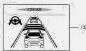
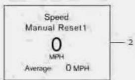


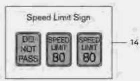


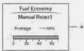
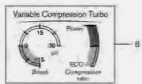
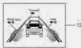
WAC0660X
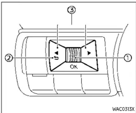
TRIP COMPUTER
Switches for the trip computer are located on the left side of the steering wheel.
① Scroll dial - navigate through the items and change or select an item in vehicle information display
this scroll dial allows up/down navigation and push to select
② - go back to the previous menu
③ - change from one display screen to the next (i.e. trip, Fuel economy)
The displayed images may differ depending on the model.
1. Home
The Home mode shows the following information.
●Vehicle speed
●Navigation (if so equipped)
●Audio
2. Speed and Average speed (if so equipped)
The Speed and Average speed mode shows the current vehicle speed and the average vehicle speed since the last reset. The Speed and Average speed mode have three modes of operation. You can switch between Manual Reset1, Manual Reset2 or Auto Refuel by pushing the scroll dia 1 .
Manual Reset1 can be reset manually by using the scroll dial ① .
Manual Reset2 can be reset manually by using the scroll dial ⏻ or will be reset automatically each time the ignition switch is placed in the OFF position (if so equipped).
Auto Refuel will be reset automatically each time when refueling.
3. Drive Computer
Averagefuelconsumption:
The average fuel consumption shows the average fuel consumption since the last reset.
Averagespeed:
The average speed shows the average vehicle speed since the last reset.
Tripodometer:
The trip odometer shows the total distance the vehicle has been driven since the last reset.
Elapsedtime:
The elapsed time shows the time since the last reset.
The Drive Computer mode have three modes of operation. You can switch between Manual Reset1, Manual Reset2 or Auto Refuel by pushing the scroll dial ①
Manual Reset1 can be reset manually by using the scroll dial①
Manual Reset2 can be reset manually by using the scroll dial ①, or will be reset automatically each time the ignition switch is placed in the OFF position (if so equipped).
Auto Refuel will be reset automatically
each time when refueling.
4. Fuel Economy display
Currentfuelconsumption:
The Fuel economy display mode shows the current fuel consumption.
Averagefuelconsumption:
The Fuel economy display mode shows the average fuel consumption since the last reset.
The Fuel economy display mode have three modes of operation. You can switch between Manual Reset1, Manual Reset2 or Auto Refuel by pushing the scroll dia 1 .
Manual Reset1 can be reset manually by using the scroll dial ① .
Manual Reset2 can be reset manually by using the scroll dial Ⓤ or will be reset automatically each time the ignition switch is placed in the OFF position (if so equipped).
Auto Refuel will be reset automatically each time when refueling.
5. ECO Pedal Guide
When the ECO mode is selected, you can view the ECO Pedal Guide function for improving fuel economy.
The ECO Pedal Guide mode have three modes of operation. You can switch between Manual Reset1, Manual Reset2 or Auto Refuel by pushing the scroll dial ①.
Manual Reset1 can be reset manually by using the scroll dial ① .
Manual Reset2 can be reset manually by using the scroll dial ①, or will be reset automatically each time the ignition switch is placed in the OFF position (if so equipped).
Auto Refuel will be reset automatically each time when refueling. (See "ECO Pedal Guide function" (P.5-33).)
6. Tire Pressures
The tire pressure mode shows the pressure of all four tires while the vehicle is driven.
With the "Tire Pres ECO advice" function ON, when the tire pressure is getting low, "Check Tire Pressures for Best Fuel Economy" appears. (See "ECO Mode Setting" (P.2-26) and "Tire Pres ECO advice" (P.5-33).)
When the Tire Pressure Low — Add Air warning appears, the display can be switched to the tire pressure mode by pushing the scroll dial ① to reveal additional details on the displayed warning.
- Intelligent 4x4 torque distribution display (if so equipped)
When the Intelligent 4x4 torque distribution display is selected, you can view the distribution ratio of the transmission torque to the front and rear wheels during driving.
- Variable Compression Turbo (if so equipped)
Variable Compression Turbo mode shows the status of Variable Compression Turbo Information. (See "Variable Compression Turbo" (P.2-12).)
- Compass (if so equipped)
This display indicates the heading direction of the vehicle.
- Navigation (if so equipped)
When the route guidance is set in the navigation system, this item shows the navigation route information.
11. Audio
The audio mode shows the status of audio information.
12. Driver Assistance
The Driver Assistance mode shows the operating condition for the following systems.
-Forward:
— Automatic Emergency Braking (AEB) with Pedestrian Detection system
— Intelligent Forward Collision Warning (I-FCW)
Lane:
— Lane Departure Warning (LDW)
— Intelligent Lane Intervention (I-LI) (if so equipped)
- Blind Spot:
— Blind Spot Warning (BSW)
— Intelligent Blind Spot Intervention (I-BSI) (if so equipped)
For more details, see "Automatic Emergency Braking (AEB) with Pedestrian Detection system" (P.5-122), "Lane Departure Warning (LDW)" (P.5-47), "Intelligent Lane Intervention (I-LI)" (P.5-52), "Blind Spot Warning (BSW)" (P.5-58) or "Intelligent Blind Spot Intervention (I-BSI)" (P.5-66).
13. ProPILOT Assist (if so equipped)
The ProPILOT Assist mode shows the operating conditions for the following systems:
●Intelligent Cruise Control (ICC)
●Steering Assist
The display will also be shown when the ProPILOT Assist is turned on. For additional information, see "ProPILOT Assist" (P.5-85).
14. Traffic Sign Recognition (if so equipped)
The Traffic Sign Recognition (TSR) system provides the driver with information about the most recently detected speed limit. See "Traffic Sign Recognition (TSR)" (P.5-44) for more details.

CLOCK AND OUTSIDE AIR TEMPERATURE
The clock ③ and outside air temperature ② are displayed on the upper side of the vehicle information display.
Clock
For clock adjustment, see "Clock" (P.2-27) or the separate NissanConnect® Owner's Manual (if so equipped).
HEADUPDISPLAY(HUD)(ifsoequipped)
Outside air temperature (°F or °C)
The outside air temperature is displayed in °F or °C in the range of -40 to 140°F to 60°C).
The outside air temperature mode includes a low temperature warning feature. If the outside air temperature is below 27° F ( -3° C), the indicator ③ is displayed.
The outside temperature sensor is located in front of the radiator. The sensor may be affected by road or engine heat, wind directions and other driving conditions. The display may differ from the actual outside temperature or the temperature displayed on various signs or billboards.

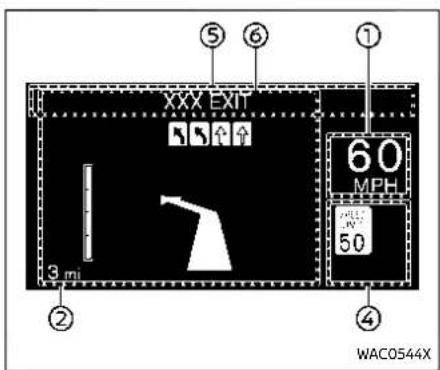

WARNING
●Failuretoproperlyadjustthe brightnessandpositionofthe displayedimagemayinterfere withthedriver'sabilitytosee throughthewindshield,which couldcauseanaccidentleading tosevereinjuryordeath.
- DonotusetheHeadUpDisplay (HUD)forextendedperiodsof timeasthatcancauseyouto notseeothervehicles,pedestriansorobjects,whichcould causeanaccidentleadingtosevereinjuryordeath.
The Head Up Display (HUD) can display one or more of the following features (if so equipped):
① Vehicle speed
② Navigation
③ Driving Assist
④ Traffic Sign
⑤ Audio
⑥ TEL/SMS
NOTE:
- Donotplaceanytypeofliquidonor neartheprojector.Doingsomay cause malfunctionoftheequipment.

- Dependingonweatherconditions (rain,snow,sunlight,etc.),thedis-playmaybedifficulttosee.
- Donottouchanyinternalpartsof theprojector.Doingsomaycause malfunctionoftheequipment.
- Topreventscratchestotheprojectorglass, donotplaceanysharp objectsonorneartheprojector opening.
- Donotplaceanyobjectsonthe instrumentpanelwhichmayobstructthedisplayoftheHUD.
- If you wear polarized sunglasses, the display may be difficult to see. Increase the brightness of the HUD in the vehicle information display or remove your sunglasses.

HOW TO USE THE HUD
To turn the HUD on, push the HUD switch To turn the HUD off, push the switch again.
If the HUD is turned off, it will remain off even if the vehicle is restarted.
The following settings can be changed in the vehicle information display:
●Brightness
●Height
- Rotation
- Contents selection
- Navigation (if so equipped)
- Driving Assist
- Speed Limit Sign
- Audio
- TEL/SMS
- Reset
NOTE:
Emergencyinformationmaydisplay eveniftheHUDisturnedoff.
This product includes the following software.
(1) Panasonic Corporation or software developed for Panasonic Corporation
(2) Third-party software licensed to Panasonic Corporation
(3) Open source software
Regarding (3) Open source software, it includes open source software (OSS), including various software to which license information applies.
Refer to the license web site at: http://car.panasonic.jp/oss/i02lln39
Display brightness
The brightness of the display may be controlled in the vehicle information display. The brightness will also be adjusted automatically according to the exterior ambient lighting brightness.

NOTE:
•TheHUDhasabuilt-insensor ①that controlsthebrightnessofthedis-playedimage.Ifyoublockthesensorwithanobject,thedisplaywill darken,makingitdifficulttosee.
SECURITYSYSTEMS
DRIVER ASSISTANCE/NAVIGATION/ TRAFFIC SIGN/AUDIO/TEL/SMS LINKING
The HUD will display Driver Assistance and navigation information.
The Driver Assistance display will show warning situations for the following systems:
●Automatic Emergency Braking (AEB) with Pedestrian Detection
●Intelligent Forward Collision Warning (I-FCW)
●Lane Departure Warning (LDW)
●Intelligent Lane Intervention (I-LI)
●Hands-free warning (for vehicles with ProPILOT Assist) (if so equipped)
The Navigation System linking display will show the following items:
- Intersection names
●Arrows indicating turning direction
- Distance to the next intersection
●Recommended lane indicator
The Traffic Signs Recognition (TSR) system linking display will show the following items:
●Speed Limit Sign
- No Entry Sign
The Audio System linking display will show the following items:
●Songs
●Radio stations
The TEL/SMS linking display will show the following item:
- Caller's name or phone number

Your vehicle has two types of security systems, as follows:
●Vehicle security system (if so equipped)
●NISSAN Vehicle Immobilizer System VEHICLE SECURITY SYSTEM (if so equipped)
The vehicle security system provides visual and audio alarm signals if someone opens the doors, hood and liftgate when the system is armed. It is not, however, a motion detection type system that activates when a vehicle is moved or when a vibration occurs.
The system helps deter vehicle theft but cannot prevent it, nor can it prevent the
2-52 Instrumentsandcontrols
theft of interior or exterior vehicle components in all situations. Always secure your vehicle even if parking for a brief period. Never leave your keys in the vehicle, and always lock it when unattended. Be aware of your surroundings, and park in secure, well-lit areas whenever possible.
Many devices offering additional protection, such as component locks, identification markers, and tracking systems, are available at auto supply stores and specialty shops. Your NISSAN dealer may also offer such equipment. Check with your insurance company to see if you may be eligible for discounts for various theft protection features.
How to arm the vehicle security system
- Close all windows. Thesystemcanbe armedevenifthewindowsareopen.
- Remove the keys from the vehicle.
- Close all doors, hood and liftgate. Lock all doors. The doors can be locked with Intelligent Key, door handle request switch (if so equipped).
Evenwhenthedriverand/orpassengersareinthevehicle,thesystemwill activatewithallthedoors,hoodand liftgatelockedwiththeignitionswitch placedintheOFFposition.Whenpla-
cingtheignitionswitchintheON position,thesystemwillbereleased.
Vehicle security system activation The vehicle security system will give the following alarm:
- The headlights or the hazard indicator lights blink and the horn sounds intermittently.
- The alarm automatically turns off after approximately 30 seconds. However, the alarm reactivates if the vehicle is tampered with again.
The alarm is activated by:
- opening any doors, the hood or lift-gate without using Intelligent Key (even if the door is unlocked by releasing the door inside lock knob).
How to stop an activated alarm
The alarm stops by pushing the UNLOCK button on the Intelligent Key, pushing the request switch (if so equipped) in range of the door handle or placing the ignition switch in the ON position.
NISSAN VEHICLE IMMOBILIZER SYSTEM
The NISSAN Vehicle Immobilizer System will not allow the engine to start without the use of the registered key.
If the engine does not start using the registered Intelligent Key, it may be due to interference caused by:
• Another Intelligent Key.
- Automated toll road device.
- Automated payment device.
- Other devices that transmit similar signals.
Start the engine using the following procedure:
- Remove any items that may be causing the interference away from the Intelligent Key.
- Start the engine again.
If this procedure allows the engine to start, NISSAN recommends placing the registered Intelligent Key separate from other devices to avoid interference.
Statementrelatedtosection15ofFCC rulesforNISSANVehicleImmobilizer System(CONTASSY-SMARTKEYLESS)
FCCNotice:
ForUSA:
FCCID:KR5HFM401
WIPERANDWASHERSWITCH
ThisdevicecomplieswithPart15ofthe FCCRules.Operationissubjecttothe followingtwoconditions:(1)Thisdevice maynotcauseharmfulinterference, and(2)thisdevicemustacceptany interferencereceived,includinginterferencethatmaycauseundesiredoperation.
Note: Changesormodificationsnot expresslyapprovedbythepartyresponsibleforcompliancecouldvoid theuser'sauthoritytooperatethe equipment.
ForCanada:
ICID:7812D-HFM401
This device complies with Industry Canada licence-exempt RSS standard(s). Operation is subject to the following two conditions: (1) this device may not cause interference, and (2) this device must accept any interference, including interference that may cause undesired operation of the device.

WARNING
Infreezingtemperaturesthewasher solutionmayfreezeonthewind-shieldandobscureyourvisionwhich mayleadtoanaccident.Warmwind-shieldwiththedefrosterbeforeyou washthewindshield.

CAUTION
- Donotoperatethewashercontinuouslyformorethan30seconds.
- Donotoperatethewasherifthe reservoirtankisempty.
- Donotfillthewindowwasher reservoirtankwithwasherfluid concentratesatfullstrength. Some methyl alcohol based washerfluidconcentratesmay permanentlystainthegrilleif spilledwhilefillingthewindow washerreservortank.
•Pre-mixwasherfluidconcentrateswithwatertothemanufacturer'srecommendedlevels beforepouringthefluidintothe windowwasherreservoirtank.Do
notusethewindowwasherreservoirtanktomixthewasher fluidconcentrateandwater.
Ifthewindshieldwiperoperationis interruptedbysnoworice,thewiper maystopmovingtoprotectitsmotor.If thisoccurs,turnthewiperswitchtothe OFFpositionandremovethesnowor icethatisonaroundthewiper arms.Inapproximately1minute,turn theswitchonagaintooperatethe wiper.

The windshield wiper and washer operates when the ignition switch is in the ON position.
Push the lever down to operate the wiper at the following speed:
① Intermittent - Intermittent operation can be adjusted by turning the knob toward Ⓐ (Faster) or Ⓑ blower). Also, the intermittent operation speed varies in accordance with the vehicle speed. (For example, when the vehicle speed is high, the intermittent operation speed will be faster.)
② Low - continuous low speed operation
③ High — continuous high speed operation If the ignition switch is placed in the OFF position while the wiper operates in the high speed position, the wiper will not operate the next time the ignition switch is placed in the ON position. To operate the wiper, move the lever to any position other than high speed.
Push the lever up to have one sweep operation of the wiper.
Pull the lever toward you to operate the washer. Then the wiper will also operate several times.
NOTE:
TheSpeedDependentfeaturemaybe disabled. For additional information, refer to "VehicleSettings" (P.2-27).

CAUTION
Donotoperatethewindshieldwiper whilethewiperarmispulledup.The wiperarmmaybedamaged.
REAR WINDOW WIPER AND WASHER OPERATION

WARNING
Infreezingtemperaturesthewasher solutionmayfreezeontherear windowglassandobscureyourvision.Warmtherearwindowwiththe defrosterbeforeyouwashtherear window.

CAUTION
- Donotoperatethewashercontinuouslyformorethan30seconds.
- Donotoperatethewasherifthe reservoirtankisempty.
- Donotfillthewindowwasher reservoirtankwithwasherfluid concentratesatfullstrength. Somemethylalcoholbased washerfluidconcentratesmay permanentlystainthegrilleif spilledwhilefillingthewindow washerreservoirtank.
•Pre-mixwasherfluidconcentrateswithwatertothemanufacturer'srecommendedlevels beforepouringthefluidintothe windowwasherreservoirtank.Do notusethewindowwasherreservoirtanktomixthewasher fluidconcentrateandwater.
If therearwindowwiperoperationis interruptedbysnoworice,thewiper maystopmovingtoprotectitsmotor.If thisoccurs,turnthewiperswitchtothe OFFpositionandremovethesnowor icethatisonaroundthewiper arms.Inapproximately1minute,turn theswitchonagaintooperatethe wiper.

The rear window wiper and washer operate when the ignition switch is in the ON position.
Turn the switch clockwise from the OFF position to operate the wiper.
① Intermittent (INT) — intermittent operation (not adjustable)
② Low (ON) — continuous low speed operation
Push the switch forward to operate the washer. Then the wiper will also operate several times.
ReverseLinkfeature:
When the windshield wiper switch is on, moving the shift lever to the R (Reverse) position will operate the rear window
wiper.
NOTE:
TheReverseLinkfeaturemaybedisabled. For additional information, refer to "VehicleSettings" (P.2-27).
REARWINDOWANDOUTSIDEMIRROR (ifsoequipped)DEFROSTERSWITCH

TypeA(ifsoequipped)
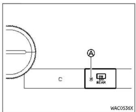
TypeC(ifsoequipped)

TypeB(ifsoequipped)
To defog/defrost the rear window glass and outside mirrors (if so equipped), start the engine and push the switch on. The indicator light Ⓐ will illuminate. Push the switch again to turn the defroster off. It will automatically turn off in approximately 20 minutes.

CAUTION
Whencleaningtheinnersideofthe rearwindow, be careful not to scratchordamagetherearwindow defroster.
HEADLIGHTANDTURNSIGNALSWITCH
HEADLIGHT SWITCH

CAUTION
Usetheheadlightswiththeengine runningtoavoiddischargingthe vehiclebattery.

Lighting
TypeA(ifsoequipped):
① Rotate the switch to the position, and the front parking, tail, license plate, and instrument panel lights will come on.
② Rotate the switch to the position, and the headlights will come on and all the other lights remain on. The daytime running light will turn off.
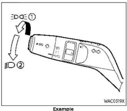
TypeB(ifsoequipped):
① Rotate the switch to the position, and the front parking, tail, license plate, and instrument panel lights will come on.
The Intelligent Auto Headlight system will also be set in this position.
② Rotate the switch to the position, and the headlights will come on and all the other lights remain on. The daytime running light will turn off.
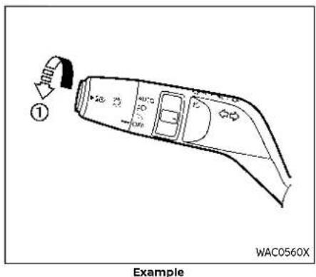
Intelligent Auto Headlight system
TypeA(ifsoequipped):
The Intelligent Auto Headlight system allows the headlights to be set so they turn on and off automatically.
To set the Intelligent Auto Headlight system:
- Make sure the headlight switch is in the AUTO position①
- Place the ignition switch in the ON position.
- The Intelligent Auto Headlight system automatically turns the headlights on and off.
To turn the Intelligent Auto Headlight system off, turn the switch to the OFF, or position.
The Intelligent Auto Headlight system can turn on the headlights automatically when it is dark and turn off the headlights when it is light.
The headlights will also be turned on automatically at twilight or in rainy weather (when the windshield wiper is operated continuously).
If the ignition switch is placed in the OFF position and one of the doors is opened and this condition is continued, the headlights remain on for 5 minutes.

Example
TypeB(ifsoequipped):
The Intelligent Auto Headlight system allows the headlights to be set so they turn on and off automatically.
To set the Intelligent Auto Headlight system:
- Make sure the headlight switch is in the FOD or AUTO position①
- Place the ignition switch in the ON position.
- The Intelligent Auto Headlight system automatically turns the headlights on and off.
To turn the Intelligent Auto Headlight system off, turn the switch to the
position.
The Intelligent Auto Headlight system can turn on the headlights automatically when it is dark and turn off the headlights when it is light.
If the ignition switch is placed in the ON position when the parking brake is applied, the headlights remain off.
With the FDA position selected, the headlights turn off when the ignition switch is placed in the OFF position, the shift position is placed in the P (Park) position or the parking brake is applied. (The front parking, tail, license plate, and instrument panel lights are on.)
The headlights will also be turned on automatically at twilight or in rainy weather (when the windshield wiper is operated continuously).
With the AUTO position selected (headlights are on), if the ignition switch is placed in the OFF position and one of the doors is opened and this condition is continued, the headlights remain on for 5 minutes.
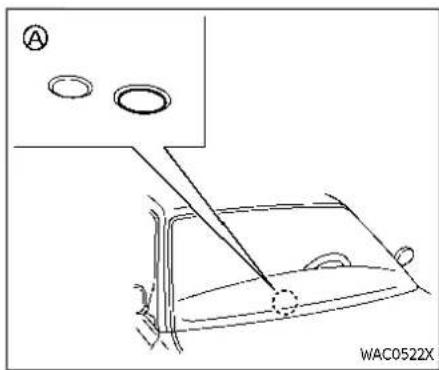
Besurenottoputanythingontopof thephotosensor locatedonthetop oftheinstrumentpanel.Thephoto sensorcontrolstheIntelligentAuto Headlight;ifitiscovered,thephoto sensorreactsasifitisdarkandthe headlightswillilluminate.
Automaticheadlightsoffdelay:
You can keep the headlights on for up to 180 seconds after you place the ignition switch in the OFF and open any door then close all the doors. You can adjust the period of the automatic headlights off delay from 0 seconds (OFF) to 180 seconds. The factory default setting is 45 seconds.
For automatic headlights off delay setting, see "Vehicle Settings" (P.2-27).
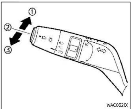
Example
Headlight beam select
① To select the high beam, push the lever forward and release it. The high beam lights come on and the light illuminates.
② Pull the lever back and release it to select the low beam.
③ To flash the headlights when the high beam is not selected, pull the lever towards the rear position. To flash the headlights when the high beam is selected, pull the lever twice towards the rear position.
High beam assist
The high beam assist system will operate when the vehicle is driven at speeds of approximately 19 MPH (30 km/h) and above. If an oncoming vehicle or leading vehicle appears in front of your vehicle when the headlight high beam is on, the headlight will be switched to the low beam automatically.
Precautionsonhighbeamassist:

WARNING
•Thehighbeamassistsystemisa conveniencebutitisnotasubstituteforsafedrivingoperation. Thedrivershouldremainalertat alltimes,ensuresafedriving practicesandswitchthehigh beamsandlowbeammanually whennecessary.
- Thehighbeamorlowbeammay notswitchautomaticallyunder thefollowingconditions.Switch thehighbeamandlowbeam manually.
—Duringbadweather(rain,fog, snow,wind,etc.).
—Whenalightsourcesimilarto aheadlighttortaillightisin
thevicinityofthevehicle.
—Whentheheadlightsofthe oncomingvehicleortheleadingvehicleareturnedoff, whenthecolorofthelightis affectedduetoforeignmaterialsonthelights,orwhenthe lightbeamisoutofposition.
—Whenthereisasudden, continuouschangeinbrightness.
—Whendrivingonaroadthat passesoverrollinghills,ora roadthathasleveldifferences.
—Whendrivingonaroadwith manycurves.
—When asignormirror-like surface is reflecting intense lighttowardsthefrontofthe vehicle.
—Whenthecontainer,etc.being towedbyaleadingvehicleis reflectingintenselight.
—Whenaheadlightonyour vehicleisdamagedordirty.
—whenthevehicleisleaningat anangleduetoapunctured tire,beingtowed,etc.
- Thetimingofswitchingthelow beam and high beam may changeunderthefollowingsituations.
—The brightness of the head-light sof the on coming vehicle or leading vehicle.
—Themovementanddirection of theoncomingvehicle and theleadingvehicle.
—whenonlyonelightonthe oncomingvehicleortheleadingvehicleisilluminated.
—When the oncoming vehicle or the leading vehicle is at two-wheeled vehicle.
— Road conditions (incline, curve,theroadsurface,etc.).
—Thenumberofpassengers andtheamountofcargo.
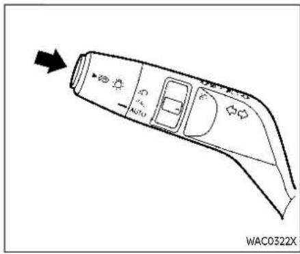
Example
headlight remains the low beam. To turn off the high beam assist system, push the switch again.
Highbeamassistoperations:
To activate the high beam assist system, push the switch as illustrated with the AUTO position (or : position, depending on the model). The high beam assist indicator light in the meter will illuminate while the headlights are turned on.
If the high beam assist indicator light does not illuminate in the above condition, it may indicate that the system is not functioning properly. It is recommended you have the system checked by a NISSAN dealer.
When the vehicle speed lowers to less than approximately 13 MPH (20 km/h), the
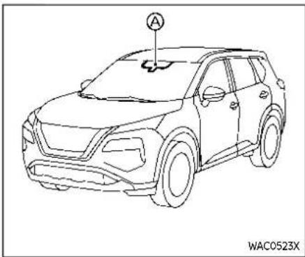
Ambientimagesensormaintenance:
The ambient image sensor for the high beam assist system is located in front of the inside mirror. To keep the proper operation of the high beam assist system and prevent a system malfunction, be sure to observe the following:
●Always keep the windshield clean.
- Do not attach a sticker (including transparent material) or install an accessory near the ambient image sensor.
- Do not strike or damage the areas around the ambient image sensor. Do not touch the sensor lens that is located on the ambient image sensor.
2-62 Instrumentsandcontrols
If the ambient image sensor is damaged due to an accident, it is recommended you contact a NISSAN dealer.
Battery saver system
- When the headlight switch is in the position or position while the ignition switch is in the ON position, the lights will automatically turn off within a period of time after the ignition switch has been placed in the OFF position.
- When the headlight switch remains in the for or position after the lights automatically turn off, the lights will turn on when the ignition switch is placed in the ON position.

CAUTION
- Whenyouturnontheheadlight switchagainafterthelightsautomaticallyturnoff,thelightswill notturnoffautomatically.Be suretoturnthelightswitchto theOFF(ifsoequipped)orthe AUTOpositionwhenyouleave thevehicleforextendedperiods oftime,otherwisethebatterywill bedischarged.
●Neverleavethelightswitchon whentheengineisnotrunning
forextendedperiodsoftimeeven iftheheadlightsturnoffautomatically.
Daytime Running Light (DRL) system
The LED Daytime Running Lights (DRL) automatically illuminate when the engine is started and the parking brake is released. The LED DRL operate with the headlight switch in the OFF (if so equipped), or AUTO (when the headlights are off) position. When you turn the headlight switch to the position for full illumination, the LED lights switch from LED DRL to the park function.
TypeA: If the parking brake is applied before the engine is started, the LED DRL do not illuminate. The LED DRL illuminate when the parking brake is released. This feature will work in the EDDE , AUTO or OFF position. The LED DRL will remain on until the ignition switch is placed in the OFF position.
TypeB: If the parking brake is applied before the engine is started, the LED DRL do not illuminate. The LED DRL illuminate when the parking brake is released. This feature will work in the AUTO or position. The LED DRL will remain on until the ignition switch is placed in the OFF
position.

WARNING
When the LEDDRL system is active with the headlight switch in the OFF position (if so equipped), taillights on your vehicle are not on. It is necessary at dusktoturnony our headlights. Failure to dosocould cause an accident in juring yourself and others.

Example
TURN SIGNAL SWITCH
① Turn signal
Move the lever up or down to signal the turning direction. When the turn is completed, the turn signals cancel automatically.
② Lane change signal
Move the lever up or down until the turn signal begins to flash, but the lever does not latch, to signal a lane change. Hold the lever until the lane change is completed.
Move the lever up or down until the turn signal begins to flash, but the lever does
not latch, and release the lever. The turn signal will automatically flash three times. Choose the appropriate method to signal a lane change based on road and traffic conditions.

Example
FOG LIGHT SWITCH (if so equipped)
To turn the fog lights on, turn the head-light switch to the position, then turn the fog light switch to the position.
To turn the fog lights on with the headlight switch in the AUTO position, the headlights must be on, then turn the fog light switch to the Ⓞ position.
To turn them off, turn the fog light switch to the OFF position.
The headlights must be on for the fog lights to operate.
The fog lights automatically turn off when the high beam headlights are selected.
HORN

To sound the horn, push the center pad area of the steering wheel.

WARNING
Donotdisassemblethehorn.Doing socouldaffectproperoperationof thesupplementalfrontairbagsystem.Tamperingwiththesupplementalfrontairbagsystemmay resultinseriouspersonalinjury.
HEATEDSTEERINGWHEEL(ifsoequipped)

Example
Push the heated steering wheel switch to warm the steering wheel after the engine starts. The indicator light® on the switch will illuminate.
If the surface temperature of the steering wheel is below 86 to 104°F (30 to 40°C), the system will heat the steering wheel and cycle off and on to maintain a temperature above 86 to 104°F (30 to 40°C). The indicator light will remain on as long as the system is on.
The heated steering wheel system is automatically turned off after 30 minutes.
Push the switch again to turn the heated steering wheel system off manually. The indicator light will turn off.
HEATEDSEATS(ifsoequipped)

WARNING
Donotuseorallowoccupantstouse theseatheaterifyouortheoccupantscannotmonitorelevatedseat temperaturesorhaveanabilityto feelpaininbodypartsthatcontact theseat.Useoftheseatheaterby suchpeoplecouldresultinserious injury.

CAUTION
- The battery could rundown if the seat theater is operated while the engine is not running.
- Donotusetheseatheaterfor extendedperiodsorwhennoone isusingtheseat.
- Donotputanythingontheseat whichinsulatesheat,suchasa blanket,cushion,seatcover,etc. Otherwise,theseatmaybecome overheated.
- Donotplaceanythinghardor heavyontheseatorpierceitwith apinorsimilarobject. This may resultindamagetotheheater.
Instrumentsandcontrols2-65
- Anyliquidspilledontheheated seatshouldberemovedimmediatelywithadrycloth.
- Whencleaningtheseat,neveruse gasoline,thinner,oranysimilar materials.
- Ifanymalfunctionsarefoundor theheatedseatdoesnotoperate, turntheswitchchoffandhavethe systemchecked.ItisrecommendedyouvisitaNISSANdealer forthisservice.

Front

Rear(ifsoequipped)
The front and rear (if so equipped) seats are warmed by built-in heaters. The switches are located on the instrument panel and the back of the center console box and can be operated independently of each other.
- Start the engine.
-
Push the heated seat switch and select the desired heat range.
-
For high heat, push the switch once.
- For medium heat, push the switch twice.
- For low heat, push the switch three times.
-
The indicator light on the switch will illuminate depending on the heat level when the heater is on.
-
To turn off the heater, push the heated seat switch until the indicator light turns off.
The heater is controlled by a control module, automatically adjusting the heat level to maintain comfort according to the selected heat range.
The indicator light will remain on as long as the switch is on.
When the vehicle's interior is warmed, or before you leave the vehicle, be sure to turn off the seat heater.
STEERINGASSISTSWITCH(models withProPILOTAssist)
The Steering Assist switch is used to temporarily turn on and off the Steering Assist system.
You can also use the "Driver Assistance" menu in the vehicle information display to turn on and off the Steering Assist system. (See "How to enable/disable the Steering Assist" (P.5-97).)
The Steering Assist system controls the steering system to help keep your vehicle near the center of the lane when driving. (See "ProPILOT Assist" (P.5-85).)
REARDOORALERT
The Rear Door Alert system functions under certain conditions to indicate there may be an object or passenger in the rear seat(s). Check the seat(s) before exiting the vehicle.
The Rear Door Alert system is initially disabled. The driver can enable the system using the vehicle information display. (See "Vehicle Settings" (P.2-27).)
When the system is enabled:
- The system is activated when a rear door is opened and closed. When the vehicle is started and the system is activated, a visual message appears in the vehicle information display. (See "31. Rear Door Alert is activated indicator" (P.2-37).)
- If a rear door is opened and closed but the vehicle is not driven, the system will not be activated. A rear door must be opened and closed and the car driven for the system to activate.
●The time interval to activate the system between when the rear door is opened and closed and the vehicle is started is about 10 minutes. A longer interval does not indicate a malfunction.
When the Rear Door Alert system is activated:
- When the driver puts the vehicle in the P (Park) position, a notification message appears in the vehicle information display with the options to "Dismiss Message" or "Disable Alert" if desired.
- Select "Disable Alert" to temporarily disable for that stop.
- No selection or 'Dismiss Message' will keep the alert enabled for that stop.
- If the alert is enabled when a driver exits the vehicle, a message will appear in the vehicle information display that states "Check Rear Seat for All Articles."
If "Horn & Alert" setting is selected:
— An audible horn sound will occur after a short time unless a rear door is opened and closed within a short time to deactivate the alert.
- If the doors are locked before the alert is deactivated by opening a rear door, the horn will sound.
- If the liftgate is opened before a rear door is opened, the horn will be delayed until after the liftgate is closed.
NOTE: If"AlertOnly"settingisselected,the messagealertwillstillbeshowninthe
Instrumentsandcontrols2-67
POWEROUTLETS
vehicleinformationdisplaybutthehorn willnotsound.

WARNING
- If the driver selects "Disable Alert", no audible alert will be provided regardless of reardoor open/close status.
- Theremaybetimeswhenthereis anobjectorpassengerintherear seat(s)buttheaudiblealertdoes notsound. Forexample, this may occurifrearseatpassengers enterorexitthevehicleduringa trip.
- Thesystemdoesnotdirectly detectobjectorspassengersin therearseat(s).Instead,itcan detect when a reardoor is openedandclosed,indicating thattheremaybesomethingin therearseat(s).
NOTE:
Theremaybetimeswhenthehorn soundsbuttherearenoobjector passengersintherearseat(s).
(See "31. Rear Door Alert is activated indicator" (P.2-37).)

InstrumentPanel

Luggagearea
The power outlets are located in the lower part of the instrument panel and in the luggage area.

CAUTION
•Theoutletandplugmaybehot duringorimmediatelyafteruse.
- Donotusewithaccessoriesthat exceeda12volt,120W(10A) powerdraw.Donotusedouble adaptersormorethanoneelectricalaccessory.
- Usepoweroutletwiththeengine runningtoavoiddischargingthe vehiclebattery.
- Avoidusingpoweroutletwhen theairconditioner,headlightsor rearwindowdefrosterison.
- Thispoweroutletisnotdesigned forusewithacigarettelighter unit.
- Pushthepluginasfarasitwill go.Ifgoodcontactisnotmade, theplugmayoverheat.
- Beforeinsertingordisconnecting aplug, besuretheelectrical accessorybeingusedisturned OFF.
- When not in use, besuret close the cap. Donot allow water or any liquid to contact the outlet.
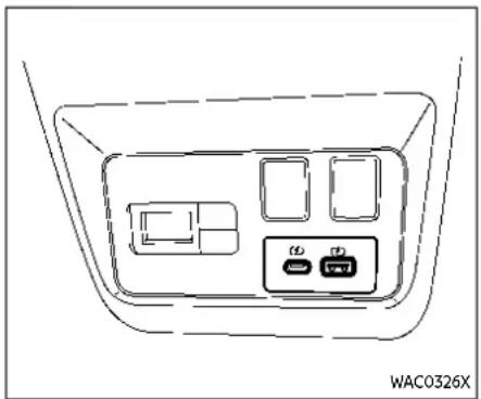
USB (Universal Serial Bus) CHARGING CONNECTOR (if so equipped) The USB charging connector is located on the back of the center console box.
The USB charging connector can be used only for charging an external device.
Connect a USB device into the connector. Charging will start automatically (maximum output up to 5 volt, 12W, 2.4A).
The external device will be charged continuously while the ignition switch is in the ON position.
Some mobile devices cannot be charged depending on their specifications.

CAUTION
- DonotforceaUSBdeviceintothe connector. DependingontheUSB connector, insertingtheUSBdevicetiltedorupsidedownmay damagetheconnector. Make surethattheUSBdeviceisconnectedcorrectlyintotheconnector.
- DonotuseareversibleUSBcable. UsingthereversibleUSBcable maydamagetheconnector.
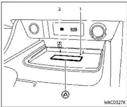
- Charging pad
- Indicator
WIRELESS CHARGER (if so equipped)
The wireless charger is located on the front of the center console. Lay the smartphone on the pad of the wireless charger. Charging will start automatically. The smartphone will be charged continuously while the ignition switch is in the ON position.

WARNING
- Neverputmetallicmaterialsbetweenthewirelesschargeranda smartphone.
- Thosewhouseapacemakeror othermedicalequipmentshould contact the electric medical equipmentmanufacturerforthe possibleinfluencesbeforeuse.
- Neverputclothoverthesmart-phoneduringchargingprocess.
●Neverchargeasmartphonewhen itiswet. - Neverputmetallicmaterialsor smallgoodssuchasacigarette lighter, IntelligentKeyormemory drive.

CAUTION
- DonotputanRFID/NFC/credit cardbetweenthewirelesschargerandasmartphone. This could causedatacorruptioninthecard.
-
Donotusethewirelesscharger withdustaccumulatedordirton thepad.
-
Donothitthesurfaceofthe wirelesscharger.
- Donotspillliquid(water,drinks, etc.)onthechargingpad.
- Donotusegrease, oiloralcohol forcleaningchargingpad.
Wireless charger Indicator
The indicator will illuminate in orange when the charging process is started.
When the charging has completed, the indicator illuminates in green.
If a malfunction occurs or the charging process has stopped, the indicator will blink in orange for 8 seconds then turn off.
Operation of the wireless charger To use the wireless charger, it is necessary to seat the smartphone well within the charging pad. To maximize charging performance, ensure the smartphone is fully seated on the center of the charging pad over the "Qi" logo ⚙ Because the location of the power receiver may vary depending on the smartphone, you will need to try and find the area that suits your smartphone.
Because some smartphone cases or accessories may adversely affect charging,
remove them before wireless charging. Turn off the vibration function of the smartphone before wireless charging.
NOTE:
- OnlyaQicompatiblesmartphone canbeused.
- Thesmartphonemaybewarmed duringchargingprocessandthe chargingmaystopbytheprotection functionofthewirelesscharger.This isnotamalfunction.Ifthisoccurs, restartchargingafterthesmart-phonecooleddown.Theindicator willblinkinorangethenturnoff.
●Thewirelesschargingprocessmay bestoppedbythestatusofthe smartphone(batterytemperature, etc.). - Ifaradionoiseinterferenceoccurs duringchargingprocess,putthe smartphoneontothecenter("Qi" logo)positionofthewirelesscharger.
- Thewirelesschargingprocesswill stopduringprocessofsearchingthe IntelligentKey.
- Thewirelesschargingprocesswill notbestartedwhenaUSB(UniversalSerialBus)cableisconnectedto thesmartphone.Theindicatormay illuminateinorangeorblinkifthe smartphoneisputonthewireless
chargerwithaUSBcableconnected. However, chargingisnotperformed.
- Dependingonthetypeofthesmartphone,theindicatormayremain illuminatedinorangeevenwhen thechargingprocesshasbeencompleted.
FCCID:BEJWC500MNM
IC:2703H-WC500MNM
Thisdevicecomplieswithpart15ofthe FCCRulesandRSS-GenofICRules.
Operationissubjecttothefollowing twoconditions:
(1) This device may not cause harmful interference, and
(2) This device must accept any interference received, including interference that may cause undesired operation.
Changesormodificationsnotexpressly approvedbythepartyresponsiblefor compliance could void the user's authoritytooperatetheequipment.
RFRadiationExposureStatement: This equipmentcomplieswithFCCRFRadiationexposurelimitssetforthforan uncontrolledenvironment.
This device and its antennam must not be co-located or operating in conjunction with any other antenna or transmitter.
This equipment should be installed and operated with a minimum distance of 15cmbetweentheradiator and your body.
ISEDComplianceStatement
ThisdevicecomplieswithRSS-GenofIC Rules
Operationissubjecttothefollowing twoconditions:
(1) This device may not cause harmful interference, and
(2) This device must accept any interference received, including interference that may cause undesired operation.
Changesormodificationsmadetothis device,notexpresslyapprovedby LG VehicleComponentsCompany,willvoid theuser'sauthoritytooperatethe equipment.
ISEDRFRadiationExposureStatement: ThisequipmentcomplieswithISEDRF Radiationexposurelimitssetforthfor anuncontrolledenvironment.Thisdeviceanditsantennamustnotbecolocatedoroperatinginconjunctionwith anyotherantennaortransmitter.This equipmentshouldbeinstalledtooperatewithaminimumdistanceof15cm betweentheradiatorandtheend-user'sbodyandarms.
EMERGENCYCALL(SOS)BUTTON (ifsoequipped)
EMERGENCY SUPPORT
NissanConnect® Services provide various services to support dealing with emergencies of the subscribed vehicle and the driver.
For example, in case of an illness or serious injury, you can seek support by pushing the in-vehicle Emergency Call (SOS) button and connecting to the NissanConnect® Services Response Center. The NissanConnect® Services Response Center can specify the location of the vehicle via GPS, and the information will be sent to the police or other agencies as needed.
For information about other NissanConnect® Services emergency support related services, contact the NissanConnect® Customer Support line at 1-855-426-6628 or refer to the NissanConnect® Services website www.nissanusa.com/connect (for U.S.) or www.nissan.ca/nissanconnect (English)/www.nissan.ca/nissanconnect/fr (French) (for Canada).

WARNING
- PleasenotethattheAutomatic CollisionNotificationserviceand EmergencyCallfunctioncannot
2-72 Instrumentsandcontrols
beusedinthefollowingconditions:
—Emergencyfunctionsandserviceswillnotbeavailable withoutapaidsubscription toNissanConnect®Services.
—TheNissanConnect®Services networksystemisdisabled.
—The vehicle moves outside the service area where the TCU (Telematics Control Unit) is connected to the system.
—The vehicle is outside the area where the cellular network service is receivable.
—The vehicle isinalocation with poorsignal reception suchastunnels, underground parking garages, behind buildings or in mountainous areas.
—Thelineisbusy.
—TheTCU(TelematicsControl Unit)orothersystemsofyour vehiclearenotworkingproperly.
—It may not be possible to make an emergency call depending on these severity of a
collisionand/oremergency.
•Parkthevehicleinasafelocation andsettheparkingbrakebefore operatingtheEmergencyCall (SOS)button.
- Onlyusethisserviceincaseofan emergency. Theremaybepenaltyforinappropriateuseofthe service.
- Radiowavescouldadverselyaffectelectricmedicalequipment. Individualswhouseapacemaker shouldcontactthedevicemanu-facturerregardinganypossible effectsbeforeusingthesystem.
- TheTCU(TelematicsControlUnit) antennaisinstalledinsidethe uppercentralpartoftheinstrumentpanel.Anoccupantshould notgetanyclosertotheantenna transpecifiedbythepacemaker manufacturer.Theradiowaves fromtheTCUantennamayadversely affect the operation of the pacemakerwhileusingtheNissanConnect®Services.

Making an emergency call
The Emergency Call (SOS) button is located near the map light.
- Push the cover to expose the Emergency Call (SOS) button®.
- Push the Emergency Call (SOS) button to make an emergency call.
- When the line is connected, speak to the Response Specialist.
If you want to cancel the emergency call, push and hold the Emergency Call (SOS) button for a few seconds.
NOTE:
- AftertheEmergencyCall(SOS)buttonispushed, it may take sometime until the system initiates connection, depending on the technical environment and whether the TCU (TelematicsControlUnit) is being used by otherservices.
●AnindicatorlightontheEmergency Call(SOS)buttonshowsthereadinessoftheemergencysupportsystem.Iftheindicatorlightisnot illuminated,pushingtheEmergency Call(SOS)buttondoesnotconnect yourvehicletotheResponseSpecialist.
The indicator lightblinks while connected to the Nissan Connect® Services Response Center.
- Evenwhentheindicatorlightis illuminated, connection to the Nissan Connect® Services Response Center may not be possible. If this occurs in an emergency situation, contact the authorities by other means.
•Toavoid disconnectingtheline, keeptheengine running during an emergencycall, if it is a fast to do.
STORAGE
CUP HOLDERS

CAUTION
- Avoid abrupt starting and braking whenthecupholderis being used to prevent spilling the drink. If the liquid is hot, it can scale you or your passenger.
- Useonlysoftcupsinthecup holder.Hardobjectscaninjure youinanaccident.

Centerconsole
Front

Rear seat
The rear cup holders are located in the rear fold-down armrest.
SOFT BOTTLE HOLDERS
Door(frontandrear)

CAUTION
- Donotusebottleholderforany other objects that could be thrownaboutinthevehicleand possiblyinjurepeopleduring suddenbrakingoranaccident.
- Donotusebottleholderforopen liquidcontainers.
2-74 Instrumentsandcontrols

SINGLE LUGGAGE BOARD (if so equipped)
The luggage board is secured by two retainer pins Ⓐ.
To ensure proper removal and prevent part damage, perform the following procedure:
- Pull the board slightly up. Do not lift up largely.
- Pull the board rearward to disengage front retainer pins®
- Remove the board from the vehicle. When reinstalling the board to the vehicle, put the retainer pins Ⓐ in the original location.
ADJUSTABLE LUGGAGE FLOOR (if so equipped)
You can use the luggage compartment in different ways using the adjustable luggage boards.

WARNING
Donotputobjectsheavierthan165 lbs(75kg)ontheloadfloorwhilein theupperposition.

CAUTION
- Donotpushthefrontedgeofthe luggageboardforcibly.Doingso maycausetheluggageboardto betilted,resultinginpersonal injury.
- Donothandletheluggageboard forciblyasthismaydeformit.
- Whileintheupperposition,do notreclinetheseatbacks.
- Donotplacecargohigherthan theseatbacks.Inasuddenstop orcollision,unsecuredcargo couldcausepersonalinjury.

Before moving the rear (outer) luggage board, release the lock on the both sides of the board as shown.
![graph TD A["Step ①: Internal body part"] --> B["Step ②: Side panel assembly"] B --> C["Step ③: Internal body part with internal connectors"] C --> D["Step ④: Internal body part with internal connectors"] D --> E["WAC0328X"]](/content/2026/05/810569/images/1743bd492b9dd4833831eea141b2b3caf1a1d292afbbb0192b48c449686f982a.jpg)
Two-stage mode
- Pull the rear board upward to ① approximately 30°.
-
Pull the rear board toward the rear of the vehicle② and then push it into the bottom of the luggage under space
-
Pull up the front (inner) board and push it into the bottom of the luggage under space in the same way.
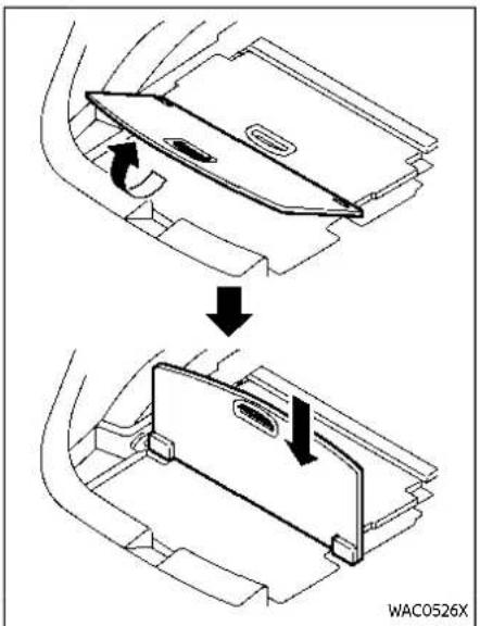
Vertical mode
- Pull the rear board upward to 90°.
- Push down the board until it stops.

Luggage under space
To use the luggage under space, pull off the rear board.
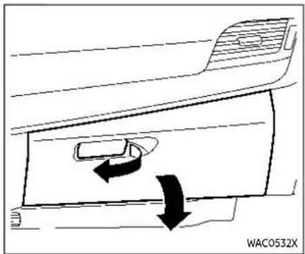
GLOVE BOX

WARNING
Keepgloveboxlidclosedwhiledrivingtohelppreventinjuryinan accidentorasuddenstop.
To open the glove box, pull the handle. To close, push the lid in until the lock latches. The glove box light (if so equipped) illuminates when the headlight switch is turned on.
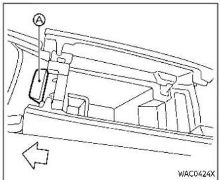
CONSOLE BOX
To open the console box lids, push the knob Ⓐ in the rearward.
To close, push each lid down until the lock latches.
If something is put on top of either side of the lids, that side lid may not open. Remove any object and push the knob again to open the lid.

LOWER CONSOLE TRAY

CAUTION
Donotplaceanyobjectsinlower consoletraythatcouldbethrown aboutinthevehicleandcauseinjury duringsuddenbrakingorcollision.
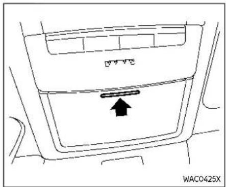
SUNGLASSES HOLDER

WARNING
Keepthesunglassesholderclosed whiledrivingtoavoidobstructing thedriver'sviewandtohelpprevent anaccident.

CAUTION
- Donotuseforanythingother thansunglasses.
- Donotleavesunglassesinthe sunglassesholderwhileparking indirectsunlight.Theheatmay damagethesunglasses.
To open the sunglasses holder, push and release. Only store one pair of sunglasses in the holder.

CARD HOLDER
Slide a card in the card holder.

COAT HOOKS
The coat hook is located above the rear side window.

CAUTION
Donotapplyatotalloadofmore than2lb(1kg)tothehook.

CARGO COVER (if so equipped)
The cargo cover keeps the luggage compartment contents hidden from the outside.
To use the cargo cover, pull it out and insert both sides to the guide.
To remove the cargo cover, stow the cover and push the button ③ .
2-80 Instrumentsandcontrols

WARNING
- Neverputanythingonthecargo cover,nomatterhowsmall.Any objectonitcouldcauseaninjury inanaccidentorsuddenstop.
- Donotleavethecargocoverin thevehiclewithitdisengaged fromtheholder.
•Thechildrestrainttoptether strapmaybedamagedbycontactwiththecargocoveroritemsintheluggagearea.Removethe cargocoverfromthevehicleor secureitintheluggagearea.Also secureanyitemsintheluggage area.Yourchildcouldbeseriously injuredorkilledinacollisionifthe toptetherstrapisdamaged.

LUGGAGE HOOKS
To use the hook, pull it down as illustrated.

WARNING
●Alwaysmakesurethatthecargo isproperlysecured. Usethesuitableropesandhooks.
•Unsecuredcargocanbecome dangerousinanaccidentorsuddenstop.
- Donotapplyatotalloadofmore than22lb(10kg)toasinglehook.
ROOFRACK(ifsoequipped)

Do not apply any load directly to the roof side rails. Cross bars must be installed before applying load/cargo/luggage to the roof of the vehicle. Genuine NISSAN accessory cross bars are available through a NISSAN dealer. It is recommended that you visit a NISSAN dealer for additional information.
The service load capacity for the roof side rails is 163 lb (74 kg), however do not exceed the accessory cross bars load capacity.
Be careful that your vehicle does not exceed the Gross Vehicle Weight Rating (GVWR) or its Gross Axle Weight Rating (GAWR front and rear). The GVWR and
GAWR are located on the F.M.V.S.S. or C.V. M.S.S. certification label (located on the driver's door pillar). For additional information regarding GVWR and GAWR, refer to "Vehicle loading information" (P.10-15).

WARNING
●Alwaysinstallthecrossbarsonto
theroofsiderailsbeforeloading
cargoofanykind.Loadingcargo
directlyontotheroofsiderailsor
thevehicle'sroofmaycauseve-
hicledamage.
- Driveextracarefullywhenthe vehicleisloadedatornearthe cargocarryingcapacity,especiallyifthesignificantportionof thatloadiscarriedonthecross bars.
●Heavyloadingofthecrossbars hasthepotentialtoaffectthe vehiclestabilityandhandling duringsuddenorunusualhandlingmaneuvers.
●Roofrackcrossbarsshouldbe evenlydistributed.
- Donotexceedmaximumroof rackcrossbarsload.
•Properlysecureallcargowith ropesorstrapstohelppreventit fromslidingorshifting.Inasuddenstoporcollision,unsecured cargocouldcausepersonalinjury.

CAUTION
Usecarewhenplacingorremoving itemsfromtheroofrack.Ifyou cannotcomfortablylifttheitems ontotheroofrackfromtheground, usealadderorastool.
WINDOWS
POWER WINDOWS

WARNING
- Makesurethatallpassengers havetheirhands,etc.insidethe vehiclewhileitisinmotionand beforeclosingthewindows.Use thewindowlockswitchtopreventunexpecteduse of the powerwindows.
- To help avoid risk of injury or death through unintended operation of the vehicle and its systems, including entrapment in windows or in advertent door lock activation, donot leave children, people who require the assistance of others or pets unattended in your vehicle. Additionally, the temperature inside a closed vehicle on a warm day can quickly become high enough to cause significant risk of injury or death to people and pets.
The power windows operate when the ignition switch is in the ON position, or for a period of time after the ignition switch is placed in the OFF position. If the driver's or front passenger's door is opened dur-
ing this period of time, power to the windows is canceled.
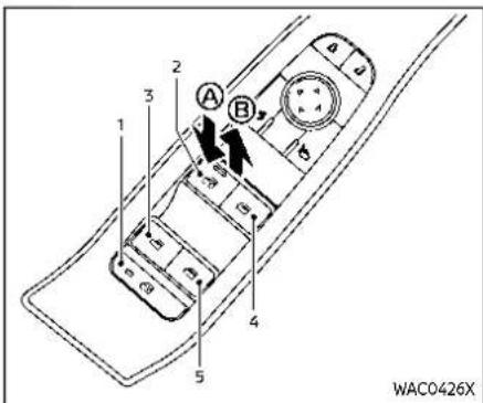
- Window lock button
- Driver side window
- Rear left passenger side window
- Front passenger side window
- Rear right passenger side window
Main power window switch (driver's side)
To open or close the window, push down Ⓐ or pull up ® the switch and hold it. The main switch (driver side switches) will open or close all the windows.
2-82 Instrumentsandcontrols
Locking rear passenger's windows When the window lock button is pushed (the indicator illuminates), the rear passenger's windows cannot be operated with the rear passenger's power window switch. The rear passenger's windows can only be operated with the main switch (driver side switches). To cancel the passenger's windows lock, push the window lock button again.
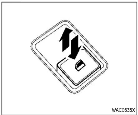
Passenger side power window switch
The passenger's switch can control its corresponding window. When the window lock button on the driver's switch is pushed, the rear passenger's switch cannot be operated.
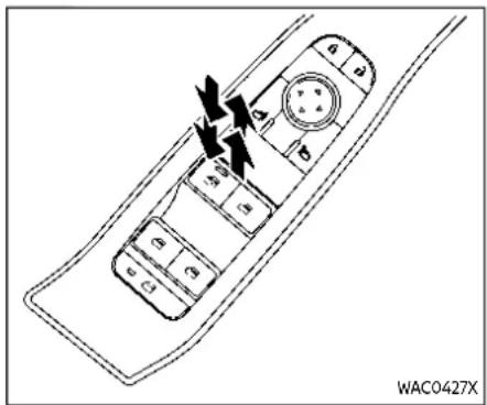
Automatic operation (driver's side) The automatic function enables a window to fully open or close without holding the switch down or up.
To fully open the window, push the power window switch down to the second detent and release the switch. To fully close the window, pull the power window switch up to the second detent and release the switch. The switch does not have to be held during window operation. To stop the window open/close operation during the automatic function, push down or pull up the switch in opposite directions.
Auto-reverse function (driver's side)

WARNING
Therearesomesmalldistancesimmediatelybeforetheclosedposition whichcannotbedetected.Makesure thatallpassengershavetheirhands, etc.,insidethevehiclebeforeclosing thewindow.
The auto-reverse function enables a window to automatically reverse when something is caught in the window as it is closing by the automatic function. When the control unit detects an obstacle, the window will be lowered immediately.
Depending on the environment or driving conditions, the auto-reverse function may activate if an impact or load similar to something being caught in the window occurs.
Windowtimer:
The window timer allows the window switch to be operated for a short time even if the ignition switch is placed in the OFF position. The window timer will be cancelled when the driver's or front passenger's side door is opened or the preset time has expired.
2-84 Instrumentsandcontrols
When power window switch does not operate
If the power window automatic function does not operate properly, perform the following procedure to initialize the power window functions.
- Close the door.
- Place the ignition switch in the ON position.
- Pull the power window switch and hold it to fully close the window.*1
- Release the power window switch.
- Pull the power window switch and hold it for approximately 5 seconds or more.*2
-
Push the power window switch down and hold it to fully open the window.
-
Release the power window switch.
-
Push the power window switch down and hold it for approximately 5 seconds or more.*2
-
Pull the power window switch and hold it to fully close the window.*1
-
Operate the window by the automatic function (window open and close) to confirm that the initialization is complete.
*1: If the window stops before reaching the fully closed position, release the
switch, then pull and hold it again to fully close the window.
*2: After pulling or pushing the power window switch and holding it for approximately 5 seconds or more, the window will move again.
If the window cannot automatically be closed since the auto-reverse function activated due to a malfunction, perform the following procedure to cancel the auto-reverse function.
-
Pull the power window switch up until the auto-reverse function is activated, then the window will reverse automatically.
-
Repeat the procedure twice.
-
Pull the power window switch and hold it to close the window to confirm that the cancellation is completed.

WARNING
Whentheauto-reversefunctionis canceled, the window will not automatically reverse even if the control unit detects an obstacle. Makes sure that all passengers have their hands, etc. inside the vehicle before closing the windows.
MOONROOF(ifsoequipped)
If the power window functions do not operate properly after performing the procedure above, have your vehicle checked by a NISSAN dealer.

WARNING
•Inanaccidentyoucouldbe thrownfromthevehiclethrough anopenmoonroof.Alwaysuse seatbeltsandchildrestraints.
- Donotallowanyonetostandup orextendanyportionoftheir bodyoutofthemoonroofopeningwhilethevehicleisinmotion orwhilethemoonroofisclosing.

CAUTION
-Removewaterdrops, snow, iceor sandfromthemoonroof before opening.
- Donotplaceanyheavyobjecton themoonrooforsurrounding area.
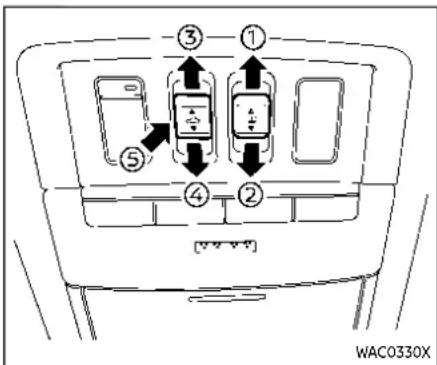
AUTOMATIC MOONROOF AND SUNSHADE
Sliding sunshade and moonroof When the sunshade switch is pushed to the OPEN position ① the sunshade open. (If the sunshade starts to open from the position between close and half open, the sunshade will stop half. When the switch is pushed again, the sunshade will open fully.) When the moonroof switch is pushed to the OPEN position ③ the moonroof opens to the comfort mode position. (If the sunshade is close, the sunshade will open half first. When the switch is pushed again, the moonroof will open fully.)
Instrumentsandcontrols2-85
When the moonroof switch is pushed to the CLOSE position ④, the moonroof will automatically close. When the sunshade switch is pushed to the CLOSE position ⑤, the sunshade will close. (If the sunshade starts to close from the position between full and half open, the sunshade will stop half. When the switch is pushed again, the sunshade will close fully. However, if the moonroof is open or tilted up, the sunshade will not close beyond half.)
To stop the sunshade or moonroof during the operation, push the moonroof switch to either of the OPEN, ③CLOSE ②, or UP position.
Tilting moonroof
To tilt up the moonroof, push the moon-roof switch to the up position 6 .
To tilt down the moonroof, push the switch to the CLOSE position 4 .
Comfort mode
This is the position used when driving with the moonroof open. When driving with the moonroof fully open, wind noise may be very loud. Use the comfort mode position when driving.
Auto-reverse function

WARNING
Therearesomesmalldistancesjust beforetheclosedpositionwhich cannotbedetected.Makesurethat allpassengershavetheirhands,etc. insidethevehiclebeforeclosingthe moonroofandsunshade.
The auto-reverse function enables the moonroof and sunshade to automatically reverse when something is caught in the moonroof and sunshade as it is closing. When the control unit detects an obstacle, the moonroof and sunshade will open immediately.
Depending on the environment or driving conditions, the auto-reverse function may activate if an impact or load similar to something being caught in the moon-roof and sunshade occurs.
If the auto-reverse function activates consecutively or the battery is discharged, the moonroof and sunshade may not close properly. In this case, push and hold the switch to the CLOSE position ④ to close the moonroof.
If the moonroof does not operate if the moonroof and sunshade do not operate properly, perform the following procedure to initialize the operation system.
- If the moonroof and sunshade are open, close them fully by repeatedly pushing the moonroof switch to the CLOSE ② and @position.
- Push and hold the moonroof switch to the CLOSE ④ position for 10 seconds.
- After the moonroof and sunshade move slightly to the closed position and then move back a little, release the moonroof switch.
- Push and hold the moonroof switch to the CLOSE ④ position, and the glass and shade will move.
- Release the moonroof switch. Then the moonroof and sunshade will fully open and then fully close.
- Check if the moonroof switch operates normally.

WARNING
The driverisalways responsible for operating themoonroof properly, including the operation by all passengers. Failure to follow the warn-
INTERIORLIGHTS
ingsandinstructionsforproperuse ofthemoonroofcouldresultin seriousinjuryordeath.
- Donotallowchildrentooperate themoonroof.Improperoperationbychildrenmaycausean accident.Ifchildrenorotherset caughtinthemoonroof,itcould causeseriousinjury.
- To help avoid risk of injury or death through unintended operation of the moonroof, placethe ignition switch in the OFF position when leaving the vehicle, and do not leave children and the intelligent Key inside the vehicle.
- Donotactivatetheauto-reverse functionintentionally.Ifhandsor face,etc.getcaughtinthemoon-roof,itcouldcauseseriousinjury.

CAUTION
- Donotplaceobjects(suchas newspapers,handkerchiefs,etc.) onthesunshadewhenitisextendingorretractingcausingimproperoperationordamageto thesunshade.
- Donotpushthesunshadearm withyourhands,etc.,asthismay deformit.Improperoperationor damagetothesunshademay result.
- Donotputanyobjectintothe sunshadeinletportasthismay resultinimproperoperationor damagethesunshade.
- Donothanganyobjectonthe armrailasthismayresultin improperoperationordamage thesunshade.
- Donotforcefullypullthesun-shade.Doingsomayelongate thesunshade.Improperoperationordamagetothesunshade mayresult.
If the moonroof does not operate properly after performing the procedure above, have your vehicle checked by a NISSAN dealer.

CAUTION
- Donotleavethelightswitchon whentheengineisnotrunning forextendedperiodsoftimeto preventthebatteryfrombeing discharged.
- Turnoffthelightswhenyouleave thevehicle.

INTERIOR LIGHT SWITCH
① The interior light can be turned ON regardless of door position. The light will go off after a period of time unless the ignition switch is placed in the ON position when any door is opened.
② The interior lights can be set to operate when the doors are opened. To turn off the interior lights when a door is open, push the switch, the interior lights will not illuminate, regardless of door position. The lights will go off when the ignition switch is placed in the ON position, or the driver's door is closed and locked.

MAP LIGHTS
Push the button to turn the map lights on. To turn them off, push the button again.
Thelightswillalsoturnoffaftera periodoftimewhenthelightsremain illuminatedtopreventthebatteryfrom becomingdischarged.
ROOM LIGHTS (if so equipped)
Push the button to turn the room lights on. To turn them off, push the button again.
Thelightswillalsoturnoffaftera periodoftimewhenthelightsremain illuminatedtopreventthebatteryfrom becomingdischarged.

REAR PERSONAL LIGHTS (if so equipped)
To turn the rear personal lights on, push the button. To turn them off, push the button again.
Thelightswillalsoturnoffaftera periodoftimewhenthelightsremain illuminatedtopreventthebatteryfrom becomingdischarged.
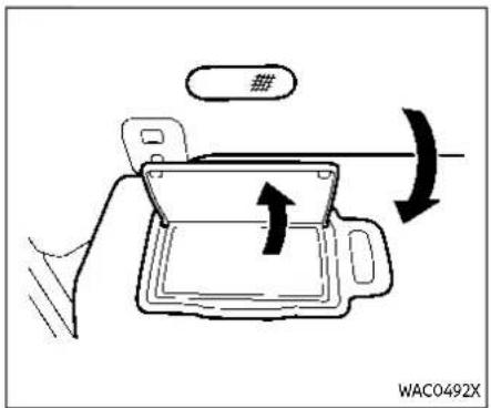
VANITY MIRROR LIGHT
The light over the vanity mirror will turn on when the cover on the vanity mirror opened.
When the cover is closed, the light will turn off.
Thelightswillalsoturnoffaftera periodoftimewhenthelightsremain illuminatedtopreventthebatteryfrom becomingdischarged.
![graph TD A["A"] --> Box1["Box"] B["B"] --> Box2["Box"] C["C"] --> Box3["Box"] Box1 --> Grid["Grid Pattern"] Box2 --> Grid Box3 --> Grid](/content/2026/05/810569/images/944bc5c152ce185c339e2f6ca5319d6518247758346d2ee3846e32daab3c21fa.jpg)
CARGO LIGHT
The cargo light has a three-position switch.
ONposition
When the cargo light switch is in the ON position Ⓐ the cargo light illuminates, regardless of any condition.
DOORposition
When the cargo light switch is in the DOOR position ® the cargo light illuminates when the liftgate is opened.
OFFposition
When the cargo light switch is in the OFF position Ⓐ, the cargo light does not illuminate, regardless of any condition.
Instrumentsandcontrols2-89
Thelightwillalsoturnoffafteraperiod oftimewhenthelightremainsilluminatedtopreventthebatteryfrom becomingdischarged.
2-90 Instrumentsandcontrols
3Pre-drivingchecksandadjustments
Keys....3-3
IntelligentKey....3-3
Doors....3-5
Lockingwithkey 3-5
Lockingwithinsidelockknob....3-6
Lockingwithpowerdoorlockswitch....3-6
Automaticdoorlocks....3-7
Childsafetyreardoorlock....3-7
IntelligentKeysystem....3-7
IntelligentKeyoperatingrange(modelswith requestswitch)....3-9
Doorlocks/unlocksprecaution(modelswith requestswitch)....3-10
IntelligentKeyoperation(modelswith requestswitch)....3-11
Batterysaversystem....3-12
Warninglightsandaudiblereminders....3-12
Troubleshootingguide....3-13
Howtouseremotekeylessentryfunction.....3-15
Remoteenginestart(ifsoequipped)....3-19
Remoteenginestartoperatingrange....3-20
Remotestartingtheengine....3-20
Extendingengine runtime....3-20
Cancelingaremoteenginestart....3-21
Conditionstheremoteenginestartwill notwork....3-21
Hood....3-22
Liftgate....3-23
Operatingmanualliftgate(if soequipped)....3-23
Operatingpowerliftgate(ifsoequipped).....3-24 Motion-activatedliftgate(if
soequipped)....3-26
Garagemodesystem(ifsoequipped)....3-27
Autoclosure(ifsoequipped)....3-28
liftgatereleaselever....3-28
Fuel-fillerdoor 3-29
Openingthefuel-fillerdoor....3-29
Howtorefuel....3-29
When refueling from a portable fuel container....3-30
Tilt/telescopicsteering....3-31
Tiltandtelescopicoperation....3-31
Sunvisors....3-32
Rearsunshade(ifsoequipped)....3-32
Mirrors....3-33
Insidemirror 3-33
Outsidemirrors....3-35
Vanitymirror....3-36
Memoryseat(ifsoequipped)....3-37
Memorystoragefunction....3-37
Entry/Exit function 3-38
System operation 3-39
KEYS

TypeA(ifsoequipped)

TypeC(ifsoequipped)
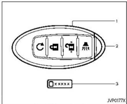
TypeB(ifsoequipped)
- Intelligent Key (2 sets)
- Mechanical key (inside Intelligent Key) (2 sets)
- Key number plate
INTELLIGENT KEY
Your vehicle can only be driven with the Intelligent Keys which are registered to your vehicle's Intelligent Key system components and NISSAN Vehicle Immobilizer System components. As many as 4 Intelligent Keys can be registered and used with one vehicle. The new keys must be registered by a NISSAN dealer prior to use with the Intelligent Key system and NISSAN Vehicle Immobilizer System of your vehicle. Since the registration pro-
cess requires erasing all memory in the Intelligent Key components when regis- tering new keys, be sure to take all Intelligent Keys that you have to the NISSAN dealer.
A key number plate is supplied with your keys. Record the key number and keep it in a safe place (such as your wallet), not in the vehicle. If you lose your keys, it is recommended you visit a NISSAN dealer for duplicates by using the key number. NISSAN does not record any key numbers so it is very important to keep track of your key number plate.
A key number is only necessary when you have lost all keys and do not have one to duplicate from. If you still have a key, it can be duplicated without knowing the key number.

CAUTION
- BesuretocarrytheIntelligent Keywithyouwhendriving.The IntelligentKeyisaprecisiondevicewithabuilt-intransmitter.To avoiddamagingit,pleasenote thefollowing.
—TheIntelligentKeyiswater resistant; however, wetting may damage the Intelligent
Pre-drivingchecksandadjustments3-3
Key.IftheIntelligentKeygets wet,immediatelywipeuntil it iscompletelydry.
—Donotbend, droporstrikeit againstanotherobject.
-Iftheoutsidetemperatureis below 14°F(-10°C) degrees,the batteryoftheIntelligentKey maynotfunctionproperly.
—Donotplacethe Intelligent Keyforanextendedperiodin aplacewheretemperatures exceed140°F(60°C).
—Donotchangeormodifythe IntelligentKey.
—Donotuseamagnetkey holder.
—Donotplacethe Intelligent Keynearanelectric appliance suchasatelevisionset, personalcomputerorcellular phone.
—DonotallowtheIntelligent Keytocomeintocontactwith waterorsaltwater,anddo notwashitinawashing machine. This could affect thesystemfunction.
If an Intelligent Key is lost or stolen, NISSAN recommends erasing the ID code of that Intelligent Key. This will prevent the Intelligent Key from unauthorized use to unlock the vehicle. For information regarding the erasing procedure, it is recommended you visit a NISSAN dealer.
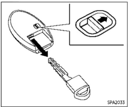
Mechanical key
To remove the mechanical key, release the lock knob at the back of the Intelligent Key.
To install the mechanical key, firmly insert it into the Intelligent Key until the lock knob returns to the lock position.
Use the mechanical key to lock or unlock the driver's door. (See "Doors" (P.3-5).)
DOORS

CAUTION
Alwayscarrythemechanicalkey installedintheIntelligentKey.

WARNING
●Alwayshavethedoorslocked whiledriving. Alongwiththeuse ofseatbelts, thisprovidesgreat- ersafety in the event of an accident by helping to prevent persons from being thrown from the vehicle. This also helps keep children and others from unintentionally opening the doors, and will help keep out intruders.
- Beforeopeninganydoor,always lookforandavoidoncoming traffic.
●Tohelpavoidriskofinjuryor deaththroughunintendedoperationofthevehicleandorits systems,includingentrapment inwindowsorinadvertentdoor lockactivation,donotleavechildren,peoplewhorequirethe assistanceofothersorpetsunattendedinyourvehicle.Additionally,thetemperatureinsidea closedvehicleonawarmdaycan quicklybecomehighenoughto causeasignificantriskofinjury ordeathtopeopleandpets.

LOCKING WITH KEY
To lock the driver's door, turn the driver's door key cylinder to the rear of the vehicle ①
To unlock the driver's door, turn the driver's door key cylinder to the front of the vehicle ②.
To lock or unlock the other doors and the liftgate, use the Intelligent Key function. (See "Intelligent Key system" (P.3-7).)
Pre-drivingchecksandadjustments3-5
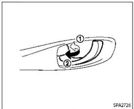
Example
LOCKING WITH INSIDE LOCK KNOB
To lock the door without the key, move the inside lock knob to the lock position then close the door.
To unlock, move the inside lock knob to the unlock position②.
To unlock and open the front door without using the lock knob, pull once on the door handle to unlock it, and again to open it.
Whenlockingthedoorwithouttakey, be surenottoleavethekeyinsidethe vehicle.

Driver'sarmrest

Frontpassenger'sarmrest
LOCKING WITH POWER DOOR LOCK SWITCH
Operating the power door lock switch (located on the driver's and front passenger's doors) will lock or unlock all the doors.
To lock the doors, push the power door lock switch to the lock position with the driver's and front passenger's doors open, then close the door.
Whenlockingthedoorthisway,besure nottoleavethekeyinsidethevehicle.
To unlock the doors, push the power door lock switch to the unlock position 2 .
Lockout protection
Lockout protection function helps to prevent the keys from being accidentally locked inside the vehicle.
When the power door lock switch (driver's or front passenger's side) is moved to the lock position with the Intelligent Key left in the vehicle and any door open, all doors will unlock automatically and a chime will sound after the door is closed.
INTELLIGENTKEYSYSTEM
AUTOMATIC DOOR LOCKS
- All doors lock automatically when the vehicle speed reaches 15 MPH (24 km/h).
- All doors unlock automatically when the ignition switch is placed in the OFF position or when the shift position is placed in the P (Park) position, if selected.
NOTE:
TheAutomaticdoorunlockfeaturecan bechangedusingthe"VehicleSettings" menuonthevehicleinformationdisplay.(See"VehicleSettings"(P.2-27).)

CHILD SAFETY REAR DOOR LOCK Child safety rear door locks help prevent the rear doors from being opened accidentally, especially when small children are in the vehicle.
Whentheleversareinthelockposition ①thereardoorscanbeopenedonly fromtheoutside.
To disengage, move the levers to the unlock position ②.

WARNING
●Radiowavescouldadverselyaffectelectricmedicalequipment. Thosewhouseapacemaker shouldcontacttheelectricmedicalequipmentmanufacturerfor thepossibleinfluencesbefore use.
- The Intelligent Key transmits radiowaves when the buttons are pushed. The FAA advises that theradiowaves may affect aircraft navigation and communications systems. Donotoperatethe Intelligent Key while on an air-plane. Makes sure the buttons are not operated unintentionally when the unit is stored during a flight.
The Intelligent Key system can operate all the door locks using the remote controller function or pushing the request switch (if so equipped) on the vehicle without taking the key out from a pocket or purse. The operating environment and/or conditions may affect the Intelligent Key system operation.
Be sure to read the following before using the Intelligent Key system.
Pre-drivingchecksandadjustments3-7

CAUTION
- BesuretocarrytheIntelligent Keywithyouwhenoperatingthe vehicle.
- NeverleavetheIntelligentKeyin thevehiclewhenyouleavethe vehicle.
The Intelligent Key is always communicating with the vehicle as it receives radio waves. The Intelligent Key system transmits weak radio waves. Environmental conditions may interfere with the operation of the Intelligent Key system under the following operating conditions.
- When operating near a location where strong radio waves are transmitted, such as a TV tower, power station and broadcasting station.
- When in possession of wireless equipment, such as a cellular phone, transceiver, and CB radio.
- When the Intelligent Key is in contact with or covered by metallic materials.
- When any type of radio wave remote control is used nearby.
- When the Intelligent Key is placed near an electric appliance such as a personal computer.
- When the vehicle is parked near a parking meter. In such cases, correct the operating conditions before using the Intelligent Key function or use the mechanical key. Although the life of the battery varies depending on the operating conditions, the battery's life is approximately 2 years. If the battery is discharged, replace it with a new one.
When the Intelligent Key battery is low, an indicator illuminates in the vehicle information display. (See "4. Key Battery Low warning" (P.2-34).)
Since the Intelligent Key is continuously receiving radio waves, if the key is left near equipment which transmits strong radio waves, such as signals from a TV and personal computer, the battery life may become shorter.
For information regarding replacement of a battery, see "Intelligent Key battery replacement" (P.8-25).
As many as 4 Intelligent Keys can be registered and used with one vehicle. For information about the purchase and use of additional Intelligent Keys, it is recommended that you contact a NISSAN dealer.

CAUTION
- DonotallowtheIntelligentKey, whichcontainselectricalcomponents,tocomeintocontactwithwaterorsaltwater.Thiscould affectthesystemfunction.
- DonotdroptheIntelligentKey.
- DonotstrikethelIntelligentKey sharplyagainstanotherobject.
- Donotchangeormodifythe IntelligentKey.
- WettingmaydamagetheIntelligentKey.IftheIntelligentKey getswet,immediatelywipeuntil itiscompletelydry.
- If the outside temperature is below 14° F(-10° C) degrees, the battery of the Intelligent Key may not function properly.
- DonotplacetheIntelligentKey foranextendedperiodinanarea where temperatures exceed 140°F(60°C).
- DonotattachtheIntelligentKey withakeyholderthatcontainsa magnet.
- DonotplacetheIntelligentKey nearequipmentthatproducesa
3-8 Pre-drivingchecksandadjustments
magneticfield,suchasaTV, audioequipment,personalcomputers,cellularphoneorwireless charger.
If an Intelligent Key is lost or stolen, NISSAN recommends erasing the ID code of that Intelligent Key from the vehicle. This may prevent the unauthorized use of the Intelligent Key to operate the vehicle. For information regarding the erasing procedure, it is recommended that you contact a NISSAN dealer.
For models with request switch: The Intelligent Key function can be disabled. For information about disabling the Intelligent Key function, it is recommended that you contact a NISSAN dealer.
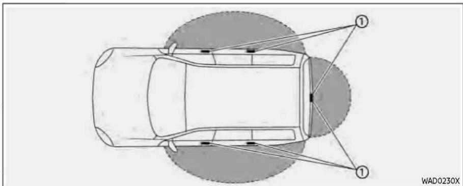
INTELLIGENT KEY OPERATING RANGE (models with request switch)
The Intelligent Key functions can only be used when the Intelligent Key is within the specified operating range from the request switch ①.
When the Intelligent Key battery is discharged or strong radio waves are present near the operating location, the Intelligent Key system's operating range becomes narrower, and the Intelligent Key may not function properly.
The operating range is within 31.50 in (80 cm) from each request switch ①
If the Intelligent Key is too close to the door glass, handle or rear bumper, the request switches may not function.
When the Intelligent Key is within the operating range, it is possible for anyone who does not carry the Intelligent Key to push the request switch to lock/unlock the doors including the liftgate.

- Do not pull the door handle before pushing the door handle request switch.
DOOR LOCKS/UNLOCKS PRECAUTION (models with request switch)
- Do not push the door handle request switch with the Intelligent Key held in your hand as illustrated. The close distance to the door handle will cause the Intelligent Key system to have difficulty recognizing that the Intelligent Key is outside the vehicle.
●After locking with the door handle request switch, verify the doors are securely locked by testing them.
●To prevent the Intelligent Key from being left inside the vehicle, make sure you carry the key with you and then lock the doors.

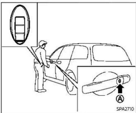
Example
3-10 Pre-drivingchecksandadjustments
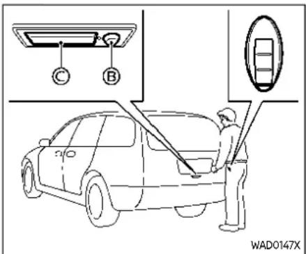
Example
INTELLIGENT KEY OPERATION (models with request switch)
You can lock or unlock the doors without taking the key out from your pocket or bag.
When you carry the Intelligent Key with you, you can lock or unlock all doors by pushing the door handle request switch (located on the front and rear doors) or liftgate request switch within the range of operation.
When you lock or unlock the doors, the hazard indicator will flash and the outside chime will sound as a confirmation. For details, see "Setting hazard indicator and horn mode" (P.3-18).
Welcome light function
When you unlock the doors or the liftgate, the daytime running lights, parking lights and the tail lights will illuminate for a period of time. The welcome light function can be disabled. For information about disabling the welcome light function, see "Vehicle Settings" (P.2-27).
Locking doors
- Push the park button to engage the P (Park) position. Place the ignition switch in the OFF position and make sure you carry the Intelligent Key with you.
- Close all doors.
- Push the door handle request switch Ⓐ or the liftgate request switch Ⓑ while carrying the Intelligent Key with you.
- All doors and the liftgate will lock.
- The hazard indicator lights flash twice and the outside buzzer sounds twice.
NOTE:
- Requestswitchesforalldoorscan bedeactivatedwhenthe"Ext.Door Switch"isturnedoffintheVehicle Settingsofthevehicleinformation display.Foradditionalinformation,
see"VehicleSettings"(P.2-27).
- Doorslockwiththedoorhandle requestswitchwhiletheignition switchisnotintheOFFposition.
- Doorsdonotlockbypushingthe driver'sdoorhandlerequestswitch whilethedriver'sdoorisopen.However,doorslockwiththemechanical keyevenifanydoorisopen.
- Doorsdonotlockwiththedoor handlerequestswitchwiththeIntelligentKeyinsidethevehicleanda beepsoundstowarnyou.However, whenanIntelligentKeyisinsidethe vehicle,doorscanbelockedwith anotherIntelligentKey.

CAUTION
●Afterlockingthedoorsusingthe requestswitch,makesurethat thedoorshavebeensectrely lockedbyoperatingthedoor handlesortheliftgateopener switch.
- Whenlockingthedoorsusingthe requestswitch,makesureto havetheIntelligentKeyinyour possessionbeforeoperatingthe requestswitchtopreventthe IntelligentKeyfrombeing
Pre-drivingchecksandadjustments3-11
thevehicle.
- Therequestswitchisoperational onlywhentheIntelligentKeyhas beendetectedbytheIntelligent Keysystem.
Unlocking doors
- Push the door handle request switch Ⓐ or the liftgate request switch Ⓑ while carrying the Intelligent Key with you.
- The hazard indicator flashes once and outside chime sounds once. The corresponding door or the liftgate will unlock.
- Push the request switch again within 1 minute.
- The hazard indicator flashes once and outside chime sounds once again. All the doors and the liftgate will unlock.
All doors will be locked automatically unless one of the following operations is performed within 1 minute after pushing the request switch while the doors are locked.
- Opening any door.
- Pushing the ignition switch.
During this 1-minute time period, if the UNLOCK 🔒 button on the Intelligent Key is pushed, all doors will be locked auto-
3-12 Pre-drivingchecksandadjustments
matically after another 1 minute.
NOTE:
The unlocking operation can be changedinselectiveunlockintheVehicle Settingsofthevehicleinformationdisplay.Foradditionalinformation,see "VehicleSettings"(P.2-27).
Opening liftgate
- Carry the Intelligent Key.
- Push the liftgate opener switch
- The liftgate will unlock and then open.
BATTERY SAVER SYSTEM
When all the following conditions are met for a period of time, the battery saver system will cut off the power supply to prevent battery discharge.
- The ignition switch is in the ON position. (See "Push-button ignition switch positions" (P.5-16).)
WARNING LIGHTS AND AUDIBLE REMINDERS
To help prevent the vehicle from moving unexpectedly by erroneous operation of the Intelligent Key listed on the following chart or to help prevent the vehicle from being stolen, chime or beep sounds inside and outside the vehicle and the warning display appears on the vehicle information display.
When a chime or beep sounds or the warning display appears, be sure to check the vehicle and Intelligent Key.
See "Troubleshooting guide" (P.3-13) and "Vehicle information display" (P.2-22).
TROUBLESHOOTING GUIDE
Verify the location of all Intelligent Keys that are programmed for the vehicle. If another Intelligent Key is in range or inside the vehicle, the vehicle system may respond differently than expected.
| Symptom Possible cause | Action to take | ||
| When stopping the engine | The Shift to P range warning appears on the display and the inside warning chime sounds continuously. | The shift position is not in the P (Park) position. | Push the park button to engage the (Park) position. |
| "No Key Press and Hold to Stop Engine message appears on the display. | The Intelligent Key is not inside the vehicle. | Carry the Intelligent Key inside the vehicle and push the ignition switch once to stop the engine. | |
| There is not the Intelligent Key or the battery charge is low. | Rapidly push the ignition switch 3 consecutive times or push and hold the ignition switch for more than 2 seconds to stop the engine. | ||
| When opening the driver's door to get out of the vehicle | The door/liftgate open warning appears on the display. | The ignition switch is in the ON position. | Place the ignition switch in the OFF position. |
| When closing the door after getting out of the vehicle | The No Key Detected warning appears on the display, the outside chime sounds three times and the inside warning chime sounds for approximately 3 seconds. | The engine is running. | Place the ignition switch in the OFF position. |
| The Rear Door Alert warning message appears on the display, the horn sounds three times, pauses, and sounds three more times, or a Check Rear Seat for All Articles warning appears on the display. | The Rear Door Alert is activated. | Check the rear seat for all articles, clear the Rear Door Alert warning message by using the steering switches. | |
| When pushing the door handle request switch (if so equipped) | The outside chime sounds for approximately 3 seconds. | The Intelligent Key is inside the vehicle. | Carry the Intelligent Key with you. |
| When pushing the ignition switch to start the engine | The Key Battery Low warning appears on the display. | The Intelligent Key battery charge is low. | Replace the battery with a new one. (See "Intelligent Key battery replacement" (P.8-25).) |
Pre-drivingchecksandadjustments3-13
| Symptom Possible cause | Action to take | ||
| When pushing the ignition switch | The Key System Error warning appears on the display. | It warns of a malfunction with the Intelligent Key system. | It is recommended that you contact a NISSAN dealer. |
3-14 Pre-drivingchecksandadjustments
HOW TO USE REMOTE KEYLESS ENTRY FUNCTION

WARNING
●Radiowavescouldadverselyaffectelectricmedicalequipment. Thosehouseapacemaker shouldcontacttheelectricmedicalequipmentmanufacturerfor thepossibleinfluencesbefore use.
- The Intelligent Key transmits radiowaves when the buttons are pushed. The FAA advises that theradiowaves may affect air-craft navigation and communications systems. Donotoperatethe Intelligent Key while on an air-plane. Makes sure the buttons are not operated unintentionally when the unit is stored during a flight.

CAUTION
- DonotallowtheIntelligentKey, whichcontainselectricalcomponents,tocomeintocontactwithwaterorsaltwater.Thiscould
affectthesystemfunction.
- DonotdroptheIntelligentKey.
- DonotstrikethIntelligentKey sharplyagainstanotherobject.
- Donotchangeormodifythe IntelligentKey.
- WettingmaydamagethelIntelligentKey.IftheIntelligentKey getswet,immediatelywipeuntilitiscompletelydry.
- If the outside temperature is below 14° F(-10° C) degrees, the battery of the Intelligent Key may not function properly.
- DonotplacetheIntelligentKey foranextendedperiodinanarea where temperatures exceed 140°F(60°C) .
- DonotattachtheIntelligentKey withakeyholderthatcontainsa magnet.
- DonotplacetheIntelligentKey nearequipmentthatproducesa magneticfield,suchasaTV, audioequipment,personalcomputers,cellularphoneorwireless charger.
The remote keyless entry function can operate all door locks using the remote
keyless entry function of the Intelligent Key. The remote keyless entry function can operate at a distance of approximately 33 ft (10 m) from the vehicle. (The operating distance depends upon the conditions around the vehicle.)
The remote keyless entry function will not operate:
- When the Intelligent Key is not within the operational range.
- When the Intelligent Key battery is discharged.
The remote keyless entry function can also operate the vehicle alarm.

TypeA(ifsoequipped)

TypeC(Ifsoequipped)

TypeB(ifsoequipped)
A LOCK button
⑧ UNLOCK button
© Power liftgate button
© PANIC button
Remote engine start button
When you lock or unlock the doors or the liftgate, the hazard indicator will flash and the horn will sound as a confirmation. For details, see "Setting hazard indicator and horn mode" (P.3-18).
Locking doors
- Place the ignition switch in the OFF position.
- Carry the Intelligent Key with you.*
- Close all the doors.
- Push the LOCK 🔒 button on the Intelligent Key.
- All the doors and the liftgate will lock.
- The hazard indicator flashes twice and the horn chirps once.
*: Doors will lock with the Intelligent Key while the ignition switch is in the ON position.
Operate the door handles to confirm that the doors have been securely locked.
Unlocking doors
-
Push the UNLOCK button on the Intelligent Key once.
-
The hazard indicator flashes once. The driver's door will unlock.
-
Push the UNLOCK button again within 1 minute.
-
The hazard indicator flashes once. All the doors and the liftgate will unlock.
All doors will be locked automatically unless one of the following operations is performed within 1 minute after pushing the UNLOCK 🔒 button while the doors are locked.
3-16 Pre-drivingchecksandadjustments
- Opening any door (including the lift-gate).
- Pushing the ignition switch.
During this 1-minute time period, if the UNLOCK 🔒 button is pushed, all doors will be locked automatically after another 1 minute.
NOTE:
The unlocking operation can be changed in selective unlock in the Vehicle Setting of the vehicle information display. For additional information, see "Vehicle Settings" (P.2-27).
Opening/closing liftgate (if so equipped)
-
Push the power liftgate button © for more than 1 second.
-
The liftgate will automatically open.
The outside chime sounds 3 times for approximately 3 seconds.
To close the liftgate, push the power liftgate button 🎨 for more than 1 second.
The liftgate will automatically close.
If the button 📄 is pushed while the liftgate is being opened or closed, the liftgate will immediately stop. Pushing the button 📄 again will reverse the direction of the liftgate. However, when the liftgate is near the fully open position, it
moves in the closing direction and when the liftgate is near the fully close position, it moves in the opening direction.
Using panic alarm
If you are near your vehicle and feel threatened, you may activate the alarm to call attention as follows:
-
Push the PANIC ➕ button on the Intelligent Key for morethan0.5 seconds.
-
The theft warning alarm and headlights will stay on for 25 seconds.
-
The panic alarm stops when:
- It has run for 25 seconds, or - Any of the buttons on the Intelligent Key is pushed.
Remote engine start (if so equipped)
The remote engine start 🔒 button is on the Intelligent Key if the vehicle has remote engine start function. This function allows the engine to start from outside the vehicle. See "Remote engine start" (P.3-19).

Intelligent Key button operation light
The light blinks only when you push any button on the Intelligent Key. The light illumination only signifies that the Intelligent Key has transmitted a signal. You may look and/or listen to verify that the vehicle has performed the intended operation. If the light does not blink, your battery may be too weak to communicate to the vehicle. If this occurs, the battery may need to be replaced.
For additional information regarding the replacement of a battery, see "Intelligent Key battery replacement" (P.8-25).
Setting hazard indicator and horn mode
This vehicle is set in hazard indicator and horn mode when you first receive the vehicle.
In hazard indicator and horn mode, when the LOCK 🔒 button 🔒 pushed, the hazard indicator flashes twice and the horn chirps once. When the UNLOCK 🔒 button 🔒 pushed, the hazard indicator flashes once.
If horns are not necessary, the system can be switched to the hazard indicator mode.
In hazard indicator mode, when the LOCK button is pushed, the hazard indicator flashes twice. When the UNLOCK button is pushed, neither the hazard indicator nor the horn operates.
Hazardindicatorandhornmode:
| Operation DOORLOCK | DOORUNLOCK | |
| Pushing door handle request switch or liftgate request switch (if so equipped) | HAZARD - twiceOUTSIDE CHIME - twice | HAZARD - onceOUTSIDE CHIME - once |
| Pushing 🔒 or button | HAZARD - twiceHORN - once | HAZARD - onceHORN - none |
Hazardindicatormode:
| Operation DOORLOCK | DOORUNLOCK | |
| Pushing door handle request switch (if so equipped) or liftgate request switch | HAZARD - twice OUTSIDE CHIME - none | HAZARD - none OUTSIDE CHIME - none |
| Pushing 🔒 or button | HAZARD - twice HORN - none | HAZARD - none HORN - none |
REMOTEENGINESTART(ifsoequipped)
Switchingprocedure:
To switch the hazard indicator and horn (chime) operation, push the LOCK 🔒 and UNLOCK buttons on the Intelligent Key simultaneously for more than 4 seconds.
- When the hazard indicator mode is set, the hazard indicator flashes 3 times.
- When the hazard indicator and horn mode is set, the hazard indicator flashes once and the horn chirps once.
![graph TD A["HAZARD INDICATOR AND HORN MODE"] --> B["Push ( ) for more than 4 sec."] B --> C["• HAZARD - 3 times"] C --> D["Push ( ) for more than 4 sec."] D --> E["• HAZARD - once"] E --> F["• HORN - once"] F --> G["HAZARD INDICATOR MODE"] G --> H["Push ( ) for more than 4 sec."]](/content/2026/05/810569/images/74fe1558be10c6611c5cae09596078da04c4166a651fb4ad1ba281a51206c518.jpg)
The horn operation can also be turned on or off in the vehicle information display. See "Vehicle Settings" (P.2-27).

WARNING
Toavoidriskofinjuryordeath,do notusetheremoteenginestart functionwhenthevehicleisinan enclosedareasuchasagarage.
![graph TD A["Check"] --> B["Lock"] B --> C["Question Mark"] C --> D["Arrow pointing inward"]](/content/2026/05/810569/images/c20b53b3898b06cd29b32c7a0c48a24480b671ee405cc5025e0325325f3d3f3d.jpg)
JVP0446X
Example
The remote engine start button is on the Intelligent Key if the vehicle has remote engine start function. This function allows the engine to start from outside the vehicle.
Some systems, such as the air conditioner system, will turn on during a remote engine start, if the system was on the last time the ignition switch was turned off.
Laws in some local communities may restrict the use of remote engine starters. For example, some laws require a person using remote engine start to have the vehicle in view. Check local regulations for any requirements.
Pre-drivingchecksandadjustments3-19
Other conditions may affect the remote engine start function. See "Conditions the remote engine start will not work" (P.3-21).
Other conditions can affect the performance of the Intelligent Key transmitter. See "Intelligent Key system" (P.3-7) for additional information.
The remote engine start function can only be used when the Intelligent Key is within the specified operating range from the vehicle.
When the Intelligent Key battery is discharged or other strong radio wave sources are present near the operating location, the Intelligent Key operating range becomes narrower, and the Intelligent Key may not function properly.
The remote engine start operating range is approximately 197 ft (60 m) from the vehicle.
REMOTE STARTING THE ENGINE
To use the remote start function to start the engine, perform the following:
-
If the doors are unlocked, push the LOCK 🔒 button to lock all doors.
-
Aim the Intelligent Key at the vehicle.
-
Push the LOCK 🔒 button again.
-
Within 5 seconds push and hold the remote engine start 🔒 button until the turn signal lights flash and the tail lights illuminate. If the vehicle is not within view, push and hold the remote engine start 🔒 button for at least 2 seconds.
The following events will occur when the engine starts:
●The front parking lights will turn on and remain on as long as the engine is running.
●The doors will be locked and the air conditioner system may turn on.
- The engine will continue to run for about 10 minutes. Repeat the steps to extend the time for an additional 10 minutes. See "Extending engine run time" (P.3-20).
Depress and hold the brake pedal, then place the ignition switch in the ON position before driving. For further instructions, see "Driving the vehicle" (P.5-19).
EXTENDING ENGINE RUN TIME
The remote engine start function can be extended one time by performing the steps listed in "Remote starting the engine" (P.3-20). Run time will be calculated as follows:
●The first 10 minute run time will start when the remote engine start function is performed.
- The second 10 minutes will start immediately when the remote engine starts to start function is performed. For example, if the engine has been running for 5 minutes, and 10 minutes are added, the engine will run for a total of 15 minutes.
- Extending engine run time will count towards the two remote engine start limit.
A maximum of two remote engine starts, or a single start with an extension can be used.
The vehicle needs to be driven at speeds of 4 MPH (7 km/h) before the remote engine start procedure can be used again.
CANCELING A REMOTE ENGINE START
To cancel a remote engine start, perform one of the following:
- Aim the Intelligent Key at the vehicle and push the remote engine start button until the front parking lights turn off.
- Turn on the hazard indicator flashers.
- Cycle the ignition switch ON and then OFF.
- The extended engine run time has expired.
●The first 10 minute timer has expired.
●The engine hood has been opened.
●The shift position is shifted out of the P (Park) position.
●The theft alarm sounds due to illegal entry into the vehicle.
●The ignition switch is pushed without an Intelligent Key in the vehicle.
●The ignition switch is pushed with an Intelligent Key in the vehicle but the brake pedal is not depressed.
●The accelerator pedal is depressed.
●The vehicle moves after a remote engine start. (The hazard indicator flashers blink once and the engine is stopped.)
CONDITIONS THE REMOTE ENGINE START WILL NOT WORK
The remote engine start will not operate if any of the following conditions are present:
●The ignition switch is placed in the ON position.
●The hood is not securely closed.
●The hazard indicator flashers are on.
- The engine is still running. The engine must be completely stopped. This is not applicable when extending engine run time.
- The remote engine start 🔒 button is not pushed and held for at least 2 seconds.
- The remote engine start 🔒 button is not pushed and held within 5 seconds of pushing the LOCK 🔒 button.
- The doors are not closed and locked. (The hazard indicator flashers blink twice to indicate the function is not operated.)
- The liftgate is open. (The hazard indicator flashers blink twice to indicate the function is not operated.)
- The Key System Error warning message remains on in the vehicle information display.
- The theft alarm sounds due to illegal entry into the vehicle. (The hazard indicator flashers blink twice to indicate the function is not operated.)
- Two remote engine starts, or a single remote engine start with an extension, have already been used. (To use the remote engine start function again, the vehicle needs to be driven at speeds of 4 MPH (7 km/h).)
●The shift position is not in the P (Park) position.
HOOD

WARNING
- Makesurethehoodiscompletely closedandlatchedbeforedriving. Failuretodosocouldcausethe hoodtoflyopenandresultinan accident.
●Neveropenthehoodifsteamor smokeiscomingfromtheengine compartmenttoavoidinjury.
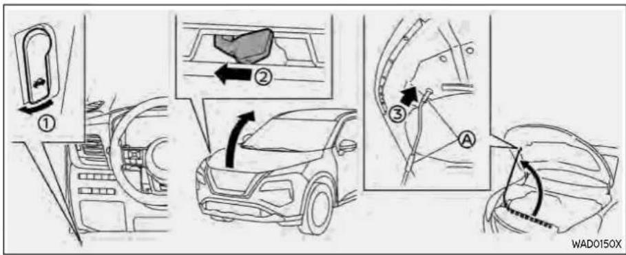
- Pull the hood lock release handle ① located below the driver's side instrument panel; the hood springs up slightly.
- Push the lever ② underneath the front of the hood sideways as illustrated with your fingertips.
- Raise the hood.
- Remove the support rod and insert it into the slot③.
Holdthecoatedparts whenremoving orresettingthesupportrod.Avoid directcontactwiththemetalparts,as theymaybehotimmediatelyafterthe enginehasbeenstopped.
When closing the hood:
- While supporting the hood, return the support rod to its original position.
- Slowly lower the hood to about 8 to 12 in (20 to 30 cm) above the hood lock, then let it drop.
- Make sure it is securely latched.
3-22 Pre-drivingchecksandadjustments
LIFTGATE

WARNING
●Alwaysbesuretheliftgatehas beenclosedsecurelytopreventit fromopeningwhiledriving.
- Donotdrivewiththeliftgate open. This could allow dangerous exhaust gas estobedrawn into the vehicle. For additional information, refer to "Exhaustgas (carbonmonoxide)" (P.5-5).
•Tohelpavoidriskofinjuryor deaththroughunintendedoperationofthevehicleandorits systems,includingentrapment inwindowsorinadvertentdoor lockactivation,donotleavechildren,peoplewhorequirethe assistanceofothersorpetsun-attendedinyourvehicle.Additionally,thetemperatureinsidea closedvehicleonawarmdaycan quicklybecomehengenoughto causeasignificantriskofinjury ordeathtopeopleandpets.
●Alwaysbesurethathandsand feetareclearofthedoorframeto avoidinjurywhileclosingthe liftgate.

CAUTION
Donotuseaccessorycarriersthat attachtotheliftgate.Doingsowill causedamagetothevehicle.

OPERATING MANUAL LIFTGATE (if so equipped)
To open the liftgate, unlock it. Pull up the liftgate to open.
The liftgate can be unlocked by:
- pushing the UNLOCK 🔒 button on the Intelligent Key twice.
- pushing the liftgate request switch (if so equipped).
- pushing the door handle request switch (if so equipped).
To close the liftgate, pull down until it securely locks.
Pre-drivingchecksandadjustments3-23
To operate the power liftgate, the vehicle must be in the P (Park) position.
The power liftgate will not operate if the battery voltage is low.
The power liftgate operation can be activated or deactivated in the vehicle information display. (See "Vehicle Settings" (P.2-27).)
NOTE:
- Formodelswithmotion-activated liftgate:Whenwashing,waxingor maintainingyourvehicle,placingor replacingthebodycover,orsplashingwatertotheareaaroundthekick motionsensor,turnoffthepower liftgate.
- If the power open or close operation is performed consecutively, the safety mode activates and the operation cannot be performed for a certain period of time. In this case, wait for while and then perform the operation.

Powerliftgateswitch—Instrumentpanel

Powerliftgatebutton-Key(example)
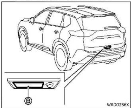
Liftgateopenerswitch
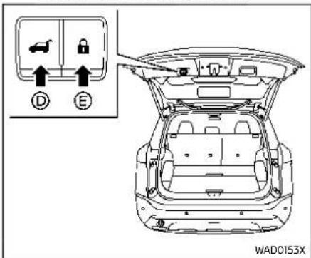
Powerliftgatecloseandlockswitches—Liftgate
3-24 Pre-drivingchecksandadjustments
Power open (using switches) When the liftgate is fully closed, the liftgate will fully open automatically by:
- pushing the power liftgate switch Ⓐ on the instrument panel for more than 1 second
- pushing the liftgate opener switch Ⓗ
- pushing the power liftgate button on the key for more than 1 second The outside chime sounds when the liftgate starts opening.
NOTE:
Theliftgatecanbeopenedbythe powerliftgateswitch orthepower liftgatebutton evenifthe liftgateislocked. Theliftgatecanbe unlockedandopenedindependently of theotherdoors, evenwhentheyare locked. Theliftgatemustbeunlocked (ortheIntelligentKeymustbewithin range) to openwiththeliftgateopener switch .
Power close (using switches) When the liftgate is fully opened, the liftgate will fully close automatically by:
- pushing the power liftgate switch Ⓐ on the instrument panel for more than 1 second
- pushing the power liftgate button © on the key for more than 1 second
- pushing the power liftgate close switch Ⓓ on the lower part of the liftgate for 1 second
The outside chime sounds when the liftgate starts closing.
Power close and lock
When the liftgate is fully opened and the Intelligent Key is carried with you near the liftgate, the liftgate will fully close and loc automatically by pushing the power lift-gate lock switch Ⓔ on the lower part of the liftgate.
The outside chime sounds when the liftgate starts closing.
Stop and reverse function (if so equipped)
The power liftgate will stop immediately if one of the following actions is performed during power open or close.
- pushing the power liftgate switch Ⓐ
- pushing the liftgate opener switch Ⓢ
- pushing the power liftgate close switch Ⓓ on the lower part of the liftgate
- pushing the power liftgate button on the key
And then the power liftgate will move in
the reverse direction if one of the above actions is performed again.
The outside chime sounds when the liftgate starts to reverse.
Auto reverse function
The auto-reverse function enables the liftgate to automatically reverse when something is caught in the liftgate as it is opening or closing. When the control unit detects an obstacle, the liftgate will reverse and return to the full open or full close position.
If a second obstacle is detected, the liftgate motion will stop. The liftgate will enter the manual mode.
A pinch sensor is mounted on each side of the liftgate. If an obstacle is detected by the pinch sensor during power close, the liftgate will reverse and return to the full open position immediately.
NOTE:
If the pinch sensor is damaged or removed, the power close function will not operate.

WARNING
Thereisasmalldistanceimmediatelybeforetheclosedpositionthat cannotbedetected.Makesurethat
Pre-drivingchecksandadjustments3-25
allpassengerskeeptheirhands,etc., clearfromtheliftgateopeningbeforeclosingtheliftgate.
Manual mode
If power operation is not available, the liftgate can be operated manually. Power operation may not be available if multiple obstacles have been detected in a single power cycle or if the battery voltage is low. When the power liftgate is turned off, the liftgate can be opened manually by pushing the liftgate opener switch. If the power liftgate opener switch is pushed during power open or close, the power operation will be canceled and the liftgate can be operated manually. This will allow normal power operation functions to resume.

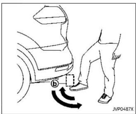
MOTION-ACTIVATED LIFTGATE (if so equipped)
The liftgate can be operated using a quick kicking motion under the center of the rear bumper.
The kick motion sensor Ⓤ is located on the back of the rear bumper. when you move your foot under and then away from the operating range Ⓐ similar to a kicking motion, while carrying the Intelligent Key with you, the liftgate will open or close automatically.
Properoperationtechnique
●While at the rear of the vehicle, begin making a quick forward kicking motion.
- Raise your foot straight under the center of the rear bumper then immediately return your foot to the ground in a continuous motion.
- You do not need to hold your foot under the bumper or move it side to side. Immediately return your foot to the ground.
●The kicking motion should be straight, smooth and consistent.
●After your kick motion is complete, step back and allow the liftgate to open/close.
- Three beeps will sound and the lift-gate will begin moving within 2 seconds after the kick.

WARNING
Preventunintentionalliftgateopening/closing.Theremaybeconditions whenopening/closingtheliftgateis notdesired.KeeptheIntelligentKey outofrangeoftheliftgate,(7ft(2m) ormore)orinsidethevehicle,when washingorworkingaroundtheback ofthevehicle.
NOTE:
●Thekickmotionsensormaynot functionunderthefollowingconditions:
- Whenoperatingnearalocation wherestrongradiowaves are transmitted, such as a TV tower, power station or broadcasting station.
- Whenthevehicleisparkedneara parkingmeter.
- Thepowerliftgatemaynotoperate whenyourfootremainsintheoperatingrange

CAUTION
- WhentheIntelligentKeyiscarried withyouneartheliftgate,even someone,whodoesnotcarrythe IntelligentKey,maybeableto openorclosetheliftgatewitha kickmotion.
- Donotperformakickmotion neartheexhaustsystemcomponentswhiletheyarehot.Youmay severelyburnyourself.
- Donotperformakickmotionon anunstableplace(forexample, onaslopeoramuddyground, etc.).
Power open or close function
The liftgate will fully open automatically using the kick motion sensor.
- Carry the Intelligent Key.
- Move your foot under and away from the rear bumper similarly to a kicking motion within the operation range of the kick motion sensor.
- The liftgate will automatically open or close.
Stop and reverse function
The power liftgate will stop immediately if a kick motion is performed during power open or close. The liftgate can be stopped even if you do not carry the Intelligent Key.
And then the power liftgate will move in the reverse direction if a kick motion is performed again. The power liftgate can be reversed when you carry the Intelligent Key.
GARAGE MODE SYSTEM (if so equipped)
The liftgate can be set to open to a specific height by performing the following:
- Open the liftgate.
- Pull the liftgate down to the desired position and hold the liftgate (the liftgate will have some resistance when being manually adjusted).
- While holding the liftgate in position, press and hold the power liftgate close and lock switch ① located on the liftgate for approximately 3 seconds or until 2 beeps are heard.
The liftgate will open to the selected position setting. To change the position of the liftgate, repeat steps 1-3 for setting the position of the liftgate.
Pre-drivingchecksandadjustments

CAUTION
Donotsettheheightoftheliftgate belowapproximately1/3oftheway tothefloorusinggaragemode.Even ifyousettheheightbelowapproximately1/3ofthewaytothefloor, theheightwillautomaticallybeset toapproximately1/3ofthewayto thefloor.
AUTO CLOSURE (if so equipped)
When the liftgate reaches the secondary position, the closure motor engages and pulls the liftgate to its primary latch position.
Donotapplyexcessiveforcewhenthe autoclosureisoperating.Excessive forceappliedmaycausethemechanismtomalfunction.

CAUTION
- Theliftgatewillautomatically closefromthesecondaryposition.Toavoidpinching,keep handsandfingersawayfrom liftgateopening.
- Donotletchildrenoperatethe liftgate.
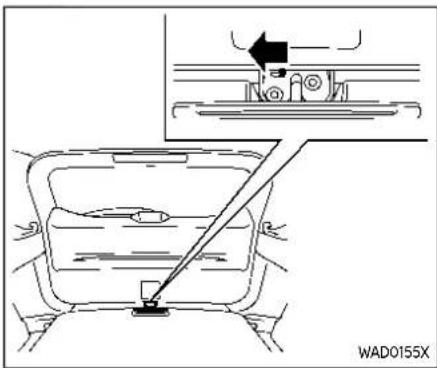
If the liftgate cannot be opened with the power door lock switch due to a discharged battery, follow these steps.
- Fold the rear seats down. (See "Seats" (P.1-3).)
- Insert a suitable tool in the access opening. Move the release lever to the left. The liftgate will be unlatched.
- Push the liftgate up to open.
Contact a NISSAN dealer as soon as possible for repair.
FUEL-FILLERDOOR

CAUTION
- Avoidapplyingdirectwaterpressure,suchashigh-pressured sprayer,onoraroundthefuel-fillerdoor.
- Besuretoclosethefuel-filler doorbeforeusinganautomatic carwashorahigh-pressuredcar wash.

OPENING THE FUEL-FILLER DOOR
To open the fuel-filler door, push the middle left side of the door.

HOW TO REFUEL
The fuel tank is not equipped with a fuel-filler cap. After opening the fuel-filler door, insert the fuel pump nozzle directly into the fuel-filler opening. When the fuel pump nozzle is pulled out, the fuel-filler opening will be sealed.
To refuel:
Be sure to insert the fuel pump nozzle slowly into the fuel-filler opening as far as it will go before fueling.
Nevermovethenozzleduringrefueling.
Pull out the nozzle approximately 5 seconds after the fuel pump nozzle shuts off automatically (initial shut-off).
Pre-drivingchecksandadjustments3-29
Close the fuel-filler door after refueling. If you need to refuel from a portable fuel container, use the funnel supplied with your vehicle. (See "When refueling from a portable fuel container" (P.3-30).)

CAUTION
- Donotattempttoopentheflaps onthefuel-filleropeningusing anytoolotherthanthefuelpump nozzle.
- This fuel-filler opening is only conformable on normal fuel pump nozzles at gas stations. Using a nozzle with a small diameter may damage the opening and the fuel system.
- Iffuelisspilledonthevehicle body, flushitawaywithwaterto avoidpaintdamage.

WARNING
•Gasolineisextremelyflammable andhighlyexplosiveundercertainconditions. You could be burnedorseriouslyinjuredifitis misusedormishandled. Always
stopengineanddonotsmokeor allowopenflamesorsparksnear thevehiclewhenrefueling.
- Donotattempttotopoffthefuel tankafterthefuelpumpnozzle shutsoffautomatically.Continuedrefuelingmaycausefuel overflow,resultinginfuelspray andpossiblyafire.
- Neverpourfuelintothethrottle bodytoattempttostartyour vehicle.
- Donotfillaportablefuelcontainerinthevehicleortrailer.Staticelectricitycancauseanexplosionofflammableliquid,vapororgasinanyvehicleortrailer.Toreducetheriskofseriousinjuryordeathwhenfillingportablefuelcontainers:
—Alwaysplacethecontaineron thegroundwhenfilling.
—Donotuseelectronicdevices whenfilling.
—Keepthepumpnozzleincontactwiththecontainerwhile youarefillingit.
—Useonlyapprovedportable fuelcontainersforflammable liquid.


WAD0214X
WHEN REFUELING FROM A PORTABLE FUEL CONTAINER
If you need to refuel from a portable fuel container, use the funnel® stored in the tool bag (located under the luggage board).
Be sure to insert the funnel into the fuel-
TILT/TELESCOPICSTEERING
filler opening slowly and fully. Insert the nozzle of the portable fuel container into the opening along the funnel and fill the fuel tank.
After refueling, remove the funnel from the fuel-filler opening. Wipe the funnel clean and return it to the tool bag.

CAUTION
- Donotinsertthenozzleofthe portablefuelcontainerdirectly intothefuel-filleropening.Doing somaydamagetheopeningand thefuelsystem.
- Useonlythefunnelprovidedwith yourvehicle. Otherwise, thefuel-filleropeningandthefuelsystem maybedamaged.

WARNING
- Donotadjustthesteeringwheel whiledriving.Youcouldlosecon-trolofyourvehicleandcausean accident.
- Donotadjustthesteeringwheel anyclosertoyouthanisnecessaryforpropersteeringoperationandcomfort. Thedriver'sair baginflateswithgreatforce. If youareunrestrained, leaningforward, sittingsidewaysoroutof positioninanyway, youareat greaterriskofinjuryordeathina crash. Youmayalsoreceiveseriousorfatalinjuriesfromtheair bagifyouareupagainstitwhen itinflates. Alwayssitbackagainst theseatbackandasfarawayas practicalfromthesteeringwheel. Alwaysusetheseatbelts.

TILT AND TELESCOPIC OPERATION Pull the lock lever down and adjust the steering wheel up, down, forward or rearward to the desired position. Push the lock lever up securely to lock the steering wheel in place.
SUNVISORSREARSUNSHADE(ifsoequipped)
![graph TD A["Step ①: Car Body"] --> B["Step ②: Rear Window"] B --> C["Step ③: Rear Window"]](/content/2026/05/810569/images/f73a903ebbc957929226d954b65be4bb75b4ed82c44aa944369b77c5bbc90872.jpg)
-
To block glare from the front, swing down the main sun visor①.
3-32 Pre-drivingchecksandadjustments -
To block glare from the side, remove the main sun visor from the center mount and swing it to the side.
- Slide the sun visor ③ in or out as needed.

CAUTION
- Donotstorethesunvisorbefore returningtheextensiontoits originalposition.
- Donotpulltheextensionsun visorforcedlydownward.
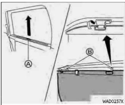

CAUTION
- Donotreleasetherearsunshade duringoperation. This could damage the sunshade or cause injury.
- Donotforcefullypullthesun-shade.Doingsomayelongate thesunshade.Thiscouldcause improperoperationorcoulddamagethesunshade.
- Donotplaceobjectsonornear therearsunshade. This could cause improper operation or
MIRRORS
coulddamagethesunshade.
The rear sunshades are equipped on the rear seat windows.
To raise the sunshade, pull the knob up and hang the sunshade on the hooks. To store the sunshade, remove the sunshade from the hooks and lower it.
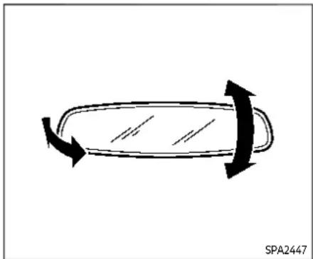
INSIDE MIRROR
Adjust the angle of the inside mirror to the desired position.

Manual anti-glare type (if so equipped)
The night position will reduce glare from the headlights of vehicles behind you at night.
Use the day position ② when driving in daylight hours.

WARNING
Usethenightpositiononlywhen necessary, because it reduces rear view clarity.
Pre-drivingchecksandadjustments3-33

rearview mirror operate normally. The indicator light will turn off. Push the ⏻ switch again to turn the system on.
Donothanganyobjectsonthemirror orapplyglasscleaner.Doingsowill reducethesensitivityofthesensor resultinginimproperoperation.
©
Automatic anti-glare type (if so equipped)
TypeA(ifsoequipped):
The inside mirror is designed so that it automatically changes reflection according to the intensity of the headlights of the following vehicle.
The anti-glare system will be automatically turned on when the ignition switch is placed in the ON position.
When the anti-glare system is turned on, the indicator light Ⓤ will illuminate and excessive glare from the headlights of the vehicle behind you will be reduced.
Push the ⏻ switch to make the inside
3-34 Pre-drivingchecksandadjustments
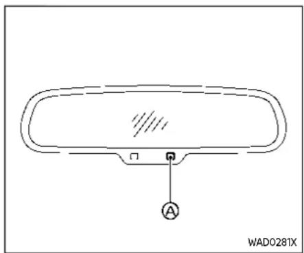
TypeB(ifsoequipped):
The inside mirror is designed so that it automatically dims during night time conditions and according to the intensity of the headlights of the following vehicle. The anti-glare system will be automatically turned on when the ignition switch is placed in the ON position.
Donothanganyobjectsonthemirror orapplyglasscleaner.Doingsowill reducethesensitivityofthesensor resultinginimproperoperation.
A
OUTSIDE MIRRORS

WARNING
Objectsviewedintheoutsidemirror onthepassengersidearecloser thantheyappear.Becarefulwhen movingtotheright.Usingonlythis mirrorcouldcauseanaccident.Use theinsidemirrororglanceoveryour shouldertoproperlyjudgedistances tootherobjects.
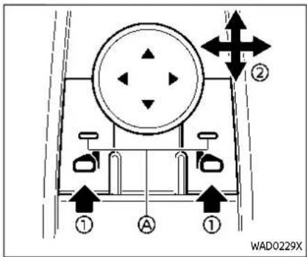
Defrosting outside mirrors (if so equipped)
The outside mirrors will be heated when the rear window defroster switch is operated. (See "Rear window and outside mirror defroster switch" (P.2-57).)
Adjusting outside mirrors
The outside mirror control switch is located on the driver's armrest.
The outside mirror will operate only when the ignition switch is in the ON position.
Push either the right or left switch to select the right or left side mirror ① (the indicator light ④ on the selected mirror switch illuminates), then adjust ② using the control switch.

Example
Foldable outside mirrors
Fold the outside mirror by pushing it toward the rear of the vehicle.
Reverse tilt-down feature (if so equipped)
When backing up the vehicle, the right or left outside mirror will turn downward automatically to provide better rear visibility.
- Place the ignition switch in the ON position.
- Move the shift lever to the R (Reverse) position.
3-36 Pre-drivingchecksandadjustments
- Choose the right or left outside mirror by operating the outside mirror control switch.
- The selected outside mirror surface moves downward.
When one of the following conditions has occurred, the outside mirror surface will return to its original position.
●The shift lever is moved out of the R (Reverse) position for a short period of time when the vehicle speed is lower than 5 MPH (8 km/h).
- The vehicle speed exceeds 5 MPH (8 km/h).
- The selected outside mirror is deselected using the outside mirror control switch.
●The ignition switch is placed in the OFF position.
●The engine is stopped.

VANITY MIRROR
To use the vanity mirror, pull down the sun visor and pull up the cover.
MEMORYSEAT(ifsoequipped)
The memory seat system has the following features:
●Memory storage function
-Entry/exit function

MEMORY STORAGE FUNCTION
Two positions for the driver's seat and outside mirrors can be stored in the memory switch. Follow these procedures to use the memory system.
- Adjust the driver's seat and outside mirrors to the desired positions by manually operating each adjusting switch. For additional information, refer to "Seats" (P.1-3) and "Outside mirrors" (P.3-35).
-
Push the SET switch and, within 5 seconds, push the memory switch (1 or 2).
-
The indicator light for the pushed memory switch will come on and stay on for approximately 5 seconds.
- The chime will sound if the memory has been stored.
NOTE:
Ifanewmemorypositionisstoredin thesamememoryswitch, theprevious memorypositionwillbeoverwrittenby thenewstoredposition.
Confirming memory storage
Push the SET switch. If a memory position has not been stored in the switch (1 or 2) the indicator light for the respective switch will come ON for approximately 0.5 seconds. If a memory position has been stored in the switch (1 or 2) then the indicator light for the respective switch will stay ON for approximately 5 seconds.
Recalling switch memory positions To recall the manually stored positions, push the memory switch (1 or 2). The driver's seat and the outside mirrors will move to the positions stored in the memory switch.
Linking log-in function to a stored memory position (models with navigation system)
The log-in function can be linked to a stored memory position with the following procedure.
- Place the ignition switch in the ON position while carrying the Intelligent Key that was registered to the vehicle with a log-in function.
NOTE: MakesuretheIntelligentKeyisfar apart. Otherwise, the vehicle may detect the wrong Intelligent Key.
- Adjust the position of the driver's seat and outside mirrors. (See "Seats" (P.1-3) and "Outside mirrors" (P.3-35).)
- Place the ignition switch in the OFF position.
The next time you log in (selecting the user on the display) after placing the ignition switch in the ON position while carrying the Intelligent Key, the system will automatically adjust to the memorized driving position. (See the separate NissanConnect® Owner's Manual.)
Linking an Intelligent Key to a stored memory position (models without navigation system)
Each Intelligent Key can be linked to a stored memory position (memory switch 1 or 2) with the following procedure.
- Follow steps 1-3 in the "Memory storage function" (P.3-37) for storing the memory position.
- The indicator light for the pushed memory switch will come on. While the indicator light is on for 5 seconds, press the 🔒 button and the 🔒 button on the Intelligent Key in succession. The indicator light of the linked memory switch will blink. After the indicator light goes off, the Intelligent Key is linked to that memory setting.
Once it is linked, when ignition switch is placed in the OFF position, pressing the button on the Intelligent Key will move the driver's seat and outside mirrors to the linked memory switch position.
NOTE:
Ifanewmemorypositionisstoredin thelinkedmemoryswitch,thenthe IntelligentKeywillinkthenewposition andoverwritesthepreviousposition.
ENTRY/EXIT FUNCTION
This system is designed so that the driver's seat will automatically move when the shift position is in the P (Park) position. This allows the driver to get into and out of the driver's seat more easily.
The driver's seat will slide backward:
- When the driver's door is opened with the ignition switch placed in the OFF position.
- When the ignition switch is changed from ON to OFF with the driver's door open.
The driver's seat will return to the previous position:
- When the ignition switch is placed in the ON position while the shift position is in the P (Park) position.
The entry/exit function can be canceled through "Vehicle Settings" in the vehicle information display by performing the following:
- Switch the "Exit Seat Slide" from ON to OFF. For additional information, refer to "Vehicle Settings" (P.2-27).
SYSTEM OPERATION
The memory seat system will not work or will stop operating under the following conditions:
- When the vehicle is moving. (The driver's seat returning function can be operated if the vehicle speed is below 2 MPH (3 km/h).)
- When any of the memory switches are pushed while the memory seat system is operating.
- When the switch for the driver's seat is pushed while the memory seat system is operating.
- When the seat has already been moved to the memorized position.
- When no seat position is stored in the memory switch.
- When the shift lever is moved from P (Park) to any other position.
MEMO
3-40 Pre-drivingchecksandadjustments
4Monitor, heater, airconditioner, audio andphonesystems
NissanConnect®Owner'sManual....4-2
RearViewMonitor(ifsoequipped)....4-2
RearViewMonitorsystemoperation....4-3
Howtoreadthedisplayedlines....4-3
Differencebetweenpredictiveand
actualdistances....4-4
Howtoparkwithpredictivecourselines......4-5
Adjustingthescreen 4-7
Howtoturnonandoffpredictive
courselines....4-7
RearViewMonitorsystemlimitations....4-7
Systemmaintenance....4-8
IntelligentAroundView®Monitor(if
soequipped)....4-9
IntelligentAroundView®Monitor
systemoperation....4-10
Differencebetweenpredictiveand
actualdistances....4-14
Howtoparkwithpredictivecourselines.....4-16
Howtoswitchthedisplay....4-17
Adjustingthescreen....4-18
IntelligentAroundView®Monitor
systemlimitations....4-18
Systemmaintenance....4-20
MovingObjectDetection(MOD)(if
soequipped)....4-21
MODsystemoperation....4-22
TurningMODonandoff....4-23
MODsystemlimitations....4-23
Systemmaintenance....4-24
Ventilators....4-25
Centerventilators....4-25
Sideventilators....4-25
Rearventilators....4-26
Heaterandairconditioner....4-26
Manualairconditionerandheater....4-27
Automaticairconditioner(modelswithout
rearcontrol)....4-31
Automaticairconditioner(modelswith
rearcontrol)....4-34
Operatingtips(forautomatic
airconditioner)....4-36
Servicingairconditioner 4-37
Antenna....4-38
Sharkfinantenna....4-38
CarphoneorCBradio....4-38
NISSANCONNECT® OWNER'SMANUAL
REARVIEWMONITOR(ifsoequipped)
For models with NissanConnect® System, refer to NissanConnect® Owner's Manual that includes the following information. Available functions may vary depending on the models and specifications.
•Audio
•Hands-Free Phone
-Apple CarPlay®
●Android Auto TM
●NissanConnect® Services powered by SiriusXM®
●Navigation system
●Voice recognition
- Information and settings viewable on NissanConnect®
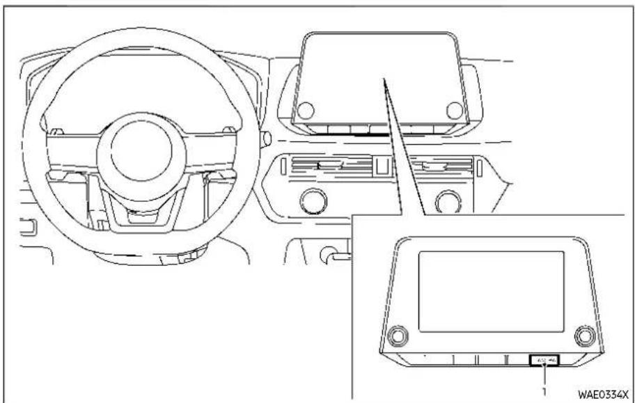
- CAMERA button

WARNING
- Failuretofollowthewarnings andinstructionsforproperuse oftheRearViewMonitorcould
resultinseriousinjuryordeath.
•RearViewMonitorisaconveni-encefeatureandisnotasub-stituteforproperbacking.Always turnandlookoutthewindows, andcheckmirrorstobesurethat itissafetomovebeforeoperat-
4-2 Monitor, heater, airconditioner, audioandphonesystems
ingthevehicle.Alwaysbackup slowly.
- Thesystemisdesignedasanaid tothedriverinshowinglarge stationaryobjectsdirectlybehind thevehicle,tohelpavoiddamagingthevehicle.
- Thedistanceguidelineandthe vehiclewidthlineshouldbeused asareferenceonlywhenthe vehicleisonalevelpavedsurface. Thedistanceviewedonth monitorisforreferenceonly and maybedifferentthantheactual distancebetweenthevehicleand displayedobjects.

CAUTION
Donotscratchthecameralenswhen cleaningDIRtorsnowfromthefront ofthecamera.
The RearView Monitor system automatically shows a rear view of the vehicle when the shift lever is placed in the R (Reverse) position.
The radio can still be heard while the RearView Monitor is active.

To display the rear view, the RearView Monitor system uses a camera ① located just above the vehicle's license plate.
When the ignition switch is placed in the ON position, move the shift lever to the R (Reverse) position to operate the Rear-View Monitor.

HOW TO READ THE DISPLAYED LINES
Guiding lines which indicate the vehicle width and distances to objects with reference to the bumper line Ⓐ are displayed on the monitor.
Distanceguidelines:
Indicate distances from the vehicle body.
●Red line ① approximately 1.5 ft (0.5 m)
●Yellow line ②: approximately 3 ft (1 m)
●Green line ③ approximately 7 ft (2 m)
Vehiclewidthguidelines ④:
Indicate the vehicle width when backing up.
Predictivecourselines: ⑤
Indicate the predictive course when backing up. The predictive course lines will be displayed on the monitor when the shift lever is in the R (Reverse) position and if the steering wheel is turned. The predictive course lines will move depending on how much the steering wheel is turned and will not be displayed while the steering wheel is in the straight ahead position. The vehicle width guide lines and the width of the predictive course lines are wider than the actual width and course.
DIFFERENCE BETWEEN PREDICTIVE AND ACTUAL DISTANCES
The displayed guide lines and their locations on the ground are for approximate reference only. Objects on uphill or downhill surfaces or projecting objects will be actually located at distances different from those displayed in the monitor relative to the guide lines (refer to illustrations). When in doubt, turn around and view the objects as you are backing up, or park and exit the vehicle to view the positioning of objects behind the vehicle.

Backing up on a steep uphill
When backing up the vehicle up a hill, the distance guide lines and the vehicle width guide lines are shown closer than the actual distance. Note that any object on the hill is farther than it appears on the monitor.
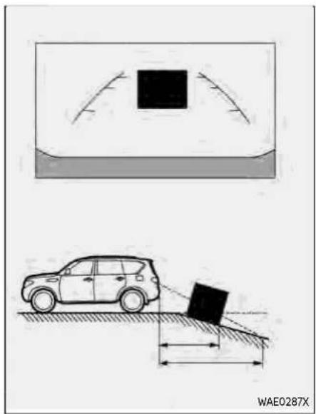
Backing up on a steep downhill
When backing up the vehicle down a hill, the distance guide lines and the vehicle width guide lines are shown farther than the actual distance. Note that any object on the hill is closer than it appears on the monitor.
4-4 Monitor, heater, airconditioner, audioandphonesystems
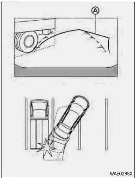

Backing up near a projecting object Backing up behind a projecting The predictive course lines do not object
touch the object in the display. However, The position is shown farther than the the vehicle may hit the object if it projects position in the display. However, the over the actual backing up course. Position is actually at the same dis-
position Ⓐ if the object projects over the actual backing up course.
HOW TO PARK WITH PREDICTIVE COURSE LINES

WARNING
- If the tires are replaced with different-sized tires, the predictive course lines may be displayed incorrectly.
- Onasnow-coveredorslippery road,theremaybeadifference between the predictive course line and the actual course line.
- If the battery is disconnected or becomes discharged, the predictive course lines may be displayed incorrectly. If this occurs, please perform the following procedures:
—Turnthesteeringwheelfrom locktolockwhiletheengineis running.
—Drivethevehicleonastraight roadformorethan5minutes.
- When the steering wheel is turned with the ignition switch in the ON position, the predictive courselines may be displayed
incorrectly.
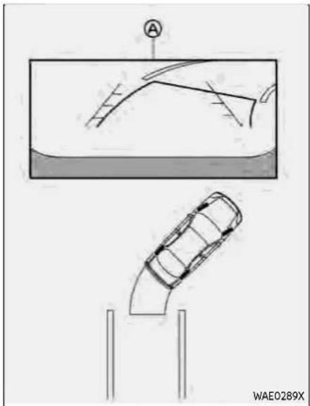
- Visually check that the parking space is safe before parking your vehicle.
- The rear view of the vehicle is displayed on the screen when the shift lever is moved to the R (Reverse) position.

- Slowly back up the vehicle adjusting the steering wheel so that the predictive course lines ® enter the parking space ©.
- Maneuver the steering wheel to make the vehicle width guide lines parallel to the parking space while referring to the predictive course lines.
4-6 Monitor, heater, airconditioner, audioandphonesystems
- When the vehicle is parked in the space completely, place the shift position to the P (Park) position and apply the parking brake.

- Push the MENU button.
- Touch the "Settings" key and then touch the "Camera" key.
- Touch the "Display Settings" key.
- Touch the "Brightness", "Contrast", "Tint", "Color", or "Black Level" key.
- Adjust the item by touching the "+" or "-" key on the touch screen display.
NOTE:
Donotadjustanyofthedisplaysettings oftheRearViewMonitorwhilethe vehicleismoving.Makesuretheparkingbrakeisfirmlyapplied.
HOW TO TURN ON AND OFF PREDICTIVE COURSE LINES
Pushing the CAMERA button while the shift lever is in the R (Reverse) position can turn on and off the predictive course lines.
REARVIEW MONITOR SYSTEM LIMITATIONS

WARNING
ListedbelowarethesystemlimitationsforRearViewMonitor.Failureto operatethevehicleinaccordance withthesesystemlimitationscould resultinseriousinjuryordeath.
-
Thesystemcannotcompletely eliminateblindspotsandmay notshoweveryobject.
•Underneaththebumperandthe cornerareasofthebumpcannotbeviewedontheRearView Monitorbecauseofitsmonitoring rangelimitation.Thesystemwill notshowsmalobjectsbelowthe bumper, and may not show objects close to the bumper or on theground. -
ObjectsviewedintheRearView Monitordifferfromactualdis- tancebecauseawide-anglelens isused.
- ObjectsintheRearViewMonitor will appear visually opposite compared to when viewed in the rearview and outsidemirrors.
- Usethedisplayedlinesasareference. Thelinesarehighlyaffected by the number of occupants, fuellevel, vehicleposition, roadconditionsandroad grade.
- Makesurethattheliftgateis securelyclosedwhenbackingup.
- Donotputanythingontherear-viewcamera.Therearviewcameraisinstalledabovethelicense plate.
- When washing the vehicle with high-pressure water, besurenot to spray it around the camera. Otherwise, water may enter the camera unit causing water condensation on the lens, amalfunction, fire or an electric shock.
- Donotstrikethecamera.Itisa precisioninstrument. Otherwise, itmaymalfunctionorcausedamageresultinginafireoran
electricshock.
The following are operating limitations and do not represent a system malfunction:
- When the temperature is extremely high or low, the screen may not clearly display objects.
- When strong light directly shines on the camera, objects may not be displayed clearly.
- Vertical lines may be seen in objects on the screen. This is due to strong reflected light from the bumper.
●The screen may flicker under fluorescent light.
●The colors of objects on the RearView Monitor may differ somewhat from the actual color of objects. - Objects on the monitor may not be clear in a dark environment.
- There may be a delay when switching between views.
- If dirt, rain or snow accumulates on the camera, the RearView Monitor may not display objects clearly. Clean the camera.
- Do not use wax on the camera lens. Wipe off any wax with a clean cloth dampened with a diluted mild cleaning agent, then wipe with a dry cloth.

SYSTEM MAINTENANCE

CAUTION
- Donotusealcohol, benzineor thinnertocleanthecamera. This will caused discoloration.
- Donotdamagethecameraasthe monitorscreenmaybeadversely affected.
If dirt, rain or snow accumulates on the camera ① RearView Monitor may not display objects clearly. Clean the camera by wiping it with a cloth dampened with a
INTELLIGENTAROUNDVIEW® MONITOR(ifsoequipped)
diluted mild cleaning agent and then wiping it with a dry cloth.

- CAMERA button

WARNING
●Failuretofollowthewarnings andinstructionsfortheproper useoftheIntelligentAround
View®Monitorsystemcouldresultinseriousinjuryordeath.
•TheIntelligentAroundView® Monitorisaconveniencefeature andisnotasubstituteforproper vehicleoperationbecauseithas areaswhereobjectscannotbe
Monitor, heater, airconditioner, audioandphonesystems4-9
viewed. The four corners of the vehicle in particular, are areas where objects don total ways appear in the bird's-eye, front, or rearviews. Always check your surrounding stobesure that it is safetomove before operating the vehicle. Always operatethe vehicles slowly.
- Thedriverisalwaysresponsible for safetyduringparking and othermaneuvers.

CAUTION
Donotscratchthelenswhencleaningdirtorsnowfromthefrontofthe camera.
The Intelligent Around View® Monitor system is designed as an aid to the driver in situations such as slot parking or parallel parking.
The monitor displays various views of the position of the vehicle in a split screen format. Not all views are available at all times.
Availableviews:
- Front view
A view of the front of the vehicle
●Rear view A view of the rear of the vehicle
●Bird's-eye view The surrounding view of the vehicle from above
●Front-side view The view around and ahead of the front passenger's side wheel
●Front-wide view A wider area view of the front view
●Rear-wide view A wider area view of the rear view

To display the multiple views, the Intelligent Around View® Monitor system uses cameras ① located on the front grille, on the vehicle's outside mirrors and one just above the vehicle's rear license plate.
When the ignition switch is placed in the ON position, push the CAMERA button on the instrument panel or move the shift lever to the R (Reverse) position to operate the Intelligent Around View® Monitor.
The screen displayed on the Intelligent Around View® Monitor will automatically return to the previous screen 3 minutes
after the CAMERA button has been pushed with the shift lever in a position other than the R (Reverse) position.
Available views

WARNING
- Thedistanceguidelinesandthe vehiclewidthguideliness should be used as a reference only when the vehicle is onapaved, level surface. The apparent distance viewed on themonitorm maybe different than the actual distance between the vehicle and displayed objects.
- Usethedisplayedlinesandthe bird's-eyeviewasareference. Thelinesandthebird's-eyeview aregreatlyaffectedbythenumberofoccupants,fuellevel,vehicleposition,roadconditionand roadgrade.
- If the tires are replaced with different-sized tires, the predictive courselines and the bird's-eyeview may be displayed incorrectly.
- Whendrivingthevehicleupahill, objectsviewedinthemonitorare
fartherthantheyappear.When drivingthevehicledownahill, objectsviewedinthemonitorare closerthantheyappear.
- Objectsintherearviewwillappearvisuallyoppositecompared towhenviewedintherearview andoutsidemirrors.
•Usethemirrorsoractuallylookto properlyjudgedistancestoother objects. - Thedistancebetweenobjects viewedintherearviewdiffers fromactualdistancebecausea wide-anglelensisused.
•Onasnow-coveredorslippery road,theremaybeadifference between the predictive course line and the actual course line.
•Thevehiclewidthandpredictive courselinesarewiderthanthe actualwidthandcourse.
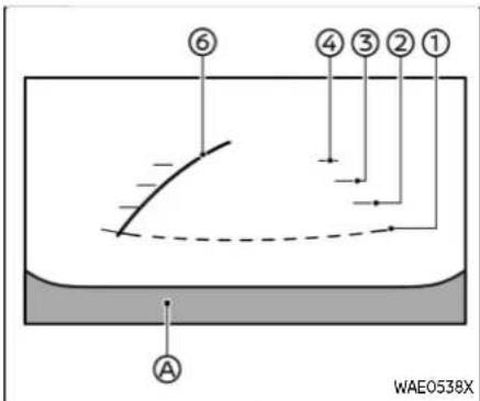
Frontview
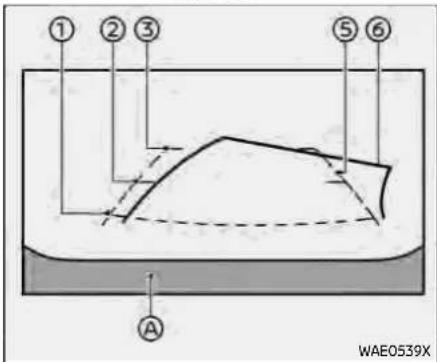
Rearview(example)
Monitor, heater, airconditioner, audioandphonesystems4-11
Frontandrearview:
Guiding lines that indicate the approximate vehicle width and distances to objects with reference to the vehicle body line Ⓐ, are displayed on the monitor.
Distanceguidelines:
Indicate distances from the vehicle body.
●Red line ①: approximately 1.5 ft (0.5 m)
●Yellow line ②: approximately 3 ft (1 m)
●Green line ③: approximately 7 ft (2 m)
●Green line ④ (if so equipped): approximately 10 ft (3 m)
Vehiclewidthguidelines ⑤:
Indicate the vehicle width.
Predictivecourselines ⑥:
Indicate the predictive course when operating the vehicle. The predictive course lines will move depending on how much the steering wheel is turned. The predictive course lines in the rear view will not be displayed while the steering wheel is in the straight ahead position.
The front view will not be displayed when the vehicle speed is above 6 MPH (10 km/h).
NOTE:
- Whenthemonitordisplaysthefront viewandthesteeringwheelturns about90degreesorlessfromthe straightaheadposition,boththe
4-12 Monitor, heater, airconditioner, audioandphonesystems
rightandleftpredictivecourselines ⑥ aredisplayed.Whenthesteering wheelturnsabout90degreesor more,thepredictivecourselineis displayedonlyontheoppositeside oftheturn.
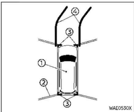
Bird's-eyeview:
The bird's-eye view shows the overhead view of the vehicle which helps confirm the vehicle position and the predictive course to a parking space.
The vehicle icon① shows the position of the vehicle. Note that the distance between objects viewed in the bird's-eye view differs from the actual distance.
The areas between the camera views (if so equipped) are indicated in black.
After the ignition switch is placed in the ON position, the non-viewable area ② (if so equipped) is highlighted in yellow for a few seconds after the bird's-eye view is displayed.
The amber markers are displayed when the sonar is turned off or the sonar is not available at the corner.
The predictive course lines 4 indicate the predicted course when operating the vehicle.

WARNING
- Objectsinthebird's-eyeviewwill appearfartherthantheactual distance.
- Tallobjects,suchasacurbor vehicle,maybemisalignedornot displayedattheseamofthe views.
- Objectsthatareabovethecam- eracannotbedisplayed.
- Theviewforthebird's-eyeview maybemisalignedwhenthe camerapositionalters.
●Alineonthegroundmaybe misalignedandisnotseenas beingstraightattheseamofthe views. Themisalignmentwillincreaseasthelineproceedsaway fromthevehicle.
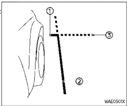
Front-sideview:
Guidinglines:
Guiding lines that indicate the approximate width and the front end of the vehicle are displayed on the monitor.
The front-of-vehicle line ① shows the front part of the vehicle.
The side-of-vehicle line ② shows the vehicle width including the outside mirrors.
The extensions ③ of both the front and side ② lines are shown with a green dotted line.

CAUTION
Theturnsignallightmaylooklike theside-of-vehicleline. Thisisnota malfunction.
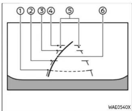
Front-wideview
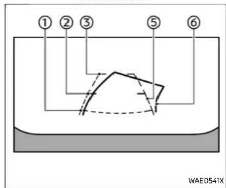
Rear-wideview
Front-wide/rear-wideview:
While the front view/rear view shows a normal view on the split screens, the front-wide view/rear-wide view shows a wider area on the entire screen and allows checking of the blind corners on the right and left sides.
Distanceguidelines ① - ④ :
Indicate distances from the vehicle body.
●Red line ①: approx. 1.5 ft (0.5 m)
●Yellow line ② approx. 3 ft (1 m)
●Green line ③: approx. 7 ft (2 m)
●Green line ④ (front-wide view only): approx. 10 ft (3 m)
Vehiclewidthguidelines ⑤:
Indicate the approximate vehicle width.
Predictivecourselines ⑥:
Indicate the predictive course when operating the vehicle. The predictive course lines will move depending on how much the steering wheel is turned. The predictive course lines in the rear-wide view will not be displayed while the steering wheel is in the straight ahead position.
The front-wide view will not be displayed when the vehicle speed is above 6 MPH (10 km/h).
NOTE:
-when the monitor displays the front-wide view and the steering wheel turns about 90 degrees or less from the straight head position, both the right and left predictive courses lines are displayed. When the steering wheel turns about 90 degrees more, the predictive course line is displayed only on the opposite side of the turn.
DIFFERENCE BETWEEN PREDICTIVE AND ACTUAL DISTANCES
The displayed guide lines and their locations on the ground are for approximate reference only. Objects on uphill or downhill surfaces or projecting objects will be actually located at distances different from those displayed in the monitor relative to the guide lines (refer to illustrations). When in doubt, turn around and view the objects as you are backing up, or park and exit the vehicle to view the positioning of objects behind the vehicle.


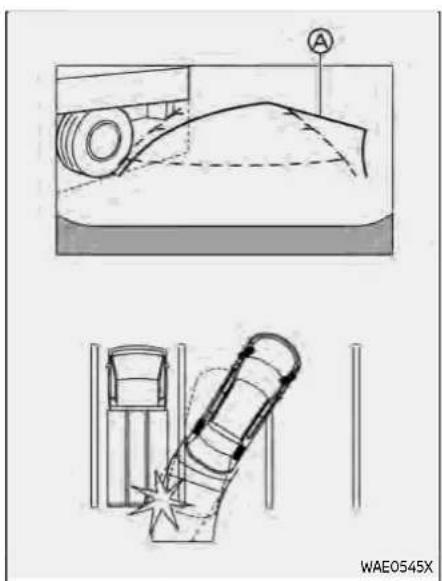
Backing up on a steep uphill
When backing up the vehicle up a hill, the distance guide lines and the vehicle width guide lines are shown closer than the actual distance. Note that any object on the hill is farther than it appears on the monitor.
Backing up on a steep downhill
When backing up the vehicle down a hill, the distance guide lines and the vehicle width guide lines are shown farther than the actual distance. Note that any object on the hill is closer than it appears on the monitor.
Backing up near a projecting object
The predictive course lines do not touch the object in the display. However, the vehicle may hit the object if it projects over the actual backing up course.

Backing up behind a projecting object
The position 15 shown farther than the position 8 in the display. However, the position 0 is actually at the same distance as the position . The vehicle may hit the object when backing up to the
position Ⓐ if the object projects over the actual moving course.
HOW TO PARK WITH PREDICTIVE COURSE LINES

WARNING
- If the tires are replaced with different-sized tires, the predictive courselines may be displayed incorrectly.
- Onasnow-coveredorslippery road,theremaybeadifference between the predictive course line and the actual course line.
- If the battery is disconnected or becomes discharged, the predictive courselines may be displayed incorrectly. If this occurs, please perform the following procedures:
—Turnthesteeringwheelfrom locktolockwhiletheengineis running.
—Drivethevehicleonastraight roadformorethan5minutes.
- When the steering wheel is turned with the ignition switch in the ON position, the predictive courselines may be displayed
incorrectly.

- Visually check that the parking space is safe before parking your vehicle.
- The rear view of the vehicle is displayed on the screen when the shift lever is moved to the R (Reverse) position.
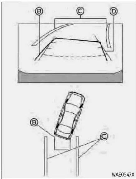
- Slowly back up the vehicle adjusting the steering wheel so that the predictive course lines enter the parking space.
-
Maneuver the steering wheel to make the vehicle width guide lines parallel to the parking space while referring to the predictive course lines.
-
When the vehicle is parked in the space completely, place the shift position in the P (Park) position and apply the parking brake.
HOW TO SWITCH THE DISPLAY
With the ignition switch placed in the ON position, push the CAMERA button or move the shift lever to the R (Reverse) position to operate the Intelligent Around View® Monitor.
The Intelligent Around View® Monitor displays different split screen views depending on the position of the shift lever. Push the CAMERA button to switch between the available views.
If the shift lever is in the R (Reverse) position, the available views are:
●Rear view/bird's-eye view split screen
●Rear view/front-side view split screen
●Rear-wide view
If the shift lever is out of the R (Reverse) position, the available views are:
●Front view/bird's-eye view split screen
●Front view/front-side view split screen
- Front-wide view
The display will switch from the Intelligent Around View® Monitor screen when:
●The shift lever is in the D (Drive) position and the vehicle speed increases above approximately 6 MPH
(10 km/h). ●A different screen is selected.
TypeA
TypeB
- Push the MENU button.
- Touch the "Settings" key and then touch the "Camera" key.
- Touch the "Display Settings" key.
- Touch the "Brightness", "Contrast", "Tint", "Color", or "Black Level" key.
- Adjust the item by touching the "+" or "-" key on the touch screen display.
NOTE:
Donotadjustthedisplaysettingsofthe IntelligentAroundView®Monitorwhile thevehicleismoving.Makesurethe parkingbrakeisfirmlyapplied.
INTELLIGENT AROUND VIEW® MONITOR SYSTEM LIMITATIONS

WARNING
ListedbelowarethesystemlimitationsforIntelligentAroundView® Monitor.Failuretooperatethevehicleinaccordancewiththesesystem limitationscouldresultinserious injuryordeath.
- DonotusethelIntelligentAround View®Monitorwiththeoutside mirrorsinthestoredposition, andmakesurethattheliftgate
4-18 Monitor, heater, airconditioner, audioandphonesystems
issecurelyclosedwhenoperating thevehicleusingtheIntelligent AroundView®Monitor.
- Theapparentdistancebetween objectsviewedonthelntelligent AroundView® Monitordiffers fromtheactualdistance.
- Thecamerasareinstalledonthe frontgrille,theoutsidemirrors andabovetherearlicenseplate. Donotputanythingonthecameras.
- When washing the vehicle with high pressure water, besure not to spray it around the cameras. Otherwise, water may enter the camera unit causing water condensation on the lens, amalfunction, fire or an electric shock.
- Donotstrikethecameras. They are precision instruments. Doing socould cause amalfunction or caused damage resulting in a fire or an electric shock.
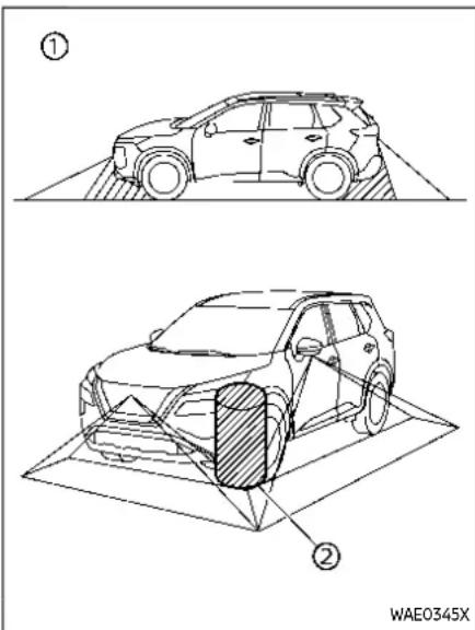
There are some areas where the system will not show objects and the system does not warn of moving objects. When the front or the rear view display, an object below the bumper or on the ground may not be viewed ① When in the bird's-eye view, a tall object near the seam ② of the camera viewing areas will
not appear in the monitor.
The following are operating limitations and do not represent a system malfunction:
- There may be a delay when switching between views.
- When the temperature is extremely high or low, the screen may not display objects clearly.
- When strong light directly shines on the camera, objects may not be displayed clearly.
●The screen may flicker under fluorescent light. - The colors of objects on the Intelligent Around View® Monitor may differ somewhat from the actual color of objects.
- Objects on the Intelligent Around View® Monitor may not be clear and the color of the object may differ in a dark environment.
- There may be differences in sharpness between each camera view of the bird's-eye view.
Do not use wax on the camera lens. Wipe off any wax with a clean cloth that has been dampened with a diluted mild cleaning agent, then wipe with a dry cloth.
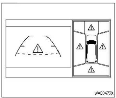
System temporarily unavailable When the "⚠️" icon is displayed on the screen, there will be abnormal conditions in the Intelligent Around View® Monitor. This will not hinder normal driving operation but the system should be inspected. It is recommended you visit a NISSAN dealer.

When the "con is displayed on the screen, the camera image may be receiving temporary electronic disturbances from surrounding devices. This will not hinder normal driving operation but the system should be inspected. It is recommended you visit a NISSAN dealer.

SYSTEM MAINTENANCE

CAUTION
- Donotusealcohol, benzineor thinnertocleanthecamera. This will caused discoloration.
- Donotdamagethecameraasthe monitorscreenmaybeadversely affected.
If dirt, rain or snow accumulates on any of the cameras ① the Intelligent Around View® Monitor may not display objects clearly. Clean the camera by wiping with a
MOVINGOBJECTDETECTION (MOD)(ifsoequipped)
cloth dampened with a diluted mild cleaning agent and then wiping with a dry cloth.

- CAMERA button

WARNING
●Failuretofollowthewarnings andinstructionsforproperuse oftheMovingObjectDetection
systemcouldresultinserious injuryordeath.
•TheMODsystemisnotasubstituteforpropervehicleoperation andisnotdesignedtoprevent contactwithobjectssurrounding thevehicle.Whenmaneuvering,
Monitor, heater, airconditioner, audioandphonesystems4-21
alwaysusetheoutsidemirror andrearviewmirrorandturn andcheckthesurroundingsto ensureitissafetomaneuver.
- Thesystem is deactivated at speeds above 5MPH (8km/h). It is reactivated at lower speeds.
•TheMODsystemisnotdesigned todetectthesurroundingstationaryobjects.
The MOD system can inform the driver of moving objects near the vehicle when driving out of garages, maneuvering in parking lots and in other such instances. The MOD system detects moving objects by using image processing technology on the image shown in the display.
The MOD system will turn on automatically under the following conditions:
- When the shift lever is in the R (Reverse) position.
- When the CAMERA button is pushed to activate the Intelligent Around View® Monitor system on the display.
- When vehicle speed decreases below approximately 5 MPH (8 km/h).
The MOD system operates in the following conditions when the camera view is
displayed:
- When the shift lever is in the P (Park) or N (Neutral) position and the vehicle is stopped, the MOD system detects the moving objects in the bird's-eye view. The MOD system will not operate if either door is opened. If outside mirrors are folded, MOD may not operate properly.
- When the shift lever is in the D (Drive) position, and the vehicle speed is below approximately 5 MPH (8 km/h), the MOD system detects moving objects in the front view or front-wide view.
- When the shift lever is in the R (Reverse) position and the vehicle speed is below approximately 5 MPH (8 km/h), the MOD system detects moving objects in the rear view or rear-wide view. The MOD system will not operate if the liftgate is open.
The MOD system does not detect moving objects in the front-side view. The MOD icon is not displayed on the screen when in this view.
When the MOD system detects a moving object near the vehicle, the yellow frame will be displayed on the view where the object is detected and a chime will sound once. While the MOD system continues to detect moving objects, the yellow frame
continues to be displayed.
NOTE:
While the RCTA chime (if soe equipped) is beeping, the MOD system does not chime.
4-22 Monitor, heater, airconditioner, audioandphonesystems
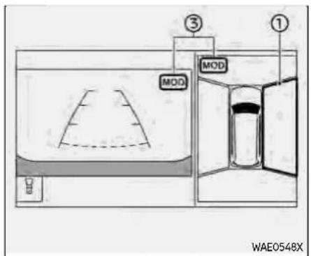
Frontandbird's-eyeviews

Rearandfront-sideviews
In the bird's-eye view, the yellow frame is displayed on each camera image (front, rear, right, left) depending on where moving objects are detected.
The yellow frame ② is displayed on the front view, rear view, front-wide view and rear-wide view.
A green MOD icon ③ is displayed in the view where the MOD system is operative. A gray MOD icon is displayed in the view where the MOD system is not operative.
If the MOD system is turned off, the MOD icon ③ is not displayed.
TURNING MOD ON AND OFF
The MOD system can be turned on and off using the vehicle information display. (See "Driver Assistance" (P.2-24).)
MOD SYSTEM LIMITATIONS

Rearandbird's-eyeviews

Front-wideview/rear-wideview

WARNING
ListedbelowarethesystemlimitationsforMOD.Failureretooperatethe vehicleinaccordancewiththese systemlimitationscouldresultin seriousinjuryordeath.
- DonotusetheMODsystemwhen towingatrailer.Thesystemmay notfunctionproperly.
Monitor, heater, airconditioner, audioandphonesystems4-23
- Excessivenoise(forexample, audiosystemvolumeoropen vehiclewindow)willinterfere withthechimesound,andit maynotbeheard.
●TheMODsystemperformance willbelimitedaccordingtoenvironmentalconditionsandsurroundingobjectssuchas:
—Whenthereislowcontrast betweenbackgroundandthe movingobjects.
—Whenthereisblinkingsource oflight.
—When strong lights such as another vehicle's headlightor sunlight is present.
—Whencameraorientationis notinitsusualposition,such aswhentheoutsidemirroris folded.
—Whenthereisdirt,waterdrops orsnowonthecameralens.
—Whenthepositionofthemovingobjectsinthedisplayis notchanged.
•TheMODsystemmightdetect flowingwaterdropletsonthe cameralens,whitesmokefrom
themuffler,movingshadows,etc.
- TheMODsystemmaynotfunctionproperlydependingonthe speed, direction, distance or shapeofthemovingobjects.
- If your vehicles sustain damage to the part where the camera is installed, leaving it misaligned for bent, the sensing zone may be altered and the MOD system may not detect objects properly.
- Whenthetemperatureisextremelyhighorlow,thescreenmay notdisplayobjectsclearly.This is notamalfunction.
NOTE:
ThegreenMODiconwillchangeto orangeifoneofthefollowinghas occurred.
- Whenthesystemismalfunctioning.
- Whenthecomponenttemperature reachesahighlevel.
- Whentherearviewcamerahas detectedablockage.
If the icon light continues to illuminate in orange, have the MOD system checked. It is recommended that you visit a NISSAN dealer forth this service.

SYSTEM MAINTENANCE

CAUTION
- Donotusealcohol, benzineor thinnertocleanthecamera. This will caused discoloration.
- Donotdamagethecameraasthe monitorscreenmaybeadversely affected.
If dirt, rain or snow accumulates on any of the cameras ① , the MOD system may not operate properly. Clean the camera by wiping with a cloth dampened with a
VENTILATORS
diluted mild cleaning agent and then wiping with a dry cloth.
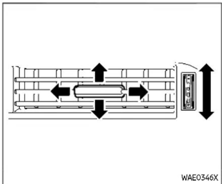
Rightside

Rightside
CENTER VENTILATORS
Open/close the ventilators by moving the control to either direction.
Adjust the air flow direction of the ventilators by moving the center knob (up/down, left/right) until the desired position is achieved.
SIDE VENTILATORS
Open/close the ventilators by moving the control to either direction.
Adjust the air flow direction of the ventilators by moving the center knob (up/down, left/right) until the desired position is achieved.
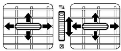
JVH0940X
REAR VENTILATORS
Open/close the ventilators by moving the control to either direction.
≡: This symbol indicates that the ventilators are open. Moving the side control to this direction will open the ventilators.
☒: This symbol indicates that the ventilators are closed. Moving the side control to this direction will close the ventilators.
Adjust the air flow direction of the ventilators by moving the center knob (up/down, left/right) until the desired position is achieved.
HEATERANDAIRCONDITIONER

WARNING
•Theheaterandairconditioner operateonlywhentheengineis running.
●Neverleavechildrenoradults whowouldnormallyrequirethe supportofothersaloneinthe vehicle.Petsshouldnotbeleft aloneeither.Theycouldunknowinglyactivateswitchesorcontrolsandinadvertentlybecome involvedinaseriousaccident andinjurethemselves.Onhot, sunnydays,temperaturesina closedvehiclecouldquicklybecomehighenoughtocausesevereorpossiblyfatalinjuriesto peopleoranimals.
- Donotusethere circulationmode forlongperiodsasitmaycause theinteriorairtobecomestale andthewindowstofogup.
- Donotadjusttheheatingandair conditioningcontrolswhiledrivingsothatfullattentionmaybe giventovehicleoperation.
The heater and air conditioner operate when the engine is running. The air
blower will operate even if the engine is turned off and the ignition switch is placed in the ON position.
NOTE:
- Odorsfrominsideandoutsidethe vehiclecanbuildupintheairconditionerunit.Odorcanenterthepassengercompartmentthroughthe ventilators.
- Whenparking, settheheaterandair conditionercontrolstoturnoffair recirculationtoallowfreshairinto thepassengercompartment. This should help reduce odors insidethe vehicle.

- (fangspeed control) dial
- Dial pointers
- A/C (air conditioner) button
- Air flow control buttons
- Temperature control dial
- (front defroster) button
- (rear window defroster) button (See "Rear window and outside mirror defroster switch" (P.2-57).)
- (air recirculation) button
MANUAL AIR CONDITIONER AND HEATER
Controls
Turningsystemon/off:
To turn on the system, turn the dial out of the OFF position. Turn the dial counterclockwise to the OFF position to turn off the system.
Fanspeedcontrol:
Turn the dial clockwise to increase the fan speed.
Turn the \$ dial counterclockwise to decrease the fan speed.
The dial pointer indicates the fan speed
level.
Temperaturecontrol:
Turn the temperature control dial to set the desired temperature. Turn the dial between the middle and the right position to select the hot temperature. Turn the dial between the middle and the left position to select the cool temperature. The dial pointer indicates the temperature level.
Airflowcontrol:
Push one of the air flow control buttons to select the air flow outlets.
- Air flows mainly from center and side ventilators.
- Air flows mainly from center and side ventilators and foot outlets.
Air flows mainly from the foot outlet and partly from the defroster. - Air flows mainly from the defroster and foot outlets.
Airintakecontrol:
The air intake control mode will change each time the button is pushed.
- When the indicator light is turned on, the air recirculates inside the vehicle.
- When the indicator light is turned off, the air flow is drawn from outside the vehicle.
Monitor, heater, airconditioner, audioandphonesystems4-27
A/C(AirConditioner)operation:
Push the A/C button to turn on or off the air conditioner. When the air conditioner is on, the A/C indicator light on the button illuminates.
MAXA/C(QuickAirConditioning)operation:
To turn on the MAX A/C mode for maximum cooling and dehumidifying, turn the temperature control dial counterclockwise until the dial pointer is at the "MAX A/C" position.
When the MAX A/C mode is turned on, the air flow mode indicator light will turn off with the air flow mode fixed at ω .
At the same time, the indicator light on the A/C button and the air recirculation mode will turn on.
To turn off the MAX A/C mode, turn the temperature control dial clockwise so that the dial pointer is out of the "MAX A/C" position. When the MAX A/C mode is turned off, most of the settings will return to the previous state, while the indicator light on the A/C button will stay on.
Heater operation
Heating:
This mode is used to direct heated air from the foot outlets. Some air also flows from the defroster outlets and the side ventilator outlets.
- Push the 📄 button for normal heating. (The indicator light will turn off.)
- Push the 📋 button. (The indicator light will turn on.)
- Turn the dial to the desired position.
- Turn the temperature control dial to the desired position between the middle and the hot (right) position.
Ventilation:
This mode directs outside air from the side and center ventilators.
- Push the 📄 button. (The indicator light will turn off.)
- Push the 📋 button. (The indicator light will turn on.)
- Turn the \$ dial to the desired position.
- Turn the temperature control dial to the desired position.
Defrostingordefogging:
This mode directs the air to the defroster outlets to defrost/defog the windows.
- Push the 🎨 button. (The indicator light will turn on.)
- Turn the \$ dial to the desired position.
- Turn the temperature control dial to the desired position between the middle and the hot (right) position.
To remove frost from the windshield quickly, turn the temperature control dial to the maximum hot (right) position and the ✿ dial to the maximum position.
When the front defroster mode is selected, the air conditioner automatically turns on if the outside temperature is more than slightly above freezing. This dehumidifies the air which helps defog the windshield. The air recirculation indicator light automatically turns off, allowing outside air to be drawn into the passenger compartment to further improve the defogging performance. The recirculation mode cannot be activated in the front defroster mode.
Bi-levelheating:
The bi-level mode directs warmed air to
the side and center ventilators and to the front and rear floor outlets.
- Push the 📄 button. (The indicator light will turn off.)
- Push the 🎨 button. (The indicator light will turn on.)
- Turn the \\ dial to the desired position.
- Turn the temperature control dial to the desired position.
Heatinganddefogging:
This mode heats the interior and defogs the windows.
- Push the 🎨 button. (The indicator light will turn on.)
-
Turn the dial to the desired position.
-
Turn the temperature control dial to the maximum hot (right) position. When the 🎨 button is pushed, the air conditioner automatically turns on if the outside temperature is more than slightly above freezing. This dehumidifies the air which helps defog the windshield. The air recirculation indicator light automatically turns off, allowing outside air to be drawn into the passenger compartment to further improve the defogging performance.
NOTE:
Clearsnowandicefromthewiper bladesandairinletinfrontofthe windshield. This improves heateroperation.
Air conditioner operation
Start the engine, turn the stial to the desired position, and push the A/C button to activate the air conditioner. When the air conditioner is on, cooling and dehumidifying functions are added to the heater operation. The air conditioner cooling function operates only when the engine is running.
Cooling:
This mode is used to cool and dehumidify the air.
- Push the 📋 button. (The indicator light will turn on.)
- Turn the \\ dial to the desired position.
- Push the A/C button. (The indicator light will turn on.)
- Turn the temperature control dial to the desired position between the middle and the cool (left) position.
For quick cooling, turn on the MAX A/C mode by turning the temperature control dial until the dial pointer is at the "MAX A/C" position. When the MAX A/C mode is
turned on, it will activate the air recirculation mode. The amount of air coming through the ventilators is the highest it can go when in MAX A/C mode regardless of the position of the dial.
Dehumidifiedheating:
This mode is used to heat and dehumidify the air.
- Push the 📄 button. (The indicator light will turn off.)
- Push the 🎨 button. (The indicator light will turn on.)
- Turn the sp dial to the desired position.
- Push the A/C button on. (The indicator light will turn on.)
- Turn the temperature control dial to the desired position between the middle and the hot (right) position.
Dehumidifieddefogging:
This mode is used to defog the windows and dehumidify the air.
- Push the 🎨 button. (The indicator light will turn on.)
-
Turn the dial to the desired position.
-
Turn the temperature control dial to the desired position.
When the 🎨 or 🎩 mode is selected, the
air conditioner automatically turns on if the outside temperature is more than slightly above freezing. This dehumidifies the air which helps defog the windshield. The air recirculation mode automatically turns off, allowing outside air to be drawn into the passenger compartment to further improve the defogging performance.
The air conditioner is always turned on in the 🎨 or 🌘 mode, regardless of whether the indicator light is on or off.
theairconditioneroff.(See "If your vehicleoverheats"(P.6-14).)
NOTE:
•Theairconditionersystemshould beoperatedforapproximately10 minutesatleastonceamonth. This helpspreventdamagetotheair conditionersystemduetothelack oflubrication.
- Avisiblemistmaybeseencoming fromtheventilatorsinhot,humid conditionsastheairiscooledrapidly.Thisdoesnotindicateamal-function.
- If the engine coolant temperature be comestoo high, the air recirculation mod will be activated and the indicator light will turn on automatically.
- If the engine coolant temperature gauge indicates engine coolant temperature over then normal range, turn
4-30 Monitor, heater, airconditioner, audioandphonesystems
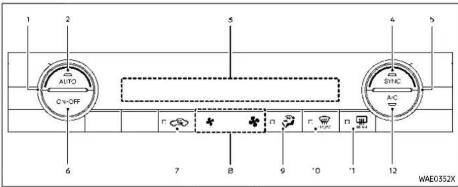
Modelswithheatedsteeringwheel

Modelswithoutheatedsteeringwheel
-
Temperature control dial (driver's side)
-
AUTO (automatic) button
-
Display screen
-
SYNC (synchronize) button
-
Temperature control dial (passenger's side)
-
ON-OFF button
-
(air recirculation) button
-
(fan speed control) buttons
-
(air flow control) button
-
(front defroster) button
-
(rear window defroster) button (See "Rear window and outside mirror defroster switch" (P.2-57).)
-
A/C (air conditioner) button
AUTOMATIC AIR CONDITIONER (models without rear control)
Automatic operation
Cooling and/or dehumidified heating (AUTO):
This mode may be used all year round as the system automatically works to keep a constant temperature. Air flow distribution and fan speed are also controlled automatically.
-
Push the AUTO button on. (The indicator light on the button will illuminate.)
-
Turn the temperature control dial on the corresponding side to set the desired temperature.
- You can individually set temperatures for the driver's side and front passenger's side when the indicator light on the SYNC button is not illuminated.
A visible mist may be seen coming from the ventilators in hot, humid conditions as the air is cooled rapidly. This does not indicate a malfunction.
Heating(A/COFF):
The air conditioner does not activate in this mode. Use this mode when you only need to heat.
- Push the AUTO button on. (The indicator light on the button will illuminate.)
- Push the A/C button. (The indicator light will turn off.)
- Turn the temperature control dial on the corresponding side to set the desired temperature.
- You can individually set temperatures for the driver's side and front passenger's side when the indicator light on the SYNC button is not illuminated.
- The temperature of the passenger compartment will be maintained automatically. Air flow distribution and fan speed are also controlled automatically.
NOTE:
- Donotsetthetemperaturelower thantheoutsideairtemperatureor thesystemmaynotworkproperly.
- Notrecommendedifwindowsfog up.
Dehumidifieddefrostingordefogging:
- Push the 🎨 button. (The indicator light on the button will turn on.)
- Turn the temperature control dial on the corresponding side to set the desired temperature.
- To quickly remove ice from the outside of the windows, use the \$5 button to set the fan speed to maximum.
- As soon as possible after the windshield is clean, push the AUTO button to return to the automatic mode.
- When the button is pushed, the air conditioner will automatically be turned on at outside temperatures more than slightly above freezing. The air recirculation mode automatically turns off, allowing outside
air to be drawn into the passenger compartment to further improve the defogging performance.
Manual operation
Fanspeedcontrol:
Push the 🎨 buttons to manually control the fan speed.
Airintakecontrol:
The air intake control mode will change each time the button is pushed.
- When the indicator light is turned on, the air recirculates inside the vehicle.
- When the indicator light is turned off, the air flow is drawn from outside the vehicle.
- To switch to automatic control mode, push and hold the 📋 button for about 2 seconds. The indicator light will blink, and then the air intake will be controlled automatically.
Airflowcontrol:
Pushing the 📋 button manually controls air flow and selects the air outlet:
4-32 Monitor, heater, airconditioner, audioandphonesystems
- Air flows mainly from center and side ventilators.
Air flows mainly from center and side ventilators and foot outlets.
— Air flows mainly from the foot outlet and partly from the defroster. - Air flows mainly from the defroster and foot outlets.
Synchronizetemperaturesettings:
Push the SYNC button to turn on the SYNC mode. (The indicator light on the button will turn on.)
When the SYNC mode is active, the driver's side temperature control dial will control the driver's and front passenger's side temperatures.
To exit the SYNC mode, change the passenger's side temperature using the temperature control dial on the front passenger's side. (The indicator light on the SYNC button will turn off.)
To turn the system off
Push the ON-OFF button.
Remote engine start logic (if so equipped)
When the remote engine start function is activated, the vehicles equipped with the automatic air conditioner and heater may go into automatic heating or cooling mode depending on the outside and cabin temperatures. During this period, the display and the buttons will be inoperable until the ignition switch is placed in the ON position. When the temperature is low, the rear defroster and the heated steering wheel (if so equipped) may also be activated automatically with the activation of the remote engine start function. (See "Remote engine start" (P.3-19).)

- Temperature control dial (driver's side)
- AUTO (automatic) button
- (air recirculation) button
- (outside air circulation) button
- Display screen
- SYNC (synchronize) button
- Temperature control dial (passenger's side)
- ON-OFF button
- Rear temperature control buttons
- (fan speed control) buttons
- (air flow control) button
- (front defroster) button
-
(rear window defroster) button (See "Rear window and outside mirror defroster switch" (P.2-57).)
-
A/C (air conditioner) button
AUTOMATIC AIR CONDITIONER (models with rear control)
Automatic operation
Cooling and/or dehumidified heating (AUTO):
This mode may be used all year round as the system automatically works to keep a constant temperature. Air flow distribution and fan speed are also controlled automatically.
-
Push the AUTO button on. (The indicator light on the button will illuminate.)
-
Turn the temperature control dial on the corresponding side to set the desired temperature.
- You can individually set temperatures for the driver's side and front passenger's side when the indicator light on the SYNC button is not illuminated.
A visible mist may be seen coming from the ventilators in hot, humid conditions as the air is cooled rapidly. This does not indicate a malfunction.
Heating(A/COFF):
The air conditioner does not activate in this mode. Use this mode when you only need to heat.
- Push the AUTO button on. (The indicator light on the button will illuminate.)
- Push the A/C button. (The indicator light will turn off.)
- Turn the temperature control dial on the corresponding side to set the desired temperature.
- You can individually set temperatures for the driver's side and front passenger's side when the indicator light on the SYNC button is not illuminated.
4-34 Monitor, heater, airconditioner, audioandphonesystems
- The temperature of the passenger compartment will be maintained automatically. Air flow distribution and fan speed are also controlled automatically.
NOTE:
- Donotsetthetemperaturelower thantheoutsideairtemperatureor thesystemmaynotworkproperly.
- Notrecommendedifwindowsfog up.
Dehumidifieddefrostingordefogging:
-
Push the 🤘 button. (The indicator light on the button will come on.)
-
Turn the temperature control dial on the corresponding side to set the desired temperature.
-
To quickly remove ice from the outside of the windows, use the 🎨 button to set the fan speed to maximum.
- As soon as possible after the windshield is clean, push the AUTO button to return to the automatic mode.
- When the button is pushed, the air conditioner will automatically be turned on at outside temperatures more than slightly above freezing. The air recirculation mode automatically turns off, allowing outside
air to be drawn into the passenger compartment to further improve the defogging performance.
Manual operation
Fanspeedcontrol:
Push the 🎨 buttons to manually control the fan speed.
Airintakecontrol:
- Push the button to recirculate interior air inside the vehicle. The indicator light on the button will come on.
- Push the 📊 button to draw outside air into the passenger compartment. The indicator light on the button will come on.
- To control the air intake automatically, push and hold either the button or the button. The indicator light will blink, and then the air intake will switch to automatic control. When the automatic control is set, the system automatically alternates between the outside air circulation and the air recirculation modes. (The Indicator light of the active mode will turn on.)
Airflowcontrol:
Pushing the 📋 button manually controls air flow and selects the air outlet:
- Air flows mainly from center and side ventilators.
- Air flows mainly from center and side ventilators and foot outlets.
- Air flows mainly from the foot outlet and partly from the defroster.
- Air flows mainly from the defroster and foot outlets.
Synchronizetemperaturesettings:
Push the SYNC button to turn on the SYNC mode. (The indicator light on the button will turn on.)
When the SYNC mode is active, the driver's side temperature control dial will control the driver's side, front passenger's side and rear temperatures.
When the passenger's side temperature control dial or the rear temperature control buttons are operated, it will cancel the SYNC mode of the individual zone. (The indicator light on the SYNC button will remain on.)
Operating both the passenger's side temperature control dial and the rear temperature control buttons will turn off the SYNC mode. (The indicator light on the SYNC button will turn off.) (See "Rear temperature control" (P.4-36).)
To turn the system off Push the ON·OFF button.

- Rear temperature display
- " ^ " Rear temperature increase button
- " √ " Rear temperature decrease button
Rear temperature control (if so equipped)
You can adjust the temperature for rear seat passengers using the buttons located on the back side of the console b
Remote engine start logic
When the remote engine start function is activated, the vehicles equipped with the automatic air conditioner and heater may go into automatic heating or cooling mode depending on the outside and cabin temperatures. During this period,
the display and the buttons will be inoperable until the ignition switch is placed in the ON position. When the temperature is low, the rear defroster and the heated steering wheel (if so equipped) may also be activated automatically with the activation of the remote engine start function. (See "Remote engine start" (P.3-19).)
OPERATING TIPS (for automatic air conditioner)
When the engine coolant temperature and outside air temperature are low, the air flow from the foot outlets may be limited when in the automatic mode. However, this is not a malfunction. After the coolant temperature warms up, air flow from the foot outlets will operate normally.
Forreartemperaturecontrol(ifso equipped):
- The purpose of the rear temperature control is to vary the temperature of the rear airflow.
- The amount of airflow to the rear ventilators is primarily controlled by the front passenger's blower and mode settings.
- The amount of airflow to the rear ventilators is also affected by the rear temperature setting. Higher rear tem-
perature settings have lower airflow amounts than cooler temperature settings. This condition ensures better comfort to the head and face area, while primary heating for the rear passenger seats is provided through the foot outlets.


Sensors:
The sensors ① and ② located on the instrument panel, help maintain a constant temperature. Do not put anything on or around the sensors.
SERVICING AIR CONDITIONER

WARNING
The air conditionersystem contains refrigerant under high pressure. To avoid personal injury, any air conditionerservices should be done only by an experienced technician with the properequipment.
The air conditioner system in your vehicle is charged with a refrigerant designed with the environment in mind.
Thisrefrigerantwillnotharmthe earth'sozonelayer.However, it may contribute in a small part to global warming.
Special charging equipment and lubricant are required when servicing your vehicle's air conditioner. Using improper refrigerants or lubricants will cause severe damage to the air conditioner system. (See "Air conditioning system refrigerant and lubricant recommendations" (P.10-8).)
ANTENNA
A NISSAN dealer will be able to service your environmentally friendly air conditioner system.
In-cabin microfilter
The air conditioner system is equipped with an in-cabin microfilter. To make sure the air conditioner heats, defogs, and ventilates efficiently, replace the filter according to the specified maintenance intervals listed in the "9. Maintenance and schedules" section. It is recommended to visit a NISSAN dealer to replace the filter.
The filter should be replaced if the air flow decreases significantly or if windows fog up easily when operating the heater or air conditioner.
SHARK FIN ANTENNA
The shark fin antenna is located on the rear part of the vehicle roof.
The radio performance may be affected if cargo carried on the roof blocks the radio signal. If possible, do not put cargo near the shark fin antenna.
A build up of ice on the shark fin antenna can affect radio performance. Remove the ice to restore radio reception.
CARPHONEORCBRADIO
When installing a car phone or a CB radio in your vehicle, be sure to observe the following precautions, otherwise the new equipment may adversely affect the electronic control modules and electronic control system harness.

WARNING
- Acellularphoneshouldnotbe usedforanypurposewhiledrivingsofullattentionmaybegiven tovehicleoperation.Somejurisdictionsprohibittheuseofcellularphoneswhiledriving.
- If you must make a call while your vehicle is in motion, the hands-free cellular phone operational mode (if so equipped) is highly recommended. Exercise extreme caution at all times of full attention may begin to vehicle operation.
- Ifaconversationinamoving vehiclerequiresyoutotake notes,pullofftheroadtoasafe locationandstopyourvehicle beforedoingso.

CAUTION
- Keeptheantennaasfarawayas possiblefromtheeelectroniccontrolmodules.
- Keeptheantennawiremorethan 8in(20cm)awayfrom the electroniccontrolsystemharness.Donotroutetheantenna wirenexttoanyharness.
- Adjust the antennastanding-waveratioas recommended by themanufacturer.
- Connectthegroundwirefromthe CBradiochassistothebody.
•Fordetails,itisrecommended youvisitaNISSANdealer.
MEMO
4-40 Monitor, heater, airconditioner, audioandphonesystems
5Startinganddriving
Precautionswhenstartinganddriving....5-5
Exhaustgas(carbonmonoxide)....5-5
Three-waycatalyst....5-6
Turbochargersystem(ifsoequipped)....5-6
TirePressureMonitoringSystem(TPMS)......5-6
Avoidingcollisionandrollover....5-10
On-pavementandoff-road
drivingprecautions....5-10
Off-roadrecovery....5-11
Rapidairpressureloss....5-11
Drinkingalcohol/drugsanddriving....5-12
Drivingsafetyprecautions....5-12
Push-buttonignitionswitch....5-14
Operatingrangeforenginestartfunction.....5-15
Push-buttonignitionswitchoperation....5-15
Push-buttonignitionswitchpositions....5-16
Emergencyengineshutoff....5-16
IntelligentKeybatterydischarge....5-17
Beforestartingtheengine....5-17
Startingtheengine....5-18
Remoteenginestart(ifsoequipped)....5-18
Drivingthevehicle....5-19
ContinuouslyVariable
Transmission(CVT) 5-19
Parkingbrake 5-25
Automaticoperation....5-26
Manualoperation....5-27
Automaticbrakehold 5-28
Howtoactivate/deactivatetheautomatic
brakeholdfunction....5-29
Howtousetheautomaticbrake
holdfunction....5-30
DriveModeSelector 5-31
OFF-ROADmode(AWDmodels)....5-32
SNOWmode(AWDmodels) 5-32
STANDARDmode(2WDmodels)/AUTO
mode(AWDmodels)....5-32
ECOmode 5-32
SPORTmode 5-34
DriverAssistancesystems....5-35
Howtoenable/disablethesystems....5-38
Commontroubleshootingguide....5-40
TrafficSignRecognition(TSR)(if
soequipped)....5-44
Systemoperation....5-44
Howtoenable/disabletheTSRsystem.....5-46
Systemtemporarilyunavailable....5-46
Systemmalfunction....5-46
Systemmaintenance....5-47

LaneDepartureWarning(LDW)....5-47
LDWsystemoperation....5-48
Howtoenable/disabletheLDWsystem......5-49
LDWsystemlimitations....5-49
Systemtemporarilyunavailable....5-50
Systemmalfunction....5-51
Systemmaintenance....5-51
IntelligentLaneIntervention(I-LI)(if
soequipped)....5-52
I-Llsystemoperation....5-53
Howtoenable/disablethel-LIsystem....5-54
I-Llsystemlimitations....5-54
Systemtemporarilyunavailable....5-56
Systemmalfunction....5-56
Systemmaintenance....5-57
BlindSpotWarning(BSW)....5-58
BSWsystemoperation....5-59
Howtoenable/disabletheBSWsystem.....5-60
BSWsystemlimitations....5-60
BSWdrivingsituations....5-61
Systemtemporarilyunavailable....5-64
Systemmalfunction....5-64
Systemmaintenance....5-65
IntelligentBlindSpotIntervention(I-BSI)(if
soequipped)....5-66
I-BSIsystemoperation....5-67
Howtoenable/disablethel-BSIsystem.....5-69
I-BSIsystemlimitations....5-69
I-BSIdrivingsituations....5-71
Systemtemporarilyunavailable....5-75
Systemmalfunction....5-75
Systemmaintenance....5-76
RearCrossTrafficAlert(RCTA)....5-77
RCTAsystemoperation....5-77
Howtoenable/disabletheRCTAsystem.....5-79
RCTAsystemlimitations....5-80
Systemtemporarilyunavailable....5-82
Systemmalfunction....5-82
Systemmaintenance....5-82
Cruisecontrol(ifsoequipped)....5-83
Precautionsoncruisecontrol....5-84
Cruise control operations....5-84
ProPILOTAssist(ifsoequipped)....5-85
ProPILOTAssistsystemoperation....5-87
ProPILOTAssistswitches....5-89
ProPILOTAssistsystemdisplay
andindicators....5-90
Turningtheconventional(fixedspeed)
cruisecontrolmodeON....5-92
OperatingProPILOTAssist....5-92
SteeringAssist 5-113
Conventional(fixedspeed)cruise
controlmode....5-119
AutomaticEmergencyBraking(AEB)with
PedestrianDetectionsystem....5-122
AEBwithPedestrianDetection
systemoperation....5-123
TurningtheAEBwithPedestrianDetection
systemON/OFF 5-125
AEBwithPedestrianDetection
systemlimitations....5-125
Systemtemporarilyunavailable....5-129
Systemmalfunction 5-130
Systemmaintenance....5-131
IntelligentForwardCollision
Warning(I-FCW)....5-132
I-FCWsystemoperation....5-134
Turningthel-FCWsystemON/OFF....5-135
I-FCWsystemlimitations....5-137
Systemtemporarilyunavailable....5-138
Systemmalfunction....5-139
Systemmaintenance....5-139
IntelligentDriverAlertness(I-DA)....5-141
I-DAsystemoperation....5-141
Howtoenable/disablethel-DAsystem.....5-142
I-DAsystemlimitations....5-142
Systemmalfunction....5-143
RearAutomaticBraking(RAB)....5-143
RABsystemoperation....5-145
TurningtheRABsystemON/OFF....5-145
RABsystemlimitations....5-146
Systemmalfunction....5-148
Systemmaintenance....5-148
Break-inschedule 5-149
FuelEfficientDrivingTips....5-149
Increasingfueleconomy....5-150
Intelligent4x4(ifsoequipped)....5-151
Parking/parkingonhills....5-153
Electricpowersteering....5-154
Brakesystem....5-155
Brakingprecautions....5-155
Brakeassist....5-156
Brakeassist....5-156
Anti-lockBrakingSystem(ABS)....5-156
VehicleDynamicControl(VDC)system....5-157
Systemoperation....5-163
Systemoperation....5-168
Howtoenable/disabletheRSS....5-170
RSSlimitations....5-170
Systemtemporarilyunavailable....5-171
Systemmaintenance....5-172
Coldweatherdriving....5-172
Freeingafrozendoorlock....5-172
Anti-freeze....5-172
Battery....5-172
Drainingofcoolantwater....5-172
Tireequipment....5-173
Specialwinterequipment....5-173
Drivingonsnoworice....5-173
Activenoisecancellation(ifsoequipped)/
Activesoundenhancement(if
soequipped)....5-174
Activenoisecancellation....5-174
Activesoundenhancement....5-174
PRECAUTIONSWHENSTARTING ANDDRIVING

WARNING
- Donotleavechildrenoradults whowouldnormallyrequirethe supportofothersaloneinyour vehicle.Petsshouldnotbeleft aloneeither.Theycouldaccidentallyinjurethemselvesorothers throughinadvertentoperation of thevehicle.Also,onhot,sunny days,temperaturesinaclosed vehiclecouldquicklybecome highenoughtocausesevereor possiblyfatalinjuriestopeopleor animals.
•Properlysecureallcargowith ropesorstrapstohelppreventit fromslidingorshifting.Donot placecargohigherthantheseat-backs.Inasuddenstoporcollision,unsecured cargo could causepersonalinjury.
EXHAUST GAS (carbon monoxide)

WARNING
- Donotbreatheexhaustgas; it contains colorless and odorless carbon monoxide. Carbon mon-
oxideisdangerous.Itcancause unconsciousnessordeath.
- Ifyoususpectthatexhaustfumes areenteringthevehicle,drive withallwindowsfullyopen,and havethevehicleinspectedimmediately.
- Donotruntheengineinclosed spacesuchasagarage.
- Donotparkthevehiclewiththe engineerunningforanextended periodoftime.
- Keeptheliftgateclosedwhile driving,otherwiseexhaustgas could bedrawnintothepassengercompartment. If you must drivewith the lift gate open, follow these precautions: - Open all the windows.
—Turn the air recirculation modeoff and set the fan speed control to the highest level to circulatetheair.
- Ifaspecialbodyorotherequipmentisaddedforrecreationalorotherusage,followthemanufacturer'srecommendationtopreventcarbonmonoxideentryintothevehicle.(Somerecreationalvehicleappliancesuchasstoves,
refrigerators,heaters,etc.may alsogeneratecarbonmonoxide.)
- Ifelectricalwiringorothercable connectionsmustpasstoatrailer throughthesealontheliftgateor thebody,followthemanufac-turer'srecommendationtopre-ventcarbonmonoxideentryinto thevehicle.
•Theexhaustsystemandbody shouldbeinspectedbyaqualifiedmechanicwhenever:
—Yourvehicleisraisedwhile beingserviced.
—You suspect that exhaust fumes are entering into the passenger compartment.
—Younoticeachangeinthe soundoftheexhaustsystem.
—Youhavehadanaccident involvingdamagetotheex-haustsystem,underbody,or rearofthevehicle.
THREE-WAY CATALYST
The three-way catalyst is an emission control device installed in the exhaust system. Exhaust gases in the three-way catalyst are burned at high temperatures to help reduce pollutants.

WARNING
•Theexhaustgasandtheexhaust systemareveryhot.Keeppeople, animalsandflammablematerials awayfromtheexhaustsystem components.
- Donotstoporparkthevehicle overflammablematerialssuchas drygrass,wastepaperorrags. Theymayigniteandcauseafire.

CAUTION
- Donotuseleadedgasoline.Depositsfromleadedgasolinewill seriouslyreducethethree-way catalyst'sabilitytohelpreduce exhaustpollutants.
- Keepyourenginetunedup.Malfunctionsintheignition,fuelinjection,orelectricalsystemscan
causeoverrichfuelflowintothe three-waycatalyst,causingitto overheat.Donotkeepdrivingif theenginemisfires,orifnotice- ablelossofperformanceorother unusualoperatingconditionsare detected.Havethevehicleins-pected.Itisrecommendedyou visitaNISSANdealerforthis service.
- Avoiddrivingwithanextremely lowfuellevel.Runningoutoffuel couldcausetheenginetomisfire, damagingthethree-waycatalyst.
- Donotracetheenginewhile warmingitup.
- Donotpushortowyourvehicle tostarttheengine.
TURBOCHARGER SYSTEM (if so equipped)
The turbocharger system uses engine oil for lubrication and cooling of its rotating components. The turbocharger turbine turns at extremely high speeds and it can reach an extremely high temperature. It is essential to maintain a clean supply of oil flowing through the turbocharger system. A sudden interruption of oil supply may cause a malfunction in the turbocharger.
To ensure prolonged life and performance of the turbocharger, it is essential to comply with the following maintenance procedure.

CAUTION
- Changeyourengineoilaccording totherecommendedintervals showninthe"Maintenanceand schedules"(P.9-1).
- Useonlytherecommendedengineoil.(See"Capacitiesandrecommendedfluids/lubricants"(P.10-3).)
- If the engine has been operating at high rpm for an extended period of time, let it idle for a few minutes prior to turn off.
- Donotaccelerateyourengineto highrpmimmediatelyafterstartingit.
TIRE PRESSURE MONITORING SYSTEM (TPMS)
Each tire, including the spare, should be checked monthly when cold and inflated to the inflation pressure recommended by the vehicle manufacturer on the vehicle placard or tire inflation pressure
label. (If your vehicle has tires of a different size than the size indicated on the vehicle placard or tire inflation pressure label, you should determine the proper tire inflation pressure for those tires.)
As an added safety feature, your vehicle has been equipped with a Tire Pressure Monitoring System (TPMS) that illuminates a low tire pressure telltale when one or more of your tires is significantly under-inflated. Accordingly, when the low tire pressure telltale illuminates, you should stop and check your tires as soon as possible, and inflate them to the proper pressure. Driving on a significantly under-inflated tire causes the tire to overheat and can lead to tire failure. Under-inflation also reduces fuel efficiency and tire tread life, and may affect the vehicle's handling and stopping ability.
Please note that the TPMS is not a substitute for proper tire maintenance, and it is the driver's responsibility to maintain correct tire pressure, even if under-inflation has not reached the level to trigger illumination of the TPMS low tire pressure telltale.
Your vehicle has also been equipped with a TPMS malfunction indicator to indicate when the system is not operating properly. The TPMS malfunction indicator is combined with the low tire pressure tell-tale. When the system detects a malfunction, the telltale will flash for approximately one minute and then remain continuously illuminated. This sequence will continue upon subsequent vehicle start-ups as long as the malfunction exists. When the malfunction indicator is illuminated, the system may not be able to detect or signal low tire pressure as intended. TPMS malfunctions may occur for a variety of reasons, including the installation of replacement or alternate tires or wheels on the vehicle that prevent the TPMS from functioning properly. Always check the TPMS malfunction telltale after replacing one or more tires or wheels on your vehicle to ensure that the replacement or alternate tires and wheels allow the TPMS to continue to function properly.
Additional information
- Since the spare tire is not equipped with the TPMS, the TPMS does not monitor the tire pressure of the spare tire.
- The TPMS will activate only when the vehicle is driven at speeds above 16 MPH (25 km/h). Also, this system may not detect a sudden drop in tire pressure (for example a flat tire while
driving).
●The low tire pressure warning light does not automatically turn off when the tire pressure is adjusted. After the tire is inflated to the recommended pressure, the vehicle must be driven at speeds above 16 MPH (25 km/h) to activate the TPMS and turn off the low tire pressure warning light. Use a tire pressure gauge to check the tire pressure.
- The "Tire Pressure Low - Add Air" warning appears in the vehicle information display when the low tire pressure warning light is illuminated and low tire pressure is detected. The "Tire Pressure Low - Add Air" warning turns off when the low tire pressure warning light turns off.
The "Tire Pressure Low - Add Air" warning does not appear if the low tire pressure warning light illuminates to indicate a TPMS malfunction.
●Tire pressure rises and falls depending on the heat caused by the vehicle's operation and the outside temperature. Do not reduce the tire pressure after driving because the tire pressure rises after driving. Low outside temperature can lower the temperature of the air inside the tire which can cause a lower tire inflation pressure.
Startinganddriving5-7
This may cause the low tire pressure warning light to illuminate. If the warning light illuminates in low ambient temperature, check the tire pressure for all four tires.
- You can also check the tire pressure of all tires (except the spare tire) in the vehicle information display. (See "Trip computer" (P.2-46).)
For additional information, see "Low tire pressure warning light" (P.2-18) and "Tire Pressure Monitoring System (TPMS)" (P.6-3).

WARNING
- Ifthelowtirepressurewarning lightilluminateswhiledriving, avoidsuddensteeringmaneu-versorabruptbraking,reduce vehiclespeed,pullofftheroad toasafelocationandstopthe vehicleassoonaspossible.Drivingwithunder-inflatedtiresmay permanentlydamagethetires andincreasethelikelihoodoftire failure.Seriousvehicledamage couldoccurandmayleadtoan accidentandcouldresultinseriouspersonalinjury.Checkthe tirepressureforallfourtires. Adjustthetirepressuretothe
5-8 Startinganddriving
recommendedCOLDtirepressure shownontheTireandLoading Informationlabeltoturnthelow tirepressurewarninglightOFF.If youhaveaflattire,replaceitwith asparetireassoonaspossible. (See"Flattire"(P.6-3)forchangingaflattire.)
- Since the spare tire is not equipped with the TPMS, when a spare tire is mounted or a raw wheel is replaced, the TPMS will not function and the low tire pressure warning light will flash for approximately 1 minute. The light will remain on after 1 minute. Have your tires replaced and/or TPMS system reset as soon as possible. It is recommended you visit a NISSAN dealer for these services.
- Replacingtireswiththosenot originallyspecifiedbyNISSAN couldaffecttheproperoperation oftheTPMS.
- Donotinjectanytireliquidor aerosoltiresealantintothetires, asthismaycauseamalfunction ofthetirepressuresensors.

CAUTION
- The TPMS may not function properly when the wheels are equipped with tire chains or the wheels are buried in snow.
- Donotplacemetalizedfilmor anymetalparts(antenna,etc.)on thewindows. This may cause poor reception of the signals from the tire pressures sensors, and the TPMS will not function properly.
Some devices and transmitters may temporarily interfere with the operation of the TPMS and cause the low tire pressure warning light to illuminate. Some examples are:
●Facilities or electric devices using similar radio frequencies are near the vehicle.
- If a transmitter set to similar frequencies is being used in or near the vehicle.
- If a computer (or similar equipment) or a DC/AC converter is being used in or near the vehicle.
Low tire pressure warning light may illuminate in the following cases.
- If the vehicle is equipped with a wheel and tire without TPMS.
- If the TPMS has been replaced and the ID has not been registered.
- If the wheel is not originally specified by NISSAN.
FCCNotice:
ForUSA:
TirePressureMonitoringSystem(TPMS) transmitter
FCCID:KR5TIS-10DL
BodyControlModule(BCM)

40406556
Continental
ThisdevicecomplieswithPart15ofthe FCCRules.Operationissubjecttothe followingtwoconditions:(1)Thisdevice maynotcauseharmfulinterference, and(2)thisdevicemustacceptany interferencereceived,includinginterferencethatmaycauseundesiredoperation.
Note: Changesormodificationsnot expresslyapprovedbythepartyresponsibleforcompliancecouldvoid theuser'sauthoritytooperatethe equipment.
ForCanada:
TirePressureMonitoringSystem(TPMS) transmitter
Continental
Model:TIS-10DL
IC:7812D-TIS10DL
BodyControlModule(BCM)
Model:40406556
IC:7812D-5235RXDP
Continental
ThisdevicecomplieswithIndustryCanadalicense-exemptRSSstandard(s). Operationissubjecttothefollowing twoconditions:(1)thisdevicemaynot causeinterference,and(2)thisdevice mustacceptanyinterference,including interferencethatmaycauseundesired operationofthedevice.
TPMS with Easy Fill Tire Alert

WARNING
Afterrotatingthetires, donotuse the Easy-Fill Tire Alert to adjust the tire pressure. Instead use a gaugeto adjust the tire to the correct pressure in accordance with Tire and Loading Information label.
When adding air to an under-inflated tire,
the TPMS with Easy Fill Tire Alert provides visual and audible signals outside the vehicle to help you inflate the tires to the recommended COLD tire pressure.
Vehicleset-up:
- Park the vehicle in a safe and level place.
- Apply the parking brake and push the park button to shift to the P (Park) position.
- Place the ignition switch in the ON position. Do not start the engine.
Operation:
- Add air to the tire.
- After a few seconds, the hazard indicators will start flashing.
- When the designated pressure is reached, the horn beeps once and the hazard indicators stop flashing.
- Perform the above steps for each tire.
- If the tire is over-inflated more than approximately 4 psi (30 kPa), the horn beeps and the hazard indicators flash 3 times. To correct the pressure, push the core of the valve stem on the tire briefly to release pressure. When the pressure reaches the designated pressure, the horn beeps once.
- If the hazard indicator does not flash within approximately 15 seconds after starting to inflate the tire, it indicates that the TPMS with Easy Fill Tire Alert is not operating.
- The TPMS will not activate the Easy Fill Tire Alert under the following conditions:
- If there is interference from an external device or transmitter
— The air pressure from the inflation device such as those using a power socket is not sufficient to inflate the tire
- If an electrical equipment is being used in or near the vehicle
— There is a malfunction in the TPMS system
— There is a malfunction in the horn or hazard indicators
- If the TPMS with Easy Fill Tire Alert does not operate due to TPMS interference, move the vehicle about 3 ft (1m) backward or forward and try again.
If the TPMS with Easy Fill Tire Alert is not working, use a tire pressure gauge.
AVOIDING COLLISION AND ROLL-OVER

WARNING
Failuretooperatethisvehicleina safeandprudentmannermayresult inlossofcontroloranaccident.
Be alert and drive defensively at all times. Obey all traffic regulations. Avoid excessive speed, high speed cornering, or sudden steering maneuvers, because these driving practices could cause you to lose control of your vehicle. Aswith anyvehicle, alossofcontrol could resultinacollisionwithothervehicles orobjects, orcausethevehicletorollover, particularlyifthelossofcontrol causes the vehicletoslidesideways. Be attentive at all times, and avoid driving when tired. Never drive when under the influence of alcohol or drugs (including prescription or over-the-counter drugs which may cause drowsiness). Always wear your seat belt as outlined in "Seat belts" (P.1-14) of this manual, and also instruct your passengers to do so. Seat belts help reduce the risk of injury in collisions and rollovers. Inarollover crash, an unbeltedorimproperlybelted
personissignificantlymorelikelytobe injuredorkilledthanapersonproperly wearingaseatbelt.
ON-PAVEMENT AND OFF-ROAD DRIVING PRECAUTIONS
Utilityvehicleshaveasignificantlyhigh-errolloverratethanothertypesof vehicles.
They have higher ground clearance than passenger cars to make them capable of performing in a variety of on-pavement and off-road applications. This gives them a higher center of gravity than ordinary cars. An advantage of higher ground clearance is a better view of the road, allowing you to anticipate problems. However, they are not designed for cornering at the same speeds as conventional passenger cars any more than low-slung sports cars are designed to perform satisfactorily under off-road conditions. If at all possible, avoid sharp turns or abrupt maneuvers, particularly at high speeds. As with other vehicles of this type, failure to operate this vehicle correctly may result in loss of control or vehicle rollover. Seat belts help reduce the risk of injury in collisions and rollovers. In a rollover crash, an unbelted or improperly belted person is significantly more likely to be injured or killed than a person properly wearing a seat belt.
Be sure to read "Driving safety precautions" (P.5-12).
OFF-ROAD RECOVERY
If the right side or left side wheels leave the road surface, maintain control of the vehicle by following the procedure below. Please note that this procedure is only a general guide. The vehicle must be driven as appropriate based on the conditions of the vehicle, road and traffic.
- Remain calm and do not overreact.
- Do not apply the brakes.
- Maintain a firm grip on the steering wheel with both hands and try to hold a straight course.
- When appropriate, slowly release the accelerator pedal to gradually slow the vehicle.
- If there is nothing in the way, steer the vehicle to follow the road while the vehicle speed is reduced. Do not attempt to drive the vehicle back onto the road surface until vehicle speed is reduced.
- When it is safe to do so, gradually turn the steering wheel until both tires return to the road surface. When all tires are on the road surface, steer the vehicle to stay in the appropriate driving lane.
- If you decide that it is not safe to return the vehicle to the road surface based on vehicle, road or traffic conditions, gradually slow the vehicle to a stop in a safe place off the road.
RAPID AIR PRESSURE LOSS
Rapid air pressure loss or a "blow-out" can occur if the tire is punctured or is damaged due to hitting a curb or pothole. Rapid air pressure loss can also be caused by driving on under-inflated tires.
Rapid air pressure loss can affect the handling and stability of the vehicle, especially at highway speeds.
Help prevent rapid air pressure loss by maintaining the correct air pressure and visually inspect the tires for wear and damage. See "Wheels and tires" (P.8-31) of this manual.
If a tire rapidly loses air pressure or "blows-out" while driving, maintain control of the vehicle by following the procedure below. Please note that this procedure is only a general guide. The vehicle must be driven as appropriate based on the conditions of the vehicle, road and traffic.

WARNING
The following actions can increase the chance of losing control of the vehicle if there is sudden loss of air pressure. Losing control of the vehicle may cause a collision and result in personal injury.
- Thevehiclegenerallymovesor pulls inthedirectionofthe flat tire.
- Donotrapidlyapplythebrakes.
- Donotrapidlyreleasetheacceleratorpedal.
-
Do not rapidly turn the steering wheel.
-
Remain calm and do not overreact.
- Maintain a firm grip on the steering wheel with both hands and try to hold a straight course.
- When appropriate, slowly release the accelerator pedal to gradually slow the vehicle.
-
Gradually steer the vehicle to a safe location off the road and away from traffic if possible.
-
Lightly apply the brake pedal to gradually stop the vehicle.
- Turn on the hazard warning flashers and either contact a roadside emergency service to change the tire or "Changing a flat tire" (P.6-4) of this Owner's Manual.
DRINKING ALCOHOL/DRUGS AND DRIVING

WARNING
Neverdriveundertheinfluence of alcoholordrugs. Alcohol in the bloodstream reduces coordination, delays reaction time and impairs judgement. Driving after drinking alcohol increasestehelikelihood of being involved in an accident injury yourself and others. Additionally, if you are injured in an accident, alcohol can increase these severity of the injury.
NISSAN is committed to safe driving. However, you must choose not to drive under the influence of alcohol. Every year thousands of people are injured or killed in alcohol-related accidents. Although the local laws vary on what is considered to be legally intoxicated, the fact is that
alcohol affects all people differently and most people underestimate the effects of alcohol.
Remember, drinking and driving don't remix! And that is true for drugs, too (over-the-counter, prescription, and illegal drugs). Don't drive if your ability to operate your vehicle is impaired by alcohol, drugs, or some other physical condition.
DRIVING SAFETY PRECAUTIONS
Your vehicle is designed for both normal and off-road use. However, avoid driving in deep water or mud as your vehicle is mainly designed for leisure use, unlike a conventional off-road vehicle.
Remember that Two-Wheel Drive (2WD) models are less capable than All-Wheel Drive (AWD) models for rough road driving and extrication when stuck in deep snow, mud, or the like.
Please observe the following precautions:

WARNING
- Drivecarefullywhenofftheroad andavoiddangerousareas.Every personwhodrivesorridesinthis vehicleshouldbeseatedwith theirseatbeltfastened.Thiswill keepyouandyourpassengersin
positionwhendrivingoverrough terrain.
- Donotdriveacrosssteepslopes. Insteaddriveeitherstraightupor straightdowntheslopes. Off-roadvehiclescantipoversidewaysmuchmoreeasilythanthey canforwardorbackward.
- Manyhillsaretoosteepforany vehicle.Ifyoudriveupthem,you maystall.Ifyoudrivedownthem, youmaynotbeabletocontrol yourspeed.Ifyoudriveacross them,youmayrollover.
- Donotshiftrangeswhiledriving ondownhillgradesasthiscould causelossofcontrolofthevehicle.
- Stayalertwhendrivingtothetop ofahill.Atthetoptherecouldbe adrop-offorotherhazardthat couldcauseanaccident.
- If you're enginestallsory you cannot make it to the top of fast eephill, never attempt to turnaround. Your vehicle could tip or rollover. Always back straight down in R (Reverse) range. Never back down in N (Neutral), using only the brake, asthiscould cause loss of control.
●Heavybrakinggoingdownahill could cause your brakesto over heat and fade, resulting in loss of control and accident. Apply brakes lightly and use a low range to control your speed.
- Unsecuredcargocanbethrown aroundwhendrivingoverrough terrain. Properlysecureallcargo soitwillnotbethrownforward andcauseinjurytoyouoryour passengers.
•Toavoidraisingthecenterof gravityexcessively,donotexceed theratedcapacityoftheroofrack (ifsoequipped)andevenlydistributetheload.Secureheavy loadsinthecargoareaasfar forwardandaslowaspossible. Donotequipthevehiclewithtires largerthanspecifiedinthismanual.Thiscouldcauseyourvehicle torollover.
- Donotgriptheinsideorspokes ofthesteeringwheelwhendrivingoff-road.Thesteeringwheel couldmovesuddenlyandinjure yourhands.Insteaddrivewith yourfingersandthumbsonthe outsideoftherim.
- Beforeoperatingthevehicle,ensurethatthedriverandallpassengershavetheirseatbelts fastened.
●Alwaysdrivewiththefloormats inplaceasthefloormaybecame hot.
- Loweryourspeedwhenencounteringstrongcrosswinds. With a highercenterofgravity, your vehicleismoreaffectedbystrong sidewinds. Slowerspeedsensure bettervehiclecontrol.
- Donotdrivebeyondtheperformancecapabilityofthetires, evenwithAWDengaged.
- For AWDequippedvehicles, do not attempt toraiset wow wheels off the ground and shift the transmission to any drive or reverse position with the engine running. Doings may result in drivetrain damage or unexpected vehicle movement which could result in serious vehicled damage or personal injury.
- DonotattempttotestanAWD equippedvehicleona2-wheel dynamometer(suchasthedynamometers used by some statesforemissionstesting),or
similarequipmentevenifthe othertwowheelsareraisedoff theground.Makesureyouinform testfacilitypersonnelthatyour vehicleisequippedwithAWD beforeitisplacedonadynamometer.Usingthewrongtest equipmentmayresultindrive-traindamageorunexpectedvehicle movementwhich could resultinseriousvehicledamage orpersonalinjury.
- Whenawheelisofftheground duetoanunlevelsurface, donot spinthewheelexcessively (AWD model).
- Accelerating quickly, sharpsteeringmaneuversorsuddenbraking may causelossofcontrol.
- Ifatallpossible, avoidsharp turningmaneuvers, particularly athighspeeds. Your vehicle has a higher center of gravity than a conventional passenger car. The vehicle is not designed for cornering at the same speed as a conventional passenger cars. Failure to operate this vehicle correctly could result in loss of control and/or rollover accident.
PUSH-BUTTONIGNITIONSWITCH
●Alwaysusetiresofthesametype, size,brand,construction(bias, bias-beltedorradial),andtread patternonallfourwheels.Install tractiondevisonthefront wheelswhendrivingonslippery roadsanddrivecarefully.
- Besuretocheckthebrakesimmediatelyafterdrivinginmudor water.See"Brakesystem"(P.5-155)forwetbrakes.
- Avoidparkingyourvehicleon steephills.Ifyougetoutofthe vehicleanditrollsforward,backwardorsideways,youcouldbe injured.
- Whenever you drive off-road throughsand, mudorwaters deepasthewheelhub, more frequent maintenance may be required. Seethemaintenance schedules shown in the "9. Maintenance and schedules" section.
- Spinningthefrontwheelson slipperysurfacesmaycausethe AWDwarningmessagetodisplay andtheAWDsystemtoautomaticallyswitchfromtheAWDmode tothe2WDmode.Thiscould reducetraction.Beespecially carefulwhentowingatraler
(AWDmodels).

WARNING
Donot operate the push-button ignitionswitchwhiledrivingthe vehicle exceptinanemergency.(The enginewillstopwhentheignition switchispushed3consecutivetimes ortheignitionswitchispushed and heldformorethan2seconds.)If the enginestopswhilethevehicle is being driven, this could lead to a crashandserious injury.
Before operating the push-button ignition switch, be sure to push the park button to shift to the P (Park) position.
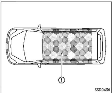
The Intelligent Key can only be used for starting the engine when the Intelligent Key is within the specified operating range ①.
When the Intelligent Key battery is almost discharged or strong radio waves are present near the operating location, the Intelligent Key system's operating range becomes narrower and may not function properly.
If the Intelligent Key is within the operating range, it is possible for anyone, even someone who does not carry the Intelligent Key, to push the ignition switch to
start the engine.
- The cargo room area is not included in the operating range but the Intelligent Key may function.
- If the Intelligent Key is placed on the instrument panel, inside the glove box or door pocket, the Intelligent Key may not function.
- If the Intelligent Key is placed near the door or window outside the vehicle, the Intelligent Key may function.
If the battery of the Intelligent Key is discharged, see "Intelligent Key battery discharge" (P.5-17).
- Donotleavethevehicleforex-tendedperiodsoftimewhenthe ignitionswitchisintheONpositionandtheengineisnotrun- ning. This candischargethe battery.
- Use electrical accessories with the engineer running to avoid discharging the vehicle battery. If you must use accessories while the engine is not running, donot
usethemforextendedperiodsof timeanddonotusemultiple electricalaccessoriesatthesame time.
When the ignition switch is pushed without depressing the brake pedal, the ignition switch will illuminate.
Push the ignition switch center:
- once to change to ON.
- two times to change to OFF.
When the ignition switch cannot be placed in the OFF position, proceed as follows:
- Push the park button to shift to the P (Park) position.
-
Push the ignition switch. The ignition switch position will change to the ON position.
-
Push the ignition switch again to the OFF position.
Theshiftpositioncanbeshiftedfrom theP(Park)positioniftheignition switchisintheONpositionandthe brakepedalisdepressed.
PUSH-BUTTON IGNITION SWITCH POSITIONS
ON (Normal operating position)
The ignition system and the electrical accessory power activate at this position without the engine turned on.
The ON position has a battery saver feature that will place the ignition switch in the OFF position, if the vehicle is not running, after some time under the following conditions:
- all doors are closed.
●vehicle is in P (Park) position.
OFF position
The engine is turned off in this position.
Auto ACC position
With the vehicle in the P (Park) position, the Intelligent Key with you and the ignition placed from ON to OFF, the radio can still be used for a period of time, or until the driver's door is opened. After a period of time, functions such as radio,
navigation (if so equipped), and Bluetooth® Hands-Free Phone System may be restarted by turning on the audio system (see the separate NissanConnect® Owner's Manual), or by pushing the UN-LOCK button on the Intelligent Key for up to a total of 30 minutes.
EMERGENCY ENGINE SHUT OFF
To shut off the engine in an emergency situation while driving or when the Intelligent Key battery is discharged, perform the following procedure:
- Rapidly push the push-button ignition switch 3 consecutive times in less than 1.5 seconds, or
- Push and hold the push-button ignition switch for more than 2 seconds.
After engine shut-off, open the door to return to the normal condition.

INTELLIGENT KEY BATTERY DIS- CHARGE
If the battery of the Intelligent Key is discharged, or environmental conditions interfere with the Intelligent Key operation, start the engine according to the following procedure:
- Push the park button to shift to the P (Park) position.
- Firmly apply the foot brake.
- Touch the ignition switch with the Intelligent Key as illustrated. (A chime will sound.)
- Push the ignition switch while depressing the brake pedal within 10 sec-
onds after the chime sounds. The engine will start.
After step 3 is performed, when the ignition switch is pushed without depressing the brake pedal, the ignition switch position will change to ON.
NOTE:
- Whentheignitionswitchispushed totheONpositionortheengineis startedbytheaboveprocedures,the "KeyBatteryLow"warningappears (onthevehicleinformationdisplay) evenifthelntelligentKeyisinside thevehicle.Thisisnotamalfunction. Toturnoffthewarning,touchthe ignitionswitchwiththeIntelligent Keyagain.
- If the "KeyBatteryLow" warning appears, replacethebatteryassoon as possible. (See "IntelligentKey batteryreplacement"(P.8-25).)
BEFORESTARTINGTHEENGINE
●Make sure the area around the vehicle is clear.
- Check fluid levels such as engine oil, coolant, brake fluid, and window washer fluid as frequently as possible, or at least whenever you refuel.
- Check that all windows and lights are clean.
- Visually inspect tires for their appearance and condition. Also check tires for proper inflation.
- Lock all doors.
- Position seat and adjust head restraints/headrests.
- Adjust inside and outside mirrors.
- Fasten seat belts and ask all passengers to do likewise.
- Check the operation of warning lights when the ignition switch is placed in the ON position. (See "Warning lights, indicator lights and audible reminders" (P.2-13).)
STARTINGTHEENGINE
- Apply the parking brake.
- Confirm that the vehicle is in the P (Park) position.
The Intelligent Key must be carried when operating the ignitions switch.
- Push the ignition switch to the ON position. Depress the brake pedal and push the ignition switch to start the engine.
To start the engine immediately, push and release the ignition switch while depressing the brake pedal with the ignition switch in any position.
- If the engine is very hard to start in extremely cold weather or when restarting, depress the accelerator pedal a little (approximately 1/3 to the floor) and while holding, crank the engine. Release the accelerator pedal when the engine starts.
- If the engine is very hard to start because it is flooded, depress the accelerator pedal all the way to the floor and hold it. Push the ignition switch to the ON position to start cranking the engine. After 5 or 6 seconds, stop cranking by pushing the ignition switch to OFF. After cranking the engine, release the accelerator pedal. Crank the engine withyourfootofftheaccelerator pedalby depressing the brake
5-18 Startinganddriving
pedal and pushing the push-button ignition switch to start the engine. If the engine starts, but fails to run, repeat the above procedure.

CAUTION
Donotoperatethestarterformore than15secondsatatime.Ifthe enginedoesnotstart,pushthe ignitionswitchtoOFFandwait10 secondsbeforecranking again, otherwisethestartercouldbedamaged.
4. Warm-up
Allow the engine to idle for at least 30 seconds after starting. Do not race the engine while warming it up. Drive at moderate speed for a short distance first, especially in cold weather. In cold weather, keep the engine running for a minimum of 2 - 3 minutes before shutting it off. Starting and stopping the engine over a short period of time may make the vehicle more difficult to start.
When the engine is racing with no load and cold, the engine speed is limited to about 4,500 rpm.
- To stop the engine, push the park button to shift to the P (Park) position, and push the ignition switch to the OFF position.
NOTE:
Careshouldbetakentoavoidsituations thatcanleadtopotentialbatterydischargeandpotentialno-startconditionssuchas:
- Installationorextendeduseofelectronicaccessoriesthatconsume batterypowerwhentheengineis notrunning(Phonechargers,GPS, DVDplayers,etc.)
- Vehicleisnotdrivenregularlyand/oronlydrivenshortdistances.
In these cases, the battery may need to be charged to maintain battery health.
REMOTE ENGINE START (if so equipped)
Vehicles started with the remote engine start function require the ignition switch to be placed in the ON position before the shift position can be shifted from the P (Park) position. To place the ignition switch in the ON position, perform the following steps:
- Make sure that the Intelligent Key is carried with you.
DRIVINGTHEVEHICLE
- Depress the brake pedal.
- Push the ignition switch once to the ON position.
For additional information about the remote engine start function, see "Remote engine start" (P.3-19).
CONTINUOUSLY VARIABLE TRANSMISSION (CVT)
The CVT in your vehicle is electronically controlled to produce maximum power and smooth operation.
The recommended operating procedures for this transmission are shown on the following pages. Follow these procedures for maximum vehicle performance and driving enjoyment.
Enginepowermaybeautomatically reducedtoprotecttheCVTiftheengine speedincreasesquicklywhendriving onslipperyroadsorwhilebeingtested onsomedynamometers.

WARNING
-
Donotdepresstheaccelerator pedalwhileshiftingfromP(Park) orN(Neutral)toR(Reverse),D (Drive),orM(Manualshiftmode). Alwaysdepresssthebrakepedal untilshiftingiscompleted.Failure todosocouldcauseyoutolose controlandhaveanaccident.
•Coldengineidlespeedishigh,so usecautionwhenshiftingintoa forwardorreversegearbefore theenginehaswarmedup. -
Donotdownshiftabruptlyon slipperyroads. This may cause a loss of control.
- NevershifttoeithertheP(Park) orR(Reverse)positionwhile the vehicleismovingforwardandP (Park)orD(Drive)positionwhile thevehicleisreversing.Thiscould causeanaccidentordamagethe transmission.
- Exceptinanemergency, donot shift to the N(Neutral) position while driving. Coasting with the transmission in the N(Neutral) position may cause serious damage to the transmission.

CAUTION
- To avoid possible damage to your vehicle, when stopping the vehicle on an uphill grade, donothold the vehicle by depressing the accelerator pedal. The footbrake should be used forth this purpose.
- Donothangitemsontheshift lever. This may cause an accident dueto as sudden start.
Startinganddriving5-19
Starting the vehicle
- After starting the engine, fully depress the foot brake pedal before attempting to place the shift position out of the P (Park) position. ThisCVTis designed so that the foot brake pedalmust be depressed before shifting from P (Park) to any driving position while the ignitions switch is in the ON position. Theshift position cannot be placed out of the P (Park) position and into any of the other positions if the ignitions switch is placed in the OFF position.
- Keep the foot brake pedal depressed and move the shift lever into a driving position.
- Release the parking brake, the foot brake pedal, and then gradually start the vehicle in motion.

CAUTION
-DEPRESSTHEFOOTBRAKEPEDAL -ShiftingtheshiftlevertoD (Drive),R(Reverse)orM(Manual shiftmode)withoutdepressing thefootbrakepedalcausesthe vehicletomoveslowlywhenthe engineisrunning.Makesurethe footbrakepedalisdepressed
5-20 Startinganddriving
fullyandthevehicleisstopped beforeshiftingtheshiftlever.
- MAKESUREOFTHESHIFTLEVER POSITION-Makesuretheshift positionisinthedesiredposition onthevehicleinformationdisplay.D(Drive) andM (Manualshift mode)areusedtomoveforward andR(Reverse)tobackup.
- WARM UP THE ENGINE - Due to the higheridlespeedswhentheengineiscold,extracautionmust beexercisedwhenshiftingthe shiftleverintothedrivingpositionimmediatelyafterstarting theengine.

Ⓐ Home position (central position)
To move the shift lever,
→: Push the button① to shift.
Shift without pushing the button 1
Shifting
Push the park button ② to shift to the P (Park) position.
After starting the engine, fully depress the brake pedal, push the shift lever button and move the shift lever from the P (Park) position ② to any of the desired shift positions.
Confirm that the vehicle is in the desired shift position by checking the shift indicator located on the shift lever or on the
vehicle information display.

WARNING
Apply the electronic parking brake if the shift lever is in any position while the engine is not running. Failure to dos could cause the vehicle to move unexpectedly or roll away and result in serious personal injury or property damage.

CAUTION
- UsetheP(Park),R(Reverse)orD (Drive)positiononlywhenthe vehicleiscompletelystopped.
- Whenswitchingtothedesired shiftpositionbyoperatingthe shiftlever,checkthattheshift leverreturnstothecentralpositionbyreleasingyourhandfrom thelever.Holdingtheshiftleverin amid-waypositionmayalso damagetheshiftcontrolsystem.
- Donotoperatetheshiftlever while the accelerator pedalis depressed. This may cause a sudden start which could result
inanaccident.
- The following operations are not allowed because excessive force would be applied to the transmission and this may result in damage to the vehicle:
—MovingtheshiftlevertotheR (Reverse)positionwhendrivingforward
—MovingtheshiftlevertotheD (Drive)positionwhenreversing
If these operations are attempted, achimesounds and the vehicleshiftstotheN(Neutral)position.
P(Park):

CAUTION
- Topreventtransmissiondamage, usetheP(Park)positiononly whenthevehicleiscompletely stopped.
- Donotslidetheshiftleverwhile pushingtheparkbutton.This maydamagetheshiftcontrol system.
Use this position when the vehicle is parked or starting the engine. Always make sure that the vehicle is completely stopped before pushing the park button to engage the P (Park) position. For maximum safety, the brake pedal must be depressed before engaging the P (Park) position. Use this position together with the electronic parking brake. When parking on a hill, first depress the brake pedal, apply the electronic parking brake and then engage the P (Park) position. The parking lock should not be used as a brake when parking. In order to secure the vehicle, always apply the electronic parking brake in addition to the parking lock.
In the event of a malfunction of the vehicle's electronics, the transmission may lock in the P (Park) position. Have the vehicle's electronics checked immediately. It is recommended that you visit a NISSAN dealer for this service.
The P (Park) position is automatically engaged if:
- You switch off the ignition switch
- You unfasten the driver's seat belt and open the driver side door when the vehicle is stationary or driving at very low speed and the transmission is in the D (Drive) position, the R (Reverse) position or the N position unless the
Startinganddriving5-21
Neutral hold mode is engaged.

CAUTION
ToavoidCVTmalfunction,itisrecommendedthatyoumanually placetheshiftpositionintheP(Park) positionundertheaboveconditions.
R(Reverse):

CAUTION
Topreventtransmissiondamage, usetheR(Reverse)positiononly whenthevehicleiscompletely stopped.
Use the R (Reverse) position to back up. Make sure the vehicle is completely stopped before selecting the R (Reverse) position. Thebrakepedalmustbede-pressedandtheshiftleverbutton pushedtomovetheshiftleverfrom thehomepositiontoR(Reverse).Ifthe vehicleisplacedintheR(Reverse) positionwhilethevehicleismoving forward,thechimewillsoundandthe vehiclewillswitchintotheN(Neutral) position.
N(Neutral):
Neither the forward nor reverse gear is engaged. The engine can be started in this position. You may shift to the N (Neutral) position and restart a stalled engine while the vehicle is moving.
You can select this position by holding the shift lever at this position for 0.5 seconds.
D(Drive):
Use this position for all normal forward driving. The CVT changes gears automatically. All forward gears are available. If the vehicle is placed in the D(Drive) position while the vehicle is reversing, the chimewill sound and the vehicle will switch into the N(Neutral) position.
Neutral hold mode function
This function enables you to turn off the engine with the vehicle in the N (Neutral) position. While this function is activated, the vehicle can be moved by pushing with hand (when car washing) even if the ignition switch is in the OFF position. When using this function, release the electronic parking brake.

WARNING
- Use this function on a level surface only. Failure to do so may cause the vehicle to move accidentally and could result in collision or serious personal injury.
- Donotusethisfunctionfora purposeotherthancarwashing.
- Whentheignitionswitchisplaced intheONpositionafteractivating thisfunction,depressthebrake pedaltostopthevehiclebecause theshiftleverisintheN(Neutral) position.
- If this function is not activated regardless of proper operation, transmission may malfunction. It is recommended that you visit a NISSAN dealer forth this service.
To activate the Neutral hold mode, perform the following operations.
- Push the ignition switch to start the engine.
- Release the electronic parking brake.
- Depress and hold the brake pedal.
5-22 Startinganddriving
- Push the P position switch.
- Slide the shift lever to the N (Neutral) position, and hold it for 0.5 second until "N" appears in the vehicle information display.
- Slide the shift lever to the N (Neutral) position again, and hold it for 0.5 second, until a message "Neutral Hold Mode has been activated" appears in the vehicle information display. (See "66. Neutral Hold Mode activated indicator" (P.2-43).)
- Place the ignition switch in the OFF position. The engine will turn off with holding the N (Neutral) position.
To exit the Neutral hold mode, place the vehicle in other than N (Neutral) position.
NOTE:
- It is necessary to perform the steps 4 through 6 within approximately 5 second stop prevent incorrect operation.
- Whentheignitionswitchisplaced in theOFFpositionwhiletheshiftlever isintheN(Neutral)position, a messagewillappearinthevehicle informationdisplay.(See"65.NeutralHoldModeguidanceindicator" (P.2-43).)
- IftheNeutralholdmodeisunavailable,amessagewillappearinthe
vehicleinformationdisplay.(See"67. NeutralHoldModewasnotactivated indicator"(P.2-43).)Toactivatethe Neutralholdmode, waitforawhile withoutshiftingoperationandthen performtheoperationsagain.

Paddleshifter
Manual shift mode
When the shift lever is moved to the D (Drive) position again with the vehicle in the D (Drive) position while driving, the transmission enters the manual shift mode. Shift range can be selected manually using the paddle shifters on the steering wheel.
When shifting up, pull the right-side paddle shifter (+) Ⓐ The transmission shifts to the higher range.
When shifting down, pull the left-side paddle shifter (-) ® The transmission shifts to the lower range.
When canceling the manual shift mode,
Startinganddriving5-23
move the shift lever to the D (Drive) position again. The transmission returns to the normal driving mode.
When you pull the paddle shifter while in the D (Drive) position, the transmission will shift to the upper or lower range temporarily. The transmission will automatically return to the D (Drive) position after a short period of time. If you want to return to the D (Drive) position manually, pull and hold the paddle shifter for about 1.5 seconds.
In the manual shift mode, the shift range is displayed in the vehicle information display.
Shift ranges up or down one by one as follows:
1 ^ M → ← 2 ^ M → ← 3 ^ M → ← 4 ^ M → ← 5 ^ M → ← 6 ^ M → ← 7 ^ M → ← 8 ^ M
8M (8th):
Use this position for all normal forward driving at highway speeds.
7M (7th), 6M (6th) and 5M (5th):
Use these positions when driving up long slopes, or for engine braking when driving down long slopes.
4M (4th), 3M (3rd) and 2M (2nd):
Use these positions for hill climbing or engine braking on downhill grades.
1M (1st):
Use this position when climbing steep hills slowly or driving slowly through deep snow, or for maximum engine braking on steep downhill grades.
- Remember not to drive at high speeds for extended periods of time in lower than 8th gear. This reduces fuel economy.
- Pulling the same paddle shifter twice will shift the ranges in succession. However, if this motion is rapidly done, the second shifting may not be completed properly.
•Inthemanualshiftmode, the transmission may not shift to these-lected gear. This helps maintain driving performance and reduces the chance of vehicled damage or loss of control.
- Whenthissituationoccurs, the Continuously Variable Transmission (CVT) position indicator will blink and the chimewill sound.
- Inthemanualshiftmode, the transmission may shift up automatically to a higher range than selected if the enginespeed is too high. When the vehicles speed decreases, the transmission automatically shifts down and shift to 1st gear before the vehicle comestoastop.
- CVT operation is limited to automatic drive mode when CVT fluid temperature is extremely low even if manual shift mode is selected. This is not a malfunction. When CVT fluid warms up, manual shift mode can be selected.
- When the CVT fluid temperature is high, the shift range may upshift in lower rpm than usual. This is not a malfunction.
Accelerator downshift - in D (Drive) position -
For passing or climbing hills, depress the accelerator pedal to the floor. This shifts the transmission down into a lower gear, depending on the vehicle speed.
High fluid temperature protection mode
This transmission has a high fluid temperature protection mode. If the fluid temperature becomes too high, (for example, when climbing steep grades in high temperatures with heavy loads, such as when towing a trailer), engine power and, under some conditions, vehicle speed will be decreased automatically to reduce the chance of transmission damage. Vehicle speed can be controlled with the accelerator pedal, but the engine
PARKINGBRAKE
and vehicle speed may be limited.
Fail-safe
When the fail-safe operation occurs, the Continuously Variable Transmission will not be shifted into the selected driving position.
Ifthevehicleisdrivenunderextreme conditions,suchasexcessivewheel spinningandsubsequenthardbraking, thefail-safesystemmaybeactivated. TheMalfunctionIndicatorLight(MIL) maycomeontoindicatethefail-safe modeisactivated.Foradditionalinformation,referto"MalfunctionIndicator Light(MIL)"(P.2-19).Thiswilloccureven ifallelectricalcircuitsarefunctioning properly.Inthiscase,placetheignition switchintheOFFpositionandwaitfor 10seconds.Thenplacetheignition switchbackintheONposition.The vehicleshouldreturntoitsnormal operatingcondition.(TheMILmaybe illuminatedevenwhenthevehiclehas returnedtoitsnormaloperatingcondition.)Ifitdoesnotreturntoitsnormal operatingcondition,havethetransmissioncheckedandrepaired,ifnecessary, byaNISSANdealer.

WARNING
Whenthehighfluidtemperature protectionmodeorfail-safeoperationoccurs, vehiclespeedmaybe gradually reduced. Thereduced speedmaybelowerthanother traffic, which could increase the chance of collision. Beespecially careful when driving. If necessary, pull to the side of the road at a safe place and allow the transmission to return on normal operation, or have it repaired if necessary.

WARNING
●Neverdrivethevehiclewiththe parkingbrakeapplied.Thebrake willoverheatandfailtooperate andwillleadtoanaccident.
- Neverreleasetheparkingbrake fromoutsidethevehicle.Ifthe vehiclemoves,itwillbeimpossibletopushthefootbrakepedal andwillleadtoanaccident.
- Neverusetheshiftleverinplace of the parking brake. When parking, besuretheparking brake is fully applied.
●Tohelpavoidriskofinjuryor deaththroughunintendedoperationofthevehicleand/orits systems,donotleavechildren, peoplewhorequiretheassistanceofothersorpetsunattended in your vehicle. Additionally,thetemperatureinsideaclosedvehicleonawarm daycanquicklybecomehigh enoughtocauseasignificantrisk ofinjuryordeathtopeopleand pets.
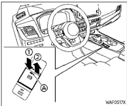
① Apply
② Release
Ⓐ Indicator light
The electronic parking brake can be applied or released automatically or by operating the parking brake switch.
AUTOMATIC OPERATION
The electronic parking brake will apply automatically under any of the following conditions while the brake force is maintained by the automatic brake hold function:
- When the ignition switch is placed in the OFF position.
- When the shift position is placed in the P (Park) position.
- When the driver's door is opened.
- When the driver's seat belt is unfastened.
The electronic parking brake is automatically released as soon as the vehicle starts while the accelerator pedal is depressed under the following conditions.
●while the engine is running.
- When the shift position is in the D (Drive) or R (Reverse) position.
- When the driver's door is closed.
The electronic parking brake is automatically released within 5 seconds after the shift position is placed in the D (Drive) or R (Reverse) position even if the driver's door is opened. Be sure to close the door before starting the vehicle.

WARNING
- When the automatic brakehold function is activated, the electronic parking braking will not be automatically applied when the engine is stopped without using the ignition switch (fore example, by enginstalling).
withoutthevehiclestationary, theelectronicparkingbrakewill notbeautomatically applied eveniftheengineisturnedoff withtheignitionswitch.
- Beforeleavingthevehicle, place theshiftpositionintheP(Park) positionandcheckthattheelec tronicparkingbrakewarning lightisilluminatedtoconfirm thattheelecronicparkingbrake isapplied.Theelectronicparking brakewarninglightwillremain onforaperiodoftimeafterthe driver'sdoorislocked.

CAUTION
When parking in an area where the outside temperature is below 32° F ( 0° C), the electronic parking brake, if applied, may freeze in place and may be difficult to release.
Forsafeparking, it is recommended that you placetheshift position in the P(Park) position and securely blockthewheels.
NOTE:
•Tokeeptheelectronicparkingbrake releasedaftertheengineisturned off, placetheignitionswitchinthe OFFposition, depressthebrake pedalandpushdowntheparking brakeswitchbeforeopeningthe driver'sdoor.
- Ifamalfunctionoccursintheelectronicparkingbrakesystem(for example,duetobatterydischarge), itisrecommendedtocontacta NISSANdealer.
- Underthefollowingconditions,the electronicparkingbrakewillautomaticallybeappliedandthebrake forceoftheautomaticbrakehold willbereleased.
— Thebrakingforceisappliedby theautomaticbrakeholdfunction for3minutesorlonger.
— ThevehicleisplacedintheP (Park)position.
— Thedriver'sseatbeltisunfas-
tened.
— Thedriver'sdoorisopened.
- Theignitionswitchisplaced in theOFFposition.
— Theelectronicparkingbrakeis appliedmanually.
- Ifamalfunctionoccursinthe automaticbrakeholdfunction.
- Makesurethattheelectronicparkingbrakesystemwarninglightis OFFbeforestartingthevehicle.
MANUAL OPERATION
Toapply: When the vehicle is stopped, pull the parking brake switch ② up. (The electronic parking brake will apply even if the ignition switch is placed in the OFF position.) The indicator light Ⓐ on the switch and the electronic parking brake warning light PARK or Ⓞ (red) will illuminate.
Torelease: With the ignition switch in the ON position, depress the brake pedal and push the parking brake switch down ① The indicator light ② and the electronic parking brake warning light (red) will turn off.
Before driving, check that the electronic parking brake warning light (red) turns off. For additional information, see "Warning lights, indicator lights and audible reminders" (P.2-13).
NOTE:
- While the electronic parking brake is applied or released, an operating soundis heard from the lowerside of therearseat. This is normal and does not indicate a malfunction.
- When the electronic parking brake is frequently applied and released a short period of time, the electronic parking brakes system warning light may blink and the electronic parking brake may not operate in order to prevent the electronic parking brake system from overheating. If this occurs, operatethe parking brake switch again after waiting approximately 1 minute.
- If the electronic parking brakemust be applied while driving in an emergency, pull up and hold the parking brakes switch. When you are a set the parking brakes switch, the electronic parking brakewill bereleased.
●Whilepullinguptheparkingbrake switchduringdriving,theelectronic parkingbrakeisappliedandachime sounds.Theelectronicparking brakewarninglight(red)andthe indicatorlightontheparkingbrake switchilluminate.Thisdoesnotindicateamalfunction.Theelectronic parkingbrakewarninglight(red) andtheindicatorlightontheparkingbrakeswitchwillturnoffwhen theelectronicparkingbrakeisreleased. - When pulling the parking brake switch up with the ignitions switch in the OFF position, the indicator
Startinganddriving5-27
AUTOMATICBRAKEHOLD
lightontheparkingbrakeswitchwill continuetoilluminateforashort periodoftime.
when towing a trailer
Depending on the weight of the vehicle and trailer and the steepness of the slope, there may be a tendency for the vehicle to move backwards when starting from a standstill. When this occurs, you can use the parking brake switch in the same way as a conventional lever type parking brake.
Before starting on sloping roads when towing a trailer, be sure to read the following to prevent the vehicle from moving backward unintentionally.
- Release the parking brake switch as soon as the engine is delivering enough torque to the wheels.
The automatic brake hold function maintains the braking force without the driver having to depress the brake pedal when the vehicle is stopped at a traffic light or intersection. As soon as the driver depresses the accelerator pedal again, the automatic brake hold function is deactivated and the braking force is released. The operating status of the automatic brake hold can be displayed on the vehicle information display. (See "Warning lights, indicator lights and audible reminders" (P.2-13).)

WARNING
- The automatic brakehold function is not designed to hold the vehicle on a steep chillorslippery road. Never use the automatic brake hold when the vehicle is stopped on a steep chillorslippery road. Failure todos may cause the vehicle to move.
- The automatic brakehold warning may appear in the vehicle information display to request that the driver retake control by depressing the brake pedal.
- When the automatic brakehold function is activated but fails to maintain the vehicle at a stand-
still, depress the brake pedal to stop the vehicle. If the vehicle unexpectedly moves due to outside conditions, the chimemay sound and automatic brake hold warning may illuminate in the vehicle information display.
- Besuretodeactivatetheautomaticbrakeholdfunctionwhen usingacarwashortowingyour vehicle.
- MakesuretopushtheparkbuttertoshifttotheP(Park)positionandapplytheelectronic parkingbrakewhenparkingyour vehicle,ridingonoroffthevehicle,orloadingluggage.Failureto dosocouldcausethevehicletomoveorrollawayunexpectedly andresultinseriouspersonal injuryorpropertydamage.
- Ifanyofthefollowingconditions occur, the automaticbrakehold function may not function. Have the system checked promptly. It is recommended that you visit a NISSAN dealer forth this service. Failure to operate the vehicle in accordance with these conditions could cause the vehicle to move or roll away unexpectedly and result in serious personal injury
orpropertydamage.
—Awarningmessageappears inthevehicleinformationdisplay.
—The indicator light on the automatic brake hold switch does not illuminate when the switch is pushed.
●Theautomaticbrakeholdfunctionwillnotbeactivatedifthe slipindicatorlight,electronic parkingbrakewarninglight,electronic parking brakesystem warninglight,ormasterwarning lightilluminatesandtheChassis ControlSystemErrorwarning messageappearsinthevehicle informationdisplay.
- Tomaintainthebrakingforceto keepthevehicletoastandstill,a noisemaybeheard.Thisisnota malfunction.

HOW TO ACTIVATE/DEACTIVATE THE AUTOMATIC BRAKE HOLD FUNCTION
How to activate the automatic brake hold function
- With the ignition switch in the ON position, push the automatic brake hold switch ① The indicator light on the automatic brake hold switch ② illuminates.
- When the automatic brake hold function goes into standby, the automatic brake hold indicator light (white) illuminates.
To use the automatic brake hold function,
the following conditions need to be met.
●The driver's seat belt is fastened.
●The electronic parking brake is released.
●The vehicle is not in the P (Park) position.
NOTE:
Theautomaticbrakehold functionresetstoOFFeverytimetheignition switch is switched from the OFF positiontotheONposition.
How to deactivate the automatic brake hold function
While the automatic brake hold function is activated, push the automatic brake hold switch to turn off the automatic brake hold indicator light and deactivate the automatic brake hold function. To deactivate the automatic brake hold function while the brake force has been maintained by the automatic brake hold function, depress the brake pedal and push the automatic brake hold switch.

WARNING
Makesuretofirmlydepressandhold thebrakepedalwhenturningoffthe automaticbrakeholdfunctionwhile thebrakeforceisapplied.Whenthe
Startinganddriving
automaticbrakeholdfunctionis deactivated,thebrakeforcewillbe released.Thiscouldcausethevehicletomoveorrollawayunexpectedly.
Failuretopreventthevehiclefrom rollingmayresultinseriouspersonal injuryorpropertydamage.
HOW TO USE THE AUTOMATIC BRAKE HOLD FUNCTION
For additional information on using the automatic brake hold function, refer to the instructions outlined in this section.
To maintain braking force automatically
With the automatic brake hold function activated and the automatic brake hold indicator light (white) illuminated on the meter, depress the braking pedal to stop the vehicle. The brake force is automatically applied without your foot depressed on the brake pedal. While the brake hold maintained, the automatic brake hold indicator light (green) illuminates on the meter.
To start the vehicle from a stand-still
With the vehicle not in the P (Park) or the shift lever not in the N (Neutral) position, depress the accelerator pedal while the brake force is maintained. The brake force will automatically be released to restart the vehicle. The automatic brake hold indicator light (white) on the meter illuminates and the automatic brake hold returns to standby.
Parking
When the park button is pushed to engage the P (Park) position with the brake force maintained by the automatic brake hold function, the electronic parking brake will automatically be applied and the brake force of the automatic brake hold will be released. The automatic brake hold indicator light turns off. When the electronic parking brake is applied with the brake force maintained by the automatic brake hold function, the brake force of the automatic brake hold will be released. The automatic brake hold indicator light turns off.
NOTE:
- Underthefollowingconditions,the electronicparkingbrakewillautomaticallybeappliedandthebrake forceoftheautomaticbrakehold
willbereleased:
- Thebrakingforceisappliedby theautomaticbrakeholdfunction for3minutesorlonger.
— Thedriver'sseatbeltisunfas- tened. - Theignitionswitchisplaced in theOFFposition.
- Ifamalfunctionoccursinthe automaticbrakeholdfunction.
— ThevehicleisplacedintheP (Park)position.
— Thedriver'sdoorisopened.
— Theelectronicparkingbrakeis appliedmanually.
- Whenthevehiclestops, but the brakeforce is not automatically applied, depress the brake pedal firmly until the automatic brake hold indicator light (green) illuminates.
DRIVEMODESELECTOR
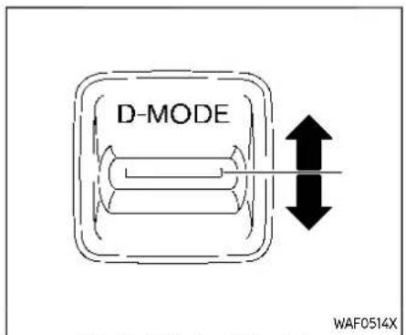
DriveModeSelector:2WDmodels

Vehicleinformationdisplay:2WDmodels
Multiple driving modes can be selected by using the Drive Mode Selector.
2WD:SPORT, STANDARD and ECO
To change the mode, push the Drive Mode Selector up or down.
AWD:OFF-ROAD, SNOW, AUTO, ECO and SPORT
To change the mode, turn the Drive Mode Selector right or left.
NOTE:
WhentheDriveModeSelectorselects a mode, themodemaynotswitchim- mediately. This is not a malfunction.
The current mode is displayed in the vehicle information display. The mode list will appear in the vehicle information display and you can select the mode.
NOTE:
Themodelistwillbeturnedoffin approximately5secondsafterthe modeisselected.
If the driving mode cannot be switched using the Drive Mode Selector when the ignition switch is in the ON position, have the system checked. It is recommended you visit a NISSAN dealer for this service.

DriveModeSelector:AWDmodels

Vehicleinformationdisplay:AWDmodels

WARNING
DonotstareattheDriveMode Selectororthedisplaywhiledriving sothatfullattentionmaybegivento vehicleoperation.
OFF-ROAD MODE (AWD models)
Allows for easier driving or starting on a bumpy road surface such as an uneven dirt road or a steep uphill slope or through sand.

CAUTION
Neverdriveondry, hardsurface roadsintheOFF-ROADmode, asthis willoverloadthepowertrain and may cause a serious malfunction. Additionally, this will cause premature tire wear and reduced fuel economy.
When the OFF-ROAD mode is selected, small tight-corner braking phenomenon or small vibration in cornering may occur. This is not a malfunction.
SNOW MODE (AWD models)
This mode makes it easier to start and run from snowy roads and frozen roads.

CAUTION
Neverdriveondry, hardsurface roadsintheSNOWmode, asthiswill overload the powertrain and may cause a serious malfunction. Additionally, this will cause premature tire wear and reduced fueleconomy.
When the SNOW mode is selected, small vibration in cornering may occur. This is not a malfunction.
STANDARD MODE (2WD models)/AUTO MODE (AWD models)
This is the standard mode that is most suitable for normal driving.
This mode will be selected first each time the ignition switch is placed in the ON position.
ECO MODE
Assists the driver's ECO-driving. The engine and transmission points are adjusted for improved fuel economy, providing such a driving features as smooth starting or constant cruising.
NOTE:
SelectingtheECOmodewillnotnecessarilyimprovefueleconomyasmany drivingfactorsinfluenceitseffectiveness.
Operation
Select the ECO mode using the Drive Mode Selector. The ECO indicator illuminates.
When the accelerator pedal is depressed within the range of economy drive, the ECO indicator illuminates in green. When the accelerator pedal is depressed above the range of economy drive, the ECO indicator turns off.
The ECO indicator will not illuminate in the following cases:
- When the shift lever is in the R (Reverse) position.
- When the vehicle speed is below 2 MPH (3.2 km/h) or over 90 MPH (144 km/h).
- When the cruise control (if so equipped) or the Intelligent Cruise Control (ICC) system (if so equipped) is operated.
ECO Mode Customize
The "ECO Mode Customize" is a function that can change the priority from the Cruise Control (if so equipped) or the Intelligent Cruise Control (ICC) function to fuel efficiency improvements. It can be set when the ECO mode is selected. To activate or deactivate this function, see "ECO Mode Setting" (P.2-26).
•Cruise Control
When the setting is ON, the fuel efficiency while cruising will be improved by lowering the acceleration target from normal (setting OFF) mode.
NOTE:
Whenthevehiclespeedisreduced(for example,whenthevehicleisdrivenon anuphillroadfromaflatroad),itwill takemoretimetoreturntothepreviouslysetspeedthannormalmode.
Tire Pres ECO advice
The "Tire Pres ECO advice" is a function to show an ECO advice message in the vehicle information display when low tire pressure is detected. To activate or deactivate this function, see "ECO Mode Setting" (P.2-26).
When the setting is ON, the ECO Drive Report display shows "Check Tire Pressures for Best Fuel Economy". You can switch the display to the Tire Pressures display by pushing the ◀ button on the steering wheel.

ECO Pedal Guide function
The ECO Pedal Guide display can be selected in the vehicle information display in the ECO mode. (See "5. ECO Pedal Guide" (P.2-47).) Use the ECO Pedal Guide function for improving fuel economy.
When the ECO Pedal Guide bar is in the green range ① it indicates that the vehicle is being driven within range of the super economy drive.
When the ECO Pedal Guide bar is in the light green range ② it indicates that the vehicle is being driven within range of the economy drive.
If the ECO Pedal Guide bar is out of the
green range (1and ), ① indicates that the accelerator pedal is depressed over the range of economy drive.
The ECO Pedal Guide bar is not displayed when:
●The vehicle speed is less than approximately 2 MPH (4 km/h).
●The shift lever is in the P (Park), N (Neutral) or R (Reverse) position.
SPORT MODE
- Adjusts the engine and transmission points for a higher response.
●The setting of the steering system is adjusted to moderately increase steering wheel effort for a sporty feel.
NOTE:
IntheSPORTmode,fueleconomymay bereduced.
DRIVERASSISTANCESYSTEMS
Each Driver Assistance system is designed to help the driver in different ways as they drive. The following Driver Assistance systems (if so equipped) are available on this vehicle:
| Category System | Symbol System description | (See the specified page for detailed information.) | Page | |
| Forward DrivingAids | Automatic Emergency Braking (AEB) with Pedestrian Detection |  | Assists the driver with a warning and/or braking operation when there is a risk of a forward collision with the vehicle ahead in the traveling lane, or with a pedestrian or a cyclist. | 5-122 |
| Intelligent Forward Collision Warning (I-FCW) | [802Y] | Helps alert the driver when there is a sudden braking of a second vehicle traveling in front of the vehicle ahead in the same lane. | 5-132 | |
| Intelligent Cruise Control (ICC) (models with ProPILOT Assist) |  | Intelligent Cruise Control (ICC)Helps the driver maintain a selected distance from the vehicle ahead and can reduce the speed to match a slower vehicle ahead.Decelerates the vehicle to a standstill when a vehicle ahead slows to a stop. | 5-98 | |
| [9327] | Conventional (fixed speed) cruise control modeAllows the driver to drive the vehicle at a fixed speed without keeping his/her foot on the accelerator pedal. | 5-119 | ||
| Cruise control (models without ProPILOT Assist) |  | Allows the driver to drive the vehicle at a fixed speed without keeping his/her foot on the accelerator pedal. (For vehicles equipped with the ProPILOT Assist, see "Conventional (fixed speed) cruise control mode" (P.5-119).) | 5-83 | |
| Side Driving Aids(Lane and Blind Spot) | Lane Departure Warning (LDW) | [TKZS] | Warns the driver that the vehicle is about to cross a lane marker with an indicator and a steering wheel vibration. | 5-47 |
| Intelligent Lane Intervention (I-LI) |  | Warns the driver that the vehicle is about to cross a lane marker with an indicator and a steering wheel vibration.Assists the driver to return the vehicle to the center of the traveling lane. | 5-52 | |
| Blind Spot Warning (BSW) |  | Warns the driver of a vehicle in an adjacent lane when changing lanes with an indicator. | 5-58 | |
| Intelligent Blind Spot Intervention (I-BSI) | [YDKX] | Warns the driver of a vehicle in an adjacent lane when changing lanes.Assists the driver to return the vehicle to the center of the traveling lane. | 5-66 | |
| Steering Assist |  | Assists the driver to help keep the vehicle within the center of the traveling lane(this system is Integrated in the ProPILOT Assist). | 5-113 | |
| Rear Driving Aids | Rear Cross Traffic Alert (RCTA) | [OWCT] | Assists the driver when backing out from a parking space by detecting other vehicles approaching from the right or left of the vehicle. | 5-77 |
| Rear Automatic Braking (RAB) | [4703] | Assists the driver when the vehicle is backing up and approaching stationary objects directly behind the vehicle by providing a warning and automatic braking if needed. | 5-143 | |
| Parking Aids | RearView Monitor - | Shows a rear view of the vehicle when the shift lever is placed in the R (Reverse) position. | 4-2 | |
| Intelligent Around View® Monitor | - | Assists the driver in parking situations by showing various views of the position of the vehicle in a split screen format. | 4-9 | |
| Moving Object Detection (MOD) | - Informs the driver of moving objects near the vehicle in parking situations. | 4-21 | ||
| Sonar system - | Informs the driver with a visual and audible alert of stationary obstacles near the bumpers or the vehicle sides (flanks) (if so equipped). | 5-162 | ||
| Rear Sonar System (RSS) - | Informs the driver with a visual and audible alert of stationary obstacles to the rear of the vehicle when the shift lever is in the R (Reverse) position. | 5-168 | ||
| ProPILOT Assist | ProPILOT Assist | [4467] | Consists of Intelligent Cruise Control (ICC) and Steering Assist. | 5-85 |
| Speed Limit Assist - a feature of ProPILOT Assist with Navi-link | [4070] | Detects a change of the speed limit, indicates the detected speed limit and apply it to the vehicle set speed automatically or manually. | car 3-103 | |
| Speed Adjust by Route - a feature of ProPILOT Assist with Navi-link | [8237] | Adjusts the vehicle speed depending on curves, junctions and exits, using road information provided by the navigation system. | 5-106 | |
| Other DrivingAids | High beam assist | Switches the headlights to the low beam automatically when an oncoming vehicle or leading vehicle appears in front of your vehicle. | 2-61 | |
| Traffic Sign Recognition(TSR) | Provides the driver with information about the most recently detected speed limit. | 5-44 | ||
| Intelligent Driver Alertness(I-DA) | Helps alert the driver when a lack of attention or driving fatigue is detected. | 5-141 | ||
| Hill Start Assist - | Helps prevent the vehicle from rolling backwards in the time it takes the driver to release the brake pedal and apply the accelerator when the vehicle is stopped on a hill. | 5-161 | ||
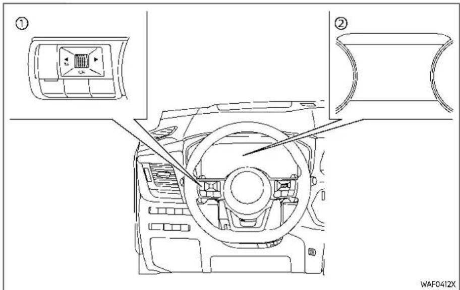
① Steering-wheel-mounted controls (left side)
② Vehicle information display
HOW TO ENABLE/DISABLE THE SYSTEMS
The following systems (if so equipped) can be enabled or disabled using the settings menu in the vehicle information display. Select each setting item using the scroll dial on the steering-wheel-
mounted controls.
●Automatic Emergency Braking (AEB) with Pedestrian Detection
●Intelligent Forward Collision Warning (I-FCW)
●Lane Departure Warning (LDW)
-Intelligent Lane Intervention (I-LI)*
●Blind Spot Warning (BSW)
-Intelligent Blind Spot Intervention (I-BSI) *
●Steering Assist
●Rear Cross Traffic Alert (RCTA)
●Rear Automatic Braking (RAB)
●Moving Object Detection (MOD)
- Sonar system
●Rear Sonar System (RSS)
●Speed Limit Assist (ProPILOT Assist with Navi-link)
●Speed Adjust by Route (ProPILOT Assist with Navi-link)
●Traffic Sign Recognition (TSR)
●Intelligent Driver Alertness (I-DA)
*: To operate the I-LI and I-BSI systems, you need to push the ProPILOT Assist switch after enabling each system in the settings menu.
5-38 Startinganddriving
Driver Assistance display
The Driver Assistance display appears in the vehicle information display when selected using the scroll dial, or for a short period of time when the ProPILOT Assist switch (if so equipped) is pushed. The status of the following systems can be shown in each zone of the display.
| Zone | Driving Aid |
| Forward | Automatic Emergency Braking (AEB) with Pedestrian Detection |
| Intelligent Forward Collision Warning (I-FCW) | |
| Lane | Lane Departure Warning (LDW) |
| Intelligent Lane Intervention (I-LI) (if so equipped) | |
| Blind Spot | Blind Spot Warning (BSW) |
| Intelligent Blind Spot Intervention (I-BSI) (if so equipped) |
- When any of the "Warning" systems are enabled, the "🔒" mark is shown in each zone.
- When any of the "Intervention" systems are enabled, the " 🔺 " mark is shown in each zone.
- When no system is enabled, "OFF" is shown in each zone.
The display changes as the following examples:

All:outline
| Zone Driving Aid | Status | |
| Forward | Automatic Emergency Braking (AEB) with Pedestrian Detection | Enabled(outline) |
| Intelligent Forward Collision Warning (I-FCW) | ||
| Lane | Lane Departure Warning (LDW) | Enabled(outline) |
| Intelligent Lane Intervention (I-LI) | Disabled | |
| Blind Spot | Blind Spot Warning (BSW) | Enabled(outline) |
| Intelligent Blind Spot Intervention (I-BSI) | Disabled | |
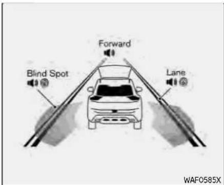
Forward:outline,Other:shaded
| Zone Driving Aid | Status | |
| Forward | Automatic Emergency Braking (AEB) with Pedestrian Detection | Enabled(outline) |
| Intelligent Forward Collision Warning (I-FCW) | ||
| Lane | Lane Departure Warning (LDW) | Enabled |
| Intelligent Lane Intervention (I-LI) | Enabled(shaded) | |
| Blind Spot | Blind Spot Warning (BSW) | Enabled |
| Intelligent Blind Spot Intervention (I-BSI) | Enabled(shaded) | |
COMMON TROUBLESHOOTING GUIDE
Some of the Driver Assistance systems use the common parts (camera, radar, etc.) to function. When a pop-up warning message appears in the vehicle information display, or the warning light flashes/illuminates, check the system condition. For details, see "System temporarily unavailable" and "System malfunction" sections in this Owner's Manual for each applicable system.
Forcameraandradartemporaryblockage
| Warning message/Warning light | Symptom Possible cause System affected | Action to take | ||
| "Unavailable High Cabin Temperature" | High camera temperature | Direct sunlight/High cabin temperature | TSR, LDW, I-LI and I-BSI and Steering Assist | When the interior temperature is reduced, the system resumes automatically. (Push the ProPILOT Assist switch to turn back on the I-LI and I-BSI systems.) |
| Flashing | AEB with Pedestrian Detection and I-FCW | |||
| "Not Available Front Camera Obstructed" or Flashing | Poor camera visibility | Direct sunlight | Steering Assist and AEB with Pedestrian Detection | When the condition no longer exists, the system resumes automatically. |
| Camera obstruction | Windshield glass misted, frozen or covered with dirt | Clean the windshield glass of the camera area. Use the wipers and the defroster to help clear the windshield glass. | ||
| "Forward Driving Aids temporarily disabled Front Sensor blocked See Owner's Manual" and Flashing | Front radar obstruction | Inclement weather (rain, fog, snow, etc.) | ICC, AEB with Pedestrian Detection and I-FCW | When the condition no longer exists, the system resumes automatically. (Push the ProPILOT Assist switch to turn back on the ICC system.) |
| Sensor covered with dirt or obstructed | Clean the front radar sensor area on the front of the vehicle. | |||
| Roads with limited road structures or buildings | When the condition no longer exists, the system resumes automatically. (Push the ProPILOT Assist switch to turn back on the ICC system.) | |||
| Flashing | Front radar interruption | Interference from another radar source | ICC, AEB with Pedestrian Detection and I-FCW | When the condition no longer exists, the system resumes automatically. (Push the ProPILOT Assist switch to turn back on the ICC system.) |
| Warning message/Warning light | Symptom Possible cause System affected | Action to take | ||
| "UnavailableSide RadarObstruction" | Side radarobstruction | Radar blockage | BSW, I-BSI andRCTA | Clean the side rear radar area on the rear of the vehicle.When the condition no longer exists, the system resumes automatically. (Push the ProPILOT Assist switch to turn back on the I-BSI system.) |
Forsystemtemporarilyunavailable
| Warning light/Warning message | Possible cause System to check | Action to take |
| Illuminating | VDC turned off AEB with Pedestrian Detection | Turn on the VDC. |
| VDC turned off | Turn on the VDC. | |
| “Currently not available” | SNOW mode or OFF-ROAD mode I-LI, I-BSI and ICC selected (AWD models) | Select a mode other than SNOW and OFF-ROAD. |
Forsystemmalfunction
| Warning light/warning message | Symptom System to check | Action to take | |
| "Malfunction" andIlluminating | RCTA, AEB with Pedestrian Detection and I-FCW | ||
| "Malfunction See Owner's Manual" | System malfunction | TSR and RAB | Stop the vehicle in a safe location. Turn the engine off and restart the engine. If the warning light/message continues to illuminate, have the system checked. It is recommended that you visit a NISSAN dealer for this service. |
| "Not Available System Malfunction" | LDW, I-LI, BSW, I-BSI, ICC and Steering Assist | ||
| "Parking Sensor Error See Owner's Manual" | Sonar system and RSS | ||
| "Driver Attention Alert Malfunction" | I-DA | ||
Camera, radar and sonar locations The camera, radar and sonar that are used by each Driver Assistance systems are located on the front and rear of the vehicle. For the maintenance of each component, see "System maintenance" section in this Owner's Manual for each application system.
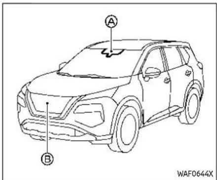
— Intelligent Cruise Control (ICC)
Vehiclefront
Ⓐ Front camera unit
— Automatic Emergency Braking (AEB) with Pedestrian Detection
— Lane Departure Warning (LDW)
— Intelligent Lane Intervention (I-LI)
— Intelligent Blind Spot Intervention (I-BSI)
— Steering Assist
- High beam assist
— Traffic Sign Recognition (TSR)
® Front radar sensor
— Automatic Emergency Braking (AEB) with Pedestrian Detection
— Intelligent Forward Collision Warning (I-FCW)
5-42 Startinganddriving
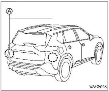
Vehiclerear
Ⓐ Side radar sensor
— Blind Spot Warning (BSW)
— Intelligent Blind Spot Intervention (I-BSI)
— Rear Cross Traffic Alert (RCTA)

— Rear Sonar System (RSS)
Sonar
Ⓐ Front and side (if so equipped) sonar sensors
- Sonar system
⑧ Rear and side (if so equipped) sonar sensors
— Rear Automatic Braking (RAB)
- Sonar system
Startinganddriving5-43
TRAFFICSIGNRECOGNITION(TSR) (ifsoequipped)
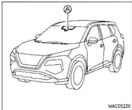
The Traffic Sign Recognition (TSR) system provides the driver with information about the most recently detected speed limit. The system captures the road sign information with the multi-sensing front camera unit located on the windshield in front of the inside mirror and displays the detected signs in the vehicle information display. For vehicles equipped with navigation system, the speed limit displayed is based on a combination of navigation system data and live camera recognition. TSR information is shown in the vehicle information display and in the Head Up Display (HUD) (If so equipped). (See "Head Up Display (HUD)" (P.2-49).)
WARNING
The TSR system is only intended to be as support device to provide the driver within information. It is not a replacement for the driver's attention to traffic conditions or responsibility to drives safely. It cannot prevent accidents due to carelessness. It is the driver's responsibility to stay alert and drives safely at all times.
SYSTEM OPERATION
The TSR system displays the following types of road sign:

5-44 Startinganddriving
A

B
©
WAF0788X
Ⓐ Latest detected speed limit
® Reduce speed limit caution
© No passing zone

CAUTION
- The TSR system is intended as an aid to careful driving. It is the driver's responsibility to stay alert, drives safely, and observe all road regulation that currently apply, including looking out for road signs.
•TheTSRsystemmaynotfunction properlyunderallconditions.Belowaresomeexamples:
—Whentheroadsignisnot clearlyvisible,forexample, duetodamageorweather conditions.
—Whenrain,snowordirtad-herestothewindshieldin frontofthemulti-sensing frontcameraunit.
—Whentheheadlightsarenot brightduetodirtonthelens oriftheaimingisnotadjusted properly.
—Whenstronglightentersthe cameraunit.(Forexample,the lightdirectlyshinesonthe frontofthevehicleatsunrise orsunset.)
—Whenasuddenchangein brightnessoccurs.(Forexample,whenthevehicleentersor exitsatunnelorundera bridge.)
-Inareasnotcoveredbythe navigationsystem.
- If there are deviations in relation to the navigation, forex-amplueduetochanges in the road routing.
—When overtaking busesor truckswithspeedstickers.
—Whenthedatafromthenavigationsystemisnotup-to-dateorisunavailable.
- The TSR system may display a traffic sign, though there is no traffic sign in front of the vehicle. It may display a different speed limit from that for a passenger vehicle. (The maximum speed limits may show a higher or lower number than the actual maximum speed, for example, when detecting as speed limits sign for truck, advisory sign, different speed limits sign between daytime and nighttime, or speed limits sign written indifferent unit near the border, etc.)

① Steering-wheel-mounted controls (left side)
② Vehicle information display
HOW TO ENABLE/DISABLE THE TSR SYSTEM
Perform the following steps to enable or disable the TSR system:
- Push the ◀ button until "Settings" appears in the vehicle information display and then push the scroll
dial. Use the scroll dial to select "Driver Assistance". Then push the scroll dial.
2. Select "Speed Limit Sign" and push the scroll dial to turn the system on or off.
SYSTEM TEMPORARILY UNAVAILABLE
If the vehicle is parked in direct sunlight under high temperature conditions (over approximately 104°F (40°C) and then started, the TSR system may be deactivated automatically. The "Unavailable High Cabin Temperature" warning message will appear in the vehicle information display.
Actiontotake:
When the interior temperature is reduced, the TSR system will resume operating automatically.
SYSTEM MALFUNCTION
If the TSR system malfunctions it will be turned off automatically and the TSR "Malfunction See Owner's Manual" warning message will appear in the vehicle information display.
Actiontotake
If the warning message appears, pull off the road at a safe location and stop the vehicle. Turn the engine off and restart the engine. If the warning message continues to appear, have the system
LANEDEPARTUREWARNING(LDW)
checked by a NISSAN dealer.
SYSTEM MAINTENANCE
The TSR system uses the same multi-sensing front camera unit that is used by the Lane Departure Warning (LDW) system, located in front of the inside mirror. For maintenance of the camera, see "System maintenance" (P.5-51).

WARNING
Failuretofollowthewarningsand instructionsforproperuseofthe LDWsystemcouldresultinserious injuryordeath.
- This system is only awarning device to inform the driver of potential unintended lane departure. It will not steer the vehicle prevent loss of control. It is the driver's responsibility to stay alert, drives safely, keep the vehicle in the traveling lane, and be in control of the vehicle at all times.
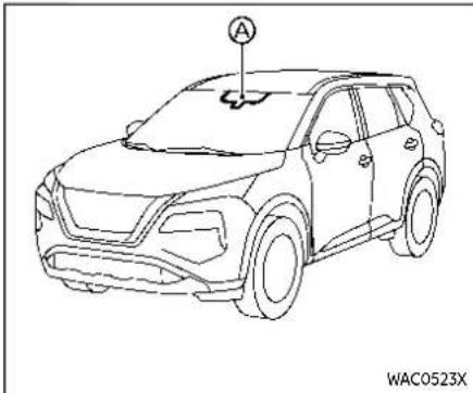
The LDW system will operate when the vehicle is driven at speeds of approximately 37 MPH (60 km/h) and above, and the lane markings are clearly visible on the road.
The LDW system monitors the lane markers on the traveling lane using the camera unit located above the inside mirror.
The LDW system warns the driver that the vehicle is beginning to leave the driving lane with an indicator and a steering wheel vibration. (See "LDW system operation" (P.5-48).)

of the traveling lane, the steering wheel will vibrate and the LDW indicator on the vehicle information display will blink to alert the driver.
The warning function will stop when the vehicle returns inside of the lane markers.
① LDW indicator (on the vehicle information display)
② Vehicle information display
③ Steering-wheel-mounted controls (left side)
The LDW system provides a lane departure warning function when the vehicle is driven at speeds of approximately 37 MPH (60 km/h) and above and the lane markings are clear. When the vehicle approaches either the left or the right side
5-48 Startinganddriving

① Steering-wheel-mounted controls (left side)
② Vehicle information display
HOW TO ENABLE/DISABLE THE LDW SYSTEM
Perform the following steps to enable or disable the LDW system.
- Push the ◀ button until "Settings" appears in the vehicle information display and then push the scroll
dial. Use the scroll dial to select "Driver Assistance". Then push the scroll dial.
- Select "Lane" and push the scroll dial.
- Select "Warning (LDW)" and push the scroll dial.
NOTE:
If you disable the LDW system, the system will remain disabled then next time you start the vehicle's engine.
LDW SYSTEM LIMITATIONS

WARNING
ListedbelowarethesystemlimitationsfortheLDWsystem.Failureto followthewarningsandinstructions forproperuseoftheLDWsystem couldresultinseriousinjuryor death.
- Thesystemwillnotoperateat speedsbelowapproximately37 MPH(60km/h)orifitcannot detectlanemarkers.
- DonotusetheLDWsystemunder thefollowingconditionsasitmay notfunctionproperly:
—Duringbadweather(rain,fog, snow,etc.).
Startinganddriving5-49
—When driving on slippery roads, such as soniceorsnow.
—Whendrivingonwindingor
unevenroads.
—Whenthereisalaneclosure duetoroadrepairs.
—Whendrivinginamakeshiftor temporarylane.
—Whendrivingonroadswhere thelanewidthhistoonarrow.
—Whendrivingwithoutnormal tireconditions(forexample, tirewear, lowtirepressure, installationofsparetire, tire chains, non-standardwheels).
—Whenthevehicleisequipped withnon-originalbrakeparts or suspensionparts.
—Whentowingatrailerorother vehicle.
- Thesystemmaynotfunction properlyunderthefollowingconditions:
—Onroadswherethereare multipleparallelanemarkers; lanemarkersthatarefadedor notpaintedclearly; yellow paintedlanemarkers; non-standardlanemarkers; or
lanemarkerscoveredwith water,dirt,snow,etc.
—Onroadswherediscontinued lanemarkersarestilldetectable.
—Onroadswherethereare sharpcurves.
—Onroadswherethereare sharplycontrastingobjects, such as shadows, snow, water, wheelruts, seamsor linesremainingafterroadre-pairs.(TheLDWsystemcould detecttheseitemsaslane markers.)
—Onroadswherethetraveling lanemergesorseparates.
—Whenthevehicle'straveling directiondoesnotalignwith thelanemarker.
—Whentravelingclosetothe vehicleinfrontofyou,which obstructsthelanecamera unitdetectionrange.
—Whenrain,snow,dirtorobject adherestothewindshieldin frontofthelanecameraunit.
—Whenthe headlightsarenot brightduetodirtonthelens
oriftheaimingisnotadjusted properly.
—When strong light enter the lanecamera unit. (Forexample, the light directly shines on the front of the vehicle at sunrise or sunset.)
—Whenasuddenchangein brightnessoccurs.(Forexample,whenthevehicleentersorexitsatunnelorunderabridge.)
SYSTEM TEMPORARILY UNAVAILABLE
ConditionA:
If the vehicle is parked in direct sunlight under high temperature conditions (over approximately 104° F ( 40° C)) and then started, the LDW system may be deactivated automatically, the LDW indicator will flash and the following message will appear in the vehicle information display.
- "Unavailable High Cabin Temperature" When the interior temperature is reduced, the LDW system will resume operating automatically and the LDW indicator will stop flashing.
ConditionB:
The warning function of the LDW system is not designed to work under the following conditions:
- When you operate the lane change signal and change traveling lanes in the direction of the signal. (The LDW system will become operable again approximately 2 seconds after the lane change signal is turned off.)
- When the vehicle speed lowers to less than approximately 37 MPH (60 km/h).
Actiontotake:
After the above conditions have finished and the necessary operating conditions are satisfied, the LDW system will resume.
SYSTEM MALFUNCTION
If the LDW system malfunctions, it will cancel automatically and "Not Available System Malfunction" warning message will appear in the vehicle information display. If the warning message appears, pull off the road to a safe location and stop the vehicle. Place the ignition switch in the OFF position and restart the engine. If the warning message continues to appear, have the system checked. It is recommended that you visit a NISSAN dealer for this service.
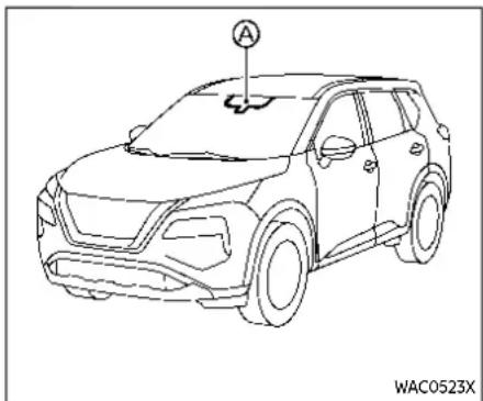
SYSTEM MAINTENANCE
The lane camera unit for the LDW system is located above the inside mirror. To keep the proper operation of the LDW system and prevent a system malfunction, be sure to observe the following:
●Always keep the windshield clean.
- Do not attach a sticker (including transparent material) or install an accessory near the camera unit.
- Do not place reflective materials, such as white paper or a mirror, on the instrument panel. The reflection of sunlight may adversely affect the camera unit's capability of detecting the lane markers.
- Do not strike or damage the areas around the camera unit. Do not touch the camera lens or remove the screw located on the camera unit. If the camera unit is damaged due to an accident, it is recommended that you visit a NISSAN dealer.
INTELLIGENTLANEINTERVENTION (I-LI)(ifsoequipped)

WARNING
Failuretofollowthewarningsand instructionsforproperuseofthel-LI systemcouldresultinseriousinjury ordeath.
- Thel-Llsystemwillnotsteerthe vehicleorpreventlossofcontrol. Itisthedriver'sresponsibilityto stayalert,drivesafely,keepthe vehicleinthetravelinglane,and beincontrolofthevehicleatall times.
- Thel-Llsystemisprimarilyintendedforuseonwell-developed freewaysorhighways.Itmaynot detectthelanemarkersincertain road,weather,ordrivingconditions.

The I-LI system monitors the lane markers on the traveling lane using the camera unit located above the inside mirror.
The I-LI system must be turned on with the ProPILOT Assist switch on the steering wheel, every time the ignition is placed in the ON position.
The I-LI system will operate when the vehicle is driven at speeds of approximately 37 MPH (60 km/h) and above, and only when the lane markings are clearly visible on the road. The I-LI system warns the driver when the vehicle has left the center of the traveling lane with an indicator and steering wheel vibration. The system helps assist the driver to return the vehicle to the center of the traveling lane by applying the brakes to the left or right wheels individually (for a short period of time).

on the vehicle information display will blink to alert the driver. Then, the I-LI system will automatically apply the brakes for a short period of time to help assist the driver to return the vehicle to the center of the traveling lane.
To turn on the I-LI system, push the ProPILOT Assist switch on the steering wheel after starting the engine. The I-LI ON indicator on the vehicle information display will illuminate. Push the ProPILOT Assist switch again to turn off the I-LI system. The I-LI ON indicator will turn off.
① I-LI ON indicator (on the vehicle information display)
② I-LI indicator (on the vehicle information display)
③ Vehicle information display
④ ProPILOT Assist switch
The I-LI system operates above approximately 37 MPH (60 km/h) and when the lane markings are clear. When the vehicle approaches either the left or the right side of the traveling lane, steering wheel will vibrate and the I-LI indicator (orange)

① Steering-wheel-mounted control (left side)
② Vehicle information display
③ ProPILOT Assist switch
HOW TO ENABLE/DISABLE THE I-LI SYSTEM
Perform the following steps to enable or disable the I-LI system.
- Push the ◀ button until "Settings" appears in the vehicle information display and then push the scroll dial.
Use the scroll dial to select "Driver Assistance." Then push the scroll dial.
- Select "Lane" and push the scroll dial.
- Select "Prevention (LDP)" and push the scroll dial.
- Push the ProPILOT Assist switch to turn the system on or off.
NOTE:
TurningontheProPILOTAssistsystem willturnonthel-L1andl-BSIsystemsat thesametime.Ifthel-L1systemis disabledinthesettingsmenu,thel-L1 willautomaticallybeturnedonwhen theSteeringAssistsystemisactive. (See"ProPILOTAssist"(P.5-85).)
I-LI SYSTEM LIMITATIONS

WARNING
Listedbelowarethesystemlimitationsforthel-LIsystem.Failureto followthewarningsandinstructions forproperuseofthel-LIsystem couldresultinseriousinjuryor death.
- TheI-Lisystemmayactivateif youchangelaneswithoutfirst activatingyourturnsignalor,for example,ifaconstructionzone directstraffictocrossanexisting
lanemarker.Ifthisoccursyou mayneedtoapplycorrective steeringtocompleteyourlane change.
- Becausethel-Limaynotactivate undertheroad, weather, and lane marker conditions described in this section, it may not activate every time your vehicle begin to leave its lane and you will need to apply correctivesteering.
- Thel-LIsystemwillnotoperateat speedsbelowapproximately37 MPH(60km/h)orifitcannot detectlanemarkers.
- Whenthel-Llsystemisoperating, avoidexcessiveorsuddensteeringmaneuvers. Otherwise, you couldlosecontrolofthevehicle.
- Donotusethel-Lisystemunder the following conditions as it may not function properly:
—Duringbadweather(rain,fog, snow,etc.).
—When driving on slippery roads, such as oiceorsnow.
—Whendrivingonwindingor unevenroads.
—Whenthereisalaneclosure duetoroadrepairs.
—Whendrivinginamakeshiftor temporarylane.
—Whendrivingonroadswhere thelanewidthhistoonarrow.
—Whendrivingwithoutnormal tireconditions(forexample, tirewear, lowtirepressure, installationofsparetire,tire chains, non-standardwheels).
—Whenthevehicleisequipped withnon-originalbrakeparts or suspensionparts.
—Whentowingatrailerorother vehicle.
—Onroadswherethereare multipleparallelanemarkers; lanemarkersthatarefadedor notpaintedclearly; yellow paintedlanemarkers; non-standardlanemarkers; or lanemarkerscoveredwith water,dirt,snow,etc.
—Onroadswherediscontinued lanemarkersarestilldetectable.
—Onroadswherethereare sharpcurves.
—Onroadswherethereare sharplycontrastingobjects, such as shadows, snow, water, wheelruts, seamsor linesremainingafterroadre-pairs.(TheI-Lisystemcould detecttheseitemsaslane markers.)
—Onroadswherethetraveling lanemergesorseparates.
—Whenthevehicle'straveling directiondoesnotalignwith thelanemarker.
—Whentravelingclosetothe vehicleinfrontofyou,which obstructsthelanecamera unitdetectionrange.
—Whenrain,snowordirtad-herestothewindshieldin frontofthelanecameraunit.
—Whentheheadlightsarenot brightduetodirtonthelens oriftheaimingisnotadjusted properly.
—When strong light enter the lanecamera unit. (Forexample, the light directly shines on the front of the vehicle at sunrise or sunset.)
—Whenasuddenchangein brightnessoccurs.(Forexample,whenthevehicleentersor exitsatunnelorundera bridge.)
While the I-LI system is operating, you may hear a sound of brake operation. This is normal and indicates that the I-LI system is operating properly.
SYSTEM TEMPORARILY UNAVAILABLE
ConditionA:
The warning and assist functions of the I-LI system are not designed to work under the following conditions:
- When you operate the lane change signal and change the traveling lanes in the direction of the signal. (The I-LI system will be deactivated for approximately 2 seconds after the lane change signal is turned off.)
- When the vehicle speed lowers to less than approximately 37 MPH (60 km/h).
Actiontotake:
After the above conditions have finished and the necessary operating conditions are satisfied, the warning and assist functions will resume.
ConditionB:
The assist function of the I-LI system is not designed to work under the following conditions (warning is still functional):
- when the brake pedal is depressed. - when the steering wheel is turned as far as necessary for the vehicle to change lanes.
- When the vehicle is accelerated during the I-LI system operation.
- When the Intelligent Cruise Control (ICC) approach warning occurs (if so equipped).
- When the hazard warning flashers are operated.
- When driving on a curve at high speed.
Actiontotake:
After the above conditions have finished and the necessary operating conditions are satisfied, the I-LI system application of the brakes will resume.
ConditionC:
If the following message appears in the vehicle information display, a chime will sound and the I-LI system will be turned off automatically.
- "Currently not available": - When the Vehicle Dynamic Control (VDC) system is turned off.
- When the SNOW mode and the OFF-ROAD mode is selected (AWD models).
Actiontotake:
When the above conditions no longer exist, turn off the I-LI system. Push the ProPILOT Assist switch again to turn the I-LI system back on.
Temporarydisabledstatusathighttemperature:
If the vehicle is parked in direct sunlight under high temperature conditions (over approximately 104° F ( 40° C)) and then the I-LI system is turned on, the I-LI system may be deactivated automatically and the following message will appear on the vehicle information display:
- "Unavailable High Cabin Temperature" when the interior temperature is reduced, of the system will resume operating automatically.
SYSTEM MALFUNCTION
If the I-LI system malfunctions, it will cancel automatically. The I-LI indicator (orange) will illuminates and the "Not Available System Malfunction" warning message will appear in the vehicle information display.
If the I-LI indicator (orange) illuminates, pull off the road to a safe location. Turn
the engine off and restart the engine. If the I-LI indicator (orange) continues to illuminate, have the I-LI system checked. It is recommended that you visit a NISSAN dealer for this service.

SYSTEM MAINTENANCE
The lane camera unit for the I-LI system is located above the inside mirror. To keep the proper operation of the I-LI system and prevent a system malfunction, be sure to observe the following:
●Always keep the windshield clean.
- Do not attach a sticker (including transparent material) or install an accessory near the camera unit.
- Do not place reflective materials, such as white paper or a mirror, on the instrument panel. The reflection of sunlight may adversely affect the camera unit's capability of detecting the lane markers.
- Do not strike or damage the areas around the camera unit. Do not touch the camera lens or remove the screw located on the camera unit. If the camera unit is damaged due to an accident, it is recommended that you visit a NISSAN dealer.
BLINDSPOTWARNING(BSW)

WARNING
Failuretofollowthewarningsand instructionsforproperuseofthe BSWsystemcouldresultinserious injuryordeath.
- TheBSWsystemisnotareplacementforproperdrivingprocedureandisnotdesignedto preventcontactwithvehiclesor objects.Whenchanginglanes,alwaysusethesideandrearmirrorsandturnandlookinthe directionyourvehiclewillmove toensureitissafetochange lanes.Neverrelysolelyonthe BSWsystem.
The BSW system helps alert the driver of other vehicles in adjacent lanes when changing lanes.

The BSW system uses radar sensors installed near the rear bumper to detect other vehicles in an adjacent lane.
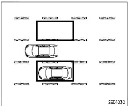
Detectionzone
The radar sensors can detect vehicles on either side of your vehicle within the detection zone shown as illustrated. This detection zone starts from the outside mirror of your vehicle and extends approximately 10 ft (3.0 m) behind the rear bumper, and approximately 10 ft (3.0 m) sideways.
When the turn signal is activated, the detection zone may extend more than approximately 10 ft (3.0 m).

system chimes (twice) and the side indicator light flashes. The side indicator light continues to flash until the detected vehicle leaves the detection zone.
The side indicator light illuminates for a few seconds when the ignition switch is placed in the ON position.
The brightness of the side indicator light is adjusted automatically depending on the brightness of the ambient light.
① Side indicator light
② BSW indicator (on the vehicle information display)
③ Vehicle information display
④ Steering-wheel-mounted controls (left side)
The BSW system operates above approximately 20 MPH (32 km/h).
If the radar sensors detect a vehicle in the detection zone, the side indicator light illuminates.
If the turn signal is then activated, the
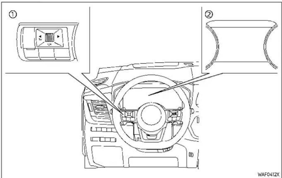
① Steering-wheel-mounted controls (left side)
② Vehicle information display
HOW TO ENABLE/DISABLE THE BSW SYSTEM
Perform the following steps to enable or disable the BSW system.
- Push the ◀ button until "Settings" appears in the vehicle information display and then push the scroll
dial. Use the scroll dial to select "Driver Assistance". Then push the scroll dial.
- Select "Blind Spot" and push the scroll dial.
- Select "Warning (BSW)" and push the scroll dial.
NOTE:
Thesystemwillretaincurrentsettings inthevehicleinformationdisplayeven iftheengineisrestarted.
BSW SYSTEM LIMITATIONS

WARNING
ListedbelowarethesystemlimitationsfortheBSWsystem.Failuretooperatethevehicleinaccordancewiththesesystemlimitationscouldresultinseriousinjuryordeath.
•TheBSWsystemcannotdetectall vehiclesunderallconditions.
•Theradarsensorsmaynotbe
abletodetectandactivateBSW
whencertainobjectsarepresent
suchas:
—Pedestrians, bicycles, animals.
—Vehiclessuchasmotorcycles, lowheightvehicles, or high groundclearance vehicles.
—Oncomingvehicles.
—Vehiclesremaininginthedetectionzonewhenyouacceleratefromastop.
—Avehiclemergingintoan adjacentlaneataspeedapproximatelythesameasyour vehicle.
—Avehicleapproachingrapidly frombehind.
—Avehiclewhichyourvehicle overtakesrapidly.
—Avehiclethatpassesthrough thedetectionzonequickly.
—whenovertakingseveralvehiclesinarow,thevehiclesafter thefirstvehiclemaynotbe detectediftheyaretraveling closetogether.
- Theradarsensor'sdetectionzone isdesignedbasedonastandard lanewidth.Whendrivingina widerlane,theradarsensors maynotdetectvehiclesinan adjacentlane.Whendrivingina narrowlane,theradarsensors maydetectvehiclesdrivingtwo lanesaway.
- Theradarsensorsaredesigned toignoremoststationaryobjects, howeverobjectssuchasguardrails, walls, foliageandparked vehiclesmayoccasionallybedetected. Thisisanormaloperation condition.
- The following conditions may reduce the ability of the radar to detect other vehicles:
—Severeweather
—Roadspray
—Ice/frost/dirtbuild-uponthe vehicle
- Donotattachstickers(including transparentmaterial),installaccessoriesorapplyadditional paintneartheradarsensors. Theseconditionsmayreducethe abilityoftheradartodetectother vehicles.
- Excessivenoise(forexample, audiosystemvolume, openvehiclewindow)willinterferewiththe chimesound, anditmaynotbe heard.
BSW DRIVING SITUATIONS
Indicator on
Indicator off
Indicator flashing


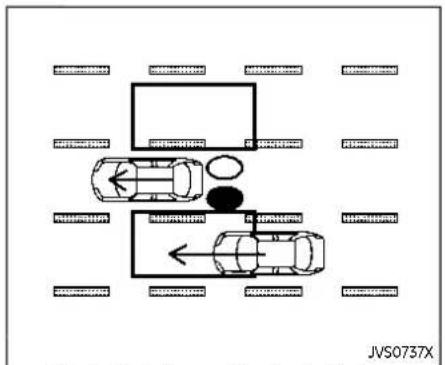
Illustration1-Approachingfrombehind
Another vehicle approaching from behind
Illustration 1: The side indicator light illuminates if a vehicle enters the detection zone from behind in an adjacent la

Illustration2-Approachingfrombehind
Illustration 2: If the driver activates the turn signal while another vehicle is in the detection zone, then the system chimes (twice) and the side indicator light flashes.
NOTE:
•Theradarsensorsmaynotdetect vehicleswhichareapproachingrapidlyfrombehind.

Illustration3-Overtakinganothervehicle
Overtaking another vehicle Illustration 3: The side indicator light illuminates if you overtake a vehicle and that vehicle stays in the detection zone for approximately 2 seconds.
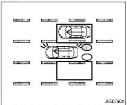
Illustration4-Overtakinganothervehicle
Illustration 4: If the driver activates the turn signal while another vehicle is in the detection zone, then the system chimes (twice) and the side indicator light flashes.
NOTE:
- Whenovertakingseveralvehiclesin arow,thevehiclesafterthefirst vehiclemaynotbedetectedifthey aretravelingclosetogether.
- Theradarsensorsmaynotdetect slowermovingvehiclesiftheyare passedquickly.
- If the driver activates the turns signal before vehicle enter the detection zone, the side indicator light will flash but nochimewill sound when
theothervehicleisdetected.

Illustration5-Enteringfromtheside
Entering from the side
Illustration 5: The side indicator light illuminates if a vehicle enters the detection zone from either side.

Illustration6-Enteringfromtheside
Illustration 6: If the driver activates the turn signal while another vehicle is in the detection zone, then the system chimes (twice) and the side indicator light flashes.
NOTE:
•Theradarsensorsmaynotdetecta vehiclewhichistravelingatabout thesamespeedasyourvehicle whenitentersthedetectionzone.
SYSTEM TEMPORARILY UNAVAILABLE
When radar blockage is detected, the BSW system will be turned off automatically, a chime will sound and the "Unavailable Side Radar Obstruction" warning message will appear in the vehicle information display.
The system is not available until the conditions no longer exist.
The radar sensors may be blocked by temporary ambient conditions such as splashing water, mist or fog. The blocked condition may also be caused by objects such as ice, frost or dirt obstructing the radar sensors.
NOTE:
IftheBSWsystemstopsworking,the IntelligentBlindSpotIntervention(I- BSI)(ifsoequipped)andtheRearCross TrafficAlert(RCTA)systemswillalso stopworking.
Actiontotake:
When the above conditions no longer exist, the system will resume automatically.
SYSTEM MALFUNCTION
When the BSW system malfunctions, it will be turned off automatically, the BSW indicator illuminates and the "Not Available System Malfunction" warning message will appear in the vehicle information display.
NOTE:
If the BSWsystemstopworking, the Intelligent Blind Spot Intervention (IBSI) (if so equipped) and Rear Cross Traffic Alert (RCTA) system will also stop working.
Actiontotake:
Stop the vehicle in a safe location, turn the engine off and restart the engine. If the message continues to appear, have the BSW system checked. It is recommended that you visit a NISSAN dealer for this service.
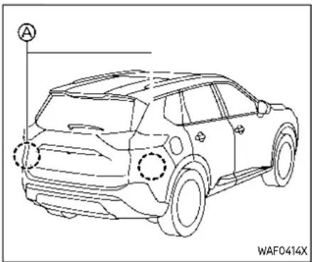
SYSTEM MAINTENANCE
The two radar sensors for the BSW system are located near the rear bumper. Always keep the area near the radar sensors clean.
The radar sensors may be blocked by temporary ambient conditions such as splashing water, mist or fog.
The blocked condition may also be caused by objects such as ice, frost or dirt obstructing the radar sensors.
Check for and remove objects obstructing the area around the radar sensors.
Do not attach stickers (including transparent material), install accessories or
apply additional paint near the radar sensors.
Do not strike or damage the area around the radar sensors.
See a NISSAN dealer or other authorized repair shop if the area around the radar sensors is damaged due to a collision.
Radio frequency statement
ForUSA
FCCID:LTQRN5TR
CAUTIONTOUSERS
Changesormodificationsnotexpressly approvedbythepartyresponsiblefor compliance could void the user's authoritytooperatetheequipment.
This device complies with Part 15 of the FCC Rules and with RSS of the Industry Canada. Operation is subject to the following two conditions:
(1) This device may not cause harmful interference, and
(2) this device must accept any interference received, including interference that may cause undesired operation
ForCanada
Model:RN5TR
IC:3659A-RN5TR
ThisdevicecomplieswithIndustryCa-
nadalicence-exemptRSSstandard(s). Operationissubjecttothefollowing twoconditions:(1)thisdevicemaynot causeinterference,and(2)thisdevice mustacceptanyinterference,including interferencethatmaycauseundesired operationofthedevice.
INTELLIGENTBLINDSPOT INTERVENTION(I-BSI)(ifsoequipped)

WARNING
Failuretofollowthewarningsand instructionsforproperuseofthel-BSIsystemcouldresultinserious injuryordeath.
- Thel-BSIsystemisnotareplacementforproperdrivingproceduresandisnotdesignedto preventcontactwithvehiclesor objects.Whenchanginglanes,alwaysusethesideandrearmirrorsandturnandlookinthe directionyourvehiclewillmove toensureitissafetochange lanes.Neverrelysolelyonthel-BSIsystem.
- Thereisalimitationtothedetectioncapabilityoftheradar. Not everymovingobjectorvehicle willbedetected. Usingthel-BSI systemundersomeroad,ground, lanemarker,trafficorweather conditionscouldleadtoimproper systemoperation. Alwaysrelyon yourownoperationtoavoidaccidents.
The I-BSI system helps alert the driver of other vehicles in adjacent lanes when changing lanes, and helps assist the 5-66 Startinganddriving
driver to return the vehicle to the center of the traveling lane.
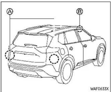
The I-BSI system uses radar sensors installed near the rear bumper to detect other vehicles in an adjacent lane. In addition to the radar sensors, the I-BSI system uses a camera installed behind the windshield to monitor the lane markers of your traveling lane.
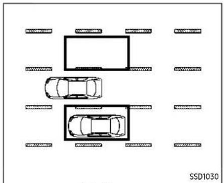
Detectionzone
The radar sensors can detect vehicles on either side of your vehicle within the detection zone shown as illustrated.
This detection zone starts from the outside mirror of your vehicle and extends approximately 10 ft (3.0 m) behind the rear bumper, and approximately 10 ft (3.0 m) sideways.

① Side indicator light
② I-BSI ON indicator (on the vehicle information display)
③ I-BSI indicator (on the vehicle information display)
④ Vehicle information display
⑤ ProPILOT Assist switch
The I-BSI system operates above approximately 37 MPH (60 km/h).
If the radar sensors detect a vehicle in the detection zone, the side indicator light illuminates.
If the turn signal is then activated, the
Startinganddriving5-67
system chimes (twice) and the side indicator light flashes. The side indicator light continues to flash until the detected vehicle leaves the detection zone.
If the I-BSI system is ON and your vehicle approaches a lane marker while another vehicle is in the detection zone, the system chimes (three times) and the side indicator light flashes. The I-BSI system activates to help return the vehicle back to the center of the driving lane. The I-BSI system operates regardless of turn signal usage.
To turn on the I-BSI system, push the ProPILOT Assist switch on the steering wheel after starting the engine. The I-BSI ON indicator on the vehicle information display will illuminate. Push the ProPILOT Assist switch again to turn off the I-BSI system.
- TheI-BSIsystemistypicallyactivatedearlierthantheIntelligent LaneIntervention(I-LI)systemwhen yourvehicleisapproachingalane marker.
NOTE:
- I-BSIwarningandsystemapplicationwillonlybeactivatediftheside indicatorlightisalreadyilluminated whenyourvehicleapproachesa lanemarker.Ifanothervehicle comesintothedetectionzoneafter yourvehiclehascrossedalane marker,nol-BSIwarningorsystem applicationwillbeactivated.(For additionalinformation,see"I-BSI drivingsituations"(P.5-71).)
5-68 Startinganddriving
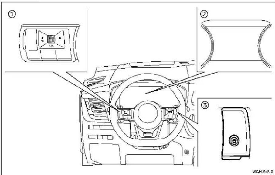
① Steering-wheel-mounted control (left side)
② Vehicle information display
③ ProPILOT Assist switch
HOW TO ENABLE/DISABLE THE I-BSI SYSTEM
-
Push the button until "Settings" appears in the vehicle information display and then push the scroll dial. Use the scroll dial to select "Driver Assistance." Then push the scroll dial.
-
Select "Blind Spot" and push the scroll dial.
- Select "Intervention (BSI)" and push the scroll dial.
- Push the ProPILOT Assist switch to turn the system on or off.
NOTE:
TurningontheProPILOTAssistsystem willturnonthel-BSlandl-LIsystemsat thesametime.Foradditionalinformation,see"IntelligentLaneIntervention (I-LI)"(P.5-52).
TurningtheBSWsystemoffwilldeactivatethel-BSIsystematthesametime.
I-BSI SYSTEM LIMITATIONS

WARNING
Listedbelowarethesystemlimitationsforthel-BSIsystem.Failureto operatethevehicleinaccordance withthesesystemlimitationscould resultinseriousinjuryordeath.
- TheI-BSIsystemcannotdetectall vehiclesunderallconditions.
•Theradarsensorsmaynotbe abletodetectandactivatel-BSI whencertainobjectsarepresent suchas:
Startinganddriving5-69
—Pedestrians, bicycles, animals.
—Vehiclessuchasmotorcycles, lowheightvehicles, or high groundclearance vehicles.
—Vehiclesremaininginthedetectionzonewhenyouacceleratefromastop.
—Oncomingvehicles.
—Avehiclemergingintoan adjacentlaneataspeedapproximatelythesameasyour vehicle.
—Avehicleapproachingrapidly frombehind.
—Avehiclewhichyourvehicle overtakesrapidly.
—Avehiclethatpassesthrough thedetectionzonequickly.
- Theradarsensor'sdetectionzone isdesignedbasedonastandard lanewidth.Whendrivingina widerlane,theradarsensors maynotdetectvehiclesinan adjacentlane.Whendrivingina narrowlane,theradarsensors maydetectvehiclesdrivingtwo lanesaway.
- Theradarsensorsaredesigned toignoremoststationaryobjects, howeverobjectssuchasguardrails, walls, foliageandparked vehiclesmayoccasionallybedetected. Thisisanormaloperation condition.
- The following conditions may reduce the ability of the radar to detect other vehicles:
—Severeweather
—Roadspray
—Ice/frost/dirtbuild-uponthe vehicle
- Donotattachstickers(including transparentmaterial),installaccessoriesorapplyadditional paintneartheradarsensors. Theseconditionsmayreducethe abilityoftheradartodetectother vehicles.
- Thecameramaynotdetectlane markersinthefollowingsituationsandthel-BSIsystemmay notoperateproperly.
—Onroadswherethereare multipleparallelanemarkers; lanemarkersthatarefadedor notpaintedclearly; yellow paintedlanemarkers; non-
standardlanemarkers;lane markerscoveredwithwater, dirt,snow,etc.
—Onroadswherediscontinued lanemarkersarestilldetectable.
—Onroadswherethereare sharpcurves.
—Onroadswherethereare sharplycontrastingobjects, such as shadows, snow, water, wheelruts, seamsor linesremainingafterroadre-pairs.
—Onroadswherethetraveling lanemergesorseparates.
—Whenthevehicle'straveling directiondoesnotalignwith thelanemarkers.
—Whentravelingclosetothe vehicleinfrontofyou,which obstructsthelanecamera unitdetectionrange.
—Whenrain, snowordirtad- herestothewindshieldin frontofalanecameraunit.
—Whentheheadlightsarenot brightduetodirtonthelens orifaimingisnotadjusted
properly.
—When strong light tentersa lanecamera unit.(Forexample: light directly shines on the front of the vehicle at sunrise or sunset.)
—Whenasuddenchangein brightnessoccurs.(Forexample:whenthevehicleentersorexitsatunnelorunderabridge.)
- Donotusethel-BSIsystemunder the following conditions because the system may not function properly.
—Duringbadweather.(Forexample:rain,fog,snow,etc.)
—When driving on slippery roads, such as one or more snow, etc.
—Whendrivingonwindingor
unevenroads.
—Whenthereisalaneclosure duetoroadrepairs.
—Whendrivinginamakeshiftor temporarylane.
—Whendrivingonroadswhere thelanewidthhistoonarrow.
—Whendrivingwithatirethatis notwithinnormaltireconditions(forexample,tirewear, lowtirepressure,installation ofsparetire,tirechains,non-standardwheels).
—Whenthevehicleisequipped withnon-originalsteering partsorsuspensionparts.
—Whentowingatrailerorother vehicle.
- Excessivenoise(forexample, audiosystemvolume, openvehiclewindow) will interferewith the chimesound, and it may not be heard.
I-BSI DRIVING SITUATIONS
Indicator on
Indicator off
Indicator flashing


Illustration1-Approachingfrombehind
Another vehicle approaching from behind
Illustration 1: The side indicator light illuminates if a vehicle enters the detection zone from behind in an adjacent lane.
Illustration2-Approachingfrombehind
Illustration 2: If the driver activates the turn signal then the system chimes a sound (twice) and the side indicator light flashes.
Illustration3-Approachingfrombehind
Illustration 3: If the I-BSI system is on and your vehicle approaches a lane marker while another vehicle is in the detection zone, the system chimes (three times) and the side indicator light flashes. The I-BSI system activates to help return the vehicle back to the center of the driving lane.
NOTE:
- Theradarsensorsmaynotdetect vehicleswhichareapproachingrapidlyfrombehind.

Illustration4-Overtakinganothervehicle
Overtaking another vehicle
Illustration 4: The side indicator light illuminates if you overtake a vehicle and that vehicle stays in the detection zone for approximately 3 seconds.

Illustration5-Overtakinganothervehicle
Illustration 5: If the driver activates the turn signal while another vehicle is in the detection zone, then the system chimes (twice) and the side indicator light flashes.

Illustration6-Overtakinganothervehicle
Illustration 6: If the I-BSI system is on and your vehicle approaches a lane marker while another vehicle is in the detection zone, the system chimes (three times) and the side indicator light flashes. The I-BSI system activates to help return the vehicle back to the center of the driving lane.
NOTE:
- Whenovertakingseveralvehiclesin arow,thevehiclesafterthefirst vehiclemaynotbedetectedifthey aretravelingclosetogether.
- Theradarsensorsmaynotdetect slowermovingvehiclesiftheyare passedquickly.
Startinganddriving5-73

Illustration7-Enteringfromtheside
Entering from the side
Illustration 7: The side indicator light illuminates if a vehicle enters the detection zone from either side.
NOTE:
Theradarsensorsmaynotdetecta vehiclewhichistravelingataboutthe samespeedasyourvehiclewhenit entersthedetectionzone.
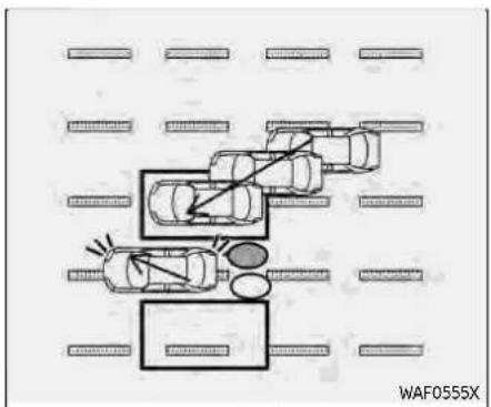
Illustration8-Enteringfromtheside
Illustration 8: If the driver activates the turn signal while another vehicle is in the detection zone, then the side indicator light flashes and a chime will sound twice.
NOTE:
If the driver activates the turns signal before an vehicle enter the detection zone, the side indicator light will flash but nochimewill sound when another vehicle is detected.
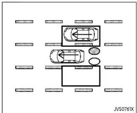
Illustration9-Enteringfromtheside
Illustration 9: If the I-BSI system is on and your vehicle approaches the lane marker while another vehicle is in the detection zone, the system chimes (three times) and the side indicator light flashes. The I-BSI system activates to help return the vehicle back to the center of the driving lane.

Illustration10-Enteringfromtheside
Illustration 10: The I-BSI system will not operate if your vehicle is on a lane man when another vehicle enters the detection zone. In this case only the BSW system operates.
NOTE:
- Theradarsensorsmaynotdetecta vehiclewhichistravelingatabout thesamespeedasyourvehicle whenitentersthedetectionzone.
- I-BSI will not operate or will stop operating and only awarning chime will sound under the following conditions.
— Whenthebrakepedalisdepressed.
- Whenthevehicleisaccelerated duringI-BSIsystemoperation
— Whensteeringquickly
— WhentheICC,I-FCWorAEBwarningssound.
— Whenthehazardwarningflashers areoperated.
— Whendrivingonacurveatahigh speed.
- WhentheBSWsystemisturned off.
SYSTEM TEMPORARILY UNAVAILABLE
When any of the following messages appear on the vehicle information display, a chime will sound and the I-BSI system will be turned off automatically.
- "Not Available Poor Road Conditions": When the VDC system (except traction control system function) or ABS operates.
- "Currently not available":
- When the VDC system is turned off.
-
When the SNOW mode and the OFF-ROAD mode is selected (AWD models).
-
"Unavailable High Cabin Temperature": If the vehicle is parked in direct sunlight under high temperature conditions (over approximately 104°F (40°C)).
- "Unavailable Side Radar Obstruction": When side radar blockage is detected.
Turn off the I-BSI system and turn it on again when the above conditions no longer exist.
SYSTEM MALFUNCTION
When the I-BSI system malfunctions, it will be turned off automatically, the I-BSI indicator illuminates and a chime will sound, and the "Not Available System Malfunction" warning message will appear in the vehicle information display.
Actiontotake:
Stop the vehicle in a safe location and push the park button to engage the P (Park) position. Turn the engine off and restart the engine. If the warning message continues to appear, it is recommended you visit a NISSAN dealer for this service.
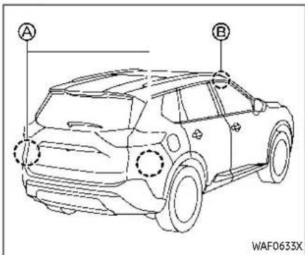
SYSTEM MAINTENANCE
The two radar sensors for the I-BSI system are located near the rear bumper. Always keep the area near the radar sensors clean.
The radar sensors may be blocked by temporary ambient conditions such as splashing water, mist or fog.
The blocked condition may also be caused by objects such as ice, frost or dirt obstructing the radar sensors.
Check for and remove objects obstructing the area around the radar sensors.
Do not attach stickers (including transparent material), install accessories or
apply additional paint near the radar sensors.
Do not strike or damage the area around the radar sensors.
It is recommended you visit a NISSAN dealer if the area around the radar sensors is damaged due to a collision.
The lane camera unit for I-BSI system is located above the inside mirror. To keep the proper operation of I-BSI and prevent a system malfunction, be sure to observe the following:
●Always keep the windshield clean.
- Do not attach a sticker (including transparent material) or install an accessory near the camera unit.
- Do not place reflective materials, such as white paper or a mirror, on the instrument panel. The reflection of sunlight may adversely affect the camera unit's capability of detecting the lane markers.
- Do not strike or damage the areas around the camera unit. Do not touch the camera lens or remove the screw located on the camera unit. It is recommended you contact a NISSAN dealer if the camera unit is damaged due to an accident.
Radio frequency statement ForUSA
FCCID:LTQRN5TR
CAUTIONTOUSERS
Changesormodificationsnotexpressly approvedbythepartyresponsiblefor compliance could void the user's authoritytooperatetheequipment.
This device complies with Part 15 of the FCC Rules and with RSS of the Industry Canada. Operation is subject to the following two conditions:
(1) This devicemay not cause harmful interference, and
(2) this device must accept any interference received, including interference that may cause undesired operation
ForCanada
Model:RN5TR
IC:3659A-RN5TR
ThisdevicecomplieswithIndustryCanadalicense-exemptRSSstandard(s). Operationissubjecttothefollowing twoconditions:(1)thisdevicemaynot causeinterference,and(2)thisdevice mustacceptanyinterference,including interferencethatmaycauseundesired operationofthedevice.
REARCROSSTRAFFICALERT(RCTA)

WARNING
Failuretofollowthewarningsand instructionsforproperuseofthe RCTAsystemcouldresultinserious injuryordeath.
- The RCTAsystemisnotareplacementforproperdrivingproceduresandisnotdesignedtopreventcontactwithvehiclesorobjects.Whenbackingoutofaparkingspace,alwaysusethesideandreamirrorsandturnandlookinthedirectionyourvehiclewillmove.NeverrelysolelyontheRCTAsystem.
The RCTA system will assist you when backing out from a parking space. When the vehicle is in reverse, the system is designed to detect other vehicles approaching from the right or left of the vehicle. If the system detects cross traffic, it will alert you.

① Side indicator light
② Vehicle information display
③ Steering-wheel-mounted controls (left side)
The RCTA system can help alert the driver of an approaching vehicle when the driver is backing out of a parking space. When the shift position is in R (Reverse) and the vehicle speed is less than approximately 5 MPH (8 km/h), the RCTA
Startinganddriving5-77
system is operational.
If the radar detects an approaching vehicle from either side, the system chimes (once) and the side indicator light flashes on the side the vehicle is approaching from.

The RCTA system uses radar sensors Ⓐ installed on both sides near the rear bumper to detect an approaching vehicle.
The radar sensors can detect an approaching vehicle from up to approximately 66 ft (20 m) away.

5-78 Startinganddriving
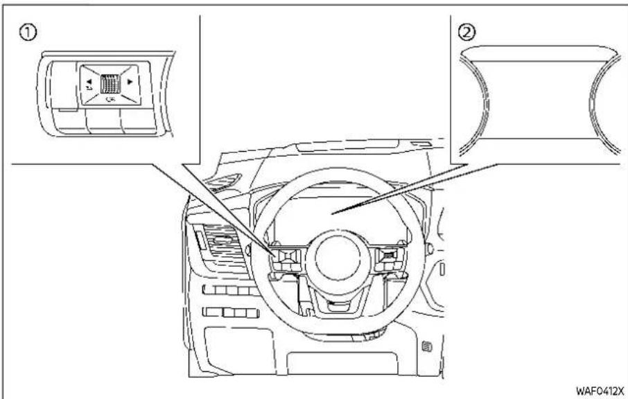
① Steering-wheel-mounted controls (left side)
② Vehicle information display
HOW TO ENABLE/DISABLE THE RCTA SYSTEM
Perform the following steps to enable or disable the RCTA system.
- Push the ◀ button until "Settings" appears in the vehicle information display and then push the scroll
dial. Use the scroll dial to select "Driver Assistance". Then push the scroll dial.
- Use the button to select "Cross Traffic Alert" then press the scroll dial.
- Use the scroll dial to enable or disable the system.
NOTE:
Thesystemsettingwillberetained eveniftheengineisrestarted.
![graph TD A["Step a: Traffic flow on road"] --> B["Step b: Collision path on slope"] B --> C["Step c: Accident on road"] C --> D["Step d: Collision path on slope"] D --> E["Step e: Collision path on slope"] style A fill:#f9f,stroke:#333 style B fill:#f9f,stroke:#333 style C fill:#f9f,stroke:#333 styl…](/content/2026/05/810569/images/2bd8440e782ddc0966a9795591bc220c7ef2a1364d494e43f84e54855ae76260.jpg)
RCTA SYSTEM LIMITATIONS

WARNING
ListedbelowarethesystemlimitationsfortheRCTAsystem.Failureto operatethevehicleinaccordance withthesesystemlimitationscould resultinseriousinjuryordeath.
●Alwayschecksurroundingsand turntocheckwhatisbehindyou beforebackingup.Theradar sensors detect approaching (moving)vehicles.Theradarsensors cannot detect every object suchas:
—Pedestrians, bicycles, motorcycles, animals or child-operated toy vehicles
—Avehiclethatispassingat speedsgreaterthanapproximately19MPH(30km/h)
—Avehiclethatispassingat speedslowerthanapproximately5MPH(8km/h)
•Theradarsensorsmaynotdetect approachingvehiclesincertain situations:
—Illustration: When a vehicle parked next to you obstructs the beam of the adarsensor.
—Illustration ⑥: Whenthevehicle is parked in an angled parkingspace.
—Illustration Ⓞ:Whenthevehicle is parked on inclined ground.
—Illustration @Whenanapproachingvehicleturnsinto yourvehicle'sparkinglotaisle.
—Illustration @:Whentheangle formedbyyourvehicleand approachingvehicleissmall
- The following conditions may reduce the ability of the radar to detect other vehicles:
—Severeweather
—Roadspray
—Ice/frost/dirtbuild-uponthe vehicle
- Donotattachstickers(including transparentmaterial),installaccessoriesorapplyadditional paintneartheradarsensors. Theseconditionsmayreducethe abilityoftheradartodetectother vehicles
- Excessivenoise(e.g.audiosystemvolume,openvehiclewindow) will interfere with the chimesound,anditmaynotbe heard.
![graph TD A["Top Car"] --> B["Left Car"] B --> C["Right Car"] C --> D["Bottom Car"] style A fill:#f9f,stroke:#333 style B fill:#ccf,stroke:#333 style C fill:#cfc,stroke:#333 style D fill:#fcc,stroke:#333](/content/2026/05/810569/images/7001939aa251d05be7e806f1e77ff5c1574863fc6b2eefe6f1daf2c296705ee3.jpg)
Illustration1

Illustration2
Startinganddriving5-81
NOTE:
Inthecaseofseveralvehiclesap- proachinginarow(Illustration1)orin theoppositedirection(Illustration2),a chimemaynotbesoundedbytheRCTA systemafterthefirstvehiclepassesthe sensors.
SYSTEM TEMPORARILY UNAVAILABLE
When radar blockage is detected, the system will be deactivated automatically. The "Unavailable Side Radar Obstruction" warning message will appear in the vehicle information display.
The systems are not available until the conditions no longer exist.
The radar sensors may be blocked by temporary ambient conditions such as splashing water, mist or fog.
The blocked condition may also be caused by objects such as ice, frost or dirt obstructing the radar sensors.
NOTE:
If the BSW system stops working, the RCTA and Intelligent Blind Spot Intervention (I-BSI) (if so equipped) systems will also stop working.
Actiontotake:
Whentheaboveconditionsnolonger exist,thesystemwillresumeautomati-
5-82 Startinganddriving
cally.
SYSTEM MALFUNCTION
When the RCTA system malfunctions, it will turn off automatically. The "Malfunction" warning message will appear in the vehicle information display.
NOTE:
If the BSWsystem stops working, the RCTA and I-BS system will also stop working.
Actiontotake:
Stop the vehicle in a safe location, turn the engine off and restart the engine. If the message continues to appear, have the system checked. It is recommended that you visit a NISSAN dealer for this service.

SYSTEM MAINTENANCE
The two radar sensors for the RCTA system are located near the rear bumper. Always keep the area near the radar sensors clean.
The radar sensors may be blocked by temporary ambient conditions such as splashing water, mist or fog.
The blocked condition may also be caused by objects such as ice, frost or dirt obstructing the radar sensors.
Check for and remove objects obstructing the area around the radar sensors.
Do not attach stickers (including transparent material), install accessories or
apply additional paint near the radar sensors.
Do not strike or damage the area around the radar sensors. It is recommended that you visit a NISSAN dealer if the area around the radar sensors is damaged due to a collision.
Radio frequency statement ForUSA
FCCID:LTQRN5TR CAUTIONTOUSERS
Changesormodificationsnotexpressly approvedbythepartyresponsiblefor compliance could void the user's authoritytooperatetheequipment. ThisdevicecomplieswithPart15ofthe FCCRulesandwithRSSoftheIndustry Canada.Operationissubjecttthe followingtwoconditions:
(1) This devicemay not cause harmful interference, and
(2) this device must accept any interference received, including interference that may cause undesired operation
ForCanada
Model:RN5TR
IC:3659A-RN5TR
This device complies with Industry Canada licence-exempt RSS standard(s).
Operationissubjecttothefollowing twoconditions:(1)thisdevicemaynot causeinterference,and(2)thisdevice mustacceptanyinterference,including interferencethatmaycauseundesired operationofthedevice.
CRUISECONTROL(ifsoequipped)

- RES+ switch
- SET- switch
- CANCEL switch
- Cruise ON/OFF switch
For models with the ProPILOT Assist system, see "Conventional (fixed speed) cruise control mode" (P.5-119).

WARNING
- Alwaysobservethepostspeed limitsanddonotsetthespeed overthem.
- Donotusethecruise control when driving under the following
Startinganddriving5-83
conditions.Doingsocouldcause alossofvehiclecontrolandresult inanaccident.
—Whenitisnotpossibletokeep thevehicleataconstant speed
—Whendrivinginheavytraffic
—Whendrivingintrafficthat variesspeed
—Whendrivinginwindyareas
—Whendrivingonwindingor hillyroads
—Whendrivingonslippery(rain, snow, ice, etc.)roads
PRECAUTIONS ON CRUISE CONTROL
- If the cruise control system malfunctions, it will cancel automatically. The cruise indicator in the vehicle information display will then blink to warn the driver.
- If the cruise indicator blinks and "Unavailable: Cruise system trouble" message appears in the display, turn the Cruise ON/OFF switch off and have the system checked. It is recommended that you visit a NISSAN dealer for this service.
5-84 Startinganddriving
- The cruise indicator may blink when the Cruise ON/OFF switch is turned ON while pushing up the RES+, pushing down the SET-, or pushing the CANCEL switch. To properly set the cruise control system, perform the following procedures.
The cruise control allows driving at speeds above 25 MPH (40 km/h) without keeping your foot on the accelerator pedal.
The cruise control will automatically be canceled if the vehicle slows down more than approximately 8 MPH (13 km/h) below the vehicle set speed. ("Unavailable: Under specified speed" message appears in the display.)
Moving the shift lever to the N (Neutral) position will cancel the cruise control.
Turning on cruise control
Push the Cruise ON/OFF switch. The cruise indicator and "Standby Push SET-to active" message in the vehicle information display will appear.
Setting cruising speed
- Accelerate to the desired speed.
- Push the SET- switch down or RES+ switch up and release it.
- Take your foot off the accelerator pedal.
The vehicle will maintain the set speed. ("+/- Change Set speed" message appears in the display.)
NOTE:
IfpushedtheRES+switchandreleased itwhenthereisnovehiclesetspeed, thesetspeedissettothecurrent vehiclespeed.
Passinganothervehicle:
Depress the accelerator pedal to accelerate. After releasing the accelerator pedal, the vehicle will return to the previously set speed.
The vehicle may not maintain the set speed when going up or down steep hills. In such cases, drive without the cruise control.
Resettingtoslowerspeed:
Use any one of the following methods to reset to a slower speed.
- Lightly tap the foot brake pedal. When the vehicle reaches the desired speed, push down and release the SET-
5-84 Startinganddriving
PROPILOTASSIST(ifsoequipped)
switch.
- Push down and hold the SET- switch. When the vehicle reaches the desired speed, release the SET- switch.
- Quickly push down and release the SET- switch. This will reduce the vehicle speed by about 1 MPH (1.6 km/h).
Resettingtofasterspeed:
Use any one of the following methods to reset to a faster speed.
- Depress the accelerator pedal. When the vehicle reaches the desired speed, push down and release the SET-switch.
- Push up and hold the RES+ switch. When the vehicle reaches the desired speed, release the RES+ switch.
- Quickly push up and release the RES+ switch. This will increase the vehicle speed by about 1 MPH (1.6 km/h).
Resumingatpresetspeed:
Push up and release the RES+ switch. The vehicle will resume the last set cruising speed when the vehicle speed is over 25 MPH (40 km/h). ("Resumed" message appears in the display.)
Cancelling cruising speed
Use any one of the following methods to cancel the vehicle set speed. ("Standby Push RES+ to resume" message appears in the display.)
- Push the CANCEL switch.
- Tap the foot brake pedal.
- Push the Cruise ON/OFF switch. The cruise indicator will turn off.
This section contains the information about the following system features:
●ProPILOT Assist (general system operation)
●ProPILOT Assist with Navi-link (additional functionality, if so equipped)

WARNING
Failuretofollowthewarningsand instructionsforproperuseofthe ProPILOTAssistsystemcouldresult inseriousinjuryordeath.
•ProPILOTAssistisnotaself-driving system. Withinthelimitsofits capabilities, as described in this manual, ithelpsthedriver with certain driving activities.
•TheProPILOTAssistsystemisnot areplacementforproperdriving proceduresandisnotdesigned tocorrectcareless,inattentiveor absent-mindeddriving.ProPILOT Assistwillnotalwayssteerthe vehicletokeepitinthelane.The ProPILOTAssistsystemisnot designedtopreventlossofcontrol.itisthedriver'sresponsibility tostayalert,drivesafely,keep thevehicleinthetravelinglane, andbeincontrolofthevehicleat
Startinganddriving5-85
alltimes.
- TherearelimitationstothePro-PILOTAssistsystemcapability. TheProPILOTAssistsystemdoes notfunctioninalldriving,traffic, weather, androadconditions. It is thedriver's responsibility to stay alert, drivesafely, keepthevehicleinthetravelinglane, and bein control of the vehicle at all times.
•TheProPILOTAssistsystemis onlyanaidtoassistthedriver andisnotacollisionwarningor avoidance device.
•TheProPILOTAssistsystemisfor highwayuseonlyandisnot intendedforcitydriving.Failure toapplythebrakesorsteerthe vehiclewhennecessarymayresultinaseriousaccident.
•Alwaysobservepostedspeed limitsanddonotsetthespeed overthem. - Nevertakeyourhandsoffthe steeringwheelwhendriving.Alwayskeepyourhandsonthe steeringwheelanddriveyour vehiclesafely.
- Neverunfastenyoursafetybelt when using ProPILOTAssist. Doingsoautomaticallycancels
theProPILOTAssistsystem.
•TheProPILOTAssistsystemdoes notreactwhenapproachingstationaryandslowmovingvehicles.
●AlwaysdrivecarefullyandattentivelywhenusingtheProPILOT Assistsystem.ReadandunderstandtheOwner'sManualthoroughlybeforeusingtheProPILOT Assistsystem.Toavoidserious injuryordeath,donotrelyonthe systemtopreventaccidentsorto controlthevehicle'sspeedin emergencysituations.Donot usetheProPILOTAssistsystem exceptinappropriateroadand trafficconditions.
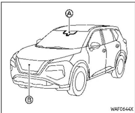
The ProPILOT Assist system is intended to enhance the operation of the vehicle when following a vehicle traveling in the same lane and direction.
The ProPILOT Assist system uses a multi-sensing front camera installed behind the windshield to monitor the lane markers and a radar sensor located on the front of the vehicle to measure the distance to the vehicle ahead in the same lane. If the system detects a slower moving vehicle ahead, the system will reduce the vehicle speed so that your vehicle follows the vehicle in front at the selected distance. The system will also help keep the vehicle centered in the traveling lane when clear lane markings
are detected.
NOTE:
It is important to ensure the front camera and radarsensors are clear at all times. (See "ICCSensor maintenance" (P.5-112) and "Steering Assist maintenance" (P.5-118) formoredetails.)
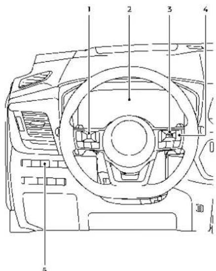
WAF0557X
① Steering-wheel-mounted control (left)
② Vehicle information display
③ Steering-wheel-mounted control (right)
④ ProPILOT Assist switch
⑤ Steering Assist switch
The ProPILOT Assist system has the following two functions:
1. Intelligent Cruise Control (ICC)
The ICC system can be set to one of two cruise control modes:
●Conventional (fixed speed) cruise control mode:
For cruising at a preset vehicle speed For additional information, see "Turning the conventional (fixed speed) cruise control mode ON" (P.5-92).
NOTE:
SteeringAssistisnotavailableinthe conventional(fixedspeed)cruisecontrolmode.
●Vehicle-to-vehicle distance control mode:
The ICC system maintains a selected distance from the vehicle in front of you within the speed range of 0 to 90 MPH (0 to 144 km/h) up to the vehicle set speed. The vehicle set speed can be selected by the driver between 20 to 90 MPH (30 to 144 km/h). When the vehicle ahead slows to a stop, your vehicle gradually decelerates to a standstill. When the vehicle is stopped, the ICC system maintains braking force to keep your vehicle stopped.
- When your vehicle is stopped for less than approximately 3 seconds and the vehicle ahead begins to move, your vehicle will start moving again auto-
matically.
- When your vehicle is at a standstill for more than approximately 3 seconds and the vehicle ahead begins to accelerate, push up the RES+ switch or lightly depress the accelerator pedal. The ICC system starts to follow the vehicle ahead.
●Always check surroundings before restarting the vehicle.
- For vehicles equipped with ProPILOT Assist with Navi-link and only when on a limited access freeway (as identified in the navigation map data):
- The time the vehicle can remain stopped and automatically restart is extended from 3 seconds to 30 seconds.
- If a vehicle ahead cuts in or out of the lane ahead, the vehicle may not automatically start when the traffic ahead begins to move. You need to push up the RES+ switch or lightly depress the accelerator pedal to follow the vehicle directly ahead when it is safe to do so.
- When no vehicle is detected ahead within the driver selected distance, the vehicle travels at the speed set by the driver. The speed must be above 20 MPH (30 km/h) to use this function.
NOTE:
EveniftheAutomaticEmergencyBraking(AEB)settingisturnedoffbythe driverusingthe"Settings"menuinthe vehicleinformationdisplay,AEBwillbe automaticallyturnedonwhenICCis used.
2. Steering Assist
The Steering Assist function helps the driver to keep the vehicle centered within the traveling lane.
When there is no vehicle ahead, Steering Assist is not available at speeds under 37 MPH (60 km/h).
5-88 Startinganddriving

PROPILOT ASSIST SWITCHES
- RES+ switch:
Resumes vehicle set speed or increases speed incrementally
- SET- switch:
Sets desired cruise speed or reduces speed incrementally
- CANCEL switch:
Deactivates the ProPILOT Assist system
- ProPILOT Assist switch:
Turns the ProPILOT Assist system on or off
-
DISTANCE switch:
-
Long
- Middle
-
Short
-
Steering Assist switch:
Turns the Steering Assist function on or off
NOTE:
ForProPILOTAssistwithNavi-link equippedvehicles:WhenManualmode isselectedinthe"Spd.LimitAssist" menu,operatingtheRES+orSET-switchcanapplytheindicatedspeed limittothevehiclesetspeed.(See "SpeedLimitAssist-afeatureofProPI-
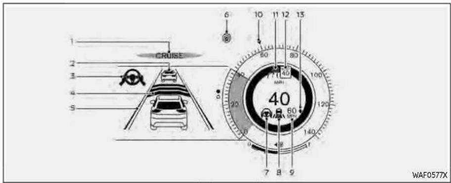
Modelswithfull-screendisplay

Modelswithanalogmeterandcolordisplay
PROPILOT ASSIST SYSTEM DISPLAY AND INDICATORS
1. ProPILOTAssistactivation
Displays once the ProPILOT Assist system is activated
2. Vehicleaheaddetectionindicator
Indicates whether the system detects a vehicle in front of you
3. SteeringAssistindicator
Indicates the status of the Steering Assist function by the color of the indicator
• Steering Assist indicator (gray): Steering Assist standby
• Steering Assist indicator (green): Steering Assist active
4. Setdistanceindicator
Displays the selected distance
5. Lanemarkerindicator
Indicates whether the system detects lane markers
- No lane markers displayed: Steering Assist is turned off
- Lane marker indicator (gray): No lane markers detected
- Lane marker indicator (green): Lane markers detected, Steering Assist is active
- Lane marker indicator (orange): Lane departure is detected
6. ProPILOTAssiststatusindicator ( )
Indicates the status of the ProPILOT Assist system by the color of the indicator
- ProPILOT Assist status indicator (white): ProPILOT Assist is on but in standby
• ProPILOT Assist status indicator (blue): ProPILOT Assist active
7. Steering Assist status indicator/warning( 📄 , 📄 )
Displays the status of the Steering Assist by the color of the indicator/warning
- No Steering Assist status indicator displayed: Steering Assist is turned off
• Steering Assist status indicator (gray): Steering Assist standby
• Steering Assist status indicator (green): Steering Assist active
• Steering Assist status indicator (orange): Steering Assist malfunction
8. Speedcontrolstatusindicator/set distanceindicator/lanemarkerindicator( )
Displays the status of speed control by the color of the indicator, and displays
the selected distance by the number of horizontal bars shown
• Speed control status indicator (white): ICC standby
- Speed control status indicator (green): ICC (distance control mode) is active
— Green vehicle icon displayed: Vehicle detected ahead
— No vehicle icon shown: No vehicle detected ahead (Your vehicle maintains the driver-selected set speed.)
- Speed control status indicator (orange): Indicates an ICC malfunction For the lane marker indicator, see "Steering Assist display and indicators" (P.5-115).
9. Vehiclesetspeedindicator
Indicates the vehicle set speed
10. Vehiclesetspeedindicator(ifso equipped)(▶)
Indicates the vehicle set speed
11. Roadinformationindicator(ifso equipped)(A, B)
Indicates the detected road information
For additional information, see "Speed Adjust by Route - a feature of ProPI-LOT Assist with Navi-link" (P.5-106).
- Detectedspeedlimitindicator(ifso equipped)(40)
Indicates the currently detected speed limit
For additional information, see "Speed Limit Assist - a feature of ProPILOT Assist with Navi-link" (P.5-103).
Indicates the Speed Limit Assist activation mode or system operation For additional information, see "Speed Limit Assist - a feature of ProPILOT Assist with Navi-link" (P.5-103).
13. SpeedLimitAssistindicator(ifso equipped)(A, ↑, ↓)
NOTE:
WhentheProPILOTAssistsystemis activated, thedisplaywillautomatically beswitchedtotheProPILOTAssist systemdisplay. Todisablethisfunction, turn "Transition(Cruise)"offunder "CustomizeDisplay" of thesettingsmenu.
The ProPILOT Assist display is also shown in the Head Up Display (HUD) (if so equipped). (See "Head Up Display (HUD)" (P.2-49).)
TURNING THE CONVENTIONAL (fixed speed) CRUISE CONTROL MODE ON
NOTE:
ProPILOTAssistprovidesnoapproach warnings, automaticbraking, or Steering Assistintheconventional(fixed speed)cruisecontrolmode.
To choose the conventional (fixed speed) cruise control mode, push and hold the ProPILOT Assist switch for longer than approximately 1.5 seconds. For additional information, see "Conventional (fixed speed) cruise control mode" (P.5-119).

Example
OPERATING PROPILOT ASSIST
- Push the ProPILOT Assist switch. A This turns on the ProPILOT Assist system.
- The ProPILOT Assist status indicator ® illuminates in white.
- A screen is displayed for a period of time that indicates the status of the Driving Aid functions.

Example(allenabled)
When the Driving Aids are enabled:
| Zone Driving Aid | Display | |
| Forward | Automatic Emergency Braking (AEB) with Pedestrian Detection | Outline |
| Intelligent Forward Collision Warning (I-FCW) | ||
| Lane | Lane Departure Warning (LDW) | Outline |
| Intelligent Lane Intervention (I-LI) | Shaded | |
| Blind Spot | Blind Spot Warning (BSW) | Outline |
| Intelligent Blind Spot Intervention (I-BSI) | Shaded | |
- When any of the "Warning" systems are enabled, the " 🔵" mark is shown in each zone.
- When any of the "Intervention" systems are enabled, the 🔒 " mark is shown in each zone.
- When no system is enabled, "OFF" is shown in each zone.

To change the status of the Driving Aids, use ① or to navigate the settings screen. For additional information, see "How to use the vehicle information display" (P.2-23).
- Accelerate or decelerate your vehicle to the desired speed and push down the SET- switch. The ProPILOT Assist system begins to automatically maintain the vehicle set speed. The ProPILOT Assist activation indicator and ProPILOT Assist status indicator illuminate in blue. When a vehicle ahead is detected and traveling at a speed of 20 MPH (30 km/h) or below and the SET- switch is pushed
Startinganddriving5-93
down, the vehicle set speed is 20 MPH (30 km/h).
NOTE:
Whenthel-LlandI-BSIsystemsare enabledinthesettingsmenuofthe vehicleinformationdisplay,turningthe ProPILOTAssistsystemonwillturnon thel-LlandI-BSIsystemsatthesame time.Ifthel-LIsystemisdisabledinthe settingsmenu,thel-LIsystemwill automaticallybeturnedonwhenthe SteeringAssistsystemisactive.For additionalinformation,see"Intelligent LaneIntervention(I-LI)("P.5-52),"IntelligentLaneIntervention(I-LI)("P.5-115) and"IntelligentBlindSpotIntervention (I-BSI)("P.5-66).
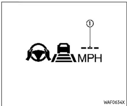
When the SET- switch is pushed down under the following conditions, the Pro-PILOT Assist system cannot be set and the vehicle set speed indicator ① blinks for approximately 2 seconds:
- When traveling below 20 MPH (30 km/h) and a vehicle ahead is not detected
- When the shift lever is moved out of the D (Drive) position or into the manual shift mode
- When the parking brake is applied
- When the brakes are operated by the driver
- When the VDC system is off. For additional information, see "Vehicle
Dynamic Control (VDC) system" (P.5-157).
- When the VDC system (including the traction control system) is activated
- When the SNOW mode or OFF-ROAD mode is selected (AWD models)
- When a wheel is slipping
- When any door is open
- When the driver's seat belt is not fastened

How to change the vehicle set speed
The vehicle set speed can be adjusted.
To change to a faster cruising speed:
- Push up and hold the RES+ switch ①. The vehicle set speed increases in increments of 5 MPH (5 km/h).
- Push up, then quickly release the RES+ switch ①. Each time you do this, the vehicle set speed increases by 1 MPH (1 km/h).
To change to a slower cruising speed:
- Push down and hold the SET- switch ②. The vehicle set speed decreases in increments of 5 MPH (5 km/h).
- Push down, then quickly release the SET-switch ②. Each time you do this, the vehicle set speed decreases by 1 MPH (1 km/h).
For ProPILOT Assist with Navi-link equipped vehicles: The vehicle set speed can also be changed according to the speed limit. (See "Speed Limit Assist - a feature of ProPILOT Assist with Navi-link" (P.5-103).)
How to momentarily accelerate or decelerate
- Depress the accelerator pedal when acceleration is required. Release the accelerator pedal to resume the previously set vehicle speed.
- Depress the brake pedal when deceleration is required. Control by the ProPILOT Assist system is canceled. Push up the RES+ switch to resume the previously set vehicle speed.

WARNING
When the accelerator pedal is depressed and you are approaching the vehicle ahead, the CC system will neither control the brakenor warmth driver with the chime and display. The driver must manually control the vehicles speed to maintain
asafedistancetothevehicleahead. Failuretodosocouldresultinsevere personalinjuryordeath.
NOTE:
When you accelerate by depressing the accelerator pedal or decelerate by pushing down the SET-switch and the vehicle travels faster than the speed set by the driver, the vehicle sets speed indicator will blink.
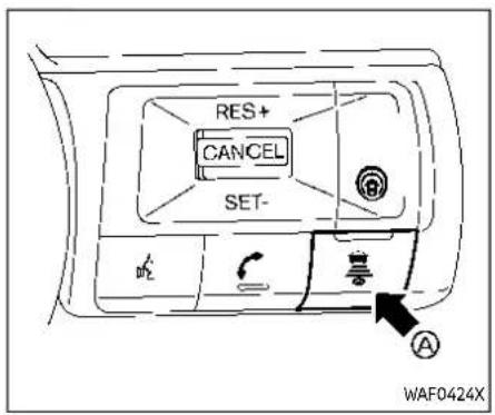
How to change the set distance to the vehicle ahead The distance to the vehicle ahead can be selected at any time.
Each time the DISTANCE switch Ⓐ is pushed, the set distance will change to "long", "middle", "short" and back to "long" again in that sequence.
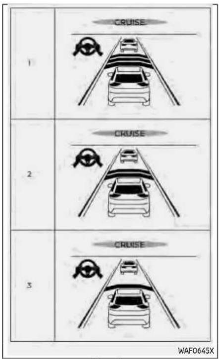
Example
Distance—approximatedistanceat60 MPH(100km/h)
-
Long - 200 ft (60 m)
-
Middle - 150 ft (45 m)
-
Short - 90 ft (30 m)
●The actual distance to the vehicle ahead adjusts automatically according to the vehicle speed. The higher the vehicle speed, the longer the distance.
●The distance setting will remain at the current setting even if the engine is restarted.

① Steering-wheel-mounted control (left)
② Vehicle information display
③ Steering Assist switch
HOW TO ENABLE/DISABLE THE STEERING ASSIST
Use the following methods to enable or disable the Steering Assist.
SteeringAssistswitch:
To turn the Steering Assist on or off, push the Steering Assist switch ③ on the instrument panel.
NOTE:
- WhentheSteeringAssistswitchis usedtoturnthesystemonoroff, thesystemremembersthesetting eveniftheignitswitchiscycled. Theswitchmustbepushedagainto changethesettingtoonoroff.
•TheSteeringAssistswitchchanges thestatusofthe"SteeringAssist" selectionmadeinthe"Settings" screeninthevehicleinformation display.
Settinginthevehicleinformationdisplay:
- Push the ◀ button on the steering wheel ① until "Settings" appears in the vehicle information display ② and then push the scroll dial.
- Use the scroll dial to select "Driver Assistance." Then push the scroll dial.
- Select "Steering Assist" and push the scroll dial to turn the Steering Assist on or off.
NOTE:
- WhentheCruisescreenisdisplayed onthevehicleinformationdisplay, pushthescrolldialonthesteering wheeltocallupthe"DriverAssistance"settingdisplay.
- Whenenabling/disablingthesystem throughthevehicleinformationdisplay,thesystemretainsthecurrent settingseveniftheengineisre-started.
HOW TO CANCEL THE PROPILOT ASSIST SYSTEM
To cancel the ProPILOT Assist system, use one of the following methods:
- Push the CANCEL switch.
- Tap the brake pedal (except at a standstill).
- Push the ProPILOT Assist switch to turn the system off. The ProPILOT Assist status indicator will turn off. When the ProPILOT Assist system is canceled while the vehicle is stopped, the electronic parking brake is automatically activated.

WARNING
Topreventthevehiclefrommoving orrollingunexpectedly,whichcould
resultinseriouspersonalinjuryor propertydamage, beforeexitingthe vehiclemakesuretopushthePro-PILOTAssistswitchtoturnthesystemoff, pushtheparkbuttontoshift totheP(Park)position, andturnthe engineoff.
INTELLIGENT CRUISE CONTROL (ICC)
- The Intelligent Cruise Control (ICC) is a part of the ProPILOT Assist system. To choose the ICC system without the Steering Assist, activate the ProPILOT Assist and then turn off the Steering Assist with the switch or in the settings menu. For additional information, see "Operating ProPILOT Assist" (P.5-92) and "How to enable/disable the Steering Assist" (P.5-97).
- To choose the conventional (fixed speed) cruise control mode, push and hold the ProPILOT Assist switch for longer than approximately 1.5 seconds. For additional information, see "Conventional (fixed speed) cruise control mode" (P.5-119).

WARNING
Failuretofollowthewarningsand instructionsforproperuseoftheICC systemcouldresultinseriousinjury ordeath.
- The ICC system is only an aid to assist the driver and is not a collision warning or avoidance device. It is recommended for highway use only and it is not intended for city driving. It is the driver's responsibility to stay alert, drives safely, and be in control of the vehicle at all times.
- TherearelimitationstothelCC systemcapability.TheICCsystem doesnotfunctioninalldriving, traffic,weather,androadconditions.Itisthedriver'sresponsibilitytostayalert,drivesafely, keepthevehicleinthetraveling lane,andbeincontrolofthe vehicleataltimes.
●Alwaysobservepostedspeed limitsanddonotsetthespeed overthem. - TheICCsystemdoesnotreactto stationaryandslowmovingvehicles.
●AlwaysdrivecarefullyandattentivelywhenusingtheICCsystem. ReadandunderstandtheOwner's Manualthoroughlybeforeusing theICCsystem.Toavoidserious injuryordeath,donotrelyonthe systemtopreventaccidentsorto controlthevehicle'sspeedin emergencysituations.Donot usetheICCsystemexcept in appropriateroadandtrafficconditions.
ICC system operation
The ICC system is designed to maintain a selected distance from the vehicle in front of you and can reduce the speed to match a slower vehicle ahead. The system decelerates the vehicle as necessary and if the vehicle ahead comes to a stop, the vehicle decelerates to a standstill. However, the ICC system can only apply up to 40% of the vehicle's total braking power.
This system should only be used when traffic conditions allow vehicle speeds to remain fairly constant or when vehicle speeds change gradually. If a vehicle moves into the traveling lane ahead or if a vehicle traveling ahead rapidly decelerates, the distance between vehicles may become closer because the ICC system cannot decelerate the vehicle quickly enough. If this occurs, the ICC system sounds a warning chime and blinks the system display to notify the driver to take necessary action.
The ICC system cancels and a warning chime sounds if the speed is below approximately 15 MPH (25 km/h) and a vehicle is not detected ahead. For ProPI-LOT Assist with Navi-link equipped vehicles on a limited access freeway as identified in the navigation map data, the ICC system cancels and a warning chime sounds if your vehicle is at a standstill for more than approximately 3 seconds and a vehicle is not detected ahead.
The ICC system operates as follows:
- When there are no vehicles traveling ahead, the ICC system maintains the speed set by the driver. The vehicle set speed range is between approximately 20 and 90 MPH (30 and 144 km/h).
- When there is a vehicle traveling ahead, the ICC system adjusts the speed to maintain the distance, selected by the driver, from the vehicle ahead. If the vehicle ahead comes to a stop, the vehicle decelerates to a standstill. Once your vehicle stops,
the ICC system keeps the vehicle stopped.
- When the vehicle traveling ahead moves to a different traveling lane, the ICC system accelerates and maintains vehicle speed up to the set speed.
The ICC system does not control vehicle speed or warn you when you approach stationary and slow moving vehicles. You must pay attention to vehicle operation to maintain proper distance from vehicles ahead when approaching toll gates or traffic congestion.
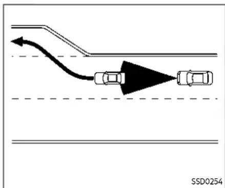
When driving on the highway at a vehicle set speed and approaching a slower traveling vehicle ahead, the ICC system adjusts the speed to maintain the distance, selected by the driver, from the vehicle ahead. If the vehicle ahead changes lanes or exits the highway, the ICC system accelerates and maintains the vehicle set speed. Pay attention to the driving operation to maintain control of the vehicle as it accelerates to the set speed.
The vehicle may not maintain the set speed on winding or hilly roads. If this occurs, you will have to manually control the vehicle speed.
Normally when controlling the distance to a vehicle ahead, the system automatically accelerates or decelerates your vehicle according to the speed of the vehicle ahead.
Depress the accelerator to properly accelerate your vehicle when acceleration is required for a lane change. Depress the brake pedal when deceleration is required to maintain a safe distance to the vehicle ahead due to sudden braking or if a vehicle cuts in. Always stay alert when using the ICC system.

Systemsetdisplay—novehicledetectedahead*
Novehicledetectedahead:
The driver sets the desired vehicle speed based on the road conditions. The ICC system maintains the vehicle set speed, similar to standard cruise control, as long as no vehicle is detected in the lane ahead. The ICC system displays the vehicle set speed.
*: The design of the set display may differ depending on the model.


CRUISE

WAF0580X
Systemsetdisplay—vehicleahead*
Vehicledetectedahead:
When a vehicle is detected in the lane ahead, the ICC system decelerates the vehicle by controlling the throttle and applying the brakes to match the speed of a slower vehicle ahead. The ICC system then adjusts the vehicle speed based on the speed of the vehicle ahead to maintain the driver selected distance.
NOTE:
- Thestoplightsofthevehiclecome onwhenbrakingisperformedby theICCsystem.
- Whenthebrakeisappliedbythe system,anoisemaybeheard.This is notamalfunction.
When the ICC system detects a vehicle ahead, the vehicle ahead detection indicator and the speed control status indicator (distance control mode) illuminates in green.
*: The design of the set display may differ depending on the model.
Vehicleaheadstops:
When a vehicle ahead is detected and it gradually decelerates to stop, your vehicle decelerates to a standstill. When your vehicle is at a standstill, the "(RES+) Follow Vehicle Ahead" message is displayed on the vehicle information display.
Vehicleaheadaccelerates:
- When your vehicle is stopped for less than approximately 3 seconds and the vehicle ahead begins to move, your vehicle will start moving again automatically.
- When your vehicle is at a standstill for more than approximately 3 seconds and the vehicle ahead begins to accelerate, push up the RES+ switch or lightly depress the accelerator pedal. The ICC system starts to follow the vehicle ahead.
●Always check surroundings before restarting the vehicle.
- For vehicles equipped with ProPILOT Assist with Navi-link and only when on a limited access freeway (as identified in the navigation map data):
— The time the vehicle can remain stopped and automatically restart is extended from 3 seconds to 30 seconds.
- If a vehicle ahead cuts in or out of the lane ahead, the vehicle may not automatically start when the traffic ahead begins to move. You need to push up the RES+ switch or lightly depress the accelerator pedal to follow the vehicle directly ahead when it is safe to do so.
Vehicleaheadnotdetected:
When a vehicle is no longer detected ahead, the ICC system gradually accelerates your vehicle to resume the previously vehicle set speed. The ICC system then maintains the vehicle set speed.
When a vehicle is no longer detected, the vehicle ahead detection indicator and speed control status indicator (maintain speed control mode) turn off.
The ICC system gradually accelerates to the vehicle set speed, but you can depress the accelerator pedal to quickly accelerate. When a vehicle is no longer
detected and your vehicle is traveling under approximately 15 MPH (25 km/h), the ICC system automatically cancels. For ProPILOT Assist with Navi-link equipped vehicles on a limited access freeway as identified in the navigation map data, the ICC system cancels and a warning chime sounds if your vehicle is at a standstill for more than approximately 3 seconds and a vehicle is not detected ahead.

When passing another vehicle, the vehicle set speed indicator Ⓐ flashes when the vehicle speed exceeds the set speed. The vehicle ahead detection indicator turns off when the area ahead of the vehicle is open. When the pedal is released, the vehicle returns to the previously set speed. Even though your vehicle speed is set in the ICC system, you can depress the accelerator pedal when it is necessary to accelerate your vehicle rapidly.
Cut-in detection
If a vehicle moves into your traveling lane near your vehicle, the ICC system may inform the driver by flashing the vehicle ahead detection indicator.
Approach warning
If your vehicle comes closer to the vehicle ahead due to rapid deceleration of that vehicle or if another vehicle cuts in, the system warns the driver with the chime and ICC system display. Decelerate by depressing the brake pedal to maintain a safe vehicle distance if:
●The chime sounds.
●The vehicle ahead detection indicator and set distance indicator blink.
- You judge it necessary to maintain a safe distance.
The warning chime may not sound in some cases when there is a short distance between vehicles. Some examples are:
- When the vehicles are traveling at the same speed and the distance between vehicles is not changing.
- When the vehicle ahead is traveling faster and the distance between vehicles is increasing.
- When a vehicle cuts in near your vehicle.
The warning chime will not sound when:
-Your vehicle approaches other vehicles that are parked or moving slowly.
●The accelerator pedal is depressed, overriding the system.
NOTE:
The approach warning chimemay sound and the system display may flash when theradarsensor detects object on the side of the vehicle or on the side of the road. This may cause the ICC system to decelerate or accelerate the vehicle. Theradarsensormay detect these objects when the vehicle is driven on winding, narrow, or hilly roads or when the vehicle is entering or exiting a curve. In these cases, you will havet manually control the proper distance ahead of your vehicle.
Also, the sensors sensitivity can be affected by vehicle operation (steering maneuver driving position in the lane) or traffic or vehicle conditions (fore example, if a vehicle is being driven with somed damage).
Acceleration when passing
When the ICC system is engaged above 44 MPH (70 km/h) and following a slower vehicle (below the vehicle set speed), and the turn signal is activated to the left, the ICC system will automatically start to accelerate the vehicle to help initiate passing on the left and will begin to reduce the distance to vehicle directly ahead. Only the left side turn signal operates this feature. As the driver steers the vehicle and moves into the passing lane, if no vehicle is detected ahead the ICC system will continue to accelerate to the vehicle set speed. If another vehicle is detected ahead, then the vehicle will accelerate up to the following speed of that vehicle. If the vehicle is not steered into the left lane to pass, the acceleration will stop after a short time and regain the set following distance. Acceleration can be stopped at any point by depressing the brake pedal or the CANCEL switch on the steering wheel.

WARNING
Inordertoreducetheriskofa collisionthatmayresultinserious injuryordeath,pleasebeawareof thefollowing:
- This function is only activated with the left turn signal and will briefly accelerate the vehicle even if a change is not initiated. This can include non-passingsituations such as left side exits.
- Ensure that when passing another vehicle, the adjacent lane is clear before initiating the pass. Sudden changes in traffic may occur while passing. Always manually steer or brake as needed. Neversolely rely on the system.
Speed Limit Assist - a feature of ProPILOT Assist with Navi-link (if so equipped)

WARNING
ListedbelowarethesystemlimitationsfortheSpeedLimitAssist.Failure to operate the vehicle in accordancewiththesesystemlimitationscouldresultinseriousinjury ordeath:
- Itisthedriver's responsibility to select the properspeed, follow all traffic regulations and observe
Startinganddriving5-103
otherroadusers.
- TheSpeedLimitAssistmaynot operateproperlyandtheactual speedlimitmaynotbeappliedto thevehiclesetspeedinallconditions. Thedrivermustmanually controlthevehiclespeed.
Belowaresomeexamples:
—When the Traffic Sign Recognition (TSR) system is not functioning properly overturned off. (See "Traffic Sign Recognition (TSR)" (P.5-44).)
—Whendrivingincountriesor areasnotcoveredbythenavigationsystem.
—When crossing national boundaries.
—Whendrivingontheexitofthe limitedaccessfreewayas identifiedinthenavigation mapdata.
—Whendrivinginanareawith nearbyparallelroads(forexample,freewaywithaparallel servicedrive).
—Whendrivinginanareawhere each lane has a different speed limits sign.
—Whendrivingonaroadunder constructionorina constructionzone.
—When thedata fromthe navigationsystemisnot up-to-dateorisunavailable.
When the ProPILOT Assist with Navi-link is active and it detects a change of the speed limit, the new speed limit is indicated and it can be applied to the vehicle set speed automatically or manually.
The Speed Limit Assist operates:
- When the detected speed limit is 20 MPH (30 km/h) and above.
- The "Spd. Limit Assist" is enabled in the settings menu of the vehicle information display.
NOTE:
- While the accelerator pedal is operated with AUTOModeselected, the SpeedLimitAssistwillfunction (automatically adjust the vehicle set speed) only when the detected speed limit is faster than the vehicle setspeed.
•In the following situations, the SpeedLimitAssistwillnotoperate:
- Whenanincreaseintheposted speedlimitisdetected, but the
vehiclesetspeedisalreadyfaster thanthenewspeedlimit.
- When a decrease in the posted speedlimitisdetected, but the vehiclesetspeedisalreadylower thanthenewspeedlimit.
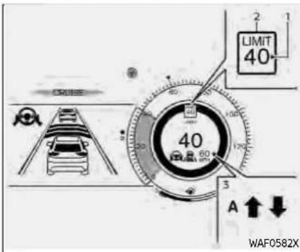
Example
Systemdisplayandindicators:
- Detected speed limit indicator Displays the currently detected speed limit. For additional information, see "Traffic Sign Recognition (TSR)" (P.5-44).
- Applied speed limit indicator (green frame) Indicates the detected speed limit can be applied to the vehicle set speed.
- Speed Limit Assist indicator Indicates the system activation mode or system operation.
"↑": Manual mode is activated and a
new speed limit (faster speed value) is WhenAutomodeisselectedonthe indicated. settingsmenu:
"↓": Manual mode is activated and a new speed limit (lower speed value) is indicated.
"A": Auto mode is activated.
Operatingthesystem:
When the system detects a different speed limit, the new speed value is indicated. The vehicle set speed can be changed to the indicated speed limit automatically or manually.
WhenManualmodeisselectedonsettingsmenu(factorydefaultsetting):
- To accept the newly indicated speed limit, operate the RES+ switch (in case of speed limit up) or SET- switch (in case of speed limit down).
- The Speed Limit Assist indicator ( ↑ or ↓) will turn off after approximately 10 seconds if the RES+ or SET-switch is not operated. (The Speed Limit Assist Indicator can be turned off immediately by operating the opposite switch from the direction indicated by the Speed Limit Assist indicator.)
The system will not activate if a speed limit change is not detected.
NOTE:
AutomodewillnotfunctioninHawaiior USislandterritories.
Howtoactivateordeactivatethesystem:
- Push the ◀ button on the steering wheel until "Settings" appears in the vehicle information display, and push the scroll dial.
- Use the scroll dial to select "Driver Assistance". Then push the scroll dial.
- Select "Spd. Limit Assist", and push the scroll dial to select "Auto" or "Manual" to enable (not activate) the system.
To deactivate the system, select "OFF". NOTE:
Thesystemwillretaincurrentsettings inthevehicleinformationdisplayeven iftheengineisrestarted.
Speed Adjust by Route - a feature of ProPILOT Assist with Navi-link (if so equipped)

WARNING
ListedbelowarethesystemlimitationsfortheSpeedAdjustbyRoute. Failuretooperatethevehiclein accordancewiththesesystemlimitationscouldresultinseriousinjury ordeath:
-
TherearelimitationstotheSpeed AdjustbyRoutesystemcapability.Thesystemdoesnotfunction inalldriving,traffic,weatherand roadconditions.Itisthedriver's responsibilitytostayalert,drive safely,andbeincontrolofthe vehicleataltimes.
●TheSpeedAdjustbyRoutesystemdoesnotbrakethevehicletoastop.Whenevernecessary,the drivermustapplyappropriate braking. -
Itisthedriver's responsibility to select the properspeed, follow all traffic regulations and observe other road users.
•TheSpeedAdjustbyRoutesystemwillnotfunctioninHawaiior USislandterritories. - TheSpeedAdjustbyRoutemay notoperateproperlyinsome roadandtrafficconditions,the system may unexpectedly changethespeed.Thedriver mustmanuallycontrolthe vehicle speed.
Belowaresomeexamples:
—Whenthedatafromthenavigationsystemisnotup-to-dateorisunavailable.
—When not driving along the routes suggested by then navigation system.
—Whenthenavigationsystemis recalculatingtheroute.
—whendrivingincountriesor areasnotcoveredbythenavigationsystem.
—Whendrivingonaroadunder constructionornewlyconstructedroad.
—Whendrivingneararoadsplit orjunction.
—Whendrivinginbadweather orpoorroadconditions.
When the ProPILOT Assist with Navi-link is active on a limited access freeway (as identified in the navigation map data), the Speed Adjust by Route uses road information provided by the navigation system and can adjust the vehicle speed depending on curves, junctions and exits. The system may not always reduce speed for all curves, junctions or exits and the driver may need to apply additional braking at any time.
When the vehicle is through the curve or junction, the vehicle will accelerate again to the set speed. When exiting the limited access freeway, the driver will need to apply braking at the end of the exit.
NOTE:
- Thesystemdoesnotoperatewhen theacceleratorpedalisdepressed.
- Thesystemmaynotoperatede- pendingonthesetdistancetothe vehicleaheadandvehiclesdetected ahead.

Example
Systemdisplayandindicators:
- Road information indicator
Appears when the system adjusts the speed depending on turns or exits.
| Curves and junctions | |
| Exits |
Howtoactivateordeactivatethesystem:
- Push the
▶ button on the
steering wheel until "Settings" appears in the vehicle information display, and push the scroll dial. - Use the scroll dial to select "Driver Assistance". Then push the scroll dial.
- Select "Speed Adjust by Route" and push the scroll dial to turn the system on or off.

NOTE:
Thesystemwillretaincurrentsettings inthevehicleinformationdisplayeven iftheengineisrestarted.
ICC system limitations

WARNING
ListedbelowarethesystemlimitationsforthelCCsystem.Failureto operatethevehicleinaccordance withthesesystemlimitationscould resultinseriousinjuryordeath:
●TheICCsystemisprimarilyintendedforuseonhighwaysand freeways.Itisnotadvisableto usethelCCsystemincity/urban traffic.
●TheICCsystemwillnotadapt automaticallytoroadconditions. Thissystemshouldbeusedin evenlyflowingtraffic.Donotuse thesystemonroadswithsharp curvesoronicyroads,inheavy rainorinfog.
- Asthereisaperformancelimitto thedistancecontrolfunction, neverrelysolelyontheICCsystem. Thissystemdoesnotcorrect careless, inattentiveorabsent-mindeddrivingorovercomepoor visibilityinrain, fog, orotherbad weather. Deceleratethevehicle speedbydepressingthebrake pedal, dependingonthedistance tothevehicleahead and the surroundingcircumstancesinordertomaintainasafedistance betweenvehicles.
-WhenthelCCsystemautomaticallybringsthevehicletoastop, yourvehiclecanautomatically accelerate if the vehicle is stoppedforlessthanapproximately3seconds.Beprepared tostopyourvehicleifnecessary.
- ForvehiclesequippedwithProPI-LOTAssistwithNavi-linkandonly whenonalimitedaccessfreeway (asidentifiedinthenavigation
Startinganddriving
mapdata):
—Thetimethevehiclecanre-
mainstoppedandautomati-
callyrestartisextendedfrom
3secondsto30seconds.
-Ifavehicleaheadcutsinor outofthelaneahead,the vehiclemaynotautomatically startwhenthetrafficahead beginstomove.Youneedto pushuptheRES+switchor lightlydepresstheaccelerator pedaltofollowthevehicle directlyaheadwhenitissafe todos.
●Alwayschecksurroundingsbeforererestartingthevehicle.
- Alwayspayattentiontotheoperationofthevehicleandbe readytomanuallycontrolthe properfollowingdistance.The ICCsystemmaynotbeableto maintaintheselecteddistance betweenvehicles(followingdistance)orselectedvehiclespeed undersomecircumstances.
- TheICCsystemdoesnotdetect thefollowingobjects:
- Stationaryorslowmovingvehicles(whenyourvehicleis
approachingthem)
—Pedestriansorobjectsinthe roadway
—Oncomingvehicles in the samelane
—Motorcyclestravelingoffsetin thetravellane
- TheICCsystemmaynotdetecta vehicleaheadincertainroad, weatherordrivingconditions.To avoidaccidents,neverusethelCC systemunderthefollowing conditions:
—Onroadswithheavy,high-speedtrafficorsharpcurves
—Onslipperyroadsurfaces suchasoniceorsnow,etc.
—Onabumpyroadsurface, suchasanunevendirtroad
—Onsteepdownhillroads(the vehiclemaygobeyondthe vehiclesetspeedandfrequentbrakingmayresultin overheatingthebrakes)
—Onrepeateduphillanddown-hillroads
—Duringbadweather(rain,fog, snow,etc.)
—When the sensor detection is reduced (condition such as rain, snow, fog, dust storms, sandstorms, and roadspray from other vehicles)
—Whendirt,ice,snoworother materialadheretotheradar sensorarea
—Whentrafficconditionsmake itdifficulttokeepaproper distancebetweenvehiclesbecauseoffrequentaccelerationordeceleration
—When acomplicated-shaped vehicles such as acarcarrier traileror flatbed truck/trailer is near the vehicle ahead
—When thereis interferenceby otherradarsources
—Whenexcessivelyheavybaggageisloadedintherearseat orcargoareaofyourvehicle
—Whentowingatrailerorother vehicle
•Insomeroadortrafficconditions, avehiclorobjectcanunexpectedlycomeintothesensordetectionzoneandcauseautomatic braking. Alwaysstayalertand
avoidusingtheICCsystemwhere notrecommendedinthiswarningsection.
●TheICCsystemalsousesamulti-sensingfrontcamera. The following aresomeconditions in which the cameramay not properly detect vehicle and detection of vehicle ahead may be delayed:
—Poorvisibility(conditionssuch as rain, snow, fog, dust storms, sandstorms, android spray from other vehicles)
—Thecameraareaofthewind-shieldisfoggeduporcovered withdirt,waterdrops,ice, snow,etc.
—Stronglight(forexample,sun-lightorhighbeamsfromon-comingvehicles)entersthe frontcamera
—Asuddenchangeinbrightnessoccurs(forexample, whenthevehicleentersor exitsatunnelorshadedarea orlightningflashes)
The detection zone of the radar sensor is limited. A vehicle ahead must be in the detection zone for the ICC system to maintain the selected distance from the vehicle ahead. A vehicle ahead may move outside of the detection zone due to its position within the same lane of travel. Motorcycles may not be detected in the same lane ahead if they are traveling offset from the center line of the lane. A vehicle that is entering the lane ahead may not be detected until the vehicle has completely moved into the lane.
If this occurs, the ICC system may warn you by blinking the system indicator and sounding the chime. The driver may have to manually control the proper distance away from the vehicle traveling ahead.
The ICC system is designed to automatically check the radar sensor's operation within the limitations of the system
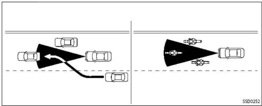

When driving on some roads, such as winding, hilly, curved, narrow roads, or roads which are under construction, the radar sensor may detect vehicles in a different lane, or may temporarily not detect a vehicle traveling ahead. This may cause the ICC system to decelerate or accelerate the vehicle.
The detection of vehicles may also be affected by vehicle operation (steering maneuver or traveling position in the lane, etc.) or vehicle condition.
If this occurs, the ICC system may warn you by blinking the system indicator and sounding the chime unexpectedly. You will have to manually control the proper distance away from the vehicle traveling ahead.
ICC system temporarily unavailable The following are conditions in which the ICC system may be temporarily unavailable. In these instances, the ICC system may not cancel and may not be able to maintain the selected following distance from the vehicle ahead.
ConditionA:
Under the following conditions, the ICC system is automatically canceled. A chime will sound and the system will not be able to be set:
●Any door is open.
- The driver's seat belt is unfastened.
●The vehicle ahead is not detected and your vehicle is traveling below the speed of 15 MPH (25 km/h). For ProPILOT Assist with Navi-link equipped vehicles on a limited access freeway as identified in the navigation map data, the ICC system cancels and a warning chime sounds if your vehicle is at a standstill for more than approximately 3 seconds and a vehicle is not detected ahead.
-Your vehicle has been stopped by the ICC system for approximately 3 minutes or longer.
●The shift lever is moved out of the D (Drive) position or into the manual shift mode.
●The electronic parking brake is applied.
●The VDC system is turned off.
●The AEB applies harder braking
•VDC (including the traction control system) operates.
●The SNOW mode or OFF-ROAD mode is selected (AWD models).
●A wheel slips.
- When the front radar is impaired due to dirt or an other obstruction blocking the radar sensor.
- When the radar signal is temporarily interrupted.
Actiontotake:
When the conditions listed above are no longer present, turn the system off using the ProPILOT Assist switch. Turn the ProPILOT Assist system back on to use the system.
NOTE:
WhenthelCCsystemiscanceledunder anyofthefollowingconditionsata standstill,theelectronicparkingbrake isautomaticallyactivated:
•Anydoorisopen.
•Thedriver'sseatbeltisunfastened.
-Yourvehiclehasbeenstoppedby theICCsystemforapproximately3 minutesorlonger.
- TheshiftleverismovedoutoftheD (Drive)positionorintothemanual shiftmode.
•TheVDCsystemisturnedoff.
- Whenthefrontradarisimpaireddue todirtoranotherobstructionblockingtheradarsensor.
- Whentheradarsignalistemporarily interrupted.
ConditionB:
When there is inclement weather (rain, fog, snow, etc.) blocking the front radar sensor, the ICC system will automatically be canceled, the chime will sound and the "Forward Driving Aids temporarily disabled Front Sensor blocked" warning message will appear in the vehicle information display.
Actiontotake:
When the above condition is no longer present, the warning message will no longer be available in the vehicle information display and the system will operate normally. If the warning message continues to appear, have the system checked. It is recommended that you visit a NISSAN dealer for this service.
ConditionC:
When the radar sensor on the front of the vehicle is covered with dirt or is obstructed, the ICC system will automatically be canceled.
The chime will sound and the "Forward Driving Aids temporarily disabled Front Sensor blocked" warning message will appear in the vehicle information display.
Actiontotake:
If the warning message appears, stop the vehicle in a safe place, push the park button to engage the P (Park) position, and turn the engine off. When the radar signal is temporarily interrupted, clean the sensor area and restart the engine. If
Startinganddriving5-111
the warning message continues to appear, have the system checked. It is recommended that you visit a NISSAN dealer for this service.
ConditionD:
When driving on roads with limited road structures or buildings (for example, long bridges, deserts, snow fields, driving next to long walls), the system may display the "Forward Driving Aids temporarily disabled Front Sensor blocked" message.
Actiontotake:
When the above driving conditions no longer exist, turn the system back on.
ICC system malfunction
If the ICC system malfunctions, it will be turned off automatically, a chime will sound, and the speed control status warning (orange) will illuminate.
Actiontotake:
If the warning illuminates, stop the vehicle in a safe place. Turn the engine off, restart the engine and set the ICC system again. If it is not possible to set the ICC system the warning stays on, it may be a malfunction. Although the normal driving can be continued, the ICC system should be inspected. It is recommended that you visit a NISSAN dealer for this service.
NOTE:
If the CC system is temporarily unavailable, the conventional cruise control modemaystill be used. For additional information, see "Conventional (fixed speed) cruise control mode" (P.5-119).
ICC sensor maintenance
The radar sensor is located on the front of the vehicle.
To keep the ICC system operating properly, be sure to observe the following:
●Always keep the sensor area clean.
- Do not strike or damage the areas around the sensor.
- Do not attach a sticker (including transparent material) or install an accessory near the sensor. This could cause failure or malfunction.
- Do not attach metallic objects near the sensor area (brush guard, etc.). This could cause failure or malfunction.
Do not alter, remove, or paint the front bumper.
Before customizing or restoring the front bumper, it is recommended that you visit a NISSAN dealer.
The camera sensor is located above the inside mirror.
To keep the proper operation of the
systems and prevent a system malfunction, be sure to observe the following:
●Always keep the windshield clean.
- Do not attach a sticker (including transparent material) or install an accessory near the camera unit.
- Do not place reflective materials, such as white paper or a mirror, on the instrument panel. The reflection of sunlight may adversely affect the camera unit's capability of detecting the lane markers.
- Do not strike or damage the areas around the camera unit. Do not touch the camera lens or remove the screw located on the camera unit.
If the camera unit is damaged due to an accident, it is recommended that you visit a NISSAN dealer.
For additional information, see "Common troubleshooting guide" (P.5-40).
Radiofrequencystatement:
ForUSA
Type approval number:
FCC ID: NF3-FR5CPEC
User Manual statement according to §15.19:
This device complies with Part 15 of the FCC Rules.
Operation is subject to the following two conditions:
- this device may not cause harmful interference, and
- this device must accept any interference received, including interference that may cause undesired operation.
User Manual statement according to §15.21:
Changes or modifications made to this equipment not expressly approved by Robert BOSCH GmbH may void the FCC authorization to operate this equipment. User Manual statement according to §15.105:
This equipment has been tested and found to comply with the limits for a Class A digital device, pursuant to Part 15 of the FCC Rules. These limits are designed to provide reasonable protection against harmful interference when the equipment is operated in a commercial environment. This equipment generates, uses, and can radiate radio frequency energy and, if not installed and used in accordance with the instruction manual, may cause harmful interference to radio communications. Operation of this equipment In a residential area is likely to cause harmful interference in which case the user will be required to correct the interference at his own expense.
RF Exposure Information according 2.1091/2.1093/OET bulletin 65:
Radiofrequency radiation exposure information:
This equipment complies with FCC radiation exposure limits set forth for an uncontrolled environment. This equipment should be installed and operated with minimum distance of 20 cm between the radiator and your body.
The transmitter must not be co-located or operating in conjunction with any other antenna or transmitter.
ForCanada
Type approval number:
IC: 3387A-FR5CPEC
Legal warning for RF equipment:
This device complies with Industry Canada licence-exempt RSS standard(s). Operation is subject to the following two conditions: (1) this device may not cause interference, and (2) this device must accept any interference, including interference that may cause undesired operation of the device.
STEERING ASSIST

WARNING
Failuretofollowthewarningsand instructionsforproperuseofthe SteeringAssistcouldresultinseriousinjuryordeath.
•TheSteeringAssistisnotare-placementforproperdrivingproceduresandisnotdesignedtocorrectcareless,inattentiveorabsent-mindeddriving.The SteeringAssistwillnotalwayssteerthevehicletokeepitinthe lane.Itisnotdesignedtoprevent lossofcontrol.Itisthedriver's responsibilitytostayalert,drive safely,keepthevehicleinthe travelinglane,andbeincontrol ofthevehicleatalltimes.
- Asthereisaperformancelimitto theSteeringAssist'scapability, neverrelysolelyonthesystem. TheSteeringAssist does not functioninalldriving, traffic, weather,androadconditions.Alwaysdrivesafely,payattention totheoperationofthevehicle, andmanuallycontrolyourvehicle appropriately.
•TheSteeringAssistisintended foruseonwell-developedhighways with gentle (moderate) curves.Toavoidriskofanaccident,donotusethissystemon localornon-highwayroads.
- TheSteeringAssistonlysteers thevehicletomaintinitspositioninthecenterofalane. The vehiclewillnotsteertoavoid objectsintheroadinfront of thevehicleortoavoid Vehicle movingintoyourlane.
- ltisthedriver's responsibility to stayalert,drivesafely,keepthe vehicleinthetravelinglane,and beincontrolofthevehicleatall times.Nevertakeyourhandsoff thesteeringwheelwhendriving. Alwayskeepyourhandsonthe steeringwheelanddriveyour vehiclesafely.
●AlwaysdrivecarefullyandattentivelywhenusingtheSteering Assist.Readandunderstandthe Owner'sManualthoroughlybeforeusingtheSteeringAssist.To avoidseriousinjuryordeath,do notrelyonthesystemtoprevent accidentsortocontrolthevehicle'sspeedinemergencysituations.DonotusetheSteering
Assistexceptinappropriateroad andtrafficconditions.
see "How to enable/disable the Steering Assist" (P.5-97).
Steering Assist operation
Steering Assist helps the driver keep the vehicle near the center of the lane when both right and left lane markers are detected. Steering Assist only operates when combined with the Intelligent Cruise Control (ICC) system. For additional information, see "Intelligent Cruise Control (ICC)" (P.5-98).
The Steering Assist can be activated when the following conditions are met:
●The ICC system is activated.
●Lane markers on both sides are clearly detected.
●A vehicle ahead is detected (when the vehicle is driven at speeds under 37 MPH (60 km/h)).
●The driver grips the steering wheel.
●The vehicle is driven at the center of the lane.
●The turn signals are not operated.
●The windshield wiper is not operated in the high speed position (the Steering Assist function is disabled after the wiper operates for approximately 10 seconds in the high speed position).
To enable or disable the Steering Assist,

Example
Steering Assist display and indicators
1. Steering Assist status indicator/warning
Displays the status of the Steering Assist by the color of the indicator/warning
• Steering Assist status indicator (gray): Steering Assist standby
• Steering Assist status indicator (green): Steering Assist active
• Steering Assist status indicator (orange): Steering Assist malfunction
2. SteeringAssistindicator
Indicates the status of the Steering Assist by the color of the indicator
• Steering Assist indicator (gray): Steering Assist standby
• Steering Assist indicator (green): Steering Assist active
3. Lanemarkerindicator
Indicates whether the system detects the lane marker
- Lane marker indicator (gray): Lane markers not detected
- Lane marker indicator (green): Lane markers detected
- Lane marker indicator (orange): Lane departure is detected
4. Lanemarkerindicator/speedcontrolstatusindicator/setdistance indicator
Displays the status of the Steering Assist by the color of the lane marker indicator.
- Lane marker indicator (gray): Steering Assist standby
- Lane marker indicator (green): Steering Assist active
For the speed control status indicator and set distance indicator, see "ProPILOT Assist system display and indicators" (P.5-90).
When the Steering Assist is in operation, the Steering Assist status indicator ① the Steering Assist indicator ② and the lane marker indicator ③ and ④ on the vehicle information display turn green. A chime sounds when the Steering Assist initially activates.
When the Steering Assist deactivates, the Steering Assist status indicator ① the Steering Assist Indicator ② and the lane marker indicator ③ and on the vehicle information display turn gray and a chime sounds twice.
Intelligent Lane Intervention (I-LI) With the Steering Assist active, when a curve or strong cross wind exceeds the capabilities of the system and your vehicle approaches either the left or the right side of the traveling lane, the I-LI system will flash the I-LI indicator on the vehicle information display and provide steering wheel vibration to alert the driver. The warning chime will also sound (4 rapid beeps). Then, the I-LI system automatically applies the brakes for a short period of time to help assist the driver to return the vehicle to the center of the traveling lane. This action is in addition to any Steering Assist actions and the warnings cannot be turned off. For more information, see "Intelligent Lane Intervention (I-LI)" (P.5-52).
Startinganddriving5-115

Hands on detection
When the Steering Assist is activated, it monitors the driver's steering wheel operation.
If the steering wheel is not operated or the driver takes his/her hands off the steering wheel for a period of time, the warning ① appears in the vehicle information display and the hands OFF warning light ② illuminates.
If the driver does not operate the steering wheel after the warning has been displayed and the warning light illuminated, an audible alert sounds and both the warning and the warning light flash. If the driver still does not operate the steering
wheel, the system applies a momentary brake application to request the driver to take control of the vehicle again.
If the driver still does not respond, the system turns on the hazard flasher and slows the vehicle to a complete stop.
The driver can cancel the deceleration at any time by steering, braking, accelerating, or operating the ProPILOT Assist switch.

WARNING
SteeringAssistisnotasystemfora hands-freedriving.Alwayskeepyour handsonthesteeringwheeland driveyourvehiclesafely.Failurereto dosocouldcauseacollisionresultinginseriouspersonalinjuryor death.
NOTE:
Ifthedriverlightlytouches(insteadof firmlygrips)thesteeringwheel,the steeringtorquesensormaynotdetect thedriver'shand(s)onthesteering wheelandasequenceofwarnings mayoccur.Whenthedriverholdsand operatesthesteeringwheelagain,the warningsturnoff.
5-116 Startinganddriving
Steering Assist limitations

WARNING
•Inthefollowingsituations, the cameramaynotdetectlanemarkerscorrectlyormaydetectlane markersincorrectly and the SteeringAssistmaynotoperate properly:
—Whendrivingonroadswhere thereare multiple parallel lanemarkers, lanemarkers that are faded or not painted clearly, non-standard lane markers, or lanemarkers covered with water, dirt, snow, etc.
—Whendrivingonroadswith discontinuedlanemarkers
—Whendrivingonroadswitha wideningornarrowinglane width
—Whendrivingonroadswhere therearemultiplelanesor unclearlanemarkersdueto roadconstruction
—Whendrivingonroadswhere therearesharplycontrasting objects,suchasshadows,
snow, water, wheel ruts, seams, or lines remaining after road repairs (the Steering Assist could detect these items as lanemarkers)
—Whendrivingonroadswhere thetravelinglanemergesor separates
- DonotusetheSteeringAssist underthefollowingconditions because the system may not properly detect lanemarkers. Doingsocould cause alossof vehiclecontrol and result in an accident.
—Duringbadweather(rain,fog, snow,dust,etc.)
—Whenrain,snow,sand,etc.,is thrownupbythewheelsof othervehicles
—whendirt,oil,ice,snow,water, oranotherobjectadheresto thecameraunit
—Whenthelensofthecamera unitisfoggy
—Whenstronglight(forexample,sunlightorhighbeams from oncoming vehicles) shinesonthecamera
—Whentheheadlightsarenot brightduetodirtonthelens ortheheadlightsareoffin tunnelsordarkness
—Whenasuddenchangein brightnessoccurs(forexample,whenthevehicleentersor exitsatunnelorisundera bridge)
—Whendrivingonroadswhere thetravelinglanemergesor separatesorwherethereare temporarylanemarkersbecauseofroadconstruction
—Whenthereisalaneclosure duetoroadrepairs
—Whendrivingonabumpyroad surface,suchasanuneven dirtroad
—Whendrivingonsharpcurves orwindingroads
—Whendrivingonrepeatedup-hillanddownhillroads
- DonotusetheSteeringAssist underthefollowingconditions because the system will not operate properly:
—Whendrivingwithatirethatis notwithinnormaltrecondi-
tions(forexample,tirewear,abnormal tirepressure,installationofasparetire,tirechains,non-standardwheels)
—Whenthevehicleisequipped withnon-originalbrakeor suspensionparts
-Whenanobjectsuchasa stickerorcargoobstructsthe camera
—Whenexcessivelyheavybaggageisloadedintherearseat orluggageareaofyourvehicle
—Whenthevehicleloadcapacityisexceeded
—Whentowingatrailerorother vehicle
- Excessivenoisewillinterferewith thewarningchimesound,and thebeepmaynotbeheard.
- FortheProPILOTAssistsystemto operateproperly, the windshield in front of the cameramust be clean. Replace wornwiperblades. The correctsizewiperblades must be used to help make sure the windshield is kept clean. Only use GenuineNISSANwiperblades, or equivalentwiperblades, that
Startinganddriving5-117
arespecificallydesignedforuse onyourvehiclemodelandmodel year. It is recommended that you visit your NISSAN dealer for the correct parts for your vehicle.
Steering Assist temporary standby Automaticstandbyduetodrivingoperation:
When the driver activates the turn signal, the Steering Assist is temporarily placed in a standby mode. (The Steering Assist restarts automatically when the operating conditions are met again.)
Automaticstandby:
In the following cases, "Not Available Front Camera Obstructed" warning message appears in the vehicle information display, along with the chime, and the Steering Assist is placed in a temporary standby mode. (The Steering Assist restarts automatically when the operating conditions are met again.)
- When lane markers on both sides are no longer detected
- When a vehicle ahead is no longer detected under approximately 37 MPH (60 km/h)
NOTE:
For Pro PILOT Assist with Navi-link equipped vehicles on limited access freeway as identified in the navigation map data, the Steering Assist system may continue to operate with visible lanemarkerson the both sides, even when the vehicles speed down approximately 37 MPH (60 km/h) and a vehicle is not detected ahead.
Steering Assist cancel
Under the following conditions, the Steering Assist cancels, and the Steering Assist status indicator and the Steering Assist indicator turn off:
- When unusual lane markers appear in the traveling lane or when the lane marker cannot be correctly detected for some time due to certain conditions (for example, a snow rut, the reflection of light on a rainy day, the presence of several unclear lane markers)
- When the windshield wiper operates in the high speed operation (the Steering Assist is disabled when the wiper operates for more than approximately 10 seconds)
Actiontotake:
Turn the ICC system off using the CANCEL switch. When the conditions listed above are no longer present, turn the ICC system on again.
Steering Assist malfunction
When the system malfunctions, it turns off automatically. The Steering Assist status warning (orange) illuminates. A chime may sound depending on the situation.
Actiontotake:
Stop the vehicle in a safe location, push the park button to shift to the P (Park) position, turn the engine off, restart the engine, resume driving, and set the ICC system again. If the warning (orange) continues to illuminate, the Steering Assist is malfunctioning. Although the vehicle is still drivable under normal conditions, have the system checked. It is recommended that you visit a NISSAN dealer for this service.
Steering Assist maintenance
The camera is located above the inside mirror.
To keep the proper operation of the system and prevent a system malfunction, be sure to observe the following:
●Always keep the windshield clean.
- Do not attach a sticker (including transparent material) or install an accessory near the camera unit.
- Do not place reflective materials, such as white paper or a mirror, on the instrument panel. The reflection of sunlight may adversely affect the camera unit's capability of detecting the lane markers.
- Do not strike or damage the areas around the camera unit. Do not touch the camera lens or remove the screw located on the camera unit.
If the camera unit is damaged due to an accident, it is recommended that you visit a NISSAN dealer.
For additional information, see "Common troubleshooting guide" (P.5-40).
CONVENTIONAL (fixed speed) CRUISE CONTROL MODE NOTE:
ProPILOTAssistprovidesnoapproach warnings, automaticbraking, or Steering Assistintheconventional(fixed speed)cruisecontrolmode.
This mode allows driving at a speed between 20 to 90 MPH (30 to 144 km/h) without keeping your foot on the accelerator pedal.

WARNING
•Intheconventional(fixedspeed) cruisecontrolmode,awarning chimedoesnotsoundtowarn youifyouaretooclosetothe vehicleahead,asneitherthepresenceofthevehicleaheadnor thevehicle-to-vehicledistanceis detected.
- Payspecialattentiontothedistancebetweenyourvehicleand thevehicleaheadofyouora collisioncouldoccur.
- Alwaysconfirmthesettinginthe ICCsystemdisplay.
- Donotusetheconventional (fixedspeed)cruisecontrolmode whendrivingunderthefollowing conditions:
—Whenitisnotpossibletokeep thevehicleatasetspeed
—Inheavytrafficorintraffic thatvariesinspeed
—Onwindingorhillyroads
—Onslipperyroads(rain,snow, ice,etc.)
—Inverywindyareas
- Doingsocouldcausealossof vehiclecontrolandresultinan accident.

Conventional (fixed speed) cruise control switches
- RES+ switch:
Resumes vehicle set speed or increases speed incrementally
- SET- switch:
Sets desired cruise speed or reduces speed incrementally
- CANCEL switch:
Deactivates the system without erasing the vehicle set speed
- ProPILOT Assist switch:
Turns the ProPILOT Assist system on or off
5-120 Startinganddriving

Conventional (fixed speed) cruise control mode display and indicators
The display is located in the vehicle information display.
- Cruise indicator:
This indicator indicates the condition of the ICC system depending on a color.
- Cruise control ON indicator (gray): Indicates that the ProPILOT Assist switch is on
- Cruise control SET indicator (green): Indicates that the cruising speed is set
- Cruise control warning (orange): Indicates that there is a malfunction in the ICC system
- Vehicle set speed indicator:
This indicator indicates the vehicle set speed.
For Canadian models, the speed is displayed in km/h.

Operating conventional (fixed speed) cruise control mode
To turn on the conventional (fixed speed) cruise control mode, push and hold the ProPILOT Assist switch Ⓐ for longer than about 1.5 seconds.
When pushing the ProPILOT Assist switch on, the conventional (fixed speed) cruise control mode display and indicators are displayed in the vehicle information display. After you hold the ProPILOT Assist switch on for longer than about 1.5 seconds, the ICC system display turns off. The cruise indicator appears. You can now set your desired cruising speed. Pushing the ProPILOT Assist switch again
will turn the system completely off. When the ignition switch is placed in the OFF position, the system is also automatically turned off.
To use the ICC system again, quickly push and release the ProPILOT Assist switch (vehicle-to-vehicle distance control mode) or push and hold it (conventional cruise control mode) again to turn it on.

WARNING
To avoid accidentally engaging cruisecontrol, makesuretoturn theProPILOTAssistswitchoffwhen notusingtheICCsystem.

To set cruising speed, accelerate your vehicle to the desired speed, push down the SET—® switch and release it. (The color of the cruise indicator changes to green and vehicle set speed indicator comes on.) Take your foot off the accelerator pedal. Your vehicle will maintain the set speed.
- To pass another vehicle, depress the accelerator pedal. When you release the pedal, the vehicle will return to the previously set speed.
- The vehicle may not maintain the set speed when going up or down steep hills. If this happens, manually maintain vehicle speed.
Startinganddriving5-121
AUTOMATICEMERGENCYBRAKING(AEB) WITHPEDESTRIANDETECTIONSYSTEM
To cancel the preset vehicle speed, use any of the following methods:
- Push the CANCEL switch. The vehicle set speed indicator will turn off.
- Tap the brake pedal. The vehicle set speed indicator will turn off.
- Turn the ProPILOT Assist switch off. Both the cruise indicator and vehicle set speed indicator will turn off.
To reset at a faster cruising speed, use one of the following three methods:
- Depress the accelerator pedal. When the vehicle attains the desired speed, push down and release the SET-switch.
- Push up and hold the RES+ switch. When the vehicle attains the desired speed, release the switch.
- Push up, then quickly release the RES+ switch. Each time you do this, the vehicle set speed will increase by about 1 MPH (1 km/h).
To reset at a slower cruising speed, use one of the following three methods:
- Lightly tap the brake pedal. When the vehicle attains the desired speed, push down the SET— switch and release it.
- Push down and hold the SET- switch. Release the switch when the vehicle
5-122 Startinganddriving
slows down to the desired speed.
- Push down, then quickly release the SET— switch. Each time you do this, the vehicle set speed will decrease by about 1 MPH (1 km/h).
To resume the preset vehicle speed, push up and release the RES+ switch. The vehicle will resume the last set cruising speed when the vehicle speed is over 20 MPH (30 km/h).

WARNING
Failuretofollowthewarningsand instructionsforproperuseofthe AEBwithPedestrianDetectionsystemcouldresultinseriousinjuryor death.
•TheAEBwithPedestrianDetectionsystemisasupplementalaid tothedriver.Itisnotareplacementforthedriver'sattentionto trafficconditionsorresponsibility todrivesafely.Itcannotprevent accidentsduetocarelessnessor dangerousdrivingtechniques.
•The AEB with Pedestrian Detection system does not function in all driving, traffic, weather and road conditions.
The AEB with Pedestrian Detection system can assist the driver when there is a risk of a forward collision with
●a vehicle ahead in the travelling lane
- a pedestrian ahead in the travelling lane
●a cyclist ahead in the travelling lane

The AEB with Pedestrian Detection system uses a radar sensor ® located on the front of the vehicle to measure the distance to the vehicle ahead in the same lane.
For pedestrians and cyclists, the AEB system uses a camera® installed behind the windshield in addition to the radar sensor.
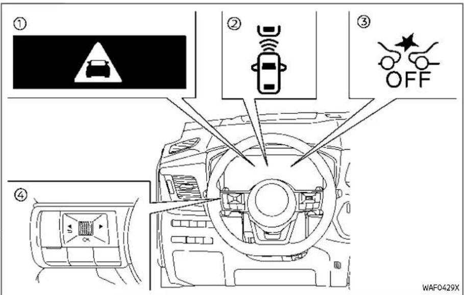
① AEB emergency warning indicator
② Vehicle ahead detection indicator (on the vehicle information display)
③ AEB system OFF warning light (on the meter panel)
④ Steering-wheel-mounted controls (left side)
AEB WITH PEDESTRIAN DETECTION SYSTEM OPERATION
The AEB with Pedestrian Detection system will function when your vehicle is driven at speeds above approximately 3 MPH (5 km/h).
For the pedestrian and cyclists detection
Startinganddriving5-123
function, the AEB with Pedestrian Detection system operates at speeds between 6 - 37 MPH (10 - 60 km/h).
If a risk of a forward collision is detected, the AEB with Pedestrian Detection system will firstly provide the warning to the driver by flashing the vehicle ahead detection indicator (yellow) in the vehicle information display and providing an audible alert. In addition, the system applies partial braking.
If the driver applies the brakes quickly and forcefully after the warning, and the AEB with Pedestrian Detection system detects that there is still the possibility of a forward collision, the system will automatically increase the braking force.
If the driver does not take action, the AEB with Pedestrian Detection system issues the second visual (flashing) (red) and audible warning. Then the system applies partial braking.
If the risk of a collision becomes imminent, the AEB with Pedestrian Detection system applies harder braking automatically.
While the AEB with Pedestrian Detection system is operating, you may hear the sound of brake operation. This is normal and indicates that the AEB with Pedestrian Detection system is operating properly.
NOTE:
The vehicle's stoplights come on when braking is performed by the AEB with Pedestrian Detection system.
Depending on vehicle speed and distance to the vehicle, pedestrian or cyclists ahead, as well as driving and roadway conditions, the system may help the driver avoid a forward collision or may help mitigate the consequences of a collision should one be unavoidable.
If the driver is handling the steering wheel, accelerating or braking, the AEB with Pedestrian Detection system will function later or will not function.
The automatic braking will cease under the following conditions:
- When the steering wheel is turned as far as necessary to avoid a collision.
- When the accelerator pedal is depressed.
- When there is no longer a vehicle, pedestrian detected ahead.
If the AEB with Pedestrian Detection system has stopped the vehicle, the vehicle will remain at a standstill for approximately 2 seconds before the brakes are released.
When the brake pedal is depressed while
the brake is applied by the system, you may feel the pedal effort is changed and may hear a sound and vibration noise. This is normal and does not indicate a malfunction. In addition, the braking force can be increased by adding the pedal effort.

① AEB system OFF warning light (on the meter panel)
② Vehicle information display
③ Steering-wheel-mounted controls (left side)
TURNING THE AEB WITH PEDESTRIAN DETECTION SYSTEM ON/OFF Perform the following steps to turn the AEB with Pedestrian Detection system on or off.
- Push the ◀ button until "Settings" appears in the vehicle informa-
tion display and then push the scroll dial. Use the scroll dial to select "Driver Assistance." Then push the scroll dial.
- Select "Emergency Brake" and push the scroll dial.
- Select "Front" and use the scroll dial to turn the system on or off.
When the AEB with Pedestrian Detection system is turned off, the AEB system OFF warning light illuminates.
NOTE:
●TheAEBwithPedestrianDetection systemwillbeautomaticallyturned ONwhentheengineisrestarted.
●TheIntelligentForwardCollision Warning(I-FCW)systemisintegratedintotheAEBsystem.There isnotaseparateselectionforthel-FCWsystem.WhentheAEBwith PedestrianDetectionsystem is turnedoff,thel-FCWsystemisalso turnedoff.
AEB WITH PEDESTRIAN DETECTION SYSTEM LIMITATIONS

WARNING
ListedbelowarethesystemlimitationsfortheAEBwithPedestrian Detectionsystem.Failuretooperate
Startinganddriving 5-125
thevehicleinaccordancewiththese systemlimitationscouldresultin seriousinjuryordeath.
•The AEB with Pedestrian Detection system cannot detect all vehicles, pedestrians or cyclists under all conditions.
•TheAEBwithPedestrianDetectionsystemdoesnotdetectthe following:
—Pedestriansthataresmall(for example,children),inasitting position,operatingtoys/skateboards,onscootersorin wheelchairs,ornotinanup-rightstandingorwalkingposition.
—Animalsofanysize.
—Obstacles(forexample,cargo ordebris)ontheroadwayor roadside.
—Oncomingorcrossingvehicles.
—Vehicleswherethetiresare difficulttoseeortheshapeof therearofthevehicleisunclearorobstructed.
—Parkedvehicles.
●TheAEBwithPedestrianDetectionsystemhassomeperformancelimitations.
—Ifastationaryvehicleisinthe vehicle'spath,thesystemwill notfunctionwhenthevehicle approachesthestationaryvehicleatspeedsoverapproximately50MPH(80km/h).
—Pedestrianandcyclistdetectionwillnotfunctionwhenthe vehicleisdrivenatspeeds overapproximately37MPH (60km/h)orbelowapproximately6MPH(10km/h).
- Forpedestrians, the AEB with Pedestrian Detection system will not issue the first warning.
•The AEBwithPedestrianDetectionsystemmaynotfunction properlyordetect Vehicle, pedestrianorcyclistaheadin the following conditions:
—Inpoorvisibility conditions (suchasrain, snow, fog, dust storms, sandstorms, smoke, androadspray from other vehicles).
—Ifdirt,ice,snow,fogorother materialiscoveringtheradar
sensorareaorcameraareaof thewindshield.
—Ifstronglight(forexample, sunlightorhighbeams)entersthefrontcameraora suddenchangeinbrightness occurs(forexample, entering atunnelordrivinginlightning).
—Indarkordimlylitconditions, suchasatnightorintunnels, includingcaseswhereyour vehicle'sheadlightsareoffor dim,orthetaillightsofthe vehicleaheadareoff.
—When the direction of the cameraismisaligned.
—When driving on a steep downhillslope, on road with sharp curves, and/or bumpy or dirtroads.
—If there is interference by otherradarsources.
—When your vehicle's position or movement is changed quickly or significantly (for example, lane change, turning vehicle, abrupt steering, sudden acceleration or deceleration).
—When your vehicle or the vehicle, pedestrian or cyclist ahead moves quickly or significantly such that the system cannot detect and react into (forexample, pedestrian moving quickly toward the vehicle at closer range, vehicle cutting in, changing lanes, making aturn, steering abruptly, sudden acceleration or deceleration).
—Whenthevehicle,pedestrian orcyclistisoffsetfromthe vehicle'sforwardpath.
—If the speed difference between the two vehicles is small.
—Thepedestrian'sprofileispartiallyobscuredorunidentifiable;forexample,dueto transportingluggage,pushingastroller,wearingbulky orveryloose-fittingclothing oraccessories,orbeingina uniqueposture(suchasraisinghands).
—Thereispoorcontrastofa persontothebackground, suchashavingclothingcolor orpatternwhichissimilarto
thebackground.
—Forapproximately15seconds afterstartingtheengine
-Ifthevehicleaheadhasa uniqueorunusualshape,extremelyloworhighclearance heights,orunusualcargo loadingorisnarrow(forexample,amotorcycle).
—Whenthevehicle,pedestrian orcyclistislocatedneara trafficsign,areflectivearea (forexample,wateronroad), orisinashadow.
—When multiple pedestriansor cyclists are grouped together.
—Whentheviewofthepedestrianorcyclistisobscuredby avehicleorotherobject.
—Whiletowingatrailerorother vehicle.
- Thesystemperformancemaybe degraded in the following conditions:
—The vehicle is driven on a slippery road.
—The vehicle is driven on a slope.
—Excessivelyheavybaggageis loadedintherearseatorthe cargoareaofyourvehicle.
-
Thesystemisdesignedtoautomaticallycheckthesensor(radar andcamera)'sfunctionality,withincertainlimitations.Thesystem maynotdetectsomeforms of obstructionofthesensorarea suchasice,snoworstickers,for example.inthesecases,thesystemmaynotbeabletowarnthe driverproperly.Besurethatyou check,cleanandclearsensor areasregularly.
•Insomeroadandtrafficconditions,theAEBwithPedestrian Detectionsystemmayunexpectedlyapplypartialbraking.When accelerationisnecessary,depresstheacceleratorpedalto overridethesystem.
•The AEB with Pedestrian Detection system may operate when a pattern, object, shadowor lights are detected that a similar to the outline of vehicles, pedestrians or cyclists, or if they are the namesize and position as vehicle or motorcycle's taillights. -
Thesystemmaykeepoperating whenthevehicleaheadisturning rightorleft.
- Thesystemmayoperatewhen yourvehicleisapproaching and passingavehicleahead.
- Depending on the road shape (curved road, entrance and exit of the curve, winding road, lane regulation, under construction, etc.), the system may operate temporarily for the coming vehicle in front of your vehicle.


WARNING
ListedbelowarethesystemlimitationsfortheAEBwithPedestrian Detectionsystem.Failureretooperate thevehicleinaccordancewiththese systemlimitationscouldresultin seriousinjuryordeath.
•TheAEBwithPedestrianDetectionsystemmayreactto:
—objectsontheroadside(traff-ficsign, guardrail, pedestrian, cyclist, motorcycle, vehicle, etc.)
—pedestriansorcyclistswhen drivingonthenarrowalleys, etc.
—pedestriansorcyclistswho temporarilyprotrudeintoor approachingthedrivinglane toavoidtheobstaclesonthe roadshoulder
- objects above road (low bridge, traffic sign, etc.)
—objectsontheroadsurface (railroadtrack, grate, steel plate, etc.)
—objectsintheparkinggarage (beam,pillar,etc.)
—pedestrians, cyclistsormotor-cyclesapproachingthetravel-inglane
-vehicles,pedestrians,cyclists, motorcyclesorobjectsinadjacentlanesorclosetothe vehicle
-oncomingpedestrians,cyclists
—objectsontheroad(suchas trees)
- Brakingdistancesincreaseon slipperysurfaces.
- Excessivenoisewillinterferewith thewarningchimesound,and thechimemaynotbeheard.
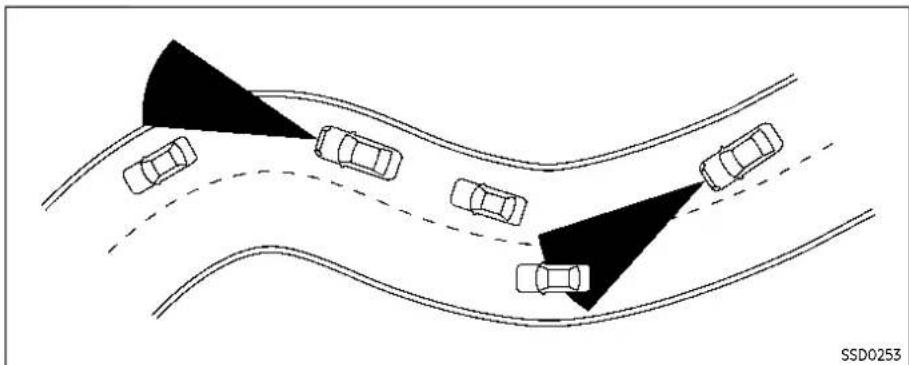
When driving on some roads, such as winding, hilly, curved, narrow roads, or roads which are under construction or on a slope, the sensor may detect vehicles in a different lane, or may temporarily not detect a vehicle traveling ahead. This may cause the system to work inappropriately.
The detection of vehicles may also be affected by vehicle operation (steering maneuver or traveling position in the lane, etc.) or vehicle condition. If this occurs, the system may warn you by blinking the system indicator and sounding the chime unexpectedly. You will have to manually control the proper distance away from the vehicle traveling ahead.
SYSTEM TEMPORARILY UNAVAILABLE
Condition A
If the following conditions, the AEB system OFF warning light will flash (no message appears in the vehicle information display).
●Strong light is shining from the front of the vehicle.
- The cabin temperature is over approximately 104°F (40°C) in direct sunlight.
●The camera area of the windshield is misted or frozen.
Startinganddriving5-129
- The camera unit detects it's misalignment condition.
●The radar sensor picks up interference from an another radar source.
Actiontotake:
When the above conditions no longer exist, the AEB with Pedestrian Detection system will resume automatically.
NOTE:
Whentheinsideofthewindshieldon cameraareaismistedorfrozen, it will takeoveriodoftimetoremoveitafter airconditionerturnson. If dirtappears on this area, it is recommended you visitaNISSANdealer.
Condition B
In the following condition, the AEB system OFF warning light will flash and the "Forward Driving Aids temporarily disabled Front Sensor blocked" warning message will appear in the vehicle information display.
●The sensor area of the front of the vehicle is covered with dirt or is obstructed
Actiontotake:
If the warning light flashes, stop the vehicle in a safe place and turn the engine off. Clean the radar cover on the front of the vehicle with a soft cloth, and restart
the engine. If the warning message continues to appear, have the AEB with Pedestrian Detection system checked. It is recommended that you visit a NISSAN dealer for this service.
- When driving on roads with limited road structures or buildings (for example, long bridges, deserts, snow fields, driving next to long walls).
Actiontotake:
When the above conditions no longer exist, the AEB with Pedestrian Detection system will resume automatically.
Condition C
When the Vehicle Dynamic Control (VDC) system is OFF, the AEB brake will not operate. In this case only visible and audible warning operates. The AEB system OFF warning light (orange) will illuminate.
Actiontotake:
When the VDC system is ON, the AEB with Pedestrian Detection system will resume automatically.
SYSTEM MALFUNCTION
If the AEB with Pedestrian Detection system malfunctions, it will be turned off automatically, a chime will sound, the AEB system OFF warning light will (orange) will illuminate and the "Malfunction" warning message will appear in the vehicle information display.
Actiontotake:
If the warning light (orange) comes on, stop the vehicle in a safe location. Turn the engine off and restart the engine. If the warning light continues to illuminate, have the AEB with Pedestrian Detection system checked. It is recommended that you visit a NISSAN dealer for this service.
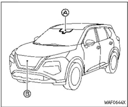
SYSTEM MAINTENANCE
The radar sensor is located on the front of the vehicle. The camera is located on the upper side of the windshield.
To keep the AEB with Pedestrian Detection system operating properly, be sure to observe the following:
- Always keep the sensor area on the front of the vehicle and windshield clean.
- Do not strike or damage the areas around the sensors (ex. bumper, windshield).
- Do not cover or attach stickers or similar objects on the front of the vehicle near the sensor area. This
could cause failure or malfunction.
- Do not attach metallic objects near the radar sensor area (brush guard, etc.). This could cause failure or malfunction.
- Do not place reflective materials, such as white paper or a mirror, on the instrument panel. The reflection of sunlight may adversely affect the camera unit's detection capability.
- Do not alter, remove or paint the front of the vehicle near the sensor area. Before customizing or restoring the sensor area, it is recommended that you visit a NISSAN dealer.
Radio frequency statement ForUSA
Type approval number:
FCC ID: NF3-FR5CPEC
User Manual statement according to §15.19:
This device complies with Part 15 of the FCC Rules.
Operation is subject to the following two conditions:
- this device may not cause harmful interference, and
- this device must accept any interference received, including interference
that may cause undesired operation. User Manual statement according to §15.21:
Changes or modifications made to this equipment not expressly approved by Robert BOSCH GmbH may void the FCC authorization to operate this equipment. User Manual statement according to §15.105:
This equipment has been tested and found to comply with the limits for a Class A digital device, pursuant to Part 15 of the FCC Rules. These limits are designed to provide reasonable protection against harmful interference when the equipment is operated in a commercial environment. This equipment generates, uses, and can radiate radio frequency energy and, if not installed and used in accordance with the instruction manual, may cause harmful interference to radio communications. Operation of this equipment in a residential area is likely to cause harmful interference in which case the user will be required to correct the interference at his own expense.
RF Exposure Information according 2.1091/2.1093/OET bulletin 65:
Radiofrequency radiation exposure information:
This equipment complies with FCC radia-
INTELLIGENTFORWARDCOLLISION WARNING(I-FCW)
tion exposure limits set forth for an uncontrolled environment. This equipment should be installed and operated with minimum distance of 20 cm between the radiator and your body.
The transmitter must not be co-located or operating in conjunction with any other antenna or transmitter.
ForCanada
Type approval number:
IC: 3387A-FR5CPEC
Legal warning for RF equipment:
This device complies with Industry Canada licence-exempt RSS standard(s). Operation is subject to the following two conditions: (1) this device may not cause interference, and (2) this device must accept any interference, including interference that may cause undesired operation of the device.

WARNING
Failuretofollowthewarningsand instructionsforproperuseofthel-FCWsystemcouldresultinserious injuryordeath.
- Thel-FCWsystemhelpswarnthe driverbeforeacollisionbutwill notavoidacollision.Itisthe driver'sresponsibilitytostay alert,drivesafelyandbeincontrolofthevehicleataltimes.
The I-FCW system can help alert the driver when there is a sudden braking of a second vehicle traveling in front of the vehicle ahead in the same lane.
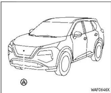
The I-FCW system uses a radar sensor ® located on the front of the vehicle to measure the distance to a second vehicle ahead in the same lane.

① Vehicle ahead detection indicator (on the vehicle information display)
② Automatic Emergency Braking (AEB) system OFF warning light (on the meter panel)

The I-FCW system operates at speeds above approximately 3 MPH (5 km/h).
If there is a potential risk of a forward collision, the I-FCW system will warn the driver by blinking the vehicle ahead detection indicator, and sounding an audible alert.
5-134 Startinganddriving

① AEB system OFF warning light (on the meter panel)
② Vehicle information display
③ Steering-wheel-mounted controls (left side)
Perform the following steps to turn the I-FCW system on or off.
- Push the ◀ button until "Settings" appears in the vehicle information display and then push the scroll
dial. Use the scroll dial to select "Driver Assistance." Then push the scroll dial.
- Select "Emergency Brake" and push the scroll dial.
- Select "Front" and use the scroll dial to turn the system on or off.
When the I-FCW system is turned off, the AEB system OFF warning light (orange) illuminates.
NOTE:
- TheI-FCWsystemwillbeautomaticallyturnedonwhentheengineis restarted.
- Thel-FCWsystemisintegratedinto theAEBsystem.Thereisnota separateselectionforthel-FCW system.WhentheAEBsystemis turnedoff,thel-FCWsystemisalso turnedoff.
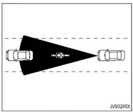
IllustrationA

IllustrationB

IllustrationC
5-136 Startinganddriving
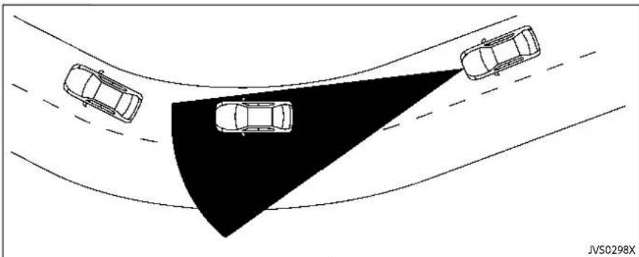
IllustrationD
I-FCW SYSTEM LIMITATIONS

WARNING
Listedbelowarethesystemlimitationsforthel-FCWsystem.Failureto operatethevehicleinaccordance withthesesystemlimitationscould resultinseriousinjuryordeath.
- Thel-FCWsystemcannotdetect allvehiclesunderallconditions.
- Theradarsensordoesnotdetect thefollowingobjects:
—Pedestrians, animalsorobstaclesintheroadway
—Oncomingvehicles
-Crossingvehicles
●(IllustrationA)TheI-FCWsystem does not function when a vehicle ahead is an arrow vehicle, such as amotorcycle.
•Theradarsensormaynotdetect avehicleaheadinthefollowing conditions:
—Snoworheavyrain
—Dirt,ice,snoworothermateri-
alcoveringtheradarsensor
—Interferencebyotherradar sources
—Snoworroadsprayfromtravellingvehicles.
-Drivinginatunnel
—Towingatraler
●(IllustrationB)Whenthevehicle aheadisbeingtowed.
●(IllustrationC)Whenthedistance tothevehicleaheadistoo close, thebeamoftheradarsensoris obstructed.
●(IllustrationD)Whendrivingona steepdownhillslopeorroads withsharpcurves.
- Thesystemisdesignedtoautomaticallycheckthesensor'sfunctionality, within certain limitations. Thesystemmaynot detectsomeformsofobstruction ofthesensorareasuchasice, snow, stickers, forexample. In these cases, thesystemmaynot beabletowarnthedriverproperly. Besurethatyoucheck, clean and clearthesensorareregularly.
Startinganddriving5-137
- Excessivenoisewillinterferewith thewarningchimesound,and thechimemaynotbeheard.
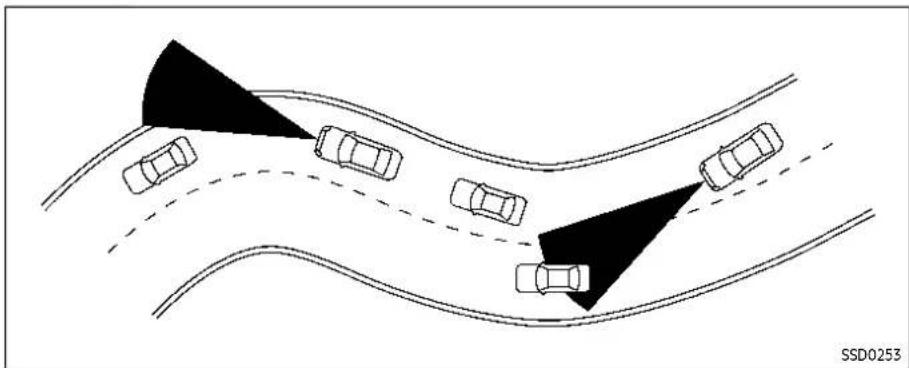
When driving on some roads, such as winding, hilly, curved, narrow roads, or roads which are under construction, the radar sensor may detect vehicles in a different lane, or may temporarily not detect a vehicle traveling ahead. This may cause the I-FCW system to work inappropriately.
The detection of vehicles may also be affected by vehicle operation (steering maneuver or traveling position in the lane, etc.) or vehicle condition. If this occurs, the system may warn you by blinking the vehicle ahead detection indicator and sounding the chimeun-expectedly. You will have been manually controlled the proper distance away from
thevehicletravelingahead.
SYSTEM TEMPORARILY UNAVAILABLE
Condition A
When the radar sensor picks up interference from another radar source, making it impossible to detect a vehicle ahead, the I-FCW system is automatically turned off. The AEB system OFF warning light (orange) will flash.
Actiontotake:
When the above conditions no longer exist, the I-FCW system will resume automatically.
Condition B
Under the following conditions, making it impossible to detect a vehicle ahead, the I-FCW system is automatically turned off.
The AEB system OFF warning light (orange) will flash and the "Forward Driving Aids temporarily disabled Front Sensor blocked" warning message will appear in the vehicle information display.
- When the sensor area of the front of the vehicle is covered with dirt or is obstructed
Actiontotake:
If the warning light (orange) flashes, stop the vehicle in a safe place, push the park button to engage the P (Park) position and turn the engine off. Clean the radar cover on the front of the vehicle with a soft cloth, and restart the engine. If the warning light continues to illuminate, have the I-FCW system checked. It is recommended you visit a NISSAN dealer for this service.
- When driving on roads with limited road structures or buildings (for example, long bridges, deserts, snow fields, driving next to long walls)
Actiontotake:
When the above conditions no longer exist, the I-FCW system will resume automatically.
SYSTEM MALFUNCTION
If the I-FCW system malfunctions, it will be turned off automatically, a chime will sound, the AEB system OFF warning light (orange) will illuminate and the "Malfunction" warning message will appear in the vehicle information display.
Actiontotake:
If the warning light (orange) illuminates, stop the vehicle in a safe location. Turn the engine off and restart the engine. If the warning light continues to illuminate, have the I-FCW system checked. It is recommended you visit a NISSAN dealer for this service.

SYSTEM MAINTENANCE
The radar sensor is located on the front of the vehicle.
To keep the system operating properly, be sure to observe the following:
- Always keep the sensor area on the front of the vehicle clean.
- Do not strike or damage the areas around the sensor.
- Do not cover or attach stickers or similar objects on the front bumper near the sensor area. This could cause failure or malfunction.
- Do not attach metallic objects near the sensor area (brush guard, etc.). This could cause failure or malfunc-
Startinganddriving5-139
tion.
- Do not alter, remove or paint the front bumper. It is recommended you contact a NISSAN dealer before customizing or restoring the front bumper.
Radio frequency statement
ForUSA
Type approval number:
FCC ID: NF3-FR5CPEC
User Manual statement according to §15.19:
This device complies with Part 15 of the FCC Rules.
Operation is subject to the following two conditions:
-
this device may not cause harmful interference, and
-
this device must accept any interference received, including interference that may cause undesired operation.
User Manual statement according to §15.21:
Changes or modifications made to this equipment not expressly approved by Robert BOSCH GmbH may void the FCC authorization to operate this equipment.
User Manual statement according to §15.105:
This equipment has been tested and found to comply with the limits for a Class A digital device, pursuant to Part 15 of the FCC Rules. These limits are designed to provide reasonable protection against harmful interference when the equipment is operated in a commercial environment. This equipment generates, uses, and can radiate radio frequency energy and, if not installed and used in accordance with the instruction manual, may cause harmful interference to radio communications. Operation of this equipment in a residential area is likely to cause harmful interference in which case the user will be required to correct the interference at his own expense.
RF Exposure Information according 2.1091/2.1093/OET bulletin 65:
Radiofrequency radiation exposure information:
This equipment complies with FCC radiation exposure limits set forth for an uncontrolled environment. This equipment should be installed and operated with minimum distance of 20 cm between the radiator and your body.
The transmitter must not be co-located or operating in conjunction with any other antenna or transmitter.
ForCanada
Type approval number:
IC: 3387A-FR5CPEC
Legal warning for RF equipment:
This device complies with Industry Canada licence-exempt RSS standard(s). Operation is subject to the following two conditions: (1) this device may not cause interference, and (2) this device must accept any interference, including interference that may cause undesired operation of the device.
INTELLIGENTDRIVERALERTNESS(I-DA)

WARNING
Failuretofollowthewarningsand instructionsforproperuseofthel-DAsystemcouldresultinserious injuryordeath.
- Thel-DAsystemisonlyawarning toinformthedriverofapotential lackofdriverattentionordrowsiness.itwillnotsteerthevehicle orpreventlossofcontrol.
- Thel-DAsystemdoesnotdetect andprovideanalertofthedriver'slackofattentionorfatigue ineverysituation.
- ltisthedriver'sresponsibilityto:
—Stayalert.
—Drivesafely.
—Keepthevehicleinthetravelinglane.
—Beincontrolofthevehicleat alltimes.
—Avoiddrivingwhentired.
—Avoid distractions(texting, etc).
The I-DA system helps alert the driver if the system detects a lack of attention or driving fatigue.
The system monitors driving style and steering behavior over a period of time, and it detects changes from the normal pattern. If the system detects that driver attention is decreasing over a period of time, the system uses audible and visual warnings to suggest that the driver take break.
Driver Attention Alert

Take a Break?
WAF0641X
Example
If the system detects driver fatigue or that driver attention is decreasing, the message "Take a Break?" appears in the vehicle information display and a chime sounds when the vehicle is driven at speeds above 37 MPH (60 km/h).
The system continuously monitors driver attention and can provide multiple warnings per trip.
The system resets and starts reassessing driving style and steering behavior when the ignition switch is cycled from the ON to the OFF position and back to the ON position.
Startinganddriving5-141
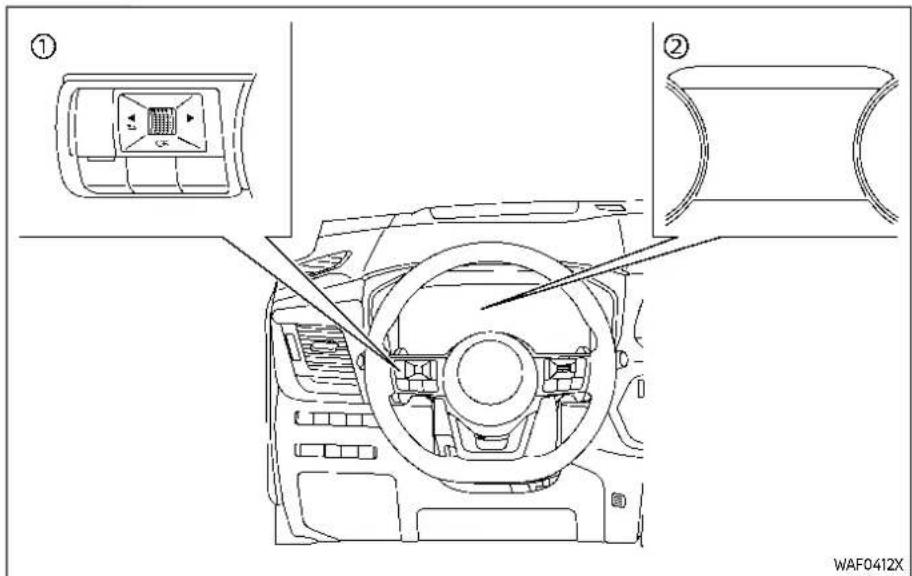
① Steering-wheel-mounted control (left side)
② Vehicle information display
HOW TO ENABLE/DISABLE THE I-DA SYSTEM
Perform the following steps to enable or disable the I-DA system.
- Push the ◀ button until "Settings" appears in the vehicle information display and push the scroll dial.
Use the scroll dial to select "Driver Assistance." Then push the scroll dial.
- Select "Driver Attention Alert" and push the scroll dial.
NOTE:
Thesettingwillberetainedevenifthe engineisrestarted.
I-DA SYSTEM LIMITATIONS

WARNING
Listedbelowarethesystemlimitationsforthel-DAsystem.Failureto operatethevehicleinaccordance withthesesystemlimitationscould resultinseriousinjuryordeath.
•Thel-DAsystemmaynotoperate properlyandmaynotprovidean alertinthefollowingconditions:
—Poorroadconditionssuchas anunevenroadsurfaceorpot holes.
—Strongsidewind.
-If you have adopted asporty driving style with higher cornerings speeds or higherrates of acceleration.
REARAUTOMATICBRAKING(RAB)
—Frequentlanechangesor changestovehiclespeed.
- TheI-DAsystemwillnotprovide analertinthefollowingconditions:
—Vehiclespeedslowerthan37 mph(60km/h).
—Shortlapsesofattention.
—Instantaneous distractions such as dropping an object.
SYSTEM MALFUNCTION
If the I-DA system malfunctions, the "Driver Attention Alert Malfunction" warning message will appear in the vehicle information display and the function will be stopped automatically.
Actiontotake
Stop the vehicle in a safe location, place the vehicle in P (Park) position, turn the engine off and restart the engine. If the warning message continues to appear, have the system checked. It is recommended that you visit a NISSAN dealer for this service.

WARNING
Failuretofollowthewarningsand instructionsforproperuseofthe RABsystemcouldresultinserious injuryordeath.
•TheRABsystemisasupplementalaidtothedriver.itisnota replacementforproperdriving procedures.Alwaysusetheside andrearmirrorsandturnand lookinthedirectionyouwill movebeforeandwhilebacking up.NeverrelysolelyontheRAB system.itisthedriver'sresponsibilitytostayalert,drivesafely, andbeincontrolofthevehicleat alltimes.
- ThereisalimitationtotheRAB systemcapability.TheRABsystemisnoteffectiveinallsituations.
The RAB system can assist the driver when the vehicle is backing up and approaching objects directly behind the vehicle.

Modelswith4sonarsensors
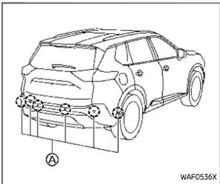
Modelswith6sonarsensors
Startinganddriving5-143
The RAB system detects obstacles behind the vehicle using the sonar sensors located on the rear bumper.
NOTE:
Youcantemporarilycancelthesonar functioninthevehicle,buttheRAB systemwillcontinuetooperate.For additionalinformation,see"Sonarsystem"(P.5-162)or"RearSonarSystem (RSS)("P.5-168).

① RAB system warning indicator (on the vehicle information display)
② RAB system OFF warning light (on the meter panel)
③ Steering-wheel-mounted controls (left side)
④ Vehicle information display
⑤ Center display (if so equipped)
When the shift lever is in the R (Reverse) position and the vehicle speed is less than approximately 9 MPH (15 km/h), the RAB system operates.
If a risk of a collision with an obstacle is detected when your vehicle is backing up, the RAB system warning indicator will flash in the vehicle information display, a red frame will appear in the center display (models with the Intelligent Around View® Monitor system), and the system will chime three times. The system will then automatically apply the brakes. After the automatic brake application, the driver must depress the brake pedal to maintain brake pressure.
NOTE:
- Thestoplightsofthevehiclecome onwhenbrakingisperformedby theRABsystem.
- Whenthebrakesoperate,anoise maybeheard. This is not a malfunction.
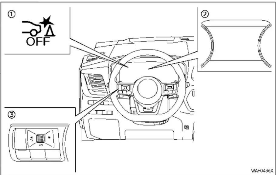
① RAB system OFF warning light
② Vehicle information display
③ Steering-wheel-mounted control (left side)
TURNING THE RAB SYSTEM ON/OFF Perform the following steps to turn the RAB system ON or OFF.
- Push the ◀ button until "Settings" appears in the vehicle information display and then push the scroll dial. Use the scroll dial to select "Driver
Startinganddriving5-145
Assistance." Then push the scroll dial.
- Select "Emergency Brake" and push the scroll dial.
- Select "Rear" and use the scroll dial to turn the system on or off.
When the RAB system is turned off, the RAB system OFF warning light illuminates.
NOTE:
TheRABsystemwillbeautomatically turnedonwhentheengineisrestarted.
RAB SYSTEM LIMITATIONS

WARNING
ListedbelowarethesystemlimitationsfortheRABsystem.Failureto followthewarningsandinstructions forproperuseoftheRABsystem couldresultinseriousinjuryor death.
- When the vehicle approaches an obstacle while the accelerator or brake pedal is depressed, the function may not operate on the start of the operation maybe delayed. The RAB system may not operate on may not perform sufficiently due to vehicle conditions, driving conditions, the traffic environment, the weather,
5-146 Startinganddriving
roadsurfaceconditions,etc.Do notwaitforthesystemtooperate.Operatethebrakepedalby yourselfassoonasnecessary.
- IfitisnecessarytooverrideRAB operation,stronglypresstheacceleratorpedal.
●Alwayscheckyoursurroundings andturntocheckwhatisbehind youbeforeandwhilebackingup. TheRABsystemdetectsstationaryobjectsbehindthevehicle. TheRABsystemdoesnotdetect thefollowingobjects:
—Movingobjects
—Lowobjects
—Narrowobjects
—Wedge-shapedobjects
—Complex-shapedobjects
—Multipleobjectinclose
—Objectsclosetothebumper (lessthanapproximately1ft [30cm])
—Objectsthatsuddenlyappear
—Thinobjectssuchasrope, wire, chain, etc.
•TheRABsystemmaynotoperate forpedestriansoranimals.
•TheRABsystemmaynotoperate forthefollowingobstacles:
—Obstacleslocatedhighoffthe ground
—Obstaclesinapositionoffset fromyourvehicle
—Obstacles, such as spongy materialsorsnow, that have soft outersurfaces and can easily absorb asoundwave
•TheRABsystemmaynotoperate inthefollowingconditions:
—Thereisrain, snow, ice, dirt, etc., attached to the sonar sensors.
—Aloudsoundisheardinthe areaaroundthevehicle.
—Thesurfaceoftheobstacleis diagonaltotherearofthe vehicle.
—Thesonarsensorsorthearea aroundthemareextremely hotorcold.
•TheRABsystemmayunintentionallyoperateinthefollowing conditions:
—Thereisovergrowngrassin theareaaroundthevehicle.
—Thereisastructure(e.g., a wall, tollgateequipment, a narrowtunnel, aparkinglot gate)nearthesideofthe vehicle.
—Therearebumps, protrusions, ormanhole covers on the roadsurface.
—The vehicle is driving through adraped flagor acurtain.
—The vehicle is driving on a steep hill.
—Thereisanaccumulation of snoworicebehindthevehicle.
—Anultrasonicwavesource, suchasanothervehicle'sso-nar,isnearthevehicle.
- Oncetheautomaticbrakecontrol operates, it does not operate again if the vehicle approaches the same obstacle.
•Theautomaticbrakecontrolcan onlyoperateforashortperiodof time.Therefore,thedrivermust depressthebrakepedal.
•Inthefollowingsituations,the RABsystemmaynotoperate properlyormaynotfunction sufficiently:
—The vehicle is driven in bad weather (rain, fog, snow, etc.).
—The vehicle is driven on a steephill.
—The vehicle'spostureischanged(e.g.,whendrivingovera bump).
—The vehicle is driven on a slippery road.
—The vehicle is turned sharply by turning the steering wheel fully.
—Snowchainsareused.
—Wheelsortiresotherthan NISSANrecommended are used.
—Thebrakesarecoldatlow ambienttemperaturesorimmediatelyafterdrivinghas started.
—The braking force becomes poorduetowet brakes after driving through hapuddle or washing the vehicle.
•TurntheRABsystemoffinthe followingconditionstoprevent theoccurrenceofanunexpected accidentresultingfromsudden systemoperation:
—Thevehicleistowed.
—Thevehicleiscarriedona flatbedtruck.
—Thevehicleisonthechassis dynamometer.
—Thevehicledrivesonanun-evenroadsurface.
—Suspensionpartsotherthan thosedesignadasgenuine partsareused.(ifthevehicle heightorthevehiclebody inclinationischanged,the systemmaynotdetectan obstaclecorrectly.)
- Excessivenoise(e.g., audiosystemvolume, anopenvehiclewindow) will interferewith the chime sound, and it may not be heard.
SYSTEM MALFUNCTION
If the RAB system malfunctions, it will be turned off automatically, the RAB system OFF warning light will illuminate, and the "Malfunction See Owner's Manual" warning message will appear in the vehicle information display.
Action to take
If the warning light illuminates, park the vehicle in a safe location, turn the engine off, and restart the engine. If the warning light continues to illuminate, have the RAB system checked. It is recommended that you visit a NISSAN dealer for this service.
NOTE:
If the RAB system cannot be operated temporarily, the RAB system OFF warning lightblinks.

Modelswith4sonarsensors

Modelswith6sonarsensors
SYSTEM MAINTENANCE
The sonar sensors are located on the rear bumper. Observe the following items to ensure proper operation of the system:
●Always keep the sonar sensors clean.
- If the sonar sensors are dirty, wipe them off with a soft cloth while being careful to not damage them.
●The sonar sensors may be blocked by temporary ambient conditions such as splashing water, mist or fog. The blocked condition may also be caused by objects such as ice, frost or dirt obstructing the sonar sensors. Check for and remove objects obstructing the area around the sonar sensors.
- Do not subject the area around the sonar sensors to strong impact. Also, do not remove or disassemble the sonar sensors. If the sonar sensors and peripheral areas are deformed in an accident, etc., have the sonar sensors checked. It is recommended that you visit a NISSAN dealer for this service.
- Do not attach stickers (including transparent material), install accessories or apply additional paint on the sonar sensors and their surrounding areas. This may cause a malfunction or improper operation.
BREAK-INSCHEDULE
FUELEFFICIENTDRIVINGTIPS
- When washing the vehicle using a high-pressure washer, do not apply direct washer pressure on the sonar sensors. This may cause a malfunction of the sonar sensors.

CAUTION
During the first 1,200 miles (2,000 km), follow the recommendations to obtain maximum engine performance and ensure the future reliability and economy of your new vehicle. Failure to follow the recommendations may result in shortened engine life and reduced engine performance.
- Avoid driving for long periods at constant speed, either fast or slow. Do not run the engine over 4,000 rpm.
- Do not accelerate at full throttle in any gear.
- Avoid quick starts.
- Avoid hard braking as much as possible.
- Do not tow a trailer for the first 500 miles (800 km). Your engine, axle or other parts could be damaged.
Follow these easy-to-use Fuel Efficient Driving Tips to help you achieve the most fuel economy from your vehicle.
- Use smooth accelerator and brake pedal application.
- Avoid rapid starts and stops.
- Use smooth, gentle accelerator and brake application whenever possible.
-
Maintain constant speed while commuting and coast whenever possible.
-
Maintain constant speed.
-
Look ahead to try and anticipate and minimize stops.
- Synchronizing your speed with traffic lights allows you to reduce your number of stops.
-
Maintaining a steady speed can minimize red light stops and improve fuel efficiency.
-
Use air conditioning (A/C) at higher vehicle speeds.
-
Below 40 MPH (64 km/h), it is more efficient to open windows to cool the vehicle due to reduced engine load.
- Above 40 MPH (64 km/h), it is more efficient to use A/C to cool the vehicle due to increased aerodynamic drag.
Startinganddriving5-149
INCREASINGFUELECONOMY
- Recirculating the cool air in the cabin when the A/C is on reduces cooling load.
- Drive at economical speeds and distances.
- Observing the speed limit and not exceeding 60 MPH (97 km/h) (where legally allowed) can improve fuel efficiency due to reduced aerodynamic drag.
- Maintaining a safe following distance behind other vehicles reduces unnecessary braking.
- Safely monitoring traffic to anticipate changes in speed permits reduced braking and smooth acceleration changes.
-
Select a gear range suitable to road conditions.
-
Use cruise control.
-
Using cruise control during highway driving helps maintain a steady speed.
-
Cruise control is particularly effective in providing fuel savings when driving on flat terrains.
-
Plan for the shortest route.
- Utilize a map or navigation system to determine the best route to save time.
- Avoid idling.
- Shutting off your engine when safe for stops exceeding 30-60 seconds saves fuel and reduces emissions.
- Buy an automated pass for toll roads.
- Automated passes permit drivers to use special lanes to maintain cruising speed through the toll and avoid stopping and starting.
-
Winter warm up.
-
Limit idling time to minimize impact to fuel economy.
- Vehicles typically need no more than 30 seconds of idling at start-up to effectively circulate the engine oil before driving.
-
Your vehicle will reach its ideal operating temperature more quickly while driving versus idling.
-
Keeping your vehicle cool.
-
Park your vehicle in a covered parking area or in the shade whenever possible.
-
When entering a hot vehicle, opening the windows will help to reduce the inside temperature faster, resulting in reduced demand on your A/C system.
-
Keep your engine tuned up.
- Follow the recommended scheduled maintenance.
- Keep the tires inflated to the correct pressure. Low tire pressure increases tire wear and lowers fuel economy.
- Keep the wheels in correct alignment. Improper alignment increases tire wear and lowers fuel economy.
- Use the recommended viscosity engine oil. (See "Engine oil and oil filter recommendation" (P.10-7).)
INTELLIGENT4X4(ifsoequipped)
If any malfunction occurs in the Intelligent 4x4 system while the engine is running, warning messages appear in the vehicle information display.
![graph TD A["AWD"] --> B["AWD Error\nSee Owner's Manual"] B --> C["①"] D["AWD"] --> E["AWD High Temp.\nStop Vehicle"] E --> F["②"] G["AWD"] --> H["Tire Size Incorrect\nSee Owner's Manual"] H --> I["③"]](/content/2026/05/810569/images/28738069952a92182d0edde15a95e0cc7181a13974246901b6372cd91fbc875c.jpg)
If the "AWD Error" warning appears, there may be a malfunction in the intelligent 4x4 system. Reduce vehicle speed and have your vehicle checked by a NISSAN dealer as soon as possible.
The "AWD High Temp. Stop vehicle" (high temperature) warning ② appears when the oil temperature of the powertrain
parts increases due to the difference in rotation between the front and rear wheels is large (wheel slip), such as when driving on rough roads, driving through sand or mud, or freeing a stuck vehicle. If this warning is displayed, stop the vehicle with the engine idling, as soon as it is safe to do so. In these cases, the AWD changes to 2WD to protect the powertrain parts. Then if the warning turns off, you can continue AWD driving.
The "Tire Size Incorrect" warning ③ may appear if there is a large difference between the diameters of front and rear wheels and tires. Pull off the road in a safe area, with the engine idling. Check that all tire sizes, brand, construction and tread pattern are the same, that the tire pressures are correct and that the tires are not excessively worn. If you have any problems, change tires or adjust tire pressures correctly. Do not select the SNOW or OFF-ROAD mode with the Drive Mode Selector and do not drive fast.
If any warning message continues to be displayed, have your vehicle checked by a NISSAN dealer as soon as possible.

WARNING
-ForAWDequippedvehicles,do notattempttoraisetwowheels offthegroundandshiftthe transmissionoanydriveorreversepositionwiththeengine running.Doingsomayresultin drivetraindamageorunexpected vehiclemovementwhichcould resultinseriousvehicledamage orpersonalinjury.
- DonotattempttotestanAWD equippedvehicleona2-wheel dynamometer(suchasthodynamometers used by some statesforemissionstesting)or similarequipmentevenifthe othertwowheelsareraisedoff theground.Makesurethatyou informthetestfacilitypersonnel thatyourvehicleisequippedwith AWDbeforeitisplacedona dynamometer.Usingthewrong testequipmentmayresult in drivetraindamageorunexpectedvehiclemovementwhich couldresultinseriousvehicle damageorpersonalinjury.

CAUTION
- Donotoperatetheengineona freerollerwhenanyofthewheels raised.
- Thepowertrainmaybedamaged ifyoucontinuedrivingwiththe "AWDError" warningon.
- If the warning message remains on after the above operation, have your vehicle checked as soon as possible. It is recommended that you visit a NISSAN dealer for this service.
- If the "AWDError" warning appears while driving, theremaybe amalfunction in the AWD system.
Reducethevehiclespeed and have your vehicle checked as soon as possible. It is recommended that you visit a NISSAN dealer forth this service.
When the vehicle is in the P (Park) position, the operation noise may be heard from the lower part of the vehicle. This is not a malfunction.
PARKING/PARKING ONHILLS
①
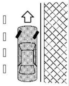
②
③
placedintoP(Park).Failureto dosocouldcausethevehicleto moveunexpectedlyorrollaway andresultinanaccident.
●Makesuretheshiftlevercannot bemovedwithoutdepressingthe footbrakepedal.
- Apply the parking brake.
- Push the park button to shift to the P (Park) position.
-
To help prevent the vehicle from rolling into the street when parked on a sloping drive way, it is a good practice to turn the wheels as illustrated.
-
HEADED DOWNHILL WITH CURB:① Turn the wheels into the curb and move the vehicle forward until the curb side wheel gently touches the curb.
- HEADED UPHILL WITH CURB:② Turn the wheels away from the curb and move the vehicle back until the curb side wheel gently touches the curb.
- HEADED UPHILL OR DOWNHILL, NO CURB: ③ Turn the wheels toward the side of the road so the vehicle will move away from the center of the road if it moves.
ELECTRICPOWERSTEERING
- Place the ignition switch in the OFF position.

WARNING
- If the engine is not running, the power assist for the steering will not work. Steering will be harder to operate.
- When the electric power steering warning light illuminates with the engineer running, the power assist for the steering will cease operation. You will still have control of the vehicle but the steering will behard to operate.
The electric power steering is designed to provide power assist while driving to operate the steering wheel with light force.
When SPORT mode is selected, the steering wheel effort is moderately increased for a sporty feel. (See "SPORT mode" (P.5-34).)
When the steering wheel is operated repeatedly or continuously while parking or driving at a very low speed, the power assist for the steering wheel will be reduced. This is to prevent overheating of the electric power steering and protect it from getting damaged. While the power
assist is reduced, steering wheel operation will become heavy. If the steering wheel operation is still performed, the electric power steering may stop and the electric power steering warning light will illuminate. In a safe location, stop the engine and place the ignition switch in the OFF position. When the temperature of the electric power steering goes down, the power assist level will return to normal. Avoid repeating such steering wheel operations that could cause the electric power steering to overheat.
You may hear a noise when the steering wheel is operated quickly. However, this is not a malfunction.
If the electric power steering warning light illuminates while the engine is running, it may indicate the electric power steering is not functioning properly and may need servicing. Have the electric power steering checked. It is recommended that you visit a NISSAN dealer for this service. (See "Electric power steering warning light" (P.2-17).)
When the electric power steering warning light illuminates with the engine running, the power assist for the steering will cease operation. You will still have control of the vehicle. However, greater steering effort is needed, especially in sharp turns and at low speeds.
BRAKESYSTEM
BRAKING PRECAUTIONS
The brake system has two separate hydraulic circuits. If one circuit malfunctions, you will still have braking at two wheels.
Vacuum assisted brakes
The brake booster aids braking by using engine vacuum. If the engine stops, you can stop the vehicle by depressing the brake pedal. However, greater foot pressure on the brake pedal will be required to stop the vehicle and the stopping distance will be longer.
Using the brakes
Avoid resting your foot on the brake pedal while driving. This will cause overheating of the brakes, wearing out the brake pads faster and reduce gas mileage.
To help reduce brake wear and to prevent the brakes from overheating, reduce speed and downshift to a lower gear before going down a slope or long grade. Overheated brakes may reduce braking performance and could result in loss of vehicle control.

WARNING
-While driving on aslippery surface, be careful when braking, accelerating order down shifting. Abrupt braking or accelerating could cause the wheel stoskii and result in an accident.
- If the engine is not running, is turned off while driving, the power assist for the brakes will not work. Braking will be harder.
Wet brakes
When the vehicle is washed or driven through water, the brakes may get wet. As a result, your braking distance will be longer and the vehicle may pull to one side during braking.
To dry brakes, drive the vehicle at a safe speed while lightly tapping the brake pedal to heat-up the brakes. Do this until the brakes return to normal. Avoid driving the vehicle at high speeds until the brakes function correctly.
Parking brake break-in
Break in the parking brake pads whenever the stopping effect of the parking brake is weakened or whenever the parking brake pads and/or calipers/rotors are replaced, in order to assure the best braking performance.
This procedure is described in the vehicle service manual. It is recommended you visit a NISSAN dealer for this service.
BRAKEASSIST
BRAKE ASSIST
When the force applied to the brake pedal exceeds a certain level, the Brake Assist is activated generating greater braking force than a conventional brake booster even with light pedal force.

WARNING
The Brake Assistisonlyanaidto assistbrakingoperationandisnota collisionwarningoravoidancedevice.Itisthedriver'sresponsibility to stayalert,drivesafelyandbein controlofthevehicleataalltimes.
ANTI-LOCK BRAKING SYSTEM (ABS)

WARNING
•The Anti-lock Braking System (ABS) is as sophisticated device, but it cannot prevent accidents resulting from careless or dangerous driving techniques. It can help maintain vehicle control during braking on slippery surfaces. Remember that stopping distances on slippery surfaces will be longer than on normal sur-
facesevenwithABS.Stopping distancesmayalsobelongeron rough,gravelorsnowcovered roads,orifyouareusingtire chains.Alwaysmaintainasafe distancefromthevehicleinfront ofyou.Ultimately,thedriveris responsibleforsafety.
•Tiretypeandconditionmayalso affectbrakingeffectiveness.
—Whenreplacingtires,install thespecifiedsizeoftireson allfourwheels.
—Wheninstallingasparetire, makesurethatistiheproper sizeandtypeasspecified on the Tire and Loading Information label. See "Tire and Loading Information label" (P.10-13) of this manual.
—Fordetailedinformation,see "Wheelsandtires"(P.8-31)of thismanual.
The Anti-lock Braking System (ABS) controls the brakes so the wheels do not lock during hard braking or when braking on slippery surfaces. The system detects the rotation speed at each wheel and varies the brake fluid pressure to prevent each wheel from locking and sliding. By preventing each wheel from locking, the system helps the driver maintain steering control and helps to minimize swerving and spinning on slippery surfaces.
Using the system
Depress the brake pedal and hold it down. Depress the brake pedal with firm steady pressure, but do not pump the brakes. The ABS will operate to prevent the wheels from locking up. Steer the vehicle to avoid obstacles.

WARNING
Donotpumpthebrakepedal.Doing somayresultinincreasedstopping distances.
Self-test feature
The ABS includes electronic sensors, electric pumps, hydraulic solenoids and a computer. The computer has a built-in diagnostic feature that tests the system each time you start the engine and move the vehicle at a low speed in forward or reverse. When the self-test occurs, you may hear a "clunk" noise and/or feel a pulsation in the brake pedal. This is normal and does not indicate a malfunction. If the computer senses a malfunction
VEHICLEDYNAMICCONTROL(VDC)SYSTEM
tion, it switches the ABS off and illuminates the ABS warning light on the instrument panel. The brake system then operates normally, but without anti-lock assistance.
If the ABS warning light illuminates during the self-test or while driving, have the vehicle checked. It is recommended you visit a NISSAN dealer for this service.
Normal operation
The ABS operates at speeds above 3 to 6 MPH (5 to 10 km/h). The speed varies according to road conditions.
When the ABS senses that one or more wheels are close to locking up, the actuator rapidly applies and releases hydraulic pressure. This action is similar to pumping the brakes very quickly. You may feel a pulsation in the brake pedal and hear a noise from under the hood or feel a vibration from the actuator when it is operating. This is normal and indicates that the ABS is operating properly. However, the pulsation may indicate that road conditions are hazardous and extra care is required while driving.
The Vehicle Dynamic Control (VDC) system uses various sensors to monitor driver inputs and vehicle motion. Under certain driving conditions, the VDC system helps to perform the following functions.
●Controls brake pressure to reduce wheel slip on one slipping drive wheel so power is transferred to a non slipping drive wheel on the same axle.
- Controls brake pressure and engine output to reduce drive wheel slip based on vehicle speed (traction control function).
●Controls brake pressure at individual wheels and engine output to help the driver maintain control of the vehicle in the following conditions:
- understeer (vehicle tends to not follow the steered path despite increased steering input)
— oversteer (vehicle tends to spin due to certain road or driving conditions).
The VDC system can help the driver to maintain control of the vehicle, but it cannot prevent loss of vehicle control in all driving situations.
When the VDC system operates, the slip indicator light ⚙ in the instrument panel flashes so note the following:
●The road may be slippery or the system may determine some action is required to help keep the vehicle on the steered path.
- You may feel a pulsation in the brake pedal and hear a noise or vibration from under the hood. This is normal and indicates that the VDC system is working properly.
- Adjust your speed and driving to the road conditions.
If a malfunction occurs in the system, the slip indicator light 📋 illuminates in the instrument panel. The VDC system automatically turns off.
The vehicle information display is used to turn off the VDC system. The VDC off indicator 🚙 illuminates to indicate the VDC system is off. When the VDC system is turned off, the VDC system still operates to prevent one drive wheel from slipping by transferring power to a non slipping drive wheel. The slip indicator light 🔗 flashes if this occurs. All other VDC functions are off, and the slip indicator light 🔗 will not flash. The VDC system is automatically reset to on when the ignition switch is placed in the off position then back to the on position. See "Slip Indicator light" (P.2-20) and "Vehicle Dynamic Control (VDC) off indicator light" (P.2-20).
Startinganddriving5-157
The computer has a built-in diagnostic feature that tests the system each time you start the engine and move the vehicle forward or in reverse at a slow speed. When the self-test occurs, you may hear a "clunk" noise and/or feel a pulsation in the brake pedal. This is normal and is not an indication of a malfunction.

WARNING
•TheVDCsystemisdesignedto helpimprovedrivingstabilitybut doesnotpreventaccidentsdue toabruptsteeringoperationat highspeedsorbycarelessor dangerousdrivingtechniques. Reducevehiclespeedandbe especiallycarefulwhendriving andcorneringonslipperysurfacesandalwaysdrivecarefully.
- Donotmodifythevehicle'ssuspension. Ifsuspensionpartssuch as shock absorbers, struts, springs, stabilizerbars, bushings and wheels are not NISSAN recommended for your vehicle or are extremely deteriorated, the VDC system may not operate properly. This could adversely affect vehicle handling performance, and the lip indicator light
mayilluminate.
- Ifbrakerelatedpartssuchas brakepads,rotorsandcalipers arenotNISSANrecommendedor areextremelydeteriorated,the VDCsystemmaynotoperate properlyandtheslipindicator light mayilluminate.
- Ifenginecontrolrelatedpartsare notNISSANrecommendedorare extremelydeteriorated,theslip indicatorlight mayilluminate.
- Whendrivingonextremelyin-clinedsurfacesuchashigher bankedcorners,theVDCsystem maynotoperateproperlyandthe slipindicatorlight mayilluminate.Donotdriveonthese typesofroads.
-whendrivingonanunstablesurfacesuchasaturntable,ferry, elevatororramp,theslipindicatorlight mayilluminate.This isnotamalfunction.Restartthe engineafterdrivingontoastable surface. - If wheels sortires other than the NISSAN recommended ones are used, the VDC system may not operate properly and the slip indicator light may illuminate.
•TheVDCsystemisnotasubstituteforwintertiresortirechains onasnowcoveredroad.
The vehicle should be driven with the Vehicle Dynamic Control (VDC) system ON for most driving conditions.
When the vehicle is stuck in mud or snow, the VDC system reduces the engine output to reduce wheel spin. The engine speed will be reduced even if the accelerator is depressed to the floor. If maximum engine power is needed to free a stuck vehicle, turn the VDC system off.

Example
To turn off the VDC system, perform the following steps in the vehicle information display.
- Push the ◀ button on the steering wheel until "Settings" appears and then push the job dial.
- Use the scroll dial to select "VDC Setting" and then push it.
- Select "System" and push the scroll dial. The indicator light will illuminate.
Turn "VDC Setting" back on in the vehicle information display or restart the engine to turn on the VDC system.
BRAKE FORCE DISTRIBUTION
During braking while driving through turns, the system optimizes the distribution of force to each of the four wheels depending on the radius of the turn.

WARNING
•TheVDCsystemisdesignedto helpthedrivermaintainstability butdoesnotpreventaccidents duetoabruptsteeringoperation athighspeedsorbycarelessor dangerousdrivingtechniques. Reducevehiclespeedandbe especiallycarefulwhndriving andcorneringonslipperysurfacesandalwaysdrivecarefully.
- Donotmodifythevehicle'ssuspension.Ifsuspensionpartssuch as shock absorbers,struts,springs,stabilizerbars,bushings andwheelsarenotNISSANrecommendedforyourvehcleor areextremelydeteriorated,the VDCsystemmaynotoperate properly.Thiscouldadversely affectvehiclehandlingperformance,and the indicator light mayflash orboththe and indicatorlightsmayilluminate.
- Ifbrakerelatedpartssuchas brakepads,rotorsandcalipers arenotNISSANrecommendedor areextremelydeteriorated,the VDCsystemmaynotoperate properlyandboththe and indicatorlightsmayilluminate.
- Ifenginecontrolrelatedpartsare notNISSANrecommendedorare extremelydeteriorated,boththe and indicatorlightsmay illuminate.
-Whendrivingonextremelyin-clinedsurfacesuchashigher bankedcorners,theVDCsystem maynot operateproperlyandthe indicatorlightmayflash or boththe and indicator lightsmayilluminate.Donot driveonthesetypesofroads. - Whendrivingonanunstablesurfacesuchasaturntable,ferry, elevatororramp,the indicator lightmayflash orboth the and indicatorlightsmayilluminate.Thisisnotamalfunction. Restarttheengineafterdriving ontoastablesurface.
- Ifwheelsortiresotherthanthe NISSANrecommendedonesare
CHASSISCONTROL
used, the VDCsystemmaynot operateproperly and the indicatorlightmayflashorboth the andindicatorlights mayilluminate.
•TheVDCsystemisnotasubstituteforwintertiresortirechains onasnowcoveredroad.
The chassis control includes the following functions:
●Intelligent Trace Control
●Active Ride Control
INTELLIGENT TRACE CONTROL
This system senses driving based on the driver's steering and acceleration/braking patterns, and controls brake pressure at individual wheels to aid tracing at corners and promote smooth vehicle response.
The amount of brake control is changed based on the drive mode selector. When the VDC system is turned off, Intelligent Trace Control is also turned off.
When Intelligent Trace Control is not functioning properly, the master warning light illuminates, and the warning message "Chassis Control System Error" will also appear in the vehicle information display.
If the chassis control warning message appears in the vehicle information display, it may indicate that Intelligent Trace Control is not functioning properly. Have the system checked as soon as possible. It is recommended that you visit a NISSAN dealer for this service. (See "Vehicle information display warnings and indicators" (P.2-34).)

WARNING
IntelligentTraceControlmaynotbe effectivedependingonthedriving condition.Alwaysdrivecarefullyand attentively.
When Intelligent Trace Control is operating, you may feel a pulsation in the brake pedal and hear a noise. This is normal and indicates that Intelligent Trace Control is operating properly. You may also feel deceleration when Intelligent Trace Control is operating. However, this is not a malfunction.
ACTIVE RIDE CONTROL
This system senses upper body motion and controls four wheel brake pressure. This will enhance ride comfort in an effort to restrain uncomfortable upper body movement when passing over undulated road surfaces. When the VDC system is turned off, Active Ride Control is also turned off.
If the chassis control warning message appears in the vehicle information display, it may indicate that Active Ride Control is not functioning properly. Have the system checked as soon as possible. It is recommended that you visit a NISSAN
dealer for this service.

WARNING
ActiveRideControlmaynotbeef- fectivedependingonthedriving condition.Alwaysdrivecarefully andattentively.
When Active Ride Control is operating, you may feel a pulsation in the brake pedal and hear a noise. This is normal and indicates that Active Ride Control is operating properly. You may also feel deceleration when Active Ride Control is operating. However, this is not a malfunction.

WARNING
- Neverrelysolelyonthehillstart assistsystemtopreventthevehiclefrommovingbackwardona hill.Alwaysdrivecarefully and attentively.Depressthebrake pedalwhenthevehicleisstopped onasteephill.Beespeciallycarefulwhenstoppedonahillon frozenormuddyroads.Failure topreventthevehiclefromrolling backwardsmayresultinalossof controlofthevehicleandpossibleseriousinjuryordeath.
●Thehillstartassistsystemisnot designedtoholdthevehicleata standstillonahill.Depressthe brakepedalwhenthevehicleis stoppedonasteephill.Failureureto dosomaycausethevicieto rollbackwardsandmayresultin acollisionorseriouspersonal injury.
●Thehillstartassistsystemmay notpreventthevehiclefromrollingbackwardsonahillunderall loadorroadconditions.Always bepreparedtodepressthebrake pedaltopreventthevehiclefrom rollingbackwards.Failureretodo
somayresultinacollisionor seriouspersonalinjury.
The hill start assist system automatically keeps the brakes applied to help prevent the vehicle from rolling backwards in the time it takes the driver to release the brake pedal and apply the accelerator when the vehicle is stopped on a hill. The hill start assist system will operate automatically under the following conditions:
- The transmission is shifted to a forward or reverse gear.
●The vehicle is stopped completely on a hill by applying the brake.
The maximum holding time is 2 seconds. After 2 seconds the vehicle will begin to roll back and the hill start assist system will stop operating completely.
The hill start assist system will not operate when the transmission is shifted to the N (Neutral) or P (Park) position or on a flat and level road.
When the slip indicator light illuminates in the meter, the hill start assist system will not operate. (See "Slip indicator light" (P.2-20).)
SONARSYSTEM(ifsoequipped)
WAF0648X
Example
The sonar system sounds a tone to inform the driver of obstacles around the vehicle using the sonar sensors located in the front and rear bumpers.
When the sonar system is turned on, the sonar view will automatically appear in the vehicle information display.

WARNING
- Thesonarsystemisaconveniencebutitisnotasubstitutefor properparking.
- Thedriverisalwaysresponsible forsafetyduringparkingand othermaneuvers.Alwayslook aroundandcheckthatitissafe todosobeforeparking.
- Readandunderstandthelimitationsofthesonarsystemas containedinthissection. The colorosofthesonarindicatorindicatesdifferentdistancestothe object.
•Inclementweatherorultrasonic sourcessuchasanautomaticcar wash,atruck'scompressed-air brakesorapneumaticdrillmay
affectthefunctionofthesystem; thismayincludereducedperformanceorafalseactivation.
- Thesonarsystemisdesignedas anaidtothedriverindetecting largestationaryobjectstohelp avoiddamagingthevehicle.
- Thesonarsystemisnotdesigned topreventcontactwithsmallor movingobjects.Alwaysmove slowly.Thesystemwillnotdetect smallobjectsbelowthebumper/vehicleside,andmaynotdetect objectsclosetothebumper/vehiclesideorontheground.
- Thesonarsystemmaynotdetect thefollowingobjects:fluffyobjectssuchassnow,cloth,cotton, glass-wool,etc.;thinobjectssuch asrope,wireandchain,etc.;or wedge-shapedobjects.
If your vehicle sustains damage to the bumper fascia, leaving it misaligned or bent, the sensing zone may be altered causing inaccurate measurement of obstacles or false alarms.
5-162 Startinganddriving

CAUTION
- Excessivenoise(suchasaudio systemvolumeoranopenvehiclewindow)willinterferewiththe toneanditmaynotbeheard.
- Keepthesonarsensors(located onthebumperfascia)freefrom snow,iceandlargeaccumulationsofdirt.Donotcleanthe sensorswithsharpobjects.Ifthe sensorsarecovered,theaccuracy ofthesonarfunctionwillbe diminished.

① Center sonar sensors
② Corner sonar sensors
③ Side sonar sensors (if so equipped)
SYSTEM OPERATION
Formodelswithoutsidesonarsensors:
The system informs with a visual and audible alert of:
•front obstacles when the shift lever is in the D (Drive) position
- front and rear obstacles when the shift lever is in the R (Reverse) position
Formodelswithsidesonarsensors:
The system informs with a visual and audible alert of obstacles in the traveling direction, when the sensor detects them within its detection range.
The system informs with a visual and audible alert of potential obstacles near the side of the vehicle. The driver will only be notified of side obstacles located out of detection range of the front and rear sonar sensors if they were previously detected as the vehicle traveled towards them.
Howthesystemalertofobstacles:
The system is deactivated at speeds above 6 MPH (10 km/h). It is reactivated at lower speeds.
The intermittent tone will stop after several seconds when the obstacle is identified only with the center sensor. The tone will stop when the obstacle gets away from the vehicle.
When the object is detected, the indicator (green) appears and blinks and the tone sounds intermittently. When the vehicle moves closer to the object, the color of the indicator turns yellow and the rate of the blinking increases. When the vehicle is very close to the object, the indicator stops blinking and turns red, and the tone sounds continuously.
Startinganddriving5-163

Example
When the vehicle moves closer to an obstacle, the sonar indicator (detected area) appears in the vehicle information display.

Example
The sonar indicator also appears on the camera view of the center display.
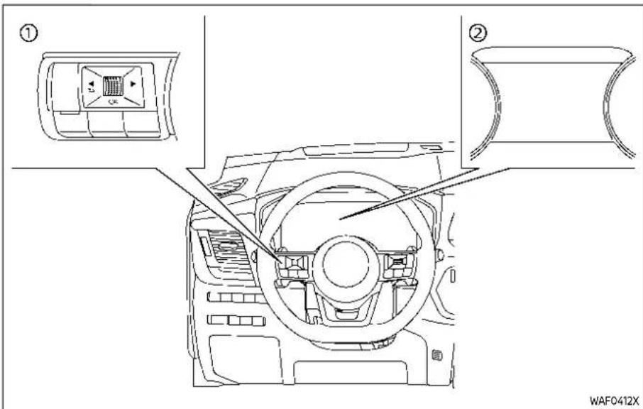
① Steering-wheel-mounted control (left side)
② Vehicle information display
HOW TO ENABLE/DISABLE THE SO-NAR SYSTEM
The system is automatically activated when the ignition switch is in the ON position and the shift lever is in the D (Drive) or R (Reverse) position.
Perform the following steps to set up the
sonar system function.
- Push the ◀ button until "Settings" appears in the vehicle information display and then push the scroll dial. Use the scroll dial to select "Driver Assistance." Then push the scroll dial.
- Select "Parking Aids" and push the scroll dial.
- Use the scroll dial to navigate in the menu and select or change an item:
- Moving Object
- Turns ON/OFF the Moving Object Detection (MOD) (See "Moving Ob-ject Detection (MOD)" (P.4-21).)
• Auto Show Sonar
— Shows the sonar display in the vehicle information display when the sonar activates
- Front
— Turns ON/OFF the front sonar sensors - Rear
— Turns ON/OFF the rear sonar sensors - Side (if so equipped)
— Turns ON/OFF the side sonar sensors - Distance
— Changes the sonar sensor's detection distance to "Long," "Med-
Startinganddriving5-165
ium" or "Short"
• Volume
— Changes the volume of the tone sound to "High," "Medium" or "Low"
SONAR SYSTEM LIMITATIONS

WARNING
Listedbelowarethesystemlimitationsforthesonarsystem.Failureto operatethevehicleinaccordance withthesesystemlimitationscould resultinseriousinjuryordeath.
- Readandunderstandthelimitationsofthesonarsystemas containedinthissection.Inclementweathermayaffectthe functionofthesonarsystem;this mayinclude reduced performanceorafalseactivation.
- Thesonarsystemisdeactivated atspeedsabove6MPH(10km/h). Itisreactivatedatlowerspeeds.
-
Inclementweatherorultrasonic sourcessuchasanautomaticcar wash,atruck'scompressed-air brakesorapneumaticdrillmay affectthefunctionofthesonar system;thismayincludereduced performanceorafalseactivation.
-
Thesonarsystemisnotdesigned topreventcontactwithsmallor movingobjects.Alwaysmove slowly.Thesystemwillnotdetect smallobjectsbelowthebumper orontheground.
- Thesonarsystemmaynotdetect the following objects: fluffy object such as snow, cloth, cotton, glass-wool, etc.; thin object such as rope, wire and chain, etc.; or wedge-shaped objects; complex-shaped objects or multiple objects in close.
- Thesonarsystemmaynotdetect objectsatspeedabove3MPH(5 km/h)andmaynotdetectcertain angularormovingobjects.
- Thesonarsystemmaynotdetect thefollowingobjects:
—Pedestrianswhoapproach thevehiclefromtheside
—Objectsplacednexttothe vehicle
- Thesonarsystemmaynotoperateinthefollowingconditions:
—Whenrain,snow,ice,dirt,etc. adherestothesonarsensor.
—Whenaloudsoundisheardin theareaaroundthevehicle.
—Whenthesurfaceoftheob-stacleisdiagonaltothefront orrearofthevehicle.
—Whenasonarsensororthe areaaroundthesensoris extremelyhotorcold.
- Thesonarsystemmayunintentionallyoperateinthefollowing conditions:
—When there is overgrown grassintheareaaroundthe vehicle.
—Whenthereisastructure(for example,awall,atollgate equipment,a narrow tunnelor aparkinglotgate)nearthe sideofthevehicle.
—whentherearebumps, protrusions ormanholecoverson theroadsurface.
—When the vehicle drives throughadrapedflagora curtain.
—Whenthereisanaccumulationofsnoworicebehindthe vehicle.
—Whendrivingonasteephill.
SYSTEM TEMPORARILY UNAVAILABLE
When sonar blockage is detected, the system will be deactivated automatically.
The system is not available until the conditions no longer exist.
The sonar sensors may be blocked by temporary ambient conditions such as splashing water, mist or fog. The blocked condition may also be caused by objects such as ice, frost or dirt obstructing the sonar sensors.
Actiontotake:
When the above conditions no longer exist, the system will resume automatically.
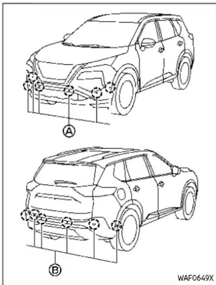
SYSTEM MAINTENANCE
The sonar sensors and are located on the front and rear bumpers.
●Always keep the area near the sonar sensors clean.
- If the sonar sensors are dirty, wipe them off with a soft cloth while being
careful to not damage them.
●The sonar sensors may be blocked by temporary ambient conditions such as splashing water, mist or fog. The blocked condition may also be caused by objects such as ice, frost or dirt obstructing the sonar sensors. Check for and remove objects obstructing the area around the sonar sensors.
- Do not subject the area around the sonar sensors to strong impact. Also, do not remove or disassemble the sonar sensors. If the sonar sensors and peripheral areas are deformed in an accident, etc., have the sonar sensors checked. It is recommended that you visit a NISSAN dealer for this service.
- Do not attach stickers (including transparent material), install accessories or apply additional paint on the sonar sensors and their surrounding areas. This may cause a malfunction or improper operation.
- When washing the vehicle using a high-pressure washer, do not apply direct washer pressure on the sonar sensors. This may cause a malfunction of the sonar sensors.
REARSONARSYSTEM(RSS)(ifso equipped)

The RSS sounds a tone to inform the driver of obstacles near the rear bumper.
When the RSS is turned on, the sonar view will automatically appear in the vehicle information display.

WARNING
•TheRSSisaconveniencebutilis notasubstituteforproperparking.
- Thedriverisalwaysresponsible for safetyduringparking and othermaneuvers.Alwayslook aroundandcheckthatitissafe
todosobeforeparking.
- ReadandunderstandthelimitationsoftheRSSascontainedin thissection.Thecolorsofthe sonarindicatorindicatesdifferentdistanceotheobject.
•Inclementweatherorultrasonic sourcessuchasanautomaticcar wash,atruck'scompressed-air brakesorapneumaticdrillmay affectthefunctionofthesystem; thismayincludereducedperformancearafalseactivation.
•TheRSSisdesignedasanaidto thedriverindetectinglargestationaryobjectstohelpavoiddamagingthevehicle. - TheRSSisnotdesignedtopreventcontactwithsmallormovingobjects.Alwaysmoveslowly. Thesystemwillnotdetectsmall objectsbelowthebumper,and maynotdetectobjectscloseto thebumperorontheground.
- TheRSS may not detect the following objects: fluffy objects such as snow, cloth, cotton, glass-wool, etc.; thin object such as rope, wire and chain, etc.; or wedge-shaped objects.
If your vehicle sustains damage to the bumper fascia, leaving it misaligned or bent, the sensing zone may be altered causing inaccurate measurement of obstacles or false alarms.

CAUTION
- Excessivenoise(suchasaudio systemvolumeoranopenvehiclewindow)willinterferewiththe toneanditmaynotbeheard.
- Keepthesonarsensors(located ontherearbumperfascia)free fromsnow,iceandlargeaccumulationsofdirt.Donotcleanthe sensorswithsharpobjects.Ifthe sensorsarecovered,theaccuracy ofthesonarfunctionwillbe diminished.
SYSTEM OPERATION
The system informs with a visual and audible alert of rear obstacles when the shift lever is in the R (Reverse) position.
The system is deactivated at speeds above 6 MPH (10 km/h). It is reactivated at lower speeds.
The intermittent tone will stop after several seconds when an obstacle is
identified only with the corner sensor. The tone will stop when the obstacle gets away from the vehicle.
When the object is detected, the indicator (green) appears and blinks and the tone sounds intermittently. When the vehicle moves closer to the object, the color of the indicator turns yellow and the rate of the blinking increases. When the vehicle is very close to the object, the Indicator stops blinking and turns red, and the tone sounds continuously.

Example
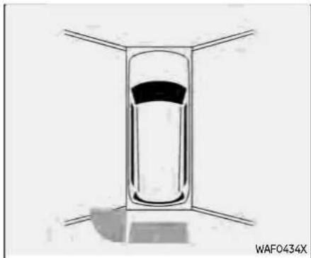
Example
When the rear of the vehicle moves closer The sonar indicator also appears on the to an obstacle, the sonar indicator ap- camera view of the center display. pears in the vehicle information display.
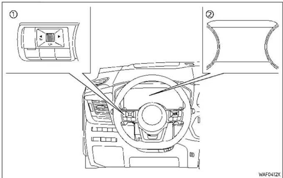
① Steering-wheel-mounted control (left side)
② Vehicle information display
HOW TO ENABLE/DISABLE THE RSS The system is automatically activated when the ignition switch is in the ON position and the shift lever is in the R
(Reverse) position.
Perform the following steps to set up the RSS function:
- Push the ◀ button until "Settings" appears in the vehicle information display and then push the scroll dial. Use the scroll dial to select "Driver
Assistance." Then push the scroll dial.
- Select "Parking Aids" and push the scroll dial.
-
Use the scroll dial to navigate in the menu and select or change an item:
-
Moving Object (if so equipped) — Turns ON/OFF the Moving Object Detection (MOD) (See "Moving Ob- ject Detection (MOD)" (P.4-21).)
- Auto Show Sonar — Shows the sonar display in the vehicle information display when the RSS activates
- Rear
- Turns ON/OFF the RSS
- Distance
— Changes the RSS sensor's detection distance to "Long," "Medium" or "Short"
• Volume — Changes the volume of the tone sound to "High," "Medium" or "Low"
RSS LIMITATIONS

WARNING
ListedbelowarethesystemlimitationsfortheRSS.Failureretooperate thevehicleinaccordancewiththese
systemlimitationscouldresultin seriousinjuryordeath.
- Readandunderstandthelimitations of the RSS as contained in this section. Inclement weather may affect the function of the RSS; this may include reduced performance or false activation.
- Thesystemisdeactivatedat speedsabove6MPH(10km/h). Itisreactivatedatlowerspeeds.
- Inclementweatherorultrasonic sourcessuchasanautomaticcar wash,atruck'scompressed-air brakesorapneumaticdrillmay affectthefunctionoftheRSS; thismayincludeducedperformanceorafalseactivation.
- TheRSSisnotdesignedtopreventcontactwithsmallormovingobjects.Alwaysmoveslowly. Thesystemwillnotdetectsmall objectsbelowthebumperoron theground.
- The RSS may not detect the following objects: fluffy objects such as snow, cloth, cotton, glass-wool, etc.; thin object such as rope, wire and chain, etc.; or wedge-shaped objects; complex-shaped objects or multiple ob
jectsinclose.
•TheRSSmaynotdetectobjects atspeedabove3MPH(5km/h) andmaynotdetectcertainangularormovingobjects.
•TheRSSmaynotoperateinthe followingconditions:
—Whenrain,snow,ice,dirt,etc.
adherestothesonarsensor.
—Whenaloudsoundisheardin theareaaroundthevehicle.
—Whenthesurfaceoftheobstacleisdiagonaltotherear ofthevehicle.
—Whenasonarsensororthe areaaroundthesensoris extremelyhotorcold.
•TheRSSmayunintentionallyoperateinthefollowingconditions:
—When there is overgrown grassin the area around the vehicle.
—whentherearebumps, protrusionsormanholecoverson theroadsurface.
— When the vehicle drives throughadrapedflagora curtain.
—Whenthereisanaccumulationofsnoworicebehindthe vehicle.
—Whendrivingonasteephill.
SYSTEM TEMPORARILY UNAVAILABLE
When sonar blockage is detected, the system will be deactivated automatically.
The system is not available until the conditions no longer exist.
The sonar sensors may be blocked by temporary ambient conditions such as splashing water, mist or fog. The blocked condition may also be caused by objects such as ice, frost or dirt obstructing the sonar sensors.
Actiontotake:
When the above conditions no longer exist, the system will resume automatically.

SYSTEM MAINTENANCE
The sonar sensors Ⓐ are located on the rear bumper.
●Always keep the area near the sonar sensors clean.
- If the sonar sensors are dirty, wipe them off with a soft cloth while being careful to not damage them.
●The sonar sensors may be blocked by temporary ambient conditions such as splashing water, mist or fog. The blocked condition may also be caused by objects such as ice, frost or dirt obstructing the sonar sensors. Check for and remove objects obstructing the area around the sonar sensors.
5-172 Startinganddriving
- Do not subject the area around the sonar sensors to strong impact. Also, do not remove or disassemble the sonar sensors. If the sonar sensors and peripheral areas are deformed in an accident, etc., have the sonar sensors checked. It is recommended that you visit a NISSAN dealer for this service.
- Do not attach stickers (including transparent material), install accessories or apply additional paint on the sonar sensors and their surrounding areas. This may cause a malfunction or improper operation.
- When washing the vehicle using a high-pressure washer, do not apply direct washer pressure on the sonar sensors. This may cause a malfunction of the sonar sensors.
COLDWEATHERDRIVING
FREEING A FROZEN DOOR LOCK
To prevent a door lock from freezing, apply deicer through the key hole. If the lock becomes frozen, heat the key before inserting it into the key hole, or use the Intelligent Key system.
ANTI-FREEZE
In the winter when it is anticipated that the outside temperature will drop below 32° F ( 0° C), check the anti-freeze to assure proper winter protection. For additional information, see "Engine cooling system" (P.8-4) or "Intercooler cooling system" (P.8-6).
BATTERY
If the battery is not fully charged during extremely cold weather conditions, the battery fluid may freeze and damage the battery. To maintain maximum efficiency, the battery should be checked regularly. For additional information, see "Battery" (P.8-15).
DRAINING OF COOLANT WATER
If the vehicle is to be left outside without anti-freeze, drain the cooling system, including the engine block. Refill before operating the vehicle. For details, see "Engine cooling system" (P.8-4).
TIRE EQUIPMENT
SUMMER tires have a tread designed to provide superior performance on dry pavement. However, the performance of these tires will be substantially reduced in snowy and icy conditions. If you operate your vehicle on snowy or icy roads, NISSAN recommends the use of MUD & SNOW or ALL SEASON tires on all four wheels. It is recommended you consult a NISSAN dealer for the tire type, size, speed rating and availability information.
For additional traction on icy roads, studded tires may be used. However, some U.S. states and Canadian provinces prohibit their use. Check local, state and provincial laws before installing studded tires.
Skid and traction capabilities of studdedsnowtires, onwetordry surfaces, may be poorer than that of non-studdedsnowtires.
Tire chains may be used. For details, see "Tire chains" (P.8-38) of this manual.
All-Wheel Drive (AWD) model
If you install snow tires, they must also be the same size, brand, construction and tread pattern on all four wheels.
SPECIAL WINTER EQUIPMENT
It is recommended that the following items be carried in the vehicle during winter:
●A scraper and stiff-bristled brush to remove ice and snow from the windows and wiper blades.
●A sturdy, flat board to be placed under the jack to give it firm support.
●A shovel to dig the vehicle out of snow-drifts.
- Extra window washer fluid to refill the reservoir tank.
DRIVING ON SNOW OR ICE

WARNING
- Wetice(32°F,0°Candfreezing rain),very cold snoworice can be slick and very hard to drive on. The vehicle will have much less traction or "grip" under these conditions. Try to avoid driving on wetice until theroadissalted or sanded.
- Whatever the condition, drive with caution. Accelerate and slow downwith care. If accelerating or downshifting to of fast, the drive wheels will lose even more traction.
- Allowmorestoppingdistance undertheseconditions.Braking shouldbestartedsoonerthanon drypavement.
- Allowgreaterfollowingdistances onslipperyroads.
- Watchforslipperyspots(glare ice). These may appear on a otherwise clear road in shaded areas. If a patch of one is seen ahead, brake before reaching it. Try not to be while on the time, and avoid any sudden steering maneuvers.
- Donotusecruisecontrol on slipperyroads.
●Snowcantrapdangerousex-haustgasesundryourvehicle. Keepsnowclearoftheexhaust pipeandfromaroundyourvehicle.
ACTIVENOISECANCELLATION(if soequipped)/ACTIVESOUND ENHANCEMENT(ifsoequipped)

NOTE:
Tooperatetheactivenoisecancellation andactivesoundenhancementsystem properly:
- Do not cover the speakers or woofer.
- Do not cover the microphones.
- Do not change or modify speakers including the woofer and any audio related parts such as the amplifier.
- Do not make any modification including sound deadening or modifications around the microphones, speakers or woofer.
ACTIVE NOISE CANCELLATION
The active noise cancellation uses microphones ① located inside the vehicle to detect engine booming noises. The system then automatically produces a muted engine booming noise through the speakers ② and woofer to reduce engine booming noise.
If the microphones① or the area around it is tapped, abnormal noise may be output from the speaker.
ACTIVE SOUND ENHANCEMENT
The active sound enhancement generates sounds according to engine speed and driving modes through the speakers ② and woofer ③ to enhance the quality of the engine sound.
6Incaseofemergency
Hazardwarningflasherswitch....6-2
ConnectiontoRoadsideAssistance....6-2
Emergencyengineshutoff....6-3
Flattire....6-3
TirePressureMonitoringSystem(TPMS)......6-3
Changingaflattire....6-4
Jumpstarting....6-11
Pushstarting....6-14
Ifyourvehicleoverheats....6-14
Towingyourvehicle....6-16
TowingrecommendedbyNISSAN....6-17
Vehiclerecovery(freeingastuckvehicle).....6-18
Push the switch on to warn other drivers when you must stop or park under emergency conditions. All turn signal lights will flash.

WARNING
- Ifstoppingforanemergency,be suretomovethevehiclewelloff theroad.
- Donotusethehazardwarning flasherswhilemovingonthe highwayunlessunusualcircumstancesforceyoutodriveso slowlythatyourvehiclemight becomeahazardtoothertraffic.
6-2 Incaseofemergency
-Turnsignalsdonotworkwhen thehazardwarningflasherlights areon.
The flasher can be actuated with the ignition switch in any position.
Somestatelawsmayprohibittheuseof thehazardwarningflasherswitchwhile driving.
CONNECTIONTOROADSIDEASSISTANCE
In the event of a roadside emergency, Roadside Assistance Service is available to you. Please refer to your Warranty Information Booklet (U.S.) or Warranty & Roadside Assistance Information Booklet (Canada) for details.
EMERGENCYENGINESHUTOFFFLATTIRE
To shut off the engine in an emergency situation while driving, perform the following procedure:
- Rapidly push the push-button ignition switch 3 consecutive times in less than 1.5 seconds, or
- Push and hold the push-button ignition switch for more than 2 seconds.
TIRE PRESSURE MONITORING SYSTEM (TPMS)
This vehicle is equipped with the Tire Pressure Monitoring System (TPMS). It monitors tire pressure of all tires except the spare. When the low tire pressure warning light is lit, and the "Tire Pressure Low - Add Air" warning message is displayed in the vehicle information display, one or more of your tires is significantly under-inflated. If the vehicle is being driven with low tire pressure, the TPMS will activate and warn you of it by the low tire pressure warning light. This system will activate only when the vehicle is driven at speeds above 16 MPH (25 km/h). For more details, see "Warning lights, indicator lights and audible reminders" (P.2-13) and "Tire Pressure Monitoring System (TPMS)" (P.5-6).

WARNING
- Ifthelowtirepressurewarning lightilluminateswhiledriving, avoidsuddensteeringmaneu-versorabruptbraking, reduce vehiclespeed,pullofftheroad toasafelocationandstopthe vehicleassoonaspossible.Drivingwithunder-inflatedtiresmay permanentlydamagethetires
andincreasethelikelihoodoftire failure.Seriousvehicledamage couldoccurandmayleadtoan accidentandcouldresultinseriouspersonalinjury.Checkthe tirepressureforallfourtires. Adjustthetirepressuretothe recommendedCOLDtirepressure shownontheTireandLoading Informationlabeltoturnthelow tirepressurewarninglightOFF.If thelightstillilluminateswhile drivingafteradjustingthetire pressure,atiremaybeflat.If youhaveaflattire,replaceitwith asparetireassoonaspossible.
- Since the spare tire is not equipped with the TPMS, when a spare tire is mounted or raw wheel is replaced, the TPMS will not function and the low tire pressure warning light will flash for approximately 1 minute. Thelight will remain on after 1 minute. Have your tires replaced and/or TPMS system reset as soon as possible. It is recommended you visit a NISSAN dealer for these services.
- Replacingtireswiththosenot originallyspecifiedbyNISSAN couldaffecttheproperoperation
Incaseofemergency6-3
oftheTPMS.
- Donotinjectanytireliquidor aerosoltiresealantintothetires, asthismaycauseamalfunction ofthetirepressuresensors.
CHANGING A FLAT TIRE
If you have a flat tire, follow the instructions below.
Stopping the vehicle
- Safely move the vehicle off the road and away from traffic.
- Turn on the hazard warning flashers.
- Park on a level surface and apply the parking brake.
- Push the park button to engage the P (Park) position.
- Turn off the engine.
- Raise the hood to warn other traffic, and to signal professional road assistance personnel that you need assistance.
- Have all passengers get out of the vehicle and stand in a safe place, away from traffic and clear of the vehicle.

WARNING
- Makesuretheparkingbrakeis securelyappliedandtheshift positionisplacedintheP(Park) position.
- Neverchangetireswhenthevehicleisonaslope,iceorslippery areas.Thisishazardous.
- Neverchangetiresifoncoming trafficisclosetoyourvehicle. Waitforprofessionalroadassistance.

Blocking wheels
Place suitable blocks ① at both the front and back of the wheel diagonally opposite the flat tire to prevent the vehicle from moving when it is jacked up.

WARNING
Besuretoblockthewheelasthe vehiclemay move and resultin personal injury.
6-4 Incaseofemergency

Modelswithadjustableluggagefloor
Getting the spare tire and tools The jack, jacking tools and the spare tire are stored in the storage in the luggage area.

To remove the jack:
- Remove the storage door by pressing the two release tabs simultaneously.
- Turn the jack lever in a counter-clock-wise direction, and then remove the jack slowly.
When storing the jack, set the jack slowly back, then turn the jack lever in a clockwise direction until the jack is fixed.

CAUTION
Whenremovingthejack,becareful thatyourhandsdonothitagainst thevehicle. Otherwise, this could resultinpersonalinjury.
NOTE:
- Whenstoringthejack, donotovertightenthejackleverusingascrew driver. Doingsocouldcausedeformationoftheinstallationareafor thejack.
- Donotallowthejacktocontactthe interiorparts.Doingsocouldcause damagetothevehicle.
![graph TD A["Top Panel"] --> B["Downward Rotation Arrow"] B --> C["Left Panel"] C --> D["Downward Rotation Arrow"] D --> E["Bottom Panel"]](/content/2026/05/810569/images/dbe1c38c4b0642df43b84a43553db0512000b3e27297d6be8724a519c3d53260.jpg)
Modelswithadjustableluggagefloor
floor: Release the locks before removing the rear (outer) luggage board. (See "Adjustable luggage floor" (P.2-75) for details.)
Models with the single luggage board: Disengage the retainer pins. (See "Single luggage board" (P.2-75).)
- Remove the floor carpet (if so equipped).
Remove the tools from the tool bag located in the storage area.

Remove the spare tire by removing the clamp holding it.
Removing the spare tire and tools The spare tire and tools are located under the luggage board(s).
To access the storage area:
- Remove the luggage floorboard(s). Models with the adjustable luggage
6-6 Incaseofemergency

Example
Removing the spare tire with sub-woofer (if so equipped)
- To loosen the bolt, turn counterclockwise.
- Once loosened, remove the bolt.

Example
- Place the sub-woofer in the left corner of the cargo space.
- Remove the spare tire.
- Once the flat tire is exchanged with the spare tire, store the flat tire where the spare was located.
- Place the sub-woofer inside the flat tire.
- Turn the bolt clockwise to tighten.
Jacking up the vehicle and removing the damaged tire

WARNING
- Nevergetunderthevehiclewhile itissupportedonlybythejack.If itsnecessarytoworkunderthe vehicle,supportitwithsafety stands.
- Useonlythejackprovidedwith yourvehicletoliftthevehicle.Do notusethejackprovidedwith yourvehicleonothervehicles. Thejackisdesignedforlifting onlyyourvehicleduringatire change.
- Usethecorrectjack-uppoints. Neveruseanyotherpartofthe vehicleforjacksupport.
●Neverjackupthevehiclemore thannecessary. - Neveruseblocksonorunderthe jack.
- Donotstartorruntheengine while vehicle is on the jack, as it maycausethevehicletomove.
- Do not allow passengers to stay inthevehiclewhileitisonthe
jack.
Carefullyreadthecautionlabelattachedtothejackbodyandthefollowinginstructions.
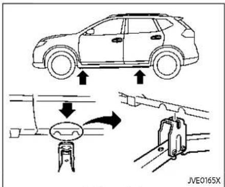
Jack-uppoint
- Place the jack directly under the jack-up point as illustrated so the top of the jack contacts the vehicle at the jack-up point. Align the jack head between the two notches in the front or the rear as shown. Also fit the groove of the jack head between the notches as shown.
Thejackshouldbeusedonfirmand levelground.
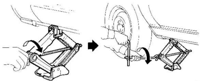
SCE0504

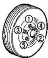
SCE0933
- Loosen each wheel nut one or two turns by turning it counterclockwise with the wheel nut wrench. Donot removethewheelnutsuntilthetire isofftheground.
- To lift the vehicle, securely hold the jack lever and rod with both hands as shown above. Carefully raise the vehicle until the tire clears the ground. Remove the wheel nuts, and then remove the tire.
Installing the spare tire Thesparetireisdesignedforemergencyuse.(Seespecificinstructions undertheheading"Wheelsandtires" (P.8-31).)
- Clean any mud or dirt from the surface between the wheel and hub.
- Carefully put the spare tire on and tighten the wheel nuts finger tight. Check that all the wheel nuts contact the wheel surface horizontally.
- With the wheel nut wrench, tighten wheel nuts alternately and evenly in the sequence illustrated ① ② ③ ④ ⑤ more than 2 times, until they are tight.
Incaseofemergency6-9
- Lower the vehicle slowly until the tire touches the ground. Then, with the wheel nut wrench, tighten the wheel nuts securely in the sequence illustrated. Lower the vehicle completely.

WARNING
- Incorrectwheelnutsorimproperlytightenedwheelnutscan causethewheeltobecomeloose orcomeoff. This could cause an accident.
- Donotuseoilorgreaseonthe wheelstudsornuts. This could cause thenutstobecomeloose.
- Retightenthewheelnutswhen thevehiclehasbeendrivenfor 600miles(1,000km)(alsoin casesofaflattire,etc.).
- As soon as possible, tighten the wheelnut stothespecified torque withatorquewrench.
Wheelnuttighteningtorque: 83ft-lb(113N·m)
Thewheelnutsmustbekeptigh- tenedtospecificationsatalltimes.It isrecommendedthatthewheelnuts betightenedtospecificationsat
eachlubricationinterval.
- AdjusttirepressuretotheCOLD pressure.
COLDpressure:
Afterthevehiclehasbeenparkedfor 3hoursormoreordrivenlessthan1 mile(1.6km).
COLDtirepressuresareshownon theTireandLoadingInformation labelaffixedtothedriversidecenter pillar.
Stowing the damaged tire and the tools
- Securely store the jack, tools and the damaged tire in the storage area.
- Replace the luggage boards and cover.
- Close the liftgate.

WARNING
●Alwaysmakesurethatthespare tireandjackingequipmentare properlysecuredafteruse.Such itemscanbecomedangerous projectilesinanaccidentorsuddenstop.
- Thesparetireisdesignedfor emergencyuse.Seespecificinstructionsundertheheading "Wheelsandtires"(P.8-31).
JUMPSTARTING
To start your engine with a booster battery, the instructions and precautions below must be followed.

WARNING
- If done incorrectly, jump starting can lead to a battery explosion, resulting in severe injury or death. It could also damage your vehicle.
•Explosivehydrogengasisalways presentinthevicinityofthe battery.Keepallsparksand flamesawayfromthebattery. - Donotallowbatteryfluidtocome into contact with eyes, skin, clothingorpaintedsurfaces. Batteryfluidisacorrosivesulfuric acid solution which can cause severe burns. If the fluid should come into contact with anything, immediately flush the contacted are with water.
-
Keepthebatteryoutofthereach ofchildren.
•Theboosterbatterymustbe ratedat12volts.Useofanim-properlyratedbatterycanda-mageyourvehicle. -
Whenever working on near a battery, always wears suitable eye protectors (forexample, goggles or industrials safety spectacles) and removerings, metal bands, or any other jewelry. Donotlean over the battery when jump starting.
- Donotattempttojumpstarta frozenbattery.Itcouldexplode andcauseseriousinjury.
-Yourvehiclehasanautomatic enginecoolingfan.Itcouldcome onatanytime.Keephandsand otherobjectsawayfromit.
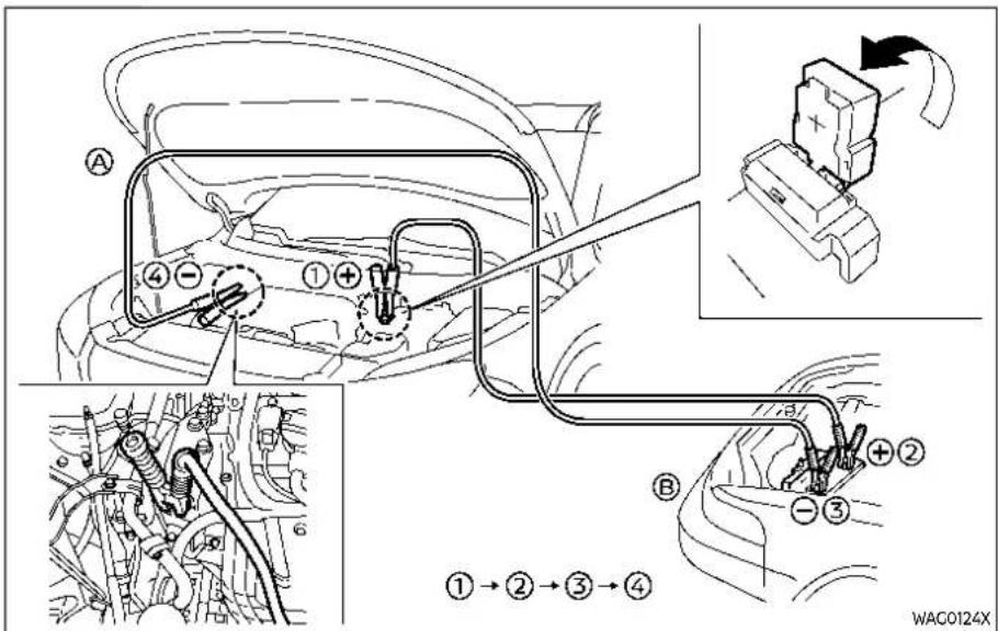
PR25DDengine
6-12 Incaseofemergency

KR15DDTengine

WARNING
Alwaysfollowtheinstructionsbelow. Failuretodosocouldresultin damagetothechargingsystemand causepersonalinjury.
-
If the booster battery is in another vehicle ⑧ position the two vehicles⑨ and ⑩ to bring their batteries into close proximity to each other. Donotallowthetwovehiclesto touch.
-
Apply the parking brake.
- Push the park button to engage the P (Park) position.
- Switch off all unnecessary electrical systems (headlights, heater, air conditioner, etc.).
- Connect jumper cables in the sequence as illustrated (1) → 2 → 3 ④).

CAUTION
●Alwaysconnectpositive(+)to positive(+)andnegative(-)to bodyground(forexample,as illustrated),nottothebattery.
●Makesurethejumpercablesdo nottouchmovingpartsinthe enginecompartmentandthat thecableclampsdonotcontact anyothermetal.
- Start the engine of the booster vehicle ® and let it run for a few minutes.
- Keep the engine speed of the booster vehicle ® at about 2,000 rpm, and start the engine of the vehicle being jump started.
PUSHSTARTINGIFYOURVEHICLEOVERHEATS

CAUTION
Donotkeepthestartermotoren-gagedformorethan10seconds.If theenginedoesnotstartrightaway, placetheignitionswitchintheOFF positionandwait10secondsbefore tryingagain.
- After starting your engine, carefully disconnect the negative cable and then the positive cable (4 → 3 → 2 →)①
Do not attempt to start the engine by pushing.

CAUTION
- ContinuouslyVariableTransmission(CVT)modelscannotbe push-startedortow-started.Attemptingtodosomaycause transmissiondamage.
- Three-way catalyst equipped model should not be started by pushings in each three-way catalyst may be damaged.
- Nevertrytostartthevehicleby towingit;whentheenginestarts, theforwardsurgecouldcause thevehicletocollidewiththe towvehicle.

WARNING
●Nevercontinuedrivingify your vehicleoverheats.Doingsocould causeavehiclefire.
- Neveropenthehoodifsteamis comingout.
- Neverremovetheradiator or coolantreservoircapwhile the engineishot.Iftheradiator or coolantreservoircapisremoved whentheengineishot,pressurizedhotwaterwillspurtout and possiblycauseburning,scalding orseriousinjury.
- If steamorcoolantiscoming from the engine, stand clear of the vehicle to prevent getting burned.
•Theenginecoolingfanwillstart atanytimewhenthecoolant temperatureexceedspresetdegrees.
- Becareful not to allow your hands, hair, jewelry or clothing to come into contact with, orto get caught in the cooling fan or drive belts.
If your vehicle is overheating (indicated by an extremely high temperature gauge reading), or if you feel a lack of engine power, detect abnormal noise, etc., take the following steps:
Donotstoptheengine.
- Move the vehicle safely off the road and apply the parking brake.
- Push the park button to shift to the P (Park) position.
- Turn off the air conditioner (if so equipped). Open all the windows, move the heater or air conditioner temperature control to maximum hot and fan control to high speed.
- Get out of the vehicle. Look and listen for steam or coolant escaping from the radiator or coolant reservoir before opening the hood. (If steam or coolant is escaping, turn off the engine.) Do not open the hood further until no steam or coolant can be seen.
- Open the engine hood.

WARNING
Ifsteamorwateriscomingfromthe engine,standcleartopreventgettingburned.
- Visually check the drive belt for damage or looseness. Also check if the cooling fan is running. The radiator hoses and radiator should not leak water. If coolant is leaking or the cooling fan does not run, stop the engine.

WARNING
Becarefulnottoallowyourhands, hair,jewelryorclothingtocomeinto contactwith,orgetcaughtin,engine beltsortheenginecoolingfan.The enginecoolingfancanstartatany time.
- After the engine cools down, check the coolant level in the reservoir with the engine running. Add coolant to the reservoir if necessary. Have your vehicle repaired. It is recommended you visit a NISSAN dealer for this service.
TOWINGYOURVEHICLE
When towing your vehicle, all jurisdictional and local regulations for towing must be followed. Incorrect towing equipment could damage your vehicle. Towing instructions are available from a NISSAN dealer. Local service operators are generally familiar with the applicable laws and procedures for towing. To assure proper towing and to prevent accidental damage to your vehicle, NISSAN recommends that you have a service operator tow your vehicle. It is advisable to have the service operator carefully read the following precautions.

WARNING
- Neverrideinavehiclethatis beingtowed.
●Nevergetunderyourvehicleafter ithasbeenliftedbyatowtruck.

CAUTION
- Whentowing, makesure that the transmission, axles, steeringsystem and powertrain are in working condition. If any of these conditions apply, dolliesora flatbedtowtruck must be used.
6-16 Incaseofemergency
●Alwaysattachsafetychainsbeforetowing.
(See "Flat towing for All-Wheel Drive vehicle" (P.10-28) or "Flat towing for Front-Wheel Drive vehicle" (P.10-28).) NOTE:
If the battery is completely drained, the transmission will not manually shift to other positions. For shifting together positions, charge the battery or supply power following the jump starting procedure. Push the park button to the Park position before shifting to other positions.
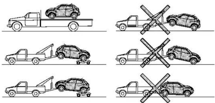
SCE0952
TOWING RECOMMENDED BY NISSAN
All-Wheel Drive (AWD) models
NISSAN recommends that towing dollies be used when towing your vehicle or the vehicle be placed on a flat bed truck as illustrated.
pensivedamagetothetransfercase and transmission.

CAUTION
NevertowAll-WheelDrive(AWD) modelsequippedwithaContinuouslyVariableTransmission(CVT) withanyofthewheelsontheground asthismaycauseseriousandex-
Incaseofemergency6-17

SCE0950
Two-Wheel Drive (2WD) models NISSAN recommends that your vehicle be towed with the driving (front) wheels off the ground or place the vehicle on a flat bed truck as illustrated.
NOTE: Iftheelectronicparkingbrakeisre- leased, the rear wheels can be groundedwhiletowing.Iftheelectronic parkingbrakeisnotreleased,towing dolliesshouldbeused.Foradditional information,referto"Parkingbrake" (P.5-25).

CAUTION
NevertowCVTmodelswiththefront wheelsonthegroundorfourwheels ontheground(forwardorbackward),asthismaycauseserious andexpensivedamagetothetransmission.Ifitisnecessarytotowthe vehiclewiththerearwheelsraised, alwaysusetowingdolliesunderthe frontwheels.
VEHICLE RECOVERY (freeing a stuck vehicle)

WARNING
Toavoidvehicledamage,serious personalinjuryordeathwhenrecoveringastuckvehicle:
- Contactaprofessionaltowing servicetorecoverthevehicleif youhaveanyquestionsregardingtherecoveryprocedure.
- Towchainsorcablesmustbe attachedonlytomainstructural membersofthevehicle.
- Donotusethevehicletie-downs totoworfreeeastuckvehicle.
- Onlyusedevicesspecificallydesignedforvehiclerecoveryand followthemanufacturer's instructions.
- Alwayspulltherecoverydevice straightoutfromthefrontofthe vehicle.Neverpullatanangle.
- Routerecoverydevicessothey donottouchanypartofthe vehicleexcepttheattachment point.
If your vehicle is stuck in sand, snow, mud,
etc., use a tow strap or other device designed specifically for vehicle recovery. Always follow the manufacturer's instructions for the recovery device.
Rocking a stuck vehicle

WARNING
- Standclearofastuckvehicle.
- Donotspinyourtiresathigh speed. This could cause them to explode and result in serious injury. Part of your vehicle could also overheat and bedamaged.
If your vehicle is stuck in sand, snow, mud, etc., use the following procedure:
- Turn off the Vehicle Dynamic Control (VDC) system.
- Make sure the area in front and behind the vehicle is clear of obstructions.
- Turn the steering wheel right and left to clear an area around the front tires.
- Slowly rock the vehicle forward and backward.
- Shift back and forth between R (Reverse) and D (Drive).
- Apply the accelerator as little as possible to maintain the rocking motion.
- Release the accelerator pedal before shifting between R and D.
-
Do not spin the tires above 35 MPH (55 km/h).
-
If the vehicle cannot be freed after a few tries, contact a professional towing service to remove the vehicle.
MEMO
6-20 Incaseofemergency
7Appearanceandcare
Cleaningexterior....7-2
Washing....7-2
Waxing....7-3
Removingspots....7-3
Underbody....7-3
Glass....7-3
Wheels....7-3
Aluminumalloywheels....7-3
Chromeparts....7-4
Tiredressing....7-4
Cleaninginterior....7-4
Airfresheners....7-5
Floormats....7-5
Seatbelts....7-7
Cleaningtheseattracks....7-7
Corrosionprotection....7-7
Mostcommonfactorscontributingto
vehiclecorrosion....7-7
Environmentalfactorsinfluencetherate
ofcorrosion....7-7
Toprotectyourvehiclefromcorrosion....7-8
CLEANINGEXTERIOR
In order to maintain the appearance of your vehicle, it is important to take proper care of it.
To protect the paint surfaces, wash your vehicle as soon as you can:
●after a rainfall to prevent possible damage from acid rain
●after driving on coastal roads
- when contaminants such as soot, bird droppings, tree sap, metal particles or bugs get on the paint surface
- when dust or mud builds up on the surface
Whenever possible, store or park your vehicle inside a garage or in a covered area.
When it is necessary to park outside, park in a shady area or protect the vehicle with a body cover.
Becarefulnottoscratchthepaint surfacewhenputtingonorremoving thebodycover.
WASHING
Wash dirt off the vehicle with a wet sponge and plenty of water. Clean the vehicle thoroughly using a mild soap, a special vehicle soap or general purpose dishwashing liquid mixed with clean, lukewarm (never hot) water.

CAUTION
- Donotconcentratewaterspray directlyonthesonsensorson thebumperasthiswillresultin damagetothesensors.Donot usepressurewasherscapableof sprayingwaterover1,200psi (8,274kPa)towashyourvehicle. Useofhigh-pressurewashers over,1,200psi(8,274kPa)can resultindamagetoorremoval ofpaintorgraphics.Avoidusinga high-pressurewashercloserthan 12inches(30cm)tothevehicle. Alwaysuseawide-anglenozzle only,keepthenozzlemovingand donotconcentratethewater sprayonanyonearea.
-
Donotusecarwashesthatuse acidinthedetergent. Some car washes, especially brushless ones, usesomeacidforcleaning. Theacidmayreactwithsome plasticvehiclecomponents, causing themtocrack. This could affect their appearance, and also could cause themnottofunction properly. Always check with your carwashtoconfirm that aacid is not used.
-
Donotwashthevehiclewith stronghouseholdsoap,strong chemicaldetergents,gasolineor solvents.
- Donotwashthevehicleindirect sunlightorwhilethevehiclebody ishot,asthesurfacemaybecome water-spotted.
- Avoid using tight-napped or roughcloths, such as washing mitts. Care must be taken when removing caked-ondirtor other foreign substance so the paint surface is not scratched or damaged.
Rinse the vehicle thoroughly with plenty of clean water.
Inside flanges, seams and folds on the doors, hatches and hood are particularly vulnerable to the effects of road salt. Therefore, these areas must be regularly cleaned. Make sure that the drain holes in the lower edge of the door are open. Spray water under the body and in the wheel wells to loosen the dirt and wash away road salt.
Avoid leaving water spots on the paint surface by using a damp chamois to dry the vehicle.
7-2 Appearanceandcare
WAXING
Regular waxing protects the paint surface and helps retain new vehicle appearance. Polishing is recommended to remove built-up wax residue and to avoid a weathered appearance before reapplying wax.
A NISSAN dealer can assist you in choosing the proper product.
- Wax your vehicle only after a thorough washing. Follow the instructions supplied with the wax.
- Do not use a wax containing any abrasives, cutting compounds or cleaners that may damage the vehicle finish.
Machine compound or aggressive polishing on a base coat/clear coat paint finish may dull the finish or leave swirl marks.
REMOVING SPOTS
Remove tar and oil spots, industrial dust, insects, and tree sap as quickly as possible from the paint surface to avoid lasting damage or staining. Special cleaning products are available at a NISSAN dealer or any automotive accessory stores. It is recommended that you visit a NISSAN dealer for these products.
UNDERBODY
In areas where road salt is used in winter, the underbody must be cleaned regularly. This will prevent dirt and salt from building up and causing the acceleration of corrosion on the underbody and suspension. Before the winter period and again in the spring, the underseal must be checked and, if necessary, re-treated.
GLASS
Use glass cleaner to remove smoke and dust film from the glass surfaces. It is normal for glass to become coated with a film after the vehicle is parked in the hot sun. Glass cleaner and a soft cloth will easily remove this film.

CAUTION
Whencleaningtheinsideofthe windows, donotusesharp-edged tools, abrasivecleanersorchlorine-baseddisinfectantcleaners. They could damage the electrical conductors or rear window defrosterelements.
WHEELS
Wash the wheels when washing the vehicle to maintain their appearance.
- Clean the inner side of the wheels when the wheel is changed or the underside of the vehicle is washed.
- Inspect wheel rims regularly for dents or corrosion. Such damage may cause loss of pressure or poor seal at the tire bead.
- NISSAN recommends that the road wheels be waxed to protect against road salt in areas where it is used during winter.

CAUTION
Donotuseabrasivecleanerswhen washingthewheels.
ALUMINUM ALLOY WHEELS
Wash regularly with a sponge dampened in a mild soap solution, especially during winter months in areas where road salt is used. Salt could discolor the wheels if not removed.

CAUTION
Followthedirectionsbelowtoavoid stainingordiscoloringthewheels:
- Donotuseacleanerthatuses strongacidoralkalicentsto cleanthewheels.
- Donotapplywheelcleanersto thewheelswhentheyarehot. Thewheeltemperatureshouldbe thesameasambienttemperature.
- Rinsethewheeltocompletely removethecleanerwithin15 minutesafterthecleanerisapplied.
CHROME PARTS
Clean chrome parts regularly with a non-abrasive chrome polish to maintain the finish.
TIRE DRESSING
NISSAN does not recommend the use of tire dressings. Tire manufacturers apply a coating to the tires to help reduce discoloration of the rubber. If a tire dressing is applied to the tires, it may react with the coating and form a compound. This compound may come off the tire while
7-4 Appearanceandcare
CLEANINGINTERIOR
driving and stain the vehicle paint. If you choose to use a tire dressing, take the following precautions:
- Use a water-based tire dressing. The coating on the tire dissolves more easily with an oil-based tire dressing.
- Apply a light coat of tire dressing to help prevent it from entering the tire tread/grooves (where it would be difficult to remove).
- Wipe off excess tire dressing using a dry towel. Make sure the tire dressing is completely removed from the tire tread/grooves.
- Allow the tire dressing to dry as recommended by tire dressing manufacturer.
Occasionally remove loose dust from the interior trim, plastic parts and seats using a vacuum cleaner or soft bristled brush. Wipe the vinyl and leather surfaces with a clean, soft cloth dampened in mild soap solution, then wipe clean with a dry soft cloth.
Regular care and cleaning is required in order to maintain the appearance of the leather (if so equipped).
Before using any fabric protector, read the manufacturer's recommendations. Some fabric protectors contain chemicals that may stain or bleach the seat material.
Use a cloth dampened only with water, to clean the meter and gauge lens.

WARNING
Donotusewateroracidiccleaners (hotsteamcleaners) on theseat. This candamagetheseatoroccupant classificationsensors. This can also affect the operation of the airbag system and result in serious personal injury.

CAUTION
●Neverusebenzine, thinner, or any similar material.
- Forcleaning, use as soft cloth, dampened with water. Never use a rough cloth, alcohol, benzine, thinner or any kind of solvent or papertowel with a chemical cleaning agent. They will scratch or caused discoloration to the helens.
- Donotsprayanylyliquidsuchas wateronthemeterlens.Spraying liquidmaycausethesystemto malfunction.
- Smalldirtparticlescanbeabra-
siveanddamagingtotheleather
surfacesandshouldberemoved
promptly.Donotusesaddlesoap,
carwaxes,polishes,oils,cleaning
fluids,solvents,detergentsor
ammonia-basedcleanersasthey
maydamagetheleather'snatural
finish.
- Neverusefabricprotectorsunlessrecommendedbythemanu-facturer.
- Donotuseglassorplasticcleaner onmeterorgaugelenscovers.It maydamagethelenscover.
- Donotspillonormakecontact withinteriorsurfaceswhilehandlingairfresheners, aromaagents, cosmetics,sunscreen,etc.They maycausepermanentdiscoloration,stain,crack,paintpeeling, etc. dependingontheingredients.Iftheycontacttheinterior surface,wipethemoffimmediatelyusingasoftcloth.
- Donotusethechlorine-based cleaningliquidsuchaschlorine dioxideandhypochlorousacid, whichmaycausethepaintpeeling, corrosion, etc. Ifitisunavoidabletocleanorsterilizeinterior surfaces, useless than 75% ethanol. Wipetheinteriorpartswitha dryclothdampenedwithethanol. Wipeoffethanol completely. If youleaveituncleaned, it may cause paint peeling, discoloration, etc. Sinceethanolisflammable, be careful off fire.
AIR FRESHENERS
Most air fresheners use a solvent that could affect the vehicle interior. If you use an air freshener, take the following precautions:
●Hanging-type air fresheners can cause permanent discoloration when they contact vehicle interior surfaces. Place the air freshener in a location that allows it to hang free and not contact an interior surface.
- Liquid-type air fresheners typically clip on the vents. These products can cause immediate damage and discoloration when spilled on interior surfaces.
Carefully read and follow the manufacturer's instructions before using air fresheners.
FLOOR MATS

WARNING
To avoid potential pedal interference that may result in a collision, injury or death:
- NEVERplaceafloormatontopof anotherfloormatinthedriver frontpositionorinstallthemup-sidedownorbackwards.
Appearanceandcare7-5
- It is recommended that you use only genuine NISSANfloormats specifically designed for use in your vehicle model and model year.
-Properlypositionthematsinthe floorwellusingthefloormatpositioninghooks.See"Floormat installation"(P.7-6). - Makesurethefloormatdoesnot interferewithpedaloperation.
- Periodically check the floormats to make sure they are properly installed.
- Aftercleaningthevehicleinterior, checkthefloormatstomake suretheyareproperlyinstalled.

floor mat is properly positioned.
- Make sure the floor mat does not interfere with pedal operation. With the ignition in the OFF position and the shift position in the P (Park) position, fully apply and release all pedals. The floor mat must not interfere with pedal operation or prevent the pedal from returning to its normal position. It is recommended you see a NISSAN dealer for details about installing the floor mats in your vehicle.
The use of genuine NISSAN floor mats can extend the life of your vehicle carpet and make it easier to clean the Interior. Mats should be maintained with regular cleaning and replaced if they become excessively worn.
Floor mat installation
Your vehicle is equipped with floor mat positioning hook(s). The number and shape of the floor mat positioning hook (s) for each seating position varies depending on the vehicle.
When installing genuine NISSAN floor mats, follow the installation instructions provided with the floor mat and the following:
-
Position the floor mat in the floorwell so that the floor mat grommet holes are aligned with the hook(s).
-
Push the grommet holes into the hook (s) and secure them. Ensure that the

Positioninghook(s)
The illustration shows the location of the floor mat positioning hook(s).
SEAT BELTS
The seat belts can be cleaned by wiping them with a sponge dampened in a mild soap solution. Allow the belts to dry completely in the shade before using them.
See "Seat belts" (P.1-14).

WARNING
Donotallowwetseatbeltstorollup intheretractor.NEVERusebleach,
dye, orchemicalsolventstoclean theseatbelts, sincethesematerials mayseverelyweakentheseatbelt webbing.
CLEANING THE SEAT TRACKS

CAUTION
Periodically clean these at track to prevent reduction of ability to move theseats.
Clean periodically with a high-powered vacuum cleaner. Dirt and debris may reduce the ability to adjust the seat. A wet cleansing agent may be used if necessary.
CORROSIONPROTECTION
MOST COMMON FACTORS CONTRIBUTING TO VEHICLE CORROSION
●The accumulation of moisture-retaining dirt and debris in body panel sections, cavities, and other areas.
- Damage to paint and other protective coatings caused by gravel and stone chips or minor traffic accidents.
ENVIRONMENTAL FACTORS INFLUENCE THE RATE OF CORROSION
Moisture
Accumulation of sand, dirt and water on the vehicle body underside can accelerate corrosion. Wet floor coverings will not dry completely inside the vehicle, and should be removed for drying to avoid floor panel corrosion.
Relative humidity
Corrosion will be accelerated in areas of high relative humidity, especially those areas where the temperatures stay above freezing where atmospheric pollution exists, or where road salt is used.
Temperature
A temperature increase will accelerate the rate of corrosion to those parts which are not well ventilated.
Air pollution
Industrial pollution, the presence of salt in the air in coastal areas, or heavy road salt use will accelerate the corrosion process. Road salt will also accelerate the disintegration of paint surfaces.
TO PROTECT YOUR VEHICLE FROM CORROSION
- Wash and wax your vehicle often to keep the vehicle clean.
●Always check for minor damage to the paint and repair it as soon as possible. - Keep drain holes at the bottom of the doors open to avoid water accumulation.
- Check the underbody for accumulation of sand, dirt or salt. If present, wash with water as soon as possible.

CAUTION
- NEVERremovedirt, sandorother debris from the passenger compartment by washing it out with a hose. Removedirt with avacuum
cleaner.
●Neverallowwaterorotherliquids tocomeincontactwithelectronic componentsinsidethevehicleas thismaydamagethem.
Chemicals used for road surface deicing are extremely corrosive. They accelerate corrosion and deterioration of underbody components such as the exhaust system, fuel and brake lines, brake cables, floor pan and fenders.
Inwinter, the underbody must be cleaned periodically.
For additional protection against rust and corrosion, which may be required in some areas, it is recommended you consult a NISSAN dealer.
7-8 Appearanceandcare
8Do-it-yourself
Maintenance precautions 8-2
Enginecompartmentchecklocations....8-3
PR25DDenginemodel....8-3
KR15DDTenginemodel....8-4
Enginecoolingsystem....8-4
Checkingenginecoolantlevel....8-6
Changingenginecoolant 8-6
Intercoolercoolingsystem(ifsoequipped)......8-6
Checkingintercoolercoolantlevel....8-7
Changingintercoolercoolant 8-8
Engineoil....8-8
Checkingengineoillevel....8-8
Changingengineoilandfilter 8-8
ContinuouslyVariableTransmission
(CVT)fluid....8-12
Brakefluid....8-12
Windowwasherfluid....8-13
Battery....8-15
Jumpstarting....8-16
Variablevoltagecontrolsystem....8-17
Drivebelt....8-17
Sparkplugs....8-18
Replacingsparkplugs....8-19
Aircleaner 8-19
Windshieldwiperblades....8-20
Cleaning....8-20
Replacing....8-21
Rearwindowwiperblade....8-21
Brakes....8-22
Self-adjustingbrakes....8-22
Brakepadwearwarning....8-22
Fuses....8-22
Enginecompartment....8-22
Passengercompartment....8-24
IntelligentKeybatteryreplacement....8-25
Lights....8-28
Headlights....8-29
Exteriorandinteriorlights....8-29
Wheelsandtires....8-31
Tirepressure....8-31
Tirelabeling....8-35
Changingwheelsandtires....8-39
MAINTENANCEPRECAUTIONS
When performing any inspection or maintenance work on your vehicle, always take care to prevent serious accidental injury to yourself or damage to the vehicle. The following are general precautions which should be closely observed.

WARNING
- Parkthevehicleonalevelsurface,applytheparkingbrake securelyandblockthewheelsto preventthevehiclefrommoving. Pushtheparkbuttontoshift to theP(Park)position.
- Besuretheignitionswitchisin theOFFpositionwhenperforminganypartsreplacementor repairs.
- If you must work with the engine running, keep your hands, clothing, hair and tools away from moving fans, belts and any other moving parts.
-Itisadvisabletosecureorremoveanylooseclothingand removeanyjewelry,suchas rings,watches,etc.beforework-ingonyourvehicle.
●Always wear eye protection whenever you work on your vehicle.
- If you mustruntheengineinan enclosedspaces such as agarage, besurethereisproperventilation forexhaustgasestoescape.
- Nevergetunderthevehiclewhile itissupportedonlybyajack.Ifit isnecessarytoworkunderthe vehicle,supportitwithsafety stands.
- Because the fuellines are under high pressure even when the engine is off, it is recommended you visit a NISSAN dealer for service of the fuel filter or fuel lines.
- Keepsmokingmaterials,flame andsparksawayfromfueland thebattery.
- Ongasolineenginemodelswith theMultiportFuelInjection(MFI) system, thefuelfilterandfuel lines should beserviced because the fuellines are underhigh pressure even when the engine is turned off. It is recommended that you visita NISSAN dealer for this service.
-Yourvehicleisequippedwithan automaticenginecoolingfan.It maycomeonatanytimewithout warning,eveniftheignition switchisintheOFFpositionand theengineisnotrunning.To avoidinjury,alwaysdisconnect thenegativebatterycablebefore workingnearthefan.

CAUTION
- Donotworkunderthehoodwhile theengineishot.Turntheengine offandwaituntilcoolsdown.
- Avoiddirectcontactwithused engineoilandcoolant.Improperlydisposedengineoil,and enginecoolantand/orothervehiclefluidscandamagetheenvironment.Alwaysconformto localregulationsfordisposalof vehiclefluid.
- NeverleavetheengineortheCVT relatedcomponentharnesses disconnectedwhiletheignition switchisintheONposition.
- Neverconnectordisconnectthe batteryoranytransistorized componentwhiletheignition
ENGINECOMPARTMENTCHECKLOCATIONS
switchisintheONposition.
This "8. Do-it-yourself" section gives instructions regarding only those items which are relatively easy for an owner to perform.
A genuine NISSAN Service Manual is also available. (See "Owner's manual/service manual order information" (P.10-33).)
You should be aware that incomplete or improper servicing may result in operating difficulties or excessive emissions, and could affect your warranty coverage. Ifin doubtaboutanyservicing,itisrecommendedyouhaveitdonebyaNISSAN dealer.

PR25DD ENGINE MODEL
- Engine coolant reservoir
- Engine oil filler cap
- Engine oil dipstick
- Brake fluid reservoir
- Battery
-
Fuse/fusible link box
-
Window washer fluid reservoir
- Drive belt
- Air cleaner
Do-it-yourself8-3
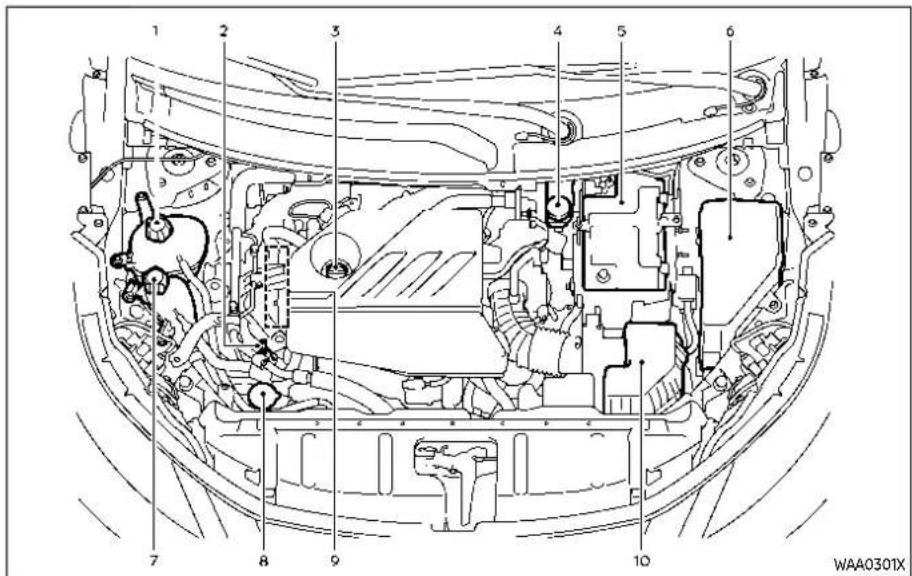
KR15DDT ENGINE MODEL
- Engine coolant reservoir
- Engine oil dipstick
- Engine oil filler cap
- Brake fluid reservoir
- Battery
- Fuse/fusible link box
8-4 Do-it-yourself
- Intercooler coolant reservoir
- Window washer fluid reservoir
- Drive belt
- Air cleaner
ENGINECOOLINGSYSTEM
The engine cooling system is filled at the factory with a pre-diluted mixture of 50% Genuine NISSAN Long Life Antifreeze/Coolant (blue) and 50% water to provide year-round anti-freeze and coolant protection. The anti-freeze solution contains rust and corrosion inhibitors. Additional engine cooling system additives are not necessary.

WARNING
- Neverremovetheradiator or coolantreservoircapwhen the engineishot.Waituntiltheengine and radiator cooldown. Serious burnscouldbecaused by high pressure fluidescaping fromtheradiator or coolantreservoir.Seeprecautionsin "If your vehicle overheats" (P.6-14) of this manual.
- Thecoolantreservoirisequipped withapressuretypecoolantreservoircap.Topreventengine damage, use only a genuine NISSANcoolantreservoircap.
- If the engine was stopped soon when the engine is shot, the cooling fan may operate for approximately 10 minutes after the
enginewasstoppedtocoolthe componentsintheenginecompartment.Whenthecoolingfanis operating,besurethathandsor otheritemsdonotgetcaughtin it.

CAUTION
- Neveruseanycoolingsystem additivessuchasradiatorsealer. Additivesmayclogthecooling systemandcausedamageto theengine,transmissionand/or coolingsystem.
- Whenaddingorreplacingcoolant,besuretouseonlyGenuine NISSANLongLifeAntifreeze/Coolant(blue)orequivalent.GenuineNISSANLongLifeAntifreeze/Coolant(blue)ispre-dilutedto provideantifreezeprotectionto -34°F(-37°C) .Ifadditionalfreeze protection is needed due to weatherwhereyouoperateyour vehicle,addGenuineNISSANLong Life Antifreeze/Coolant(blue) concentratefollowingthedirections onthe container. Ifan equivalentcoolantotherthan
GenuineNISSANLongLifeAntifreeze/Coolant(blue)isused, followthecoolantmanufacture's instructionstomaintainminimumantifreezeprotectionto -34°F(-37°C) .Theuseofother typesofcoolantsolutionsother than GenuineNISSANLongLife Antifreeze/Coolant(blue) or equivalentmaydamagetheenginecoolingsystem.
- Thelifeexpectancyofthefactory-fillcoolantis105,000miles (168,000km)or7years.Mixing anyothertypeofcoolantother thanGenuineNISSANLongLife Antifreeze/Coolant(blue),includingGenuineNISSANLongLife Antifreeze/Coolant(green),or theuseofnon-distilledwaterwill reducethelifeexpectancyofthe factory-fillcoolant.Refertothe "9.Maintenanceandschedules" sectionofthismanualformore details.

PR25DDengine
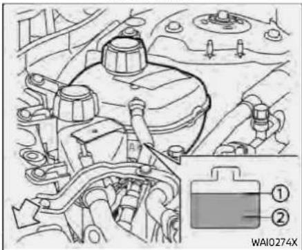
KR15DDTengine
CHECKING ENGINE COOLANT LEVEL
Check the coolant level inthereservoir whentheengineiscold. If the coolant level is below the MIN level ②, open the reservoir cap and add coolant up to the MAX level ①.
Tighten the cap securely after adding engine coolant.
Ifthecoolingsystemfrequentlyrequirescoolant,haveitchecked.itis recommendedyouvisitaNISSANdealer forthisservice.
CHANGING ENGINE COOLANT
A NISSAN dealer can change the engine coolant. The service procedure can be found in the NISSAN Service Manual.
Improperservicing can result in reduced heater performance and engine overheating.

WARNING
•Toavoidbeingscalded,never changethecoolantwhenthe engineishot.
- Neverremovetheradiator or coolantreservoircapwhenthe engineishot.Seriousburnscould becausedbyhighpressurefluid escapingfromtheradiatoror
coolantreservoir.
- Avoiddirectskincontactwith usedcoolant.Ifskincontactis made,washthoroughlywithsoap orhandcleanerassoonaspossible.
- Keepcoolantoutofthereachof childrenandpets.
Engine coolant must be disposed of properly. Check your local regulations.
INTERCOOLERCOOLINGSYSTEM(if soequipped)
The intercooler cooling system is filled at the factory with a pre-diluted mixture of 50% Genuine NISSAN Long Life Anti-freeze/Coolant (blue) and 50% water to provide year-round anti-freeze and coolant protection. The antifreeze solution contains rust and corrosion inhibitors. Additional intercooler cooling system additives are not necessary.

WARNING
- Neverremovetheradiator or coolantreservoircapwhenthe engineishot.Waituntiltheenginecoolsdown.Seriousburns couldbecausedbyhighpressure fluidescapingfromtheradiator orcoolantreservoir.
- Thecoolantreservoirisequipped withapressuretypecoolantreservoircap.Topreventengine andintercoolerdamage,useonly agenuineNISSANcoolantreservoircap.

CAUTION
●Neveruseanyadditivesinthe coolantsuchasradiatorsealerin thecoolingsystem. This may causedamagetotheintercooler.
- Whenaddingorreplacingcoolant,besuretouseonlyGenuineNISSANLongLifeAntifreeze/Coolant(blue)orequivalent.GenuineNISSANLongLifeAntifreeze/Coolant(blue)ispre-dilutedto provideantifreezeprotectionto -34°F(-37°C) .Ifadditionalfreeze protection is needed due to weatherwhereyouoperateyour vehicle,addGenuineNISSANLong LifeAntifreeze/Coolant(blue) concentratefollowingthedirectionsontheccontainer.Ifan equivalentcoolantotherthan GenuineNISSANLongLifeAntifreeze/Coolant(blue)isused,followthecoolantmanufacture's instructionstomaintainminimumantifreezeprotectionto -34°F(-37°C) .Theuseofother typesofcoolantsolutionsother thanGenuineNISSANLongLife Antifreeze/Coolant(blue) or equivalentmaydamagetheln
tercoolercoolingsystem.
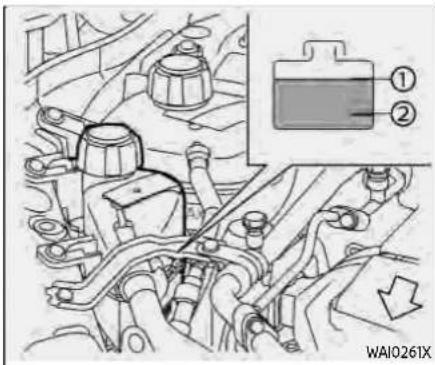
CHECKING INTERCOOLER COOL- ANT LEVEL
Check the coolant level in the reservoir when the engine is cold. If the coolant level is below the MIN level, add coolant to the MAX level ①
Tighten the cap securely after adding intercooler coolant.
If the intercooler coolingsystem frequently requires coolant, have it checked. It is recommended you visit a NISSAN dealer forth this service.
ENGINEOIL
CHANGING INTERCOOLER COOL- ANT
Intercooler coolant is maintenance-free.
If replacement is required, it is recommended you visit a NISSAN dealer for this service.
Improperservicingcanresultininter-cooleroverheating.

WARNING
•Toavoidthedangerofbeing scalded,neverchangethecoolantwhentheengineishot.
- Neverremovetheradiator or coolantreservoircapwhenthe engineishot.Seriousburnscould becausedbyhighpressurefluid escapingfromtheradiator or coolantreservoir.
- Avoiddirectskincontactwith usedcoolant.Ifskincontactis made,washthoroughlywithsoap orhandcleanerassoonaspossible.
- Keepcoolantoutofthereachof childrenandpets.
Intercooler coolant must be disposed of properly. Check your local regulations.
8-8 Do-it-yourself
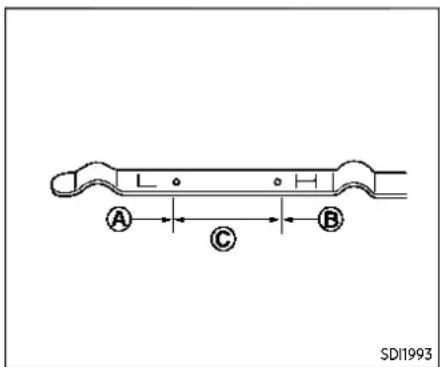
CHECKING ENGINE OIL LEVEL
- Park the vehicle on a level surface and apply the parking brake.
- Run the engine until it reaches operating temperature.
- Turn off the engine. Waitmorethan 10minutesfortheoiltodrainback intotheoilpan.
- Remove the dipstick and wipe it clean. Reinsert it all the way.
- Remove the dipstick again and check the oil level. It should be within the range ☐ If the oil level is below ☑ remove the oil filler cap and pour recommended oil through the open-
ing. Donotoverfill Ⓑ.
- Recheck oil level with the dipstick.
Itisnormaltoaddsomeoilbetweenoil maintenanceintervalsorduringthe break-inperiod,dependingonthese-verityofoperatingconditions.

CAUTION
Oillevelshouldbecheckedregularly. Operatingtheenginewithaninsufficientamountofoilcandamagethe engine,andsuchdamageisnot coveredbythewarranty.
CHANGING ENGINE OIL AND FILTER

WARNING
•Usedoilmustbedisposedof properly.Neverpourordumpoil intotheground,canals,rivers, etc.Itshouldbedisposedofat properwastefacilities.NISSAN recommendshaving your oil changedbyaNISSANdealer.
- Becarefulnottoburnyourself, as theengineoilmaybehot.
•Prolongedandrepeatedcontact withusedengineoilmaycause skincancer.
- Avoiddirectskincontactwithusedoil.Ifcontacted,washthoroughlywithsoaporhandcleanerandplentyofwaterassoonaspossible.
- Storeusedengineoilinmarked containersoutofthereachof children.
Vehicle set-up
- Park the vehicle on a level surface and apply the parking brake.
- Run the engine until it reaches the operating temperature.
- Turn the engine off and wait more than 10 minutes.
-
Raise and support the vehicle using a suitable floor jack and safety jack stands.
-
Place the safety jack stands under the vehicle jack-up points.
-
A suitable adapter should be attached to the jack stand saddle.
-
Remove the engine undercover.
- Remove clips at the around of the undercover.
- Then remove the other bolts that hold the undercover in place.

CAUTION
Makesurethecorrectlifting and supportpointsareusedtoavoid vehicledamage.

PR25DDengine
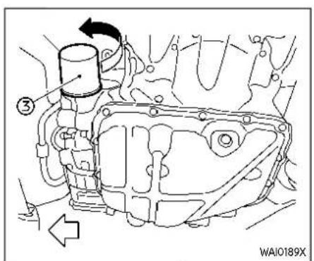
PR25DDengine

KR15DDTengine

KR15DDTengine
① Oil filler cap
② Oil drain plug
③ Oil filter
Engine oil and filter
- Place a large drain pan under the drain plug.
- Remove the oil filler cap.
- Remove the drain plug with a wrench and completely drain the oil.

CAUTION
Becarefulnottoburnyourself, as theengineoilishot.

WARNING
- Prolongedandrepeatedcontact withusedengineoilmaycause skincancer.
- Trytoavoiddirectskincontact withusedoil.Ifskincontactis made,washthoroughlywithsoap orhandcleanerassoonaspossible.
-
Keepusedengineoiloutofreach ofchildren.
-
Wasteoilmustbedisposedof properly.
- Checkyourlocalregulations.
(Perform steps 4 to 7 only when the engine oil filter change is needed.)
-
Loosen the oil filter with an oil filter wrench. Remove the oil filter by turning it by hand.
-
Wipe the engine oil filter mounting surface with a clean rag.

CAUTION
Besuretoremoveanyoldgasket materialremainingonthemounting surfaceoftheengine.Failureretodo socouldleadtoenginedamage.
- Coat the gasket on the new filter with clean engine oil.
- Screw in the oil filter clockwise until a slight resistance is felt, then tighten additionally more than 2/3 turn.
Oilfiltertighteningtorque:
-PR25DDengine
11to15ft-lb
(14.7to20.6N·m)
-KR15DDTengine
11to15ft-lb
(15.0to21.0N·m)
- Clean and re-install the drain plug with a new washer. Securely tighten the drain plug with a wrench.
Drainplugtighteningtorque:
-PR25DDengine
22to29ft-lb
(29.4to39.2N·m)
- KR15DDTengine
22to27ft-lb
(30.0to37.0N·m)
Do not use excessive force.
- Refill the engine with the recommended oil through the oil filler opening, and install the oil filler cap securely.
See "Capacities and recommended fluids/lubricants" (P.10-3) for drain and refill capacity. The drain and refill capacity depends on the oil temperature and drain time. Use these specifications for reference only. Always use the dipstick to determine the proper amount of oil in the engine.
- Start the engine and check for leakage around the drain plug and the oil filter. Correct as required.
- Turn the engine off and wait more than 10 minutes. Check the oil level with the dipstick. Add engine oil if necessary.
After the operation
- Reinstall undercover in reverse order of removal.
- Lower the vehicle carefully to the ground.
Do-it-yourself8-11
CONTINUOUSLYVARIABLE TRANSMISSION(CVT)FLUID
- Reset the Oil Control System and oil and filter maintenance reminder. (See "Maintenance" (P.2-29).)
When checking or replacement is required, we recommend a NISSAN dealer for servicing.

CAUTION
- NISSAN recommends using Genuine NISSANCVT Fluid NS-3 (or equivalent) ONLY in NISSANCVTs. Donot mix with other fluids.
- DonotuseAutomatictransmissionfluid(ATF)orManualTransmissionfluidinaNISSANCVT,as itmaydamagetheCVT.Damage causedbytheuseoffluidsother thanasrecommendedisnot coveredbytheNISSAN'sNew VehicleLimitedWarranty.
- UsingfluidsthatarenotequivalentoGenuineNISSANCVTFluid NS-3mayalsodamagetheCVT. Damagecausedbytheuseof fluids other than as recommendedisnotcoveredunder theNISSAN'sNewVehicleLimited Warranty.
BRAKEFLUID
For additional brake fluid information, see "Capacities and recommended fluids/lubricants" (P.10-3) of this manual.

WARNING
- Useonlynewfluidfromasealed container.Old,inferiororcontaminatedfluidmaydamagethe brakesystem.Theuseofimproperfluidscandamagethebrake system,andaffectthevehicle's stoppingability.
- Cleanthefillercapbeforeremoving.
- Brakefluid is poisonous and should bestored carefully in marked containers out of the reach of children.

CAUTION
Donotspillthefluidonanypainted surfaces. This will damage the paint. If fluidisspilled, immediately wash the surface with water.
WINDOWWASHERFLUID

Check the fluid level in the reservoir. If the fluid is below the MIN line 2 or the brake warning light comes on, add Genuine NISSAN Super Heavy Duty Brake Fluid or equivalent DOT3fluid up to the MAX line 1 and it is recommended you have your vehicle checked by a NISSAN dealer as soon as possible. If fluid must be added frequently, the system should be checked. It is recommended you visit a NISSAN dealer for this service.

TypeA(ifsoequipped)

TypeB(ifsoequipped)
Type A: Check the fluid level in the window washer reservoir. If the fluid level is low, add window washer fluid.
Type B: To check the fluid level, use your finger to plug the center hole ⚙ of the cap/tube assembly, then remove it from the reservoir. If there is no fluid in the tube, add fluid.
Add a washer solvent to the washer for better cleaning. In the winter season, add a windshield washer antifreeze. Follow the manufacturer's instructions for the mixture ratio.
Fill the window washer fluid reservoir periodically.
Add fluid when the low washer fluid warning appears (if so equipped).
Refill the reservoir more frequently when driving conditions require an increased amount of window washer fluid.
Recommended fluid:
Genuine NISSAN Windshield Washer Concentrate Cleaner & Antifreeze or equivalent

CAUTION
- Donotsubstituteengineanti-freeze coolant for window washersolution. This may result
Do-it-yourself8-13
indamagetothepaint.
- Donotfillthewindowwasher reservoirtankwithwasherfluid concentratesatfullstrength. Some methyl alcohol based washerfluidconcentratesmay permanentlystainthegrilleif spilledwhilefillingthewindow washerreservortank.
- Pre-mixwasherfluidconcentrateswithwatertothemanu-facturer'srecommendedlevels beforepouringthefluidintothe windowwasherreservoirtank.Do notusethewindowwasherreservoirtanktomixthewasher fluidconcentrateandwater.
BATTERY
| Caution symbols for battery | △ WARNING | ||
| 1 |  | No smoking, No exposed flames. No sparks | Do not expose the battery to electrical sparks, flames or smoking. Hydrogen gas generated by the battery is explosive. Explosive gases can cause blindness or injury |
| 2 |  | Shield eyes | Handle the battery cautiously. Always wear eye protection glasses to protect against explosion or battery acid. |
| 3 |  | Keep away from children | Never allow children to handle battery. Keep the battery out of the reach of children |
| 4 |  | Battery acid | Do not allow battery fluid to contact your skin, eyes, fabrics, or painted surfaces. Sulfuric acid can cause blindness or severe burns. After touching a battery or battery cap, do not touch or rub your eyes. Thoroughly wash your hands. If the acid contacts your eyes, skin or clothing, immediately flush with water for at least 15 minutes and seek medical attention. Battery fluid is acid. If the battery fluid gets into your eyes or onto your skin, it could cause loss of your eyesight or burns. |
| 5 |  | Note operating instructions | Before handling the battery, read this instruction carefully to ensure correct and safe handling. |
| 6 |  | Explosive gas | Hydrogen gas generated by battery fluid is explosive. Explosive gases can cause blindness or injury. |
WAI0270X
- If the battery is labeled "do not open" it is maintenance free and battery fluid should not be checked. It is recommended that you visit a NISSAN dealer or a qualified specialist workshop to confirm the battery's performance.
- Keep the battery surface clean and dry. Clean the battery with a solution of baking soda and water.
- Make certain the terminal connections are clean and securely tightened.
- If the vehicle is not to be used for 30 days or longer, disconnect the negative ⊖ battery terminal cable to prevent discharging it.
NOTE:
Careshouldbetakentoavoidsituations thatcanleadtopotentialbatterydischargeandpotentialno-startconditionssuchas:
- Installationorextendeduseofelectronicaccessoriesthatconsume batterypowerwhentheengineis notrunning(Phonechargers,GPS, DVDplayers,etc.).
- Vehicleisnotdrivenregularlyand/oronlydrivenshortdistances.
In these cases, the battery may need to be charged to maintain battery health.

WARNING
- Donotexposethebatteryto flamesorelectricalsparks.Hydrogengasgeneratedbythe batteryisexplosive.Donotallow batteryfluidtocontactyourskin, eyes,fabricsorpaintedsurfaces. Aftertouchingabatteryorbatterycap,donottouchorrubyour eyes.Thoroughlywash your hands.Iftheacidcontactsyour eyes,skinorclothing,immediatelyflushwithwaterforatleast 15minutesandseekmedical attention.
- Whenworkingonornearabattery,alwayswearsuitableeye protectionandremovealljewelry.
- Batteryposts,terminalsandrelatedaccessoriescontainlead and lead compounds. Wash handsafterhandling.
- Keepthebatteryoutofthereach ofchildren.
- Donottipthebattery.

Example
NOTE:
Donottrytoopenthetopofthe battery.
This battery is not equipped with removable vent caps.
JUMP STARTING
If jump starting is necessary, see "Jump starting" (P.6-11). If the engine does not start by jump starting, the battery may have to be replaced. It is recommended you visit a NISSAN dealer for this service.
VARIABLEVOLTAGECONTROLSYSTEM


CAUTION
- Donotgroundaccessoriesdirectlytothebatteryterminal. Doingsowillbypasssthevariable voltagecontrolsystemandthe vehiclebatterymaynotcharge completely.
- Useelectricalaccessorieswith theenginerunningtoavoiddischargingthevehiclebattery.
The variable voltage control system measures the amount of electrical discharge from the battery and controls voltage
generated by the generator.
DRIVEBELT
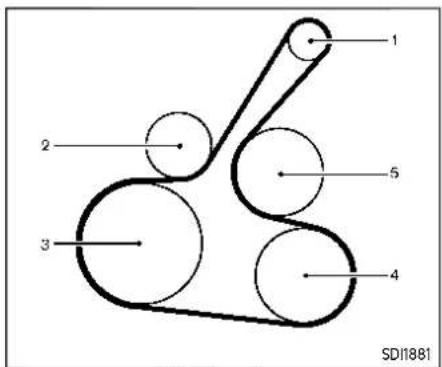
PR25DDengine
- Alternator
- Drive belt auto-tensioner
- Crankshaft pulley
- Air conditioner compressor
- Water pump
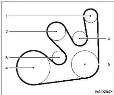
KR15DDTengine
- Alternator
- Water pump
- Drive belt auto-tensioner
- Crankshaft pulley
- Idler pulley
- Air conditioner compressor

WARNING
Besuretheignitionswitchisinthe OFFpositionbeforeservicingdrive belts.Theenginecouldrotateun-expectedly.
8-18 Do-it-yourself
SPARKPLUGS
- Visually inspect the belt for signs of unusual wear, cuts or fraying. If the belt is in poor condition, have it replaced. It is recommended that you visit a NISSAN dealer for this service.
- Have the belt condition checked regularly.

WARNING
Besuretheengineandignition switchareoffandthattheparking brakeisapplied.

CAUTION
Besuretousethecorrectsocketto removethesparkplugs.Anincorrect socketcandamagethesparkplugs.
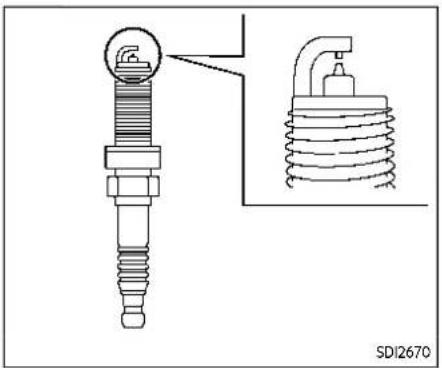
If replacement is required, it is recommended you visit a NISSAN dealer for this service.
Iridium platinum-tipped spark plugs
It is not necessary to replace the iridium platinum-tipped spark plugs as frequently as the conventional type spark plugs since they will last much longer. Follow the maintenance schedule shown in the "9. Maintenance and schedules" section. Do not reuse the iridium platinum-tipped spark plugs by cleaning or regapping.
Alwaysreplacesparkplugswithrecom-
AIRCLEANER
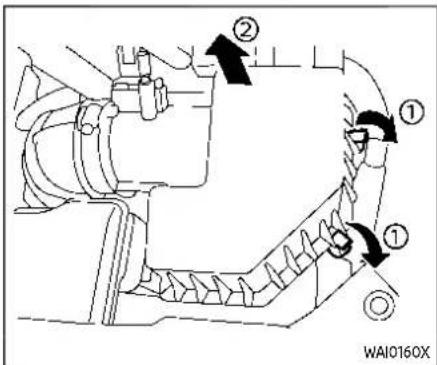
To remove the filter, release the lock pins ① and pull the unit upward②
The viscous paper type filter element (if so equipped) should not be cleaned and reused. The dry paper type filter element (if so equipped) may be cleaned and reused. Replace the filter according to the maintenance schedule shown in the "9. Maintenance and schedules" section. When replacing the filter, wipe the inside of the air cleaner housing and the cover with a damp cloth.
Do-it-yourself8-19
WINDSHIELDWIPERBLADES

WARNING
- Operatingtheenginewiththeair cleanerfilteroffcancauseyouor otherstobeburned.Theair cleanerfilternotonlycleansthe intakeair,italsostopsflameif theenginebackfires.Iftheair cleanerfilterisnotinstalledand theenginebackfires,youcould beburned.Neverdrivewiththe aircleanerfilteroff.Becautious workingontheenginewhenthe aircleanerfilterisoff.
- Neverpourfuelintothethrottle bodyorattempttostartthe enginewiththeaircleanerremoved.Doingsocouldresultin seriousinjury.
CLEANING
If your windshield is not clear after using the windshield washer or if a wiper blade chatters when running, wax or other material may be on the blade or windshield.
Clean the outside of the windshield with a washer solution or a mild detergent. Your windshield is clean if beads do not form when rinsing with clear water.
Clean each blade by wiping it with a cloth soaked in a washer solution or a mild detergent. Then rinse the blade with clear water. If your windshield is still not clear after cleaning the blades and using the wiper, replace the blades.

CAUTION
Wornwindshieldwiperbladescan damagethewindshieldandimpair drivervision.
When a washer nozzle is clogged it is recommended you see a NISSAN dealer if a washer nozzle is clogged or any malfunction occurs. Do not attempt to clean the nozzle using a needle or a pin. Doing so may damage the nozzle.
REARWINDOWWIPERBLADE

It is recommended you contact a NISSAN dealer if checking or replacement is required.
REPLACING
Replace the wiper blades if they are worn.
- Lift the wiper arm away from the windshield.
- Open Ⓐ, using a suitable tool, and then move the wiper blade down as shown to remove.
- Insert the new wiper blade onto the wiper arm until a click sounds.
- Close Ⓐ

CAUTION
- Afterwiperbladereplacement, returnthewiperarmtoitsoriginalposition;otherwiseitmaybe damaged when the hood is opened.
- Makesurethewiperbladescontacttheglass;otherwisethearm may bedamaged from wind pressure.
BRAKESFUSES
If the brakes do not operate properly, it is recommended you have the brakes checked by a NISSAN dealer.
SELF-ADJUSTING BRAKES
Your vehicle is equipped with self-adjusting brakes.
The disc-type brakes self-adjust every time the brake pedal is applied.

WARNING
Haveyourbrakesystemcheckedif thebrakepedalheightdoesnot returntonormal.Itisrecommended youvisitaNISSANdealerforth this service.
The disc brake pads have audible wear warnings. When a brake pad requires replacement, it will make a high pitched scraping sound when the vehicle is in motion. This scraping sound will first occur only when the brake pedal is depressed. After more wear of the brake pad, the sound will always be heard even if the brake pedal is not depressed. Have the brakes checked as soon as possible if the wear warning sound is heard.
Under some driving or climate conditions,
occasional brake squeak, squeal or other noise may be heard. Occasional brake noise during light to moderate stops is normal and does not affect the function or performance of the brake system.
Properbrake inspection intervals should be followed. For additional information, see the maintenance schedule shown in the "9. Maintenance and schedules" section.

ENGINE COMPARTMENT

WARNING
Neveruseafuseofahigherorlower amperageratingthanthatspecified onthefuseboxcover.Thiscould damagetheelectricalsystemor electroniccontrolunitsorcausea fire.
If any electrical equipment does not operate, check for an open fuse.
-
Be sure the ignition switch is turned off and the headlights are off.
-
Open the engine hood.
- Remove the fuse/fusible link box cover by using a suitable tool and pushing the tab.
- Locate the fuse that needs to be replaced.
- Remove the fuse using the fuse puller located in the passenger compartment fuse box.
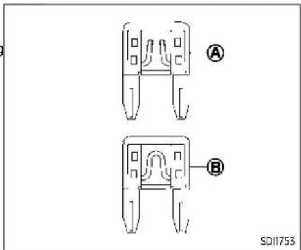
- If the fuse is open 📆replace it with a new fuse Ⓗ.
- If a new fuse also opens, have the electrical system checked and repaired. It is recommended you visit a NISSAN dealer for this service.
Fusible links
If any electrical equipment does not operate and the fuses are in good condition, check the fusible links. If any of these fusible links are melted, replace only with genuine NISSAN parts.
For checking and replacing the fusible links, it is recommended you visit a NISSAN dealer.

PASSENGER COMPARTMENT

WARNING
Neveruseafuseofahigherorlower amperageratingthanthatspecified onthefuseboxcover.Thiscould damagetheelectricalsystemor electroniccontrolunitsorcausea fire.
If any electrical equipment does not operate, check for an open fuse.
- Be sure the ignition switch is turned off and the headlights are off.
8-24 Do-it-yourself
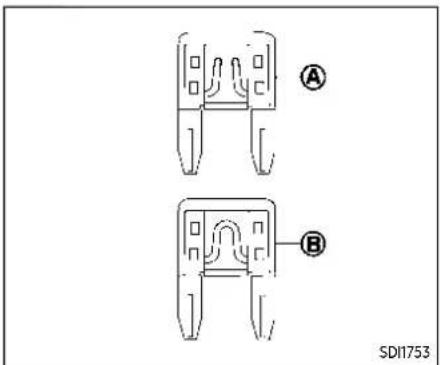
- If the fuse is open 📆replace it with a new fuse Ⓗ
- If a new fuse also opens, have the electrical system checked and repaired. It is recommended you visit a NISSAN dealer for this service.

Extended storage switch (if so equipped)
The extended storage switch is used when shipping the vehicle. It is located in the fuse panel on the driver's side of the instrument panel. If any electrical equipment does not operate, ensure the extended storage switch is pushed fully in place.
To inspect the extended storage switch, ensure the ignition switch and headlights are off.
INTELLIGENTKEYBATTERYREPLACEMENT
Howtoremovetheextendedstorage switch:
- To remove the extended storage switch, be sure the ignition switch is in the OFF or LOCK position.
- Be sure the headlights are off. (See "Headlight switch" (P.2-57) or "Intelligent Auto Headlight system" (P.2-58).)
- Remove the fuse box cover.
- Pinch the locking tabs ① on top and bottom of the extended storage switch.
- Pull the extended storage switch straight out from the fuse box 2

CAUTION
- Becarefulnottoallowchildrento swallowthebatteryandremoved parts.
- Animproperly disposed battery can harm the environment. Always confirm local regulations forbattery disposal.
- Whenchangingbatteries, donot letdustoroilgetonthecomponents.
- Thereisdangerofexplosionifthe lithiumbatteryisincorrectlyreplaced.Replaceonlywiththe sameorequivalenttype.
![graph TD A["Heating Device"] --> B["Switching"] B --> C["Discharge"] C --> D["Capacitor with + and - polarity indicators"] D --> E["Electricity Sensor"] style A fill:#f9f,stroke:#333 style B fill:#ccf,stroke:#333 style C fill:#cfc,stroke:#333 style D fill:#fcc,stroke:#333 style E fill:#ffc,stroke:#3…](/content/2026/05/810569/images/3e6c78d93d66351131606679e2fc02517b04448a307ae2b97080ff9ce7cb74aa.jpg)
Replace the battery in the Intelligent Key as follows:
- Remove the mechanical key from the Intelligent Key.
- Insert a small screwdriver into the slit of the corner and twist it to separate the upper part from the lower part.
8-26 Do-it-yourself
Use a cloth to protect the casing.
- Replace the battery with a new one.
Recommended battery:
CR2032 or equivalent
- Do not touch the internal circuit and electric terminals as doing so could cause a malfunction.
- Hold the battery by the edges. Holding the battery across the contact points will seriously deplete the storage capacity.
• Make sure that the ⊕side faces the bottom of the case.
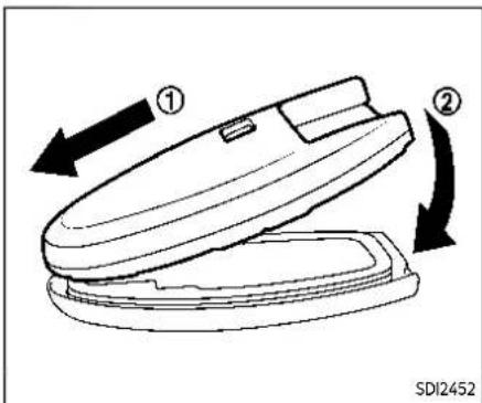
- Align the tips of the upper and lower parts ① and then push them together ② until it is securely closed.
- Operate the buttons to check its operation.
If you need any assistance for replacement, it is recommended you visit a NISSAN dealer for this service.
FCCNotice:
ForUSA:
FCCID:KR5TXN1
FCCID:KR5TXN3
FCCID:KR5TXN4
FCCID:KR5HFM401
ThisdevicecomplieswithPart15ofthe FCCRules.Operationissubjecttothe followingtwoconditions:(1)Thisdevice maynotcauseharmfulinterference, and(2)thisdevicemustacceptany interferencereceived,includinginterferencethatmaycauseundesiredoperation.
Note: Changesormodificationsnot expresslyapprovedbythepartyresponsibleforcompliancecouldvoid theuser'sauthoritytooperatethe equipment.
ForCanada:
ICID:7812D-TXN1
ICID:7812D-TXN3
ICID:7812D-TXN4
ICID:7812D-HFM401
ThisdevicecomplieswithIndustryCanadalicense-exemptRSSstandard(s). Operationissubjecttothefollowing twoconditions:(1)thisdevicemaynot causeinterference,and(2)thisdevice mustacceptanyinterference,including interferencethatmaycauseundesired operationofthedevice.
LIGHTS

- Front map light
- Vanity mirror light
- Room light (if so equipped)
- Side turn signal light
- Rear personal light (if so equipped)
- Headlight (high-beam)
-
Front fog light (if so equipped)
-
Headlight (low-beam)
- Front parking light/Daytime running light/Front turn signal light (LED type)
- Front turn signal light (Bulb type)
- Front side marker light
- High-mounted stop light
- Cargo light
8-28 Do-it-yourself
- License plate light
- Back-up light/Tail light
- Rear turn signal light/Stop light/Tail light
- Rear side marker light
HEADLIGHTS
Fog may temporarily form inside the lens of the exterior lights in the rain or in a car wash. A temperature difference between the inside and the outside of the lens causes the fog. This is not a malfunction. If large drops of water collect inside the lens, it is recommended you visit a NISSAN dealer for servicing.
Replacing
If LED headlight replacement is required, it is recommended that you visit a NISSAN dealer for this service.
EXTERIOR AND INTERIOR LIGHTS
| Item Wattage (W) Bulb No. | ||
| Headlight high/low beams* | LED | - |
| Front turn signal light* 28/8 or LED 7444NA or - | ||
| Front parking light* LED - | ||
| Front side marker light* 5 W5W | ||
| Front fog light (if so equipped)* LED - | ||
| Side turn signal light (if so equipped)* LED - | ||
| Daytime running light* | LED - | |
| Rear combination light* | ||
| Turn signal light | 21 | W21W |
| Stop/tail light | LED | — |
| Back-up | 16 | W16W |
| Rear side marker light* | 5 W5W | |
| License plate light* | 5 (assembly) | W5W |
| Map light* | 8 W8W | |
| Rear personal light (if so equipped)* | 5 W5W | |
| Vanity mirror light* | 5 W5W | |
| High-mounted stop light* | LED - | |
| Room light (if so equipped)* | 8 W8W | |
| Cargo light | 8 | - |
| Lower center light (if so equipped)* | 1.4 | - |
| Glove box light (if so equipped)* | 1.4 | - |
| Console box light* | 1.4 or LED | - |
*: It is recommended you visit a NISSAN dealer for replacement.
NOTE: It is recommended that you check with the Parts Department at a NISSAN dealer for the latest information about parts.

![graph TD A["User Phone"] --> B{Switch} B -->|Yes| C["Device 1"] B -->|No| D["Device 2"] C --> E["Device 3"] D --> F["Device 4"] E --> G["Final Display"] F --> G style A fill:#f9f,stroke:#333 style G fill:#ccf,stroke:#333](/content/2026/05/810569/images/8cddbce7280ca2ed60853826977697691153c0225b44cf7034e4ab24f4c776fe.jpg)

REMOVE
INSTALL
Replacement procedures
All other lights are either type A, B, C, D or E. When replacing a bulb, first remove the lens and/or cover.
8-30 Do-it-yourself
WHEELSANDTIRES
If you have a flattire, see "Flattire" (P.6-3).
TIRE PRESSURE
Tire Pressure Monitoring System (TPMS)
This vehicle is equipped with the Tire Pressure Monitoring System (TPMS). It monitors tire pressure of all tires except the spare. When the low tire pressure warning light is lit, and the "Tire Pressure Low - Add Air" warning message is displayed in the vehicle information display, one or more of your tires is significantly under-inflated.
The TPMS will activate only when the vehicle is driven at speeds above 16 MPH (25 km/h). Also, this system may not detect a sudden drop in tire pressure (for example a flat tire while driving).
For more details, see "Low tire pressure warning light" (P.2-18), "Tire Pressure Monitoring System (TPMS)" (P.5-6) and "Tire Pressure Monitoring System (TPMS)" (P.6-3).
Tire inflation pressure
Check the pressure of the tires (including the spare) often and always prior to long distance trips. The recommended tire pressure specifications are shown on the Tire and Loading Information label under the "Cold Tire Pressure" heading. The Tire and Loading Information label is affixed to the driver side center pillar. Tire pressures should be checked regularly because:
- Most tires naturally lose air over time.
- Tires can lose air suddenly when driven over potholes or other objects or if the vehicle strikes a curb while parking.
The tire pressures should be checked when the tires are cold. The tires are considered COLD after the vehicle has been parked for 3 or more hours, or driven less than 1 mile (1.6 km) at moderate speeds.
TPMS with Easy Fill Tire Alert provides visual and audible signals outside the vehicle for inflating the tires to the recommended COLD tire pressure. (See "TPMS with Easy Fill Tire Alert" (P.5-9).)
Incorrect tire pressure, including underinflation, may adversely affect tire life and vehicle handling.

WARNING
- Improperlyinflatedtirescan failsuddenlyandcausean accident.
•TheGrossVehicleWeight rating(GVWR)islocated on theF.M.V.S.S./C.M.V.S.S.certification label. Thevehicle weightcapacityisindicated ontheTireandLoadingInformationlabel.Donotload yourvehiclebeyondthiscapacity.Overloadingyourvehiclemayresultinreduced tirelife,unsafeoperating conditionsduetopremature tirefailure, orunfavorable
handlingcharacteristicsand couldalsoleadtoaserious accident. Loading beyond thespecifiedcapacitymay alsoresultinfailureofother vehiclecomponents.
- Beforetakingalongtrip,or whenever you heavily load your vehicle,useatirepressuregaugetoensure that the tire pressures are at the specified level.
•Foradditionalinformation regardingtires,referto"ImportantTireSafetyInformation"(US)or"TireSafety Information"(Canada)inthe WarrantyInformationBooklet.
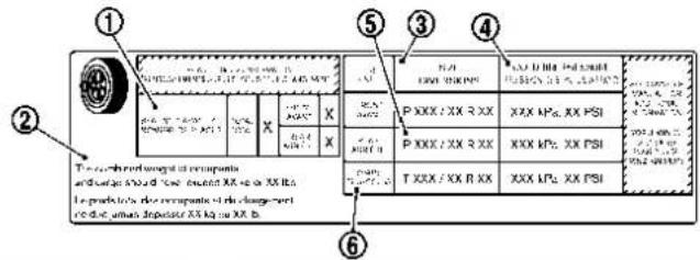
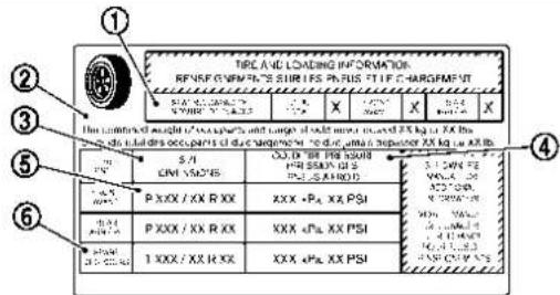
SDI2503
Tire and Loading Information label
① Seating capacity: The maximum number of occupants that can be seated in the vehicle.
② Vehicle load limit: See "Ve-
hicle loading information" (P.10-15).
③ Original size: The size of the tires originally installed on the vehicle at the factory.
Cold tire pressure: Inflate the tires to this pressure when the tires are cold. Tires are considered COLD after the vehicle has been parked for 3 or more hours, or driven less than 1 mile (1.6 km) at moderate speeds. The recommended cold tire inflation is set by the manufacturer to provide the best balance of tire wear, vehicle handling, driveability, tire noise, etc., up to the vehicle's GVWR.
⑤ Tire size — see "Tire labeling" (P.8-35).
⑥ Spare tire size or compact spare tire size

Checking the tire pressure
-
Remove the valve stem cap from the tire.
-
Press the pressure gauge squarely onto the valve stem. Do not press too hard or force the valve stem sideways, or air will escape. If the hissing sound of air escaping from the tire is heard while checking the pressure, reposition the gauge to eliminate this leakage.
-
Remove the gauge.
8-34 Do-it-yourself
- Read the tire pressure on the gauge stem and compare it to the specification shown on the Tire and Loading Information label.
- Add air to the tire as needed. If too much air is added, press the core of the valve stem briefly with the tip of the gauge stem to release pressure. Recheck the pressure and add or release air as needed.
- Install the valve stem cap.
- Check the pressure of all other tires, including the spare.
| SIZE | COLDTIREINFLATION PRESSURE | |
| FRONTORIGINAL TIRE | 235/65R17 | 250kPa,36PSI |
| 235/60R18 | 230kPa,33PSI | |
| 235/55R19 | 230kPa,33PSI | |
| REARORIGINALTIRE | 235/65R17 | 230kPa,33PSI |
| 235/60R18 | 210kPa,30PSI | |
| 235/55R19 | 210kPa,30PSI | |
| SPARETIRE | T155/80D17(2WD)T165/90D17(AWD) | 420kPa,60PSI |
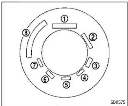
Example
TIRE LABELING
Federal law requires tire manufacturers to place standardized information on the sidewall of all tires. This information identifies and describes the fundamental characteristics of the tire and also provides the tire identification number (TIN) for safety standard certification. The TIN can be used to identify the tire in case of a recall.

① Tire size (example: P215/60R16 94H)
- P: The "P" indicates the tire is designed for passenger vehicles. (Not all tires have this information.)
- Three-digit number (215): This number gives the width in millimeters of the tire from sidewall edge to sidewall edge.
- Two-digit number (60): This number, known as the aspect ratio, gives the tire's ratio of
8-36 Do-it-yourself
height to width.
- R: The "R" stands for radial.
- Two-digit number (16): This number is the wheel or rim diameter in inches.
- Two- or three-digit number (94): This number is the tire's load index. It is a measurement of how much weight each tire can support. You may not find this information on all tires because it is not required by law.
- H: Tire speed rating. You should not drive the vehicle faster than the tire speed rating.

② TIN (Tire Identification Number) for a new tire (example: DOT XX XX XXX XXXX)
- DOT: Abbreviation for the "Department of Transportation". The symbol can be placed above, below or to the left or right of the Tire Identification Number.
- Two-digit code: Manufacturer's identification mark
-
Two-digit code: Tire size
-
Three-digit code: Tire type code (Optional)
-
Four numbers represent the week and year the tire was built. For example, the numbers 3103 means the 31st week of 2003. If these numbers are missing, then look on the other sidewall of the tire.
③ Tire ply composition and material
The number of layers or plies of rubber-coated fabric in the tire.
Tire manufacturers also must indicate the materials in the tire, which include steel, nylon, polyester, and others.
④ Maximum permissible inflation pressure
This number is the greatest amount of air pressure that should be put in the tire. Do not exceed the maximum permissible inflation pressure.
⑤ Maximum load rating
This number indicates the maximum load in kilograms and pounds that can be carried by the tire. When replacing the tires on the vehicle, always use a tire that has the same load rating as the factory installed tire.
⑥ Term of "tubeless" or "tube type" indicates whether the tire requires an inner tube ("tube type") or not ("tubeless").
⑦ The word "radial"
The word "radial" is shown, if the tire has radial structure.
⑧ Manufacturer or brand name Manufacturer or brand name is shown.
Othertire-relatedterminology:
In addition to the many terms that are defined throughout this section, Intended Outboard Sidewall is (1) the sidewall that contains a whitewall, bears white lettering or bears manufacturer, brand and/or model name molding that is higher or deeper than the same molding on the other sidewall of the tire, or
(2) the outward facing sidewall of an asymmetrical tire that has a particular side that must always face outward when mounted on a vehicle.
TYPES OF TIRES

WARNING
- Whenchangingorreplacingtires, besureallfourtiresareofthe sametype(Example:Summer,All SeasonorSnow)andconstruction.A NISSAN dealermay beable to helpyouwithinformation abouttiretype,size,speedrating andavailability.
- Replacementtiresmayhavea lowerspeedratingthanthefactoryequippedtires,andmaynot matchthepotentialmaximum vehiclespeed.Neverexceedthe maximumspeedratingofthe tire.
●Replacing tires with thosenot originally specified by NISSAN could affect the proper operation of the TPMS.
- For additional information regarding tires, refer to "Important TireSafetyInformation" (US) or "TireSafetyInformation" (Canada) in the Warranty Information Booklet.
●Alwaysusetiresofthesametype, size, brand, construction and treadpatternallfourwheels. Failuretodosomayresultina circumference difference betweeniresonthefrontandrear axleswhichcancausetheVehicle DynamicControl(VDC)systemto malfunctionresultinginpersonal injuryordeath,excessivetire wearandmaydamagethetransmission,transfercaseanddifferentialgears.
All season tires
NISSAN specifies all season tires on some models to provide good performance all year, including snowy and icy road conditions. All Season tires are identified by ALL SEASON and/or M&S (Mud and Snow) on the tire sidewall. Snow tires have better snow traction than All Season tires and may be more appropriate in some areas.
Summer tires
NISSAN specifies summer tires on some models to provide superior performance on dry roads. Summer tire performance is substantially reduced in snow and ice. Summer tires do not have the tire traction rating M&S on the tire sidewall.
If you plan to operate your vehicle in snowy or icy conditions, NISSAN recommends the use of SNOW tires or ALL SEASON tires on all four wheels.
Snow tires
If snow tires are needed, it is necessary to select tires equivalent in size and load rating to the original equipment tires. If you do not, it can adversely affect the safety and handling of your vehicle.
Generally, snow tires will have lower speed ratings than factory equipped tires and may not match the potential maximum vehicle speed. Never exceed the maximum speed rating of the tire.
If you install snow tires, they must be the same size, brand, construction and tread pattern on all four wheels.
For additional traction on icy roads, studded tires may be used. However, some U.S. states and Canadian provinces prohibit their use. Check local, state and provincial laws before installing studded tires. Skid and traction capabilities of studded snow tires, on wet or dry surfaces, may be poorer than that of non-studded snow tires.
TIRE CHAINS

WARNING
Iftirechainsareusedwiththis vehicle,theymustallowsufficient clearancebetweenethireandthe closestvehiclesuspensionorbbody component.Failuretousethecorrectchains,ornotproperlyinstalling chains,candamagethebrakes,suspensionorothervehiclepartsand causeacrashinwhichaperson couldbeseriouslyinjuredorkilled. NISSANrecommendsusingthefollowingchains,orequivalent.
•PEERLESSSUPERZ6SZ-429
Use of tire chains may be prohibited according to location. Check the local laws before installing tire chains. When installing tire chains, make sure they are the proper size for the tires on your vehicle and are installed according to the chain manufacturer's suggestions. UseonlySAEClassSchains.Class "S" chains are used on vehicles with re-
stricted tire to vehicle clearance. Vehicles that can use Class "S" chains are designed to meet the SAE standard minimum clearances between the tire and the closest vehicle suspension or body component required to accommodate the use of a winter traction device (tire chains or cables). The minimum clearances are determined using the factory equipped tire size. Other types may damage your vehicle. Use chain tensioners when recommended by the tire chain manufacturer to ensure a tight fit. Loose end links of the tire chain must be secured or removed to prevent the possibility of whipping action damage to the fenders or underbody. If possible, avoid fully loading your vehicle when using tire chains. In addition, drive at a reduced speed. Otherwise, your vehicle may be damaged and/or vehicle handling and performance may be adversely affected.
Tirechainsmustbeinstalledonlyon thefrontwheelsandnotontherear wheels.
Never install tire chains on a TEMPORARY USE ONLY spare tire.
Do not use tire chains on dry roads. Driving with tire chains in such conditions can cause damage to the various mechanisms of the vehicle due to some overstress.
![graph TD A["Component 1"] --> B["Component 2"] B --> C["Component 3"] C --> D["Component 4"] D --> E["Output"] style A fill:#f9f,stroke:#333 style B fill:#f9f,stroke:#333 style C fill:#f9f,stroke:#333 style D fill:#f9f,stroke:#333 style E fill:#ccf,stroke:#333](/content/2026/05/810569/images/d5f10b82ac02c20cd87c74028e631fe20e5df4168fddcce1c055d74b4d8eecc9.jpg)
CHANGING WHEELS AND TIRES
Tire rotation
NISSAN recommends rotating the tires at the specified interval shown in the maintenance schedule. (See the "Maintenance and schedules" section. For tire replacing procedures, see "Flat tire" (P.6-3).)
Assoonaspossible,tightenthe wheelnutstothespecifiedtorque withatorquewrench.
Wheelnuttighteningtorque: 83ft-lb(113N·m)
The wheelnuts must be kept tightened to the specification at all times. It is recommended that wheel nuts be tightened to the specification at achtirerotation interval.

WARNING
•Retightenthewheelnuts whenthevehiclehasbeen drivenfor600miles(1,000 km)(alsoincasesofaflat tire,etc.).
- Donotincludethesparetire inthetirerotation.
- For additional information regarding tires, refer to "Important Tire Safety Information" (US) or "Tire Safety Information" (Canada) in the Warranty Information Book
Do-it-yourself
let.
•Afterrotatingthetires,do notusetheEasy-FillTire Alerttoadjustthetirepressure.Insteaduseagaugeto adjustthetirestothecorrectpressureinaccordance withTireandLoadingInformationlabel.
•Toensureproperoperation oftheEasy-FillTireAlert systemafteratirerotation, resetandregisterthesensor totheirnewinstalledlocations.Itisrecommended thatyouvisitaNISSANdeal-erforthisservice.
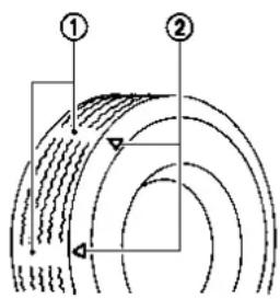
SDI1663
- Wear indicator
- Wear indicator location mark
Tire wear and damage

WARNING
•Tiresshouldbeperiodically inspectedforwear, cracking, bulgingorobjectscaughtin thetread. If excessive wear, cracks, bulgingordeepcuts arefound, thetire(s) should bereplaced.
•Theoriginaltireshavebuilt-intreadwearindicators. Whenwearindicators are visible, the tire(s) should be replaced.
•Tiresdegradewithage and use.Havetires,includingthe spare,over 6 years old checkedbyaqualified technician,because sometire damagemaynotbeobvious.Replaceethe tiresas necessarytopreventtire failureand possible personal injury.
•Improperservice of the spare tire may result in serious personal injury. If it is necessary to repair the spare tire, it is recommended you visit a NISSAN dealer forth this service.
- Foradditional information regardingtires,referto"ImportantTireSafetyInformation"(US)or"TireSafety Information"(Canada)inthe
WarrantyInformationBooklet.
Replacing wheels and tires
When replacing a tire, use the same size, tread design, speed rating and load carrying capacity as originally equipped. (See "Specifications" (P.10-9) for recommended types and sizes of tires and wheels.)

WARNING
- Theuseoftiresotherthanthose recommendedorthemixeduse oftiresofdifferentbrands,construction(bias,bias-beltedorradial),ortread patterns can adverselyaffecttheride,braking, handling,VDCsystem,ground clearance,body-to-tireclearance, tire chain clearance,speedometercalibration,headlight aimandbumperheight.Someof theseeffectsmayleadtoaccidentsandcouldresultinserious personalinjury.
- ForTwo-WheelDrive(2WD)models, if your vehicle was originally equipped with 4tiresthat were
thesamesizeandyouareonly replacing2ofthe4tires,install thenewtiresontherearaxle. Placingnewtiresonthefront axlemaycauselossofvehicle controlinsomedrivingconditionsandcauseanaccidentand personalinjury.
- If the wheels are exchanged for any reason, always replace with wheels which have the same off-set dimension. Wheel of different-off-set could cause premature tire wear, degrade vehicle handling characteristics and/or interference with the brake discs/drums. Such interference can lead to decreased braking efficiency and/or early brake pad/shoewear. See "Wheels and tires" (P.10-10) of this manual for wheel off-set dimensions.
- Since the spare tire is not equipped with the TPMS, when a spare tire is mounted or a raw wheel is replaced, the TPMS will not function and the low tire pressure warning light will flash for approximately 1 minute. Thelight will remain on after 1 minute. Have your tires replaced and/or TPMS system reset as soon as
possible.Itisrecommendedyou visitaNISSANdealerforthese services.
- Replacingtireswiththosenot originallyspecifiedbyNISSAN couldaffecttheproperoperation oftheTPMS.
- TheTPMSsensormaybe-damagedifitisnothandledcor-rectly.Becarefulwhenhandling theTPMSsensor.
- WhenreplacingtheTPMSsensor, theIDregistrationmayberequired.ItisrecommendedyouvisitaNISSANdealerforIDregistration.
- Donotuseavalvestemcapthat isnotspecifiedbyNISSAN.The valvestemcapmaybecome stuck.
- Besurethatthevalvestemcaps arecorrectlyfitted. Otherwisethe valvemaybecloggedupwithdirt andcauseamalfunctionorloss of pressure.
- Donotinstalladamagedor deformedwheelortireevenifit hasbeenrepaired.Suchwheels ortirescouldhavestructural damageandcouldfailwithout warning.
•Theuseofretreadtireisnot recommended.
- For additional information regarding tires, referto "Important TireSafetyInformation" (US) or "TireSafetyInformation" (Canada) in the Warranty Information Booklet.
All-Wheel Drive (AWD) models

CAUTION
●Alwaysusetiresofthesamesize, brand, construction(bias,bias-beltedorradial), and tread patternonallfourwheels. Failureto dosomayresultinacircumferencedifferencebetweenireson thefrontandrearaxleswhichwill cause excessivetirewear and maydamagethetransmission andthedrivetrainparts.
- Onlyusesparetiressspecifiedfor eachAWDmodel.
If excessive tire wear is found, it is recommended that all four tires be replaced with tires of the same size, brand, construction and tread pattern. The tire
pressure and wheel alignment should also be checked and corrected as necessary. It is recommended you visit a NISSAN dealer for this service.
Wheel balance
Unbalanced wheels may affect vehicle handling and tire life. Even with regular use, wheels can get out of balance. Therefore, they should be balanced as required.
Wheelbalanceservicesshouldbeperformedwiththewheelsoffthevehicle. Spinbalancingthewheelsonthevehiclecouldleadtomechanicaldamage.
For additional information regarding tires, refer to "Important Tire Safety Information" (US) or "Tire Safety Information" (Canada) in the Warranty Information Booklet.
Care of wheels
See "Cleaning exterior" (P.7-2) for details about care of the wheels.
Spare tire
Since the spare tire is not equipped with the TPMS, when a spare tire is mounted (TEMPORARY USE ONLY), the TPMS will not function.
Observe the following precautions if the TEMPORARY USE ONLY spare tire must be used, otherwise your vehicle could be damaged or involved in an accident.

WARNING
- TheTEMPORARYUSEONLYspare tireshouldbeusedforemergencyuse.itshouldbereplaced withthestandardtireatthefirst opportunitytoavoidpossibletire ordifferentialdamage.
- DrivecarefullywhiletheTEMPORARYUSEONLYsparetireisinstalled.Avoidsharpturnsand abruptbrakingwhiledriving.
- Periodicallychecksparetireinflationpressure.Alwayskeepthe pressureoftheTEMPORARYUSE ONLYsparetireat60psi(420 kPa,4.2bar).
- With the TEMPORARY USE ONLY spare tire installed, donot drive your vehicle speeds faster than 50 MPH (80 km/h).
- When driving on roads covered with snow or ice, the TEMPORARY USE ONLY spare tires should be used on therear wheels and original tire used on the front wheels (drivewheels). Usetire chains only on the front (original)
tires.
- TiretreadoftheTEMPORARYUSE ONLYsparetirewillwearata fasterratethanthestandardtire. Replacethesparetireassoonas thetreadwearindicatorsappear.
- Donotusethesparetireonother vehicles.
- Donotusemorethanonespare tireatthesametime.
- Donottowatrailerwhenthe TEMPORARYUSEONLYsparetire isinstalled.

CAUTION
- Donotusetirechainsona TEMPORARYUSEONLYsparetire. Tirechainswillnotfitproperly andmaycausedamagetothe vehicle.
- Because the TEMPORARY USE ONLY spare tire is smaller than the original tire, ground clearance is reduced. To avoid damage to the vehicle, donot drive over obstacles. Also onot drivethe vehicle through an automatic car wash since it may get caught.
MEMO
8-44 Do-it-yourself
9Maintenanceandschedules
Maintenancerequirement....9-2
Generalmaintenance....9-2
Scheduledmaintenance....9-2
Wheretogoforservice....9-2
Generalmaintenance....9-2
Explanationofgeneralmaintenanceitems.....9-2
Explanationofscheduledmaintenanceitems.....9-5
Emissioncontrolsystemmaintenance....9-5
Chassisandbodymaintenance....9-6
Maintenanceschedules....9-7
Additionalmaintenanceitemsforsevere
operatingconditions....9-7
Oilcontrolsystem....9-7
Standardmaintenance....9-8
PR25DDenginemodel....9-8
KR15DDTenginemodel....9-21
MAINTENANCEREQUIREMENTGENERALMAINTENANCE
Some day-to-day and regular maintenance is essential to maintain your vehicle good mechanical condition, as well as its emission and engine performance.
It is the owner's responsibility to make sure that the scheduled maintenance, as well as general maintenance, is performed.
As the vehicle owner, you are the only one who can ensure that your vehicle receives the proper maintenance care. You are a vital link in the maintenance chain.
GENERAL MAINTENANCE
General maintenance includes those items which should be checked during normal day-to-day operation. They are essential for proper vehicle operation. It is your responsibility to perform these procedures regularly as prescribed.
Performing general maintenance checks requires minimal mechanical skill and only a few general automotive tools.
These checks or inspections can be done by yourself, a qualified technician or, if you prefer, a NISSAN dealer.
SCHEDULED MAINTENANCE
The maintenance items listed in this section are required to be serviced at regular intervals. However, under severe driving conditions, additional or more frequent maintenance will be required.
WHERE TO GO FOR SERVICE
If maintenance service is required or your vehicle appears to malfunction, have the systems checked and serviced. It is recommended you visit a NISSAN dealer for this service.
NISSAN technicians are well-trained specialists and are kept up-to-date with the latest service information through technical bulletins, service tips, and training programs. They are completely qualified to work on NISSAN vehicles beforework begins.
If your vehicle is involved in a collision, it is recommended that you ask your NISSAN dealer where the nearest NISSAN Certified Collision Center is located, or go to http://collision.nissanusa.com.
You can be confident that a NISSAN dealer's service department performs the best job to meet the maintenance requirements on your vehicle.
During the normal day-to-day operation of the vehicle, general maintenance should be performed regularly as prescribed in this section. If you detect any unusual sounds, vibrations or smells, be sure to check for the cause or have it checked promptly. In addition, it is recommended that you visit a NISSAN dealer if you think that repairs are required. When performing any checks or maintenance work, see "Maintenance precautions" (P.8-2).
EXPLANATION OF GENERAL MAINTENANCE ITEMS
Additionalinformationonthefollowing itemswith""isfoundinthe"8.Do-it-yourself"sectionofthismanual.
Outside the vehicle
The maintenance items listed here should be performed from time to time, unless otherwise specified.
Doorsandenginehood:Check that all doors and the engine hood operate properly. Also ensure that all latches lock securely. Lubricate hinges, latches, latch pins, rollers and links if necessary. Make sure that the secondary latch keeps the hood from opening when the primary latch is released.
When driving in areas using road salt or
9-2 Maintenanceandschedules
other corrosive materials, check lubrication frequently.
Lights*: Clean the headlights on a regular basis. Make sure that the headlights, stop lights, tall lights, turn signal lights, and other lights are all operating properly and installed securely. Also check headlight aim.
Roadwheelnuts(lugnuts)*:When checking the tires, make sure no wheel nuts are missing, and check for any loose wheel nuts. Tighten if necessary.
Tirerotation*: Rotate tires at the specified interval shown in the maintenance schedule.
Tires*:Check the pressure with a gauge often and always prior to long distance trips. If necessary, adjust the pressure in all tires, including the spare (if so equipped), to the pressure specified. Check carefully for damage, cuts or excessive wear.
TirePressureMonitoringSystem(TPMS) transmittercomponents:Replace the TPMS transmitter snap-in type, valve core and cap when the tires are replaced due to wear or age.
Wheelalignmentandbalance:If the vehicle should pull to either side while driving on a straight and level road, or if you detect uneven or abnormal tire wear, there may be a need for wheel alignment. If the steering wheel or seat vibrates at normal highway speeds, wheel balancing may be needed.
For additional information regarding tires, refer to "Important Tire Safety Information" (US) or "Tire Safety Information" (Canada) in the NISSAN Warranty Information Booklet.
Windshield: Clean the windshield on a regular basis. Check the windshield at least every six months for cracks or other damage. Have a damaged windshield repaired by a qualified repair facility.
It is recommended that you have a damaged windshield repaired by a NISSAN dealer, or a NISSAN Certified Collision Center. To locate a collision center in your area, refer to http://collision.nissanusa.com.
Windshieldwiperblades*:Check for cracks or wear if they do not wipe properly.
Inside the vehicle
The maintenance items listed here should be checked on a regular basis, such as when performing scheduled maintenance, cleaning the vehicle, etc.
Acceleratorpedal: Check the pedal for smooth operation and make sure the pedal does not catch or require uneven effort. Keep the floor mat away from the pedal.
Brakepedal: Check the pedal for smooth operation. If the brake pedal suddenly goes down further than normal, the pedal feels spongy or the vehicle seems to take longer to stop, have your vehicle checked immediately. It is recommended you visit a NISSAN dealer for this service. Keep the floor mat away from the pedal.
Brakes: Check that the brakes do not pull the vehicle to one side when applied.
ContinuouslyVariableTransmission (CVT)P(Park)mechanism:On a fairly steep hill, check that the vehicle is held securely with the shift lever in the P (Park) position without applying any brakes.
Parkingbrake: Check the parking brake operation regularly. The vehicle should be securely held on a fairly steep hill with only the parking brake applied. If the parking brake needs adjusted, it is recommended you visit a NISSAN dealer for this service.
Seatbelts: Check that all parts of the seat belt system (for example, buckles, anchors, adjusters and retractors) operate properly and smoothly, and are installed securely. Check the belt webbing for cuts, fraying, wear or damage.
Seats: Check seat position controls such as seat adjusters, seatback recliners, etc. to ensure they operate smoothly and that all latches lock securely in every position. Check that the head restraints/headrests move up and down smoothly and that the locks (if so equipped) hold securely in all latched positions.
Steeringwheel: Check for changes in the steering conditions, such as excessive free play, hard steering or strange noises.
Warninglightsandchimes: Make sure that all warning lights and chimes are operating properly.
Windshielddefroster: Check that the air comes out of the defroster outlets properly and in sufficient quantity when operating the heater or air conditioner.
Windshieldwiperandwasher*:Check that the wipers and washers operate properly and that the wipers do not streak.
Under the hood and vehicle
The maintenance items listed here should be checked periodically (for example, each time you check the engine oil or refuel).
Battery*: This vehicle is equipped with a sealed maintenance free battery. It is recommended that you visit a NISSAN dealer for service.
NOTE:
Careshouldbetakentoavoidsituations thatcanleadtopotentialbatterydischargeandpotentialno-startconditionssuchas:
-
Installationorextendeduseofelectronicaccessoriesthatconsume batterypowerwhentheengineis notrunning(Phonechargers,GPS, DVDplayers,etc.)
-
Vehicleisnotdrivenregularlyand/oronlydrivenshortdistances.
Inthesecases, the battery may need to be charged to maintain battery health.
Brakefluidlevel*:Make sure that the brake fluid level is between the MAX and MIN lines on the reservoir.
Enginecoolantlevel*:Check the coolant level when the engine is cold.
Intercoolercoolantlevel*:Check the coolant level when the engine is cold.
Enginedrivebelt*:Make sure that the drive belt is not frayed, worn, cracked or oily.
Engineoillevel*:Check the level after parking the vehicle on a level surface and turning off the engine. Wait more than 10 minutes for the oil to drain back into the oil pan.
Exhaustsystem: Make sure there are no loose supports, cracks or holes. If the sound of the exhaust seems unusual or there is a smell of exhaust fumes, immediately have the exhaust system inspected. It is recommended you visit a NISSAN dealer for this service. (See "Precautions when starting and driving" (P.5-5) for exhaust gas (carbon monoxide).)
Fluidleaks: Check under the vehicle for fuel, oil, water or other fluid leaks after the vehicle has been parked for a while. Water dripping from the air conditioner after use is normal. If you should notice any leaks or if gasoline fumes are evident, check for the cause and have it corrected immediately.
Radiatorandhoses:Check the front of the radiator and clean off any dirt, insects, leaves, etc., that may have accumulated. Make sure the hoses have no cracks, deformation, rot or loose connections.
Underbody:The underbody is frequently exposed to corrosive substances such as those used on icy roads or to control dust. It is very important to remove these substances, otherwise rust will form on the floor pan, frame, fuel lines and around the exhaust system. At the end of winter, the underbody should be thoroughly flushed with plain water, being careful to clean those areas where mud and dirt
EXPLANATIONOFSCHEDULED MAINTENANCEITEMS
may accumulate. For additional information, see "Cleaning exterior" (P.7-2).
Windshieldwasherfluid*:Check that there is adequate fluid in the reservoir.
The following descriptions are provided to give you a better understanding of the scheduled maintenance items that should be regularly checked or replaced. The maintenance schedule indicates at which mileage/time intervals each item requires service.
In addition to scheduled maintenance, your vehicle requires that some items be checked during normal day-to-day operation. Refer to "General maintenance" (P.9-2).
Items marked with "*" are recommended by NISSAN for reliable vehicle operation. You are not required to perform maintenance on these items in order to maintain the warranties which come with your vehicle. Other maintenance items and intervals are required.
When applicable, additional information can be found in the "8. Do-it-yourself" section of this manual.
NOTE:
NISSANdoesnotadvocatetheuseof non-OEMapprovedaftermarketflushingsystems and strongly advises againstperformingtheseservicesona NISSANproduct.Manyoftheaftermarketflushingsystemsusenon-OEMapprovedchemicalsorsolvents,theuseof which has not been validated by NISSAN.
For recommended fuel, lubricants, fluids, grease, and refrigerant, referto "Capacities and recommended fluids/ lubricants" (P.10-3) of this manual.
Check engine drive belt for wear, fraying or cracking and for proper tension. Replace any damaged drive belt.
Engineairfilter:
Replace at specified intervals. When driving for prolonged periods in dusty conditions, check/replace the filter more frequently.
Enginecoolant*:
Replace coolant at the specified interval. When adding or replacing coolant, be sure to use only Genuine NISSAN Long Life Antifreeze/Coolant (blue) or equivalent with the proper mixture. (Refer to "Engine cooling system" (P.8-4) to determine the proper mixture for your area.)
NOTE:
Mixinganyothertypeofcoolantorthe useofnon-distilledwatermayreduce therecommendedserviceintervalof thecoolant.
Maintenanceandschedules9-5
Intercoolercoolant:
Intercooler coolant is maintenance-free.
Engineoilandoilfilter:
Replace engine oil and oil filter at the specified intervals. For recommended oil grade and viscosity refer to "Capacities and recommended fluids/lubricants" (P.10-3).
Enginevalveclearance*:
Inspect only if valve noise increases.
Adjust valve clearance if necessary.
Evaporativeemissionscontrolvapor lines*:
Check vapor lines for leaks or looseness. Tighten connections or replace parts as necessary.
Fuelfilter
Periodic maintenance is not required (in-tank type filter).
Fuellines*:
Check the fuel hoses, piping and connections for leaks, looseness, or deterioration. Tighten connections or replace parts as necessary.
Sparkplugs:
Replace at specified intervals. Install new plugs of the type as originally equipped.
CHASSIS AND BODY MAINTENANCE
Brakelinesandcables:
Visually inspect for proper installation. Check for chafing, cracks, deterioration, and signs of leaking. Replace any deteriorated or damaged parts immediately.
Brakepadsandrotors:
Check for wear, deterioration and fluid leaks. Replace any deteriorated or damaged parts immediately.
Exhaustsystem:
Visually inspect the exhaust pipes, muffler and hangers for leaks, cracks, deterioration, and damage. Tighten connections or replace parts as necessary.
In-cabinmicrofilter:
Replace at specified intervals. When driving for prolonged periods in dusty conditions, replace the filter more frequently.
Propellershaft(s):
Check for damage, looseness, and grease leakage. (AWD)
Steeringgearandlinkage,axleand suspensionparts,driveshaftboots:
Check for damage, looseness, and leakage of oil or grease. Under severe driving conditions, inspect more frequently.
Tirerotation:
Rotate tires at the specified interval.
Transmissionfluid/oil,differentialoil andtransfercaseoil:
Visually inspect for signs of leakage at specified intervals.
If using a car-top carrier, or towing a trailer, or using a camper, or driving on rough or muddy roads:
- Replace the differential oil and transfer case oil every 20,000 miles (32,000 km) or 24 months.
- Replace the CVT fluid every 60,000 miles (96,000 km) or request the dealer to inspect the fluid deterioration data using a CONSULT. If the deterioration data is more than 210,000, replace the CVT fluid.
MAINTENANCESCHEDULES
To help ensure smooth, safe and economical driving, NISSAN provides two maintenance schedules that may be used, depending upon the conditions in which you usually drive. These schedules contain both distance and time intervals, up to 120,000 miles (192,000 km)/96 months. For most people, the odometer reading will indicate when service is needed. However, if you drive very little, your vehicle should be serviced at the regular time intervals shown in the schedule.
After 120,000 miles (192,000 km) / 96 months, continuemaintenance at the samemileage/time intervals.
ADDITIONAL MAINTENANCE ITEMS FOR SEVERE OPERATING CONDITIONS
Additional maintenance items for severe operating conditions; should be performed on vehicles that are driven under especially demanding conditions. Additional maintenance items should be performed if you primarily operate your vehicle under the following conditions:
●Repeated short trips of less than 5 miles (8 km).
- Repeated short trips of less than 10 miles (16 km) with outside temperatures remaining below freezing.
- Operating in hot weather in stop-and-go "rush hour" traffic.
- Extensive idling and/or low speed driving for long distances, such as police, taxi or door-to-door delivery use.
●Driving in dusty conditions. - Driving on rough, muddy or salt spread roads.
●Using a car-top carrier.
●Towing a trailer. - Using a camper.
If your vehicle is mainly operated under the severe conditions, follow the severe maintenance intervals shown in the maintenance schedule.
OIL CONTROL SYSTEM
Your vehicle is equipped with oil control system. It calculates engine oil and filter change intervals based on driving conditions. Driving in the following severe conditions will shorten the engine oil and filter change interval.
STANDARDMAINTENANCE
PR25DD ENGINE MODEL
The following shows the maintenance schedule. Choose the maintenance schedule needed based on your vehicle driving conditions.
After 120,000 miles (192,000 km) / 144 months, continue maintenance at the same time interval.
5,000 Miles/6 Months/8,000 Km
Standardmaintenance:
• Perform tire rotation
Severemaintenance:
• Inspect brake pads and rotors
• Inspect exhaust system
- Inspect steering gear and linkage
• Inspect axle and suspension parts
- Inspect propeller shaft (AWD models)
• Inspect drive shaft boots
10,000 Miles/12 Months/16,000 Km
Standardmaintenance:
• Inspect brake lines and cables
• Inspect brake pads and rotors
- Inspect CVT fluid
- Inspect propeller shaft (AWD models)
- Inspect differential gear oil (AWD models)
- Inspect AWD coupling oil (AWD models)
- Inspect transfer case oil (AWD models)
• Inspect drive shaft boots
- Replace engine oil and filter (1)
• Perform tire rotation
Severemaintenance:
- Inspect brake pads and rotors
- Inspect exhaust system
• Inspect steering gear and linkage - Inspect axle and suspension parts
- Inspect propeller shaft (AWD models)
• Inspect drive shaft boots - Replace brake fluid
(1) If the oil replacement indicator is displayed,
change the engine oil and filter within two
weeks or less than 500 miles (800 km)
15,000 Miles/18 Months/24,000
Km
Standardmaintenance:
• Inspect Intelligent Key battery
- Replace In-cabin microfilter
• Perform tire rotation
Severemaintenance:
• Inspect brake pads and rotors
- Inspect exhaust system
- Inspect steering gear and linkage
• Inspect axle and suspension parts
- Inspect propeller shaft (AWD models)
- Inspect drive shaft boots
20,000 Miles/24 Months/32,000
Km
Standardmaintenance:
• Inspect brake lines and cables
- Inspect brake pads and rotors
- Inspect CVT fluid
- Inspect fuel tank vapor vent system
• Inspect fuel lines/connections
- Inspect exhaust system
- Inspect steering gear and linkage
- Inspect axle and suspension parts
- Inspect propeller shaft (AWD models)
- Inspect differential gear oil (AWD models)
- Inspect AWD coupling oil (AWD models)
- Inspect transfer case oil (AWD models)
- Inspect drive shaft boots
- Replace brake fluid
- Replace engine oil and filter (1)
• Perform tire rotation
Severemaintenance:
- Inspect brake pads and rotors
- Inspect exhaust system
- Inspect steering gear and linkage
• Inspect axle and suspension parts - Inspect propeller shaft (AWD models)
- Inspect drive shaft boots
- Replace brake fluid
(1) If the oil replacement indicator is displayed,
change the engine oil and filter within two
weeks or less than 500 miles (800 km).
25,000 Miles/30 Months/40,000
Km
Standardmaintenance:
• Perform tire rotation
Severemaintenance:
• Inspect brake pads and rotors
- Inspect exhaust system
- Inspect steering gear and linkage
- Inspect axle and suspension parts
- Inspect propeller shaft (AWD models)
• Inspect drive shaft boots
30,000 Miles/36 Months/48,000
Km
Standardmaintenance:
• Inspect brake lines and cables
• inspect brake pads and rotors
• Inspect CVT fluid
- Inspect propeller shaft (AWD models)
• Inspect differential gear oil (AWD models)
- Inspect AWD coupling oil (AWD models)
• Inspect transfer case oil (AWD models)
• Inspect drive shaft boots
- Replace engine air filter (1)
- Replace engine oil and filter (2)
- Replace In-cabin microfilter
- Replace Intelligent Key battery
• Perform tire rotation
Severemaintenance:
- Inspect brake pads and rotors
- Inspect exhaust system
- Inspect steering gear and linkage
- Inspect axle and suspension parts
- Inspect propeller shaft (AWD models)
- Inspect drive shaft boots
- Replace brake fluid
(1) If operating mainly in dusty conditions, more
frequent maintenance may be required
(2) If the oil replacement indicator is displayed,
change the engine oil and filter within two
weeks or less than 500 miles (800 km).
35,000 Miles/42 Months/56,000 Km
Standardmaintenance:
• Perform tire rotation
Severemaintenance:
• Inspect brake pads and rotors
• Inspect exhaust system
- Inspect steering gear and linkage
- Inspect axle and suspension parts
- Inspect propeller shaft (AWD models)
• Inspect drive shaft boots
40,000 Miles/48 Months/64,000 Km
Standardmaintenance:
- Inspect brake lines and cables
• Inspect brake pads and rotors - Inspect CVT fluid
• Inspect engine drive belts - Inspect fuel tank vapor vent system
- Inspect fuel lines/connections
- Inspect exhaust system
• Inspect steering gear and linkage - Inspect axle and suspension part
- Inspect propeller shaft (AWD models)
- Inspect differential gear oil (AWD models)
- Inspect AWD coupling oil (AWD models)
- Inspect transfer case oil (AWD models)
- Inspect drive shaft boots
- Replace brake fluid
- Replace engine oil and filter (1)
• Perform tire rotation
Severemaintenance:
- Inspect brake pads and rotors
- Inspect exhaust system
- Inspect steering gear and linkage
• Inspect axle and suspension parts - Inspect propeller shaft (AWD models)
- Inspect drive shaft boots
- Replace brake fluid
(1) If the oil replacement indicator is displayed,
change the engine oil and filter within two
weeks or less than 500 miles (800 km).
45,000 Miles/54 Months/72,000
Km
Standardmaintenance:
- Replace In-cabin microfilter
- Replace Intelligent Key battery
• Perform tire rotation
Severemaintenance:
• Inspect brake pads and rotors
• Inspect exhaust system
- Inspect steering gear and linkage
• Inspect axle and suspension parts
- Inspect propeller shaft (AWD models)
- Inspect drive shaft boots
50,000 Miles/60 Months/80,000
Km
Standardmaintenance:
• Inspect brake lines and cables
• Inspect brake pads and rotors
- Inspect CVT fluid
• Inspect engine drive belts
- Inspect propeller shaft (AWD models)
- Inspect differential gear oil (AWD models)
- Inspect AWD coupling oil (AWD models)
- Inspect transfer case oil (AWD models)
- Inspect drive shaft boots
- Replace engine oil and filter (1)
• Perform tire rotation
Severemaintenance:
- Inspect brake pads and rotors
- Inspect exhaust system
- Inspect steering gear and linkage
- Inspect axle and suspension parts
- Inspect propeller shaft (AWD models)
- Inspect drive shaft boots
- Replace brake fluid
(1) If the oil replacement indicator is displayed,
change the engine oil and filter within two
weeks or less than 500 miles (800 km).
55,000 Miles/66 Months/88,000
Km
Standardmaintenance:
• Perform tire rotation
Severemaintenance:
• Inspect brake pads and rotors
• Inspect exhaust system
• Inspect steering gear and linkage
- Inspect axle and suspension parts
- Inspect propeller shaft (AWD models)
• Inspect drive shaft boots
60,000 Miles/72 Months/96,000
Km
Standardmaintenance:
• Inspect brake lines and cables
• Inspect brake pads and rotors
- Inspect CVT fluid
• Inspect engine drive belts
- Inspect fuel tank vapor vent system
- Inspect fuel lines/connections
- Inspect exhaust system
• Inspect steering gear and linkage
- Inspect axle and suspension part
- Inspect propeller shaft (AWD models)
- Inspect differential gear oil (AWD models)
- Inspect AWD coupling oil (AWD models)
- Inspect transfer case oil (AWD models)
- Inspect drive shaft boots
- Replace engine air filter (1)
- Replace brake fluid
- Replace engine oil and filter (2)
- Replace In-cabin microfilter
- Replace Intelligent Key battery
• Perform tire rotation
Severemaintenance:
• Inspect brake pads and rotors
- Inspect exhaust system
- Inspect steering gear and linkage
- Inspect axle and suspension parts
- Inspect propeller shaft (AWD models)
- Inspect drive shaft boots
- Replace brake fluid
- Replace CVT fluid
(1) If operating mainly in dusty conditions, more frequent maintenance may be required.
(2) If the oil replacement indicator is displayed, change the engine oil and filter within two weeks or less than 500 miles (800 km).
65,000 Miles/78 Months/104,000 Km
Standardmaintenance:
• Perform tire rotation
Severemaintenance:
• Inspect brake pads and rotors
- Inspect exhaust system
- Inspect steering gear and linkage
- Inspect axle and suspension parts
- Inspect propeller shaft (AWD models)
• Inspect drive shaft boots
70,000 Miles/84 Months/112,000 Km
Standardmaintenance:
• Inspect brake lines and cables
• inspect brake pads and rotors
• Inspect CVT fluid
• Inspect engine drive belts
- inspect propeller shaft (AWD models)
- Inspect differential gear oil (AWD models)
• Inspect AWD coupling oil (AWD models)
- Inspect transfer case oil (AWD models)
- Inspect drive shaft boots
- Replace engine oil and filter (1)
• Perform tire rotation
Severemaintenance:
- Inspect brake pads and rotors
- Inspect exhaust system
- Inspect steering gear and linkage
- Inspect axle and suspension parts
- Inspect propeller shaft (AWD models)
- Inspect drive shaft boots
- Replace brake fluid
(1) If the oil replacement indicator is displayed,
change the engine oil and filter within two
weeks or less than 500 miles (800 km).
75,000 Miles/90 Months/120,000
Km
Standardmaintenance:
- Replace In-cabin microfilter
- Replace Intelligent Key battery
• Perform tire rotation
Severemaintenance:
• Inspect brake pads and rotors
- Inspect exhaust system
- Inspect steering gear and linkage
• Inspect axle and suspension parts
- Inspect propeller shaft (AWD models)
- Inspect drive shaft boots
80,000 Miles/96 Months/128,000
Km
Standardmaintenance:
- Inspect brake lines and cables
- Inspect brake pads and rotors
- Inspect CVT fluid
• Inspect engine drive belts - Inspect fuel tank vapor vent system
- Inspect fuel lines/connections
- Inspect exhaust system
• Inspect steering gear and linkage - Inspect axle and suspension part
- Inspect propeller shaft (AWD models)
- Inspect differential gear oil (AWD models)
- Inspect AWD coupling oil (AWD models)
- Inspect transfer case oil (AWD models)
- Inspect drive shaft boots
- Replace brake fluid
- Replace engine oil and filter (1)
• Perform tire rotation
Severemaintenance:
- Inspect brake pads and rotors
- Inspect exhaust system
• Inspect steering gear and linkage
• Inspect axle and suspension parts - Inspect propeller shaft (AWD models)
- Inspect drive shaft boots
- Replace brake fluid
(1) If the oil replacement indicator is displayed, change the engine oil and filter within two weeks or less than 500 miles (800 km).
85,000 Miles/102 Months/136,000 Km
Standardmaintenance:
• Perform tire rotation
Severemaintenance:
• Inspect brake pads and rotors
• Inspect exhaust system
- Inspect steering gear and linkage
- Inspect axle and suspension parts
- Inspect propeller shaft (AWD models)
• Inspect drive shaft boots
90,000 Miles/108 Months/144,000 Km
Standardmaintenance:
• Inspect brake lines and cables
• inspect brake pads and rotors
• Inspect CVT fluid
• Inspect engine drive belts
- inspect propeller shaft (AWD models)
- Inspect differential gear oil (AWD models)
• Inspect AWD coupling oil (AWD models)
- Inspect transfer case oil (AWD models)
- Inspect drive shaft boots
- Replace engine air filter (1)
- Replace engine oil and filter (2)
- Replace In-cabin microfilter
- Replace Intelligent Key battery
• Perform tire rotation
Severemaintenance:
- Inspect brake pads and rotors
- Inspect exhaust system
- Inspect steering gear and linkage
- Inspect axle and suspension parts
- Inspect propeller shaft (AWD models)
- Inspect drive shaft boots
- Replace brake fluid
(1) If operating mainly in dusty conditions, more
frequent maintenance may be required
(2) If the oil replacement indicator is displayed,
change the engine oil and filter within two
weeks or less than 500 miles (800 km).
95,000 Miles/114 Months/152,000 Km
Standardmaintenance:
• Perform tire rotation
Severemaintenance:
• Inspect brake pads and rotors
• Inspect exhaust system
• Inspect steering gear and linkage
- Inspect axle and suspension parts
- Inspect propeller shaft (AWD models)
• Inspect drive shaft boots
100,000 Miles/120 Months/160,000 Km
Standardmaintenance:
- Inspect brake lines and cables
- Inspect brake pads and rotors
- Inspect CVT fluid
• Inspect engine drive belts - Inspect fuel tank vapor vent system
- Inspect fuel lines/connections
- Inspect exhaust system
• Inspect steering gear and linkage - Inspect axle and suspension part
- Inspect propeller shaft (AWD models)
- Inspect differential gear oil (AWD models)
- Inspect AWD coupling oil (AWD models)
- Inspect transfer case oil (AWD models)
- Inspect drive shaft boots
- Replace brake fluid
- Replace engine oil and filter (1)
• Perform tire rotation
Severemaintenance:
• Inspect brake pads and rotors
- Inspect exhaust system
- Inspect steering gear and linkage
• Inspect axle and suspension parts
- Inspect propeller shaft (AWD models)
- Inspect drive shaft boots
- Replace brake fluid
(1) If the oil replacement indicator is displayed, change the engine oil and filter within two weeks or less than 500 miles (800 km).
105,000 Miles/126 Months/168,000 Km
Standardmaintenance:
- Replace In-cabin microfilter
- Replace Intelligent Key battery
• Perform tire rotation - Replace spark plugs (1) (2)
- Replace engine coolant* (3)
Severemaintenance:
• Inspect brake pads and rotors
• Inspect exhaust system
- Inspect steering gear and linkage
- Inspect axle and suspension parts
- Inspect propeller shaft (AWD models)
• Inspect drive shaft boots
(1) Performed based on the number of miles only
(2) Replace spark plug when the plug gap exceeds 0.053 in (1.35 mm) even if within specified periodic replacement mileage.
(3) First replacement interval is 105,000 miles (168,000 km) or 84 months. After first replacement, replace every 75,000 miles (120,000 km) or 60 months.
*: Maintenance items and intervals with " * " are recommended by NISSAN for reliable vehicle operation. The owner need not perform such maintenance in order to maintain the emission warranty or manufacturer recall liability. Other maintenance items and intervals are required.
110,000 Miles/132 Months/176,000 Km
Standardmaintenance:
- Inspect brake lines and cables
• Inspect brake pads and rotors - Inspect CVT fluid
- Inspect engine drive belts
- Inspect propeller shaft (AWD models)
- Inspect differential gear oil (AWD models)
- Inspect AWD coupling oil (AWD models)
- Inspect transfer case oil (AWD models)
- Inspect drive shaft boots
- Replace engine oil and filter (1)
• Perform tire rotation
Severemaintenance:
• Inspect brake pads and rotors
- Inspect exhaust system
- Inspect steering gear and linkage
• Inspect axle and suspension parts
- Inspect propeller shaft (AWD models)
- Inspect drive shaft boots
- Replace brake fluid
(1) If the oil replacement indicator is displayed, change the engine oil and filter within two weeks or less than 500 miles (800 km).
115,000 Miles/138 Months/184,000 Km
Standardmaintenance:
• Perform tire rotation
Severemaintenance:
- Inspect brake pads and rotors
• Inspect exhaust system
• Inspect steering gear and linkage
- Inspect axle and suspension parts
- Inspect propeller shaft (AWD models)
• Inspect drive shaft boots
120,000 Miles/144 Months/192,000 Km
Standardmaintenance:
- Inspect brake lines and cables
• Inspect brake pads and rotors
- Inspect CVT fluid
• Inspect engine drive belts
- Inspect fuel tank vapor vent system
- Inspect fuel lines/connections
- Inspect exhaust system
• Inspect steering gear and linkage
- Inspect axle and suspension part
- Inspect propeller shaft (AWD models)
- Inspect differential gear oil (AWD models)
- Inspect AWD coupling oil (AWD models)
- Inspect transfer case oil (AWD models)
- Inspect drive shaft boots
- Replace engine air filter (1)
- Replace brake fluid
- Replace engine oil and filter (2)
- Replace In-cabin microfilter
- Replace Intelligent Key battery
• Perform tire rotation
Severemaintenance:
• Inspect brake pads and rotors
- Inspect exhaust system
• Inspect steering gear and linkage
- Inspect axle and suspension parts
- Inspect propeller shaft (AWD models)
• Inspect drive shaft boots
- Replace brake fluid
- Replace CVT fluid
(1) If operating mainly in dusty conditions, more
frequent maintenance may be required.
(2) If the oil replacement indicator is displayed.
change the engine oil and filter within two
weeks or less than 500 miles (800 km).
KR15DDT ENGINE MODEL
The following shows the maintenance schedule. Choose the maintenance schedule needed based on your vehicle driving conditions.
After 90,000 miles (144,000 km) / 144 months, continue maintenance at the same time interval.
3,750 Miles/6 Months/6,000 Km
Standardmaintenance:
• Perform tire rotation
Severemaintenance:
• Inspect brake pads and rotors
• Inspect exhaust system
• Inspect steering gear and linkage
- Inspect axle and suspension parts
- Inspect propeller shaft (AWD models)
- Inspect drive shaft boots
7,500 Miles/12 Months/12,000 Km
Standardmaintenance:
- Inspect brake lines and cables
- Inspect brake pads and rotors
- Inspect CVT fluid
- Inspect propeller shaft (AWD models)
- Inspect differential gear oil (AWD models)
- Inspect AWD coupling oil (AWD models)
- Inspect transfer case oil (AWD models)
• Inspect drive shaft boots - Replace engine oil and filter (1)
• Perform tire rotation
Severemaintenance:
- Inspect brake pads and rotors
- Inspect exhaust system
- Inspect steering gear and linkage
- Inspect axle and suspension parts
- Inspect propeller shaft (AWD models)
• Inspect drive shaft boots - Replace brake fluid
(1) If the oil replacement indicator is displayed,
change the engine oil and filter within two
weeks or less than 500 miles (800 km).
11,250 Miles/18 Months/18,000 Km
Standardmaintenance:
• Inspect Intelligent Key battery
- Replace In-cabin microfilter
• Perform tire rotation
Severemaintenance:
• Inspect brake pads and rotors
- Inspect exhaust system
- Inspect steering gear and linkage
- Inspect axle and suspension parts
• Inspect propeller shaft (AWD models)
• Inspect drive shaft boots
15,000 Miles/24 Months/24,000
Km
Standardmaintenance:
• Inspect brake lines and cables
• inspect brake pads and rotors
• Inspect CVT fluid
• Inspect fuel tank vapor vent system
• inspect fuel lines/connections
• Inspect exhaust system
- Inspect steering gear and linkage
- Inspect axle and suspension parts
- Inspect propeller shaft (AWD models)
- Inspect differential gear oil (AWD models)
- Inspect AWD coupling oil (AWD models)
- Inspect transfer case oil (AWD models)
- Inspect drive shaft boots
- Replace brake fluid
- Replace engine oil and filter (1)
• Perform tire rotation
Severemaintenance:
- Inspect brake pads and rotors
- Inspect exhaust system
- Inspect steering gear and linkage
- Inspect axle and suspension parts
- Inspect propeller shaft (AWD models)
- Inspect drive shaft boots
- Replace brake fluid
(1) If the oil replacement indicator is displayed,
change the engine oil and filter within two
weeks or less than 500 miles (800 km).
18,750 Miles/30 Months/30,000 Km
Standardmaintenance:
• Perform tire rotation
Severemaintenance:
• Inspect brake pads and rotors
• Inspect exhaust system
• Inspect steering gear and linkage
- Inspect axle and suspension parts
- Inspect propeller shaft (AWD models)
• Inspect drive shaft boots
22,500 Miles/36 Months/36,000 Km
Standardmaintenance:
- Inspect brake lines and cables
• Inspect brake pads and rotors - Inspect CVT fluid
- Inspect propeller shaft (AWD models)
- Inspect differential gear oil (AWD models)
- Inspect AWD coupling oil (AWD models)
- Inspect transfer case oil (AWD models)
• Inspect drive shaft boots - Replace engine oil and filter (1)
- Replace In-cabin microfilter
- Replace Intelligent Key battery
• Perform tire rotation
Severemaintenance:
- Inspect brake pads and rotors
- Inspect exhaust system
- Inspect steering gear and linkage
• Inspect axle and suspension parts - Inspect propeller shaft (AWD models)
- Inspect drive shaft boots
- Replace brake fluid
(1) If the oil replacement indicator is displayed,
change the engine oil and filter within two
weeks or less than 500 miles (800 km).
26,250 Miles/42 Months/42,000 Km
Standardmaintenance:
• Perform tire rotation
Severemaintenance:
• Inspect brake pads and rotors
- Inspect exhaust system
- Inspect steering gear and linkage
- Inspect axle and suspension parts
- Inspect propeller shaft (AWD models)
• Inspect drive shaft boots
30,000 Miles/48 Months/48,000 Km
Standardmaintenance:
• Inspect brake lines and cables
• inspect brake pads and rotors
• Inspect CVT fluid
• Inspect engine drive belts
- inspect fuel tank vapor vent system
- Inspect fuel lines/connections
- Inspect exhaust system
• Inspect steering gear and linkage
- Inspect axle and suspension part
- Inspect propeller shaft (AWD models)
- Inspect differential gear oil (AWD models)
- Inspect AWD coupling oil (AWD models)
- Inspect transfer case oil (AWD models)
- Inspect drive shaft boots
- Replace engine air filter (1)
- Replace brake fluid
- Replace engine oil and filter (2)
• Perform tire rotation
Severemaintenance:
- Inspect brake pads and rotors
- Inspect exhaust system
- Inspect steering gear and linkage
- Inspect axle and suspension parts
- Inspect propeller shaft (AWD models)
- Inspect drive shaft boots
- Replace brake fluid
(1) If operating mainly in dusty conditions, more
frequent maintenance may be required
(2) If the oil replacement indicator is displayed,
change the engine oil and filter within two
weeks or less than 500 miles (800 km).
33,750 Miles/54 Months/54,000
Km
Standardmaintenance:
- Replace In-cabin microfilter
- Replace Intelligent Key battery
• Perform tire rotation
Severemaintenance:
• Inspect brake pads and rotors
- Inspect exhaust system
- Inspect steering gear and linkage
- Inspect axle and suspension parts
- Inspect propeller shaft (AWD models)
- Inspect drive shaft boots
37,500 Miles/60 Months/60,000
Km
Standardmaintenance:
- Inspect brake lines and cables
- Inspect brake pads and rotors
- Inspect CVT fluid
- Inspect engine drive belts
- Inspect propeller shaft (AWD models)
- Inspect differential gear oil (AWD models)
- Inspect AWD coupling oil (AWD models)
- Inspect transfer case oil (AWD models)
- Inspect drive shaft boots
- Replace engine oil and filter (1)
• Perform tire rotation
Severemaintenance:
• Inspect brake pads and rotors
- Inspect exhaust system
- Inspect steering gear and linkage
• Inspect axle and suspension parts
- Inspect propeller shaft (AWD models)
- Inspect drive shaft boots
- Replace brake fluid
(1) If the oil replacement indicator is displayed,
change the engine oil and filter within two
weeks or less than 500 miles (800 km).
41,250 Miles/66 Months/66,000 Km
Standardmaintenance:
• Perform tire rotation
Severemaintenance:
• Inspect brake pads and rotors
- Inspect exhaust system
- Inspect steering gear and linkage
- Inspect axle and suspension parts
- Inspect propeller shaft (AWD models)
• Inspect drive shaft boots
45,000 Miles/72 Months/72,000 Km
Standardmaintenance:
- Inspect brake lines and cables
• Inspect brake pads and rotors - Inspect CVT fluid
• Inspect engine drive belts - Inspect fuel tank vapor vent system
- Inspect fuel lines/connections
- Inspect exhaust system
• Inspect steering gear and linkage - Inspect axle and suspension part
- Inspect propeller shaft (AWD models)
- Inspect differential gear oil (AWD models)
- Inspect AWD coupling oil (AWD models)
- Inspect transfer case oil (AWD models)
- Inspect drive shaft boots
- Replace brake fluid
- Replace engine oil and filter (1)
- Replace In-cabin microfilter
- Replace Intelligent Key battery
• Perform tire rotation
Severemaintenance:
- Inspect brake pads and rotors
- Inspect exhaust system
- Inspect steering gear and linkage
- Inspect axle and suspension parts
- Inspect propeller shaft (AWD models)
- Inspect drive shaft boots
- Replace brake fluid
(1) If the oil replacement indicator is displayed,
change the engine oil and filter within two
weeks or less than 500 miles (800 km).
48,750 Miles/78 Months/78,000 Km
Standardmaintenance:
• Perform tire rotation
Severemaintenance:
- Inspect brake pads and rotors
• Inspect exhaust system
- Inspect steering gear and linkage
- Inspect axle and suspension parts
- Inspect propeller shaft (AWD models)
• Inspect drive shaft boots
52,500 Miles/84 Months/84,000 Km
Standardmaintenance:
- Inspect brake lines and cables
- Inspect brake pads and rotors
- Inspect CVT fluid
- Inspect engine drive belts
- Inspect propeller shaft (AWD models)
- Inspect differential gear oil (AWD models)
- Inspect AWD coupling oil (AWD models)
- Inspect transfer case oil (AWD models)
- Inspect drive shaft boots
- Replace engine oil and filter (1)
• Perform tire rotation
Severemaintenance:
- Inspect brake pads and rotors
- Inspect exhaust system
- Inspect steering gear and linkage
• Inspect axle and suspension parts - Inspect propeller shaft (AWD models)
- Inspect drive shaft boots
- Replace brake fluid
(1) If the oil replacement indicator is displayed,
change the engine oil and filter within two
weeks or less than 500 miles (800 km).
56,250 Miles/90 Months/90,000
Km
Standardmaintenance:
- Replace In-cabin microfilter
- Replace Intelligent Key battery
• Perform tire rotation
Severemaintenance:
• Inspect brake pads and rotors
• Inspect exhaust system
- Inspect steering gear and linkage
- Inspect axle and suspension parts
- Inspect propeller shaft (AWD models)
- Inspect drive shaft boots
60,000 Miles/96 Months/96,000
Km
Standardmaintenance:
• Inspect brake lines and cables
• Inspect brake pads and rotors
- Inspect CVT fluid
• Inspect engine drive belts
- Inspect fuel tank vapor vent system
- Inspect fuel lines/connections
- Inspect exhaust system
• Inspect steering gear and linkage
- Inspect axle and suspension part
- Inspect propeller shaft (AWD models)
- Inspect differential gear oil (AWD models)
- Inspect AWD coupling oil (AWD models)
- Inspect transfer case oil (AWD models)
- Inspect drive shaft boots
- Replace engine air filter (1)
- Replace brake fluid
- Replace engine oil and filter (2)
• Perform tire rotation
Severemaintenance:
- Inspect brake pads and rotors
- Inspect exhaust system
- Inspect steering gear and linkage
- Inspect axle and suspension parts
- Inspect propeller shaft (AWD models)
- Inspect drive shaft boots
- Replace brake fluid
(1) If operating mainly in dusty conditions, more
frequent maintenance may be required
(2) If the oil replacement indicator is displayed,
change the engine oil and filter within two
weeks or less than 500 miles (800 km).
63,750 Miles/102 Months/102,000
Km
Standardmaintenance:
• Perform tire rotation
Severemaintenance:
• Inspect brake pads and rotors
• Inspect exhaust system
• Inspect steering gear and linkage
- Inspect axle and suspension parts
- Inspect propeller shaft (AWD models)
• Inspect drive shaft boots
67,500 Miles/108 Months/108,000
Km
Standardmaintenance:
- Inspect brake lines and cables
- Inspect brake pads and rotors
- Inspect CVT fluid
- Inspect engine drive belts
- Inspect propeller shaft (AWD models)
- Inspect differential gear oil (AWD models)
- Inspect AWD coupling oil (AWD models)
- Inspect transfer case oil (AWD models)
- Inspect drive shaft boots
- Replace engine oil and filter (1)
- Replace in-cabin microfilter
- Replace Intelligent Key battery
• Perform tire rotation
Severemaintenance:
• Inspect brake pads and rotors
- Inspect exhaust system
- Inspect steering gear and linkage
• Inspect axle and suspension parts
- Inspect propeller shaft (AWD models)
- Inspect drive shaft boots
- Replace brake fluid
(1) If the oil replacement indicator is displayed,
change the engine oil and filter within two
weeks or less than 500 miles (800 km).
71,250 Miles/114 Months/114,000 Km
Standardmaintenance:
• Perform tire rotation
Severemaintenance:
• Inspect brake pads and rotors
• Inspect exhaust system
- Inspect steering gear and linkage
- Inspect axle and suspension parts
- Inspect propeller shaft (AWD models)
• Inspect drive shaft boots
75,000 Miles/120 Months/120,000 Km
Standardmaintenance:
• Inspect brake lines and cables
• inspect brake pads and rotors
• Inspect CVT fluid
• Inspect engine drive belts
- inspect fuel tank vapor vent system
- Inspect fuel lines/connections
- Inspect exhaust system
• Inspect steering gear and linkage
- Inspect axle and suspension part
- Inspect propeller shaft (AWD models)
- Inspect differential gear oil (AWD models)
- Inspect AWD coupling oil (AWD models)
- Inspect transfer case oil (AWD models)
• Inspect drive shaft boots
- Replace brake fluid
- Replace engine oil and filter (1)
• Perform tire rotation
Severemaintenance:
- Inspect brake pads and rotors
- Inspect exhaust system
- Inspect steering gear and linkage
- Inspect axle and suspension parts
- Inspect propeller shaft (AWD models)
- Inspect drive shaft boots
- Replace brake fluid
(1) If the oil replacement indicator is displayed,
change the engine oil and filter within two
weeks or less than 500 miles (800 km).
78,750 Miles/126 Months/126,000
Km
Standardmaintenance:
- Replace In-cabin microfilter
- Replace Intelligent Key battery
• Perform tire rotation
Severemaintenance:
• Inspect brake pads and rotors
- Inspect exhaust system
- Inspect steering gear and linkage
• Inspect axle and suspension parts
- Inspect propeller shaft (AWD models)
- Inspect drive shaft boots
82,500 Miles/132 Months/132,000
Km
Standardmaintenance:
- Inspect brake lines and cables
- Inspect brake pads and rotors
- Inspect CVT fluid
• Inspect engine drive belts - Inspect propeller shaft (AWD models)
- Inspect differential gear oil (AWD models)
- Inspect AWD coupling oil (AWD models)
- Inspect transfer case oil (AWD models)
- Inspect drive shaft boots
- Replace engine oil and filter (1)
• Perform tire rotation
Severemaintenance:
• Inspect brake pads and rotors
- Inspect exhaust system
- Inspect steering gear and linkage
• Inspect axle and suspension parts
- Inspect propeller shaft (AWD models)
- Inspect drive shaft boots
- Replace brake fluid
(1) If the oil replacement indicator is displayed, change the engine oil and filter within two weeks or less than 500 miles (800 km).
86,250 Miles/138 Months/138,000 Km
Standardmaintenance:
• Perform tire rotation
Severemaintenance:
• Inspect brake pads and rotors
- Inspect exhaust system
- Inspect steering gear and linkage
- Inspect axle and suspension parts
- Inspect propeller shaft (AWD models)
• Inspect drive shaft boots
90,000 Miles/144 Months/144,000 Km
Standardmaintenance:
• Inspect brake lines and cables
• inspect brake pads and rotors
• Inspect CVT fluid
• Inspect engine drive belts
- inspect fuel tank vapor vent system
- Inspect fuel lines/connections
- Inspect exhaust system
• Inspect steering gear and linkage
- Inspect axle and suspension part
- Inspect propeller shaft (AWD models)
- Inspect differential gear oil (AWD models)
- Inspect AWD coupling oil (AWD models)
- Inspect transfer case oil (AWD models)
- Inspect drive shaft boots
- Replace engine air filter (1)
- Replace brake fluid
- Replace engine oil and filter (2)
- Replace In-cabin microfilter
- Replace Intelligent Key battery
• Perform tire rotation
Severemaintenance:
- Inspect brake pads and rotors
- Inspect exhaust system
- Inspect steering gear and linkage
- Inspect axle and suspension parts
- Inspect propeller shaft (AWD models)
- Inspect drive shaft boots
- Replace brake fluid
(1) If operating mainly in dusty conditions, more
frequent maintenance may be required
(2) If the oil replacement indicator is displayed,
change the engine oil and filter within two
weeks or less than 500 miles (800 km).
Additional information
NOTE FOR ENGINE COOLANT *:
(1) First replacement interval is 105,000 miles (168,000 km) or 84 months. After first replacement, replace every 75,000 miles (120,000 km) or 60 months.
(2) Use only Genuine NISSAN Long Life Anti-freeze/Coolant (blue) or equivalent with proper mixture ratio of 50% antifreeze and 50% demineralized or distilled water. Mixing any other type of coolant or the use of non-distilled water may reduce the life expectancy of the factory fill coolant.
* Maintenance items and intervals with “ * ” are recommended by NISSAN for reliable vehicle operation. The owner need not perform such maintenance in order to maintain the emission warranty or manufacturer recall liability. Other maintenance items and intervals are required.
NOTE FOR SPARK PLUGS:
(1) Replace every 105,000 miles (168,000 km) (2) Replace spark plug when the plug gap exceeds 0.041 in (1.05 mm) even if within specified replacement mileage.
MEMO
9-34 Maintenanceandschedules
10Technicalandconsumerinformation
Capacitiesand
recommendedfluids/lubricants....10-3
Fuelinformation....10-5
Engineoilandoilfilterrecommendation.....10-7
Airconditioningsystemrefrigerant and lubricant recommendations....10-8
Specifications....10-9
Engine....10-9
Wheelsandtires....10-10
Dimensionsandweights....10-10
Whentravelingorregisteringin
anothercountry....10-10
Vehicleidentification....10-11
VehicleIdentificationNumber (VIN)plate....10-11
Vehicleidentificationnumber (chassisnumber)....10-11
Engineserialnumber....10-12
F.M.V.S.S./C.M.V.S.S.certificationlabel....10-12
Emissioncontrolinformationlabel....10-12
TireandLoadingInformationlabel....10-13
Airconditionerspecificationlabel....10-13
Installingfrontlicenseplate....10-14
Vehicleloadinginformation....10-15
Terms....10-15
Vehicleloadcapacity....10-15
Securingtheload....10-17
Loadingtips....10-17
Measurementofweights....10-18
Towingatrailer....10-18
Maximumloadlimits....10-19
MaximumGrossVehicleWeight(GVW)/maximumGrossAxleWeight(GAW)....10-20
Towingload/specification....10-22
Towingsafety....10-23
Flattowing....10-28
FlattowingforAll-WheelDrivevehicle(if soequipped)....10-28 FlattowingforFront-WheelDrivevehicle
(ifsoequipped)....10-28
Uniformtirequalitygrading....10-29
Treadwear....10-29
TractionAA,A,BandC....10-29
TemperatureA,BandC....10-29
Emissioncontrolsystemwarranty....10-30
Reportingsafetydefects....10-30
ReadinessforInspection/Maintenance (I/M)test....10-31
EventDataRecorders(EDR)....10-32
Additionaldatarecording(onvehicles equippedwithoptional
ProPILOTAssist)....10-32

Owner'smanual/servicemanual
orderinformation....10-33
CAPACITIESAND RECOMMENDED FLUIDS/LUBRICANTS
The following are approximate capacities. The actual refill capacities may be a little different. When refilling, follow the procedure instructed in the "8.Do-it-yourself" section to determinethe proper refill capacity.
| Fluid type | Capacity (approximate) | Recommended Fluids/Lubricants | ||||
| Metric Measure | US Measure | Imperial Measure | ||||
| Fuel 55 L 14-1/2 | gal | 12-1/8 gal | · See "Fuel information" (P.10-5). | |||
| Engine oil 1 Drain and refill 1 : For additional information, see "Changing engine oil and filter" (P.8-8). | PR25DD | With oil filter change | 5.1 L | 5-3/8 qt | 4-1/2 qt | · Genuine "NISSAN Motor Oil 0W-20 SN" (or equivalent) is recommended.· if the above motor oil (or engine oil) is not available, a synthetic 0W CF-5 SN motor oil (or engine oil) may be used. Damage caused by th of motor oil (or engine oil) other than as recommended is not covered under NISSAN's New Vehicle Limited Warranty. For additional information, see "Engine oil and oil filter recommendation" (P.10-7). |
| Without oil filter change 4.8 L 5-1/8 qt | 4-1/4 qt | |||||
| KR15DDT With oil filter change | 4.7 | L 5 qt | 4-1/8 qt | |||
| Without oil filter change 4.6 L 4-7/8 qt | 4 qt | |||||
| Engine coolant | PR25DD | With reservoir | 8.8 L | 9-1/4 qt | 7-3/4 qt | · Pre-diluted Genuine NISSAN Long Life Antifreeze/Coolant (blue) or equivalent |
| Reservoir | 0.8 L | 7/8 qt | 3/4 qt | |||
| KR15DDT | With reservoir | 8.5 L | 9 qt | 7-1/2 qt | ||
| Reservoir | 0.8 L | 7/8 qt | 3/4 qt | |||
| Intercooler coolant | With reservoir | 3 L | 3-1/8 qt | 2-5/8 qt | ||
| Reservoir | 0.5 L | 1/2 qt | 1/2 qt | |||
| Continuously Variable Transmission (CVT) fluid | — | — | — | · Genuine NISSAN CVT Fluid NS-3· NISSAN recommends using Genuine NISSAN CVT Fluid NS-3 (or equiv lent) ONLY in NISSAN CVTs. Do not mix with other fluids. Using fluids that are not equivalent to Genuine NISSAN CVT Fluid NS-3 may damage t CVT. Damage caused by the use of fluids other than as recommended is not covered under NISSAN's New Vehicle Limited Warranty. | ||
| Differential gear oil | — | — | — | · Genuine NISSAN HYPOID FLUID-S1 GL-5 75W-80 or equivalent | ||
| Transfer fluid | — | — | — | · Genuine NISSAN Differential Oil Hypoid Super-S GL-5 synthetic 75W-90 or equivalent | ||
| Brake fluid | Refill to the proper oil level according to the instructions in the "8. Do-it-yourself" sec-tion. | · Genuine NISSAN Super Heavy Duty Brake Flüdor equivalent DOT 3 2 : Available in mainland U.S.A. through a NISSAN dealer. | ||||
| Multi-purpose grease | — | — | — | · NLGI No. 2 (Lithium soap base) | ||
| Air conditioning system refrigerant | — | — | — | · See "Vehicle identification" (P.10-11) for air conditioner specification label.· HFO-1234yf (R-1234yf) | ||
| Air conditioning system oil | — | — | — | · See "Vehicle identification" (P.10-11) for air conditioner specification label.· A/C System Oil ND-OIL12(PAG) or equivalent | ||
| Window washer fluid | With liquid level sensor | 5 L | 1-3/8gal | 1-1/8gal | · Genuine NISSAN Windshield Washer Concentrate Cleaner & Antifreeze or equivalent | |
| Without liquid level sensor | 2.4 L | 5/8gal | 1/2gal | |||
| Fluid type | Capacity (approximate) | Recommended Fluids/Lubricants | ||
| Metric Measure | US Measure | Imperial Measure | ||
| Coupling oil | — | — | — | · LSC Transmission Fluid 12-301 or equivalent |
10-4 Technicalandconsumerinformation
FUEL INFORMATION
Use unleaded regular gasoline with an octane rating of at least 87 AKI (Anti-Knock Index) number (Research octane number 91).

CAUTION
- Using fuel other than that specified could adversely affect the emission control system, and may also affect warranty coverage.
- Undernocircumstanceshoulda leadedgasolinebeused, because thiswilldamagethethree-way catalyst.
-
Donotuseafuelcontainingmore than15%ethanolinyourvehicle. Yourvehicleisnotdesignedto runonafuelcontainingmore than15%ethanol.Usingafuel containingmorethan15%ethanolinavehiclenotspecifically designedforafuelcontaining morethan15%ethanolcanadverselyaffecttheemissioncontroldevicesandsystemsofthe vehicle.Damagecausedbysuch fuelisnotcoveredbytheNISSAN newvehiclelimitedwarranty.
-
Donotusefuelthatcontainsthe octaneboostermethylcyclopentadienylmanganesetricarbonyl (MMT).Usingfuel containing MMTmayadverselyaffectvehicle performanceandvehicleemissions.Notallfueldispensersare labeledtoindicateMMTcontent, soyoumayhavetoconsultyour gasolineretailerformoredetails. NotethatFederalandCalifornia lawsprohibittheuseofMMTin reformulatedgasoline.
•U.S. government regulations requireethanoldispensingpumps to be identified by a small, square, orange and black label with the common abbreviation or the appropriate percentage for that region.
Gasoline specifications
NISSAN recommends using gasoline that meets the World-Wide Fuel Charter (WWFC) specifications where it is available. Many of the automobile manufacturers developed this specification to improve emission control system and vehicle performance. Ask your service station manager if the gasoline meets the WWFC specifications.
Reformulated gasoline
Some fuel suppliers are now producing reformulated gasolines. These gasolines are specially designed to reduce vehicle emissions. NISSAN supports efforts towards cleaner air and suggests that you use reformulated gasoline when available.
Gasoline containing oxygenates
Some fuel suppliers sell gasoline containing oxygenates such as ethanol, MTBE and methanol with or without advertising their presence. NISSAN does not recommend the use of fuels of which the oxygenate content and the fuel compatibility for your vehicle cannot be readily determined. If in doubt, ask your service station manager.
If you use oxygenate-blend gasoline, please take the following precautions as the usage of such fuels may cause vehicle performance problems and/or fuel system damage.
- Thefuelshouldbeunleadedand haveanoctaneratingnolowerthan thatrecommendedforunleaded gasoline.
- Ifanoxygenate-blend,otherthan methanolblendisused,itshould containnomorethan15%oxygenate.
Technicalandconsumerinformation10-5
- Ifamethanolblendisused, it should contain nomorethan 5% methanol (methylalcohol, woodalcohol). It should also contain a suitable amount of appropriate cosolvents and corrosion inhibitors. If not properly formulated with appropriate cosolvents and corrosion inhibitors, such methanol blends may cause fuel system damage and/or vehicle performance problems. At thistime, sufficient data is not available to ensure that all methanol blends are suitable for use in NISSAN vehicles.
If any driveability problems such as engine stalling and difficult hot-starting are experienced after using oxygenate-blend fuels, immediately change to a non-oxygenate fuel or a fuel with a low blend of MTBE.
Takecarenottospillgasolineduring refueling.Gasolinecontainingoxygenatescancausepaintdamage.
E-15 fuel
E-15 fuel is a mixture of approximately 15% fuel ethanol and 85% unleaded gasoline. E-15 can only be used in vehicles designed to run on E-15 fuel. U.S. government regulations require fuel ethanol dispensing pumps to be identified with small, square, orange and black label with the common abbreviation or the appro-
10-6 Technicalandconsumerinformation
priate percentage for that region.
E-85 fuel
E-85 fuel is a mixture of approximately 85% fuel ethanol and 15% unleaded gasoline. E-85 can only be used in a Flexible Fuel Vehicle (FFV). Do not use E-85 fuel in your vehicle. U.S. government regulations require fuel ethanol dispensing pumps to be identified by a small, square, orange and black label with the common abbreviation or the appropriate percentage for that region.
Fuel containing MMT
MMT, or methylcyclopentadienyl manganese tricarbonyl, is an octane boosting additive. NISSAN does not recommend the use of fuel containing MMT. Such fuel may adversely affect vehicle performance, including the emissions control system. Note that while some fuel pumps label MMT content, not all do, so you may have to consult your gasoline retailer for more details.
Aftermarket fuel additives
NISSAN does not recommend the use of any aftermarket fuel additives (for example, fuel injector cleaner, octane booster, intake valve deposit removers, etc.) which are sold commercially. Many of these additives intended for gum, varnish or deposit removal may contain active solvent or similar ingredients that can be harmful to the fuel system and engine.
Octane rating tips
Usingunleadedgasolinewithanoctane ratinglowerthanrecommendedcan causepersistent,heavy"sparkknock". (Sparkknockisametallicrapping noise.)Ifsevere,thiscanleadtoengine damage.Ifyoudetectapersistent heavysparkknockevenwhenusing gasolineofthestatedoctanerating,or ifyouhearsteadysparkknockwhile holdingasteadyspeedonlevelroads,it isrecommendedyouhaveaNISSAN dealercorrectthecondition.Failureto correcttheconditionmisuseofthe vehicle,forwhichNISSANisnotresponsible.
Incorrect ignition timing will result in spark knock, after-run and/or overheating, which may cause excessive fuel consumption or engine damage. If any of the above symptoms are encountered, have your vehicle checked. It is recommended you visit a NISSAN dealer for servicing.
However, now and then you may notice light spark knock for short time while accelerating or driving up hills. This is not a cause for concern, because you
getthegreatestfuelbenefitwhenthere islightsparkknockforashorttime underheavyengineload.
①

②
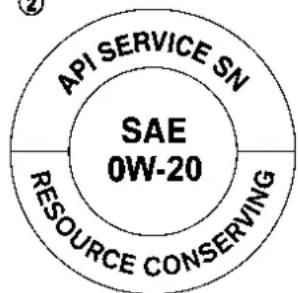
JVT0351X
① API certification mark
② API service symbol
ENGINE OIL AND OIL FILTER RECOMMENDATION
Selecting the correct oil
It is essential to choose the correct grade quality, and viscosity engine oil to ensure satisfactory engine life and performance, see "Capacities and recommended fluids/lubricants" (P.10-3). NISSAN recommends the use of an energy conserving oil in order to improve fuel economy.
Select only engine oils that meet the American Petroleum Institute (API) certification or International Lubricant Standardization and Approval Committee (ILSAC) certification and SAE viscosity standard. These oils have the API certification mark on the front of the container. Oils which do not have the specified quality label should not be used as they could cause engine damage.
Oil additives
NISSAN does not recommend the use of oil additives. The use of an oil additive is not necessary when the proper oil type is used and maintenance intervals are followed.
Oil which may contain foreign matter or has been previously used should not be used.
Technical and consumer information 10-7
Oil viscosity
The engine oil viscosity or thickness changes with temperature. Because of this, it is important to select the engine of viscosity based on the temperatures at which the vehicle will be operated before the next oil change. Choosing an oil viscosity other than that recommended could cause serious engine damage.
Selecting the correct oil filter
Your new NISSAN vehicle is equipped with a high-quality genuine NISSAN oil filter. When replacing, use a genuine NISSAN oil filter or its equivalent for the reason described in "Change intervals".
Change intervals
The oil and oil filter change intervals for your engine are based on the use of the specified quality oils and filters. Using an engine oil and filter other than the specified quality, or exceeding recommended oil and filter change intervals could reduce engine life. Damage to the engine caused by improper maintenance or use of incorrect oil and filter quality and/or viscosity is not covered by the NISSAN new vehicle limited warranty.
Your engine was filled with a high quality engine oil when it was built. You do not have to change the oil before the first
recommended change interval.
Oil and filter change intervals depend upon how you use your vehicle. Operation under the following conditions may require more frequent oil and filter changes:
●repeated short distance driving at cold outside temperatures
●driving in dusty conditions
- extensive idling
- towing a trailer
- stop and go commuting
(See "9. Maintenance and schedules" section.)
AIR CONDITIONING SYSTEM RE- FRIGERANT AND LUBRICANT RE- COMMENDATIONS
The air conditionersysteminyour NISSAN vehicle must be charged with the specified refrigerant HFO-1234yf(R-1234yf) and A/C system oil ND-OIL12 (PAG) or the exact equivalent.

CAUTION
Theuseofanyotherrefrigerantoroil willcauseseveredamagetotheair conditioningsystemandwillrequire thereplacementofallairconditioner
systemcomponents.
The refrigerant HFO-1234yf (R-1234yf) in your NISSAN vehicle will not harm the earth's ozone layer. Although this refrigerant does not affect the earth's atmosphere, certain government regulations require the recovery and recycling of any refrigerant during automotive air conditioner system service. Air conditioner system should only be serviced by trained and certified technicians to ensure proper and safe operation (SAE J2845). A NISSAN dealer has the trained technicians and equipment needed to recover and recycle your air conditioner system refrigerant. Only new and SAEJ2842 certified evaporator(s) shall be used as replacement parts.
A damaged or leaking air conditioning evaporator shall never be repaired or replaced with one removed from a used or salvaged vehicle. To replace a damaged or leaking evaporator, use only new and SAE J2842 certified evaporator (s). It is recommended that you visit a NISSAN dealer when servicing your air conditioner system.
SPECIFICATIONS
ENGINE
| Model PR25DD KR15DDT | |||
| Type | Gasoline, 4-cycle, DOHC | Gasoline, 4-cycle, DOHC | |
| Cylinder arrangement | 4-cylinder, in-line 3-cylinder, in-line | ||
| Bore × Stroke in (mm) | 3.504 × 3.937 (89.0 × 100.0) - | ||
| when compression ratio = 8 in (mm) | - | 3.307 × 3.547 (84.0 × 90.1) | |
| when compression ratio = 14 in (mm) | - | 3.307 × 3.500 (84.0 × 88.9) | |
| Displacement cu in (cm) | 3) 151.85 (2,488) - | ||
| when compression ratio = 8 cu in ( cm3 ) | - | 91.41 (1,497) | |
| when compression ratio = 14 cu in ( cm3 ) | - | 90.19 (1,477) | |
| Firing order 1-3-4-2 1-2-3 | |||
| Idle speed rpmIgnition timing (B.T.D.C.) degree/rpm | No adjustment is necessary. | ||
| Spark plug | Standard | DXE22H11C ILMAR8G8GS | |
| Spark plug gap (Normal) | in (mm) 0.043 (1.1) | 0.031 (0.8) | |
| Camshaft operation | Timing chain | Timing chain | |
This spark ignition system complies with the Canadian standard ICES-002.
WHEELS AND TIRES
Road wheel
| Type Size Offset in | (mm) |
| Conven-tional | 17 × 7.5J 1.57 (40) |
| 18 × 7.5J 1.57 (40) | |
| 19 × 7.5J 1.57 (40) | |
| Spare | 17 × 4T 1.18 (30) |
Tire
| Type Size | Pressure PSI (kPa) [Cold] | |
| Con-ven-tional | 235/65 R17 | Front: 36 (250)Rear: 33 (230) |
| 235/60 R18 | Front: 33 (230)Rear: 30 (210) | |
| 235/55 R19 | ||
| Spare | T155/80 D17 (2WD)T165/90 D17 (AWD) | 60 (420) |
DIMENSIONS AND WEIGHTS
| Overall length in (mm) | 182.9 (4,645)*1183.5 (4,660)*2 |
| Overall width in (mm) | 72.4 (1,840) |
| Overall height in (mm) | 67.9 (1,725) |
| Front tread in (mm) | 62.4 (1,585) |
| Rear tread in (mm) | 62.6 (1,590) |
| Wheelbase in (mm) | 106.5 (2,705) |
| Gross Vehicle Weight Rating (GVWR) | Ib (kg)See the F.M.V.S.S. or C.M.V.S.S. certification label on the driver's side center pillar. |
| Gross Axle Weight Rating (GAWR) | |
| Front lb (kg) | |
| Rear | Ib (kg) |
*1: Without license plate
*2: With license plate
WHENTRAVELINGORREGISTERING INANOTHERCOUNTRY
When planning to travel in another country, you should first find out if the fuel available is suitable for your vehicle's engine.
Using fuel with an octane rating that is too low may cause engine damage. All gasoline vehicles must be operated with unleaded gasoline. Therefore, avoid taking your vehicle to areas where appropriate fuel is not available.
When transferring the registration of your vehicle to another country, state, province or district, it may be necessary to modify the vehicle to meet local laws and regulations.
The laws and regulations for motor vehicle emission control and safety standards vary according to the country, state, province or district; therefore, vehicle specifications may differ.
When any vehicle is to be taken into another country, state, province or district and registered, its modifications, transportation, and registration are the responsibility of the user. NISSAN is not responsible for any inconvenience that may result.
VEHICLEIDENTIFICATION
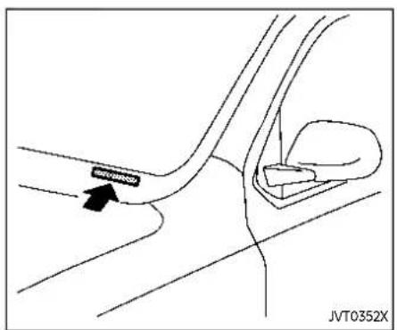
VEHICLE IDENTIFICATION NUMBER (VIN) PLATE
The vehicle identification number plate is attached as shown. This number is the identification for your vehicle and is used in the vehicle registration.

VEHICLE IDENTIFICATION NUMBER (chassis number)
The vehicle identification number is located as shown.

PR25DDengine
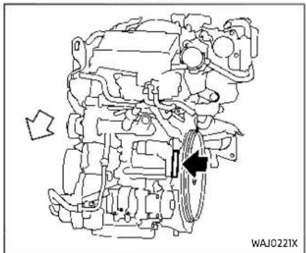
KR15DDTengine
Technical and consumer information 10-11
ENGINE SERIAL NUMBER
The number is stamped on the engine as shown.
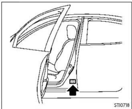
F.M.V.S.S./C.M.V.S.S. CERTIFICATION LABEL
The Federal/Canadian Motor Vehicle Safety Standards (F.M.V.S.S./C.M.V.S.S.) certification label is affixed as shown. This label contains valuable vehicle information, such as: Gross Vehicle Weight Ratings (GVWR), Gross Axle Weight Rating (GAWR), month and year of manufacture, Vehicle Identification Number (VIN), etc. Review it carefully.

EMISSION CONTROL INFORMATION LABEL
The emission control information label is attached to the underside of the hood as shown.
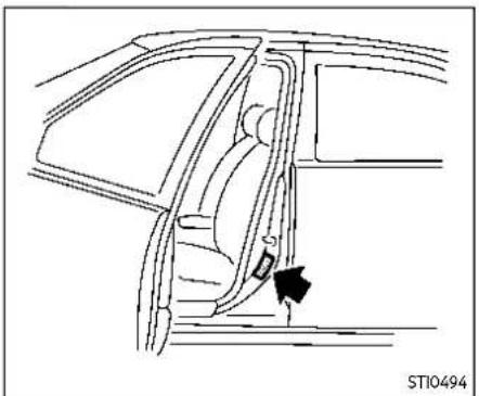
TIRE AND LOADING INFORMATION LABEL
The cold tire pressure is shown on the Tire and Loading Information label affixed to the pillar as shown.

AIR CONDITIONER SPECIFICATION LABEL
The air conditioner specification label is affixed to the underside of the hood as shown.
INSTALLINGFRONTLICENSEPLATE
| Airconditionerspecificationlabelsymbols: | ||
| Symbol Name Reference Graphic | ||
| Caution ISO 7000 0434 |  | |
| Air Conditioning System (MAC) | ISO 2575 D01 |  |
| MAC System Lubricant Type (PAG-POE) |  | |
| Requires Registered Technician to Service MAC System |  | |
| Flammable Refrigerant |  | |
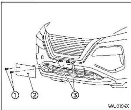
To mount the front license plate, attach the licence plate to the location marks (small dimples) of the bumper using the two screws ① provided.
VEHICLELOADINGINFORMATION

WARNING
- Itisextremelydangerousto rideinacargoareainside thevehicle.Inacollision, peopleridingintheseareas aremorelikelytobeseriouslyinjuredorkilled.
- Donotallowpeopletoride inanyareaofyourvehicle thatisnotequippedwith seatsandseatbelts.
- Besureeveryonein your vehicleisinaseatandusing aseatbeltproperly.
TERMS
It is important to familiarize yourself with the following terms before loading your vehicle:
- Curb Weight (actual weight of your vehicle) - vehicle weight including: standard and optional equipment, fluids, emergency tools, and spare tire assembly. This weight does not include
passengers and cargo.
•GVW (Gross Vehicle Weight) - curb weight plus the combined weight of passengers and cargo.
•GVWR (Gross Vehicle Weight Rating) - maximum total combined weight of the unloaded vehicle, passengers, luggage, hitch, trailer tongue load and any other optional equipment. This information is located on the F.M.V.S.S./C.M.V.S.S. label.
- GAWR (Gross Axle Weight Rating) - maximum weight (load) limit specified for the front or rear axle. This information is located on the F.M.V.S.S./C.M.V.S.S. label.
•GCWR (Gross Combined Weight Rating) - The maximum total weight rating of the vehicle, passengers, cargo, and trailer.
- Vehicle Capacity Weight, Load limit, Total load capacity - maximum total weight limit specified of the load (passengers and cargo) for the vehicle. This is the maximum combined weight of occupants and cargo that can
be loaded into the vehicle. If the vehicle is used to tow a trailer, the trailer tongue weight must be included as part of the cargo load. This information is located on the Tire and Loading Information label.
- Cargo capacity - permissible weight of cargo, the subtracted weight of occupants from the load limit.
VEHICLE LOAD CAPACITY
Do not exceed the load limit of your vehicle shown as "The combined weight of occupants and cargo" on the Tire and Loading Information label. Do not exceed the number of occupants shown as "Seating Capacity" on the Tire and Loading Information label.
To get "the combined weight of occupants and cargo", add the weight of all occupants, then add the total luggage weight. Examples are shown in the following illustration.
Example
Load limit - ( Occupants amp; Luggage 1 5 0 lb × 2 = 3 0 0 lb amp; 3 0 lb × 2 = 6 0 lb (7 0 kg) amp; (1 3 5 kg) + Trailer Tongue Weight (1 4 kg) amp; (2 7 kg) + Trailer Tongue (1 3 5 kg) ) = Remaining available cargo and luggage load capacity = 7 4 0 lb (3 3 6 kg)
Load limit - ( Occupants amp; Luggage 1 5 0 lb × 2 = 3 0 0 lb amp; 3 0 lb × 2 = 6 0 lb (7 0 kg) amp; (1 3 5 kg) (1 4 kg) amp; (2 7 kg) ) = Remaining available cargo and luggage load capacity = 1, 0 4 0 lb (4 7 2 kg)
Load limit 1, 4 0 0 lb (6 4 0 kg) - ( Occupants amp; amp; amp; Luggage amp; amp; amp; 1 5 0 lb × 5 = 7 5 0 lb (7 0 kg) amp; (3 4 0 kg) amp; amp; 3 0 lb × 5 = 1 5 0 lb amp; amp; (1 4 kg) amp; (7 0 kg) ) = Remaining available cargo and luggage load capacity = 5 0 0 lb (2 2 7 kg)
ST10445
Steps for determining correct load limit
- Locate the statement "The combined weight of occupants and cargo should never exceed XXX kg or XXX lbs" on your vehicle's placard.
- Determine the combined weight of the driver and passengers that will be riding in your vehicle.
- Subtract the combined weight of the driver and passengers from XXX kg or XXX lbs.
- The resulting figure equals the available amount of cargo and luggage load capacity. For example, if the XXX amount equals 1400 lbs. and there will be five 150 lb. passengers in your vehicle, the amount of available cargo and luggage load capacity is 650 lbs. (1400 - 750 (5 x 150) = 650 lbs) or (640 - 340 (5 x 70) = 300 kg.)
- Determine the combined weight of luggage and cargo being loaded on the vehicle. That
weight may not safely exceed the available cargo and luggage load capacity calculated in Step 4.
Before driving a loaded vehicle, confirm that you do not exceed the Gross Vehicle Weight Rating (GVWR) or the Gross Axle Weight Rating (GAWR) for your vehicle. (See "Measurement of weights" (P.10-18).)
Also check tires for proper inflation pressures. See the Tire and Loading Information label.
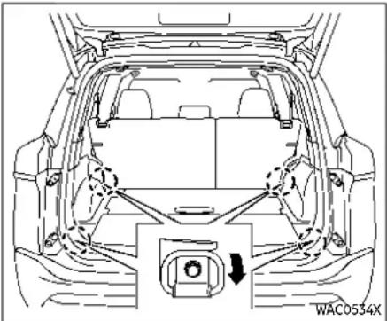
SECURING THE LOAD
There are luggage hooks located in the cargo area as shown. The hooks can be used to secure cargo with ropes or other types of straps.
Donotapplyatotalloadofmorethan 22lbs.(10kg)toasinglemetalfloor hookwhensecuringcargo.

WARNING
•Properlysecureallcargowith ropesorstrapstohelppreventit fromslidingorshifting.Donot placecargohigherthantheseat-
backs.Inasuddenstoporcollision,unsecured cargo could causepersonalinjury.
- Thechildrestrainttoptether strapmaybedamagedbycontactwithitemsinthecargoarea. Secureanyitemsinthecargo area.Yourchildcouldbeseriously injuredorkilledinacollisionifthe toptetherstrapisdamaged.
- Donotloadyourvehicleany heavierthantheGVWRorthe maximumfrontandrearGAWRs. If youdo, part sof your vehicle can break, tired damage could occur, or it can chan getheway your vehicle handles. This could result in loss of control and cause personal injury.
LOADING TIPS
- The GVW must not exceed GVWR or GAWR as specified on the F.M. V.S.S./C.M.V.S.S. certification label.
- Do not load the front and rear axle to the GAWR. Doing so will exceed the GVWR.
TOWINGATRAILER

WARNING
•Properlysecureallcargo withropesorstrapstohelp preventitfromslidingor shifting.Donotplacecargo higherthantheseatbacks. Inasuddenstoporcollision, unsecured cargo could causepersonalinjury.
- Donotloadyourvehicleany heavierthantheGVWRor themaximumfrontandrear GAWRs.Ifyoudo,partsof yourvehiclecanbreak,tire damagecouldoccur,orit canchangethewayyour vehiclehandles.Thiscould resultinlossofcontroland causepersonalinjury.
•Overloadingnotonlycan shortenthelifeofyourvehicleandthetire,butcan causeunsafevehiclehandlingandlongerbrakingdistances.Thismaycausea prematuretirefailure,which
couldresultinaserious accidentandpersonalinjury. Failures caused by overloadingarenotcovered bythevehicle'swarranty.
MEASUREMENT OF WEIGHTS
Secure loose items to prevent weight shifts that could affect the balance of your vehicle. When the vehicle is loaded, drive to a scale and weigh the front and the rear wheels separately to determine axle loads. Individual axle loads should not exceed either of the Gross Axle Weight Ratings (GAWR). The total of the axle loads should not exceed the Gross Vehicle Weight Rating (GVWR). These ratings are given on the vehicle certification label. If weight ratings are exceeded, move or remove items to bring all weights below the ratings.

WARNING
Overloading or improper loading of a traileranditscargocanadversely affectvehiclehandling,braking and performanceandmayleadtoaccidents.

CAUTION
- Do not tow a trailer or haul a heavyloadforthefirst500miles (800km). Yourengine,axleor otherpartscouldbedamaged.
- Forthefirst500miles(800km) that you tow a trailer, do not drive over50MPH(80km/h)anddo notmakestartsatfullthrottle. Thishelpstheengineandother partsofyourvehiclewearinat theheavierloads.
Your new vehicle was designed to be used primarily to carry passengers and cargo. Remember that towing a trailer places additional loads on your vehicle's engine, drivetrain, steering, braking and other systems.
A NISSAN Towing Guide (U.S. only) is
available on the website at www.nissanusa.com. This guide includes information on trailer towing capability and the special equipment required for proper towing.
MAXIMUM LOAD LIMITS
Maximum trailer loads
Never allow the total trailer load to exceed the value specified in the "Towing load/specification" (P.10-22) chart found in this section. The total trailer load equals trailer weight plus its cargo weight.
The maximum Gross Combined Weight Rating (GCWR) should not exceed the value specified in the following "Towing Load/Specification" chart.

The GCWR equals the combined weight of the towing vehicle (including passengers and cargo) plus the total trailer load. Towing loads greater than these or using improper towing equipment could adversely affect vehicle handling, braking and performance.
The ability of your vehicle to tow a trailer is not only related to the maximum trailer loads, but also the places you plan to tow. Tow weights appropriate for level highway driving may have to be reduced for low traction situations (for example, on slippery boat ramps).
Temperature conditions can also affect towing. For example, towing a heavy
trailer in high outside temperatures on graded roads can affect engine performance and cause overheating. The transmission high fluid temperature and engine protection mode, which helps reduce the chance of transmission and engine damage, could activate and automatically decrease engine power. Vehicle speed may decrease under high load. Plan your trip carefully to account for trailer and vehicle load, weather and road conditions.

WARNING
Overheatingcanresultinreduced enginepowerandvehiclespeed. Thereducedspeedmaybelower thanothertraffic,whichcouldincreasethechanceofacollision.Be especiallycarefulwhendriving.Ifthe vehiclecannotmaintainasafedringspeed,pulltothesideoftheroad inasafearea.Allowtheengineto coolandreturntonormaloperation. (See"Ifyourvehicleoverheats"(P.6-14).)

CAUTION
Vehicledamageresultingfromim-propertowingproceduresisnot coveredbyNISSANwarranties.


Tongue load
When using a weight carrying or a weight distributing hitch, keep the tongue load between 10 - 15% of the total trailer load or use the trailer tongue load specified by the trailer manufacturer. The tongue load must be within the maximum tongue load limits shown in the following "Towing Load/Specification" chart. If the tongue load becomes excessive, rearrange cargo to allow for proper tongue load.
MAXIMUM GROSS VEHICLE WEIGHT (GVW)/MAXIMUM GROSS AXLE WEIGHT (GAW)
The GVW of the towing vehicle must not exceed the Gross Vehicle Weight Rating (GVWR) shown on the F.M.V.S.S./C.M.V.S.S. certification label. The GVW equals the combined weight of the unloaded vehicle, passengers, luggage, hitch, trailer tongue load and any other optional equipment. In addition, front or rear GAW must not exceed the Gross Axle Weight Rating (GAWR) shown on the F.M.V.S.S./C.M.V.S.S. certification label.
Towing capacities are calculated assuming a base vehicle with driver and any
options required to achieve the rating. Additional passengers, cargo and/or optional equipment, such as the trailer hitch, will add weight to the vehicle and reduce your vehicle's maximum towing capacity and trailer tongue load.
The vehicle and trailer need to be weighed to confirm the vehicle is within the GVWR, Front GAWR, Rear GAWR, Gross Combined Weight Rating (GCWR) and Towing capacity.
All vehicle and trailer weights can be measured using platform type scales commonly found at truck stops, highway weigh stations, building supply centers or salvage yards.
To determine the available payload capacity for tongue/king pin load, use the following procedure.
- Locate the GVWR on the F.M.V.S.S./C. M.V.S.S. certification label.
- Weigh your vehicle on the scale with all of the passengers and cargo that are normally in the vehicle when towing a trailer.
- Subtract the actual vehicle weight from the GVWR. The remaining amount is the available maximum tongue/king pin load.
To determine the available towing capacity, use the following procedure.
- Find the GCWR for your vehicle on the "Towing Load/Specification" chart found later in this section.
- Subtract the actual vehicle weight from the GCWR. The remaining amount is the available maximum towing capacity.
To determine the Gross Trailer Weight, weigh your trailer on a scale with all equipment and cargo, that are normally in the trailer when it is towed. Make sure the Gross trailer weight is not more than the Gross Trailer Weight Rating shown on the trailer and is not more than the calculated available maximum towing capacity.
Also weigh the front and rear axles on the scale to make sure the Front Gross Axle Weight and Rear Gross Axle Weight are not more than Front Gross Axle Weight and Rear Gross Axle Weight on the F.M.V.S. S./C.M.V.S.S. certification label. The cargo in the trailer and vehicle may need to be moved or removed to meet the specified ratings.
Example:
●Gross Vehicle Weight (GVW) as weighed on a scale - including passengers, cargo and hitch - 6,350 lb. (2,880 kg).
●Gross Vehicle Weight Rating (GVWR) from F.M.V.S.S./C.M.V.S.S. certification label - 7,250 lb. (3,289 kg).
●Gross Combined Weight Rating (GCWR) from "Towing Load/Specification" chart - 15,100 lb. (6,849 kg).
●Maximum Trailer towing capacity from "Towing Load/Specification" chart - 9,100 lb (4,128 kg).
| 7,250 lb. (3,289 kg) | GVWR |
| - 6,350lb. (2,880 kg) | GVW |
| = 900 lb. (409 kg) | Available for tongue weight |
| e | 15,100 lb. (6,849 kg) | GCWR |
| - 6,350 lb. (2,880 kg) | GVW | |
| = 8,750 lb. (3,969 kg) | Capacity available for towing |
| 900 lb. (409 kg) / 8,750 lb. (3,969 kg) | Available tongue weightAvailable capacity |
| = 10 % tongue weight |
The available towing capacity may be less than the maximum towing capacity due to the passenger and cargo load in the vehicle.
Remember to keep trailer tongue weight between 10 - 15% of the trailer weight or within the trailer tongue load specifica-
tion recommended by the trailer manufacturer. If the tongue load becomes excessive, rearrange the cargo to obtain the proper tongue load. Do not exceed the maximum tongue weight specification shown in the "Towing load/specification" chart even if the calculated available tongue weight is greater than 15%. If the calculated tongue weight is less than 10%, reduce the total trailer weight to match the available tongue weight.
Always verify that available capacities are within the required ratings.
TOWING LOAD/SPECIFICATION

WARNING
Thetowingcapacitiesprovidedin thismanualareforgeneralreference only. Thesafetowingcapacity of your vehicle is affected by dealer and factory installed options and passenger and cargoloads. You must weigh the vehicle and trailer as described in this manual to determine the actual vehicletowing capacity. Donot exceed the published maximum towing capacity, or the GCWRorthe GVWR shown on the F.M.V.S.S./C.M.V.S.S. certification label. Doingsocan result in an accident causing serious personal injury or property damage.
| Towing load/specification chart | ||||
| Engine Type | PR25DD | KR15DDT | ||
| Axle Type | Two-Wheel Drive (2WD) | All-Wheel Drive (AWD) | Two-Wheel Drive (2WD) | All-Wheel Drive (AWD) |
| Maximum Towing Capa-city*1 | 1,350 lbs (612 kg) | 1,500 lbs (680 kg) | ||
| Maximum Tongue Load | 135 lbs (61 kg) | 150 lbs (68 kg) | ||
| Maximum Gross Com-bined Weight Rating | 5,836 lbs (2,647 kg) | 5,969 lbs (2,707 kg) | 6,053 lbs (2,745 kg) | 6,185 lbs (2,805 kg) |
1: The towing capacity values are calculated assuming a base vehicle with driver and any options required to achieve the rating. Additional passengers, cargo and/or optional equipment will add weight to the vehicle and reduce your vehicle's maximum towing capacity.
TOWING SAFETY
Trailer hitch
Choose a proper hitch for your vehicle and trailer. Make sure the trailer hitch is securely attached to the vehicle to help avoid personal injury or property damage due to sway caused by crosswinds, rough road surfaces or passing trucks.

WARNING
Trailerhitchcomponentshavespecificweightratings.Yourvehiclemay becapableoftowingatrailerheavier thantheweightratingofthehitch components.Neverexceed the weightratingofthehitchcomponents.Doingsocancauseserious personalinjuryorpropertydamage.
Hitch ball
Choose a hitch ball of the proper size and weight rating for your trailer:
●The required hitch ball size is stamped on most trailer couplers. Most hitch balls also have the size printed on top of the ball.
- Choose the proper class hitch ball based on the trailer weight.
Technical and consumer information 10-23
- The diameter of the threaded shank of the hitch ball must be matched to the ball mount hole diameter. The hitch ball shank should be no more than 1/16' smaller than the hole in the ball mount.
●The threaded shank of the hitch ball must be long enough to be properly secured to the ball mount. There should be at least 2 threads showing beyond the lock washer and nut.
Ball mount
The hitch ball is attached to the ball mount and the ball mount is inserted into the hitch receiver. Choose a proper class ball mount based on the trailer weight. Additionally, the ball mount should be chosen to keep the trailer tongue level with the ground.
Weight carrying hitches
A weight carrying or "dead weight" ball mount is one that is designed to carry the whole amount of tongue weight and gross weight directly on the ball mount and on the receiver.
Weight distribution hitch
This type of hitch is also called a "load-leveling" or "equalizing" hitch. A set of bars attach to the ball mount and to the trailer to distribute the tongue weight (hitch weight) of your trailer. Many vehicles cannot carry the full tongue weight of a given trailer, and need some of the tongue weight transferred through the frame and pushing down on the front wheels. This gives stability to the tow vehicle.
A weight-distributing hitch system (Class IV) is recommended if you plan to tow trailers with a maximum weight over 5,000 lbs (2,267 kg). Check with the trailer and towing equipment manufacturers to determine if they recommend the use of a weight-distributing hitch system.
NOTE:
Aweight-distributinghitchsystemmay affecttheoperationoftrailersurge brakes.Ifyouareconsideringuseofa weight-distributinghitchsystemwitha surgebrake-equipped trailer,check withthesurgebrake,hitchortrailer manufacturertodetermineifandhow thiscanbedone.
Follow the instructions provided by the manufacturer for installing and using the weight-distributing hitch system.
General set-up instructions are as follows:
- Park unloaded vehicle on a level surface. With the ignition switch in the ON position and the doors closed, allow the vehicle to stand for several minutes so that it can level.
- Measure the height of a reference point on the front and rear bumpers at the center of the vehicle.
- Attach the trailer to the vehicle and adjust the hitch equalizers so that the front bumper height is within 0 - .5 inches (0 - 13 mm) of the reference height measured in step 2. The rear bumper should be no higher than the reference height measured in step 2.

WARNING
Properlyadjusttheweightdistribut-inghitchsotherearofthebumperis nohigherthanthemeasuredreferenceheightwhentetrailerisattached.iftherearbumperishigher thanthemeasuredreferenceheight whenloaded,thevehiclemayhandle unpredictablywhichcouldcausea lossofvehiclecontrolandcause seriouspersonalinjuryorproperty damage.
Sway control device
Sudden maneuvers, wind gusts and buffeting caused by other vehicles can affect trailer handling. Sway control devices may be used to help control these affects. If you choose to use one, contact a reputable trailer hitch supplier to make sure the sway control device will work with the vehicle, hitch, trailer and the trailer's brake system. Follow the instructions provided by the manufacturer for installing and using the sway control device.
Class I hitch
Class I trailer hitch equipment (receiver, ball mount and hitch ball) can be used to tow trailers of a maximum weight of 2,000 lb (907 kg).
Tire pressures
- When towing a trailer, inflate the vehicle tires to the recommended cold tire pressure indicated on the Tire and Loading Information label.
- Trailer tire condition, size, load rating and proper inflation pressure should be in accordance with the trailer and tire manufacturers' specifications.
Safety chains
Always use a suitable chain between your vehicle and the trailer. The safety chains should be crossed and should be attached to the hitch, not to the vehicle bumper or axle. Be sure to leave enough slack in the chains to permit turning corners.
Trailer lights (if so equipped)

CAUTION
Whensplicingintothevehicleelectricalsystem,acommerciallyavailablepower-typemodule/converter mustbeusedtoprovidepowerfor alltrailerlighting.Thisunitusesthe vehiclebatteryasadirectpower sourceforalltrailerlightswhile usingthevehicletaillight,stoplight andturnsignalcircuitsasasignal source. Themodule/convertermust drawnomorethan15milliamps fromthestopandtaillampcircuits. Usingamodule/converterthatexceedsthesepower requirements maydamagethevehicle'selectrical system.Seeareputabletrailerretailertoobtaintheproperequipment andtohaveitinstalled.
Trailer lights should comply with federal and/or local regulations. For assistance in hooking up trailer lights, contact a NISSAN dealer or reputable trailer retailer.
Pre-towing tips
- Be certain your vehicle maintains a level position when a loaded or unloaded trailer is hitched. Do not drive the vehicle if it has an abnormal nose-up or nose-down condition; check for improper tongue load, overload, worn suspension or other possible causes of either condition.
- Always secure items in the trailer to prevent load shift while driving.
- Keep the cargo load as low as possible in the trailer to keep the trailer center of gravity low.
- Load the trailer so approximately 60% of the trailer load is in the front half and 40% is in the back half. Also make sure the load is balanced side to side.
- Check your hitch, trailer tire pressure, vehicle tire pressure, trailer light operation, and trailer wheel lug nuts every time you attach a trailer to the vehicle.
- Be certain your rearview mirrors conform to all federal, state or local regulations. If not, install any mirrors required for towing before driving the
vehicle.
●Determine the overall height of the vehicle and trailer so the required clearance is known.
Trailer towing tips
In order to gain skill and an understanding of the vehicle's behavior, you should practice turning, stopping and backing up in an area which is free from traffic. Steering stability, and braking performance will be somewhat different than under normal driving conditions.
- Always secure items in the trailer to prevent load shift while driving.
- Lock the trailer hitch coupler with a pin or lock to prevent the coupler from inadvertently becoming unlatched.
- Avoid abrupt starts, acceleration or stops.
- Avoid sharp turns or lane changes.
●Always drive your vehicle at a moderate speed. Some states or provinces have specific speed limits for vehicles that are towing trailers. Obey the local speed limits.
- When backing up, hold the bottom of the steering wheel with one hand. Move your hand in the direction in which you want the trailer to go. Make small corrections and back up slowly. If possible, have someone guide you
10-26 Technicalandconsumerinformation
when you are backing up. Always block the wheels on both vehicle and trailer when parking. Parking on a slope is not recommended; however, if you must do so:

CAUTION
If you push the park button to engage the Park position before blocking the wheels and applying the parking brake, transmission damage could occur.
- Apply and hold the brake pedal.
- Have someone place blocks on the downhill side of the vehicle and trailer wheels.
- After the wheel blocks are in place, slowly release the brake pedal until the blocks absorb the vehicle load.
- Apply the parking brake.
- Push the park button to engage the P (Park) position.
- Turn off the engine.
To drive away: - Apply and hold the brake pedal.
-
Start the engine.
-
Shift the transmission into gear.
- Release the parking brake.
- Drive slowly until the vehicle and trailer are clear from the blocks.
- Apply and hold the brake pedal.
- Have someone retrieve and store the blocks.
- While going downhill, the weight of the trailer pushing on the tow vehicle may decrease overall stability. Therefore, to maintain adequate control, reduce your speed and shift to a lower gear. Avoid long or repeated use of the brakes when descending a hill, as this reduces their effectiveness and could cause overheating. Shifting to a lower gear instead provides "engine braking" and reduces the need to brake as frequently.
- If the engine coolant temperature rises to a high temperature, see "If your vehicle overheats" (P.6-14).
●Trailer towing requires more fuel than normal circumstances. - Avoid towing a trailer for your vehicle's first 500 miles (800 km).
- For the first 500 miles (800 km) that you do tow, do not drive over 50 MPH (80 km/h).
●Have your vehicle serviced more often than at intervals specified in the recommended maintenance schedule shown in the "9. Maintenance and schedules" section.
- when making a turn, your trailer wheels will be closer to the inside of the turn than your vehicle wheels. To compensate for this, make a larger than normal turning radius during the turn.
- Crosswinds and rough roads will adversely affect vehicle/trailer handling, possibly causing vehicle sway. When being passed by larger vehicles, be prepared for possible changes in crosswinds that could affect vehicle handling.
Do the following if the trailer begins to sway:
- Take your foot off the accelerator pedal to allow the vehicle to coast and steer as straight ahead as the road conditions allow. This combination will help stabilize the vehicle.
- Do not correct trailer sway by steering or applying the brakes.
-
When the trailer sway stops, gently apply the brakes and pull to the side of the road in a safe area.
-
Try to rearrange the trailer load so it is balanced as described earlier in this section.
- Be careful when passing other vehicles. Passing while towing a trailer requires considerably more distance than normal passing. Remember the length of the trailer must also pass the other vehicle before you can safely change lanes.
- Downshift the transmission to a lower gear for engine braking when driving down steep or long hills. This will help slow the vehicle without applying the brakes.
- Avoid holding the brake pedal down too long or too frequently. This could cause the brakes to overheat, resulting in reduced braking efficiency.
- Increase your following distance to allow for greater stopping distances while towing a trailer. Anticipate stops and brake gradually.
- NISSAN recommends that the cruise control not be used while towing a trailer.
- While towing a trailer, do not use the following systems (if so equipped):
- Lane Departure Warning (LDW) system
— Intelligent Lane Intervention (I-LI) system
— Blind Spot Warning (BSW) system
— Intelligent Blind Spot Intervention (I-BSI) system
— Rear Cross Traffic Alert (RCTA) system
— ProPILOT Assist system (Intelligent Cruise Control (ICC), ProPILOT Assist with Navi-link and Steering Assist)
- Automatic Emergency Braking (AEB) with Pedestrian Detection system
— Intelligent Forward Collision Warning (I-FCW) system
— Rear Automatic Braking (RAB) system
- Some states or provinces have specific regulations and speed limits for vehicles that are towing trailers. Obey the local speed limits.
- Check your hitch, trailer wiring harness connections, and trailer wheel lug nuts after 50 miles (80 km) of travel and at every break.
- When launching a boat, do not allow the water level to go over the exhaust tail pipe or rear bumper.
●Make sure you disconnect the trailer lights before backing the trailer into
Technical and consumer information 10-27
FLATTOWING
the water or the trailer lights may burn out.
Whentowingatrailer, the Continuously Variable Transmission (CVT) fluid, transfer fluid and differential gear oil should be changed more frequently. For additional information, seethe "9. Maintenance and schedules" section.
FLAT TOWING FOR ALL-WHEEL DRIVE VEHICLE (if so equipped)
Towing your vehicle with all four wheels on the ground is sometimes called flat towing. This method is sometimes used when towing a vehicle behind a recreational vehicle, such as a motor home.

CAUTION
●Failuretofollowtheseguidelines canresultinseveretransmission damage.
●NeverflattowyourAll-Wheel Drive(AWD)vehicle.
- DONOTtowyourAll-WheelDrive (AWD)vehiclewithanywheelson theground.Doingsomaycause seriousandexpensivedamageto thepowertrain.
- Foremergencytowingproceduresreferto"TowingrecommendedbyNISSAN"(P.6-17).
FLAT TOWING FOR FRONT-WHEEL DRIVE VEHICLE (if so equipped)
Towing your vehicle with all four wheels on the ground is sometimes called flat towing. This method is sometimes used when towing a vehicle behind a recreational vehicle, such as a motor home.

CAUTION
- Failuretofollowtheseguidelines canresultinseveretransmission damage.
- Whenever flattowing your vehicle, alwaystowforward, never backward.
- Nevertowyourfrontwheeldrive vehiclewiththefronttiresonthe ground.Doingsomaycauseseriousandexpensivedamageto thepowertrain.
- DONOTtowyourfrontwheel drive Continuously Variable Transmission(CVT)vehiclewith allfourwheelsontheground(flat towing).DoingsoWILLDAMAGE internaltransmissionpartsdue to lackoftransmissionlubrication.
UNIFORMTIREQUALITYGRADING
- Foremergencytowingproceduresreferto"TowingrecommendedbyNISSAN"inthe"In caseofemergency"sectionof thismanual.
Continuously Variable Transmission (CVT)
To tow a vehicle equipped with a CVT, an appropriate vehicle dolly MUST be placed under the towed vehicle's drive wheels.
Alwaysfollow the dolly manufacturer's recommendations when using their product.
DOT (Department Of Transportation) Quality Grades: All passenger car tires must conform to federal safety requirements in addition to these grades.
Quality grades can be found where applicable on the tire sidewall between tread shoulder and maximum section width. For example:
Treadwear200TractionAATemperatureA
TREADWEAR
The treadwear grade is a comparative rating based on the wear rate of the tire when tested under controlled conditions on a specified government test course. For example, a tire graded 150 would wear one and one-half
(1 1/2) times as well on the government course as a tire graded 100. The relative performance of tires depends upon actual conditions of their use, however, and may depart significantly from the norm due to variations in driving habits, service practices and differences in road characteristics and climate.
TRACTION AA, A, B AND C
The traction grades, from highest to lowest, are AA, A, B and C. Those grades represent the tire's ability to stop on wet pavement as measured under controlled conditions on specified government test surfaces of asphalt and concrete. A tire marked C may have poor traction performance.

WARNING
Thetractiongradeassignedtothis tireisbasedonstraight-aheadbrakingtractiontests, and does not include acceleration, cornering, hydroplaning, or peaktraction characteristics.
TEMPERATURE A, B AND C
The temperature grades A (the highest), B, and C, representing the tire's resistance to the generation of heat and its ability to dissipate heat when tested under controlled conditions on a specified indoor laboratory test wheel. Sustained high temperature can cause the material of the tire to degenerate and reduce tire life, and excessive temperature can lead to sudden tire failure. The grade C corresponds to a level of performance which
Technicalandconsumerinformation10-29
all passenger car tires must meet under the Federal Motor Vehicle Safety Standard No. 109. Grades B and A represent higher levels of performance on the laboratory test wheel than the minimum required by law.

WARNING
Thetemperaturegradeforthistireis establishedforatirethatisproperly inflatedandnotoverloaded.Excessivespeed,under-inflation,orexcessiveloading,eitherseparatelyorin combination,cancauseheatbuild-upandpossibletirefailure.
EMISSIONCONTROLSYSTEMWARRANTY
Your vehicle is covered by the following emission warranties.
ForUSA:
●Emission Defects Warranty
●Emissions Performance Warranty
Details of these warranties may be found with other vehicle warranties in your Warranty Information Booklet which comes with your vehicle. If you did not receive a Warranty Information Booklet, or it has become lost, you may obtain a replacement by writing to:
●Nissan North America, Inc.
Consumer Affairs Department P.O. Box 685003
Franklin, TN 37068-5003
ForCanada:
Emission Control System Warranty Details of this warranty may be found with other vehicle warranties in your Warranty Information Booklet which comes with your vehicle. If you did not receive a Warranty Information Booklet, or it has become lost, you may obtain a replacement by writing to:
●Nissan Canada Inc.
5290 Orbitor Drive Mississauga, Ontario, L4W 4Z5
REPORTINGSAFETYDEFECTS
For USA
If you believe that your vehicle has a defect which could cause a crash or could cause injury or death, you should immediately inform the National Highway Traffic Safety Administration (NHTSA) in addition to notifying NISSAN.
If NHTSA receives similar complaints, it may open an investigation, and if it finds that a safety defect exists in a group of vehicles, it may order a recall and remedy campaign. However, NHTSA cannot become involved in individual problems between you, your dealer, or NISSAN.
To contact NHTSA, you may call the Vehicle Safety Hotline toll-free at 1-888-327-4236 (TTY: 1-800-424-9153); go to http://www.safercar.gov; or write to: Administrator, NHTSA, 400 Seventh Street, SW., Washington, D.C. 20590. You can also obtain other information about motor vehicle safety from http://www.safercar.gov.
READINESSFORINSPECTION/MAINTENANCE(I/M)TEST
You may notify NISSAN by contacting our Consumer Affairs Department, toll-free, at 1-800-NISSAN-1. For Canada
If you believe that your vehicle has a defect which could cause a crash or could cause injury or death, you should immediately inform Transport Canada in addition to notifying NISSAN.
If Transport Canada receives complaints, it may open an investigation, and if it finds that a safety defect exists in a group of vehicles, it may request that NISSAN conduct a recall campaign. However, Transport Canada cannot become involved in individual problems between you, your dealer, or NISSAN. You may contact Transport Canada's Defect Investigations and Recalls Division toll free at 1-800-333-0510. You may also report safety defects online at: https://wwwapps.tc.gc.ca/Saf-Sec-Sur/7/PCDB-BDPP/fc-cp.aspx?lang=eng (English speakers) or https:// wwwapps.tc.gc.ca/Saf-Sec-Sur/7/PCDB-BDPP/fc-cp.aspx?lang=fra(French speakers).
Additional information concerning motor vehicle safety may be obtained from Transport Canada's Road Safety Information Centre at 1-800-333-0371 or online at www.tc.gc.ca/roadsafety (English speakers) or www.tc.gc.ca/securiteroutiere (French speakers).
To notify NISSAN of any safety concerns please contact our Consumer Information Centre toll free at 1-800-387-0122.

WARNING
AvehicleequippedwithAll-Wheel Drive(AWD)shouldneverbetested usingatwowheeldynamometer (suchasthedynamometersusedby somestatesforemissionstesting), orsimilarequipment.Makesureyou informtestfacilitypersonnelthat yourvehicleisequippedwithAWD beforeitisplacedonadynamometer.Usingthewrongtestequipmentmayresultintransmission damage or unexpected vehicle movementwhichcouldresultin seriousvehicledamageorpersonal injury.
Due to legal requirements in some states/areas or provinces, your vehicle may be required to be in what is called the "ready condition" for an Inspection/Maintenance (I/M) test of the emission control system. The vehicle is set to the "ready condition" when it is driven through certain driving patterns. Usually, the "ready condition" can be obtained by ordinary usage of the vehicle.
If a powertrain system component is repaired or the battery is disconnected, the vehicle may be reset to a "not ready
Technicalandconsumerinformation10-31
EVENTDATARECORDERS(EDR)
condition". Before taking the I/M test, check the vehicle's inspection/maintenance test readiness condition. Place the ignition switch in the ON position without starting the engine. If the Malfunction Indicator Light (MIL) comes on steady for 20 seconds and then blinks for 10 seconds, the I/M test condition is "not ready". If the MIL does not blink after 20 seconds the I/M test condition is "ready".
It is recommended you visit a NISSAN dealer to set "ready condition" or to prepare the vehicle for testing.
This vehicle is equipped with an Event Data Recorder (EDR). The main purpose of an EDR is to record, in certain crash or near crash-like situations, such as an air bag deployment or hitting a road obstacle, data that will assist in understanding how a vehicle's systems performed. The EDR is designed to record data related to vehicle dynamics and safety systems for a short period of time, typically 30 seconds or less. The EDR in this vehicle is designed to record such data as:
- How various systems in your vehicle were operating;
- Whether or not the driver and passenger safety belts were buckled/fastened;
●How far (if at all) the driver was depressing the accelerator and/or brake pedal; and,
●How fast the vehicle was traveling.
●Sounds are not recorded.
These data can help provide a better understanding of the circumstances in which crashes and injuries occur.
NOTE: EDR data are recorded by your vehicle only if a nontrivial crash situation occurs; no data are recorded by the EDR under normal driving conditions and no personal data (e.g. name, gender, age and crash location) are recorded. However, other parties, such as law enforcement, could combine the EDR data with the type of personally identifying data routinely acquired during a crash investigation.
To read data recorded by an EDR, special equipment is required and access to the vehicle or the EDR is needed. In addition to the vehicle manufacturer and NISSAN dealer, other parties, such as law enforcement, that have the special equipment, can read the information if they have
access to the vehicle or the EDR. EDR data will only be accessed with the consent of the vehicle owner or lessee or as otherwise required or permitted by law.
ADDITIONAL DATA RECORDING (on vehicles equipped with optional ProPILOT Assist)
If your vehicle is equipped with the optional ProPILOT Assist, it will also be equipped with supplemental data recording function intended to assist in understanding how ProPILOT Assist performs in certain nontrivial crash or near-crash scenarios. Specifically, supplemental recording is designed to capture the following:
- Driver operational status of the accelerator, brakes, steering, etc.
●Detection status of a vehicle ahead and lane markers
OWNER'SMANUAL/SERVICE MANUALORDERINFORMATION
●Vehicle information including distance to vehicle ahead and lateral position
•Information on the operation of the ProPILOT Assist and other crash avoidance features
●ProPILOT Assist malfunction diagnosis information
●External images from the multi-sensing front camera (Available only when the SRS air bag or AEB with Pedestrian Detection system is activated)
The ProPILOT Assist does not record conversations, sounds or images of the inside of the vehicle.
To read this supplemental data, special equipment is required and access to the vehicle or the recording unit is needed. This supplemental data will only be accessed with the consent of the vehicle owner or lessee or as otherwise required or permitted by law. If downloaded, NISSAN and third parties entrusted by NISSAN may use the data recorded for the purpose of improving NISSAN's vehicle safety performance.
NISSAN and third parties entrusted by NISSAN will not disclose/provide the recorded data to a third party except:
●With the consent of the vehicle owner or with the consent of the lessee
- In response to an official request from law enforcement, court order, governmental agency, or other legally enforceable request
- For research purposes after the data is modified such that it is no longer tied to a specific vehicle or vehicle owner (anonymized)
Genuine NISSAN Service Manuals for this model year and prior can be purchased. A genuine NISSAN Service Manual is the best source of service and repair information for your vehicle. This manual is the same one used by the factory trained technicians working at a NISSAN dealer. Genuine NISSAN Owner's Manuals can also be purchased.
IntheUSA:
For current pricing and availability of genuine NISSANServiceManualscontact:
www.nissan-techinfo.com
For current pricing and availability of genuine NISSANOwner'sManualscontact:
1-800-247-5321
InCanada:
To purchase a copy of a genuine NISSAN Service Manual or Owner's Manual for this model year and prior please contact a NISSAN dealer. For the phone number and location of a NISSAN dealer in your area call the NISSAN Information Center at 1-800-387-0122 and a bilingual NISSAN representative will assist you.
MEMO
10-34 Technicalandconsumerinformation
11Index
A
ABS(Anti-lockBrakingSystem)....5-156
Activenoisecancellation....5-174
ActiveRideControl....5-160
Activesoundenhancement....5-174
Adjustableluggagefloor 2-75
AdvancedAirBagSystem....1-53
Airbagsystem
AdvancedAirBagSystem....1-53
Driverandfrontpassenger
supplementalkneeairbagsystem.....1-62
Frontandrearseat-mounted
side-impactsupplementalair
bagsystem....1-64
Frontcentralseat-mounted
side-impactsupplementalair
bagsystem....1-64
Frontpassengerairbagand
statuslight....1-55
Roof-mountedcurtainside-impact
supplementalairbagsystem....1-64
Airbagwarninglabels....1-67
Airbagwarninglight....1-67,2-16
Aircleanerhousingfilter....8-19
Airconditioner
Airconditioneroperation....4-26
Airconditionerservice....4-37
Airconditionerspecificationlabel.....10-13
Airconditioningsystemrefrigerant
andlubricantrecommendations......4-37
Airconditioningsystemrefrigerant
andoilrecommendations....10-8
Alarm, Howtostopalarm(seevehicle
securitysystem)....2-53
Alcohol,drugsanddriving 5-12
Alert
RearDoorAlert....2-67
All-WheelDrive(AWD)(See
Intelligent4x4)....5-151
AndroidAuto 4-2
Antenna....4-38
Anti-lockBrakingSystem(ABS)....5-156
Anti-lockBrakingSystem(ABS)
warninglight....2-17
Appearancecare
Exteriorappearancecare....7-2
Interiorappearancecare....7-4
AppleCarPlay ® 4-2
Armrest....1-9
Audiblereminders....2-22
AUTOmode 5-32
Automatic
Doorlocks....3-7
Automaticairconditioner
andheater....4-31,4-34
Automaticbrakehold 5-28
AutomaticEmergencyBraking(AEB)
systemOFFwarninglight....2-17
AutomaticEmergencyBraking(AEB)
withPedestrianDetectionsystem....5-122
Automaticmoonroofandsunshade.....2-85
Averagefuelconsumption....2-46
Averagespeed....2-46
Avoidingcollisionandrollover....5-10
AWD(SeeIntelligent4x4)....5-151
B
Battery....8-15
Batteryreplacement,IntelligentKey.....8-25
Batterysaversystem....2-63
Variablevoltagecontrolsystem....8-17
Beforestartingtheengine....5-17
BlindSpotWarning(BSW)......5-58
Boosterseats....1-44
Brake
Anti-lockBrakingSystem(ABS)......5-156
Brakefluid....8-12
Brakesystem....5-155
Electronicparkingbrakesystem
warninglight 2-18
Parkingbrake 5-25
warninglight....2-14
Break-inschedule....5-149
Brightnesscontrol
Instrumentpanel....2-11
Bulbcheck/instrumentpanel....2-14
Bulbreplacement....8-28
C
Capacitiesand
recommendedfluids/lubricants....10-3
CarphoneorCBradio....4-38
Cardholder 2-79
Cargocover 2-80
Cargolight....2-89
Catalyticconverter, Threewaycatalyst.....5-6
Charger
USB(UniversalSerialBus)
chargingconnector 2-69
Wirelesscharger....2-70
Chassiscontrol....5-160
Childrestraints....1-24
Boosterseats....1-44
LATCHsystem....1-26
Precautionsonchildrestraints....1-24
Childsafety....1-21
Childsafetyreardoorlock....3-7
Chimes
Seatbeltwarninglight
andchime....1-16,2-16
Chimes, Audiblereminders....2-22
Circuitbreaker,Fusiblelink....8-23
Cleaningexteriorandinterior....7-2,7-4
Clock 2-48
Coathook 2-79
Cockpit 2-3
Coldweatherdriving....5-172
ConnectiontoRoadsideAssistance......6-2
Consolebox....2-78
ContinuouslyVariableTransmission
(CVT)fluid....8-12
ContinuouslyVariableTransmission(CVT)
positionindicator....2-11
Conventional(fixedspeed)cruisecontrol
mode(withProPILOTAssist)......5-119
Coolant
Capacitiesand
recommendedfluids/lubricants.....10-3
Changingenginecoolant....8-6
Changingintercoolercoolant....8-8
Checkingenginecoolantlevel....8-6
Checkingintercoolercoolantlevel.....8-7
Corrosionprotection....7-7
Cover,Cargocover 2-80
Cruisecontrol
Conventional(fixedspeed)cruise
controlmode....5-119
Cruisecontrol(withProPILOTAssist)
(SeeConventional(fixedspeed)cruise
controlmode)....5-119
Cruisecontrol(without
ProPILOTAssist)....5-83
IntelligentCruiseControl(ICC)....5-98
Cupholders....2-73
CVT, DrivingwithCVT(Continuously
VariableTransmission) 5-19
D
DaytimeRunningLights(DRL)system.....2-63
Defrosterswitch, Rearwindowand
outsidemirrordefrosterswitch....2-57
Dimensionsandweights....10-10
Display
HeadUpDisplay(HUD)......2-49
Vehicleinformationdisplay....2-22
Drivebelt 8-17
DriveComputer 2-46
DriveModeSelector....5-31
Driverandfrontpassengersupplemental
kneeairbag....1-62
DriverAssistancesystems....5-35
Commontroubleshootingguide....5-40
Driving
Coldweatherdriving....5-172
DriveModeSelector....5-31
DrivingwithCVT(Continuously
VariableTransmission)....5-19
Intelligent4x4....5-151
On-pavementandoff-roaddriving.....5-10
Precautionswhenstarting
anddriving....5-5
Safetyprecautions....5-12
E
Easy-FillTireAlertsystem....5-9
ECOmode 5-32
ECOmodesystem
ECODriveReport 2-11
Economy,Fuel 5-150
Elapsedtime....2-46
Electricpowersteering 5-154
Electricpowersteeringwarninglight.....2-17
Electricshiftcontrolsystem
warninglight 2-15
EmergencyCall(SOS)button....2-72
Emissioncontrolinformationlabel.....10-12
Emissioncontrolsystemwarranty......10-30
Engine
Beforestartingtheengine....5-17
Break-inschedule....5-149
Capacitiesand
recommendedfluids/lubricants.....10-3
Changingenginecoolant....8-6
Changingengineoilandfilter......8-8
Checkingenginecoolantlevel....8-6
Checkingengineoillevel....8-8
Coolanttemperaturegauge....2-9
Emergencyengineshutoff......5-16,6-3
Enginecompartment
checklocations....8-3
Enginecoolingsystem 8-4
Engineoil 8-8
Engineoilandoil
filterrecommendation....10-7
Engineoilviscosity....10-8
Engineserialnumber....10-12
Enginespecifications....10-9
Enginestartoperationindicator......2-34
Ifyourvehicleoverheats....6-14
| Remoteenginestart | 3-19 |
| Startingtheengine | 5-18 |
| EventDataRecorders(EDR) | 10-32 |
| Exhaustgas(carbonmonoxide) | 5-5 |
| Explanationofscheduledmaintenanceitems | 9-5 |
F
F.M.V.S.S./C.M.V.S.S.certificationlabel.....10-12
Filter
Aircleanerhousingfilter....8-19
Changingengineoilandfilter....8-8
Flashers(Seehazardwarning
flasherswitch)....6-2
Flattire....6-3
Flattowing....10-28
Floormatcleaning....7-5
Fluid
Brakefluid....8-12
Capacitiesand
recommendedfluids/lubricants.....10-3
ContinuouslyVariableTransmission
(CVT)fluid....8-12
Enginecoolant 8-4
Engineoil....8-8
Intercoolercoolant....8-6
Windowwasherfluid....8-13
Foglightswitch....2-64
ForwardDrivingAids....5-35
Frontmanualseatadjustment....1-4
Frontpassengerairbagand
statuslight....1-55
Frontseat, Frontseatadjustment....1-4
Fuel
Capacitiesand
recommendedfluids/lubricants.....10-3
Fueleconomy....5-150
Fuelinformation....10-5
Fueloctanerating....10-5
Fuel-fillerdoor 3-29
Gauge....2-10
FuelEfficientDrivingTips....5-149
Fuses....8-22
Fusiblelinks....8-23
G
Enginecoolanttemperaturegauge.....2-9
Fuelgauge....2-10
Odometer 2-8
Speedometer 2-8
Tachometer....2-9
Generalmaintenance....9-2
Glovebox....2-77
H
Hazardwarningflasherswitch....6-2
Headrestraints/headrests....1-10
HeadUpDisplay(HUD) 2-49
Headlights
Bulbreplacement....8-29
Headlightswitch....2-57
Heatedseats 2-65
Heatedsteeringwheel....2-65
Heater
Heaterandair
conditioneroperation....4-26
Highbeamassist....2-61
Hillstartassistsystem....5-161
Hoodrelease....3-22
Hook
Coathook 2-79
Luggagehook 2-80
Horn 2-65
|
Ignitionswitch 5-14
Ignitionswitchpositions....5-15
Immobilizersystem 2-53
Indicator
Lights....2-17
Vehicleinformationdisplay 2-22
indicatorlight
Electronicparkingbrake
warninglight 2-15
Insidemirror 3-33
Inspection/maintenance(I/M)test....10-31
Instrumentbrightnesscontrol....2-11
Instrumentpanel 2-4
Intelligent4x4....5-151
IntelligentAroundView®Monitor....4-9
IntelligentAutoHeadlightsystem....2-58
IntelligentBlindSpot
Intervention(I-BSI) 5-66
IntelligentCruiseControl(ICC)....5-98
IntelligentDriverAlertness(I-DA)....5-141
IntelligentForwardCollision
Warning(I-FCW)....5-132
IntelligentKeybuttonoperationlight.....3-17
IntelligentKeysystem....3-7
Keyoperatingrange....3-9
Keyoperation....3-11
Remotekeylessoperation....3-15
IntelligentLaneIntervention(I-LI)....5-52
IntelligentTraceControl 5-160
Intercoolercoolingsystem....8-6
Interiorlightreplacement....8-29
Interiorlightswitch....2-88
Interiorlights....2-87
ISOFIXchildrestraint....1-26
J
Jumpstarting....6-11
K
Key Ignitionswitchpositions....5-15
Keylessentry With Intelligent Keysystem (SeelntelligentKeysystem)....3-15
Keys....3-3 For Intelligent Keysystem....3-7
KR15DDTenginemodel....8-4
L
Labels Airbagwarninglabels....1-67 Airconditionerspecificationlabel.....10-13
Emissioncontrolinformationlabel....10-12
Engineserialnumber....10-12
F.M.V.S.S./C.M.V.S.S.
certificationlabel....10-12
TireandLoading
informationlabel....8-33,10-13
Vehicleidentificationnumber(VIN)....10-11
LaneDepartureWarning(LDW)....5-47
LATCHsystem....1-26
Licenseplate,Installingfront licenseplate....10-14
Liftgate....3-23
Autoclosure....3-28
Liftgatereleaselever....3-28
Operatingmanualliftgate....3-23
Operatingpowerliftgate....3-24
Light Airbagwarninglight....1-67
Bulbreplacement....8-28
Cargolight 2-89
Foglightswitch 2-64
Headlightswitch....2-57
Headlightsbulbreplacement....8-29
Indicatorlights....2-17
Interiorlights....2-87
Maplights....2-88
Rearpersonallights....2-89
Roomlights....2-88
Vanitymirrorlights....2-89
Warninglights,indicatorlightsand
audiblereminders....2-14
Lights, Exterior and interior
lightreplacement....8-29
Loadinginformation(Seevehicle
loadinginformation)....10-15
Lock
Automaticdoorlocks....3-7
Doorlocks....3-5
Lowtirepressurewarning(Tire
PressureLow) 2-35
Lowtirepressurewarninglight....2-18
Lowtirepressurewarningsystem
(SeeTirePressureMonitoring
System(TPMS)....5-6
Lowerconsoletray....2-78
Luggage Adjustable luggage floor....2-75
Singleluggageboard....2-75
Luggagehooks....2-80
M
Maintenance Battery 8-15
Generalmaintenance....9-2
Maintenance precautions....8-2
Maintenancerequirements....9-2
Maintenanceschedules....9-7
Seatbeltmaintenance....1-21
Standardmaintenance....9-8
Maintenanceschedules....9-7
Malfunctionindicatorlight(MIL)....2-19
Manualairconditionerandheater....4-27
Manualfrontseatadjustment....1-4
Maplights....2-88
Masterwarninglight....2-16,2-20
Mechanicalkey(IntelligentKeysystem).....3-4
Memoryseat....3-37
Metersandgauges....2-5
Instrumentbrightnesscontrol.....2-11
Mirror Insidemirror....3-33
Outsidemirrors....3-35
Vanitymirror 3-36
Moonroof 2-85
MovingObjectDetection(MOD)....4-21
N
Neutralholdmode....5-22
Newvehiclebreak-in....5-149
NISSANVehicleImmobilizerSystem....2-53
0
Odometer 2-8
OFF-ROADmode....5-32
Off-roadrecovery....5-11
Oil
Capacitiesand
recommendedfluids/lubricants.....10-3
Changingengineoilandfilter 8-8
Checkingengineoillevel....8-8
Engineoil....8-8
Engineoilviscosity....10-8
Oilcontrolsystem....2-29,9-7
Otherlights....2-21
Outsideairtemperature....2-49
Outsidemirrors....3-35
Overheat,Ifyourvehicleoverheats......6-14
Owner's Manual/ServiceManual
orderinformation....10-33
P
Panicalarm....3-17
Parking
Brakebreak-in....5-155
Parkingbrake 5-25
Parkingonhills....5-153
ParkingAids....5-35
Parkingbrake
Electronicparkingbrake
warninglight....2-15
Power
Electricpowersteering....5-154
Powerwindows....2-82
PR25DDenginemodel....8-3
Precautions
Brakingprecautions....5-155
Childrestraints....1-24
Drivingsafety 5-12
Maintenance....8-2
On-pavementandoff-roaddriving.....5-10
Seatbeltusage....1-14
SRS....1-47
Whenstartinganddriving....5-5
ProPILOTAssist 5-85
ProPILOTAssistwithNavi-link....5-85
SpeedAdjustbyRoute....5-106
SpeedLimitAssist 5-103
Pushstarting....6-14
Push-buttonignitionswitch....5-14
R
RABsystem....5-143
Rapidairpressureloss....5-11
Readinessforinspection/maintenance
(I/M)test....10-31
RearAutomaticBraking(RAB)....5-143
RearAutomaticBraking(RAB)system
OFFwarninglight 2-20
RearCrossTrafficAlert(RCTA)....5-77
RearDoorAlert 2-67
Reardoorlock, Childsafetyrear
doorlock....3-7
RearDrivingAids....5-35
Rearpersonallights....2-89
Rearseats....1-7
RearSonarSystem(RSS)....5-168
Rearsunshade....3-32
Rearwindowandoutsidemirror
defrosterswitch 2-57
Rearwindowwiperandwasherswitch....2-55
RearViewMonitor 4-2
Recorders,Eventdata....10-32
Registeringinanothercountry....10-10
Remoteenginestart....3-19
Remotekeylessentryfunction, For
IntelligentKeysystem....3-15
Reportingsafetydefects....10-30
RoadAssistance....6-2
Rollover 5-10
Roofrack 2-81
Roomlights....2-88
S
Safety
Childseatbelts....1-21
Reportingsafetydefects....10-30
Towingsafety....10-23
Seatadjustment
Frontmanualseatadjustment....1-4
Frontpowerseatadjustment....1-5
Frontseats....1-4
Seatbelt(s)
Childsafety....1-21
Infants....1-22
Injuredpersons....1-17
Largerchildren....1-22
Precautionsonseatbeltusage....1-14
Pregnantwomen....1-17
Seatbeltcleaning....7-7
Seatbeltextenders....1-20
Seatbelthook 1-20
Seatbeltmaintenance....1-21
Seatbeltwarninglight
andchime....1-16,2-16
Seatbelts....1-14
Seatbeltswithpretensioners....1-66
Shoulderbeltheightadjustment....1-19
Smallchildren....1-22
Three-pointtypewithretractor....1-17
Seat(s)
Heatedseats....2-65
Memoryseat....3-37
Seats 1-3
Securitysystem(NISSANVehicle
ImmobilizerSystem),Enginestart....2-53
Securitysystem, Vehicle
securitysystem....2-52
Servicingairconditioner 4-37
Shifting
CVT(Continuously
VariableTransmission)....5-19
Shoulderbeltheightadjustment,For
frontseats....1-19
SideDrivingAids....5-35
Singleluggageboard....2-75
SNOWmode 5-32
Softbottleholders....2-74
Sonar
RearAutomaticBraking(RAB)....5-143
RearSonarSystem(RSS)......5-168
Sonarsystem....5-162
SOSbutton(SeeEmergencyCall
(SOS)button)....2-72
Sparetire....8-42,10-10
Sparkplugs....8-18
SpeedAdjustbyRoute(ProPILOTAssist
withNavi-link)....5-106
SpeedandAveragespeed....2-46
Beforestartingtheengine....5-17
Jumpstarting....6-11
Precautionswhenstarting
anddriving....5-5
Pushstarting....6-14
Startingtheengine....5-18
Statuslight,Frontpassengerairbag......1-55
Steering
Electricpowersteering....5-154
Heatedsteeringwheel....2-65
Tilt/telescopicsteering....3-31
SteeringAssist 5-113
SteeringAssistswitch....2-67
Storage....2-73
Sunvisors....3-32
Sunglassesholder....2-78
Sunshade(rear)....3-32
Supplementalairbagwarninglabels.....1-67
Supplementalairbag
warninglight....1-67,2-16
SupplementalRestraintSystem(SRS).....1-47
switch
DriveModeSelector....5-31
EmergencyCall(SOS)button....2-72
Foglightswitch....2-64
Hazardwarningflasherswitch....6-2
Headlightswitch....2-57
IntelligentAutoHeadlightswitch......2-58
Memoryseatswitch....3-37
SteeringAssistswitch....2-67
Turnsignalswitch....2-64
Wiperandwasherswitch....2-54
T
Tachometer....2-9
Temperaturegauge,Enginecoolant
temperaturegauge....2-9
Theft(NISSANVehicleImmobilizer
System),Enginestart....2-53
Three-waycatalyst....5-6
Tilt/telescopicsteering....3-31
Tirepressure, Lowtirepressure
warninglight 2-18
Tires
Easy-FillTireAlertsystem....5-9
Flattire....6-3
Lowtirepressurewarningsystem......5-6
TireandLoading
informationlabel....8-33,10-13
Tirechains....8-38
Tiredressing....7-4
Tirepressure....8-31
Tirepressuremonitoring
system(TPMS)....5-6,6-3
Tirerotation....8-39
Wheel/tiresize....10-10
Wheelsandtires....8-31
Towing
Towtrucktowing....6-16
Towingatrailer....10-18
Towingsafety....10-23
TPMS,Tirepressuremonitoringsystem.....5-6
TPMSwithEasyFillTireAlert 5-9
TPMS,Tirepressurewarningsystem....6-3
TrafficSignRecognition(TSR)....5-44
Trailertowing....10-18
Transmission
ContinuouslyVariableTransmission
(CVT)fluid 8-12
DrivingwithCVT(Continuously
VariableTransmission)....5-19
Transmitter, With Intelligent Keysystem
(See IntelligentKeysystem)....3-15
Travelingorregisteringin
anothercountry....10-10
Tripcomputer 2-46
Tripodometer....2-46
Troubleshootingguide
DriverAssistancesystems....5-40
Turbochargersystem....5-6
Turnsignalswitch....2-64
U
Underbodycleaning....7-3
Uniformtirequalitygrading....10-29
USB(UniversalSerialBus)
chargingconnector....2-69
v
Vanitymirror....3-36
Vanitymirrorlights....2-89
VariableCompressionTurbo....2-12
Variablevoltagecontrolsystem....8-17
Vehicle
Dimensionsandweights....10-10
Identificationnumber(VIN)....10-11
Loadinginformation....10-15
Recovery(freeingastuckvehicle)......6-18
Securitysystem....2-52
VehicleDynamicControl
(VDC)system....5-157
Vehicleinformationdisplay....2-22
Settings....2-24
Vehicleinformationdisplaywarnings
andindicators....2-34
Ventilators....4-25
W
Warning
BlindSpotWarning(BSW)....5-58
DriverAssistancesystems
troubleshootingguide....5-40
Hazardwarningflasherswitch....6-2
IntelligentForwardCollision
Warning(I-FCW)....5-132
LaneDepartureWarning(LDW)....5-47
Lights....2-14
Lowtirepressurewarning....2-35
RearDoorAlert....2-67
Tirepressuremonitoring
system(TPMS)....5-6,6-3
Vehicleinformationdisplay 2-22
Warninglights, indicatorlights and
audiblereminders....2-13
Warninglabels, Airbagwarninglabels.....1-67
Warninglight
Airbagwarninglight....1-67,2-16
Anti-lockBrakingSystem(ABS)
warninglight 2-17
Brakewarninglight....2-14
Electricpowersteering
warninglight....2-17
Electricshiftcontrolsystem
warninglight 2-15
Electronicparkingbrakesystem
warninglight 2-18
Lowtirepressurewarninglight......2-18
Seatbeltwarninglight
andchime....1-16,2-16
Warranty, Emissioncontrol
systemwarranty 10-30
washerswitch
Rearwindowwiperand
washeroperation 2-55
Wiperandwasherswitch....2-54
Washing....7-2
Waxing....7-3
Weights(Seedimensions
andweights)....10-10
Wheel/tiresize....10-10
Wheelsandtires....8-31
Careofwheels....7-3
Cleaningaluminumalloywheels....7-3
Windowwasherfluid....8-13
window(s)
Cleaning....7-3
Powerwindows....2-82
wiper
Rearwindowwiperblade....8-21
Wiperandwasherswitch....2-54
Wiperblades 8-20
wiperandwasherswitch....2-54
Wirelesscharger....2-70
MEMO
MEMO
MEMO
MEMO
GASSTATIONINFORMATION
FUEL INFORMATION:
Use unleaded regular gasoline with an octane rating of at least 87 AKI (Anti-Knock Index) number (Research octane number 91).

CAUTION
- Usingafuelotherthanthatspecifiedcouldadverselyaffectthe emissioncontrolsystem,and mayalsoaffectwarrantycoverage.
- Undernocircumstanceshoulda leadedgasolinebeused, because thiswilldamagethethree-way catalyst.
- Donotuseafuelcontainingmore than15%ethanolinyourvehicle. Yourvehicleisnotdesignedto runonafuelcontainingmore than15%ethanol. Usingafuel containingmorethan15%ethanolinavehiclenotspecifically designedforafuelcontaining morethan15%ethanolcanadverselyaffecttheemissioncontroldevicesandsystemsofthe vehicle. Damagecausedbysuch
fuelisnotcoveredbytheNISSAN newvehiclelimitedwarranty.
- Donotusefuelthatcontainsthe octaneboostermethylcyclopentadienylmanganesetricarbonyl (MMT).Usingfuel containing MMTmayadverselyaffectvehicle performanceandvehicleemissions.Notallfueldispensersare labeledtoindicateMMTcontent, soyoumayhavetoconsultyour gasolineretailerformoredetails. NotethatFederalandCalifornia lawsprohibittheuseofMMTin reformulatedgasoline.
•U.S. government regulations requireethanoldispensingpumps to be identified by a small, square, orange and black label with the common abbreviation or the appropriate percentage for that region.
For additional information, see "Capacities and recommended fluids/lubricants" (P.10-3).
ENGINE OIL RECOMMENDATION:
See "Capacities and recommended fluids/lubricants" (P.10-3) for engine oil and oil filter recommendation.
COLD TIRE PRESSURES:
For additional information, see "Tire and Loading Information label" (P.10-13).
The label is typically located on the driver side center pillar. For additional information, see "Wheels and tires" (P.8-31).
NEW VEHICLE BREAK-IN PROCEDURES RECOMMENDATION:
During the first 1,200 miles (2,000 km) of vehicle use, follow the recommendations outlined in the "Break-in schedule" (P.5-149) of this Owner's Manual. Follow these recommendations for the future reliability and economy of your new vehicle.

Printing : September 2021
Publication No.: OM21EA 0T33U4
Printed in the U.S.A.
T33-D

- OWNER'SMANUALSUPPLEMENT
- VEHICLESETTINGS
- POWERBACKDOOR(IFSOEQUIPPED)
- LIGHTING
- LOCKING
- TYPEA
- WIPERANDWASHERSWITCH
- TYPEB
- WARNING
- CAUTION
- NOTE
- INTELLIGENTKEYOPERATION (MODELSWITHREQUESTSWITCH)
- WELCOMELIGHTFUNCTION
- LOCKINGDOORS
- UNLOCKINGDOORS
- CALIFORNIAPROPOSITION 65WARNING
- FOREWORD
- IMPORTANT SAFETY INFORMATION REMINDERS
- ON-PAVEMENTANDOFF-ROAD DRIVING
- MODIFICATIONOFYOURVEHICLE
- WHEN READING THE MANUAL
- IMPORTANT INFORMATION ABOUT THIS MANUAL
- CALIFORNIA PERCHLORATE ADVISORY
- NISSANCUSTOMERCAREPROGRAM
- NISSANCARES
- OLLUSTRATEDTABLEOFCONTENTS
- SEATS, SEATBELTSANDSUPPLEMENTAL RESTRAINTSYSTEM(SRS)
- ILLUSTRATEDTABLEOFCONTENTS
- EXTERIORFRONT
- EXTERIORREAR
- PASSENGERCOMPARTMENT
- COCKPIT
- INSTRUMENT PANEL
- METERSANDGAUGES
- MODELS WITH ANALOG METER AND COLOR DISPLAY
- MODELS WITH FULL-SCREEN DISPLAY
- ENGINECOMPARTMENT
- PR25DD ENGINE MODEL
- KR15DDT ENGINE MODEL
- 1 SAFETY—SEATS, SEATBELTSANDSUPPLEMENTALRESTRAINTSYSTEM
- SEATS
- FRONT SEATS
- FRONT MANUAL SEAT ADJUSTMENT
- FORWARDANDBACKWARD
- RECLINING
- SAFETY—SEATS, SEAT BELTS AND SUPPLEMENTAL RESTRAINTSYSTEM
- SEATLIFTER(IFSOEQUIPPED)
- OPERATINGTIPS
- FOLDING
- BEFOREFOLDINGTHEREARSEATS
- TORETURNTHESEATBACK
- HEADRESTRAINTS/HEADRESTS
- POSITION
- RAISE
- LOWER
- SEATBELTS
- PRECAUTIONS ON SEAT BELT USAGE
- SEAT BELT WARNING LIGHT AND CHIME
- PREGNANT WOMEN
- INJURED PERSONS
- THREE-POINT TYPE SEAT BELT WITH RETRACTOR
- FASTENING THE SEAT BELTS
- CHECKING SEAT BELT OPERATION
- SEAT BELT EXTENDERS
- CHILDSAFETY
- SEAT BELT MAINTENANCE
- CHILDRENNEEDADULTSTOHELPPROTECT THEM
- THEYNEEDTOBEPROPERLYRESTRAINED
- NISSANRECOMMENDSTHATALLPRE-TEENS ANDCHILDRENBERESTRAINEDINTHEREAR SEAT.STUDIESHOWTHATCHILDRENARE SAFERWHENPROPERLYRESTRAINEDINTHE REARSEATTHANINTHEFRONTSEAT
- THISISESPECIALLYIMPORTANTBECAUSE YOURVEHICLEHASASUPPLEMENTALRESTRAINTSYSTEM(AIRBAGSYSTEM)FORTHE FRONTPASSENGER.SEE"SUPPLEMENTAL RESTRAINTSYSTEM(SRS)("P.1-47)
- INFANTS
- SMALL CHILDREN
- LARGER CHILDREN
- CHILDRESTRAINTS
- ACHILDRESTRAINTINACLOSEDVEHICLE CANBECOMEVERYHOT.CHECKTHE SEATINGSURFACEANDBUCKLESBEFORE PLACINGACHILDINTHECHILDRESTRAINT
- COLLISION
- REAR-FACING CHILD RESTRAINT INSTALLATION USING LATCH
- PASSENGER AIR BAG
- FORWARD-FACING-STEP10
- BOOSTER SEATS
- SUPPLEMENTALRESTRAINTSYSTEM(SRS)
- PRECAUTIONS ON SRS
- SUPPLEMENTALFRONT-IMPACTAIRBAGSYS
- FRONTCENTRALSEAT-MOUNTEDSIDE-IMPACT SUPPLEMENTAL AIRBAG (IFSO
- ROOF-MOUNTEDCURTAINSIDE-IMPACT AND ROLLOVERSUPPLEMENTALAIRBAGSYSTEM
- INGTHEUSEOFSEATS,SEATBELTSAND CHILDRESTRAINTSCANINCREASETHERISK ORSEVERITYOFINJURYINANACCIDENT
- STATUSLIGHT
- FRONTPASSENGERAIRBAG
- NORMALOPERATION
- PRECAUTIONS
- STEPS
- TROUBLESHOOTING
- ASYSTEMCHECKWILLBEPERFORMEDDURINGWHICHTHEFRONTPASSENGERAIRBAGSTATUSLIGHTWILLREMAINLITFORABOUT7SECONDSINITIALLY
- THE SRSWIRINGHARNESSORCONNECTORS ARE YELLOWORORANGEFOREASYIDENTIFICATION
- THE SRSWIRINGHARNESS CONNECTORS ARE YELLOW AND ORANGE FOREASY IDENTIFICATION
- REPAIR AND REPLACEMENT PROCEDURE
- 2INSTRUMENTSANDCONTROLS
- INSTRUMENTPANEL
- INSTRUMENTSANDCONTROLS
- SPEEDOMETER AND ODOMETER
- SPEEDOMETER
- DISTANCETOEMPTY(DTE)
- ODOMETER
- TACHOMETER
- ENGINE COOLANT TEMPERATURE GAUGE
- FUEL GAUGE
- REFUELBEFORETHEGAUGEREADSTHE EMPTY(0)POSITION
- INSTRUMENT BRIGHTNESS CONTROL
- CONTINUOUSLY VARIABLE TRANSMISSION (CVT) POSITION INDICATOR
- ECO DRIVE REPORT
- WARNINGLIGHTS,INDICATOR LIGHTSANDAUDIBLEREMINDERS
- CHECKING LIGHTS
- WARNING/INDICATOR LIGHTS (RED)
- LOWBRAKEFLUIDWARNINGLIGHT
- ANTI-LOCKBRAKINGSYSTEM(ABS)WARNING INDICATOR
- CHARGE WARNING LIGHT
- ELECTRIC SHIFT CONTROL SYSTEM ING LIGHT
- OR BAKTRONIC PARKING
- BRAKE WARNING LIGHT
- ENGINE OIL PRESSURE WARNING
- ELECTRONIC PARKING BRAKE SYSTEM WARNING LIGHT
- LOW TIRE PRESSURE WARNING LIGHT
- LOWTIREPRESSUREWARNING
- TPMSMALFUNCTION
- MALFUNCTION INDICATOR LIGHT (MIL)
- OPERATION
- OMY,ANDPOSSIBLEDAMAGETOTHE EMISSIONCONTROLSYSTEM
- MASTER WARNING LIGHT
- REAR AUTOMATIC BRAKING (RAB) EM OFF WARNING LIGHT
- SLIP INDICATOR LIGHT
- VEHICLE DYNAMIC CONTROL (VDC) INDICATOR LIGHT
- THEVDCSHOULDREMAINONUNLESS FREEINGAVEHICLEFROMMUDORSNOW
- WARNING/INDICATOR LIGHTS (OTHER)
- D FRONT FOG LIGHT INDICATOR LIGHT (IF SO EQUIPPED)
- VEHICLEINFORMATIONDISPLAY
- AUDIBLE REMINDERS
- LIGHT REMINDER CHIME
- DRIVING AID CHIMES (IF SO EQUIPPED)
- DOOR LOCK WARNING CHIME
- BRAKE PAD WEAR WARNING
- HOW TO USE THE VEHICLE INFORMATION DISPLAY
- STARTUP DISPLAY
- (P.2-24)
- SETTINGS
- VDC SETTING
- THE VEHICLES SHOULD BE DRIVEN WITH THE VEHICLE DYNAMIC CONTROL (VDC) SYSTEM ON FOR MOST DRIVING CONDITIONS. (SEE "VEHICLE DYNAMIC CONTROL (VDC) SYSTEM" (P.5-157).)
- DRIVER ASSISTANCE
- STEERINGASSIST(IFSOEQUIPPED)
- LANE
- BLINDSPOT
- EMERGENCYBRAKE
- ●REAR
- SPEEDLIMITSIGN(IFSOEQUIPPED)
- SPEEDADJUSTBYROUTE(IFSOEQUIPPED)
- SPD.LIMITASSIST(IFSOEQUIPPED)
- PARKINGAIDS
- CROSSTRAFFICALERT
- DRIVERATTENTIONALERT
- TIMERALERT
- LOWTEMP.ALERT
- HEAD-UP DISPLAY (IF SO EQUIPPED)
- ECO MODE SETTING
- TPMS SETTING
- TIREPRESSUREUNIT
- CLOCK
- VEHICLE SETTINGS
- ●AUTO HEADLIGHT
- ●LIGHT OFF DELAY
- EXT. DOOR SWITCH (IF SO EQUIPPED)
- SELECTIVE UNLOCK (IF SO EQUIPPED)
- ●AUTO DOOR UNLOCK
- WIPERS
- ●SPEED DEPENDENT
- REVERSE LINK
- DRIVINGPOSITION(IFSOEQUIPPED)
- EXIT SEAT SLIDE
- REARDOORALERT
- ●HORN & ALERT
- ALERT ONLY
- OFF
- MAINTENANCE
- OILCONTROLSYSTEM
- OILANDFILTER
- TIRE
- OTHER
- CUSTOMIZE DISPLAY
- MAINMENUSELECTION
- ROUTEGUIDANCE(IFSOEQUIPPED)
- TRANSITION(CRUISE)(IFSOEQUIPPED)
- WELCOMEEFFECT
- OPERATIONGUIDANCE
- ●WIPER
- UNIT/LANGUAGE
- MILEAGE/FUEL
- TIREPRESSURE
- PSI
- TEMPERATURE
- LANGUAGE
- FACTORY RESET
- VEHICLE INFORMATION DISPLAY WARNINGS AND INDICATORS
- NO KEY DETECTED WARNING
- SHIFT TO PARK WARNING (IF SO EQUIPPED)
- KEY BATTERY LOW WARNING
- ENGINE START OPERATION FOR INTELLIGENT KEY SYSTEM INDICATOR
- KEY SYSTEM ERROR: SEE OWNER'S MANUAL WARNING
- LOW FUEL WARNING
- LOW WASHER FLUID WARNING (IF SO EQUIPPED)
- DOOR/LIFTGATE OPEN WARNING
- REAR SEAT BELT WARNING
- TIRE PRESSURE LOW — ADD AIR WARNING
- 6).)
- SHIFT TO P RANGE WARNING
- CVT MALFUNCTION SERVICE NOW WARNING
- CVT MALFUNCTION STOP SAFELY WARNING
- CHECK POSITION OF SHIFT LEVER WARNING
- WHEN PARKED APPLY PARKING BRAKE WARNING
- DRIVE MODE SELECTOR INDICATOR
- AWD HIGH TEMP. STOP VEHICLE WARNING (IF SO EQUIPPED)
- MALFUNCTION WARNING
- MALFUNCTION SEE OWNER'S MANUAL WARNING (IF SO EQUIPPED)
- NOT AVAILABLE SYSTEM MALFUNCTION WARNING
- UNAVAILABLE HIGH CABIN TEMPERATURE WARNING (IF SO EQUIPPED)
- CURRENTLY NOT AVAILABLE WARNING THIS WARNING APPEARS WHEN THE INTELLIGENT LANE INTERVENTION (I-LI) (IF SO EQUIPPED), INTELLIGENT BLIND SPOT INTERVENTION (I-BSI) (IF SO EQUIPPED) OR THE INTELLIGENT CRUISE CONTROL (ICC) SYSTEM (IF SO EQUIPPED) BECOMES UNAVAILABLE IN THE FOLLOWING CONDITIONS
- FORWARD DRIVING AIDS TEMPORARILY DISABLED FRONT SENSOR BLOCKED WARNING
- UNAVAILABLE SIDE RADAR OBSTRUCTION WARNING
- I-LI ON INDICATOR/I-BSI ON INDICATOR/PROPILOT ASSIST STATUS INDICATOR (IF SO EQUIPPED)
- STEERING ASSIST INDICATOR (IF SO EQUIPPED)
- HANDS ON DETECTION WARNING (IF SO EQUIPPED)
- PRESS BRAKE PEDAL INDICATOR (IF SO EQUIPPED)
- NOT AVAILABLE POOR ROAD CONDITIONS WARNING (IF SO EQUIPPED)
- NOT AVAILABLE SEAT BELT NOT FASTENED INDICATOR (IF SO EQUIPPED)
- NOT AVAILABLE BAD WEATHER INDICATOR (IF SO EQUIPPED)
- NOT AVAILABLE FRONT CAMERA OBSTRUCTED INDICATOR (IF SO EQUIPPED)
- STEERING ASSIST NOT AVAILABLE CANNOT DETECT LANE INDICATOR (IF SO EQUIPPED)
- NOT AVAILABLE PARKING BRAKE ON INDICATOR (IF SO EQUIPPED)
- TAKE A BREAK? INDICATOR
- INTELLIGENT DRIVER ALERTNESS (I-DA) MALFUNCTION WARNING
- NEUTRAL HOLD MODE GUIDANCE INDICATOR (IF SO EQUIPPED)
- NEUTRAL HOLD MODE ACTIVATED INDICATOR (IF SO EQUIPPED)
- LOW OIL LEVEL WARNING (IF SO EQUIPPED)
- ENGINE OIL SERVICE DUE IN - - - MILES
- STOP THE VEHICLE WARNING (IF SO EQUIPPED)
- SERVICE CVT POWER REDUCED WARNING (IF SO EQUIPPED)
- TRIP COMPUTER
- HOME
- SPEED AND AVERAGE SPEED (IF SO EQUIPPED)
- DRIVE COMPUTER
- AVERAGEFUELCONSUMPTION
- AVERAGESPEED
- TRIPODOMETER
- ELAPSEDTIME
- FUEL ECONOMY DISPLAY
- CURRENTFUELCONSUMPTION
- ECO PEDAL GUIDE
- TIRE PRESSURES
- AUDIO
- PROPILOT ASSIST (IF SO EQUIPPED)
- TRAFFIC SIGN RECOGNITION (IF SO EQUIPPED)
- CLOCK AND OUTSIDE AIR TEMPERATURE
- HEADUPDISPLAY(HUD)(IFSOEQUIPPED)
- HOW TO USE THE HUD
- EMERGENCYINFORMATIONMAYDISPLAY EVENIFTHEHUDISTURNEDOFF
- DISPLAY BRIGHTNESS
- SECURITYSYSTEMS
- DRIVER ASSISTANCE/NAVIGATION/ TRAFFIC SIGN/AUDIO/TEL/SMS LINKING
- HOW TO ARM THE VEHICLE SECURITY SYSTEM
- CINGTHEIGNITIONSWITCHINTHEON POSITION,THESYSTEMWILLBERELEASED
- NISSAN VEHICLE IMMOBILIZER SYSTEM
- STATEMENTRELATEDTOSECTION15OFFCC RULESFORNISSANVEHICLEIMMOBILIZER SYSTEM(CONTASSY-SMARTKEYLESS)
- REAR WINDOW WIPER AND WASHER OPERATION
- REVERSELINKFEATURE
- HEADLIGHTANDTURNSIGNALSWITCH
- TYPEA(IFSOEQUIPPED)
- TYPEB(IFSOEQUIPPED)
- INTELLIGENT AUTO HEADLIGHT SYSTEM
- AUTOMATICHEADLIGHTSOFFDELAY
- HEADLIGHT BEAM SELECT
- HIGH BEAM ASSIST
- PRECAUTIONSONHIGHBEAMASSIST
- THEVICINITYOFTHEVEHICLE
- HIGHBEAMASSISTOPERATIONS
- AMBIENTIMAGESENSORMAINTENANCE
- BATTERY SAVER SYSTEM
- FOREXTENDEDPERIODSOFTIMEEVEN IFTHEHEADLIGHTSTURNOFFAUTOMATICALLY
- TURN SIGNAL SWITCH
- ① TURN SIGNAL
- ② LANE CHANGE SIGNAL
- FOG LIGHT SWITCH (IF SO EQUIPPED)
- HORN
- HEATEDSTEERINGWHEEL(IFSOEQUIPPED)
- HEATEDSEATS(IFSOEQUIPPED)
- STEERINGASSISTSWITCH(MODELS WITHPROPILOTASSIST)
- POWEROUTLETS
- FCCID:BEJWC500MNM
- EMERGENCYCALL(SOS)BUTTON (IFSOEQUIPPED)
- EMERGENCY SUPPORT
- MAKING AN EMERGENCY CALL
- STORAGE
- CUP HOLDERS
- TWO-STAGE MODE
- VERTICAL MODE
- CONSOLE BOX
- ROOFRACK(IFSOEQUIPPED)
- WINDOWS
- WINDOWTIMER
- MOONROOF(IFSOEQUIPPED)
- TILTING MOONROOF
- COMFORT MODE
- AUTO-REVERSE FUNCTION
- INTERIORLIGHTS
- INTERIOR LIGHT SWITCH
- MAP LIGHTS
- ROOM LIGHTS (IF SO EQUIPPED)
- ONPOSITION
- DOORPOSITION
- OFFPOSITION
- 3PRE-DRIVINGCHECKSANDADJUSTMENTS
- KEYS
- INTELLIGENT KEY
- MECHANICAL KEY
- DOORS
- LOCKING WITH KEY
- LOCKING WITH INSIDE LOCK KNOB
- LOCKING WITH POWER DOOR LOCK SWITCH
- WHENLOCKINGTHEDOORTHISWAY,BESURE NOTTOLEAVETHEKEYINSIDETHEVEHICLE
- LOCKOUT PROTECTION
- INTELLIGENTKEYSYSTEM
- AUTOMATIC DOOR LOCKS
- PRE-DRIVINGCHECKSANDADJUSTMENTS
- INTELLIGENT KEY OPERATING RANGE (MODELS WITH REQUEST SWITCH)
- DOOR LOCKS/UNLOCKS PRECAUTION (MODELS WITH REQUEST SWITCH)
- INTELLIGENT KEY OPERATION (MODELS WITH REQUEST SWITCH)
- WELCOME LIGHT FUNCTION
- LOCKING DOORS
- THEVEHICLE
- UNLOCKING DOORS
- OPENING LIFTGATE
- WARNING LIGHTS AND AUDIBLE REMINDERS
- TROUBLESHOOTING GUIDE
- USING PANIC ALARM
- REMOTEENGINESTART(IFSOEQUIPPED)
- SWITCHINGPROCEDURE
- REMOTE STARTING THE ENGINE
- EXTENDING ENGINE RUN TIME
- CANCELING A REMOTE ENGINE START
- CONDITIONS THE REMOTE ENGINE START WILL NOT WORK
- HOOD
- LIFTGATE
- POWER CLOSE AND LOCK
- STOP AND REVERSE FUNCTION (IF SO EQUIPPED)
- AUTO REVERSE FUNCTION
- ALLPASSENGERSKEEPTHEIRHANDS,ETC., CLEARFROMTHELIFTGATEOPENINGBEFORECLOSINGTHELIFTGATE
- MANUAL MODE
- MOTION-ACTIVATED LIFTGATE (IF SO EQUIPPED)
- PROPEROPERATIONTECHNIQUE
- AUTO CLOSURE (IF SO EQUIPPED)
- FUEL-FILLERDOOR
- HOW TO REFUEL
- NEVERMOVETHENOZZLEDURINGREFUELING
- TILT/TELESCOPICSTEERING
- SUNVISORSREARSUNSHADE(IFSOEQUIPPED)
- MIRRORS
- COULDDAMAGETHESUNSHADE
- INSIDE MIRROR
- OUTSIDE MIRRORS
- ADJUSTING OUTSIDE MIRRORS
- FOLDABLE OUTSIDE MIRRORS
- VANITY MIRROR
- MEMORYSEAT(IFSOEQUIPPED)
- MEMORY STORAGE FUNCTION
- NOTE: MAKESURETHEINTELLIGENTKEYISFAR APART. OTHERWISE, THE VEHICLE MAY DETECT THE WRONG INTELLIGENT KEY
- ENTRY/EXIT FUNCTION
- SYSTEM OPERATION
- 4MONITOR, HEATER, AIRCONDITIONER, AUDIO ANDPHONESYSTEMS
- NISSANCONNECT® OWNER'SMANUAL
- REARVIEWMONITOR(IFSOEQUIPPED)
- DISTANCEGUIDELINES
- PREDICTIVECOURSELINES: ⑤
- DIFFERENCE BETWEEN PREDICTIVE AND ACTUAL DISTANCES
- BACKING UP ON A STEEP UPHILL
- BACKING UP ON A STEEP DOWNHILL
- MONITOR, HEATER, AIRCONDITIONER, AUDIOANDPHONESYSTEMS
- HOW TO TURN ON AND OFF PREDICTIVE COURSE LINES
- ELECTRICSHOCK
- AVAILABLEVIEWS
- FRONTANDREARVIEW
- VEHICLEWIDTHGUIDELINES ⑤
- PREDICTIVECOURSELINES ⑥
- BIRD'S-EYEVIEW
- FRONT-SIDEVIEW
- GUIDINGLINES
- FRONT-WIDE/REAR-WIDEVIEW
- DISTANCEGUIDELINES ① - ④
- BACKING UP NEAR A PROJECTING OBJECT
- HOW TO SWITCH THE DISPLAY
- TURNING MOD ON AND OFF
- THEMUFFLER,MOVINGSHADOWS,ETC
- VENTILATORS
- CENTER VENTILATORS
- SIDE VENTILATORS
- REAR VENTILATORS
- HEATERANDAIRCONDITIONER
- MANUAL AIR CONDITIONER AND HEATER
- CONTROLS
- TURNINGSYSTEMON/OFF
- FANSPEEDCONTROL
- TEMPERATURECONTROL
- AIRFLOWCONTROL
- AIRINTAKECONTROL
- A/C(AIRCONDITIONER)OPERATION
- MAXA/C(QUICKAIRCONDITIONING)OPERATION
- HEATER OPERATION
- HEATING
- VENTILATION
- DEFROSTINGORDEFOGGING
- BI-LEVELHEATING
- HEATINGANDDEFOGGING
- CLEARSNOWANDICEFROMTHEWIPER BLADESANDAIRINLETINFRONTOFTHE WINDSHIELD. THIS IMPROVES HEATEROPERATION
- COOLING
- DEHUMIDIFIEDHEATING
- DEHUMIDIFIEDDEFOGGING
- AUTOMATIC AIR CONDITIONER (MODELS WITHOUT REAR CONTROL)
- AUTOMATIC OPERATION
- COOLING AND/OR DEHUMIDIFIED HEATING (AUTO)
- HEATING(A/COFF)
- DEHUMIDIFIEDDEFROSTINGORDEFOGGING
- MANUAL OPERATION
- SYNCHRONIZETEMPERATURESETTINGS
- AUTOMATIC AIR CONDITIONER (MODELS WITH REAR CONTROL)
- FORREARTEMPERATURECONTROL(IFSO EQUIPPED)
- SENSORS
- ANTENNA
- IN-CABIN MICROFILTER
- SHARK FIN ANTENNA
- CARPHONEORCBRADIO
- 5STARTINGANDDRIVING
- AUTOMATICEMERGENCYBRAKING(AEB)WITH
- PRECAUTIONSWHENSTARTING ANDDRIVING
- THREE-WAY CATALYST
- ADDITIONAL INFORMATION
- FCCNOTICE
- FORUSA
- 40406556
- CONTINENTAL
- FORCANADA
- TIREPRESSUREMONITORINGSYSTEM(TPMS) TRANSMITTER
- VEHICLESET-UP
- OFF-ROAD RECOVERY
- RAPID AIR PRESSURE LOSS
- DRIVING SAFETY PRECAUTIONS
- PUSH-BUTTONIGNITIONSWITCH
- THESHIFTPOSITIONCANBESHIFTEDFROM THEP(PARK)POSITIONIFTHEIGNITION SWITCHISINTHEONPOSITIONANDTHE BRAKEPEDALISDEPRESSED
- PUSH-BUTTON IGNITION SWITCH POSITIONS
- OFF POSITION
- AUTO ACC POSITION
- EMERGENCY ENGINE SHUT OFF
- BEFORESTARTINGTHEENGINE
- STARTINGTHEENGINE
- THE INTELLIGENT KEY MUST BE CARRIED WHEN OPERATING THE IGNITIONS SWITCH
- WARM-UP
- DRIVINGTHEVEHICLE
- CONTINUOUSLY VARIABLE TRANSMISSION (CVT)
- STARTING THE VEHICLE
- SHIFTING
- INANACCIDENT
- P(PARK)
- N(NEUTRAL)
- D(DRIVE)
- NEUTRAL HOLD MODE FUNCTION
- MANUAL SHIFT MODE
- PARKINGBRAKE
- FAIL-SAFE
- AUTOMATICBRAKEHOLD
- LIGHTONTHEPARKINGBRAKESWITCHWILL CONTINUETOILLUMINATEFORASHORT PERIODOFTIME
- WHEN TOWING A TRAILER
- HOW TO USE THE AUTOMATIC BRAKE HOLD FUNCTION
- TO MAINTAIN BRAKING FORCE AUTOMATICALLY
- PARKING
- WILLBERELEASED
- DRIVEMODESELECTOR
- OFF-ROAD MODE (AWD MODELS)
- SNOW MODE (AWD MODELS)
- STANDARD MODE (2WD MODELS)/AUTO MODE (AWD MODELS)
- ECO MODE
- ECO MODE CUSTOMIZE
- TIRE PRES ECO ADVICE
- ECO PEDAL GUIDE FUNCTION
- SPORT MODE
- DRIVERASSISTANCESYSTEMS
- HOW TO ENABLE/DISABLE THE SYSTEMS
- MOUNTED CONTROLS
- STARTINGANDDRIVING
- DRIVER ASSISTANCE DISPLAY
- COMMON TROUBLESHOOTING GUIDE
- VEHICLEFRONT
- SONAR
- TRAFFICSIGNRECOGNITION(TSR) (IFSOEQUIPPED)
- HOW TO ENABLE/DISABLE THE TSR SYSTEM
- SYSTEM TEMPORARILY UNAVAILABLE
- ACTIONTOTAKE
- SYSTEM MALFUNCTION
- LANEDEPARTUREWARNING(LDW)
- SYSTEM MAINTENANCE
- HOW TO ENABLE/DISABLE THE LDW SYSTEM
- CONDITIONA
- CONDITIONB
- INTELLIGENTLANEINTERVENTION (I-LI)(IFSOEQUIPPED)
- HOW TO ENABLE/DISABLE THE I-LI SYSTEM
- WHENASUDDENCHANGEIN BRIGHTNESSOCCURS.(FOREXAMPLE,WHENTHEVEHICLEENTERSOR EXITSATUNNELORUNDERA BRIDGE.)
- CONDITIONC
- TEMPORARYDISABLEDSTATUSATHIGHTTEMPERATURE
- BLINDSPOTWARNING(BSW)
- BSW DRIVING SITUATIONS
- ENTERING FROM THE SIDE
- IFTHEBSWSYSTEMSTOPSWORKING,THE INTELLIGENTBLINDSPOTINTERVENTION(I- BSI)(IFSOEQUIPPED)ANDTHEREARCROSS TRAFFICALERT(RCTA)SYSTEMSWILLALSO STOPWORKING
- IF THE BSWSYSTEMSTOPWORKING, THE INTELLIGENT BLIND SPOT INTERVENTION (IBSI) (IF SO EQUIPPED) AND REAR CROSS TRAFFIC ALERT (RCTA) SYSTEM WILL ALSO STOP WORKING
- INTELLIGENTBLINDSPOT INTERVENTION(I-BSI)(IFSOEQUIPPED)
- HOW TO ENABLE/DISABLE THE I-BSI SYSTEM
- PROPERLY
- I-BSI DRIVING SITUATIONS
- FCCID:LTQRN5TR
- CAUTIONTOUSERS
- MODEL:RN5TR
- IC:3659A-RN5TR
- REARCROSSTRAFFICALERT(RCTA)
- HOW TO ENABLE/DISABLE THE RCTA SYSTEM
- RCTA SYSTEM LIMITATIONS
- CALLY
- IF THE BSWSYSTEM STOPS WORKING, THE RCTA AND I-BS SYSTEM WILL ALSO STOP WORKING
- PRECAUTIONS ON CRUISE CONTROL
- TURNING ON CRUISE CONTROL
- SETTING CRUISING SPEED
- IFPUSHEDTHERES+SWITCHANDRELEASED ITWHENTHEREISNOVEHICLESETSPEED, THESETSPEEDISSETTOTHECURRENT VEHICLESPEED
- PASSINGANOTHERVEHICLE
- RESETTINGTOSLOWERSPEED
- PROPILOTASSIST(IFSOEQUIPPED)
- RESETTINGTOFASTERSPEED
- RESUMINGATPRESETSPEED
- CANCELLING CRUISING SPEED
- ALLTIMES
- THEPROPILOTASSISTSYSTEM
- INTELLIGENT CRUISE CONTROL (ICC)
- STEERINGASSISTISNOTAVAILABLEINTHE CONVENTIONAL(FIXEDSPEED)CRUISECONTROLMODE
- STEERING ASSIST
- PROPILOT ASSIST SWITCHES
- PROPILOT ASSIST SYSTEM DISPLAY AND INDICATORS
- PROPILOTASSISTACTIVATION
- VEHICLEAHEADDETECTIONINDICATOR
- STEERINGASSISTINDICATOR
- SETDISTANCEINDICATOR
- LANEMARKERINDICATOR
- PROPILOTASSISTSTATUSINDICATOR ( )
- STEERING ASSIST STATUS INDICATOR/WARNING( 📄 , 📄 )
- SPEEDCONTROLSTATUSINDICATOR/SET DISTANCEINDICATOR/LANEMARKERINDICATOR( )
- VEHICLESETSPEEDINDICATOR
- VEHICLESETSPEEDINDICATOR(IFSO EQUIPPED)(▶)
- ROADINFORMATIONINDICATOR(IFSO EQUIPPED)(A, B)
- SPEEDLIMITASSISTINDICATOR(IFSO EQUIPPED)(A, ↑, ↓)
- OPERATING PROPILOT ASSIST
- DISTANCE—APPROXIMATEDISTANCEAT60 MPH(100KM/H)
- HOW TO ENABLE/DISABLE THE STEERING ASSIST
- STEERINGASSISTSWITCH
- SETTINGINTHEVEHICLEINFORMATIONDISPLAY
- HOW TO CANCEL THE PROPILOT ASSIST SYSTEM
- ICC SYSTEM OPERATION
- THE ICC SYSTEM OPERATES AS FOLLOWS
- NOVEHICLEDETECTEDAHEAD
- VEHICLEDETECTEDAHEAD
- VEHICLEAHEADSTOPS
- VEHICLEAHEADACCELERATES
- VEHICLEAHEADNOTDETECTED
- CUT-IN DETECTION
- APPROACH WARNING
- OTHERROADUSERS
- BELOWARESOMEEXAMPLES
- SYSTEMDISPLAYANDINDICATORS
- OPERATINGTHESYSTEM
- WHENMANUALMODEISSELECTEDONSETTINGSMENU(FACTORYDEFAULTSETTING)
- AUTOMODEWILLNOTFUNCTIONINHAWAIIOR USISLANDTERRITORIES
- HOWTOACTIVATEORDEACTIVATETHESYSTEM
- MAPDATA)
- APPROACHINGTHEM)
- CONDITIOND
- ICC SYSTEM MALFUNCTION
- IF THE CC SYSTEM IS TEMPORARILY UNAVAILABLE, THE CONVENTIONAL CRUISE CONTROL MODEMAYSTILL BE USED. FOR ADDITIONAL INFORMATION, SEE "CONVENTIONAL (FIXED SPEED) CRUISE CONTROL MODE" (P.5-119)
- RADIOFREQUENCYSTATEMENT
- ASSISTEXCEPTINAPPROPRIATEROAD ANDTRAFFICCONDITIONS
- STEERING ASSIST OPERATION
- STEERING ASSIST STATUS INDICATOR/WARNING
- LANEMARKERINDICATOR/SPEEDCONTROLSTATUSINDICATOR/SETDISTANCE INDICATOR
- HANDS ON DETECTION
- STEERING ASSIST LIMITATIONS
- STEERING ASSIST TEMPORARY STANDBY AUTOMATICSTANDBYDUETODRIVINGOPERATION
- AUTOMATICSTANDBY
- STEERING ASSIST CANCEL
- STEERING ASSIST MALFUNCTION
- STEERING ASSIST MAINTENANCE
- CONVENTIONAL (FIXED SPEED) CRUISE CONTROL SWITCHES
- CONVENTIONAL (FIXED SPEED) CRUISE CONTROL MODE DISPLAY AND INDICATORS
- AUTOMATICEMERGENCYBRAKING(AEB) WITHPEDESTRIANDETECTIONSYSTEM
- AEB WITH PEDESTRIAN DETECTION SYSTEM OPERATION
- THE VEHICLE'S STOPLIGHTS COME ON WHEN BRAKING IS PERFORMED BY THE AEB WITH PEDESTRIAN DETECTION SYSTEM
- CONDITION A
- WHENTHEINSIDEOFTHEWINDSHIELDON CAMERAAREAISMISTEDORFROZEN, IT WILL TAKEOVERIODOFTIMETOREMOVEITAFTER AIRCONDITIONERTURNSON. IF DIRTAPPEARS ON THIS AREA, IT IS RECOMMENDED YOU VISITANISSANDEALER
- CONDITION B
- CONDITION C
- RADIO FREQUENCY STATEMENT FORUSA
- INTELLIGENTFORWARDCOLLISION WARNING(I-FCW)
- I-FCW SYSTEM LIMITATIONS
- THEVEHICLETRAVELINGAHEAD
- RADIO FREQUENCY STATEMENT
- INTELLIGENTDRIVERALERTNESS(I-DA)
- EXAMPLE
- REARAUTOMATICBRAKING(RAB)
- ACTION TO TAKE
- BREAK-INSCHEDULE
- FUELEFFICIENTDRIVINGTIPS
- INCREASINGFUELECONOMY
- INTELLIGENT4X4(IFSOEQUIPPED)
- PARKING/PARKING ONHILLS
- ELECTRICPOWERSTEERING
- BRAKESYSTEM
- BRAKING PRECAUTIONS
- VACUUM ASSISTED BRAKES
- USING THE BRAKES
- WET BRAKES
- PARKING BRAKE BREAK-IN
- BRAKEASSIST
- BRAKE ASSIST
- USING THE SYSTEM
- SELF-TEST FEATURE
- VEHICLEDYNAMICCONTROL(VDC)SYSTEM
- NORMAL OPERATION
- MAYILLUMINATE
- BRAKE FORCE DISTRIBUTION
- CHASSISCONTROL
- INTELLIGENT TRACE CONTROL
- ACTIVE RIDE CONTROL
- SOMAYRESULTINACOLLISIONOR SERIOUSPERSONALINJURY
- SONARSYSTEM(IFSOEQUIPPED)
- FORMODELSWITHOUTSIDESONARSENSORS
- FORMODELSWITHSIDESONARSENSORS
- HOWTHESYSTEMALERTOFOBSTACLES
- HOW TO ENABLE/DISABLE THE SO-NAR SYSTEM
- SONAR SYSTEM FUNCTION
- SONAR SYSTEM LIMITATIONS
- WHENDRIVINGONASTEEPHILL
- REARSONARSYSTEM(RSS)(IFSO EQUIPPED)
- RSS LIMITATIONS
- COLDWEATHERDRIVING
- FREEING A FROZEN DOOR LOCK
- ANTI-FREEZE
- BATTERY
- DRAINING OF COOLANT WATER
- TIRE EQUIPMENT
- SKID AND TRACTION CAPABILITIES OF STUDDEDSNOWTIRES, ONWETORDRY SURFACES, MAY BE POORER THAN THAT OF NON-STUDDEDSNOWTIRES
- ALL-WHEEL DRIVE (AWD) MODEL
- SPECIAL WINTER EQUIPMENT
- DRIVING ON SNOW OR ICE
- ACTIVENOISECANCELLATION(IF SOEQUIPPED)/ACTIVESOUND ENHANCEMENT(IFSOEQUIPPED)
- ACTIVE NOISE CANCELLATION
- ACTIVE SOUND ENHANCEMENT
- 6INCASEOFEMERGENCY
- CONNECTIONTOROADSIDEASSISTANCE
- EMERGENCYENGINESHUTOFFFLATTIRE
- OFTHETPMS
- CHANGING A FLAT TIRE
- STOPPING THE VEHICLE
- BLOCKING WHEELS
- INCASEOFEMERGENCY
- JUMPSTARTING
- PUSHSTARTINGIFYOURVEHICLEOVERHEATS
- DONOTSTOPTHEENGINE
- TOWINGYOURVEHICLE
- ●ALWAYSATTACHSAFETYCHAINSBEFORETOWING
- TOWING RECOMMENDED BY NISSAN
- 7APPEARANCEANDCARE
- CLEANINGEXTERIOR
- BECAREFULNOTTOSCRATCHTHEPAINT SURFACEWHENPUTTINGONORREMOVING THEBODYCOVER
- WASHING
- APPEARANCEANDCARE
- WAXING
- REMOVING SPOTS
- UNDERBODY
- GLASS
- WHEELS
- ALUMINUM ALLOY WHEELS
- CHROME PARTS
- TIRE DRESSING
- CLEANINGINTERIOR
- AIR FRESHENERS
- FLOOR MAT INSTALLATION
- SEAT BELTS
- CORROSIONPROTECTION
- MOISTURE
- RELATIVE HUMIDITY
- AIR POLLUTION
- TO PROTECT YOUR VEHICLE FROM CORROSION
- CLEANER
- INWINTER, THE UNDERBODY MUST BE CLEANED PERIODICALLY
- 8DO-IT-YOURSELF
- MAINTENANCEPRECAUTIONS
- ENGINECOMPARTMENTCHECKLOCATIONS
- SWITCHISINTHEONPOSITION
- DO-IT-YOURSELF
- ENGINECOOLINGSYSTEM
- CHECKING ENGINE COOLANT LEVEL
- CHANGING ENGINE COOLANT
- COOLANTRESERVOIR
- INTERCOOLERCOOLINGSYSTEM(IF SOEQUIPPED)
- CHECKING INTERCOOLER COOL- ANT LEVEL
- ENGINEOIL
- CHANGING INTERCOOLER COOL- ANT
- CHECKING ENGINE OIL LEVEL
- CHANGING ENGINE OIL AND FILTER
- VEHICLE SET-UP
- ENGINE OIL AND FILTER
- AFTER THE OPERATION
- CONTINUOUSLYVARIABLE TRANSMISSION(CVT)FLUID
- BRAKEFLUID
- WINDOWWASHERFLUID
- JUMP STARTING
- VARIABLEVOLTAGECONTROLSYSTEM
- DRIVEBELT
- SPARKPLUGS
- WINDSHIELDWIPERBLADES
- CLEANING
- REARWINDOWWIPERBLADE
- REPLACING
- BRAKESFUSES
- SELF-ADJUSTING BRAKES
- FUSIBLE LINKS
- INTELLIGENTKEYBATTERYREPLACEMENT
- HOWTOREMOVETHEEXTENDEDSTORAGE SWITCH
- LIGHTS
- HEADLIGHTS
- REPLACEMENT PROCEDURES
- WHEELSANDTIRES
- IF YOU HAVE A FLATTIRE, SEE "FLATTIRE" (P.6-3)
- TIRE PRESSURE
- CHECKING THE TIRE PRESSURE
- TIRE LABELING
- OTHERTIRE-RELATEDTERMINOLOGY
- ALL SEASON TIRES
- SUMMER TIRES
- SNOW TIRES
- TIRECHAINSMUSTBEINSTALLEDONLYON THEFRONTWHEELSANDNOTONTHEREAR WHEELS
- CHANGING WHEELS AND TIRES
- LET
- WARRANTYINFORMATIONBOOKLET
- WHEEL BALANCE
- WHEELBALANCESERVICESSHOULDBEPERFORMEDWITHTHEWHEELSOFFTHEVEHICLE. SPINBALANCINGTHEWHEELSONTHEVEHICLECOULDLEADTOMECHANICALDAMAGE
- CARE OF WHEELS
- SPARE TIRE
- TIRES
- 9MAINTENANCEANDSCHEDULES
- MAINTENANCEREQUIREMENTGENERALMAINTENANCE
- GENERAL MAINTENANCE
- SCHEDULED MAINTENANCE
- WHERE TO GO FOR SERVICE
- EXPLANATION OF GENERAL MAINTENANCE ITEMS
- ADDITIONALINFORMATIONONTHEFOLLOWING ITEMSWITH""ISFOUNDINTHE"8.DO-IT-YOURSELF"SECTIONOFTHISMANUAL
- OUTSIDE THE VEHICLE
- MAINTENANCEANDSCHEDULES
- EXPLANATIONOFSCHEDULED MAINTENANCEITEMS
- ENGINEAIRFILTER
- ENGINECOOLANT
- INTERCOOLERCOOLANT
- ENGINEOILANDOILFILTER
- ENGINEVALVECLEARANCE
- EVAPORATIVEEMISSIONSCONTROLVAPOR LINES
- FUELFILTER
- FUELLINES
- CHASSIS AND BODY MAINTENANCE
- BRAKELINESANDCABLES
- BRAKEPADSANDROTORS
- EXHAUSTSYSTEM
- IN-CABINMICROFILTER
- PROPELLERSHAFT(S)
- STEERINGGEARANDLINKAGE,AXLEAND SUSPENSIONPARTS,DRIVESHAFTBOOTS
- TIREROTATION
- TRANSMISSIONFLUID/OIL,DIFFERENTIALOIL ANDTRANSFERCASEOIL
- MAINTENANCESCHEDULES
- AFTER 120,000 MILES (192,000 KM) / 96 MONTHS, CONTINUEMAINTENANCE AT THE SAMEMILEAGE/TIME INTERVALS
- ADDITIONAL MAINTENANCE ITEMS FOR SEVERE OPERATING CONDITIONS
- OIL CONTROL SYSTEM
- STANDARDMAINTENANCE
- 5,000 MILES/6 MONTHS/8,000 KM
- SEVEREMAINTENANCE
- 10,000 MILES/12 MONTHS/16,000 KM
- 15,000 MILES/18 MONTHS/24,000
- KM
- 20,000 MILES/24 MONTHS/32,000
- 25,000 MILES/30 MONTHS/40,000
- 30,000 MILES/36 MONTHS/48,000
- 35,000 MILES/42 MONTHS/56,000 KM
- 40,000 MILES/48 MONTHS/64,000 KM
- 45,000 MILES/54 MONTHS/72,000
- 50,000 MILES/60 MONTHS/80,000
- 55,000 MILES/66 MONTHS/88,000
- 60,000 MILES/72 MONTHS/96,000
- 65,000 MILES/78 MONTHS/104,000 KM
- 70,000 MILES/84 MONTHS/112,000 KM
- 75,000 MILES/90 MONTHS/120,000
- 80,000 MILES/96 MONTHS/128,000
- 85,000 MILES/102 MONTHS/136,000 KM
- 90,000 MILES/108 MONTHS/144,000 KM
- 95,000 MILES/114 MONTHS/152,000 KM
- 100,000 MILES/120 MONTHS/160,000 KM
- 105,000 MILES/126 MONTHS/168,000 KM
- 110,000 MILES/132 MONTHS/176,000 KM
- 115,000 MILES/138 MONTHS/184,000 KM
- 120,000 MILES/144 MONTHS/192,000 KM
- 3,750 MILES/6 MONTHS/6,000 KM
- 7,500 MILES/12 MONTHS/12,000 KM
- 11,250 MILES/18 MONTHS/18,000 KM
- 15,000 MILES/24 MONTHS/24,000
- 18,750 MILES/30 MONTHS/30,000 KM
- 22,500 MILES/36 MONTHS/36,000 KM
- 26,250 MILES/42 MONTHS/42,000 KM
- 30,000 MILES/48 MONTHS/48,000 KM
- 33,750 MILES/54 MONTHS/54,000
- 37,500 MILES/60 MONTHS/60,000
- 41,250 MILES/66 MONTHS/66,000 KM
- 45,000 MILES/72 MONTHS/72,000 KM
- 48,750 MILES/78 MONTHS/78,000 KM
- 52,500 MILES/84 MONTHS/84,000 KM
- 56,250 MILES/90 MONTHS/90,000
- 60,000 MILES/96 MONTHS/96,000
- 63,750 MILES/102 MONTHS/102,000
- 67,500 MILES/108 MONTHS/108,000
- 71,250 MILES/114 MONTHS/114,000 KM
- 75,000 MILES/120 MONTHS/120,000 KM
- 78,750 MILES/126 MONTHS/126,000
- 82,500 MILES/132 MONTHS/132,000
- 86,250 MILES/138 MONTHS/138,000 KM
- 90,000 MILES/144 MONTHS/144,000 KM
- NOTE FOR ENGINE COOLANT
- NOTE FOR SPARK PLUGS
- 10TECHNICALANDCONSUMERINFORMATION
- CAPACITIESAND
- CAPACITIESAND RECOMMENDED FLUIDS/LUBRICANTS
- FUEL INFORMATION
- GASOLINE SPECIFICATIONS
- REFORMULATED GASOLINE
- GASOLINE CONTAINING OXYGENATES
- E-15 FUEL
- E-85 FUEL
- FUEL CONTAINING MMT
- AFTERMARKET FUEL ADDITIVES
- OCTANE RATING TIPS
- SELECTING THE CORRECT OIL
- OIL ADDITIVES
- OIL VISCOSITY
- SELECTING THE CORRECT OIL FILTER
- CHANGE INTERVALS
- AIR CONDITIONING SYSTEM RE- FRIGERANT AND LUBRICANT RE- COMMENDATIONS
- SYSTEMCOMPONENTS
- SPECIFICATIONS
- WHENTRAVELINGORREGISTERING INANOTHERCOUNTRY
- VEHICLEIDENTIFICATION
- ENGINE SERIAL NUMBER
- INSTALLINGFRONTLICENSEPLATE
- VEHICLELOADINGINFORMATION
- TERMS
- VEHICLE LOAD CAPACITY
- LOADING TIPS
- TOWINGATRAILER
- COULDRESULTINASERIOUS ACCIDENTANDPERSONALINJURY. FAILURES CAUSED BY OVERLOADINGARENOTCOVERED BYTHEVEHICLE'SWARRANTY
- MAXIMUM LOAD LIMITS
- MAXIMUM TRAILER LOADS
- TONGUE LOAD
- TOWING LOAD/SPECIFICATION
- TOWING SAFETY
- TRAILER HITCH
- HITCH BALL
- BALL MOUNT
- WEIGHT CARRYING HITCHES
- WEIGHT DISTRIBUTION HITCH
- SWAY CONTROL DEVICE
- CLASS I HITCH
- SAFETY CHAINS
- PRE-TOWING TIPS
- TRAILER TOWING TIPS
- IF YOU PUSH THE PARK BUTTON TO ENGAGE THE PARK POSITION BEFORE BLOCKING THE WHEELS AND APPLYING THE PARKING BRAKE, TRANSMISSION DAMAGE COULD OCCUR
- FLATTOWING
- UNIFORMTIREQUALITYGRADING
- TREADWEAR
- TEMPERATURE A, B AND C
- EMISSIONCONTROLSYSTEMWARRANTY
- REPORTINGSAFETYDEFECTS
- READINESSFORINSPECTION/MAINTENANCE(I/M)TEST
- EVENTDATARECORDERS(EDR)
- OWNER'SMANUAL/SERVICE MANUALORDERINFORMATION
- INTHEUSA
- INCANADA
- 11INDEX
- A
- B
- C
- D
- E
- F
- G
- H
- J
- K
- L
- M
- N
- 0
- P
- R
- S
- T
- U
- V
- W
- GASSTATIONINFORMATION
- ENGINE OIL RECOMMENDATION
- COLD TIRE PRESSURES
- NEW VEHICLE BREAK-IN PROCEDURES RECOMMENDATION
Brand : NISSAN
Model : Rogue (2021)
Category : Automobile