
Continental (2020) - Automotive Lincoln - Free user manual and instructions
Find the device manual for free Continental (2020) Lincoln in PDF.


User questions about Continental (2020) Lincoln
0 question about this device. Answer the ones you know or ask your own.
Ask a new question about this device
Download the instructions for your Automotive in PDF format for free! Find your manual Continental (2020) - Lincoln and take your electronic device back in hand. On this page are published all the documents necessary for the use of your device. Continental (2020) by Lincoln.
USER MANUAL Continental (2020) Lincoln
The information contained in this publication was correct at the time of going to print. In the interest of continuous development, we reserve the right to change specifications, design or equipment at any time without notice or obligation. No part of this publication may be reproduced, transmitted, stored in a retrieval system or translated into any language in any form by any means without our written permission. Errors and omissions excepted.
© Ford Motor Company 2019
All rights reserved.
Part Number: 201907 20190730133151
California Proposition 65

WARNING: Operating, servicing and maintaining a passenger vehicle or off-highway motor le can expose you to chemicals including engine exhaust, carbon monoxide, phthalates, ead, which are known to the State of California to cause cancer and birth defects or other ductive harm. To minimize exposure, avoid breathing exhaust, do not idle the engine except cessary, service your vehicle in a well-ventilated area and wear gloves or wash your hands ently when servicing your vehicle. For more information go to P65Warnings.ca.gov/passenger-vehicle.

WARNING: Battery posts, terminals and related accessories contain lead and lead pounds, chemicals known to the State of California to cause cancer and reproductive harm. In your hands after handling.

[Non-Text]
[Non-Text]
[Non-Text]
[Non-Text]
[Non-Text]
[Non-Text]
-
[Non-Text]
[Non-Text]
[Non-Text]
[Non-Text]
[Non-Text]
[Non-Text]
[Non-Text]
[Non-Text]
[Non-Text]
[Non-Text]
[Non-Text]
[Non-Text]
[Non-Text]
—
[Non-Text]
[Non-Text]
[Non-Text]
[Non-Text]
[Non-Text]
[Non-Text]
[Non-Text]
[Non-Text]
[Non-Text]
[Non-Text]
[Non-Text]
[Non-Text]
[Non-Text]
[Non-Text]
[Non-Text]
[Non-Text]
[Non-Text]
[Non-Text]
[Non-Text]
[Non-Text]
-
1
[Non-Text]
[Non-Text]
[Non-Text]
[Non-Text]
[Non-Text]
[Non-Text]
[Non-Text]
[Non-Text]
[Non-Text]
[Non-Text]
[Non-Text]
[Non-Text]
[Non-Text]
[Non-Text]
[Non-Text]
[Non-Text]
[Non-Text]
[Non-Text]
[Non-Text]
[Non-Text]
[Non-Text]
[Non-Text]
[Non-Text]
[Non-Text]
[Non-Text]
1
一
[Non-Text]
[Non-Text]
[Non-Text]
[Non-Text]
[Non-Text]
[Non-Text]
[Non-Text]
[Non-Text]
[Non-Text]
[Non-Text]
[Non-Text]
[Non-Text]
[Non-Text]
[Non-Text]
[Non-Text]
[Non-Text]
[Non-Text]
[Non-Text]
[Non-Text]
广力云智慧零售收银系统
m = 311
[Non-Text]
[Non-Text]
[Non-Text]
[Non-Text]
[Non-Text]
[Non-Text]
[Non-Text]
[Non-Text]
[Non-Text]
[Non-Text]
[Non-Text]
[Non-Text]
[Non-Text]
[Non-Text]
[Non-Text]
[Non-Text]
[Non-Text]
[Non-Text]
L
[Non-Text]
[Non-Text]
[Non-Text]
[Non-Text]
[Non-Text]
[Non-Text]
[Non-Text]
[Non-Text]
[Non-Text]
[Non-Text]
[Non-Text]
[Non-Text]
[Non-Text]
[Non-Text]
[Non-Text]
[Non-Text]
[Non-Text]
[Non-Text]
[Non-Text]
[Non-Text]
The Ground Truth image displays a single, solid horizontal line. According to Rule 2 (UNDERSCORE & LINE RULES), this is a stylistic or background line, not a placeholder underscore. Therefore, the OCR result must ignore it and output nothing or only meaningful text. The provided OCR content is "____", which consists of four underscores. This is an incorrect interpretation of the line as a placeholder, violating the rule that stylistic lines must be ignored. The OCR has hallucinated underscores where none should exist based on the GT's visual context. Hence, the OCR result is inconsistent with the Ground Truth.
1
[Non-Text]
[Non-Text]
[Non-Text]
[Non-Text]
[Non-Text]
[Non-Text]
[Non-Text]
[Non-Text]
[Non-Text]
[Non-Text]
[Non-Text]
[Non-Text]
[Non-Text]
-
[Non-Text]
[Non-Text]
[Non-Text]
[Non-Text]
[Non-Text]
[Non-Text]
[Non-Text]
[Non-Text]
[Non-Text]
[Non-Text]
[Non-Text]
[Non-Text]
1
一
[Non-Text]
[Non-Text]
[Non-Text]
[Non-Text]
[Non-Text]
[Non-Text]
[Non-Text]
[Non-Text]
[Non-Text]
[Non-Text]
[Non-Text]
[Non-Text]
[Non-Text]
[Non-Text]
[Non-Text]
[Non-Text]
[Non-Text]
[Non-Text]
[Non-Text]
m = 311
-
[Non-Text]
[Non-Text]
[Non-Text]
[Non-Text]
[Non-Text]
[Non-Text]
[Non-Text]
[Non-Text]
[Non-Text]
[Non-Text]
[Non-Text]
[Non-Text]
[Non-Text]
[Non-Text]
[Non-Text]
[Non-Text]
[Non-Text]
[Non-Text]
[Non-Text]
[Non-Text]
[Non-Text]
—
[Non-Text]
[Non-Text]
[Non-Text]
[Non-Text]
[Non-Text]
[Non-Text]
[Non-Text]
[Non-Text]
[Non-Text]
[Non-Text]
[Non-Text]
[Non-Text]
[Non-Text]
[Non-Text]
[Non-Text]
-
1
[Non-Text]
[Non-Text]
[Non-Text]
[Non-Text]
[Non-Text]
[Non-Text]
[Non-Text]
[Non-Text]
[Non-Text]
[Non-Text]
[Non-Text]
[Non-Text]
[Non-Text]
[Non-Text]
[Non-Text]
[Non-Text]
-
[Non-Text]
[Non-Text]
Table of Contents
Introduction
About This Manual 7
Symbols Glossary 7
Data Recording 10
Perchlorate 14
Lincoln Automotive Financial Services 14
Replacement Parts Recommendation 15
Special Notices ....15
Mobile Communications Equipment .....16
Export Unique Options ....17
Environment
Protecting the Environment .....18
At a Glance
Instrument Panel 19
Child Safety
General Information ......21
Child Seats 23
Installing Child Restraints 23
Booster Seats ....32
Child Restraint Positioning ....35
Child Safety Locks 37
Seatbelts
Principle of Operation ....39
Fastening the Seatbelts 40
Seatbelt Height Adjustment ....44
Seatbelt Warning Lamp and Indicator Chime 45
Seatbelt Reminder 46
Child Restraint and Seatbelt Maintenance 47
Seatbelt Extensions ....48
Personal Safety System™
Personal Safety System ^™ 49
Supplementary Restraints System
Principle of Operation ....50
Driver and Passenger Airbags ....51
Front Passenger Sensing System ....53
Side Airbags ....56
Driver and Passenger Knee Airbags .....57
Safety Canopy ^™ 57
Crash Sensors and Airbag Indicator .....59
Airbag Disposal 60
911 Assist
What Is 911 Assist ....61
Emergency Call Requirements ....61
Emergency Call Limitations ....62
Keys and Remote Controls
General Information on Radio Frequencies 63
Remote Control 63
Replacing a Lost Key or Remote Control 68
MyKey™
Principle of Operation 69
Creating a MyKey 70
Clearing All MyKeys 71
Checking MyKey System Status .....71
Table of Contents
Using MyKey With Remote Start Systems 72
MyKey – Troubleshooting .....72
Doors and Locks
Locking and Unlocking 74
Opening the Doors 80
Emergency Door Release 81
Power Decklid 81
Soft Closing Door 85
Keyless Entry 85
Interior Luggage Compartment Release 87
Security
Passive Anti-Theft System 89
Anti-Theft Alarm 91
Steering Wheel
Adjusting the Steering Wheel 93
Audio Control 94
Voice Control 95
Cruise Control 95
Information Display Control 95
Heated Steering Wheel 96
Horn 96
Wipers and Washers
Windshield Wipers 97
Autowipers 98
Windshield Washers 99
Lighting
General Information ....100
Lighting Control 100
Autolamps ....101
Instrument Lighting Dimmer .....102
Headlamp Exit Delay 102
Daytime Running Lamps - Vehicles With: Configurable Daytime Running Lamps 102
Daytime Running Lamps - Vehicles With: Daytime Running Lamps (DRL) .....103
Adaptive Headlamps ....103
Direction Indicators ....104
Welcome Lighting 104
Interior Lamps ....104
Ambient Lighting 105
Automatic High Beam Control
What Is Automatic High Beam Control 107
Switching Automatic High Beam Control On and Off ....107
Automatic High Beam Control Indicators 108
Overriding Automatic High Beam Control 108
Windows and Mirrors
Power Windows 109
Global Opening and Closing .....110
Exterior Mirrors ....111
Interior Mirror ....113
Sun Visors 113
Sun Shades ....114
Moonroof 114
Instrument Cluster
Gauges 116
Warning Lamps and Indicators .....117
Table of Contents
Audible Warnings and Indicators .....121
Information Displays
General Information ....122
Information Messages ....130
Head Up Display 149
Climate Control
Automatic Climate Control ....153
Hints on Controlling the Interior Climate 155
Rear Passenger Climate Controls .....156
Heated Windshield 158
Heated Rear Window 158
Heated Exterior Mirrors ....158
Cabin Air Filter 159
Remote Start 159
Seats
Sitting in the Correct Position .....160
Head Restraints ....161
Power Seats 164
Memory Function ....170
Rear Seats ....172
Heated Seats ....173
Climate Controlled Seats ....175
Garage Door Opener
Universal Garage Door Opener .....177
Auxiliary Power Points
Auxiliary Power Points ....181
Storage Compartments
Center Console 183
Overhead Console 183
Rear Seat Armrest ....183
Starting and Stopping the Engine
General Information ....185
Keyless Starting 185
Starting a Gasoline Engine ....186
Engine Block Heater ....189
Fuel and Refueling
Safety Precautions ....191
Fuel Quality 192
Fuel Filler Funnel Location ....192
Running Out of Fuel 193
Refueling 194
Fuel Consumption 197
Engine Emission Control
Emission Law 198
Catalytic Converter ....199
Transmission
Automatic Transmission 203
All-Wheel Drive
Using All-Wheel Drive 210
Brakes
General Information ......219
Hints on Driving With Anti-Lock Brakes 220
Electric Parking Brake 220
Table of Contents
Hill Start Assist 222
Auto Hold 223
Traction Control
Principle of Operation ......225
Using Traction Control ....225
Stability Control
Principle of Operation ......226
Using Stability Control 227
Parking Aids
Principle of Operation ....228
Rear Parking Aid 229
Front Parking Aid 230
Side Sensing System 233
Active Park Assist 234
Rear View Camera 243
360 Degree Camera 246
Cruise Control
Using Adaptive Cruise Control .....249
Driving Aids
Driver Alert 258
Lane Keeping System 259
Blind Spot Information System ....265
Cross Traffic Alert 267
Steering 272
Pre-Collision Assist 273
Drive Control 277
Load Carrying
Load Limit 279
Towing
Towing a Trailer 284
Recommended Towing Weights .....285
Essential Towing Checks ....286
Towing the Vehicle on Four Wheels .....288
Driving Hints
Breaking-In 290
Economical Driving 290
Driving Through Water 290
Floor Mats 291
Roadside Emergencies
Roadside Assistance 293
Hazard Flashers 294
Fuel Shutoff 294
Jump Starting the Vehicle 295
Post-Crash Alert System ....298
Transporting the Vehicle 299
Customer Assistance
Getting the Services You Need ....300
In California (U.S. Only) 301
The Better Business Bureau (BBB) Auto Line Program (U.S. Only) ....302
Utilizing the Mediation/Arbitration Program (Canada Only) 303
Getting Assistance Outside the U.S. and Canada 304
Ordering Additional Owner's Literature 306
Reporting Safety Defects (U.S. Only) .....307
Reporting Safety Defects (Canada Only) 307
Table of Contents
Fuses
Fuse Specification Chart 309
Changing a Fuse 324
Maintenance
General Information 327
Opening and Closing the Hood ....328
Under Hood Overview - 2.7L/3.0L .....329
Under Hood Overview - 3.7L ....331
Engine Oil Dipstick - 2.7L/3.0L ......333
Engine Oil Dipstick - 3.7L 333
Engine Oil Check 333
Oil Change Indicator Reset 334
Engine Coolant Check 335
Automatic Transmission Fluid Check .....340
Brake Fluid Check 340
Power Steering Fluid Check 341
Washer Fluid Check 341
Fuel Filter - 2.7L/3.7L 342
Fuel Filter - 3.0L 342
Changing the 12V Battery ....342
Checking the Wiper Blades ....344
Changing the Wiper Blades ....345
Adjusting the Headlamps ....345
Changing a Bulb 347
Changing the Engine Air Filter - 3.7L .....347
Changing the Engine Air Filter - 2.7L/3.0L 348
Vehicle Care
General Information 350
Cleaning Products 350
Cleaning the Exterior 351
Waxing 352
Cleaning the Engine 353
Cleaning the Windows and Wiper Blades 353
Cleaning the Interior 354
Cleaning the Instrument Panel and Instrument Cluster Lens ....356
Cleaning Leather Seats ....356
Repairing Minor Paint Damage ....357
Cleaning the Wheels 357
Vehicle Storage 358
Body Styling Kits ....360
Wheels and Tires
General Information 361
Tire Care 361
Using Summer Tires ....375
Using Snow Chains ....375
Tire Pressure Monitoring System ......376
Changing a Road Wheel 381
Technical Specifications ....388
Capacities and Specifications
Engine Specifications - 2.7L ......390
Engine Specifications - 3.0L ......391
Engine Specifications - 3.7L ......393
Motorcraft Parts - 2.7L ......394
Motorcraft Parts - 3.0L 395
Motorcraft Parts - 3.7L 396
Vehicle Identification Number ....398
Vehicle Certification Label 398
Transmission Code Designation ....399
Capacities and Specifications - 2.7L .....400
Capacities and Specifications - 3.0L .....411
Capacities and Specifications - 3.7L .....422
Bulb Specification Chart ....433
Table of Contents
Vehicle Identification
Installing the Vehicle Identification Card 436
Network Connectivity
Connecting the Vehicle to a Mobile Network 437
Network Connectivity – Troubleshooting 438
Wi-Fi Hotspot
Creating a Wi-Fi Hotspot ....441
Changing the Wi-Fi Hotspot Name or Password 441
Audio System
General Information 443
Audio Unit 444
Digital Radio 446
Satellite Radio 449
USB Port 452
SYNC™ 3
General Information 453
Using Voice Recognition ....455
Entertainment 467
Climate 479
Phone 482
Navigation 484
Apps 492
Settings 495
SYNC™ 3 Troubleshooting ....497
Accessories
Accessories 514
Lincoln Protect
Lincoln Protect ....516
Scheduled Maintenance
General Maintenance Information .....519
Normal Scheduled Maintenance .....524
Special Operating Conditions Scheduled Maintenance ....528
Scheduled Maintenance Record ....531
Appendices
Electromagnetic Compatibility ....551
End User License Agreement ....556
Declaration of Conformity ....587
Type Approvals ....587
Introduction
ABOUT THIS MANUAL
Thank you for choosing Lincoln. We recommend that you take some time to get to know your vehicle by reading this manual. The more that you know about it, the greater the safety and pleasure you will get from driving it.

WARNING: Driving while
distracted can result in loss of vehicle control, crash and injury. We strongly recommend that you use extreme caution when using any device that may take your focus off the road. Your primary responsibility is the safe operation of your vehicle. We recommend against the use of any hand-held device while driving and encourage the use of voice-operated systems when possible. Make sure you are aware of all applicable local laws that may affect the use of electronic devices while driving.
Note: This manual describes product features and options available throughout the range of available models, sometimes even before they are generally available. It may describe options not fitted to the vehicle you have purchased.
Note: Some of the illustrations in this manual may show features as used in different models, so may appear different to you on your vehicle.
Note: Always use and operate your vehicle in line with all applicable laws and regulations.
Note: Pass on this manual when selling your vehicle. It is an integral part of your vehicle.
This manual may qualify the location of a component as left-hand side or right-hand side. The side is determined when facing forward in the seat.
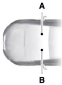
natural_image
Close-up of a transparent U-shaped object with two vertical lines labeled A and B, no text or symbols present.E154903
Right-hand side.A
Left-hand side.B
SYMBOLS GLOSSARY
These are some of the symbols you may see on your vehicle.
Air conditioning system
Air conditioning system lubricant type
Introduction

Anti-lock braking system

Avoid smoking, flames or sparks

Battery

Battery acid

Brake fluid - non petroleum based

Brake system

Brake system

Cabin air filter

Check fuel cap

Child safety door lock or unlock

Child seat lower anchor

Child seat tether anchor

Cruise control

Do not open when hot

Engine air filter

Engine coolant

Engine coolant temperature

Engine oil

Explosive gas

Fan warning

Fasten seatbelt

Flammable

Front airbag

Front fog lamps

Fuel pump reset

Fuse compartment

Hazard flashers

Heated rear window
Introduction

Windshield defrosting system

Interior luggage compartment release

Jack

Keep out of reach of children

Lighting control

Low tire pressure warning

Maintain correct fluid level

Note operating instructions

Horn control

Panic alarm

Parking aid

Parking brake

Power steering fluid

Power windows front/rear

Power window lockout

Requires registered technician

Safety alert

See Owner's Manual

See Service Manual

Service engine soon

Passenger airbag activated

Passenger airbag deactivated

Side airbag

Shield the eyes

Stability control

Hill descent control

Trail control

Windshield wiping system
Introduction

Windshield wash and wipe
DATA RECORDING

WARNING: Do not connect
wireless plug-in devices to the data link connector. Unauthorized third parties could gain access to vehicle data and impair the performance of safety related systems. Only allow repair facilities that follow our service and repair instructions to connect their equipment to the data link connector.
We respect your privacy and are committed to protecting it. The information contained in this publication was correct at the time of going to print but as technology rapidly changes, we recommend that you visit the regional Lincoln website for the latest information.
Your vehicle has electronic control units that have data recording functionality and the ability to permanently or temporarily store data. This data could include information on the condition and status of your vehicle, vehicle maintenance requirements, events and malfunctions. The types of data that can be recorded are described in this section. Some of the data recorded is stored in event logs or error logs.
Note: Error logs are reset following a service or repair.
Note: We may provide information in response to requests from law enforcement, other government authorities and third parties acting with lawful authority or through a legal process. Such information could be used by them in legal proceedings.
Data recorded includes, for example:
- Operating states of system components, for example, fuel level, tire pressure and battery charge level.
- Vehicle and component status, for example, wheel speed, deceleration, lateral acceleration and seatbelt status.
- Events or errors in essential systems, for example, headlamps and brakes.
- System responses to driving situations, for example, airbag deployment and stability control.
- Environmental conditions, for example, temperature.
Some of this data, when used in combination with other information, for example, an accident report, damage to a vehicle or eyewitness statements, could be associated with a specific person.
Service Data
Service data recorders in your vehicle are capable of collecting and storing diagnostic information about your vehicle. This potentially includes information about the performance or status of various systems and modules in the vehicle, such as engine, throttle, steering or brake systems. In order to properly diagnose and service your vehicle, Lincoln Motor Company (Lincoln of Canada in Canada), and service and repair facilities may access or share among them vehicle diagnostic information received
Introduction
through a direct connection to your vehicle when diagnosing or servicing your vehicle. Additionally, Ford Motor Company (Ford of Canada, in Canada) may, where permitted by law, use vehicle diagnostic information for vehicle improvement or with other information we may have about you, for example, your contact information, to offer you products or services that may interest you. Data may be provided to our service providers such as part suppliers that may help diagnose malfunctions, and who are similarly obligated to protect data. We retain this data only as long as necessary to perform these functions or to comply with law. We may provide information where required in response to official requests to law enforcement or other government authorities or third parties acting with lawful authority or court order, and such information may be used in legal proceedings. For U.S. only (if equipped), if you choose to use connected apps and services, you consent that certain diagnostic information may also be accessed electronically by Ford Motor Company and Lincoln authorized service facilities, and that the diagnostic information may be used to provide services to you, personalizing your experience, troubleshoot, and to improve products and services and offer you products and services that may interest you, where permitted by law. For Canada only, for more information, please review the Lincoln of Canada privacy policy at www.Lincolncanada.com, including our U.S. data storage and use of service providers in other jurisdictions who may be subject to legal requirements in Canada, the United States and other countries applicable to them, for example, lawful requirements to disclose personal information to governmental authorities in those countries.
Event Data
This vehicle is equipped with an event data recorder. The main purpose of an event data recorder is to record, in certain crash or near crash-like situations, such as an airbag deployment or hitting a road obstacle; this data assist in understanding how a vehicle's systems performed. The event data recorder is designed to record data related to vehicle dynamics and safety systems for a short period of time, typically 30 seconds or less.
The event data recorder in this vehicle is designed to record such data as:
•How various systems in your vehicle were operating;
- Whether or not the driver and passenger seatbelts were buckled/fastened;
•How far (if at all) the driver was depressing the accelerator and/or the brake pedal; and
•How fast the vehicle was traveling; and
- Where the driver was positioning the steering wheel.
This data can help provide a better understanding of the circumstances in which crashes and injuries occur.
Introduction
Note: Event data recorder data is recorded by your vehicle only if a non-trivial crash situation occurs; no data is recorded by the event data recorder under normal driving conditions and no personal data or information (e.g., name, gender, age, and crash location) is recorded. However, other parties, such as law enforcement, could combine the event data recorder data with the type of personally identifying data routinely acquired during a crash investigation.
To read data recorded by an event data recorder, special equipment is required, and access to the vehicle or the event data recorder is needed. In addition to the vehicle manufacturer, other parties, such as law enforcement, that have such special equipment, can read the information if they have access to the vehicle or the event data recorder.
Comfort, Convenience and Entertainment Data
Your vehicle has electronic control units that have the ability to store data based on your personalized settings. The data is stored locally in the vehicle or on devices that you connect to it, for example, a USB drive or digital music player. You can delete some of this data and also choose whether to share it through the services to which you subscribe. See Settings (page 495).
Comfort and Convenience Data
Data recorded includes, for example:
- Seat and steering wheel position.
•Climate control settings. - Radio presets.
Entertainment Data
Data recorded includes, for example:
•Music, videos or album art.
- Contacts and corresponding address book entries.
•Navigation destinations.
Services That We Provide
If you use our services, we collect and use data, for example, account information, vehicle location and driving characteristics, that could identify you. We transmit this data through a dedicated, protected connection. We only collect and use data to enable your use of our services to which you have subscribed, with your consent or where permitted by law. For additional information, see the terms and conditions of the services to which you have subscribed.
Services That Third Parties Provide
We recommend that you review the terms and conditions and data privacy information for any services to which you subscribe. We take no responsibility for services that third parties provide.
Introduction
Vehicles With a Modem

The modem has a SIM. The modem was enabled when your vehicle was built and periodically sends messages to stay connected to the cell phone network, receive automatic software updates and send vehicle-related information to us, for example, diagnostic information. These messages could include information that identifies your vehicle, the SIM and the electronic serial number of the modem. Cell phone network service providers could have access to additional information, for example, cell phone network tower identification. For additional information about our privacy policy, visit www-connectedLincoln.com or refer to your local Lincoln website.
Note: The modem continues to send this information unless you disable the modem or stop the modem from sharing vehicle data by changing the modem settings. See Network Connectivity (page 437).
Note: The service can be unavailable or interrupted for a number of reasons, for example, environmental or topographical conditions and data plan coverage.
Note: To find out if your vehicle has a modem, visit www.ConnectedLincoln.com.
Vehicles With SYNC
Mobile Device Data
If you connect a mobile device to your vehicle, you can display data from your device on the touchscreen for example, music and album art. You can share your vehicle data with mobile apps on your device through the system. See Apps (page 492).
The mobile apps function operates by your connected device sending data to us in the United States. The data is encrypted and includes the vehicle identification number of your vehicle, the SYNC module serial number, odometer, enabled apps, usage statistics and debugging information. We
retain it only as long as necessary to provide the service, to troubleshoot, for continuous improvement and to offer you products and services that may be of interest to you according to your preferences and where allowed by law.
If you connect a cell phone to the system, the system creates a profile that links to that cell phone. The cell phone profile enables more mobile features and efficient operation. The profile contains, for example, data from your phonebook, read and unread text messages and call history, including history of calls when your cell phone was not connected to the system.
If you connect a media device, the system creates and retains a media device index of supported media content. The system also records a short diagnostic log of approximately 10 minutes of all recent system activity.
Introduction
The cell phone profile, media device index and diagnostic log remain in your vehicle unless you delete them and are generally accessible only in your vehicle when you connect your cell phone or media device. If you no longer plan to use the system or your vehicle, we recommend you use the master reset function to erase the stored information. See Settings (page 495).
System data cannot be accessed without special equipment and access to your vehicle's module.
For additional information about our privacy policy, refer to your local Lincoln website.
Note: To find out if your vehicle has connectivity technology, visit www-connectedLincoln.com.
Vehicles With an Emergency Call System
When the emergency call system is active, it may disclose to emergency services that your vehicle has been in a crash involving the deployment of an airbag or activation of the fuel pump shut-off. Certain versions or updates to the emergency call system may
also be capable of electronically or verbally disclosing to emergency services operators your vehicle location or other details about your vehicle or crash to assist emergency services operators to provide the most appropriate emergency services. If you do not want to disclose this information, do not activate the emergency call system.
Note: You cannot deactivate emergency call systems that are required by law.
PERCHLORATE
Certain components in your vehicle such as airbag modules, seatbelt pretensioners and remote control batteries may contain perchlorate material. Special handling may apply for service or vehicle end of life disposal.
For more information visit:
| Web Address |
| www.dtsc.ca.gov/hazard-ouswaste/perchlorate |
LINCOLN AUTOMOTIVE FINANCIAL SERVICES
Lincoln Automotive Financial Services offers a full range of financing and lease plans to help you acquire your vehicle. We are dedicated to providing answers, information and a truly extraordinary experience.
Use the options below to contact us with questions about your account or financing and we will respond promptly:
| Web Address |
| www.credit.lincoln.com |
Mail: Lincoln Automotive Financial Services
Introduction
P.O. Box 542000
Omaha, NE 68154-8000
REPLACEMENT PARTS RECOMMENDATION
We have built your vehicle to the highest standards using quality parts. We recommend that you demand the use of genuine Ford and Motorcraft parts whenever your vehicle requires scheduled maintenance or repair. You can clearly identify genuine Ford and Motorcraft parts by looking for the Ford, FoMoCo or Motorcraft branding on the parts or their packaging.
Scheduled Maintenance and Mechanical Repairs
One of the best ways for you to make sure that your vehicle provides years of service is to have it maintained in line with our recommendations using parts that conform to the specifications detailed in this Owner's Manual. Genuine Ford and Motorcraft parts meet or exceed these specifications.
Collision Repairs
We hope that you never experience a collision, but accidents do happen. Genuine Ford replacement collision parts meet our stringent requirements for fit, finish, structural integrity, corrosion protection and dent resistance. During vehicle development we validate that these parts deliver the intended level of protection as a whole system. A great way to know for sure you are getting this level of protection is to use genuine Ford replacement collision parts.
Warranty on Replacement Parts
Genuine Ford and Motorcraft replacement parts are the only replacement parts that benefit from a Lincoln Warranty. Damage caused to your vehicle as a result of the failure of non-Ford parts may not be covered by the Lincoln Warranty. For additional information, refer to the terms and conditions of the Lincoln Warranty.
SPECIAL NOTICES
New Vehicle Limited Warranty
Vehicles sold in the United States and Canada
For a detailed description of what is covered by your New Vehicle Limited Warranty, see your warranty guide that is available online. For more information, refer to our website and download your copy of the warranty guide.
Vehicles sold outside the United States and Canada
For a detailed description of what is covered by your New Vehicle Limited Warranty, see the warranty guide that is provided to you along with your Owner's Manual.
Special Instructions
For your added safety, your vehicle is fitted with sophisticated electronic controls.
Introduction

WARNING: You risk death or injury to yourself and others if you follow the instruction highlighted warning symbol. Failure to follow specific warnings and instructions result in personal injury.

WARNING: NEVER use a rearward child restraint on a seat protected ACTIVE AIRBAG in front of it, DEATH OUS INJURY to the CHILD can
On Board Diagnostics Data Link Connector

WARNING: Do not connect
wireless plug-in devices to the data link connector. Unauthorized third parties could gain access to vehicle data and impair the performance of safety related systems. Only allow repair facilities that follow our service and repair instructions to connect their equipment to the data link connector.
Your vehicle has an OBD Data Link Connector (DLC) that is used in conjunction with a diagnostic scan tool for vehicle diagnostics, repairs and reprogramming services. Installing an aftermarket device that uses the DLC during normal driving for purposes such as remote insurance company monitoring, transmission of vehicle data to other devices or entities, or altering the performance of the vehicle, may cause
interference with or even damage to vehicle systems. We do not recommend or endorse the use of aftermarket plug-in devices unless approved by Ford. The vehicle Warranty will not cover damage caused by an aftermarket plug-in device.
MOBILE COMMUNICATIONS EQUIPMENT

WARNING: Driving while
distracted can result in loss of vehicle control, crash and injury. We strongly recommend that you use extreme caution when using any device that may take your focus off the road. Your primary responsibility is the safe operation of your vehicle. We recommend against the use of any hand-held device while driving and encourage the use of voice-operated systems when possible. Make sure you are aware of all applicable local laws that may affect the use of electronic devices while driving.
Introduction
Using mobile communications equipment is becoming increasingly important in the conduct of business and personal affairs. However, you must not compromise your own or others' safety when using such equipment. Mobile communications can enhance personal safety and security when appropriately used, particularly in emergency situations. Safety must be paramount when using mobile communications equipment to avoid negating these benefits. Mobile communication equipment includes, but is not limited to, cellular phones, pagers, portable email devices, text messaging devices and portable two-way radios.
EXPORT UNIQUE OPTIONS
For your particular global region, your vehicle may be equipped with features and options that are different from the features and options that are described in this Owner's Manual. A market unique supplement may be supplied that complements this book. By referring to the market unique supplement, if provided, you can properly identify those features, recommendations and
specifications that are unique to your vehicle. This Owner's Manual is written primarily for the U.S. and Canadian Markets. Features or equipment listed as standard may be different on units built for export. Refer to this Owner's Manual for all other required information and warnings.
Environment
PROTECTING THE ENVIRONMENT
You should play your part in protecting the environment. Correct vehicle usage and the authorized disposal of waste, cleaning and lubrication materials are significant steps toward this aim.
For details about Ford Motor Company's sustainability progress and initiatives visit:
| Web Address |
| www.sustainability.ford.com |
At a Glance
INSTRUMENT PANEL
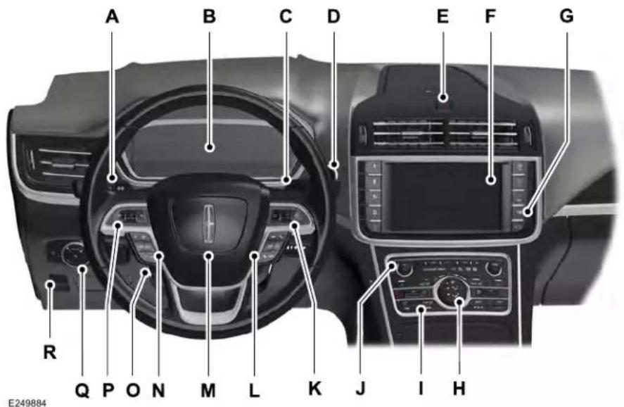
text_image
A B C D E F G R Q P O N M L K J I H E249884At a Glance
Direction indicators. See Direction Indicators (page 104).A
Instrument cluster. See Instrument Cluster (page 116).B
Wiper lever. See Windshield Wipers (page 97).C
Start button. See Keyless Starting (page 185).D
Hazard warning flasher switch. See Hazard Flashers (page 294).E
Information and entertainment display.F
Parking aid switch. See Parking Aids (page 228).G
Climate controls. See Climate Control (page 153).H
Heated rear window switch. See Heated Rear Window (page 158).
Audio unit.J
Voice control. See Voice Control (page 95).K
Information display controls. See Information Display Control (page 95).L
Horn.M
Cruise control switches. See Using Adaptive Cruise Control (page 249).N
O Steering wheel adjustment. See Adjusting the Steering Wheel (page 93).
P Audio controls. See Audio Control (page 94).
Q Lighting control. See Lighting Control (page 100).
R Parking brake. See Electric Parking Brake (page 220).
Child Safety
GENERAL INFORMATION
See the following sections for directions on how to properly use safety restraints for children.

WARNING: Always make sure your
child is secured properly in a device that is appropriate for their height, age and weight. Child safety restraints must be bought separately from your vehicle. Failure to follow these instructions and guidelines may result in an increased risk of serious injury or death to your child.

WARNING: All children are shaped differently. The National Highway Traffic Safety Administration and other safety organizations, base their recommendations for child restraints on probable child height, age and weight thresholds, or on the minimum requirements of the law. We recommend that you check with a NHTSA Certified Child Passenger Safety Technician (CPST) to make sure that you properly install the child restraint in your vehicle and that you consult your pediatrician to make sure you have a child restraint appropriate for your child. To locate a child restraint fitting station and CPST, contact NHTSA toll free at
1-888-327-4236 or go to
www.nhtsa.dot.gov. In Canada, contact Transport Canada toll free at
1-800-333-0371 or go to www.tc.gc.ca to find a Child Car Seat Clinic in your area.
Failure to properly restrain children in child restraints made especially for their height, age and weight, may result in an increased risk of serious injury or death to your child.

WARNING: On hot days, the
temperature inside the vehicle can rise very quickly. Exposure of people or animals to these high temperatures for even a short time can cause death or serious heat related injuries, including brain damage. Small children are particularly at risk.
Child Safety
Recommendations for Safety Restraints for Children
| Recommended Restraint TypeChild Size, Height, W | ||
| Infants or toddlers | Children weighing 40 lb (18 kg) or less (generally age four or younger). | Use a child restraint (sometimes called an infant carrier, convertible seat, or toddler seat). |
| Small children | Children who have outgrown or no longer properly fit in a child restraint (generally children who are less than 57 in (1.45 m) tall, are greater than age four and less than age 12, and between 40 lb (18 kg) and 80 lb (36 kg) and upward to 100 lb (45 kg) if recommended by your child restraint manufacturer). | Use a belt-positioning booster seat. |
| Larger children | Children who have outgrown or no longer properly fit in a belt-positioning booster seat (generally children who are at least 57 in (1.45 m) tall or greater than 80 lb (36 kg) or 100 lb (45 kg) if recommended by child restraint manufacturer). | Use a vehicle seatbelt having the lap belt snug and low across the hips, shoulder belt centered across the shoulder and chest, and seat backrest upright. |
Child Safety
- You are required by law to properly use child restraints for infants and toddlers in the United States and Canada.
- Many states and provinces require that small children use approved booster seats until they reach age eight, a height of 57 in (1.45 m) tall, or 80 lb (36 kg). Check your local and state or provincial laws for specific requirements about the safety of children in your vehicle.
- When possible, properly restrain children 12 years of age and under in a rear seating position of your vehicle. Accident statistics suggest that children are safer when properly restrained in the rear seating positions than in a front seating position. See Front Passenger Sensing System (page 53).
- When installing a rear facing child restraint, adjust the vehicle seats to avoid interference between the child restraint and the vehicle seat in front of the child restraint.
CHILD SEATS
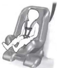
natural_image
Child wearing a car seatbelt and seatbelt, no visible text or symbolsE142594
Use a child safety seat (sometimes called an infant carrier, convertible seat, or toddler seat) for Infants, toddlers and children weighing 40 lb (18 kg) or less (generally four-years-old or younger).
INSTALLING CHILD RESTRAINTS
Using Lap and Shoulder Belts

WARNING: Airbags can kill or child in a child restraint. Never rear-facing child restraint in front active airbag. If you must use a l-facing child restraint in the front ove the seat upon which the child it is installed all the way back.

WARNING: Airbags can kill or child in a child restraint. Properly, children 12 and under in the rear whenever possible.
Child Safety

WARNING: Depending on where you secure a child restraint, and depending on the child restraint design, you may block access to certain seatbelt buckle assemblies and LATCH lower anchors, rendering those features potentially unusable. To avoid risk of injury, make sure occupants only use seating positions where they are able to be properly restrained.
When installing a child safety seat with combination lap and shoulder belts:
- Use the correct seatbelt buckle for that seating position.
- Insert the belt tongue into the proper buckle until you hear a snap and feel it latch. Make sure the tongue is securely fastened in the buckle.
-
Keep the buckle release button pointing up and away from the safety seat, with the tongue between the child seat and the release button, to prevent accidental unbuckling.
-
Place the vehicle seat upon which the child seat will be installed in the upright position.
- Put the seatbelt in the automatic locking mode. See Step 5. This vehicle does not require the use of a locking clip.
Perform the following steps when installing the child restraint with combination lap and shoulder belts:
Note: Although the child restraint illustrated is a forward facing child restraint, the steps are the same for installing a rear facing child restraint.
Standard Seatbelts
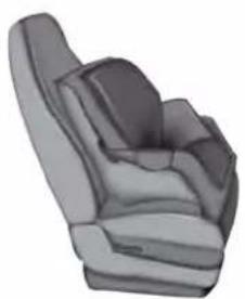
natural_image
3D rendered illustration of a car seat with visible seat covers and frontrest (no text or symbols)E142528
- Position the child safety seat in a seat with a combination lap and shoulder belt.
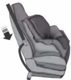
natural_image
3D rendering of a car seat with a visible seatbelt and side arm (no text or symbols)- After positioning the child safety seat in the proper seating position, pull down on the shoulder belt and then grasp the shoulder belt and lap belt together behind the belt tongue.
Child Safety
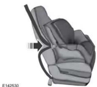
natural_image
3D rendering of a car seat assembly with a black belt and orange arrow indicating a specific seat (no text or symbols)- While holding the shoulder and lap belt portions together, route the tongue through the child restraint according to the child restraint manufacturer's instructions. Be sure the belt webbing is not twisted.
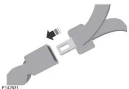
natural_image
3D illustration of a seatbelt buckle with a black arrow indicating fastening (no text or symbols)- Insert the belt tongue into the proper buckle (the buckle closest to the direction the tongue is coming from) for that seating position until you hear a snap and feel the latch engage. Make sure the tongue is latched securely by pulling on it.
natural_image
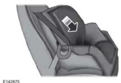
3D mechanical component diagram showing a curved surface with an arrow indicating direction (no text or symbols)- To put the retractor in the automatic locking mode, grasp the shoulder portion of the belt and pull downward until you pull all of the belt out.
Note: The automatic locking mode is available on the front passenger and rear seats.
- Allow the belt to retract to remove slack. The belt clicks as it retracts to indicate it is in the automatic locking mode.
Child Safety
- Try to pull the belt out of the retractor to make sure the retractor is in the automatic locking mode (you should not be able to pull more belt out). If the retractor is not locked, unbuckle the belt and repeat Steps 5 and 6.
natural_image
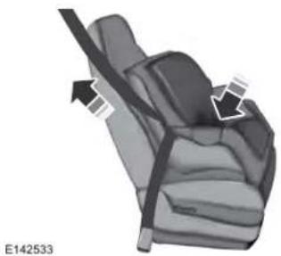
Car seatbelt diagram showing two arrows indicating seat movement (no text or symbols)- Remove remaining slack from the belt. Force the seat down with extra weight, for example, by pressing down or kneeling on the child restraint while pulling up on the shoulder belt in order to force slack from the belt. This is necessary to remove the remaining slack that will exist once the extra weight of
the child is added to the child restraint. It also helps to achieve the proper snugness of the child restraint to your vehicle. Sometimes, a slight lean toward the buckle will provide extra help to remove remaining slack from the belt.
- Attach the tether strap (if the child restraint is equipped).
natural_image
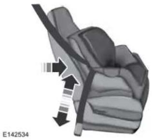
3D illustration of a car seatbelt with arrows indicating force or movement (no text or symbols)- Before placing the child in the seat, forcibly move the seat forward and back to make sure the seat is securely held in place. To check this, grab the seat at the belt path and attempt to move it side to side and forward and back. There should be no more than 1 in (2.5 cm) of movement for proper installation.
We recommend checking with a NHTSA Certified Child Passenger Safety Technician to make certain the child restraint is properly installed. In Canada, check with Transport Canada for referral to a Child Car Seat Clinic.
Child Safety
Inflatable Seatbelts
natural_image
3D rendered image of a car seat with visible ribs and seat layers (no text or symbols)E142528
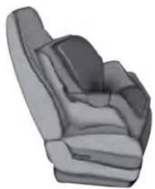
1. Position the child safety seat in a seat with a combination lap and shoulder belt.
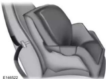
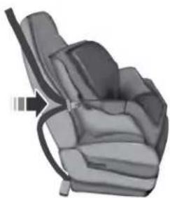
natural_image
3D rendered illustration of a car seat assembly (no text or symbols visible)- After positioning the child safety seat in the proper seating position, grasp the shoulder belt and lap belt together behind the belt tongue.
natural_image
3D illustration of a car seatbelt with a black arrow pointing to the seat (no text or symbols)E142530
3. While holding the shoulder and lap belt portions together, route the tongue through the child restraint according to the child restraint manufacturer's instructions. Be sure the belt webbing is not twisted.
Child Safety
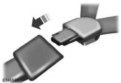
natural_image
3D illustration of a mechanical belt buckle assembly with a highlighted section (no text or symbols)- Insert the belt tongue into the proper buckle (the buckle closest to the direction the tongue is coming from) for that seating position until you hear a snap and feel the latch engage. Make sure the tongue is latched securely by pulling on it.
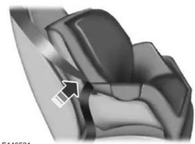
natural_image
3D rendered mechanical component with an arrow pointing to a section (no text or symbols visible)E146524
- To put the retractor in the automatic locking mode, grasp the lap portion of the inflatable seatbelt and pull upward until you pull all of the belt out.
Note: The automatic locking mode is available on the front passenger and rear seats.
Note: Unlike the standard seatbelt, the inflatable seatbelt's unique lap portion locks the child restraint for installation. The ability for the shoulder portion of the belt to move freely is normal, even after you put the lap belt into the automatic locking mode.
Note: The lock-off device on some child restraints may not accommodate the shoulder portion of the inflatable seatbelt. Follow all instructions provided by the manufacturer of the child restraint regarding the necessary and proper use of the lock-off device. In some instances, these devices have been provided only for use in vehicles with seatbelt systems that would otherwise require a locking clip.
-
Allow the belt to retract to remove slack. The belt clicks as it retracts to indicate it is in the automatic locking mode.
-
Try to pull the belt out of the retractor to make sure the retractor is in the automatic locking mode (you should not be able to pull more belt out). If the retractor is not locked, unbuckle the belt and repeat Steps 5 and 6.
Child Safety
natural_image
3D rendered mechanical component with two downward arrows indicating a process or assembly (no text or symbols)-
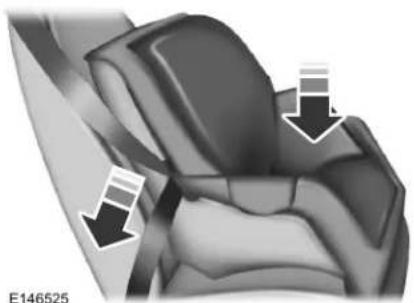
Remove remaining slack from the belt. Force the seat down with extra weight, for example, by pressing down or kneeling on the child restraint while pulling down on the lap belt in order to force slack from the belt. This is necessary to remove the remaining slack that will exist once the extra weight of the child is added to the child restraint. It also helps to achieve the proper snugness of the child restraint to your vehicle. Sometimes, a slight lean toward the buckle will additionally help to remove remaining slack from the belt.
-
Attach the tether strap (if the child restraint is equipped).
natural_image
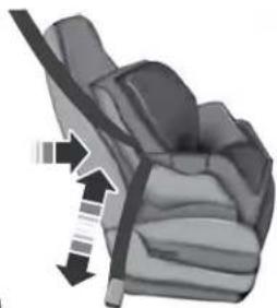
Diagram of a car seat with a belt and directional arrows indicating motion (no text or symbols)- Before placing the child in the seat, forcibly move the seat forward and back to make sure the seat is securely held in place. To check this, grab the seat at the belt path and attempt to move it side to side and forward and back. There should be no more than 1 in (2.5 cm) of movement for proper installation.
We recommend checking with a NHTSA Certified Child Passenger Safety Technician to make certain the child restraint is properly installed. In Canada, check with Transport Canada for referral to a Child Car Seat Clinic.
Using Lower Anchors and Tethers for CHildren (LATCH)

WARNING: Do not attach two child
safety restraints to the same anchor. In a crash, one anchor may not be strong enough to hold two child safety restraint attachments and may break, causing serious injury or death.
Child Safety

WARNING: Depending on where you secure a child restraint, and depending on the child restraint design, you may block access to certain seatbelt buckle assemblies and LATCH lower anchors, rendering those features potentially unusable. To avoid risk of injury, make sure occupants only use seating positions where they are able to be properly restrained.
The LATCH system is composed of three vehicle anchor points: two lower anchors where the seatback and seat cushion meet (called the seat bight) and one top tether anchor behind that seating position.
LATCH compatible child safety seats have two rigid or webbing mounted attachments that connect to the two lower anchors at the LATCH equipped seating positions in your vehicle. This type of attachment method eliminates the need to use seatbelts to attach
the child restraint, however the seatbelt can still be used to attach the child restraint. For forward-facing child restraints, you must also attach the top tether strap to the proper top tether anchor, if a top tether strap has been provided with your child restraint.
natural_image
Pure electrical circuit lines without any symbolsE142535
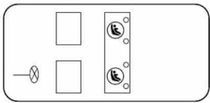
Your vehicle has LATCH lower anchors for child restraint installation at the seating positions marked with the child restraint symbol.
natural_image
Interior view of a vehicle showing two circular icons with ' airplane' symbols and an upward arrow, no text or labels present.E144054
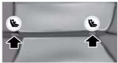
The LATCH anchors are at the rear section of the rear seat between the cushion and seatback below the symbols as shown. Follow the child restraint manufacturer's instructions to properly install a child restraint with LATCH attachments. Follow the instructions on attaching child safety seats with tether straps.
Attach LATCH lower attachments of the child restraint only to the anchors shown.
Child Safety
Use of Inboard Lower Anchors from the Outboard Seating Positions (Center Seating Use)

WARNING: The standardized f for LATCH lower anchors is 11 in m) center to center. Do not use lower anchors for the center position unless the child restraint acturer's instructions permit and using anchors spaced at least as t as those in this vehicle.
The lower anchors at the center of the second row rear seat are spaced 18 in (46 cm) apart. You cannot install a child restraint with rigid LATCH attachments at the center seating position. You can only use LATCH compatible child restraints (with attachments on belt webbing) at this seating position provided that the child restraint manufacturer's instructions permit use with the anchor spacing stated. Do not attach a child restraint to any lower anchor if an adjacent child restraint is attached to that anchor.
Each time you use the safety seat, check that the seat is properly attached to the lower anchors and tether anchor, if applicable. Tug the child restraint from side to side and forward and back where it is secured to your vehicle. The seat should move less than one inch when you do this for a proper installation.
If the safety seat is not anchored properly, the risk of a child being injured in a crash greatly increases.
Combining Seatbelt and LATCH Lower Anchors for Attaching Child Safety Seats
When used in combination, either the seatbelt or the LATCH lower anchors may be attached first, provided a proper installation is achieved. Attach the tether strap afterward, if included with the child restraint.
Using Tether Straps

Many forward-facing child safety seats include a tether strap which extends from the back of the child safety seat and hooks to an anchoring point called the top tether anchor. Tether straps are available as an accessory for many older safety seats.
Contact the manufacturer of your child restraint for information about ordering a tether strap, or to obtain a longer tether strap if the tether strap on your safety seat does not reach the appropriate top tether anchor in your vehicle.
Once the child safety seat has been installed using either the seatbelt, the lower anchors of the LATCH system, or both, you can attach the top tether strap.
The tether strap anchors in your vehicle are in the following positions (shown from top view):
Child Safety

natural_image
Pure electrical circuit lines without any symbolsE142537
Perform the following steps to install a child safety seat with tether anchors:
Note: If you install a child restraint with rigid LATCH attachments, do not tighten the tether strap enough to lift the child restraint off your vehicle seat cushion when the child is seated in it. Keep the tether strap just snug without lifting the front of the child restraint. Keeping the child restraint just touching your vehicle seat gives the best protection in a severe crash.
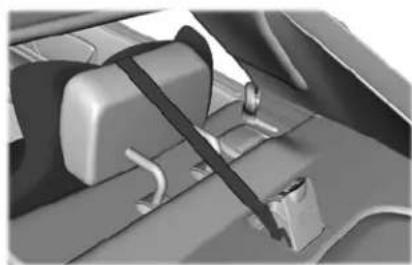
- Route the child safety seat tether strap over the head restraint.
natural_image
Interior view of a car seatbelt with visible seatbelt and seatbelt buckle (no text or symbols)E225547
- Locate the correct anchor for the selected seating position.
- Open the tether anchor cover.
- Clip the tether strap to the anchor.
- Tighten the child safety seat tether strap according to the manufacturer's instructions.
If your child restraint system has a tether strap, and the child restraint manufacturer recommends its use, we also recommend its use.
BOOSTER SEATS

WARNING: Do not put the shoulder section of the seatbelt or allow the child to put the shoulder section of the seatbelt under their arm or behind their back.
Failure to follow this instruction could reduce the effectiveness of the seatbelt and increase the risk of injury or death in a crash.
Note: Some booster seat seatbelt guides may not accommodate the shoulder portion of the inflatable seatbelt.
Use a belt-positioning booster seat for children who have outgrown or no longer properly fit in a child safety seat (generally children who are less than 57 in (1.45 m) tall, are greater than age four (4) and less than age twelve (12), and between 40 lb (18 kg) and 80 lb (36 kg) and upward to 100 lb
Child Safety
(45 kg) if recommended by your child restraint manufacturer). Many state and provincial laws require that children use approved booster seats until they reach age eight, a height of 57 in (1.45 m) tall, or 80 lb (36 kg).
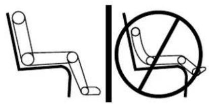
Booster seats should be used until you can answer YES to ALL of these questions when seated without a booster seat:
text_image
Diagram showing two types of vehicle door seat rules: one with a diagonal line and another with a circle and diagonal line crossed out by a diagonal line.E142595
- Can the child sit all the way back against their vehicle seat backrest with knees bent comfortably at the edge of the seat cushion?
- Can the child sit without slouching?
- Does the lap belt rest low across the hips?
•Is the shoulder belt centered on the shoulder and chest?
- Can the child stay seated like this for the whole trip?
Always use booster seats in conjunction with your vehicle lap and shoulder belt.
Types of Booster Seats
natural_image
Silhouette of a seated person holding a long object, possibly a pole or tool, in a simple outdoor setting (no text or symbols)E68924
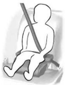
- Backless booster seats
If your backless booster seat has a removable shield, remove the shield. If a vehicle seating position has a low seat backrest or no head restraint, a backless booster seat may place your child's head (as measured at the tops of the ears) above the top of the seat. In this case, move the backless booster to another seating position with a higher seat backrest or head restraint and lap and shoulder belts, or consider using a high back booster seat.
natural_image
Silhouette of a person sitting in a seat with a backbelt, no text or symbols visibleE70710
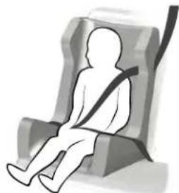
•High back booster seats
Child Safety
If, with a backless booster seat, you cannot find a seating position that adequately supports your child's head, a high back booster seat would be a better choice.
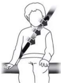
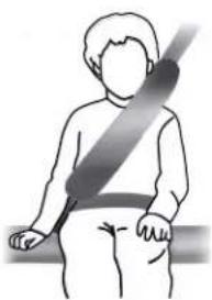
Children and booster seats vary in size and shape. Choose a booster that keeps the lap belt low and snug across the hips, never up across the stomach, and lets you adjust the shoulder belt to cross the chest and rest snugly near the center of the shoulder. The
following drawings compare the ideal fit (center) to a shoulder belt uncomfortably close to the neck and a shoulder belt that could slip off the shoulder. The drawings also show how the lap belt should be low and snug across the child's hips.
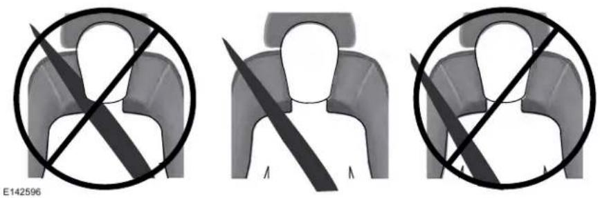
text_image
E142596Child Safety
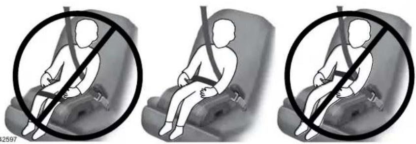
natural_image
Three illustrations showing a person seated in a car seat with a diagonal line indicating no movement or restriction (no text or symbols present)If the booster seat slides on the vehicle seat upon which it is being used, placing a rubberized mesh sold as shelf or carpet liner under the booster seat may improve this condition. Do not introduce any item thicker than this under the booster seat. Check with the booster seat manufacturer's instructions.
CHILD RESTRAINT POSITIONING
WARNING: Do not place a rearward facing child restraint in front of an active airbag. Failure to follow this instruction could result in personal injury or death.
WARNING: Properly secure children 12 years old and under in a rear seating position whenever possible. If you are unable to properly secure all children in a rear seating position, properly secure the largest child on the front seat. If you must use a forward facing child restraint on the front seat, move the seat as far back as possible. Failure to follow these instructions could result in personal injury or death.
Child Safety

WARNING: Always carefully follow the instructions and warnings provided by the manufacturer of any child restraint to determine if the restraint device is appropriate for your child's size, height, weight, or age. Follow the child restraint manufacturer's instructions and warnings provided for installation and use in conjunction with the instructions and warnings provided by your vehicle manufacturer. A safety seat that is improperly installed or utilized, is inappropriate for your child's height, age, or weight or does not properly fit the child may increase the risk of serious injury or death.

WARNING: Do not allow a passenger to hold a child on their lap when your vehicle is moving. Failure to follow this instruction could result in personal injury or death in the event of a sudden stop or crash.

WARNING: Do not use pillows, books or towels to boost your child's height. Failure to follow this instruction could result in personal injury or death.

WARNING: Properly secure child restraints or booster seats when they are not in use. They could become projectiles in a sudden stop or crash. Failure to follow this instruction could result in personal injury or death.

WARNING: Do not put the shoulder section of the seatbelt or allow the child to put the shoulder section of the seatbelt under their arm or behind their back. Failure to follow this instruction could reduce the effectiveness of the seatbelt and increase the risk of injury or death in a crash.

WARNING: Do not leave children or pets unattended in your vehicle. Failure to follow this instruction could result in personal injury or death.
Child Safety
Recommendations for Attaching Child Safety Restraints for Children
| Restraint Type | Combined Weight of Child and Child Restraint | Use Any Attachment Method as Indicated Below by X | ||||
| LATCH (Lower Anchors and Top Tether Anchor) | LATCH (Lower Anchors Only) | Seatbelt and Top Tether Anchor | (Lower Anchors and Top Tether Anchor) | Seatbelt Only Seatbelt a | ||
| Rear facing child restraint | Up to 65 lb (29.5 kg) | X | X | |||
| Rear facing child restraint | Over 65 lb (29.5 kg) | X | ||||
| Forward facing child restraint | Up to 65 lb (29.5 kg) | X | X | X | ||
| Forward facing child restraint | Over 65 lb (29.5 kg) | X | X | |||
Note: The child restraint must rest tightly against the vehicle seat upon which it is installed. It may be necessary to lift or remove the head restraint. See Seats (page 160).
CHILD SAFETY LOCKS
The child safety lock controls are on the driver door.
When these locks are set, the rear doors cannot be opened from the inside.
Child Safety
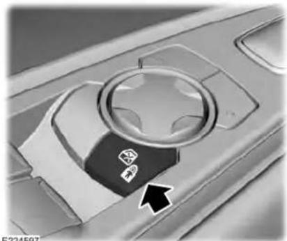
natural_image
Close-up of a car interior panel with a star-shaped knob and directional arrow (no text or symbols)Press the control to engage or disengage the child lockout feature. It will illuminate when you engage this feature.
The child lock setting remains on when you turn the ignition off.
Seatbelts
WARNING: Always drive and ride
with your seatback upright and the lap belt snug and low across the hips.

WARNING: Children must always
be properly restrained.

WARNING: Never let a passenger
hold a child on his or her lap while the vehicle is moving. The passenger cannot protect the child from injury in a crash.

WARNING: All occupants of your
vehicle, including the driver, should always properly wear their seatbelts, even when an airbag supplemental restraint system is provided. Failure to properly wear your seatbelt could seriously increase the risk of injury or death.

WARNING: It is extremely
dangerous to ride in a cargo area, inside or outside of a vehicle. In a crash, people riding in these areas are more likely to be seriously injured or killed. Do not allow people to ride in any area of your vehicle that is not equipped with seats and seatbelts. Make sure everyone in your vehicle is in a seat and properly using a seatbelt. Failure to follow this warning could result in serious personal injury or death.

WARNING: In a rollover crash, an unbelted person is significantly more likely to die than a person wearing a seatbelt.

WARNING: Each seating position in your vehicle has a specific seatbelt assembly made up of one buckle and one tongue designed to be used as a pair. Use the shoulder belt on the outside shoulder only. Never wear the shoulder belt under the arm. Never use a single seatbelt for more than one person.

WARNING: Even with advanced restraints systems, properly restrain children 12 and under in a rear seating position. Failure to follow this could seriously increase the risk of injury or death.

WARNING: Seatbelts and seats may be hot in a vehicle that is in the sunshine. The hot seatbelts or seats may burn a small child. Check seat covers and buckles before you place a child anywhere near them.
Seatbelts
All seating positions in your vehicle have lap and shoulder seatbelts. All occupants of the vehicle should always properly wear their seatbelts, even when an airbag supplemental restraint system is provided.
The seatbelt system consists of:
•Lap and shoulder seatbelts.
- Shoulder seatbelt with automatic locking mode, (except driver seatbelt and rear inflatable seatbelt).
- Height adjuster at the front outboard seating positions.
- Seatbelt pretensioner at the front outboard seating positions.
- Belt tension sensor at the front outboard passenger seating position.

- Seatbelt warning light and chime.

- Crash sensors and monitoring system with readiness indicator.
The seatbelt pretensioners and rear inflatable seatbelts are designed to activate in frontal, near-frontal and side crashes, and in rollovers. The seatbelt pretensioners at the front seating positions are designed to tighten the seatbelts firmly against the occupant's body when activated. This helps increase the effectiveness of the seatbelts. In frontal crashes, the seatbelt pretensioners can be activated alone or, if the crash is of sufficient severity, together with the front airbags.
FASTENING THE SEATBELTS
Standard belts shown, inflatable belts similar The front outermost and rear safety restraints in the vehicle are combination lap and shoulder belts.
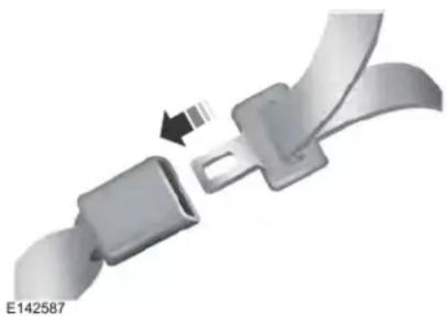
natural_image
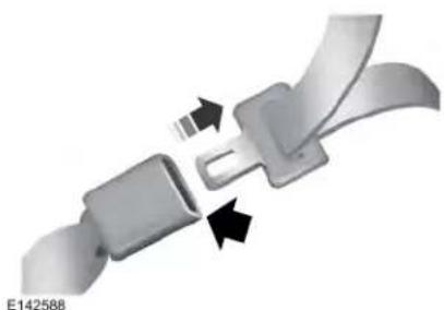
Close-up of a metallic belt buckle with a black arrow indicating fastening (no text or symbols)- Insert the belt tongue into the proper buckle (the buckle closest to the direction the tongue is coming from) until you hear a snap and feel it latch. Make sure you securely fasten the tongue in the buckle.
Seatbelts
natural_image
Close-up of a metallic belt buckle with two black arrows indicating fastening or disassembly (no text or symbols)- To unfasten, press the release button and remove the tongue from the buckle.
Using Seatbelts During Pregnancy

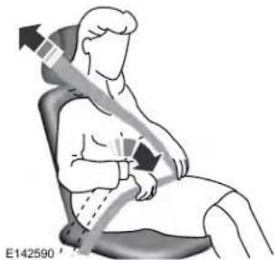
WARNING: Always ride and drive with your seatback upright and properly fasten your seatbelt. Fit the lap portion of the seatbelt snugly and low across the hips. Position the shoulder portion of the seatbelt across your chest. Pregnant women must follow this practice. See the following figure.
natural_image
Illustration of a person seated in a chair with a belt and arrow indicating direction (no text or symbols)Pregnant women should always wear their seatbelt. Position the lap belt portion of a combination lap and shoulder belt low across the hips below the belly and worn as tight as comfort allows. Position the shoulder belt to cross the middle of the shoulder and the center of the chest.
Seatbelt Locking Modes

WARNING: If your vehicle is
involved in a crash, have the seatbelts and associated components inspected as soon as possible. Failure to follow this instruction could result in personal injury or death.
All safety restraints in the vehicle are combination lap and shoulder belts. The driver seatbelt has the vehicle sensitive locking mode. The front outboard passenger and rear seat seatbelts have both the vehicle sensitive locking mode and the automatic locking mode.
Seatbelts
Vehicle Sensitive Mode
This is the normal retractor mode, which allows free shoulder belt length adjustment to your movements and locking in response to vehicle movement. For example, if the driver brakes suddenly or turns a corner sharply, or the vehicle receives an impact of about 5 mph (8 km/h) or more, the combination seatbelts lock to help reduce forward movement of the driver and passengers.
In addition, the retractor is designed to lock if you pull the webbing out too quickly. If the seatbelt retractor locks, slowly lower the height adjuster to allow the seatbelt to retract. If the retractor does not unlock, pull the seatbelt out slowly then feed a small length of webbing back toward the stowed position. For rear seatbelts, recline the rear seat backrest or push the seat backrest cushion away from the seatbelt. Feed a small length of webbing back toward the stowed position.
Automatic Locking Mode
In this mode, the shoulder belt automatically pre-locks. The belt still retracts to remove any slack in the shoulder belt. The automatic locking mode is not available on the driver seatbelt.
When to Use the Automatic Locking Mode
Use this mode any time you install a child restraint, except a booster, in passenger front or rear seating positions. Properly restrain children 12 years old and under in a rear seating position whenever possible. See Child Safety (page 21).
How to Use the Automatic Locking Mode
Standard Seatbelts
E142591
natural_image
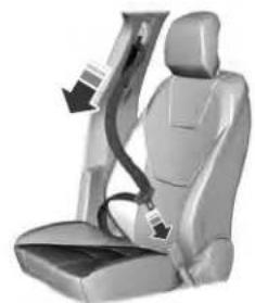
Car seatbelt buckle with black arrow indicating seatbelt (no text or symbols)- Buckle the combination lap and shoulder belt.
- Grasp the shoulder portion and pull downward until you pull the entire belt out. As the belt retracts, you will hear a clicking sound. This indicates the seatbelt is now in the automatic locking mode.
Rear Outermost Inflatable Seatbelts (If Equipped)
Seatbelts
natural_image
Side view of a car seatbelt with a belt buckle (no text or symbols)E146363
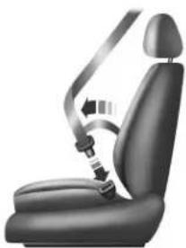
- Buckle the combination lap and shoulder belt.
- Grasp the lap portion of the belt and pull upward until you pull the entire belt out.
- Allow the belt to retract. As the belt retracts, you will hear a clicking sound. This indicates the seatbelt is now in the automatic locking mode.
How to Disengage the Automatic Locking Mode
Unbuckle the combination lap and shoulder belt and allow it to retract completely to disengage the automatic locking mode and activate the vehicle sensitive (emergency) locking mode.
Rear Inflatable Seatbelt (If Equipped)

WARNING: Do not attempt to
service, repair, or modify the supplementary restraint system or associated components. Failure to follow this instruction could result in personal injury or death.
The rear inflatable seatbelts are in the shoulder portion of the seatbelts of the second-row outermost seating positions.
Note: The rear inflatable seatbelts are compatible with most infant and child safety car seats and belt positioning booster seats when properly installed. This is because they are designed to fill with a cooled gas at a lower pressure and at a slower rate than traditional airbags. After inflation, the shoulder portion of the seatbelt remains cool to the touch.
The rear inflatable seatbelt consists of the following:
- An inflatable bag in the shoulder seatbelt webbing.
- Lap seatbelt webbing with automatic locking mode.
•The same warning light, electronic control and diagnostic unit as used for the front seatbelts. - Impact sensors in various parts of the vehicle.
Seatbelts
How does the rear inflatable seatbelt system work?

WARNING: If a supplementary
restraint system component has deployed, it will not function again. Have the system and associated components inspected as soon as possible. Failure to follow this instruction could result in personal injury or death.
The rear inflatable seatbelts function like standard restraints in everyday usage.
natural_image
Illustration of a person sitting on a bench with a lightning bolt symbol indicating pressure or stress (no text or labels)E146364
During a crash of sufficient force, the inflatable belt inflates from inside the webbing.
natural_image
Illustration of a person sitting with a bandage, showing body posture (no text or symbols)E146365
The fully inflated belt's increased diameter more effectively holds the occupant in the appropriate seating position, and spreads crash forces over more area of the body than regular seatbelts. This helps reduce pressure on the chest and helps control head and neck motion for passengers.
The rear inflatable seatbelts are designed to inflate in frontal or near-frontal crashes and some side impact crashes and rollovers. The fact that the rear inflatable seatbelt did not inflate in a crash does not mean that something is wrong with the system. Rather, it means the forces were not of the type sufficient to cause activation.
SEATBELT HEIGHT ADJUSTMENT

WARNING: Position the safety belt adjusters so that the belt rests the middle of your shoulder. Failure at the safety belt properly could the effectiveness of the safety belt rease the risk of injury in a crash.
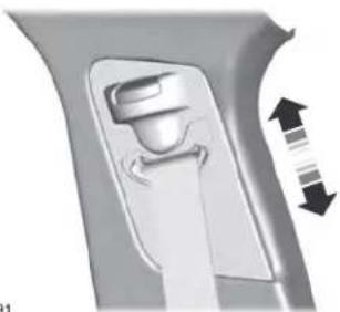
Adjust the height of the shoulder belt so the belt rests across the middle of your shoulder.
Seatbelts
natural_image
3D rendered mechanical component with directional arrows indicating movement or force (no text or symbols)E146191
To adjust the shoulder belt height:
- Press the button and slide the height adjuster up or down.
- Release the button and pull down on the height adjuster to make sure it is locked in place.
SEATBELT WARNING LAMP AND INDICATOR CHIME

This lamp illuminates and an indicator chime will sound if the driver seatbelt has not been
fastened when the vehicle's ignition is turned on.
Conditions of operation
| Thenlf | |
| The driver seatbelt is not buckled before the ignition switch is turned to the on position... | The seatbelt warning lamp illuminates and the indicator chime sounds for a few seconds. |
| The driver seatbelt is buckled while the warning lamp is illuminated and the indicator chime is sounding... | The seatbelt warning lamp and indicator chime turn off. |
| The driver seatbelt is buckled before the ignition switch is turned to the on position... | The seatbelt warning lamp and indicator chime remain off. |
Seatbelts
SEATBELT REMINDER
Belt-Minder™
This feature supplements the safety belt warning function by providing additional reminders that intermittently sound a tone and illuminate the safety belt warning light when you are in the driver seat or you have a front seat passenger and a safety belt is
unbuckled.
The system uses information from the front passenger sensing system to determine if a front seat passenger is present and therefore potentially in need of a warning. To avoid activating the Belt-Minder feature for objects you place in the front passenger seat, only the front seat passengers receive warnings as determined by the front passenger sensing system.
If the Belt-Minder warnings expire (warnings for about five minutes) for one passenger (driver or front passenger), the other passenger can still cause the Belt-Minder feature to turn on.
| Then...If... | |
| You and the front seat passenger buckle your safety belts before you switch the ignition on or less than 1-2 minutes elapse after you switch the ignition on... | The Belt-Minder feature will not activate. |
| You or the front seat passenger do not buckle your safety belts before your vehicle reaches at least 6 mph (9.7 km/h) and 1-2 minutes elapse after you switch the ignition on... | The Belt-Minder feature activates, the safety belt warning light illuminates and a warning tone sounds for 6 seconds every 25 seconds, repeating for about 5 minutes or until you and the front seat passenger buckle your safety belts. |
| The safety belt for the driver or front passenger is unbuckled for about 1 minute while the vehicle is traveling at least 6 mph (9.7 km/h) and more than 1-2 minutes elapse after you switch the ignition on... | The Belt-Minder feature activates, the safety belt warning light illuminates and a warning tone sounds for 6 seconds every 25 seconds, repeating for about 5 minutes or until you and the front seat passenger buckle your safety belts. |
Seatbelts
Deactivating and Activating the Belt-Minder Feature

WARNING: While the system
allows you to deactivate it, this system is designed to improve your chances of being safely belted and surviving an accident. We recommend you leave the system activated for yourself and others who may use the vehicle.
Note: The driver and front passenger warnings switch on and off independently. When you perform this procedure for one seating position, do not buckle the other position as this will terminate the process.
Read Steps 1 - 4 thoroughly before proceeding with the programming procedure.
Before following the procedure, make sure that:
•The parking brake is set.
• The transmission is in park (P) or neutral (N).
•The ignition is off.
•The driver and front passenger safety belts are unbuckled.
- Switch the ignition on. Do not start the vehicle.
- Wait until the safety belt warning light turns off (about one minute). After Step 2, wait an additional 5 seconds before proceeding with Step 3. Once you start Step 3, you must complete the procedure within 30 seconds.
- For the seating position you are switching off, buckle then unbuckle the safety belt three times at a moderate speed, ending in the unbuckled state. After Step 3, the safety belt warning light turns on.
- While the safety belt warning light is on, buckle and then unbuckle the safety belt. After Step 4, the safety belt warning light flashes for confirmation.
- This will switch the feature off for that seating position if it is currently on.
- This will switch the feature on for that seating position if it is currently off.
CHILD RESTRAINT AND SEATBELT MAINTENANCE
Inspect the vehicle seatbelts and child restraint systems periodically to make sure they work properly and are not damaged. Inspect the vehicle seatbelts to make sure there are no nicks, tears or cuts. Replace if necessary. All vehicle seatbelt assemblies, including retractors, buckles, front seatbelt buckle assemblies, buckle support assemblies (slide bar-if equipped), shoulder belt height adjusters (if equipped), shoulder belt guide on seatback (if equipped), rear inflatable seatbelts (if equipped), child restraint LATCH and tether anchors, and attaching hardware, should be inspected after a crash. Read the child restraint manufacturer's instructions for additional inspection and maintenance information specific to the child restraint.
Seatbelts
We recommend that all seatbelt assemblies in use in vehicles involved in a crash be replaced. However, if the crash was minor and an authorized dealer finds that the belts do not show damage and continue to operate properly, they do not need to be replaced. Seatbelt assemblies not in use during a crash should also be inspected and replaced if either damage or improper operation is noted.
Properly care for seatbelts. See Cleaning the Interior (page 354).
SEATBELT EXTENSIONS

WARNING: Persons who fit into aicle's seatbelt should not use an on. Unnecessary use could result in us personal injury in the event of a

WARNING: Only use extensions and free of charge by Lincoln Motor, any dealers. The dealer will provide pension designed specifically for this model year and seating position. Use of an extension intended for vehicle, model year or seating may not offer you the full position of your vehicle's seatbelt system.

WARNING: Never use seatbelt ons to install child restraints.

WARNING: Do not use a seatbelt on with an inflatable seatbelt.

WARNING: Do not use extensions ge the fit of the belt across the ver the lap or to make the seatbelt easier to reach.
If, because of body size or driving position, it is not possible to properly fasten the seatbelt over your lap and shoulder, an extension that is compatible with the seatbelts is available free of charge from Lincoln Motor Company dealers. Only Lincoln seatbelt extensions made by the same company which made the original equipment seatbelts, should be used with Lincoln seatbelts. Ask your authorized dealer if your extension is compatible with your Lincoln vehicle restraint system.
Personal Safety System™
The Personal Safety System provides an improved overall level of frontal crash protection to front seat occupants and is designed to help further reduce the risk of airbag-related injuries. The system is able to analyze different occupant conditions and crash severity before activating the appropriate safety devices to help better protect a range of occupants in a variety of frontal crash situations.
The Vehicle Personal Safety System consists of:
- Driver and passenger dual-stage airbag supplemental restraints.
- Front seat outermost seatbelts with pretensioners, energy management retractors and seatbelt usage sensors.
- Driver seat position sensor.
- Passenger seat position sensor.
- Front passenger sensing system.
- Passenger airbag off and on indicators.
•Front crash severity sensors. -
Restraints control module with impact and safing sensors.
-
Restraint system warning lamp and tone.
• The electrical wiring for the airbags, crash sensors, seatbelt pretensioners, front seatbelt usage sensors, driver seat position sensor, front passenger sensing system and indicators.
How Does the Personal Safety System Work?
The Personal Safety System can adapt the deployment strategy of the safety devices according to crash severity and occupant conditions. A collection of crash and occupant sensors provides information to the restraints control module. During a crash, the restraints control module may deploy the seatbelt pretensioners, one or both stages of the dual-stage airbags based on crash severity and occupant conditions.
Supplementary Restraints System
WARNING: Airbags do not inflate or gently, and the risk of injury from flying airbag is the greatest close to a covering the airbag module.

WARNING: All occupants of your
vehicle, including the driver, should always properly wear their seatbelts, even when an airbag supplemental restraint system is provided. Failure to properly wear your seatbelt could seriously increase the risk of injury or death.

WARNING: Even with advanced
restraints systems, properly restrain children 12 and under in a rear seating position. Failure to follow this could seriously increase the risk of injury or death.

WARNING: Do not place your arms airbag cover or through the steering Failure to follow this instruction result in personal injury.

WARNING: Keep the areas in front airbags free from obstruction. Do x anything to or over the airbag Objects could become projectiles airbag deployment or in a sudden failure to follow this instruction could in personal injury or death.

WARNING: Airbags can kill or child in a child restraint. Never rear-facing child restraint in front active airbag. If you must use a d-facing child restraint in the front ove the seat upon which the child it is installed all the way back.

WARNING: Do not attempt to repair, repair, or modify the mandatory restraint system or related components. Failure to follow construction could result in personal or death.

WARNING: Several airbag system ments get hot after inflation. To the risk of injury, do not touch them flation.

WARNING: If a supplementary system component has deployed, not function again. Have the system associated components inspected as is possible. Failure to follow this action could result in personal injury.
Supplementary Restraints System
The airbags are a supplemental restraint system and are designed to work with the seatbelts to help protect the driver and right front passenger from certain upper body injuries. Airbags do not inflate slowly; there is a risk of injury from a deploying airbag.
Note: You will hear a loud bang and see a cloud of harmless powdery residue if an airbag deploys. This is normal.
The airbags inflate and deflate rapidly upon activation. After airbag deployment, it is normal to notice a smoke-like, powdery residue or smell the burnt propellant. This may consist of cornstarch, talcum powder (to lubricate the bag) or sodium compounds (for example, baking soda) that result from the combustion process that inflates the airbag. Small amounts of sodium hydroxide may be present which may irritate the skin and eyes, but none of the residue is toxic.
While the system is designed to help reduce serious injuries, contact with a deploying airbag may also cause abrasions or swelling. Temporary hearing loss is also a possibility as a result of the noise associated with a deploying airbag. Because airbags must
inflate rapidly and with considerable force, there is the risk of death or serious injuries such as fractures, facial and eye injuries or internal injuries, particularly to occupants who are not properly restrained or are otherwise out of position at the time of airbag deployment. Thus, it is extremely important that occupants be properly restrained as far away from the airbag module as possible while maintaining vehicle control.
Routine maintenance of the airbags is not required.
DRIVER AND PASSENGER AIRBAGS

WARNING: Do not place your arms airbag cover or through the steering Failure to follow this instruction result in personal injury.

WARNING: Keep the areas in front airbags free from obstruction. Do not anything to or over the airbag. Objects could become projectiles on airbag deployment or in a sudden failure to follow this instruction could not personal injury or death.

WARNING: Airbags can kill or a child in a child restraint. Never on rear-facing child restraint in front of active airbag. If you must use a d-facing child restraint in the front, move the seat upon which the child is installed all the way back.
Supplementary Restraints System
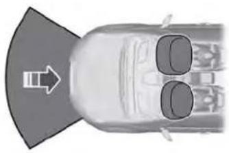
natural_image
Top-down view of a car with two side seats and an arrow pointing to the front wheel (no text or symbols)E151127
The driver and front passenger airbags will deploy during significant frontal and near frontal crashes.
The driver and passenger front airbag system consists of:
- Driver and passenger airbag modules.
•Front passenger sensing system.

- Crash sensors and monitoring system with readiness indicator. See Crash Sensors and Airbag
Indicator (page 59).
Proper Driver and Front Passenger Seating Adjustment

WARNING: National Highway
Traffic Safety Administration (NHTSA) recommends a minimum distance of at least 10 in (25 cm) between an occupant's chest and the driver airbag module.
To properly position yourself away from the airbag:
- Move your seat to the rear as far as you can while still reaching the pedals comfortably.
•Recline the seat slightly (one or two degrees) from the upright position.
After all occupants have adjusted their seats and put on seatbelts, it is very important that they continue to sit properly. A properly seated occupant sits upright, leaning against the seatback, and centered on the seat cushion, with their feet comfortably extended on the floor. Sitting improperly can increase
the chance of injury in a crash event. For example, if an occupant slouches, lies down, turns sideways, sits forward, leans forward or sideways, or puts one or both feet up, the chance of injury during a crash is greatly increased.
Children and Airbags

WARNING: Airbags can kill or
injure a child in a child restraint. Never place a rear-facing child restraint in front of an active airbag. If you must use a forward-facing child restraint in the front seat, move the seat upon which the child restraint is installed all the way back.
Supplementary Restraints System
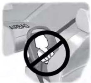
text_image
AIRBASE142846
Children must always be properly restrained. Accident statistics suggest that children are safer when properly restrained in the rear seating positions than in the front seating position. Failure to follow these instructions may increase the risk of injury in a crash.
FRONT PASSENGER SENSING SYSTEM

WARNING: Even with advanced
restraints systems, properly restrain children 12 and under in a rear seating position. Failure to follow this could seriously increase the risk of injury or death.

WARNING: Sitting improperly, out of position or with the seatback reclined too far can take weight off the seat cushion and affect the decision of the passenger sensing system, resulting in serious injury or death in the event of a crash. Always sit upright against your seat back, with your feet on the floor.

WARNING: Any alteration or ation to the front passenger seat fect the performance of the front ger sensing system. This could ly increase the risk of injury or

E181984
The front passenger sensing system uses a passenger airbag status indicator which illuminates indicating that the front passenger frontal airbag is either on (enabled) or off (disabled).
The indicator lamp is in the center stack of the instrument panel.
Supplementary Restraints System
Note: When you first switch the ignition on, the passenger airbag status indicator off and on lamps illuminate for a short period to confirm it is functional.
The front passenger sensing system is designed to disable (will not inflate) the front passenger frontal airbag under certain conditions:
•The front passenger seat is unoccupied.
•The system determines an infant is present in a child restraint.
- A passenger takes their weight off of the seat for a period of time.
- If there is a problem with the airbag system or the passenger sensing system.
Even with this technology, parents are strongly encouraged to always properly restrain children in the rear seat.
- When the front passenger sensing system disables (will not inflate) the front passenger frontal airbag, the passenger airbag status indicator illuminates the off lamp and stays lit to remind you that the front passenger frontal airbag is disabled.
- If you have installed the child restraint and the passenger airbag status indicator illuminates the on lamp, then switch your vehicle off, remove the child restraint from your vehicle and reinstall the restraint following the child restraint manufacturer's instructions.
The front passenger sensing system works with sensors that are part of the front passenger seat and seatbelt. The sensors are designed to detect the presence of a properly seated occupant and determine if the front passenger frontal airbag should be enabled.
- When the front passenger sensing system enables the front passenger frontal airbag (may inflate), the passenger airbag status indicator illuminates the on lamp and remains illuminated.
If a person of adult size is sitting in the front passenger seat, but the passenger airbag status indicator off lamp is lit, it is possible that the person is not sitting properly in the seat. If this happens:
- Switch your vehicle off and ask the person to place the seat backrest in an upright position.
- Have the person sit upright in the seat, centered on the seat cushion, with the person's legs comfortably extended.
- Restart your vehicle and have the person remain in this position for about two minutes. This allows the system to detect that person and enable the passenger frontal airbag.
- If the indicator off lamp remains lit even after this, you should advise the person to ride in the rear seat.
After all occupants have adjusted their seats and put on seatbelts, it is very important that they continue to sit properly. A properly seated occupant sits upright, leaning against the seatback, and centered on the seat cushion, with their feet comfortably extended on the floor. Sitting improperly can increase
Supplementary Restraints System
the chance of injury in a crash event. For example, if an occupant slouches, lies down, turns sideways, sits forward, leans forward or sideways, or puts one or both feet up, the chance of injury during a crash is greatly increased.
If you think that the state of the passenger airbag status indicator lamp is incorrect, check for the following:
- Objects lodged underneath the seat.
- Objects between the seat cushion and the center console.
- Objects hanging off the seat backrest.
- Objects stowed in the seat backrest map pocket.
- Objects placed on the occupant's lap.
• Cargo interference with the seat - Other passengers pushing or pulling on the seat.
- Rear passenger feet and knees resting or pushing on the seat.
The conditions listed above may cause the weight of a properly seated occupant to be incorrectly interpreted by the front passenger sensing system. The person in the front passenger seat may appear heavier or lighter due to the conditions described in the previous list.

Make sure the front passenger sensing system is operating properly. See Crash Sensors and
Airbag Indicator (page 59).
If the airbag readiness light is lit, do the following:
The driver and adult passengers should check for objects lodged underneath the front passenger seat or cargo interfering with the seat.
If objects are lodged or cargo is interfering with the seat, please take the following steps to remove the obstruction:
• Pull your vehicle over.
- Switch your vehicle off.
- Driver or adult passengers should check for any objects lodged underneath the front passenger seat or cargo interfering with the seat.
- Remove the obstruction(s) (if found).
- Restart your vehicle.
- Wait at least two minutes and verify that the airbag readiness light in the instrument cluster is no longer illuminated.
- If the airbag readiness light in the instrument cluster remains illuminated, this may or may not be a problem due to the front passenger sensing system.
Do not attempt to repair or service the system. Take your vehicle immediately to an authorized dealer.
If it is necessary to modify an advanced front airbag system to accommodate a person with disabilities, contact the Ford Customer Relationship Center.
Supplementary Restraints System
SIDE AIRBAGS

WARNING: Do not place objects
or mount equipment on or near the airbag cover, on the side of the front or rear seatbacks, or in areas that may come into contact with a deploying airbag. Failure to follow these instructions may increase the risk of personal injury in the event of a crash.

WARNING: Do not use accessory
seat covers. The use of accessory seat covers may prevent the deployment of the side airbags and increase the risk of injury in an accident.

WARNING: Do not lean your head
on the door. The side airbag could injure you as it deploys from the side of the seatback.

WARNING: Do not attempt to
service, repair, or modify the supplementary restraint system or associated components. Failure to follow this instruction could result in personal injury or death.

WARNING: If a supplementary
restraint system component has deployed, it will not function again. Have the system and associated components inspected as soon as possible. Failure to follow this instruction could result in personal injury or death.
The side airbags are on the outermost side of the front seat backrests. In certain sideways crashes or rollover events, the side airbags will be inflated. The airbag was designed to inflate between the door panel and occupant to further enhance the protection provided to occupants in side impact crashes.
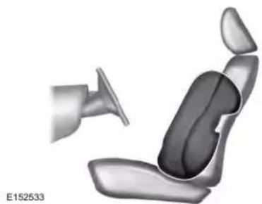
natural_image
3D rendered illustration of a car seat assembly with a side-mounted fan (no text or symbols)The system consists of the following:
• A label or embossed side panel indicating that your vehicle has side airbags.
- Side airbags inside the driver and front passenger seat backrests.

Crash sensors and monitoring
system with readiness indicator
See Crash Sensors and Airbag
Indicator (page 59).
Supplementary Restraints System
The design and development of the side airbag system included recommended testing procedures that were developed by a group of automotive safety experts known as the Side Airbag Technical Working Group. These recommended testing procedures help reduce the risk of injuries related to the deployment of side airbags.
DRIVER AND PASSENGER KNEE AIRBAGS
Driver and passenger knee airbags are located under or within the instrument panel. During a crash, the restraints control module may activate the driver and passenger knee airbags (individually or both) based on crash severity and respective occupant conditions. Under certain crash and occupant conditions, the driver and passenger knee airbags may deploy (individually or both) but the corresponding front airbag may not activate. As with front and side airbags, it is important to be properly seated and restrained to reduce the risk of death or serious injury.

Make sure the knee airbags are operating properly. See Crash Sensors and Airbag Indicator
(page 59).
SAFETY CANOPY™

WARNING: Do not place objects
or mount equipment on or near the headliner at the siderail that may come into contact with a deploying curtain airbag. Failure to follow these instructions may increase the risk of personal injury in the event of a crash.

WARNING: Do not lean your head
on the door. The curtain airbag could injure you as it deploys from the headliner.

WARNING: Do not attempt to service, repair, or modify the supplementary restraint system or associated components. Failure to follow this instruction could result in personal injury or death.

WARNING: All occupants of your vehicle, including the driver, should always properly wear their seatbelts, even when an airbag supplemental restraint system is provided. Failure to properly wear your seatbelt could seriously increase the risk of injury or death.

WARNING: To reduce risk of injury, do not obstruct or place objects in the deployment path of the airbag.
Supplementary Restraints System

WARNING: If a supplementary restraint system component has deployed, it will not function again. Have the system and associated components inspected as soon as possible. Failure to follow this instruction could result in personal injury or death.
The Safety Canopy deploys during significant side crashes or when a certain likelihood of a rollover event is detected by the rollover sensor. The Safety Canopy is mounted to the roof side rail sheet metal, behind the headliner, above each row of seats. In certain sideways crashes or rollover events, the Safety Canopy will be activated, regardless of which seats are occupied. The Safety Canopy is designed to inflate between the side window area and occupants to further enhance protection provided in side impact crashes and rollover events.
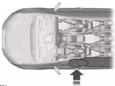
natural_image
Top-down technical illustration of a car interior showing internal components and a directional arrow (no text or symbols)E75004
The system consists of the following:
- Safety Canopy curtain airbags above the trim panels over the front and rear side windows identified by a label or wording on the headliner or roof-pillar trim.
• A flexible headliner which opens above the side doors to allow air curtain deployment

- Crash sensors and monitoring system with a readiness indicator. See Crash Sensors and Airbag
Indicator (page 59).
Properly restrain children 12 years old and under in the rear seats. The Safety Canopy will not interfere with children restrained using a properly installed child or booster seat because it is designed to inflate downward from the headliner above the doors along the side window opening.
The design and development of the Safety Canopy included recommended testing procedures that were developed by a group of automotive safety experts known as the Side Airbag Technical Working Group. These recommended testing procedures help reduce the risk of injuries related to the deployment of side airbags (including the Safety Canopy).
Supplementary Restraints System
CRASH SENSORS AND AIRBAG INDICATOR

WARNING: Modifying or adding
equipment to the front end of the vehicle (including frame, bumper, front end body structure and tow hooks) may affect the performance of the airbag system, increasing the risk of injury. Do not modify the front end of the vehicle.
Your vehicle has a collection of crash and occupant sensors which provide information to the restraints control module. The restraints control module deploys (activates) the front seatbelt system, the adaptive collapsible steering column, driver airbag, passenger airbag, knee airbag(s), seat mounted side airbags, Safety Canopy and optional rear inflatable seatbelts. Based on the type of crash, the restraints control module will deploy the appropriate safety devices.
The restraints control module also monitors the readiness of the above safety devices plus the crash and occupant sensors. The readiness of the safety system is indicated by a warning indicator light in the instrument cluster or a backup tone (if equipped). Routine maintenance of the airbag is not required.
A difficulty with the system is indicated by one or more of the following:

The readiness light will not illuminate immediately after the ignition is turned on.
•The readiness light will either flash or stay lit.
•A series of five beeps will be heard (If equipped). The tone pattern will repeat periodically until the problem, the light or both are repaired.
If any of these things happen, even intermittently, have the supplemental restraint system serviced at an authorized dealer immediately. Unless serviced, the system may not function properly in the event of a crash.
The seatbelt pretensioners and the front airbag supplemental restraint system are designed to activate when the vehicle sustains frontal deceleration sufficient to cause the restraints control module to deploy a safety device.
The fact that the seatbelt pretensioners or front airbags did not activate for both front seat occupants in a crash does not mean that something is wrong with the system. Rather, it means the restraints control module determined the accident conditions (crash severity, belt usage) were not appropriate to activate these safety devices.
•The design of the front airbags is to activate only in frontal and near-frontal crashes (not rollovers, side impacts or rear impacts) unless the crash causes sufficient frontal deceleration.
•The seatbelt pretensioners and rear inflatable seatbelts are designed to activate in frontal, near-frontal and side crashes and rollovers.
•The knee airbag(s) may deploy based on crash severity and occupant conditions.
Supplementary Restraints System
•The design of the side airbags is to inflate in certain side impact crashes. Side airbags may activate in other types of crashes if the vehicle experiences sufficient sideways motion or deformation.
•The design of the Safety Canopy is to inflate in certain side impact crashes or rollover events. The Safety Canopy may activate in other types of crashes if the vehicle experiences sufficient sideways motion or deformation, or a certain likelihood of rollover.
AIRBAG DISPOSAL
Contact your authorized dealer as soon as possible. Airbags must be disposed of by qualified personnel.
911 Assist
WHAT IS 911 ASSIST
911 Assist is a SYNC system feature that can call for help if you are in an accident. If a crash deploys an airbag, excluding knee airbags and rear inflatable seatbelts [if equipped], or activates the fuel pump shut-off, your SYNC-equipped vehicle may be able to contact emergency services by dialing 911 through a paired and connected Bluetooth enabled phone. You can learn more about the 911 Assist feature, by visiting:
Website
www.owner.lincoln.com www.syncmyride.ca www.syncmaroute.ca
Not all crashes will deploy an airbag or activate the fuel pump shut-off, the triggers for 911 Assist. If a connected cell phone sustains damage or loses its connection to SYNC during a crash, SYNC will search for and try to connect to a previously paired cell phone. SYNC will then attempt to call the emergency services.
Before making the call:
- SYNC provides a short window of time, about 10 seconds, to cancel the call. If you fail to cancel the call, SYNC attempts to dial 911.
- SYNC says the following, or a similar message: SYNC will attempt to call 911, to cancel the call, press Cancel on your screen or press and hold the phone button on your steering wheel.
If you do not cancel the call, and SYNC makes a successful call, a pre-recorded message plays for the 911 operator, and then the occupant(s) in your vehicle is able to talk with the operator. Be prepared to immediately provide your name, phone number and location, because not all 911 systems are capable of receiving this information electronically.
During an emergency call, the system transmits vehicle data to the emergency service. See Data Recording (page 10).
EMERGENCY CALL REQUIREMENTS

WARNING: Do not wait for 911
Assist to make an emergency call if you can do it yourself. Dial emergency services immediately to avoid delayed response time which could increase the risk of serious injury or death after a crash. If you do not hear 911 Assist within five seconds of the crash, the system or phone may be damaged or non-functional.

WARNING: Always place your in a secure location in your vehicle des not become a projectile or get ed in a crash. Failure to do so may serious injury to someone or e the phone which could prevent ist from working properly.
911 Assist

WARNING: Unless the 911 Assist is set on before a crash, the system dial for help which could delay use time, potentially increasing the serious injury or death after a crash.
•SYNC must be powered and working properly at the time of the incident and throughout feature activation and use.
•The 911 Assist feature must be set on before the incident.
- You must pair and connect a Bluetooth enabled and compatible cell phone to SYNC.
•A connected Bluetooth enabled phone must have the ability to make and maintain an outgoing call at the time of the incident.
•A connected Bluetooth enabled phone must have adequate network coverage, battery power and signal strength.
•The vehicle must have battery power and be located in the U.S., Canada or in a territory in which 911 is the emergency number.
Note: If any user sets 911 Assist to on or off, that setting applies for all paired phones. If 911 Assist is switched off and the phone is connected to SYNC, an icon displays on the status bar.
Note: Every phone operates differently. While SYNC 911 Assist works with most cellular phones, some may have trouble using this feature.
EMERGENCY CALL LIMITATIONS
The SYNC 911 Assist feature only operates in the U.S., Canada or in a territory in which 911 is the emergency number.
- Your cellular phone or 911 Assist hardware sustains damage in a crash.
•The vehicle's battery or the SYNC system has no power.
•The phone(s) thrown from your vehicle are the ones paired and connected to the system.
Keys and Remote Controls
GENERAL INFORMATION ON RADIO FREQUENCIES
This device complies with Part 15 of the FCC Rules and with Industry Canada license-exempt RSS standard(s). Operation is subject to the following two conditions: (1) This device may not cause harmful interference, and (2) This device must accept any interference received, including interference that may cause undesired operation.

WARNING: Changes or
modifications not expressively approved by the party responsible for compliance could void the user's authority to operate the equipment. The term "IC:" before the radio certification number only signifies that Industry Canada technical specifications were met.
The typical operating range for your transmitter is approximately 33 ft (10 m). Vehicles with the remote start feature will have a greater range.
One of the following could cause a decrease in operating range:
- Weather conditions.
•Nearby radio towers.
•Structures around the vehicle.
- Other vehicles parked next to your vehicle.
The radio frequency used by your remote control can also be used by other radio transmitters, for example amateur radios, medical equipment, wireless headphones, wireless remote controls, cell phones, battery chargers and alarm systems. If the frequencies are jammed, you will not be able to use your remote control. You can lock and unlock the doors with the key.
Note: Make sure to lock your vehicle before leaving it unattended.
Note: If you are in range, the remote control will operate if you press any button unintentionally.
Note: The remote control contains sensitive electrical components. Exposure to moisture or impact may cause permanent damage.
Intelligent Access (If Equipped)
The system uses a radio frequency signal to communicate with your vehicle and authorize your vehicle to unlock when one of the following conditions are met:
- You activate the front exterior door handle switch.
- You press the luggage compartment button.
- You press a button on the transmitter.
If excessive radio frequency interference is present in the area or if the transmitter battery is low, you may need to mechanically unlock your door. You can use the mechanical key blade in your intelligent access key to open the driver door in this situation. See Remote Control (page 63).
REMOTE CONTROL
Intelligent Access Key
Note: You may not be able to shift out of park (P) unless the intelligent access key is inside your vehicle.
Keys and Remote Controls
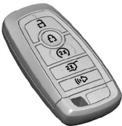
natural_image
3D rendered image of a gray remote control device with buttons and function labels (no readable text or symbols)The intelligent access keys operate the power locks and the remote start system. The key must be in your vehicle to use the push button start.
text_image
SAVE FOR CUSTOMER RECORDSE151795
Note: Your vehicle keys came with a security label that provides important key cut information. Keep the label in a safe place for future reference.
Removable Key Blade
The intelligent access key also contains a removable key blade that you can use to unlock your vehicle.
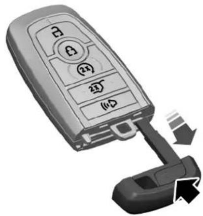
natural_image
Close-up of a car keychain with labeled buttons and a USB port, showing no text or symbols on the main body.Push the release button and pull the key blade out.
Keys and Remote Controls
Replacing the Battery

WARNING: Keep batteries away
from children to prevent ingestion. Failure to follow this instruction could result in personal injury or death. If ingested, immediately seek medical attention.

WARNING: If the battery
compartment does not securely close, stop using the remote control and replace it as soon as possible. In the meantime, keep the remote control away from children. Failure to follow this instruction could result in personal injury or death.
Note: Refer to local regulations when disposing of transmitter batteries.
Note: Do not wipe off any grease on the battery terminals or on the back surface of the circuit board.
Note: Replacing the battery does not erase the programmed key from your vehicle. The transmitter should operate normally.
A message appears in the information display when the remote control battery is low. See Information Messages (page 130).
The remote control uses one coin-type three-volt lithium battery CR2450 or equivalent.
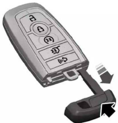
natural_image
Close-up of a car key with control buttons and a USB port, showing no text or symbols on the main object.- Push the release button and pull the key blade out.
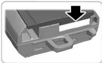
natural_image
3D mechanical part with a black arrow pointing to a feature, no visible text or symbols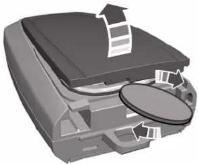
natural_image
3D illustration of a printer with a paper roll and cover, showing internal components (no text or symbols)- Twist a thin coin under the tab hidden behind the key blade head to remove the battery cover.
Keys and Remote Controls
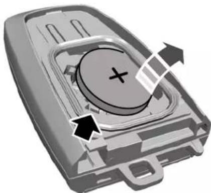
natural_image
3D diagram of a device casing with internal components and directional arrows indicating movement (no text or symbols)- Insert a suitable tool, for example a screwdriver, in the position shown and carefully remove the battery.
- Install a new battery with the + facing upward.
- Reinstall the battery cover and the key blade.
Car Finder

Press the button twice within three seconds. A tone sounds and the direction indicators flash. We
recommend you use this method to locate your vehicle, rather than using the panic alarm.
Sounding the Panic Alarm
Note: The panic alarm only operates when the ignition is off.

Press the button to sound the panic alarm. Press the button again or switch the ignition on to
turn it off.
Remote Start

WARNING: To avoid exhaust
fumes, do not use remote start if your vehicle is parked indoors or in areas that are not well ventilated.
Note: Do not use remote start if your fuel level is low.

The remote start button is on the transmitter.
This feature allows you to start your vehicle from the outside. The transmitter has an extended operating range.
You can configure your automatic climate control to operate when you remote start your vehicle. See Automatic Climate Control (page 153).
Many states and provinces have restrictions for the use of remote start. Check your local and state or provincial laws for specific requirements regarding remote start systems.
The remote start system does not work if any of the following occur:
•The ignition is on.
•The anti-theft alarm triggers.
- You switch the feature off in the information display.
•The hood is open.
Keys and Remote Controls
•The transmission is not in park (P).
• The battery voltage is below the minimum operating voltage.
Remote Control Feedback
An LED on the remote control provides status feedback of remote start or stop commands.
| StatusLED | |
| Solid green | Remote start successful |
| Solid red | Remote stop successful |
| Blinking red | Request failed or status not received |
| Status incompleteBI |
Remote Starting your Vehicle
Note: You must press each button within three seconds of each other. If you do not follow this sequence, your vehicle does not start remotely, the direction indicators do not flash twice and the horn does not sound.
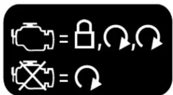
text_image
Diagram showing two icons: a lock and an X with a minus sign, each followed by an arrow symbol indicating rotation or refresh.E138626
- Press the lock button to lock all the doors.
- Press the remote start button twice. The exterior lamps flash twice.
The horn sounds if the system fails to start, unless quiet start is on.
Note: You must press the push button ignition switch on the instrument panel once while applying the brake pedal before driving your vehicle.
The power windows do not work during remote start and the radio does not turn on automatically.
The parking lamps remain on and your vehicle will run for 5, 10 or 15 minutes, depending on the setting.
Extending the Engine Running Time
To extend the engine running time duration of your vehicle during remote start, repeat steps 1 and 2 while the engine is running. If the duration is set to 15 minutes, the duration extends by another 15 minutes. For example, if your vehicle had been running from the first remote start for 5 minutes, your vehicle continues to run now for a total of 30 minutes. You can extend the engine running time duration to a maximum of 30 minutes.
Wait at least five seconds before remote starting after the engine stops running.
Turning Your Vehicle Off After Remote Starting

Press the button once. Your vehicle and the parking lamps turn off.
You may have to be closer to your vehicle than when starting due to ground reflection and the added noise of your running vehicle.
You can switch this feature on or off from the vehicle tile in SYNC 3. See Settings (page 495).
Keys and Remote Controls
Memory Feature
You can program your intelligent access key to recall memory positions. See Memory Function (page 170).
REPLACING A LOST KEY OR REMOTE CONTROL
Replacement keys or remote controls can be purchased from an authorized dealer. Authorized dealers can program remote controls for your vehicle. See Passive Anti-Theft System (page 89).
MyKey™
MyKey allows you to program keys with restricted driving modes to promote good driving habits. You can program the restrictions to all keys except one. Any keys that you did not program are administrator keys or admin keys.
You can use admin keys to:
- Create a MyKey with certain vehicle restrictions.
•Program certain MyKey settings. - Clear all MyKey restrictions.
After you program a MyKey, you can view the following information through the information display:
• The total number of admin keys and MyKeys for your vehicle.
•The total distance a MyKey driver traveled with your vehicle.
Note: Every MyKey receives the same restrictions and settings. You cannot program them individually.
Note: For vehicles equipped with a push-button start switch: When both a MyKey and an admin key are present when you start your vehicle, the system recognizes the admin key only.
Standard Settings
Not every vehicle includes the features listed below. If your vehicle has this equipment, then you cannot change the following settings when using a MyKey:
- Seatbelt reminder or Belt-Minder™. MyKey mutes the audio system until drivers, and in some instances, passengers, fasten their seatbelts. Note: If your vehicle includes an AM/FM radio or a very basic audio system, then the radio may not mute.
-
Earlier low-fuel warning. The low-fuel warning activates earlier for MyKey drivers, giving them more time to refuel.
-
Certain driver alerts, stability systems or parking aids turn on automatically when you use the MyKey system. For example, Blind Spot Information System (BLIS), cross traffic alert, lane departure warning or forward collision warning. Note: MyKey drivers may be able to turn the lane departure warning feature off, but this feature turns back on automatically with every new key cycle.
- Restricted touchscreen operation in some markets. For example, MyKey may prevent manual navigation destination input while the vehicle is in any gear other than park (P) or when the vehicle reaches a certain rate of speed.
- Satellite radio adult content restrictions, if this feature is available in your market.
Optional Settings
You can configure certain vehicle feature settings when you first create a MyKey. You can also change the settings afterward with an admin key.
MyKey™
Note: Not every feature applies to every vehicle in every market. When they are available for your vehicle, then they appear in your information display, providing choices to switch them on or off, or to select a more specific setting.
- Various vehicle speed limits so the MyKey driver cannot exceed certain speeds. The information display shows warnings followed by an audible tone when the MyKey driver reaches the set speed. You cannot override the set speed by fully depressing the accelerator pedal.

WARNING: Do not set MyKey lum speed limit to a limit that will t the driver from maintaining a safe considering posted speed limits and ing road conditions. The driver is responsible to drive in accordance cal laws and prevailing conditions. to do so could result in accident or
- Various vehicle speed reminders so MyKey drivers know when their vehicle speed approaches the limits. Warnings appear in your information display and a tone sounds when the MyKey drivers exceed the set vehicle speed.
•The audio system's maximum volume limits to 45% so MyKey drivers can concentrate on the road. A message appears in the information display when MyKey drivers attempt to exceed the limited volume. MyKey also disables the automatic volume control. Note: If your vehicle includes an AM/FM radio or a very basic audio system, then the radio may not limit.
•Always on setting. This setting forces certain features to remain on and active for MyKey drivers. For example, E911 or emergency assistance and the do not disturb features stay on even if a MyKey driver uses the feature's control to switch it off. When selected, you will not be able to turn off Advance Trac or traction control (if your vehicle has this feature).
CREATING A MYKEY
Use the information display to create a MyKey:
- Insert the key you want to program into the ignition. If your vehicle is equipped with a push-button start, place the remote control into the backup slot. See Starting a Gasoline Engine (page 186).
- Switch the ignition on.
- Access the main menu in the information display and then scroll through the menus to change the settings of your MyKey. From the MyKey menu select the option Create MyKey. See Information Displays (page 122).
- When prompted, hold the OK button until you see a message informing you to label this key as a MyKey. The programmed restrictions apply when you key off, open and close the driver door and restart your vehicle with the programmed key or transmitter.
MyKey is successfully created. Make sure you label it so you can distinguish it from the admin keys.
MyKey™
You can also program configurable settings for the key(s). See Programming and Changing Configurable Settings.
Programming and Changing Configurable Settings
Use the information display to access your configurable MyKey settings.
- Switch the ignition on using an admin key or transmitter you want to program.
- Access the main menu in the information display and then scroll through the menus to change the settings of your MyKey. See Information Displays (page 122).
- Follow the instructions in the display. The programmed restrictions apply when you switch the vehicle off, open and close the driver door and restart your vehicle with the programmed key or transmitter.
Note: You can clear or change your MyKey settings at any time during the same key cycle as you created the MyKey. Once you have switched the vehicle off, however, you will need an admin key to change or clear your MyKey settings. When you make any changes to your MyKey settings, you change the settings for every MyKey. You cannot make individual changes to apply to certain MyKeys.
CLEARING ALL MYKEYS
When you clear your MyKeys, you remove all restrictions and return all MyKeys to their original admin key status at once. To clear all MyKeys of all MyKey settings, use the information display.
- Switch the ignition on using an admin key.
- Access the main menu in the information display and then scroll through the menus to begin clearing your MyKey programming. See Information Displays (page 122).
-
Follow the instructions in the display.
-
A confirmation message appears in the display after you finish clearing your MyKeys.
Note: When you clear your MyKeys, you remove all restrictions and return all MyKeys to their original admin key status. You cannot remove the MyKey restrictions individually.
CHECKING MYKEY SYSTEM STATUS
You can find information about your programmed MyKeys by using the information display. See Information Displays (page 122).
MyKey Distance
Tracks the distance when drivers use a MyKey. The only way to delete the accumulated distance is by using an admin key to clear all MyKeys. If the distance does not accumulate as expected, then the intended user is not using the MyKey, or an admin key user recently cleared and then recreated a MyKey.
MyKey™
Number of MyKeys
Indicates the number of MyKeys programmed to your vehicle. Use this feature to detect how many MyKeys you have for your vehicle and determine when all MyKeys have been deleted.
Number of Admin Keys
Indicates how many admin keys are programmed to your vehicle. Use this feature to determine how many admin keys you have for your vehicle, and detect if an additional MyKey has been programmed.
USING MYKEY WITH REMOTE START SYSTEMS
MyKey is not compatible with non Lincoln-approved, aftermarket remote start systems. If you choose to install a remote start system, see an authorized dealer for a Lincoln-approved remote start system.
MYKEY - TROUBLESHOOTING
| Potential causesCondition | |
| I cannot create a MyKey. | ·The key or transmitter used to start the vehicle does not have admin privileges.·Vehicles with keyless start: Make sure you place the transmitter into the backup slot. See Passive Anti-Theft System (page 89).·The key or transmitter used to start the vehicle is the only admin key. There always has to be at least one admin key.·SecuriLock passive anti-theft system is disabled or in unlimited mode. |
| I cannot program the configurable settings. | ·The key or transmitter used to start the vehicle does not have admin privileges. |
MyKey™
| Potential causesCondition | |
| · There are no MyKeys programmed to the vehicle. See Creating a MyKey (page 70). | |
| I cannot clear the MyKeys. | · The key or transmitter used to start the vehicle does not have admin privileges.· No MyKeys are created. See Creating a MyKey (page 70). |
| · Purchase a new key or transmitter from your authorized dealer.I lost the o | |
| I lost a key. | · Program a spare key or transmitter. You may need to see your authorized dealer. See Passive Anti-Theft System (page 89). |
| · The MyKey user is not using the MyKey.MyKey distances do not accumula· An admin key holder cleared the MyKeys and created new MyKeys.· The key system has been reset. |
Doors and Locks
LOCKING AND UNLOCKING
Your vehicle has an intelligent electronically controlled door system that is in constant communication with overall vehicle systems.
When you lock your vehicle using the lock switch on each door interior trim panel, or by using the keyless entry keypad or the lock sensor on each door exterior trim panel, the exterior door handle switches do not release the doors. This helps to secure your vehicle and prevent unauthorized entry. Also, when your vehicle reaches a speed greater than 12 mph (20 km/h) the exterior door handle switches do not release the doors.
If the airbags deploy or the fuel pump shutoff switch activates, all interior and exterior unlock switches do not unlock your door for six seconds. This helps to secure the doors in the event of a crash. After six seconds, all switches reset and you can open the doors using the interior and exterior unlatch switches.
Door Lock Indicator
An LED on each front door window trim illuminates when you lock the doors. It remains on for 2 to 5 seconds after you switch the ignition off.
Door Lock Switch Inhibitor
When you electronically lock your vehicle, the door lock switches and the interior luggage compartment release switch do not operate after 20 seconds. You must unlock your vehicle with the remote control or keyless entry keypad, or switch the ignition on, to restore function to these switches. You can switch this feature on or off in the information display. See General Information (page 122).
Activating Intelligent Access
The intelligent access key must be within 3 ft (1 m) of the door or luggage compartment you intend to lock or unlock.
At a Door
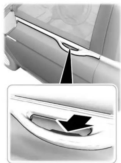
natural_image
Diagram showing a car's side profile and its interior component, with no visible text or symbols.E222428
Doors and Locks
Electronic door handles are on each door. Gently depress the switch inside the exterior door handle to unlock and open the door. An unlock symbol illuminates on the door window trim indicating your vehicle is unlocked.
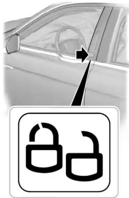
text_image
Diagram showing a car's side profile with an arrow pointing to a padlock icon, indicating lock status or security.E222429
Locking sensors are on both front doors. When the intelligent access key is within 3 ft (1 m) of your vehicle you can lock your vehicle by touching the locking sensor below the keyless entry keypad. Doing so causes a lock symbol to illuminate on the door window trim indicating your vehicle is locked and you can no longer release the door using the exterior door handle switches. Touching the locking sensor when the intelligent access key is not within 3 ft (1 m) causes the lock status to display, but does not lock the doors.
Swipe across the locking sensor to display the current lock status of your vehicle. The lock status also displays when you open a door or when the lock status changes.
Note: You cannot use the locking sensors to unlock your vehicle.
Doors and Locks
At the Luggage Compartment
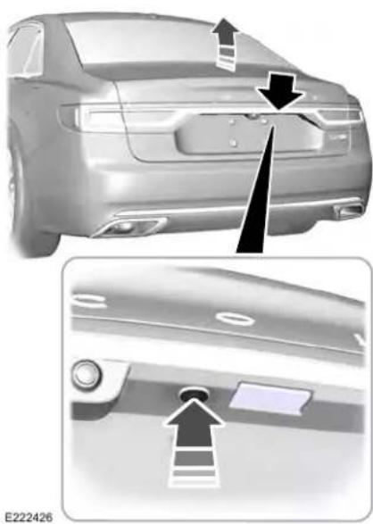
natural_image
Side view of a car back panel with arrows indicating top and side features (no text or symbols)Press the exterior release button.
Remote Control
You can use the remote control at any time. When you press the lock button on the remote control, all exterior door handle switches do not release the doors. When you press the unlock button, all exterior door handle switches release the doors.
Unlocking the Doors
Press the button. The direction indicators flash. You can then use the exterior door handle switch to unlock the door.
Press and hold both the lock and unlock buttons on the remote control for three seconds to change between driver door or all doors unlock mode. The direction indicators flash twice to confirm the change. Driver door mode only unlocks the driver door when you press the unlock button once. All door mode unlocks all doors when
you press the unlock button once. The unlocking mode applies to the remote control, keyless entry keypad and intelligent access. You can also change between the unlocking modes using the information display. See General Information (page 122).
Locking the Doors

Press the button. The direction indicators flash. You can no longer use the exterior door handle switch
to release the door.
Press the button again within three seconds to confirm that all the doors are closed. A tone sounds and the direction indicators flash if all the doors and the luggage compartment are closed.
Mislock
If any door is open, or if the luggage compartment or hood is open, a tone sounds and the direction indicators do not flash. The exterior lock status display also flashes if any door does not lock. You can switch this feature on or off in the information display. See General Information (page 122).
Doors and Locks
Locking and Unlocking the Doors From Inside
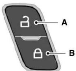
text_image
A BE196954
Unlock.A
Lock.B
Locking the Doors
Press the lock switch on the door interior trim panel. The doors can no longer be released using the exterior door handle switches and the luggage compartment locks.
Unlocking the Doors
Press the unlock switch on the door interior trim panel. The doors can then be released using the exterior door handle switches.
Emergency Locking
Each door has a backup power system which allows the door to function if your vehicle has no power. The system has a limited number of operations before the power is depleted and turns off. When the system turns off, the door remains open and unlatched and does not close.
If your vehicle has no power and the backup power system is turned off, you can close and secure your vehicle by manually resetting each door latch using a key in the position shown.
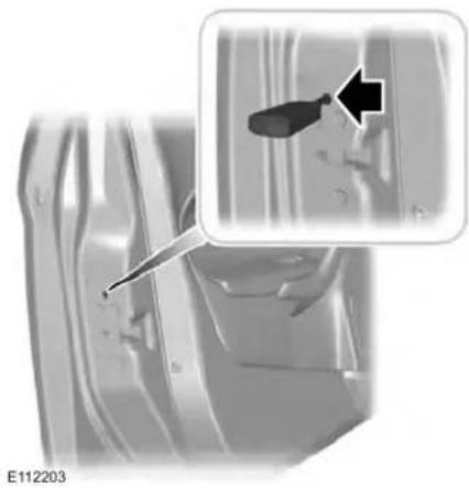
natural_image
Close-up of a car body panel with a magnified inset showing a tool interacting with the interior (no text or symbols visible)Left-Hand Side
Turn clockwise to reset the latch.
Right-Hand Side
Turn counterclockwise to reset the latch. When you have reset the latch, you are then able to fully close and latch the door.
Doors and Locks
Note: You cannot open the door again until the vehicle battery is fully charged and operational.
Unlocking the Driver Door with the Key Blade
If your vehicle has no power and the backup power system is turned off, you can manually unlock the driver door using a key in the position shown.
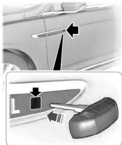
natural_image
Interior view of a car showing the door panel and dashboard with arrows indicating direction (no text or symbols)E222424
- Remove the key blade from the transmitter.
- Insert the key blade into the lock cylinder.
- Turn the key clockwise to unlock the driver door.
Note: All other doors remain locked.
Smart Unlocks for Intelligent Access Keys
This feature helps to prevent you from locking your intelligent access key inside your vehicle's passenger compartment or rear cargo area.
When you electronically lock your vehicle with any door open, the transmission is in park (P) and the ignition is off, the system searches for an intelligent access key inside your vehicle after you close the last door. If the system finds a key, all of the doors will immediately unlock and the horn will sound twice, indicating that a key is inside.
You can override the smart unlock feature and intentionally lock the intelligent access key inside your vehicle.
To do this, lock your vehicle after you have closed all the doors by:
• Using the keyless entry keypad.
- Pressing the lock button on another intelligent access key.
- Touching the locking sensor on the door window trim with another intelligent access key in your hand.
Doors and Locks
When you open one of the front doors and lock your vehicle using the power door lock control, all doors will lock then unlock if:
•The ignition is on.
•The ignition is off and the transmission is not in park (P).
Autolock (If Equipped)
Autolock locks all the doors when:
- All doors are closed.
•The ignition is on. - You shift into any gear putting your vehicle in motion.
- Your vehicle reaches a speed greater than 12 mph (20 km/h).
Autolock repeats when:
- You open then close any door while the ignition is on and your vehicle speed is 9 mph (15 km/h) or lower.
- Your vehicle reaches a speed greater than 12 mph (20 km/h).
Autounlock
Autounlock unlocks all the doors when:
•The ignition is on, all the doors are closed, and your vehicle has been moving at a speed greater than 12 mph (20 km/h).
- Your vehicle comes to a stop and you switch the ignition off or to the accessory position.
- You open the driver door within 10 minutes of switching the ignition off or to accessory.
Note: The doors do not autounlock if you electronically lock your vehicle after you switch the ignition off and before you open the driver door.
Enabling or Disabling Autounlock
You can enable or disable the autounlock feature in the information display or an authorized dealer can do it for you. See
General Information (page 122).
Illuminated Entry
The interior lamps and some exterior lamps illuminate when you unlock the doors with the remote control.
The illuminated entry system turns off the lights if:
•The ignition is on.
- You press the remote control lock button.
•After 25 seconds of illumination.
The lights do not turn off if:
- You turn them on with the lamp control.
- Any door is open.
Illuminated Exit
The interior lamps and some exterior lamps illuminate when all doors are closed and you switch the ignition off.
The lamps turn off if all the doors remain closed and:
- 25 seconds have elapsed.
- You press the push button ignition switch.
Doors and Locks
Battery Saver
If you leave the courtesy lamps, interior lamps or headlamps on, the battery saver shuts them off 10 minutes after you switch the ignition off.
Battery Saver for Intelligent Access Keys
If you leave the ignition switched on, it shuts off when it detects a certain amount of battery drain, or after 45 minutes.
Opening the Luggage Compartment
From Inside Your Vehicle

Press the button on the instrument panel to open the luggage compartment.
With the Remote Control

Press twice within three seconds to open the luggage compartment.
From Outside Your Vehicle
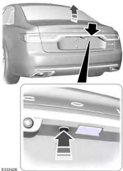
natural_image
Side view of a car showing rear bumper and side panel with arrows indicating features (no text or symbols)Press the exterior release button. Your vehicle must be unlocked or have an intelligent access key within 3 ft (1 m) of the luggage compartment.
To unlock and release the trunk using the keypad, enter the factory-set code or your personal code and then press 5-6 on the keypad.
OPENING THE DOORS
Note: When your vehicle reaches a speed greater than 2 mph (3 km/h), you will only be able to release the door by pressing the unlock button and then door release button within two seconds.
Front Doors

Press the door release button on the arm rest to release the door. Push the door out to open the
door.
Doors and Locks
Rear Doors

Press the unlock switch on the door and then press the door release button on the arm rest to release the door. The first press unlocks the door and the second press unlatches the door. Push the door out to open the door.
EMERGENCY DOOR RELEASE
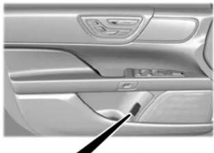
natural_image
Interior view of a car showing the dashboard and side panels with a black tool inserted (no visible text or symbols)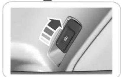
natural_image
Close-up of a car door handle with a black button labeled 'bg' and an arrow pointing to it (no readable text or symbols beyond the button)E231925
If you are inside your vehicle and unable to use the electronic door system, you can open the driver door using the emergency door release switch in the map pocket.
POWER DECKLID (IF EQUIPPED)

WARNING: It is extremely
dangerous to ride in a cargo area, inside or outside of a vehicle. In a crash, people riding in these areas are more likely to be seriously injured or killed. Do not allow people to ride in any area of your vehicle that is not equipped with seats and seatbelts. Make sure everyone in your vehicle is in a seat and properly using a seatbelt. Failure to follow this warning could result in serious personal injury or death.

WARNING: Make sure all persons of the power decklid area before the power decklid control.
Doors and Locks

WARNING: Keep keys out of the of children. Do not allow children to e or play near an open or moving decklid. You should supervise the on of the power decklid at all times.
Note: Do not drive with the decklid open unless you switch off the power feature. Make sure you fully close the decklid before you drive your vehicle.
You can switch the power decklid feature on or off in the information display. See General Information (page 122). The remote control and instrument panel button still operates the decklid regardless of the setting.
Opening and Closing the Power Decklid

WARNING: Make sure all persons of the power decklid area before the power decklid control.
Note: You can reverse the decklid movement. Press the instrument panel or decklid button again, or press the remote control button twice.
Note: Do not push or pull on the power decklid while it is under operation, as this may cause damage to your vehicle.
The decklid only operates with the transmission in park (P).
If the decklid starts to close after it has fully opened, this indicates there may be excessive weight on the decklid or a possible strut failure. A repetitive tone sounds and the decklid closes under control. Remove any excessive weight from the decklid. If the decklid continues to close after opening, have the system checked by an authorized dealer.
From Inside Your Vehicle

Press the button on the instrument panel.
With the Remote Control

Press the button twice within three seconds.
Doors and Locks
From Outside Your Vehicle
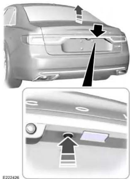
natural_image
Side view of a car showing rear bumper and side profile details with arrows indicating features (no text or symbols)Press the exterior release button. Your vehicle must be unlocked or have an intelligent access transmitter within 3 ft (1 m) of the luggage compartment.
Note: Allow the power system to open the decklid. Manually pushing or pulling the decklid may activate the system's obstacle detection feature and stop the power operation or reverse its direction.
With the Decklid Close Button
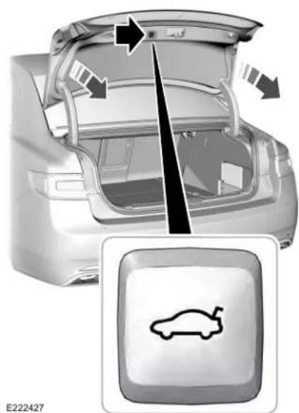
natural_image
Diagram of a car trunk with internal components and a car icon inside, showing no text or symbols.Press the button inside the decklid on the left-hand side.
Doors and Locks
Stopping the Decklid Movement
Note: Do not apply sudden excessive force to the decklid while it is in motion. This could damage the power decklid and its components.
You can stop the decklid movement by doing any of the following:
- Pressing the decklid control button.
- Pressing the remote control button twice.
- Pressing the button on the instrument panel.
- Moving your foot under and away from the center rear bumper in a single-kick motion.
This method only works for vehicles with the hands-free decklid feature.
Resetting the Power Decklid
The decklid may not operate correctly and you may need to reset it if:
•The vehicle battery charge is low.
- You disconnect the battery.
- You manually close the decklid and leave it unlatched.
- Disconnect the battery for 20 seconds then reconnect the battery.
- Manually close the decklid making sure it is fully closed.
- Power open the decklid using the remote control or instrument panel button.
Obstacle Detection
When Closing
The system stops when it detects an obstacle. A tone sounds and the system reverses to open. Once you remove the obstacle, you can power close the decklid.
Note: Entering your vehicle while the decklid is closing can cause your vehicle to bounce and activate obstacle detection. To prevent this, let the power decklid close completely before you enter your vehicle. Before driving your vehicle, check the instrument cluster for a trunk ajar or door ajar message or warning indicator. Failure to do this could result in unintentionally leaving the decklid open while driving.
When Opening
The system stops when it detects an obstacle and a tone sounds. Once you remove the obstacle, you can continue to operate the decklid.
Hands-Free Feature (If Equipped)
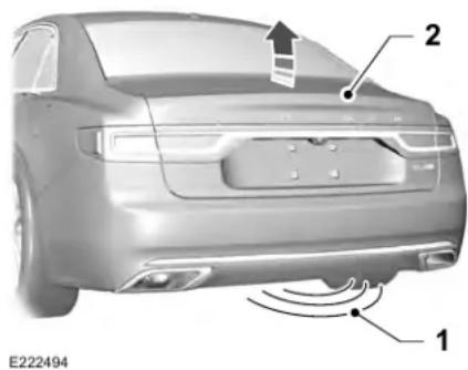
text_image
E222494 1 2The intelligent access key must be within 3 ft (1 m) of the decklid.
Doors and Locks
- Move your foot under and away from the rear bumper detection area in a single-kick motion. Do not move your foot sideways or the sensors may not detect the motion.
- The decklid opens or closes.
Note: Allow the power system to open the decklid. Manually pushing or pulling the decklid may activate the system's obstacle detection feature and stop the power operation or reverse its direction.
Note: Splashing water may cause the hands-free decklid to open. Keep the intelligent access key away from the rear bumper detection area when washing your vehicle.
SOFT CLOSING DOOR
Gently close the door until it fully latches. The system automatically closes the door, making sure it is fully secure.
Note: The system does not work if the vehicle battery charge is low.
Note: The system is limited to 25 cycles between each ignition cycle. This is to prevent the vehicle battery from losing charge.
Note: You can override soft close by fully closing the door manually.
KEYLESS ENTRY
SECURICODE™ Keyless Entry Keypad
The keypad is near the driver window. It illuminates when touched.
Note: If you enter your entry code too fast on the keypad, the unlock function may not work. Enter your entry code again more slowly.
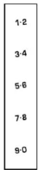
E138637
You can use the keypad to do the following: - Lock or unlock the doors.
- Program and erase user codes.
- Arm and disarm the anti-theft alarm.
You can operate the keypad with the factory-set five-digit entry code. The code is on the owner's wallet card in the glove box and is available from an authorized dealer. You can also program up to five of your own five-digit personal entry codes.
Doors and Locks
Programming a Personal Entry Code
- Enter the factory-set five-digit code.
- Press 1·2 on the keypad within five seconds.
- Enter your personal five-digit code. You must enter each number within five seconds of each other.
- Press 1.2 on the keypad to save personal code 1.
The doors lock then unlock to confirm that programming was successful.
To program additional personal entry codes, repeat steps 1 through 3, then for step 4:
- Press 3.4 to save personal code 2.
- Press 5.6 to save personal code 3.
- Press 7.8 to save personal code 4.
- Press 9.0 to save personal code 5.
Hints:
- Do not set a code that uses five of the same number.
- Do not use five numbers in sequential order.
•The factory-set code works even if you have set your own personal code.
Erasing a Personal Code
- Enter the factory-set five-digit code.
- Press and release 1·2 on the keypad within five seconds.
- Press and hold 1·2 for two seconds. You must do this within five seconds of completing step 2.
All personal codes erase and only the factory-set five-digit code works.
Anti-Scan Feature
The keypad goes into an anti-scan mode if you enter the wrong code seven times. This mode turns off the keypad for one minute and the keypad lamp flashes.
The anti-scan feature turns off after any of the following occur:
•One minute of keypad inactivity.
- You press the unlock button on the remote control.
- You switch your vehicle on.
- You unlock the vehicle using intelligent access.
Locking and Unlocking the Doors
Locking All Doors
Press and hold 7.8 and 9.0 on the keypad simultaneously with the driver door closed. You do not need to enter a code first.
Unlocking All Doors
Enter the factory-set code or your personal code, then press 3·4 on the keypad within five seconds.
Unlocking Only the Driver Door
Enter the factory-set or your personal five-digit code. You must press each number within five seconds of each other. The interior lamps illuminate.
Doors and Locks
Note: All doors unlock if the two-stage unlocking feature is turned off. See Locking and Unlocking (page 74).
INTERIOR LUGGAGE COMPARTMENT RELEASE

WARNING: Keep vehicle doors and
luggage compartment locked and keep keys and remote transmitters out of a child's reach. Unsupervised children could lock themselves in the trunk and risk injury. Children should be taught not to play in vehicles.

WARNING: Do not leave children
or animals unattended in the vehicle. On hot days, the temperature in the trunk or vehicle interior can rise very quickly.
Exposure of people or animals to these high temperatures for even a short time can cause death or serious heat-related injuries, including brain damage. Small children are particularly at risk.
Your vehicle is equipped with a release handle that provides a means of escape for children and adults if they become locked inside the luggage compartment.
Adults should familiarize themselves with the operation and location of the release handle.
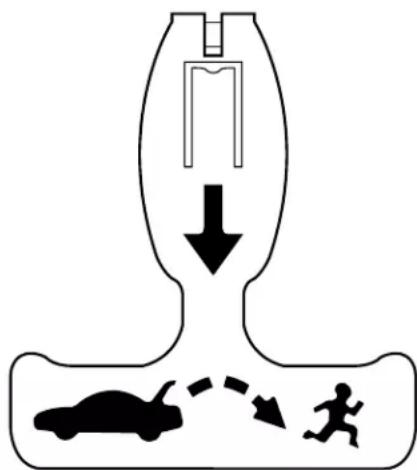
text_image
Diagram illustrating vehicle collision with a moving car and running person, showing downward force and motion pathE144403
Doors and Locks
The handle is located inside the luggage compartment either on the luggage compartment door (lid) or near the tail lamps. It is composed of a material that will glow for hours in darkness following brief exposure to ambient light.
Pull the handle and push up on the luggage compartment door (lid) to open from within the luggage compartment.
Security
Note: The system is not compatible with non-Lincoln aftermarket remote start systems. Use of these systems may result in engine starting problems and a loss of security protection.
Note: Metallic objects, electronic devices or a second coded key on the same key chain may result in vehicle starting problems, especially if they are too close to the key when starting your vehicle. Prevent these objects from touching the coded key when starting your vehicle. Switch the ignition off, move all objects on the key chain away from the coded key and restart your vehicle if a problem occurs.
Note: Do not leave a duplicate coded key in your vehicle. Always take your keys and lock all doors when leaving your vehicle.
SecuriLock®
The system helps prevent the engine from starting unless you use a coded key programmed to your vehicle. Using the wrong key may prevent your vehicle from starting. A message may appear in the information display.
If you are unable to start your vehicle with a coded key, it is not operating correctly. A message may appear in the information display.
Automatic Arming
The system arms when you switch the ignition off.
Automatic Disarming
The system disarms when you switch the ignition on with a coded key.
Replacement Keys
Note: Your vehicle comes with two keys.
The intelligent access key functions as a programmed key that operates the driver door lock and turns on the intelligent access with push button start system, as well as a remote control.
If your programmed transmitters are lost or stolen and you do not have an extra coded key, you will need to have your vehicle towed to an authorized dealer. You need to erase the key codes from your vehicle and program new coded keys.
Store a spare intelligent access key away from your vehicle in a safe place. You can purchase replacement keys or remote controls from an authorized dealer.
Programming a Spare Intelligent Access Key
Note: You can program a maximum of four keys to your vehicle.
You must have two previously programmed intelligent access keys inside your vehicle and the new unprogrammed intelligent access key readily accessible. You can purchase replacement keys or remote controls from an authorized dealer.
Security
Make sure that the ignition is switched off before beginning this procedure. Make sure that you close all the doors before beginning and that they remain closed throughout the procedure. Carry out all steps within 30 seconds of starting the sequence. Stop and wait for at least one minute before starting again if you carry out any steps out of sequence.
Read and understand the entire procedure before you begin.
- Remove the key blade from the transmitter.
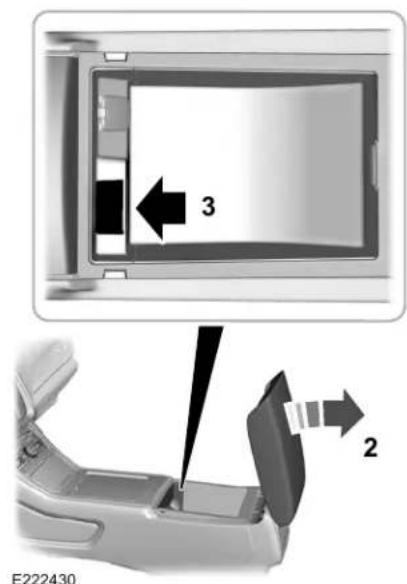
text_image
3 2 E222430- Open the floor console storage compartment lid.
-
Insert the first programmed key in the backup slot.
-
Press the push button ignition switch.
- Wait five seconds and then press the push button ignition switch again.
- Remove the intelligent access key.
- Within 10 seconds, place a second programmed intelligent access key in the backup slot and press the push button ignition switch.
- Wait five seconds and then press the push button ignition switch again.
- Remove the intelligent access key.
- Wait five seconds, then place the unprogrammed intelligent access key in the backup slot and press the push button ignition switch.
Programming is now complete. Check that the remote control functions operate and your vehicle starts with the new intelligent access key.
If programming was unsuccessful, wait 10 seconds and repeat steps 1 through 7. If it still does not work, take your vehicle to an authorized dealer.
Security
ANTI-THEFT ALARM
The active anti-theft system is designed to warn you in the event of unauthorized vehicle entry and is also designed to help prevent unwanted towing of your vehicle. You can choose what is monitored by arming the system in different ways. See Information Displays (page 122).
The direction indicators flash and the horn sounds if the system triggers while the alarm is armed.
Take all remote controls to an authorized dealer if there is any potential alarm problem with your vehicle.
Using the System
You can select two levels of alarm security. You can change the level of security when the ignition is switched off through the information display with the two options below:
Perimeter Sensing (If Equipped)
Perimeter sensing monitors the following:
- Doors.
•Hood.
•Liftgate.
All Sensors (If Equipped)
All sensors monitors the following:
- Doors.
•Hood.
•Liftgate. - Movement inside your vehicle.
- Change in vehicle inclination, for example, unwanted towing.
Note: Do not choose all sensors monitor mode when the vehicle is in transport or if movement within the vehicle is likely to occur.
Note: For correct operation of the interior motion detection system, make sure you close all the windows prior to arming the system. This helps prevent accidental alarm activation due to external influences. Additionally, the interior motion sensing system does not arm if any door is ajar.
Arming the Alarm
The alarm is ready to arm when there is not a key in the ignition. Lock your vehicle using the remote control or keyless entry keypad. You can also lock your vehicle using the lock sensor on the exterior door handle if your vehicle is equipped with intelligent access. See Locking and Unlocking (page 74).
The direction indicators flash once after you lock your vehicle. This indicates the alarm is in the pre-armed mode. It fully arms after 20 seconds.
Security
Disarming the Alarm
Disarm the alarm by any of the following actions:
- Press the power door unlock button within the 20-second pre-armed mode.
- Unlock the doors with the remote control or keyless entry keypad. If equipped with intelligent access, you can use the unlock sensor on the exterior door handle. See Locking and Unlocking (page 74).
- Switch the ignition on or start your vehicle.
- Use a key in the driver door lock cylinder to unlock your vehicle, then switch the ignition on within 12 seconds.
Note: Pressing the panic button on the remote control stops the horn and direction indicators, but does not disarm the system.
Steering Wheel
ADJUSTING THE STEERING WHEEL

WARNING: Do not adjust the
steering wheel when your vehicle is moving.
Note: Make sure that you are sitting in the correct position. See Sitting in the Correct Position (page 160).
E261582
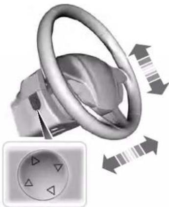
natural_image
Mechanical component with rotating ring and directional arrows, shown in 3D rendering (no text or symbols)Use the control on the side of the steering column to adjust the position.
To adjust:
- Tilt: Press the top or bottom of the control.
- Telescope: Press the front or rear of the control.
End of Travel Position
The steering column sets a stopping position just short of the end of the column position to prevent damage to the steering column. A new stopping position sets if the steering column encounters an object when tilting or telescoping.
To reset the steering column to its normal stopping position:
-
Confirm there is nothing obstructing the motion of the steering column.
-
Press and hold the steering column control until the steering column stops moving.
-
Press the steering column control again.
Note: The steering column may begin to move again.
-
When the steering column stops, continue holding the control for a few seconds.
-
Repeat for each direction as necessary.
Steering Wheel
A new stopping position sets. The next time you tilt or telescope the steering column, it stops just short of the end of the column position.
Memory Feature (If Equipped)
You can save and recall the steering column position with the memory function. See Memory Function (page 170).
Pressing the adjustment control during a memory recall cancels the operation.
Easy Entry and Exit Feature
The column moves up when you switch the ignition off. Switch the ignition on to return the system to its previous settings. You can switch this feature on or off in the information display. See Information Displays (page 122).
Note: If you press any adjustment or memory button when in easy exit mode, the system cancels the operation.
Note: Depending on your vehicle, the column may move up and in.
AUDIO CONTROL
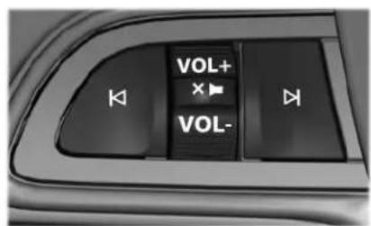
text_image
VOL+ VOL-E289590
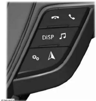
text_image
DISP F251877You can operate the following functions with the control:

Press - to decrease volume level.
Press + to increase volume level.

Press to silence the current media
Steering Wheel

Press to access the previous media selection.

Press to access the next media selection.

Press to access phone mode or to answer a phone call.

Press to end a phone call.

Press to access the audio quick access menu (QAM).
VOICE CONTROL
The controls are on the steering wheel.

Press and release to activate voice recognition.
CRUISE CONTROL
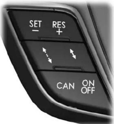
text_image
SET RES + CAN ON OFFE223599
See Using Adaptive Cruise Control (page 249).
INFORMATION DISPLAY CONTROL
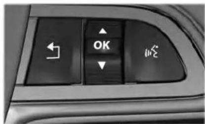
text_image
OK ← ↓ ←E221074
Steering Wheel
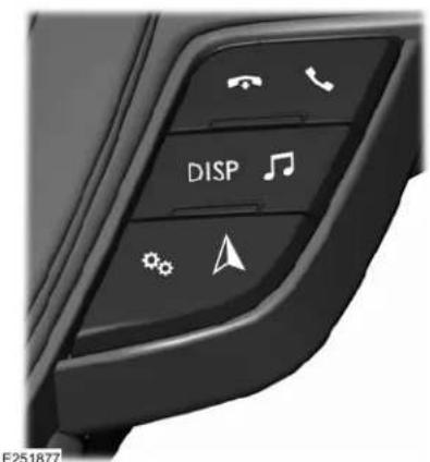
text_image
DISP E251877See Information Displays (page 122).
Note: The HUD button replaces the DISP button on vehicles that have a head up display (HUD).
HEATED STEERING WHEEL (IF
EQUIPPED)
The heated steering wheel button is on the climate controls.

Press the button to switch the heated steering wheel on and off.
Note: You can use the heated steering wheel only when the engine is running.
Note: The system uses a sensor and is designed to control the temperature of the steering wheel and to prevent it from overheating.
Note: In warm temperatures, the steering wheel quickly reaches its maximum temperature and the system reduces the current to the heating element. This could cause you to think that the system has stopped working but it has not. This is normal.
HORN

Wipers and Washers
WINDSHIELD WIPERS

Push the lever up or down to operate the windshield wiper.
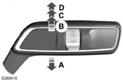
text_image
D C B A E269410Single wipe.A
Intermittent wipe.B
Normal wipe.C
High-speed wipe.D
Note: Fully defrost the windshield before you switch the windshield wipers on.
Note: Make sure that you switch the windshield wipers off before entering a car wash.
Note: If streaks or smears appear on the windshield, clean the windshield and the wiper blades. If that does not resolve the issue, install new wiper blades.
Note: Do not operate the wipers on a dry windshield. This may scratch the glass, damage the wiper blades or cause the wiper motor to burn out. Always use the windshield washers before wiping a dry windshield.
Intermittent Wipe
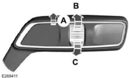
text_image
A B C E269411Intermittent wipeA
Shortest wipe interval.B
Longest wipe interval.C
Use the rotary control to adjust the intermittent wipe interval.
Speed Dependent Wipers
When your vehicle speed increases, the interval between wipes decreases.
Wipers and Washers
AUTOWIPERS
Wet or winter driving conditions with ice, snow or salty road mist can cause inconsistent and unexpected wiping or smearing.

text_image
A B C E269411Autowipers On.A
High sensitivity.B
Low sensitivity.C
Use the rotary control to adjust the sensitivity of the autowipers. When you select low sensitivity, the wipers operate when the sensor detects a large amount of water on the windshield. When you select high sensitivity, the wipers operate when the sensor detects a small amount of water on the windshield.
Keep the outside of the windshield clean. The rain sensor is very sensitive and the wipers may operate if dirt, mist or insects hit the windshield.
In these conditions, you can do the following:
- Lower the sensitivity of the autowipers to reduce the amount of smearing on the windshield.
- Switch to normal or high-speed wipe.
- Switch autowipers off.
Note: Fully defrost the windshield before you switch the windshield wipers on.
Note: Make sure that you switch the windshield wipers off before entering a car wash.
Note: If streaks or smears appear on the windshield, clean the windshield and the wiper blades. If that does not resolve the issue, install new wiper blades.
Note: If you switch autolamps and autowipers on, the headlamps turn on when the windshield wipers continuously operate.
Autowipers Settings
Autowipers defaults to on and remains on until you switch it off in the information display. When you switch off autowipers, the wipers operate in intermittent mode.
Wipers and Washers
WINDSHIELD WASHERS
natural_image
Close-up of a car frontview handle with a white vent and a small arrow pointing to the side (no text or symbols)E269412

Pull the lever toward you to operate the windshield washers.
When you release the lever, the wipers operate for a short time. When activated, a courtesy wipe occurs a short time after the wipers stop to clear any remaining washer fluid.
Note: You can switch courtesy wipe on or off in the information display. See General Information (page 122).
Note: Do not operate the washers when the washer reservoir is empty. This could cause the washer pump to overheat.
Front Camera Washer (If Equipped)
Operating the windshield washer also turns on the front camera washer.
Lighting
GENERAL INFORMATION
Condensation in the Exterior Front Lamps and Rear Lamps
Exterior front lamps and rear lamps have vents to accommodate normal changes in air pressure.
Condensation can be a natural by-product of this design. When moist air enters the lamp assembly through the vents, there is a possibility that condensation can occur when the temperature is cold. When normal condensation occurs, a fine mist can form on the interior of the lens. The fine mist eventually clears and exits through the vents during normal operation.
Clearing time may take as long as 48 hours under dry weather conditions.
Examples of acceptable condensation are:
•The presence of a fine mist (no streaks, drip marks or large droplets).
• A fine mist covers less than 50% of the lens.
Examples of unacceptable condensation are:
•A water puddle inside the lamp.
• Streaks, drip marks or large droplets present on the interior of the lens.
If you see any unacceptable condensation, have your vehicle checked by an authorized dealer.
LIGHTING CONTROL
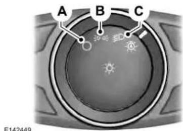
text_image
A B C E142449Lamps off.A
B Parking lamps, instrument panel lamps, license plate lamps and tail lamps.
Headlamp low beam.C
Lighting
Headlamp High Beam
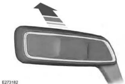
natural_image
Close-up of a car front bumper with an upward arrow indicating motion (no text or symbols on the object itself)
Push the lever away from you to switch the high beam on.
Push the lever away from you again or pull the lever toward you to switch the high beam off.
Flashing the Headlamp High Beam
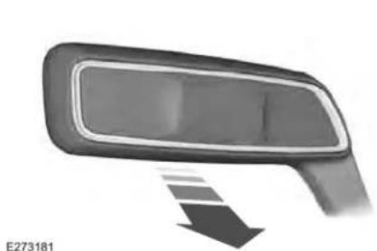
natural_image
Side mirror with a downward arrow indicating compression or dislocation (no text or symbols)Slightly pull the lever toward you and release it to flash the headlamps.
AUTOLAMPS

WARNING: The system does not relieve you of your responsibility to drive with due care and attention. You may need to override the system if it does not turn the headlamps on in low visibility conditions, for example daytime fog.
Autolamps turn the headlamps on in low light situations or when the wipers operate.

Switch the lighting control to the autolamps position.
The headlamps remain on for a period of time after you switch the ignition off. Use the information display controls to adjust the period of time that the headlamps remain on.
Note: If you switch the autolamps on, you cannot switch the high beams on until the system turns the low beams on.
Windshield Wiper Activated Headlamps
When you switch the autolamps on, the headlamps turn on within 10 seconds of switching the wipers on. They turn off approximately 60 seconds after you switch the windshield wipers off.
The headlamps do not turn on with the wipers:
- During a single wipe.
- When using the windshield washers.
- If the wipers are in intermittent mode.
Lighting
Note: If you switch the autolamps and the autowipers on, the headlamps turn on when the windshield wipers continuously operate.
INSTRUMENT LIGHTING DIMMER
The instrument lighting dimmer buttons are on the lighting control.
Repeatedly press one of the buttons to adjust the brightness.
HEADLAMP EXIT DELAY
After you switch the ignition off, you can switch the headlamps on by pulling the direction indicator lever toward you. You will hear a short tone. The headlamps will switch off automatically after three minutes with any door open or 30 seconds after the last door has been closed. You can cancel this feature by pulling the direction indicator toward you again or switching the ignition on.
DAYTIME RUNNING LAMPS - VEHICLES WITH: CONFIGURABLE DAYTIME RUNNING LAMPS
WARNING: The daytime running lamps system does not activate the rear lamps and may not provide adequate lighting during low visibility driving conditions. Make sure you switch the headlamps on, as appropriate, during all low visibility conditions. Failure to do so may result in a crash.
Switch the daytime running lamps on or off using the information display. See General Information (page 122).
The daytime running lamps turn on when:
- The lamps are on in the information display.
-
You switch the ignition on.
-
The transmission is not in park (P) for vehicles with automatic transmissions or you release the parking brake for vehicles with manual transmissions.
- The lighting control is in the autolamps position.
- The headlamps are off.
The other lighting control switch positions do not turn on the daytime running lamps.
If the daytime running lamps are off in the information display, the lamps stay off in all switch positions.
Lighting
DAYTIME RUNNING LAMPS - VEHICLES WITH: DAYTIME RUNNING LAMPS (DRL)

WARNING: The daytime running
lamps system does not activate the rear lamps and may not provide adequate lighting during low visibility driving conditions. Make sure you switch the headlamps on, as appropriate, during all low visibility conditions. Failure to do so may result in a crash.
The system turns the lamps on in daylight conditions.
To switch the system on, switch the lighting control to any position except headlamps.
ADAPTIVE HEADLAMPS
The headlamp beams move in the same direction as the steering wheel. This provides more visibility when driving around curves.
A. Without adaptive headlamps.
B. With adaptive headlamps.
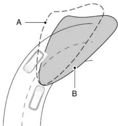
text_image
A BE161714
The system only works with the lighting control in the autolamp position. You can switch this feature on or off in the information display.
Note: There is a delay of two to five seconds before the system operates when you drive your vehicle.
Note: The system is only active at speeds above 3 mph (5 km/h).
System Check (If Equipped)
The system has a power-up movement check feature. When you start your vehicle, the lamps track left to right, then back to center to alert the driver that the system is working properly.
Lighting
DIRECTION INDICATORS
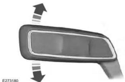
natural_image
Close-up of a car front bumper with directional arrows indicating movement (no text or symbols)
Push the lever up or down to use the direction indicators.
Indicating a Lane Change
Tap the lever up or down to make the direction indicators flash three times to indicate a lane change.
WELCOME LIGHTING
The Lincoln welcome mat projection lights are on the bottom of the exterior mirror housings. They project an image onto the ground a short distance from your vehicle when welcome lighting or lighted entry turns on.
For auto-fold mirrors, the Lincoln welcome mat turns on when welcome lighting or lighted entry turns on and the mirrors fold in upon locking or using the switch on the door.
You can switch this feature on or off in the information display.
Note: Moisture, frost and ice build-up or other types of contamination on the surface of the light lens can cause non-permanent distortion or reduced brightness of the image. Do not use abrasive materials to clean the lens.
Note: If you enable auto-fold and then you fold the mirrors in to the door window glass, the welcome mats do not turn on.
INTERIOR LAMPS
The lamps turn on under the following conditions:
- You open any door.
- You press a remote control button.
- You press the all lamps on button on the overhead console.
Front Interior Lamp
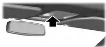
natural_image
Close-up of a car interior showing a door, rearview mirror, and cable (no visible text or symbols)E262162
The front interior lamp switches are on the overhead console.
Lighting
Note: The position and availability of each button on the overhead console depends on your vehicle.
Switching All of the Interior Lamps On

Press to switch all interior lamps on.
Note: For vehicles without a lamps off switch, press again to switch all interior lamps off.
Switching All of the Interior Lamps Off (If Equipped)

Press to switch all interior lamps off.
Switching the Individual Map Lamps On and Off

Press to switch the left-hand individual dome lamp on and off.

Press to switch the right-hand individual dome lamp on and off.
Interior Lamp Function

Press to switch the interior lamp function on and off.
When the interior lamp function is off and you open a door, the courtesy and door lamps stay off.
When the interior lamp function is on and you open a door, the courtesy and door lamps turn on.
Note: The indicator lamp lights amber when the door function is off.
Rear Interior Lamps
The rear interior lamps may be above the rear seat or above the rear windows.

Press to switch the lamps on or off.
Note: If the rear lamps are switched on through the overhead console, you cannot turn them off with the rear lamp switch.
AMBIENT LIGHTING
Use the touchscreen to select the following:

Select the settings option on the feature bar.

Select ambient lighting.
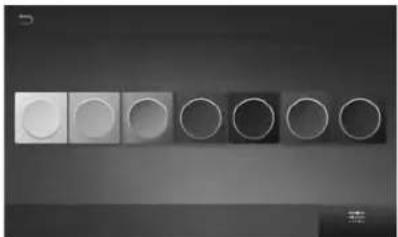
natural_image
Grid of circular and square objects arranged in rows, no text or symbols visibleSwitching Ambient Lighting On
Touch a color once.
Changing the Color
Touch any color once.
Lighting
Adjusting the Brightness
Drag the selected color up or down.
Switching Ambient Lighting Off
Touch the selected color once or drag the selected color down to zero brightness.
Automatic High Beam Control
The system turns on high beams if it is dark enough and no other traffic is present. If it detects an approaching vehicle's headlamps or tail lamps, or street lighting ahead, the system turns the high beams off. Low beams remain on.
A camera sensor, centrally mounted behind the windshield of your vehicle, continuously monitors conditions to turn the high beams on and off.
SWITCHING AUTOMATIC HIGH BEAM CONTROL ON AND OFF
Switch the system on or off using the information display. See General Information (page 122).
Activating the Automatic High Beam Control

Switch the lighting control to the autolamps position to activate. See Autolamps (page 101).
Note: Automatic high beams are not available when autolamps are not turned on.
When active, the high beams turn on if:
•The ambient light level is low enough.
- There is no traffic in front of your vehicle.
•The vehicle speed is greater than approximately 32 mph (52 km/h).
When active, the high beams turn off if:
•The ambient light level is high enough that high beams are not required.
•The system detects an approaching vehicle's headlamps or tail lamps.
• The system detects severe rain, snow or fog.
•The camera is blocked.
•The vehicle speed falls below approximately 27 mph (44 km/h).
Note: The deactivation speed is lower on curves.
Note: High beam reactivation may be delayed in certain curvy road situations.
Note: The system may not operate properly if the sensor is blocked. Keep the windshield free from obstruction or damage.
Note: The system may not operate properly in cold or inclement conditions. You can switch on the high beams by overriding the system.
Note: If the system detects a blockage, for example bird droppings, bug splatter, snow or ice, the system goes into low beam mode until you clear the blockage. A message may appear in the information display if the camera is blocked.
Note: Using much larger tires or equipping vehicle accessories such as snowplows can modify your vehicle's ride height and degrade automatic high beam control performance.
Automatic High Beam Control
AUTOMATIC HIGH BEAM CONTROL INDICATORS

The indicator illuminates to confirm when the system is ready to assist.
WARNING: The system does not you of your responsibility to drive the care and attention. You may need ride the system if it does not turn h beams on or off.
WARNING: You may need to use the system when approaching pad users.
WARNING: You may need to use the system during inclement or.
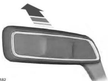
natural_image
Close-up of a car front bumper with an upward arrow indicating motion (no text or symbols)E273182
Push the lever away from you to switch between high beam and low beam.
Windows and Mirrors
POWER WINDOWS

WARNING: Do not leave children
unattended in your vehicle and do not let them play with the power windows. Failure to follow this instruction could result in personal injury.

WARNING: When closing the
power windows, verify they are free of obstruction and make sure that children and pets are not in the proximity of the window openings.
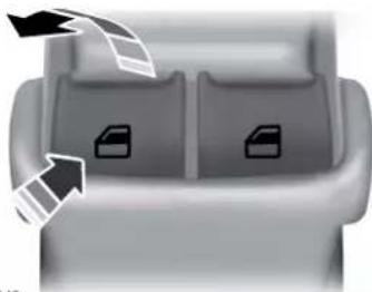
natural_image
Top-down view of a gray car backrest with two document icons and directional arrows indicating orientation (no text or symbols)E146043
Note: You may hear a pulsing noise when just one of the windows is open. Lower the opposite window slightly to reduce this noise.
Press the switch to open the window.
Lift the switch to close the window.
One-Touch Down
Press the switch fully and release it. Press again or lift it to stop the window.
One-Touch Up
Lift the switch fully and release it. Press or lift it again to stop the window.
Resetting One-Touch Up
Start the engine.
- Lift and hold the window switch until you fully close the door window. Continue to hold the switch for a few seconds after you close the window.
- Release the window switch.
- Press and hold the window switch until you fully open the door window.
- Release the window switch.
- Lift and hold the window switch until you fully close the window.
- Test for correct window operation by carrying out the one-touch down and one-touch up features.
Bounce-Back
The window will stop automatically while closing. It reverses some distance if there is an obstacle in the way.
Windows and Mirrors
Overriding the Bounce-Back Feature

WARNING: When you override the
bounce-back feature the window will not reverse if it detects an obstacle. Take care when closing the windows to avoid personal injury or damage to your vehicle.
Pull up the window switch and hold within a few seconds of the window reaching the bounce-back position. The window travels up with no bounce-back protection. The window stops if you release the switch before the window fully closes.
Window Lock
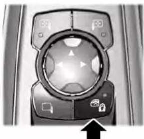
natural_image
Close-up of a camera dial with directional arrows and control buttons (no text or symbols visible)E259237
Press the control to lock or unlock the rear window controls. It illuminates when you lock the rear window controls.
Accessory Delay
You can use the window switches for several minutes after you switch the ignition off or until you open either front door.
GLOBAL OPENING AND CLOSING
You can use the remote control to operate the windows with the ignition off.
Note: You can enable or disable this feature in the information display or see an authorized dealer. See General Information (page 122).
Note: To operate this feature, accessory delay must not be active.
Opening the Windows
You can only open the windows for a short time after you unlock your vehicle with the remote control. After you unlock your vehicle, press and hold the remote control unlock button to open the windows. Release the button once movement starts. Press the lock or unlock button to stop movement.
Closing the Windows

WARNING: When closing the
power windows, you should verify they are free of obstructions and make sure that children and pets are not in the proximity of the window openings.
Windows and Mirrors
To close the windows, press and hold the remote control lock button. Release the button once movement starts. Press the lock or unlock button to stop movement.
EXTERIOR MIRRORS
Power Exterior Mirrors

WARNING: Do not adjust the
mirrors when your vehicle is moving. This could result in the loss of control of your vehicle, serious personal injury or death.
Note: Do not use an ice scraper on the mirror glass or housing.
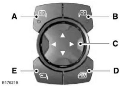
text_image
A B C E D E176219Left-hand mirror.A
Right-hand mirror.B
Adjustment control.C
Window lockout.D
Power-folding mirror control.E
To adjust a mirror:
- Select the mirror you want to adjust. The control will light.
- Adjust the position of the mirror.
- Press the mirror control again.
Fold-Away Exterior Mirrors
Push the mirror toward the door window glass. Make sure that you fully engage the mirror in its support when returning it to its original position.
Auto-Folding Mirrors (If Equipped)
The exterior mirrors automatically fold in toward the glass after you place the transmission into park (P), turn off the vehicle, open and close the driver side door and lock the vehicle. The exterior mirrors automatically unfold and return to their driving position after you unlock the vehicle and open and close the driver side door.
You can switch this feature on and off through the information display. See General Information (page 122).
Windows and Mirrors
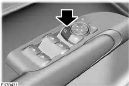
natural_image
Close-up of a car interior control panel with a black arrow pointing to the dial (no text or symbols visible)You can fold the mirrors on demand by pressing the power-folding mirror control on the door. The control lights and the mirrors fold in toward the glass. Press the control again to unfold the mirrors. The control light turns off.
Note: If you switch the auto fold feature on and use the power-folding control to fold the mirrors on demand, you must use the control again to unfold them.
Loose Mirror
If you manually fold the power-folding mirrors, they may not work properly even after you re-position them. You need to reset them if:
•The mirrors vibrate when you drive.
•The mirrors feel loose.
•The mirrors do not stay in the folded or unfolded position.
• One of the mirrors is not in its normal driving position.
To reset the power-fold feature, use the power-folding mirror control to fold and unfold the mirrors. You may hear a loud noise as you reset the power-folding mirrors. This sound is normal. Repeat this process as needed each time you manually fold the mirrors.
Heated Exterior Mirrors
See Heated Exterior Mirrors (page 158).
Memory Mirrors
You can save and recall the mirror positions through the memory function. See Memory Function (page 170).
Auto-Dimming Feature
The driver exterior mirror dims when the interior auto-dimming mirror turns on.
Signal Indicator Mirrors
The outer portion of the appropriate mirror housing blinks when you activate the direction indicator.
Lincoln Welcome Mat
Projection lights, on the bottom of the mirror housings, project an image onto the ground a short distance from the vehicle.
360-Degree Camera (If Equipped)
See 360 Degree Camera (page 246).
Windows and Mirrors
Blind Spot Monitor
See Blind Spot Information System (page 265).
INTERIOR MIRROR

WARNING: Do not adjust the mirror
when your vehicle is moving.
Note: Do not clean the housing or glass of any mirror with harsh abrasives, fuel or other petroleum or ammonia-based cleaning products.
You can adjust the interior mirror to your preference. Some mirrors also have a second pivot point. This lets you move the mirror head up or down and from side to side.
Auto-Dimming Mirror
Note: Do not block the sensors on the front and back of the mirror. Mirror performance may be affected. A rear center passenger or raised rear center head restraint may also block light from reaching the sensor.
The mirror will dim automatically to reduce glare when bright lights are detected from behind your vehicle. It will automatically return to normal reflection when you select reverse gear to make sure you have a clear view when backing up.
SUN VISORS
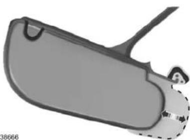
natural_image
3D rendered image of a pair of eyeglasses with no visible text or symbolsRotate the sun visor toward the side window and extend it rearward for extra shade.
Windows and Mirrors
Illuminated Vanity Mirror
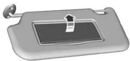
natural_image
3D rendered image of a gray electronic device with a black arrow pointing to a screen (no text or symbols)E162197
Lift the cover to switch the lamp on.
SUN SHADES
Note: Do not try to move the sun shade manually.
The power rear sun shade covers the rear window of the vehicle.
text_image
RE222384
A control is on the overhead console and on the rear seat armrest bezel.
Press and release the control to open or close the sun shade. To stop motion and return the sun shade to its previous position, press the control a second time.
The sun shade automatically retracts when you shift the transmission into reverse (R).
MOONROOF (IF EQUIPPED)

WARNING: Do not let children play the moonroof or leave them ended in the vehicle. They may fly hurt themselves.

WARNING: When closing the
moonroof, you should verify that it is free of obstructions and make sure that children and pets are not in the proximity of the roof opening.
The moonroof controls are located on the overhead console and have a one-touch open and close feature. To stop its movement during one-touch operation, press the control a second time.
Windows and Mirrors
Opening and Closing the Moonroof
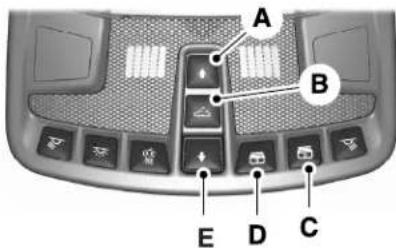
text_image
A B E D CE222844
A Moonroof open. Press and release to open the moonroof.
B Moonroof vent. Press and release to vent the moonroof.
C Sunshade open. Press and release to open the sunshade. The sunshade opens automatically with the moonroof. You can also open the sunshade with the moonroof closed.
D Sunshade close. Press and release to close the sunshade.
E Moonroof close. Press and release to close the moonroof from either the open or vent positions.
Note: Sunshade open and close controls may also be located on the rear seat armrest bezel.
Bounce-Back
The moonroof automatically reverses some distance if an obstacle is detected while closing.
To override this feature, press and hold the moonroof close control within two seconds after the roof comes to a stop following a bounce-back reversal.
Instrument Cluster
GAUGES
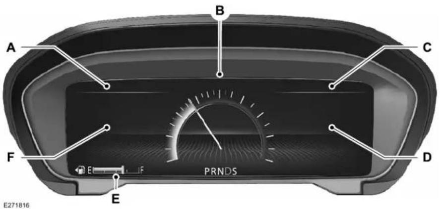
text_image
A B C F D E PRNDS E271816Audio Status Bar.A
Speedometer.B
Time and Temperature Status Bar.C
Right Information Group.D
Instrument Cluster
Fuel Gauge.E
Left Information Group.F
Audio Status Bar
Displays information related to the current audio source.
Time and Temperature Status Bar
Displays time, temperature and navigation related information.
Left/Right Information Group
Information that appears in the left and right information group varies depending on current gauge, on-demand and HUD (if equipped) settings. See General Information (page 122).
Fuel Gauge
The fuel gauge indicates about how much fuel is in the fuel tank.
The arrow adjacent to the fuel pump symbol indicates on which side of your vehicle the fuel filler door is located.
Note: The fuel gauge may vary slightly when your vehicle is moving or on a slope.
Low Fuel Reminder
A low fuel level reminder displays and sounds when the distance to empty reaches 75 mi (120 km) for MyKey, and at 50 mi (80 km), 25 mi (40 km), 10 mi (20 km) and 0 mi (0 km) for all vehicle keys.
Note: The low fuel reminder can appear at different fuel gauge positions depending on fuel economy conditions. This variation is normal.
WARNING LAMPS AND INDICATORS
The following warning lamps and indicators alert you to a vehicle condition that may become serious. Some lamps illuminate when you start your vehicle to make sure they work. If any lamps remain on after starting your vehicle, refer to the respective system warning lamp for further information.
Note: Some warning indicators appear in the information display and function the same as a warning lamp, but do not display when you start your vehicle.
Adaptive Cruise Control (If Equipped)

The speed control system indicator light changes color to indicate what mode the system is in: See
Using Adaptive Cruise Control (page 249).
Instrument Cluster
On (white light): Illuminates when the adaptive cruise control system is turned on. Turns off when the speed control system is turned off.
Engaged (green light): Illuminates when the adaptive cruise control system is engaged. Turns off when the speed control system is disengaged.
Adaptive Steering (If Equipped)

The adaptive steering system indicator illuminates if the system detects a fault during the
continuous diagnostic checks.
Adaptive Steering Initialization (yellow, flashing): The adaptive steering system detects a difference between steering wheel angle and the desired road wheel angle. The steering wheel adjusts itself to correct this difference. This adjustment is part of normal system operation.
Adaptive Steering Off (yellow, solid): The adaptive steering system is off. It is possible that the steering wheel may not be straight when you drive straight ahead. If this message persists, see an authorized dealer.
Adaptive Steering Loss (red, solid): The adaptive steering system integrity cannot be verified. Do not drive the vehicle and contact an authorized dealer immediately. See Steering (page 272).
Anti-Lock Braking System

If it illuminates when you are driving, this indicates a
malfunction. You continue to have the normal braking system (without ABS) unless the brake system warning lamp is also illuminated. Have the system checked by your authorized dealer.
Autohold Active

Illuminates when the system holds your vehicle stationary.
Autohold Unavailable

Illuminates when the system is on, but unavailable to hold your vehicle stationary.
Automatic Headlamp High Beam

Illuminates when this feature is on.
Battery

It illuminates when you switch the ignition on.
If it illuminates when the engine is running this indicates a malfunction. Have your vehicle checked as soon as possible.
Blind Spot Monitor (If Equipped)

It illuminates when you switch this feature off or in conjunction with a message. See Blind Spot
Information System (page 265).
Instrument Cluster
Brake System Warning Lamp

WARNING: Driving your vehicle
with the warning lamp on is dangerous. A significant decrease in braking performance may occur. It may take you longer to stop your vehicle. Have your vehicle checked as soon as possible. Driving extended distances with the parking brake engaged can cause brake failure and the risk of personal injury.
Note: Indicators vary depending on region.
This lamp is a dual function lamp and will illuminate when:
- You apply the parking brake with the ignition on.
- Your vehicle has a brake fault or low brake fluid level, regardless of parking brake position.

If the lamp illuminates when you are moving, you may have the parking brake applied. Make sure the parking brake is off. Have your vehicle checked as soon as possible if the lamp continues to

illuminate.
Cruise Control

Illuminates when you switch this feature on.
Direction Indicator

Illuminates when the left or right turn signal or the hazard warning flasher is turned on. If the
indicators stay on or flash faster, check for a burned out bulb. See Changing a Bulb (page 347).
Door Ajar

Displays when the ignition is on and any door is not completely closed.
Also displays when there is a lack of battery power to the electronic door system. If this displays with all doors closed, have your vehicle serviced by an authorized dealer immediately.
Electric Park Brake

Illuminates or flashes when the electric parking brake has a malfunction. See Electric Parking
Brake (page 220).
Engine Coolant Temperature

Illuminates when the engine coolant temperature is high. Stop the vehicle as soon as possible,
switch off the engine and let cool. See Engine Coolant Check (page 335).
Instrument Cluster
Engine Oil

If it illuminates with the engine running or when you are driving, this indicates a malfunction. Stop your vehicle as soon as it is safe to do so and switch the engine off. Check the engine oil level.
See Engine Oil Check (page 333).
Note: Do not resume your journey if it illuminates despite the level being correct. Have the system checked by your authorized dealer immediately.
Fasten Seatbelt

Illuminates and a chime sounds to remind you to fasten your seatbelt. See Seatbelt Reminder (page 46).
Front Airbag

If it fails to illuminate when you start your vehicle, continues to flash or remains on, it indicates a
malfunction. Have the system checked by your authorized dealer.
High Beam

Illuminates when you switch the high beam headlamps on. It flashes when you use the headlamp
flasher.
Hood Ajar

Displays when the ignition is on and the hood is not completely closed.
Low Beam Warning Lamp (If Equipped)

It illuminates when there is a malfunction with the low beam headlamp bulb.
Low Fuel Level

Illuminates when the fuel level is low or the fuel tank is nearly empty. Refuel as soon as possible.
Low Tire Pressure Warning

It illuminates if the tire pressure in one or more tires is below the correct tire pressure.
See Tire Pressure Monitoring System (page 376).
Low Washer Fluid

Illuminates when the windshield washer fluid is low.
Parking Lamps

Illuminates when you switch the parking lamps on.
Powertrain Fault

Illuminates when a powertrain or an AWD fault has been detected. Contact an authorized dealer.
Instrument Cluster
Service Engine Soon

If it illuminates when the engine is running this indicates a malfunction. The On Board Diagnostics system has detected a malfunction of the vehicle emission control system.
If it flashes, engine misfire may be occurring. Increased exhaust gas temperatures could damage the catalytic converter or other vehicle components. Drive in a moderate fashion (avoid heavy acceleration and deceleration) and have your vehicle immediately serviced.
It illuminates when you switch the ignition on prior to engine start to check the bulb and to indicate whether your vehicle is ready for Inspection and Maintenance (I/M) testing.
Normally, it illuminates until the engine is cranked and automatically turns off if no malfunctions are present. However, if after 15 seconds it flashes eight times, this indicates that your vehicle is not ready for Inspection and Maintenance (I/M) testing. See Emission Law (page 198).
Stability Control

It flashes when the system is active. If it remains illuminated or does not illuminate when you switch the ignition on, this indicates a malfunction. During a malfunction the system switches off. Have the system checked by your authorized dealer immediately. See Using Stability Control (page 227).
Stability Control Off

It illuminates when you switch the system off. It goes out when you switch the system back on or when you switch the ignition off.
See Using Stability Control (page 227).
Trunk Ajar

Displays when the ignition is on and the trunk is not completely closed.
AUDIBLE WARNINGS AND INDICATORS
Keyless Warning Alert
Sounds the horn twice when you exit your vehicle with the intelligent access key, after the last door is closed and your keyless vehicle is in RUN, indicating your vehicle is still on.
Headlamps On Warning Chime
Sounds when you have left the headlamps or parking lamps on and open the driver door with the vehicle off.
Parking Brake On Warning Chime
Sounds when you have left the parking brake on and drive your vehicle. If the warning chime remains on after you have released the parking brake, have the system checked by your authorized dealer immediately.
Information Displays
GENERAL INFORMATION

WARNING: Driving while distracted can result in loss of vehicle control, crash and injury. We strongly recommend that you use extreme caution when using any device that may take your focus off the road. Your primary responsibility is the safe operation of your vehicle. We recommend against the use of any hand-held device while driving and encourage the use of voice-operated systems when possible. Make sure you are aware of all applicable local laws that may affect the use of electronic devices while driving.
You can control various systems on your vehicle using the quick action menu (QAM) buttons on the right-hand side of the steering wheel. The information display provides the corresponding information.
Note: Some options may appear slightly different or not at all if the items are optional.
Note: Some MyKey menu options only appear if MyKey is enabled and at least one MyKey is programmed.
Note: Speedometer, driving aid information, and distance to empty information (if enabled) moves to the left information group when a menu is opened.

This icon gives you the ability to switch a feature on or off. A check in the box indicates the feature is
enabled, and unchecked indicates the feature is disabled.
Information Displays
Information Display Controls
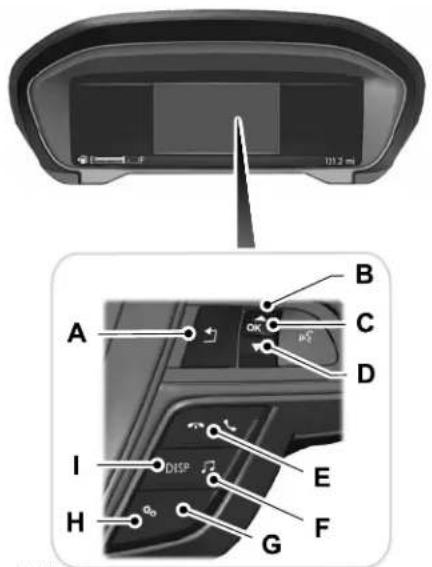
text_image
103.2 m A B C D I DISP E H Qo G FE221165
Back button.A
Toggle up.B
OK button.C
Toggle down.D
Phone button.E
Audio button.F
Navigation button (If Equipped).G
Settings button.H
Display button.1
Note: The HUD button replaces the DISP button on vehicles that have a head up display (HUD). See Head Up Display (page 149).
- Press the QAM button to enter the menu.
- Toggle (B) and (D) to scroll through and highlight the options within a menu.
- Press (C) to enter a sub-menu.
-
Press (A) to exit a menu.
-
Press the open menu's QAM button at any time to close the menu (escape button).
- Press (C) to choose and confirm settings or messages.
Information Displays
Settings
| Settings | |||
| See Display OptionsInfo/Trip/Fuel | |||
| Gauges | |||
| Traction Control | |||
| Select Your SettingHandling in DDrive Control | |||
| Handling in S | |||
| Performance in S | |||
| BlindspotDriver Assistance | |||
| Cross Traffic Alert | |||
| Select Your SettingCruise Control | |||
| Driver Alert | |||
| System | Select Your SettingModeLane Keeping | ||
| Intensity | |||
| Alert SensitivityPre-Collision | |||
| Active Braking | |||
Information Displays
| Settings | ||||
| Speedometer km/h | ||||
| Speedometer MPH | ||||
| Select Your SettingAlarmVehicleAdvanced Settings | ||||
| Ask on Exit | ||||
| Auto Engine Off | ||||
| Autofold Mirrors | ||||
| Easy Entry/Exit | ||||
| Auto HighbeamLighting | ||||
| Delay | Select Your SettingAutolamp | |||
| Daytime Lights | ||||
| Welcome Lighting | ||||
| Auto UnlockLocks | ||||
| AudibleFeedback | ||||
| Exterior Lights | ||||
| Mislock | ||||
Information Displays
| Settings | ||||
| Unlock | Select Your SettingRemote | |||
| Switch Inhibit | ||||
| Follow onscreen directions to confirm or modify your settings.Oil Life Reset | ||||
| Select Your SettingPower Decklid | ||||
| Remote Start | Control | Select Your SettingClimate | ||
| Seats and Wheel | ||||
| Duration | ||||
| System | ||||
| Follow onscreen directions to confirm or modify your settings.Tire Monitor | ||||
| Remote OpenWindows | ||||
| Remote Close | ||||
| Courtesy WipeWipers | ||||
| Rain Sensing | ||||
| Follow onscreen directions to confirm or modify your settings.MyKey StatusMyKey | ||||
Information Displays
| Settings | |||
| Create MyKey | |||
| Select Your Setting911 Assist | |||
| Do Not Disturb | |||
| Traction Control | |||
| Max Speed | |||
| Speed Minder | |||
| Volume Limiter | |||
| Follow onscreen directions to confirm or modify your settings.Clear MyKeys | |||
| Select Your SettingDistanceDisplay Setup | |||
| Temperature | |||
| Tire Pressure | |||
| Language | |||
Display Options
Note: If your vehicle does not have a head up display, use the DISP button to access your Info/Trip/Fuel and Gauges options.
Info/Trip/Fuel On Demand information appears on the right-hand side of your instrument cluster.
Information Displays
| Info/Trip/Fuel |
| Engine Hours |
| Trip 1 |
| Trip 2 |
| Fuel Economy |
| Tire Pressure |
| Intelligent AWD |
| None |
• Engine Hours - Livery vehicles only. Displays the engine hours and engine idle hours.
- Trip 1 - Displays distance traveled, average fuel economy, and time spent for trip. Press and hold OK to reset.
- Trip 2 information is the same as Trip 1.
- Fuel Economy - Displays instantaneous and average fuel economy.
- Tire Pressure - Displays a graphic of current vehicle tire pressures.
• Intelligent AWD (if equipped) - Displays a graphic of the power distribution between the front and rear wheels.
•None - Displays a blank area.
Information Displays
Gauges
There are three gauge modes:
Speedometer, Fuel Economy and Tach and
Gauges. The following table describes the display options in each mode.
| Gauges | |||||
| Right GroupLeft Group | |||||
| Bar On | HUD On and Status Bar Off | HUD On, Status Bar Off and Navigation Available | HUD OffHUD OffHUD On HUD On, Status Bar Off and Navigation Not Available | ||
| BlankDTEBlankSpeedometer Street Name | Graphic CompassCompass | ||||
| Fuel Economy | Average and Instant Fuel Economy | Average and Instant Fuel Economy / DTE | |||
| Tachometer / DTETachometerTach and Gauges Gauge | Turbo and Temp GaugeTurbo | ||||
| Average Fuel Economy displays instead of Turbo if your vehicle has a 3.7L V6 TiVCT Engine. | |||||
DTE
Shows the approximate distance your vehicle can travel before running out of fuel.
Average Fuel Economy
Shows the average fuel usage based on time.
Instant Fuel Economy
Shows your instantaneous fuel usage.
Information Displays
Tachometer
Indicates the engine speed in revolutions per minute. Driving with your tachometer pointer continuously at the top of the scale may damage the engine.
Turbo Gauge (If Equipped)
Indicates the amount of manifold air pressure in the engine.
Temperature Gauge
Indicates engine coolant temperature. At normal operating temperature, the level indicator will be in the normal range. If the engine coolant temperature exceeds the normal range, stop your vehicle as soon as safely possible, switch off the engine and let the engine cool.

WARNING: Do not remove the reservoir cap when the engine is the cooling system is hot. Wait 10 s for the cooling system to cool Cover the coolant reservoir cap with cloth to prevent the possibility of g and slowly remove the cap. to follow this instruction could result in aal injury.
Head Up Display (If Equipped)
See Head Up Display (page 149).
Phone
See General Information (page 453).
Audio
See General Information (page 453).
Navigation (If Equipped)
See General Information (page 453).
INFORMATION MESSAGES
Note: Depending on your vehicle options and instrument cluster type, not all of these messages may be available and certain messages may be abbreviated or shortened.
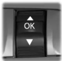
E222314
Press the OK button to acknowledge and remove some messages from the information display. Other messages will be removed automatically after a short time.
Certain messages need to be confirmed before you can access the menus.
Information Displays
Active Park
| ActionMessage | |
| Active Park Fault | The system has detected a fault that requires service. Have the system checked by an authorized dealer. |
Adaptive Cruise Control
| ActionMessage | |
| Adaptive Cruise Malfunction | A radar malfunction is preventing the adaptive cruise from engaging. See Using Adaptive Cruise Control (page 249). |
| Front Sensor Not Aligned | |
| Adaptive Cruise Not Available | Conditions exist such that the adaptive cruise cannot function properly. See Using Adaptive Cruise Control (page 249). |
| Adaptive Cruise Not Available Sensor Blocked See Manual | The radar is blocked because of poor radar visibility due to bad weather or ice/mud/water in front of radar. Driver can typically clean the sensor to resolve. See Using Adaptive Cruise Control (page 249). |
| Turned Off | Displayed when the automatic braking has been disabled.Normal Cruise Active |
| Displayed when the adaptive cruise has reinstated controls to the driver.Adaptive Cruise Control | |
| Activate | Displays when the vehicle speed is too slow to activate the adaptive cruise.Adaptive Cruise Control |
Information Displays
Adaptive Headlamps
| ActionMessage | |
| Check Headlamp System See Manual | Displays when a fault with the system has occurred. Contact an authorized dealer as soon as possible. |
Adaptive Steering
| ActionMessage | |
| Adaptive Steering Initialization | The adaptive steering system detects a difference between steering wheel angle and the desired road wheel angle. The steering wheel adjusts itself to correct this difference. This adjustment is part of normal system operation. |
| Adaptive Steering Fault Service Required | The adaptive steering system is off. It is possible that the steering wheel may not be straight when you drive the vehicle straight ahead. If this message persists, see an authorized dealer. |
| Adaptive Steering Loss Do Not Drive | The adaptive steering system integrity cannot be verified. Do not drive the vehicle and contact an authorized dealer immediately. |
Airbag
| ActionMessage | |
| Occupant Sensor BLOCKED Remove Objects Near Passenger Seat | Objects are by the passenger seat. After the objects are moved away from the seat, if the warning stays on or continues to come on contact an authorized dealer as soon as possible. |
Information Displays
Alarm
| ActionMessage | |
| Vehicle Alarm To Stop Alarm, Start Vehicle. | The alarm has been triggered due to unauthorized entry. See Anti-Theft Alarm (page 91). |
Automatic Engine Shutdown
| ActionMessage | |
| The engine is getting ready to shut off. Vehicle Shuts Off In {seconds:#0} S | |
| The engine has shut off to help increase fuel economy. Vehicle Shut Off to Save E | |
| Vehicle Shuts Off in {seconds:#0} Seconds Press Ok to Override | The engine is getting ready to shut off. You can press OK on the left steering wheel button to override the shut down. |
Information Displays
AWD
| ActionMessage | |
| AWD OFF | Displays when the system automatically disables to protect itself. This may be caused by operating the vehicle with the compact tire installed, if the system is overheating or if there is an issue with another vehicle system preventing AWD operation. The system resumes normal operation and clears this message after cycling the ignition on and off and driving a short distance with the road tire re-installed, after the system is allowed to cool or after the other vehicle system issues are resolved. |
| AWD Malfunction Service Required | Displays in conjunction with the powertrain malfunction or reduced power light when the system is not operating properly. If the message stays on or continues to come on, contact your authorized dealer as soon as possible. |
Battery and Charging System
| ActionMessage | |
| Check Charging System | The charging system needs servicing. If the warning stays on or continues to come on, contact an authorized dealer as soon as possible. |
| Charging System Service Soon | The charging system needs servicing. If the warning stays on or continues to come on, contact an authorized dealer as soon as possible. |
| The charging system needs servicing. Contact an authorized dealer as soon as possible. |
Information Displays
| ActionMessage | |
| Battery State of Charge Low | The battery management system determines that the 12V battery is at a low state of charge. Start the engine to charge the battery or charge the battery using an aftermarket battery charger. This message clears once you restart your vehicle and the battery state of charge has recovered. |
| Turn Power Off To Save Battery | The battery management system determines that the battery is at a low state of charge. Turn the ignition off as soon as possible to protect the battery. This message will clear once the vehicle has been started and the battery state of charge has recovered. Turning off unnecessary electrical loads will allow faster battery state-of-charge recovery. |
| Low Battery Features Temporarily Turned Off | Displayed when the battery management system detects an extended low-voltage condition. Various vehicle features will be disabled to help preserve the battery. Turn off as many of the electrical loads as soon as possible to improve system voltage. If the system voltage has recovered, the disabled features will operate again as normal. |
Information Displays
Blind Spot Information and Cross Traffic Alert System
| ActionMessage | |
| A fault with the system has occurred. Contact an authorized dealer as soon as possible.Blindspot System | |
| Blindspot Not Available Sensor Blocked See Manual | The system sensors are blocked. Contact an authorized dealer as soon as possible. See Blind Spot Information System (page 265). |
| Vehicle Coming From X | The system detects a vehicle. See Blind Spot Information System (page 265). |
| Cross Traffic Not Available Sensor Blocked See Manual | The blind spot information system and cross traffic alert system sensors are blocked. See Blind Spot Information System (page 265). |
| A fault with the system has occurred. Contact an authorized dealer as soon as possible.Cross Traffic System |
Doors and Locks
| ActionMessage | |
| The door listed is not completely closed.X Door Ajar | |
| Engine ON | The driver's door is opened, your vehicle is in park and the engine is on. |
| Displays when the hood is not completely closed.Hood Ajar | |
| Displays when the door switches have been disabled.Switches Inhibited Security Mod | |
| Child Lock Malfunction Service Required | There is a system malfunction with the child locks. Contact an authorized dealer as soon as possible. |
Information Displays
| ActionMessage | |
| Child Lock ON | Indicates that the rear seat interior door release switches and power windows are switched off, preventing rear seat occupants from opening the doors or windows. |
| Child Lock OFF | Indicates that the rear seat interior door release switches and power windows are switched on. |
| Displays when the door lock turns off.Door Unlocked | |
| Displays when the door lock is turned on and you attempt to open the door.Doors Lock | |
| Driver Door Fault Use Inside Override Lever In Map Pocket | Indicates a driver door fault that requires manually opening the door by the override lever. Contact an authorized dealer. |
| Indicates a fault with the electronic door system. Contact an authorized dealer.Door Fault | |
| Factory Keypad Code {X X X X X} | Displays the factory keypad code after the keypad has been reset. See Keyless Entry (page 85). |
Driver Alert
| ActionMessage | |
| Stop and rest as soon as it is safe to do so.Driver Alert Warning Rest Now | |
| Take a rest soon.Driver Alert Warning Rest Suggested |
Information Displays
Fuel
| ActionMessage | |
| An early reminder of a low fuel condition.Fuel Level Low | |
| The fuel fill inlet may not be properly closed.Check Fuel Fill Inlet |
Hill Start Assist
| ActionMessage | |
| Hill Start Assist Not Available | Displays when hill start assist is not available. Contact your authorized dealer. See Hill Start Assist (page 222). |
Keys and Intelligent Access
| ActionMessage | |
| A reminder to press the brake while starting your vehicle.To START Press Brake | |
| No Key Detected | The system does not detect the key. See Keyless Starting (page 185). |
| Restart Now or Key is Needed | The Start Stop button is pressed to shut off the engine and an Intelligent Access key is not detected inside your vehicle. |
| Your vehicle is in the accessory ignition state.Full Accessory Power Active |
Information Displays
| ActionMessage | |
| Starting System Fault | There is a problem with your vehicle's starting system. See an authorized dealer for service. |
| During spare key programming, an intelligent access key is programmed to the system.Key | |
| During spare key programming, the maximum number of keys have been programmed.Max | |
| Key Program Failure | Displayed during spare key programming, when an intelligent access key has failed to be programmed. |
| Displayed during spare key programming when not enough keys have been programmed.Not Enough | |
| Displays when the key battery is low. Change the battery as soon as possible.Key Battery Low | |
| Displays when the vehicle is switched off.Vehicle Switched Off |
Information Displays
Lane Keeping System
| ActionMessage | |
| Required | The system has malfunctioned. Contact an authorized dealer as soon as possible.Lane Keeping Sys |
| Front Camera Temporarily Not Available | The system has detected a condition that has caused the system to be temporarily unavailable. |
| Front Camera Low Visibility Clean Screen | The system has detected a condition that requires the windshield to be cleaned to operate properly. |
| Required | The system has malfunctioned. Contact an authorized dealer as soon as possible.Front Camera Mal |
| The system requests the driver to keep their hands on the steering wheel.Keep Hands on Steeri |
Maintenance
| ActionMessage | |
| Low Engine Oil Pressure | Stop your vehicle as soon as safely possible, turn off the engine. Check the oil level. If the warning stays on or continues to come on with your engine running, contact an authorized dealer as soon as possible. |
| The engine oil life remaining is 10% or less.Change Engine Oil Soon | |
| The oil life left reaches 0%.Oil Change Required |
Information Displays
| ActionMessage | |
| Brake Fluid Level Low | The brake fluid level is low and the brake system should be inspected immediately. See Brake Fluid Check (page 340). |
| Check Brake System | The brake system needs servicing. Stop the vehicle in a safe place. Contact an authorized dealer. |
| The engine coolant temperature is excessively high. Engine Coolant Over Temp | |
| The washer fluid is low and needs to be refilled. Washer Fluid Level Low | |
| Transport Mode Contact Dealer | Indicates that your vehicle is still in Transport mode. This may not allow some features to operate properly. Contact an authorized dealer. |
| Factory Mode Contact Dealer | Indicates that your vehicle is still in Factory mode. This may not allow some features to operate properly. Contact an authorized dealer. |
| Informs the driver that the powertrain needs service due to a powertrain malfunction. See Manua | |
| The engine has reduced power to help reduce high engine temperature. Power Reduced | |
| The brake system has reduced stopping power. Brake Applied Power Reduced |
Information Displays
MyKey
| ActionMessage | |
| MyKey cannot be programmed during key programming.MyKey not Created | |
| When starting your vehicle, a MyKey is in use and the MyKey speed limit is on.Speed Limited to X | |
| Near Vehicle Top Speed | When a MyKey is in use, the MyKey speed limit is on and your vehicle speed is approaching 81 mph (130 km/h). |
| Displays when MyKey is active.MyKey Active Drive Safely | |
| Displays when MyKey is active.Check Speed Drive Safely | |
| Displays when a MyKey is in use and the MyKey speed limit is reached.Vehicle at Top Speed of Unmute Au | |
| Displays when a MyKey is in use and seatbelt reminder is activated.Buckle Up to | |
| Displays when a MyKey is in use and AdvanceTrac is activated.AdvanceTrac On - MyKey S | |
| Displays when a MyKey is in use and park aid is activated.MyKey Park Aid Cannot be De | |
| Displayed when the lane keeping aid is on per MyKey settings.Lane Keeping Alert On MyK |
Information Displays
Park Aid
| ActionMessage | |
| Check Front Park Aid | The system has detected a condition that requires service. Contact your authorized dealer. See Front Parking Aid (page 230). |
| Check Rear Park Aid | The system has detected a condition that requires service. Contact your authorized dealer. See Rear Parking Aid (page 229). |
Park Brake
| ActionMessage | |
| Park Brake Engaged | The parking brake is set, the engine is running and you drive your vehicle more than 3 mph (5 km/h). If the warning stays on after the parking brake is released, contact an authorized dealer as soon as possible. |
| To Release: Press Brake and Switch | The electric parking brake is set and a manual release is attempted without the brake pedal being pressed. |
| Park Brake Use Switch to Release | The electric parking brake is set and an automatic release is attempted but cannot be performed. Perform a manual release. |
| Release Park Brake | The electric parking brake is set and your vehicle speed exceeds 3 mph (5 km/h). Release park brake before continued driving. |
| The electric parking brake is not fully applied. Park Brake Not Applied |
Information Displays
| ActionMessage | |
| The electric parking brake is not fully released.Park Brake Not Released | |
| Park Brake Maintenance Mode | The electric parking brake system has been put into a special mode that is used to allow service of the rear brakes. Contact an authorized dealer. |
| Park Brake Limited Function Service Required | The electric park brake system has detected a condition that requires service. Some functionality may still be available. Contact your authorized dealer. |
| Park Brake Malfunction Service Now | The electric parking brake system has detected a condition that requires service. Contact your authorized dealer. |
| Park Brake System Overheated | Numerous park brake applies have overheated the system. Wait 2 minutes before attempting to apply again. |
Power Steering
| ActionMessage | |
| Steering Fault Service Now | The power steering system has detected a condition that requires service. See an authorized dealer. |
| Steering Assist Fault Service Required | The power steering system has detected a condition within the power steering system or passive entry or passive start system requires service. Contact an authorized dealer. |
| Steering Loss Stop Safely | The power steering system is not working. Stop the vehicle in a safe place. Contact your authorized dealer. |
Information Displays
Pre-Collision Assist
| ActionMessage | |
| Pre-Collision Assist Not Available Sensor Blocked | You have a blocked sensor due to bad weather, ice, mud or water in front of the radar sensor. You can typically clean the sensor to resolve. |
| Pre-Collision Assist Not Available | A fault with the system has occurred. Contact an authorized dealer as soon as possible. |
Remote Start
| ActionMessage | |
| To Drive: Press Brake and Gear Shift Button | Displays as a reminder to apply the brake and push the gear shift button to drive the vehicle after a remote start. |
Seats
| ActionMessage | |
| Memory Recall Not Permitted While Driving | Displays as a reminder that memory seats are not available while driving. |
| Displays to show where your memory setting has been saved.Memory {0} Saved |
Information Displays
Stability Control
| ActionMessage | |
| Service AdvanceTrac | Displayed when the system has detected a condition that requires service. Contact your authorized dealer as soon as possible. |
| The traction control has been disabled or enabled by the driver.AdvanceTrac Off On |
Starting System
| ActionMessage | |
| Displays when starting the vehicle as a reminder to apply the brake.To START Press Brake | |
| Displays when the starter has exceeded its cranking time in attempting to start the vehicle.Cranking Tim | |
| Displays when the starter is attempting to start the vehicle.Engine Start Pending Please V | |
| Displays when the pending start has been cancelled Pending Start Cancelled |
Information Displays
Tire Pressure Monitoring System
| ActionMessage | |
| Tire Pressure Low | One or more tires on your vehicle have low tire pressure. See Tire Pressure Monitoring System (page 376). |
| Tire Pressure Monitor Fault | The tire pressure monitoring system is malfunctioning. If the warning stays on or continues to come on, contact an authorized dealer. See Tire Pressure Monitoring System (page 376). |
| Tire Pressure Sensor Fault | A tire pressure sensor is malfunctioning, or your spare tire is in use. For more information on how the system operates under these conditions, See Tire Pressure Monitoring System (page 376). If the warning stays on or continues to come on, contact an authorized dealer as soon as possible. |
Transmission
| ActionMessage | |
| You switched the engine off and shift select lever is in any position other than park (P).Shift to Par | |
| Transmission is too cold. Wait for it to warm up before you drive.Transmission Warmin | |
| Displays when the brake pedal needs to be depressed.Press Brake Pedal | |
| Transmission Over Temperature Stop Safely | The transmission is overheating and needs to cool. Stop in a safe place as soon as it's possible. |
| See an authorized dealer.Transmission Service Required |
Information Displays
| ActionMessage | |
| Transmission Too Hot Press Brake | The transmission is overheating and needs to cool. Stop in a safe place as soon as it's possible. |
| Transmission Limited Function See Manual | The transmission has limited functionality. See an authorized dealer. |
| Transmission Not in Park | A reminder to shift into park. In addition, this message is typical after reconnecting or recharging the battery until you cycle the ignition to the on mode. See Changing the 12V Battery (page 342). |
| SHIFT SYS FAULT Confirm Park Brake Apply Before Exiting the Vehicle | Displays when there is a system fault and the park brake needs to be depressed before exiting the vehicle. See your authorized dealer. |
| See your authorized dealer.SHIFT SYS FAULT Service Required | |
| SHIFT SYS FAULT Vehicle is Shifting to Park | Displays when there is a system fault while the vehicle is shifting to park. See your authorized dealer. |
| SHIFT SYS FAULT Reverse Unavailable Service Required | Displays when there is a system fault while the vehicle is shifting to reverse. See your authorized dealer. |
| S for Drive Service Required | See an authorized dealer.SHIFT SYS FAULT Drive Unavailable Select |
| Service Required | See your authorized dealer.SHIFT SYS FAULT Neutral Unavailable |
| Service Required | See your authorized dealer.SHIFT SYS FAULT Sport Unavailable |
| Displays when an invalid gear has been selected.Invalid Gear Selection |
Information Displays
| ActionMessage | |
| Depress Brake to Shift from Park | Displays when the brake pedal needs to be depressed to enable the transmission to shift from park. |
| Stay in Neutral Mode Engaged | Displays when neutral hold is active. See Automatic Transmission (page 203). |
| To Stay in Neutral When Exiting Vehicle Select N Again | Displays when the neutral button N needs to be pressed again to enter neutral hold. See Automatic Transmission (page 203). |
HEAD UP DISPLAY (IF EQUIPPED)
Head Up Display (HUD)
This is a visual system that shows information in your field of view as you drive. The information comes from various vehicle systems and includes vehicle speed, speed limit, navigation, and advanced driver assistance systems (ADAS), such as adaptive cruise control (ACC) and the lane keeping system. This system projects the information off the windshield, and focuses the image
near the end of the hood approximately 7 ft (2 m) in front of the driver. Viewing this information does not require you to significantly move your head, allowing you to keep your eyes on the road while having quick and easy access to information.
Head Up Display Information
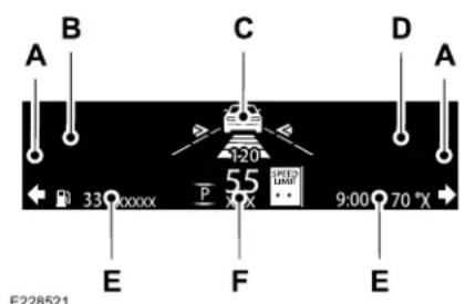
text_image
A B C D A 120 33xxxxx P 55 X 9:00 70 °X E F E E228521Signaling and Traffic Indication.A
Left Information Group.B
ADAS Display Area.C
Information Displays
Navigation Display Area.D
Status Bar.E
Speedometer Display Area.F
Signaling and Traffic Indication
Displays direction indicators, blind spot information (if direction indicators are active) and cross traffic alert.
Left Information Group
Displays incoming call information.
ADAS Display Area
Displays ACC and lane keeping system status and warnings.
Navigation Display Area
Displays navigation next turn instructions.
Status Bar
Displays distance to empty (DTE), time and outside air temperature. Next to DTE, the fuel gauge fill color changes to yellow in low fuel conditions. You can switch off the status bar in the HUD settings menu.
Speedometer Display Area
Displays current vehicle speed, speed limit (if available in the map database) and your transmission gear selection.
Configuring The Head Up Display
You can control the system's options through the information display by using the HUD, OK and arrow buttons on the right-hand side of your steering wheel. See General Information (page 122). You can adjust the display according to your height to make viewing the content easier. You can also adjust what content displays and the brightness of the content. The system's options appear in the instrument cluster while the updates happen in the HUD.
Note: If HUD On is unchecked, other options of the system are hidden.
Note: The HUD menu automatically closes after a certain period of inactivity.
Note: The HUD image brightness automatically adjusts to the brightness of the ambient environment. You have the ability to adjust the brightness further according to your preference.
Note: In some instances, sunlight can cause some reflections in and around the HUD image.
Information Displays
| Head-Up Display (HUD) | ||
| Turns the HUD on and off.HUD On | ||
| Follow onscreen directions to confirm or modify your settings.Brightness | ||
| Vertical PositionHUD Adjustments | Follow onscreen directions to confirm or modify your settings. | |
| Image Rotation | ||
| Turns the distance to empty, time and temperature on and off.HUD Content | ||
| Select Your SettingCruise and Lane Control | ||
Note: When you save a memory preset position, your current HUD settings are also saved to that memory preset position. See Memory Function (page 170).
Information Displays
Maintaining Your Head Up Display
- Do not place objects onto the transparent cover, as they may block you from seeing portions of the image. These objects could also damage the cover and affect the quality of the projected image.
•The system uses a special windshield designed to provide the optimum image quality. You must replace the windshield in a vehicle with this system with a certified original equipment manufactured (OEM) head up display windshield. Replacing this system's windshield with a non-head up display windshield causes a double image or distorted image. Have an authorized dealer or authorized repair facility replace the windshield.
•Light conditions such as oncoming headlamps, sunrise, sunset or reflections off of wet road surfaces can affect the driver's ability to see the HUD image. - Clean the windshield often for optimal HUD performance. See Cleaning the Windows and Wiper Blades (page 353).
Climate Control
AUTOMATIC CLIMATE CONTROL
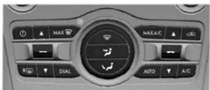
text_image
MAX MAX A/C DUAL AUTO A/CE287753
Note: Depending on your vehicle option package, the controls may look different from what you see here.
Note: You can switch temperature units between Fahrenheit and Celsius.
Directing Air to the Instrument Panel Air Vents

Press and release the button to direct airflow to instrument panel air vents.
Directing Air to the Footwell Air Vents

Press and release the button to direct airflow to footwell air vents.
Setting the Blower Motor Speed

Turn the control to adjust the volume of air circulated in the vehicle.
Setting the Temperature
Press the toggle button on the left-hand side of the climate control upward or downward to set the left-hand temperature.
Note: This control also adjusts the right-hand side temperature when you switch off dual zone mode.
Press the toggle button on the right-hand side of the climate control upward or downward to set the right-hand temperature.
Switching Auto Mode On and Off

Press and release the button to switch on automatic operation. Repeatedly press the button to
to mode.
The system adjusts the blower motor speed, air distribution, air conditioning operation, and outside or recirculated air to reach and maintain the temperature you have set.
Note: The system starts at the previous setting when you switch on AUTO mode.
Note: You can also switch off dual zone mode by pressing and holding the button for more than two seconds.
Climate Control
Auto Mode Indicator Status
| DescriptionAuto Mode Indicator Status | |
| One indicator illuminated. •The blower motor speed is reduced.•Use this setting to minimize the amount of noise from the blower motor.•This setting increases the time taken to cool the interior. | |
| Two indicators illuminated. •The blower motor speed is moderate. | |
| Three indicators illuminated. •The blower motor speed is increased.•This setting increases the amount of noise from the blower motor.•Use this setting to reduce the time taken to cool the interior. | |
Switching Defrost On and Off

Press and release the button to distribute air through the windshield air vents and de-mister.
Air directed to the instrument panel and footwell air vents turns off. You can also use this setting to defog and clear the windshield of a thin covering of ice.
Switching the Air Conditioning On and Off

Press and release the button.
Use air conditioning with recirculated air to improve cooling performance and efficiency.
Note: In certain conditions, for example, maximum defrost, the air conditioning compressor may continue to operate even though you switch off the air conditioning.
Switching the Climate Control On and Off

Press and release the button.
Climate Control
Switching Dual Zone Mode On and Off

Press and release the button to switch on temperature control for the right-hand side of the vehicle.
Switching Maximum Air Conditioning On and Off

Press and release the button for maximum cooling.
The left-hand and right-hand settings set to LO, recirculated air flows through the instrument panel air vents, air conditioning turns on and the blower motor adjusts to the highest speed.
Switching Maximum Defrost On and Off

Press and release the button for maximum defrosting.
The left-hand and right-hand settings set to HI, air flows through the windshield air vents, and the blower motor adjusts to the highest speed.
You can also use this setting to defog and clear the windshield of a thin covering of ice.
Note: To prevent window fogging, you cannot select recirculated air when maximum defrost is on.
Note: The heated rear window also turns on when you select maximum defrost.
Switching Recirculated Air On and Off

Press and release the button to switch between outside air and recirculated air.
The air currently in the passenger compartment recirculates. This may reduce the time needed to cool the interior, when used with A/C, and reduce unwanted odors from entering your vehicle.
Note: Recirculated air may turn off, or prevent you from switching on, in all air flow modes except MAX A/C to reduce the risk of fogging. Recirculation may also turn on and off in various air distribution control combinations during hot weather to improve cooling efficiency.
HINTS ON CONTROLLING THE INTERIOR CLIMATE
General Hints
Note: Prolonged use of recirculated air may cause the windows to fog up.
Note: You may feel a small amount of air from the footwell air vents regardless of the air distribution setting.
Note: To reduce humidity build-up inside your vehicle, do not drive with the system switched off or with recirculated air always switched on.
Note: Do not place objects under the front seats as this may interfere with the airflow to the rear seats.
Note: Remove any snow, ice or leaves from the air intake area at the base of the windshield.
Note: To improve the time to reach a comfortable temperature in hot weather, drive with the windows open until you feel cold air through the air vents.
Climate Control
Automatic Climate Control
Note: Adjusting the settings when your vehicle interior is extremely hot or cold is not necessary. Automatic mode is best recommended to maintain set temperature.
Note: The system adjusts to heat or cool the interior to the temperature you select as quickly as possible.
Note: For the system to function efficiently, the instrument panel and side air vents should be fully open.
Note: If you select AUTO during cold outside temperatures, the system directs air flow to the windshield and side window air vents. In addition, the blower motor may run at a slower speed until the engine warms up.
Note: If you select AUTO during hot temperatures and the inside of the vehicle is hot, the system uses recirculated air to maximize interior cooling. Blower motor speed may also reduce until the air cools.
Quickly Heating the Interior
-
Press and release AUTO.
-
Adjust the temperature function to the setting you prefer.
Recommended Settings for Heating
- Press and release AUTO.
- Adjust the temperature function to the setting you prefer. Use 72^ F ( 22^ C) as a starting point, then adjust the setting as necessary.
Quickly Cooling the Interior
- Press and release MAX A/C.
Recommended Settings for Cooling
- Press and release AUTO.
- Adjust the temperature function to the setting you prefer. Use 72°F (22°C) as a starting point, then adjust the setting as necessary.
Defogging the Side Windows in Cold Weather
-
Press and release defrost.
-
Adjust the temperature control to the setting you prefer. Use 72^ F ( 22^ C) as a starting point, then adjust the setting as necessary.
REAR PASSENGER CLIMATE CONTROLS (IF EQUIPPED)
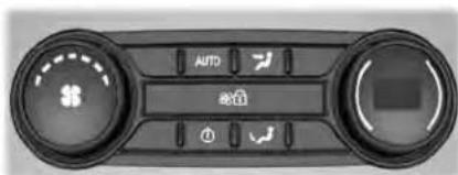
text_image
AUTO AUTOE290004
Note: Depending on your vehicle option package, the controls may look different from what you see here.
Directing Air to the Rear Console Air Vents

Press and release the button to direct airflow to the rear console air vents.
Climate Control
Directing Air to the Rear Footwell Air Vents

Press and release the button to direct airflow to rear footwell air vents.
Note: Air can be directed through any combination of air vents.
Rear Climate Control Lock Indicator

Illuminates when the rear climate controls are locked through the front climate controls.
Note: If the rear climate controls are locked and the rear climate system is turned off, the indicator illuminates for a few seconds when you try to use any of the rear climate controls.
Setting the Rear Blower Motor Speed
natural_image
Circular diagram with a central symbol and two opposing arrows pointing outward (no text or labels)Turn the control to adjust the volume of air circulated in the rear passenger compartment.
Setting the Rear Temperature
natural_image
Circular diagram with concentric rings and directional arrows, no text or symbols presentTurn the control to set the temperature in the rear passenger compartment.
Switching Rear Auto Mode On

Press and release the button to switch rear automatic operation on, then set the temperature.
Climate Control
The system adjusts the blower motor speed, air distribution, air conditioning operation to reach and maintain the temperature you have set.
Switching the Rear Climate Control On and Off

Press and release the button to switch the rear climate control on or off.
Note: If the system is on and Max Defrost is switched on through the front climate controls, the system turns off. It turns back on when Max Defrost is switched off.
Note: If Max Defrost is switched on, the system can be turned on at the same time.
Switching the Rear Heated Seats On and Off (If Equipped)

See Heated Seats (page 173).
Switching the Rear Ventilated Seats On and Off (If Equipped)

See Climate Controlled Seats (page 175).
HEATED WINDSHIELD (IF EQUIPPED)
Windshield Wiper De-Icer

When you switch the heated rear window on, the windshield wiper de-icer turns on.
HEATED REAR WINDOW

Press the button to clear the rear window of thin ice and fog. The heated rear window turns off after period of time.
Note: Make sure the engine is on before operating the heated windows.
Note: Do not use harsh chemicals, razor blades or other sharp objects to clean or remove decals from the inside of the heated rear window. The vehicle warranty may not cover damage to the heated rear window grid lines.
HEATED EXTERIOR MIRRORS
When you switch the heated rear window on, the heated exterior mirrors turn on.
Note: Do not remove ice from the mirrors with a scraper or adjust the mirror glass when it is frozen in place.
Note: Do not clean the mirror housing or glass with harsh abrasives, fuel or other petroleum-based cleaning products. The vehicle warranty may not cover damage caused to the mirror housing or glass.
Climate Control
CABIN AIR FILTER
Your vehicle is equipped with a cabin air filter, which gives you and your passengers the following benefits:
- It improves your driving comfort by reducing particle and odor concentration.
- It improves the interior compartment cleanliness.
- It protects the climate control components from particle deposits.
You can locate the cabin air filter behind the glove box.
Note: Make sure you have a cabin air filter installed at all times. This prevents foreign objects from entering the system. Running the system without a filter in place could result in degradation or damage to the system.
Replace the filter at regular intervals. See Scheduled Maintenance (page 519).
For additional cabin air filter information, or to replace the filter, see a qualified technician.
REMOTE START
You can switch this feature on or off and adjust the settings using the information display controls. See Information Displays (page 122).
The climate control system adjusts the interior temperature during remote start.
You cannot adjust the climate control setting during remote start operation. Switch the ignition on to make adjustments.
Based on your remote start settings, the following vehicle-dependent features may or may not remain on after remote starting your vehicle:
•Climate controlled seats.
- Heated steering wheel.
- Heated mirrors.
•Heated rear window.
•Windshield wiper de-icer.
Note: For dual zone climate controlled seats, the passenger seat setting defaults to match the driver seat during remote start.
Automatic Settings
If Auto is on, the system sets the interior temperature to 72^ F ( 22^ C) and heats or cools the vehicle interior as required to achieve comfort.
Note: In cold weather, the heated rear window and heated mirrors turn on.
Last Settings
If Last Settings is on, the system uses the settings last selected before you turned off the vehicle.
Heated and Cooled Features
In Auto mode, certain heated features may switch on during cold weather, and cooled features during hot weather.
Seals
SITTING IN THE CORRECT POSITION

WARNING: Sitting improperly, out
of position or with the seatback reclined too far can take weight off the seat cushion and affect the decision of the passenger sensing system, resulting in serious injury or death in the event of a crash. Always sit upright against your seat back, with your feet on the floor.

WARNING: Do not recline the
seatback too far as this can cause the occupant to slide under the seatbelt, resulting in serious injury in the event of a collision.

WARNING: Do not place objects
higher than the top of the seat backrest. Failure to follow this instruction could result in personal injury or death in the event of a sudden stop or crash.

natural_image
Line drawing of a person seated in a car seat, viewed from the side (no text or symbols)E68595
When you use them properly, the seat, head restraint, seatbelt and airbags will provide optimum protection in the event of a crash.
We recommend that you follow these guidelines:
- Sit in an upright position with the base of your spine as far back as possible.
- Do not recline the seat backrest so that your torso is more than 30^ from the upright position.
- Adjust the head restraint so that the top of it is level with the top of your head and as far forward as possible. Make sure that you remain comfortable.
- Keep sufficient distance between yourself and the steering wheel. We recommend a minimum of 10 in (25 cm) between your breastbone and the airbag cover.
- Hold the steering wheel with your arms slightly bent.
• Bend your legs slightly so that you can press the pedals fully. - Position the shoulder strap of the seatbelt over the center of your shoulder and position the lap strap tightly across your hips.
Make sure that your driving position is comfortable and that you can maintain full control of your vehicle.
Seats
HEAD RESTRAINTS

WARNING: Fully adjust the head
restraint before you sit in or operate your vehicle. This will help minimize the risk of neck injury in the event of a crash. Do not adjust the head restraint when your vehicle is moving.

WARNING: The head restraint is a
safety device. Whenever possible it should be installed and properly adjusted when the seat is occupied. Failure to adjust the head restraint properly could reduce its effectiveness during certain impacts.
Note: Adjust the seat backrest to an upright driving position before adjusting the head restraint. Adjust the head restraint so that the top of it is level with the top of your head and as far forward as possible. Make sure that you remain comfortable. If you are extremely tall, adjust the head restraint to its highest position.
Front Seat Manual Head Restraints (If Equipped)
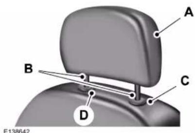
text_image
A B C D E138642The front head restraints consist of:
A An energy absorbing head restraint.
Two steel stems.B
C Guide sleeve adjust and unlock button.
D Guide sleeve unlock and remove button.
Raising the Head Restraint
Pull the head restraint up.
Lowering the Head Restraint
- Press and hold button C.
- Push the head restraint down.
Removing the Head Restraint
- Pull the head restraint up until it reaches its highest position.
- Press and hold buttons C and D.
- Pull the head restraint up.
Installing the Head Restraint
Align the steel stems into the guide sleeves and push the head restraint down until it locks.
Tilting Manual Head Restraints
The front seat head restraints tilt for extra comfort. To tilt the head restraint, do the following:
Seals
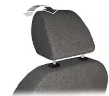
natural_image
Close-up of a car headrest with a white clip attached (no text or symbols visible)E144727
- Adjust the seat backrest to an upright driving or riding position.
- Pivot the head restraint forward toward your head to the desired position.
After the head restraint reaches the forward-most tilt position, pivot it forward again to release it to the rearward, un-tilted position.
Rear Seat Outermost Head Restraints
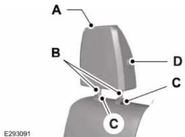
text_image
A B D C C E293091The rear outermost head restraints consist of:
A An energy absorbing head restraint.
Two steel stems.B
C Guide sleeve unlock and remove button.
Fold button (If Equipped).D
Removing the Head Restraint
- Press and hold both C buttons.
- Pull the head restraint up.
Installing the Head Restraint
Align the steel stems into the guide sleeves and push the head restraint down until it locks.
Folding the Head Restraint
- Press and hold button D.
- Pull it back up to reset.
Seats
Rear Seat Center Head Restraint
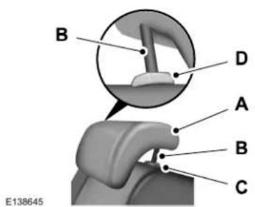
text_image
B D A B C E138645The rear center head restraint consists of:
A An energy absorbing head restraint.
Two steel stems.B
C Guide sleeve adjust and unlock button.
D Guide sleeve unlock and remove button.
Lowering the Head Restraint
- Press and hold button C.
- Push the head restraint down.
Removing the Head Restraint
- Pull the head restraint up until it reaches its highest position.
- Press and hold buttons C and D.
- Pull the head restraint up.
Installing the Head Restraint
Align the steel stems into the guide sleeves and push the head restraint down until it locks.
Power Front Head Restraints (If Equipped)
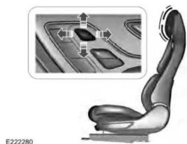
natural_image
Side view of a car seat with a highlighted interior panel and directional arrows (no text or symbols)To raise the head restraint, lift the switch up until you reach a comfortable height.
To lower the head restraint, press the switch down.
To move the head restraint forward, push the switch forward until you reach the desired position.
To move the head restraint rearward, push the switch rearward.
Raising the Head Restraint
Pull the head restraint up.
Seals
Power Rear Head Restraints (If Equipped)

natural_image
Interior view of a car dashboard showing the keyboard and seat area with directional arrows (no text or symbols)E229803
Press the button on the overhead console to fold the rear outermost head restraints.
Note: If your vehicle has power rear head restraints, you cannot remove them.
POWER SEATS

WARNING: Do not adjust the driver
seat or seat backrest when your vehicle is moving. This may result in sudden seat movement, causing the loss of control of your vehicle.

WARNING: Do not place cargo or
any objects behind the seatback before returning it to the original position.
The power seat controls are on the door.
30-Way Seat Controls
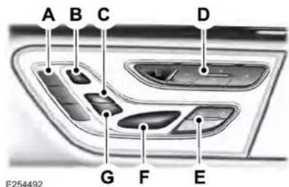
text_image
A B C D G F E E254492Memory Function.A
Head Restraints.B
Upper Seat Backrest.C
Multi-Contour.D
Seat Cushion Adjustment.E
Power Seats.F
Recline.G
Seats
Adjusting the Power Seats
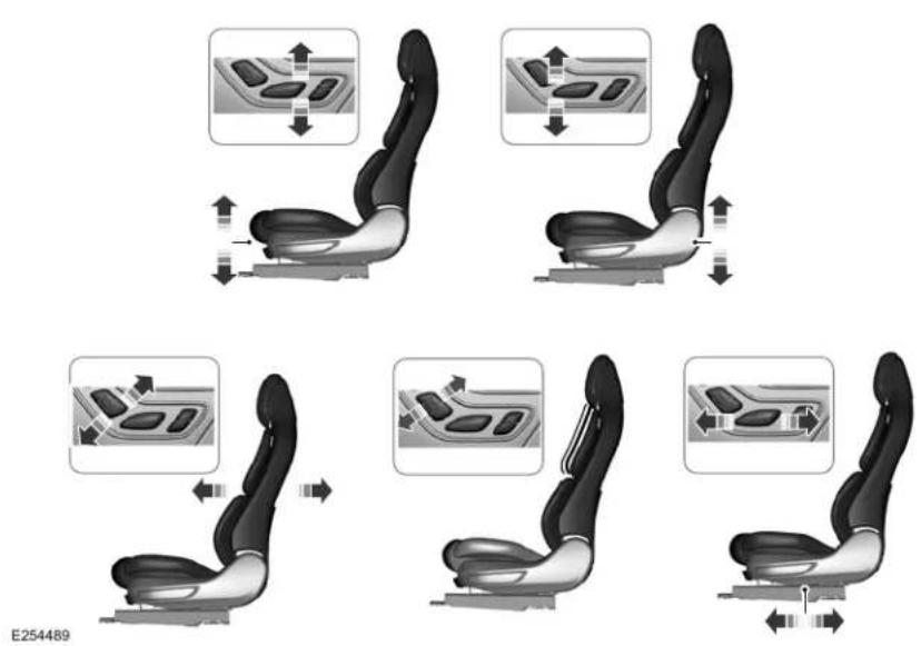
Seals
24-Way Seat Controls
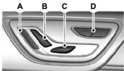
text_image
A B C DE277386
Memory Function.A
Recline.B
Power Seats.C
Lumbar.D
Seats
Adjusting the Power Seats
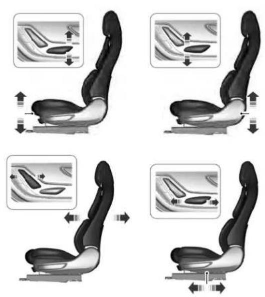
E277384
Seals
Adjusting the Power Lumbar
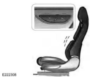
natural_image
Side view of a car seat assembly with a magnified inset showing internal components (no text or symbols)Adjusting the Length of the Seat Cushion (If Equipped)
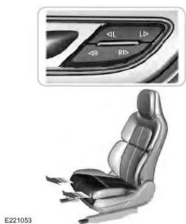
natural_image
Interior view of a car seat with control panel and side view (no text or symbols)Press the top of the control to adjust the left side of the cushion.
Press the bottom of the control to adjust the right side of the cushion.
Adjusting the Multi-Contour Front Seats With Active Motion (If Equipped)
Note: The engine must be running or the vehicle must be in accessory mode to activate the seats.
Note: Allow a few seconds for any selection to activate. The seat backrest and cushion massage cannot function at the same time.
Seats
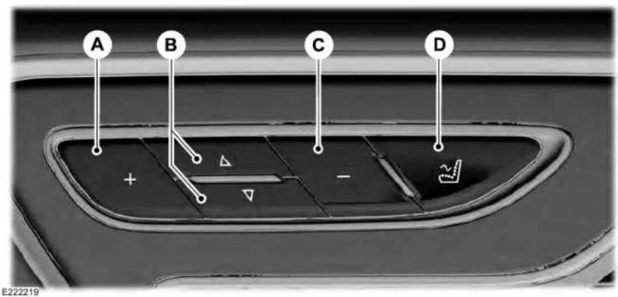
text_image
A B C D + - E222219| Massage Mode | |
| Massage intensity increaseA | |
| Massage feature selectionB | |
| Massage intensity decreaseC | |
| On and offD |
Seals
You can also adjust this feature through the touchscreen.

Press the Menu Settings icon, then Vehicle. Choose Multi-Contour Seats.
When switched on, the system displays directions for you to adjust the lumbar settings in your seat or to set the massage function.
To access and make adjustments to the lumbar setting:
- Choose the desired seat to adjust.
- Press the + or - to adjust the lumbar intensity.
To access and make adjustments to the massage setting:
- Press the Menu Settings icon, then Vehicle. Choose Multi-Contour Seats.
- Choose the desired seat to adjust.
- Press OFF, Low or High.
MEMORY FUNCTION

WARNING: Before activating the y seat, make sure that the area lately surrounding the seat is clear ructions and that all occupants are f moving parts.

WARNING: Do not use the memory in when your vehicle is moving.
This feature automatically recalls the position of the following:
- Driver seat.
•Power mirrors.
•Power steering column.
The memory control is on the driver door.
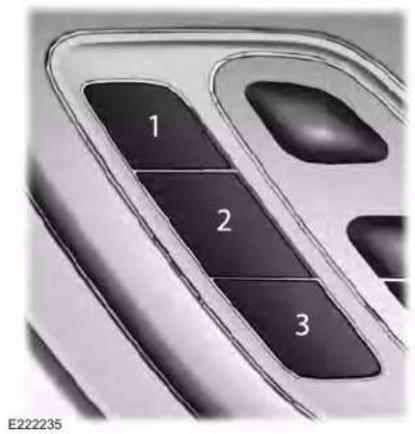
text_image
1 2 3 E222235Saving a Preset Position
- Switch the ignition on.
- Adjust the memory features to your desired position.
- Press and hold the desired preset button until you hear a single tone.
Seats
You can save up to three preset memory positions. You can save a memory preset at any time.
Recalling a Preset Position
Press and release the preset button associated with your desired driving position. The memory features move to the position stored for that preset.
Note: You can only recall a preset memory position when the ignition is off, or when the transmission is in park (P) or neutral (N) (and your vehicle is not moving) if the ignition is on.
You can also recall a preset memory position by:
- Pressing the unlock button on your intelligent access key fob if it is linked to a preset position.
- Unlocking the intelligent driver door handle if a linked key fob is present.
Note: Using a linked key fob to recall your memory position when the ignition is off moves the seat to the Easy Entry position.
Note: Pressing any active memory feature adjustment control, or any memory button during a memory recall, cancels the operation.
Linking a Preset Position to your Remote Control or Intelligent Access Key Fob
You can save preset memory positions for up to three remote controls or intelligent access (IA) keys.
- With the ignition on, move the memory features to the desired positions.
- Press and hold the preset button you desire for about five seconds. A tone sounds after a few seconds. Continue holding until you hear a second tone.
- Within three seconds, press the lock button on the remote control you are linking.
To unlink a remote control, follow the same procedure – except in step 3, press the unlock button on the remote control.
Note: If more than one linked remote control or intelligent access key is in range, the memory function moves to the settings of the first key to initiate a memory recall.
Easy Entry and Exit Feature
If you enable the easy entry and exit feature, it moves the driver seat position rearward up to 2 in (5 cm) when you switch the ignition off.
The driver seat returns to its previous position when you switch the ignition on.
Note: If you press any adjustment or memory button when in easy exit mode, the system cancels the operation.
You can enable or disable this feature through the information display. See General Information (page 122).
Seals
REAR SEATS
Adjusting the Rear Seats

WARNING: To prevent possible use to the seat or seatbelts, make sure the seatbelts are not fastened before the seatback.
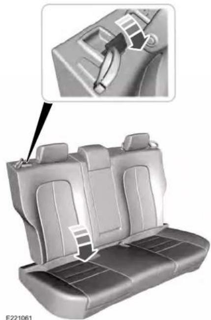
natural_image
Interior view of a car seat with side panels and a close-up inset showing the seatbelt mechanism (no text or symbols)Folding the Seatback (If Equipped)
With the seat empty, pull the lever to fold the seatback forward.
Unfolding the Seatback
Rotate the seatback upward until the seatback latches in the upright position. The seatback clicks when it is locked into position.
Seats
Power Lumbar (If Equipped)
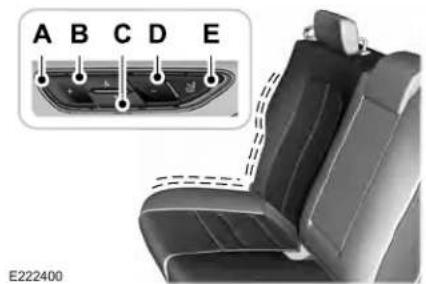
natural_image
Interior view of a car seat with labeled buttons (A–E) and a dashed-line connector, no readable text or symbols beyond labels.A Press to increase massage intensity.
B Press to activate seatback massage. Press to activate cushion massage.C
D Press to decrease massage intensity.
Press to switch on and off.E
Chauffeur Switch (If Equipped)
The switches are on the passenger side rear door.
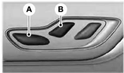
text_image
A BE229820
A Press the front of the switch to move the front passenger seat forward.
B Press the back of the switch to move the front passenger seat backward.
Power Recline (If Equipped)
The switches are on the rear doors.
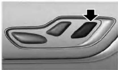
natural_image
Close-up of a car dashboard with three buttons and a black arrow pointing to the top panel (no text or symbols visible)E229821
Press the switch to recline the outboard rear seatback.
HEATED SEATS
Front Seats
WARNING: People who are unable to feel pain to their skin because of advanced age, chronic illness, diabetes, spinal cord injury, medication, alcohol use, exhaustion or other physical conditions, must exercise care when using the heated
Seats
seat. The heated seat may cause burns even at low temperatures, especially if used for long periods of time. Do not place anything on the seat that insulates against heat, such as a blanket or cushion. This may cause the heated seat to overheat. Do not puncture the seat with pins, needles or other pointed objects. This may damage the heating element which may cause the heated seat to overheat. An overheated seat may cause serious personal injury.
Do not do the following:
- Place heavy objects on the seat.
- Operate the heated seat if water or any other liquid spills on the seat. Allow the seat to dry thoroughly.
- Operate the heated seats unless the engine is running. Doing so can cause the battery to lose charge.
E146322
Press the heated seat symbol to cycle through the various heat settings and off. More indicator lights indicate warmer settings.
Rear Seats

WARNING: Persons who are
unable to feel pain to the skin because of advanced age, chronic illness, diabetes, spinal cord injury, medication, alcohol use, exhaustion, or other physical conditions, must exercise care when using the seat heater. The seat heater may cause burns even at low temperatures, especially if used for long periods of time. Do not place anything on the seat that insulates against
heat, such as a blanket or cushion, because this may cause the seat heater to overheat. Do not puncture the seat with pins, needles, or other pointed objects because this may damage the heating element which may cause the seat heater to overheat. An overheated seat may cause serious personal injury.
Do not do the following:
- Place heavy objects on the seat.
- Operate the seat heater if water or any other liquid is spilled on the seat. Allow the seat to dry thoroughly.
- Operate the heated seats unless the engine is running. Doing so can cause the battery to lose charge.
The rear seat heat controls are located on the rear of the center console.
Seats
E146322
Press the heated seat symbol to cycle through the various heat settings and off. More indicator lights indicate warmer settings.
The heated seat module resets at every ignition run cycle. While the ignition is on, press the high or low heated seat switch to enable heating mode. When activated, they will turn off automatically when you turn the engine off.
CLIMATE CONTROLLED SEATS (IF EQUIPPED)
Heated Seats

WARNING: Use caution when
using the heated seat if you are unable to feel pain to your skin because of advanced age, chronic illness, diabetes, spinal cord injury, medication, alcohol use, exhaustion or other physical conditions. The heated seat could cause burns even at low temperatures, especially if used for long periods of time. Failure to follow this instruction could result in personal injury.

WARNING: Do not poke sharp
objects into the seat cushion or seat backrest. This could damage the heated seat element and cause it to overheat. Failure to follow this instruction could result in personal injury.

WARNING: Do not place anything seat that blocks the heat, for use a seat cover or a cushion. This cause the seat to overheat. Failure is this instruction could result in all injury.
Note: The heated seats switch on during a remote start if they are enabled through the information display. See General Information (page 122).
Note: The heated seats may also switch on when you start your vehicle if they were on when you previously switched your vehicle off.
Note: Do not do the following:
- Place heavy objects on the seat.
- Operate the seat heater if water or any other liquid spills on the seat. Allow the seat to dry thoroughly.
Seats
E146322
Press this symbol to cycle through the various heat settings and off. More indicator lights indicate warmer settings.
Ventilated Seats
Note: The ventilated seats switch on during a remote start if they are enabled through the information display. See General Information (page 122).
Note: The ventilated seats may also switch on when you start your vehicle if they were on when you previously switched your vehicle off.
Note: Do not do the following:
- Place cargo or objects under the seats. They may block the air intake causing the air vents to not work properly.
- Spill liquid on the front seats. This may cause the air vent holes to become blocked and not work properly.
The ventilated seats only function when the engine is running.

E224689
Press this symbol to cycle through the various ventilation settings and off. More indicator lights indicate higher fan speeds.
If the engine falls below 350 RPM while the ventilated seats are on, the feature switches itself off. You need to reactivate it.
Note: To improve comfort, use the ventilated seats along with the vehicle's air conditioning system.
Garage Door Opener
UNIVERSAL GARAGE DOOR OPENER
HomeLink Wireless Control System

WARNING: Do not use the system with any garage door opener that does not have the safety stop and reverse feature as required by U.S. Federal Safety Standards (this includes any garage door opener manufactured before April 1, 1982). A garage door opener which cannot detect an object, signaling the door to stop and reverse, does not meet current federal safety standards. Using a garage door opener without these features increases the risk of serious injury or death.
Note: Make sure that the garage door and security device are free from obstruction when you are programming. Do not program the system with the vehicle in the garage.
Note: Make sure you keep the original remote control transmitter for use in other vehicles as well as for future system programming.
Note: We recommend that upon the sale or lease termination of your vehicle, you erase the programmed function buttons for security reasons. See Erasing the Function Button Codes later in this section.
Note: You can program a maximum of three devices. To change or replace any of the three devices after it has been initially programmed, you must first erase the current settings. See Erasing the Function Button Codes.
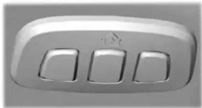
natural_image
Close-up of a white rectangular electronic device with three square cutouts (no visible text or symbols)E188211
The universal garage door opener replaces the common hand-held garage door opener with a three-button transmitter integrated into the driver's sun visor.
The system includes two primary features, a garage door opener and a platform for remote activation of devices within the home. You can program garage doors as well as entry gate operators, security systems, entry door locks and home or office lighting.
Additional system information can be found online at www.homelink.com, www.youtube.com/user/HomeLinkGentex or by calling the toll-free help line at 1-800-355-3515.
In-Vehicle Programming
This process is to program your in-vehicle HomeLink function button with your hand-held transmitter.
Note: The programming steps below assume you will be programming HomeLink that was not previously programmed. If your HomeLink was previously programmed, you may need to erase your HomeLink buttons. See Erasing the Function Button Codes.
Garage Door Opener
Note: Put a new battery in the hand-held transmitter. This allows for quicker training and accurate transmission of the radio-frequency signal.
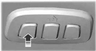
natural_image
Close-up of a three-panel computer control panel with an arrow pointing to the bottom-left corner (no text or symbols visible)E188212
- With your vehicle parked outside of the garage, switch your ignition to the on position, but do not start your vehicle.
- Press and release the function button that you would like to program.
-
Hold your hand-held garage door transmitter 1–3 in (2–8 cm) away from the HomeLink button you want to program.
-
Press and hold the hand-held transmitter button you want to program while watching the indicator light on HomeLink. Continue to hold the hand-held button until the HomeLink indicator light flashes rapidly or is continuously on.
Note: You may need to use a different method if you live in Canada or have difficulties programming your gate operator or garage door opener. See Gate Operator / Canadian Programming.
- Press and hold the HomeLink button you programmed for two seconds, then release. You may need to do this twice to activate the door. If your garage door does not operate, watch the HomeLink indicator light.
If the indicator light stays on, the programming is complete. Your device should activate when the HomeLink button is pressed and released.
If the indicator light flashes rapidly, press and hold for two seconds and release the programmed HomeLink button. Repeat the "press/hold/release" sequence up to three times to complete the programming process. If your device still does not operate, you must program your garage door. See Programming Your Garage Door Opener Motor.
To program additional buttons, repeat Steps 1–4.
For questions or comments, please contact HomeLink at www.homelink.com, www.youtube.com/user/HomeLinkGentex or by calling the toll-free help line at 1-800-355-3515.
Programming Your Garage Door Opener Motor
Note: You may need a ladder to reach the unit and you may need to remove the cover or lamp lens on your garage door opener.
Garage Door Opener
E142659
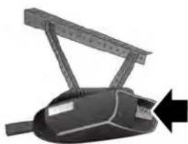
natural_image
Mechanical device with lever mechanism and arrow indicator (no text or symbols)- Press the learn button on the garage door opener motor and then you have 30 seconds to complete the next two steps.
- Return to your vehicle.
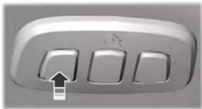
natural_image
Close-up of a three-panel computer control panel with an arrow pointing to the bottom-left corner (no text or symbols visible)E188212
- Press and hold the function button you want to program for 2 seconds, then release. Repeat this step. Depending on your brand of garage door opener, you may need to repeat this sequence a third time.
Gate Operator / Canadian Programming
Canadian radio-frequency laws require transmitter signals to "time-out" (or quit) after several seconds of transmission – which may not be long enough for HomeLink to pick up the signal during programming. Similar to this Canadian law, some U.S. gate operators are designed to "time-out" in the same manner.
Note: If programming a garage door opener or gate operator, it is advised to unplug the device during the "cycling" process to prevent possible overheating.
- Press and release, every two seconds, your hand-held transmitter until the HomeLink indicator light changes to a rapidly blinking or continuously on light.
-
Release the hand-held transmitter button.
-
Continue programing HomeLink. See In-Vehicle Programming, Step 4.
Erasing the Function Button Codes
Note: You cannot erase individual buttons.

natural_image
Close-up of a three-pin door with three buttons and an arrow pointing to the leftmost button (no text or symbols visible)E188213
- Press and hold the outer two function buttons simultaneously for approximately 10 seconds until the indicator light above the buttons flashes rapidly.
- When the indicator light flashes, release the buttons. You erased the codes for all buttons.
Garage Door Opener
Reprogramming a Single Button
To program a device to a previously trained button, follow these steps:
- Press and hold the desired button. Do NOT release the button.
- The indicator light begins to flash after 20 seconds. Without releasing the button, follow Step 1 in the Programming section.
For questions or comments, contact HomeLink at www.homelink.com, www.youtube.com/user/HomeLinkGentex or by calling the toll-free help line at 1-800-355-3515.
FCC and RSS-210 Industry Canada Compliance
This device complies with Part 15 of the FCC Rules and with RSS-210 of Industry Canada. Operation is subject to the following two conditions: (1) this device may not cause harmful interference, and (2) this device must accept any interference received, including interference that may cause undesired operation.

WARNING: Changes or modifications not expressively approved by the party responsible for compliance could void the user's authority to operate the equipment. The term "IC:" before the radio certification number only signifies that Industry Canada technical specifications were met.
This equipment complies with FCC radiation exposure limits set forth for an uncontrolled environment. End Users must follow the specific operating instructions for satisfying RF exposure compliance. This transmitter must be at least 8 in (20 cm) from the user and must not be co-located or operating in conjunction with any other antenna or transmitter.
The term "IC:" before the certification/registration number only signifies that Industry Canada technical specifications were met.
Auxiliary Power Points
12 VDC Power Point

WARNING: Do not plug optional
electrical accessories into the cigar lighter socket. Incorrect use of the cigar lighter can cause damage not covered by the vehicle warranty, and can result in fire or serious injury.
Note: When you switch the ignition on, you can use the socket to power 12 V appliances with a maximum current rating of 15 A.
Note: Do not hang any accessory from the accessory plug.
Note: Do not use the power point over the vehicle capacity of 12 V DC 15 A or a fuse may blow.
Note: Always keep the power point caps closed when not in use.
Do not insert objects other than an accessory plug into the power point. This damages the power point and may blow the fuse. Run the vehicle for full capacity use of the power point.
To prevent the battery from running out of charge:
- Do not use the power point longer than necessary when the vehicle is not running.
- Do not leave devices plugged in overnight or when you park your vehicle for extended periods.
Locations
Power points may be in the following locations:
- On the instrument panel.
•Inside the center console. - On the rear of the center console.
110 VAC Power Point

WARNING: Do not keep electrical is plugged in the power point over the device is not in use. Do not try extension cord with the 110 volt power point, since it will defeat the protection design. Doing so may the power point to overload due to multiple devices that can reach and the 150 watt load limit and could fire or serious injury.
Note: The power point turns off when you switch the ignition off, or when the battery voltage drops below 11 volts.
You can use the power point for electric devices that require up to 150 watts. It is on the rear of the center console.
Auxiliary Power Points
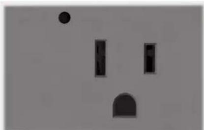
natural_image
Simple geometric shapes including a circle, rectangles, and a semicircle on a plain background (no text or symbols)E247586
The power outlet temporarily turns off power when in fault mode if the device exceeds the 150 watt limit. Unplug your device and switch the ignition off. Switch the ignition back on, but do not plug your device back in. Let the system cool off and switch the ignition off to reset the fault mode. Switch the ignition back on and make sure the indicator light remains on.
Note: Depending on your vehicle, the power point may open to the right or upward.
When the indicator light on the power point is:
- On: The power point is working, the ignition is on and a device is plugged in.
- Off: The power point is off, the ignition is off or no device is plugged in.
- Flashing: The power point is in fault mode.
Storage Compartments
CENTER CONSOLE
Stow items in the cup holder carefully as items may become loose during hard braking, acceleration or crashes, including hot drinks which may spill.
Available console features include:
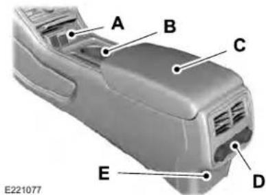
text_image
A B C E D E221077A Front storage compartment with two USB ports, DC power point and CD player (optional).
B Cup holders with auxiliary storage bin.
C Storage compartment with DC power point.
D Storage compartment, heated seat controls, or rear climate controls.
E Rear compartment with DC power point or two USB ports and AC power point.
OVERHEAD CONSOLE
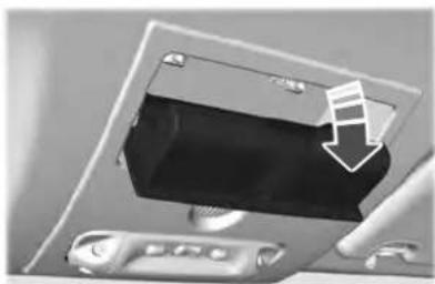
natural_image
Close-up of a device's front panel showing a black rectangular component with a white musical note icon pointing to it (no text or symbols visible)E266392
Press near the rear edge of the door to open it.
REAR SEAT ARMREST
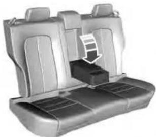
natural_image
3D rendering of a car seat with a highlighted seatbelt (no text or symbols)E221057
Fold the armrest down to use the armrest and cupholders.
The cupholders are inside the rear seat armrest. To access the cupholders, push the plastic panel on the front edge of the armrest.
Push the panel again to close the cupholders.
Storage Compartments
Rear Seat Armrest (Livery)
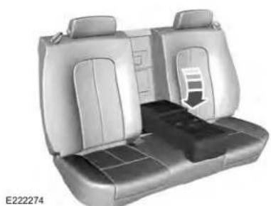
natural_image
Interior view of a car backseat showing seat compartments and seat cover (no text or symbols visible)Armrest Pass-through
Note: Do not exceed 80 lb (36 kg) of weight on the pass-through door.
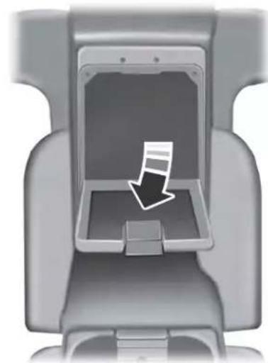
natural_image
Interior view of a car seat with a highlighted download arrow (no text or symbols)E152622
Release the latch, then pull down on the door located in the back of the armrest. You can store cargo of a longer length such as skis or lumber.
Starting and Stopping the Engine
GENERAL INFORMATION

WARNING: Extended idling at high engine speeds can produce very high temperatures in the engine and exhaust system, creating the risk of fire or other damage.

WARNING: Do not park, idle or drive your vehicle on dry grass or other dry ground cover. The emission system heats up the engine compartment and exhaust system, creating the risk of fire.

WARNING: Do not start the engine in a closed garage or in other enclosed areas. Exhaust fumes can be toxic. Always open the garage door before you start the engine.

WARNING: Exhaust leaks may result in entry of harmful and potentially lethal fumes into the passenger compartment. If you smell exhaust fumes inside your vehicle, have your vehicle inspected immediately. Do not drive if you smell exhaust fumes.
If you disconnect the battery, your vehicle may exhibit some unusual driving characteristics for approximately 5 mi (8 km) after you reconnect it. This is because the engine management system must realign itself with the engine. You can disregard any unusual driving characteristics during this period.
The powertrain control system meets all Canadian interference-causing equipment standard requirements regulating the impulse electrical field or radio noise.
When you start the engine, avoid pressing the accelerator pedal before and during operation. Only use the accelerator pedal when you have difficulty starting the engine.
KEYLESS STARTING
Note: The system may not function if the intelligent access key is close to metal objects or electronic devices, for example keys or a cell phone.
Note: A valid intelligent access key must be located inside your vehicle to switch the ignition on and start your vehicle.
Ignition Modes
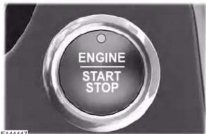
text_image
ENGINE START STOPThe keyless starting system has three modes:
Off: Turns the ignition off.
Starting and Stopping the Engine
- Without applying the brake pedal, press and release the button once when the ignition is in the on mode, or when your vehicle is running but is not moving.
On: All electrical circuits are operational and the warning lamps and indicators illuminate. - Without applying the brake pedal, press and release the button once.
Start: Starts your vehicle. The engine may not start when your vehicle starts. - Press the brake pedal, and then press the button for any length of time. An indicator light on the button illuminates when the ignition is on and when your vehicle starts.
STARTING A GASOLINE ENGINE
When you start the engine, the idle speed increases. This helps to warm up the engine. If the engine idle speed does not slow down by itself, have your vehicle checked as soon as possible.
Note: You can crank the engine for a total of 60 seconds without the engine starting before the starting system temporarily disables. The 60 seconds does not have to be all at once. For example, if you crank the engine three times for 20 seconds each time, without the engine starting, you reached the 60-second time limit. A message appears in the information display alerting you that you exceeded the cranking time. You cannot attempt to start the engine for at least 15 minutes. After 15 minutes, you are limited to a 15-second engine cranking time. You need to wait 60 minutes before you can crank the engine for 60 seconds again.
Before starting your vehicle, check the following:
- Make sure all occupants have fastened their seatbelts.
- Make sure the headlamps and electrical accessories are off.
• Make sure the parking brake is on.
• Make sure the transmission is in park (P).
Starting Your Vehicle
Note: Do not touch the accelerator pedal.
- Press the brake pedal.
- Press the push button ignition switch.
Failure to Start
The system does not function if:
• The passive key frequencies are jammed.
•The key battery has no charge.
If you are unable to start your vehicle, do the following:
- Remove the key blade from the transmitter.
Starting and Stopping the Engine
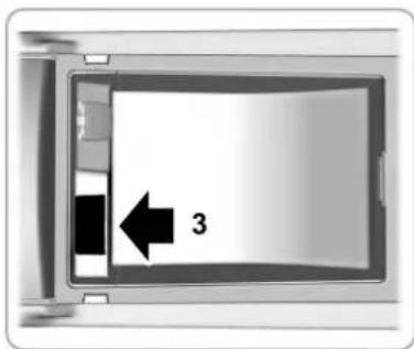
text_image
3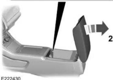
natural_image
Close-up of a mechanical component with a tool inserted, showing a 2D view and part number E222430 (no text or symbols on the main subject)- Open the floor console storage compartment lid.
-
Insert the passive key into the backup slot.
-
Press the push button ignition switch. If the engine does not start after three attempts, wait ten seconds and follow the flooded engine procedure.
-
Apply the parking brake.
- Press the brake pedal.
- Shift into park (P).
- Fully press the accelerator pedal.
- Briefly press the push button ignition switch.
Fast Restart
The fast restart feature allows you to restart your vehicle within 20 seconds of switching it off, even if it does not detect a valid passive key.
Within 20 seconds of switching the engine off, press the brake pedal and press the push button ignition switch. After 20 seconds, you can no longer start your vehicle if it does not detect a valid passive key.
Once your vehicle starts, it remains running until you press the push button ignition switch, even if your vehicle does not detect a valid passive key. If you open and close a door while your vehicle is running, the system searches for a valid passive key. After 20 seconds, you can no longer start your vehicle if it does not detect a valid passive key.
Automatic Engine Shutdown
For vehicles with a keyless ignition, this automatically shuts down your vehicle if it has been idling for an extended period. The ignition also turns off to save battery power. Before your vehicle shuts down, a message appears in the information display showing a timer counting down. If you do not intervene within 30 seconds, your vehicle shuts down. Another message appears in the information display to inform you that your vehicle has shut down to save fuel.
Start your vehicle as normal.
Starting and Stopping the Engine
Automatic Engine Shutdown Override
Note: You cannot permanently switch off the automatic shutdown. The system defaults to normal mode when you start your vehicle.
You can stop the shutdown, or reset the timer, at any point before the 30-second countdown has expired by doing any of the following:
- Interacting with your vehicle, for example pressing the brake or accelerator pedal.
- Disabling the shutdown using the information display. See Information Displays (page 122).
- Pressing the OK or RESET button during the 30-second countdown.
Stopping the Engine When Your Vehicle is Stationary
Note: The ignition, all electrical circuits and all warning lamps and indicators will be turned off.
Note: If the engine is idling for 30 minutes, the ignition and engine automatically shuts down.
- Apply the parking brake.
- Shift into park (P).
- Briefly press the push button ignition switch.
Stopping the Engine When Your Vehicle is Moving

WARNING: Switching off the
engine when your vehicle is still moving results in a significant decrease in braking assistance. Higher effort is required to apply the brakes and to stop your vehicle. A significant decrease in steering assistance could also occur. The steering does not lock, but higher effort could be required to steer your vehicle. When you switch the ignition off, some electrical circuits, for example airbags, also turn off. If you unintentionally switch the ignition off, shift into neutral (N) and restart the engine.
-
Shift into neutral and use the brakes to bring your vehicle to a safe stop.
-
When your vehicle has stopped, shift into park (P).
- Apply the parking brake.
- Press and hold the push button ignition switch until the engine stops, or press it three times within two seconds.
Guarding Against Exhaust Fumes

WARNING: Exhaust leaks may
result in entry of harmful and potentially lethal fumes into the passenger compartment. If you smell exhaust fumes inside your vehicle, have your vehicle inspected immediately. Do not drive if you smell exhaust fumes.
Important Ventilating Information
If you stop your vehicle and then leave the engine idling for long periods, we recommend that you do one of the following:
- Open the windows at least 1 in (3 cm).
- Set your climate control to outside air.
Starting and Stopping the Engine
ENGINE BLOCK HEATER (IF EQUIPPED)

WARNING: Failure to follow engine
block heater instructions could result in property damage or serious personal injury.

WARNING: Do not use your heater
with ungrounded electrical systems or two-pronged adapters. There is a risk of electrical shock.

WARNING: Do not fully close the
hood, or allow it to drop under its own weight when using the engine block heater. This could damage the power cable and may cause an electrical short resulting in fire, injury and property damage.
Note: The heater is most effective when outdoor temperatures are below 0^ F ( -18^ C).
The heater acts as a starting aid by warming the engine coolant. This allows the climate control system to respond quickly. The equipment includes a heater element, installed in the engine block and a wire harness. You can connect the system to a grounded 120-volt AC electrical source.
We recommend that you do the following for a safe and correct operation:
- Use a 16-gauge outdoor extension cord that is product certified by Underwriter's Laboratory (UL) or Canadian Standards Association (CSA). This extension cord must be suitable for use outdoors, in cold temperatures, and be clearly marked Suitable for Use with Outdoor Appliances. Do not use an indoor extension cord outdoors. This could result in an electric shock or become a fire hazard.
- Use as short an extension cord as possible.
- Do not use multiple extension cords.
- Make sure that when in operation, the extension cord plug and heater cord plug connections are free and clear of water. This could cause an electric shock or fire.
- If the block heater cord is under the hood, Do Not remove the wiring from its original location. Do Not close the hood on the extension wiring.
- Make sure your vehicle is parked in a clean area, clear of combustibles.
- Make sure the heater, heater cord and extension cord are firmly connected.
- Check for heat anywhere in the electrical hookup once the system has been operating for approximately 30 minutes.
- Make sure the system is unplugged and properly stowed before starting and driving your vehicle. Make sure the protective cover seals the prongs of the block heater cord plug when not in use.
- Make sure the heater system is checked for proper operation before winter.
Starting and Stopping the Engine
Using the Engine Block Heater
Make sure the receptacle terminals are clean and dry prior to use. Clean them with a dry cloth if necessary.
The heater uses 0.4 to 1.0 kilowatt-hours of energy per hour of use. The system does not have a thermostat. It achieves maximum temperature after approximately three hours of operation. Using the heater longer than three hours does not improve system performance and unnecessarily uses electricity.
Fuel and Refueling
SAFETY PRECAUTIONS

WARNING: Do not overfill the fuel
tank. The pressure in an overfilled tank may cause leakage and lead to fuel spray and fire.

WARNING: The fuel system may
be under pressure. If you hear a hissing sound near the fuel filler inlet, do not refuel until the sound stops. Otherwise, fuel may spray out, which could cause serious personal injury.

WARNING: Fuels can cause
serious injury or death if misused or mishandled.

WARNING: Fuel may contain
benzene, which is a cancer-causing agent.

WARNING: When refueling always shut the engine off and never allow sparks or open flames near the fuel tank filler valve. Never smoke or use a cell phone while refueling. Fuel vapor is extremely hazardous under certain conditions. Avoid inhaling excess fumes.
Follow these guidelines when refueling:
- Extinguish all smoking materials and any open flames before refueling your vehicle.
•Always switch the engine off before refueling.
• Automotive fuels can be harmful or fatal if swallowed. Fuel is highly toxic and if swallowed can cause death or permanent injury. If fuel is swallowed immediately call a physician, even if no symptoms are immediately apparent. The toxic effects of fuel may not be apparent for hours.
- Avoid inhaling fuel vapors. Inhaling fuel vapor can lead to eye and respiratory tract irritation. In severe cases, excessive or prolonged breathing of fuel vapor can cause serious illness and permanent injury.
- Avoid getting fuel in your eyes. If you splash fuel in your eyes, immediately remove contact lenses (if worn), flush with water for 15 minutes and seek medical attention. Failure to seek proper medical attention could lead to permanent injury.
- Fuels can be harmful if absorbed through the skin. If you splash fuel on your skin, clothing or both, promptly remove contaminated clothing and thoroughly wash your skin with soap and water. Repeated or prolonged skin contact causes skin irritation.
- Be particularly careful if you are taking Antabuse or other forms of Disulfiram for the treatment of alcoholism. Breathing fuel vapors could cause an adverse reaction, serious personal injury or sickness. Immediately call a physician if you experience any adverse reactions.
Fuel and Refueling
FUEL QUALITY
Choosing the Right Fuel

text_image
87 (R+M)/2 METHODE161513
Your vehicle is designed to operate on regular unleaded gasoline with a minimum pump (R+M)/2 octane rating of 87.
Some fuel stations, particularly those in high altitude areas, offer fuels posted as regular unleaded gasoline with an octane rating below 87. The use of these fuels could result in engine damage that will not be covered by the vehicle warranty.
For best overall vehicle and engine performance, premium fuel with an octane rating of 91 or higher is recommended. The performance gained by using premium fuel is most noticeable in hot weather as well as other conditions, for example when towing a trailer. See Towing (page 284).
Do not be concerned if the engine sometimes knocks lightly. However, if the engine knocks heavily while using fuel with the recommended octane rating, contact an authorized dealer to prevent any engine damage.
We recommend Top Tier detergent gasolines, where available to help minimize engine deposits and maintain optimal vehicle and engine performance. For additional information, refer to www.toptiergas.com.
Note: Use of any fuel for which the vehicle was not designed can impair the emission control system, cause loss of vehicle performance, and cause damage to the engine which may not be covered by the vehicle Warranty.
Do not use:
•Diesel fuel.
• Fuels containing kerosene or paraffin.
•Fuel containing more than 15% ethanol or E85 fuel.
• Fuels containing methanol.
• Fuels containing metallic-based additives, including manganese-based compounds.
• Fuels containing the octane booster additive, methylcyclopentadienyl manganese tricarbonyl (MMT).
- Leaded fuel, using leaded fuel is prohibited by law.
The use of fuels with metallic compounds such as methylcyclopentadienyl manganese tricarbonyl (commonly known as MMT), which is a manganese-based fuel additive, will impair engine performance and affect the emission control system.
The fuel filler funnel is under the luggage compartment floor covering.
Fuel and Refueling
RUNNING OUT OF FUEL
Running out of fuel can cause damage not covered by the vehicle Warranty.
If your vehicle runs out of fuel:
- Add a minimum of 1.3 gal (5 L) of fuel to restart the engine.
- You may need to switch the ignition from off to on several times after refueling to allow the fuel system to pump the fuel from the tank to the engine. When restarting, cranking time takes a few seconds longer than normal.
Note: If your vehicle is on a steep slope, more fuel may be required.
Filling a Portable Fuel Container

WARNING: Flow of fuel through a
fuel pump nozzle can produce static electricity. This can cause a fire if you are filling an ungrounded fuel container.
Use the following guidelines to avoid electrostatic charge build-up, which can produce a spark, when filling an ungrounded fuel container:
- Only use an approved fuel container to transfer fuel to your vehicle. Place the container on the ground when filling it.
- Do not fill a fuel container when it is inside your vehicle (including the cargo area).
- Keep the fuel pump nozzle in contact with the fuel container when filling it.
- Do not use a device that holds the fuel pump nozzle lever in the fill position.
Adding Fuel From a Portable Fuel Container

WARNING: Do not insert the nozzle of a fuel container or an aftermarket funnel into the fuel filler neck. This may damage the fuel system filler neck or its seal and cause fuel to run onto the ground.

WARNING: Do not try to pry open a open the capless fuel system with objects. This could damage the fuel and its seal and cause injury to yours.

WARNING: Do not dispose of fuel in the household refuse or the public sewage system. Use an authorized waste disposal facility.
When refueling the vehicle fuel tank from a fuel container, use the fuel filler funnel included with your vehicle. See Fuel Filler Funnel Location (page 192).
Note: Do not use aftermarket funnels as they may not work with the capless fuel system and can damage it.
When refueling the vehicle fuel tank from a fuel container, do the following:
- Fully open the fuel filler door.
- Fully insert the fuel filler funnel into the fuel filler inlet.
Fuel and Refueling
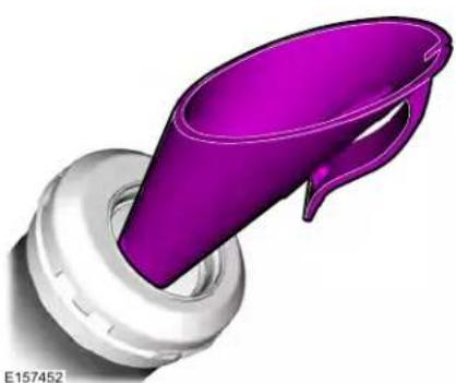
natural_image
3D rendered illustration of a purple funnel-shaped object inserted into a white circular base (no text or symbols)- Add fuel to your vehicle from the fuel container.
- Remove the fuel filler funnel.
- Fully close the fuel filler door.
- Clean the fuel filler funnel and place it back in your vehicle or correctly dispose of it.
Note: Extra funnels can be purchased from an authorized dealer if you choose to dispose of the funnel.
REFUELING
Refueling System Overview
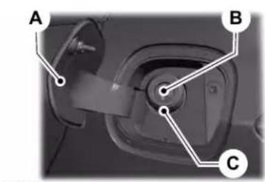
text_image
A B CFuel filler door.A
Fuel tank filler valve.B
Fuel tank filler pipe.C
Your vehicle does not have a fuel tank filler cap.
A
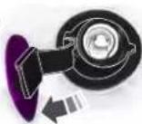
B
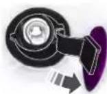
C
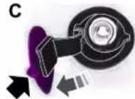
D
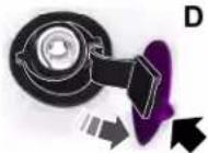
E206911
A Left-hand side. To open the fuel filler door, press the center rear edge of the fuel filler door and then release.
B Right-hand side. To open the fuel filler door, press the center rear edge of the fuel filler door and then release.
Fuel and Refueling
C Left-hand side. Pull the rear of the fuel filler door to open it.
D Right-hand side. Pull the rear of the fuel filler door to open it.
Refueling Your Vehicle

WARNING: When refueling always
shut the engine off and never allow sparks or open flames near the fuel tank filler valve. Never smoke or use a cell phone while refueling. Fuel vapor is extremely hazardous under certain conditions. Avoid inhaling excess fumes.

WARNING: The fuel system may
be under pressure. If you hear a hissing sound near the fuel filler inlet, do not refuel until the sound stops. Otherwise, fuel may spray out, which could cause serious personal injury.

WARNING: Do not pry open the
fuel tank filler valve. This could damage the fuel system. Failure to follow this instruction could result in fire, personal injury or death.

WARNING: Do not remove the fuel
pump nozzle from its fully inserted position when refueling.

WARNING: Stop refueling when
the fuel pump nozzle automatically shuts off for the first time. Failure to follow this will fill the expansion space in the fuel tank and could lead to fuel overflowing.

WARNING: Do not overfill the fuel
tank. The pressure in an overfilled tank may cause leakage and lead to fuel spray and fire.

WARNING: Wait at least five
seconds before removing the fuel pump nozzle to allow any residual fuel to drain into the fuel tank.
- Fully open the fuel filler door.
- Select the correct fuel pump nozzle for your vehicle.
Fuel and Refueling
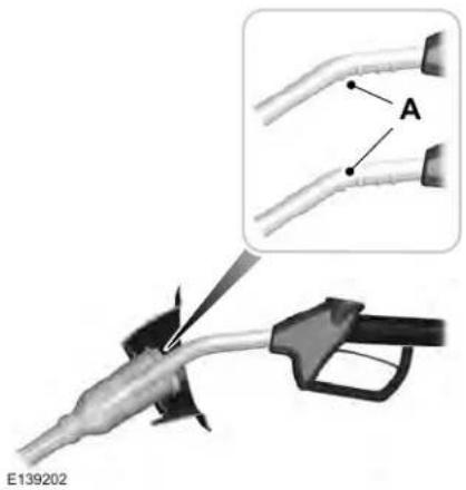
text_image
A E139202- Insert the fuel pump nozzle up to the first notch on the nozzle A. Keep the fuel pump nozzle resting on the fuel tank filler pipe.
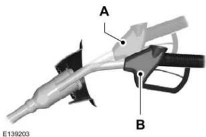
text_image
A B E139203- Hold the fuel pump nozzle in position B when refueling. Holding the fuel pump nozzle in position A can affect the flow of fuel and shut off the fuel pump nozzle before the fuel tank is full.
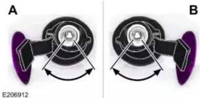
natural_image
Mechanical component diagrams labeled A and B showing rotational motion with arrows indicating direction (no text or symbols beyond labels)- Operate the fuel pump nozzle within the area shown.
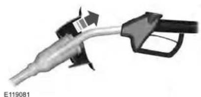
natural_image
Close-up of a fuel nozzle with a black handle and arrow indicating airflow direction (no text or symbols)- When you finish refueling slightly raise the fuel pump nozzle and slowly remove it.
- Fully close the fuel filler door.
Do not attempt to start the engine if you have filled the fuel tank with incorrect fuel. Incorrect fuel use could cause damage not covered by the vehicle Warranty. Have your vehicle immediately checked.
Refueling System Warning (If Equipped)
If the fuel tank filler valve does not fully close, a message could appear in the information display.
Fuel and Refueling
Message
Check Fuel Fill Inlet
If the message appears, do the following:
- Stop your vehicle as soon as it is safe to do so and switch the engine off.
- Shift into park (P) or neutral (N).
- Apply the parking brake.
- Fully open the fuel filler door.
- Check the fuel tank filler valve for any debris that may be restricting its movement.
- Remove any debris from the fuel tank filler valve.
- Fully insert a fuel pump nozzle or the fuel filler funnel provided with your vehicle into the fuel filler pipe. See Fuel Filler Funnel Location (page 192). This action should dislodge any debris that may be preventing the fuel tank filler valve from fully closing.
-
Remove the fuel pump nozzle or fuel filler funnel from the fuel filler pipe.
-
Fully close the fuel filler door.
Note: The message may not immediately reset. If the message continues to appear and a warning lamp illuminates, have your vehicle checked as soon as possible.
FUEL CONSUMPTION
Advertised Capacity
The advertised capacity is the maximum amount of fuel that you can add to the fuel tank after running out of fuel. Included in the advertised capacity is an empty reserve. The empty reserve is an unspecified amount of fuel that remains in the fuel tank when the fuel gauge indicates empty.
Note: The amount of fuel in the empty reserve varies and should not be relied upon to increase driving range.
Fuel Economy
Your vehicle calculates fuel economy figures through the trip computer average fuel function. See General Information (page 122).
The first 1,000 mi (1,500 km) of driving is the break-in period of the engine. A more accurate measurement is obtained after 2,000 mi (3,000 km).
Impacting Fuel Economy
- Incorrect tire inflation pressures.
- Fully loading your vehicle.
- Carrying unnecessary weight.
- Adding certain accessories to your vehicle such as bug deflectors, rollbars or light bars, running boards and ski racks.
• Using fuel blended with alcohol. See Fuel Quality (page 192). - Fuel economy may decrease with lower temperatures.
- Fuel economy may decrease when driving short distances.
- You may get better fuel economy when driving on flat terrain than when driving on hilly terrain.
Engine Emission Control
EMISSION LAW

WARNING: Do not remove or alter the original equipment floor covering or insulation between it and the metal floor of the vehicle. The floor covering and insulation protect occupants of the vehicle from the engine and exhaust system heat and noise. On vehicles with no original equipment floor covering insulation, do not carry passengers in a manner that permits prolonged skin contact with the metal floor. Failure to follow these instructions may result in fire or personal injury.
U.S. federal laws and certain state laws prohibit removing or rendering inoperative emission control system components. Similar federal or provincial laws may apply in Canada. We do not approve of any vehicle modification without first determining applicable laws.

Tampering with emissions control systems including related sensors or the Diesel Exhaust Fluid system can result in reduced engine power and the illumination of the service engine soon light.
Tampering With a Noise Control System
Federal laws prohibit the following acts:
- Removal or rendering inoperative by any person other than for purposes of maintenance.
•Repair or replacement of any device or element of the design incorporated into a new vehicle for the purpose of noise control prior to its sale or delivery to the ultimate purchaser or while it is in use.
•The use of the vehicle after any person removes or renders inoperative any device or element of the design.
The U.S. Environmental Protection Agency may presume to constitute tampering as follows:
- Removal of hood blanket, fender apron absorbers, fender apron barriers, underbody noise shields or acoustically absorptive material.
•Tampering or rendering inoperative the engine speed governor, to allow engine speed to exceed manufacturer specifications.
If the engine does not start, runs rough, experiences a decrease in engine performance, experiences excess fuel consumption or produces excessive exhaust smoke, check for the following:
• A plugged or disconnected air inlet system hose.
• A plugged engine air filter element.
•Water in the fuel filter and water separator.
• A clogged fuel filter.
•Contaminated fuel.
• Air in the fuel system, due to loose connections.
Engine Emission Control
- An open or pinched sensor hose.
- Incorrect engine oil level.
- Incorrect fuel for climatic conditions.
- Incorrect engine oil viscosity for climactic conditions.
Note: Some vehicles have a lifetime fuel filter that is integrated with the fuel tank. Regular maintenance or replacement is not needed.
Note: If these checks do not help you correct the concern, have your vehicle checked as soon as possible.
Noise Emissions Warranty, Prohibited Tampering Acts and Maintenance
On January 1, 1978, Federal regulation became effective governing the noise emission on trucks over 10,000 lb (4,536 kg) Gross Vehicle Weight Rating (GVWR). The preceding statements concerning prohibited tampering acts and maintenance, and the noise warranty found in the Warranty Guide, are applicable to complete chassis cabs over 10,000 lb (4,536 kg) GVWR.
CATALYTIC CONVERTER

WARNING: Do not park, idle or our vehicle on dry grass or other dry cover. The emission system heats engine compartment and exhaust, creating the risk of fire.

WARNING: The normal operating temperature of the exhaust system is very high. Never work around or attempt to repair any part of the exhaust system until it has cooled. Use special care when working around the catalytic converter. The catalytic converter heats up to a very high temperature after only a short period of engine operation and stays hot after the engine is switched off.

WARNING: Exhaust leaks may then entry of harmful and potentially fumes into the passenger tment. If you smell exhaust fumes your vehicle, have your vehicle ed immediately. Do not drive if you exhaust fumes.
Your vehicle has various emission control components and a catalytic converter that enables it to comply with applicable exhaust emission standards.
To make sure that the catalytic converter and other emission control components continue to work properly:
- Do not crank the engine for more than 10 seconds at a time.
- Do not run the engine with a spark plug lead disconnected.
- Do not push-start or tow-start your vehicle. Use booster cables. See Jump Starting the Vehicle (page 295).
- Use only the specified fuel listed.
Engine Emission Control
- Do not switch the ignition off when your vehicle is moving.
- Avoid running out of fuel.
- Have the items listed in scheduled maintenance information performed according to the specified schedule.
Note: Resulting component damage may not be covered by the vehicle Warranty.
The scheduled maintenance items listed in scheduled maintenance information are essential to the life and performance of your vehicle and to its emissions system.
If you use anything other than Lincoln, Motorcraft or Lincoln-authorized parts for maintenance replacements or for service of components affecting emission control, such non-Lincoln parts should be equivalent to genuine Lincoln Motor Company parts in performance and durability.
Illumination of the service engine soon indicator, charging system warning light or the temperature warning light, fluid leaks, strange odors, smoke or loss of engine power could indicate that the emission control system is not working properly.
An improperly operating or damaged exhaust system may allow exhaust to enter the vehicle. Have a damaged or improperly operating exhaust system inspected and repaired immediately.
Do not make any unauthorized changes to your vehicle or engine. By law, vehicle owners and anyone who manufactures, repairs, services, sells, leases, trades vehicles, or supervises a fleet of vehicles are not permitted to intentionally remove an emission control device or prevent it from working. Information about your vehicle's emission system is on the Vehicle Emission Control Information Decal located on or near the engine. This decal also lists engine displacement.
Please consult your warranty information for complete details.
On-Board Diagnostics (OBD-II)
Your vehicle has a computer known as the on-board diagnostics system (OBD-II) that monitors the engine's emission control system. The system protects the environment by making sure that your vehicle continues to meet government emission standards. The OBD-II system also assists a service technician in properly servicing your vehicle.

When the service engine soon indicator illuminates, the OBD-II system has detected a malfunction.
Temporary malfunctions may cause the service engine soon indicator to illuminate. Examples are:
- Your vehicle has run out of fuel—the engine may misfire or run poorly.
- Poor fuel quality or water in the fuel—the engine may misfire or run poorly.
- The fuel fill inlet may not have closed properly. See Refueling (page 194).
- Driving through deep water—the electrical system may be wet.
Engine Emission Control
You can correct these temporary malfunctions by filling the fuel tank with good quality fuel, properly closing the fuel fill inlet or letting the electrical system dry out. After three driving cycles without these or any other temporary malfunctions present, the service engine soon indicator should stay off the next time you start the engine. A driving cycle consists of a cold engine startup followed by mixed city and highway driving. No additional vehicle service is required.
If the service engine soon indicator remains on, have your vehicle serviced at the first available opportunity. Although some malfunctions detected by the OBD-II may not have symptoms that are apparent, continued driving with the service engine soon indicator on can result in increased emissions, lower fuel economy, reduced engine and transmission smoothness and lead to more costly repairs.
Readiness for Inspection and Maintenance (I/M) Testing
Some state and provincial and local governments may have Inspection/Maintenance (I/M) programs to inspect the emission control equipment on your vehicle. Failure to pass this inspection could prevent you from getting a vehicle registration.

If the service engine soon indicator is on or the bulb does not work, your vehicle may need service.
See On-Board Diagnostics.
Your vehicle may not pass the I/M test if the service engine soon indicator is on or not working properly (bulb is burned out), or if the OBD-II system has determined that some of the emission control systems have not been properly checked. In this case, the vehicle is not ready for I/M testing.
If the vehicle's engine or transmission has just been serviced, or the battery has recently run down or been replaced, the OBD-II system may indicate that the vehicle is not ready for I/M testing. To determine if the vehicle is ready for I/M testing, turn the ignition key to the on position for 15 seconds without cranking the engine. If the service engine soon indicator blinks eight times, it means that the vehicle is not ready for I/M testing; if the service engine soon indicator stays on solid, it means that your vehicle is ready for I/M testing.
The OBD-II system checks the emission control system during normal driving. A complete check may take several days.
If the vehicle is not ready for I/M testing, you can perform the following driving cycle consisting of mixed city and highway driving:
- 15 minutes of steady driving on an expressway or highway followed by 20 minutes of stop-and-go driving with at least four 30-second idle periods.
Engine Emission Control
- Allow your vehicle to sit for at least eight hours with the ignition off. Then, start the vehicle and complete the above driving cycle. The vehicle must warm up to its normal operating temperature. Once started, do not turn off the vehicle until the above driving cycle is complete.
If the vehicle is still not ready for I/M testing, you need to repeat the above driving cycle.
Transmission
AUTOMATIC TRANSMISSION

WARNING: Always fully apply the
parking brake and make sure you shift into park (P). Failure to follow this instruction could result in personal injury or death.

WARNING: Do not apply the brake
pedal and accelerator pedal simultaneously. Applying both pedals simultaneously for more than a few seconds will limit engine performance, which may result in difficulty maintaining speed in traffic and could lead to serious injury.
Note: You may not be able to shift out of park (P) unless the intelligent access key is inside your vehicle.
Push Button Shift Transmission
Your vehicle is equipped with an electronic transmission. The transmission selector is located on the instrument panel next to the display screen. The gears are selected by pressing and releasing the PRNDS buttons.
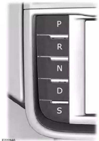
text_image
P R N D S E222846Every time you select a gear, the button will light up. The selected gear also appears in the instrument cluster.
Transmission
Putting your vehicle in gear:
- Fully press down on the brake pedal.
- Press and release the button of the gear you want to select.
- The button you select will illuminate and the selected gear appears in the instrument cluster.
- Release the brake pedal and your transmission will remain in the selected gear.
Note: If you attempt to leave your vehicle while it is in gear, your vehicle will automatically shift into park (P). Safety belt and door monitors determine your intent and make the shift for you. During this time, a message appears in the instrument cluster prompting you to make the shift to park (P).
Understanding the Shift Positions of your Automatic Transmission
Note: Always come to a complete stop before putting your vehicle into and out of park (P).
Park (P)
With the transmission in park (P), your vehicle locks the transmission and prevents the wheels from turning. Always come to a complete stop before putting your vehicle into and out of park (P). An audible chime sounds once you select park (P).
When the ignition is turned off, the vehicle will automatically shift into park (P). If the ignition is turned off while the vehicle is moving, it will first shift into neutral (N) until a slow enough speed is reached. The vehicle will then shift into park (P) automatically.
Automatic Return to Park
Note: This feature will not operate when your vehicle is in Stay in Neutral mode or neutral tow.
Your vehicle has a safety feature that will automatically shift your vehicle into park (P) when any of the following conditions occur:
- You turn the ignition off
- You open the driver's door with your safety belt unlatched
- Your safety belt is unlatched while the driver's door is open
If you turn your vehicle off while moving, your vehicle will first shift into neutral (N) until it slows down enough to shift into park (P) automatically.
Note: If you have waited an extended period of time (2-15 minutes) before starting your vehicle, unlatching your safety belt will cause this feature to activate, even with the driver's door closed.
Note: This feature may not work properly if the door ajar switch is malfunctioning. If your door ajar indicator does not illuminate when you open the driver's door or the indicator illuminates with the driver's door closed, see your authorized dealer.
Transmission
Reverse (R)
With the transmission in reverse (R), your vehicle will move backward. Always come to a complete stop before shifting into and out of reverse (R).
Neutral (N)
With the transmission in neutral (N), you can start your vehicle and it is free to roll. Hold the brake pedal down while in this position.
Stay in Neutral mode
Stay in Neutral mode allows your vehicle to stay in neutral (N) when you exit the vehicle. Your vehicle must be stationary to enter this mode.
To enter Stay in Neutral mode:
- Press the neutral (N) button on your shifter assembly.
- A message will appear in your information display screen prompting you to press the neutral (N) button again to enter Stay in Neutral mode.
- Press the neutral (N) button again to enter Stay in Neutral mode.
A message will appear in your information display screen when your vehicle has entered Stay in Neutral mode.
Note: During this mode the N button will flash continuously and your instrument cluster will display N as the selected gear.
Exiting Stay in Neutral mode
To disable Stay in Neutral mode select another gear. See the Putting the Vehicle in Gear for instructions on how to do this.
Entering a Carwash
Note: Always put your vehicle in Stay in Neutral mode when entering an automatic car wash. Failure to do this could result in vehicle damage not covered by warranty.
Drive (D)
The normal driving position for the best fuel economy.
Sport (S)
Putting the vehicle in sport (S):
- Provides additional engine braking and extends lower gear operation to enhance performance for uphill climbs, hilly terrain or mountainous areas. This will increase engine RPM during engine braking.
- Provides additional lower gear operation through the automatic transmission shift strategy.
- Provides gear selection more quickly and at higher engine speeds.
SelectShift™ Automatic Transmission
Your vehicle is equipped with a SelectShift Automatic transmission gearshift lever. The SelectShift Automatic transmission gives you the ability to change gears up or down as desired.
Transmission
In order to prevent the engine from running at too low an RPM, which may cause it to stall, SelectShift still automatically makes some downshifts if it has determined that you have not downshifted in time. Although SelectShift makes some downshifts for you, it still allows you to downshift at any time as long as the SelectShift determines that damage will not be caused to the engine from over-revving.
Note: Engine damage may occur if you maintain excessive engine revving without shifting.
SelectShift does not automatically upshift, even if the engine is approaching the RPM limit. It must be shifted manually by pressing the + button. Notice should be taken of the shift indicator lamp, which alerts the driver when to shift to ensure the highest level of efficiency and fuel economy.
Pull the + paddle on the steering wheel to activate SelectShift.
• Pull the right paddle (+) to upshift.
- Pull the left paddle (−) to downshift.
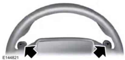
natural_image
Close-up of a metallic curved component with two black arrows pointing to features, labeled E144821 (no text or symbols on the object itself)SelectShift in drive (D):
- Provides a temporary manual mode for performing more demanding maneuvers where extra control of gear selection is required (for example, when towing or overtaking). This mode will hold a selected gear for a temporary period of time dependent on driver inputs (for example, steering or accelerator pedal input).
SelectShift in sport (S):
- Provides a permanent manual gear selection where full control of gear selection is required.
To exit SelectShift mode, shift the transmission into drive (D).
Upshift to the recommended shift speeds according to the following chart:
Transmission
| Upshifts when accelerating (recommended for best fuel economy) | ||
| Gear Upshift | Speed | |
| ToFrom | ||
| 15 mph (24 km/h)21 | ||
| 25 mph (40 km/h)32 | ||
| 40 mph (64 km/h)43 | ||
| 45 mph (72 km/h)54 | ||
| 50 mph (80 km/h)65 | ||
The instrument cluster displays your currently selected gear. If a gear is requested but not available due to vehicle conditions (low speed, too high engine speed for requested gear selection), the current gear will flash three times.
Note: At full accelerator pedal travel the transmission will auto downshift to ensure maximum performance.
Brake-Shift Interlock Override

WARNING: When doing this
procedure, you need to take the transmission out of park (P) which means your vehicle can roll freely. To avoid unwanted vehicle movement, always fully apply the parking brake prior to doing this procedure. Use wheels chocks if appropriate.

WARNING: Do not drive your until you verify that the stoplamps working.

WARNING: If the parking brake is eased, but the brake warning lamp is illuminated, the brakes may not king properly. Have your vehicle d as soon as possible.
Transmission
Note: See your authorized dealer as soon as possible if this procedure is used.
Note: For some markets this feature is not available.
Note: This feature only operates if your 12-volt battery has power. If the vehicle battery voltage is not sufficient, use an external 12 volt power source (for example, jumper cables, a battery charger or jump pack) to operate interlock override switch. Use the brake-shift interlock override to move your transmission from the park position in the event of an electrical malfunction. If your vehicle has a dead battery, you need to use an external power source.
- Apply the parking brake and turn your ignition off before performing this procedure.
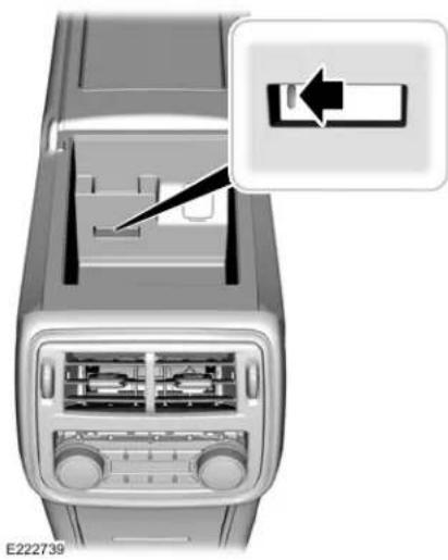
natural_image
Interior view of a car air conditioner unit showing fan, vent, and control panel (no text or symbols visible)- Locate your brake-shift interlock access slot. The slot is located in your center console storage bin. The access slot does not have a label.
Note: Make sure that you correctly identify the access hole as to not cause damage to the center console.
- Using a tool, press and hold the brake shift interlock switch. The shift buttons on the instrument panel will flash when your vehicle is in override mode.
- With the override switch still held, press the neutral (N) button to shift from park.
- Release the override button.
- Your vehicle will remain in neutral for wrecker towing purposes or can be shifted to the desired gear and driven (if possible).
- Release the parking brake.
Automatic Transmission Adaptive Learning
This feature increases durability and provides consistent shift feel over the life of your vehicle. A new vehicle or transmission may have firm or soft shifts. This operation will not affect function or durability of your transmission and is normal. Over time, the adaptive learning process will fully update transmission operation. Additionally, the strategy must be relearned whenever the battery is disconnected or a new battery is installed.
Transmission
If Your Vehicle Gets Stuck In Mud or Snow
Note: Do not rock your vehicle if your engine is not at normal operating temperature or damage to your transmission may occur.
Note: Do not rock your vehicle for more than a minute or damage to your transmission and tires may occur, or your engine may overheat.
If your vehicle gets stuck in mud or snow, you can help rock your vehicle out by shifting between forward and reverse gears, stopping between shifts in a steady pattern. Press lightly on the accelerator in each gear.
All-Wheel Drive (If Equipped)
USING ALL-WHEEL DRIVE
All-Wheel Drive (AWD) uses all four wheels to power the vehicle. This increases traction, enabling you to drive over terrain and road conditions that a conventional two-wheel drive vehicle cannot. The AWD system is active all the time and requires no input from the operator.
Note: Your vehicle may be equipped with Dynamic Torque Vectoring. This feature uses all four wheels to power the vehicle and independently controls the torque to each rear wheel. In addition, the system has the ability to over speed the outside rear wheel in a turn. This increases traction and handling performance, allowing the vehicle to travel through road conditions and have path following capability superior to conventional two-wheel drive and AWD vehicles. The Dynamic Torque Vectoring system is active all the time and requires no input from the operator.
Note: Your AWD vehicle is not intended for off-road use. The AWD feature gives your vehicle some limited off-road capabilities in which driving surfaces are relatively level, obstruction-free and otherwise similar to normal on-road driving conditions. Operating your vehicle under other than those conditions could subject the vehicle to excessive stress which might result in damage which is not covered under your warranty.
Note: When an AWD system fault is present, the warning AWD Malfunction Service
Required displays in the information display. The AWD system is not functioning correctly and defaulted to front-wheel drive. When this warning displays, have your vehicle serviced at an authorized dealer.
Note: The AWD OFF message may also appear in the information display if the AWD system overheats and defaults to front-wheel drive. This may occur if the vehicle is operated in extreme conditions with excessive wheel slip, such as deep sand. To resume normal AWD function as soon as possible, stop the vehicle in a safe location and stop the engine for at least 10 minutes. After the engine has been restarted and the AWD system has adequately cooled, the AWD OFF message will turn off and normal AWD function returns. If the engine is not stopped, the AWD OFF message turns off when the system cools and normal AWD function returns.
All-Wheel Drive (If Equipped)
All-Wheel Drive Messages
| Action / DescriptionAWD Messages | |
| AWD OFF | Displays when the system automatically disables to protect itself. This may be caused by operating the vehicle with the compact tire installed, if the system is overheating or if there is an issue with another vehicle system preventing AWD operation. The system resumes normal operation and clears this message after cycling the ignition on and off and driving a short distance with the road tire re-installed, after the system is allowed to cool or after the other vehicle system issues are resolved. |
| AWD Malfunction Service Required | Displays in conjunction with the powertrain malfunction or reduced power light when the system is not operating properly. If the message stays on or continues to come on, contact your authorized dealer as soon as possible. |
Operating AWD Vehicles With Spare or Mismatched Tires

WARNING: Only use replacement tires and wheels that are the same size, load index, speed rating and type (such as P-metric versus LT-metric or all-season versus all-terrain) as those originally provided by Ford. The recommended tire and wheel size may be found on either the Safety Compliance Certification Label (affixed to either the door hinge pillar, door-latch post, or the door edge that meets the door-latch post, next to the driver's seating position), or the Tire Label which is located on the B-Pillar or edge of the driver's door. If this information is not found on these labels, then you should contact your authorized dealer as soon as possible. Use of any tire or wheel not recommended by Ford can affect the safety and performance of your vehicle, which could result in an increased risk of loss of vehicle control, vehicle rollover, personal injury and death.
A spare tire of a different size other than the tire provided should never be used. The AWD system may disable automatically and enter front-wheel drive only mode to protect driveline components if a non-full sized tire is installed. This condition may display an
AWD OFF message in the information display. If there is an AWD OFF message in the information display from using a non-full sized spare tire, this indicator should turn off after reinstalling the repaired or replaced normal road tire and cycling the ignition off and on. It is recommended to reinstall the repaired or replaced road tire as soon as possible.
Major dissimilar tire sizes between the front and rear axles (for example, 17 inch low profile tires on the front axle and 22 inch high profile tires on the rear axle) could cause the AWD system to stop functioning and default to front-wheel drive or damage the AWD system. However, the AWD system is capable of tolerating any combination of new and worn tires of the same original tire size. For example, using 3 worn tread tires and 1 new tread tire all of the same original tire size, can be tolerated by the AWD system.
Driving In Special Conditions With All-Wheel Drive (AWD)
AWD vehicles are equipped for driving on sand, snow, mud and rough roads and have operating characteristics that are somewhat different from conventional vehicles, both on and off the highway.
When driving at slow speeds in deep sand under high outside temperatures, use a low gear when possible. Lower gear operation will maximize the engine and transmission cooling capability.
Under severe operating conditions, the A/C may cycle on and off to protect overheating of the engine.
Basic operating principles in special conditions
- Drive slower in strong crosswinds which can affect the normal steering characteristics of your vehicle.
- Be extremely careful when driving on pavement made slippery by loose sand, water, gravel, snow or ice.
If Your Vehicle Goes Off the Edge of the Pavement
- If your vehicle goes off the edge of the pavement, slow down, but avoid severe brake application, ease the vehicle back onto the pavement only after reducing your speed. Do not turn the steering wheel too sharply while returning to the road surface.
- It may be safer to stay on the apron or shoulder of the road and slow down gradually before returning to the pavement. You may lose control if you do not slow down or if you turn the steering wheel too sharply or abruptly.
- It often may be less risky to strike small objects, such as highway reflectors, with minor damage to your vehicle rather than attempt a sudden return to the pavement which could cause the vehicle to slide sideways out of control or rollover. Remember, your safety and the safety of others should be your primary concern.
If Your Vehicle Gets Stuck

WARNING: Always set the parking
brake fully and make sure you shift the gearshift lever to park (P). Switch the ignition off and remove the key whenever you leave your vehicle.

WARNING: If the parking brake is
fully released, but the brake warning lamp remains illuminated, the brakes may not be working properly. Have your vehicle checked as soon as possible.

WARNING: Do not spin the wheels
at over 34 mph (55 km/h). The tires may fail and injure a passenger or bystander.
Note: Do not rock the vehicle if the engine is not at normal operating temperature or damage to the transmission may occur.
Note: Do not rock the vehicle for more than a few minutes or damage to the transmission and tires may occur or the engine may overheat.
If your vehicle gets stuck in mud or snow it may be rocked out by shifting between forward and reverse gears, stopping between shifts, in a steady pattern. Press lightly on the accelerator in each gear.
If your vehicle is equipped with AdvanceTrac ^® with Roll Stability Control ^™ , it may be beneficial to disengage the AdvanceTrac ^® with Roll Stability Control ^™ system while attempting to rock the vehicle.
Emergency Maneuvers
• In an unavoidable emergency situation where a sudden sharp turn must be made, remember to avoid "over-driving" your vehicle (that is, turn the steering wheel only as rapidly and as far as required to avoid the emergency). Excessive steering will result in less vehicle control, not more. Additionally, smooth variations of the accelerator and/or brake pedal pressure should be utilized if changes in vehicle speed are
All-Wheel Drive (If Equipped)
called for. Avoid abrupt steering, acceleration or braking which could result in an increased risk of loss of vehicle control, vehicle rollover and/or personal injury. Use all available road surface to return the vehicle to a safe direction of travel.
• In the event of an emergency stop, avoid skidding the tires and do not attempt any sharp steering wheel movements.
- If the vehicle goes from one type of surface to another (that is, from concrete to gravel) there will be a change in the way the vehicle responds to a maneuver (steering, acceleration or braking). Again, avoid these abrupt inputs.
Sand
Most of the time traction control improves tire traction by managing wheel slip through Brake, Engine, and AWD calibrations. However, during low speed driving, disabling traction control in deep sand can help keep the wheels moving to maintain vehicle momentum.
When driving over sand, try to keep all four wheels on the most solid area of the trail. Avoid reducing the tire pressures but shift to a lower gear and drive steadily through the terrain. Apply the accelerator slowly and avoid spinning the wheels.
Do not drive your vehicle in deep sand for an extended period of time. This could cause the AWD system to overheat and default to front-wheel drive. If this occurs, an AWD OFF message displays in the information display. To resume normal AWD function as soon as possible, stop the vehicle in a safe location and stop the engine for at least 10 minutes. After the engine has been restarted and the AWD system has adequately cooled, the AWD OFF message turns off and normal AWD function returns. In the event the engine is not stopped, the AWD OFF message turns off when the system cools and normal AWD function returns.
When driving at slow speeds in deep sand under high outside temperatures, use L (Low) gear when possible. L (Low) gear operation will maximize the engine and transmission cooling capability.
Under severe operating conditions, the A/C may cycle on and off to protect overheating of the engine.
Avoid excessive speed because vehicle momentum can work against you and cause the vehicle to become stuck to the point that assistance may be required from another vehicle. Remember, you may be able to back out the way you came if you proceed with caution.
Mud and Water
If you must drive through high water, drive slowly. Traction or brake capability may be limited.
When driving through water, determine the depth; avoid water higher than the bottom of the wheel rims (for cars) or the bottom of the hubs (for trucks) (if possible) and proceed slowly. If the ignition system gets wet, the vehicle may stall.
All-Wheel Drive (If Equipped)
Once through water, always try the brakes. Wet brakes do not stop the vehicle as effectively as dry brakes. Drying can be improved by moving your vehicle slowly while applying light pressure on the brake pedal.
Be cautious of sudden changes in vehicle speed or direction when you are driving in mud. Even AWD vehicles can lose traction in slick mud. As when you are driving over sand, apply the accelerator slowly and avoid spinning your wheels. If the vehicle does slide, steer in the direction of the slide until you regain control of the vehicle.
After driving through mud, clean off residue stuck to rotating driveshafts and tires. Excess mud stuck on tires and rotating driveshafts causes an imbalance that could damage drive components.
Note: Driving through deep water may damage the transmission.
If the front or rear axle is submerged in water, have the power transfer unit (PTU) or rear axle serviced by an authorized dealer.
Driving on Hilly or Sloping Terrain
Note: Avoid driving crosswise or turning on steep slopes or hills. A danger lies in losing traction, slipping sideways and possibly rolling over. Whenever driving on a hill, determine beforehand the route you will use. Do not drive over the crest of a hill without seeing what conditions are on the other side. Do not drive in reverse over a hill without the aid of an observer.
Although natural obstacles may make it necessary to travel diagonally up or down a hill or steep incline, you should always try to drive straight up or straight down.
When climbing a steep slope or hill, start in a lower gear rather than downshifting to a lower gear from a higher gear once the ascent has started. This reduces strain on the engine and the possibility of stalling.
If you do stall out, do not try to turnaround because you might roll over. It is better to back down to a safe location.
Apply just enough power to the wheels to climb the hill. Too much power will cause the tires to slip, spin or lose traction, resulting in loss of vehicle control.
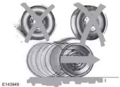
natural_image
Mechanical assembly diagram showing three circular components with cross marks, no visible text or symbolsDescend a hill in the same gear you would use to climb up the hill to avoid excessive brake application and brake overheating. Do not descend in neutral; instead, disengage overdrive or manually shift to a lower gear. When descending a steep hill, avoid sudden hard braking as you could lose control. The front wheels have to be turning in order to steer the vehicle.
All-Wheel Drive (If Equipped)
Your vehicle has anti-lock brakes, therefore apply the brakes steadily. Do not "pump" the brakes.
Driving on Snow and Ice

WARNING: If you are driving in
slippery conditions that require tire chains or cables, then it is critical that you drive cautiously. Keep speeds down, allow for longer stopping distances and avoid aggressive steering to reduce the chances of a loss of vehicle control which can lead to serious injury or death. If the rear end of your vehicle slides while cornering, steer in the direction of the slide until you regain control of your vehicle.
Note: Your vehicle may have original equipment tires designed to optimize the performance of your vehicle in dry or wet summer road conditions. If your vehicle is equipped with such tires, we recommend using a dedicated set (all 4 tires) of winter tires in snow and ice conditions. Do not mix winter tires and performance tires between axles or degraded traction and handling characteristics could result.
Note: Excessive tire slippage can cause driveline damage.
AWD vehicles have advantages over two-wheel drive (2WD) vehicles in snow and ice but can skid like any other vehicle.
Should you start to slide while driving on snowy or icy roads, turn the steering wheel in the direction of the slide until you regain control.
All-Wheel Drive (If Equipped)
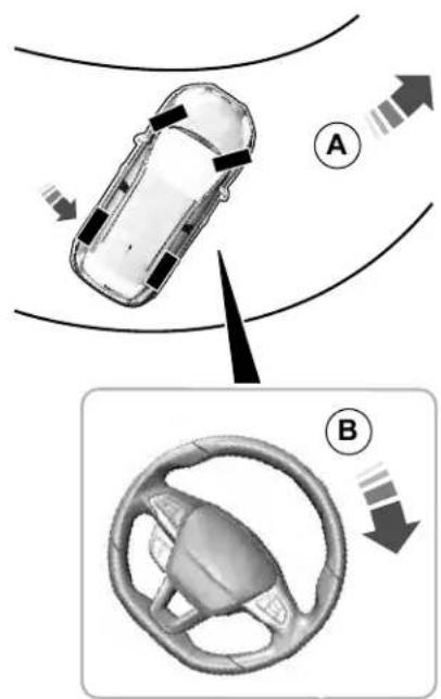
text_image
Diagram illustrating car steering and steering wheel movement, labeled with points A and B and directional arrows.E223901
Direction of travel.A
Steering wheel rotation.B
Avoid sudden applications of power and quick changes of direction on snow and ice. Apply the accelerator slowly and steadily when starting from a full stop.
Avoid sudden braking as well. Although an AWD vehicle may accelerate better than a two-wheel drive vehicle in snow and ice, it won't stop any faster, because as in other vehicles, braking occurs at all four wheels. Do not become overconfident as to road conditions.
Make sure you allow sufficient distance between you and other vehicles for stopping. Drive slower than usual and consider using one of the lower gears. In emergency stopping situations, apply the brake steadily. Since your vehicle is equipped with a four wheel (ABS), do not "pump" the brakes. See Hints on Driving With Anti-Lock Brakes (page 220).
Maintenance and Modifications
The suspension and steering systems on your vehicle have been designed and tested to provide predictable performance whether loaded or empty and durable load carrying capability. For this reason, Ford Motor Company strongly recommends that you do not make modifications such as adding or removing parts (such as lowering kits or stabilizer bars) or by using replacement parts not equivalent to the original factory equipment.
Any modifications to a vehicle that raise the center of gravity can make it more likely the vehicle will rollover as a result of a loss of control. Ford Motor Company recommends that caution be used with any vehicle equipped with a high load or device (such as ladder or luggage racks).
All-Wheel Drive (If Equipped)
Failure to maintain your vehicle properly may void the warranty, increase your repair cost, reduce vehicle performance and operational capabilities and adversely affect driver and passenger safety. Frequent inspection of vehicle chassis components is recommended if the vehicle is subjected to off-highway usage.
Brakes
GENERAL INFORMATION
Note: Occasional brake noise is normal. If a metal-to-metal, continuous grinding or continuous squeal sound is present, the brake linings may be worn-out and an authorized dealer should check them. If the vehicle has continuous vibration or shudder in the steering wheel while braking, an authorized dealer should check your vehicle.
Note: Brake dust may accumulate on the wheels, even under normal driving conditions. Some dust is inevitable as the brakes wear and does not contribute to brake noise. See Cleaning the Wheels (page 357).
Wet brakes result in reduced braking efficiency. Gently press the brake pedal a few times when driving from a car wash or standing water to dry the brakes.
Brake Over Accelerator
In the event the accelerator pedal becomes stuck or entrapped, apply steady and firm pressure to the brake pedal to slow the vehicle and reduce engine power. If you experience this condition, apply the brakes and bring your vehicle to a safe stop. Switch the engine off, move the transmission to park (P) and apply the parking brake. Inspect the accelerator pedal and the area around it for any items or debris that may be obstructing its movement. If none are found and the condition persists, have your vehicle towed to the nearest authorized dealer.
Emergency Brake Assist
Emergency brake assist detects when you brake heavily by measuring the rate at which you press the brake pedal. It provides maximum braking efficiency as long as you press the pedal. Emergency brake assist can reduce stopping distances in critical situations.
Anti-lock Brake System
This system helps you maintain steering control during emergency stops by keeping the brakes from locking.

This lamp momentarily illuminates when you switch the ignition on. If the light does not illuminate during
start up, remains on or flashes, the anti-lock braking system may be disabled. Have the system checked by an authorized dealer. If the anti-lock brake system is disabled, normal braking is still effective.
See Warning Lamps and Indicators (page 117).
Note: Indicators vary depending on region.
This lamp also illuminates momentarily when you switch the ignition on to confirm the lamp is functional. If it does not illuminate when you switch the ignition on, or begins to flash at any time, have
the system checked by an authorized dealer. If the brake warning lamp illuminates with the parking brake released, have the system checked immediately.
Brakes
HINTS ON DRIVING WITH ANTI-LOCK BRAKES
The anti-lock braking system does not eliminate the risks when:
- You drive too closely to the vehicle in front of you.
- Your vehicle is hydroplaning.
- You take corners too fast.
•The road surface is poor.
Note: If the system activates, the brake pedal may pulse and may travel further. Maintain pressure on the brake pedal. You may also hear a noise from the system. This is normal.
WARNING: Always fully apply the
parking brake and make sure you shift into park (P). Failure to follow this instruction could result in personal injury or death.

WARNING: If you drive extended es with the parking brake applied,uld cause damage to the brake

WARNING: The electric parking
brake does not operate if the vehicle battery is running out of charge.
Your vehicle has an electric parking brake. You operate it with a switch instead of a lever. The switch is on the center console or to the left-hand side of the steering wheel, on the lower part of the instrument panel.
Note: The electric parking brake makes noises during operation. This is normal.
Applying the Electric Parking Brake

Pull the switch upward.

The red warning lamp flashes during operation and illuminates when the parking brake is applied.

Note: It remains illuminated for a short period of time after you switch the ignition off.
If it continues to flash or does not illuminate, the system has malfunctioned. Have your vehicle checked as soon as possible.
Note: You can apply the electric parking brake when the ignition is off.
Note: The electric parking brake could automatically apply when you shift into park (P). See Transmission (page 203).
Applying the Electric Parking Brake in an Emergency
Note: Do not apply the electric parking brake when your vehicle is moving, except in an emergency. If you repeatedly use the electric parking brake to slow or stop your vehicle, you could cause damage to the brake system.
You can use the electric parking brake to slow or stop your vehicle in an emergency.
Brakes

Pull the switch upward and hold it.

The red warning lamp illuminates, a tone sounds and the stoplamps turn on.

The electric parking brake continues to slow your vehicle down unless you release the switch.
Manually Releasing the Electric Parking Brake
Switch the ignition on.
Press and hold the brake pedal.

Push the switch downward.

The red warning lamp turns off.

If it remains illuminated or flashes, the system has malfunctioned. Have your vehicle checked as soon as possible.
Pulling Away on a Hill When Towing a Trailer
Press and hold the brake pedal.

Pull the switch upward and hold it.
Shift into gear.
Press the accelerator pedal until engine has developed sufficient torque to prevent your vehicle from rolling down the hill.

Release the switch and pull away in a normal manner.
Automatically Releasing the Electric Parking Brake
Close the driver door.
Shift into gear.
Press the accelerator pedal and pull away in a normal manner.

The red warning lamp turns off.

If it remains illuminated or flashes, the electric parking brake has not released. Manually release the parking brake.
Releasing the Electric Parking Brake if the Vehicle Battery is Running Out of Charge
Connect a booster battery to the vehicle battery to release the electric parking brake if the vehicle battery is running out of charge. See Jump Starting the Vehicle (page 295).
Brakes
HILL START ASSIST

WARNING: The system does not take the parking brake. When you leave vehicle, always apply the parking and shift the transmission into park automatic transmission or first gear manual transmission.

WARNING: You must remain in vehicle when the system turns on. At 15 s, you are responsible for rolling your vehicle, supervising the car and intervening, if required. Failure to care may result in the loss of failure of your vehicle, serious personal or death.

WARNING: The system turns off if it is a malfunction or if you excessively use engine.
The system makes it easier to pull away when your vehicle is on a slope without the need to use the parking brake.
When the system activates, your vehicle remains stationary on a slope for a few seconds after you release the brake pedal. This allows you time to move your foot from the brake to the accelerator pedal. The brakes release when the engine has developed sufficient torque to prevent your vehicle from rolling down the slope. This is an advantage when pulling away on a slope, for example from a car park ramp, traffic lights or when reversing uphill into a parking space.
The system activates on any slope that causes your vehicle to roll.
Note: There is no warning lamp to indicate the system is either on or off.
Using Hill Start Assist
-
Press the brake pedal to bring your vehicle to a complete standstill. Keep the brake pedal pressed and shift into first gear when facing uphill or reverse (R) when facing downhill.
-
The system activates if the sensors detect that your vehicle is on a slope.
- When you remove your foot from the brake pedal, your vehicle remains on the slope without rolling away for a few seconds. This hold time increases if you are in the process of driving off.
- Pull away in the normal manner.
Switching the System On and Off
Vehicles with Manual Transmission
You can switch this feature on or off in the information display. The system remembers the last setting when you start your vehicle.
Vehicles with Automatic Transmission
The system turns on when you switch the ignition on and you cannot switch the system off.
Brakes
AUTO HOLD

WARNING: The system does not
replace the parking brake. When you leave your vehicle, always apply the parking brake.

WARNING: You must remain in
your vehicle when the system turns on. At all times, you are responsible for controlling your vehicle, supervising the system and intervening, if required. Failure to take care may result in the loss of control of your vehicle, serious personal injury or death.

WARNING: The system will turn off
if a malfunction is apparent or if you rev the engine excessively. Failure to take care may result in the loss of control of your vehicle, serious personal injury or death.
Auto Hold uses your vehicle's brake to hold your vehicle at a stop once your vehicle has reached a standstill condition. For example, Auto Hold can assist you while stopping at traffic lights or while in traffic jams by holding the brake pressure for you once you bring your vehicle to a stop.
Switch Auto Hold off during vehicle or trailer towing.
Note: In case of a malfunction in the system while Auto Hold actively holds the vehicle (for example, low power supply), a message appears in the information display asking you to press the brake pedal. If you see this message, press the brake pedal immediately.
Note: Auto Hold only activates if the system recognizes it is applying enough brake pressure. On a steep hill or slope, make sure you press the brake pedal sufficiently to activate the Auto Hold system.
Note: In some cases, Auto Hold might hand over to the parking brake. When the parking brake applies, the red brake lamp appears. This is normal. When you press the accelerator pedal, the drive away release feature releases the parking brake.
Note: Auto Hold works on all road grades.
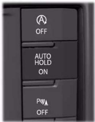
text_image
OFF AUTO HOLD ON P OFFE222988
Brakes
Press the Auto Hold button to switch the system on and off. The Auto Hold indicator light illuminates in the Auto Hold button when the system is on.
Note: You can only switch Auto Hold on if you close the door and fasten your seatbelt.
Note: The system remembers the last setting when you start your vehicle.
Note: When in reverse (R), Auto Hold does not function.
When Auto Hold is off, your vehicle behaves the same as a vehicle without Auto Hold.
There is an Auto Hold indicator lamp in the instrument cluster that has two modes, active and unavailable.

The Auto Hold (ACTIVE) indicator light illuminates in the information display when the system holds
your vehicle stationary. When in active mode, press the brake pedal and the Auto Hold button to switch Auto Hold off.

The Auto Hold (UNAVAILABLE) indicator light illuminates in the information display when the
system is on but unavailable to hold your vehicle (for example, during Active Park Assist, Stay in Neutral Mode, or when you do not fasten your seatbelt or close the door).
Note: Make sure you switch off Auto Hold or use the Stay in Neutral mode before you enter a car wash. See Automatic
Transmission (page 203).
Using Auto Hold
- Bring your vehicle to a stop by pressing the brake pedal. After coming to a stop, the green Auto Hold (ACTIVE) indicator lamp illuminates in the information display.
-
Release the brake pedal. The Auto Hold (ACTIVE) indicator light remains illuminated in the information display and Auto Hold will hold your vehicle at a stop.
-
When you press the accelerator pedal, Auto Hold releases the brakes and allows you to drive off. Once you drive off, the green Auto Hold (ACTIVE) indicator no longer illuminates in the information display.
Traction Control
The traction control system helps avoid drive wheel spin and loss of traction.
If your vehicle begins to slide, the system applies the brakes to individual wheels and, when needed, reduces engine power at the same time. If the wheels spin when accelerating on slippery or loose surfaces, the system reduces engine power in order to increase traction.
USING TRACTION CONTROL

WARNING: The stability and
traction control light illuminates steadily if the system detects a failure. Make sure you did not manually disable the traction control system using the information display controls or the switch. If the stability control and traction control light is still
illuminating steadily, have the system serviced by an authorized dealer immediately. Operating your vehicle with the traction control disabled could lead to an increased risk of loss of vehicle control, vehicle rollover, personal injury and death.
The system automatically turns on each time you switch the ignition on.
If your vehicle is stuck in mud or snow, switching traction control off may be beneficial as this allows the wheels to spin.
Note: When you switch traction control off, stability control remains fully active.
Switching the System Off
When you switch the system off or on, a message appears in the information display showing system status.
You can switch the system off by either using the information display controls or the switch.
Using the Information Display Controls
You can switch this feature off or on in the information display. See General Information (page 122).
Using a Switch (If Equipped)
Use the traction control switch on the instrument panel to switch the system off or on.
System Indicator Lights and Messages

The stability and traction control light:
•Temporarily illuminates on engine start-up.
- Flashes when a driving condition activates either of the systems.
- Illuminates if a problem occurs in either of the systems.

The stability and traction control off light temporarily illuminates on engine start-up and stays on when
you switch the traction control system off.
Stability Control
WARNING: Vehicle modifications involving braking system, aftermarket roof racks, suspension, steering system, tire construction and wheel and tire size may change the handling characteristics of your vehicle and may adversely affect the performance of the electronic stability control system. In addition, installing any stereo loudspeakers may interfere with and adversely affect the electronic stability control system. Install any aftermarket stereo loudspeaker as far as possible from the front center console, the tunnel, and the front seats in order to minimize the risk of interfering with the electronic stability control sensors. Reducing the effectiveness of the electronic stability control system could lead to an increased risk of loss of vehicle control, vehicle rollover, personal injury and death.

WARNING: Remember that even advanced technology cannot defy the laws of physics. It's always possible to lose control of a vehicle due to inappropriate driver input for the conditions. Aggressive driving on any road condition can cause you to lose control of your vehicle increasing the risk of personal injury or property damage. Activation of the electronic stability control system is an indication that at least some of the tires have exceeded their ability to grip the road; this could reduce the operator's ability to control the vehicle potentially resulting in a loss of vehicle control, vehicle rollover, personal injury and death. If your electronic stability control system activates, SLOW DOWN.
The system automatically turns on each time you switch the ignition on.
If a fault occurs in either the stability control or the traction control system, you may experience the following conditions:
•The stability and traction control light illuminates steadily.
•The stability control and traction control systems do not enhance your vehicle's ability to maintain traction of the wheels.
•The adaptive steering system (if equipped) automatically changes the steering function to a fixed steering ratio. See Steering (page 272).
If a driving condition activates either the stability control or the traction control system you may experience the following conditions:
•The stability and traction control light flashes.
- Your vehicle slows down.
- Reduced engine power.
•A vibration in the brake pedal.
•The brake pedal is stiffer than usual.
- If the driving condition is severe and your foot is not on the brake, the brake pedal may move as the system applies higher brake force.
Stability Control
The stability control system has several features built into it to help you maintain control of your vehicle:
Electronic Stability Control
The system enhances your vehicle's ability to prevent skids or lateral slides by applying brakes to one or more of the wheels individually and, if necessary, reducing engine power.
Traction Control
The system enhances your vehicle's ability to maintain traction of the wheels by detecting and controlling wheel spin. See Using Traction Control (page 225).
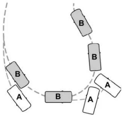
flowchart
graph TD
    A["A"] --> B["B"]
    B --> C["A"]
    C --> D["B"]
    D --> E["B"]
    E --> F["A"]
    F --> G["B"]
    G --> H["B"]
    H --> I["A"]
    I --> J["B"]
    J --> K["B"]
    K --> L["A"]
    L --> M["B"]
    M --> N["A"]
    N --> O["B"]
    O --> P["A"]
    P --> Q["B"]
    Q --> R["A"]
    R --> S["B"]
    S --> T["A"]
    T --> U["B"]
    U --> V["A"]
    V --> W["B"]
    W --> X["A"]
    X --> Y["B"]
E72903
A Vehicle without stability control skidding off its intended route.
B Vehicle with stability control maintaining control on a slippery surface.
USING STABILITY CONTROL
The system automatically turns on each time you switch the ignition on.
You cannot switch the stability control system off, but when you shift into reverse (R), the system deactivates.
You can switch the traction control system off or on. See Using Traction Control (page 225).
Parking Aids
WARNING: To help avoid personal always use caution when in reverse when using the sensing system.

WARNING: The system may not objects with surfaces that absorb on. Always drive with due care and on. Failure to take care may result ash.

WARNING: Traffic control systems, ent weather, air brakes, external and fans may affect the correct on of the sensing system. This may reduced performance or false alerts.

WARNING: The system may not small or moving objects, particularly close to the ground.
Note: If your vehicle has MyKey™, the sensing system cannot be switched off when a MyKey™ is present. See Principle of Operation (page 69).
Note: Keep the sensors on the bumper or fascia free from snow, ice and large accumulations of dirt. If the sensors are covered, the system's accuracy can be affected. Do not clean the sensors with sharp objects.
Note: If your vehicle sustains damage to the bumper or fascia, leaving it misaligned or bent, the sensing zone may be altered causing inaccurate measurement of obstacles or false alerts.
Note: Certain add-on devices installed around the bumper or fascia may create false alerts. For example, large trailer hitches, bike or surfboard racks, license plate brackets, bumper covers or any other device that may block the normal detection zone of the system. Remove the add-on device to prevent false alerts.
Note: When you connect a trailer to your vehicle, the rear parking aid may detect the trailer and therefore provide an alert. Disable the rear parking aid when you connect a trailer to prevent the alert.
The sensing system warns the driver of obstacles within a certain range of your vehicle. The system turns on automatically whenever you switch the ignition on.
You can switch the system off through the information display menu or from the pop-up message that appears once you shift the transmission into reverse (R). See General Information (page 122). If your vehicle has a parking aid button, you can switch the system off by pressing the button.
If a fault is present in the system, a warning message appears in the information display. See Information Messages (page 130).
Parking Aids
REAR PARKING AID

WARNING: The system may not
detect objects with surfaces that absorb reflection. Always drive with due care and attention. Failure to take care may result in a crash.

WARNING: The system may not
detect small or moving objects, particularly those close to the ground.

WARNING: To help avoid personal
injury, always use caution when in reverse (R) and when using the sensing system.

WARNING: The parking aid system
can only assist you to detect objects when your vehicle is moving at parking speeds. To help avoid personal injury you must take care when using the parking aid system.
Note: Keep the sensors free from snow, ice and large accumulations of dirt.
Note: Do not cover up the sensors.
Note: Do not clean the sensors with sharp objects.
Note: If your vehicle sustains damage leaving the sensors misaligned, this may cause inaccurate measurements or false alerts.
Note: Some accessories, for example large trailer hitches or bike or surfboard racks can cause reduced performance or false alerts.
The sensors are on the rear bumper.
The sensors are active when the transmission is in reverse (R) and the vehicle speed is less than 3 mph (5 km/h). When the parking aid system sounds a tone, the audio system may reduce the set volume.
A warning tone sounds when your vehicle approaches an object. As your vehicle moves closer to an object, the rate of the tone increases. The warning tone continuously sounds when an object is 12 in (30 cm) or less from the center of the rear bumper.
Note: There is a decreased coverage area at the outer corners.
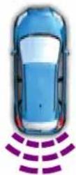
E130178
The sensor coverage area is up to 70 in (180 cm) from the rear bumper.
If the system detects a fault, a warning message appears in the information display.
Parking Aids
The system detects large objects when you shift into reverse (R) and any of the following occur:
-Your vehicle is moving backward at low speed.
- Your vehicle is stationary but an object is approaching the rear of your vehicle at low speed.
-Your vehicle is moving backward at low speed and an object is moving toward your vehicle, for example another vehicle at low speed.
If your vehicle remains stationary for two seconds the audible warning turns off. If your vehicle moves backward the tone sounds again.
Note: If the detected object is 12 in (30 cm) or less from the rear bumper, the audible warning does not turn off.
Object Distance Indicator (If Equipped)
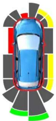
natural_image
Top-down view of a car with colored lane markings around it (no text or symbols)E190459
The system provides object distance indication through the information display.
- As the distance to the object decreases, the indicator blocks illuminate and move toward the vehicle icon.
- If the system does not detect an object, the distance indicator blocks are gray.
When you shift into reverse (R), the system provides audible warnings and visual indication when your vehicle is moving and the detected object is moving toward your vehicle. When you stop your vehicle, the audible warnings stop after two seconds. Visual indication remains on when the transmission is in reverse (R).
FRONT PARKING AID

WARNING: The system may not objects with surfaces that absorb on. Always drive with due care and on. Failure to take care may result in sh.

WARNING: The system may not small or moving objects, particularly close to the ground.
Parking Aids

WARNING: To help avoid personal always use caution when in reverse when using the sensing system.

WARNING: The parking aid system
can only assist you to detect objects when your vehicle is moving at parking speeds. To help avoid personal injury you must take care when using the parking aid system.
Note: Keep the sensors free from snow, ice and large accumulations of dirt.
Note: Do not cover up the sensors.
Note: Do not clean the sensors with sharp objects.
Note: If your vehicle sustains damage leaving the sensors misaligned, this may cause inaccurate measurements or false alerts.
Note: Some accessories, for example large trailer hitches or bike or surfboard racks can cause reduced performance or false alerts.
The sensors are on the front bumper.
The sensors are active when the transmission is in any position other than park (P). When the parking aid system sounds a tone, the audio system may reduce the set volume.
A warning tone sounds when your vehicle approaches an object. As your vehicle moves closer to an object, the rate of the tone increases. The warning tone continuously sounds when an object is 12 in (30 cm) or less from the front bumper.
Note: There is a decreased coverage area at the outer corners.
The system turns off when the vehicle speed reaches 5 mph (8 km/h).
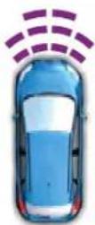
E187330
The sensor coverage area is up to 28 in (70 cm) from the center of the bumper.
If the transmission is in reverse (R), the system detects objects when your vehicle is moving at low speed or an object is moving toward your vehicle, for example another vehicle at low speed. When you stop your vehicle, the audible warning turns off after two seconds.
Parking Aids
If the transmission is in any forward gear, the system provides audible warnings when your vehicle is moving and an object is within the detection area. When you stop your vehicle, the audible warning turns off after two seconds and the visual warning turns off after four seconds.
If the system detects a fault, a warning message appears in the information display.
Object Distance Indicator (If Equipped)
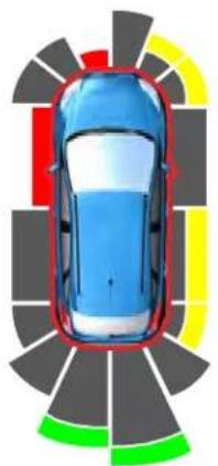
natural_image
Top-down view of a car with colored lane markings around it (no text or symbols)E190459
The system provides object distance indication through the information display.
- As the distance to the object decreases, the indicator blocks illuminate and move toward the vehicle icon.
- If there is no object detected, the distance indicator blocks are gray.
When you shift into any forward gear, the system provides audible warnings and visual indication when your vehicle is moving at a speed of approximately 5 mph (8 km/h) or below and the system detects an object within the detection zone. When you stop your vehicle, the audible warnings stop after two seconds and visual indication stops after four seconds.
Note: If the detected object is 12 in (30 cm) or less from your vehicle, visual indication remains on.
When you shift into neutral (N), the system only provides visual indication if your vehicle is moving at a speed of approximately 5 mph (8 km/h) or below, for example, your vehicle is moving on a slope, and the system detects an object moving toward your vehicle. When you stop your vehicle, visual indication stops after four seconds.
Parking Aids
SIDE SENSING SYSTEM (IF EQUIPPED)

WARNING: The system may not
detect objects with surfaces that absorb reflection. Always drive with due care and attention. Failure to take care may result in a crash.

WARNING: The system may not
detect small or moving objects, particularly those close to the ground.

WARNING: To help avoid personal
injury, always use caution when in reverse (R) and when using the sensing system.

WARNING: The parking aid system
can only assist you to detect objects when your vehicle is moving at parking speeds. To help avoid personal injury you must take care when using the parking aid system.
Note: Keep the sensors free from snow, ice and large accumulations of dirt.
Note: Do not cover up the sensors.
Note: Do not clean the sensors with sharp objects.
Note: If your vehicle sustains damage leaving the sensors misaligned, this may cause inaccurate measurements or false alerts.
Note: If you switch traction control off, the side sensing system also turns off.
Note: Some accessories, for example large trailer hitches or bike or surfboard racks can cause reduced performance or false alerts.
Note: The system does not detect an object that is moving toward the side of your vehicle, for example another vehicle moving at low speed, if it does not pass a front or rear sensor.
The system uses the front and rear outermost parking aid sensors to detect objects that are near to the sides of your vehicle. The system displays them on a virtual map in the information display as your vehicle moves past them.
The sensors are on the front and rear bumpers.
The system may not function if:
- You switch the ignition on, off and back on within a few seconds.
- Your vehicle remains stationary for over two minutes.
•The anti-lock brake system activates.
• The traction control system activates.
To reinitialize the system, you may have to drive your vehicle approximately 10 ft (3 m).
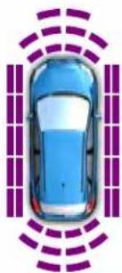
natural_image
Top-down view of a blue car with purple sensor waves surrounding it (no text or symbols)E190458
Parking Aids
The sensor coverage area is up to 24 in (60 cm) from the side of your vehicle.
When the system detects an object within the coverage area and the driving path of your vehicle, an audible warning sounds. As the object moves closer to your vehicle, the rate of the tone increases.
Object Distance Indicator (If Equipped)
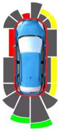
natural_image
Top-down view of a car with colored lane markings around it (no text or symbols)E190459
The system provides object distance indication through the information display.
- As the distance to the object decreases, the indicator blocks illuminate and move toward the vehicle icon.
- If there is no object detected, the distance indicator blocks are gray.
When you shift into reverse (R), the system provides audible warnings and visual indication when detected objects are within 24 in (60 cm) and are inside the driving path of your vehicle. When you stop your vehicle, the audible warnings turn off after two seconds.
When you shift into any forward gear, the system provides audible warnings and visual indication when your vehicle is moving at a speed of approximately 5 mph (8 km/h) or below and the system detects an object within the detection zone. When you stop your vehicle, the audible warnings turn off after two seconds and visual indication turns off after four seconds.
When you shift into neutral (N), the system only provides visual indication if your vehicle is moving at a speed of approximately 5 mph (8 km/h) or below. For example, your vehicle is moving on a slope, and the system detects an object moving toward your vehicle. When you stop your vehicle, visual indication turns off after four seconds.
If the system is not available, the side distance indicator blocks do not display.
ACTIVE PARK ASSIST (IF EQUIPPED)

WARNING: You must remain in
your vehicle when the system turns on. At all times, you are responsible for controlling your vehicle, supervising the system and intervening, if required. Failure to take care may result in the loss of control of your vehicle, serious personal injury or death.
Parking Aids

WARNING: The sensors may not objects in heavy rain or other ons that cause interference.

WARNING: Active park assist does
not apply the brakes under any circumstances.

WARNING: You are responsible
for controlling your vehicle at all times. The system is designed to be an aid and does not relieve you of your responsibility to drive with due care and attention. Failure to follow this instruction could result in the loss of control of your vehicle, personal injury or death.
Note: Keep the sensors free from snow, ice and large accumulations of dirt.
Note: Do not cover up the sensors.
Note: Do not clean the sensors with sharp objects.
Note: The sensors may not detect objects with surfaces that absorb ultrasonic waves. The sensors may falsely detect objects due to ultrasonic interference caused by motorcycle exhausts, truck air brakes or horns, for example.
Note: If you change any tires, the system must recalibrate and may not correctly operate for a short time.
Active park assist is a multi-step process and may require you to shift the transmission multiple times. Follow the onscreen instructions until the parking maneuver is complete.
If you are uncomfortable with the proximity to any vehicle or object, you may choose to override the system by grabbing the steering wheel, or by taking full control of your vehicle after pressing the active park assist button.
Keep your hands, hair, clothing and any loose items clear of the steering wheel when using active park assist.
The sensors are on the front and rear bumpers.
The system may not correctly operate in any of the following conditions:
- You use a spare tire or a tire that is significantly worn more than the other tires.
• One or more tires are incorrectly inflated.
- You try to park on a tight curve.
- Something passes between the front bumper and the parking space. For example, a pedestrian or cyclist.
•The edge of the neighboring parked vehicle is high off the ground. For example, a bus, tow truck or flatbed truck.
•The weather conditions are poor. For example, during heavy rain, snow, fog, high humidity and high temperatures.
Do not use the system if:
- You have attached an add-on accessory close to the sensors on the front or rear of your vehicle. For example, a bike rack or trailer.
- You have attached an overhanging object to the roof. For example, a surfboard.
Parking Aids
- The front bumper, rear bumper or the side sensors are damaged.
- The correct tire size is not in use on your vehicle. For example, a mini-spare tire.
Using Active Park Assist
Selecting an Active Park Assist Mode

Press the button once to activate parallel parking. Press the button a second time to activate
perpendicular parking. If you press the button again the system switches off.
If your vehicle is parked and after you switch the ignition on, you can use the information display to toggle through the modes. Press the button to switch the system on and open the system menu in the information display.
Note: If your vehicle is parked, the default mode is parallel park out assist. However, if you did not use active park assist to parallel park your vehicle, use the information display to select park out assist.
Note: You can repeatedly press the active park assist button to toggle through the modes only after moving your vehicle approximately 33 ft (10 m).
To toggle through the modes, use the buttons on the information display to select the following:
- Parallel parking.
•Perpendicular parking.
- Parallel park out assist.
- Switch the system off.
Note: There is no time limit for toggling through the modes.
Parallel Parking
The system detects available parallel parking spaces and steers your vehicle into the space. You control the accelerator, gearshift and brakes. The system visually and audibly guides you into a parallel parking space.

Press the button once to search for a parking space.
Note: You can also switch the system on after you have already driven partially or completely past a parking space. Press the active park assist button and the system informs you if you have recently passed a suitable parking space.
When the vehicle speed is less than 22 mph (35 km/h), the system scans both sides of your vehicle for an available parking space. A message and a graphic appear in the information display to indicate the system is searching for a parking space. Use the direction indicator lever to search for a parking space on the driver or passenger side of your vehicle.
Note: The system scans both sides of your vehicle and offers parking spaces one side at a time if you do not use the direction indicator.
Note: The system defaults to the passenger side if you do not use the direction indicator.
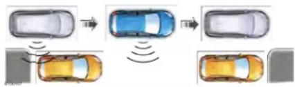
flowchart
graph TD
    A["Top Panel"] --> B["Top Panel with Blue Sensor"]
    B --> C["Top Panel with Yellow Sensor"]
    D["Bottom Panel"] --> E["Bottom Panel with Orange Sensor"]
    E --> F["Bottom Panel with Grey Sensor"]
    style A fill:#f9f,stroke:#333
    style B fill:#bbf,stroke:#333
    style C fill:#bfb,stroke:#333
    style D fill:#ffb,stroke:#333
    style E fill:#ffb,stroke:#333
Parking Aids
Drive your vehicle approximately 3 ft (1 m) and parallel to the other parked vehicles when searching for a parking space.
Note: If you drive your vehicle less than 2 ft (0.5 m) or greater than 5 ft (1.5 m) away from other parked vehicles, the system may not be able to detect an available parking space.
When the system detects a suitable space, a message displays and a tone sounds. Stop your vehicle and follow the onscreen instructions. If your vehicle is moving very slowly, you may have to move forward a short distance before the system is ready to park.
Note: You must observe that the space the system selects remains clear of obstructions at all times during the maneuver.
Note: The system always offers the last parking space it detects. For example, if your vehicle detects multiple spaces when you are driving, it offers the last one.
Note: If the vehicle speed is greater than approximately 22 mph (35 km/h), the system shows a message to instruct you to reduce the vehicle speed.
Automatically Steering into a Parallel Parking Space
When you shift into reverse (R), with your hands off the steering wheel and nothing obstructing its movement, your vehicle steers itself into the space. The system displays instructions to move your vehicle backward and forward in the space.
Note: If the vehicle speed exceeds approximately 6 mph (9 km/h), you interrupt the maneuver, or the system switches off, you must take full control of your vehicle.
Note: If the system detects an object is very close to your vehicle and it may be unsafe to continue the maneuver, it may instruct you to stop your vehicle. The system may not provide any further instruction. Steering assistance continues to operate but you must decide if it is safe to continue the maneuver.
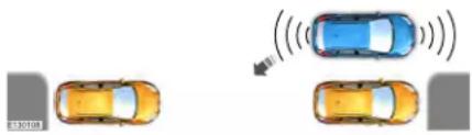
text_image
Diagram showing three cars with sound waves, one emitting a signal to the others, labeled with vehicle ID 30108.When you believe your vehicle is correctly parked, or a solid tone sounds and an information message appears, bring your vehicle to a complete stop.
When the Active Park Assist maneuver is complete, a tone sounds and an information message appears.
Note: You are responsible for checking how your vehicle is parked and making any necessary corrections before leaving your vehicle.
Deactivating Active Park Assist
You can manually deactivate the system by:
- Pressing the Active Park Assist button during an active maneuver.
- Grabbing the steering wheel during an active maneuver.
- Driving above 22 mph (35 km/h) for 30 seconds when searching for a parking space.
- Driving above 6 mph (9 km/h) during an active maneuver.
- Switching the traction control system off.
Parking Aids
Certain vehicle conditions may also deactivate the system, for example:
•The traction control system activates or fails.
•The anti-lock brake system activates or fails.
If the system malfunctions, a message appears and a tone sounds. Have your vehicle checked as soon as possible.
Perpendicular Parking
The system detects available perpendicular parking spaces and steers your vehicle into the space. You control the accelerator, gearshift and brakes. The system visually and audibly guides you into a perpendicular parking space.

Press the button twice to search for a parking space.
When the vehicle speed is less than 19 mph (30 km/h), the system scans both sides of your vehicle for an available parking space. A message and a graphic appear in the information display to indicate the system is searching for a parking space. Use the direction indicator lever to search for a parking space on the driver or passenger side of your vehicle.
Note: The system scans both sides of your vehicle and offers parking spaces one side at a time if you do not use the direction indicator.
Note: The system defaults to the passenger side if you do not use the direction indicator.
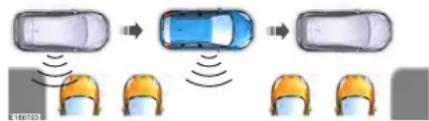
flowchart
graph TD
    A["Top Car Position"] --> B["Top Car Position"]
    B --> C["Top Car Position"]
    style A fill:#f9f,stroke:#333
    style B fill:#bbf,stroke:#333
    style C fill:#f9f,stroke:#333
Drive your vehicle approximately 3 ft (1 m) and perpendicular to the other parked vehicles when searching for a parking space.
Note: If you drive your vehicle less than 2 ft (0.5 m) or greater than 5 ft (1.5 m) away from other parked vehicles, the system may not be able to detect an available parking space.
When the system detects a suitable space, a message displays and a tone sounds. Stop your vehicle and follow the onscreen instructions. If your vehicle is moving very slowly, you may have to move forward a short distance before the system is ready to park.
Note: You must observe that the space the system selects remains clear of obstructions at all times during the maneuver.
Note: The system always offers the last detected parking space. For example, if your vehicle detects multiple spaces when you are driving, it offers the last one.
Note: If the vehicle speed is greater than approximately 19 mph (30 km/h), the system shows a message to instruct you to reduce the vehicle speed.
Parking Aids
Automatically Steering into a Perpendicular Parking Space
When you shift into reverse (R), with your hands off the steering wheel and nothing obstructing its movement, your vehicle steers itself into the space. The system displays instructions to move your vehicle backward and forward in the space.
Note: If the vehicle speed exceeds approximately 6 mph (9 km/h), you interrupt the maneuver, or the system switches off, you must take full control of your vehicle.
Note: If the system detects an object is very close to your vehicle and it may be unsafe to continue the maneuver, it may instruct you to stop your vehicle. The system may not provide any further instruction. Steering assistance continues to operate but you must decide if it is safe to continue the maneuver.
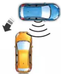
natural_image
Illustration of two cars with signal waves, one emitting a car (no text or symbols)E186191
When you believe your vehicle is correctly parked, or a solid tone sounds and an information message appears, bring your vehicle to a complete stop.
When the active park assist maneuver is complete, a tone sounds and a message appears.
Note: You are responsible for checking how your vehicle is parked and making any necessary corrections before leaving your vehicle.
Deactivating Active Park Assist
You can manually deactivate the system by:
- Pressing the Active Park Assist button during an active maneuver.
- Grabbing the steering wheel during an active maneuver.
- Driving above 19 mph (30 km/h) for 30 seconds when searching for a parking space.
- Driving above 6 mph (9 km/h) during an active maneuver.
- Switching the traction control system off.
Certain vehicle conditions may also deactivate the system, for example:
•The traction control system activates or fails.
•The anti-lock brake system activates or fails.
If the system malfunctions, a message appears and a tone sounds. Have your vehicle checked as soon as possible.
Parking Aids
Parallel Park Out Assist
The system steers your vehicle out of a parallel parking space. You control the accelerator, gearshift and brakes. The system visually and audibly guides you out of a parallel parking space.
Note: This system is not intended to assist when exiting a perpendicular parking space.

Press the button once when your vehicle is stationary in a parallel parking space.
Note: If you did not use active park assist to parallel park your vehicle, pressing the button once selects parallel park. You must use the information display to select park out assist.
The system displays a message instructing you to switch a direction indicator on. Use the direction indicator to select which side of your vehicle you want to exit the parking space. The system displays instructions to move your vehicle backward and forward in the space.
Note: If the system detects an object is very close to your vehicle and it may be unsafe to continue the maneuver, it may instruct you to stop your vehicle. The system may not provide any further instruction. Steering assistance continues to operate but you must decide if it is safe to continue the maneuver.

After the system directs your vehicle to a position where you can exit the parking space in a forward movement, a message appears instructing you to take full control of your vehicle. Generally, hand-over is when your vehicle is still inside the parking space.
Note: Parallel Park Out Assist may not be available when the clearance to the front or the rear of your vehicle is too small.
Note: If the vehicle speed exceeds approximately 6 mph (9 km/h), you interrupt the maneuver, or the system switches off, you must take full control of your vehicle.
Note: You are responsible for controlling your vehicle and making sure the path is clear prior to pulling into traffic.
Parking Aids
Troubleshooting
| Possible CauseSymptom | |
| You may have switched the traction control off. The system does not search for a parking space. | |
| The transmission is in reverse (R). Your vehicle must be moving forward to be able to detect a parking space. | |
| The system does not offer a parking space. | The sensors may be blocked. For example, snow, ice or dirt buildup. Blocked sensors can affect how the system functions. |
| There is not enough room in the parking space for your vehicle to safely park. | |
| There is not enough space for the parking maneuver on the opposite side of the parking space. | |
| The parking space is more than 5 ft (1.5 m) or less than 2 ft (0.5 m) away. | |
| The vehicle speed is greater than 22 mph (35 km/h) for parallel parking or greater than 19 mph (30 km/h) for perpendicular parking. | |
| You recently disconnected or replaced the battery. After you reconnect the battery you must drive your vehicle on a straight road for a short period of time. | |
| The system does not correctly position your vehicle in a parking space. | Your vehicle is rolling in the opposite direction of the current transmission position. For example, rolling forward when in reverse (R). |
| An irregular curb along the parking space prevents the system from correctly aligning your vehicle. |
Parking Aids
| Possible CauseSymptom | |
| Vehicles or objects bordering the space may not be correctly parked. | |
| Your vehicle stopped too far past the parking space. | |
| The tires may not be correctly installed or maintained. For example, not inflated correctly, improper size, or of different sizes. | |
| A repair or alteration changes the detection capabilities. | |
| A parked vehicle has a high attachment. For example, a salt sprayer, snowplow or moving truck bed. | |
| The parking space length or position of parked objects changes after your vehicle passes the space. | |
| The temperature around your vehicle quickly changes. For example, driving from a heated garage into the cold, or after leaving a car wash. |
Parking Aids
REAR VIEW CAMERA

WARNING: The rear view camera
system is a reverse aid supplement device that still requires the driver to use it in conjunction with the interior and exterior mirrors for maximum coverage.

WARNING: Objects that are close
to either corner of the bumper or under the bumper, might not be seen on the screen due to the limited coverage of the camera system.

WARNING: Reverse your vehicle
slowly. Failure to follow this instruction could result in the loss of control of your vehicle, personal injury or death.

WARNING: Use caution when the
rear cargo door is ajar. If the rear cargo door is ajar, the camera will be out of position and the video image may be incorrect. All guidelines disappear when the rear cargo door is ajar. Failure to follow this instruction could result in personal injury.

WARNING: Use caution when
turning camera features on or off when the transmission is not in park (P). Make sure your vehicle is not moving.
The rear view camera system provides a video image of the area behind your vehicle.
During operation, lines appear in the display which represent your vehicle's path and proximity to objects behind your vehicle.
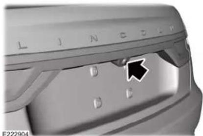
natural_image
Close-up of a mechanical component with no visible text or symbols, featuring a black arrow pointing to a specific part (no readable text or symbols)The camera is located on the rear cargo door.
Using the Rear View Camera System
The rear view camera system displays what is behind your vehicle when you place the transmission in reverse (R).
Note: The reverse sensing system is not effective at speeds above 3 mph (5 km/h) and may not detect certain angular or moving objects.
Parking Aids
The system uses three types of guides to help you see what is behind your vehicle:
•Active guidelines: Show the intended path of your vehicle when reversing.
- Fixed guidelines: Show the actual path your vehicle is moving in while reversing in a straight line. This can be helpful when backing into a parking space or aligning your vehicle with another object behind you.
- Centerline: Helps align the center of your vehicle with an object. For example, a trailer.
Note: If the transmission is in reverse (R) and the rear cargo door is open, no rear view camera features display.
Note: When towing, the camera only sees what you are towing. This might not provide adequate coverage as it usually provides in normal operation and some objects might not be seen. In some vehicles, the guidelines may disappear when you connect the trailer tow connector.
The camera may not operate correctly under the following conditions:
• Nighttime or dark areas if one or both reverse lamps are not operating.
- Mud, water or debris obstructs the camera's view. Clean the lens with a soft, lint-free cloth and non-abrasive cleaner.
•The rear of your vehicle is hit or damaged, causing the camera to become misaligned.
Camera Guidelines
Note: Active guidelines are only available when the transmission is in reverse (R).
Note: Upon a battery disconnect, the active guidelines may not be functional until you drive your vehicle a short distance and exceed a speed of 12 mph (20 km/h).
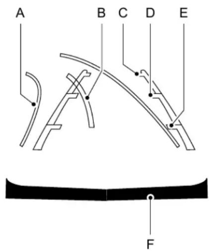
text_image
A B C D E FE142436
Active guidelinesA
CenterlineB
Fixed guideline: Green zoneC
Parking Aids
Fixed guideline: Yellow zoneD
Fixed guideline: Red zoneE
Rear bumperF
Active guidelines are only shown with fixed guidelines. To use active guidelines, turn the steering wheel to point the guidelines toward an intended path. If you change the steering wheel position while reversing, your vehicle might deviate from the original intended path.
The fixed and active guidelines fade in and out depending on the steering wheel position. The active guidelines do not display when the steering wheel position is straight.
Always use caution while reversing. Objects in the red zone are closest to your vehicle and objects in the green zone are farther away. Objects are getting closer to your vehicle as they move from the green zone to the yellow or red zones. Use the side view mirrors and rear view mirror to get better coverage on both sides and rear of the vehicle.
Camera System Settings
You can access the rear view camera system settings through the display screen. See Settings (page 495).
Enhanced Park Aids or Park Pilot
Selectable settings for this feature are on and off.
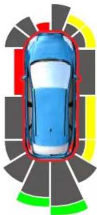
natural_image
Top-down view of a car with colored lane markings around the road (no text or symbols)E190459
The system uses red, yellow and green highlights that appear on top of the video image when any of the sensing systems detect an object.
Manual Zoom

WARNING: When manual zoom is full area behind your vehicle may w. Be aware of your surroundings sing the manual zoom feature.
Note: Manual zoom is only available when the transmission is in reverse (R).
Note: When you enable manual zoom, only the centerline is shown.
Selectable settings for this feature are zoom in (+) and zoom out (-). Press the symbol in the camera screen to change the view. The default setting is zoom off.
This allows you to get a closer view of an object behind your vehicle. The zoomed image keeps the bumper in the image to provide a reference. The zoom is only active while the transmission is in reverse (R).
Parking Aids
Rear Camera Delay
Selectable settings for this feature are on and off.
The default setting for the rear camera delay is off.
When shifting the transmission out of reverse (R) and into any gear other than park (P), the camera image remains in the display until:
- Your vehicle speed sufficiently increases.
- You shift your vehicle into park (P).
360 DEGREE CAMERA (IF EQUIPPED)

WARNING: The 360 degree
camera system still requires the driver to use it in conjunction with looking out of the windows, and checking the interior and exterior mirrors for maximum coverage.

WARNING: You may not see that are close to either corner of bumper or under the bumper due to red coverage of the camera system.

WARNING: Use caution when camera features on or off when the ssion is not in park (P). Make sure hicle is not moving.

WARNING: At all times, you are possible for controlling your vehicle, using the system and intervening, if it is. Failure to take care may result in a loss of control of your vehicle, serious injury or death.
Note: Use caution using the 360 view when any of the doors are ajar. If a door is ajar, the camera will be out of position and the video image may be incorrect.
The 360 degree camera system consists of front, side and rear cameras. The system:
- Allows you to see what is directly in front or behind your vehicle.
- Provides cross traffic view in front and behind your vehicle.
- Allows you to see a top-down view of the area outside your vehicle, including the blind spots.
- Provides visibility around your vehicle to you in parking maneuvers such as:
- Centering in a parking space.
- Obstacles near vehicle.
- Parallel parking.

The front camera enable button is located near the display screen and turns on the front camera
when your vehicle is not in reverse (R).
Using the System
Note: The 360 degree camera system turns off when your vehicle is in motion at low speed, except when in reverse (R).
Parking Aids
The front and rear cameras have multiple screens which consist of: normal view with 360, normal view, and split view. When in park (P), neutral (N) or drive (D), only the front images display when you press the button. When in reverse (R), only the rear images display.

Press to access the different camera views.

Normal + 360 view: Contains the normal camera view next to a 360 degree camera view.

Normal view: Provides an image of what is directly in front or behind your vehicle.

Split view: Provides an extended view of what is in front or behind your vehicle.

Zooms in on the image.
Keep Out Zone
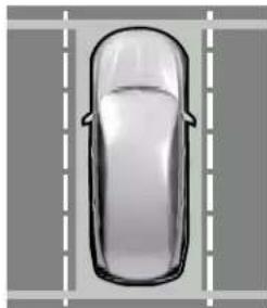
natural_image
Top-down view of a car viewed from above, showing front and side views (no text or symbols)E225016
The Keep Out Zone is represented by the yellow dotted lines running parallel to your vehicle. It is designed to give you the indication on the ground of the fully extended outside mirror position.
Front Camera

WARNING: The front camera
system still requires the driver to use it in conjunction with looking out of your vehicle.
Note: The system turns off the front video image when your vehicle is in motion at low speed, except when in reverse (R).
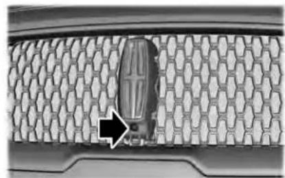
natural_image
Close-up of a car grille with a metallic object and an arrow pointing to a specific area (no text or symbols visible)E222978
The front video camera, located behind the star emblem on the grille, provides a video image of the area in front of your vehicle. It adds assistance to the driver while driving forward at low speeds. To use the front video camera system, place the transmission in any gear except reverse (R). An image displays once you press the front camera enable button. The image on the screen may vary according to your vehicle's orientation or road condition.
Parking Aids
Side Camera
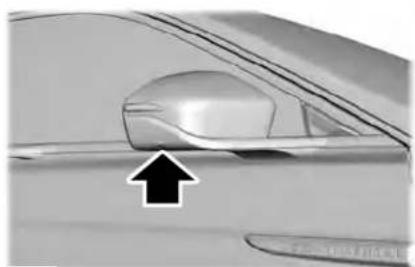
natural_image
Close-up of a car's side panel showing a curved glass lens and a black arrow pointing to the lens (no text or symbols visible)E222977
The side view camera, located in the outside mirror, provides a video image of the area on the sides of your vehicle as part of the front 360 + normal view and rear 360 + normal view. It aids you while parking your vehicle either forward or backwards.
Cruise Control
USING ADAPTIVE CRUISE CONTROL

WARNING: Always pay close
attention to changing road conditions when using adaptive cruise control. The system does not replace attentive driving. Failing to pay attention to the road may result in a crash, serious injury or death.

WARNING: Do not use the
adaptive cruise control when entering or leaving a highway, on roads with intersections or roundabouts or non-vehicular traffic or roads that are winding, slippery, unpaved, or steep slopes.

WARNING: Do not use the system
in poor visibility, for example fog, heavy rain, spray or snow.

WARNING: Do not use the system owing a trailer that has aftermarket panic trailer brake controls. Failure to this instruction could result in the control of your vehicle, personal or death.

WARNING: Do not use tire sizes than those recommended because a affect the normal operation of the failure to do so may result in a loss on the control, which could result in injury.

WARNING: Adaptive cruise control t detect stationary or slow moving s below 6 mph (10 km/h).

WARNING: Adaptive cruise control not detect pedestrians or objects in d.

WARNING: Adaptive cruise control does not detect oncoming vehicles in the same lane.

WARNING: Adaptive cruise control, crash warning or avoidance
The system adjusts your vehicle speed to maintain the set gap between you and the vehicle in front of you in the same lane. You can select four gap settings.
The system uses a radar sensor which projects a beam directly in front of your vehicle.
Note: It is your responsibility to stay alert, drive safely and be in control of the vehicle at all times.
Cruise Control
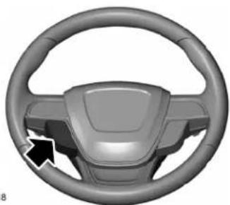
natural_image
3D rendered steering wheel with black arrow pointing to the dashboard (no text or symbols)E262918
The cruise controls are on the steering wheel. See Cruise Control (page 95).
Switching Adaptive Cruise Control On

Press and release the button.

The indicator, current gap setting and set speed appear in the information display.

E164805
Setting the Adaptive Cruise Speed
Drive to your preferred speed.

Press and release the button.
Take your foot off the accelerator pedal.
The indicator, current gap setting and set speed appear in the information display.
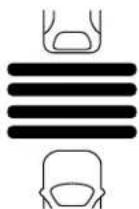
E164805
Note: When adaptive cruise control is active, the speedometer may vary slightly from the set speed displayed in the information display.
Setting the Adaptive Cruise Speed When Your Vehicle is Stationary
Follow a vehicle to a complete stop.

Press while keeping the brake pedal fully pressed.
The set speed adjusts to 20 mph (30 km/h).
The indicator, current gap setting and set speed appear in the information display.
Following a Vehicle

WARNING: When following a
vehicle, your vehicle does not always decelerate quickly enough to avoid a crash without driver intervention. Always apply the brakes when necessary. Failing to do so may result in a crash, serious injury or death.
Cruise Control

WARNING: Adaptive cruise control only warns of vehicles detected by the radar sensor. In some cases there may be no warning or a delayed warning. You should always apply the brakes when necessary. Failure to do so may result in a crash, serious injury or death.
When a vehicle ahead of you enters the same lane or a slower vehicle is ahead in the same lane, the vehicle speed adjusts to maintain a preset gap distance. A vehicle graphic illuminates in the instrument cluster.
Note: The brakes may emit noise when applied by the system.
Note: When you are following a vehicle and you switch on a direction indicator, adaptive cruise control may provide a small temporary acceleration to help you pass.
Your vehicle maintains a consistent gap from the vehicle ahead until:
•The vehicle in front of you accelerates to a speed above the set speed.
•The vehicle in front of you moves out of the lane you are in.
- You set a new gap distance.
The system applies the brakes to slow your vehicle to maintain a safe gap distance from the vehicle in front. The system only applies limited braking. You can override the system by applying the brakes.
If the system determines that its maximum braking level is not sufficient, an audible warning sounds, a message appears in the information display and an indicator flashes when the system continues to brake. Take immediate action.
Following a Vehicle to a Complete Stop
If your vehicle follows a vehicle to a complete stop and remains stationary for less than three seconds, your vehicle accelerates from a stationary position to follow the vehicle ahead.

If your vehicle follows a vehicle to a complete stop and remains stationary for more than three
seconds, press to follow the vehicle ahead. Or press the accelerator pedal.
Setting the Gap Distance
You can decrease or increase the distance between your vehicle and the vehicle in front by pressing the gap control.

Press and release to decrease the gap distance.

Press and release to increase the gap distance.
E164805
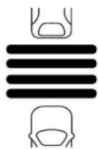
The selected gap appears in the information display as shown by the bars in the image.
Cruise Control
Note: The gap setting is time dependent and therefore the distance adjusts with your vehicle speed.
Note: It is your responsibility to select a gap appropriate to the driving conditions.
Adaptive Cruise Control Gap Settings
| display, bars indicated between vehicles | Distance GapGraphDynamic behavior |
Each time you switch the system on, it selects the last chosen gap setting.
Overriding the Set Speed

WARNING: If you override the by pressing the accelerator pedal, not automatically apply the brakes tain a gap from any vehicle ahead.
When you press the accelerator pedal, you override the set speed and gap distance.

Use the accelerator pedal normally to intentionally exceed the set speed limit.
- When you override the system, the green pose.2. Indicator light illuminates and the vehicle image does not appear in the information medium.3. display.
ar.4 The system resumes operation when you release the accelerator pedal. The vehicle speed decreases to the set speed, or a lower speed if following a slower vehicle.
Changing the Set Speed

Press and release to increase the set speed in small increments.

Press and release to decrease the set speed in small increments.
Press and hold either button to change the set speed in large increments. Release the button when you reach your preferred speed.
The system may apply the brakes to slow the vehicle to the new set speed. The set speed displays continuously in the information display when the system is active.
Canceling the Set Speed

Press and release the button or tap the brake pedal.
The set speed does not erase.
Resuming the Set Speed

Press and release the button.
Cruise Control
Your vehicle speed returns to the previously set speed and gap setting. The set speed displays continuously in the information display when the system is active.
Note: Only use resume if you are aware of the set speed and intend to return to it.
Automatic Cancellation
Automatic cancellation can also occur when:
•The tires lose traction.
- You apply the parking brake.
Park Brake Application
Automatic parking brake application and cancellation occurs if:
- You unbuckle the seatbelt and open the door after you stop the vehicle.
- You hold the vehicle at a stop continuously for more than three minutes.
Hilly Condition Usage
You should select a lower gear when the system is active in situations such as prolonged downhill driving on steep grades, for example in mountainous areas. The system needs additional engine braking in these situations to reduce the load on the vehicle's regular brake system to prevent it from overheating.
Note: An audible alarm sounds and the system shuts down if it applies brakes for an extended period of time. This allows the brakes to cool. The system functions normally again after the brakes cool.
Switching Adaptive Cruise Control Off

Press and release the button when the system is in standby mode, or switch the ignition off.
Note: You erase the set speed and gap setting when you switch the system off.
Detection Issues

WARNING: On rare occasions, on issues can occur due to the road structures, for example bridges, and safety barriers. In these cases, item may brake late or ectedly. At all times, you are possible for controlling your vehicle, using the system and intervening, if d.

WARNING: If the system actions, have your vehicle checked in as possible.
The radar sensor has a limited field of view. It may not detect vehicles at all or detect a vehicle later than expected in some situations. The lead vehicle graphic does not illuminate if the system does not detect a vehicle in front of you.
Cruise Control
A
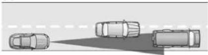
natural_image
Diagram of four cars positioned on a road with a shadow line (no text or symbols)B
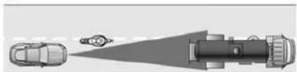
natural_image
Top-down diagram of a vehicle showing a car, a person, and a vehicle with a spotlight (no text or symbols)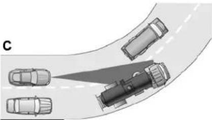
natural_image
Top-down diagram of a road intersection with vehicles, no text or symbols presentE71621
Detection issues can occur:
A When driving on a different line than the vehicle in front.
B With vehicles that edge into your lane. The system can only detect these vehicles once they move fully into your lane.
C There may be issues with the detection of vehicles in front when driving into and coming out of a bend or curve in the road.
In these cases, the system may brake late or unexpectedly. You should stay alert and take action when necessary.
If something hits the front end of your vehicle or damage occurs, the radar-sensing zone may change. This could cause missed or false vehicle detection.
Optimal system performance requires a clear view of the road by the windshield-mounted camera.
Optimal performance may not occur if:
•The camera is blocked.
• There is poor visibility or lighting conditions.
•There are bad weather conditions.
System Not Available
Conditions that can cause the system to deactivate or prevent the system from activating when requested include:
•A blocked sensor.
•High brake temperature.
• A failure in the system or a related system.
Cruise Control
Blocked Sensor
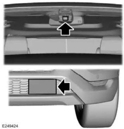
natural_image
Top-down and side-view diagrams of a car's rearview showing engine compartment, battery, and door panel (no text or symbols)A message displays if something obstructs the radar signals from the sensor. The sensor is in the lower grille. The system cannot detect a vehicle ahead and does not function when something blocks the sensor.
Note: You cannot see the sensor. It is behind a fascia panel.
Keep the front of your vehicle free of dirt, metal badges or objects. Vehicle front protectors and aftermarket lights may also block the sensor.
Cruise Control
Possible Causes and Actions for This Message Displaying:
| ActionCause | |
| The surface of the radar is dirty or obstructed. | Clean the grille surface in front of the radar or remove the object causing the obstruction. |
| The surface of the radar is clean but the message remains in the display. | Wait a short time. It may take several minutes for the radar to detect that it is free from obstruction. |
| Heavy rain or snow is interfering with the radar signals. | Do not use the system in these conditions because it may not detect any vehicles ahead. |
| Water, snow or ice on the surface of the road may interfere with the radar signals. | Do not use the system in these conditions because it may not detect any vehicles ahead. |
| roadside objects. | Wait a short time or switch to normal cruise control.You are in a deser |
Due to the nature of radar technology, it is possible to get a blockage warning with no actual block. A false blocked condition either self clears, or clears after you restart your vehicle.
Cruise Control
Switching to Normal Cruise Control

WARNING: Normal cruise control
will not brake when your vehicle is approaching slower vehicles. Always be aware of which mode you have selected and apply the brakes when necessary.

The cruise control indicator light replaces the adaptive cruise control indicator light if you select
normal cruise control. The gap setting does not display, and the system does not respond to lead vehicles. Automatic braking remains active to maintain set speed.
You can change from adaptive cruise control to normal cruise control through the information display.
Driving Aids
DRIVER ALERT

WARNING: You are responsible
for controlling your vehicle at all times. The system is designed to be an aid and does not relieve you of your responsibility to drive with due care and attention. Failure to follow this instruction could result in the loss of control of your vehicle, personal injury or death.

WARNING: The system may not
function if the sensor is blocked.

WARNING: Take regular rest
breaks if you feel tired. Do not wait for the system to warn you.

WARNING: Certain driving styles
may result in the system warning you even if you are not feeling tired.

WARNING: In cold and severe
weather conditions the system may not function. Rain, snow and spray can all limit sensor performance.

WARNING: The system will not
operate if the sensor cannot track the road lane markings.

WARNING: If damage occurs in the
immediate area surrounding the sensor, have your vehicle checked as soon as possible.

WARNING: The system may not
correctly operate if your vehicle is fitted with a suspension kit not approved by us.
Note: Keep the windshield free from obstructions. For example, bird droppings, insects and snow or ice.
Note: If the camera is blocked or if the windshield is damaged, the system may not function.
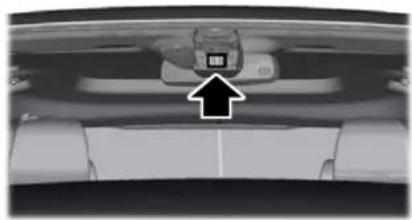
natural_image
Interior view of a vehicle showing a car with a mounted device and a black arrow pointing to the side (no visible text or symbols)E249505
The system automatically monitors your driving behavior using various inputs including the front camera sensor.
If the system detects that your driving alertness is reduced below a certain threshold, the system will alert you using a tone and a message in the information display.
Driving Aids
Using Driver Alert
Switching the system on and off
You may switch the system on or off through the information display. See General
Information (page 122). When activated, the system will monitor your alertness level based upon your driving behavior in relation to the lane markings and other factors.
System Warnings
Note: The system does not issue warnings below approximately 40 mph (64 km/h).
The warning system is in two stages. At first the system issues a temporary warning that you need to take a rest. This message will only appear for a short time. If the system detects further reduction in driving alertness, another warning may be issued which will remain in the information display for a longer time. Press OK on the steering wheel control to clear the warning
System Display
When active the system will run automatically in the background and only issue a warning if required.
Note: If the camera sensor cannot track the road lane markings or if your vehicle speed drops below approximately 40 mph (64 km/h), the system does not issue warnings.
Resetting the System
You can reset the system by either:
- Switching the ignition off and on.
- Stopping the vehicle and then opening and closing the driver's door.
LANE KEEPING SYSTEM

WARNING: You are responsible
for controlling your vehicle at all times. The system is designed to be an aid and does not relieve you of your responsibility to drive with due care and attention. Failure to follow this instruction could result in the loss of control of your vehicle, personal injury or death.

WARNING: Always drive with due
care and attention when using and operating the controls and features on your vehicle.

WARNING: In cold and severe
weather conditions the system may not function. Rain, snow and spray can all limit sensor performance.
Driving Aids

WARNING: The system will not be if the sensor cannot track the road markings.

WARNING: The sensor may
incorrectly track lane markings as other structures or objects. This can result in a false or missed warning.

WARNING: The system may not be properly if the sensor is blocked. The windshield free from obstruction.

WARNING: If damage occurs in the
immediate area surrounding the sensor, have your vehicle checked as soon as possible.

WARNING: The system may not only operate if your vehicle is fitted suspension kit not approved by us.
Note: The system works as long as the camera can detect one lane marking.
Note: When aid or alert and aid modes are selected and the system detects no steering activity for a short period, the system alerts you to put your hands on the steering wheel. The system may detect a light grip or touch on the steering wheel as hands off driving.
Note: The system may not function with a blocked camera, or a damaged or dirty windshield. The system does not function if the operational speed of the vehicle is less than 40 mph (64 km/h).
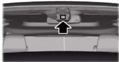
natural_image
Interior view of a vehicle showing a car seat with a mounted device and an arrow pointing to the front panel (no visible text or symbols)E249505
When you switch the system on and it detects an unintentional drift out of your lane is likely to occur, the system notifies or assists you to stay in your lane through the steering system and information display. In Alert mode, the system provides a warning by vibrating the steering wheel. In Aid mode, the system provides steering assistance by gently counter steering your vehicle back into the lane.
When the system is functioning in the combined Alert and Aid mode, the system first provides steering assistance by gently counter steering your vehicle back into the lane, followed by a warning by vibrating the steering wheel if the vehicle is still out of the lane markings.
Switching the System On and Off
Note: The system on or off setting is stored until it is manually changed unless a MyKey is detected. If the system detects a MyKey it defaults to on and the mode is set to Alert.
Driving Aids
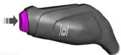
natural_image
3D rendered image of a handheld device with purple handle and orange arrow pointing to the tip (no text or symbols)E132099
Press the button on the direction indicator stalk to switch the system on or off.
System Settings
The system has optional setting menus available. To view or adjust the settings, See Settings (page 495). The system stores the last-known selection for each of these settings. You do not need to readjust your settings each time you switch the system on.
Mode: This setting allows you to select which of the system features you can enable.

natural_image
Top-down view of a car with two dashed lane lines (no text or symbols)E165515
Alert only – Provides a steering wheel vibration when the system detects an unintended lane departure.
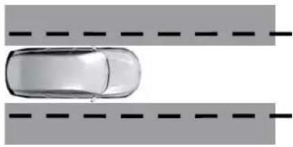
natural_image
Top-down view of a car on two parallel road markings (no text or symbols)E165516
Aid only – Provides steering assistance toward the lane center when the system detects an unintended lane departure.
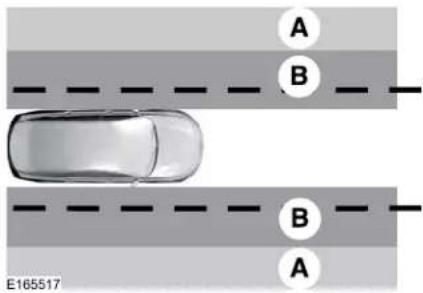
text_image
A B B A E165517AlertA
B Aid
Alert + Aid – Provides steering assistance toward the lane center.
If your vehicle continues drifting out of the lane, the system provides a steering wheel vibration.
Note: The alert and aid diagrams illustrate general zone coverage. They do not provide exact zone parameters.
Driving Aids
Intensity: This setting affects the intensity of the steering wheel vibration used for the alert and alert + aid modes. This setting does not affect the aid mode.
•Low.
•Normal.
•High.
System Display
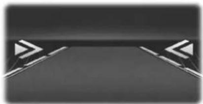
natural_image
Abstract geometric design with two white chevrons on a dark background, no text or symbols present.E224867
If you switch the system on in alert mode, a graphic with lane markings appears in the information display.
If you switch the system on in aid or alert and aid mode, arrows appear with the lane markings.
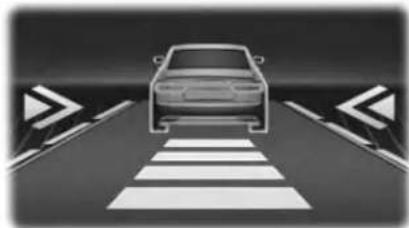
natural_image
Diagram of a car on a crosswalk with directional arrows indicating traffic flow (no text or symbols)E222903
If Adaptive Cruise Control is enabled and a vehicle is being followed, additional graphics appear in the display.
When you switch the system off, the lane marking graphics do not display.
When the system is on, the color of the lane markings change to indicate the system status.
Gray: Indicates that the system is temporarily unable to provide a warning or intervention on the indicated side. This may be because:
-Your vehicle is under the activation speed.
•The direction indicator is active.
- Your vehicle is in a dynamic maneuver.
•The road has no or poor lane markings in the camera field-of-view.
•The camera is obscured or unable to detect the lane markings due to environmental, traffic or vehicle conditions. For example, significant sun angles, shadows, snow, heavy rain or fog, following a large vehicle that is blocking or shadowing the lane, poor headlamp illumination.
See Troubleshooting for additional information.
Green: Indicates that the system is available or ready to provide a warning or intervention, on the indicated side.
Yellow: Indicates that the system is providing or has just provided a lane keeping aid intervention.
Red: Indicates that the system is providing or has just provided a lane keeping alert warning.
Driving Aids
The system can be temporarily suppressed at any time by the following:
- Quick braking.
- Fast acceleration.
• Using the direction indicator.
•Evasive steering maneuver.
- Driving too close to the lane markings.
Troubleshooting
| Why is the feature not available (line markings are gray) when I can see the lane markings on the road? |
| Your vehicle speed is outside the operational range of the feature. |
| The sun is shining directly into the camera lens. |
| A quick intentional lane change has occurred. |
| Your vehicle stays too close to the lane markings. |
| Driving at high speeds in curves. |
| The last alert warning or aid intervention occurred a short time ago. |
| Ambiguous lane markings, for example in construction zones. |
| Rapid transition from light to dark, or from dark to light. |
| Sudden offset in lane markings. |
| ABS or AdvanceTracTM is active. |
| There is a camera blockage due to dirt, grime, fog, frost or water on the windshield. |
| You are driving too close to the vehicle in front of you. |
Driving Aids
| Why is the feature not available (line markings are gray) when I can see the lane markings on the road? |
| Transitioning between no lane markings to lane markings or vice versa. |
| There is standing water on the road. |
| Faint lane markings, for example partial yellow lane markings on concrete roads. |
| Lane width is too narrow or too wide. |
| The camera has not been calibrated after a windshield replacement. |
| Driving on tight roads or on uneven roads. |
| Why does the vehicle not come back toward the middle of the lane, as expected, in the Aid or Aid + Alert mode? |
| High cross winds are present. |
| There is a large road crown. |
| Rough roads, grooves or shoulder drop-offs. |
| Heavy uneven loading of the vehicle or improper tire inflation pressure. |
| The tires have been changed, or the suspension has been modified. |
Driving Aids
WARNING: Do not use the blind
spot information system as a replacement for using the interior and exterior mirrors or looking over your shoulder before changing lanes. The blind spot information system is not a replacement for careful driving.

WARNING: The system may not
operate properly during severe weather conditions, for example snow, ice, heavy rain and spray. Always drive with due care and attention. Failure to take care may result in a crash.
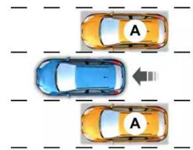
text_image
A AE124788
The system is designed to detect vehicles that may have entered the blind spot zone (A). The detection area is on both sides of your vehicle, extending rearward from the exterior mirrors to approximately 13 ft (4 m) beyond the rear bumper.
Note: The system does not prevent contact with other vehicles. It is not designed to detect parked vehicles, pedestrians, animals or other infrastructures.
Using the Blind Spot Information System
Vehicles with Automatic Transmission
The system turns on when all of the following occur:
•You start your vehicle.
- You shift into drive (D).
• The vehicle speed is greater than 6 mph (10 km/h).
Note: The system does not operate in park (P) or reverse (R).
Vehicles with Manual Transmission
The system turns on when all of the following occur:
- You start your vehicle.
• The vehicle speed is greater than 6 mph (10 km/h).
Note: The system does not operate in reverse (R).
Driving Aids
System Lights and Messages
natural_image
3D rendered image of a metallic USB flash drive (no text or symbols visible)E142442
When the system detects a vehicle, an alert indicator illuminates in the exterior mirror on the side the approaching vehicle is coming from. If you turn the direction indicator on for that side of your vehicle, the alert indicator flashes.
Note: The system may not alert you if a vehicle quickly passes through the detection zone.
Blocked Sensors
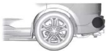
natural_image
Side profile illustration of a car wheel and side-mounted sensor (no text or symbols)E205199
The sensors are behind the rear bumper on both sides of your vehicle.
Note: Keep the sensors free from snow, ice and large accumulations of dirt.
Note: Do not cover the sensors with bumper stickers, repair compound or other objects.
Note: Blocked sensors could affect system performance.
If the sensors are blocked, a message may appear in the information display. See
Information Messages (page 130). The alert indicators remain illuminated but the system does not alert you.
System Errors
If the system detects a fault, a warning lamp illuminates and a message displays. See Information Messages (page 130).
Switching the System Off and On
You can switch the system off using the information display. See General
Information (page 122). When you switch the system off, a warning lamp illuminates and a message displays. When you switch the system on or off, the alert indicators flash twice.
Note: The system remembers the last setting when you start your vehicle.
Note: The system may not correctly operate when towing a trailer. For vehicles with a trailer tow module and tow bar approved by us, the system turns off when you attach a trailer. For vehicles with an aftermarket trailer tow module or tow bar, we recommend that you switch the system off when you attach a trailer.
To permanently switch the system off, contact an authorized dealer.
Driving Aids
CROSS TRAFFIC ALERT

WARNING: Do not use the cross traffic alert system as a replacement for using the interior and exterior mirrors or looking over your shoulder before reversing out of a parking space. The cross traffic alert system is not a replacement for careful driving.

WARNING: The system may not be properly during severe weather conditions, for example snow, ice, heavy and spray. Always drive with due care intention. Failure to take care may in a crash.
The system alerts you of vehicles approaching from the sides behind your vehicle when you shift into reverse (R).
Using Cross Traffic Alert
The system detects vehicles that approach at a speed between 4 mph (6 km/h) and 37 mph (60 km/h). Coverage decreases when the sensors are partially, mostly or fully obstructed. Slowly reversing helps increase the coverage area and effectiveness.
The system turns on when you start the engine and you shift into reverse (R). The system turns off when you shift out of reverse (R).
Driving Aids

flowchart
graph TD
    A["Left Parking Garage"] --> B["Right Traffic Lane"]
    B --> C["Left Road"]
    C --> D["Right Traffic Lane"]
    style A fill:#f9f,stroke:#333
    style D fill:#bbf,stroke:#333
E142440
The sensor on the left-hand side is only partially obstructed and zone coverage on the right-hand side is maximized.
Driving Aids
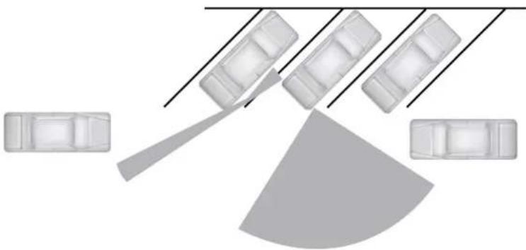
natural_image
Top-down diagram of a vehicle parking lot with multiple lanes and a shaded area (no text or symbols)E142441
Zone coverage also decreases when parking at narrow angles. The sensor on the left-hand side is mostly obstructed and zone coverage on that side is severely reduced.
Driving Aids
Cross Traffic Alert System Sensors
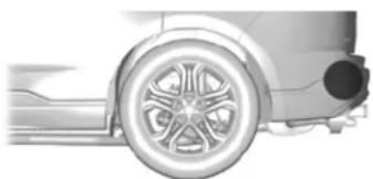
natural_image
Side profile illustration of a car wheel and side panel (no text or symbols)E205199
The sensors are behind the rear bumper on both sides of your vehicle.
Note: Keep the sensors free from snow, ice and large accumulations of dirt.
Note: Do not cover the sensors with bumper stickers, repair compound or other objects.
Note: Blocked sensors could affect system performance.
If the sensors are blocked, a message may appear in the information display when you shift into reverse (R).
Cross Traffic Alert System Limitations
The system may not correctly operate when any of the following occur:
•The sensors are blocked.
- Adjacently parked vehicles or objects are obstructing the sensors.
• Vehicles approach at speeds less than 4 mph (6 km/h) or greater than 37 mph (60 km/h).
• The vehicle speed is greater than 7 mph (12 km/h).
- You reverse out of an angled parking space.
Cross Traffic Alert Behavior When Trailer is Attached
Note: The system may not correctly operate when towing a trailer. For vehicles with an approved trailer tow module and tow bar, the system turns off when you attach a trailer. For vehicles with an aftermarket trailer tow module or tow bar, we recommend that you switch the system off when you attach a trailer.
Cross traffic alert remains on when you attach a trailer in vehicles that come with blind spot information system with trailer tow under the following conditions:
- You connect a trailer.
•The trailer is a bike rack or cargo rack with a maximum length of 3 ft (1 m). - You set the trailer length to 3 ft (1 m) in the information display.
See Blind Spot Information System (page 265).
Switching the System On and Off
To switch the system on or off, adjust the setting. Depending on your vehicle options, the setting could be in the following:
•Information display. See General Information (page 122).
- Touchscreen. See Settings (page 495).
Note: The system turns on every time you switch the ignition on. To permanently switch the system off, contact an authorized dealer.
Driving Aids
Cross Traffic Alert Indicator

When the system detects an approaching vehicle, a tone sounds, a warning lamp illuminates
in the relevant exterior mirror and arrows appear in the information display to show which side the approaching vehicle is coming from.
Note: If arrows do not display, a message appears in the information display.
If the system malfunctions, a warning lamp illuminates in the instrument cluster and a message appears in the information display. Have your vehicle checked as soon as possible.
Note: In exceptional conditions, the system could alert you, even when there is nothing in the detection zone, for example a vehicle passing further away from your vehicle.
Cross Traffic Alert Information Messages
| ActionMessage | |
| Cross Traffic Alert | Displays instead of indication arrows when the system detects a vehicle. Check for approaching traffic. |
| Cross Traffic Not Available Sensor Blocked See Manual | Indicates blocked cross traffic alert system sensors. Clean the sensors. If the message continues to appear, have your vehicle checked as soon as possible. |
| The system has malfunctioned. Have your vehicle checked as soon as possible.Cross Traffic System | |
| Attached | Displays if you attach a trailer to your vehicle.Cross Traffic Alert Deactivated Trailer |
Driving Aids
STEERING
Electric Power Steering

WARNING: If the system detects
an error, you may not feel a difference in the steering, however a serious condition may exist. Have your vehicle checked as soon as possible. Failure to do so may result in loss of steering control.

WARNING: The electric power
steering system has diagnostic checks that continuously monitor the system. If a fault is detected, a message displays in the information display. Stop your vehicle as soon as it is safe to do so. Switch the ignition off. After at least 10 seconds, switch the ignition on and watch the information display for a steering system warning message. If a steering system warning message returns, have the system checked as soon as possible.
Your vehicle has an electric power steering system. There is no fluid reservoir. No maintenance is required.
If your vehicle loses electrical power while you are driving, electric power steering assistance is lost. The steering system still operates and you can steer your vehicle manually. Manually steering your vehicle requires more effort.
Extreme continuous steering may increase the effort required for you to steer your vehicle. This increased effort prevents overheating and permanent damage to the steering system. You do not lose the ability to steer your vehicle manually. Typical steering and driving maneuvers allow the system to cool and return to normal operation.
Steering Tips
Steering wander or pull could be caused by any of the following:
- Incorrect tire pressures.
- Uneven tire wear.
• Crowned road surface.
•High crosswind.
If the problem persists, have your vehicle checked as soon as possible.
Adaptive Learning
The electronic power steering system adaptive learning helps correct road irregularities and improves overall handling and steering feel. It communicates with the brake system to help operate advanced stability control and accident avoidance systems. Additionally, whenever the battery is disconnected or a new battery installed, you must drive your vehicle a short distance before the system relearns the strategy and reactivates all systems.
Driving Aids
Adaptive Steering
Note: The adaptive steering system has diagnostic checks that continuously monitor the system. If a fault is detected a message displays in the information display. If a red warning message displays, stop your vehicle as soon as it is safe to do so. The message may clear if the fault is no longer present. If an adaptive steering system warning message appears each time you start your vehicle, have the system checked as soon as possible.
The adaptive steering system continually changes the steering ratio with changes to vehicle speed, optimizing the steering response in all conditions.
The adaptive steering system is designed with a locking device. While the lock is engaged, your vehicle returns to a fixed steering ratio. You may also notice a sound when you start or turn off your vehicle as the lock is disengaged or engaged. If your vehicle loses electrical power or detects a fault while you are driving, the lock engages and you are able to continue steering. During this time it is possible that the steering wheel
may not be straight when the vehicle is driving straight ahead. During this time you may notice that the steering wheel angle required to steer the vehicle may be different. Extreme operating conditions may also cause the lock to engage. This strategy prevents overheating and permanent damage to the adaptive steering system. Typical steering and driving maneuvers allow the system to cool and return to normal operation.
PRE-COLLISION ASSIST

WARNING: You are responsible
for controlling your vehicle at all times. The system is designed to be an aid and does not relieve you of your responsibility to drive with due care and attention. Failure to follow this instruction could result in the loss of control of your vehicle, personal injury or death.

WARNING: The system does not vehicles that are driving in a fat direction, pedestrians at night, or animals. Failure to take care may have the loss of control of your vehicle, personal injury or death.

WARNING: The system does not be during hard acceleration or g. Failure to take care may lead to or personal injury.

WARNING: The system may fail or fail with reduced function during cold weather conditions. Snow, ice, and fog can adversely affect the other. Keep the front camera and radar to snow and ice. Failure to take care result in the loss of control of your own, serious personal injury or death.
Driving Aids
WARNING: In situations where the vehicle camera has limited detection capability, this may reduce system performance. These situations include but are not limited to direct or low sunlight, vehicles at night without tail lights, unconventional vehicle types, pedestrians with complex backgrounds, partly obscured pedestrians, or pedestrians that the system cannot distinguish from a group. Failure to take care may result in the loss of control of your vehicle, serious personal injury or death.
WARNING: The system cannot help prevent all crashes. Do not rely on this system to replace driver judgment and the need to maintain a safe distance and speed.
Using the Pre-Collision Assist System
The system is active at speeds above approximately 3 mph (5 km/h) and pedestrian detection is active at speeds up to 50 mph (80 km/h).

E156130
If your vehicle is rapidly approaching another stationary vehicle, a vehicle traveling in the same direction as yours, or a pedestrian within your driving path, the system is designed to provide three levels of functionality:
- Alert
- Brake Support
- Active Braking

natural_image
Silhouette of two cars with a star and bidirectional arrow, no text or symbols presentE255268
Alert: When active, the system provides a flashing, visual warning and an audible warning sound.
Brake Support: The system is designed to help reduce the impact speed by preparing the brakes for rapid braking. The system does not apply the brakes. If you press the brake pedal, the system could apply additional braking up to maximum braking force, even if you lightly press the brake pedal.
Driving Aids
Active Braking: Active braking may activate if the system determines that a collision is imminent. The system may help the driver reduce impact damage or avoid the crash completely.
Note: If you perceive Pre-Collision Assist alerts as being too frequent or disturbing, then you can reduce the alert sensitivity, though the manufacturer recommends using the highest sensitivity setting where possible. Setting lower sensitivity would lead to fewer and later system warnings.
Adjusting the Pre-Collision Assist Settings
You can adjust the Alert sensitivity to one of three possible settings by using the information display control. See General Information (page 122).
If required, you can switch Active Braking off using the information display control. See General Information (page 122).
Note: Active braking automatically turns on every time you switch the ignition on.
Blocked Sensors
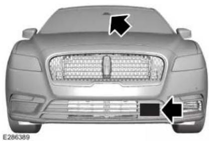
natural_image
Front view of a silver sedan car with grille and side-mounted grille (no visible text or symbols)If a message regarding a blocked sensor or camera appears in the information display, the radar signals or camera images are obstructed. The radar sensor is located behind a fascia cover near the driver side of the lower grille. With an obstructed radar, the Pre-Collision Assist system does not function and cannot detect a vehicle ahead. With the front camera obstructed, the Pre-Collision Assist system does not respond to pedestrians or stationary vehicles and the system performance on moving vehicles reduces. The following table lists possible causes and actions for when this message displays.
Driving Aids
| ActionCause | |
| The surface of the radar in the grille is dirty or obstructed in some way. | Clean the grille surface in front of the radar or remove the object causing the obstruction. |
| The surface of the radar in the grille is clean but the message remains in the display. | Wait a short time. It may take several minutes for the radar to detect that there is no obstruction. |
| Heavy rain, spray, snow, or fog is interfering with the radar signals. | The Pre-Collision Assist system is temporarily disabled. Pre-Collision Assist should automatically reactivate a short time after the weather conditions improve. |
| Swirling water, or snow or ice on the surface of the road may interfere with the radar signals. | The Pre-Collision Assist system is temporarily disabled. Pre-Collision Assist should automatically reactivate a short time after the weather conditions improve. |
| Radar is out of alignment due to a front end impact. | Contact an authorized dealer to have the radar checked for proper coverage and operation. |
| The windshield in front of the camera is dirty or obstructed in some way. | Clean the outside of the windshield in front of the camera. |
| The windshield in front of the camera is clean but the message remains in the display. | Wait a short time. It may take several minutes for the camera to detect that there is no obstruction. |
Note: Proper system operation requires a clear view of the road by the camera. Have any windshield damage in the area of the camera's field of view repaired.
Driving Aids
Note: If something hits the front end of your vehicle or damage occurs, the radar sensing zone may change. This could cause missed or false vehicle detections. Contact an authorized dealer to have the radar checked for proper coverage and operation.
Note: If your vehicle detects excessive heat at the camera or a potential misalignment condition, a message may display in the information display indicating temporary sensor unavailability. This message deactivates automatically when operational conditions are correct. For example, when the ambient temperature around the sensor decreases or the sensor automatically recalibrates.
DRIVE CONTROL
Lincoln Drive Control
The system delivers a driving experience through a suite of sophisticated electronic vehicle systems. These systems continuously monitor your driving inputs and the road conditions to optimize ride comfort, steering, handling, powertrain response and sound.
You can preset your preferences for these systems within the information display. The system responds to your preferences based on what gear position you select. This provides a single location to control multiple systems performance settings.
Lincoln Drive Control consists of the following systems:
- Adaptive suspension dynamically adjusts the shock absorbers stiffness in real time to match the road surface and driver inputs. This system continuously monitors your vehicle's motion (roll, pitch, bounce), suspension position, load, speed, road conditions, and steering to adjust the suspension damping for optimal vehicle control.
• Electronically power-assisted steering adjusts steering effort and feel based on your vehicle speed and your inputs.
- Adaptive steering optimizes your vehicle's steering response based on your steering wheel input, changes in vehicle speed and other conditions.
•Active noise control utilizes your vehicle electronics to enhance the acoustic experience.
- Electronic stability control and traction control maintain your vehicle control in adverse conditions or high performance driving.
- Electronic throttle control enhances the powertrain response to your inputs.
Using Lincoln Drive Control
You can configure which of the Drive Control modes are active when your vehicle is in drive (D) or in sport (S). The configuration remains active until modified from the main menu on the information display.
Driving Aids
These systems have a range of modes which you can choose from in order to customize your ideal driving experience:
- Comfort – Provides a more relaxed driving experience, maximizing comfort. Your steering effort decreases and the suspension movement is more fluid. Comfort mode is ideal when you desire enhanced traveling comfort.
- Normal – Delivers a balanced combination of comfortable, controlled ride and confident handling. This mode provides an engaging drive experience and a direct connection to the road without sacrificing any of the composure demanded from a luxury vehicle.
- Sport – Provides a sportier driving experience. The suspension stiffens, with an emphasis on handling and control. The engine responds more directly to your inputs and takes on a more powerful tone. This mode is ideal for use during more spirited driving.
You can change the drive control settings in the information display. See General Information (page 122).
Note: Not all settings may be available.
Note: Lincoln Drive Control has diagnostic checks that continuously monitor the system to ensure proper operation. Certain types of system errors gray out the mode selections within the information display, preventing you from changing states when the gear position is changed. Other types of errors produce a temporary message in the information display. If either condition persists for multiple key cycles, see an authorized dealer.
Load Carrying
LOAD LIMIT
Vehicle Loading - with and without a Trailer
This section guides you in the proper loading of your vehicle, trailer, or both. Keep your loaded vehicle weight within its design rating capability, with or without a trailer. Properly loading your vehicle provides maximum return of vehicle design performance. Before you load your vehicle, become familiar with the following terms for determining your vehicle's weight rating, with or without a trailer, from the vehicle's Tire and Loading Information label or Safety Compliance Certification label.
Tire and Loading Label Information Example:

TIRE AND LOADING INFORMATION SEATING CAPACITY TOTAL: 5 FRONT: 2 REAR: 3
The combined weight of occupants, 385 kg or 850 lbs. and cargo should never exceed
| TIME | SIZE | GOLD TIRE PRESSURE |
| FRONT | 235/45R18 94V | 235 KPA, 34 PSI |
| FEAR | 235/45R18 94V | 235 KPA, 34 PSI |
| SPARE | NONE | NONE |

TIRE AND LOADING INFORMATION RENSEIGNEMENTS SUR LES PNEUS ET LE CHARGEMENT
SEATING CAPACITY NOMBRE DE PLACES TOTAL 5 FRONT 2 REAR 3 AVANT ARRIÈRE
Payload is the combined weight of cargo and passengers that your vehicle is carrying. The maximum payload for your vehicle appears on the Tire and Loading label. The label is either on the B-pillar or the edge of the driver door. Vehicles exported outside the US and Canada may not have a tire and loading label. Look for "The combined weight of occupants and cargo should never exceed XXX kg OR XXX lb" for maximum payload. The payload listed on the Tire and Loading Information label is the maximum payload for your vehicle as built by the assembly plant. If you install any additional equipment on your vehicle, you must determine the new payload. Subtract the weight of the equipment from the payload listed on the Tire and Loading label. When towing, trailer tongue weight or king pin weight is also part of payload.
Load Carrying

WARNING: The appropriate loading capacity of your vehicle can be limited either by volume capacity (how much space is available) or by payload capacity (how much weight the vehicle should carry). Once you have reached the maximum payload of your vehicle, do not add more cargo, even if there is space available. Overloading or improperly loading your vehicle can contribute to loss of vehicle control and vehicle rollover.
GAWR (Gross Axle Weight Rating)
GAWR is the maximum allowable weight that a single axle (front or rear) can carry. These numbers are on the Safety Compliance Certification label. The label is located on the door hinge pillar, door-latch post, or the door edge that meets the door-latch post, next to the driver seating position.
The total load on each axle must never exceed its Gross Axle Weight Rating.
GVWR (Gross Vehicle Weight Rating)
GVWR is the maximum allowable weight of the fully loaded vehicle. This includes all options, equipment, passengers and cargo. It appears on the Safety
Compliance Certification label. The label is located on the door hinge pillar, door-latch post, or the door edge that meets the door-latch post, next to the driver seating position.
The gross vehicle weight must never exceed the Gross Vehicle Weight Rating.
Safety Compliance Certification Label Example:
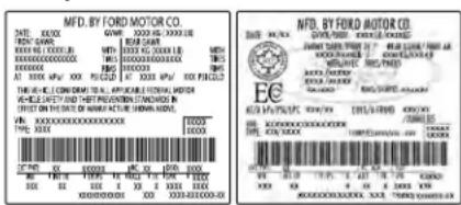
E198828

WARNING: Exceeding the Safety Compliance Certification label vehicle weight limits can adversely affect the performance and handling of your vehicle, cause vehicle damage and can result in the loss of control of your vehicle, serious personal injury or death.
Maximum Loaded Trailer Weight
Maximum loaded trailer weight is the highest possible weight of a fully loaded trailer the vehicle can tow. Consult an authorized dealer (or the RV and Trailer Towing Guide available at an authorized dealer) for more detailed information.
Load Carrying
GCWR (Gross Combined Weight Rating)
GCWR is the maximum allowable weight of the vehicle and the loaded trailer, including all cargo and passengers, that the vehicle can handle without risking damage. (Important: The towing vehicle's braking system is rated for operation at Gross Vehicle Weight Rating, not at Gross Combined Weight Rating.) Separate functional brakes should be used for safe control of towed vehicles and for trailers where the Gross Combined Weight of the towing vehicle plus the trailer exceed the Gross Vehicle Weight Rating of the towing vehicle.
The gross combined weight must never exceed the Gross Combined Weight Rating.
Note: For trailer towing information refer to the RV and Trailer Towing Guide available at an authorized dealer.

WARNING: Do not exceed the or the GAWR specified on the ation label.

WARNING: Do not use cement tires with lower load capacity than the original because they may lower your's GVWR and GAWR limitations. Cement tires with a higher limit the original tires do not increase VWR and GAWR limitations.

WARNING: Exceeding any weight rating can adversely affect the performance and handling of vehicle, cause vehicle damage in result in the loss of control of vehicle, serious personal injury with.
Steps for determining the correct load limit:
- Locate the statement "The combined weight of occupants and cargo should never exceed XXX kg or XXX lb." on your vehicle's placard.
- Determine the combined weight of the driver and passengers that will be riding in your vehicle.
- Subtract the combined weight of the driver and passengers from XXX kg or XXX lb.
- The resulting figure equals the available amount of cargo and luggage load capacity. For example, if the "XXX" amount equals 1,400 lb. and there will be five 150 lb. passengers in your vehicle, the amount of available cargo and luggage load capacity is 650 lb. (1400-750 (5 x 150) = 650 lb.)
Load Carrying
- Determine the combined weight of luggage and cargo being loaded on the vehicle. That weight may not safely exceed the available cargo and luggage load capacity calculated in Step 4.
- If your vehicle will be towing a trailer, load from your trailer will be transferred to your vehicle. Consult this manual to determine how this reduces the available cargo and luggage load capacity of your vehicle.
Helpful examples for calculating the available amount of cargo and luggage load capacity
Suppose your vehicle has a 1400-pound (635-kilogram) cargo and luggage capacity. You decide to go golfing. Is there enough load capacity to carry you, four of your friends and all the golf bags? You and four friends average 220 pounds (99 kilograms) each and the golf bags weigh approximately 30 pounds (13.5 kilograms) each. The calculation would be: 1400 - (5 x 220) - (5 x 30) = 1400 - 1100 - 150 = 150 pounds. Yes, you have enough load capacity in your vehicle to transport four friends and your golf bags. In metric units, the calculation would be: 635 kilograms - (5 x 99 kilograms) - (5 x 13.5 kilograms) = 635 - 495 - 67.5 = 72.5 kilograms.
Suppose your vehicle has a 1400-pound (635-kilogram) cargo and luggage capacity. You and one of your friends decide to pick up cement from the local home improvement store to finish that patio you have been planning for the past two years. Measuring the inside of the vehicle with the rear seat folded down, you have room for twelve 100-pound (45-kilogram) bags of cement. Do you have enough load capacity to transport the cement to your home? If you and your friend each weigh 220 pounds (99 kilograms), the calculation would be: 1400 - (2 x 220) - (12 x 100) = 1400 - 440 - 1200 = - 240 pounds. No, you do not have enough cargo capacity to carry that much weight. In metric units, the calculation would be: 635 kilograms - (2 x 99
kilograms) - (12 x 45 kilograms) = 635 - 198 - 540 = -103 kilograms. You will need to reduce the load weight by at least 240 pounds (104 kilograms). If you remove three 100-pound (45-kilogram) cement bags, then the load calculation would be: 1400 - (2 x 220) - (9 x 100) = 1400 - 440 - 900 = 60 pounds. Now you have the load capacity to transport the cement and your friend home. In metric units, the calculation would be: 635 kilograms - (2 x 99 kilograms) - (9 x 45 kilograms) = 635 - 198 - 405 = 32 kilograms.
The above calculations also assume that the loads are positioned in your vehicle in a manner that does not overload the front or the rear gross axle weight rating specified for your vehicle on the Safety Compliance Certification label.
Load Carrying
Special Loading Instructions for Owners of Pick-up Trucks and Utility-type Vehicles

WARNING: When loading the
roof racks, we recommend you evenly distribute the load, as well as maintain a low center of gravity. Loaded vehicles, with higher centers of gravity, may handle differently than unloaded vehicles. Take extra precautions, such as slower speeds and increased stopping distance, when driving a heavily loaded vehicle.
Towing
TOWING A TRAILER

WARNING: Do not exceed the
GVWR or the GAWR specified on the certification label.

WARNING: Towing trailers
beyond the maximum recommended gross trailer weight exceeds the limit of your vehicle and could result in engine damage, transmission damage, structural damage, loss of vehicle control, vehicle rollover and personal injury.
Note: There may be electrical items such as fuses or relays that can affect trailer towing operation. See Fuses (page 309).
The load capacity of your vehicle is designated by weight not volume. You may not necessarily be able to use all available space when loading your vehicle or trailer.
Towing a trailer places extra load on the engine, transmission, axle, brakes, tires, and suspension. Inspect these components before, during and after towing.
Load Placement
To help minimize how trailer movement affects the vehicle when driving:
- Load the heaviest items closest to the trailer floor.
-
Load the heaviest items in the center of the left and right side trailer tires.
-
Load the heaviest items above the trailer axles or just slightly forward toward the trailer tongue. Do not allow the final trailer tongue weight to go above or below 10 - 15% of the loaded trailer weight.
- Select a ball mount with the correct rise or drop. When both the loaded vehicle and trailer are connected, the trailer frame should be level, or slightly angled down toward the vehicle, when viewed from the side.
When driving with a trailer or payload, a slight takeoff vibration or shudder may be present due to the increased payload weight. Additional information regarding proper trailer loading and setting your vehicle up for towing is located in the Load Carrying chapter. See Load Limit (page 279).
You can also find information in the RV & Trailer Towing Guide available at your authorized dealer, or online.
Towing
| RV & Trailer Towing Guide Online | |
| http://www.fleet.ford.com/towing-guides/Website | |
RECOMMENDED TOWING WEIGHTS
Note: Do not exceed the trailer weight for your vehicle configuration listed in the chart below.
Note: Be sure to take into consideration trailer frontal area. Do not exceed 12 ft ^2 (1.11 m ^2 ) trailer frontal area.
Note: For high altitude operation, reduce the gross combined weight by 2% per 1,000 ft (300 m) starting at the 1,000 ft (300 m) elevation point.
Note: Certain states require electric trailer brakes for trailers over a specified weight. Be sure to check state regulations for this specified weight. The maximum trailer weights listed may be limited to this specified weight, as the vehicle's electrical system may not include the wiring connector needed to use electric trailer brakes.
Your vehicle may tow a Class I trailer provided the maximum trailer weight is less than or equal to the maximum trailer weight listed for your vehicle configuration on the following chart.
| Maximum Trailer WeightPowertrain | |
| 1,000 lb (454 kg)2.7L GTDI | |
| 1,000 lb (454 kg)3.0L GTDI | |
| 1,000 lb (454 kg)3.7L TiVCT |
Towing
ESSENTIAL TOWING CHECKS
Follow these guidelines for safe towing:
- Do not tow a trailer until you drive your vehicle at least 1,000 mi (1,600 km).
- Consult your local motor vehicle laws for towing a trailer.
• See the instructions included with towing accessories for the proper installation and adjustment specifications.
•Service your vehicle more frequently if you tow a trailer. See your scheduled maintenance information. - If you use a rental trailer, follow the instructions the rental agency gives you.
You can find information on load specification terms found on the tire label and Safety Compliance label as well as instructions on calculating your vehicle's load in the Load Carrying chapter. See Load Limit (page 279).
Remember to account for the trailer tongue weight as part of your vehicle load when calculating the total vehicle weight.
Hitches
Do not use a hitch that either clamps onto the bumper or attaches to the axle.
Distribute the trailer load so 10-15% of the total trailer weight is on the tongue.
Safety Chains
Note: Never attach safety chains to the bumper.
Always connect the safety chains to the hook retainers of your vehicle hitch.
To connect the safety chains, cross them under the trailer tongue and allow enough slack for turning tight corners. Do not allow the chains to drag on the ground.
Trailer Brakes

WARNING: Do not connect a trailer's hydraulic brake system directly to your vehicle's brake system. Your vehicle may not have enough braking power and your chances of having a collision greatly increase.
Electric brakes and manual, automatic or surge-type trailer brakes are safe if you install them properly and adjust them to the manufacturer's specifications. The trailer brakes must meet local and federal regulations.
The rating for the tow vehicle's braking system operation is at the gross vehicle weight rating, not the gross combined weight rating.
Separate functioning brake systems are required for safe control of towed vehicles and trailers weighing more than 1500 lb (680 kg) when load.
Towing
Trailer Lamps

WARNING: Never connect any
trailer lamp wiring to the vehicle's tail lamp wiring; this may damage the electrical system resulting in fire. Contact your authorized dealer as soon as possible for assistance in proper trailer tow wiring installation. Additional electrical equipment may be required.
Trailer lamps are required on most towed vehicles. Make sure all running lights, brake lights, turn signals and hazard lights are working.
Before Towing a Trailer
Practice turning, stopping and backing up to get the feel of your vehicle-trailer combination before starting on a trip. When turning, make wider turns so the trailer wheels clear curbs and other obstacles.
When Towing a Trailer
- Do not drive faster than 70 mph (113 km/h) during the first 500 mi (800 km).
- Do not make full-throttle starts.
- Check your hitch, electrical connections and trailer wheel lug nuts thoroughly after you have traveled 50 mi (80 km).
- When stopped in congested or heavy traffic during hot weather, place the transmission in park (P) to aid engine and transmission cooling and to help A/C performance.
- Turn off the speed control with heavy loads or in hilly terrain. The speed control may turn off automatically when you are towing on long, steep grades.
- Shift to a lower gear when driving down a long or steep hill. Do not apply the brakes continuously, as they may overheat and become less effective.
- If your transmission is equipped with a Grade Assist or Tow/Haul feature, use this feature when towing. This provides engine braking and helps eliminate excessive transmission shifting for optimum fuel economy and transmission cooling.
- Allow more distance for stopping with a trailer attached. Anticipate stops and brake gradually.
- Avoid parking on a grade. However, if you must park on a grade:
- Turn the steering wheel to point your vehicle tires away from traffic flow.
- Set your vehicle parking brake.
- Place the transmission in park (P).
- Place wheel chocks in front and back of the trailer wheels. Chocks are not included with your vehicle.
Launching or Retrieving a Boat or Personal Watercraft (PWC)
Note: Disconnect the wiring to the trailer before backing the trailer into the water.
Towing
Note: Reconnect the wiring to the trailer after removing the trailer from the water.
When backing down a ramp during boat launching or retrieval:
- Do not allow the static water level to rise above the bottom edge of the rear bumper.
- Do not allow waves to break higher than 6 in (15 cm) above the bottom edge of the rear bumper.
Exceeding these limits may allow water to enter vehicle components:
- Causing internal damage to the components.
- Affecting driveability, emissions, and reliability.
Replace the rear axle lubricant anytime you submerge the rear axle in water. Water may contaminate the rear axle lubricant, which is not a normal maintenance inspection item unless there is a possibility of a leak or other axle repair is required.
TOWING THE VEHICLE ON FOUR WHEELS
Emergency Towing

WARNING: If your vehicle has a g wheel lock make sure the ignition e accessory or on position when owed.
If your vehicle becomes inoperable (without access to wheel dollies, car-hauling trailer, or flatbed transport vehicle), it can be flat-towed (all wheels on the ground, regardless of the powertrain and transmission configuration) under the following conditions:
-Your vehicle is facing forward for towing in a forward direction.
- Place the transmission in position N. If you cannot move the transmission into N, you must override it and enable stay in neutral mode. Failing to do so may result in damage to the transmission. See Transmission (page 203).
•Maximum speed is 35 mph (56 km/h).
• Maximum distance is 50 miles (80 kilometers).
Recreational Towing
Note: Put your climate control system in recirculated air mode to prevent exhaust fumes from entering the vehicle. See Climate Control (page 153).
Follow these guidelines if you have a need for recreational (RV) towing. An example of recreational towing would be towing your vehicle behind a motorhome. We designed these guidelines to prevent damage to your transmission.
Front-wheel Drive Vehicles
Front-wheel drive vehicles CANNOT be flat-towed (all wheels on the ground) as vehicle or transmission damage may occur. It is recommended to tow your vehicle with the front wheels off the ground by using a tow dolly. If you are using a tow dolly, follow the instructions specified by the equipment provider.
Towing
All-wheel Drive Vehicles
All-wheel drive vehicles CANNOT be flat-towed (all wheels on the ground) as vehicle or transmission damage may occur. It is recommended to tow your vehicle with all four (4) wheels off the ground such as when using a car-hauling trailer. Otherwise, you cannot recreational tow your vehicle.
Driving Hints
BREAKING-IN
You need to break in new tires for approximately 300 mi (480 km). During this time, your vehicle may exhibit some unusual driving characteristics.
Avoid driving too fast during the first 1,000 mi (1,600 km). Vary your speed frequently and change up through the gears early. Do not labor the engine.
Do not tow during the first 1,000 mi (1,600 km).
ECONOMICAL DRIVING
Fuel economy is affected by several things such as how you drive, the conditions you drive under and how you maintain your vehicle.
There are some things to keep in mind that may improve your fuel economy:
- Accelerate and slow down in a smooth, moderate fashion.
- Drive at steady speeds.
- Anticipate stops; slowing down may eliminate the need to stop.
- Combine errands and minimize stop-and-go driving (When running errands, go to the furthest destination first and then work your way back home).
- Close the windows for high-speed driving.
- Drive at reasonable speeds.
- Keep the tires properly inflated and use only the recommended size.
- Use the recommended engine oil.
- Perform all regularly scheduled maintenance.
There are also some things you may want to avoid doing because they reduce your fuel economy: - Avoid sudden or hard accelerations.
- Avoid revving the engine before turning off the car.
- Avoid long idle periods.
-
Do not warm up your vehicle on cold mornings.
-
Reduce the use of air conditioning and heat.
- Avoid using speed control in hilly terrain.
- Do not rest your foot on the brake pedal while driving.
- Avoid carrying unnecessary weight.
- Avoid adding particular accessories to your vehicle (e.g. bug deflectors, rollbars/light bars, running boards, ski racks).
- Avoid driving with the wheels out of alignment.
DRIVING THROUGH WATER

WARNING: Do not drive through
flowing or deep water as you may lose control of your vehicle.
Note: Driving through standing water can cause vehicle damage.
Note: Engine damage can occur if water enters the air filter.
Driving Hints
Before driving through standing water, check the depth. Never drive through water that is higher than the bottom of the front rocker area of your vehicle.
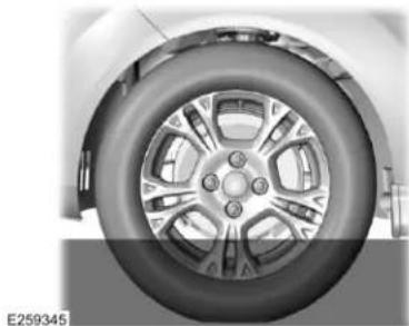
natural_image
Close-up of a car wheel rim and tire component (no visible text or symbols)When driving through standing water, drive very slowly and do not stop your vehicle. Your brake performance and traction may be limited. After driving through water and as soon as it is safe to do so:
- Lightly press the brake pedal to dry the brakes and to check that they work.
-
Check that the horn works.
-
Check that the exterior lights work.
- Turn the steering wheel to check that the steering power assist works.
FLOOR MATS

WARNING: Use a floor mat
designed to fit the footwell of your vehicle that does not obstruct the pedal area. Failure to follow this instruction could result in the loss of control of your vehicle, personal injury or death.

WARNING: Pedals that cannot freely can cause loss of vehicle and increase the risk of serious al injury.

WARNING: Secure the floor mat retention devices so that it cannot of position and interfere with the Failure to follow this instruction result in the loss of control of your, personal injury or death.

WARNING: Do not place additional mats or any other covering on top of ginal floor mats. This could result in or mat interfering with the operation pedals. Failure to follow this tion could result in the loss of of your vehicle, personal injury or

WARNING: Always make sure that cannot fall into the driver foot well our vehicle is moving. Objects that se can become trapped under the causing a loss of vehicle control.
Driving Hints
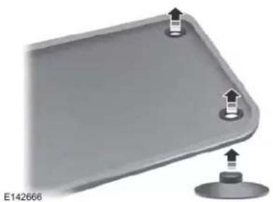
natural_image
3D diagram of a mechanical component with two mounting holes and a base, no text or symbols presentTo install the floor mats, position the floor mat eyelet over the retention post and press down to lock in position.
To remove the floor mat, reverse the installation procedure.
Note: Regularly check the floor mats to make sure they are secure.
Roadside Emergencies
ROADSIDE ASSISTANCE
Vehicles sold in the United States: Getting Roadside Assistance
To fully assist you should you have a vehicle concern, Lincoln Motor Company offers a complimentary roadside assistance program. This program is separate from the New Vehicle Limited Warranty.
The service is available:
•Throughout the life of the vehicle for original owners.
- For six years or 70,000 mi (110,000 km) (whichever comes first) for subsequent owners.
Roadside Assistance covers:
- A flat tire change with a good spare (except vehicles supplied with a tire inflation kit).
- Battery jump start.
- Lock-out assistance (key replacement cost is the client's responsibility).
•Fuel delivery — independent service contractors, if not prohibited by state, local or municipal law shall deliver up to 2 gal (8 L) of gasoline fuel to a disabled vehicle. Roadside Assistance limits fuel delivery service to two no-charge occurrences within a 12-month period.
- Winch out — available within 100 ft (30 m) of a paved or county maintained road, no recoveries.
•Towing — independent service contractors, if not prohibited by state, local or municipal law shall tow Lincoln eligible vehicles to the client's selling or preferred dealer within 100 mi (160 km) of the disablement location or to the nearest Lincoln dealer. If a client requests a tow to a selling or preferred dealer that is more than 100 mi (160 km) from the disablement location, the client is responsible for any mileage costs in excess of 100 mi (160 km).
- Roadside Assistance includes up to \$200 for a towed trailer if the disabled eligible vehicle requires service at the nearest authorized dealer. If the towing vehicle is operational but the trailer is not, then the trailer does not qualify for any roadside services.
Vehicles Sold in the United States: Using Roadside Assistance
United States clients who require roadside assistance, call 1-800-521-4140 or contact Roadside Assistance using the Lincoln Way mobile app.
Roadside Emergencies
If you need to arrange roadside assistance for yourself, Lincoln Motor Company reimburses a reasonable amount for towing to the nearest Lincoln dealership within 100 mi (160 km). To obtain reimbursement information, United States clients, call 1-800-521-4140. Clients need to submit their original receipts.
Vehicles Sold in Canada: Getting Roadside Assistance
To fully assist you should you have a vehicle concern, Lincoln Motor Company offers a complimentary roadside assistance program. This program is eligible within Canada or the continental United States.
The service is available 24 hours a day, seven days a week.
This program is separate from the New Vehicle Limited Warranty, beginning from the original warranty start date and lasts the life of the vehicle for the original owner. Subsequent owners receive coverage that is concurrent with the 6 years or 70,000 mi (110,000 km) (whichever occurs first) powertrain warranty coverage period.
Note: Canadian roadside coverage and benefits may differ from the U.S. coverage.
For complete program coverage details, review your warranty guide, contact your dealer, call us in Canada at 1-800-387-9333, or visit our website at www.lincolncanada.com.
If you purchased your vehicle in Canada and require roadside assistance, please call 1-800-387-9333 or contact Roadside Assistance using the Lincoln Way mobile app.
Note: For quick reference, complete the roadside assistance identification card found in the glove compartment of your vehicle and place it in your wallet.
HAZARD FLASHERS
Note: The hazard flashers operate when the ignition is in any position, or if the key is not in the ignition. If used when the vehicle is not running, the battery loses charge. As a result, there may be insufficient power to restart your vehicle.

The flasher control is on the instrument panel. Use your hazard flashers when your vehicle is
creating a safety hazard for other motorists.
- Press the flasher control and all front and rear direction indicators flash.
- Press the button again to switch them off.
FUEL SHUTOFF

WARNING: If your vehicle has been found in a crash, have the fuel system found. Failure to follow this instruction result in fire, personal injury or death.
Note: When you try to restart your vehicle after a fuel shutoff, the vehicle makes sure that various systems are safe to restart. Once the vehicle determines the systems are safe, then the vehicle allows you to restart.
Note: In the event that your vehicle does not restart after your third attempt, contact a qualified technician.
Roadside Emergencies
The fuel pump shutoff stops the flow of fuel to the engine in the event of a moderate to severe crash. Not every impact causes a shutoff.
Should your vehicle shut off after a crash, you may restart your vehicle.
- Press START/STOP to switch off your vehicle.
- Press the brake pedal and START/STOP to switch on your vehicle.
- Remove your foot from the brake pedal and press START/STOP to switch off your vehicle.
- You can attempt to start the vehicle by pressing the brake pedal and START/STOP, or press START/STOP without pressing the brake pedal.
- If the vehicle does not start, repeat steps 1 through 4.
WARNING: Batteries normally
produce explosive gases which can cause personal injury. Therefore, do not allow flames, sparks or lighted substances to come near the battery. When working near the battery, always shield your face and protect your eyes. Always provide correct ventilation.

WARNING: Keep batteries out of reach of children. Batteries contain sulfuric acid. Avoid contact with skin, eyes or clothing. Shield your eyes when working near the battery to protect against possible splashing of acid solution. In case of acid contact with skin or eyes, flush immediately with water for a minimum of 15 minutes and get prompt medical attention. If acid is swallowed, call a physician immediately.

WARNING: Use only adequately
sized cables with insulated clamps.
Preparing Your Vehicle
Do not attempt to push-start your automatic transmission vehicle.
Note: Attempting to push-start a vehicle with an automatic transmission may cause transmission damage.
Note: Use only a 12-volt supply to start your vehicle.
Note: Do not disconnect the battery of the disabled vehicle as this could damage the vehicle electrical system.
Park the booster vehicle close to the hood of the disabled vehicle, making sure the two vehicles do not touch.
Roadside Emergencies
Connecting the Jumper Cables

WARNING: Do not attach the
cables to fuel lines, engine rocker covers, the intake manifold or electrical components as grounding points. Stay clear of moving parts. To avoid reverse polarity connections, make sure that you correctly identify the positive (+) and negative (-) terminals on both the disabled and booster vehicles before connecting the cables.

WARNING: Do not attach the end
of the positive cable to the studs or L-shaped eyelet located above the positive (+) terminal of your vehicle's battery. High current may flow through and cause damage to the fuses.

WARNING: Do not connect the end of the second cable to the negative (-) terminal of the battery to be jumped. A spark may cause an explosion of the gases that surround the battery.
Note: In the illustration, the bottom vehicle represents the booster vehicle.
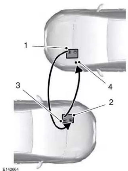
text_image
1 3 2 4 E142664- Connect the positive (+) jumper cable to the positive (+) terminal of the discharged battery.
Roadside Emergencies
- Connect the other end of the positive (+) cable to the positive (+) terminal of the booster vehicle battery.
- Connect the negative (-) cable to the negative (-) terminal of the booster vehicle battery.
- Make the final connection of the negative (-) cable to an exposed metal part of the stalled vehicle's engine, away from the battery and the fuel injection system, or connect the negative (-) cable to a ground connection point if available.
Negative Ground Point Location
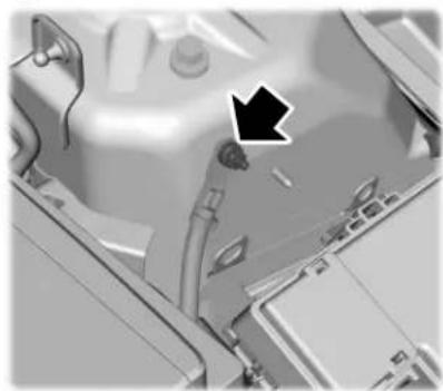
natural_image
Close-up of a mechanical component with a black arrow pointing to a detail (no visible text or symbols)- Once the disabled vehicle has been started, run both vehicle engines for an additional three minutes before disconnecting the jumper cables.
Removing the Jumper Cables
Remove the jumper cables in the reverse order that they were connected.
Jump Starting
- Start the engine of the booster vehicle and rev the engine moderately, or press the accelerator gently to keep your engine speed between 2000 and 3000 RPM, as shown in your tachometer.
- Start the engine of the disabled vehicle.
Roadside Emergencies
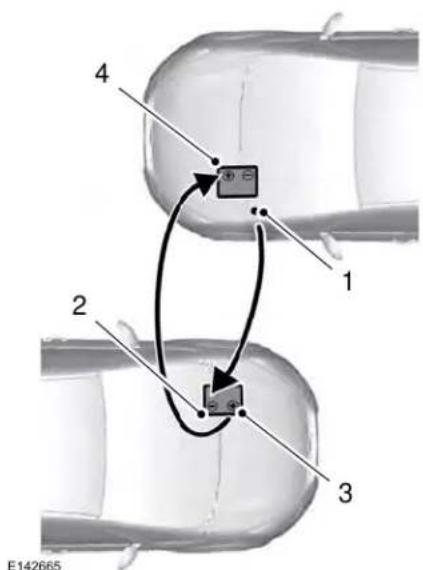
flowchart
graph TD
    A["Component 1"] --> B["Component 2"]
    B --> C["Component 3"]
    C --> D["Component 4"]
    style A fill:#f9f,stroke:#333
    style B fill:#ccf,stroke:#333
    style C fill:#cfc,stroke:#333
    style D fill:#fcc,stroke:#333
-
Remove the negative (-) jumper cable from the disabled vehicle.
-
Remove the jumper cable on the negative (-) terminal of the booster vehicle battery.
- Remove the jumper cable from the positive (+) terminal of the booster vehicle battery.
- Remove the jumper cable from the positive (+) terminal of the disabled vehicle battery.
- Allow the engine to idle for at least one minute.
POST-CRASH ALERT SYSTEM
The system flashes the direction indicators and sounds the horn (intermittently) in the event of a serious impact that deploys an airbag (front, side, side curtain or Safety Canopy) or the seatbelt pretensioners.
The horn and indicators turn off when:
- You press the hazard control button.
- You press the panic button on the remote entry transmitter (if equipped).
- Your vehicle runs out of power.
- Sounding of the horn is only enabled in specific markets.
Roadside Emergencies
TRANSPORTING THE VEHICLE
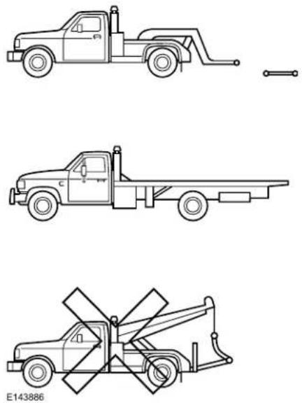
natural_image
Three line drawings of a flatbed truck with crane, shown from top, side, and cross-section views (no text or symbols)If you need to tow your vehicle, contact a professional towing service or, if you are a member of a roadside assistance program, your roadside assistance service provider.
We recommend the use of a wheel lift and dollies or flatbed equipment to tow your vehicle. Do not tow with a slingbelt. Lincoln Motor Company does not approve a slingbelt towing procedure. If you tow your vehicle incorrectly, or by any other means, vehicle damage may occur.
Lincoln Motor Company produces a towing manual for all authorized tow truck operators. Have your tow truck operator refer to this manual for proper hook-up and towing procedures for your vehicle.
It is acceptable to have your front-wheel drive vehicle towed from the front if using proper wheel lift equipment to raise the front wheels off the ground. When towing in this manner, the rear wheels can remain on the ground.
Front-wheel drive vehicles must have the front wheels placed on a tow dolly when towing your vehicle from the rear using wheel lift equipment. This prevents damage to the transmission.
Towing an all-wheel drive vehicle requires that all wheels be off the ground, such as using a wheel lift and dollies or flatbed equipment. This prevents damage to the transmission, all-wheel drive system and vehicle.
Customer Assistance
GETTING THE SERVICES YOU NEED
Warranty repairs to your vehicle must be performed by an authorized dealer. While any authorized dealer handling your vehicle line provides warranty service, we recommend you return to your selling authorized dealer who wants to ensure your continued satisfaction.
Please note that certain warranty repairs require special training and equipment, so not all authorized dealers are authorized to perform all warranty repairs. This means that, depending on the warranty repair needed, you may have to take your vehicle to another authorized dealer.
A reasonable time must be allowed to perform a repair after taking your vehicle to the authorized dealer. Repairs are made using Lincoln or Motorcraft parts, or remanufactured or other parts that are authorized by Lincoln.
Away From Home
If you are away from home when your vehicle needs service, contact the Lincoln Client Relationship Center or use the online resources listed below to find the nearest authorized dealer.
In the United States:
Mailing address
Lincoln Motor Company Client Relationship Center P.O. Box 6248 Dearborn, MI 48126
Telephone
1-800-521-4140 TDD for the hearing impaired: 1-800-232-5952
Web Address
www.LincolnOwner.com
These are some of the items that can be found online:
•United States dealer locator by Dealer Name, City, State or ZIP Code.
- Owner Manuals.
- Maintenance Schedules.
•Recalls.
•Lincoln Extended Service Plans.
•Lincoln Original Accessories.
•Service specials and promotions.
In Canada:
Mailing address
Lincoln Client Relationship Centre
Lincoln Motor Company of Canada, Limited
P.O. Box 2000
Oakville, Ontario L6K 1C8
Telephone
1-800-387-9333
Customer Assistance
Web Address
www.LincolnCanada.com
Online Resources
Twitter English
@LincolnMotorCA
Twitter French
@LincolnQC
@LincolnMotorCA
/LincolnMotorCA
Additional Assistance
If you have questions or concerns, or are unsatisfied with the service you are receiving, follow these steps:
-
Contact your Sales Representative or Service Advisor at your selling or servicing authorized dealer.
-
If your inquiry or concern remains unresolved, contact the Sales Manager, Service Manager or Customer Relations Manager.
- If you require assistance or clarification on Lincoln Motor Company policies, please contact the Lincoln Client Relationship Center.
In order to help us serve you better, please have the following information available when contacting a Client Relationship Center:
•Vehicle Identification Number.
- Your telephone number (home and business).
•The name of the authorized dealer and city where located.
- The vehicle's current odometer reading.
In some states, you must directly notify Lincoln in writing before pursuing remedies under your state's warranty laws. Lincoln is also allowed a final repair attempt in some states.
In the United States, a warranty dispute must be submitted to the BBB AUTO LINE before taking action under the Magnuson-Moss Warranty Act, or to the extent allowed by state law, before pursuing replacement or repurchase remedies provided by certain state laws. This dispute handling procedure is not required prior to enforcing state created rights or other rights which are independent of the Magnuson-Moss Warranty Act or state replacement or repurchase laws.
IN CALIFORNIA (U.S. ONLY)
California Civil Code Section 1793.2(d) requires that, if a manufacturer or its representative is unable to repair a motor vehicle to conform to the vehicle's applicable express warranty after a reasonable number of attempts, the manufacturer shall be required to either replace the vehicle with one substantially identical or repurchase the
Customer Assistance
vehicle and reimburse the buyer in an amount equal to the actual price paid or payable by the consumer (less a reasonable allowance for consumer use). The consumer has the right to choose whether to receive a refund or replacement vehicle.
California Civil Code Section 1793.22(b) presumes that the manufacturer has had a reasonable number of attempts to conform the vehicle to its applicable express warranties if, within the first 18 months of ownership of a new vehicle or the first 18,000 mi (29,000 km), whichever occurs first:
- Two or more repair attempts are made on the same non-conformity likely to cause death or serious bodily injury OR
- Four or more repair attempts are made on the same nonconformity (a defect or condition that substantially impairs the use, value or safety of the vehicle) OR
- The vehicle is out of service for repair of nonconformities for a total of more than 30 calendar days (not necessarily all at one time).
In the case of 1 or 2 above, the consumer must also notify the manufacturer of the need for the repair of the nonconformity at the following address:
Ford Motor Company 16800 Executive Plaza Drive Mail Drop 3NE-B Dearborn, MI 48126
You are required to submit your warranty dispute to BBB AUTO LINE before asserting in court any rights or remedies conferred by California Civil Code Section 1793.22(b). You are also required to use BBB AUTO LINE before exercising rights or seeking remedies created by the Federal Magnuson-Moss Warranty Act, 15 U.S.C. sec. 2301 et seq. If you choose to seek redress by pursuing rights and remedies not created by California Civil Code Section 1793.22(b) or the Magnuson-Moss Warranty Act, resort to BBB AUTO LINE is not required by those statutes.
THE BETTER BUSINESS BUREAU (BBB) AUTO LINE PROGRAM (U.S. ONLY)
Your satisfaction is important to Ford Motor Company and to your dealer. If a warranty concern has not been resolved using the three-step procedure outlined earlier in this chapter in the Getting the Services you need section, you may be eligible to participate in the BBB AUTO LINE program.
The BBB AUTO LINE program consists of two parts – mediation and arbitration. During mediation, a representative of the BBB will contact both you and Ford Motor Company to explore options for settlement of the claim. If an agreement is not reached during mediation or you do not want to participate in mediation, and if your claim is eligible, you may participate in the arbitration process. An arbitration hearing will be scheduled so that you can present your case in an informal setting before an impartial person. The arbitrator will consider the testimony provided and make a decision after the hearing.
Customer Assistance
Disputes submitted to the BBB AUTO LINE program are usually decided within forty days after you file your claim with the BBB. You are not bound by the decision, and may reject the decision and proceed to court where all findings of the BBB Auto Line dispute, and decision, are admissible in the court action. Should you choose to accept the BBB AUTO LINE decision, Ford is then bound by the decision, and must comply with the decision within 30 days of receipt of your acceptance letter.
BBB AUTO LINE Application: Using the information provided below, please call or write to request a program application. You will be asked for your name and address, general information about your new vehicle, information about your warranty concerns, and any steps you have already taken to try to resolve them. A Customer Claim Form will be mailed that will need to be completed, signed and returned to the BBB along with proof of ownership. Upon receipt, the BBB will review the claim for eligibility under the Program Summary Guidelines.
You can get more information by calling BBB AUTO LINE at 1-800-955-5100, or writing to:
BBB AUTO LINE 3033 Wilson Boulevard, Suite 600 Arlington, Virginia 22201
BBB AUTO LINE applications can also be requested by calling the Ford Motor Company Customer Relationship Center at 1-800-392-3673.
For additional information refer to the Better Business Bureau website.
Note: Ford Motor Company reserves the right to change eligibility limitations, modify procedures, or to discontinue this process at any time without notice and without obligation.
UTILIZING THE MEDIATION/ARBITRATION PROGRAM (CANADA ONLY)
For vehicles delivered to authorized Canadian dealers. In those cases where you continue to feel that the efforts by Ford of Canada and the authorized dealer to resolve a factory-related vehicle service concern have been unsatisfactory, Ford of Canada participates in an impartial third party mediation/arbitration program administered by the Canadian Motor Vehicle Arbitration Plan (CAMVAP).
The CAMVAP program is a straight forward and relatively speedy alternative to resolve a disagreement when all other efforts to produce a settlement have failed. This procedure is without cost to you and is designed to eliminate the need for lengthy and expensive legal proceedings.
Customer Assistance
In the CAMVAP program, impartial third-party arbitrators conduct hearings at mutually convenient times and places in an informal environment. These impartial arbitrators review the positions of the parties, make decisions and, when appropriate, render awards to resolve disputes. CAMVAP decisions are fast, fair, and final as the arbitrator's award is binding on both you and Ford of Canada.
CAMVAP services are available in all Canadian territories and provinces. For more information, without charge or obligation, call your CAMVAP Provincial Administrator directly at 1-800-207-0685 or visit www.camvap.ca.
GETTING ASSISTANCE OUTSIDE THE U.S. AND CANADA
Before exporting your vehicle to a foreign country, contact the appropriate foreign embassy or consulate. These officials can inform you of local vehicle registration regulations and where to find unleaded fuel or petrol/gas engines or the proper sulfur fuel for diesel engines.
If you cannot find the proper fuel recommended for your vehicle, contact our Customer Relationship Center.
The use of improper fuels in your vehicle without proper conversion may damage the effectiveness of your emission control system and may cause engine knocking or serious engine damage. Ford Motor Company or Ford of Canada is not responsible for any damage caused by use of improper fuel. Using improper fuels may also result in difficulty importing your vehicle back into the United States.
If your vehicle must be serviced while you are traveling or living in Asia-Pacific Region, Sub-Saharan Africa, U.S. Virgin Islands and/or Puerto Rico, Central America, the Caribbean, and Israel and the Middle East, contact the nearest authorized dealer. If the authorized dealer cannot help you, contact the corresponding Ford Customer Assistance Center:
FORD MOTOR COMPANY
Customer Relationship Centers in:
Customer Assistance
| E-mailFaxPhoneCustomer R | |||
| apemcrc@ford.comN/AN/ASia F | |||
| expcac@ford.com-1 313 594 48 | |||
| Middle East | Ford80004443673 | menacac@ford.com971 4 3327 2 | |
| Lincoln80004441067 | |||
| UAE80004441066 | |||
| Saudi Arabia8008443673 | |||
| Mobily and Zain cell phone usersin Saudi800850078 | |||
| Kuwait22280384 | |||
| nafcrc@ford.comN/AN/ANorth A |
Customer Assistance
| E-mailFaxPhoneCustomer Relatio | |||
| prcac@ford.comN/A+1-800-841-3673 | |||
| ssacrc@ford.comN/AN/ASub-Saharan | |||
| N/A+82-02-1600-6003South Korea | infokr1@ford.com or infokr@lincoln.com |
If you buy your vehicle in North America and then relocate to any of the above locations, register your vehicle identification number (VIN) and new address with Ford Global Trade Services by emailing, expcso@ford.com.
If you are in another foreign country, contact the nearest authorized dealer. In the event your inquiry is unresolved, communicate your concern with the dealership's Sales Manager, Service Manager or Customer Relations Manager. If you require additional assistance or clarification, please contact the respective Customer Relationship Center as previously listed.
Customers in the U.S. should call 1-800-392-3673.
ORDERING ADDITIONAL OWNER'S LITERATURE
To order the publications in this portfolio, contact Helm, Incorporated at:
HELM, INCORPORATED
47911 Halyard Drive
Plymouth, Michigan 48170
Attention: Customer Service
Or to order a free publication catalog, call toll free: 1-800-782-4356
Monday-Friday 8:00 a.m. - 6:00 p.m. EST
Helm, Incorporated can also be reached by their website:
www.helminc.com
(Items in this catalog may be purchased by credit card, check or money order.)
Obtaining a French Owner's Manual
French Owner's Manual can be obtained from your authorized dealer or by contacting Helm, Incorporated using the contact information listed previously in this section.
Customer Assistance
REPORTING SAFETY DEFECTS (U.S. ONLY)
If you believe that your vehicle has a defect which could cause a crash or could cause injury or death, you should immediately inform the National Highway Traffic Safety Administration (NHTSA) in addition to notifying Ford Motor Company.
If NHTSA receives similar complaints, it may open an investigation, and if it finds that a safety defect exists in a group of vehicles, it may order a recall and remedy campaign. However, NHTSA cannot become involved in individual problems between you, your dealer, or Ford Motor Company.
To contact NHTSA, you may call the Vehicle Safety Hotline toll-free at 1-888-327-4236 (TTY: 1-800-424-9153); go to http://www.safercar.gov; or write to:
Administrator
1200 New Jersey Avenue, Southeast Washington, D.C. 20590
You can also obtain other information about motor vehicle safety from http://www.safercar.gov.
REPORTING SAFETY DEFECTS (CANADA ONLY)
If you believe that your vehicle has a defect which could cause a crash or could cause injury or death, you should immediately inform Transport Canada and Ford of Canada.
| Transport Canada Contact Information | |
| http://www.tc.gc.ca/eng/motorvehiclesafety/reporting-defects-motor-vehicles.html (English)Website | |
| http://www.tc.gc.ca/fra/securiteautomobile/signaler-defaults-vehicules-automobiles.html (French)Website | |
| 1-800-333-0510Phone | |
Customer Assistance
| Ford of Canada Contact Information | |
| www.ford.caWebsite | |
| 1-800-565-3673Phone | |
Fuses
FUSE SPECIFICATION CHART
Power Distribution Box

WARNING: Always disconnect the before servicing high current fuses.

WARNING: To reduce risk of total shock, always replace the cover power distribution box before infecting the battery or refilling fluid airs.
The power distribution box is in the engine compartment. It has high-current fuses that protect your vehicle's main electrical systems from overloads.
If you disconnect the battery, you need to reset some features. See Changing the 12V Battery (page 342).
Fuses
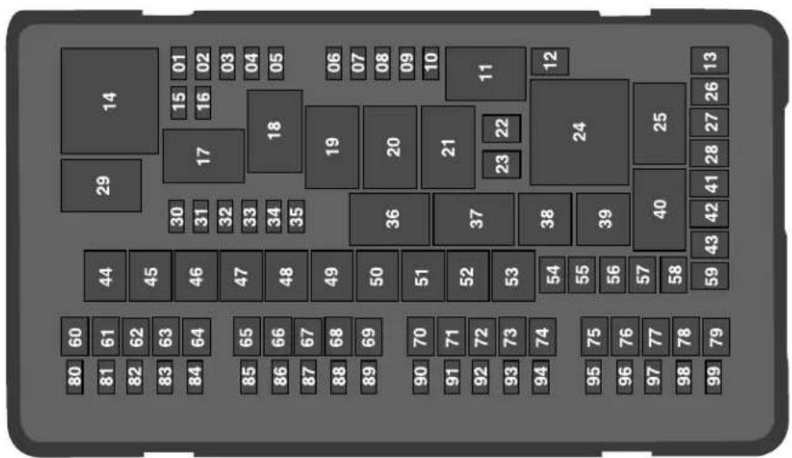
E193713
Fuses
| Protected ComponentFuse RatingFu | ||
| 01 | 20A^1 | Powertrain control module power. |
| 02 | 20A^1 | Engine emissions (malfunction indicator lamp). |
| 03 | 20A^1 | A/C clutch control relay coil.Ventilation and climate control (VACC).Active grille shutters.Cooling fan relays.All-wheel drive module (2.7L and 3.7L engines). |
| 04 | 20A^1 | Ignition coils. |
| Not used.—05 | ||
| 06 | 15A^1 | Fuel injectors (3.7L engine). |
| 07 | 5A^1 | Rear recline relay box. |
| Not used.—08 | ||
| Not used.—09 | ||
| 10 | 10A^1 | Not used (spare). |
| Torque vectoring relay (3.0L engine).—11 |
Fuses
| Protected ComponentFuse RatingFuse or Relay | ||
| Not used.—12 | ||
| 13 | 40A^2 | Rear seat recline. |
| Powertrain control module relay.—14 | ||
| 15 | 20A^1 | Horn. |
| 16 | 10A^1 | A/C clutch. |
| Not used.—17 | ||
| Not used.—18 | ||
| Heated rear window relay.—19 | ||
| Electric cooling fan relay.—20 | ||
| Electric cooling fan relay (3.0L engine).—21 | ||
| 22 | 30A^2 | Electric cooling fan (3.0L engine). |
| Not used.—23 | ||
| Not used.—24 | ||
| Blower motor relay.—25 |
Fuses
| Protected ComponentFuse RatingFu | ||
| 26 | 30A^2 | Anti-lock brake system valves. |
| Not used.—27 | ||
| 28 | 30A^2 | Rear climate controlled seats. |
| Run/start relay.—29 | ||
| 30 | 10A^1 | Not used (spare). |
| 31 | 10A^1 | Electric power-assisted steering.Electric parking brake. |
| 32 | 10A^1 | Anti-lock brake system module. |
| 33 | 10A^1 | Powertrain control module. |
| 34 | 10A^1 | Blind spot information system.Adaptive cruise control.Front view camera.360 degree camera module.Rear camera.Transmission range control module. |
| Not used.—35 | ||
| Electric cooling fan relay.—36 |
Fuses
| Protected ComponentFuse RatingFuse or Relay | ||
| Rear seat recline relay.—37 | ||
| A/C compressor clutch relay.—38 | ||
| Horn relay.—39 | ||
| Not used.—40 | ||
| Not used.—41 | ||
| 42 | 40A^2 | Blower motor. |
| Not used.—43 | ||
| 44 | 50A^3 | Body control module/voltage quality module bus. |
| Not used.—45 | ||
| 46 | 50A^3 | Electric cooling fan. |
| 47 | 50A^3 | Electric cooling fan. |
| 48 | 50A^3 | Body control module RP1 bus. |
| 49 | 40A^3 | Torque vectoring (3.0L engine). |
| 50 | 50A^3 | Body control module RP2 bus. |
Fuses
| Protected ComponentFuse RatingFu | ||
| Not used.—51 | ||
| 52 | 60A^3 | Anti-lock brake system pump. |
| 53 | 40A^3 | Adaptive front steering. |
| 54 | 40A^2 | Heated windshield. |
| 55 | 40A^2 | Heated rear window. |
| 56 | 40A^2 | Power inverter. |
| 57 | 30A^2 | Power deck lid module.Manual deck lid latch. |
| Not used.—58 | ||
| Not used.—59 | ||
| 60 | 30A^2 | Fuel pump. |
| Not used.—61 | ||
| 62 | 20A^2 | Power point 2A. |
| 63 | 30A^2 | Power seat control module.Front heated seats. |
Fuses
| Protected ComponentFuse RatingFuse or Relay | ||
| Not used.—64 | ||
| 65 | 30A^2 | Fuel pump 2. |
| 66 | 30A^2 | Passenger power seat. |
| 67 | 20A^2 | Power point 1B. |
| 68 | 15A^2 | Auxiliary blower. |
| 69 | 20A^2 | Power point 1A. |
| Not used.—70 | ||
| Not used.—71 | ||
| 72 | 30A^2 | Driver power seat module. |
| Not used.—73 | ||
| 74 | 25A^2 | Wiper motor. |
| Not used.—75 | ||
| 76 | 20A^2 | Not used (spare). |
| Not used.—77 |
Fuses
| Protected ComponentFuse RatingFu | ||
| 78 | 30A^2 | Starter. |
| 79 | 20A^2 | Auxiliary transmission pump (2.0L engine with start-stop). |
| Not used.—80 | ||
| 81 | 5A^1 | USB smart charge - passenger side. |
| 82 | 5A^1 | USB smart charge - console. |
| 83 | 20A^1 | Electronic door latch (left-hand rear). |
| 84 | 5A^1 | USB smart charge - driver side. |
| 85 | 20A^1 | Electronic door latch (right-hand front). |
| 86 | 20A^1 | Electronic door latch (right-hand rear). |
| 87 | 15A^1 | Transmission range control module. |
| 88 | 5A^1 | Rear recline. |
| 89 | 20A^1 | Electronic door latch (left-hand front). |
Fuses
| Protected ComponentFuse RatingFuse or Relay | ||
| 90 | 10A^1 | Powertrain control module relay. |
| 91 | 10A^1 | Brake on/off switch. |
| 92 | 15A^1 | Front multi-contour seat module. |
| 93 | 15A^1 | Rear multi-contour seats. |
| 94 | 20A^1 | Right-hand side high intensity discharge headlamp. |
| 95 | 20A^1 | Left-hand side high intensity discharge headlamp. |
| 96 | 10A^1 | Wiper park heater. |
| 97 | 10A^1 | Alternator sense line. |
| 98 | 5A^1 | Rain sensor. |
| Not used.—99 |
^1 Micro fuse.
^2 M-type fuse.
^3 J-type fuse.
Fuses
Note: Spare fuse amperage could vary.
Passenger Compartment Fuse Panel
The fuse panel is under the instrument panel to the left of the steering column.
Note: It may be easier to access the fuse panel if you remove the finish trim piece.
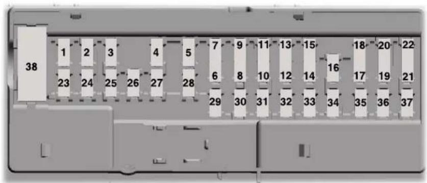
E145984
Fuses
| Protected ComponentFuse RatingFuse or Relay Number | ||
| Not used.—1 | ||
| 2 | 7.5A^1 | Driver seat switch.Passenger seat switch. |
| 3 | 20A^1 | Driver unlock relay. |
| 4 | 5A^1 | Not used (spare). |
| 5 | 20A^1 | Subwoofer amplifier.Revel digital signal processing amplifier. |
| Not used.—6 | ||
| Not used.—7 | ||
| 8 | 10A^1 | Security horn. |
| 9 | 10A^1 | Not used. |
| 10 | 5A^2 | Telematics module.Power decklid module. |
| 11 | 5A^2 | Keypad.Outside lock switch.Combined security sensor module. |
Fuses
| Protected ComponentFuse RatingFuse or Re | ||
| 12 | 7.5A^2 | Front control interface module (climate control).Gear shift module.Rear climate control module. |
| 13 | 7.5A^2 | Instrument cluster.Smart data link.Steering column control module. |
| 14 | 10A^1 | Restraints control module. |
| 15 | 10A^2 | Smart datalink connector power. |
| 16 | 5A^2 | Decklid release relay. |
| 15A^2 | Power decklid. | |
| 17 | 5A^2 | Not used (spare). |
| 18 | 5A^2 | Push button start switch. |
| 19 | 7.5A^2 | Not used. |
| 20 | 7.5A^1 | Headlamp control module. |
| 21 | 5A^2 | Humidity sensor. |
Fuses
| Protected ComponentFuse RatingFuse or Relay Number | ||
| 22 | 5A^2 | Not used. |
| 23 | 10A^1 | Delayed accessory power.Left front window switch.Moonroof.Rear window power sunshade module.DC inverter. |
| 24 | 30A^1 | Central lock relay. |
| 25 | 30A^1 | Left-hand front door zone module. |
| 26 | 30A^1 | Right-hand front door zone module. |
| 27 | 30A^1 | Moonroof. |
| 28 | 20A^1 | Revel digital signal processing amplifier. |
| 29 | 30A^1 | Left-hand rear door zone module. |
| 30 | 30A^1 | Right-hand rear door zone module. |
| 31 | 15A^1 | Column memory module.Advanced heads up display. |
Fuses
| Protected ComponentFuse RatingFuse or Re | ||
| 32 | 10A^1 | SYNC. |
| 33 | 20A^1 | Radio frequency receiver.Rear Seat Entertainment. |
| 34 | 30A^1 | Run/start relay. |
| 35 | 5A^1 | Restraint control module. |
| 36 | 15A^1 | Lane keeping system module.Auto high beam.Electrochromic mirrors.Rear heated seats.Vehicle dynamics module. |
| 37 | 20A^1 | Heated steering wheel.Steering effort control module.Steering angle control module. |
| 38 | 30A^3 | Not used. |
^1 Micro fuse.
^2 Dual micro fuse.
^3 Circuit breaker.
Note: Spare fuse amperage could vary.
Fuses
CHANGING A FUSE
Fuses

WARNING: Always replace a fuse that has the specified amperage. Using a fuse with a higher age rating can cause severe wire
damage and could start a fire.
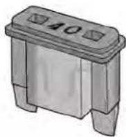
If electrical components in the vehicle are not working, a fuse may have blown. Blown fuses are identified by a broken wire within the fuse. Check the appropriate fuses before replacing any electrical components.
E217331
Fuses
Fuse Types
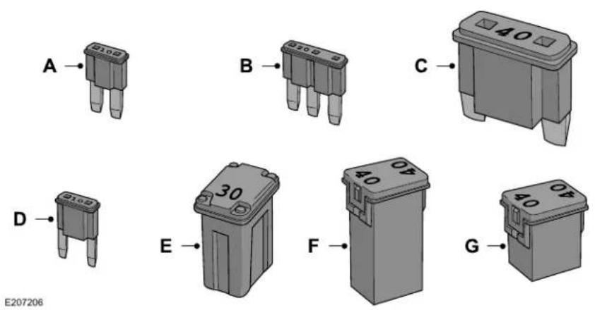
| Fuse TypeCallout | |
| Micro 2A | |
| Micro 3B | |
| MaxiC |
Fuses
| Fuse TypeCallout | |
| MiniD | |
| M CaseE | |
| J CaseF | |
| J Case Low ProfileG |
Maintenance
GENERAL INFORMATION
Have your vehicle serviced regularly to help maintain its roadworthiness and resale value. There is a large network of authorized dealers that are there to help you with their professional servicing expertise. We believe that their specially trained technicians are best qualified to service your vehicle properly and expertly. They are supported by a wide range of highly specialized tools developed specifically for servicing your vehicle.
If your vehicle requires professional service, an authorized dealer can provide the necessary parts and service. Check your warranty information to find out which parts and services are covered.
Use only recommended fuels, lubricants, fluids and service parts conforming to specifications. Motorcraft® parts are designed and built to provide the best performance in your vehicle.
Precautions
- Do not work on a hot engine.
- Make sure that nothing gets caught in moving parts.
- Do not work on a vehicle with the engine running in an enclosed space, unless you are sure you have enough ventilation.
- Keep all open flames and other burning material (such as cigarettes) away from the battery and all fuel related parts.
Working with the Engine Off
- Set the parking brake and shift the transmission to park (P).
- Switch off the engine.
- Block the wheels.
Working with the Engine On

WARNING: To reduce the risk of damage and personal burn injuries, start your engine with the air removed and do not remove it the engine is running.
- Set the parking brake and shift the transmission to park (P).
- Block the wheels.
Maintenance
OPENING AND CLOSING THE HOOD
Opening the Hood
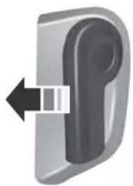
natural_image
3D illustration of a door handle with a double-headed arrow indicating left motion (no text or symbols)E142457
- Inside the vehicle, pull the hood release handle located under the left-hand side of the instrument panel.
- Slightly lift the hood.
- Lift and release the hood latch.

text_image
4 F191432E191432
- Open the hood. The hood strut automatically supports the hood.
Closing the Hood
- Lower the hood until it engages on to the secondary latch.
- Firmly push down on the front of the hood to close it fully.
Note: Make sure that the hood is correctly closed.
Maintenance
UNDER HOOD OVERVIEW - 2.7L/3.0L
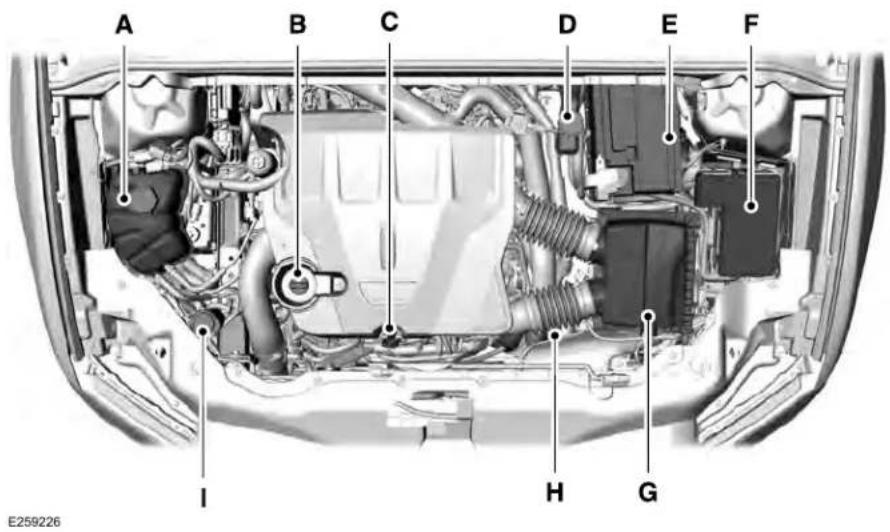
text_image
A B C D E F I H G E259226Maintenance
Engine coolant reservoir. See Engine Coolant Check (page 335).A.
Engine oil filler cap. See Engine Oil Check (page 333).B.
Engine oil dipstick. See Engine Oil Dipstick (page 333).C.
Brake fluid reservoir. See Brake Fluid Check (page 340).D.
Battery. See Changing the 12V Battery (page 342).E.
Engine compartment fuse box. See Changing a Fuse (page 324).F.
Air filter assembly. See Changing the Engine Air Filter (page 348).G.
H. Automatic transmission dipstick. See Automatic Transmission Fluid Check (page 340).
Washer fluid reservoir. See Washer Fluid Check (page 341).I.
Maintenance
UNDER HOOD OVERVIEW - 3.7L
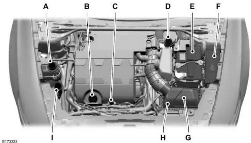
text_image
A B C D E F I H G E173333Engine coolant reservoir. See Engine Coolant Check (page 335).A.
Engine oil filler cap. See Engine Oil Check (page 333).B.
Engine oil dipstick. See Engine Oil Dipstick (page 333).C.
Maintenance
Brake fluid reservoir. See Brake Fluid Check (page 340).D.
Battery. See Changing the 12V Battery (page 342).E.
Engine compartment fuse box. See Fuses (page 309).F.
Air filter assembly. See Changing the Engine Air Filter (page 348).G.
H. Automatic transmission dipstick. See Automatic Transmission Fluid Check (page 340).
Washer fluid reservoir. See Washer Fluid Check (page 341).I.
Maintenance
ENGINE OIL DIPSTICK - 2.7L/3.0L
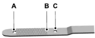
text_image
A B CE250320
Minimum.A
Nominal.B
Maximum.C
ENGINE OIL DIPSTICK - 3.7L
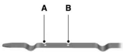
text_image
A BE146429
A MIN
B MAX
ENGINE OIL CHECK
To check the engine oil level consistently and accurately, do the following:
-
Make sure the parking brake is on. Make sure the transmission is in park (P) or neutral (N).
-
Run the engine until it reaches normal operating temperature.
- Make sure that your vehicle is on level ground.
- Switch the engine off and wait 15 minutes for the oil to drain into the oil pan. Checking the engine oil level too soon after you switch the engine off may result in an inaccurate reading.
- Open the hood. See Opening and Closing the Hood (page 328).
- Remove the dipstick and wipe it with a clean, lint-free cloth. See Under Hood Overview (page 331).
- Reinstall the dipstick and remove it again to check the oil level. See Engine Oil Dipstick (page 333).
- Make sure that the oil level is between the maximum and minimum marks. If the oil level is at the minimum mark, add oil immediately. See Capacities and Specifications (page 400).
- If the oil level is correct, replace the dipstick and make sure it is fully seated.
Maintenance
Note: Do not remove the dipstick when the engine is running.
Note: If the oil level is between the maximum and minimum marks, the oil level is acceptable. Do not add oil.
Note: The oil consumption of new engines reaches its normal level after approximately 3,000 mi (5,000 km).
Adding Engine Oil

WARNING: Do not remove the filler en the engine is running.
Do not use supplemental engine oil additives because they are unnecessary and could lead to engine damage that may not be covered by the vehicle Warranty.

text_image
AMERICAN PETROLEUM INSTITUTE FOR GASOLINE ENGINES CERTIFIEDE142732
Only use oils certified for gasoline engines by the American Petroleum Institute (API). An oil with this trademark symbol conforms to the current engine and emission system protection standards and fuel economy requirements of the International Lubricants Specification Advisory Committee (ILSAC).
To top up the engine oil level do the following:
- Clean the area surrounding the engine oil filler cap before you remove it.
-
Remove the engine oil filler cap. See Under Hood Overview (page 331). Turn it counterclockwise and remove it.
-
Add engine oil that meets our specifications. See Capacities and Specifications (page 400). You may have to use a funnel to pour the engine oil into the opening.
- Recheck the oil level.
- If the oil level is correct, replace the dipstick and make sure it is fully seated.
- Replace the engine oil filler cap. Turn it clockwise until you feel a strong resistance.
Note: Do not add oil further than the maximum mark. Oil levels above the maximum mark may cause engine damage.
Note: Make sure you install the oil filler cap correctly.
Note: Soak up any spillage with an absorbent cloth immediately.
OIL CHANGE INDICATOR RESET
Use the information display controls on the steering wheel to reset the oil change indicator.
Maintenance
From the main menu scroll to:
| Action and descriptionMessage | |
| Settings | Press the right arrow button, then from this menu scroll to the following message. |
| Vehicle | Press the right arrow button, then from this menu scroll to the following message. |
| Oil Life | Press the right arrow button, then from this menu scroll to the following message. |
| Hold OK to Reset | Press and hold the OK button until the instrument cluster displays the following message.Reset Successful |
| When the oil change indicator resets the instrument cluster displays 100%.Remaining Life{00} % |
| Action and descriptionMess | |
| If the instrument cluster displays one of the following messages, repeat the process.Not ResetReset Cancelled |
ENGINE COOLANT CHECK

WARNING: Do not remove the
coolant reservoir cap when the engine is on or the cooling system is hot. Wait 10 minutes for the cooling system to cool down. Cover the coolant reservoir cap with a thick cloth to prevent the possibility of scalding and slowly remove the cap. Failure to follow this instruction could result in personal injury.

WARNING: Do not put coolant in dshield washer reservoir. If sprayed windshield, coolant could make it to see through the windshield.

WARNING: To reduce the risk of a real injury, make sure the engine is before unscrewing the coolant are relief cap. The cooling system is pressure. Steam and hot liquid can out forcefully when you loosen the rightly.

WARNING: Do not add coolant than the MAX mark.
When the engine is cold, check the concentration and level of the coolant at the intervals listed in the scheduled maintenance information. See Scheduled Maintenance (page 519).
Note: Make sure that the coolant level is between the MIN and MAX marks on the coolant reservoir.
Maintenance
Note: Coolant expands when it is hot. The level may extend beyond the MAX mark.
Maintain coolant concentration within 48% to 50%, which equates to a freeze point between -29°F (-34°C) and -35°F (-37°C).
Coolant concentration should be checked using a refractometer. We do not recommend the use of hydrometers or coolant test strips for measuring coolant concentration.
Adding Coolant

WARNING: Do not add engine
coolant when the engine is on or the cooling system is hot. Failure to follow this instruction could result in personal injury.

WARNING: Do not remove the reservoir cap when the engine is the cooling system is hot. Wait 10 s for the cooling system to cool Cover the coolant reservoir cap with cloth to prevent the possibility of g and slowly remove the cap.
Failure to follow this instruction could result in personal injury.

WARNING: Do not put coolant in dshield washer reservoir. If sprayed windshield, coolant could make it to see through the windshield.
Note: Do not use stop leak pellets, cooling system sealants, or non-specified additives as they can cause damage to the engine cooling or heating systems. Resulting component damage may not be covered by the vehicle Warranty.
Note: Automotive fluids are not interchangeable.
It is very important to use prediluted coolant approved to the correct specification in order to avoid plugging the small passageways in the engine cooling system. See Capacities and Specifications (page 390). Do not mix different colors or types of coolant in your vehicle. Mixing of engine coolants or using an incorrect coolant may harm the engine or cooling system components and may not be covered by the vehicle Warranty.
Note: If prediluted coolant is not available, use the approved concentrated coolant diluting it to 50/50 with distilled water. See Capacities and Specifications (page 390). Using water that has not been deionised may contribute to deposit formation, corrosion and plugging of the small cooling system passageways.
Note: Coolants marketed for all makes and models may not be approved to our specifications and may cause damage to the cooling system. Resulting component damage may not be covered by the vehicle Warranty.
Maintenance
If the coolant level is at or below the minimum mark, add prediluted coolant immediately.
To top up the coolant level do the following:
- Unscrew the cap slowly. Any pressure escapes as you unscrew the cap.
- Add prediluted coolant approved to the correct specification. See Capacities and Specifications (page 390).
- Add enough prediluted coolant to reach the correct level.
- Replace the coolant reservoir cap. Turn it clockwise until it contacts the hard stop.
- Check the coolant level in the coolant reservoir the next few times you drive your vehicle. If necessary, add enough prediluted engine coolant to bring the coolant level to the correct level.
If you have to add more than 1.1 qt (1 L) of engine coolant per month, have your vehicle checked as soon as possible. Operating an engine with a low level of coolant can result in engine overheating and possible engine damage.
In case of emergency, you can add a large amount of water without engine coolant in order to reach a vehicle service location. In this instance, qualified personnel:
- Must drain the cooling system.
- Chemically clean the coolant system.
- Refill with engine coolant as soon as possible.
Water alone, without engine coolant, can cause engine damage from corrosion, overheating or freezing.
Do not use the following as a coolant substitute:
•Alcohol.
•Methanol.
•Brine.
- Any coolant mixed with alcohol or methanol antifreeze.
Alcohol and other liquids can cause engine damage from overheating or freezing.
Do not add extra inhibitors or additives to the coolant. These can be harmful and compromise the corrosion protection of the coolant.
Recycled Coolant
We do not recommend the use of recycled coolant as an approved recycling process is not yet available.
Note: Dispose of used coolant in the appropriate manner.
Follow your community's regulations and standards for recycling and disposing of automotive fluids.
Severe Climates
If you drive in extremely cold climates:
- It may be necessary to increase the coolant concentration above 50%.
• A coolant concentration of 60% provides improved freeze point protection. Coolant concentrations above 60% decrease the overheat protection characteristics of the coolant and may cause engine damage.
Maintenance
If you drive in extremely hot climates:
- You can decrease the coolant concentration to 40%.
•Coolant concentrations below 40% decrease the freeze and corrosion protection characteristics of the coolant and may cause engine damage.
Vehicles driven year-round in non-extreme climates should use prediluted coolant for optimum cooling system and engine protection.
Coolant Change
At specific mileage intervals, as listed in the scheduled maintenance information, the coolant should be changed. Add prediluted coolant approved to the correct specification. See Capacities and Specifications (page 390).
Fail-Safe Cooling
Fail-safe cooling allows you to temporarily drive your vehicle before any incremental component damage occurs. The fail-safe distance depends on ambient temperature, vehicle load and terrain.
How Fail-Safe Cooling Works

If the engine begins to overheat, the coolant temperature gauge moves toward the red zone:

A warning lamp illuminates and a message may appear in the information display.
If the engine reaches a preset over-temperature condition, the engine automatically switches to alternating cylinder operation. Each disabled cylinder acts as an air pump and cools the engine.
When this occurs, your vehicle still operates, however:
•Engine power is limited.
•The air conditioning system turns off.
Continued operation increases the engine temperature, causing the engine to completely shut down. Your steering and braking effort increases in this situation.
When the engine temperature cools, you can re-start the engine. Have your vehicle checked as soon as possible to minimize engine damage.
When Fail-Safe Mode Is Activated

WARNING: Fail-safe mode is for
use during emergencies only. Operate your vehicle in fail-safe mode only as long as necessary to bring your vehicle to rest in a safe location and seek immediate repairs. When in fail-safe mode, your vehicle will have limited power, will not be able to maintain high-speed operation, and may completely shut down without warning, potentially losing engine power, power steering assist, and power brake assist, which may increase the possibility of a crash resulting in serious injury.

WARNING: Do not remove the
coolant reservoir cap when the engine is on or the cooling system is hot. Wait 10 minutes for the cooling system to cool down. Cover the coolant reservoir cap with a thick cloth to prevent the possibility of scalding and slowly remove the cap. Failure to follow this instruction could result in personal injury.
Maintenance
Your vehicle has limited engine power when in the fail-safe mode, drive your vehicle with caution. Your vehicle does not maintain high-speed operation and the engine may operate poorly.
Remember that the engine is capable of automatically shutting down to prevent engine damage. In this situation:
- Pull off the road as soon as safely possible and switch the engine off.
- If you are a member of a roadside assistance program, we recommend that you contact your roadside assistance service provider.
- If this is not possible, wait for a short period of time for the engine to cool.
- Check the coolant level. If the coolant level is at or below the minimum mark, add prediluted coolant immediately.
- When the engine temperature cools, you can re-start the engine. Have your vehicle checked as soon as possible to minimize engine damage.
Note: Driving your vehicle without repair increases the chance of engine damage.
Engine Coolant Temperature Management (If Equipped)

WARNING: To reduce the risk of crash and injury, be prepared that the vehicle speed may reduce and the vehicle may not be able to accelerate with full power until the coolant temperature reduces.
If you tow a trailer with your vehicle, the engine may temporarily reach a higher temperature during severe operating conditions, for example ascending a long or steep grade in high ambient temperatures.
At this time, you may notice the coolant temperature gauge moves toward the red zone and a message may appear in the information display.
You may notice a reduction in vehicle speed caused by reduced engine power in order to manage the engine coolant temperature. Your vehicle may enter this mode if certain high-temperature and high-load conditions take place. The amount of speed reduction depends on vehicle loading, grade and ambient temperature. If this occurs, there is no need to stop your vehicle. You can continue to drive.
The air conditioning may automatically turn on and off during severe operating conditions to protect the engine from overheating. When the coolant temperature decreases to the normal operating temperature, the air conditioning turns on.
If the coolant temperature gauge moves fully into the red zone, or if the coolant temperature warning or service engine soon messages appear in your information display, do the following:
- Stop your vehicle as soon as it is safe to do so. Fully apply the parking brake, shift into park (P) or neutral (N).
Maintenance
- Leave the engine running until the coolant temperature gauge needle returns to the normal position. If the temperature does not drop after several minutes, follow the remaining steps.
- Switch the engine off and wait for it to cool. Check the coolant level.
- If the coolant level is at or below the minimum mark, add prediluted coolant immediately.
- If the coolant level is normal, restart the engine and continue.
AUTOMATIC TRANSMISSION FLUID CHECK
Note: Transmission fluid should be checked by an authorized dealer. If required, fluid should be added by an authorized dealer.
Have an authorized dealer check and change the transmission fluid at the correct service interval. See Maintenance (page 327). Your transmission does not consume fluid. However, the fluid level should be checked if the transmission is not working properly, (i.e., if the transmission slips or shifts slowly) or if you notice some sign of fluid leakage.
Do not use supplemental transmission fluid additives, treatments or cleaning agents. The use of these materials may affect transmission operation and result in damage to internal transmission components.
BRAKE FLUID CHECK

WARNING: Do not use any fluid than the recommended brake fluid will reduce brake efficiency. Use of act fluid could result in the loss of control, serious personal injury or

WARNING: Only use brake fluid sealed container. Contamination t, water, petroleum products or materials may result in brake system e or failure. Failure to adhere to this g could result in the loss of vehicle s, serious personal injury or death.

WARNING: Do not allow the fluid with your skin or eyes. If this happens, we affected areas immediately with of water and contact your physician.

WARNING: The brake system is affected if the brake fluid level is the MIN mark or above the MAX in the brake fluid reservoir.
Maintenance
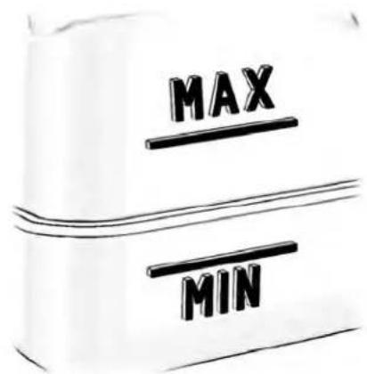
text_image
MAX MINE170684
- Park your vehicle on a level surface.
- Look at the brake fluid reservoir to see where the brake fluid level is relative to the MIN and the MAX marks on the reservoir.
Note: If the brake fluid level is between the MIN and the MAX marks on the reservoir, it is acceptable.
Note: If the brake fluid level is below the MIN mark or above the MAX mark, have your vehicle checked as soon as possible.
Note: To avoid fluid contamination, the reservoir cap must remain in place and fully tight, unless you are adding fluid.
Only use fluid that meets our specifications. See Capacities and Specifications (page 390).
Brake Fluid Service Interval
Brake fluid absorbs water over time which degrades the effectiveness of the brake fluid. Change the brake fluid at the specified intervals to prevent degraded braking performance.
For detailed interval information, see Scheduled Maintenance in your Owner's Manual or your local maintenance guide.
POWER STEERING FLUID CHECK
Your vehicle is equipped with an electric power steering (EPS) system. There is no fluid reservoir to check or fill.
WASHER FLUID CHECK

WARNING: If you operate your in temperatures below 40^ F ( 5^ C),sher fluid with antifreeze protection. to use washer fluid with antifreeze ion in cold weather could result in d windshield vision and increase of injury or accident.
Add fluid to fill the reservoir if the level is low. Only use a washer fluid that meets Ford specifications. See Capacities and Specifications (page 390).
State or local regulations on volatile organic compounds may restrict the use of methanol, a common windshield washer antifreeze additive. Washer fluids containing non-methanol antifreeze agents should be used only if they provide cold weather protection without damaging the vehicle's paint finish, wiper blades or washer system.
Maintenance
FUEL FILTER - 2.7L/3.7L
Your vehicle has a lifetime fuel filter that is integrated with the fuel tank, regular maintenance or replacement is not required.
FUEL FILTER - 3.0L
The fuel filter on your vehicle must be replaced at the specified service interval. Refer to your scheduled maintenance information.
CHANGING THE 12V BATTERY

WARNING: Batteries normally use explosive gases which can cause all injury. Therefore, do not allow sparks or lighted substances to wear the battery. When working near artery, always shield your face and your eyes. Always provide correction.

WARNING: When lifting a
plastic-cased battery, excessive pressure on the end walls could cause acid to flow through the vent caps, resulting in personal injury and damage to the vehicle or battery. Lift the battery with a battery carrier or with your hands on opposite corners.

WARNING: Keep batteries out of if children. Batteries contain sulfuric avoid contact with skin, eyes or g. Shield your eyes when working the battery to protect against possible ing of acid solution. In case of acid with skin or eyes, flush immediately enter for a minimum of 15 minutes andempt medical attention. If acid isived, call a physician immediately.

WARNING: Battery posts, terminals rated accessories contain lead and compounds, chemicals known to the of California to cause cancer and reactive harm. Wash your hands after ing.

WARNING: This vehicle may have more than one battery. Removing the cables from only one battery does not connect your vehicle electrical cable. Make sure you disconnect the cables from all batteries when connecting power. Failure to do so may be serious personal injury or property issue.

WARNING: For vehicles with
Auto-Start-Stop the battery requirement is different. You must replace the battery with one of exactly the same specification.
The battery is in the engine compartment. See Under Hood Overview (page 329).
Maintenance
Your vehicle has a maintenance-free battery. It does not require additional water during service.
If the vehicle battery has a cover and vent hose, make sure you correctly install it after cleaning or replacing the battery.
For longer, trouble-free operation, keep the top of the battery clean and dry and the battery cables tightly fastened to the battery terminals. If any corrosion is present on the battery or terminals, remove the cables from the terminals and clean with a wire brush. You can neutralize the acid with a solution of baking soda and water.
We recommend that you disconnect the negative battery cable terminal from the battery if you plan to store your vehicle for an extended period.
Note: If you only disconnect the negative battery cable terminal, make sure it is isolated or placed away from the battery terminal to avoid unintended connection or arcing.
If you replace the battery make sure it matches the electrical requirements of your vehicle.
If you disconnect or replace the battery and your vehicle has an automatic transmission, it must relearn its adaptive strategy. Because of this, the transmission may shift firmly when first driven. This is normal operation while the transmission fully updates its operation to optimum shift feel.
Battery Management System (If Equipped)
The battery management system monitors battery conditions and takes actions to extend battery life. If excessive battery drain is detected, the system temporarily disables some electrical systems to protect the battery.
Systems included are:
- Heated rear window.
- Heated seats.
•Climate control.
•Heated steering wheel.
•Audio unit.
- Navigation system.
A message may appear in the information displays to alert you that battery protection actions are active. These messages are only for notification that an action is taking place, and not intended to indicate an electrical problem or that the battery requires replacement.
After battery replacement, or in some cases after charging the battery with an external charger, the battery management system requires eight hours of vehicle sleep time to relearn the battery state of charge. During this time your vehicle must remain fully locked with the ignition switched off.
Note: Prior to relearning the battery state of charge, the battery management system may temporarily disable some electrical systems.
Maintenance
Electrical Accessory Installation
To make sure the battery management system works correctly, do not connect an electrical device ground connection directly to the battery negative post. This can cause inaccurate measurements of the battery condition and potential incorrect system operation.
Note: If you add electrical accessories or components to the vehicle, it may adversely affect battery performance and durability. This may also affect the performance of other electrical systems in the vehicle.
Remove and Reinstall the Battery
To disconnect or remove the battery, do the following:
- Apply the parking brake and switch the ignition off.
- Switch all electrical equipment off, for example lights and radio.
- Wait a minimum of two minutes before disconnecting the battery.
Note: The engine management system has a power hold function and remains powered for a period of time after you switch the ignition off. This is to allow diagnostic and adaptive tables to be stored. Disconnecting the battery without waiting can cause damage not covered by the vehicle Warranty.
- Disconnect the negative battery cable terminal.
- Disconnect the positive battery cable terminal.
- Remove the battery securing clamp.
- Remove the battery.
- To install, reverse the removal procedure.
Note: Before reconnecting the battery, make sure the ignition remains switched off.
Note: Make sure the battery cable terminals are fully tightened.
If you disconnect or replace the vehicle battery, you must reset the following features:
- Window bounce-back. See Power Windows (page 109).
- Clock Settings.
•Pre-set radio stations.
Battery Disposal

Make sure that you dispose of old batteries in an environmentally friendly way. Seek advice from
your local authority about recycling old batteries.
CHECKING THE WIPER BLADES
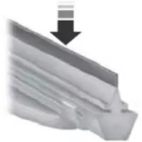
natural_image
Close-up of a metallic mechanical component with a downward arrow indicating compression or dislocation (no text or symbols visible)E142463
Maintenance
Run the tip of your fingers over the edge of the blade to check for roughness.
Clean the wiper blades with washer fluid or water applied with a soft sponge or cloth.
CHANGING THE WIPER BLADES
Replace the wiper blades at least annually for optimum performance.
You can improve poor wiper quality by cleaning the wiper blades and the windshield. See Cleaning the Windows and Wiper Blades (page 353).
Changing the Windshield Wiper Blades
Note: Do not hold the wiper blade when lifting the wiper arm.
Note: Make sure that the wiper arm does not spring back against the glass when the wiper blade is not attached.
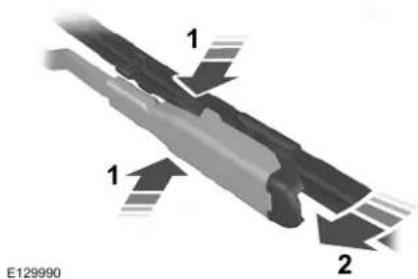
text_image
1 1 2 E129990- Lift the wiper arm and then press the wiper blade locking buttons together.
- Slightly rotate the wiper blade.
- Remove the wiper blade.
- Install in the reverse order.
Note: Make sure that the wiper blade locks into place.
ADJUSTING THE HEADLAMPS
Vertical Aim Adjustment
The headlamps on your vehicle are properly aimed at the assembly plant. If your vehicle has been in an accident, have the alignment of your headlamps checked by your authorized dealer.
Headlamp Aiming Target
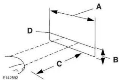
text_image
A D C B E1425928 feet (2.4 meters)A
Center height of lamp to groundB
Maintenance
25 feet (7.6 meters)C
Horizontal reference lineD
Vertical Aim Adjustment
- Park the vehicle directly in front of a wall or screen on a level surface, approximately 25 ft (7.6 m) away.
- Measure the height from the center of your headlamp indicated by a 3.0 millimeter circle on the lens to the ground and mark an 8 ft (2.4 m) horizontal reference line on the vertical wall or screen at this height (a piece of masking tape works well).
Note: To see a clearer light pattern for adjusting, you may want to block the light from one headlamp while adjusting the other.
- Turn on the low beam headlamps to illuminate the wall or screen and open the hood. Cover one of the headlamps so no light hits the wall.
natural_image
Blank white rectangle with a horizontal gray line dividing it into two sections (no text or symbols)E142465
- There is a distinct cut-off (change from light to dark) in the left portion of the beam pattern. Position the top edge of this cut-off 2 in (5 cm) below the horizontal reference line.
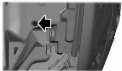
natural_image
Close-up of a mechanical component with an arrow pointing to a small circular feature (no visible text or symbols)E277389
- Locate the vertical adjuster on each headlamp. Use a Phillips #2 screwdriver to turn the adjuster either clockwise or counterclockwise to adjust the vertical aim of the headlamp. The horizontal edge of the brighter light should touch the horizontal reference line.
- Repeat Steps 3 through 7 to adjust the other headlamp.
- Close the hood and turn off the lamps.
Horizontal Aim Adjustment
Horizontal aim is not required for this vehicle and is not adjustable.
Maintenance
CHANGING A BULB

WARNING: Bulbs can become hot.
Let the bulb cool down before removing it. Failure to do so could result in personal injury.

WARNING: Switch the lamps and
the ignition off. Failure to follow this warning could result in serious personal injury.
Use the correct specification bulb. See Bulb Specification Chart (page 433).
Install in the reverse order unless otherwise stated.
High-Intensity Discharge Headlamps
These lamps operate at a high voltage. See an authorized dealer if they fail.
Front Direction Indicator
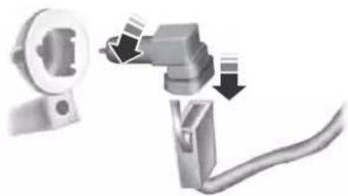
natural_image
Mechanical assembly diagram showing a connector with arrows indicating motion (no text or symbols)E163826
- Switch all of the lamps and the ignition off.
- Disconnect the electrical connector.
- Turn the bulb holder counterclockwise and remove it.
- Remove the bulb by pulling it straight out.
LED Lamps
LED lamps are not serviceable items. See an authorized dealer if they fail.
The following lamps are LED:
- Front parking lamps.
- Front side marker lamps.
•Side direction indicators. - Rear side marker lamps.
- Brake and rear lamps.
• Central high mounted brake lamp.
•Rear direction indicators. - Reversing lamps.
- License plate lamps.
CHANGING THE ENGINE AIR FILTER - 3.7L

WARNING: To reduce the risk of vehicle damage and personal burn injuries, do not start your engine with the air cleaner removed and do not remove it while the engine is running.
Maintenance
When changing the air filter element, use only the air filter element listed. See Capacities and Specifications (page 390).
For turbocharged equipped vehicles: When servicing the air cleaner, it is important that no foreign material enter the air induction system. The engine and turbocharger are susceptible to damage from even small particles.
Change the air filter element at the proper interval. See Scheduled Maintenance (page 519).
Note: Failure to use the correct air filter element may result in severe engine damage. The customer warranty may be void for any damage to the engine if the correct air filter element is not used.
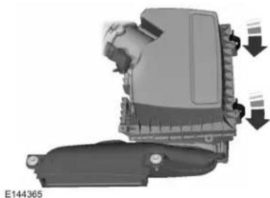
natural_image
Mechanical component diagram showing a lever mechanism with arrows indicating motion (no text or symbols)- Release the clamps that secure the air filter housing cover.
- Carefully lift the air filter housing cover.
- Remove the air filter element from the air filter housing.
-
Wipe any dirt or debris from the air filter housing and cover to make sure no dirt gets in the engine and to make sure you have a good seal.
-
Install a new air filter element. Be careful not to crimp the filter element edges between the air filter housing and cover. This could cause filter damage and allow unfiltered air to enter the engine if not properly seated.
- Install the air filter housing cover.
- Engage the clamps to secure the air filter housing cover to the air filter housing.
CHANGING THE ENGINE AIR FILTER - 2.7L/3.0L

WARNING: To reduce the risk of damage and personal burn injuries, start your engine with the air removed and do not remove it the engine is running.
When changing the air filter element, use only the air filter element listed. See Capacities and Specifications (page 390).
Maintenance
For Turbocharged equipped vehicles: When servicing the air cleaner, it is important that no foreign material enter the air induction system. The engine and turbocharger are susceptible to damage from even small particles.
Change the air filter element at the proper interval. See Scheduled Maintenance (page 519).
Note: Failure to use the correct air filter element may result in severe engine damage. The customer warranty may be void for any damage to the engine if the correct air filter element is not used.
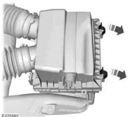
natural_image
Mechanical assembly diagram showing fluid flow and component alignment (no text or symbols)- Release the clamps that secure the air filter housing cover.
- Carefully lift the air filter housing cover.
- Remove the air filter element from the air filter housing.
-
Wipe any dirt or debris from the air filter housing and cover to make sure no dirt gets in the engine and to make sure you have a good seal.
-
Install a new air filter element. Be careful not to crimp the filter element edges between the air filter housing and cover. This could cause filter damage and allow unfiltered air to enter the engine if not properly seated.
- Install the air filter housing cover.
- Engage the clamps to secure the air filter housing cover to the air filter housing.
Vehicle Care
GENERAL INFORMATION
Your dealer has many quality products available to clean your vehicle and protect its finishes.
CLEANING PRODUCTS
Materials
For best results, use the following products or products of equivalent quality:
| SpecificationName | |
| Motorcraft® Bug and Tar Remover, ZC-42 (U.S. & Canada) | |
| ESR-M5B194-BMotorcraft® Custom | |
| ESR-M14P4-AMotorcraft® Detail Wa | |
| ESR-M14P3-AMotorcraft® Engine S | |
| Motorcraft® Engine Shampoo, CXC-66-A (Canada) | |
| Motorcraft® Premium Leather and Vinyl Cleaner, ZC-56 (U.S. & Canada) | |
| Motorcraft® Multi-Purpose Cleaner, CXC-101 (Canada) | |
| WSS-M14P19-AMotorcraft® Premium | |
| WSS-M14P19-AMotorcraft® Premium | |
| Motorcraft® Professional Strength Carpet & Upholstery Cleaner, ZC-54 (U.S. & Canada) | |
| ESR-M14P5-AMotorcraft® Premium |
Vehicle Care
| SpecificationName | |
| Motorcraft® Spot and Stain Remover, ZC-14 (U.S.) | |
| ESR-M14P5-AMotorcraft® | |
| Motorcraft® Wheel and Tire Cleaner, ZC-37-A (U.S. & Canada) |
CLEANING THE EXTERIOR
Wash your vehicle regularly with cool or lukewarm water and a neutral pH shampoo, we recommend Motorcraft Detail Wash.
- Never use strong household detergents or soap, for example dish washing or laundry liquid. These products can discolor and spot painted surfaces.
- Never wash your vehicle when it is hot to the touch, or during strong or direct sunlight.
-
Dry your vehicle with a chamois or soft terry cloth towel to eliminate water spotting.
-
Immediately remove fuel spillages, bird droppings, insect deposits and road tar. These may cause damage to your vehicle's paintwork or trim over time. We recommend Motorcraft Bug and Tar Remover.
- Remove any exterior accessories, for example antennas, before entering a car wash.
- When filling with AdBlue®, remove any residue on painted surfaces immediately.
Note: Suntan lotions and insect repellents can damage painted surfaces. If these substances come in contact with your vehicle, wash the affected area as soon as possible.
Cleaning the Headlamps
Note: Do not scrape the headlamp lenses or use abrasives, alcoholic solvents or chemical solvents to clean them.
Note: Do not wipe the headlamps when they are dry.
Vehicle Care
Exterior Chrome Parts
- Apply a high quality-cleaning product to bumpers and other chrome parts. Follow the manufacturer's instructions. We recommend Motorcraft Custom Bright Metal Cleaner.
- Do not apply the cleaning product to hot surfaces. Do not leave the cleaning product on chrome surfaces longer than the time recommended.
• Using non-recommended cleaners can result in severe and permanent cosmetic damage.
Note: Never use abrasive materials, for example steel wool or plastic pads as they can scratch the chrome surface.
Note: Do not use chrome cleaner, metal cleaner or polish on wheels or wheel covers.
Exterior Plastic Parts
For routine cleaning we recommend Motorcraft Detail Wash. If tar or grease spots are present, we recommend Motorcraft Bug and Tar Remover.
Stripes or Graphics (If Equipped)
Hand washing your vehicle is preferred however, pressure washing may be used under the following conditions:
- Do not use water pressure higher than 2,000 psi (14,000 kPa).
- Do not use water hotter than 179^ (82°C).
- Use a spray with a 40^ wide spray angle pattern.
- Keep the nozzle at a 12 in (305 mm) distance and 90^ angle to your vehicle's surface.
Note: Holding the pressure washer nozzle at an angle to the vehicle's surface may damage graphics and cause the edges to peel away from the vehicle's surface.
Underbody
Regularly clean the underside of your vehicle using water. Keep body and door drain holes free of debris or foreign material.
Under Hood
For removing black rubber marks from under the hood we recommend Motorcraft Wheel and Tire Cleaner or Motorcraft Bug and Tar Remover.
WAXING
Regular waxing is necessary to protect your car's paint from the elements. We recommend that you wash and wax the painted surface once or twice a year.
When washing and waxing, park your vehicle in a shaded area out of direct sunlight. Always wash your vehicle before applying wax.
- Use a quality wax that does not contain abrasives.
- Follow the manufacturer's instructions to apply and remove the wax.
- Apply a small amount of wax in a back-and-forth motion, not in circles.
Vehicle Care
- Do not allow wax to come in contact with any non-body (low-gloss black) colored trim. The wax will discolor or stain the parts over time.
- Roof racks.
• Bumpers. - Grained door handles.
- Side moldings.
- Mirror housings.
•Windshield cowl area. - Do not apply wax to glass areas.
• After waxing, your car's paint should feel smooth, and be free of streaks and smudges.
CLEANING THE ENGINE
Engines are more efficient when they are clean because grease and dirt buildup keep the engine warmer than normal.
When washing:
•Take care when using a power washer to clean the engine. The high-pressure fluid could penetrate the sealed parts and cause damage.
- Do not spray a hot engine with cold water to avoid cracking the engine block or other engine components.
- Spray Motorcraft Engine Shampoo and Degreaser on all parts that require cleaning and pressure rinse clean. In Canada, use Motorcraft Engine Shampoo.
Note: If your vehicle has an engine cover remove the cover before application of Motorcraft Engine Shampoo and Degreaser. Immediately rinse away any over spray.
- Never wash or rinse the engine while it is hot or running; water in the running engine may cause internal damage.
- Never wash or rinse any ignition coil, spark plug wire or spark plug well, or the area in and around these locations.
- Cover the battery, power distribution box, and air filter assembly to prevent water damage when cleaning the engine.
CLEANING THE WINDOWS AND WIPER BLADES
Car wash chemicals and environmental fallout can result in windshield and wiper blade contamination. Dirty windshield and wipers will result in poor windshield wiper operation. Keep the windshield and wiper blades clean to maintain windshield wiper performance.
To clean the windshield and wiper blades:
- Clean the windshield with a non-abrasive glass cleaner. When cleaning the interior of the windshield, avoid getting any glass cleaner on the instrument panel or door panels. Wipe any glass cleaner off these surfaces immediately.
- For windshields contaminated with tree sap, chemicals, wax or bugs, clean the entire windshield using steel wool (no greater than 0000 grade) in a circular motion and rinse with water.
- Clean the wiper blades with isopropyl rubbing alcohol or windshield washer concentrate.
Vehicle Care
Note: Do not use razor blades or other sharp objects to clean or remove decals from the inside of the heated rear window. The vehicle warranty does not cover damage caused to the heated rear window grid lines.
CLEANING THE INTERIOR

WARNING: Do not use cleaning its, bleach or dye on the vehicle's suits, as these actions may weaken it webbing.

WARNING: On vehicles equipped
with seat-mounted airbags, do not use chemical solvents or strong detergents. Such products could contaminate the side airbag system and affect performance of the side airbag in a crash.
Note: Follow the same procedure for cleaning leather seats when cleaning leather interior. See Cleaning Leather Seats (page 356).
Note: Do not use household cleaning products or glass cleaners, which can stain and discolor the fabric and affect the flame retardant abilities of the seat materials.
For fabric, carpets, cloth seats, safety belts and seats equipped with side airbags:
- Remove dust and loose dirt with a vacuum cleaner.
- Remove light stains and soil with Motorcraft® Professional Strength Carpet & Upholstery Cleaner.
For grease or tar stains:
- Spot clean the area with Motorcraft® Spot and Stain Remover. In Canada, use Motorcraft® Multi-Purpose Cleaner.
- If a ring forms on the fabric after spot cleaning, clean the entire area immediately, but do not oversaturate or the ring will set.
Cleaning Black Label or Presidential Interior (If Equipped)
Note: Alcantara microfiber cloth fabric is made of polyester microfiber with micro-porous polyurethane. Using commercially available fabric cleaners can cause permanent damage.
Note: Do not use commercially available leather and vinyl cleaning products on Alcantara microfiber cloth fabric.
Note: Lincoln Black Label or Presidential vehicles may have Alcantara microfiber cloth fabric on the seats, headliner, floor mats and door panels.
Depending on the type of stain, use water, lemon juice or pure ethyl alcohol when cleaning. For cleaning Alcantara microfiber cloth, refer to the following chart:
Vehicle Care
| Cleaning ProcedureType of Stain | |
| Use lukewarm water and rinse by dabbing with clean water.Fruit juice, | |
| Blood, egg, excrement or urine. | Use cold water and rinse by dabbing with clean water. Avoid warm water because it makes these substances coagulate. |
| Liquor, alcoholic beverages, wine, beer, cola and tea. | Use lukewarm water. If the color remains, treat with lemon juice and then rinse. |
| Indelible pencil, cocoa, chocolate, pastry with cream or chocolate, ice cream or mustard. | Use lukewarm water and rinse by dabbing with clean water. |
| Vinegar, hair gel, tomato sauce or coffee with sugar. | Use lemon juice, wipe with lukewarm water and rinse by dabbing with clean water. |
| Use ethyl alcohol, then dab with water.Dye transfer and all other stains |
Vehicle Care
CLEANING THE INSTRUMENT PANEL AND INSTRUMENT CLUSTER LENS

WARNING: Do not use chemicals or strong detergents when using the steering wheel or instrument to avoid contamination of the airbag.
Note: Follow the same procedure as cleaning leather seats for cleaning leather instrument panels and leather interior trim surfaces. See Cleaning Leather Seats (page 356).
Clean the instrument panel and cluster lens with a clean, damp and soft cloth, then use a clean, dry and soft cloth to dry these areas.
- Avoid cleaners or polishes that increase the gloss of the upper portion of the instrument panel. The dull finish in this area helps protect you from undesirable windshield reflection.
- Do not use any household cleaning products or glass cleaners as these may damage the finish of the instrument panel, interior trim and cluster lens.
- Wash or wipe your hands clean if you have been in contact with certain products such as insect repellent and suntan lotion to avoid possible damage to the interior painted surfaces.
- Do not allow air fresheners and hand sanitizers to spill onto interior surfaces. If a spill occurs, wipe off immediately. Your warranty may not cover these damages.
If a staining liquid like coffee or juice has been spilled on the instrument panel or on interior trim surfaces: -
Wipe up spilled liquid using a clean, soft cloth as quickly as possible.
-
Use Motorcraft Premium Leather and Vinyl Cleaner or a commercially available leather cleaning product for automotive interiors. Test any cleaner or stain remover on an inconspicuous area.
- Alternatively, wipe the surface with a clean, soft cloth and a mild soap and water solution. Dry the area with a clean, soft cloth.
- If necessary, apply more soap and water solution or cleaning product to a clean, soft cloth and press it onto the soiled area. Allow this to set at room temperature for 30 minutes.
- Remove the soaked cloth, then with a clean, damp cloth, use a rubbing motion for 60 seconds on the soiled area.
- Dry the area with a clean, soft cloth.
CLEANING LEATHER SEATS
Note: Follow the same procedure as cleaning leather seats for cleaning leather instrument panels and leather interior trim surfaces.
Vehicle Care
For routine cleaning, wipe the surface with a soft, damp cloth and a mild soap and water solution. Dry the area with a clean, soft cloth.
Note: Test any cleaner or stain remover on an inconspicuous area.
You should:
- Remove dust and loose dirt with a vacuum cleaner.
- Clean and treat spills and stains as soon as possible.
Do not use the following products as these may damage the leather: - Oil and petroleum or silicone-based leather conditioners.
•Household cleaners.
•Alcohol solutions. - Solvents or cleaners intended specifically for rubber, vinyl and plastics.
REPAIRING MINOR PAINT DAMAGE
Authorized dealers have touch-up paint to match your vehicle's color. Your vehicle color code is printed on a sticker on the front, left-hand side door jamb. Take your color code to your authorized dealer to make sure you get the correct color.
Before repairing minor paint damage, use a cleaner such as Motorcraft Bug and Tar Remover to remove particles such as bird droppings, tree sap, insect deposits, tar spots, road salt and industrial fallout.
Always read the instructions before using cleaning products.
CLEANING THE WHEELS
Note: Do not apply a cleaning chemical to warm or hot wheel rims and covers.
Note: Industrial-strength (heavy-duty) cleaners, or cleaning chemicals, in combination with brush agitation to remove brake dust and dirt, could wear away the clear coat finish over a period of time.
Note: Do not use hydrofluoric acid-based or high caustic-based wheel cleaners, steel wool, fuels or strong household detergent.
Note: If you intend to park your vehicle for an extended period after cleaning the wheels with a wheel cleaner, drive your vehicle for a few minutes before doing so. This reduces the risk of increased corrosion of the brake discs, brake pads and linings.
Note: Some automatic car washes could cause damage to the finish on your wheel rims and covers.
Vehicle Care
Alloy wheels and wheel covers are coated with a clear coat paint finish. To maintain their condition we recommend that you:
- Clean them weekly with the recommended wheel and tire cleaner.
- Use a sponge to remove heavy deposits of dirt and brake dust accumulation.
- Rinse them thoroughly with a pressurized stream of water when you complete the cleaning process.
We recommend that you use our surface wheel cleaner. Make sure that you read and follow the manufacturer's instructions.
Using other non-recommended cleaning products can result in severe and permanent damage.
VEHICLE STORAGE
If you plan on storing your vehicle for 30 days or more, read the following maintenance recommendations to make sure your vehicle stays in good operating condition.
We engineer and test all motor vehicles and their components for reliable, regular driving. Under various conditions, long-term storage may lead to degraded engine performance or failure unless you use specific precautions to preserve engine components.
General
- Store all vehicles in a dry, ventilated place.
- Protect from sunlight, if possible.
- If vehicles are stored outside, they require regular maintenance to protect against rust and damage.
Body
- Wash your vehicle thoroughly to remove dirt, grease, oil, tar or mud from exterior surfaces, rear-wheel housing and the underside of front fenders.
•Periodically wash your vehicle if it is stored in exposed locations. -
Touch-up exposed or primed metal to prevent rust.
-
Cover chrome and stainless steel parts with a thick coat of auto wax to prevent discoloration. Re-wax as necessary when you wash your vehicle.
- Lubricate all hood, door and luggage compartment hinges and latches with a light grade oil.
- Cover interior trim to prevent fading.
- Keep all rubber parts free from oil and solvents.
Engine
- Change the engine oil and filter prior to storage because used engine oil contains contaminates which may cause engine damage.
- Start the engine every 15 days for a minimum of 15 minutes. Run at fast idle with the climate controls set to defrost until the engine reaches normal operating temperature.
- With your foot on the brake, shift through all the gears while the engine is running.
• We recommend that you change the engine oil before you use your vehicle again.
Vehicle Care
Fuel system
- Fill the fuel tank with high-quality fuel until the first automatic shutoff of the fuel pump nozzle.
Cooling system
- Protect against freezing temperatures.
- When removing your vehicle from storage, check coolant fluid level. Confirm that there are no cooling system leaks and that fluid is at the recommended level.
Battery
- Check and recharge as necessary. Keep connections clean.
- If storing your vehicle for more than 30 days without recharging the battery, we recommend that you disconnect the battery cables to maintain battery charge for quick starting.
Note: It is necessary to reset memory features if battery cables are disconnected.
Brakes
- Make sure the brakes and parking brake release fully.
Tires
- Maintain recommended air pressure.
Miscellaneous
- Make sure all linkages, cables, levers and pins under your vehicle are covered with grease to prevent rust.
- Move vehicles at least 25 ft (7.5 m) every 15 days to lubricate working parts and prevent corrosion.
Removing Vehicle From Storage
When your vehicle is ready to come out of storage, do the following:
- Wash your vehicle to remove any dirt or grease film build-up on window surfaces.
-
Check windshield wipers for any deterioration.
-
Check under the hood for any foreign material that may have collected during storage such as mice or squirrel nests.
- Check the exhaust for any foreign material that may have collected during storage.
- Check tire pressures and set tire inflation per the Tire Label.
- Check brake pedal operation. Drive your vehicle 15 ft (4.5 m) back and forth to remove rust build-up.
- Check fluid levels (including coolant, oil and gas) to make sure there are no leaks, and fluids are at recommended levels.
- If you remove the battery, clean the battery cable ends and check for damage.
Contact an authorized dealer if you have any concerns or issues.
Vehicle Care
BODY STYLING KITS
The distance between the underside of your vehicle and the ground is less than that of other models. Drive with extreme care to avoid damage to your vehicle.
GENERAL INFORMATION
The recommended tire inflation pressures are on the tire information label on the driver side B-pillar.
Check and set the tire pressure at the ambient temperature in which you are intending to drive your vehicle and when the tires are cold. See Technical Specifications (page 388).
Note: Check your tire pressures regularly to optimize fuel economy.
Only use approved wheel and tire sizes. Using other sizes could damage your vehicle and could make the National Type Approval invalid.
Installation of any tires that are not the original equipment tire size can cause the speedometer to display incorrect vehicle speed.
TIRE CARE
Important Information About Low-Profile Tires
If your vehicle is equipped with 245/40R20 tires, they are low-profile tires. These tires and wheels are designed to give your vehicle a sport appearance. With low-profile tires, you may notice an increase in road noise and faster tire wear, depending on road conditions and driving styles. Due to their design, low-profile tires and wheels are more prone to road damage from potholes, rough or unpaved roads, car wash rails and curb contact than standard tires and wheels.
Note: Your vehicle's warranty does not cover these types of damages. Extra caution should be taken when operating on rough roads to avoid impacts that could cause wheel and tire damage.
Information About Uniform Tire Quality Grading
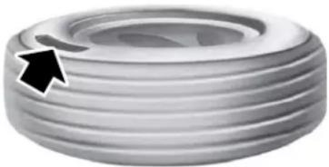
natural_image
Close-up of a metallic tire with concentric grooves and a black arrow pointing to the rim (no text or symbols)E142542
Tire Quality Grades apply to new pneumatic passenger car tires. The Quality grades can be found where applicable on the tire sidewall between tread shoulder and maximum section width. For example: Treadwear 200 Traction AA Temperature A.
These Tire Quality Grades are determined by standards that the United States Department of Transportation has set.
Wheels and Tires
Tire Quality Grades apply to new pneumatic passenger car tires. They do not apply to deep tread, winter-type snow tires, space-saver or temporary use spare tires, light truck or LT type tires, tires with nominal rim diameters of 10 to 12 inches or limited production tires as defined in Title 49 Code of Federal Regulations Part 575.104 ©)(2).
U.S. Department of Transportation Tire quality grades: The U.S. Department of Transportation requires Ford Motor Company to give you the following information about tire grades exactly as the government has written it.
Treadwear
The treadwear grade is a comparative rating based on the wear rate of the tire when tested under controlled conditions on a specified government test course. For example, a tire graded 150 would wear 1 12 times as well on the government course as a tire graded 100. The relative performance of tires depends upon the actual conditions of their use, however, and may depart significantly from the norm due to variations in driving habits, service practices, and differences in road characteristics and climate.
Traction AA A B C

WARNING: The traction grade assigned to this tire is based on straight-ahead braking traction tests, and does not include acceleration, cornering, hydroplaning or peak traction characteristics.
The traction grades, from highest to lowest are AA, A, B, and C. The grades represent the tire's ability to stop on wet pavement as measured under controlled conditions on specified government test surfaces of asphalt and concrete. A tire marked C may have poor traction performance.
Temperature A B C

WARNING: The temperature for this tire is established for a bit is properly inflated and notaded. Excessive speed, inflation, or excessive loading, separately or in combination, use heat buildup and possible cure.
The temperature grades are A (the highest), B and C, representing the tire's resistance to the generation of heat and its ability to dissipate heat when tested under controlled conditions on a specified indoor laboratory test wheel. Sustained high temperature can cause the material of the tire to degenerate and reduce tire life, and excessive temperature can lead to sudden tire failure. The grade C corresponds to a level of performance which all
Wheels and Tires
passenger car tires must meet under the Federal Motor Vehicle Safety Standard No. 139. Grades B and A represent higher levels of performance on the laboratory test wheel than the minimum required by law.
Glossary of Tire Terminology
•Tire label: A label showing the original equipment tire sizes, recommended inflation pressure and the maximum weight the vehicle can carry.
•Tire Identification Number: A number on the sidewall of each tire providing information about the tire brand and manufacturing plant, tire size and date of manufacture. Also referred to as DOT code.
- Inflation pressure: A measure of the amount of air in a tire.
- Standard load: A class of P-metric or Metric tires designed to carry a maximum load at set pressure. For example: For P-metric tires 35 psi (2.4 bar) and for Metric tires 36 psi (2.5 bar). Increasing the inflation pressure beyond this pressure will not increase the tire's load carrying capability.
- Extra load: A class of P-metric or Metric tires designed to carry a heavier maximum load at 42 psi (2.9 bar). Increasing the inflation pressure beyond this pressure will not increase the tire's load carrying capability.
- kPa: Kilopascal, a metric unit of air pressure.
- PSI: Pounds per square inch, a standard unit of air pressure.
-
Cold tire pressure: The tire pressure when the vehicle has been stationary and out of direct sunlight for an hour or more and prior to the vehicle being driven for 1 mile (1.6 km).
-
Recommended inflation pressure: The cold inflation pressure found on the Safety Compliance Certification Label (affixed to either the door hinge pillar, door-latch post, or the door edge that meets the door-latch post, next to the driver's seating position), or Tire Label located on the B-Pillar or the edge of the driver's door.
•B-pillar: The structural member at the side of the vehicle behind the front door - Bead area of the tire: Area of the tire next to the rim.
- Sidewall of the tire: Area between the bead area and the tread.
- Tread area of the tire: Area of the perimeter of the tire that contacts the road when mounted on the vehicle.
- Rim: The metal support (wheel) for a tire or a tire and tube assembly upon which the tire beads are seated.
Wheels and Tires
Information Contained on the Tire Sidewall
Both United States and Canada Federal regulations require tire manufacturers to place standardized information on the sidewall of all tires. This information identifies and describes the fundamental characteristics of the tire and also provides a U.S. DOT Tire Identification Number for safety standard certification and in case of a recall.
Information on P Type Tires
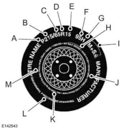
text_image
C D E F G A B 95H I+S H TIRE NAME P215/65R15 M L K E142543P215/65R15 95H is an example of a tire size, load index and speed rating. The definitions of these items are listed below. (Note that the tire size, load index and speed rating for your vehicle may be different from this example.)
A. P: Indicates a tire, designated by the Tire and Rim Association, that may be used for service on cars, sport utility vehicles, minivans and light trucks. Note: If your tire size does not begin with a letter this may mean it is designated by either the European Tire and Rim Technical Organization or the Japan Tire Manufacturing Association.
B. 215: Indicates the nominal width of the tire in millimeters from sidewall edge to sidewall edge. In general, the larger the number, the wider the tire.
C. 65: Indicates the aspect ratio which gives the tire's ratio of height to width.
D. R: Indicates a radial type tire.
E. 15: Indicates the wheel or rim diameter in inches. If you change your wheel size, you will have to purchase new tires to match the new wheel diameter.
Wheels and Tires
F. 95: Indicates the tire's load index. It is an index that relates to how much weight a tire can carry. You may find this information in your owner's manual. If not, contact a local tire dealer.
Note: You may not find this information on all tires because it is not required by federal law.
G. H: Indicates the tire's speed rating. The speed rating denotes the speed at which a tire is designed to be driven for extended periods of time under a standard condition of load and inflation pressure. The tires on your vehicle may operate at different conditions for load and inflation pressure. These speed ratings may need to be adjusted for the difference in conditions. The ratings range from 81 mph (130 km/h) to 186 mph (299 km/h). These ratings are listed in the following chart.
Note: You may not find this information on all tires because it is not required by federal law.
| mph (km/h)Letter | |
| 81 mph (130 km/h)M | |
| 87 mph (140 km/h)N | |
| 99 mph (159 km/h)Q | |
| 106 mph (171 km/h)R | |
| 112 mph (180 km/h)S | |
| 118 mph (190 km/h)T | |
| 124 mph (200 km/h)U | |
| 130 mph (210 km/h)H | |
| 149 mph (240 km/h)V |
| mph (km/h)Letter rating | |
| 168 mph (270 km/h)W | |
| 186 mph (299 km/h)Y |
Note: For tires with a maximum speed capability over 149 mph (240 km/h), tire manufacturers sometimes use the letters ZR. For those with a maximum speed capability over 186 mph (299 km/h), tire manufacturers always use the letters ZR.
H. U.S. DOT Tire Identification Number: This begins with the letters DOT and indicates that the tire meets all federal standards. The next two numbers or letters are the plant code designating where it was manufactured, the next two are the tire size code and the last four numbers represent the week and year the tire was built. For example, the numbers 317 mean the 31st week of 1997. After 2000 the numbers go to four
Wheels and Tires
digits. For example, 2501 means the 25th week of 2001. The numbers in between are identification codes used for traceability. This information is used to contact customers if a tire defect requires a recall.
I. M+S or M/S: Mud and Snow, or
AT: All Terrain, or
AS: All Season.
J. Tire Ply Composition and Material Used: Indicates the number of plies or the number of layers of rubber-coated fabric in the tire tread and sidewall. Tire manufacturers also must indicate the ply materials in the tire and the sidewall, which include steel, nylon, polyester, and others.
K. Maximum Load: Indicates the maximum load in kilograms and pounds that can be carried by the tire. See the Safety Compliance Certification Label (affixed to either the door hinge pillar, door-latch post, or the door edge that meets the door-latch post, next to the driver's seating position), for the correct tire pressure for your vehicle.
L. Treadwear, Traction and Temperature Grades:
•Treadwear The treadwear grade is a comparative rating based on the wear rate of the tire when tested under controlled conditions on a specified government test course. For example, a tire graded 150 would wear one and one-half times as well on the government course as a tire graded 100.
- Traction: The traction grades, from highest to lowest are AA, A, B, and C. The grades represent the tire's ability to stop on wet pavement as measured under controlled conditions on specified government test surfaces of asphalt and concrete. A tire marked C may have poor traction performance.
•Temperature: The temperature grades are A (the highest), B and C, representing the tire's resistance to the generation of heat and its ability to dissipate heat when tested under controlled conditions on a specified indoor laboratory test wheel.
Wheels and Tires
M. Maximum Inflation Pressure: Indicates the tire manufacturers' maximum permissible pressure or the pressure at which the maximum load can be carried by the tire. This pressure is normally higher than the vehicle manufacturer's recommended cold inflation pressure which can be found on the Safety Compliance Certification Label (affixed to either the door hinge pillar, door-latch post, or the door edge that meets the door-latch post, next to the driver's seating position), or Tire Label which is located on the B-Pillar or the edge of the driver's door. The cold inflation pressure should never be set lower than the recommended pressure on the vehicle label.
The tire suppliers may have additional markings, notes or warnings such as standard load or radial tubeless.
Additional Information Contained on the Tire Sidewall for LT Type Tires
Note: Tire Quality Grades do not apply to this type of tire.
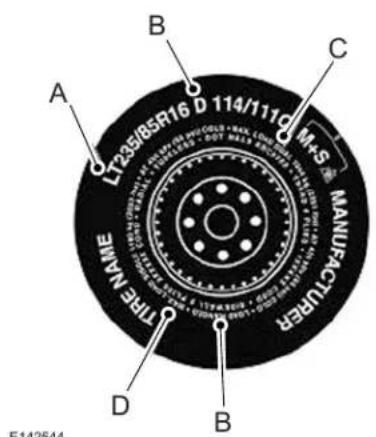
text_image
A LT235/85R16 D 114/111Q M+S MANUFACTURER TYPE NAME D B CLT type tires have some additional information beyond those of P type tires; these differences are described below.
A. LT: Indicates a tire, designated by the Tire and Rim Association, that is intended for service on light trucks.
B. Load Range and Load Inflation Limits: Indicates the tire's load-carrying capabilities and its inflation limits.
C. Maximum Load Dual Ib (kg) at psi (kPa) cold: Indicates the maximum load and tire pressure when the tire is used as a dual; defined as four tires on the rear axle (a total of six or more tires on the vehicle).
D. Maximum Load Single lb (kg) at psi (kPa) cold: Indicates the maximum load and tire pressure when the tire is used as a single; defined as two tires (total) on the rear axle.
Information on T Type Tires
T145/80D16 is an example of a tire size.
Note: The temporary tire size for your vehicle may be different from this example. Tire Quality Grades do not apply to this type of tire.
Wheels and Tires
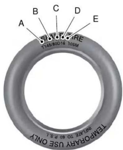
text_image
A B C D E T145/80D16 10SM TEMPORARY USE ONLY INFATIE TO 60 P.S.L.E142545
T type tires have some additional information beyond those of P type tires; these differences are described below:
A. T: Indicates a type of tire, designated by the Tire and Rim Association, that is intended for temporary service on cars, sport utility vehicles, minivans and light trucks.
B. 145: Indicates the nominal width of the tire in millimeters from sidewall edge to sidewall edge. In general, the larger the number, the wider the tire.
C. 80: Indicates the aspect ratio which gives the tire's ratio of height to width. Numbers of 70 or lower indicate a short sidewall.
D. D: Indicates a diagonal type tire.
R: Indicates a radial type tire.
E. 16: Indicates the wheel or rim diameter in inches. If you change your wheel size, you will have to purchase new tires to match the new wheel diameter.
Location of the Tire Label
You will find a Tire Label containing tire inflation pressure by tire size and other important information located on the B-Pillar or the edge of the driver's door.
Inflating Your Tires
Safe operation of your vehicle requires that your tires are properly inflated. Remember that a tire can lose up to half of its air pressure without appearing flat.
Every day before you drive, check your tires. If one looks lower than the others, use a tire gauge to check pressure of all tires and adjust if required.
At least once a month and before long trips, inspect each tire and check the tire pressure with a tire gauge (including spare, if equipped). Inflate all tires to the inflation pressure recommended by Ford Motor Company.
Wheels and Tires
You are strongly urged to buy a reliable tire pressure gauge, as automatic service station gauges may be inaccurate. Ford recommends the use of a digital or dial-type tire pressure gauge rather than a stick-type tire pressure gauge.
Use the recommended cold inflation pressure for optimum tire performance and wear. Under-inflation or over-inflation may cause uneven treadwear patterns

WARNING: Under-inflation is
the most common cause of tire failures and may result in severe tire cracking, tread separation or blowout, with unexpected loss of vehicle control and increased risk of injury. Under-inflation increases sidewall flexing and rolling resistance, resulting in heat buildup
and internal damage to the tire. It also may result in unnecessary tire stress, irregular wear, loss of vehicle control and accidents. A tire can lose up to half of its air pressure and not appear to be flat!
Always inflate your tires to the Ford recommended inflation pressure even if it is less than the maximum inflation pressure information found on the tire. The Ford recommended tire inflation pressure is found on the Safety Compliance Certification Label (affixed to either the door hinge pillar, door-latch post, or the door edge that meets the door-latch post, next to the driver's seating position), or Tire Label which is located on the B-Pillar or the edge of the driver's door. Failure to follow the tire pressure recommendations can cause uneven treadwear patterns and adversely affect the way your vehicle handles
Maximum Inflation Pressure is the tire manufacturer's maximum permissible pressure and the pressure at which the maximum load can be carried by the tire. This pressure is normally higher than the manufacturer's recommended cold inflation pressure which can be found on the Safety Compliance Certification Label (affixed to either the door hinge pillar, door-latch post, or the door edge that meets the door-latch post, next to the driver's seating position), or Tire Label which is located on the B-Pillar or the edge of the driver's door. The cold inflation pressure should never be set lower than the recommended pressure on the Safety Compliance Certification Label or Tire Label.
When weather temperature changes occur, tire inflation pressures also change. A 10°F (6°C) temperature drop can cause a corresponding drop of 1 psi (7 kPa) in inflation pressure. Check your tire pressures frequently and adjust them to the proper pressure which can be found on the Safety Compliance Certification Label or Tire Label.
Wheels and Tires
To check the pressure in your tire(s):
- Make sure the tires are cool, meaning they are not hot from driving even a mile.
Note: If you are checking tire pressure when the tire is hot, (for example driven more than 1 mile [1.6 kilometers]), never bleed or reduce air pressure. The tires are hot from driving and it is normal for pressures to increase above recommended cold pressures. A hot tire at or below recommended cold inflation pressure could be significantly under-inflated.
Note: If you have to drive a distance to get air for your tire(s), check and record the tire pressure first and add the appropriate air pressure when you get to the pump. It is normal for tires to heat up and the air pressure inside to go up as you drive.
-
Remove the cap from the valve on one tire, then firmly press the tire gauge onto the valve and measure the pressure.
-
Add enough air to reach the recommended air pressure.
Note: If you overfill the tire, release air by pressing on the metal stem in the center of the valve. Then recheck the pressure with your tire gauge.
-
Replace the valve cap.
-
Repeat this procedure for each tire, including the spare.
Note: Some spare tires operate at a higher inflation pressure than the other tires. For T type mini-spare tires, see the Dissimilar spare wheel and tire assembly information for a description. Store and maintain at 60 psi (4.15 bar). For full-size and dissimilar spare tires, see the Dissimilar spare wheel and tire assembly information for a description. Store and maintain at the higher of the front and rear inflation pressure as shown on the Tire Label.
- Visually inspect the tires to make sure there are no nails or other objects embedded that could poke a hole in the tire and cause an air leak.
- Check the sidewalls to make sure there are no gouges, cuts or bulges.
Inspecting Your Tires and Wheel Valve Stems
Periodically inspect the tire treads for uneven or excessive wear and remove objects such as stones, nails or glass that may be wedged in the tread grooves. Check the tire and valve stems for holes, cracks, or cuts that may permit air leakage and repair or replace the tire and replace the valve stem. Inspect the tire sidewalls for cracking, cuts, bruises and other signs of damage or excessive wear. If internal damage to the tire is suspected, have the tire demounted and inspected in case it needs to be repaired or replaced. For your safety, tires that are damaged or show signs of excessive wear should not be used because they are more likely to blow out or fail.
Wheels and Tires
Improper or inadequate vehicle maintenance can cause tires to wear abnormally. Inspect all your tires, including the spare, frequently, and replace them if one or more of the following conditions exist:
Tire Wear
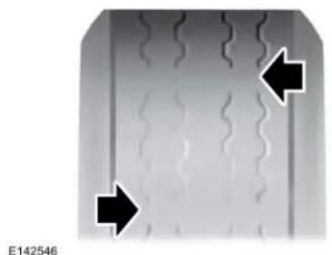
natural_image
Close-up of a metallic component with wavy internal lines and two black arrows pointing to specific features (no text or symbols)When the tread is worn down to one sixteenth of an inch (2 millimeters), tires must be replaced to help prevent your vehicle from skidding and hydroplaning. Built-in treadwear indicators, or wear bars, which look like narrow strips of smooth rubber across the tread will appear on the tire when the tread is worn down to one sixteenth of an inch (2 millimeters).
When the tire tread wears down to the same height as these wear bars, the tire is worn out and must be replaced.
Damage
Periodically inspect the tire treads and sidewalls for damage (such as bulges in the tread or sidewalls, cracks in the tread groove and separation in the tread or sidewall). If damage is observed or suspected have the tire inspected by a tire professional. Tires can be damaged during off-road use, so inspection after off-road use is also recommended.
Age
WARNING: Tires degrade over time depending on many factors such as weather, storage conditions, and conditions of use (load, speed, inflation pressure) the tires experience throughout their lives.
WARNING: In general, tires should be replaced after six years regardless of tread wear or even if they have not been used. However, heat caused by hot climates or frequent high-load conditions can accelerate the aging process and may require you to replace tires more frequently.
WARNING: You should replace your spare tire when you replace the road tires or after six years due to aging even if it has not been used.
Wheels and Tires
U.S. DOT Tire Identification Number
Both U.S. and Canada Federal regulations require tire manufacturers to place standardized information on the sidewall of all tires. This information identifies and describes the fundamental characteristics of the tire and also provides a U.S. DOT Tire Identification Number for safety standard certification and in case of a recall.
This begins with the letters DOT and indicates that the tire meets all federal standards. The next two numbers or letters are the plant code designating where it was manufactured, the next two are the tire size code and the last four numbers represent the week and year the tire was built. For example, the numbers 317 mean the 31st week of 1997. After 2000 the numbers go to four digits. For example, 2501 means the 25th week of 2001. The numbers in between are identification codes used for traceability. This information is used to contact customers if a tire defect requires a recall.
Tire Replacement Requirements
Your vehicle is equipped with tires designed to provide a safe ride and handling capability.

WARNING: Only use
replacement tires and wheels that are the same size, load index, speed rating and type (such as P-metric versus LT-metric or all-season versus all-terrain) as those originally provided by Ford. The recommended tire and wheel size may be found on either the Safety Compliance Certification Label (affixed to either the door hinge pillar, door-latch post, or the door edge that meets the door-latch post, next to the driver's seating position), or the Tire Label which is located on the B-Pillar or edge of the driver's door. If this information is not found on these labels, then you should contact your authorized dealer as soon as possible. Use of any tire or wheel not
recommended by Ford can affect the safety and performance of your vehicle, which could result in an increased risk of loss of vehicle control, vehicle rollover, personal injury and death.

WARNING: To reduce the risk
of serious injury, when mounting replacement tires and wheels, you should not exceed the maximum pressure indicated on the sidewall of the tire to set the beads without additional precautions listed below. If the beads do not seat at the maximum pressure indicated, re-lubricate and try again.

WARNING: When inflating the
tire for mounting pressures up to 20 psi (1.38 bar) greater than the maximum pressure on the tire sidewall, the following precautions must be taken to protect the person mounting the tire:
Wheels and Tires

WARNING: 1. Make sure that
you have the correct tire and wheel size.

WARNING: 2. Lubricate the tire
bead and wheel bead seat area again.

WARNING: 3. Stand at a
minimum of 12 ft (3.66 m) away from the wheel and tire assembly.

WARNING: 4. Use both eye and
ear protection.

WARNING: For a mounting
pressure more than 20 psi (1.38 bar) greater than the maximum pressure, a Ford dealer or other tire service professional should do the mounting.

WARNING: Always inflate steel
carcass tires with a remote air fill with the person inflating standing at a minimum of 12 ft (3.66 m) away from the wheel and tire assembly.
Important: Remember to replace the wheel valve stems when the road tires are replaced on your vehicle
It is recommended that the two front tires or two rear tires generally be replaced as a pair.
The tire pressure sensors mounted in the wheels (originally installed on your vehicle) are not designed to be used in aftermarket wheels.
The use of wheels or tires not recommended by Ford Motor Company may affect the operation of your tire pressure monitoring system.
If the tire pressure monitoring system indicator is flashing, your system is malfunctioning. Your replacement tire might be incompatible with your tire pressure monitoring system, or some component of the system may be damaged.
Safety Practices

WARNING: If your vehicle is in snow, mud or sand, do not spin the tires; spinning the tires for the tire and cause an ion. A tire can explode in as little one to five seconds.

WARNING: Do not spin the s at over 34 mph (55 km/h). The say fail and injure a passenger ander.
Wheels and Tires
Driving habits have a great deal to do with your tire mileage and safety.
- Observe posted speed limits
- Avoid fast starts, stops and turns
- Avoid potholes and objects on the road
- Do not run over curbs or hit the tire against a curb when parking
Highway Hazards
No matter how carefully you drive there is always the possibility that you may eventually have a flat tire on the highway. Drive slowly to the closest safe area out of traffic. This may further damage the flat tire, but your safety is more important.
If you feel a sudden vibration or ride disturbance while driving, or you suspect your tire or vehicle has been damaged, immediately reduce your speed. Drive with caution until you can safely pull off the road. Stop and inspect the tires for damage. If a tire is under-inflated or damaged, deflate it, remove the wheel and replace it with your spare tire and wheel (if provided). If you cannot detect a cause, have the vehicle towed to the nearest repair facility or tire dealer to have the vehicle inspected.
Tire and Wheel Alignment
A bad jolt from hitting a curb or pothole can cause the front end of your vehicle to become misaligned or cause damage to your tires. If your vehicle seems to pull to one side when you're driving, the wheels may be out of alignment. Have an authorized dealer check the wheel alignment periodically.
Wheel misalignment in the front or the rear can cause uneven and rapid treadwear of your tires and should be corrected by an authorized dealer. Front-wheel drive vehicles and those with an independent rear suspension (if equipped) may require alignment of all four wheels.
The tires should also be balanced periodically. An unbalanced tire and wheel assembly may result in irregular tire wear.
Tire Rotation
Note: If your tires show uneven wear ask an authorized dealer to check for and correct any wheel misalignment, tire imbalance or mechanical problem involved before tire rotation.
Note: Your vehicle may be equipped with a dissimilar spare wheel and tire assembly. A dissimilar spare wheel and tire assembly is defined as a spare wheel and tire assembly that is different in brand, size or appearance from the road tires and wheels. If you have a dissimilar spare wheel and tire assembly it is intended for temporary use only and should not be used in a tire rotation.
Note: After having your tires rotated, inflation pressure must be checked and adjusted to the vehicle requirements.
Wheels and Tires
Rotating your tires at the recommended interval (as indicated in the Scheduled Maintenance chapter) will help your tires wear more evenly, providing better tire performance and longer tire life.
Front-wheel drive and all-wheel drive vehicles (front tires on the left side of the diagram)
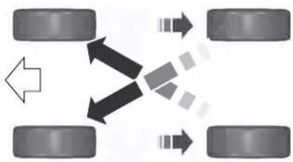
flowchart
graph TD
    A["Vehicle 1"] --> B["Vehicle 2"]
    A --> C["Vehicle 3"]
    A --> D["Vehicle 4"]
    B --> E["Vehicle 5"]
    C --> F["Vehicle 6"]
    D --> G["Vehicle 7"]
E142547
Sometimes irregular tire wear can be corrected by rotating the tires.
USING SUMMER TIRES
Summer tires provide superior performance on wet and dry roads. Summer tires do not have the Mud and Snow (M+S or M/S) tire traction rating on the tire side wall. Since summer tires do not have the same traction performance as All-season or Snow tires, we do not recommend using summer tires when temperatures drop to approximately 45°F (7°C) or below (depending on tire wear and environmental conditions) or in snow and ice conditions. Like any tire, summer tire performance is affected by tire wear and environmental conditions. If you must drive in those conditions, we recommend using Mud and Snow (M+S, M/S), All-season or Snow tires.
Always store your summer tires indoors at temperatures above 19^ F ( -7^ C). The rubber compounds used in these tires lose flexibility and may develop surface cracks in the tread area at temperatures below 19^ F ( -7^ C). If the tires have been subjected to 19^ F ( -7^ C) or less, warm them in a heated space to at least 41^ F ( 5^ C) for at least 24 hours before installing them on a vehicle, or moving the vehicle with the tires installed, or checking tire inflation. Do not place tires near heaters or heating devices used to warm the room where the tires are stored. Do not apply heat or blow heated air directly on the tires. Always inspect the tires after storage periods and before use.
USING SNOW CHAINS

WARNING: Snow tires must be the
same size, load index, and speed rating as those originally provided by Ford. Use of any tire or wheel not recommended by Ford can affect the safety and performance of your vehicle, which could result in an increased risk of loss of vehicle control, vehicle rollover, personal injury, and death. Additionally, the use of non-recommended tires and wheels could cause steering, suspension, axle, transfer case, or power transfer unit failure. It is also strongly advised to follow the Ford recommended tire inflation pressure found on the Safety Compliance Certification Label (affixed to
Wheels and Tires
either the door hinge pillar, door-latch post, or the door edge that meets the door-latch post, next to the driver's seating position), or Tire Label which is located on the B-Pillar or the edge of the driver door. Failure to follow the tire pressure recommendations can cause uneven treadwear patterns and adversely affect the way your vehicle handles.
The tires on your vehicle may have all-weather treads to provide traction in rain and snow. However, in some climates you may need to use snow chains.
Your vehicle may not be compatible with snow chain or cable usage with the factory-fitted wheels and tires. Only certain chains or snow cables have been approved by Ford as safe for use on your vehicle with the following tire size: 235/50R18. You should only install chains or cables sized at 10 mm or less in dimension as measured on the sidewall of your tire. Not all S-class snow chains meet these restrictions. Chains of this size restriction will include a tensioning
device. The chains should be mounted in pairs on the front tires only. If you need to use chains, it is recommended that steel wheels (of the same size and specification) be used, as chains may chip aluminum wheels.
Follow these guidelines when using traction devices:
- If possible, avoid fully loading your vehicle
•Purchase chains or cables from a manufacturer that clearly labels body to tire dimension restrictions.
- When driving with snow chains or cables, do not exceed 30 mph (48 km/h) or the maximum speed recommended by the chain manufacturer; whichever is less.
- Drive cautiously. If you hear the chains or cables rub or bang against the vehicle, stop and retighten them. If this does not work, remove the chains or cables and prevent vehicle damage.
- Remove the chains or cables when they are no longer needed. Do not use the chains or cables on dry roads.
- If a temporary spare tire is mounted on your vehicle, do not use snow chains on the axle with the temporary spare tire.
If you have any questions regarding snow tires or snow chains, please contact your authorized dealer.
TIRE PRESSURE MONITORING SYSTEM

WARNING: The tire pressure
monitoring system is not a substitute for manually checking tire pressures. You should periodically check tire pressures using a pressure gauge. Failure to correctly maintain tire pressures could increase the risk of tire failure, loss of control, vehicle rollover and personal injury.
Wheels and Tires
Note: You should only use tire sealants in roadside emergencies as they could cause damage to the tire pressure monitoring system sensor.
Note: If the tire pressure monitoring system sensor becomes damaged, it will not function.

Each tire, including the spare (if provided), should be checked monthly when cold and inflated to the inflation pressure recommended by the vehicle manufacturer on the vehicle placard or tire inflation pressure label. (If your vehicle has tires of a different size than the size indicated on the vehicle placard or tire inflation pressure label, you should determine the proper tire inflation pressure for those tires).
As an added safety feature, your vehicle has been equipped with a Tire Pressure Monitoring System (TPMS) that illuminates a low tire pressure telltale when one or more of your tires is significantly under-inflated. Accordingly, when the low tire pressure telltale illuminates, you should stop and check your tires as soon as possible, and
inflate them to the proper pressure. Driving on a significantly under-inflated tire causes the tire to overheat and can lead to tire failure. Under-inflation also reduces fuel efficiency and tire tread life, and could affect the vehicle's handling and stopping ability.
Please note that the TPMS is not a substitute for proper tire maintenance, and it is the driver's responsibility to maintain correct tire pressure, even if under-inflation has not reached the level to trigger illumination of the TPMS low tire pressure telltale.
Your vehicle has also been equipped with a TPMS malfunction indicator to indicate when the system is not operating properly. The TPMS malfunction indicator is combined with the low tire pressure telltale. When the system detects a malfunction, the telltale will flash for approximately one minute and then remain continuously illuminated. This sequence will continue upon subsequent vehicle start-ups as long as the malfunction exists.
When the malfunction indicator is illuminated, the system will not be able to detect or signal low tire pressure as intended. TPMS malfunctions could occur for a variety of reasons, including the installation of replacement or alternate tires or wheels on the vehicle that prevent the TPMS from functioning properly. Always check the TPMS malfunction telltale after replacing one or more tires or wheels on your vehicle to ensure that the replacement or alternate tires and wheels allow the TPMS to continue to function properly.
This device complies with Part 15 of the FCC Rules and with License exempt RSS Standards of Industry Canada. Operation is subject to the following two conditions:
- This device will not cause harmful interference, and
- This device must accept any interference received, including interference that could cause undesired operation.
Wheels and Tires
Note: Changes or modifications not expressively approved by the party responsible for compliance could void the user's authority to operate the equipment. The term "IC:" before the radio certification number only signifies that Industry Canada technical specifications were met.
Changing Tires With a Tire Pressure Monitoring System
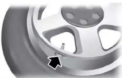
natural_image
Close-up of a car wheel rim with a black arrow pointing to the center (no text or symbols visible)E142549
Note: Each road tire is equipped with a tire pressure sensor located inside the wheel and tire assembly cavity. The pressure sensor is attached to the valve stem. The pressure sensor is covered by the tire and is not visible unless the tire is removed. Take care when changing the tire to avoid damaging the sensor.
You should always have your tires serviced by an authorized dealer.
Check the tire pressure periodically (at least monthly) using an accurate tire gauge. See When Inflating Your Tires in this chapter.
Understanding Your Tire Pressure Monitoring System
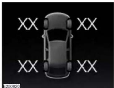
natural_image
Top-down view of a car with four 'XX' lettering arranged around it, no text or symbols on the car itself.The tire pressure monitoring system measures pressure in your road tires and sends the tire pressure readings to your vehicle. You can view the tire pressure readings through the information display. See General Information (page 122). The low tire pressure warning light will turn on if the tire pressure is significantly low. Once the
Wheels and Tires
light is illuminated, your tires are under-inflated and need to be inflated to the manufacturer's recommended tire pressure. Even if the light turns on and a short time later turns off, your tire pressure still needs to be checked.
When Your Temporary Spare Tire is Installed
When one of your road tires needs to be replaced with the temporary spare, the system will continue to identify an issue to remind you that the damaged road wheel and tire assembly needs to be repaired and put back on your vehicle.
To restore the full function of the tire pressure monitoring system, have the damaged road wheel and tire assembly repaired and remounted on your vehicle.
When You Believe Your System is Not Operating Properly
The main function of the tire pressure monitoring system is to warn you when your tires need air. It can also warn you in the event the system is no longer capable of functioning as intended. See the following chart for information concerning your tire pressure monitoring system:
Wheels and Tires
| Customer action requiredPossible causeLow tire pressure w | ||
| Solid warning light Repair | Tire(s) under-inflated | Make sure tires are at the proper pressure. See Inflating your tires in this chapter. After inflating your tires to the manufacturer's recommended pressure as shown on the Tire Label (located on the edge of driver's door or the B-Pillar), the vehicle must be driven for at least two minutes over 20 mph (32 km/h) before the light turns off. |
| the damaged road wheel and tire assembly | bly and reinstall | |
| Spare tire in use | it on the vehicle to restore system function. For a description on how the system functions, seeWhen Your Temporary Spare Tire isInstalledin this section. | |
| TPMS malfunction | If the tires are properly inflated and the spare tire is not in use but the light remains on, contact your authorized dealer as soon as possible. | |
| Flashing warning light | Spare tire in use | Repair the damaged road wheel and tire assembly and reinstall it on the vehicle to restore system function. For a description on how the system functions, seeWhen Your Temporary Spare Tire isInstalledin this section. |
| TPMS malfunction | If the tires are properly inflated and the spare tire is not in use but the light remains on, contact your authorized dealer as soon as possible. |
Wheels and Tires
When Inflating Your Tires

WARNING: Do not use the tire
pressure displayed in the information display as a tire pressure gauge. Failure to follow this instruction could result in personal injury or death.
When putting air into your tires (such as at a gas station or in your garage), the tire pressure monitoring system will not respond immediately to the air added to your tires.
It could take up to two minutes of driving over 20 mph (32 km/h) for the light to turn off after you have filled your tires to the recommended inflation pressure.
How Temperature Affects Your Tire Pressure
The tire pressure monitoring system monitors tire pressure in each pneumatic tire. While driving in a normal manner, a typical passenger tire inflation pressure could increase about 2–4 psi (14–28 kPa) from a cold start situation. If the vehicle is stationary overnight with the outside temperature significantly lower than the daytime temperature, the tire pressure could decrease about 3 psi (21 kPa) for a drop of 30^ F ( 17^ C) in ambient temperature. This lower pressure value could be detected by the tire pressure monitoring system as being significantly lower than the recommended inflation pressure and activate the system warning light for low tire pressure. If the low tire pressure warning light is on, visually check each tire to verify that no tire is flat. If one or more tires are flat, repair as necessary. Check the air pressure in the road tires. If any tire is under-inflated, carefully drive the vehicle to the nearest location where air can be added to the tires. Inflate all the tires to the recommended inflation pressure.
CHANGING A ROAD WHEEL

WARNING: If the tire pressure
monitor sensor becomes damaged it may not function.
Note: You should only use tire sealants in roadside emergencies as they may cause damage to the tire pressure monitoring system sensor.
Note: The tire pressure monitoring system indicator light illuminates when the spare tire is in use. To restore the full function of the monitoring system, all road wheels equipped with tire pressure monitoring sensors must be mounted on the vehicle.
If you get a flat tire when driving, do not apply the brake heavily. Instead, gradually decrease your speed. Hold the steering wheel firmly and slowly move to a safe place on the side of the road.
Have a flat serviced by an authorized dealer in order to prevent damage to the tire pressure monitoring system sensors. See Tire Pressure Monitoring System (page 376). Replace the spare tire with a road tire as soon as possible. During repairing or replacing of the flat tire, have an authorized dealer inspect the tire pressure monitoring system sensor for damage.
Wheels and Tires
Dissimilar Spare Wheel and Tire Assembly Information

WARNING: Failure to follow these hes could result in an increased risk of vehicle control, injury or death.
If you have a dissimilar spare wheel and tire, then it is intended for temporary use only. This means that if you need to use it, you should replace it as soon as possible with a road wheel and tire assembly that is the same size and type as the road tires and wheels that were originally provided. If the dissimilar spare tire or wheel is damaged, it should be replaced rather than repaired.
A dissimilar spare wheel and tire assembly is defined as a spare wheel and tire assembly that is different in brand, size or appearance from the road tires and wheels and can be one of three types:
- T-type mini-spare: This spare tire begins with the letter T for tire size and may have Temporary Use Only molded in the sidewall.
- Do not exceed the maximum speed labeled on the tire and wheel assembly. This maximum speed can be either on a label affixed to the wheel or molded into the tire.
2. Full-size dissimilar spare with label on wheel: This spare tire has a label on the wheel that states: THIS WHEEL AND TIRE ASSEMBLY FOR TEMPORARY USE ONLY.
When driving with one of the dissimilar spare tires listed above, do not:
•Exceed 50 mph (80 km/h).
- Load the vehicle beyond maximum vehicle load rating listed on the Safety Compliance Label.
- Tow a trailer.
- Use snow chains on the end of the vehicle with the dissimilar spare tire.
- Use more than one dissimilar spare tire at a time.
- Use commercial car washing equipment.
- Try to repair the dissimilar spare tire.
Use of one of the dissimilar spare tires listed above at any one wheel location can lead to impairment of the following:
- Handling, stability and braking performance.
- Comfort and noise.
•Ground clearance and parking at curbs.
• Winter weather driving capability.
•Wet weather driving capability. - All-wheel driving capability, if applicable.
3. Full-size dissimilar spare without label on wheel
When driving with the full-size dissimilar spare wheel and tire assembly, do not:
•Exceed 70 mph (113 km/h).
- Use more than one dissimilar spare wheel and tire assembly at a time.
- Use commercial car washing equipment.
- Use snow chains on the end of the vehicle with the dissimilar spare wheel and tire assembly.
Wheels and Tires
The usage of a full-size dissimilar spare wheel and tire assembly can lead to impairment of the following:
- Handling, stability and braking performance.
- Comfort and noise.
• Ground clearance and parking at curbs.
• Winter weather driving capability.
•Wet weather driving capability. - All-wheel driving capability.
When driving with the full-size dissimilar spare wheel and tire assembly additional caution should be given to:
• Towing a trailer.
- Driving vehicles equipped with a camper body.
- Driving vehicles with a load on the cargo rack.
Drive cautiously when using a full-size dissimilar spare wheel and tire assembly and seek service as soon as possible.
Tire Change Procedure (If Equipped)

WARNING: The jack supplied with
this vehicle is only intended for changing wheels. Do not use the vehicle jack other than when you are changing a wheel in an emergency.

WARNING: The jack should be
used on level firm ground wherever possible.

WARNING: Check that the vehicle
jack is not damaged or deformed and the thread is lubricated and clean.

WARNING: Never place anything
between the vehicle jack and the ground.

WARNING: Never place anything
between the vehicle jack and your vehicle.

WARNING: Use only the specified
jacking points. If you use other positions, you may damage the body, steering, suspension, engine, braking system or the fuel lines.

WARNING: To help prevent your
vehicle from moving when changing a wheel, shift the transmission into park (P), set the parking brake and use an appropriate block or wheel chock to secure the wheel diagonally opposite to the wheel being changed. For example, when changing the front left wheel, place an appropriate block or wheel chock on the right rear wheel.

WARNING: When one of the front
wheels is off the ground, the transmission alone will not prevent the vehicle from moving or slipping off the jack, even if the transmission is in park (P).
Wheels and Tires

WARNING: Do not get under a that is only supported by a vehicle

WARNING: Always use the jack ed as original equipment with your . If using a jack other than the one ed, make sure the jack capacity is date for the vehicle weight, including vehicle cargo or modifications. If you sure if the jack capacity is adequate, the authorized dealer.
Note: The jack does not require maintenance or additional lubrication over the service life of your vehicle.
Note: Passengers should not remain in your vehicle when the vehicle is being jacked.
- Park on a level firm surface, shift the transmission into park (P), set the parking brake and switch the ignition off. Activate the hazard flashers and set up the warning triangle.
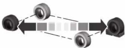
flowchart
graph LR
    A["Component 1"] --> B["Component 2"]
    B --> C["Component 3"]
E175447
- Block both the front and rear of the wheel diagonally opposite the flat tire. For example, if the left front tire is flat, block the right rear wheel.
- Lift the carpeted load floor panel and slide it forward.
Note: The wheel trim tool in the following illustration is optional.
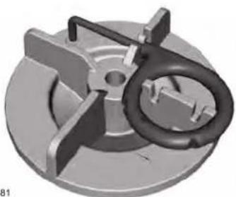
natural_image
3D rendered mechanical component with a central ring and three arms (no text or symbols visible)E224481
- Remove the wing nut securing the spare tire by turning it counterclockwise.
- Remove the spare tire from the spare tire compartment.
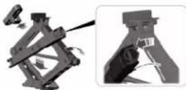
- Remove plastic wing nut and jack and lug wrench assembly. Remove the strap from the jack. Turn the jack hex nut drive screw counterclockwise and detach lug wrench from the jack.
Wheels and Tires
natural_image
Mechanical component with directional arrows indicating motion or force (no text or symbols)E181744
- If your vehicle has a wheel trim that covers the lug nuts, use the tool stored on the spare tire wing nut to remove the wheel trim for access to the lug nuts. Feed the wire end of the tool through the small hole on the wheel trim to hook behind it and pull to remove the wheel trim.
natural_image
Close-up of a car wheel with a mechanical component inserted, showing parts numbered 1 and 2 (no text or symbols present)E181745
- Loosen each wheel lug nut one-half turn counterclockwise, but do not remove them until the wheel is raised off the ground.
natural_image
Side view of a car with two upward arrows indicating motion or orientation (no text or symbols)E145908
- The vehicle jacking points are shown above, and are depicted on the yellow warning label on the jack.
natural_image
Simple line drawing of a person sitting on a bench with a diagonal line crossing through the circle (no text or symbols)E166722
Wheels and Tires

WARNING: Do not attempt to
change a tire on the side of the vehicle close to moving traffic. Pull far enough off the road to avoid the danger of being hit when operating the jack or changing the wheel.
- Position the jack so that the vehicle downward flange rests in the jack saddle. Use the lug wrench and turn the jack nut clockwise. When the flat tire is off the ground, remove the lug nuts with the lug wrench.
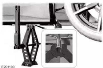
natural_image
Mechanical assembly diagram showing a bracket and wheel assembly with a close-up inset of a mechanical component (no text or symbols visible)- Replace the flat tire with the spare tire, making sure the valve stem is facing outward. Reinstall the lug nuts until the wheel is snug against the hub. Do not fully tighten the lug nuts until the wheel has been lowered.
- Lower the wheel by turning the jack handle counterclockwise.
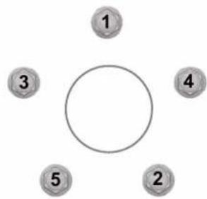
flowchart
graph TD
    A["1"] --> B[" "]
    C["3"] --> B
    D["4"] --> B
    E["5"] --> B
    F["2"] --> B
    B --> G(( ))
E75442
13. Remove the jack and fully tighten the lug nuts in the order shown. See Technical Specifications (page 388).
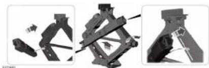
natural_image
Three mechanical assembly diagrams showing different structural configurations (no text or symbols visible)- Fold up the wrench and re-attach to the jack. Re-position the jack and wrench assembly into the original vehicle position and secure with the plastic wing nut. Securely fasten the jack before you drive.
- Unblock the wheel and pick up the warning triangle.
Stowing the flat tire
You cannot store the full-sized road wheel in the temporary spare tire well.
- Find the flat tire retainer strap tucked inside the jack channel. Slide the carpeted load floor into position.
- Stow the flat tire in the cargo area on the load floor with the wheel facing up. Secure the flat tire with the retainer strap by following the next steps.
Wheels and Tires
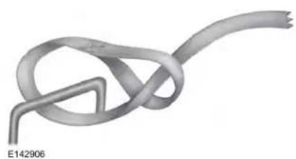
natural_image
3D rendered illustration of a knotted cable or wire with a triangular loop and a curved end, labeled E142906 (no text or symbols on the diagram itself)-
Locate the rear left side and right side cargo tie-down rings. Push the loop end of the retainer strap through one cargo tie-down ring. Thread the non-loop end through the loop.
-
Weave the retainer strap through the wheel openings.
-
Locate the cargo tie-down in the opposite rear corner of the cargo area. Thread the retainer strap though the tie-down and pull tight.
1
E143746
- Secure the flat tire by tying a 2-half hitch knot.
2
natural_image
Abstract interwoven ribbon-like shapes forming a symmetrical design (no text or symbols)- After having your tire serviced, make sure that you stow the retention strap back in its original location on the jack.
3
natural_image
Abstract interlocking ribbon diagram with no text or symbolsWheels and Tires
TECHNICAL SPECIFICATIONS
Wheel Lug Nut Torque Specifications

WARNING: When installing a wheel, always remove any corrosion, dirt or foreign materials present on the mounting surfaces of the wheel or the surface of the wheel hub, brake drum or brake disc that contacts the wheel. Make sure that any fasteners that attach the wheel to the hub are secured so they do not interfere with the mounting surfaces of the wheel. Installing wheels without correct metal-to-metal contact at the wheel mounting surfaces can cause the wheel nuts to loosen and the wheel to come off while your vehicle is in motion, being in loss of control.
| Bolt size | lb-ft (Nm) |
| 162 lb.ft (220 Nm)M14 x 1.5 |
Torque specifications are for nut and bolt threads free of dirt and rust. Use only Ford recommended replacement fasteners.
Retighten the lug nuts to the specified torque within 100 miles (160 kilometers) after any wheel disturbance (such as tire rotation, changing a flat tire, wheel removal).
Wheels and Tires
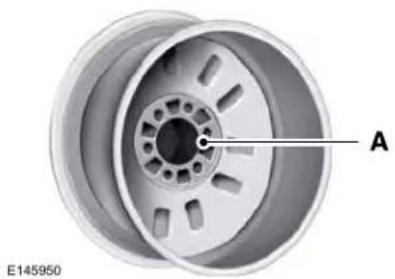
natural_image
3D rendering of a car wheel rim with labeled component A, no text or symbols on the rim itselfWheel pilot boreA
Inspect the wheel pilot bore and mounting surface prior to installation. Remove any visible corrosion or loose particles.
Capacities and Specifications
ENGINE SPECIFICATIONS - 2.7L
| SpecificationMeasurement | |
| 164Cubic inches. | |
| 1-4-2-5-3-6Firing order. | |
| 10.0:1Compression ratio. | |
| 0.028–0.031 in (0.7–0.8 mm)Spark plug gap. | |
| Coil in plugIgnition system. |
Drivebelt Routing
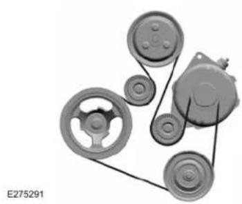
natural_image
Mechanical assembly diagram showing pulleys and gears (no text or labels)Capacities and Specifications
ENGINE SPECIFICATIONS - 3.0L
| SpecificationMeasurement | |
| 180Cubic inches. | |
| 1-4-2-5-3-6Firing order. | |
| 9.5:1Compression ratio. | |
| 0.028–0.031 in (0.7–0.8 mm)Spark plug gap. | |
| Coil in plugIgnition system. |
Capacities and Specifications
Drivebelt Routing
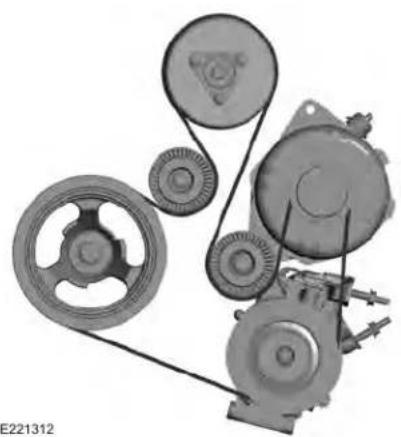
natural_image
Mechanical assembly diagram showing pulleys, gears, and linkages (no text or symbols)Capacities and Specifications
ENGINE SPECIFICATIONS - 3.7L
| SpecificationMeasurement | |
| 227Cubic inches. | |
| 1-4-2-5-3-6Firing order. | |
| Coil on plugIgnition system. | |
| 0.049 - 0.053 in (1.25 - 1.35 mm)Spark plug gap. | |
| 10.5:1Compression ratio. |
Drivebelt Routing
3.7L Duratec
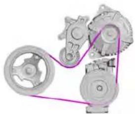
natural_image
Mechanical assembly diagram showing gears and pulleys connected by a purple wire (no text or labels)E191904
Capacities and Specifications
MOTORCRAFT PARTS - 2.7L
| Motorcraft Part numberComponent | |
| FA-1912AAir filter element. | |
| BAGM-94RH7-800Battery. | |
| FP-80Cabin air filter. | |
| Engine oil filter.^1 | FL-2062 |
| Spark plug.^2 | SP-578 |
| WW-2431 (driver side)Windshield wiper blade.WW-2050 (passenger side) |
^1 If a Motorcraft ^® oil filter is not available, use an oil filter that meets industry performance specification SAE/USCAR-36.
^2 For spark plug replacement, contact your authorized dealer. Replace the spark plugs at the recommended intervals. See Scheduled Maintenance Record (page 531).
Capacities and Specifications
We recommend Motorcraft® parts that are available at your authorized dealer or at www.fordparts.com. The parts engineered for your vehicle meet or exceed our
specifications. Use of other parts could impact vehicle performance, emissions and durability. Your warranty could be void for any damage related to use of other parts.
MOTORCRAFT PARTS - 3.0L
| Motorcraft Part numberComponent | |
| FA-1912AAir filter element. | |
| BAGM-94RH7-800Battery. | |
| FP-80Cabin air filter. | |
| Engine oil filter.^1 | FL-2062 |
| FG-1083Fuel filter. | |
| Spark plugs.^2 | SP-578 |
| WW-2431 (driver side)Windshield wiper bladesWW-2050 (passenger side) |
^1 If a Motorcraft ^® oil filter is not available, use an oil filter that meets industry performance specification SAE/USCAR-36.
^2 For spark plug replacement, contact your authorized dealer. Replace the spark plugs at the recommended intervals. See Scheduled Maintenance Record (page 531).
Capacities and Specifications
We recommend Motorcraft® parts that are available at your authorized dealer or at www.fordparts.com. The parts engineered for your vehicle meet or exceed our
specifications. Use of other parts could impact vehicle performance, emissions and durability. Your warranty could be void for any damage related to use of other parts.
MOTORCRAFT PARTS - 3.7L
| Motorcraft Part numberComponent | |
| FA-1912AAir filter element. | |
| FL-500-SOil filter. | |
| BAGM-48H6-760Battery (non-Livery). | |
| BAGM-94RH7-800Battery (Livery). | |
| SP-520Spark plugs. | |
| FP-80Cabin air filter. | |
| WW-2431 (driver side)Windshield wiper blade. |
Capacities and Specifications
| Motorcraft Part numberComponent | |
| WW-2050 (passenger side) |
We recommend Motorcraft® parts that are available at your authorized dealer or at www.fordparts.com. These parts are engineered for your vehicle, and meet or exceed our specifications. Use of other parts could impact vehicle performance, emissions and durability. Your warranty could be void for any damage related to use of other parts.
If a Motorcraft® oil filter is not available, use an oil filter that meets industry performance specification SAE/USCAR-36.
For spark plug replacement, contact an authorized dealer. Replace the spark plugs at the appropriate intervals. See Scheduled Maintenance (page 519).
Capacities and Specifications
VEHICLE IDENTIFICATION NUMBER
The vehicle identification number is located on the left-hand side of the instrument panel.
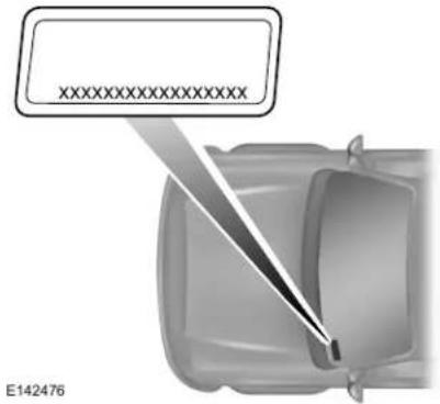
text_image
XXXXXXXXXXXXXX E142476Please note that in the graphic, XXXX is representative of your vehicle identification number.
The Vehicle Identification Number contains the following information:
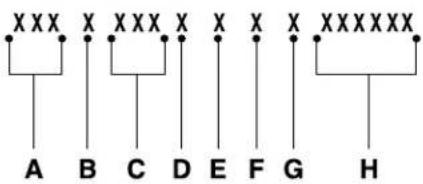
flowchart
graph TD
    A["XXX"] --> B["XX"]
    B --> C["XXX"]
    C --> D["XX"]
    D --> E["XX"]
    E --> F["XXX"]
    F --> G["XXXXXX"]
    G --> H["XX"]
    style A fill:#f9f,stroke:#333
    style B fill:#f9f,stroke:#333
    style C fill:#f9f,stroke:#333
    style D fill:#f9f,stroke:#333
    style E fill:#f9f,stroke:#333
    style F fill:#f9f,stroke:#333
    style G fill:#f9f,stroke:#333
    style H fill:#f9f,stroke:#333
E142477
World manufacturer identifierA
B Brake system, Gross Vehicle Weight Rating, Restraint Devices and their locations
C Make, vehicle line, series, body type
Engine typeD
Check digitE
Model yearF
Assembly plantG
Production sequence numberH
VEHICLE CERTIFICATION LABEL
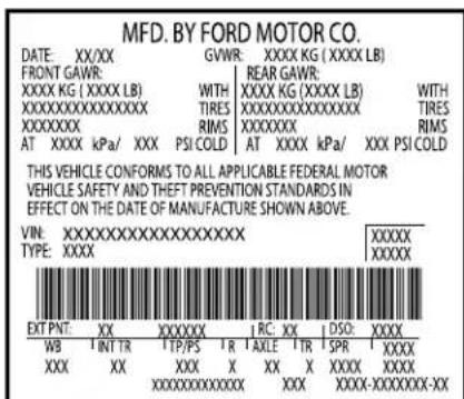
text_image
MFD. BY FORD MOTOR CO. DATE: XX/XX GVWR: XXXX KG (XXXX LB) FRONT GAWR: REAR GAWR: XXXX KG (XXXX LB) WITH XXXX KG (XXXX LB) WITH XXXXXXXXXXXXX TIRESXXXXXXXXXXXXX TIRES XXXXXXXX RIMS XXXXXX RIMS AT XXXK kPa/ XXX PSI COLD AT XXXX kPa/ XXX PSI COLD THIS VEHICLE CONFORMS TO ALL APPLICABLE FEDERAL MOTOR VEHICLE SAFETY AND THEFT PREVENTION STANDARDS IN EFFECT ON THE DATE OF MANUFACTURE SHOWN ABOVE. VIN:XXXXXXXXXXXXXXXXXXXX TYPE:XXXX XXXXXX EXT PNT: XX XXXXXX RC: XX DSO:XXXX WB INT TR TTP/PS T R AXLE TR SPR XXXX XXX XX XXX X XX X XXX XXXX XXXXXXXXXXXX XXX XXX-XXXXXXXX-XXE167469
The National Highway Traffic Safety Administration Regulations require that a Safety Compliance Certification Label be affixed to a vehicle and prescribe where the Safety Compliance Certification Label may be located. The Safety Compliance Certification Label shall be affixed to either the door hinge pillar, the door latch post, or the edge of the door near the door latch, next to the driver's seating position.
Capacities and Specifications
TRANSMISSION CODE DESIGNATION
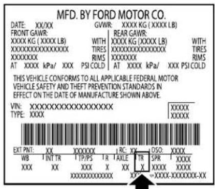
The transmission code is on the Safety Compliance Certification Label. The following table shows the transmission code along with the transmission description.
| CodeDescription | |
| JSix-speed automatic transmis | |
| CSix-speed automatic transmis |
Capacities and Specifications
CAPACITIES AND SPECIFICATIONS - 2.7L
Use oil and fluid that meets the defined specification and viscosity grade.
If you do not use oil and fluid that meets the defined specification and viscosity grade, it could result in:
- Component damage not covered by the vehicle warranty.
- Longer engine cranking periods.
- Increased emission levels.
- Reduced engine performance.
- Reduced fuel economy.
- Reduced brake performance.
Air Conditioning System

WARNING: The air conditioning refrigerant system contains refrigerant under high pressure. Only qualified personnel should service the air conditioning refrigerant system. Opening the air conditioning refrigerant system can cause personal injury.
Capacities
| Refrigerant OilRefrigerantVariant | ||
| 5.24 fl oz (155 ml)20.00 oz (0.567 kg)All. |
Capacities and Specifications
Materials
| SpecificationName | |
| R-134a Refrigerant / Frigorigène R-134a (Canada)YN-19 (U.S.)CYN-19-R (Canada) | WSH-M17B19-AMotorcraft® R-134a Refrigeration |
| Motorcraft® PAG Refrigerant Compressor Oil / Huile PAG pour compresseur frigori-fique Motorcraft® (Canada)YN-12-D (U.S. & Canada) | WSH-M1C231-BMotorcraft® PAG Refrigeration |
Automatic Transmission
Note: Automatic transmissions that require MERCON ^® LV transmission fluid should only use MERCON ^® LV transmission fluid. The use of any other fluid could cause transmission damage.
Capacities and Specifications
Capacities
| QuantityVariant | |
| All. | 11.6 qt (11 L)1 |
^1 Approximate dry fill capacity. Actual amount could vary during fluid changes.
Materials
| SpecificationName | |
| Motorcraft® MERCON® LV Automatic Transmission Fluid / Huile pour boîte automatique MERCON® LV Motorcraft® (Canada)XT-10-QLVC (U.S.)CXT-10-LV6 (Canada) | MERCON® LV WSS-M2C938-AMotorcraft® MERCON® |
Engine Coolant
Capacities
| QuantityVariant | |
| 10.9 qt (10.3 L)Front wheel drive. | |
| 11.0 qt (10.4 L)Rear wheel drive. |
Capacities and Specifications
Materials
| SpecificationName | |
| Motorcraft® Orange Prediluted Antifreeze/Coolant / Antigel/liquide de refroidissement prédilué orange Motorcraft® (Canada)VC-3DIL-B (U.S.)CVC-3DIL-B (Canada) | WSS-M97B44-D2Motorcraft® Orange Pred |
Engine Oil

text_image
AMERICAN PETROLEUM INSTITUTE FOR GASOLINE ENGINES CERTIFIEDE276075
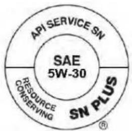
text_image
API SERVICE SN SAE 5W-30 RESOURCE CONSERVING SN PLUS (6)An oil that displays this symbol conforms to current engine, emission system and fuel economy performance standards of ILSAC.
We recommend Motorcraft ^® motor oil for your vehicle. If Motorcraft ^® oil is not available, use motor oils of the recommended viscosity grade that meet API SN PLUS requirements and display the API Certification Mark for gasoline engines.
Do not use supplemental engine oil additives because they are unnecessary and could lead to engine damage that your vehicle warranty does not cover.
E142732
Capacities and Specifications
Capacities
| Including the Oil FilterVariant | |
| 6.0 qt (5.7 L)All. |
Materials
| SpecificationName | |
| Engine Oil - SAE 5W-30 - Super Premium Motor Oil / Huile moteur de très haute qualité SAE 5W-30 Motorcraft® (Canada)XO-5W30-Q1SP (U.S.)CXO-5W30-LSP6 (Canada) | WSS-M2C946-B1Engine Oil - SAE 5W-30 - Synt |
Alternative Engine Oil for Extremely Cold Climates
To improve engine cold start performance, we recommend that you use the following alternative engine oil in extremely cold climates, where the ambient temperature reaches -22.0^ F ( -30^ C) or below.
Capacities and Specifications
Materials
| SpecificationName | |
| WSS-M2C953-B1Engine Oil - SAE 0W-30 |
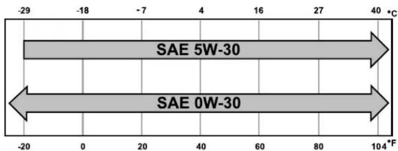
other
| Direction | Value | | --------- | ----- | | SAE 5W-30 | 40 °C | | SAE 0W-30 | -20 °C |Capacities and Specifications
Fuel Tank
Capacities
| QuantityVariant | |
| 18.0 gal (68.1 L)All. |
Grease
Materials
| SpecificationName | |
| Motorcraft® Premium Long-Life Grease / Graisse longue durée de qualité première Motorcraft® (Canada)XG-1-E1 (U.S. & Canada) | ESA-M1C75-BMotorcraft® Premium Long-Life Grease |
| Motorcraft® Multi-Purpose Grease Spray / Graisse tout usage en aérosol Motorcraft® (Canada)XL-5-A (U.S. & Canada) | ESB-M1C93-BMotorcraft® Multi-Purpose Grease |
Capacities and Specifications
Hydraulic Brake System
Note: We recommend using DOT 4 Low Viscosity (LV) High Performance Brake Fluid or equivalent meeting WSS-M6C65-A2. Use of any fluid other than the recommended fluid could cause reduced brake performance and not meet our performance standards. Keep brake fluid clean and dry. Contamination with dirt, water, petroleum products or other materials could result in brake system damage and possible failure.
Materials
| SpecificationName | |
| Motorcraft® DOT 4 LV High Performance Motor Vehicle Brake Fluid / Liquide de frein automobile haute performance DOT 4 LV Motorcraft® (Canada) PM-20 (U.S. & Canada) | WSS-M6C65-A2Motorcraft® DOT 4 LV High |
Locks
Capacities and Specifications
Materials
| SpecificationName | |
| Motorcraft® Penetrating Fluid / Liquide dégrippant Motorcraft® (Canada)XL-1 (U.S.)CXC-51-A (Canada) | -Motorcraft® Penetrating and Lock Lubr |
Power Transfer Unit
Capacities
| QuantityVariant | |
| All. | 23.7 fl oz (0.7 L) ^1 |
^1 Contact an authorized dealer for fluid level checking and filling.
Capacities and Specifications
Materials
| SpecificationName | |
| Motorcraft® SAE 75W-140 Synthetic Rear Axle Lubricant / Lubrifiant synthétique pour pont arrière SAE 75W-140 Motorcraft® (Canada)XY-75W140-QL (U.S.)CXY-75W140-1L (Canada) | WSL-M2C192-AMotorcraft® SAE 75W-140 |
Rear Axle
Capacities
| QuantityVariant | |
| 1.0–1.1 qt (0.97–1.03 L)All. |
Capacities and Specifications
Materials
| SpecificationName | |
| Motorcraft® SAE 80W-90 Premium Axle Lubricant / Lubrifiant pour essieux de très haute qualité SAE 80W-90 Motorcraft® (Canada)XY-80W90-QL (U.S.)CXY-80W90-1L (Canada) | WSP-M2C197-AMotorcraft® SAE 80W-90 Prem |
Washer Reservoir
Capacities
| QuantityVariant | |
| Fill as required.All. |
Capacities and Specifications
Materials
| SpecificationName | |
| Motorcraft® Premium Quality Windshield Washer Fluid / Liquide lave-glace de haute qualité Motorcraft® (Canada)ZC-32-B2 (U.S.)CXC-37-A/B/D/F (Canada) | WSS-M14P19-AMotorcraft® Premium Wind |
CAPACITIES AND SPECIFICATIONS - 3.0L
Use oil and fluid that meets the defined specification and viscosity grade.
If you do not use oil and fluid that meets the defined specification and viscosity grade, it could result in:
- Component damage not covered by the vehicle warranty.
- Longer engine cranking periods.
- Increased emission levels.
- Reduced engine performance.
- Reduced fuel economy.
- Reduced brake performance.
Air Conditioning System

WARNING: The air conditioning
refrigerant system contains refrigerant under high pressure. Only qualified personnel should service the air conditioning refrigerant system. Opening the air conditioning refrigerant system can cause personal injury.
Capacities
| Refrigerant OilRefrigerantVariant | ||
| 5.24 fl oz (155 ml)20.00 oz (0.567 kg) |
Capacities and Specifications
Materials
| SpecificationName | |
| R-134a Refrigerant / Frigorigène R-134a (Canada)YN-19 (U.S.)CYN-19-R (Canada) | WSH-M17B19-AMotorcraft® R-134a Refrigerant |
| Motorcraft® PAG Refrigerant Compressor Oil / Huile PAG pour compresseur frigori-fique Motorcraft® (Canada)YN-12-D (U.S. & Canada) | WSH-M1C231-BMotorcraft® PAG Refrigerant Co |
Automatic Transmission
Note: Automatic transmissions that require MERCON ^® LV transmission fluid should only use MERCON ^® LV transmission fluid. The use of any other fluid could cause transmission damage.
Capacities and Specifications
Capacities
| QuantityVariant | |
| All. | 11.6 qt (11 L)1 |
^1 Approximate dry fill capacity. Actual amount could vary during fluid changes.
Materials
| SpecificationName | |
| Motorcraft® MERCON® LV Automatic Transmission Fluid / Huile pour boîte automatique MERCON® LV Motorcraft® (Canada)XT-10-QLVC (U.S.)CXT-10-LV6 (Canada) | MERCON® LV WSS-M2C938-AMotorcraft® MERC |
Engine Coolant
Capacities
| QuantityVariant | |
| 11.6 qt (11 L)All. |
Capacities and Specifications
Materials
| SpecificationName | |
| Motorcraft® Orange Prediluted Antifreeze/Coolant / Antigel/liquide de refroidissement prédilué orange Motorcraft® (Canada)VC-3DIL-B (U.S.)CVC-3DIL-B (Canada) | WSS-M97B44-D2Motorcraft® Orange Prediluted |
Engine Oil

text_image
AMERICAN PETROLEUM INSTITUTE FOR GASOLINE ENGINES CERTIFIEDE276075
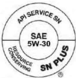
text_image
API SERVICE SN SAE 5W-30 RESOURCE CONSERVING SN PLUSAn oil that displays this symbol conforms to current engine, emission system and fuel economy performance standards of ILSAC.
We recommend Motorcraft® motor oil for your vehicle. If Motorcraft® oil is not available, use motor oils of the recommended viscosity grade that meet API SN PLUS requirements and display the API Certification Mark for gasoline engines.
Do not use supplemental engine oil additives because they are unnecessary and could lead to engine damage that your vehicle warranty does not cover.
E142732
Capacities and Specifications
Capacities
| Including the Oil FilterVariant | |
| 6.0 qt (5.7 L)All. |
Materials
| SpecificationName | |
| Engine Oil - SAE 5W-30 - Super Premium Motor Oil / Huile moteur de très haute qualité SAE 5W-30 Motorcraft® (Canada)XO-5W30-Q1SP (U.S.)CXO-5W30-LSP6 (Canada) | WSS-M2C946-B1Engine Oil - SAE 5W-30 - |
Alternative Engine Oil for Extremely Cold Climates
To improve engine cold start performance, we recommend that you use the following alternative engine oil in extremely cold climates, where the ambient temperature reaches -22.0^ F ( -30^ C) or below.
Capacities and Specifications
Materials
| SpecificationName | |
| WSS-M2C953-B1Engine Oil - SAE 0W-30 |
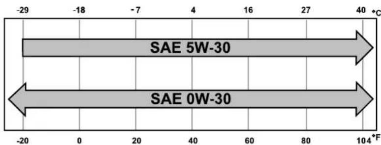
other
| Direction | Value | | --------- | ----- | | SAE 5W-30 | 40 °C | | SAE 0W-30 | 104 °F |Capacities and Specifications
Fuel Tank
Capacities
| QuantityVariant | |
| 18.0 gal (68.1 L)All. |
Grease
Materials
| SpecificationName | |
| Motorcraft® Premium Long-Life Grease / Graisse longue durée de qualité première Motorcraft® (Canada)XG-1-E1 (U.S. & Canada) | ESA-M1C75-BMotorcraft® Premium Long |
| Motorcraft® Multi-Purpose Grease Spray / Graisse tout usage en aérosol Motorcraft® (Canada)XL-5-A (U.S. & Canada) | ESB-M1C93-BMotorcraft® Multi-Purpose |
Capacities and Specifications
Hydraulic Brake System
Note: We recommend using DOT 4 Low Viscosity (LV) High Performance Brake Fluid or equivalent meeting WSS-M6C65-A2. Use of any fluid other than the recommended fluid could cause reduced brake performance and not meet our performance standards. Keep brake fluid clean and dry. Contamination with dirt, water, petroleum products or other materials could result in brake system damage and possible failure.
Materials
| SpecificationName | |
| Motorcraft® DOT 4 LV High Performance Motor Vehicle Brake Fluid / Liquide de frein automobile haute performance DOT 4 LV Motorcraft® (Canada) PM-20 (U.S. & Canada) | WSS-M6C65-A2Motorcraft® DOT 4 LV High Pe |
Locks
Capacities and Specifications
Materials
| SpecificationName | |
| Motorcraft® Penetrating Fluid / Liquide dégrippant Motorcraft® (Canada)XL-1 (U.S.)CXC-51-A (Canada) | -Motorcraft® Penetrating and Lock |
Power Transfer Unit
Capacities
| QuantityVariant | |
| All. | 23.7 fl oz (0.7 L) ^1 |
^1 Contact an authorized dealer for fluid level checking and filling.
Capacities and Specifications
Materials
| SpecificationName | |
| Motorcraft® SAE 75W-140 Synthetic Rear Axle Lubricant / Lubrifiant synthétique pour pont arrière SAE 75W-140 Motorcraft® (Canada)XY-75W140-QL (U.S.)CXY-75W140-1L (Canada) | WSL-M2C192-AMotorcraft® SAE 75W-140 Synt |
Rear Axle
| QuantityTypeVariant | ||
| All. | 1.0 qt (0.95 L)Rear axle fluid. | |
| 1.86 fl oz (55 ml)Rear axle friction modifier. |
^1 For complete refill of our limited slip axles, add 1.86 fl oz (55 ml) of XL-19 - Motorcraft ^® Torque Vectoring RDU Additive. Include this friction modifier in the total fluid capacity.
Capacities and Specifications
Materials
| QuantityVariant | |
| Fill as required.All. |
Capacities and Specifications
Materials
| SpecificationName | |
| Motorcraft® Premium Quality Windshield Washer Fluid / Liquide lave-glace de haute qualité Motorcraft® (Canada)ZC-32-B2 (U.S.)CXC-37-A/B/D/F (Canada) | WSS-M14P19-AMotorcraft® Premium Windshield |
CAPACITIES AND SPECIFICATIONS - 3.7L
Use oil and fluid that meets the defined specification and viscosity grade.
If you do not use oil and fluid that meets the defined specification and viscosity grade, it could result in:
- Component damage not covered by the vehicle warranty.
- Longer engine cranking periods.
- Increased emission levels.
- Reduced engine performance.
- Reduced fuel economy.
- Reduced brake performance.
Air Conditioning System

WARNING: The air conditioning
refrigerant system contains refrigerant under high pressure. Only qualified personnel should service the air conditioning refrigerant system. Opening the air conditioning refrigerant system can cause personal injury.
Capacities
| Refrigerant OilRefrigerantVariant | ||
| 5.24 fl oz (155 ml)20 oz (0.567 kg)All. |
Capacities and Specifications
Materials
| SpecificationName | |
| R-134a Refrigerant / Frigorigène R-134a (Canada)YN-19 (U.S.)CYN-19-R (Canada) | WSH-M17B19-AMotorcraft® R-134a Refrigeration |
| Motorcraft® PAG Refrigerant Compressor Oil / Huile PAG pour compresseur frigori-fique Motorcraft® (Canada)YN-12-D (U.S. & Canada) | WSH-M1C231-BMotorcraft® PAG Refrigeration |
Automatic Transmission
Note: Automatic transmissions that require MERCON ^® LV transmission fluid should only use MERCON ^® LV transmission fluid. The use of any other fluid could cause transmission damage.
Capacities and Specifications
Capacities
| QuantityVariant | |
| All. | 11.6 qt (11 L)1 |
^1 Approximate dry fill capacity. Actual amount could vary during fluid changes.
Materials
| SpecificationName | |
| Motorcraft® MERCON® LV Automatic Transmission Fluid / Huile pour boîte automatique MERCON® LV Motorcraft® (Canada)XT-10-QLVC (U.S.)CXT-10-LV6 (Canada) | MERCON® LV WSS-M2C938-AMotorcraft® MERCON® |
Engine Coolant
Capacities
| QuantityVariant | |
| 10.2 qt (9.7 L)All. |
Capacities and Specifications
Materials
| SpecificationName | |
| Motorcraft® Orange Prediluted Antifreeze/Coolant / Antigel/liquide de refroidissement prédilué orange Motorcraft® (Canada)VC-3DIL-B (U.S.)CVC-3DIL-B (Canada) | WSS-M97B44-D2Motorcraft® Orange Pred |
Engine Oil

text_image
AMERICAN PETROLEUM INSTITUTE FOR GASOLINE ENGINES CERTIFIEDE275759
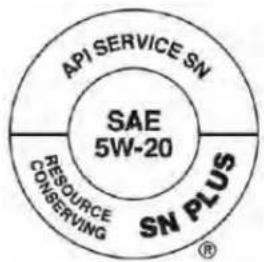
text_image
API SERVICE SN SAE 5W-20 RESOURCE CONSERVING SN PLUSAn oil that displays this symbol conforms to current engine, emission system and fuel economy performance standards of ILSAC.
We recommend Motorcraft ^® motor oil for your vehicle. If Motorcraft ^® oil is not available, use motor oils of the recommended viscosity grade that meet API SN PLUS requirements and display the API Certification Mark for gasoline engines.
Do not use supplemental engine oil additives because they are unnecessary and could lead to engine damage that your vehicle warranty does not cover.
E142732
Capacities and Specifications
Capacities
| Including the Oil FilterVariant | |
| 6.0 qt (5.7 L)All. |
Materials
| SpecificationName | |
| Engine Oil - SAE 5W-20 - Super Premium Motor Oil / Huile moteur de très haute qualité SAE 5W-20 Motorcraft® (Canada)XO-5W20-Q1SP (U.S.)CXO-5W20-LSP6 (Canada) | WSS-M2C945-B1Engine Oil - SAE 5W-20 - Synt |
Alternative Engine Oil for Extremely Cold Climates
To improve engine cold start performance, we recommend that you use the following alternative engine oil in extremely cold climates, where the ambient temperature reaches -22.0^ F ( -30^ C) or below.
Capacities and Specifications
Materials
| SpecificationName | |
| (Canada)XO-0W20-Q1SP (U.S.) | WSS-M2C947-B1Engine Oil - SAE 0W-20 - |
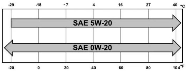
text_image
-29 -18 -7 4 16 27 40 °C SAE 5W-20 SAE 0W-20 -20 0 20 40 60 80 104°FCapacities and Specifications
Fuel Tank
Capacities
| QuantityVariant | |
| 18.0 gal (68.1 L)All. |
Grease
Materials
| SpecificationName | |
| Motorcraft® Premium Long-Life Grease / Graisse longue durée de qualité première Motorcraft® (Canada)XG-1-E1 (U.S. & Canada) | ESA-M1C75-BMotorcraft® Premium Long-Life Grease |
| Motorcraft® Multi-Purpose Grease Spray / Graisse tout usage en aérosol Motorcraft® (Canada)XL-5-A (U.S. & Canada) | ESB-M1C93-BMotorcraft® Multi-Purpose Grease |
Capacities and Specifications
Hydraulic Brake System
Note: We recommend using DOT 4 Low Viscosity (LV) High Performance Brake Fluid or equivalent meeting WSS-M6C65-A2. Use of any fluid other than the recommended fluid could cause reduced brake performance and not meet our performance standards. Keep brake fluid clean and dry. Contamination with dirt, water, petroleum products or other materials could result in brake system damage and possible failure.
Materials
| SpecificationName | |
| Motorcraft® DOT 4 LV High Performance Motor Vehicle Brake Fluid / Liquide de frein automobile haute performance DOT 4 LV Motorcraft® (Canada)PM-20 (U.S. & Canada) | WSS-M6C65-A2Motorcraft® DOT 4 LV High |
Locks
Capacities and Specifications
Materials
| SpecificationName | |
| Motorcraft® Penetrating Fluid / Liquide dégrippant Motorcraft® (Canada)XL-1 (U.S.)CXC-51-A (Canada) | -Motorcraft® Penetrating and Lock Lubr |
Power Transfer Unit
Capacities
| QuantityVariant | |
| All. | 15.2 fl oz (0.45 L)1 |
^1 Contact an authorized dealer for fluid level checking and filling.
Capacities and Specifications
Materials
| SpecificationName | |
| Motorcraft® SAE 75W-140 Synthetic Rear Axle Lubricant / Lubrifiant synthétique pour pont arrière SAE 75W-140 Motorcraft® (Canada)XY-75W140-QL (U.S.)CXY-75W140-1L (Canada) | WSL-M2C192-AMotorcraft® SAE 75W-140 |
Rear Axle
Capacities
| QuantityVariant | |
| 1.0 qt (0.95 L)All. |
Capacities and Specifications
Materials
| SpecificationName | |
| Motorcraft® SAE 80W-90 Premium Axle Lubricant / Lubrifiant pour essieux de très haute qualité SAE 80W-90 Motorcraft® (Canada)XY-80W90-QL (U.S.)CXY-80W90-1L (Canada) | WSP-M2C197-AMotorcraft® SAE 80W-90 Prem |
Washer Reservoir
Capacities
| QuantityVariant | |
| Fill as required.All. |
Capacities and Specifications
Materials
| SpecificationName | |
| Motorcraft® Premium Quality Windshield Washer Fluid / Liquide lave-glace de haute qualité Motorcraft® (Canada)ZC-32-B2 (U.S.)CXC-37-A/B/D/F (Canada) | WSS-M14P19-AMotorcraft® Premium Wind |
BULB SPECIFICATION CHART
The specified replacement bulbs are in the chart below. Headlamp bulbs have an authorized D.O.T. (Department of Transportation) marking for North America to affirm lamp performance, light brightness and pattern and safe visibility. The correct bulbs will not damage the lamp assembly or void the lamp assembly warranty and will provide quality bulb burn time.
Capacities and Specifications
| Trade NumberFunction | |
| Headlamp low and high - HID. ^1 | D3S. |
| Headlamp low and high - LED. ^1 | LED. |
| Sidemarker - front. ^1 | LED. |
| Park lamp - front. ^1 | LED. |
| 7444NA.Direction indicator - front. | |
| Signal indicator mirror lamp. ^1 | LED. |
| Approach lamp. ^1 | LED. |
| Tail and brake lamp ^1 | LED. |
| Direction indicator - rear. ^1 | LED. |
| Backup lamp. ^1 | LED. |
| License plate lamp. ^1 | LED. |
Capacities and Specifications
| Trade NumberFunction | |
| High-mount brake lamp.1 | LED. |
| Interior lamps.1 | LED. |
^1 To replace these lamps, see an authorized dealer.
Note: To replace instrument panel lights, see an authorized dealer.
Vehicle Identification
INSTALLING THE VEHICLE IDENTIFICATION CARD
Install the vehicle identification card to the specified area on the windshield.
Note: Follow the manufacturer's installation instructions.
Note: When installing the radio frequency identification device, do not block objects such as the rain sensor and the auto-dimming sensor.
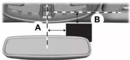
text_image
A BE292412
| DimensionDimension DescriptionIt | ||
| 1 in (25 mm)The center of the win | ||
| 2 in (40 mm)The top edge of the v |
Network Connectivity
CONNECTING THE VEHICLE TO A MOBILE NETWORK
What Is the Modem
The modem allows you to connect your vehicle to the Internet to use when you are on the road.
If you enable the modem using the Lincoln Way app, you can access the following services:
- Locating and remotely starting, locking and unlocking your vehicle. See the information in the Lincoln Way app.
•Automatic system updates.
Note: We may need to update operating system software on your vehicle to keep connected services updated without prior notice to you.
Enabling the Modem Using The Lincoln Way
-
Open the Lincoln Way app on your device and log in.
-
Select your vehicle.
-
Select the option for vehicle details.
-
Select the option to activate your vehicle.
-
Switch the ignition on.
-
Make sure that the name on the screen matches the name shown in your Lincoln Way account.
-
Confirm the association of your vehicle with your Lincoln Way account.
Enabling the Modem Using the Touchscreen

Select the settings option on the feature bar.
-
Select FordPass Connect.
-
Select Connectivity Settings.
-
Switch connectivity features on.
Network Connectivity
NETWORK CONNECTIVITY - TROUBLESHOOTING
Wi-Fi Network
| Possible Cause and ResolutionSymptom | |
| I cannot connect to a Wi-Fi network. -Password error.Enter the correct network password.-Weak network signal.Move your vehicle closer to the Wi-Fi hotspot or to a place where the network signal is not obstructed.-Multiple access points in range with the same SSID.Use a unique name for your SSID,. Do not use the default name unless it contains a unique identifier, for example as part of the MAC address. | |
| The Wi-Fi connection disconnects after successful connection. | -Weak network signal.Move your vehicle closer to the Wi-Fi hotspot or to a place where the network signal is not obstructed. |
| I am close to a Wi-Fi hotspot but the network signal strength is weak. | -Obstructed network signal.If your vehicle has a heated windshield, position your vehicle so that the windshield is not facing the Wi-Fi hotspot.If your vehicle has metallic tinting on the windows but not on the windshield, position your vehicle so that the windshield is facing the Wi-Fi hotspot or open the windows that are facing the hotspot. |
Network Connectivity
| Possible Cause and ResolutionSymptom | |
| ·If your vehicle has metallic tinting on the windows and the windshield, open the windows that are facing the hotspot.·If your vehicle is in a garage and you have the garage door closed, open the garage door. | |
| I cannot see a network in the list of available networks that I expect to see. | -Hidden network.·Make the network visible and try again. |
| I cannot see the Wi-Fi Hotspot name when I search for Wi-Fi networks on my cell phone or other device. | -System limitation.·Make sure Wi-Fi hotspot visibility is on.·The system does not provide a Wi-Fi hotspot at this time. |
| Software downloads take too long. | -Weak network signal·Move your vehicle closer to the Wi-Fi hotspot or to a place where the network signal is not obstructed.-Wi-Fi hotspot in high demand or has a slow Internet connection.·Use an more reliable Wi-Fi hotspot. |
| The system seems to connect to a Wi-Fi network and the signal strength is excellent but the software does not update. | -No software update available.-Wi-Fi network requires a subscription or acceptance of terms and conditions.·Test the connection using another device. If the network requires a subscription or acceptance of terms and conditions, contact the network service provider. |
Network Connectivity
Mobile Network
| Possible Cause and ResolutionSymptom | |
| I cannot confirm association with Lincoln Way when trying to enable the modem. | -Modem is not enabled.•Enable the modem through Lincoln Way.-Weak network signal.•Move your vehicle closer to a place where the network signal is not obstructed. |
Wi-Fi Hotspot
CREATING A WI-FI HOTSPOT
You can create a Wi-Fi hotspot in your vehicle and allow devices to connect to it for access to the Internet.

Press the button to enter the settings menu.
- Select Lincoln Connect.
- Select Vehicle Hotspot.
Note: The vehicle hotspot default setting is on.
Finding the Wi-Fi Hotspot Name and Password

Press the button to enter the settings menu.
- Select Lincoln Connect.
- Select Vehicle Hotspot.
- Select Settings.
Note: The SSID is the hotspot name.
- Select View Password.
Connecting a Device to the Wi-Fi Hotspot
- On your device, turn on Wi-Fi and select the hotspot from the list of available Wi-Fi networks.
- When prompted, enter the password.
Purchasing a Data Plan
- Connect a device to the hotspot.
Note: The vehicle network carrier's portal opens on your device. - If the portal does not open on your device, open a website and it redirects to the vehicle network carrier's portal.
Note: Secure websites do not redirect.
- Follow the instructions on the carrier portal to purchase a plan.
Note: If you have an active plan, the system does not redirect to the vehicle network carrier's portal when you connect a device. Visit the vehicle network carrier's website to purchase more data.
Note: If data usage information is available in the vehicle hotspot menu, it is approximate.
Note: If you carry out a master reset, the system does not remove your vehicle from your vehicle network carrier's account. To remove your vehicle from the account, contact your vehicle network carrier.
Note: The vehicle network carrier provides Vehicle Hotspot services, subject to your vehicle network carrier agreement, coverage and availability.
CHANGING THE WI-FI HOTSPOT NAME OR PASSWORD

Press the button to enter the settings menu.
- Select Lincoln Connect.
- Select Vehicle Hotspot.
- Select Settings.
- Select Edit .
- Select Change SSID Name.
Wi-Fi Hotspot
- Enter your required SSID.
- Select Done.
- Select Change Password.
- Enter your required password.
- Select Done.
Audio System
GENERAL INFORMATION
Radio Frequencies and Reception Factors

WARNING: Driving while distracted
can result in loss of vehicle control, crash and injury. We strongly recommend that you use extreme caution when using any device that may take your focus off the road. Your primary responsibility is the safe operation of your vehicle. We recommend
against the use of any hand-held device while driving and encourage the use of voice-operated systems when possible. Make sure you are aware of all applicable local laws that may affect the use of electronic devices while driving.
Note: Listening to loud audio for long periods of time could damage your hearing.
| Radio Reception Factors | |
| Distance and strength | The further you travel from an AM or FM station, the weaker the signal and the weaker the reception. |
| Terrain | Hills, mountains, tall buildings, bridges, tunnels, freeway overpasses, parking garages, dense tree foliage and thunderstorms can interfere with the reception. |
| Station overload | When you pass a ground-based broadcast repeating tower, a stronger signal may overtake a weaker one and result in the audio system muting. |
Audio System
AUDIO UNIT

WARNING: Driving while distracted can result in loss of vehicle control, crash and injury. We strongly recommend that you use extreme caution when using any device that may take your focus off the road. Your primary responsibility is the safe operation of your vehicle. We recommend against the use of any hand-held device while driving and encourage the use of voice-operated systems when possible. Make sure you are aware of all applicable local laws that may affect the use of electronic devices while driving.
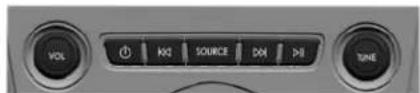
text_image
VOLT KG SOURCE DOI >I TUNEE287755
Note: Depending on your vehicle option package, the controls may look different from what you see here.
Note: The touchscreen system controls most of the audio features.
Adjusting the Volume
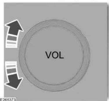
text_image
VOL E265373Turn to adjust the volume.
Changing Radio Stations
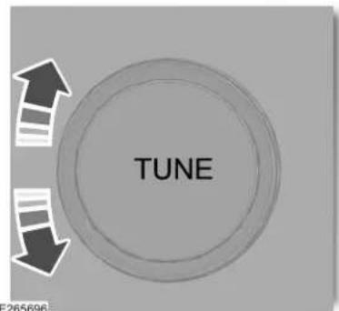
text_image
TUNE 265696In radio mode, turn to search through the radio frequency band.
In satellite radio mode, turn to find the previous or next available satellite radio station.
Ejecting the CD (If Equipped)

Press and release the button to eject a CD.
Audio System
Inserting a CD (If Equipped)
Insert a CD into the CD slot.
Note: The CD player slot is in the front storage compartment. See Center Console (page 183).
Selecting the Audio Modes

Press and release the button to access different audio modes, for example AM, FM and CD.
Setting a Memory Preset
Tune to a station then press and hold one of the memory preset buttons on the touchscreen. The audio mutes briefly while the system saves the station and returns once the station is stored.
Switching the Audio Unit On and Off

Press and release the button.
Using Seek, Fast Forward and Reverse
In radio mode, select a frequency band and press and release either button. The system stops at the first station it finds in that direction.
In CD mode, press and release to select the next or previous track. Press and hold to move quickly forward or backward through the current track.
In satellite radio mode, press and release to select the next or previous satellite radio station. If you select a specific category, such as jazz, rock or news, press to find the next or previous station in the category you select.
Rear Passenger Audio Controls (If Equipped)
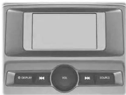
natural_image
Top-down view of a car dashboard with control buttons (DISPLAY, VOL, SOURCE) and a blank screen area (no readable text or symbols beyond basic icons)E289983
Note: Depending on your vehicle option package, the controls may look different from what you see here.
Audio System
Adjusting the Volume
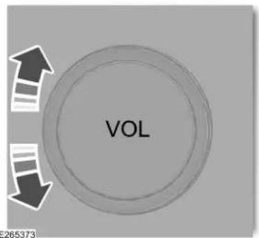
text_image
VOL 265373Turn to adjust the volume.
Using Seek, Fast Forward and Reverse
In radio mode, press either button to scroll through the presets from the front radio. To select a radio station, press and hold to move quickly forward or backward through the radio stations.
In CD or USB mode, press to select the next or previous track. Press and hold to move quickly forward or backward through the selected media source.
Selecting the Audio Modes

Press and release the button to access different media modes, for example AM, FM, CD, and USB.
Switching the Display On and Off

Press and release the button.
DIGITAL RADIO (IF EQUIPPED)
Note: HD Radio broadcasts are not available in all markets.
HD Radio technology is the digital evolution of analog AM/FM radio. Your system has a special receiver that allows it to receive digital broadcasts, where available, in addition to the analog broadcasts, it already receives. Digital broadcasts provide a better sound quality than analog broadcasts with free, crystal-clear audio and no static or distortion. For more information, and a guide to available stations and programming, please visit www.hdradio.com.
When HD Radio is on and you tune to a station broadcasting HD Radio technology, you may notice the HD Radio logo on your screen. When this logo is available, you may also see Title and Artist fields on-screen.
Audio System
The multicast indicator appears in FM mode, only, if the current station is broadcasting multiple digital broadcasts. The highlighted numbers signify available digital channels where new or different content is available. HD1 signifies the main programming status and is available in analog and digital broadcasts. Other multicast stations, HD2 through HD7, are only available digitally.
When HD Radio broadcasts are active, you can access the following functions:
- Memory presets allow you to save an active channel as a memory preset. Touch and hold a memory preset slot until the sound returns. There is a brief mute while the radio saves the station. Sound returns when finished. When switching to an HD2 or HD3 memory preset, the sound mutes before the digital audio plays, because the system has to reacquire the digital signal.
Note: As with any saved radio station, you cannot access the saved station if your vehicle is outside the station's reception area.
HD Radio Reception and Station Troubleshooting
| Potential reception issues | |
| Reception area | If you are listening to a multicast station and you are on the fringe of the reception area, the station may mute due to weak signal strength. |
| If you are listening to HD1, the system switches back to the analog broadcast until the digital broadcast is available again. However, if you are listening to any of the possible HD2-HD7 multicast channels, the station mutes and stays muted unless it is able to connect to the digital signal again. | |
| Station blending | When the system first receives a station, aside from HD2-HD7 multicast stations, it first plays the station in the analog version. Once the receiver verifies the station is an HD Radio station, it shifts to the digital version. Depending on the station quality, you may hear a slight sound change when the station changes from analog to digital. Blending is the shift from analog to digital sound or digital back to analog sound. |
Audio System
In order to provide the best possible experience, use the contact form to report any station issues found while listening to a station broadcasting with HD Radio
technology. Independent entities own and operate each station. These stations are responsible for the accuracy of all audio streams and data fields.
| Potential station issues | ||
| ActionCauselssues | ||
| Echo, stutter, skip or repeat in audio. Increase or decrease in audio volume. | broadcaster. | No action required. This is a broadcast issue.T |
| Sound fading or blending in and out. | The radio is shifting between analog and digital audio. | No action required. The reception issue may clear up as you continue to drive. |
| There is an audio mute delay when selecting HD2 or HD3, multicast preset or Direct Tune. | The digital multicast is not available until the HD Radio broadcast is decoded. Once decoded, the audio is available. | No action required. This is normal behavior. Wait until the audio is available. |
| Cannot access HD2 or HD3 multicast channel when recalling a preset or from a direct tune. | The previously stored multicast preset or direct tune is not available in your current reception area. | No action required. The station is not available in your current location. |
| playing audio. | Data service issue by the radio broadcaster.T | File of the station is not for at website listed below. ^1 |
| currently selected frequency. | Data service issue by the radio broadcaster.T | File of the station is not for at website listed below. ^1 |
his is poor
^1 http://hdradio.com/stations/feedback
Audio System
HD Radio Technology manufactured under license from iBiquity Digital Corporation and foreign patents. HD Radio and the HD and HD Radio logos are proprietary trademarks of DTS Ford Motor Company and DTS are not responsible for the content sent using HD Radio technology. Content may be changed, added or deleted at any time at the station owner's discretion.
SATELLITE RADIO
SiriusXM® Satellite Radio broadcasts a variety of music, news, sports, weather, traffic and entertainment satellite radio channels. For more information and a complete list of SiriusXM satellite radio channels, visit www.siriusxm.com in the United States, www.siriusxm.ca in Canada, or call SiriusXM at 1-888-539-7474.
Note: This receiver includes the eCos real-time operating system. eCos is published under the eCos License.
Satellite Radio Reception Factors
| Potential satellite radio reception issues | |
| Antenna obstructions | For optimal reception performance, keep the antenna clear of snow and ice build-up and keep luggage and other material as far away from the antenna as possible. |
| Terrain | Hills, mountains, tall buildings, bridges, tunnels, freeway overpasses, parking garages, dense tree foliage and thunderstorms can interfere with your reception. |
| Station overload | When you pass a ground-based broadcast-repeating tower, a stronger signal may overtake a weaker one and the audio system may mute. |
| Satellite radio signal interference | Your display may show ACQUIRING . . . to indicate the interference and the audio system may mute. |
Audio System
SiriusXM Satellite Radio Service
Note: SiriusXM reserves the unrestricted right to change, rearrange, add or delete programming including canceling, moving or adding particular channels, and its prices, at any time, with or without notice to you. Ford Motor Company shall not be responsible for any such programming changes.
E208625
SiriusXM satellite radio is a subscription-based satellite radio service that broadcasts a variety of music, sports, news, weather, traffic and entertainment programming. Your factory-installed SiriusXM satellite radio system includes hardware and a limited subscription term, which begins on the date of sale or lease of your vehicle. See an authorized dealer for availability.
For more information on extended subscription terms (a service fee is required), the online media player and a complete list of SiriusXM satellite radio channels, and other features, please visit www.siriusxm.com in the United States, www.siriusxm.ca in Canada, or call SiriusXM at 1-888-539-7474.
Satellite Radio Electronic Serial Number (ESN)
You need your ESN to activate, modify or track your satellite radio account.
Locating Your ESN
With satellite radio as the source, use the touchscreen to select the following:
- Select Settings. See Settings (page 495).
- Select SiriusXM.
- Select SiriusXM information.
Audio System
Troubleshooting
| ActionConditionMessage | ||
| Acquiring... | Radio requires more than two seconds to produce audio for the selected channel. | No action required. This message should disappear shortly. |
| Satellite antenna faultSIRIUS system failure | There is an internal module or system failure present. | If this message does not clear shortly, or with an ignition key cycle, your receiver may have a fault. See an authorized dealer for service. |
| The channel is no longer available.Invalid Char | True to another channel or choose another preset. | |
| Unsubscribed Channel | Your subscription does not include this channel. | Contact SiriusXM at 1-888-539-7474 to subscribe to the channel, or tune to another channel. |
| No Signal | The signal is lost from the SiriusXM satellite or SiriusXM tower to your vehicle antenna. | The signal is blocked. When you move into an open area, the signal should return. |
| Update of channel programming in progress. | Undation required. The process may take up to three minutes. | |
| 1-888-539-7474 | Your satellite service is no longer available.Qu | Estimate SiriusXM at 1-888-539-7474 to resolve subscription issues. |
Audio System
| ActionConditionMessage | ||
| None foundCheck Channel Guide | All the channels in the selected category are either skipped or locked. | Use the channel guide to turn off the Lock or Skip function on that station. |
| Subscription Updated | for your vehicle. | No action required.SiriusXM has updated the channels a |
USB PORT

WARNING: Driving while distracted
can result in loss of vehicle control, crash and injury. We strongly recommend that you use extreme caution when using any device that may take your focus off the road. Your primary responsibility is the safe operation of your vehicle. We recommend against the use of any hand-held device while driving and encourage the use of voice-operated systems when possible. Make sure you are aware of all applicable local laws that may affect the use of electronic devices while driving.
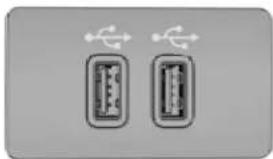
natural_image
Two identical rectangular electronic components with AC/DC connectors, no text or symbols visibleE242003
The USB Port is below the climate control and in the center console.
You can use the USB port to play media and charge a device.
SYNC ^TM 3
GENERAL INFORMATION

WARNING: Driving while distracted can result in loss of vehicle control, crash and injury. We strongly recommend that you use extreme caution when using any device that may take your focus off the road. Your primary responsibility is the safe operation of your vehicle. We recommend against the use of any hand-held device while driving and encourage the use of voice-operated systems when possible. Make sure you are aware of all applicable local laws that may affect the use of electronic devices while driving.
About SYNC
The system allows you to interact with the entertainment, information and communication systems on your vehicle using voice commands and a touchscreen. The system provides easy interaction with audio, phone, navigation, mobile apps and settings.
Note: You can switch the system on and use it for up to an hour without switching the ignition on.
Note: You can use the system after you switch the ignition off for up to 10 minutes or until you open a door.
Note: For your safety, some features are speed-dependent. Their use is limited to when your vehicle speed is less than 3 mph (5 km/h).
Using the Touchscreen
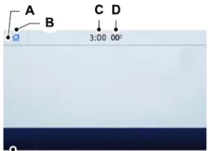
text_image
A B C D 3:00 00°E
Status bar.A
Home screen.B
Clock. See Settings (page 495).C
Outside air temperature.D
Feature bar.E
SYNC ^TM 3
Status Bar

Cell phone microphone muted.

Audio system muted.

Software update installed.

Wi-Fi connected.

Cell phone roaming.

Text message received.

Automatic crash notification system off.

Cell phone network signal strength.
Feature Bar

Select to use the radio, a USB, a media player or a Bluetooth device. See Entertainment (page

Select to adjust climate settings See Climate (page 479).

Select to make calls and access the phonebook on your cell phone. See Phone (page 482).

Select to use the navigation system. See Navigation (page 484).

Select to search for and use compatible apps on your iOS or Android device. See Apps (page

Select to adjust system settings. See Settings (page 495).
Cleaning the Touchscreen
See Cleaning the Interior (page 354).
Updating the System
Updating the System Using a USB Drive
Downloading an Update
-
Go to the SYNC update page on the local Ford website.
-
Download the update.
Note: The website notifies you if an update is available.
- Insert a USB drive into your computer.
Note: The USB drive needs to be empty and meet the minimum requirements detailed on the website.
- Follow the instructions provided to download the update to the USB drive.
Installing an Update
Note: You can use the system when an installation is in progress.
-
Disconnect all other USB devices from the USB ports.
-
Connect the USB drive with the update to a USB port.
SYNC ^TM 3
Note: Installation starts automatically within 10 minutes.
Updating the System Using a Wi-Fi Network Connection
Connecting to a Wi-Fi Network

Select the settings option on the feature bar.
- Select Automatic Updates.
- Select System Wi-Fi.
- Switch System Wi-Fi on.
- Select Available Wi-Fi Networks.
- Select an available Wi-Fi network.
Note: Enter the network password to connect to a secure network.
Switching Automatic System Updates On

Select the settings option on the feature bar.
- Select Automatic Updates.
- Switch Automatic System Updates on.
The system is now set to check for and receive system updates when it is connected to a Wi-Fi network.
Note: You can use the system when a download is in progress.
Note: If the system is disconnected from the Wi-Fi network when a download is in progress, the download continues the next time the system is connected to a Wi-Fi network.
Additional Information and Assistance
For additional information and assistance, we recommend that you contact an authorized dealer or refer to the local Ford website.
The system allows you to interact with the entertainment, information and communication systems on your vehicle using voice commands. This allows you to keep your hands on the steering wheel and focus on what is in front of you.

Press the voice control button on the steering wheel and wait for the voice prompt.
Note: Press the voice control button again to interrupt a voice prompt and begin speaking.
Note: Turn the volume control when a voice prompt plays to adjust the volume.
Note: Press and hold the voice control button on the steering wheel to use Siri on your iOS device.
The following voice commands are designed to help you from any screen:
• List of Commands
•Help
The following tables list some of the more frequently used voice commands. For a complete list of voice commands, refer to our website.
SYNC ^TM 3
General
| DescriptionVoice Command | |
| ____ List of Commands | Get a list of voice commands for a specific feature. ^1 |
| Cancel an active voice session.Cancel | |
| ____ Help | Get a list of voice commands for a specific feature. ^1 |
| Return to the previous screen.Go back | |
| Go to the main menu.Main Menu | |
| Go to the next page.Next Page | |
| Go to the previous page.Previous Page |
^1 Add the name of the feature to the command.
SYNC ^TM 3
Entertainment
Audio Source
| DescriptionVoice Command | |
| Use the radio.Radio | |
| Use the CD player.CD Player | |
| Use a Bluetooth device.Bluetooth Stereo | |
| Use a USB or media player.USB |
Radio
| DescriptionVoice Command | |
| Listen to AM radio.AM | |
| AM _ | Tune to a specific AM frequency. ^1 |
| Sirius Channel _ | Listen to SiriusXM radio. ^2 |
SYNC ^TM 3
| DescriptionVoice Command | |
| Listen to FM radio.FM | |
| FM ___ | Tune to a specific FM frequency. ^1 |
^1 Add the radio frequency to two decimal places to the command.
^2 You can say the Sirius channel name or number such as "Sirius Channel 16" or "Sirius The Pulse".
USB and Media Player
| DescriptionVoice Command | |
| Play Album __ | Play your music by category. ^1 |
| Play Artist __ | |
| Play Genre __ | |
| Play Playlist __ | |
| Play Song __ | |
| Play Audiobook __ | |
| Play Podcast __ | |
| Browse All Albums | Browse music on a USB device. |
| Browse All Artists |
SYNC ^TM 3
| DescriptionVoice Command | |
| Browse All Audiobooks | |
| Browse All Genres | |
| Browse All Playlists | |
| Browse All Podcasts | |
| Browse All Songs | |
| Browse Album ____ | Browse your music by category on a USB device. ^1 |
| Browse Artist ____ | |
| Browse Audiobook ____ | |
| Browse Genre ____ | |
| Browse Playlist ____ | |
| Browse Podcast ____ |
^1 Add an album name, artist name, audiobook name, genre name, playlist name, podcast name or track name to the command. Say the name exactly as it appears on your device.
Climate (If Equipped)
____ is a dynamic listing, meaning that for climate voice commands it can be the desired degrees for the temperature setting.
You can control the temperature of the vehicle using voice commands.
SYNC ^TM 3
To adjust the temperature, say:
| DescriptionVoice command | |
| Set Temperature ___ | Adjust the temperature between 60–85°F (15.5–29.5°C). |
Phone
| DescriptionVoice Command | |
| Pair a cell phone or Bluetooth enabled device.Pair Phone | |
| Redial the last number that you dialed.Redial | |
| Dial __ | Dial a number.^1 |
| Call __ | Call a specific contact from your phonebook. ^2 |
| Call __ __ | Call a specific contact from your phonebook at a specific location. ^3 |
| Listen to a text message.Listen to Message |
SYNC ^TM 3
| DescriptionVoice Command | |
| Listen to a specific text message from a list of text messages.Listen to Message ____ | |
| Reply to the last text message.Reply to Message |
^1 Add the number you want to dial to the command.
^2 Add a contact name from your phonebook to the command. Say the first and last name of your contact exactly as it appears on your device.
^3 Add a contact name and location from your phonebook to the command. Say the first and last name of your contact exactly as it appears on your device.
SYNC ^TM 3
Navigation (If Equipped)
Setting a Destination
| DescriptionVoice Command | |
| Find an Address | Enter a destination address. When prompted, provide the house number, the street and city. |
| Search for a point of interest by name or by category.Find a Place | |
| Find the Next _ | Search for a nearby point of interest by category.^1 |
| Find a POI Category | Search for a point of interest category.^1 |
| Set your saved home address as your destination.Drive Home | |
| Set your saved place of work as your destination.Drive to Work | |
| Display and select from a list of previous destinations.Show Previous Destinations | |
| Display and select from a list of favorite destinations.Show Favorites |
^1 Add a point of interest category or the name of a major brand or chain to the command.
SYNC ^TM 3
Route Guidance
| DescriptionVoice Command | |
| Cancel the current route.Cancel Route | |
| Select an alternate route.Detour | |
| Repeat the last guidance prompt.Repeat Instruction | |
| Display an overview of the route.Show Route | |
| Display a list of traffic events on your route.Show Traffic | |
| Display the map on the touchscreen.Show Map | |
| Display a two-dimensional map with north toward the top of the touchscreen.North | |
| Heading Up | Display a two-dimensional map with the direction you are traveling toward the top of the touchscreen. |
| Show 3D | Display a three-dimensional map with the direction you are traveling toward the front. |
SYNC ^TM 3
Apps
General
| DescriptionVoice Command | |
| Start an app. The system prompts your for the app name.Mobile Applications | |
| Get a list of apps running on your device.List Applications | |
| Search and connect to apps running on your device.Find Applications |
Active App
| DescriptionVoice Command | |
| ____ Help | Get a list of voice commands for a specific app. ^1 |
| Exit ____ | Close an app. ^1 |
^1 Add an app name to the command.
SYNC ^TM 3
SiriusXM Traffic and Travel Link (If Equipped)
| DescriptionVoice command | |
| Displays a list of traffic incidents.Show Traffic | |
| Displays the current weather map.Show Weather Map | |
| Displays a list of fuel prices.Show Fuel Prices | |
| cast | Displays the 5 day weather forecast.Show 5 Day Fore- |
Voice Settings
| DescriptionVoice Command | |
| Go to the voice settings menu.Voice Settings | |
| Switch long voice prompts on.Interaction Mode Novice | |
| Switch short voice prompts on.Interaction Mode Advanced | |
| Phone Confirmation On | Switch call confirmation on. The system prompts you to confirm before making a call. |
SYNC ^TM 3
| DescriptionVoice Command | |
| Phone Confirmation Off | Switch call confirmation off. The system does not prompt you to confirm before making a call. |
| Switch the display of voice commands on.Voice Command Lists On | |
| Switch the display of voice commands off.Voice Command Lists Off |
Automatic Blower Motor Speed Reduction
If necessary, the system decreases the blower motor speed when you are using voice commands to reduce the amount of background noise in your vehicle. It returns to normal when you are finished.
Switching Automatic Blower Motor Speed Reduction Off
Simultaneously press the A/C and recirculated air buttons.
SYNC ^TM 3
ENTERTAINMENT
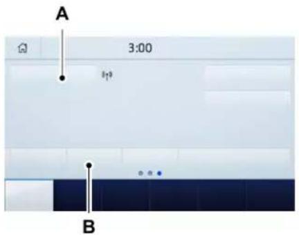
text_image
A 3:00 BA Audio source. Select to choose a different audio source.
B Presets. Swipe left to view more presets.
You can access these options using the touchscreen or voice commands.
Sources
Press this button to select the source of media you want to listen to.
| Menu Item | |
| AM | |
| FM | |
| SIRIUS 1 | |
| CD 1 |
SYNC ^TM 3
| Menu Item | |
| The name of the USB that is plugged in displays here.USB | |
| Bluetooth Stereo | |
| If you have SYNC 3 compatible apps on your connected smart phone, they display here as individual source selections. Apps | |
^1 This feature may not be available in all markets and requires an active subscription.
AM/FM Radio
Tuning a Station
You can use the tune or seek controls on the radio bezel to select a station.
To tune a station using the touchscreen, select:
| Menu Item |
| Direct Tune |
A pop up appears, allowing you to type in the frequency of a station. You can only enter a valid station for the source you are currently listening to.
You can press the backspace button to delete the previously entered number.
Once you have entered the station's call numbers, you can select:
| Menu Item | Action and Descrip-tion |
| Enter | Press to begin playing the station you have entered. |
| Cancel | Press to exit without changing the station. |
Presets
To set a new preset, tune to the station and then press and hold one of the memory preset buttons. The audio mutes briefly while the system saves the station and then returns.
SYNC ^TM 3
You may be able to add additional preset pages using the settings option on the feature bar.
SiriusXM® Satellite Radio (If Activated)
Note: This feature may not be available in all markets and requires an active subscription.

text_image
((SiriusXM™)) SATELLITE RADIOE234451
SiriusXM satellite radio is a subscription-based satellite radio service that broadcasts a variety of music, sports, news, weather, traffic and entertainment programming. Your factory-installed SiriusXM satellite radio system includes hardware and a limited subscription term that begins on the date of sale or lease of your vehicle. See an authorized dealer for availability.
For more information on extended subscription terms (a service fee is required), the online media player and a list of SiriusXM satellite radio channels, and other features, please visit www.siriusxm.com in the United States, www.siriusxm.ca in Canada, or call SiriusXM at 1-888-539-7474.
Note: SiriusXM reserves the unrestricted right to change, rearrange, add or delete programming. This includes canceling, moving or adding particular channels, and its prices, at any time, with or without notice to you. We are not responsible for any such programming changes.
Note: This receiver includes the eCos real-time operating system. eCos is published under the eCos License.
The following buttons are available for SiriusXM:
| Action and DescriptionMenu Item | ||
| Touch this button to see a list of available stations.Browse | ||
| A pop-up appears, allowing you to type in the call numbers of a station.Direct TuneOnce you enter the stations call numbers, you can select: | ||
| The system tunes to the station you select.Enter | ||
| You exit the pop-up and the current station continues to play.Cancel | ||
SYNC ^TM 3
| Action and DescriptionMenu Item | ||
| You can press the backspace button to delete the previous number. | ||
| Replay | Replay audio on the current channel. You can replay approximately 45 minutes of audio as long as you remain tuned to the current station. Changing stations erases the previous audio. | |
| Live | When you are in replay mode, you are not able to select a different preset until you return to live audio. Pressing this button returns you to the live broadcast. | |
| ALERT | Save the current song, artist, or team as a favorite. The system alerts you when it plays again on any channel.Selecting this button allows you to enable and edit alerts. See Settings (page 495). | |
Memory Presets
To set a preset, tune to the station then press and hold one of the memory preset buttons. The audio mutes briefly while the system saves the station and returns once the station is stored.
You may be able to add additional preset pages using the settings option on the feature bar.
Satellite Radio Electronic Serial Number (ESN)
You need your ESN to activate, modify or track your satellite radio account. See Settings (page 495).
SYNC ^TM 3
SiriusXM Satellite Radio Reception Factors and Troubleshooting
| Potential Reception Issues | |
| Antenna obstructions | For optimal reception performance, keep the antenna clear of snow and ice build-up and keep luggage and other materials as far away from the antenna as possible. |
| Terrain | Hills, mountains, tall buildings, bridges, tunnels, freeway overpasses, parking garages, dense tree foliage and thunderstorms can interfere with your reception. |
| Station overload | When you pass a ground-based broadcast-repeating tower, a stronger signal may overtake a weaker one and the audio system may mute. |
| Satellite radio signal interference | Your display may show ACQUIRING... to indicate the interference and the audio system may mute. |
| Troubleshooting Tips | ||
| ActionCauseMessage | ||
| Acquiring Signal | Radio requires more than two seconds to produce audio for the selected channel. | No action required. This message should disappear shortly. |
| Satellite antenna faultSIRIUS system failure | There is an internal module or system failure present. | If this message does not clear shortly, or with an ignition key cycle, your receiver may have a fault. See an authorized dealer for service. |
| Invalid Channel | The channel is no longer available. | Tune to another channel or choose another preset. |
SYNC ^TM 3
| Troubleshooting Tips | ||
| ActionCauseMessage | ||
| Your subscription does not include this channel. | Cobert-SiduXMmall-888-539-7474 to subscribe to the channel, or tune to another channel. | |
| Satellite acquiring signal... | The signal is lost from the SiriusXM satellite or SiriusXM tower to your vehicle antenna. | The signal is blocked. When you move into an open area, the signal should return. |
| Update of channel programming in progress. | No action required. The process may take up to three minutes. | |
| Your satellite service is no longer available. | Cobert-SiduXMmall-888-539-7474 to resolve subscription issues. | |
| None found. Check channel guide. | All the channels in the selected category are either skipped or locked. | Use the channel guide or the Sirius XM Settings tile to turn off the Lock or Skip function on that station. |
| SIRIUS Subscription updated | your vehicle. | No action required.SiriusXM has updated the channels available |
HD Radio™ Information (If Available)
Note: HD Radio broadcasts are not available in all markets.
To activate HD radio, please see the Radio Settings in the Settings Chapter. See Settings (page 495).
HD Radio technology is the digital evolution of analog AM/FM radio. Your system has a special receiver that allows it to receive digital broadcasts (where available) in addition to the analog broadcasts, it already receives. Digital broadcasts provide a better sound quality than analog broadcasts with free, crystal-clear audio and no static or distortion. For more information, and a guide to available stations and programming, please visit:
Website
www.hdradio.com
When HD Radio is on and you tune to a station broadcasting HD Radio technology, you may notice the following indicators on your screen:

E142616
The HD logo is grey when acquiring a digital station, and then changes to orange when digital audio is playing. When this logo is available, you may also see Title and Artist fields on-screen.
The multicast indicator appears in FM mode (only) if the current station is broadcasting multiple digital broadcasts. The highlighted numbers signify available digital channels where new or different content is available. HD1 signifies the main programming status and is available in analog and digital broadcasts. Other multicast stations (HD2 through HD7) are only available digitally.
Note: There is also an additional feature for stations that have more than 1 HD multicast (For example, HD1 or HD2). The HD logo and Radio text appears as a button. Pressing this button allows you to cycle through all of the HD stations on that specific frequency. For example, if you are on 101.1 and it has HD1, HD2, HD3, pressing the button repeatedly causes the radio to cycle through the HD stations in a cyclic increasing order.
SYNC ^TM 3
When HD Radio broadcasts are active, you can access the following functions:
| Action and DescriptionMessage | |
| Presets | Allows you to save an active channel as a memory preset. Touch and hold a memory preset slot until the sound returns. There is a brief mute while the radio saves the station. Sound returns when the channel saves. When switching to an HD2 or HD3 memory preset, the sound mutes before the digital audio plays, because the system has to reacquire the digital signal. |
Note: As with any station you save, you cannot access the saved station if your vehicle is outside the station's reception area.
HD Radio Reception and Station Troubleshooting
| Potential Reception Issues | |
| Reception area | If you are listening to a multicast station and you are on the fringe of the reception area, the station may mute due to weak signal strength. |
| If you are listening to HD1, the system changes back to the analog broadcast until the digital broadcast is available again. However, if you are listening to any of the possible HD2-HD7 multicast channels, the station mutes and stays muted unless it is able to connect to the digital signal again. | |
| Station blending | When the system first receives a station (aside from HD2-HD7 multicast stations), it first plays the station in the analog version. Once the receiver verifies the station is an HD Radio station, it shifts to the digital version. Depending on the station quality, you may hear a slight sound change when the station changes from analog to digital. Blending is the shift from analog to digital sound or digital back to analog sound. |
SYNC ^TM 3
In order to provide the best possible experience, use the contact form to report any station issues found while listening to a station broadcasting with HD Radio
technology. Independent entities own and operate each station. These stations are responsible for ensuring all audio streams and data fields are accurate.
| Potential Station Issues | ||
| ActionCauselssues | ||
| Echo, stutter, skip or repeat in audio. Increase or decrease in audio volume. | caster. | No action required. This is a broadcast issue.This |
| Sound fading or blending in and out. | The radio is shifting between analog and digital audio. | No action required. The reception issue may clear up as you continue to drive. |
| There is an audio mute delay when selecting HD2 or HD3, multicast preset or Direct Tune. | The digital multicast is not available until the HD Radio broadcast is decoded. Once decoded, the audio is available. | No action required. This is normal behavior. Wait until the audio is available. |
| Cannot access HD2 or HD3 multicast channel when recalling a preset or from a direct tune. | The previously stored multicast preset or direct tune is not available in your current reception area. | No action required. The station is not available in your current location. |
| currently playing audio. | Data service issue by the radio broadcaster.Text information does not match Fill out the station issue form. | |
| for currently selected frequency. | Data service issue by the radio broadcaster.There is no text information shown Fill out the station issue form. | |
^1 You can find the form here:
SYNC ^TM 3
| Website |
| http://hdradio.com/stations/feedback |
HD Radio Technology manufactured under license from iBiquity Digital Corporation and foreign patents. HD Radio and the HD and HD Radio logos are proprietary trademarks of DTS. The vehicle manufacturer and DTS are not responsible for the content sent using HD Radio technology. Content may be changed, added or deleted at any time at the station owner's discretion.
CD (If equipped)
Once you select this option, the system returns you to the main audio screen.
The current audio information appears on the screen.
The following buttons are also available:
| FunctionButton | |
| You can use the browse button to select a track.Browse | |
| Select this button and a small number one displays to indicate the track is set to repeat.Repeat For MP3 CDs, this button allows you to toggle through repeat off, repeat one track (a small number one displays), and repeat current folder (a small folder displays). | |
| Select the shuffle symbol to have the audio on the disk play in random order.Shuffle |
You can use the forward, reverse, pause or play buttons to control the audio playback.
Bluetooth Stereo or USB
Bluetooth Stereo and USB allow you to access media that you store on your Bluetooth device or USB device such as music, audio books or podcasts.
The following buttons are available for Bluetooth and USB:
| FunctionButton | |
| Repeat | Pressing the repeat button toggles the repeat setting through three modes: repeat off (button not highlighted), repeat all (button highlighted) and repeat track (button highlighted with a small number one). |
| Play the tracks in random order.Shuffle |
You can use the forward, reverse, pause or play buttons to control the audio playback.
To get more information about the currently playing track, press the cover art or Info button.
For some devices, SYNC 3 is able to provide 30-second skip buttons when you listen to audio books or podcasts. These buttons allow you to skip forward or backward within a track.
While playing audio from a USB device you can look for certain music by selecting the following:
SYNC ^TM 3
| FunctionButton | |
| If available, displays the list of tracks in the Now Playing playlist.Browse | |
| New Search | This option, which is available under browse, allows you to play all tracks or to filter the available media into one of the below categories. |
| Play All | |
| Playlists | |
| Artist | |
| Albums | |
| Songs | |
| Genres | |
| Podcasts | |
| Audio books | |
| Composers | |
| A-Z Jump | This button allows you to choose a specific letter to view within the category you are browsing. |
| Explore Device | If available, this allows you to browse the folders and files on your USB device. |
SYNC ^TM 3
USB Ports
natural_image
Two connected USB ports shown in two cropped rectangular blocks (no text or symbols)E211463
The USB ports are in the center console or behind a small access door in the instrument panel.
This feature allows you to plug in USB media devices, memory sticks, flash drives or thumb drives, and charge devices if they support this feature.
Select this option to play audio from your USB device.
Apps
The system supports the use of certain audio apps such as iHeartRadio through a USB or Bluetooth enabled device.
Each app gives you different on-screen options depending on the app's content. See Apps (page 492).
Supported Media Players, Formats and Metadata Information
The system is capable of hosting nearly any digital media player, including iPod, iPhone, and most USB drives.
Supported audio formats include MP3, WMA, WAV, AAC, and FLAC.
Supported audio file extensions include MP3, WMA, WAV, M4A, M4B, AAC, and FLAC.
Supported USB file systems include: FAT, exFAT, and NTFS.
SYNC 3 is also able to organize the media from your USB device by metadata tags. Metadata tags, which are descriptive software identifiers embedded in the media files, provide information about the file.
If your indexed media files contain no information embedded in these metadata tags, SYNC 3 may classify the empty metadata tags as unknown.
SYNC 3 is capable of indexing up to 50,000 songs per USB device, for up to 10 devices.
CLIMATE
Touch the climate button on the touchscreen to access your climate control features.
Note: You can switch temperature units between Fahrenheit and Celsius. See Settings (page 495).
Accessing the Climate Control Menu

Touch the button to access additional controls for the front climate system.
Directing the Airflow

Touch the button to direct airflow to the windshield air vents and de-mister.
SYNC ^TM 3

Touch the button to direct airflow to the instrument panel air vents.

Touch the button to direct airflow to the footwell air vents.
You can direct air through any combination of these air vents.
Setting the Blower Motor Speed

Touch up or down to increase or decrease the volume of air that circulates in your vehicle.
Setting the Temperature
Touch up or down on the left-hand temperature control to set the left-hand temperature.
Note: This control also adjusts the right-hand side temperature when you switch off dual zone mode.
Touch up or down on the right-hand temperature control to set the right-hand temperature.
Switching Auto Mode On and Off

Touch the button to switch on automatic operation, then set the temperature.
The system adjusts the blower motor speed, air distribution, air conditioning operation, and outside or recirculated air to reach and maintain the temperature you have set.
Switching the Air Conditioning On and Off

A pop-up appears on the screen to display the air conditioning options.
MAX A/C: Touch the button to activate and maximize cooling. The driver and passenger temperatures are set to LO, recirculated air flows through the instrument panel vents, air conditioning automatically turns on and the fan automatically adjusts to the highest speed.
A/C: Touch to switch the air conditioning on or off. Use A/C with recirculated air to improve cooling performance and efficiency.
Note: In certain conditions, such as maximum defrost, the air conditioning compressor may continue to operate even though you switch off the air conditioning.
Switching the Climate Control On and Off

Touch the button.
Switching the Climate Controlled Seats On and Off

Touch the button to cycle through the various climate controlled seat settings.
Switching Dual Zone Mode On and Off

Touch the button to switch on temperature control for the right-hand side of the vehicle.
SYNC ^TM 3
Switching the Heated Exterior Mirrors On and Off

Touch the button.
Switching the Heated Windshield On and Off

Touch the button to clear the windshield of thin ice and fog. The heated windshield turns off after a
short period of time.
Switching the Heated Rear Window On and Off

Touch the button to clear the rear window of thin ice and fog.
Switching the Heated Seats On and Off

Touch the button to cycle through the various heat settings.
Switching the Heated Steering Wheel On and Off

Touch the button.
Switching Maximum Air Conditioning On and Off

Touch the button for maximum cooling.
Recirculated air flows through the instrument panel air vents, air conditioning turns on and the blower motor adjusts to the highest speed.
Switching Maximum Defrost On and Off

Touch the button for maximum defrosting.
Air flows through the windshield air vents, and the blower motor adjusts to the highest speed.
You can also use this setting to defog and clear the windshield of a thin covering of ice.
Note: To prevent window fogging, you cannot select recirculated air when maximum defrost is on.
Note: The heated rear window also turns on when you select maximum defrost.
Switching Recirculated Air On and Off

Touch the button to switch between outside air and recirculated air.
The air currently in the passenger compartment recirculates. This may reduce the time needed to cool the interior, when used with A/C, and reduce unwanted odors from entering your vehicle.
Note: Recirculated air may turn off, or prevent you from switching on, in all air flow modes except MAX A/C to reduce the risk of fogging. Recirculation may also turn on and off in various air distribution control combinations during hot weather to improve cooling efficiency.
SYNC ^TM 3
Switching the Ventilated Seats On and Off

Touch the button to cycle through the various ventilated seat settings.
Accessing Rear Climate Controls

Touch the button to access additional controls for the rear climate system.
Rear Climate Control Lock Indicator

Touch the button. When on, you can only operate the rear passenger settings through controls.
Switching Rear Auto Mode On and Off

Touch the button to switch on rear automatic operation, then set the temperature.
Switching the Rear Climate Controlled Seats On and Off

Touch the button to cycle through the various climate controlled seat settings.
Switching the Rear Heated Seats On and Off

Touch the button to cycle through the various heat settings.
Switching the Rear Ventilated Seats On and Off

Touch the button to cycle through the various ventilated seat settings.
PHONE

WARNING: Driving while distracted can result in loss of vehicle control, crash and injury. We strongly recommend that you use extreme caution when using any device that may take your focus off the road. Your primary responsibility is the safe operation of your vehicle. We recommend against the use of any hand-held device while driving and encourage the use of voice-operated systems when possible. Make sure you are aware of all applicable local laws that may affect the use of electronic devices while driving.
Check the compatibility of your device on the regional website.
Pairing Your Cell Phone for the First Time
Go to the settings menu on your cell phone and switch Bluetooth on.
SYNC ^TM 3

Select the phone option on the feature bar.
- Select Add Phone.
Note: A prompt alerts you to search for your vehicle on your cell phone.
- Select your vehicle on your cell phone.
Note: A number appears on your cell phone and on the touchscreen.
- Confirm that the number on your cell phone matches the number on the touchscreen.
Note: The touchscreen indicates that you have successfully paired your cell phone.
- Download the phonebook from your cell phone when you are prompted.
Note: If you pair more than one cell phone, use the phone settings to specify the primary phone. You can change this setting at any time.
Using Your Cell Phone
Recent Call List
Display and select an entry from a list of previous calls.
Contacts
Display a smart search form to look up your contacts. Use the List button to alphabetically sort your contacts.
Change Device
Display the list of paired or connected devices that you can select.
Phone Settings
Change ring tones, alerts or pair another phone.
Do Not Disturb
Reject incoming calls and switch ring tones and alerts off.
Phone Keypad
Directly dial a number.
Mute
Mute the microphone.
Text Messaging
Setting Text Message Notification
iOS
- Go to the settings menu on your cell phone.
- Select Bluetooth.
- Select the information icon to the right of your vehicle.
- Switch text message notification on.
Android
- Go to the settings menu on your cell phone.
- Select Bluetooth.
- Select the profiles option.
- Select the phone profile.
- Switch text message notification on.
SYNC ^TM 3
Using Text Messaging
| DescriptionMenu Item | |
| Hear the text message.Hear It | |
| View the text message.View | |
| Call the sender.Call | |
| Reply to the text message with a standard text message.Reply |
Apple CarPlay (If Equipped)
- Connect your device to a USB port.
- Follow the instructions on the touchscreen.
Note: Certain features of the system are not available when you are using Apple CarPlay.
Switching Apple CarPlay Off

Select the settings option on the feature bar.
- Select Apple CarPlay Preferences.
- Switch Apple CarPlay off.
Android Auto (If Equipped)
- Connect your device to a USB port.
- Follow the instructions on the touchscreen.
Note: You might need to enable Android Auto from the settings menu.
Note: Certain features of the system are not available when you are using Android Auto.
Switching Android Auto Off

Select the settings option on the feature bar.
-
Select Android Auto.
-
Switch Android Auto off.
NAVIGATION (IF EQUIPPED)
Note: For more information, refer to our website.

Select the navigation option on the feature bar.
SYNC ^TM 3
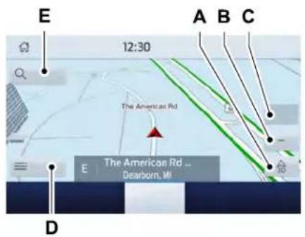
text_image
E 12:30 A B C The American Rd E The American Rd ... Dearborn, MI DMap view menu.A
Zoom out.B
Zoom in.C
Route guidance menu.D
Destination entry menu.E
SYNC ^TM 3
Setting a Destination
Destination Entry Menu
| DescriptionItem | |
| Enter a destination address.Search | |
| Display and select from a list of previous destinations.Previous Destinations | |
| Set your saved home address as your destinationHome | |
| Set your saved place of work as your destination.Work | |
| Display and select from a list of favorite destinations.Favorites |
SYNC ^TM 3
Setting a Destination Using the Text Entry Screen
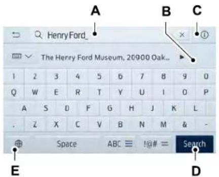
text_image
Henry Ford_ The Henry Ford Museum, 20900 Oak.. A B C 1 2 3 4 5 6 7 8 9 0 Q W E R T Y U I O P A S D F G H J L . Z X C V B N M & ⊕Space ABC !@# = Search E DText entry field.A B Automatic suggestions based on the text you enter. Information icon.C
Search.D
Keyboard settings.E
Note: Select one of the suggestions to copy the detail to the text entry field.
You can search by entering all or part of the destination, such as the Address, POI Category or Name, Intersection, City, Latitude/Longitude, etc. Tips: If you do not specify a location, the system will use the current vehicle location. You can specify a location by address, city, state or zip code. For additional search support, please visit: support.ford.com.
Note: Press the button in the top right-hand corner of the main map to display estimated time of arrival, remaining travel time or distance to destination.
Setting a Destination Using the Map Screen
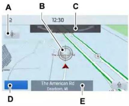
text_image
A B C 12:30 The American Rd The American Rd Dearborn, MI D ERe-center the map.A
Selected location.B
3D map rotation. Swipe left or right.C
Start route guidance.D
Destination name.E
Select the location on the map.
Select Start to begin route guidance.
SYNC ^TM 3
Changing the Format of the Map
Display the map in one of the following formats:
- A two-dimensional map with the direction you are traveling toward the top of the screen.
• A two-dimensional map with north toward the top of the screen.
•A three-dimensional map with the direction you are traveling toward the front.
Zoom
Display more or less detail on the map.
Note: You can use pinch gestures to zoom in and out. Place two fingers on the screen and move them apart to zoom in. Place two fingers on the screen and bring them together to zoom out.
Route Guidance
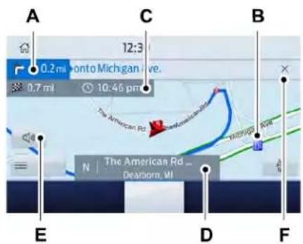
text_image
A 0.2 mi Toronto Michigan Ave. 0,7 mi 10:46 pm C B N | The American Rd ... Dearborn, MI D E FA Turn indicator. Select to hear the last voice prompt. Point of interest.B
C Estimated time of arrival, distance to destination or time to destination.
Current road.D
Mute guidance prompts.E
Cancel route guidance.F
Note: To change guidance prompt volume, turn the volume control when a guidance prompt plays.
SYNC ^TM 3
Route Guidance Menu
| DescriptionMenu Item | |
| Adjust your map preferences for when route guidance is active.Screen View | |
| View a full screen map when route guidance is active.Full Map | |
| View highway exit information for your current route.Highway Exit Info | |
| View the turn list for your current route. Select a road to avoid it.Turn List | |
| Traffic List | You can find the SiriusXM Traffic and Travel Link information by pressing this button. This information requires an active subscription to SiriusXM Traffic and Travel Link. When a route is not active, a list of nearby traffic incidents displays. When a route is active, you can choose to display a list of traffic nearby or on the route. |
| Adjust navigation settings. See Settings (page 495).Navigation Settings | |
| View information about your current location.Where Am I? | |
| Cancel route guidance.Cancel Route | |
| View the entire current route on the map.View Route | |
| View an alternative route compared to your current one.Detour | |
| Change the order or remove waypoints.Edit Waypoints | |
| The system determines the order of waypoints for you.Optimize Order | |
| Go to the next screen and start the new route.Go |
SYNC ^TM 3
Adjusting the Guidance Prompt Volume
Turn the volume control when a guidance prompt plays to adjust the volume.
Note: If you have inadvertently adjusted the volume to zero, press the turn indicator button to play the last voice prompt and then adjust the volume to the desired level.
Muting Guidance Prompts

Select the mute option on the screen to mute guidance prompts.
Note: The system mutes the next and all future guidance prompts.
Adding Waypoints
You can add a waypoint to a navigation route as a destination along your route. You can add up to five waypoints.
- Select the search option on the map.
- Set a destination.
- Select Add Waypoint.
- Select Go.
Canceling Route Guidance

Select the route guidance menu option on the active guidance screen.
Select Cancel Route.
text_image
12:30 0.2 mi Monto The American Rd / Amer ... then 550 m 12:41 amNote: The route guidance menu option is always in the bottom right-hand corner of the main map.
cityseeker (If Equipped)
Note: cityseeker point of interest (POI) information is limited to approximately 1,110 cities (1,049 in the United States, 36 in Canada and 15 in Mexico).

text_image
cityseekercityseeker, when available, is a service that provides more information about certain points of interest such as restaurants, hotels and attractions.
When you have selected a point of interest, the location and information appear, such as address, phone number and a star rating.
Press More Information to see a photo, a review, a list of services and facilities, the average room or meal price and the web address. This screen displays the point of interest icons.
SYNC ^TM 3
For restaurants, cityseeker can provide information such as star rating, average cost, review, handicap access, hours of operation, and website address.
For hotels, cityseeker can provide information such as star rating, price category, review, check-in and checkout times, hotel service icons and website address. Hotel service icons include:
•Restaurant
•Business center
•Handicap facilities
• Laundry
•Refrigerator
•24 hour room service
•Fitness center
- Internet access
•Pool
•Wi-Fi
Attractions include nearby landmarks, amusement parks, historic buildings and more. cityseeker can provide information such as star rating, reviews, hour of operation and admission price.
SiriusXM Traffic and Travel Link (If Equipped)
SiriusXM Traffic and Travel Link is available on vehicles equipped with navigation and only in select markets. You must activate and subscribe to receive SiriusXM Traffic and Travel Link information. It helps you locate the best gas prices, find movie listings, get current traffic alerts, view the weather map, get accurate ski conditions and see current sports scores.
The system calculates a reasonable efficient route based on available speed limits, traffic, and road conditions. You may know a local short cut that is more efficient at a given time than the route provided by SYNC 3, but you should expect a slight difference in minutes or miles with the SYNC 3 route.
Michelin Travel Guide (If Equipped)
The Michelin travel guide is a service which provides additional information about certain places of interest, for example restaurants, hotels and tourist sites. Points of interest that have Michelin travel guide information display a button to show you more information. Push the button to see the additional information. If you have paired your phone with the system, you can press the phone button to directly establish a call with the selected point of interest.
Navigation Map Accuracy and Updates
HERE is the digital map provider for the navigation application. If you find map data errors, you may report them directly to HERE by going to www.here.com. HERE evaluates all reported map errors and responds with the result of their investigation by e-mail.
SYNC ^TM 3
The navigation system map data may contain inaccurate or incomplete information due to the passage of time, changing circumstances, sources used and the nature of collecting comprehensive geographic data, any of which may lead to incorrect results. Inaccurate speed limit information, turn restrictions and other road attributes may affect the determined route and associated guidance
Annual navigation map updates are available for purchase through your dealership. Depending on your purchase agreement, you might be eligible for free Map update. You can choose to download the Map data update onto a USB, order a USB, or use Wi-Fi to deliver automatic updates. To update your Map data over Wi-Fi, your vehicle must be connected to a Wi-Fi access point. Map Data files are large, so it is highly recommended to perform the update when free Wi-Fi is available otherwise high data rates may apply. For USB updates, free map update eligibility, and other details, contact dealers at 1-866-462-8837 in the United States and Canada or 01-800-557-5539 in Mexico or visit our local website for more information.
APPS
The system allows you interact with select mobile apps while keeping your eyes on the road. Voice commands, your steering wheel buttons, or a quick tap on your touchscreen give you advanced control of compatible mobile apps. You can also stream your favorite music or podcasts, share your time of arrival with friends, and keep connected safely.
When you start an app through the system for the first time, you could be asked to grant certain permissions. You can review and change the permissions that you have granted at any time when your vehicle is not moving. We recommend that you check your data plan before using your apps through the system. Using them could result in additional charges. We also recommend that you check the app provider's terms and conditions and privacy policy before using
their app. Make sure that you have an active account for apps that you want to use through the system. Some apps will work with no setup. Others require you to configure some personal settings before you can use them.
Note: For more information about available apps, visit catalog.ford.com.
Using Apps on an iOS Device

Select the apps option on the feature bar.
- If your device is connected via USB, switch Apple CarPlay off. See Phone (page 482).
- Connect your device to a USB port or pair and connect using Bluetooth.
- If prompted to enable CarPlay, select Disable.
- Start the apps on your device that you want to use through SYNC.
Note: If you close the apps on your device, you will not be able to use them through the system.
SYNC ^TM 3
- Select the app that you want to use on the touchscreen.
Note: Connect your device to a USB port if you want to use a navigation app. When using a navigation app, keep your device unlocked and the app open.
Using Apps on an Android Device

Select the apps option on the feature bar.
- If your device is connected via USB, switch Android Auto off. See Phone (page 482).
- Pair your device. See Phone (page 482).
- Start the apps on your device that you want to use through SYNC.
Note: If you close the apps on your device, you will not be able to use them through the system.
- Select Find Mobile Apps.
Note: The system searches and connects to compatible apps that are running on your device.
- Select the app that you want to use on the touchscreen.
Note: Mobile Apps on your device use the USB port to establish a connection with SYNC. Some devices may lose the ability to play music over USB when Mobile Apps are enabled.
Using Mobile Navigation on an Android Device
- Connect your device to a USB port.
- Switch Android Auto off. See Phone (page 482).
- Switch on Enable Mobile Apps via USB in the Mobile Apps Settings tile.
- Select the apps option on the feature bar.
- Select the navigation app that you want to use on the touchscreen.
Note: When using a navigation app, keep your device unlocked and the app open.
SiriusXM Traffic and Travel Link (If Equipped)

WARNING: Driving while distracted
can result in loss of vehicle control, crash and injury. We strongly recommend that you use extreme caution when using any device that may take your focus off the road. Your primary responsibility is the safe operation of your vehicle. We recommend against the use of any hand-held device while driving and encourage the use of voice-operated systems when possible. Make sure you are aware of all applicable local laws that may affect the use of electronic devices while driving.
Note: SiriusXM Traffic and Travel Link may not be available in all markets.
Note: In order to use SiriusXM Traffic and Travel Link, your vehicle must have navigation.
SYNC ^TM 3
Note: A paid subscription is required to access and use these features. Go to www.siriusxm.com/travellink for more information.
Note: Visit www.siriusxm.com/traffic and click on Coverage map and details for a complete listing of all traffic areas covered by SiriusXM Traffic and Travel Link.
Note: Neither Sirius nor Ford is responsible for any errors or inaccuracies in the SiriusXM Traffic and Travel Link services or its use in vehicles.
When you subscribe to SiriusXM Traffic and Travel Link, it can help you locate the best gas prices, find movie listings, get current traffic alerts, view the current weather map, get accurate ski conditions and see scores to current sports games.
| Action and DescriptionMenu Item | ||
| Traffic on Route | Touch these buttons to identify traffic incidents on your route, near your vehicle's current location or near any of your favorite places, if programmed. | |
| Traffic Nearby | ||
| Fuel Prices | Touch this button to view fuel prices at stations close to your vehicle's location or on an active navigation route. | |
| Touch this button to view nearby movie theaters and their show times, if available.Movie Listings | ||
| Weather | Touch this button to view the nearby weather, current weather, or the five-day forecast for the chosen area. | |
| Map | Select to see the weather map, which can show storms, radar information, charts and winds. | |
SYNC ^TM 3
| Action and DescriptionMenu Item | ||
| Select to choose from a listing of weather locations.Area | ||
| Sports Info | Touch this button to view scores and schedules from a variety of sports. You can also save up to 10 favorite teams for easier access. The score automatically refreshes when a game is in progress. | |
| Touch this button to view ski conditions for a specific area.Ski Conditions | ||
SETTINGS

Press the button to enter the settings menu.

Once you select a tile, press the button next to a menu item to view an explanation of the feature or
setting.
Sound
Select this tile to adjust the sound settings.
Clock
Select this tile to adjust the clock settings.
Bluetooth
Select this tile to switch Bluetooth on and off and adjust settings.
Phone
Select this tile to connect, disconnect, and manage the connected device settings.
Audio
Select this tile to adjust the audio settings.
Driver Assist (If Equipped)
Select this tile to adjust Driver Assist features like Parking Aids, Lane Keeping system, Pedestrian Detection, and Auto-Start-Stop.
Vehicle
Select this tile to adjust vehicle settings like windows, alarm, lighting, backup starting passcode, and MyKey settings.
Lincoln Way
Select this tile to adjust the Lincoln Way settings.
General
Select this tile to adjust settings like language, measurement units, or to reset the system.
911 Assist (If Equipped)
Select this tile to switch 911 Assist on and off.
SYNC ^TM 3
Automatic Updates
Select this tile to adjust automatic update settings.
Mobile Apps
Select this tile to adjust permissions, enable, disable, and update mobile apps.
Display
Select this tile to adjust display settings like brightness and auto dim.
Charge Settings (If Equipped)
Select this tile to adjust the electric vehicle charge setting.
Voice Control
Select this tile to adjust voice control settings like command confirmations and displayed lists.
Navigation (If Equipped)
Select this tile to adjust navigation settings like map preferences and route guidance.
Multi Contour Seats (If Equipped)
Select this tile to adjust the position and massage function of your multi contour seats.
Seats (If Equipped)
Select this tile to adjust the lumbar function of your seat.
Message Center (If Equipped)
Select this tile to view vehicle messages.
Personal Profiles (If Equipped)
Select this tile to adjust recalled memory features when using personal profiles.
Valet Mode (If Equipped)
Select this tile to enable and disable valet mode.
Ambient Lighting (If Equipped)
Select this tile to change the color or intensity of the interior lighting.
SYNC ^TM 3
SYNC™ 3 TROUBLESHOOTING
Voice Recognition
| Possible Cause and ResolutionSymptom | |
| The system does not understand what I am saying. | -You are using the wrong voice commands.•See Using Voice Recognition (page 455).•For a complete list of voice commands, refer to our website.-You are speaking too soon.•Wait for the voice prompt before you speak. |
SYNC ^TM 3
| Possible Cause and ResolutionSymptom | |
| The system does not understand the name of a track or artist. | -Device limitation. Bluetooth does not support voice commands.•Connect your device to a USB port.•If you have an iOS device, press and hold the voice control button on the steering wheel to use Siri to play specific tracks.-You are using the wrong voice commands.•See Using Voice Recognition (page 455).•For a complete list of voice commands, refer to our website.-You are not saying the name exactly as it appears on your device.•Say the name of the track or artist exactly as it appears on your device. Spell out any abbreviations in the name.The song or artist name may have some special characters that are not being recognized by the system.-The name contains special characters, for example *, - or +.•Rename the files on your device or use the touchscreen to select and play the track. |
| The system does not understand the name of a contact in the phonebook on my device and calls the wrong contact. | -You are not saying the name exactly as it appears on your device.•Say the first and last name of the contact exactly as it appears on your device. Spell out any abbreviations in the name.-The name contains special characters, for example *, - or +.•Rename the contact on your device or use the touchscreen to select and call the contact. |
SYNC ^TM 3
| Possible Cause and ResolutionSymptom | |
| The system does not understand foreign names of contacts in the phonebook on my device. | -You are not saying the name exactly as it appears on your device.•Say the first and last name of the contact exactly as it appears on your device. The system applies phonetic pronunciation rules of the selected language to the names of contacts in the phonebook on your device. Select the name of the contact on the touchscreen and use the Hear it option to get an idea of how the system expects you to pronounce it. |
| The system voice prompts and the pronunciation of some words does not seem to be very accurate. | -Device limitation.•The system uses text-to-speech technology and uses a synthetically generated voice rather than pre-recorded human voice. |
USB and Bluetooth Audio
| Possible Cause and ResolutionSymptom | |
| I cannot connect my device. –Device malfunction.•Disconnect your device. Switch your device off, reset it and try again.–Cable connection issue.•Correctly connect the cable to your device and the vehicle USB port.–Incompatible cable.•Use the cable recommended by the manufacturer of your device. | |
SYNC ^TM 3
| Possible Cause and ResolutionSymptom | |
| -Incorrect device settings.Make sure that your device does not have an auto-install program or active security settings.Check that your device is not set only to charge.-Device lock screen enabled.Unlock your device before connecting it. | |
| The system does not recognize my device. -Device limitation.Do not leave your device in your vehicle during very hot or very cold weather conditions.-Cable connection issue.Correctly connect the cable to your device and the vehicle USB port.-Incompatible cable.Use the cable recommended by the manufacturer of your device. | |
| The system does not understand the name of a track or artist. | -Device limitation. Bluetooth does not support voice commands.Connect your device to a USB port.If you have an iOS device, press and hold the voice control button on the steering wheel to use Siri to play specific tracks. |
SYNC ^TM 3
| Possible Cause and ResolutionSymptom | |
| I cannot stream audio from my Bluetooth device. | -Incompatible device.•Check the compatibility of your device on our website.-Device not connected.•Pair your device. See Phone (page 482).-Media player not running.•Start the media player on your device. |
| The system does not recognize the music on my device. | -Missing or incorrect audio file metadata, for example artist, song title, album or genre.•Repair the files on your device.-Corrupt files.•Repair the files on your device.-Copyright protected files.•Use a device that contains files that are not copyright protected.-Unsupported file format.• Repair or convert the files to a supported format. See Entertainment (page 467).-Device indexing required.•Re-index your device. See Settings (page 495).-Device lock screen enabled.•Unlock your device before connecting it. |
SYNC ^TM 3
| Possible Cause and ResolutionSymptom | |
| Sometimes I cannot hear a track playing on my device. | -Device malfunction.•Disconnect your device. Switch your device off, reset it and try again. |
| When I disconnect my iOS device the audio volume is set to maximum. | -Device limitation.•Turn the volume down on your device |
| The system does not play the tracks on my USB drive in the correct order. | If the system does not play the tracks on your USB device in the correct order, the following information could help:- If you are selecting USB as the audio source when the system is still indexing, SYNC plays tracks sorted alphabetically by file name in the root directory.-If you are selecting USB as the audio source after the system has finished indexing, SYNC plays all tracks sorted alphabetically by the title in the ID3 tag regardless of where they are located. SYNC uses the file name if the title in the ID3 Tag does not exist.-If you are selecting the option to play all tracks from the browsing menu, SYNC plays all tracks sorted alphabetically by the title in the ID3 tag regardless of where they are located. SYNC uses the file name if the title in the ID3 Tag does not exist.-If you are selecting a track when using the explore device option, SYNC plays tracks sorted alphabetically by file name in the folder you have selected. SYNC then plays all tracks in any subfolders in the folder you have selected. |
SYNC ^TM 3
Phone
| Possible Cause and ResolutionSymptom | |
| During a call, I can hear excessive background noise. | -Incorrect cell phone settings.•Check and adjust the audio settings on your cell phone. Refer to your cell phone's user manual. |
| During a call, I can hear the other person but they cannot hear me. | -Cell phone malfunction.•Switch your cell phone off, reset it and try again.-Cell phone microphone muted.•Unmute your cell phone microphone. |
| During a call, I cannot hear the other person and they cannot hear me. | -System restart required.•Restart the system. Switch the ignition off and open the door. Close the door and lock the vehicle. Wait until the touchscreen is off and any illuminated USB ports are not illuminated. Unlock the vehicle, switch the ignition on and try again. |
| I cannot download phonebook. -Incompatible | cell phone.•Check the compatibility of your cell phone on our website.-Incorrect cell phone settings.•Allow the system to retrieve contacts from your cell phone. Refer to your cell phone's user manual. |
SYNC ^TM 3
| Possible Cause and ResolutionSymptom | |
| -Incorrect system settings.•Switch automatic phonebook download on. See Settings (page 495).-Cell phone malfunction.•Switch your cell phone off, reset it and try again. | |
| A message displays suggesting that my phonebook has downloaded but it is empty or it has missing contacts. | -Incorrect cell phone settings.• Allow the system to retrieve contacts from your cell phone. Refer to your cell phone's user manual.•Check the location of the missing contacts on your cell phone. If they are stored on the SIM card, move them to the cell phone memory.-Incorrect system settings.•Switch automatic phonebook download on. See Settings (page 495). |
SYNC ^TM 3
| Possible Cause and ResolutionSymptom | |
| I cannot connect my cell phone. | -Incompatible cell phone.Check the compatibility of your cell phone on our website.-Cell phone malfunction.Switch your cell phone off, reset it and try again.Install the latest cell phone firmware.Delete your device from system and delete SYNC from your device and try again.Switch automatic phonebook download off. See Settings (page 495). |
| Text messaging does not work. -You did not switch on text message notifications.Switch text message notifications on. See Phone (page 482).-Incompatible cell phone.Check the compatibility of your cell phone on our website.-Cell phone malfunction.Switch your cell phone off, reset it and try again. | |
| I cannot hear text messages. | -Device message sharing is not enabled.Check the permissions on your device to ensure text message sharing is enabled.-Incompatible cell phone.Check the compatibility of your cell phone on our website. |
SYNC ^TM 3
Navigation (If Equipped)
| Possible Cause and ResolutionSymptom | |
| I cannot enter a street name when I am abroad. | -Incorrect entry method.•Enter the street name with the country. |
| The system does not recognize coordinates. | -You are using the wrong coordinates format.•Use the format ##. #####, ##. ###### (for N/S , E/W). Add a minus before coordinates if the direction is West and keep a positive value if the direction is East, for example 12.5412 means East and -12.5412 means West. |
SYNC ^TM 3
Apps
| Possible Cause and ResolutionSymptom | |
| The system cannot find any apps. –Incompatible device. | You will need an Android device with OS 4.3 or higher or an iOS device with iOS 8.0 or higher. Pair and connect your Android device to find AppLink compatible apps. Connect your iOS device to a USB port or pair and connect using Bluetooth. |
| I have a compatible device and it is correctly connected but the system still cannot find any apps. | -AppLink compatible apps not installed on your device.Download and install the latest version of the app.-AppLink compatible apps not running on your device.Start the apps to allow the system to find them and make sure you sign in to any apps if required.-Incorrect app settings.Check and adjust the app settings on your device and allow SYNC to access the app if required. |
| I have a compatible device, it is correctly connected and my apps are running but the system still cannot find any apps. | -Apps failed to fully close.Restart the apps and try again.If you have an Android device with apps that have an exit or quit option, use this and then restart the apps. Alternatively, use the force stop option in the settings menu on your device.If you have an iOS device with iOS 7.0 or higher, tap the home button on your device twice and then swipe the app upward to close it. |
SYNC ^TM 3
| Possible Cause and ResolutionSymptom | |
| I have an Android device that is correctly connected, I have restarted my apps and they are running but the system still cannot find them. | -An issue on some older versions of the Android operating system could result in apps not being found.•Switch Bluetooth off and on again to force the system to reconnect to your device. |
| I have an iOS device that is correctly connected, I have restarted my apps and they are running but the system still cannot find them. | -Cable connection issue.•Disconnect the cable from your device, wait for a moment and then connect it again to force the system to reconnect to your device. |
| I have an Android device running a media app which the system has found but I cannot hear the sound or the sound is very quiet. | -Device volume is low.•Turn the volume up on your device. |
| I have an Android device running a number of compatible apps but the system cannot find all of them. | -Device limitation. Some Android devices have a limited number of Bluetooth ports that apps can use to connect. If you have more apps running on your device than the number of available Bluetooth ports, the system cannot find all of them.•Close some of the apps to allow the system to find those that you want to use. |
SYNC ^TM 3
Wi-Fi Connectivity
| Possible Cause and ResolutionSymptom | |
| I cannot connect to a Wi-Fi network. -Password error.Enter the correct network password.-Weak network signal.Move your vehicle closer to the Wi-Fi hotspot or to a place where the network signal is not obstructed.-Multiple access points in range with the same SSID.Use a unique name for your SSID,. Do not use the default name unless it contains a unique identifier, for example as part of the MAC address. | |
| The Wi-Fi connection disconnects after successful connection. | -Weak network signal.Move your vehicle closer to the Wi-Fi hotspot or to a place where the network signal is not obstructed. |
| I am close to a Wi-Fi hotspot but the network signal strength is weak. | -Obstructed network signal.If your vehicle has a heated windshield, position your vehicle so that the windshield is not facing the Wi-Fi hotspot.If your vehicle has metallic tinting on the windows but not on the windshield, position your vehicle so that the windshield is facing the Wi-Fi hotspot or open the windows that are facing the hotspot.If your vehicle has metallic tinting on the windows and the windshield, open the windows that are facing the hotspot. |
SYNC ^TM 3
| Possible Cause and ResolutionSymptom | |
| If your vehicle is in a garage and you have the garage door closed, open the garage door. | |
| I cannot see a network in the list of available networks that I expect to see. | -Hidden network.Make the network visible and try again. |
| I cannot see SYNC when I search for Wi-Fi networks on my cell phone or other device. | -System limitation.SYNC does not provide a Wi-Fi hotspot at this time. |
| Software downloads take too long. | -Weak network signal.Move your vehicle closer to the Wi-Fi hotspot or to a place where the network signal is not obstructed.-Wi-Fi hotspot in high demand or has a slow Internet connection.Use a more reliable Wi-Fi hotspot. |
| The system seems to connect to a Wi-Fi network and the signal strength is excellent but the software does not update. | -No software update available.-Wi-Fi network requires a subscription or acceptance of terms and conditions.Test the connection using another device. If the network requires a subscription or acceptance of terms and conditions, contact the network service provider. |
SYNC ^TM 3
Personal Profiles (If Equipped)
| Possible Cause and SolutionSymptom | |
| I cannot create a profile. | You have not set up Personal Profiles. |
| You entered an invalid profile. | |
| You did not select a memory button when prompted. | |
| You did not have the ignition on or in park (P), or you shifted out park (P) when creating a profile. | |
| Personal Profiles has been switched off. | |
| I cannot link a remote control. | You did not select the lock button on the remote control. |
| The remote control selected was already associated with another profile and the system declined to overwrite. | |
| The system performed a profile recall when linking a remote control. | |
| You did not have the ignition on or in park (P), or you shifted out park (P) when creating a profile. | |
| You are using the old linking method. | |
| My personalized settings do not save. A different | Personal Profiles does not support your unsaved settings. |
| ent personal profile is active. | |
| Another user changed the settings for the wrong personal profile. |
SYNC ^TM 3
| Possible Cause and SolutionSymptom | |
| My profile will not recall. | You did not create a personal profile. |
| Personal Profiles is turned off. | |
| The profile you requested is already active. | |
| You did not link the memory button you are using to a profile. | |
| You did not link the remote control you are using to a profile. | |
| You are using the wrong remote control. | |
| You are pressing a button other than the unlock or remote start on a linked remote control. | |
| You deleted the personal profile. | |
| not. | You switched the personal profiles off.My preset positions recall, but my profile does |
| My profile recalls but my preset positions do not. | The vehicle is in motion. |
| The preset positions are the same as the guest or previously active profile. | |
| I lost a remote control. | Unlink and relink your remote control in the Personal Profiles menu. You may need to see your authorized dealer. |
| I lost all profiles. | You erased and reprogrammed the remote controls. This could happen if you let a dealership add a new remote control to replace a lost one. |
| Someone performed a master reset without your knowledge. |
SYNC ^TM 3
Resetting the System
- Simultaneously press and hold the seek up and the audio unit power buttons until the screen goes black.
- Wait three minutes to allow the system to complete the reset.
- Press the audio unit power button to switch the system on.
Note: You can reset the system to restore functionality that has stopped working. The system reset is designed to restore functionality and not delete any data that you have stored.
Additional Information and Assistance
For additional information and assistance, we recommend that you contact an authorized dealer or refer to our website.
Accessories
For a complete listing of the accessories that are available for your vehicle, please contact your authorized dealer or visit the online store website:
Web Address (United States)
www.Accessories.Lincoln.com
Web Address (Canada)
www.LincolnCanada.com
We will repair or replace any properly authorized dealer-installed Lincoln Original Accessory found to be defective in factory-supplied materials or workmanship during the warranty period, as well as any component damaged by the defective accessories.
We will warrant your Lincoln Original Accessory through the warranty that provides the greatest benefit:
•24 months, unlimited mileage.
•The remainder of your new vehicle limited warranty.
*Lincoln Licensed Accessory. The accessory manufacturer designs, develops and therefore warrants Lincoln Licensed Accessories, and does not design or test these accessories to Lincoln Motor Company engineering requirements. Contact an authorized Lincoln dealer for the accessory manufacturer's limited warranty details and request a copy of the Lincoln Licensed Accessories product limited warranty from the accessory manufacturer.
For maximum vehicle performance, keep the following information in mind when adding accessories or equipment to your vehicle:
- When adding accessories, equipment, passengers and luggage to your vehicle, do not exceed the total weight capacity of the vehicle or of the front or rear axle (GVWR or GAWR as indicated on the Safety Compliance Certification label). Ask an authorized dealer for specific weight information.
•The Federal Communications Commission (FCC) and Canadian Radio Telecommunications Commission (CRTC) regulate the use of mobile communications systems that have radio transmitters, for example two-way radios, telephones and theft alarms. Any such equipment installed in your vehicle should comply with Federal Communications Commission (FCC) and Canadian Radio Telecommunications Commission (CRTC) regulations and should only be installed by an authorized dealer.
Accessories
- Mobile communications systems may harm the operation of your vehicle, particularly if their manufacturer did not design them specifically for automotive use.
- If you or an authorized Lincoln dealer add any non-Lincoln electrical or electronic accessories or components to your vehicle, you may adversely affect battery performance and durability. In addition, you may also adversely affect the performance of other electrical systems in the vehicle.
Lincoln Protect
PROTECT YOURSELF FROM THE RISING COST OF VEHICLE REPAIRS WITH LINCOLN PROTECT EXTENDED SERVICE PLAN.
Lincoln Protect Extended Service Plans (U.S. Only)
Lincoln Protect means peace of mind. It's the extended service plan backed by the Lincoln Motor Company, and provides more protection beyond the New Vehicle Limited Warranty coverage. When you visit your Lincoln Dealer, insist on genuine Lincoln Protect extended service plans!
Lincoln Protect Extended Service Plan Can Quickly Pay for Itself
One trip to the Service Center could easily exceed the price of your Lincoln Protect extended service plan. With Lincoln Protect you minimize your risk for unexpected repair bills and rising repair costs.
Up to 1000+ Covered Vehicle Components
There are four mechanical Lincoln Protect extended service plans with different levels of coverage. Ask your authorized dealer for details.
- PremiumCARE - Our most comprehensive coverage. With over 1,000 covered components, this plan is so complete it's probably easier to list what's not covered.
- ExtraCARE - Covers 113 components, and includes many high-tech items.
- BaseCARE - Covers 84 components.
- PowertrainCARE - Covers 29 critical components.
Lincoln Protect extended service plans are honored by all authorized Lincoln dealers in the U.S., Canada and Mexico.
That means you get:
- Reliable, quality service at any Lincoln or Ford dealership.
• Repairs performed by factory trained technicians, using genuine parts.
Rental Car Reimbursement
1st day Rental Benefit
If you bring your car into your dealer for service, we'll give you a loaner to use for the day.
Extended Rental Benefits
If your vehicle is kept overnight for covered repairs, you are eligible for rental car coverage, including bumper to bumper warranty repairs, and Field Service Actions.
Roadside Assistance
Exclusive 24/7 roadside assistance, including:
- Towing, flat-tire change and battery jump starts.
- Out of fuel and lock-out assistance.
- Travel expense reimbursement for lodging, meals and rental car.
- Assistance for taxi, shuttle, rental car coverage and other transportation.
Lincoln Protect
Transferable Coverage
If you sell your vehicle before your Lincoln Protect extended service plan coverage expires, you can transfer any remaining coverage to the new owner. Which should give you and your potential buyer a little more peace of mind.
Less Cost to Properly Maintain Your Vehicle
Lincoln Protect extended service plan also offers a Premium Maintenance Plan that covers all scheduled maintenance, and selected wear items. The coverage is prepaid, so you never have to worry about the cost of your vehicle's maintenance.
Covered maintenance includes:
•Windshield wiper blades.
- Spark plugs.
•The clutch disc (if equipped).
- Brake pads and linings.
- Shock absorbers and struts.
- Engine cooling hoses, clamps and o-rings.
- Engine belts.
•Diesel exhaust fluid replenishment (if equipped).
Interest Free Finance Options
Just a 10% down payment will provide you with an affordable, no interest, no fee payment program allowing you all the security and benefits Lincoln Protect extended service plan has to offer while paying over time. You are pre-approved with no credit check or hassles. To learn more, call our Lincoln Protect extended service plan specialists at 800-367-3377.
Complete the information below and mail to:
Lincoln Protect Extended Service Plan P.O. Box 321067 Detroit, MI 48232
Lincoln Protect (CANADA ONLY)
You can get more protection for your vehicle by purchasing a Lincoln Protect extended service plan. Lincoln Protect extended service plan is the only service contract backed by Lincoln Motor Company of Canada, Limited. Depending on the plan you purchase, Lincoln Protect extended service plan provides benefits such as:
• Rental reimbursement.
•Coverage for certain maintenance and wear items.
- Protection against repair costs after your New Vehicle Limited Warranty Coverage expires.
•Roadside Assistance benefits.
Lincoln Protect
There are several Lincoln Protect extended service plans available in various time, distance and deductible combinations. Each plan is tailored to fit your own driving needs, including reimbursement for towing and rental. When you purchase Lincoln Protect extended service plan, you receive added peace-of-mind protection throughout Canada, the United States and Mexico, provided by a network of participating authorized Lincoln Motor Company dealers.
Note: Repairs performed outside of Canada, the United States and Mexico are not eligible for Lincoln Protect extended service plan coverage.
This information is subject to change. For more information, visit your local Lincoln of Canada dealer or www.LincolnCanada.com to find the Lincoln Protect extended service plan that is right for you.
Scheduled Maintenance
GENERAL MAINTENANCE INFORMATION
Why Maintain Your Vehicle?
Carefully following the maintenance schedule helps protect against major repair expenses resulting from neglect or inadequate maintenance and may help to increase the value of your vehicle when you sell or trade it. Keep all receipts for completed maintenance with your vehicle.
We have established regular maintenance intervals for your vehicle based upon rigorous testing. It is important that you have your vehicle serviced at the proper times. These intervals serve two purposes; one is to maintain the reliability of your vehicle and the second is to keep your cost of owning your vehicle down.
It is your responsibility to have all scheduled maintenance performed and to make sure that the materials used meet the specifications identified in this owner's manual. See Capacities and Specifications (page 390).
Failure to perform scheduled maintenance invalidates warranty coverage on parts affected by the lack of maintenance.
Why Maintain Your Vehicle at Your Dealership?
Factory-Trained Technicians
Service technicians participate in extensive factory-sponsored certification training to help them become experts on the operation of your vehicle. Ask your dealership about the training and certification their technicians have received.
Genuine Ford and Motorcraft® Replacement Parts
Dealerships stock Ford, Motorcraft and Ford-authorized branded re-manufactured replacement parts. These parts meet or exceed our specifications. Parts installed at your dealership carry a nationwide 24-month or unlimited mile (kilometer) parts and labor limited warranty.
If you do not use our authorized parts they may not meet our specifications and depending on the part, it could affect emissions compliance.
Convenience
Many dealerships have extended evening and Saturday hours to make your service visit more convenient and they offer one stop shopping. They can perform any services that are required on your vehicle, from general maintenance to collision repairs.
Note: Not all dealers have extended hours or body shops. Please contact your dealer for details.
Protecting Your Investment
Maintenance is an investment that pays dividends in the form of improved reliability, durability and resale value. To maintain the proper performance of your vehicle and its emission control systems, make sure you have scheduled maintenance performed at the designated intervals.
Scheduled Maintenance
Your vehicle has an Intelligent Oil-Life Monitor system, a message appears in the information display at the proper oil change interval. This interval may be up to one year or 10,000 mi (16,000 km), hybrid vehicles may exceed 10,000 mi (16,000 km).
When the oil change message appears in the information display, it is time for an oil change. Make sure you perform the oil change within two weeks or 500 mi (800 km) of the message appearing. Make sure you reset the Intelligent Oil-Life Monitor after each oil change. See Oil Change Indicator Reset (page 334).
If your information display resets prematurely or becomes inoperative, you should perform the oil change interval at six months or 5,000 mi (8,000 km) from your last oil change. Never exceed one year or 10,000 mi (16,000 km) between oil change intervals,
Your vehicle is very sophisticated and built with multiple, complex, performance systems. Every manufacturer develops these systems using different specifications and performance features. That is why it is important to rely upon your dealership to properly diagnose and repair your vehicle.
We have recommended maintenance intervals for various parts and component systems based upon engineering testing. We rely upon this testing to determine the most appropriate mileage for replacement of oils and fluids to protect your vehicle at the lowest overall cost to you and recommends against maintenance schedules that deviate from the scheduled maintenance information.
We strongly recommend the use of only genuine Ford, Motorcraft or Ford-authorized re-manufactured replacement parts engineered for your vehicle.
Additives and Chemicals
This owner's manual and the our Workshop Manual list the recommended additives and chemicals for your vehicle. We do not recommend using chemicals or additives not approved by us as part of your vehicle's normal maintenance. Please consult your warranty information.
Oils, Fluids and Flushing
In many cases, fluid discoloration is a normal operating characteristic and, by itself, does not necessarily indicate a concern or that the fluid needs to be changed. However, a qualified expert, such as the factory-trained technicians at your dealership, should inspect discolored fluids that also show signs of overheating or foreign material contamination immediately.
Scheduled Maintenance
Make sure to change your vehicle's oils and fluids at the specified intervals or in conjunction with a repair. Flushing is a viable way to change fluid for many vehicle sub-systems during scheduled maintenance.
It is critical that systems are flushed only with new fluid that is the same as that required to fill and operate the system or using a Ford-approved flushing chemical.
Owner Checks and Services
Make sure you perform the following basic maintenance checks and inspections every month or at six-month intervals.
| Check Every Month |
| Engine oil level. |
| Function of all interior and exterior lights. |
| Tires (including spare) for wear and proper pressure. |
| Windshield washer fluid level. |
| Fuel and water separator. Drain if necessary (or if indicated by the information display). |
| Holes and slots in the tail pipe to make sure they are functional and clear of debris. |
| Check Every Six Months |
| Battery connections. Clean if necessary. |
| Body and door drain holes for obstructions. Clean if necessary. |
| Cooling system fluid level and coolant strength. |
| Door weatherstrips for wear. Lubricate if necessary. |
Scheduled Maintenance
| Check Every Six Months |
| Hinges, latches and outside locks for proper operation. Lubricate if necessary. |
| Parking brake for proper operation. |
| Seatbelts and seat latches for wear and function. |
| Safety warning lamps (brake, ABS, airbag and seatbelt) for operation. |
| Washer spray and wiper operation. Clean or replace blades as necessary. |
Multi-Point Inspection
In order to keep your vehicle running right, it is important to have the systems on your vehicle checked regularly. This can help identify potential issues and prevent major problems. We recommend having the following multi-point inspection performed at every scheduled maintenance interval to help make sure your vehicle keeps running great.
Scheduled Maintenance
| Multi-Point Inspection | |
| Hazard warning system operationAccessory drive belt(s) | |
| Horn operationBattery performance | |
| Radiator, cooler, heater and air conditioning hosesEngine air filter | |
| Suspension components for leaks or damageExhaust system | |
| Steering and linkageExterior lamps operation | |
| Fluid levels1; fill if necessary | Tires (including spare) for wear and proper pressure2 |
| Windshield for cracks, chips or pitsFor oil and fluid leaks | |
| Washer spray and wiper operationHalf-shaft dust boots | |
Brake, coolant recovery reservoir, automatic transmission and window washer
If your vehicle is equipped with a temporary mobility kit, check the tire sealant expiration Use By date on the canister. Replace as needed.
Be sure to ask your dealership service advisor or technician about the multi-point vehicle inspection. It is a comprehensive way to perform a thorough inspection of your vehicle. Your checklist gives you immediate feedback on the overall condition of your vehicle.
Scheduled Maintenance
NORMAL SCHEDULED MAINTENANCE
Intelligent Oil-Life Monitor™
Your vehicle is equipped with an Intelligent Oil-Life Monitor that determines when you should change the engine oil based on how you use your vehicle. By using several
important factors in its calculations, the monitor helps reduce the cost of owning your vehicle and reduces environmental waste at the same time.
This means you do not have to remember to change the oil on a mileage-based schedule. Your vehicle lets you know when an oil change is due by displaying a message in the information display.
The following table provides examples of vehicle use and its impact on oil change intervals. It is a guideline only. Actual oil change intervals depend on several factors and generally decrease with severity of use.
| When to Expect the Message Prompting you to Change your Oil | |
| Vehicle Use and ExampleInterval | |
| 7,500–10,000 mi (12,000–16,000 km) | Normal |
| Normal commuting with highway drivingNo, or moderate, load or towingFlat to moderately hilly roadsNo extended idling | |
| 5,000–7,500 mi (8,000–12,000 km) | Severe |
| Moderate to heavy load or towingMountainous or off-road conditionsExtended idling | |
Scheduled Maintenance
| When to Expect the Message Prompting you to Change your Oil | |
| Vehicle Use and ExampleInterval | |
| Extended hot or cold operation | |
| 3,000–5,000 mi (5,000–8,000 km) | Extreme |
| Maximum load or towingExtreme hot or cold operation | |
Normal Maintenance Intervals
| At Every Oil Change Interval as Indicated by the Information Display1 |
| Change engine oil and filter.2 |
| Rotate the tires. |
| Perform a multi-point inspection (recommended). |
| Inspect the automatic transmission fluid level (if equipped with a dipstick). Consult your dealer for requirements. |
| Inspect the brake pads, rotors, hoses and parking brake. |
| Inspect the engine cooling system strength and hoses. |
| Inspect the exhaust system and heat shields. |
Scheduled Maintenance
| At Every Oil Change Interval as Indicated by the Information Display1 |
| Inspect the rear axle (All Wheel Drive vehicles only). |
| Inspect the half-shaft boots. |
| Inspect the steering linkage, ball joints, suspension, tie-rod ends, driveshaft and U-joints. |
| Inspect the tires, tire wear and measure the tread depth. |
| Inspect the wheels and related components for abnormal noise, wear, looseness or drag. |
^1 Do not exceed one year or 10,000 mi (16,000 km) between service intervals.
^2 Reset the Intelligent Oil-Life Monitor after engine oil and filter changes. See Oil Change Indicator Reset (page 334).
| Brake Fluid Maintenance ^1 | |
| Every 3 Years | Change brake fluid. ^2 |
^1 Perform this maintenance item every 3 years. Do not exceed the designated time for the interval.
^2 Brake fluid servicing requires special equipment available at your authorized dealer.
Scheduled Maintenance
| Other Maintenance Items1 | |
| Every 20,000 mi (32,000 km) | Replace cabin air filter. |
| Every 30,000 mi (48,000 km) | Replace engine air filter. |
| Every 40,000 mi (64,000 km) | Replace fuel filter (3.0L only). |
| Every 100,000 mi (160,000 km) | Change engine coolant.2 |
| Every 100,000 mi (160,000 km) | Replace spark plugs. |
| Inspect accessory drive belt(s).3 | |
| Every 150,000 mi (240,000 km) | Change automatic transmission fluid. |
| Replace accessory drive belt(s).4 | |
^1 Perform these maintenance items within 3,000 mi (4,800 km) of the last engine oil and filter change. Do not exceed the designated distance for the interval.
^2 Initial replacement at six years or 100,000 mi (160,000 km), then every three years or 50,000 mi (80,000 km).
^3 After initial inspection, inspect every other oil change until replaced.
^4 If not replaced within the last 100,000 mi (160,000 km).
Scheduled Maintenance
SPECIAL OPERATING CONDITIONS SCHEDULED MAINTENANCE
If you operate your vehicle primarily in any of the following conditions, you need to perform extra maintenance as indicated. If you operate your vehicle occasionally under any of these conditions, it is not necessary to perform the extra maintenance. For specific recommendations, see your dealership service advisor or technician.
Perform the services shown in the following tables when specified or within 3,000 mi (4,800 km) of the message appearing in the information display prompting you to change your oil.
•Example 1: The message comes on at 28,750 mi (46,270 km). Perform the 30,000 mi (48,000 km) automatic transmission fluid replacement.
-Example 2: The message has not come on, but the odometer reads 30,000 mi (48,000 km) (for example, the Intelligent Oil-Life Monitor was reset at 25,000 mi (40,000 km). Perform the engine air filter replacement.
Scheduled Maintenance
| Towing a Trailer or Using a Car-top Carrier | |
| As required | Change the engine oil and filter as indicated by information display and perform services listed in the Normal Scheduled Maintenance chart. |
| as required | Inspect the U-joints (AWD only).Inspect frequently, service |
| (48,000 km) | Change the automatic transmission fluid.Every 30,000 mi |
| (96,000 km) | Replace the spark plugs.Every 60,000 mi |
| Extensive Idling or Low-speed Driving for Long Distances, as in Heavy Commercial Use Such as Delivery, Taxi, Patrol Car or Livery | |
| As required | Change the engine oil and filter as indicated by information display and perform services listed in the Normal Scheduled Maintenance chart. |
| as required | Replace the cabin air filter.Inspect frequently, service |
| Replace the engine air filter. | |
| (48,000 km) | Change the automatic transmission fluid.Every 30,000 mi |
| (96,000 km) | Replace the spark plugs.Every 60,000 mi |
Scheduled Maintenance
| Operating in Dusty or Sandy Conditions Such as Unpaved or Dusty Roads | |
| as required | Replace the cabin air filter.Inspect frequently, service |
| Replace the engine air filter. | |
| Inspect the wheels and related components for abnormal noise, wear, looseness or drag.Every 5,000 mi (8,000 km) | |
| Rotate the tires, inspect tires for wear and measure tread depth. | |
| Every 5,000 mi (8,000 km) or six months | Change the engine oil and filter.1 |
| Perform a multi-point inspection. | |
| (48,000 km) | Change the automatic transmission fluid.Every 30,000 mi |
Reset your Intelligent Oil-Life Monitor after engine oil and filter changes. See Oil Change Indicator Reset (page 334).
Exceptions
There are several exceptions to the Normal Schedule:
Axle and PTU Maintenance
The Power Transfer Unit (PTU) and rear axle (AWD only) in your vehicle does not require any normal scheduled maintenance. Changing or checking the PTU lubricant is not necessary unless the unit has been submerged in water or shows signs of leakage. Contact your authorized dealer for service.
Scheduled Maintenance
California Fuel Filter Replacement
If you register your vehicle in California, the California Air Resources Board has determined that the failure to perform this maintenance item does not nullify the emission warranty or limit recall liability before the completion of your vehicle's useful life. Ford Motor Company, however, urges you to have all recommended maintenance services performed at the specified intervals and to record all vehicle service.
Engine Air Filter and Cabin Air Filter Replacement
The life of the engine air filter and cabin air filter is dependent on exposure to dusty and dirty conditions. Vehicles operated in these conditions require frequent inspection and replacement of the engine air filter and cabin air filter.
SCHEDULED MAINTENANCE RECORD
After the scheduled maintenance services are performed, record the Repair Order #, Distance and Engine Hours in the boxes provided.
text_image
Repair Order #: Distance: Engine hours (optional): Multi-point inspection (recommended): Dealer stamp Signature:Scheduled Maintenance
text_image
Repair Order #: Distance: Engine hours (optional): Multi-point inspection (recommended): Dealer stamp Signature:Scheduled Maintenance
text_image
Repair Order #: Distance: Engine hours (optional): Multi-point inspection (recommended): Dealer stamp Signature:Scheduled Maintenance
text_image
Repair Order #: Distance: Engine hours (optional): Multi-point inspection (recommended): Dealer stamp Signature:Scheduled Maintenance
text_image
Repair Order #: Distance: Engine hours (optional): Multi-point inspection (recommended): Dealer stamp Signature:Scheduled Maintenance
text_image
Repair Order #: Distance: Engine hours (optional): Multi-point inspection (recommended): Dealer stamp Signature:Scheduled Maintenance
text_image
Repair Order #: Distance: Engine hours (optional): Multi-point inspection (recommended): Dealer stamp Signature:Scheduled Maintenance
text_image
Repair Order #: Distance: Engine hours (optional): Multi-point inspection (recommended): Dealer stamp Signature:Scheduled Maintenance
text_image
Repair Order #: Distance: Engine hours (optional): Multi-point inspection (recommended): Dealer stamp Signature:Scheduled Maintenance
text_image
Repair Order #: Distance: Engine hours (optional): Multi-point inspection (recommended): Dealer stamp Signature:Scheduled Maintenance
text_image
Repair Order #: Distance: Engine hours (optional): Multi-point inspection (recommended): Dealer stamp Signature:Scheduled Maintenance
text_image
Repair Order #: Distance: Engine hours (optional): Multi-point inspection (recommended): Dealer stamp Signature:Scheduled Maintenance
text_image
Repair Order #: Distance: Engine hours (optional): Multi-point inspection (recommended): Dealer stamp Signature:Scheduled Maintenance
text_image
Repair Order #: Distance: Engine hours (optional): Multi-point inspection (recommended): Dealer stamp Signature:Scheduled Maintenance
text_image
Repair Order #: Distance: Engine hours (optional): Multi-point inspection (recommended): Dealer stamp Signature:Scheduled Maintenance
text_image
Repair Order #: Distance: Engine hours (optional): Multi-point inspection (recommended): Dealer stamp Signature:Scheduled Maintenance
text_image
Repair Order #: Distance: Engine hours (optional): Multi-point inspection (recommended): Dealer stamp Signature:Scheduled Maintenance
text_image
Repair Order #: Distance: Engine hours (optional): Multi-point inspection (recommended): Dealer stamp Signature:Scheduled Maintenance
text_image
Repair Order #: Distance: Engine hours (optional): Multi-point inspection (recommended): Dealer stamp Signature:Scheduled Maintenance
text_image
Repair Order #: Distance: Engine hours (optional): Multi-point inspection (recommended): Dealer stamp Signature:Appendices
ELECTROMAGNETIC COMPATIBILITY

WARNING: Do not place objects
or mount equipment on or near the airbag cover, on the side of the seatbacks (of the front seats), or in front seat areas that may come into contact with a deploying airbag. Failure to follow these instructions may increase the risk of personal injury in the event of a crash.

WARNING: Do not fasten antenna to original vehicle wiring, fuel pipes make pipes.

WARNING: Keep antenna and cables at least 4 in (10 cm) from any nic modules and airbags.
Note: We test and certify your vehicle to meet electromagnetic compatibility legislation (UNECE Regulation 10 or other applicable local requirements). It is your responsibility to make sure that any equipment an authorized dealer installs on your vehicle complies with applicable local legislation and other requirements.
Note: Any radio frequency transmitter equipment in your vehicle (such as cellular telephones and amateur radio transmitters) must keep to the parameters in the following table. We do not provide special provisions or conditions for installations or use.
Appendices
Car
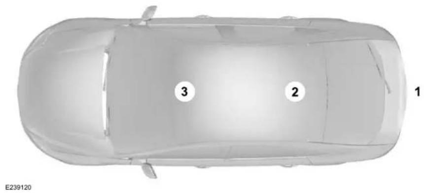
text_image
E239120 1 2 3Appendices
Van
Appendices
Truck
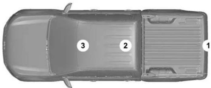
natural_image
Top-down view of a car with three numbered components (1, 2, 3) marked on its side, no text or symbols present.E239121
| Antenna PositionsMaximum output po | ||
| 1501-30 | ||
| 2, 35050-54 | ||
| 2, 35068-88 |
Appendices
| Antenna PositionsMaximum output power W | ||
| 2,350142-176 | ||
| 2,350380-512 | ||
| 2,310806-870 |
Note: After the installation of radio frequency transmitters, check for disturbances from and to all electrical equipment in your vehicle, both in the standby and transmit modes.
Check all electrical equipment:
- With the ignition ON.
- With the engine running.
•During a road test at various speeds.
Check that electromagnetic fields generated inside your vehicle cabin by the transmitter installed do not exceed applicable human exposure requirements.
Appendices
END USER LICENSE AGREEMENT
VEHICLE SOFTWARE END USER LICENSE AGREEMENT (EULA)
- You ("You" or "Your" as applicable) have acquired a vehicle having several devices, including SYNC® and various control modules, ("DEVICES") that include software licensed or owned by Ford Motor Company and its affiliates ("FORD MOTOR COMPANY"). Those software products of FORD MOTOR COMPANY origin, as well as associated media, printed materials, and "online" or electronic documentation ("SOFTWARE") are protected by international intellectual property laws and treaties. The SOFTWARE is licensed, not sold. All rights reserved.
•The SOFTWARE may interface with and/or communicate with, or may be later upgraded to interface with and/or communicate with additional software and/or systems provided by FORD MOTOR COMPANY.
IF YOU DO NOT AGREE TO THIS END USER LICENSE AGREEMENT ("EULA") DO NOT USE THE DEVICES OR COPY THE SOFTWARE. ANY USE OF THE SOFTWARE, INCLUDING BUT NOT LIMITED TO USE ON THE DEVICES, WILL CONSTITUTE YOUR AGREEMENT TO THIS EULA (OR RATIFICATION OF ANY PREVIOUS CONSENT).
GRANT OF SOFTWARE LICENSE: This EULA grants you the following license:
- You may use the SOFTWARE as installed on the DEVICES and as otherwise interfacing with systems and/or services provide by or through FORD MOTOR COMPANY or its third party software and service providers.
Description of Other Rights and Limitations
- Speech Recognition: If the SOFTWARE includes speech recognition component(s), you should understand that speech recognition is an inherently statistical process and that recognition errors are inherent in the process. Neither FORD MOTOR COMPANY nor
its suppliers shall be liable for any damages arising out of errors in the speech recognition process. It is your responsibility to monitor any speech recognition functions included in the system.
- Limitations on Reverse Engineering, Decompilation and Disassembly: You may not reverse engineer, decompile, translate, disassemble or attempt to discover any source code or underlying ideas or algorithms of the SOFTWARE nor permit others to reverse engineer, decompile or disassemble the SOFTWARE, except and only to the extent that such activity is expressly permitted by applicable law notwithstanding this limitation or to the extent as may be permitted by the licensing terms governing use of any open source components included with the SOFTWARE.
Appendices
- Limitations on Distributing, Copying, Modifying and Creating Derivative Works: You may not distribute, copy, make modifications to or create derivative works based on the SOFTWARE, except and only to the extent that such activity is expressly permitted by applicable law notwithstanding this limitation or to the extent as may be permitted by the licensing terms governing use of any open source components included with the SOFTWARE.
- Single EULA: The end user documentation for the DEVICES and related systems and services may contain multiple EULAs, such as multiple translations and/or multiple media versions (e.g., in the user documentation and in the software). Even if you receive multiple EULAs, you are licensed to use only one (1) copy of the SOFTWARE.
- SOFTWARE Transfer: You may permanently transfer your rights under this EULA only as part of a sale or transfer of the DEVICES, provided you retain no copies, you transfer all of the SOFTWARE (including all component parts, the media and printed materials, any upgrades, and, if applicable, the Certificate(s) of Authenticity), and the recipient agrees to the terms of this EULA. If the SOFTWARE is an upgrade, any transfer must include all prior versions of the SOFTWARE.
•Termination: Without prejudice to any other rights, FORD MOTOR COMPANY may terminate this EULA if you fail to comply with the terms and conditions of this EULA.
- Internet-Based Services Components: The SOFTWARE may contain components that enable and facilitate the use of certain Internet-based services. You acknowledge and agree that FORD MOTOR COMPANY, third party software and service suppliers, its affiliates and/or its designated agent may
automatically check the version of the SOFTWARE and/or its components that you are utilizing and may provide upgrades or supplements to the SOFTWARE that may be automatically downloaded to your DEVICES.
•Additional Software/Services: The SOFTWARE may permit FORD MOTOR COMPANY, third party software and service suppliers, its affiliates and/or its designated agent to provide or make available to you SOFTWARE updates, supplements, add-on components, or Internet-based services components of the SOFTWARE after the date you obtain your initial copy of the SOFTWARE ("Supplemental Components"). SOFTWARE updates may cause you to incur additional charges from your wireless service provider. If FORD MOTOR COMPANY or third party software and services suppliers provide or make available to you Supplemental Components and no other EULA terms are provided along with the Supplemental Components, then the terms of this EULA shall apply. FORD
Appendices
MOTOR COMPANY, its affiliates and/or its designated agent reserve the right to discontinue without liability any Internet-based services provided to you or made available to you through the use of the SOFTWARE.
Appendices
•Links to Third Party Sites: The
SOFTWARE may provide you with the ability to link to third party sites. The third party sites are not under the control of FORD MOTOR COMPANY, its affiliates and/or its designated agent. Neither FORD MOTOR COMPANY nor its affiliates nor its designated agent are responsible for (I) the contents of any third party sites, any links contained in third party sites, or any changes or updates to third party sites, or (ii) webcasting or any other form of transmission received from any third party sites. If the SOFTWARE provides links to third party sites, those links are provided to you only as a convenience, and the inclusion of any link does not imply an endorsement of the third party site by FORD MOTOR COMPANY, its affiliates and/or its designated agent.
- Obligation to Drive Responsibly: You recognize your obligation to drive responsibly and keep attention on the road. You will read and abide with the DEVICES operating instructions particularly as they pertain to safety and you agree to assume any risk associated
with the use of the DEVICES.
UPGRADES AND RECOVERY MEDIA: If the SOFTWARE is provided by FORD MOTOR COMPANY separate from the DEVICES on media such as a ROM chip, CD ROM disk(s) or via web download or other means, and is labeled "For Upgrade Purposes Only" or "For Recovery Purposes Only" you may install one (1) copy of such SOFTWARE onto the DEVICES as a replacement copy for the existing SOFTWARE, and use it in accordance with this EULA, including any additional EULA terms accompanying the upgrade SOFTWARE.
INTELLECTUAL PROPERTY RIGHTS: All title and intellectual property rights in and to the SOFTWARE (including but not limited to any images, photographs, animations, video, audio, music, text and "applets" incorporated into the SOFTWARE), the accompanying printed materials, and any copies of the SOFTWARE, are owned by FORD MOTOR COMPANY, or its affiliates or suppliers. The SOFTWARE is licensed, not sold. You may not copy the printed materials accompanying the SOFTWARE. All title and intellectual property rights in and to the content which
may be accessed through use of the SOFTWARE is the property of the respective content owner and may be protected by applicable copyright or other intellectual property laws and treaties. This EULA grants you no rights to use such content outside its intended use. All rights not specifically granted under this EULA are reserved by FORD MOTOR COMPANY, its affiliates, and third party software and service providers and suppliers. Use of any on-line services which may be accessed through the SOFTWARE may be governed by the respective terms of use relating to such services. If this SOFTWARE contains documentation that is provided only in electronic form, you may print one copy of such electronic documentation.
Appendices
EXPORT RESTRICTIONS: You acknowledge that the SOFTWARE is subject to U.S. and European Union export jurisdiction. You agree to comply with all applicable international and national laws that apply to the SOFTWARE, including the U.S. Export Administration Regulations, as well as end-user, end-use and destination restrictions issued by U.S. and other governments.
TRADEMARKS: This EULA does not grant you any rights in connection with any trademarks or service marks of FORD MOTOR COMPANY, its affiliates, and third party software and service providers.
PRODUCT SUPPORT: Please refer to FORD MOTOR COMPANY instructions provided in the documentation for the DEVICES product support, such as the vehicle owner guide.
Should you have any questions concerning this EULA, or if you desire to contact FORD MOTOR COMPANY for any other reason, please refer to the address provided in the documentation for the DEVICES.
No Liability for Certain Damages: EXCEPT AS PROHIBITED BY LAW, FORD MOTOR COMPANY, ANY THIRD PARTY SOFTWARE OR SERVICES SUPPLIERS, AND THEIR AFFILIATES SHALL HAVE NO LIABILITY FOR ANY INDIRECT, SPECIAL, CONSEQUENTIAL OR INCIDENTAL DAMAGES ARISING FROM OR IN CONNECTION WITH THE USE OR PERFORMANCE OF THE SOFTWARE. THIS LIMITATION SHALL APPLY EVEN IF ANY REMEDY FAILS OF ITS ESSENTIAL PURPOSE. THERE ARE NO WARRANTIES OTHER THAN THOSE THAT MAY BE EXPRESSLY PROVIDED FOR YOUR NEW VEHICLE.
SYNC® Automotive Important Safety Information Read and follow instructions:
- Before using your SYNC® system, read and follow all instructions and safety information provided in this end user manual ("Owner Guide".) Not following precautions found in the Owner Guide can lead to an accident or other serious injuries.
General Operation
- Voice Command Control: Certain functions within the SYNC® system may be accomplished using voice commands. Using voice commands while driving helps you to operate the system without removing your hands from the wheel or eyes from the road.
- Prolonged Views of Screen: Do not access any function requiring a prolonged view of the screen while you are driving. Pull over in a safe and legal manner before attempting to access a function of the system requiring prolonged attention.
•Volume Setting: Do not raise the volume excessively. Keep the volume at a level where you can still hear outside traffic and emergency signals while driving. Driving while unable to hear these sounds could cause an accident.
Appendices
-Navigation Features: Any navigation features included in the system are intended to provide turn by turn instructions to get you to a desired destination. Please make certain all persons using this system carefully read and follow instructions and safety information fully.
- Distraction Hazard: Any navigation features may require manual (non-verbal) setup. Attempting to perform such set-up or insert data while driving can distract your attention and could cause an accident or other serious injury. Stop the vehicle in a safe and legal manner before attempting these operations.
- Let Your Judgment Prevail: Any navigation features are provided only as an aid. Make your driving decisions based on your observations of local conditions and existing traffic regulations. Any such feature is not a substitute for your personal judgment. Any route suggestions made by this system should never replace any local traffic regulations or your personal judgment or knowledge of safe driving practices.
- Route Safety: Do not follow the route suggestions if doing so would result in an unsafe or illegal maneuver, if you would be placed in an unsafe situation, or if you would be directed into an area that you consider unsafe. The driver is ultimately responsible for the safe operation of the vehicle and therefore, must evaluate whether it is safe to follow the suggested directions.
- Potential Map Inaccuracy: Maps used by this system may be inaccurate because of changes in roads, traffic controls or driving conditions. Always use good judgment and common sense when following the suggested routes.
- Emergency Services: Do not rely on any navigation features included in the system to route you to emergency services. Ask local authorities or an emergency services operator for these locations. Not all emergency services such as police, fire stations, hospitals and clinics are likely to be contained in the map database for such navigation features.
Appendices
Your Responsibilities and Assumptions of Risk
Appendices
- You agree to each of the following:(a) Any use of the SOFTWARE while driving an automobile or other vehicle in violation of applicable law or otherwise driving in an unsafe manner presents a significant risk of distracted driving and should not be attempted under any circumstances;(b) Use of the SOFTWARE at excessive volume poses a significant risk of hearing damage and should not be attempted under any circumstances;(c) The SOFTWARE may not be compatible with new or different versions of an operating system, third party software, or third party services, and the SOFTWARE may potentially cause a critical failure of an operating system, third party software, or third party service.(d) Any third party service accessed by or third party software used with the SOFTWARE (I) may charge an additional fee for access, (ii) may not work correctly, on an uninterrupted basis, or error free, (iii) may change streaming formats or discontinue operation, (iv) may contain adult, profane or offensive content; and (v) may contain inaccurate, false or misleading traffic, weather,
financial or safety information or other content; and (e) Use of the SOFTWARE may cause you to incur additional charges from your wireless service provider (WSP) and any data or minute calculators that may be included in the software program are for reference only, are not warranted in any way and should not be relied upon in anyway.
- When using the SOFTWARE, you agree to be responsible for and assume the entire risk to the items set forth in Section (a) – (e) above.
Disclaimer of Warranty
YOU EXPRESSLY ACKNOWLEDGE AND AGREE THAT USE OF THE DEVICES AND SOFTWARE IS AT YOUR SOLE RISK AND THAT THE ENTIRE RISK AS TO SATISFACTORY QUALITY, PERFORMANCE, COMPATIBILITY, ACCURACY AND EFFORT IS WITH YOU. TO THE MAXIMUM EXTENT PERMITTED BY APPLICABLE LAW, THE SOFTWARE AND ANY THIRD PARTY SOFTWARE OR THIRD-PARTY SERVICES ARE PROVIDED "AS IS" AND "AS AVAILABLE", WITH ALL FAULTS AND
WITHOUT WARRANTY OF ANY KIND, AND FORD MOTOR COMPANY HEREBY DISCLAIMS ALL WARRANTIES AND CONDITIONS WITH RESPECT TO THE SOFTWARE, THIRD PARTY SOFTWARE, AND THIRD-PARTY SERVICES, EITHER EXPRESS, IMPLIED OR STATUTORY, INCLUDING, BUT NOT LIMITED TO, THE IMPLIED WARRANTIES AND/OR CONDITIONS OF MERCHANTABILITY, OF SATISFACTORY QUALITY, OF FITNESS FOR AN ARTICULAR PURPOSE, OF ACCURACY, OF QUIET ENJOYMENT, AND NON-INFRINGEMENT OF THIRD-PARTY RIGHTS. FORD MOTOR COMPANY DOES NOT WARRANT (a) AGAINST INTERFERENCE WITH YOUR ENJOYMENT OF THE SOFTWARE, THIRD PARTY SOFTWARE, OR THIRD-PARTY SERVICES, (b) THAT THE SOFTWARE, THIRD PARTY SOFTWARE, OR THIRD-PARTY SERVICES WILL MEET YOUR REQUIREMENTS, (c) THAT THE OPERATION OF THE SOFTWARE, THIRD PARTY SOFTWARE, OR THIRD-PARTY SERVICES WILL BE UNINTERRUPTED OR ERROR-FREE, (d) OR THAT DEFECTS IN THE SOFTWARE, THIRD PARTY SOFTWARE, OR THIRD-PARTY SERVICES WILL BE CORRECTED. NO ORAL
Appendices
OR WRITTEN INFORMATION OR ADVICE GIVEN BY FORD MOTOR COMPANY OR ITS AUTHORIZED REPRESENTATIVE SHALL CREATE A WARRANTY. SHOULD THE SOFTWARE, THIRD PARTY SOFTWARE, OR THIRD-PARTY SERVICES PROVE DEFECTIVE, YOU ASSUME THE ENTIRE COST OF ALL NECESSARY SERVICING, REPAIR OR CORRECTION. SOME JURISDICTIONS DO NOT ALLOW THE DISCLAIMER OF IMPLIED WARRANTIES OR LIMITATIONS ON APPLICABLE STATUTORY RIGHTS OF A CONSUMER, SO THE ABOVE DISCLAIMER MAY NOT FULLY APPLY TO YOU. THE SOLE WARRANTY PROVIDED BY FORD MOTOR COMPANY SHALL BE FOUND IN THE WARRANTY INFORMATION INCLUDING WITH YOUR OWNER GUIDE. TO THE EXTENT THAT THERE IS ANY CONFLICT BETWEEN THE TERMS OF THIS SECTION AND THE WARRANTY BOOKLET, THE WARRANTY BOOKLET SHALL CONTROL.
Applicable Law, Venue, Jurisdiction
•The laws of the State of Michigan govern this EULA and Your use of the SOFTWARE. Your use of the SOFTWARE may also be subject to other local, state, national, or international laws. Any litigation arising out of or related to this EULA shall be brought and maintained exclusively in a court of the State of Michigan located in Wayne County or in the United States District Court for the Eastern District of Michigan. You hereby consent to submit to the personal jurisdiction of a court in the State of Michigan located in Wayne County and the United States District Court for the Eastern District of Michigan for any dispute arising out of or relating to this EULA.
Binding Arbitration and Class Action Waiver
(a) Application. This Section applies to any dispute EXCEPT IT DOES NOT INCLUDE A DISPUTE RELATING TO COPYRIGHT INFRINGEMENT, OR TO THE ENFORCEMENT OR VALIDITY OF YOUR, FORD MOTOR COMPANY, OR ANY OF
FORD MOTOR COMPANY'S LICENSORS' INTELLECTUAL PROPERTY RIGHTS. Dispute means any dispute, action, or other controversy between You and FORD MOTOR COMPANY, other than the exceptions listed above, concerning the SOFTWARE (including its price) or this EULA, whether in contract, warranty, tort, statute, regulation, ordinance, or any other legal or equitable basis.
(b) Notice of Dispute. In the event of a Dispute, You or FORD MOTOR COMPANY must give the other a “Notice of Dispute”, which is a written statement of the name, address, and contact information of the party giving it, the facts giving rise to the dispute, and the relief requested. You and FORD MOTOR COMPANY will attempt to resolve any dispute through informal negotiation within 60 days from the date the Notice of Dispute is sent. After 60 days, You or FORD MOTOR COMPANY may commence arbitration.
Appendices
(c) Small claims court. You may also litigate any dispute in small claims court in your county of residence or FORD MOTOR COMPANY'S principal place of business, if the dispute meets all requirements to be heard in the small claims court. You may litigate in small claims court whether or not You negotiated informally first.
(d) Binding arbitration. If You and FORD MOTOR COMPANY, do not resolve any dispute by informal negotiation or in small claims court, any other effort to resolve the dispute will be conducted exclusively by binding arbitration. You are giving up the right to litigate (or participate in as a party or class member) all disputes in court before a judge or jury. Instead, all disputes will be resolved before a neutral arbitrator, whose decision will be final except for a limited right of appeal under the Federal Arbitration Act. Any court with jurisdiction over the parties may enforce the arbitrator's award.
(e) Class action waiver. Any proceedings to resolve or litigate any dispute in any forum will be conducted solely on an individual basis. Neither you nor FORD MOTOR COMPANY, will seek to have any dispute heard as a class action, as a private attorney general action, or in any other proceeding in which any party acts or proposes to act in a representative capacity. No arbitration or proceeding will be combined with another without the prior written consent of all parties to all affected arbitrations or proceedings.
(f) Arbitration procedure. Any arbitration will be conducted by the American Arbitration Association (the "AAA"), under its Commercial Arbitration Rules. If You are an individual and use the SOFTWARE for personal or vehicle use, or if the value of the dispute is \$75,000 or less whether or not You are an individual or how You use the SOFTWARE, the AAA Supplementary Procedures for Consumer-Related Disputes will also apply. To commence arbitration, submit a Commercial Arbitration Rules Demand for Arbitration form to the AAA. You may request a telephonic or in-person hearing by following the AAA rules. In a
dispute involving \$10,000 or less, any hearing will be telephonic unless the arbitrator finds good cause to hold an in-person hearing instead. For more information, see adr.org or call 1-800-778-7879. You agree to commence arbitration only in your county of residence or FORD MOTOR COMPANY'S principal place of business. The arbitrator may award the same damages to You individually as a court could. The arbitrator may award declaratory or injunctive relief only to You individually, and only to the extent required to satisfy Your individual claim.
(g) Arbitration fees and incentives.
- I. Disputes involving \$75,000 or less. FORD MOTOR COMPANY will promptly reimburse your filing fees and pay the AAA's and arbitrator's fees and expenses. If you reject FORD MOTOR COMPANY'S last written settlement offer made before the arbitrator was appointed ("last written offer"), your dispute goes all the way to an arbitrator's decision (called an "award"), and the arbitrator awards you more than the last written offer, FORD MOTOR COMPANY will give
Appendices
you three incentives: (1) pay the greater of the award or \$1,000; (2) pay twice your reasonable attorney's fees, if any; and (3) reimburse any expenses (including expert witness fees and costs) that your attorney reasonably accrues for investigating, preparing, and pursuing your claim in arbitration. The arbitrator will determine the amounts.
- ii. Disputes involving more than \$75,000. The AAA rules will govern payment of filing fees and the AAA's and arbitrator's fees and expenses.
•iii. Disputes involving any amount. In any arbitration you commence, FORD MOTOR COMPANY will seek its AAA or arbitrator's fees and expenses, or Your filing fees it reimbursed, only if the arbitrator finds the arbitration frivolous or brought for an improper purpose. In any arbitration FORD MOTOR COMPANY commences, it will pay all filing, AAA, and arbitrator's fees and expenses. It will not seek its attorney's fees or expenses from you in any arbitration. Fees and expenses are not counted in determining how much a dispute involves.
(h) Claims or disputes must be filed within one year. To the extent permitted by law, any claim or dispute under this EULA to which this Section applies must be filed within one year in small claims court (Section c) or in arbitration (Section d). The one-year period begins when the claim or dispute first could be filed. If such a claim or dispute is not filed within one year, it is permanently barred.
(I) Severability. If the class action waiver (Section e) is found to be illegal or unenforceable as to all or some parts of a dispute, then that portion of Section e will not apply to those parts. Instead, those parts will be severed and proceed in a court of law, with the remaining parts proceeding in arbitration. If any other provision of that portion Section e is found to be illegal or unenforceable, that provision will be severed with the remainder of Section e remaining in full force and effect.
Telenav Software End User License Agreement
Please read these terms and conditions carefully before you use the TeleNav Software. Your use of the TeleNav Software indicates that you accept these terms and conditions. If you do not accept these terms and conditions, do not break the seal of the package, launch, or otherwise use the TeleNav Software. TeleNav may revise this Agreement and the privacy policy at any time, with or without notice to you. You agree to visit http://www.telenav.com from time to time to review the then current version of this Agreement and of the privacy policy.
1. Safe and Lawful Use
You acknowledge that devoting attention to the TeleNav Software may pose a risk of injury or death to you and others in situations that otherwise require your undivided attention, and you therefore agree to comply with the following when using the TeleNav Software:
(a) observe all traffic laws and otherwise drive safely;
Appendices
(b) use your own personal judgment while driving. If you feel that a route suggested by the TeleNav Software instructs you to perform an unsafe or illegal maneuver, places you in an unsafe situation, or directs you into an area that you consider to be unsafe, do not follow such instructions;
(c) do not input destinations, or otherwise manipulate the TeleNav Software, unless your vehicle is stationary and parked;
(d) do not use the TeleNav Software for any illegal, unauthorized, unintended, unsafe, hazardous, or unlawful purposes, or in any manner inconsistent with this Agreement;
(e) arrange all GPS and wireless devices and cables necessary for use of the TeleNav Software in a secure manner in your vehicle so that they will not interfere with your driving and will not prevent the operation of any safety device (such as an airbag).
You agree to indemnify and hold TeleNav harmless against all claims resulting from any dangerous or otherwise inappropriate use of the TeleNav Software in any moving vehicle, including as a result of your failure to comply with the directions above.
2. Account Information
You agree: (a) when registering the TeleNav Software, to provide TeleNav with true, accurate, current, and complete information about yourself, and (b) to inform TeleNav promptly of any changes to such information, and to keep it true, accurate, current and complete.
3. Software License
- Subject to your compliance with the terms of this Agreement, TeleNav hereby grants to you a personal, non-exclusive, non-transferable license (except as expressly permitted below in connection with your permanent transfer of the TeleNav Software license), without the right to sublicense, to use the TeleNav Software (in object code form only) in order to access and use the TeleNav Software. This license shall terminate upon any termination or expiration of this Agreement. You agree that you will use the TeleNav Software only for your personal business or leisure purposes, and not to provide commercial navigation services to other parties.
3.1 License Limitations
•(a) reverse engineer, decompile, disassemble, translate, modify, alter or otherwise change the TeleNav Software or any part thereof; (b) attempt to derive the source code, audio library or structure of the TeleNav Software without the prior express written consent of TeleNav; (c) remove from the TeleNav Software, or alter, any of TeleNav's or its suppliers' trademarks, trade names, logos, patent or copyright notices, or other notices or markings; (d) distribute, sublicense or otherwise transfer the TeleNav Software to others, except as part of your permanent transfer of the TeleNav Software; or (e) use the TeleNav Software in any manner that
- infringes the intellectual property or proprietary rights, rights of publicity or privacy or other rights of any party,
ii. violates any law, statute, ordinance or regulation, including but not limited to laws and regulations related to spamming, privacy, consumer and child protection, obscenity or defamation, or
Appendices
iii. is harmful, threatening, abusive, harassing, tortuous, defamatory, vulgar, obscene, libelous, or otherwise objectionable; and (f) lease, rent out, or otherwise permit unauthorized access by third parties to the TeleNav Software without advanced written permission of TeleNav.
4. Disclaimers
•To the fullest extent permissible pursuant to applicable law, in no event will TeleNav, its licensors and suppliers, or agents or employees of any of the foregoing, be liable for any decision made or action taken by you or anyone else in reliance on the information provided by the TeleNav Software. TeleNav also does not warrant the accuracy of the map or other data used for the TeleNav Software. Such data may not always reflect reality due to, among other things, road closures, construction, weather, new roads and other changing conditions. You are responsible for the entire risk arising out of your use of the TeleNav Software. For example but without limitation, you agree not to rely
on the TeleNav Software for critical navigation in areas where the well-being or survival of you or others is dependent on the accuracy of navigation, as the maps or functionality of the TeleNav Software are not intended to support such high risk applications, especially in more remote geographical areas.
•TELENAV EXPRESSLY DISCLAIMS AND EXCLUDES ALL WARRANTIES IN CONNECTION WITH THE TELENAV SOFTWARE, WHETHER STATUTORY, EXPRESS OR IMPLIED, INCLUDING ALL WARRANTIES WHICH MAY ARISE FROM COURSE OF DEALING, CUSTOM OR TRADE AND INCLUDING, BUT NOT LIMITED TO, THE IMPLIED WARRANTIES OF MERCHANTABILITY, FITNESS FOR A PARTICULAR PURPOSE AND NON-INFRINGEMENT OF THIRD PARTY RIGHTS WITH RESPECT TO THE TELENAV SOFTWARE.
- Certain jurisdictions do not permit the disclaimer of certain warranties, so this limitation may not apply to you.
5. Limitation of Liability
• TO THE EXTENT PERMITTED UNDER APPLICABLE LAW, UNDER NO CIRCUMSTANCES SHALL TELENAV OR ITS LICENSORS AND SUPPLIERS BE LIABLE TO YOU OR TO ANY THIRD PARTY FOR ANY INDIRECT, INCIDENTAL, CONSEQUENTIAL, SPECIAL OR EXEMPLARY DAMAGES (INCLUDING IN EACH CASE, BUT NOT LIMITED TO, DAMAGES FOR THE INABILITY TO USE THE EQUIPMENT OR ACCESS DATA, LOSS OF DATA, LOSS OF BUSINESS, LOSS OF PROFITS, BUSINESS INTERRUPTION OR THE LIKE) ARISING OUT OF THE USE OF OR INABILITY TO USE THE TELENAV SOFTWARE, EVEN IF TELENAV HAS BEEN ADVISED OF THE POSSIBILITY OF SUCH DAMAGES. NOTWITHSTANDING ANY DAMAGES THAT YOU MIGHT INCUR FOR ANY REASON WHATSOEVER (INCLUDING, WITHOUT LIMITATION, ALL DAMAGES REFERENCED HEREIN AND ALL DIRECT OR GENERAL DAMAGES IN CONTRACT, TORT (INCLUDING NEGLIGENCE) OR
Appendices
OTHERWISE), THE ENTIRE LIABILITY OF TELENAV AND OF ALL OF TELENAV'S SUPPLIERS SHALL BE LIMITED TO THE AMOUNT ACTUALLY PAID BY YOU FOR THE TELENAV SOFTWARE. SOME STATES AND/OR JURISDICTIONS DO NOT ALLOW THE EXCLUSION OR LIMITATION OF INCIDENTAL OR CONSEQUENTIAL DAMAGES, SO THE ABOVE LIMITATIONS OR EXCLUSIONS MAY NOT APPLY TO YOU.
6. Arbitration and Governing Law
- You agree that any dispute, claim or controversy arising out of or relating to this Agreement or the TeleNav Software shall be settled by independent arbitration involving a neutral arbitrator and administered by the American Arbitration Association in the County of Santa Clara, California. The arbitrator shall apply the Commercial Arbitration Rules of the American Arbitration Association, and the judgment upon the award rendered by the arbitrator may be entered by any court having jurisdiction. Note that there is no judge or jury in an
arbitration proceeding and the decision of the arbitrator shall be binding upon both parties. You expressly agree to waive your right to a jury trial. This Agreement and performance hereunder will be governed by and construed in accordance with the laws of the State of California, without giving effect to its conflict of law provisions. To the extent judicial action is necessary in connection with the binding arbitration, both TeleNav and you agree to submit to the exclusive jurisdiction of the courts of the County of Santa Clara, California. The United Nations Convention on Contracts for the International Sale of Goods shall not apply.
7. Assignment
- You may not resell, assign, or transfer this Agreement or any of your rights or obligations, except in totality, in connection with your permanent transfer of the TeleNav Software, and expressly conditioned upon the new user of the TeleNav Software agreeing to be bound by the terms and conditions of this
Agreement. Any such sale, assignment or transfer that is not expressly permitted under this paragraph will result in immediate termination of this Agreement, without liability to TeleNav, in which case you and all other parties shall immediately cease all use of the TeleNav Software. Notwithstanding the foregoing, TeleNav may assign this Agreement to any other party at any time without notice, provided the assignee remains bound by this Agreement.
8. Miscellaneous
8.1
This Agreement constitutes the entire agreement between TeleNav and you with respect to the subject matter hereof.
8.2
Except for the limited licenses expressly granted in this Agreement, TeleNav retains all right, title and interest in and to the TeleNav Software, including without limitation all related intellectual property rights. No licenses or other rights which are
Appendices
not expressly granted in this Agreement are intended to, or shall be, granted or conferred by implication, statute, inducement, estoppel or otherwise, and TeleNav and its suppliers and licensors hereby reserve all of their respective rights other than the licenses explicitly granted in this Agreement.
8.3
By using the TeleNav Software, you consent to receive from TeleNav all communications, including notices, agreements, legally required disclosures or other information in connection with the TeleNav Software (collectively, "Notices") electronically. TeleNav may provide such Notices by posting them on TeleNav's Website or by downloading such Notices to your wireless device. If you desire to withdraw your consent to receive Notices electronically, you must discontinue your use of the TeleNav Software.
8.4
TeleNav's or your failure to require performance of any provision shall not affect that party's right to require performance at any time thereafter, nor shall a waiver of any breach or default of this Agreement constitute a waiver of any subsequent breach or default or a waiver of the provision itself.
8.5
If any provision herein is held unenforceable, then such provision will be modified to reflect the intention of the parties, and the remaining provisions of this Agreement will remain in full force and effect.
8.6
The headings in this Agreement are for convenience of reference only, will not be deemed to be a part of this Agreement, and will not be referred to in connection with the construction or interpretation of this Agreement. As used in this Agreement, the words "include" and "including" and variations thereof, will not be deemed to be terms of limitation, but rather will be deemed to be followed by the words "without limitation".
9. Other Vendors Terms and Conditions
- The Telenav Software utilizes map and other data licensed to Telenav by third party vendors for the benefit of you and other end users. This Agreement includes end-user terms applicable to these companies (included at the end of this Agreement), and thus your use of the Telenav Software is also subject to such terms. You agree to comply with the following additional terms and conditions, which are applicable to Telenav's third party vendor licensors::
Appendices
9.1 End User Terms Required by HERE North America, LLC
The data (“Data”) is provided for your personal, internal use only and not for resale. It is protected by copyright, and is subject to the following terms and conditions which are agreed to by you, on the one hand, and Telenav (“Telenav”) and its licensors (including their licensors and suppliers) on the other hand.
© 2013 HERE. All rights reserved.
The Data for areas of Canada includes information taken with permission from Canadian authorities, including: © Her Majesty the Queen in Right of Canada, © Queen's Printer for Ontario, © Canada Post Corporation, GeoBase®, © Department of Natural Resources Canada.
HERE holds a non-exclusive license from the United States Postal Service ^® to publish and sell ZIP+4 ^® information.
©United States Postal Service® 2014. Prices are not established, controlled or approved by the United States Postal Service®. The following trademarks and registrations are owned by the USPS: United States Postal Service, USPS, and ZIP+4
9.2 End User Terms Required by NAV2 (Shanghai) Co., Ltd
The data (“Data”) is provided for your personal, internal use only and not for resale. It is protected by copyright, and is subject to the following terms and conditions which are agreed to by you, on the one hand, and NAV2 (Shanghai) Co., Ltd (“NAV2”) and its licensors (including their licensors and suppliers) on the other hand. 20xx. All rights reserved
Terms and Conditions
Permitted Use. You agree to use this Data together with the Telenav Software solely for the internal business and personal purposes for which you were licensed, and not for service bureau, time-sharing or other similar purposes. Accordingly, but subject to the restrictions set forth in the following paragraphs, you agree not to otherwise reproduce, copy, modify, decompile, disassemble, create any derivative works of, or reverse engineer any portion of this Data, and may not transfer or distribute it in any form, for any purpose, except to the extent permitted by mandatory laws.
Restrictions. Except where you have been specifically licensed to do so by Telenav, and without limiting the preceding paragraph, you may not use this Data (a) with any products, systems, or applications installed or otherwise connected to or in communication with vehicles, capable of vehicle navigation, positioning, dispatch, real time route guidance, fleet management or similar applications; or (b) with or in
Appendices
communication with any positioning devices or any mobile or wireless-connected electronic or computer devices, including without limitation cellular phones, palmtop and handheld computers, pagers, and personal digital assistants or PDAs.
Warning. The Data may contain inaccurate or incomplete information due to the passage of time, changing circumstances, sources used and the nature of collecting comprehensive geographic data, any of which may lead to incorrect results.
No Warranty. This Data is provided to you “as is,” and you agree to use it at your own risk. Telenav and its licensors (and their licensors and suppliers) make no guarantees, representations or warranties of any kind, express or implied, arising by law or otherwise, including but not limited to, content, quality, accuracy, completeness, effectiveness, reliability, fitness for a particular purpose, usefulness, use or results to be obtained from this Data, or that the Data or server will be uninterrupted or error-free.
Disclaimer of Warranty: TELENAV AND ITS LICENSORS (INCLUDING THEIR LICENSORS AND SUPPLIERS) DISCLAIM ANY WARRANTIES, EXPRESS OR IMPLIED, OF QUALITY, PERFORMANCE, MERCHANTABILITY, FITNESS FOR A PARTICULAR PURPOSE OR NON-INFRINGEMENT. Some States, Territories and Countries do not allow certain warranty exclusions, so to that extent the above exclusion may not apply to you.
Disclaimer of Liability: TELENAV AND ITS LICENSORS (INCLUDING THEIR LICENSORS AND SUPPLIERS) SHALL NOT BE LIABLE TO YOU: IN RESPECT OF ANY CLAIM, DEMAND OR ACTION, IRRESPECTIVE OF THE NATURE OF THE CAUSE OF THE CLAIM, DEMAND OR ACTION ALLEGING ANY LOSS, INJURY OR DAMAGES, DIRECT OR INDIRECT, WHICH MAY RESULT FROM THE USE OR POSSESSION OF THE INFORMATION; OR FOR ANY LOSS OF PROFIT, REVENUE, CONTRACTS OR SAVINGS, OR ANY OTHER DIRECT, INDIRECT, INCIDENTAL, SPECIAL OR CONSEQUENTIAL DAMAGES ARISING OUT OF YOUR USE OF OR INABILITY TO USE
THIS INFORMATION, ANY DEFECT IN THE INFORMATION, OR THE BREACH OF THESE TERMS OR CONDITIONS, WHETHER IN AN ACTION IN CONTRACT OR TORT OR BASED ON A WARRANTY, EVEN IF TELENAV OR ITS LICENSORS HAVE BEEN ADVISED OF THE POSSIBILITY OF SUCH DAMAGES. Some States, Territories and Countries do not allow certain liability exclusions or damages limitations, so to that extent the above may not apply to you.
Export Control. You shall not export from anywhere any part of the Data or any direct product thereof except in compliance with, and with all licenses and approvals required under, applicable export laws, rules and regulations, including but not limited to the laws, rules and regulations administered by the Office of Foreign Assets Control of the U.S. Department of Commerce and the Bureau of Industry and Security of the U.S. Department of Commerce. To the extent that any such export laws, rules or regulations prohibit HERE from complying with any of its obligations hereunder to deliver or distribute Data, such failure shall be excused and shall not constitute a breach of this Agreement.
Appendices
Entire Agreement. These terms and conditions constitute the entire agreement between Telenav (and its licensors, including their licensors and suppliers) and you pertaining to the subject matter hereof, and supersedes in their entirety any and all written or oral agreements previously existing between us with respect to such subject matter.
Governing Law. The above terms and conditions shall be governed by the laws of the State of Illinois [insert “Netherlands” where European HERE Data is used], without giving effect to (i) its conflict of laws provisions, or (ii) the United Nations Convention for Contracts for the International Sale of Goods, which is explicitly excluded. You agree to submit to the jurisdiction of the State of Illinois [insert “The Netherlands” where European HERE Data is used] for any and all disputes, claims and actions arising from or in connection with the Data provided to you hereunder.
Government End Users. If the Data is being acquired by or on behalf of the United States government or any other entity seeking or applying rights similar to those customarily claimed by the United States government, this Data is a “commercial item” as that term is defined at 48 C.F.R. (“FAR”) 2.101, is licensed in accordance with these End-User Terms, and each copy of Data delivered or otherwise furnished shall be marked and embedded as appropriate with the following “Notice of Use,” and shall be treated in accordance with such Notice:
NOTICE OF USE
CONTRACTOR (MANUFACTURER/SUPPLIER) NAME: HERE
CONTRACTOR (MANUFACTURER/SUPPLIER) ADDRESS: c/o Nokia, 425 West Randolph Street, Chicago, Illinois 60606
This Data is a commercial item as defined in FAR 2.101 and is subject to these End-User Terms under which this Data was provided.
© 1987 – 2014 HERE – All rights reserved.
If the Contracting Officer, federal government agency, or any federal official refuses to use the legend provided herein, the Contracting Officer, federal government agency, or any federal official must notify HERE prior to seeking additional or alternative rights in the Data.
I. US/Canada Territory
A. United States Data. The End-User Terms for any Application containing Data for the United States shall contain the following notices:
"HERE holds a non-exclusive license from the United States Postal Service® to publish and sell ZIP+4® information."
"©United States Postal Service® 20XX. Prices are not established, controlled or approved by the United States Postal Service®. The following trademarks and registrations are owned by the USPS: United States Postal Service, USPS, and ZIP+4."
Appendices
B. Canada Data. The following provisions apply to the Data for Canada, which may include or reflect data from third party licensors ("Third Party Data"), including Her Majesty the Queen in Right of Canada ("Her Majesty"), Canada Post Corporation ("Canada Post") and the Department of Natural Resources of Canada ("NRCan"):
- Disclaimer and Limitation: Client agrees that its use of the Third Party Data is subject to the following provisions:
a. Disclaimer: The Third Party Data is licensed on an “as is” basis. The licensors of such data, including Her Majesty, Canada Post and NRCan, make no guarantees, representations or warranties respecting such data, either express or implied, arising by law or otherwise, including but not limited to, effectiveness, completeness, accuracy or fitness for a particular purpose.
b. Limitation on Liability: The Third Party Data licensors, including Her Majesty, Canada Post and NRCan, shall not be liable: (i) in respect of any claim, demand or action, irrespective of the nature of the cause of the claim, demand or action alleging any loss, injury or damages, direct or indirect, which may result from the use or possession of such Data; or (ii) in any way for loss of revenues or contracts, or any other consequential loss of any kind resulting from any defect in the Data.
- Copyright Notice: In connection with each copy of all or any portion of the Data for the Territory of Canada, Client shall affix in a conspicuous manner the following copyright notice on at least one of: (i) the label for the storage media of the copy; (ii) the packaging for the copy; or (iii) other materials packaged with the copy, such as user manuals or end user license agreements: "This data includes information taken with permis-
sion from Canadian authorities, including © Her Majesty the Queen in Right of Canada, © Queen's Printer for Ontario, © Canada Post Corporation, GeoBase®, © The Department of Natural Resources Canada. All rights reserved."
- End-User Terms: Except as otherwise agreed by the parties, in connection with the provision of any portion of the Data for the Territory of Canada to End-Users as may be authorized under the Agreement, Client shall provide such End-Users, in a reasonably conspicuous manner, with terms (set forth with other end user terms required to be provided
Appendices
under the Agreement, or as otherwise may be provided, by Client) which shall include the following provisions on behalf of the Third Party Data licensors, including Her Majesty, Canada Post and NRCan:
The Data may include or reflect data of licensors, including Her Majesty the Queen in the Right of Canada ("Her Majesty"), Canada Post Corporation ("Canada Post") and the Department of Natural Resources Canada ("NRCan"). Such data is licensed on an "as is" basis. The licensors, including Her Majesty, Canada Post and NRCan, make no guarantees, representations or warranties respecting such data, either express or implied, arising by law or otherwise, including but not limited to, effectiveness, completeness, accuracy or fitness for a particular purpose. The licensors, including Her Majesty, Canada Post and NRCan, shall not be liable in respect of any claim, demand or action, irrespective of the nature of the cause of the claim, demand or
action alleging any loss, injury or damages, direct or indirect, which may result from the use or possession of the data or the Data. The licensors, including Her Majesty, Canada Post and NRCan, shall not be liable in any way for loss of revenues or contracts, or any other consequential loss of any kind resulting from any defect in the data or the Data.
End User shall indemnify and save harmless the licensors, including Her Majesty, Canada Post and NRCan, and their officers, employees and agents from and against any claim, demand or action, irrespective of the nature of
the cause of the claim, demand or action, alleging loss, costs, expenses, damages or injuries (including injuries resulting in death) arising out of the use or possession of the data or the Data.
- Additional Provisions: The terms contained in this Section are in addition to all of the rights and obligations of the parties under the Agreement. To the extent that any of the provisions of this Section are inconsistent with, or conflict with, any other provisions of the Agreement, the provisions of this Section shall prevail.
Appendices
II. Mexico. The following provision applies to the Data for Mexico, which includes certain data from the Instituto Nacional de Estadística y Geografía ("INEGI"):
A. Any and all copies of the Data and/or packaging containing Data for Mexico shall contain the following notice: "Fuente: INEGI (Instituto Nacional de Estadística y Geografía)"
III. Latin America Territory
A. Third Party Notices. Any and all copies of the Data and/or packaging relating thereto shall include the respective Third Party Notices set forth below and used as described below corresponding to the Territory (or portion thereof) included in such copy:
NoticeTerritory
Argentina IGN "INSTITUTO GEOGRAFICO NACIONAL ARGENTINO"
| Ecuador | “INSTITUTO GEOGRAFICO MILITAR DEL ECUADOR AUTORIZACION N° IGM-2011-01-PCO-01 DEL 25 DE ENERO DE 2011” “source: © IGN 2009 - BD TOPO €” |
| Guadeloupe, French Guiana and |
A. Third Party Notices. Any and all copies of the Data and/or packaging relating thereto shall include the respective Third Party Notices set forth below and used as described below corresponding to the Territory (or portion thereof) included in such copy:
NoticeCountry
| Jordan | “© Royal Jordanian Geographic Centre”. The foregoing notice requirement for Jordan Data is a material term of the Agreement. If Client or any of its permitted sublicensees (if any) fail to meet such requirement, HERE shall have the right to terminate Client’s license with respect to the Jordan Data. |
B. Jordan Data. Client and its permitted sublicensees (if any) are restricted from licensing and/or otherwise distributing HERE's database for the country of Jordan ("Jordan Data") for use in Enterprise Applications to (i) non-Jordanian entities for use of the Jordan Data solely in Jordan or (ii) Jordan-based customers. In addition, Client, its permitted sublicensees (if any) and End-Users are restricted from using the Jordan Data in Enterprise Applications if such party is (i) a non-Jordanian entity using the Jordan Data solely in Jordan or (ii) a Jordan-based customer. For purposes
Appendices
of the foregoing, "Enterprise Applications" shall mean Geomarketing applications, GIS applications, mobile business asset management applications, call center applications, telematics applications, public organization Internet applications or for providing geocoding services.
V. Europe Territory
A. Use of Certain Traffic Codes in Europe
-
General Restrictions Applicable to Traffic Codes. Client acknowledges and agrees that in certain countries of the Europe Territory, Client will need to obtain rights directly from third party RDS-TMC code providers to receive and use the Traffic Codes in the Data and to deliver to End-Users Transactions in any way derived from or based on such Traffic Codes. For such countries, HERE shall deliver the Data incorporating Traffic Codes to Client only after receiving certification from Client of its having obtained such rights.
-
Display of Third Party Rights Legends for Belgium. Client shall, for each Transaction that uses Traffic Codes for Belgium, provide the following notice to the End-User: "Traffic Codes for Belgium are provided by the Ministerie van de Vlaamse Gemeenschap and the Ministérie de l'Equipement et des Transports."
B. Paper Maps. With respect to any license granted to Client relating to making, selling or distributing paper maps (i.e., a map fixed on a paper or paper-like medium): (a) such license with respect to Data for the Territory of Great Britain is conditioned on Client's entering into and complying with a separate written agreement with the Ordnance Survey ("OS") to create and sell paper maps, Client's paying to the OS any and all applicable paper map royalties, and Client's complying with the OS copyright notice requirements; (b) such license for selling or otherwise distributing for charge with respect to Data for the Territory of Czech Republic is conditioned on Client's obtaining prior written consent from
Kartografie a.s.; (c) such license for selling or distributing with respect to Data for the Territory of Switzerland is conditioned on Client's obtaining a permit from Bundesamt für Landestopografie of Switzerland; (d) Client is restricted from using Data for the Territory of France to create paper maps with a scale between 1:5,000 and 1:250,000; and (e) Client is restricted from using any Data to create, sell or distribute paper maps that are the same or substantially similar, in terms of data content and specific use of color, symbols and scale, to paper maps published by the European national mapping agencies, including without limitation, Landervermessungämter of Germany, Topografische Dienst of the Netherlands, Nationaal Geografisch Instituut of Belgium, Bundesamt für Landestopografie of Switzerland, Bundesamt für Eich-und Vermessungswesen of Austria, and the National Land Survey of Sweden.
Appendices
| C. OS Enforcement. Without limiting Section IV(B) above, with respect to Data for the Territory of Great Britain, Client acknowledges and agrees that the Ordnance Survey (“OS”) may bring a direct action against Client to enforce compliance with the OS copyright notice (see Section IV(D) below) and paper map requirements (see Section IV(B) above) contained in this Agreement.D. Third Party Notices. Any and all copies of the Data and/or packaging relating thereto shall include the respective Third Party Notices set forth below and used as described below corresponding to the Territory (or portion thereof) included in such copy:NoticeCountry(ies)Austria “© Bundesamt für Eich- und Vermessungswesen”Croatia Cyprus, Estonia, Latvia,Lithuania, “© EuroGeographics” | Moldova, Poland,Slovenia and/or UkraineFrance“source: © IGN 2009 – BD TOPO ®”Germany“Die Grundlagendaten wurden mit Genehmigung der zuständigen Behörden entnommen”Great Britain“Contains Ordnance Survey data © Crown copyright and database right 2010Contains Royal Mail data ©Royal Mail copyright and database right 2010”“Copyright Geomatics Ltd.”GreeceHungary“Copyright © 2003; Top-Map Ltd.” | ItalyItalyE. Respective Country Distribution. Client acknowledges that HERE has not received approvals to distribute map data for the following countries in such respective countries: Albania, Belarus, Kyrgyzstan,Moldova and Uzbekistan. HERE mayNorway“Copyright © 2000; Norwegian Mapping Authority”“Source: lgeoE – Portugal”PortugalSpain“Información geográfica propiedad del CNIG”Sweden“Based upon electronic data © National Land Survey Sweden.”Switzerland“Topografische Grundlage: © Bundesamt für Landestopographie. |
Appendices
update such list from time to time. The license rights granted to Client under this TL with respect to the Data for such countries are contingent upon Client's compliance with all applicable laws and regulations, including, without limitation, any required licenses or approvals to distribute the Application incorporating such Data in such respective countries.
VI. Australia Territory
A. Third Party Notices. Any and all copies of the Data and/or packaging relating thereto shall include the respective Third Party Notices set forth below and used as described below corresponding to the Territory (or portion thereof) included in such copy:
Copyright. Based on data provided under license from PSMA Australia Limited (www.psma.com.au).
Product incorporates data which is © 20XX Telstra Corporation Limited, GM Holden Limited, Intelematics Australia Pty Ltd and Continental Pty Ltd.
B. Third Party Notices for Australia. In addition to the foregoing, the End-User Terms for any Application containing RDS-TMC Traffic Codes for Australia shall contain the following notice: "Product incorporates traffic location codes which is © 20XX Telstra Corporation Limited and its licensors."
AT&T Vehicle Network Carrier Telematics Disclosure
END USER FOR PURPOSES OF THIS SECTION MEANS YOU AND YOUR HEIRS, EXECUTORS, LEGAL PERSONAL REPRESENTATIVES AND PERMITTED ASSIGNS. FOR PURPOSES OF THIS SECTION "UNDERLYING WIRELESS SERVICE CARRIER" INCLUDES ITS AFFILIATES AND CONTRACTORS AND THEIR RESPECTIVE OFFICERS, DIRECTORS, EMPLOYEES, SUCCESSORS AND ASSIGNS. END USER HAS NO CONTRACTUAL RELATIONSHIP
WITH THE UNDERLYING WIRELESS SERVICE CARRIER AND END USER IS NOT A THIRD PARTY BENEFICIARY OF ANY AGREEMENT BETWEEN FORD AND UNDERLYING CARRIER. END USER UNDERSTANDS AND AGREES THAT THE UNDERLYING CARRIER HAS NO LEGAL, EQUITABLE, OR OTHER LIABILITY OF ANY KIND TO END USER. IN ANY EVENT, REGARDLESS OF THE FORM OF THE ACTION, WHETHER FOR BREACH OF CONTRACT, WARRANTY, NEGLIGENCE, STRICT LIABILITY IN TORT OR OTHERWISE, END USER'S EXCLUSIVE REMEDY FOR CLAIMS ARISING IN ANY WAY IN CONNECTION WITH THIS AGREEMENT, FOR ANY CAUSE WHATSOEVER, INCLUDING BUT NOT LIMITED TO ANY FAILURE OR DISRUPTION OF SERVICE PROVIDED HEREUNDER, IS LIMITED TO PAYMENT OF DAMAGES IN AN AMOUNT NOT TO EXCEED THE AMOUNT PAID BY END USER FOR THE SERVICES DURING THE TWO-MONTH PERIOD PRECEDING THE DATE THE CLAIM AROSE.
Appendices
(ii) END USER AGREES TO INDEMNIFY AND HOLD HARMLESS THE UNDERLYING WIRELESS SERVICE CARRIER AND ITS OFFICERS, EMPLOYEES, AND AGENTS AGAINST ANY AND ALL CLAIMS, INCLUDING WITHOUT LIMITATION CLAIMS FOR LIBEL, SLANDER, OR ANY PROPERTY DAMAGE, PERSONAL INJURY OR DEATH, ARISING IN ANY WAY, DIRECTLY OR INDIRECTLY, IN CONNECTION WITH THIS AGREEMENT OR THE USE, FAILURE TO USE, OR INABILITY TO USE THE DEVICE EXCEPT WHERE THE CLAIMS RESULT FROM THE UNDERLYING CARRIER'S GROSS NEGLIGENCE OR WILLFUL MISCONDUCT. THIS INDEMNITY WILL SURVIVE THE TERMINATION OF THE AGREEMENT.
(iii) END USER HAS NO PROPERTY RIGHT IN ANY NUMBER ASSIGNED TO THE DEVICE.
(iv) END USER UNDERSTANDS THAT FORD AND THE UNDERLYING CARRIER CANNOT GUARANTY THE SECURITY OF WIRELESS TRANSMISSIONS, AND WILL NOT BE LIABLE FOR ANY LACK OF SECURITY RELATING TO THE USE OF THE SERVICES
THE SERVICE IS FOR [END USER'S] USE ONLY AND END USER MAY NOT RESELL THE SERVICE TO ANY OTHER PARTY END USER UNDERSTANDS THAT THE UNDERLYING CARRIER DOES NOT GUARANTEE ANY END USER UNINTERRUPTED SERVICE OR COVERAGE. THE UNDERLYING CARRIER DOES NOT WARRANT THAT END USERS CAN OR WILL BE LOCATED USING THE SERVICE. THE UNDERLYING CARRIER MAKES NO WARRANTY, EXPRESS OR IMPLIED, OF MERCHANTABILITY OR FITNESS FOR A PARTICULAR PURPOSE, SUITABILITY, OR PERFORMANCE REGARDING ANY SERVICES OR GOODS, AND IN NO EVENT SHALL AT&T BE LIABLE, WHETHER OR NOT DUE TO ITS OWN NEGLIGENCE, FOR ANY: (A) ACT OR OMISSION OF A THIRD PARTY; (B) MISTAKES, OMISSIONS, INTERRUPTIONS, ERRORS, FAILURES TO TRANSMIT, DELAYS, OR DEFECTS IN THE SERVICE PROVIDED BY OR THROUGH THE UNDERLYING CARRIER; (C) DAMAGE OR INJURY CAUSED BY SUSPENSION OR TERMINATION BY THE UNDERLYING CARRIER; OR (D) DAMAGE OR INJURY CAUSED BY A FAILURE OR DELAY IN CONNECTING A CALL TO ANY ENTITY,
INCLUDING 911 OR ANY OTHER EMERGENCY SERVICE. TO THE FULL EXTENT ALLOWED BY LAW, THE END USER RELEASES, INDEMNIFIES AND HOLDS THE UNDERLYING CARRIER HARMLESS FROM AND AGAINST ANY AND ALL CLAIMS OF ANY PERSON OR ENTITY FOR DAMAGES OF ANY NATURE ARISING IN ANY WAY FROM OR RELATING TO, DIRECTLY OR INDIRECTLY, SERVICES PROVIDED BY THE UNDERLYING CARRIER OR ANY PERSON'S USE THEREOF, INCLUDING CLAIMS ARISING IN WHOLE OR IN PART FROM THE ALLEGED NEGLIGENCE OF THE UNDERLYING CARRIER.
VII. China Territory
Personal Use Only
You agree to use this Data together with [insert name of Client Application] for the solely personal, non-commercial purposes for which you were licensed, and not for service bureau, time-sharing or other similar purposes. Accordingly, but subject to the restrictions set forth in the following paragraphs, you may copy this Data only as necessary for your personal use to (i) view
Appendices
it, and (ii) save it, provided that you do not remove any copyright notices that appear and do not modify the Data in any way. You agree not to otherwise reproduce, copy, modify, decompile, disassemble or reverse engineer any portion of this Data, and may not transfer or distribute it in any form, for any purpose, except to the extent permitted by mandatory laws.
Restrictions
Except where you have been specifically licensed to do so by NAV2, and without limiting the preceding paragraph, you may not (a) use this Data with any products, systems, or applications installed or otherwise connected to or in communication with vehicles, capable of vehicle navigation, positioning, dispatch, real time route guidance, fleet management or similar applications; or (b) with or in communication with any positioning devices or any mobile or wireless-connected electronic or computer devices, including without limitation cellular phones, palmtop and handheld computers, pagers, and personal digital assistants or PDAs. You agree to cease using this Data if you fail to comply with these terms and conditions.
Limited Warranty
NAV2 warrants that (a) the Data will perform substantially in accordance with the accompanying written materials for a period of ninety (90) days from the date of receipt, and (b) any support services provided by NAV2 shall be substantially as described in applicable written materials provided to you by NAV2, and NAV2's support engineers will make commercially reasonable efforts to solve any problem issues.
rigCustomer Remedies
NAV2 and its suppliers' entire liability and your exclusive remedy shall be, at NAV2's sole discretion, either (a) return of the price paid, if any, or (b) repair or replacement of the Data that do not meet NAV2's Limited Warranty and that are returned to NAV2 with a copy of your receipt. This Limited Warranty is void if failure of the Data has resulted from accident, abuse, or misapplication. Any replacement Data will be warranted for the remainder of the original warranty period or thirty (30) days, whichever is longer. Neither these remedies nor any product support services offered by NAV2 are available without proof of purchase from an authorized international source.
No Other Warranty:
EXCEPT FOR THE LIMITED WARRANTY SET FORTH ABOVE AND TO THE EXTENT PERMITTED BY APPLICABLE LAW, NAV2 AND ITS LICENSORS (INCLUDING THEIR LICENSORS AND SUPPLIERS) DISCLAIM ANY WARRANTIES, EXPRESS OR IMPLIED, OF QUALITY, PERFORMANCE, MERCHANTABILITY, FITNESS FOR A PARTICULAR PURPOSE, OWNERSHIP OR NON-INFRINGEMENT. Certain warranty exclusions may not be permitted under applicable law, so to that extent the above exclusion may not apply to you.
Appendices
Limited Liability:
TO THE EXTENT PERMITTED BY APPLICABLE LAW, NAV2 AND ITS LICENSORS (INCLUDING THEIR LICENSORS AND SUPPLIERS) SHALL NOT BE LIABLE TO YOU: IN RESPECT OF ANY CLAIM, DEMAND OR ACTION, IRRESPECTIVE OF THE NATURE OF THE CAUSE OF THE CLAIM, DEMAND OR ACTION ALLEGING ANY LOSS, INJURY OR DAMAGES, DIRECT OR INDIRECT, WHICH MAY RESULT FROM THE USE OR POSSESSION OF THE INFORMATION; OR FOR ANY LOSS OF PROFIT, REVENUE, CONTRACTS OR SAVINGS, OR ANY OTHER DIRECT, INDIRECT, INCIDENTAL, SPECIAL OR CONSEQUENTIAL DAMAGES ARISING OUT OF YOUR USE OF OR INABILITY TO USE THIS INFORMATION, ANY DEFECT IN THE INFROMATION, OR THE BREACH OF THESE TERMS OR CONDITIONS, WHETHER IN AN ACTION IN CONTRACT OR TORT OR BASED ON A WARRANTY, EVEN IF NAV2 OR ITS LICENSORS HAVE BEEN ADVISED OF THE POSSIBILITY OF SUCH DAMAGES. UNDER
NO CIRCUMSTANCES SHALL NAV2's OR ITS SUPPLIERS' LIABILITY HEREUNDER EXCEED THE PRICE PAID. Certain liability exclusions may not be permitted under applicable law, so to that extent the above exclusion may not apply to you.
Export Control
You agree not to export to anywhere any part of the Data provided to you or any direct product thereof except in compliance with, and with all licenses and approvals required under, applicable export laws, rules and regulations.
IP Protection
The Data are owned by NAV2 or its suppliers and are protected by applicable copyright and other intellectual property law and treaties. The Data are provided solely on the basis of a license to use, not sale.
Entire Agreement
These terms and conditions constitute the entire agreement between NAV2(and its licensors, including their licensors and suppliers) and you pertaining to the subject matter hereof, and supersedes in their entirety any and all written or oral agreements previously existing between us with respect to such subject matter.
Governing Law.
The above terms and conditions shall be governed by the laws of the People's Republic of China, without giving effect to (i) its conflict of laws provisions, or (ii) the United Nations Convention for Contracts for the International Sale of Goods, which is explicitly excluded. Any dispute arising from or in connection with the Data provided to you hereunder shall be submitted to the Shanghai International Economic and Trade Arbitration Commission for arbitration.
Gracenote® Copyright
CD and music-related data from Gracenote, Inc., copyright©
Appendices
2000-2007 Gracenote. Gracenote Software, copyright © 2000-2007 Gracenote. This product and service may practice one or more of the following U.S. Patents 5,987,525; 6,061,680; 6,154,773; 6,161,132; 6,230,192; 6,230,207; 6.240,459; 6,330,593 and other patents issued or pending. Some services supplied under license from Open Globe, Inc. for U.S. Patent 6,304,523.
Gracenote and CDDB are registered trademarks of Gracenote. The Gracenote logo and logotype, and the "Powered by Gracenote™" logo are trademarks of Gracenote.
Gracenote® End User License Agreement (EULA)
This device contains software from Gracenote, Inc. of 2000 Powell Street Emeryville, California 94608 ("Gracenote").
The software from Gracenote (the "Gracenote Software") enables this device to do disc and music file identification and obtain music-related information, including name, artist, track, and title information ("Gracenote Data") from online servers ("Gracenote Servers"), and to perform other
functions. You may use Gracenote Data only by means of the intended End User functions of this device. This device may contain content belonging to Gracenote's providers. If so, all of the restrictions set forth herein with respect to Gracenote Data shall also apply to such content and such content providers shall be entitled to all of the benefits and protections set forth herein that are available to Gracenote. You agree that you will use the content from Gracenote ("Gracenote Content"), Gracenote Data, the Gracenote Software, and Gracenote Servers for your own personal, non-commercial use only. You agree not to assign, copy, transfer or transmit the Gracenote Content, Gracenote Software or any Gracenote Data (except in a Tag associated with a music file) to any third party. YOU AGREE NOT TO USE OR EXPLOIT GRACENOTE CONTENT, GRACENOTE DATA, THE GRACENOTE SOFTWARE, OR GRACENOTE SERVERS, EXCEPT AS EXPRESSLY PERMITTED HEREIN.
You agree that your non-exclusive licenses to use the Gracenote Content, Gracenote Data, the Gracenote Software, and Gracenote Servers will terminate if you violate these restrictions. If your licenses terminate, you agree to cease any and all use of the Gracenote Content, Gracenote Data, the Gracenote Software, and Gracenote Servers.
Gracenote, respectively, reserve all rights in Gracenote Data, the Gracenote Software, and the Gracenote Servers and Gracenote Content, including all ownership rights. Under no circumstances will either Gracenote become liable for any payment to you for any information that you provide, including any copyrighted material or music file information. You agree that Gracenote may enforce its respective rights, collectively or separately, under this agreement against you, directly in each company's own name.
Appendices
Gracenote uses a unique identifier to track queries for statistical purposes. The purpose of a randomly assigned numeric identifier is to allow Gracenote to count queries without knowing anything about who you are. For more information, see the web page at www.gracenote.com for the Gracenote Privacy Policy.
THE GRACENOTE SOFTWARE, EACH ITEM OF GRACENOTE DATA AND THE GRACENOTE CONTENT ARE LICENSED TO YOU "AS IS". NEITHER GRACENOTE MAKES ANY REPRESENTATIONS OR WARRANTIES, EXPRESS OR IMPLIED, REGARDING THE ACCURACY OF ANY GRACENOTE DATA FROM THE GRACENOTE SERVERS OR GRACENOTE CONTENT. GRACENOTE COLLECTIVELY AND SEPARATELY RESERVE THE RIGHT TO DELETE DATA AND/OR CONTENT FROM THE COMPANIES' RESPECTIVE SERVERS OR, IN THE CASE OF GRACENOTE, CHANGE DATA CATEGORIES FOR ANY CAUSE THAT GRACENOTE DEEMS SUFFICIENT. NO WARRANTY IS MADE THAT EITHER GRACENOTE CONTENT OR THE GRACENOTE SOFTWARE OR GRACENOTE SERVERS ARE
ERROR-FREE OR THAT THE FUNCTIONING OF THE GRACENOTE SOFTWARE OR GRACENOTE SERVERS WILL BE UNINTERRUPTED. GRACENOTE IS NOT OBLIGATED TO PROVIDE YOU WITH ANY ENHANCED OR ADDITIONAL DATA TYPES THAT GRACENOTE MAY CHOOSE TO PROVIDE IN THE FUTURE AND IS FREE TO DISCONTINUE ITS ONLINE SERVICES AT ANY TIME. GRACENOTE DISCLAIM ALL WARRANTIES EXPRESS OR IMPLIED, INCLUDING, BUT NOT LIMITED TO, IMPLIED WARRANTIES OF MERCHANTABILITY, FITNESS FOR A PARTICULAR PURPOSE, TITLE, AND NON-INFRINGEMENT. NEITHER GRACENOTE WARRANTS THE RESULTS THAT WILL BE OBTAINED BY YOUR USE OF THE GRACENOTE SOFTWARE OR ANY GRACENOTE SERVER. IN NO CASE WILL GRACENOTE BE LIABLE FOR ANY CONSEQUENTIAL OR INCIDENTAL DAMAGES OR FOR ANY LOST PROFITS OR LOST REVENUES FOR ANY REASON WHATSOEVER. © Gracenote 2007.
Radio Frequency Statement
FCC ID: ACJ-SYNCG3-L
IC: 216B-SYNCG3-L
This device complies with Part 15 of the FCC Rules and with RSS-210 of Industry Canada. Operation is subject to the following two conditions:
(1) This device may not cause harmful interference, and
(2) this device must accept any interference received, including interference that may cause undesired operation.

WARNING: Changes or
modifications not expressively approved by the party responsible for compliance could void the user's authority to operate the equipment. The term "IC:" before the radio certification number only signifies that Industry Canada technical specifications were met.
The antenna used for this transmitter must not be co-located or operating in conjunction with any other antenna or transmitter.
Appendices
Taiwan Territory
Note: In accordance with the management approach of low-power radio wave radiation motors:
Article 12: For approved and certified low-power radiation motor models, companies, firms or users must not alter the frequency, increase the power or change the characteristics and functions of the original design without authorization.
Article 14: The usage of low-power radio-frequency motors must not affect aviation safety and interfere with legal telecommunications. Should interference be detected, immediately stop using the device and only resume usage after ensuring that there is no longer any interference. For the legal telecommunication and wireless telecommunication of the telco, the low-power radio frequency motor must be able to tolerate legal limits of interference from telecommunication, industrial, scientific and radio wave equipment.
SUNA TRAFFIC CHANNEL – TERMS AND CONDITIONS
By activating, using and/or accessing the SUNA Traffic Channel, SUNA Predictive or other content or material provided by Intelematics (together, SUNA Products and/or Services), you must accept certain terms and conditions. The following is a brief summary of the terms and conditions that apply to you. To view the full terms and conditions relevant to your use of the SUNA Products and/or Services, please consult:
Website
www.sunatraffic.com.au/termsandconditions/
1. Acceptance
By using SUNA Products and/or Services, you will be deemed to have accepted and agreed to be bound by the terms and conditions fully detailed at:
Website
www.sunatraffic.com.au/termsandconditions/
2. Intellectual Property
SUNA Products and/or Services are for your personal use. You may not record, or retransmit the content, nor use the content in association with any other traffic information or route guidance service or device not approved by Intelematics. You obtain no right of ownership in any Intellectual Property Rights (including copyright) in the data that is used to provide SUNA Products and/or Services.
3. Appropriate Use
Appendices
SUNA Products and/or Services are intended as an aid to personal motoring and travel planning, and do not provide comprehensive or accurate information on all occasions. On occasions, you may experience additional delay as a result of using SUNA Products and/or Services. You acknowledge that it is not intended, or suitable, for use in applications where time of arrival or driving directions may impact the safety of the public or yourself.
4. Use of SUNA Products and Services while driving
You, and other authorised drivers of the vehicle in which SUNA Products and/or Services are available or installed and active, remain at all times responsible for observing all relevant laws and codes of safe driving. In particular, you agree to only actively operate SUNA Products and/or Services when the Vehicle is at a complete stop and it is safe to do so.
5. Service Continuity and Reception of the SUNA Traffic Channel
We will use reasonable endeavours to provide the SUNA Traffic Channel 24 hours a day, 365 days a year. The SUNA Traffic Channel may occasionally be unavailable for technical reasons or for planned maintenance. We will try to perform maintenance at times when congestion is light. We reserve the right to withdraw SUNA Products and/or Services at any time.
Also, we cannot assure the uninterrupted reception of the SUNA Traffic Channel RDS-TMC signal at any particular location.
6. Limitation of Liability
Neither Intelematics (nor its suppliers or the manufacturer of your device (the "Suppliers")) shall be liable to you or to any third party for any damages either direct, indirect, incidental, consequential or otherwise arising out of the use of or inability
to use SUNA Products and/or Services even if Intelematics or a Supplier has been advised of the possibility of such damages. You also acknowledge that the neither Intelematics nor any Supplier guarantees nor make any warranties that relate to the availability, accuracy or completeness of SUNA Products and/or Services, and to the extent which it is lawful to do so, both Intelematics and each Supplier excludes any warranties which might otherwise be implied by any State or Federal legislation in relation to SUNA Products and/or Services.
7. Please Note
Great care has been taken in preparing this manual. Constant product development may mean that some information is not entirely up-to-date. The information in this document is subject to change without notice.
Appendices
DECLARATION OF CONFORMITY
Radio Frequency Statement
| IC Identification NumberFCC Identification | ||
| 216B-SYNCG3-LACJ-SYNCG3-L3.0 | ||
| 216B-FA170BCARHSACJ-FA-170-BCARHS3.1 | ||
| 216B-FG185SG32MHACJ-FG-185-SG32MH3.2 |

WARNING: Changes or
modifications not expressively approved by the party responsible for compliance could void the user's authority to operate the equipment. The term "IC:" before the radio certification number only signifies that Industry Canada technical specifications were met.
These devices comply with Part 15 of the FCC Rules and with RSS-210 of Industry Canada. Operation is subject to the following two conditions:
- The device does not cause harmful interference.
- The device accepts any interference received, including interference that could cause undesired operation.
TYPE APPROVALS
Radio Frequency Certifications for Tire Pressure Monitoring Sensor(s)
Argentina
Schrader AG2SZ4 Numero de Registro CNC: H-13498
E207816
Appendices
Brazil
text_image
MODELO: AG2SZ3 2109-14-8001 ANATEL (01)07898953530292E197509
Canada
IC: 850K-11545917
IC: 2546A-FP3
European Union EU
Herby, Schrader Electronics UK Ltd., declares that this TPMS is in compliance with the essential requirements and other provisions of directive 1999/5/EC. The declaration of conformity may be consulted at emcteam@schrader.co.uk
E207818
Ghana
NCA APPROVED: 3R88M14030
E253824
Jordan
Kingdom of Jordon Type approval for tyre pressre sensor Model : AG2SZ4
Manufacturer: Schrader Electronics Ltd
Type Approval Number:TRC/LPD/2014/56
Equipment Type: Low Power Device (LPD)
E253823
Malaysia
E253822

Mexico
IFT: RLVSCMR15-1238
E253812
IFT: RLVSCMR15-1249
E253813
Appendices
Moldova

1024
E197811
Morocco
Complies with IDA Standards DA 105282
E253820

Appendices
South Africa

TA-2014/064
Approved
Taiwan

CCAM14LP0090T3
United Arab Emirates
TRA REGISTERED NO:ER0130238/14 DEALER NO:DA0047074/10
E207817
E198002
South Korea
E253819
E203679
Ukraine
E253818

109
United States of America
FCC ID: OUC11545917
FCC ID: MRXFP3
Appendices
Radio Frequency Certifications for Mid Range Radar
Argentina
MMR ID: C-20001
E269659
Ghana
MRR ID:
NCA approved: 0R2-9H-7E1-x4D.
E269662
Jordan
MRR:
Type Approval No.: TRC/LPD/2017/158
Equipment Type: Low Power Device (LPD) ID: C-20001
E269660
Morocco
MRR ID:
No. D'Agreement: MR 13639 ANRT 2017 (28 March 2017)
E269661
South Africa
MRR ID:
TA-2017/370
E269664
Appendices
United Arab Emirates
text_image
MRR ID: ERS4071/17, Dealer License Number (WAC Dealer License Number:DA37180/15)E269663
Radio Frequency Certifications for Passive Anti-Theft System
Argentina

text_image
ANATEL MT-2821/2014E269675
Canada
IC: 850K-11545917
Appendices
Djibouti
AGREE PAR LE MCPT (REPUBLIQUE DE DJIBOUTI) Numéro d'agrément: 243/MCPT/SC/16 Date d'agrément: 23/05/2016
E274068
Jamaica
This product has been Type Approved by Jamaica; SMA- OUC11S4S917
E274067
Malaysia

RAAY/60A/0814/S(14-1549)
E269673
Ghana
NCA PRODUCT IDENTIFIER: NCA/TA/16/22
E269674
Jordan
Type approval No.: TRC/LPD/2013/235 Equipment Type: Low Power Device (LPD)
E269666
Morocco
N° D'AGRÉMENT: MR 8922 ANRT 2014
E269670
Appendices
Paraguay
text_image
CONATEL NR: 2012-11-1-0185E274066
Serbia
text_image
И011 16-3E269672
South Africa

text_image
TA-2013/1617 APPROVED ICASAE269667
Pakistan

text_image
Approved by PTA (year) PTA Pakistan Telecommunication Authority Date of Issuance: 06.01.2015E275754
Singapore
text_image
Complies with IDA standards Dealer License Number: N3226-13E269676
Ukraine
text_image
ID No. 10094.004449-16 028E269671
Appendices
United Arab Emirates
TRA REGISTERED No. ER49115/16
E269668
United States of America
FCC ID: OUC11545917
Vietnam
So.No: A0364120416AF04A2

E269677
Radio Frequency Certifications for Radio Transceiver Module
Canada
IC: 3659A-F03AM315RX
IC: 3659A-F04AM902TRX
Djibouti
AGREE PAR LE MCPT (REPUBLIQUE DE DJIBOUTI) Numéro d'agrément: 247/MCPT/SC/16 Date d'agrément: 23/05/2016
E272192
Jamaica
This product has been Type Approved by Jamaica: SMA - F03-AM315RX
E272193
Appendices
Jordan
Type approval No.: TRC/LPD/2013/233 Equipment Type: Low Power Device (LPD)
E272194
Pakistan

TAC NO: 14.1008/2015
E269684
Paraguay

NR: 2012-11-1-0189
E272195
Morocco
N° D'AGRÉMENT: MR 12432 ANRT 2016

text_image
Approved by PTA (year) PTA Pakistan Telecommunication AuthorityDate of issuance : 06/01/2015 E287633
Serbia

И011 16
E269683
E269681
Appendices
South Africa

text_image
TA-2013/1618 APPROVED ICASAE269685
Ukraine
text_image
UA.TR.028E269682
United Arab Emirates
text_image
TRA REGISTERED No. ER46324/16 DEALER No.: DA37380/15E272196
United States of America
FCC ID: LTQF03AM315RX
FCC ID: LTQF04AM902TRX
Radio Frequency Certifications for Blind Spot Information System
Canada
RSS-310 compliant, per FCC Test report no.: 1-8707/14-01-03
Ghana
text_image
NCA PRODUCT IDENTIFIER: 3R8-8M-7DF-231E269695
Malaysia

text_image
MCMCE269697
Appendices
South Africa
TA-2015/444 APPROVED

E269696
United Arab Emirates
TRA REGISTERED No. ER39534/15 DEALER No.: DA37380/15
E269694
United States of America
FCC ID: OAYSRR3B
Vietnam
text_image
Ford Vietnam A0675110817AF042 ICTE269693
Radio Frequency Certifications for Wireless Charging
United Arab Emirates
TRA REGISTERED No: ER57347/17 DEALER No: DA37380/15
E272903
Appendices
South Korea
text_image
R-RMM-DLH-WACME273475
Radio Frequency Certifications for SYNC 3
Brazil
text_image
SYNC3 05008-16-09014 ANATELE252722
text_image
SYNC3 06355-17-09014 ANATELE282218
China
text_image
CMIIT ID: 2016AJ495E291427
Radio Frequency Certifications for Cruise Control Module
Canada
IC: 3432A-0065TR
United States of America
FCC ID: L2C0065TR
Radio Frequency Certifications for Body Control Module
Canada
IC: 7812A-A2C738448
Model #: M : A2C750526
Model #: M : A2C750561
United States of America
FCC ID: M3NA2C738448
Model #: M : A2C750526
Model #: M : A2C750561
Appendices
Radio Frequency Certification for Keys and Remote Controls
Canada
CMIIT ID: 2016DJ2196
E291430
United States of America
Radio Frequency Statement for Audio Unit
Canada
IC: 3043A-UP375AHU
United States
FCC ID: NT8-16UP375AHU
Index
3
360 Degree Camera....246
Front Camera....247
Side Camera....248
Using the System....246
9
911 Assist....61
A
A/C
See: Climate Control....153
About This Manual....7
ABS
See: Brakes....219
ABS driving hints
See: Hints on Driving With Anti-Lock
Brakes....220
Accessories....514
Accessories
See: Replacement Parts Recommendation.....15
ACC
See: Using Adaptive Cruise Control.....249
Active Park Assist....234
Using Active Park Assist....236
Adaptive Headlamps....103
System Check....103
Adjusting the Headlamps....345
Horizontal Aim Adjustment....346
Vertical Aim Adjustment....345
Adjusting the Steering Wheel....93
End of Travel Position....93
Memory Feature....94
AFS
See: Adaptive Headlamps....103
Airbag Disposal....60
Air Conditioning
See: Climate Control....153
Air Filter
See: Changing the Engine Air Filter - 2.7L/
3.0L....348
See: Changing the Engine Air Filter - 3.7L....347
Alarm
See: Anti-Theft Alarm....91
All-Wheel Drive....210
Ambient Lighting....105
Adjusting the Brightness....106
Changing the Color....105
Switching Ambient Lighting Off....106
Switching Ambient Lighting On....105
Anti-Theft Alarm....91
Arming the Alarm....91
Disarming the Alarm....92
Using the System....91
Appendices....551
Apps....492
SiriusXM Traffic and Travel Link....493
Using Apps on an Android Device....493
Using Apps on an iOS Device....492
Using Mobile Navigation on an Android Device....493
At a Glance....19
Audible Warnings and Indicators......121
Headlamps On Warning Chime....121
Keyless Warning Alert....121
Parking Brake On Warning Chime....121
Audio Control....94
You can operate the following functions with the control:....94
Audio System....443
General Information....443
Audio Unit....444
Adjusting the Volume......444
Changing Radio Stations....444
Ejecting the CD....444
Inserting a CD....445
Rear Passenger Audio Controls....445
Selecting the Audio Modes....445
Setting a Memory Preset....445
Switching the Audio Unit On and Off.....445
Using Seek, Fast Forward and Reverse.....445
Index
Auto Hold....223
Using Auto Hold....224
Autolamps....101
Windshield Wiper Activated Headlamps.....101
Automatic Climate Control....153
Directing Air to the Footwell Air Vents.....153
Directing Air to the Instrument Panel Air Vents....153
Setting the Blower Motor Speed....153
Setting the Temperature....153
Switching Auto Mode On and Off....153
Switching Defrost On and Off....154
Switching Dual Zone Mode On and Off.....155
Switching Maximum Air Conditioning On and Off....155
Switching Maximum Defrost On and Off.....155
Switching Recirculated Air On and Off.....155
Switching the Air Conditioning On and Off....154
Switching the Climate Control On and Off....154
Automatic High Beam Control.....107
Automatic High Beam Control Indicators....108
Automatic Transmission....203
Automatic Transmission Adaptive Learning....208
Brake-Shift Interlock Override....207
If Your Vehicle Gets Stuck In Mud or Snow....209
Push Button Shift Transmission....203
SelectShift™ Automatic Transmission......205
Understanding the Shift Positions of your Automatic Transmission....204
Automatic Transmission Fluid Check....340
Autowipers....98
Autowipers Settings....98
Auxiliary Power Points....181
AC Power Point....181 DC Power Point....181 Locations....181
AWD See: All-Wheel Drive....210
B
Battery See: Changing the 12V Battery....342
Blind Spot Information System......265
Switching the System Off and On....266
System Errors....266
Using the Blind Spot Information System....265
BLIS See: Blind Spot Information System......265
Body Styling Kits....360
Bonnet Lock See: Opening and Closing the Hood.....328
Booster Seats....32
Types of Booster Seats....33
Brake Fluid Check....340
Brake Fluid Service Interval....341
Brakes....219
General Information......219
Breaking-In....290
Bulb Specification Chart....433
C
Cabin Air Filter....159
Capacities and Specifications - 2.7L......400
Air Conditioning System....400 Alternative Engine Oil for Extremely Cold Climates....404
Automatic Transmission....401
Engine Coolant....402
Engine Oil....403
Fuel Tank 406
Grease....406
Hydraulic Brake System....407
Locks....407
Power Transfer Unit....408
Rear Axle....409
Index
Washer Reservoir....410
Capacities and Specifications - 3.0L......411
Air Conditioning System....411
Alternative Engine Oil for Extremely Cold Climates....415
Automatic Transmission....412
Engine Coolant....413
Engine Oil....414
Fuel Tank 417
Grease....417
Hydraulic Brake System....418
Locks....418
Power Transfer Unit....419
Rear Axle....420
Washer Reservoir....421
Capacities and Specifications - 3.7L......422
Air Conditioning System....422
Alternative Engine Oil for Extremely Cold Climates....426
Automatic Transmission....423
Engine Coolant....424
Engine Oil....425
Fuel Tank 428
Grease....428
Hydraulic Brake System....429
Locks....429
Power Transfer Unit....430
Rear Axle....431
Washer Reservoir....432
Capacities and Specifications....390
Car Wash See: Cleaning the Exterior....351
Catalytic Converter....199
On-Board Diagnostics (OBD-II)....200
Readiness for Inspection and Maintenance (I/M) Testing....201
Center Console....183
Changing a Bulb....347
Front Direction Indicator....347
High-Intensity Discharge Headlamps.....347
LED Lamps....347
Changing a Fuse....324
Fuses....324
Changing a Road Wheel....381
Dissimilar Spare Wheel and Tire Assembly Information....382
Stowing the flat tire ....386
Tire Change Procedure....383
Changing the 12V Battery....342
Battery Management System....343
Remove and Reinstall the Battery....344
Changing the Engine Air Filter - 2.7L/
3.0L....348
Changing the Engine Air Filter - 3.7L.....347
Changing the Wi-Fi Hotspot Name or
Password....441
Changing the Wiper Blades....345
Changing the Windshield Wiper Blades.....345
Checking MyKey System Status....71
MyKey Distance....71
Number of Admin Keys....72
Number of MyKeys....72
Checking the Wiper Blades....344
Child Restraint and Seatbelt
Maintenance....47
Child Restraint Positioning....35
Child Safety....21
General Information....21
Child Safety Locks....37
Child Seats....23
Cleaning Leather Seats....356
Cleaning Products....350
Materials....350
Cleaning the Engine....353
Cleaning the Exterior....351
Cleaning the Headlamps....351
Exterior Chrome Parts....352
Exterior Plastic Parts....352
Stripes or Graphics....352
Underbody....352
Under Hood....352
Cleaning the Instrument Panel and
Instrument Cluster Lens....356
Index
Cleaning the Interior....354
Cleaning Black Label or Presidential Interior....354
Cleaning the Wheels....357
Cleaning the Windows and Wiper Blades....353
Clearing All MyKeys....71
Climate....479
Accessing Rear Climate Controls....482
Accessing the Climate Control Menu....479
Directing the Airflow....479
Rear Climate Control Lock Indicator......482
Setting the Blower Motor Speed....480
Setting the Temperature....480
Switching Auto Mode On and Off....480
Switching Dual Zone Mode On and Off.....480
Switching Maximum Air Conditioning On and Off....481
Switching Maximum Defrost On and Off.....481
Switching Rear Auto Mode On and Off.....482
Switching Recirculated Air On and Off.....481
Switching the Air Conditioning On and Off 480
Switching the Climate Controlled Seats On and Off....480
Switching the Climate Control On and Off....480
Switching the Heated Exterior Mirrors On and Off....481
Switching the Heated Rear Window On and Off....481
Switching the Heated Seats On and Off.....481
Switching the Heated Steering Wheel On and Off....481
Switching the Heated Windshield On and Off....481
Switching the Rear Climate Controlled Seats On and Off......482
Switching the Rear Heated Seats On and Off....482
Switching the Rear Ventilated Seats On and Off....482
Switching the Ventilated Seats On and Off....482
Climate Control....153
Climate Controlled Seats....175
Heated Seats....175
Ventilated Seats....176
Connecting the Vehicle to a Mobile Network....437
Enabling the Modem Using The Lincoln Way....437
Enabling the Modem Using the Touchscreen....437
What Is the Modem....437
Coolant Check See: Engine Coolant Check....335
Crash Sensors and Airbag Indicator.....59
Creating a MyKey....70 Programming and Changing Configurable Settings....71
Creating a Wi-Fi Hotspot....441
Connecting a Device to the Wi-Fi Hotspot....441
Finding the Wi-Fi Hotspot Name and Password....441
Cross Traffic Alert 267
Cross Traffic Alert Behavior When Trailer is Attached....270
Cross Traffic Alert Indicator......271
Cross Traffic Alert Information Messages....271
Cross Traffic Alert System Limitations......270
Cross Traffic Alert System Sensors....270
Switching the System On and Off....270
Using Cross Traffic Alert....267
Cruise Control....95
Customer Assistance....300
Index
D
Data Recording....10
Comfort, Convenience and Entertainment Data....12
Event Data....11
Service Data....10
Services That Third Parties Provide....12
Services That We Provide....12
Vehicles With a Modem....13
Vehicles With an Emergency Call System.....14
Vehicles With SYNC....13
Daytime Running Lamps - Vehicles With:
Configurable Daytime Running
Lamps....102
Daytime Running Lamps - Vehicles With:
Daytime Running Lamps (DRL)....103
Declaration of Conformity....587
Radio Frequency Statement....587
Digital Radio....446
HD Radio Reception and Station
Troubleshooting....447
Direction Indicators......104
Indicating a Lane Change....104
Doors and Locks....74
Drive Control....277
Lincoln Drive Control....277
Driver Alert....258
Using Driver Alert....259
Driver and Passenger Airbags......51
Children and Airbags....52
Proper Driver and Front Passenger Seating Adjustment....52
Driver and Passenger Knee Airbags......57
Driving Aids....258
Driving Hints....290
Driving Through Water....290
DRL
See: Daytime Running Lamps - Vehicles With:
Configurable Daytime Running Lamps.....102
See: Daytime Running Lamps - Vehicles With:
Daytime Running Lamps (DRL)....103
E
Economical Driving....290
Electric Parking Brake....220
Applying the Electric Parking Brake......220
Automatically Releasing the Electric Parking
Brake....221
Manually Releasing the Electric Parking
Brake 221
Releasing the Electric Parking Brake if the
Vehicle Battery is Running Out of
Charge....221
Electromagnetic Compatibility....551
Emergency Call Limitations....62
Emergency Call Requirements......61
Emergency Door Release......81
Emission Law....198
Noise Emissions Warranty, Prohibited
Tampering Acts and Maintenance.....199
Tampering With a Noise Control
System....198
End User License Agreement....556
VEHICLE SOFTWARE END USER LICENSE
AGREEMENT (EULA) 556
Engine Block Heater....189
Using the Engine Block Heater....190
Engine Coolant Check....335
Adding Coolant....336
Coolant Change....338
Engine Coolant Temperature
Management....339
Fail-Safe Cooling....338
Recycled Coolant....337
Severe Climates....337
Engine Emission Control....198
Engine Immobilizer
See: Passive Anti-Theft System....89
Engine Oil Check....333
Adding Engine Oil....334
Engine Oil Dipstick - 2.7L/3.0L....333
Index
Engine Oil Dipstick - 3.7L....333
Engine Specifications - 2.7L....390
Drivebelt Routing....390
Engine Specifications - 3.0L....391
Drivebelt Routing....392
Engine Specifications - 3.7L....393
Drivebelt Routing....393
Entertainment......467
AM/FM Radio 468
Apps....479
Bluetooth Stereo or USB....477
CD (If equipped)......476
HD Radio™ Information (If Available)......472
SiriusXM® Satellite Radio (If Activated)......469
Sources....467
Supported Media Players, Formats and
Metadata Information....479
USB Ports....479
Environment....18
EPB
See: Electric Parking Brake....220
Essential Towing Checks....286
Before Towing a Trailer....287
Hitches....286
Launching or Retrieving a Boat or Personal
Watercraft (PWC)......287
Safety Chains....286
Trailer Brakes....286
Trailer Lamps....287
When Towing a Trailer....287
Event Data Recording
See: Data Recording....10
Export Unique Options....17
Exterior Mirrors....111
360-Degree Camera....112
Auto-Dimming Feature....112
Auto-Folding Mirrors....111
Blind Spot Monitor....113
Fold-Away Exterior Mirrors....111
Heated Exterior Mirrors....112
Lincoln Welcome Mat....112
Memory Mirrors....112
Power Exterior Mirrors....111
Signal Indicator Mirrors....112
F
Fastening the Seatbelts....40
Rear Inflatable Seatbelt....43
Seatbelt Locking Modes....41
Using Seatbelts During Pregnancy....41
Flat Tire
See: Changing a Road Wheel....381
Floor Mats....291
Front Parking Aid....230
Object Distance Indicator....232
Front Passenger Sensing System....53
Fuel and Refueling....191
Fuel Consumption....197
Advertised Capacity....197
Fuel Economy....197
Fuel Filler Funnel Location....192
Fuel Filter - 2.7L/3.7L....342
Fuel Filter - 3.0L....342
Fuel Quality....192
Choosing the Right Fuel....192
Fuel Shutoff....294
Fuses....309
Fuse Specification Chart....309
Passenger Compartment Fuse Panel....319
Power Distribution Box....309
G
Garage Door Opener....177
Garage Door Opener
See: Universal Garage Door Opener.....177
Gauges....116
Audio Status Bar....117
Fuel Gauge....117
Left/Right Information Group....117
Time and Temperature Status Bar......117
Gearbox
See: Transmission....203
Index
General Information on Radio
Frequencies....63
Intelligent Access....63
General Maintenance Information......519
Multi-Point Inspection....522
Owner Checks and Services....521
Protecting Your Investment....519
Why Maintain Your Vehicle?......519
Why Maintain Your Vehicle at Your Dealership?......519
Getting Assistance Outside the U.S. and Canada....304
Getting the Services You Need......300
Away From Home....300
Global Opening and Closing......110
Closing the Windows....110
Opening the Windows....110
H
Hazard Flashers....294
Headlamp Adjusting
See: Adjusting the Headlamps....345
Headlamp Exit Delay....102
Headrest
See: Head Restraints....161
Head Restraints....161
Front Seat Manual Head Restraints....161
Rear Seat Center Head Restraint....163
Rear Seat Outermost Head Restraints.....162
Head Up Display....149
Configuring The Head Up Display....150
Head Up Display (HUD)....149
Head Up Display Information....149
Maintaining Your Head Up Display....152
Heated Exterior Mirrors....158
Heated Rear Window....158
Heated Seats....173
Front Seats....173
Rear Seats....174
Heated Steering Wheel....96
Heated Windshield....158
Windshield Wiper De-Icer....158
Heating
See: Climate Control....153
Hill Start Assist....222
Switching the System On and Off....222
Using Hill Start Assist....222
Hints on Controlling the Interior
Climate....155
Defogging the Side Windows in Cold
Weather....156
General Hints....155
Quickly Cooling the Interior....156
Quickly Heating the Interior....156
Recommended Settings for Cooling.....156
Recommended Settings for Heating.....156
Hints on Driving With Anti-Lock
Brakes....220
Hood Lock
See: Opening and Closing the Hood......328
Horn....96
|
In California (U.S. Only)....301
Information Display Control....95
Information Displays....122
General Information....122
Information Messages....130
Active Park....131
Adaptive Cruise Control....131
Adaptive Headlamps....132
Adaptive Steering....132
Airbag....132
Alarm....133
Automatic Engine Shutdown......133
AWD....134
Battery and Charging System....134
Blind Spot Information and Cross Traffic Alert
System....136
Doors and Locks....136
Driver Alert....137
Fuel....138
Index
Hill Start Assist....138
Keys and Intelligent Access....138
Lane Keeping System....140
Maintenance....140
MyKey....142
Park Aid....143
Park Brake....143
Power Steering....144
Pre-Collision Assist....145
Remote Start....145
Seats......145
Stability Control....146
Starting System 146
Tire Pressure Monitoring System......147
Transmission....147
Installing Child Restraints....23
Inflatable Seatbelts....27
Standard Seatbelts....24
Using Lap and Shoulder Belts....23
Using Lower Anchors and Tethers for
CHildren (LATCH)....29
Using Tether Straps....31
Installing the Vehicle Identification
Card....436
Instrument Cluster....116
Instrument Lighting Dimmer....102
Instrument Panel....19
Interior Lamps....104
Front Interior Lamp....104
Interior Lamp Function....105
Rear Interior Lamps....105
Switching All of the Interior Lamps Off.....105
Switching All of the Interior Lamps On.....105
Switching the Individual Map Lamps On and
Off....105
Interior Luggage Compartment
Release....87
Interior Mirror....113
Auto-Dimming Mirror....113
Introduction......7
J
Jump Starting the Vehicle....295
Connecting the Jumper Cables....296
Jump Starting....297
Preparing Your Vehicle....295
Removing the Jumper Cables....297
K
Keyless Entry....85
SECURICODE™ Keyless Entry Keypad......85
Keyless Starting....185
Ignition Modes....185
Keys and Remote Controls....63
L
Lane Keeping System....259
Switching the System On and Off....260
Lighting Control....100
Flashing the Headlamp High Beam....101
Headlamp High Beam....101
Lighting....100
General Information....100
Lincoln Automotive Financial Services.....14
Lincoln Protect....516
Lincoln Protect (CANADA ONLY)....517
Lincoln Protect Extended Service Plans (U.S.
Only)....516
Load Carrying....279
Load Limit....279
Special Loading Instructions for Owners of
Pick-up Trucks and Utility-type
Vehicles....283
Vehicle Loading - with and without a
Trailer....279
Locking and Unlocking....74
Activating Intelligent Access....74
Autolock....79
Battery Saver....80
Door Lock Indicator....74
Index
Door Lock Switch Inhibitor....74
Emergency Locking....77
Illuminated Entry....79
Illuminated Exit....79
Locking and Unlocking the Doors From Inside....77
Opening the Luggage Compartment......80
Remote Control....76
Smart Unlocks for Intelligent Access Keys....78
Unlocking the Driver Door with the Key Blade....78
Lug Nuts
See: Changing a Road Wheel....381
M
Maintenance....327
General Information....327
Memory Function....170
Easy Entry and Exit Feature....171
Linking a Preset Position to your Remote Control or Intelligent Access Key Fob.....171
Saving a Preset Position....170
Message Center
See: Information Displays....122
Mirrors
See: Windows and Mirrors....109
Mobile Communications Equipment......16
Moonroof....114
Bounce-Back....115
Opening and Closing the Moonroof....115
Motorcraft Parts - 2.7L....394
Motorcraft Parts - 3.0L....395
Motorcraft Parts - 3.7L....396
MyKey – Troubleshooting....72
MyKey™ 69
Principle of Operation....69
N
Navigation....484
Changing the Format of the Map....488
cityseeker....490
Michelin Travel Guide....491
Navigation Map Accuracy and Updates......491
Route Guidance....488
Setting a Destination....486
SiriusXM Traffic and Travel Link....491
Zoom....488
Network Connectivity....437
Connecting the Vehicle to a Mobile
Network....437
Network Connectivity –
Troubleshooting....438
Normal Scheduled Maintenance....524
Intelligent Oil-Life Monitor™ 524
Normal Maintenance Intervals....525
O
Oil Change Indicator Reset....334
Oil Check
See: Engine Oil Check....333
Opening and Closing the Hood....328
Closing the Hood....328
Opening the Hood....328
Opening the Doors....80
Front Doors....80
Rear Doors....81
Ordering Additional Owner's
Literature....306
Obtaining a French Owner's Manual......306
Overhead Console....183
Overriding Automatic High Beam
Control....108
P
Parking Aids....228
Principle of Operation....228
Passive Anti-Theft System......89
SecuriLock ^® 89
Index
PATS
See: Passive Anti-Theft System....89
Perchlorate....14
Personal Safety System™ 49
How Does the Personal Safety System Work?......49
Phone 482
Android Auto....484
Apple CarPlay 484
Pairing Your Cell Phone for the First Time....482
Text Messaging....483
Using Your Cell Phone 483
Post-Crash Alert System....298
Power Decklid....81
Hands-Free Feature....84
Obstacle Detection....84
Opening and Closing the Power Decklid.....82
Power Door Locks See: Locking and Unlocking....74
Power Seats....164
24-Way Seat Controls....166
30-Way Seat Controls....164
Adjusting the Multi-Contour Front Seats With Active Motion ....168
Adjusting the Power Lumbar....168
Adjusting the Power Seats....165
Power Steering Fluid Check....341
Power Windows....109
Accessory Delay....110
Bounce-Back....109
One-Touch Down....109
One-Touch Up....109
Window Lock....110
Pre-Collision Assist....273
Using the Pre-Collision Assist System......274
Protecting the Environment....18
Puncture See: Changing a Road Wheel....381
R
Rear Parking Aid....229
Object Distance Indicator....230
Rear Passenger Climate Controls.....156
Directing Air to the Rear Console Air Vents....156
Directing Air to the Rear Footwell Air Vents....157
Rear Climate Control Lock Indicator.....157
Setting the Rear Blower Motor Speed.....157
Setting the Rear Temperature....157
Switching Rear Auto Mode On....157
Switching the Rear Climate Control On and Off....158
Switching the Rear Heated Seats On and Off....158
Switching the Rear Ventilated Seats On and Off....158
Rear Seat Armrest....183
Rear Seats....172
Adjusting the Rear Seats....172
Rear View Camera....243 Using the Rear View Camera System....243
Rear View Camera See: Rear View Camera....243
Recommended Towing Weights......285
Refueling....194
Refueling System Overview....194
Refueling System Warning....196
Refueling Your Vehicle....195
Remote Control......63
Car Finder......66
Intelligent Access Key......63
Remote Start....66
Replacing the Battery....65
Sounding the Panic Alarm....66
Remote Start....159
Automatic Settings....159
Heated and Cooled Features....159
Last Settings....159
Repairing Minor Paint Damage....357
Index
Replacement Parts Recommendation.....15
Collision Repairs....15
Scheduled Maintenance and Mechanical Repairs....15
Warranty on Replacement Parts....15
Replacing a Lost Key or Remote Control....68
Reporting Safety Defects (Canada Only)....307
Reporting Safety Defects (U.S. Only)......307
Roadside Assistance....293
Vehicles Sold in Canada: Getting Roadside Assistance....294
Vehicles sold in the United States: Getting Roadside Assistance....293
Vehicles Sold in the United States: Using Roadside Assistance....293
Roadside Emergencies....293
Running-In See: Breaking-In....290
Running Out of Fuel....193
Adding Fuel From a Portable Fuel Container....193
Filling a Portable Fuel Container....193
S
Safety Canopy ^™ 57
Safety Precautions....191
Satellite Radio....449
Satellite Radio Electronic Serial Number (ESN)....450
Satellite Radio Reception Factors......449
SiriusXM Satellite Radio Service....450
Troubleshooting....451
Scheduled Maintenance Record....531
Scheduled Maintenance....519
Seatbelt Extensions....48
Seatbelt Height Adjustment....44
Seatbelt Reminder....46 Belt-Minder™....46
Seatbelts....39
Principle of Operation....39
Seatbelt Warning Lamp and Indicator Chime....45
Conditions of operation....45
Seats......160
Security......89
Settings....495
911 Assist....495
Ambient Lighting....496
Audio....495
Automatic Updates....496
Bluetooth....495
Charge Settings....496
Clock....495
Display....496
Driver Assist....495
General....495
Lincoln Way....495
Message Center....496
Mobile Apps....496
Multi Contour Seats....496
Navigation....496
Personal Profiles....496
Phone....495
Seats......496
Sound....495
Valet Mode 496
Vehicle....495
Voice Control....496
Side Airbags....56
Side Sensing System....233
Object Distance Indicator......234
Sitting in the Correct Position....160
Snow Chains See: Using Snow Chains....375
Soft Closing Door 85
Spare Wheel See: Changing a Road Wheel....381
Special Notices....15
New Vehicle Limited Warranty....15
On Board Diagnostics Data Link Connector....16
Index
Special Instructions....15
Special Operating Conditions Scheduled Maintenance....528
Exceptions....530
Speed Control
See: Cruise Control....249
Stability Control....226
Principle of Operation....226
Starting a Gasoline Engine....186
Automatic Engine Shutdown....187
Failure to Start....186
Guarding Against Exhaust Fumes....188
Important Ventilating Information....188
Starting Your Vehicle....186
Stopping the Engine When Your Vehicle is Moving....188
Stopping the Engine When Your Vehicle is Stationary....188
Starting and Stopping the Engine....185
General Information....185
Steering....272
Adaptive Steering....273
Electric Power Steering....272
Steering Wheel....93
Storage Compartments....183
Sunroof
See: Moonroof....114
Sun Shades....114
Sun Visors....113
Illuminated Vanity Mirror....114
Supplementary Restraints System....50
Principle of Operation....50
Switching Automatic High Beam Control
On and Off....107
Activating the Automatic High Beam
Control....107
Symbols Glossary....7
SYNC™ 3....453
General Information....453
SYNC™ 3 Troubleshooting....497
Additional Information and Assistance....513
Apps....507
Navigation....506
Personal Profiles....511
Phone....503
Resetting the System....513
USB and Bluetooth Audio....499
Voice Recognition......497
Wi-Fi Connectivity....509
T
Technical Specifications See: Capacities and Specifications....390
The Better Business Bureau (BBB) Auto Line Program (U.S. Only)....302
Tire Care....361
Glossary of Tire Terminology....363
Important Information About Low-Profile Tires....361
Information About Uniform Tire Quality Grading....361
Information Contained on the Tire
Sidewall....364
Temperature A B C....362
Traction AA A B C....362
Treadwear....362
Tire Pressure Monitoring System....376
Changing Tires With a Tire Pressure
Monitoring System....378
Understanding Your Tire Pressure Monitoring System ....378
Tires
See: Wheels and Tires....361
Towing a Trailer....284
Load Placement....284
Towing the Vehicle on Four Wheels.....288
Emergency Towing.....288
Recreational Towing.....288
Towing....284
Traction Control....225
Principle of Operation....225
Transmission Code Designation....399
Transmission....203
Index
Transporting the Vehicle....299
Type Approvals....587
China....599
Radio Frequency Certification for Keys and Remote Controls....600
Radio Frequency Certifications for Blind Spot Information System....597
Radio Frequency Certifications for Body Control Module....599
Radio Frequency Certifications for Cruise Control Module....599
Radio Frequency Certifications for Mid Range Radar....591
Radio Frequency Certifications for Passive Anti-Theft System....592
Radio Frequency Certifications for Radio Transceiver Module....595
Radio Frequency Certifications for SYNC 3....599
Radio Frequency Certifications for Tire Pressure Monitoring Sensor(s)....587
Radio Frequency Certifications for Wireless Charging....598
Radio Frequency Statement for Audio Unit....600
U
Under Hood Overview - 2.7L/3.0L.....329
Under Hood Overview - 3.7L....331
Universal Garage Door Opener......177
HomeLink Wireless Control System......177
USB Port......452
Using Adaptive Cruise Control....249
Automatic Cancellation....253
Blocked Sensor....255
Canceling the Set Speed....252
Changing the Set Speed....252
Detection Issues....253
Following a Vehicle....250
Following a Vehicle to a Complete Stop.....251
Hilly Condition Usage....253
Overriding the Set Speed....252
Park Brake Application....253
Resuming the Set Speed....252
Setting the Adaptive Cruise Speed....250
Setting the Adaptive Cruise Speed When Your Vehicle is Stationary....250
Setting the Gap Distance....251
Switching Adaptive Cruise Control Off.....253
Switching Adaptive Cruise Control On.....250
Switching to Normal Cruise Control....257
System Not Available....254
Using All-Wheel Drive....210
Driving In Special Conditions With All-Wheel Drive (AWD)....212
Operating AWD Vehicles With Spare or Mismatched Tires....212
Using MyKey With Remote Start Systems....72
Using Snow Chains....375
Using Stability Control....227
Using Summer Tires....375
Using Traction Control....225
Switching the System Off....225
System Indicator Lights and Messages.....225
Using a Switch....225
Using the Information Display Controls.....225
Using Voice Recognition....455 Apps....464
Automatic Blower Motor Speed Reduction....466
Climate....459
Entertainment......457
General....456
Navigation....462
Phone....460
SiriusXM Traffic and Travel Link....465
Voice Settings....465
Utilizing the Mediation/Arbitration Program (Canada Only)....303
Index
V
Vehicle Care....350
General Information....350
Vehicle Certification Label......398
Vehicle Identification Number......398
Vehicle Identification....436
Vehicle Storage....358
Battery....359
Body 358
Brakes....359
Cooling system....359
Engine....358
Fuel system....359
General....358
Miscellaneous....359
Removing Vehicle From Storage....359
Tires....359
Ventilation
See: Climate Control....153
VIN See: Vehicle Identification Number......398
Voice Control....95
W
Warning Lamps and Indicators......117
Adaptive Cruise Control....117
Adaptive Steering....118
Anti-Lock Braking System....118
Autohold Active....118
Autohold Unavailable....118
Automatic Headlamp High Beam....118
Battery....118
Blind Spot Monitor....118
Brake System Warning Lamp....119
Cruise Control....119
Direction Indicator....119
Door Ajar....119
Electric Park Brake....119
Engine Coolant Temperature....119
Engine Oil....120
Fasten Seatbelt....120
Front Airbag....120
High Beam....120
Hood Ajar....120
Low Beam Warning Lamp....120
Low Fuel Level....120
Low Tire Pressure Warning....120
Low Washer Fluid....120
Parking Lamps....120
Powertrain Fault....120
Service Engine Soon....121
Stability Control....121
Stability Control Off....121
Trunk Ajar....121
Washer Fluid Check....341
Washers See: Cleaning the Exterior....351
See: Wipers and Washers....97
Waxing....352
Welcome Lighting....104
What Is 911 Assist....61
What Is Automatic High Beam Control....107
Wheel Nuts See: Changing a Road Wheel....381
Wheels and Tires....361
General Information....361
Technical Specifications....388
Wi-Fi Hotspot....441
Windows and Mirrors......109
Windshield Washers....99 Front Camera Washer....99
Windshield Wipers....97
Intermittent Wipe....97
Speed Dependent Wipers....97
Wiper Blades See: Checking the Wiper Blades....344
Wipers and Washers....97