
ULX1 - Microphone SHURE - Free user manual and instructions
Find the device manual for free ULX1 SHURE in PDF.


User questions about ULX1 SHURE
0 question about this device. Answer the ones you know or ask your own.
Ask a new question about this device
Download the instructions for your Microphone in PDF format for free! Find your manual ULX1 - SHURE and take your electronic device back in hand. On this page are published all the documents necessary for the use of your device. ULX1 by SHURE.
USER MANUAL ULX1 SHURE
natural_image
Product photo of a Shure ULX4 audio recording device with visible controls and external earphones (no text or symbols on main body)Shure ULX Wireless
ULX sans fil de Shure
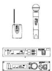
All systems include either a ULXS4 Standard Diversity Receiver or ULXP4 Professional Diversity Receiver.
natural_image
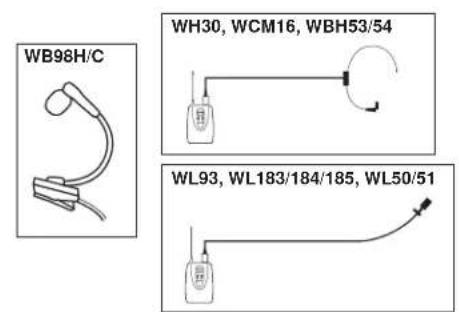
Technical line drawing of a wireless device with two speakers and control panel (no text or symbols)Bodypack systems include a choice of lavalier, headworn, or instrument microphones.
text_image
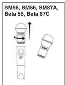
WB98H/C WH30, WCM16, WBH53/54 WL93, WL183/184/185, WL50/51Handheld systems include a choice of interchangeable microphone heads.
text_image
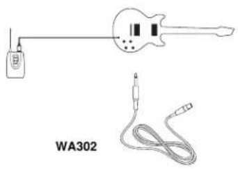
SM58, SM86, SM87A, Beta 58, Beta 87CGuitar systems include a 1/4" to mini 4-pin cable.
text_image
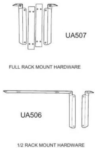
WA302ULXP4 receivers include rack-mounting hardware.
text_image
UA507 FULL RACK MOUNT HARDWARE UA506 1/2 RACK MOUNT HARDWAREAntennas
Active Antennas
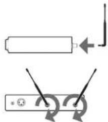
The antenna connectors on the ULX receiver provide 12 V DC for active circuit antennas.
Caution: Use only Shure antenna accessories to ensure the best operation. Do not use splitters, combiners, or antennas that provide a DC ground, as this can cause the receiver to function improperly.
natural_image
Pure electrical circuit lines without any symbolsAntenna Combiners and Accessories
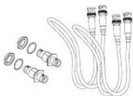
The supplied antennas can be connected directly to the BNC-type ANTENNA connectors. However, optional antenna mounting accessories from Shure can improve reception and reduce rack clutter. Use the following guidelines:
- Antennas and receivers must be from the same band.
- Mount antennas more than 40 cm (16 inches) apart.
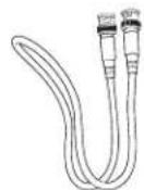
- Use Shure UA825 or UA850 low-loss coaxial antenna cable (or any 50 ohm, low-loss cable such as RG-8U).
Visit www.shure.com for more information on wireless antenna accessories.
Coaxial Cables
natural_image
Illustration of various cable connectors and fittings (no text or symbols)Front Mount Antenna Kit
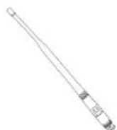
1/2-Wave Antenna included with ULXP4 systems
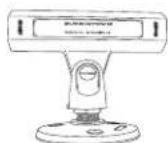
Inline Antenna Amplifier for long antenna cable run
natural_image
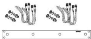
Two identical cable connectors with terminal connectors, shown above a separate panel with circular and rectangular elements (no text or symbols visible)Antenna Rack Mount Kit
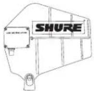
Active Directional Antenna
for more focused reception

Distribution Amplifier
combines antennas and power supplies for multiple receivers
Rack Installation
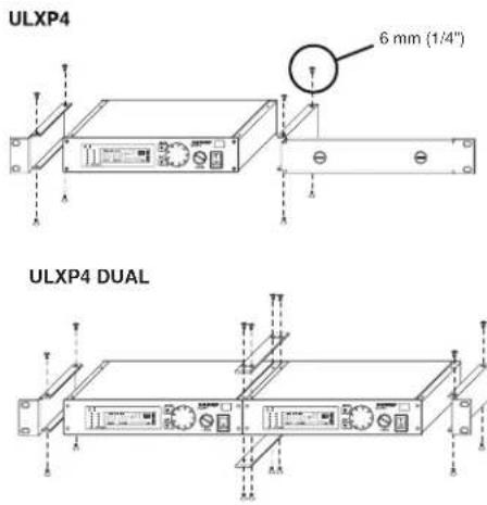
text_image
ULXP4 6 mm (1/4") ULXP4 DUALRackmount Options
The following shows rackmounting options for one to four receivers and lists the required accessories.
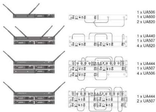
text_image
1 x UA506 1 x UA600 2 x UA820 1 x UA440 1 x UA507 4 x UA820 1 x UA444 1 x UA507 4 x UA506 1 x UA444 2 x UA507Power
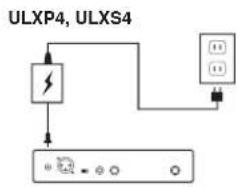
flowchart
graph TD
    A["ULXP4, ULXS4"] --> B["Battery"]
    B --> C["Power Line"]
    C --> D["Device 1"]
    C --> E["Device 2"]
    C --> F["Device 3"]
Power switch Power Connector
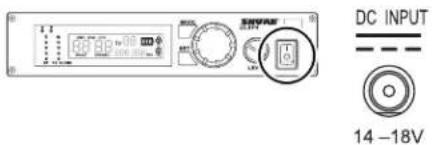
text_image
DC INPUT 14 -18VConnect using the supplied AC adapter or certified 14–18 Vdc (550 mA) replacement supply.
Batteries
Installation
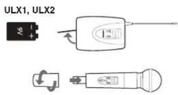
text_image
ULX1, ULX2 A6Battery Life
Use only 9V alkaline or lithium batteries. Typical life for common types of 9V batteries are listed below. For detailed information on battery performance, contact Shure Applications Engineering.
Recommended:
• Lithium (16 hours)
- Alkaline (8 hours)
Not recommended:
• Carbon-Zinc ( 12 hour)
• Rechargeable Ni-Cd (2 hours)
• Rechargeable Ni-MH (2½ hours)
Note:
- Battery life varies with type and manufacturer.
- Batteries stored for more than a year or stored in excessively hot environments may experience a higher failure rate.
- Do not use rechargeable batteries with a fully-charged rating of greater than 9 V (for example, 9.6 V).
- Transmitters require a minimum of 6 V to operate.
Power/Mute Switch
- Turn transmitter off to mute the microphone or conserve battery power.
- Use the lock feature to avoid accidental muting of the microphone during a performance.
Battery Indicator
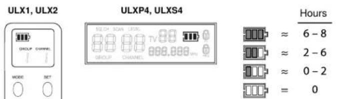
Both the transmitter and receiver LCD shows approximate operation time remaining for the transmitter.
Single System
If you encounter wireless interference, perform a channel scan on the receiver and use the selected channel. You usually do not need to change the group.
Multiple Systems
To maximize performance, set all wireless systems to different channels from the same group. These channels are selected to work well together.
Follow these steps when using group and channel scan with multiple systems.
- Power off all system transmitters. Turn on all other wireless or digital devices as they would be during the performance or presentation.
- On the first receiver: Perform a group scan. Note the selected group, then use channel scan to find the first open channel in that group.
- Power on the first transmitter and set it to the selected group and channel.
-
IMPORTANT: Leave the first transmitter powered on while setting up the next system.
-
For each additional system: Set to the same group as the first. Perform a channel scan and set the receiver and transmitter to the selected channel.
- Leave each transmitter on while setting up additional systems.
Note:
- Keep each transmitter at least two meters (6 feet) apart.
- If using systems from different bands, set up all systems from the same band together.
Tip: To reduce setup time, you can manually set up the group and channels before arriving at the venue. Visit www.shure.com for a list of groups and channels that are anticipated to be free of interference in a particular city or region.
Automatic Frequency Scan
Channel Scan
This feature scans for an open channel in the selected group.
①
ULXP4, ULXPS4
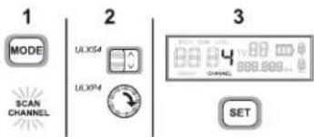
text_image
1 MODE SCAN CHANNEL 2 ULX5M ULXPM 3 SETULX1, ULX2
②
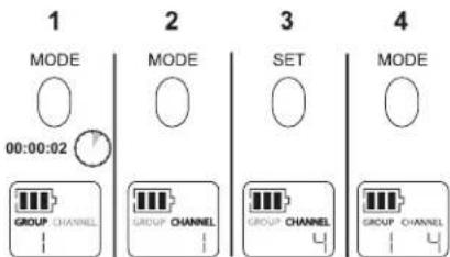
text_image
1 MODE 00:00:02 2 MODE SET 3 MODE GROUP CHANNEL GROUP CHANNEL GROUP CHANNEL GROUP CHANNELGroup Scan (ULXP4 only)
The "group scan" feature on the ULXP helps maximize the number of systems you can install at a single venue. It scans for wireless interference and finds the group with the most open channels.
ULXP4
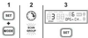
text_image
1 SET + MODE 2 SCAN GROUP 3 3.88x60000000000000000000000000000000000 GROUP OPEN CH... SETChanging Group and Channel
If you encounter wireless interference, set the receiver and transmitter to a different channel or group.
Change Channel
ULXP4, ULXS4

ULX1, ULX2
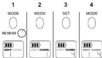
text_image
1 MODE 00:00:02 2 MODE SET 3 MODE GROUP CHANNEL GROUP CHANNEL GROUP CHANNEL GROUP CHANNELChange Group
ULXP4, ULXS4
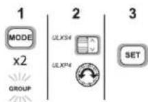
ULX1, ULX2
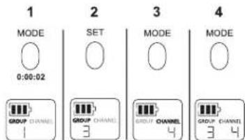
text_image
1 MODE 0:00:02 2 SET GROUP CHANNEL 3 3 MODE GROUP CHANNEL 4 4 MODE GROUP CHANNEL 3 4* Note: You can reverse the scroll direction by holding SET and pressing MODE.
Wireless Indicators
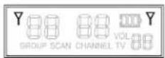
RF Indicator
Indicates wireless activity over the selected channel.
Note: When the antenna and battery indicators are illuminated, the RF indicator shows signal strength from the transmitter. Otherwise, it is showing interference from another source. Select a different channel.
This indicator shows which antenna is receiving the strongest signal from the transmitter.
ULXP4

ULXS4
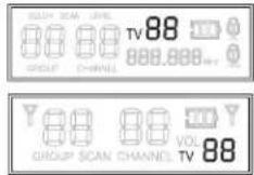
Frequency Display
ULXP4

TV
For models sold in the United States only. Displays the TV channel occupied by the selected frequency.
ULXP4, ULXPS4
Frequency Master List Mode
Master List mode offers more precise frequency selection for larger, multiple-system installations.
Enter Master List mode on the receiver or transmitter by holding down the SET button for 10 seconds. Set GROUP and CHANNEL as you would in normal mode.
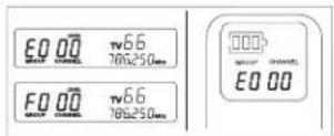
Note: The unit must remain in Master List mode to operate at the selected frequency.
Exit Master List mode by holding the SET button for 10 seconds.

10 s
Squelch
The factory setting offers the optimum performance for most installations.
Increasing squelch filters out all but the highest quality signal, but this decreases operating range. Decreasing squelch extends the operating range, but can increase signal noise.
ULXP4
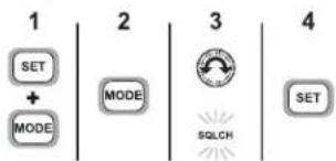
text_image
1 SET + MODE 2 MODE 3 SQLCH 4 SETAudio Output
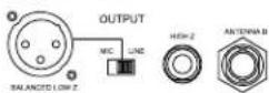
Audio Output Connectors
Balanced XLR: Connect to a mixer or other professional audio input. Use the MIC/LINE switch to adjust for microphone or line-level inputs.
Unbalanced 6.35 mm (1/4"):
Connect to high impedance inputs, such as a guitar amplifier.
Note: The LINE/MIC switch does not affect the 6.35 mm (1/4") jack.
ULXP4, ULXS4
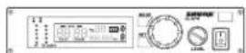
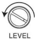
Receiver Output Level
Adjusts the level of the receiver's audio outputs.
ULXP4
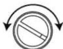
LEVEL
PEAK Icon
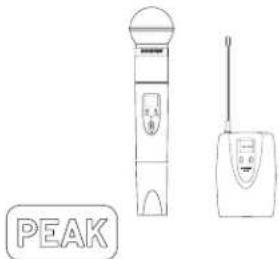
This icon appears when the input signal overloads the transmitter. The icon is displayed for 2 seconds after input overload is detected.
ULX1, ULX2
text_image
PEAK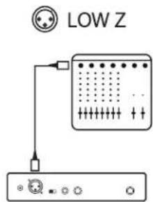
text_image
LOW Z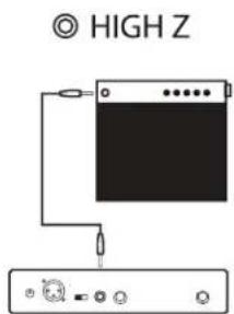
text_image
HIGH ZTransmitter Gain
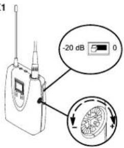
For best audio quality, adjust transmitter gain so only the green and yellow TXAUDIO LEDs flicker. (Occasional illumination of the red LED is okay.)
Green = nominal
Yellow = peak
Red = overload
ULX1
text_image
1 -20 dB 5 0 ↓ULX2

text_image
ULX2 GAINTX
RF AUDIO
Audio Input Meter
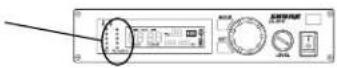
ULX1
- Set the attenuator (pad) switch to 0 dB for microphones and -20 dB for guitars. (Some low output instruments may not need attenuation.)
- Adjust gain control as necessary.
ULX2
- Fully clockwise for quiet to normal vocal performance.
• Halfway counterclockwise for loud vocal performance. - Fully counterclockwise for horn or percussive instruments.
Locking the Transmitter
Lock/Unlock Power (On)
Hold SET and MODE for four seconds or until the lock icon appears.
ULX1, ULX2
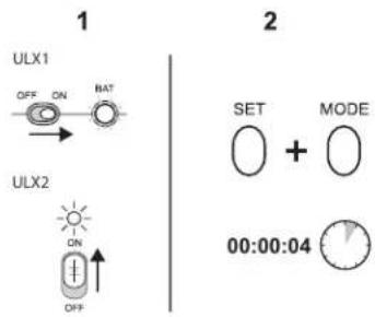
text_image
1 ULX1 OFF ON BAT ULX2 ON OFF 2 SET + MODE 00:00:04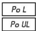
power lock
power unlock
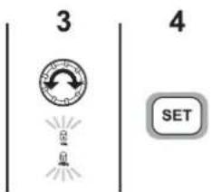
Locking the Receiver (ULXP4 Only)
This feature prevents accidental setting changes.
ULXP4
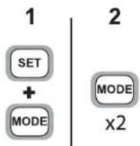
flowchart
graph TD
    A["SET"] --> B["+"]
    C["MODE"] --> B
    B --> D["MODE"]
    D --> E["x2"]
text_image
3 4 SET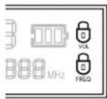
lock volume
lock frequency
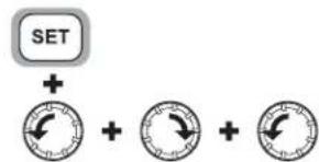
Unlocking
Hold the SET button while turning the control wheel left, right, left.
ULXP4
text_image
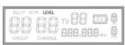
SET +Note: If LEVEL flashes on the LCD, decrease the LEVEL control to continue. This feature safeguards against sudden level increases when the lock is removed.
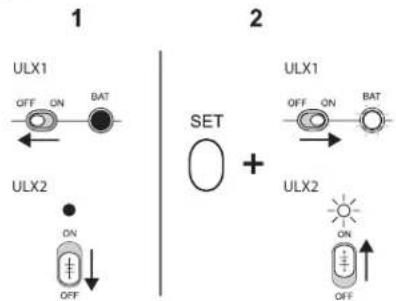
Lock/Unlock Frequency
Hold the SET button while powering on the transmitter.
ULX1, ULX2
text_image
1 ULX1 OFF ON BAT 2 SET + ULX1 OFF ON BAT ULX2 ON OFF ULX2 ON OFF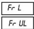
frequency lock
frequency unlock
Troubleshooting
No power: Check battery and power supply connections and voltage. Check the power switch on the transmitter.
The LCD displays "E0 00" or similar code: Exit master list mode by holding the SET button for ten seconds.
Can't turn off or change settings on the transmitter or receiver: The interface is locked. See the section on locking the interface.
No audio: If the antenna and battery indicators do not appear on the receiver, then it is not receiving a signal from the transmitter. Make sure the transmitter and receiver are tuned to the same group and channel.
Faint or distorted audio: Adjust transmitter gain, bodypack attenuator switch, and receiver output level.
Noise: Noise usually results from wireless interference or a weak signal from the transmitter. See Tips for Improving System Performance.
Tips for Improving System Performance
If you encounter wireless interference or dropouts, try the following:
- Replace the transmitter battery with a fresh alkaline battery (avoid rechargeable batteries).
- Choose a different frequency channel.
- Reposition the antennas so there is nothing obstructing a line of sight to the transmitter (including the audience).
- Avoid placing transmitter and receiver where metal or other dense materials may be present.
-
Move the receiver to the top of the equipment rack (or remote mount antennas outside the rack).
-
Remove nearby sources of wireless interference, such as cell phones, two-way radios, computers, media players, and digital signal processors.
- Keep transmitters more then two meters (6 feet) apart.
- Keep the transmitter and receiver more than 5 meters (15 ft) apart.
- Point the receiver antenna tips away from each other at a 45^ angle, and keep them away from large metal objects.
- During sound check, mark "trouble spots" and ask presenters or performers to avoid those areas.
Parts and Accessories
Included Accessories
| Microphone Stand Adapter (ULX2) | WA371 |
| Grip/Switch Cover (ULX2) | WA555 |
| Zipper Bag (ULX1) | 95A2313 |
| Zipper Bag (ULX2) | 95B2313 |
| Screwdriver (ULX2) | 80A498 |
Optional Accessories
| Passive Antenna Splitter/Combiner Kit | UA221 |
| UHF Line Amplifier | UA830WB |
| UHF Powered Directional Antenna | UA874US |
| UA874E | |
| UA874WB | |
| UA874X | |
| UHF Antenna Power Distribution Amplifier (U.S.A.) | UA844SWB |
| UHF Antenna Power Distribution Amplifier (Europe) | UA844SWB-E |
| UHF Antenna Power Distribution Amplifier (UK) | UA844SWB-UK |
| 33 m (100 ft.) BNC-BNC cable | UA8100 |
| 1.8 m (6 ft.) BNC-BNC cable | UA806 |
| Antenna Rack Panel | UA440 |
| Front Mount Antenna Kit (Includes 2 cables and 2 bulkhead adapters) | UA600 |
| Remote Antenna Bracket with BNC Bulkhead Adapter | UA505 |
| Rack Mount Kit for single Receiver | UA506 |
| Rack Mount Kit for Two Receivers | UA507 |
| Carrying Case | WA610 |
| Microphone Adapter Cable (XLR) | WA310 |
Replacement Parts
| AC Adapter (120 VAC, 60 Hz) PS41 | |
| AC Adapter (220 VAC, 50 Hz) PS41AR | |
| AC Adapter (230 VAC, 50/60 Hz) PS41AZ | |
| AC Adapter (230 VAC, 50/60 Hz, Europlug) PS41E | |
| AC Adapter (230 VAC, 50/60 Hz) PS41UK | |
| AC Adapter (100 VAC, 50/60 Hz) PS41J | |
| SM58- Cartridge with Grille (ULX2/58) RPW112 | |
| BETA 58A- Cartridge with Grille (ULX2/ BETA 58) RPW118 | |
| SM86 Cartridge with Grille (ULX2/SM86) RPW114 | |
| SM87A Cartridge with Grille (ULX2/87) RPW116 | |
| BETA 87A Cartridge with Grille (ULX2/BETA 87A) RPW120 | |
| BETA 87C Cartridge with Grille (ULX2/BETA 87C ) RPW122 | |
| Matte Silver Grille for SM58 RK143G | |
| Matte Silver Grille for SM86 RPM226 | |
| Matte Silver Grille for BETA 58A RK265G | |
| Matte Silver Grille for BETA 87A RK312 | |
| Black Grille for SM87A RK214G | |
| Black Grille for BETA 58A RPM323G | |
| Black Grille for BETA 87A and BETA 87C RPM324G | |
| Belt Clip 44A8013A | |
| 1/4-Wave Antenna (470 - 752 MHz) | UA400B |
| 1/4-Wave Antenna (774 - 952 MHz) | UA400 |
| 1/2-Wave Antenna (774 - 865 MHz) | UA8-774-865 |
| 1/2-Wave Antenna (638 - 698 MHz) | UA8-638-698 |
| 1/2-Wave Antenna (554 - 590 MHz) | UA8-554-590 |
| 1/2-Wave Antenna (740 - 814 MHz) | UA8-740-814 |
| 1/2-Wave Antenna (470 - 530 MHz) | UA8-470-530 |
| 1/2-Wave Antenna (746 - 784 MHz) | UA8-746-784 |
| 1/2-Wave Antenna (572 - 596 MHz) | UA8-572-596 |
| 1/2-Wave Antenna (578 - 638 MHz) | UA8-578-638 |
Certifications
This product meets the Essential Requirements of all relevant European directives and is eligible for CE marking.
The CE Declaration of Conformity can be obtained from: www.shure.com/europe/compliance
Authorized European representative:
Shure Europe GmbH
Headquarters Europe, Middle East & Africa
Department: EMEA Approval
Jakob-Dieffenbacher-Str. 12
75031 Eppingen, Germany
Phone: 49-7262-92 49 0
Fax: 49-7262-92 49 11 4
Email: EMEAsupport@shure.de
ULX1, ULX2
Certified under FCC Part 74.
Certified by IC in Canada under RSS-123 and RSS-102.
Approved under the Declaration of Conformity (DoC) provision of FCC Part 15.
Certified in Canada by IC to RSS-123.
Important Product Information
LICENSING INFORMATION
Licensing: A ministerial license to operate this equipment may be required in certain areas. Consult your national authority for possible requirements. Changes or modifications not expressly approved by Shure Incorporated could void your authority to operate the equipment. Licensing of Shure wireless microphone equipment is the user's responsibility, and licensability depends on the user's classification and application, and on the selected frequency. Shure strongly urges the user to contact the appropriate telecommunications authority concerning proper licensing, and before choosing and ordering frequencies.
Information to the user
This equipment has been tested and found to comply with the limits for a Class B digital device, pursuant to Part 15 of the FCC Rules. These limits are designed to provide reasonable protection against harmful interference in a residential installation. This equipment generates uses and can radiate radio frequency energy and, if not installed and used in accordance with the instructions, may cause harmful interference to radio communications. However, there is no guarantee that interference will not occur in a particular installation. If this equipment does cause harmful interference to radio or television reception, which can be determined by turning the equipment off and on, the user is encouraged to try to correct the interference by one or more of the following measures:
- Reorient or relocate the receiving antenna.
- Increase the separation between the equipment and the receiver.
- Connect the equipment to an outlet on a circuit different from that to which the receiver is connected.
- Consult the dealer or an experienced radio/TV technician for help.
Note: EMC conformance testing is based on the use of supplied and recommended cable types. The use of other cable types may degrade EMC performance.
Please follow your regional recycling scheme for batteries, packaging, and electronic waste.
WARNING: This product contains a chemical known to the State of California to cause cancer and birth defects or other reproductive harm.
Australia Warning for Wireless
This device operates under an ACMA class licence and must comply with all the conditions of that licence including operating frequencies. Before 31 December 2014, this device will comply if it is operated in the 520-820 MHz frequency band. WARNING: After 31 December 2014, in order to comply, this device must not be operated in the 694-820 MHz band.
Wiring Diagram
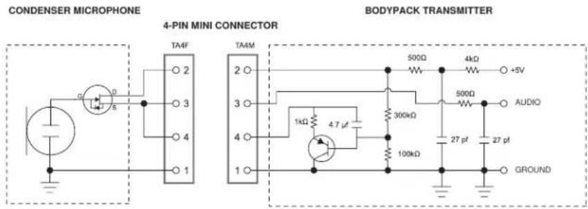
text_image
CONDENSER MICROPHONE 4-PIN MINI CONNECTOR TA4F TA4M 500Ω 4kΩ +5V 300kΩ 500Ω AUDIO 1kΩ 4.7 μF 100kΩ 27 pt 27 pt GROUND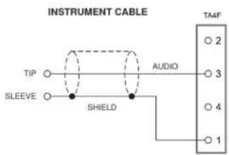
text_image
INSTRUMENT CABLE TIP SLEEVE AUDIO SHIELD TA4F 2 3 4 1Specifications
RF Carrier Range
470,000-865,000 MHz
varies by region
Working Range
100 m (300 ft) typical
Note: Actual range depends on RF signal absorption, reflection and interference.
Audio Frequency Response
25 Hz - 15 kHz, ±2 dB
Note: Dependent on microphone type
Modulation
±38 kHz deviation compressor-expander system with pre- and de-emphasis
Dynamic Range
100 dB, A-weighted
Image Rejection
80 dB, typical
RF Sensitivity
1.26 μV for 12 dB SINAD, typical
Spurious Rejection
75 dB, typical
Ultimate Quieting
Ref. ±38 kHz deviation with 1 kHz tone
105 dB, A-Weighted
Total Harmonic Distortion
Ref. ±38 kHz deviation with 1 kHz tone
0.3%, typical
Operating Temperature Range
-20°C (-4°F) to 49°C (120°F)
Note: Battery characteristics may limit this range.
Polarity
Positive pressure on microphone diaphragm (or positive voltage applied to tip of WA302 phone plug) produces positive voltage on pin 2 (with respect to pin 3 of low-impedance output) and the tip of the high impedance 1/4-inch output.
Battery Life
8 to 9 hours (9 V alkaline)
ULX1
Gain Adjustment Range
25 dB
Attenuation Switch
0, -20 dB
Dimensions
96.5 x 67 x 26.7 mm (3.86 x 2.68 x 1.10 in.), H x W x D
Weight
79 g (2.8 oz.) without batteries
Power Requirements
9 V alkaline
Input Impedance
1 MΩ
RF Output Power
30 mW maximum
varies by region
Transmitter Input
Connector
4-Pin male mini connector (TA4M)
Configuration
Unbalanced, active
Impedance
| Microphone | 75 kΩ |
| WA302 | 1 MΩ |
Maximum Input Level
1 kHz at 1% THD
| Microphone | -4 dBV (1.82 Vp-p) | |
| WA302 | PAD OFF (0dB) | 5 dBV (5 Vp-p) |
| PAD ON (-20dB) | 25 dBV (50 Vp-p) | |
Pin Assignments
TA4M
| 1 | ground (cable shield) |
| 2 | + 5 V Bias |
| 3 | audio |
| 4 | Tied through active load to ground (On instrument adapter cable, pin 4 floats) |
ULX2
Gain Adjustment Range
20 dB
Dimensions
| SM58 | 229 x 51 mm (9 x 2 in.), L x Dia. |
| BETA 58 | 221 x 51 mm (8.7 x 2 in.), L x Dia. |
| SM86 | 213 x 49 mm mm (8.4 x 1.9 in.), L x Dia. |
| SM87/BETA 87 | 223 x 51 mm (8.8 x 2 in.), L x Dia. |
Weight
| SM58/BETA 58 | 289 g (10.2 oz.) without batteries |
| SM86 | 251 g (8.8 oz.) without batteries |
| SM87/BETA 87 | 258 g (9.1 oz.) without batteries |
Power Requirements
9 V alkaline
RF Output Power
30 mW maximum
varies by region
Transmitter Input
Configuration
Unbalanced, active
Impedance
20 kΩ
Maximum Input Level
1 kHz at 1% THD
12 dBV (10 Vp-p)
ULXS4, ULXP4
Dimensions
| ULXS4 | 43 x 214 x 163 mm (1.72 x 8.56 x 6.52 in.), H x W x D |
| ULXP4 | 43 x 214 x 172 mm (1.72 x 8.56 x 6.88 in.), H x W x D |
Weight
| ULXS4 | 1049 g (2 lbs, 5 oz.) |
| ULXP4 | 1105 g (2 lbs, 7 oz.) |
Power Requirements
14–18 V DC (negative ground), 550 mA
Analog Audio Output
Configuration
| XLR Output | Active Balanced |
| 6.35 mm (1/4") output | Unbalanced |
Impedance
| XLR Output | MIC setting | 1848 Ω |
| LINE setting | 75 Ω | |
| 6.35 mm (1/4") output | 3 kΩ | |
Maximum Audio Output Level
Ref. ±38 kHz deviation with 1 kHz tone
| XLR connector (Into 600 Ω load) | MIC setting | -17 dBV |
| LINE setting | +3.9 dBV | |
| 6.35 mm (1/4") connector (Into 3 kΩ load) | -2 dBV | |
Pin Assignments
| XLR Output | 1=ground, 2=hot, 3=cold |
| 6.35 mm (1/4") connector | Tip=audio, Ring/Sleeve=ground |
Receiver Antenna Input
Connector Type
BNC
Impedance
50 Ω
Nominal Input Level
-95 to -30 dBm
Maximum Input Level
-20 dBm
DC bias
12 V DC, 150 mA, maximum
ULX FREQUENCIES FOR EUROPEAN COUNTRIES
| ULX-G3E 470 - 506 MHz, max. 30 mW | |
| Country Code Frequency Range | |
| Code de Pays Gamme de frequencies | |
| Codice di paese Gamme di frequenza | |
| Código de país Gama de frequencias | |
| Länder-Kürzel Frequenzbereich | |
| A, B, BG, CH, CY, CZ, D, EST | 470 - 506 MHz * |
| F, GB, GR, H, I, IS, L, LT | 470 - 506 MHz * |
| NL, P, PL, S, SK, SLO | 470 - 506 MHz * |
| DK, FIN, M, N | * |
| HR, E, IRL, LV, RO, TR | * |
| all other countries | * |
| ULX R4 784–820 MHz max. 30 mW | |
| Country Code: | Frequency Range |
| Code de Pays: | Gamme de frequencies |
| Codice di paese: | Gamme di frequenza |
| Código de país: | Gama de frequencias |
| Länder-Kürzel: | Frequenzbereich |
| A, B, CH, D, E, F, GB 784–820 MHz * | |
| GR, I, IRL, L, NL, P | 784–820 MHz * |
| DK, N | 800-820 MHz * |
| FIN | 800.1–819.9 MHz * |
| S | 800–814 MHz * |
| I, GB, All other Countries | * |
| ULX J2 554–590 MHz max. 30 mW | |
| Country Code: Frequency Range | |
| Code de Pays: Gamme de frequencies | |
| Codice di paese: Gamme di frequenza | |
| Código de país: Gama de frequencias | |
| Länder-Kürzel: Frequenzbereich | |
| A, B, CH, D, E, F, GB 554–590 MHz * | |
| GR, I, IRL, L, NL, P 554–590 MHz * | |
| DK, FIN, N, S | * |
| All other Countries | * |
| ULX S3 829–865 MHz max. 10 mW | |
| Country Code: | Frequency Range |
| Code de Pays: | Gamme de frequencies |
| Codice di paese: | Gamme di frequenza |
| Código de país: | Gama de frequencias |
| Länder-Kürzel: | Frequenzbereich |
| A, B, CH, D, E | 829–865 MHz * |
| GR, IRL, L, NL, P | 838–862 MHz * |
| GB | 830-865 MHz* |
| DK, F, FIN, I, N, S 863–865 MHz* | |
| All other Countries | * |
| ULX-K2E 606 - 642 MHz, max. 10 mW | |
| Country Code Frequency Range | |
| Code de Pays Gamme de frequencies | |
| Codice di paese Gamme di frequenza | |
| Código de país Gama de frequencias | |
| Länder-Kürzel Frequenzbereich | |
| A, BG, CH, CY, CZ, D, EST 606 - 642 MHz * | |
| F, GB, GR, H, I, IS, L, LT 606 - 642 MHz * | |
| P, PL, S, SK, SLO 606 - 642 MHz * | |
| B, DK, FIN, M, N, NL * | |
| HR, E, IRL, LV, RO, TR * | |
| all other countries * | |
| ULX Q2 748–784 MHz max. 30 mW | |
| Country Code: | Frequency Range |
| Code de Pays: | Gamme de frequencies |
| Codice di paese: | Gamme di frequenza |
| Código de país: | Gama de frequencias |
| Länder-Kürzel: | Frequenzbereich |
| A, B, CH, D, E, F, GB | 748–784 MHz * |
| GR, I, IRL, L, NL, P | 748–784 MHz * |
| DK, FIN, N, S | * |
| All other Countries | * |
| ULX M2 662-698 MHz max. 30 mW | |
| Country Code: Frequency Range | |
| Code de Pays: Gamme de frequencies | |
| Codice di paese: Gamme di frequenza | |
| Código de país: Gama de frequencias | |
| Länder-Kürzel: Frequenzbereich | |
| A, B, CH, D, E, F, GB 662-698 MHz * | |
| GR, I, IRL, L, NL, P 662-698 MHz * | |
| DK, FIN, N, S | * |
| All other Countries | * |
ULX SYSTEM COMPATIBILITY GUIDE FOR FREQUENCY BAND G3E (470–506 MHz)
| Channel | Group 1 Group 2 | Group 3 Group 4 Group | 5 Group 6 Group 7 | ||||
| Full Range max. # of compatible frequencies (option 1) | Full Range max. # of compatible frequencies (option 2) | Full Range max. # of compatible frequencies (option 3) | France preferred: User Group A (option 1) | France preferred: User Group A (option 2) | France preferred: User Group A (option 3) | France preferred: User Group B (option 1) | |
| 1 | 470.775 470.250 | 470.450 470.750 471.500 | 470.750 472.025 | ||||
| 2 | 471.525 471.950 | 473.575 471.500 472.500 | 471.750 472.775 | ||||
| 3 | 473.350 473.300 | 474.125 472.500 473.750 | 472.500 474.225 | ||||
| 4 | 474.875 474.175 | 475.150 473.250 474.500 | 474.500 474.975 | ||||
| 5 | 476.150 475.700 | 476.450 473.750 475.500 | 475.750 476.900 | ||||
| 6 | 476.850 476.875 | 476.975 474.500 476.250 | 476.250 477.700 | ||||
| 7 | 477.775 478.875 | 479.025 475.500 480.500 | 478.750 480.025 | ||||
| 8 | 480.000 479.950 | 480.725 479.750 481.250 | 479.250 480.775 | ||||
| 9 | 481.250 481.525 | 482.150 483.250 481.750 | 480.500 486.100 | ||||
| 10 | 481.900 482.300 | 483.275 484.250 483.250 | 482.500 490.225 | ||||
| 11 | 483.400 483.925 | 484.175 487.250 483.750 | 483.250 490.975 | ||||
| 12 | 484.300 485.025 | 485.600 487.750 486.750 | 483.750 492.900 | ||||
| 13 | 488.250 486.850 | 488.575 489.250 487.750 | 487.500 493.700 | ||||
| 14 | 490.175 491.925 | 489.875 489.750 489.250 | 489.750 496.775 | ||||
| 15 | 491.500 492.425 | 493.425 490.500 490.500 | 491.500 498.225 | ||||
| 16 | 494.250 494.000 | 494.450 491.500 491.500 | 495.250 498.975 | ||||
| 17 | 495.025 495.125 | 495.250 495.500 495.750 | 496.500 500.900 | ||||
| 18 | 495.550 497.225 | 496.725 496.500 496.500 | 497.250 501.700 | ||||
| 19 | 497.600 498.575 | 497.300 497.250 498.500 | 498.500 504.025 | ||||
| 20 | 499.350 500.175 | 499.650 498.500 499.500 | 499.500 504.775 | ||||
| 21 | 500.575 500.700 | 501.675 499.250 500.250 | 502.750 | ||||
| 22 | 501.325 503.675 | 502.325 500.250 502.750 | 503.500 | ||||
| 23 | 502.300 504.400 | 504.275 502.750 503.500 | 504.500 | ||||
| 24 | 504.725 505.450 | 505.300 504.500 505.750 | 505.250 |
| Channel | Group 8 Group 9 Group 10 Group 11 Group 12 Group 13 Group 14 Group 15 | Group 16 | |||||||
| France preferred:User Group B (option 2) | France preferred:User Group B (option 3) | France preferred:User Group C (option 1) | France preferred:User Group C (option 2) | France preferred:User Group C (option 3) | European TV channel 21 optimized470 - 478 MHz | European TV channel 22 optimized478 - 486 MHz | European TV channel 23 optimized486 - 494 MHz | European TV channel 24 optimized494 - 502 MHz | |
| 1 | 470.500 | 472.025 | 470.300 | 470.300 | 470.300 | 470.300 | 478.300 | 486.300 | 494.300 |
| 2 | 472.025 | 473.500 | 471.000 | 471.000 | 471.000 | 471.025 | 479.025 | 487.025 | 495.025 |
| 3 | 472.775 | 477.300 | 472.225 | 474.025 | 472.225 | 471.525 | 479.525 | 487.525 | 495.525 |
| 4 | 474.225 | 478.100 | 474.775 | 474.775 | 474.775 | 472.275 | 480.275 | 488.275 | 496.275 |
| 5 | 477.300 | 480.025 | 476.000 | 476.000 | 476.000 | 473.275 | 481.275 | 489.275 | 497.275 |
| 6 | 478.500 | 480.775 | 476.700 | 476.700 | 476.700 | 473.875 | 481.875 | 489.875 | 497.875 |
| 7 | 480.025 | 482.225 | 478.300 | 478.300 | 478.300 | 474.775 | 482.775 | 490.775 | 498.775 |
| 8 | 480.775 | 482.975 | 479.000 | 479.000 | 479.000 | 475.250 | 483.250 | 491.250 | 499.250 |
| 9 | 482.225 | 484.900 | 480.225 | 480.225 | 480.225 | 475.975 | 483.975 | 491.975 | 499.975 |
| 10 | 485.300 | 485.700 | 482.775 | 484.700 | 484.000 | 476.950 | 484.950 | 492.950 | 500.950 |
| 11 | 492.900 | 490.225 | 484.000 | 490.775 | 484.700 | 477.675 | 485.675 | 493.675 | 501.675 |
| 12 | 493.700 | 492.900 | 492.700 | 492.000 | 490.775 | ||||
| 13 | 496.775 | 493.700 | 494.300 | 494.300 | 494.300 | ||||
| 14 | 498.225 | 496.025 | 495.000 | 495.000 | 495.000 | ||||
| 15 | 498.975 | 496.775 | 496.225 | 496.225 | 496.225 | ||||
| 16 | 500.900 | 501.300 | 498.775 | 498.775 | 498.775 | ||||
| 17 | 502.500 | 502.100 | 500.000 | 500.000 | 500.000 | ||||
| 18 | 504.775 | 504.025 | 500.700 | 500.700 | 500.700 | ||||
| 18 | 505.500 | 505.500 | 502.300 | 502.300 | 502.300 | ||||
| 20 | 503.000 | 503.000 | 503.000 | ||||||
| 21 | 504.225 | 504.225 | 504.225 | ||||||
ULX SYSTEM COMPATIBILITY GUIDE FOR FREQUENCY BAND K2E (606-642 MHz)
| Channel | Group 1 Group 2 Group 3 Group | 4 Group 5 Group 6 | Group 7 Group 8 | Group 9 | |||||
| Full Range max. # of compatible frequencies (option 1) | Full Range max. # of compatible frequencies (option 2) | Full Range max. # of compatible frequencies (option 3) | Full Range max. # of compatible frequencies, Ch. 38 excluded (option 1) | Full Range max. # of compatible frequencies, Ch. 38 excluded (option 2) | Full Range max. # of compatible frequencies, Ch. 38 excluded (option 3) | U.K. preferred: TV ch. 38 606-614 MHz with 500 kHz guard band (option 1) | U.K. preferred: TV ch. 38 606-614 MHz with 500 kHz guard band (option 2) | U.K. preferred: TV ch. 38 606-614 MHz with 500 kHz guard band (option 3) | |
| 1 | 606.450 606 | 800 606.150 614 | 200 614.125 614 | 225 606.775 606 | 650 606.500 | ||||
| 2 | 607.250 608 | 300 607.350 614 | 950 615.200 615 | 175 607.300 607 | 625 607.150 | ||||
| 3 | 608.725 608 | 925 607.825 615 | 450 615.925 615 | 875 608.325 608 | 375 608.025 | ||||
| 4 | 609.900 610 | 375 608.775 616 | 950 617.125 616 | 350 609.100 608 | 850 608.525 | ||||
| 5 | 611.325 611 | 525 612.875 617 | 575 618.050 617 | 275 609.600 609 | 725 609.300 | ||||
| 6 | 611.825 612 | 175 613.350 619 | 925 619.875 618 | 950 610.500 610 | 350 610.325 | ||||
| 7 | 613.075 613 | 450 615.300 620 | 675 620.425 620 | 100 611.125 611 | 325 610.975 | ||||
| 8 | 615.150 614 | 400 616.150 621 | 175 621.375 621 | 1025 612.175 612 | 2075 611.875 | ||||
| 9 | 615.725 615 | 000 616.700 623 | 375 623.500 622 | 475 612.925 612 | 2575 612.350 | ||||
| 10 | 616.950 615 | 825 617.475 624 | 125 626.125 623 | 375 613.450 613 | 400 613.075 | ||||
| 11 | 617.875 616 | 900 620.275 628 | 950 628.125 625 | 325 | |||||
| 12 | 619.350 619 | 150 621.375 630 | 400 629.425 631 | 275 | |||||
| 13 | 621.200 628 | 325 624.175 632 | 175 630.350 632 | 275 | |||||
| 14 | 626.425 628 | 875 628.550 633 | 025 631.500 632 | 775 | |||||
| 15 | 628.100 630 | 525 629.125 633 | 525 633.875 633 | 950 | |||||
| 16 | 631.900 631 | 125 630.500 635 | 150 635.600 634 | 550 | |||||
| 17 | 632.750 635 | 400 633.700 636 | 150 636.600 635 | 950 | |||||
| 18 | 634.300 636 | 375 634.700 637 | 725 637.900 637 | 600 | |||||
| 19 | 635.425 636 | 850 636.325 638 | 550 638.750 638 | 325 | |||||
| 20 | 636.250 637 | 800 637.625 639 | 025 639.925 639 | 850 | |||||
| 21 | 638.625 638 | 975 638.525 640 | 575 640.550 640 | 950 | |||||
| 22 | 639.525 639 | 450 639.175 641 | 650 641.400 641 | 750 | |||||
| 23 | 640.150 640 | 575 640.050 | |||||||
| 24 | 641.300 641 | 325 641.250 | |||||||
| Channel | Group 10 Group 11 Group 12 | Group 13 Group | 14 Group 15 Group | 16 Group 17 | Group 18 | ||||
| France preferred:User Group A (option 1)614 - 642 MHz | France preferred:User Group A (option 2)614 - 642 MHz | France preferred:User Group B (option 1)614 - 642 MHz | France preferred:User Group B (option 2)614 - 642 MHz | France preferred:User Group C (option 1)614 - 642 MHz | France preferred:User Group C (option 1)614 - 642 MHz | European TV channel 39 optimized614 - 622 MHz | European TV channel 40 optimized622 - 630 MHz | European TV channel 41 optimized630 - 638 MHz | |
| 1 | 614.750 614 | 750 614.500 616 | 025 614.300 640 | 975 614.200 622 | 200 630.200 | ||||
| 2 | 615.500 615 | 250 616.025 616 | 775 615.000 640 | 225 614.700 622 | 700 630.700 | ||||
| 3 | 616.500 616 | 500 616.775 618 | 225 616.225 637 | 900 615.750 623 | 750 631.750 | ||||
| 4 | 617.250 617 | 250 618.225 620 | 900 618.775 637 | 100 616.500 624 | 500 632.500 | ||||
| 5 | 617.750 618 | 500 620.900 621 | 700 620.000 636 | 000 617.025 625 | 025 633.025 | ||||
| 6 | 618.500 619 | 500 621.700 624 | 025 621.900 632 | 975 617.900 625 | 900 633.900 | ||||
| 7 | 619.500 620 | 250 624.025 624 | 775 623.000 632 | 225 618.550 626 | 550 634.550 | ||||
| 8 | 622.750 622 | 750 624.775 628 | 900 626.775 630 | 300 619.575 627 | 575 635.575 | ||||
| 9 | 623.750 623 | 500 629.300 630 | 500 629.100 629 | 100 620.375 628 | 375 636.375 | ||||
| 10 | 625.750 626 | 500 630.500 634 | 225 630.300 626 | 775 620.875 628 | 875 636.875 | ||||
| 11 | 627.500 627 | 250 634.225 634 | 975 632.225 623 | 000 621.850 629 | 850 637.850 | ||||
| 12 | 631.500 627 | 750 636.500 636 | 500 632.975 621 | 900 | |||||
| 13 | 632.500 631 | 500 637.300 637 | 300 636.000 620 | 000 | |||||
| 14 | 633.250 632 | 500 638.500 638 | 500 637.100 618 | 775 | |||||
| 15 | 634.500 633 | 250 640.775 640 | 775 637.900 616 | 225 | |||||
| 16 | 635.250 633 | 750 641.500 641 | 500 640.225 615 | 000 | |||||
| 17 | 636.250 635 | 500 640.975 614 | 300 | ||||||
| 18 | 638.750 636 | 250 | |||||||
| 19 | 639.750 640 | 500 | |||||||
| 20 | 640.500 641 | 250 | |||||||
| 21 | 641.750 641 | 750 | |||||||
ULX SYSTEM COMPATIBILITY GUIDE FOR FREQUENCY BAND X3 (925-932 MHz)
| Channel | Group 1 Group 2 Group 3 Group 4 Group 5 Group 6 Group 7 Group 8 Group 9 | ||||||||
| Full range, Robust, 7 channels | Full range, Robust, 7 channels | Full range, Robust, 7 channels | Full range, Standard, 8 channels | Full range, Standard, 8 channels | Full range, Standard, 8 channels | Full range, Max frequencies, 9 channels | Full range, Max frequencies, 9 channels | Full range, Max frequencies, 9 channels | |
| 1 | 925.175 925 | 150 925.775 925 | 325 925.450 925 | 225 925.125 925 | 275 925.150 | ||||
| 2 | 926.325 926 | 200 926.475 926 | 125 926.000 926 | 275 925.850 926 | 275 926.050 | ||||
| 3 | 926.925 927 | 700 927.550 926 | 600 927.050 926 | 950 926.300 926 | 975 926.625 | ||||
| 4 | 927.900 928 | 625 928.125 927 | 350 927.825 927 | 950 927.075 927 | 925 927.475 | ||||
| 5 | 929.750 929 | 875 930.125 929 | 700 929.025 928 | 400 928.600 928 | 425 928.650 | ||||
| 6 | 930.225 930 | 575 931.025 930 | 325 929.925 929 | 250 929.300 929 | 250 929.375 | ||||
| 7 | 931.100 931 | 725 931.500 931 | 225 930.525 931 | 250 929.725 930 | 325 930.400 | ||||
| 8 | 931.775 931 | 650 931.850 930 | 400 930.900 930 | 925 | |||||
| 9 | 931.775 931 | 850 931.700 | |||||||
ULX SYSTEM COMPATIBILITY GUIDE FOR FREQUENCY BAND X7 (925 - 937.5 MHz)
| CHANNEL | Group 1 Group 2 Group 3 | Group 4 Group 5 Group 6 Group 7 Group 8 Group 9 | ||||||
| more freqs. | more freqs. | more freqs. | more freqs. | more freqs. | more freqs. | more freqs. | more freqs. | |
| 1 | 925.175 925 | 150 925.775 | 925.325 925.450 | 925.225 925.1 | 25 925.275 925.150 | |||
| 2 | 926.325 926 | 200 926.475 | 926.125 926.000 | 926.275 925.8 | 50 926.275 926.050 | |||
| 3 | 926.925 927 | 700 927.550 | 926.600 927.050 | 926.950 926.3 | 300 926.975 926.625 | |||
| 4 | 927.900 928 | 625 928.125 | 927.350 927.825 | 927.950 927.075 | 927.925 927.475 | |||
| 5 | 929.750 929 | 875 930.125 | 929.700 929.025 | 928.400 928.6 | 300 928.425 928.650 | |||
| 6 | 930.225 930 | 575 931.025 | 930.325 929.925 | 929.250 929.3 | 300 929.250 929.375 | |||
| 7 | 931.100 931 | 725 931.500 | 931.225 930.525 | 931.250 929.7 | 25 930.325 930.400 | |||
| 8 932.825 | 933.200 932 | 375 | 931.775 931 | 1.650 931.850 | 930.400 930.900 | 930.925 | ||
| 9 934.875 | 933.825 935 | 150 934.825 | 934.800 933.525 | 931.775 931 | 1.850 931.700 | |||
| 10 936.250 | 935.450 935 | 875 935.600 | 935.925 934.800 | 935.325 934.1 | 25 936.200 | |||
| 11 936.675 | 936.250 936 | 900 936.625 | 936.675 936.475 | 935.925 936.1 | 50 937.100 | |||
| 12 937.350 | 936.800 937 | 025 936.875 | 937.100 | |||||
PERU DECLARATION OF CONFORMITY
Shure Incorporated
5800 W. Touhy Avenue
Niles, Illinois 60714-4608, U.S.A.
(847) 600-2000
Shure Incorporated declares that the following product
Model: ULX1-J2 (554-590MHz) ULX1-M2 (662-698MHz)
Description: UHF FM Wireless Microphone Transmitter
Has been tested and found to comply with the limits set in Peru wireless regulatory standard RM N°204-2009-MTC/03. It's effective radiated power (ERP) has been measured to be less than 10 mW, as measured in accordance with ETSI standard EN 300 422.
Signed
Date: August 24, 2009
Name, Title: Kevin Marrs, Manager, Global Compliance, Shure Incorporated
PERU DECLARATION OF CONFORMITY
Shure Incorporated
5800 W. Touhy Avenue
Niles, Illinois 60714-4608, U.S.A.
(847) 600-2000
Shure Incorporated declares that the following product
Model: ULX2-J2 (554-590MHz) ULX2-M2 (662-698MHz)
Description: UHF FM Wireless Microphone Transmitter
Has been tested and found to comply with the limits set in Peru wireless regulatory standard RM N°204-2009-MTC/03. It's effective radiated power (ERP) has been measured to be less than 10 mW, as measured in accordance with ETSI standard EN 300 422.
Signed
Date: August 24, 2009
Name, Title: Kevin Marrs, Manager, Global Compliance, Shure Incorporated
SHURE®
LEGENDARY
PERFORMANCE™
©2014 Shure Incorporated
United States, Canada,
Latin America, Caribbean:
Shure Incorporated
5800 West Touhy Avenue
Niles, IL 60714-4608 USA
Europe, Middle East, Africa:
Shure Europe GmbH
Jakob-Dieffenbacher-Str. 12,
75031 Eppingen, Germany
Phone: +49-7262-92490
Fax: +49-7262-9249114
22/F, 625 King's Road
North Point, Island East
Hong Kong
Phone: +852-2893-4290
Fax: +852-2893-4055