
MXA80 - Hi-Fi System MCINTOSH - Free user manual and instructions
Find the device manual for free MXA80 MCINTOSH in PDF.


| Product Type | Integrated Audio System (Hi-Fi) |
| Brand | McIntosh |
| Model | MXA80 |
| Dimensions (W x H x D) | 23-1/4 x 10-7/8 x 19 inches (59.1 x 27.6 x 48.3 cm) |
| Weight | 50 lb (22.6 kg) net, 66 lb (29.9 kg) shipping |
| Power Requirements | 120V~50/60Hz, 1.5 amps (other voltages available) |
| Power Output (Loudspeaker) | 50 watts per channel into 8 ohms, both channels driven |
| Frequency Response | +0, -0.5 dB from 20Hz to 20,000Hz; +0, -3 dB from 10Hz to 100,000Hz |
| Total Harmonic Distortion | 0.005% maximum from 250 mW to rated power, 20Hz to 20,000Hz |
| Headphone Output | 250 mW (Normal) or 1 W (High) selectable; impedance ranges 8-40Ω, 40-150Ω, 150-600Ω |
| Headphone Technology | HXD® (Headphone Crossfeed Director) for enhanced spatial sound |
| Digital Audio Inputs | Optical, Coaxial, MCT (SACD/CD), USB (up to 384kHz/32-bit PCM, DSD256) |
| Analog Audio Inputs | 1 Balanced (XLR), 1 Unbalanced (RCA) |
| Speaker System | 1 x 4-inch woofer/midrange, 1 x 3/4-inch titanium dome tweeter, 8 ohms nominal |
| Speaker Frequency Response | 60Hz - 45,000Hz |
| Power Handling (Speaker) | 75 watts |
| Protection Circuits | Sentry Monitor, Power Guard, Thermal protection, Direct Current detection |
| Display | Multifunction OLED display, illuminated power output meters (peak responding) |
| Remote Control | IR remote with input selection, volume, mute, trim, profile controls |
| Cabinet Finish | Glass front panel, stainless steel super mirror chassis, high gloss black loudspeaker enclosure |
Frequently Asked Questions - MXA80 MCINTOSH
User questions about MXA80 MCINTOSH
0 question about this device. Answer the ones you know or ask your own.
Ask a new question about this device
Download the instructions for your Hi-Fi System in PDF format for free! Find your manual MXA80 - MCINTOSH and take your electronic device back in hand. On this page are published all the documents necessary for the use of your device. MXA80 by MCINTOSH.
USER MANUAL MXA80 MCINTOSH
McIntosh Laboratory, Inc. 2 Chambers Street Binghamton, New York 13903-2699 Phone: 607-723-3512 www.mcintoshlabs.com


The lightning flash with arrowhead, within an equilateral triangle, is intended to alert the user to the presence of uninsulated "dangerous voltage" within the product's enclosure that may be of sufficient magnitude to constitute a risk of electric shock to persons.
WARNING - TO REDUCE RISK OF FIRE OR ELECTRICAL SHOCK, DO NOT EXPOSE THIS EQUIPMENT TO RAIN OR MOISTURE.
IMPORTANT SAFETY INSTRUCTIONS!
PLEASE READ THEM BEFORE OPERATING THIS EQUIPMENT.
-
Read these instructions.
-
Keep these instructions.
-
Heed all warnings.
-
Follow all instructions.
-
Do not use this apparatus near water.
-
Clean only with a dry cloth.
-
Do not block any ventilation openings. Install in accordance with the manufacturer's instructions.
-
Do not install near any heat sources such as radiators, heat registers, stoves, or other apparatus (including amplifiers) that produce heat.
-
Do not defeat the safety purpose of the polarized or grounding-type plug. A polarized plug has two blades with one wider than the other. A grounding type plug has two blades and a third grounding prong. The wide blade or the third prong are provided for your safety. If the provided plug does not fit into your outlet, consult an electrician for replacement of the obsolete outlet.
-
Protect the power cord from being walked on or pinched particularly at plugs, convenience receptacles, and the point where they exit from the apparatus.
-
Only use attachments/accessories specified by the manufacturer.
-
Use only with the cart, stand, tripod, bracket, or table specified by the manufacturer, or sold with the apparatus. When a cart is used, use


ATTENTION: RISQUE DE CHOC ELECTRIQUE - NE PAS OUVRIR
NO USER-SERVICEABLE PARTS INSIDE. RE- FER SERVICING TO QUALIFIED PERSONNEL.
caution when moving the cart/apparatus combination to avoid injury from tip-over.
-
Unplug this apparatus during lightning storms or when unused for long periods of time.
-
Refer all servicing to qualified service personnel. Servicing is required when the apparatus has been damaged in any way, such as power-supply cord or plug is damaged, liquid has been spilled or objects have fallen into the apparatus, the apparatus has been exposed to rain or moisture, does not operate normally, or has been dropped.
-
Do not expose this equipment to dripping or splashing and ensure that no objects filled with liquids, such as vases, are placed on the equipment.
- If this equipment is supplied with a power supply cord only, the mains plug of the power supply cord shall remain readily operable. To completely disconnect this equipment from the a.c. mains remove the plug from the a.c. receptacle.
The exclamation point within an equilateral triangle is intended to alert the user to the presence of important operating and maintenance (servicing) instructions in the literature accompanying the appliance.
To prevent the risk of electric shock, do not remove cover or back. No user-serviceable parts inside.
- If this equipment is supplied with AC/DC Adapter with separate power supply cord or the AC/DC Adapter plugging directly into an a.c. receptacle, they shall remain readily operable. To completely disconnect this equipment from the a.c. mains remove the AC/DC Adapter mains power supply cord from the a.c. receptacle or remove the AC/DC Adapter when it is directly plugged into the a.c. receptacle.
- WARNING: Do not expose batteries or battery pack to excessive heat such as sunshine, fire or the like.
Your decision to own this McIntosh MXA80 Integrated Audio System ranks you at the very top among discriminating music listeners. You now have the best. The McIntosh dedication to precision performance assures many years of musical enjoyment. Please take a short time to read the information in this manual. We want you to be as familiar as possible with all the features and functions of your new McIntosh.
Please Take A Moment
The serial number, purchase date and McIntosh Dealer name are important to you for possible insurance claim or future service. The spaces below have been provided for you to record that information:
Serial Number:
Purchase Date:
Dealer Name:
Technical Assistance
If at any time you have questions about your McIntosh product, contact your McIntosh Dealer who is familiar with your McIntosh equipment and any other brands that may be part of your system. If you or your Dealer wish additional help concerning a suspected problem, you can receive technical assistance for all McIntosh products at:
McIntosh Laboratory, Inc.
2 Chambers Street
Binghamton, New York 13903
Phone: 607-723-3512
Fax: 607-724-0549
Copyright 2016 © by McIntosh Laboratory, Inc.
Customer Service
If it is determined that your McIntosh product is in need of repair, you can return it to your Dealer. You can also return it to the McIntosh Laboratory Service Department. For assistance on factory repair return procedure, contact the McIntosh Service Department at:
McIntosh Laboratory, Inc.
2 Chambers Street
Binghamton, New York 13903
Phone: 607-723-3515
Fax: 607-723-1917
Table of Contents
Safety Instructions....2
Thank You and Please Take a Moment....3
Technical Assistance and Customer Service....3
Table of Contents 3
General Information 4
Connector and Cable Information....4
Introduction 5
Performance Features....5
Dimensions 6
Installation....7
Connections:
Rear Panel Connections....8
Connecting Components and
Optional Loudspeakers.... 10-11
System Thru Connections....12
External Power Amplifier Connections....13
Remote Control and Front Panel:
Remote Control Push-buttons 14
How to use the Remote Control....15
Front Panel Displays, Controls,
Push-button and Jack....16
Setup Mode:
How to Operate the Setup Mode....17
Default Settings 17
Firmware Version....18
Setup Mode: con't
Input Renaming 18
Speaker Mode....19
Subwoofer Mode....19
Power Mode....19
Remote Control....20
Volume Guard....20
Factory Reset 20
Operation:
How to Operate the MXA80 21
Power On/Off 21
Source Selection 21
Volume Control 21
Trim Functions:
Trim Functions Introduction...... 21
Bass Boost....21
Balance....22
Trim Level....22
Mono/Stereo Mode 22
Meter Lights....23
Display 23
Display Information Mode....23
Mute 23
Headphone Jack, Headphone IIXD TM 24
Output Control....24
Profile Mode 24-26
Power Output Meters and Power Guard....26
Using a Separate Power Amplifier....26
Optical and Coaxial Digital Inputs 27
USB Input Operation and Driver Installation....27
Installing the Software 27-28
USB Audio Driver Operation and Reset
of Microprocessors 29
Specifications....30
Packing Instructions 31
General Information
- For additional connection information, refer to the owner's manual(s) for any component(s) connected to the MXA80.
- Apply AC Power to the MXA80 and other McIntosh Component(s) only after all the system components are connected together. Failure to do so may cause a malfunction of system operations as the Microprocessor's Circuitry inside the components is active when AC Power is applied.
- The MXA80 includes an Auto Off Power Save Feature and the default setting is enabled. For additional information including how to disable it, refer to page 19.
- When Power Amplifier Protection Circuitry of the MXA80 has activated, the Front Panel Power Guard LEDs are illuminated continuously and the sound will be muted.
- If the Power Transformer has overheated due to improper ventilation and/or high ambient operating temperature, AC Power is removed from the MXA80. Normal operation will resume when the operating temperature is in a safe range again.
- The Remote Control supplied with the MXA80 is also capable of operating other McIntosh Components. These other components may include Prcamplifiers, A/V Control Centers, Integrated Amplifiers, Source Components and Integrated Audio Systems. There is a chance the MXA80 and one of these other components may both respond to a command issued by the MXA80 Remote Control or the Remote Control supplied with the other component. This could affect operations such as Volume Up/Down and Power On/Off. Many of these other McIntosh components have the ability to utilize what is known as "Alternate Codes" to prevent them from responding to commands issued
by the MXA80 Remote Control. For additional information refer to the Owner's Manual supplied with the other McIntosh Component and look in the "Setup Section - Remote Control Codes" of the manual. In those rare instances where using the "Alternate Codes" is not possible, the Remote Control Sensor on the MXA80 can be switched Off and the Front Panel Controls can be used for operation instead of using the Remote Control. Refer to page 20.
- For the best performance and safety, it is important to always match the impedance of the Loudspeaker to the Power Amplifier connections. Refer to pages 10 and 11.
Note: The impedance of a Loudspeaker actually varies as the Loudspeaker reproduces different frequencies. As a result, the nominal impedance rating of the Loudspeaker (usually measured at a midrange frequency) might not always agree with the impedance of the Loudspeaker at low frequencies where the greatest amount of power is required. Contact the Loudspeaker Manufacturer for additional information about the actual impedance of the Loudspeaker before connecting it to the McIntosh MXA80.
-
Sound Intensity is measured in units called Decibels and "dB" is the abbreviation.
-
When discarding the unit, comply with local rules or regulations. Batteries should never be thrown away or incinerated but disposed of in accordance with the local regulations concerning battery c
-
For additional information on the MXA80 and other McIntosh Products please visit the McIntosh Web Site at www.mcintoshlabs.com.
Connector and Cable Information
XLR Connectors
Below is the Pin configuration for the XLR Balanced Input Connectors on the MXA80. Refer to the diagram for connection:
PIN 1: Shield/Ground
PIN 2: + Input
PIN 3: - Input

Power Control Connectors
The Power Control Input Jack receives Power On/Off Signals (+12 volt/0 volt) when connected to other McIntosh Components. The Power
Control Output Jack sends Power On/Off Signals (+12 volt/0 volt) when connected to other McIntosh Components. An additional con-

nection is for controlling the illumination of the Power Output Meters on McIntosh Power Amplifiers. A 3.5mm stereo mini phone plug is used for connection to the Power Control Jacks.
Output Terminal Connector
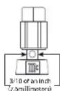
When cables with spade lugs are used for Loudspeaker Connection, the spade lugs need an opening of at least 3/10 inch (7.6mm).
Introduction
Now you can take advantage of traditional McIntosh standards of excellence in the MXA80 Integrated Audio System. The Power Amplifier section of the MXA80 will drive Headphones or Loudspeakers to a high level of performance.
The flexible Preamplifier section provides connections for various input sources, including Digital sources and music streaming from the Internet via an USB Computer connection.
The MXA80 reproduction is sonically transparent and absolutely accurate. The McIntosh Sound is “The Sound of the Music Itself.”
Performance Features
- Power Output
The McIntosh MXA80 is designed for connection of a single 8 ohm Loudspeaker per channel and will deliver 50 watts per channel with less than 0.005% distortion. The Power Amplifier uses ThermalTrak Output Transistors for lower distortion and cool operation.
• Autoformer Designed for Headphones
The MXA80 Amplifier uses a specially designed Autoformer for Headphones. There are three selectable impedances ranges, allowing connection of Headphones from 8 ohms thru 600 ohms.
- HXD® for Headphones
The MXA80 Headphone Crossfeed Director Circuitry (HXD ^® ) improves the sound localization for Headphone Listening. HXD ^ restores the directionality component of the spatial sound stage normally heard with Loudspeaker listening.
• Automatic Output Switching
The MXA80 has a Front Panel one-quarter inch Headphone Jack for private listening. Loudspeaker Listening is automatically switched Off when Headphones are connected.
- Superior Protection
McIntosh Sentry Monitor Protection Circuits ensure a long and trouble free operating life. It also protects the Headphones in the event of an impedance mismatch. Thermal Protection guards against overheating and Direct Current Detection Protects both Headphones and Loudspeakers.
• Electronic Switching for Analog Inputs
The Preamplifier uses Logic Circuits controlling Electromagnetic Switches for reliable, noiseless, distortion free switching. There is a Balanced and Unbalanced Input for connection of source components.
• Digital Audio Inputs
The MHA150 has four Digital Audio Inputs to decode PCM Signals. When the Coaxial, Optical and MCT Inputs receive a PCM Signal, the MHA150 upsamples the Digital Signal to 192kHz with 24Bit resolution before the Digital to Analog process begins. The Digital MCT Input Circuitry directly decodes SACD/CD signals from an external Transport component. The USB Input for streaming audio, processes Digital Signals up to 384kHz with 32Bit resolution, decodes up to DSD256 Digital Signals and DXD 24Bit with a sampling rate up to 384kHz.
• Multifunction OLED Display
The Front Panel Display indicates source selection, volume levels, trim settings and setup functions.
- Illuminated Meters
The Illuminated Power Output Meters on the MXA80 are peak responding, and indicate the output of the amplifier.
• Power Control and Remote Control
The Power Control Output connection provides convenient Turn-On/Off of McIntosh Source Components.
• Special Power Supply
The large Power Transformer, multiple large filter capacitors and regulated Power Supply ensure stable noise free operation even though the power line varies.
• McIntosh Custom Binding Posts
McIntosh Patented gold plated output terminals deliver high current output. They accept large diameter wire and spade lugs.
• Glass Front Panel and Super Mirror Chassis
The even Illumination of the Front Panel is accomplished by the combination of custom designed Fiber Optic Light Diffusers and extra long life Light Emitting Diodes (LEDs). The Stainless Steel Super Mirror Finish Chassis ensures the pristine beauty of the MXA80 will be retained for many years.
• High Excursion Woofer and Dome Tweeter
The 4" Woofer/Midrange delivers lower bass notes with less distortion. The three-quarter inch titanium tweeter reproduces frequencies up to 45,000Hz.
- Cast Aluminum Loudspeaker Enclosure
The durable cast aluminum enclosure is finished in a high gloss, piano black. All of the components making up the Loudspeaker were designed to achieve correct time arrival in the reproduced musical sound (also known as group delay).
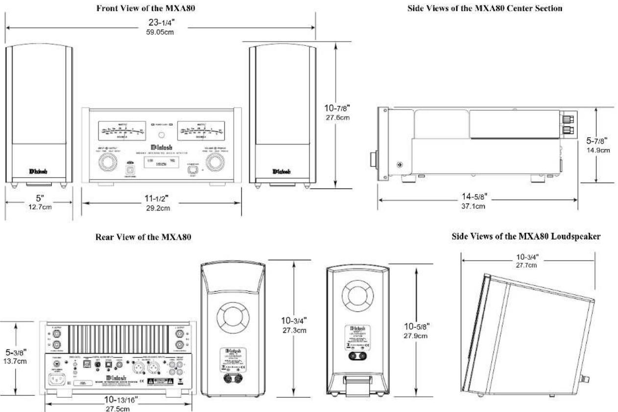
Dimensions
The following dimensions can assist in determining the best location for your MXA80 System. There is additional information on the next page pertaining to installing the MXA80 System into cabinets.
Installation
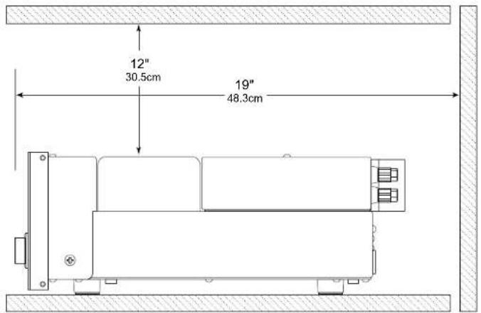
The MXA80 Integrated Audio System is designed to be placed upright on a table or shelf, standing on its feet. The required ventilation requirements are shown. Always provide adequate ventilation for your MXA80. Cool operation ensures the longest possible operating life for any electronic instrument. Do not install the MXA80 directly above a heat generating device, such as a Power Amplifier. Allow at least 12 inches (30.5cm) above the top and 5/8 inch (1.6cm) below the bottom of the Amplifier, so that airflow is not obstructed. Allow 19 inches (48.3cm) of depth for airflow and cable connections.
MXA80 Front View

MXA80 Side View

Notes

Connecting Components
The MXA80 has the ability to automatically switch power On/Off to McIntosh Source Components via the Power Control connection.
The connection instructions below, together with the MXA80 Connection Diagram on the next page is an example of a typical audio system. Your system may vary from this, however the actual components would be connected in a similar manner. For additional information refer to “Connector and Cable Information” on page 4.
Note: When the MXA80 is being added to an existing Audio (or Audio/Video) System, please proceed to page 12. If the MXA80 will be used with an external Power Amplifier, please refer to page 13.
Power Control Connections:
- Connect a Control Cable from the MXA80 PWR CTRL (Power Control) OUT Jack to the Power Control In Jack on the Tuner.
- Connect a Control Cable from the Tuner Power Control Out Jack to the Disc Player Power Control In Jack.
- Connect any additional McIntosh Components in a similar manner, as outlined in steps 1 thru 2.
Optional Audio Connections:
- Connect the Audio Cable from the MXA80 UN-BAL 1 (or BALANCED) L & R connectors to the Disc Player Fixed Audio Output Jacks.
- Connect any additional Components in a similar manner, as outlined in step 4.
Digital Audio Connections:
- Connect a "DIN Cable-Twisted Pair" cable (supplied with a MCT Transport) from the MXA80 DIGITAL AUDIO MCT INPUT connector to the SACD/CD Transport DIN Output connector.
- Connect any additional Components in a similar manner, as outlined in step 6.
Optional USB Connection:
- Connect a USB cable with (type A to type B) connectors from the MXA80 USB Input to an available USB connector on a Computer.
Output Terminals
When connecting the Loudspeaker Hookup Cables to the MXA80 Output Terminals please follow the steps below:
- Rotate the top of the Output Te terclockwise until an opening appears. Refer to figures A and B.
- Insert the Loudspeaker hookup cable into the Output Terminal Post opening or the cable spade lug around the center post of the Output Terminal. Refer to figure C.
- Rotate the top of the Output Terminal Post clockwise until it is finger tight. Refer to figure D.
- Place the supplied McIntosh Wrench over the top of the Output Terminal and rotate it one quarter of a turn (90°) to secure the Loudspeaker Cable Connection. Do not over tighten. Refer to figure E.
Loudspeaker Connections:
- The supplied Loudspeaker Connecting Cables are color coded ends (red and black) to connect between the MXA80 Electronic Chassis Output Terminals to the Input Terminals on the Loudspeakers, being careful to observe the correct polarities. Note: If the long cables are need, proceed to "Optional Loudspeaker Connections".


Figure E
Optional Loudspeaker Connections
Caution: Do not connect the AC Power Cord to the MXA80 Rear Panel until after the Loudspeaker Connections are made. Failure to observe this could result in Electric Shock.
Warning: Loudspeaker terminals are hazardous live and present a risk of electric shock. For additional instruction on making Loudspeaker Connections contact your McIntosh Dealer or McIntosh Technical Support.
The McIntosh MXA80 Power Amplifier Circuitry is designed for a single 8 ohms Loudspeaker connected to the Right and Left Output Terminals.
The recommended cable size is shown below:
| Cable Distance vs American Wire Gauge (Size) | |||
| Loudspeaker Impedance | 25 feet(7.62 meters)or less | 50 feet(15.24 meters)or less | 100 feet(30.48 meters)or less |
| 8 Ohms | 16AWG 14AWG 12AWG | ||
- Prepare the Loudspeaker Hookup Cable for attachment to the MXA80:
Bare wire cable ends:
Carefully remove sufficient insulation from the cable ends, refer to figures F, G & H. If the cable is stranded, ↓
carefully twist the strands together as tightly as possible.

Notes: 1. If desired, the twisted ends can be tinned with solder to keep the strands together.
2. The prepared bare wire cable ends may be inserted into spade lug connectors.
3. Banana plugs are for use in the United States and Canada only.
Banana Plugs are for use in the United States and Canada only:
-
Attach the previously prepared bare wire cable ends into the banana plugs and secure the connections. Refer to figure I.
-
Rotate the Output Terminal Post clockwise until it is
finger tight. Refer to figure J. Then using the McIntosh Wrench, rotate the top of the Output Terminal one quarter of a turn (90°). Do not over tighten. Refer to figure E.

- Referring to figure K, connect the Loudspeaker hookup cables with banana plugs into the hole at the top of the terminal to the MXA80 Negative Output Terminal and Positive Output Terminal to the Loudspeaker Terminal Connections being careful to observe the correct polarities.

Refer to "General Information" Note 7 on page 4 for additional information.
- Connect the MXA80 power cord to an active AC outlet.
Spade Lug or Wire Connections:
- Connect the Loudspeaker hookup cables between to the MXA80 Output Terminals and Loudspeaker Input Terminals for both channels. Be careful to observe the correct polarities (Positive and Negative) at both of the cables. Insert the spade lug connector or prepared section of the cable end into the terminal side access hole, and tighten the terminal cap until the cable is firmly clamped into the terminals so the lugs or wire cannot slip out. Refer to
figures L and M.
Refer to "General Information" Note 7 on page 4 for additional information.


- Connect the MXA80 power cord to an active AC outlet.


System Thru Connections
System Thru Connections
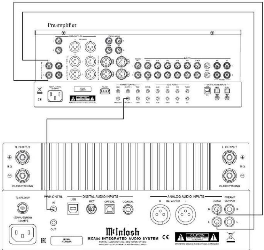
The MXA80 can also be part of an existing Audio or Audio/Video Sound System. The MXA80 allows connection of Headphones for private listening. It can also drive Loudspeakers in a second room. The MXA80 becomes active when the Main Preamplifier or Audio/Video Controller is On. In the example below, the MXA80 will go On/Off when the OUTPUT 2 function of the Preamplifier is activated using the Power Control 2 connections.
- Connect Audio Cables from the Preamplifier OUTPUT 2 Jacks to the MXA80 Analog Audio UNBAL Jacks.
Note: The Preamplifier Balanced OUTPUT 2 connected to the MXA80 BALANCED Input may be used instead of the unbalanced connections.
- Connect a Control Cable from the Preamplifier POWER CONTROL OUTPUT 2 Jack to the MXA80 PWR CTRL (Power Control) IN Jack.
For additional operational information when using the System Thru Connection with the MXA80 and Main Preamplifier or Audio/Video Controller, refer to "System Thru Operation" on page 26.
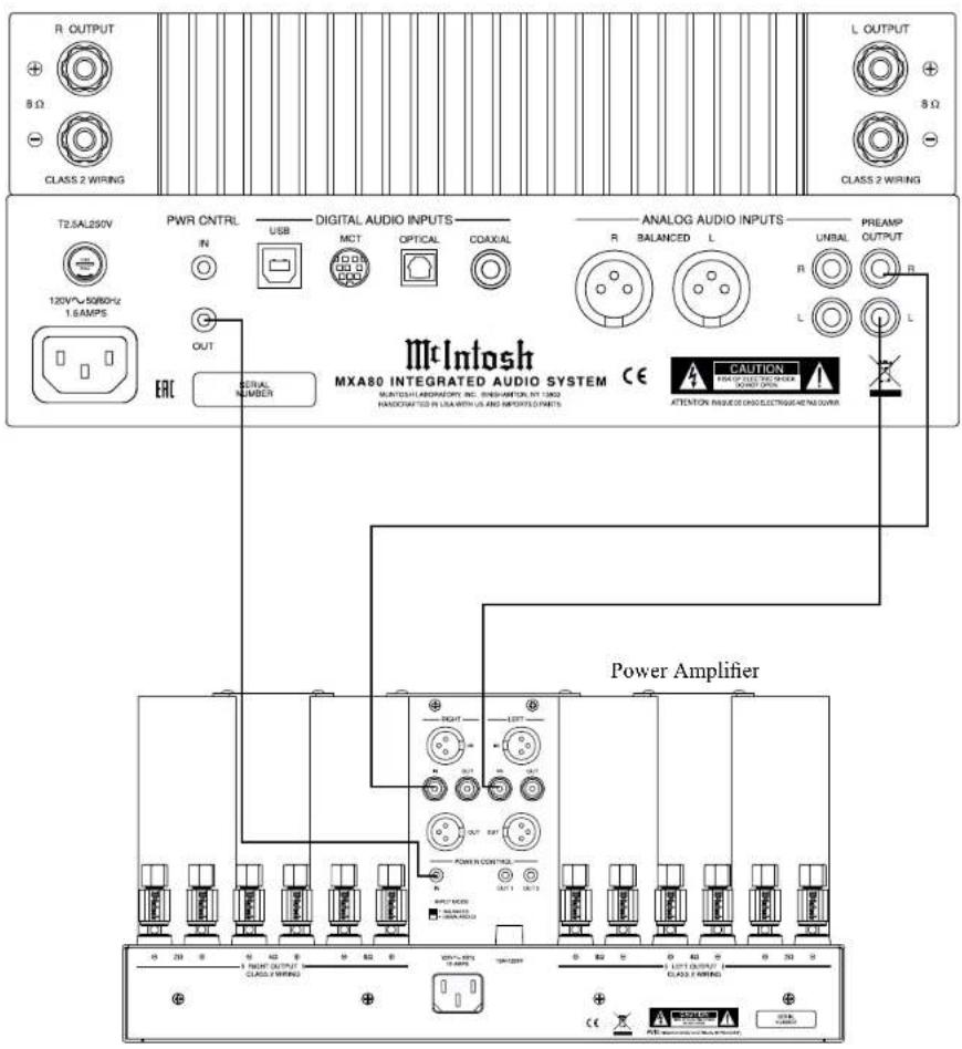
External Power Amplifier Connections
The MXA80 has the ability to drive an External Power Amplifier. In the example below, the MXA80 automatically switches the External Power Amplifier On/Off via Power Control function.
- Connect Audio Cables from the MXA80 PRE-AMPlifier OUTPUT Jacks to the External Power Amplifier IN (Left and Right) Jacks.
- Connect a Control Cable from the MXA80 PWR CNTRL (Power Control) OUT Jack to the External Power Amplifier Power Control IN Jack.
- Refer to page 10 for connecting other component(s) to the MXA80.
- Refer to the External Power Amplifier Owner's Manual for connection of Loudspeakers.

Note: Push-buttons whose function is not identified above are for use with other McIntosh Products.
How to use the Remote Control
The supplied Remote Control performs the various Operating Functions for the MXA80 Integrated Audio System.
Note: Refer to the "How to Operate" Section of this manual for additional information.
Input Source Selection
Press the Push-button → to select the desired program source.
Volume
Press the + or - Push-buttons to increase or decrease the listening level.
Mute
Press the ⚫(Mute) Push-button to mute the audio and a second time to resume listening.
Select Push-Button
Press the Select Push-button to activate the TRIM Mode. Then use the Directional Push-Buttons to select a Trim Mode Function and make changes.
Directional Push-Buttons
After having pressed the SELECT Push-button, press the ◀▶ (Left or Right) Push-buttons to scroll through the various Trim Functions. Then press the
▲ ▼ (Up or Down) Push-buttons to make a change to the current Trim Setting.
Note: If a contemporary McIntosh Tuner is used with the MXA80 the ▲▼ (Up or Down) on the Remote Control will allow for manual tuning of stations. Refer to “General Information, note 6” on page 4 for additional information.
Back and Next
When using an optional contemporary McIntosh Tuner with the MXA80, select the next Station Preset by pressing the ▶ Push-button. Select the previous Station Preset by pressing the ◀ Push-button.


How to Operate the Setup Mode
Your McIntosh MXA80 has been factory configured for default operating settings that will allow immediate enjoyment of superb audio without the need for further adjustments. If you wish to make changes to the factory default settings, a Setup Feature is provided to customize the operating settings using the Front Panel Display. Refer to the MXA80 Front Panel Illustration on the previous page while performing an introduction into operating the Setup Mode, follow the steps below.
Note: If the MXA80 is currently On, proceed to step 2.
- Press the STANDBY/ON Push-button on the Front Panel or press the ⏻ (Power) Push-button on the Remote Control to switch On the MXA80. The MXA80 will go through a brief startup initialization with the Front Panel Display indicating the last used input and volume setting. This is followed by the volume setting indication starting at zero and then increasing to the last used volume setting. Refer to figure 1.

Figure 1
- Press and hold in the INPUT CONTROL until the Front Panel Display indicates "MXA80 V_._, S/N: AEU____". The information indicated on the Front Panel Display includes the Model Number, Firmware Version and the Serial Number for this unit; see page 18 for additional information. Refer to figure 2.

Figure 2
- Next, rotate the INPUT CONTROL Clockwise again until the Front Panel Display indicates "INPUT: UNBAL, NAME: UNBAL" Refer to figure 3.

Figure 3
- Rotate the INPUT CONTROL Clockwise again to select other Setup Functions. Refer to pages 18 thru 20.
- To exit from the Setup Mode, press the INPUT CONTROL and the Front Panel Display will revert back to its normal display. Refer to figure 1.
Default Settings
The Default Settings Chart below indicates the Function Name, Default Setting and the Page Number for additional information.
| Default Settings | ||
| Function Name Setting | Page No. | |
| MXA80 | V_S/N: AEU____ | 18 |
| INPUT NAME (Reassign Input Names) | INPUT: ____NAME: ____ | 18 |
| SPEAKER MODE Large 19 | ||
| SUBWOOFER MODE Disabled 19 | ||
| POWER MODE (Auto Off) | Enabled 20 | |
| REMOTE CONTROL Enabled 20 | ||
| VOLUME GUARD Enabled 20 | ||
| FACTORY RESET (Hold SETUP) | ---- 20 | |
Note: Setup Mode operations should be performed in the order they appear in the Setup Menu as they are interactive.

Firmware Version
The MXA80 functionality is controlled by internal software that is known as Firmware. The Version of the Firmware in the MXA80 can be identified at any time by utilizing the Setup Mode.
- Press and hold the INPUT CONTROL until the Front Panel Display indicates "MXA80 V_, S/N: AEU_". The number after the "V" is the firmware version and the number after the "S/N" is the serial number of the unit. Refer to figure 2.
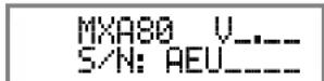
Figure 2
- To exit from the Setup Mode, press the INPUT CONTROL and the Front Panel Display will revert back to its normal display.
Input Renaming
The MXA80 Default Input Names (UNBAL, BALANCED, OPTICAL, COAX and AES/EBU as indicated on the Front Panel Display) can be customized with a different name up to eight characters long (My Phone, MCD550, etc.). The available characters for renaming the input include the following: ! <> *, / - _0123456789a b c d e f g h i j k l m n o p q r s t u v w x y z A B C D E F G H I J K L M N O P Q R S T U V W X Y Z.
In the following example, the UNBAL Input will be renamed to "MY-PHONE".
- Press and hold the INPUT CONTROL until the Front Panel Display indicates the Model, Firmware Version and Serial Number. Refer to figure 2. Then rotate the INPUT CONTROL and select the Setup Menu item "INPUT: UNBAL, NAME: UNBAL". Refer to figure 4.

Figure 4
Note: If the UNBAL Input is not displayed, rotate the OUTPUT Control repeatedly until it is displayed.
- Press and hold in the INPUT Control until the character "U" of the "NAME: UNBAL" starts flashing (and is underlined). Refer to figure 5.

Figure 5
- Rotate the INPUT Control until the character "M" appears. Refer to figure 6.
- Rotate the OUTPUT Control until the character "N" of the "NAME: UNBAL" starts flashing. Refer to figure 7.
INPUT: UNBAL NAME: MNBAL
Figure 6
INPUT: UNBAL NAME: MJBAL
Figure 7
- Rotate the INPUT Control until the character "Y" appears. Refer to figure 8.
INPUT: UNBAL NAME: MYBAL
Figure 8
- Repeat steps 3 thru 5 until the new name of "MY-PHONE" is indicated on the Front Panel Display. Refer to figures 9 thru 11.
INPUT: UNBAL NAME: MY_AL
Figure 9
INPUT: UNBAL NAME: MY-PL
Figure 10
INPUT: UNBAL NAME: MY-PHONE
Figure 11
- To save the new Input Name press and hold the INPUT Control until the "character underline" disappears on the Front Panel Display. Refer to figure 12.
INPUT: UNBAL NAME: MY-PHONE
Figure 12
Record any changes made to the various default Input Names in the following chart for future reference.
| Input Renaming | |
| Default Input Name | New Input Name |
| UNBAL | |
| BALANCED | |
| OPTICAL | |
| COAXIAL | |
| MCT | |
| USB | |
- To exit from the Setup Mode, press the INPUT CONTROL and the Front Panel Display will revert back to its normal display.
Speaker Mode
The MXA80 allows for the connection of Loudspeakers with different performance capabilities. One of the differences in Loudspeaker performance is the ability to reproduce bass frequencies down to 35Hz within -3dB of the midrange frequencies.
The MXA80 provides two different settings, SMALL and LARGE. When using the MXA80 Loudspeakers, use the default setting of SMALL. The LARGE listing refers to the Loudspeaker's capability for reproducing bass frequencies down to 35Hz within -3dB of the midrange frequencies. If a Loudspeaker can not reproduce bass frequencies down to 35Hz within -3dB of the midrange frequencies, it is considered SMALL.
In the following example, the Speaker Size default setting of SMALL will be changed to LARGE:
- Press and hold the INPUT CONTROL until the Front Panel Display indicates the Model, Firmware Version and Serial Number. Refer to figure 2. Then rotate the INPUT CONTROL and select the Setup Menu item "SPEAKER MODE, Small".
Refer to figure 13.
SPEAKER MODE Small
Figure 13
- Rotate the OUTPUT Control until the Front Panel Display indicates "SPEAKER MODE, Large". Refer to figure 14.
SPEAKER MODE Large
Figure 14
- To exit from the Setup Mode, press the INPUT CONTROL and the Front Panel Display will revert back to its normal display.
Subwoofer Mode
The MXA80 is designed to work with an external Powered Subwoofer. The subwoofer would be used when the Loudspeakers connected to MXA80 Output Terminals do not have the ability to reproduce bass frequencies down to 35Hz (within -3dB of the mid-range frequencies).
The MXA80 provides two different Subwoofer Mode settings, "Disabled" and "Enabled". The Default Setting of "Disabled" provides a Stereo Signal at the PREAMPlifier OUTPUT Jacks. When the setting is changed to "Enabled" the Left and Right channel signals are combined into a monaural signal available at both PREAMP OUTPUT Jacks. In the following example, the Subwoofer Mode default setting of DISABLED will be changed to Enable:
- Press and hold the INPUT CONTROL until the Front Panel Display indicates the Model, Firmware Version and Serial Number. Refer to figure 2. Then rotate the INPUT CONTROL and select the Setup Menu item "SUBWOOFER MODE, Disabled".
Refer to figure 15.
SUBWOOFER MODE Disabled
Figure 15
- Rotate the OUTPUT Control until the Front Panel Display indicates "SUBWOOFER MODE, Enabled". Refer to figure 16.
SUBWOOFER MODE Enabled
Figure 16
Note: When the MXA80 Subwoofer Mode is set to "ENABLED" it is important the Powered Subwoofer internal crossover frequency be set to 80Hz. It is recommended the Professionals at your McIntosh Dealer, who are skilled in all aspects of room acoustics he involved when the MXA80 is used with a Powered Subwoofer and any associated audio equipment.
- To exit from the Setup Mode, press the INPUT CONTROL and the Front Panel Display will revert back to its normal display.
Power Mode
The MXA80 incorporates an Auto Off Feature, which automatically places it into the Power Saving Standby/Off Mode. This occurs approximately 30 minutes after there has been an absence of audible audio signals on the selected input (on either channel) or user activity (includes changes to any of the Operation Functions such as source selection, volume adjustment, etc). If it is desirable to disable the Auto Off Feature perform the following steps:
- Press and hold the INPUT CONTROL until the Front Panel Display indicates the Setup Mode is
Power Mode, con't
active. Then rotate the INPUT CONTROL until the Setup Menu item "POWER MODE, Enabled" appears on the Front Panel Display. Refer to figure 17.
POWER MODE Enabled
Figure 17
- Rotate the OUTPUT Control until "POWER MODE, Disabled" appears on the Front Panel Display. Refer to figure 18.
POWER MODE Disabled
Figure 18
- To exit from the Setup Mode, press the INPUT CONTROL and the Front Panel Display will revert back to its normal display.
Remote Control
The Front Panel IR Sensor used for Remote Control Operation can be disabled in the event there is a conflict with another McIntosh component located in the same room as the MXA80. Refer to “General Information, note 6” on page 4 for additional information. Disable the Front Panel IR Sensor by performing the following steps:
- Press and hold the INPUT CONTROL until the Front Panel Display indicates the Model, Firmware Version and Serial Number. Then rotate the INPUT CONTROL and select the Setup Menu item "REMOTE CONTROL, Enabled". Refer to figure 19.
REMOTE CONTROL Enabled
Figure 19
- Rotate the OUTPUT Control until the Front Panel-Display indicates "REMOTE CONTROL, Disabled". Refer to figure 20.
REMOTE CONTROL Disabled
Figure 20
- To exit from the Setup Mode, press the INPUT CONTROL and the Front Panel Display will revert back to its normal display.
Volume Guard
The MXA80 incorporates a Volume Guard Feature to provide Loudspeaker Protection if the Amplifier was set to a high listening level the last time it was used. When it is switched back ON, the volume listening will return to a normal safe level. If desirable, the Volume Guard Feature may be switched OFF by performing the following steps:
- Press and hold the INPUT CONTROL until the Front Panel Display indicates the Setup Mode is active. Then rotate the INPUT CONTROL until the Setup Menu item "VOLUME GUARD, Enabled" appears on the Front Panel Display. Refer to figure 21.
VOLUME GUARD Enabled
Figure 21
- Rotate the OUTPUT Control until "VOLUME GUARD, Disabled" appears on the Front Panel Display. Refer to figure 22.
VOLUME GUARD Disabled
Figure 22
- To exit from the Setup Mode, press the INPUT CONTROL and the Front Panel Display will revert back to its normal display.
Factory Reset
If it becomes desirable to reset all the adjustable settings (Setup and Trim Settings) to the factory default values, perform the following steps:
- Press and hold in the INPUT Control to enter the SETUP MODE. Refer to figure 2 on page 18.
- Rotate the INPUT Control until "FACTORY RESET, (Hold SETUP)" appears on the Information Display. Refer to figure 23.
FACTORY RESET (Hold SETUP)
Figure 23
- Press and hold in the INPUT Control until "FACTORY RESET, In Progress!" appears on the Information Display, then release the INPUT Control. Refer to figures 24 and 25.
FACTORY RESET In Progress!
Figure 24
FACTORY RESET Completed!
Figure 25
- Press the Front Panel STAND/BY Push-button to switch the MXA80 On.
How to Operate the MXA80
Power On and Off
The Red LED beside the STANDBY/ON Push-button lights to indicate the MXA80 is in Standby mode. To switch ON the MXA80, press the STANDBY/ON Push-button on the Front Panel or press the ⏻ (Power) Push-button on the Remote Control. The MXA80 will go through a brief startup initialization, with the Front Panel Display indicating the last used input and volume setting. This is followed by the volume setting indication starting at zero and then increasing to the last used volume setting. Refer to figures 50, 51 and 52. To switch OFF the MXA80, press the STANDBY/ON Push-button on the Front Panel or the OFF Push-button on the Remote Control.

Figure 51
Note: For an explanation of the Remote Control Push-button functions, refer to pages 14 and 15.
Source Selection
Rotate the INPUT Control to select the desired input
or press the appropriate push-button on the Remote Control. Refer to figures 50 and 52.
Volume Control
Rotate the Front Panel VOLUME Control or use the Up ▪(+) or Down ▪(-) Push-buttons on the Remote Control for the desired listening level. Refer to figures 50 and 52.
Trim Functions Introduction
The MXA80 has various Trim Selections with Adjustments. The Trim Functions include Bass Boost, Balance, Level (Input Trim), Mono/Stereo, Meter Backlight, Display (Information) and Digital Audio (Display Information). The Bass Boost, Balance, Level (Input Trim), Mono/Stereo, Trim Settings are stored in memory independently for each Input Selected; the other Trim Settings are the same for all inputs.
The selection and adjustment of all Trim Functions may be performed by first momentarily pressing the Front Panel INPUT Control. Then rotate the INPUT Control to select the desired Trim Function. This is followed by rotating the OUTPUT Control to make a

Figure 50
change/adjustment in the Trim Setting. To verify a TRIM Setting without changing it, press the INPUT Control and then Rotate the INPUT Control to select the desired Trim Function. After approximately 5 seconds the Display returns to indicate the Input Selection and Volume Level.
BASS BOOST
The Intensity of the Low Frequencies in the music can be increased by using the Bass Boost Trim

Figure 52
Function. To make an adjustment perform the following:
- Momentarily press the Front Panel INPUT Control to enter the TRIM Mode. Then rotate the INPUT Control until "BASS BOOST, 0dB" appears on the Front Panel Display. Refer to figure 53.

Figure 53
- Rotate the OUTPUT Control to change the Bass Boost, the range of adjustment is from 0dB to +12.5 dB in 2.5 dB steps. Refer to figure 54.

Figure 54

How to Operate the MXA80, con't
After approximately 5 seconds the Display returns to indicate the Input Selection and Volume Level.
BALANCE
The Channel Balance while listening can vary with different program sources. When using Loudspeakers, the room acoustics and listening positions also can effect the Channel Balance. Use the Balance Trim Function as needed to achieve approximately equal listening volume levels in each channel. To adjust the Balance perform the following:
- Momentarily press the Front Panel INPUT Control to enter the TRIM Mode. Then rotate the INPUT Control until "L BALANCE R" appears on the Front Panel Display. Refer to figure 55.
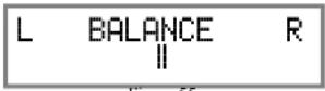
Figure 55
- Rotate the OUTPUT Control to change the Channel Balance, the range of adjustment is 50dB (to emphasize the Left or Right Channel) in 1 dB steps. Refer to figures 56 and 57.

Figure 56

Figure 57
After approximately 5 seconds the Display returns to indicate the Input Selection and Volume Level.
TRIM LEVEL
Source Components can have slightly different volume levels resulting in the need to readjust the MXA80 Volume Control when switching between different Inputs. The MXA80 allows the adjustment of levels for each of the Inputs for the desired same relative volume. The UNBAL and OPTICAL Inputs are used in the following example.
Note: The TRIM Level Adjustments made are retained in permanent memory.
- Rotate the INPUT Control to select the UNBAL Input and adjust the VOLUME Control for the desired listening level.
- Momentarily press the Front Panel INPUT Control to enter the TRIM Mode. Then rotate the INPUT Control until "TRIM LEVEL, _ dB" appears on the Front Panel Display. Rotate the OUTPUT Control until the Front Panel Display indicates "TRIM LEVEL, 0.0dB". Refer to figure 58.

Figure 58
The range of TRIM Adjustment is ± 6dB. Refer to figures 59 and 60.

Figure 59

Figure 60
Note: The UNBAL Input is serving as a reference level or choose another Input frequently listened to.
- Note the current listening level. Then rotate INPUT Control to select the OPTICAL Input and note if the relative volume is louder or quieter than the volume level of the UNBAL.
- Momentarily press the Front Panel INPUT Control to enter the TRIM Mode. Then rotate the INPUT Control until "TRIM LEVEL, _._ dB" appears on the Front Panel Display. Using the OUTPUT Control adjust the TRIM Level to match the same relative volume level heard when listening to the UNBAL Input.
- In our example, the relative volume level of the OPTICAL Input is louder than the UNBAL Input, so the trim level for the OPTICAL Input is reduced to -2.5 dB. Refer to figure 61.

- Repeat steps 1 thru 4 until the relative volume is the same between the UNBAL and OPTICAL Inputs.
- Repeat the above steps for the remaining inputs with component sources connected until they all have the same relative volume levels. Record any changes made to the various inputs from the default settings in the "Input Trim Settings" Chart on the next page.
After approximately 5 seconds the Display returns to indicate the Input Selection and Volume Level.
MONO/STEREO MODE
By default the Stereo Mode is active for all Input Sources however, any Input Source may be assigned to Mono Mode. To change Stereo Mode to Mono for a given Input Source, perform the following steps:
- Momentarily press the Front Panel INPUT Control to enter the TRIM Mode. Then rotate the INPUT Control until "MONO / STEREO" appears on the Front Panel Display. Refer to figure 62.

Figure 62
- Rotate the OUTPUT Control to change the Mode to "Mono". Refer to figure 63.

Figure 63
After approximately 5 seconds the Display returns to indicate the Input Selection and Volume Level.
| Input Trim Settings | ||
| Connection Type | Input Name New Trim Level | |
| UNBAL | ||
| BALANCED | ||
| OPTICAL | ||
| COAXIAL | ||
| AES/EBU | ||
| USB | ||
METER BACKLIGHT
The MXA80 Front Panel Meter Illumination may be switched On or Off by performing the following:
- Momentarily press the Front Panel INPUT Control to enter the TRIM Mode. Then rotate the INPUT Control until "METER LIGHTS, On" appears on the Front Panel Display. Refer to figure 64.
- Rotate the OUTPUT Control to change illumination to "Off". Refer to figure 65.
METER LIGHTS On
Figure 64
METER LIGHTS Off
Figure 65
After approximately 5 seconds the Display returns to indicate the Input Selection and Volume Level.
Note: Meter Illumination of contemporary McIntosh Power Amplifiers will also switch On/Off when connected to the MX480 via a power control cable. Refer to "Power Control Connections" on page 4.
DISPLAY
The MXA80 Front Panel Display Illumination may be switched On or Off by performing the following:
- Momentarily press the Front Panel INPUT Control to enter the TRIM Mode. Then rotate the INPUT Control until "DISPLAY, Always On" appears on the Front Panel Display. Refer to figure 66.
DISPLAY Always On
Figure 66
- Rotate the OUTPUT Control to change the Display to "DISPLAY, Auto Off". Refer to figure 67.
DISPLAY Auto Off
Figure 67
After approximately 5 seconds the Display will switch Off. When a Front Panel Control Operation or Remote Control Operation occurs, the Front Panel Display will
switch On to indicate current status. Then approximately 5 seconds later the Display will switch Off.
DISPLAY INFORMATION MODE
By default, the Display INFO Mode is set to indicate the Sample Rate for Digital Input Sources. The other Display INFO Mode will indicate the amplifier Output Mode (Headphones with an impedance range or Speakers) information. To change from the default setting perform the following steps:
- Momentarily press the Front Panel INPUT Control to enter the TRIM Mode. Then rotate the INPUT Control until "DISPLAY INFO, Sample Rate" appears on the Front Panel Display. Refer to figure 68.

Figure 68
- Rotate the OUTPUT Control to change the Display Mode to "DISPLAY INFO, Output". Refer to figure 69.

Figure 69
After approximately 5 seconds, the Display returns to indicate the Input Selection and Volume Level.
Mute
Press the ⚡MUTE Push-button on the Remote Control to Mute the Audio in the Headphones, Loudspeakers and PRE AMP OUTPUT Jacks. The Front Panel Display will indicate the Input Name with the word MUTE in place of the actual volume setting. Refer to figure 70.
How to Operate the MXA80, con't
UNBAL MUTE
Figure 70
To un-MUTE the Audio, press the MUTE Push-button on the Remote Control, adjust the Volume level or change Inputs.
Headphones Jack
Connect a pair of dynamic headphones to the Headphones Jack with a 1/4" (6.3mm) stereo phone type plug for private listening.
Note: Use the OUTPUT Control to select the correct impedance range.
Headphone HXD®
The MXA80 Headphone Crossfeed Director (HXD ^® ) improves the sound localization for Headphone Listening. HXD ^® restores the directionality component of the spatial sound stage normally heard with Loudspeaker listening. To activate the HXD ^® when Headphones are connected to the Front Panel Headphone Jack perform the following:
-
Momentarily press the Front Panel VOLUME Control to enable the HXD ^® Mode. The HXD ^® Icon located above the Headphone Jack will illuminate Green. Refer to figure 71.
-
To disable the IIXD ^® Mode momentarily press the Front Panel VOLUME Control.

HEADPHONES
Figure 71
Note: HXD ^® Mode is automatically disabled when SPEAKERS are selected with the OUTPUT Control.
HXD ^® is a registered trademark of McIntosh Laboratory, Inc.
Output Control
Rotate the OUTPUT Control to select the desired listening device, Headphones or Loudspeakers. Refer to the OUTPUT CONTROL SELECTION chart below:
Notes: 1. For the best performance and safety, it is important to always match the impedance of the Headphones and Loudspeakers to the MXA80 Output.
-
Do not exceed the maximum power handling capacity of Headphones or Loudspeakers connected to the MXA80.
-
The first time the OUTPUT Control is rotated, the Front Panel Display will indicate the current Output selection.
Profile Control
Rotate the PROFILE Control to select from up to 5 different Profile Settings for Headphone use. The default Profile Setting is for the McIntosh MHP1000
Headphones. Refer to figure 72.
UNBAL 20% MHP1000
Figure 72
Profile Mode
Each profile setting stores the selected Headphone Impedance Range, HXD Setting (On or Off), Bass Boost Setting (0 to +12.5 dB) and assigns a custom name to it. In the following example a second Profile will be created, recalled, renamed and finally deleted using the Profile Setup Mode:
PROFILE SETTINGS
- Using the OUTPUT Control select, from the six choices available, the correct impedance and power output for the Headphones that will be used for listening. Refer to the chart below.
| OUTPUT CONTROL SELECTION | ||||
| Listening Device | Impedance in Ohms (Ω) | Power Level | Output Front Panel D | splay |
| Speakers 8 Ω --- 50 Watts | UNBAL 21XSPEAKERS | |||
| Headphones | 8 to 40 Ω | Norm | 250 milliwatts | UNBAL 21X NORM 8Ω - 40Ω |
| 1Headphones | 40 to 150 Ω | Norm | 250 milliwatts | UNBAL 21X NORM 40Ω - 150Ω |
| Headphones | 150 to 600 Ω | Norm | 250 milliwatts | UNBAL 21X NORM 150Ω - 600Ω |
| Headphones | 8 to 40 Ω | High | 1 Watt | UNBAL 21X HIGH 8Ω - 40Ω |
| Headphones | 40 to 150 Ω | High | 1 Watt | UNBAL 21X HIGH 40Ω - 150Ω |
| 1Headphones | 150 to 600 Ω | 1High | 1 Watt | UNBAL 21X HIGH 150Ω - 600Ω |
- If desired, select the HXD ^TM Mode by momentarily pressing the volume Control. The HXD Icon located above the Headphone Jack will illuminate Green. Refer to figure 71.
- If desired, select the amount of TRIM Bass Boost by momentarily pressing the INPUT Control. Then rotate the INPUT Control to select BASS BOOST followed by using the OUTPUT Control for the desired increase. Refer to figures 53 and 54 on page 21.
CREATE A PROFILE
With the Impedance/Power, HXD and Bass Boost settings made, they will now be assigned to a Profile, for easy recall at a later time. The PROFILE and VOLUME Controls are used to perform the various Profile Functions (Save, Select Rename and Delete). When the PROFILE Control is rotated and there are no saved Profiles, the Front Panel Display will indicate the currently selected Input and "UNBAL 20%, No Profile". Refer to figure 79.

Create a new Profile by following the below steps:
- Press and hold in the VOLUME CONTROL until the Front Panel Display indicates "SAVE PROFILE, MHP1000". Refer to figure 80.
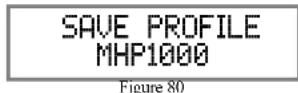
- Rotate the PROFILE Control until the Front Panel Display indicates "SAVE PROFILE, Profile2". Refer to figure 81.
SAVE PROFILE Profile2
Figure 81
- To save Profile2 press and hold in the VOLUME Control until the Front Panel Display indicates "SAVE PROFILE, Profile Saved". Refer to figure 82.
SAVE PROFILE Profile Saved
Figure 82
- To exit the Profile Setup Mode momentarily press the VOLUME Control and the Front Panel Display returns to indicating the selected Input and Volume Setting.
RENAMING A PROFILE
The MXA80 Profile Name (MHP1000[Profile1] thru Profile5) can be customized with a different name up to eight characters long (Y10-PRO, etc.). The available characters for renaming the input include the following: !<>>*, /- _ 0 1 2 3 4 5 6 7 8 9 a b c d e f g h i j k l m n o p q r s t u v w x y z A B C D E F G H I J K L M N O P Q R S T U V W X Y Z . In this example the previously created and saved Profile2 will be renamed to "Y10-PRO" by performing the following steps:
- Referring to figure 83, rotate the PROFILE Control to select "UNBAL 20%, Profile2".
UNBAL 20% Profile2
Figure 83
- Select the "Profile Mode" by pressing and holding in the VOLUME Control and rotating the VOLUME Control until the Front Panel Display indicates "NAME PROFILE, Profile2".
Refer to figure 84.
NAME PROFILE Profile2
Figure 84
- Press and hold the VOLUME Control until the character "P" of the "Profile2" starts flashing (and is underlined). Refer to figure 85.
NAME PROFILE Profile2
Figure 85
- Rotate the VOLUME Control until the character "Y" appears. Then Rotate the PROFILE Control until the character "r" of the "Yrofile1" starts flashing. Refer to figure 86.
NAME PROFILE Yprofile1
Figure 86
- Rotate the VOLUME Control until the character "1" appears. Then rotate the PROFILE Control until the character "o" of the "Ylofile1" starts flashing. Refer to figure 87.
NAME PROFILE Yiofilei
Figure 87
- Repeat steps 10 thru 12 until the new Profile Name of "Y10-PRO" is indicated on the Front Panel Display. Refer to figure 88.
NAME PROFILE Y10-PRO
Figure 88

How to Operate the MXA80, con't
Profile Mode, con't
- To store the renamed Profile into memory press and hold in the VOLUME CONTROL until the Front Panel Display indicates "SAVE PROFILE, Profile Saved". Refer to figure 89.

Figure 89
- To exit the Profile Rename Mode momentarily press the VOLUME Control.
DELETING PROFILES
There are two ways to Delete Profiles, delete one saved Profile or delete all saved Profile Names. In the first example, one Profile will be deleted. Perform the following steps:
- Using the Profile Control, select the Profile to be deleted. Refer to figure 90.
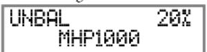
Figure 90
- Rotate the VOLUME Control to select "DELETE PROFILE, MHP1000". Refer to figure 91.
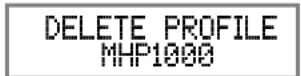
Figure 91
- Press and hold in the VOLUME CONTROL until the Front Panel Display indicates "DELETE PROFILE, Profile Deleted". Refer to figure 92.

Figure 92
- To exit the Profile Delete Mode momentarily press the VOLUME Control.
To Delete All the stored Profiles, perform the following steps:
- Using the Profile Control, select one of the available Profiles (1 thru 5). Refer to figure 93.
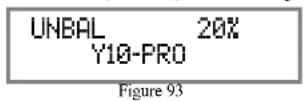
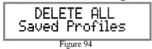
- Rotate the VOLUME Control to select "DELETE ALL, Saved Profiles". Refer to figure 94.
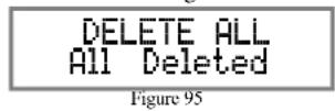
- Press and hold in the VOLUME CONTROL until the Front Panel Display indicates "DELETE ALL, All Deleted". Refer to figure 95.
- To exit the Profile Delete Mode momentarily press the VOLUME Control.
Power Output Meters
The MXA80 Power Output Meters indicate the power delivered to the Loudspeakers or Headphones. Refer to figure 100. The meters respond to all the musical

Figure 100
information being produced by the Amplifier. They indicate to an accuracy of at least 95% of the power output with only a single cycle of a 2,000Hz tone burst.
Power Guard
During normal operation, the Front Panel Power Guard Indicators will momentarily illuminate during peaks in the audio signals. In the event the MXA80 over heats, due to improper ventilation, high ambient temperature and/or impedance mismatch, the internal protection circuits will activate. The Front Panel Power Guard Indicators will continuously illuminate and the audio will be muted. When the MXA80 has returned to a safe operating temperature, normal operation will resume.
Using a Separate Power Amplifier or Subwoofer To use a separate Amplifier instead of the MXA80 built-in Power Amplifier, connect the Loudspeakers to the separate Power Amplifier. Refer to page 1
"External Power Amplifier Connections" for addition connection information. An external Powered Subwoofer may also be used with the MXA80. Refer to page 19 "Subwoofer Mode" for additional information.
When either an External Power Amplifier or Powered Subwoofer is used with the MXA80 the Rear Panel PREAMP OUTPUT Jacks are used. Refer to figure
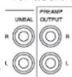

Figure 101
System Thru Operation
When the MXA80 is connected to a Main Preamplifier or Audio/Video Controller (as illustrated on page 12) it is important to maximize the combined
performance. For the best performance, the volume control on the MXA80 should be set to 70%. The Volume Control on the Main Preamplifier or Audio/Video Controller should be used to adjust the listening volume level.
Digital Inputs
When a Digital Input (Optical, Coax or AES/EBU Connection) on the MXA80 is selected, the Front Panel Display will indicate the Sampling Frequency when a signal is present "48kHz". Refer to figure 102. During the time there is no Digital Signal present the display will indicate "SILENT". Refer to figure 103.
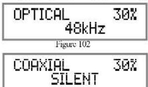
Figure 103
USB Input Operation and Driver Installation
The MXA80 USB Input provides the capability to playback music from a computer, when the computer is connected to the rear panel USB connector.
Note: The USB Input is for direct connection to a computer only. To playback music from an USB Drive, connect the USB Drive to another USB Port on the computer and select the USB Drive with the Media Playback Program.
The MXA80 USB Input is compatible with PC Computers using Microsoft®, Windows 7 (SP1), Windows 8.1 and Windows 10. It is also compatible with Apple® Macintosh® Computers using OS-10.6.8 or later.
When using a PC Computer with Windows, a special McIntosh USB Audio Software Driver needs to be installed on the PC Computer. The driver needs to be installed before connecting the MXA80 USB Input to the USB Port on the computer.
Note: If an Apple Macintosh computer is used with the MXA80, no additional driver is required.
The McIntosh USB Audio Windows Driver is available for download from the McIntosh Web Site: http://www.mcintoshlabs.com/us/Support/Pages/Manuals.aspx
Under "PRODUCT CATEGORY" select "Integrated Amplifiers" then under "MODEL NUMBER" select "MXA80". Click on "SEARCH" then select "McIntosh-HD USB Audio Windows Drive D v2.0" and download the PC Windows Driver. Follow the instructions below to install the McIntosh MXA80 Driver:
Purpose: To Install the McIntosh
USB Audio Windows Driver for use with McIntosh Products with an USB-Digital Audio Input.
Requirements: 1. A PC Computer with a functioning USB Port.
-
Windows 7 (SP1 or greater), Windows 8 (8.1) or Windows 10 Operating System.
-
An USB Cable with Type A to Type B Connectors.
Installing the Software
It is important to first install the downloaded software on your computer before connecting the McIntosh Product to the computer. The USB Driver is included in the downloaded software package.
Note: Before installing this software, please check to see if the McIntosh Product(s) with the USB-Digital
Audio Input has the latest firmware version, if not update the firmware first.
-
Unzip the downloaded McIntosh Windows USB Driver Software Package.
-
Run "McIntoshHDSwPkg_20150814_v1p9p110p2.zip". Refer to figures 104 thru 111.
-
When the Windows Security window appears check the Always trust software from "Savitech Corp." box and then the Install button. When the software has been installed, it is necessary to reboot the computer. Refer to figure 109.

Figure 104

Figure 105
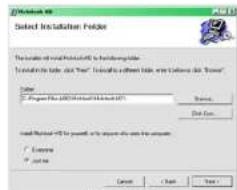
Figure 106
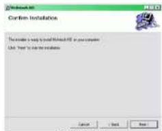
Figure 107

Figure 108

Figure 109


Fig urc 110

Figure 111
After rebooting, a McIntosh-HD icon will appear on the desktop. Refer to figure 112.

Figure 112
USB Connection
Connect the USB Cable with Type A to Type B connectors between the PC Computer and the McIntosh Product with the USB-Digital Audio Input. An Icon will appear On-Screen indicating Windows
has found new hardware. Refer to figure 113.
Upon completion of in- stalling the driver, figure 114 will appear.

Figure 113

Figure 114
Windows Sound Settings
For proper operation of the McIntosh Product via the Computer USB Connection, it is required to make changes to Windows Sound Settings:
-
From the Windows START button, click on "CONTROL PANEL" followed by selecting "SOUND". Refer to figure 115.
-
Referring to figure 116, first select "McIntosh-HD HS USB Audio" and then
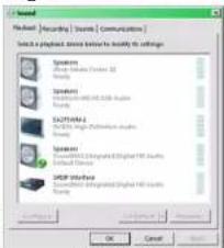
Figure 115
click on the "Set Default" button.
Notes: 1. When the McIntosh USB Audio Product is not connected to your computer, the previous default Audio Device will be selected.
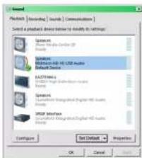
Figure 116
- If other McIntosh Products with USB Audio Connections are also connected to the computer, an additional "McIntosh USB Audio" playback device will appear in the listing. Make sure to select the "McIntosh-HD HS USB Audio" from available playback devices listed when using this McIntosh Product for USB Audio.
Control Panel Settings
To activate the McIntosh-HID USB Audio Control Panel, click on the "McIntosh Icon" (located in the
Windows notification area on the right side of the taskbar) or click on the Windows "Show hidden icons", then select the "McIntosh Icon". Refer to figures 117 and 118.
Notes: 1. It is not necessary for the

Figure 117
McIntosh-HD USB Audio Control Panel to be running, unless it is desired to make changes to the default settings.
- The McIntosh-HD USB Audio Control Panel displays the current Sampling Rate, Bit-Rate and Buffer Size for the music streaming from the computer into the MXA80.

area
| Device | ASIO | State | Not Available | UNLOAD | | :--- | :--- | :--- | :--- | :--- | | Preferred Buffer size | 16 bits | 3 ms | 10 ms | 30 ms | | Device | 16 bits | 24 bits | 48000 Hz | 50 ms | | Device | 32 bits | 32 bits | 88200 Hz | 100 ms | | Device | Not Available | Not Available | 96000 Hz | 100 ms | | Device | State | 7 ms | 15 ms | 20 ms | | Device | State | 5 ms | 10 ms | 30 ms | | Device | State | 3 bits | Not Available | Not Available | | Device | State | 16 bits | Not Available | Not Available | | Device | State | 16 bits | Not Available | Not Available | | Device | State | 16 bits | Not Available | Not Available | | Device | State | 16 bits | Not Available | Not Available | | Device | State | 16 bits | Not Available | Not Available | | Device | State | 16 bits | Not Available | Not Available | | Device | State | 16 bits | Not AVAILABLE | Not AVAILABLE | | Device | State | 16 bits | Not AVAILABLE | Not AVAILABLE | | Device | State | 16 bits | Not AVAILABLE | Not AVAILABLE | | Device | State | 16 bits | Not AVAILABLE | Not AVAILABLE | | Device | State | 16 bits | Not AVAILABLE | Not AVAILABLE | | Device | State | 16 bits | Not AVAILABLE | Not AVAILABLE | | Device | State | 16 bits | Not AVAILABLE | Not AVAILABLE | | Device - Unload: Device - Not Available Device - Unload: Preferred Buffer size: 3 ms, 5 ms, 7 ms, 10 ms, 15 ms, 20 ms, 30 ms, 50 ms, 100 msFigure 118
- When the Media Stream Program on the computer is set to output in the "ASIO" format, the McIntosh -HD USB Audio Control Panel allows for changing the settings parameters on the fly.
USB Music Playback
When the USB Input is selected on the McIntosh MXA80, the Front Panel Display indicates the Sampling Rate (refer to figures 119 and 120 for PCM Signals).

Figure 120
Figures 121 and 122 indicate a Sampling Rate of 128 or 256 times the Sampling Rate of a CD Disc for the incoming DSD Digital Audio Signal.

Figure 122
The Sampling Rate and the Bit Rate are determined by the original recording, the Application Output Format (when available) and the McIntosh-HD Control Panel Settings.
Note: In general, when the original music is recorded at a higher Sampling Rate, the result is usually more detail in the music. However, this higher
rate results in consuming larger amounts of storage space. The Sample Rate usually should be set to match the Sample Rate of the music recording being played back.
There are many third party Applications (besides Applications like Windows Media Player) for streaming music from the computer to the McIntosh MXA80 USB Input. An example of just one of the available applications is “JRiver Media Center”.
Reset of Microprocessors
In the unlikely event the controls of the MXA80 stop functioning, the microprocessors can be reset by performing the following:
- Press and hold in the STANDBY/ON Push-button until the LED above the STANDBY/ON Push-button illumination is extinguished. Then release the STANDBY/ON Push-button.
- To switch the MXA80 back On, press the STAND-BY/ON Push-button.
Note: This can be performed with the MXA80 On or in the Standby Mode.
Amplifier Specifications
Loudspeaker Power Output
50 watts is the minimum sine wave continuous average power output per channel, both channels operating
Headphone Power Output
250mWatts - Norm Selection, 1 watt - High Selection
Loudspeaker Output Load Impedance
8 ohms
Headphone Output Load Impedance
8 - 40 ohms, 40 - 150 ohms, 150 - 600 ohms
Rated Power Band
20Hz to 20,000Hz
Total Harmonic Distortion
0.005% maximum with both channels operating from
250 milliwatts to rated power, 20Hz to 20,000Hz
Dynamic Headroom (Loudspeaker)
1.5dB
Frequency Response
+0,-0.5dB from 20Hz to 20,000Hz
+0,-3dB from 10Hz to 100,000Hz
Tone Control
Bass Boost 0 to +12.5dB (2.5dB steps) @ 40Hz
Preamplifier Output (for rated input)
3V (8V Maximun)
Signal To Noise Ratio (A-Weighted)
High Level, 105dB below rated output
Input Impedance
25K ohms unbalanced and balanced
Maximum Input Signal
8V unbalanced, 16V balanced
Sensitivity (for rated output)
300mV unbalanced, 600mV balanced
Intermodulation Distortion
0.005% maximum, if the instantaneous peak power is 100 watts or less per channel with both channels operating for any combination of frequencies from 2011z to 20,000Hz.
Wide Band Damping Factor
Greater than 150
Preamplifier Output Impedance
500 ohms
Power Guard
Less than 2% THD with up to 16dB overdrive at 1,000Hz
Voltage Gain
36.5dB
Digital Input Sample Rates
Optical: PCM - 16Bit, 24Bit - 32kHz to 192kHz
Coaxial: PCM - 16Bit, 24Bit - 32kHz to 192kHz
MCT: PCM, SACD, -16Bit, 24Bit - 32kHz to 192kHz
USB: PCM - 16Bit, 24Bit, 32Bit - 32kHz to 384kHz
DXD - DXD352.8kHz, DXD384kHz
DSD - DSD64, DSD128, DSD256
Power Control
Input: 5-15VDC, < 1mA Output: 12VDC, 25mA maximum
Loudspeaker Specifications
System Driver Complement
One 4 inch Woofer/Midrange, One 3/4 inch Tweeter
Impedance
8 ohms Nominal
Frequency Response
60Hz - 45kHz
Crossover Frequency
2,000Hz
Power Handling
75 Watts
Finish Enclosure and Grille
High Gloss Black, Black Knit Cloth
General Specifications
Power Requirements
Field AC Voltage conversion of the MXA80 is not possible. The MXA80 is factory configured for one of the following AC Voltages:
100 Volts, 50/60Hz at 1.8 amps
110 Volts, 120 Volts, 50/60Hz at 1.5 amps
220 Volts, 50/60Hz at 0.9 amps
230 Volts, 240 Volts, 50/60Hz at 0.8 amps
Standby: Less than 0.25 watt
Note: Refer to the rear panel of the MXA80 for the correct voltage.
Overall Dimensions
Width is 23-1/4 inches (59.1cm)
Height is 10-7/8 inches (27.6cm) including feet
Depth is 19 inches (48.3cm) including the Front Panel, Knobs and Cables
Weight
50 pounds (22.6 kg) net, 66 pounds (29.9 kg) in shipping carton
Shipping Carton Dimensions
Width is 35 inches (88.9cm)
Depth is 20 inches (50.8cm)
Height is 15-1/2 inches (39.4cm)
Packing Instructions
In the event it is necessary to repack the equipment for shipment, the equipment must be packed exactly as shown below. It is very important that the four plastic feet are attached to the bottom of the equipment. Failure to do this will result in shipping damage.
Use the original shipping carton and interior parts only if they are all in good serviceable condition. If a shipping carton or any of the interior part(s) are needed, please call or write Customer Service Department of McIntosh Laboratory. Refer to page 3. Please see the Part List for the correct part numbers.
MXA80 Packing Material List
Quantity Part Number Description
1 034475 Shipping carton
4 034484 Foam Pads
2 034483 Slit Score Wrap
1 034548 Electronic inner carton
1 034558 Left foam end cap
1 034557 Right foam end cap
1 034559 Corrugated wrap
4 163185 Plastic foot
4 400159 #10-32 x 3/4 machine screw
2 310411SP Loudspeaker inner carton
2 310409SP Loudspeaker top foam
2 310410SP Loudspeaker bottom foam

flowchart
graph TD
    A["LOUDSPEAKER TOP FOAM PAD"] --> B["FOAM PAD"]
    C["LOUDSPEAKER BOTTOM FOAM PAD"] --> D["FOAM PAD"]
    E["LOUDSPEAKER INNER CARTON"] --> F["SLIT SCORE WRAP"]
    G["SHIPPING CARTON"] --> H["FOAM PAD"]
    I["COBRUGATED WRAP"] --> J["FORUM BOARD"]
    K["LEFT FOAM END CAP"] --> L["FORUM BOARD"]
    M["RIGHT FOAM END CAP"] --> N["FORUM BOARD"]
    O["Electronic INNER CARTON"] --> P["FORUM BOARD"]
    Q["ACCESSORY PACK"] --> R["FORUM BOARD"]
    S["ACCESSORY PACK"] --> T["FORUM BOARD"]

McIntosh Laboratory, Inc.
2 Chambers Street
Binghamton, NY 13903
www.mcintoshlabs.com
The continuous improvement of its products is the policy of McIntosh Laboratory Incorporated who reserve the right to improve design without notice. Printed in the U.S.A.
- WARNING - TO REDUCE RISK OF FIRE OR ELECTRICAL SHOCK, DO NOT EXPOSE THIS EQUIPMENT TO RAIN OR MOISTURE.
- IMPORTANT SAFETY INSTRUCTIONS!
- PLEASE READ THEM BEFORE OPERATING THIS EQUIPMENT.
- ATTENTION: RISQUE DE CHOC ELECTRIQUE - NE PAS OUVRIR
- NO USER-SERVICEABLE PARTS INSIDE. RE- FER SERVICING TO QUALIFIED PERSONNEL.
- To prevent the risk of electric shock, do not remove cover or back. No user-serviceable parts inside.
- Please Take A Moment
- Technical Assistance
- Customer Service
- Table of Contents
- Connections:
- Remote Control and Front Panel:
- Setup Mode:
- Setup Mode: con't
- Operation:
- Trim Functions:
- General Information
- Connector and Cable Information
- XLR Connectors
- Power Control Connectors
- Output Terminal Connector
- Introduction
- Performance Features
- - Power Output
- • Autoformer Designed for Headphones
- - HXD® for Headphones
- • Automatic Output Switching
- - Superior Protection
- • Electronic Switching for Analog Inputs
- • Digital Audio Inputs
- • Multifunction OLED Display
- - Illuminated Meters
- • Power Control and Remote Control
- • Special Power Supply
- • McIntosh Custom Binding Posts
- • Glass Front Panel and Super Mirror Chassis
- • High Excursion Woofer and Dome Tweeter
- - Cast Aluminum Loudspeaker Enclosure
- Dimensions
- Installation
- Connecting Components
- Power Control Connections:
- Optional Audio Connections:
- Digital Audio Connections:
- Optional USB Connection:
- Output Terminals
- Loudspeaker Connections:
- Optional Loudspeaker Connections
- Banana Plugs are for use in the United States and Canada only:
- Spade Lug or Wire Connections:
- System Thru Connections
- External Power Amplifier Connections
- How to use the Remote Control
- Input Source Selection
- Volume
- Mute
- Select Push-Button
- Directional Push-Buttons
- Back and Next
- How to Operate the Setup Mode
- Default Settings
- Firmware Version
- Input Renaming
- Speaker Mode
- SPEAKER MODE Small
- SPEAKER MODE Large
- Subwoofer Mode
- SUBWOOFER MODE Disabled
- SUBWOOFER MODE Enabled
- Power Mode
- Power Mode, con't
- POWER MODE Enabled
- POWER MODE Disabled
- Remote Control
- REMOTE CONTROL Enabled
- REMOTE CONTROL Disabled
- Volume Guard
- VOLUME GUARD Enabled
- VOLUME GUARD Disabled
- Factory Reset
- FACTORY RESET (Hold SETUP)
- FACTORY RESET In Progress!
- FACTORY RESET Completed!
- How to Operate the MXA80
- Power On and Off
- Source Selection
- Volume Control
- Trim Functions Introduction
- BASS BOOST
- How to Operate the MXA80, con't
- BALANCE
- TRIM LEVEL
- MONO/STEREO MODE
- METER BACKLIGHT
- DISPLAY
- DISPLAY INFORMATION MODE
- Headphones Jack
- Headphone HXD®
- Output Control
- Profile Control
- Profile Mode
- PROFILE SETTINGS
- CREATE A PROFILE
- SAVE PROFILE Profile2
- SAVE PROFILE Profile Saved
- RENAMING A PROFILE
- UNBAL 20% Profile2
- NAME PROFILE Profile2
- NAME PROFILE Yprofile1
- NAME PROFILE Yiofilei
- NAME PROFILE Y10-PRO
- Profile Mode, con't
- DELETING PROFILES
- Power Output Meters
- Power Guard
- Using a Separate Power Amplifier or Subwoofer To use a separate Amplifier instead of the MXA80 built-in Power Amplifier, connect the Loudspeakers to the separate Power Amplifier. Refer to page 1
- System Thru Operation
- Digital Inputs
- USB Input Operation and Driver Installation
- Purpose: To Install the McIntosh
- Installing the Software
- USB Connection
- Windows Sound Settings
- Control Panel Settings
- USB Music Playback
- Reset of Microprocessors
- Amplifier Specifications
- Loudspeaker Power Output
- Headphone Power Output
- Loudspeaker Output Load Impedance
- Headphone Output Load Impedance
- Rated Power Band
- Total Harmonic Distortion
- Dynamic Headroom (Loudspeaker)
- Frequency Response
- Tone Control
- Preamplifier Output (for rated input)
- Signal To Noise Ratio (A-Weighted)
- Input Impedance
- Maximum Input Signal
- Sensitivity (for rated output)
- Intermodulation Distortion
- Wide Band Damping Factor
- Preamplifier Output Impedance
- Voltage Gain
- Digital Input Sample Rates
- Power Control
- Loudspeaker Specifications
- System Driver Complement
- Impedance
- Crossover Frequency
- Power Handling
- Finish Enclosure and Grille
- General Specifications
- Power Requirements
- Overall Dimensions
- Weight
- Shipping Carton Dimensions
- Packing Instructions
- MXA80 Packing Material List
Brand : MCINTOSH
Model : MXA80
Category : Hi-Fi System