
Pro iCAN - Receiver iFi Audio - Free user manual and instructions
Find the device manual for free Pro iCAN iFi Audio in PDF.


| Product Type | Professional Headphone Amplifier and High-end Preamplifier |
| Brand | iFi Audio |
| Model | Pro iCAN |
| Dimensions | 213 x 192.5 x 63.3 mm (8.4 x 7.6 x 2.5 in) |
| Power Supply Input | DC 15V/4A (iPower Plus 15V included); accepts 9V-18V DC with min 60VA |
| Power Consumption | ≤ 22W idle, 50W max |
| Gain Selection | 0dB, 9dB, 18dB (user-selectable) |
| Frequency Response | 0.5Hz – 500kHz (-3dB) |
| Total Harmonic Distortion (THD) – Solid-State Balanced | ≤ 0.0025% |
| Total Harmonic Distortion (THD) – Tube Balanced | ≤ 0.0025% |
| Total Harmonic Distortion (THD) – Tube+ Balanced | ≤ 0.0025% |
| Signal-to-Noise Ratio (SNR) Balanced | 147dB(A) re 23V |
| Signal-to-Noise Ratio (SNR) Single-Ended | > 137dB(A) re 11.5V |
| Output Power (16Ω Balanced) | 14,000mW |
| Output Power (16Ω Single-Ended) | > 4,800mW |
| Output Voltage (600Ω Balanced) | 23V |
| Output Voltage (600Ω Single-Ended) | > 11.5V |
| Operation Modes | Solid-State, Tube, Tube+ |
| Inputs | 1 x Balanced (XLR), 3 x Unbalanced (RCA) |
| Outputs | 1 x Balanced Line (XLR), 2 x Unbalanced Line (RCA), Headphone: 2 x XLR 3-pin, 2 x 6.3mm (balanced/single-ended), 1 x 3.5mm single-ended, 1 x XLR 4-pin balanced, 1 x 3.5mm TRRS balanced |
| XBass® Bass Correction | Off, 10Hz, 20Hz, 40Hz (max boost 12dB) |
| 3D Holographic Systems | Headphone: Off, 30°, 60°, 90°; Loudspeaker: Off, +, 30°+, 60°+ |
| Tubes | 2 x NOS GE5670 (New Old Stock, USA) |
| Clean | Disconnect power before cleaning. Use dry cloth to wipe exterior. Do not use solvents. |
| Safety | Very powerful – start with lowest gain and low volume. Do not operate with wet hands. Keep away from moisture. Use only supplied DC adapter. |
| Spare parts and repairability | Contact iFi Audio authorized service center. Tubes are user-replaceable. No other user-serviceable parts inside. |
Frequently Asked Questions - Pro iCAN iFi Audio
User questions about Pro iCAN iFi Audio
0 question about this device. Answer the ones you know or ask your own.
Ask a new question about this device
Download the instructions for your Receiver in PDF format for free! Find your manual Pro iCAN - iFi Audio and take your electronic device back in hand. On this page are published all the documents necessary for the use of your device. Pro iCAN by iFi Audio.
USER MANUAL Pro iCAN iFi Audio
Thank you for purchasing this Pro series iCAN. The Pro iCAN is both :
(i) a Professional Headphone Amplifier;
(ii) a fully-fledged, High-end Preamplifier.
WARNING: The Pro iCAN is VERY POWERFUL and can offer very large amounts of sub-bass boost. As a starting point, always use the lowest gain possible and start with the volume set low and XBass^® set to OFF. iFi is not responsible for any ancillary equipment damage caused by the Pro iCAN.
ifi
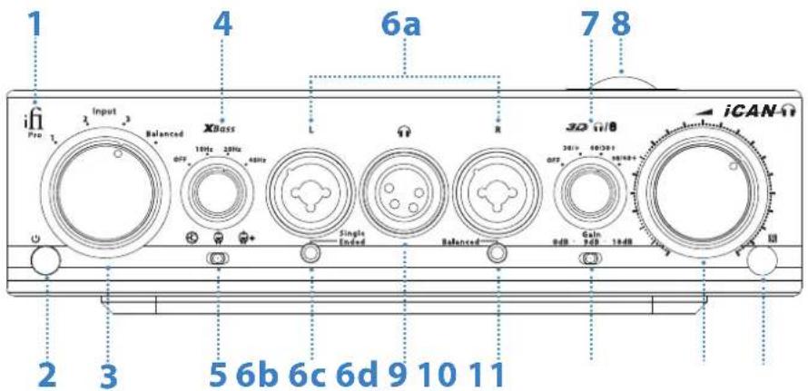
- LED Logo (illuminated) P.4
- Power Switch P.4
- Input Selector P.4
- XBass® Bass Correction System P.4
- Operation Modes (Solid-State/Tube/Tube+) P.5
- Headphone Output Sockets P.6
- 3D Holographic for Headphones® / 3D Holographic for Loudspeakers® Systems P.7
- NOS GE5670 Tubes P.9
- Gain Selection P.9
- Volume Control P.10
- IR Remote Control P.10
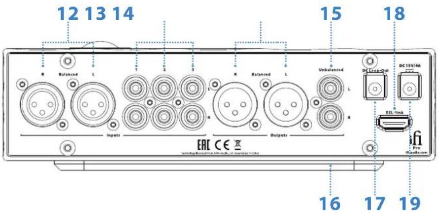
- Balanced Input
- Unbalanced Inputs 1-3
- Balanced Line Output
- Unbalanced Line Outputs
P.10 16. Quad-Damped Isolation Base Mount
P.10 17. DC Loop-Out
P.10 18. Connector for iFi Electrostatic Add-On Module
P.10 19. DC Power Supply Input
P.11
P.11
P.11
P.11

1. LED Logo
Warming-up: Orange (flashing)
Tube/Tube+ mode: Orange
Solid-State mode: White
Protection: Red
Tip: See Section 5 for details of the different operation modes.
2. Power Switch
ON/OFF.
Note: When switched on, the Pro iCAN will go through a warm-up sequence of 45 seconds before it is operational.
3. Input Selector
Input 1-3: RCA, single-ended.
Input balanced: XLR, balanced.
Tip: Even if single-ended RCA inputs are used with balanced outputs, the Pro iCAN will still operate in fully-balanced mode for the highest sound quality.
4. XBass® Bass Correction System
Different recordings and different headphones exhibit different frequency responses. X_Bass^ is an analogue signal processing (ASP) circuitry. It is sonically superior to Digital Signal Processing (DSP) systems. X_Bass^ is tailored to correct the bass deficiency in the headphone/loudspeaker and achieve the desired level. It is NOT a traditional tone or loudness control. The maximum boost is 12dB and the frequency at which this maximum boost it achieved is as follows:
OFF: XBass® is disabled (this allows the 'direct' sound to be enjoyed).
10Hz: for headphones/loudspeakers missing only the very lowest bass (below 40Hz).
20Hz: for headphones/loudspeakers missing some bass (below 80Hz).
40Hz: for headphones/loudspeakers missing substantial bass including some mid-bass (below 160Hz).
Note: Please be careful with the XBass®settings especially at high gain and high volume control settings, as even the most power-hungry headphones may be damaged by the power of the Pro iCAN.
Tip: The XBass® circuit is designed to correct different levels of bass deficiency inherent in many headphones/loudspeakers. It is NOT a gimmick to add artificial bass to recordings. Great care has been taken in the design to ensure there is no degradation of sound quality.
5. Operation Modes (Solid-State/Tube/Tube+)
The Pro iCAN has 3 operation modes:
Solid-State mode: is a pure, solid-state circuit and uses J-FETs and is fully-discrete Class A.
Tube mode: 2 x NOS GE5670s are engaged with the J-FET circuitry switched out for an all-valve Class A operation.
Tube+ mode: reduces negative feedback to a minimum. As a result, a greater amount of the tubes' natural harmonics are produced (Even Order harmonics dominate).
Note: Upon switching between modes, there will be a brief mute as the circuit switches. To maximise tube life, the Pro iCAN has a built-in intelligent monitor; after an extended period of operation in Solid-State mode, the tubes will switch off. If the tube circuit is shut-off, upon switching back to Tube/Tube+ mode, the tubes will need to warm up (as if the whole Pro iCAN itself was powered up from OFF). Music will continue to play via the Solid-State section until the tubes are fully activated.
ifi
Tip: For the first time, one can enjoy both the sound of Solid-State and Tubes in a single package (rather than as an 'Effect Type' add-on within an otherwise conventional solid-state design) and be able to switch in real-time. For some recordings and headphones/loudspeakers, Solid-State may sound more lively. For others, Tube and Tube+ (especially Tube+) will sound more luxurious. Select the one that sounds best for that particular moment, be it the recording, the mood or even the weather. After all, enjoying music is an experience to be savoured and not a scientific research exercise.
6. Headphone Output Sockets
6a. XLR 3 Pin x 2 (Balanced), 6.3mm x 2 (Balanced/Single Ended)
Balanced:
XLR - 3 Pin x 2
6.3mm TRS x 2 (iFi SEC balanced system)
Note: The iFi SEC (Single-Ended Compatible) balanced connection uses one 6.3mm Jack for L-/R- (left jack) and the other for L+/R+ (right jack) with both sleeves being Ground (GND). This makes it directly compatible with standard non-balanced headphones. With the correct Headphone cable it allows Balanced connection using two 6.3mm plugs.
Single-Ended:
6.3mm TRS x 2 (use right jack for unbalanced headphones, however it is possible to drive two separate headphones simultaneously).
6b. 3.5mm (Single Ended)
3.5mm TRS (with built-in iEMatch – output matched to high-sensitivity headphones).
6c. XLR 4 Pin (Balanced)
XLR - 4 Pin Balanced.
6d. 3.5mm (Balanced, TRRS standard)
3.5mm TRRS (with built-in iEMatch ^® – output matched to high-sensitivity headphones).
7. 3D Holographic for Headphones® / 3D Holographic for Loudspeakers® Systems
There are two separate Analogue Signal Processing (ASP) matrix circuits that switch automatically between headphone and loudspeaker use.
Note: When using the headphone outputs, the 3D Holographic matrix for headphones is engaged. When using the line outputs (RCA/XLR), the 3D Holographic matrix for loudspeakers is engaged.
For Headphones: (Headphone Outputs)
3D Holographic for Headphones® is an analogue matrix to 'undo' the negative sonic impact of headphone listening with recordings that were originally made for loudspeakers (as is the case for >95% of recordings). When listening with headphones this 'In Head Localisation' (sound is 'located' in the centre of one's head) can often lead to listening fatigue and even possibly, a little nausea.
i. OFF: 3D Holographic is disabled (this allows the 'direct' sound to be enjoyed).
ii. 30° Loudspeaker Angle: This matrix simulates a narrow loudspeaker placement (e.g. loudspeakers either side of a large computer monitor or in a car) and can also be used for recordings that have been artificially enhanced for spaciousness or early 'Ping-Pong' type stereo recordings.
iii. 60° Loudspeaker Angle: This matrix simulates traditional 'textbook' loudspeaker placement in an equilateral triangle.
iv. 90° Loudspeaker Angle: This matrix simulates a wide loudspeaker placement favoured by some audiophiles. It may also be used to enhance recordings that lack spaciousness (some minimalist 'single point' recordings fall into this group).
ifi
Tip: The 3D Holographic for Headphones is not based on a standard cross-feed system, as found in some High-End headphone amplifiers. Many so called '3D systems' are usually DSP based that artificially effect the sound and add unwanted reverb in order to simulate a 'spacious' type of sound.
It's true that traditional cross-feed tends to produce an 'out of head' sound, but with much diminished spatial components and a narrower soundstage, sometimes almost approaching mono. Most DSP based 3D designs produce an unnatural, echo-like sound, which may initially be impressive, but soon becomes tiring.
By contrast, 3D Holographic for Headphones, provides not only 'out of head' placement of the sound sources, but renders the whole 3D sound field in a manner that strongly parallels listening to loudspeakers in a normal room, all achieved without the added reverb. This is the first system in commercial production to achieve this.
For Loudspeakers: (Line Outputs)
The 3D Holographic for loudspeakers® is an analogue matrix circuit that has two distinct functions:
- Corrects the fundamental spatial distortion in stereo recordings;
- Increase the width of the apparent soundstage beyond the width dictated by the loudspeaker placement.
i. OFF: 3D Holographic is disabled (this allows the 'direct' sound to be judged).
ii. +: This matrix corrects ('+) the spatial distortion caused by the recording/mixing/mastering process and restores the original width of the soundstage. This is the recommended default setting if the loudspeakers are already ideally placed for imaging.
iii. 30°+: This matrix corrects ('+) the spatial distortion caused by the recording/mixing/mastering process and adds an approximate 30° to the apparent width of the soundstage. Thus, loudspeakers with narrow placement (e.g. Loudspeakers closely located either side of a TV set) can offer a soundstage that extends beyond the left and right past the loudspeakers and is close to the ideal placement.
iv. 60°+: This matrix corrects (+') the spatial distortion caused by the recording/mixing/mastering process and adds an approximate 60° to the apparent width of the soundstage. This is close to the 'wide' placement preferred by some audiophiles.
The 3D Holographic circuit for loudspeakers corrects a distortion of the 3D sound field caused by recording via microphones and playback via loudspeakers. This sound field distortion was first described by Alan Dower Blumlein (the Inventor of Stereophonic sound) and corrected by EMI in early 'Stereosonic' recordings.
However, the original Stereosonic circuit tended to result in a narrower soundstage than if recorded straight and often overcompensated distortion of the soundstage perspective. iFi's 3D Holographic systems avoid this and instead, allow an expansion of the width of the sound stage.
Tip: These modes can also be used to enhance the imaging of recordings that offer poor spatiality.
8. NOS GE5670 Tubes
New Old Stock 'Made in the USA' General Electric 5670 x 2.
Tip: Each GE5670 tube has undergone a special rejuvenation process and the tube circuit is specially-designed for long life. Combined, the tubes should offer many years of enjoyment.
9. Gain Selection
0dB (Default)/9dB/18dB.
Tip: Use the lowest gain possible for the best sound. At normal listening levels, the volume control should be around 12 o'clock. Increase the gain if the 12 o'clock position does not provide satisfying listening levels.
Note: Please be aware that the Pro iCAN can output >10V in Single Ended mode and over 20V in Balanced mode. For comparison,

20V is equal to 100W with a 4 ohm loudspeaker. These levels are very high and can damage many headphones and/or drive most amplifiers (if used as a line-stage) into very hard clipping. Damage to headphones and/or loudspeakers may result from excessively high volume settings.
10.Volume Control
To control the volume.
Tip: For loud but normal listening levels, the volume control should be between 10 and 2 o'clock. Adjust the gain upwards if the volume is unsatisfactory. If one cannot turn up the volume to even 10 o'clock (at the lowest gain setting), please connect the headphone to the iEMatch embedded 3.5mm connections, which are matched to high-sensitivity headphones such as in-ear-monitors and other high-sensitivity modern headphones designed to operate from portable devices.
11.IR Remote Control
Window for IR Remote Control receiver.
12.Balanced Input
Balanced/XLR x 1.
13. Unbalanced Inputs 1-3
RCAs x 3.
14.Balanced Line Output
Balanced/XLR Output.
15. Unbalanced Line Outputs
RCA Outputs.
16. Quad-Damped Isolation Base Mount
Base support, please set the Pro iCAN on a flat surface.
Tip: The Quad-damped Isolation Base Mount was specially-designed to provide the ultimate vibration damping control and electromagnetic shielding. It consists of a custom quad-layer sandwich; dual layer elastomers (silicone layer and copolymer of ethylene and vinyl acetate layer), and a dual-layer of metal alloy (aluminium alloy layer and ferrous alloy layer finished with special honeycomb coating).
Together with the variable (golden ratio) thickness chassis, the chassis resonance is optimally distributed and minimised.
17.DC Loop-Out
DC loop through for use with Pro iCAN add-ons (e.g. Electrostatic module).
18. Connector for iFi Electrostatic Add-on Module
This is only for connection with the iFi Electrostatic module. DO NOT CONNECT ANY OTHER EQUIPMENT!
19.DC Power Supply Input
15V/4A DC Power input.
Tip: Any 9v to 18v DC power source with a minimum 60VA rating can be used with the Pro iCAN (including vehicular, RV and boat based 12V DC power). The Pro iCAN uses double-conversion power supplies that make it impervious to power supply noise and related problems. However, we strongly recommend the use of the included iPOWER Plus 15V. It offers the latest in power supply technology and is better and cleaner than battery and aftermarket linear power supplies.

Design Notes from the AMR/iFi Research & Development department:
- The Pro iCAN circuit is fully-balanced with completely equal circuit sections for Positive (Hot) and Negative (Cold) signal phase of each channel. The Volume control is a 6-way motorized ALPS type, 4 Tracks are used to adjust the volume for the balanced signal, the other two are used for monitoring the volume control operation.
- Maximum Output is >20V in balanced mode, >10V in single ended mode, maximum peak current is 1.4A for Single-Ended Headphone connections and 0.7A for Balanced Headphone connections. The continuous output current is limited by protection circuitry that only engages in case of sustained overload. A short term sustained output of around 14,000mW (14 VA) is possible in Balanced operation.
- The amplifier audio circuit is a development of iFi's revolutionary 'TubeState' design. It is fully discrete, fully-balanced with either tube or J-FET input switchable, bipolar second stage and MOSFET-buffered bipolar class A Power stage (with Class AB for low impedance headphones at very high levels). The resulting circuit may be best described as 'tri-brid' where each device is used to greatest sonic advantage while minimising any drawbacks. Furthermore, the circuit is pure DC coupled to avoid using any sonically-degrading coupling capacitors.
- Frequency response (0.5Hz -500kHz @ 0dB), noise (-142dB @ 0dB) and distortion (0.0008% @ 0dB) depend on gain and on which input device is selected. However (generally speaking), the levels of noise and distortion, especially in balanced operation challenge the limits of the Audio Precision test system.
- The XLR and RCA outputs on the back offer full preamplifier function, but are not switched off if headphones are connected. Nonetheless, the Pro iCAN should be used either as preamplifier or headphone amplifier, as generally a mixed use setup is not recommended.
- The 3D Holographic matrices are tightly integrated into the signal circuit. Not only is there no use of DSP and the linked AD/DA conversion, there are also no additional active elements.
- If disabled, the passive elements (resistors, capacitors and inductors) that form the analogue matrix are completely removed from the circuit, so the fidelity of the signal in 'OFF' remains unaffected.
- If enabled, the 3D Holographic matrix fundamentally re-shapes the transfer function of the actual amplifying circuit to do its job. So again, the fidelity of the signal is as if the 3D Holographic matrix was designed integral to the circuit. This is a highly-unusual design, as normally signal processing functions add extra circuits to the main amplification circuit.
Such additional circuitry cannot but negatively impact sound quality when in use and often even when disabled.
Specifications:
- Gain :
• Frequency Response:
• Total Harmonic Distortion (THD, Balanced/Single-Ended):
0dB, 9dB and 18dB user-selectable 0.5Hz to 500kHz(-3dB)
| Balanced | SE | |
| Solid-State: | ≤ 0.0025% | ≤ 0.005% |
| Tube: | ≤ 0.0025% | ≤ 0.007% |
| Tube+: | ≤ 0.0025% | ≤ 0.07% |
• Signal-to-Noise Ratio (SNR, Balanced/Single-Ended):
• Output Power (16Ω, Balanced/Single-Ended):
• Output Voltage (600Ω, Balanced/Single-Ended):
- Input Voltage (Pro iCAN):
• Input Voltage (iPower Plus):
• Power Consumption:
- Dimensions:
147dB(A) / > 137dB(A)
14,000mW / >4,800mW
23V / >11.5V
DC 9V/6.7A - 18V/3.35A
AC 85 - 265V, 50/60Hz
≤ 22W idle, 50W max.
213(l) x 192.5(w) x 63.3(h) mm
Test conditions:
Gain = 0dB, 0.775V(0dBu) with 300 Ohm load unless stated otherwise
SNR Balanced re 23V, SNR SE re. 11.5V


139-141 Cambridge Road, Churchtown, Southport, PR9 7LN, United Kingdom www.ifi-audio.com
Ver1.1


- ifi
- LED Logo
- Power Switch
- Input Selector
- XBass® Bass Correction System
- Operation Modes (Solid-State/Tube/Tube+)
- Headphone Output Sockets
- 6a. XLR 3 Pin x 2 (Balanced), 6.3mm x 2 (Balanced/Single Ended)
- 6d. 3.5mm (Balanced, TRRS standard)
- 3D Holographic for Headphones® / 3D Holographic for Loudspeakers® Systems
- For Headphones: (Headphone Outputs)
- For Loudspeakers: (Line Outputs)
- NOS GE5670 Tubes
- Gain Selection
- 10.Volume Control
- 11.IR Remote Control
- 12.Balanced Input
- Unbalanced Inputs 1-3
- 14.Balanced Line Output
- Unbalanced Line Outputs
- Quad-Damped Isolation Base Mount
- 17.DC Loop-Out
- Connector for iFi Electrostatic Add-on Module
- 19.DC Power Supply Input
- Design Notes from the AMR/iFi Research & Development department:
- Specifications:
Brand : iFi Audio
Model : Pro iCAN
Category : Receiver