Optic 5 - Régulateur Hitec - Free user manual and instructions
Find the device manual for free Optic 5 Hitec in PDF.


User questions about Optic 5 Hitec
0 question about this device. Answer the ones you know or ask your own.
Ask a new question about this device
Download the instructions for your Régulateur in PDF format for free! Find your manual Optic 5 - Hitec and take your electronic device back in hand. On this page are published all the documents necessary for the use of your device. Optic 5 by Hitec.
USER MANUAL Optic 5 Hitec
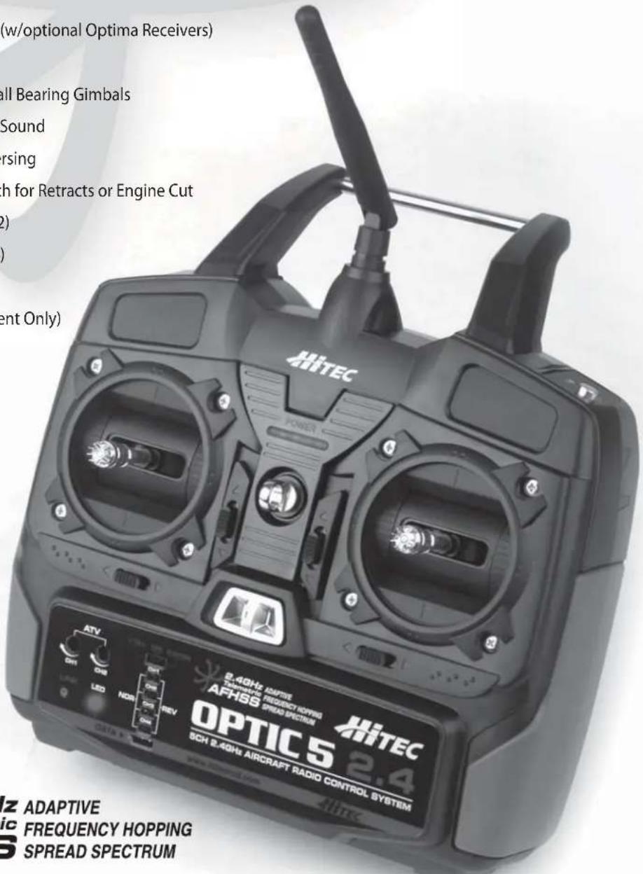
- Telemetry Capabilities (w/optional Optima Receivers)
- 1024 Resolution
- High Precision Quad Ball Bearing Gimbals
- Digital Trim with Beep Sound
- All Channel Servo Reversing
- 5th Channel AUX Switch for Retracts or Engine Cut
- Elevon Mixing (Ch.1 & 2)
- V-Tail Mixing (Ch.2 & 4)
- ATV on Ch.1 & 2
- Trainer Function (Student Only)
text_image
(w/optional Optima Receivers) All Bearing Gimbals Sound orsing with for Retracts or Engine Cut (2) ent Only) HiTEC POWER 2.40Hz ADAPTIC TANTHATIC REGENCY OPTIC AFHSB SPREAD SPECTRUM OPTIC5 2.4 SCH 2.40Hz AIRCRAFT RADIO CONTROL SYSTEM HiTEC ATV ON OE LED NOR REV ATV ADAPTIVE FREQUENCY HOPPING SPREAD SPECTRUMOPTIC 5 2.4
5CH 2.4GHz DIGITAL COMPUTER RADIO SYSTEM
Table of Contents
| Introducing the Optic 5 2.4 | 2 |
| Hitec AFHSS 2.4GHz Technology | 3 |
| Equipment Mounting | 3 |
| Vibration and Water | 4 |
| Receiver Antenna Installation | 4 |
| Connectors | 5 |
| Charging the Batteries! | 5 |
| Operating with a Trainer Cord | 6 |
| Stick Length Adjustment | 7 |
| Stick Lever Tension Adjustment / Mode Change | 7 |
| Flying Safety | 8 |
| Optic 5 2.4GHz Controls and Switch Assignments | 9 |
| On-Off Switch | 10 |
| Optic 5 2.4GHz Programming Switches and Buttons | 10 |
| Minima 6T Receiver Features | 11 |
| Minima 6T Receiver Connection Diagrams | 12 |
| Minima Series Receiver Features | 13 |
| Minima Series Receiver Features | 14 |
| Set-up and Use of the Hitec 2.4GHz System | 15 |
| Minima Series Receiver Features | 16 |
| Set-up and Use of the Hitec 2.4GHz System | 17 |
| Receiver-Servo Connection List | 17 |
| ATV (Adjustable Travel Volume) Function | 18 |
| Trim Adjustment | 18 |
| S. REV (Servo Reverse) | 19 |
| ELVN (Elevon Mix) | 19 |
| V.TAIL (V-Tail) | 20 |
| CUT (Engine Cut Function) | 20 |
| Setting the Engine Cut Function | 20 |
| Setting the Gear (Retractor Gear) Control Function | 20 |
| Service & Support | 21 |
| Service & Support | 21 |
| MEMO | 22 |
Introducing the Optic 5 2.4
Congratulations and welcome to the R/C world! You now own a basic, but unusually versatile and powerful, 5-Channel beginner's RC transmitter. The Optic 5 2.4GHz is all the radio you need to fly most 5-Channel fixed-wing aircraft.
Standard features include servo-reversing for all channels and trim adjustments on all control channels, ATV (Adjustable Travel Volume) on Aileron (CH.1) and Elevator (CH.2).
The Optic 5 2.4GHz advanced features include:
Pre-mixed Flight Control Functions:
The Optic 5 2.4GHz computer automatically mixes rudder and elevator outputs to control a V-tail or mixes aileron and elevator outputs to create elevons for tail-less flying wings, eliminating the need for on-board mixing systems.
Trim Adjustment Function:
This computerized radio allows you to easily tune and coordinate the control surfaces (such as keeping a rudder centered or two ailerons each on their own servo-moving the same amount) without having to physically re-adjust linkages.
Buddy-Box Function:
For those learning to fly, the transmitter has a "buddy-box" capability so that you can use the optional trainer cord (part # xxxx) to connect your Optic 5 2.4GHz to another Hitec transmitter (Master)*. This function allows one transmitter to be used by an instructor as the primary flight control while the other is controlled by the student pilot.
\*Note: Optic 5 2.4GHz can only be used as a pupil transmitter.
Hitec's Telemetry 2.4Ghz System
The Optic 5 can easily connect to a receiver via the Spectra 2.4 system. When the Optima series of receivers are used, the Optic 5 Telemetry System can check the receiver's voltage through the LED and a buzzer.
Engine Cut & Landing Gear
The Optic 5 has an engine off button for safety after flying as well as a retract landing gear operation for safe landings.
If you are new to Computerized RC Transmitters:
If the OPTIC 5 is your first radio control transmitter, you may be feeling a bit overwhelmed. However, if you take the time to read this manual and follow the programming steps as you watch your model's control surfaces respond, handling the Optic 5 will soon become quite comfortable. So stick with it. Learning the programming basics won't take any longer or require any more brain power than it takes to do the average crossword or Sudoku puzzle.
You'll discover that the rewards for mastering this simple radio are well worth the effort.
TIP :
Throughout the manual you will see our "Tip Sheet" notes.
These highlight specific function details we didn't want you to miss within the body of the manual.
Check these out, they can make programming the Optic 5 easier.

Hitec's AFHSS 2.4GHz Technology
Hitec is proud to introduce our first 2.4GHz built-in 2.4 transmitter. The Optic 5 2.4 can be used with most of the Hitec's existing AFHSS (Adaptive Frequency Hopping Spread Spectrum) 2.4GHz receivers. Other features of our system include telemetry capabilities, our exclusive BODA(Boosted Omni-Directional Antenna) system and a SPC(Supplemental Power Connection) for added insurance. Providing the hobbyists with the latest technology at an affordable price has always been Hitec's primary goal, a goal that we have now achieved in 2.4GHz technology.
Adaptive Frequency Hopping Spread Spectrum Technology (AFHSS)
Our 2.4GHz system utilizes the latest AFHSS technology and our exclusive Scan Mode system to ensure a rock solid, interference-free connection between the transmitter and receiver. When selected, Hitec's 2.4GHz Scan Mode function scans the 2.4GHz spectrum to find the cleanest channels in which to operate, providing interference-free operation even in the most crowded environments.
Boosted Omni Directional Antenna (BODA) \*
The Optima 2.4GHz line of receivers features our exclusive BODA receiver technology. Intensive tests have proven that the single BODA antenna system in our 6 & 7 channel systems is better than or equal to our competitors' dual antenna systems. Our Optima 9 receiver features a dual BODA system to give the added security that larger models need.
Telemetry System \*
The Optima 6 receiver offers the basic telemetry function of the low battery warning. With the purchase of an Optima 7 and 9, you can enjoy our full line up of telemetry functions such as temperature, GPS, fuel level, and RPM sensors!
Supplementary Power Connection (SPC) \*
Since most hobbyists are concerned about their BEC capacity when setting up their planes, we are proud to offer a way to supplement your power source. Hitec's 2.4GHz system operates with a normal 4, 5-cell(4.8V, 6.0V) receiver battery, but you can also utilize the SPC system if you feel that you need to supply more sufficient power to the receiver. Once the SPC system is activated, receiver battery power will be concentrated on the servo operation, and the power from your motor battery will directly feed the receiver through the SPC port.
Need more? The SPC enables you to monitor the motor battery voltage through the telemetry function.
NOTE
These functions
* are applicable in the Optima series receivers only.(Not applicable in Minima receivers)

Equipment Mounting
Mounting
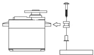
When you mount each servo, use the supplied rubber grommets and insert an eyelet up through the bottom. Be sure not to over tighten the screws.
If any portion of the servo case directly contacts the fuselage or the servo rails, the rubber grommets will not be able to attenuate vibration, which can lead to mechanical wear and possible servo failure.
natural_image
Technical line drawing of a mechanical device with a spring scale and lever mechanism (no text or symbols)Servo Throw
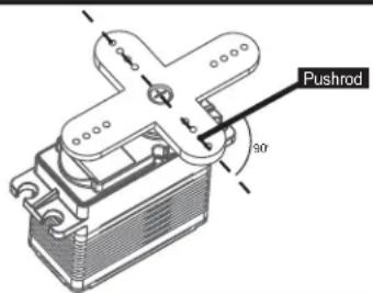
Once you have installed the servos, operate each one over its full travel and check that the pushrod and output arms do not bind or collide with each other, even at extreme trim settings.
Check to see that each control linkage does not require undue force to move (if you hear a servo buzzing when there is no transmitter control motion, most likely there is too much friction in the control or pushrod).
Even though the servo will tolerate loads like this, they will drain the battery pack much more rapidly.
text_image
Pushrod 90°Factory Repair Service Information
Please read the warranty card supplied with your system and return it. Before you decide to have your system repaired, if there is no apparent physical damage, read this instruction manual again and check to be sure that you are operating the system as it was designed to be operated. If you are still having trouble, pack up your system in its original shipping materials and send it to the nearest authorized Hitec R/C Service Center.
Be sure to include a note in your package that describes the trouble in as much detail as possible, including: symptoms of the problem in as much detail as you can provide, including any unusual mounting conditions or equipment orientation, a list of items you are sending, and what you want to be repaired. Make sure you also provide your name, address and telephone number.
Vibration and Water
Vibration and Water
The receiver contains precision electronic parts. Be sure to avoid vibration, shock, and temperature extremes.
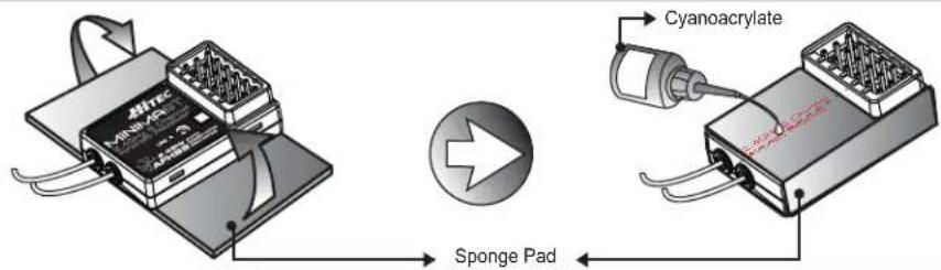
For protection, wrap the receiver in the provided "Flight Preserver" foam rubber, or use some other vibration-absorbing materials.
If you are flying near bodies of water, it's also a good idea to protect the receiver by placing it in a plastic bag and securing the open end of the bag with a rubber band before wrapping it with foam. If you accidentally get moisture inside the receiver, you may experience intermittent operation or a possible crash.
text_image
Sponge Pad CyanoacrylateSwitch Harness Installation
When you are ready to install the receiver's switch harness, remove the switch cover and use it as a template to cut screw holes and a rectangular hole slightly larger than the full stroke of the switch.
Choose a switch location on the opposite side of the fuselage from the engine exhaust, and choose a location where it can't be inadvertently turned on or off during handling or storage. Install the switch so that it moves without restriction and "snaps" from ON to OFF and vice versa.
Receiver Antenna Installation
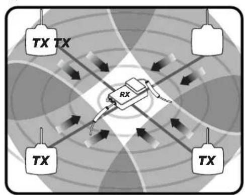
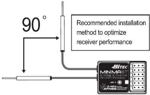
The Minima 6T and 6E M-BODA antenna system is made for high directivity consisting of two antennas. In order to maximize the functions of the Minimas, please install as shown below.
flowchart
graph TD
    A["TX TX"] --> B["RX"]
    C["TX"] --> B
    D["TX"] --> B
    E["TX"] --> B
    B --> F["Output"]
    style A fill:#f9f,stroke:#333
    style C fill:#f9f,stroke:#333
    style D fill:#f9f,stroke:#333
    style E fill:#f9f,stroke:#333
    style F fill:#ccf,stroke:#333
text_image
90° Recommended installation method to optimize receiver performance HITEC MINIMAST 2.4GHz AC/DC APHSSNOTE
*Detailed range check method can be found on page 19. During the range check period, you should be able to walk away at least 75 feet from the model without losing control or seeing "jitter" in the servos.
The range check should be done with the motor running and the model should be securely restrained in case of loss of control.


Warnings
text_image
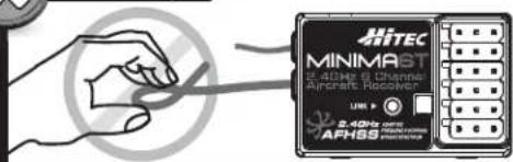
MINIMAST 2.4GHz AC Channel Aircraft Receiver APHSSNever pinch or bend the antenna, such behavior will cause serious damage to the antenna.
Changing the length of the antenna reduces range.
text_image
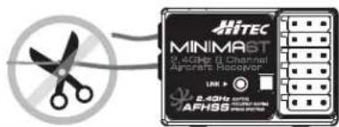
MINIMAST 2.4GHz 10 Channel Aircraft Recovery LINK > 2.4GHz 10 AFHSSNever cut the antenna, such behavior will seriously reduce the reception range.
Connectors
Be sure the alignment of a servo or battery connector is correct before inserting it into the receiver. To remove a connector from the receiver, try to pull on the connector's plastic housing rather than pulling on the wires. Pulling the wires can ruin the connector pins and break wires.
Using Servo Wire Extensions
If any of your servos are located too far away to plug directly into the receiver (like the aileron servo), or you need to unplug the servo each time you disassemble the model, use a servo extension cord to extend the length of the servo lead.
Additional Hitec extension cords of varying lengths are available from your hobby dealer.
Charging the Batteries!
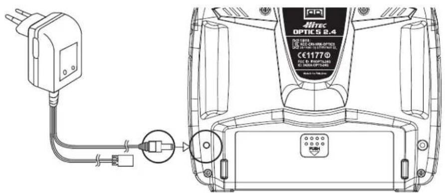
Before we dive into the programming and use of the Optic 5, let's charge the batteries.
text_image
MITEC OPTIC 2.4 1993 ECO CHINK OPTIC SALDO ELECTRONICS CE11770 ECO D ENOPTICAL EC TURI OPTICALS PUSH*Warning: During the OPTIC 5 2.4's charging process, turn off the transmitter power.
- Connect the transmitter charging cord to the transmitter's charging socket (on the rear of the case, left side).
- If your aircraft uses a receiver battery, connect it to the receiver connector on the charging cord.
- Plug the charger into a wall socket.
- The charger's LEDs should light, indicating charging is in progress.
If either light does not turn on, verify that the transmitter and receiver power switches are OFF.
The batteries should be left on charge for about 15 hours or below depending upon battery capacity.
Try to charge the batteries with the charger supplied with your system exclusively.
The use of a fast-charger may damage the batteries by overheating and dramatically reduce their life span.
NOTE: If you need to remove or replace the transmitter battery, do not pull on its wires to remove it. Instead, gently pull on the connector's plastic housing where it plugs into the transmitter. The battery must be removed to charge it properly with a "peak" charger.

Be careful if you choose to use a field charger on your batteries.
A fast-charger may overcharge the batteries, causing overheating and a premature failure. Never charge your transmitter or receiver battery at a rate higher than the batteries' capacity.
For example, if you use a 7.2 volt, 1300 mAh NIMH battery, it should not be charged at a rate any higher than 1.3 amps.
Caution: When your transmitter beeps indicating a low battery warning, land your aircraft at once and stop flying. (L.B.W. activates when battery level hits below 6.6V)

A training cable may be used to help a beginner pilot learn to fly safer by allowing a second transmitter, operated by an experienced instructor, to be connected to the Optic 5 transmitter. The instructor may override the beginner at any time to bring the model back under safe control. For training, the transmitter may be connected to another Hitec 2.4GHz system using the Hitec cord part No. #58320 TRAINER CABLE (between 6-cell transmitter battery systems) or #58321 TRAINER CABLE FULL PACKAGE (#58320 + Slave DIN + Master DIN) - For use between a 6-cell transmitter battery system and 8-cell transmitter battery system.
Operating with a Trainer Cord
When used as a student radio, the Optic 5 supports the trainer system. Instructions below provide general information about the trainer system and which method may work for you.
NOTE:
- WHEN USING THE TRAINER SYSTEM IN THE STEREO JACK TO STEREO JACK FORMAT AS NOTED IN THE NEXT SEVERAL PARAGRAPHS, BOTH TRANSMITTERS ARE GOING TO TRANSMIT.
- IF THE STUDENT TRANSMITTER HAS A REMOVABLE MODULE, REMOVE IT. THEN, IT WILL NOT BE TRANSMITTING. OTHERWISE, IF YOU ARE FLYING AT A CLUB FIELD USING FREQUENCY CONTROL, BE SURE YOU HAVE THE OK TO USE BOTH FREQUENCIES.
- IF THERE IS NO REMOVABLE MODULE ON THE STUDENT TRANSMITTER, BOTH TRANSMITTERS MUST BE ON DIFFERENT FREQUENCIES.

- To use the trainer system between STEREO Jack Transmitter and STEREO Jack Transmitter (Needs #58320 between 6-cell battery radios). 1) Set up both the student's and instructor's transmitter to have identical trim and control motions. If the instructor's transmitter is on a different frequency than the student's, use the student's transmitter as the master transmitter, and the other transmitter as the student's.
2) Turn on the instructor's transmitter and DO NOT turn on the student's transmitter power. Plug Trainer Cord (#58320 Stereo Jack) accordingly into each transmitter. The trainer jack is on the back of the transmitter. (The OPTIC 5 has no LCD screen and "SLV MODE" only)
3) Move the controls on the instructor's transmitter, and verify each control moves the proper direction. Now verify that the student's trims and control travels match the instructor's by (the momentary ENG CUT/TRAINER button on the top right of the transmitter case) switching the trainer button on and off while leaving the control sticks and trims alone then move the control sticks.
4) The instructor's transmitter has normal control over the model unless the trainer button is pressed, passing control to the student's transmitter. If the student loses control, the instructor can quickly "take over" by releasing the trainer button and then controlling the model.
- To use the trainer system between a STEREO Jack Transmitter and a DIN Jack Transmitter. (Needs trainer cable package #58321 between 6-cell battery radio and 8-cell battery radio systems). Please read the following instructions carefully for using transmitters with DIN Jack and/or stereo jack for the trainer system. You will need the Trainer cable full package (#58321). This full package consists of a STEREO Jack trainer cable(#58320), Instructor DIN Jack and Student DIN Jack Adapter.
This package allows the proper connection between a 6-cell battery system radio (ex. Optic 5 2.4, Optic 6 Sport 2.4, Aurora 9) and 8-cell battery system radio (ex. Optic 6 2.4 / Eclipse 7 2.4).
NOTE
This section tells you how to connect the transmitters only.
Please read the prior sections for the full information needed to properly operate the trainer cable system.

- To use the trainer system between the Transmitter having a STEREO jack as INSTRUCTOR and Transmitter having DIN jack as STUDENT.
1) Power on the INSTRUCTORS Transmitter having the STEREO Jack.
2) Plug the STEREO Jack trainer cable (#58320) into the Master, or INSTRUCTOR'S transmitter. Note you will see "MAS MODE" on the LCD screen which means the transmitter is recognized as the INSTRUCTOR or "Master".
3) Connect the DIN Jack adapter marked "STUDENT" from the cable package #58320 to the other end of the stereo connector cable. This combination enables you to connect the cable to the STUDENT transmitter with a DIN Jack connector.
4) Plug the DIN connector into the socket on the STUDENT transmitter.
5) Finally, power on the STUDENT transmitter. Though it is powered on, the STUDENT transmitter will not transmit the radio signal as long as the trainer cable is connected properly.
- To use the trainer system between the Transmitter having a DIN jack as INSTRUCTOR and a Transmitter having a STEREO jack as STUDENT.
1) Connect the INSTRUCTOR or DIN Jack adapter marker "Master" with #58320 stereo jack Trainer cable.
2) Power on the INSTRUCTOR transmitter.
3) Plug the combined trainer cable into the INSTRUCTOR transmitter DIN jack connection.
4) The STUDENT transmitter should be turned off.
5) Plug the trainer cable into the STUDENT transmitter with the stereo jack. The power to the STUDENT transmitter will turn on automatically (OPTIC 5 2.4 has no LCD screen and "SLV MODE" only)
6) Though the STUDENT transmitter is powered on automatically, it will not transmit a radio signal as long as the trainer cable is connected properly.
NOTE
1) Do NOT turn on the power of the STUDENT transmitter having the STEREO Jack. Once you plug the trainer cable into the STUDENT Transmitter using the STEREO Jack, it will be powered on automatically.
2) All Transmitters in the trainer system use their own batteries. Both batteries in both the Instructor and Student Transmitters should be properly charged and installed when flying in the trainer mode.
3) You may wish to use a simple "contractors cord" knot on the cable to connect the adapter and to keep it from coming "unplugged" when using it. Heat shrink tubing or electrical tape can also be used.

Stick Length Adjustment
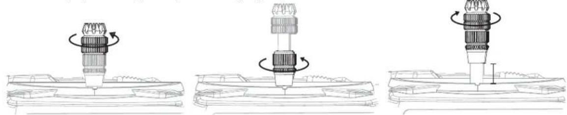
Everyone's hand size is different, so in order to accommodate all, we use a two piece stick "top" that can be adjusted to fit a wide variety of users.
Separate the top from the bottom piece and adjust the top piece to the length required.
Screw the bottom up against the top piece to "jam" lock everything into position.
natural_image
Three technical line drawings showing mechanical assembly steps with no visible text or symbolsStick Lever Tension Adjustment | Mode Change
Stick Lever Tension Adjustment
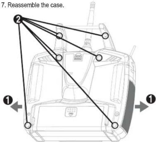
You may adjust the stick tension of your sticks to provide the "feel" that you like for flying. To adjust your springs, you'll have to remove the rear case of the transmitter. Using a screwdriver, remove the six screws that hold the transmitter's rear cover into position, and put them in a safe place. Now, place some padding under the front of the transmitter and set it face down on the pad.
Gently ease off the transmitter's rear cover. Now you'll see the view shown. Using a small cross-point screwdriver, rotate the adjusting screw for each stick for the desired spring tension.
The tension increases when the adjusting screw is turned clockwise, and decreases for counterclockwise motion.
Note: Please use M2(2mm) or 5/64 inch hex key for gimbals' tension adjustment and mode changes.
When you are satisfied with the spring tensions, you may close the transmitter. Very carefully reinstall the rear cover.
When the cover is properly in place, tighten the six screws.
Change to 'Mode 1' Configuration

All Optic 5 system's Mode (Mode 1 or 2) configurations are set up at the factory, but you may wish to change your current Mode.
Please follow the hardware set-up below in order to change your Mode.
The set-up shown below is based on Mode 2 (Mode2 → Mode 1 change), so you can apply the procedure adversely if your radio is Mode 1.
- Carefully remove the plastic side panels from the transmitter.
- Remove all the six phillips head screws from the back of the case.
- Unscrew a hex screw to remove the copper ratchet from where it is located and move it to the other side.
- Tighten up the tension spring hex screw on the new location, try to control the stick feeling first if you like the tension.
- Loosen up the tension spring hex screw on the original location.
- Allocate the "Mode Selection Jumper" to the desired mode.
- Reassemble the case.
text_image
7. Reassemble the case. ① ② ①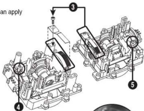
text_image
an apply 3 4 5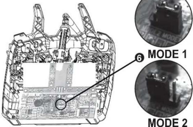
text_image
MODE 1 MODE 2Page 7
Flying Safety
To ensure your own safety and the safety of others, please observe the following precautions:
Flying field
We recommend that you fly at a recognized model airplane flying field.
You can find model clubs and fields by asking the nearest hobby dealer, or contacting the Academy of Model Aeronautics.
Always pay particular attention to the flying field's rules, as well as the presence and location of spectators, the wind direction, and any obstacles on the field.
Be very careful flying in areas near power lines, tall buildings, or communication facilities as there may be radio interference in the vicinity.
Once you arrive at the flying field...
- Before you fly, perform a range check to confirm your radio system is responding correctly.
- To do a range check, power-up the aircraft and either ask a friend to help hold the aircraft or secure it somehow.
- Walk away from the aircraft until the aircraft "glitches" or you notice intermittent control loss.
- Walk back to the aircraft, pacing out the distance.
Note: We want a good range check to be at least 75 feet or so.

- When you are ready to fly your model, position the throttle stick or switch to its low speed or off position.
Then, you may turn on the transmitter power followed by the receiver power. - When you have finished flying, turn off the receiver power first then turn off the transmitter power.
If you do not follow these procedures, the receiver has no information to hold the servos steady and you may damage your servos or control surfaces. You may also flood the motor.

- In case of electric-powered models, the motor may unexpectedly turn on and cause a severe injury if the transmitter is switched off before the receiver.
- Before starting the engine, power up the transmitter and receiver, and check to be sure that the servos follow the movement of the sticks.
- If a servo operates abnormally, don't attempt to fly until you determine the cause of the problem.
- Before starting the engine, be sure to check that the transmitter model memory is correct for the chosen model.
- While you're getting ready to fly, if you place your transmitter on the ground, be sure that the wind won't tip it over.
- If it is knocked over, the throttle stick may accidentally get moved causing the engine to race unexpectedly, causing damage or injury to anyone nearby.
- Finally, don't fly in the rain! Water or moisture may enter the transmitter through the antenna or stick openings and cause erratic operation or loss of control.
If you must fly in wet weather during a contest, be sure to protect your transmitter with a plastic bag or waterproof barrier.

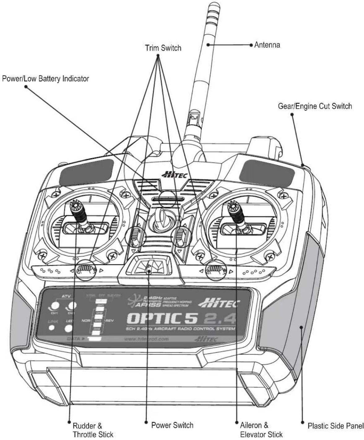
Optic 5 2.4 Controls and Switch Assignments
text_image
Power/Low Battery Indicator Trim Switch Antenna Gear/Engine Cut Switch Rudder & Throttle Stick Power Switch Aileron & Elevator Stick Plastic Side PanelThis figure shows the assignments for a Mode 2 system as supplied by the factory. Note that some of the functions will not operate until activated in the mixing menus.
On-Off Switch

text_image
ATV PAN AVG 2-40Hz AVTS AFHSS HTEC BRICE 3.4This switch does more than just turn the radio on and off, it also allows you to link to the receivers (see page 13).
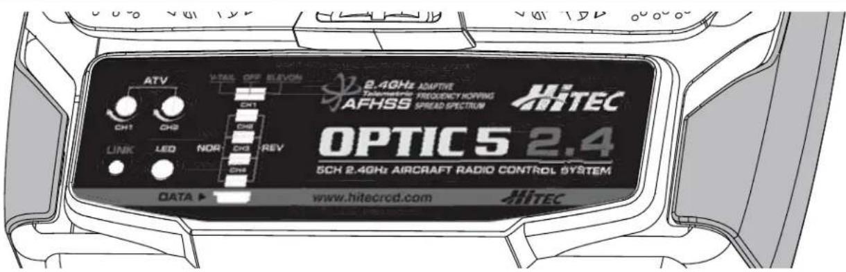
Optic 5 2.4 Programming Switches and Buttons
text_image
ATV CH1 CH2 LINK LED NOR CH3 CH4 OFF ELEVON CH1 CH2 CH3 REV CH4 8.4GHz ADAPTIVE Telematric FREQUENCY HOPPING AFHSS SWEED SPECTRUM HiTEC OPTIC 5 2.4 5CH 2.4GHz AIRCRAFT RADIO CONTROL SYSTEM DATA ▶ www.hitecrod.com HiTEC"ATV" potentiometer
The ATV function is somewhat similar to EPA (End Point Adjustment) and D/R (Dual Rate) function; it allows you to adjust a servo's travel end position amount over a control stick's movement.
The ATV function affects both endpoints at once, while the EPA function allows each servo end to travel individually. This function can be found useful when the plane is too sensitive over a control stick's movement.
"LINK" button and LED Indicator
The Link button can be used for the Link (ID setting) process between the Optic 5 radio and Hitec 2.4GHz receivers, entering the power down mode for range check, activating SmartScan function and using Fail-safe function. The LED indicator shows current working status of the radio with both red and blue lights. For more detailed information, please read pages13\~16.
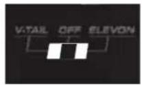
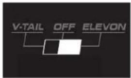
"Mixing ( V-TAIL and ELEVON )" slide switch
The Mixing switch is used for mixing the function of servos with different wing types. (V-TAIL and ELEVON)
"REV (Servo Reverse)" slide switch
The REV switch is used for reversing the direction of the servos.
"Sensor Data Output and System Upgrade Connector" Port
The DATA port is designed with a 3-pin type. Through the HPP-22 Hitec PC program, you can down load the firmware program and software upgrade. In addition, you can monitor the sensor data with the voice solutions and set up a low voltage receiver alarm. *
* The Minima 6T and 6E are designed for a single direction from the transmitter to the receiver, so you CAN NOT use all other sensors (including the receiver's voltage sensor). However, if you use the Optima 6, Optima 7 or Optima 9 receivers and connect your PC with the HPP-22 and Optic 5 together, then you can check sensor values on the PC screen. You can also hear the sensor data and warnings through the HTS-VOICE.
Hitec AFHSS 2.4 GHz Receiver system
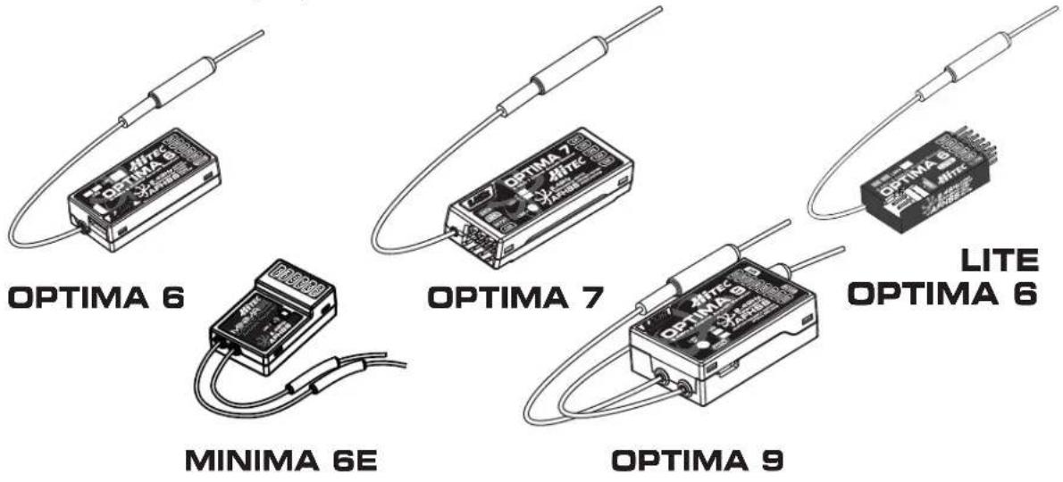
As of this writing, there are three Optima and two Minima 2.4GHz receivers that are compatible with Hitec AFHSS 2.4GHz System. The Optima 6, Optima 7, Optima 9 and the Minima 6T and 6E are loaded with a variety of functions that are sure to deliver a satisfying R/C experience.
The Minima 6T(or Minima 6E) receiver is offered as a standard receiver for the Optic 5 and you can purchase an Optima series receiver to utilize the "telemetry function". With an Optima series receiver, you may enjoy the basic "low voltage battery warning" function and all other full telemetry functions like RPM, temperature, fuel gauge, GPS, voltage and current sensing. (To activate the full telemetry function, an HTS-SS (Blue) sensor station and desired sensors are required.)
text_image
OPTIMA 6 MINIMA 6E OPTIMA 7 OPTIMA 9 LITE OPTIMA 6Minima 6T Receiver Features
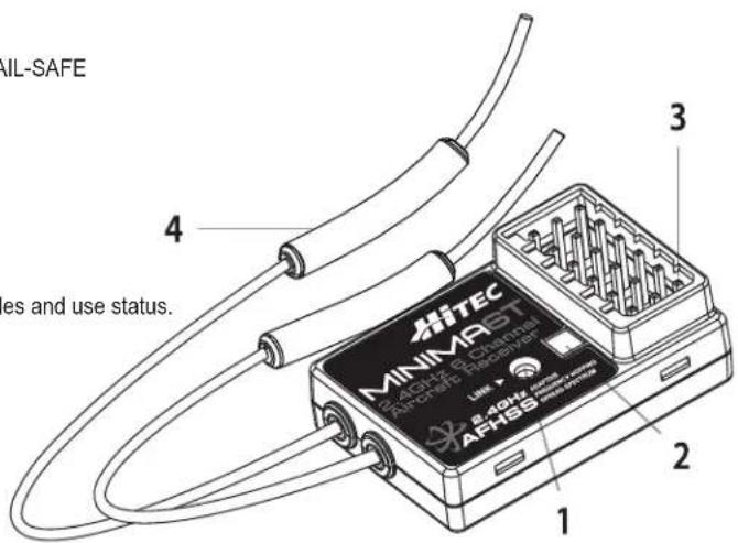
Functions:
SmartScan Function
Select between two operational signal types. See page 14 for details.
FAIL-SAFE Option
Servos and other accessories may be programmed with a FAIL-SAFE point in the event power to the receiver is interrupted.
See page 16 for details.
- Function Link Button
Used for Linking (ID-Setting) the receiver to a module, entering Fail-Safe / Hold mode set-up function. - Dual LED Status indicator indicates the set-up process codes and use status.
- Channel Output and Battery Input Ports for battery power, servos, gyros and other accessories.
- BODA (Boosted Omni-Directional Antenna) System The M-BODA Antenna System is designed to provide a safe flying environment. It consists of two antennas that help you fly more safely.
text_image
NIL-SAFE 4 es and use status. 3 HITEC MINIMARST Microchip Receiver LINE 2 AFHSS 1Warning : Verify your servos are rated for use with these higher voltage batteries or use a regulator.

Minima 6T Receiver Connection Diagrams
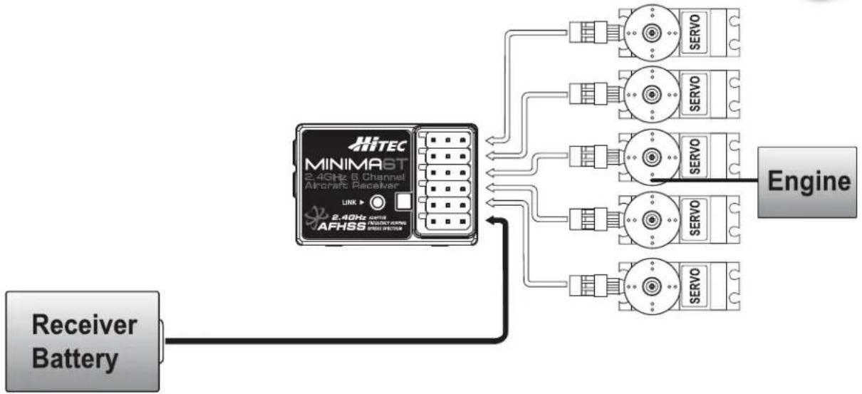
Glow, Gas, Nitro or Electric-Powered Aircraft Using a Separate Receiver Battery.
Follow this connection diagram when using a dedicated 4.8 to 6.0V NiMH battery pack.
Warning : Verify your servos are rated for use with higher voltage(7.4V) batteries or a regulator.

flowchart
graph TD
    A["Receiver Battery"] --> B["MINIMAST 2.4GHz 6 Channel Aircraft Receiver"]
    B --> C["SERVO"]
    B --> D["SERVO"]
    B --> E["SERVO"]
    B --> F["SERVO"]
    B --> G["SERVO"]
    B --> H["SERVO"]
    B --> I["SERVO"]
    B --> J["SERVO"]
    B --> K["SERVO"]
    B --> L["SERVO"]
    B --> M["SERVO"]
    B --> N["SERVO"]
    B --> O["SERVO"]
    B --> P["SERVO"]
    B --> Q["SERVO"]
    B --> R["SERVO"]
    B --> S["SERVO"]
    B --> T["SERVO"]
    B --> U["SERVO"]
    B --> V["SERVO"]
    B --> W["SERVO"]
    B --> X["SERVO"]
    B --> Y["SERVO"]
    B --> Z["SERVO"]
    B --> AA["SERVO"]
    B --> AB["SERVO"]
    B --> AC["SERVO"]
    B --> AD["SERVO"]
    B --> AE["SERVO"]
    B --> AF["SERVO"]
    B --> AG["SERVO"]
    B --> AH["SERVO"]
    B --> AI["SERVO"]
    B --> AJ["SERVO"]
    B --> AK["SERVO"]
    B --> AL["SERVO"]
    B --> AM["SERVO"]
    B --> AN["SERVO"]
    B --> AO["SERVO"]
    B --> AP["SERVO"]
    B --> AQ["SERVO"]
    B --> AR["SERVO"]
    B --> AS["SERVO"]
    B --> AT["SERVO"]
    B --> AU["SERVO"]
    B --> AV["SERVO"]
    B --> AW["SERVO"]
    B --> AX["SERVO"]
    B --> AY["SERVO"]
    B --> AZ["SERVO"]
    B --> BA["SERVO"]
    B --> BB["SERVO"]
    B --> BC["SERVO"]
    B --> BD["SERVO"]
    B --> BE["SERVO"]
    B --> BF["SERVO"]
    B --> BG["SERVO"]
    B --> BH["SERVO"]
    B --> BI["SERVO"]
    B --> BJ["SERVO"]
    B --> BK["SERVO"]
    B --> BL["SERVO"]
    B --> BM["SERVO"]
    B --> BN["SERVO"]
    B --> BO["SERVO"]
    B --> BP["SERVO"]
    B --> BQ["SERVO"]
    B --> BR["SERVO"]
    B --> BS["SERVO"]
    B --> BT["SERVO"]
    B --> BU["SERVO"]
    B --> BV["SERVO"]
    B --> BW["SERVO"]
    B --> BX["SERVO"]
    B --> BY["SERVO"]
    B --> BZ["SERVO"]
    B --> CA["SERVO"]
    B --> CB["SERVO"]
    B --> CC["SERVO"]
    B --> CD["SERVO"]
    B --> CE["SERVO"]
    B --> CF["SERVO"]
    B --> CG["SERVO"]
    B --> CH["SERVO"]
    B --> CI["SERVO"]
    B --> CJ["SERVO"]
    B --> CK["SERVO"]
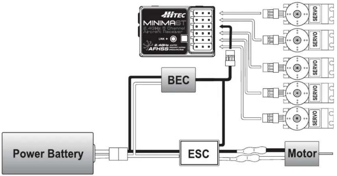
Electric-Powered Aircraft with Electronic Speed Control
Use this method on electric planes using ESCs providing power, A.K.A. BEC (Battery Eliminator Circuit), to the receiver and servo functions.
flowchart
graph TD
    A["Power Battery"] --> B["BEC"]
    B --> C["ESC"]
    C --> D["Motor"]
    E["MINIMAST 2.4GHz & Channel Aircraft Receiver"] --> F["LINK"]
    F --> G["SERVO"]
    E --> H["SERVO"]
    E --> I["SERVO"]
    E --> J["SERVO"]
    E --> K["SERVO"]
    E --> L["SERVO"]
    E --> M["SERVO"]
    E --> N["SERVO"]
    E --> O["SERVO"]
    E --> P["SERVO"]
    E --> Q["SERVO"]
    E --> R["SERVO"]
    E --> S["SERVO"]
    E --> T["SERVO"]
Optional BEC shown in diagram. It is recommended to use a large capacity BEC when a number of high torque servos are used and power requirements exceed that which the ESC provides.

Minima Series Receiver Features
Set-up and Use of the Hitec 2.4GHz System
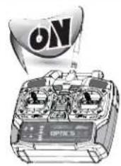
To turn the system on and off, use the following sequence at all times.
text_image
ON OPTICS

natural_image
Illustration of a small airplane with a 'ON' label on its wing (no other text or symbols)Turning On -Turn on the transmitter, then turn on the receiver.
natural_image
Illustration of a propeller airplane with an 'OFF' button and a play button icon (no text or symbols on the aircraft itself)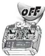
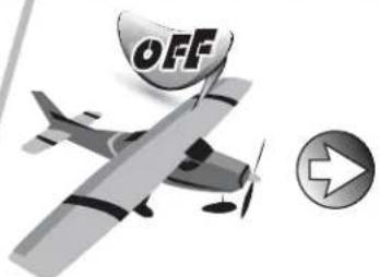
Turning Off -Turn off the receiver, then turn off the transmitter.
ID-Setup A.K.A, Link or Bind

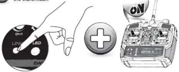
Press and hold the button on the front of the transmitter, and turn on the transmitter.
text_image
CH1 LINK LED DA3 +
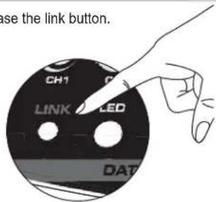
Release the link button.
text_image
use the link button. CH1 LINK LED DAT
Please check that the LED blinks
BLUE. If the LED blinks RED, press the LINK button for one second until the LED turns BLUE. (BLUE LED - binding mode for Minima series; RED LED - binding mode for Optima series).
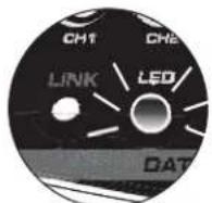

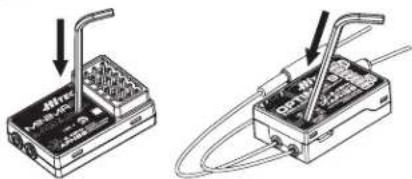
Press and hold the LINK button on the Receiver and turn on the power.
natural_image
Two technical diagrams showing a device with a plug inserted into its base and connected to a cable, with no visible text or symbols.ON

OFF

Both the RED and BLUE LEDs will blink rapidly to find the transmitter signal. Release the LINK button when the RED LED on receiver glows steady.
natural_image
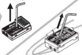
Two electronic device setups with wires and connectors, no visible text or symbolsRelease the LINK button.

When the link is completed, the BLUE LED on the transmitter will blink while the BLUE LED on the receiver glows steady. (when using telemetry receivers, both BLUE & RED LEDs will glow steady)

text_image
CH1 CH2 LINK LED OAT Non-telemetry RXs (MANIMA & MICROD Series) Telemetry RXs (OPTIMA Series)
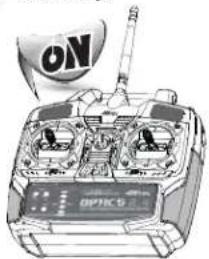
Turn off and on the transmitter and receiver again to save the setting.
natural_image
Illustration of a vintage multi-wheeled vehicle chassis with no visible text or symbols

OFF
Minima Series Receiver Features

[Minima or Micro series Receivers]
When they are turned on again, the RED LED on the module(or radio) and the BLUE LED on the receiver will glow steady.
![Hitec Optic 5 - [Minima or Micro series Receivers] - 1](/content/2026/05/809955/images/3f77a0d9aca8292947a8ae9ee3f01d960c2567abf63cc52cf886520ff12e1fc0.jpg)
text_image
CH1 CHE LINK LED DAT![Hitec Optic 5 - [Minima or Micro series Receivers] - 2](/content/2026/05/809955/images/3713d3e47ec0aa2f94e958bdf18b1b1c9933583622e31e150b916829ef2ab8f9.jpg)
![Hitec Optic 5 - [Minima or Micro series Receivers] - 3](/content/2026/05/809955/images/8908adeed5889875498239aa820d76bbfd07e5b87854cbff2bbc89f6ad851d9c.jpg)
[Optima series Receivers]
When they are turned on again, you will hear a continuous beep sound. Both RED LEDs on the module and receiver will glow steady in normal status.
![Hitec Optic 5 - [Optima series Receivers] - 1](/content/2026/05/809955/images/a07884850a780b5caba4a1c0a7a18779957d3a146f0c4ed192855fce71e1691e.jpg)
text_image
CH1 CH2 LINK LED/ DAT![Hitec Optic 5 - [Optima series Receivers] - 2](/content/2026/05/809955/images/927f572ad3d9d47d8d04a439dc505c1eb69373e54dea06d1993a4e2cc555a288.jpg)
![Hitec Optic 5 - [Optima series Receivers] - 3](/content/2026/05/809955/images/2c7d28a09432b962699263f2727d5a4cae3956f53516d956bd95daf9657b2f37.jpg)
SmartScan Function
The SmartScan is a unique function of Hitec's AFHSS 2.4GHz technology providing the user with the cleanest and most stable frequency channels even in the most crowded environments.

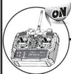
Turn on the transmitter.
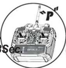
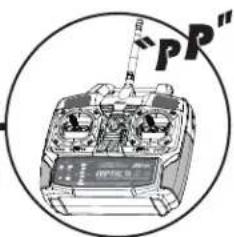
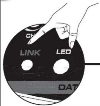
Press and hold the LINK button on the Spectra 2.4 Module for about 6 sec. Release the LINK button when you hear two continuous beeps.
natural_image
Illustration of a tank with visible engine and control panel, enclosed in a circular frame (no text or symbols)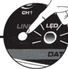
text_image
CH1 LIN1 LED DAT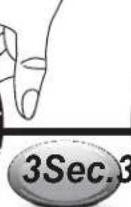
text_image
"P" Sec
text_image
"PP"
The Spectra 2.4 Module will scan the frequency to find the cleanest and the most stable frequency in any area. (The BLUE LED on the module will blink during the scanning.) When the scan is completed, the BLUE LED on the module stops blinking and glows steady. Re-boot the transmitter (turn Off and On) and follow the link process with your receiver.
text_image
CH LINK LED DAT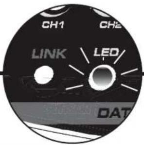
text_image
CH1 CH2 LINK LED/ DAT

text_image
CH1 CH2 LINK LED DATNOTE
After Scanning, you need to do the link process again for all your receivers as receivers need new frequency hopping codes from the Spectra 2.4 module.

Minima Series Receiver Features and Set-up
FAIL-SAFE and Hold Mode Set-up
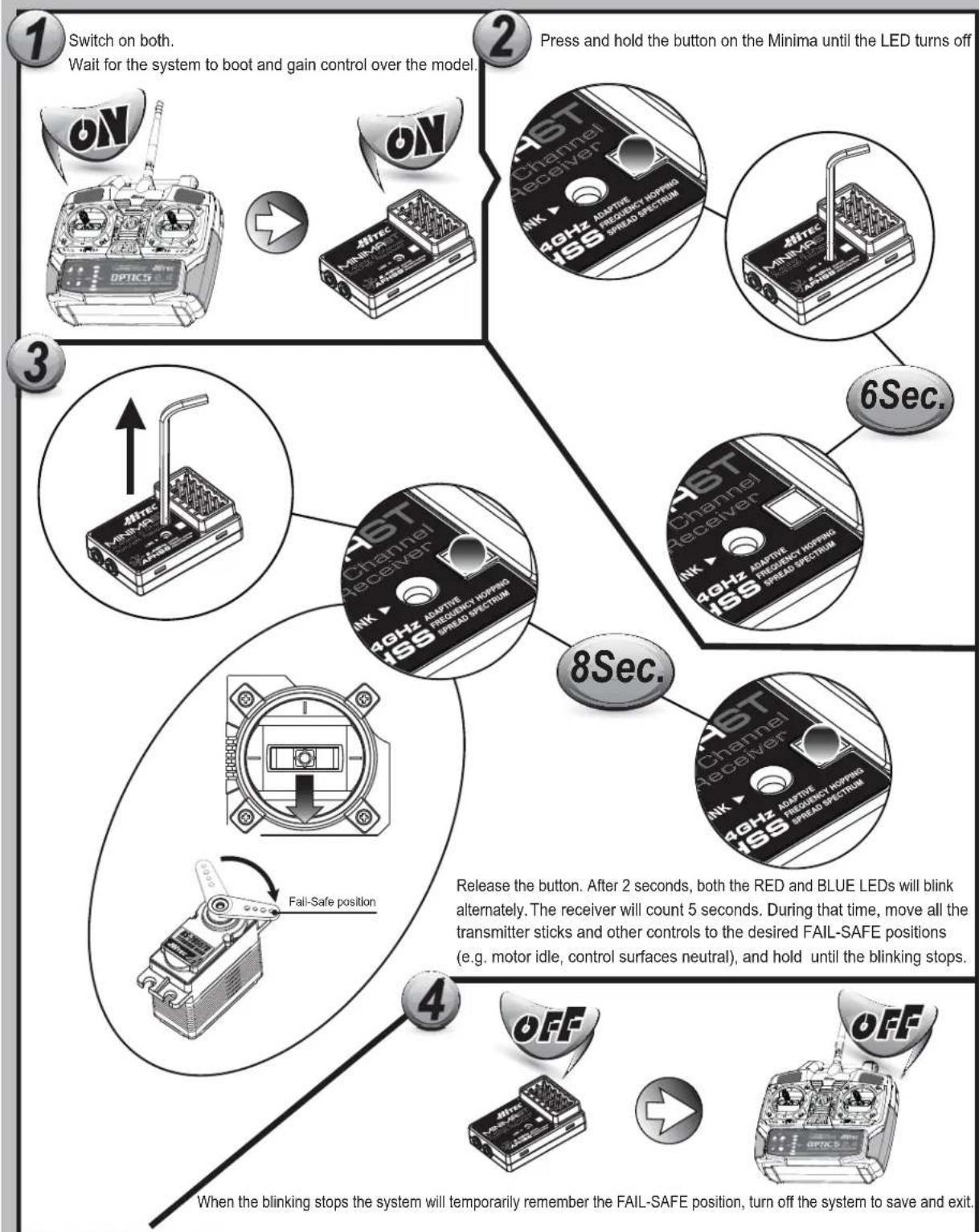
flowchart
graph TD
    A["Switch on both. Wait for the system to boot and gain control over the model."] --> B["Press and hold the button on the Minima until the LED turns off"]
    B --> C["6Sec."]
    C --> D["8Sec."]
    D --> E["4Off"]
    E --> F["When the blinking stops the system will temporarily remember the FAIL-SAFE position, turn off the system to save and exit."]

    subgraph Timeframe Details
        G["1 ST Channel Receiver"] --> H["2 GHz Adaptive Frequency Hopping / ISS Spread Spectrum"]
        H --> I["3 40Hz Adaptive Frequency Hopping / ISS Spread Spectrum"]
        I --> J["4 Fast Safe Position"]
        J --> K["5 Fast Safe Position"]
        K --> L["6 Fast Safe Position"]
        L --> M["7 Fast Safe Position"]
        M --> N["8 Fast Safe Position"]
    end

    style A fill:#f9f,stroke:#333
    style B fill:#ccf,stroke:#333
    style C fill:#cfc,stroke:#333
    style D fill:#fcc,stroke:#333
    style E fill:#cff,stroke:#333
    style F fill:#ffc,stroke:#333
    style G fill:#fff,stroke:#333
    style H fill:#fff,stroke:#333
    style I fill:#fff,stroke:#333
    style J fill:#fff,stroke:#333
    style K fill:#fff,stroke:#333
    style L fill:#fff,stroke:#333
    style M fill:#fff,stroke:#333
    style N fill:#fff,stroke:#333
Minima Series Receiver Features
Testing the FAIL-SAFE Setting
a. Move the sticks to positions other than the FAIL-SAFE settings, and then switch off the transmitter. The servos should now move to the FAIL-SAFE positions previously stored, after the HOLD period (1 sec.) has elapsed.
How to turn FAIL-SAFE Off and reactivate the Hold Mode
a. Switch on the transmitter, then the receiver. Wait for the system to boot and you have control over the model.
b. Press and hold the receiver function button for 6 seconds and release it. After 2 seconds, the RED and BLUE LEDs will blink rapidly.
c. Push the function button once shortly, during this time the LED blinks (approx. 5 seconds).
d. FAIL-SAFE Mode is now deactivated, and HOLD mode is activated instead.
e. Turn off the transmitter and the receiver to save the setting.
f. Turn the system back on to use it.
- If FAIL-SAFE is deactivated, the FAIL-SAFE position settings are also deleted! - The FAIL-SAFE settings should be checked every time before you run the engine motor.

Range Check Function
It is critical that before each flight session you perform a range check that confirms the signal between the receiver and transmitter is appropriate. Unlike the FM/PPM or PCM signal radios, 2.4GHz systems use a fixed shorter, stubby transmitter antenna so the traditional method of range checking your system by lowering the transmitter antenna will not work. We instead use a power-down mode to reduce the transmitter signal strength. Once the power-down mode is activated it runs for about 90 seconds, shortening the effective range 100 feet (30 m). During this power-down mode, you should walk away from the secured aircraft, carrying the transmitter to a distance of approx. 30 meters in order to test the effective range.
How to use Power-Down
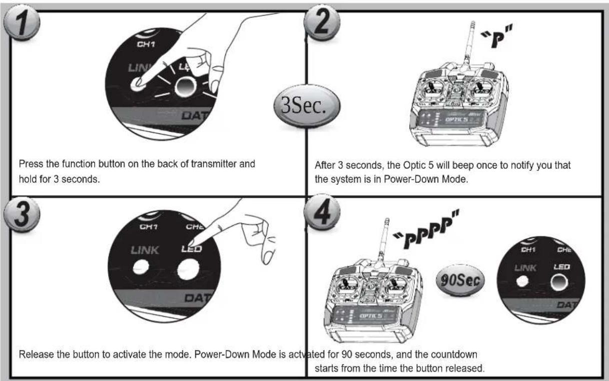
flowchart
graph TD
    A["1: Press the function button on the back of transmitter and hold for 3 seconds."] --> B["2: After 3 seconds, the Optic 5 will beep once to notify you that the system is in Power-Down Mode."]
    B --> C["3: Release the button to activate the mode. Power-Down Mode is activated for 90 seconds, and the countdown starts from the time the button released."]
    C --> D["4: Control buttons: CH1, LINK, LED, DAT, OPTICS"]
If you are unable to accomplish a successful range check of feet, DO NOT ATTEMPT TO FLY.

Set-up and Use of the Hitec 2.4GHz System
flowchart
graph LR
    A["50Cm(18in)5M(15ft)"] --> B["飞机A"]
    A --> C["飞机B"]
    A --> D["飞机C"]
    B --> E["MIN RANGE"]
    C --> F["MAX RANGE"]
    D --> G["MIN RANGE"]
    style A fill:#f9f,stroke:#333
    style B fill:#ccf,stroke:#333
    style C fill:#ccf,stroke:#333
    style D fill:#ccf,stroke:#333
    style E fill:#dfd,stroke:#333
    style F fill:#dfd,stroke:#333
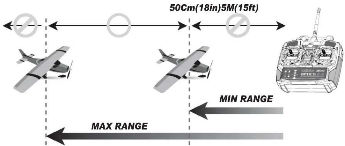
- Binding must be done within 15ft. (5m) of the transmitter and receiver.
- The Transmitter and receiver need to be at least 18in. (45cm) from each other to bind properly.
- In the ScanMode, if the transmitter or receiver has been shut off or disconnected for more than one second, both the module and receiver need to be re-booted (turn the power off and back on).
Note : Both the module and receiver need to re-boot (turn the power off and back on).

Receiver-Servo Connection List
Receiver-Servo Connection List W/ OPTIC 5 2.4
The table below shows where the aircraft's servos should plug into a six-channel receiver. Note that some functions shown will not operate until they are activated in the transmitter. The standard function is listed first for each channel.
| RX CH ACRO(Normal) ACRO(Elevon) ACRO(V-Tail) | |||
| One | Aileron | Right Elevon (ELVN on) | |
| Two | Elevator | Left Elevon (ELVN on) | Right Vtail (V-TAIL) |
| Three | Throttle (BEC In / Motor Signal Out) | ||
| Four | Rudder | Left (V_Tail on) | |
| Five | Landing gear | ||
ATV (Adjustable Travel Volume) Function
The ATV function is somewhat similar to the EPA (End Point Adjustment) and D/R (Dual Rate) functions; it allows you to adjust a servo's travel end position amount over a control stick's movement.
The ATV function affects both endpoints at once, while the EPA function allows each servo to travel individually. This function can be found useful when the plane is too sensitive over a control stick's movement.
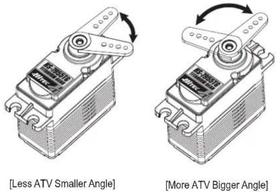
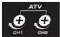
ATV can control the travel amount of a servo.
If you give more ATV; the servo movement will be more aggressive.
If you give less ATV; the servo movement will be milder. Adjustable range: 0% \~ 110%
Note : OPTIC 5 does not provide EPA & DIR functions.

Trim Adjustment
This is a function for setting the trim values for each of the servos, allowing you to make adjustments to each individual servo independently of the trim switches located near the control stick of the radio (which can be adjusted in flight).
We recommend that you first set up the model's servo pushrods so that the control surfaces are as centered as possible mechanically before attempting to adjust them in the trim switch. We also recommend that you try to keep all the trim values at the center position. If the values are skewed to once side, the servo's full range of travel may be restricted.
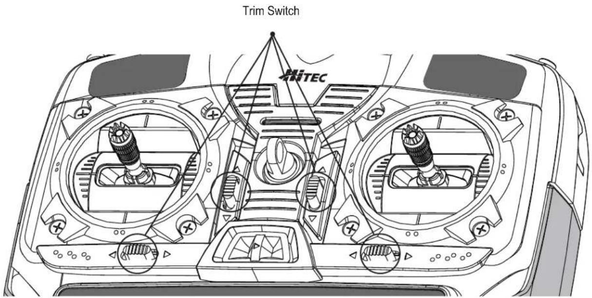
text_image
Trim Switch MITECS. REV (Servo Reverse)
S. REV (Servo Reverse)
When you first turn on your model, you will immediately see whether all the control surfaces are moving in the correct direction when you wiggle the controls.
If any are moving in reverse, you can come to this screen to reverse the throw of the offending servo.
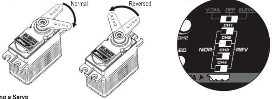
Reversing a Servo
Let's say your elevator is going down when you pull back on the joystick, that is definitely not going to be a good situation when you go to fly your plane! To reverse the elevator servo, come to the switch in front of the radio's front panel. You'll notice that the symbol NOR and REV, move the switch either NOR or REV to make the servo operate in the proper direction.
ELVN (Elevon Mix)
ELVN (Elevon mix)
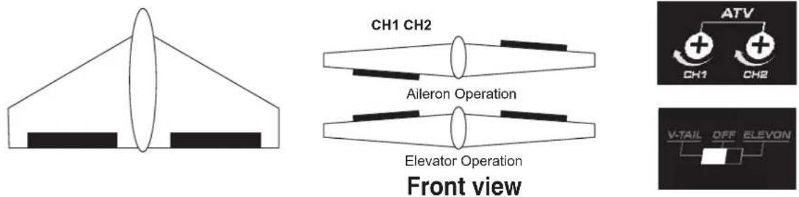
If you are setting up a tail-less delta or flying wing aircraft, you can use this program to activate the pre-programmed elevon mix that mixes the output on the CH 1 aileron and CH 2 elevator servo channels. As you will notice in the servo connection chart, you plug one aileron servo in the receiver's channel 1 slot and the other aileron servo into channel 2-the slot that usually feeds the elevator.
This is necessary because on these wing types, the ailerons must double as elevators.
NOTE:
When you activate ELVN, note that the V-tail mixing is rendered unavailable by the radio.
When you change the function of ELVN to V.TAIL or V.TAIL to ELVN,
Please TURN OFF THE TRANSMITTER FIRST and then change the function.
If you change the ELVN and V-TAIL functions when the transmitter is ON, nothing will be changed.

Setting Up Elevons
1) Activate the elevon function by pushing the pre-programmed switch to the left. Now check your model to see what happens when you move the right-hand joystick side to-side. The ailerons should go up and down appropriately.
Move the joystick forward and back to see if the ailerons both respond correctly as elevators.
If necessary, use the REV function to reverse an offending servo.
2) Now set the amount (and direction if necessary as noted above) of each servo-both as ailerons and as elevators.
Because flying wings are extraordinarily pitch sensitive (because the elevator control surface is so close to the airframe's center of gravity), you generally need the elevator travel to be much less than that of the ailerons.
3) When you fly the model, if you find that this 40% reduction isn't enough to take out "pitchiness," land and further reduce the travel volume.
To tone down the roll response, you can reduce the endpoints of the aileron travel or set up ATV on CH 1 as described in the set-up above.
V.TAIL (V-Tail)
V.TAIL (V-Tail)
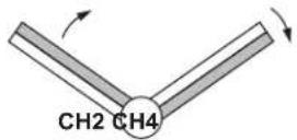
This is another built-in mixing program available on the Optic5 that mixes the rudder and elevator servos for controlling V-tailed aircraft. Similar to elevon programming, the two surfaces can move up and down together (for elevator control) or opposite (for rudder control in this case).
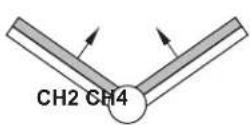
flowchart
graph TD
    A["V-TAIL"] --> B["Square Block"]
    C["OFF"] --> B
    D["ELEVON"] --> B
Up Elevator Right Rudder (view from rear)
Surfaces can move up and down together (for elevator control) or opposite (for rudder control in this case).
NOTE:
When you select V.TAIL, the ELVN program is rendered unavailable.
When you change the function of ELVN to V.TAIL or V.TAIL to ELVN,
Please TURN OFF THE TRANSMITTER FIRST and then change the function.
If you change the ELVN and V-TAIL functions when the transmitter is ON, nothing will be changed.

Setting Up a V-Tail
1) Activate the function by pushing the pre-programmed switch to the right.
2) With your model turned on, check your servo travel directions (both rudder and elevator channels) to be sure they are correct.
Use the REV switch if necessary to make the correction.
CUT (Engine Cut Function)
CUT (Engine Cut Function)
Cut (Engine Cut) Function allows a throttle servo to max out the travel value (you can also choose the direction with the Servo Reverse Function), so that you can immediately cut off the motor when the engine is below half throttle with a push of the "Eng Cut" button located on the upper right-hand corner of the transmitter case.
Setting the Engine Cut Function
Setting the Engine Cut Function
Press and hold the Cut switch for approximately three seconds to activate the Throttle (Engine) Cut function. The servo will travel more from its lowest (idling) throttle position to its End Point by 10%.
NOTE:
Watch the servo movement on your model carefully:
You don't want to overdo the travel value or you'll stall the servo (you'll probably hear it buzzing if it's stalled which creates a drain on the on-board battery and may cause a potential over-heating problem for the servo).

Setting the Gear (Retractor Gear) Control Function
Setting the Gear (Retractor Gear) Control Function
The same button is used to cut the engine or control the landing gears (Up-locked/Down and Locked). Use a Y-Cable to connect your retract servos to your receiver's CH5 then make sure they are operate properly. Push the Cut/Gear button once shortly to Up-locked or down and locked the retractable landing gears.
NOTE:
Watch the servo movement on your model carefully:
You don't want to overdo the travel value or you'll stall the servo (you'll probably hear it buzzing if it's stalled which creates a drain on the on-board battery and may cause a potential over-heating problem for the servo).

Service & Support
Hitec Customer Service
Help is available from Hitec customer service through phone support and e-mail inquiries.
Our US office is generally open Monday thru Friday, 8:00AM to 4:30PM PST. These hours and days may vary by season. Every attempt is made to answer all incoming service calls. Should you get our voice mail, leave your name and number and a staff member will return your call.
Hitec Website
Make plans to visit the Hitec website, www.hitecrcd.com, on a regular basis. Not only is it full of specs and other information about the entire Hitec product line, our FAQ pages will eventually hold valuable information and updates regarding about the Spectra 2.4 module and Optima series of receivers.
The On-Line Community
One of the benefits of the extensive R/C online community is the vast wealth of archived knowledge available. Hitec sponsors forums on most of the popular R/C websites where a Hitec staff member or representative tries to answer all manner of product related questions. Bringing together strangers with common interests is proving to be one of the greatest gifts of the internet. If past history is any guide to the future, we are certain forums will be started about the Hitec 2.4GHz system and several are certain to stand out as valuable archives of information.
Warranty and Non-Warranty Service
All Hitec products carry a two year from date-of-purchase warranty against manufacturer's defects. Our trained and professional service representative will determine if the item will be repaired or replaced. To provide all the necessary information we need to administrate your repair, visit our website at www.hitecrcd.com and download the repair form, fill it out and send in your item for repair.
Hitec Service
12115 Paine St. Poway CA 92064
1-858-748-6948
E-mail: service@hitecrcd.com

Service & Support
Hitec and Multiplex Mission Statement
Hitec and Multiplex are dedicated to providing quality, affordable radio control hobby products everyone can enjoy. We will serve our customers in the same loving way we serve our families and together we shall create a higher quality of life.
Hitec RCD Korea, Inc.
Ochang, Cheongwon-gun,
Chungcheongbuk-do, Korea
Int'l Headquarter, R&D Center
http://www.hitecrcd.co.kr

Hitec RCD USA, Inc.
12115 Paine Street. Poway,
CA. 92064, U.S.A.
Sales Headquarter for
North & South America
http://www.hitecrcd.com
Hitec-Multiplex Japan, Inc.
1-30-10 1F, Nishi-Koiwa,
Edogawa-ku, Tokyo, Japan
Sales Headquarter for Japan
http://www.hitecrcd.co.jp

Sales Headquarter for European market
Production and R&D Center
http://www.hitecrc.de
http://www.multiplex-rc.de

Hitec RCD Philippines, Inc.
Lot 6 & 8, Block 24,
Phase 4 Peza,
Rosario, Cavite, Philippines
Production & Logistics Center

Hitec-Multiplex China, Inc.
3F of Hong Li Bldg #1,
24W Jinfeng Rd,
Jinding Industrial Park,
Tangjia, Zhuhai, China
www.hitecrcd-china.com
MEMO
The Optic 5 is Hitec's most affordable, simple stick radio equipped with our built-in AFHSS 2.4GHz technology, pre-programmed mixes and simple plug-and-fly link system. All these features make the Optic 5 the perfect match for any beginner's needs.
OPTIC5 2.4
5CH 2.4GHz AIRCRAFT RADIO CONTROL SYSTEM

text_image
MiTEC AFH59 OPTIC5 2.4 SCH 2.48% AIRCRAFT RADIO CONTROL SYSTEM
2.4GHz
Telemetric
FHSS
ADAPTIVE
FREQUENCY HOPPING
SPREAD SPECTRUM
English Version
CE1177①
2.4GHz Band for use in: AT, BE, BG, CH, CY, CZ, DE, DK, EE, ES, FI, GB, GR, HU, IE, IT, LT, LU, LV, MT, NL, PL, PT, RO, SE, SI, SK, FR