
Z24i G2 - Screen HP - Free user manual and instructions
Find the device manual for free Z24i G2 HP in PDF.


User questions about Z24i G2 HP
0 question about this device. Answer the ones you know or ask your own.
Ask a new question about this device
Download the instructions for your Screen in PDF format for free! Find your manual Z24i G2 - HP and take your electronic device back in hand. On this page are published all the documents necessary for the use of your device. Z24i G2 by HP.
USER MANUAL Z24i G2 HP
HP Z24i, Z27i, and Z30i IPS Displays
User Guide
© 2013 Hewlett-Packard Development Company, L.P.
Microsoft® and Windows® are U.S. registered trademarks of Microsoft Corporation.
The only warranties for HP products and services are set forth in the express warranty statements accompanying such products and services. Nothing herein should be construed as constituting an additional warranty. HP shall not be liable for technical or editorial errors or omissions contained herein.
This document contains proprietary information that is protected by copyright. No part of this document may be photocopied, reproduced, or translated to another language without the prior written consent of Hewlett-Packard Company.
First Edition (August 2013)
Document Part Number: 727282-001
About This Guide
This guide provides information on monitor features, setting up the monitor, and technical specifications.
WARNING! Text set off in this manner indicates that failure to follow directions could result in bodily harm or loss of life.
CAUTION: Text set off in this manner indicates that failure to follow directions could result in damage to equipment or loss of information.
NOTE: Text set off in this manner provides important supplemental information.
Table of contents
1 Product Features .... 1
HP IPS Monitors .... 1
2 Setting Up and Using the Monitor .... 3
Installing the Stand 3
Rear Components 4
Z24i Model 4
Z27i and Z30i Models 5
Connecting the Cables 6
Front Panel Controls 10
Adjusting the Monitor 11
Turning on the Monitor 14
HP Watermark and Image Retention Policy 14
Connecting USB Devices 15
Removing the Monitor Stand 15
Mounting the Monitor 16
Mounting the Monitor Using the Quick Release 2 Mounting Bracket .... 17
Mounting the Monitor Without Using the Quick Release 2 Mounting Bracket .... 20
Locating the Serial Number and Product Number 21
Locating the Information Card 21
Installing a Cable Lock 22
Power Saving Features 22
Power-Saver Mode 22
Auto-Sleep Mode 23
Sleep Timer 23
3 Finding More Information 25
Reference Guides 25
Product Support 25
Appendix A Technical Specifications 26
Z24i Model 26
Z27i Model 26
Z30i Model 28
Recognizing Preset Display Resolutions 29
Z24i Model 29
Z27i Model 30
Z30i Model 31
Entering User Modes 32
1 Product Features
HP IPS Monitors
The LCD (liquid crystal display) monitors have an active matrix, In-Plane Switching (IPS) panel. The monitor models and features include:
- Z24i model, 60.96 cm (24-inch) diagonal viewable area display with 1920 x 1200 resolution, plus full-screen support for lower resolutions: includes custom scaling for maximum image size while preserving original aspect ratio
- Z27i model, 68.58 cm (27-inch) diagonal viewable area display with 2560 x 1440 resolution, plus full-screen support for lower resolutions; includes custom scaling for maximum image size while preserving original aspect ratio
- Z30i model, 76.2 cm (30-inch) diagonal viewable area display with 2560 x 1600 resolution, plus full-screen support for lower resolutions; includes custom scaling for maximum image size while preserving original aspect ratio
• Non-glare panel with an LED backlight - Wide viewing angle to allow viewing from a sitting or standing position, or moving from side-to-side
- Tilt capability
- Pivot capability to rotate the display from landscape to portrait
• Swivel and height adjustment capabilities - Removable stand for flexible monitor panel mounting solutions
- HP Quick Release 2 to quickly install the monitor with a simple click and remove it with the convenient sliding tab release
- Optional thin client mounting bracket that attaches to the rear of the stand (purchased separately)
- Easy access pull-out information card with the information needed when contacting HP support
• Video signal input to support VGA analog (cables are provided with select models)
• Video signal input to support DVI digital (cables are provided with select models)
• Video signal input to support DisplayPort digital (cables are provided with select models)
• Video signal input to support HDMI digital (Z27i and Z30i models only)
• Audio output headphone jack (Z27i and Z30i models only) - USB 2.0 hub (Z24i models) or USB 3.0 hub (Z27i and Z30i models) with one upstream port (connects to the computer) and four downstream ports (connects to USB devices)
• USB cable provided to connect the monitor's USB hub to the USB connector on the computer
• Supports an optional HP speaker bar -
Plug and play capability if supported by your operating system
-
Privacy filter slots to insert filters (purchased separately) to block side screen viewing (Z24i model only)
• Security slot provision on rear of monitor for optional cable lock
• Cable management feature for placement of cables and cords - On-Screen Display (OSD) adjustments in several languages for easy setup and screen optimization
HP Display Assistant for adjusting monitor settings and enabling theft deterrence features
• HDCP (High-Bandwidth Digital Content Protection) copy protection on all digital inputs - Software and documentation CD that includes monitor drivers and product documentation
• Energy saver feature to meet requirements for reduced power consumption - Safety guidelines, certifications, and regulatory notices for these products are available in the HP LCD Monitors Reference Guide on the CD included with this monitor.
2 Setting Up and Using the Monitor
To set up the monitor, ensure that the power is turned off to the monitor, computer system, and other attached devices, then follow the instructions below.

NOTE: Be sure the master power switch, located on the rear panel of the monitor, is in the off position. The master power switch turns off all power to the monitor.
Installing the Stand

CAUTION: Do not touch the surface of the LCD panel. Pressure on the panel may cause non-uniformity of color or disorientation of the liquid crystals. If this occurs the screen will not recover to its normal condition.
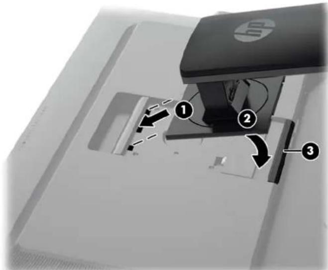
The displays use the HP Quick Release 2 for easy moving of the monitor. To mount the panel onto the stand:
- Lay the monitor panel face down on a flat surface covered by a clean, dry cloth.
- Slide the top of the mounting plate (1) on the stand under the upper lip of the recess in the back of the panel.
- Lower the bottom of the stand's mounting plate (2) into the recess until it snaps into place.
- The HP Quick Release 2 latch (3) pops up when the stand is locked in place.
text_image
Diagram of a computer monitor with labeled parts and directional arrows indicating movement or operationRear Components
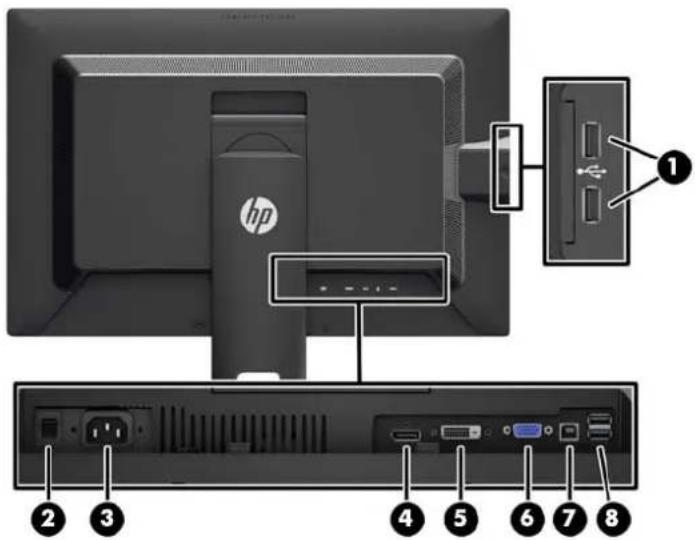
Z24i Model
text_image
Diagram of a computer monitor rear panel with labeled ports and components, showing front, back, and internal layout.Component Function
| 1 USB 2.0 Downstream Connectors (side panel) | Connects optional USB devices to the monitor. |
| 2 Master Power Switch Turns off all power to the monitor. | |
| NOTE: Putting the switch in the Off position will yield the lowest power state for the monitor when not in use. | |
| 3 AC Power Connector Connects the AC power cord to the monitor. | |
| 4 DisplayPort Connects the DisplayPort cable to the monitor. | |
| 5 DVI-D Connects the DVI-D cable to the monitor. | |
| 6 VGA Connects the VGA cable to the monitor. | |
| 7 USB 2.0 Upstream Connector | Connects the USB hub cable to the monitor's USB hub connector and to a host USB port/hub. |
| 8 USB 2.0 Downstream Connectors | Connects optional USB devices to the monitor. |
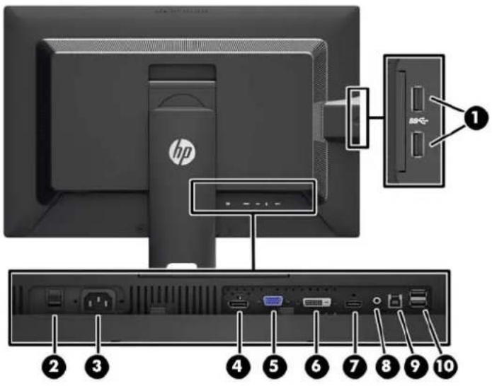
Z27i and Z30i Models
text_image
Diagram of a HP computer monitor rear panel with labeled ports and connectors, showing front and back views with numbered labels.Component Function
| 1 USB 3.0 Downstream Connectors (side panel) | Connects optional USB devices to the monitor. |
| 2 Master Power Switch Turns off all power to the monitor. | |
| NOTE: Putting the switch in the Off position will yield the lowest power state for the monitor when not in use. | |
| 3 AC Power Connector Connects the AC power cord to the monitor. | |
| 4 DisplayPort Connects the DisplayPort cable to the monitor. | |
| 5 VGA Connects the VGA cable to the monitor. | |
| 6 DVI-D Connects the DVI-D cable to the monitor. | |
| 7 HDMI Connects an HDMI cable to the monitor. | |
| 8 Audio Out Connects headphones or optional HP Speaker Bar to the monitor. | |
| 9 USB 3.0 Upstream Connector | Connects the USB hub cable to the monitor's USB hub connector and to a host USB port/hub. |
| 10 USB 3.0 Downstream Connectors | Connects optional USB devices to the monitor. |
Connecting the Cables
- Place the monitor in a convenient, well-ventilated location near the computer.
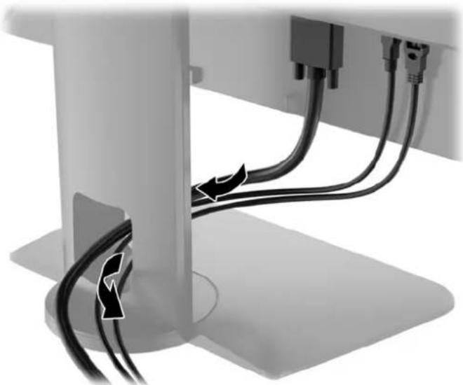
- Before connecting the cables, route the cables through the cable routing hole in the center of the stand.
natural_image
Close-up of cable routing between a mechanical component (no text or symbols visible)- Depending on your model and configuration, connect either the DisplayPort, DVI, HDMI, or VGA video cable between the PC and the monitor.

NOTE: The monitor is capable of supporting either analog or digital input. The video mode is determined by the video cable used. The monitor will automatically determine which inputs have valid video signals. The inputs can be selected by pressing the Input button on the front panel or through the On-Screen Display (OSD) feature by pressing the Menu button.
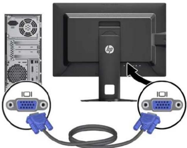
- For analog operation, connect the VGA signal cable to the VGA connector on the rear of the monitor and the other end to the VGA connector on the computer (cable provided with select models).
natural_image
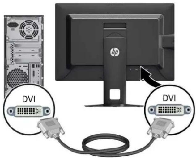
Diagram showing a computer monitor connected to two V12D port connectors via cable, with an HP logo on the screen (no text or symbols present)- For DVI digital operation, connect the DVI-D signal cable to the DVI connector on the rear of the monitor and the other end to the DVI connector on the computer (cable provided with select models).
text_image
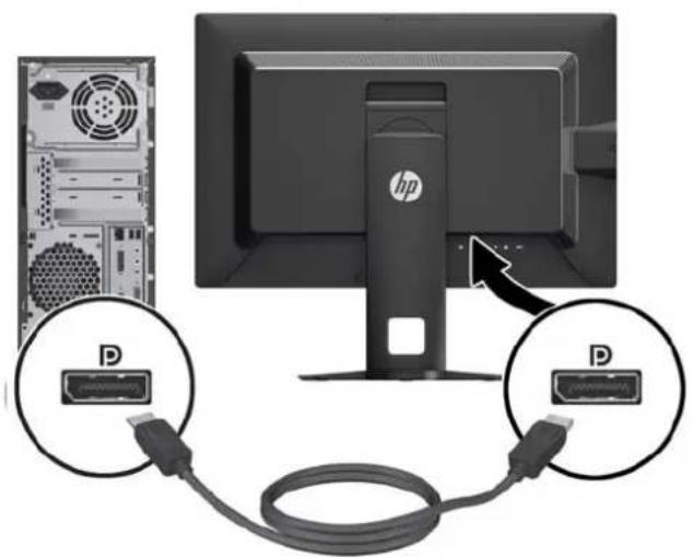
DVI DVI- For DisplayPort digital operation, connect the DisplayPort signal cable to the DisplayPort connector on the rear of the monitor and the other end to the DisplayPort connector on the computer (cable provided with select models).
text_image
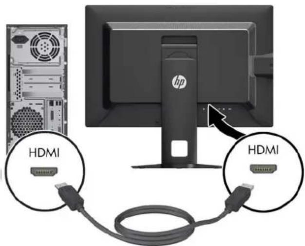
Diagram showing computer monitor connected to a USB cable with D port labels, indicating data transfer or connection.- For HDMI digital operation (Z27i and Z30i models only), connect the HDMI signal cable to the HDMI connector on the rear of the monitor and the other end to the HDMI connector on the computer (cable provided with select models).
text_image
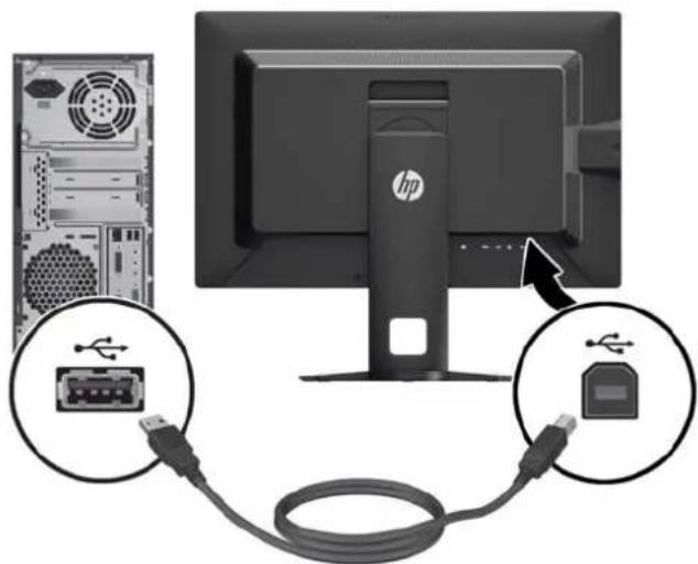
HDMI HDMI- Connect one end of the provided USB cable to the USB hub connector on the rear panel of the computer, and the other end to the upstream USB connector on the monitor.

NOTE: The Z24i model supports USB 2.0. The Z27i and Z30i models support USB 3.0.
text_image
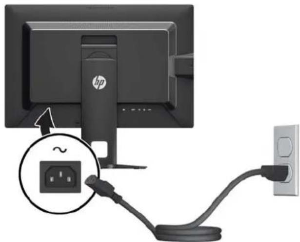
Diagram showing a computer monitor connected to a USB port, with labeled connectors and hardware icons.- Connect one end of the power cord to the AC power connector on the back of the monitor, and the other end to an electrical wall outlet.
natural_image
Computer monitor connected to a cable with an outlet, showing a close-up of the cable's internal socket (no text or symbols visible)
WARNING! To reduce the risk of electric shock or damage to the equipment:
Do not disable the power cord grounding plug. The grounding plug is an important safety feature.
Plug the power cord into a grounded (earthed) electrical outlet that is easily accessible at all times.
Disconnect power from the equipment by unplugging the power cord from the electrical outlet.
For your safety, do not place anything on power cords or cables. Arrange them so that no one may accidentally step on or trip over them. Do not pull on a cord or cable. When unplugging from the electrical outlet, grasp the cord by the plug.
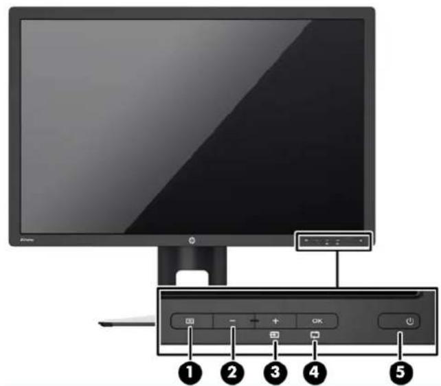
Front Panel Controls
text_image
Diagram of a computer monitor with labeled buttons and control panel, showing numbered labels 1 to 5 for navigation or system adjustment.Control Function
| 1 |  | Menu Opens, selects or exits the OSD menu. |
| 2 | [C448] | Minus If the OSD menu is on, press to navigate backward through the OSD menu and decrease adjustment levels. |
| 3 | Plus/Input If the OSD menu is on, press to navigate forward through the OSD menu and increase adjustment levels.If the OSD menu is inactive, press to activate the input button that chooses the video signal input | |
| 4 | OK | OK/Auto Adjust If the OSD menu is on, press to select the highlighted menu item.If the OSD menu is inactive, press to activate the auto adjustment feature to optimize the screen image. |
| 5 | Power Turns the monitor on or off.NOTE: Be sure the master power switch on the rear of the monitor is in the ON position to turn on the monitor. |

NOTE: To view an OSD menu simulator, visit the HP Customer Self Repair Services Media Library at http://www.hp.com/go/sml.
Adjusting the Monitor
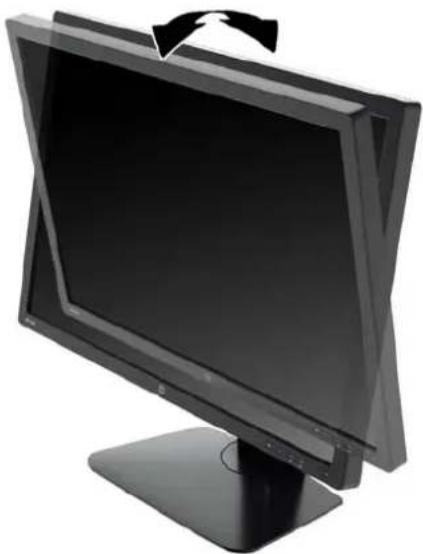
- Tilt the monitor's panel forward or backward to set it to a comfortable eye level.
natural_image
Black computer monitor with a stand and a curved cable, no visible text or symbols- Swivel the monitor to the left or right for the best viewing angle.
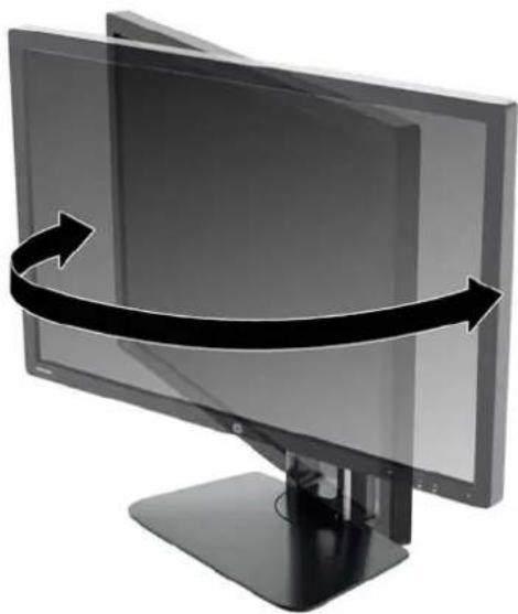
natural_image
Illustration of a computer monitor with a curved arrow indicating rotation or refresh (no text or symbols)- Adjust the monitor's height to a comfortable position for your individual workstation. The monitor's top bezel edge should not exceed a height that is parallel to your eye height. A monitor that is positioned low and reclined may be more comfortable for users with corrective lenses. The monitor should be repositioned as you adjust your working posture throughout the work day.
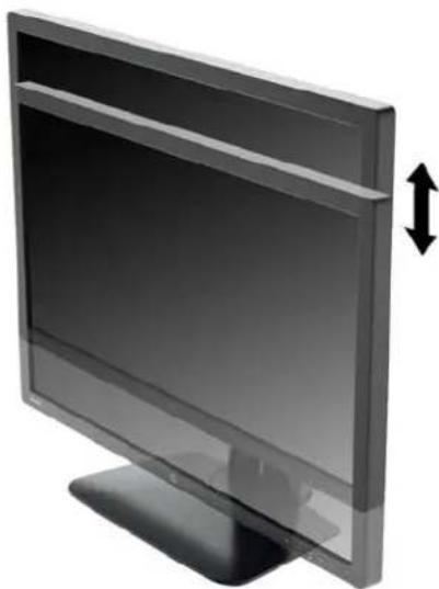
natural_image
Illustration of a flat-screen computer monitor with a double-headed arrow indicating vertical motion (no text or symbols)- You can pivot the monitor from landscape to portrait orientation viewing to adapt to your application.
a. Adjust the monitor to full height position and tilt the monitor back to full tilt position (1).
b. Pivot the monitor clockwise 90° from landscape to portrait orientation (2).
CAUTION: If the monitor is not in full height and full tilt position when pivoting, the bottom right corner of the monitor panel will come in contact with the base and potentially cause damage to the monitor.
If you are adding an optional speaker bar to the monitor, install it after pivoting the monitor. The speaker bar will come in contact with the base when pivoting and potentially cause damage to the monitor or speaker bar.
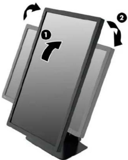
natural_image
Illustration of a computer monitor with directional arrows indicating rotation (no text or symbols)
NOTE: To view information on the screen in portrait mode, you can install the HP Display Assistant software included on the software and documentation CD. The position of the OSD menu can also be rotated to portrait mode. To rotate the OSD menu, access the OSD menu by pressing the Menu button on the front panel, select OSD Control from the menu, then select Rotate OSD.
Turning on the Monitor
- Set the master power switch on the rear of the monitor to the On position.
- Press the power button on the computer to turn it on.
- Press the power button on the front of the monitor to turn it on.
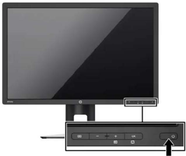
natural_image
Computer monitor setup with a control panel and an icon, no visible text or symbols on the device itself.CAUTION: Burn-in image damage may occur on monitors that display the same static image on screen for a prolonged period of time.* To avoid burn-in image damage on the monitor screen, you should always activate a screen saver application or turn off the monitor when it is not in use for a prolonged period of time. Image retention is a condition that may occur on all LCD screens. Monitors with a "burned-in image" are not covered under the HP warranty.
* A prolonged period of time is 12 consecutive hours of a static image.
NOTE: If pressing the power button has no effect, the Power Button Lockout feature may be enabled. To disable this feature, press and hold the monitor power button for 10 seconds.
NOTE: You can disable the power LED in the OSD menu. Press the Menu button on the front of the monitor, then select Management > Bezel Power LED > Off.
When the monitor is powered on, a Monitor Status message is displayed for five seconds. The message shows which input is the current active signal, the status of the auto-switch source setting (On or Off; factory default is On), the default source signal (factory default is DisplayPort), the current preset display resolution, and the recommended preset display resolution.
The monitor automatically scans the signal inputs for an active input and uses that input for the display. If two or more inputs are active, the monitor will display the default input source. If the default source is not one of the active inputs, then the monitor will display the highest ranking priority input. You can change the default source in the OSD by pressing the front panel Menu button and selecting Input Control > Default Input.
HP Watermark and Image Retention Policy
The IPS monitor models are designed with IPS (In-Plane Switching) display technology which provides ultra-wide viewing angles and advanced image quality. IPS monitors are suitable for a wide variety of advanced image quality applications. This panel technology, however, is not suitable for
applications that exhibit static, stationary or fixed images for long periods of time without the use of screen savers. These types of applications may include camera surveillance, video games, marketing logos, and templates that are displayed on the screen for a prolonged period of time. Static images may cause image retention damage that could look like stains or watermarks on the monitor's screen.
Monitors in use for 24 hours per day that result in image retention damage are not covered under the HP warranty. To avoid image retention damage, always turn off the monitor when it is not in use or use the power management setting, if supported on your system, to turn off the display when the system is idle.
Connecting USB Devices
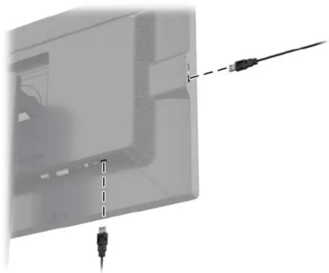
USB connectors are used to connect devices such as a digital camera, USB keyboard, or USB mouse. There are four downstream USB ports on the monitor (two on the rear and two on the side).

NOTE: You must connect the USB hub cable from the monitor to the computer to enable the USB ports on the monitor. Refer to Step 4 in Connecting the Cables on page 6.
natural_image
Diagram showing a computer monitor with USB cable and connector, no text or symbols presentRemoving the Monitor Stand
You can remove the monitor panel from the stand to install the panel on a wall, a swing arm, or other mounting fixture.

CAUTION: Before beginning to disassemble the monitor, be sure the monitor is turned off and the power and signal cables are both disconnected. Also disconnect all USB cables connected to the monitor.
- Disconnect and remove the signal, power, and USB cables from the monitor.
- Lay the monitor face down on a flat surface covered by a clean, dry cloth.
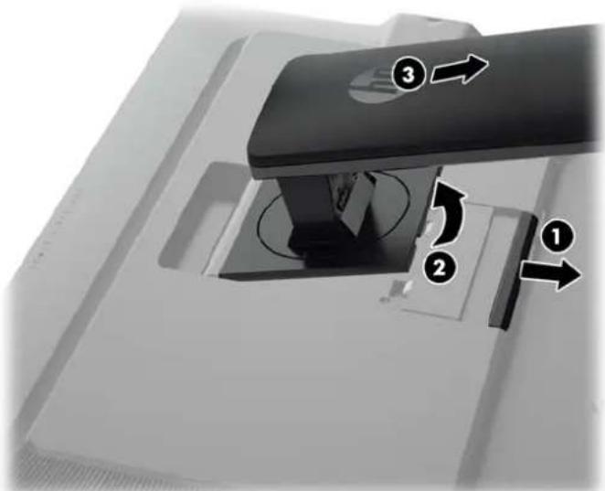
- Press down on the latch near the bottom center of the monitor to unlock the HP Quick Release 2 (1).
-
Swing the bottom of the stand up until the mounting plate clears the recess in the panel (2).
-
Slide the stand out of the recess (3).
text_image
Diagram of a mechanical device with numbered components and directional arrows indicating motion or flowMounting the Monitor
The monitor panel can be attached to a wall, swing arm, or other mounting fixture.
You can attach the monitor panel to a mounting fixture using the HP Quick Release 2 mounting bracket or you can attach the monitor panel to a mounting fixture without the HP Quick Release 2 mounting bracket.

NOTE: This apparatus is intended to be supported by UL or CSA Listed wall mount bracket.

CAUTION: This monitor supports the VESA industry standard 100 mm mounting holes. To attach a third-party mounting solution to the monitor, four 4 mm, 0.7 pitch, and 10 mm long screws are required. Longer screws must not be used because they may damage the monitor. It is important to verify that the manufacturer's mounting solution is compliant with the VESA standard and is rated to support the weight of the monitor display panel. For best performance, it is important to use the power and video cables provided with the monitor.
Mounting the Monitor Using the Quick Release 2 Mounting Bracket
To mount the monitor panel to a mounting fixture using the Quick Release 2 mounting bracket:
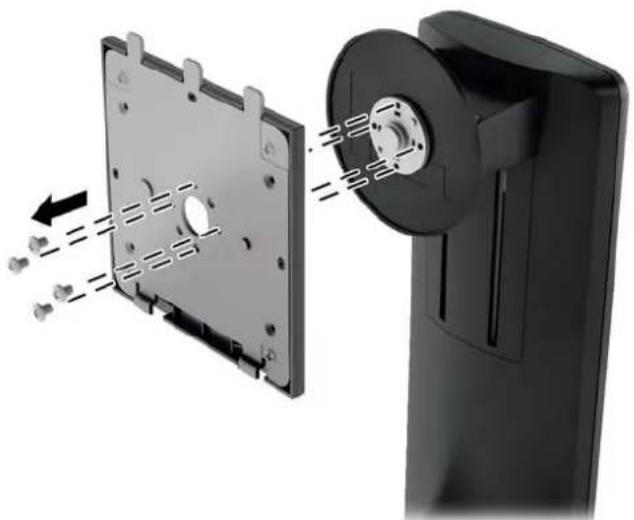
- Remove the four screws holding the mounting plate to the head of the stand.
natural_image
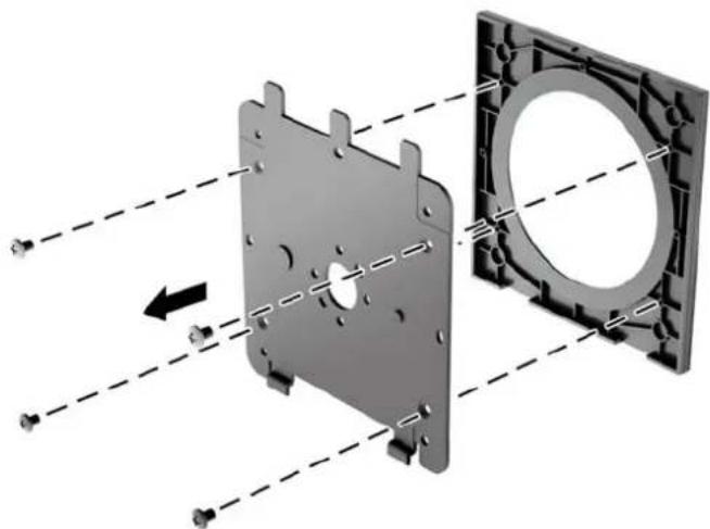
Diagram of a mechanical assembly showing a component being inserted into a housing, with arrows indicating direction (no text or symbols present)- Remove the four screws from the mounting plate to separate the mounting plate from its cover.
natural_image
3D mechanical assembly diagram showing a housing component with mounting holes and a circular component, connected by dashed lines indicating alignment (no text or symbols present)- Remove the four screws from the VESA holes located on the rear of the monitor panel.
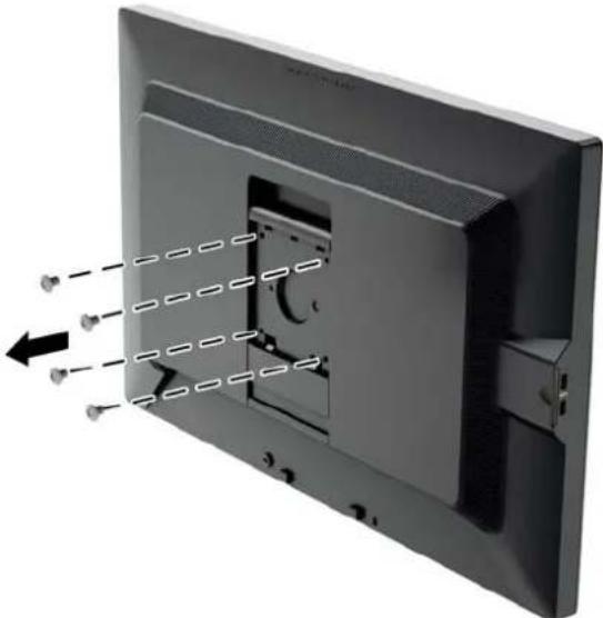
natural_image
Diagram of a flat-screen TV with internal components and directional arrows indicating flow or movement (no text or symbols)- Install the mounting plate to the wall or swing arm of your choice using the four screws that were removed from the VESA holes on the rear of the monitor panel.
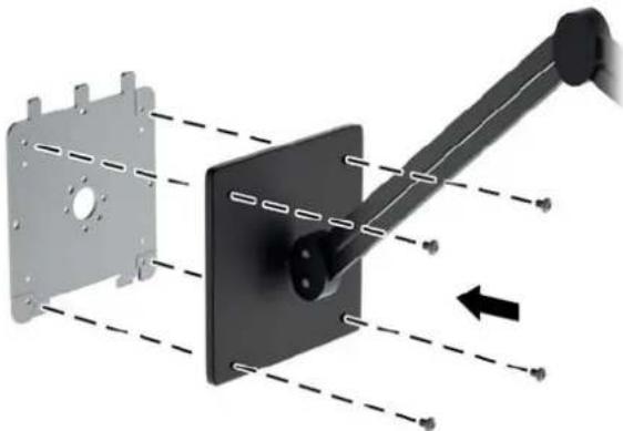
natural_image
Diagram of a mechanical assembly with a black component and dashed lines indicating motion, no text or symbols present.- Place the monitor panel on the mounting bracket you've installed by aligning its recess with the mounting bracket, then sliding it down over the top of the bracket and pressing it back into place against the bracket. The release latch on the monitor will pop up when the monitor is safely locked in place.
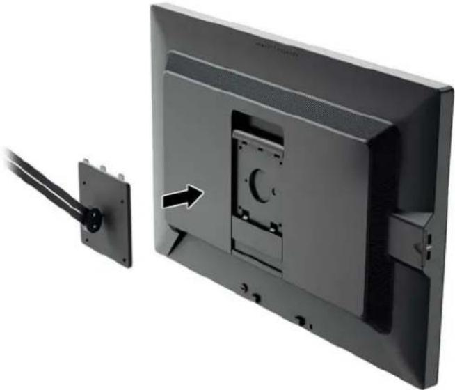
natural_image
Exterior view of a flat-screen computer monitor with cable attachment, showing front panel and rear panel (no text or symbols visible)Mounting the Monitor Without Using the Quick Release 2 Mounting Bracket
To mount the monitor panel directly to a mounting fixture without using the HP Quick Release 2 mounting bracket, use the four screws removed from the VESA holes on rear of the monitor panel and install them to attach the mounting device to the rear of the monitor panel.
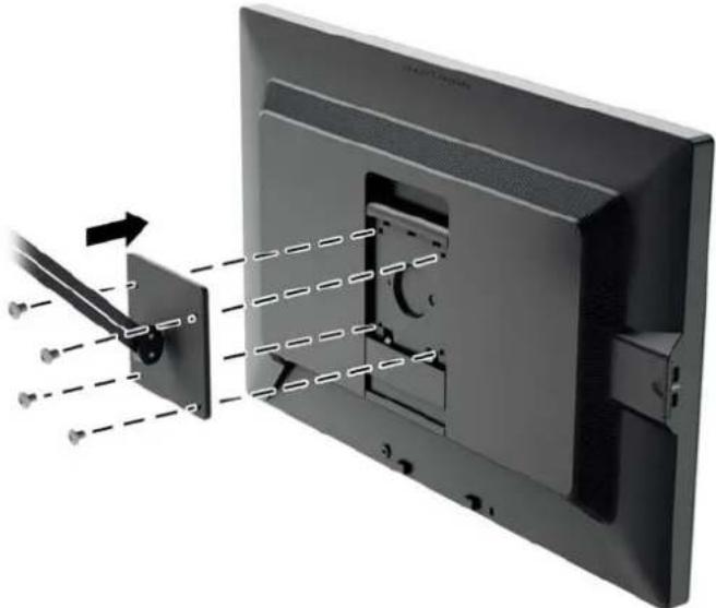
natural_image
Diagram of a computer monitor with cable attachment and cable disassembly, showing internal components and alignment lines (no text or symbols)Locating the Serial Number and Product Number
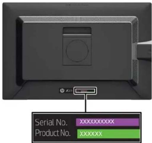
The serial number and product number are located on a label on the rear panel of the display head. You may need these numbers when contacting HP about the monitor model.

NOTE: You may need to partially pivot the display head to read the label.
text_image
Serial No. xxxxxxxxxxxx Product No. xxxxxxxLocating the Information Card
Identifying information is located on the pull-out card (and included on a label on the back of the monitor). The card pulls out from behind the USB connectors on the left side of the panel. Warranty support information (model number, serial number, product number) is printed on the front of the card (and the label) and regulatory information is printed on the back of the card.

text_image
Diagram showing a computer monitor with an open screen displaying a red barcode, annotated with a magnified view of its edge.Installing a Cable Lock
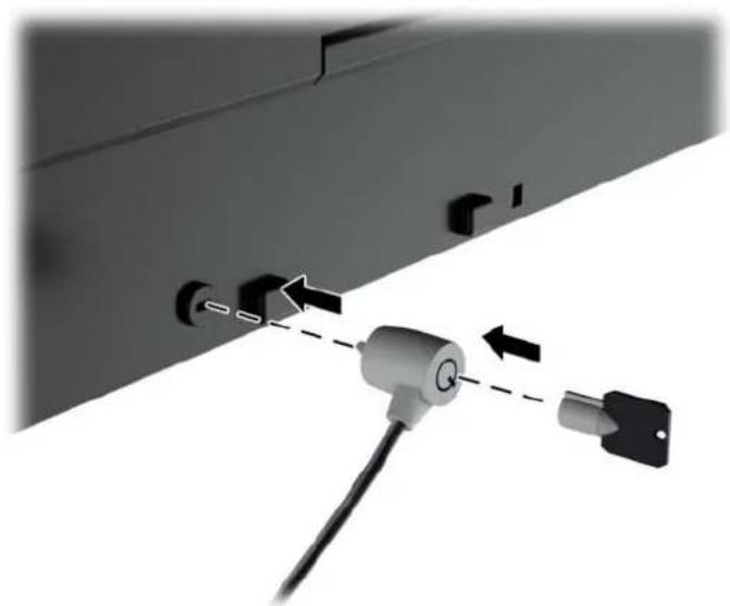
You can secure the monitor to a fixed object with an optional cable lock available from HP.
natural_image
Diagram showing a device with a lock and cable, connected by arrows indicating connection (no text or symbols present)Power Saving Features
The monitors support a reduced power state. The reduced power state will be entered into if the monitor detects the absence of either the horizontal sync signal and/or the vertical sync signal. Upon detecting the absence of these signals, the monitor screen is blanked, the backlight is turned off, and the power light is turned amber. When the monitor is in the reduced power state, the monitor will utilize .5 watts of power. There is a brief warm up period before the monitor will return to its normal operating mode.
Refer to the computer manual for instructions on setting energy saver features (sometimes called power management features).

NOTE: The above power saver feature only works when connected to computers that have energy saver features.
By selecting the settings in the monitor's energy saver utility, you can also program the monitor to enter into the reduced power state at a predetermined time. When the monitor's energy saver utility causes the monitor to enter the reduced power state, the power light blinks amber.
Power-Saver Mode
The monitor includes a Power-Saver Mode that can be quickly adjusted in the OSD while the monitor is still in use. The Power Saver function serves primarily to reduce LED backlight current (display brightness) in stages to enable power savings of the monitor. The savings levels are NOT calibrated but are approximate savings based on power measurements conducted during product qualification.
To adjust the power savings, press the Menu button on the front of the monitor to open the OSD and select Management > Power-Saver Mode. Set the power savings to one of the following:
Off
10% Savings
20% Savings
30% Savings
40% Savings
50% Savings

NOTE: The power saving percentages are based on a pre-test of multiple units. Actual power reductions and screen results may vary from unit to unit.
Adjusting the power saving percentages does not affect power reserved for the USB ports.
Auto-Sleep Mode
These displays support an OSD (On-Screen Display) option called Auto-Sleep Mode, that allows you to enable or disable a reduced power state for the display. When Auto-Sleep Mode is enabled (enabled by default), the monitor will enter a reduced power state when the host PC signals low power mode (absence of either horizontal or vertical sync signal).
Upon entering this reduced power state sleep mode, the monitor screen is blanked, the backlight is turned off and the power LED indicator turns amber. The monitor draws less than 0.5W of power when in this reduced power mode. The monitor will wake from the sleep mode when the host PC sends an active signal to the monitor (for example, if the user activates the mouse or keyboard).
Sleep Timer
The Sleep Timer OSD (On-Screen Display) option is an energy-saving feature that enables you to set a time for the monitor to enter and exit a reduced power state (Sleep Mode) at the programmable times each day. This can help you save energy and can potentially extend the life of the display.
The Sleep Timer has five settings:
- Set Current Time
Set Sleep Time
Set On Time
Timer: On/Off
Sleep Now
To set the timer:
- Press the Menu button on the monitor front panel to display the OSD Menu.
- Scroll down and highlight Management.
- Press the OK button to select Management.
- Scroll down and highlight and select Sleep Timer > Set Current Time.

NOTE: You must set the current local time before you set the time for Sleep Time or On Time. Note that the time is displayed in a 24-hour clock format. For example, 1:15 p.m. is displayed as 13 hours 15 minutes.
A power failure or loss of power to the monitor will cause the timer to reset to 00:00. If this occurs, you will need to reset the sleep timer.
- Press the OK button once to enter the adjustment mode for hours.
- Press the - (Minus) or + (Plus) button to adjust the hour.
-
Press the OK button again to enter the time for minutes.
-
Press the - (Minus) or + (Plus) button to adjust the minutes.
- Press the OK button to lock in the time chosen.
- After setting the current time, the highlight automatically skips to Set Sleep Time. Repeat steps 6 through 9 to set Sleep Time.
- If you do not want to set Sleep Time, press the OK button twice, then select Save and Return to exit the menu.
- After setting Sleep Time, the highlight automatically skips to Set On Time. Repeat steps 6 through 9 to set On Time.
- Set the Timer to On to activate the Sleep Timer settings.
- When you are finished, select Save and Return to exit the menu.
The fifth selection, Sleep Now, turns the monitor backlights off immediately and stays in sleep mode until the next On Time activates or a monitor button is pressed.
3 Finding More Information
Reference Guides
Refer to the HP LCD Monitors Reference Guide included on the CD with your monitor for additional information on:
• Optimizing monitor performance
• Safety and maintenance guidelines
• Installing software from the CD
• Using the OSD menu
• Downloading software from the Web
• Agency regulatory information
- Troubleshooting and recommended solutions to common problems
For information on theft deterrence, refer to the HP Display Assistant User Guide included on the CD with your monitor.
Product Support
For additional information on using and adjusting your monitor, go to http://www.hp.com/support. Select your country or region, select Product Support & Troubleshooting, and then enter your monitor model in the SEARCH window.

NOTE: The monitor user guide, reference guide, and drivers are available at http://www.hp.com/support.
If the information provided in the guide or in the HP LCD Monitors Reference Guide do not address your questions, you can contact support. For U.S. support, go to http://www.hp.com/go/contactHP. For worldwide support, go to http://welcome.hp.com/country/us/en/wwcontact_us.html.
Here you can:
• Chat online with an HP technician

NOTE: When support chat is not available in a particular language, it is available in English.
E-mail support
• Find support telephone numbers
- Locate an HP service center
A Technical Specifications

NOTE: All specifications represent the typical specifications provided by HP's component manufacturers; actual performance may vary either higher or lower.
Z24i Model
| Display | 60.96 cm wide screen | 24 inches wide screen |
| Type | IPS LCD | |
| Viewable Image Size 60.96 cm diagonal 24-inch diagonal | ||
| Maximum Weight (Unpacked) 6.96 kg 15.34 lbs | ||
| Dimensions (include base) | ||
| Height (highest position) | 52.5 cm | 20.67 inches |
| Height (lowest position) | 40.5 cm | 15.94 inches |
| Depth | 23.798 cm | 9.37 inches |
| Width | 55.94 cm | 22.02 inches |
| Maximum Graphic Resolution 1920 x 1200 (60 Hz) analog input | ||
| 1920 x 1200 (60 Hz) digital input | ||
| Optimum Graphic Resolution 1920 x 1200 (60 Hz) analog input | ||
| 1920 x 1200 (60 Hz) digital input | ||
| Environmental Requirements Temperature | ||
| Operating Temperature | 5 to 35°C | 41 to 95°F |
| Storage Temperature | -20 to 60°C | -4 to 140°F |
| Power Source 100 – 240 VAC 50/60 Hz | ||
| Input Terminal One VGA connector; one DVI connector;one DisplayPort connector (cable inclusion varies by region) | ||
NOTE: For the latest specifications or additional specifications on this product, go to http://www.hp.com/go/productbulletin and search for your specific display model to find the model-specific QuickSpecs.
Z27i Model
| Display | 68.58 cm wide screen | 27 inches wide screen |
| Type | IPS LCD | |
| Viewable Image Size 68.58 cm diagonal 27-inch diagonal | ||
| Maximum Weight (Unpacked) 7.6 kg | 16.74 lbs | |
| Dimensions (include base) | ||
| Height (highest position) | 54.04 cm | 21.28 inches |
| Height (lowest position) | 42.04 cm | 16.55 inches |
| Depth | 24.248 cm | 9.55 inches |
| Width | 64.10 cm | 25.24 inches |
| Maximum Graphic Resolution 1920 x 1200 (60 Hz) analog input | ||
| 2560 x 1440 (60 Hz) digital input | ||
| Optimum Graphic Resolution 1920 x 1200 (60 Hz) analog input | ||
| 2560 x 1440 (60 Hz) digital input | ||
| Environmental Requirements Temperature | ||
| Operating Temperature | 5 to 35°C | 41 to 95°F |
| Storage Temperature | -20 to 60°C | -4 to 140°F |
| Power Source 100 – 240 VAC 50/60 Hz | ||
| Input Terminal One VGA connector; one DVI connector;one HDMI connector; one DisplayPortconnector (cable inclusion varies byregion) | ||
NOTE: For the latest specifications or additional specifications on this product, go to http://www.hp.com/go/productbulletin and search for your specific display model to find the model-specific QuickSpecs.
Z30i Model
| Display | 76.2 cm wide screen | 30 inches wide screen |
| Type | IPS LCD | |
| Viewable Image Size 76.2 cm diagonal 30-inch diagonal | ||
| Maximum Weight (Unpacked) 9.96 kg 21.96 lbs | ||
| Dimensions (include base) | ||
| Height (highest position) | 60.1 cm | 23.66 inches |
| Height (lowest position) | 48.1 cm | 18.94 inches |
| Depth | 26.648 cm | 10.49 inches |
| Width | 69.03 cm | 27.18 inches |
| Maximum Graphic Resolution 1920 x 1200 (60 Hz) analog input | ||
| 2560 x 1600 (60 Hz) digital input | ||
| Optimum Graphic Resolution 1920 x 1200 (60 Hz) analog input | ||
| 2560 x 1600 (60 Hz) digital input | ||
| Environmental Requirements Temperature | ||
| Operating Temperature | 5 to 35°C | 41 to 95°F |
| Storage Temperature | -20 to 60°C | -4 to 140°F |
| Power Source 100 – 240 VAC 50/60 Hz | ||
| Input Terminal One VGA connector; one DVI connector;one HDMI connector; one DisplayPortconnector (cable inclusion varies byregion) | ||
NOTE: For the latest specifications or additional specifications on this product, go to http://www.hp.com/go/productbulletin and search for your specific display model to find the model-specific QuickSpecs.
Recognizing Preset Display Resolutions
The display resolutions listed below are the most commonly used modes and are set as factory defaults. This monitor automatically recognizes these preset modes and they will appear properly sized and centered on the screen.
Z24i Model
| Preset Pixel Format Horz Freq (kHz) Vert Freq (Hz) |
| 1 640 × 480 31.469 59.940 |
| 2 720 × 400 31.469 70.087 |
| 3 800 × 600 37.879 60.317 |
| 4 1024 × 768 48.363 60.004 |
| 5 1280 × 1024 63.981 60.02 |
| 6 1440 × 900 55.935 59.887 |
| 7 1680 × 1050 65.29 59.954 |
| 8 1920 × 1080 67.5 60.00 |
| 9 1920 × 1200 74.038 59.950 |
| 10 1920 × 1200 74.556 59.885 |
| Preset Timing Name Pixel Format Horz Freq (kHz) Vert Freq (Hz) |
| 1 480p 720 × 480 31.469 59.94 |
| 2 576p 720 × 576 31.25 50 |
| 3 720p50 1280 × 720 37.5 50 |
| 4 720p60 1280 × 720 45 60 |
| 5 1080p50 1920 × 1080 56.25 50 |
| 6 1080p60 1920 × 1080 67.5 60 |
Z27i Model
| Preset Pixel Format Horz Freq (kHz) Vert Freq (Hz) |
| 1 640 × 480 31.469 59.940 |
| 2 720 × 400 31.469 70.087 |
| 3 800 × 600 37.879 60.317 |
| 4 1024 × 768 48.363 60.004 |
| 5 1280 × 720 45.00 59.94 |
| 6 1280 × 800 49.702 59.81 |
| 7 1280 × 1024 63.981 60.02 |
| 8 1366 × 768 47.712 59.79 |
| 9 1440 × 900 55.935 59.887 |
| 10 1600 × 900 55.935 59.887 |
| 11 1680 × 1050 65.29 59.954 |
| 12 1920 × 1080 67.5 60.00 |
| 13 1920 × 1200 74.038 59.950 |
| 14 1600 × 1200 75.00 60.000 |
| 15 1920 × 1200 74.556 59.885 |
| 16 2560 × 1440 88.787 59.951 |
| Preset Timing Name Pixel Format Horz Freq (kHz) Vert Freq (Hz) |
| 1 480p 720 × 480 31.469 59.94 |
| 2 576p 720 × 576 31.25 50 |
| 3 720p50 1280 × 720 37.5 50 |
| 4 720p60 1280 × 720 45 60 |
| 5 1080p50 1920 × 1080 56.25 50 |
| 6 1080p60 1920 × 1080 67.5 60 |
Z30i Model
| Preset Pixel Format Horz Freq (kHz) Vert Freq (Hz) |
| 1 640 × 480 31.469 59.940 |
| 2 720 × 400 31.469 70.087 |
| 3 800 × 600 37.879 60.317 |
| 4 1024 × 768 48.363 60.004 |
| 5 1280 × 720 45.00 59.94 |
| 6 1280 × 800 49.702 59.81 |
| 7 1280 × 1024 63.981 60.02 |
| 8 1366 × 768 47.712 59.79 |
| 9 1440 × 900 55.935 59.887 |
| 10 1600 × 900 55.935 59.887 |
| 11 1680 × 1050 65.29 59.954 |
| 12 1920 × 1080 67.5 60.00 |
| 13 1920 × 1200 74.038 59.950 |
| 14 1600 × 1200 75.00 60.000 |
| 15 1920 × 1200 74.556 59.885 |
| 16 2560 × 1440 88.787 59.951 |
| 17 2560 × 1600 98.713 59.972 |
| Preset Timing Name Pixel Format Horz Freq (kHz) Vert Freq (Hz) |
| 1 480p 720 × 480 31.469 59.94 |
| 2 576p 720 × 576 31.25 50 |
| 3 720p50 1280 × 720 37.5 50 |
| 4 720p60 1280 × 720 45 60 |
| 5 1080p50 1920 × 1080 56.25 50 |
| 6 1080p60 1920 × 1080 67.5 60 |
Entering User Modes
The video controller signal may occasionally call for a mode that is not preset if:
• You are not using a standard graphics adapter.
• You are not using a preset mode.
It this occurs, you may need to readjust the parameters of the monitor screen by using the on-screen display. Your changes can be made to any or all of these modes and saved in memory. The monitor automatically stores the new setting, then recognizes the new mode just as it does a preset mode. In addition to the factory preset modes, there are at least 10 user modes that can be entered and stored.