
Alteas One Net - Chauffe-eau instantané et ballon d'eau chaude Ariston Thermo - Free user manual and instructions
Find the device manual for free Alteas One Net Ariston Thermo in PDF.


| Product Type | Combined instantaneous water heater and storage tank |
| Brand | Ariston Thermo |
| Model | Alteas One Net |
| Energy Source | Electricity (mains power) |
| Installation Type | Wall-mounted |
| Dimensions (H x W x D) | 700 x 410 x 230 mm |
| Weight | Approximately 25 kg |
| Water Supply Connection | 1/2 inch BSP |
| Maximum Pressure | 8 bar (0.8 MPa) |
| Tank Capacity | 50 liters |
| Instantaneous Heating Power | Up to 24 kW |
| Temperature Range | 30°C to 60°C |
| Control Type | Electronic with LCD display |
| Smart Features | Wi-Fi connected for remote control via Ariston Net app |
| Energy Efficiency Class | A (for water heating) |
| Safety Devices | Overheat protection, anti-freeze, safety valve |
| Material | Stainless steel tank with enamel coating |
| Maintenance | Descaling every 2 years, anode check annually |
| Spare Parts Availability | Thermostat, heating element, anode, control board |
| Repairability Index | 8.5/10 |
| Certifications | CE, UKCA, ErP compliant |
Frequently Asked Questions - Alteas One Net Ariston Thermo
User questions about Alteas One Net Ariston Thermo
0 question about this device. Answer the ones you know or ask your own.
Ask a new question about this device
Download the instructions for your Chauffe-eau instantané et ballon d'eau chaude in PDF format for free! Find your manual Alteas One Net - Ariston Thermo and take your electronic device back in hand. On this page are published all the documents necessary for the use of your device. Alteas One Net by Ariston Thermo.
USER MANUAL Alteas One Net Ariston Thermo
Including
CUBE Room Sensor wireless
G.C.N.: 47-116-91 (30 KW)
G.C.N.: 47-116-92 (35 KW)

ARISTON

ALTEAS ONE NET
INSTALLATION AND SERVICING INSTRUCTIONS
kiwa
approved product
UK WATER SUPPLY
REGULATIONS

Country of Destination: GB/IE
HOT WATER | HEATING | RENEWABLES
ErP
INDEX
Overview 3
General Information 4
Advice for the Installer....4
CE Labelling 4
Data Plate Symbols 4
Safety Regulations 5
Product description....7
Control Panel 7
Display....8
Overall View 8
Overall Dimension 9
Minimum Clearances 9
Installation....10
Reference Standards ....10
Installing the Boiler 13
Gas Connection 14
Water Connection 14
Instructions for Opening the Casing and Performing an Internal Inspection 14
Underfloor heating 15
Water circuit diagram 16
Connecting the Flue 17
Fitting the Coaxial Flue (∅ 60/100 Horizontal) ...... 18
Fitting the 5" Flue (∅ 80/125 Horizontal / Vertical) .....19
Fitting the Coaxial Flue (∅ 60/100 Vertical) ......20
Fitting the Twin Pipe (∅ 80/80) 21
Electrical Connections 24
Peripheral Unit Connection 24
Room Thermostat Connection 25
Electrical Diagram 26
Commissioning 27
Initial Preparation 27
Electricity Supply 27
Filling the Heating System 27
Start-up procedure 29
First ignition
(deaeration cycle and automatic calibration ....29
Maximum heating power adjustment 33
Checking slow ignition power 33
Heating ignition delay adjustment 33
Table summarising changes 33
Gas changeover 34
AUTO Function 35
Boiler Protection Devices....36
Boiler Protection Devices.... 36
Table summarising error codes 37
Anti-Frost Device 37
Technical Area 38
Accessing the Menus ....38
Maintenance....45
General Comments 45
Operational Test 45
Draining procedures.... 45
Cleaning the primary exchanger 45
Cleaning the trap 46
Maintenance Guide 47
General Access 47
Electrical Unit 48
Hydraulic Unit 50
Burner Unit 60
Annual Maintenance 64
Technical Information......66
Technical Data GENUS ONE NET 66
ERP Data GENUS ONE NET 67
Product fiche GENUS ONE NET 68
Product fiche CUBE WIFI 68
Package Label - Instructions to filling....69
Package fiche 70
Benchmark Commissioning Checklist 73
Benchmark Service Interval Record 74
These instructions are suitable for Alteas One Net boilers :
Do not forgot to complete the Benchmark Commissioning Checklist!

The Benchmark Scheme
Benchmark places responsibilities on both manufacturers and installers. The purpose is to ensure that customers are provided with the correct equipment for their needs, that it is installed, commissioned and serviced in accordance with the manufacturer's instructions by competent persons and that it meets the requirements of the appropriate Building Regulations. The Benchmark Checklist can be used to demonstrate compliance with Building Regulations and should be provided to the customer for future reference.
Installers are required to carry out installation, commissioning and servicing work in accordance with the Benchmark Code of Practice which is available from the Heating and Hotwater Industry Council who manage and promote the Scheme. Visit www.centralheating.co.uk for more information.
To The Installer
As part of the commissioning of this appliance it is vital that the Benchmark Commissioning Checklist is completed and given to the Householder. Please ensure that your customer is aware of the importance of keeping the Commissioning Checklist and Service Interval Record safe to document the product's history.
Please ensure that your customer is aware of the correct operation of the system, boiler and controls.
ARISTON recommend the use of protective clothing, when installing and working on the appliance i.e. gloves.
CUSTOMER CARE
ARISTON, as a leading manufacturer of domestic and commercial water heating appliances is committed to providing high quality products and a high quality after sales service.
Advice on installation or servicing can also be obtained by contacting the ARISTON Technical and Customer Service Departments at High Wycombe.
TECHNICAL DEPARTMENT CUSTOMER SERVICE DEPARTMENT
Tel: 0333 240 7777 Tel: 0333 240 8777
Fax: 01494 459775 Fax: 01494 459775
WARRANTY
The manufacturer's warranty is for 12 years from the date of purchase. The warranty is invalidated if the appliance is not installed in accordance with the recommendations made herein or in a manner not approved by the manufacturer. To assist us in providing you with an efficient after sales service, please register the warranty online at www.ariston.co.uk
CAUTION
In the United Kingdom, installation, start-up, adjustments and maintenance, must be performed by a competent person only, in accordance with the current Gas Safety (Installation & Use) Regulations and the instructions provided.
In the Republic of Ireland, the installation and initial start up of the appliance must be carried out by a Competent Person in accordance with the current edition of I.S.813 “Domestic Gas Installations”, the current Buildling Regulations, reference should also be made to the current ETCI rules for electrical installation.
All GAS SAFE registered installers carry a GAS SAFE ID card, and have a registration number. Both should be recorded in your boiler Benchmark Commissioning Checklist. You can check your installer is GAS SAFE registered by calling GAS SAFE directly on:- 0800 408 5500.
Improper installation may cause damage or injury to individuals, animals and personal property for which the manufacturer will not be held liable. To ensure efficient and safe operation it is recommended that the boiler is serviced annually by a competent person.
If it is known that a fault exists on the appliance, it must not be used until the fault has been corrected by a competent person.
Please refer to the terms and conditions of warranty in the user manual which are also available on our website.
This instruction booklet is especially designed for appliances installed in the UK and the Republic of Ireland
ATTENTION!!
THE INSTALLATION AND FIRST IGNITION OF THE BOILER MUST BE PERFORMED BY GAS SAFE REGISTERED ENGINEER IN COMPLIANCE WITH GAS SAFETY (INSTILLATION & USE) REGULATIONS AND ALL OTHER NATIONAL REGULATIONS REGARDING INSTALLATION, AND IN CONFORMITY WITH ANY REQUIREMENTS ESTABLISHED BY LOCAL AUTHORITIES AND PUBLIC HEALTH ORGANISATIONS. AFTER THE BOILER HAS BEEN INSTALLED, THE INSTALLER MUST ENSURE THAT THE END USER RECEIVES THE DECLARATION OF CONFORMITY AND THE OPERATING MANUAL, AND SHOULD PROVIDE ALL NECESSARY INFORMATION AS TO HOW THE BOILER AND THE SAFETY DEVICES SHOULD BE HANDLED.

Advice for the Installer
This appliance is designed to produce hot water for domestic use.
It should be connected to a heating system and a distribution network for domestic hot water, both of which must be compatible with its performance and power levels.
The use of the appliance for purposes other than those specified is strictly forbidden. The manufacturer cannot be held responsible for any damage caused by improper, incorrect and unreasonable use of the appliance or by the failure to comply with the instructions given in this manual.
Installation, maintenance and all other interventions must be carried out in full conformity with the governing legal regulations and the instructions provided by the manufacturer. Incorrect installation can harm persons, animals and possessions; the manufacturing company shall not be held responsible for any damage caused as a result. The boiler is delivered in a carton. Once you have removed all the packaging, make sure the appliance is intact and that no parts are missing. If this is not the case, please contact your supplier.
Keep all packaging material (clips, plastic bags, polystyrene foam, etc.) out of reach of children as it may present a potential hazard.
In the event of a fault and/or malfunction, turn the appliance off, turn off the gas cock and do not attempt to repair it yourself. Contact a qualified professional instead.
Before any maintenance or repair work is performed on the boiler, make sure you have disconnected it from the electricity supply by switching the external bipolar switch to the "OFF" position and removing the fuse.
All repairs, which should only be performed using original spare parts, should be carried out by a qualified professional. Failure to comply with the above instructions could compromise the safety of the appliance and invalidate all liability on the part of the manufacturer.
In the event of any maintenance or other structural work in the immediate vicinity of the ducts or flue gas exhaust devices and their accessories, switch the appliance off by switching the external bipolar switch to the "OFF" position and shutting off the gas control valve. When the work has been completed, ask a
qualified technician to check the efficiency of the ducting and the devices.
Turn the boiler off and turn the external switch "OFF" to clean the exterior parts of the appliance.
Clean using a cloth dampened with soapy water. Do not use aggressive detergents, insecticides or toxic products. If the appliance is used in full compliance with current legislation, it will operate in a safe, environmentally-friendly and cost-efficient manner.
If using kits or optional extras, make sure they are authentic.
CE labelling
The CE mark guarantees that the appliance conforms to the following directives:
- 2016/426/EU
relating to gas appliances
- 2014/30/EU
relating to electromagnetic compatibility
- 92/42/CEE
relating to energy efficiency
2014/35/EU
relating to electrical safety
- 2009/125/CE
Energy related Products
- 813/2013
Commission regulation (EU)
Symbols used on the data plate
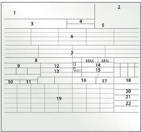
Legend :
- Brand
- Manufacturer
- Boiler model Serial number
- Commercial reference
- Certifi cation number
- Destination country Gas category
- Gas setting
- Installation type
- Electrical data
- Maximum domestic hot water pressure
- Maximum heating pressure
- Boiler type
-
NOx class / Efficiency
-
Input rating nominal heating
- Power output heating
- DHW specific flow rate
- Boiler output effi ciency
- Input rating nominal DHW
- Gases which may be used
- Minimum ambient temperature for use
- Max. central heating temperature
- Max. domestic hot water temperature
SAFETY REGULATION
Key to symbols:

Failure to comply with this warning implies the risk of personal injury, in some circumstances even fatal

Failure to comply with this warning implies the risk of damage, in some circumstances even serious, to property, plants or animals.
Install the appliance on a solid wall which is not subject to vibration.
Noisy operation.

When drilling holes in the wall for installation purposes, take care not to damage any electrical wiring or existing piping.
Electrocution caused by contact with live wires. Explosions, fires or asphyxiation caused by gas leaking from damaged piping.

Damage to existing installations.

Flooding caused by water leaking from damaged piping.
Perform all electrical connections using wires which have a suitable section.
Fire caused by overheating due to electrical current passing through undersized cables.

Protect all connection pipes and wires in order to prevent them from being damaged.
Electrocution caused by contact with live wires. Explosions, fires or asphyxiation caused by gas leaking from damaged piping.

Flooding caused by water leaking from damaged piping.

Make sure the installation site and any systems to which the appliance must be connected comply with the applicable norms in force.
Electrocution caused by contact with live wires which have been installed incorrectly.

Damage to the appliance caused by improper operating conditions.

Use suitable manual tools and equipment (make sure in particular that the tool is not worn out and that its handle is fixed properly); use them correctly and make sure they do not fall from a height. Replace them once you have finished using them.
Personal injury from the falling splinters or fragments, inhalation of dust, shocks, cuts, pricks and abrasions.

Damage to the appliance or surrounding objects caused by falling splinters, knocks and

incisions.
Use electrical equipment suitable for its intended use (in particular, make sure that the power supply cable and plug are intact and that the parts featuring rotary or reciprocating motions are fastened correctly); use this equipment correctly; do not obstruct passageways with the power supply cable, make sure no equipment could fall from a height. Disconnect it and replace it safely after use.
Personal injury caused by falling splinters or fragments, inhalation of dust, knocks, cuts, puncture wounds, abrasions, noise and vibration.

Damage to the appliance or surrounding objects caused by falling splinters, knocks and incisions.

Make sure any portable ladders are positioned securely, that they are suitably strong and that the steps are intact and not slippery and do not wobble when someone climbs them. Ensure someone provides supervision at all times.
Personal injury caused by falling from a height or cuts (stepladders shutting accidentally).

Make sure any rolling ladders are positioned securely, that they are suitably strong, that the steps are intact and not slippery and that the ladders are fitted with handrails on either side of the ladder and parapets on the landing.
Personal injury caused by falling from a height.

During all work carried out at a certain height (generally with a difference in height of more than two metres), make sure that parapets are used to surround the work area or that individual harnesses are used to prevent falls. The space where any accidental fall may occur should be free from dangerous obstacles, and any impact upon falling should be cushioned by semi-rigid or deformable surfaces.
Personal injury caused by falling from a height.

Make sure the workplace has suitable hygiene and sanitary conditions in terms of lighting, ventilation and solidity of the structures.
Personal injury caused by knocks, stumbling etc.

Protect the appliance and all areas in the vicinity of the work place using suitable material.
Damage to the appliance or surrounding objects caused by falling splinters, knocks and incisions.

Handle the appliance with suitable protection and with care.
Damage to the appliance or surrounding objects from shocks, knocks, incisions and squashing.
During all work procedures, wear individual protective clothing and equipment.
Personal injury caused by electrocution, falling splinters or fragments, inhalation of dust, shocks, cuts, puncture wounds, abrasions, noise and vibration.
Place all debris and equipment in such a way as to make movement easy and safe, avoiding the formation of any piles which could yield or collapse.
Damage to the appliance or surrounding objects from shocks, knocks, incisions and squashing.
All operations inside the appliance must be performed with the necessary caution in order to avoid abrupt contact with sharp parts.
Personal injury caused by cuts, puncture wounds and abrasions.
Reset all the safety and control functions affected by any work performed on the appliance and make sure they operate correctly before restarting the appliance.
Explosions, fi res or asphyxiation caused by gas leaks or an incorrect fl ue gas exhaust. Damage or shutdown of the appliance caused by out-of-control operation.
Before handling, empty all components that may contain hot water, carrying out any bleeding if necessary.
Personal injury caused by burns.
Descale the components, in accordance with the instructions provided on the safety data sheet of the product used, airing the room, wearing protective clothing, avoid mixing different products, and protect the appliance and surrounding objects.
Personal injury caused by acidic substances coming into contact with skin or eyes; inhaling or swallowing harmful chemical agents.
Damage to the appliance or surrounding objects due to corrosion caused by acidic substances.
If you detect a smell of burning or smoke, keep clear of the appliance, disconnect it from the electricity supply, open all windows and contact the technician.
Personal injury caused by burns, smoke inhalation, asphyxiation.

This appliance can be used by children aged from 8 years and above and person with reduced physical, sensory or mental capabilities or lack of experience and knowledge if they have been given supervision or instruction concerning use of the appliance in a safe way and understand the hazards involved. Children shall not play with the appliance. Cleaning and user maintenance shall not be made by children without supervision.
CONTROL PANNEL
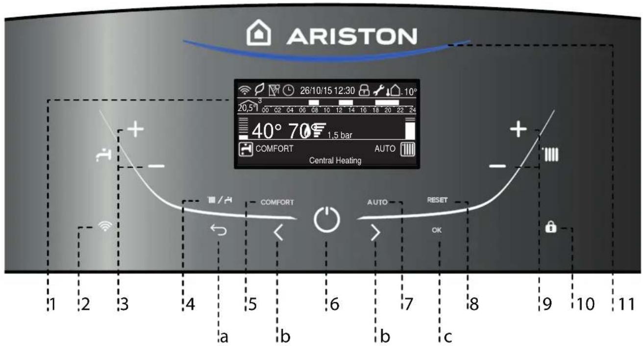
Legend:
- Display
- WIFI button
(enable / disable / configure) - Domestic Hot Water adjustment button +/-
- MODE button
(Operation mode selection summer/winter) - COMFORT button
- ON/OFF button
- Auto button (To activate Thermoregulation)
- RESET button
- Heating temperature adjustment button +/-
- Keylock
- Led Blue - Flame presence
Programming key
a. Esc button (Back)
b. Programming keys
c. Ok button programming key
DISPLAY
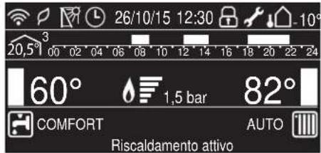
| Date and time | 26/10/15 12:30 |
| Keylock active | |
| D.H.W. set temperature and indication of the set temperature level |  |
| C.H. set temperature and indication of the set temperature level |  |
| Warning scheduled maintenance | |
| Heating operation set |  |
| Heating operation active |  |
| D.H.W. operation set |  |
| D.H.W. operation active |  |
| Flame detected with indication of power used |  |
| Digital pressure gauge (bar) | 1,5 bar |
| Scrolling text displaying operation as information | Central heating |
| Error wsignalsThe display show the code and description |  |
| AUTO function activated | AUTO |
| Hot Water Comfort activated | COMFORT |
| CH Schedule programming(set display: boiler base - see user's menù) |  |
| [6Y50] | |
| CH Schedule programming(set display: boiler complete - see user's menù) | |
| Internal temperature displayed for set zone. (with bus device connected - optional) |  |
| External temperature displayed |  |
| ECO mode | [48DS] |
| WIFI active |  |
| WIFI connected to the local network, but without access to the server |  |
| WIFI not confi gured | [8BKC] |
| Solar temperature probe connected - option |  |
Overall view
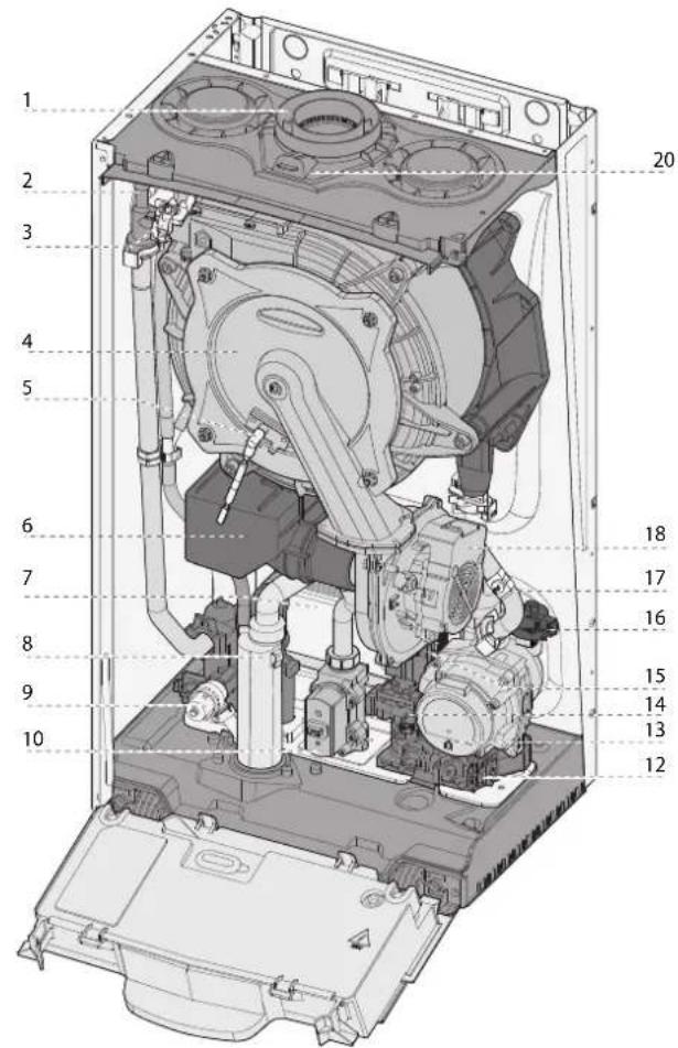
- Flue connector
- Air relief valve
- C.H. Flow temperature probe
- Main heat exchanger
- Detection Electrode
- Silencer
- Secondary heat exchanger
8 Condensate trap - C.H. pressure relief valve
- Gas valve
- C.H. circuit fi Iter
- Modulating circulation Pump with air release valve
- D.H.W. Flow switch
- Diverter valve
- Water pressure sensor
- C.H. Return temperature probe
- Modulating Fan
- Combustion Analysis Test Point
Overall Dimensions
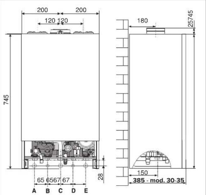
A. Central Heating Flow
B. Domestic Hot Water Outlet
C. Gas Inlet
D. Domestic Cold Water Inlet
E. Central Heating Return
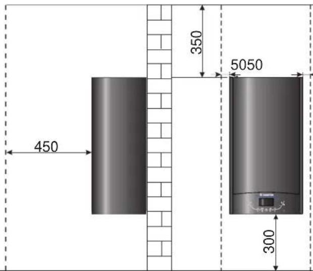
Minimum clearances
In order to allow easy access to the boiler for maintenance operations, The boiler must be installed in accordance with the clearances stated below.
Reference Standards
In the United Kingdom, the installation and initial start-up of the boiler must be by a Gas Safe registered installer in accordance with the installation standards currently in effect, as well as with any and all local health and safety standards i.e. Gas Safe.
In the Republic of Ireland the installation and initial start-up of the appliance must be carried out by a Competent Person in accordance with the current edition of I.S.813 “Domestic Gas Installations” and the current Building Regulations, reference should also be made to the current ETCI rules for electrical installation.
The installation of this appliance must be in accordance with the relevant requirements of the Local Building Regulations, the current I.E.E. Wiring Regulations, the by-laws of the local authority, in Scotland, in accordance with the Building Standards (Scotland) Regulation and Health and Safety document No. 635, "Electricity at Work Regulations 1989" and in the Republic of Ireland with the current edition of I.S. 813 and the Local Building Regulations (IE).
C.O.S.H.H.
Materials used in the manufacture of this appliance are non-hazardous and no special precautions are required when servicing.
Codes of Practice
Installation should also comply with the following British Standards Code of Practice (refer to the most recent version):
BS 7593: Treatment of water in domestic hot water central heating systems
BS 5546: Installation of hot water supplies for domestic purposes
BS 5440-1: Flues
BS 5440-2: Air supply
BS EN 12831 - BS EN 14336:
Forced circulation hot water systems
BS 6798: Installation of gas fi red hot water boilers of rated input not exceeding 70kW
BS 6891: Installation of low pressure gas pipes up to 28mm
BS 7671: IEE Wiring Regulations
BS 4814: Specifi cation for expansion vessels
BS 5482: Installation of L.P.G.
Technical Bulletin TB143 Flue Gas Analysis
and in the Republic of Ireland in accordance with the following codes of practice:
I.S. 813 Domestic Gas Installations
Avoid installing the boiler where the air inlet can be polluted by chemical products such as chlorine (swimming pool area), or ammonia (hair dresser), or alkalin products (launderette).
Flue
Detailed information on fl ue assembly can be found in the "Connecting the Flue" section.
The boiler must be installed so that the flue terminal is exposed to the free passage of external air at all times and must not be installed in a place likely to cause nuisance. It must not be allowed to discharge into another room or space such as an outhouse or closed lean-to.
Condensing boilers have a tendency to form a plume of water vapour from the fl ue terminal due to the low temperature of the fl ue gasses. The terminal should therefore be located with due regard for the damage or discolouration that may occur to building within the vicinity and consideration must also be given to adjacent boundaries, openable windows should also be taken into consideration when siting the fl ue.
The minimum acceptable clearances are shown below:
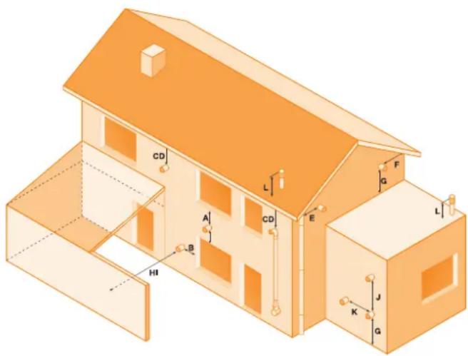
- A Directly below an opening, window, etc 300 mm
- B Horizontally to an opening, window, etc 300 mm
- C Below gutters, soils pipes or drain pipes 75 mm
- D Below eaves 200 mm
- E From vertical drain pipe or soil pipe 75 mm
- F From internal or external corner 300 mm
- G Above ground, roof or balcony level 300 mm
- H From a surface facing the terminal 600 mm
- I From a terminal facing a terminal 1200 mm
- J Vertically from a terminal on the same wall 1500 mm
- K Horizontally from an terminal on the same wall 300 mm
- L Fixed by vertical fl ue terminal
NOTE: THE FLUE MUST NOT BE INSTALLED IN A PLACE LIKELY TO CAUSE A NUISANCE AND POSITIONED TO ENSURE THAT PRODUCTS OF COMBUSTION DO NOT DISCHARGE ACROSS A BOUNDARY
It may be necessary to protect the terminal with a guard, if this is the case it will be necessary to purchase a stainless steel terminal guard. Reference should be made to the Building Regulations for guidance.
Ventilation
The room in which the boiler is installed does not require specific ventilation. If the boiler is installed in a cupboard or compartment ventilation is not required for cooling purposes.
Gas Supply
The gas installation and tightness testing must be in accordance with the requirements of BS6891. Ensure that the pipe size is adequate for demand including other gas appliances on the same supply.
Electrical Supply
The appliance requires an earthed 230V - 50 Hz supply and must be in accordance with current I.E.E. regulations. It must also be possible to be able to completely isolate the appliance electrically. Connection should be via a 3 amp double pole fused isolating switch with contact separation of at least 3mm on both poles. Alternatively, a fused 3 amp, 3 pin plug and unswitched socket may be used, provided it is not used in a room containing a bath or shower. It should only supply the appliance.
Water Supply
The boiler is suitable for sealed systems only. The maximum working pressure for the appliance is 6 bar. All fittings and pipework for the appliance should be of the same standard. If there is a possibility of the incoming mains pressure exceeding 6 bar, particularly at night, then a suitable pressure limiting valve must be fitted.
The boiler is designed to provide hot water on demand to multiple outlets within the property. If there is a requirement for greater demands, for example if the boiler has several bathrooms and cloakrooms, a vented or unvented hot water storage system may be used.
Showers
Any shower valves used with the appliance should be of a thermostatic or pressure balanced type. Refer to the shower manufacturer for performance guidance and suitability.
Flushing and Water Treatment
The boiler is equipped with a stainless steel heat exchanger.
The detailed recommendations for water treatment are given in BS 7593 (Treatment of water in domestic hot water central heating systems); the following notes are given for general guidance.
If the boiler is installed on an existing system, any unsuitable additives must be removed.
Under no circumstances should the boiler be fired before the system has been thoroughly flushed; the flushing procedure must be in line with BS 7593.
We highly recommend the use of a flushing detergent appropriate for the metals used in the circuit.
In hard water areas or where large quantities of water are in the system the treatment of water to prevent premature scaling of the main exchanger is necessary.
The formation of scale heat compromises the efficiency of the thermic exchanger because small areas of scale cause a high increase of the temperature of the metallic walls and therefore add to the thermal stress of the heat exchanger.
Demineralised water is more aggressive so in this situation it is necessary to treat the water with an appropriate corrosion inhibitor.
Any treatment of water by additives in the system for frost protection or for corrosion inhibition has to be absolutely suitable for all metals used in the circuit.
The use of a corrosion inhibitor in the system is recommended to prevent corrosion (sludge) damaging the boiler and system;
If anti-freeze substances are to be used in the system, check carefully that they are compatible with the metals used in the circuit.
ARISTON suggests the use of suitable anti-freeze products, which will prevent rust and incrustation taking place.
Periodically check the pH balance of the water/anti-freeze mixture of the boiler circuit and replace it when the amount measured is out of the range stipulated by the manufacturer (7 < pH < 8).
DO NOT MIX DIFFERENT TYPES OF ANTI-FREEZE
In under-floor systems, the use of plastic pipes without protection against penetration of oxygen through the walls can cause corrosion of the systems metal parts (metal piping, boiler etc), through the formation of oxides and bacterial agents.
To prevent this problem it is necessary to use pipes with an "oxygen proof barrier", in accordance with standards DIN 4726/4729. If pipes of this kind are not used, keep the system separate by installing heat exchangers of those with a specific system water treatment.
Ariston suggests the installation of a magnetic filter on every installation.
IMPORTANT
Failure to carry out the water treatment procedure will invalidate the appliance warranty.
System Controls
The boiler is electrically controlled and is suitable for most modern electronic time and temperature controls. The addition of such external controls can be beneficial to the efficient operation of the system. The boiler connections for external controls are 12V DC and so only controls of 12V DC that have voltage free contacts should be used. (page 25).
ARISTON supply a range of wired and wireless system controls. Contact your supplier for more details.
Location
The boiler can be installed on any suitable internal wall (suitable sound proofing may be required when installing onto a stud partition wall). Provision must be made to allow for the correct routing of the flue and siting of the terminal to allow the safe and efficient removal of the flue products. A compartment or cupboard may be used provided that it has been built or modified for this purpose. It is not necessary to provide permanent ventilation for cooling purposes. Detailed recommendations are given in BS 5440 Part 2. If it is proposed that it is to be installed in a timber framed building then reference should be made to IGEM Document, IGE/UP/7 or advice sought from Gas Safe.
Where a room sealed appliance is installed in a room containing a bath or shower, the appliance and any electrical switch or appliance control, utilising mains electricity should be situated specifically in accordance with current IEE Wiring Regulations.
For unusual locations, special procedures may be necessary. BS 6798 gives detailed guidance on this aspect.
Codensate Discharge
The condensate discharge hose from the boiler must have a continuous fall of 2.5° and must be inserted by at least 50mm into a suitable acid resistant pipe - e.g. plastic waste or
INSTALLATION
overfl ow pipe. The condensate discharge pipe must have a minimum diameter of 22mm, must have a continuous fall and preferably be installed and terminated to prevent freezing. The discharge pipe must be terminated in a suitable position:
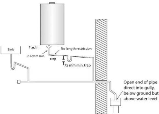
i) Connecting into an internal soil stack (at least 450mm above the invert of the stack). A trap giving a water seal of at least 75mm must be incorporated into the pipe run, there also must be an air beak upstream of the trap.
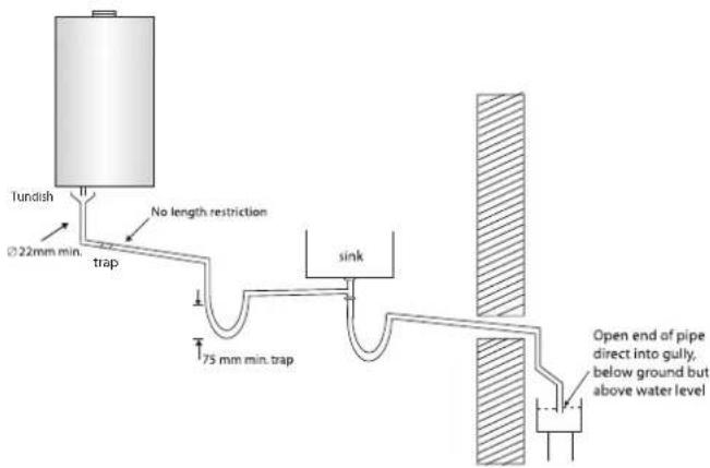
ii) Connecting into the waste system of the building such as a washing machine or sink trap. The connection must be upstream of the washing machine/sink. If the connection is downstream of the waste trap then an additional trap giving a minimum water seal of 75mm and an air break must be incorporated in the pipe run, as above.
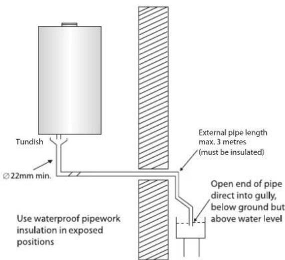
iii) Terminating into a gully, below the grid level but above the water level
iv) Into a soakaway
Note: If any condensate pipework is to be installed externally then it should be kept to a minimum and be insulated with a waterproof insulation and have a continuous fall. The total length of external pipe used should not exceed 3 metres.
Some examples of the type of condensate terminations can be found below.
- Internal termination of condensate drainage pipe to internal stack.
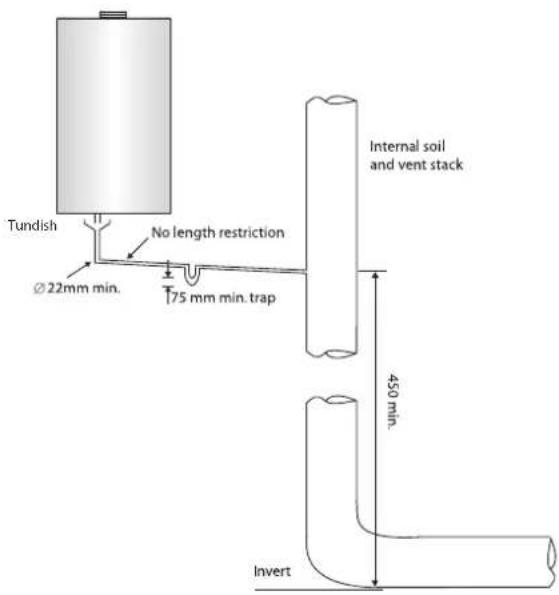
Condensate Discharge
Push fit the flexible condensate pipe into the outlet spigot on the appliance. Cut to length and locate outlet into a tundish
- External termination of condensate drainage pipe via internal discharge branch (e.g. sink waste) and condensate siphon.
- External termination of condensate drainage pipe via internal discharge branch (e.g. sink waste - proprietary fi tting).
- External termination of condensate drainage pipe via condensate siphon
natural_image
Technical line drawing of an internal mechanical assembly with no visible text or symbols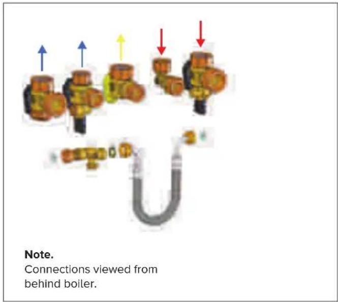
Installing the Boller
Please check that you are familiar with the installation requirement before commencing work (pages 10 - 14).
The installation accessories described in the following list are included in the boiler packaging:
- Hanging bracket
- Connection valves (compression)
- Screws and washers
- Filling loop
- Installation, Servicing and User manual
- A paper template (showing the dimensions of the boiler with 5 mm side clearances)
Method of positioning the boiler on the wall
The paper template can be used to ensure the correct positioning of kitchen cabinets etc.
The paper template has to be fixed to the wall and used to locate the position of the hanging bracket and the centre for the flue hole.
Drill and plug the wall and secure the hanging bracket using the screws provided ensure the hanging bracket is level. Remove the boiler from its packaging and remove the front casing panel. Place the boiler on the hanging bracket.
NOTE: THE APPLIANCE MUST NOT BE FITTED ON A COMBUSTIBLE WALL SURFACE.
Connecting the boiler to the system
- Remove the boiler casing as described on page 14
- Remove the caps and connect the valves to the boiler using the washers provided
- 5 x fibre washers for the CH flow and return, cold water inlet, gas and hot water outlet connections
Safety Valve Discharge
The pressure relief valve pipe is made of copper. It should terminate below the boiler safely outside the premises. Care should be taken that it does not terminate over an entrance or window or where a discharge of heated water could endanger occupants or passers by.
WARNING!

DO NOT APPLY HEAT TO THE COPPER SAFETY VALVE OUTLET PIPE WHILST IT IS CONNECTED TO THE 3 BAR SAFETY RELIEF VALVE.
Fill the central heating and DHW system and bleed air from the system as described in the Commissioning instructions (page 27).
The system should be carefully checked for leaks, as frequent refilling could cause premature system corrosion or unnecessary scaling of the heat exchanger. The pipe from the trap should be connected to a drain as described in the relevant regulations.
Pay special attention not to bend the condensate silicone drain pipe is such a way as to interrupt the flow. Please only use drain pipe material compatible with condensate products (refer to BS 6798:2009).
The condensate flow can reach 2 litres/hour because of the acidity of the condensate products (Ph close to 2), take care before operation.
See page 13 for condensate discharge options.
INSTALLATION
Gas connection
Make sure, using the labels on the packaging and the data plate on the appliance itself, that the boiler is in the correct country and that the gas category for which the boiler was designed corresponds to one of the categories available in the country where it will be used.
The gas supply piping must be created and measured out in compliance with specific legal requirements and in accordance with the maximum power of the boiler.
Check that the supplied gas corresponds to the type of gas for which the boiler was designed (see the data plate located on the appliance itself).
It is also important to check that the pressure of the gas (methane or LPG) you will be using to feed the boiler is suitable, because if it is insufficient the power may be reduced, causing inconvenience for the user.
Water connection
The illustration below shows the connections for the water and gas attachments of the boiler. See valves configuration on page 13.
Check that the maximum water mains pressure does not exceed 6 bar; if it does, a pressure reducing valve must be installed.
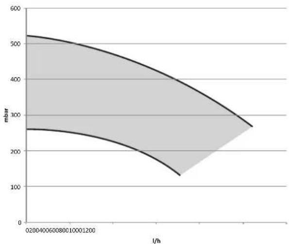
For the measuring of the pipes and of the heating bodies in the heating system, the residual head value should be calculated as a function of the requested flow rate, in accordance with the values shown in the circulation pump graph.
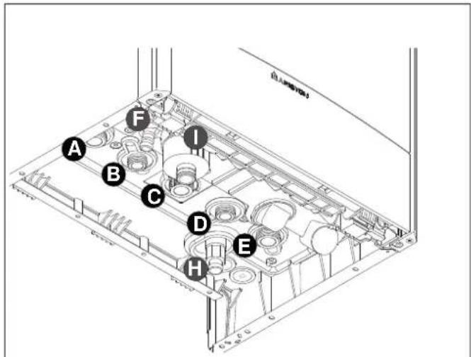
Legend:
A. Central heating Flow
B. Domestic Hot Water Outlet
C. Gas Inlet
D. Domestic Cold Water Inlet
E. Central Heating Return
F. Safety Valve Discharge
H. Drain Valve
1. Condensate discharge
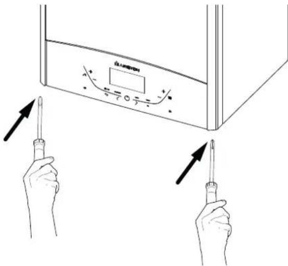
Instructions for removing the housing and inspecting the appliance.
Before carrying out any work on the boiler, switch off the power supply using the external bipolar switch and close the gas tap.
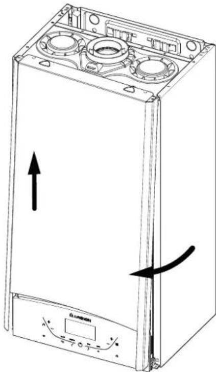
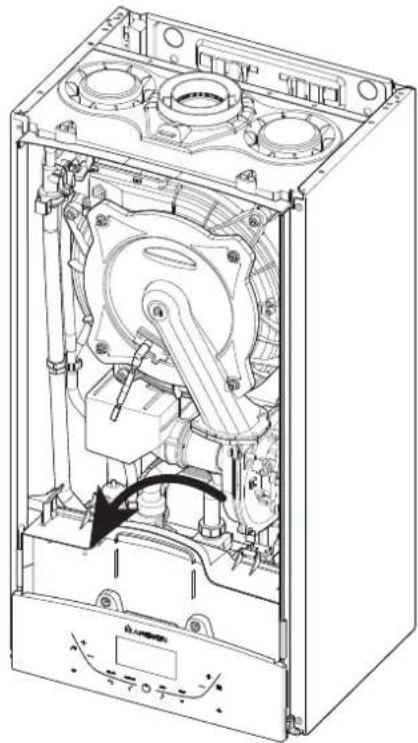
To access the inside of the boiler:
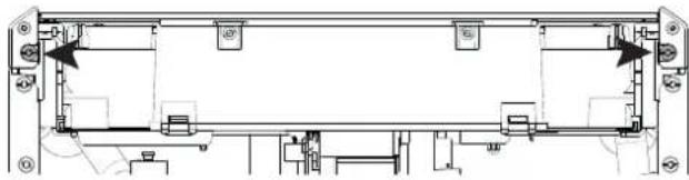
- unscrew the two screws from the front panel (a), pull the panel forwards and uncouple it from the upper pins (b).
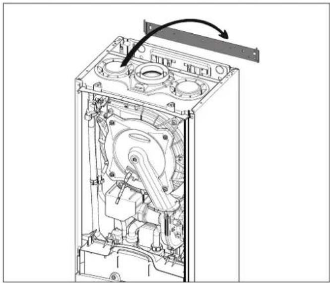
- pivot the electronic unit by pulling it forwards (c).
(a)
natural_image
Technical line drawing of a mechanical assembly with mounting brackets and internal components (no text or symbols)CAUTION!!
REMOVE ONLY THE SCREWS SHOWN IN THE PICTURE

(b)
natural_image
Technical line drawing of a rectangular electronic device with mounting holes and control panel (no text or symbols)(c)
natural_image
Technical line drawing of an internal mechanical device with no visible text or symbolsTo calculate the size of the heating installation, refer to the "Available pressure" graph below.
Graph representing the available circulation pump pressure T20^
area
| l/h | mbar | | ------ | ----- | | 0200400 | 520 | | 0600800 | 500 | | 10001200| 480 | | 1400000 | 440 | | 1800000 | 380 | | 2200000 | 320 | | 2600000 | 260 |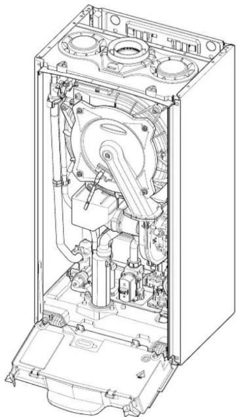
natural_image
Technical line drawing of a mechanical device interior showing internal components and housing (no text or symbols)Underfl oor heating
For appliances with underfloor heating, it is possible but not necessary to fit a safety thermostat onto the underfloor heating outlet. For the electrical connection of the thermostat see the section on "Electrical connections - pages 26".
If the outlet temperature is too high, the boiler will stop both domestic hot water and the heating production and the error code 1 16 "fl oor thermostat contact open" will appear on the display. The boiler will restart when the thermostat is closed during automatic resetting.
If the thermostat cannot be installed, the underfloor heating equipment must be protected by a thermostatic valve, or by a bypass to prevent the floor from reaching too high a temperature.
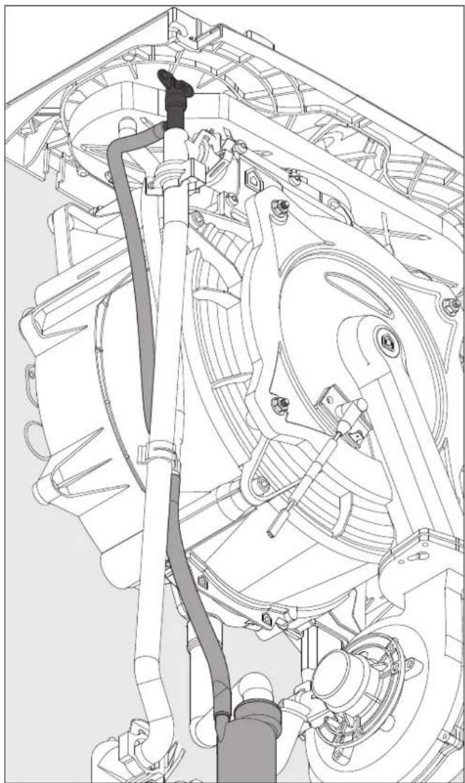
BEFORE THE DEVICE IS USED, FOR THE FIRST TIME THE TRAP MUST BE FILLED WITH WATER.

The siphon is filled with water during deaeration procedure of the boiler (or heating system) - see p. 32
Ensure that the siphon contains water; if not, it must be refilled. Open the manual air vent (2) on the main exchanger until complete filling. Check again the system pressure on the pressure gauge.
WARNING!

INSUFFICIENT WATER IN THE TRAP CAN TEMPORARILY CAUSE THE FLUE GAS TO BE EXPELLED INTO THE SURROUNDING AMBIENT AIR
natural_image
Technical line drawing of a mechanical assembly with hoses and components (no text or symbols)Water circuit diagram

- Air relief valve
- Main Heat Exchanger
- Detection/Ignition electrode
- Central Heating Return Temperature Probe
- Central Heating Flow Temperature Probe
- Gas Valve
- Secondary Exchanger
- Safety valve
- Automatic By-pass
- Drain valve
- Condensate Trap
- Filling loop
- Central Heating Filter
- D.H.W. Flow Switch
- Divverter valve
- Pressure Gauge
- Water pressure sensor
- Modulating Circulation Pump with air release valve
- Expansion Vessel
- Modulating Fan
Connecting the Flue
Flue System
The provision for satisfactory flue termination must be made as described in BS 5440-1.
The appliance must be installed so that the flue terminal is exposed to outdoor air.
The terminal must not discharge into another room or space such as an outhouse or lean-to.
It is important that the position of the terminal allows a free passage of air across it at all times.
The terminal should be located with due regard for the damage or discolouration that might occur on buildings in the vicinity, it must also be located in a place not likely to cause nuisance.
In cold or humid weather water vapour may condense on leaving the flue terminal.
The effect of such "steaming" must be considered.
If the terminal is less than 2 metres above a balcony, above ground or above a flat roof to which people have access, then a suitable stainless steel terminal guard must be fitted.
The minimum acceptable spacing from the terminal to obstructions and ventilation openings are specified in Fig. 1.
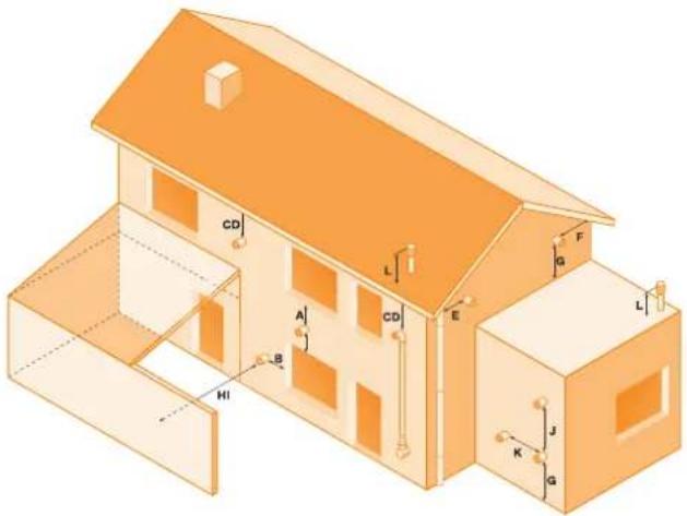
Fig. 1
- A Directly below an opening, window, etc 300 mm
- B Horizontally to an opening, window, etc 300 mm
- C Below gutters, soils pipes or drain pipes 75 mm
- D Below eaves 200 mm
- E From vertical drain pipe or soil pipe 75 mm
- F From internal or external corner 300 mm
- G Above ground, roof or balcony level 300 mm
- H From a surface facing the terminal 600 mm
- I From a terminal facing a terminal 1200 mm
- J Vertically from a terminal on the same wall 1500 mm
- K Horizontally from an terminal on the same wall 300 mm
- L Fixed by vertical fl ue terminal
INSTALLATION
Warning
The exhaust gas ducts must not be in contact with or close to infl ammable material and must not pass through building structures or walls made of infl ammable material.
When replacing an old appliance, the fl ue system must be changed.
Important
Ensure that the fl ue is not blocked.
Ensure that the fl ue is supported and assembled in accordance with these instructions.
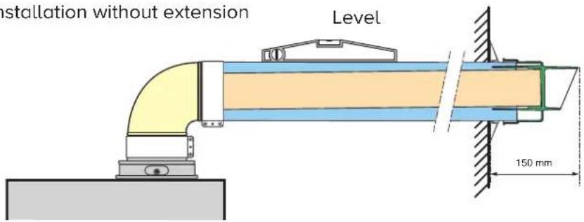
Installation with extension
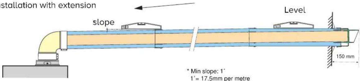
Fig. 3
Fitting the Coaxial Flue (∅ 60 / 100 Horizontal)
Contents:
1x Silicone O-Ring (60mm)
1x Elbow (90°)
2x Wall Seals (Internal & External)
1x Flue Pipe including Terminal (1 metre - 60/100)
2x Flue Clamps
4x Screws
2x Seals
Once the boiler has been positioned on the wall, fit the rubber flue seal into the internal flue turret (see diagram opposite),
Insert the elbow into the socket and rotate to the required position. note: It is possible to rotate the elbow 360° on its vertical axis.
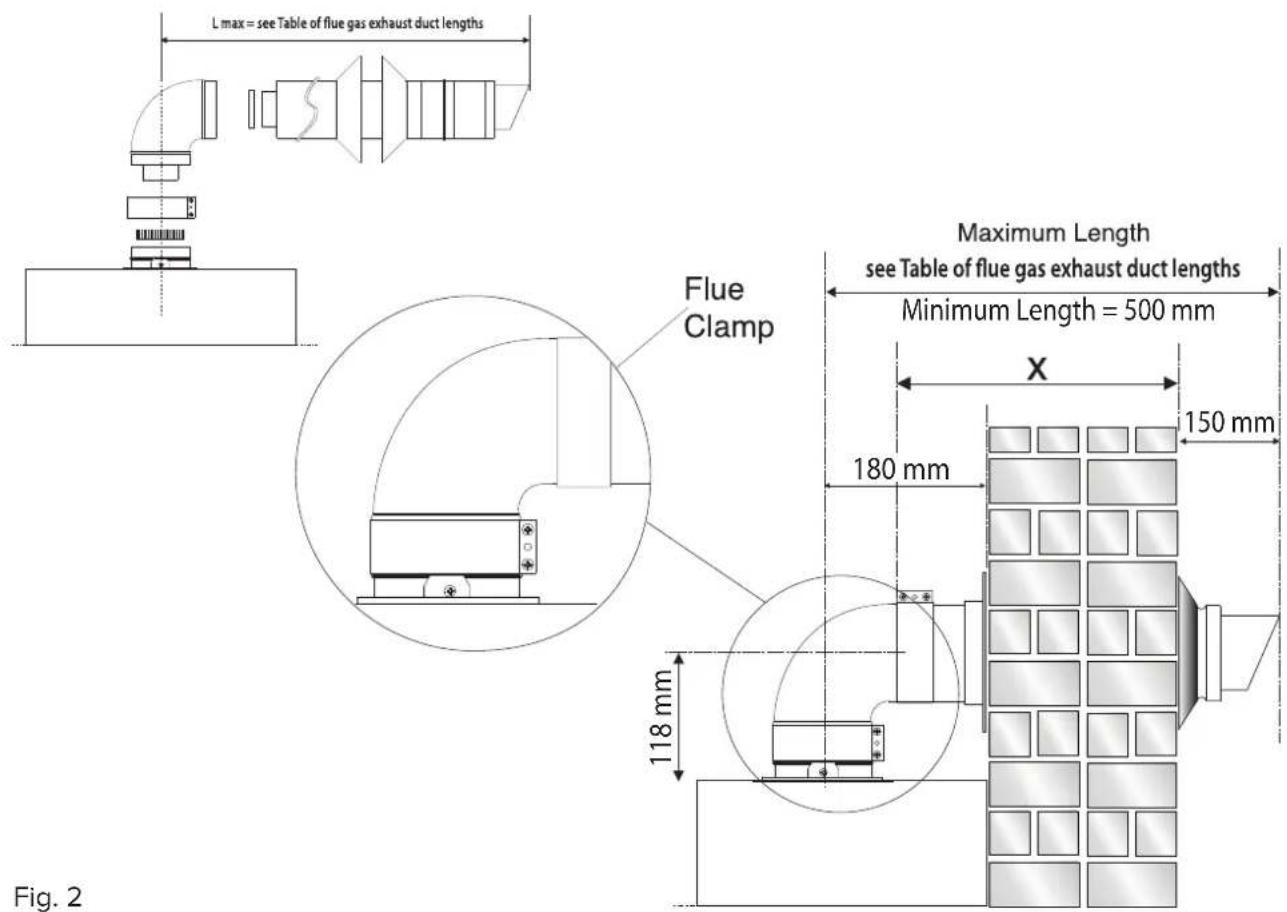
Using the flue clamp, seals and screws supplied (Fig 4) secure the elbow to the boiler.
The 1 metre horizontal flue kit (3318073) supplied is suitable for an exact X dimension of 753mm.
Measure the distance from the face of the external wall to the face of the flue elbow (X - Fig 2), this figure must now be subtracted from 753mm, you now have the total amount to be cut from the plain end of the flue.
Note: A Plume management kit is available for 60/100 horizontal termination. Instructions for installation are supplied with the Plume management kit.
Draw a circle around the outer flue and cut the flue to the required length taking care not to cut the inner flue, next cut the inner fl ue ensuring that the length between the inner and outer fl ue is maintained. (Fig 4).
e.g.
$$ X = 5 5 5 \mathrm{mm} $$
753-555 = 198mm (Length to be cut from the plain end of the fl. ue).
Once cut to the required length, ensure that the flue is free from burrs and reassemble the flue. If fitting the flue from inside of the building attach the outer wall seal to the flue terminal and push the flue through the hole, once the wall seal has passed through the hole, pull the flue back until the seal is flush with the wall. Alternatively, the flue can be installed from outside of the building, the outer seal being fitted last.
Should the flue require extending, the flue connections are push fit, however, one flue bracket should be used to secure each metre of flue.
Note: See table for maximum and minimum fl ue runs.
Clamp
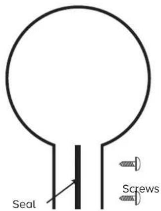
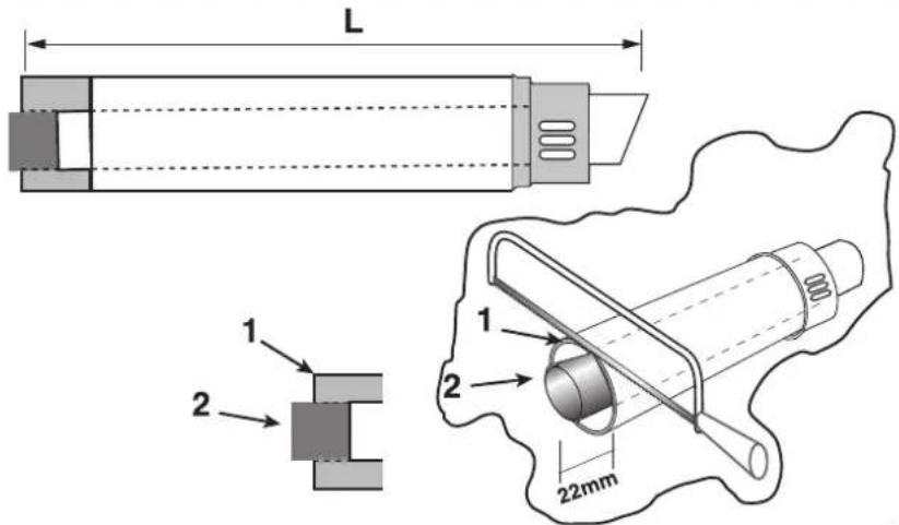
Fig. 4
Fitting the 5" Flue
(∅ 80 / 125 Horizontal/vertical)
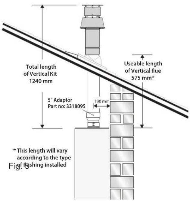
Once the boiler has been positioned on the wall, it is necessary to insert the ∅80/125 adaptor (Fig. 5) for both horizontal and vertical flue runs into the boiler flue socket (not supplied with flue kit - Part No 3318095).
Push the adaptor onto the boilers fl ue connection, grease the seals then add extensions or elbows as required, secure the adaptor, using the clamp and screws provided.
To fit extensions or elbows it is first necessary to ensure that the lip seal is fitted correctly into the inner flue, once verified, it is simply necessary to push them together, no clamps are necessary to secure the flue components.
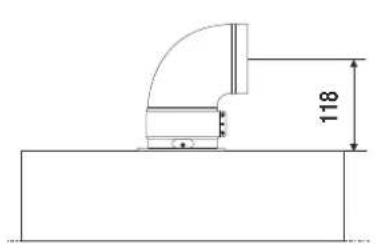
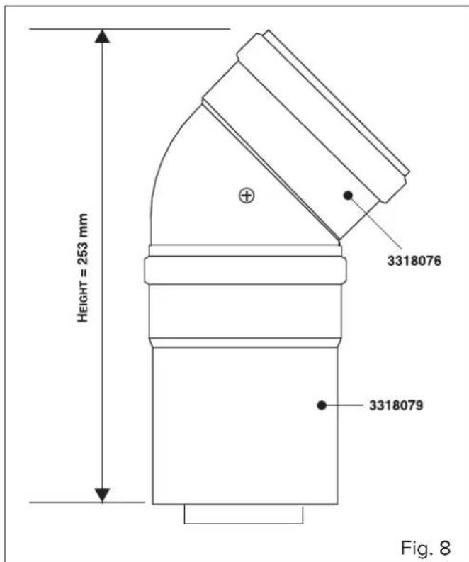
Before proceeding to fit the flue, ensure that the maximum flue length has not been exceeded (See the tables) and that all elbows and bends have been taken into consideration, for each additional 90° elbow 1 metre must be subtracted from the total flue length, and for each 45° 0.5 metres must be subtracted from the total flue length (the height of the vertical adaptor and a 45° bend can be seen in Fig.6 and a 90° bend in Fig.7).
Note: DO NOT cut the vertical fl ue kit.
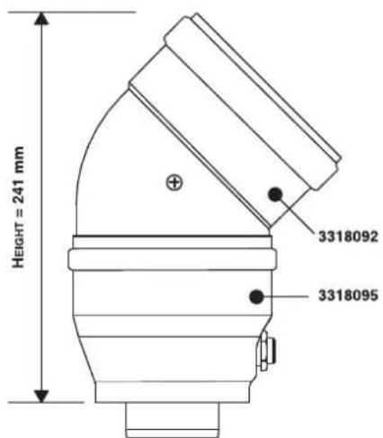
Fig. 6
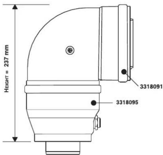
Fig. 7
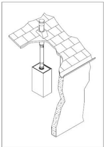
Fitting the Coaxial Flue (∅ 60 / 100 Vertical)
Note: See table for maximum and minimum fl ue runs.
Contents:
1x Conical Adaptor (60/100mm) 1x Vertical Flue Kit (80/125mm)
The vertical fl ue kit is supplied with a specially designed weather proof terminal fitted, it can be used either with a flat roof or a pitched roof.
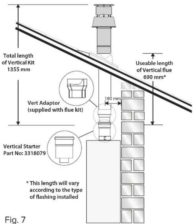
The Vertical fl ue kits useable lengths with the pitched roof fl ashings are indicated in Fig. 7.
Before proceeding to fit the flue, ensure that the maximum flue length has not been exceeded (See the tables) and that all elbows and bends have been taken into consideration, for each additional 90° elbow 1 metre must be subtracted from the total flue length, and for each 45° 0.5 metres must be subtracted from the total flue length (the height of the vertical adaptor and a 45° bend can be seen in Fig. 8).
Mark the position of the flue hole in the ceiling and/or roof (see Fig. 7 for distance from wall to the centre of the flue).
Cut a 130mm diameter hole through the ceiling and/or roof and fit the flashing plate to the roof.
DO NOT cut the vertical fl ue kit.
To connect the vertical flue kit directly to the boiler, place the vertical starter kit (Part No. 3318079) (see Fig. 7) onto the exhaust manifold and secure with the clamp, fit the vertical adaptor onto the vertical starter kit (note: there is no need to use a clamp to secure this as it is a push fit connection), the vertical flue kit must then be inserted through the roof flashing, this will ensure that the correct clearance above the roof is provided as the terminal is a fixed height.
Should extensions be required, they are available in 1 metre (Part No. 3318077), 500mm (Part No. 3318078) and they must be connected directly to the vertical starter kit before connecting the adaptor to allow the vertical flue kit to be fitted. In the event that extension pieces need to be shortened, they must only be cut at the male end and it must be ensured that the inner and outer flue remain flush.
When utilising the vertical flue system, action must be taken to ensure that the flue is supported adequately to prevent the weight being transferred to the appliance fl ue connection by using 1 fl ue bracket per extension.
When the flue passes through a ceiling or wooden floor, there must be an air gap of 25mm between any part of the flue system and any combustible material. The use of a ceiling plate will facilitate this. Also when the flue passes from one room to another a fire stop must be fitted to prevent the passage of smoke or flue, irrespective of the structural material through which the flue passes.
Fitting the Twin Pipe (∅80 / 80)
natural_image
Technical line drawing of a mechanical housing or enclosure with internal components and mounting holes (no text or symbols)Note: See table for maximum and minimum fl ue runs.
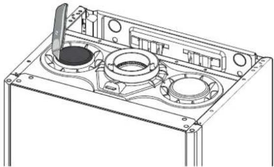
Where it is not possible to terminate the flue within the distance permitted for coaxial flues, the twin flue pipe can be used by fitting a special adaptor to the flue connector and using the aperture for the air intake located on top of the combustion chamber.
Always ensure that the flue is adequately supported, using one fl ue bracket per extension and avoiding low points. (ARISTON supply suitable clamps as Part No. 3318015).
To utilise the air intake it is necessary to:
1) Remove the top of the air intake by cutting it with a suitable knife.
2) Insert the header on the tube or the elbow up until the lower stop (you do not have to use the washer).
3) Insert the elbow/header in the boiler air intake hole and fasten it with screws.
The twin flue pipes can be fitted with or without additional elbows and need no clamps, simply ensure that the lip seal is inserted in the female end of the flue pipe and push the extension piece fully into the previous section of flue pipe or elbow, check that the lip seal is not dislodged when assembling the flue (greasing the seal will aid assembly).
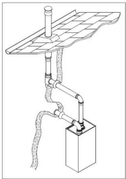
Twin pipe can also be converted back to Coaxial flue to enable vertical termination with a coaxial kit by using the pipe bridge (Twin - Coaxial Adaptor - Part No. 3318089). When running the twin flue pipe vertically.
It is not possible to terminate concentrically horizontally. Termination is only possible with separate air and exhaust terminals.
When siting the twin flue pipe, the air intake and exhaust terminals must terminate on the same wall, the centres of the terminals must be a minimum of 280 mm apart and the air intake must not be sited above the exhaust terminal (refer to Fig. 10). The air intake pipe can be run horizontally, however, the terminal and the final 1 metre of flue must be installed either horizontally or with a slight fall away from the boiler to avoid rain ingress.
It is also strongly recommended that the air intake pipe run be constructed of insulated pipe to prevent condense forming on the outside of the tube.
Ensure the exhaust tube has a minimum fall back to the boiler of 1^/ metre ( 1^=17.5mm/metre )
The maximum permissible flue length for twin flue is dependent on the type of run used (see table on page 23).
For further information relating to flue runs not illustrated, please contact the Technical Department on 0333 240 7777.
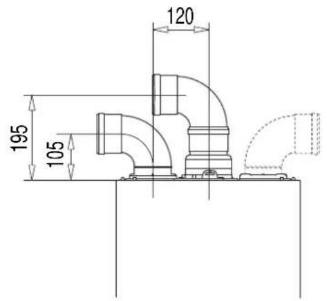
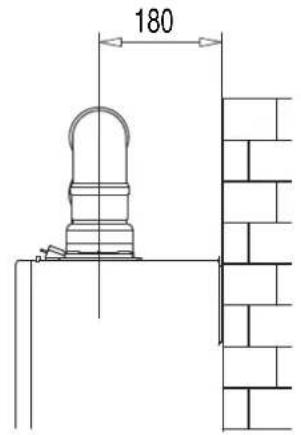
Fig. 9
For coaxial systems, the maximum development value, mentioned in the table below also takes into account an elbow. For twin fl ue systems the maximum development value, mentioned in the table includes the exhaust gas/air intake terminal.
Twin fl ue systems outlets should respect the following instructions:
1- Use the same 0 80 mm fl ue pipes for the air intakes and exhaust gas ducts.
2- If you need to insert elbows in the air intake and exhaust gas ducts, you should consider for each one the equivalent length to be included in the calculation of developed length.
3- The exhaust gas duct should jut above the roof by at least 0.5 m.
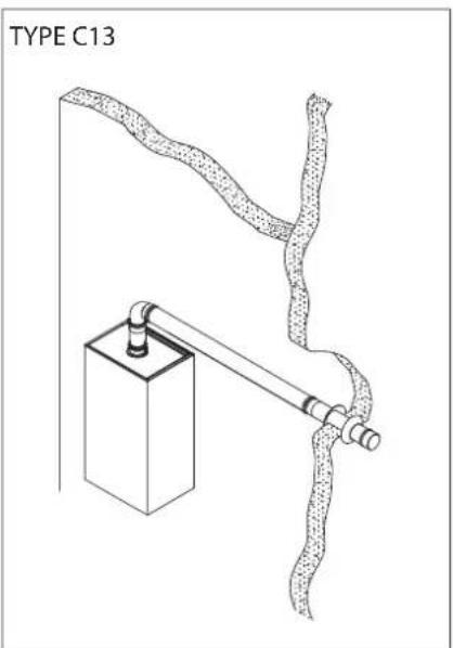
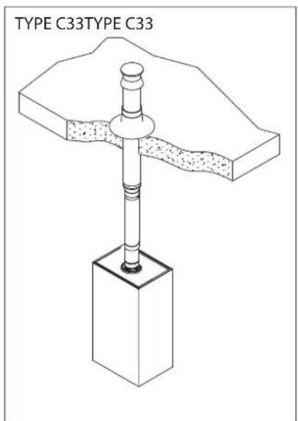
4- The intake and exhaust gas ducts in Type C13 + C53 must be installed on the same wall, or where the exhaust is vertical and the air intake horizontal, the terminals must be on the same side of the building.
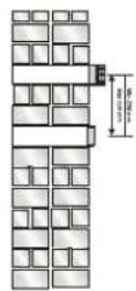
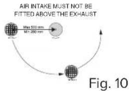
Table of fl ue gas exhaust duct lengths
| FLUE TYPE | Maximum Extension Exhaust-air (m) | Diameter of pipe (mm) | ||
| ALTEAS ONE NET | ||||
| 30 35 | ||||
| Coaxial System | C13 | 76ø60/100 | ||
| C33 | ||||
| C43 | ||||
| C13 | 20 24ø80/125 | |||
| C33 | ||||
| C43 | ||||
| Twin-pipe System | S1 = S2 | ø 80/80 | ||
| C13 | 30 = 30 23 = 23 | |||
| C33 | 40 = 40 30 = 30 | |||
| C43 | 30=30 23 = 23 | |||
| C53 | S1 + S2 | |||
| 60 45 | ø 80/80 | |||
S1 = Air intake S2 = Flue gas exhaust
S1 = S2 - Air intake and fl ue gas exhaust equal lengths
S1 + S2 - Air intake and fl ue gas exhaust unequal lengths
natural_image
Technical line drawing of a solar panel installation with a base and support structure (no text or symbols)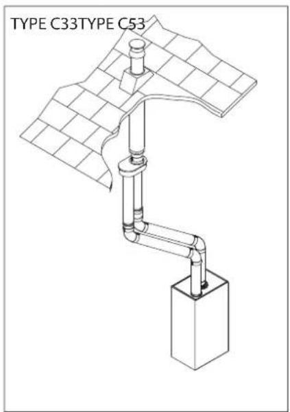
natural_image
Technical line drawing of a mechanical or electrical device with pipes and a base, no visible text or symbolsWARNING!

BEFORE PERFORMING ANY WORK ON THE BOILER, FIRST DISCONNECT IT FROM THE ELECTRICAL POWER SUPPLY USING THE EXTERNAL BIPOLAR SWITCH AND REMOVE THE FUSE.
Electrical connections
For increased safety, ask a qualified technician to perform a thorough check of the electrical system.
The manufacturer is not responsible for any damage caused by the lack of a suitable earthing system or by the malfunctioning of the electricity mains supply.
Make sure that the system is able to withstand the maximum power absorbed by the boiler (this is indicated on the appliance data plate). Check that the section of the wires is suitable and is not less 0,75 mm ^2
The appliance must be connected to an efficient earthing system if it is to operate correctly.
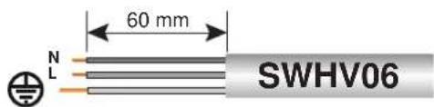
The power supply cable must be connected to a 230V-50Hz network, where the L-N poles and the earth connection are all respected.
Important!
In the event that the power supply cable must be changed, replace it with one with the same specifications.
Power supply cable

Important!
The appliance is supplied with a fly-lead already connected, this must be connected to a 240V supply fused at 3 Amp and must facilitate completed electrical isolation of the appliance, by use of a fused double pole isolator having a contact separation of at least 3mm in all poles or alternatively by means of a 3A fused three pin plug and unswitched shuttered socket outlet both complying with BS1363.
The use of multiplugs, extension leads or adaptors is strictly prohibited.
It is strictly forbidden to use the piping from the hydraulic, heating and gas systems for the appliance earthing connection. The boiler is not protected against the effects caused by lightning. If the mains fuses need to be replaced, use 2A rapid fuses.
Peripheral unit connection
To access peripheral unit connections carry out the following steps:
- Disconnect the boiler from the power supply
- Remove the casing
- Rotate the control panel while pulling it forwards
- Unhook the two clips to have access to the peripheral connections and the main P.C.B.
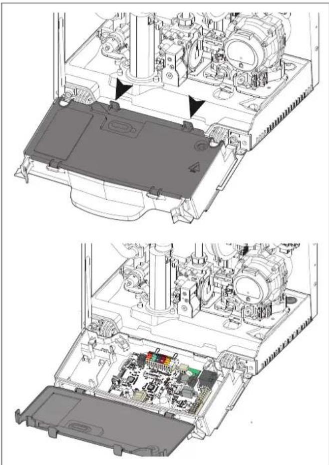
natural_image
Technical line drawings of an electronic device showing internal components and casing (no text or symbols)Peripheral connections:
BUS = Remote control connection
FLOOR/TA2 = the underfloor heating thermostat or the room thermostat 2 (selected via parameter 223)
SE = the external sensor.
SOL = Solar temperature probe
TA1 = the room thermostat 1
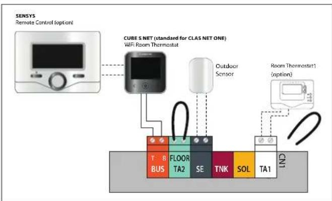
flowchart
graph TD
    A["SENSYS Remote Control (option)"] --> B["CUBE 5 NET (standard for CLAS NET ONE)"]
    B --> C["Outdoor Sensor"]
    B --> D["Room Thermostat (option)"]
    B --> E["T BUS"]
    B --> F["FLOOR TA2"]
    B --> G["SE"]
    B --> H["TNK"]
    B --> I["SOL"]
    B --> J["TA1"]
    B --> K["ND"]
Cube Room sensor (wireless) Connection
To connect a room thermostat, read the instructions present in the kit delivered with the gas boiler.
DO NOT CONNECT 240V TO ANY PERIPHERAL CONNECTIONS
Room Thermostat / Remote Clock Connection
To connect a room thermostat, it is necessary to:
- Open the control panel
- Loosen the cable clamp using a screwdriver and insert the wires leading from the room thermostat
- Connect the wires to the terminals as indicated in the figure below, removing the link
- If a remote time clock is to be fitted, using a volt free switching time clock connect the switching wires from the time clock following points 1 - 3 above
- If using an external time clock and room thermostat, these must be connected in series as shown in diagram C,
- Ensure that they are well connected and not subject to stress when the control panel is closed
DO NOT CONNECT 240V TO ANY PERIPHERAL CONNECTIONS
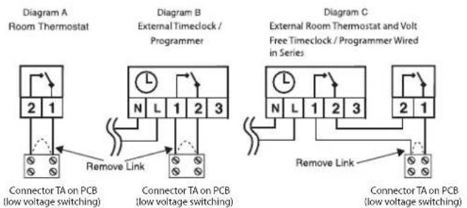
Timeclock and Room Thermostat low voltage compatible
INSTALLATION
Electrical diagram
For increased safety, ask a qualified technician to perform a thorough check of the electrical system.
The manufacturer is not responsible for any damage caused by the lack of a suitable earthing system or by the malfunctioning of the electricity mains supply.
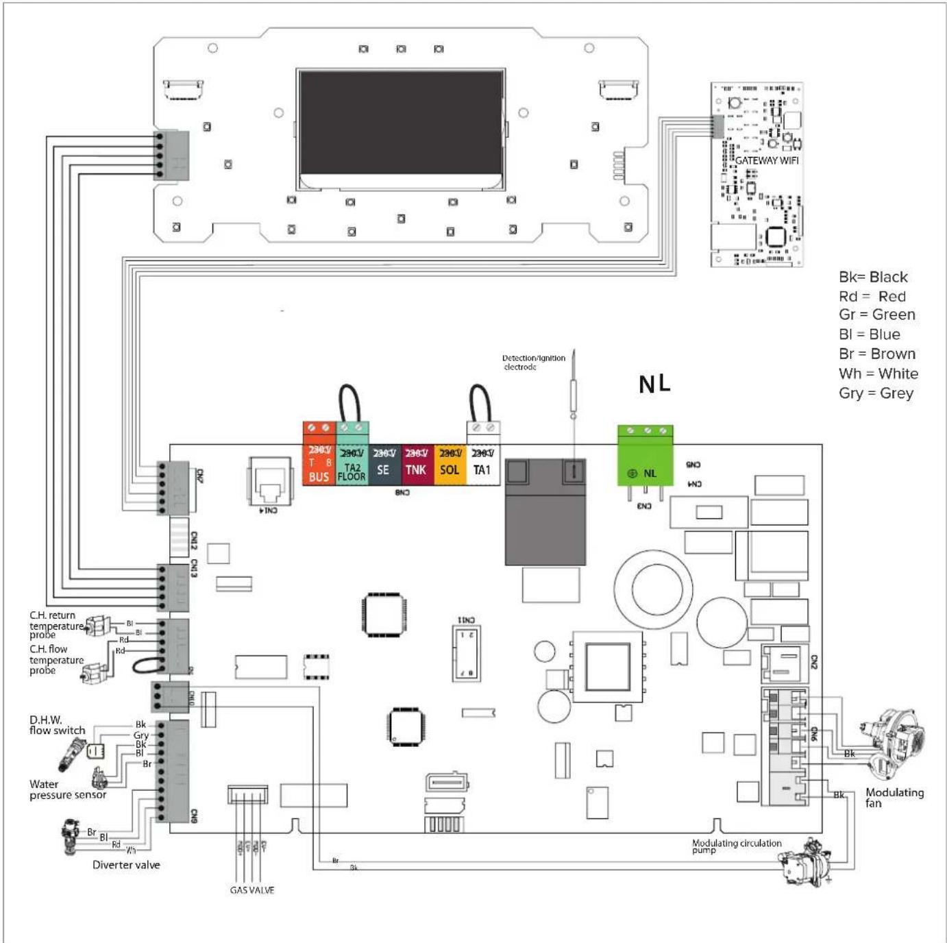
Initial preparation
Ariston Thermo UK Ltd support the benchmark initiative.
On pages 77 and 78 of this manual the Benchmark Commissioning Checklist and Service interval Record can be found. It is important that this is completed in the presence of your customer, they are shown how to use it, and it is signed by them. Please instruct your customer that they must have this manual with them whenever they contact a service engineer or us.
Preliminary electrical system checks to ensure electrical safety must be carried out by a competent person i.e. polarity, earth continuity, resistance to earth and short circuit.
Electricity supply
- Check that the voltage and frequency of the electricity supply correspond to the data shown on the boiler data plate;
- Make sure that the earthing connection is efficient.
Filling the Heating System:
ATTENTION!!
CONNECT THE PIPE OF CONDENSATE DISCHARGE BEFORE REFILLING AND THE DE-AERATION OF THE HEATING CIRCUIT.
Remove the front casing panel and lower the control panel as described on page 14.
Open the central heating flow and return cocks supplied with the connection kit;
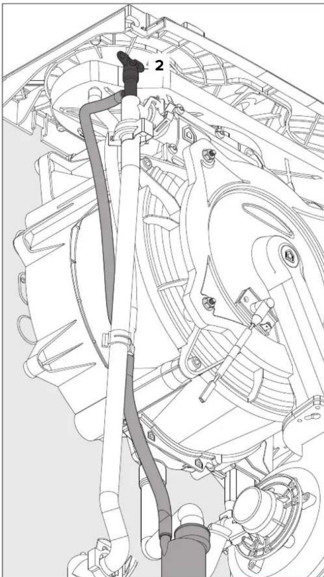
Open the manual air vent positioned at the side of the primary exchanger (2). The valve is already connected to a discharge pipe related to the condensate trap.
Close all air release valves on the central heating system;
Gradually open the valves at the filling point (filling loop) until water is heard to flow, do not open fully;
Open each air release tap starting with the lowest point and close them only when clear water free of air is visible;
Continue filling the system until at least 1.5 bar registers on the pressure gauge;
Inspect the system for water tightness and remedy any leaks discovered.
IMPORTANT!
MANUALLY VENT THE HEAT EXCHANGER AT THE MANUAL AIR VENT. FAILURE TO VENT ADEQUATELY MAY DAMAGE THE HEAT EXCHANGER (PAGE 8, LEGEND 2).
Close all hot water draw off taps;
Open the cold water inlet cock supplied with the connection kit; Slowly open each draw off tap and close them only when clear water, free of bubbles, is visible.
Gas Supply:
Inspect the entire installation including the gas meter and test for tightness. The entire installation should be in accordance with the relevant standards. In GB this is BS 6891 and in IE this is the current edition of I.S.813.
The connection on the appliance is a 15mm (22mm on 35Kw) nut and olive located at the rear of the gas service cock.
If the gas supply serves other appliances, ensure that an adequate supply is available both to the boiler and the other appliances when they are in use at the same time.
Pipe work must be of an adequate size. The final pipe size must not be smaller than the appliance inlet size.
Open the gas cock (supplied with the connection kit) to the appliance and check the gas connection on the appliance for leaks.
Water Treatment:
The boiler is equipped with a stainless steel heat exchanger.
The detailed recommendations for water treatment are given in BS 7593 (Treatment of water in domestic hot water central heating systems); the following notes are given for general guidance;
If the boiler is installed on an existing system, any unsuitable additives must be removed;
Under no circumstances should the boiler be fired before the system has been thoroughly flushed; the flushing procedure must be in line with BS7593.
Firstly fill the central heating system with the power off, and flush through cold, fill the central heating system again, adding a flushing detergent, run the boiler on central heating until it reaches its operating temperature and flush the system, refill the system with a suitable corrosion inhibitor,
NOTE: FAILURE TO CARRY OUT THE FLUSHING PROCEDURE WILL RESULT IN THE WARRANTY BECOMING VOID.
natural_image
Technical line drawing of a mechanical assembly with hoses and components (no text or symbols)- Check the electrical supply.
-
Check the type of gas (change the gas if necessary during the Calibration procedure point 8).
Complete ....
Complete .... -
Check the gas tightness.
-
Check the Flue
-
Fill the installation.
Complete ....
Complete ....
Complete ....
-
Check the hydraulic water tightness.
-
Measure the gas inlet static pressure.
Complete ....
Complete ....
- Carry out the deaeration cycle and automatic calibration procedure (change gas type, if necessary). Adjusting the CO2 by pressing the RESET button for 5 sec..
Complete ....
-
Set the heating power.
-
Balance the central heating circuit.
-
Check the operation in DHW mode.
Complete ....
Complete ....
Complete ....
-
Adjust DHW flow rate on the boiler (if necessary).
-
Check gas rate.
-
Check the ionisation current.
Complete ....
Complete ....
Complete ....
- Explain to the end user the working of the boiler.
Complete ....
Start-up procedure
Press the ON/OFF button on the control panel to switch on the boiler: the display will light up.
The initialisation procedure - indicated by the bar - begins.

Once the procedure is completed, the display will visualise the temperatures set for the central heating and domestic hot water circuits (display configuration: boiler base).
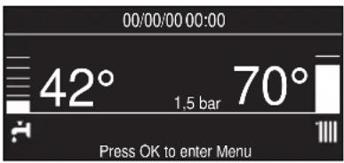
The boiler will request the setting of the date, time and language. Proceed as indicated in the USER MENU - see the User's Manual.
FIRST IGNITION
CARRY OUT THE DEAERATION CYCLE AND AUTOMATIC CALIBRATION
1. Assicurarsi che:
- The gas valve is closed;
- The electrical connection has been properly carried out. Make sure that, in any case, the green/yellow earthing wire is connected to an efficient earthing system;
- Unscrew the cap on the automatic air relief valve;
- The exhaust duct for combustion products should be suitable and free from any obstructions;
IMPORTANT!
DURING THE CALIBRATION PROCEDURE AND MEASUREMENT OF THE CO2 VALUE, IT'S IMPORTANT THAT THE BOILER WORKS WITH THE FRONT COVER CLOSED AND THE AIR/ FUMES DUCTS FULLY ASSEMBLED.
- Any necessary ventilation inlets in the room should be open (type B installation).
- Check whether the condense trap contains water; if not, it must be refilled. If necessary, open the manual air vent on the main exchanger until complete filling.
N.B.: if the boiler will not be used for long periods, the trap should be filled before the boiler is started up again. It is dangerous not to refill the siphon as fumes may be released into the environment.
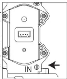
2. Supply static pressure check
Loosen the screw 1 and insert the pressure gauge connection pipe into the pipe tap.
The supply pressure should correspond to the value established in relation to the type of gas, for which the boiler is designed see
Table summarising changes.
natural_image
Diagram of an electronic component with a labeled pinout and arrow indicator (no readable text or symbols)ATTENTION!!
THE BOILER CAN NOT BE ACTIVATED IF THE PRESSURE IS NOT CORRESPONDING TO THE TABLE SUMMARISING CHANGES.
3. ACTIVATION OF THE DISAERATION PROCEDURE AND AUTOMATIC CALIBRATION
- Switch on the boiler (by pressing the ON/OFF button) and use the Mode button to select the standby mode, where no
hot water or heating requests are made.
The display asks to start the deaeration and calibration procedure.
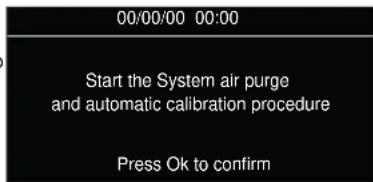
- Press the OK button.
The display shows:
"Attention, this procedure can be performed only by qualified personnel.
To proceed, press OK button for 5 seconds."
- Press OK for 5 seconds. The display shows:
"System air purge
The function activates the air-purge cycle of system.
To start the cycle, press "OK" button
(advised) otherwise "ESC"."
- Press the OK button. The boiler will start a deaeration cycle lasting about 7 minutes (See below). If you need to stop it press MODE. During the
deaeration cycle open the manual air vent (2) on the heat exchanger and close when clear water free of air is visible. At the end, check that the system is completely deaerated and, if not, repeat the procedure.
The display shows:
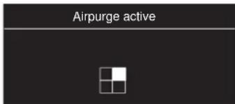
"If air is still present inside the system, start again the air purge cycle (OK button); otherwise press the exit button (ESC button)"
- Verify that the system pressure is at least 1 bar on the pressure gauge. Open the filling valve if pressure is not sufficient and close as soon as it reaches 1 - 1.5 bar
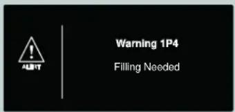
Note! If pressure in the heating circuit decreases, the display shows Malfunction warning 1P4 (parameter 241 - alert pressure).
If the pressure falls below the alarm value
the display will show the
Error 108. Open the filling valve and close as soon as it reaches 1 - 1.5 bar.
IN THESE CASES,
THE PROCEDURE IS INTERRUPTED.
AFTER FILLING THE SYSTEM THE DISPLAY REQUESTS TO START
AGAIN THE SYSTEM AIR
PURGE AND AUTOMATIC CALIBRATION.

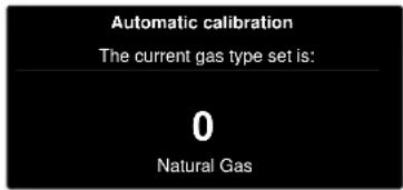
- After the system air purge the display shows the gas set from factory. Enter the type of gas used (if necessary), press the button to select: 0 = Natural gas (factory setting)
1 = LPG
2 = G230 (IT)
3 = G130 (FR)
Press OK. The display shows:
"Automatic Calibration
This function enables the boiler to calibrate automatically.
This procedure may take a few minutes. If you want to proceed press OK."
- Press OK to enable the Automatic Calibration.
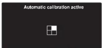
The procedure may take few minutes. The display shows the steps of the procedure
If the calibration is completed the display shows “Completed Calibration” and returns to the main screen:
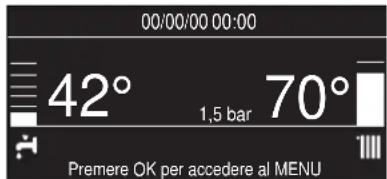
- Start the boiler by selecting the heating or domestic hot water operation using the Mode button.

CAUTION
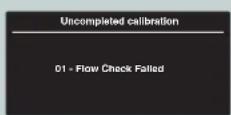
IF THE CALIBRATION PROCEDURE IS NOT COMPLETED THE DISPALY SHOWS
"UNCOMPLETED CALIBRATION" AND AN ERROR
CODE (see table B) FOR 10 SECONDS.
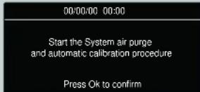
FOLLOWS THE REQUEST TO ACTIVATE THE PROCEDURE AGAIN.
PRESS OK AND REPEAT CALIBRATION.
IF AN ERROR IS STILL
REPORTED, CONTACT A QUALIFIED TECHNICIAN.
| Table B | ||
| Error Description | ||
| 01 | 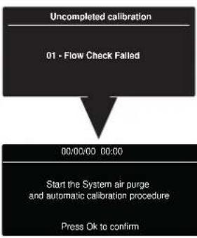 | Insuffi cient circulation.Make sure that:- the pump works correctly- the water pressure in the system is suffi cient. |
| 02 | 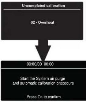 | - Deteted a C.H. Flow temperature ≥ 88°C in Heating Mode- Deteted a C.H. Flow temperature ≥ 88°C or a C.H. Return temperature >67°C in D.H.W. Mode.(Open a hot water tap or the zone valves/thermostatic valves on the system to dissipate heat). |
| 03 | 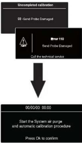 | Error 03 and the detected error (ex: Error 110 - Send Probe Damaged" - see Table summarising error codes) are displayed alternately for 10 seconds.Press the RESET button for Operation Shutdown, the display again requires to start the automatic calibration.For Safety shut-off if the problem is removed automatically, the display again requires automatic calibration.If the boller still indicates a safety shut-off , switch it off . Make sure the external electric switch Is in the OFF position, shut off the gas valve and contact a qualifi ed technician. |
WARNING!! THE AUTOMATIC CALIBRATION MUST BE DONE IN CASE OF:
- REPLACEMENT OF: FAN, GAS VALVE, AIR/GAS MIXER, BURNER, ELECTRODE.
- REPLACEMENT OF P.C.B.
- GAS CHANGEOVER
- ANY MODIFICATION TO THE FOLLOWING PARAMETERS
220 - SOFT IGNITION
231 - MAX CH ADJUSTABLE
232 - MAX DHW PERCENTAGE
233 - MIN PERCENTAGE
234 - MAX CH PERCENTAGE
4. Preparing the measuring equipment
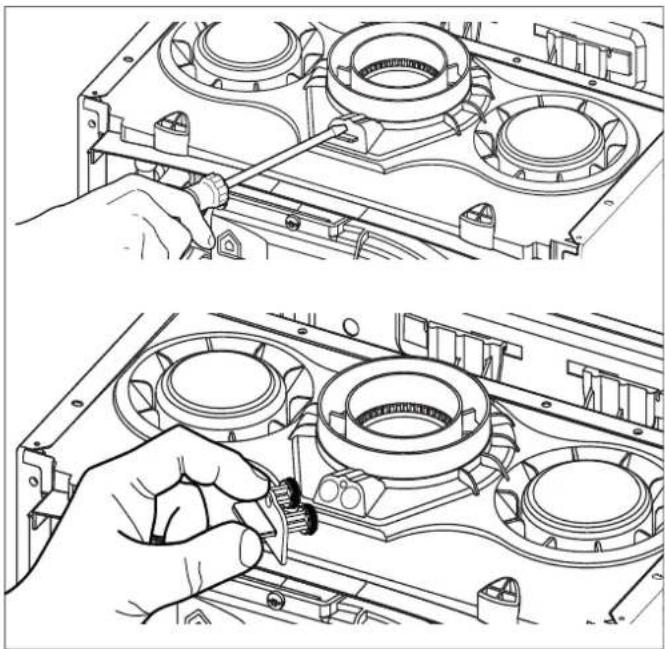
Connect the calibrated measuring device to the left-hand combustion outlet by unscrewing the screw and removing the blanking cover.
natural_image
Technical line drawing showing two views of a mechanical assembly with a hand adjusting a component (no text or symbols present)5. Supply dinamic pressure check
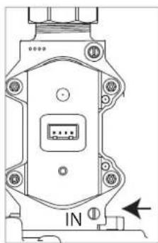
Loosen the screw 1 and insert the pressure gauge connection pipe into the pipe tap. Switch the boiler on at D.H.W. maximum power, enabling the "Chimney function" (press the RESET button for 10 seconds and press th button > to select D.H.W. maximum power).
The supply pressure should correspond to the value established in relation to the type of gas, for which the boiler is designed see Table summarising changes.
natural_image
Technical diagram of a mechanical component with internal connector and mounting holes (no text or symbols)ATTENTION!!
THE BOILER CAN NOT BE ACTIVATED IF THE PRESSURE IS NOT CORRESPONDING TO THE TABLE SUMMARISING CHANGES
6. Adjusting the CO2
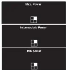
Intermediate Power
Draw off the domestic hot water at the maximum water flow rate. Select the Chimney function by pressing the RESET button for 10 seconds.
WARNING! When the cleaning function is activated, the temperature of the water coming out of the boiler may be more than 65^ C.
The display will visualise the Chimney Function active at Intermediate Power
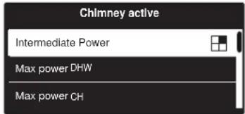
Wait 1 minute for the boiler to stabilise before carrying out the combustion analyses.
Read the CO2 value (%) and compare it with the values given in the table A below:
| Table A | |||
| ALTEAS ONE NET 30/35 | |||
| Gas | CO2 (%) | ||
| Intermediate Power | Max Power DHW | Min Power | |
| G20 8,8 ± 0,7 | |||
| G30 / G31 10,5 ± 1,0 | |||
N.B.: VALUES WITH THE CASING CLOSED.
If the CO_2 (\%) value is correct proceed to the next operation.
f the value of CO_2 detected, differs from the values given in the table, press the button OK. The display, after a few seconds, shows an adjustment bar. Press the buttons b
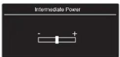
< > to adjust the value. It's possible modify the value of ± 0,5%. Press OK to confirm and proceed to the next operation.
Maximum power DHW
Press the button > to select Max Power DHW
The display will visualise the Chimney Function active at the Maximum power DHW
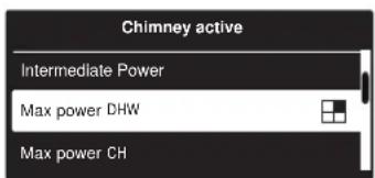
Wait 1 minute for the boiler to stabilise before carrying out the combustion analyses.
Read the CO2 value (%) and compare it with the values given in the table A.
If the CO2 (%) value is correct proceed to the next operation.
If the value of CO_2 detected, differs from the values given in the table, press the button OK. The display, after a few seconds, shows an adjustment bar. Press the buttons b
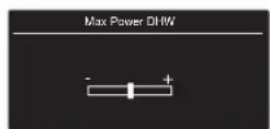
< > to adjust the value. It's possible modify the value of ± 0,5%. Press OK to confirm and proceed to the next operation.
Minimum power
Press the button > to select Minimum power
The display will visualise the Chimney Function active at Minimum power
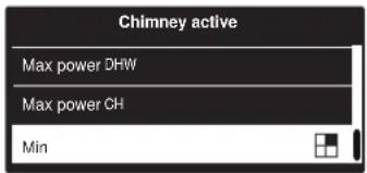
Wait 1 minute for the boiler to stabilise before carrying out the combustion analyses.
Read the CO2 value (%) and compare it with the values given in the table A.
If the CO2 (%) value is correct proceed to the next operation.
f the value of CO_2 detected, differs from the values given in the table, press the button OK. The display, after a few seconds, shows an adjustment bar. Press the buttons b < > to adjust
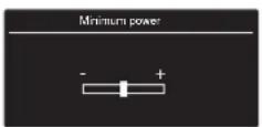
the value. It's possible modify the value of ±0.5% . Press OK to confirm and proceed to the next operation.
7. Ending the adjustment
Exit cleaning mode by pressing RESET.
Stop the draw-off.
Verify and repair any leaks of gas.
Refi t the blanking cover for the combustion outlets.
THE CLEANING FUNCTION IS AUTOMATICALLY DEACTIVATED AFTER 30 MINUTES OR MANUALLY BY BRIEFLY PRESSING THE RESET BUTTON.
THE CLEANING FUNCTION IS AUTOMATICALLY DEACTIVATED AFTER 30 MINUTES OR MANUALLY BY BRIEFLY PRESSING THE RESET BUTTON.
Maximun Heating Power adjustment
The maximum heating power can be adjusted to between the maximum power allowed by the boiler and the minimum power). The display shows the value between "100" and 0 of this interval. To check the maximum heating power, access menu 2/sub menu 3/parameter 1, check the value and, if necessary, modify it as indicated in the Gas Pressure table.
Checking slow Ignition power
The soft light can be adjusted between the maximum power and the minimum power.
The display shows the value between "100" and 0 of this interval. To check the slow ignition power, access menu 2/sub menu 2/parameter 0.
If needed, change the parameter value until suitable pressure is achieved.
Heating ignition delay adjustment
This parameter - menu 2/sub menu 3/parameter 5 - can be used to manually (0) or automatically (1) set the delay time before the subsequent reignition of the burner after it has switched off on reaching the desired temperature.
By selecting manual, it is possible to set the delay in minutes using the successive parameter (menu 2/sub menu 3/parameter 6), to a time between 0 and 7 minutes.
Automatic selection means that the boiler will establish the delay time based on the set-point temperature.
The table indicate the existing relationship between the gas pressure at the burner and the boiler power level in heating mode.
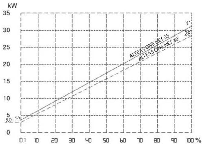
line
| % | ALTEAS ONE NET 30 | ALTEAS ONE NET 35 | | --- | ----------------- | ----------------- | | 0 | 3.5 | 3.0 | | 100 | 31 | 28 |Table summarising changes
| parameter | ALTEAS ONE NET | |||||||
| 30 35 | ||||||||
| G20 G30 G31 | G20 G30 G31 | |||||||
| Lower Wobbe index (15°C, 1013 mbar) ( MJ/m3) | 45,67 | 80,58 | 70,69 | 45,67 | 80,58 | 70,69 | ||
| Supply gas pressure min-max (mbar) | 17-25 | 25-35 | 25-45 | 17-25 | 25-35 | 25-45 | ||
| Slow ignition 220 | 42 | 43 | ||||||
| Maximum C. H.power Adjustable | 231 | 65 | 65 | |||||
| Minimum power (%) | 233 | 1 | 1 | |||||
| Max CH power (%) | 234 | 82 | 73 | |||||
| Max DHW power (%) | 232 | 88 | 84 | |||||
| Parametro 202 - Set gas type | 0 | 1 | 1 | 0 | 1 | 1 | ||
| Gas flow max/min (15°C, 1013 mbar)(nat - m3/h) (GPL - kg/h) | max D.H.W | 3.17 | 2.37 | 2.33 | 3.65 | 2.72 | 2.68 | |
| max C.H | 2.96 | 2.21 | 2.18 | 3.28 | 2.44 | 2.41 | ||
| min | 0.32 | 0.24 | 0.23 | 0.37 | 0.28 | 0.27 | ||
Gas Changeover
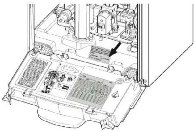
The boiler is factory set for the gas type indicated on the data plate. The adjustment, if necessary, must be performed by a Qualified Technician. It is not necessary a conversion kit, because the boiler has a auto adaptation gas system.
Proceed as indicated:
- Change parameter 202 to the new gas (see Technical Area). The display shows the error "The boiler must be calibrated".
- Perform the Calibration procedure and check the CO_2 as indicated at the page 30.
- At the end apply, near the data plate, the new label (supplied with the product) indicated the new gas type used.
- Verify and repair any leaks of gas.
Set for gas: / Regolata per funzionare a gas: / Réglé pour gaz: / Gerelged voor gas: / Reglaje para gas: / Ajustamento a gás : / Seta pentru gaz: / Набор для газа / Рúθμιση για το φυσικό αέριο: / Set za plin:

G20 20 mbar

G230 20 mbar
G30 - G31 28/37 mbar
Example: Boiler adjusted for LPG
WARNING!!
THE AUTOMATIC CALIBRATION MUST BE DONE IN CASE OF:
- REPLACEMENT OF: FAN, GAS VALVE, AIR/GAS MIXER, BURNER, ELECTRODE.
- REPLACEMENT OF P.C.B.
- GAS CHANGEOVER
- ANY MODIFICATION TO THE FOLLOWING PARAMETERS
220 - SOFT IGNITION
231 - MAX CH ADJUSTABLE
232 - MAX DHW PERCENTAGE
233 - MIN PERCENTAGE
234 - MAX CH PERCENTAGE
natural_image
Technical line drawing of a mechanical device interior showing internal components and a highlighted section (no text or symbols)AUTO function
This is a function which enables the boiler to automatically adapt its operation routine (the temperature of the heating elements) in line with the outdoor conditions, in order to achieve and maintain the requested room temperature conditions.
Depending on the peripheral units connected and the number of zones controlled, the boiler adjusts its flow temperature automatically.
The various corresponding parameters should therefore be set (see adjustments menu).
To activate the function, press the Auto button.
Example 1:
Single zone system (high-temperature) with on/off room Thermostat:
In this case the following parameters must be set:
4 21 - Activation of temperature adjustment using sensors
- Select 1 = Basic temperature adjustment
2 44 - Boost Time (optional)
The wait time for the flow temperature increase in steps of 4^ C may be set. The value varies according to the type of system and installation.
If the Boost Time value = 00 the function is not activated.
Example 2:
Single zone system (high-temperature) with on/off room Thermostat + outdoor sensor:
In this case the following parameters must be set:
4 21 - Activation of temperature adjustment using sensors
- Select 3 = outdoor sensor only
4 22 - Temperature adjustment curve selection
- Select the relevant curve according to the type of system, installation, heat insulation used in the building, etc.
4 23 - Perform a parallel curve shift if necessary, increasing or decreasing the set-point temperature (this may also be modified by the user, using the heating temperature adjustment knob, which, with the Auto function activated, is used to shift the curve in a parallel manner).
Example 3:
Single zone system (high-temperature) with Sensys controller + outdoor sensor
In this case the following parameters must be set:
4 21 - Activation of temperature adjustment using sensors
- select 4 = outdoor sensor + room sensor
4 22 - Temperature adjustment curve selection
- Select the relevant curve according to the type of system, installation, heat insulation used in the building, etc
4 23 - Perform a parallel curve shift if necessary, increasing or decreasing the set-point temperature. (This may also be changed by the user by the buttons 8 which, with the Auto function activated, is used to shift the curve in a parallel manner.)
4 24 - Influence of room sensor
- used to adjust the influence the room temperature has on the calculation of the set-point flow temperature (20 = maximum, 0 = minimum).
Note: See page 38 for details on accessing menus.
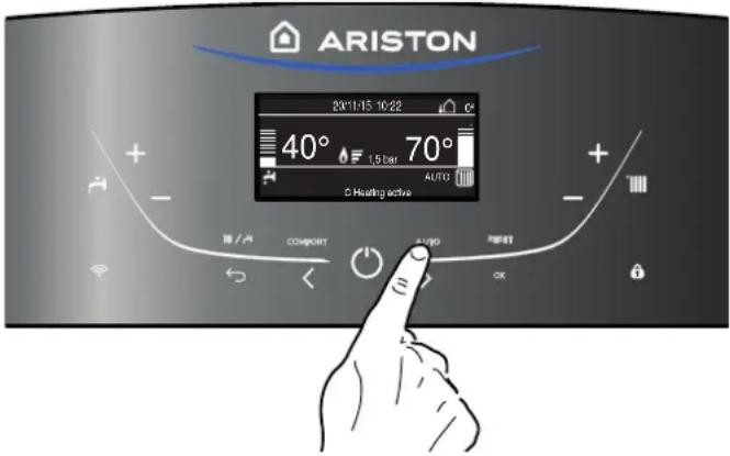
Appliance shut-off conditions
The boiler is protected from malfunctions by means of internal checks performed by the electronic P.C.B., which stops the boiler from operating if necessary. In the event of the boiler being shut off in this manner, a code appears on the control panel display which refers to the type of shut-off and the reason behind it.
Two types of shut-off may occur:
Safety shut-off
This type of error is “volatile”, which means that the boiler starts up again automatically as soon as the problem which caused the shut-off is removed.
The display shows the code and the error description.
"Fault 110 - Send Probe Damaged"
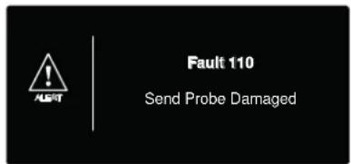
In fact, soon as the cause of the shut-off disappears, the boiler starts up again and continues to operate normally.
If the boiler still indicates a safety shut-off, switch it off. Make sure the external electric switch is in the OFF position, shut off the gas valve and contact a qualified technician.
Safety shut-off due to insufficient water pressure
If the re-balancing request is performed on a frequent basis, switch the boiler off, bring the external electric switch to the OFF position, shut off the gas valve and contact a qualified technician to check for any leaks of water.
Operation shutdown
This type of error is “non-volatile”, which means that it is not removed automatically.
The display shows the code and the error description.
To restore normal operation press the RESET button on the control panel.
The display shows "Reset in progress" and then "Fault solved". If the problem manifests itself again after several attempts to reset the appliance, contact a qualified technician.
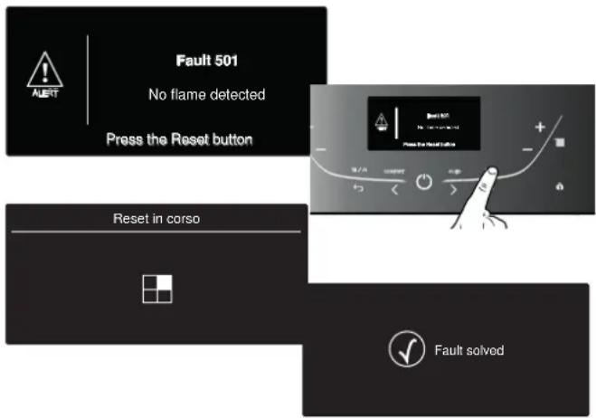
Important
If this shutdown occurs frequently, contact an authorised Technical Service Centre for assistance. For safety reasons, the boiler will permit a maximum of 5 resets in 15 minutes (5 presses of the RESET button); at the 6th attempt within this 15-minute period the boiler will shut down and may only be operated again after the electricity supply has been disconnected. If the shutdown is occasional or an isolated event, this is not a problem.
The first figure of the error code (e.g. 101) indicates within which operational assembly the error occurred.
1 - Primary Circuit
2 - Domestic Hot Water Circuit
3 - Internal Electronic Part
4 - External Electronic Part
5 - Ignition and Detection
6 - Air inlet - fl ue gas outlet
7 - Multizone heating
8 - Combustion Control System
Malfunction warning
This warning is shown by the display in the following format:
5 P3 = Flame cut-off
the first figure indicating the operational assembly is followed by a P (warning) and the code relating to the specific warning.
Circulation pump malfunction signal
The circulation pump has an LED display that shows its operating status:
LED off :
The circulation pump is electrically charged.
LED solid green: circulation pump enabled.
LED fl ashing green: change of speed taking place.
LED red:
Circulation pump is blocked or lacks water.
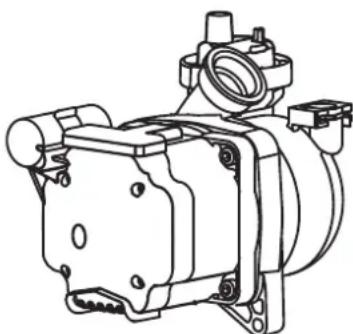
natural_image
Technical line drawing of a mechanical assembly (no text or symbols)Table summarising error codes
| Central Heating circuit | RESET | |
| Display | Description | X |
| 1 01 | Overheat | |
| 1 02 | Pressure Sens Error | |
| 1 03 | Insuffi cient circulation | |
| 1 04 | ||
| 1 05 | ||
| 1 06 | ||
| 1 07 | ||
| 1 08 | Insufficient water (request filling) | |
| 1 10 | C.H. Flow temp. probe circuit open / short circuit | |
| 1 12 | C.H. Return temp. probe circuit open / short circuit | |
| 1 14 | External sensor circuit open / short circuit | |
| 1 18 | Heating delivery probe problem | |
| 1 P1 | Insuffi cient circulation indication | |
| 1 P2 | ||
| 1 P3 | ||
| 1 P4 | Insufficient water (request filling) | |
| D.H.W. circuit | ||
| 2 05 | DHW In Probe Open Circuit | |
| Internal P.C.B.'s | ||
| 3 01 | EEPROM error | |
| 3 02 | Comunication error | |
| 3 03 | Main P.C.B. error | X |
| 3 04 | Too many (>5) resets in 15 minutes | |
| 3 05 | Main P.C.B. error | X |
| 3 06 | Main P.C.B. error | |
| 3 07 | Main P.C.B. error | X |
| 3 13 | Low Voltage Fault | |
| 3 P9 | Sched.Maintanace-Call Service | |
| External P.C.B.'s | ||
| 4 11 | Zone 1 - Room sensor circuit open / short circuit | |
| 4 12 | Zone 2 - Room sensor circuit open / short circuit | |
| 4 13 | Zone 3 - Room sensor circuit open / short circuit | |
| Ignition and Deteclon | ||
| 5 01 | No flame detected (After 5 times with 5P6) | X |
| 5 02 | Flame detected with gas valve closed | |
| 5 03 | Flame detected with gas valve closed (After 20 seconds with 502) | X |
| 5 04 | Flame lift | X |
| 5 P3 | Flame cut-off | |
| 5 P5 | Low Gas Pressure Fault | |
| 5 P6 | Ignition Failed | |
| Air Inlet / Flue gas outlet | ||
| 6 11 | Fan Warning - Anomaly in air inlet and / or fl ue gas exhaust ducts (Boiler switch off the fan works 20 minutes at maximum).If the problem is not resolved appears error 612. | |
| 6 12 | Fan Error (speed higher or lower than the set values) | |
| Multi-zone Heating | |
| 7 01 | Zone 1 send sensor defective |
| 7 02 | Zone 2 send sensor defective |
| 7 03 | Zone 3 send sensor defective |
| 7 11 | Zone 1 return sensor defective |
| 7 12 | Zone 2 return sensor defective |
| 7 13 | Zone 3 return sensor defective |
| 7 22 | Zone 2 overheating |
| 7 23 | Zone 3 overheating |
| 7 50 | All Heating Zones locked |
| Combustion Control System (CCS) | |
| 8 01 | Calibration Tuning Fault |
| 8 02 | Flame Sensed with Gas Valve Closed |
| 8 03 | Mismatch kW Size, ID combustion(Set parameter 229) |
| 8 04 | Decoupling Clip-In required (see note) |
NOTE - ERROR 804:
TO CONNECT THE BOILER TO ELECTRONIC SOLUTIONS FOR SOLAR MANAGEMENT OR IBRID SYSTEMS (ONLY FOR COMBINATIONS NOT ADMITTED), IT'S NECESSARY TO INSTALL A CLIPIN SUPPLIED AS ACCESSORY CODE 3319171.
Anti-frost Device
The anti-frost function acts on the central heating flow temperature probe, independently from other regulations, when the electrical supply is turned on.
If the primary circuit temperature falls below 8^ the pump will run for 2 minutes.
After the two minutes of circulation (fixed) the boiler will check the following:
a) if the central heating flow temperature is >8^ , the pump stops;
b) if the central heating flow temperature is between 4 and 8°C, the pump will run for another two minutes;
c) if the central heating flow temperature is < 4^ , the burner will fire (heating position) at minimum power until the temperature reaches 33^ , the burner will go out and the pump will continue to run for two minutes.
The anti-frost device activates only when (with the boiler operating correctly):
- the system pressure is correct;
- the boiler is electrically powered;
- there is a supply of gas.
TECHNICAL AREA - reserved for qualifi ed technician
Accessing the Technical Area allows for setting/configuring the device according to the specific requirements of every installation procedure.
It also provides important information relating to the efficient operation of the boiler.
The Technical Area comprises various display windows that allow for directly accessing the parameters Intervening in each single product installation/confi guration phase.
The parameters relating to each single menu are listed in the following pages.
The various parameters can be accessed and modified using the OK button, the programming Keys b < > and the ESC button (see picture below).
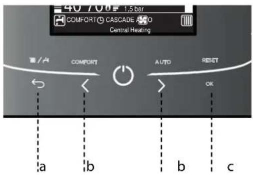
a. ESC button (Back)
b. Programming keys
c. OK button
For accessing the Technical Area simultaneously press the ESC and Buttons for 5 seconds; the display will visualise the request for entering the technical code.
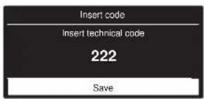
Press the programming key b < > to select 234 and press the OK button.
To move within the Technical Area, press the programming key b <> and press OK button to access the selected window.
Press the programming key b < > to select a parameter and press OK button to access it.
To modify the value of a parameter, press the programming key b < > and press OK button to store the value.
Use the ESC ← button to exit a parameter without storing the modification and for returning to the normal viewing mode.
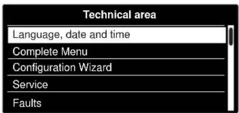
Example:
Modification of parameter
2.3.1 Max. Adjustable Central Heating Power
Proceed as follows:
- Simultaneously press the ESC ↩ and OK buttons for 5 seconds; the display will visualise the request for entering the technical code.
- Press the programming key b <> and select code 234.
- Press the OKbutton; the display will visualise the available windows.
- Press the programming key b <> to select the Complete Menu.
- Press the OKbutton to access; the display will visualise the available menus.
- Press the programming key b <> to select Menu 2 - Boiler parameters.
- Press the OK button. The display will visualise the available sub-menus.
- Press the programming key b <> to select 2.3 - Central heating 1.
- Press the OK button to access.
The display will visualise the parameters relative to sub-menu 2.3.
-
Press the programming key b <> to select parameter 2.3.1 - Max. C.H. Adjustable.
-
Press the OK button to access the parameter.
The display will visualise the value of the parameter (50%) in addition to the minimum and maximum values allowed. - Press the programming key b <> to select the new value, e.g. 46%.
- Press the OK button to store the modification.
(To exit the parameter without storing the modification, press the ESC ← button). - Press the ESC ← button to return to the normal viewing mode.
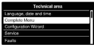
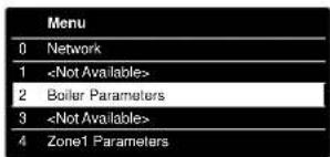
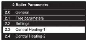
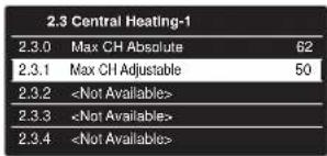
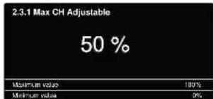
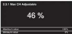
COMPLETE MENU STRUCTURE
Technical Area
Service code (reserved for qualified technicians) - Press the programming key b ▲ √ to select 234 and press the OK button.
Language, date and time - Follow the instructions of the display.
Press OK button at each entry to save
COMPLETE MENU - The parameters relating to each individual menu are listed in the following pages.
Configuration Wizard
Boiler
Conf i guration parameters
Gas Parameter
Direct access to the parameters → 220 - 230 - 231 - 232 - 233 - 234 - 270
Settings
Direct access to the parameters → 220 - 231 - 223 - 238 - 245 - 246
Visualization
Direct access to the parameters → 821 - 822 - 823 - 824 - 825 - 827 - 830 - 831 - 832 - 833 - 840 - 835 - 874
Zone
Direct access to the parameters -402-502-602-420-520-620-434-534-634-830
Guided procedures
System Filling
System air purge
Exhaust fumes analysis
Service options
Service Center Data - To insert the name and phone number of Service Center
The data appears in the display in case of error
Enable service warnings
Service warning reset
Months remaining before Service
Test mode
Pump test
3 way valve Test
Fan test
Service
Boiler
Confi guration parameters
Gas parameter
Direct access to the parameters → 220 - 230 - 231 - 232 - 233 - 234 - 270
Visualization
Direct access to the parameters → 821 - 822 - 824 - 825 - 827 - 830 - 831 - 832 - 833 - 840 - 835
Boiler PCB change
Direct access to the parameters -220 - 226 - 228 -229 - 231 - 232 - 233 - 234 - 247 - 250 - 253
Automatic Calibration
see page 30
Faults - The display shows the last 10 errors with details of the code, description and date.
Turn the encoder to scroll the errors
TECHNICAL AREA
| menu | sub-menu | parameter | description | value | default settings |
SERVICE CODE
| Press th programming key b to select code 234 and press Ok |
COMPLETE MENU
0 NETWORK
0. 2 BUS NETWORK
| 0.2. | 0 Network Presence Boiler | Indication of the devices connected via BUS. |
0.4 BOILER USER INTERFACE
| 0.4.0 Zone to be set by display | from 1 to 3 (nr) 1 | |||
| 0.4.1 Backlight timing | from 1 to 10 minutes or 24 hours | 10 | ||
| 0.4.2 Thermoregulation button deactivation | 0 = OFF1 = ON | 0 | ||
2 BOILER PARAMETERS
2.0 GENERAL
| 2.0.0 | DHW Setpoint Temperature | from 36 to 60 (°C) 55 | ||
| Setting by DHW button 2 | ||||
| 2.0.1 | DHW Pre-Heating | 0 = OFF1 = ON | 0 | |
| 2.0.2 | Gas type | 0 = Natural Gas1 = LPG2 = G2303 = G130 | 0 | |
2.1 FREE PARAMETERS
| 2.1.4 Boiler circulator type | 0 = Standard effi-ciency1 = High effi ciency | 1 |
| ONLY FOR SERVICE - To be used only in substitution P.C.B. | ||
2.2 SETTINGS
| 2.2. | 0 | Soft ignition from 0 to 100 | ||
| see Table summarising changes | ||||
| 2. | 2. | 3 | Underfloor thermostat or zone 2 ambient thermostat selection | 0 = Floor safety thermostat1 = Zone 2 ambient thermostat |
| 2.2.4 | Termoregulation | 0 | Absent1 = Present | 0 |
| Termoregulation can be activated by pressing the AUTO button. | ||||
| 2. | 2. | 5 | Heating ignition delay | 0 = Deactivated1 = 10 seconds2 = 90 seconds3 = 210 seconds | 0 |
| 2.2.8 | Boiler version- NOT TO MODIFY | from 0 to 50 = Combi | 0 |
| ONLY FOR SERVICE - To be used only insubstitution P.C.B. | |||
| 2.2.9 | Boiler nominal power (kW) | |
| ONLY FOR SERVICE - To be used only in substitution P.C.B. | ||
2.3 CENTRAL HEATING - 1
| 2.3. | 0 | < Not Available> | |||
| 2.3. | 1 | Maximum CH Adjustable from | 0 to 100 | (%) | 60 |
| see Table summarising changes | |||||
| menu | sub-menu | parameter | description | value | default settings |
| 2.3. | 2 | D.H.W. Maximum power percentage | from 0 to 100 (%) | |
| RESERVED FOR TECHNICAL ASSISTANCE Only if the gas or PCB is changed - see Table summarising changes | ||||
| 2.3. | 3 | Minimum power percentage | from 0 to 100 (%) | |
| RESERVED FOR TECHNICAL ASSISTANCE Only if the gas or PCB is changed - see Table summarising changes | ||||
| 2.3. | 4 | C.Heating Maximum power percentage | from 0 to 100 (%) | |
| RESERVED FOR TECHNICAL ASSISTANCE Only if the gas or PCB is changed - see Table summarising changes | ||||
| 2.3. | 5 | CHAnti-cycling time mode | 0 = Manual1 = Automatic | 1 |
| 2.3. | 6 | Anti-cycling time (If 235 = 0) | from 0 to 7(minutes) | 3 |
| 2.3. | 7 | CIH pump overrun | from 0 to 15 (minutes)or 16 = continuos | 3 |
| 2.3. | 8 | Pump speed control - NOT ACTIVE | ||
| 2.3. | 9 | Delta T Pump Set - NOT ACTIVE | ||
| 2.4 | CENTRAL HEATING PARAMETER - 2 | |||
| 2.4. | 0 | Not Available> | ||
| 2.4. | 1 | Warning Pressure from 4 to 8(0,x bar) | 6 | |
| if the pressure falls down to the pre-set alert value, the boiler will signal a malfunction warning (IP4) for insufficient circulation; the request for re-establishing the correct value will appear on the display. | ||||
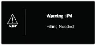 | ||||
| 2.4. | 2 | < Not Available> | ||
| 2.4. | 3 | Post-ventilation CH 0 = OFF1 = ON | 0 | |
WARNING!!
THE AUTOMATIC CALIBRATION MUST BE DONE IN CASE OF:
- REPLACEMENT OF: FAN, GAS VALVE, AIR/GAS MIXER, BURNER, ELECTRODE.
- REPLACEMENT OF P.C.B.
- GAS CHANGEOVER
- ANY MODIFICATION TO THE FOLLOWING PARAMETERS
220 - SOFT IGNITION
231 - MAX CH ADJUSTABLE
232 - MAX DHW PERCENTAGE
233 - MIN PERCENTAGE
234 - MAX CH PERCENTAGE
| menu | sub-menu | parameter | description | value | default settings |
| 2.4. | 4 | Boot | st Time from 0 to 60 | (minutes) | 16 |
| only enabled with Room Thermostat on/off and temperature adjustment activated (parameter 421 or 521 or 621 on 01 = Basic temperature adjustment) | |||||
| This parameter can be used to set the delay time before the automatic increase in flow temperature, in steps of 4^ (max. 12^ ). If the value of this parameter remains at 00 the function is not activated. | |||||
| 2.4. | 5 | Max | PWM Pump from 75 to 100 | 100 | |
| 2.4. | 6 | Min | PWM Pump from 40 to 100 | 75 | |
| 2.4. | 7 | CHP | Pressure detection device | 0 = Temperature Probes only1 = Pressure switch2 = Pressure sensor | 2 |
| ONLY FOR SERVICE - To be used only in substitution P.C.B. | |||||
| 2.4. | 8 | < Not Available> | |||
| 2.4. | 9 | External temperature correction | from -3 to +3 0 | ||
| 2.5 | DOMESTIC HOT WATER | ||||
| 2.5. | 0 | COMFORT Function 0 = Disabled | 0 | ||
| 1 = Time Based(30 minutes)2 = Always active | |||||
| The “COMFORT” function of the appliance can be used to increase the comfort level of the user when drawing hot water.This function keeps the secondary exchanger hot during periods of boiler inactivity; this increases the initial heat status of the water drawn, as the water is delivered at a higher temperature.When the function is enabled the text COMFORT appears on the display.Note: this function can be activated or deactivated by the user as well - consult the User’s Manual. | |||||
| 2.5. | 1 | Comfort Anti-cycling Time | from 0 to 120 minutes | 0 | |
| 2.5. | 2 | DHW start Delay from 5 to 200(0.5 to 20 seconds) | 5 | ||
| 2. | 5. | 3 | D.H.W. switch Off logic | 0 = Anti-scale(stop at >67°C)1 = At 4°C over set-point | 0 |
| 2.5. | 4 | DHW Post CoolingPost-circulation and post-ventilation after domestic hot water is drawn | 0 = OFF1 = ON | 0 | |
| OFF = 3 minutes post-circulation and post-ventilation after domestic hot water draw-off if the boiler temperature measured requires it.ON = always on for 3 minutes post-circulation and post-ventilation after domestic hot water draw-off . | |||||
| 2.5. | 5 | Delay start in CH after D.H.W. request | from 0 to 30(minutes) | 0 | |
| menu | sub-menu | parameter | description | value | default settings |
| 2.6 | BOILER MANUAL SETTINGS | ||||
| 2.6.0 | Manual mode activation 0 = OFF1 = ON | 0 | |||
| 2.6.1 | Boiler pump control 0 = OFF1 = ON | 0 | |||
| 2.6.2 | Fan control 0 = OFF1 = ON | 0 | |||
| 2.6.3 | Diverter valve control 0 = DHW1 = CH | 0 | |||
| 2.7 | TEST & UTILITIES | ||||
| 2.7.0 | Test mode 0 = OFF1 = ON | 0 | |||
| Press the programming key b> and press OK.The boiler is forced to the maximum heating power.Turning the encoder allows for selecting the D.H.W. maximum or minimum power operating modelt is possible to activate the Cleaning Function (Chimney active) by pressing the Reset button for 10 seconds. | |||||
| 2.7.1 | Air-purge Function 0 = OFF1 = ON | ||||
| Press the programming key b> and press OK.The Deaeration Cycle can be activated by pressing the MODE button for 5 seconds. | |||||
| 2.7.2 | Automatic Calibration 0 = OFF1 = ON | ||||
| ESERVED FOR TECHNICAL ASSISTANCE - see paragraph Combustion checking procedure | |||||
| 2.8 | RESET MENU' 2 | ||||
| 2.8.0 | Reset Factory Settings | Reset OK = yesESC = no | |||
| To reset all default parameter settings, press the OK button | |||||
| 4 | ZONE 1 PARAMETERS | ||||
| 4.0 | SETPOINT | ||||
| 4.0.2 | T set Zone 1 from 35 to 82 (°C)(high temperature) | 70 | |||
| from 20 to 45 (°C)(low temperature) | 25 | ||||
| 4.2 | ZONE 1 SETTINGS | ||||
| 4.2.0 | Zone 1 Temperature range | 0 = from 20 to 45°C(low temperature)1 = from 35 to 82°C(high temperature) | 1 | ||
| 4.2.1 | ThermoregulationTo enabled thermoregulation press Auto button.On the dispaly will appear the symbol AUTO | 0 = Fixed Flow Temperature1 = Basic Thermoregulation2 = Room Temp only3 = Outdoor Temp.only4 = Room + outdoor Temp. | 1 | ||
TECHNICAL AREA
| menu | sub-menu | parameter | description | value | default settings |
| 4.2. | 2 | Slope from 1.0 to 3.5 | (high temperature) | 1.5 |
| from 0.2 to 0.8(low temperature) | 0.6 | |||
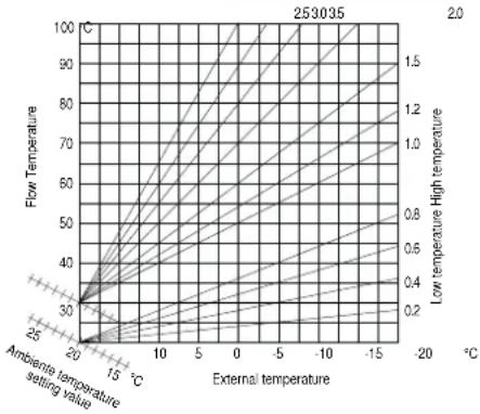 | ||||
| When an outdoor sensor is used, the boiler calculates the most suitable delivery temperature, taking into account the outside temperature and type of system.The type of curve should be selected in correspondence with the projected temperature of the system and the nature of the dispersions present in the structure.For high-temperature systems, one of the curves depicted below may be chosen. | ||||
| 4.2. | 3 | Off setAuto Function active | from - 14 to + 14 (°C)(high temperature) | 0 |
| from - 7 to + 7 (°C)(low temperature) | 0 | |||
| To adapt the heating curve to the system requirements, shift the curve in parallel so that the calculated flow temperature is modified, in addition to the room temperature.By accessing the parameter and pressing the button b, it is possible to shift the curve in a parallel direction. The shifting value can be read on the display: from -14 to +14 for high-temperature devices, or from -7 to 7 for low-temperature devices.Each step corresponds to a 1°C increase/decrease In the flow temperature with respect to the set-point value. | ||||
| 4.2. | 4 | Room InfluenceProportionalAuto Function active | from 0 to 20 | 20 |
| If setted = 0 the room temperature doesn't influence the calculation of the set-point.If setted = 20, the room temperature has the maximum influence to calculate the set-point-only active when the BUS device is connected | ||||
| 4.2. | 5 | Maximum CHTemperature Zone 1 | from 35 to 82 °C(Param. 420 = 1) | 82 |
| from 20 to 45 °C(Param. 420 = 0) | 45 | |||
| 4.2. | 6 | Minimum CHTemperature Zone 1 | from 35 to 82 °C(Param. 420 = 1) | 35 |
| from 20 to 45 °C(Param. 420 = 0) | 20 | |||
| 4.3. | Z1 DIAGNOSTICS | |||
| 4.3. | 4 | Heat request Zone 1 0 = | OFF1 = ON | |
| menu | sub-menu | parameter | description | value | default settings |
| 5 | ZONE 2 PARAMETERS | |||||
| 5.0 | SETPOINT | |||||
| 5.0. | 2 T set | Zone 2 from 35 to 82 (°C)(high temperature) | 70 | |||
| from 20 to 45 (°C)(low temperature) | 25 | |||||
| To set only with Fixed Flow Temperature of Thermoregulation (see 521) | ||||||
| 5.2 | ZONE 2 SETTING | |||||
| 5.2. | 0 | Zone 2 Temperature range | 0 = from 20 to 45°C(low temperature)1 = from 35 to 82°C(high temperature) | 1 | ||
| 5.2. | 1 | ThermoregulationTo enabled thermoregulation press Auto button.On the dispaly will appear the symbol AUTO | 0 = Fixed Flow Temperature1 = Basic Thermoregulation2 = Room Temp only3 = Outdoor Temp.only4 = Room + outdoor Temp. | 1 | ||
| 5.2. | 2 | Slope from 1.0 to 3.5 | (high temperature) | 1.5 | ||
| from 0.2 to 0.8(low temperature) | 0.6 | |||||
| See parameter 422Only enabled when an outdoor sensor is installedWhen an outdoor sensor is used, the boiler calculates the most suitable delivery temperature, taking into account the outside temperature and type of system. The type of curve should be selected in correspondence with the projected temperature of the system and the nature of the dispersions present in the structure. For high-temperature systems, one of the curves depicted below may be chosen. | ||||||
| 5.2. | 3 Off setAuto Function active | from -14 to +14 (°C)(high temperature) | 0 | |||
| from -7 to +7 (°C)(low temperature) | 0 | |||||
| To adapt the heating curve to the system requirements, shift the curve in parallel so that the calculated flow temperature is modified, in addition to the room temperature.By accessing the parameter and pressing the button b, it is possible to shift the curve in a parallel direction. The shifting value can be read on the display: from -14 to +14 for high-temperature devices, or from -7 to 7 for low-temperature devices. Each step corresponds to a 1°C increase/decrease In the flow temperature with respect to the set-point value. | ||||||
| 5. | 2. | 4 | Room Influence Proportional Auto Function active | from 0 to 20 | 20 | |
| If setted = 0 the room temperature doesn't influence the calculation of the set-point.If setted = 20, the room temperature has the maximum influence to calculate the set-point - only active when the BUS device is connected | ||||||
| menu | sub-menu | parameter | description value | default settings | ||
| 5.2. | 5 | Maximum CH Temperature Zone 2 | from 35 to 82 °C (Param. 520 = 1) | 82 |
| from 20 to 45 °C (Param. 520 = 0) | 45 | |||
| 5.2. | 6 | Minimum CH Temperature Zone 2 | from 35 to 82 °C (Param. 520 = 1) | 35 |
| from 20 to 45 °C (Param. 520 = 0) | 20 | |||
| 5.3 | Z2 | DIAGNOSTICS | ||
| 5.3. | 4 | Heat request Zone 2 0 = OFF | 1 = ON | |
| 6 ZONE 3 PARAMETER | ||||
| 6.0 | SETPOINT | |||
| 6.0. | 2 | set Zone 3 from 35 to 82 (°C) | 70 | |
| To set only with Fixed Flow Temperature of Thermoregulation (see 521) | ||||
| 6.2 | ZONE 3 SETTING | |||
| 6.2. | 0 | Zone 3 Temperature range | 0 = from 20 to 45°C (low temperature)1 = from 35 to 82°C (high temperature) | 1 |
| 6.2. | 1 | ThermoregulationTo enabled thermoregulation press Auto button.On the dispaly will appear the symbol AUTO | 0 = Fixed Flow Temperature1 = Basic Thermoregulation2 = Room Temp only3 = Outdoor Temp. only4 = Room + outdoor Temp. | 1 |
| 6.2. | 2 | Slope from 1.0 to 3.5 | (high temperature) | 1.5 |
| from 0.2 to 0.8 (low temperature) | 0.6 | |||
| See parameter 422Only enabled when an outdoor sensor is installedWhen an outdoor sensor is used, the boiler calculates the most suitable delivery temperature, taking into account the outside temperature and type of system. The type of curve should be selected in correspondence with the projected temperature of the system and the nature of the dispersions present in the structure. For high-temperature systems, one of the curves depicted below may be chosen. | ||||
| menu | sub-menu | parameter | description value | default settings |
| 6.2. | 3 | Off | setAuto Function active | from - 14 to + 14 (°C)(high temperature) | 0 |
| from - 7 to + 7 (°C)(low temperature) | 0 | ||||
| To adapt the heating curve to the system requirements, shift the curve in parallel so that the calculated flow temperature is modified, in addition to the room temperature.By accessing the parameter and pressing the button b, it is possible to shift the curve in a parallel direction. The shifting value can be read on the display: from -14 to +14 for high-temperature devices, or from -7 to 7 for low-temperature devices. Each step corresponds to a 1°C increase/decrease In the flow temperature with respect to the set-point value. | |||||
| 6.2. | 4 | Room | Infl uenceProportionalAuto Function active | from 0 to 20 | 20 |
| If setted = 0 the room temperature doesn't influ uence the calculation of the set-point.If setted = 20, the room temperature has the maximum influ uence to calculate the set-point - only active when the BUS device is connected | |||||
| 6.2. | 5 | Max | imum CHTemperature Zone 3 | from 35 to 82 °C(Param. 620 = 1) | 82 |
| from 20 to 45 °C(Param. 620 = 0) | 45 | ||||
| 6.2. | 6 | Min | imum CHTemperature Zone 3 | from 35 to 82 °C(Param. 620 = 1) | 35 |
| from 20 to 45 °C(Param. 620 = 0) | 20 | ||||
| 6.3 | Z3 | DIAGNOSTICS | |||
| 6.3. | 0 | < Not Available> | |||
| 6.3. | 4 | Heat request Zone 2 0 = OFF | 1 = ON | ||
| 8 SERVICE PARAMETERS | |||||
| 8. | 0 | BOILER STATISTICS - 1 | |||
| 8.0. | 0 | Diverter valve cycles No. (nx10) | |||
| 8.0. | 1 | Time of circulator on (nx10) | |||
| 8.0. | 2 | Boiler circulator cycles No. (nx10) | |||
| 8.0. | 3 | Boiler Life Time (hx10) | |||
| 8.0. | 4 | Time of fan ON (hx10) | |||
| 8.0. | 5 | Fan cycles No. (nx10) | |||
| 8. | 0. | 6 | CH flame detection (nx10) | ||
| 8. | 0. | 7 | DHW flame detection (nx10) | ||
| 8. | 1 | BOILER STATISTICS - 2 | |||
| 8.1. | 0 | Hours Burner On CH (hx10)) | |||
| 8.1. | 1 | Hours Burner On DHW (hx10) | |||
| 8.1. | 2 | Number of Flame Faults (nx10) | |||
| 8.1. | 3 | Number of ignition Cycles (nx10) | |||
| 8.1. | 4 | Heat request Duration | |||
| 8. | 2 | BOILER | |||
| 8.2. | 1 | Fan | Status 0 = OFF1 = ON | ||
| 8.2. | 2 | Fan | Speed - x100 RPM | ||
| 8.2. | 3 | Pump speed - NOT ACTIVE | |||
TECHNICAL AREA
| menu | sub-menu | parameter | description | value | default settings |
| 8.2. | 4 | Diverter valve position 0 = D.H. | W.1 = Central Heating | |
| 8.2. | 5 | D.H. W. Flow Rate (l/min) | ||
| 8.2. | 7 | Pump Modulation % | ||
| 8.2. | 8 | Gas Power (kW) | ||
| 8.3 | BOILER TEMPERATURE | |||
| 8.3. | 0 | CH Flow set Temperature(°C) | ||
| 8.3. | 1 | CH Flow Temperature(°C) | ||
| 8.3. | 2 | CH Return Temperature(°C) | ||
| 8.3. | 3 | DHW Temperature (°C) | ||
| 8.3. | 4 | < Not Available> | ||
| 8.3. | 5 | Outdoor temperature (°C) | ||
| 8.4 | STORAGE | |||
| 8.4. | 2 | D.H. W. Inlet Temperature (°C) | ||
| 8.5 | SERVICE | |||
| 8.5. | 0 | Months to next maintenance | from 0 to 60 (month) | 24 |
| If setted the boiler will display that is time to call the installer for maintenance | ||||
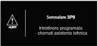 | ||||
| 8.5. | 1 | Maintenance on Day At 0 = OFF | 1=ON | |
| 8.5. | 2 | Maintenance Warning Reset | Reset? OK= Yes Esc = No | |
| to erase the advice for maintenance | ||||
| 8.5. | 4 | SW version Interface | ||
| 8.5. | 5 | SW version Main | ||
| 8.6 | ERROR HISTORY | |||
| 8.6. | 0 | Last 10 Errors from Fault 0 to Fault 9 | ||
| This parameter makes it possible to see the last 10 errors shown by the boiler as well as the relevant day, month and year.Turning the encoder allows for viewing the sequence of errors that occurred, from 0 to 9. | ||||
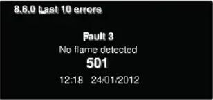 | ||||
| 8.6. | 1 | Reset Error List Reset? | Ok=Yes Esc=No | |
| 8.7 | FREE PARAMETERS | |||
| 8.7. | 4 | Boiler Flowswitch 0 = Open | 1 = Closed | |
| 8.7. | 6 | Safety fl ame sensor | ||
| 19 | WI - FI (only for ALTEAS ONE) | |||
| 19.0 | WI-FI CONFIGURATION | |||
| 19.0.0 | Wi-Fi activation 0 = OFF | 1 = ON | ||
| menu | sub-menu | parameter | description | value | default settings |
| 19. | 0. | 1 | Network configuration | 0 = OFF1 = ON | |
| 19. | 0.2 | ||||
| 19. | 0.3 | Internet time 0 = OFF1 = ON | |||
| 19. | 1 | Connectivity Info | |||
| 19. | 1. | 0 | Connectivity status | ||
| 19. | 1. | 1 | Signal level | ||
| 19. | 1. | 2 | Active Status | ||
| 19. | 1. | 4 | Serial Number | ||
| 19. | 1. | 5 | SW Upgrade Status | ||
| 19. | 2 | Reset Menu | |||
| 19. | 2. | 0 | Factory Reset (soft reset) Do you really want to perform the reset? if you press OK button, the reset command will be executed otherwise, by way of ESC, the previous page is shown. | ||
Important
Maintenance is an essential part of the safe and efficient operation of the boiler and ensures its durability. It should be performed according to the instructions given in current legislation. Perform combustion analysis regularly in order to check the operating efficiency of the boiler and to make sure any polluting substances released are within the boundaries set by current legislation.
Before beginning maintenance work:
- Disconnect the appliance from the electricity supply by turning the external bipolar switch to the "OFF" position;
- Close the gas valve and the central heating and domestic hot water system valves.
After the work has been completed the initial settings will be restored.
General comments
It is recommended that the following inspections be carried out on the boiler at least once a year:
- Check the seals in the water part and, if necessary, replace the gaskets and restore the seal to perfect working order.
- Check the seals in the gas part and, if necessary, replace the gaskets and restore the seal to perfect working order.
- Visually check the overall condition of the boiler.
- Visually check and, if necessary, disassemble and clean the burner.
- Following the inspection detailed in point "3", disassemble and clean the combustion chamber, if necessary.
- Following the inspection detailed in point "4", disassemble and clean the burner, if necessary.
- Cleaning the primary heat exchanger
- Make sure the following heating safety devices are operating correctly:
- temperature limit safety device.
- Make sure that the following gas part safety devices are operating correctly:
- absence of gas or flame safety device (ionisation).
- Check the efficiency of the domestic hot water production process (test the flow rate and temperature).
- Perform a general inspection of the boiler operation.
- Remove oxide from the detection electrode using an emery cloth.
- These checks are not exhaustive. Further mechanical, electrical and combustion maintenance checks may be required.
WARNING!!
THE AUTOMATIC CALIBRATION MUST BE DONE IN CASE OF:
- REPLACEMENT OF: FAN, GAS VALVE, AIR/GAS MIXER, BURNER, ELECTRODE.
- REPLACEMENT OF P.C.B.
- GAS CHANGEOVER
- ANY MODIFICATION TO THE FOLLOWING PARAMETERS
220 - SOFT IGNITION
231 - MAX CH ADJUSTABLE
232 - MAX DHW PERCENTAGE
233 - MIN PERCENTAGE
234 - MAX CH PERCENTAGE
Operational test
After having carried out the maintenance operations, fill the heating circuit at a pressure of approximately 1.5 bar and release the air from the system.
Fill the domestic hot water system at the same time.
- Begin operating the boiler.
- If necessary, release the air from the heating system again.
- Check the settings and make sure all the command, adjustment and monitoring parts are working correctly.
- Check the flue system is sealed and operating correctly.
Draining procedures
The heating system must be drained using the following procedure:
- Switch off the boiler, make sure the external bipolar switch is in the OFF position and shut off the gas valve;
- Loosen the automatic air relief valve;
- Open the system drain off cock and collect the escaping water in a container;
- Empty the water from the lowest points of the system (where applicable).
If the system is to be left inactive in areas where the room temperature may fall below 0^ C during winter, we recommend that anti-freeze liquid is added to the water in the heating system in order to avoid the need for repeated draining; when this liquid is used make sure it is compatible with the stainless steel used for the bodywork of the boiler.
We recommend the use of anti-freeze products which contain PROPYLENE GLYCOLS as these inhibit corrosion and that they are used in conjunction with the anti-scaling and anti-corrosion function, in the quantities suggested by the manufacturer, at the minimum temperature.
Regularly check the pH level of the water/anti-freeze mix in the boiler circuit and replace it when the value measured is lower than the limit prescribed by the manufacturer.
DO NOT MIX DIFFERENT TYPES OF ANTI-FREEZE.
The manufacturer will not be held liable for any damage caused by the appliance or the system due to the use of inappropriate anti-freeze substances or additives.
Draining the domestic hot water system and indirect cylinder
Every time there is a danger of freezing, the domestic hot water system must be drained as follows:
- Shut off the water mains inlet valve;
- Open all the hot and cold water taps;
- Empty the water from the lowest points of the system (where applicable).
WARNING
Before handling, empty all components which may contain hot water, performing bleeding where necessary.
Descal the components in accordance with the instructions provided on the safety data leaflet supplied with the product used, make sure the room is well ventilated, wear protective clothing, avoid mixing different products, and protect the appliance and surrounding objects.
Seal all openings used to take a gas pressure reading or to make any gas adjustments.
If a smell of burning is detected or smoke is seen leaking from the appliance, or there is a smell of gas, disconnect it from the electricity supply, shut off the gas valve, open the windows and call for technical assistance.
Cleaning the primary exchanger
Cleaning the combustion side
The inside of the primary exchanger is accessed by removing the burner. Wash with water and detergent using a non-metallic rifl e-type brush, rinse with water.
Cleaning the trap
The trap is accessed by emptying the condensate bowl located in the bottom section. Wash with water and detergent.
Replace the condensate collection bowl in its housing.
NB: In the event of prolonged use of the appliance, the trap must be filled before being used again.
A lack of water in the trap is dangerous and may cause products to be released into the atmosphere.
1. GENERAL ACCESS
1.0 Disconnect the boiler
Before beginning maintenance work:
a. Disconnect the appliance from the electricity supply.
Press the ON/OFF button and wait 1 minute (the 3-way valve turn on Stand-by position)
ATTENTION!! With the 3-way valve on heating position is not possible to remove the motor.
Turn the external bipolar switch to the "OFF" position.
b. Close the gas valve and the central heating and domestic hot water system valves.
1
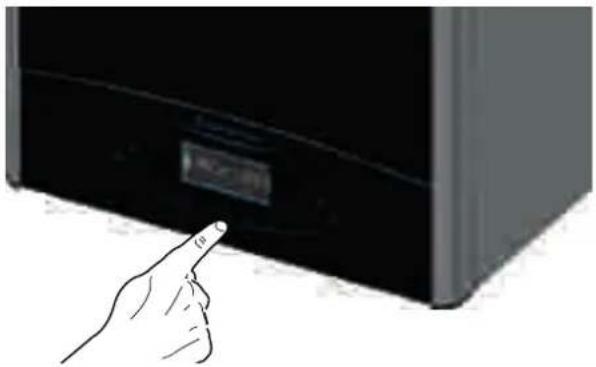
natural_image
Hand pointing at a device panel with a digital display (no text or symbols visible)2
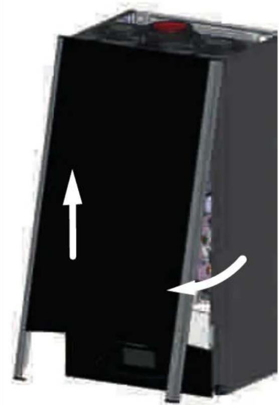
natural_image
Black rectangular device with white arrows indicating upward and curved movement, no visible text or symbols1.1 General Access
Tools
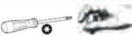
TIME 3 min
Remove the two screws
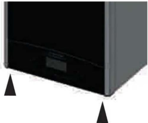
natural_image
Close-up of a black appliance front panel with a digital display and two black triangular markers pointing to the sides (no text or symbols visible)1
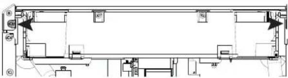
natural_image
Technical line drawing of a mechanical assembly with no visible text or symbolsCAUTION!!
REMOVE ONLY THE SCREWS SHOWN IN THE PICTURE
Lower the electrical front panel
3
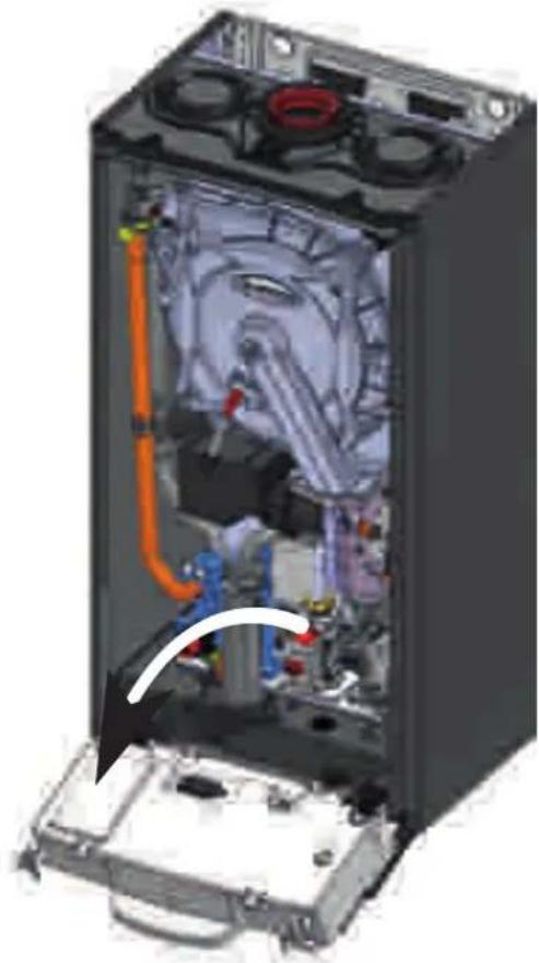
natural_image
Interior view of a battery pack with visible internal components and wiring (no text or symbols)2. ELECTRICAL UNIT
2.1 Control box access
Tools
TIME

min
Remove the front panel as above and pivot the electric box
1
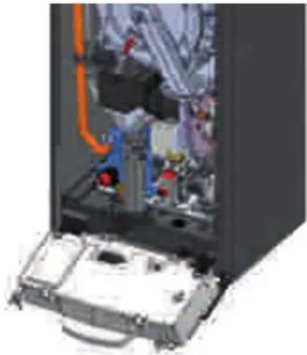
natural_image
3D cutaway view of an electronic device showing internal components and wiring (no text or symbols visible)Unhook the two clip and remove the cover
2
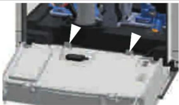
natural_image
Interior view of a mechanical device with a central component and two people in the background (no visible text or symbols)3
natural_image
Interior view of an electronic device showing internal circuit board and wiring (no visible text or symbols)2.2 Fuse
Tools
TIME

min
1
natural_image
Interior view of an electronic device showing internal circuitry and wiring (no visible text or symbols)Remove the fuse
2
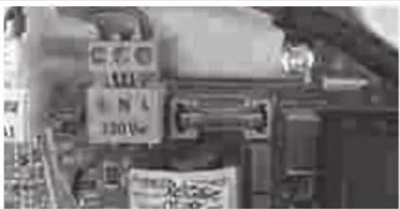
natural_image
Interior view of a kitchen appliance with refrigerators and a 320V label (no readable text or symbols)3
2.3 Main P.C.B.

TIME 5 min
After opening the control box, disconnect the electrical plug connections
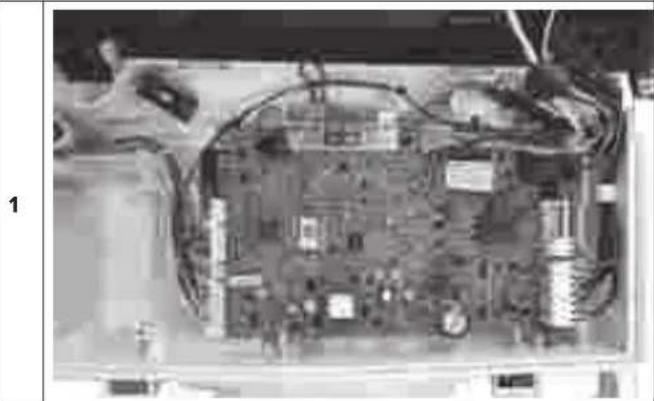
natural_image
Interior view of an electronic device showing exposed circuit board and wiring (no visible text or symbols)Unhook and remove the P.C.B.
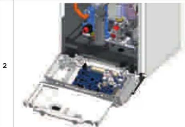
natural_image
Interior view of a computer chassis showing internal components and casing (no visible text or symbols)2.4 Display P.C.B.
TIME 5 min
Unscrews the two screws and pull the assembly towards you
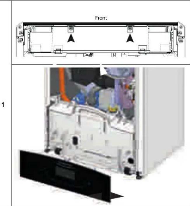
Disconnect the electrical plug connections
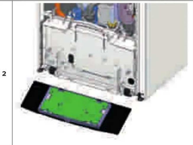
natural_image
Interior view of a device showing internal components and a green-labeled panel (no visible text or symbols)3. HYDRAULIC UNIT
3.1 RIGHT HAND HYDRAULIC BLOCK ASSEMBLY
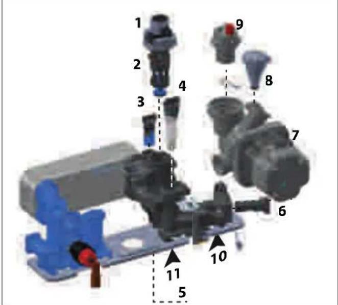
Legend:
1 - Divverter valve motor
2 - Diverter valve
3 - By-pass
4 - D.H.W. flow switch assembly
5 - C.H. drain valve
6 - Central heating filter
7 - Pump
8 - Water pressure sensor
9 - Auto air vent
10 - Central Heating return
11 - Cold water inlet (D.H.W.)
3.2. 3 Way valve unit

TIME 5 min
Drain the boiler (see 3.3).
Unplug the diverter valve cable
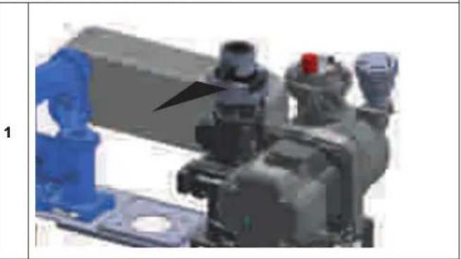
natural_image
3D mechanical assembly with blue structural elements and a black arrow pointing to a component (no visible text or symbols)Rotate clockwise to unhook the locking ring.
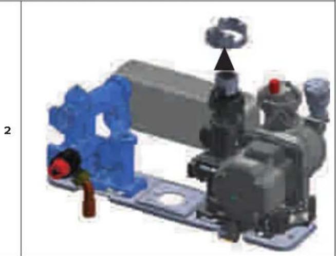
natural_image
3D mechanical assembly diagram showing a blue component and a gray motor with a black arrow pointing to a circular component (no text or symbols present)Remove the 3 way valve motor.
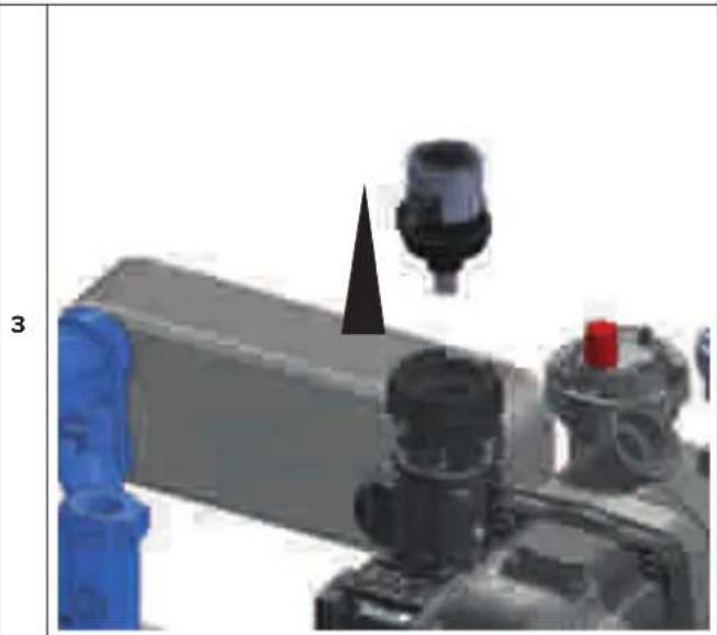
natural_image
3D mechanical assembly with blue and black components, no visible text or symbolsRemove the clip and lift the diverter valve from the assembly.
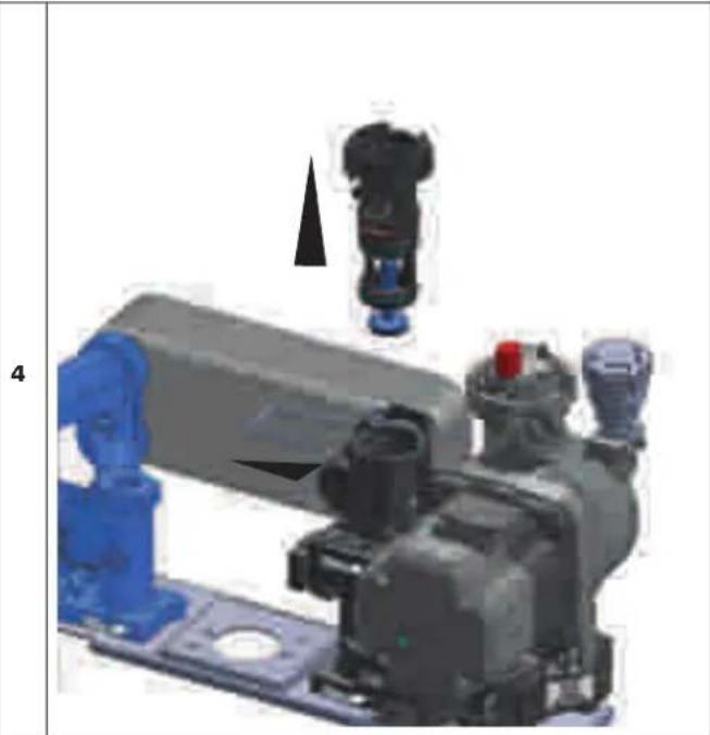
natural_image
3D mechanical assembly diagram showing a blue component and a black component with an arrow indicating motion (no text or symbols)WHEN REASSEMBLING, ENSURE THE DIVERTER VALVE IS ALIGNED CORRECTLY.
| 3.3 Draining | |
 Tools Tools | |
| TIME trowel min | |
| Turn the drain valve anti-clockwise to open and drain the water from the boiler | |
| 1 | 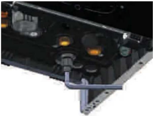 |
| 3.4 Automatic air vent | |
 Tools Tools | |
| TIME min | |
| Drain the boiler (see 3.3).Unscrew anticlockwise the AAV from the assembly. | |
| 1 | 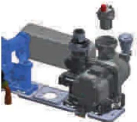 |
| 2 |  |
| 3.5 Primary water pressure sensor | |
 Tools Tools | |
| TIME 5 min | |
| Drain the boiler (see 3.3).Slide the fixing clip, (it is held captive) unplug the electrical connector and lift the sensor from the assembly. | |
| 1 | 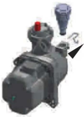 |
| 2 |  |
3.6 By-pass assembly
Tools
TIME

min
Drain the boiler (see 3.3). Rotate clockwise to unhook the locking ring of the diverter valve.
1
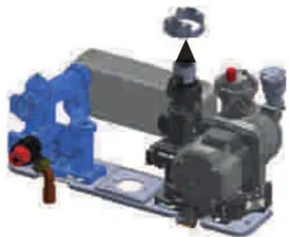
natural_image
3D mechanical assembly diagram showing a blue component and gray components with no visible text or symbolsRemove the clip and pull the assembly towards you
2
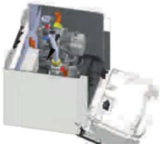
natural_image
3D rendered mechanical assembly with robotic arms and a highlighted component (no visible text or symbols)3
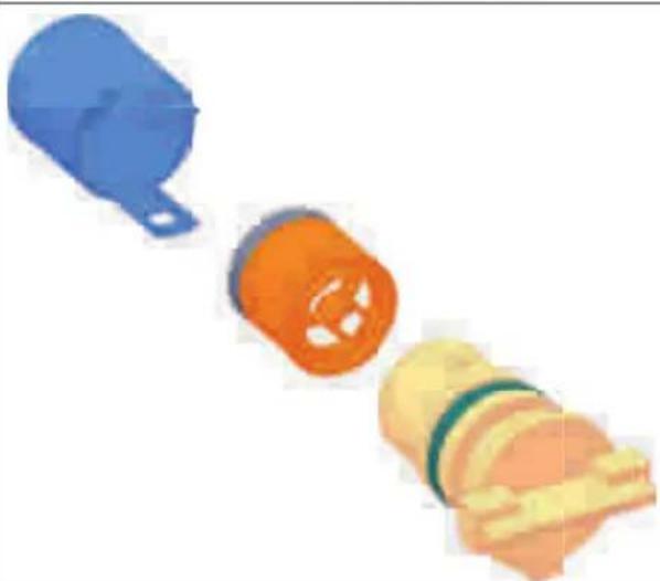
natural_image
Three colorful plastic containers arranged diagonally (blue, orange, yellow) with no visible text or symbols.3.7 Pump
Tools
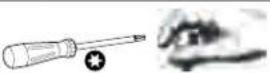
TIME

min
Drain the boiler (see 3.3). Remove the clip and the two screws
1
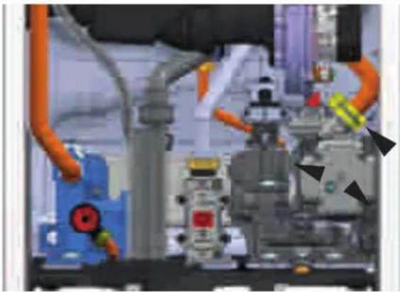
natural_image
Industrial machinery setup with orange piping and blue components (no visible text or symbols)Disconnect the pipe and then move the pump to the right to disengage
2
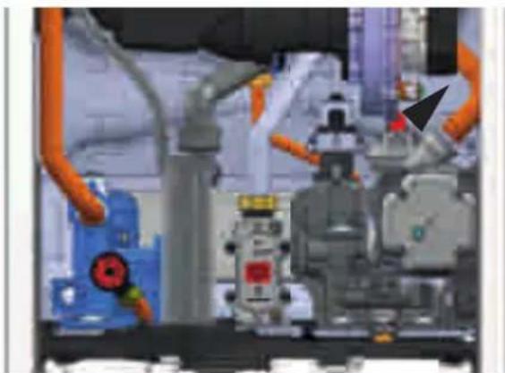
natural_image
Industrial robotic arms and control panels in a factory setting (no visible text or symbols)Remove the pump
3
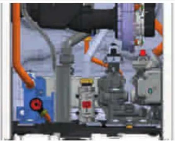
natural_image
Industrial machinery setup with pipes, valves, and control panels (no visible text or symbols)| Remove the sensor (see 3.5) | |
| 4 | 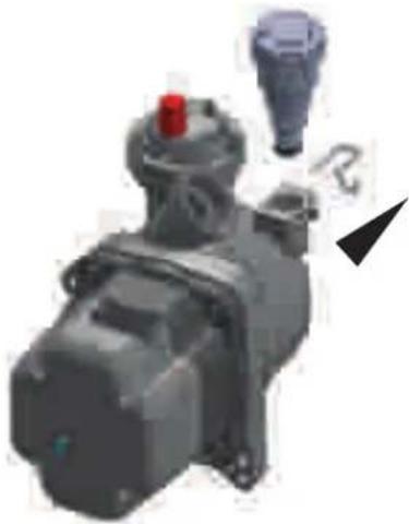 |
| Remove the AAV (see 3.4) | |
| 5 | 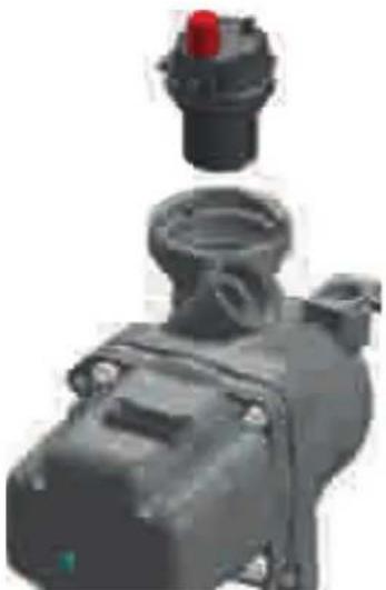 |
| 6 | 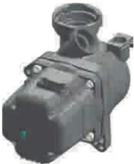 |
| 3.8 C.H. Filter | |
Tools  | |
| TIME 5 min | |
| Drain the boiler (see 3.3).Remove the clip and remove the pressure gauge | |
| 1 |  |
| 2 |  |
| Remove the clip and remove the filter | |
| 3 |  |
| 4 |  |
3.9 D.H.W. Flow switch assembly
Tools
TIME

10 min
Drain the boiler (see 3.3). Remove the clip and pull the flow switch assembly upward.
1
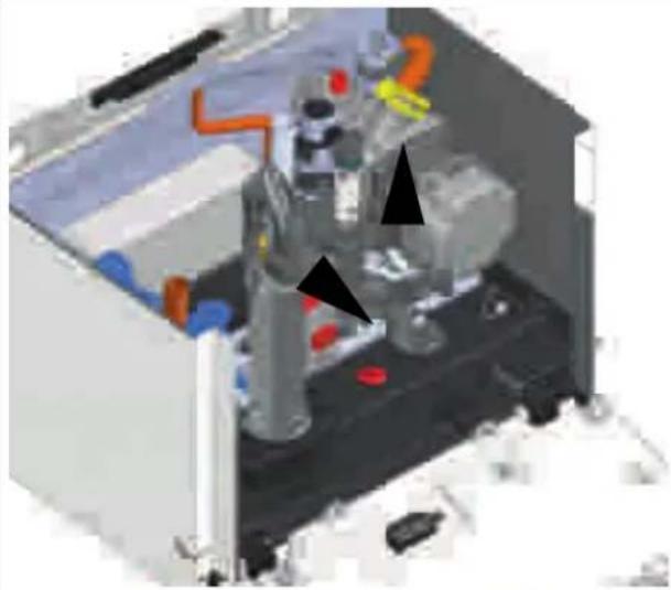
natural_image
3D mechanical assembly diagram showing internal components with no visible text or symbols
natural_image
Three abstract shapes: a gray container, a green cube, and a brown irregular shape (no text or symbols)3.10 LEFT HAND HYDRAULIC BLOCK ASSEMBLY
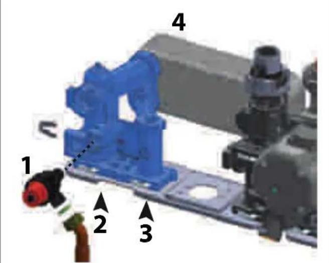
Legend:
1 - Safety valve
2 - Central heating flow
3 - Domestic hot water outlet
4 - Secondary heat exchanger
3.11 Secondary heat exchanger
Tools
TIME

10 min
Drain primary and domestic hot water circuits. Remove the silencer.
1
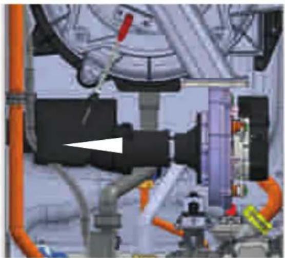
natural_image
Industrial piping system with orange valves and valves, no visible text or symbolsRemove the two screws and remove the heat exchanger
2
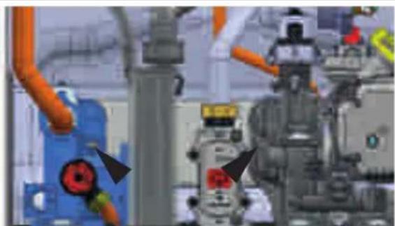
natural_image
Industrial robotic arm with blue components and orange piping (no visible text or symbols)| 3 | 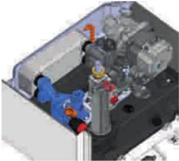 |
| 4 | 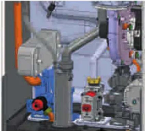 |
| 5 | 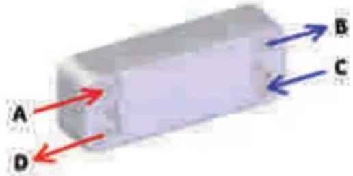 |
3.12 Condensate trap
TIME 5 min
Disconnect the condensate discharge pipe from the bottom of the boiler. Unscrw the two screws.
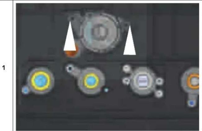
natural_image
Close-up of a mechanical component with circular and rectangular features, no visible text or symbolsDisconnect the condensate pipe from the condensate trap
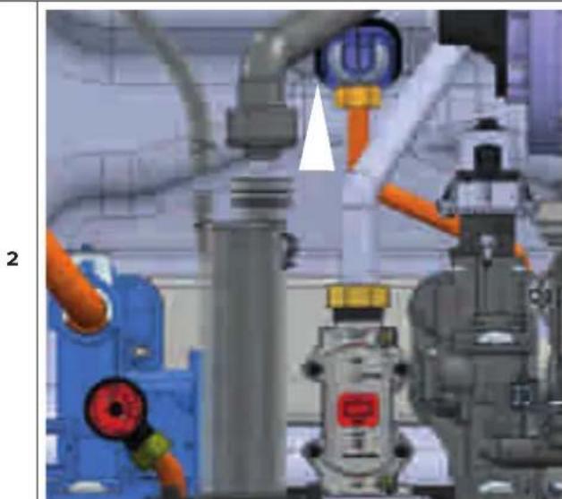
natural_image
Industrial piping system with valves and valves in a factory setting (no visible text or labels)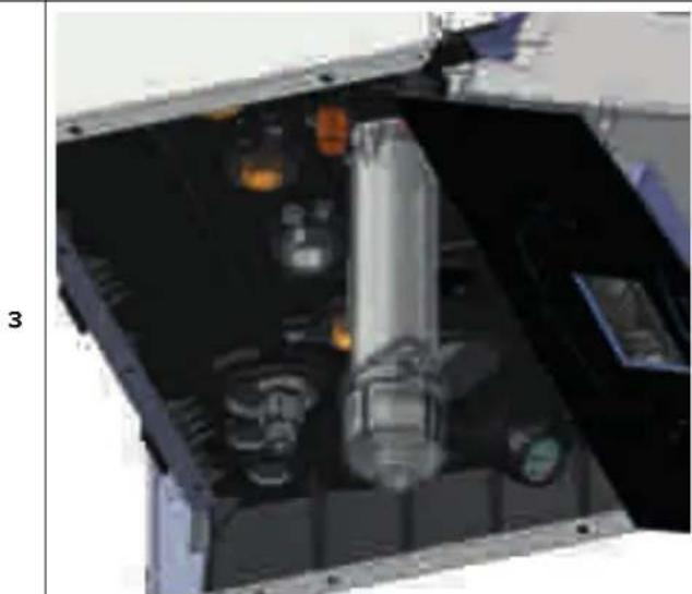
natural_image
Interior view of a mechanical device with internal components and mounting holes (no visible text or symbols)3.13 Safety valve

TIME

5 min
Drain the boiler (see 3.3). Disconnect the discharge pipe. Remove the fi st clip on the left and pull the safety valve towards you
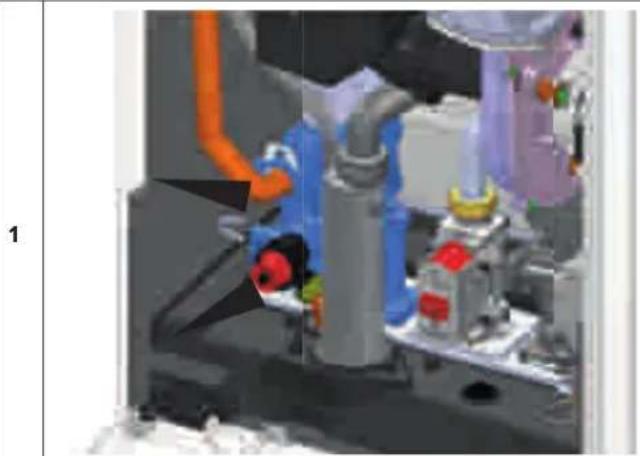
natural_image
Industrial mechanical assembly with pipes and components, no visible text or symbols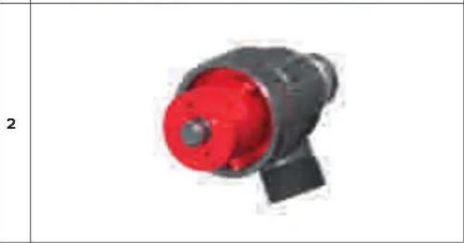
natural_image
Close-up of a red and black mechanical component (no visible text or symbols)3.14 Temperature sensors
TIME

5 min
NTC1: Black
NTC2: Red
1
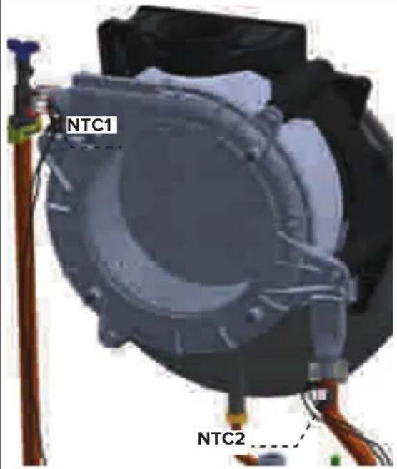
Unplug the electrical connectors
2
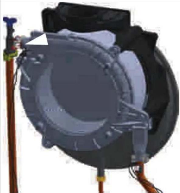
natural_image
Close-up of a mechanical component with visible internal structure and wiring (no text or symbols)Remove the clip and the temperature sensor
IMPORTANT! Do not use conducting paste for the contact sensors because it will alter the resistance value.
| TEMPERATURE RESISTANCE (kOhm) | |
| 0 | 27 |
| 10 17 | |
| 20 12 | |
| 25 10 | |
| 30 | 8 |
| 40 | 5 |
| 50 | 4 |
3.15 Manual Air vent
Tools
TIME

min
Drain boiler (see 3.3)
Unscrew and lift the manual air vent from the exchanger
1
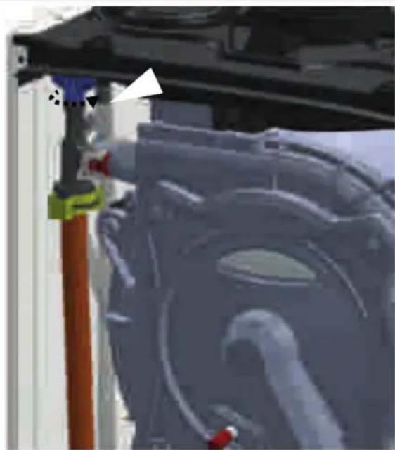
natural_image
Close-up of a car body panel with visible wiring and a blue tool, no text or symbols present.2
natural_image
Abstract illustration of a blue and black pipe fitting with a circular inset (no text or symbols)3.16 Main heat exchanger
Tools

TIME

0 min
Drain boiler (see 3.3)
Remove the silencer
1
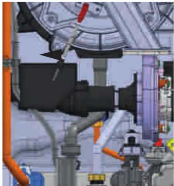
natural_image
Industrial machinery setup with pipes, valves, and a large circular component (no visible text or symbols)Isolate the gas supply and disconnect the gas pipe.
2
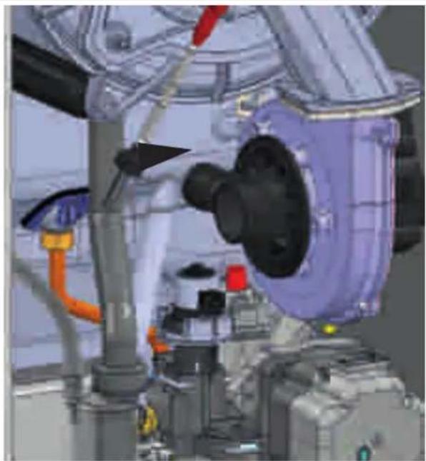
natural_image
Industrial robotic arm with purple pump and orange piping (no visible text or symbols)Disconnect the cable of the electrode.
Remove the four nuts and remove the burner unit
3
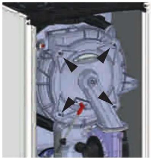
natural_image
3D mechanical assembly diagram showing internal components with black arrows pointing to specific parts (no text or labels visible)4
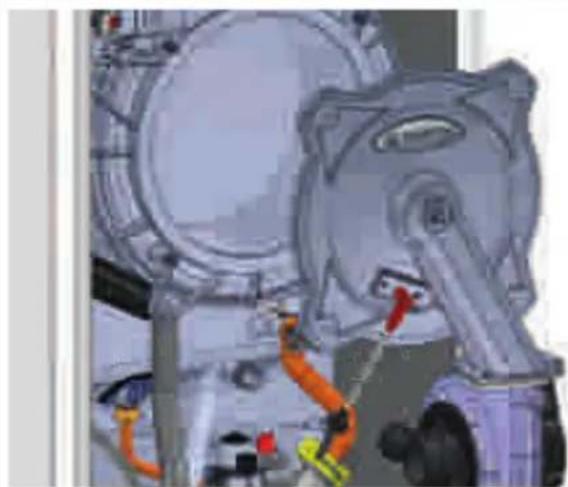
natural_image
Industrial machinery component with orange and yellow cables, no visible text or symbolsRemove the two clips to disconnet the exchanger on the heating flow side
5
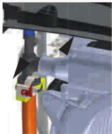
natural_image
Close-up of industrial machinery components with no visible text or symbolsDisconnect the plastic pipes from the manual air vent.
6
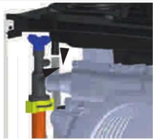
natural_image
Close-up of a mechanical assembly with blue and yellow components, no visible text or symbols7
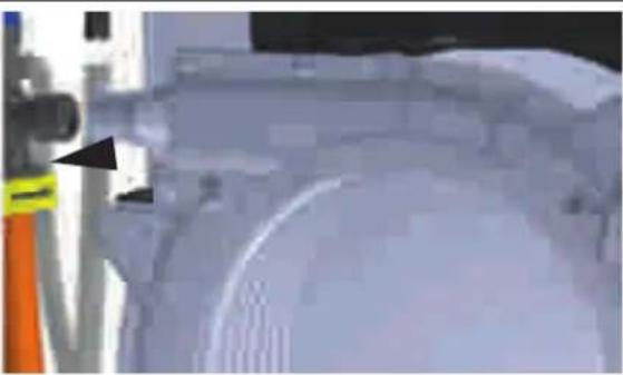
natural_image
Close-up of a mechanical component with a black arrow pointing to a feature, no visible text or symbols.8
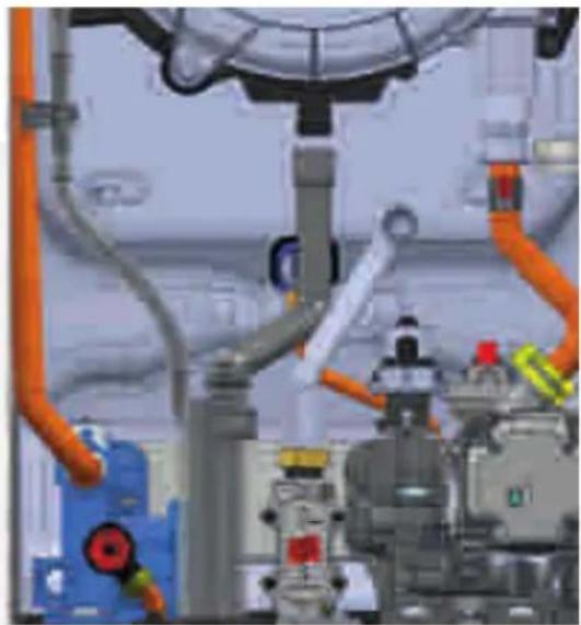
natural_image
Industrial piping system with valves and valves (no visible text or labels)Unscrew the four screws to remove the heat exchanger
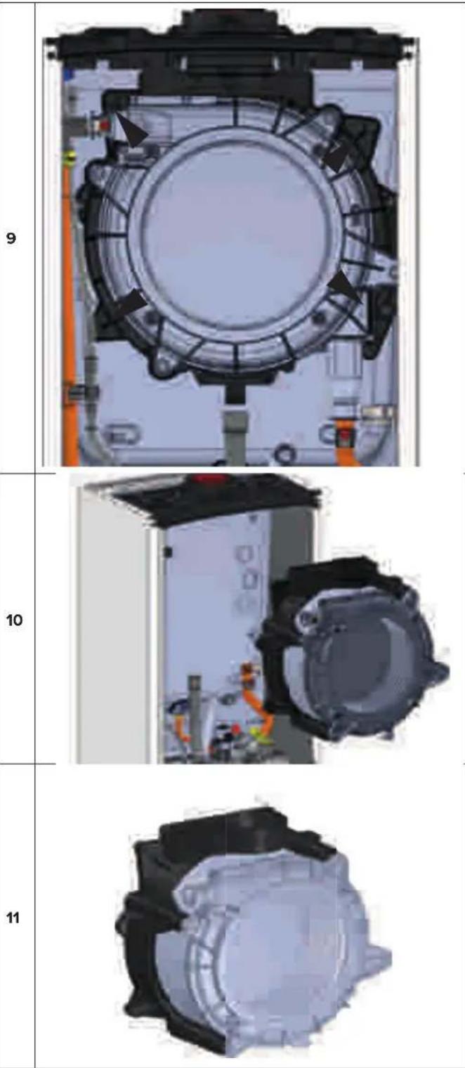
4. BURNER UNIT
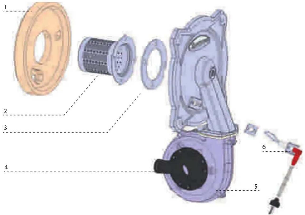
Legend:
1 - Ceramic fi bre
2 - Burner
3 - Silencer
4 - Mixing tube
5 - Fan
6 - Detection/Ignition electrode
| 4.1 Electrode (detection and ignition) | |
Tools  | |
| TIME ^[3K3] min | |
| Unplug the electrode on the control boxRemove the screws and pull the electrodes towards you. | |
| 1 | 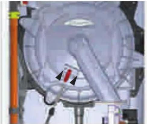 |
| 2 |  |
| 4.2 Burner | |
Tools  | |
| TIME 15 min | |
| Remove the silencer | |
| 1 | 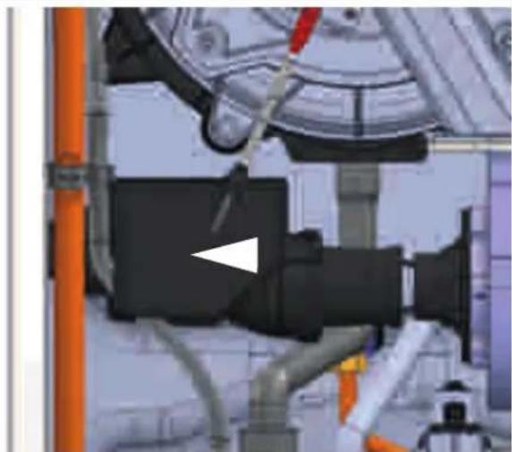 |
| Isolate the gas supply. Disconnect the gas pipe. | |
| 2 | 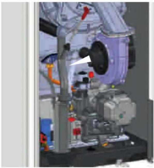 |
| Disconnect the cable of the electrode.Remove the four nuts and remove the burner unit | |
| 3 | 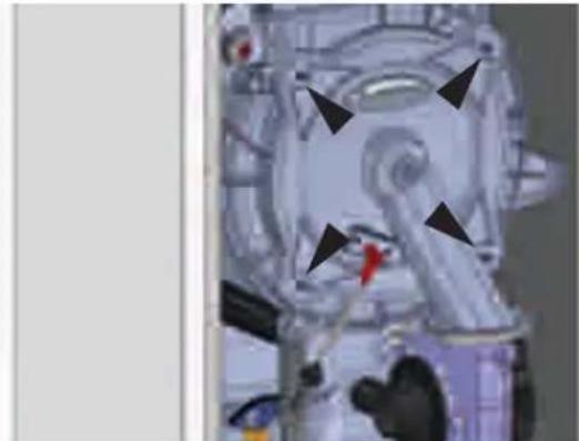 |
Pull the assembly towards you
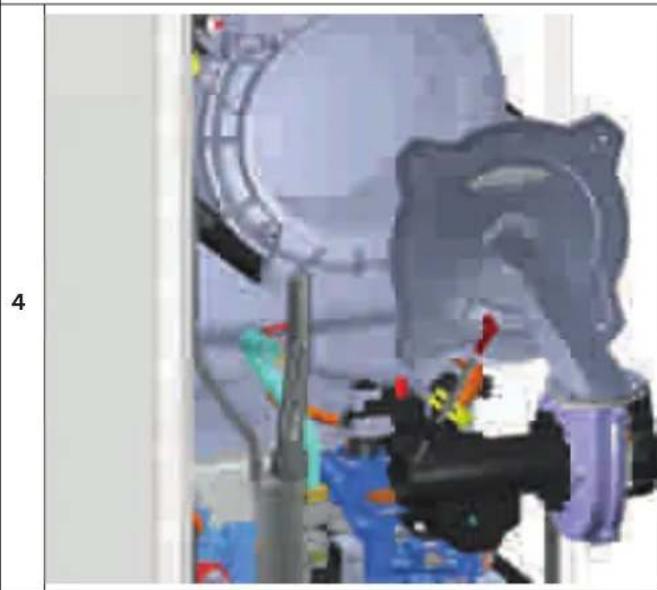
natural_image
Industrial machinery component with mechanical parts and a highlighted chamber (no visible text or symbols)Remove the two screws and remove the electrode
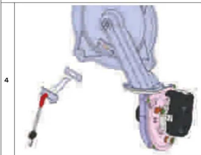
natural_image
Mechanical assembly diagram showing a linkage mechanism with a red pin and component (no text or labels)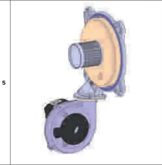
natural_image
3D mechanical component diagram showing a shaft and housing assembly (no text or symbols)Remove the ceramic fi bre.
Remove the four screws and pull the burner toward you. Always replace the burner gasket (*).
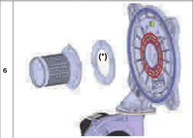
natural_image
Mechanical assembly diagram showing a motor, gear, and housing components with no visible text or symbolsVerify and replace the other gaskets if they are damaged or showing signs of deterioration
4.3 Fan
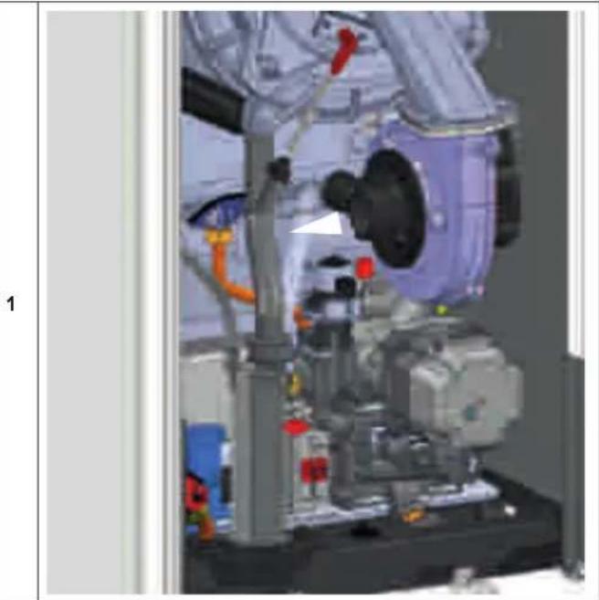
natural_image
Interior view of a mechanical assembly with visible components and no text or symbolsRemove the three screws to free the fan.
2
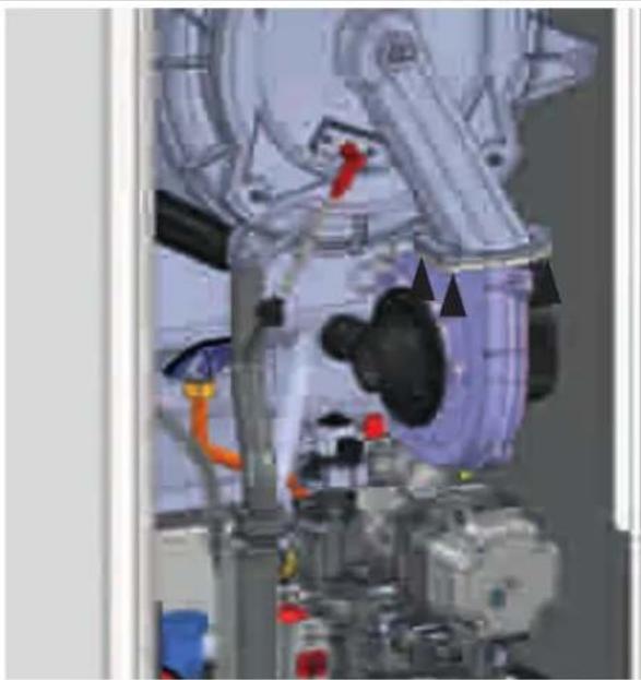
natural_image
Industrial machinery assembly with visible pipes, valves, and components (no text or symbols)Remove the three nuts.
Verify and replace the gasket if it's damaged or showing signs of deterioration
3
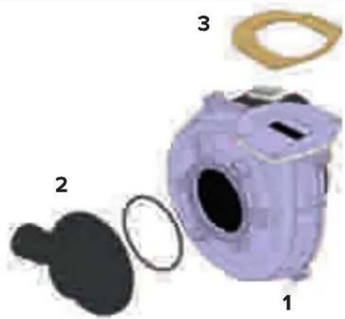
natural_image
Exploded view diagram of a mechanical component with numbered parts (1, 2, 3), no text or symbols present.Legend:
1 - Fan
2 - Venturi
3 - Gasket
| Fan & mixer venturi according to the model | ||
| Power Fan Venturi diameter | ||
| 30 kW EBM 118 85W ∅ 18,7 | ||
| 38 kW EBM 118 85W ∅ 21,6 | ||
4.4 Gas Valve

TIME 15 min
Remove the two screws under the boiler and disconnect the gas pipe on the top of the gas valve
1

natural_image
Industrial machinery setup with blue hydraulic cylinders and orange piping (no visible text or symbols)Remove the gas valve
2
natural_image
Industrial machinery setup with robotic arms and control panels (no visible text or symbols)
GAS OUTLET
natural_image
3D rendered mechanical component with red and gray sections, no visible text or symbolsLegend:
1 - Inlet test point
- ANNUAL MAINTENANCE
| Plate heat exchangerMaintenance Interval: As necessaryHow: To measure specifi cation of DHW performance. |  |
| By-pass & Safety valveMaintenance Interval: AnnuallyHow: Visual inspection / Clean as necessary |  |
| Central heating fi lterMaintenance Interval: AnnuallyHow: Visual inspection / Clean as necessary |  |
| Flow switch operationMaintenance Interval: AnnuallyHow: Visual inspection / Clean as necessary / Check flow rate |  |
| Expansion vesselMaintenance Interval: AnnuallyHow: Check air pressure is at 15 psi (System drained) |  |
| Ignition & detection electrodeMaintenance Interval: AnnuallyHow: Visual inspection / Clean as necessary / Distance from the burner / Ionisation current more than 1 μA |  |
| BurnerMaintenance Interval: AnnuallyHow: Visual inspection / Clean as necessary |  |
| FanMaintenance Interval: AnnuallyHow : Visual inspection / Clean as necessary |  |
| Primary Heat exchangerMaintenance Interval: AnnuallyHow : Visual inspection / Clean as necessary |  |
| Condensate trapMaintenance Interval: Annuallyor after cleaning primary heat exchangerHow : Visual Inspection / Clean as necessary /Add water before replacing |  |
| PumpMaintenance Interval: At the fi rst ignition and annuallyHow: Check that the AAV Is open /Visual inspection / Clean as necessary |  |
| GENERAL | Model: ALTEAS ONE NET | |||
| 30 35 | ||||
| CE Certifi cation (pin) | 0085CR0394 | |||
| Boiler type | C13(X)-C23-C33(X)-C43(X)-C53(X)-C63(X)C83(X)-C93(X)B23-B23P-B33 | |||
| POWER SPECIFICATIONS | Max/min nominal calorific flow rate (Pci)...... Qn | kW | 28.0 / 3.0 31.0 / 3.5 | |
| Max/min nominal calorific flow rate (Pcs)...... Qn | kW | 31.1 / 3.0 34.4 / 3.9 | ||
| Domestic hot water max/min nominal calorific flow rate (Pci)...... Qn | kW | 30.0 / 3.0 34.5 / 3.5 | ||
| Domestic hot water max/min nominal calorific flow rate (Pcs)...... Qn | kW | 33.3 / 3.3 38.3 / 3.9 | ||
| Max/min power output (80°C-60°C)...... Pn | kW | 27.5 / 2.8 30.3 / 3.3 | ||
| Max/min power output (50°C-30°C)...... Pn | kW | 30.3 / 3.1 33.5 / 3.6 | ||
| Domestic hot water max/min power output ...... Pn | kW | 28.7 / 2.9 | 33.1 / 3.4 | |
| Combustion efficiency (of flue gas) | % | 97.8 | 97.8 | |
| Nominal calorific flow rate efficiency (60/80°C) Hi/Hs | % | 98.4 / 88.6 | 97.7 / 88.0 | |
| Nominal calorific flow rate efficiency (30/50°C) Hi/Hs | % | 108.3 / 97.5 | 108.0 / 97.2 | |
| Efficiency at 30% at 30°C (condensation) Hi/Hs | % | 109.5 / 98.6 | 109.5 / 98.6 | |
| Minimum calorific flow rate efficiency (60/80°C) Hi/Hs | % | 93.0 / 83.8 | 93.5 / 84.2 | |
| Efficiency rating (dir. 92/42/EEC) | stars | ★★★★ | ||
| Loss of burner gas when operating | % | 2.2 | 2.2 | |
| EMISSIONS | Available air pressure | Pa | 100 | 100 |
| NoX class | class | 6 | ||
| Flue gas temperature (G20) (80°C-60°C) | °C | 66 | 66 | |
| CO2 content (G20) (80°C-60°C) | % | 8.8 | 8.8 | |
| CO content (0%O2) (80°C-60°C) | ppm | 102.2 | 98.8 | |
| O2 content (G20) (80°C-60°C) | % | 3.8 | 4.5 | |
| Maximum flue gas flow (G20) (80°C-60°C) | Kg/h | 47.6 | 55.7 | |
| Excess air (80°C-60°C) | % | 22 | 27 | |
| HEATING CIRCUIT | Expansion chamber inflation pressure | bar | 1 | |
| Maximum heating pressure | bar | 3 | ||
| Expansion chamber capacity | l | 8 | ||
| Min/max heating temperature (high temperature range) | °C | 35 / 82 | ||
| Min/max heating temperature (low temperature range) | °C | 20 / 45 | ||
| DOMESTIC HOT WATER CIRCUIT | Domestic hot water max/min temperature | °C | 36 / 60 | |
| Specific flow rate of domestic hot water (ΔT=30°C) | l/min | 14.3 | 16.5 | |
| Quantity of hot water ΔT=25°C | l/min | 17.2 | 19.8 | |
| Quantity of hot water ΔT=35°C | l/min | 12.3 | 14.1 | |
| Hot water comfort rating (EN13203) | stars | ★★★ | ||
| Hot water minimum flow rate | l/min | 2 | 2 | |
| Domestic hot water max/min pressure | bar | 7.0 / 0.2 | ||
| ELECTRICAL | Power supply frequency/voltage | V/Hz | 230 / 50 | |
| Total electrical power absorbed | W | 91 | 82 | |
| Circulation Pump energy efficiency index | EEI ≤ 0,23 | |||
| Minimum ambient temperature for use | °C | +5 | ||
| Protection level for the electrical appliance | IP | X5D | ||
| Weight | kg | 35,3 | 37,6 | |
ErP Data - EU 813/2013
| Model: ALTEAS ONE NET 30 35 | |||
| Condensing boiler yes/no | yes yes | ||
| Low-temperature boiler: yes/no | no no | ||
| B1 boiler yes/no | no no | ||
| Cogeneration space heater yes/no | no no | ||
| Combination heater yes/no | yes yes | ||
| Contact details (Name and address of the manufacturer or its authorised representative) | ARISTON THERMO S.p.A. Viale A. Merloni 45 60044 FABRIANO AN - ITALIA | ||
| ErP HEATING | |||
| Power output P_h | kW | 28 31 | |
| Useful heat output at rated heat output and high-temperature regime P_4 | kW | 28.0 | 3 |
| Useful heat output at 30 % of rated heat output and low-temperature regime (Return temperature 30°C) P_1 | kW | 8.4 | 9 |
| Seasonal space heating energy efficiency η_S | % | 94 94 | |
| Useful efficiency at rated heat output and high-temperature regime (60-80°C) η_4 | % | 88.6 | 8 |
| Useful efficiency at 30 % of rated heat output and low-temperature regime (Return temperature 30°C) η_1 | % | 98.6 | 9 |
| ErP D.H.W. | |||
| Declared load profi le | XL XXL | ||
| Water heating energy effi ciency η_wh | % | 85 86 | |
| Daily electricity consumption Q_elec | kWh | 0.220 | 0.230 |
| Daily fuel consumption Q_fuel | kWh | 22.770 | 28.460 |
| AUXILIARY ELECTRICITY CONSUMPTION | |||
| At full load elmax | kW | 0,042 | 0,042 |
| At part load elmin | kW | 0,014 | 0,014 |
| In standby mode P_SB | kW | 0,005 | 0,005 |
| OTHER ITEMS | |||
| Standby heat loss P_stbu | kW | 0.0045 | 0.046 |
| Ignition burner power consumption P_ian | kW | 0.000 | 0.000 |
| Sound power level, indoors L_WA | dB | 54 51 | |
| Emissions of nitrogen oxides NOx | mg/kWh | 33 35 | |
| PRODUCT FICHE - EU 811/2013 | |||
| Brand |  ARISTON ARISTON | ||
| Model ALTEAS ONE NET | |||
| 30 35 | |||
| Declared load profi le | XL XXL | ||
| Seasonal space heating energy effi ciency class |  | [2TSH] | |
| Water heating energy effi ciency class |  |  | |
| Power output P_n | kW | 28 31 | |
| Annual energy consumption Q_HE | GJ | 48 | 54 |
| Annual electricity consumption AEC | kWh | 49 | 50 |
| Annual fuel consumption AFC | GJ | 18 | 23 |
| Seasonal space heating energy effi ciency _s | % | 94 | 94 |
| Water heating energy effi ciency _WH | % | 85 | 86 |
| Sound power level, indoors L_WA | dB | 54 | 51 |
| PRODUCT FICHE - CUBE - WiFi Room sensor | |
| Brand | ARISTON |
| Supplier identification model | CUBE WIFI |
| Temperature control class VI | |
| Energy effi ciency contribution for space heating % | 4% |
Important!!
The installation of the boiler and all the included thermoregulation accessories determines a final value of Seasonal space heating energy efficiency (s) as shown in the table below for the various models.
| Brand | ALTEAS ONE NET | ||
| 30 35 | |||
| Seasonal space heating energy effi ciency ηs | % | 94+4 =98 94+4 =98 | |
 |  | ||
Package fi che
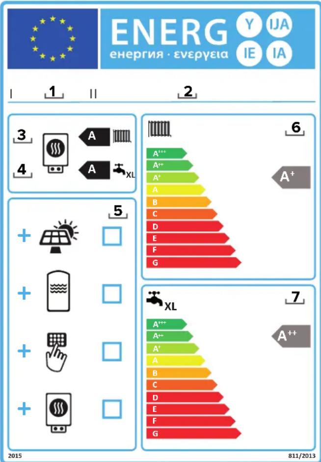
Instructions for filling the label for packages of space heater (or combination heater), temperature control and solar device.
- supplier's name or trademark;
- supplier's model identifier;
- the seasonal space heating energy efficiency class of the space heater, already filled;
- the seasonal space heating and water heating energy efficiency classes of the combination heater already filled;
- Indication of whether a solar collector, hot water storage tank, temperature control and/or supplementary heater, may be included in the package of combination heater, temperature control and solar device;
- the seasonal space heating energy efficiency class of the package of combination heater, temperature control and solar device, determined in accordance with the figure 1 in the following pages.
The head of the arrow containing the seasonal space heating energy efficiency class of the package of combination heater, temperature control and solar device shall be placed at the same height as the head of the relevant energy efficiency class;
- the water heating energy efficiency class of the package of combination heater, temperature control and solar device, determined in accordance with the figure 5 in the following pages.
The head of the arrow containing the water heating energy efficiency class of the package of combination heater, temperature control and solar device shall be placed at the same height as the head of the relevant energy efficiency class.
The energy efficiency of the package of products provided for this fiche may not correspond to its actual energy efficiency once installed in a building, as the efficiency is influenced by further factors such as heat loss in the distribution system and the dimensioning of the products in relation to building size and characteristics.
PACKAGES OF COMBINATION HEATER, TEMPERATURE CONTROL AND SOLAR DEVICE
The fi che for packages of combination heater, temperature control and solar device shall contain the elements set out in points (a) and (b):
a) the elements set out in Figure 1, respectively, for evaluating the seasonal space heating energy efficiency of a package of combination heater, temperature control and solar device, including the following information:
- I: the value of the seasonal space heating energy efficiency of the preferential combination heater, expressed in %;
- II: the factor for weighting the heat output of the preferential and supplementary heaters of a package (see COMMISSION DELEGATED REGULATION (EU) No 811/2013 - annex IV - 6.a);
- III: the value of the mathematical expression: 294/(11 - Prated), whereby Prated is related to the preferential combination heater;
- IV: the value of the mathematical expression 115/(11 - Prated), whereby Prated is related to the preferential combination heater;
in addition, for preferential heat pump combination heaters:
- V: the value of the difference between the seasonal space heating energy effi ciencies under average and colder climate conditions, expressed in %;
- VI: the value of the difference between the seasonal space heating energy efficiencies under warmer and average climate conditions, expressed in %;
(b) the elements set out in Figure 5 for evaluating the water heating energy efficiency of a package of combination heater, temperature control and solar device, where the following information shall be included:
- I: the value of the water heating energy efficiency of the combination heater, expressed in %;
- II: the value of the mathematical expression (220 · Q ref)/Q nonsol, where Q ref is taken from Table 15 in Annex VII of the COMMISSION DELEGATED REGULATION (EU) N. 811/2013 and Q nonsol from the product fiche of the solar device for the declared load profile M, L, XL or XXL of the combination heater;
- III: the value of the mathematical expression (Qaux · 2,5)/(220 · Qref), expressed in %, where Q aux is taken from the product fi che of the solar device and Q ref from Table 15 in Annex VII of the COMMISSION DELEGATED REGULATION (EU) N. 811/2013 for the declared load profi le M, L, XL or XXL.
Figure 1
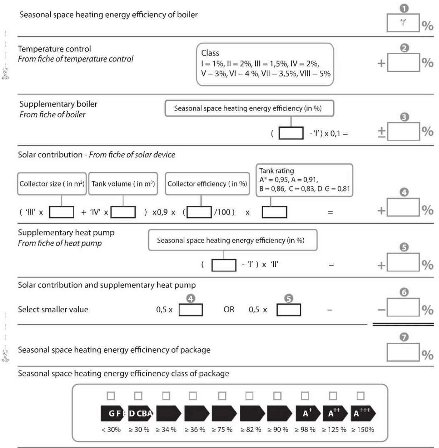
other
| Category | Subcategory | Value | | -------- | ----------- | ----- | | Top Section | Seasonal space heating energy efficiency of boiler | 1 | | Top Section | Temperature control From fiche of temperature control | Class I = 1%, II = 2%, III = 1.5%, IV = 2%, V = 3%, VI = 4%, VII = 3.5%, VIII = 5% | | Top Section | Supplementary boiler From fiche of boiler | Seasonal space heating energy efficiency (in %) - ('I') x 0,1 = ± | | Top Section | Solar contribution - From fiche of solar device | Collector size (in m²) + 'IV' x ) x0,9 x (/100) x = + | | Bottom Section | Supplementary heat pump From fiche of heat pump | Seasonal space heating energy efficiency (in %) - (- 'I') x 'II' = + | | Bottom Section | Solar contribution and supplementary heat pump Select smaller value | 4 OR 0,5 x = - | | Bottom Section | Seasonal space heating energy efficiency of package | 5 ≥ 98% ≥ 125% ≥ 150% ≥ | | Bottom Section | Seasonal space heating energy efficiency class of package | G F B D CBA < 30% ≥ 30% ≥ 34% ≥ 36% ≥ 75% ≥ 82% ≥ 90% ≥ 98% ≥ 125% ≥ 150% < |Boiler and supplementary heat pump installed with low temperature heat emitters at 35 °C?
From fiche of heat pump
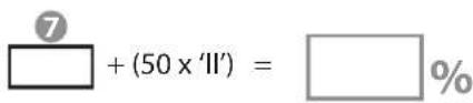
The energy efficiency of the package of products provided for this fiche may not correspond to its actual energy efficiency once installed in a building, as the efficiency is influenced by further factors such as heat loss in the distribution system and the dimensioning of the products in relation to building size and characteristics.
Figure 5
Water heating energy efficiency of combination heater

Solar contribution - From fiche of solar device
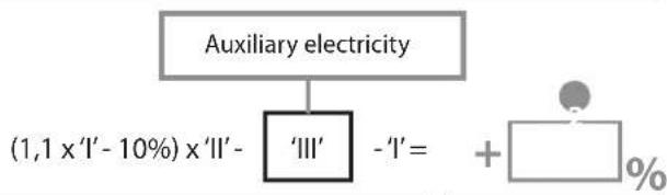
Water heating energy efficiency of package under average climate
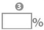
Water heating energy efficiency class of package under average climate
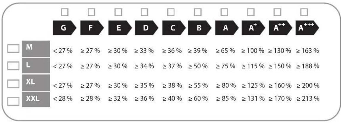
other
| Category | G (%) | F (%) | E (%) | D (%) | C (%) | B (%) | A (%) | A⁺ (%) | A⁺⁺ (%) | A⁺⁺⁺ (%) | | :--- | :--- | :--- | :--- | :--- | :--- | :--- | :--- | :--- | :--- | :--- | | M | < 27 % | ≥ 27 % | ≥ 30 % | ≥ 33 % | ≥ 36 % | ≥ 39 % | ≥ 65 % | ≥ 100 % | ≥ 130 % | ≥ 163 % | | L | < 27 % | ≥ 27 % | ≥ 30 % | ≥ 34 % | ≥ 37 % | ≥ 50 % | ≥ 75 % | ≥ 115 % | ≥ 150 % | ≥ 188 % | | XL | < 27 % | ≥ 27 % | ≥ 30 % | ≥ 35 % | ≥ 38 % | ≥ 55 % | ≥ 80 % | ≥ 125 % | ≥ 160 % | ≥ 200 % | | XXL | < 28 % | ≥ 28 % | ≥ 32 % | ≥ 36 % | ≥ 40 % | ≥ 60 % | ≥ 85 % | ≥ 131 % | ≥ 170 % | ≥ 213 % |Water heating energy efficiency under colder and warmer climate conditions
The energy efficiency of the package of products provided for this fiche may not correspond to its actual energy efficiency once installed in a building, as the efficiency is influenced by further factors such as heat loss in the distribution system and the dimensioning of the products in relation to building size and characteristics.

GAS BOILER SYSTEM COMMISSIONING CHECKLIST
This Commissioning Checklist is to be completed in full by the competent person who commissioned the boiler as a means of demonstrating compliance with the appropriate Building Regulations and then handed to the customer to keep for future reference.
Failure to install and commission according to the manufacturer's instructions and complete this Benchmark Commissioning Checklist will invalidate the warranty. This does not affect the customer's statutory rights.
| Customer name: Telephone number: | ||||||||||||||||||||||
| Address: | ||||||||||||||||||||||
| Boiler make and model: | ||||||||||||||||||||||
| Boiler serial number: | ||||||||||||||||||||||
| Commissioned by (PRINT NAME): Gas Safe register number:Company name: Telephone number: | ||||||||||||||||||||||
| Company address: | ||||||||||||||||||||||
| Commissioning date: | ||||||||||||||||||||||
| To be completed by the customer on receipt of a Building Regulations Compliance Certificate*Building Regulations Notification Number (if applicable): | ||||||||||||||||||||||
| CONTROLS (tick the appropriate boxes) | ||||||||||||||||||||||
| Time and temperature control to heating Room thermostat and programmer/timerLoad/weather compensation | Programmable room thermostat | |||||||||||||||||||||
| Optimum start control | ||||||||||||||||||||||
| Time and temperature control to hot water Cylinder thermostat and programmer/timer Combination Combination | Boiler | |||||||||||||||||||||
| Heating zone valves Fitted Not required | ||||||||||||||||||||||
| Hot water zone valves Fitted Not required | ||||||||||||||||||||||
| Thermostatic radiator valves Fitted Not required | ||||||||||||||||||||||
| Automatic bypass to system Fitted Not required | ||||||||||||||||||||||
| Boiler interlock Provided | ||||||||||||||||||||||
| ALL SYSTEMS | ||||||||||||||||||||||
| The system has been flushed and cleaned in accordance with BS7593 and boiler manufacturer's instructions Yes | ||||||||||||||||||||||
| What system cleaner was used? | ||||||||||||||||||||||
| What inhibitor was used? Quantity litres | ||||||||||||||||||||||
| Has a primary water system filter been installed? Yes No | ||||||||||||||||||||||
| CENTRAL HEATING MODE measure and record: | ||||||||||||||||||||||
| Gas rate | m3/hr | OR ft3/hr | ||||||||||||||||||||
| Burner operating pressure (if applicable) | mbar | OR Gas inlet pressure | mbar | |||||||||||||||||||
| Central heating flow temperature °C | ||||||||||||||||||||||
| Central heating return temperature °C | ||||||||||||||||||||||
| COMBINATION BOILERS ONLY | ||||||||||||||||||||||
| Is the installation in a hard water area (above 200ppm)? Yes No | No | |||||||||||||||||||||
| If yes, and if required by the manufacturer, has a water scale reducer been fitted? Yes No | No | |||||||||||||||||||||
| What type of scale reducer has been fitted? | ||||||||||||||||||||||
| DOMESTIC HOT WATER MODE Measure and Record: | ||||||||||||||||||||||
| Gas rate | m3/hr | OR ft3/hr | ||||||||||||||||||||
| Burner operating pressure (at maximum rate) | mbar OR Gas inlet pressure at maximum rate mbar | |||||||||||||||||||||
| Cold water inlet temperature °C | ||||||||||||||||||||||
| Hot water has been checked at all outlets Yes Temperature °C | Yes | Temperature °C | ||||||||||||||||||||
| Water flow rate l/min | ||||||||||||||||||||||
| CONDENSING BOILERS ONLY | ||||||||||||||||||||||
| The condensate drain has been installed in accordance with the manufacturer's instructions and/or BS5546/BS6798 Yes | ||||||||||||||||||||||
| ALL INSTALLATIONS | ||||||||||||||||||||||
| Record the following: | At max. rate: CO ppmAt min. rate: (where possible) CO ppmAND CO/CO2 Ratio | AND | CO/CO2 Ratio | |||||||||||||||||||
| The heating and hot water system complies with the appropriate Building Regulations Yes | ||||||||||||||||||||||
| The boiler and associated products have been installed and commissioned in accordance with the manufacturer's instructions Yes | ||||||||||||||||||||||
| The operation of the boiler and system controls have been demonstrated to and understood by the customer Yes | ||||||||||||||||||||||
| The manufacturer's literature, including Benchmark Checklist and Service Record, has been explained and left with the customer Yes | ||||||||||||||||||||||
| Commissioning Engineer's Signature | ||||||||||||||||||||||
| Customer's Signature(To confirm satisfactory demonstration and receipt of manufacturer's literature) | ||||||||||||||||||||||
*All installations in England and Wales must be notified to Local Authority Building Control (LABC) either directly or through a Competent Persons Scheme. A Building Regulations Compliance Certificate will then be issued to the customer.

SERVICE RECORD
It is recommended that your heating system is serviced regularly and that the appropriate Service Interval Record is completed.
Service Provider
Before completing the appropriate Service Record below, please ensure you have carried out the service as described in the manufacturer's instructions. Always use the manufacturer's specified spare part when replacing controls.
| SERVICE 01 | Date: | |||
| Engineer name: | ||||
| Company name: | ||||
| Telephone No: | ||||
| Gas safe register No: | ||||
| Record: | At max. rate: CO ppm AND CO | 2% | ||
| At min. rate: (Where Possible) | CO ppm | AND | CO2% | |
| Comments: | ||||
| Signature | ||||
| SERVICE 03 | Date: | |||
| Engineer name: | ||||
| Company name: | ||||
| Telephone No: | ||||
| Gas safe register No: | ||||
| Record: | At max. rate: CO ppm AND CO | 2% | ||
| At min. rate: (Where Possible) | CO ppm | AND | CO2% | |
| Comments: | ||||
| Signature | ||||
| SERVICE 05 | Date: | |||
| Engineer name: | ||||
| Company name: | ||||
| Telephone No: | ||||
| Gas safe register No: | ||||
| Record: | At max. rate: CO ppm AND CO | 2% | ||
| At min. rate: (Where Possible) | CO ppm | AND | CO2% | |
| Comments: | ||||
| Signature | ||||
| SERVICE 07 | Date: | |||
| Engineer name: | ||||
| Company name: | ||||
| Telephone No: | ||||
| Gas safe register No: | ||||
| Record: | At max. rate: CO ppm AND CO | 2% | ||
| At min. rate: (Where Possible) | CO ppm | AND | CO2% | |
| Comments: | ||||
| Signature | ||||
| SERVICE 09 | Date: | |||
| Engineer name: | ||||
| Company name: | ||||
| Telephone No: | ||||
| Gas safe register No: | ||||
| Record: | At max. rate: CO ppm AND CO | 2% | ||
| At min. rate: (Where Possible) | CO ppm | AND | CO2% | |
| Comments: | ||||
| Signature | ||||
| SERVICE 02 | Date: | |||
| Engineer name: | ||||
| Company name: | ||||
| Telephone No: | ||||
| Gas safe register No: | ||||
| Record: | At max. rate: CO ppm AND CO | _2 % | ||
| At min. rate: (Where Possible) | CO ppm | AND | CO_2 % | |
| Comments: | ||||
| Signature | ||||
| SERVICE 04 | Date: | |||
| Engineer name: | ||||
| Company name: | ||||
| Telephone No: | ||||
| Gas safe register No: | ||||
| Record: | At max. rate: CO ppm AND CO | 2% | ||
| At min. rate: (Where Possible) CO ppm | AND | CO2% | ||
| Comments: | ||||
| Signature | ||||
| SERVICE 06 | Date: | |||
| Engineer name: | ||||
| Company name: | ||||
| Telephone No: | ||||
| Gas safe register No: | ||||
| Record: | At max. rate: CO ppm AND CO | 2% | ||
| At min. rate: (Where Possible) CO ppm | AND | CO2% | ||
| Comments: | ||||
| Signature | ||||
| SERVICE 08 | Date: | |||
| Engineer name: | ||||
| Company name: | ||||
| Telephone No: | ||||
| Gas safe register No: | ||||
| Record: | At max. rate: CO ppm AND CO | 2% | ||
| At min. rate: (Where Possible) CO ppm | AND | CO2% | ||
| Comments: | ||||
| Signature | ||||
| SERVICE 10 | Date: | |||
| Engineer name: | ||||
| Company name: | ||||
| Telephone No: | ||||
| Gas safe register No: | ||||
| Record: | At max. rate: CO ppm AND CO | 2% | ||
| At min. rate: (Where Possible) CO ppm | AND | CO2% | ||
| Comments: | ||||
| Signature | ||||

ITALIAN DESIGN
Ariston Thermo UK Ltd
Artisan Building
Hillbottom Road
High Wycombe
Bucks HP124HJ
Telephone: 01494 418500
ariston.co.uk
- ALTEAS ONE NET
- INDEX
- The Benchmark Scheme
- To The Installer
- CUSTOMER CARE
- WARRANTY
- CAUTION
- ATTENTION!!
- Advice for the Installer
- CE labelling
- Legend :
- SAFETY REGULATION
- CONTROL PANNEL
- Legend:
- Programming key
- DISPLAY
- Overall view
- Minimum clearances
- Reference Standards
- C.O.S.H.H.
- Codes of Practice
- I.S. 813 Domestic Gas Installations
- Flue
- Ventilation
- Gas Supply
- Electrical Supply
- Water Supply
- Showers
- Flushing and Water Treatment
- IMPORTANT
- System Controls
- Location
- Codensate Discharge
- INSTALLATION
- Condensate Discharge
- Installing the Boller
- Method of positioning the boiler on the wall
- Connecting the boiler to the system
- Safety Valve Discharge
- WARNING!
- DO NOT APPLY HEAT TO THE COPPER SAFETY VALVE OUTLET PIPE WHILST IT IS CONNECTED TO THE 3 BAR SAFETY RELIEF VALVE.
- Gas connection
- Water connection
- CAUTION!!
- REMOVE ONLY THE SCREWS SHOWN IN THE PICTURE
- Underfl oor heating
- BEFORE THE DEVICE IS USED, FOR THE FIRST TIME THE TRAP MUST BE FILLED WITH WATER.
- Connecting the Flue
- Warning
- Fitting the Coaxial Flue (∅ 60 / 100 Horizontal)
- Fitting the 5" Flue
- Contents:
- Electrical connections
- Power supply cable
- Important!
- Peripheral unit connection
- Cube Room sensor (wireless) Connection
- Room Thermostat / Remote Clock Connection
- Electrical diagram
- Initial preparation
- Electricity supply
- Filling the Heating System:
- CONNECT THE PIPE OF CONDENSATE DISCHARGE BEFORE REFILLING AND THE DE-AERATION OF THE HEATING CIRCUIT.
- Gas Supply:
- Water Treatment:
- Start-up procedure
- FIRST IGNITION
- Assicurarsi che:
- Supply static pressure check
- ACTIVATION OF THE DISAERATION PROCEDURE AND AUTOMATIC CALIBRATION
- WARNING!! THE AUTOMATIC CALIBRATION MUST BE DONE IN CASE OF:
- Preparing the measuring equipment
- Supply dinamic pressure check
- Adjusting the CO2
- Intermediate Power
- N.B.: VALUES WITH THE CASING CLOSED.
- Maximum power DHW
- Minimum power
- Ending the adjustment
- Maximun Heating Power adjustment
- Checking slow Ignition power
- Heating ignition delay adjustment
- Gas Changeover
- WARNING!!
- AUTO function
- Example 1:
- Example 2:
- Example 3:
- Appliance shut-off conditions
- Safety shut-off
- Safety shut-off due to insufficient water pressure
- Operation shutdown
- Malfunction warning
- Circulation pump malfunction signal
- NOTE - ERROR 804:
- Anti-frost Device
- TECHNICAL AREA - reserved for qualifi ed technician
- COMPLETE MENU STRUCTURE
- Technical Area
- Configuration Wizard
- Boiler
- Guided procedures
- Service options
- Test mode
- Service
- General comments
- THE AUTOMATIC CALIBRATION MUST BE DONE IN CASE OF:
- Operational test
- Draining procedures
- DO NOT MIX DIFFERENT TYPES OF ANTI-FREEZE.
- Draining the domestic hot water system and indirect cylinder
- Cleaning the primary exchanger
- Cleaning the trap
- GENERAL ACCESS
- Disconnect the boiler
- General Access
- ELECTRICAL UNIT
- Control box access
- Fuse
- Main P.C.B.
- Display P.C.B.
- HYDRAULIC UNIT
- By-pass assembly
- Pump
- D.H.W. Flow switch assembly
- LEFT HAND HYDRAULIC BLOCK ASSEMBLY
- Secondary heat exchanger
- Condensate trap
- Safety valve
- Temperature sensors
- Manual Air vent
- Main heat exchanger
- BURNER UNIT
- Important!!
- PACKAGES OF COMBINATION HEATER, TEMPERATURE CONTROL AND SOLAR DEVICE
- GAS BOILER SYSTEM COMMISSIONING CHECKLIST
- SERVICE RECORD
- Service Provider
Brand : Ariston Thermo
Model : Alteas One Net
Category : Chauffe-eau instantané et ballon d'eau chaude