
TruTouch X7 - Screen Newline - Free user manual and instructions
Find the device manual for free TruTouch X7 Newline in PDF.


| Product Type | Collaboration Touch Screen |
| Display Size Available | 65", 75", 86" |
| Resolution | 4K UHD (3840 x 2160 pixels) |
| Touch Points | 10 points |
| Brightness | ≥ 320 cd/m² |
| Contrast Ratio | 4000:1 |
| Response Time | 8 ms |
| Speaker Output | 2 x 15 W forward |
| Microphone Array | 4 microphones, 8 m pickup range |
| Camera | Top and bottom 2 MP, 1080p@30fps |
| Power Consumption (Max) | ≤ 300 W (75" model) |
| Standby Power | ≤ 0.5 W |
| Working Voltage | AC 100 V – 240 V, 50/60 Hz |
| Net Weight (75") | 54.6 kg |
| Dimensions (75") | 1792 x 1170 x 102 mm |
| Touch Surface | Anti-glare tempered glass, 7H hardness |
| Ports | HDMI (4 in, 1 out), DP, USB (multiple), RS-232, RJ45, OPS slot |
| Smart System | ARM A53 quad-core, 2 GB RAM, 8 GB flash |
| Mounting Standard | VESA 800 x 400 mm (75"/86") or 600 x 400 mm (65") |
| Operating Temperature | 0 °C – 40 °C |
| Safety Features | Overheat protection, auto shut-off, child lock |
Frequently Asked Questions - TruTouch X7 Newline
User questions about TruTouch X7 Newline
0 question about this device. Answer the ones you know or ask your own.
Ask a new question about this device
Download the instructions for your Screen in PDF format for free! Find your manual TruTouch X7 - Newline and take your electronic device back in hand. On this page are published all the documents necessary for the use of your device. TruTouch X7 by Newline.
USER MANUAL TruTouch X7 Newline
Collaboration Touch Screen
User Manual
-V1.0-
Contents
About This Document 01
Safety Instruction 02
A. Overview 05
Introduction 05
Parts 06
Ports 08
Remote Control 10
Camera 12
Temperature Control Reset Button 13
B. Installation Guide 14
Safety Precautions 14
Installation Precautions 15
Installation 17
Installing the Internal PC (Optional) 18
Installing Newline Assistant 19
C. Getting Started 20
Power On 20
Power Off 21
Calibration 22
D. Operating the Touch Screen 25
Start Screen 25
Home 25
System Settings 30
Network Settings 30
Language and Input Method Settings 31
Storage 34
Applications 34
Date and Time Settings 35
Power ON/OFF Setting 37
Tool Bar Setting 39
Camera Setting 39
Input/Output Setting 40
Logo and Wallpaper Setting 40
Bluelight Filter 41
Newline Extension 41
About 42
Windows 42
Connection 43
Whiteborad 44
Whiteboard Mode 44
Whiteboard Functions 45
Page Operations 50
Object Detection 51
Add Shortcut 53
Add Shortcuts to Home Page 53
Add Quick Start Windows Programs in Smart System 54
Gadget 56
File Management 57
File Viewer Page 57
File Preview 57
File Filtering 58
File Search 59
File Operation 59
End Meeting 60
Manually End Meeting 60
Automatically End Meeting 62
E. Quick Setting Menu 63
F.Serial Port Control 64
G.FAQs & Troubleshooting 69
H. Specifications 72
I.More Information 75
Welcome to the world of TRUTOUCH.
Thank you for choosing the TRUTOUCH X series Collaboration Touch Screen. Please use this document to get the most out of your screen.
This device complies with part 15 of the FCC Rules. Operation is subject to the following two conditions:(1) This device may not cause harmful interference, and (2) this device must accept any interference received, including interference that may cause undesired operation.
NOTE 1: This equipment has been tested and found to comply with the limits for a Class B digital device, pursuant to part 15 of the FCC Rules. These limits are designed to provide reasonable protection against harmful interference in a residential installation. This equipment generates, uses and can radiate radio frequency energy and, if not installed and used in accordance with the instructions, may cause harmful interference to radio communications. However, there is no guarantee that interference will not occur in a particular installation. If this equipment does cause harmful interference to radio or television reception, which can be determined by turning the equipment off and on, the user is encouraged to try to correct the interference by one or more of the following measures:
- Reorient or relocate the receiving antenna.
- Increase the separation between the equipment and receiver.
- Connect the equipment into an outlet on a circuit different from that to which the receiver is connected.
- Consult the dealer or an experienced radio/TV technician for help.
NOTE 2: Any changes or modifications to this unit not expressly approved by the party responsible for compliance could void the user's authority to operate the equipment.
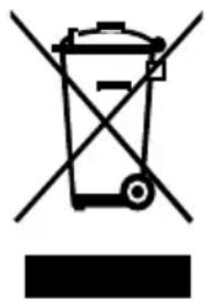
The symbol of the crossed out wheeled bin indicates this product should not be placed in municipal waste. Instead, dispose of waste equipment by taking it to a designated collection point for electrical and electronic equipment recycling.
About This Document
This document describes multiple functions, instructions, and notes about the product.
Symbols are used in this document to indicate operations that need particular attention. The symbols are defined as follows:
 NOTE NOTE | Provides additional information to supplement operation in the main text. |
 TIP TIP | Provides tips for operation. |
 CAUTION CAUTION | Indicates a potentially hazardous situation that, if not avoided, could result in equipment damage, data loss, performance deterioration, or unanticipated results. |
 WARNING WARNING | Indicates a hazard with risk that, if not avoided, could result in death or injury. |
Safety Instruction
For your safety, please read the following instruction before you use the product. Serious injury or property damage may be caused by improper operations. Do not try to repair the product on your own.
| WARNING | |
 | Disconnect the product from power supply immediately if major failures occur.Major failures include the following:Smoke, peculiar smell or abnormal sound is discharged from the product.No image or sound is displayed, or the image error occurs.In the preceding scenarios, do not continue to use the product. Disconnect power supply immediately and contact professional staff for troubleshooting. |
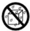
 | Do not drop liquid, metal or anything combustible into the product.If any liquid or metal is dropped into the product, power off the product and disconnect power supply, then contact professional staff for solutions.Pay attention to children when they are close to the product. |
| Put the product on a stable surface.An unstable surface includes and does not limited to an inclined plane, a shaky stand, desk or platform, which might cause turnover and damage. | |
 | Do not open the cover or change the product on your own.High voltage components are installed in the product. When you open the cover, high voltage, electric shock, or other dangerous situations may occur.If inspection, adjustment, or maintenance is required, contact the local distributor for help. |
 | Use the specified power supply.To prevent the product from being damaged, do not use any cables other than the one provided with the product.Use a three-wire socket and ensure that it is properly grounded.Pull out the power plug from the socket if the product is not used for a long period. |
| Clean the dust and metal on the power plug regularly.Fire or electric shock may be caused if the product is powered on, when you are cleaning.Pull out the power plug before cleaning it with a dried cloth. | |
| The voltage/current of the rear power output port is 5 V/2 A (maximum). Purchase the power code/AC adapter according to customer needs. The port can be used for Newline Android box X10D. Please do not connect any products with different power requirement. Otherwise, it may cause damage to products or fire.Do not put items on the top of the product.Do not put items, such as a container for liquid (a vase, flowerpot, cosmetics or liquid medicine) on the top of the product.If any water or liquid is spilled on the product, a short circuit may occur and cause fire or electric shock.Do not walk on or hang any items on the product. | |
 | |
 | Do not install the product in an improper place.Do not install the product in humid places, such as the bathroom, the shower room, near windows, or outdoor environments that experience rain, snow or other harsh weather. Avoid installation near hot spring vapor. The preceding environments may cause faults in the product or electric shock under extreme conditions.Do not put exposed fire source, such as an ignited candle, on the product. |
 | Pull out the power plug during thunderstorms.Do not touch the product during a lighting storm to avoid electric shock.Install or place components that supply high enough voltage to cause personal injury out of the reach of children. |
 | Do not touch the power cable with wet hands. |
 CAUTION CAUTION | |
 | Do not install the product in high temperature environments.Do not install the product near a heat source, such as a radiator, a heat reservoir, a stove or other heating products.Do not expose the product to direct sunlight, which may cause high temperatures and subsequent faults in the product. |
 | For transport.Pack the product for transport or maintenance by using the cartons and cushioning material provided with the product.Vertically move the product during transport. The screen or other components are easily broken if the product is moved by an improper way.Before you move the product, disconnect all external connections and separate all toppling preventing products. Move the product carefully to prevent it from being hit or squeezed, especially the screen, which may cause injury if broken. |
 | Do not cover or block up any vents on the product.Any overheated components may cause fire, damage the product, and shorten the service life.Do not lay the product down where the venting surface will be covered. |
| CAUTION | |
 | Do not install the product on a carpet or cloth.Do not use a cloth such as table cloth to cover the product. |
 | Use the battery correctly.Galvanic corrosion, electric leakage, and even fire may be caused by improper battery usage.It is recommended to use the designated type of battery and install the battery by correct electrodes (positive and negative).Do not install and use a new battery with a used one.Take out the batteries if the remote control is not used for a long period.Do not expose the batteries to overheated environments such as sunlight and firing.Dispose of the used batteries based on your local regulations. |
| Do not damage the power cable.Do not damage, change, twist, bend, or forcibly drag the power cable.Do not put weights (such as the product itself) on the power cable.Do not forcibly drag the cable when you pull out the power plug. If the power cable is damaged, please contact the local distributor to repair or replace it.The power cable in the accessory box is for this product only. Do not use it on other products. | |
| Additional advice:Use the product in an environment with comfortable lighting. It is harmful to your eyes to watch in a too bright or too dark environment.Relax your eyes after a period of time for watching.Keep sufficient distance from the product to protect your eyes and prevent eyestrain.Adjust the volume to an appropriate level, especially at night.Use amplifier equipment as the audio input source with caution. If you must use amplifier equipment, the input power should not exceed the maximum of speaker power. Otherwise, the speaker can become overpowered and damaged. | |
| About USB port.Front USB ports (marked with ⇌) and rear USB 3.0/USB 2.0 ports switch connections based on signal sources. If the current signal source is reading the data from an external product connecting to the port, please switch the signal source after the data reading is complete. Otherwise, the data or product may be damaged. | |
| Keep away from the product when you use a radio.The product complies with the international EMI standard to pervent radio interference. However, interference may still exists and causes noise in the radio.If noise occurs in the radio, try the following solutions.Adjust the direction of the radio antenna to avoid the interference from the product.Keep the radio away from the product. | |
Introduction
The Collaboration Touch Screen adopts the advanced touch technology and All in One design, and integrates video, audio, touch, writing, and multi-media presentation functions. This product does not require additional products such as camera, speakers or microphone.
Dedicated smart system is customized as a meeting assistant. It can meet requirements of various meeting modes, implementing convenient comments on local documents, viewing multi-media files, conducting multi-party remote video and audio meetings, managing local files, and improving the meeting experience and work efficiency.
- All-in-one design facilitates operation and saves complex hardware and software setting.
- 4K HD LED screen uses full lamination technology and high gamut backlight, which completely avoids light refraction and ghosting problems and enables a clear, light and thin screen.
- Provide perfect writing experience, enable writing mode to be switched over in the Windows and smart systems, and automatically identify pen thickness and color. With a feel like writing on paper, meeting quality is significantly improved.
Parts
- Front View
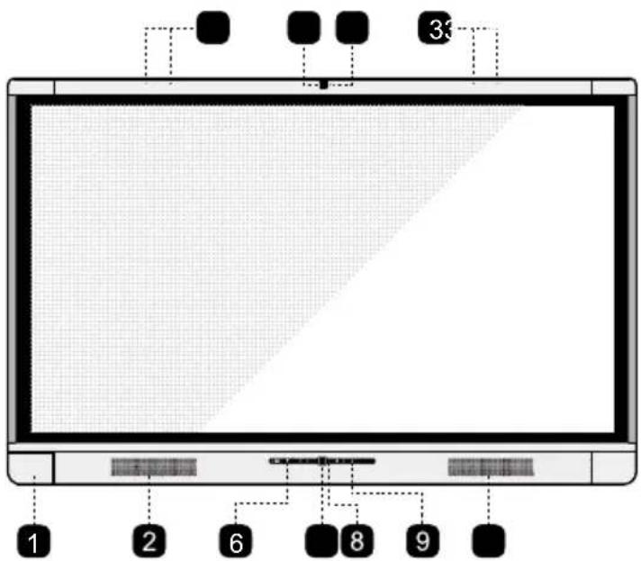
Note
- The top and bottom cameras cannot be used at the same time.
-
The indicators of the top and bottom cameras are turning white when in use and off when not in use.
-
Rear View
• X9/X8
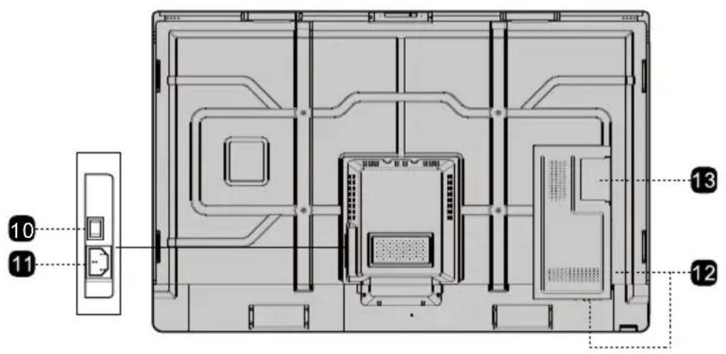
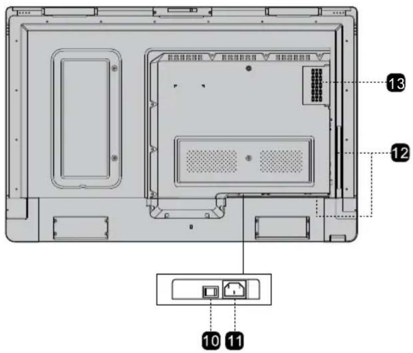
1 Front Ports
2 Speakers
3 Microphone Array
4 Top Camera
5 Camera Indicator(Top)
6 Remote control receiver
7 Bottom Camera
8 Camera Indicator (Bottom)
9 Front Buttons
10 Power Switch
11 Power Supply Plug
12 Rear Ports
13 Internal PC Port (OPS)
Ports
- Front Ports

CAUTION
Front USB ports (marked with ) and rear USB 3.0/USB 2.0 ports switch connections based on signal sources. If the current signal source is reading the data from an external product connecting to the port, please switch the signal source after the data reading is complete. Otherwise, the data or product may be damaged.
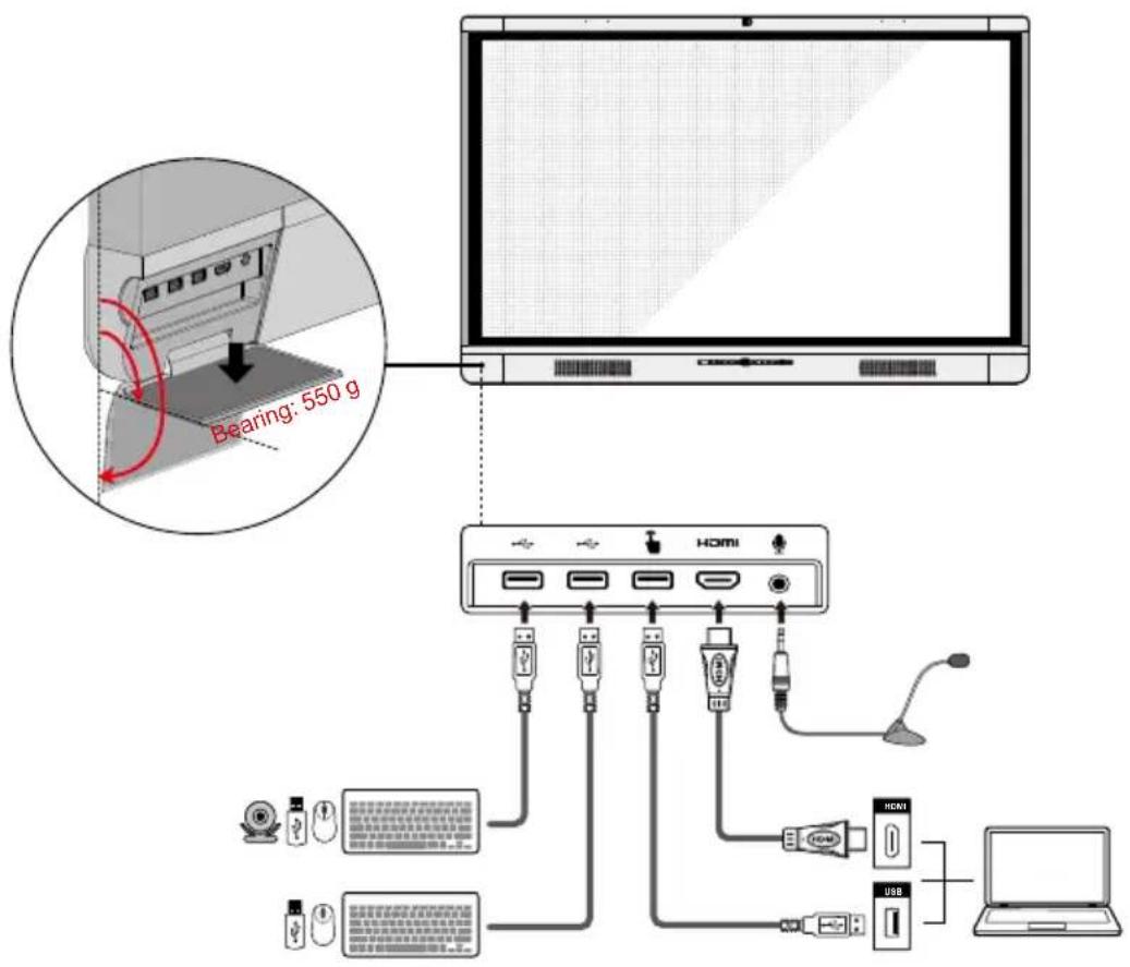
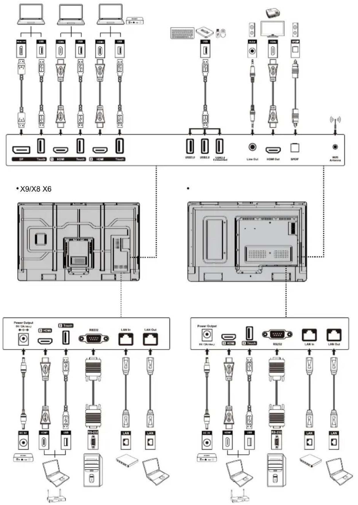
- Rear Ports

WARNING
The voltage/current of the rear power output port is 5V/2A (maximum). Purchase the power code/AC adapter according to customer needs. The port can be used for Newline Android box X10D. Please do not connect any products with different power requirement. Otherwise it may cause the damage to products or fire.
flowchart
graph TD
    subgraph Top架构
        A["笔记本电脑"] --> B["USB1.0"]
        C["笔记本电脑"] --> D["USB2.0"]
        E["笔记本电脑"] --> F["USB3.0"]
        G["笔记本电脑"] --> H["USB4.0"]
        I["笔记本电脑"] --> J["USB5.0"]
        K["笔记本电脑"] --> L["USB6.0"]
        M["笔记本电脑"] --> N["USB7.0"]
        O["笔记本电脑"] --> P["USB8.0"]
        Q["笔记本电脑"] --> R["USB9.0"]
        S["笔记本电脑"] --> T["USB10.0"]
        U["笔记本电脑"] --> V["USB11.0"]
        W["笔记本电脑"] --> X["USB12.0"]
        Y["笔记本电脑"] --> Z["USB13.0"]
        AA["笔记本电脑"] --> AB["USB14.0"]
        AC["笔记本电脑"] --> AD["USB15.0"]
        AE["笔记本电脑"] --> AF["USB16.0"]
        AG["笔记本电脑"] --> AH["USB17.0"]
        AI["笔记本电脑"] --> AJ["USB18.0"]
        AK["笔记本电脑"] --> AL["USB19.0"]
        AM["笔记本电脑"] --> AN["USB20.0"]
        AO["笔记本电脑"] --> AP["USB21.0"]
        AQ["笔记本电脑"] --> AR["USB22.0"]
        AS["笔记本电脑"] --> AT["USB23.0"]
        AU["笔记本电脑"] --> AV["USB24.0"]
        AW["笔记本电脑"] --> AX["USB25.0"]
        AY["笔记本电脑"] --> AZ["USB26.0"]
        BA["笔记本电脑"] --> BB["USB27.0"]
        BC["笔记本电脑"] --> BD["USB28.0"]
        BE["笔记本电脑"] --> BF["USB29.0"]
        BG["笔记本电脑"] --> BH["USB30.0"]
        BI["笔记本电脑"] --> BJ["USB31.0"]
        BK["笔记本电脑"] --> BL["USB32.0"]
        BM["笔记本电脑"] --> BN["USB33.0"]
        BO["笔记本电脑"] --> BP["USB34.0"]
        BQ["X9/X8 X6"] --> BR["X9/X8 X6"]
    end

    subgraph Bottom架构
        C
        D
        E
        F
        G
        H
        I
        J
        K
        L
        M
        N
        O
        P
        Q
        R
        S
        T
        U
        V
        W
        X
        Y
        Z
    end

    Top架构 -->|USB| TopLevel
    TopLevel -->|USB| TopLevel
    TopLevel -->|USB| TopLevel
    TopLevel -->|USB| TopLevel
    TopLevel -->|USB| TopLevel
    TopLevel -->|USB| TopLevel
    TopLevel -->|USB| TopLevel
    TopLevel -->|USB| TopLevel
    TopLevel -->|USB| TopLevel
    TopLevel -->|USB| TopLevel
    TopLevel -->|USB| TopLevel
    Toplevel -->|USB| TopLevel
    TopLevel -->|USB| TopLevel
    TopLevel -->|USB| TopLevel
    TopLevel -->|USB| TopLevel
    TopLevel -->|USB| TopLevel
    TopLevel -->|USB| TopLevel
    TopLevel -->|USB| TopLevel
    TopLevel -->|USB| TopLevel
    TopLevel -->|USB| TopLevel
    TopLevel -->|USB| TopLevel
    Top Level -->|USB| TopLevel
    Top Level -->|USB| TopLevel
    Top Level -->|USB| TopLevel
    Top Level -->|USB| TopLevel
    Top Level -->|USB| TopLevel
    Top Level -->|USB| TopLevel
    Top Level -->|USB| TopLevel
    Top Level -->|USB| TopLevel
    Top Level -->|USB| TopLevel
    Top Level -->|USB| TopLevel
    Top Layer -->|USB| TopLevel
    Top Layer -->|USB| TopLevel
    Top Layer -->|USB| TopLevel
    Top Layer -->|USB| TopLevel
    Top Layer -->|USB| TopLevel
    Top Layer -->|USB| TopLevel
    Top Layer -->|USB| TopLevel
    Top Layer -->|USB| TopLevel

Tip:
You are advised to connect X10D to HDMI rear 2.
- Front Buttons

natural_image
User interface bar with playback controls and a circular button (no text or symbols)| Buttons Operations Functions | Indicator Status Description | ||
 | Short press Power on/off | · Steady on red: shut down modes· Steady on white: working state | |
 | Short press | Decrease the sound volume | · Steady on white: receiving an instruction from a button or remote control (off in 10 seconds)· Off: no instruction received from the button or the remote control in 10 seconds (in power-on state) |
| Long press for more than 1 second | Decrease the sound volume continuously | ||
 | Short press | Increase the sound volume | |
| Long press for more than 1 second | Increase the sound volume continuously | ||
 | Short press | Open the external source menu | |
| Long press for more than 2 second | Screen Lock | ||
 | Short press | Return to the last menu/Exit | |
 | Short press | Go to the home page | |
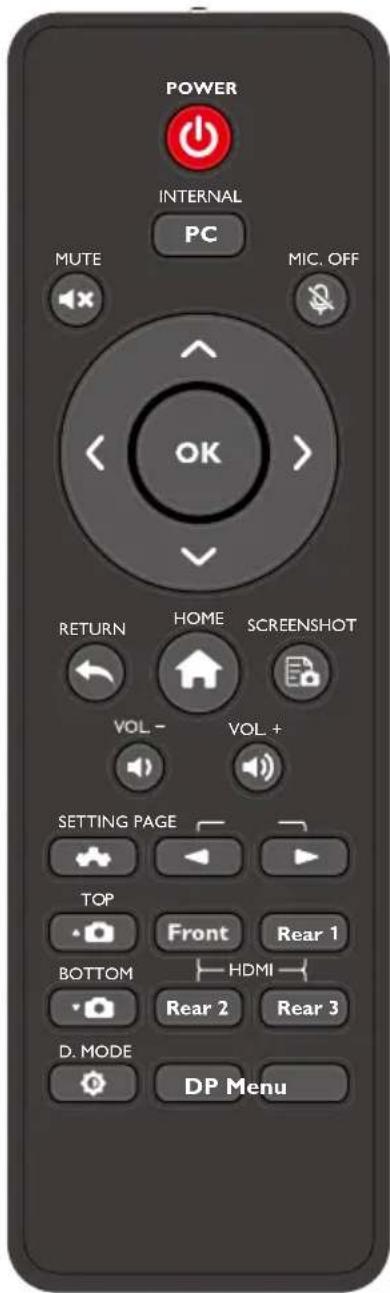
Remote Control

CAUTION
Carefully read the following instructions before using the remote control to avoid possible faults:
- Do not drop or damage the remote control.
- Do not spill water or other liquids on the remote control.
- Do not place the remote control on a wet object.
- Do not place the remote control directly under sunlight or near an overheating heat source.
| Buttons Functions | |
| Power On/Off | |
| PC | Switch Source to Internal PC |
| Mute/Unmute Audio | |
| Mute/Unmute Microphone | |
| OK | Confirm/OK |
| Up/Down/Left/Right | |
| Return to Previous/Exit | |
| Go to the Home Page | |
| Take a Screenshot | |
| Decrease the Sound Volume | |
| Increase the Sound Volume | |
| Settings | |
| Page Up | |
| Page Down | |
| Switch to Top Camera | |
| Switch to Bottom Camera | |
| Front | Switch Source to HDMI Front |
| Rear 1 | Switch Source to HDMI Rear 1 |
| Rear 2 | Switch Source to HDMI Rear 2 |
| Rear 3 | Switch Source to HDMI Rear 3 |
| Buttons Functions | |
| Toggle Display Backlight Mode (including Standard and ECO modes) | |
| DP | Switch Source to DisplayPort |
| Menu | Open the External Source Menu (Short Press)Screen Lock (Long Press for More than 2 Second) |
Camera
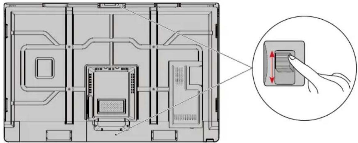
You can fine-tune the angles of the cameras using the cameras adjustment handle on the back of the screen.
• X9/X8
• X6
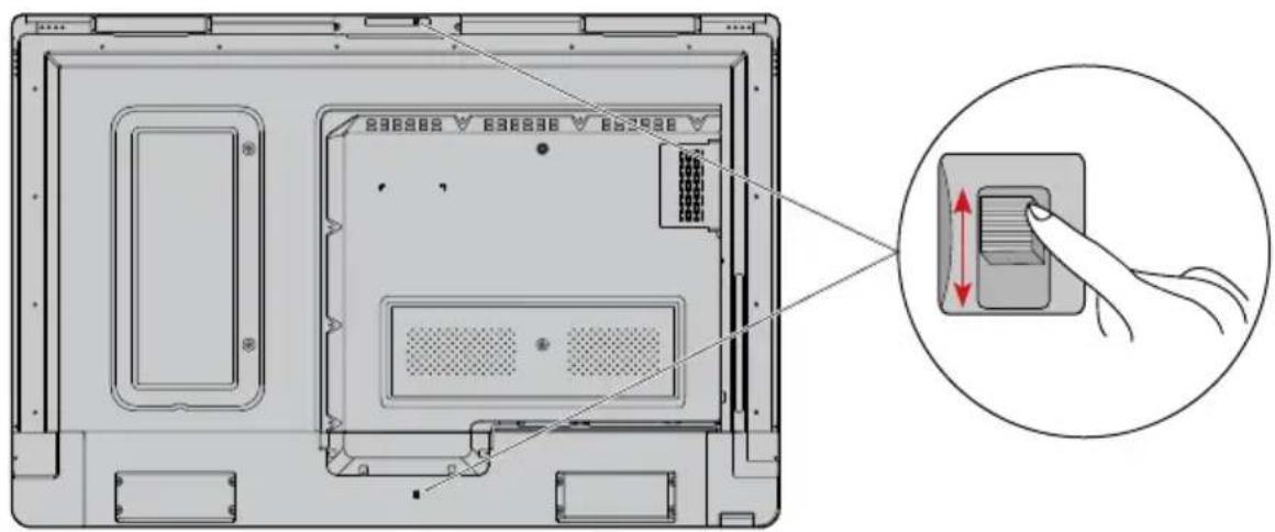
Angle adjustment:
Top camera: The initial position is 6^ facing down and can be adjust up to 9^ more downwards.
Bottom camera: The initial position is 0^ and can be adjust up to 12^ upwards.

Adjustment angle of the top camera
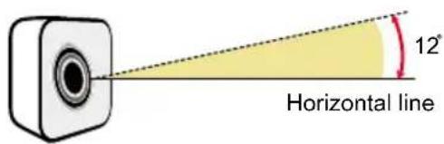
Adjustment angle of the bottom camera
Temperature Control Reset Button
In certain special installation or operation environments, the ventilation condition of the screen is poor and the heat dissipation efficiency is low. As a result, the internal temperature can rise. When the internal temperature sensor detects that the temperature has reached the threshold, the system will go to shut down mode to avoid any permanent damages to the components caused by high temperature. Please check the device and environment, and turn the power on again.
Safety Precautions
- Installation Environment
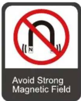
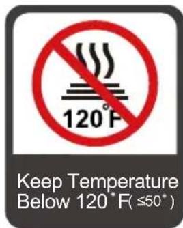


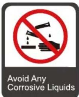
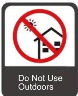
- Installation Direction
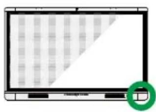
natural_image
Front view of a computer monitor with a grid pattern and a green circular icon (no text or symbols)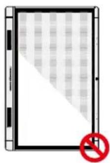
natural_image
Diagram of a tablet with a diagonal striped pattern and a red prohibition symbol (no text or labels)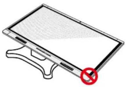
natural_image
Illustration of a flat-screen monitor with a red prohibition symbol on its side (no text or labels)Hang the Unit Horizontally No Vertical Installation Do Not Lay Flat
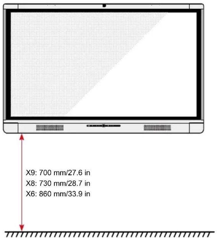
- Installation Height
Recommended installation height from the floor to the bottom of the screen: 700 mm/27.6 in (X9), 730 mm/28.7 in (X8), 860 mm/33.9 in (X6)
Installation Precautions
- Weight Loading
Weight of the product: 157.9 lb/71.6 kg (X9), 120.4 lb/54.6 kg (X8), 98.1 lb/44.5 kg (X6)
- When using a mobile stand, ensure that the weight of the product is less than the loading capacity of the mobile stand.
- When using the wall-mount bracket, ensure that the wall can support the weight of the product. We recommend that the wall surface be reinforced and have a loading capacity 4 times of the weight of the product. Consult a professional installer for wall-mount installation.
Note
The company does not undertake relevant legal responsibility for any problems caused by improper operation, if the third party mobile stand, or wall-mount bracket is beyond the scope of the product.
- Do not install the product where it might be hit by a door.
- Ventilation
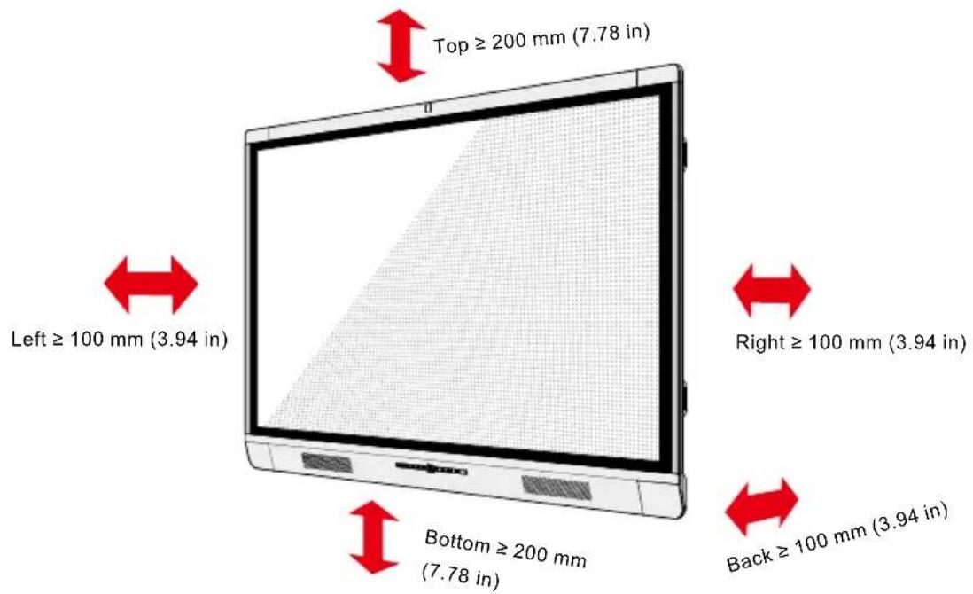
Ensure adequate ventilation and/or air conditioning environment. We recommend keeping certain distances from the side of the product to the wall or panels. Proper space for ventilation is shown in following figure.
Installation
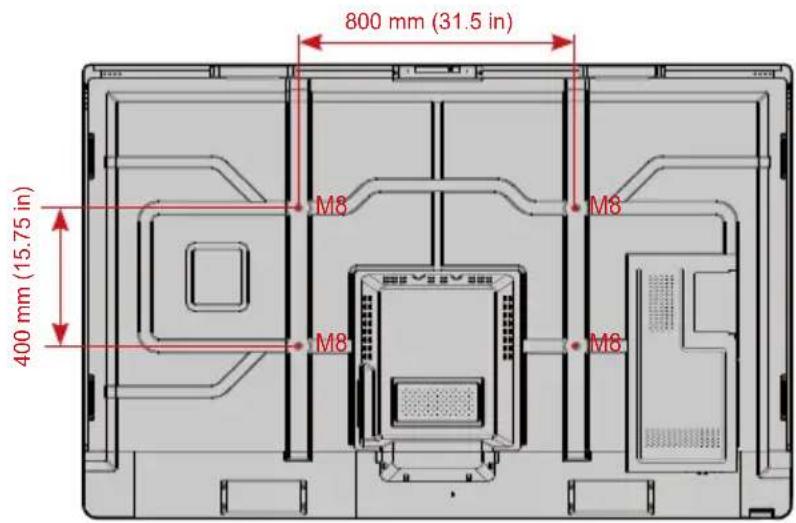
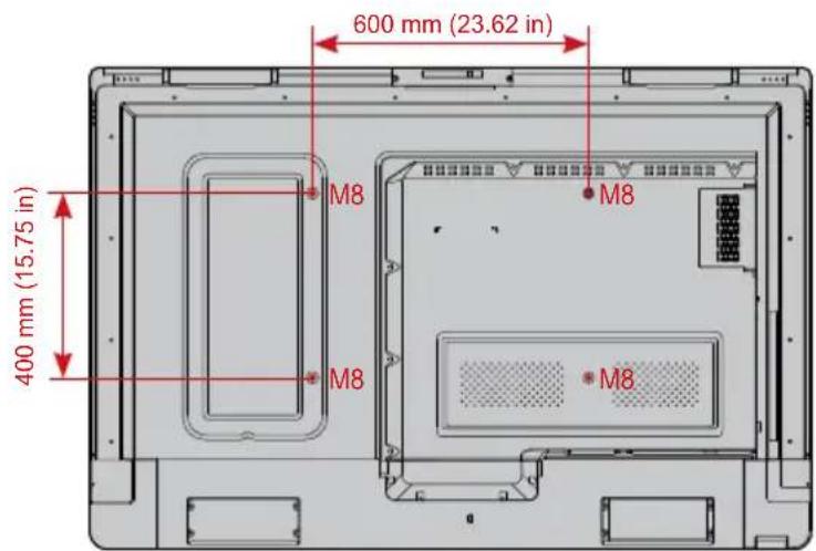
The dimensions of the four bracket mounting holes on the back panel are VESA MIS-Fcompliant (X9 or X8: 800 x 400 mm/31.50 x 15.75 in; X6: 600 x 400 mm/23.62 x 15.75 in). Use metric M8 screws with length of 10 mm to 15 mm (0.40 to 0.59 in) to secure the touch screen with the mounting system. Dimensions of the mounting holes on the back panel are shown on the following figure.
Note
Consult a professional installer to install the display product.
• X9/X8
• X6
Installing the Internal PC (Optional)

CAUTION
The internal PC does not support hot plugging. Therefore, you must insert or remove it when the screen is powered is off. Otherwise, the screen or internal PC may be damaged.
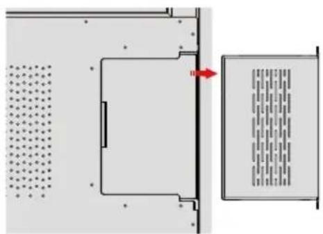
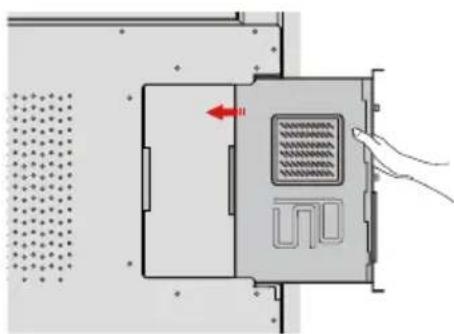
You will need to purchase the internal PC separately. Perform the following steps to install the internal PC.
Step 1: Unscrew the M3 screws by hand to remove the internal PC shielding cover.
natural_image
Diagram showing a room with ventilation grilles and a door, no text or symbols presentStep 2: Push the internal PC into the port at the rear of the screen from right to left.
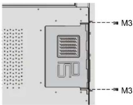
Step 3: Secure the internal PC to the display by using the M3 screws.
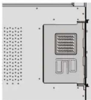
Step 4: Ensure the installation is correct before turning the power on again.
natural_image
Pure diagram of a device casing with internal grid pattern and no text or symbolsInstalling Newline Assistant
- Introduction
Newline Assistant is the tool used as a bridge between smart system and Internal PC (OPS). It helps to add windows software to smart system as well as to protect USB data/camera when switching between sources.
Therefore we strongly recommend users install Newline Assistant after installing the internal PC.
- Installation
Step 1: Install Internal PC correctly.
Step 2: On the Home page, click Windows. It will switch the signal source to Internal Windows system.
Step 3: Log in to the website www.newline-interactive.com and choose Products > Software to download the Newline Assistant installation package.
Step 4: Install Newline Assistant as instructed.
Power On
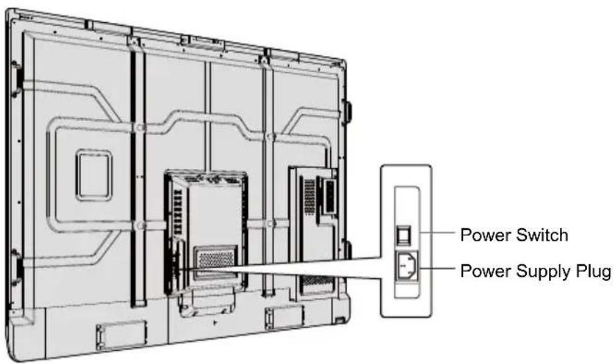
Step 1: Plug the power supply into the power outlet fully and plug the power connector into the side of the product. Ensure the power is in the range of 100V to 240V with frequency at 50Hz / 60Hz ± 5% . The power current must be grounded.
Note
The power outlet should be installed near the equipment and shall be easily accessible.
Step 2: Flip on the power switch located on the side of the product to "On".
• X9/X8
• X6
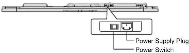
Step 3: Press the power button ⏻ on the front control panel or ⏻ on the remote control.
Power Off
Step 1: Power off the screen in the following situations:
- If there is no whiteboard data or screenshot(s), press the power button ⏻ on the front panel or the power button ⏻ on the remote control to power off the screen. Go to Step 3.
- If there is whiteboard data or screenshot(s), store your meeting documentations before powering off the touch screen. Otherwise, the product will delete your meeting documentations after the meeting is complete.
Press the power button ⏻ on the front panel or the power button ⏻ on the remote control. The Save meeting discussion page will be displayed as shown in the following figure.
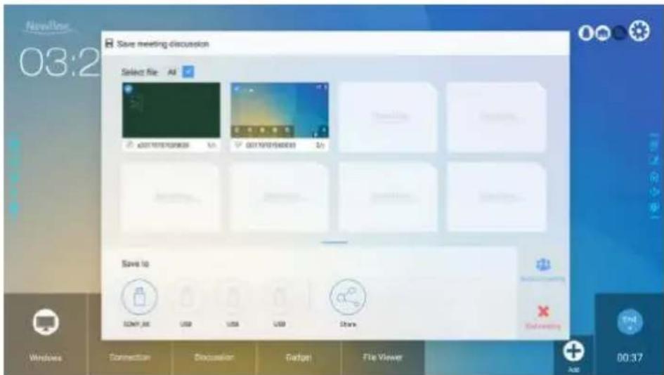
Step 2: Press the power button ⏻ on the front panel or the power button ⏻ the remote control again. The Warning dialog box will be displayed as shown in the following figure.
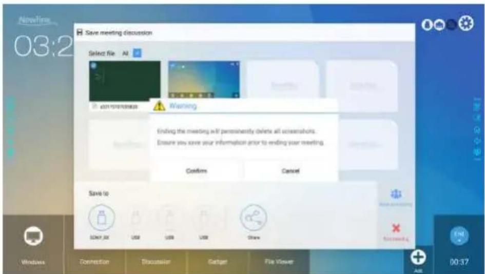
Step 3: In the Warning dialog box, click Cancel. You can save files if desired. After files are saved, return to Step 2. Click Confirm, and the power indicator will turn to red.
Step 4: If you are not going to use the product for an extended period of time, we recommend you to switch the power switch to "Off".
Note
- If an internal PC is equipped, the internal PC and the screen are powered off simultaneously when you power off the system.
- Do not forcibly disconnect the power supply of the screen when the internal PC is on.
Calibration
If the cursor position has a big deviation from the actual touch point, calibration is used to eliminate the deviation. Positioning is required in the following scenarios:
- The internal PC is used.
- A computer is connected through the HDMI or DisplayPort interface.
Note
Interface operation on the Smart system does not need positioning. External products with Microsoft Windows 7 or later versions will require positioning.
If the positioning is not correct, perform the following operations to calibrate again. The following takes Windows 10 as an example:
Step 1: Ensure that the HDMI or DP interface and external products are connected properly.
Step 2: Select the corresponding Windows signal from the signal source menu. The Windows page will be displayed.
Step 3: Select Tablet PC Settings on the Control Panel page.
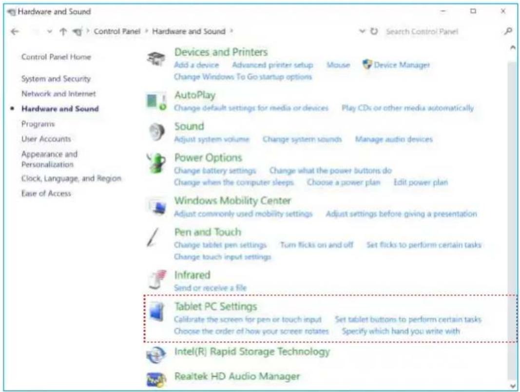
Step 4: Select Calibrate... in the Tablet PC Settings window.
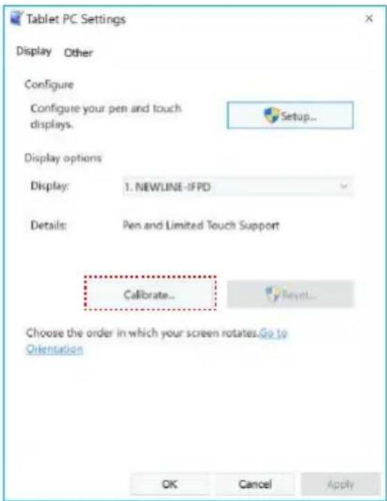
Step 5: Select Touch input from the option and start calibration.
Step 6: Use finger or pencil to click and hold the center of the flickering cross + . Do not release it until + moves to the next positioning point. Complete the calibration process as instructed.
To provide calibration samples, tap the crosshair each time that it appears on the screem.
Right-click anywhere on the screen to return to the last calibration point. Press the Esc button to close the tool. Do not change your screen orientation until you have completed the calibration process.
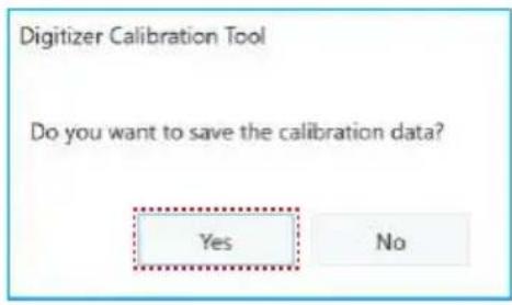
Step 7: After the calibration is complete, the Digitizer Calibration Tool dialog box will be displayed. Click Yes to save calibration data.
Tip:
- To ensure writing accuracy, use the pencil or stylus included with the product for proper positioning.
- Positioning errors may cause failure of touch functions of the display. In that case, please perform positioning again.
Step 8: The Tablet PC Settings dialog box will be displayed again. Click OK. The positioning will be complete.
Start Screen
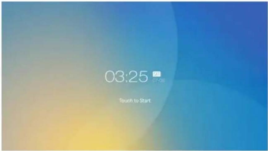
When the product is turned on, the product will show the start screen page. As shown in the following figure.
Home
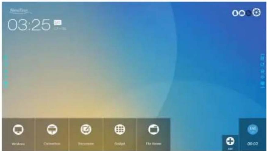
Touch the screen to start a meeting, and the product will go to the Home page. As shown in the following figure.
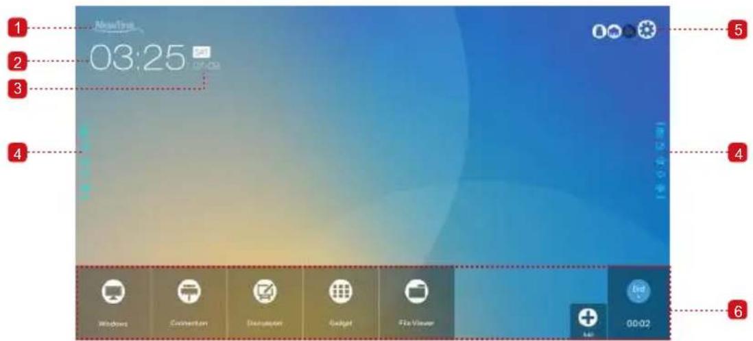
1 Logo (Shortcut to Settings)
4 Side Toolbar
2 Clock (Shortcut to World Clock)
5 Status Bar and Settings
3 Date and Week (Shortcut to Calendar)
6 Main Toolbar
Shortcut for Settings
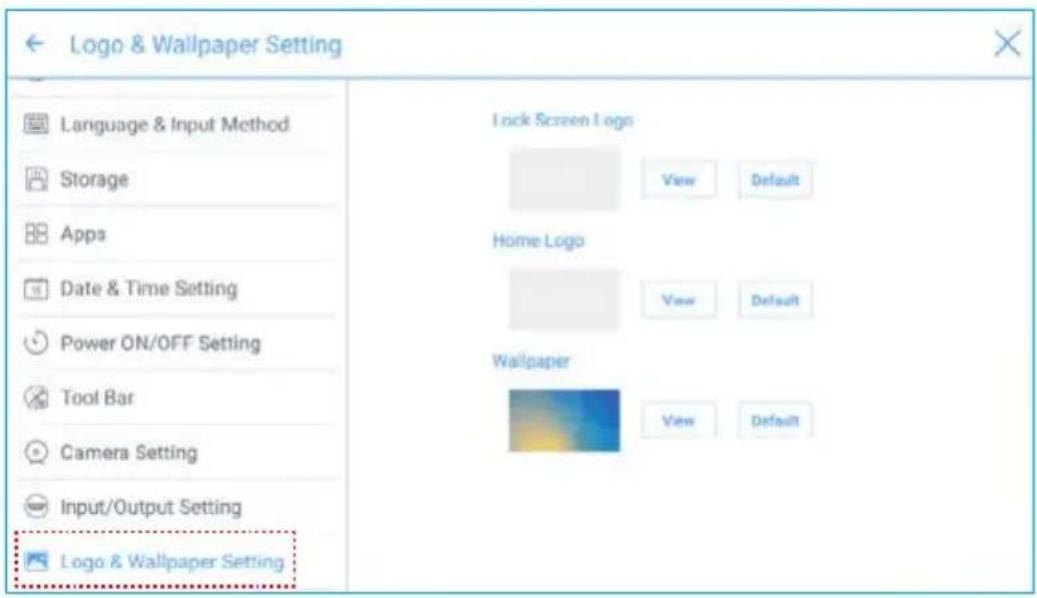
Click the Newline icon on the Home page to enter the logo & Wallpaper Setting page to set the logo and wallpaper. The logo and wallpaper can be obtained locally or from a device connected via the USB port, as shown in the following figure.
Shortcut for World Clock
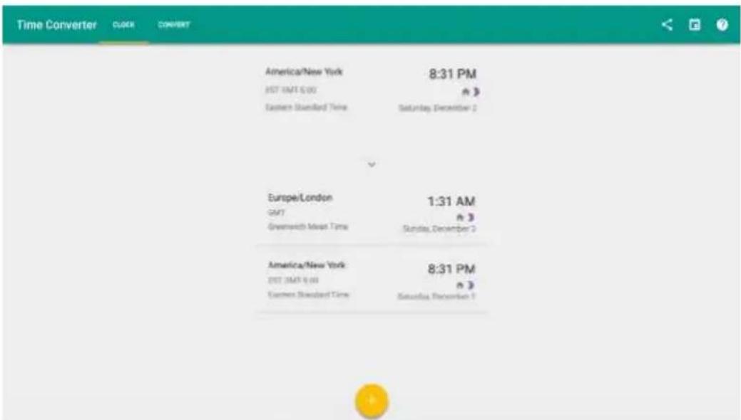
Click the time icon on the Home page to enter the Time Converter page and convert the time and zone. Click + to add other time zones indicating other countries, as shown in the following figure.
Shortcut for Calendar
Click this icon to enter the Calendar page and set schedules and synchronize with Google calendar, as shown in the following figure.

Side Toolbar
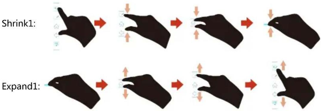
The Annotation Mode/Discussion Mode/Home/Return/Windows icons are displayed by default in the toolbar at two sides of the screen. The bottom side toolbar can be customized as your choice (The default icon is Windows). You may also hide the side tool bar at the setting or move it up and down, shrink or expand by gestures. You may double-click the — to expand or shrink the toolbar. Long press the customized icon to unfold level-2 icons.
flowchart
graph TD
    A["Shrink1:"] --> B["Arrow to Start"]
    B --> C["Arrow to Shift"]
    C --> D["Arrow to Shift"]
    D --> E["Arrow to Shift"]
    E --> F["Arrow to Shift"]
    F --> G["Arrow to Shift"]
    G --> H["Arrow to Shift"]
    H --> I["Arrow to Shift"]
    I --> J["Arrow to Shift"]
    J --> K["Arrow to Shift"]
    K --> L["Arrow to Shift"]
    L --> M["Arrow to Shift"]
    M --> N["Arrow to Shift"]
    N --> O["Arrow to Shift"]
    O --> P["Arrow to Shift"]
    P --> Q["Arrow to Shift"]
    Q --> R["Arrow to Shift"]
    R --> S["Arrow to Shift"]

The functions of the side toolbar are as follows:
| Icon Functions | |
 | Enter annotation mode, and click again to stop annotation and save screenshot. |
 | Enter discussion mode. |
 | Go to Home page. |
 | Return to the last menu/Exit. |
 | Enter the internal PC source. |
 | Manage currently running applications.Slide left/right the currently running application or click × at the upper right corner to close the application. |
 | Enter the favorite source. |
| [KABA] | View all gadgets. |
Status Bar and Settings
The upper right corner of the home page displays three working status icons (including USB flash memory(s), Ethernet, and Wi-Fi), and system setting shortcut.
| Icon Functions | |
 | If USB flash memory(s) is connected to the USB port, this icon will be turned on. For details on the wiring method of the USB port, see section "Ports". |
 | If the product is connected to Ethernet, the icon will be turned on. For details on the wiring method of the wired network, see section "Ports". |
| [z4XC] | If the product is connected to a wireless network, the icon will be turned on. For details on the wiring method of the wireless network, see section "Ports". |
 | Access the system setting page. |
Main Toolbars
| Icon Functions | |
 | Switch to the internal PC source. |
 | Enter Connection to switch to the connected product, including cabled signal sources and wireless applications.Cabled signal sources include HDMI Front, HDMI Rear (1 to 3), and DisplayPort.Wireless applications include Montage and Trucast. |
 | Discussion provides discussion board function. |
 | Gadget displays all pre-installed applications, including Office viewer, Email, Calendar, Word clock, and Calculator. Click the icon of an application to run the application. |
 | Open the File Manager, and you can can explore on internal and external files of the screen. |
 | Click Add to enter Add page, you can add up to 7 shortcuts to your favorite software, gadgets or connections to the Home page. (See more detail in “Add Shortcuts to Home Page”) |
 | Click End to end a meeting. Users will have the choice of saving the discussion boards screen captures and ending the meeting. Once a meeting is ended, all screenshots and discussion data are cleared. |
System Settings
Enter the system setting page using one of the following methods:
- Click Newline or on the Home page.
- Press ✦ on the remote control.
- In the Quick Setting Menu, click the 🎨 icon.
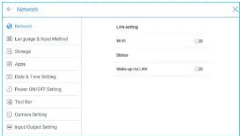
♦ Network Settings
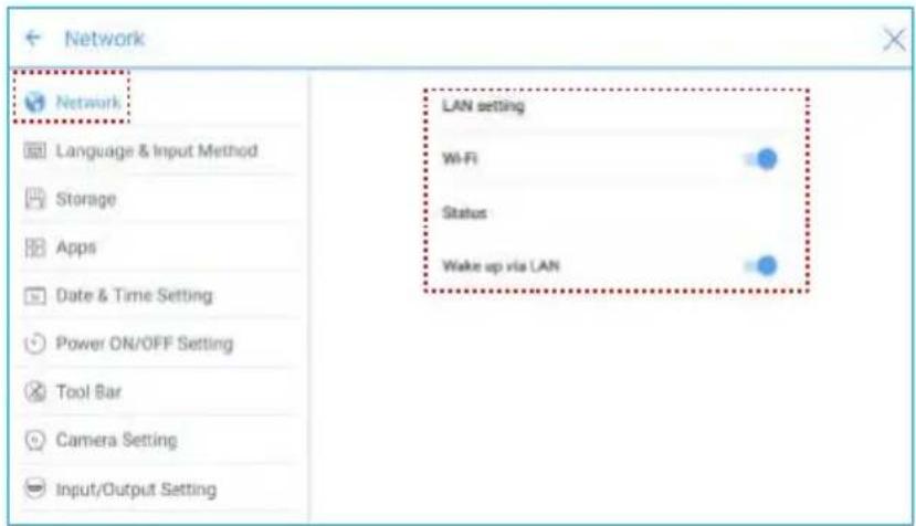
Enter the Network submenu to set a LAN, enable Wi-Fi, view network information, and enable the Wake up via LAN function.
• LAN setting: Automatically obtain the LAN IP address or set static IP address according to requirements.
- Wi-Fi: Click corresponding button to enable the Wi-Fi function.
- Status: View IP address, MAC address and work time of the screen.
- Wake up via LAN: Click corresponding button to enable the Wake up via LAN function. Connect the screen and PC to a same LAN using cables, run the Wake up via LAN, and search for the IP address and MAC address that match the screen.
♦ Language and Input Method Settings
Enter the Language & Input Method submenu to set language and input method.
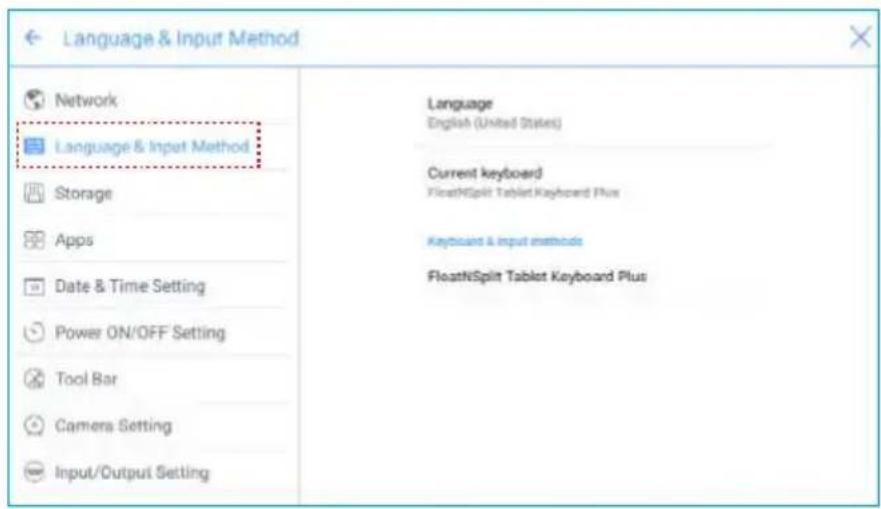
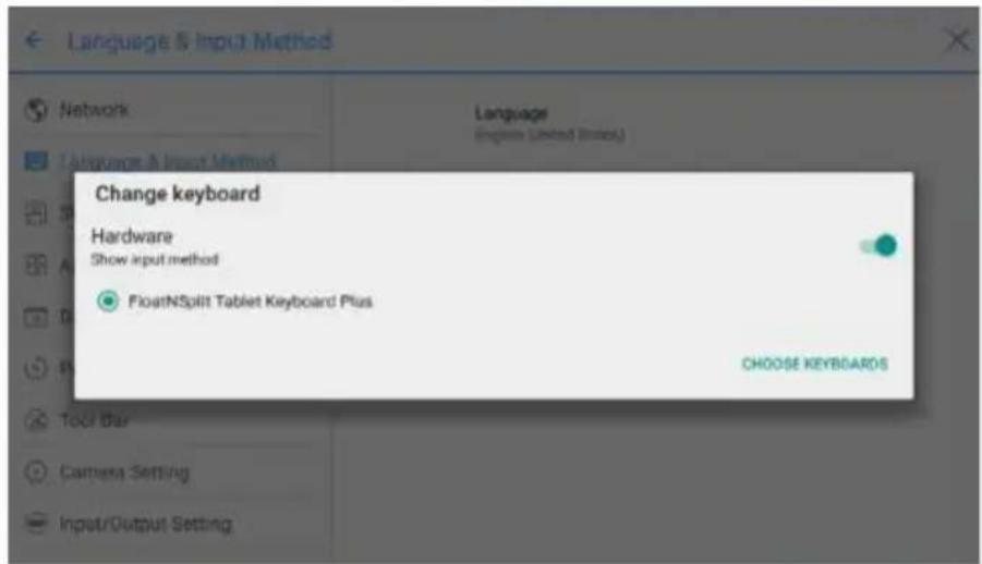
The default input method of the system is FloatNSplit Table Keyboard Plus, and Hardware keyboard must be enabled. If you want to switch to another language, switch the keyboard input method via Keyboard & input methods, in addition to switching the language.
Note
FloatNSplit Table Keyboard Plus does not support Chinese and Japanese.
FloatNSplit Table Keyboard Plus description:
• : Drag this icon and change the size of the keyboard.
• : Drag this icon to move the keyboard.
• : Click this icon to switch the keyboard unfold mode.
![Cancel Eng 1 2 3 4 5 6 7 8 9 0 q w e r t y u i o p Done a s d f g h j k l z x c v b n m +=[] ,](/content/2026/05/809794/images/aef378900b3442b5e946c0196416ce1b5883957d566da6b6774149746922e91d.jpg)
Setting a Language
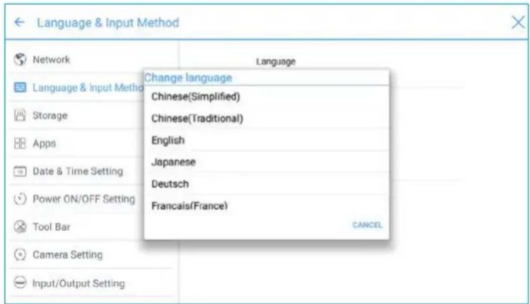
Click Language at the right side. In the Change language dialog box that is displayed, select a language.
Adding an Input Method
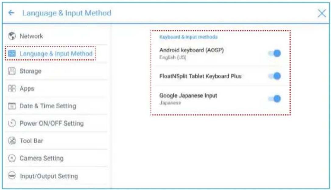
Click Current keyboard at the right side. In the Change keyboard page, click CHOOSE KEYBOARDS, unfold Keyboard & input methods, and click the button at the right side according to reference to add an input method (multiple choices can be selected).
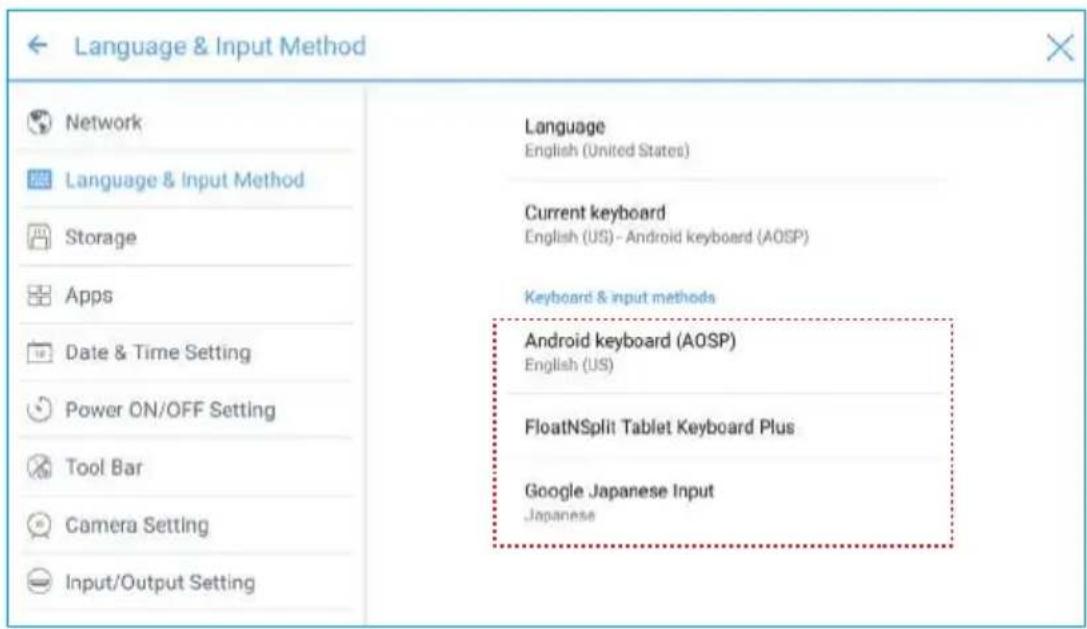
Setting an Input Method
Select an input method at the right side to set the attributes of the input method.
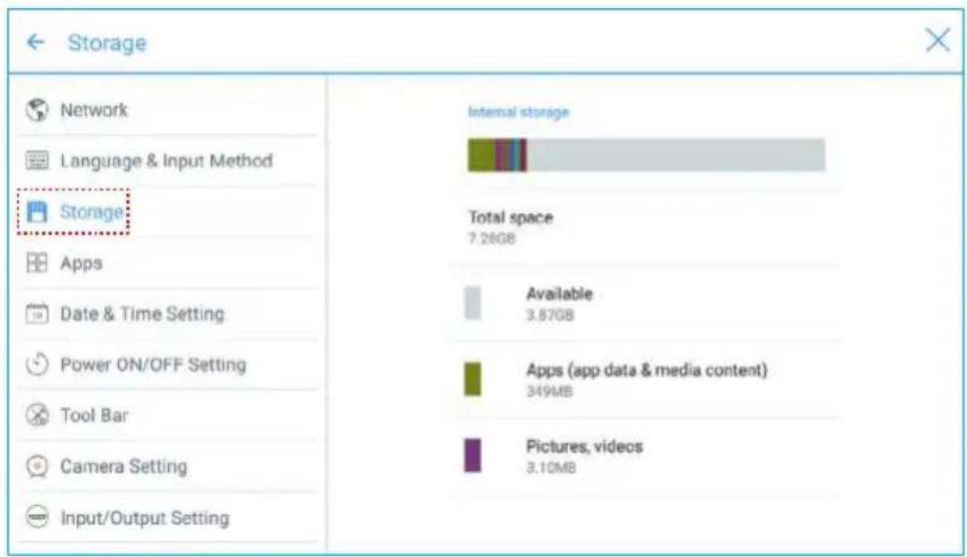
Storage
Enter the Storage submenu to view space distribution of the internal storage.
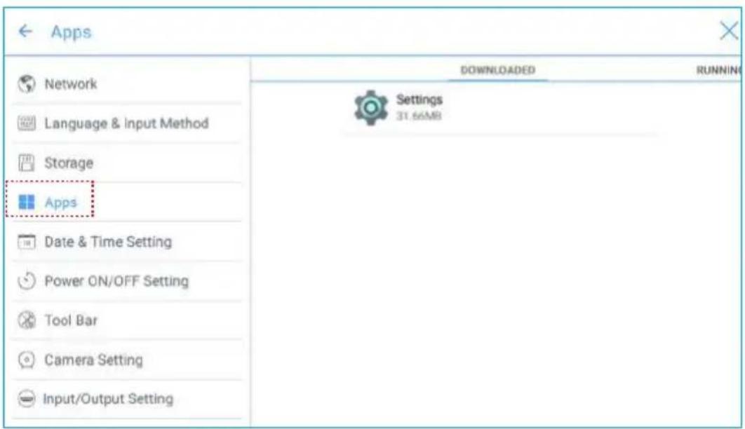
- Applications
Enter the Apps submenu to view downloaded applications by type, running applications, and all applications.
♦ Date and Time Settings
Enter the Date & Time Setting submenu to set the date and time. Before setting the date and time, users should click Select time zone to select local time zone.
| Date & Time Setting | |
| Network | Eastern Daylight Time GMT-04:00 |
| Language & Input Method | Barbados GMT-04:00 |
| Storage | Manaus GMT-04:00 |
| Apps | Santiago GMT-04:00 |
| Date & Time Setting | Halifax GMT-03:00 |
| Power ON/OFF Setting | Sao Paulo GMT-03:00 |
| Tool Bar | |
| Camera Setting | Buenos Aires GMT-03:00 |
| Input/Output Setting | |
Setting a Date
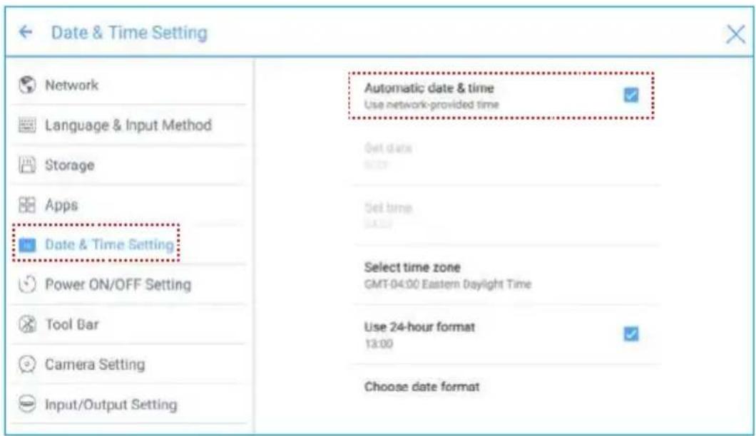
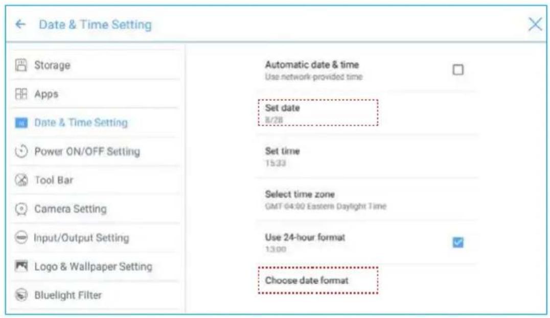
You can automatically obtain the system date or customize a date.
• To automatically obtain a date, select Automatic date & time.
- To customize a date and date format, set them in Set date and Choose date format.
Setting Time
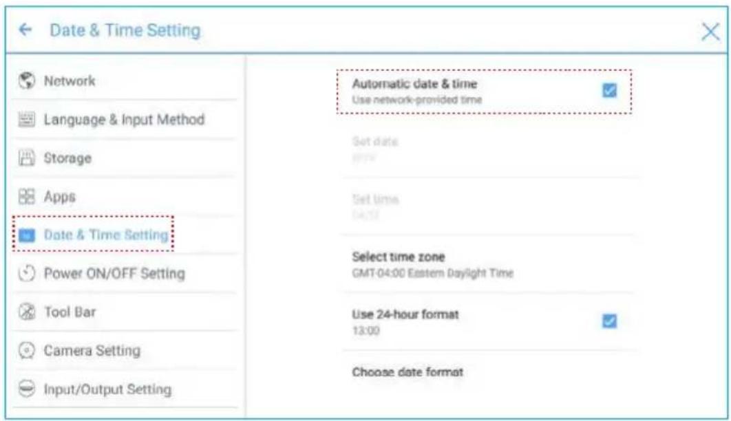
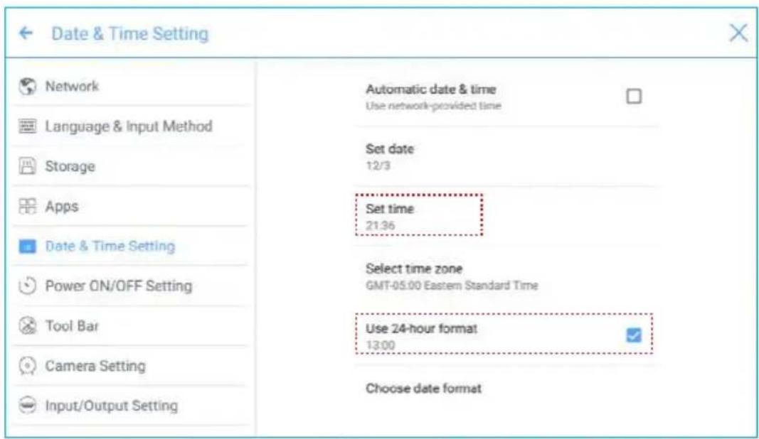
You can automatically obtain the system time or customize time.
- To automatically obtain time, select Automatic date & time.
- To customize time and time format, set them in Set time and Use 24-hour format.
Power ON/OFF Setting
Enter the Power ON/OFF Setting submenu to set automatic power on/off time and the time or the system to enter the shut down mode.
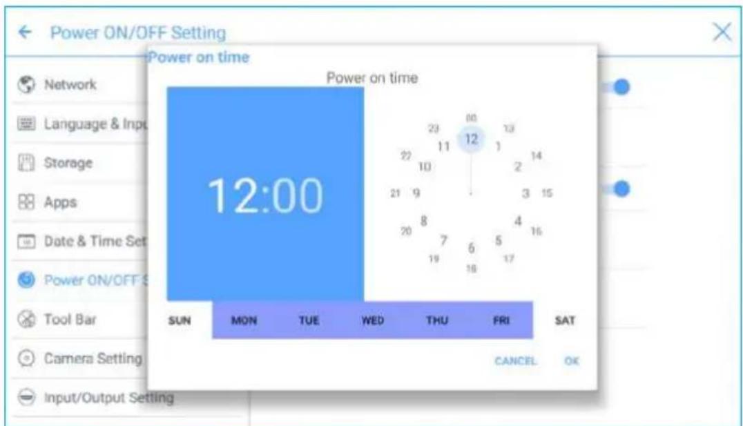
- To set the automatic power on time, select Auto power on, and set the power on time in Power on time, as shown in the following figure.
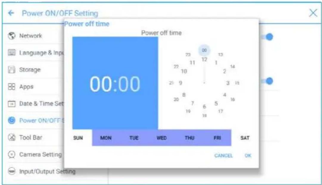
- To set the automatic power off time, select Auto power off, and set the power off time in Power off time, as shown in the following figure.
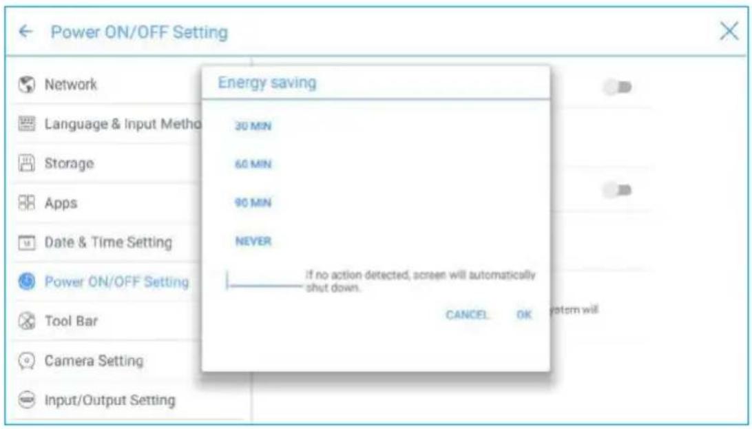
- To set the energy saving time, click Energy saving. In the dialog box that is displayed, set a duration after which the screen enters the lock mode if the screen is left un-operated. After the screen is locked, if the user does not operate the screen within 120s, the screen enters the shut down mode. The duration can be set to 30 MIN, 60 MIN, 90 MIN, or NEVER. You can also customize this duration and the range is 3 minutes to 480 minutes.
Note
NEVER indicates that the automatic shut down mode function is not enabled.
- Tool Bar Setting
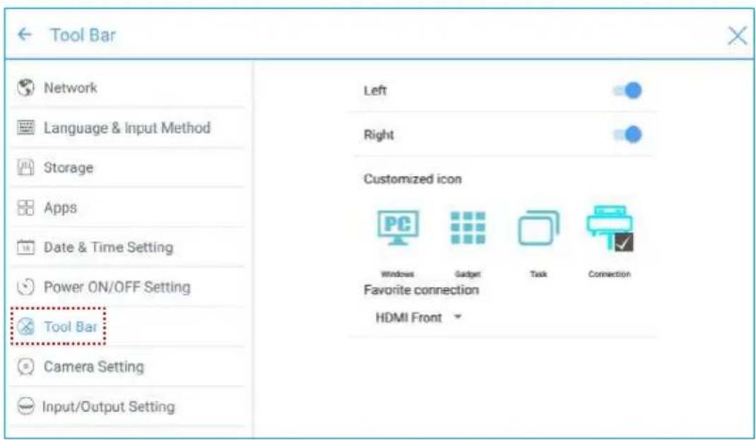
Enter the Tool Bar submenu to set whether to display the side tool bar and icons.
- Left: Click to turn on/off the left tool bar.
• Right: Click to turn on/off the right tool bar. - Customized icon: Click the icon under Customized icon to display the last shortcut key at both sides of the tool bars. If you define the shortcut key as Connection, you can set a signal source to enter after this shortcut key is clicked in Favorite Connection.
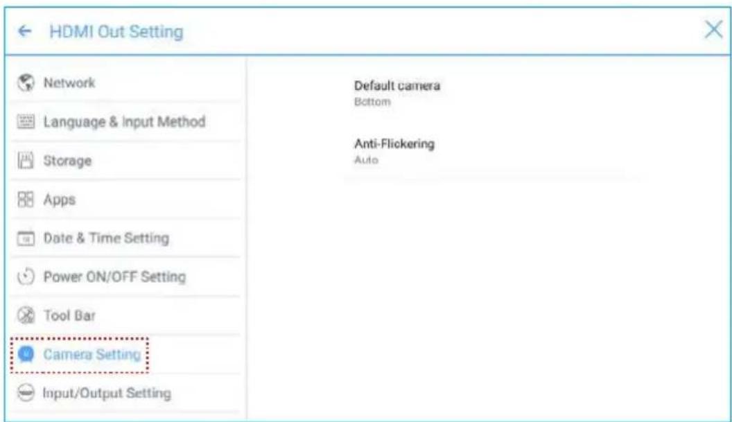
- Camera Setting
Enter the Camera Setting submenu to switch the default camera and set anti-flick function for the lens.
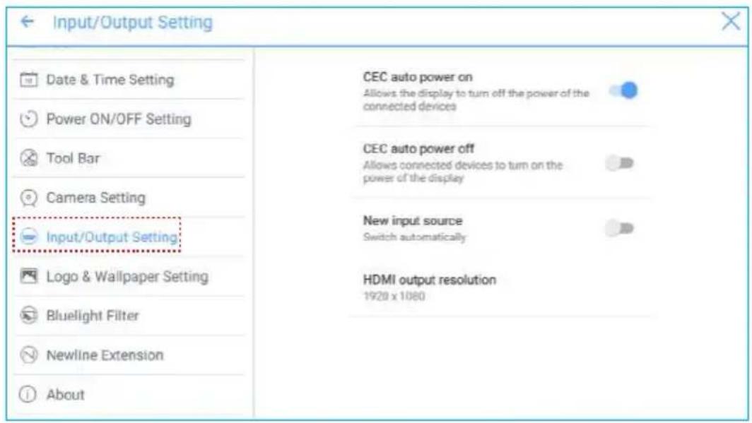
- Input/Output Setting
Enter the Input/Output Setting submenu to set the automatic power on/off function of the consumer electronics control (CEC) device, new signal source, and resolution of image output through the HDMI port.
- After the CEC auto power on function is enabled and the screen is connected with the CEC device via the HDMI port, the screen automatically starts if the CEC device starts and the screen receives a CEC startup command.
- After the CEC auto power off function is enabled and the screen is connected with the CEC device via the HDMI port, the CEC device automatically stops if the screen stops and the CEC device receives a CEC shutdown command.
- After the New input source function is enabled, the system can automatically switch to the screen of the newly connected signal source.
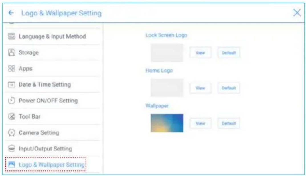
♦ Logo and Wallpaper Setting
Enter the Logo & Wallpaper Setting submenu to set background, lock page, or Home page log.
On this page, click View to select a picture and automatically upload it to replace current picture. Click Default. The logo and wallpaper are reset to Newline pictures.
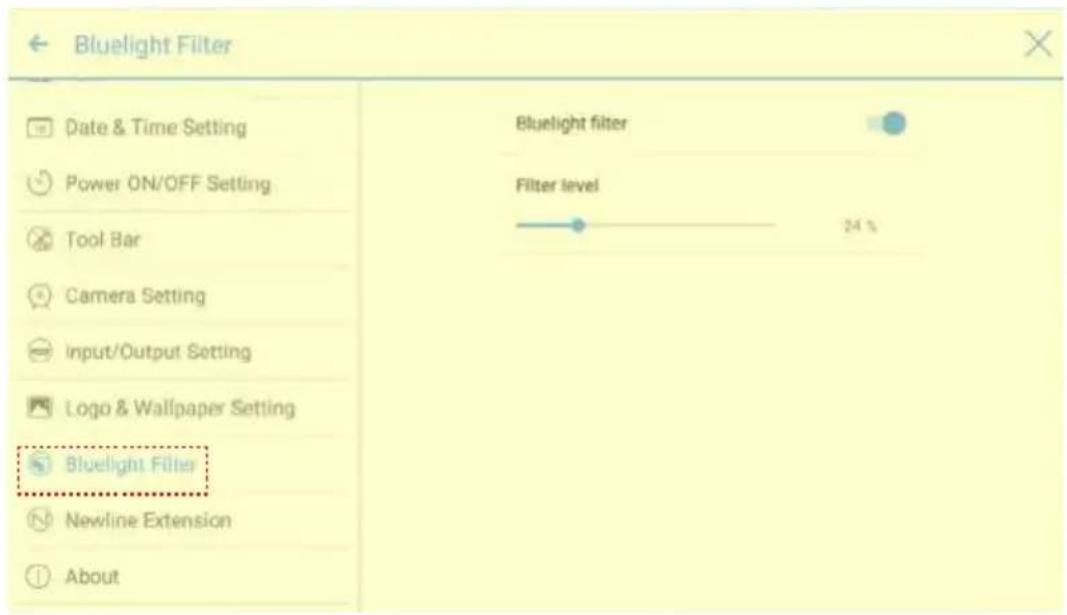
- Bluelight Filter
Enter the Bluelight Filter submenu to enable the bluelight filter function and set filter level.
- Newline Extension
Enter the Newline Extension submenu to set external devices (Trucast, X10D, and Trucam) to be displayed in the Cable Connection column of Connection and the wireless application Montage to be displayed in the Wireless Connection column. Furthermore, you can set the HDMI Rear channel to be displayed on the Trucast, X10D, or Trucam screen. If an auxiliary device of our company X10D is connected, the system identifies it through the CEC signal and automatically enables and switches to corresponding channel.
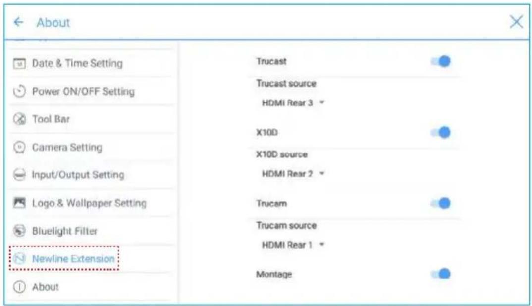
- About
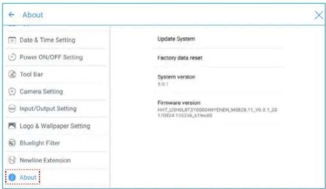
Enter the About submenu to view firmware or system version information, system upgrade, and factory setting.
Windows
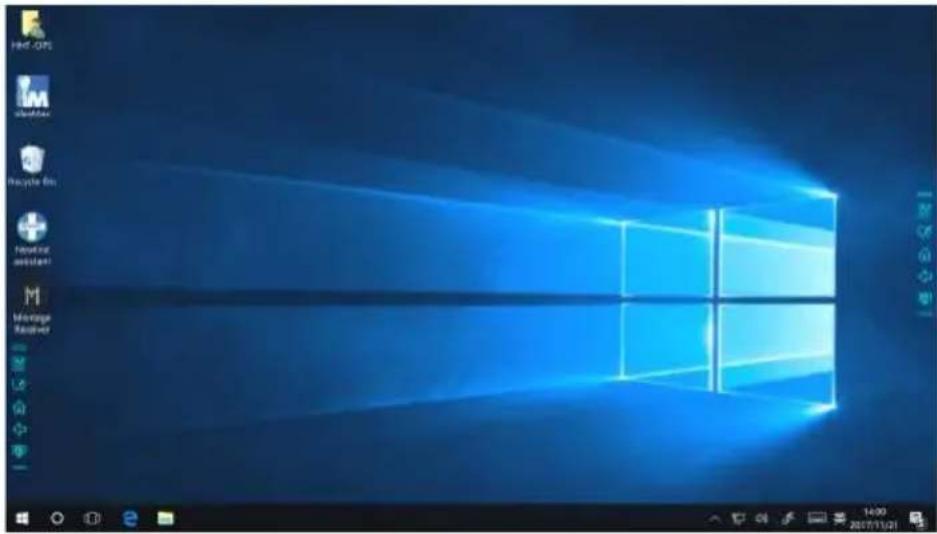
On the Home page, click Windows to enter the Internal PC source page, as shown in the following figure. If the screen is not equipped with an internal PC, "No Signal" is displayed.
Connection
On the Home page, click Connection to enter the connected product, including cabled signal sources and wireless applications.
- Cabled signal sources include HDMI Front, HDMI Rear (1 to 3), and DisplayPort. You can preview the image of the corresponding signal channel. If the channel has no signal input, No Signal will appear. You can click the selected signal source to switch to the corresponding channel in full screen. You can also long press the signal source page and enter remark information in the Modify remarks dialog box that is displayed. If Trucast, Trucam, or X10D options have been enabled in Newline Extension, corresponding channel cannot be remarked.
- Wireless applications include Montage and Trucast.
Note
Montage should be installed manually to the internal PC first. If the Montage software is not added to the Newline assistant, the system prompts users to install Montage and add it into the Newline assistant. For details on the addition method, see section "Add Shortcuts to Home Page".
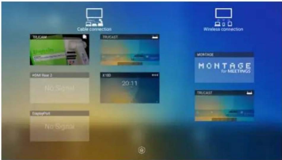
The first time you turn the screen on, only the cable connections appear in Connection. Wireless connection can be added in the Newline Extension setting. In this case, the name and icon of the HDMI on the left cabled channel change as the Trucast application is enabled or an external product is connected. For details on the configuration, see section "Newline Extension". After the setting is successful, connect the Trucast, X10D and Trucam to corresponding HDMI ports of the screen.
Whiteborad
The whiteboard has the following functions:
• Discussion and screen annotation
On the whiteboard page, you can select pen type, width, and color to write or annotate on the screen. You can also erase selected content or clear all contents.
- Page navigation
Preview or delete pages.
Whiteboard Mode
- Click Discussion in the main toolbar or click 📋 in the side toolbar to enter the discussion mode, as shown in the following figure.
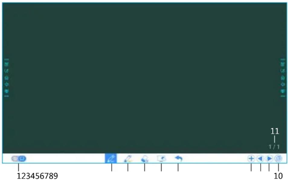
- Click 📋 in the side toolbar or click 📋 in the discussion mode to enter the annotation. In annotation mode it would generate a transparent layer above the screen, and user could add the annotation on it until they exit the annotation mode.
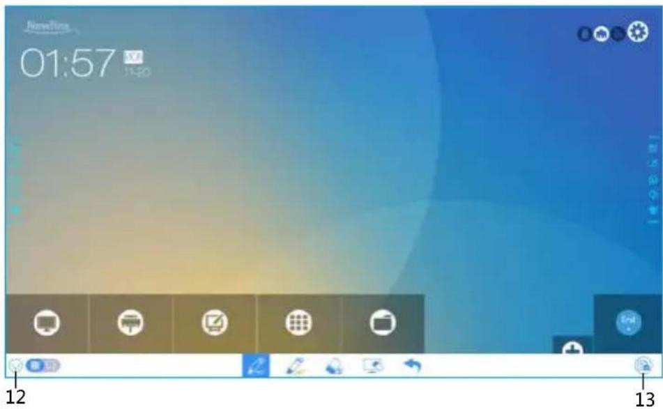
| SN Icon Name Icon Function | ||
| 1 Mode Switch | Click the icon to switch between annotation mode and the discussion mode. (See more detail in whiteboard mode section) | |
| 2 Pen | Click to use the pen function, and the icon turns into blue. Click and hold the icon for two seconds to set the size or color. | |
| 3 Highlighter | Click to use the highlighter function, and the icon turns into blue. Click and hold the icon for two seconds to set the size or color. | |
| 4 Eraser | Click to select the eraser function, when it is selected, the icon turns into blue. Click and hold the icon for two seconds to set the size of eraser. | |
| 5 Clear Clear all data in this page. | ||
| 6 Undo Back to the previous step. | ||
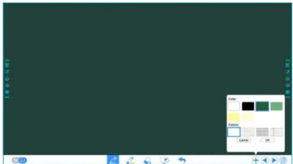
| 7 New Page | Click to add a new page. Click and hold for two seconds to set the color and the pattern of the new page. | |
| 8 Previous Page Click to back to the previous page. | ||
| 9 Next Page Click to go to the next page. | ||
| 10 Navigation Click to show the page thumbnails. | ||
| 11 Page Number Shows which page is used right now. | ||
| 12 Hide Smart Bar Click to hide or show the smart bar. | ||
| 13 Screenshot | Click to print screen, and save the data in file management.Click and hold the icon for two seconds to show the pop-up windows to make users to choose if they want to save the screenshot automatically when they leave the annotation mode. | |
Whiteboard Functions
New Page and Settings
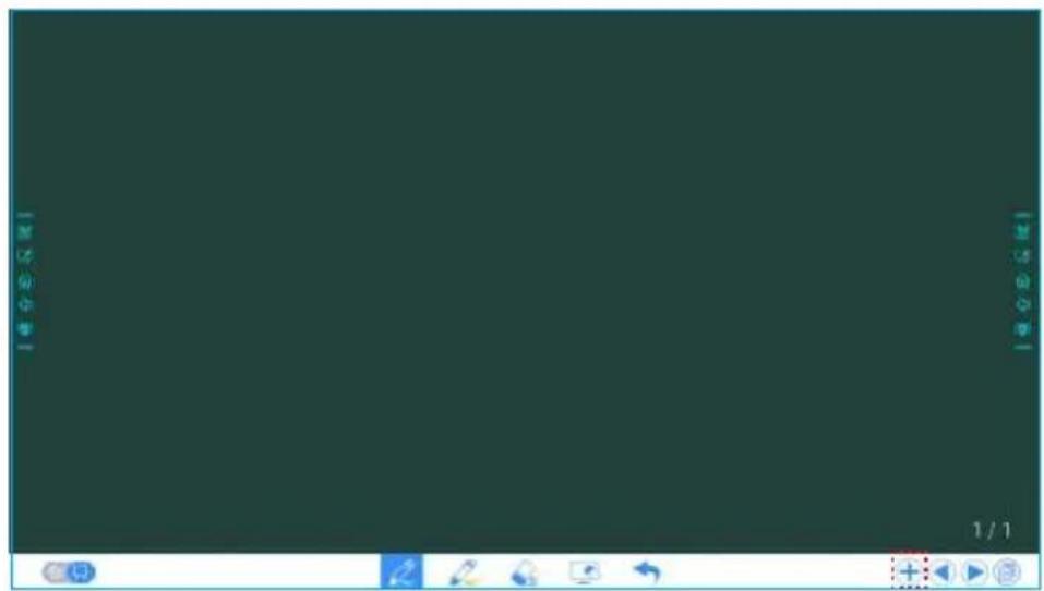
- Create a new page
In discussion mode, click + to create a new page. Up to 20 pages can be created. See the following figure.
- Page settings
Click and hold + for two seconds to set the color and the pattern of the new page, as show in the figure below.
Whiteboard Mode
Click and in the lower left corner of the discussion mode to switch between whiteboard modes.
• : Annotation mode
The background is transparent and the real-time image of the current signal source will be displayed. You can comment on presentation content such as Office documents and pictures as showing in the following figure.
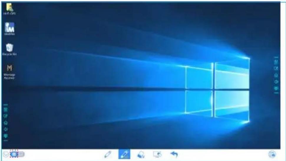
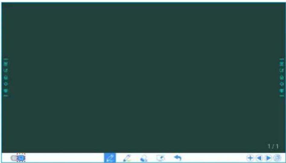
• : Discussion mode
The background is in mono color, as shown in the following figure. You can write content on the page as required.
Pen Type
On the Whiteboard, two types of pens are supported: Pen and highlighter.
- Pen : used to write.
- Highlighter : used to highlight. Characters covered by comments are visible.
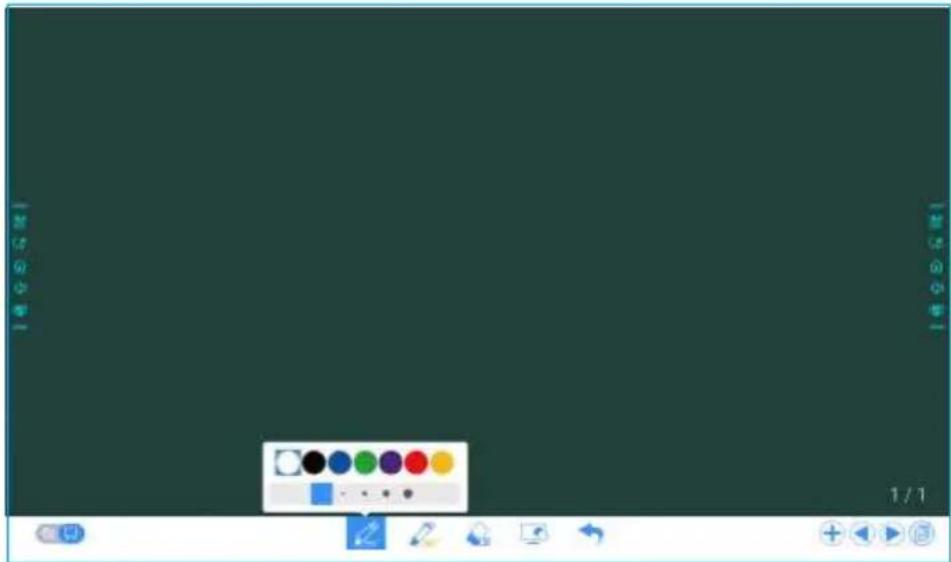
Line Size and Color
On the Whiteboard, click and hold 🔔 or 🔒 for two seconds to set the size and color. You can select the line size and color for writing, as shown in the following figure.
Eraser
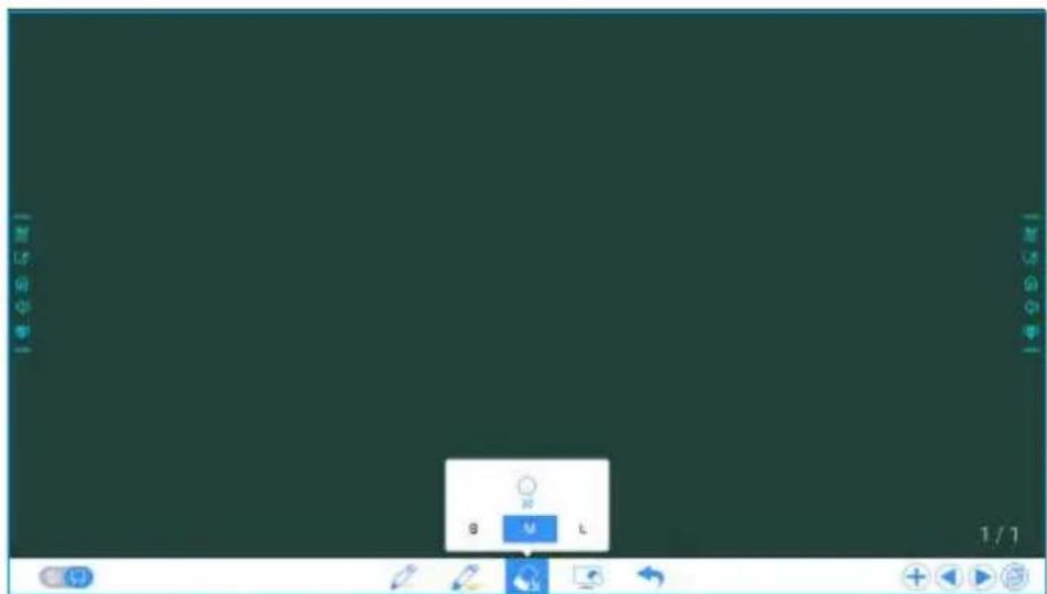
Two methods are available to erase written errors or content as follows:
- Fist/hand back erasing: corresponding erase shape is a round with diameter 100pt.
- Spot erasing: Click 🔍 to clear wrong or unnecessary content. Click and hold the icon for two seconds to set the size of eraser (S 10pt/M 30pt/L 50pt), it would be shown by the icon, as shown in the following figure.
Screenshot
In annotation mode, click 📄 to save the current image as a picture. Up to 50 screenshots screenshots can be created. Click and hold the icon for two seconds to show the pop-up windows to make users to choose if they want to save the screenshot automatically when they leave the annotation mode, as shown in following figure.
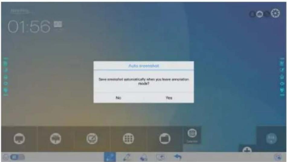
Pictures saved through screenshots can be viewed and obtained using the following methods:
- After a meeting is complete, screenshots are saved on the Save meeting Discussion page, as shown in the following figure.
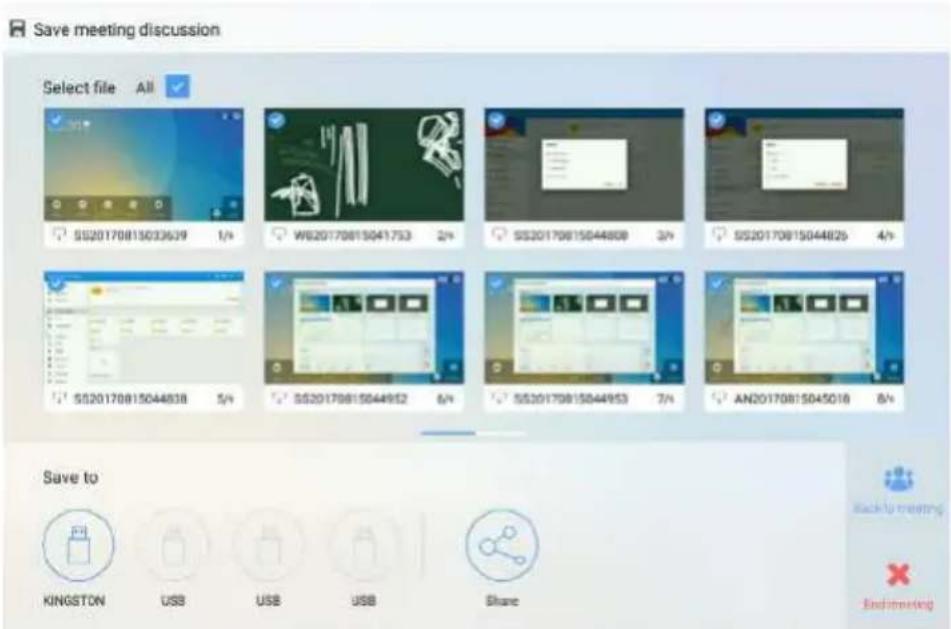
- Click 📄 on the home page and choose Internal storage > Pictures > Screenshots > image to view or obtain screenshots.
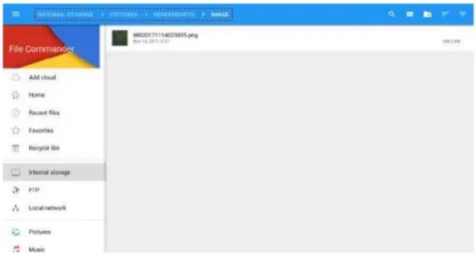
Clear All
On the Whiteboard page, click 📄 to show the pop-up windows to make users to choose if they want to clear contents on current page, as shown in the following figure.
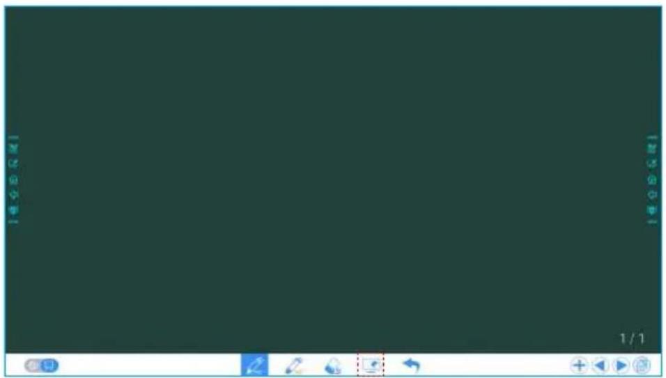
Page Operations
You can preview, select, and delete a created writing page.
Page Preview
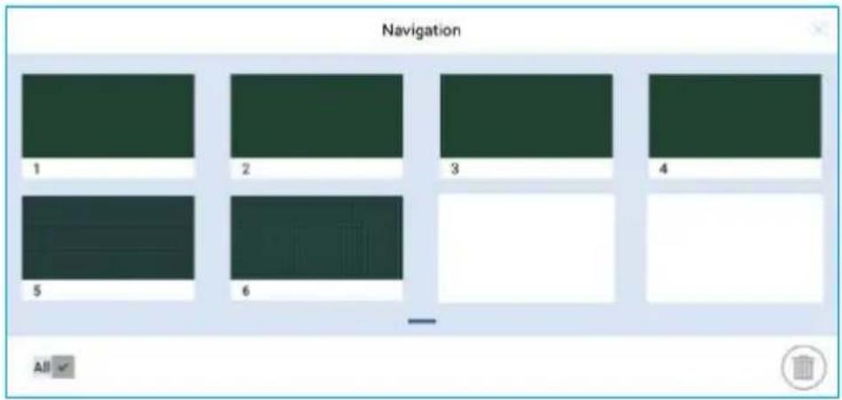
Click at the lower right corner in the discussion mode. All pages will be displayed. Click one page to switch to that page for more operations, as shown in the following figure.

Note
Only 8 pages are displayed at once, and you can slide right or left by one finger to see more.
Page Selection and Deletion
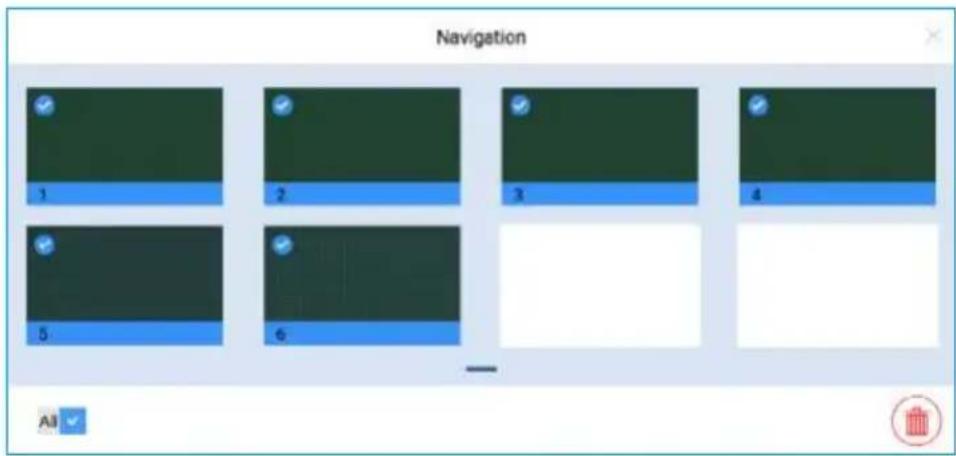
On the Navigation page, you can select or delete writing pages according to requirements, as shown in the following figure
- Click √ to select all pages.
- Click to delete selected pages.
Object Detection
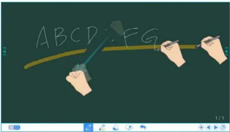
This product supports the object detection function and produces different effects according to the diameter and size of the input objects.
- Fist/palm: identified as an eraser (100 pt).
- Fine Pen (2mm): suggested to be used during writing.
- Thick Pen (≥ 6.5 mm)/ finger: suggested to be used during function operation or highlighter operation.
Note
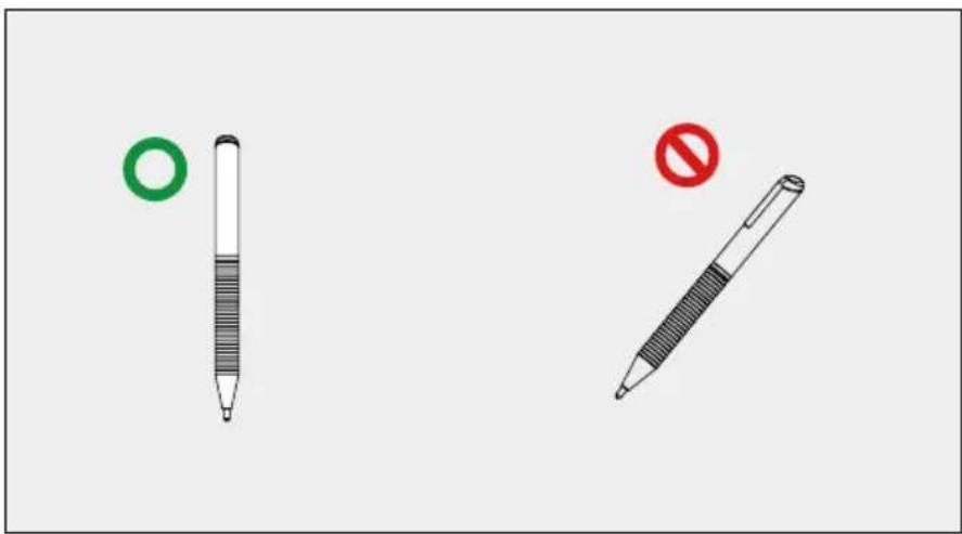
If the diameter or size of the input object is larger than 2mm or smaller than 6.5mm, there is a risk of identification failure. You are advised to keep the object vertically to write.
Operation method: The system automatically remembers the settings of fine pen and thick pen. Users can use a fine pen or thick pen (finger) to select functions (including color and thickness). After that, the system remembers the attributes of corresponding function until users change them manually.
- Fist/palm: keep the eraser (100 pt) function.
- Fine pen (2mm): before users manually change, the system remembers the previous selected attributes (including color and thickness).
- Thick pen (≥ 6.5 mm): before users manually change, the system remembers the previous selected attributes (including color and thickness).
Add Shortcut
Add Shortcuts to Home Page
Step 1: On Home page, click the + icon in the lower right corner. The interface for adding shortcuts will be displayed.
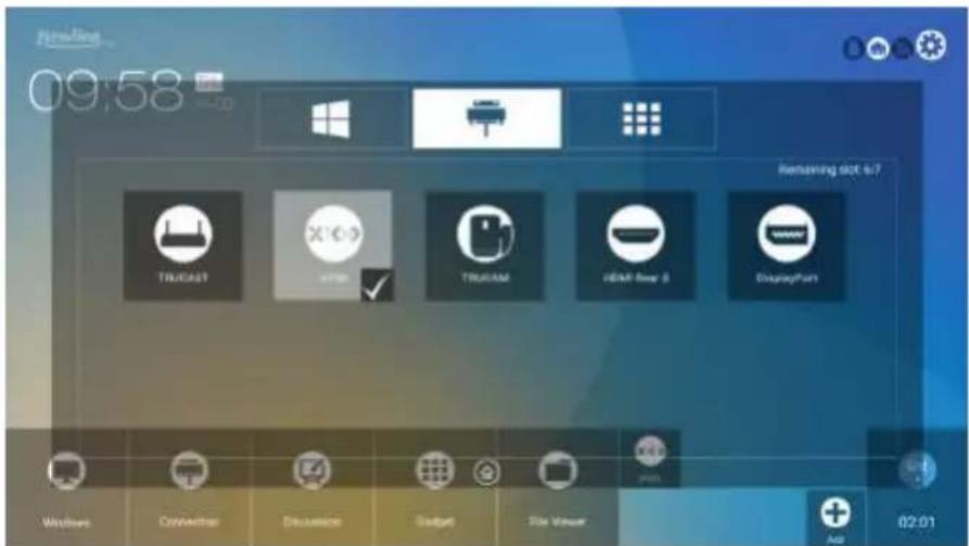
Step 2: Click the icons on top to switch the list between Windows programs, external signal sources, and pre-installed gadgets.
- Click 📋 to view the Windows programs that the Newline Assistant uploads to the Smart system. For details, see "Add Quick Start Windows Programs in Smart System".
- Click 📋 to view signal sources in Connection. You can set the Newline accessories to signal sources at Newline Extensions setting.
- Click to view Gadget applications.
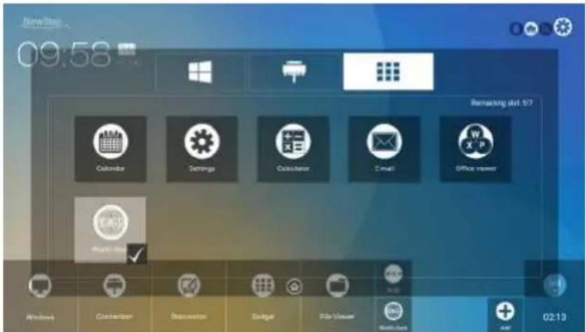
Step 3: Add or delete applications on the tab.
- In the list, click the icon to add it to the shortcut on the Home page. The check icon will appear at the bottom of the shortcut icons. Up to 7 shortcuts can be added.
- Tap the icon with the check mark again, the check icon will disappear and the shortcut will be deleted from the Home page.
Step 4: At the Home page, click the shortcut icon and you can start the program/application or change to the external signal source.
- Add Quick Start Windows Programs in Smart System
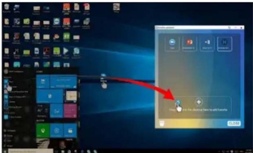
Step 1: In Windows, run the Newline Assistant program and drag the software icons or folder shortcut icons that you want to add from desktop or menu to the Newline Assistant window. The applications added or deleted through the Windows system will be automatically updated to the smart system until the upload progress reaches 100%. If there is an application not updated, click ○ in the upper right corner to manually update all icons in the Newline assistant window to the smart system.

Tip: Only .exe file and folder are supported.
Step 2: Click ⬆ to return to the Home page. Click the ⊕ icon and go to shortcut setting. The page for adding application program will be displayed.
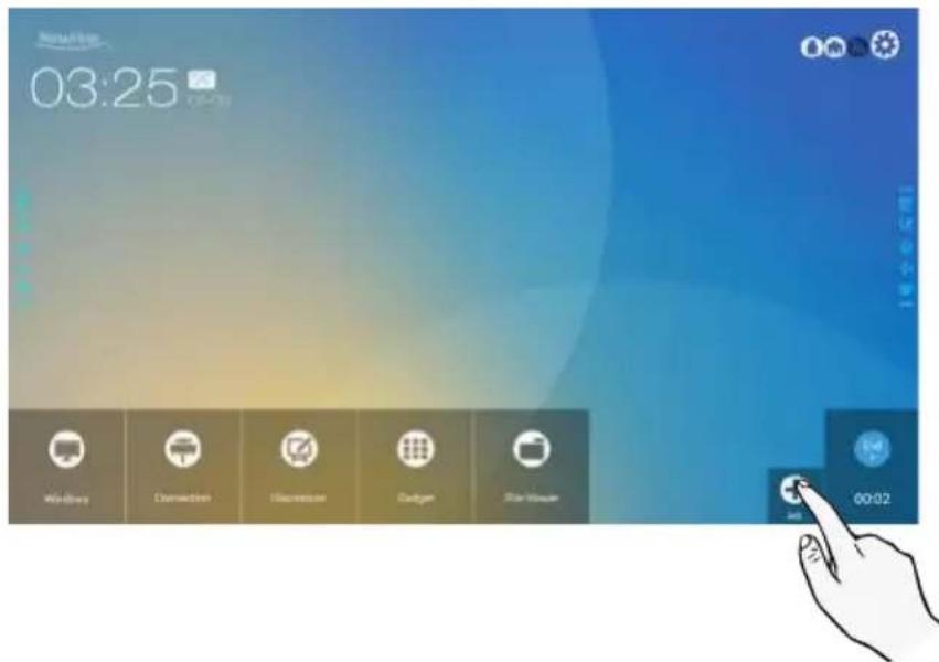
Step 3: At the shortcut setting page, click icon to view all the Windows programs added by Newline Assistant in Step 1.

Note
By default, the Newline Assistant application is added on the tab.
Step 4: Tap the icon and add the shortcut at the Home page. Tap again and remove it.
Step 5: Return to Home page. Click the icon of an added Windows software to start the software.
Gadget
On the Home page, click Gadget. On the page that is displayed, all applications can be viewed. The following figure shows applications that the system is delivered with.
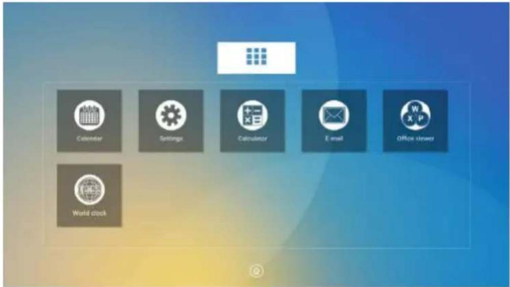
| Icon Functions | |
 | Click this icon to enter the Calendar application, set schedule, and update to Google Calendar. |
 | Click this icon to enter the system setting page. |
 | Click this icon to enter the calculator application. |
 | Click this icon to enter the email application and send files. Before sending files, you need to create an email account. |
 | Click this icon to enter the Office viewer application. In this application, you can view office files, including excel, word, power point, and PDF files. |
 | Click this icon to enter the World clock application. In this application, you can convert time and zone. |
File Management
The product supports connection to USB flash memory. Enter the File Viewer application, you can preview all files in the internal storage and storage devices connected via USB ports and select, copy, paste, delete and search for files.
- File Viewer Page
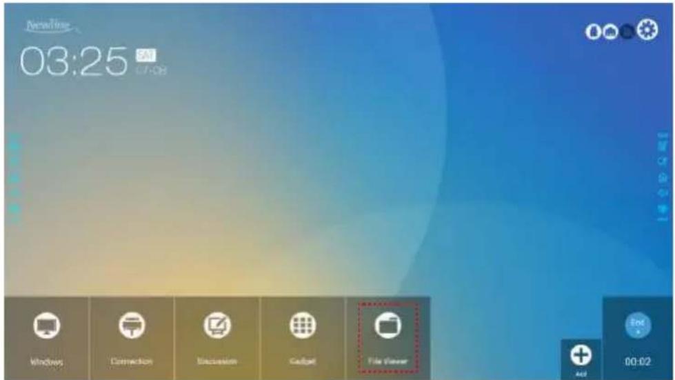
On the Home page, click File Viewer, as shown in the following figure.
- File Preview
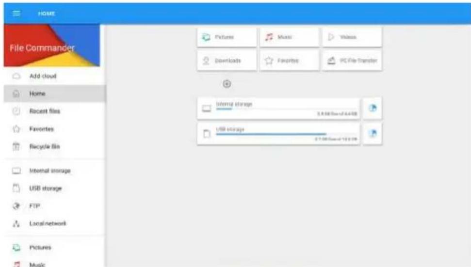
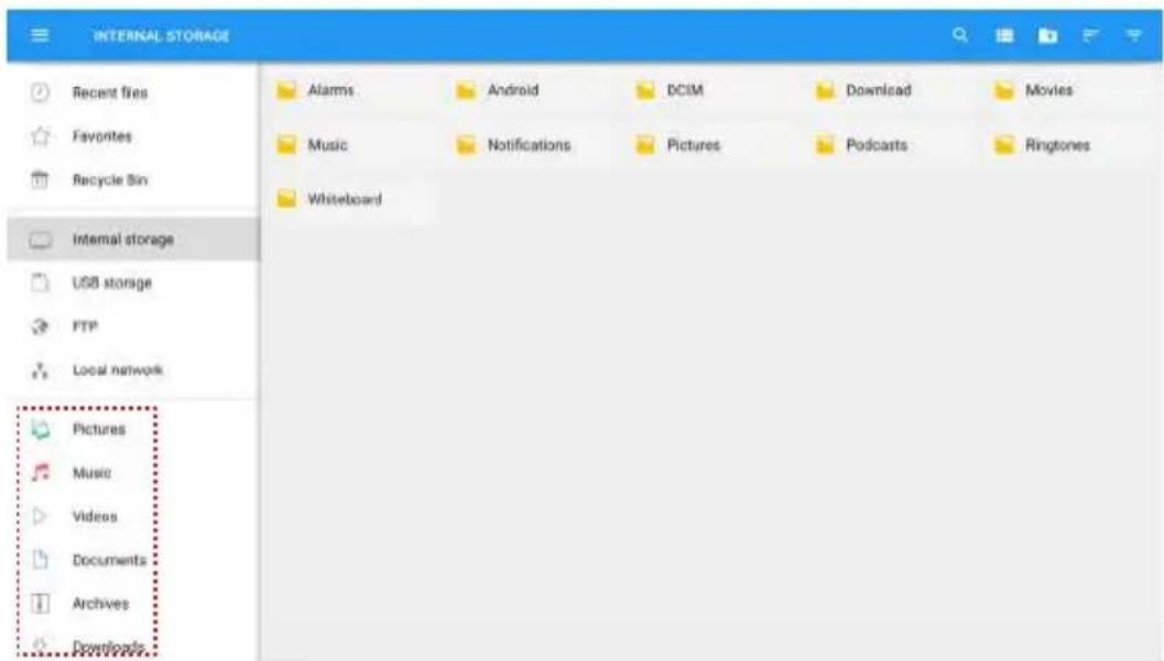
Enter the File Viewer application, you can click the submenu at the left side according to requirements, preview internal storage, external storage devices connected via the USB ports, cloud stored files, FTP uploaded files, and local network files, as shown in the following figure.
◆ File Filtering
You can click the menu at the left side to display files by types, for example, document, picture, music, video, archive and downloaded. You can also click → to filter files by picture, music and video.
- The system supports two view modes: list and thumbnail. You can click and at the top right corner to switch view modes, as shown in the following figure.
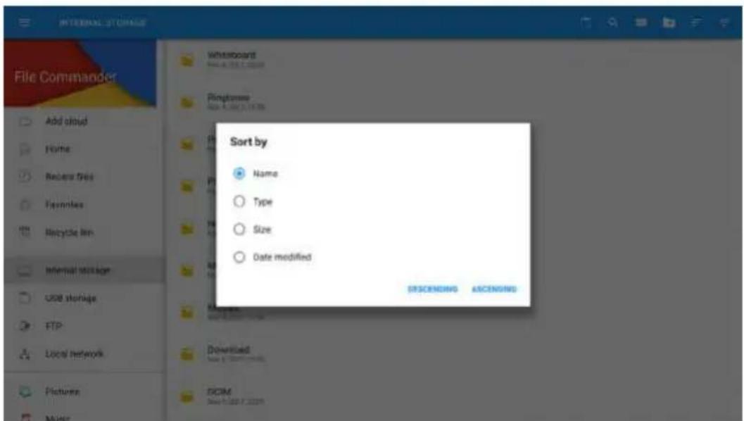
- Click to display files based on name, type, size, and modification time in an increment or decrement manner.
- File Search
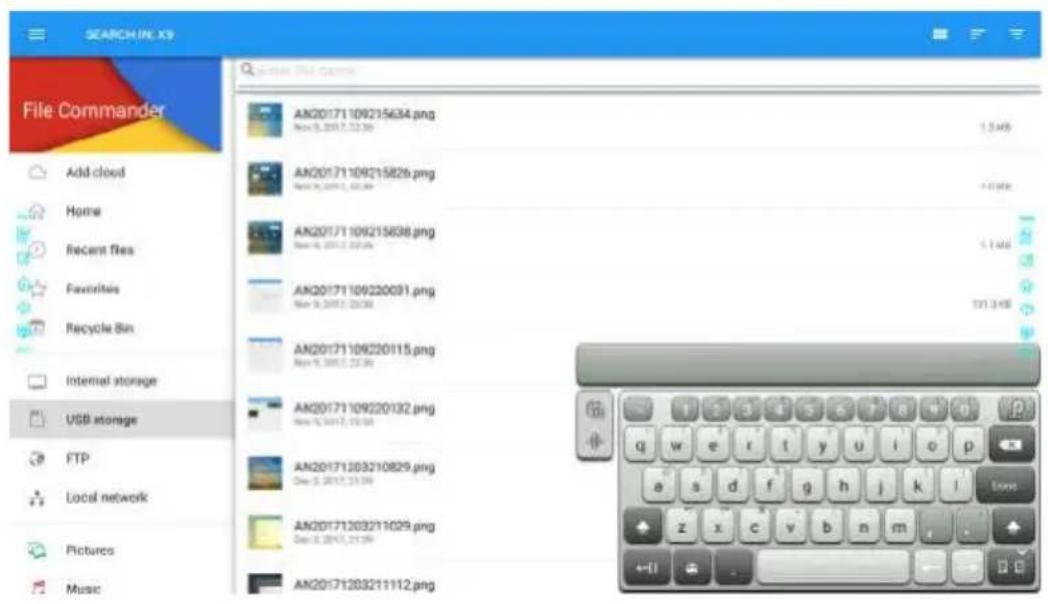
Enter the File Viewer application, and click 🔒. In the dialog box that is displayed, enter keywords in the search box according to requirements. The system will display a list of files that match the keywords.
- File Operation
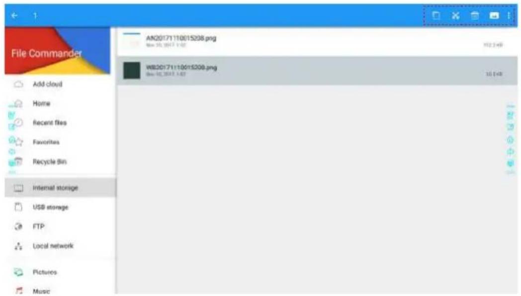
Enter the File Viewer application. You can create folders according to requirements, select files by long pressing, and set wallpaper/copy/paste/delete. For details on other operation, click in the upper right corner for more operation.
End Meeting
- Manually End Meeting
On the Home page, click 📋. The Save meeting discussion page will be displayed. The meeting will end and timer will stop.
File Name
The Save meeting discussion page displays pages, annotation page screenshots, and remote control screenshots in the discussion mode in this meeting, as shown in the following figure.
Picture files are named in the following of prefix + creation file. Slide left/right using a finger to switch pictures.
Prefix name rule: WB (discussion mode page), AN (annotation page screenshot), and SS (remote control screenshot).
Save Meeting Data
When no external USB flash memories are connected, icons in the Save to area will be gray. When an external USB flash memory is connected, icons in the Save to area will turn into blue. Click the USB icon in blue. The "uc" folder will be created under the root folder, and the selected files will be saved in it.
-
Back to meeting: The meeting will be continued; files are not cleared and timer continued.
• End meeting: The Warning dialog box will be displayed. -
Click Confirm. All writing pages and screenshots will be deleted, and go back to start screen page. The current meeting will be ended and the timer will reset.
- Click Cancel. The meeting continues and the system stays on the Save meeting discussion page.
Note
- Do not eject USB flash memory before completing the saving process.
- If the USB flash memory is bigger than 16GB or the file format is not FAT32, the data will not be saved properly.
Save meeting discussion
Select file



\$320170815033639

Warning
3320170815044826


5520170815044938
Ending the meeting will permanently delete all screenshots. Ensure you save your information prior to ending your meeting.
Confirm
Cancel
AN20170015046018

Save to

KINGSTON

USB

USB

USB

Share

Huron 10 Medding

und meeting
Send E-mail
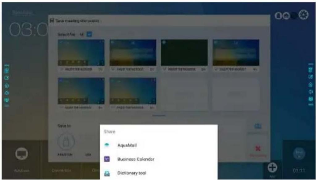
Click the button on the Save meeting discussion page, and click AquaMail to share current meeting files by email. Before sending, confirm that an email account is successfully set.
- Automatically End Meeting
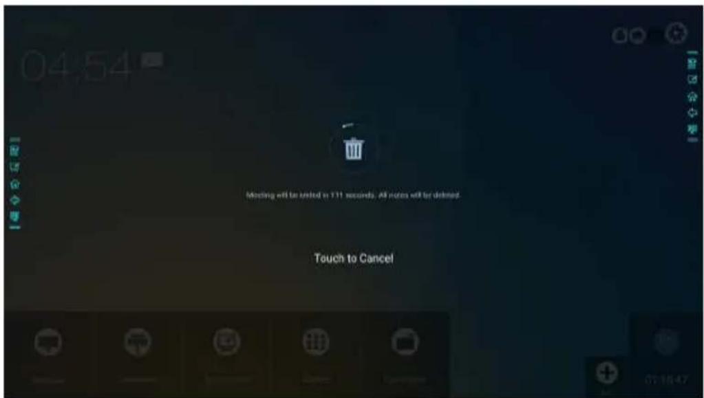
If the screen is left un-operated for a specified duration, it will be locked to guarantee your privacy. Choose Settings > Power ON/OFF Setting to set the duration. For details on the setting method, see "Power ON/OFF Setting".
After the screen is locked, if it is operated again within 120 seconds, the screen is unlocked. Otherwise, the screen enters the shut down mode and automatically deletes all meeting content. After the screen is unlocked, the countdown dialog box will not appear in current meeting. The dialog box can be restored if you create a new meeting after current meeting is complete.
Using two fingers to swipe up from the bottom of the screen, the quick setting menu will show up, as shown in the following figure.
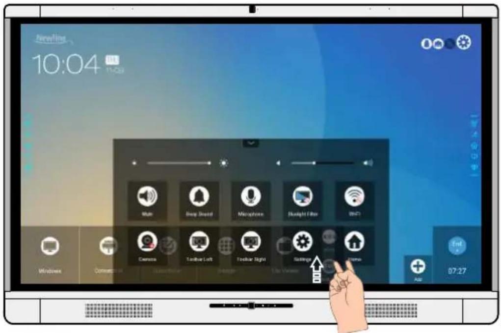
| Icon Functions | |
 | Drag the slider to adjust the brightness. |
 | Drag the slider to adjust the sound volume. |
 | Click the icon to mute/unmute. |
 | Click the icon to turn on/off the beep sound. |
 | Click the icon to turn on/off the microphone. |
 | Click the icon to turn on/off the blue light filter. |
 | Click the icon to turn on/off the Smart system Wi-Fi. |
 | Click the icon to switch to top camera or bottom camera. |
 | Click the icon to turn on/off the left toolbar. |
 | Click the icon to turn on/off the right toolbar. |
 | Click the icon to enter the settings page. |
 | Click the icon to return to Home page. |
Connect RS-232 port to the PC or controlling product. Enable RS-232 serial port connection and complete the following configuration.
| Port: COM1 (Set according to PC or controlling product's port number) | |||
| Baud rate 19200 Odd/even check None | |||
| Data bits 8 Stop bit 1 | |||
The following tables list controlling codes, querying codes and return codes.
| Function Controlling | codes Return codes | |
| Power on | 7F 08 99 A2 B3 C4 02 FF01 00 CF | 7F 09 99 A2 B3 C4 02 FF 01 0001 CF |
| Power off | 7F 08 99 A2 B3 C4 02 FF01 01 CF | 7F 09 99 A2 B3 C4 02 FF 01 0101 CF |
| Mute/Unmute | 7F 08 99 A2 B3 C4 02 FF01 02 CF | 7F 09 99 A2 B3 C4 02 FF 01 0201 CF |
| Signal source | 7F 08 99 A2 B3 C4 02 FF01 06 CF | 7F 09 99 A2 B3 C4 02 FF 01 0601 CF |
| Enable whiteboard | 7F 08 99 A2 B3 C4 02 FF01 07 CF | 7F 09 99 A2 B3 C4 02 FF 01 0701 CF |
| Display status | 7F 08 99 A2 B3 C4 02 FF01 09 CF | 7F 09 99 A2 B3 C4 02 FF 01 0901 CF |
| HDMI front | 7F 08 99 A2 B3 C4 02 FF01 0A CF | 7F 09 99 A2 B3 C4 02 FF 01 0A01 CF |
| HDMI rear 1 | 7F 08 99 A2 B3 C4 02 FF01 52 CF | 7F 09 99 A2 B3 C4 02 FF 01 5201 CF |
| HDMI rear 2 | 7F 08 99 A2 B3 C4 02 FF01 53 CF | 7F 09 99 A2 B3 C4 02 FF 01 5301 CF |
| HDMI rear 3 | 7F 08 99 A2 B3 C4 02 FF01 54 CF | 7F 09 99 A2 B3 C4 02 FF 01 5401 CF |
| Internal PC | 7F 08 99 A2 B3 C4 02 FF01 38 CF | 7F 09 99 A2 B3 C4 02 FF 01 3801 CF |
| DP | 7F 08 99 A2 B3 C4 02 FF01 56 CF | 7F 09 99 A2 B3 C4 02 FF 01 5601 CF |
| Page up | 7F 08 99 A2 B3 C4 02 FF01 13 CF | 7F 09 99 A2 B3 C4 02 FF 01 1301 CF |
| Page down | 7F 08 99 A2 B3 C4 02 FF01 14 CF | 7F 09 99 A2 B3 C4 02 FF 01 1401 CF |
| VOL - | 7F 08 99 A2 B3 C4 02 FF01 17 CF | 7F 09 99 A2 B3 C4 02 FF 01 1701 CF |
| VOL + | 7F 08 99 A2 B3 C4 02 FF01 18 CF | 7F 09 99 A2 B3 C4 02 FF 01 1801 CF |
| Menu | 7F 08 99 A2 B3 C4 02 FF01 1B CF | 7F 09 99 A2 B3 C4 02 FF 01 1B01 CF |
| Home page | 7F 08 99 A2 B3 C4 02 FF01 1C CF | 7F 09 99 A2 B3 C4 02 FF 01 1C01 CF |
| Return (exit) | 7F 08 99 A2 B3 C4 02 FF01 1D CF | 7F 09 99 A2 B3 C4 02 FF 01 1D01 CF |
| OK | 7F 08 99 A2 B3 C4 02 FF01 2B CF | 7F 09 99 A2 B3 C4 02 FF 01 2B01 CF |
| ← | 7F 08 99 A2 B3 C4 02 FF01 2C CF | 7F 09 99 A2 B3 C4 02 FF 01 2C01 CF |
| → | 7F 08 99 A2 B3 C4 02 FF01 2D CF | 7F 09 99 A2 B3 C4 02 FF 01 2D01 CF |
| ↑ | 7F 08 99 A2 B3 C4 02 FF01 2E CF | 7F 09 99 A2 B3 C4 02 FF 01 2E01 CF |
| ↓ | 7F 08 99 A2 B3 C4 02 FF01 2F CF | 7F 09 99 A2 B3 C4 02 FF 01 2F01 CF |
| Query the firmware version number | 7F 08 99 A2 B3 C4 02 FF01 3D CF | 7F 09 99 A2 B3 C4 02 FF 01 3D01 CF |
| Enable the comment function | 7F 08 99 A2 B3 C4 02 FF01 40 CF | 7F 09 99 A2 B3 C4 02 FF 01 4001 CF |
| Microphone mute | 7F 08 99 A2 B3 C4 02 FF01 41 CF | 7F 09 99 A2 B3 C4 02 FF 01 4101 CF |
| Switch cameras | 7F 08 99 A2 B3 C4 02 FF08 XX CFNOTE:• XX = 01 indicates that the top camera is enabled.• XX = 02 indicates that the bottom camera is enabled. | 7F 09 99 A2 B3 C4 02 FF 08 XX 01 CF |
| Set volume | 7F 08 99 A2 B3 C4 02 FF05 XX CFNOTE:XX indicates the volume value (0 to 100), corresponding to hexadecimals 00 to 64. | 7F 09 99 A2 B3 C4 02 FF 05 XX 01 CF |
| Set display mode | 7F 08 99 A2 B3 C4 02 FF06 XX CFNOTE:XX indicates the mode. 00 and 01 indicate standard and ECO modes respectively. | 7F 09 99 A2 B3 C4 02 FF 06 XX 01 CF |
| Increase backlight brightness | 7F 08 99 A2 B3 C4 02 FF01 47 CF | 7F 09 99 A2 B3 C4 02 FF 01 47 01 CF |
| Decrease backlight brightness | 7F 08 99 A2 B3 C4 02 FF01 48 CF | 7F 09 99 A2 B3 C4 02 FF 01 48 01 CF |
| Set the value of backlight brightness | 7F 08 99 A2 B3 C4 02 FF09 XX CFNOTE:XX indicates the value of backlight brightness (0 - 100), corresponding to the hexadecimal number system (00 - 64). | 7F 09 99 A2 B3 C4 02 FF 09 XX 01 CF |
| Switch backlight | 7F 08 99 A2 B3 C4 02 FF01 15 CF | 7F 09 99 A2 B3 C4 02 FF 01 15 XX CFNOTE:• XX = 01 indicates the backlight is on.• XX = 00 indicates the backlight is off. |
| Switch to child safety lock | 7F 08 99 A2 B3 C4 02 FF01 57 CF | 7F 09 99 A2 B3 C4 02 FF 01 57 01 CF |
| Screenshot | 7F 08 99 A2 B3 C4 02 FF01 1F CF | 7F 09 99 A2 B3 C4 02 FF 01 1F 01 CF |
| Settings | 7F 08 99 A2 B3 C4 02 FF01 20 CF | 7F 09 99 A2 B3 C4 02 FF 01 20 01 CF |
| Function Querying codes Return codes | ||
| Power supply | 7F 08 99 A2 B3 C4 02 FF 01 37 CF | 7F 09 99 A2 B3 C4 02 FF 01 37 XX CFNOTE:XX indicates the power on/off state.XX = 01: power on stateXX = 00: power off state |
| Speaker | 7F 08 99 A2 B3 C4 02 FF 01 82 CF | 7F 08 99 A2 B3 C4 02 FF 01 82 XX CFNOTE:01: mute00: non-mute |
| Current signal source | 7F 08 99 A2 B3 C4 02 FF 01 50 CF | 7F 09 99 A2 B3 C4 02 FF 01 50 XX CFNOTE:Smart system = 30PC = 17DP = 20HDMI rear 1 = 1FHDMI Rear 2 = 1EHDMI Rear 3 = 18HDMI Front = 19 |
| Speaker volume | 7F 08 99 A2 B3 C4 02 FF 01 33 CF | 7F 09 99 A2 B3 C4 02 FF 01 33 XX CFNOTE:XX indicates current volume value (XX is a hexadecimal value, range: 00~64).For example, XX = 20 indicates current volume value is 32 (decimal value), XX = 00 indicates mute state. |
| D.Mode | 7F 08 99 A2 B3 C4 02 FF 01 35 CF | 7F 09 99 A2 B3 C4 02 FF 01 35 XX CFNOTE:XX indicates the mode. 00 and 01 indicate standard and eco modes respectively. |
| Microphone status | 7F 08 99 A2 B3 C4 02 FF 01 45 CF | 7F 09 99 A2 B3 C4 02 FF 01 45 XX CFNOTE:XX =01 indicates that the microphone is mute.XX = 02 indicates that the microphone is not mute. |
| Camera position | 7F 08 99 A2 B3 C4 02 FF 01 44 CF | 7F 09 99 A2 B3 C4 02 FF 01 44 XX CFNOTE:XX = 01 indicates that the top camera is enabled.XX = 02 indicates that the bottom camera is enabled. |
| Backlight brightness | 7F 08 99 A2 B3 C4 02 FF 01 49 CF | 7F 09 99 A2 B3 C4 02 FF 01 49 XX CFNOTE:XX indicates the value of backlight brightness (0 - 100), corresponding to the hexadecimal number system (00 - 64). |
| Backlight status | 7F 08 99 A2 B3 C4 02 FF 01 81 CF | 7F 08 99 A2 B3 C4 02 FF 01 81 XX CFNOTE:XX = 00 indicates the backlight is on.XX = 01 indicates the backlight is off. |
| Switch to child safety lock | 7F 08 99 A2 B3 C4 02 FF 01 84 CF | 7F 08 99 A2 B3 C4 02 FF 01 84 XX CFNOTE:XX = 01 indicates the child safety lock is on.XX = 00 indicates the child safety lock is off. |
| Whiteboard state | 7F 08 99 A2 B3 C4 02 FF 01 83 CF | 7F 08 99 A2 B3 C4 02 FF 01 83 XX CFNOTE:XX = 01 indicates the whiteboard state.XX = 00 indicates non-whiteboard state. |
| Return to system state of the previous 11 options | 7F 08 99 A2 B3 C4 02 FF 0A 00 CF | 7F 08 99 A2 B3 C4 02 FF 0A 00 AB CD EF GH IJ KL MN OP QR ST UV CFNOTE:AB: Power supplyCD: SpeakerEF: Current signal sourceGH: Speaker volumeIJ: D.ModeKI: microphoneMN: camera positionOP: backlight brightnessQR: backlight stateST: Whiteboard stateUV: Switch to child safety lock |
| Symptom Troubleshooting Methods | |
| The microphone and speaker cannot be used simultaneously. | Choose Control Panel > Sound. In the Playback tab page, disable Speaker. |
| The screen cannot be powered on or the indicator is off. | Check whether the power supply is connected. |
| Check whether the power supply plug is properly connected. | |
| Check whether the power supply line is properly connected. | |
| Check whether the rocker switch is enabled. | |
| Press the reset switch and start the system again. | |
| The remote control is not causing a response. | Replace the batteries. |
| Check whether the polarity direction of the batteries is correct. | |
| Use the remote control aligning with the IR receive window. For details, see section "Remote Control". | |
| The image is normal but there is no sound. | Increase volume on both the screen and the Windows system. |
| Check whether the screen and the Windows system are muted. | |
| If an external computer is connected, check whether the connection cables are normal. | |
| During the video conference, the remote party cannot hear the sound of the local party. | Check whether the local microphone is muted. |
| In Control Panel > Sound, set the product parameters to the default values in the Recording tab page. | |
| The system is automatically powered on/off when no operation is performed. | Disable the automatic power-on/off function. For details, see section "Power ON/OFF Setting". |
| Check whether the screen entered shut down mode due to no operation for an extended period of time. | |
| Check whether the input power supply is stable. | |
| The colors of images are abnormal. | Check whether the HDMI cable is properly connected or has any quality issue. |
| The touch function is abnormal or the positioning is inaccurate. | Restart the screen. |
| In the Windows system, perform positioning again. For details, see section "Positioning". | |
| The touch function is unavailable when the external signal source channel is being used. | Switch between different external signal sources. |
| Ensure that the USB touch cable is connected to the proper port. For details, see section "Ports". | |
| Remove and insert the USB touch cable again. | |
| There is no sound when the HDMI in channel is used. | Remove and insert the HDMI cable again. |
| No image is displayed when the HDMI out channel is used. | Generally, this issue is caused by the compatibility of the external display product. Replace the external display product and test again. |
| The HDMI cable is too long or has a poor quality. Replace the HDMI cable delivered with the product. | |
| The touch function on the front panel is ineffective. | Touch the button using the fingertip completely. |
| Check whether the finger is wet or has other liquids on it. | |
| Restart the screen. | |
| The USB flash memory cannot be identified. | Check whether the USB flash memory is inserted into the correct USB port. For details, see section "Ports." |
| The conference records cannot be saved on the USB flash memory, and the system prompts "The target storage product has no write permissions." | Format the USB flash memory to the FAT32 format. |
| The internal PC has no signal. | Check whether the internal PC is properly inserted in the slot. |
| Check whether the internal PC enters the shut down state. | |
| Press the power button on the internal PC (for details, see the instructions of the internal PC), and manually start up the internal PC. | |
| In the Smart system or Windows system, no wireless network can be found or the wireless network signal is weak. | Check whether the Wi-Fi antenna is properly installed on the Smart system. For details, see section "Ports". |
| Check whether the Wi-Fi antenna is properly installed for the internal PC. | |
| The keyboard is not correctly displayed. | Confirm that the hardware keyboard is enabled. |
| When connect the handheld microphone to the interface on the front panel, the distance from user to microphone should be no less than 1 meter, otherwise may cause sound to distort. | Front panel doesn't support handheld microphone, and need to use the fixed microphone. To make sure of the sound quality, the distance from user to microphone should be no less than 1 meter. |
| When the touch screen connect CEC facilities and power down, touch screen will be in shut down after power restart. CEC facilities can't recall the touch screen. | Please use the remote controller to start and close the touch screen, then can use the CEC facilities to recall it. |
| Model X9 X8 X6 | |||
| Display | |||
| Backlight LED | |||
| Display Area | 1897.00 mm x 1068.00 mm | 1650.24 mm x 928.26 mm | 1428.48 mm x 803.52 mm |
| Active Screen Size | 85.60 inch 75 inch 65 | inch | |
| Display Ratio 16:9 | |||
| Resolution 3840 x 2160 Pixel | |||
| Display Colors | 10 bit, 1.07 billion colors | 8 bit, 1.07 billion colors | 8 bit, 1.07 billion colors |
| Brightness ≥ 320 | cd/m ^2 | ||
| Contrast 4000:1 | |||
| Response Time 8 | ms | ||
| Life Time 30000 h (Min.) | |||
| Speaker | |||
| Speaker Position | Forward | ||
| Max. Power Output | 2 x 15 W | ||
| Microphone | |||
| Sensitivity -38 dB | ± 3 dB | ||
| Frequency Response | 65 Hz – 12.5 kHz | ||
| Sampling Frequency | 48 kHz | ||
| Polar Patterns Omni-directional | |||
| THD +N (1 kHz @ +4dBu) | < 0.05% | ||
| Pickup range 8 m | |||
| Quantity 1 Array (4 Microphones)Camera | |||
| Position Top x 1 & Bottom x 1 (Only one can use in the same time) | |||
| Sensor 2 M Pixels | |||
| Lens 86° | |||
| Video Resolution | 1920 x 1080@30 fps (Max.) | ||
| Frame Rate 30 fps/ 60 fps | |||
| Electrical | |||
| Power Consumption | Maximum ≤ 450 W Standby Mode ≤ 0.5 W | Maximum ≤ 300 W Standby Mode ≤ 0.5 W | Maximum ≤ 220 W Standby Mode ≤ 0.5 W |
| Working Voltage | AC 100 V – 240 V, 50 Hz/ 60 Hz | ||
| Touch | |||
| Touch Surface Anti-glare tempered glass | |||
| Transparency 88% | |||
| Surface Hardness | 7 H | ||
| HID support HID | |||
| Touch Points 10 | Points | ||
| Writing Tools Eraser, Stylus or Finger | |||
| Scan Speed 7.6 ms | |||
| Positioning Accuracy | Center area 1.0 – 1.5 mm/ Edge area 1.2 – 2.0 mm | ||
| Communication Interface | USB-A | ||
| Transportation/Storage | |||
| Storage Temperature/Humidity | -10 °C – 50 °C/ 10% – 90% | ||
| Working Temperature/Humidity | 0 °C – 40 °C/ 10% – 90% | ||
| Mounting (optional) | Wall-mounted/ Floor Stand | ||
| Outline Dimension | 2039 mm x 1316 mm x 109 mm | 1792 mm x 1170 mm x 102 mm | 1569 mm x 1054 mm x 87 mm |
| Packing Dimension | 2150 mm x 1400 mm x 310 mm | 1918 mm x 1295 mm x 275 mm | 1720 mm x 1170 mm x 275 mm |
| Net Weight 71.6 kg | 54.6 kg 44.5 kg | ||
| Gross Weight 94.0 kg | 71.2 kg 56.0 kg | ||
| Ports | |||
| Front Interface Inputs | HDMI In x 1, USB (Touch) x 1, USB (Public) x 2, Microphone In x 1 | ||
| Rear Interface Inputs | HDMI In x 3, DP x 1, USB (Touch) x 4, HDMI Out x 1, Line Out x 1, DC Out (5 V, 2 A), SPDIF out x 1, Earphone x 1, USB 2.0 (Public) x 1, USB 2.0 (Embedded) x 1, RS-232 x 1, RJ45 x 2, USB 3.0 (Public) x 1, OPS Slots (4 K@60 Hz) | ||
| Other functions | |||
| Intelligent thermos protector | Yes | ||
| Build-in WIFI 2.4 | G/ 5 G (Optional) | ||
| Smart System | |||
| Chips ARM A53 x | 4, 1.4 GHz | ||
| RAM 2 GB | |||
| Flash 8 GB | |||
| Multimedia File Formats | Supports all major types of multi-media files | ||
| Android Software | |||
| On Screen Annotation | Yes | ||
| Discussion Board | Yes | ||
For more information
Please visit our website (www.newline-interactive.com) for detailed instruction manual.
Contact Us for Support
Please email us at support@newline-interactive.com.

- Contents
- About This Document 01
- Safety Instruction 02
- Overview 05
- Installation Guide 14
- Getting Started 20
- Operating the Touch Screen 25
- About This Document
- Safety Instruction
- Introduction
- Parts
- Note
- Ports
- - Front Ports
- CAUTION
- - Rear Ports
- WARNING
- - Front Buttons
- Remote Control
- Camera
- Temperature Control Reset Button
- Safety Precautions
- - Installation Height
- Installation Precautions
- - Weight Loading
- - Ventilation
- Installation
- Installing the Internal PC (Optional)
- Installing Newline Assistant
- - Introduction
- - Installation
- Power On
- Power Off
- Calibration
- Tip:
- Start Screen
- Home
- Shortcut for Settings
- Shortcut for World Clock
- Shortcut for Calendar
- Side Toolbar
- Status Bar and Settings
- Main Toolbars
- System Settings
- ♦ Network Settings
- ♦ Language and Input Method Settings
- Setting a Language
- Adding an Input Method
- Setting an Input Method
- Storage
- - Applications
- ♦ Date and Time Settings
- Setting a Date
- Setting Time
- Power ON/OFF Setting
- - Tool Bar Setting
- - Camera Setting
- - Input/Output Setting
- ♦ Logo and Wallpaper Setting
- - Bluelight Filter
- - Newline Extension
- - About
- Windows
- Connection
- Whiteborad
- Whiteboard Mode
- Whiteboard Functions
- Pen Type
- Line Size and Color
- Eraser
- Screenshot
- Clear All
- Page Operations
- Page Preview
- Page Selection and Deletion
- Object Detection
- Add Shortcut
- Add Shortcuts to Home Page
- - Add Quick Start Windows Programs in Smart System
- Gadget
- File Management
- - File Viewer Page
- - File Preview
- ◆ File Filtering
- - File Search
- - File Operation
- End Meeting
- - Manually End Meeting
- File Name
- Save Meeting Data
- Save meeting discussion
- Send E-mail
- - Automatically End Meeting
- For more information
- Contact Us for Support
Brand : Newline
Model : TruTouch X7
Category : Screen