
DIN-2MC2 - Régulateur Crestron - Free user manual and instructions
Find the device manual for free DIN-2MC2 Crestron in PDF.


| Product Type | DIN Rail Control Module |
| Model | DIN-2MC2 |
| Brand | Crestron |
| Mounting | DIN Rail (EN 60715) |
| Dimensions (H x W x D) | 90 x 72 x 60 mm |
| Weight | Approx. 150 g |
| Power Supply | 24 VDC, 0.5 A |
| Control Bus | Cresnet |
| Number of Relays | 2 (Form C, 10 A @ 30 VDC) |
| Additional I/O | 2 Low-Voltage Inputs |
| Operating Temperature | 0°C to 40°C |
| Humidity Range | 10% to 90% (non-condensing) |
| Primary Functions | Lighting control, shading, relay switching |
| Programming | Via Crestron Toolbox or SIMPL Windows |
| LED Indicators | Power, Cresnet, Relay status |
| Spare Parts Available | Yes, contact Crestron or authorized dealer |
| Repairability | Replaceable terminal blocks, factory repair |
| Safety Compliance | CE, UL listed |
| Maintenance | Clean with dry cloth, no liquids |
| General Information | Designed for commercial and residential automation |
Frequently Asked Questions - DIN-2MC2 Crestron
User questions about DIN-2MC2 Crestron
0 question about this device. Answer the ones you know or ask your own.
Ask a new question about this device
Download the instructions for your Régulateur in PDF format for free! Find your manual DIN-2MC2 - Crestron and take your electronic device back in hand. On this page are published all the documents necessary for the use of your device. DIN-2MC2 by Crestron.
USER MANUAL DIN-2MC2 Crestron
Crestron Green Light™
DIN-2MC2
DIN Rail Motor Control
Operations & Installation Guide
This document was prepared and written by the Technical Documentation department at:

CRESTRON®
Crestron Electronics, Inc.
15 Volvo Drive
Rockleigh, NJ 07647
1-888-CRESTRON
Regulatory Compliance
This product is Listed to applicable UL Standards and requirements by Underwriters Laboratories Inc.

As of the date of manufacture, the DIN-2MC2 has been tested and found to comply with specifications for CE marking and standards per EMC and Radiocommunications Compliance Labelling.

Federal Communications Commission (FCC) Compliance Statement
This device complies with part 15 of the FCC Rules. Operation is subject to the following conditions: (1) This device may not cause harmful interference and (2) this device must accept any interference received, including interference that may cause undesired operation.
CAUTION: Changes or modifications not expressly approved by the manufacturer responsible for compliance could void the user's authority to operate the equipment.
NOTE: This equipment has been tested and found to comply with the limits for a Class B digital device, pursuant to part 15 of the FCC Rules. These limits are designed to provide reasonable protection against harmful interference in a residential installation. This equipment generates, uses and can radiate radio frequency energy and, if not installed and used in accordance with the instructions, may cause harmful interference to radio communications. However, there is no guarantee that interference will not occur in a particular installation. If this equipment does cause harmful interference to radio or television reception, which can be determined by turning the equipment off and on, the user is encouraged to try to correct the interference by one or more of the following measures:
• Reorient or relocate the receiving antenna
- Increase the separation between the equipment and receiver
- Connect the equipment into an outlet on a circuit different from that to which the receiver is connected
- Consult the dealer or an experienced radio/TV technician for help
Industry Canada (IC) Compliance Statement
This Class B digital apparatus complies with Canadian ICES-003.
Features and Functions....1
Applications....3
Specifications 4
Physical Description....5
Setup....9
Network Wiring....9
Identity Code....9
Installation....10
Hardware Hookup 12
Programming Software....14
Earliest Version Software Requirements for the PC 14
Programming with Crestron SystemBuilder....14
Programming with D3 Pro....15
Programming with SIMPL Windows....15
Example Program....17
Uploading and Upgrading....18
Establishing Communication....18
Programs and Firmware 19
Program Checks 19
Operation 20
Problem Solving 22
Troubleshooting....22
Check Network Wiring....23
Reference Documents....25
Further Inquiries....25
Future Updates 25
Return and Warranty Policies....26
Merchandise Returns / Repair Service 26
CRESTRON Limited Warranty....26
DIN Rail Motor Control: DIN-2MC2
Introduction
The DIN-2MC2 is a 2-channel motor control module designed to provide control of bidirectional motors for drapes, shades, projection screens, lifts, skylights, and gates. Each channel supports up/down or open/close control of a conventional three-wire bidirectional type motor up to 1/2 HP at voltages up to 240 Volts. Built-in timing and interlock logic make it easy to program the DIN-2MC2 for failsafe operation.
Features and Functions
• Dual-channel bidirectional motor control
• Supports 120 to 240 Volt 50/60 Hz
- Override input
• Cresnet ^® communications
- Setup via front panel or software
• Programmable functionality via DIN-AP2
- 6M wide DIN rail mounting
Override Input
An override input is provided to allow an external contact closure to momentarily override the control system program and set each channel output to its override preset state. States can be set and saved locally from the front panel, or remotely via software.
DIN Rail Installation
The DIN-2MC2 is designed to snap onto a standard DIN rail for installation in a wall mount enclosure. Wiring connections are made using screw terminals positioned along the top and bottom, clearly accessible from the front for easy installation and servicing. All setup controls and indicators are positioned on the center front panel. When installed in an enclosure utilizing 45 mm cutouts, the DIN-2MC2's front panel stays accessible while the connections are concealed.
Cresnet®
The DIN-2MC2 communicates with a DIN-AP2 2-Series Automation Processor, or other Crestron ^® 2-Series control system, via the Cresnet control network. A pair of Cresnet ports is provided on the DIN-2MC2 allowing for easy daisy-chaining of several DIN Rail Series automation control modules.
Applications
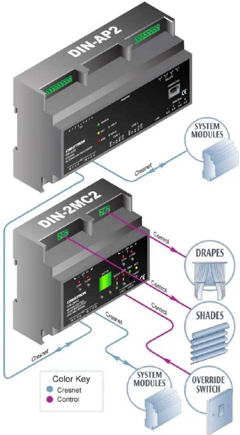
The following diagram shows a DIN-2MC2 in a typical application.
DIN-2MC2 in a Typical Application
flowchart
graph TD
    A["DIN-AP2"] -->|Cresnet| B["DIN-2MC2"]
    B -->|Control| C["DRAPES"]
    B -->|Control| D["SHADES"]
    B -->|Control| E["OVERRIDE SWITCH"]
    style A fill:#f9f,stroke:#333
    style B fill:#bbf,stroke:#333
    style C fill:#fff,stroke:#333
    style D fill:#fff,stroke:#333
    style E fill:#fff,stroke:#333
    subgraph DIN-AP2
        F["DIN-AP2"]
        G["CREDTRON"]
        H["POWER"]
        I["REF"]
        J["HR1"]
        K["GPIO"]
        L["COM1"]
        M["COM2"]
        N["JAN"]
        O["R0/DEA"]
        P["SIU"]
        Q["SIU"]
        R["SIU"]
        S["SIU"]
        T["SIU"]
        U["SIU"]
    end
    subgraph DIN-2MC2
        V["CREDTRON"]
        W["DIN-2MC2"]
        X["OUTPUT"]
        Y["INPUT"]
        Z["CONTROL"]
        AA["CONTROL"]
        AB["CONTROL"]
        AC["CONTROL"]
        AD["CRESNET"]
        AE["CRESNET"]
        AF["CRESNET"]
        AG["CRESNET"]
    end
    style A fill:#f9f,stroke:#333
    style B fill:#f9f,stroke:#333
    style C fill:#f9f,stroke:#333
    style D fill:#f9f,stroke:#333
    style E fill:#f9f,stroke:#333
    style F fill:#f9f,stroke:#333
    style G fill:#f9f,stroke:#333
    style H fill:#f9f,stroke:#333
    style I fill:#f9f,stroke:#333
    style J fill:#f9f,stroke:#333
    style K fill:#f9f,stroke:#333
    style L fill:#f9f,stroke:#333
    style M fill:#f9f,stroke:#333
    style N fill:#f9f,stroke:#333
    style O fill:#f9f,stroke:#333
    style P fill:#f9f,stroke:#333
    style Q fill:#f9f,stroke:#333
    style R fill:#f9f,stroke:#333
    style S fill:#f9f,stroke:#333
    style T fill:#f9f,stroke:#333
    style U fill:#f9f,stroke:#333
    style V fill:#f9f,stroke:#333
    style W fill:#f9f,stroke:#333
    style X fill:#f9f,stroke:#333
    style Y fill:#f9f,stroke:#333
    style Z fill:#f9f,stroke:#333
    style AA fill:#f9f,stroke:#333
    style AB fill:#f9f,stroke:#333
    style AC fill:#f9f,stroke:#333
    style AD fill:#f9f,stroke:#333
Specifications
Specifications for the DIN-2MC2 are listed in the following table.
DIN-2MC2 Specifications
| SPECIFICATION | DETAILS |
| Load RatingsMotor Control Channels 2Per Channel 0.5 HP @ 240 Volts AC, 50/60 HzModule Total 1 HP @ 240 Volts AC, 50/60 HzLoad Types 3-Wire bidirectional motors | |
| Power RequirementsCresnet Power Usage | 3 Watts(1.13 Amps @ 24 Volts DC) |
| Default Net ID 85 | |
| Minimum 2-Series Control System Update File ^1,2 | Version 4.000.0226 or later |
| EnvironmentalTemperature 0° to 40°C (32° to 104°F)Humidity 10% to 90% RHHeat Dissipation 10 BTU/Hr | (non-condensing) |
| Enclosure Light gray polycarbonate housing | with polycarbonate label overlay,UL94 V-0 rated, 35mm DIN EN60715 rail mount, DIN 43880 formfactor for enclosures with 45 mmfront panel cutout, occupies 6 DINmodule spaces (108 mm) |
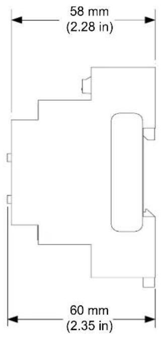
| DimensionsHeight 95 mm (3.71 in)Width 106 mm (4.18 in)Depth | 60 mm (2.35 in) |
| Weight | 210 g (7 oz) |
-
The latest software versions can be obtained from the Crestron website. Refer to the NOTE following these footnotes.
-
Crestron 2-Series control systems include the AV2 and PRO2. Consult the latest Crestron Product Catalog for a complete list of 2-Series control systems.
NOTE: Crestron software and any files on the website are for authorized Crestron dealers and Crestron Authorized Independent Programmers (CAIP) only. New users may be required to register to obtain access to certain areas of the site (including the FTP site).
Physical Description
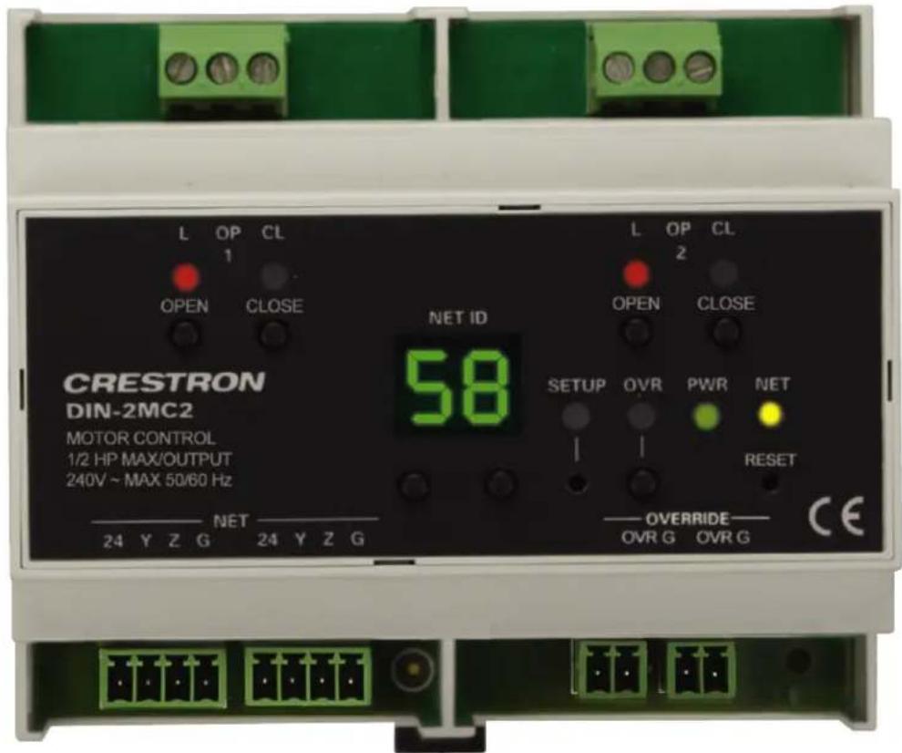
This section provides information on the connections, controls and indicators available on your DIN-2MC2.
DIN-2MC2 Physical View
DIN-2MC2 Overall Dimensions
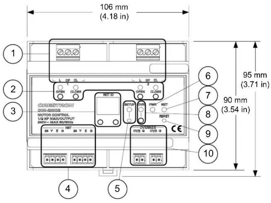
Connectors, Controls & Indicators
| # | CONNECTORS*, CONTROLS & INDICATORS | DESCRIPTION | |
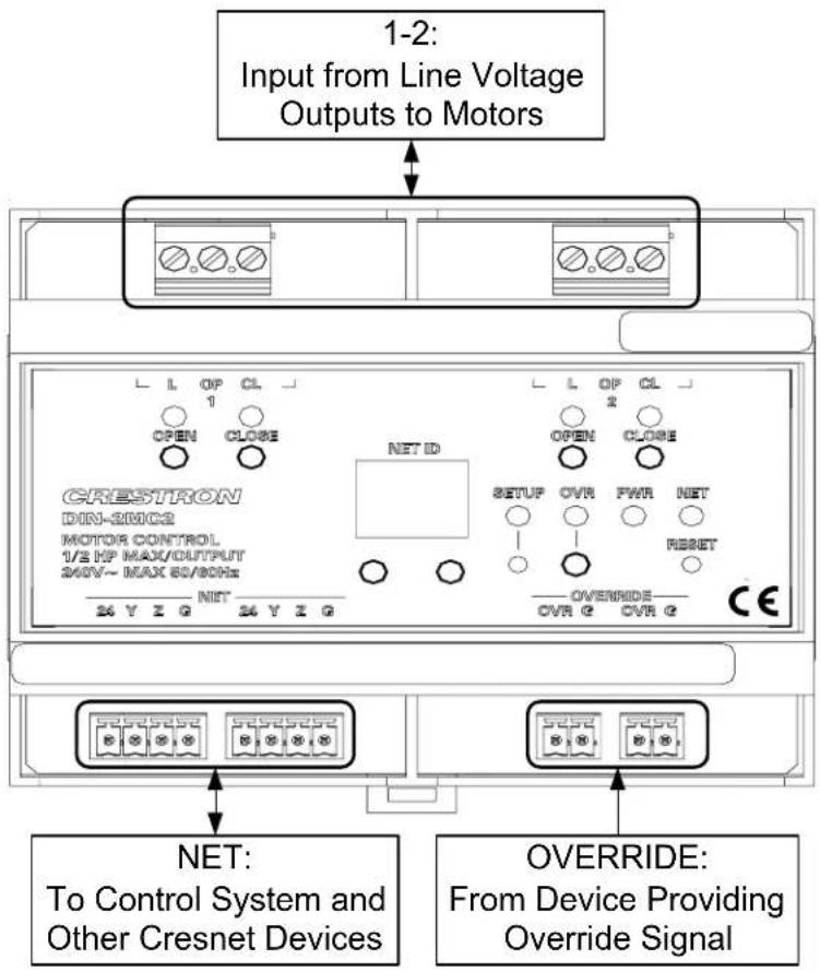
| 1 1 | -2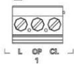 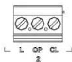 | (2) Sets of (3) captive screw terminals;L: Line Input (120/240V)OP: Motor Output (Open)CL: Motor Output (Close)3-wire bidirectional motor control relays;Maximum Wire Size: 2.5 mm ^2 (12 AWG)Maximum Load per Channel:0.5 HP @ 120/240 Volts AC,50/60 Hz | |
| 2 | OPEN & CLOSE 1 – 2 (4) | Red LEDs and (4) miniature pushbuttons for status indication and local control of each channel | |
| 3 | NET ID(LED and buttons) | (2) 7-Segment green LED digits and (2) miniature pushbuttons for setting Cresnet ID | |
| 4 | NET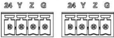 | (2) 4-pin 3.5mm detachable terminal blocks, paralleled; Cresnet slave portMax Wire Size: 1.5 mm ^2 (16 AWG)24: Power (24 Volts DC)Y: DataZ: DataG: Ground | |
| 5 | SETUP(LED and button) | (1) Red LED and (1) recessed miniature pushbutton for enabling setup mode and touch-settable ID | |
| 6 | PWR LED (1) Green LED, | illuminates when DC power is applied to the NET port | |
| 7 | NET LED (1) Yellow LED, | indicates communication with the control processor | |
| 8 | OVR(LED and button) | (1) Red LED and (1) miniature pushbutton for enabling Override mode and saving override presets | |
| 9 | RESET (1) Recessed miniature pushbutton, resets internal processor | ||
| 10 | OVERRIDE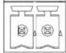 | OVRG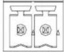 | (2) 2-pin 3.5 mm detachable terminal blocks, paralleled; Max Wire Size: 1.5 mm^2 (16 AWG)Sensing input for external low-voltage contact closure; Activates Override mode when a closure is present; Minimum Closure Rating: 10 mA (per module) at 24 Volts For more information, refer to “Operation” on page 20. |
* Interface connectors for NET and OVERRIDE ports are provided with the unit.
Setup
Network Wiring
When wiring the Cresnet, consider the following:
- Use Crestron Certified Wire.
NOTE: Cresnet-HP wire cannot be used.
- Use Crestron power supplies for Crestron equipment.
- Provide sufficient power to the system.
CAUTION: Insufficient power can lead to unpredictable results or damage to the equipment. Please use the Crestron Power Calculator to help calculate how much power is needed for the system (www.crestron.com/calculators).
- For networks with 20 or more devices, use a Cresnet Hub/Repeater (DIN-HUB) to maintain signal quality.
For more details, refer to “Check Network Wiring” on page 23.
Identity Code
The Net ID of the DIN-2MC2 has been factory set to 85. The Net IDs of multiple DIN-2MC2 devices in the same system must be unique. Net IDs are changed on the front panel of the DIN-2MC2 or from a personal computer (PC) via Crestron Toolbox™ (refer to “Establishing Communication” on page 18).
To set the Net ID using the front panel:
- Press the SETUP button to enter the Setup mode. The SETUP LED illuminates.
- Press the left button under the NET ID display to change the most significant digit of the Net ID or press the right button under the NET ID display to change the least significant digit of the Net ID number.
- When the desired Net ID is displayed, press the SETUP button to exit the Setup mode. The SETUP LED extinguishes.
NOTE: If an invalid Net ID is set (00, 02, FF), “Er” will be displayed on the NET ID display. The DIN-2MC2 will revert to the previously set Net ID.
NOTE: The DIN-2MC2 will leave the Setup mode after 10 seconds of inactivity. The DIN-2MC2 will revert to the previously set Net ID.
NOTE: A small label (with numbers and letters) is provided on the front panel of the DIN-2MC2 to document the unit's Net ID in the case where power is not available. Apply a mark over the digits that correspond to the assigned Net ID.
NET ID Label ("3C" Shown)

When setting the Net ID, consider the following:
- The Net ID of each unit must match an ID code specified in the SIMPL™ Windows program.
• Each network device must have a unique Net ID.
For more details, refer to the Crestron Toolbox help file.
Installation
The DIN-2MC2 must be installed by a licensed electrician, in accordance with all national and local codes.
CAUTION: This equipment is for indoor use only. Mount in a well ventilated area. The ambient temperature must be 0^ to 40^ C ( 32^ to 104^ F). The relative humidity must be 10% – 90% (non-condensing).
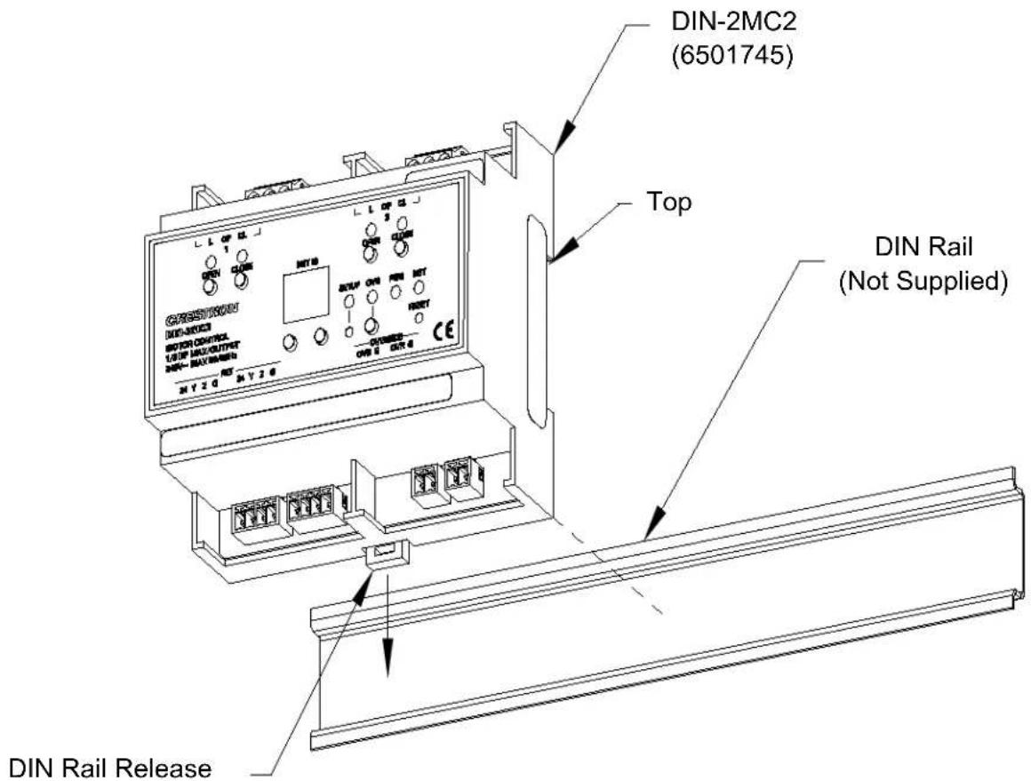
The DIN-2MC2 is designed for installation on a DIN rail. Refer to the following diagram when installing.
Installing the DIN-2MC2
-
Place the top of the DIN-2MC2's rail mount over the top of the DIN rail.
-
Tilt the bottom of the DIN-2MC2 toward the DIN rail until it snaps into place.
NOTE: When mounting DIN rail products, it may be necessary to use a flat-head screwdriver to pull the DIN rail release tab while snapping the device onto the DIN rail.
To remove the DIN-2MC2 from the DIN rail, use a small, flat object (i.e., a flat-head screwdriver) to pull the DIN rail release tab and tilt the bottom of the DIN-2MC2 away from the DIN rail.
NOTE: Certain third party DIN cabinets provide space for an informational label between each DIN rail row. Crestron's Engraver software (version 4.0 or later) can generate appropriate labels for all Crestron DIN rail products.
Hardware Hookup
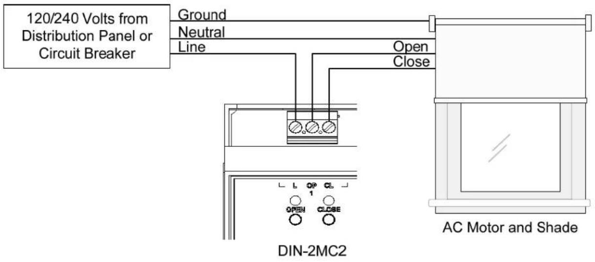
Make the necessary connections as called out in the illustration that follows this paragraph. Refer to “Network Wiring” on page 9 before attaching the 4-position terminal block connector. Apply power after all connections have been made.
WARNING: Prior to connecting the device, turn off power at the circuit breaker. Failure to do so may result in serious personal injury or damage to the device. Restore power after all connections have been made.
CAUTION: Connecting this device to the wrong type of load, or short-circuiting the load can cause severe product damage. Each load should be tested to identify a short circuit condition prior to wiring the load to the module.
NOTE: Install in accordance with all local and national electric codes.
NOTE: High-voltage connections accept 2.5 mm^2 (12 AWG) wire. Wire should be stripped to 8 mm (1/3 inch). Tighten terminal blocks to 0.5 Nm (5 in-lbs).
NOTE: Use copper wire only. For high-voltage connections, use wires rated for at least 75^ C ( 167^ F).
NOTE: Each channel of the DIN-2MC2 may be fed from a separate circuit breaker or a single, shared breaker.
When making connections to the DIN-2MC2 use Crestron power supplies for Crestron equipment.
Hardware Connections for the DIN-2MC2
flowchart
graph TD
    A["Input from Line Voltage Outputs to Motors"] --> B["1-2: Input from Line Voltage Outputs to Motors"]
    B --> C["CRESTRON DIN-SNICE MOTOR CONTROL 1/2 HP MAX/OUTPUT 240V~ MAX 60/80Hz"]
    C --> D["NET ID: NIT 24 Y Z G"]
    C --> E["NET: To Control System and Other Cresnet Devices"]
    C --> F["OVERRIDE: From Device Providing Override Signal"]
Detailed View of Connections between Circuit Breaker & AC Motor/Shade
Programming Software
Have a question or comment about Crestron software?
Answers to frequently asked questions (FAQs) can be viewed in the Online Help section of the Crestron website. To post a question or view questions you have submitted to Crestron's True Blue Support, log in at www.crestron.com/support. First-time users will need to establish a user account.
Earliest Version Software Requirements for the PC
NOTE: Crestron recommends that you use the latest software to take advantage of the most recently released features. The latest software is available from the Crestron website.
Crestron has developed an assortment of Windows ^® -based software tools to develop a Cresnet system. You can create a program to control the DIN-2MC2 using the Crestron programming tools Crestron SystemBuilder ^™ , D3 Pro ^® or SIMPL Windows. Customers whose focus is on lighting systems may prefer to use the D3 Pro software since it is designed especially for creating lighting and environmental system control applications. Customers already familiar with SIMPL Windows who are including a lighting system as part of an overall control system project may prefer to continue using SIMPL Windows. For the minimum recommended software versions, visit the Version Tracker page of the Crestron website (www.crestron.com/versiontracker).
Programming with Crestron SystemBuilder
Crestron SystemBuilder is the easiest method of programming but does not offer as much flexibility as SIMPL Windows. For additional details, download SystemBuilder from the Crestron website and examine the extensive help file.
Programming with D3 Pro
Crestron's D3 Pro lighting software provides all the tools necessary to create a complete Crestron lighting system for residential applications. The lighting system includes the control system logic program, touchpanel projects and keypad programming, documentation and real-time lighting adjustment capabilities.
As with all Crestron software, D3 Pro provides extensive right-click and drag-and-drop functionality in addition to convenient keyboard shortcuts for frequently used functions and commands.
Programming is organized into six system Views of the lighting system, each providing a moveable toolbox of devices such as interfaces, fixtures and control modules. You can add a device to your system simply by selecting it from one of the toolboxes and dragging it to a room. The available toolboxes differ depending on the View but all Views include a "General" toolbox that allows you to add areas and rooms at any time.
Programming with SIMPL Windows
NOTE: While SIMPL Windows can be used to program the DIN-2MC2, it is recommended to use SystemBuilder for configuring a system.
SIMPL Windows is Crestron's premier software for programming Crestron control systems. It is organized into two separate but equally important “Managers”.
Configuration Manager
Configuration Manager is the view where programmers “build” a Crestron control system by selecting hardware from the Device Library.
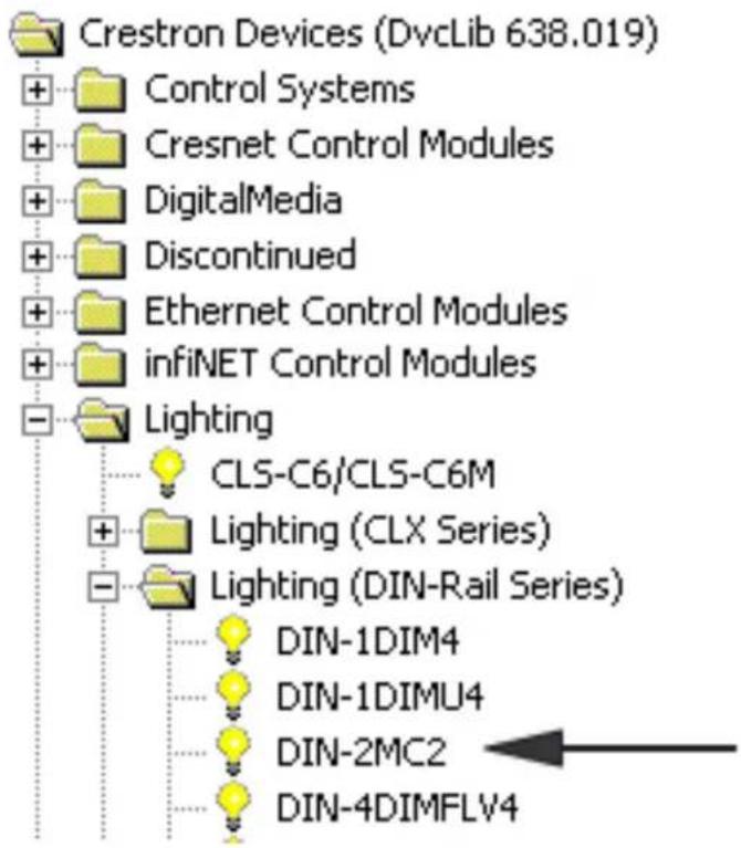
- To incorporate the DIN-2MC2 into the system, drag the DIN-2MC2 from the Lighting | Lighting (DIN-Rail Series) folder of the Device Library and drop it in the System Views.
Locating the DIN-2MC2 in the Device Library
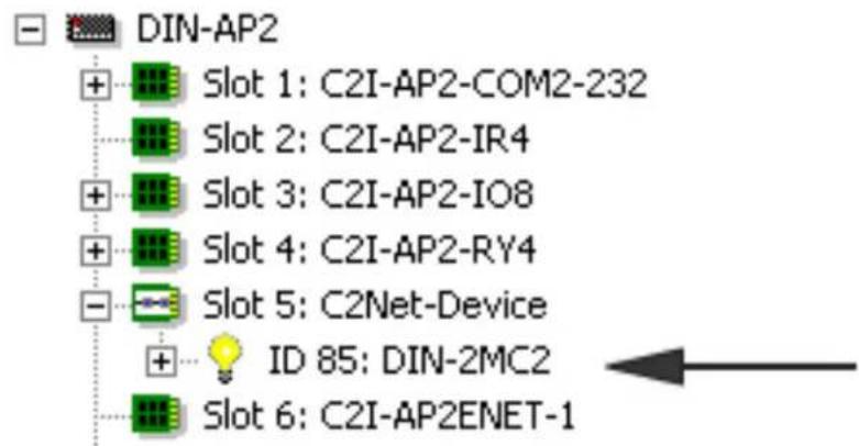
- The system tree of the control system displays the device in the appropriate slot with a default Net ID as shown in the following illustration.
C2Net Device, Slot 5
-
Additional DIN-2MC2 devices are assigned different Net ID numbers as they are added.
-
If necessary, double click a device to open the "Device Settings" window and change the Net ID, as shown in the following figure.
"Device Settings: Crestron DIN-2MC2" Window
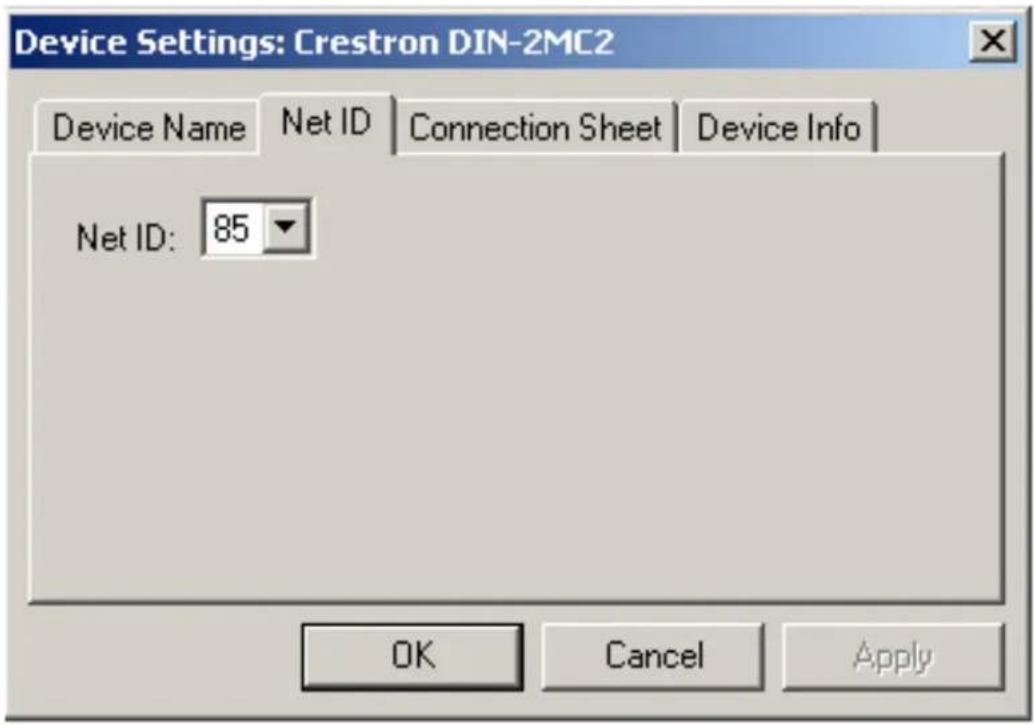
- The ID code specified in the SIMPL Windows program must match the Net ID of each unit. Refer to “Identity Code” on page 9.
Program Manager
Program Manager is the view where programmers “program” a Crestron control system by assigning signals to symbols.
The symbol can be viewed by double clicking on the icon or dragging it into Detail View. Each signal in the symbol is described in the SIMPL Windows help file (F1).
Example Program
An example program for the DIN-2MC2 is available from the Crestron website (www.crestron.com/exampleprograms).
Uploading and Upgrading
Crestron recommends using the latest programming software and that each device contains the latest firmware to take advantage of the most recently released features. However, before attempting to upload or upgrade it is necessary to establish communication. Once communication has been established, files (for example, programs or firmware) can be transferred to the control system (and/or device). Finally, program checks can be performed (such as changing the device ID or creating an IP table) to ensure proper functioning.
Establishing Communication
Use Crestron Toolbox for communicating with the DIN-2MC2; refer to the Crestron Toolbox help file for details. There is a single method of communication: indirect communication.
Indirect Communication

flowchart
graph LR
    A["PC Running Crestron Toolbox"] <-->|Serial, Ethernet or USB| B["Control System"]
    B <-->|Cresnet| C["DIN-2MC2"]
DIN-2MC2 connects to control system via Cresnet:
- Establish communication between the PC and the control system as described in the latest version of the 2-Series Control Systems Reference Guide (Doc. 6256) which is available for download from the Crestron website (www.crestron.com/manuals).
- Use the Address Book in Crestron Toolbox to create an entry for the DIN-2MC2 using the expected communication protocol (indirect). Select the Cresnet ID of the DIN-2MC2 and the address book entry of the control system that is connected to the DIN-2MC2.
- Display the DIN-2MC2's "System Info" window (click the icon); communications are confirmed when the device information is displayed.
Programs and Firmware
Program or firmware files may be distributed from programmers to installers or from Crestron to dealers. Firmware upgrades are available from the Crestron website as new features are developed after product releases. One has the option to upload programs via the programming software or to upload and upgrade via the Crestron Toolbox. For details on uploading and upgrading, refer to the SIMPL Windows help file or the Crestron Toolbox help file.
SIMPL Windows
If a SIMPL Windows program is provided, it can be uploaded to the control system using SIMPL Windows or Crestron Toolbox.
Firmware
Check the Crestron website to find the latest firmware. (New users may be required to register to obtain access to certain areas of the site, including the FTP site.)
Upgrade DIN-2MC2 firmware via Crestron Toolbox.
- Establish communication with the DIN-2MC2 and display the "System Info" window.
- Select Functions | Firmware... to upgrade the DIN-2MC2 firmware.
Program Checks
Using Crestron Toolbox, display the network device tree (Tools | Network Device Tree) to show all network devices connected to the control system. Right-click on the DIN-2MC2 to display actions that can be performed on the DIN-2MC2
Operation
NET ID
Use the NET ID buttons to change the Net ID of the DIN-2MC2. For more information on setting the Net ID, refer to “Identity Code” on page 9.
Manual Control
Each of the DIN-2MC2 outputs can be in one of three states: OPEN, CLOSE, or STOP. When an output is in the OPEN state, the OPEN LED illuminates. When an output is in the CLOSE state, the CLOSE LED illuminates. When an output is in the STOP state, neither of the output LEDs illuminate.
The state of each output can be manually controlled from the buttons on the front panel.
If an output is in the STOP state, press and release the OPEN or CLOSE button to activate the OPEN or CLOSE state. The corresponding LED illuminates to indicate the state of the output. The LED stays lit until the programmable “max time” parameter is reached. Additionally, the NET ID display briefly indicates the state of the output (“OP” for open, “CL” for close).
If an output is in the OPEN or CLOSE state, pressing the OPEN or CLOSE button places the output in the STOP state. Neither of the LEDs illuminate. However, the NET ID display briefly indicates the state of the output (“St” for stop).
An output left in the OPEN or CLOSE state reverts to the STOP state after a programmable timeout.
NOTE: The control system program may change the state of the output if the Override mode is not enabled.
Override Mode
The Override mode overrides the control system program and sets the motor outputs to the saved override settings. For instructions on saving override settings, refer to “Save Override Settings” on page 21.
To enable the Override mode, press and release the OVR button. The OVR LED flashes slowly.
NOTE: If the Override mode was enabled from an external device (i.e., a contact closure is present on the OVERRIDE terminals), the OVR LED flashes quickly. Pressing the OVR button has no effect.
To disable the Override mode, press the OVR button again. The OVR LED extinguishes and the motor outputs go to their STOP states.
NOTE: If override settings have not been saved, the factory default setting is for the motor outputs to remain unaffected when the Override mode is enabled.
Save Override Settings
The state of each output can be saved as an override setting which can be automatically recalled when the Override mode is enabled.
NOTE: The control system program has a setting that can prevent locally saving the override settings. If this setting is enabled, the display shows “Er” when trying to save the override settings. For more information, refer to the SIMPL Windows help file.
To save the state of an output as an override setting:
- Press the OPEN or CLOSE control button to activate the desired function on one or both motor outputs. To leave an output unaffected by the Override mode, leave the output in the STOP state.
- Press and hold the OVR button for three seconds. The OVR LED blinks to indicate new override settings have been stored. Motor outputs that were “closing” are set to go to the “Full Close” position when the Override mode is enabled. Motor outputs that were “opening” are set to go to the “Full Open” position when the Override mode is enabled. Motor outputs that were “stopped” are unaffected when the Override mode is enabled.
Reset
To reboot the DIN-2MC2, press the RESET button. The motor outputs are set to the state currently specified by the control system program. If the control system does not provide a setting, the outputs are set to the last-known state.
Problem Solving
Troubleshooting
The following table provides corrective action for possible trouble situations. If further assistance is required, please contact a Crestron customer service representative.
DIN-2MC2 Troubleshooting
| TROUBLE POSSIBLE CAUSE(S) | CORRECTIVE ACTION | |
| Device does not function. | Device is not communicating with the network. | Use Crestron Toolbox to poll the network. Verify network connection to the device. |
| Device is not receiving power from a Crestron power source. | Use the provided Crestron power source. Verify connections. | |
| Device is not receiving sufficient power. | Use the Crestron Power Calculator to help calculate how much power is needed for the system. | |
| Motor moves in opposite direction. | Incorrect motor wiring. | Reverse the polarity of motor wires. |
| Motor does not respond | Motor fault. Verify motor's upper and lower limits. Refer to motor manufacturer's instruction manual. | |
| Unit ignores control system commands. | Unit is in Override mode. | Take out of Override mode by pressingOVR button or releasing override contact closure. |
Check Network Wiring
Use the Right Wire
In order to ensure optimum performance over the full range of your installation topology, Crestron Certified Wire and only Crestron Certified Wire may be used. Failure to do so may incur additional charges if support is required to identify performance deficiencies because of using improper wire.
Calculate Power
CAUTION: Use only Crestron power supplies for Crestron equipment. Failure to do so could cause equipment damage or void the Crestron warranty.
CAUTION: Provide sufficient power to the system. Insufficient power can lead to unpredictable results or damage to the equipment. Please use the Crestron Power Calculator to help calculate how much power is needed for the system (www.crestron.com/calculators).
When calculating the length of wire for a particular Cresnet run, the wire gauge and the Cresnet power usage of each network unit to be connected must be taken into consideration. Use Crestron Certified Wire only. If Cresnet units are to be daisy-chained on the run, the Cresnet power usage of each network unit to be daisy-chained must be added together to determine the Cresnet power usage of the entire chain. If the unit is home-run from a Crestron system power supply network port, the Cresnet power usage of that unit is the Cresnet power usage of the entire
run. The wire gauge and the Cresnet power usage of the run should be used in the following equation to calculate the cable length value on the equation's left side.
Cable Length Equation
$$ L < \frac {4 0 , 0 0 0}{R \times P} \quad \boxed { \begin{array}{l} \text {Where: L = Length of run (or chain) in feet} \ R = 6 \text {Ohms (Crestron Certified Wire: 0.75 mm} ^ {2} (1 8 \mathrm{AWG})) \ P = \text {Cresnet power usage of entire run (or chain)} \end{array} } $$
Make sure the cable length value is less than the value calculated on the right side of the equation. For example, a Cresnet run using 0.75 mm^2 (18 AWG) Crestron Certified Wire and drawing 20 watts should not have a length of run more than 101 meters (333 feet). Cresnet-HP wire cannot be used.
NOTE: All Crestron certified Cresnet wiring must consist of two twisted pairs. One twisted pair is the +24V conductor and the GND conductor and the other twisted pair is the Y conductor and the Z conductor.
Strip and Tin Wire
When daisy-chaining Cresnet units, strip the ends of the wires carefully to avoid nicking the conductors. Twist together the ends of the wires that share a pin on the network connector and tin the twisted connection. Apply solder only to the ends of the twisted wires. Avoid tinning too far up the wires or the end becomes brittle. Insert the tinned connection into the Cresnet connector and tighten the retaining screw. Repeat the procedure for the other three conductors.
Add Hubs
Use of a Cresnet Hub/Repeater (DIN-HUB) is advised whenever the number of Cresnet devices on a network exceeds 20 or when the combined total length of Cresnet cable exceeds 914 meters (3000 feet).
Reference Documents
The latest version of all documents mentioned within the guide can be obtained from the Crestron website (www.crestron.com/manuals). This link will provide a list of product manuals arranged in alphabetical order by model number.
List of Related Reference Documents
DOCUMENT TITLE
2-Series Control Systems Reference Guide
Further Inquiries
If you cannot locate specific information or have questions after reviewing this guide, please take advantage of Crestron's award winning customer service team by calling Crestron at 1-888-CRESTRON [1-888-273-7876].
You can also log onto the online help section of the Crestron website (www.crestron.com/onlinehelp) to ask questions about Crestron products. First-time users will need to establish a user account to fully benefit from all available features.
Future Updates
As Crestron improves functions, adds new features and extends the capabilities of the DIN-2MC2, additional information may be made available as manual updates. These updates are solely electronic and serve as intermediary supplements prior to the release of a complete technical documentation revision.
Check the Crestron website periodically for manual update availability and its relevance. Updates are identified as an “Addendum” in the Download column.
Return and Warranty Policies
Merchandise Returns / Repair Service
- No merchandise may be returned for credit, exchange or service without prior authorization from CRESTRON. To obtain warranty service for CRESTRON products, contact an authorized CRESTRON dealer. Only authorized CRESTRON dealers may contact the factory and request an RMA (Return Merchandise Authorization) number. Enclose a note specifying the nature of the problem, name and phone number of contact person, RMA number and return address.
- Products may be returned for credit, exchange or service with a CRESTRON Return Merchandise Authorization (RMA) number. Authorized returns must be shipped freight prepaid to CRESTRON, 6 Volvo Drive, Rockleigh, N.J. or its authorized subsidiaries, with RMA number clearly marked on the outside of all cartons. Shipments arriving freight collect or without an RMA number shall be subject to refusal. CRESTRON reserves the right in its sole and absolute discretion to charge a 15% restocking fee plus shipping costs on any products returned with an RMA.
- Return freight charges following repair of items under warranty shall be paid by CRESTRON, shipping by standard ground carrier. In the event repairs are found to be non-warranty, return freight costs shall be paid by the purchaser.
CRESTRON Limited Warranty
CRESTRON ELECTRONICS, Inc. warrants its products to be free from manufacturing defects in materials and workmanship under normal use for a period of three (3) years from the date of purchase from CRESTRON, with the following exceptions: disk drives and any other moving or rotating mechanical parts, pan/tilt heads and power supplies are covered for a period of one (1) year; touchscreen display and overlay components are covered for 90 days; batteries and incandescent lamps are not covered.
This warranty extends to products purchased directly from CRESTRON or an authorized CRESTRON dealer. Purchasers should inquire of the dealer regarding the nature and extent of the dealer's warranty, if any.
CRESTRON shall not be liable to honor the terms of this warranty if the product has been used in any application other than that for which it was intended or if it has been subjected to misuse, accidental damage, modification or improper installation procedures. Furthermore, this warranty does not cover any product that has had the serial number altered, defaced or removed.
This warranty shall be the sole and exclusive remedy to the original purchaser. In no event shall CRESTRON be liable for incidental or consequential damages of any kind (property or economic damages inclusive) arising from the sale or use of this equipment. CRESTRON is not liable for any claim made by a third party or made by the purchaser for a third party.
CRESTRON shall, at its option, repair or replace any product found defective, without charge for parts or labor. Repaired or replaced equipment and parts supplied under this warranty shall be covered only by the unexpired portion of the warranty.
Except as expressly set forth in this warranty, CRESTRON makes no other warranties, expressed or implied, nor authorizes any other party to offer any warranty, including any implied warranties of merchantability or fitness for a particular purpose. Any implied warranties that may be imposed by law are limited to the terms of this limited warranty. This warranty statement supersedes all previous warranties.
Trademark Information
All brand names, product names and trademarks are the sole property of their respective owners. Windows is a registered trademark of Microsoft Corporation. Windows95/98/Me/XP/Vista/7 and WindowsNT/2000 are trademarks of Microsoft Corporation.
This page is intentionally left blank.

CRESTRON®
Crestron Electronics, Inc. Operations & Installation Guide – DOC. 6665B
15 Volvo Drive Rockleigh, NJ 07647
(2020747)
Tel: 888.CRESTRON
04.10
Fax: 201.767.7576 Specifications subject to
www.crestron.com change without notice.

- CRESTRON®
- Regulatory Compliance
- Federal Communications Commission (FCC) Compliance Statement
- Industry Canada (IC) Compliance Statement
- DIN Rail Motor Control: DIN-2MC2
- Introduction
- Features and Functions
- Override Input
- DIN Rail Installation
- Cresnet®
- Applications
- Specifications
- Physical Description
- Setup
- Network Wiring
- Identity Code
- NET ID Label ("3C" Shown)
- Installation
- Installing the DIN-2MC2
- Hardware Hookup
- Programming Software
- Earliest Version Software Requirements for the PC
- Programming with Crestron SystemBuilder
- Programming with D3 Pro
- Programming with SIMPL Windows
- Example Program
- Uploading and Upgrading
- Establishing Communication
- Programs and Firmware
- Program Checks
- Operation
- NET ID
- Manual Control
- Override Mode
- Save Override Settings
- Reset
- Problem Solving
- Troubleshooting
- Check Network Wiring
- Cable Length Equation
- Strip and Tin Wire
- Add Hubs
- Reference Documents
- List of Related Reference Documents
- DOCUMENT TITLE
- Further Inquiries
- Future Updates
- Return and Warranty Policies
- Merchandise Returns / Repair Service
- CRESTRON Limited Warranty
- Trademark Information
Brand : Crestron
Model : DIN-2MC2
Category : Régulateur