
SLXD24 - Microphone SHURE - Free user manual and instructions
Find the device manual for free SLXD24 SHURE in PDF.


User questions about SLXD24 SHURE
0 question about this device. Answer the ones you know or ask your own.
Ask a new question about this device
Download the instructions for your Microphone in PDF format for free! Find your manual SLXD24 - SHURE and take your electronic device back in hand. On this page are published all the documents necessary for the use of your device. SLXD24 by SHURE.
USER MANUAL SLXD24 SHURE
Shure online user guide for SLX-D digital wireless system.
Version: 4.0 (2020-H)
Table of Contents
SLX-D Wireless System 3
IMPORTANT SAFETY INSTRUCTIONS 3
WARNING 4
Important Product Information 4
LICENSING INFORMATION 4
Australia Warning for Wireless 4
Overview 5
Features 5
System Components 6
Set Up the Receiver 8
Wearing the Bodypack Transmitter 9
Hardware Interface 10
Receiver Front and Back Panels 10
Navigating the Receiver Menus 11
Transmitters 13
Transmitter Menu Options and Navigation 15
Locking and Unlocking the Receiver Controls 15
Batteries and Chargers 16
Install Transmitter Batteries 16
Setting the AA Battery Type 17
Shure SB903 Rechargeable Battery 17
Average Charging Times 19
Sound Check and Gain Adjustment 19
System Set Up 20
Creating Audio Channels 20
What are Groups and Channels? 20
Using the Guided Frequency Setup 21
Manual Frequency Selection 22
Linking Two Transmitters to a Receiver 23
Adding SLX-D to Other Shure Wireless Systems 23
Radio Frequency (RF) Settings 23
Setting the Transmitter RF Power 23
Networking 24
Connecting to a Network 24
Automatic IP Addressing 24
Configuration Tips 24
Network Troubleshooting 24
Connecting to an External Control System 24
Firmware Updates 24
Firmware Release Requirements 25
Mount the SLX-D Receiver in a Rack 25
Installing Footpads 26
Accessories 27
Optional Accessories 27
Specifications 31
Receiver Output Connectors 38
Transmitter Input 38
Frequency Range and Transmitter Output Power 38
Frequencies for European Countries 39
Certifications 41
Information to the user 41
SLX-D Wireless System
IMPORTANT SAFETY INSTRUCTIONS
- READ these instructions.
- KEEP these instructions.
- HEED all warnings.
- FOLLOW all instructions.
- DO NOT use this apparatus near water.
- CLEAN ONLY with dry cloth.
- DO NOT block any ventilation openings. Allow sufficient distances for adequate ventilation and install in accordance with the manufacturer's instructions.
- DO NOT install near any heat sources such as open flames, radiators, heat registers, stoves, or other apparatus (including amplifiers) that produce heat. Do not place any open flame sources on the product.
- DO NOT defeat the safety purpose of the polarized or grounding type plug. A polarized plug has two blades with one wider than the other. A grounding type plug has two blades and a third grounding prong. The wider blade or the third prong are provided for your safety. If the provided plug does not fit into your outlet, consult an electrician for replacement of the obsolete outlet.
- PROTECT the power cord from being walked on or pinched, particularly at plugs, convenience receptacles, and the point where they exit from the apparatus.
- ONLY USE attachments/accessories specified by the manufacturer.
- USE only with a cart, stand, tripod, bracket, or table specified by the manufacturer, or sold with the apparatus. When a cart is used, use caution when moving the cart/apparatus combination to avoid injury from tip-over.

- UNPLUG this apparatus during lightning storms or when unused for long periods of time.
- REFER all servicing to qualified service personnel. Servicing is required when the apparatus has been damaged in any way, such as power supply cord or plug is damaged, liquid has been spilled or objects have fallen into the apparatus, the apparatus has been exposed to rain or moisture, does not operate normally, or has been dropped.
- DO NOT expose the apparatus to dripping and splashing. DO NOT put objects filled with liquids, such as vases, on the apparatus.
- The MAINS plug or an appliance coupler shall remain readily operable.
- The airborne noise of the Apparatus does not exceed 70dB (A).
- Apparatus with CLASS I construction shall be connected to a MAINS socket outlet with a protective earthing connection.
- To reduce the risk of fire or electric shock, do not expose this apparatus to rain or moisture.
- Do not attempt to modify this product. Doing so could result in personal injury and/or product failure.
- Operate this product within its specified operating temperature range.

This symbol indicates that dangerous voltage constituting a risk of electric shock is present within this unit.
!
This symbol indicates that there are important operating and maintenance instructions in the literature accompanying this unit.
WARNING
- Battery packs may explode or release toxic materials. Risk of fire or burns. Do not open, crush, modify, disassemble, heat above 140°F (60°C), or incinerate.
• Follow instructions from manufacturer - Only use Shure charger to recharge Shure rechargeable batteries
- WARNING: Danger of explosion if battery incorrectly replaced. Replace only with same or equivalent type.
- Never put batteries in mouth. If swallowed, contact your physician or local poison control center
- Do not short circuit; may cause burns or catch fire
- Do not charge or use battery packs other than Shure rechargeable batteries
- Dispose of battery packs properly. Check with local vendor for proper disposal of used battery packs.
- Batteries (battery pack or batteries installed) shall not be exposed to excessive heat such as sunshine, fire or the like
- Do not immerse the battery in liquid such as water, beverages, or other fluids.
- Do not attach or insert battery with polarity reversed.
- Keep away from small children.
- Do not use abnormal batteries.
- Pack the battery securely for transport.
Important Product Information
LICENSING INFORMATION
Licensing: A ministerial license to operate this equipment may be required in certain areas. Consult your national authority for possible requirements. Changes or modifications not expressly approved by Shure Incorporated could void your authority to operate the equipment. Licensing of Shure wireless microphone equipment is the user's responsibility, and licensability depends on the user's classification and application, and on the selected frequency. Shure strongly urges the user to contact the appropriate telecommunications authority concerning proper licensing, and before choosing and ordering frequencies.
低功率電波輻射性電機管理辦法
第十二條
Australia Warning for Wireless
This device operates under an ACMA class licence and must comply with all the conditions of that licence including operating frequencies. Before 31 December 2014, this device will comply if it is operated in the 520-820 MHz frequency band.
WARNING: After 31 December 2014, in order to comply, this device must not be operated in the 694-820 MHz band.
Canada Warning for Wireless
This device operates on a no-protection, no-interference basis. Should the user seek to obtain protection from other radio services operating in the same TV bands, a radio licence is required. For further details, consult Innovation, Science and Economic Development Canada's document Client Procedures Circular CPC-2-1-28, Voluntary Licensing of Licence-Exempt Low-Power Radio Apparatus in the TV Bands.
SLX-D Digital Wireless delivers clear audio and stable RF performance with easy setup and rechargeability options. SLX-D is built to handle a wide range of applications, from day-long conferences to nighttime performances.
Automatic channel scan and IR sync are even easier with a guided setup feature programmed into each SLX-D wireless receiver. Manage multiple-system group scans and firmware updates with third-party setup and control via Ethernet. Operate up to 32 compatible systems per 44 MHz band for up to 8 hours from 2 AA batteries, or add Shure SB903 rechargeable batteries and charger accessories. SLX-D provides >120 dB dynamic range and stable, efficient RF transmission for a selection of handheld, lavalier and headset microphones.
Features
• Transparent 24-bit digital audio
- Extended 20 Hz to 20 kHz frequency range (microphone dependent)
• 120 dB dynamic range
• Digital predictive switching diversity
• 44 MHz tuning bandwidth (region dependent)
• 32 available channels per frequency band (region dependent)
- Up to 10 compatible systems per 6MHz TV band; 12 systems per 8 MHz band
- Easy pairing of transmitters and receivers over IR scan and sync
• Automatic channel scan
- Link multiple receivers for group scan and firmware updates via Ethernet port
• Third-party setup and control via Ethernet
- Elegant and easy-to-use interface with high-contrast LCD menu
• Guided setup mode installed in each SLX-D receiver
• Transmitters use 2 AA batteries or Shure SB903 rechargeable battery
- System configurations include handheld transmitters with interchangeable microphone capsules, bodypacks with a range of lavalier, headset and instrument microphones and single and dual rack-mountable receivers.
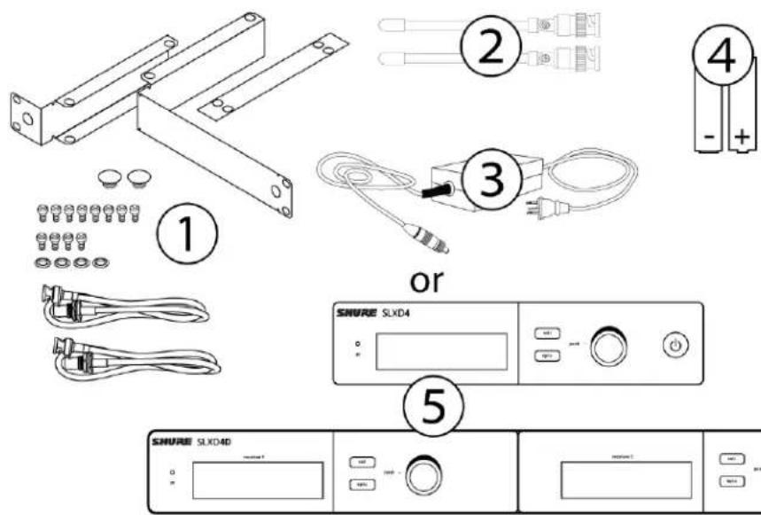
System Components
All systems include:
①
Rack mounting hardware
②
14 -wave antennas (2)
③
Power supply
④
1.5V AA batteries (2)
⑤
SLXD4 or SLXD4D receiver
text_image
Technical diagram showing exploded view of a device with labeled components including metal brackets, cable connectors, and a control panel.Guitar system includes:
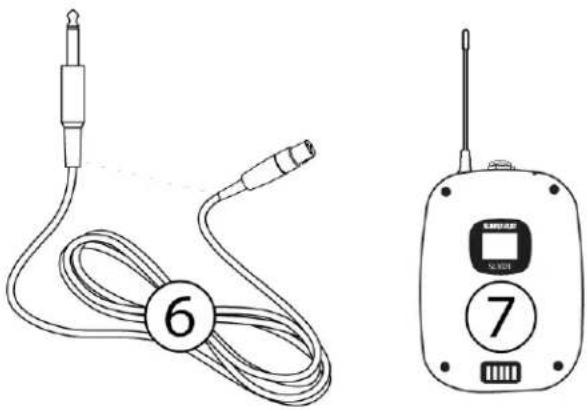
⑥
14 " to mini 4-pin guitar cable
⑦
SLXD1 bodypack transmitter
natural_image
Line drawings of two electronic devices: a cable with connector 6 and a walk-in device with labeled buttons 7 (no text or symbols on main components)Vocal system includes:
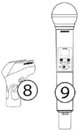
⑧
Microphone clip
⑨
SLXD2 handheld transmitter with microphone cartridge (choice of SM58 ^® , SM86, Beta 58A ^® , Beta 87A ^™ , Beta 87C ^™ , or KSM8/B*)
text_image
8 9*KSM8/B availability depends on region.
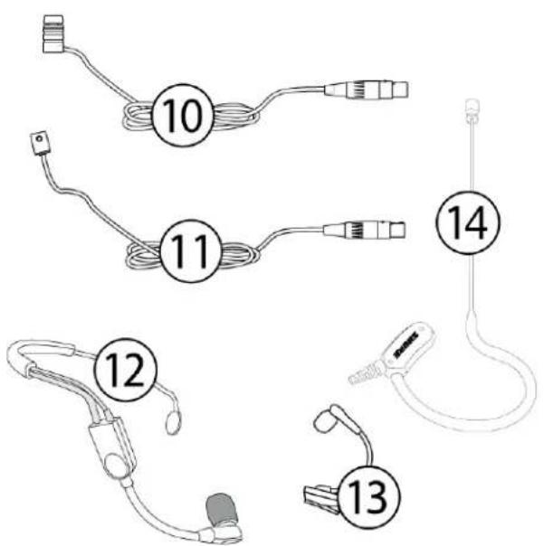
Lavalier, Headworn, and Instrument systems include bodypack transmitter (⑦) and one of the following:
10
WL183/WL185 lavalier microphone
⑪
WL93 miniature lavalier microphone
⑫
SM35 headset microphone
⑬
Beta 98H/C ^TM instrument microphone
⑭
MX153 earset headworn microphone
text_image
Diagram showing labeled medical or medical device parts with numbered labels 10 to 14 indicating different components.Combo system includes:
⑦
SLXD1 bodypack transmitter
⑨
Handheld transmitter with SM58 microphone head
⑪
WL185 lavalier microphone
Set Up the Receiver
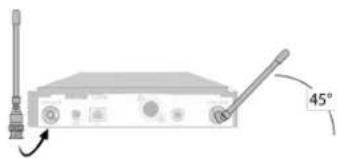
- Attach the included antennas to the back of the receiver.
natural_image
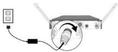
Diagram of a portable electronic device with a 45-degree angle indicator (no text or symbols present)- Connect the power supply to the receiver and plug the cord into an AC power source.
natural_image
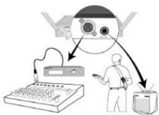
Diagram showing a connected device with a cable and a magnified inset of a connector (no text or symbols)- Connect the audio output to an amplifier or mixer.
flowchart
graph TD
    A["User Interaction"] --> B["Data Acquisition"]
    B --> C["Processing Unit"]
    C --> D["Monitor"]
    D --> E["Display"]
    style A fill:#f9f,stroke:#333
    style B fill:#ccf,stroke:#333
    style C fill:#cfc,stroke:#333
    style D fill:#fcc,stroke:#333
    style E fill:#ffc,stroke:#333
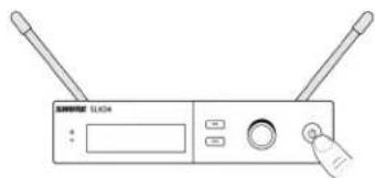
- Press the power button on the receiver. Use the menu to set the system to microphone (mic) or instrument (line) level as appropriate.
natural_image
Line drawing of a wireless router device with two antennas and a control panel (no text or symbols)Wearing the Bodypack Transmitter
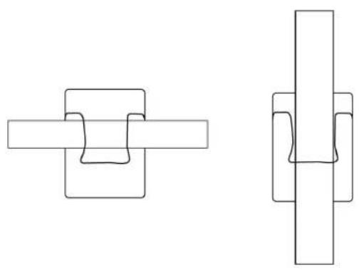
Clip the transmitter to a belt or slide a guitar strap through the transmitter clip as shown.
For best results, the belt should be pressed against the base of the clip.
natural_image
Two abstract geometric line drawings with interlocking rectangular shapes (no text or symbols)Hardware Interface
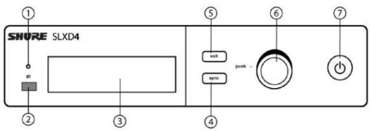
Receiver Front and Back Panels
text_image
SHURE SLXD4 in ① ② ③ ④ ⑤ ⑥ ⑦ wall push - sync ④① Sync LED
- Flashing: IR sync mode is enabled
• Solid: Receiver and transmitter aligned for IR sync
② IR Port
Align with the transmitter IR port during an IR sync to program transmitters.
③ Display
Shows menu options, receiver and transmitter settings.
④ Sync Button
Press to activate IR sync.
⑤ Exit Button
Press to cancel and exit the current operation.
⑥ Control Knob
Change menu parameters, push knob to confirm.
⑦ Power Button
Powers receiver on or off.
text_image
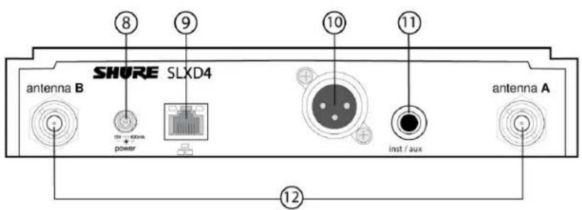
SHORE SLXD4 antenna B 10 11 inst / aux antenna A 12⑧ Power Supply Jack
Connection point for DC power supply.
⑨ Ethernet Port
For network connection.
- Amber LED (network speed):
off = 10 Mbps, on = 100 Mbps
- Green LED (network status):
off = no network link, on = network link active
flashing = rate corresponds to traffic volume
⑩ XLR Audio Output
Balanced (1: ground, 2: audio +, 3: audio -)
⑪ 1/4" Instrument/Auxiliary Output
Impedance Balanced (Tip: audio+, Ring: audio-, Sleeve: ground)
⑫ Antenna Connectors
BNC connector for receiver antennas
Navigating the Receiver Menus
The receiver has a main menu for setup and configuration and an advanced menu to access additional receiver functions. Use the control knob to navigate menu screens and confirm selections; use the exit button to return to the previous level.
Main Menu
Push the control knob button to access the menu, and rotate to advance to the next menu screen.
| 1. Frequency Setup | 1.1 Guided Frequency Setup | Step-by-step instructions to initialize a new system, or to add a receiver to an existing system |
| 1.2 Group Scan | Receiver automatically scans for the best available group, if applicable.Note: Some bands consist of only a single group. RF performance is the same in single-group bands as in bands that support multiple groups. | |
| 1.3 Channel Scan | Receiver automatically scans for available channels within the selected group | |
| 1.4 Manual Frequency Setup | Manually tune the receiver to a desired frequency | |
| 2. Channel Name | Customize the channel name | |
| 3. Gain | Monitor audio levels and adjust the receiver gain | |
| 4. Mic/Line Level | Switch between output levels | |
| 5. Advanced Settings | 5.1 Device Lock | Unlock: Receiver is unlockedLock Menu: Receiver settings are lockedLock Menu & Power: Receiver settings and power button are locked |
| 5.2 Network Configuration | Switch between automatic and manual IP addressing | |
| 5.3 Controller Access | Block or allow third-party control access | |
| 5.4 Transmitter Preset | Apply and sync transmitter presets | |
| 5.5 Device Preset | Save current receiver settings or restore last saved settings | |
| 5.6 Factory Reset | Restores all settings to factory defaults following a system reboot | |
| 5.7 Transmitter Firmware | Update transmitter firmware using IR sync | |
| 5.8 About | Displays firmware version and serial number | |
| 6. Help | Provides a link to additional materials (http://help.shure.com/slxd4) | |
Transmitters
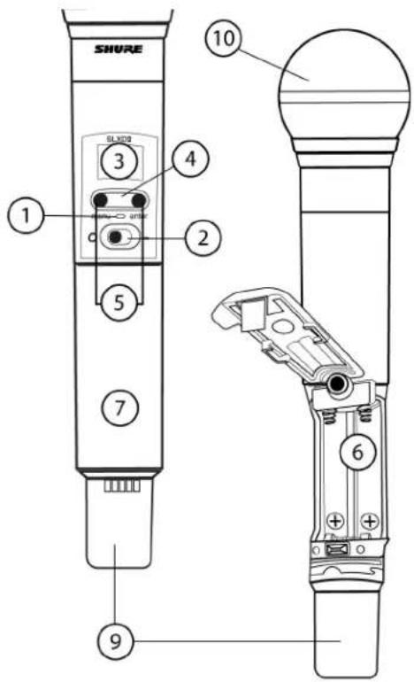
① Power LED
- Green = unit is powered on
- Red = low battery
② On/Off Switch
Powers the transmitter on or off.
③ Display:
View menu screens and settings. Press any control button to activate the display.
④ IR Port
Align with the receiver IR port during an IR sync for automated transmitter programming.
⑤ Menu Navigation Buttons
menu = Use to navigate between menu screens.
enter = Press to confirm and save parameter changes.
⑥ Battery Compartment
Requires 2 AA batteries or a Shure SB903 rechargeable battery.
⑦ Battery Cover
Screws into place to protect battery compartment during use.
⑧ Bodypack Antenna
For RF signal transmission.
⑨ Handheld Integrated Antenna
For RF signal transmission.
⑩ Microphone Cartridge
Interchangeable with a variety of Shure cartridges.
⑪ TA4M Input Jack
Connects to a 4-Pin Mini Connector (TA4F) microphone or instrument cable.
text_image
SHURE 1 2 3 4 5 6 7 9 10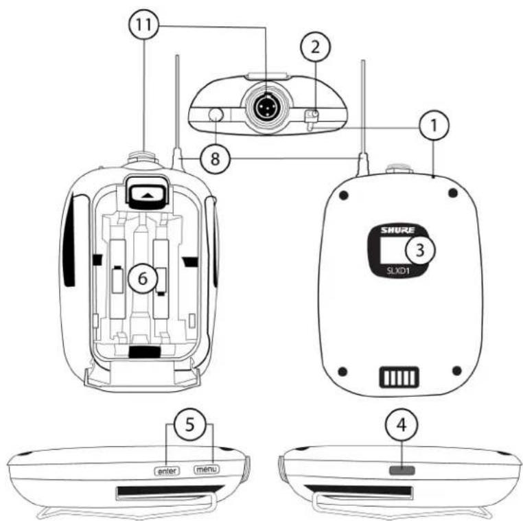
text_image
11 2 8 1 6 5 4 enter menu SHUWE SLXD1Transmitter Menu Options and Navigation
The transmitter features individual menu screens for setting up and adjusting the transmitter. To access the menu options from the home screen, press the menu button. Each additional press of the menu button advances to the next menu screen. Use the enter button to select and confirm options on the active menu screen.
| Home Screen | Use the enter button to select one of the following home screen displays:Channel name/Group and channel/Battery iconChannel name/Frequency/Battery iconChannel name/Battery icon/Group and channelChannel name/Battery icon |
| 1 Mic Offset | Match audio levels between two transmitters used in a combo system. Range is 0 to 21 dB (3 dB increments). |
| 2 RF Power | Select an RF power setting:High = 10 mWLow = 1 mW |
| 3 High Pass | Turn the high pass filter On or Off |
| 4 Battery | To ensure accurate battery metering, set the battery type to match the installed AA battery type.Note:Menu is not selectable when Shure rechargeable batteries are installed. |
| 5 Auto Lock | Turn the transmitter auto lock on or off |
| 6 Lock Type | Determine auto lock behavior:Menu Only: Locks the menu to prevent transmitter settings from being changedMenu & Power: Locks the menu and disables the power switch |
| 7 About | Displays the firmware, hardware, and band information |
Locking and Unlocking the Receiver Controls
The following control lock options can be accessed under 5. Advanced Settings > 5.1 Device Lock:
- Unlock: receiver controls are unlocked
- Lock Menu: prevents access to menu items (receiver can still be powered off)
- Lock Menu & Power: disables the power switch as well as menu controls
Select the desired option and press the control knob to confirm.
Transmitter Auto Lock
The transmitter controls can be locked or unlocked by selecting On (locked) or Off (unlocked) from the transmitter Auto Lock menu. When auto lock is enabled, the transmitter controls lock when you return to the home screen.
Note: The enter button can still be used to change the home screen display on a locked transmitter.
To activate auto lock:
- Press the menu button to navigate to the Auto Lock settings.
- Use the enter button to edit and the menu button to select On.
- Press enter to save. The lock icon appears on the display to confirm that the control locks are enabled.
To unlock the transmitter and deactivate auto lock:
- Press enter then menu to unlock the transmitter controls.
- Navigate to the Auto Lock settings and select Off.
- Press enter to save. The transmitter will no longer lock when you return to the home screen.
Batteries and Chargers Install Transmitter Batteries
Important: To avoid damaging transmitters, only use Shure SB903 Li-ion rechargeable batteries or 1.5V AA batteries.
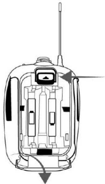
Bodypack:
- Push the tab up and open the battery door to access the battery compartment.
- Place a Shure SB903 Li-ion rechargeable battery or 2 AA batteries in the compartment.
- Close the battery door.
natural_image
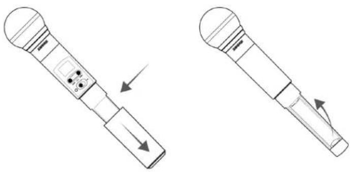
Technical line drawing of a mechanical device with internal components and directional arrows (no text or symbols)Handheld:
- Remove the battery cover to access the battery compartment.
- Lift the battery door to open the battery compartment.
- Place a Shure SB903 Li-ion rechargeable battery or 2 AA batteries in the compartment.
- Replace the battery cover.
natural_image
Technical line drawing of a handheld device with two views showing internal components and directional arrows (no text or symbols)Setting the AA Battery Type
To ensure accurate display of transmitter runtime, set the battery type in the transmitter menu to match the installed AA battery type (the default setting is Alkaline). If a Shure rechargeable battery is installed, selecting a battery type is not necessary and the battery type menu will not be displayed.
- Press the menu button to navigate to the Battery screen.
- Press enter, then use the menu button to select the installed battery type:
-
Alkaline = Alkaline
• NiMH (nickel metal hydride)
• Lithium (non-rechargeable, 1.5V max) -
Press enter to save.
Shure SB903 Rechargeable Battery
The SB903 lithium-ion rechargeable battery powers the SLX-D transmitters. Use the SBC10-903 single bay or SBC203 dual bay chargers to recharge SB903 batteries.
Important: Always fully charge a new battery before first use.
To fully charge a new SB903 battery, it must be placed directly in the charger. After the first charge, the battery can be charged by docking the transmitter in the SBC203 dual-bay charging station.
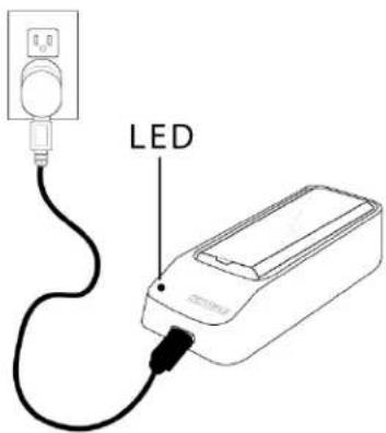
Single Bay Charger
The SBC10-903 single bay charger offers a compact charging solution.
- Plug the charger into an AC power source or USB port.
- Insert a battery into the charging bay.
- Monitor the charging status LEDs until charging is complete.
text_image
LEDCharging Status LEDs
| Description | Color | State |
| Ready for Use | Green (solid) | Device is fully charged |
| Charging | Red (flashing) | Charging |
| Error | Yellow (quick flashing) | Battery or power supply error |
| Not charging | Off | Power supply is disconnected, or no device is docked in the charging bay |
Dual Bay Chargers
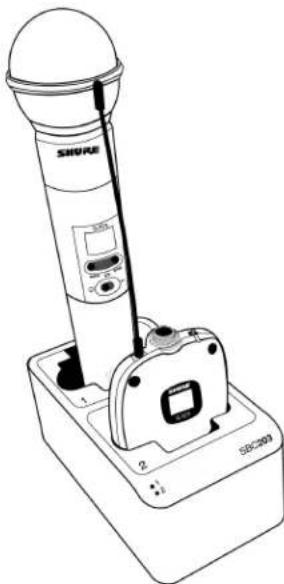
The SBC203 dual-bay charger can charge individual batteries or batteries installed in transmitters.
natural_image
Line drawing of a SHAVRE device with labeled components and a base (no text or symbols beyond branding)- Plug the charger into an AC power source.
- Insert batteries or transmitters into the charging bay.
IMPORTANT: Insert transmitters facing forward to avoid damage.
- Monitor the charging status LEDs until charging is complete.
Charging Status LEDs
| Description | Color | State |
| Ready for Use | Green (solid) | Device is fully charged |
| Charging | Red (flashing) | Charging |
| Error | Yellow (quick flashing) | Battery or power supply error* |
| Yellow (slow flashing) | Outside of operating temperature range | |
| Not charging | Off | Power supply is disconnected, or no device is docked in the charging bay |
* If an error occurs when a transmitter is docked in the charger, remove the battery from the transmitter and place directly into the charger. If the error persists, contact Shure Technical Support.
Important Tips for Care and Storage of Shure Rechargeable Batteries
Proper care and storage of Shure batteries results in reliable performance and ensures a long lifetime.
• Always store batteries and transmitters at room temperature
- Ideally, batteries should be charged to approximately 40% of capacity for long-term storage
- During storage, check batteries every 6 months and recharge to 40% of capacity as needed
Average Charging Times
SBC10-903
| Time Charging | Operating Runtime | Capacity |
| 1 hour | 1 hour | 15% |
| 3 hours | 4 hours | 50% |
| 5 hours : 30 minutes | >8 hours | 100% |
SBC203
| Time Charging | Operating Runtime | Capacity |
| 30 minutes | 1 hour | 15% |
| 1 hour : 15 minutes | 4 hours | 50% |
| 2 hours : 30 minutes | >8 hours | 100% |
*based on battery with 100% health
Sound Check and Gain Adjustment
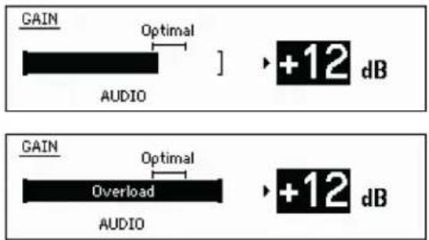
Navigate to the receiver's Gain screen to test the transmitter at performance levels. Adjust the gain to keep the audio indicator within the optimal range. Reduce the gain if there is audible distortion of the audio.
text_image
GAIN Optimal AUDIO ] ➕+12 dB GAIN Optimal Overload AUDIO ➕+12 dBSystem Set Up
Creating Audio Channels
A wireless audio channel is formed when a receiver and transmitter are tuned to the same frequency. The SLX-D system provides 3 methods for tuning the receiver and transmitter to the same frequency:
• Guided Frequency Setup: A step-by-step guide to walk you through the process
- Scan and IR Sync: The receiver scans the RF spectrum for the best available frequency and an IR sync automatically tunes the transmitter to the receiver frequency
- Manual Group, Channel, or Frequency Assignment: Manually set the receiver and transmitter to the same group and channel number, or frequency
What are Groups and Channels?
To minimize interference, Shure wireless systems organize RF bands into predefined groups and channels. A group is a set of compatible frequencies within a frequency band. A single frequency within a group is a channel. Tune a receiver and transmitter to the best available channel within its group to set up your system.
Note: Because groups are band-dependent, some systems don't have multiple groups. Single-group bands have the same RF performance as those with multiple groups.
All receivers in the same band should be set to the same group. You can set them manually, or use the Guided Frequency Setup to walk you through the process.
Connect all the receivers in your system using Ethernet cables. For best results, use a network switch when connecting 3 or more receiver units.
Important! To avoid interference, before you begin:
Turn off all transmitters for the systems you are setting up. This prevents them from interfering with the frequency scan.
Turn on the following devices so they are operating as they would be during the presentation or performance. This will allow the scan to detect and avoid any interference from these devices:
- Configured wireless systems or devices
- Computers
• Large LED panels - Effects processors
- CD players
Using the Guided Frequency Setup
Set up a new system:
- Push the control knob on the receiver and select 1. Frequency Setup > 1.1 Guided Frequency Setup.
- Select Initialize My System and push the control knob to continue.
- Turn off all transmitters you plan to use with your system.
- Select start scan.
- After the scan is done, push the control knob to assign frequencies to the receiver.
- Turn on the transmitter you plan to use with this receiver.
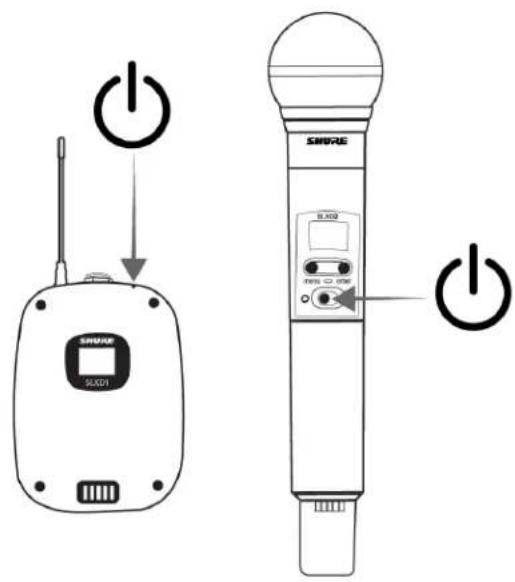
text_image
SWEKE SLXD1 SWEKE SLXD2 Power Power- Align the infrared (IR) ports on the transmitter and receiver, and push the sync button.
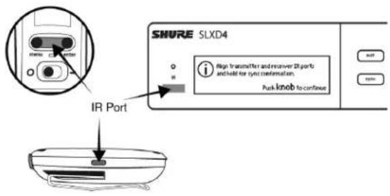
text_image
SHURE SLXD4 IR Port High transmitter and receiver 28 ports and hold for sync confirmation. Park knob to continue- Once the sync is complete, the system is ready for use.
Add a new receiver to your system:
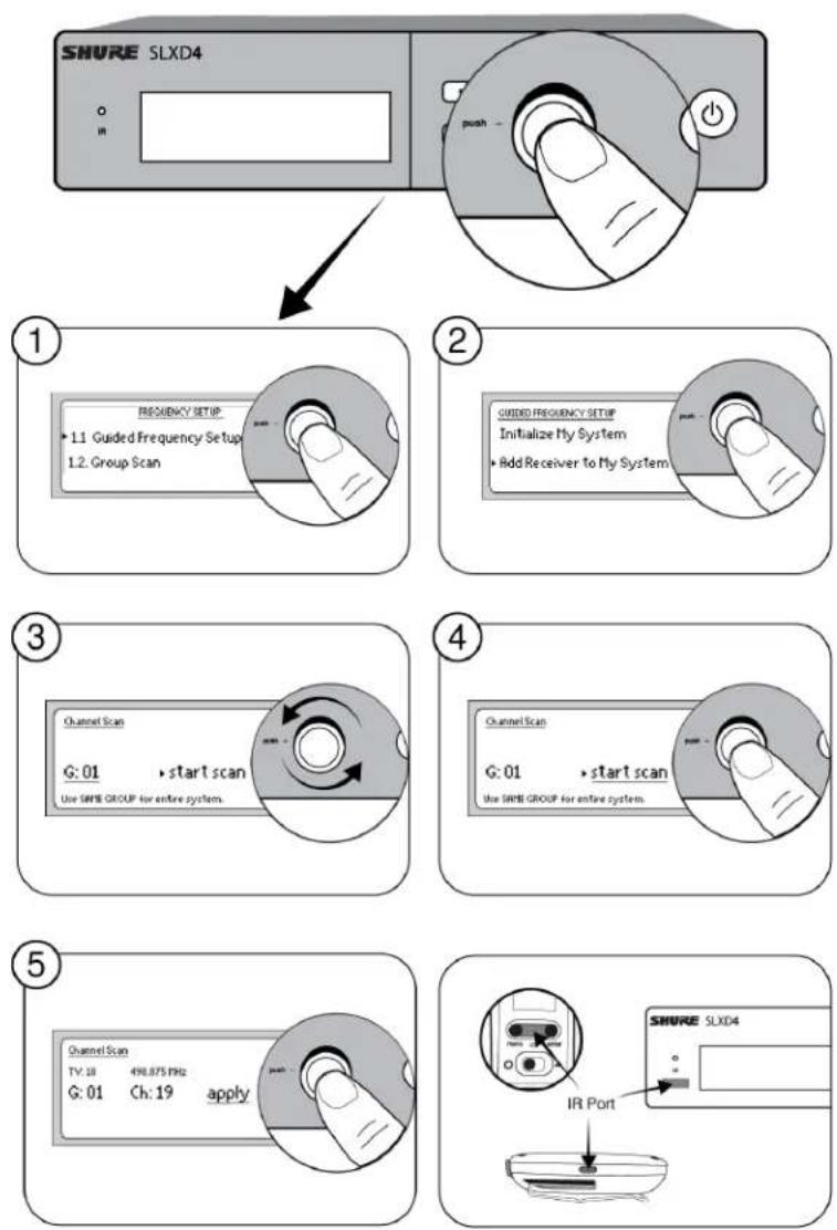
- Push the control knob and select 1. Frequency Setup > 1.1 Guided Frequency Setup.
- Select Add Receiver to My System.
- To change the group, rotate the control knob to select G:, push to select, rotate to change the number, push again to confirm.
- Select start scan.
- After the scan completes, push the control knob to apply the receiver channel.
- Turn on the transmitter you plan to use with this receiver.
- Align the infrared (IR) port on the transmitter with that on the receiver, and push the sync button.
- Once the sync is complete, the system is ready for use.
Manual Frequency Selection
To manually adjust group, channel or frequency:
- Select 1. Frequency Setup > 1.4 Manual Frequency Setup from the receiver menu.
-
Use the control knob to select and adjust the group (G), channel (C), or frequency (MHz).
-
Select apply and push the control knob to save.
Linking Two Transmitters to a Receiver
Linking two transmitters to a receiver offers the flexibility to provide a performer with either a handheld or bodypack transmitter to meet their preference. For performances requiring instrument changes, two bodypack transmitters can be linked to a single receiver.
Note: Only turn on and operate one transmitter at a time to prevent interference between the transmitters.
Syncing the Transmitters to the Receiver
Both transmitters must be individually linked to the receiver by performing an IR Sync.
- Turn on the first transmitter and perform an IR Sync with the receiver.
- Perform a sound check and adjust the transmitter gain if necessary. When finished, turn off the transmitter.
- Turn on the second transmitter and perform an IR Sync with the receiver.
- Test the transmitter at performance conditions and adjust the transmitter gain if necessary. When finished, turn off the transmitter.
Matching Audio Levels with Mic Offset
When linking two transmitters to a receiver, there may be a difference in volume levels between microphones or instruments. If this occurs, use the Mic Offset function to match the audio levels and eliminate audible volume differences between transmitters. If using a single transmitter, set Mic Offset to 0 dB.
- Turn on the first transmitter and perform a sound check to test the audio level. Turn off the transmitter when finished.
- Turn on the second transmitter and perform a sound check to test the audio level.
- If there is an audible difference in the sound level between the transmitters, navigate to the Mic Offset menu on the transmitter to increase or decrease the Mic Offset to match the audio levels.
Mic Offset 1/6
+6 dB
Adding SLX-D to Other Shure Wireless Systems
Use Shure's Wireless Workbench frequency coordination tool to find compatible frequencies across different Shure wireless systems. To get started, download the software from http://www.shure.com/wwb. For additional assistance, please visit http://www.shure.com/contact.
Radio Frequency (RF) Settings
Setting the Transmitter RF Power
The transmitter offers two RF power settings which determine the transmitter range.
- Low = 1 mW
- High = 10 mW
Use the Low setting when the transmitter and receiver are in close proximity.
- Navigate to the transmitter RF power menu.
- Use the menu button to select High or Low.
- Press enter to save.
Networking
The receiver uses an Ethernet connection to network with other components and includes an internal DHCP client for automatic network configuration when connected to a DHCP enabled router.
Connecting to a Network
- Insert an Ethernet cable in the Ethernet port on the rear of the receiver.
- Connect the cable to a computer or router.
- The port LEDs on the receiver will illuminate to indicate network connectivity and network traffic.
Automatic IP Addressing
- Enable a DHCP service on the server or use a DHCP enabled router.
- When the receiver is powered on, the DHCP server will automatically assign an IP address to the receiver.
Configuration Tips
- Use shielded Cat 5 or better Ethernet cables to ensure reliable network performance
- The LEDs on the Ethernet port illuminate indicating a network connection is active
- The network icon illuminates when the receiver detects additional Shure devices on the network
- All components must operate on the same subnet
- Use multiple Ethernet switches to extend the network for larger installations
Network Troubleshooting
• Use only one DHCP server per network
- All devices must share the same subnet mask
- All receivers must have the same level of firmware version installed
- Check the LED status of the network icon on the front panel of each device.
- If the network icon is not illuminated, check the cable connection and the LEDs on the Ethernet port.
- If the Ethernet port LEDs are not illuminated and the cable is plugged in, replace the cable and recheck the LEDs and network icon.
Connecting to an External Control System
The SLX-D receiver is compatible with external control systems such as AMX or Crestron via Ethernet. Use only one controller per system to avoid messaging conflicts.
- Connection: Ethernet (TCP/IP; SLX-D receiver is the client)
- Port: 2202
For a comprehensive list of SLX-D command strings, visit https://pubs.shure.com/command-strings/SLXD/en-US.
Firmware Updates
Firmware is embedded software in each component that controls functionality. Periodically, new versions of firmware are developed to incorporate additional features and enhancements. To take advantage of design improvements, new versions of the firmware can be uploaded and installed using the Shure Update Utility (SUU). Download the SUU from https://www.shure.com/en-US/products/software/shure_update_utility.
Perform the following steps to update the firmware:
CAUTION! Ensure the device has a stable network connection during the update. Do not turn off the device until the update is complete.
- Connect the device and computer to the same network (set to the same subnet).
- Open the SUU application.
- Click the Updates button at the top of the window to open the Download Manager.
Note: This button will be labeled either "Check for updates..." or "[#] updates available"
- From the Download Manager, select the desired firmware versions.
Tip: The dropdown in the upper right allows you to quickly Select: All or Select: None.
Note: After updating, you may need to clear your browser's cache to display updates to the device's web application.
- Click Download, and then Close the Download Manager. Downloaded firmware is listed and can be viewed and managed in the Firmware tab.
- From the Update Devices tab, select the new firmware and press Send Updates to begin the firmware update, which overwrites the existing firmware on the device.
Firmware Release Requirements
All devices are part of a network with multiple communications protocols that work together to ensure proper operation. The recommended best practice is that all devices are on an identical release. To view the firmware version of each device on the
network, navigate to device configuration and look under (Settings) > Firmware.
The format for Shure device's firmware is MAJOR.MINOR.PATCH. (Ex. 1.6.2 where 1 is the Major firmware level, 6 is the Minor firmware level, and 2 is the Patch firmware level.) At a minimum, devices that operate on the same subnet should have identical MAJOR and MINOR release numbers.
• Devices of different MAJOR releases are not compatible.
- Differences in the PATCH firmware release level may introduce undesired inconsistencies.
Mount the SLX-D Receiver in a Rack
All accessories are supplied:
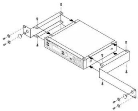
text_image
Technical diagram of an electronic device with labeled ports and connection pointsInstalling Footpads
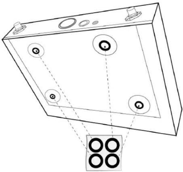
natural_image
Technical line drawing of a mechanical component with four circular features and a separate inset showing four concentric rings (no text or symbols)Accessories
Optional Accessories
Batteries and Chargers
| Shure Lithium-Ion Rechargeable Battery | SB903 |
| Dual Docking Charger | SBC203-AR |
| SBC203-AZ | |
| SBC203-BR | |
| SBC203-CN | |
| SBC203-E | |
| SBC203-IN | |
| SBC203-J | |
| SBC203-K | |
| SBC203-TW | |
| SBC203-UK | |
| SBC203-US | |
| Single Battery Charger | SBC10-903-AR |
| SBC10-903-AZ | |
| SBC10-903-BR | |
| SBC10-903-CN | |
| SBC10-903-E | |
| SBC10-903-IN | |
| SBC10-903-J | |
| SBC10-903-K | |
| SBC10-903-TW | |
| SBC10-903-UK | |
| SBC10-903-US |
UHF Antenna Power Distribution Amplifiers
| Antenna/Power Distribution System 470-960 MHz | UA844+SWB |
| UA844+SWB-AR | |
| UA844+SWB-AZ | |
| UA844+SWB-BR | |
| UA844+SWB-C | |
| UA844+SWB-E | |
| UA844+SWB-J | |
| UA844+SWB-K | |
| UA844+SWB-TW | |
| UA844+SWB-UK | |
| UA844+SWB-IN | |
| Antenna/Power Distribution System, Less cable 470-960 MHz | UA844+SWB/LC |
| UA844+SWB/LC-AR | |
| UA844+SWB/LC-BR | |
| UA844+SWB/LC-C | |
| UA844+SWB/LC-E | |
| UA844+SWB/LC-UK | |
| Ultra Wideband Antenna/Power Distribution System 174-1805 MHz | UA845UWB |
| UA845UWB-AR | |
| UA845UWB-AZ | |
| UA845UWB-BR | |
| UA845UWB-C | |
| UA845UWB-E | |
| UA845UWB-IN | |
| UA845UWB-J | |
| UA845UWB-K | |
| UA845UWB-TW | |
| UA845UWB-UK | |
| Ultra Wideband Antenna/Power Distribution System, Less cable 174-1805 MHz | UA845UWB/LC |
| UA845UWB/LC-AR | |
| UA845UWB/LC-BR | |
| UA845UWB/LC-E | |
| UA845UWB/LC-UK |
UABIAST
| In-Line Power Supply | UABIAST-US |
| UABIAST-UK | |
| UABIAST-BR | |
| UABIAST-AR | |
| UABIAST-E | |
| UABIAST-CHN | |
| UABIAST-IN | |
| UABIAST-K | |
| UABIAST-J | |
| UABIAST-AZ | |
| UABIAST-TW |
In-Line Amplifiers and Antennas
| In-Line Antenna Amplifier, 470-900 MHz | UA834WB |
| In-Line Antenna Amplifier, 902-960 MHz | UA834XA |
| Active Directional Antenna 470-790 MHZ | UA874E |
| Active Directional Antenna 470-698 MHZ | UA874US |
| Active Directional Antenna 470-900 MHZ | UA874WB |
| Active Directional Antenna 925-952 MHZ | UA874X |
| Directional Wideband Antenna for PSM Systems 470-952 MHz | PA805SWB |
| Directional Wideband Antenna for PSM Systems 650-1100 MHz | PA805X |
| Passive Omnidirectional Antenna 470-1100 MHz | UA860SWB |
| UHF Passive Antenna Splitter | UA221 |
| Front Mount Antenna Kit (Includes 2 Cables And 2 Bulk-head) | UA600 |
| Remote Antenna Bracket With BNC Bulkhead Adaptor | UA505 |
| Helical Antenna, 470-900MHZ | HA-8089 |
Cables and Connectors
| Coaxial Cable, BNC-BNC, RG58C/U TYPE, 50 OHM, 2 FT Length (0.6 M) | UA802 |
| Coaxial Cable, BNC-BNC, RG58C/U TYPE, 50 OHM, 6 FT Length (2 M) | UA806 |
| Coaxial Cable, BNC-BNC, RG8X/U TYPE, 50 OHM, 25 FT Length (7.5 M) | UA825 |
| Coaxial Cable, BNC-BNC, RG8X/U TYPE, 50 OHM, 50 FT Length (15 M) | UA850 |
| Coaxial Cable, BNC-BNC, RG213/U TYPE, 50 OHM, 100 FT Length (30 M) | UA8100 |
| Ethernet Jumper Cable, 8" | C8006 |
| Ethernet Cable, 3 FT. | C803 |
| Ethernet Cable, 10 FT. | C810 |
| Ethernet Cable, Ruggedized, 25 FT. | C825 |
| Ethernet Cable, Ruggedized, 50 FT. | C850 |
| Ethernet Cable, Ruggedized, 100 FT. | C8100 |
1/2 Wave Omnidirectional Receiver Antennas
| 470-542 MHz | UA8-470-542 |
| 500-560 MHz | UA8-500-560 |
| 518-598 MHz | UA8-518-598 |
| 554-638 MHz | UA8-554-638 |
| 596-698 MHz | UA8-596-698 |
| 670-742 MHz | UA8-670-742 |
| 690-746 MHz | UA8-690-746 |
| 694-758 MHz | UA8-694-758 |
| 710-790 MHz | UA8-710-790 |
| 740-814 MHz | UA8-740-814 |
| 750-822 MHz | UA8-750-822 |
| 774-865 MHz | UA8-774-865 |
| 00-1000 MHz | UA8-900-1000 |
Specifications
System
RF
RF Carrier Frequency Range
470–937.5 MHz, varies by region (See Frequency Range and Output Power table)
Working Range
100 m (328 ft)
RF Tuning Step Size
25 kHz, varies by region
Image Rejection
70 dB, typical
RF Sensitivity
-97 dBm at 10^-5 BER
Audio
Latency
3.2 ms
Audio Frequency Response
20 Hz - 20 kHz (+1, -2 dB)
Audio Dynamic Range
120 dB at 1% THD, A-weighted, typical
Total Harmonic Distortion
<0.02%
System Audio Polarity
Positive pressure on microphone diaphragm produces positive voltage on pin 2 (with respect to pin 3 of
XLR output) and the tip of the 6.35 mm (with respect to the ring of the 6.35 mm output) output.
Mic Offset Range
0 to 21 dB (in 3 dB steps)
Temperature Range
Operating Temperature Range
-18°C (0°F) to 50°C (122°F)
Storage Temperature Range
-29°C (-20°F) to 74°C (165°F)
SLXD4 / SLXD4D
Dimensions
| SLXD4 | 42 x 197 x 152 mm (1.65 x 7.76 x 5.98 in.), H x W x D |
| SLXD4D | 42 x 393 x 152 mm (1.65 x 15.47 x 5.98 in.), H x W x D |
Weight
| SLXD4 | 816 g, without antennas |
| SLXD4D | 1451 g, without antennas |
Housing
Galvanized Steel
Power Requirements
15 V DC @ 600 mA, supplied by external power supply (tip positive)
RF Input
Spurious Rejection
75 dB, typical
Connector Type
BNC
Impedance
50 Ω
Phantom Power Protection
| 1/4" (6.35 mm) | Yes |
| XLR | Yes |
Audio Output
Gain Adjustment Range
-18 to +42 dB in 1 dB steps
Configuration
| 1/4" (6.35 mm) | Balanced (Tip = audio +, Ring = audio -, Sleeve = ground) |
| XLR | Balanced (1=ground, 2=audio +, 3=audio -) |
Impedance
| 1/4" (6.35 mm) | 1.3 kΩ (670 Ω Unbalanced) |
| XLR (line) | 400 Ω (200 Ω Unbalanced) |
| XLR (mic) | 150 Ω |
Full Scale Output
| 1/4" (6.35 mm) | +15 dBV differentially (+9 dBV single) |
| XLR | LINE setting= +15 dBV, MIC setting= -15 dBV |
Mic/Line Switch
30 dB pad
Networking
Network Interface
Single Port Ethernet 10/100 Mbps
Network Addressing Capability
DHCP or Manual IP address
Maximum Cable Length
100 m (328 ft)
SLXD1
Battery Type
Rechargeable Li-Ion or 1.5 V AA batteries
Dimensions
$$ 9 8 \times 6 8 \times 2 5. 5 \mathrm{mm} (3. 8 6 \times 2. 6 8 \times 1 \text {in.}), H \times W \times D $$
Weight
89 g
Housing
PC/ABS
Audio Input
Connector
4-Pin male mini connector (TA4M)
Configuration
See drawing for details
Impedance
1 MΩ
Maximum Input Level
8.2 dBV (2.57 Vrms, 7.27 Vpp)
Preamplifier Equivalent Input Noise (EIN)
-118 dBV
RF Output
Antenna Type
1/4 wave
Occupied Bandwidth
<200 kHz
Modulation Type
Shure proprietary digital
Power
1 mW or 10 mW
SLXD2
Battery Type
Rechargeable Li-Ion or 1.5 V AA batteries
Dimensions
37.1 x 176 mm (1.46 x 6.93 in.), D x L
Weight
147 g
Housing
Aluminum
Audio Input
Configuration
See drawing for details
Maximum Input Level
8.2 dBV (2.57 Vrms, 7.27 Vpp)
RF Output
Antenna Type
Integrated Single Band Helical
Occupied Bandwidth
<200 kHz
Modulation Type
Shure proprietary digital
Power
1 mW or 10 mW
SB903
Charge Voltage
4.2 V (±0.03 V)
Charge Current
| SBC10-903 | 220 mA |
| SBC203 | 625 mA (normal), 250 mA (reduced) |
Nominal Voltage
3.6 V
Nominal Capacity
1200 mAh
Housing
Molded Polycarbonate
Charging Temperature Range
| SBC10-903 | 10 °C to 45 °C (50 °F to 113 °F) |
| SBC203 | 0 °C to 10 °C (32 °F to 50 °F), reduced, and 10 °C to 45 °C (50 °F to 113 °F), normal |
Dimensions
14.5 x 32.5 x 55.5 mm (0.57 x 1.28 x 2.19 in.), H x W x D
Weight
28 g
SBC10-903
Battery Charger
DC Input Voltage Range
5 V DC
Charge Current
USB-powered
220 mA
Charge Time
50% = 3 hours; 100% = 5 hours : 30 minutes
Charge Voltage
4.2 V
Operating Temperature Range
10 °C to 45 °C (50 °F to 113 °F)
Dimensions
20.5 x 37.5 x 79.5 mm (0.81 x 1.48 x 3.13 in.), H x W x D
Weight
39 g
Housing
Molded Polycarbonate
Power Supply
Input Voltage Range
100 to 240 V AC
Operating Frequency
50 Hz to 60 Hz
Maximum Input Power
0.2A
Output Voltage
4.75 to 5.25 V DC
Maximum Output Power
1.0 A
Operating Temperature Range
0 °C to 60 °C (32 °F to 140 °F)
SBC203
Charge Current
625 mA or 250 mA
Charge Time
50% = 1 hour : 15 minutes; 100% = 2 hours : 30 minutes
External Power Supply
SBC10-USB15W or SBC10-USB15WS
Power Requirements
5 V DC, 3 A max.
Charging Temperature Range for Battery
0 °C to 45 °C (32 °F to 113 °F)
Dimensions
66 x 99 x 165 mm (2.6 x 3.9 x 6.5 in.), H x W x D
Weight
284 g
Housing
ABS
Power Supply
Input Voltage Range
100 to 240 V AC
Operating Frequency
50 Hz to 60 Hz
Maximum Input Power
0.6 A
Output Voltage
4.75 to 5.25 V DC
Maximum Output Power
3.0 A
Operating Temperature Range
0 °C to 60 °C (32 °F to 140 °F)
Receiver Output Connectors
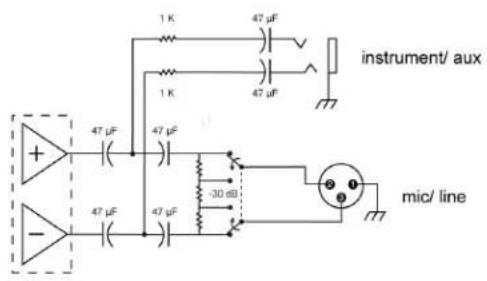
text_image
instrument/ aux + 47 μF 47 μF - 47 μF 47 μF -30 dB mic/ lineTransmitter Input
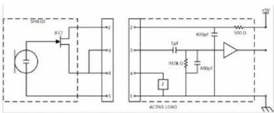
text_image
SPEDS IFET 2 3 4 1 2 820qF 500 Ω 1μF 910k Ω 400pF 1 2 ACTIVE LOAD +5V| 1 | Ground |
| 2 | Bias Voltage |
| 3 | Audio Input |
| 4 | Active Load |
Frequency Range and Transmitter Output Power
| Band | Frequency Range (MHz) | Power ( mW RMS )* (Low/High) |
| G58 | 470 to 514 | 1 / 10 |
| G59 | 470 to 514 | 1 / 10 |
| G60 | 470 to 510 | 1 / 10 |
| G61 | 479 to 523 | 1 / 10 |
| G62 | 510 to 530 | 1 / 10 |
| H55 | 514 to 558 | 1 / 10 |
| H56 | 518 to 562 | 1 / 10 |
| H57 | 520 to 564 | 1 / 10 |
| J52 | 558 to 616 | 1 / 10 |
| J53 | 562 to 606 | 1 / 10 |
| J54 | 562 to 606 | 1 / 10 |
| JB | 806 to 810 | 1 / 10 |
| K59 | 606 to 650 | 1 / 10 |
| L55 | 646 to 690 | 1 / 10 |
| L56 | 650 to 694 | 1 / 10 |
| L57 | 650 to 694 | 1 / 10 |
| L58 | 630 to 674 | 1 / 10 |
| L59 | 654 to 698 | 1 / 10 |
| M55 | 694 to 703, 748 to 758 | 1 / 10 |
| S50 | 823 to 865 | 1 / 10 |
| X51 | 925 to 937.5 | 1 / 10 |
* Power delivered to the antenna port
Note: Frequency bands might not be available for sale or authorized for use in all countries or regions.
Frequencies for European Countries
| Country Code | Frequency Range | |
| SLXD-G59470-514MHz,max.1/10mW | A, B, BG, CH, CY, CZ, D, EST | 470 - 514 MHz* |
| F, GB, GR, H, I, IS, L, LT | 470 - 514 MHz* | |
| NL, P, PL, S, SK, SLO | 470 - 514 MHz* | |
| DK, FIN, M, N | 470 - 514 MHz* | |
| HR, E, IRL, LV, RO, TR | 470 - 514 MHz* | |
| SLXD-H56 | A, B, BG, CH, CY, CZ, D, EST | 518 - 562 MHz* |
| 518 - 562 MHz, max. 1/10 mW | F, GB, GR, H, I, IS, L, LT | 518 - 562 MHz* |
| NL, P, PL, S, SK, SLO | 518 - 562 MHz* | |
| DK, FIN, M, N | 518 - 562 MHz* | |
| HR, E, IRL, LV, RO, TR | 518 - 562 MHz* | |
| SLXD-J53 562-606 MHz, max. 1/10 mW | A, B, CH, CZ, D, E, EST | 562-606 MHz* |
| F, GB, GR, H, I, IRL, L | 562-606 MHz* | |
| LT, M, NL, P, PL, SLO | 562-606 MHz* | |
| DK, FIN, N, S | 562-606 MHz* | |
| CY, LV, SK | 562-606 MHz* | |
| SLXD-K59 606-650 MHz, max. 1/10 mW | A, B, CH, CZ, D, E, EST | 606-650 MHz* |
| F, GB, GR, H, I, IRL, L | 606-650 MHz* | |
| LT, M, NL, P, PL, SLO | 606-650 MHz* | |
| DK, FIN, N, S | 606-650 MHz* | |
| CY, LV, SK | 606-650 MHz* | |
| SLXD-L56 650 - 694 MHz, max. 1/10 mW | A, BG, CH, CY, CZ, D, EST | 650 - 694 MHz* |
| F, GB, GR, H, I, IS, L, LT | 650 - 694 MHz* | |
| P, PL, S, SK, SLO | 650 - 694 MHz* | |
| B, DK, FIN, M, N, NL | 650 - 694 MHz* | |
| HR, E, IRL, LV, RO, TR | 650 - 694 MHz* | |
| SLXD-S50 823-832 863-865 MHz max. 1/10 mW | A, BG, CH, CY, CZ, D, EST | 823-832 MHz * |
| F, GB, GR, H, I, IS, LT | 823-832 MHz * | |
| P, PL, S, SK, SLO | 823-832 MHz * | |
| B, DK, E, FIN, HR, IRL, L | 823-832 MHz * | |
| LV, M, N, NL, RO, TR | 823-832 MHz * |
* This equipment may be capable of operating on some frequencies not authorized in your region. See Licensing Information.
Certifications
Information to the user
This device complies with part 15 of the FCC Rules. Operation is subject to the following two conditions:
- This device may not cause harmful interference.
- This device must accept any interference received, including interference that may cause undesired operation.
Note: This equipment has been tested and found to comply with the limits for a Class B digital device, pursuant to part 15 of the FCC Rules. These limits are designed to provide reasonable protection against harmful interference in a residential installation. This equipment generates uses and can radiate radio frequency energy and, if not installed and used in accordance with the instructions, may cause harmful interference to radio communications. However, there is no guarantee that interference will not occur in a particular installation. If this equipment does cause harmful interference to radio or television reception, which can be determined by turning the equipment off and on, the user is encouraged to try to correct the interference by one or more of the following measures:
- Reorient or relocate the receiving antenna.
- Increase the separation between the equipment and the receiver.
- Connect the equipment to an outlet on a circuit different from that to which the receiver is connected.
- Consult the dealer or an experienced radio/TV technician for help.
This device operates on frequencies shared with other devices. Consult the Federal Communications Commission White Space Database Administration website to determine available channels in your area prior to operation.
This device contains licence-exempt transmitter(s)/receiver(s) that comply with Innovation, Science and Economic Development Canada's licence-exempt RSS(s). Operation is subject to the following two conditions:
- This device may not cause interference.
- This device must accept any interference, including interference that may cause undesired operation of the device.
These transmitters have been tested and found to comply with international radiation exposure limits set forth for an uncontrolled environment. This equipment is in direct contact with the body of the user under normal operating conditions. These transmitters must not be co-located or operating in conjunction with any other antenna or transmitter.
Certified under FCC Part 15 and FCC Part 74.
Certified by ISED in Canada under RSS-102 and RSS-210.
CAN ICES-3 (B)/NMB-3 (B)
Approved under the Declaration of Conformity (DoC) provision of FCC Part 15.
Meets essential requirements of the following European Directives:
• WEEE Directive 2012/19/EU, as amended by 2008/34/EC
• RoHS Directive EU 2015/863
Note: Please follow your regional recycling scheme for batteries and electronic waste
This product meets the Essential Requirements of all relevant European directives and is eligible for CE marking.
Hereby, Shure Incorporated declares that the radio equipment is in compliance with Directive 2014/53/EU. The full text of the
EU declaration of conformity is available at the following internet address: http://www.shure.com/europe/compliance
Authorized European representative:
Shure Europe GmbH
Headquarters Europe, Middle East & Africa
Department: EMEA Approval
Jakob-Dieffenbacher-Str. 12
75031 Eppingen, Germany
Phone: +49-7262-92 49 0
Fax: +49-7262-92 49 11 4
Email: EMEAsupport@shure.de