
ThinkCentre M625q - Desktop computer LENOVO - Free user manual and instructions
Find the device manual for free ThinkCentre M625q LENOVO in PDF.


User questions about ThinkCentre M625q LENOVO
0 question about this device. Answer the ones you know or ask your own.
Ask a new question about this device
Download the instructions for your Desktop computer in PDF format for free! Find your manual ThinkCentre M625q - LENOVO and take your electronic device back in hand. On this page are published all the documents necessary for the use of your device. ThinkCentre M625q by LENOVO.
USER MANUAL ThinkCentre M625q LENOVO
Note: Before using this information and the product it supports, be sure to read and understand the Important Product Information Guide and Appendix A “Notices” on page 67.
Second Edition (August 2019)
© Copyright Lenovo 2018, 2019.
LIMITED AND RESTRICTED RIGHTS NOTICE: If data or software is delivered pursuant to a General Services Administration "GSA" contract, use, reproduction, or disclosure is subject to restrictions set forth in Contract No. GS-35F-05925.
Contents
Chapter 1. Overview.....1
Front view....1
Rear view....2
System board 4
Machine type and model label ..... 6
Chapter 2. Specifications .....7
Chapter 3. Computer locks .....9
Attaching a Kensington-style cable lock ..... 9
Chapter 4. Replacing hardware . . . . 11
Before replacing hardware ..... 11
Knowing FRUs (including CRUs) ..... 11
Locating FRUs (including CRUs) ..... 13
Replacing the keyboard or wireless keyboard . . . 16
Replacing the mouse or wireless mouse ..... 17
Replacing the power adapter ..... 21
Replacing the vertical stand ..... 24
Replacing the VESA mount bracket ..... 25
Replacing the power adapter bracket ..... 26
Removing the computer cover ..... 28
Replacing the storage drive for 10TF, 10TG, 10TH, 10TJ, and 10TK models ..... 30
Replacing the storage drive cable for 10TF, 10TG, 10TH, 10TJ, and 10TK models ..... 33
Replacing the system fan for 10TF, 10TG, 10TH, 10TJ, and 10TK models. . . . . . . . . . . . 34
Replacing the heat sink....36
Replacing the internal speaker ..... 39
Replacing the Wi-Fi card ..... 40
Replacing the Wi-Fi antennas 45
Replacing the antenna bracket . . . . . . . . 50
Replacing the coin-cell battery ..... 54
Replacing the bottom cover ..... 56
Replacing the memory module ..... 58
Replacing the M.2 storage drive ..... 59
Replacing the system board and chassis ..... 61
Completing the parts replacement ..... 64
Appendix A. Notices....67
Appendix B. Trademarks ..... 69
Chapter 1. Overview
This chapter provides basic information to help you get familiar with your computer.
Front view
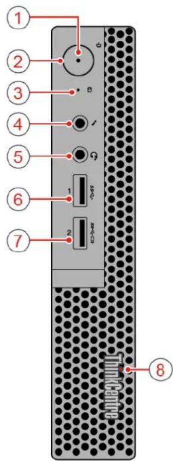
Note: Your computer model might look slightly different from the illustration.
text_image
1 2 3 4 5 6 7 8Figure 1. Front view
| 1 Power indicator | 2 Power button |
| 3 Storage drive status indicator | 4 Microphone connector |
| 5 Headset connector | 6 USB 3.0 connector |
| 7 Always On USB 3.0 connector | 8 Illuminated red dot |
Power indicator
This indicator is on when the computer is on.
2 Power button
Used to turn on your computer. When you cannot shut down the computer from the operating system, press and hold the power button for four or more seconds to turn off the computer.
Storage drive status indicator
This indicator is on when the storage drive is in use.
4 Microphone connector
Used to connect a microphone to your computer. You can use the microphone to record sounds or interact with the computer using speech-recognition software.
5 Headset connector
Used to connect a headset or headphones to your computer.
6 USB 3.0 connector
Used to connect a USB-compatible device, such as a USB keyboard, mouse, scanner, printer, or personal digital assistant (PDA). For optimal data transfer, connect a USB 3.0 device to a USB 3.0 connector instead of a USB 2.0 connector.
7 Always On USB 3.0 connector
Used to connect a device that requires a USB 2.0 or USB 3.0 connection, such as a keyboard, a mouse, a scanner, a printer, or a personal digital assistant (PDA). With the power adapter connected, you can charge the automatically detected device even when the computer is in hibernation mode or turned off.
8 Illuminated red dot
This indicator is on when the computer is on.
Rear view
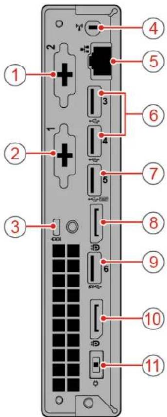
Note: Your computer model might look slightly different from the illustration.
text_image
Diagram of a device rear panel with numbered labels pointing to ports and connectorsFigure 2. Rear view
| 1 Optional connector 1 | 2 Optional connector 2 |
| 3 Security-lock slot | 4 Wi-Fi antenna slot |
| 5 Ethernet connector | 6 USB 2.0 connectors |
| 7 USB 2.0 connector | 8 DisplayPort® connector |
| 9 USB 3.0 connector | 10 DisplayPort connector |
| 11 Power adapter connector |
■ Optional connector 1
Depending on the computer model, the connector might vary.
2 Optional connector 2
Depending on the computer model, the connector might vary.
3 Security-lock slot
Used to secure a Kensington-style cable lock.
4 Wi-Fi antenna slot
Used to install the rear Wi-Fi antenna cable connector that is available only on some models. The rear Wi-Fi antenna is installed on the rear Wi-Fi antenna cable connector.
Ethernet connector
Used to connect an Ethernet cable for network access.
6 USB 2.0 connector
Used to connect a USB-compatible device. For optimal data transfer, connect a USB 2.0 device to a USB 2.0 connector.
7 USB 2.0 connector
Used to connect a USB-compatible device. For optimal data transfer, connect a USB 2.0 device to a USB 2.0 connector.
8 DisplayPort connector
Used to send audio and video signals from the computer to another audio or video device, such as a high-performance monitor.
9 USB 3.0 connector
Used to connect a USB-compatible device. For optimal data transfer, connect a USB 3.0 device to a USB 3.0 connector instead of a USB 2.0 connector.
10 DisplayPort connector
Used to send audio and video signals from the computer to another audio or video device, such as a high-performance monitor.
11 Power adapter connector
Used to connect the power adapter to your computer for power supply.
System board
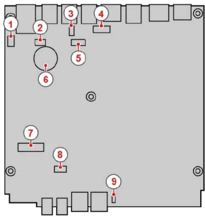
Note: See "Front view" on page 1 and "Rear view" on page 2 for additional component descriptions.
flowchart
graph TD
    1 --> 2
    2 --> 3
    3 --> 4
    4 --> 5
    5 --> 6
    6 --> 7
    7 --> 8
    8 --> 9
    9 --> 10
    10 --> 11
    11 --> 12
    12 --> 13
    13 --> 14
    14 --> 15
    15 --> 16
    16 --> 17
    17 --> 18
    18 --> 19
    19 --> 20
    20 --> 21
    21 --> 22
    22 --> 23
    23 --> 24
    24 --> 25
    25 --> 26
    26 --> 27
    27 --> 28
    28 --> 29
    29 --> 30
    30 --> 31
    31 --> 32
    32 --> 33
    33 --> 34
    34 --> 35
    35 --> 36
    36 --> 37
    37 --> 38
    38 --> 39
    39 --> 40
    40 --> 41
    41 --> 42
    42 --> 43
    43 --> 44
    44 --> 45
    45 --> 46
    46 --> 47
    47 --> 48
    48 --> 49
    49 --> 50
    50 --> 51
    51 --> 52
    52 --> 53
    53 --> 54
    54 --> 55
    55 --> 56
    56 --> 57
    57 --> 58
    58 --> 59
    59 --> 60
    60 --> 61
    61 --> 62
    62 --> 63
    63 --> 64
    64 --> 65
    65 --> 66
    66 --> 67
    67 --> 68
    68 --> 69
    69 --> 70
    70 --> 71
    71 --> 72
    72 --> 73
    73 --> 74
    74 --> 75
    75 --> 76
    76 --> 77
    77 --> 78
    78 --> 79
    79 --> 80
text_image
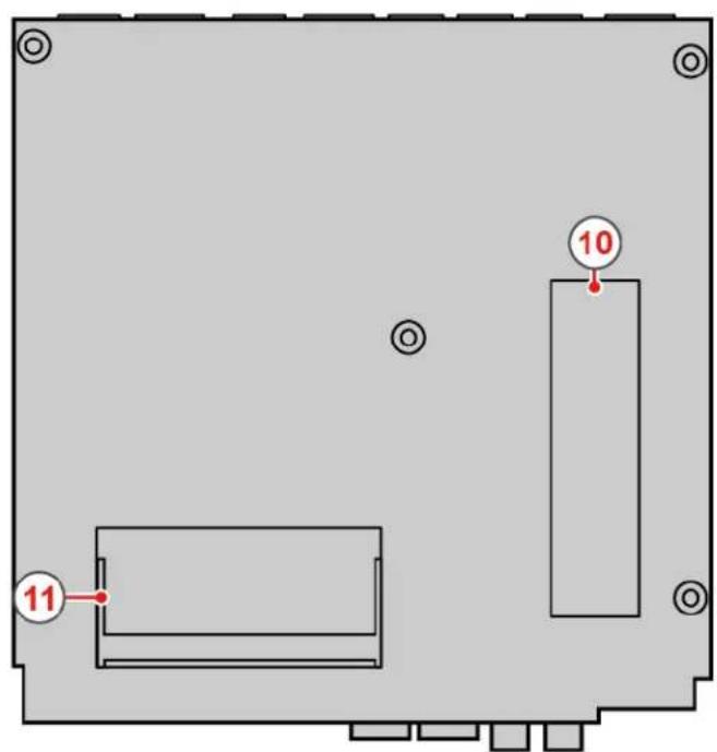
10 11Figure 3. System board
| 1 Serial connector 1 | 2 Serial connector 2 |
| 3 USB 2.0 connector | 4 DisplayPort connector |
| 5 System fan connector | 6 Coin-cell battery |
| 7 M.2 Wi-Fi card slot | 8 Storage drive slot |
| 9 Internal speaker connector | 10 M.2 storage drive slot |
| 11 Memory slot |
Machine type and model label
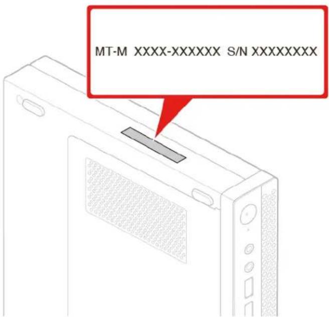
The machine type and model label identifies the computer. When you contact Lenovo for help, the machine type and model information helps support technicians to identify the computer and provide faster service. The machine type and model label is attached on the top of the computer as shown.
text_image
MT-M XXXX-XXXXXX S/N XXXXXXXXXFigure 4. Machine type and model label
Chapter 2. Specifications
Power supply
- 65-watt automatic voltage-sensing power supply
Storage drives
• 2.5-inch storage drive
• M.2 storage drive
Video features
- The integrated graphics card supports the following:
- DisplayPort connector
Audio features
- The integrated audio card supports the following:
- Headset connector
- Internal speaker
Input/Output (I/O) features
• Audio connectors (headset and microphone)
- DisplayPort connector
- Ethernet connector
- Serial connector (optional)
- Type-C USB connector (optional)
- USB connector
• VGA connector (optional)
Network features
- Ethernet LAN
- Wireless LAN (optional)
- Bluetooth (optional)
Physical dimensions
• Width: 35 mm (1.4 inches)
• Height: 183 mm (7.2 inches)
• Depth: 179 mm (7.1 inches)
Weight (without the package)
Maximum configuration as shipped: 1.1 kg (2.4 lb)
Statement on USB transfer rate
Depending on many factors such as the processing capability of the host and peripheral devices, file attributes, and other factors related to system configuration and operating environments, the actual transfer
rate using the various USB connectors on this device will vary and will be slower than the data rate listed below for each corresponding device.
| USB device Data rate (Gbit/s) | |
| 3.1 Gen 1 | 5 |
| 3.1 Gen 2 | 10 |
| 3.2 20 |
Chapter 3. Computer locks
This chapter provides instructions on how to lock your computer with the locking devices to keep your computer safe.
Attaching a Kensington-style cable lock
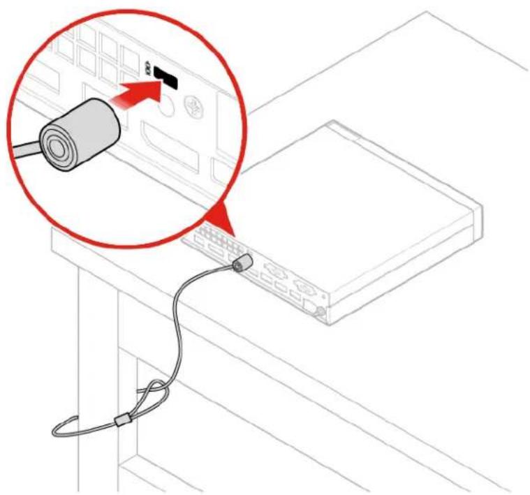
You can use a Kensington-style cable lock to secure your computer to a desk, table, or other nonpermanent fixture. The cable lock connects to the security-lock slot at the rear of your computer. Depending on the type selected, the cable lock can be operated with a key or combination. The cable lock also locks the buttons used to open the computer cover. This is the same type of lock used with many notebook computers. You can order such a cable lock directly from Lenovo by searching for Kensington at: http://www.lenovo.com/support
natural_image
Line drawing of a cable being inserted into a device panel, with a magnified inset showing the cable's tip and cable ends (no text or symbols present)Figure 5. Attaching a Kensington-style cable lock
Chapter 4. Replacing hardware
This chapter provides instructions on how to replace hardware for your computer.
Before replacing hardware
Attention: Do not open your computer or attempt any repairs before reading this section and the Important Product Information Guide.
Notes before replacing hardware
- Use computer components provided only by Lenovo.
- When installing or replacing an option, use the appropriate instructions explained in this manual along with the instructions that come with the option.
- In most areas of the world, Lenovo requires the return of defective CRUs. Information about this will come with the CRU or will come a few days after the CRU arrives.
Handling static-sensitive devices
Do not open the static-protective package containing the new part until the defective part has been removed and you are ready to install the new part. Static electricity, although harmless to you, can seriously damage computer components and options.
When you handle options and other computer components, take these precautions to avoid static-electricity damage:
- Limit your movement. Movement can cause static electricity to build up around you.
- Always handle options and other computer components carefully. Handle PCI/PCIe cards, memory modules, system boards, and microprocessors by the edges. Never touch any exposed circuitry.
- Prevent others from touching the options and other computer components.
- Touch the static-protective package containing the part to a metal expansion-slot cover or other unpainted metal surface on the computer for at least two seconds. This reduces static electricity from the package and your body before you install or replace a new part.
- When possible, remove the new part from the static-protective package, and install it directly in the computer without setting the part down. When this is not possible, place the static-protective package on a smooth, level surface and place the part on the package.
- Do not place the part on the computer cover or other metal surface.
Knowing FRUs (including CRUs)
- Field Replaceable Units (FRUs) are computer parts that a trained technician can upgrade or replace. FRUs include all CRUs. For detailed FRU information, such as the FRU part numbers and supported computer models, go to: http://www.lenovo.com/serviceparts-lookup
- Customer Replaceable Units (CRUs) are computer parts that a user can upgrade or replace.
- Self-service CRUs: You can install self-service CRUs easily. These CRUs might be stand-alone, latched, or secured by up to two screws. Examples of self-service CRUs include the keyboard, mouse, any USB device. You are responsible for replacing all self-service CRUs.
- Optional-service CRUs: Handling optional-service CRUs requires some technical skills and simple tools (such as a screwdriver). These CRUs are isolated parts within the computer. They are usually
concealed by an access panel that is secured by more than two screws. You must remove the screws and panel to access the specific CRU. Optional-service CRUs can be removed and installed by users or, during the warranty period, by a Lenovo service technician.
Before replacing FRUs
Before replacing any FRU, read the following:
- Only certified and trained personnel can service the computer.
- Before replacing an FRU, read the entire section about replacing the part.
- Be extremely careful during writing operations such as copying, saving, or formatting.
The sequence of the drives in the computer that you are servicing might have been altered. If you select an incorrect drive, data or programs might be overwritten.
- Replace an FRU only with another FRU of the correct model.
When you replace an FRU, ensure that the model of the machine and the FRU part number are correct.
- An FRU should not be replaced because of a single, unreproducible failure.
Single failures can occur for a variety of reasons that have nothing to do with a hardware defect, such as cosmic radiation, electrostatic discharge, or software errors. Consider replacing an FRU only when a problem recurs. If you suspect that an FRU is defective, clear the error log and run the test again. If the error does not recur, do not replace the FRU.
- Only replace a defective FRU.
Locating FRUs (including CRUs)
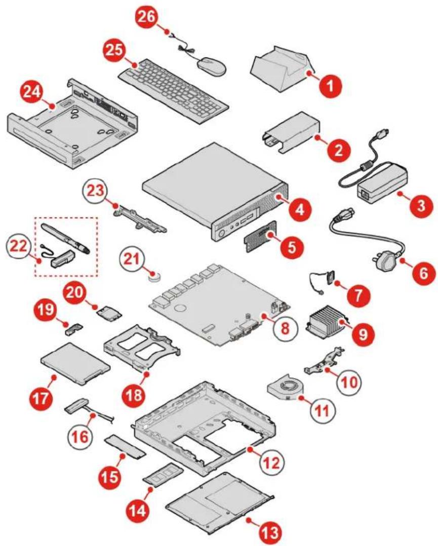
Locating FRUs (including CRUs) for 10TF, 10TG, 10TH, 10TJ, and 10TK models
text_image
Exploded view diagram of a computer system with numbered components for identificationFigure 6. Locating FRUs (including CRUs)
Notes:
• Some of the components are optional.
- To replace a component that is not in the list below, contact a Lenovo service technician. For a list of Lenovo Support phone numbers, go to: http://www.lenovo.com/serviceparts-lookup
| Number | FRU description Self-service CRU Optional-service | CRU | |
| 1 | Vertical stand | Yes No | |
| 2 | Power adapter bracket | Yes No | |
| 3 | Power adapter | Yes No | |
| 4 | Computer cover | Yes No | |
| 5 | Dust shield | Yes No | |
| 6 | Power cord | Yes No | |
| 7 | Internal speaker | Yes No | |
| 8 | System board | No No | |
| 9 | Heat sink | No Yes | |
| 10 | Antenna bracket | No No | |
| 11 | System fan | No No | |
| 12 | Chassis No No | ||
| 13 | Bottom cover | Yes No | |
| 14 | Memory module | Yes No | |
| 15 | M.2 storage drive | Yes No | |
| 16 | Storage drive cable | No No | |
| 17 | Storage drive | No Yes | |
| 18 | Storage drive bracket | No Yes | |
| 19 | Wi-Fi card shield | No Yes | |
| 20 | Wi-Fi card | No Yes | |
| 21 | Coin-cell battery | No No | |
| 22 | Wi-Fi antennas | No No | |
| 23 | Storage drive assembly bracket | No No | |
| 24 | VESA®mount bracket Yes No | ||
| 25 | Keyboard or wireless keyboard | Yes No | |
| 26 | Mouse or wireless mouse | Yes No |
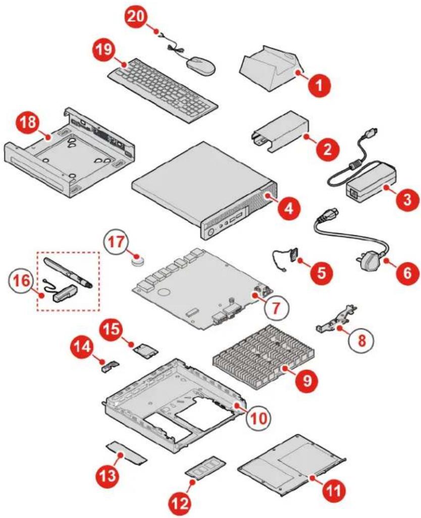
Locating FRUs (including CRUs) for 10TL, 10UY, 10V0, 10V1, and 10V2 models
text_image
Exploded view diagram of a computer system with numbered components for identificationFigure 7. Locating FRUs (including CRUs)
Notes:
• Some of the components are optional.
- To replace a component that is not in the list below, contact a Lenovo service technician. For a list of Lenovo Support phone numbers, go to: http://www.lenovo.com/support/phone
| Number | FRU description Self-service CRU Optional-service | CRU | |
| 1 | Vertical stand | Yes No | |
| 2 | Power adapter bracket | Yes No | |
| 3 | Power adapter | Yes No | |
| 4 | Computer cover | Yes No | |
| 5 | Internal speaker | Yes No | |
| 6 | Power cord | Yes No | |
| 7 | System board | No No | |
| 8 | Antenna bracket | No No | |
| 9 | Heat sink | No Yes | |
| 10 | Chassis No No | ||
| 11 | Bottom cover | Yes No | |
| 12 | Memory module | Yes No | |
| 13 | M.2 storage drive | Yes No | |
| 14 | Wi-Fi card shield | No Yes | |
| 15 | Wi-Fi card | No Yes | |
| 16 | Wi-Fi antennas | No No | |
| 17 | Coin-cell battery | No No | |
| 18 | VESA mount bracket Yes No | ||
| 19 | Keyboard or wireless keyboard | Yes No | |
| 20 | Mouse or wireless mouse | Yes No |
Replacing the keyboard or wireless keyboard
Note: The wireless keyboard is available only on some models.
Replacing the keyboard
- Turn off the computer and disconnect all power cords from electrical outlets.
- Disconnect the old keyboard cable from the computer.
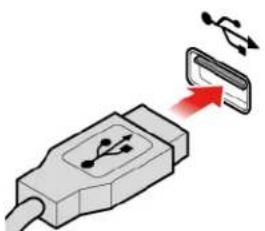
- Connect a new keyboard to the appropriate connector on the computer.
natural_image
Illustration of a USB connector with a red arrow pointing to its internal component (no text or symbols)Figure 8. Replacing the keyboard
Replacing the wireless keyboard
- Remove your old wireless keyboard.
- Take out the new wireless keyboard from the package.
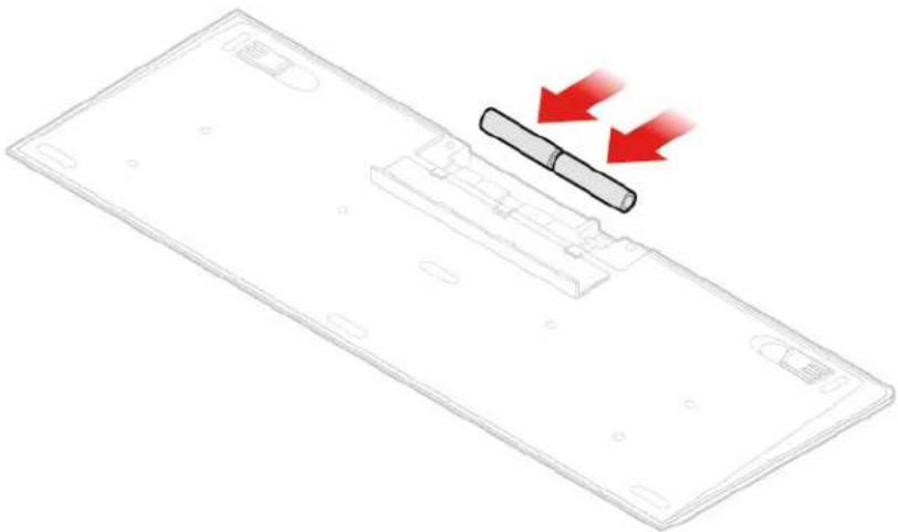
- Open the battery compartment cover, and install two AAA batteries according to the polarity indicators.
natural_image
Diagram of a device panel with a pen and two red arrows indicating motion or movement (no text or symbols)Figure 9. Replacing the wireless keyboard
- Remove the USB dongle from the keyboard compartment or from the wireless mouse compartment and connect it to an available USB connector on the computer.
- Close the compartment cover. The keyboard is ready for use.
Replacing the mouse or wireless mouse
Note: The wireless mouse is available only on some models.
Replacing the mouse
- Turn off the computer and disconnect all power cords from electrical outlets.
- Disconnect the old mouse cable from the computer.
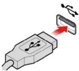
- Connect a new mouse to the appropriate connector on the computer.
natural_image
Illustration of a USB connector with a red arrow pointing to its internal component (no text or symbols)Figure 10. Replacing the mouse
Replacing the wireless mouse
- Disconnect the USB dongle from your computer. Then, remove your old wireless mouse.
- Remove the new wireless mouse from the package.
- Open the battery compartment cover, and install two AAA batteries according to the polarity indicators.
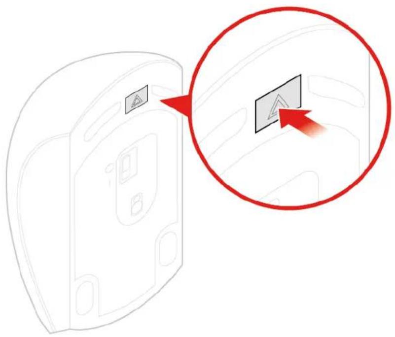
a. Open the battery compartment.
text_image
Diagram showing a device with a warning sign and a red circle highlighting a button, likely illustrating a safety or hazard detection concept.Figure 11. Opening the battery compartment
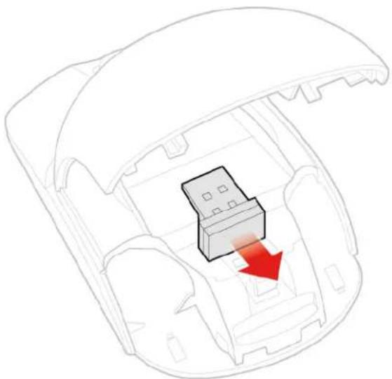
b. Take out the USB dongle.
natural_image
Diagram of a car interior showing a highlighted component with a red arrow indicating direction (no text or symbols present)Figure 12. Taking out the USB dongle
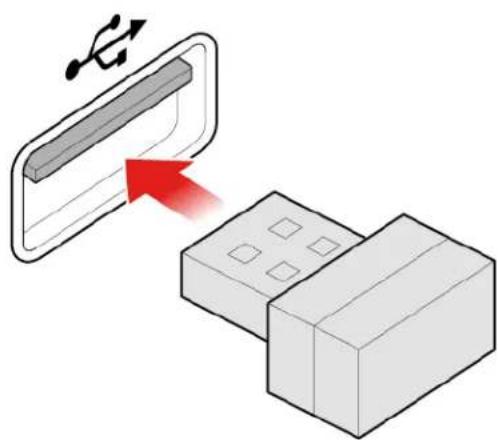
c. Connect the USB dongle to a USB connector.
natural_image
Diagram showing a device with a USB symbol interacting with a rectangular block, with a red arrow pointing to it (no text or symbols present)Figure 13. Connecting the USB dongle to a USB connector
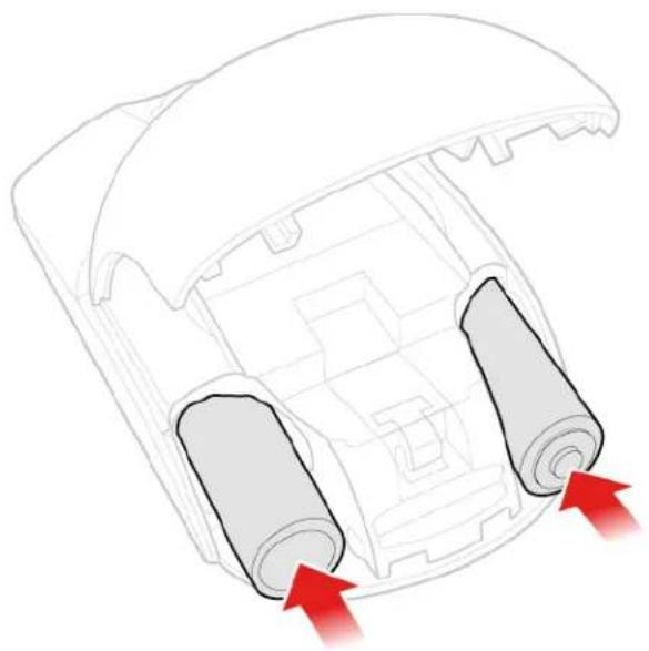
d. Install the mouse batteries.
natural_image
Diagram of a car interior showing two cylindrical components with red arrows indicating flow or movement (no text or symbols present)Figure 14. Installing the mouse batteries
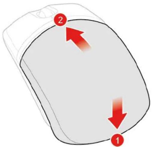
e. Close the battery compartment cover.
text_image
2 1Figure 15. Closing the battery compartment cover
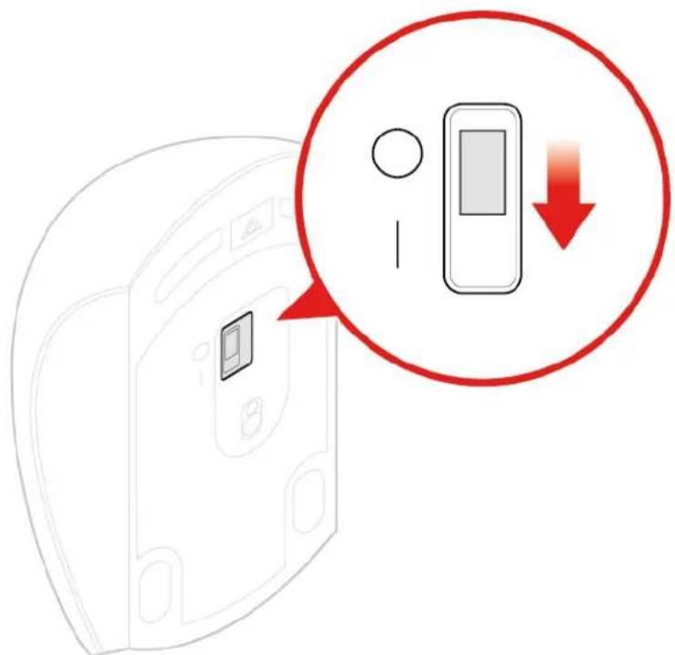
f. Push the power switch to the on position.
text_image
Diagram showing a device with a lock and indicator, highlighting a red circle with downward arrow indicating process or change.Figure 16. Pushing the power switch to the on position
Notes:
- The green LED indicates that the mouse is ready for use.
- The flashing amber LED indicates a low battery level.
- Push the power switch to the off position when you are not using the mouse to extend the battery life.
- After disconnecting the USB dongle from your computer, store it in the wireless mouse compartment or in the wireless keyboard compartment.
Replacing the power adapter
Attention: Do not open your computer or attempt any repairs before reading the Important Product Information Guide.
- Remove any media from the drives and turn off all connected devices and the computer.
- Disconnect all power cords from electrical outlets and disconnect all cables that are connected to the computer.
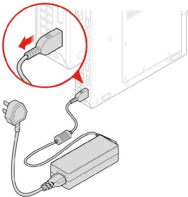
- Replace the power adapter.
Note: Your power cord might look different from the one illustrated.
a. Remove the power adapter.
natural_image
Diagram showing a plug connected to an charger with a magnified inset highlighting the cable connection (no text or symbols present)Figure 17. Removing the power adapter
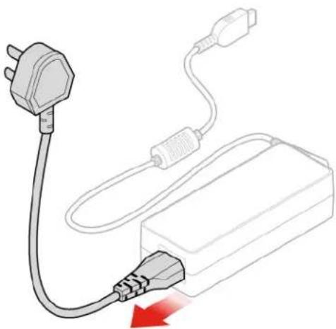
b. Remove the power cord.
natural_image
Diagram of an electrical plug connected to a battery pack, showing wiring and a red arrow indicating direction (no text or symbols)Figure 18. Removing the power cord
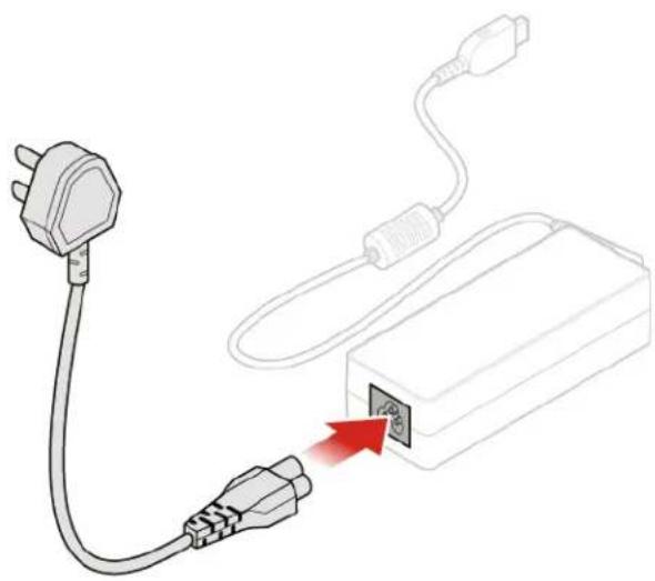
c. Install the power cord.
natural_image
Diagram showing a plug connected to a charger with a red arrow indicating power input (no text or symbols present)Figure 19. Installing the power cord
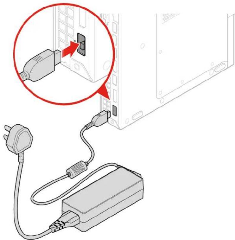
d. Install the power adapter.
natural_image
Diagram showing a plug connected to an charger via cable, with a magnified inset highlighting the connector (no text or symbols present)Figure 20. Installing the power adapter
Replacing the vertical stand
Attention: Do not open your computer or attempt any repairs before reading the Important Product Information Guide.
- Remove any media from the drives and turn off all connected devices and the computer.
- Disconnect all power cords from electrical outlets and disconnect all cables that are connected to the computer.
- Replace the vertical stand.
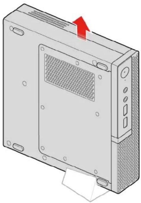
a. Remove the vertical stand.
natural_image
Illustration of a computer tower case with ventilation grilles and a red arrow indicating upward motion (no text or symbols)Figure 21. Removing the vertical stand
b. Install the vertical stand.

natural_image
Illustration of a computer case with a red downward arrow pointing to a base component (no text or symbols)Figure 22. Installing the vertical stand
Replacing the VESA mount bracket
Attention: Do not open your computer or attempt any repairs before reading the Important Product Information Guide.
- Remove any media from the drives and turn off all connected devices and the computer.
- Disconnect all power cords from electrical outlets and disconnect all cables that are connected to the computer.
- Replace the VESA mount bracket.
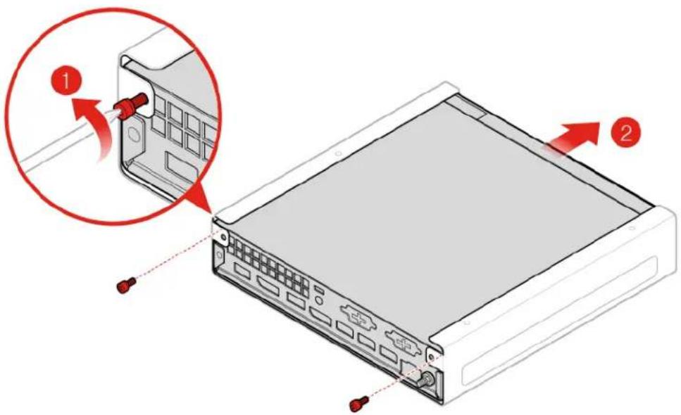
a. Remove the VESA mount bracket.
text_image
Diagram showing a computer drive with labeled components and a magnified view of the internal structure, highlighting component 1 and component 2.Figure 23. Removing the VESA mount bracket
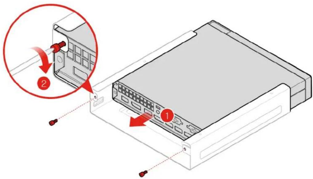
b. Install the VESA mount bracket.
text_image
Diagram showing a computer tower with labeled components and red arrows indicating assembly steps, including numbered annotations.Figure 24. Installing the VESA mount bracket
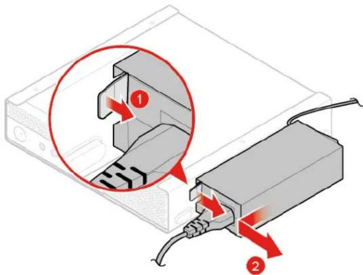
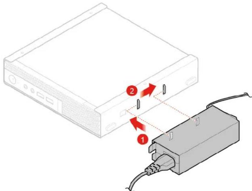
Replacing the power adapter bracket
Attention: Do not open your computer or attempt any repairs before reading the Important Product Information Guide.
-
Remove any media from the drives and turn off all connected devices and the computer.
-
Disconnect all power cords from electrical outlets and disconnect all cables that are connected to the computer.
-
Replace the power adapter bracket.
a. Remove the power adapter bracket.
text_image
Diagram showing a device with labeled components and red arrows indicating connection or movement, highlighting a structural change.Figure 25. Removing the power adapter bracket
b. Install the power adapter bracket.
text_image
Diagram showing connection between a device and a cable, labeled with numbered arrows indicating data flow or connection points.Figure 26. Installing the power adapter bracket
Removing the computer cover
Attention: Do not open your computer or attempt any repairs before reading the Important Product Information Guide.
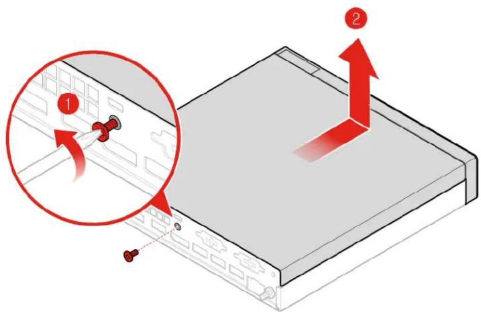
Removing the computer cover for 10TF, 10TG, 10TH, 10TJ, and 10TK models
CAUTION:


Before you open the computer cover, turn off the computer and wait several minutes until
the computer is cool.
- Remove any media from the drives and turn off all connected devices and the computer.
- Disconnect all power cords from electrical outlets and disconnect all cables that are connected to the computer.
- Remove the dust shield.

natural_image
Diagram of a desktop computer tower with ventilation grilles and a red arrow pointing to a component (no text or symbols)Figure 27. Removing the dust shield
- Remove the computer cover.
text_image
Diagram showing a server rack with red arrows indicating movement, labeled with numbered components and a magnified inset highlighting the component '1'.Figure 28. Removing the computer cover
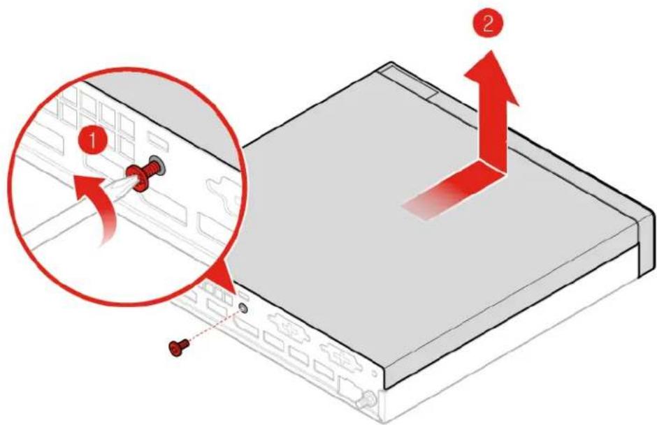
Removing the computer cover for 10TL, 10UY, 10V0, 10V1, and 10V2 models
CAUTION:
Before you open the computer cover, turn off the computer and wait several minutes until the computer is cool.
- Remove any media from the drives and turn off all connected devices and the computer.
- Disconnect all power cords from electrical outlets and disconnect all cables that are connected to the computer.
- Remove the computer cover.
text_image
Diagram showing server rack with red directional arrows and a magnified view of the rack's cable attachment, labeled with numbers 1 and 2.Figure 29. Removing the computer cover
Replacing the storage drive for 10TF, 10TG, 10TH, 10TJ, and 10TK models
Attention: Do not open your computer or attempt any repairs before reading the Important Product Information Guide.
- Remove any media from the drives and turn off all connected devices and the computer.
- Disconnect all power cords from electrical outlets and disconnect all cables that are connected to the computer.
- Remove the computer cover. For details, see "Removing the computer cover" on page 28.
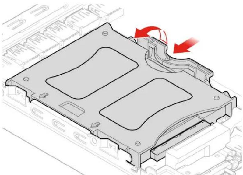
- Replace the storage drive.
a. Remove the storage drive.
natural_image
Technical illustration of a mechanical housing component with red arrows indicating motion or force direction (no text or symbols)Figure 30. Removing the storage drive
b. Disconnect the storage drive cable from the system board.
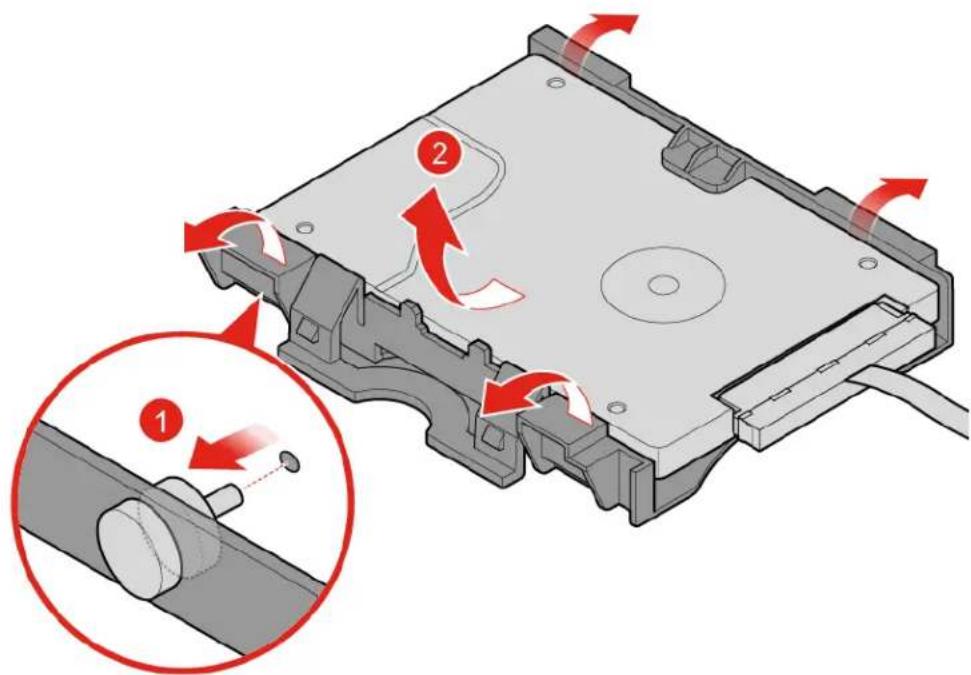
c. Remove the storage drive bracket.
text_image
Technical diagram of a hard disk drive with labeled components and directional arrows indicating motion or movement.Figure 31. Removing the storage drive bracket
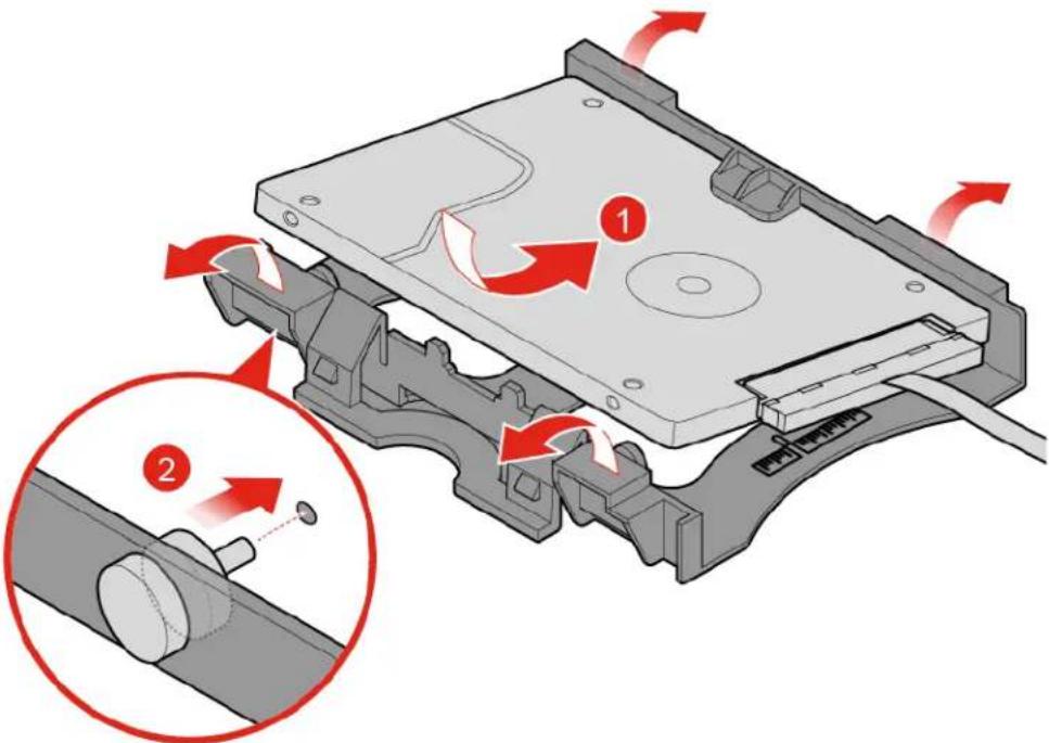
d. Install the storage drive bracket.
text_image
Diagram illustrating the internal mechanism of a floppy disk drive, showing two states of rotation and mechanical assembly.Figure 32. Installing the storage drive bracket
e. Connect the storage drive cable to the system board.
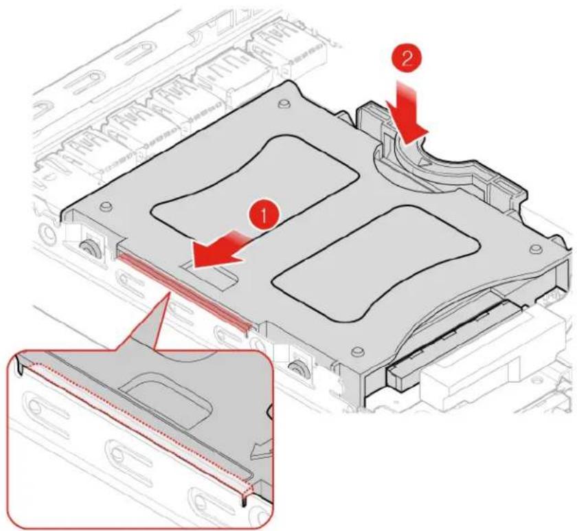
f. Install the storage drive.
text_image
Technical diagram of a mechanical component with numbered parts and red arrows indicating assembly or alignment.Figure 33. Installing the storage drive
- Reinstall the computer cover and reconnect the cables. For details, see "Completing the parts replacement" on page 64.
Replacing the storage drive cable for 10TF, 10TG, 10TH, 10TJ, and 10TK models
Attention: Do not open your computer or attempt any repairs before reading the Important Product Information Guide.
- Remove any media from the drives and turn off all connected devices and the computer.
- Disconnect all power cords from electrical outlets and disconnect all cables that are connected to the computer.
- Remove the computer cover. For details, see "Removing the computer cover" on page 28.
- Remove the storage drive. For details, see "Replacing the storage drive for 10TF, 10TG, 10TH, 10TJ, and 10TK models" on page 30.
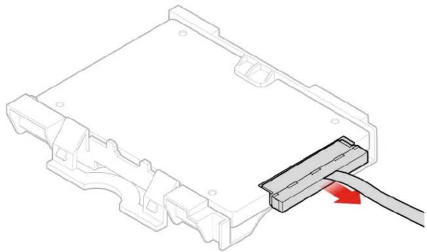
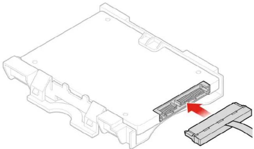
- Replace the storage drive cable.
a. Remove the storage drive cable.
natural_image
Technical line drawing of a mechanical component with a cable inserted, showing no text or symbolsFigure 34. Removing the storage drive cable
b. Install the storage drive cable.
natural_image
Technical line drawing of an electronic device showing a connector with a red arrow pointing to its internal structure (no text or symbols present)Figure 35. Installing the storage drive cable
- Reinstall the computer cover and reconnect the cables. For details, see "Completing the parts replacement" on page 64.
Replacing the system fan for 10TF, 10TG, 10TH, 10TJ, and 10TK models
Attention: Do not open your computer or attempt any repairs before reading the Important Product Information Guide.
-
Remove any media from the drives and turn off all connected devices and the computer.
-
Disconnect all power cords from electrical outlets and disconnect all cables that are connected to the computer.
-
Remove the computer cover. For details, see "Removing the computer cover" on page 28.
-
Disconnect the system fan cable from the system fan connector on the system board. See "System board" on page 4.
-
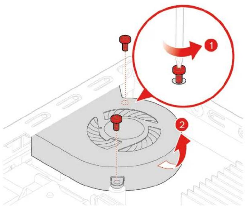
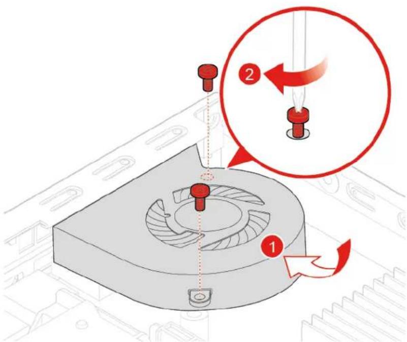
Replace the system fan.
a. Remove the system fan.
text_image
Technical diagram showing mechanical assembly with labeled parts and directional arrows indicating motion or movementFigure 36. Removing the system fan
b. Install the system fan.
text_image
Technical diagram showing a mechanical component with labeled parts and a magnified view of the process, including numbered annotations.Figure 37. Installing the system fan
- Connect the system fan cable to the system fan connector on the system board. See "System board" on page 4.
- Reinstall the computer cover and reconnect the cables. For details, see "Completing the parts replacement" on page 64.
Replacing the heat sink
Attention: Do not open your computer or attempt any repairs before reading the Important Product Information Guide.
Replacing the heat sink for 10TF, 10TG, 10TH, 10TJ, and 10TK models
- Remove any media from the drives and turn off all connected devices and the computer.
- Disconnect all power cords from electrical outlets and disconnect all cables that are connected to the computer.
- Remove the computer cover. For details, see "Removing the computer cover" on page 28.
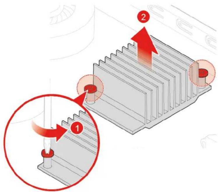
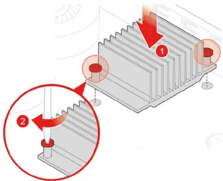
- Replace the heat sink.
a. Remove the heat sink.
text_image
Diagram illustrating a mechanical assembly with numbered components and red arrows indicating motion or force directions.Figure 38. Removing the heat sink
b. Install the heat sink.
text_image
Technical diagram illustrating a mechanical assembly with numbered components and red arrows indicating motion or force directions.Figure 39. Installing the heat sink
- Reinstall the computer cover and reconnect the cables. For details, see "Completing the parts replacement" on page 64.
Replacing the heat sink for 10TL, 10UY, 10V0, 10V1, and 10V2 models
- Remove any media from the drives and turn off all connected devices and the computer.
- Disconnect all power cords from electrical outlets and disconnect all cables that are connected to the computer.
-
Remove the computer cover. For details, see "Removing the computer cover" on page 28.
-
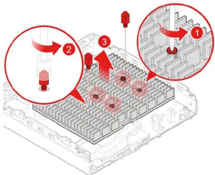
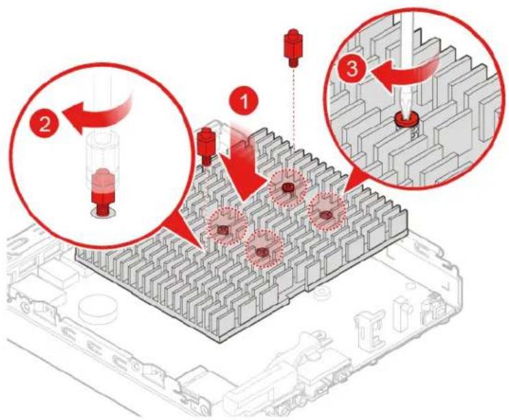
Replace the heat sink.
a. Remove the heat sink.
text_image
Technical diagram illustrating a mechanical assembly with numbered components and red arrows indicating process steps.Figure 40. Removing the heat sink
b. Install the heat sink.
text_image
Technical diagram illustrating a mechanical assembly process with numbered steps and component placementFigure 41. Installing the heat sink
- Reinstall the computer cover and reconnect the cables. For details, see "Completing the parts replacement" on page 64.
Replacing the internal speaker
Attention: Do not open your computer or attempt any repairs before reading the Important Product Information Guide.
- Remove any media from the drives and turn off all connected devices and the computer.
- Disconnect all power cords from electrical outlets and disconnect all cables that are connected to the computer.
- Remove the computer cover. For details, see "Removing the computer cover" on page 28.
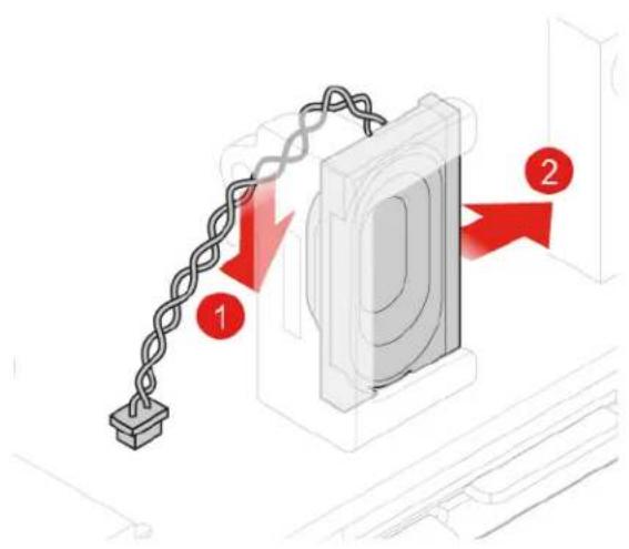
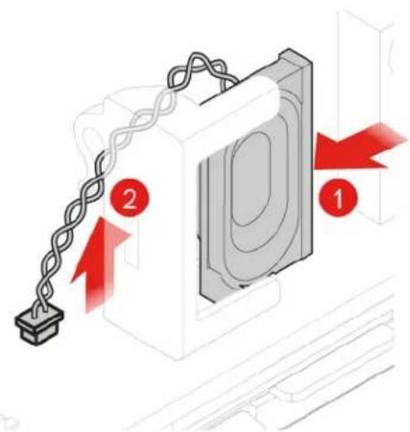
- Disconnect the internal speaker cable from the internal speaker connector on the system board.
- Replace the internal speaker.
a. Remove the internal speaker.
text_image
Diagram showing a chain link attached to a device with two red arrows labeled 1 and 2 pointing to the components.Figure 42. Removing the internal speaker
b. Install the internal speaker.
text_image
Diagram showing a chain attached to a device with labeled parts 1 and 2, indicating mechanical or electrical components.Figure 43. Installing the internal speaker
- Connect the internal speaker cable to the internal speaker connector on the system board.
- Reinstall the computer cover and reconnect the cables. For details, see "Completing the parts replacement" on page 64.
Replacing the Wi-Fi card
Attention: Do not open your computer or attempt any repairs before reading the Important Product Information Guide.
-
Remove any media from the drives and turn off all connected devices and the computer.
-
Disconnect all power cords from electrical outlets and disconnect all cables that are connected to the computer.
- Remove the computer cover. For details, see "Removing the computer cover" on page 28.
- Remove the storage drive if necessary. For details, see "Replacing the storage drive for 10TF, 10TG, 10TH, 10TJ, and 10TK models" on page 30.
- Remove the heat sink if necessary. For details, see "Replacing the heat sink" on page 36.
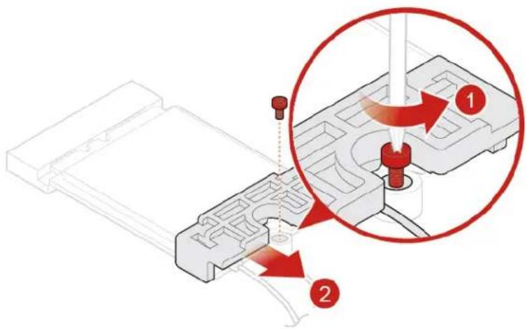
- Depending on your computer model, refer to one of the following to replace the Wi-Fi card.
- Type 1
a. Remove the Wi-Fi card shield.
text_image
Technical diagram showing a mechanical assembly with labeled parts and a magnified view of the component being inserted into a tool.Figure 44. Removing the Wi-Fi card shield
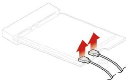
b. Disconnect the Wi-Fi antennas.
natural_image
Pure diagram of a rectangular device with two red arrows pointing upward, no text or symbols presentFigure 45. Disconnecting the Wi-Fi antennas
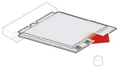
c. Remove the Wi-Fi card.
natural_image
Diagram of a layered electronic component with a red arrow indicating a process or connection (no text or symbols present)Figure 46. Removing the Wi-Fi card
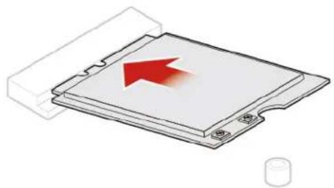
d. Install the Wi-Fi card.
natural_image
Illustration of a computer processor with a red arrow pointing to its top surface (no text or symbols present)Figure 47. Installing the Wi-Fi card
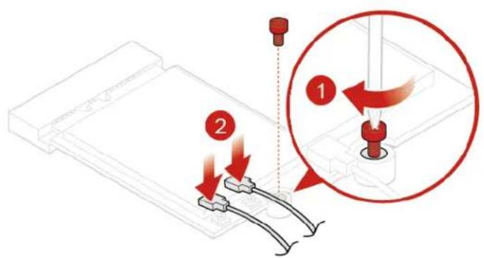
e. Connect the Wi-Fi antennas.
text_image
Technical diagram showing mechanical assembly with labeled parts and a magnified view of a tool tip componentFigure 48. Connecting the Wi-Fi antennas
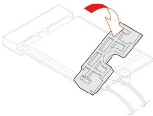
f. Install the Wi-Fi card shield.
natural_image
Diagram of a hand pressing down on a mechanical component (no text or symbols visible)Figure 49. Install the Wi-Fi card shield
- Type 2
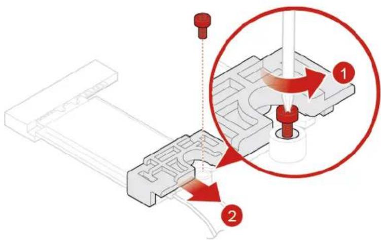
a. Remove the Wi-Fi card shield.
text_image
Technical diagram showing a mechanical assembly with labeled parts and a magnified view of a component being inserted into a cylindrical part.Figure 50. Removing the Wi-Fi card shield
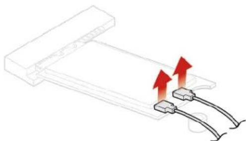
b. Disconnect the Wi-Fi antennas.
natural_image
Diagram showing two connectors with red arrows indicating upward motion (no text or symbols)Figure 51. Disconnecting the Wi-Fi antennas
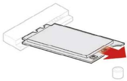
c. Remove the Wi-Fi card.
natural_image
Diagram of a device with a red arrow pointing to a component, showing layered structure without any text or symbols.Figure 52. Removing the Wi-Fi card
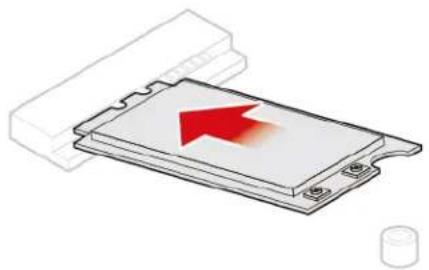
d. Install the Wi-Fi card.
natural_image
Illustration of a computer RAM module with a red arrow indicating compression (no text or symbols)Figure 53. Installing the Wi-Fi card
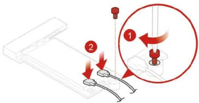
e. Connect the Wi-Fi antennas.
text_image
Diagram illustrating a mechanical assembly with labeled parts and a magnified view showing a tool interacting with a component.Figure 54. Connecting the Wi-Fi antennas
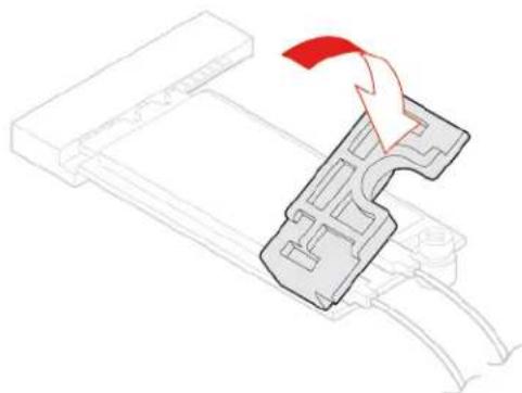
f. Install the Wi-Fi card shield.
natural_image
Diagram of a mechanical component with a red arrow indicating direction, no text or symbols presentFigure 55. Install the Wi-Fi card shield
- Reinstall the computer cover and reconnect the cables. For details, see "Completing the parts replacement" on page 64.
Replacing the Wi-Fi antennas
Attention: Do not open your computer or attempt any repairs before reading the Important Product Information Guide.
Replacing the front Wi-Fi antenna
- Remove any media from the drives and turn off all connected devices and the computer.
- Disconnect all power cords from electrical outlets and disconnect all cables that are connected to the computer.
- Remove the computer cover. For details, see "Removing the computer cover" on page 28.
-
Remove the storage drive if necessary. For details, see "Replacing the storage drive for 10TF, 10TG, 10TH, 10TJ, and 10TK models" on page 30.
-
Replace the front Wi-Fi antenna.
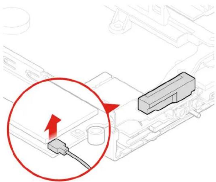
a. Disconnect the front Wi-Fi antenna cable from the Wi-Fi card.
natural_image
Diagram showing a red circle highlighting a cable connector with an arrow, next to a gray rectangular component (no text or symbols present)Figure 56. Disconnecting the front Wi-Fi antenna cable from the Wi-Fi card
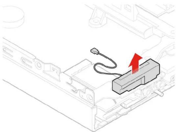
b. Remove the front Wi-Fi antenna.
natural_image
Technical line drawing of a mechanical component with a red arrow indicating upward motion (no text or symbols)Figure 57. Removing the front Wi-Fi antenna
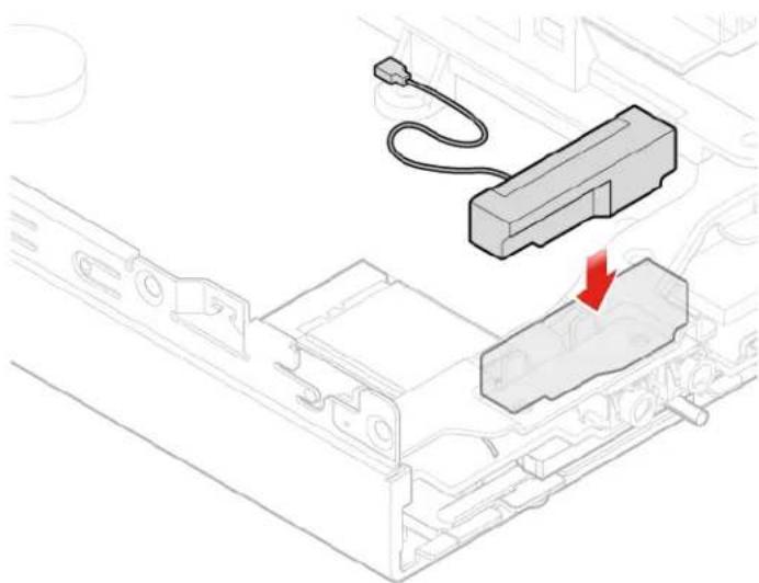
c. Install the front Wi-Fi antenna.
natural_image
Technical line drawing of a mechanical assembly with a component and a red arrow indicating direction (no text or symbols)Figure 58. Installing the front Wi-Fi antenna
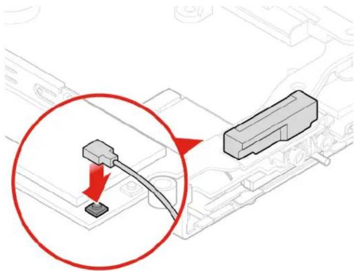
d. Connect the front Wi-Fi antenna cable to the Wi-Fi card.
text_image
Diagram showing a cable connector inserted into a device, with a magnified view highlighting the connection point.Figure 59. Connecting the front Wi-Fi antenna cable to the Wi-Fi card
- Reinstall the computer cover and reconnect the cables. For details, see "Completing the parts replacement" on page 64.
Replacing the rear Wi-Fi antenna
- Remove any media from the drives and turn off all connected devices and the computer.
- Disconnect all power cords from electrical outlets and disconnect all cables that are connected to the computer.
-
Remove the computer cover. For details, see "Removing the computer cover" on page 28.
-
Remove the storage drive if necessary. For details, see "Replacing the storage drive for 10TF, 10TG, 10TH, 10TJ, and 10TK models" on page 30.
- Disconnect the rear Wi-Fi antenna cable from the Wi-Fi card.
- Replace the rear Wi-Fi antenna.
Note: Record the cable routing before removing the rear Wi-Fi antenna cable.
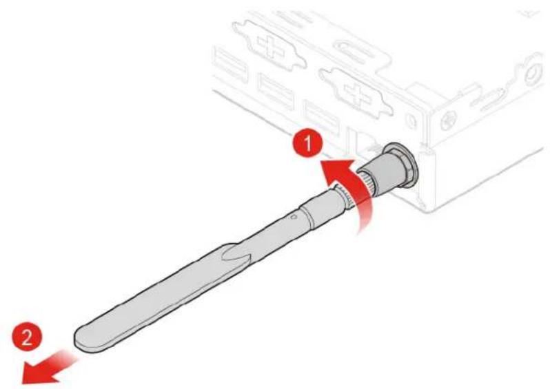
a. Remove the rear Wi-Fi antenna.
text_image
Diagram showing a device being inserted into a device with labeled parts and directional arrowsFigure 60. Removing the rear Wi-Fi antenna
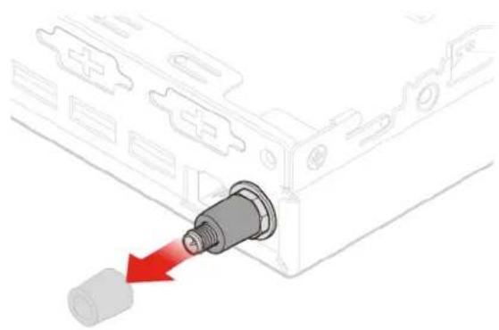
b. Remove the screw cover that secures the rear Wi-Fi antenna cable.
natural_image
Diagram of a mechanical component with a red arrow pointing to a cylindrical component (no text or symbols present)Figure 61. Removing the screw cover that secures the rear Wi-Fi antenna cable
c. Remove the rear Wi-Fi antenna cable.
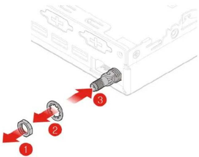
text_image
Diagram showing three labeled parts (1, 2, 3) pointing to a connector or assembly with red arrows indicating direction.Figure 62. Removing the rear Wi-Fi antenna cable
d. Install the rear Wi-Fi antenna cable.
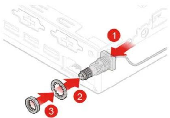
text_image
Diagram showing three labeled parts of a mechanical assembly with arrows indicating connection to a connector or component.Figure 63. Installing the rear Wi-Fi antenna cable
e. Install the screw cover to secure the rear Wi-Fi antenna cable.
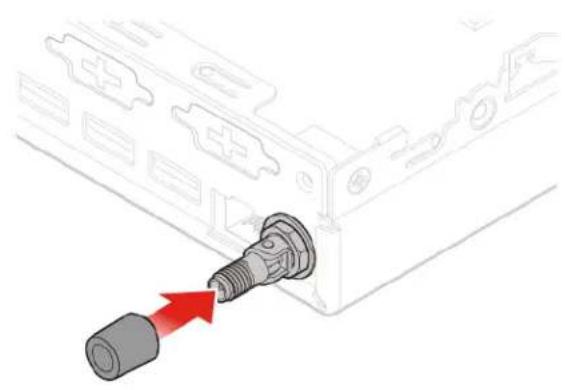
natural_image
Diagram of a connector inserted into a device housing, showing a red arrow pointing to the connector (no text or symbols present)Figure 64. Installing the screw cover to secure the rear Wi-Fi antenna cable
f. Install the rear Wi-Fi antenna.
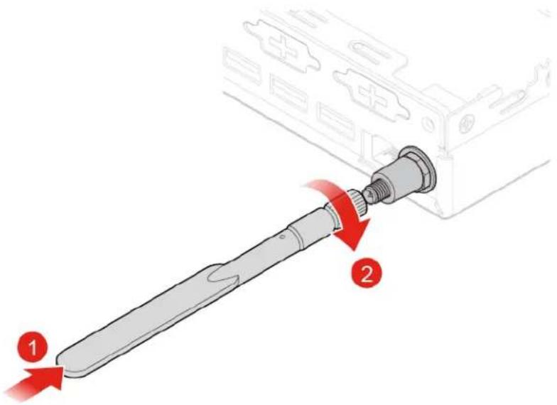
text_image
Diagram showing a screwdriver inserted into a battery, with numbered instructions indicating step 1 and step 2.Figure 65. Installing the rear Wi-Fi antenna
- Connect the rear Wi-Fi antenna cable to the Wi-Fi card.
- Reinstall the computer cover and reconnect the cables. For details, see "Completing the parts replacement" on page 64.
Replacing the antenna bracket
Attention: Do not open your computer or attempt any repairs before reading the Important Product Information Guide.
Replacing the antenna bracket for 10TF, 10TG, 10TH, 10TJ, and 10TK models
-
Remove any media from the drives and turn off all connected devices and the computer.
-
Disconnect all power cords from electrical outlets and disconnect all cables that are connected to the computer.
- Remove the computer cover. For details, see "Removing the computer cover" on page 28.
- Remove the storage drive. For details, see "Replacing the storage drive for 10TF, 10TG, 10TH, 10TJ, and 10TK models" on page 30.
- Remove the front Wi-Fi antennas. For details, see "Replacing the Wi-Fi antennas" on page 45.
- Replace the antenna bracket.
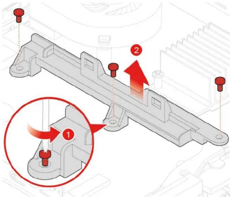
a. Remove the storage drive assembly bracket.
text_image
Technical diagram of a mechanical assembly with numbered components and red arrows indicating motion or assembly stepsFigure 66. Removing the storage drive assembly bracket
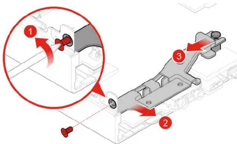
b. Remove the antenna bracket.
text_image
Technical diagram showing mechanical assembly with numbered components and red arrows indicating motion or movementFigure 67. Removing the antenna bracket
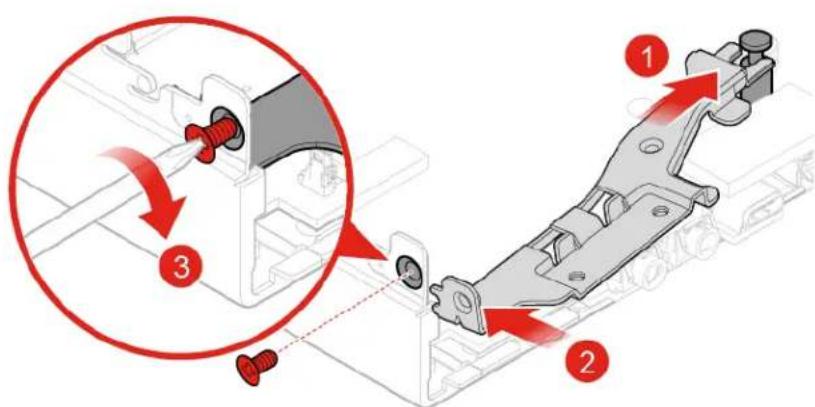
c. Install the antenna bracket.
text_image
Technical diagram showing mechanical assembly with numbered components and red arrows indicating motion or movementFigure 68. Installing the antenna bracket
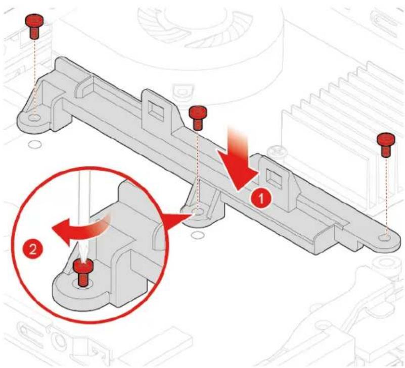
d. Install the storage drive assembly bracket.
text_image
Technical diagram showing mechanical assembly with numbered components and red arrows indicating motion or assembly stepsFigure 69. Installing the storage drive assembly bracket
- Reinstall the computer cover and reconnect the cables. For details, see "Completing the parts replacement" on page 64.
Replacing the antenna bracket for 10TL, 10UY, 10V0, 10V1, and 10V2 models
- Remove any media from the drives and turn off all connected devices and the computer.
- Disconnect all power cords from electrical outlets and disconnect all cables that are connected to the computer.
- Remove the computer cover. For details, see "Removing the computer cover" on page 28.
- Remove the front Wi-Fi antenna. For details, see "Replacing the Wi-Fi antennas" on page 45.
- Replace the antenna bracket.
a. Remove the antenna bracket.
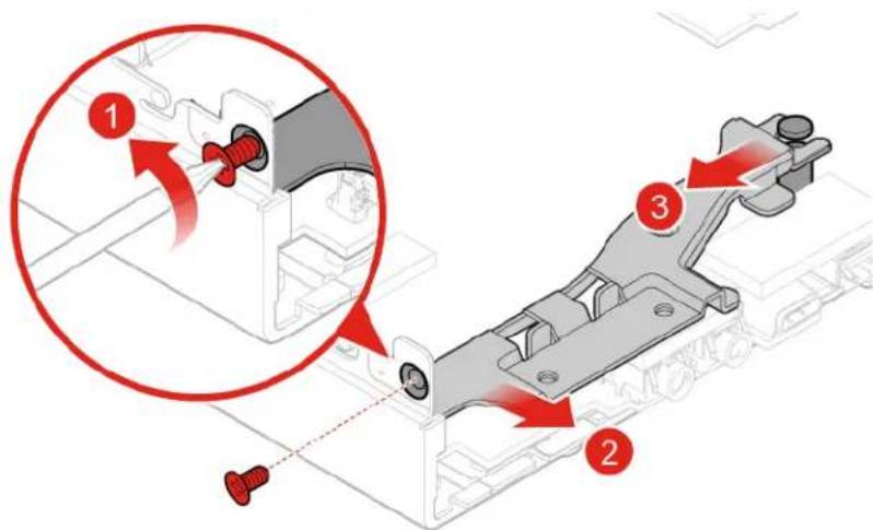
text_image
Technical diagram showing mechanical assembly with numbered components and red arrows indicating motion or movementFigure 70. Removing the antenna bracket
b. Install the antenna bracket.
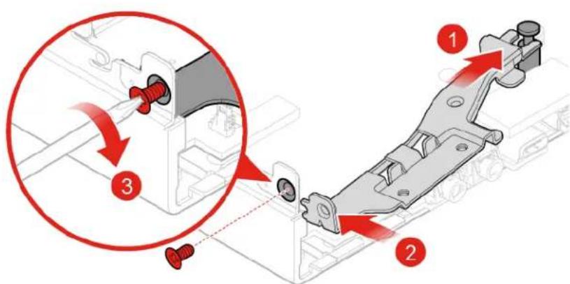
text_image
Technical diagram showing mechanical assembly with numbered components and red arrows indicating motion or movementFigure 71. Installing the antenna bracket
- Reinstall the computer cover and reconnect the cables. For details, see "Completing the parts replacement" on page 64.
Replacing the coin-cell battery
Attention: Do not open your computer or attempt any repairs before reading the Important Product Information Guide.
Your computer has a special type of memory that maintains the date, time, and settings for built-in features, such as parallel connector assignments (configurations). A coin-cell battery keeps this information active when you turn off the computer.
The coin-cell battery normally requires no charging or maintenance throughout its life; however, no coin-cell battery lasts forever. If the coin-cell battery fails, the date, time, and configuration information (including passwords) are lost. An error message is displayed when you turn on the computer.
- Remove any media from the drives and turn off all connected devices and the computer.
-
Disconnect all power cords from electrical outlets and disconnect all cables that are connected to the computer.
-
Remove the computer cover. For details, see "Removing the computer cover" on page 28.
-
Remove the storage drive if necessary. For details, see "Replacing the storage drive for 10TF, 10TG, 10TH, 10TJ, and 10TK models" on page 30.
-
Remove the heat sink if necessary. For details, see "Replacing the heat sink" on page 36.
-
Replace the coin-cell battery.
a. Press the metallic tab as shown.
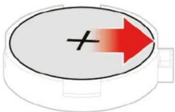
natural_image
Circular object with a plus sign and red arrow pointing right (no text or symbols)Figure 72. Unlocking the microprocessor socket retainer
b. Remove the coin-cell battery.
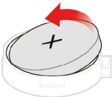
natural_image
Illustration of a circular object with a plus sign and a red arrow indicating rotation (no text or symbols)Figure 73. Pivoting the microprocessor socket upward
c. Install the coin-cell battery.
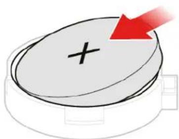
natural_image
Illustration of a circular object with a plus sign and a red arrow pointing downward (no text or symbols)Figure 74. Removing the microprocessor
d. Press the coin-cell battery downward until it snaps into position.
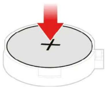
natural_image
Simple diagram showing a red downward arrow pointing to a plus sign on a circular base (no text or symbols)Figure 75. Installing the microprocessor
- Reinstall the computer cover and reconnect the cables. For details, see "Completing the parts replacement" on page 64.
To dispose of the coin-cell battery, refer to the "Lithium coin-cell battery notice" topic in the Safety and Warranty Guide.
Replacing the bottom cover
Attention: Do not open your computer or attempt any repairs before reading the Important Product Information Guide.
-
Remove any media from the drives and turn off all connected devices and the computer.
-
Disconnect all power cords from electrical outlets and disconnect all cables that are connected to the computer.
-
Remove the computer cover. For details, see "Removing the computer cover" on page 28.
-
Replace the bottom cover.
a. Remove the bottom cover.
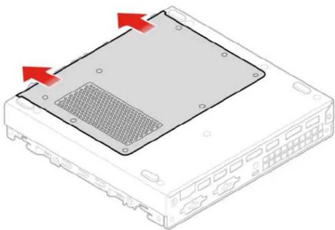
natural_image
Diagram of a computer drive chassis showing a mesh socket and red directional arrows indicating movement (no text or symbols)Figure 76. Removing the bottom cover
b. Install the bottom cover.
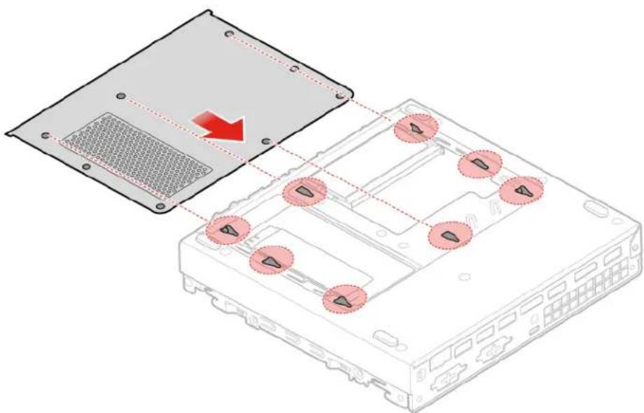
text_image
Diagram showing a device's internal structure with labeled ports and a red arrow indicating a process or transformation.Figure 77. Installing the bottom cover
- Reinstall the computer cover and reconnect the cables. For details, see "Completing the parts replacement" on page 64.
Replacing the memory module
Attention: Do not open your computer or attempt any repairs before reading the Important Product Information Guide.
- Remove any media from the drives and turn off all connected devices and the computer.
- Disconnect all power cords from electrical outlets and disconnect all cables that are connected to the computer.
- Remove the computer cover. For details, see "Removing the computer cover" on page 28.
- Remove the bottom cover. For details, see "Replacing the bottom cover" on page 56.
- Replace the memory module.
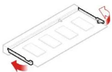
a. Open the memory module retainer.
natural_image
Pure diagram of a rectangular tray with internal compartments and directional arrows, no text or symbols present.Figure 78. Opening the memory module retainer
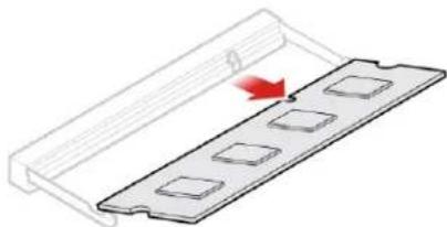
b. Remove the memory module.
natural_image
Diagram of a mechanical component with a red arrow indicating direction, showing a rectangular slot and a flat base (no text or symbols)Figure 79. Removing the memory module
c. Install the memory module.

natural_image
Diagram showing a mechanical component with a magnified inset highlighting a specific section (no text or symbols present)Figure 80. Installing the memory module
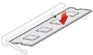
d. Close the memory module retainer.
natural_image
Diagram of a metal plate with four square cutouts and a red downward arrow indicating a direction (no text or symbols)Figure 81. Closing the memory module retainer
- Reinstall the computer cover and reconnect the cables. For details, see "Completing the parts replacement" on page 64.
Replacing the M.2 storage drive
Attention: Do not open your computer or attempt any repairs before reading the Important Product Information Guide.
- Remove any media from the drives and turn off all connected devices and the computer.
- Disconnect all power cords from electrical outlets and disconnect all cables that are connected to the computer.
- Remove the computer cover. For details, see "Removing the computer cover" on page 28.
- Remove the bottom cover. For details, see "Replacing the bottom cover" on page 56.
- Replace the M.2 storage drive.
a. Unlock the M.2 storage drive clip.

natural_image
3D diagram of a rectangular object with a red arrow pointing to its base, no text or symbols presentFigure 82. Unlocking the M.2 storage drive clip
b. Remove the M.2 storage drive.

natural_image
Diagram of a rectangular device with a red arrow pointing to its side, connected to a pipe outlet (no text or symbols present)Figure 83. Removing the M.2 storage drive
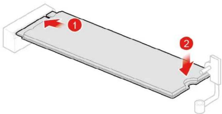
c. Install the M.2 storage drive.
text_image
Diagram showing a device with two labeled components (1 and 2) and directional arrows indicating flow or movement.Figure 84. Installing the M.2 storage drive
d. Lock the M.2 storage drive clip.
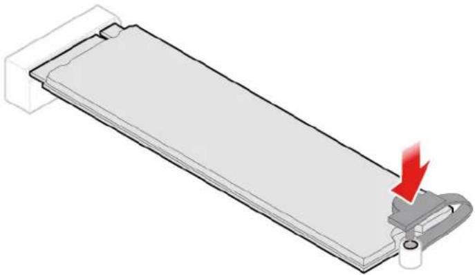
natural_image
Diagram of a mechanical component with a red arrow indicating downward motion (no text or symbols present)Figure 85. Locking the M.2 storage drive clip
- Reinstall the computer cover and reconnect the cables. For details, see "Completing the parts replacement" on page 64.
Replacing the system board and chassis
Attention: Do not open your computer or attempt any repairs before reading the Important Product Information Guide.
- Remove any media from the drives and turn off all connected devices and the computer.
- Disconnect all power cords from electrical outlets and disconnect all cables that are connected to the computer.
- Remove the computer cover. For details, see "Removing the computer cover" on page 28.
- Remove the storage drive if necessary. For details, see "Replacing the storage drive for 10TF, 10TG, 10TH, 10TJ, and 10TK models" on page 30.
- Remove the system fan if necessary. For details, see "Replacing the system fan for 10TF, 10TG, 10TH, 10TJ, and 10TK models" on page 34.
- Remove the heat sink. For details, see "Replacing the heat sink" on page 36.
- Remove the internal speaker. For details, see "Replacing the internal speaker" on page 39.
- Remove the Wi-Fi card. For details, see "Replacing the Wi-Fi card" on page 40.
- Remove the Wi-Fi antennas. For details, see "Replacing the Wi-Fi antennas" on page 45.
- Remove the antenna bracket. For details, see "Replacing the antenna bracket" on page 50.
- Remove the bottom cover. For details, see "Replacing the bottom cover" on page 56.
- Remove the memory module. For details, see "Replacing the memory module" on page 58.
- Remove the M.2 storage drive. For details, see "Replacing the M.2 storage drive" on page 59.
- Record the cable routing and cable connections, and then disconnect all cables from the system board. See "System board" on page 4.
- Replace the system board and chassis.
Note: Carefully handle the system board by its edges.
a. Remove the screws that secure the system board.
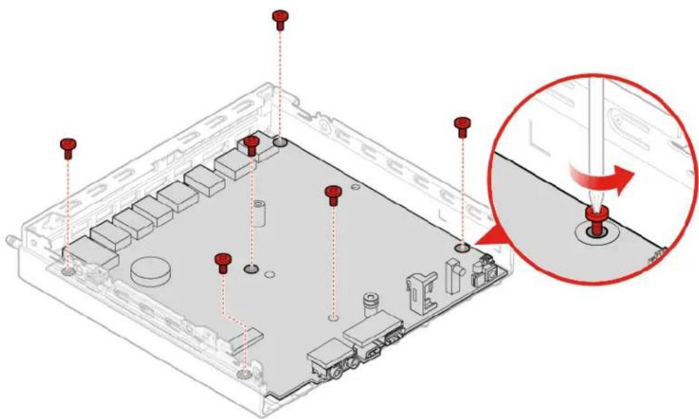
natural_image
Isometric view of a computer chassis with red screw fasteners and a magnified inset showing the internal component (no text or symbols)Figure 86. Removing the screws that secure the system board
b. Remove the system board.
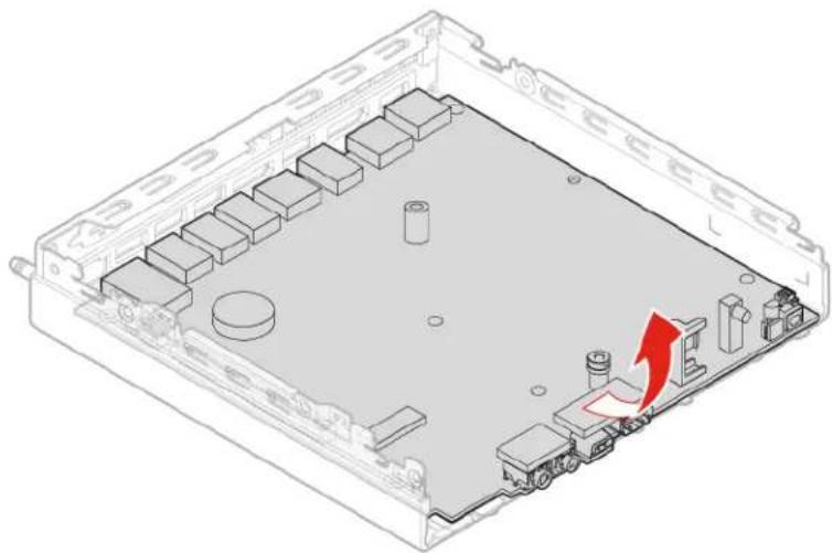
natural_image
Isometric view of an electronic device chassis with a red arrow indicating a component or connection point (no text or symbols present)Figure 87. Removing the system board
c. Install the system board.
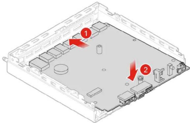
text_image
Technical diagram of an electronic device rear panel with labeled components and red arrows indicating featuresFigure 88. Installing the system board
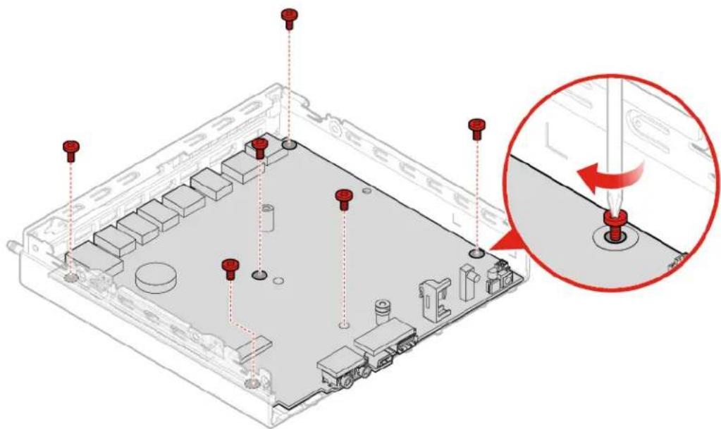
d. Install the screws to secure the system board.
natural_image
3D diagram of an electronic device chassis with red screwdrivers and a magnified inset showing the internal component (no text or symbols)Figure 89. Installing the screws to secure the system board
- Route all the cables that you disconnected from the failing system board, and then reconnect the cables to the new system board. See "System board" on page 4.
- Reinstall the computer cover and reconnect the cables. For details, see "Completing the parts replacement" on page 64.
Completing the parts replacement
Completing the parts replacement for 10TF, 10TG, 10TH, 10TJ, and 10TK models
After completing the installation or replacement for all parts, reinstall the computer cover and reconnect the cables.
To reinstall the computer cover and reconnect the cables to your computer, do the following:
- Ensure that all components have been reassembled correctly and that no tools or loose screws are left inside your computer.
- Ensure that the cables are routed correctly before reinstalling the computer cover. Keep cables clear of the hinges and sides of the computer chassis to avoid interference when reinstalling the computer cover.
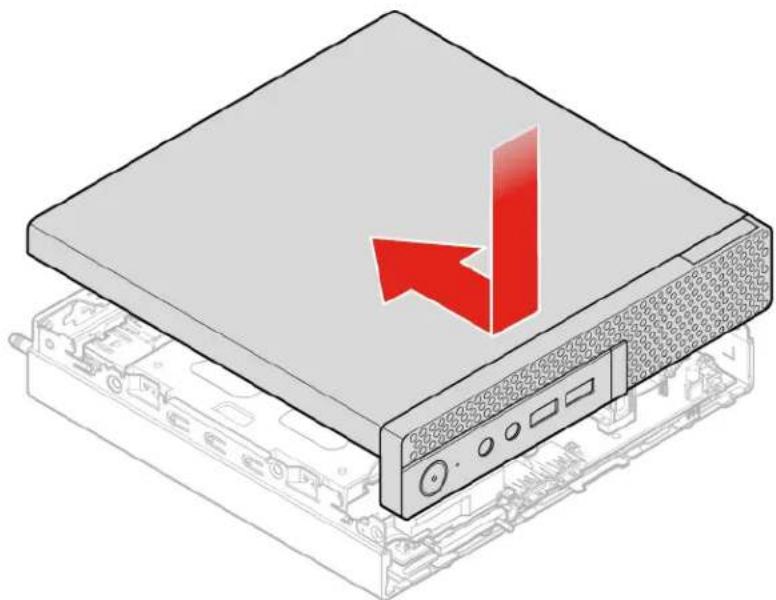
- Reinstall the computer cover.
natural_image
Illustration of a computer drive with a red arrow pointing to the top panel (no text or symbols present)Figure 90. Reinstalling the computer cover
- Install the screw to secure the computer cover.
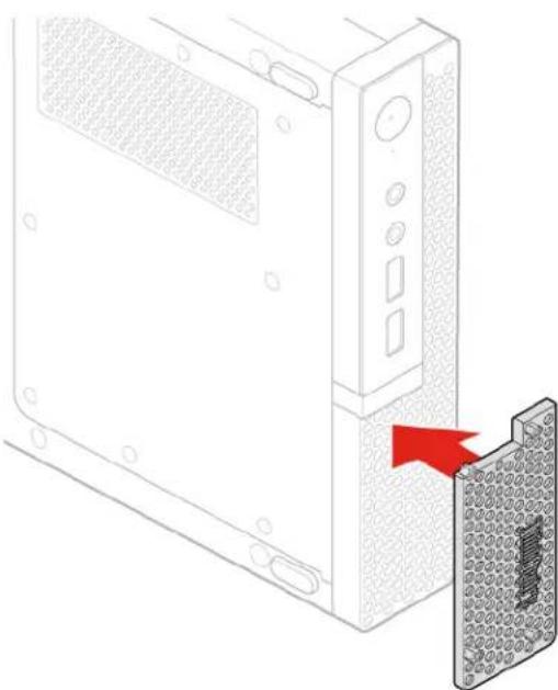
- Reinstall the dust shield.
natural_image
Diagram of a computer tower with a red arrow pointing to a component, showing no text or symbols.Figure 91. Reinstalling the dust shield
- Place the computer in an upright position.
- If a locking device is available, use it to lock the computer.
- Reconnect the external cables and power cords to the corresponding connectors on the computer.
Completing the parts replacement for 10TL, 10UY, 10V0, 10V1, and 10V2 models
After completing the installation or replacement for all parts, reinstall the computer cover and reconnect the cables.
To reinstall the computer cover and reconnect the cables to your computer, do the following:
- Ensure that all components have been reassembled correctly and that no tools or loose screws are left inside your computer.
- Ensure that the cables are routed correctly before reinstalling the computer cover. Keep cables clear of the hinges and sides of the computer chassis to avoid interference when reinstalling the computer cover.
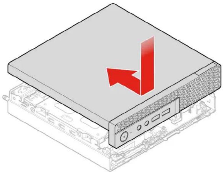
- Reinstall the computer cover.
natural_image
Illustration of a computer drive with a red arrow pointing to the top panel (no text or symbols present)Figure 92. Reinstalling the computer cover
- Install the screw to secure the computer cover.
- Place the computer in an upright position.
- If a locking device is available, use it to lock the computer.
- Reconnect the external cables and power cords to the corresponding connectors on the computer.
Appendix A. Notices
Lenovo may not offer the products, services, or features discussed in this document in all countries. Consult your local Lenovo representative for information on the products and services currently available in your area. Any reference to a Lenovo product, program, or service is not intended to state or imply that only that Lenovo product, program, or service may be used. Any functionally equivalent product, program, or service that does not infringe any Lenovo intellectual property right may be used instead. However, it is the user's responsibility to evaluate and verify the operation of any other product, program, or service.
Lenovo may have patents or pending patent applications covering subject matter described in this document. The furnishing of this document does not give you any license to these patents. You can send license inquiries, in writing, to:
Lenovo (United States), Inc.
1009 Think Place - Building One
Morrisville, NC 27560
U.S.A.
Attention: Lenovo Director of Licensing
LENOVO PROVIDES THIS PUBLICATION "AS IS" WITHOUT WARRANTY OF ANY KIND, EITHER EXPRESS OR IMPLIED, INCLUDING, BUT NOT LIMITED TO, THE IMPLIED WARRANTIES OF NON-INFRINGEMENT, MERCHANTABILITY OR FITNESS FOR A PARTICULAR PURPOSE. Some jurisdictions do not allow disclaimer of express or implied warranties in certain transactions, therefore, this statement may not apply to you.
This information could include technical inaccuracies or typographical errors. Changes are periodically made to the information herein; these changes will be incorporated in new editions of the publication. Lenovo may make improvements and/or changes in the products and/or the programs described in this publication at any time without notice.
The products described in this document are not intended for use in implantation or other life support applications where malfunction may result in injury or death to persons. The information contained in this document does not affect or change Lenovo product specifications or warranties. Nothing in this document shall operate as an express or implied license or indemnity under the intellectual property rights of Lenovo or third parties. All information contained in this document was obtained in specific environments and is presented as an illustration. The result obtained in other operating environments may vary.
Lenovo may use or distribute any of the information you supply in any way it believes appropriate without incurring any obligation to you.
Any references in this publication to non-Lenovo Web sites are provided for convenience only and do not in any manner serve as an endorsement of those Web sites. The materials at those Web sites are not part of the materials for this Lenovo product, and use of those Web sites is at your own risk.
Any performance data contained herein was determined in a controlled environment. Therefore, the result obtained in other operating environments may vary significantly. Some measurements may have been made on development-level systems and there is no guarantee that these measurements will be the same on generally available systems. Furthermore, some measurements may have been estimated through extrapolation. Actual results may vary. Users of this document should verify the applicable data for their specific environment.
Appendix B. Trademarks
LENOVO, LENOVO logo, and the THINKCENTRE logo are trademarks of Lenovo.
DisplayPort is a trademark of the Video Electronics Standards Association.
VESA is a trademark of the Video Electronics Standards Association.
All other trademarks are the property of their respective owners. © 2019 Lenovo.
Lenovo