LANtest PoE - Câble pour ordinateur et périphériques Hobbes - Free user manual and instructions
Find the device manual for free LANtest PoE Hobbes in PDF.


User questions about LANtest PoE Hobbes
0 question about this device. Answer the ones you know or ask your own.
Ask a new question about this device
Download the instructions for your Câble pour ordinateur et périphériques in PDF format for free! Find your manual LANtest PoE - Hobbes and take your electronic device back in hand. On this page are published all the documents necessary for the use of your device. LANtest PoE by Hobbes.
USER MANUAL LANtest PoE Hobbes
LANtest PoE user manual
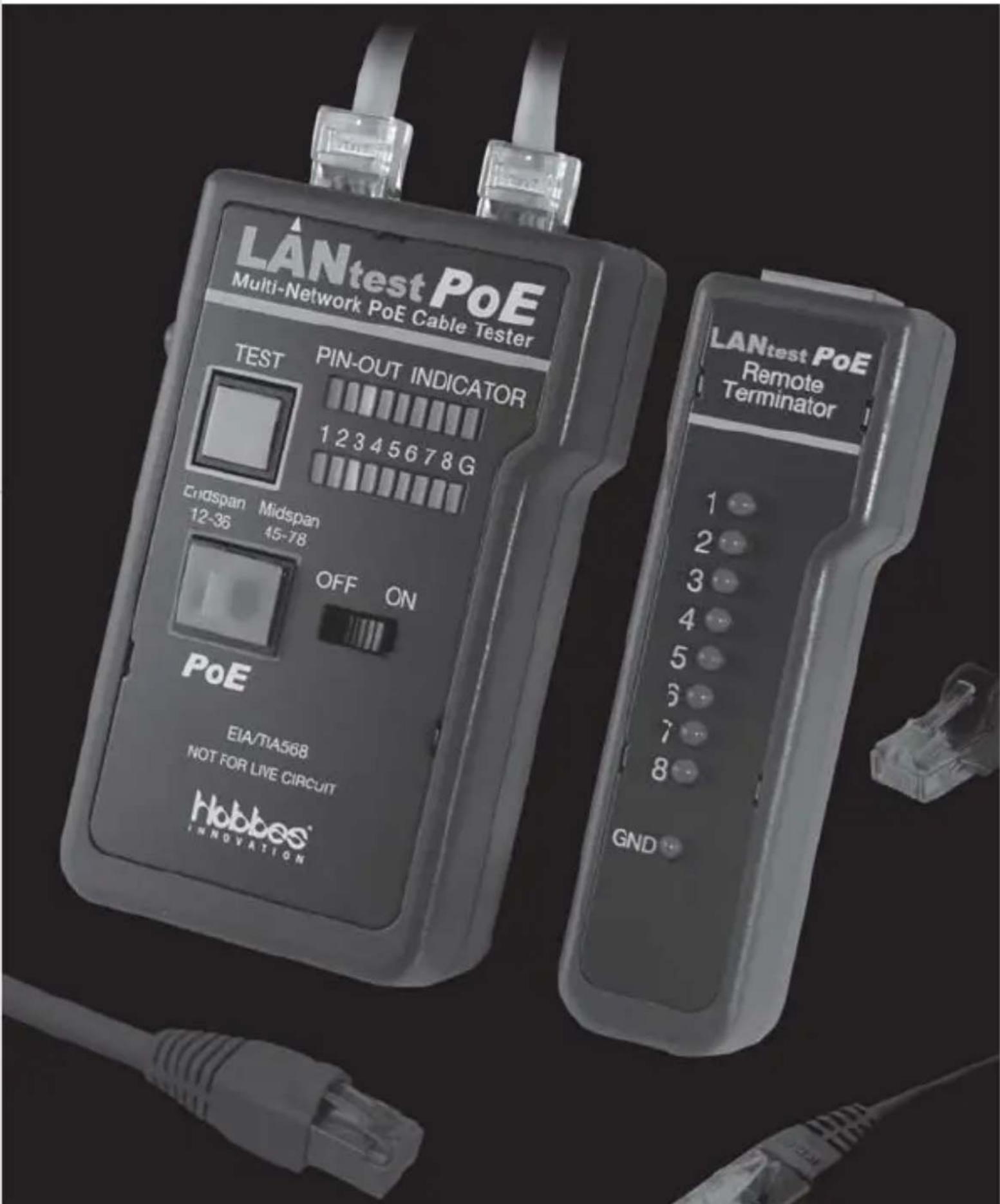
Multi-Network PoE Cable Tester
text_image
LANtest PoE Multi-Network PoE Cable Tester TEST PIN-OUT INDICATOR 1 2 3 4 5 6 7 8 G Endspan Midspan 12-36 45-78 OFF ON PoE EIA/TIA568 NOT FOR LIVE CIRCUIT Hobbes® INNOVATION LANtest PoE Remote Terminator 1 2 3 4 5 6 7 8 GNDLANtest PoE Introduction 2
Features 2
Test Equipment Overview 3
Operation
- PoE (Power over Ethernet) test 5
- Loopback test
A. 258A, TIA-568A/568B 6 cable test
B. Modular cable test 8
C. 10Base-2 cable test 9
- Remote test 10
Test Result 11
Warning 12
Warranty 12
LANtest PoE is a newly designed and very practical tester that can easily read the correct pin configuration of RJ45/RJ11 modular cables, 258A, TIA-568A/568B and Token Ring cable by comparing transmitting end to the corresponding receiving end. With the remote unit, it can test installed cables behind walls via wall plates or patch panels. It easily verifies the cables continuity, open, short and cross-connect. It’s affordable, so you can benefit the most.
Features
- Check the existence of PoE in seconds.
- Identifies the type of PSE, whether the PoE voltage is detected on the pair 12-36 (Endspan), or on the 45-78 (Midspan).
- Compliant with IEEE802.3af and IEEE802.3at standard.
- Wiring configuration for Cat5, Cat5e, Cat6, Cat7, coaxial and modular telephone cables by comparing one transmitting end to another receiving end.
- Easy to read cable status and verify cable continuity including ground, open, short and miswire.
- With the remote unit, it can test installed cables behind walls via wall plates or patch panels.
- Features auto or manual scan.
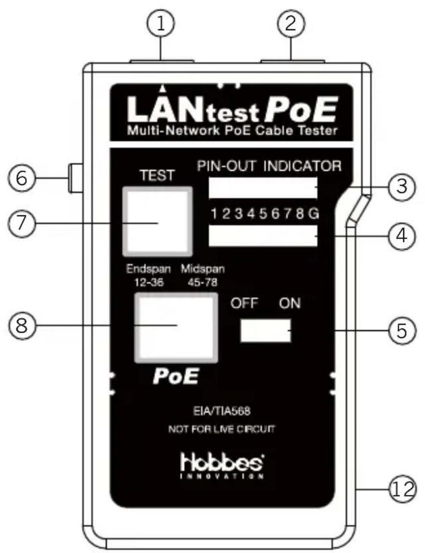
Test Equipment Overview
text_image
LANtestPoE Multi-Network PoE Cable Tester TEST PIN-OUT INDICATOR 1 2 3 4 5 6 7 8 G Endspan Midspan 12-36 45-78 OFF ON PoE EIA/TIA568 NOT FOR LIVE CIRCUIT Hobbes® INNOVATION ① ② ③ ④ ⑤ ⑥ ⑦ ⑧ ⑫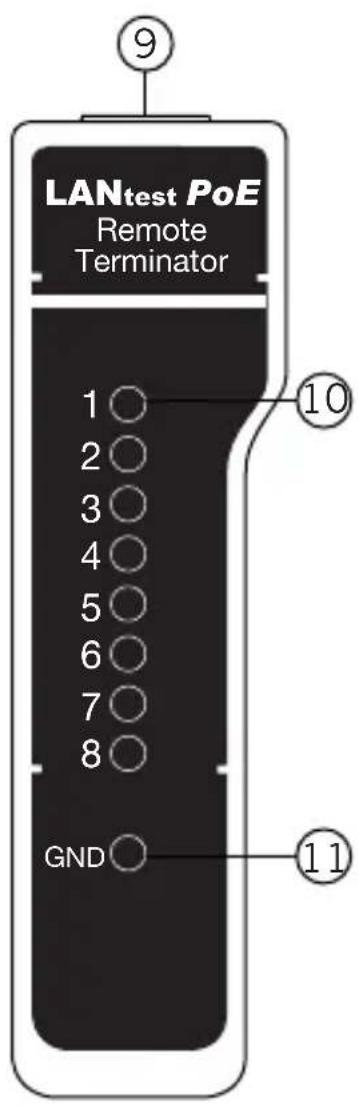
- RJ45 jack
- RJ45 jack
- LED display for sourcing end (Jack 1)
- LED display for receiving end (Jack 2)
- Power switch
- LED scanning mode switch
- Test switch for manual scan
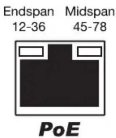
- RJ45 jack for PoE test
- RJ45 jack
- LED display for receiving end (same as Jack 2)
- Ground LED for receiving end
- Battery compartment (On back of main unit)
Operation
1. PoE (Power over Ethernet) test
Connect the PoE RJ45 jack via network cable. In one second, the LEDs will indicate the standard PoE voltage if detected. It will display the voltage detected on pair 12-36, or 45-78. If an unsolicited voltage above 24VDC detected on the network, the PoE LEDs will immediately light “on” without delay. The LEDs will not turn on if detect any voltage under 24VDC.
text_image
Endspan Midspan 12-36 45-78 PoE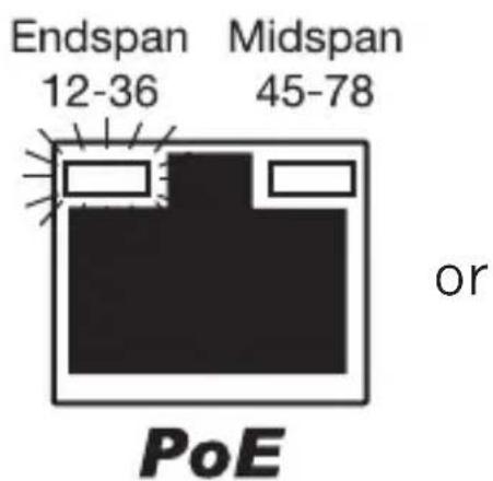
text_image
Endspan 12-36 Midspan 45-78 or PoE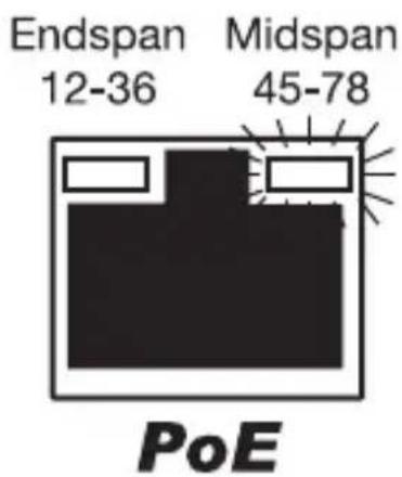
text_image
Endspan 12-36 Midspan 45-78 PoE2. Loopback test
A. 258A, TIA-568A/568B cable test
A1. Plug one end of the cable being tested on the RJ45 sourcing jack (Marked with ▲) and another end of the cable being tested on the remaining receiving RJ45 jack.
A2. Slide power switch on, the upper row LEDs will start to scan in sequence if the LED scanning mode switch is press on Auto mode, or the LED will light on pin 1 if the scanning switch is release on Manual mode.
Note: You have to make sure the battery power is sufficient. If battery power is low, the LEDs will be dimmed or off, and the test result will be incorrect.
A3. Operate the LED scanning mode by pressing the Auto/Manual switch.
A4. In this moment the corresponding LED indicators of another row of LED will light up simultaneously.
A5. LED displays the result of the pin configuration for the cable being tested. If you fail to read the result in the first run of LED scan, you may read it again in the next run of LED scan, or use the manual mode and press the test switch to scan each pin manually to display each result.
B. Modular cable test
Please follow the procedure of 258A, TIA-568A/568B cable test. However, the LED display should be read as below.
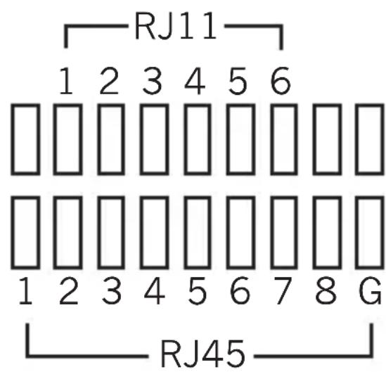
text_image
RJ11 1 2 3 4 5 6 1 2 3 4 5 6 7 8 G RJ45C. 10Base-2 cable test
C1. Plug the attached two BNC adaptor cables on both RJ45 jacks, then connect both ends of tested cables on BNC adaptor cables.
C2. As to the remaining procedures you may refer to 258A, TIA-568A/568B cable test from step A2 to A5.
Note: The center pin of BNC should be read on LED 1 and shielding pin of BNC should be read on LED 2. As the 10Base-2 cable has only two wires, we suggest reading the result of LED scan by using manual mode.
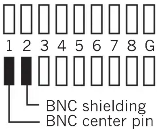
text_image
1 2 3 4 5 6 7 8 G BNC shielding BNC center pin3. Remote test
A. Plug one end of tested cable on the RJ45 sourcing jack (Marked with ▲) of main unit and another end on the receiving RJ45 jack of the remote unit. If the cable being tested is already installed on the patch panel or wall plate, you may use the adaptor cable to solve the connector gender problem.
B. Now, set the Auto/Manual switch on Auto mode if you work alone.
C. Read the test result from LED display on remote unit.
Note: The LED display on remote unit was scanned in sequence corresponding to the sourcing end of main unit.
Test Result
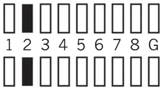
- Continuity:
text_image
1 2 3 4 5 6 7 8 GPin 2 is continued.
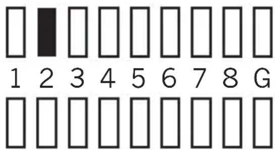
- Open:
text_image
1 2 3 4 5 6 7 8 GPin 2 is opened.
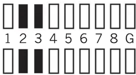
- Short:
text_image
1 2 3 4 5 6 7 8 GPin 2 and pin 3 are shorted.
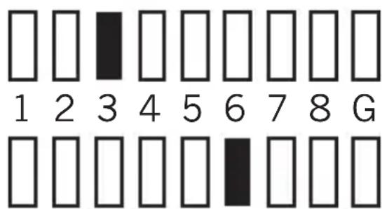
- Miswire:
text_image
1 2 3 4 5 6 7 8 GPin 3 and pin 6 are miswired.
Warning
-
Please do not connect this device to a telephone network. If the detected voltage is over 63VDC, it may permanently damage the unit.
-
Please do not operate the tester in live circuit as it may damaged the tester.
-
If the tester will not be used for a long period of time, remove batteries.
Warranty
The device is guaranteed for two years after completing the registration procedure from the date of original sale in Hobbes Group web site.
The manufacturer will repair the device free of charge if manufacturer determines the product failed due to manufacture defect. This warranty is only valid if the device is used for its intended purposes only.
Consumables such as connector can not be repaired under warranty.
Manufacturers warranty is voided if the product has been tampered and damaged from misused.