
HRX-1620 - Dictaphone Hanwha - Free user manual and instructions
Find the device manual for free HRX-1620 Hanwha in PDF.


| Product Type | Network Video Recorder (NVR/DVR) |
| Model | HRX-1620 |
| Brand | Hanwha Techwin |
| Video Input | Up to 16 channels (analog and network cameras) |
| Video Output | HDMI, VGA |
| Recording Resolution | Up to 4K (depending on camera) |
| Compression | H.264, H.265 |
| Hard Disk Drive | Internal HDD support (SATA) |
| Network Interface | Ethernet (RJ-45), supports DHCP, PPPoE, DDNS |
| Power Supply | AC power adapter (included) |
| Power Consumption | Typical 30W (depending on HDD) |
| Dimensions (W x D x H) | Approximately 440 x 300 x 44 mm (rack-mountable) |
| Weight | Approximately 2.5 kg (without HDD) |
| Operating Temperature | 0°C to 40°C |
| Humidity | 20% to 85% (non-condensing) |
| Remote Access | Web viewer, VMS, mobile app (via P2P) |
| Recording Modes | Continuous, scheduled, event (motion/sensor/alarm) |
| Playback Features | Time search, event search, backup to USB, SEC format |
| PTZ Control | Support for PTZ cameras (presets, tours, patterns) |
| Audio Support | Bidirectional audio on supported channels |
| Cleaning | Use soft dry cloth; avoid alcohol, solvents, or detergents |
| Safety | Read instructions, keep away from water, ensure proper ventilation |
| Certifications | FCC Part 15 Class A, CE, RoHS |
Frequently Asked Questions - HRX-1620 Hanwha
User questions about HRX-1620 Hanwha
0 question about this device. Answer the ones you know or ask your own.
Ask a new question about this device
Download the instructions for your Dictaphone in PDF format for free! Find your manual HRX-1620 - Hanwha and take your electronic device back in hand. On this page are published all the documents necessary for the use of your device. HRX-1620 by Hanwha.
USER MANUAL HRX-1620 Hanwha
©2019 Heruhe TechwinCo, Ltd. All rights reserved.
Trademark
Each of trademarks I are not yet used. The name of the product and other trademarks mentioned in Instrumentale are the registered trademark of their respective company.
Restriction
Copyright of this document is reserved. Under no circumstances, this document shall be reproduced, distributed or changed, partially enclosed, without formal authorization.
Disclaimer
Hanuha Techwin makes the best to verify the integrity and correctes of the contents in this document, but no formal guarantee shall be provided. Use of this documentary, the best quarteries, or may be entirely on the user's own responsibility. Hanuha Techwin serves the right to change the contents of this document without prior action.
- Design and specifications are subject to change without prior notice.
You can download the latest version from the Hanwha Techwin web site. (www.hanwha-security.com)
The initial administrator ID is "admin" and the password should be set when logging in for the first time. Please change your password every three months to safely protect personal information and to prevent the damage of the information theft.
Please, take note that it's a user's responsibility for the security and any other problems caused by mismanaging a password.
overview
IMPORTANT SAFETY INSTRUCTIONS
Read these operating instructions carefully before using the unit.
Follow all the safety instructions listed below.
Keep these operating instructions handy for future reference.
1) Read these instructions.
2) Keep these instructions.
3) Heed all warnings.
4) Follow all instructions.
5) Do not use this apparatus near water.
6) Clean the contaminated area on the product surface with a soft, dry cloth or a damp cloth. (Do not use a detergent or cosmetic products that contain alcohol, solvents or surfactants or oil constituents as they may deform or cause damage to the product.)
7) Do not block any ventilation openings, Install in accordance with the manufacturer's instructions.
8) Do not install near any heat sources such as radiators, heat registers, stoves, or other apparatus (including amplifiers); that produce heat.
9) Do not defeat the safety purpose of the polarized or grounding-type plug. A polarized plug has two blades with one wider than the other. A grounding type plug has two blades and a third grounding prong. The wide blade or the third prong are provided for your safety, if the provided plug does not fit into your outlet, consult an electrician for replacement of the obsolete outlet.
10) Protect the power cord from being walked on or pinched particularly at plugs, convenience receptacles, and the point where they exit from the apparatus.
11) Only use attachments/accessories specified by the manufacturer.
12) Use only with the cart, stand, tripod, bracket, or table specified by the manufacturer, or sold with the apparatus. When a cart is used, use caution when moving the cart/apparatus combination to avoid injury from lip-over.

13) Unplug this apparatus during lightning storms or when unused for long periods of time.
14) Refer all servicing to qualified service personnel. Servicing is required when the apparatus has been damaged in any way, such as power-supply cord or plug is damaged, liquid has been spilled or objects have fallen into the apparatus, the apparatus has been exposed to rain or moisture, does not operate normally, or has been dropped.
Standards Approvals

- Any changes or modifications in construction of this device which are not expressly approved by the party responsible for compliance could void the user's authority to operate the equipment.
This device complies with part 15 of the FCC Rules. Operation is subject to the following two conditions: (1) This device may not cause harmful interference, and (2) this device must accept any interference receive, including interference that may cause undesired operation.
This equipment has been tested and found to comply with the limits for a Class A digital device, pursuant to part 16 of the FCC Rules. These limits are designed to provide reasonable protection against harmful interference when the equipment is operated in a commercial environment. This equipment generates, uses, and can rotate radio frequency energy and, if not installed and used in accordance with the instruction manual, may cause harmful interference to radio communications. Operation of this equipment in a residential area is likely to cause harmful interference in which case the user will be required to correct the interference at his own expense.
PRODUCT USER MANUAL DESCRIPTION
This document is a user manual for Wisenet Recorder product. Before using this product, please read this document carefully in order to use it properly.
- This user manual explains how to use the product based on the defaults and default screens of this product.
- The content of this manual is subject to change depending on the product software updates and the company policies. It is subject to partial changes without prior notification to users.
TARGET AUDIENCE
This user manual contains contents for Wiserel Recorder users.
HOW TO USE THE PRODUCT
Users of this product can perform the following:
• Monitor cameras registered to Wisenet Recorder in real time
• Search for or play videos saved in Wisenet Recorder
• Monitor text data being transmitted to the POS device connected to Wisenet Recorder in real time
- Search for text data from the POS device connected to Wisenet Recorder
- Monitor real time events that occur in Wisenet Recorder, sensors, and cameras or search through logs
Before using this product, check if the latest version of this software is installed. Go to Hanwha Techwin's website (http://www.hanwha-security.com) to check the software version and download necessary files.
overview
contentS
overview

3 Important Safety Instructions
3 Product User Manual Description
3 Target Audience
3 How to Use the Product
4 Contents
llve

5 Getting Started
8 Live Screen Configuration
11 Live Screen Mode
12 Status
14 Zoom
15 Layout
15 Audio ON/OFF
15 Freeze
16 Event Monitoring
16 Capture
17 Maintain the Screen Ratio
17 Display Text
17 PTZ control
19 Backup
menu Setup

20 System Setup
26 Setting the Camera
34 Setting the Device
39 Setting the Recording
40 Setting the Event
44 Network Configuration
Search & play

51 Search
54 Playback
Starting web viewer

55 What is Web Viewer?
55 Connecting Web Viewer
llve vlewer

56 Live Viewer
61 Control of connecting Network Camera
Search viewer

62 Search viewer
Setup vlewer

66 Setup Viewer
backup vlewer

76 SEC Backup Viewer
appendix

78 Using a remote controller
79 Use Joystick
79 Using Virtual Keyboard
80 Troubleshooting
GETTING STARTED
Starting the system
- Connect the power cable of the Recorder to the wall outlet.
- You will see the initialization screen.
The initialization process will last about 2 minute.
If a new HDD is installed, the initialization process may take longer.

- The live screen appears with a beep.
The following symptoms might be observed when starting the system.
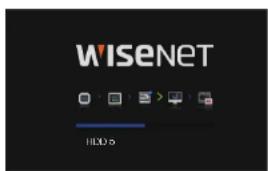
If the HDD number is displayed at the bottom of the screen along with <■> while the product is booting up, it indicates that the HDD is in recovery, and for this reason booting up may take longer.
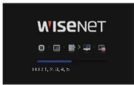
- If the progress stalls while in <■> state, it indicates that the HDD has problems. Visit your nearest customer service center to check the HDD.
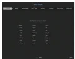
Install Wizard
As shown below, proceed through each step of the
Install Wizard can only be accessed at factory reset. If you do not want to proceed, click
- In the
screen, select the language and press the button.
- Set the network connection type and the connection environment on the
screen, and then click the button.
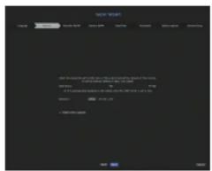
Setting up the DHCP server
If you set up the DHCP server, the IP address is automatically assigned to your camera.
For more details, see the 'DHCP server' page under 'Menu Setup > Network Configuration' in the Table of Contents.
- Depending on the camera's state, no IP may be automatically assigned to the camera. After exiting the installation wizard, go to the menu to assign an IP to DHCP, or set the IP manually.
Setting up the network
The network port can be used as a common port for camera and web viewer connection.
• IP type: Allows you to select the type of network access.
• IP address, subnet mask, gateway, DNS
- Static: IP address, subnet mask, gateway, and DNS can be directly entered.
- DHCP: IP address, subnet mask, gateway, and DNS can be automatically set.
- PPPoE: IP address, subnet mask, gateway, and DNS can be automatically set.
- User ID, password: To set the access mode to PPPoE, enter the "User ID" and "Password" registered to PPPoE.
If the LAN cable is not connected to the port, the setting button will not be activated for use. Check the LAN cable connection.
- The built-in DHCP Server in Recorder will turn on automatically at stage 2. At this stage, using the existing DHCP server in the same network may cause a problem, as two DHCP servers would be simultaneously operating.
live
- Set the administrator password on the
screen and click the button. Click < 🔒 > to view the basic guide for setting a password. Refer to the password setup rules.
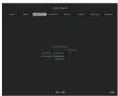
- Set the camera password in factory reset on the
screen. If ID/PW is already set in the camera, register the ID/PW and click .
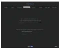
- When the password is in factory reset, it can be changed and managed in a batch. - Up to 3 sets of camera ID with password and password can be registered. - You cannot change password of a camera registered using ONVIF or RTSP.
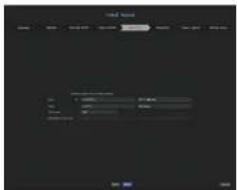
- Set the date, time, time zone, and DST on the
screen, and then click the button.
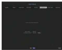
- To set the recommended resolution on the
screen, click followed by the button.
- On the
screen, select a camera to register from the searched camera list and click the button. Select a camera to register from the list and click the button. After completing camera register, click .
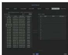
- On the
screen, you can view the camera video registered to each channel in thumbnails along with thumbnail information. To change the camera video position, select a video and drag and drop it to the desired location.
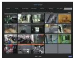
- Click the
button to complete the install Wizard.
Shutting Down the System
- In the live screen menu, select
. - The "Shutdown" confirmation pop-up window will appear.
- Click on
. The system will shut down.
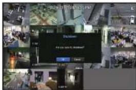
Restarting the System
- In the live screen menu, select
. - The "Restart" confirmation pop-up window will appear.
- Click on
. The system will restart.
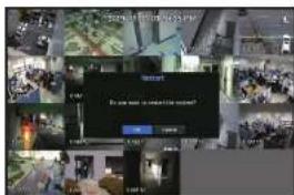
- Only the user with the "Shutdown" or "Restart" permission can shut down or restart the system.
To manage Permission Setup, see the "User" page under "Menu Setup > System Setup" in the Table of Contents.
Login
To use the Recorder menu, you are required to login as a user that is authorized to access the applicable menu.
- Right click with your mouse button on the live mode screen. You will see the context menu on the screen as shown.
- Select
. The login dialog appears.
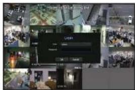
- The initial administrator ID is set to "admin" and you will need to configure the password in the installation board.
- Please change your password every three months to safely protect personal information and to prevent the damage of the information theft. Please, take note that it's a user's responsibility for the security and any other problems caused by mismanaging a password.
For more information about limited-access permission, see the "User" page under "Menu Setup > System Setup" in the Table of Contents.
Icons on the Live Screen
You can check the status or operation with the icons on the live screen.
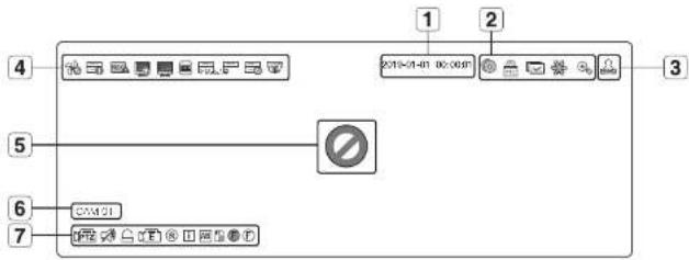
| Name Description | |||
| 1 | Current Date, Time | Displays the current time and date. | |
| 2 | Screen Mode | It is displayed when there is ongoing backup in the live condition. | |
| Displayed when manually recording a video while the access restriction for stop recording is enabled.Only a user with the permission to stop recording is allowed to stop recording. | |||
| It is displayed when all the channels are switched at the set time interval. | |||
| This icon is displayed when you press the Boxero button. | |||
| It is displayed when the magnifying function is in operation. | |||
| 3 | Login Information | When you are logged in, the "LOG ON" icon will be displayed. | |
| 4 | System Operation | It is displayed when there is a problem with the fan.Only provided for products that support fans. (See page 4 of the Product Specification Manual) | |
| Displayed when recording data is not properly saved. | |||
| Appears when Input data rate per channel exceeds the specified data rate limit. | |||
| Name Description | |||
| 4 | System Operation | It is displayed when there is firmware to update the server. | |
| It is displayed when the network is overloaded.■ It occurs when the main receiving allowance is exceeded, causing an overload to the CPU. It will disappear if you modify the camera settings or delete a camera to reduce the performance burden. | |||
| Displayed when system overload occurs.■ Limit the number of users remotely monitored by Web Viewer or VMS or control the number of channels played by remote or recordar. | |||
| Displayed if the HDD is full and the Recorder has an insufficient space to record. | |||
| Displayed when there is no HDD or HDD is not detected. | |||
| Displayed if the HDD needs a technical examination. | |||
| Displayed when the camera firmware upgrade is complete. Click to view the results. | |||
| 5 | Video Input Status | Displayed if no input is entered in the condition that the camera is set to. | |
| Displayed when the live image with the camera turned. exceeds the supported resolution. | |||
| WISENET | Displayed if no permission to live view is granted. | ||
| If the camera channel is., the camera is not registered, or it is set to., the live screen will display nothing. For., the screen will display nothing but OSD. | |||
| 6 | Camera Title / Channel | Display the camera title and channel number. | |
| 7 | Camera Operation | [IMAGE] | This icon is displayed for a channel that a PTZ-featuring camera is connected to. |
| [IMAGE] | Displays AUDIO ON/MUTE. Not displayed in video mode if deactivated. | ||
| [IMAGE] | If the sensor is set to, the input signal will be displayed on the screen of the connected channel. | ||
| [IMAGE] | This icon is displayed when Motion Detection is set toand a camera motion or camera event occurs. | ||
| 8 / 8 / 8 | It displays the status of general/event/scheduled recording. | ||
| [IMAGE] | It is displayed when it fails to decide all the frames due to limited decoding performance and in this case only the I-Frame is decoded. | ||
| [IMAGE] | This is displayed when a POS touch event occurs. | ||
| [IMAGE] | RED - Displayed when there is any abnormality in the RED-SO card.YELLOW - Displayed when there is no storage space in the SD card. | ||
| ● / ● | Pickers when a defocus event occurs. When you click the icon, a simple focus command is sent to the camera.*Displayed when a fog detection event occurs. | ||
Error Information
- If the built-in HDD is not connected, the "NO HDD" icon (☐) will be displayed in the top cell corner. In this case, make sure you contact the service center for assistance as this may cause a failure of recording, playback or backup.
# you do not format a purchased HDD in a format supporting Recorder, a "NO HDD" icon! will be displayed on the top left side of the screen. If the "NO HDD" icon is displayed, go to 'Menu > Storage Device' to check the HDD connection status, and format your HDD.
If a product with a fan does not work or has a problem with the fan,
- If an abnormal fan icon (⌘) or NO HDD (☐) icon, HDD FAIL (☐) icon is displayed, contact our customer service. - For products that support fan, see page 4 "Products supporting each feature" of the Product Specification Manual.
Live Screen Menu
If you right click with your mouse button in live screen mode, it will launch the live screen menu where you can access each menu.
The context menu differs depending on the state of Log input, split mode, and Recorder operation status.
- Depending on the user permissions, you may have limited access to menu items of Live View, Backup, Stop Recording, Search, PTZ, Remote Alarm Output and Ext.
Single Mode Menu
The single mode menu is available only in Single Mode.
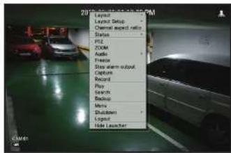
| Menu | Description |
| PTZ | Accesses the PTZ Control menu. The PTZ menu will be active on the Live screen after you select a single channel.For more details, see the "Live > PTZ Control" page in the Table of Contents. |
| ZOOM | You can enlarge the selected screen.See the "Live > Zoom" page in the Table of Contents. |
| Capture | Captures the screen of the selected channel.See the "Live > Capture" page in the Table of Contents. |

Split mode menu
In Live split mode, right-click to display this context menu as shown.
The look of the split mode menu is different for each Recorder product and it also depends on the login/logout status.
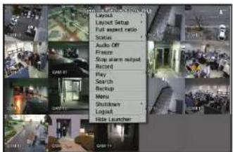
| Menu Description | |
| Layout | Select the split mode to display on the live screen.See the "Live > Live screen mode" page in the Table of Contents. |
| Layout Setup | Set the layout of each channel.See the "Live > Layout" page in the Table of Contents. |
| Full aspect ratio/Channel aspect ratio | Channel screen ratio is changed.See the "Live > Maintain the Screen Ratio" page in the Table of Contents. |
| Status | Shows the connection information of camera connected to each channel as well as live and recording status.See the "Live > Status" page in the Table of Contents. |
| Audio On/Off | Turns ON/MUTE the sound of the selected channel.See the "Live > Audio ON/OFF" page in the Table of Contents. |
| Freeze | Stop playing the video temporarily.See the "Live > Freeze" page in the Table of Contents. |
| Stop alarm output | Stop the alarm output, deactivate the event loan and release the auto sequencing.See the "Live > Event Monitoring" page in the Table of Contents. |
| Record/Stop Starts or stops manual recording. | |
| Play | See the "Search & Play > Play" page in the Table of Contents. |
| Search | See the "Search & Play > Search" page in the Table of Contents. |
| Backup | Searches for a backup device and back up each channel at your desired time.See the "Live > Backup" page in the Table of Contents. |
| Menu Description | |
| Menu | Enter the main menu.Sac the "Menu Setup" page in the Table of Contents. |
| Shutdown/Restart | The system shutdown/restart dialog will appear. |
| Login/Logout | You can log in or out. |
| Show Launcher/Hide Launcher | Shows or hides the launcher. Refer to "View the Launcher Menu". |
View the Launcher Menu
The Launcher menu appears on the bottom of the live screen.
- Select
in the context menu of the Live screen. - Move the cursor to the bottom and click a desired item in the Launcher menu.
- If no input is entered for 10 seconds, the menu will disappear.
| Layout 01 | 3x4 | 4x4 | 3x3 | 2x2 | 2x | 2x | 2n | 1+5 | 1+7 | 1+12 | ||||||||||||||||||||||||||||||||||||||||||||||||||||||||||||||||||||||||||||||||||||||||||||||||||||
| 1 | 1 | |||||||||||||||||||||||||||||||||||||||||||||||||||||||||||||||||||||||||||||||||||||||||||||||||||||||||||||
| 3 | 4 | 2 | 13 | 12 | 11 | 10 | 9 | 8 | 7 | 6 | 5 | 1 |
| Menu Description | ||
| 1 | Layout Select the layout to be displayed on the screen. | |
| 2 | Layout Setup You can set, change or delete the new layout of each channel. | |
| 3 | Screen Mode | Displays a list of split modes available in a car type.The current screen mode will be displayed grey. |
| 4 | Close Slide/Open Slide | Click to display the hidden menu to the right. |
| 5 | Manual Backup Searches for a backup device and back up each channel at your desired time. | |
| 6 | Zoom In Entarges the selected area. This is available only in Single Live mode. | |
| 7 | PTZ Mode | If the network camera connected to the selected channel supports the PTZ operations, this will run the PTZ control launcher. |
| 8 | Alarm Stop Stops the alarm if it's activated. | |
| 9 | Freeze Frezes the Live screen temporarily. | |
| 10 | Capture | Captures the screen of the selected channel. |
| 11 | Print Text | Text output is ON or OFF. |
| 12 | Play | Enters Play mode if a Tie to play exist, and if not, enters Search mode. |
| 13 | Manual Record | Start/End recording the Live screen. |
LIVE SCREEN MODE
You can display your camera's live video in various split modes.
- Displayed a camera resolution on the screen when analog camera is automatically registered.
- The Live4NVR profile is added automatically with network camera auto registration, and settings can be changed according to
user environment. - Live4MVR Profile Basic Settings : H.264 (coded), 800 x 600 or 800 x 448 (resoluzioni), 30ips tiframe ratei
- Depending on camera specification, you may not be able to add a profile or if you have the PLUGINFREE profile, you will not be able to add the Live4Net profile.
- When system overloaded and the performance is down, network camera may play only main frameell-frame).
- To sel profiles, see the "Camera Setting" page under "Menu Setup > Setting the Device"
Method for displaying screen mode
If you want to change the split mode, select a screen mode suggested in the launcher menu or right click with the mouse button and select a split mode in the screen mode menu.
Each product may support different split view modes. See page 15 "Product specification" of the Product Specification Manual.
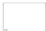
Single mode
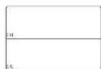
Horizontal 2-split screen
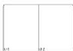
Vertical 2-split screen
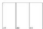
3-split mode
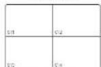
4-split mode
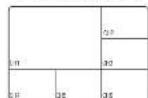
6-split mode
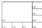
8-split mode
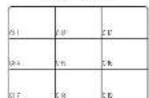
9-split mode
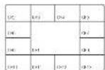
13-split mode
(1+12-split mode)
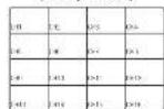
16-split mode
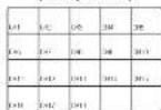
20-split mode
Auto Sequence

Switching the split mode
You can split the live video from cameras to Single, 4-split, 9-Split, or 18-split mode and watch them one by one.
- Each product supports different split modes. For more information, see "Method for displaying screen mode".
Press the button in the launcher or use the right menu to automatically switch the screen.
Mouse right button menu → Layout → Auto switching mode
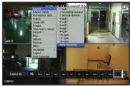
Auto Sequence
You can monitor the split mode of your own choice by switching one after another at a certain interval.
For segmented screen switching, set
- When you switch the channel, the video may be delayed depending on the network condition.
Example) HRX-1621
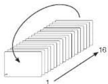
Single mode
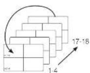
4-split mode
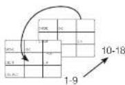
9-split mode
Manual Switching
Click the arrow </> key to move to the next split mode.
- If your product supports a remote controller, you can manually press the Left/Right buttons to switch between different screen modes. For products that support remote controls, see page 4 "Products supporting each feature" of the Product Specification Manual
Example) After setting to 4-split mode in HRX-1621, if you press the Right [▶] button:
Channel(CH 1-4) = Channel(CH 5-8) = Channel(CH 9-12) = Channel(CH 13-16) = Channel(CH 17-18)

flowchart
graph LR
    A["输入1"] --> B["输入2"]
    B --> C["输入3"]
    C --> D["输入4"]
    D --> E["输出1"]
    E --> F["输出2"]
    F --> G["输出3"]
    G --> H["输出4"]
STATUS
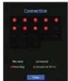
You can check the connection information of the camera to be connected to each channel on the live screen.
Channel info
Right-click on the live screen and select
■ABE is only displayed when an AFB situation occurs.
The letters shown next to the product name represents the protocol used to register the camera.
- S and V represent Wilsonet protocol while O represents ONVIE.
- If connected using the RTSP protocol, then only RTSP is displayed without any product name.
- In case of analog camera, it is indicated as "Analog CAM (port number)."
Connection
Right-click on the live screen and select
Live Status
Right-click on the live screen and select
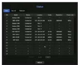
- Model: Displays the model name of camera connected to each channel.
- Status: Shows the connection status of camera set to each channel.
- Location: Displays the camera location information set by channel.
- Codec : Displays the live profile codec information for a camera set to each channel.
- Resolution: Displays the live profile resolution of a camera set to each channel.
- Frame Rate : Displays the live profile transmission rate for a camera set to each channel.
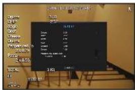
Record Status
Right-click on the live screen and select
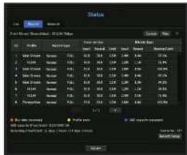
- Total Bitrate (Record/Max) : Record bitrate shows the amount of actual data recording while Total bitrate shows the maximum data transfer allowed by the Recorder.
• Profile : Shows the video profile configured to each channel. - Frame rate (fps): Show the input/record frames per second for each channel.
- Bitrate (bps)
- Limit / Input / Record : Shows the amount of limit/input/reccording data for each channel.
- Receive/Limit : Shows the data ratio of actual data transferred from the camera and allowed maximum defined by user.
- Current: Shows the recording status information of currently transferred data.
- Max : Shows recording information of the most biggest recording data out of configured standard and event recordings.
: Reloads the recording information.
- Record Setup: The menu screen will switch to the record setting screen.

If an error occurs during recording, the channel's profile column turns yellow.
This profile error indicates that when a recording profile cannot be used to receive a video from camera, an additional profile is used in record the video. When the recording profile returns, the camera video can record by using the set recording profile
- If Record or exceeds the recording limit, any the key frame will be recorded. In that case, a next card recording popp and an lon will appear. The card card recording popp can only see it again. If your card is the card setup and record slot, the card card recording popp may appear more more than the card. If you can't want to see it again, then check Do not show this again in the popp. For the maximum allowed number of recording, see the "Record Setup" page under "Menu Setup" > Setting the Recording* in the Table of Contents.
- For dual recording, the bit rate is shown as the sum of Main Stream and Sub Stream.

Check network status
Displays the status of network bandwidth currently being received/transmitted.

Channel Setting
You can display the channel in a desired area of a split screen.
-
Place the cursor over the camera name of each channel to display the <▼> key to the right on the screen.
-
Click a camera name to display a channel list where you can select a different channel.
-
Select a desired channel and click it.
The current channel will be switched to the selected one.

- Use the cursor to select a channel to move, and drag and drop it to a desired channel; this can also change the channel position.
Example) If switching CH 1 to CH 7
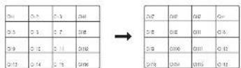
Switching to Single Mode
When in split mode, select and double-click a desired channel to switch to its Single mod.

If your product supports a remote controller, press the number button for the desired channel on the remote controller to switch to a single screen.
For more information, see "Using a remote controller > Using the Numeric buttons".
This function is only available for products that support the use of a remote controller. For products that support remote controls, see page 4 "Products supporting each feature" of the Product Specification Manual.
Example) If double-clicking CH 3.
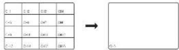
ZOOM
This is activated only in Live Single mode.
- After right-clicking on the live screen, click
.
You can also press the [ZOOM] button on your remote controller or click < Ⓞ> in the launcher menu. The Zoom in icon will appear at the bottom right. - Click < > icons to magnify the selected area.
By adjusting the box at the bottom, you can adjust the position of the magnified screen. - Click < ● > icons to zoom out the selected area.
- Click < ■ > at the top right to close zoom.
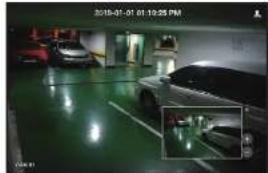
natural_image
Interior view of a car garage with parked cars and a highlighted parking area (no visible text or symbols)If your product supports a remote controller, follow these steps to zoom in on the video screen:
- Press the [ZOOM] button on your remote controller.
- Press the four directional keys (▲▼◀▶) to designate an area to zoom in.
- In the selected area, press the [ENTER] button on your remote controller. The selected area can be magnified up to 10 times.
- If you want to close the zoom, then press the [ZOOM] button on your remote controller.

- For products that support remote controls, see page 4 "Products supporting each feature" of the Product Specification Manual.
LAYOUT
In the live screen, you can set the layout for each channel.
Setting Up the Live Layout
This section outlines how to select a series of channels based on their purpose/accessibility and monitor them in a single layout.
Example) Layout "Lobby" - Lobby camera 1, Lobby camera 2, Front entrance camera 2 Layout "VIP" - Directors' meeting room 1, Directors' meeting room 2, Directors' lounge 1, Corridor camera on the 7th floor
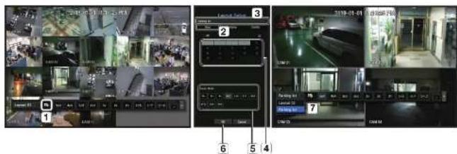
To create a new layout, follow these steps:
[1] Open the channel layout setup menu.
2 Click
3 Enter a name for the selected channels (e.g., Parking lot).
4 Select the channels that you want to add to the layout (e.g., 1, 2, 3, 4).
⑤ Choose a split mode to apply (e.g., 4-way split).
6 Click
[7] Choose a layout to view it on the screen (e.g., change to Parking lot).
1. Select the < 10 >.
The layout setting screen will appear.
• New : You can set the new layout.
- Rename: You can make changes to the selected layout.
When the layout is changed, the channel order is initialized.
- Delete: You can delete the selected layout.
- Channel Table: You can select channels in the table to be registered in, or removed from the layout.
- Channel List: You can select channels in the list to be registered in, or removed from the layout.
- Press the
button and enter the name of layout to add. - In the channel table or channel list, click and select the channel to be displayed on the layout screen.
- Click on
to save the selected layout.
The layout for each user is saved separately.
- You can use a configured layout even in the Search Time function to facilitate search using the channel sequence and combination that you have set.
See the "Time Search" page under "Search & Play > Search" In the Table of Contents
AUDIO ON/OFF
You can turn the sound on/off corresponding to the channel in Live mode.
AUDIO ON/OFF in Single mode
Click on the audio icon (on the screen to turn it ON/OFF.
- If you have configured the audio output settings properly but the audio or voice is not output. Check if the connected network camera supports the sound signal and if you have configured the sound settings as appropriate. The sound icon can be displayed if the sound signal fails to output from noise.
- Only the channel where
FREEZE
This is available only in Live mode, this pauses playing the Live image temporarily.
- Click < □> of the launcher mode.
Video playing is paused.
- Click on <
Pause is canceled. Playing is resumed.
If your product supports a remote controller, you can press the [FREEZE] button to pause the video.
For products that support remote controls, see page 4 "Products supporting each feature" of the Product Specification Manual.

EVENT MONITORING
This will display the channel in sync with a specific event (Sensor/Motion/Video Loss) if it occurs.
To use the event monitoring function, you should set the
- If multiple events occur simultaneously, the screen will switch to a split mode.
- 2 \~ 4 events : 4-split mode
- 5 - 9 events : 9-split mode
- 10 \~ 16 events : 16-split mode
- 17 - 18 events : 20-split mode
- if the second event occurs within the set time of
Example1)
If you set
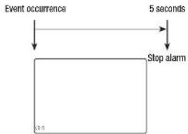
flowchart
graph TD
    A["Event occurrence"] --> B["Stop alarm"]
    B --> C["5 seconds"]
Example2)
- If you set
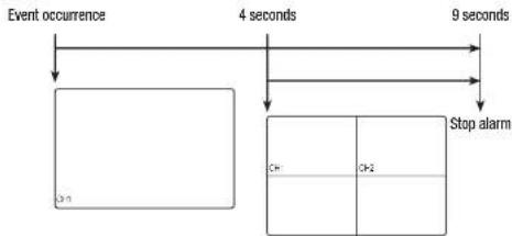
flowchart
graph TD
    A["Event occurrence"] --> B["4 seconds"]
    B --> C["Stop alarm"]
    C --> D["9 seconds"]
    D --> E["Stop alarm"]
    style A fill:#f9f,stroke:#333
    style B fill:#ccf,stroke:#333
    style C fill:#cfc,stroke:#333
    style D fill:#fcc,stroke:#333
    style E fill:#ffc,stroke:#333

- Select
- If your product supports a remote controller, then press the [ALARM] button to reset the alarm output status. For products that support remote controls, see page 4 "Products supporting each feature" of the Product Specification Manual.
- If an alarm is output with the pre-event and post-event times specified together with the event recording settings, the event recording will perform according to the specified recording type (pre event or post event);

- In case of continuous events such as motion detection, switching to another split mode display may not immediate if concatenating events follow, even when you stopped alarm of the event.
- The video may be delayed depending on the network condition.
The event output can be delayed as the transfer of the alarm event from the network camera takes time.
CAPTURE
You can capture a screen selected on the live screen.
Function to perform in single channel mode on the live screen or when selecting a channel.
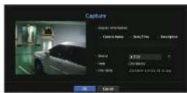
- Right-click on the live screen and select
You can click on < 80 > in the launcher menu. - Select the output information to be displayed on the captured screen.
- If the
box is checked, the description field will be enabled where you can enter up to 50 Korean letters. - Select a device to save a captured file, file path and file name.
- Complete the settings and click
, then the image captured from the screen is saved to the selected device.

- Camera screen larger than 2 megapixels is captured in Full HD size.
The screen ratio for a live video can be changed.
Maintain a screen ratio for all channels
Video screen ratio for all channels can be changed in live split screen mode.
- Right-click on the live screen and select
. The screen ratio for all channels will be changed. - If you want to go back to the previous screen ratio, check the menu option for
.
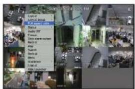
→
Maintain a channel screen ratio
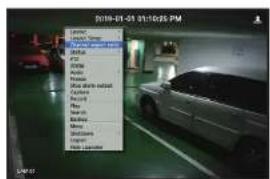
If you select a channel from a live single screen or split screen, you can change its video screen ratio.
- Right-click on the live screen and select
. The screen ratio of a specified channel will be changed. - If you want to go back to a previous screen ratio, select
again.
→
natural_image
Interior view of a car garage with two cars parked in the background (no visible text or symbols)DISPLAY TEXT
You can monitor texts regarding the sales record received from POS in real time.
Change text output
The Recorder can display text on a live screen when a text device is set.
Select text output
This is executable when a text device is connected.
- How to turn the text output off: Select 'OFF' from the text list.
How to display on other devices differently from the preset device: Select a device to display from the text list.
PTZ CONTROL
With the Recorder, you can configure the settings of a PTZ camera as well as commercial cameras in the market to your preference.
PTZ device
This is active only if a channel that a PTZ camera is connected to is selected.
Getting started with PTZ operations
The PTZ camera will be activated only if the channel of the PTZ camera is selected, which can be performed in the following way:
• Using the launcher menu : Click > from the launcher menu of the Live screen.
- Using the Live screen menu: Select
• Using the icons on the Live screen: Simply click the icon on the Live screen.
This is available only if a PTZ camera is connected and the
Even if the connected network camera does not support the PTZ operations, you can configure the PTZ control settings (if possible) by installing the PTZ driver (physical device).
- It supports only the Hanwha Technic PTZ function network camera, CWIF registration network camera. RS-465/422 (Samsung-T, Peico-D, Peico-P), and coaxial analog camera.

Using the PTZ camera
You can use a single PTZ camera to perform the Pan, Tilt and Zoom operations to monitor multiple places, and configure the custom settings of the presets in a desired mode.
- Open the
menu.
The
The PTZ working (active) mark can be active even if the PTZ operation is not available in normal mode. So ensure that you have completed the PTZ settings before proceeding.
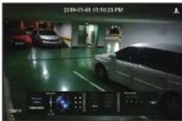
- Use the PTZ Wheel in the launch menu to adjust the location of recording by a camera.
- Sensitivity: Adjust sensitivity for Pan, Tilt controls.
- PTZ Wheel: Click a near area from the center to move the camera lens slowly, clicking a far area will move it fast.
- If clicking and holding the mouse in the left will turn the camera counterclockwise; if clicking and holding the mouse in the right will move the camera lens clockwise.
- Zoom: Activate the Zoom operation of the PTZ camera.
- Iris: Adjust the amount of light incoming to the camera.
- Focus: You can adjust the focus manually.
- Swing: Swing is a monitoring function that moves between two preset points and enables you to trace the motion,
- Group: The group function enables you to group various presets before calling them in sequence.
- Trace: Tracking remembers the trace of movements that you instructed and reproduces it for your reference.
• Tour: Monitor all the groups created by a user in turn.
- Some cameras may differ in the menu title and operation with regard to Swing. Group, Tour and Trace.
Even if your network camera supports the function, you can use it only if the button is activated in the PTZ control launcher. In case of analog cameras, it supports ALX.
- If your product supports a remote controller, then press the four directional keys (▲▼◀▶) to control PTZ. For products that support remote controls, see page 4 "Products supporting each feature" of the Product Specification Manual.
Using Digital PTZ (D-PTZ) function
- Register a camera that supports the D-PTZ profile.
- In cameras that support the D-PTZ profile, you can use the D-PTZ function.
- Both cameras that support general PTZ and cameras that support D-PTZ can control the live image using some of the
function menus.
- For more information about the supported functions, please refer to the camera manual.
Preset
Preset is a set of saved data specifying the locations of a PTZ camera. A single PTZ camera can save up to 300 locations.
To add a preset
-
Check the preset checkbox.
-
Select <
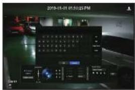
The virtual keyboard will appear on the screen. Use it to provide the preset name.
- See "Using virtual keyboard" in the Appendix.
: You can change the preset settings to your preference.
: Delete a selected preset.
: Delete all the existing preset settings.
If you replace a camera that saves your preset settings with a different one, you must configure the preset settings again.
- Select
The preset setting will be saved in the provided name.
To change or delete a registered preset
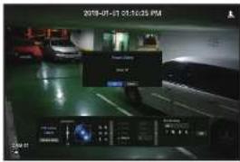
- Check the preset checkbox and select a preset to change or delete.
- Press < ■ > or < ■ as needed.
: Delete all the existing preset settings.
- Deleting all presets might delete even the default preset from the network camera.
- Provide a new name and press
.
BACKUP
You can search for a backup device and back up video recording at your desired time for each layout or channel.
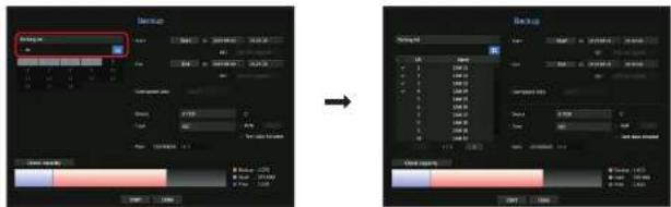
- Right-click on the live screen and select
.
You can click on < C in the launcher menu,
If your product supports a remote controller, then press the [BACKUP] button to go to the Backup menu. For products that support remote controls, see page 4 "Products supporting each feature" of the Product Specification Manual.
2. The backup settings screen will be opened.
- Select a layout. : Select a desired layout from the layout list.
• Channel : Sets the channel to backup.
■You can select multiple channels.
# you select
- Backup Range: Sets the
and time for the backup.
Start time : Set the backup start time to your desired time. If you click the [Start] button, the Backup start time is set to the starting time of the last video recording. However, the Start time will not be displayed on the screen. If you click the [Start] button once more, the Backup start time is set to the time set by user. - End: You can set the Backup end time to your desired time. If you click the [End] button, the Backup end time is set to the ending time of the last video recording. However, the End time will not be displayed on the screen. If you click the [End] button once more, the Backup end time is set to the time set by user.
- Overlapped Data : Shows a list of overlapping data on a same time according to the number of data. This is displayed when there are duplicate data in the same channel due to changes in the time or time zone.
-
See the "Setting the Date/Time/Language" page under "Menu Setup > System Setup" in the Table of Contents
-
Device : Select a backup device from the recognized devices.
- Type: Sets the backup data format.
- SEC : SEC is a proprietary file format, which can be played on the PC immediately as it is backed up with a dedicated viewer.
- Recorder: Saved data can be played back only by the Recorder.
- When you select the SEC format, you can select or reselect "Password" and "Text data Included".
- Path: displays the location of the folder in which the backup file is to be saved.
- Check capacity: Shows the size of the selected backup data, used and available capacity of the selected backup device.
- When the backup setup is done, press
.
- If there is no device to back up, the
If you insert a USB memory stick with insufficient storage space, volume calculation may be disabled. Format the memory stick or delete some of the data on the memory stick to secure adequate storage space.
■The application may slow down during the backup.
- You can switch to the menu screen during the backup in operation, but playback of data is not available.
- The data can be played back on a Walviewer while the backup is in progress but auto does not function.
- If backup has failed, select "Device > Storage Device" and check the free space of the HDD and check also if the HDD is properly connected.
- Pressing the
menu setup
Sets the camera, recording, event, device, network, and system environment.
SYSTEM SETUP
You can setup Date/Time/Language, User, System Properties and Log.
Date/Time/Language
Setting the Date/Time/Language
You can check and setup the current Date/Time and time related properties, as well as the language used for the interface on the screen.
Menu > System > Date/Time/Language
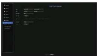
- Date : Sets the date and its format that will appear on the screen.
• Time : Sets the time and its format that will appear on the screen.
• Time Zone : Sets the time zone of your area based on the Greenwich Mean Time (GMT). - GMT (Greenwich Mean Time) is standard World Time and the basis of world time zone.
- Time Sync.: Specify the use of synchronization with the time server.
Click the
If this is the case, you cannot change the time setting manually.
- Synchronization : Specify the use of synchronization with the time server.
- Time Server : Enter an IP or URL address of the time server.
- Last Sync Time : Displays the most recent synchronization time from the selected time server.
- Activate as Server : Set to
- DST: Set up Daylight Saving Time with its period to make the time earlier than the GMT of its time zone by 1 hour during the set period.
- Language : Select your language. Sets the language for the interface. English, French, German, Spanish, Italian, Chinese, Russian, Korean, Polish, Japanese, Dutch, Portuguese, Turkish, Czech, Danish, Swedish, Thai, Romanian, Serbian, Croatian, Hungarian, Greek, Finnish, and Norwegian are supported.

- Depending on the location of the product release, the language and standard time setup may vary.
- Holiday: A user can select specific dates as holidays according to their own preferences. Holidays are applied in the
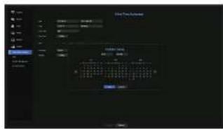
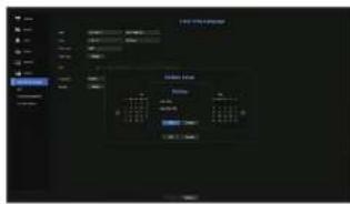
Example) After selecting Aug. 1, if you check
To use the calendar
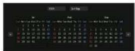
- Select year and month. Select the < ☐ > key on both ends of year and month to move back/forward to the previous/next year or previous/next three month.
- Select a date and click on the
button.
User
You can set permissions of each user over the Recorder's specific function and settings.
Setting the Administrator
You can set and change Administrator's ID and password. The administrator can use and set all menu items and functions.
Menu > System > User > Administrator
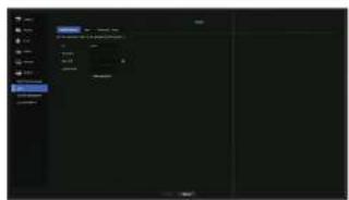
• ID : Change the admin ID.
- Password: Checks the current password.
- New PAV: Enter new password.
- Confirm PAV : Confirms the new password.
- If
The Initial administrator ID is set to "admin" and you will need to configure the password in the installation wizard.
- Please change your password every three months to satisfy protect personal information and to prevent the damage of the Information theft. Please, take note that it's a user's responsibility for the security and any other problems caused by mismanaging a password.
- If you click < >, a basic guide for password setup is displayed.
See "Using virtual keyboards" in the Appendix.
User setting
You can create a group or set permissions for each group. You can add a user and edit the registered user information.
Menu > System > User > User
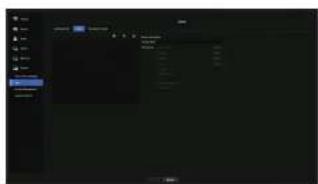
If you want to add a group
- Click on the [ ] button to launch the Group Addition popup window. If you want to add a group, click on
. - Press the group name item to launch the virtual keyboard used to enter group names. Enter the group name to register. =You can add a maximum of 10 groups.
If you want to set group permission
Set permission to access each group. Each group's users can only access items with a check mark beside them.
- Select the menu to set group permissions.
The menu with access permissions will appear when a user of the group logs in.
• Live View: You can set permissions to access the live screen for each channel. - Search: You can set permissions to access the search menu for each channel.
- Backup: You can set permissions to access the backup menu for each channel.
- Menu: You can select and set the setting menu that can be accessed. A group user can only access the menu selected. If you select the menu, the menu permission setting screen will be displayed.
-
Record, Record Stop, PTZ, Remote Alarm Out, Shutdown: You can select these functions to add to a group's permissions.
-
Click
. Check a group user to give them the permission to access the selected item.
menu setuo
If you want to register a user
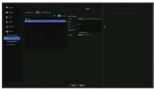
- Click on the [button] button to launch the user addition popup window. To add a user, click on
. - Select a group. When registering a user, the selected group will be automatically registered. ■ A group can be changed after inputting all required information.
- Enter a name, ID and password (confirm password) and enable or disable the viewer option.
If you activate use of
, you will have the right to use the web viewer and the network viewer. ■ If is selected, the password is no longer hidden on the screen when you type it. - Click
. Registered user information will be saved.
When you want to delete the group and user information
- Select the group or user to delete and press the [ ] button.
- The deletion confirmation window will appear and click on
.
Setting Permissions
You can set restricted access for all general users. Items with restrictions will require logging in for use.
Menu > System > User > Permission Setup
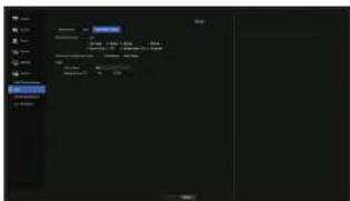
- Restricted Access: All menu items allowed for a user can be set with restricted access,
- Checked ☐: Restricted
- Not checked ☐: Accessible
- If it is not checked (■) in
, any user can access the item no matter what the - If it is checked (■) in
, a user can access the item only if the user has permission in .
- Restriction on Network Access : Restricts remote access from a
- All Network : Restricts all access instances via Network Viewer and Web Viewer.
-
Web Viewer : Restricts access via the Web Viewer
-
Auto Log out: A user will be automatically logged out if there is no operation on Recorder for over set period of time.
- Manual Input of ID: In the login window, select whether to enter ID.
If the user has restricted access
If a new group is restricted to access the entire menus, the users belonging to the group can access only the basic menus and can change only their respective password.
If all permissions are restricted, you will see only some menu items accessible in the Live screen menu.

To change the user password
If you log in with the user account of a group with restricted access, you just can change your own password.
Menu > System > User > User
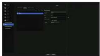
- Provide the login information.
- Select
from window. - Select
. - Provide a new password.
- Select
. The old password will be changed to a new one.
System Management
You can check the system version, update to a newer version, as well as data backup and initialization.
Checking the System Information
You can check the current software version and MAC address before proceeding with the upgrade.
Menu > System > System Management > System Information
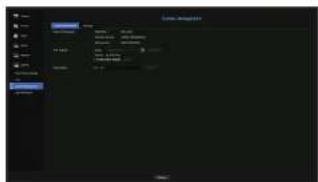
- System Information; Shows the current system's information.
- Model Name : Shows the model name of the product.
- Software version: The software version of the product currently being used is displayed. You can check the software version and upgrade to the latest version.
MAC address 1 : Shows the Mac address of the product. - SAW Upgrade: Updates the Recorder's software up to date.
- Press the <→> buttons to search for the software in the USB or on the network.
- Device Name: You can enter a device name for your product. To differentiate multiple storage devices in VMS, Device Manager, etc., it is recommended to enter a different device name for each device.
menu setuo
To upgrade the current software versio
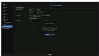
- Connect a device storing the software to be updated.
- All may take about 10 seconds to recognize the device.
■ Upgradeable devices include USB memory and network device.
If you want to upgrade it on the network, the product should be connected to an external network. Upgrade via the proxy server may not be enabled due to the restricted access
-
Select
from window. -
Select
. -
When the recognized device appears, select
.
- If you connect a device in the upgrade menu window, you can press the < > button to search for available software.
- If there is an upgrade image on the network, the popup window will appear.
- The
- Press
in the System Information window.
=While updating, it shows the progress.
- When the updating is done, it automatically restarts.
Do not turn the power off until it finishes restarting.
- If "Upgrade Failed" appears, retry from the step 4. When you experience continued failure, consult the service center for assistance.
Settings
You can copy and import the Recorder settings by using a storage media.
Menu > System > System Management > Settings
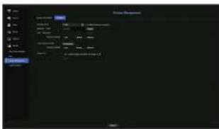
• Storage Device : Shows the connected storage device.
Press the <→> button to view the list of storage devices.
- Recorder = USB : Exports Recorder settings to the connected storage device.
- USB → Recorder : Imports Recorder settings from the storage device and applies to the Recorder.
- If you select the exclusion setting, you can import all information but the selected information.
The
- Load Factory Default: Resets the product to its factory default settings. However, logs won't be reset. Anything selected under Exclusion Setting won't be part of the factory reset.
A confirmation pop-up will appear when you press the
- Power off: If the power is off, the first alarm is generated. After checking the checkbox, if the
Only provided for products that support alarm output.
- If that function is set, the first alarm-out checkbox and all alarms in the alarm setup screen are deactivated, to Off
If you export setup information, then the data will be saved as a file in the recorder folder of your storage device.
- If you want to import setup information, you have to first make sure that the setup information file is located in the recorder folder of the storage device.
Log Information
You can browse logs on the system and events.
Checking the system log
System Log shows log and timestamp on every system start up, system shutdown, and changes on system settings.
Menu > System > Log Information > System Log
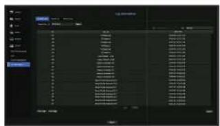
- Search Day: Click the Calendar icon to display the calendar window, or use the direction buttons to specify the search period of the system log.
- See the "To use the calendar" page under "Menu Setup > System Setup" in the Table of Contents.
- Search: Specify the date and press this button to display the search result in the log list.
- Type: When there are too many logs, you can display logs of the desired format by selecting the type.
- Export: Save all the logged information recorded in the Recorder into the storage media.
Checking the event log
You can search recorded events including alarms, camera events and video loss. It also shows the log and its timestamp.
Menu > System > Log Information > Event Log
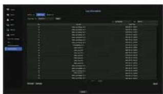
- Search Day : Click the Calendar icon to display the calendar window, or use the direction buttons to specify the search period of the system log.
- See the 'To use the calendar' page under 'Menu Setup > System Setup' in the Table of Corrents.
- Search: Specify the date and press this button to display the search result in the log list.
- Type: When there are too many logs, you can display logs of the desired format by selecting the type.
- Export: Save all the logged information recorded in the Recorder into the storage media.
menu setuo
Checking the backup log
You can find out who backed up and the details (backup time, channel, device to use, file format, etc.).
Menu > System > Log Information > Backup Log
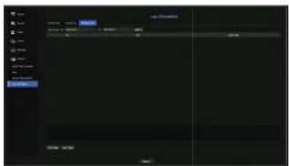
- Search Day: Click the Calendar icon to display the calendar window, or use the direction buttons to specify the search period of the system log.
- See the "To use the calendar" page under "Menu Setup > System Setup" in the Table of Contents.
- Search : Specify the data and press this button to display the search result in the log list.
SETTING THE CAMERA
Sets the contents related to the camera, channel, profile, and camera password.
Setting the Channel
You can register a network camera for each channel and make connection between.
Menu > Camera > Channel Setup
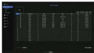
- >: View the video of the channel as a current image. - Camera searched with ONVF does not provide previews.
- Camera Name: Provide a camera Name. You can enter up to 15 letters including spaces.
• Model: Show the camera model name.
- Protocol: Show the protocol information of a registered network camera.
• IP/Port : Shows the IP or port location of the network camera.
- Video
-
-
- If the channel is set to
- Audio
- If set to
, you can turn the audio of the channel ON/OFF on the Live screen. - If set to
, the channel's audio is off on the Live screen and not recorded.
• Status : Display the connection status. - ONVIF: Additional setting is available for an ONVIF protocol camera.
- Upgrade: You can check the camera's version, upgrade version, and status and upgrade it.
- Error code guides: Check the details of error codes generated.
If you cannot register a camera after initializing the system, check the network setting. As the system is initialized and the network setting is reset, the camera's network bandwidth will be different from the product's network bandwidth, so it will be impossible to register a camera.
Setting the Analog Camera
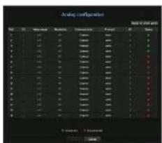
- In the
field, click on the button. - Search for an analog camera connected.
- Select the desired item and change the setting.
- Apply to other ports: If you select
, the "Apply to other ports" confirmation window will appear. After selecting ports that the settings will be applied to, click on to apply them to the selected ports.
• Video signal : Displays video signals inputted from AHD, TVI, CVI, and CVBS.
• Resolution : Displays the resolution input to the camera.
- Communication: You can set the camera port control method as Coaxial cable and Serial.
- Protocol: When the communication method selected is Serial, you can select Samsung-T, Pelco-D, or Pelco-P.
- When the communication method selected is Serial, you can enter the device ID.
- Status: Shows the camera connection status.( Connected, connected)
Registering a Network Camera
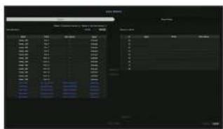
- In the
field, click on the button. - Select a camera to register in the
list and press the button.
You can check the selected camera in the
An already registered camera will be marsed in blue in the list.
If you search for the camera again or if the IP is an old IP that was not assigned by the DHCP server (such as -192.168.1.100), then press the
Click a header at the top of the list to sort the list according to that header.
In the
- To change the IP address of the camera, select the desired camera from the
list and press the button. - Press the
button on the lower right of the screen to register the selected camera.
If you register a camera using a user account—not admin account—the camera features may be limited.
When you change the camera ID/password in the camera was viewer, if the camera is already registered in Recorder, you also have to change the camera ID/password information registered in Recorder.
The maximum reception bandwidth of the network camera varies depending on the number of registered analog cameras.
-1FX-1621/1620 (0-5: 51mbps, 6-11: 37mbps, 12-16: 24mbps)
- HFX-821/820 (0-4: 26mbps, 5-8: 20mbps)
-HRX-421/420 (0-2:17mbps, 3, 4:13mbps)
menu setup
Registering a Network Camera Manually
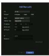
-
In the
field, click on the button. -
The Add Manually pane will be displayed.
If you double-click a channel not registered on the live screen, the Add Camera. Manually popup will appear that allows you to manually register the camera.
- Select a channel and protocol used to connect to a camera.
The input items may differ depending on the selected protocol.
- Wisenet: Wisenet camera's protocol can be used.
- ONVIF: Means the camera supports ONVIF protocols. When connecting a camera that its name cannot be found from the list, select

- When a camera is registered with ONVIF, if the difference in system time between the camera and storage device is 2 minutes or more, you won't be able to register it. In this case, synchronizes the camera and storage device time.
- RTSP: Comply with RFC 2326, one of "Real Time Streaming Protocol (RTSP)" for real-time streaming.
- If you select the
protocol, check options as necessary.
• Model : Select a camera model.
- Wisenet Camera: You can register Hanwha Techwin's cameras and encoders.
- Wisenet Multi-Channel: You can register Hanwha Techwin's multi-directional cameras and multi-imager
cameras. A multi-channel camera is a camera that has multiple camera modules in one body.
Auto-registering your camera to Recorder lets you register multiple channels at once. However, if you want to manually register it, you need to register one channel at a time.
- Address type: Select an address type of the camera.
- The supported address type may differ depending on the type of the connected product.
- Static(IPv4)/Static(IPv6) : Used to provide the IP address of the camera manually.
- Wisenet DDNS: This is available only if the camera is registered with the Wisenet DDNS(clns.hanwha.security.com) server. Provide the registered domain for DDNS ID.
Example) http://ddns.hanwhs-security.com/snb5000 = provide "snb5000" for Wisenet DDNS - URL : Used for URL address input.

- The DDNS specs supported by each camera can be checked in the user manual of the corresponding camera.
• IP Address : Provide the IP address of the camera.
• Device Port : Provide the device port of the camera.
- Depending on the camera type, some device ports will not be supported.
- HTTP Port : Provide the HTTP port of the camera.
• ID : Provide the ID of the camera that you want to register.
- Password : Enter the password of the camera to be registered.
- Select
or for the protocol and enter your input for each field appears.
ONVIF : After selecting an IP type, set IP address, ONVIF port, ID, password, and details.
- ONMIF Port : Enter the port number when the address type is IPv4 or IPv6.
- ID : Enter the camera ID.
- Password : Enter the camera password.
- More Detail: You can set the permission and streaming modes.
• RTSP: Set URL, ID, password, and details.
- URL : Enter your RTSP access address. For more information, see your camera user manual.
- ID : Enter the camera ID.
- Password : Enter the camera password.
- More Detail: You can set the streaming mode.

- If OMVIF or RTSP protocol is selected, you can set the streaming mode in the Details section.
- TCP: The connection to network camera operates in the RTP over TCP mode.
- UDP: The connection to network camera operates in the RTP over UDP mode.
- HTTP: The connection to network camera operates in the RTP over TCP (HTTP) made.
- HTTPS: The connection to network camera operates in the RTP over TCP (HTTPS) mode.
If you want to check the error details of camera registration
If you failed to register a camera, the reason for the failure will be displayed.
- Connection failed due to unknown error. : This message appears if the camera has failed to be registered due to unknown connection status.
- Due to the camera account locking, access has failed. : When you enter a wrong ID/password 5 times to login to the camera account, this message is displayed. Try to log in again after 30 seconds. If the same message appears, you may need to check whether someone has tried to access your camera account from the outside.
- Connected successfully. : This message appears if the camera is connected successfully.
- Incorrect model information. Provide the correct model information.: This message appears if the model information provided for registering the camera is incorrect.
- Authentication has failed: This message appears if the ID or password provided for registering the camera is incorrect.
- Connection has failed due to excessive concurrent users. : This message appears if the concurrent user count exceeds the upper limit.
- Connection has failed due to incorrect HTTP port information. : This message appears if the HTTP port number of the camera is invalid.
- Connection has failed. Unknown connection status. : This message appears if the camera has failed to be connected due to a unknown error.
- User Model Modification: When registering a new camera, it is named according to the device's default if user set the model to
. In case if automatic registration fails, user can change the model name of camera to be registered.
To edit camera profile
To change profile, see the "Setting up camera record profile" or "Live setup" page under "Menu Setup > Setting the Device" in the Table of Contents.
In case of Recorder, if you set 3 different profiles for live, recording and network profile, one camera will produce video streams accordingly, having different stream formats. Especially, note that the live profile may vary depending on the used screen split mode.
- For cameras, if applied with one profile only, the produced frame rate is fixed as the profile specellas; if applied with multiple profiles, produced video stream's frame rate is not guaranteed. For example, if applied with 2 profiles of 30fps, the camera may transmit streams at 20fps.
Network Camera Firmware Upgrade
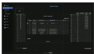
• Model : Displays the camera model information.
- Current version: Displays the current camera firmware version.
- Upgrade version : Displays the firmware version to upgrade.
Press the < 🔒 > button to select the firmware manually within the USB.
< 📄 indicates an upgrade via a remote server.
- Status : Displays the status of the ongoing upgrade (upgrading, successful, failed).
1. Press the
2. Displays the upgradeable channel list among the connected cameras.
- If newer firmware exists on the remote server, the upgrade version is displayed, and the check box is automatically selected.
If you do not see the upgrade version, you can press the < > button to get the upgrade version information from the server.
- Connect a USB camera with camera firmware to the device and press the < 🔒> button to check and select the firmware file in the USB.
- elect a channel and press the
- Check the box of the channel you want to upgrade.
- Click the
button. The camera firmware upgrade starts.
■You can move to another menu while upgrading.
- You can stop the upgrade by clicking the
When the upgrade is complete, < > will be displayed on the upper left of the live. You can click the icon to check the result.
■ Firmware upgrade is available only for channels connected with the W'senat protocol and the camera's administrator account.
- If the upgrade version is not displayed even though the camera's firmware is out of data, check the network settings.
- If there are more than 50 firmware files in the top USB folder, the file may not be scanned.
- The system may reboot if USB is disconnected from the device during an upgrade via USB.
■ Video data of the channel connected to the camera to upgrade may not be recorded.
- Do not format the HDD until the upgrade is complete. The upgrade may fall.
menu setuo
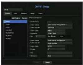
ONVIF Setup
In the bottom of the camera addition screen, click on the
- You can change the information only if the user account (camera account used for camera registration) is used to read the user information and a connection is made with the admin privilege.
Channel
You can set the list of channels for a camera registered using the ONIF protocol.
Profile
- Add Profile: You can add camera profile.
After adding a profile, click on thebutton to add it to the list. - Delete: After selecting the profile to delete, click on the
button to delete the selected profile.
• Profile information: You can set the details of the selected profile.
After finishing setting each item, click on thebutton to save changes.
User
- Add User: You can add a camera user.
After adding a user, click on thebutton to add them to the list. - Delete : After selecting the user to delete, click on the
button to delete the selected user. - User Information: You can set the details of the selected user.
Network
You can set the details of the network.
- IP Type : Select from either the IPv4/IPv6 IP types.
• DHCP : Select whether to use the DHCP. - DNS / NTP Server : Only if the DHCP setting is
, the DHCP checkbox will be activated. - If the DHCP is checked, you can manually enter the IP address.
Relay
You can set details of the relay.
• Digital Output : You can select a digital output channel.
- Relay Mode: Select either bi or mono stable modes.
- Relay Idle State: Select either open or closed relay standby modes.
- Delay time(sec) : Select the relay operation waiting time.
Event
You can set details of the event.
• Available events (camera): It shows the list of all the events supported by a camera by using the CNMF protocol.
- Events supported by the recorder: You can map the list of events supported by a camera to events that the Recorder can detect. There is no default value. It only shows the value sent by a camera.
Setting the Camera Functions
You can set the camera while viewing the live video of the selected camera.
Menu > Camera > Camera Setup
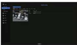
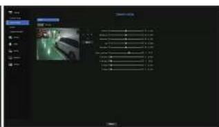

*You can use this feature in the following cases:
1. A camera connected to Wisenet protocols.
2. A camera connected with admin privileges.
- For more details on camera settings, refer to the camera user manual. Settings and operational spec vary depending on each camera.
- This function is not supported in some models.
SSDR
If there is a significant difference between the dark and the bright areas, increase the brightness of the dark areas to maintain the level of brightness of the entire area.
Mode, level, D-Range can be set.
Backlight
You can view both bright and dark areas.
Mode, WDR level, WDR black/white levels can be set.
Exposure
You can adjust the exposure of your camera.
You can set brightness, shutter, SSNR, Sens-up, Iris/lens, and AGC.
Day/Night
You can change the mode to adjust the color and contrast.
You can set Mode, Dwell time, Negative color, Duration, Alarm input, Switching brightness, Simple Focus After D/N, and Activation time (color).
Special
DIS (shaking compensation), use of Dafog levels can be set.
Focus
You can adjust the focus of you camera's video.
You can set focus, zoom in, simple focus, and focus reset.
Flip
You can set flip/mirror modes and hallway view.
Screen
You can set the screen adjustments (Contrast, Brightness, Saturation, Hue, Sharpness), Noise Reduction, Horizontal Position, Vertical Position, Horizontal Scale, and Vertical Scale.
Privacy
You can set an area to be hidden in the camera image range to protect privacy. You can select whether or not to use the privacy setting and set up to six now privacy areas.

- With a PTZ camera, it is not possible to configure settings, and when it is permitted, the setting area may be incorrect.
Setting the Profiles
Setting the Recording Profile
You can configure the video profile settings for instructing the network camera (connected to each channel) to make recording.
Menu > Camera > Profile > Record
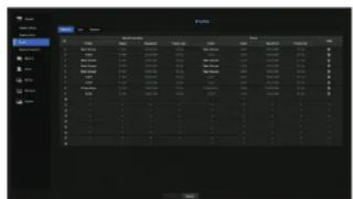

- You can configure the settings only for the profiles that are supported by the camera.
- If the profiles used for recording and network are different, camera's video lead may not comply with the frame rate as specified in the camera.
-
In case of analog cameras, you can set normal recording and event recording profiles separately.
-
CH : Click < ▼ > to display the channel information table.
• Profile : You can select the recording profile for selected channel. -
Codec : You can check the codec for selected channel.
- Resolution: You can select the resolution for selected channel.
- Frame Rate: You can set the frame rate for selected recording profile.
- Edit: You can change, modify, and delete camera profiles.
Setting the Live Profile
You can change the live transfer settings of the network camera.
Menu > Camera > Profile > Live

- CH : Click < 0 > to display the channel information table.
• Live Replacement : You can select the live profile setup mode.
If you select
- Auto: For the profile for live monitoring, a profile optimized for each split mode is displayed, along with the
'Live4NVR' profile automatically generated at the time of the camera registration.
Live4MVR profile default: H.264 800 x 600, 800 x 448 30 fps
- Manual: Live monitoring is performed with the profile selected by the user from the registered camera profiles.
- Recording : Live monitoring is performed with the profile set for recording.
• Profile : You can set the camera profile.
- Codec : Show the codec of the selected profile.
• Resolution : Show the resolution of the selected profile.
• Frame Rate : Show the frame rate of the selected profile.
- Edit: You can change, modify, and delete camera profiles.
menu setuo
Setting the Remote Profile
You can set the video profile transmitted to the network.
Menu > Camera > Profile > Remote
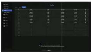
- CH : Click < ▶ > to display the channel information table.
• Profile : Select a network profile for the connected camera. - Codec : Show the codec information for the selected network profile.
- Resolution: Display the resolution for the selected network profile.
• Frame Rate : Shows the selected network profile's frame rates. - Edit: You can change, modify, and delete camera profiles.
- If the profiles used for network and recording are different, camera's video feed may not comply with the frame rate as specified in the camera.
Editing the Profiles
You can change the video settings of a registered network camera for each channel.
Menu > Camera > Profile
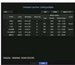
- Channel Selection: You can select camera channels to change their video transmission settings.
- Add: You can add camera profile. Click on the Add button to launch the addition window. Enter the information and click on the
button to add it to the list.
- Delete: You can delete the selected profile from the list.
Apply to CH: If you select
After selecting channels that the settings will be applied to, click on
- Profile: You can check the video profile of the camera connected in the camera setup.
- Codec: You can check the codec for the selected channel.
- Resolution: You can change the resolution of the selected channel.
• Frame rate : You can change the frame rate of the selected channel. - Bitrate control: You can change the bitrate of the selected channel.
- If you change specific profile settings for each product, the frame rate's setup range may be changed. Example) If you set the frame rate for the first profile to 30 fps, then the setting range for the second profile may be changed to 15 fps.
- Any settings other than codec, resolution, and frame rates can be changed in the setup menu of the camera web viewer. For camera web viewer, see the "Camera Setup" page under "Setup Viewer > Device" in the Table of Contents. Click
button for connection. - If you change the current profile settings, you may encounter an interrupted playback on the recording or live screen for a certain time.
- Changes made in your camera's setup page will be applied immediately. But any changes made through the camera's online website, it may take up to 5 minutes to apply the changes.
Dewarping Setup
Press the
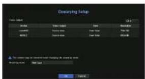
- Profile/View Type: From the profile list in the dewarping setup popup, you can select a view type.
- You cannot change SourceMUPEG, SourceH264, DevarpMUPEG, or DevarpH264 settings.
- Mounting mode: You can change the fisheye installation type. You can select a view mode from among ceiling/ground/wall depending on the installation location.
- You can select view modes supported by your camera.
- View: You can change the fisheye view mode of the current screen according to each split section.
If there is no camera registered in the Recorder that supports fisheye view, Dewatering Setup will not be available.
How to set WiseStream
Function to analyze the complexity of the video and effectively reduce the data size while maintaining the quality. For details, refer to the camera's help or the product's user guid.
Press the
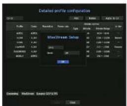
- Channel: You can select the channel to set WiseStream.
Mode: You can choose the degree of video compression. You can choose either OFF, Low, Medium, or High.
- WscStream setup cannot be executed if there is no camera registered in Recorder that supports WscStream.
Dynamic GOV/FPS setup
Dynamic GOV can be used to automatically change the length of GOV depending on the video condition. For more information, see help for your camera or the product user manual.
At the bottom of the
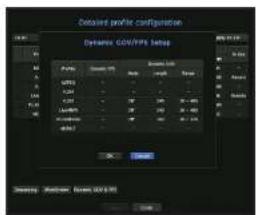
• Profile : Shows the video profile of the connected camera setting.
- Dynamic FPS: Automatically adjusts the frame rate (frames per second) based on the video conditions.
• Dynamic GOV
- Mode: Set the GOV length to change automatically.
- Length : Enter the maximum GOV length value to be applied when there is no motion in the video. Minimum GOV value can be set on the camera web page.
- Range : The range of the input value of
- Any profile not supported with the dynamic GOWEPS setting is marked with *.*
menu setuo
Setting Camera Password
You can change the passwords of all registered cameras at once. You can register the camera's ID and password.
Menu > Camera > Camera Password
- Password: Input a new password according to the password setting rules.
- Confirm Password: Input the new password again.
• ID : Enter the ID of the camera whose ID and password are set.
- Password : Enter the password of the camera whose ID and password are set.

- If you click < , a basic guide for password setup is displayed.
- If you select
, the current password is displayed as the actual input characters. - A camera, password registered with ONVIF and RTSP cannot be changed.
SETTING THE DEVICE
Sets the content for storage device, remote device, monitor, text, and serials.
Storage Device
You can check information on storage devices.
Device/Format
You can check storage devices and their capacity, usage as well as status. HDD and USB (memory or HDD) can be connected as a storage device.
Menu > Device > Storage Device > Device/Format
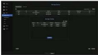
- Storage Status: Displays the working status of a storage device.
- Red: Displays the situation of video loss.
- Green: Displays the normal situation without video recording losses.
- Status
■ Total bps : Displays the current rate of recording.
■ Present Loss: Displays the current recording loss rate.
- Worst Loss: Displays the maximum amount of losses up until now.
■If loss is continuously generated, check the following.
For more information, see "Troubleshooting (FAQ)" in the Appendix.
- When data is lost due to system failure (reset the rate of data transferred from the camera)
- When there is a problem in HDD recording performance due to an HDD malfunction (check the HDD error or replace the HDD)
• No.: You can check the designated number for the built-in HDD.
- If you want the find out about the location corresponding to the HDD number, refer to the
• Model : Displays the model name of the built-in HDD.
- Capacity: Displays the amount of storage device use and the full capacity.
• Usage : Designate the purpose of use for a storage device.
- If the state of use is in "Not Defined", format the HDD before use.
- Status : Displays the current working condition of a storage device. To create an HDD alarm for inspection or replacement, see the "HDD Alarm Setting" page under "Menu Setup > Setting the Device" in the Table of Contents.
- Temperature: You can check the temperature of the HDD mounted in the Recorder.
Time : Displays the use time of an HDD. - Format: Select a device and click on format after which a format confirmation window appears. Click on the
button to format the selected storage device.
- Formatting will delete all the recording data that has been saved. Be careful.
While formatting is ongoing, you cannot record video.
■Do not remove a formatting device until it is finished.
After installing an HDD, if the state of use of the HDD is "Not Defined", format the HDD before use (if the warning message persists after formatting, replace the HDD with a new one)
- ARB: Video that was not recorded due to a camera disconnection can be backed up after the connection with the camera is re-established. Press the button and an
- ARB Storage Device : Select a storage device to be set to ARB.
- Capacity : Shows the capacity of the storage device to be set as ARB.
- ARB Channel Selection : Select a channel to run the ARB.
■You can select multiple channels.
If you select
- ARB bandwidth : Select a bandwidth for the ARB function.
The ARB feature is available only when your video is saved in the SD card after registering your Wisenet camera using the Wisanot protocol. This is only supported in SUNAPI 2.3.2 or later.
- Set the profile bitrate used for recording a video in the SD card of camera to 6144 kbps or below. For more information on how to set the SD card recording profile, see your camera manual.
To use the ARB function correctly, both the camera and Recorder should be time synchronized with the time server. See the "Menu Setup > System Setup" page in the Table of Contents.
- AFB function is activated when Recorder starts/when the channel camera set is reconnected/when an Recorder recording missing section recurs at regular intervals after Recorder starts.
- Recorder recording missing section that can be restored with the ARB function is for 24 hours backwards from the point when the ARB function is activated.
- You can check which channels have ARE function activated through the message on each channel screen that is displayed when selecting a channel. See the "Channel info" page under "Live > Status" in the Table of Contents.
- For automatically recovered files through ARB, see the "ARB Search" page under "Search & Play > Search" in the Table of Contents.
■ APB storage capacity is recommended to be at least one day.
Example) If you saved 64 channels with 1 Mbps each, the ARB capacity should be set to 0.7 TB or higher.
- HDD Map: You can check the location according to the assigned number for the HDDs installed inside.
■ Refer to this when servicing or installing an additional HCD.
Do not add or remove an HOD while Recorder is running.
HDD Alarm Setting
For HDD malfunctions, you can sat the inspection alarm output terminal, the replacement alarm output terminal and the alarm time.
Menu > Device > Storage Device > HDD Alarm
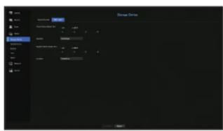
- Alarm
- If
- If
- If you select an alarm output terminal number, a signal is displayed on the alarm output terminal at the back. Each product has a different number of alarm output terminals.
- Check Alarm Output Port: If HDD generates check alarm, the alarm signal will output to the specified alarm output port.
- Replace Alarm Output Port : If HDD generates replace alarm, the alarm signal will output to the specified alarm output port.
• Duration : Sets the alarm duration for the alarm signal and beep sound.
-
menu setuo
Remote Devices
This function is only available for products that support the use of a remote controller. For products that support remote controls, see page 4 "NVR products supporting each feature" of the Product Specification Manual. You can adjust the ID for a remote control to be used in connection with Recorder.
Menu > Device > Remote Device
- Remote control: Select whether to use a remote control.
• ID: Select an ID number linked to a camera.
If the remote control ID does not match, it will not operate properly.
To change the remote controller ID, see "Using a remote controller > Changing the Remote Control ID" In the Appendix.
Monitor
You can set the information displayed on the monitor as well as the output system.
Menu > Device > Monitor
Monitor settings
You can set the monitor output related screen displays, switching time, video display, etc.
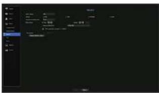
- Event Display: Sets the dwell time of the event channel display on the monitor when an event occurs. If you set
, it will keep displaying until you cancel it.
• Display: Displays only checked items on the monitor screen. - Sequence switching time: Set the automatic switching time for the segmented screen in live mode.
• Video Output: Set the video display resolution.
For products that support an extended monitor, select eitheror mode to set the resolution of and .
- Clone mode: You can set the video display resolutions of the primary monitor (HDMI) and the secondary monitor (VCA) to the same value. In the Clone mode, if the resolution exceeds 1920 x 1080, the secondary monitor will not display any video.
- Extended mode: You can set the video display resolutions of the primary monitor (HDMI) and the secondary monitor (VGA) separately. In case of expanded mode, the main monitor (HDMI) video output is limited to 1920 x 1080.
- Spot output: Sets the content for analog video output.
- Layout mode : Select the analog video output layout and sequence switching time in auto sequence mode. - Ch. Table : Select the desired channel for analog video output.
If your product supports a remote controller, press |STOP(■)| → |ZOOM| → |STOP(■)| → |ZOOM| → |MENU| on the remote controller to pop up a default resolution window and change to your desired resolution.
- If the newly selected resolution does not fit with the monitor, the display won't function properly. In this case, wall until the native resolution is restored and then switch to another resolution of your choice.
- For products that support extended monitor, see page 4 "Products supporting each feature" of the Product Specification Manual
Expansion monitor settings
This function is only available for products that support the use of an extended monitor. For products that support extended monitor, see page 4 "Products supporting each feature" of the Product Specification Manual.
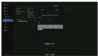
- Select the Expand mode, then
button to change the layout of the expansion monitor is enabled. - Select split mode in the layout mode.
- Select as many channels on the channel table as the number of channels selected in layout mode, and you can view the applicable screens on the monitor.

- When extended mode is selected, the maximum resolution of the image output on the primary monitor (HDMI) is limited to 1920 x 1080.
- If the new resolution does not fit the monitor, the output will not be displayed normally. In this case, wait until the monitor returns to the default resolution and then change to a different resolution.
- Sat up Event Display and Sequence Switching Time in consideration of the network environment time.
- The profile used in the live output of the expanded monitor uses a remote profile. If the user changes the remote profile, the video output of the expanded monitor may be affected.
- If the monitor is in clone mode, you can specify up to the split mode supported by the recorder. When the monitor is set to expanded mode, you can assign up to 16-split of the secondary monitor.
Display position settings
Some monitors many not display information (camera name, icon, time information, etc.) about the Recording, depending on the condition. Then, you can change the display position of the data.

-
From the monitor setup menu, select
. -
Using < ■ > button to adjust the screen that is cut off.
-
Press
.

This products only support 4K resolution at 30 Hz.
menu setuo
Text
Device and events can be set up.
Device Settings
Relevant values of a device connected to Recorder can be set.
Menu > Device > Text > Device
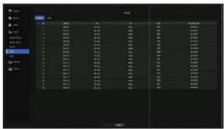
• Device : Enter the user's desired name
• Use: Select whether or not to use
- CH: Select a channel to add a device from a channel table.
- Port : Display a port number that is set
• Encoding type : Select an encoding type to use from a list.
■You can select starting and ending character strings.
- A text string can be entered by using texts, hex codes, and regular expressions.
- Text: Enter a text string to search for.
- Hex Code: Enter a hexadecimal text string to search for.
(Your Input should not be in hexadecimal—e.g. 1b40, 1b69)
Regular expression: Enter a regular expression to search for text strings that follow specific rules.
Eason, Winoor Nibiont, Axichom, Radiant System, IBM PCS device and ANFR protocols are supported.
- Equipment connected to Recorder uses TCP/IP communication protocol
Event Settings
You can set up event keywords.
Menu > Device > Text > Event
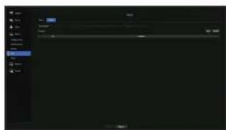
• Total amount : Set a total amount condition to receive alarms.
- Keyword: If the
Serial setup
You can set the serial port (RS-485/RS-422) of the recorder.
Configure the same settings as the analog PTZ camera or system keyboard to be linked.
Menu > Device > Serial
Some models support RS-485 only.
SETTING THE RECORDING
You can setup scheduled recording, event recording and other recording related settings.
Recording Schedule
Make your reservation on a date and time to schedule the recording on specified time.
Menu > Record > Recording Schedule

- All: The entire time range (Monday through Sunday including holidays, AM 0\~ PM 23) will be reserved with the same recording schedule
- Apply to CH: If you select
, the 'Apply to CH' confirmation pop-up window will appear. After selecting channels that the settings will be applied to, click on to apply them to the selected channels.
- Event recording and scheduled recording starts about 3 seconds prior to the event/schedule for guaranteed recording.
Record setting by the color
| Color Function Description | ||
| No Color No Recording No schedule / event recording | ||
| Green ( ■ ) | Continuous Scheduled recording only | |
| Orange ( ■ ) | Event Event recording only | |
| While ( □ ) | Both(Con&End); Both scheduled / event recordings | |
Each press of a selected cell will cycle through
Record Setup
You can set resolution, IPS, and quality of recordings by channel, and by recording type of standard / event. You can check frame rates and data transfer amount of Full Frame and Key Frame recordings for each channel, and set the transfer limit for recordings.
Menu > Record > Record Setup
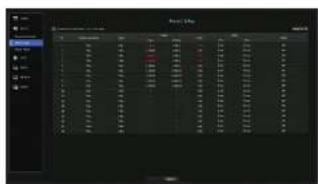
- CH: Click < .> to display the channel information table.
Apply to CH: If you select, the 'Apply to CH' confirmation window will appear. After selecting channels that the settings will be applied to, click on to apply them to the selected channels. - Standard, Event : Configures Standard recording and Event recording
- FULL : Records all frames fed by the camera.
- 1-frame : Records only key frames led by the camera.
Actual recording rate may differ from camera settings. In general, 1 to 2 frames per second are recorded. - OFF: No recording is made.
Frame
- FULL : Shows the amount of data for all the scene recordings.
-
I-frame : Shows the amount of data for the main scene recordings.
-
Limit: Set the amount of data allowed for input for each channel.
- Event: When an event occurs, you can set which point you will start or stop recording.
- Pre: When an event occurs, recording will be started regardless of the time set.
If you set it to five seconds, recording will start at five seconds before an event occurs.
Post: When an event occurs, recording will continue after the time set.
If you set it to five seconds, recording will continue for a further five seconds after an event is finished.
- Audio: Specify whether to record the sound received from the camera or not.
If a channel's data transfer exceeds defined allowed limit, then it may affect to other channels, and may force switching to
- A channel displayed in yellow indicates that the recorded data is not being transferred from the camera and that the recording is being performed temporarily using another profile on the camera.
Check the channel information to see the applied profile to the channel listed in yellow.
A channel displayed in orange indicates that the amount of inputted data is greater than the permitted data amount. In this case, it is impossible to record all of the incoming frames.
Instead, only part of the frames (1 or 2 frames per second) can be recorded. To resolve this issue, you must set the permitted data amount to be greater than the amount of inputted data.
See the note text on the "Record status" page under "Live > Status" in the Table of Contents.
menu setuo
Record Option
When the HDD capacity is full, you can set whether to stop recording or start overwriting.
Menu > Record > Record Option
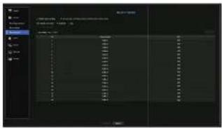
- Enable dual recording check if you want to record Sub Stream simultaneously.
• HDD Repeat Recording : Select a HDD repetitive recording type.
Overwrite: If the HDD is full, this will overwrite the existing data and keep recording.
- Stop: If the HDD is full, this will stop recording automatically.
- Disk End Beep: If you select
for the HDD Repeat Recording mode, this button will be active. Specify the use of beep when the HDD recording ends.
If you check it, the beep will sound on the disk full and the recording stops. - Auto Delete: If you check this option, the period list box is active. Specify the deletion period to delete any earlier data than the specified date. However, you can search for data from the current time to the selected date.
- If you select
for the HDD Repeat Recording, the button is enabled. -
You can select a channel and set a different recording duration for each channel.
-
Apply to CH: If you select
, a confirmation dialog window is opened.
Select a channel to apply the applicable settings then press. The settings will be applied to the selected channel.
If you presswhen you have completed your settings, all the existing data earlier than the specified period will be deleted automatically. So it is recommend to backup the previous data if necessary for later use.
SETTING THE EVENT
You can make the setup for record in case of sensor detection, camera event or video loss detection.
Sensor Detection
You can set the sensor's operating condition and connected camera, as well as alarm output and its duration.
Menu > Event > Sensor Detection
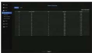
- Apply to other sensors: If you select
After selecting channels that the settings will be applied to, click on
- Sensor Operation: Sets the operation mode of sensors.
-
-
- Cam: Select a channel to be connected to the sensor.
If selected camera, "Cam Preset setup" window appears.
Select a channel and setup the preset.
■Present setup can be done in PTZ mode.
• Alarm out : Sets the alarm output method.
- For alarm output, see the "HDD Alarm Setting" In "Menu Setup > Setting the Device" in the Table of Contents.
• Duration : Sets the duration of alarm signal and alarm sound.
- If you select
- If the connected network camera that has configured the alarm in/out settings triggers an alarm, Recorder will perform the alarm out.
Camera Event
You can set the activation of events (motion detection, video analysis, audio event) sent from the camera, alarm output method and alarm time.
Menu > Event > Camera Event
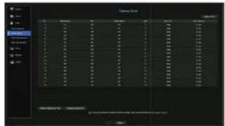
- Apply to CH: If you select
- CH : Click > to display the channel information table.
- Camera Event: Select whether to use an event detection.
- MD: You can specify whether to receive an event of camera's motion detection in the storage device.
To receive an event of camera's motion detection, you need to enable the camera motion detection.
• Smart Search : Enables or disables the Smart Search option.
- To use the smart search function, the smart search option must be set to
• Cam: Select an event detection channel
If you select a camera item, the 'Camera preset' screen will appear. Select a channel to connect and set the preset.
■You can set the preset in PTZ made.
- Alarm Out: Select the method for alarm output.
- For alarm output, see the "HOD Alarm Setting" in "Menu Setup > Setting the Device" in the Table of Contents.
- Alarm Duration: Set the duration of alarm.
- Motion detection & NA: You can set the detailed setting of motion detection for a camera connected. In the mode, you can set motion detection or video analysis.
- Tampering detection: You can configure detailed settings for tampering detection of the connected camera.
Motion detection setup
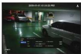
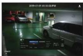
- Area: Click the Setup button to set a motion detection area.
- MD Type: You can set a detection area and a detection excluded area.
- Object Size : Click the Setup button to set the size of object whose motion is to be detected.
- Detection Result Overlay: You can overlay the detection area over video.
- Activation time: You can set the activation time for motion detection.
Aways: Detects motion regardless of time.
- Schedule : Detect motion only during the set period.
- Motion Region: You can set the detection sensitivity, detection levels, and alarm time for each motion detection area.
- Detection Level: You can set the basic level required for motion detection. You can set the level for each detection area specified in [Area]. If a motion value is bigger than the set level, then a motion detection event is triggered.
- Sensitivity: You can set sensitivity required for motion detection for each area. Set a lower sensitivity for an environment where the background and an object are clearly distinguishable and a higher sensitivity for an environment where the background and an object are not clearly distinguishable.
- Duration: You can set the minimum observation time for each area, which is needed to trigger an event after motion detection.
menu setuo
Analog camera setup
You can configure detailed settings for motion detection of analog cameras.
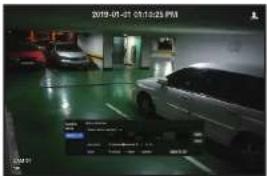
- Enable motion detection: Check the box to set motion detection.
- Motion detection area: Selects the area where you want to detect motion.
- Sensitivity: You can set the motion detection sensitivity. Make the sensitivity lower in the environment where the background and object are clearly distinguished and higher in the environment where the background and object are not clearly distinguished.
- Mode: Selects the mode for the motion detection area setup.
- Inverse The selected motion detection area setup is reversed.
Select: The selected area is selected as the motion detection area.
- Deselect: The selected motion detection area setting is canceled.
- Apply to CH: if you select
, the "Apply to CH" confirmation window will appear.
After selecting channels that the settings will be applied to, click onto apply them to the selected channels.
Video Analysis Setup
• Area: Click the Setup button to set a video analysis area.
- Vip: You can set a virtual line, virtual area, and detection excluded area.
- Object Size: Click the Setup button to set the size of object whose motion is to be detected.
- Sensitivity: You can set the motion detection sensitivity for the virtual line and the virtual area.
- Detection Result Overlay: You can overlay the detection area over video.
- Activation time: You can set the activation time to recognize motion analysis.
- Always: Detects motion analysis regardless of time.
- Schedule: Detects motion analysis only during the set period.
• Virtual Area: You can set the details of virtual areas to fit your purposes.
- Intrusion: Creates an event when the motion of an object in the designated area is detected.
- Enter: Creates an event when a moving object enters into the target area from the outside.
- Exit: Creates an event when a user goes out of the target area.
Appear/Disappear: When an object which does not exist inside the area designated by the user appears inside the area without passing the area line and remains for a certain period of time, or if an object which exists inside the area disappears, an event is created.
Loitering: Creates an event when the motion of a loitering object in the virtual area is detected.
Minimum Duration (sec): You can set the minimum time required to create an event after object detection for each virtual area. If an object keeps being detected over the set period, an event is created.
Detection-excluded area/Non-detection area setup
In the virtual line and area, you can set areas to exclude motion detection from.
Area Initialization: You can clear all the set areas.
■Add: You can create an event area within an area.
The Motion detection & MA setup is applied to the camera setting.
- Each camera product support different features. For more information, see the camera manual or help
Tampering detection
You can set up an event signal when camera tampering is detected, such as when the screen is obstructed or the camera location is changed.
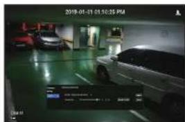
- Enable tampering detection: Check the box to set the tampering detection.
- Sensitivity: Sets the tampering detection sensitivity.
- Apply to CH: If you select

- Since tampering detection is designed for optimal performance based on the sensitivity level by the user, there may be no noticeable change in the tampering detection performance depending on the sensitivity level under normal monitoring conditions.
Video Loss Detection
You can set the camera so that the camera can trigger the alarm if it is disconnected or the video is lost due to unstable network connection.
Menu > Event > Video Loss Detection
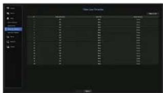
- Apply to CH: If you select
, the 'Apply to CH' confirmation window will appear. After selecting channels that the settings will be applied to, click on to apply them to the selected channels. - CH : Click > to display the channel information table.
- Video Loss State: Specify the use of video loss detection.
- Alarm Out: Select an alarm output method.
- For alarm output, see the "HDD Alarm Setting" in "Menu Setup > Setting the Device" in the Table of Contents.
- Alarm Duration: Specify the duration of the alarm output with the beep.
menu setuo
Alarm Out Schedule
You can set the conditions and operating hours for scheduled alarms.
Menu > Event > Alarm Out Schedule
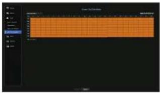
- Alarm Out: Sets the alarm output method.
For alarm output, see the "HDD Alarm Setting" in 'Menu Setup > Setting the Device' In the Table of Contents. : Marked in black, no alarm is generated even if an event occurs. : Marked in green, and always generates alarm on scheduled time. : Marked in orange, generates alarm only when an event occurs. - Apply to All Alarm out: Applies the configured schedule to all alarms.
- When the alarm is generated on the scheduled time, you can stop the alarm by canceling the schedule.
It provides networked monitoring of Live screen from a remote place, and supports mail forwarding function with events. You can configure the network environment which enables such functions.
Interface
You can set the network connection route and protocol.
Setting a network connection
Sets the protocol and environment of the network.
Menu > Network > Interface
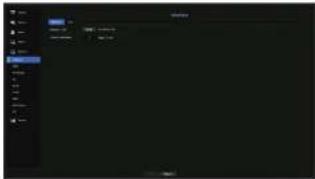
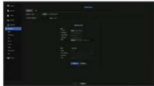
• Network 1 (AI): It can be used as a common port for camera and web viewer connection.
- IF Type : Select the type of network access.
- IP Address, Subnet Mask, Gateway. D8
- Static: IP address, subnet mask, gateway, and DNS can be directly entered.
- DHCP : IP address, subnet mask, gateway, and DNS can be automatically set
- FPPoE: P address, subnal mask, galaway, and DNS can be automatically set.
- User ID, Password: To set the IP Type to PPPoE, enter the "User ID" and "Password" registered to PPPoE.
• Transfer Bandwidth : Enter the max data rate for transfer.
The DNS values of
Connecting and Setting the Network
Networking may differ from the connection method, check your environment before setting the connection mode.
When no router is used
- Static mode
- Internet connection : Static IP, leased line, and LAN environments allows connection between the Recorder and remote user.
- Network Settings : Set the
- Consult your network manager for IP, Gateway and Subnet Mask.
- DHCP mode
- Internet connection : Connect the Recorder directly to a cable modem, DHCP ADSL modem or FTTH network.
- Network Settings : Set the
- PPPoE
- Internet connection: An PPPoE modem is directly connected to the Recorder, where the PPPoE connection requires user ID and password.
- Network Settings : Set the
- PPPoE
When a router is used
To avoid IP address conflict with the Recorder's static IP, check followings:
- Setting the Recorder with a static IP
- Internet connection: You can connect the Recorder to a router which is connected to an PPPoE/Cable modem or a router in a Local Area Network (LAN) environment.
- Setting the Recorder Network
-
Set the
in menu of the connected Recorder to . -
Check whether the set IP address is in the static IP range provided by the Broadband Router. IP Address, Gateway, and Subnet Mask : Consult your network manager.
If a DHCP server is configured with starting address (192.168.0.100) and end address (192.168.0.200), you should set the IP address out of the configured DHCP range (192.168.0.2 - 192.168.0.39 and 192.168.0.201 - 192.168.0.254).
- Check the Gateway address and subnet mask are equal to those set in the Broadband Router.
- Setting the DHCP IP Address of the Broadband Router
- To access the Broadband Router's configurations, open a web browser on the local PC that is connected to the Broadband Router and enter the router's address (ex: http://192.168.1.1).
- At this stage, make the local PC's windows network configurations to the below example: Example) IP: 192.168.1.2
Subnet Mask : 255.255.255.0 Gateway : 192.168.1.1
- Once connected to the Broadband Router, it prompts with password. While entering nothing to the User Name field, enter "admin" into the password field and press
to access the router configurations. - Access the router's DHCP configuration menu and set its DHCP server activation, and provide the start and end address. Set the start address (192.168.0.100) and end address (192.168.0.200).
- Above steps may differ from the router devices depending on the manufacturer.
Port Setting
Menu > Network > Interface > Port
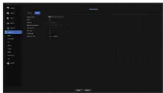
- Protocol Type : Select the protocol type among TCP, UDP - Unicast and UDP - Multicast.
- RTSP: It is used to transmit the video over the network. The initial value is <558>.
- UDP Port: Initially, <8000\~8159> is set. It increases / decreases by 160.
- UDP: It has less stability and faster speed when compared to TCP, and recommended for local area network (LAN) environments.
• Multicast IP Address : User can directly input.
- Multicast TTL: Select from 0 - 255. Initial value for the TTL is set to <5>.
- HTTP Port : Enter the port number for the Web Viewer. Initially, it is set to <80>.
- HTTPS Port : In this version, the security of HTTP (web communication protocol) is enhanced. The initial port is <443>.
- Cam Proxy Port : Sets the camera proxy port. The default is <10001>.
menu setuo
DDNS
If a remote user accesses the network, you can set whether or not to use DDNS and the site to be connected.
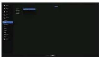
- DDNS Site : Specify the use of DDNS and select a site that you registered.
- Server Name : Enter the server name registered with the DDNS site.
• Product ID : Enter the CONS site user name.
- Host Name: Enter the hostname registered with the DDNS site.
- User Name: Enter the user name registered with the DDNS site.
- Password: Enter the user password registered with the DONS site.

- See "Using virtual keyboard" in the Appendix.
- If you select
, the input box will be inactive. - If you select
the host name input box will be inactive.
- Quick Connect: Appears if the
To use the function, set to

- It canceled during Quick Connect configuration. It automatically switches to
and saved. - If you are setting up a port that is already in use, then the connection might fail. Check the port setup of your router.
- Server name, product ID, and quick connect can be displayed if you set
to - DDNS is a short form of Dynamic Domain Naming System.
DNS (Domain Name System) is a service that routes a domain name consisting of user friendly characters (ex: www.google.
com) to an IP address consisting of numbers (64 233,189,104).
DDNS (Dynamic DNS) is a service that registers a domain name and the floating IP address with the DDNS server so that the domain name can be routed to the IP address even if the IP is changed in a dynamic IP system.
To check Quick Connect status
A progress bar and its message appears for a Quick Connect.
- Quick Connect Success : Message for a successful connection.
- Invalid Network Configuration : Message appears if the network configuration is not valid. Check the configuration.
- Please enable UPnP function of the router: Message appears if the router requires UPnP function enabled.
- Failed to find the router: Message appears if the router is not found. Check the router's configurations.
- Please restart the router: Message appears if the router should be restarted.
DDNS Setting
- Setting DDNS in the Recorder
In themenu of the connected Recorder, set .
The Protocol type can only be set to TCP.
• DDNS Settings of the Router
Select the corresponding menu for the network transfer protocol of the router. - Setting up UPnP of Router
Refer to the router's documentation to enable the UPnP function of the router.
IP Filtering
You can prepare the list of IP addresses to allow or block access to a specific IP address.
Menu > Network > IP Filtering
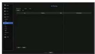
- Filtering Type :
- Deny: If you select reject, access to the registered IP address will be limited.
- Allow: If you choose permit, then they can only access the registered IP addresses.
- Use: Select the checkbox for the IP address that will use IP filtering.
- IP Address : Enter the IP address for filtering.
- Prefix: Enter the Prefix for filtering.
- Filtering Range: If you enter an IP address or prefix, then the range of IP addresses blocked or permitted will be displayed.
If a camera's IP address is not included in the Permit list or is in the Reject list access to it will be rejected.
- For IPv4, camera IP filtering through PoE port is not immediately applied. (Previous connections are maintained, and filtering is applied on next login.)
SSL
You can select a security connection system or install public certificates.
Menu > Network > SSL
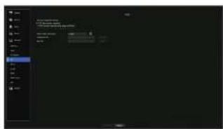
- Secured Connection System: You can select a type of security connection system.
- HTTP (Non-secured connection)
- HTTPS (Secured connection using unique certificate)
- HTTPS (Secured connection using public certificate)
- If the Recorder device is connected to the external internet or installed in an environment with high priority for security, making a secure connection is recommended.
- Install Public Certificate: You can scan and register public certificates to be installed.
If you want to use a certificate, you need to install a certificate file along with and an encryption file.
- The
menu setuo
802.1x
When connecting to a network, you can select whether to use the 802.1x protocol and install a corresponding certificate.
802.1x is a certificate system for the server and the client. It can guarantee robust performance against hacking into the Tx/Fx network data, virus or information leaks.
By using this system, you can block access from a client who is not certified and only allow communication to certified users and thus increase the level of security.
Menu > Network > 802.1x
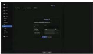
- EAPOL Version : Select the EAPOL version to be used as protocol.
- Some switch tube will not operate if you set them to version <2>. Select version <1>.
• ID : Enter the ID provided by the RADIUS server administrator.
- If the entered ID does not match the ID of the client's certificate, it won't be processed properly.
- Password: Enter the password provided by the RADIUS server administrator.
- If the password you entered does not match that of the client's private key, it won't be processed properly.
- Certificates: Search for a device. Click on 📋 to search for a device again.
- CA Certificate : Select this only if your public certificate includes the public key.
- Client Certificate : Select if the public certificate includes a client's authentication key.
- Client Private Key: Select it if the public certificate contains the client private key.
For successful implementation of the 802.1x operating environment, the administrator must use the RADIUS server. In addition, the switch hub connected to the server must be a device that supports 802.1x.
- If the time setting of the RADIUS server, the switch hub and an Recorder device do not match, communication between them can fail.
- If a password is assigned to the client's private key, the server administrator should confirm the ID and password. The ID and password allow up to 30 characters each. (But it only supports letters, numbers and special characters (*, *, *). 3 types only.
Accessing non password-protected files is allowed without entering a password. ■The BC2.1x protocol adopted by the Recorder is EAP-TLS.
- You need to install all three certificates to use 802.1x
You can send an e-mail to a Recorder-registered user at a specific time interval, or if an event occurs.
SMTP Setting
Sets the SMTP mail server.
Menu > Network > E-mail > SMTP
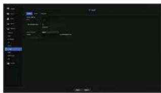
• Server Address: Enter the SMTP server address to connect to.
• Port : Sets the communication port.
- Use Authentication: Check this if the SMTP server uses user authentication. The account input box will be activated.
- ID : Enter a ID to use authentication when connecting to the SMTP server.
- Password : Enter the password of the SMTP server user.
- Secure Transfer : Select one from
- Sender: Use the virtual keyboard to enter the sender's e-mail address.
- See "Using virtual keyboard" in the Appendix.
• E-mail Test : Conducts the test on the server settings.
Event Setting
You can set the interval and type of the event that will be sent to the user.
Menu > Network > E-mail > Event
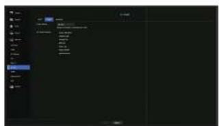
• Event Interval: Set the event interval.
- If a series of events occurs, the e-mail will be sent at the specified interval, not on each event
- Use Event Transfer; Select an event type to send if an event occurs.
If the selected event occurs, the e-mail will be sent to the group that has the recipient authority.
Recipient Setting
You can create a group and add users to it or, you can delete users and change a group.
Menu > Network > E-mail > Recipient
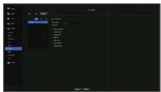
- Click on > to add a group.
Select a group name and the privilege.
- Select a recipient group to receive emails.
If a group is added, it will appear in the group list.
- Click on 25 > to add a recipient.
Select a group and enter names and email addresses.
If a group is created, you can add a recipient.
- For information on entering user name and email address, see "Using virtual keyboard" in the Appendix.
SNMP
Using the SNMP protocol, the system or network administrator can monitor the network devices remotely as well as the operating environment.
Menu > Network > SNMP
- Enable SNMP v1 : SNMP v1 is used.
- Enable SNMP v2c : SNMP v2c is used.
- Read Community : Enter the name of read-only community to access the SNMP information. By default it is set to
- Write Community : Enter the name of write-only community to access the SNMP information. By default, it is set to
. - Enable SNMP v3 : SNMP v3 is used.
- Password : Set the initial user password for SNMP version 3.
- Enable SNMP Traps: SNMP trap is used to send important events and conditions to the Admin System.
- Trap Manager : Enter the IP address to which messages will be sent.
SNMP v3 can be set only if the security connection method is set to HTTPS mode. See the "SSL" page under "Menu Setup > Network Configuration" in the Table of Contents.
menu setuo
DHCP Server
You can set the internal DHCP server and assign an IP address to the network camera.
Network Setting
Menu > Network > DHCP Server > Network
- Network : Select
To set the DHCP server
- On the DHCP Server Setup window, click
. - Select
in the field. - Enter the starting IP and end IP in the
field. - Fill in the
field, - Click
.
The IP range entered is set as the DHCP server address of the network.
Check IP
You can check the IP address assigned to the current DHCP server, MAC address, and the connected network port information.
Menu > Network > DHCP Server > Check IP
50_menu setup
P2P
This function is only available for products that support P2P. For products that support P2P function, see page 4 "Products supporting each feature" of the Product Specification Manual.
When using P2P service, Recorder can be used by connecting to mobile web viewer.
Menu > Network > P2P
- Enable P2P : Select check box if you want to use P2P service. - QR Code : Scan QR code by mobile device.
To run the P2P service
- When
is checked, the connection test runs to check if it can be remotely connected from the current Recorder. - When the connection is successful, search for Wisenet Mobile from the smart phone, and then install and run it.
- When Add a device > CR code is selected, the Recorder OR code can be scanned.
- When the QR code is scanned, the device ID that can be seen in Recorder is automatically converted to mobile viewer ID, and the mobile viewer can be used right away when the ID/password of Recorder is entered.
- After this, it automatically connects to Recorder and can be monitored easily with a smart phone when running Wisenet mobile app saved in the smart phone.
■ P2P service period expires in 5 years. If you want to extend it after expiration, contact your vendor.
- Only motion and video loss events are forwarded to the event push.
search & play
SEARCH
You can perform the search for recorded data by the time or by the search criteria such as an event. You can access the
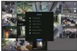
- In live mode, right click with your mouse button. The Live menu appears.
- Select
- The Search menu should appear.
- The search can be restricted by the Auto Delete function.
See the "Record Option" page under "Menu Setup > Setting the Recording" in the Table of Contents.
- Overlapped data: It only appears if there exists overlapped data on a certain time, produced due to the charge of Recorder's time setup. The latest data comes first, from
Time Search
You can search for recorded data of a desired time.
The displayed time is based on the local time zone and the daylight saving time (DST). Therefore, data recorded at the same time from different areas may differ based on the time zone and the DST.
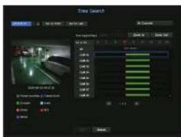
- Select
- In the date selection window, click on the < ◆ > button to select a search date.
-
See the "To use the calendar" page under "Menu Setup > System Setup" In the Table of Contents.
-
The record data on the specific date will be listed.
The display bar is different according to the data type. So check the data type for the color in the left pane.

- If DST (Daylight Saving Time) is configured, overlapping multiple recordings may be produced for a certain moment of time. Such a time section is distinguished with red color to mark DST section.
- Go to First : Move to the earliest recording date.
- Go to Last: Move to the latest recording date.
- All Channels: If you select a list, you can search for recorded video of layout specified by you. By default, it will show search results for all channels.
- Time : Enter a time to perform the search or use the up/down button <♦> to select one.
- Zoom In: The map enlarges in detail.
It will switch in the sequence of 24 hours - 12 hours - 8 hours - 2 hours - 1 hour. - Zoom Out: The map will switch in the reverse order of the detailed mode above.
It will switch in the sequence of 1hour - 2 hours - 6 hours - 12 hours - 24 hours. - Preview screen: After selecting
, mouse-clock or mouse-drag a desired time in timeline to view the still image at the time. -
If the selected channel does not contain any recorded data, it will be marked black.
-
Select a data item and click
. The recorded video for the selected channel will play.
- Just like the timeline in time search, the timeline of the playback screen will exhibit different colors depending on the types of recorded data.
Color indications depending on current recording status
The recorded data types are represented through the use of different colors. Each color corresponds to a certain recording type.
Event Search
You can search for events by the channel and play them.
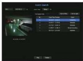
-
Select
on the menu. -
Configure the channel and date to search for.
- Select Event Type. An Event Type pop-up appears when the
button is pressed.
- Event Type Option: All Motion, Video Analysis, Auto Tracking, Defocusing, Fog Detection, Audio Detection, Sound Classification Sensor, Schedule, Normal Recording
- Select an event to play from the search list. Then the selected events will be played.
search & play
Smart Search
You can select a specific area of the image as an area of interest or exclusion using a virtual line to perform a search of events that have occurred in a specific time period.
- To use Smart Search, set "Menu > Event > Camera Event > Smart Search" to
and set the "Motion Detection" or "IVA" area of the camera to the whole area. However, to perform Smart Search for the Wilsonet X series camera or later models, go to the camera's "Setup > IVA" and select "Enable IVA". See the "Camera Event" page under "Menu setup > Event setup".
This function is supported only when a network camera is connected.
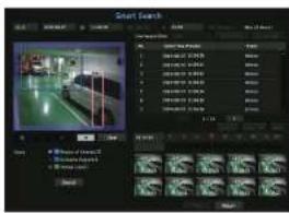
- In the
menu, select . - Configure the channel, search date and time settings.
- Go to First: Moves to the oldest smart search result.
- Go to Last: Moves to the most recent smart search result.
• Event : Displays the type of event generated.
- Region of Interest: The entire screen is set as a non-detection area and a specific area designated as a detection area. Click and drag on the image or select 4 vertexes to designate a desired detection area.
- Exclusive Region: The entire screen is set as a detection area and a specific area designated as a non-detection area. Click and drag on the image or select 4 verlexes to designate a desired non-detection area.
- Virtual Line: Detects a motion towards a marked direction based on the virtual line. At a desired position on the screen, click or drag the start point and end point of the line.
-
Up to 3 areas of interest, areas of exclusion and virtual lines can be set, respectively.
-
Click the
button. -
Search results displayed include a list, timeline and thumoral.
- When you double click a list or thumbnail displayed as search results, the applicable data can be played back.
- Click the
or button to change the date directly within the search results. - Select data to play and click
Moves to the playback screen for the data searched.
Text Search
You can search data that was entered into POS systems connected to Recorder.
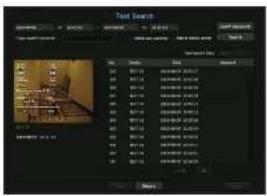
- Select
from the menu. - Please specify the search criteria and click the
button.
- A deeper and more detailed search can be performed by using specific characters.
- Type search keyword: You can search for text with preset event keywords. Event keywords can be set by referring to the "Text > Event Settings" page in the table of contents "Menu Setup > Setting the Device".
-
Search Condition: Enter a word to search in the input screen and press the
button. -
: If this option is checked, the search terms are case-sensitive. -
: If checked, only results that exactly match the input words will be displayed. -
Overlapped Data: This is displayed if there is data duplicated during a preset time interval.
- Overlapped Data: This is displayed if there is data duplicated during a preset time interval.
- Preview screen: If data is selected from a list, a preview image is displayed.
All information is displayed in the text display below.
- Export; Stores all text search information recorded in Recorder to storage media.
- Select data and
Moves to a replay screen for searched text data.
Backup Search
Searches for backup data in the connected backup device. Only data in the format of Recorder is included in the search.
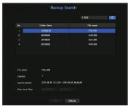
-
Select
in the menu. -
If a storage device with data is connected, the recording list saved in the device and the ARB data capacity are displayed.
-
File Name : Displays the name of a file recorded.
• Channel : Displays the recorded channel.
• Record Period : Displays the record period.
• Play Start Time : Select a time that you start playing. -
Select data to play and click
. The screen switches to the backup data playback mode.
ARB Search
You can search ARB data and export it to a file on your preferred storage device or play it back.
This function is supported only when a network camera is connected.
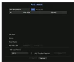
- Select
from the menu.
To perform ARB search, you should setby referring to the "Storage Device > Device/Format" page In the table of contents "Menu Setup > Setting the Device". -
The type and model name of the ARB storage device are displayed.
When storage media with data is connected, the list of recordings stored and ARB data volume are displayed on the equipment. -
File Name : Displays the name of a file recorded.
• Channel : Displays the channel recorded.
• Record Period : Displays the duration of recording.
- Play Start Time: Select the time at which the video is to be played.
• ARB Export Device : Selects an ARB storage device and exports a file.
- Press the < > button and you can check the free space remaining in the storage device.
- Select data to play and click
.
The screen moves to the ARB backup data play screen.
PLAYBACK
Play
You can play data stored in the HDD and backup a desired portion of the data.
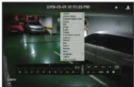
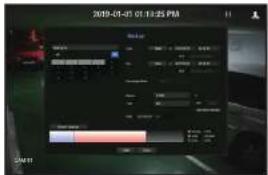
-
In the live screen menu, select the
menu or click on <▶> in the launcher menu. -
Select a menu for searches.
- If this is the first time you try to play, you will start with the data search window. To search for data, see the "Search & Play > Search" page in the Table of Contents.
- Select a data item and click
in the Search menu.
The selected data is played and the play launcher appears on the screen.
- If there is an existing data,
- Playback Information: Displays the date and time of the current data in the top corner.
- Backup : Click > to set the current time to the start time of backup; you can specify a backup area using the mouse yellow triangle. Click < > again to set the current time to the end time of the backup and the 'Backup Range' window appears.
Type : Supports formats of Recorder and SEC.
- When you select the SEC format, you can select or deselect "Text data included".
- Device : Select a backup device.
- Check Capacity : Enables you to check the capacity of the selected storage device.
- If you want to go back to the live screen during plays, then click on < □> of the launcher menu.
Checking menu while playing a video
- Right-click on the play screen.
Screen menu appears on the play screen.
- Select a menu to run.
For each menu details, see the 'Split Mode Menu' page under 'Live > Live Screen Menu' in the Table of Contents.
- Rotate mode only appears in single screen mode. You can rotate the play screen by 90 degrees.
Using the Playback Button
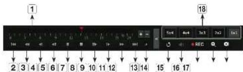
| Name | Description | |
| 1 | Play Timeline | Indicates the current playback point, and can be used to move. |
| 2 | Skip Backward | Moves backward by unit time. |
| 3 | Fast Backward | Used to rewind a video. (Supports x2, x4, x8, x16, x32, x64, x128, x256 speed)■There may be restrictions on test play for each split screen. |
| 4 | Slow Backward | Used to rewind the video at a slow speed. (Supports x1/2, x1/4, x1/8 speed)■There may be a limit on slow play for each split screen. |
| 5 | Stop Backward | Moves backward by one frame at a time. |
| 6 | Pause | Stops playing the current video temporarily. |
| 7 | Stop | Stops playback and moves to the live screen. |
| 8 | Stop Forward | Moves forward by one frame at a time. |
| 9 | Slow Forward | Used to play the video forward at a slow speed.(supports x1/2, x1/4, x1/8 speed) |
| 10 | Fast Forward | Used to play a video forwards.(Supports x2, x4, x8, x16, x32, x64, x128, x256 speed) |
| 11 | Skip Forward | Moves forward by unit time. |
| 12 | Playback settings | You can configure the settings for last play, slow play and skip in detail.#Settings may be applied differently depending on the number of channels. |
| 13 | Return | Move back to Search Menu before playing back video recording. |
| 14 | Audio | Sets Audio ON/OFF. |
| 15 | Record | Records all channels In Live mode. |
| 16 | ZOOM | This is available in Single mode, which will enlarge the video from a selected channel. |
| 17 | Backup | You can back up the video of the channel currently playing back. |
| 18 | Mode Switch | Click on a desirable play mode to change the screen segmentation mode. |
starting web viewer
WHAT IS WEB VIEWER?
WebViewer is a software program with which the operator can access a remote Recorder for real-time monitoring, PTZ control (if configured) or search.
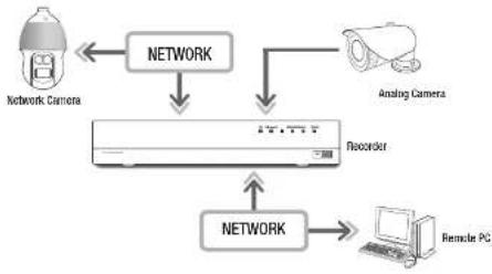
flowchart
graph TD
    A["Network Camera"] --> B["NETWORK"]
    C["Analog Camera"] --> D["Recorder"]
    B --> D
    D --> E["NETWORK"]
    E --> F["Remote PC"]
Product Features
• Remote connection using the browser
• PTZ camera control enabled
Split mode supported
- 2-split vertical, 2-split horizontal, 3-split, 4-split, 6-split. 1+5-split, 1+7-split, 9-split
- Depending on the number of channels supported by the product, the number of screen split modes may vary.
- Saving function in JPEG/BMP/PNG image format for printing and storage.
- Record video in AMI format-compatible with popular media players. (The integrated codeo is needed)
- To play the video in Windows Media Player, you must download and install the relevant codec from www.windows7codecs.com. (version 4.0.3 or higher)
System Requirements
The following lists the minimum suggested hardware and operating system requirements needed to run the Web Viewer.
• Recommended browser : Chrome
• Supported browsers : Chrome, Edge, and Salar
- Supported OS: Works on all of the Windows, Linux, and OS X environments given the platform-independent nature of the web.
- Tested environments: Tested and certified to run on Windows® 10 with Google Chrome™ version 76 and Intel® Core™ i7-7700 processor 3.60 GHz with NVIDIA® GeForce® GTX™ 1050 or Intel™ HD Graphics 630.
- Performance restrictions: The performance of users' CPU/CPU may impact the video playback performance of the web viewer.
CONNECTING WEB VIEWER
- Open your web browser and type the IP address or URL of Recorder Into the URL address box.
- A user with the admin permissions should provide the admin ID and password. A registered user should provide the user ID and password.
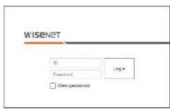
- After you log in, the Live Viewer main screen appears.
All settings are applied according to the Recorder settings.
- To log in with a different ID, quit your Internet browser and log back in.
- When an initial password is entered, while partially resetting to access a web viewer, a pop up window will appear that will guide the user to change the password and when coming a whole reset to access a web viewer, a pop up window will appear that will guide the user to complete the settings for the install Wizard. Set a new password when a pop up window appears.
- If you change the web port when connecting to the WebViewer, you may fail to access since the applicable port is blocked. In this case, change the port to a different port.
- Please change your password every three months to safely protect personal information and to prevent the damage of the information theft. Please, take note that it's a user's responsibility for the security and any other problems caused by mismanaging a password.
- It allows up to 10 simultaneous access including the Admin and general users.
- Password of the Admin and general users can be changed in
menu of the Recorder. - Normal users should have set
under to Use before connecting to the Web Viewer. See the "Setting Permissions" page under "Menu Setup>User" in the Table of Contents. - All settings are applied according to the Recorder settings.
live viewer
LIVE VIEWER
You can check the video from camera registered in the Recorder connected from a remote PC. Also, you can adjust the camera and check the network transfer status.
Screen layout of the live viewer
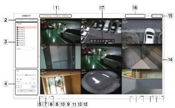
| Menu Description | ||
| 1 | Menu Selection | Click each menu to go to the menu screen. |
| 2 | Detailed Menu Tab | Shows the detailed menu provided by each menu. |
| 3 | List menu item | Checks the list of Registered Cameras in the recorder and sets the layout of the cameras. |
| Event menu item | Shows a list of events that occurred on the device. | |
| 4 | PTZ Control | Controls the connected PTZ camera. |
| 5 | Enables the Manual recording function of the recorder. | |
| 6 | Saves the live video of this selected channel in the designated folder of the PC in AVI format. | |
| 7 | Unselects alarm when an alarm occurs. | |
| 8 | Displays information of the OSD screen on the Web Viewer Video window. | |
| Menu Description | ||
| 9. | Shows the selected Channel Information.If a PC monitor does not support 60Hz at a certain high resolution, or if the HDMI cable does not support HDMI 2.0, it will not output more than 60fps in Channel information. | |
| 10 | Shows the status of all cameras connected to the recorder. | |
| 11 | Sets the split screen of the video window. | |
| 12 | Changes the aspect ratio to 4:3 or 16:9. | |
| 13 | It changes to full screen from the current Split Mode.To sell full screen, press the [ESC] key on your keyboard.MAC Safari does not support full screen. | |
| 14 | Video window | Shows the video of the camera connected to the recorder. |
| 15 | The ID of the connected user is displayed. | |
| You are directly connected to the Hanwha Techwin homepage (www.hanwhite-security.com). | ||
| Changes the color theme of Web Viewer. | ||
| 16 | System status display | Displays the status of the system, hard disk, and network. |
| 17 | Saves the current video of the selected channel in the specified path. | |
| Starts and stops recorder recording. | ||
| Plays the previous video for 1 minute. | ||
| Turns on or off the PC microphone. | ||
| Controls the PTZ setup of the selected channel. | ||
| Turns ON/OFF the audio connected to each channel. | ||
| The screen of the selected channel is rotated 50 degrees clockwise. | ||
| Change the aspect ratio of the selected channel. | ||
Checking the system status
The icon at the top of the screen indicates the status of the system.
| Name Description | |
| Displayed when a problem occurs with the pan or recording status. Displayed when the amount of input data by channel accords the set amount of data limit. | |
| Displayed when the hand disk does not exist or needs to be replaced. Displayed when the hand disk is full during recording and the recording capacity is insufficient. Displayed when there are problems with the recording status. | |
| Displayed when the system or network is overloaded. w/ occurs in case of excessive CPU load because the recording performance is exceeded. If disappears when you modify the Delete Camera or Set Camera to reduce the data rate. w/ limit the number of users remotely monitored by Web Viewer or VMS or control the number of channels played by remote or recorder. | |
| Displayed if the server has firmware to update. | |
Check User ID
Displays the user ID and authority for the user connected to Web Viewer.
Camera Layout Setup
Check Camera List
Displays the camera type, status, and name registered in the recorder.
| Monitoring > List | ||
| Name Description | ||
| Channel information | Displays channel information (channel number, video window assignment, and color indication). | |
| Camera type | Displays a normal camera. | |
| Displays a PTZ camera. | ||
| Displays an analog camera. | ||
| Camera status | Displays the camera look status. | |
| Displays the camera error status. | ||
| Camera name | Displays the name set for the camera. | |

- If a camera connection error occurs, it is disabled in the list.
live viewer
Layout setup
According to the purpose of use and convenience, the desired channels can be grouped in a layout so that they can be checked immediately when needed.
Monitoring > List
To add a layout
Click the <+> button.
Enter the name of the layout you want to add, and then click the <button to add the layout.

To change the layout name
-
Select the layout you want to rename and click the < O > button.
-
Change the name as you want and click the < ☐> button.
To delete a layout
Select the layout you want to delete and click < img>.
■Each layout is saved separately by the user.
- The sum of the resolution that can be simultaneously monitored in multi-channel in the web viewer cannot exceed 18 mega pixels, and the sum of bitrate cannot exceed 20 mega pixels (based on the set resolution and bitrate of the remote profile). If a video exceeds any of the above specifications, a warning popup and < △> icon will appear.
- If this kind of warning shows up, set the resolution and operate of the remote profile of the channels to be placed into the layout area.
- Chrome browser does not support hardware acceleration for H.265 codec. For Chrome browser, the sum of H.265 codec video resolution cannot exceed 4 mega pixels and the sum of bitrate cannot exceed 4 mega bps while up to 4 channels can be monitored.
Check Event list
Check Event list
Check the event list set under Setup > Device > Text > Event
Monitoring > Event
Checks the video of the channel by clicking the desired event in the Event list.
To filter the Event list
Click the <▼> button followed by the desired event item. Only selected event items are displayed in the event list.
The Safari browser does not support this feature.
Video Export
You can back up the recorded video by manually inputting the desired channel, date, and time.
- Click the
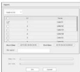
- Select a layout to export and select the desired channel.
- Set the start date/time and end date/time.
- Enter a file name to save, and then click the
button. - When the export is complete, a confirmation window appears. Click the
button to exit. The exported video is saved as .avi file in the download folder.
Check the camera status
You can check the status of all cameras connected to the recorder.
Check the Live video status
Click the <p button. You can check the status and transmission information of the camera connected to each channel.
- To change the profile setup, click the
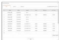
Check the recorded video status
Click the <a button, followed by the
You can check the profile, recording type, input/recording rate, and setting/input/recorded data rate by channel.
- Use
- To change the profile setup, click the
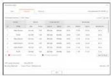
Check network status
Click the
button, followed by the
You can check the status of network bandwidth currently being received/transmitted.
To Change the split screen
Click the
The selected split screen is applied to the video window.
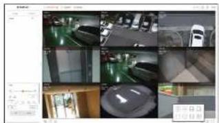
live viewer
Capture
Select a channel to capture video and click the
PC Recording
You can record video on your PC while monitoring.
- Select the desired channel and click the < ☐> button to start PC recording.
- To end the PC recording, click the <#> button. The recording ends, and the recorded video is saved as .avi file in the download folder.
Use Instant play
You can move the video back 1 minute and play it while monitoring. Select the desired channel and click the
The instant play screen appears.
/ × The video is played/stopped.
← : Instant playback ends
■ Q : Moves to the Search menu.

■Instant play supports H.264 codec waco only
Using PTZ
You can control PTZ of the selected channel. Select a channel and click the < +> button. The PTZ control screen will appear.
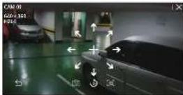
- If you hover your mouse over < + > , 8-directional arrow keys will appear. If mouse goes out of the area, the keys will disappear. Click each of the 8-directional arrow keys to finetune the camera direction. Continue clicking the arrow keys to move in the desired direction and release the mouse to stop.
■ Position adjustment: Click on the screen area you want, and drag the mouse to aim the camera at the direction you want.
: Captures video of the current state.
- : Moves to the instant play screen.
- Click the Digital zoom icon and use the mouse wheel to zoom in or out on the video.
- The PTZ mode is closed.
Performing Digital zoom
You can zoom in or cut using the mouse wheel.
If you scroll up using the mouse wheel, the selected video screen is enlarged by 10%, and a thumbnail window is displayed.
- Scrolling up/down using the mouse wheel will room in/out the video screen by 10%.
- Digital zoom ends when the video screen is reduced to the original size.
In PTZ mode, click the [@] button to run digital zoom.
CONTROL OF CONNECTING NETWORK CAMERA
PTZ Control
If the connected network camera is a PTZ camera, the
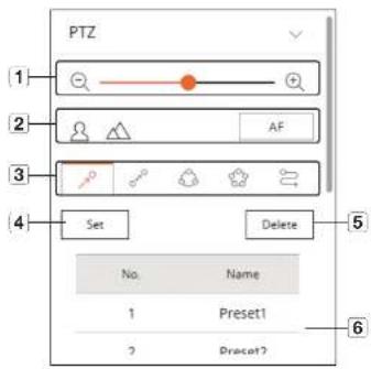
| Name Description | |||
| 1 | Zoom In/Zoom Out | Adjusts the zoom of the camera to enlarge or reduce the image. | |
| 2 | Focus | Adjusts the focus of the camera image. | |
| 3 | Preset | Set the preset position to move the camera, and then select the desired preset to move to the set position. | |
| Swing | The camera moves back and torn between the set start point and end point. | ||
| Group | Moves to the selected path by combining presets. | ||
| Tour | Moves to the set path by combining several groups. | ||
| Trace | The camera moves along the set path. | ||
| 4 | Set | The preset you set is saved and displayed in the list | |
| 5 | Delete | Deletes the selected preset list. | |
| 16 | Preset List | Shows a list of saved presets. | |
To utilize the digital PTZ (D-PTZ) function
- Register a camera that supports the D-PTZ profile.
- You can utilize the D-PTZ feature only for cameras that support the D-PTZ profile.
- In addition to cameras that support normal PTZ, cameras that support D-PTZ can also control Live video
using some
■For more support functions, refer to the camera manual.
To use the digital PTZ function on the Dewarping screen
-
Click the loan on the Dewarping screen.
-
Place the cursor on the screen and drag it to control.
To set a preset
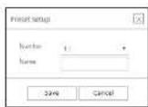
- Click the <> tab.
- Click the
button to go to the 'Preset setup' window. - Click < 1: * > to select the Preset Order to set.
- Enter the Preset name.
- Use the arrow keys to adjust the camera to the point.
- Click the
button.
To run a preset
- Click the <> tab.
- Click the preset to run from the list.
The camera lens moves to the set position.
When running Swing (auto pan), Group (scan), Tour, or Trace (pattern)
The running method of each function is the same as the preset operation method. For details on how to use it, refer to the camera's user manual.
- Depending on the camera's capabilities, only some features may be available.
search viewer
SEARCH VIEWER
You can search and play the recorded video stored in the recorder by connecting the recorder remotely.
Configuration of Search Viewer Screen
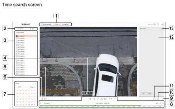
| Name Description | ||
| 1 | Menu Selection | Click each menu to go to the menu screen. |
| 2 | Detailed Menu Tab | Shows the detailed menu provided by each menu. |
| 3 | Selecting channel | Displays the search channel. |
| 4 | Saves the current video of the selected channel in the specified path. | |
| Turns OK / OFF the audio connected to each channel. | ||
| This screen of the selected channel is rotated 50 degrees clockwise. | ||
| Change the aspect ratio of the selected channel. | ||
| Name Description | ||
| 5 | [ ] | Turns on/off the section setup. |
| 6 | [ ] | Saves the video of the selected channel in the designated path in AWI format. |
| 7 | Calendar | The date of the recorded video is displayed in orange, and the current data is displayed in a orange circle. Click the date in orange to view the recorded video information on the time line. |
| 8 | Play adjustment | Select a search result to open the play screen for that data. |
| 9 | [ ] | It changes to full screen.To exit full screen, press the [ESC] key on your keyboard. |
| 10 | [ ] | Shows the status of all cameras connected to the recorder. |
| 11 | [ ] | Displays Information of the OSD screen on the Web Viewer Video window. |
| 12 | Event List | Displays an Event list. |
| 13 | [ ] | Exports the Event list to a file. |
Text Search screen
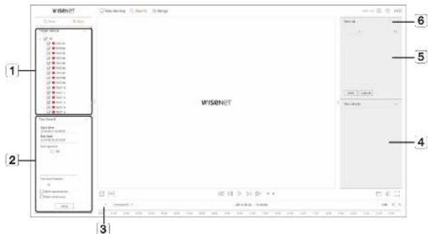
| Name Description | ||
| 1 | Target device | Displays the POS device connected to the recorder. |
| 2 | Text search | Displays the input data of the POS device connected to the recorder. |
| 3 | Selecting channel | Displays the channel list. |
| 4 | Text details | Displays the details of the Text list. |
| 5 | Text list | Displays the searched Text list. |
| 6 | Exports the Text list to a file. | |
Search for time
You can search recorded data by setting the desired date and time.
To search by date
You can use the calendar to select a search date.
- Click <<,>> to select the year and month to search.
Dates with data appear in orange, and current dates appear in orange circle. - Click the date to search in the calendar.
The first video of the searched data of the day is displayed on the video window, and the data is displayed on the time line. - Click
to search today's date.
Today's date is selected immediately.
Color information by current recording status
The color displayed for each recorded data type is shown.
• Groon: Normal recording video
- Post: Event video
To adjust the time line
You can zoom in and out on the time line by moving the play position.
![7. [播放] 2019-06-27 15:00:00 2019-06-27 15:00:00](/content/2026/05/807624/images/b6dbc8377677a3143a080395858f58ce6935360ee8091c253e8c8567762f8ca7.jpg)
- Click the desired playback position on the time line.
The play start position moves.
- Click: >, <@to zoom in or zoom out the time display magnification. When the time line is zoomed in, a scrollbar appears at the bottom.

- To view the time line before and after while zooming, click the time line and drag it left or right.
: You can filter the event items to view the time line.
• Overlapped: You can set the DST overlap section to check the time line.
search viewer
Export search results
You can export the searched results to a file.
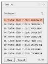
- Click the [Button.
- Select a layout to export, and select a channel you want.
- Set the start date/time and end date/time.
- Enter the file name to save, and click the
button. - Once export is complete, a confirmation window pops up. Click the
button to close the window. ■ While exporting click the button to stop the export.
Export with section setup
You can select the desired section from the time line or search list during video playing and export it to a file.
- Click the [☐] button.
| □回 | ||||||||||||||||||||||||||||||||||||||||||||||||||||||||||||||||||||||||||||||||||||||||||||||||||||||||||||||||||||||||||||||||||||||||||||||||||||||||||||||||||||||||||||||||||||||||||||||||||||||||||||||||||||||||||||||||||||||||||||||||||||||||||||||||||||||||||||||||||||||||||||||||||||||||||||||||||||||||||||||||||||||||||||||||||||||||||||||||||||||||||||||||||||||||||||||||||||||||||||||||||||||||||||||||||||||||||||||||||||||||||||||||||||||||||||||||||||||||||||||||||||||||||||||||||||||||||||||||||||||||||||||||||||||||||||||||||||||||||||||||||||||||||||||||||||||||||||||||||||||||||||||||||||||||||||||||||||||||||
| □ | □ | □ | □ | □ | □ | □ | □ | □ | □ | □ | □ | □ | □ | □ | □ | □ | □ | □ | □ | □ | □ | □ | □ | □ | □ | □ | □ | □ | □ | □ | □ | □ | □ | □ | □ | □ | □ | □ | □ | □ | □ | □ | □ | □ | □ | □ | □ | □ | □ | ○ | 1 | 1 | 1 | 1 | 1 | 1 | 1 | 1 | 1 | 1 | 1 | 1 | 1 | 1 | 1 | 1 | 1 | 1 | 1 | 1 | 1 | 1 | 1 | 1 | 1 | 1 | 1 | 1 | 1 | 1 | 1 | 1 | 1 | 1 | 1 | 1 | 1 | 1 | 1 | 1 | 1 | 1 | 1 | 1 | 1 | 1 | 1 | 1 | 1 | 1 | 2 | 2 | 2 | 2 | 2 | 2 | 2 | 2 | 2 | 2 | 2 | 2 | 2 | 2 | 2 | 2 | 2 | 2 | 2 | 2 | 2 | 2 | 2 | 2 | 2 | 2 | 2 | 2 | 2 | 2 | 2 | 2 | 2 | 2 | 2 | 2 | 2 | 2 | 2 | 2 | 2 | 2 | 2 | 2 | 2 | 2 | 2 | 2 | 2 | 2 | 3 | 3 | 3 | 3 | 3 | 3 | 3 | 3 | 3 | 3 | 3 | 3 | 3 | 3 | 3 | 3 | 3 | 3 | 3 | 3 | 3 | 3 | 3 | 3 | 3 | 3 | 3 | 3 | 3 | 3 | 3 | 3 | 3 | 3 | 3 | 3 | 3 | 3 | 3 | 3 | 3 | 3 | 3 | 3 | 3 | 3 | 3 | 3 | 3 | 3 | 4 | 4 | 4 | 4 | 4 | 4 | 4 | 4 | 4 | 4 | 4 | 4 | 4 | 4 | 4 | 4 | 4 | 4 | 4 | 4 | 4 | 4 | 4 | 4 | 4 | 4 | 4 | 4 | 4 | 4 | 4 | 4 | 4 | 4 | 4 | 4 | 4 | 4 | 4 | 4 | 4 | 4 | 4 | 4 | 4 | 4 | 4 | 4 | 4 | 4 | 5 | 5 | 5 | 5 | 5 | 5 | 5 | 5 | 5 | 5 | 5 | 5 | 5 | 5 | 5 | 5 | 5 | 5 | 5 | 5 | 5 | 5 | 5 | 5 | 5 | 5 | 5 | 5 | 5 | 5 | 5 | 5 | 5 | 5 | 5 | 5 | 5 | 5 | 5 | 5 | 5 | 5 | 5 | 5 | 5 | 5 | 5 | 5 | 5 | 5 | 6 | 6 | 6 | 6 | 6 | 6 | 6 | 6 | 6 | 6 | 6 | 6 | 6 | 6 | 6 | 6 | 6 | 6 | 6 | 6 | 6 | 6 | 6 | 6 | 6 | 6 | 6 | 6 | 6 | 6 | 6 | 6 | 6 | 6 | 6 | 6 | 6 | 6 | 6 | 6 | 6 | 6 | 6 | 6 | 6 | 6 | 6 | 6 | 6 | 6 | 7 | 7 | 7 | 7 | 7 | 7 | 7 | 7 | 7 | 7 | 7 | 7 | 7 | 7 | 7 | 7 | 7 | 7 | 7 | 7 | 7 | 7 | 7 | 7 | 7 | 7 | 7 | 7 | 7 | 7 | 7 | 7 | 7 | 7 | 7 | 7 | 7 | 7 | 7 | 7 | 7 | 7 | 7 | 7 | 7 | 7 | 7 | 7 | 7 | 7 | 8 | 8 | 8 | 8 | 8 | 8 | 8 | 8 | 8 | 8 | 8 | 8 | 8 | 8 | 8 | 8 | 8 | 8 | 8 | 8 | 8 | 8 | 8 | 8 | 8 | 8 | 8 | 8 | 8 | 8 | 8 | 8 | 8 | 8 | 8 | 8 | 8 | 8 | 8 | 8 | 8 | 8 | 8 | 8 | 8 | 8 | 8 | 8 | 8 | 8 | 9 | 9 | 9 | 9 | 9 | 9 | 9 | 9 | 9 | 9 | 9 | 9 | 9 | 9 | 9 | 9 | 9 | 9 | 9 | 9 | 9 | 9 | 9 | 9 | 9 | 9 | 9 | 9 | 9 | 9 | 9 | 9 | 9 | 9 | 9 | 9 | 9 | 9 | 9 | 9 | 9 | 9 | 9 | 9 | 9 | 9 | 9 | 9 | 9 | 9 | 10 | 10 | 10 | 10 | 10 | 10 | 10 | 10 | 10 | 10 | 10 | 10 | 10 | 10 | 10 | 10 | 10 | 10 | 10 | 10 | 10 | 10 | 10 | 10 | 10 | 10 | 10 | 10 | 10 | 10 | 10 | 10 | 10 | 10 | ||||||||||||||||||||||||||||||||||||||||||||||||||||||||||||||||||||||||||||||||||||||||||||||||||||
- Select a layout to export, and select a channel you want.
- Set the start date/time and end date/time.
- Enter the file name to save, and click the
button. - Once export is complete, a confirmation window pops up. Click the
button to close the window. ■ While exporting click the button to stop the export.
Text search
You can search data entered into the POS device connected to the recorder.
To search text
- Select a POS device to search.
- Select the date and time to search.
- Set the event keywords and search condition.
- Event keywords: You can search for text with preset event keywords. Event keywords can be set by referring to "Text > Event setup" of "Menu setup > Device setup" in contents.
■Type search keyword: Enter the text you want to search.
- Match case sensitivity: Searches are case-sensitive when checking.
- Match whole words: Searches for data that exactly matches the characters entered.
- Click the
button.
- For more information about search text, refer to the "Text Search" page of the table of contents "Search & Play > Search."
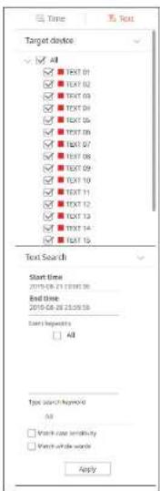
To play Text Search
Select the desired list from the text search list to check the recorded video and details.
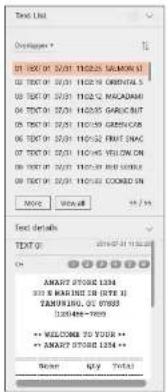
To adjust the time line
You can zoom in and out on the time line by moving the play position.
| # | Insgesoft # | |||||||||||||||||||||||||||||||||||||||||||||||||||||||||||||||||||||||||||||||||||||||||||||||||||||||||||||||||||||||||||||||||||||||||||||||||||||||||||||||||||||||||||||||||||||||||||||||||||||||||||||||||||||||||||||||||||||||||||||||||||||||||||||||||||||||||||||||||||||||||||||||||||||||||||
| 2019-06-27 15:00:00 | 2019-06-27 15:00:00 | |||||||||||||||||||||||||||||||||||||||||||||||||||||||||||||||||||||||||||||||||||||||||||||||||||||||||||||||||||||||||||||||||||||||||||||||||||||||||||||||||||||||||||||||||||||||||||||||||||||||||||||||||||||||||||||||||||||||||||||||||||||||||||||||||||||||||||||||||||||||||||||||||||||||||||
| 2019-06-27 15:00:00 | 2019-06-27 15:00:00 | 2019-06-27 15:00:00 | 2019-06-27 15:00:00 | 2019-06-27 15:00:00 | 2019-06-27 15:00:00 | 2019-06-27 15:00:00 | 2019-06-27 15:00:00 | 2019-06-27 15.00:00 | 2019-06-27 15:00:00 | 2019-06-27 15:00:00 | 2019-06-27 15:00:00 | 2019-06-27 15:00:00 | 2019-06-30 15:00:00 | 2019-06-30 15:00:00 | 2019-06-30 15:00:00 | 2019-06-30 15:00:00 | 2019-06-30 15:00:00 | 2019 | 2019 | 2019 | 2019 | 2019 | 2019 | 2019 | 2019 | 2019 | 2019 | 2019 | 2019 | 2019 | 2019 | 2019 | 2019 | 2019 | 2019 | 2019 | 2019 | 201 | 2019 | 2019 | 2019 | 2019 | 2019 | 2019 | 2019 | 2019 | 2019 | 2019 | 2019 | 2019 | 2019 | 2019 | 2019 | 2019 | 2019 | 2019 | 2019 | 201 | ||||||||||||||||||||||||||||||||||||||||||||||||||||||||||||||||||||||||||||||||||||||||||||||||||||||||||||||||||||||||||||||||||||||||||||||||||||||||||||||||||||||||||||||||||||||||||||||||||||||||||||||||||||||||||||||||||||||||||||||||||
• < - >: You can select the channel to search.
- Click the desired playback position on the time line.
The clay start position moves. - Click >, < to zoom in or zoom out the time display magnification. When the time line is zoomed in, a scrollbar appears at the bottom.

- To view the time line before and after while zooming, click the time line and drag it left or right.
• Overlapped; You can set the DST overlap section to check the time line.
Play button names and functions
Pause status
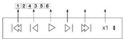
Play status
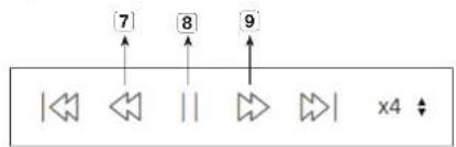
flowchart
graph TD
    A["1"] --> B["2"]
    B --> C["3"]
    C --> D["4"]
    D --> E["5"]
    E --> F["6"]
    F --> G["7"]
    G --> H["8"]
    H --> I["9"]
    I --> J["10"]
    J --> K["x4"]
| Name Description | ||
| 1 | Previous Event | Moves back by event. |
| 2 | Backward | Moves to Stop Backward. |
| 3 | Play | Plays the video. |
| 4 | Forward | Moves to Stop Forward. |
| 5 | Next Event | Moves forward by event. |
| 6 | Speed | Selects the play speedSpeed: x1/2, x1/4, x1/8, x1, x2, x4, x5, x16, x32, x64, x128, x256 |
| 7 | Backward X TimesPlayback | Used for reverse playSpeed: -x1, -x2, -x4, -x5, -x16, -x32, -x64, -x128, -x256 |
| 8 | Freeze | Pauses the video. |
| 9 | Forward X Times playback | Used for forward playSpeed: x1, x2, x4, x8, x16, x32, x64, x128, x256 |
setup viewer
SETUP VIEWER
You can configure the Recorder settings remotely on the network.
To configure the Recorder settings, click
Settings Screen
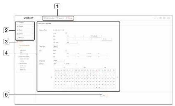
| Item Description | ||
| 1 | Menu Selection | Click each menu to switch into corresponding menu screen. |
| 2 | Parent Menu | Configure the settings or select a parent item to change the existing settings. |
| 3 | Sub-Menu | Among the sub-menus of selected parent menu, select a desired item to set. |
| 4 | Detailed Menu | Click desired Item's input field to change and enter a desired value. |
| 5 | OK | Apply the modified settings. |
System
You can configure the various settings of the Recorder system.
Date/Time/Language
See the "Setting the Date/Time/Language" page under "Menu Setup > System Setup" in the Table of Contents.
Date/Time
Set the date and time.
Time Sync.
Set the time synchronization.
DST (Daylight Saving Time)
During the summer, Daylight Saving Time (DST) advances clocks one hour forwards from the standard local time zone.
Language
Select a preferred language for the Recorder.
Holiday
A user can select specific dates as holidays according to their own preferences.
User
See the 'User' page under 'Menu Setup > System Setup' in the Table of Contents.
Administrator
You can change the admin ID or the password.
- D allows alphanumeric characters only.
- If the admin ID is not used for access, you cannot change the ID.
- If the ID being used is changed, you will be automatically logged out.
User
You can add, change or remove a user or users.

Permission Setup
You can set the user permission.
System Management
See the 'System Management' page under 'Menu Setup > System Setup' in the Table of Contents.
System Information
You can see information of the current system.
Check the model name, software version, and MAC address.
You can search for a file from the storage device connected to the PC to perform an upgrade.
Settings
Using a storage device, you can apply the current configuration of Recorder to another Recorder.
Press the Initialize button to return the network settings to their factory default state. Items in the
setup viewer
Log information
System Log
Data recorded in the system log displays various system-related logs/dale/time such as system starts, system ending and menu setting changes.
The event log lists recorded events, such as sensor events, camera events, or image losses.

Backup Log
You can inquire about a user who performed a backup, execution time, details (backup time, channel, backup device, backup file type).
You can check a list of cameras that are connected to the Recorder and configure the necessary settings. Click
For more detailed setup, see the 'Menu Setup > Setting the Camera' page in the Table of Contents.
Camera register
You can add a network camera(s).
Channel Setup
You can configure the video settings for each channel.
You can change the settings of a connected network camera.
- When you click the [Camera website] button, a new camera web browser window is opened.
- This is not supported if the camera is connected to the RTSP protocol.
- This is not supported if the camera is connected to DDNS, URL, or MAC Address.
- It supports the version specified below or later for each Q/P/X series camera.
(QND-7010R series: 1.04, QND-7080R series: 1.02, QND-6010R series: 1.02, QND-6070R series: 1.01, P series: 1.01)
- It supports only when the camera is connected to IPv4 and is not set to HTTPS.
- When you are connecting to the camera web page on a closed network, a camera that does not support the universal web will not be able to output an image.
- The cam proxy port's default settings are automatically set in sequence as many as the number of
channels supported by Roccorder. If you want to change the proxy port, then select the port setup menu.
- 4 channels (10001-10004), 8 channels (10001-10008), 16 channels (10001-10016)
Example) Defaults of cam proxy ports for each product
• HRX-1620, HRX-1621 (16 channels): 10001-10016
• HRX-820, HRX-821 (8 channels) : 10001-10008
- HRX-420, HRX-421 (4 channels): 10001-10004
- When connecting outside the closed network as shown in the figure, the port forwarding setting of the camera proxy port is required for the router.
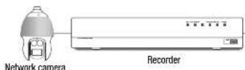
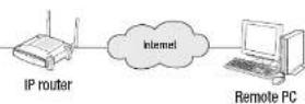
If there are multiple Recorders within the closed network, each cam proxy port should be set using a different port.
- II DDNS and Quick Connect are enabled, port forwarding will be automatically set.
- Chrome, Edge and Safari (Mac OS) browsers are supported.
Profile Setup
You can set the profile for a network camera.
Record
You can set the recording profile for a network camera.

Live
You can change the live transfer settings of the network camera.
You can set the video profile transmitted to the network and the expansion monitor.
You can change the passwords of all registered cameras at once.
Device
You can check a list of devices that are connected to the Recorder and configure the necessary settings.
Click
For more detailed setup, see the "Menu Setup > Setting the Device" page in the Table of Contents.
Storage Device
You can check and change the settings related to the data storage device.
Device/Format
You can check a storage device, amount of use, type of use and status of storage device.
- ARB : Video that was not recorded due to disconnection from the camera can be backed up after the connection with the camera is re-established.
Press the button and an
HDD Alarm
You can set the alarm output port and the duration in case an error occurs.
Monitor
You can configure the monitoring screen settings and set the output system.
- If the screen does not work properly, see "Troubleshooting (FAQ)" in the Appendix.
- The Monitor Setup settings control the monitor connected to the Recorder.
Text
Device
Relevant values of a device connected to Recorder can be set.
It is possible to set total amount conditions and keywords to display events of a text device.
Serial
Sets the serial port (RS-485/RS-422) of the recorder.
Record
For more detailed setup, see the 'Menu Setup > Setting the Recording' page in the Table of Contents.
Recording Schedule
If you set a recording schedule for a specific date and time, the recording will start at that specific time.
Record Setup
Select a type of the normal/event recording frame rate for each channel.
- You can set the recording duration separately for each channel.
setup viewer
Event
For more detailed setup, see the 'Menu Setup > Setting the Event' page in the Table of Contents.
Sensor Detection
Recorder / Camera
You can set the sensor operation mode and the synchronized camera as well as the alarm cutout type and the duration.
- If the connected network camera that has configured the alarm invout settings triggers an alarm, Recorder will perform the alarm out.
Camera Event
You can set camera event mode, alarm output type and alarm time.
Video Loss Detection
You can set to trigger the alarm if a video loss occurs.
You can schedule the alarm output according to the day of the week and the time. The default setting is Event Sync, which activates the alarm only if an event occurs.
Network
For more detailed setup, see the "Menu Setup > Network Configuration" page in the Table of Contents.
Interface
A remote user can access the Recorder via the network to check the current mode and the IP address.
Network
Specify the network connection path.
Port
You can configure the protocol related settings.
You can prepare the list of IP address to allow or block accesses to a specific IP address.
SSL
You can select a security connection system or install public certificates.

- While using HTTPS, if you want to switch to HTTP, then abnormal operation can take place as the browser contains the setting values. You need to change the URL to HTTP and reconnect or initialize the cookie setting of the browser.
setup viewer
802.1x
When connecting to a network, you can select whether to use the 802.1x protocol and install corresponding certificate.
You can specify the SMTP server that sends a mail if an event occurs and set the recipient group and users.
SMTP
You can set the server that sends malls and specify if you use the authentication process.
You can set the event interval and specify which events the server sends mails for.
Recipient
You can set groups and recipients to receive emails.
Using the SNMP protocol, the system or network administrator can remotely monitoring the network devices and sets the environment.
DHCP Server
Network
You can sell the internal DHCP server and assign an IP address to the network camera.
Check IP
You can check the IP and MAC currently used through the DHCP server, and the connected network port.
This function is only available for products that support P2P.
For products that support P2P function, see page 4 "Products supporting each feature" of the Product Specification Manual.
If you want to use P2P service, check the "Enable P2P" box.
You need to scan the QR code on the screen to use the P2P service.
backup viewer
SEC BACKUP VIEWER
You can play a file that is backed up in the format of SEC.
Backup in SEC format produces backup data file, library file and self-executable viewer file.
If you run the backup file viewer, the backup data file will be played.
Recommended System Requirements
PCs with a lower specification than the recommended below may not fully support forward/backward and high-speed playback.
PC specifications
| Name Minimum requirements Recommended | |
| CPU Intel Pentium 2.5GHz or more Intel 67(3.5GHz) or more | |
| RAM 43B or more | 86S or more |
| HDD 200GB or more 500GB or more | |
| VGA memory 512MB or more 13B or more | |
| Display resolution 1280x1024 or higher 1920x1080 or higher | |
| OS Windows 7, 8, 10 | |
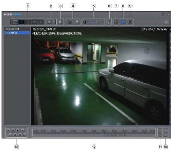
| Item | Description | ||
| 1 | Split screen | Selects screen ratio to display. | |
| The screen is changed to a split screen. | |||
| 2 | Fisheye view mode | If < > is pushed, it is possible to change to a fisheye installation type. It is possible to select wall/ground/celling mode according to the installation place. | |
| The fisheye view mode on the current screen can be changed independently on each split. | |||
| Item Description | |||
| 3 | Digital Zoom | Enlarge the Image by up to 100 times as big as the current one.Press the Zoom in (1) button the enlarge the image press the Zoom Out(2) button to shrink the image.You can also use the slide bar (3) in the pop-up window to zoom input.Press (4) on a size-changed video to restore the default zoom factor (100%).If you enlarge the image by more than 200%, the enlarged area will be markedon the digital zooming screen. Click on this marked area and move it to a desiredposition.The digital zooming is applied to all backup viewer. When the digital zooming iscancelled, the video size will restore the default rate of 100%. | |
| 4 | Screen Printout | Saves the current video's image as in an image file. Supports JPEG file format. | |
| Prints out the current screen. You should have installed the appropriate printerdriver before you can print out the screen. | |||
| 5 | Audio | A toggle button. Each time you press this button, the audio output will togglebetween activated and deactivated. | |
| You can adjust the volume level from 0 to 100. | |||
| 6 | Watermark | Press the button to enable file tamporting detection. to detect data file forging. | |
| 7 | Deinterlace You can enable the interface function. | ||
| 8 | Show OSD | Check the OSD checkbox to display the OSD information on the backup playbackscreen.Information such as backup date, day of the week, time, model name, andchannel number will be displayed on the screen. | |
| 9 | Maintain aspectratio/Full screen | Maintains the aspect ratio of the playsack screen. | |
| Plays the video on a full screen. | |||
| 10 | Enlarge /Reduce Timeline | Collapse the time range that is displayed on the range bar of the storage time.You can collapse the range bar until the overall range is shortened to 24 hours. | |
| Enlarges the time range that is displayed on the range bar of the storage time.You can enlarge the range bar until the overall range is extended to 1 minute. | |||
| 11 | Restore Timeline Restores the timeline to the default. | ||
| 12 | Display of storage time range | Displays the time range of a stored video file.You can move the gridline of the range bar to select a time point to play. | |
| 13 | Playback Control |  | You can adjust the video playback of the timeline. |
appendix
USING A REMOTE CONTROLLER
This function is only available for products that support the use of a remote controller. For products that support remote controls, see page 4 "Products supporting each feature" of the Product Specification Manual.
![POWER Display the Full pump screen NUMBER [0-10] Used as the number input ways, or displays a single channel PTZ Displays or sends PTZ T/W Zoom in or out SEARCH Displays the next session MODE Changes the next session MENU Display the next session Preset Displays the Preset Setup FREEZE Presses the screen to remove by ZOOM Draw the right screen to action Skip Backward (by unit time) Slow Rewind, Slow Forward, Skip Forward (by unit time) REC Share or ends for the recording. ID Select a fin of the scope. Select a right from 3 to while opening the F1 key. SCROLL A/V Browse the menu scroll VIEW Browse the next function in the PTZ mode. BACKUP Displays the backup menu. RETURN Returns to the previous screen. Up/Down/Left/Right(▲▼▼)ENTER Browse the output of how with your hand and turn the Select Menu. REC LOCK Select the matching lock function. AUDIO Turns Audio or left. ALARM Create the Alarm. Move Frame Write frames, moves to the previous next frame. IFR, STOP, PLAY/PAUSE, FF](/content/2026/05/807624/images/83f516a36d6795f88acefdd754313f319bf2131cb058fc32a9353291e4c5bc2f.jpg)
Using the Numeric buttons
| CHANNEL 1-9 Press each button between 1 to 9. | |
| CHANNEL 10 | Press the [+10] button first, then press the 0 button again within 3 seconds. |
| CHANNEL 11-18 | Press the [+10] button first, then press any number between 1 to 8 within 3 seconds. |
Changing the Remote Control ID
Remote control's ID and Recorder's ID should be matched for proper operation.
- Press the ID button of the remote control and check the ID displayed on the Recorder screen. The factory default ID of the remote control is 00.
- Enter 2 digits of your selection in order, while pressing the [ID] button of the remote control.
- When ID input is done, press the [ID] button of the remote control again to check the setting.
- If you want to change the remote control ID to 08: Press 0 and 8 in order while the [ID] button of this remote control is pressed. To change your remote device ID, see the "Remote Device" page under "Menu Setup > Remote Devices" In the Table of Contents.
USE JOYSTICK
The function is only available for the product that supports a joystick.
For products that support joy stick, see page 4 "Products supporting each feature" of the Product Specification
Manual.
The SPC-2000 joystick is operated as follows:
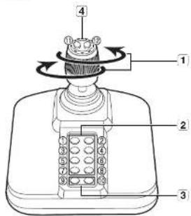
| Name Function | ||
| 1 | Up/Down/Left/Right | In PTZ mode, the camera can be paned, tilted, and controlled in 5 directionsThe webweaver only supports the PTZ mode.In Screen mode, the top/bottom/left/right tile can be selected.When you press the Near/Far button while controlling with the joystick, you can perform control simultaneously. |
| Rotation | In PTZ mode, the screen is zoomed in when it is rotated clockwise and zoomed out when it is rotated counterclockwise. | |
| 2 | 1-8 | In PTZ mode, presets number 1~8 are run.Screen mode works as follows:Changing two layout / 2: SearchBackup / 4: Zoom modeFreeze mode / 6: AudioAlarm / 8: Rec |
| 3 | 9 | It allows to exit PTZ mode in PTZ mode.The webweaver won't be able to stop the PTZ on its own.This is used to change to PTZ mode from screen mode. |
| 10 | It allows to exit PTZ mode in PTZ mode.The webweaver won't be able to stop the PTZ on its own.Goes back to the previous screen in the Screen mode. | |
| 4 | 11, 12 | In PTZ mode, Focus Near/Fat operation is run.When using the screen mode, the same operations can be done by moving the mouse. |
USING VIRTUAL KEYBOARD
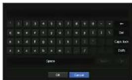
-
For alphanumeric inputs, the virtual keyboard window appears.
-
Using a mouse, click on the desired character tab.
-
Select
Entered word is applied.
- If you want to enter a special character or uppercase letters, select
■ Using the virtual keyboard is the same to a normal keyboard use in your region.
- Your ID can contain any combination of upper/overcase alphabet letters and numbers.
- If the password length is 8 to 9 digits, you can combine at least three different types of the following characters: upper/lowercase alphabets, numbers, and special characters.
- If the password length is 10 digits or more, you can combine at least two different types of the following characters: upper/lower-case alphabets, numbers, and special characters.
TrOUBLEShOOTiNg
| Problem Action | |
| Live video will be slow or cut off. | The frame number set for multiple data transmission set in camera or network environment could differ from the actual rate of transmission. Right click with the mouse button and selectto check the number of incoming frames for each channel and the actual number of frames played.Basically when you register a camera, the Live4KWR profile is created and the rate is set to 11.264.800*448fps.If necessary go to→→→and change the number of frames.If you loop scaling video slow down or cut off, then check the network environment or camera condition. |
| The system does not turn on and the indicator on the front panel does not work at all. | Check if the power supply system is properly connected.Check the system for the input voltage from the power source.If the problem persists even after you have taken the above actions, check the power supplier and replace it with a new one if necessary.Check inside if the cables are properly connected. (SNPS, FRONT) |
| The video input is okay, but the videos of some channels are not properly displayed or are abnormally displayed (e.g. black screen, BWV screen) | Check if the camera is properly supplied with power.Check the state of the cable connected to the camera and reconnect it after replacing or disconnecting itCheck the video output connecting the camera's webviewer.Check if the network port is properly connected and the network setting is set correctly.Change the hub supporting Gigabit, it may solve. |
| The screen displays the logo image repeatedly. | This may occur from a problem with the main board, or the related software is corrupt.Contact the nearest service center for more information. |
| The Channel button does not work on the Live screen. | The Channel button does not work if the current screen is in the event monitoring mode. |
| The cursor will not move to the Start button when I start the calendar search. | Check if the channel and the date that you want to play are marked with the V symbol.Both channel and date should be checked before you can start playing with the Start button. |
| No video is played on the connected monitor. | Check if the necessary cables are connected to the monitor property.Some monitors do not support the Recorder output HDMI or VGA,iRecorder output resolution - VGA - 1280*720, 1280*1024, 1920*1080, HDMI - 720P, 1080P, 1440P, 2160P. Check the monitor resolution. |
| Logo screen on backup stalls in the State. | The HDD may have problems. Visit your nearest customer service center to check the HDD. |
| No response controlling PTZ In the live viewer. | Check the registered Camera if it support PTZ function. |
| Problem Action | |
| The camera is not connected or the PC fails to connect to the product. | Check if the network cable is connected properly.Ensure that you have set Network - Connection Mode.Check the IP setting of the PC or camera.Try the Ping Test.Check if there is a different device near the product uses the same IP |
| I registered a camera, but the web viewer does not show live video. | After registering a camera, a user need to address the desired layout, before the screen split mode and live screen hit for the setting appears. |
| The input camera image is too bright or too dark. | Check the registered camera settings in "Menu> Camera> Camera Setup." |
| The time setup window will pop up. | This message is displayed if there occurs a problem with the time setting of the internal clock or an error in the clock itself.Contact the retailer or the service center for more information. |
| The time bar is not displayed in Search mode. | The timeline can switch between normal and extension mode.In extension mode, the time bar may not be displayed in the current timeline.Switch to normal mode or use the left or right button to navigate through the time bar. |
| The "NO HDD" icon and an error message are displayed. | If you do not format your purchased HDD at all or in a format supported by Recorder, a "NO HDD" icon (≡) will be displayed at the top willWhen the "NO HDD" icon is displayed, go to "Menu > Storage Device" and check the HDD connection status and format the HDD.If the problem persists in a normal condition, contact the nearest service center to have the HDD checked by the service personnel. |
| I have installed an additional HDD on the Recorder but it does not recognize the HDD. | See the compatibility list to check if the additional HDD is supported by the Recorder. For the compatibility list, contact the retailer where you purchased the Recorder. |
| I have connected an external storage device (USB Memory, USB HDD) to the Recorder but the Recorder seems not to recognize it. | See the compatibility list of external storage devices to check if the connected device is supported by the Recorder. For the compatibility list, contact the retailer where you purchased the Recorder. |
| If I press the ESC key in full screen mode of the WebViewer, the system does not switch to a normal split mode. | Press the ALT+FAB keys to select "ACTIVE MOVE" and press the ESC key again. The system will switch to a normal split mode. |
| I found it difficult to configure the network settings if using the default search, backup and router settings. | For more information, refer to the user manual.If you want to check the basics of the product for a quick start, refer to the quick start guide (backup, search).If you use the router for network connection, refer to the "Connecting and Setting the Network" section in this manual. |
| I forgot the password. | Contact the Recorder administrator for help. |
| Backup data is just not played by the PC or Recorder. | ·When you are backing up data, you have choices about the player other: PC or Recorder, Make your selection before proceeding.·If you are using the PC to play the data, the format of the backup file should be either SCC.·If you are using the Recorder for this purpose, formatting backup files should be done by the Recorder. |
| Recording does not work. | if your prayer does not display a Live image at all, that indicates recording does not work so first check if you see an image on the screen.·Recording does not work if the recording settings are not properly configured.Scheduled Record: Specify a distinct time in Menu – Record - Recording Schedule, Recording will start at the specified time.- <Continuous> Record: Recording will proceed in any conditions at the specified time.- <Event> Record: When an event occurs, recording will perform only if the event is of alarm, motion detection and video loss. If there is no event found, recording will not perform.- <Continuous / Event> Record: If there is no event found, Continuous recording will perform. Whereas, if an event occurs, Event recording will perform. |
| The image quality of the recording data is not good. | Increase the resolution and quality level in Menu – Record – Quality / Resolution.1) Resolution: Select a bigger size when specifying the recording size.The recording image in the CIF format shows a deteriorated quality as it is enlarged from a small-sized image.2) Record Quality: Specify a bigger level for the recording quality.·If you increase the resolution and the recording quality, the data size increases accordingly. So the HDD will be filled faster. Overwriting will overwrite the existing data so recording will proceed at a shorter interval. |
| Frame rate of the actual recording does not match that of configured to the camera. | ·multiple profiles were applied to one camera for video transmission, the actual video stream can be serviced by the camera at a lower frame rate than specified.Contigure your camera to use one profile for data streaming as possible. For example, if you set the same profile for recording and network profiles, the actual recording is made at the specified frame rate. Still, live video display using scilt screen mode may apply yet another profile to camera in accordance with the used screen mode. Note that allowed limit bitrate for recording / recording settings should be set to be bigger values than that of camera's feed. |
| In the recording setting screen, the permitted level for a specific channel is displayed in orange | ·the input data is greater than the permitted level for each channel, it is displayed in orange. Set the permitted data limit to higher than the amount of input data.·the sum of input data for each channel exceeds the limit, the alarm icon will be displayed. In this case, the channel exceeding the input limit does not record the entire frame, but it records the main frame onlyone or two per sec. |
| In this live screen, the [ ] Icon is displayed and the massage window saying " recording data load oxocads the limit. Check it in the record setting." pops up. | ·the sum of input data for each channel exceeds the limit, the alarm icon and the pop up window will be displayed. In this case, the channel exceeding the input limit does not record the entire frame, but it records the main frame onlyone or two per sec.Get the permitted data limit to higher than the amount of input data entered in the record Setup menu. |
| Problem Action | |
| Recording is not performed in accordance with the settings. | # the recording status displays "Exceeds the maximum hard disc performance", set the recording size according to the recording performance specifications for each HDD condition.(See the "Menu Setup > Setting the Recording" page in the Table of Contents.) |
| The recording screen will slow down. | Check whether the recording performance specifications for each HDD condition match the actual recording settings.(See the "Menu Setup > Setting the Recording" page in the Table of Contents.)# the data volume of a video exceeds the paying performance, only the main frame is played.(See the "Product Specification Manual".) |
| If recording loss persists continuously | Reset the camera recording profile to let the entire recording bps size fit the recording performance for each HDD condition. (See the "Menu Setup > Setting the Recording" page in the Table of Contents.)Check the HDD status and determine whether inspection or replacement is necessary.(See the" Storage Device" page under "Menu Setup > Setting the Recording" in the Table of Contents.) |

Hanwha Techwin cares for the environment at all product manufacturing stages, and is taking measures to provide customers with more environmentally friendly products.
The Eco mark represents Harwha Techwen's devotion to creating environmentally friendly products, and indicates that the product satisfies the EU RoHS Directive.
Correct Disposal of This Product (Waste Electrical & Electronic Equipment)
Applicable In the European Union and other European countries with separate selection systems;
This meaning on the product, accessories or literature indicates that the product and its electroto accessories is a change, headset, USB cable, which not be deposited of with other household waste at the end of their working life. To prevent possible harm to the environment or human health from uncontrolled waste disposal, please separate these items from other types of waste and recycle them responsibly to promote the sustainability use of material resources.
- In a retail user should contact either the retailer where they purchase this product, or their local government office, for means of where and how they can take these items for environmentally safe recycling.
Business users should contact their supplier and check the terms and conditions of the purchase contract. This product and its electronic accessories should not be mixed with other commercial wastes for disposal.

Correct disposal of batteries in this product
Applicable In the European Union and other European countries with separate battery return systems.
This marking on the battery, manual or packaging indicates that the batteries in this product are not being disposed or with other household waste at the end of their working line. Where marked, the chemical symbols are, Cite or Po indicate that the battery contains mercury, calcium or lead above the reference levels in FC Directive 200588. If batteries are not properly disposed, these substances can cause harm to human health or the environment. To protect natural resources and to promote material use, please separate batteries from other types of waste and recycle them through your local, more battery return system.
Head Office
6, Pangyo-ro 319 beon-gil, Bundang-gu, Seongnam-si,
Gyeonggi-do, 463-400 Rep. of KOREA
Tel: +82.70.7147.8753 Fax: +82.31.8018.3740
www.hanwha-security.com
Hanwha Techwin America
500 Frank W. Burr Blvd. Suite 43 Teaneck, NJ 07666
Toll Free +1.877.213.1222 Direct +1.201.325.6920
Fax +1.201.373.0124
www.hanwhasecurity.com
Hanwha Techwin Europe
Heriot House, Heriot Road, Chertsey, Surrey, KT16 9DT, United Kingdom
Tel +44.1932.57.8100 Fax +44.1932.57.8101
www.hanwha-security.eu

Hanwha
Techwin


- Trademark
- Restriction
- Disclaimer
- overview
- IMPORTANT SAFETY INSTRUCTIONS
- Standards Approvals
- PRODUCT USER MANUAL DESCRIPTION
- TARGET AUDIENCE
- HOW TO USE THE PRODUCT
- contentS
- llve
- menu Setup
- Search & play
- Starting web viewer
- llve vlewer
- Search viewer
- Setup vlewer
- backup vlewer
- appendix
- GETTING STARTED
- Starting the system
- Install Wizard
- Setting up the DHCP server
- Setting up the network
- live
- Shutting Down the System
- Restarting the System
- Login
- Icons on the Live Screen
- Error Information
- Live Screen Menu
- Single Mode Menu
- Split mode menu
- View the Launcher Menu
- LIVE SCREEN MODE
- Method for displaying screen mode
- Switching the split mode
- Auto Sequence
- Manual Switching
- STATUS
- Channel info
- Connection
- Live Status
- Record Status
- Check network status
- Channel Setting
- Switching to Single Mode
- ZOOM
- LAYOUT
- Setting Up the Live Layout
- AUDIO ON/OFF
- AUDIO ON/OFF in Single mode
- FREEZE
- EVENT MONITORING
- Example1)
- Example2)
- CAPTURE
- Maintain a screen ratio for all channels
- Maintain a channel screen ratio
- DISPLAY TEXT
- Change text output
- Select text output
- PTZ CONTROL
- PTZ device
- Getting started with PTZ operations
- Using the PTZ camera
- Using Digital PTZ (D-PTZ) function
- Preset
- To add a preset
- To change or delete a registered preset
- BACKUP
- SYSTEM SETUP
- Date/Time/Language
- Setting the Date/Time/Language
- User
- Setting the Administrator
- User setting
- If you want to add a group
- If you want to set group permission
- menu setuo
- Setting Permissions
- If the user has restricted access
- To change the user password
- System Management
- Checking the System Information
- Settings
- Log Information
- Checking the system log
- Checking the event log
- Checking the backup log
- SETTING THE CAMERA
- Setting the Channel
- Setting the Analog Camera
- Registering a Network Camera
- Registering a Network Camera Manually
- Network Camera Firmware Upgrade
- ONVIF Setup
- Channel
- Profile
- Network
- Relay
- Event
- Setting the Camera Functions
- SSDR
- Backlight
- Exposure
- Day/Night
- Special
- Focus
- Flip
- Screen
- Privacy
- Setting the Profiles
- Setting the Recording Profile
- Setting the Live Profile
- Setting the Remote Profile
- Editing the Profiles
- Dewarping Setup
- How to set WiseStream
- Dynamic GOV/FPS setup
- Setting Camera Password
- SETTING THE DEVICE
- Storage Device
- Device/Format
- HDD Alarm Setting
- Remote Devices
- Monitor
- Monitor settings
- Expansion monitor settings
- Display position settings
- Text
- Device Settings
- Event Settings
- Serial setup
- SETTING THE RECORDING
- Recording Schedule
- Record Setup
- Record Option
- SETTING THE EVENT
- Sensor Detection
- Camera Event
- Motion detection setup
- Analog camera setup
- Video Analysis Setup
- Detection-excluded area/Non-detection area setup
- Tampering detection
- Video Loss Detection
- Alarm Out Schedule
- Interface
- Setting a network connection
- Connecting and Setting the Network
- When no router is used
- - Static mode
- - DHCP mode
- - PPPoE
- When a router is used
- - Setting the Recorder with a static IP
- - Setting the Recorder Network
- - Setting the DHCP IP Address of the Broadband Router
- Port Setting
- DDNS
- To check Quick Connect status
- DDNS Setting
- IP Filtering
- SSL
- 802.1x
- SMTP Setting
- Event Setting
- Recipient Setting
- SNMP
- DHCP Server
- Network Setting
- To set the DHCP server
- Check IP
- P2P
- To run the P2P service
- SEARCH
- Time Search
- Color indications depending on current recording status
- Event Search
- Smart Search
- Text Search
- Backup Search
- ARB Search
- PLAYBACK
- Play
- Checking menu while playing a video
- Using the Playback Button
- WHAT IS WEB VIEWER?
- Product Features
- System Requirements
- CONNECTING WEB VIEWER
- live viewer
- Checking the system status
- Check User ID
- Camera Layout Setup
- Check Camera List
- Layout setup
- Monitoring > List
- To add a layout
- To change the layout name
- To delete a layout
- Check Event list
- To filter the Event list
- Video Export
- Check the camera status
- Check the Live video status
- Check the recorded video status
- To Change the split screen
- PC Recording
- Use Instant play
- Using PTZ
- Performing Digital zoom
- CONTROL OF CONNECTING NETWORK CAMERA
- To utilize the digital PTZ (D-PTZ) function
- To use the digital PTZ function on the Dewarping screen
- To set a preset
- To run a preset
- When running Swing (auto pan), Group (scan), Tour, or Trace (pattern)
- Search for time
- To search by date
- Color information by current recording status
- To adjust the time line
- Export search results
- Export with section setup
- To search text
- To play Text Search
- Play button names and functions
- setup viewer
- System
- Date/Time
- Time Sync.
- DST (Daylight Saving Time)
- Language
- Holiday
- Administrator
- Permission Setup
- System Information
- System Log
- Backup Log
- Camera register
- Channel Setup
- Example) Defaults of cam proxy ports for each product
- Profile Setup
- Record
- Device
- HDD Alarm
- Serial
- Recorder / Camera
- Port
- SMTP
- Recipient
- backup viewer
- SEC BACKUP VIEWER
- Recommended System Requirements
- USING A REMOTE CONTROLLER
- Changing the Remote Control ID
- USE JOYSTICK
- USING VIRTUAL KEYBOARD
- TrOUBLEShOOTiNg
- Correct Disposal of This Product (Waste Electrical & Electronic Equipment)
- Correct disposal of batteries in this product
- Head Office
- Hanwha Techwin America
- Hanwha Techwin Europe
Brand : Hanwha
Model : HRX-1620
Category : Dictaphone