RapMan 3.2 - 3D Printer BFB - Free user manual and instructions
Find the device manual for free RapMan 3.2 BFB in PDF.


| Product Type | 3D Printer |
| Brand | BFB |
| Model | RapMan 3.2 |
| Technology | Fused Deposition Modeling (FDM) |
| Build Volume (Approx.) | 200 mm x 200 mm x 200 mm |
| Assembly Required | Yes (kit form) |
| Number of Extruders | 1 (single head standard) or 2 (double head upgrade option) |
| Hot End Type | Non-built (NBHE), Built (BHE), or Double (DH) depending on option |
| Power Supply | Standard power supply unit included (unspecified voltage/wattage) |
| Frame Material | Steel rods with laser-cut acrylic panels |
| Control Panel | Touch screen display (Version 3.2) |
| Print Material | PLA, ABS, or similar filament (1.75 mm diameter typical) |
| Nozzle Diameter | 0.5 mm (standard) |
| Bed Leveling | Manual adjustable bed with microswitch |
| Motion System | Belt-driven X, Y, and Z axes |
| Temperature Sensing | 200K thermistor included |
| Heating Element | Insulated nichrome wire for hot end |
| Build Time (Assembly) | 2-3 full days recommended |
| Maintenance | Regular cleaning of rods and bearings; avoid over-tightening acrylic parts |
| Safety Precautions | Wear eye protection when assembling; do not over-tighten acrylic to prevent shattering |
| Spare Parts Availability | Bolt tray, laser-cut acrylic pack, steel pack, stepper tray, and other bagged components included; double head upgrade available |
| Repair | Broken acrylic parts can be repaired with cyanoacrylate glue (super glue) |
| Software | Compatible with standard 3D printing software (e.g., Repetier-Host, Slic3r) |
| Connectivity | USB breakout PCB for computer connection |
Frequently Asked Questions - RapMan 3.2 BFB
User questions about RapMan 3.2 BFB
0 question about this device. Answer the ones you know or ask your own.
Ask a new question about this device
Download the instructions for your 3D Printer in PDF format for free! Find your manual RapMan 3.2 - BFB and take your electronic device back in hand. On this page are published all the documents necessary for the use of your device. RapMan 3.2 by BFB.
USER MANUAL RapMan 3.2 BFB
natural_image
Blue globe logo with white 'BFB' text, no additional symbols or text visibleRapMan 3.2
Build Manual
-
Home
-
RapMan 3.2 build manual
2.1 1. How to use this manual
2.2 2.3D content
2.2.1 Configuring Firefox for viewing 3D content
2.2.2 Configuring Internet Explorer (IE) for viewing 3D content
2.3 3. Build requirements
2.4 4. Kit contents
2.4.1 a. Bolts tray
2.4.2 b. Laser cut parts identification
2.4.3 c. Small bags contents
2.4.4 d. Double head upgrade pack contents (option)
2.4.5 e. PCB pack
2.5 5. Assembly technique for acrylic parts
2.6 6. Assembly overview
2.7 7. Frame minor sub-assemblies
2.7.1 7a. Bottom Corner Block R x 2
2.7.2 7b. Bottom Corner Block L x 1
2.7.3 7c. Z Motor Block x 1
2.7.4 7d. Top Corner Block R x 2
2.7.5 7e. Top Corner Block L
2.7.6 7f. Y Motor Block x 1
2.7.7 7g. Bed Corner (Long) x 2
2.7.8 7h. Bed Corner (Short) x 2
2.7.9 7i. Filament Reel Holder
2.7.10 7j. Adjustable Bed x 1
2.7.11 7k. X Motor Plate x 1
2.7.12 7I. X Idler Plate x
2.7.13 7m. X Rod & Belt Clamps
2.7.14 7n. Z Idler Post (long) x 2
2.7.15 7o. Z Idler Post (short) x 2
2.8 8. Frame major sub-assemblies
2.8.1 8a. Base Frame
2.8.2 8b. Frame Vertical Bars
2.8.3 8c. Z Idlers
2.8.4 8d. Top Frame
2.8.5 8e. Fitting Upper Square To Frame
2.8.6 8f. X Motor & Rails
2.8.7 8g. Y Idlers
2.8.8 8h. Y Motor
2.8.9 8i. X Carriage
2.8.10 8j. Bed frame
2.8.11 8k. X, Y & Z Belts
2.8.12 8l. Fitting adjustable Bed
2.8.13 8m. Diagonal Ties Base
2.8.14 8n. Diagonal Ties Sides
2.8.15 8o. Diagonal Ties Front & Back
2.8.16 8p. Fitting the Conduit
2.8.17 8q. Serial number
2.9 9. Hot end assembly (option)
2.9.1 a. Preparing the insulated nicrome heating wire
2.9.2 b. Preparing the thermistor
2.9.3 c. Nozzle assembly
2.9.4 d. Wrapping the insulated nichrome
2.9.5 e. Fitting the thermistor
2.10 10. Extruder assembly
2.10.1 10a. Extruder acrylic parts identification
2.10.2 10b. Main plates
2.10.3 10c. Drive shaft
2.10.4 10d. Drive assembly
2.10.5 10e. Motor Mount
2.10.6 10f. Filament guide
2.10.7 10g. Pressure wheels
2.10.8 10h. Mounting plate
2.10.9 10i. Hot end fitting
2.10.10 10j. Pressure springs and wheels
2.10.11 10k. Conduit preparation
2.10.12 10l. Running the wires
2.10.13 10m. Mounting the extruder fan
2.10.14 10n. Mounting the extruder
2.11 11. Control panel
2.11.1 11a. PCB base
2.11.2 11b. Top plate
2.11.3 11c. Wiring
2.11.3.1 IDC wire fitting tool
2.11.4 11d. Ribbon cables
2.11.5 11e. Final assembly
2.11.6 11f. Tidying the conduit
2.12 12. Double head calibration
2.13 13. Next step
Home
Error formatting macro: redirect: java.lang.NullPointerException
RapMan 3.2 build manual
natural_image
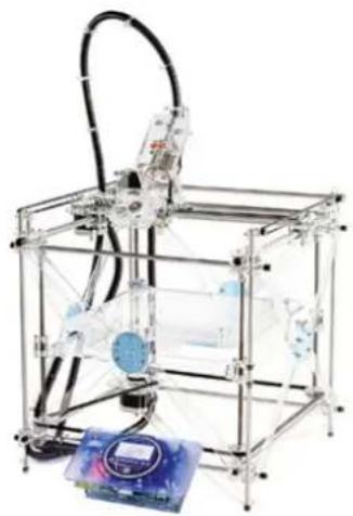
Transparent 3D printer setup with transparent frame and internal components, no visible text or symbolsWelcome to the RapMan 3.2 Build Manual. This manual is designed to get you up and running as quickly as possible. It can be read either on-line or off-line (see below). To print out a copy of this manual, simply follow the off-line instructions to generate a PDF of the build manual, and then print the PDF. 3D content can be downloaded separately.
To complete the exercises in this manual the user will need all the items included in the RapMan 3.2 box.
On-line reading (essential notes)
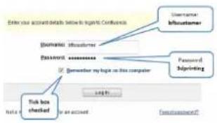
Online reading includes embedded 3D content. However, if left idle for over 120 minutes, technical resources will automatically time-out, and direct you to a log in page. Please note the details below. Simply enter:
- Username: bfbcustomer
• Password: 3D printing - Check the "Remember me" box
This will prevent the timeout from happening again during your session.
text_image
Enter your account details below to login. Confuses Username In customer Password Password Password by login on this computer Password Authentication Help Help box checked No check Fax: https://www.103.com/ Fax: https://www.103.com/You can start reading the manual by clicking the links on the navigation bar at the left of the screen:

text_image
3D Touch Set Up and Operations Manual 1. Introduction 2. How this manual works 3. Manual symbols 4. Process overview... how the 3D Touch works 5. Print material 6. Pre-print checks 7. Print the first model 8. Essential post-print operations 9. Further printing 10. Further operations 11. Troubleshooting 12. SpecificationsOff-line reading
Download the build manual
If you prefer to view this document off-line:
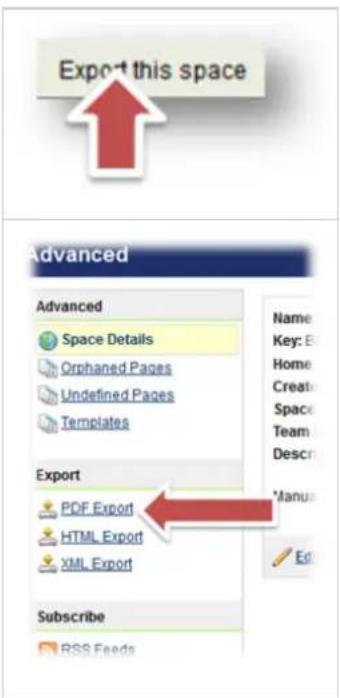
- Simply click on the "Export this space" button at the top left of the screen to export the manual to a PDF. Follow the on screen instructions.
- For printing it is suggested that your print mode is set to "picture". This will slow the print speed but make the document much clearer to read.
text_image
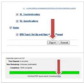
Export this space Advanced Advanced Space Details Orphaned Pages Undefined Pages Templates Export PDF Export HTML Export XML Export Subscribe RSS Feeds Name: Key: E Home Create Space Team Descr Manu EditIf you have a slow internet connection, it is possible to select individual sections of the manual to export, making it possible to download small sections at a time. Simply tick the boxes next to the sections you need.
Alternatively, if bandwidth is not an issue, select all.
text_image
11. Troubleshooting 12. Specifications Home BFB-Touch Set Up and Open Manual Export Cancel Expiring Space as PDF Time Disposed: 4 seconds Time Remapping: (Minimum estimated) Completion: 10% complete Finished PDF once report DownloadingDownload the 3D content
Embedded 3D content will not be downloaded with the build manual PDF. You will need to download the 3D content separately here and view it in parallel with the build manual.
1. How to use this manual
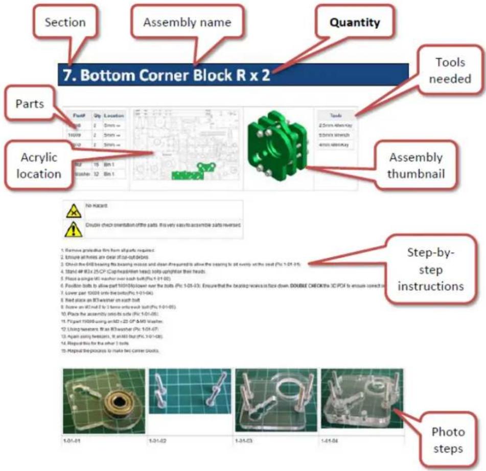
This manual offers a step-by-step procedure for assembling your RapMan. The picture below illustrates how each assembly build page is laid out:
text_image
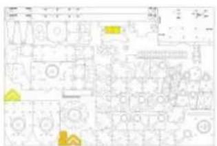
Section Assembly name Quantity 7. Bottom Corner Block R x 2 Tools needed Parts Acrylic location No Hazard Crude check orientation of the suits. Find very easy to assemble suits reversed Step-by-step instructions Photo steps 1. Remove protective lines from all parts required. 2. Ensure arches are clear of out-of-care. 3. Choose the MD bearing the bearing motion and clean if required to allow the bearing to sit onto the seat (Pc 1-01-05). 4. Stip #8 (Ex 25 CP Cup head/beam head) suits upright for their heads. 5. Place a single MD washer over load built (Pc 1-01-05). 6. Position bolts to allow part 10/01/05 lower over the bolts (Pc 1-01-05). Enquire that the bearing marks face down. DOUBLE CHECK the IC PD is ensure correct or 7. Lower part 10/01 into the bolt (Pc 1-01-05). 8. Red place an RT washer on each bolt. 9. Solve an RD not 2 by 3 times each bolt (Pc 1-01-05). 10. Place the assembly onto its bolt (Pc 1-01-05). 11. Print part 10/00 using an MD + 25 CP & MD Washer. 12. Using websets, it is RT washer (Pc 1-01-05). 13. Again serial breakers, it should be (Pc 1-01-05). 14. Repeat this for the other 3 bolts. 15. Replace the process to make arc corner clips. 1.01-01 1.31-02 1.31-03 1.41-04TIP: For the on-line manual all images are thumbnails - simply click on an image to reveal a magnified version. This is especially useful for the laser cut part identification image. To test using this functionality, click the image below: you should see a pop-out larger version on your browser.
text_image
Technical schematic diagram with labeled components and colored annotations indicating specific areas or zones.2. 3D content
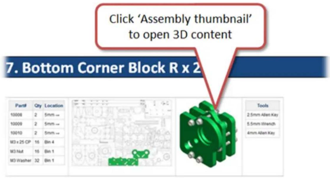
The online manual also hosts 3D content which allows you to view a model of each sub-assembly in 3D on-screen. On any manual page, simply click on the "Assembly thumbnail" to open the 3D model.
text_image
Click 'Assembly thumbnail' to open 3D content 7. Bottom Corner Block R x 2 Part# Qty Location 10008 2 5mm → 10009 2 5mm → 10010 2 5mm → M3 x 25 CP 16 Bin 4 M3 Nut 16 Bin 1 M3 Washer 32 Bin 1 Tools 2.5mm Allen Key 5.5mm Wrench 4mm Allen Key
No Hazard
Double check orientation of the parts. It is very easy to assemble parts reversed.
- Remove protective film from all parts required.
Ensure all holes are clear of cut-out debris.
Check the 608 bearing fits bearing recess and clean if required to allow the bearing to sit evenly on the seat (Plc 1-01-01) - Stand 4# M3 x 25 OP (Cap head/Hlen head) bolts upright on their heads.
Place a single M3 washer over each bolt (Pic 1-01-02)
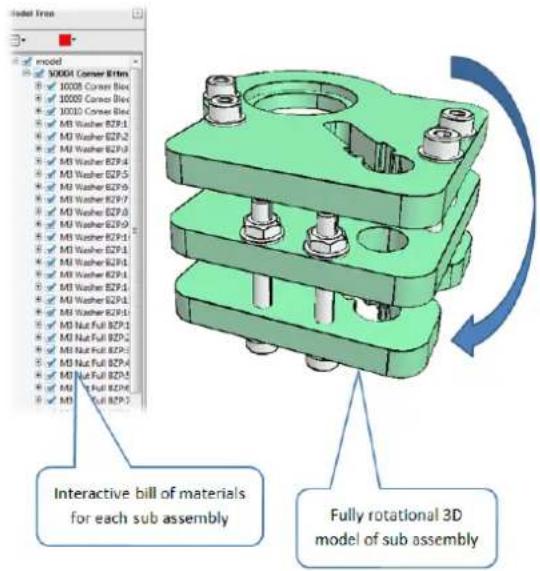
This enables you to either follow step-by-step instructions, or work from a 3D model, or both. The 3D model is:
- fully rotational
• complete with part identification - layered, to switch part visibilities on and off
text_image
Model Tree model 1000A Corner B1M 1000B Corner B2C 1000C Corner B3C 1000D Corner B4C 1000E B5P.1 1000F B5P.2 1000G B5P.3 1000H B5P.4 1000I B5P.5 1000J B5P.6 1000K B5P.7 1000L B5P.8 1000M B5P.9 1000N B5P.10 1000O B5P.11 1000P B5P.12 1000Q B5P.13 1000R B5P.14 1000S B5P.15 1000T B5P.16 1000U B5P.17 1000V B5P.18 1000W B5P.19 1000X B5P.20 1000Y B5P.21 1000Z B5P.22 1000A B5P.23 1000B B5P.24 1000C B5P.25 1000D B5P.26 1000E B5P.27 1000F B5P.28 1000G B5P.29 1000H B5P.30 Interactive bill of materials for each sub assembly Fully rotational 3D model of sub assemblyConfiguring your browser
You will need to check the settings on your browser to ensure that the 3D content opens in a new window. This makes viewing much more efficient, as you will be able to flip between the 3D content and main manual. Click below for:
- Configuring Firefox (recommended browser)
- Configuring Internet Explorer (IE)
System requirements
- You will need Adobe Reader version 7 or later. You can download Adobe Reader here.
- You will need a fairly quick computer and an internet connection with good bandwidth.
System test
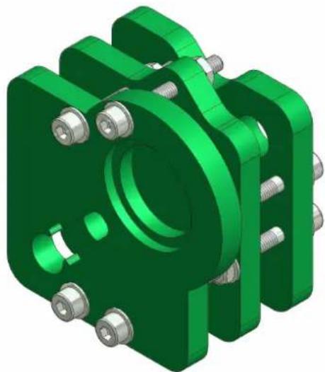
You can test your system by clicking on the thumbnail below:
natural_image
3D rendered green mechanical bracket with bolts and mounting holes (no text or symbols)How to use the 3D content
Part rotation
Left click on the model and drag to rotate the model.
Part identification
The model tree pane should appear on the left of the window. If not, while the mouse is over the model, click the 'Model tree' button:

flowchart
graph TD
    A["Input 1"] --> B["Process 1"]
    C["Input 2"] --> D["Process 2"]
    E["Input 3"] --> F["Process 3"]
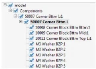
Expand the model tree on the left of the screen:
text_image
model Components 50007 Corner Bttm L1 50007 Corner Bttm L 10008 Corner Block Bttm Bttm1 10009 Corner Block Bttm Mid1 10011 Corner Block Bttm Top L1 M3 Washer BZP:1 M3 Washer BZP:2 M3 Washer BZP:3 M3 Washer BZP:4 M3 Washer BZP:5Click on either the model to highlight a part in the model tree, or on the model tree to highlight a part in the model.
Part visibility
Next to a part in the model tree, click the checkbox to remove the tick and hide the part. Click again to restore the tick and restore visibility. This can be useful to see/find embedded parts on complex assemblies.
Configuring Firefox for viewing 3D content
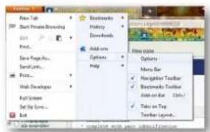
Click on the, then: Main menu Options
text_image
New Tab Start Private Streaming Add... Save Pages... Send Lines... Add... Web Developer Add Screen... Set View... Add Bookworks History Downloads Add some Options Help Options Menu Bar Navigator Toolbar Bestmasks Toolbar Add on Bar (Edit) Sales on Top Toolbar Layout...Click on and set to :pdf File (application/x-download) Use Adobe Reader
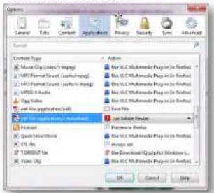
text_image
Options General Views Content Applications Preview Security Sync Advanced Search Content Type Movie Clip (L studio/mpg) MPC Format Sound (audio/mpg) MPC Format Sound (audio/mpg) MPC 4 Audio Play Value Soft File Applications (off) Audio Use UCL Multimode Plug in (in radio) Use UCL Multimode Plug in (in radio) Use UCL Multimode Plug in (in radio) Use UCL Multimode Plug in (in radio) Save Film Use Sublinear Filter Premiere Audio Use UCL Multimode Plug in (in radio) Always ask Use Disordered HQ plugin for Windows... Use UCL Multimode Plug in (in radio) OK Cancel HelpClick .OK
This will open 3D content in a separate window. To flip between the 3D content window and the main manual, press the Alt key then the Tab key:

text_image
Alt & TabConfiguring Internet Explorer (IE) for viewing 3D content
When viewing all 3D content in IE, it is best to load it in a new tab so that you can flip between written and 3D content easily. To load the 3D content in a new tab, click the 3D thumbnail using the left mouse button whilst pressing the CTRL key:
+ Left mouse click
Then, to flip between tabs, press the CTRL key + Tab:
+
3. Build requirements
To build a RapMan, we recommend allocating:
• 2-3 full days, depending on the skill of the builder.
• A bench area of 3 square meters.
4. Kit contents
RapMan options
The table below references the variation in contents for each RapMan option. Check to make sure you are aware what you RapMan option includes.
| RapMan option Number of extruders Hot end type | ||
| Extreme (NBHE) | 1 Non-built | |
| Universal (BHE-NS) | 1 Built | |
| Ultimate (DH-NS) | 2 Built | |
| Education pack | 1 Built | |
| Techlink pack | 1 Built | |
Contents
Before beginning assembly, check the kit contents.
| Description Option Qty Identification | |||
| Bolt Tray Standard 1 Click here | |||
| 5mm laser cut panel pack Standard 1 Click here | |||
| Steel Pack Standard 1 See image below | |||
| Stepper Tray Standard 1 See image below | |||
| Bag 1 Standard 1 Click here | |||
| Bag 2 Standard 1 Click here | |||
| Hot End Built/Hot end non-built Option (see table above) 1 Click here | |||
| Power Supply Standard 1 See image below | |||
| PP Conduit (Stiff) Standard 1 See image below | |||
| PVC Conduit (Shiny) | Standard 1 See image below | ||
| Test Length of Filament | Standard 1 See image below | ||
| 8mm/3mm laser cut panel pack | Standard 1 Click here | ||
| Extruder Bag Standard 1 Click here | |||
| Fan kit | Option (see table above) 1 Click here | ||
| Double head upgrade pack | Option (see table above) 1 Click here | ||
| Motor wire set | Standard 1 Click here | ||
| Control panel acrylics | Standard 1 Click here | ||
| Control panel parts | Standard 1 Click here | ||
| PCB pack | Standard 1 Click here | ||
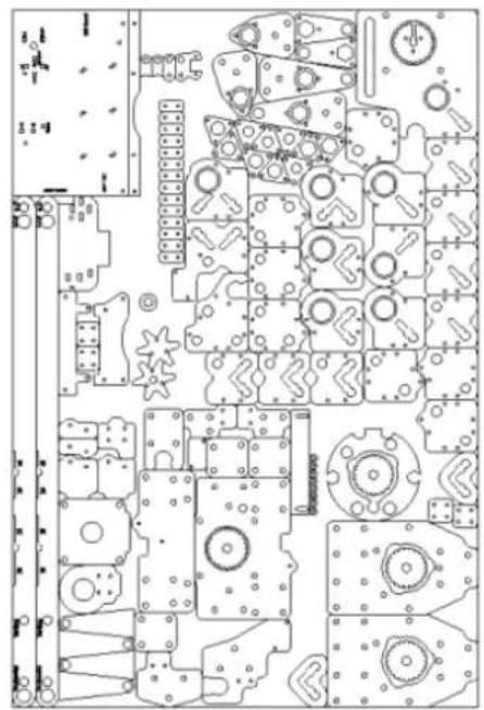
Top Layer 5mm Panels
natural_image
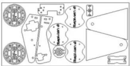
Pure technical schematic lines without any readable text, numbers, or symbolsBase Layer 8mm Panels
text_image
Technical diagram of a mechanical part with labeled parts and cross-sectional views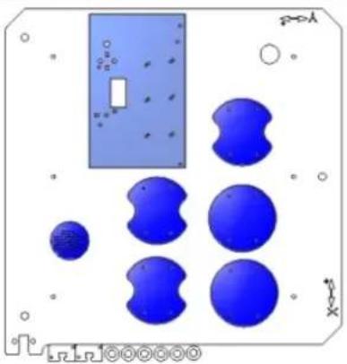
natural_image
Pure electrical circuit lines without any symbolstext_image
Power Supply Bolt TrayLoose In Box



a. Bolts tray
| Bin Number | Description Qty | |
| Bin 1 | M3 Nut Full BZP 135 | |
| M3 Nut Nyloc BZP 2 | ||
| M3 Washer BZP 335 | ||
| Bin 2 | M3 x 12 Cap Head BZP 20 | |
| M3 x 16 Cap Head BZP 37 | ||
| M3 x 20 Cap Head BZP 15 | ||
| M3 x 30 Cap Head BZP 4 | ||
| M3 x 6 Grub Screw (Set Screw) 4 | ||
| M3 x 35 Cap Head BZP 4 | ||
| Bin 3 | M8 x 40 Washer BZP 8 | |
| Bin 4 | M3 x 25 Cap Head BZP 74 | |
| Bin 5 | M2 Nut Full BZP 2 | |
| M2 x 12 Cheese Head BZP 2 | ||
| M3 x 12 Washer BZP 5 | ||
| M5 x 16 Cap Head BZP 10 | ||
| M5 x 20 Cap Head BZP 18 | ||
| M8 x 30 Washer BZP 2 | ||
| Bin 6 | M5 Nut Full BZP 96 | |
| M5 Washer BZP 110 | ||
| M5 x 6 Grub Screw (Set Screw) 24 | ||
| Bin 7 | M5 x 35 Cap Head BZP 26 | |
| Bin 8 | M8 Nut Full BZP 32 | |
| M8 Nut Wing BZP | 1 | |
| M8 Washer BZP 37 | ||
| Bin 9 | M5 x 20 Hexagon Head BZP | 3 |
| M5 x 25 Cap Head BZP 4 | ||
| M5 x 30 Cap Head BZP 10 | ||
| M5 x 45 Cap Head BZP 2 | ||
| M5 x 55 Cap Head BZP 2 | ||
| Bin 10 | 008 7150 114 42 8∅ Slide Bearing | 4 |
| 1_4 Coupling | 1 | |
| 301 3150 599 34 M3 Spacer 15mm | 12 | |
| C2-4243-2M Spring | 7 | |
| MXL 18T DF Pulley | 3 | |
| 12∅ Rod Cover | 4 | |
| Bin 11 | 608ZZ Bearing | 9 |
| 623ZZ Bearing 5 | |
| RI-1214ZZ 1 | |
| 8∅ Rod Cover 16 |
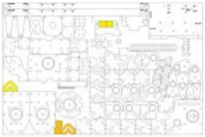
b. Laser cut parts identification
Notes:
- For each panel, "mm" refers to the thickness of the plastic sheet.
- Both 5mm sheets are packed together
• The 8mm and the 3mm sheets are packed together
Jump to:
- 5mm main panel
- 5mm braces panel
- 8mm panel
- 3mm panel
• Control panel acrylics
• Extra 5mm parts for double head (option)
5mm main panel
Note: Parts 10130, 10132, 10135, and 10136 are for an older version of machine and may not be included in the laser cut-outs. They are not needed for the RapMan 3.2.
Note: Two extra 10027/10008 have been included as spares.
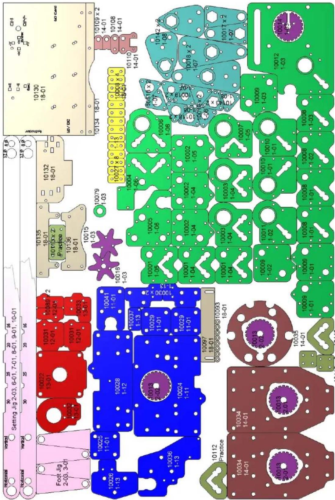
text_image
Horizontal Vertical Setting Jig 2-03, 6-01, 7-01, 8-01, 9-01, 10-01 Horizontal Vertical Foot Jig 2-03, 3-01 10022 13-01 10031 12-01 10089 x 2 12-01 10032 13-01 10031 12-01 10033 13-01 10135 18-01 d0 t13 x 2 Practice 10136 18-01 10132 18-01 10015 1-03 10079 1-03 10027 x 8 1-3 10008 x 4 15-01 10134 18-01 10109 x 2 14-01 10108 14-01 10026 1-13 10025 11-01 10028 1-12 10041 11-01 *10037 1-13 10036 1-13 *10029 11-01 10024 1-11 *10037 x 2 *1-13 10030 x 2 *2-02 10097 18-01 *2-02 *2-02 *2-02 *2-02 *2-02 *2-02 *2-02 *2-02 *2-02 *2-02 *2-02 *2-02 *2-02 *2-02 *2-02 *2-02 *2-02 *2 - 2 - 2 - 2 - 2 - 2 - 2 - 2 - 2 - 2 - 2 - 2 - 2 - 2 - 2 - 2 - 2 - 2 - 2 - 2 - 2 - 2 - 2 - 2 - 2 - 2 - 2 - 2 - 2 - 2 - 2 - 2 - 2 - 2 - 5 *5/6/7/8/9/10/11/14/15/16/17/18/19/20/21/22/23/24/25/26/27/28/29/30/31/32/33/34/35/36/37/38/39/40/41/42/43/44/45/46/47/48/49/50/51/52/53/54/55/56/57/58/59/60/61/62/63/64/65/66/67/68/69/70/71/72/73/74/75/76/77/78/79/80/81/82/83/84/85/86/87/88/89/90/91/92/93/94/95/96/97/98/99/100 / 9 / 9 / 9 / 9 / 9 / 9 / 9 / 9 / 9 / 9 / 9 / 9 / 9 / 9 / 9 / 9 / 9 / 9 / 9 / 9 / 9 / 9 / 9 / 9 / 9 / 9 / 9 / 9 / 9 / 9 / 9 / 9 / 9 / 9 :5mm braces panel
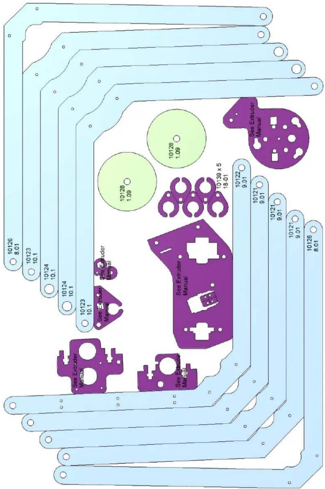
other
| Panel ID | Dimension | | -------- | --------- | | 10126 | 8.01 | | 10123 | 10.1 | | 10124 | 10.1 | | 10124 | 10.1 | | 10123 | 10.1 | | 10128 | 1.09 | | 10128 | 1.09 | | 10139 x 5 | 18-01 | | 10122 | 9.01 | | 10121 | 9.01 | | 10121 | 9.01 | | 10126 | 8.01 | | See Extruder Manual | — | | See Extruder Manual | — | | See Extruder Manual | — | | See Extruder Manual | — | | See Extruder Manual | — | | See Extruder Manual | — | | See Extruder Manual | — | | See Extruder Manual | — | | See Extruder Manual | — | | See Extruder Manual | — | | See Extruder Manual | — | | See Extruder Manual | — |8mm panel
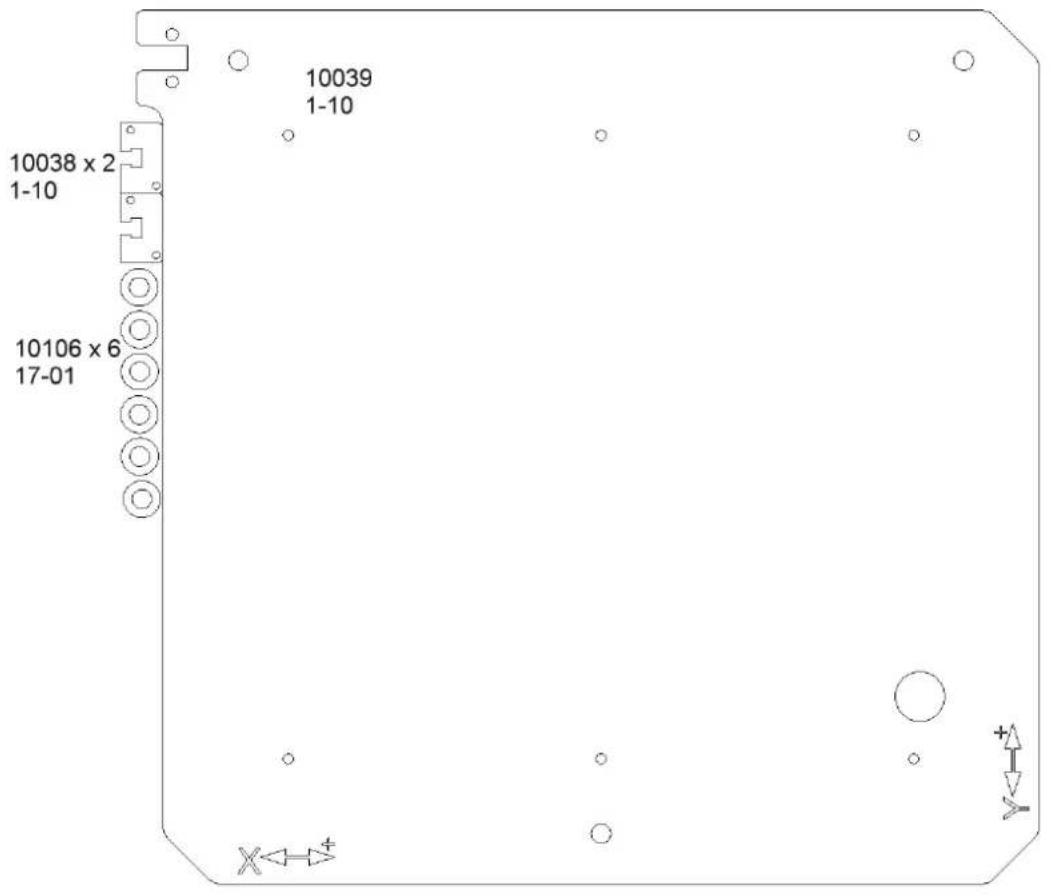
text_image
10038 x 2 1-10 10106 x 6 17-01 10039 1-10 X←→+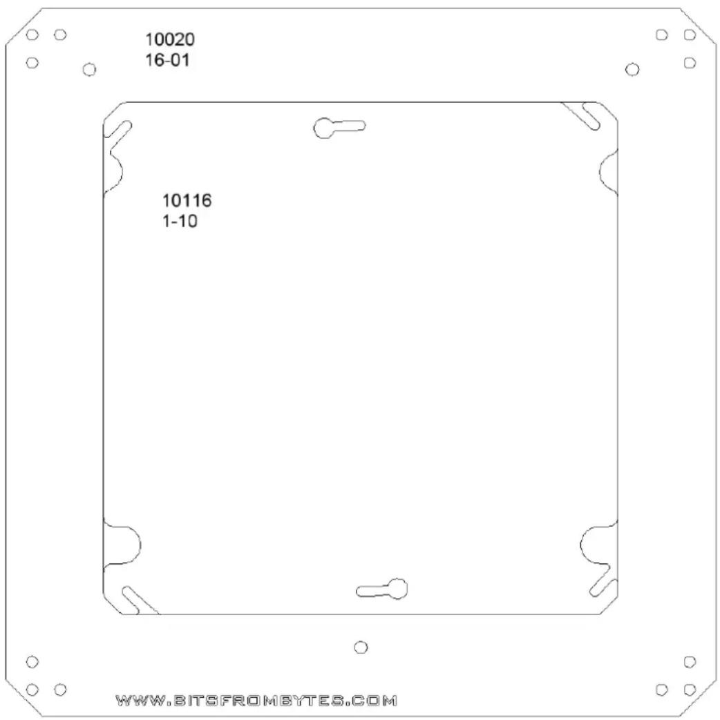
text_image
10020 16-01 10116 1-10 WWW.BITSFROMBYTES.COMNote: Part 10039 only shown here with one larger hole, but will have two large holes in actual part.
3mm panel
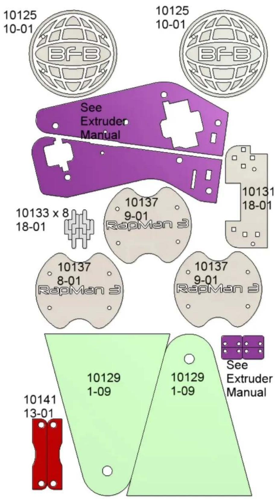
text_image
10125 10-01 BFB 10125 10-01 BFB See Extruder Manual 10133 x 8 18-01 10137 9-01 RapMan 3 10137 8-01 RapMan 3 10137 9-01 RapMan 3 10141 13-01 10129 1-09 10129 1-09 See Extruder ManualControl panel acrylics
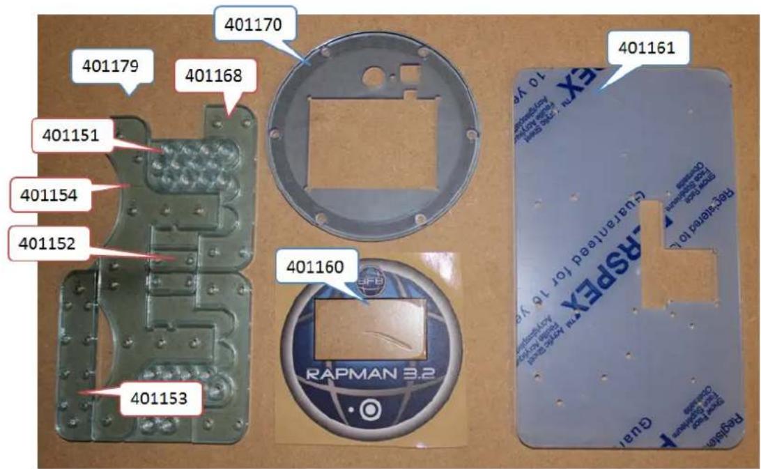
text_image
401179 401168 401170 401151 401154 401152 401153 401160 401161 RAPMAN 3.2 PAPSPLEX Renewable for 16 years Regulated 10 years Guari PapSPLX Renewable for 16 years Regulated 10 years Guari PapSPLX Renewable for 16 years Regulated 10 years Guari PapSPLX Renewable for 16 years Regulated 10 years Guari PapSPLX Renewable for 16 years Regulated 10 years Guari PapSPLXX Renewable for 16 years Regulated 10 years Guari PapSPLXX Renewable for 16 years Regulated 10 years Guari PapSPLXX Renewable for 16 years Regulated 10 years Guari PapSPLXX Renewable for 16 years Regulated 10 years Guari PapSPLXXX Renewable for 16 years Regulated 10 years Guari PapSPLXXX Renewable for 16 years Regulated 10 years Guari PapSPLXXX Renewable for 16 years Regulated 10 years Guari PapSPLXXX Renewable for 16 years Regulated 10 years Guari PapSPLXXXX Renewable for 16 years Regulated 10 years Guari PapSPLXXX Renewable for 16 years Regulated 10 years Guari PapSPLXXXExtra 5mm parts for double head (option)
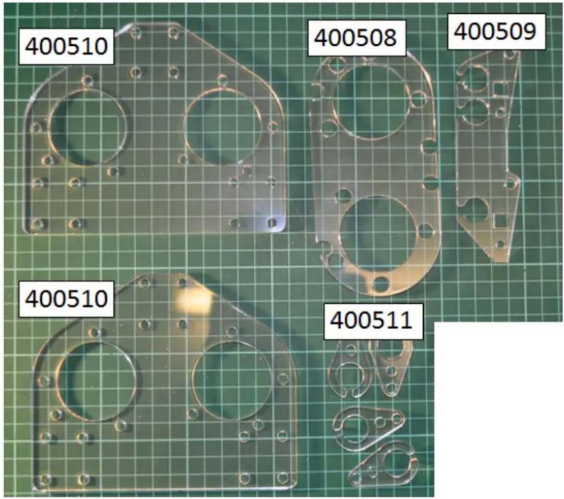
text_image
400510 400508 400509 400510 400511c. Small bags contents
This page list the parts in the small bags:
- Bag 1
- Bag 2
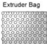
- Extruder Bag
- Fan kit
• Hot end built/non-built (option) - Motor wire set
• Control panel acrylics
• Control panel parts
Tip: Click on the thumbnails to view a larger image of the bag contents.
Bag 1
| Description Qty | |
| Belt 2 | |
| Elastic Bands 7 | |
| Tie Wrap 5 | |
| Micro-switch (orange) 1 | |
| Micro-switch (yellow) 1 | |
| Micro-switch (white) 1 |
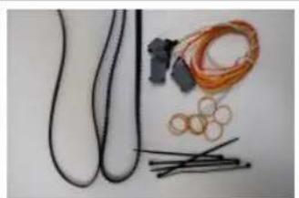
natural_image
Assorted electrical wires and components laid out on a plain surface (no text or symbols visible)Bag 2
| Description Qty |
| M8 x 120 Hex 1 |
| M8 x 40 Hex 1 |
| M8 x 60 Hex 3 |
| 20003 Steel 1 |
| 20005 Steel 2 |
| 20007 Steel 1 |
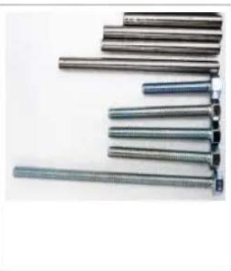
natural_image
Collection of metallic rods arranged in a row, no visible text or markingsExtruder Bag
| Description Qty | |
| M3 x 10 CP 4 | |
| M3 x 6 Grub 1 | |
| M3 Nut 6 | |
| M3 Washer 18 | |
| M3 x 30 CP 4 | |
| M3 x 20 CP 1 | |
| M5 Nut 11 | |
| M5 Nyloc 1 | |
| M5 Washer 17 | |
| M5 x 20 CP 2 | |
| M5 x 25 CP 6 | |
| M5 x 30 Hex 2 | |
| M5 x 70 Hex 1 | |
| M8 Nut 2 | |
| M8 Spring Washer 1 | |
| M8 Washer 2 | |
| Drive Shaft 1 | |
| Small Spring 2 | |
| 623 Bearing 2 | |
| 608 Bearing 2 | |
| Orange Caps 2 | |
| Hot End 1 | |
| Drive Gear 1 | |
| Driven Gear 1 | |
| Resistor 1 |
Fan kit
The bag included depends on your RapMan option. .Click here to reference option contents
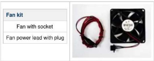
text_image
Fan kit Fan with socket Fan power lead with plugHot end built/non-built (option)
The bag included depends on your RapMan option. .Click here to reference option contents
| Hot end non-built | Hot end built |
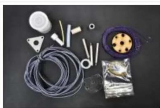
natural_image
Assorted automotive components including hoses, tools, and a wheel assembly on a dark surface (no text or symbols visible)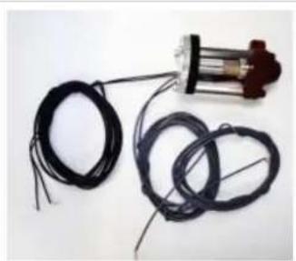
natural_image
Close-up of a mechanical sensor with coiled black wires and a mounted motor (no text or symbols visible)| Description Qty | |
| Extruder Insulation Retainer 1 | |
| Yellow Silicone Sleeving 140mm 1 | |
| M3 x 40 M-F Spacer SS 3 | |
| PEEK Insulator 1 | |
| Extruder Aluminium Spacer 1 | |
| Nozzle Holder 2mm SS 1 | |
| Silicone Insulator Tube 1 | |
| PTFE Extruder Tube 50mm 1 | |
| MDF Extruder Insulator 1 | |
| Fire Cement Tub 1 | |
| Grey Wire 2m 2 | |
| Purple Wire 2m 2 | |
| Nozzle 0.5mm 1 | |
| Hot End Small Parts Bag... contains below: 1 | |
| M3 Nut Full BZP 3 | |
| M3 x 16 Cap Head BZP 3 | |
| Bootlace Ferrule 4 | |
| 200K Thermistor | 1 |
| Insulated Ni-Chrome 680mm | 1 |
| Description | Qty |
| Pre-built hot end 1 |
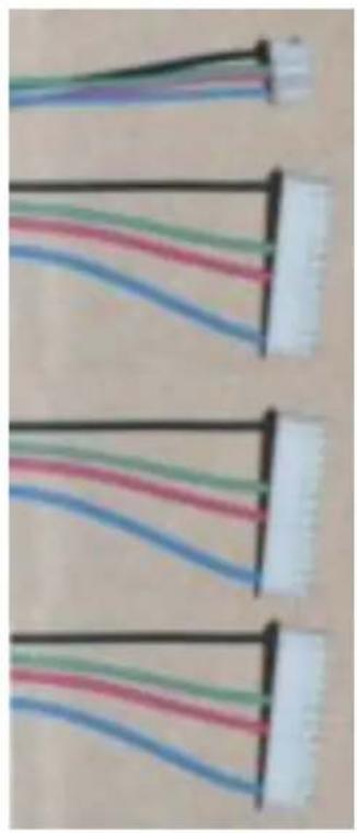
Motor wire set
Description Qty
Nema 17 Stepper c/w Plug & Wire 1
Nema 23 Stepper c/w Plug & Wire 3
natural_image
Close-up of four cable connectors with black, green, red, and blue wires (no text or symbols visible)
natural_image
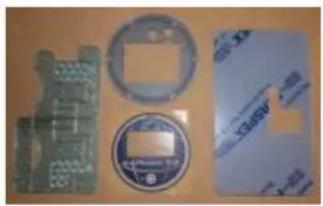
Close-up of a metallic, ribbed object wrapped in foil, with no visible text or symbols.Control panel acrylics
See for part identification. Laser cut parts
| RapMan 3.2 Touch face plate 1 | |
| RapMan 3.2 Touch laser cut electronics set 1 | |
| RapMan 3.2 Touch label 1 | |
| RapMan 3.2 Touch screen mount 1 |
natural_image
Four electronic components laid out on a wooden surface: circuit board, circular component, and printed paper (no visible text or symbols)Control panel parts
| Description Qty | |
| Cooling Fan 80mm no LEDs 2 | |
| RapMan 3.2 Touch control panel bolt bag 1 | |
| RapMan 3.2 Touch control small bag 1 | |
| RapMan 3.2 10 way ribbon cable 1 | |
| RapMan 3.2 14 way ribbon cable 1 |
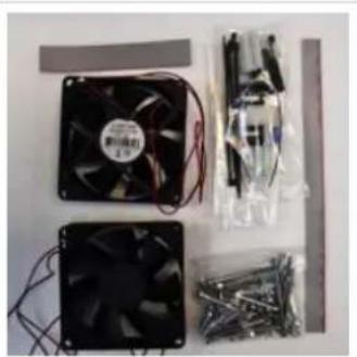
natural_image
Assorted electronic components including a black CPU fan, two black fans with visible wiring, and metal hardware parts (no text or symbols visible)d. Double head upgrade pack contents (option)
The double head pack may be included depends on your RapMan option. Click here to reference option contents. Tip: Click on thumbnail to view larger image of pack contents.
Pack contents
| Decription Qty | 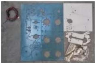 | |
| DH 5mm Laser Cut Parts 1 | ||
| DH 3mm Laser Cut Parts 1 | ||
| 8mm Extruder Main Plate 1 | ||
| RapMan 3.1 Double Head Bolt Bag contains: 1 | ||
| M8 x 130 hex head bolt SS full thread 1 | ||
| M8 Washer BZP 6 | ||
| M8 Nut Wing BZP 1 | ||
| M8 Nut Full BZP 4 | ||
| M5 x 20 Hex Head BZP 3 | ||
| M5 Nut Full BZP 6 |
| Decription Qty | 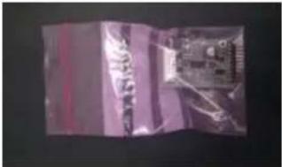 | 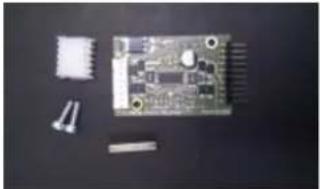 | |
| M3 x 10 Cap Head BZP 2 | |||
| IDC socket 8 way 2.54mm pitch 1 | |||
| Extruder Electronics Module 1 |
Extra components
As well as the pack detailed below, extra items will be included loose in the box to complete the kit:
• Extra extruder bolt bag
• Extra NEMA 17 motor (small)
- Extra Hot End
Identification of 5mm acrylic double head carriage parts
See Laser cut parts identification
e. PCB pack
| Part number Qty Description |
| 401049 1 Extruder Electronics Module |
| 401052 1 Touch Screen Electronics Module |
| 401053 1 Main Controller Electronics Module |
| 401071 1 USB breakout PCB |
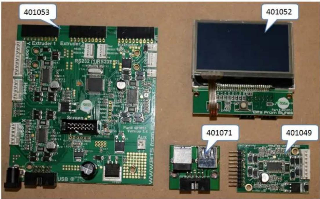
text_image
401053 Extruder 1 Extruder 2 RS232 (1)RS238 (2) Extruder 3 9690 Screen Part# 401053 Version 3.4 Aux USB 401052 Part# 401053 Burs From Bunes 401071 4010495. Assembly technique for acrylic parts
The RapMan kit consists of a steel frame held together by clamped acrylic parts to form a fully functional 3D printer. These acrylic parts require care during assembly.
Acrylic part preparation
- The acrylic parts have a blue protective film to protect them during transport. Remove this film before building the RapMan as it is not possible to fully remove it after building.
- Also, ensure that all holes are clear of any cut-out debris.
Fastening torque for acrylic parts
When building the kit, consideration of the limits of acrylic need to be taken into account. The 5mm main panel is a special grade of high-impact acrylic which makes it tougher than standard acrylic, but if the parts are over-tightened they will break.
To help prevent this, we have included some practice parts on the 5mm main panel which you are welcome to try to break! This will give you an appreciation for the strength of the acrylic parts.
The rest of this section will guide you through how to assemble the parctice parts in the same format used for the frame assembly.
Remember: If needed, click on an image to view a larger version.
Part# Qty Location
| 10112 2 5mm | ||
| 10113 2 5mm | ||
| M5 x 6 Grub(Set Screw) | 1 Bin | 6 |
| M5 Nut 1 Bin | 6 | |
| M3 x 25 CP 4 | Bin 4 | |
| M3 Nut 4 Bin | 1 | |
| M3 Washer 8 | Bin 1 |
text_image
Floor plan with room labels and annotations in Chinese, showing layout and interior layoutTools
2.5mm Allen Key
5.5mm Wrench
4mm Allen Key


Parts may shatter when severely over-tightened. Eye protection should be worn.
Please follow these instructions carefully before attempting main assembly. Failure to heed this warning may result in parts being damaged during the main build.
Bolt clamping
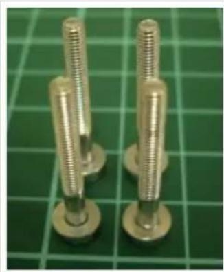
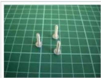
- Stand 4# M3 x 25 CP (Cap head/Allen head) bolts upright on their heads.
- Place a single M3 washer over each bolt (Pic practice-01).
- Locate 1# part 10113 over the bolts (Pic practice-02).
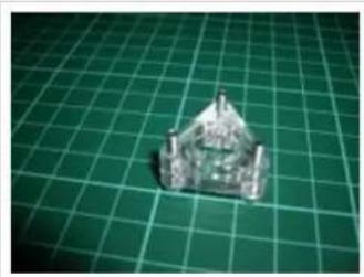
- Locate the second part 10113 over the bolts with the same orientation. Note that part 10113 is NOT square and care will be needed to orientate the 2# parts 10113 such that the holes line up. If the orientation is wrong the second part will not slide easily to sit on top of the first (Pic practice-03). If correct, they will slide together (Pic practice-04).
- Next place an M3 washer on each bolt.
- Screw an M3 nut 2 to 3 turns onto each bolt (Pic practice-05).
RapMan 3.2 manual
natural_image
Close-up of two metallic threaded fasteners on a green grid cutting mat (no text or symbols visible)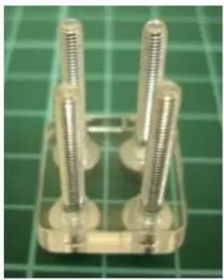
natural_image
Close-up of four metallic screw fasteners mounted on a green circuit board (no text or symbols visible)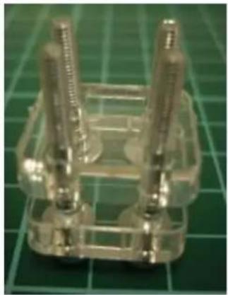
natural_image
Close-up of a transparent plastic mechanical component with four vertical pins, placed on a green cutting mat (no text or symbols visible)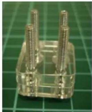
natural_image
Close-up of a transparent plastic electronic component with four metallic pins, placed on a green grid mat (no text or symbols visible)
practice-1 practice-2 practice-3 practice-4
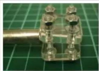
- Now slide a 80 500mm rod – part 20001 – between the bolts. Again care must be taken over the orientation of the parts since the rod will only fit in-between the bolts in one orientation (Pic practice-06 and practice-07)
- Tighten the nuts finger tight and then with a wrench and Allen key until the rod is held firm, typically finger tight followed by 12 of a turn. Practice on all four bolts (maximum torque setting 0.75 Nm). (Pic practice-08)
- Now continue to tighten, observing as you do so that the plastic will distort (Pic practice-09).
natural_image
Close-up of a metallic mechanical component with multiple bolts and connectors, placed on a green cutting board (no text or symbols visible)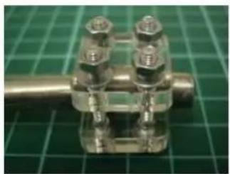
natural_image
Close-up of a metallic mechanical valve component with four bolts, placed on a green grid background (no text or symbols visible)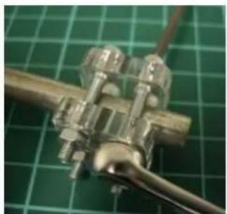
natural_image
Close-up of a metallic mechanical component with threaded ports, mounted on a green grid background (no text or symbols visible)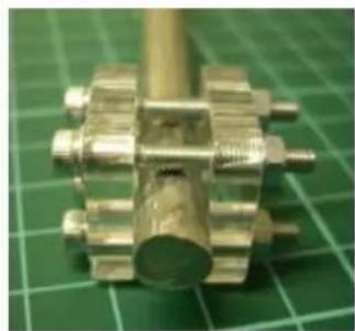
natural_image
Close-up of a metallic mechanical component with threaded shafts, placed on a green grid background (no text or symbols visible)practice-6 practice-7 practice-8 practice-9
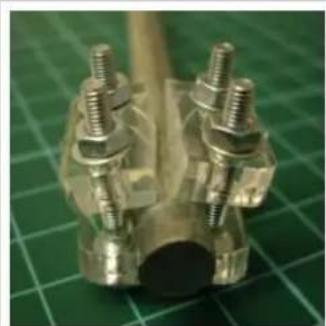
- Eventually the plastic will shatter. Carefully continue until this point to observe how it breaks suddenly (Pic practice-10)
natural_image
Close-up of metallic mechanical components with bolts and a cylindrical shaft on a green cutting mat (no text or symbols visible)picture-10
Grub screw clamping
- Thread an M5 x 6mm grub screw into each M5 nut using an Allen key. Ensure it doesn't extend through the other side of the M5 nut
- Insert part 20001 steel upright into one end of part 10112.
- Using the 4mm Allen key, position the M5 nut/grub screw sets into the locating rebate next to the upright steel. It may be necessary to file away the edges of the nut rebate to allow the M5 nut to slide into position.
- Use the ball-end of the Allen key to tighten the grub screw until the rod is held firm, typically finger tight followed by 14 of a turn. Practice on both ends of part 10112 (maximum torque setting 0.5 Nm).
Acrylic part fitting
Under no circumstances use a hammer when assembling the parts as the shock loading will break the parts.
Acrylic part repair
If parts are broken they can be repaired using Cyanoacrylate glue (Super Glue). If possible clamp the joint during gluing.
6. Assembly overview
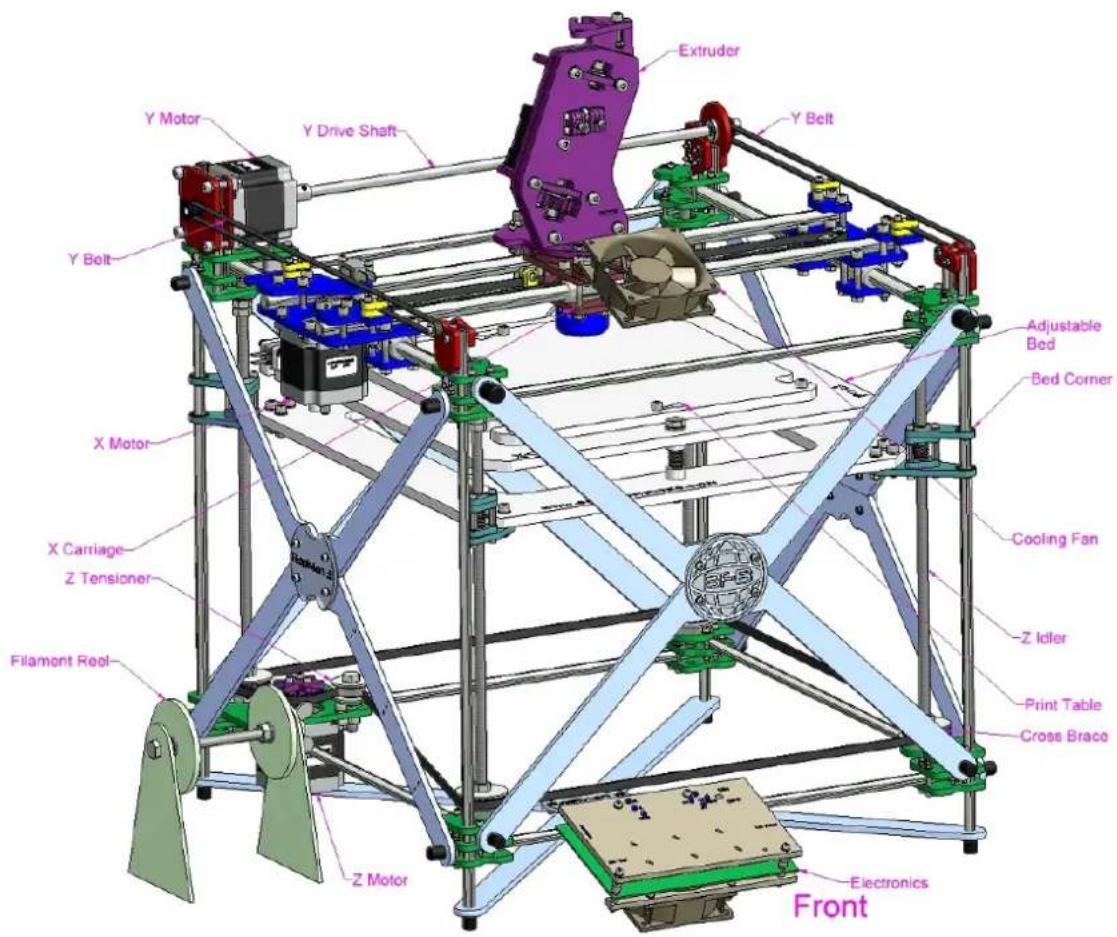
General assembly
text_image
Y Motor Y Drive Shaft Y Belt Extruder Adjustable Bed Bed Corner X Motor X Carriage Z Tensioner Filament Reel Z Motor Cooling Fan Z Idler Print Table Cross Brace Front ElectronicsNote: Control panel shown here is Version 3.1. Version 3.2 uses a touch screen display.
Note: Only a single head RapMan is shown here. A double head RapMan will have two extruders. Click here to establish how many extruders your kit contains depending on which option was purchased.
Assembly process schematic
It is best to build the RapMan in the order presented in this manual. However, if the task needs to be split up into different groups of people, the schematic below may help. Boxes refer to the manual sections.
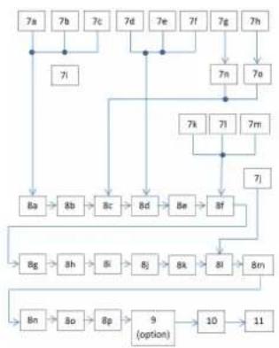
flowchart
graph TD
    A["7a"] --> B["8a"]
    C["7b"] --> B
    D["7c"] --> E["8b"]
    F["7d"] --> G["8c"]
    H["7e"] --> I["8d"]
    J["7f"] --> K["8e"]
    L["7g"] --> M["8f"]
    N["7h"] --> O["7g"]
    P["7i"] --> Q["8g"]
    R["7j"] --> S["8h"]
    T["7k"] --> U["8i"]
    V["7l"] --> W["8j"]
    X["7m"] --> Y["8k"]
    Z["7n"] --> AA["8l"]
    AB["7m"] --> AC["8m"]
    AD["8n"] --> AE["8o"]
    AF["8p"] --> AG["9 (option)"]
    AH["10"] --> AI["11"]
7. Frame minor sub-assemblies
This section contains instructions on how to make all of the sub-assemblies for the RapMan.
At times instructions will be split into "Single extruder" and "Double extruder" sections. Simply read the section that applies to your kit. If you are unsure which applies to you, check the .kit contents page
• 7a. Bottom Corner Block R x 2
• 7b. Bottom Corner Block L x 1
- 7c. Z Motor Block x 1
• 7d. Top Corner Block R x 2
• 7e. Top Corner Block L
- 7f. Y Motor Block x 1
• 7g. Bed Corner (Long) x 2
• 7h. Bed Corner (Short) x 2
• 7i. Filament Reel Holder
• 7j. Adjustable Bed x 1
- 7k. X Motor Plate x 1
• 7I. X Idler Plate x 1
• 7m. X Rod & Belt Clamps
• 7n. Z Idler Post (long) x 2
• 7o. Z Idler Post (short) x 2
7a. Bottom Corner Block R x 2
Tip: Don't forget to click on the 3D thumbnail to view the 3D content for this assembly.
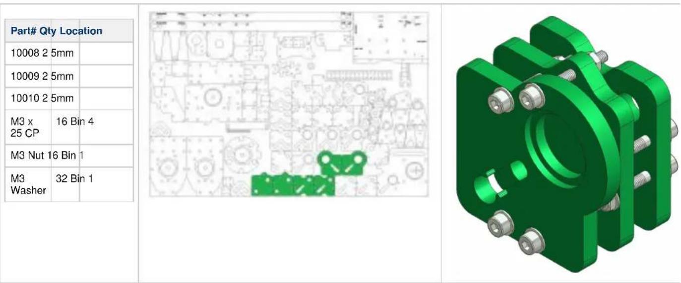
| Part# Qty Location | |
| 10008 2 5mm | |
| 10009 2 5mm | |
| 10010 2 5mm | |
| M3 x 25 CP | 16 Bin 4 |
| M3 Nut 16 Bin 1 | |
| M3 Washer | 32 Bin 1 |
| Tools | ||
| 2.5mm Allen Key |  | No Hazard. |
| 5.5mm Wrench | ||
| 4mm Allen Key |  | Double check orientation of the parts. It is very easy to assemble parts reversed. |
- Remove protective film from all parts required.
- Ensure all holes are clear of cut-out debris.
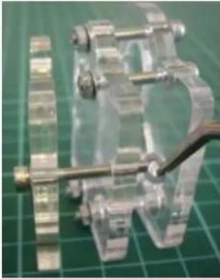
- Check the 608 bearing fits bearing recess and clean if required to allow the bearing to sit evenly on the seat (Pic 7a-01).
- Stand 4# M3 x 25 CP (Cap head/Allen head) bolts upright on their heads.
- Place a single M3 washer over each bolt (Pic 7a-02)
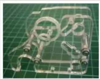
- Position bolts to allow part 10010 to lower over the bolts (Pic 7a-03). Ensure that the bearing recess is face down. DOUBLE CHECK the 3D model to ensure correct orientation.
- Lower part 10009 onto the bolts(Pic 7a-04).
- Next place an M3 washer on each bolt.
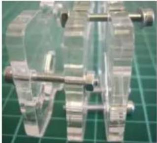
- Screw an M3 nut 2 to 3 turns onto each bolt (Pic 7a-05).
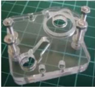
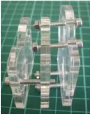
- Place the assembly onto its side (Pic 7a-06)
- Fit part 10008 using an M3 x 25 CP & M3 Washer.
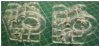
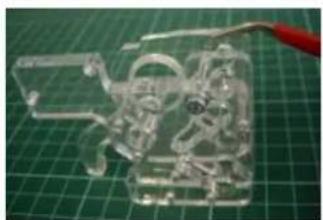
- Using tweezers, fit an M3 washer (Pic 7a-07).
- Again using tweezers, fit an M3 Nut (Pic 7a-08).
- Repeat this for the other 3 bolts.
- Repeat the process to make two corner blocks.

RapMan 3.2 manual
| 7a-01 7a-02 7a-03 7a-04 | |||
 |  |  |  |
| 7a-05 7a-06 7a-07 7a-08 | |||
 | |||
| 7a-09 | |||
7a-09
7b. Bottom Corner Block L x 1
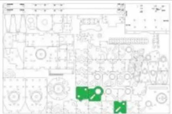
| Part# Qty Location | |
| 10008 1 5mm | |
| 10009 1 5mm | |
| 10011 1 5mm | |
| M5 x 6 Grub (Set Screw) | 1 Bin 6 |
| M5 Nut 1 Bin 6 | |
| M3 x 25 CP | 8 Bin 4 |
| M3 Nut 8 Bin 1 | |
| M3 Washer | 16 Bin 1 |
text_image
Floor plan with room labels and green icons indicating locations or features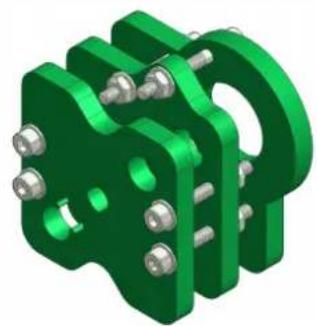
natural_image
3D rendered green mechanical bracket with bolts and mounting holes (no text or symbols)| ToolsTweezers608 Bearing(Bin 11) | ||
 | No Hazard. | |
 | Double check orientation of the parts as it is very easy to assemble parts reversed. | |
- Remove protective film from all parts required.
- Ensure all holes are clear of cut-out debris.
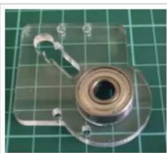
- Check the 608 bearing fits bearing recess and clean if required to allow the bearing to sit evenly on the seat (Pic 7b-01).
- Stand 4# M3 x 25 CP (Cap head/Allen head) bolts upright on their heads.
- Place a single M3 washer over each bolt (Pic 7b-02).
- Position bolts to allow part 10011 to lower over the bolts (Pic 7b-03). Ensure that the bearing recess is face down. DOUBLE CHECK the 3D model to ensure correct orientation.
- Lower part 10009 onto the bolts (Pic 7b-04).
- Next place an M3 washer on each bolt.
- Screw an M3 nut 2 to 3 turns onto each bolt (Pic 7b-05).
- Place the assembly onto its side (Pic 7b-06).
- Fit part 10008 using an M3 x 25 CP & M3 washer.
- Using tweezers fit an M3 washer (Pic 7b-07).
- Again using tweezers fit an M3 nut (Pic 7b-08).
- Repeat this for the other 3 bolts.
natural_image
Close-up of a metallic mechanical component with a central bore and attached hook, placed on a green grid background (no text or symbols visible)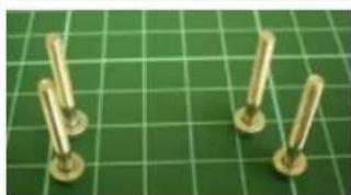
natural_image
Four brass screws arranged on a green cutting board (no text or symbols visible)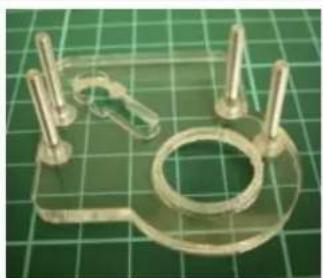
natural_image
Close-up of a transparent plastic mechanical component with pins and a circular ring on a green grid background (no text or symbols visible)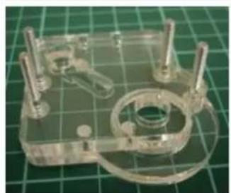
natural_image
Transparent plastic mechanical component with mounting holes and a central circular housing, placed on a green grid background (no text or symbols visible)RapMan 3.2 manual
| Tools | ||
| Wrench 13mm x 2 |  | No Hazard. |
| Wrench 8mm x 1 | ||
| Allen Key 4mm |  | Double check orientation of the parts as it is very easy to assemble parts reversed. |
| Tweezers | ||
| 608 Bearing (bin 11) | ||
- Remove protective film from all required parts.
- Ensure all holes are clear of cut-out debris.
- Stand 4# M3 x 25 CP (Cap head/Allen head) bolts upright on their heads.
- Place a single M3 washer over each bolt (Pic 7c-01).
- Position bolts to allow part 10008 to lower over the bolts (Pic 7c-02).
- Lower part 10009 onto the bolts over part 10008.
- Next place an M3 washer on each bolt.
- Screw an M3 nut 2 to 3 turns onto each bolt (Pic 7c-03).
- Place the assembly onto its side (Pic 7c-04).
- Fit part 10012 using an M3 x 25 CP & M3 Washer. Ensure that the bearing recess is face outwards. DOUBLE CHECK the 3D PDF to ensure correct orientation.
- Using tweezers, fit an M3 washer (Pic 7c-05).
- Again using tweezers, fit an M3 nut (Pic 7c-06).
- Repeat this for the other 3 bolts.
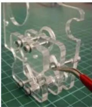
- Securely attach motor to part 10012 using 4# M5 x 16 CP, M5 washers & M5 nuts. The washers go between the bolt head and part 10012.
Please note correct orientation of cable/connector (Pic 7c-07). - Orientate wrench head over top of nuts to ease tightening of bolt (Pic 7c-08).
natural_image
Close-up of metallic screws on a green grid background (no text or symbols visible)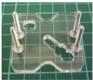
natural_image
Transparent plastic mechanical component with metal pins and a curved cutout, placed on a green grid background (no text or symbols visible)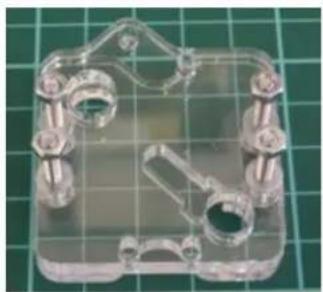
natural_image
Transparent plastic mechanical housing with mounting holes and a central hole, set on a green grid background (no text or symbols visible)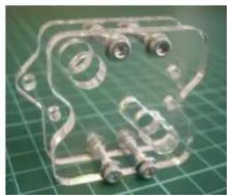
natural_image
Transparent plastic mechanical component with bolts and screws, placed on a green grid background (no text or symbols visible)7c-01 7c-02 7c-03 7c-04
natural_image
Close-up of a transparent plastic mechanical component with coiled pins and a red cable, placed on a green grid background (no text or symbols visible)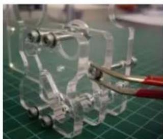
natural_image
Close-up of a transparent mechanical device with metal rods and wheels, placed on a green cutting mat (no visible text or symbols)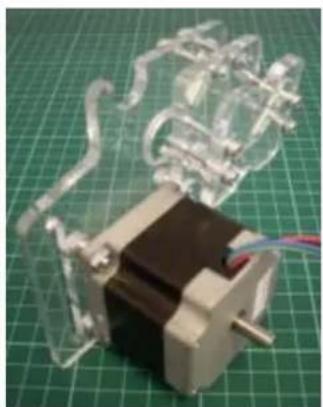
natural_image
Close-up of a small mechanical component with transparent glass parts and wiring, placed on a green grid mat (no text or symbols visible)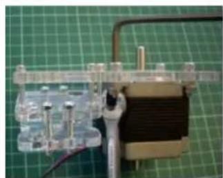
natural_image
Close-up of a mechanical component with metallic parts and a black coil on a green grid background (no visible text or symbols)7c-05 7c-06 7c-07 7c-08
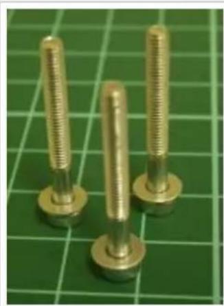
- Stand 3# M3 x 20 CP (Cap head/Allen head) bolts upright on their heads.
- Place a single M3 washer over each bolt (Pic 7c-010).
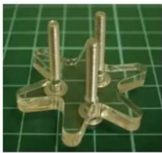
- Position bolts to allow part 10015 to lower over the bolts (Pic 7c-11). Lower part 10015 onto the bolts and place 2 more M3 washers on each bolt.
- Lower part 10014 onto the bolts.
- Thread the M3 x 6mm grub screw into an M3 nut. Position the nut/grub screw set into part 10014 (Pic 7c-12)
- Place 2 M3 spacing washers over each bolt. Place part 10016 on the bolts. Place an M3 washer over each and screw an M3 nut 2 to 3 turns
RapMan 3.2 manual
onto each bolt (Pic 7c-12)
22. Carefully place the entire assembly on its side and tighten the nuts.
natural_image
Three brass threaded bolts on a green cutting mat (no text or symbols visible)7c-10 7c-11 7c-12 7c-13
natural_image
Metallic mechanical component with threaded rods mounted on a green grid background (no text or symbols visible)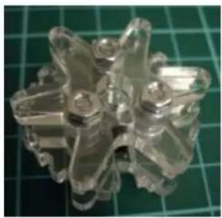
natural_image
Close-up of a transparent plastic mechanical component with multiple protrusions, placed on a green cutting mat (no text or symbols visible)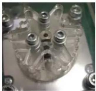
natural_image
Close-up of a transparent plastic mechanical component with multiple cylindrical features (no visible text or symbols)- Fit the completed Z drive pulley onto the Z motor.
- Position the Z pulley such that the M3 nut is in line with the flat on the motor shaft. Push the pulley on the motor shaft until the end of the shaft is touching part 10015 (Pic 7c-13). Now tighten grub screw to hold assembly in place.
Z-tensioning pulley:
- Place M8 bolt facing upwards.
- Place components on bolt in this order;
- M8x30 washer > M8 washer > 608 bearing > M8 washer > M8x30 washer > part 10079 > M8 washer
- Place bolt into channel next to motor (as shown in pic below, check 3D model for orientation).
- Place M8 washer and M8 nut onto bolt and tighten (finger tight). This will be adjusted later.
- Check bearing spins freely.
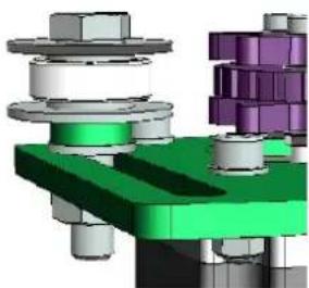
natural_image
3D mechanical assembly diagram showing layered components with no visible text or symbols7d. Top Corner Block R x 2
| Part# Qty Location | |
| 10001 2 5mm | |
| 10002 2 5mm | |
| 10003 2 5mm | |
| M3 x 25 CP | 16 Bin 4 |
| M3 Nut 16 Bin 1 | |
| M3 Washer | 32 Bin 1 |
natural_image
Floor plan layout with green patterned areas and circular elements (no text or labels)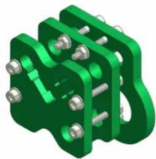
natural_image
3D rendered green mechanical clamp or bracket component with bolts and mounting holes (no text or symbols)| Tools |
| Tweezers |
| 608 Bearing (Bin 11) |
| No Hazard. | |
| Double check orientation of the parts as it is very easy to assemble parts reversed. |
- Remove protective film from all parts.
- Ensure all holes are clear of cut out debris.
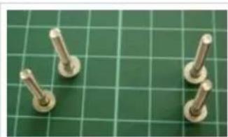
- Stand 4# M3 x 25mm CP (Cap head/Allen head) bolts upright on their heads.
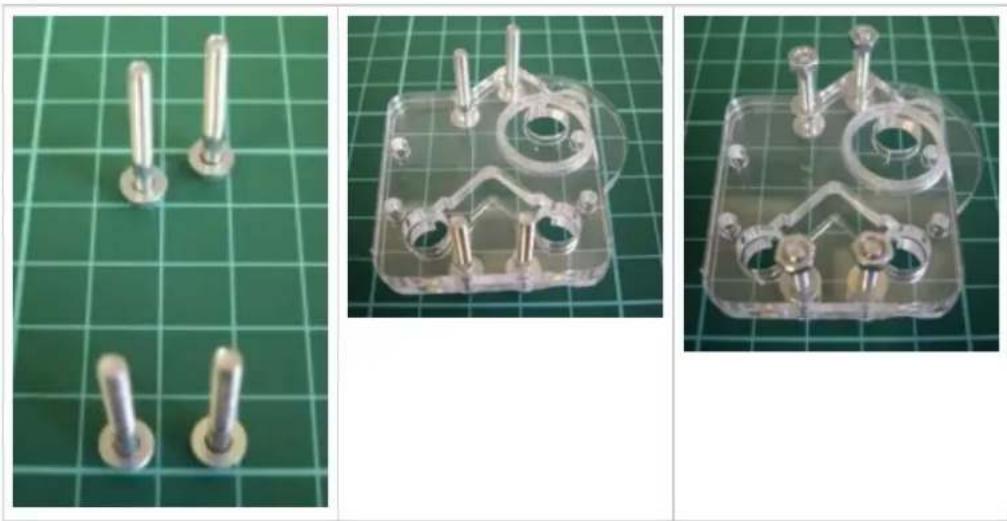
- Place a single M3 washer over each bolt (Pic 7d-01).
- Position bolts to allow part 10003 to lower over the bolts (Pic 7d-02). Ensure that the bearing recess is face down. DOUBLE CHECK the 3D PDF to ensure correct orientation
- Lower part 10002 onto the bolts (Pic 7d-03).
- Next place an M3 washer on each bolt.
- Screw an M3 nut 2 to 3 turns onto each bolt (Pic 7d-04).
- Place the assembly onto its side (Pic 7d-05).
- Fit part 10001 using an M3 x 25 CP & M3 washer.
- Using tweezers, fit an M3 washer (Pic 7d-06).
- Again using tweezers, fit an M3 nut (Pic 7d-07).
- Repeat this for the other 3 bolts.
- Repeat the process to make two corner blocks.
natural_image
Four metallic screw fasteners on a green cutting board (no text or symbols visible)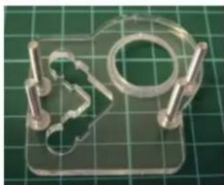
natural_image
Transparent plastic mechanical component with metal pins, placed on a green grid background (no text or symbols visible)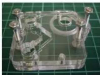
natural_image
Transparent plastic enclosure with internal mechanical components and mounting screws, placed on a green grid background (no text or symbols visible)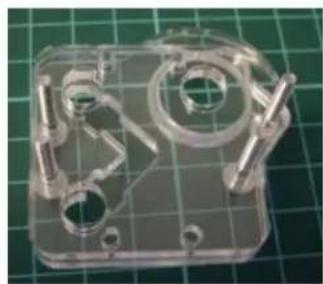
natural_image
Transparent plastic mechanical housing with internal components and mounting holes, placed on a green grid background (no text or symbols visible)natural_image
Transparent plastic mechanical component on a green grid background (no text or symbols visible)7d-05 7d-06 7d-07

natural_image
Close-up of a transparent plastic mechanical component with a red wire, placed on a green grid cutting mat (no text or symbols visible)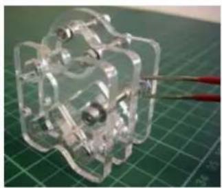
natural_image
Transparent plastic mechanical component with multiple protrusions, placed on a green cutting mat (no text or symbols visible)7e. Top Corner Block L
| Part# Qty Location | |
| 10001 1 5mm | |
| 10002 1 5mm | |
| 10007 1 5mm | |
| M3 x 25 CP | 8 Bin 4 |
| M3 Nut 8 Bin 1 | |
| M3 Washer | 16 Bin 1 |
| Tools Tweezers 608 Bearing (Bin 11) | No Hazard. |
| Double check orientation of the parts as it is very easy to assemble parts reversed. |
- Remove protective film from all parts.
- Ensure all holes are clear of cut-out debris.
- Stand 4# M3 x 25mm CP (Cap head/Allen head) bolts upright on their heads.
- Place a single M3 washer over each bolt (Pic 7e-01).
- Position bolts to allow part 10007 to lower over the bolts. Ensure that the bearing recess is face down. DOUBLE CHECK the 3D PDF to ensure correct orientation.
- Lower part 10002 onto the bolts (Pic 7e-03).
- Next place an M3 washer on each bolt.
- Screw an M3 nut 2 to 3 turns onto each bolt (Pic 7e-04)
- Place the assembly onto its side (Pic 7e-05).
- Fit part 10001 using an M3 x 25 CP & M3 washer.
- Using tweezers, fit an M3 washer (Pic 7e-06).
- Again using tweezers, fit an M3 nut (Pic 7e-07).
- Repeat this for the other 3 bolts.
RapMan 3.2 manual
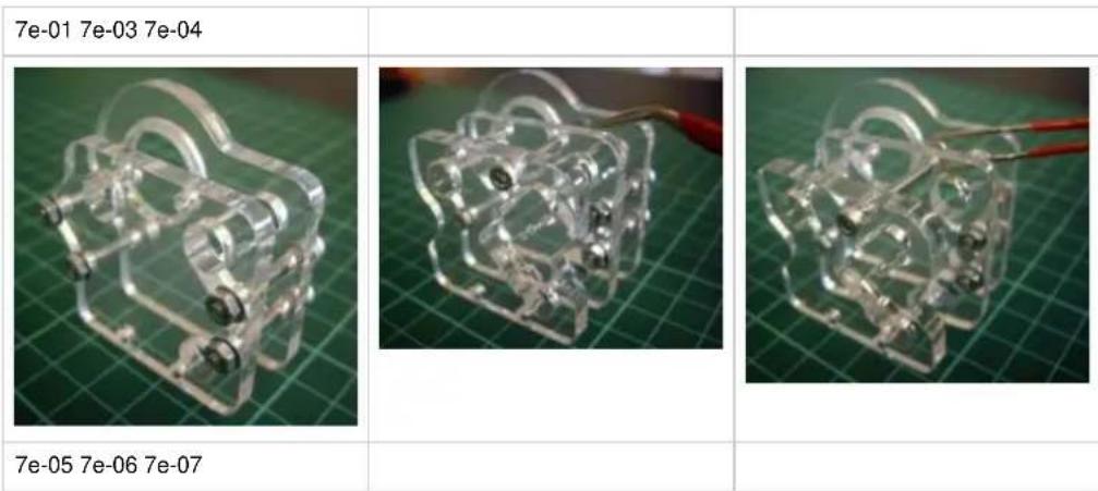
Note: Check the 608 bearing fits bearing recess on part 10012 and clean if required to allow the bearing to sit evenly on the seat.
7f. Y Motor Block x 1
| Part# Qty Location | |
| 10004 1 5mm LC | |
| 10005 1 5mm LC | |
| 10006 1 5mm LC | |
| M3 x 25 CP | 8 Bin 4 |
| M3 Nut 8 Bin 1 | |
| M3 Washer | 16 Bin 1 |
| Tools Tweezers 608 Bearing (Bin 11) | No Hazard. |
| Double check orientation of the parts as it is very easy to assemble parts reversed. |
- Remove protective film from all parts.
- Ensure all holes are clear of cut-out debris.
- Stand 4# M3 x 25mm CP (Cap head/Allen head) bolts upright on their heads.
- Place a single M3 washer over each bolt (Pic 7f-01).
- Position bolts to allow part 10006 to lower over the bolts (Pic 7f-02). Ensure that the bearing recess is face down. DOUBLE CHECK the 3D PDF to ensure correct orientation.
- Lower part 10005 onto the bolts (Pic 7f-03).
- Next place an M3 washer on each bolt.
- Screw an M3 nut 2 to 3 turns onto each bolt (Pic 7f-04).
- Place the assembly onto its side (Pic 7f-05).
- Fit part 10004 using an M3 x 25 CP & M3 Washer.
- Using tweezers, fit an M3 washer (Pic 7f-06).
- Again using tweezers, fit an M3 nut (Pic 7f-07).
- Repeat this for the other 3 bolts.
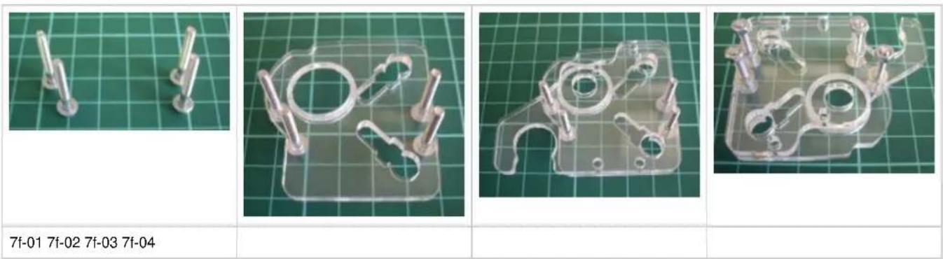
text_image
7f-01 7f-02 7f-03 7f-04RapMan 3.2 manual
natural_image
Transparent plastic mechanical component with multiple curved arms and connectors, displayed on a green grid background (no text or symbols visible)7f-05 7f-06 7f-07
natural_image
Transparent plastic mechanical component on a green cutting mat, with a red wire extending from it (no visible text or symbols)
natural_image
Transparent mechanical assembly on a green grid background (no visible text or symbols)Note: Check the 608 bearing fits bearing recess on part 10012 and clean if required to allow the bearing to sit evenly on the seat
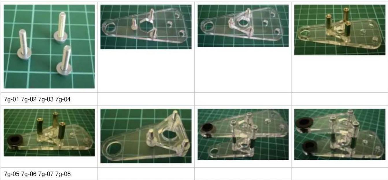
7g. Bed Corner (Long) x 2
| Part# Qty Location | 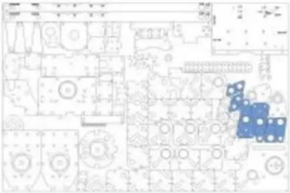 |  | |
| 10017 2 5mm LC | |||
| 10018 2 5mm LC | |||
| 10019 2 5mm LC | |||
| 10118 2 5mm LC | |||
| Slide Bearing | 4 Bin 10 | ||
| M3 x 15 Spacer | 6 Bin 10 | ||
| M3 x 16 | 12 Bin 2 | ||
| M3 Washer | 12 Bin 1 | ||
| Tools |  | No Hazard. |
| 5.5mm Wrench | ||
| 2.5mm Allen Key |  | Ensure assembled part slides easily on the 8∅ steel rod as if this is too tight it will prevent correct Z movement and will be difficult to correct later.Please note that the 3D pdf attached to the above image is incorrect and misses out part 10018. The above image and photos below are correct. |
| Needle File | ||
| 20001 Steel Rod |
- Remove protective film from all parts.
- Ensure all holes are clear of cut-out debris.
- Stand 3# M3 x 16mm CP (Cap head/Allen head) bolts upright on their heads.
- Place a single M3 washer over each bolt (Pic 7g-01).
- Lower part 10018 onto bolts (Pic 7g-02).
- Lower part 10019 onto the bolts (Pic 7g-03).
- Next thread an M3 x 15 spacer nut on each bolt and tighten (Pic 7g-04).
- Insert slide bearing into top side of part 10018 (Pic 7g-05).
- Stand 3# M3 x 16mm CP (Cap head/Allen head) bolts upright on their heads.
- Place a single M3 washer over each bolt.
- Position bolts to allow part 10017 to lower over the bolts (Pic 7g-06).
- Lower part 10118 onto the bolts (Pic 7g-07). (If part 10118 doesn't fit perfectly on to bolts try rotating it)
- Carefully invert assembly and locate M3 x 16 CP bolts into M3 x 15mm spacer nuts and tighten.
- Insert slide bearing into top side of part 10017 (Pic 7g-08).
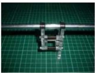
- Slide assembly along steel rod 20001 to check ease of movement. If necessary remove slide bearing and with the needle file gently file the hole until the steel rod moves easily (Pic 7g-09).
- Repeat the process to make two long bed corners.
RapMan 3.2 manual
natural_image
Close-up of a metallic mechanical component mounted on a green cutting mat (no visible text or symbols)7g-09
Note: leaving M3 Bolts loose until Steel Rod 20001 is located will prevent alignment problems.
7h. Bed Corner (Short) x 2
| Part# Qty Location | 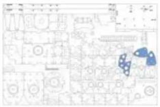 | 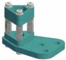 | |
| 10143 2 5mm LC | |||
| 10142 2 5mm LC | |||
| 10019 2 5mm LC | |||
| 10118 2 5mm LC | |||
| M3 x 15 Spacer 6 Bin 10 | |||
| M3 x 16 12 Bin 2 | |||
| M3 Washer 12 Bin 1 | |||
| Tools |
| 5.5mm Wrench |
| 2.5mm Allen Key |
| Needle File |
- Remove protective film from all parts.
- Ensure all holes are clear of cut-out debris.
- Stand 3# M3 x 16mm CP (Cap head/Allen head) bolts upright on their heads.
- Place a single M3 washer over each bolt.
- Position bolts to allow part 10142 to lower over the bolts (Pic 1-08-01).
- Lower part 10019 onto the bolts.
- Next thread an M3 x 15 spacer nut on each bolt and tighten (Pic 1-08-02 & 1-08-03).
- Stand 3# M3 x 16mm CP (Cap head/Allen head) bolts upright on their heads.
- Place a single M3 washer over each bolt.
- Position bolts to allow part 100143 to lower over the bolts (Pic 1-08-04).
- Lower part 10118 onto the bolts (Pic 1-08-05).
- Carefully invert assembly and locate M3 x 16 CP bolts into M3 x 15mm spacer nuts and tighten (Pic 1-08-06).
- Repeat the process to make two short bed corners (Pic 1-08-07).
natural_image
Three white plastic clips placed on a green grid cutting mat (no text or symbols visible)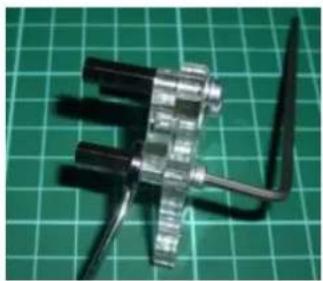
natural_image
Close-up of a metallic mechanical component with black wires, placed on a green grid background (no text or symbols visible)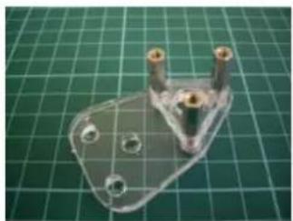
natural_image
Transparent plastic mechanical bracket on a green cutting mat (no text or symbols visible)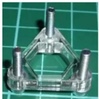
natural_image
Close-up of a transparent plastic mechanical bracket with four bolts, placed on a green grid background (no text or symbols visible)1-08-01 1-08-02 1-08-09 1-08-04
RapMan 3.2 manual
natural_image
3D rendered metallic object on a green grid background (no text or symbols visible)1-08-05 1-08-06 1-08-07
natural_image
Close-up of a mechanical device with visible wiring and components on a green grid background (no text or symbols)
natural_image
Close-up of a mechanical device with visible wiring and components on a green grid background (no text or symbols)
natural_image
Transparent plastic mechanical component placed on a green cutting mat (no text or symbols visible)
natural_image
Transparent plastic mechanical component placed on a green cutting mat (no text or symbols visible)7i. Filament Reel Holder
| Part# Qty Location | |||
| 10128 2 5mm LC | |||
| 10129 2 3mm LC | |||
| M8 x 120 Bolt | 2 Bag 2 | ||
| M8 Nut 4 Bin 8 | |||
| M8 x Washer | 6 Bin 8 | ||
| M8 Wing Nut | 1 Bin 8 | ||
text_image
Tools 13mm Wrench x 2 No Hazard. No warnings.Single head option
- Remove protective film from all parts.
- Ensure all holes are clear of cut-out debris.
- Stand the M8 x 120mm bolt upright on its head.
- Lower part 10129 onto the bolt.
- Lower a single M8 washer onto the bolt.
- Next thread an M8 nut onto the bolt and wind down bolt to tighten onto washer.
- Place a single M8 washer onto the bolt.
- Place part 10128 and then another M8 washer onto the bolt.
- Thread another M8 nut onto the bolt and wind down to tighten onto washer.
- Thread another M8 nut onto the bolt and wind down until about 40mm from end of bolt.
- Place a single M8 washer onto the bolt.
- Place second part 10128 onto the bolt.
- Place a single M8 washer onto the bolt.
- Thread another M8 nut onto the bolt and wind down until touching the washer.
- Add another washer followed by the 2nd part 10129
- Add washer and wing nut, turn until internal spacing between two parts 10129 equals 110-120mm (Pic 7i-01).
- Tighten all outer nuts checking that the 110-120mm separation is kept.
Note: the assembly is such that the inner discs (10128) are supposed to rotate freely. Loosen the inner nuts to ensure that this happens. Note: the 3D PDF on this page shows the assembly minus acrylic parts.
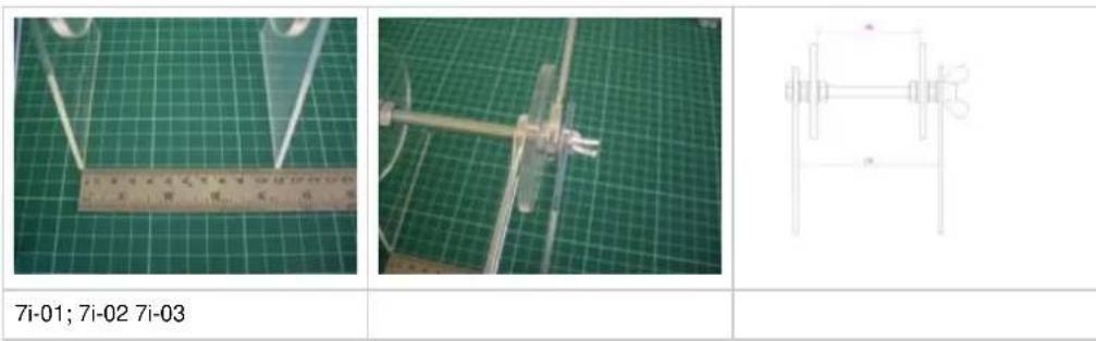
Load a filament reel onto the assembly and make sure that it is able to rotate freely.
Double head option
Repeat the "Single head" process above to create a second reel holder. Extra acrylics and bolts will be found in the Double head upgrade pack.
7j. Adjustable Bed x 1
| Part# Qty Location | ||||
| 10038 2 8mm | ||||
| 10039 1 8mm | ||||
| 10116 1 8mm | ||||
| Micro Switch Yellow Wire | 1 Bag 1 | |||
| M5 x 20 CP | 6 Bin 5 | |||
| M5 x 16 CP | 2 Bin 5 | |||
| M5 Nut 2 Bin 6 | ||||
| M5 Washer | 2 Bin 6 | |||
| M3 x 30 CP | 2 Bin 2 | |||
| M3 Nut 2 Bin 1 | ||||
| M3 Washer | 4 Bin 1 | |||
text_image
Tools 5.5mm Wrench 2.5mm Allen Key 4mm Allen Key No Hazard. No warnings.- Remove all protective film from parts.
- Ensure all holes are clear of cut-out debris.
- Correctly orientate and locate part 10116 over part 10039.
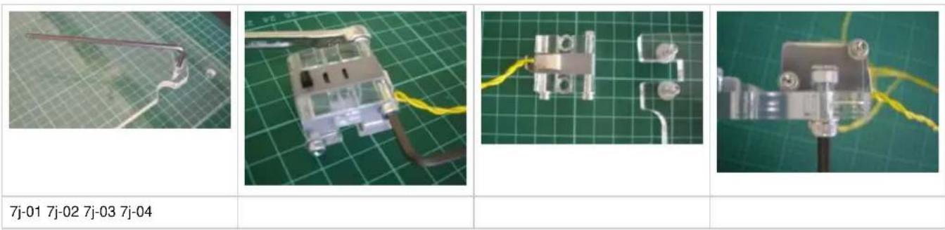
- Connect together using 6# M5 x 20 CP bolts into the threaded holes (Pic 7j-01) using the 4mm Allen key.
- Place an M3 washer over each M3 x 30 CP bolt.
- Arrange2# parts 10038 on either side of the micro switch and align holes.
- Thread M3 x 30 CP bolts through the holes.
- Place an M3 washers and nut onto each bolt and finger tighten.
- Tighten further using the 2.5mm Allen key (Pic 7j-02).
- Place M5 washer over both M5 x 16 CP bolts, locating these upside-down through underside of part 10039 (Pic 7j-03).
- Orientate this micro-switch configuration over the up-turned connecting M5 x 16mm CP bolts, with the micro-switch innermost.
- Connect the micro-switch configuration to the main base with the M5 16mm CP bolts, holding the M5 nuts in place while doing so.
- Tighten micro-switch section to the base with 4mm Allen key(Pic 7j-04).
RapMan 3.2 manual
7k. X Motor Plate x 1
| Part# Qty Location | 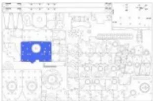 | 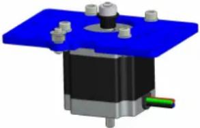 | ||
| 10024 1 | ||||
| 623 Bearing 1 Bin 11 | ||||
| Nema 23 Stepper 1 In Box | ||||
| MXL 18T Pulley | 1 Bin 10 | |||
| M5 x 16 CP 4 Bin 5 | ||||
| M5 Nut 4 Bin 6 | ||||
| M5 Washer 4 Bin 6 | ||||
| M3 x 16 CP 1 Bin 2 | ||||
| M3 Nut 1 Bin 1 | ||||
| M3 x 12 Washer | 1 Bin 5 | |||
| M3 Washer 7 Bin 1 | ||||
| Tools | ||
| 8mm Wrench |  | No Hazard. |
| 5.5mm Wrench | ||
| 4mm Allen Key | ||
| 2.5mm Allen Key |  | Check part orientations and motor wire connector orientation. |
| 1/16" Allen Key | ||
- Remove all protective film from parts.
- Ensure all holes are clear of cut-out debris.
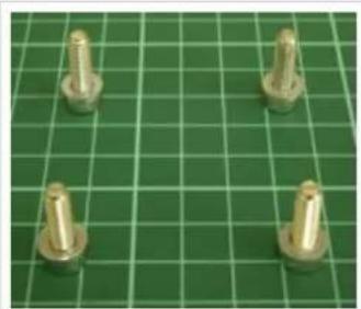
- Stand 4# M5 x 16 CP bolts upright on their heads.
- Locate and place a single M5 washer over each bolt (Pic 7k-01).
- Position each to locate at motor fixing holes.
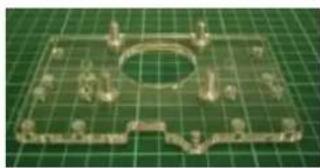
- Place part 10024 over M5 bolts (Pic 7k-02).
- Place motor over M5 bolts (Pic 7k-03).
- Carefully turn configuration on its side to allow M5 nuts to be threaded on to M5 bolts (Pic 7k-04).
- Using a 8mm wrench head on nuts, use the 4mm Allen key to tighten and secure the motor (Pic 7k-05). Check wire orientation for motor is as illustrated.
- Orientate the MXL 18T pulley over the motor spindle, teeth closest to the motor, locating the locking grub screw in-line with the flat part of the spindle (Pic 7k-06)
- Tighten the grub screw using a 1/16" Allen key
- Stand an M3 x 16 CP on its head and place the M3 x 12mm washer over it.
- Place 3# M3 spacer washers over the end of the M3 x 16 CP bolt.
- Place a 623 bearing over the M3 x 16 CP bolt (Pic 7k-07).
- Place 3# M3 spacer washers over the end of M3 x 16 CP bolt (Pic 7k-08).
- Correctly locate bearing configuration into position, and then fit M3 washer over the M3 x 16 CP bolt, followed by M3 nut, until finger-tight.
- Tighten securely with wrench and Allen key (Pic 7k-09)
RapMan 3.2 manual
natural_image
Four brass mechanical components on a green cutting board (no text or symbols visible)7k-01 7k-02 7k-03 7k-04
natural_image
Metallic mechanical component on a green cutting board (no text or symbols visible)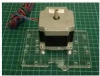
natural_image
Close-up of a small electric motor on a green cutting board with wiring visible (no text or symbols)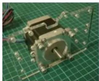
natural_image
Close-up of a metallic mechanical component mounted on a green grid mat (no visible text or symbols)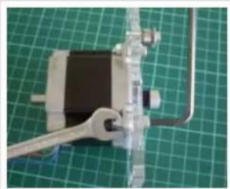
natural_image
Close-up of a mechanical clamp and wrench mounted on a green cutting board (no text or symbols visible)7k-05 7k-06 7k-07 7k-08
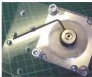
natural_image
Close-up of a mechanical component with a central hub and mounting holes, mounted on a green grid background (no visible text or symbols)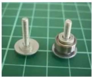
natural_image
Two metallic screw fasteners on a green cutting mat (no text or symbols visible)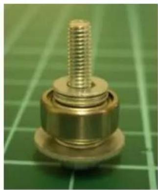
natural_image
Close-up of a brass mechanical component with threaded shaft, placed on a green cutting board (no text or symbols visible)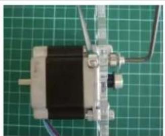
natural_image
Close-up of a small electric motor with visible stator and wiring, placed on a green grid background (no text or symbols)7k-09
7I. X Idler Plate x 1
| Part# Qty Location | |
| 10028 1 | |
| 623 Bearing | 2 Bin 11 |
| M3 x 16 CP | 2 Bin 2 |
| M3 Nut 2 | Bin 1 |
| M3 x 12 Washer | 2 Bin 5 |
| M3 Washer | 14 Bin 1 |
text_image
Floor plan with highlighted blue area and numbered rooms, likely for architectural or engineering purposes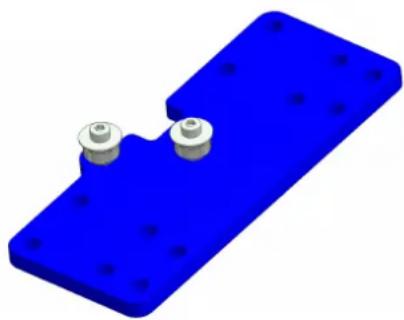
natural_image
3D rendering of a blue mechanical component with two small circular features and bolt holes (no text or symbols)| Tools |
| 5.5mm Wrench |
| 2.5mm Allen Key |
 | No Hazard. |
 | No warnings. |
- Remove all protective film from parts.
- Ensure all holes are clear of cut-out debris.
- Stand 2# M3 x 16 CP bolt and place a single M3 x 12 washer over each.
- Place 3# M3 spacer washers over each M3 x 16 CP bolt (Pic 7I-01 left).
- Locate and place a 623 bearing over each M3 x 16 CP bolt (Pic 7l-01 right).
- Place 3# M3 spacer washers over each bolt (Pic 7I-02).
- Fit the idler bearings into plate 10028.
- Carefully turn configuration on its side, and place an M3 washer and an M3 nut on to each M3 x 16 CP bolt, until finger-tight (Pic 71-03).
- Tighten securely using wrench and Allen key (Pic 71-04).
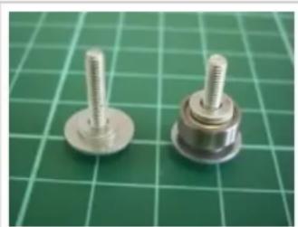
natural_image
Two metallic screw fasteners on a green cutting mat (no text or symbols visible)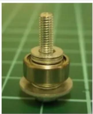
natural_image
Close-up of a brass mechanical component with threaded shaft and flange, placed on a green cutting board (no text or symbols visible)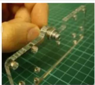
natural_image
Close-up of a hand holding a small metallic component mounted on a green cutting board (no text or symbols visible)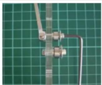
natural_image
Close-up of a metallic pipe fitting with connectors against a green grid background (no text or symbols visible)71-01 71-02 71-03 71-04
7m. X Rod & Belt Clamps
| Part# Qty Location | ||
| 10026 1 5mm | ||
| 10027 8 5mm | ||
| 10030 2 5mm | ||
| 10036 1 5mm | ||
| 10037 1 5mm | ||
| Micro Switch Orange Wire | 1 Bag 1 | |
| M3 x 20 CP 8 | Bin 2 | |
| M3 x 25 CP 2 | Bin 4 | |
| M3 Nut 10 Bin | 1 | |
| M3 Washer 20 | Bin 1 | |
| Tools |
| 8mm Wrench |
| 5.5mm Wrench |
| 4mm Allen Key |
| 2.5mm Allen Key |
| 1/16" Allen Key |
- Remove all protective film from parts.
- Ensure all holes are clear of cut-out debris.
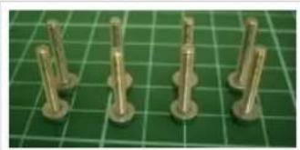
- Stand 8# M3 x 20 CP bolts upright on their heads in pairs and place an M3 washer on each (Pic 7m-01).
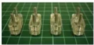
- Locate 2# parts 10027 over each pair of bolts (Pic 7m-02).
- Locate each of these configurations to each respective position on parts 10026, 10030 and 10036, paying attention to the correct orientation of each (Pic 7m-03).
- Place an M3 washer and nut onto each bolt and finger-tighten.
- Place a single M3 washer over 2# M3 x 25 CP bolts, passing them through the respective holes with in the micro switch, then directly through part 10037 (Pic 7m-04).
- Fix the micro-switch configuration to part 10036 (Pic 7m-05), here paying attention to the correct orientation.
- Secure each bolt with an M3 washer and an M3 nut until hand-tight.
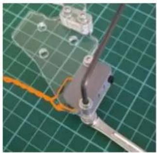
- Finally, securely tighten the 2 M3 x 25 bolts 10# fixing positions using a wrench and Allen key (Pic 7m-06).
RapMan 3.2 manual
natural_image
Five metallic cylindrical pins arranged on a green cutting mat (no text or symbols visible)7m-01 7m-02 7m-03 7m-04
natural_image
Four metallic tank-shaped objects arranged on a green grid background (no text or symbols visible)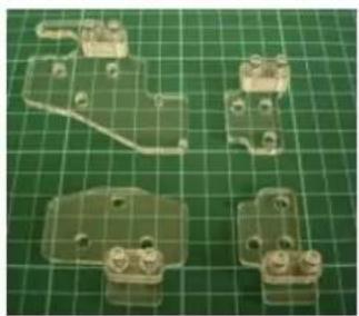
natural_image
Four transparent plastic mechanical components on a green grid background, no text or symbols visible.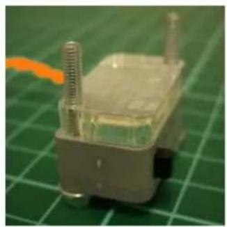
natural_image
Close-up of a small electronic component with metallic pins and wires, placed on a green grid mat (no visible text or symbols)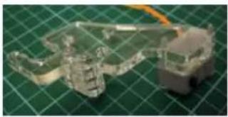
natural_image
Close-up of a transparent mechanical component with a gray base and orange cable, placed on a green cutting board (no text or symbols visible)7m-05 7m-06
natural_image
Close-up of a mechanical assembly on a green grid cutting mat, featuring a transparent plastic component and a tool handle (no visible text or symbols)
natural_image
Close-up of a mechanical assembly on a green grid cutting mat, featuring a transparent plastic component and a tool handle (no visible text or symbols)7n. Z Idler Post (long) x 2
| Part# Qty Location | |
| Bed Corner(long) | 2 Previous |
| 10013 2 | |
| 20002 2 Steel | Pack |
| 608 Bearing | 2 Bin 11 |
| C2 Spring | 2 Bin 10 |
| M8 x 40 Washer | 4 Bin 3 |
| M8 Nut 8 Bin 8 | |
| M8 Washer | 8 Bin 8 |
text_image
Technical schematic diagram with labeled components and circular features, likely from an engineering or manufacturing context.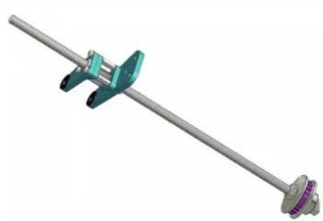
natural_image
3D rendering of a mechanical clamp or rod with a metallic shaft and two green clamps (no text or symbols visible)| Tools |
| 13mm Wrench x 2 |
| No Hazard. | |
| Check for ease of turning thread on completion of both construction processes. |
- Remove all protective film from parts.
- Ensure all holes are clear of cut-out debris.
Load corner assembly onto threaded bar:
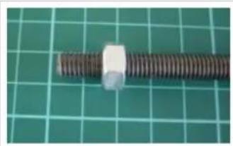
- Wind an M8 nut approximately 20mm up the length of threaded bar 20002 (Pic 7n-01).
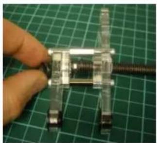
- Start to load the bed corner onto the bar, from the same end. Push the end of the bar through the small end of the bed corner (Pic 7n-02).
- As the bar passes through the center of the bed corner assembly, load the spring.
- As the bar passes through the large end of the assembly, ensure that a second nut is loaded into the hexagonal recess and the spring is compressed as the nut is engaged.
- Once fully loaded, wind the bed corner 80mm up the length of the threaded bar.
Fasten drive pulley:
- At the same end of the threaded bar, load in the following order (Pic 7n-03). Load the first of these M8 nuts at least 50mm on to the threaded bar to ensure room for the following components:
- M8 nut > M8 x 40mm washer > M8 washer > part 10013 > M8 washer > M8 x 40mm washer > M8 washer > 608 bearing > M8 washer > M8 nut
- Position the last of these M8 nuts to be flush with the very end of the bar.
- Now tighten-up the end configuration with 2# 13mm wrenches, taking care to keep the end nut in position (Pic 7n-04).
- Wind the bed corner back down to meet this drive pulley assembly.
- Now recommence this process from the top of the page for the second Z idler post.
RapMan 3.2 manual
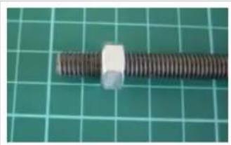
natural_image
Close-up of a metallic bolt with a white plastic cap, resting on a green cutting mat (no text or symbols visible)7n-01 7n-02 7n-03 7n-04
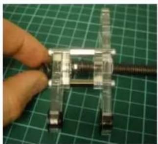
natural_image
Close-up of a hand holding a small mechanical component against a green grid background (no text or symbols visible)
natural_image
Close-up of a hand holding a small mechanical component against a green grid background (no text or symbols visible)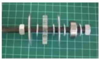
natural_image
Mechanical component with helical parts and a central shaft, displayed on a green cutting mat (no text or symbols visible)
natural_image
Mechanical component with helical parts and a central shaft, displayed on a green cutting mat (no text or symbols visible)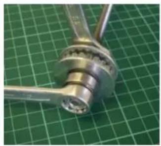
natural_image
Close-up of a metallic mechanical component with a flanged end, resting on a green grid background (no text or symbols visible)
natural_image
Close-up of a metallic mechanical component with a flanged end, resting on a green grid background (no text or symbols visible)70. Z Idler Post (short) x 2
| Part# Qty Location | |
| Bed Corner (Short) | 2 Previous |
| 10013 2 | |
| 20002 2 Steel | |
| 608 Bearing | 2 Bin 11 |
| C2 Spring | 2 Bin 10 |
| M8 x 40 Washer | 4 Bin 3 |
| M8 Nut 8 Bin 8 | |
| M8 Washer | 8 Bin 8 |
| Tools 13mm Wrench x 2 | No Hazard. | |
| Check for ease of turning thread on completion of both construction processes. |
- Remove all protective film from parts.
- Ensure all holes are clear of cut-out debris.
Load corner assembly onto threaded bar:
- Wind an M8 nut approximately 20mm up the length of threaded bar 20002 (Pic 7o-01).
- Start to load the bed corner onto the bar, from the same end. Push the end of the bar through the small end of the bed corner (Pic 7o-02).
- As the bar passes through the center of the bed corner assembly, load the spring.
- As the bar passes through the large end of the assembly, ensure that a second nut is loaded into the hexagonal recess and the spring is compressed as the nut is engaged.
- Once fully loaded, wind the bed corner 80mm up the length of the threaded bar.
Fasten drive pulley:
- At the same end of the threaded bar, load in the following order (Pic 7o-03). Load the first of these M8 nuts at least 50mm on to the threaded bar to ensure room for the following components:
- M8 nut > M8 x 40mm washer > M8 washer > part 10013 > M8 washer > M8 x 40mm washer > M8 washer > 608 bearing > M8 washer > M8 nut
- Position the last of these M8 nuts to be flush with the very end of the bar.
- Now tighten-up the end configuration with 2# 13mm wrenches, taking care to keep the end nut in position (Pic 7o-04).
- Wind the bed corner back down to meet this drive pulley assembly.
- Now recommence this process from the top of the page for the second Z idler post.
RapMan 3.2 manual
natural_image
Close-up of a metallic bolt with a white plastic cap, resting on a green cutting mat (no text or symbols visible)70-01 70-02 70-03 70-04
natural_image
Close-up of a hand holding a small mechanical component against a green grid background (no text or symbols visible)
natural_image
Close-up of a hand holding a small mechanical component against a green grid background (no text or symbols visible)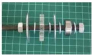
natural_image
Mechanical component with helical parts and a central shaft, displayed on a green cutting mat (no text or symbols visible)
natural_image
Mechanical component with helical parts and a central shaft, displayed on a green cutting mat (no text or symbols visible)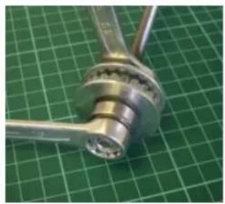
natural_image
Close-up of a metallic mechanical component mounted on a green grid cutting mat (no text or symbols visible)
natural_image
Close-up of a metallic mechanical component mounted on a green grid cutting mat (no text or symbols visible)8. Frame major sub-assemblies
This section contains instructions on how to put the smaller sub-assemblies together to build the RapMan frame.
- 8a. Base Frame
• 8b. Frame Vertical Bars
• 8c. Z Idlers - 8d. Top Frame
• 8e. Fitting Upper Square To Frame
• 8f. X Motor & Rails
• 8g. Y Idlers - 8h. Y Motor
- 8i. X Carriage
- 8j. Bed frame
• 8k. X, Y & Z Belts
• 8I. Fitting adjustable Bed
• 8m. Diagonal Ties Base
• 8n. Diagonal Ties Sides
• 80. Diagonal Ties Front & Back
• 8p. Fitting the Conduit
• 8q. Serial number
8a. Base Frame
| Part# Qty Location | 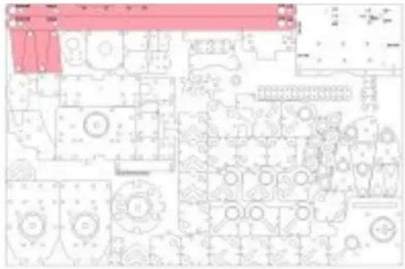 | 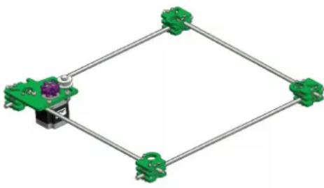 | ||
| Bottom Corner Block R | 2 Previous | |||
| Bottom Corner Block L | 1 Previous | |||
| Z motor block | 1 Previous | |||
| 20021 4 | Steel | |||
| Tools |  | No Hazard. |
| 5.5mm Wrench | ||
| 2.5mm Allen Key |  | Over tightening the corner blocks will break the acrylic (see the ).practice excerciseAccuracy during the alignment will greatly improve the performance of your RapMan 3.It is ESSENTIAL that the corner block bolts are tightened evenly.The final result should be that the plates of each corner block with bearing recesses should be horizontal. If asymmetrically tightened, the bolts will pull the top plates over, and position them at an angle of the horizontal. This will later mean that the bearings, which sit in the recess on top plate of each corner block, will not run properly, and the whole Z-axis will be prone to jamming.After assembly, check that the bearing plates for each corner block are as horizontal as the bolts will allow. |
| Setting Jig x 2 | ||
| Foot Jig x 4 | ||
| Ruler |
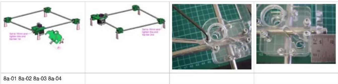
- Orientate each of the 4# sub-assemblies and steel bars to form a square, as in picture 8a-01, or in the 3D model (click thumbnail above).
- Turn each component so that the circular bearing rebates are uppermost and facing into the centre of the square.
- Insert each steel bar through the corner blocks passing between the sets of bolts holding the acrylic layers together.
- Position the temporary foot jigs (shown in pink on the parts panel above) to support the bottom level bars.
- Take up the slack of the corner block connection bolts. Taking care to keep the elements of the corner block relatively parallel to one another until finger-tight. Using the wrench and Allen key tighten until the rod is gripped so it will slide but won't fall apart. (Pic 8a-03).
- Set the motor corner top bar to 16mm (Pic 8a-01).
- Set the diagonally-opposite top bar to 16mm (Pic 8a-02 & 8a-04).
- Align the corners using the setting jigs (Pic 8a-05). The rods should protrude equally on the outsides of the corner blocks. The critical dimension is the distance between the rods as set by the setting jig
- Next using wrench and Allen key, tighten securely each bolt as diagonal pairs along the length of the steel bars, taking care not to over-tighten and stress fracture the plastic parts.
- Turn the whole frame over and repeat the process on the other 2 rods (Pic 8a-06)
- Re-check all 4 bar settings and adjust if required.
- Accuracy at this point will be repaid with better quality prints.
- After finishing, turn the assembly so that the Z-motor pulley faces up.
RapMan 3.2 manual
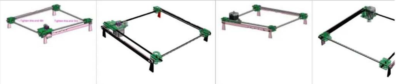
8a-05 3D model of previous (click to view) 8a-06 3D model of previous (click to
8b. Frame Vertical Bars
| Part# Qty Location | |
| Base Frame | 1 Previous |
| 20001 1 Steel | |
| 20006 3 Steel | |
| M5 x 6 Grub (Set Screw) | 8 Bin 6 |
| M5 Nut | 8 Bin 6 |
text_image
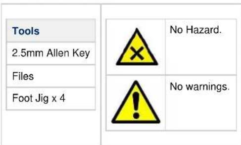
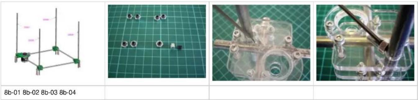
Tools 2.5mm Allen Key Files Foot Jig x 4 No Hazard. No warnings.- Use the temporary foot jigs (shown in pink on the parts panel above) to support the base frame (Pic 8b-01).
- Thread an M5 x 6mm grub screw into each M5 nut using an Allen key (Pic 8b-02). Ensure it doesn't extend through the other side of the M5 nut.
- Insert part 20001 steel upright into the Z motor corner block at the external corner location holes.
- Insert part 20006 likewise to the remaining 3# corners.
- Check all 4# vertical bars touch the construction surface when being supported by the temporary foot jigs. Adjust if necessary.
- Using the 4mm Allen key, position the M5 nut/grub screw sets into the locating rebate next to each upright steel (Pic 8b-03). It may be necessary to file away the edges of the nut rebate to allow the M5 nut to slide into position (Pic 8b-04).
- Use the ball-end of the Allen key to tighten the grub screw in order to lock the steel uprights in position.
- After each upright steel is locked, roll the assembly onto its side to access the locking nut rebates on the bottom plate of each corner.
- Repeat steps 6 + 7 for the bottom locating rebates - one for each steel upright (Pic 8b-05).
- Once secure, right the assembly and check all 4# vertical bars touch the construction surface when being supported by the temporary foot jigs. Adjust if necessary.
text_image
8b-01 8b-02 8b-03 8b-04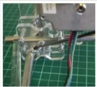
natural_image
Close-up of a mechanical assembly with wires and components on a green grid background (no visible text or symbols)8b-05
8c. Z Idlers
| Part Qty Location | ||
| Frame Vertical Bars 1 Previous | ||
| Z Idler Post (long) 2 Previous | ||
| Z Idler Post (short) 2 Previous | ||
| Z Belt XL 1 Bag 1 | ||
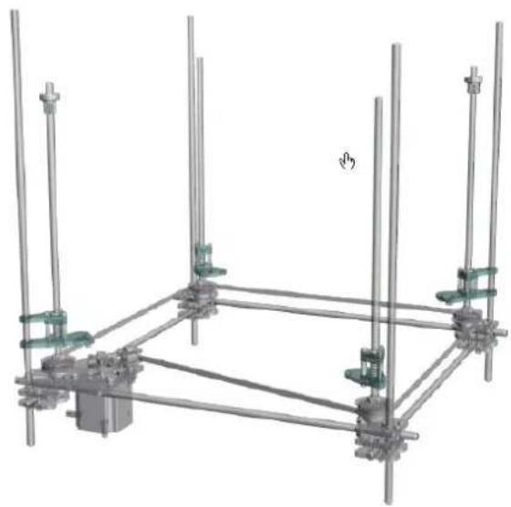
natural_image
3D mechanical assembly diagram showing vertical rods and mounting brackets (no text or symbols)
text_image
Tools None No Hazard. No warnings.- Take the Z belt (the belt with the widest gauge teeth) from bag 1.
- Lay the belt inside the 4# steel uprights (Pic 8c-01).
- Position Z Idler Post (long) components at the Z motor corner and the diagonally-opposite corner. Locate the slide bearings over the top of the adjacent upright steel rod in each case.
- Locate the bearing into the circular rebate and ensure that the Z belt is between the bearing position and the steel upright, around the outside of the pulley.
- Likewise position Z Idler Post (short) components to the remaining corners. Again ensure that the Z belt is around the outside of the pulley.
- Ensure the Z belt is around all four corners and not twisted.
natural_image
Structural diagram of a frame with vertical supports and green connectors, labeled '8c-01' (no text or symbols on the diagram itself)8d. Top Frame
| Part# Qty Location | ||
| Top Corner Block R 2 Previous | ||
| [Top Corner Block L] 1 Previous | ||
| Y Motor Block 1 Previous | ||
| 20020 2 Steel | ||
| 20021 2 Steel | ||
| KH1228 Linear Bearing 4 Stepper Frame | ||
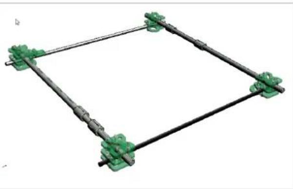
natural_image
3D mechanical linkage diagram with green components and black rods (no text or symbols)| Tools |  | No Hazard. |
| 5.5mm Wrench | ||
| 2.5mm Allen Key |  | Over tightening the corner blocks will break the acrylic (see the ).practice excerciseAccuracy during the alignment will greatly improve the performance of your RapMan 3.It is ESSENTIAL that the corner block bolts are tightened evenly.The final result should be that the plates of each corner block with bearing recesses should be horizontal. If asymmetrically tightened, the bolts will pull the top plates over, and position them at an angle of the horizontal. This will later mean that the bearings, which sit in the recess on top plate of each corner block, will not run properly, and the whole Z-axis will be prone to jamming.After assembly, check that the bearing plates for each corner block are as horizontal as the bolts will allow. |
| Setting Jig x 2 | ||
| Foot Jig x 4 | ||
| Ruler |
- Familiarise yourself with the different holes on the two setting jigs. Note that the 12mm holes slide over the larger diameter bars, and the 8mm holes slide over the smaller diameter bars.
- Click on the 3D model to correctly position the corner blocks.
- Orientate the corner blocks with the bearing recess face down.
- Insert bars 20021 into the lower halves of the corner blocks shown in the 3D model.
- Slide 2 linear bearings onto each bar 20020
- Pass parts 20020 (with bearings) into the remaining bar spaces in the corner blocks. (You will have to undo the nuts to the point of almost removing them for the bars to fit.)
-
Once loosely assembled, use the jigs to square the frame, in a similar fashion to the Base Frame:
-
Check that the ends of each 8mm bar protrude by equal amounts (approximately 16mm).
-
Check that the ends of each 12mm bar protrude by equal amounts (approximately 18.5mm).
-
Securely tighten bolts around the bars. (Make sure that the top and bottom plate remain level as an uneven plate will cause problems when running the machine.)
-
After tighening, re-check the fame is square using the jigs. Accuracy at this stage will be repaid with good print quality.
8e. Fitting Upper Square To Frame
| Part# Qty Location | ||
| Frame Vertical Bars 1 Previous | ||
| 608 bearing 4 Bin 11 | ||
| M8 nut 8 Bin 8 | ||
| M8 Washer 4 Bin 8 | ||
| [Top Frame] 1 Previous | ||
| M5 Nut 8 Bin 6 | ||
| M5x6 grub 8 Bin 6 | ||
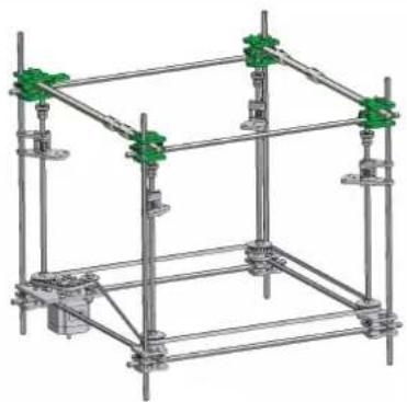
natural_image
3D mechanical assembly diagram showing a frame structure with green valve joints (no text or symbols)| Tools Setting jig x2 2.5mm allen key 5.5mm spanner |  | No Hazard. |
 | No warnings. |
- Thread 2# M8 nuts onto the top of each upright threaded bar to a nominal distance of 100mm from the top end.
- Place a single M8 washer onto each threaded bar followed by a 608 bearing.
- Slide the top frame onto the upright bars (this may take some manipulation and potentially require loosening some bolts on the upper corners. Do not forget to reset your top frame if this is the case!)
- Use the setting jigs to set the height using only the 8mm ∅ holes (3D model below)
- Set 2 opposite corners at a time (i.e. front left and back right)
- Once your setting jigs are in position insert the M5x6 grub screws into the M5 nuts off the frame (but not enough for the grub to protrude right through the nut.)
- Using the allen key, position the grub screws with nuts into the top and bottom rebates for each of the jigged corner blocks and tighten, then repeat the process for the other two corners.
- Make sure all corner blocks are locked in position.
- Check all of your frame is now set correctly as it can be awkward to go back at a later point if there is a problem.
- Position the 608 bearing into the recess of the underside of the corner block at the top of the threaded bar. Thread up the M8 nut with washer to the bearing, careful not to tighten too much or you could break the corner block, then thread up the second M8 nut and using two 13mm wrenches lock the 2 nuts together.
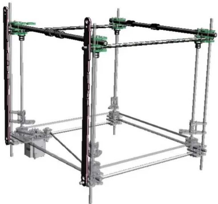
natural_image
3D mechanical assembly diagram showing a frame structure with green and black components (no text or symbols)8f. X Motor & Rails
| Part# Qty Location |  | 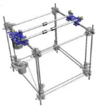 | ||
| X motor plate 1 Previous | ||||
| X Idler Plate 1 Previous | ||||
| X Rod & Belt Clamps 1 Previous | ||||
| Upper Square To Frame 1 Previous | ||||
| 10025 1 5mm | ||||
| 10029 2 5mm | ||||
| 10041 1 5mm | ||||
| 20004 2 Steel | ||||
| KH1228 3 Stepper Frame | ||||
| M5 x 35 14 Bin 7 | ||||
| M5 x 30 10 Bin 9 | ||||
| M5 x 55 2 Bin 9 | ||||
| M5 Nut 26 Bin 6 | ||||
| M5 Washer 52 Bin 6 | ||||
| Tools4mmAllenKey8mmWrench |  | No Hazard. |
 | When clamping linear bearings, make initially finger tight. Do not use tools initially. Over-tightening will permanently damage the linear bearing. After finger-tight, test bearing performance. Gradually increase clamping force, testing after each increase. Back clamping force off if bearing performance becomes lumpy or noisy. |
- Remove protective film from all required parts.
- Ensure all holes are clear of cut-out debris.
- Carefully identify the parts as 10025 & 10029 are very similar but the holes are in slightly different positions.
- Loosely fit 10025 & 10041 to the X motor plate with 2# M5 x 35 CP bolts, 4# M5 washers & 2# M5 nut (Pic 8f-01).
- Hang the X motor plate over the linear bearing on the left hand 12mm∅ bar (Pic 8f-02).
- Fit the remaining 6# M5 x 35 CP bolts complete with washers & nuts. Set the linear bearing such that it is central to the retaining bolts and
RapMan 3.2 manual
ideally with one of the visible ball slots positioned at 12 'O'clock when the motor plate is horizontal (Pic 8f-03).
- Tighten the bolts until the bearing is held firmly but also runs smoothly on the 12mm∅ bar. If the movement feels uneven loosen the bolts until the X motor plate runs smoothly.
- Place 6# M5 x 35 CP bolts head down and place 6# M5 washers over the bolts.
- Layout as per Picture 8f-04.
- Lower over the bolts with the bearings face down.X Idler Plate
- Lower 2# 10029 over the bolts ensuring all the holes align as they are not in a perfect square pattern (Pic 8f-05).
- Place 4# M5 washers over the 4 bolts that are in line then screw on 4# M5 nuts 2 -3 turns.
- Remove the 2 loose bolts and hang the assembly over the 2 linear bearings on the right 12mm∅ bars and refit the previously removed bolts. Fit 2# M5 washers and 2 # M5 nuts (Pic 8f-06).
- Finger-tighten the 3 nuts.
- Slide 2# KH1228 onto one of the 20004 12mm∅ rods.
- Slide 1# KH1228 onto the other 20004 12mm∅ rod (Pic 8f-07).
- Lay the 2# 12mm∅ rods onto the X motor plate and the X idler plate (The bar with one bearing closest to the Z motor) (Pic 8f-08).
- Fit the X micro-switch clamp plate with 3# M5 x 30 CP, 6# M5 washers & 3# M5 nuts and feed the X micro-switch wires (orange) through the hole in the X motor plate next to the X motor. (Pic 8f-09).
- Fit the second X motor plate rod clamp ensuring the belt clamp is inner-most.
- Fit 2 X idler rod clamps using 4# M5 x 30 CP, 2# M5 x 55 CP, 12# M5 washer & 6# M5 nuts (Pic 8f-10).
- At this point tighten all the X idler bolts until the linear bearings run smoothly. Adjust as required.
- Check the X assembly moves freely along the Y axis.
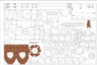
text_image
Technical diagram with labeled components and mechanical parts, including gears and a gear mechanism
natural_image
Close-up of a mechanical assembly with metallic components and bolts (no visible text or symbols)
natural_image
Close-up of a mechanical assembly with metallic components and wires (no visible text or symbols)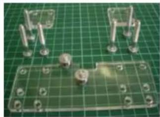
natural_image
Close-up of mechanical components on a green grid background, including screws and bolts (no visible text or symbols)8f-01 8f-02 8f-03 8f-04
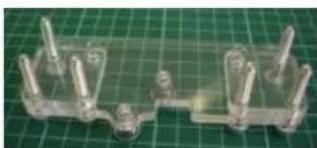
natural_image
Close-up of a transparent plastic mechanical component with multiple pins, placed on a green cutting board (no text or symbols visible)
natural_image
Close-up of mechanical components with no visible text or symbols
natural_image
Two metallic cylindrical mechanical components placed on a green cutting mat (no text or symbols visible)
natural_image
Close-up of mechanical components with metallic rods and a blue circular component (no visible text or symbols)8f-05 8f-06 8f-07 8f-08

natural_image
Close-up of a mechanical assembly with transparent housing and metal rods (no visible text or symbols)
natural_image
Close-up of a mechanical assembly with metallic components and connectors (no visible text or symbols)8f-09
Ignore belts in photo.
8f-10
8g. Y Idlers
| Part# Qty Location | ||
| X Motor & Rails 1 Previous | ||
| 10031 2 5mm | ||
| 10089 2 5mm | ||
| 20005 (70mm) 2 Bag 2 | ||
| 623 Bearing 2 Bin 11 | ||
| M5 x 6 Grub(Set Screw) | 4 Bin 6 | |
| M5 Nut 4 Bin 6 | ||
| M3 x 30 CP 2 Bin 2 | ||
| M3 x 25 CP 2 Bin 4 | ||
| M3 Nut 4 Bin 1 | ||
| M3 x 12 Washer | 2 Bin 5 | |
| M3 Washer 18 Bin 1 | ||
| Tools2.5mm Allen Key5.5mm Wrench |  | No Hazard.No warnings. |
- Place an M3 x 30mm CP bolt on its head.
- In sequence place the following over the bolt:
1# M3 x 12 washer > 3# M3 washers > 1# 623 bearing > 3# M3 washers - Place the assembled bolt from instruction 2 and an M3x25bolt with washer through part 10031.
- Add part 10089 then add a washer and nut to each bolt. (pic 8g-01)
- Fit the steel rod 20005 into the front top corner (Z motor in back left bottom corner) block as for previous steel rods. Set the steel rod level with the corner rod.
- Clamp in place using the M5 nut & grub screw (Pic 8g-02).
- Slide the Y idler assembly over the steel rods with the idler bearing on the outside of the machine closest to the short steel rod 20005 & clamp into place (Pic 8g-03).
- Repeat for the other front top corner block.
RapMan 3.2 manual
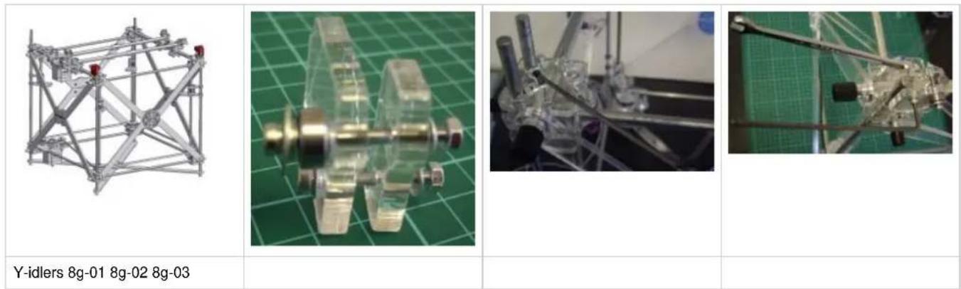
8h. Y Motor
| Part# Qty Location | 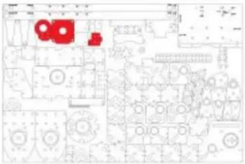 | 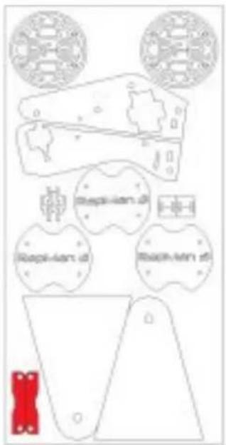 | 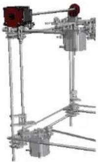 | ||
| Y Idlers 1 Previous | |||||
| 10022 1 5mm | |||||
| 10032 1 5mm | |||||
| 10033 1 5mm | |||||
| 10141 2 3mm | |||||
| Micro Switch White Wire | 1 Bag 1 | ||||
| 14" - 80mm Coupling | 1 Bin 10 | ||||
| 20003 1 Bag 2 | |||||
| 20007 1 Bag 2 | |||||
| 20014 1 Steel | |||||
| Nema 23 Stepper | 1 Loose | ||||
| MXL 18T Pulley | 2 Bin 10 | ||||
| RI-1214ZZ | 1 Bin 11 | ||||
| M5 x 25 CP | 4 Bin 9 | ||||
| M5 x 6 Grub (Set Screw) | 4 Bin 6 | ||||
| M5 Nut 8 Bin 6 | |||||
| M5 Washer | 4 Bin 6 | ||||
| M3 x 25 CP | 4 Bin 4 | ||||
| M3 x 20 CP | 2 Bin 2 | ||||
| M3 Nut 6 Bin 1 | |||||
| M3 Washer | 12 Bin 1 | ||||
| Tools |
| 4mm Allen Key |
| 8mm Wrench |
| 2.5mm Allen Key |
| 5.5mm Wrench |
| 1/16" Allen Key |
| 2mm Allen Key |
- Fix the MXL pulley, leaving 6.5mm of the motor shaft visible, & the 1/4" coupling (the end with smaller aperture) to the Stepper motor shafts, positions as defined in Pic 8h-01. The pulley uses the 1/16" Allen key & the coupling uses the 2mm Allen key.
- Fit 2# M3 x 20 CP & washers into the micro switch (Pic 8h-02).
- Mount the micro switch onto the Y motor bracket (top or corner block above Z motor) adding M3 washer and nuts from below (Pic 8h-03).
- Pre-assemble the Y bearing mount using the M3 x 25 CP bolts, washers & nuts, see picture for orientation or parts 10032 & 10033 (Pic 8h-04).
- Pre-assemble the Y motor mounting bracket. Note the mounting plate has a tab on one side this should be on the same side as the motor wires (Pic 8h-05). Check 3D model for orientation of parts 10141
- Fit steel rod 20003 (95mm long) to the Y motor corner, set level to corner rod and clamp in place using the M5 nut & grub screw.
- Fit steel rod 20007 (58mm long) to the remaining corner. Set flush to bottom of corner block (top of rod will be lower than corner rod) and clamp as in previous step.
- Fit the Y Stepper motor to the Y motor corner with the wires facing down and tighten into place (Pic 8h-06).
- Fit the Y bearing mount to the remaining corner and tighten into place (Pic 8h-07).
- Assemble the Y idler pulley and the R4A bearing onto the narrower end of Y drive rod 20014 (Pic 8h-08).
- Slide the Y drive rod through the Y bearing mount locating the bearing in the mount and sliding the drive shaft (20014) in the 14 " coupling.
- Tighten the Y drive coupling (Pic 8h-09).
| 8h-01 8h-02 8h-03 8h-04 | |||
| 8h-05 8h-06 8h-07 8h-08 |
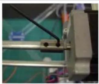
natural_image
Close-up of a mechanical assembly with metal frame and wiring, no visible text or symbols8h-09
Note: grub screws for 14 " – 80mm Coupling should already be loaded but if they are not they can be located in bin 10.
8i. X Carriage
Before completing this page, establish how many extruder heads you will be installing on your RapMan. If you are unsure as to what was included in the kit you can check the kit contents page. Then simply read the section which applies to you:
- Single head carriage assembly
• Double head carriage assembly
Single head carriage assembly
| Part# Qty Location | |
| Y Motor | 1 Previous |
| 10034 2 5mm | |
| 10035 1 5mm | |
| 10108 1 5mm | |
| 10109 2 5mm | |
| 10110 1 5mm | |
| M5 x 35 CP | 12 Bin 7 |
| M5 x 20 Hex | 3 Bin 9 |
| M5 Nut 18 Bin 6 | |
| M5 Washer | 12 Bin 6 |
| M5 x 45 CP | 2 Bin 9 |
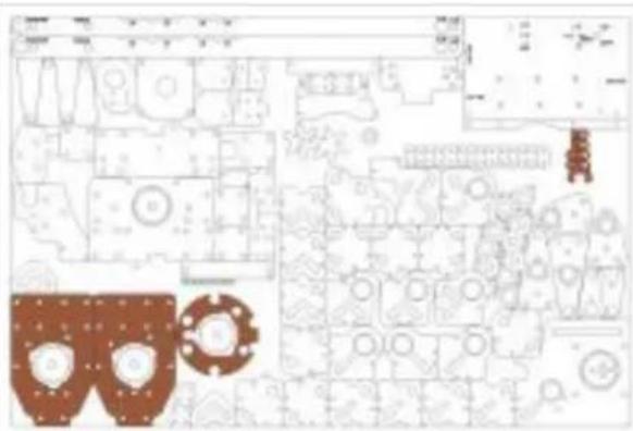
text_image
Technical schematic diagram with labeled components and annotations in Chinese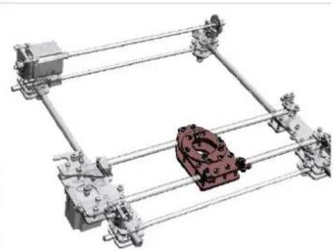
natural_image
Mechanical assembly diagram showing a frame with a red mechanical component mounted on a metal frame (no text or symbols visible)Note: only top frame shown here.
| Tools |  | No Hazard. |
| 4mmAllenKey | ||
| 8mmWrenchx 2 |  | When clamping linear bearings, make initially finger tight. Do not use tools initially. Over-tightening will permanently damage the linear bearing. After finger-tight, test bearing performance. Gradually increase clamping force, testing after each increase. Reduce clamping force if bearing performance becomes lumpy or noisy. |
- Fit the 3# M5 x 20 Hex head bolts into part 10034 make sure the version writing is the correct way up (readable) (Pic 8i-01). Fit these bolts without washers.
- Loosely fit 3# nuts to the bolts these will later fix the extruder (Pic 8i-02).
- Lay the plate onto the 3 linear bearings.
- Insert 10 M5 x 35 CP bolts again without washers. (Pic 8i-03)
- Offer up the second part 10034
- Attach M5 nuts & washers to all 10 bolts and finger tighten. (Pic 8i-04)
- Loosely assemble the fan brackets 10108, 10109 & 10110 on to the 2 M5 x 45 CP bolts. (Pic 8i-05)
- Fit to the outside front of the X carriage. (Pic 8i-06)
- Fit M5 nuts & washers to the 2 M5 x 45 CP bolts and finger tighten.
- Carefully tighten all 12 nuts in a diagonal pattern.
-
Tighten the bolts until the bearing is held firmly but also runs smoothly on the 120 bar. If the movement feels uneven loosen the bolts until the X carriage runs smoothly.
-
Place extruder spacer 10035 onto the X carriage ensuring it is orientated correctly. (Pic 8i-07)
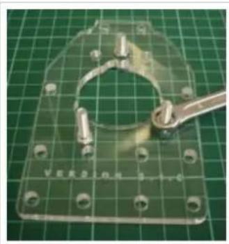
natural_image
Transparent plastic mechanical bracket with bolt holes and a metal tool on a green grid background (no text or symbols visible)8i-01 8i-02 8i-03 8i-04
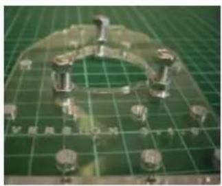
natural_image
Close-up of a mechanical component with multiple cylindrical parts arranged in a U-shaped groove on a green cutting board (no visible text or symbols)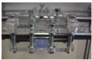
natural_image
Close-up of a mechanical assembly with transparent components and a blue highlighted section (no visible text or symbols)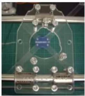
natural_image
Close-up of a transparent electronic device with metallic components and a central blue logo, mounted on a green circuit board (no visible text or symbols)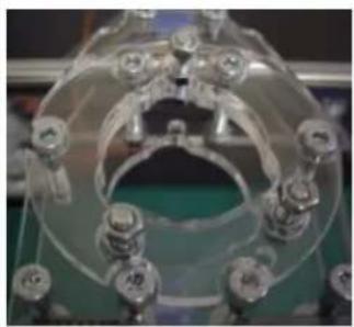
natural_image
Close-up of a transparent mechanical component with multiple circular features and mounting holes (no visible text or symbols)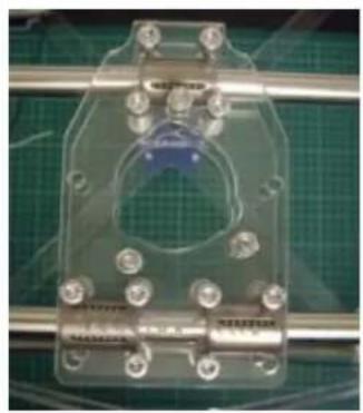
natural_image
Close-up of a transparent mechanical component mounted on a metal rod, with green grid background (no visible text or symbols)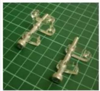
natural_image
Two transparent plastic mechanical components mounted on a green grid cutting mat (no text or symbols visible)8i-05 8i-06 8i-07
Double head carriage assembly
You will need to gather some of the components found in your Double head upgrade pack. You can identify the parts of acrylic in the Laser cut parts identification section. Some parts will also come from the standard kit locations, as detailed below:
| Part# Qty Location | |
| Y Motor 1 Previous | |
| 400510 2 Double head upgrade pack, 5mm | |
| 400508 1 Double head upgrade pack, 5mm | |
| 10108 1 5mm Main panel | |
| 10109 2 5mm Main panel | |
| 10110 1 5mm Main panel | |
| M5 x 35 CP 12 Bin 7 | |
| M5 x 20 Hex 3 Bin 9 | |
| M5 x 20 Hex 3 Double head upgrade pack, bolt bag | |
| M5 Nut 18 Bin 6 | |
| M5 Nut 6 Double head upgrade pack, bolt bag | |
| M5 Washer 12 Bin 6 | |
| M5 x 45 CP 2 Bin 9 | |
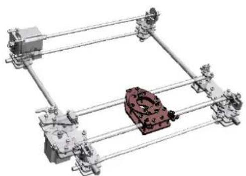
natural_image
Mechanical assembly diagram with metal frames and a central red component (no text or symbols)Note: only top frame shown here.
Note: pic only shows single head carriage in assembly.
However, positioning is the same for double head carriage.
| Tools | ||
| 4mm Allen Key |  | No Hazard. |
| 8mm Wrench x 2 |  | When clamping linear bearings, make initially finger tight. Do not use tools initially. Over-tightening will permanently damage the linear bearing. After finger-tight, test bearing performance. Gradually increase clamping force, testing after each increase. Reduce clamping force if bearing performance becomes lumpy or noisy. |
- Fit 6# M5 x 20 Hex bolts to 400510 as shown in photos (DH1 & DH2), locking with M5 nuts. Attention: Check orientation of holes in the plate.
- Tighten all nuts securely, using 8mm wrenches.
- Fit 400508 as shown in photos (DH3 & DH4). Bolts point up in DH4. Double check orientation of holes. Loosely fit 6# nuts to the bolts these will later fix the extruder
- Load M5 x 35 bolts into double carriage preassembly, as shown in DH5 and DH6. Note: in image DH5, the two bolts midway up on the far left and right will not get washers and nuts in this section as they are called for in section k. X, Y & Z Belts.
- Lay assembly over x-bearings, positioning bearings evenly between sets of bolts (DH7).
- Attach 400510 from below, checking hole alignment, using M5 washers and nuts, finger tighten (DH8).
- Follow step 7 from the Single head carriage assembly above.
- Fit to the inside front of the X carriage and fit M5 nuts & washers to the 2 M5 x 45 CP bolts and finger tighten.
- Carefully tighten all 12 nuts in a diagonal pattern. Apply even torque to ensure plates are parallel and the bearings run freely on the 120 bar as you did with the Y motor.

natural_image
Metal mechanical bracket with two circular holes and bolt holes, placed on a green grid background (no text or symbols visible)DH1 DH2 DH3 DH4
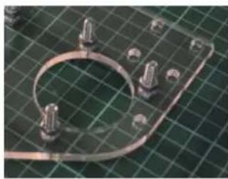
natural_image
Close-up of a metallic mechanical component mounted on a green grid background (no visible text or symbols)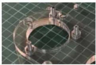
natural_image
Close-up of a metallic mechanical flange with bolt holes and a green mesh background (no text or symbols visible)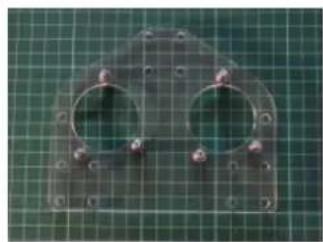
natural_image
Metal mechanical component with four circular holes and bolt holes, placed on a green grid background (no text or symbols visible)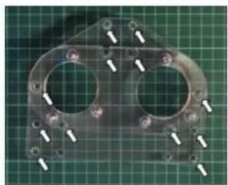
natural_image
Metal mechanical component with multiple circular holes and bolt holes, displayed on a green grid background (no text or symbols visible)DH5 DH6 DH7 DH8
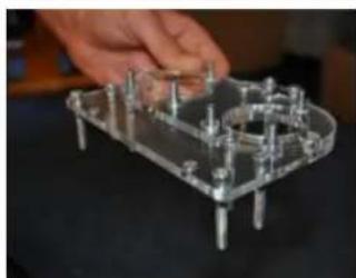
natural_image
Hand holding a transparent plastic electrical component with multiple pins (no visible text or symbols)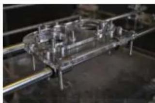
natural_image
Industrial mechanical assembly with metallic components and metal framework (no visible text or symbols)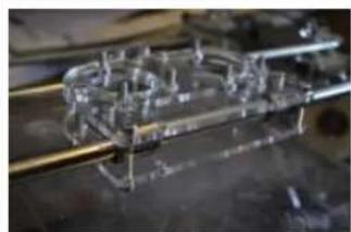
natural_image
Close-up of a mechanical assembly with transparent components and metal rods (no visible text or symbols)8j. Bed frame
| Part# Qty Location | |
| X Carriage 1 Previous | |
| 10020 1 8mm | |
| M5 x 20 CP 12 Bin 5 | |
| M5 Nut 12 Bin 6 | |
| M5 Washer 24 Bin 6 | |
| Note: Bed frame is too high in image. Bed corners should be wound down to the bottom before attaching the bed. |
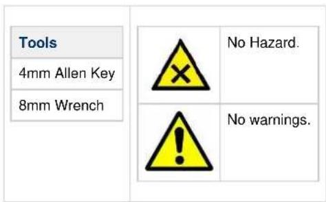
text_image
Tools 4mm Allen Key 8mm Wrench No Hazard. No warnings.- Make sure all of the bed corners are wound to the bottom of the Z bars (touching the pulleys.)
- Position the RapMan such that the Z motor is in the back left corner. Fit the Bed frame 10020 with the "Bits From Bytes" text at the front.
- Bolt the bed down with the 12 M5 x 20 CP bolts, 12 M5 nuts & 24 washers.
8k. X, Y & Z Belts
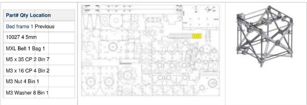
text_image
Part# Qty Location Bed frame 1 Previous 10027 4 5mm MXL Belt 1 Bag 1 M5 x 35 CP 2 Bin 7 M3 x 16 CP 4 Bin 2 M3 Nut 4 Bin 1 M3 Washer 8 Bin 1Tensioning the Z motor belt:
| Tools2.5mmAllenKey5.5mmWrench13mmx 2WrenchWireCutters1/16"Allenkey |  | No Hazard. |
 | After fitting the bed frame at the bottom of the machine, it will be difficult to access the z-belt tensioner. However, the bed frame was assembled deliberately in this low position to act as a brace for the next step: as the z-belt is tensioned, the belt will try to pull the threaded bars inwards towards the centre of the machine. In other words,tightening the belt will attempt to 'break' the parallel constraints of the threaded bar. But having the bed frame installed down low and close to belt will prevent this from happening.If it is too difficult to access the belt tensioner with the bed frame at bottom, you may need to wind the bed frame up,but ensure you do so by an even amount at each corner. | |
- Starting with the 1st corner anticlockwise from the Z motor hold the Z belt to the Z pulley.
- Using your other hand pull the belt towards the next pulley working anticlockwise towards the Z motor.
- Loop the belt around the Z motor pulley and the tensioner bearing.
- Adjust the tensioner bearing using 13mm spanners until the Z belt has no more than 30mm (+/-15mm) of play in the middle of the front belt run. (Pic 8k-01, 8k-02, 8k-03)
- Wind the Z belt by hand to move the bed corners to approximately mid position. Check the motor wires are not touching as this will make it very hard to move the motor.
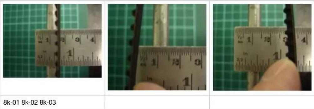
Tensioning the X motor belt:
- Loosely assemble the X belt clamps 10027 with the M3 x 16 CP, M3 nuts & washers. (Pic 8k-04)
- Cut the MXL belt in to 3 lengths 1 x 945mm (37 1/4") & 2 x 735mm (29") with the wire cutters.
- Take 945mm belt (X belt)
- Slide the belt clamp onto one end of the X belt. (Pic 8k-05)
- Wrap the belt around the M5 x 35 CP bolt and slide the clamp over the folded back belt and tighten. The belt should be flush with the clamp. (Pic 8k-06)
- Remove the bolt. (Pic 8k-07)
- Fit the bolt & belt to the X carriage on the X motor side. (Pic 8k-08)
- Feed the X belt around the X motor pulley and the 3 idler bearings.
- Install the 2nd M5 x 35 CP into the X carriage.
- Feed the X belt through the 2nd belt clamp and around the M5 x 35 CP bolt.
- Pulling the belt tight fold it back against itself so the teeth lock together, this prevents it slipping loose.
- Slide the belt clamp over the folded back belt and tighten the bolts just enough that it locks the teeth together. (Pic 8k-09)
- Slide the clamp along the belt until it is touching the side of the X carriage, this will also help tension the belt. (Pic 8k-10)
- Trim any excess belt with the wire cutters to prevent it catching in the idler bearings.
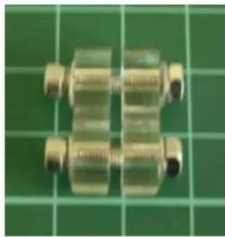
natural_image
Close-up of two metallic mechanical components mounted on a green grid background (no text or symbols visible)8k-04 8k-05 8k-06 8k-07
natural_image
Close-up of a metallic mechanical component mounted on a green grid background (no visible text or symbols)
natural_image
Close-up of a metallic mechanical component with a black strap, resting on a green cutting board (no visible text or symbols)
natural_image
Close-up of a brass mechanical component with threaded shaft and connector, placed on a green grid background (no text or symbols visible)
natural_image
Close-up of a mechanical assembly with a black and white component, possibly a tool or device (no visible text or symbols)8k-08 8k-09 8k-10
natural_image
Close-up of a mechanical component with a black rod and metallic connector (no visible text or symbols)
natural_image
Close-up of mechanical components with no visible text or symbolsFitting and Tensioning the 2 Y belts:
- Take 1 of the 735mm belts (Y belt)
- Working on the X motor side clamp the Y belt into the Y belt clamp, teeth facing up, on the X motor carriage nearest the Y motor. (Pic 8k-11)
- Wrap the belt around the Y motor pulley. (Pic 8k-12)
- Wrap it around the Y idler bearing and back through the other Y belt clamp.
- Pull the belt tight and fold back over the top of the belt clamp this will help to keep the belt tight while you are tightening it. (Pic 8k-13)
- Tighten the Y belt clamp.
- Repeat this process for the 2nd Y belt
- The X frame now has to be aligned as the belts are unlikely to be in sync.
- Loosen the Y idler pulley. (Pic 8k-14)
- Run the X Frame fully to the front of the machine away from the Y motor until both X motor plate and the X idler plate are touching the Y idler brackets. (Pic 8k-15, 8k-16)
- Now retighten the Y idler pulley to align the X-axis to the frame.

natural_image
Close-up of mechanical components with metallic rods and bolts (no visible text or symbols)
natural_image
Close-up of a mechanical assembly with a pulley and chain (no visible text or symbols)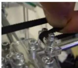
natural_image
Close-up of a hand adjusting a black cable with metallic components (no visible text or symbols)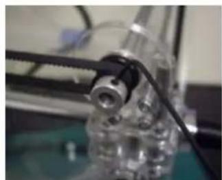
natural_image
Close-up of a mechanical assembly with a transparent cylindrical component and a black rail, no visible text or symbols.RapMan 3.2 manual
8k-11 8k-12 8k-13 8k-14
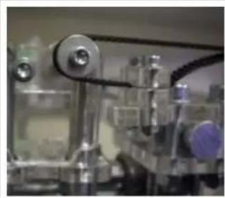
natural_image
Close-up of a laboratory apparatus with metallic components and tubing (no visible text or symbols)8k-15 8k-16
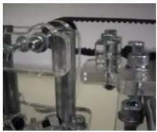
natural_image
Close-up of mechanical components with transparent tubing and fittings (no visible text or symbols)Note: The reason the motor is hard to turn if the wires are touching each other is that the motor acts as a generator when moved by hand and with the wires touching this then powers the motor in the reverse direction, this effect is called back EMF (electro motive force).
8I. Fitting adjustable Bed
| Part# Qty Location | |
| Adjustable Bed 1 Previous | |
| Section 16.01 1 Previous | |
| 10106 6 8mm | |
| Spring L 3 Bin 10 | |
| M8 x 60 Hex 3 Bag 2 | |
| M8 Nut 3 Bin 8 | |
| M8 Washer 6 Bin 8 | |
| Tools 13mm Wrench x 2 | No Hazard. | |
| DO-NOT over tighten the M8 lock nuts as this can damage the acrylic thread. |
- Slide the adjustable bed assembly into the RapMan such that the micro-switch is in the back left corner under the Y motor (Pic 8I-01).
- Fit the M8 x 60 Hex head bolts as per the 3D model fitting the spacers 10106 either side of the spring (Pic 81-02).
- DO NOT over tighten the M8 lock nuts as the bolts are only in an acrylic thread.
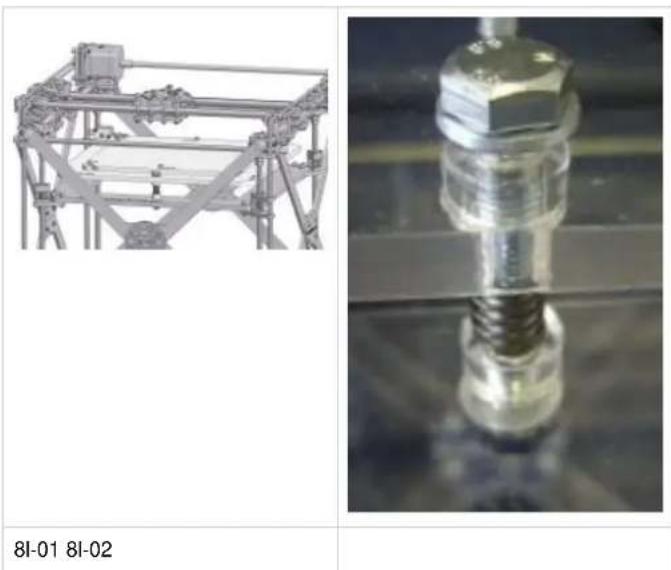
natural_image
Two technical images: one showing a mechanical frame structure, the other showing a close-up of a bolted screw assembly (no text or symbols visible)8m. Diagonal Ties Base
| Part# Qty Location | ||
| Fitting adjustable Bed | 1 Previous | |
| 10126 2 5mm | ||
| 10137 1 3mm | ||
| Tint Disc S 1 Loose | ||
| 8Ø Rod Cover 4 Bin 11 | ||
| M3 x 12 CP 4 Bin 2 | ||
| M3 Nut 4 Bin 1 | ||
| M3 Washer 8 Bin 1 |
text_image
Tools 2.5mm Allen Key 5.5mm Wrench Setting Jig x 2 No Hazard. No warnings.- Remove protective film from all required parts.
- Ensure all holes are clear of cut-out debris.
- Place 4# M3x12 CP bolts upright on their heads.
- Place a single M3 washer over each bolt (Pic 8m-01).
- Place part 10137 onto the bolts ensuring that the lettering is face down (Pic 8m-02).
- Place the tinted plastic disc (see diagram above) over part 10137 in the same manner.
- Place part 10126 over the end of the bolts so as to form an X shape with the 'circle' at the centre (Pic 8m-03).
- Place a single washer and nut onto each bolt and .loosely tighten
- Turn the X shape assembly so that the lettering is face up with the top left corner of the X being next to the Z motor position (Pic 8m-04).
- Recheck all the horizontal settings using the setting jig.
- Locate each vertical bar end through the hole at the end of the X shape. Place an 8mm∅ rod cover over each bar until fully located (Pic 8m-05).
- Ensure that each end of part 10126 lies flat against the 8mm ∅ rod cover.
- Securely tighten the 4 nuts and bolts using the wrench and Allen key while squeezing the parts together.
RapMan 3.2 manual
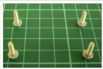
natural_image
Four metallic screwdrivers on a green cutting board (no text or symbols visible)8m-01 8m-02 8m-03 8m-04
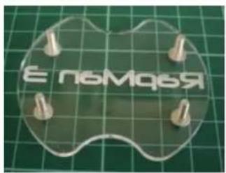
text_image
Е пьмая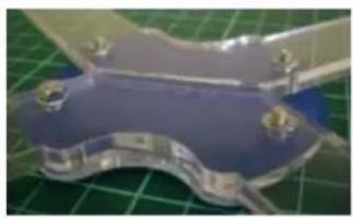
natural_image
Close-up of a metallic mechanical component with blue and silver surfaces, resting on a green grid background (no visible text or symbols)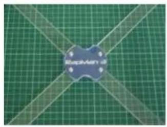
natural_image
Green cutting board with diagonal lines and a blue circular patch labeled 'BlueCAD' (no other text or symbols)
natural_image
Close-up of a mechanical component with a black base and metallic shaft, placed on a green cutting mat (no visible text or symbols)8m-05
8n. Diagonal Ties Sides
| Part# Qty Location | |
| Diagonal Ties Base | 1 Previous |
| 10121 3 5mm | |
| 10122 1 5mm | |
| 10137 2 3mm | |
| Tint Disc S 2 Loose | |
| 8Ø Rod Cover 8 Bin 11 | |
| M3 x 12 CP 8 Bin 2 | |
| M3 Nut 8 Bin 1 | |
| M3 Washer 16 Bin 1 |
| Tools 2.5mm Allen Key 5.5mm Wrench Setting Jig x 2 | No Hazard. |
| Be careful not to over-tighten and stress-fracture the acrylic. |
- Remove protective film from all required parts.
- Ensure all holes are clear of cut-out debris.
- Rotate the frame so that you are looking into the side with the z-motor on bottom left.
- Re-check the vertical and horizontal settings of the frame with the setting jig.
- Locate part 10122 with 6 additional small holes on one side of the V shape. This part will form an inverted V shape with the holes running down the leg of the V towards the corner without the motor. Attach it onto the corner 8mm∅ rods.
- Locate part 10121 (without extra holes) and place this above the inverted V to make an X shape in the centre of the bars. Attach it onto the corner 8mm∅ rods.
- Place 4# M3x12 CP bolts upright on their heads.
- Place a single M3 washer over each bolt (Pic 8n-01).
- Place part 10137 onto the bolts ensuring that the lettering is face down (Pic 8n-02).
- Place the tinted plastic disc over part 10137 in the same manner.
- Place the assembly onto the front of the X shape so as to form a 'circle' at the centre (Pic 8n-03).
- Place a single washer and nut onto each bolt and finger-tighten while pulling the 2# parts 10121 together.
- Securely tighten each nut and bolt using the wrench (wrench) and Allen key while still squeezing the parts together (Pic 8n-04).
- Part 10122 should be orientated as Picture 8n-05.
- Fit the 8∅ rod covers (Pic 8n-06).
- Repeat the steps above for the opposite side of the frame, but with the remaining two 10121 parts
RapMan 3.2 manual
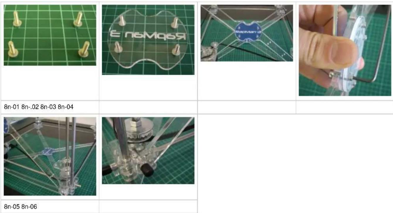
80. Diagonal Ties Front & Back
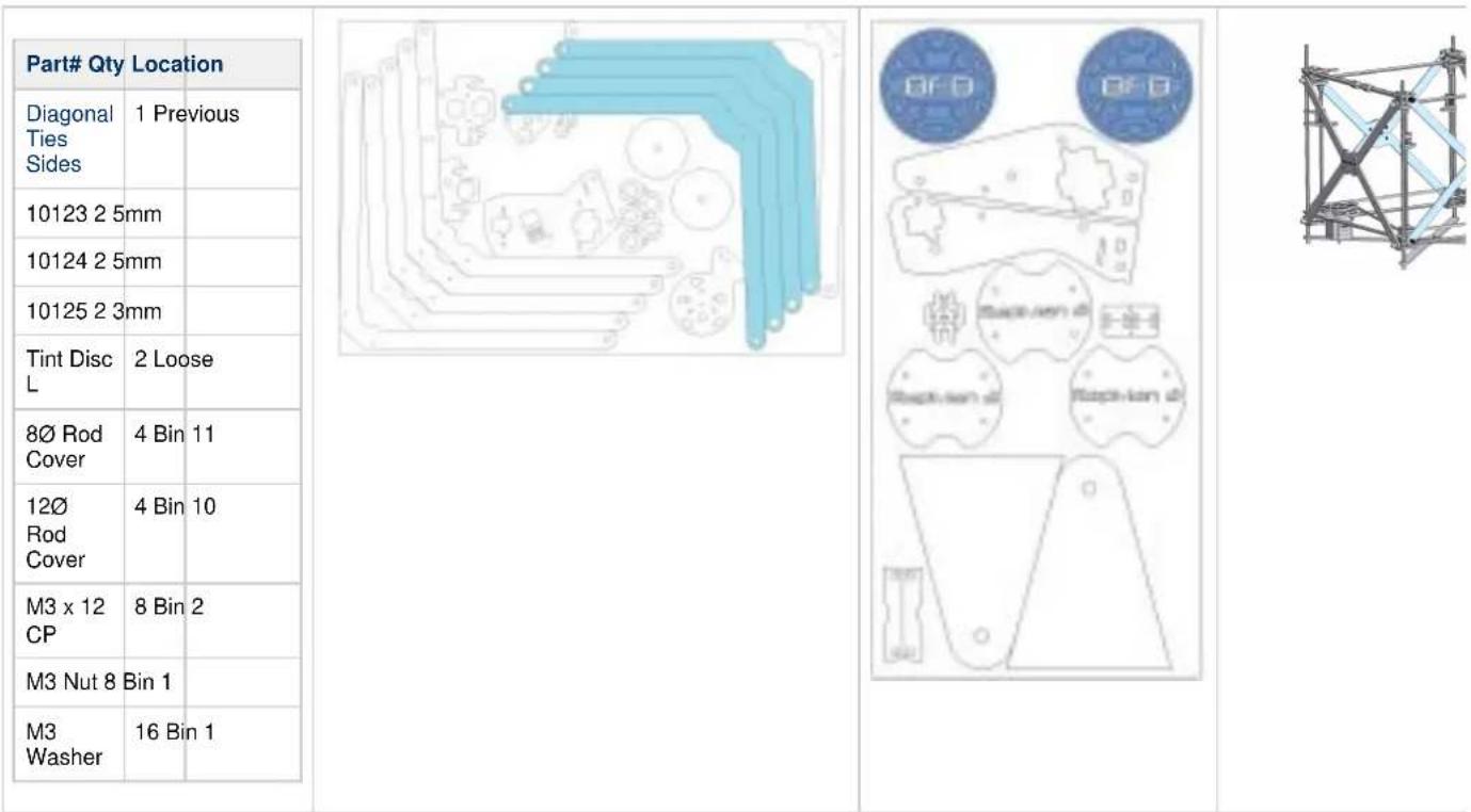
| Part# Qty Location | |
| Diagonal Ties Sides | 1 Previous |
| 10123 2 5mm | |
| 10124 2 5mm | |
| 10125 2 3mm | |
| Tint Disc L | 2 Loose |
| 8∅ Rod Cover | 4 Bin 11 |
| 12∅ Rod Cover | 4 Bin 10 |
| M3 x 12 CP | 8 Bin 2 |
| M3 Nut 8 | Bin 1 |
| M3 Washer | 16 Bin 1 |
text_image
Tools 2.5mm Allen Key 5.5mm Wrench Setting Jig x 2 No Hazard. No warnings.- Remove protective film from all required parts.
- Ensure all holes are clear of cut-out debris.
- Rotate the frame so you are looking into the front with the Z motor in the back left corner.
- Locate part 10123. This part will form an inverted V shape. Attach it onto the lower corner 8mm∅ rods on the front side.
- Locate another part 10124 (with 12∅ holes) and place this above the inverted V to make an X shape in the centre of the bars. Attach it onto the corner 12mm∅ rods.
- Re-check the vertical and horizontal settings of the frame with the setting jig.
- Place 4# M3x12 CP bolts upright on their heads.
- Place a single M3 washer over each bolt. (Pic 80-01).
- Place part 10125 onto the bolts ensuring that the lettering is face down.
- Place the tinted plastic disc over part 10125 in the same manner (Pic 8o-02).
- Place the assembly onto the front of the X shape so as to form a 'circle' at the centre.
- Place a single washer and nut onto each bolt and finger-tighten while pulling the 2# parts 10126 together.
- Securely tighten each nut and bolt using the wrench and Allen key while still squeezing the parts together (Pic 80-03).
- Fit the 8∅ & 12∅ rod cover on the rod ends (Pic 8o-04).
- Repeat for rear side, but leave the rod covers off the rod ends so you can remove the diagonal ties to fit the conduit easier in the next section.
RapMan 3.2 manual
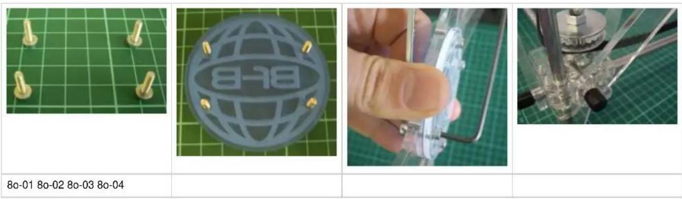
8p. Fitting the Conduit
The following section tidies the wires on the machine, and delivers them to the point where the control panel will be attached. Take a look at the photo below to establish what the conduit is working towards:
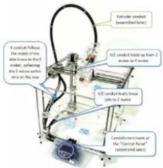
text_image
X conduct follows the inside of the side knee to the Z motor, reflecting the Z-motor switch wire on the way Extruder conduct (assembled line) HZ conduct heads up from Z motor to X motor HZ conduct walls lower side to Z motor Cereals terminate at the "Central Panel" (annealed later)| Part# Qty Location | Tools | × | Take care when punching hole in the conduit with the driver. | ||
| Ties Front & Back | 1 Previous | Wire Cutters | |||
| Wire Strippers | |||||
| PVC Conduit 1 Loose | 2mm Flat Screwdriver | Take care to make sure X conduit is on the inside of the cross brace. | |||
| Cable tie 3 | Test Filament |
X conduit
Two conduit types are supplied in the box. The PVC conduit required for this section is the shiny, more rubbery, of the two, with deep helical ribbing.
- Cut the PVC X conduit to length 800mm (Pic 8p-02).
- Mark one end as the "control panel" end.
- Measure 580mm (12") from the "control panel" end and make a hole using the screwdriver to push through the conduit (Pic 8p-04).
- Use the test filament to pull the Z-switch wires (yellow) through the conduit: Tape the z-switch wires to the test filament. Feed the filament into the conduit through the hole just made (Pic 8p-05) and pass it through to the "control panel" end. Pull through to bring the z-switch wires through to the "control panel end of the conduit.
- If your X motor is supplied with the separate wires and connector, fit the connector to the motor now.
- Feed the X motor & X micro-switch wires (orange) through the conduit so all wires exit at the "control panel" end (Pic 8p-06).
- Ensure enough slack in the microswitch wire to enable the bed to move fully up and down the entire z-axis without pulling on the wire (Pic 8p-06b).
- At the other end of the conduit, clip the conduit into the clip on the X bearing clamp (Pic 8p-07).
- Cable tie the X conduit to the inside of the cross braces using the 6 holes (Pic 8p-08).
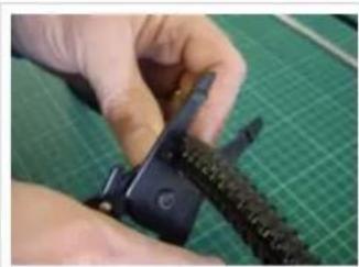
natural_image
Close-up of hands using a crimping tool on a green cutting mat (no visible text or symbols)8p-02 8p-04 8p-05 8p-06
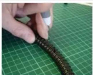
natural_image
Close-up of a hand holding a coiled black cable against a green grid cutting mat (no text or symbols visible)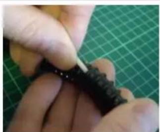
natural_image
Close-up of hands tying a knot on a green cutting mat (no text or symbols visible)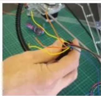
natural_image
Close-up of hands assembling a bicycle wheel with wires and wires on a green cutting board (no text or symbols visible)RapMan 3.2 manual
natural_image
Close-up of a mechanical assembly with black cables and transparent components (no visible text or symbols)8p-06b 8p-07 8p-08
natural_image
Close-up of industrial electrical equipment with visible wiring and a black insulator (no text or symbols)
natural_image
Close-up of a mechanical assembly with green mesh pattern and metal components (no visible text or symbols)Y/Z conduit
- With the remaining PVC conduit length (approximately 1120mm):
- Mark one end the "control panel" end.
- Measure 710mm from one the control and make a hole using the screwdriver to push through the conduit. This hole is for the Z motor wires.
- It will probably be easier to work with the Y/Z conduit if you remove the rear diagonal ties.
- If your Y and Z motors are supplied with the separate wires and connector, fit the connector to the motors now.
- Tape the ends of the Z motor wires together and mark them as the Z motor wires.
- Using the test filament feed technique described above, feed the Z motor wires through this side hole to the control end.
- Tape the ends of the Y motor wires together and mark them as the Y motor wires.
- Now pass the Y motor wires, and Y microswitch wires (white) through the conduit so that all wires exit at the "control panel" end.
- Clip the conduit into the Y motor bracket and the Z motor bracket (Pic 8p-09, 8p-10).
- You can now replace the rear diagonal ties and fit the rod covers to the rod ends.
natural_image
Close-up of a laboratory glassware setup with pens, tubes, and a tool holder (no visible text or symbols)8p-09 8p-10
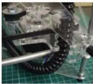
natural_image
Close-up of a mechanical assembly with transparent components and a black coiled spring on a green cutting mat (no visible text or symbols)Termination
Leave the "control panel" ends of the conduits/wires loose. They will be fitted to the control panel later. Do not attempt to tidy the conduits further as this will also be done later.
8q. Serial number
The serial number is essential if you require customer support. You will find a spare label in your box which states your machines model and serial number.

text_image
BITS FROM BYTES RapMan 3.2 Education Part #: 40182 Serial #: 52096017 WWW.BITSFROMBYTES.COMYou will need to cut around the small box that contains your serial number with scissors and stick this on the underside on the Z motor plate. It needs to be under the plastic to protect it from UV.
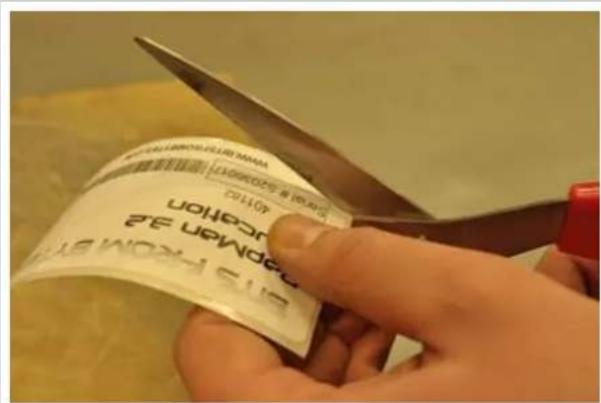
text_image
Close-up of hands cutting a printed label with visible text and a red tool, likely from a document or instruction.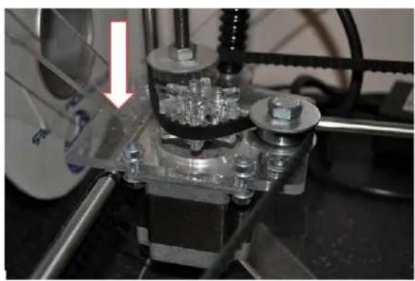
natural_image
Close-up of a mechanical testing setup with a transparent base and cylindrical components, no visible text or symbols.
natural_image
Close-up of a metallic object with reflective surface, possibly a tool or component (no visible text or symbols)9. Hot end assembly (option)
If your kit included a "built hot end" (see kit contents if you are unsure) you can skip this section.
If your kit included a "non-built hot" end you will need to complete this section. Start by the checking the contents of your hot-end pack:
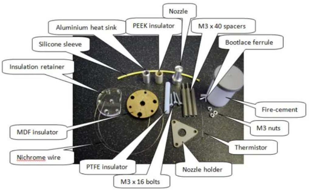
text_image
Nozzle Aluminium heat sink PEEK insulator M3 x 40 spacers Silicone sleeve Insulation retainer MDF insulator Nichrome wire PTFE insulator M3 x 16 bolts M3 x 16 bolts Thermistor Fire-cement M3 nuts Nozzle holderYou will need to complete the following sub-sections:
• a. Preparing the insulated nicrome heating wire
• b. Preparing the thermistor
• c. Nozzle assembly
• d. Wrapping the insulated nichrome
• e. Fitting the thermistor
a. Preparing the insulated nicrome heating wire
- Strip one end of a grey wire to 30mm. Repeat process for second grey wire.
- Cut 4 x 35mm yellow heat proof sleeve.
- Load one yellow heatproof sleeve onto each of the two grey wires (save the remaining 2 heatproof sleeves for later use with the thermistor).
- Check nichrome heating wire is 690mm long. Strip 5mm insulation from each end of the nichrome wire.
- Crimp one end of nicrome wire to the first grey wire (at the stripped end).
- Crimp the other end of nicrome wire to the second grey wire (at the stripped end).
- Slide the yellow heatproof sleeves over any exposed wire. Check the resistance of the wire is between 4.5 and 5.5.
Images read from left to right:
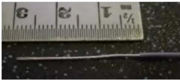
text_image
1/2 3 2 5 1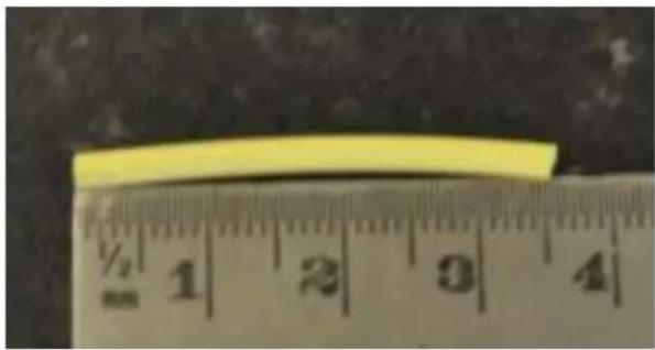
natural_image
Yellow elongated object placed above a ruler for scale (no visible text or symbols on the object itself)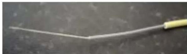
natural_image
Close-up of a thin, white wire with a yellow end cap against a dark surface (no text or symbols visible)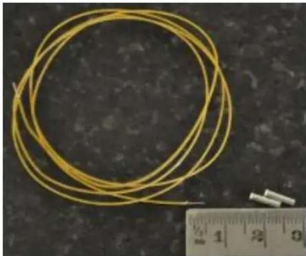
natural_image
Circular yellow wire with a small white object placed next to a ruler for scale (no text or symbols visible)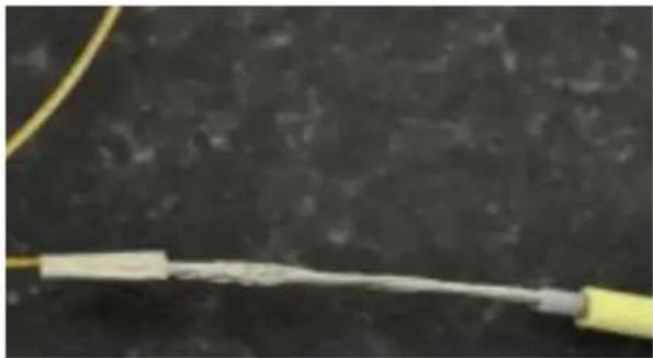
natural_image
Close-up of a yellow cable with a white insulation or wire against a dark background (no text or symbols visible)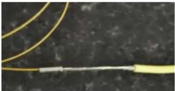
natural_image
Close-up of a yellow cable with a white connector against a dark textured background (no text or symbols visible)
natural_image
Close-up of three yellow wire loops on a dark textured surface (no text or symbols visible)b. Preparing the thermistor
- Strip 30mm of insulation from the end of both 2m purple wires.
- Load the heat-proof sleeve cut previously onto each wire.
- Crimp one of the purple wires to each of the thermistor legs as shown in the images.
Take care of the thermistor. The legs are delicate at the junction. Images read from left to right, click to view slideshow:
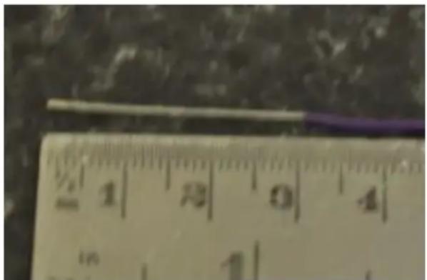
text_image
½ 1 8 0 4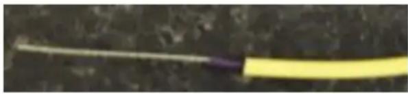
natural_image
Close-up of a yellow cable with a white wire against a dark background (no text or symbols visible)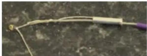
natural_image
Close-up of a thin, curved wire or filament with a small yellow object attached to it, against a textured gray background (no text or symbols visible)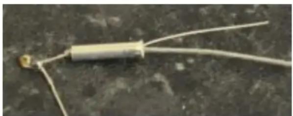
natural_image
Close-up of a small electronic component with two wires extending outward (no visible text or symbols)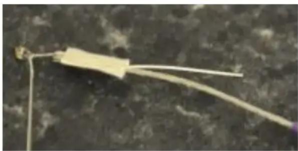
natural_image
Close-up of a thin, elongated wire or filament against a dark textured surface (no text or symbols visible)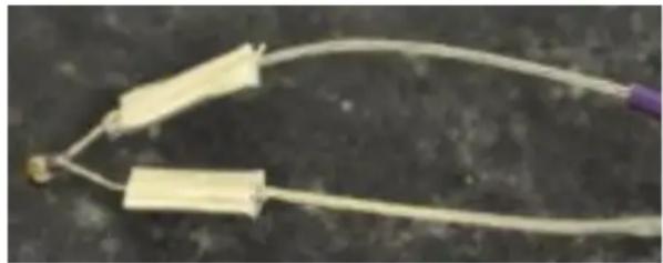
natural_image
Close-up of two medical catheters with tubing, one extending into a dark surface (no text or symbols visible)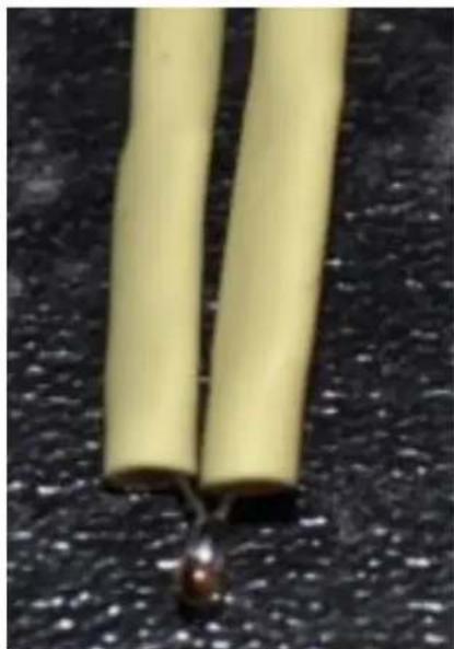
natural_image
Close-up of two yellow cylindrical wires with a black clip attached, against a dark textured background (no text or symbols visible)c. Nozzle assembly
- Push the PEEK insulator into the aluminium nozzle until only 15mm sticks out.
- Cut the end of the PTFE to be square.
- Assemble as shown in the images.
- At the second PTFE cutting stage, cut the PTFE to be flush with the MDF plate.
Images read from left to right, click to see slideshow:
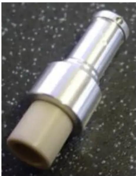
natural_image
Close-up of a metallic cylindrical mechanical component with a beige cylindrical body, resting on a dark textured surface (no text or symbols visible)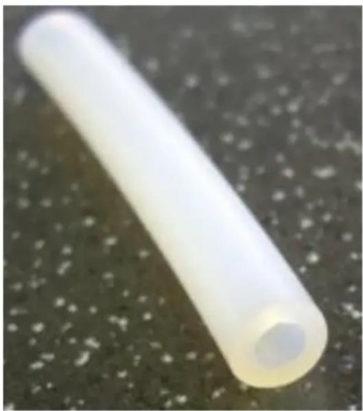
natural_image
Close-up of a translucent white cylindrical object on a dark textured surface (no text or symbols visible)
natural_image
Close-up of a blue and white train wheel on gravel ground (no visible text or symbols)
natural_image
Close-up of a metallic cylindrical object with a white plastic tip, resting on a dark surface (no text or symbols visible)
natural_image
Close-up of a metallic cylindrical object with a yellow band, resting on a dark surface (no visible text or symbols)
natural_image
Metal triangular mechanical component with four metallic pins and a central hole (no text or symbols visible)
natural_image
Close-up of a metallic mechanical component with cylindrical and rectangular parts, no visible text or symbols.
natural_image
Close-up of a yellow circular mechanical component with four holes and a triangular cutting tool (no visible text or symbols)
natural_image
Close-up of a metallic mechanical component with a central cylindrical top and three protruding pins (no visible text or symbols)
natural_image
Close-up of a mechanical assembly with metallic components and mounting flanges (no visible text or symbols)d. Wrapping the insulated nichrome
- Wind the wire around the nozzle exactly as shown.
- Coat the nichrome wire with fire cement (do not leave the fire cement tub open as the fire cement will quickly dry out).
- Connect the heater to the fan connector on the PCB – this is a convenient source of 12V.
- Turn on the PCB for 3 minutes - this will cook the fire-cement.
Images read from left to right. Click to see slideshow:
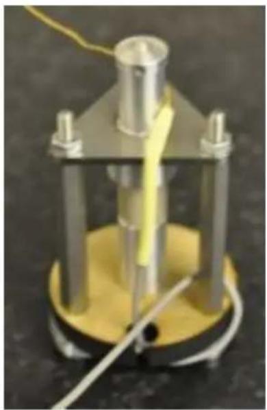
natural_image
Mechanical device with yellow base and metallic components, no visible text or symbols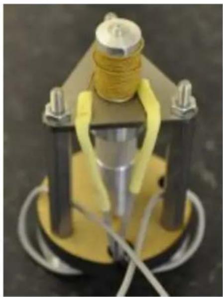
natural_image
Mechanical device with yellow and silver components mounted on a base (no visible text or symbols)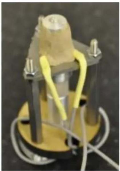
natural_image
Close-up of a mechanical component with yellow and gray wires, no visible text or symbols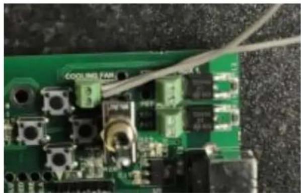
natural_image
Close-up of a green printed circuit board with visible components and wires (no readable text or symbols)
natural_image
Close-up of a green printed circuit board with electronic components and wiring (no visible text or symbols)e. Fitting the thermistor
- Put a small amount of fire-cement into the thermistor mounting hole (at the side of the nozzle end) and push the thermistor into the fire-cement.
- Pack with further cement.
- Bend wires to run down the side of the fire cement wall.
- Pack with more fire cement to cover wires.
- Check the resistance of the thermistor – it should be between 200k and 300k at room temperature.
- Cook the fire cement for 2 minutes.
- Mould the final shape so the nozzle end is slightly larger to hold the silicone insulator in place.
- Fit silicone insulator.
Images read from left to right. Click to see slideshow:
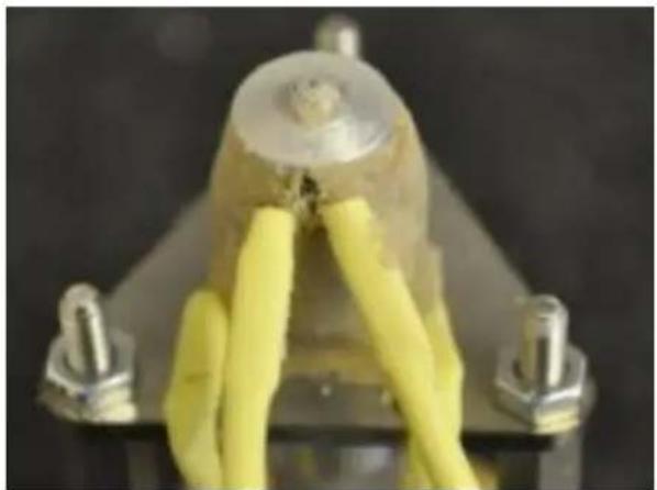
natural_image
Close-up of a mechanical component with yellow adhesive bands and metallic connectors (no visible text or symbols)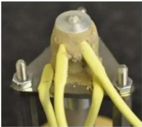
natural_image
Close-up of a mechanical component with yellow and gray wires attached, no visible text or symbols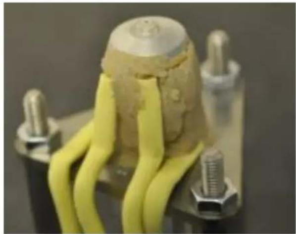
natural_image
Close-up of a yellow 3D-printed electronic component with metallic pins and wires, mounted on a black base (no visible text or symbols)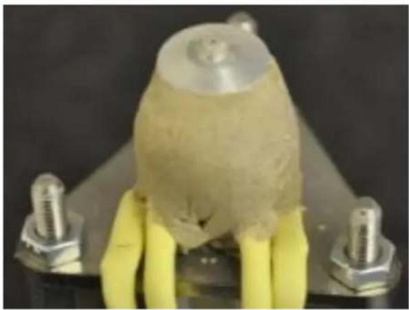
natural_image
Close-up of a mechanical component with yellow and metallic parts, no visible text or symbols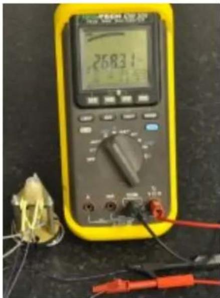
text_image
2683.1
natural_image
Close-up of a green circuit board with electronic components and wiring (no visible text or symbols)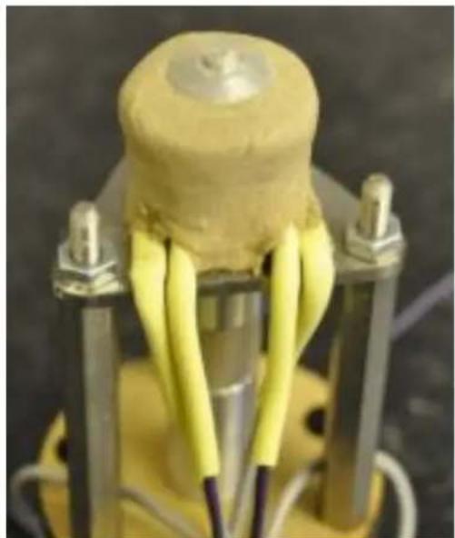
natural_image
Close-up of a yellow battery with three metal pins and yellow insulation bands, mounted on a stand (no text or symbols visible)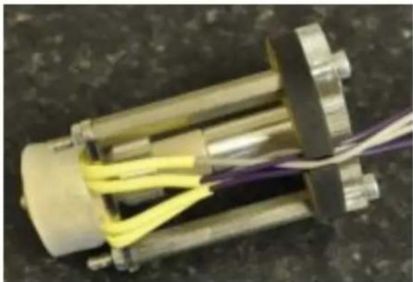
natural_image
Close-up of a mechanical component with yellow and purple wires, no visible text or symbols10. Extruder assembly
The sub sections contained here (view the tree on the left) illustrate how to assemble the extruder.
At times instructions will be split into "Single extruder" and "Double extruder" sections. Simply read the section that applies to your kit. If you are unsure which applies to you, check the .kit contents page
Note for double extruders: The second extruder is almost identical to the first. We recommend building the first extruder, and then repeating the process when instructed to do so, to make the second extruder.
10a. Extruder acrylic parts identification
Single extruder
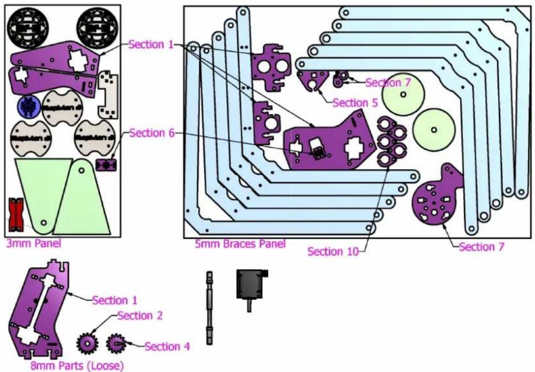
text_image
3mm Panel Section 1 Section 6 Section 7 Section 5 5mm Braces Panel Section 10 Section 7 Section 1 Section 2 Section 4 8mm Parts (Loose)Double extruder
As above, plus same parts found in the .Double head upgrade pack
10b. Main plates
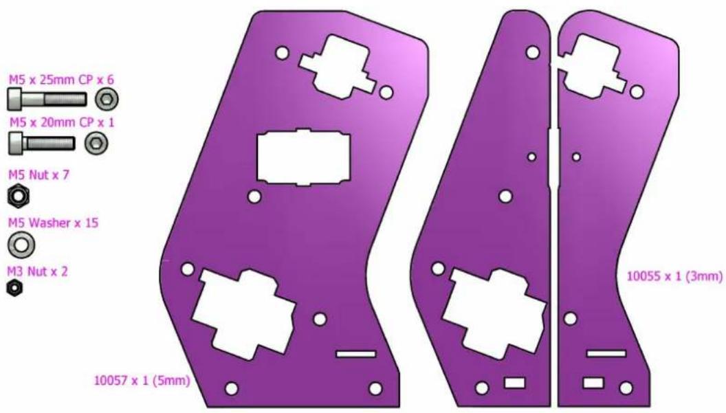
text_image
M5 x 25mm CP x 6 M5 x 20mm CP x 1 M5 Nut x 7 M5 Washer x 15 M3 Nut x 2 10057 x 1 (5mm) 10055 x 1 (3mm)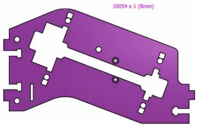
text_image
10054 x 1 (8mm)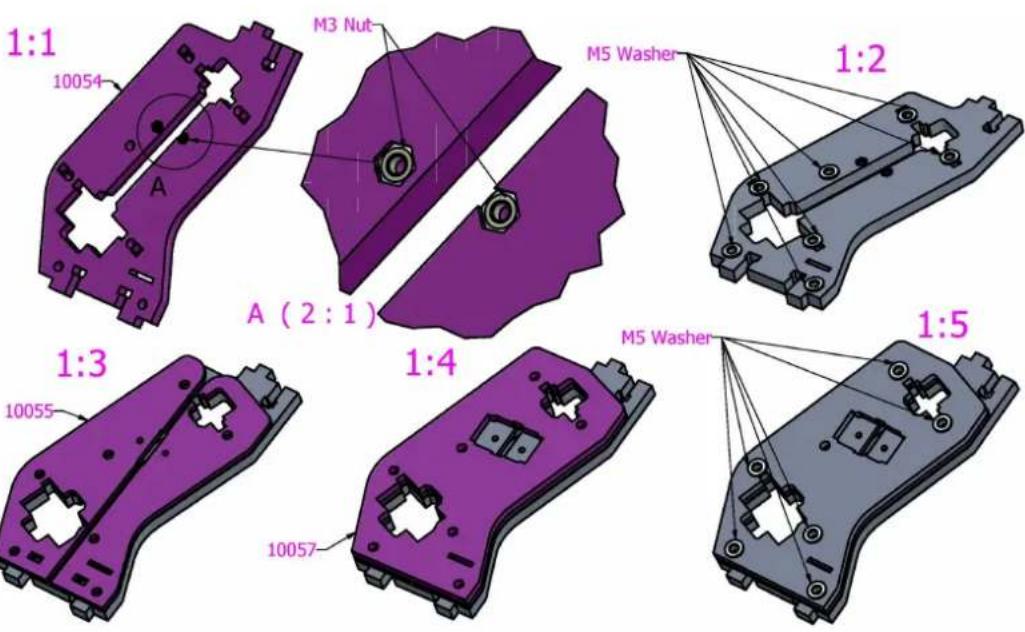
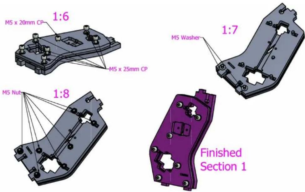
text_image
M5 x 20mm CP 1:6 M5 x 25mm CP 1:7 M5 Washer M5 Nut 1:8 Finished Section 110c. Drive shaft
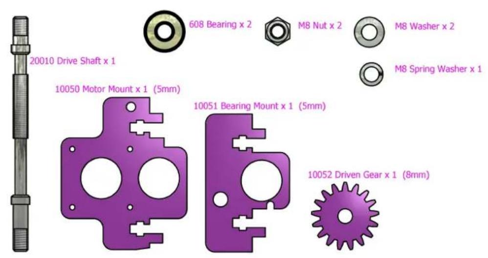
text_image
20010 Drive Shaft x 1 608 Bearing x 2 M8 Nut x 2 M8 Washer x 2 M8 Spring Washer x 1 10050 Motor Mount x 1 (5mm) 10051 Bearing Mount x 1 (5mm) 10052 Driven Gear x 1 (8mm)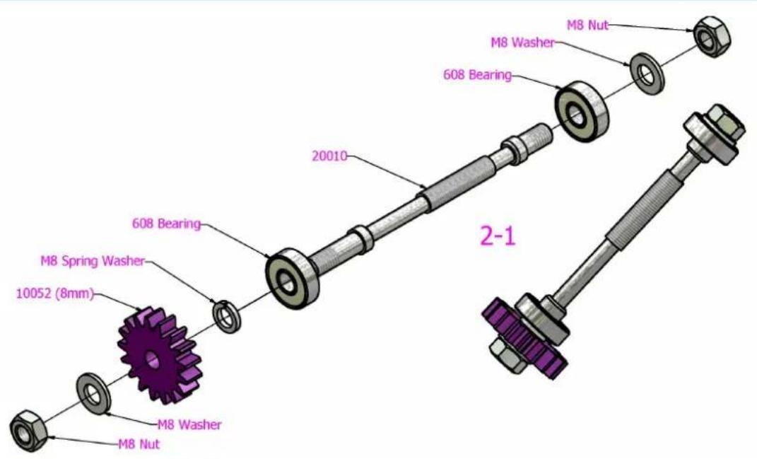
text_image
M8 Nut M8 Washer 608 Bearing 20010 608 Bearing M8 Spring Washer 10052 (8mm) M8 Washer M8 Nut 2-1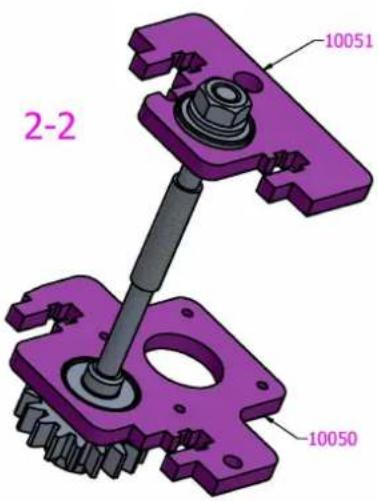
text_image
2-2 10051 10050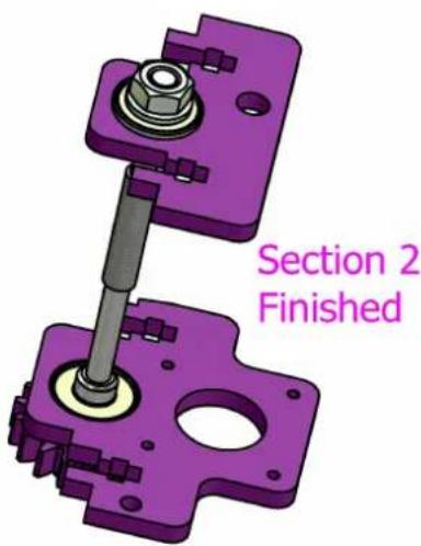
text_image
Section 2 Finished10d. Drive assembly
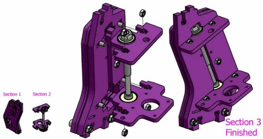
text_image
Section 1 Section 2 Section 3 FinishedAfter finishing section 3 assembly rotate the extruder driven gear (10052) by hand this will be a little stiff as the drive thread beds into the acrylic.
Drive Thread cutting into acrylic as it beds in
natural_image
Close-up of mechanical components including bolts and a threaded shaft, with no visible text or symbols.10e. Motor Mount
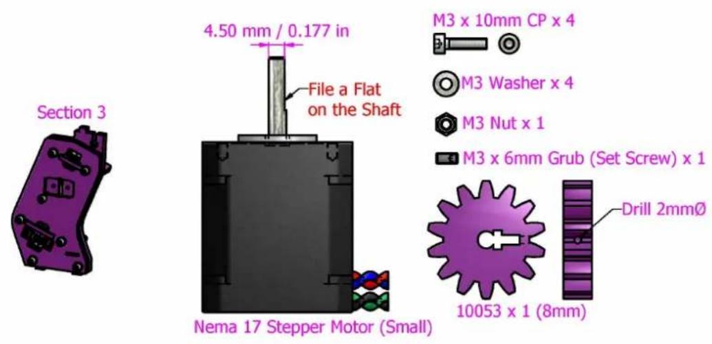
text_image
Section 3 4.50 mm / 0.177 in File a Flat on the Shaft Nema 17 Stepper Motor (Small) M3 x 10mm CP x 4 M3 Washer x 4 M3 Nut x 1 M3 x 6mm Grub (Set Screw) x 1 Drill 2mmØ 10053 x 1 (8mm)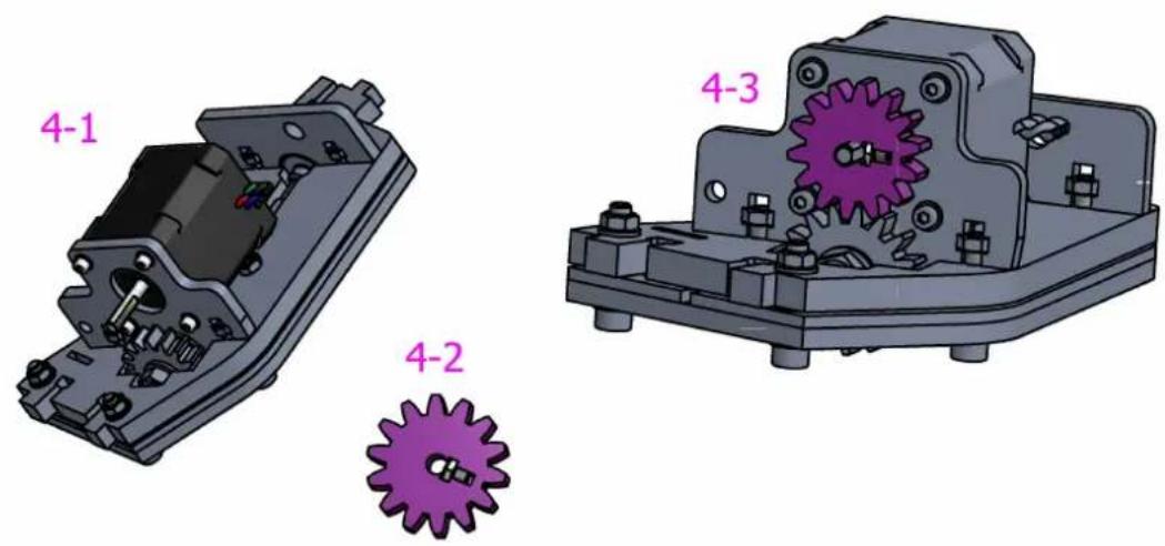
text_image
4-1 4-2 4-310f. Filament guide
Single head
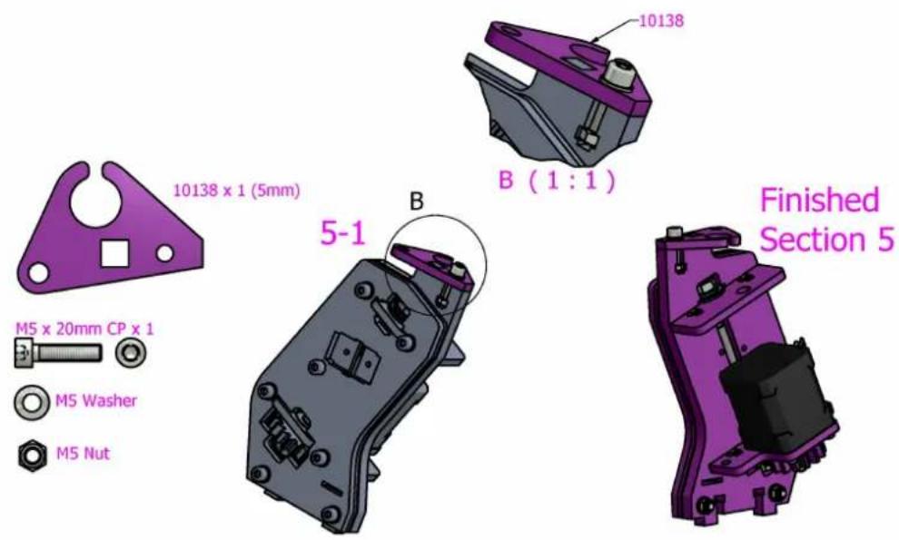
text_image
10138 x 1 (5mm) M5 x 20mm CP x 1 M5 Washer M5 Nut B (1:1) 10138 5-1 B Finished Section 5Double head
Ignore this page. The double head filament guide will be fitted after both extruders are complete.
10g. Pressure wheels
10085 x 4 (3mm)

10086 × 4 (5mm)

623 Bearing x 2
M3 Washer x 8
M3 Nut x 2
M3 × 30mm CP × 2

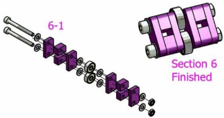
text_image
6-1 Section 6 Finished10h. Mounting plate
Single head
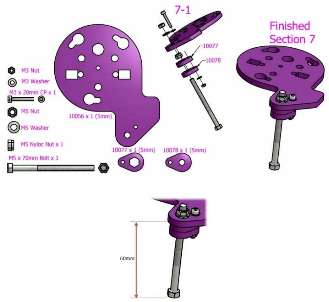
Double head
- Complete as above for the first extruder.
- For the second extruder, part 10056 is different. It is found in the Double head upgrade pack and it does not have the extra tang for long bolt. For this second extruder, only this mounting plate is needed - the other sub components are not required.
10i. Hot end fitting

M5 Washer x 2

M5 Nut x 2
M5 x 30mm Bolt x 2

Section 6
natural_image
Purple mechanical component with multiple slots and mounting holes (no text or symbols)Section 7

natural_image
Purple abstract shape resembling a stylized face or mask with no text or symbolsHot End
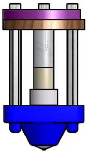
natural_image
3D mechanical assembly diagram showing a cylindrical component with three vertical supports and a base (no text or symbols)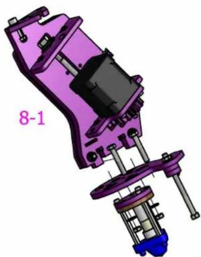
natural_image
3D mechanical assembly diagram showing purple and blue components with no visible text or symbols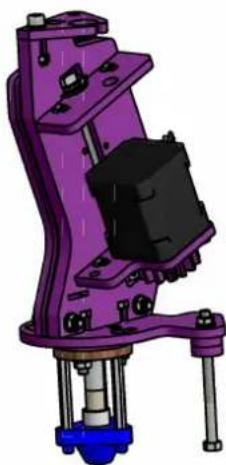
natural_image
3D rendered mechanical assembly with purple frame and black component (no text or symbols visible)Finished
Section 8
10j. Pressure springs and wheels
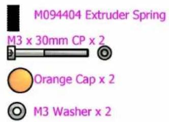
text_image
M094404 Extruder Spring M3 x 30mm CP x 2 Orange Cap x 2 M3 Washer x 2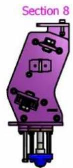
natural_image
Purple mechanical component with labeled section 8, showing internal components and mounting points (no readable text or symbols)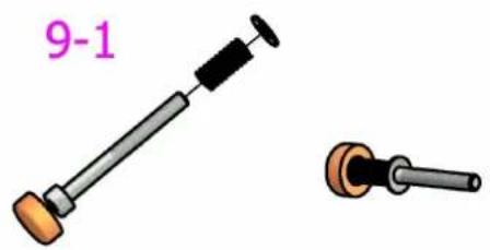
natural_image
Illustration of two mechanical components: a cylindrical tool with handle and a flanged lever (no text or symbols)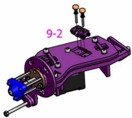
natural_image
3D mechanical assembly diagram showing a purple housing with blue internal components and orange connectors (no text or symbols)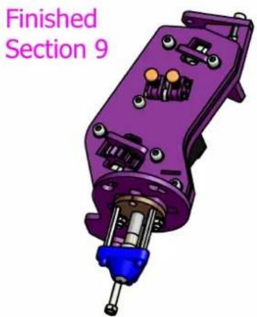
natural_image
3D rendered purple mechanical component with no visible text or symbols, labeled 'Finished Section 9' (text is part of the diagram)Single extruders
Now proceed to the next section.
Double extruders
Now repeat all stages to make your second extruder using parts from the Double head upgrade pack.
10k. Conduit preparation
Single extruder
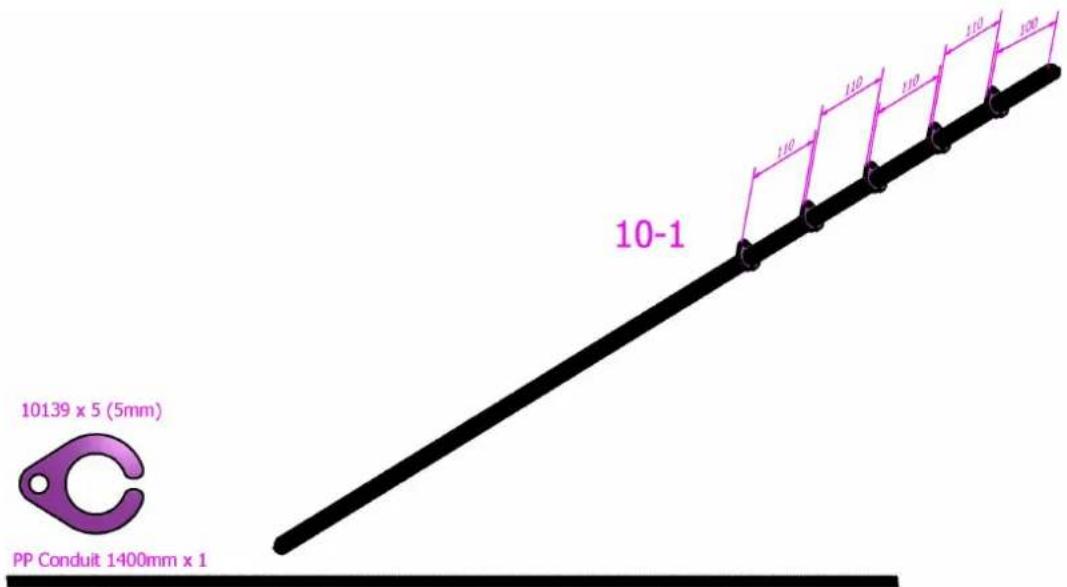
text_image
10-1 10139 x 5 (5mm) PP Conduit 1400mm x 1Double extruder
Same as above, but replace 10139's with 4# 400511's from the Double head upgrade pack. There are only 4# 400511's: omit the last position shown - positions will be adjusted later.
10I. Running the wires
Single extruder
- Fit the hot end.
- Thread wires through extruder as shown.
- Conduit is the long conduit previously prepared in .Conduit preparation
Read images from left to right. Click to view slide show:
natural_image
Close-up of a mechanical assembly with blue and metallic components on a green grid mat (no visible text or symbols)
natural_image
Close-up of a transparent mechanical device with internal components and colored wires, resting on a green grid mat (no text or symbols visible)
natural_image
Close-up of a small electronic device with wires and connectors on a green grid mat (no visible text or symbols)
natural_image
Close-up of a transparent mechanical component with green grid pattern and red ribbon, no visible text or symbols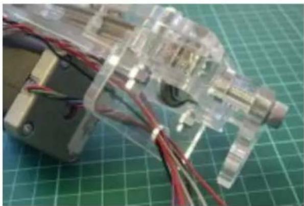
natural_image
Close-up of a transparent plastic mechanical device with red wires, placed on a green grid cutting mat (no text or symbols visible)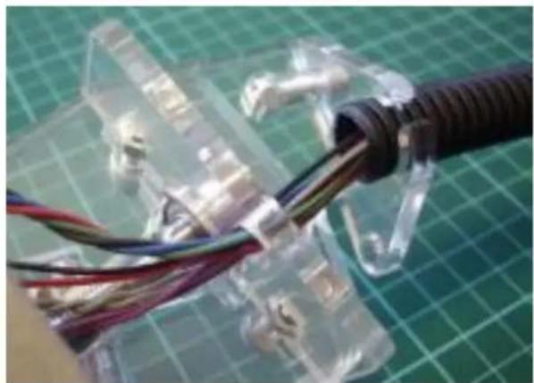
natural_image
Close-up of a flexible electronic device with exposed wires and connectors, mounted on a green grid cutting mat (no text or symbols visible)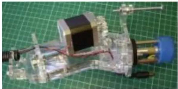
natural_image
Close-up of a mechanical device with transparent casing and blue connectors, placed on a green grid background (no visible text or symbols)Now proceed to the next section.
Double extruder
- Wire "Extruder 1" as shown above. Ensure that Extruder 1 is the extruder with the full mounting plate assembly.
- Thread the wires for "Extruder 2" as per Extruder 1, but without the fan wires.
10m. Mounting the extruder fan
Single extruder
Fasten using M3 x 20 and M3 Nyloc Nut. Screw nut onto bolt until bolt is flush with the nut face. DO-NOT fully tighten. This allows the fan to hang down at an angle, cooling the print below the hot end:
Mount the cooling fan power socket onto the plate next to the right side of the fan using the M2x12mm bolts & nuts (Bin 5)
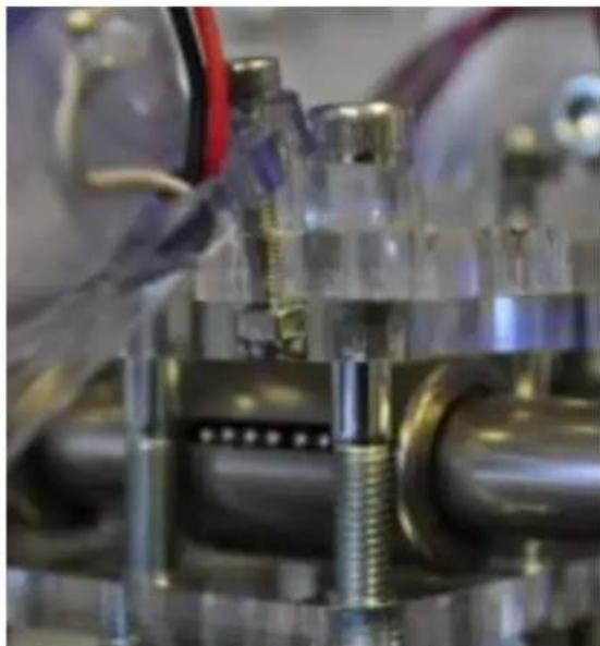
natural_image
Close-up of mechanical components with metallic and glass parts, no visible text or symbols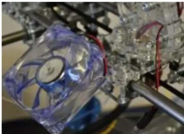
natural_image
Close-up of a transparent plastic fan with red wires attached to metal rods, no visible text or symbols.Double extruder
Fasten using M3 x 20 and M3 Nyloc Nut. Screw nut onto bolt until bolt is flush with the nut face. DO-NOT fully tighten. This allows the fan to hang down at an angle, cooling the print below the hot end:
Mount the cooling fan power socket onto the plate next to the right side of the fan using the M2x12mm bolts & nuts (Bin 5)
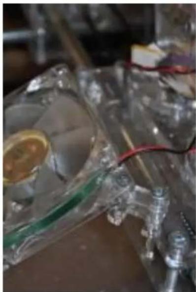
natural_image
Close-up of a transparent lab apparatus with a green liquid container and red wires, no visible text or symbols.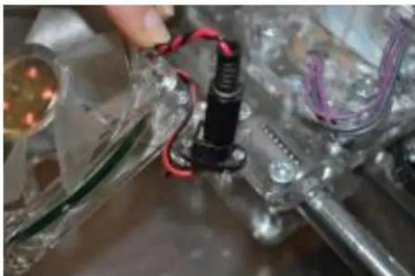
natural_image
Close-up of a mechanical assembly with red wires and components, no visible text or symbols10n. Mounting the extruder
Single extruder
- Offer the extruder into carriage.
- Allow nuts to protrude through keyway.
- Rotate the extruder to allow nuts to lock over plate, and tighten.
- Clip conduit to x-motor plate, allowing enough length for the carriage to move freely up the entire length of the x-axis.
Read images from left to right. Click to view slideshow:
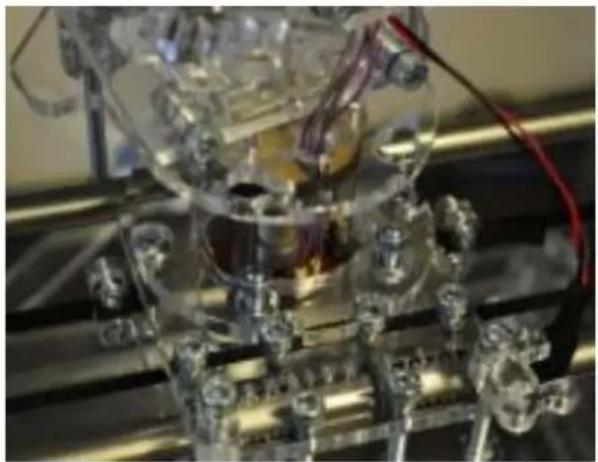
natural_image
Close-up of a mechanical assembly with transparent components and wiring (no visible text or symbols)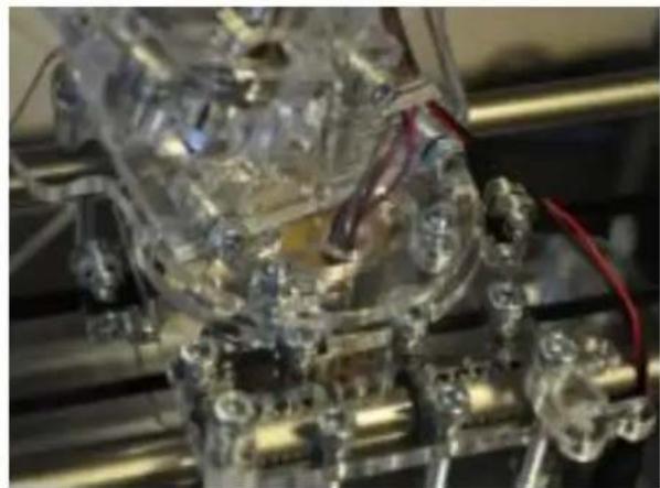
natural_image
Close-up of a transparent mechanical assembly with visible wiring and components (no text or symbols)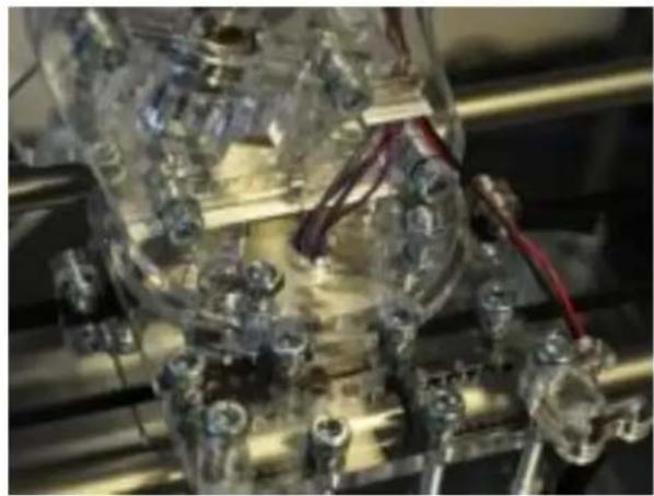
natural_image
Close-up of a transparent mechanical device with red wires and bolts, no visible text or symbols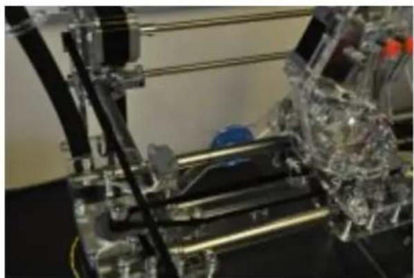
natural_image
Close-up of a transparent mechanical assembly with visible wiring and components (no text or symbols)Double extruder
Looking at the carriage from the front of the machine, Extruder 1 sits on the left, Extruder 2 sits on the right.
- Fit Extruder 1 as shown above. Then fit Extruder 2.
- Use 400509 from the Double head upgrade pack to secure the conduit clip between both extruders.
- Use the PP conduit section to thread the wires. The PP conduit is the matt black plastic conduit, with shallow finer ribbing.
Photograph taken from rear of machine.
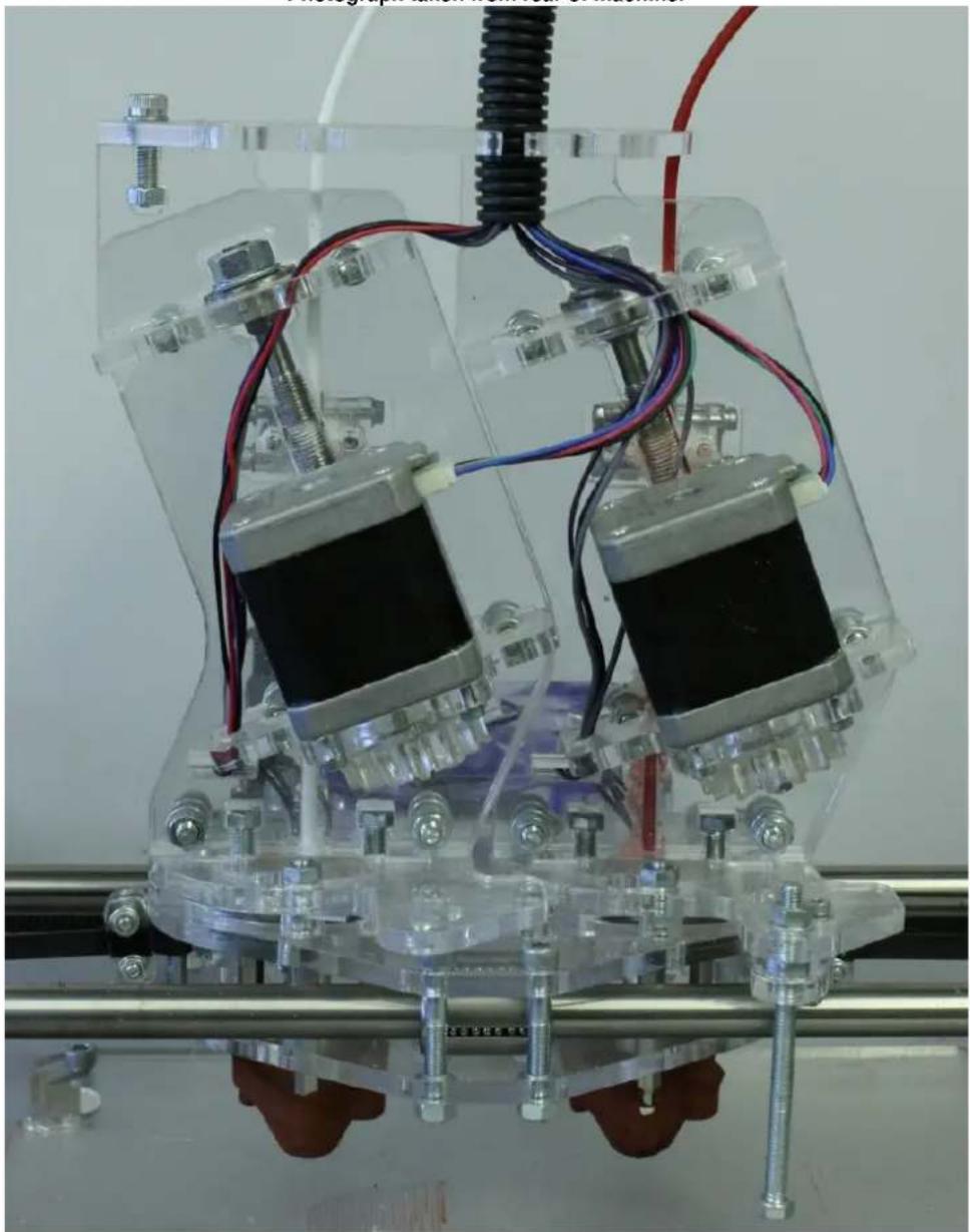
natural_image
Close-up of a transparent 3D printer with dual motors and wiring, mounted on a metal frame (no visible text or symbols)Photograph taken from rear of machine.
- Clearly identify the wire harnesses from each extruder with a zip tie or tape to make wiring up to the control box easier later on.
- Thread both harnesses down the PP conduit.
11. Control panel
This section will guide you through assembling the touchscreen control panel to complete your RapMan. After completion it should look like this:
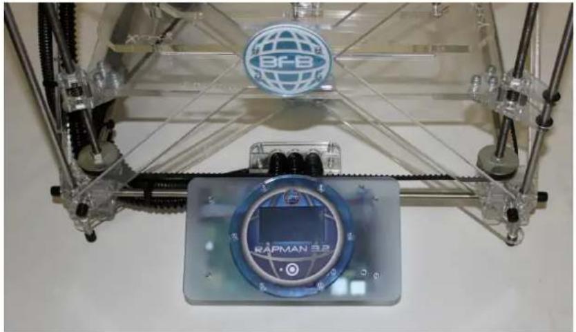
natural_image
Close-up of a transparent 3D printer with a blue control panel and a BF-B logo on top (no readable text or symbols beyond branding)To complete the assembly you will need:
• Control panel acrylics bag.
• Control panel parts bag.
- PCB pack.
- For the double head option the extra will be needed.extruder PCB module

text_image
Yellow triangular warning sign with black exclamation mark symbolFor this section you will be handling PCBs which are static-sensitive. Please make sure that all standard anti-static procedures are followed i.e. anyone handling the PCBs is properly earthed. Failure to do this may result in damaged electronic components.
Single head assembly
If you have a single extruder kit simply follow all instructions under "Single head" sections. Ignore "Double head" sections.
Double head assembly
If you have a double extruder kit follow all single head assembly instructions, but pay attention to notes under "Double head" sections. You will need to cater for the:
- Extra extruder electronics module.
• Extra wires from the second extruder.
11a. PCB base
| Part Qty Location | |
| Fans 2 Control parts bag | |
| M3 x 45 CP 8 Control panel boltbag(inside controlparts bag) | |
| 401154 1 Control panelacrylic | |
| M3 x 25 CP 2 Control panel boltbag | |
| M3 washer 8 Control panel boltbag | |
| 401151 12 Control panelacrylic | |
| 401053 1 PCB pack | |
| 401049 1 PCB pack | |
| M3 x 10 CP 1 Control panel boltbag | |
| M3 x 20 F-Fspacer | 5 Control panel boltbag |
| M3 nut 4 Control panel boltbag | |
natural_image
Electronic circuit board with green components and a black fan (no visible text or symbols)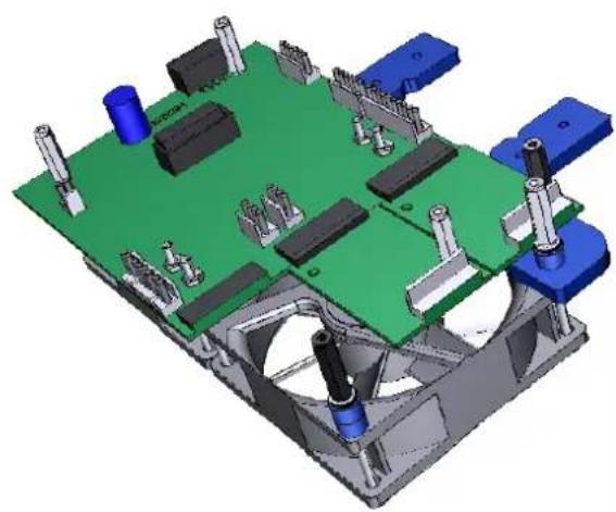
natural_image
3D CAD model of a mechanical assembly with green base, blue components, and mechanical parts (no text or symbols visible): click thumbnail to view 3D content!Tip : model includes extra PCB module for double headNote option.
| ToolsM3 driverM3 spanner | No Hazard. |
| No warnings. |
Single head
- Position fans side by side, label side up, wires converging at the top middle. Insert 8# M3 x 45 CP bolts from the bottom up (Pic 1).
- Prepare 401154 with 2# M3 x 25 CP as shown (Pic 2). Use washers on bolt head side. Use tools to clamp firmly. This will not be possible later.
- Position 401154 over top side of fans (Pic 3). Trail wires over bracket.
- Check fan labels are on the correct side (Pic 3).
- Load 1# 401151 over each of the top bolts (Pic 3).
- Load # 401151 over each of the bottom bolts (Pic 3).2
- Load main 401053 (main PCB) onto the left side of the assembly. Ensure orientation is correct (Pic 4), sitting over 6 bolts.
- Prepare 401049 (the extruder module) with 1# M3 x 10 CP and 1# M3 x 20 F-F spacer as shown (Pic 5)*. Ensure correct hole and orientation are used.
- Insert extruder module into the main PCB, into the Extruder 1 position (Pic 6)**.
- Load 3# M3 washers onto each of the two far right M3 x 45 bolts, followed by an M3 x 20 FF spacer for each bolt (Pic 7).
- Load 1# M3 x 20 F-F spacers onto each of the two far left M3 x 45 bolts (Pic 8).
- Load 1# M3 nut onto each of the middle 4 M3 x 20 bolts (Pic 8).
- Tighten all. Take care not to over tighten – the fan plastic is fairly soft.
Double head
RapMan 3.2 manual
Same as single head assembly, but refer to asterisk (*) where necessary:
* Repeat this step for the second extruder module found in the Double head upgrade kit.
** Now fit the second extruder module directly below the first, slotting into the connectors marked on the PCB as "Extruder 2".
natural_image
Two black CPU fans with visible cooling fins and red wires, no text or symbols present.
natural_image
Close-up of a metallic mechanical component with metal fasteners and a central rod (no visible text or symbols)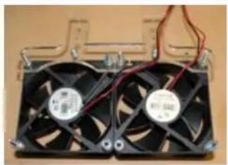
natural_image
Two black CPU fans with visible power cord and wiring, mounted on a wooden surface (no text or symbols)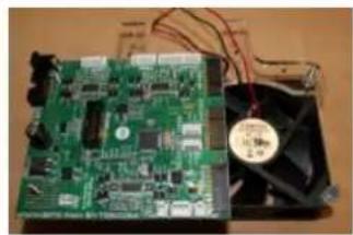
natural_image
Electronic circuit board with power supply and cooling fan (no visible text or symbols)Pic 1 Pic 2 Pic 3 Pic 4
natural_image
Close-up of a dark mechanical device with metallic components and a small attached part (no visible text or symbols)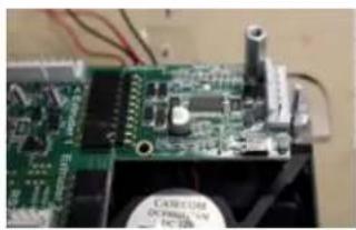
natural_image
Close-up of a green printed circuit board with visible components and wires (no readable text or symbols)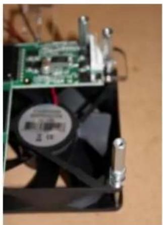
natural_image
Close-up of a CPU fan with visible cooling effect and heatsink, no text or symbols present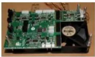
natural_image
Electronic circuit board with green components and a black fan (no visible text or symbols)Pic 5 Pic 6 Pic 7 Pic 8
11b. Top plate
| Part Qty Location | ||
| 401161 1 Control | panel acrylic | |
| M3 x 10 CP | 10 Control panel bolt bag | |
| M3 x 15 F-F spacer | 2 Control panel bolt bag | |
| 401071 1 PCBs | ||
| 401070 1 Control | panel acrylic | |
| 401051 6 Control | panel acrylic | |
| M3 washer 6 Control | panel bolt bag | |
| M3 nut 2 Control | panel bolt bag | |
| M3 x 16 CP | 6 Control panel bolt bag | |
| 401052 1 PCBs | ||
| Touch button | 1 Control small bag (inside control parts bag) | |
| 401160 1 Control | panel acrylic | |
| Tools | ||
| M3 driver |  | No Hazard. |
| M3 spanner |  | No warnings. |
- Load 4# M3 x 10 CP bolts into 401161, in orientation shown (Pic 1).
- Fasten using 4# M3 nuts.
- Assemble 401701 (USB) to the underside of the acrylic using 4# M3 x 10 CP and 2# M3 x 15 F-F spacers as shown in Pic 2, using the orange holes indicated in Pic 2b. Check that the USB port is on the same side of the acrylic as the nuts from step 2, and facing outwards.
- Attach 401052 (touch screen) using the green holes indicated in Pic 2b. Assembly sequence is important: Poke 2# M3 x 10 up from the underside of the acrylic faceplate (Pic 3). If you have a blue button load 3# M3 washers onto each bolt. If you have a clear button load 2# M3 washers onto each bolt (Pic 3). Then load 401052. Fasten using 2# M3 nuts (Pic 4).
- Check that the back of the screen rests evenly on the back of the four bolt heads loaded in step 1.
RapMan 3.2 manual
- Load 6# M3 x 16 CP into 401070 so that the bolt heads sit in the counter-bores. Turn upside down. If you have a blue button load 1# 401151 over each bolt. If you have a clear button load 1# 401151 and 1# M3 washer over each bolt. (Pic 5).
- Position top of acrylic faceplate over the assembly from step 6, and fasten using 6# M3 nuts.
- Remove protective cover from touch screen (Pic 7).
- Position 'Touch button' into button hole (Pic 8).
- Remove protective film from sticker (Pic 9).
- Place sticker over screen with light pressure, taking care that it is aligned (Pic 9b). The sticker uses a special adhesive which only fastens fully after high pressure. It is easier to align the sticker when the touch screen is on (this will be done during machine operation) - therefore do not apply high pressure until the machine has been switched on, and alignment can be confirmed.
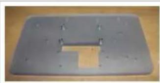
natural_image
Metallic plastic tray with a slot and rectangular cutout, placed on a wooden surface (no text or symbols visible)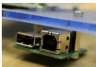
natural_image
Close-up of a small electronic component with metallic connectors and a green circuit board (no visible text or symbols)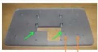
natural_image
Metal plate with green arrows indicating direction, no visible text or symbols
natural_image
Close-up of a metallic screw mounted on a white surface against a blue background (no text or symbols visible)Pic 1 Pic 2 Pic 2b Pic 3
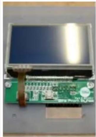
natural_image
Close-up of a green circuit board with a blue LCD screen and a small electronic component, no visible text or symbols.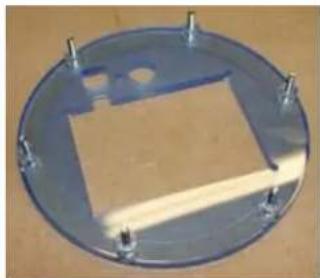
natural_image
Circular metallic component with a rectangular cutout and four small protrusions, placed on a wooden surface (no text or symbols visible)
natural_image
Close-up of a small electronic component with green and black connectors, mounted on a white base (no visible text or symbols)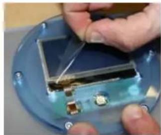
natural_image
Close-up of hands installing or adjusting a small electronic component on a blue circular base (no visible text or symbols)Pic 4 Pic 5 Pic 6 Pic 7
natural_image
Close-up of a transparent electronic device with internal components and a blue circular component (no visible text or symbols)
natural_image
Close-up of a hand holding a metallic diamond-shaped object, partially covered by a white circular component (no text or symbols visible)
natural_image
Close-up of a beige industrial control panel with a central display and 'RAPMAN 3.3' branding (no readable text beyond label)Pic 8 Pic 9 Pic 9b
11c. Wiring
Preparing the conduits
By now, there should be three conduits:
• X
• Y/Z
- Extruder
The final result is to terminate the conduits at the control panel:
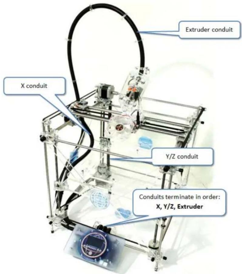
- Conduits should be roughly in position.
- Thread conduits as shown in Pic 0g: UNDER the bottom left side bar, and OVER the bottom from bar, but UNDER the Z-belt (Pic 0g).
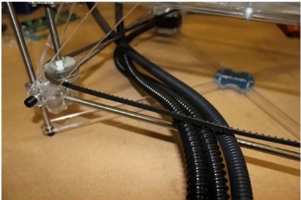
natural_image
Close-up of a mechanical assembly with coiled black cables and metal rods on a wooden surface (no visible text or symbols)Wiring diagram
Single head
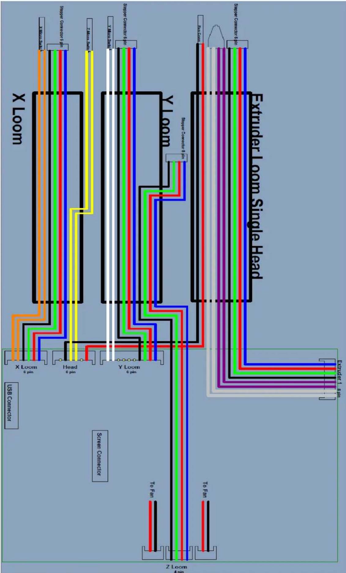
flowchart
graph TD
    subgraph Input
        direction TB
        A["User Connector"] --> B["X Loom"]
        B --> C["USB Converter"]
        D["Screen Connector"] --> E["Y Loom"]
        E --> F["Screen Converter"]
        G["Extruder 1: 8 Pin"] --> H["To Fan"]
        I["Extruder 2: 8 Pin"] --> J["To Fan"]
        K["Extruder 3: 8 Pin"] --> L["To Fan"]
        M["Extruder 4: 8 Pin"] --> N["To Fan"]
        O["Extruder 5: 8 Pin"] --> P["To Fan"]
        Q["Extruder 6: 8 Pin"] --> R["To Fan"]
        S["Extruder 7: 8 Pin"] --> T["To Fan"]
        U["Extruder 8: 8 Pin"] --> V["To Fan"]
        W["Extruder 9: 8 Pin"] --> X["To Fan"]
        Y["Extruder 10: 8 Pin"] --> Z["To Fan"]
    end
    style Input fill:#f9f,stroke:#333
    style Output fill:#bbf,stroke:#333
    style Components fill:#dfd,stroke:#333
    style Feedback
    subgraph Legend
        direction TB
        AA["X Loom"] --> AB["X Micro-Scale"]
        AC["X Loom"] --> AD["Tropper Converter 5 Pin"]
        AE["X Loom"] --> AF["Tropper Converter 5 Pin"]
        AG["X Loom"] --> AH["Tropper Converter 5 Pin"]
        AI["X Loom"] --> AJ["Tropper Converter 5 Pin"]
        AK["X Loom"] --> AL["Tropper Converter 5 Pin"]
        AM["X Loom"] --> AN["Tropper Converter 5 Pin"]
        AO["X Loom"] --> AP["Tropper Converter 5 Pin"]
        AQ["X Loom"] --> AR["Tropper Converter 5 Pin"]
        AS["X Loom"] --> AT["Tropper Converter 5 Pin"]
        AU["X Loom"] --> AV["Tropper Converter 5 Pin"]
        AW["X Loom"] --> AX["Tropper Converter 5 Pin"]
        AY["X Loom"] --> AZ["Tropper Converter 6 Pin"]
        BA["X Loom"] --> BB["Tropper Converter 6 Pin"]
        BC["X Loom"] --> BD["Tropper Converter 6 Pin"]
        BE["X Loom"] --> BF["Tropper Converter 6 Pin"]
        BG["X Loom"] --> BH["Tropper Converter 6 Pin"]
        BI["X Loom"] --> BJ["Tropper Converter 6 Pin"]
        BK["X Loom"] --> BL["Tropper Converter 6 Pin"]
        BM["X Loom"] --> BN["Tropper Converter 6 Pin"]
        BO["X Loom"] --> BP["Tropper Converter 6 Pin"]
        BQ["X Loom"] --> BR["Tropper Converter 6 Pin"]
        BS["X Loom"] --> BT["Tropper Converter 6 Pin"]
        BU["X Loom"] --> BV["Tropper Converter 6 Pin"]
        BW["X Loom"] --> BX["Tropper Converter 6 Pin"]
        BY["X Loom"] --> BZ["Tropper Converter 6 Pin"]
        CA["X Loom"] --> CB["Tropper Converter 6 Pin"]
        CC["X Loom"] --> CD["Tropper Converter 6 Pin"]
        DE["X Loom"] --> DF["Tropper Converter 6 Pin"]
        DG["X Loom"] --> DH["Tropper Converter 6 Pin"]
        DI["X Loom"] --> DJ["Tropper Converter 6 Pin"]
        DK["X Loom"] --> DL["Tropper Converter 6 Pin"]
        DM["X Loom"] --> DN["Tropper Converter 6 Pin"]
        DOX["X Loom"] --> DOY["Tropper Converter 6 Pin"]
        DZ["X Loom"] --> DB["Tropper Converter 6 Pin"]
        DC["Y Loom"] --> DD["Tropper Converter 6 Pin"]
        DV["Y Loom"] --> DV["Tropper Converter 6 Pin"]
        DW["Y Loom"] --> DW["Tropper Converter 6 Pin"]
        BXY["Y Loom"] --> BX["Tropper Converter 6 Pin"]
        BYX["Y Loom"] --> BYX["Tropper Converter 6 Pin"]
        BZX["Y Loom"] --> BZX["Tropper Converter 6 Pin"]
        DYZ["Y Loom"] --> DYZ["Tropper Converter 6 Pin"]
Double head
All the same as above, with additional wires from Extruder 2:
* Wires from extruder 2 fit to the Extruder 2 module in the same order identified for Extruder 1.
** IDC connector for the Extruder 2 module is included with the module in the Double head kit, and should be fitted in the same manner as for Extruder 1 (see below).
Using the IDC connectors to connect the PCB
| Part Qty Location | 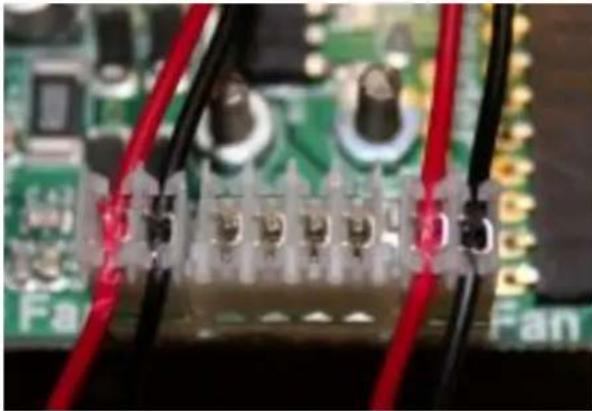 | Tools | ||
| 401153 1 Control panel | acrylic | Small flat head driver or IDC wire fitting tool | ||
| Small cable ties 6 | Control small bag | Side cutters | ||
| M3 x 15 F-F spacer | 2 Control panel bolt bag | |||
| IDC connectors 7 | Control small bag |
IDC connectors means: *I*nsulation *D*isplacement *C*onnector. As the wire is pushed into the connector, the connector cuts through the insulation, making contact with the wire inside (Pic 0e). To push the wire into the connector terminal, use a small flat head driver.
Start with the control panel fan wires:
- Fit IDC connectors to the appropriate terminals (Pic 00 and wire diagram). See note **above for double head installation.
- Fold wire over designated terminal with fingers to keep it in position (Pic 0a and 0b).
Now, to push the wire into the connector, you may either:
- use either a small flat head screw driver (width 1.5mm) in which case continue with these instructions.
- if you find this difficult, you may wish to use our IDC wire fitting tool. Please click on this link to learn how to use it.
 | Be very careful to keep supporting fingers away from the line of force of the driver before exerting any force. We recommend using thick leather gloves for personal protection. |
 | Make sure that the driver used is not too large – this may splay and damage the cutting teeth on the IDC connector. |
- Position small flat head driver over wire (Pic 0c). The idea is to push the wire down and into the teeth (Pic 0d).
- Push down firmly and make sure that both sets of connector teeth cut through the wire insulation. It is normal for the insulation to be damaged at this point! (Pic 0e).
- Trim wires after fitting (Pic 0f).
 | 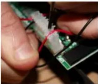 | 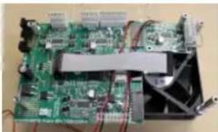 | 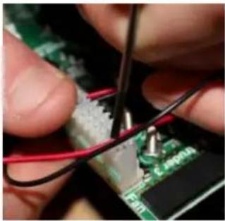 |
| Pic 00 Pic 0a Pic 0b Pic 0c |
RapMan 3.2 manual
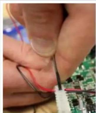
natural_image
Close-up of hands using tweezers to apply red signal to a circuit board (no visible text or symbols)Pic 0d Pic 0e Pic 0f
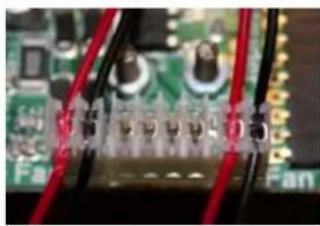
natural_image
Close-up of electronic circuit board with red and black wires, no visible text or symbols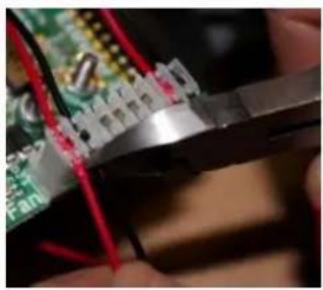
natural_image
Close-up of hands using a pliers to cut electronic circuit boards (no visible text or symbols)For XYZ and Extruders:
- Fasten the ends of the conduits to 401153 using the cable ties, as shown in Pic 1 & Pic 2. Note orientation of acrylic plate with respect to the corner radius. Conduits are ordered from left to right: X conduit, Y/Z conduit, Extruder conduit (as per wiring diagram).
- Try to position the heads of the cable ties in the middle, rather than to one side, as this will help assembly later.
- As a temporary wiring aid, position the conduit assembly over the lugs at the top of the PCB base assembly, over the top most two holes (Pic 4). Pin loosely in position with two bolts, M3 x 30 CP (Pic 4). This is to temporarily position the ends of the conduits, and make the following wiring jobs easier.
- Proceed with adding the wires to the IDC connectors (Pic 5 – ignore ribbon cable) as per wiring diagram. Double check the correct wire runs to the correct terminal before fitting: pay particular attention to elements which share colours!
- For switches, there is no polarity.
- Make sure the red extruder motor wire is not confused with the red fan wire.
- Trim wires after fitting (Pic 6).
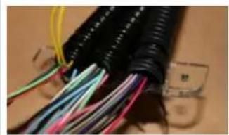
natural_image
Close-up of bundled electrical cables with multicolored wires and connectors (no visible text or symbols)Pic 1 Pic 2 Pic 4 Pic 5
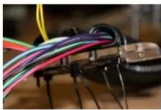
natural_image
Close-up of a black electronic component with multiple colored wires attached (no visible text or symbols)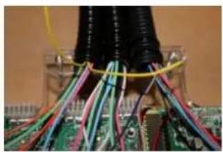
natural_image
Close-up of electronic circuit board with multicolored wires and wires wrapped around a black cable (no visible text or symbols)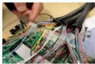
natural_image
Close-up of electronic circuit boards with multicolored wires and connectors (no visible text or symbols)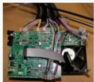
natural_image
Close-up of a green printed circuit board with visible traces and wires, partially covered by a black plastic fan (no text or symbols)Pic 6 Wiring diagram
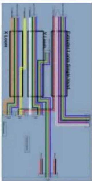
text_image
X Level Y Level Segment Length/LengthIDC wire fitting tool
The IDC wire fitting tool was developed to make fitting the wires to the IDC connectors a little easier. This is a recent addition to the kit, and will be found in the Control Panel Parts bag. If your kit was made prior to the addition of the IDC wire fitting tool and is therefore not included, but feel you need to use it, please contact us with your machine serial number and we will issue one free of charge.
Using the tool correctly
Offer the tool perpendicular to the IDC connector.
natural_image
Close-up of a finger pressing a black plastic component onto a textured surface (no text or symbols visible)Position the tool so that a tab lines up over the connector, and the connector teeth are in line with the slots on either side of the tab, as shown below:
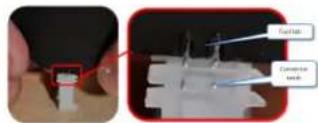
Push firmly down. The tab should move approximately 2mm into the connector. Ensure that the connector teeth pass through the tab slots.
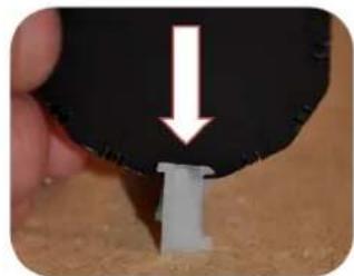
natural_image
Close-up of a hand holding a black object with a white arrow pointing downward, next to a small white component on a sandy surface (no text or symbols visible)Fitting a wire
Offer the wire over the connector with a minimum of 5mm excess.
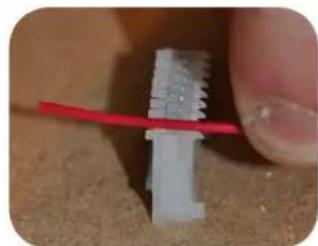
natural_image
Close-up of a hand holding a red wire over a small white plastic connector (no text or symbols visible)Position the tool over the wire, making sure that the tab is positioned over the teeth.
RapMan 3.2 manual
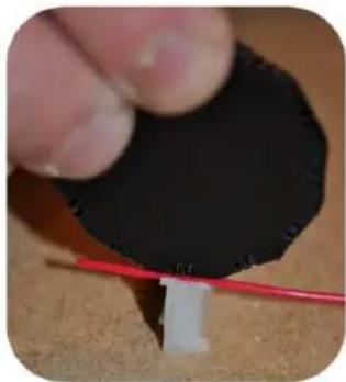
natural_image
Close-up of a hand holding a black circular object with a red wire attached to a white rectangular object (no text or symbols visible)With the tool touching the TOP surface of the wire, push down firmly using both hands.
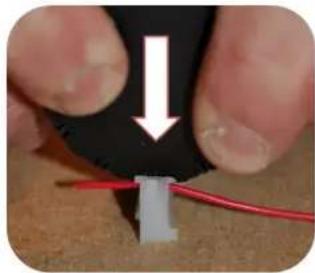
natural_image
Close-up of hands holding a black clip with a red wire, showing a small component inserted (no text or symbols visible)The wire should move approximately 2mm into the connector.
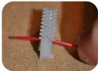
natural_image
Close-up of a hand holding a red tool next to a white plastic component (no visible text or symbols)Check that the wire is fully engaged with the teeth. The wire must have passed past the plastic top barbs.
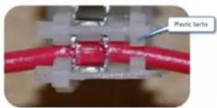
text_image
Plastic SerbsThe connector makes electrical contact with the wire by slicing through the insulation.
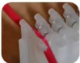
natural_image
Close-up of white plastic applicators with red bands, no visible text or symbolsAfter ensuring the connection is well made, trim the wire.
11d. Ribbon cables
| Part Qty Location | ||
| 14-wire ribbon 1 Control small bag | ||
| 14-wire connector 2 Control small bag | ||
| 10-wire ribbon 1 Control small bag | ||
| 10-wire connector 2 Control small bag | ||
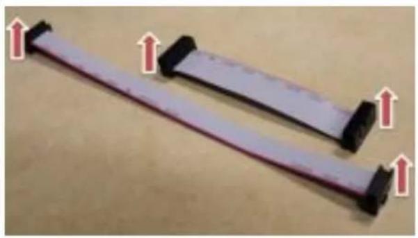
natural_image
Two flexible cable connectors with red arrows pointing upward, placed on a plain surface (no text or symbols visible)Tools
Vice/small press

It is essential that special attention is paid to the orientation of the ribbon cable connectors. There are 3 wrong orientations, and only 1 correct orientation! On each connector, note the small triangular mark over one of the end terminals (Pic 1). You may need to look closely. The red marked wire must ALWAYS run to this terminal.
- Feed the 14-wire ribbon into the 14-wire connector, past the pins and flush with the other side. Make sure the red wire runs to the triangular mark (Pic 2).
- Using a vice or small press, close the connector (Pic 3). Do not use a hammer.
- Repeat process for the other end of the ribbon. Make sure that i) the connector points the same way up as the first connector, and ii).the red wire runs to the triangular mark (Pic 4)
- Repeat whole procedure for the 10-wire ribbon cable (Pic 4).
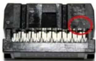
natural_image
Close-up of a black electronic component with multiple teeth and a red circle highlighting a specific area (no text or symbols visible)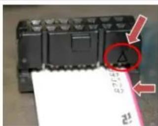
text_image
Close-up of a device component with red annotations highlighting a warning symbol and handwritten notes
natural_image
Close-up of a mechanical component with a white sheet being cut, no visible text or symbols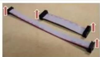
natural_image
Two flexible cable connectors with black connectors and red connectors, shown against a plain background (no text or symbols visible)Pic 1 Pic 2 Pic 3 Pic 4
11e. Final assembly
| Part Qty Location | ||
| 401168 2 Control | acrylic | |
| 401151 2 Control | acrylic | |
| M3 x 20 CP 4 Control | bolt bag | |
| M3 x 30 CP 2 Control | bolt bag | |
| M3 nut 8 Control | bolt bag | |
| 401152 2 Control | acrylic | |
| 10-wire ribbon cable c/w connector | 1 Previous | |
| 14-wire ribbon cable c/w connector | 1 Previous | |
| Top plate 1 Previous | ||
| M3 x 10 CP 5 Control | bolt bag | |
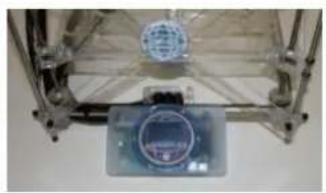
natural_image
Close-up of a transparent mechanical device with a spherical component and a circular display (no visible text or symbols)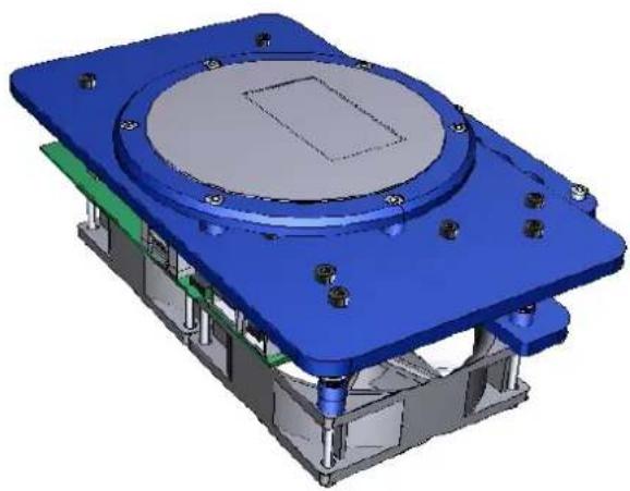
natural_image
3D CAD model of a mechanical assembly with blue housing, green base, and gray components (no text or symbols visible)
text_image
Tools M3 driver M3 spanner No Hazard. No warnings.Single head
- Make up the conduit clamp (Pic 1). Use 2# M3 x 20 CP, 2# 401168, 2# 401151, and 2# M3 nuts. Ensure the spacers (401151's) are present between the two clamp plates. Tighten.
- Move conduit plate closer towards the PCB and position using 2# M3 x30 CP bolts (Pic 2 – view from underside). Lock using 2# M3 nuts. Make sure conduit plate sits flat onto PCB acrylic bracket – check zip tie heads do not obstruct this.
- Fold the conduit back 90 degrees and slot the conduit clamp down over the top of the three conduits (Pic 3). Lock in position using 2# M3 x 20 CP and 2# M3 nuts.
- Link PCB to top plate with ribbon cables as shown in Pic 4.
- Secure to plate to PCB base using 5# M3 x 10 CP as identified in Pic 4b (the bolt identified with red arrow is for the extruder module).
- Carefully roll the RapMan onto its back (Pic 5).
- Using 2# 401152 and 4# M3 nuts, clamp the control unit to lower front bar (Pic 6) to achieve Pic 7.
Double head
Same as above, but in step 5 use an extra M3 x 10 CP to secure the second extruder module.
RapMan 3.2 manual
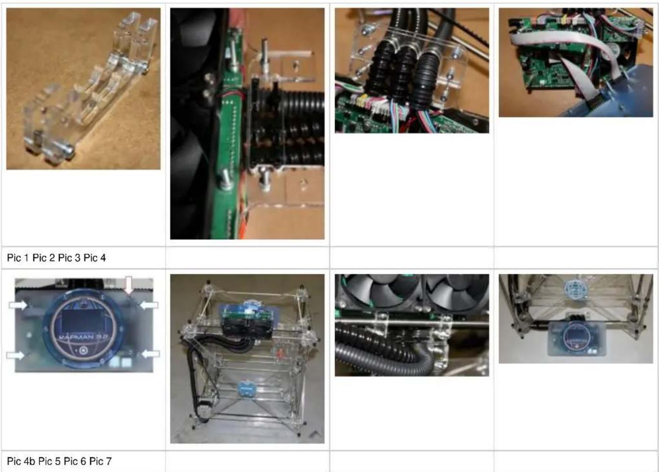
Use cable ties to fasten the conduits to the structure of the RapMan:
- Position extruder to the far right, back of the machine (Pic 0). Ensure Extruder conduit and X conduit are sufficiently relaxed that the axes are not loaded by the conduits.
- Fasten the three conduits from the control panel to the bottom left corner (Pic 1).
- Run the X conduit and Extruder conduits up the side brace: X conduit on inside, Extruder conduit on the outside. Fasten at bottom and middle of brace (Pic 2).
- Run the Y/Z conduit along the bottom side of the 8mm bar (Pic 2). Fasten along the bar.
- Your final assembly should look like Pic 3.
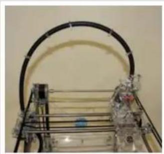
natural_image
Close-up of a transparent mechanical device with curved black components and internal wiring (no visible text or symbols)
natural_image
Close-up of a robotic arm with transparent wiring and a blue control unit (no visible text or symbols)
natural_image
Industrial piping system with black and metallic tubing inside a transparent enclosure (no visible text or symbols)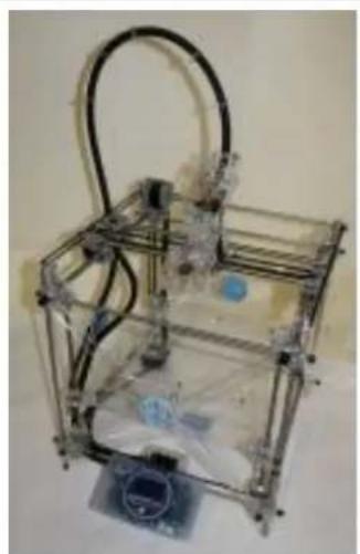
natural_image
3D-printed wireframe model of a mechanical device with transparent frame and metal casing (no text or symbols visible)Pic 0 Pic 1 Pic 2 Pic 3
12. Double head calibration
If you have installed two extruders on your RapMan, you will need to calibrate their positions. This will be explained in the RapMan 3.2 Operations (Section 9 e.).Manual
13. Next step
Congratulations! You have built the RapMan 3D printer!
No doubt you will be keen to start printing. You should now read the "RapMan Operations Manual" which will guide you through how to start using your RapMan to print 3D models.
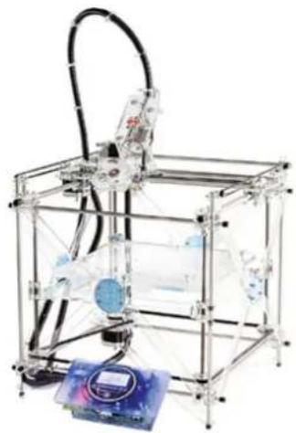
natural_image
Mechanical robotic device with transparent frame and blue internal components, no visible text or symbols14. Appendix
Document version
The table below describes the changes made to this manual.
| Version Change description Date | |
| 4.0.0 Release 30/11/11 | |
Machine changes
The table below describes the changes made to the RapMan compared to previous versions:
| Change V3.1 V3.2 | ||
| Microswitch wiring X:White Y:Orange Z:Yellow X:Orange Y:White Z:Yellow | ||
| Control panel Button interface/OLED screen Touch screen control/display | ||
| Main Electronics v3.3 v3.4 | ||