
FLM-I 420-S - Fire alarm system BOSCH - Free user manual and instructions
Find the device manual for free FLM-I 420-S BOSCH in PDF.


| Product Type | Short Circuit Isolator for fire alarm systems |
| Model | FLM-I 420-S |
| Input Voltage | 15 V DC to 33 V DC |
| Max Current Consumption | < 0.4 mA during initialization, < 0.25 mA after initialization |
| LSN/Address Setting | 3 rotary switches for classic or improved LSN mode, automatic or manual addressing (addresses 0-254) |
| Connections | 6 threaded clamps for LSN (b1+, a-, b2+) and 3 free terminals for looping aux voltage and shielding |
| Housing Material | Isolator module: PPO (Noryl); Surface-mount housing: ABS/PC blend |
| Color | Isolator module: Off-white (RAL 9002); Housing: Signal white (RAL 9003) |
| Dimensions (H x W x D) | Approx. 126 x 126 x 71 mm (4.96 x 4.96 x 2.8 in) |
| Weight | Approx. 150 g (5.3 oz) |
| Operating Temperature | -20 °C to 50 °C (-4 °F to 122 °F) |
| Storage Temperature | -25 °C to 85 °C (-13 °F to 176 °F) |
| Relative Humidity | < 96% |
| Protection Class | IP54 (IEC 60529) |
| Equipment Class | Class III (IEC 60950) |
| Certifications | EN54-17:2005; VdS G 207045 (Germany) |
| Compatible Fire Panels | FPA-5000 Modular, FPA-1200 with LSN improved technology |
| Mounting | Surface-mounted housing or DIN rail (with included adapter) |
| Cable Entry | 2 x 2 pre-punched for up to 21 mm/34 mm conduits; 2 x 4 rubber bushes for cables up to 8 mm; additional ducts on base |
| Included Accessories | Short Circuit Isolator with surface-mounted housing, DIN rail adapter |
| Function | Isolates alarm zones with short circuits; preserves LSN loop functionality via two integrated isolators; supports T-tapping and up to 254 LSN-improved elements per loop |
Frequently Asked Questions - FLM-I 420-S BOSCH
User questions about FLM-I 420-S BOSCH
0 question about this device. Answer the ones you know or ask your own.
Ask a new question about this device
Download the instructions for your Fire alarm system in PDF format for free! Find your manual FLM-I 420-S - BOSCH and take your electronic device back in hand. On this page are published all the documents necessary for the use of your device. FLM-I 420-S by BOSCH.
USER MANUAL FLM-I 420-S BOSCH
FLM-I 420-S Short Circuit Isolator
natural_image
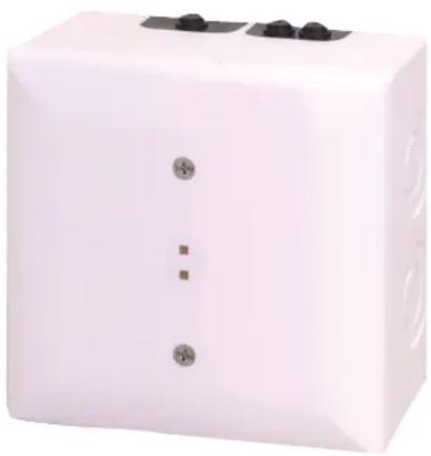
White rectangular electronic device with three black buttons and a small square symbol on its side (no visible text or labels)The Short Circuit Isolator isolates alarm zones in which a short circuit has occurred. This means the functionality of the remainder of the network remains preserved.
System Overview

Description Connector
b1+ / a- / b2+ LSN
N/A (3 x) free terminals, e.g. for looping through ext. auxiliary voltage and for shielding
- Rotary switch for automatic and manual address setting
- Preservation of LSN loop functions in the event of a short-circuit by two integrated isolators
▶ Power supply via LSN
▶ Three free screw terminals
Functions
Features of improved LSN
The interface modules in the 420 series offer all the features of improved LSN technology:
- Flexible network structures including T-tapping without additional elements
- Up to 254 LSN-improved elements per loop or stub line
• Unshielded cable can be used
Address switch (rotary switch)
The address of the Short Circuit Isolator is set using the rotary switches.
The following settings are possible:
0 0 0 Loop/stub in LSN mode improved version with automatic addressing (T-tap system not possible)
0 0 1 - 254 Loop/stub/T-tap system in LSN mode improved version with manual addressing
CL 0 0 Loop/stub in classic LSN mode
Configuration
The Short Circuit Isolator isolates alarm zones in which a short circuit has occurred. The following illustrations show typical configurations of the isolator module.
Wiring example: Isolation of separate floors

flowchart
graph TD
    A["LSN1"] -->|b+| B["LSN2"]
    B -->|a-| C["LSN"]
    B -->|b+| D["LSN"]
    D -->|a-| E["LSN"]
    E -->|b+| F["LSN"]
    F -->|b-| G["LSN"]
    G --> H["LSN"]
    H --> I["II"]
    I --> J["FLM-I 420-S"]
    J --> K["III"]
    J --> L["II"]
    J --> M["II"]
    J --> N["I"]
Pos. Description
1 Fire panel
I, II, III Floors
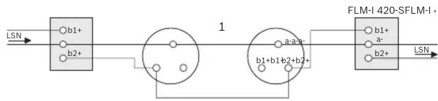
Typical wiring in a T-Tap
flowchart
graph LR
    A["LSN"] --> B["b1+"]
    B --> C["1"]
    C --> D["b2+"]
    D --> E["1"]
    E --> F["b1+b1b2+b2+"]
    F --> G["FLM-I 420-SFLM-I"]
    G --> H["LSN"]
    I["a-a-y"] --> F
    J["b1+"] --> G
    K["a-"] --> G
Pos. Description
1 Alarm zone / device group with LSN elements
Certifications and Approvals
Complies with EN54-17:2005
Region Certification
Germany VdS G 207045 FLM-I 420-S; FLM-I 420-D
Installation/Configuration Notes
- National standards and guidelines must be taken into account during the planning stage.
- The surface-mounted housing has two cable ducts on opposite sides:
- 2 x 2 pre-punched for diameter up to 21 mm/to 34 mm (for conduits)
- 2 x 4 rubber bushes for inserting cables with diameters of up to 8 mm.
- In addition, there are cable ducts on the base of the surface-mounted housing:
- 1 x pre-punched cable ducts for diameter up to 21 mm (for conduits)
- 2 x 4 rubber bushes for inserting cables with diameters of up to 8 mm.
- Connectable to the fire panels FPA-5000 Modular and FPA-1200 with LSN technology improved version.
Parts Included
Qty. Components
1 Short Circuit Isolator with surface-mounted housing.
1 DIN rail adapter
Note Alternatively to the use of the surface-mounted housing, the Isolator can be mounted on a DIN rail with the included adapter.
Technical Specifications
Electrical
| Input voltage | 15 V DC to 33 V DC |
| Max. current consumption | |
| • During initialization | < 0.4 mA |
| • Following the initializa-tion | < 0.25 mA |
Mechanics
| LSN/Address setting | 3 rotary switches for |
| • Mode LSN classic or LSN improved version | |
| • Automatic or manual addressing | |
| Connections | 6 threaded clamps |
| Housing material | |
| • Isolator module | PPO (Noryl) |
| • Surface-mount housing | ABS/PC-Blend |
| Housing color | |
| • Isolator module | Off-white, similar to RAL 9002 |
| • Surface-mount housing | Signal white, RAL 9003 |
| Dimensions | Approx. 126 x 126 x 71 mm(4.96 x 4.96 x 2.8 in.) |
| Weight | Approx. 150 g (5.3 ounces) |
Environmental conditions
| Permitted operating temperature | -20 °C to 50 °C(-4°F to 122°F) |
| Permitted storage temperature | -25 °C to 85 °C(-13°F to. 176°F) |
| Permitted relative humidity < 96% | |
| Classes of equipment as per IEC 60950 | Class III equipment |
| Protection class as per IEC 60529 | IP 54 |
Ordering Information
| FLM-I 420-S Short Circuit Isolator | FLM-I 420-S |
| for the isolation of alarm zones in which a short circuit has occurred. | |
Accessories
| FLM-IFB126-S Surface-mounted Housing as retainer for the interface modules series 420 type DIN rail (-D) or spare housing for type surface-mount (-S) | FLM-IFB126-S |
Americas:
Bosch Security Systems, Inc.
130 Perinton Parkway
Fairport, New York, 14450, USA
Phone: +1 800 289 00
Fax: +1 585 223 9180
security.sales@us.bosch.com
www.boschsecurity.us
Europe, Middle East, Africa:
Bosch Security Systems B.V.
P.O. Box 80002
5600 JB Eindhoven, The Netherlands
Phone: +31 40 2577 284
Fax: +31 40 2577 330
emea.securitysystems@bosch.com
www.boschsecurity.com
Asia-Pacific:
Robert Bosch (SEA) Pte Ltd, Security Systems
11 Bishan Street 21
Singapore 573943
Phone: +65 6258 5511
Fax: +65 6571 2698
apr.securitysystems@bosch.com
www.boschsecurity.com
Represented by
- FLM-I 420-S Short Circuit Isolator
- Description Connector
- Functions
- Features of improved LSN
- Address switch (rotary switch)
- Configuration
- Pos. Description
- Certifications and Approvals
- Region Certification
- Installation/Configuration Notes
- Parts Included
- Qty. Components
- Americas:
- Europe, Middle East, Africa:
- Asia-Pacific:
- Represented by
Brand : BOSCH
Model : FLM-I 420-S
Category : Fire alarm system