
C7Z97-M - Motherboard Supermicro - Free user manual and instructions
Find the device manual for free C7Z97-M Supermicro in PDF.


User questions about C7Z97-M Supermicro
0 question about this device. Answer the ones you know or ask your own.
Ask a new question about this device
Download the instructions for your Motherboard in PDF format for free! Find your manual C7Z97-M - Supermicro and take your electronic device back in hand. On this page are published all the documents necessary for the use of your device. C7Z97-M by Supermicro.
USER MANUAL C7Z97-M Supermicro
The information in this User's Manual has been carefully reviewed and is believed to be accurate. The vendor assumes no responsibility for any inaccuracies that may be contained in this document, makes no commitment to update or to keep current the information in this manual, or to notify any person or organization of the updates. Please Note: For the most up-to-date version of this manual, please see our web site at www.supermicro.com.
Super Micro Computer, Inc. ("Supermicro") reserves the right to make changes to the product described in this manual at any time and without notice. This product, including software and documentation, is the property of Supermicro and/or its licensors, and is supplied only under a license. Any use or reproduction of this product is not allowed, except as expressly permitted by the terms of said license.
IN NO EVENT WILL SUPERMICRO BE LIABLE FOR DIRECT, INDIRECT, SPECIAL, INCIDENTAL, SPECULATIVE OR CONSEQUENTIAL DAMAGES ARISING FROM THE USE OR INABILITY TO USE THIS PRODUCT OR DOCUMENTATION, EVEN IF ADVISED OF THE POSSIBILITY OF SUCH DAMAGES. IN PARTICULAR, SUPERMICRO SHALL NOT HAVE LIABILITY FOR ANY HARDWARE, SOFTWARE, OR DATA STORED OR USED WITH THE PRODUCT, INCLUDING THE COSTS OF REPAIRING, REPLACING, INTEGRATING, INSTALLING OR RECOVERING SUCH HARDWARE, SOFTWARE, OR DATA.
Any disputes arising between manufacturer and customer shall be governed by the laws of Santa Clara County in the State of California, USA. The State of California, County of Santa Clara shall be the exclusive venue for the resolution of any such disputes. Super Micro's total liability for all claims will not exceed the price paid for the hardware product.
FCC Statement: This equipment has been tested and found to comply with the limits for a class B digital device, pursuant to Part 15 of the FCC Rules. These limits are designed to provide reasonable protection against harmful interference in a residential installation. This equipment generates, uses, and can radiate radio frequency energy and, if not installed and used in accordance with the instructions, may cause harmful interference to radio communications. However, there is no guarantee that interference will not occur in a particular installation. If this equipment does cause harmful interference to radio or television reception, which can be determined by turning the equipment off and on, the user is encouraged to try to correct the interference by one or more of the following measures:
• Reorient or relocate the receiving antenna.
- Increase the separation between the equipment and receiver.
- Connect the equipment to an outlet on a circuit different from that to which the receiver is connected.
- Consult the authorized dealer or an experienced radio/TV technician for help.
California Best Management Practices Regulations for Perchlorate Materials: This Perchlorate warning applies only to products containing CR (Manganese Dioxide) Lithium coin cells. "Perchlorate Material-special handling may apply. See www.dtsc.ca.gov/hazardouswaste/perchlorate"
WARNING: Handling of lead solder materials used in this product may expose you to lead, a chemical known to the State of California to cause birth defects and other reproductive harm.
Manual Revision 1.0b
Release Date: August 4, 2015
Unless you request and receive written permission from Super Micro Computer, Inc., you may not copy any part of this document.
Information in this document is subject to change without notice. Other products and companies referred to herein are trademarks or registered trademarks of their respective companies or mark holders.
Copyright © 2015 by Super Micro Computer, Inc. All rights reserved.
Printed in the United States of America
Preface
This manual is written for system integrators, PC technicians and knowledgeable PC users. It provides information for the installation and use of the SUCZ97-M/MF motherboard.
Manual Organization
Chapter 1 describes the features, specifications and performance of the motherboard, and provides detailed information on the Intel Z97 Express chipset.
Chapter 2 provides hardware installation instructions. Read this chapter when installing the processor, memory modules and other hardware components into the system.
If you encounter any problems, see Chapter 3, which describes troubleshooting procedures for video, memory and system setup stored in the CMOS.
Chapter 4 includes an introduction to the BIOS, and provides detailed information on running the CMOS Setup utility.
Appendix A provides BIOS Error Beep Codes.
Appendix B lists software program installation instructions.
Appendix C contains UEFI BIOS Recovery instructions.
Appendix D contains an introduction and instructions regarding the Dual Boot Block feature of this motherboard.
Checklist
Congratulations on purchasing your computer motherboard from an acknowledged leader in the industry. Supermicro boards are designed with the utmost attention to detail to provide you with the highest standards in quality and performance.
Please check that the following items have all been included with your motherboard. If anything listed here is damaged or missing, contact your retailer.
The following items are included in the retail box.
• One (1) Supermicro Motherboard
• Six (6) SATA cables (C7Z97-M) or
• Two (2) SATA Cables (C7Z97-MF)
• One (1) I/O shield
• One (1) Quick Reference Guide
• One (1) Driver CD (C7Z97-M only)
Conventions Used in the Manual
Special attention should be given to the following symbols for proper installation and to prevent damage done to the components or injury to yourself:
Attention! Critical information to prevent damage to the components or injury to yourself.
Important: Important information given to ensure proper system installation or to relay safety precautions.
Note: Additional Information given to differentiate various models or provides information for correct system setup.



Standardized Warning Statements
The following statements are industry-standard warnings, provided to warn the user of situations which have the potential for bodily injury. Should you have questions or experience difficulty, contact Supermicro's Technical Support department for assistance. Only certified technicians should attempt to install or configure components.
Read this section in its entirety before installing or configuring components in the Supermicro chassis.
Battery Handling

Warning!
There is a danger of explosion if the battery is replaced incorrectly. Replace the battery only with the same or equivalent type recommended by the manufacturer. Dispose of used batteries according to the manufacturer's instructions
電池の取り扱い
Ultimate disposal of this product should be handled according to all national laws and regulations.
製品の廃棄
Contacting Supermicro
Headquarters
Address: Super Micro Computer, Inc.
980 Rock Ave.
San Jose, CA 95131 U.S.A.
Tel: +1 (408) 503-8000
Fax: +1 (408) 503-8008
Email: marketing@supermicro.com (General Information)
support@supermicro.com (Technical Support)
Web
www.supermicro.com
Site:
Europe
Address: Super Micro Computer B.V.
's-Hertogenbosch, The Netherlands
Tel: +31 (0) 73-6400390
Fax: +31 (0) 73-6416525
Email: sales@supermicro.nl (General Information)
support@supermicro.nl (Technical Support)
rma@supermicro.nl (Customer Support)
Asia-Pacific
Address: Super Micro Computer, Inc.
4F, No. 232-1, Liancheng Rd
Chung-Ho Dist., New Taipei City 235
Taiwan
Tel: +886-(2) 8226-3990
Fax: +886-(2) 8226-3991
Web
Where to Find More Information
For your system to work properly, please follow the links below to download all necessary drivers/utilities and the user's manual for your motherboard.
SMCI product manuals: http://www.supermicro.com/support/manuals/
Product Drivers and utilities: ftp://ftp.supermicro.com/
If you have any questions, please contact our support team at support@supermicro.com.
Table of Contents
Preface
Manual Organization ....iii
Checklist ......iv
Conventions Used in the Manual ......iv
Standardized Warning Statements...... v
Battery Handling...... v
Product Disposal....vi
Contacting Supermicro......viii
Where to Find More Information....ix
Chapter 1 Introduction
1-1 Overview 1-1
About this Motherboard 1-1
1-2 Chipset Overview 1-1
Intel Z97 Express Chipset Features.... 1-1
1-3 Motherboard Features 1-2
1-4 Special Features 1-4
Recovery from AC Power Loss 1-4
1-5 PC Health Monitoring.... 1-4
Fan Status Monitor with Firmware Control 1-4
Environmental Temperature Control 1-4
System Resource Alert 1-5
1-6 ACPI Features 1-5
Slow Blinking LED for Suspend-State Indicator....1-5
1-7 Power Supply 1-6
1-8 Super I/O 1-6
Chapter 2 Installation
2-1 Installation Components and Tools Needed 2-1
2-2 Static-Sensitive Devices.... 2-2
Precautions 2-2
Unpacking....2-2
2-3 Processor and Heatsink Installation.... 2-3
Installing the LGA1150 Processor 2-3
Installing an Active CPU Heatsink with Fan 2-6
Removing the Heatsink.... 2-8
2-4 Installing DDR3 Memory 2-9
DIMM Installation 2-9
Removing Memory Modules.... 2-9
Memory Support.... 2-10
Memory Population Guidelines 2-10
Memory Population Guidelines 2-11
2-5 Motherboard Installation.... 2-12
Tools Needed.... 2-12
Location of Mounting Holes 2-12
Installing the Motherboard 2-13
2-6 Connectors/IO Ports 2-14
Back I/O Panel 2-14
Universal Serial Bus (USB) 2-15
Ethernet / IPMI Port 2-16
Back Panel High Definition Audio (HD Audio) 2-16
HDMI Port 2-17
VGA Port 2-17
VESA® DisplayPort™ (DP) 2-17
ATX PS/2 Keyboard/Mouse Port 2-17
Front Control Panel 2-18
Front Control Panel Pin Definitions 2-19
Power LED 2-19
HDD LED 2-19
NIC1 (LAN1).... 2-19
Overheat (OH)/Fan Fail 2-19
Reset Button 2-20
Power Buttons 2-20
2-7 Connecting Cables 2-21
ATX Main PWR & CPU PWR Connectors (JPW1 & JPW2) ...... 2-21
Fan Headers (Fan 1 \~ Fan 5) ...... 2-22
Chassis Intrusion (JL1) 2-22
Internal Buzzer (SP1) 2-23
Speaker (JD1) 2-23
System Backup Battery (BT1).... 2-23
Onboard Power LED (JLED1).... 2-24
Serial Port (COM1) 2-24
DOM PWR Connector (JSD1).... 2-25
SPDIF OUT (JSPDIF_OUT) 2-25
Standby Power Header (STBY1) 2-26
TPM Header/Port 80 Header 2-26
Front Panel Audio Header (AUDIO FP) 2-27
OC Front Panel (OC FRONT PANEL) 2-27
2-8 Jumper Settings 2-28
Explanation of Jumpers 2-28
LAN1 Enable/Disable (JPL1).... 2-28
Clear CMOS (JBT1), (S8) 2-29
PCI Slot SMB Enable (I²C1/I²C2) 2-29
Audio Enable (JPAC1) 2-30
Watch Dog Enable/Disable (JWD1) 2-30
USB Wake-Up (JPUSB 1/2).... 2-31
VGA Enable (JPG1).... 2-31
Manufacturing Mode (JPME2) 2-32
2-9 Onboard Indicators 2-34
LAN 1 LEDs....2-34
Onboard Power LED (LED1) 2-34
IPMI Heartbeat (LEDM1) 2-35
2-10 SATA Connections 2-36
SATA Connections (I-SATA0\~I-SATA5) 2-36
2-10 The OC Front Control Panel (Optional) 2-37
Over-Clocking Buttons (OC1, OC2, OC3) 2-37
Clear CMOS and Reset.... 2-37
Boot BIOS Switch.... 2-37
BIOS Recovery.... 2-37
Front USB Port 2-37
Installing the OC Front Control Panel.... 2-38
Chapter 3 Troubleshooting
3-1 Troubleshooting Procedures.... 3-1
Before Power On.... 3-1
No Power.... 3-1
No Video 3-2
Memory Errors 3-2
When the System is Losing the Setup Configuration 3-2
3-2 Technical Support Procedures.... 3-3
3-3 Frequently Asked Questions 3-4
3-4 Battery Removal and Installation 3-5
Battery Removal 3-5
Proper Battery Disposal 3-5
3-5 Returning Motherboard for Service.... 3-6
Battery Installation 3-6
Chapter 4 BIOS
4-1 Introduction 4-1
Starting BIOS GUI Setup Utility 4-1
How To Change the Configuration Data 4-2
How to Start the Setup Utility 4-2
4-2 Setup Home 4-3
Load Optimized Defaults 4-5
Save All Settings Only 4-5
Save Settings to OC3 4-5
Exit Without Save 4-5
Save and Reset.... 4-5
Save and Exit Setup.... 4-5
4-3 System Information 4-6
Motherboard 4-6
System Date 4-6
System Time 4-6
CPU 4-7
Memory 4-8
PCH 4-9
4-4 Processor (CPU).... 4-10
Information 4-10
Performance.... 4-11
Hyper-threading 4-11
Active Processor Cores.... 4-11
Overclocking Lock 4-11
Limit CPUID Maximum 4-12
Execute Disable Bit 4-12
Intel® Virtualization Technology 4-12
Hardware Prefetcher 4-12
Adjacent Cache Line Prefetch 4-12
CPU AES 4-12
Boot Performance Mode 4-13
Power Management.... 4-13
EIST 4-13
Turbo Mode 4-13
CPU C States.... 4-16
Package C-State limit 4-17
LakeTiny Feature.... 4-17
4-5 Overclocking 4-18
CPU Overclocking.... 4-18
Load SMC CPU OC Setting.... 4-18
1-Core Ratio Limit 4-18
2-Core Ratio Limit 4-18
3-Core Ratio Limit 4-19
4-Core Ratio Limit 4-19
BCLK Ratio 4-19
BCLK Clock Frequency (1/100 MHz) 4-19
Internal PLL Overvoltage 4-19
CPU BCLK Filter PLL Frequency 4-19
LCPLL or SBPLL Select 4-19
CPU Non Turbo Ratio Override 4-19
CPU Power Setting 4-20
Enhanced Intel SpeedStep Technology 4-20
Turbo Mode 4-20
CPU Turbo Setting 4-20
Package TDP Lock Enable 4-20
Long Duration Power Limit (Watt) 4-20
Long Duration Power Limit Time (Seconds) 4-20
Short Duration Power Limit Switch 4-20
Short Duration Power Limit (Watt) 4-20
Package Current Lock 4-21
Processor Current Limit (1/8 Amp) 4-21
Disable OverClocking Lock.... 4-21
Voltage Configuration 4-21
CPU Voltage Mode 4-21
CPU Adaptive/Override/Offset Voltage Target (mV)...... 4-21
CPU Override Voltage Target (mV) 4-21
CPU Cache Voltage Mode 4-21
CPU Cache Adaptive/Override/Offset Voltage Target (mV) ..... 4-22
System Agent Voltage Offset (mV) 4-22
CPU IOA Voltage Offset (mV) 4-22
CPU IOD Voltage Offset (mV) 4-22
PCH 1.05V Voltage 4-22
PCH 1.5V Voltage.... 4-22
Overclocking SVID and FIVR Options.... 4-23
SVID Control Enable.... 4-23
SVID Override Voltage Target (mV) 4-23
FIVR Faults Enable 4-23
FIVR Efficiency Enable 4-23
CPU Input Voltage 4-23
CPU Input Voltage 4-23
Memory Overclocking 4-24
Load Memory Profiles 4-24
Memory Timing Configuration (Expert Mode) 4-25
DIMM Exit Mode.... 4-28
Graphics OverClocking.... 4-29
Graphics Core Ratio Limit.... 4-29
GT Voltage Mode.... 4-29
GT Adaptive Voltage Target (mV) 4-29
GT Override Voltage Target (mV) 4-29
GT Voltage Offset (mV) 4-29
Offset Prefix 4-30
OverClocking Buttons 4-30
Case LED 4-30
OC1 Button Setting Configuration
OC2 Button Setting Configuration.... 4-30
Memory OC Button Setting Configuration.... 4-31
Load Memory Profiles 4-31
Memory OC Button Setting Configurations.... 4-31
4-6 Chipset 4-34
System Agent.... 4-34
VT-d 4-34
CPU SA Audio Device (B0:D3:F0) 4-34
Above 4GB MMIO BIOS Assignment 4-35
Graphics 4-35
Primary Display 4-35
Internal Graphics 4-36
PCH-IO 4-37
Wake on LAN 4-37
Azalia (HD Audio) 4-37
4-7 Memory 4-38
Memory Information.... 4-38
Memory Configuration 4-40
Max TOLUD (Top of Low Usable DRAM).... 4-40
Enhanced Interleave Support.... 4-40
Rank Interlevel Support 4-40
MRC Fast Boot 4-40
4-8 I/O 4-41
SATA 4-41
SATA Mode Selection 4-41
SATA Controller Speed (AHCI or RAID Mode only)......4-41
Alternate ID (RAID Mode Only).... 4-41
Port 0 \~ Port 5....4-42
Hot Plug 4-42
External SATA.... 4-42
SATA Device Type 4-42
Spin Up Device 4-42
PCIe/PCI/PnP 4-43
NB PCIE Setting 4-43
Option ROM Execution 4-43
Video.... 4-43
Storage.... 4-44
Other PCI Devices 4-44
PCH_SLOT1 PCI-E 2.0 X1 (IN X4) OPROM,
CPU_SLOT2 PCI-E 3.0 X4 (IN X16) OPROM,
PCH_SLOT3 PCI-E 2.0 X1 (IN X4) OPROM....4-44
Onboard LAN1 Option ROM 4-44
USB Settings 4-44
XHCI Mode 4-45
USB Ports Per-Port Disable Control 4-45
PCH-FW (Firmware) 4-45
ME FW Image Re-Flash 4-46
Super IO Configuration.... 4-46
Enable Serial Port 1.... 4-46
Current IRQ 4-46
IRQ Settings.... 4-46
4-9 Booting 4-47
Boot Device Settings.... 4-47
Boot Mode Select 4-47
Boot Order #1\~#15 4-47
Power Settings 4-48
Bootup Numlock State 4-48
Quiet Boot 4-48
Fast Boot 4-48
AddOn ROM Display Mode 4-48
Wait for "F1" for Error 4-48
Interrupt 19 Capture 4-49
Re-try Boot 4-49
Watch Dog 4-49
Power Button Function 4-49
Restore on AC Power Loss.... 4-49
EUP Support.... 4-49
Security Settings 4-50
Administrator Password.... 4-50
User Password 4-51
Secure Boot Menu 4-51
Secure Boot 4-51
Secure Boot Mode 4-51
Key Management 4-52
Platform Key 4-52
Delete PK.... 4-52
Set New PK 4-52
Key Exchange Key 4-53
Delete KEK 4-53
Set New KEK 4-53
Append KEK 4-53
Authorized Signatures.... 4-53
Delete DBT 4-53
Set New DBT 4-53
Append DBT 4-53
Forbidded Signatures.... 4-54
Delete DBX 4-54
Set New DBX.... 4-54
Append DBX 4-54
4-10 Management 4-55
ACPI Settings 4-55
ACPI Sleep State 4-55
Console Redirection Settings 4-56
COM1 4-56
Enable Console Redirection.... 4-56
Console Redirection Settings 4-56
Serial Port for Out-of-Band Management/Windows Emergency Management Services (EMS) 4-56
Console Redirection Settings 4-57
Out-of-Band Management Port 4-57
Terminal Type 4-57
Bits Per Second 4-57
Flow Control 4-57
Data Bits, Parity, Stop Bits 4-57
4-11 IPMI 4-58
IPMI 4-58
System Event Log 4-58
Enabling/Disabling Options 4-58
SEL Components.... 4-58
Erasing Settings.... 4-59
Erase SEL 4-59
When SEL is Full.... 4-59
BMC Network Configuration.... 4-59
BMC Network Configuration 4-59
Update IPMI LAN Configuration.... 4-60
Configuration Address Source (Available when the item above - Update IPMI LAN Configuration is set to Yes) 4-60
Appendix A BIOS Error Beep Codes
A-1 BIOS Error Beep Codes ...... A-1
Appendix B Software Installation Instructions
B-1 Installing Drivers.... B-1
B-2 Configuring SuperDoctor ^® III ...... B-2
Appendix C UEFI BIOS Recovery Instructions
C-1 An Overview to the UEFI BIOS....C-1
C-2 How to Recover the UEFI BIOS Image (-the Main BIOS Block).... C-1
C-3 To Recover the Main BIOS Block Using a USB-Attached Device.... C-2
Appendix D Dual Boot Block
D-1 Introduction....D-1
BIOS Boot Block....D-1
BIOS Boot Block Corruption Occurrence ....D-1
D-2 Steps to Reboot the System by switch JBR1 ....D-2
Chapter 1
Introduction
1-1 Overview
About this Motherboard
The C7Z97-M/MF supports a single 4th Generation Intel® Core™ i7/i5/i3 DT processor, in an LGA 1150 (H3) socket. With the Intel® Z97 Express chipset built in, the C7Z97-M/MF motherboard offers substantial system performance and storage capability for overclocking platforms in a sleek package. Please refer to our website (http://www.supermicro.com/products/) for processor and memory support updates.
1-2 Chipset Overview
Intel Z97 Express Chipset Features
- Direct Media Interface (up 10 Gb/s transfer, Full Duplex)
• Intel Rapid Storage Technology
• Intel I/O Virtualization (VT-d) Support
• Intel Trusted Execution Technology Support - PCI Express 2.0 Interface (up to 5.0 GT/s) and PCI Express 3.0 Interface (up to 8.0 GT/s)
• SATA Controller (up to 6Gb/sec)
• Advanced Host Controller Interface (AHCI)
1-3 Motherboard Features
| CPU | Single 4th Generation Intel® CoreTM i7/i5/i3 DT processor, LGA1150 socket. | ||
| Memory | Four (4) Memory slots support up to 32 GB of DDR3 Unbuffered, Non-ECC 1066~3000(OC) MHz memory | ||
| Dual-channel memory | |||
| DIMM sizes | |||
| UDIMM 1 GB, 2 GB, 4GB, and 8GB | |||
| Chipset | Intel® Z97 Express | ||
| Expansion Slots | One (1) PCI Express 3.0 x8 slot (Slot 1) | ||
| One (1) PCI Express 2.0 x4 slot (Slot 2) | |||
| One (1) PCI Express 3.0 x16 slot (Slot 3) | |||
| Network Connections | One (1) Gigabit Ethernet Controller | ||
| One (1) RJ-45 rear I/O panel connectors with Link and Activity LEDs, shared as an IPMI port on the C7Z97-MF | |||
| I/O Devices SATA Connections | |||
| One (1) Front Panel Audio Header | |||
| One (1) SPDIF Out on the rear side of the chassis | |||
| Super I/O | |||
| Nuvoton NCT6776D | |||
| BIOS | 128 Mb AMI BIOS® SPI Flash BIOS | ||
| Plug and Play (PnP0, DMI 2.8.0, PCI 2.3, ACPI 1.0/2.0/3.0, USB Keyboard | |||
| Power Configuration | ACPI/ASPM Power Management | ||
| Main Switch Override Mechanism | |||
| Power-on mode for AC power recovery | |||
| Health Monitoring CPU | Monitoring | ||
| Onboard voltage monitors for +1.8V, +12V, +3.3V, +5V, +5V standby, 3.3V standby | |||
| CPU 6-phase switching voltage regulator | |||
| CPU/System overheat LED and control | |||
| CPU Thermal Trip support | |||
| Thermal Monitor support | |||
| Fan Control | |||
| Fan status monitoring with firmware 4-pin fan speed control | |||
| Low noise fan speed control | |||
| System Management | PECI (Platform Environment Configuration Interface) 2.0 support | ||
| System resource alert via SuperDoctor® III | |||
| SuperDoctor III, Watch Dog, NMI | |||
| Chassis Intrusion header and detection | |||
| CD Utilities(for C7Z97-M only) | BIOS flash upgrade utility | ||
| Drivers and software for Intel® Z97 Express chip-set utilities | |||
| Other | ROHS 6/6 (Full Compliance, Lead Free) | ||
| Dimensions | Micro ATX form factor (9.6" x 9.6") (243.84 mm x 243.84 mm) | ||
1-4 Special Features
Recovery from AC Power Loss
Basic I/O System (BIOS) provides a setting for you to determine how the system will respond when AC power is lost and then restored to the system. You can choose for the system to remain powered off, (in which case you must press the power switch to turn it back on), or for it to automatically return to a power-on state. See the Advanced BIOS Setup section to change this setting. The default setting is Last State.
1-5 PC Health Monitoring
This section describes the PC health monitoring features of the board. All have an onboard System Hardware Monitoring chip that supports PC health monitoring. An onboard voltage monitor will scan these onboard voltages continuously: +1.8V, +12V, +3.3V, +5V, +5V standby, and 3.3V standby. Once a voltage becomes unstable, a warning is given, or an error message is sent to the screen. The user can adjust the voltage thresholds to define the sensitivity of the voltage monitor.
Fan Status Monitor with Firmware Control
PC health monitoring in the BIOS can check the RPM status of the cooling fans. The onboard CPU and chassis fans are controlled by Thermal Management via SIO.
Environmental Temperature Control
The thermal control sensor monitors the CPU temperature in real time and will turn on the thermal control fan whenever the CPU temperature exceeds a user-defined threshold. The overheat circuitry runs independently from the CPU. Once the thermal sensor detects that the CPU temperature is too high, it will automatically turn on the thermal fans to prevent the CPU from overheating. The onboard chassis thermal circuitry can monitor the overall system temperature and alert the user when the chassis temperature is too high.

Note: To avoid possible system overheating, please be sure to provide adequate airflow to your system.
System Resource Alert
This feature is available when the system is used with SuperDoctor III in the Windows OS environment or used with SuperDoctor II in Linux. SuperDoctor is used to notify the user of certain system events. For example, you can also configure SuperDoctor to provide you with warnings when the system temperature, CPU temperatures, voltages and fan speeds go beyond predefined thresholds.
1-6 ACPI Features
ACPI stands for Advanced Configuration and Power Interface. The ACPI specification defines a flexible and abstract hardware interface that provides a standard way to integrate power management features throughout a PC system, including its hardware, operating system and application software. This enables the system to automatically turn on and off peripherals such as CD-ROMs, network cards, hard disk drives and printers.
In addition to enabling operating system-directed power management, ACPI also provides a generic system event mechanism for Plug and Play, and an operating system-independent interface for configuration control. ACPI leverages the Plug and Play BIOS data structures, while providing a processor architecture-independent implementation that is compatible with Windows 7, Windows 8, and Windows 2008 Operating Systems.
Slow Blinking LED for Suspend-State Indicator
When the CPU goes into a suspend state, the chassis power LED will start to blink to indicate that the CPU is in suspend mode. When the user presses any key, the CPU will "wake up", and the LED will automatically stop blinking and remain on.
1-7 Power Supply
As with all computer products, a stable power source is necessary for proper and reliable operation. It is even more important for processors that have high CPU clock rates.
This motherboard accommodates 24-pin ATX power supplies. Although most power supplies generally meet the specifications required by the CPU, some are inadequate. In addition, the 12V 8-pin power connector located at JPW2 is also required to ensure adequate power supply to the system. Also your power supply must supply 1.5A for the Ethernet ports.
Attention! To prevent damage to the power supply or motherboard, please use a power supply that contains a 24-pin and a 8-pin power connectors. Be sure to connect these connectors to the 24-pin (JPW1) and the 8-pin (JPW2) power connectors on the motherboard.
It is strongly recommended that you use a high quality power supply that meets ATX power supply Specification 2.02 or above. It must also be SSI compliant. (For more information, please refer to the web site at http://www.ssiforum.org/). Additionally, in areas where noisy power transmission is present, you may choose to install a line filter to shield the computer from noise. It is recommended that you also install a power surge protector to help avoid problems caused by power surges.
1-8 Super I/O
The Super I/O supports a high-speed, 16550 compatible serial communication ports (UARTs). Each UART includes a 16-byte send/receive FIFO, a programmable baud rate generator, complete modem control capability and a processor interrupt system. Both UARTs provide legacy speed with baud rate of up to 115.2 Kbps as well as an advanced speed with baud rates of 250 K, 500 K, or 1 Mb/s, which support higher speed modems.
The Super I/O provides functions that comply with ACPI (Advanced Configuration and Power Interface), which includes support of legacy and ACPI power management through an SMI or SCI function pin. It also features auto power management to reduce power consumption.
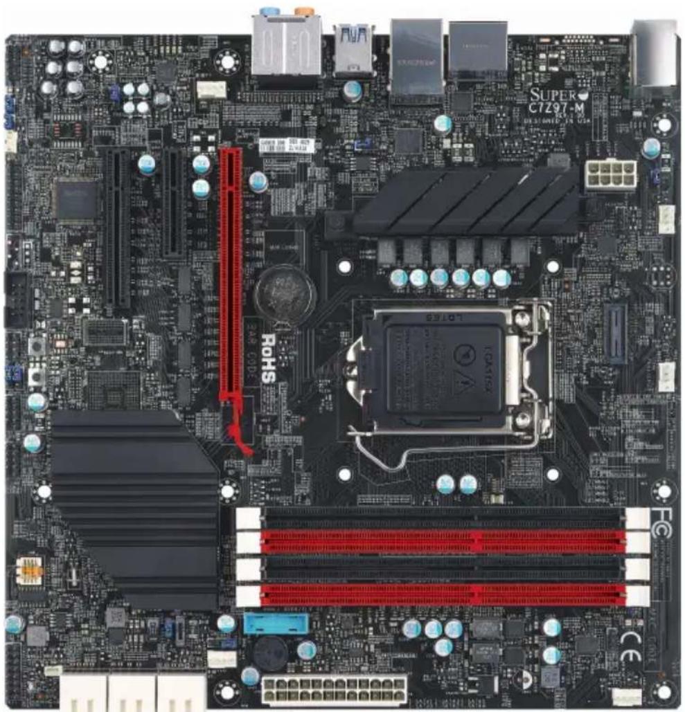
C7Z97-M/C7Z97-MF Motherboard Image
natural_image
Top-down view of a computer motherboard with visible CPU socket, RAM slots, and motherboard components (no readable text or symbols)
Note: All graphics shown in this manual were based upon the latest PCB Revision available at the time of publishing of the manual. The motherboard you've received may or may not look exactly the same as the graphics shown in this manual.
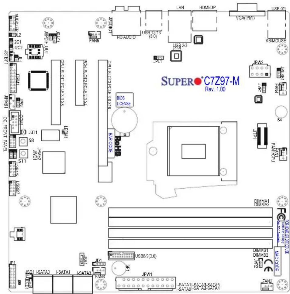
C7Z97-M/C7Z97-MF Motherboard Layout
text_image
AUDIO-IP L2 I2C1 I2C2 JSTBY1 JTPB1 JIPMB1 OC_FRONT PANEL JBT1 S8 JPNIE2 JWD1 S11 USB45 USB67 JSPD1 OUT JPAC1 CPU_SLOT1 PCLE 3.0 X8 LEDM1 JPL1 CPU_SLOT2 PCLE 2.0 X4 FAN5 HD AUDIO USB 12/13 (3.0) JPLT CPU_SLOT3 PCLE 3.0 X16 BIOS LICENSE BAR CODE S4 JTP1 FANT/CPU JW1 USB8/9(3.0) JSD1 I-SATA0 I-SATA1 I-SATA3 JID1 JPN1 JPMW1 I-SATA1 I-SATA3-SATA5 I-SATA0 I-SATA2-SATA4 VGA(IPM) USB 0/3 KB/MOUSE SUPER•C7Z97-M Rev. 1.00
Important Notes to the User
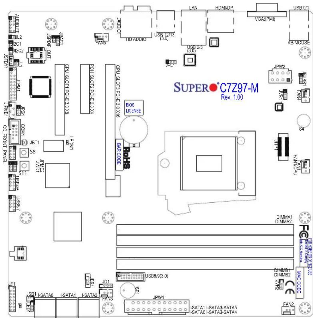
- See Chapter 2 for detailed information on jumpers, I/O ports and JF1 front panel connections.
- "■" indicates the location of "Pin 1".
- Jumpers not indicated are for testing only.
- When LED1 (Onboard Power LED Indicator) is on, system power is on. Unplug the power cable before installing or removing any components.
C7Z97-M/C7Z97-MF Quick Reference
text_image
AUDIO EP JL2 2C1 J12C2 JSTBY1 JPMB1 JPM1 JPG1 COM1 OC FRONT PANEL S8 S11 USB4/5 USB6/7 JSPDIF OUT JPAC1 JAC01 FAN5 HD AUDIO USB 2/13 (3.0) LAN HDMI/DP VGA(IPMI) USB 0/1 KB/MOUSE CPU SLOT1 PCLE 3.0 X8 PCH SLOT2 PCLE 2.0 X4 CPU SLOT3 PCLE 3.0 X16 BIOS LICENSE BAR CODE JPL1 JRW2 JWR1 JUSB1 FAN4 S4 JIP1 FAN7/PU SATAI I-SATA0 I-SATA1 I-SATA3 JSD1 I-SATA0 I-SATA1 I-SATA3 JPM2 JWD1 JPM1 USB8/9(3.0) SP1 JFW1 I-SATA1 I-SATA3-SATA5 I-SATA0 I-SATA2-SATA4 SUPER C7Z97-M Rev. 1.00| Jumper Description Default | ||
| JBT1 Clear CMOS (on board) (See Chpt. 2) | ||
| JI ^2 C1/JF C2 SMB to PCI Slots Off (Disabled) | ||
| JPAC1 Audio Enable Pins 1-2 (Enabled) | ||
| JPL1 LAN1 Enable Pins 1-2 (Enabled) | ||
| JPME2 Intel Recovery Mode Pins 2-3 (Disabled) | ||
| JBR1 BIOS Recovery Mode Pins 2-3 (Disabled) | ||
| JWD1 Watch Dog Timer Reset Enable Pins 2-3 (NMI) | ||
| JPUSB1 | USB Wake Up Enable (Back Panel) | Pins 1-2 (Enabled) |
| JPG1 | BMC VGA Enable/Disable | Pins 1-2 (Enabled) |
| LED | Description | Color/State | Status |
| LEDM1 | IPMI Heartbeat | Green: Blinking | BMC/IPMI Normal |
| LED1 | Onboard Standby PWR LED | Green: Solid on | Power On |
| Connector Description | |
| I/O Back Panel See Back Panel I/O Connectors, below right | |
| Audio FP Front Panel Audio Header | |
| Battery Onboard Battery | |
| COM1 COM1 Port Header | |
| Fan 1,2,3,4,5 System/CPU Fan Headers (Fan1: CPU Fan) | |
| JD1 Speaker/buzzer (Pins 1~4: External Speaker, Pins 3~4: Buzzer) | |
| JF1 Front Panel Control Header | |
| JL2 Chassis Intrusion Header | |
| JLED1 Power LED Indicator Header | |
| JPW1 24-pin ATX Main Power Connector (Required) | |
| JPW2 +12V 8-pin CPU power Connector (Required) | |
| JSD1 SATA DOM (Disk On Module) Power Connector | |
| JSPDIF_OUT Sony/Philips Digital Interface (S/PDIF) Out Header | |
| JSTBY1 Standby Power Header | |
| SP1 Internal Speaker/Buzzer | |
| I-SATA0~5 | (Intel Z97) Serial ATA (SATA 3.0) Ports 0~5 (6Gb/sec) |
| USB 4/5, 6/7 | Front Panel Accessible USB 2.0 Headers 4/5, 6/7 |
| USB 8/9 (3.0) | Front Panel Accessible USB 3.0 Header 8/9 |
| OC FRONT PANEL | Header for the Over-Clocking Control Panel |
| JTPM1 | Trusted Platform Module/Port 80 Connector |
| S4 | Internal Power Button |
| S8 | Clear CMOS Button |
| S11 | BIOS Restore Button |
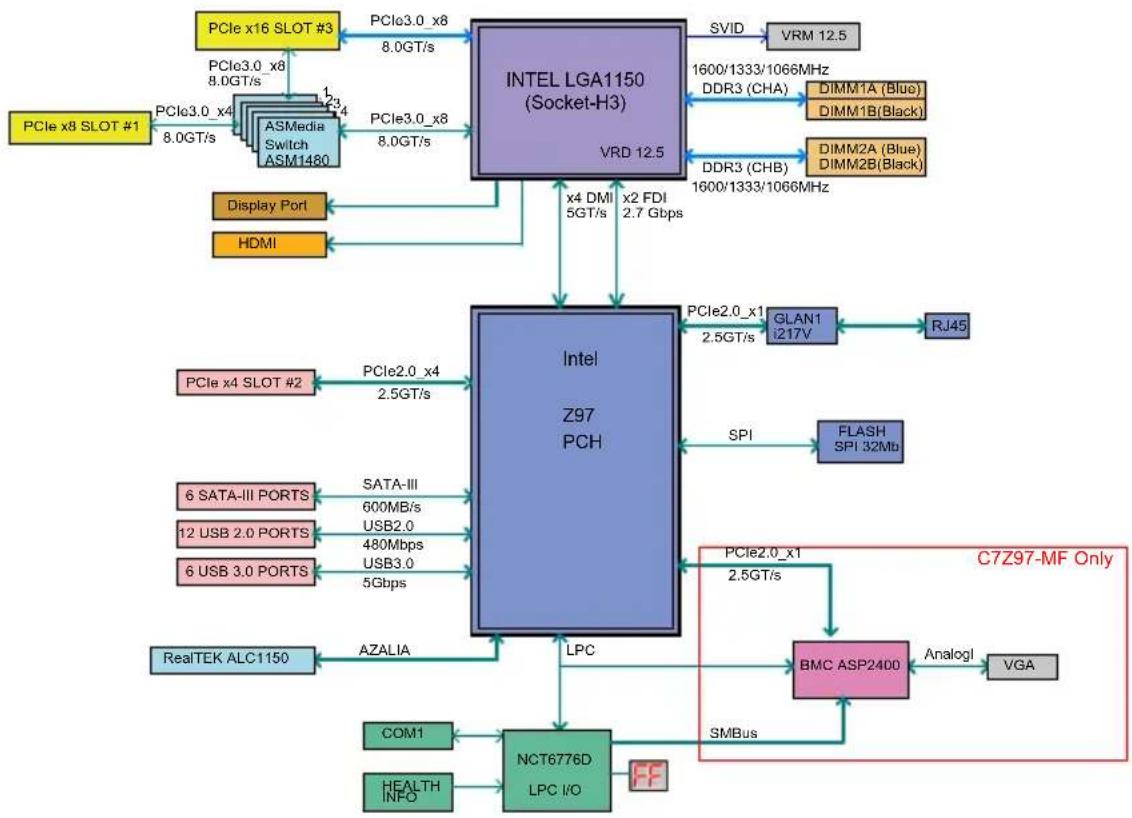
C7Z97-M/C7Z97-MF Block Diagram
flowchart
graph TD
    A["PCIe x16 SLOT #3"] -->|8.0GT/s| B["INTEL LGA1150 (Socket-H3)"]
    C["PCIe x8 SLOT #1"] -->|8.0GT/s| B
    D["ASMedia Switch ASM1480"] -->|8.0GT/s| B
    E["Display Port"] --> F["HDMI"]
    G["PCIe x4 SLOT #2"] -->|2.5GT/s| H["Intel Z97 PCH"]
    I["6 SATA-III PORTS"] -->|600MB/s| H
    J["12 USB 2.0 PORTS"] -->|480Mbps| H
    K["6 USB 3.0 PORTS"] -->|5Gbps| H
    L["RealTEK ALC1150"] -->|AZALIA| H
    M["COM1"] --> N["NCT6776D LPC I/O"]
    O["HEALTH INFO"] --> N
    P["SVID"] --> Q["VRM 12.5"]
    R["DDR3 (CHA)"] --> S["DIMM1A (Blue)"]
    R --> T["DIMM1B(Black)"]
    U["DDR3 (CHB)"] --> V["DIMM2A (Blue)"]
    U --> W["DIMM2B(Black)"]
    X["x4 DMI 5GT/s"] --> Y["x2 FDI 2.7 Gbps"]
    Z["x2 FDI 2.7 Gbps"] --> Y
    AA["PCIe2.0_x1 2.5GT/s"] --> AB["GLAN1 i217V"]
    AC["PCIe2.0_x1 2.5GT/s"] --> AD["FLASH SPI 32Mb"]
    AE["BMC ASP2400"] --> AF["Analogl"]
    AG["C7Z97-MF Only"] --> AH["VGA"]
    AI["SPI"] --> AJ["PCIe2.0_x1 2.5GT/s"]
    AK["SMBus"] --> AL["BMC ASP2400"]
    AM["PCIe3.0_x8 8.0GT/s"] --> AN["PCIe3.0_x8 8.0GT/s"]
    AO["PCIe3.0_x4 8.0GT/s"] --> AP["PCIe3.0_x4 8.0GT/s"]
System Block Diagram
Note: This is a general block diagram and may not exactly represent the features on your motherboard. See the Motherboard Features pages for the actual specifications of each motherboard.
Notes
Chapter 2
Installation
2-1 Installation Components and Tools Needed
Screws

natural_image
Four different types of threaded metal screws, shown in separate views (no text or symbols visible)Phillips-Head Screwdriver
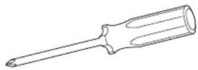
natural_image
Line drawing of a screwdriver with no text or symbolsIntel LGA 1150 Processor
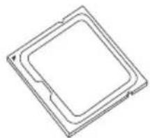
natural_image
Pure technical line drawing of a square component with no text or symbolsDDR3 DIMMs
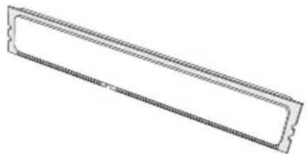
natural_image
Simple line drawing of a rectangular object with scalloped edges and textured fill (no text or symbols)PC Chassis
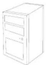
Heatsink with Fan
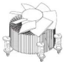
natural_image
3D rendering of a mechanical cooling fan with cooling fins and mounting base (no text or symbols)Power Supply
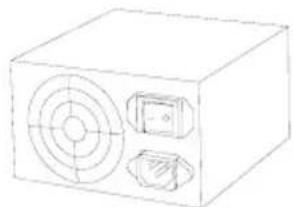
natural_image
Line drawing of a rectangular electronic device with a circular vent and two buttons (no text or symbols)Video Card (Optional)
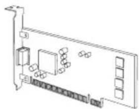
natural_image
Pure technical line drawing of a mechanical or electronic component with no text, numbers, or symbolsSATA/USB Optical Drive (Optional)
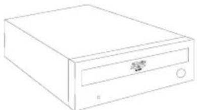
natural_image
Line drawing of a CD-ROM drive with a small internal component (no text or symbols)SATA Hard Disk Drive
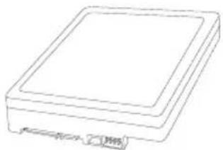
natural_image
Simple line drawing of a rectangular electronic device with a 35% label on the side (no text or symbols on the device itself)2-2 Static-Sensitive Devices
Electrostatic-Discharge (ESD) can damage electronic components. To avoid damaging your system board, it is important to handle it very carefully. The following measures are generally sufficient to protect your equipment from ESD.
Precautions
- Use a grounded wrist strap designed to prevent static discharge.
- Touch a grounded metal object before removing the board from the antistatic bag.
- Handle the board by its edges only; do not touch its components, peripheral chips, memory modules or gold contacts.
- When handling chips or modules, avoid touching their pins.
- Put the motherboard and peripherals back into their antistatic bags when not in use.
- For grounding purposes, make sure your computer chassis provides excellent conductivity between the power supply, the case, the mounting fasteners and the motherboard.
- Use only the correct type of onboard CMOS battery. Do not install the onboard battery upside down to avoid possible explosion.
Unpacking
The motherboard is shipped in antistatic packaging to avoid static damage. When unpacking the board, make sure that the person handling it is static protected.
2-3 Processor and Heatsink Installation

Attention! When handling the processor package, avoid placing direct pressure on the label area of the fan.

Important:
Always connect the power cord last, and always remove it before adding, removing or changing any hardware components. Make sure that you install the processor into the CPU socket before you install the CPU heatsink.
If you buy a CPU separately, make sure that you use an Intel-certified multi-directional heatsink only.
Make sure to install the system board into the chassis before you install the CPU heatsink.
When receiving a server board without a processor pre-installed, make sure that the plastic CPU socket cap is in place and none of the socket pins are bent; otherwise, contact your retailer immediately.
Refer to the Supermicro website for updates on CPU support.
Installing the LGA1150 Processor
- Press the load lever to release the load plate, which covers the CPU socket, from its locking position.
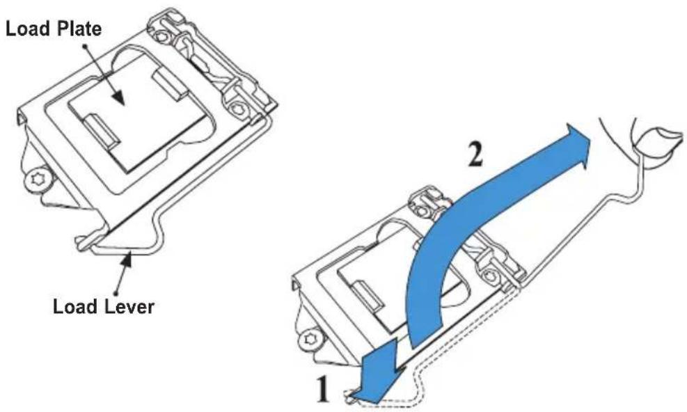
text_image
Load Plate Load Lever 1 2- Gently lift the load lever to open the load plate. Remove the plastic cap.
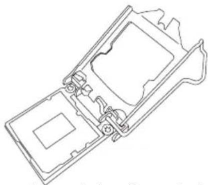
natural_image
Technical line drawing of a mechanical assembly with no visible text or symbols- Use your thumb and your index finger to hold the CPU at the North center edge and the South center edge of the CPU.
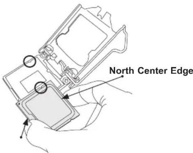
text_image
North Center EdgeSouth Center Edge
- Align the CPU key that is the semi-circle cutouts against the socket keys. Once it is aligned, carefully lower the CPU straight down into the socket. (Do not drop the CPU on the socket. Do not move the CPU horizontally or vertically.
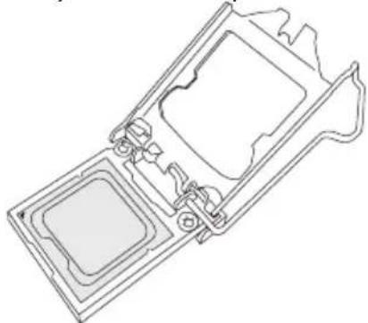
natural_image
Technical line drawing of a mechanical housing or enclosure with internal components (no text or symbols)- Do not rub the CPU against the surface or against any pins of the socket to avoid damaging the CPU or the socket.)
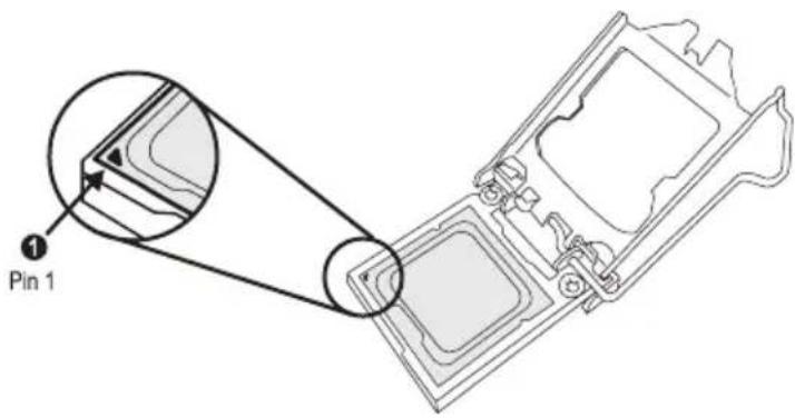
text_image
Pin 1-
With the CPU inside the socket, inspect the four corners of the CPU to make sure that the CPU is properly installed.
-
Use your thumb to gently push the load lever down to the lever lock.
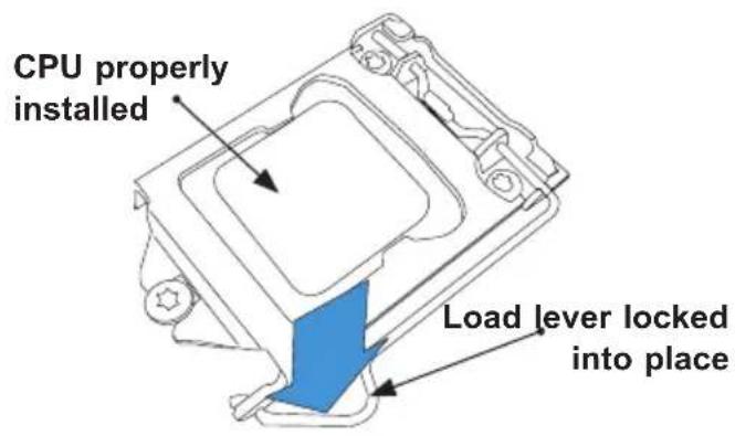
text_image
CPU properly installed Load lever locked into place! Attention! You can only install the CPU inside the socket only in one direction. Make sure that it is properly inserted into the CPU socket before closing the load plate. If it doesn't close properly, do not force it as it may damage your CPU. Instead, open the load plate again and double-check that the CPU is aligned properly.
Installing an Active CPU Heatsink with Fan
-
Locate the CPU Fan power connector on the motherboard. (Refer to the layout on the right for the CPU Fan location.)
-
Position the heatsink so that the heatsink fan wires are closest to the CPU fan power connector and are not interfered with other components.
-
Inspect the CPU Fan wires to make sure that the wires are routed through the bottom of the heatsink.
-
Remove the thin layer of the protective film from the heat-sink.
! Attention! CPU overheating may occur if the protective film is not removed from the heatsink.
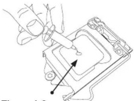
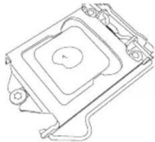
- Apply the proper amount of thermal grease on the CPU.
Note: if your heatsink came with a thermal pad, please ignore this step.
- If necessary, rearrange the wires to make sure that the wires are not pinched between the heatsink and the CPU. Also make sure to keep clearance
natural_image
Line drawing of a hand using a tool to adjust or install a device component (no text or symbols present)Thermal Grease
natural_image
Technical line drawing of a mechanical component with no visible text or symbols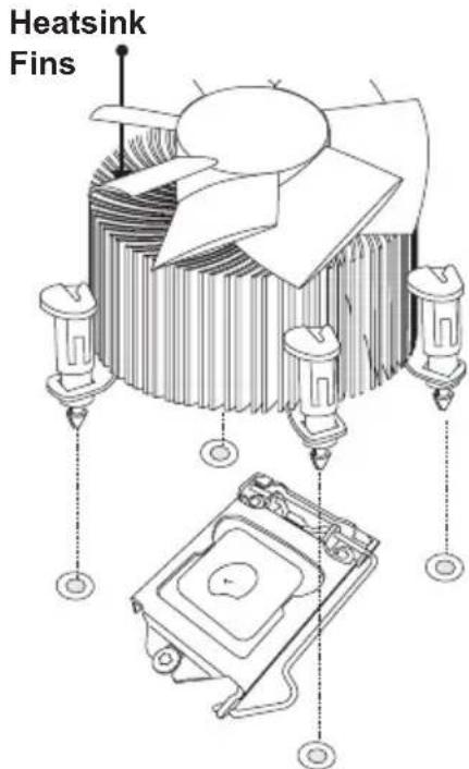
text_image
Heatsink FinsRecommended Supermicro heatsink: SNK-P0046A4 active heatsink
between the fan wires and the fins of the heatsink.
- Align the four heatsink fasteners with the mounting holes on the motherboard. Gently push the pairs of diagonal fasteners (#1 & #2, and #3 & #4) into the mounting holes until you hear a click. Also, make sure to orient each fastener so that the narrow end of the groove is pointing outward.
- Repeat Step 7 to insert all four heatsink fasteners into the mounting holes.
- Once all four fasteners are securely inserted into the mounting holes, and the heatsink is properly installed on the motherboard, connect the heatsink fan wires to the CPU Fan connector.
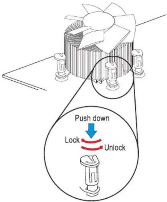
text_image
Push down Lock Unlock
natural_image
Line drawing of hands securing a cable with a clip (no text or symbols)Removing the Heatsink
! Attention! We do not recommend that the CPU or the heatsink be removed. However, if you do need to remove the heatsink, please follow the instructions below to remove the heatsink and to prevent damage done to the CPU or other components.
Active Heatsink Removal
- Unplug the power cord from the power supply.
- Disconnect the heatsink fan wires from the CPU fan header.
- Use your finger tips to gently press on the fastener cap and turn it counterclockwise to make a 1/4 (90°) turn, and pull the fastener upward to loosen it.
- Repeat Step 3 to loosen all fasteners from the mounting holes.
- With all fasteners loosened, remove the heatsink from the CPU.
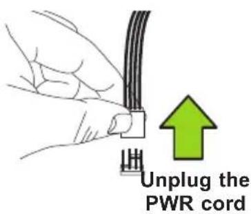
text_image
Unplug the PWR cord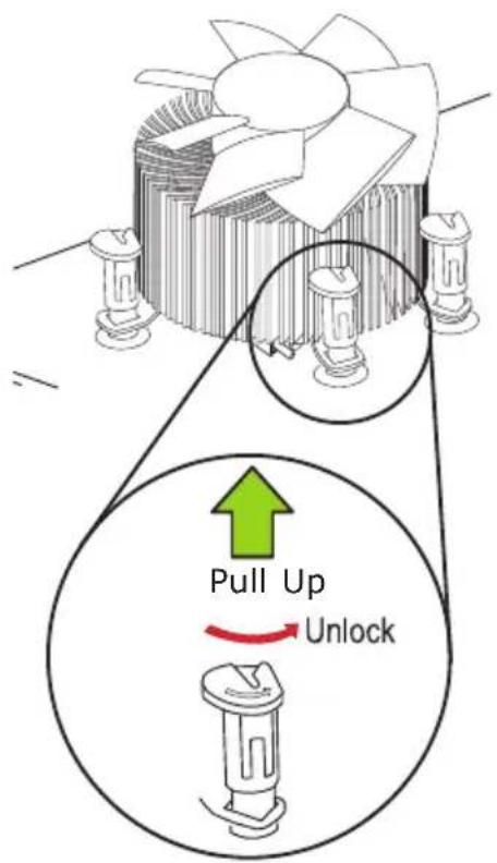
text_image
Pull Up Unlock2-4 Installing DDR3 Memory

Note: Check the Supermicro website for recommended memory modules.
! Attention! Exercise extreme care when installing or removing DIMM modules to prevent any possible damage.
DIMM Installation
- Insert the desired number of DIMMs into the memory slots, starting with DIMMA2 (see the next page for the location). For the system to work properly, please use the memory modules of the same type and speed in the same motherboard.
- Push the release tabs outwards on both ends of the DIMM slot to unlock it.
- Align the key of the DIMM module with the receptive point on the memory slot.
- Align the notches on both ends of the module against the receptive points on the ends of the slot.
- Use two thumbs together to press the notches on both ends of the module straight down into the slot until the module snaps into place.
- Press the release tabs to the lock positions to secure the DIMM module into the slot.
Removing Memory Modules
Reverse the steps above to remove the DIMM modules from the motherboard.
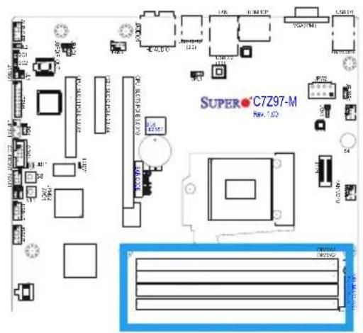
text_image
SUPER-C7Z97-M RWA 1.02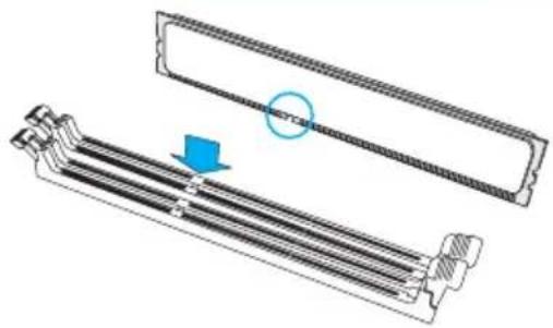
natural_image
Technical illustration of a mechanical component with a blue arrow indicating a specific section (no text or symbols present)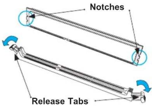
text_image
Notches Release Tabs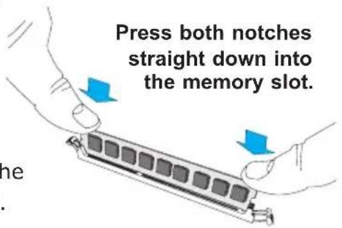
text_image
Press both notches straight down into the memory slot.Memory Support

Towards the CPU
DIMMA1
DIMMA2 (Red Slot)

natural_image
Pure electrical connector pinout diagram without any text or symbolsDIMMB1
DIMMB2 (Red Slot)

natural_image
Pure electrical connector pinout diagram without any text or symbols
Towards the edge of the motherboard
The C7Z97-M/MF supports up to 32GB of Unbuffered (UDIMM) DDR3 Non-ECC 1066\~3000(OC) MHz in 4 memory slots. Populating these DIMM modules with a pair of memory modules of the same type and same size will result in interleaved memory, which will improve memory performance. Please refer to the table below:
Memory Population Guidelines
Please follow the table below when populating the C7Z97-M/MF.
| DDR3 Unbuffered Non-ECC (UDIMM) Memory | ||||
| DIMM Slots per Channel | DIMMs Populated per Channel | DIMM Type POR | Speeds Ranks per DIM | MM (any combination) |
| 2 1 Unbuffered | DDR3 | 1066, 1333, 1600, 1866 | Single Rank, Dual Rank | |
| 2 2 Unbuffered | DDR3 | 1066, 1333, 1600, 1866 | Single Rank, Dual Rank | |

Notes
Be sure to use memory modules of the same type, same speed, same frequency on the same motherboard. Mixing of memory modules of different types and speeds is not allowed.
Due to memory allocation to system devices, the amount of memory that remains available for operational use will be re-
duced when 4 GB of RAM is used. The reduction in memory availability is disproportional. See the following table for details.
For Microsoft Windows users: Microsoft implemented a design change in the Windows XP with Service Pack 2 (SP2) and Windows Vista. This change is specific to the behavior of Physical Address Extension (PAE) mode which improves driver compatibility. For more information, please read the following article at Microsoft's Knowledge Base website at: http://support.microsoft.com/kb/888137.
| Possible System Memory Allocation & Availability | ||
| System Device Size Physical Memory | Remaining (-Available)(4 GB Total System Memory) | |
| Firmware Hub flash memory (System BIOS) 1 MB 3.99 | ||
| Local APIC 4 KB 3.99 | ||
| Area Reserved for the chipset 2 MB 3.99 | ||
| I/O APIC (4 Kbytes) 4 KB 3.99 | ||
| PCI Enumeration Area 1 256 MB 3.76 | ||
| PCI Express (256 MB) | 256 MB 3.51 | |
| PCI Enumeration Area 2 (if needed) -Aligned on 256-MB boundary- | 512 MB 3.01 | |
| VGA Memory | 16 MB | 2.85 |
| TSEG | 1 MB 2.84 | |
| Memory available to OS and other applications | 2.84 | |
Memory Population Guidelines
When installing memory modules, the DIMM slots should be populated in the following order: DIMMA2, DIMMB2, then DIMMA1, DIMMB1.
- Always use DDR3 DIMM modules of the same size, type and speed.
- Mixed DIMM speeds can be installed. However, all DIMMs will run at the speed of the slowest DIMM.
| Recommended Population (Balanced) | ||||
| DIMMA2 | DIMMB2 | DIMMA1 | DIMMB1 | Total System Memory |
| 2GB | 2GB | 4GB | ||
| 2GB | 2GB | 2GB | 2GB | 8GB |
| 4GB | 4GB | 8GB | ||
| 4GB | 4GB | 4GB | 4GB | 16GB |
| 8GB | 8GB | 16GB | ||
| 8GB | 8GB | 8GB | 8GB | 32GB |
2-5 Motherboard Installation
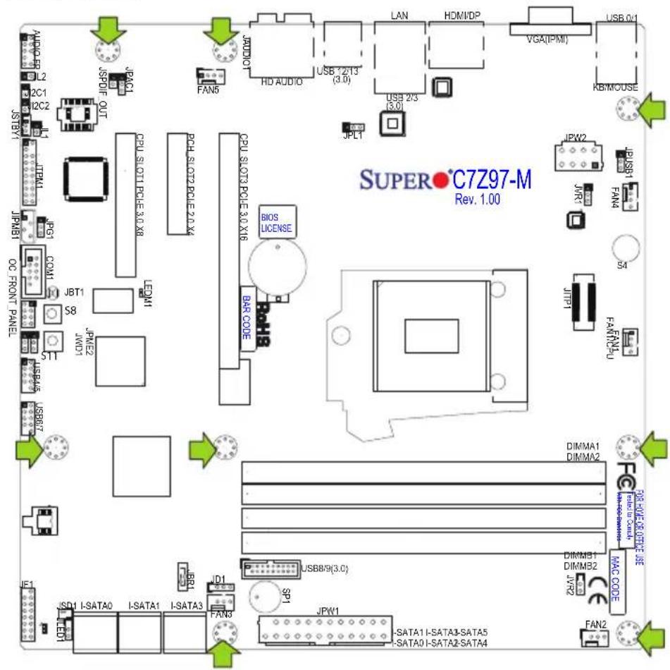
All motherboards have standard mounting holes to fit different types of chassis. Make sure that the locations of all the mounting holes for both motherboard and chassis match. Although a chassis may have both plastic and metal mounting fasteners, metal ones are highly recommended because they ground the motherboard to the chassis. Make sure that the metal standoffs click in or are screwed in tightly. Then use a screwdriver to secure the motherboard onto the motherboard tray.

Tools Needed
text_image
SUPER•C7Z97-M Rev. 1.00 JSPD1 L2 2C1 12C2 JSTBYI JTPM JPMB1 DC FRONT PANEL JPG COM1 JBT1 S8 STT JW01 JPM2 JSB015 JSB017 JSD1 I-SATA0 I-SATA1 I-SATA3 JBB1 JD1 FAN3 JPN1 CPU Slot1 PCIe 3.0 X8 PCH Slot2 PCIe 2.0 X4 LEMM1 CPU Slot3 PCIe 3.0 X16 BIOS LICENSE BAR CODE RAMB USB/9(3.0) SP1 JPW1 SATA1 I-SATA3-SATA5 SATA0 I-SATA2-SATA4 DIMMA1 DIMMA2 FAR-SUE OR CHASE USE MAC CODE DIMMB1 DIMMB2 JVR2 JPR1 FAN1 FAN1PU JPRW2 JWR1 JPLSB1 FAN4 S4 KB/MOUSE USB/01Location of Mounting Holes
! Attention! 1) To avoid damaging the motherboard and its components, please do not use a force greater than 8 lb/inch on each mounting screw during motherboard installation. 2) Some components are very close to the mounting holes. Please take precautionary measures to avoid damaging these components when installing the motherboard to the chassis.
Installing the Motherboard
- Install the I/O shield into the back of the chassis.
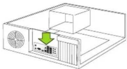
natural_image
Diagram of a computer setup with a monitor, tower, and ventilation unit (no text or symbols)-
Locate the mounting holes on the motherboard. (See the previous page.)
-
Locate the matching mounting holes on the chassis. Align the mounting holes on the motherboard against the mounting holes on the chassis.
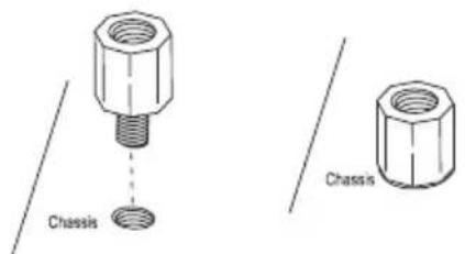
text_image
Chassis Chassis-
Install standoffs in the chassis as needed.
-
Install the motherboard into the chassis carefully to avoid damaging other motherboard components.
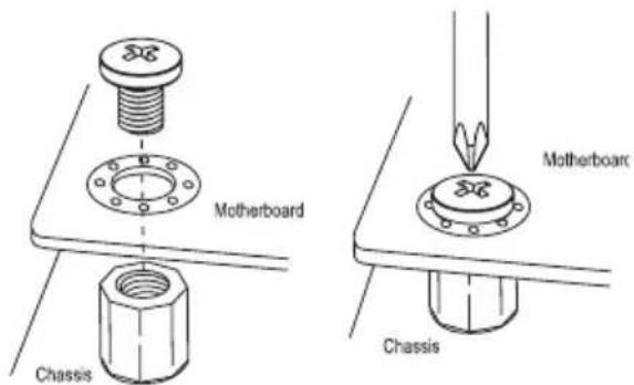
text_image
MOTHERBOARD Chassis MOTHERBOARD Chassis-
Using the Phillips screwdriver, insert a Phillips head #6 screw into a mounting hole on the motherboard and its matching mounting hole on the chassis.
-
Repeat Step 5 to insert #6 screws into all mounting holes.
-
Make sure that the motherboard is securely placed in the chassis.

Note: Images displayed are is for illustration only. Your chassis or components might look different from those shown in this manual.
2-6 Connectors/IO Ports
The I/O ports are color coded in conformance with the PC 99 specification. See the figure below for the colors and locations of the various I/O ports.
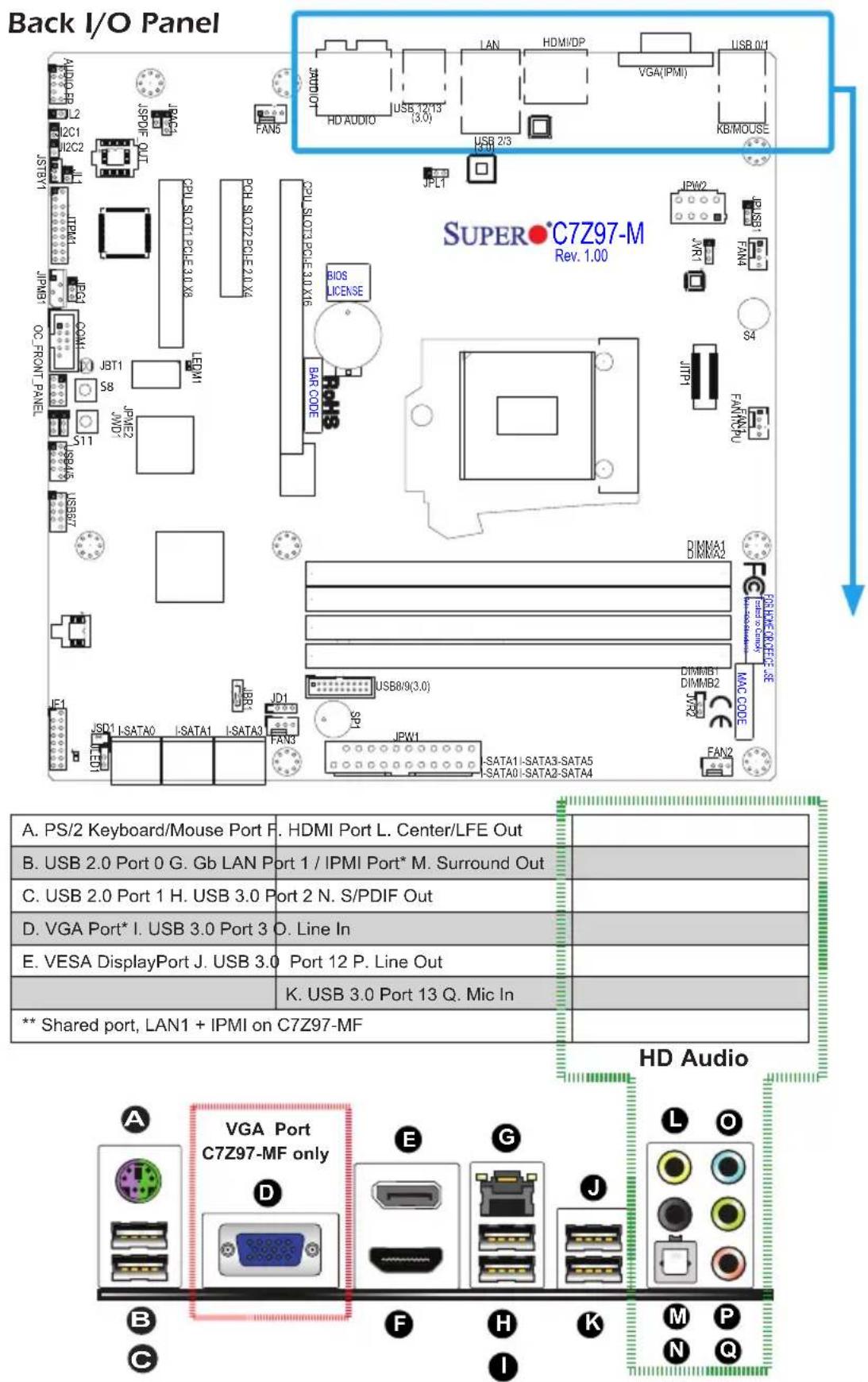
text_image
Back I/O Panel SUPER•C7Z97-M Rev. 1.00 A. PS/2 Keyboard/Mouse Port F. HDMI Port L. Center/LFE Out B. USB 2.0 Port 0 G. Gb LAN Port 1 / IPMI Port* M. Surround Out C. USB 2.0 Port 1 H. USB 3.0 Port 2 N. S/PDIF Out D. VGA Port* I. USB 3.0 Port 3 O. Line In E. VESA DisplayPort J. USB 3.0 Port 12 P. Line Out K. USB 3.0 Port 13 Q. Mic In ** Shared port, LAN1 + IPMI on C7Z97-MF HD Audio A VGA Port C7Z97-MF only B F H K M P C IUniversal Serial Bus (USB)
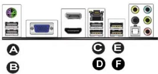
Two Universal Serial Bus 2.0 ports (0/1) and four USB 3.0 ports (2/3,12/13) are located on the I/O back panel. In addition, two USB 2.0 headers (four ports: 4/5, 6/7), and one USB 3.0 header (two ports: 14/15) are also located on the motherboard to provide front chassis access using USB cables (not included). See the tables below for pin definitions.
| Front Panel USB (2.0) Header #4/5, 6/7 Pin Definitions | |||
| Pin # Definition Pin # Definition | |||
| 1 +5V | 2 +5V | ||
| 3 USB_PN2 4 USB_PN3 | |||
| 5 USB_PP2 6 USB_PP3 | |||
| 7 Ground 8 Ground | |||
| 9 Key 10 Ground | |||
| Back Panel USB (2.0) #0/1, USB (3.0) #2/3, 12/13 Pin Definitions | |||
| Pin# Definition Pin# Definition | |||
| 1 +5V 5 +5V | |||
| 2 USB_PN1 6 USB_PNO | |||
| 3 USB_PP1 7 USB_PP0 | |||
| 4 Ground 8 Ground | |||
| Front Panel USB (3.0) Header #14/15Pin Definitions | |||
| Pin# Pin# Signal Name Description | |||
| 1 10 VBUS | Power | ||
| 2 11 D- | USB 2.0 Differential Pair | ||
| 3 12 D+ | |||
| 4 13 Ground | Ground of PWR Return | ||
| 5 14 StdA_SSRX- | SuperSpeed Receiver | ||
| 6 15 StdA_SSRX+ | Differential Pair | ||
| 7 16 GND_DRAIN | Ground for Signal Return | ||
| 8 17 StdA_SSTX- | SuperSpeed Transmitter | ||
| 9 18 StdA_SSTX+ | Differential Pair | ||
A. Backpanel USB 2.0 #0
B. Backpanel USB 2.0 #1
C. Backpanel USB 3.0 #2
D. Backpanel USB 3.0 #3
E. Backpanel USB 3.0 #12
F. Backpanel USB 3.0 #13
G. USB 2.0 Header #4/5
H. USB 2.0 Header #6/7
I. USB 3.0 Header #14/15
text_image
A B C E D F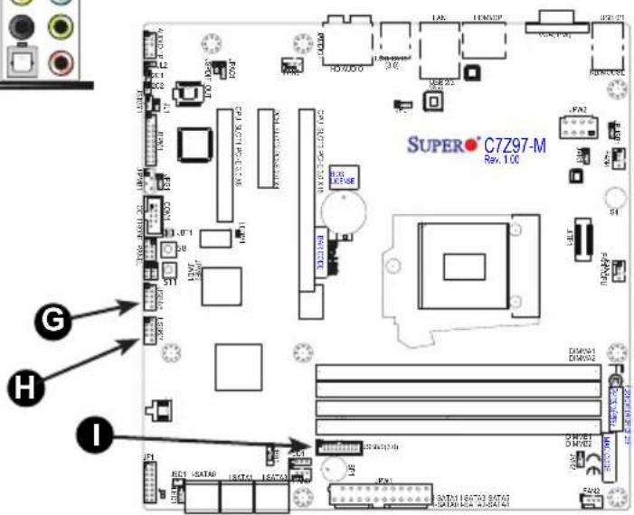
text_image
SUPER C7Z97-M Rev. 100 G H IEthernet / IPMI Port
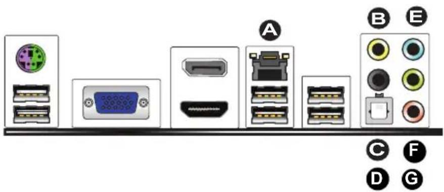
One Gigabit Ethernet ports (LAN1) is located next to the HD Audio Connector on the I/O Backpanel to provide network connections. These ports accept RJ45 type cables. On the C7Z97-MF, this is also the same port that supports the IPMI feature.
Note: Please refer to the LED Indicator Section for LAN LED information.
| LAN PortsPin Definition |
| Pin# Definition |
| 1 P2V5SB 10 SGND |
| 2 TD0+ 11 Act LED |
| 3 TD0- 12 P3V3SB |
| 4 TD1+ 13 Link 100 LED(Green, +3V3SB) |
| 5 TD1- 14 Link 1000 LED(Yellow, +3V3SB) |
| 6 TD2+ 15 Ground |
| 7 TD2- 16 Ground |
| 8 TD3+ 17 Ground |
| 9 TD3- 88 Ground |
(NC: No Connection)
Back Panel High Definition Audio (HD Audio)
This motherboard features a 7.1+2 Channel High Definition Audio (HDA) co-dec that provides 10 DAC channels. The HD Audio connections simultaneously supports multiple-streaming 7.1 sound playback with 2 channels of independent stereo output through the front panel stereo out for front, rear, center and subwoofer speakers. Use the Advanced software included in the CD-ROM with your motherboard to enable this function.
A. LAN1 / IPMI
B. Center/LFE Out
C. Surround Out
D. S/PDIF Out
E. Line In
F. Line Out
G. Mic In
text_image
Diagram showing various computer ports and connectors with labeled icons A through GHDMI Port
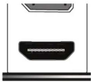
One HDMI (High-Definition Multimedia Interface) is located next to the VGA port on the I/O backpanel. This connector is used to display both high definition video and digital sound through an HDMI capable display, using a single HDMI cable (not included).
VGA Port
A VGA port is located next to the USB ports 0/1 on the I/O backpanel. Use this port to connect to a compatible VGA display.
natural_image
Simple diagram showing a device with a rectangular component and a horizontal bar, no text or symbols present.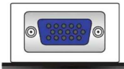
natural_image
Front view of a V12D audio jack (no text or symbols visible)VESA® DisplayPort™ (DP)
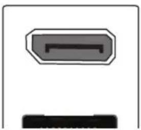
DisplayPort, developed by the VESA consortium, delivers digital display at a fast refresh rate. It can connect to virtually any display device using a DisplayPort adapter for devices such as VGA, DVI or HDMI.
natural_image
Simple diagram with a gray rectangular shape and a black horizontal bar at the bottom (no text or symbols)ATX PS/2 Keyboard/Mouse Port
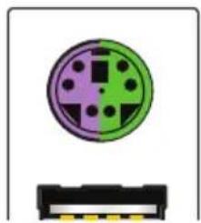
The ATX PS/2 keyboard / PS/2 mouse port is located above Back Panel USB Ports 0/1.
natural_image
Pure electrical connector pinout diagram without any text or symbolsA. HDMI Port
B. VGA Port
C. VESA DisplayPort
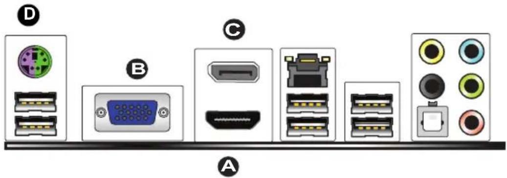
text_image
Diagram showing labeled electronic device ports and connectors, including USB, VGA, and various port designs.Front Control Panel
JF1 contains header pins for various buttons and indicators that are normally located on a control panel at the front of the chassis. These connectors are designed specifically for use with Supermicro chassis. See the figure below for the descriptions of the front control panel buttons and LED indicators. Refer to the following section for descriptions and pin definitions.
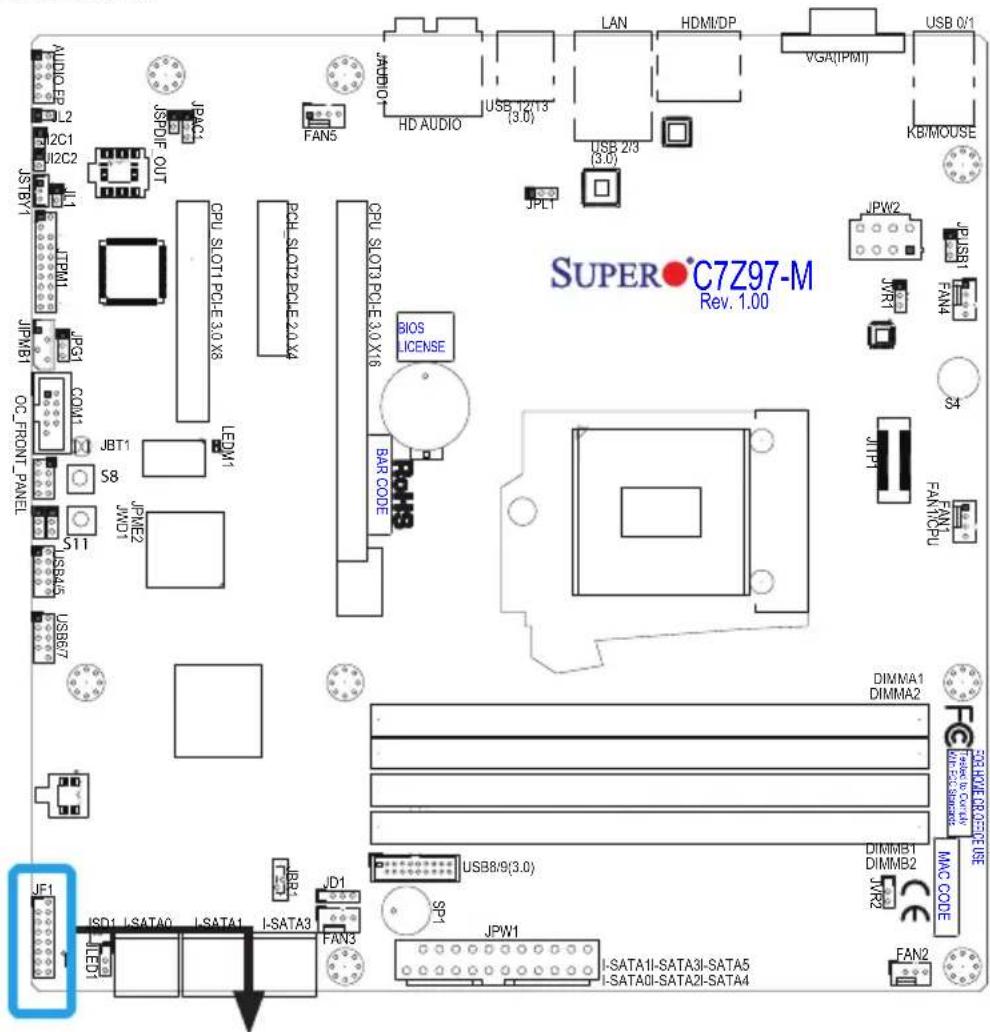
text_image
AUDIO L2 2C1 I2C2 JSTBY1 ITEM1 JPMB1 OC_FRONT PANEL JBT1 S8 S11 USB45 USB67 JF1 LED1 ISD1 I:SATA0 I:SATA1 I:SATA3 JD1 FAN3 JPN2 I:SATA1I:SATA3I:SATA5 I:SATA0I:SATA2I:SATA4 CPU SLOT1 PCLE 3.0 X8 PCB SLOT2 PCLE 2.0 X4 CPU SLOT3 PCLE 3.0 X16 BIOS LICENSE BAR CODE JPLT LAN HDMI/DP VGA(IPMI) KB/MOUSE SUPER C7Z97-M Rev. 1.00 DIMMA1 DIMMA2 DIMMB1 DIMMB2 JWR2 MAC CODE FAN2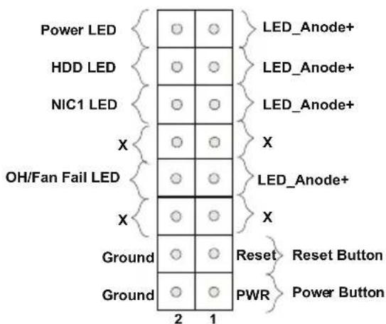
text_image
Power LED HDD LED NIC1 LED X OH/Fan Fail LED X Ground Ground 2 1 LED_Anode+ LED_Anode+ LED_Anode+ X LED_Anode+ X Reset Reset Button PWR Power Button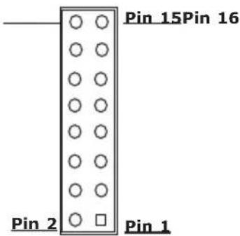
text_image
Pin 15Pin 16 Pin 2 Pin 1JF1 Header Pins
Front Control Panel Pin Definitions
Power LED
The Power LED connection is located on pins 15 and 16 of JF1. Refer to the table on the right for pin definitions.
HDD LED
The HDD LED connection is located on pins 13 and 14 of JF1. Attach a cable here to indicate the status of HDD-related activities, including IDE, SATA activities. See the table on the right for pin definitions.
NIC1 (LAN1)
The NIC (Network Interface Controller) LED connection for LAN port 1 is located on pins 11 and 12 of JF1. NIC1 LED is a 2-pin NIC LED header. Attach a NIC LED cable to the NIC1 indicator to display network activity. Refer to the table on the right for pin definitions.
Overheat (OH)/Fan Fail
Connect an LED cable to OH/Fan Fail connections on pins 7 and 8 of JF1 to provide warnings for chassis overheat/fan failure. Refer to the table on the right for pin definitions.
| Power LEDPin Definitions (JF1) | |
| Pin# | Definition |
| 15 +5V | |
| 16 Ground | |
| HDD LEDPin Definitions (JF1) | |
| Pin# | Definition |
| 13 +5V | |
| 14 HD | Active |
| LAN1 LEDPin Definitions (JF1) | |
| Pin# | Definition |
| 9/11 Vcc | |
| 10/12 Ground | |
| OH/Fan Fail LEDPin Definitions (JF1) | |
| Pin# | Definition |
| 7 Voc/Blue UID LED | |
| 8 OH/Fan Fail LED | |
| OH/Fan Fail Indicator Status | |
| State | Definition |
| Off Normal | |
| On Overheat | |
| Flashing | Fan Fail |
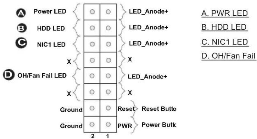
text_image
Power LED HDD LED NIC1 LED X OH/Fan Fail LED Ground Ground 2 1 LED_Anode+ LED_Anode+ LED_Anode+ X LED_Anode+ X Reset Reset Butto PWR Power Buttc A. PWR LED B. HDD LED C. NIC1 LED D. OH/Fan FailReset Button
The Reset Button connection is located on pins 3 and 4 of JF1. Attach it to a hardware reset switch on the computer case to reset the system. Refer to the table on the right for pin definitions.
Power Buttons
The Power Button connection is located on pins1 and 2 of JF1. Momentarily contacting both pins will power on/off the system. This button can also be configured to function as a suspend button (with a setting in the BIOS - see Chapter 4). To turn off the power in the suspend mode, press the button for at least 4 seconds. Refer to the table on the right for pin definitions. An on-board power button is also provided on the motherboard, shown below ©.
| Reset ButtonPin Definitions (JF1) | |
| Pin# | Definition |
| 3 Reset | |
| 4 Ground | |
| Power ButtonPin Definitions (JF1) | |
| Pin# | Definition |
| 1 Signal | |
| 2 +3V | Standby |
A. Reset Button
B. PWR Button
C. On Board Power Button
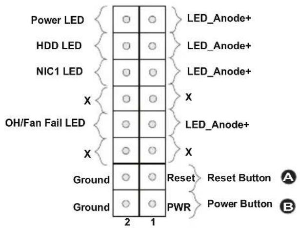
text_image
Power LED HDD LED NIC1 LED X OH/Fan Fail LED X Ground Ground 2 1 LED_Anode+ LED_Anode+ LED_Anode+ X LED_Anode+ X Reset Reset Button PWR Power Button A B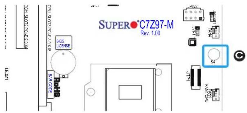
text_image
SUPER•C7Z97-M Rev. 1.00 CPU SLOT2 PCLE 2.0 X4 BIOS LICENSE BAR CODE JFWZ JWS1 JRT FANX S4 JITP1 FANYCDPU LEDM12-7 Connecting Cables
This section provides brief descriptions and pin-out definitions for on-board headers and connectors. Be sure to use the correct cable for each header or connector.
ATX Main PWR & CPU PWR Connectors (JPW1 & JPW2)
The 24-pin main power connector (JPW1) is used to provide power to the motherboard. The 8-pin CPU PWR connector (JPW2) is also required for the processor. These power connectors meet the SSI EPS 12V specification. See the table on the right for pin definitions.
| ATX Power 24-pin Connector Pin Definitions (JPW1) | |||
| Pin# | Definition | Pin # | Definition |
| 13 | +3.3V 1 +3.3V | ||
| 14 | -12V 2 +3.3V | ||
| 15 | COM 3 COM | ||
| 16 | PS_ON 4 +5V | ||
| 17 | COM 5 COM | ||
| 18 | COM 6 +5V | ||
| 19 | COM 7 COM | ||
| 20 | Res (NC) 8 PWR_OK | ||
| 21 | +5V 9 5VSB | ||
| 22 | +5V 10 +12V | ||
| 23 | +5V 11 +12V | ||
| 24 | COM 12 +3.3V | ||
| 12V 8-pin Power Connec-tor Pin Definitions | |
| Pins | Definition |
| 1 through 4 Ground | |
| 5 through 8 + | 2V |
(Required)
A. 24-Pin ATX Main PWR
B. 8-Pin PWR
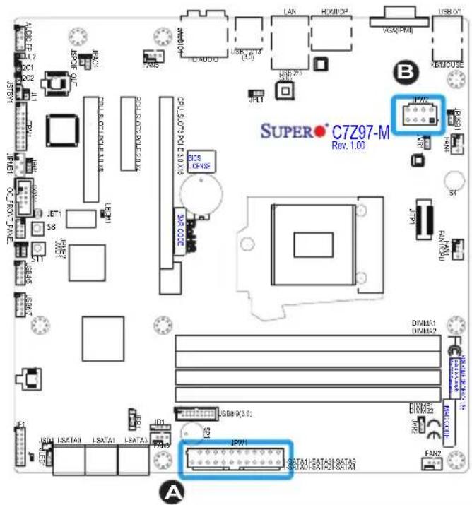
text_image
SUPER C7Z97-M Rev. 1.00Fan Headers (Fan 1 \~ Fan 5)
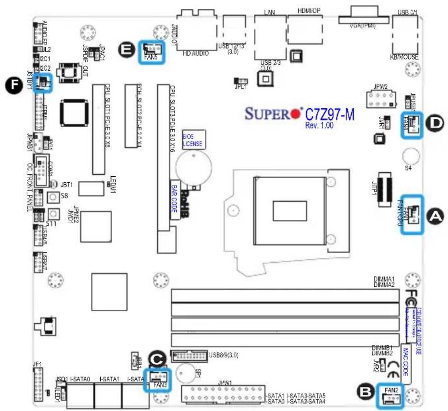
The C7Z97-M/MF has five fan headers (Fan 1\~Fan 5). These fans are 4-pin fan headers. Although pins 1-3 of the fan headers are backward compatible with the traditional 3-pin fans, we recommend the use 4-pin fans to take advantage of the fan speed control. This allows the fan speeds to be automatically adjusted based on the motherboard temperature. Refer to the table on the right for pin definitions.
Chassis Intrusion (JL1)
A Chassis Intrusion header is located at JL1 on the motherboard. Attach the appropriate cable from the chassis to inform you of a chassis intrusion when the chassis is opened.
| Fan HeaderPin Definitions | |
| Pin# | Definition |
| 1 | Ground (Black) |
| 2 | 2.5A/+12V(Red) |
| 3 | Tachometer |
| 4 | PWM_Control |
| Chassis Intrusion Pin Definitions (JL1) | |
| Pin# | Definition |
| 1 | Intrusion Input |
| 2 | Ground |
A. Fan 1 (CPU Fan)
B. Fan 2
C. Fan 3
D. Fan 4
E. Fan 5
F. Chassis Intrusion
text_image
SUPER C7Z97-M Rev. 1.00 A B C D E F J JPL JPL1 JPL2 JL2 JLC1 JLC2 JL3 JL4 JL5 JL6 JL7 JL8 JL9 JL10 JL11 JL12 JL13 JL14 JL15 JL16 JL17 JL18 JL19 JL20 JL21 JL22 JL23 JL24 JL25 JL26 JL27 JL28 JL29 JL30 JL31 JL32 JL33 JL34 JL35 JL36 JL37 JL38 JL39 JL40 JL41 JL42 JL43 JL44 JL45 JL46 JL47 JL48 JL49 JL50 JL51 JL52 JL53 JL54 JL55 JL56 JL57 JL58 JL59 JL60 JL61 JL62 JL63 JL64 JL65 JL66 JL67 JL68 JL69 JL70 JL71 JL72 JL73 JL74 JL75 JL76 JL77 JL78 JL79 JL80 JL81 JL82 JL83 JL84 JL85 JL86 JL87 JL88 JL89 JL90 JL91 JL92 JL93 JL94 JL95 JL96 JL97 JL98 JL99 JL100Internal Buzzer (SP1)
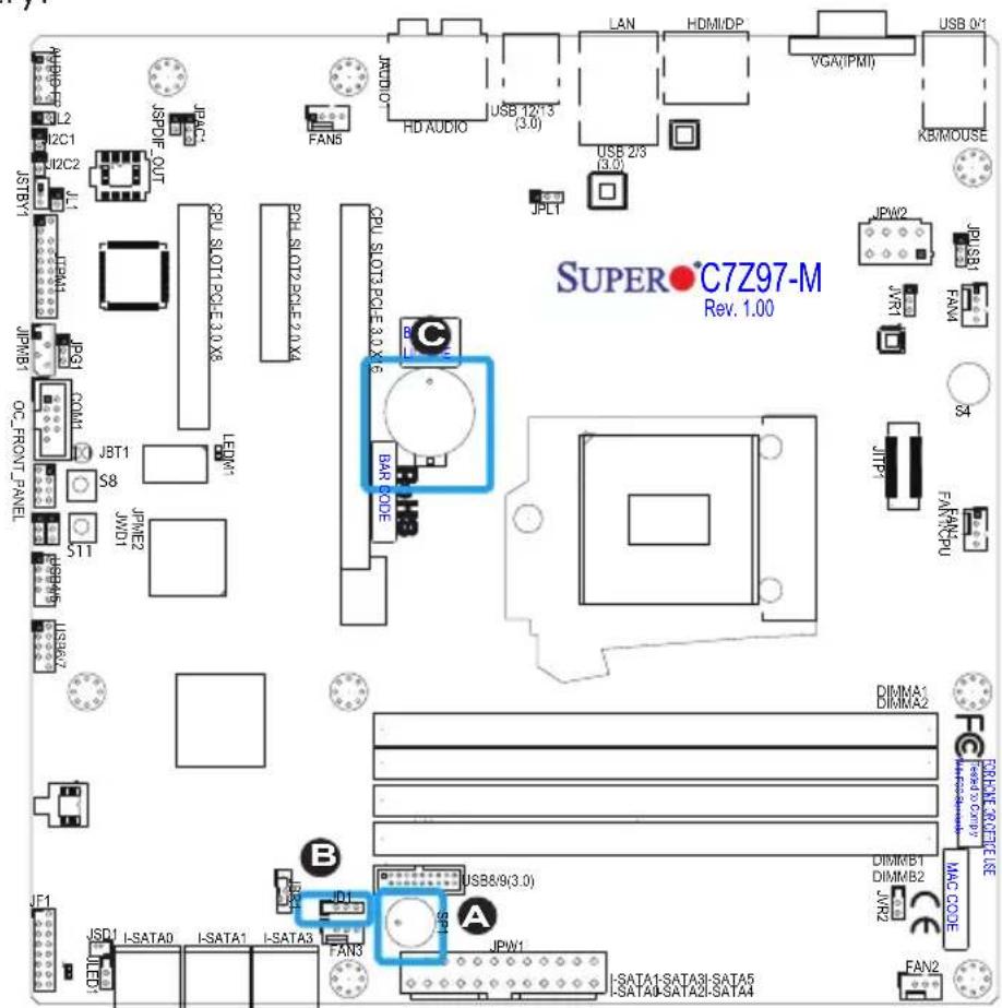
The Internal Buzzer (SP1) can be used to provide audible indications for various beep codes. See the table on the right for pin definitions.
| Internal BuzzerPin Definition | ||
| Pin# | Definitions | |
| Pin 1 Pos. (+) Beep | In | |
| Pin 2 Neg. (-) Alarm | Speaker | |
Speaker (JD1)
On the JD1 header, Pins 3\~4 are used for internal speaker. Close Pins 3\~4 with a cap to use the onboard speaker. If you wish to use an external speaker, close Pins 1\~4 with a cable. See the table on the right for pin definitions.
| Speaker ConnectorPin Definitions | |
| Pin Setting | Definition |
| Pins 3~4 Internal Speaker | |
| Pins1~4 External Speaker | |
System Backup Battery (BT1)
A system backup battery is provided on the motherboard. This provides backup power to the CMOS when the system is off. This is so the motherboard does not lose its setup configuration. See Chapter 3 for instructions on how to replace the battery.
A. Internal Buzzer
B. Speaker Header
C. Backup Battery
text_image
SUPER°C7Z97-M Rev. 1.00Onboard Power LED (JLED1)
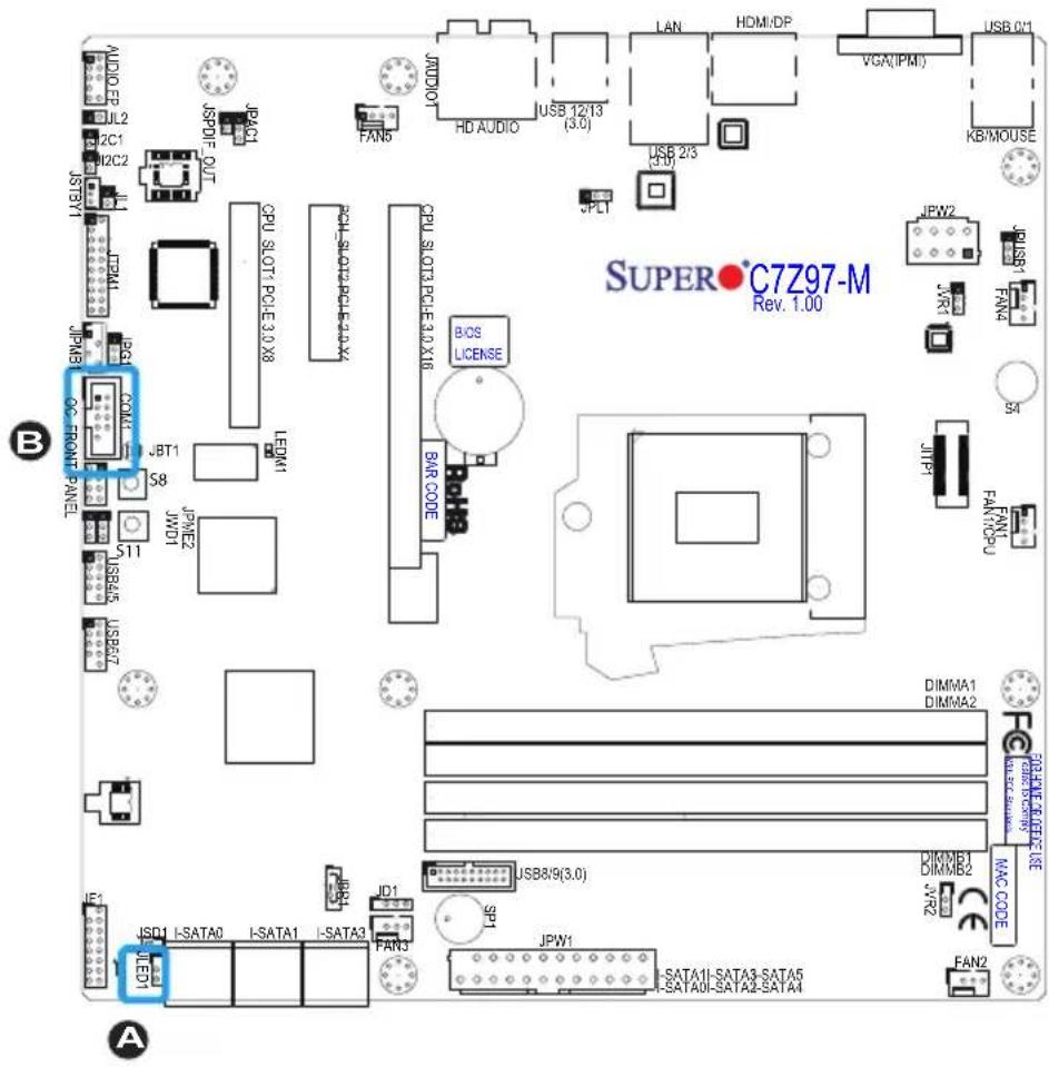
An onboard Power LED header is located at next to the SATA ports. This Power LED header is connected to Front Control Panel located at JF1 to indicate the status of system power. See the table on the right for pin definitions.
| Onboard PWR LEDPin Definitions | |
| Pin# | Definition |
| 1 VCC | |
| 2 No Connection | |
| 3 Connection to PWRLED in JF1 | |
Serial Port (COM1)
There is one serial (COM) port header on the motherboard. COM1 is located next to the JPIMB header. See the table on the right for pin definitions.
| Serial/COM PortsPin Definitions | ||
| Pin # | Definition Pin # | Definition |
| 1 DCD 6 DSR | ||
| 2 RXD 7 RTS | ||
| 3 TXD 8 CTS | ||
| 4 DTR 9 RI | ||
| 5 Ground 10 N/A | ||
A. PWR LED
B. COM1
text_image
SUPER•C7Z97-M Rev. 1.00 B A S&P5000 JCP1 JCP2 JCP3 JCP4 JCP5 JCP6 JCP7 JCP8 JCP9 JCP10 JCP11 JCP12 JCP13 JCP14 JCP15 JCP16 JCP17 JCP18 JCP19 JCP20 JCP21 JCP22 JCP23 JCP24 JCP25 JCP26 JCP27 JCP28 JCP29 JCP30 JCP31 JCP32 JCP33 JCP34 JCP35 JCP36 JCP37 JCP38 JCP39 JCP40 JCP41 JCP42 JCP43 JCP44 JCP45 JCP46 JCP47 JCP48 JCP49 JCP50 JCP51 JCP52 JCP53 JCP54 JCP55 JCP56 JCP57 JCP58 JCP59 JCP60 JCP61 JCP62 JCP63 JCP64 JCP65 JCP66 JCP67 JCP68 JCP69 JCP70 JCP71 JCP72 JCP73 JCP74 JCP75 JCP76 JCP77 JCP78 JCP79 JCP80 JCP81 JCP82 JCP83 JCP84 JCP85 JCP86 JCP87 JCP88 JCP89 JCP90 JCP91 JCP92 JCP93 JCP94 JCP95 JCP96 JCP97 JCP98 JCP99 JCP100DOM PWR Connector (JSD1)
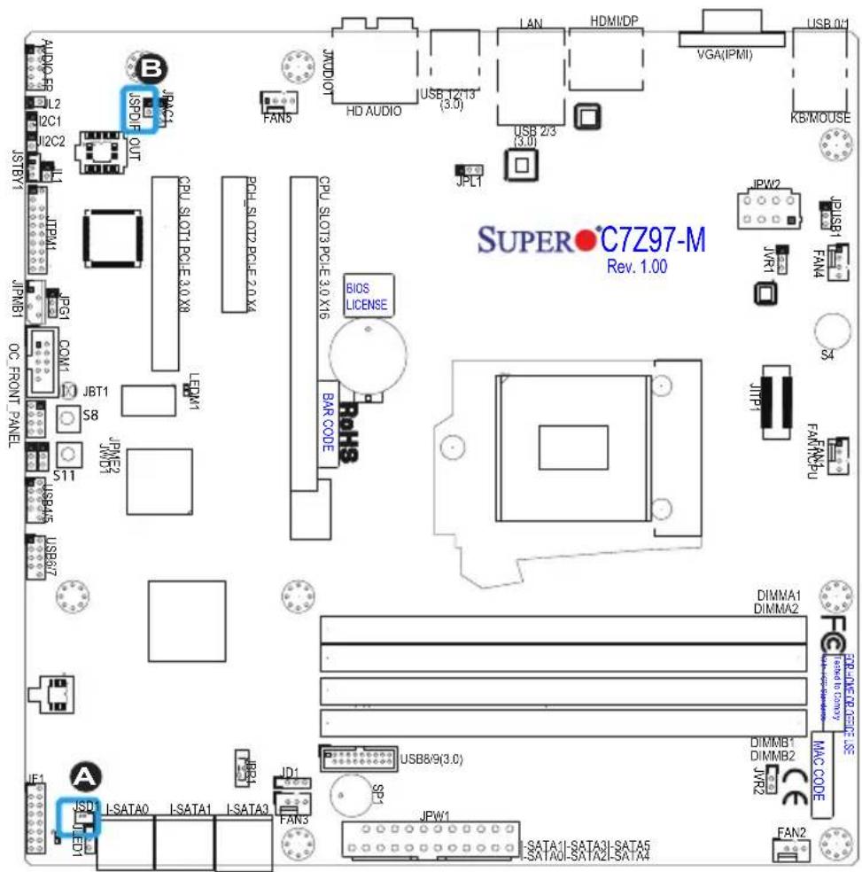
The Disk-On-Module (DOM) power connector, located next to the SATA ports, provides 5V (Gen1/Gen) power to a solid state DOM storage device connected to one of the SATA ports. See the table on the right for pin definitions.
| DOM PWRPin Definitions | |
| Pin# | Definition |
| 1 | 5V |
| 2 Ground | |
| 3 Ground | |
SPDIF OUT (JSPDIF\_OUT)
The SPDIF Out (JSPDIF_OUT) is used for digital audio output. You will also need the appropriate cable to use these features.
| SPDIF_OUTPin Definitions | |
| Pin# | Definition |
| 1 | S/PDIF_Out |
| 2 | Ground |
A.DOM PWR
B. S/PDIF OUT
text_image
SUPER C7Z97-M Rev. 1.00 S&P500 JW21 JW21 JW21 JW21 JW21 JW21 JW21 JW21 JW21 JW21 JW21 JW21 JW21 JW21 JW21 JW21 JW21 JW21 JW21 JW21 JW24 JW24 JW24 JW24 JW24 JW24 JW24 JW24 JW24 JW24 JW24 JW24 JW24 JW24 JW24 JW24 JW24 JW24 JW24 JW24 JW26 JW26 JW26 JW26 JW26 JW26 JW26 JW26 JW26 JW26 JW26 JW26 JW26 JW26 JW26 JW26 JW26 JW26 JW26 JW26 JW28/9(3.0) USB8/9(3.0) USB8/9(3.0) USB8/9(3.0) USB8/9(3.0) USB8/9(3.0) USB8/9(3.0) USB8/9(3.0) USB8/9(3.0) USB8/9(3.0) USB8/9(3.0) USB8/9(3.0) USBA1 DIMMA1 DIMMA1 DIMMA1 DIMMA1 DIMMA1 DIMMA1 DIMMA1 DIMMA1 DIMMA1 DIMMA1 DIMMA1 DIMMA1 DIMMA1 DIMMA1 DIMMA1 DIMMA1 DIMMA1 DIMMA1 DIMMA1 DIMMA1 DIMMA1 DIMMA1 DIMMA1 DIMMA1 DIMMA1 DIMMSB1 DIMMB1 DIMMB1 DIMMB1 DIMMB1 DIMMB1 DIMMB1 DIMMB1 DIMMB1 DIMMB1 DIMMB1 DIMMB1 DIMMB1 DIMMB1 DIMMB1 DIMMB1 DIMMB1 DIMMB1 DIMMB1 DIMMB1 DIMMB1 DIMMB1 DIMMB1 DIMMB1 DIMMB1 DIMMB1 DIMMSB2 DIMMSB2 DIMMSB2 DIMMSB2 DIMMSB2 DIMMSB2 DIMMSB2 DIMMSB2 DIMMSB2 DIMMSB2 DIMMSB2 DIMMSB2 DIMMSB2 DIMMSB2 DIMMSB2Standby Power Header (STBY1)
The Standby Power header is located at STBY1 on the motherboard. See the table on the right for pin definitions.
| Standby Power Pin Definitions | |
| Pin# | Definition |
| 1 +5V | Standby |
| 2 Ground | |
| 3 Wake-up | |
TPM Header/Port 80 Header
A Trusted Platform Module/Port 80 header is located at JTPM1 to provide TPM support and Port 80 connection. Use this header to enhance system performance and data security. See the table on the right for pin definitions.
| TPM/Port 80 HeaderPin Definitions | |
| Pin # Definition Pin # Definition | |
| 1 LCLK 2 GND | |
| 3 LFRAME# 4 < (KEY)> | |
| 5 LRESET# 6 +5V (X) | |
| 7 LAD 3 8 LAD 2 | |
| 9 +3.3V 10 LAD1 | |
| 11 LAD0 12 GND | |
| 13 SMB_CLK4 14 SMB_DAT4 | |
| 15 +3V_DUAL 16 SERIRQ | |
| 17 GND 18 CLKRUN# (X) | |
| 19 LPCPD# 20 LDRQ# (X) | |
A. STBY PWR
B. TPM Header
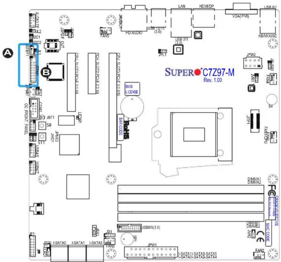
text_image
SUPER•C7Z97-M Rev. 1.00 A B C7Z97-M REV. 1.00 JPL1 JPL2 JL2C1 JL2C2 JST JSTVY JPM1 JPM1 JPM1 JPM1 JPM1 JPM1 JPM1 JPM1 JPM1 JPM1 JPM1 JPM1 JPM1 JPM1 JPM1 JPM1 JPM1 JPM1 JPM1 JPM1 JPM1 JPM1 JPM1 JPM1 JPM1 JPM2 JPM2 JPM2 JPM2 JPM2 JPM2 JPM2 JPM2 JPM2 JPM2 JPM2 JPM2 JPM2 JPM2 JPM2 JPM2 JPM2 JPM2 JPM2 JPM2 JPM2 JPM2 JPM2 JPM2 JPM2 JPM1 JPM1 JPM1 JPM1 JPM1 JPM1 JPM1 JPM1 JPM1 JPM1 JPM1 JPM1 JPM1 JPM1 JPM1 JPM1 JPM1 JPM1 JPM1 JPM1 JPM1 JPM1 JPM1 JPM1 JPM3 JPM3 JPM3 JPM3 JPM3 JPM3 JPM3 JPM3 JPM3 JPM3 JPM3 JPM3 JPM3 JPM3 JPM3 JPM3 JPM3 JPM3 JPM3 JPM3 JPM3 JPM3 JPM3 JPM3 JPM3 JPM4 JPM4 JPM4 JPM4 JPM4 JPM4 JPM4 JPM4 JPM4 JPM4 JPM4 JPM4 JPM4 JPM4 JPM4 JPM4 JPM4 JPM4 JPM4 JPM4 JPM4 JPM4 JPM4 JPM4 JPM4 JPM5 JPM5 JPM5 JPM5 JPM5 JPM5 JPM5 JPM5 JPM5 JPM5 JPM5 JPM5 JPM5 JPM5 JPM5 JPM5 JPM5 JPM5 JPM5 JPM5 JPM5 JPM5 JPM5 JPM5 JPM5 JPM6 JPM6 JPM6 JPM6 JPM6 JPM6 JPM6 JPM6 JPM6 JPM6 JPM6 JPM6 JPM6 JPM6 JPM6 JPM6 JPM6 jpm# jpm# jpm# jpm# jpm# jpm# jpm# jpm# jpm# jpm# jpm# jpm# jpm# jpm# jpm# jpm# jpm# jpm# jpm# jpm# jpm# jpm# jpm# jpm# jpm# jpm# jpm# jpm# jpm# jpm# jpm# jpm# jpm# jpm# kBA/Mouse/ KB/Mouse/ HD AUDIO/USB 2.2.13* USB 2.3* USB 2.3* USB 2.3* USB 2.3* USB 2.3* USB 2.3* USB 2.3* USB 2.3* USB 2.3* USB 2.3* USB 2.3* USB 2.3* USB 2.3* USB 2.3* USB 2.3* USB 2.3* USB 2.3* USB C7Z97-MFront Panel Audio Header (AUDIO FP)
A 10-pin Audio header is supported on the motherboard. This header allows you to connect the motherboard to a front panel audio control panet, if needed. Connect an audio cable to the audio header to use this feature (not supplied). See the table at right for pin definitions for the header.
OC Front Panel (OC FRONT PANEL)
This header is for the Over-Clocking (OC) control panel, which is optional with the motherboard. If available, attach the control panel's cable to this header. The OC control panel enables over-clocking control and management from the front of the chassis.
| 10-in Audio Pin Definitions | |
| Pin# | Signal |
| 1 | Microphone_Left |
| 2 | Audio_Ground |
| 3 | Microphone_Right |
| 4 | Audio_Detect |
| 5 | Line_2_Right |
| 6 | Ground |
| 7 | Jack_Detect |
| 8 | Key |
| 9 | Line_2_Left |
| 10 | Ground |
A. AUDIO FP
B. OC FRONT PANEL
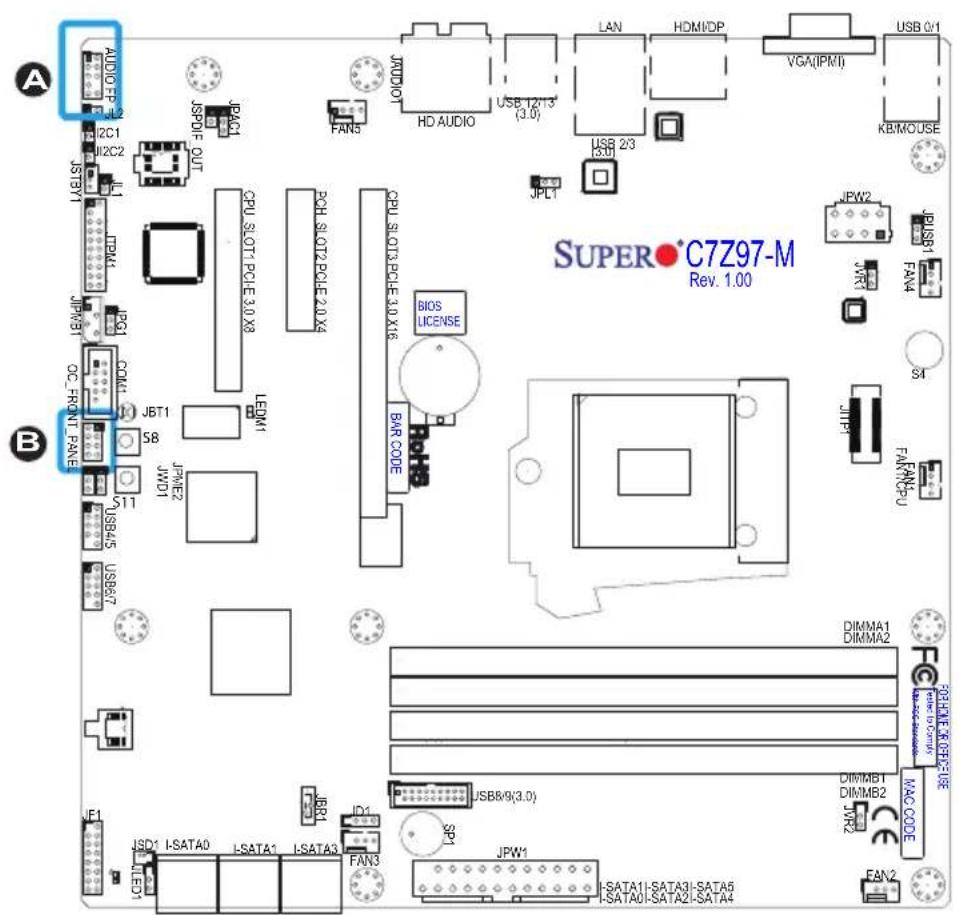
text_image
A AUDIO FP 12 JC1 JSTV1 JPW1 IC PCM1 JPM1 JPM8 OC_FRONT_PANE JBT1 5B JW01 511 USB45 USB67 JF1 LED1 JSD1 I-SATA0 I-SATA1 I-SATA3 JSPDIF OUT JPA0 FAN5 CPU 3.0T1.POLE 3.0 X8 LEDM1 JPM2 JPM2 JPM1 JPM1.POLY JSP1 JSP1.POLY JPM1.POLY JPM1.POLY JPM1.POLY JPM1.POLY JPM1.POLY JPM1.POLY JPM1.POLY JPM1.POLY JPM1.POLY JPM1.POLY JPM1.POLY JPM1.POLY JPM1.POLY JPM1.POLY JPM1.MONITOR JPM1.MONITOR JPM1.MONITOR JPM1.MONITOR JPM1.MONITOR JPM1.MONITOR JPM1.MONITOR JPM1.MONITOR JPM1.MONITOR JPM1.MONITOR JPM1.MONITOR JPM1.MONITOR JPM1.MONITOR JPM1.MONITOR JPM1.MONITOR SPT JPLI CPU 3.0T2.POLE 2.0 X8 CPU 3.0T3.POLE 3.0 X16 BIOS LICENSE BAR CODE S4 S4I JUPW2 JUPW2.POLY JUPW2.POLY JUPW2.POLY JUPW2.POLY JUPW2.POLY JUPW2.POLY JUPW2.POLY JUPW2.POLY JUPW2.POLY JUPW2.POLY JUPW2.POLY SUPER•C7Z97-M Rev. 1.002-8 Jumper Settings
Explanation of Jumpers
To modify the operation of the motherboard, jumpers can be used to choose between optional settings. Jumpers create shorts between two pins to change the function of the connector. Pin 1 is identified with a square solder pad on the printed circuit board.
Note: On two pin jumpers, "Closed" means the jumper is on, and "Open" means the jumper is off the pins.
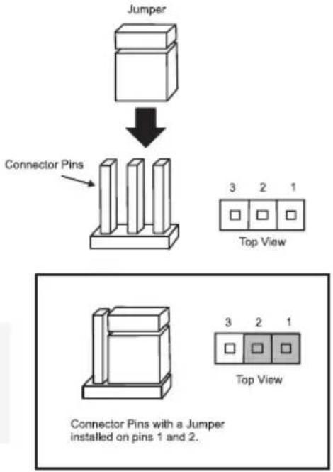
flowchart
graph TD
    A["Jumper"] --> B["Connector Pins"]
    B --> C["3 2 1 Top View"]
    B --> D["3 2 1 Top View"]
    style A fill:#f9f,stroke:#333
    style B fill:#ccf,stroke:#333
    style C fill:#cfc,stroke:#333
    style D fill:#fcc,stroke:#333
LAN1 Enable/Disable (JPL1)
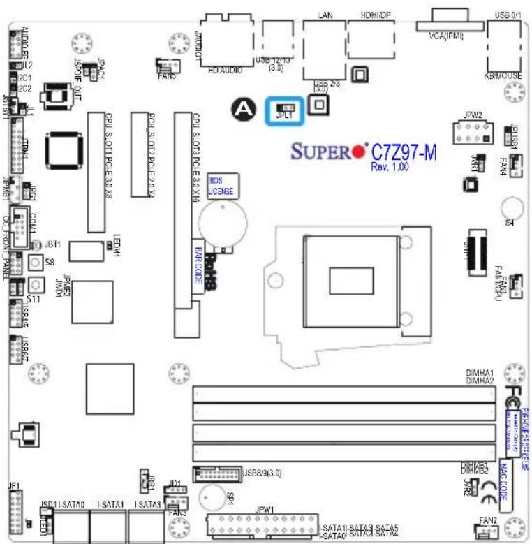
Jumper JPL1 enables or disables LAN port 1 on the motherboard. See the table on the right for jumper settings. The default setting is enabled.
| GLAN EnableJumper Settings | |
| Pin# | Definition |
| 1-2 | Enabled (default) |
| 2-3 | Disabled |
A. JPL1: LAN1 Enable
text_image
AUDIO 12 DC1 2C2 JCPB1 JCPB2 JCPB3 JCPB4 JCPB5 JCPB6 JCPB7 JCPB8 JCPB9 JCPB10 JCPB11 JCPB12 JCPB13 JCPB14 JCPB15 JCPB16 JCPB17 JCPB18 JCPB19 JCPB20 JCPB21 JCPB22 JCPB23 JCPB24 JCPB25 JCPB26 JCPB27 JCPB28 JCPB29 JCPB30 JCPB31 JCPB32 JCPB33 JCPB34 JCPB35 JCPB36 JCPB37 JCPB38 JCPB39 JCPB40 JCPB41 JCPB42 JCPB43 JCPB44 JCPB45 JCPB46 JCPB47 JCPB48 JCPB49 JCPB50 JCPB51 JCPB52 JCPB53 JCPB54 JCPB55 JCPB56 JCPB57 JCPB58 JCPB59 JCPB60 JCPB61 JCPB62 JCPB63 JCPB64 JCPB65 JCPB66 JCPB67 JCPB68 JCPB69 JCPB70 JCPB71 JCPB72 JCPB73 JCPB74 JCPB75 JCPB76 JCPB77 JCPB78 JCPB79 JCPB80 JCPB81 JCPB82 JCPB83 JCPB84 JCPB85 JCPB86 JCPB87 JCPB88 JCPB89 JCPB90 JCPB91 JCPB92 JCPB93 JCPB94 JCPB95 JCPB96 JCPB97 JCPB98 JCPB99 JCPB100 S&P 11:SATA0 I:SATA1 I:SATA3 ID1 ID2 ID3 ID4 ID5 ID6 ID7 ID8 ID9 ID10 ID21 ID3 ID4 ID5 ID6 ID7 ID8 ID9 ID10 ID21 ID3 ID4 ID5 ID6 ID7 ID8 ID9 ID10 ID21 ID3 ID4 ID5 ID6 ID7 ID8 ID9 ID10 ID21 ID3 ID4 ID5 ID6Clear CMOS (JBT1), (S8)
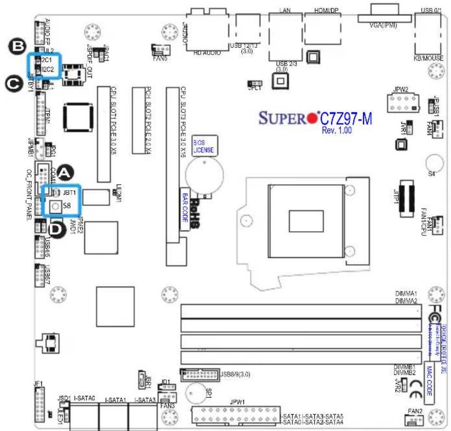
JBT1 and the S8 Button is used to clear the saved system setup configuration stored in the CMOS chip. For JBT1, to clear the contents of the CMOS, completely shut down the system, remove the AC power cord and then short JBT1 with a metallic object such as a screwdriver. For the S8 Button, shut off the system and press this button.
Any of these two will erase all user settings and revert everything to their factory-set defaults.

Note: On the C7Z97-MF, the boot time immediately after clearing the CMOS may take longer due to additional IPMI functions.
PCI Slot SMB Enable (I²C1/I²C2)
Use Jumpers I²C1/I²C2 to enable PCI SMB (System Management Bus) support to improve system management for the PCI slots. See the table on the right for jumper settings.
| PCI Slot_SMB EnableJumper Settings | |
| Jumper Setting | Definition |
| Short Enabled | |
| Open (Default) Disabled | |
A. Clear CMOS
B. JI2C1
C. JI2C2
D. Clear CMOS Button
text_image
SUPER•C7Z97-M Rev. 1.00 B C A JBT1 S8 JPW2 JPT JPTM1 JPTM2 JPTM3 JPTM4 JPTM5 JPTM6 JPTM7 JPTM8 JPTM9 JPTM10 JPTM11 JPTM12 JPTM13 JPTM14 JPTM15 JPTM16 JPTM17 JPTM18 JPTM19 JPTM20 JPTM21 JPTM22 JPTM23 JPTM24 JPTM25 JPTM26 JPTM27 JPTM28 JPTM29 JPTM30 JPTM31 JPTM32 JPTM33 JPTM34 JPTM35 JPTM36 JPTM37 JPTM38 JPTM39 JPTM40 JPTM41 JPTM42 JPTM43 JPTM44 JPTM45 JPTM46 JPTM47 JPTM48 JPTM49 JPTM50 JPTM51 JPTM52 JPTM53 JPTM54 JPTM55 JPTM56 JPTM57 JPTM58 JPTM59 JPTM60 JPTM61 JPTM62 JPTM63 JPTM64 JPTM65 JPTM66 JPTM67 JPTM68 JPTM69 JPTM70 JPTM71 JPTM72 JPTM73 JPTM74 JPTM75 JPTM76 JPTM77 JPTM78 JPTM79 JPTM80 JPTM81 JPTM82 JPTM83 JPTM84 JPTM85 JPTM86 JPTM87 JPTM88 JPTM89 JPTM90 JPTM91 JPTM92 JPTM93 JPTM94 JPTM95 JPTM96 JPTM97 JPTM98 JPTM99 JPTM100Audio Enable (JPAC1)
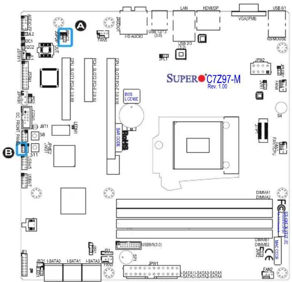
JPAC1 allows you to enable or disable the onboard audio support. The default position is on pins 1 and 2 to enable onboard audio connections. See the table on the right for jumper settings.
| Audio Enable/Disable Jumper Settings | |
| Both Jumpers | Definition |
| Pins 1-2 Enabled | |
| Pins 2-3 Disabled | |
Watch Dog Enable/Disable (JWD1)
Watch Dog (JWD1) is a system monitor that can reboot the system when a software application hangs. Close Pins 1-2 to reset the system if an application hangs. Close Pins 2-3 to generate a non-maskable interrupt signal for the application that hangs. See the table on the right for jumper settings. Watch Dog must also be enabled in the BIOS.
| Watch DogJumper Settings | |
| Jumper Setting | Definition |
| Pins 1-2 Reset (default) | |
| Pins 2-3 NM | |
| Open Disabled | |
A. Audio Enable
B. Watch Dog Enable
text_image
AUDIO JUL2 I2C1 I2C2 JSTBY1 JSP1 JCP1 JCP1 JCP1 JCP1 JCP1 JCP1 JCP1 JCP1 JCP1 JCP1 JCP1 JCP1 JCP1 JCP1 JCP1 JCP1 JCP1 JCP1 JCP1 JCP1 JCP1 JCP1 JCP1 JCP1 JCP1 JCPU.SLOT1.PCE-3.0 X8 PCH.SLOT2.PCE-2.0 X4 CPU.SLOT3.PCE-3.0 X16 BIOS LICENSE BAR CODE S4 FAN2 FAN2 S4 FAN2 S4 S4 S4 S4 S4 S4 S4 S4 S4 S4 S4 S4 S4 S4 S4 S4 S4 S4 S4 S4 S4 S4 S4 S4 S4 S4 S4 S4 S4 S4 S4 S4 S4 S4USB Wake-Up (JPUSB 1/2)
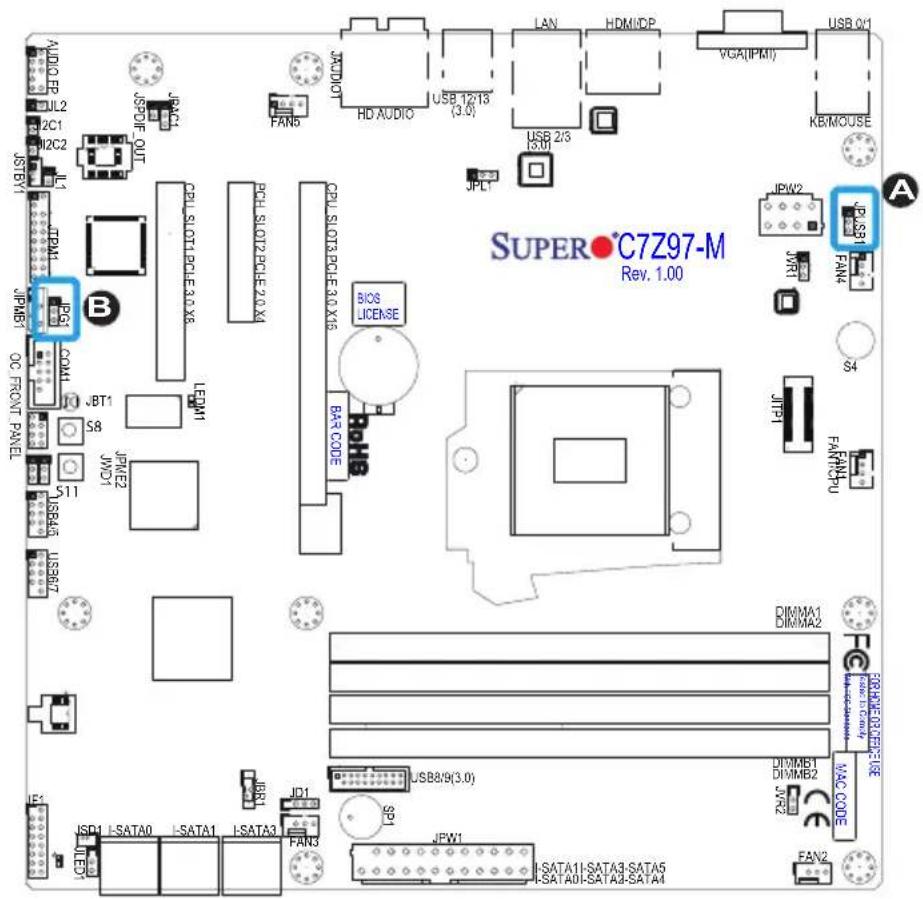
Use jumper JPUSB to activate the "wake-up" function of the USB ports by pressing a key on a USB keyboard or clicking the USB mouse connected. This jumper is used together with a USB Wake-Up feature in the BIOS. Enable this jumper and the USB support in the BIOS to wake up your system via USB devices.
| USB Wake-UpJumper Settings | |
| Jumper Setting | Definition |
| Pins 1-2 Enabled | |
| Pins 2-3 Disabled (Default) | |

Note: Use JPUSB1 for the USB ports on the back panel, and JPUSB2 for the front panel USB headers.
VGA Enable (JPG1)
Use jumper JPG1 to Enable or Disable the onboard video port (C7Z97-MF Only).

Note: Options in the BIOS also control this feature. Please see "Internal Graphics" on page 4-36.
| VGA EnableJumper Settings | |
| Jumper Setting | Definition |
| Pins 1-2 Enabled | (Default) |
| Pins 2-3 Disabled | |
A.USB Wak-Up
B. VGA Enable
text_image
SUPER•C7Z97-M Rev. 1.00 A B CCL SLOT12-PCLE 2.0 X6 LDM1 JPT1 S8 JPT1 JWD1 JPS2 JPS3 COM1 DC FRONT PANEL JSP4 JSP5 JSD1 I-SATA0 I-SATA1 I-SATA3 FAN3 JBR1 JD1 JCPDOUT JPL1 JPL1 JCPU SLOT2-PCLE 2.0 X6 CDL SLOT3-PCLE 3.0 X15 BIOS LICENSE BAR CODE USB2/9(3.0) JFW1 JFW2 JPS1 JVR1 JPM1 JPM2 JPM3 JPM4 JPM5 JPM6 JPM7 JPM8 JPM9 JPM10 JPM11 JPM12 JPM13 JPM14 JPM15 JPM16 JPM17 JPM18 JPM19 JPM20 JPM21 JPM22 JPM23 JPM24 JPM25 JPM26 JPM27 JPM28 JPM29 JPM30 JPM31 JPM32 JPM33 JPM34 JPM35 JPM36 JPM37 JPM38 JPM39 JPM40 JPM41 JPM42 JPM43 JPM44 JPM45 JPM46 JPM47 JPM48 JPM49 JPM50 JPM51 JPM52 JPM53 JPM54 JPM55 JPM56 JPM57 JPM58Manufacturing Mode (JPME2)
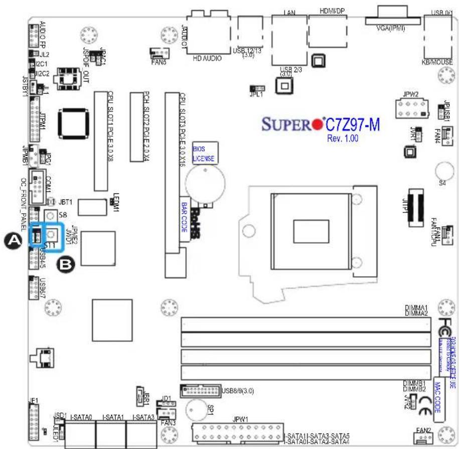
Close Pin 2 and Pin 3 of Jumper JPME2 to bypass SPI flash security and force the system to operate in Manufacturing Mode, allowing the user to flash the system firmware from a host server for system setting modifications. See the table on the right for jumper settings.
| Manufacture Mode (JPME2)Jumper Settings | |
| Pin# | Definition |
| 1-2 | Normal (Default) |
| 2-3 | Manufacture Mode |
When pressed, the BIOS Restore Button will look for, and load a file named 'SUPER.ROM' from an installed USB memory device, in any of the USB ports. It will then proceed to update the BIOS. Do NOT turn off the system when BIOS is updating.
A. Manufacturing Mode B. BIOS Restore
text_image
AUDIO RP JL2 I2C1 I2C2 JSTBY1 JPM1 JPMB1 OC_FRONT_PANEL A S8 JBT1 JPM2 JWD1 USB45 USB67 JSPDIF_OUT JSPDIF JSPDIF CPU SLOT1 PCLE 3.0 X8 LCDM1 JPT COM1 JPT SST USB45 B CPU SLOT2 PCLE 2.0 X4 RCH SLOT2 PCLE 3.0 X8 CPU SLOT3 PCLE 3.0 X16 BIOS LICENSE BAR CODE JPL1 HD AUDIO JALN HDMI/DP USB 12/13 (3.0) USB 2/3 (3.0) USB 2/3 (3.0) USB 2/3 (3.0) USB 2/3 (3.0) USB 2/3 (3.0) USB 2/3 (3.0) USB 2/3 (3.0) USB 2/3 (3.0) USB 2/3 (3.0) USB 2/3 (3.0) USB 2 /1 USB 2 /1 USB 2 /1 USB 2 /1 USB 2 /1 USB 2 /1 USB 2 /1 USB 2 /1 USB 2 /1 USB 2 /1 USB 2 /1 USB 2 /1 USB 2 /1 USB 2 /1 USB 2 /1 USB 2 /1 USB 2 /1 USB 2/1 USB 2/1 USB 2/1 USB 2/1 USB 2/1 USB 2/1 USB 2/1 USB 2/1 USB 2/1 USB 2/1 USB 2/1 USB 2/1 USB 2/1 USB 2/1 USB 2/1 USB 2/1 USB 2/1 USB_0/ KB/MOUSE JPW2 JP USB1 WMT FAN4 S4 FAR/NPU JTP1 FAR/NPU SUPER●C7Z97-M Rev. 1.00BIOS Recovery Switch (JBR1)
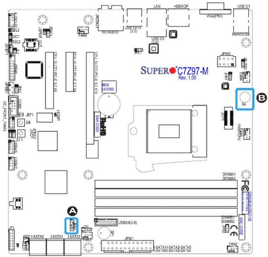
The BIOS Recovery Switch (JBR1) is used to enable or disable the BIOS Recovery feature of the motherboard. Slide the switch from the default position to begin the recovery process. See Appendix D for details.
| BIOS Recovery (JBR1) Jumper Settings | |
| State | Definition |
| Off Normal (Default) | |
| On Recover | |
Power Button (POWER BUTTON)
In addition to the soft power switch provided in JF1, your motherboard is equipped with a 'soft' power button on the motherboard. This switch works the same way as the soft power switch on JF1.
A. BIOS Recovery
B. Power Button
text_image
SUPER•C7Z97-M Rev. 1.00 S4 B DIMMA1 DIMMA2 SPRAVE/ROCK/CEUSE MAC CODE DIMMS1 DIMMB2 JYR2 FAN2 USB 0/1 USB 2/3 USB 2/3 (3.0) LAN HDMI/DP VGA(IPMI) KB/MODSE JPL1 CPU.SLOT13.PGE-3.0 X18 BIOS LICENSE BAR CODE CPU.SLOT13.PGE-3.0 X18 CPU.SLOT13.PGE-3.0 X18 LEDM1 JPTM52 JPTM67 JPTM7 JPTM87 JPTM97 JPTM10 JPTM11 JPTM12 JPTM13 JPTM14 JPTM15 JPTM16 JPTM17 JPTM18 JPTM19 JPTM20 JPTM21 JPTM22 JPTM23 JPTM24 JPTM25 JPTM26 JPTM27 JPTM28 JPTM29 JPTM30 JPTM31 JPTM32 JPTM33 JPTM34 JPTM35 JPTM36 JPTM37 JPTM38 JPTM39 JPTM40 JPTM41 JPTM42 JPTM43 JPTM44 JPTM45 JPTM46 JPTM47 JPTM48 JPTM49 JPTM50 JPTM51 JPTM52 JPTM53 JPTM54 JPTM55 JPTM56 JPTM57 JPTM58 JPTM59 JPTM60 JPTM61 JPTM62 JPTM63 JPTM64 JPTM65 JPTM66 JPTM67 JPTM68 JPTM69 JPTM70 JPTM71 JPTM72 JPTM73 JPTM74 JPTM75 JPTM76 JPTM77 JPTM78 JPTM79 JPTM80 JPTM81 JPTM82 JPTM83 JPTM84 JPTM85 JPTM86 JPTM87 JPTM88 JPTM89 JPTM90 JPTM91 JPTM92 JPTM93 JPTM94 JPTM95 JPTM96 JPTM97 JPTM98 JPTM992-9 Onboard Indicators
LAN 1 LEDs
One LAN port (LAN 1) is located on the I/O back panel of the motherboard. This LAN port has two LEDs. The yellow LED indicates activity, while the Link LED may be green, amber, or off to indicate the speed of the connections. See the tables at right for more information.
| GLAN 1/2 Activity IndicatorLED Settings | ||
| Color | Status | Definition |
| Yellow | Flashing | Active |
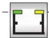
Activity LEDLink LED
| GLAN Ports 1/2 Link IndicatorLED Settings | |
| LED Color Definition | |
| Off | No Connection/10 Mbps/100Mbps |
| Amber | 1 Gbps |
| Green | 10 Gbps. |
Onboard Power LED (LED1)
An Onboard Power LED is located at LED1 on the motherboard. When LED1 is on, the AC power cable is connected. Make sure to disconnect the power cable before removing or installing any component. See the layout below for the LED location.
| Onboard PWR LED IndicatorLED Status | |
| Status | Definition |
| Off System | Off |
| On System | on, orSystem off and PWRCable Connected |
A. LAN 1 LEDs
B. PWR LED
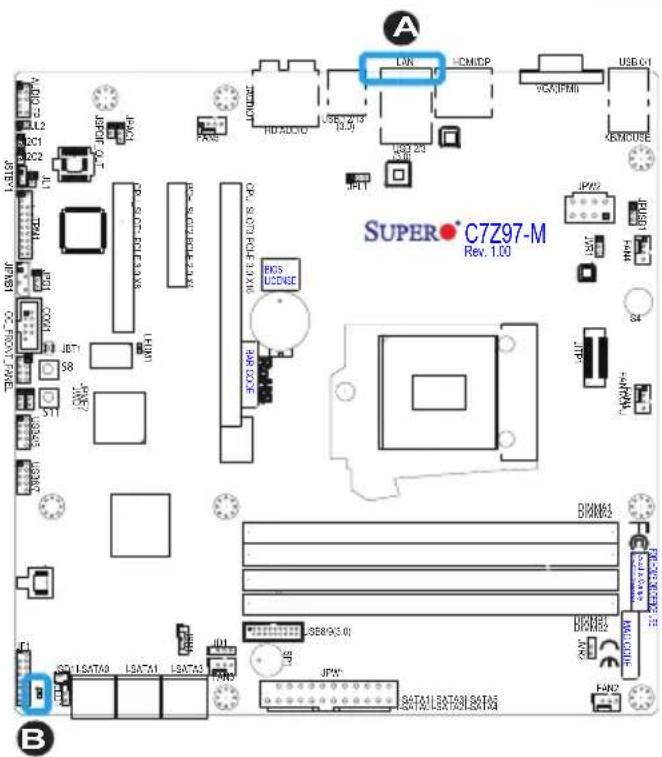
text_image
A LNN COMMDP VGA/IFM USB 04 UPD HD AUDIO USB 213 USB 23 JPN JPN JPN JPN JPN JPN JPN JPN JPN JPN JPN JPN JPN JPN JPN JPN JPN JPN JPN JPN JPN JPN JPN JPN JPN JPN JPN JPN JPN JPN JPN JPN JPN JPNIPMI Heartbeat (LEDM1)
The IPMI Heartbeat LED displays the status of the IPMI / BMC (Baseboard Management Controller).
| IPMI HeartbeatLED Status | |
| Status | Definition |
| Off System | Off |
| Blinking IP | MI/BMC is on and working normally |
A. IPMI Heartbeat
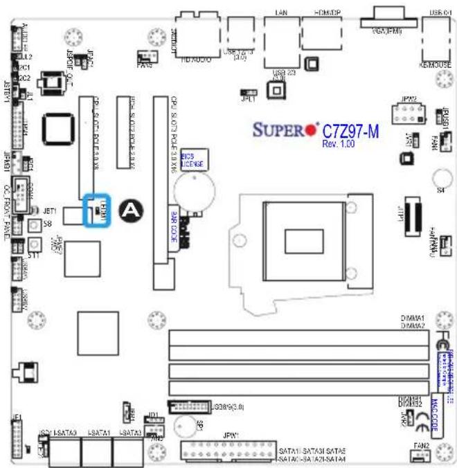
text_image
SUPER C7Z97-M Rev. 1.002-10 SATA Connections
SATA Connections (I-SATA0\~I-SATA5)
Six Serial ATA (SATA) 3.0 connectors (I-SATA 0\~5) are supported on the board. The I-SATA 3.0 ports are supported by the Intel Z97 PCH chip (supports RAID 0,1,5,10). These Serial Link connections provide faster data transmission than legacy Parallel ATA. See the table below for pin definitions.
| SATA 2.0/3.0 Connectors Pin Definitions | |
| Pin# | Signal |
| 1 | Ground |
| 2 | SATA_TXP |
| 3 | SATA_TXN |
| 4 | Ground |
| 5 | SATA_RXN |
| 6 | SATA_RXP |
| 7 | Ground |
Top
A. I-SATA 3.0 #1
B. I-SATA 3.0 #3
C. I-SATA 3.0 #5
Bottom
D. I-SATA 3.0 #0
E. I-SATA 3.0 #2
F. I-SATA 3.0 #4
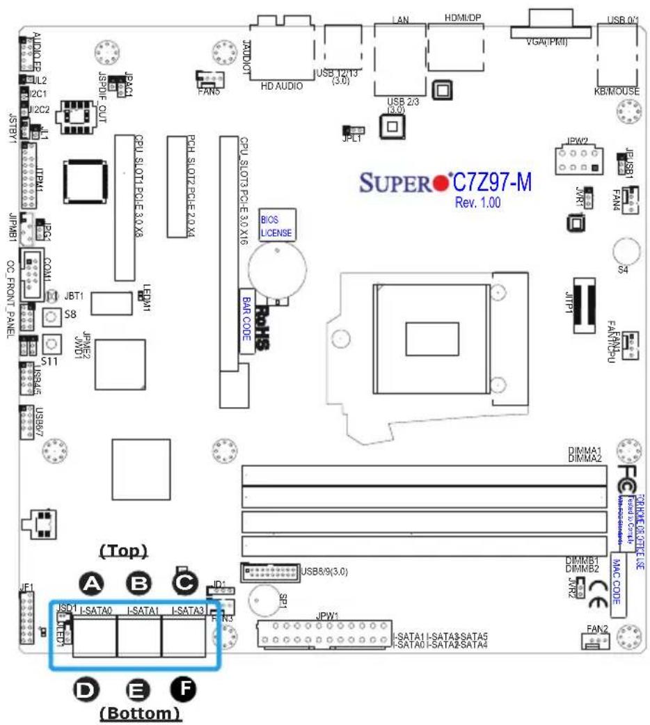
text_image
AUDIO 1L2 12C1 12C2 1L1 STBY1 ITEM1 JPMB1 CC FRONT PANEL JBT1 S8 JPM62 S11 USB87 (Top) A B C ISO1 LSATA0 LSATA1 LSATA3 F D E F (Bottom) CPU SLOT2 PCLE 3.0 X8 CPU SLOT3 PCLE 3.0 X16 BAR CODE BIOS LICENSE JPLT HD AUDIO USB T2/T3 (3.0) USB 23 (3.0) VGA(FMI) USB 01 KB/MOUSE IPW2 IPSB1 JVR1 FAN4 S4 JFP1 FAI/CHU DIMMA1 DIMMA2 USB8/9(3.0) DIMMB1 DIMMB2 JAR2 MAC CODE JPW1 LSATA1 I-SATA3 SATA5 LSATA0 I-SATA2 SATA4 FAN22-10 The OC Front Control Panel (Optional)
The OC (Over-Clocking) Front Control Panel has Six (6) control buttons, switches and one USB port.
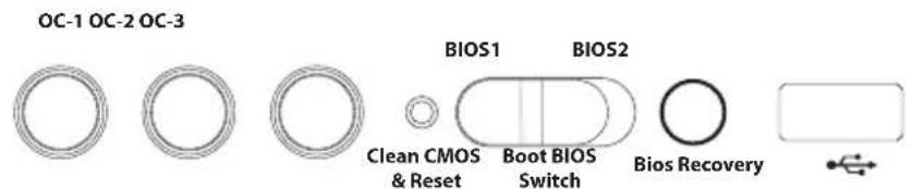
text_image
OC-1 OC-2 OC-3 BIOS1 BIOS2 Clean CMOS & Reset Boot BIOS Switch Bios RecoveryOver-Clocking Buttons (OC1, OC2, OC3)
Press these buttons to activate the over-clocking feature of the motherboard. These buttons will allow the CPU to run above its rated speed. This is an advanced feature and should only be used by experienced users. These work the same way as the OC buttons on the motherboard, see Page 2-32 for details.
Clear CMOS and Reset
Use the push-button hardware switch to clear the CMOS memory back to its default values and reset the system. There is also a similar switch on the motherboard (JBT1), but is made up of two contact pads that need to be shorted with a metallic object (i.e., screwdriver, etc).
Boot BIOS Switch
The Boot BIOS Switch is used to select between two boot BIOS blocks that are installed on the motherboard. See Appendix D for details.
BIOS Recovery
Push the BIOS Recovery button to enable the motherboard to enter the BIOS Recovery process and re-install the BIOS, reverting all settings back to factory default. It looks for a file named "SUPER.ROM" from a memory device attached to any of the USB drives. It functions the same way as the BIOS Restore Button which is installed on the motherboard, see page 2-34.
Front USB Port
The Front USB Port is defined as USB 3.0 Port# XX on this motherboard. It is conveniently located on the OC panel for quick access for USB memory sticks and other storage devices.
Installing the OC Front Control Panel
The OC Front Control Panel is designed to fit into an external 5.25-inch external drive bay of a desktop-style or tower-style computer chassis. Make sure that the appropriate type of screws are used.
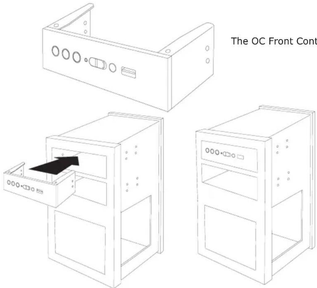
text_image
The OC Front ContThe OC Front Control panel
The OC Control panel easily slides into a standard 5.25-inch drive bay on a desktop or tower-style computer chassis.
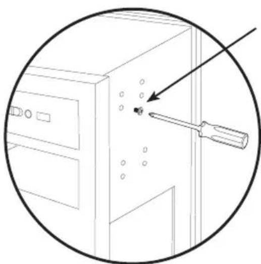
natural_image
Line drawing of a computer tower with a screwdriver inserted, showing mounting holes and a circular outline (no text or symbols)Make sure to secure the OC Control Panel with the correct screws, but do not over-tighten.
Connect all the OC Control Panel cables to the appropriate headers located on the motherboard.
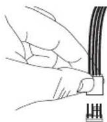
natural_image
Line drawing of hands connecting a cable to a plug (no text or symbols)Chapter 3
Troubleshooting
3-1 Troubleshooting Procedures
Use the following procedures to troubleshoot your system. If you have followed all of the procedures below and still need assistance, refer to the 'Technical Support Procedures' and/or 'Returning Merchandise for Service' section(s) in this chapter. Always disconnect the AC power cord before adding, changing or installing any hardware components.
Before Power On
- Make sure that the Standby PWR LED is not on. (Note: If it is on, the onboard power is on. Be sure to unplug the power cable before installing or removing the components.)
- Make sure that there are no short circuits between the motherboard and chassis.
- Disconnect all ribbon/wire cables from the motherboard, including those for the keyboard and mouse. Also, be sure to remove all add-on cards.
- Install a CPU and heatsink (-be sure that it is fully seated) and then connect the chassis speaker and the power LED to the motherboard. Check all jumper settings as well.
No Power
- Make sure that there are no short circuits between the motherboard and chassis.
- Make sure that all jumpers are set to their default positions.
- Check if the 115V/230V switch on the power supply is properly set.
- Turn the power switch on and off to test the system.
- The battery on your motherboard may be old. Check to make sure that it still supplies \~3VDC. If it does not, replace it with a new one.
No Video
- If the power is on, but you have no video--in this case, you will need to remove all the add-on cards and cables first.
- Use the speaker to determine if any beep codes exist. (Refer to Appendix A for details on beep codes.)
- Remove all memory modules and turn on the system. (If the alarm is on, check the specifications of memory modules, reset the memory or try a different one.)
Memory Errors
- Make sure that the DIMM modules are properly installed and fully seated in the slots.
- You should be using unbuffered Non-ECC DDR3 (1.5V) 1800/1600/1333/1066 MHz memory recommended by the manufacturer. Also, it is recommended that you use the memory modules of the same type and speed for all DIMMs in the system. Do not use memory modules of different sizes, different speeds and different types on the same motherboard.
- Check for bad DIMM modules or slots by swapping modules between slots to see if you can locate the faulty ones.
- Check the switch of 115V/230V power supply.
When the System is Losing the Setup Configuration
- Please be sure to use a high quality power supply. A poor quality power supply may cause the system to lose CMOS setup information. Refer to Section 1-5 for details on recommended power supplies.
- The battery on your motherboard may be old. Check to verify that it still supplies \~3VDC. If it does not, replace it with a new one.
- If the above steps do not fix the Setup Configuration problem, contact your vendor for repairs.
3-2 Technical Support Procedures
Before contacting Technical Support, please make sure that you have followed all the steps listed below. Also, Note that as a motherboard manufacturer, Supermicro does not sell directly to end users, so it is best to first check with your distributor or reseller for troubleshooting services. They should know of any possible problem(s) with the specific system configuration that was sold to you.
-
Please go through the 'Troubleshooting Procedures' and 'Frequently Asked Question' (FAQ) sections in this chapter or see the FAQs on our website (http://www.supermicro.com/support/faqs/) before contacting Technical Support.
-
BIOS upgrades can be downloaded from our website at (http://www.supermicro.com/support/bios/).

Note: Not all BIOS can be flashed. Some cannot be flashed; it depends on the boot block code of the BIOS.
- If you've followed the instructions above to troubleshoot your system, and still cannot resolve the problem, then contact Supermicro's technical support and provide them with the following information:
• Motherboard model and PCB revision number
- BIOS release date/version (this can be seen on the initial display when your system first boots up)
• System configuration
- An example of a Technical Support form is on our website at (http://www.supermicro.com/support/contact.cfm).
- Distributors: For immediate assistance, please have your account number ready when placing a call to our technical support department. We can be reached by e-mail at support@supermicro.com, by phone at: (408) 503-8000, option 2, or by fax at (408)503-8019.
3-3 Frequently Asked Questions
Question: What type of memory does my motherboard support?
Answer: The C7Z97-M/MF supports up to 32GB of unbuffered Non-ECC DDR3 SDRAM, 1066\~3000 MHz (OC). See Section 2-4 for details on installing memory.
Question: How do I update my BIOS?
Answer: We do NOT recommend that you upgrade your BIOS if you are not experiencing any problems with your system. Updated BIOS files are located on our website at http://www.supermicro.com/support/bios/. Please check our BIOS warning message and the information on how to update your BIOS on our web site. Select your motherboard model and download the BIOS ROM file to your computer. Also, check the current BIOS revision to make sure that it is newer than your BIOS before downloading. You may choose the zip file or the .exe file. If you choose the zipped BIOS file, please unzip the BIOS file onto a bootable device or a USB pen/thumb drive. To flash the BIOS, run the batch file named "ami.bat" with the new BIOS ROM file from your bootable device or USB pen/thumb drive. Use the following format:
F:> ami.bat BIOS-ROM-filename.xxx

Note: Always use the file named "ami.bat" to update the BIOS, and insert a space between "ami.bat" and the filename. The BIOS-ROM-filename will bear the motherboard name (i.e., C7Z97) and build version as the extension. For example, "C7Z97.115". When completed, your system will automatically reboot.
If you choose the .exe file, please run the .exe file under Windows to create the BIOS flash floppy disk. Insert the floppy disk into the system you wish to flash the BIOS. Then, boot the system to the floppy disk. The BIOS utility will automatically flash the BIOS without any prompts. Please note that this process may take a few minutes to complete. Do not be concerned if the screen is paused for a few minutes.
When the BIOS flashing screen is completed, the system will reboot and will show "Press F1 or F2". At this point, you will need to load the BIOS defaults. Press

Attention! Do not shut down or reset the system while updating the BIOS to prevent possible system boot failure!

Important: The SPI BIOS chip installed on this motherboard is not removable. To repair or replace a damaged BIOS chip, please send your motherboard to RMA at Supermicro for service.
Question: I think my BIOS is corrupted. How can I recover my BIOS?
Answer: Please see Appendix C-BIOS Recovery for detailed instructions.
Question: Why do I get an error message "IASTOR.SYS read error" and "press F6 to install Intel RAID driver" when installing Windows on my motherboard?
Answer: To solve this issue, disable the IPMI jumper. Another solution is to use a USB floppy drive instead of the onboard floppy drive. For the IPMI jumper location, please check Chapter 1.
3-4 Battery Removal and Installation
Battery Removal
To remove the onboard battery, follow the steps below:
- Power off your system and unplug your power cable.
- Locate the onboard battery as shown below.
-
Using a tool such as a pen or a small screwdriver, push the battery lock outwards to unlock it. Once unlocked, the battery will pop out from the holder.
-
Remove the battery.
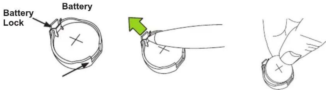
text_image
Battery Lock BatteryProper Battery Disposal
! Attention! Please handle used batteries carefully. Do not damage the battery in any way; a damaged battery may release hazardous materials into the environment. Do not discard a used battery in the garbage or a public landfill. Please comply with the regulations set up by your local hazardous waste management agency to dispose of your used battery properly.
Battery Installation
- To install an onboard battery, follow the steps 1& 2 above and continue below:
- Identify the battery's polarity. The positive (+) side should be facing up.
- Insert the battery into the battery holder and push it down until you hear a click to ensure that the battery is securely locked.

Attention! When replacing a battery, be sure to only replace it with the same type.
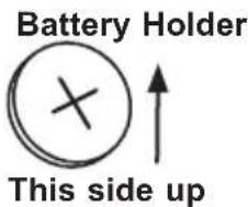
text_image
Battery Holder This side up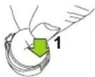
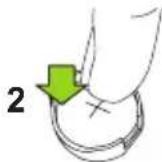
Press down until you hear a click.
3-5 Returning Motherboard for Service
A receipt or copy of your invoice marked with the date of purchase is required before any warranty service will be rendered. You can obtain service by calling your vendor for a Returned Merchandise Authorization (RMA) number. For faster service, you may also obtain RMA authorizations online (http://www.supermicro.com/support/rma/). When you return the motherboard to the manufacturer, the RMA number should be prominently displayed on the outside of the shipping carton, and mailed prepaid or hand-carried. Shipping and handling charges will be applied for all orders that must be mailed when service is complete.
This warranty only covers normal consumer use and does not cover damages incurred in shipping or from failure due to the alteration, misuse, abuse or improper maintenance of products.
During the warranty period, contact your distributor first for any product problems.
Chapter 4
BIOS
4-1 Introduction
This chapter describes the AMI BIOS Setup Utility for the C7Z97-M/MF. The ROM BIOS is stored in a Flash EEPROM and can be easily updated. This chapter describes the basic navigation of the AMI BIOS Setup Utility setup screens.

Note: For AMI BIOS Recovery, please refer to the UEFI BIOS Recovery Instructions in Appendix C.
Starting BIOS GUI Setup Utility
To enter the AMI BIOS GUI Setup Utility screens, press the

Note: In most cases, the

text_image
Home Overclocking SUPERMIC Expert Made Save & Load Main Navigation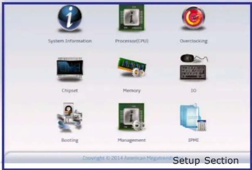
text_image
System Information Processor(CPU) Overclocking Chipset Memory IO Booting Management IPMI Copyright © 2014 American Megatrend Section Setup SectionEach BIOS menu option is described in this manual. The Main BIOS Setup screen has two main areas. The top area is the Main Navigation, and the main area is for the Setup Section. Icons that do not respond when the mouse pointer is hovering on top are not configurable.
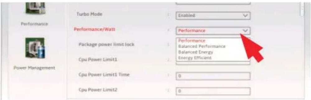
text_image
Turbo Mode Enabled Performance/Watt Performance Package power limit lock Performance Balanced Performance Balanced Energy Energy Efficient Cpu Power Limit1 Cpu Power Limit1 Time 0 Cpu Power Limit2 0The AMI BIOS GUI Setup Utility uses a mouse pointer navigation system similar to standard graphical user interfaces. Hover and click an icon to select a section, click a down arrow to select from an options list.
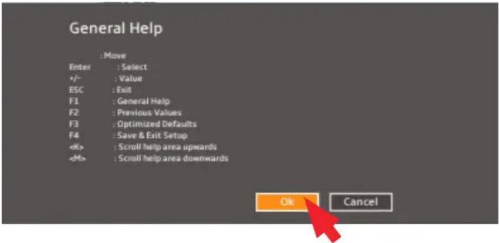
text_image
General Help : Move Enter : Select +/- : Value ESC : Exit F1 : General Help F2 : Previous Values F3 : Optimized Defaults F4 : Save & Exit SetupExcept for the Home screen you may press the
How To Change the Configuration Data
The configuration data that determines the system parameters may be changed by entering the AMI BIOS GUI Setup utility. This Setup utility can be accessed by pressing at the appropriate time during system boot.

Note: For the purposes of this manual, options that are printed in Bold are default settings.
How to Start the Setup Utility
Normally, the only visible Power-On Self-Test (POST) routine is the memory test. As the memory is being tested, press the
4-2 Setup Home
The first screen of the AMI BIOS GUI Setup Utility is the Setup Home screen. You can always return to the Setup Home screen by clicking the Home icon on the top of the screen. The Setup Home screen is shown below.
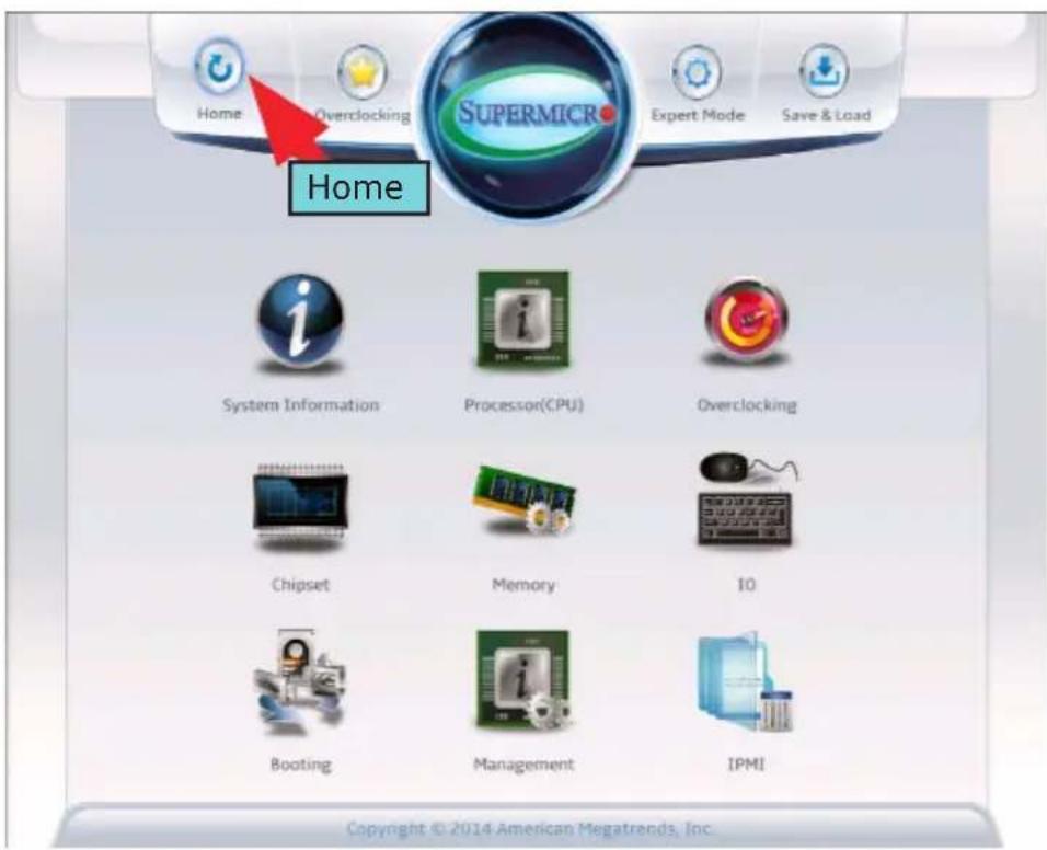
text_image
Home Overclocking SuperMICR Expert Mode Save & Load Home System Information Processor(CPU) Overclocking Chipset Memory IO Booting Management IPMI Copyright © 2014 American Megatrends, Inc.The Overclocking menu item jumps directly to the Setup's Overclocking Section, which is described in detail later in this manual.
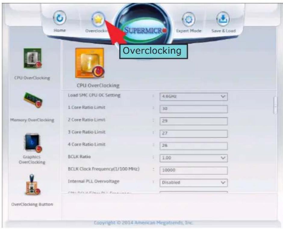
text_image
Home Overclocking Supermic Expert Mode Save & Load Overclocking CPU OverClocking CPU OverClocking Load SMC CPU DC Setting : 4.6GHz 1 Core Ratio Limit : 30 2 Core Ratio Limit : 29 3 Core Ratio Limit : 27 4 Core Ratio Limit : 26 BCLK Ratio : 1.00 BCLK Clock Frequency(1/100 MHz) : 10000 Internal PLL Overvoltage : Disabled OverClocking Button Copyright © 2014 American Megatrends, Inc.By default, some advanced menu options are hidden from display (in the CPU Overclocking section for example). Clicking Expert Mode ON or OFF will display or hide these options from the menu. In this chapter, all Expert Mode option items are bold and underlined.
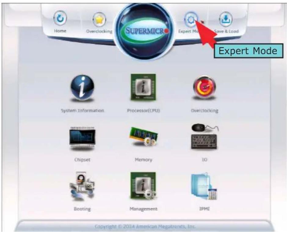
text_image
Home Overclocking SUPERMIC Expert Mode Save & Load Expert Mode System Information Processor(CPU) Overclocking Chipset Memory IO Booting Management IPMI Copyright © 2014 American Megatrends, Inc.The Save and Load icon brings up a pop-up menu that enables the user to choose from different saving options at the end of the session.
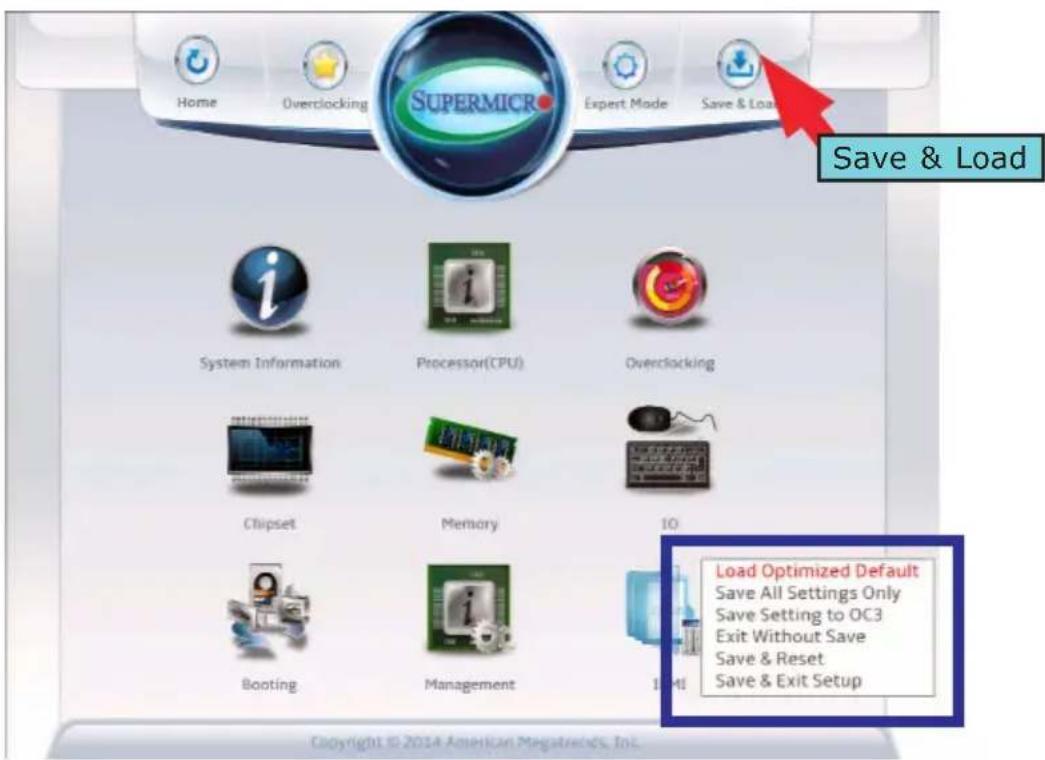
text_image
Home Overclocking SUPERMIC Expert Mode Save & Load Save & Load System Information Processor(CPU) Overclocking Chipset Memory 10 Bootling Management Load Optimized Default Save All Settings Only Save Setting to OC3 Exit Without Save Save & Reset Save & Exit SetupLoad Optimized Defaults
To set this feature, select Load Optimized Defaults from the Save & Load menu and press
Save All Settings Only
When you have completed the system configuration changes, select this option to save all changes made. This will not reset (reboot) the system and will not exit.
Save Settings to OC3
Select this option to save the current settings to the OC3 hardware button.
Exit Without Save
Select this option to quit the BIOS Setup without making any permanent changes to the system configuration, and reboot the computer.
Save and Reset
When you have completed the system configuration changes, select this option to save the changes, leave the BIOS Setup Utility, and reboot the computer for the new system configuration parameters can take effect.
Save and Exit Setup
When you have completed the system configuration changes, select this option to save the changes, and leave the BIOS Setup Utility.
4-3 System Information
The System Information Screen displays the motherboard's configuration.
Motherboard
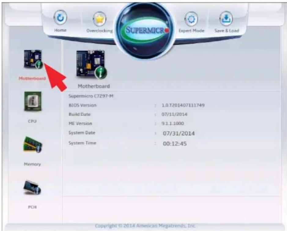
text_image
Home Overclocking SuperMICRO Expert Mode Save & Load Motherboard Motherboard Supermicro C7297-M BIOS Version : 1.0.T201407111749 Build Date : 07/11/2014 ME Version : 9.1.1.1000 System Date : 07/31/2014 System Time : 00:12:45 CPU Memory PCH Copyright © 2014 American Megatrends, Inc.The following information are displayed in this section:
• Motherboard Model Name - C7Z97-M/MF.
• BIOS Version - this item displays the BIOS version number.
• Build Date - displays the BIOS build date.
• ME Version - indicates the Management Engine version number.
System Date
This item sets and displays the system date. Click the up and down arrows to adjust the date.
System Time
This item sets and displays the system time. Click the up and down arrows to adjust the system time.
CPU
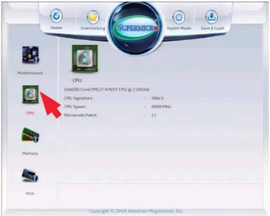
text_image
Home Overclocking SUPERMICR Expert Mode Save & Load Motherboard CPU Intel(R) Core(TM) i7-4765T CPU @ 2.00GHz CPU Signature : 306c3 CPU Speed : 2600 MHz Microcode Patch : 17 CPU Memory PCH Copyright © 2014 American Megatrends, Inc.The following information are be displayed in this section:
- Type and Speed of CPU - indicates the brand, model name, model number of the CPU and it's rated clock speed.
• CPU Signature - displays the unique signature embedded in the CPU.
• CPU Speed - this item shows the current CPU speed. - Microcode Patch - displays the CPU's microcode patch version.
Memory

text_image
Home Overclocking SUPERMICR Expert Mode Save & Load Motherboard Memory Total Memory : 4096 MB (DDR3) Memory Frequency : 1600 MHz CPU Memory PCH Copyright © 2014 American Megatrends, Inc.The following information are be displayed in this section:
• Total Memory - shows the total detected system memory.
• Memory Frequency - displays the system memory's detected speed.
PCH
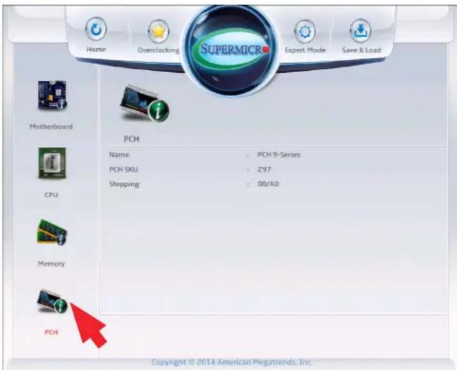
text_image
Home Overclocking SUPERMICR Expert Mode Save & Load Motherboard PCH Name : PCH 9-Series PCH SKU : Z97 Stopping : 00/A0 CPU Memory PCH Copyright © 2014 American Megatrends, Inc.The following information are be displayed in this section:
• Name - displays the name of the PCH chip (if detected).
- PCH SKU - this item displays the part number of the PCH chip.
• Stepping- shows the PCH chip's stepping number.
4-4 Processor (CPU)
Set all options for the processor in this section.
Information
The following CPU information will be displayed:
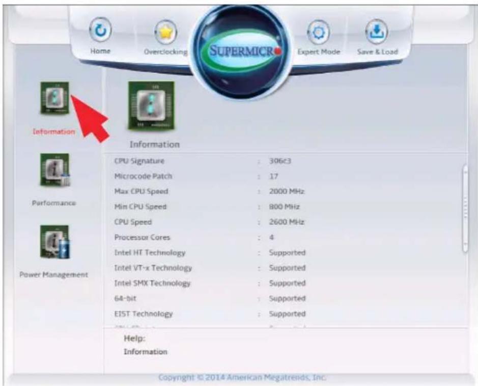
text_image
Home Overclocking SuperMICRO Expert Mode Save & Load Information Information CPU Signature : 306≤3 Microcode Patch : 17 Max CPU Speed : 2000 MHz Min CPU Speed : 800 MHz CPU Speed : 2600 MHz Processor Cores : 4 Intel HT Technology : Supported Intel VT-x Technology : Supported Intel SMX Technology : Supported 64-bit : Supported EIST Technology : Supported Help: Information Copyright © 2014 American Megatrends, Inc.- CPU Signature - displays the unique signature emebedded in CPU.
- Microcode Patch - displays the CPU's microcode patch version.
• CPU Speed - displays the CPU's rated speed. - Processor Cores - displays the number of cores the CPU has.
- Intel HT(Hyper-Threading) Technology - indicates if Intel HT is supported.
- 64-bit - indicates if 64-bit is supported.
• EIST Technology - displays whether EIST is supported or not.
• CPU C3 State - indicates if ACPI C3 state is supported. - CPU C6 State - shows whether ACPI C6 state is supported or not.
• CPU C7 State - indicates if ACPI C7 is supported.
• L1 Data Cache - indicates if Level 1 cache is supported.
• L1 Code Cache - displays if Level 1 code cache is supported.
• L2 Cache - indicates if Level 2 cache is supported.
• L3 Cache - displays whether Level 3 cache is supported or not.
• L4 Cache - - indicates if Level 4 cache is supported.
Performance
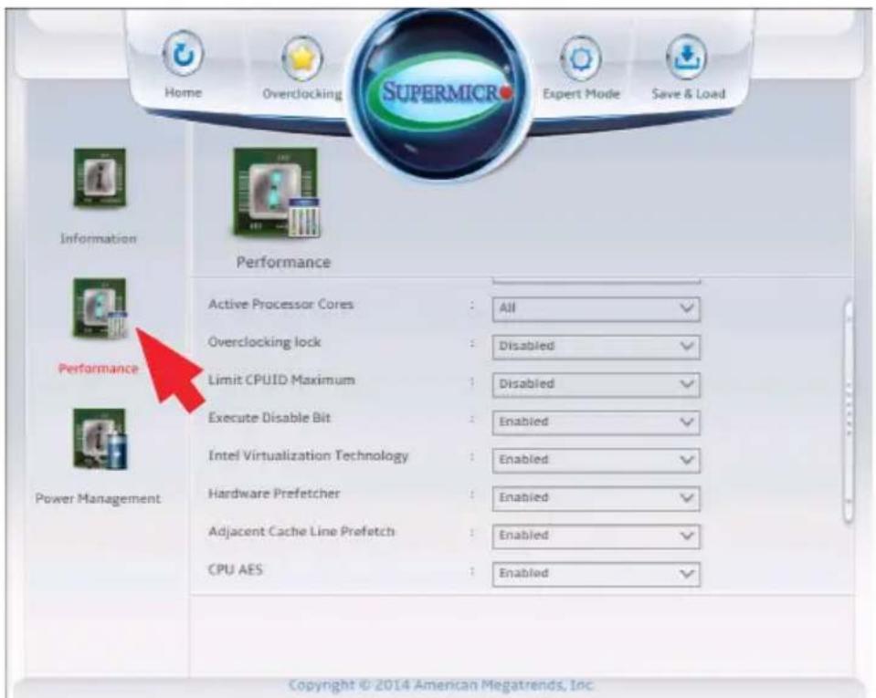
text_image
Home Overclocking Supermic Expert Mode Save & Load Information Performance Active Processor Cores : All ✓ Overclocking lock : Disabled ✓ Limit CPUID Maximum : Disabled ✓ Execute Disable Bit : Enabled ✓ Intel Virtualization Technology : Enabled ✓ Hardware Prefetcher : Enabled ✓ Adjacent Cache Line Prefetch : Enabled ✓ CPU AES : Enabled ✓ Performance Power Management Copyright © 2014 American Megatrends, Inc.Hyper-threading
Select Enabled to support Intel Hyper-threading Technology to enhance CPU performance. The options are Enabled and Disabled.
Active Processor Cores
This feature determines how many CPU cores will be activated for each CPU. When all is selected, all cores in the CPU will be activated. (Please refer to Intel's web site for more information.) The options are All, 1, 2, and 3.
Overclocking Lock
Select Enabled to prevent overclocking. The options are Enabled and Disabled.
Limit CPUID Maximum
Select Enabled to set the maximum CPU ID value and to boot a legacy OS that cannot support processors with extended CPUID functions. The options are Enabled and Disabled (for the Windows OS).
Execute Disable Bit
(Available if supported by the OS & the CPU)
Set to Enabled to enable the Execute Disable Bit to allow the processor to designate areas in the system memory where an application code can execute and where it cannot, thus preventing a worm or a virus from flooding illegal codes to overwhelm the processor or damage the system during an attack. The default is Enabled. (Refer to Intel and Microsoft Web Sites for more information.)
Intel® Virtualization Technology
(Available when supported by the CPU)
Select Enabled to use the Intel Virtualization Technology to allow one platform to run multiple operating systems and applications in independent partitions, creating multiple "virtual" systems in one physical computer. The options are Enabled and Disabled.
Hardware Prefetcher
(Available when supported by the CPU)
If set to Enabled, the hardware prefetcher will prefetch streams of data and instructions from the main memory to the L2 cache to improve CPU performance. The options are Disabled and Enabled.
Adjacent Cache Line Prefetch
(Available when supported by the CPU)
Select Enabled for the CPU to prefetch both cache lines for 128 bytes as comprised. Select Disabled for the CPU to prefetch both cache lines for 64 bytes. The options are Disabled and Enabled.

Note: If there is any change to this setting, you will need to power off and reboot the system for the change to take effect. Please refer to Intel's web site for detailed information.
CPU AES
Select Enable for Intel CPU Advanced Encryption Standard (AES) Instructions support to enhance data integrity. The options are Enabled and Disabled.
Boot Performance Mode
This option enables the selection of the default CPU performance during system boot. The options are Max Non-Turbo Performance, Max Battery and Turbo Performance.
Power Management
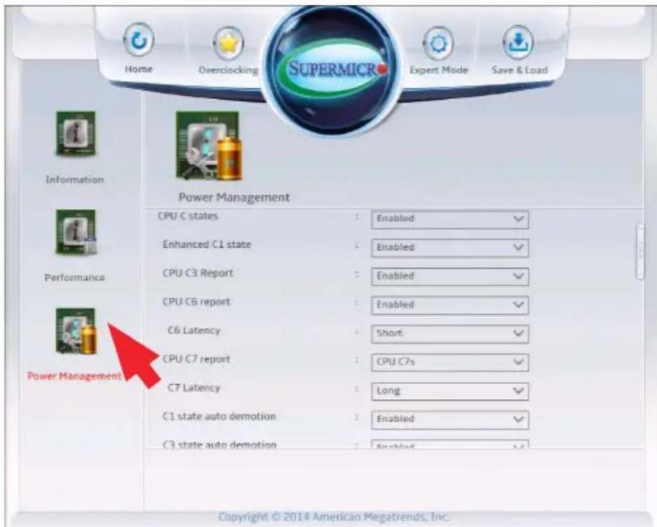
text_image
Home Overclocking Supermic Expert Mode Save & Load Information Power Management CPU C states Enabled Enhanced C1 state Enabled CPU C3 Report Enabled CPU C6 report Enabled C6 Latency Short CPU C7 report CPU C7s C7 Latency Long C1 state auto demotion Enabled C3 state auto demotion Enabled Power Management Copyright © 2014 American Megatrends, Inc.EIST
EIST (Enhanced Intel SpeedStep Technology) allows the system to automatically adjust processor voltage and core frequency in an effort to reduce power consumption and heat dissipation. Please refer to Intel's web site for detailed information. The options are Disabled and Enabled.
Turbo Mode
This feature allows processor cores to run faster than the frequency recommended by the manufacturer. The options are Disabled and Enabled. If this feature is set to Enabled, the following items will display:
Package Power Limit Lock
When Enabled, this feature will lock the PACKAGE_POWER_LIMIT MSR and a reset will be needed to unlock the register. The options are Enabled and Disabled.
CPU Power Limit1
Use this feature to set the power limit for CPU1. Use the number keys on your keyboard to enter the value. Enter 0 to use the manufacturer's default setting.
CPU Power Limit1 Time
This item allows the user to determine how long CPU1 should operate at the power limit set by the user for the item above. Use the number keys on your keyboard to enter the value. Enter 0 to use the manufacturer's default setting.
CPU Power Limit2
Use this feature to set the power limit for CPU2. Use the number keys on your keyboard to enter the value. Enter 0 to use the manufacturer's default setting.
Platform Power Limit Lock
Use this feature to lock the power limit of the motherboard (PLATFORM_POWER_LIMIT MSR). A system reset is required to unlock the register. The options are Enabled and Disabled.
CPU Power Limit3
Use this feature to set the power limit for CPU3. Use the number keys on your keyboard to enter the value. Enter 0 to use the manufacturer's default setting.
CPU Power Limit3 Time
This item allows the user to determine how long CPU3 should operate at the power limit set by the user for the item above. Use the number keys on your keyboard to enter the value. Enter 0 to use the manufacturer's default setting.
CPU Power Limit3 Duty Cycle
This item allows the user to determine the percentage of time CPU3 should operate at the power set by the user for the item above (i.e., If Power Limit3 Time is set at 100 secs, a 60% duty cycle means CPU3 will run 60 seconds at the power limit set in Power Limit3 every 100 seconds.). Use the number keys on your keyboard to enter the value between 1\~100. Enter 0 to use the manufacturer's default setting.
DDR Power Limit1
Use this feature to set the power limit for DDR Memory Module 1. Use the number keys on your keyboard to enter the value. Enter 0 to use the manufacture's default setting.
DDR Power Limit1 Time
This item allows the user to determine how long Memory Module 1 should operate at the power limit set by the item above. Use the number keys on your keyboard to enter the value. Enter 0 to use the manufacturer's default setting.
DDR Power Limit2
Use this feature to set the power limit for Memory Module 2. Use the number keys on your keyboard to enter the value. Enter 0 to use the manufacturer's default setting.
1-Core Ratio Limit
This increases (multiplies) 1 clock speed in the CPU core in relation to the bus speed when one CPU core is active. Press "+" or "-" on your keyboard to change the value. Enter 0 to use the manufacturer's default setting.
2-Core Ratio Limit
This increases (multiplies) 2 clock speeds in the CPU core in relation to the bus speed when two CPU cores are active. Press "+" or "-" on your keyboard to change the value. Enter 0 to use the manufacturer's default setting.
3-Core Ratio Limit
This increases (multiplies) 3 clock speeds in the CPU core in relation to the bus speed when three CPU cores are active. Press "+" or "-" on your keyboard to change the value. Enter 0 to use the manufacturer's default setting.
4-Core Ratio Limit
This increases (multiplies) 4 clock speeds in the CPU core in relation to the bus speed when four CPU cores are active. Press "+" or "-" on your keyboard to change the value. Enter 0 to use the manufacturer's default setting.
CPU C States
C-States architecture, a processor power management platform developed by Intel, can further reduce power consumption from the basic C1 (Halt State) state that blocks clock cycles to the CPU. Select Enabled for CPU C Sates support. The options are Enabled and Disabled. If this feature is set to Enabled, the following items will display:
Enhanced C1 State
(Available when "CPU C States" is set to Enabled)
Select Enabled to enable Enhanced C1 Power State to boost system performance. The options are Enabled and Disabled.
CPU C3 Report
(Available when "CPU C States" is set to Enabled)
Select Enabled to allow the BIOS to report the CPU C3 State (ACPI C2) to the operating system. During the CPU C3 State, the CPU clock generator is turned off. The options are Enabled and Disabled.
CPU C6 Report
(Available when "CPU C States" is set to Enabled)
Select Enabled to allow the BIOS to report the CPU C6 State (ACPI C3) to the operating system. During the CPU C6 State, the power to all caches is turned off. The options are Enabled and Disabled.
C6 Latency
(Available when "CPU C States" is set to Enabled)
Select Short to set a short delay time(period) during which the BIOS reports CPU C6 State (ACPI C3) to the operating system. Select Long to set a long delay time(period) during which the BIOS reports CPU C6 State (ACPI C3) to the operating system. The options are Short and Long.
CPU C7 Report
(Available when "CPU C States" is set to Enabled)
Select Enabled to allow the BIOS to report the CPU C7 State (ACPI C3) to the operating system. CPU C7 State is a processor-specific low C-State. The options are Disabled, CPU C7, and CPU C7s.
C7 Latency
(Available when "CPU C States" is set to Enabled)
Select Short to set a short delay time(period) during which the BIOS reports CPU C7 State (ACPI C3) to the operating system. Select Long to set a long delay time(period) during which the BIOS reports CPU C7 State (ACPI C3) to the operating system. The options are Short and Long.
C1 State Auto Demotion
When this item is enabled, the CPU will conditionally demote C3, C6 or C7 requests to C1 State based on un-cored auto-demote information. The options are Disabled and Enabled.
C3 State Auto Demotion
When this item is enabled, the CPU will conditionally demote C6 or C7 requests to C3 State based on un-cored auto-demote information. The options are Disabled and Enabled.
Package C-State Demotion
This item enables the Package C-State demotion. The options are Disabled and Enabled.
Package C-State limit
Select Auto for the AMI BIOS to automatically set the limit on the C-State package register. The options are C0, C2, C3, C6, C7, C7s and Auto.
LakeTiny Feature
Select Enabled for LakeTiny feature support for C-State configuration. The options are Enabled and Disabled.
4-5 Overclocking
Set all options for the Overclocking in this section.
CPU Overclocking
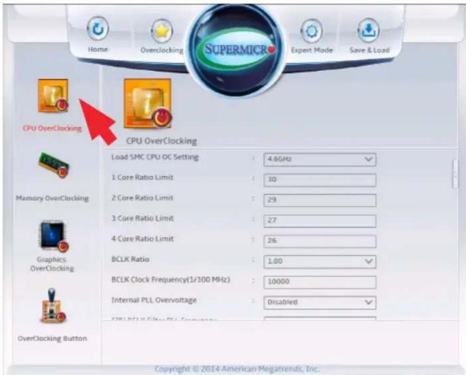
text_image
Home Overclocking SUPERMICR Expert Mode Save & Load CPU OverClocking CPU OverClocking Load SMC CPU OC Setting : 4.6GHz 1 Core Ratio Limit : 30 2 Core Ratio Limit : 29 3 Core Ratio Limit : 27 4 Core Ratio Limit : 26 BCLK Ratio : 1.00 BCLK Clock Frequency(1/100 MHz) : 10000 Internal PLL Overvoltage : Disabled OverClocking Button Copyright © 2014 American Megatrends, Inc.Load SMC CPU OC Setting
This item has optimized pre-configured overclock settings. Select one to activate. The options are Manual, 4.2GHz, 4.3GHz, 4.4GHz, 4.5GHz, 4.6GHz, 4.7GHz, and 4.8GHz.
1-Core Ratio Limit
This increases (multiplies) 1 clock speed in the CPU core in relation to the bus speed when one CPU core is active. Press "+" or "-" on your keyboard to change the value. Enter 0 to use the manufacturer's default setting.
2-Core Ratio Limit
This increases (multiplies) 2 clock speeds in the CPU core in relation to the bus speed when two CPU cores are active. Press "+" or "-" on your keyboard to change the value. Enter 0 to use the manufacturer's default setting.
3-Core Ratio Limit
This increases (multiplies) 3 clock speeds in the CPU core in relation to the bus speed when three CPU cores are active. Press "+" or "-" on your keyboard to change the value. Enter 0 to use the manufacturer's default setting.
4-Core Ratio Limit
This increases (multiplies) 4 clock speeds in the CPU core in relation to the bus speed when four CPU cores are active. Press "+" or "-" on your keyboard to change the value. Enter 0 to use the manufacturer's default setting.
BCLK Ratio
This option selects the BLCK clock ratio ratio for the processor. The options are 1.00, 1.25, 1.67 and 2.50.
BCLK Clock Frequency (1/100 MHz)
Use this item to set the CPU clock override value for the host system. Press "+" or "-" on your keyboard or on-screen keypad to change the value. The default setting is 10000.
Internal PLL Overvoltage
Enable this option for better stability when overclocking. The options are Disabled, and Enabled.
CPU BCLK Filter PLL Frequency
This option selects the speed of the CPU BCLK Filter PLL Frequency for the processor. The options are High Frequency 3.2GHz, and Lower Frequency 1.6GHz. CPU BCLK Filter Frequency. Choose 1.6 for better overclocking capabilities
LCPLL or SBPLL Select
This option selects between LCPLL (resonant circuit-based PLL) and SBPLL (Self-Biased PLL). The options are LCPLL, and SBPLL.
CPU Non Turbo Ratio Override
Use this item to set CPU ratio override when not in turbo mode. Press "+" or "-" on your keyboard or on-screen keypad to change the value. The default setting is dependent on the type of CPU installed.
CPU Power Setting
Enhanced Intel SpeedStep Technology
Enhanced Intel SpeedStep Technology (EIST) allows the system to automatically adjust processor voltage and core frequency in an effort to reduce power consumption and heat dissipation. Please refer to Intel's web site for detailed information. The options are Disabled and Enabled.
Turbo Mode
This feature allows processor cores to run faster than the frequency recommended by the manufacturer. The options are Disabled and Enabled. If this feature is set to Enabled, the following items will display:
CPU Turbo Setting
Package TDP Lock Enable
Select Enabled to lock the Thermal Design Power (TDP) value for the processor. The options are Disabled and Enabled.
Long Duration Power Limit (Watt)
This feature configures Package Power Limit 1, in watts. When the limit is exceeded, the CPU ratio is lowered after a period of time (see item below). A lower limit can save power and protect the CPU, while a higher limit improves performance. Use the number keys on your keyboard to enter the value. The default setting is dependent on the CPU.
Long Duration Power Limit Time (Seconds)
This item allows the user to determine how long the CPU should operate at the power limit set by the user for the item above, if the power limit is exceeded. Use the number keys on your keyboard to enter the value. The default setting is 8.
Short Duration Power Limit Switch
Select Enabled for power limit switch Package Power Limit 2. The settings are Disabled and Enabled.
Short Duration Power Limit (Watt)
This feature configures Package Power Limit 2, in watts. When the limit is exceeded, the CPU ratio is lowered immediately. A lower limit can save power and protect the CPU, while a higher limit improves performance.
Use the number keys on your keyboard to enter the value. The default setting is dependent on the CPU. The default setting is dependent on the CPU.
Package Current Lock
Select Enabled to lock the current CPU package values. The options are Enabled and Disabled.
Processor Current Limit (1/8 Amp)
This feature allows the user to set the maximum electric current value for the Intel CPU cores. The default setting is dependent on the type of CPU installed.
Disable OverClocking Lock
If this feature is set to Enabled, the OverClocking Lock will be deactivated. The options are Disabled and Enabled.
Voltage Configuration
CPU Voltage Mode
Use this feature to select the CPU voltage mode. The options are Override, Offset and Adaptive.
CPU Adaptive/Override/Offset Voltage Target (mV)
Use this feature to set the CPU voltage Target(mV) value from 0mV to 2000mV. Enter 0 to use the manufacture default value.
CPU Override Voltage Target (mV)
Use this feature to set the CPU Voltage Offset value from -1000mV to 998mV. Enter 0 to use the manufacture default value.
Offset Prefix
Use this feature to set the Offset value as a positive (+) number or a negative (-) number. Press "+" or "-" on your keyboard to make a selection. The default setting is "+".
CPU Cache Voltage Mode
Choose Adaptive, which adds voltage to the CPU in cases when the system is under heavy load, Override to manual enter a fixed value and Auto for optimized settings.
CPU Cache Adaptive/Override/Offset Voltage Target (mV)
Use this feature to set the CPU voltage Target(mV) value from 0mV to 2000mV. Enter 0 to use the manufacture default value.
System Agent Voltage Offset (mV)
Use this feature to set the System Agent Voltage Offset value from -1000mV to 998mV. Enter 0 to use the manufacture default value.
Offset Prefix
Use this feature to set the Offset value as a positive (+) number or a negative (-) number. Press "+" or "-" on your keyboard to make a selection. The default setting is "+".
CPU IOA Voltage Offset (mV)
Use this feature to set the CPU Voltage Offset value from -1000mV to 998mV. Enter 0 to use the manufacture default value.
Offset Prefix
Use this feature to set the Offset value as a positive (+) number or a negative (-) number. Press "+" or "-" on your keyboard to make a selection. The default setting is "+".
CPU IOD Voltage Offset (mV)
Use this feature to set the CPU Voltage Offset value from -1000mV to 998mV. Enter 0 to use the manufacture default value.
Offset Prefix
Use this feature to set the Offset value as a positive (+) number or a negative (-) number. Press "+" or "-" on your keyboard to make a selection. The default setting is "+".
PCH 1.05V Voltage
Use this feature to trim the 1.05V PCH Voltage. Select from these values: 0.955V, 1.005V, 1.055V, 1.105V, 1.155V, 1.205V, 1.255V, 1.305V, and 1.355V.
PCH 1.5V Voltage
Use this feature to trim the 1.5V PCH Voltage. Select from these values: 1.366V, 1.416V, 1.466V, 1.516V, 1.566V, 1.616V, 1.666V, 1.716V, 1.766V and 1.816V.
Overclocking SVID and FIVR Options
SVID Control Enable
Select Enabled to enable SVID control for Intel SVID Protocol support. If this setting is set to Disabled, there will be no change made to SVID until the CPU powers down. The options are Enabled and Disabled.
SVID Override Voltage Target (mV)
Use this feature to set the value for SVID Override Voltage Target (up to 2500 mV). Enter 0 to use the manufacture default value.
FIVR Faults Enable
Select Enabled to enable FIVR Faults support. If this setting is set to Disabled, there will be no change made to FIVR Faults settings until the CPU powers down. The options are Enabled and Disabled.
FIVR Efficiency Enable
Select Enabled to enable FIVR Efficiency support. If this setting is set to Disabled, there will be no change made to FIVR Efficiency status until the CPU powers down. The options are Enabled and Disabled.
CPU Input Voltage
CPU Input Voltage
Warning! Carefully select the CPU input voltage, otherwise the CPU will burn. Alos, increasing the CPU voltage will cause the CPU temperature to rise. This needs to be compensated with an upgrade in the cooling system. The options are Auto, 1.85V, 1.90V, 1.95V, 2.00V, 2.05V, 2.10V, 2.15V, 2.20V, 2.25V, 2.30V, 2.35V and 2.40V.
Memory Overclocking
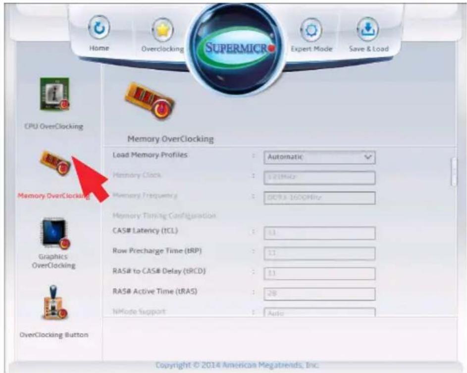
text_image
Home Overclocking Supermic Expert Mode Save & Load CPU OverClocking Memory OverClocking Load Memory Profiles : Automatic Memory Clock : 121MHz Memory Frequency : 009.3-160GHz Memory Timing Configuration CAS# Latency (TCL) : 11 Row Precharge Time (tRP) : 11 RAS# to CAS# Delay (tRCD) : 11 RAS# Active Time (tRAS) : 28 NMode Support : Auto OverClocking Button Copyright © 2014 American Megatrends, Inc.Load Memory Profiles
Use this feature to set Performance Memory Profiles which may cause impact on memory behavior*. Select Automatic to allow the BIOS to automatically set Performance Memory Profiles. Select Manual to manually configure Performance Profiles. The options are Automatic, Manual, XMP Profile 1 and XMP Profile 2.
If Automatic is selected, the installed memory will run at 2200MHz if the detected memory is rated at 2400MHz or above, and run at 1867MHz if the memory detected is rated at 1867MHz.
If Manual, XMP Profile 1 or XMP Profile 2 is selected, the following options will be available. These options will only appear if XMP (Extreme Memory Profile) Memory is/are installed:
Memory Clock
This option selects the Memory Clock Multiplier. The options are 133MHz and 100MHz.
*The C7Z97-M/MF supports memory modules having a frequency of more than 2133MHz (Extreme Memory Profile or XMP Memory). However, XMP memory is not within the JEDEC memory standard. Compatibility and stability of these memory modules depend on varying factors, including the processor's capabilities and other devices installed.
Memory Frequency
This option selects the type/speed of the memory installed. The options are DDR3-1066MHz, DDR3-1333MHz, DDR3-1600MHz, DDR3-1800MHz, DDR3-2000MHz, DDR-2200MHz, DDR-2400MHz, and DDR-2600MHz. Default speed is auto detected.
Memory Voltage
This option selects the Memory Voltag The options are Auto, 1.45V, 1.50V, 1.55V, 1.60V, 1.65V, 1.70V, 1.75V, 1.80V, 1.85V, and 1.95V.
Memory Timing Configuration (Expert Mode)
CAS# Latency (tCL)
This option configures the Cas Latency Range. Enter a number between 4-18. The default is 9.
Row Precharge Time (tRP)
This option selects the Ras Precharge Range. Enter a number between 1-38. The default is 11.
RAS# to CAS# Delay (tRCD)
This option configures the Row to Col Delay Range. Enter a number between 1-38. The default is 11.
RAS# Active Time (tRAS)
This option selects the Ras Active Time. Enter a number between 1-586. The default is 28.
Command Rate (CR)
This option sets the delay between when a memory chip is selected and when the first active command can be issued.
Write Recovery Time (tWR)
This feature sets the amount of delay that must elapse after the completion of a valid write operation, before an active bank can be precharged
Row Refresh Cycle Time (tRFC)
This feature sets the number of clocks from a Refresh command until the first Activate command to the same rank
Write to Read Delay (tWR)
This option configures the Minimum Write Recovery Time. Enter a number between 1-38. The default is 12.
Active to Active Delay (tRRD)
This option selects the Minimum Row Active To Row Active Delay Time. Enter a number between 1-38. The default is 5.
Read CAS# Precharge (tRTP)
This option configures the Internal Read to Precharge Command Delay Time. Enter a number between 1-38. The default is 6.
Minimum CAS Write Latency Time (tCWL)
This option selects the Minimum CAS Write Latency Time. Enter a numeric value. The default is 8.
Maximum tREFI Time (tREFI)
This option configures the Maximum tREFI Time (Average Periodic Refrech Interval). Enter a numeric value. The default is 6240.
Four Active Window Delay (tFAW)
This option selects the Minimum Four Activate Window Delay Time. Enter a numeric value between 1-586. The default is 24.
Row Cycle Time (tRC)
This option configures the Minimum Active to Active/Refresh Delay Time (tRCmin). Enter a numeric value between 1-586. The default is 39.
tCKE
This option configures the period of time the DDR3 initiates a minimum of one refresh command internally once it enters Self-Refresh mode. The default is 7.
tRDRD
This option configures the between module read to read delay. Enter a numeric value. The default is 7.
tRDRDDR
This option configures the between module read to read delay from different ranks. Enter a numeric value. The default is 7.
tRDRDDD
This option configures the DRAM tRWSR settings. Enter a numeric value. The default is 7.
tWRRD
This option configure between module write to read delay. Enter a numeric value. The default is 27.
tWRRDDR
This option configure between module write to read delay from different ranks. Enter a numeric value. The default is 8.
tWRRDDD
This option configure DRAM tRRSR setting. Enter a numeric value. The default is 6.
tWRWR
This option configures module write to write delay. Enter a numeric value. The default is 6.
tWRWRDR
This option configures between module write to write delay from different ranks. The default is 7.
tWRWRDD
This option configures between module write to write delay from different DIMMs. The default is 7.
tRDWR
This option configures between module read to write delay. The default is 20.
tRDWRDR
This option configures between module read to write delay from different ranks. The default is 20.
tRDWRDD
This option configures between module read to write delay from different DIMMs. The default is 20.
RTL (ChA)
This option configures round trip latency for channel A. The default is 50.
RTL (ChB)
This option configures round trip latency for channel B. The default is 58.
IO-L (ChA)
This option configures I/O latency for channel A. The default is 5.
IO-L (ChB)
This option configures I/O latency for channel B. The default is 12.
ODT WR (ChA)
This option configures the memory on die termination resistors' WR for channel A. The default is 60
ODT WR (ChB)
This option configures the memory on die termination resistors' WR for channel B. The default is 60
ODT NOM (ChA)
This option changes the ODT (CHA) Auto/Manual settings. The default is 60.
ODT NOM (ChB)
This option changes the ODT (CHB) Auto/Manual settings. The default is 60.
MRC Fast Boot
This option enable Memory Fast Boot to skip DRAM memory training for booting faster. The options are Enabled and Disabled.
DIMM Exit Mode
This item specifies the Exit Mode support options. The options are Auto, Slow Exit, and Fast Exit.
Graphics OverClocking
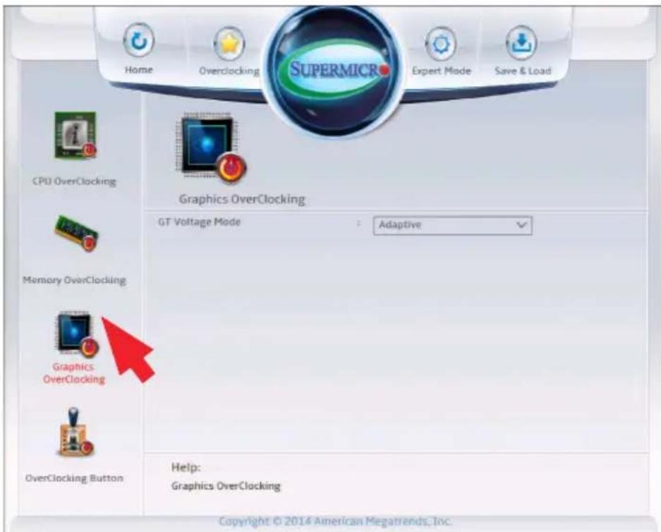
text_image
Home Overclocking SUPERMICR Expert Mode Save & Load CPU OverClocking Graphics OverClocking GT Voltage Mode : Adaptive Memory OverClocking Graphics OverClocking OverClocking Button Help: Graphics OverClocking Copyright © 2014 American Megatrends, Inc.Graphics Core Ratio Limit
Use this feature to set graphics core ratio limit. Press "+" or "-" on your keyboard or on-screen keypad to change the value. The default setting is dependent on the type of CPU installed.
GT Voltage Mode
Use this feature to select the Overclocking GT mode. The options are Override, Offset and Adaptive.
GT Adaptive Voltage Target (mV)
(if Adaptive is selected above) Use this feature to set the GT Adaptive voltage Target(mV) value from 0mV to 2000mV. Enter 0 to use the manufacture default value.
GT Override Voltage Target (mV)
(if Override is selected above) Use this feature to set the GT Adaptive voltage Target(mV) value from 0mV to 2000mV. Enter 0 to use the manufacture default value.
GT Voltage Offset (mV)
(if Offset is selected above) Use this feature to set the GT Adaptive voltage Target(mV) value from 0mV to 2000mV. Enter 0 to use the manufacture default value.
Offset Prefix
Use this feature to set the Offset value as a positive (+) number or a negative (-) number. Press "+" or "-" on your keyboard to make a selection. The default setting is "+".
OverClocking Buttons
These are the settings for the OC buttons on the optional OC panel:
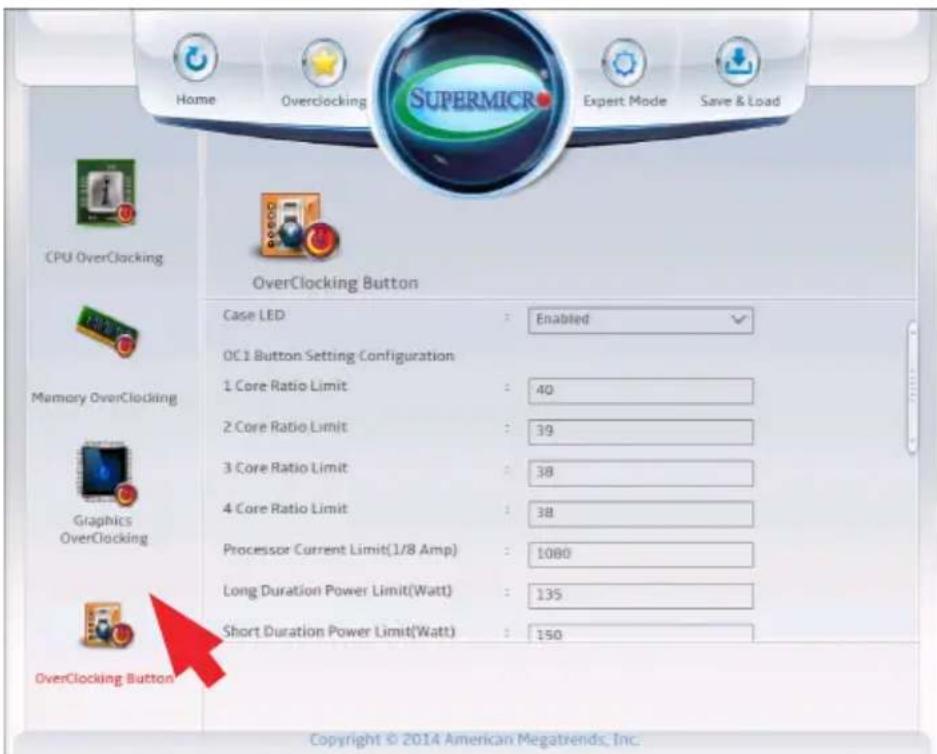
text_image
Home Overclocking Supermic Expert Mode Save & Load CPU OverClocking OverClocking Button Case LED : Enabled OC1 Button Setting Configuration 1 Core Ratio Limit : 40 2 Core Ratio Limit : 39 3 Core Ratio Limit : 38 4 Core Ratio Limit : 38 Processor Current Limit(1/8 Amp) : 1080 Long Duration Power Limit(Watt) : 135 Short Duration Power Limit(Watt) : 150 OverClocking Button Copyright © 2014 American Megatrends, Inc.Case LED
This item enables or disables the Overclocking LED on the chassis. The options are Enabled and Disabled.
OC1 Button Setting Configuration OC2 Button Setting Configuration
The following settings are displayed with their current values. Use the "-" and "+" keys to change values:
1 Core Ratio Limit
2 Core Ratio Limit
3 Core Ratio Limit
4 Core Ratio Limit
Processor Current Limit (1/8 Amp)
Long Duration Power Limit (Watts)
Short Duration Power Limit (Watts)
Memory OC Button Setting Configuration
Load Memory Profiles
Use this feature to assign Performance Memory Profiles for the Memory OC Button. Select Automatic to allow the BIOS to automatically set Performance Memory Profiles. Select Manual to manually configure Performance Profiles, see below. Select XMP Profile 1 or XMP Profile 2 to use the XMP Profiles configured under the Memory Overclocking section on Page 4-24. The options are Automatic, Manual, XMP Profile1 and XMP Profile2.
The following become available if Manual is selected above:
Memory OC Button Setting Configurations
Memory Clock
This option selects the Memory Clock Multiplier. The options are 1.33 and 1.00.
Memory Frequency
This option selects the type/speed of the memory installed. The options are DDR3-1066MHz, DDR3-1333MHz, DDR3-1600MHz, DDR3-1866MHz and DDR3-2133MHz.
CAS# Latency (tCL)
This option configures the Cas Latency Range. Enter a number between 4-18. The default is 9.
Row Precharge Time (tRP)
This option selects the Ras Precharge Range. Enter a number between 1-38. The default is 11.
RAS# to CAS# Delay (tRCD)
This option configures the Row to Col Delay Range. Enter a number between 1-38. The default is 11.
RAS# Active Time (tRAS)
This option selects the Ras Active Time. Enter a number between 1-586. The default is 28.
Write Recovery Time (tWR)
This option configures the Minimum Write Recovery Time. Enter a number between 1-38. The default is 12.
Row Refresh Cycle Time (tRFC)
This option selects the Minimum Refresh Recovery Delay Time. Enter a number between 1-9363. The default is 128.
Write to Read Delay (tWTR)
This option configures the Minimum Internal Write to Read Command Delay Time. Enter a number between 1-38. The default is 6.
Active to Active Delay (tRRD)
This option selects the Minimum Row Active To Row Active Delay Time. Enter a number between 1-38. The default is 5.
Read CAS# Precharge (tRTP)
This option configures the Internal Read to Precharge Command Delay Time. Enter a number between 1-38. The default is 6.
Minimum CAS Write Latency Time (tCWL)
This option selects the Minimum CAS Write Latency Time. Enter a numeric value. The default is 8.
Maximum tREFI Time (tREFI)
This option configures the Maximum tREFI Time (Average Periodic Refrech Interval). Enter a numeric value. The default is 6240.
Four Active Window Delay (tFAW)
This option selects the Minimum Four Activate Window Delay Time. Enter a numeric value between 1-586. The default is 24.
Row Cycle Time (tRC)
This option configures the Minimum Active to Active/Refresh Delay Time (tRCmin). Enter a numeric value between 1-586. The default is 39.
Memory Voltage
Use this feature to select the Memory Voltage. The options are 1.35V, 1.40V, 1.45V, 1.50V, 1.55V, 1.60V, 1.65V, 1.70V, 1.75V, 1.80V, 1.85V, 1.90V, 1.95V and Auto.
4-6 Chipset
Set all options for the Chipset in this section.
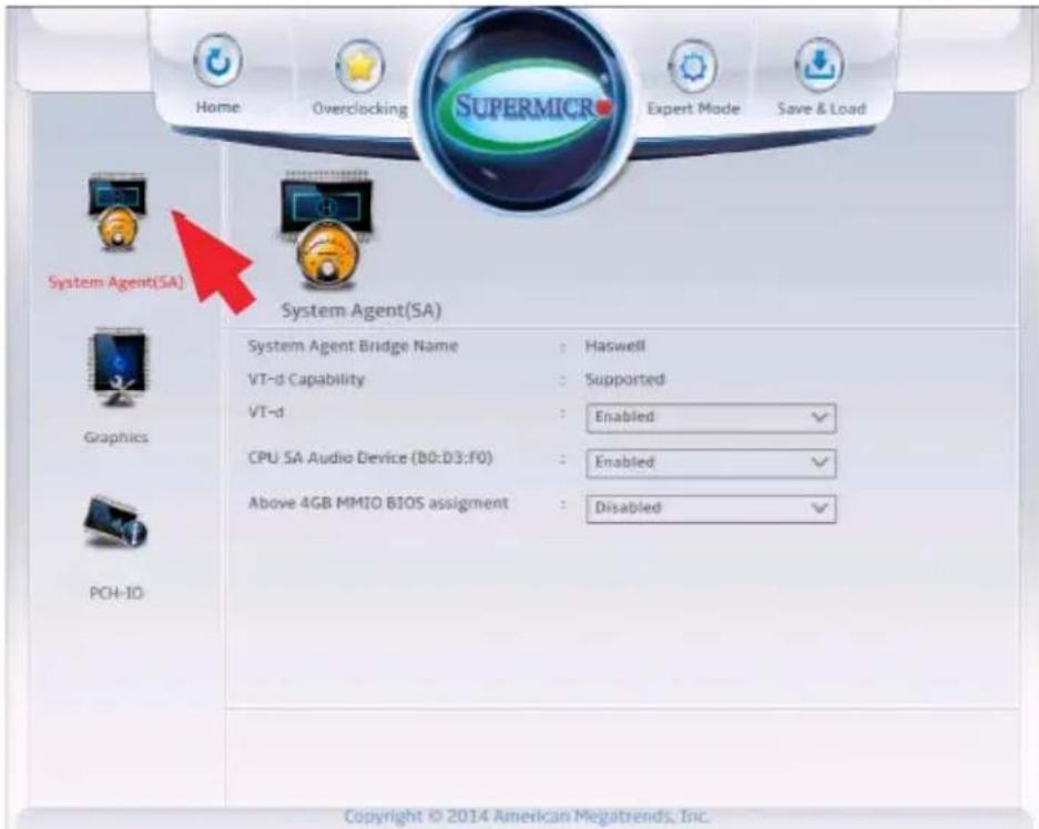
text_image
Home Overclocking SUPERMICR Expert Mode Save & Load System Agent(SA) System Agent(SA) System Agent Bridge Name : Haswell VT-d Capability : Supported VT-d : Enabled ✓ CPU SA Audio Device (B0:D3:F0) : Enabled ✓ Above 4GB MMIO BIOS assignment : Disabled ✓ Copyright © 2014 American Megatrends, Inc.System Agent
The following will be displayed:
• System Agent Bridge Name - this displays the System Agent bridge name.
• System Agent RC Version - indicates the System Agent RC version.
- VT-d Capability - this item indicates whether VT-d is supported.
VT-d
Select Enabled to enable Intel Virtualization Technology support for Direct I/O VT-d by reporting the I/O device assignments to the Virtual Machine Manager (VMM) through the DMAR ACPI Tables. This feature offers fully-protected I/O resource-sharing across the Intel platforms, providing the user with greater reliability, security and availability in networking and data-sharing. The settings are Enabled and Disabled.
CPU SA Audio Device (B0:D3:F0)
This item enables or disables the CPU System Agent (SA) Audio device. The options are Enabled and Disabled.
Above 4GB MMIO BIOS Assignment
This item enables or disables the Above 4GB Memory Mapped IO BIOS Assignment. The options are Enabled and Disabled.
Graphics
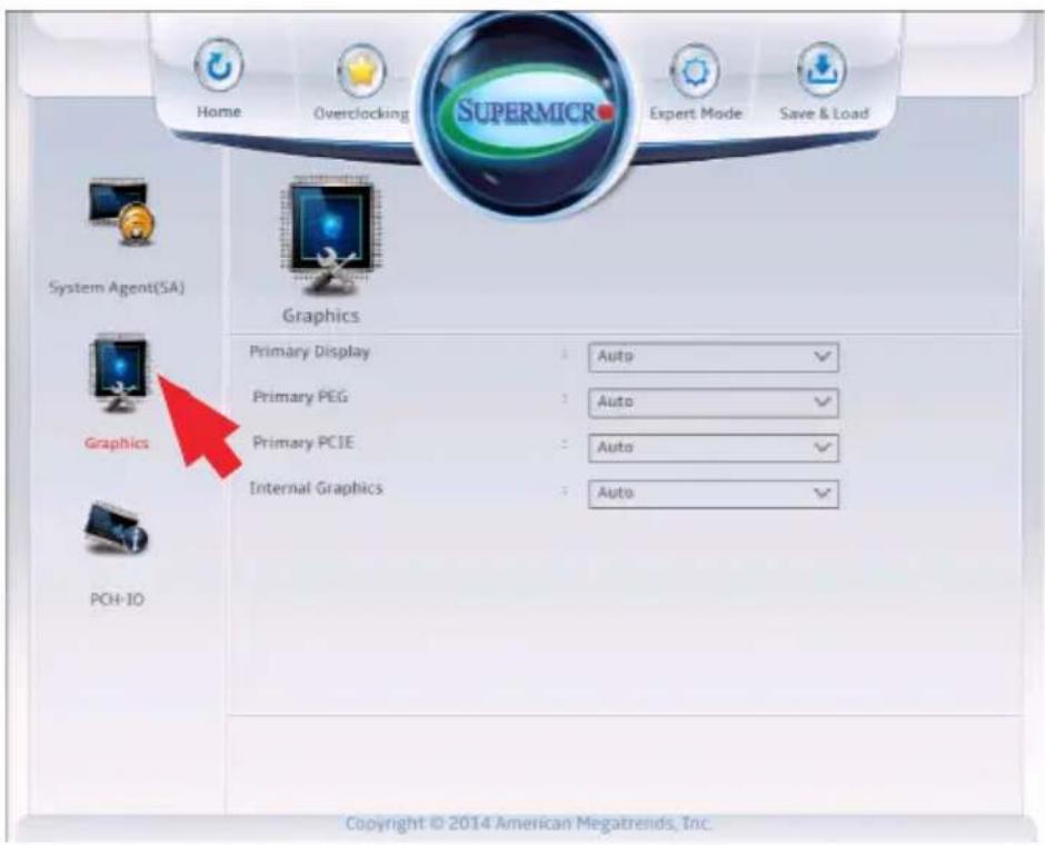
text_image
Home Overclocking Supermic Expert Mode Save & Load System Agent(SA) Graphics Primary Display Auto Primary PEG Auto Primary PCIE Auto Internal Graphics Auto PCH-IO Copyright © 2014 American Megatrends, Inc.The following will be displayed:
- IGFX VBIOS Version - displays the Integrated Graphics chip VBIOS version number.
- IGFX Frequency - indicates the clock speed of the Integrated Graphics chip.
Primary Display
Use this feature to select the graphics device to be used as the primary display. Select from IGFX/PEG/PCI or select SG for switchable GFX. The options are Auto, IGFX, PEG, PCIE and SG.
Primary PEG (if PEG is selected above)
This item selects which PEG graphics device should be the primary PEG. The options are Auto, PEG11 and PEG12.
Primary PCIE (if PEG or PCIE is selected above)
This item selects which PCIE graphics device should be the primary PEG. The options are Auto, PCIE1, PCIE2, PCIE3, PCIE4, PCIE5, PCIE6, and PCIE7.
Internal Graphics
This item keeps the IGD (Internal Graphics Device) enabled, based on setup options. The options are Auto, Enabled and Disabled.

Note: To prevent an error when installing the Intel Graphics Driver, please set this option to Enabled (C7Z97-MF only).
PCH-IO
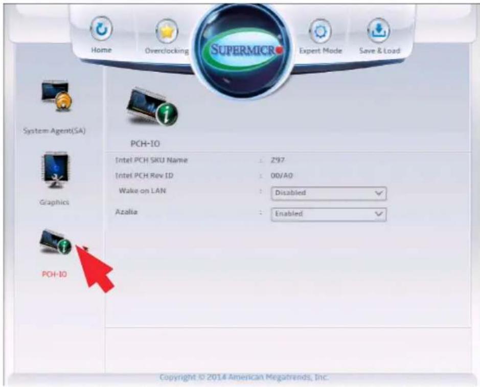
text_image
Home Overclocking SuperMICRO Expert Mode Save & Load System Agent(SA) PCH-IO Intel PCH SKU Name : Z97 Intel PCH Rev ID : 00/A0 Wake on LAN : Disabled Azalia : Enabled PHC-IO Copyright © 2014 American Megatrends, Inc.The following will be displayed:
- Intel PCH RC Version - displays the PCH chip release version.
- Intel PCH SKU Name - indicates the PCH chip part number.
• Intel PCH Rev ID - displays the PCH chip revision ID.
Wake on LAN
Select Enabled to enable the capability to 'wake-up' the system through the Ethernet port. The settings are Enabled and Disabled.
Azalia (HD Audio)
This item controls the detection of the Azalia (HD Audio) device. The settings are Enabled and Disabled.
4-7 Memory
Set all options for the System Memory in this section.
Memory Information
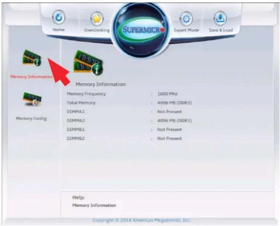
text_image
Home Overclocking Supermic Expert Mode Save & Load Memory Information Memory Information Memory Frequency : 1600 Mhz Total Memory : 4096 MB (DDR3) DIMMA1 : Not Present DIMMA2 : 4096 MB (DDR3) DIMMB1 : Not Present DIMMB2 : Not Present Help: Memory Information Copyright © 2014 American Megatrends, Inc.This item displays the following information on the memory modules installed on the motherboard.
• Memory RC Version - this item displays the memory controller version.
- Memory Frequency - this item displays the frequency of the installed memory.
• Total Memory - this item displays the total memory size detected.
• Memory Voltage - this item displays the current memory voltage.
• DIMMA1 - displays if a DIMM is installed on this slot, and the DIMM size.
- DIMMA2 - displays if a DIMM is installed on this slot, and the DIMM size.
- DIMMB1 - displays if a DIMM is installed on this slot, and the DIMM size.
- DIMMB2 - displays if a DIMM is installed on this slot, and the DIMM size.
- CAS Latency (tCL) - this item displays the Column Address Storage (CAS) latency time, in clock cycles.
- Minimum Delay Time - this item displays the Column Address Storage (CAS) minimum delay time, in clock cycles.
- CAS to RAS (tRCDmin) - this item displays the Row Address Storage (RAS) to CAS delay time, in clock cycles.
- Row Precharge (tRPmin) - this displays the number of clock cycles needed to terminate access to an open row of memory, and open access to the next row.
- Active to Precharge (tRASmin) - this item displays the Active to Precharge delay, in clock cycles.
Memory Configuration
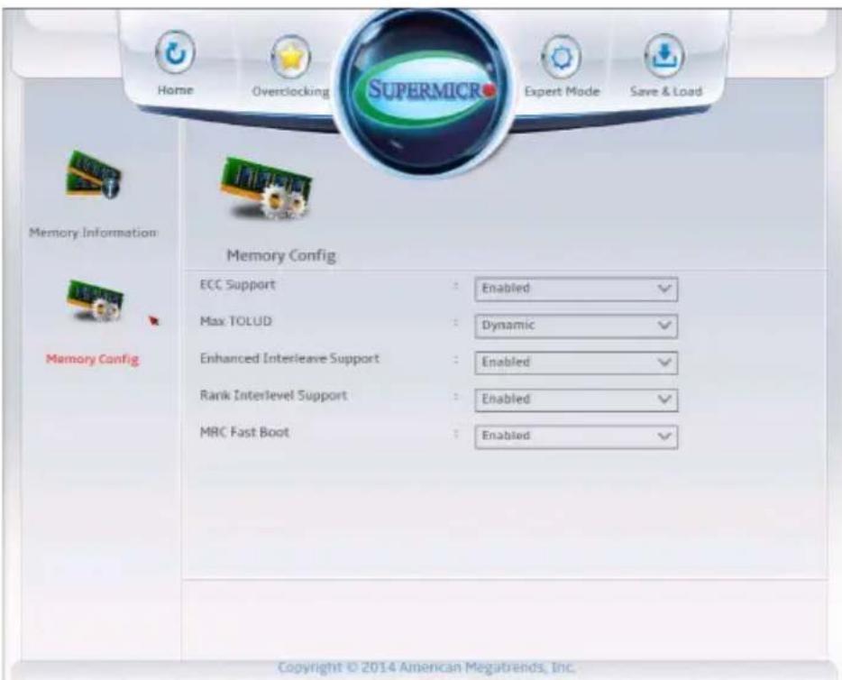
text_image
Home Overclocking SUPERMICR Expert Mode Save & Load Memory Information Memory Config ECC Support : Enabled ✓ Max TOLUD : Dynamic ✓ Enhanced Interleave Support : Enabled ✓ Rank Interlevel Support : Enabled ✓ MRC Fast Boot : Enabled ✓ Copyright © 2014 American Megatrends, Inc.Max TOLUD (Top of Low Usable DRAM)
This feature sets the maximum TOLUD value, which specifies the "Top of Low Usable DRAM" memory space to be used by internal graphics devices, GTT Stolen Memory, and TSEG, respectively, if these devices are enabled. The options are Dynamic, 1 GB, 1.25 GB, 1.5 GB, 1.75 GB, 2 GB, 2.25 GB, 2.5 GB, 2.75 GB, 3 GB and 3.25 GB.
Note: TSEG is a block of memory that is only accessible by the processor while operating in System Management Mode (SMM).
Enhanced Interleave Support
This feature enables or disables the motherboard's enhanced interleave support. The settings are Enabled and Disabled.
Rank Interlevel Support
This feature enables or disables the motherboard's Rank interlevel support. The settings are Enabled and Disabled.
MRC Fast Boot
This feature enables or disables the MRC Fast Boot support. The settings are Enabled and Disabled.
4-8 I/O
Set all options for the I/O in this section.
SATA
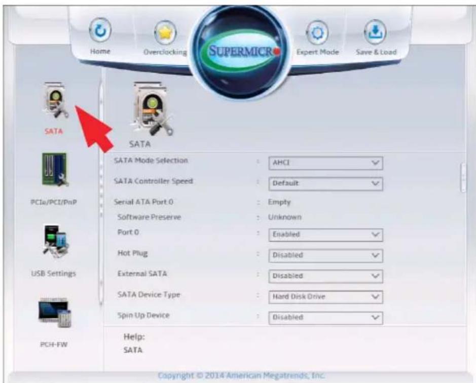
text_image
Home Overclocking SUPERMICR Expert Mode Save & Load SATA SATA SATA Mode Selection AHCI SATA Controller Speed Default Serial ATA Port 0 Empty Software Preserve Unknown Port 0 Enabled Hot Plug Disabled External SATA Disabled SATA Device Type Hard Disk Drive Spin Up Device Disabled PCH-FW Help: SATA Copyright © 2014 American Megatrends, Inc.SATA Mode Selection
This item selects the mode for the installed SATA drives. The options are IDE, AHCI and RAID.
SATA Controller Speed (AHCI or RAID Mode only)
This item selects the SATA Controller Speed. The options are Default, Gen1, Gen2 and Gen3.
Alternate ID (RAID Mode Only)
This item Enables or Disables the RAID ID feature for SATA Ports 0\~5. The options are Enabled and Disabled.
The information of the installed SATA drives on the particular SATA port are displayed.
- Serial ATA Port # (Status)
• Software Preserve Support
If the item SATA Mode Selection above is set to AHCI, the following items are displayed:
Port 0 \~ Port 5
This item Enables or Disables SATA Ports 0\~5. The options are Enabled and Disabled.
Hot Plug
This feature designates the port specified for hot plugging. Set this item to Enabled for hot-plugging support, which will allow the user to replace a SATA disk drive without shutting down the system. The options are Enabled and Disabled.
External SATA
This item Enables or Disables External SATA (eSATA) support. The options are Enabled and Disabled.
SATA Device Type
This feature configures the selected SATA port to support either a solid state drive or hard disk drive. The options are Hard Disk Drive and Solid Sate Drive.
Spin Up Device
On an edge detect from 0 to 1, set this item to allow the PCH to start a COMRESET initialization
PCIe/PCI/PnP
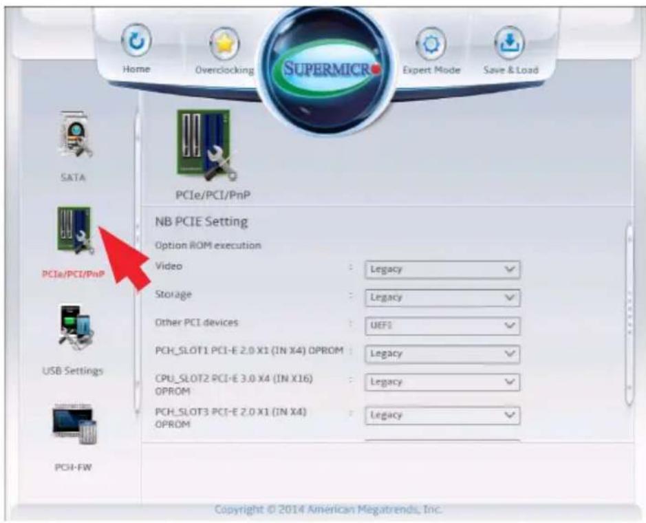
text_image
Home Overclocking Supermic Expert Mode Save & Load SATA PCIe/PCI/PnP NB PCIE Setting Option ROM execution Video : Legacy ✓ Storage : Legacy ✓ Other PCI devices : UEFI ✓ PCH_SLOT1 PCI-E 2.0 X1 (IN X4) OPROM : Legacy ✓ CPU_SLOT2 PCI-E 3.0 X4 (IN X16) OPROM : Legacy ✓ PCH_SLOT3 PCI-E 2.0 X1 (IN X4) OPROM : Legacy ✓ USB Settings PCI-FW Copyright © 2014 American Megatrends, Inc.NB PCIE Setting
This section displays if a PCIE device is detected on any PCIE slot on the motherboard.
- PCH_SLOT1 PCI-E 2.0 X1 (IN X4) - this item displays if a device is installed or not.
- CPU_SLOT2 PCI-E 3.0 X4 (IN X16) - this item displays if a device is installed or not.
- PCH_SLOT3 PCI-E 2.0 X1 (IN X4) - this item displays if a device is installed or not.
Option ROM Execution
Video
This feature controls which option ROM to execute for the Video device. The options are Do Not Launch, UEFI and Legacy.
Storage
This feature controls which option ROM to execute for the storage device. The options are Do Not Launch, UEFI and Legacy.
Other PCI Devices
This feature controls which option ROM to execute for the other PCI devices. The options are UEFI and Legacy.
PCH_SLOT1 PCI-E 2.0 X1 (IN X4) OPROM, CPU_SLOT2 PCI-E 3.0 X4 (IN X16) OPROM, PCH_SLOT3 PCI-E 2.0 X1 (IN X4) OPROM
Select Disabled to deactivate the selected slot, Legacy to activate the slot in legacy mode and EFI to activate the slot in EFI mode. The options are Disabled, Legacy, EFI and EFI and Legacy.
Onboard LAN1 Option ROM
Select PXE (Preboot Execution Environment) to boot the computer using a PXE device installed in a LAN port specified. Select Disabled to prevent system boot using a device installed in a LAN port. The options for Onboard LAN1 Option ROM/Onboard LAN2 Option ROM are Disabled and PXE.
USB Settings
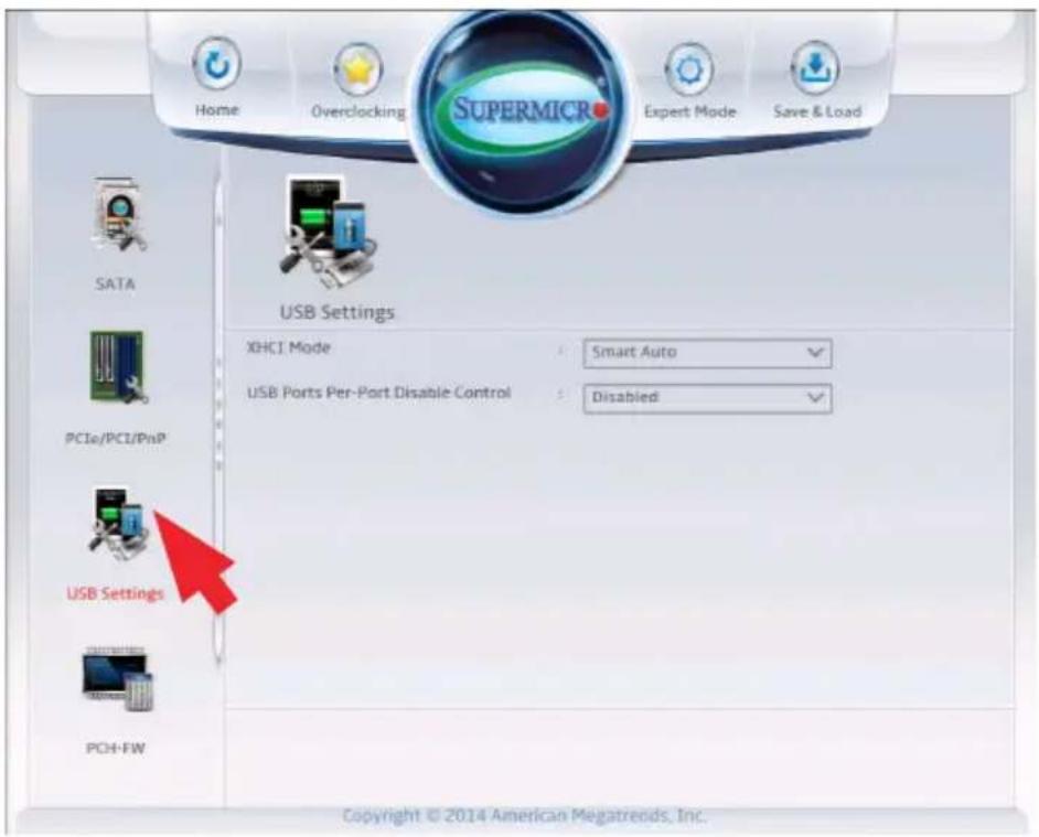
text_image
Home Overclocking SUPERMICR Expert Mode Save & Load SATA PC1a/PCI/PnP USB Settings USB Settings XHCI Mode Smart Auto USB Ports Per-Port Disable Control Disabled PCH-FW Copyright © 2014 American Megatrends, Inc.XHCI Mode
This feature handles the operation mode for the XHCI (Extensible Host Controller Interface) controller. The settings are Smart Auto, Auto, Enabled, and Disabledl.
USB Ports Per-Port Disable Control
This item activates the capability of the motherboard to Enable or Disable each USB Port independently. The options are Enabled and Disabled.
USB Port #0\~Port #13
This item Enables or Disables specified USB Port. The options are Enabled and Disabled.
PCH-FW (Firmware)
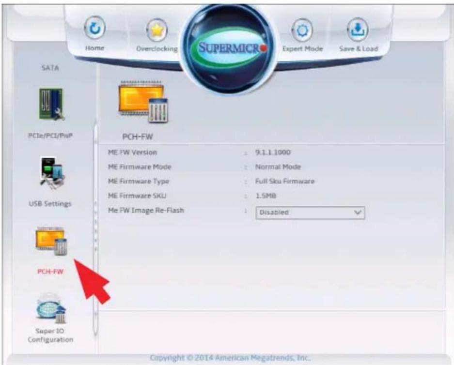
text_image
Home Overclocking SUPERMICR Expert Mode Save & Load SATA PCIe/PCI/PnP PCH-FW ME FW Version : 9.1.1.1000 ME Firmware Mode : Normal Mode ME Firmware Type : Full Sku Firmware ME Firmware SKU : 1.5MB Me FW Image Re-Flash : Disabled USB Settings PCH-FW Super 10 Configuration Copyright © 2014 American Megatrends, Inc.The following information for the PCH Firmware.
• ME FW Version - displays the Management Engine version number.
• ME Firmware Mode - displays the Management Engine mode.
• ME Firmware Type - displays the Management Engine firmware type.
• ME Firmware SKU - displays the Management Engine SKU size.
ME FW Image Re-Flash
This item will update the PCH Firmware from an omage in a USB Flash-drive attached to a USB port. The options are Enabled and Disabled.
Super IO Configuration
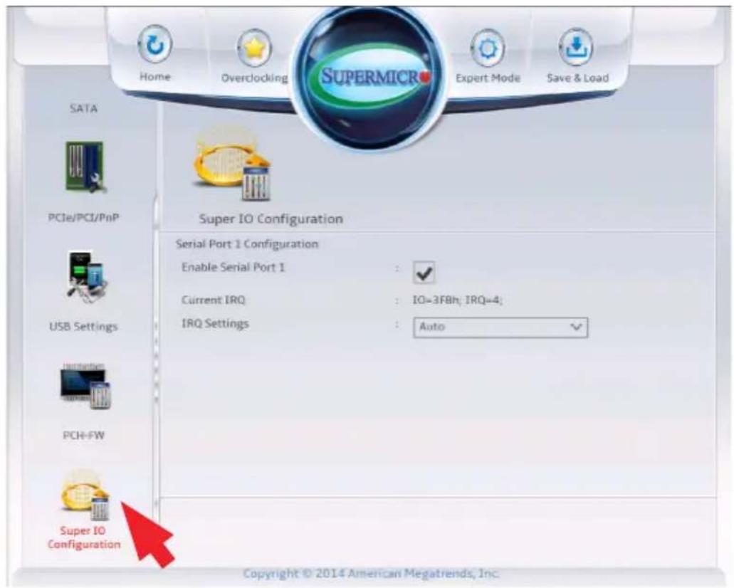
text_image
Home Overclocking SUPERMICR Expert Mode Save & Load SATA PCIe/PCI/PnP USB Settings Instruction PCH-FW Super IO Configuration Super IO Configuration Serial Port 1 Configuration Enable Serial Port 1 : ✓ Current IRQ : IO=3F8h; IRQ=4; IRQ Settings : Auto ✓ Copyright © 2014 American Megatrends, Inc.Enable Serial Port 1
This item will Enable or Disable Serial Port 1 (COM1). Place a tick mark on the box to enable Serial Port 1. The default is Enabled.
Current IRQ
This item displays the current IRQ setting for Serial Port 1 (COM1).
IRQ Settings
This item configures the IRQ setting for Serial Port 1 (COM1).
The options for Serial Port 1 are Auto, IO=3F8h; IRQ=4, IO=3F8h; IRQ=3, 4, 5, 6, 7, 9, 10, 11, 12, IO=2F8h; IRQ=3, 4, 5, 6, 7, 9, 10, 11, 12 and IO=2E8h; IRQ=3, 4, 5, 6, 7, 9, 10, 11, 12.
4-9 Booting
Set all options for the Boot devices in this section.
Boot Device Settings
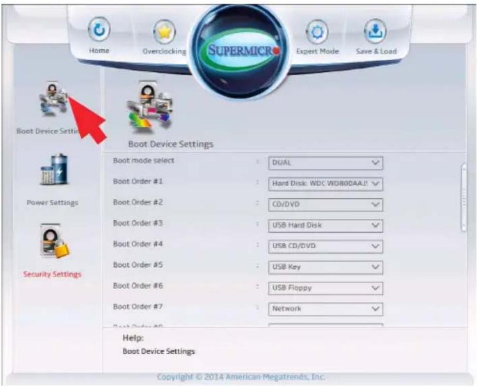
text_image
Home Overclocking SUPERMICR Expert Mode Save & Load Boot Device Settings Boot Device Settings Boot mode select : DUAL Boot Order #1 : Hard Disk: WDC WD800AAJ! Boot Order #2 : CD/DVD Boot Order #3 : USB Hard Disk Boot Order #4 : USB CD/DVD Boot Order #5 : USB Key Boot Order #6 : USB Floppy Boot Order #7 : Network Boot Order #8 Security Settings Help: Boot Device Settings Copyright © 2014 American Megatrends, Inc.Boot Mode Select
This option sets the boot mode between Legacy BIOS, UEFI BIOS or Dual. The options are Dual, Legacy and UEFI.
Boot Order #1\~#15
This option sets the order of which the system boots from the installed boot devices. The options and defaults are dependent on the boot devices detected.
Power Settings
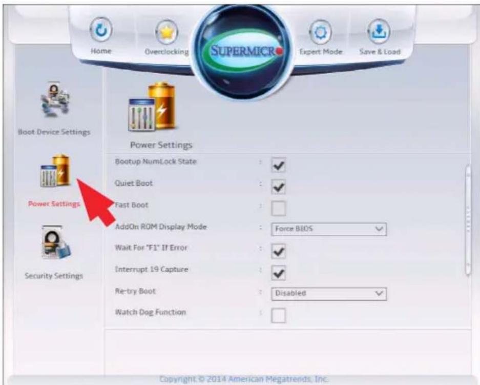
text_image
Home Overclocking SUPERMICR Expert Mode Save & Load Boot Device Settings Power Settings Bootup NumLock State Quiet Boot Fast Boot AddOn ROM Display Mode Wait For "F1" If Error Interrupt 19 Capture Re-try Boot Watch Dog Function Power Settings Power Settings Force BIOS Disabled Copyright © 2014 American Megatrends, Inc.Bootup Numlock State
This option sets the state to which the NumLock key is configured when booting. The default is checked (Activated).
Quiet Boot
This option sets the state to which the system buzzer is configured when booting. The default is checked (On), the buzzer is silent.
Fast Boot
This option sets fast system boot, quick POST, etc. The default is un-checked (Off).
AddOn ROM Display Mode
This feature sets the display mode for the option ROM. The options are Force BIOS and Keep Current.
Wait for "F1" for Error
This option sets whether the system will wait for the user to press "F1" when an error is detected during POST. The default is checked (On).
Interrupt 19 Capture
Interrupt 19 is the software interrupt that handles the boot disk function. When this item is set to Enabled, the ROM BIOS of the host adaptors will "capture" Interrupt 19 at boot and allow the drives that are attached to these host adaptors to function as bootable disks. If this item is set to Disabled, the ROM BIOS of the host adaptors will not capture Interrupt 19, and the drives attached to these adaptors will not function as bootable devices. The default is unchecked (Off).
Re-try Boot
In the event the system fails to boot, this will enable the system to retry to boot the system again. The options are Enabled and Disabled.
Watch Dog
If enabled, the Watch Dog timer will allow the system to reboot when it is unresponsive for more than 5 minutes. The default is unchecked (Off).
Power Button Function
This feature controls how the system shuts down when the power button is pressed. Select 4 Seconds Override for the user to power off the system after pressing and holding the power button for 4 seconds or longer. Select Instant Off to instantly power off the system as soon as the user presses the power button. The options are Instant Off, and 4 Seconds Override.
Restore on AC Power Loss
Use this feature to set the power state after a power outage. Select Power-Off for the system power to remain off after a power loss. Select Power-On for the system power to be turned on after a power loss. Select Last State to allow the system to resume its last power state before a power loss. The options are Last State, Power On, Stay Off.
EUP Support
EuP, or Energy Using Product is a European energy-saving specification that sets a standard on the maximum total power consumption on electrical products. Check the box to activate EUP support, the default is Uncheched (Disabled).
Security Settings
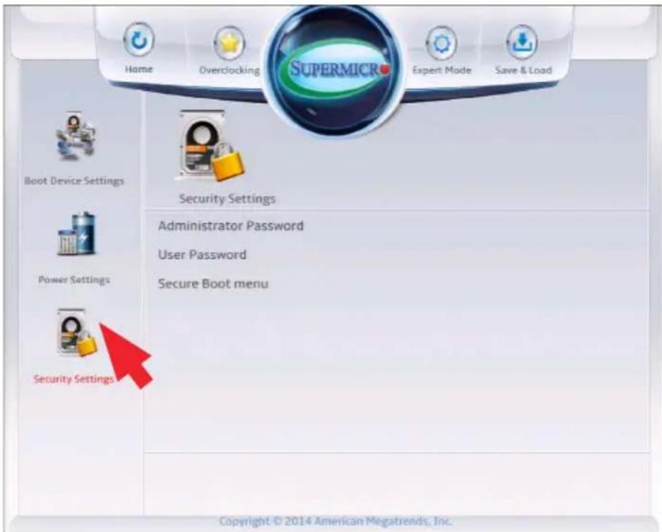
text_image
Home Overclocking SUPERMICR Expert Mode Save & Load Boot Device Settings Security Settings Administrator Password User Password Secure Boot menu Power Settings Security Settings Copyright © 2014 American Megatrends, Inc.This menu allows the user to configure the following security settings for the system.
- If the Administrator password is defined ONLY - this controls access to the BIOS setup ONLY.
- If the User's password is defined ONLY - this password will need to be entered upon each system boot, and will also have Administrator rights in the setup.
- Passwords must be at least 3 and up to 20 characters long.
Administrator Password
Use this feature to set the Administrator Password which is required to enter the BIOS setup utility. The length of the password should be from 3 characters to 20 characters long.
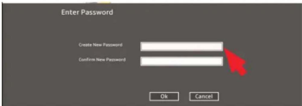
text_image
Enter Password Create New Password Confirm New Password Ok CancelUser Password
Use this feature to set the User Password, which is required every time the system boots. The length of the password should be from 3 characters to 20 characters long.
Secure Boot Menu
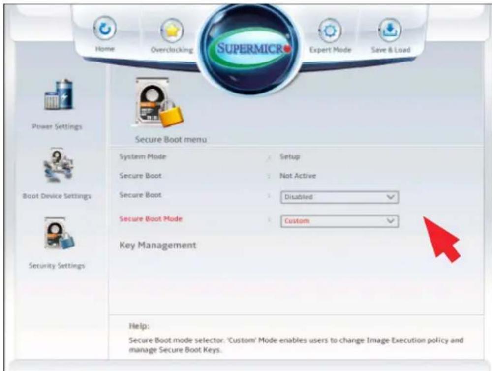
text_image
Home Overclocking SUPERMICR Expert Mode Save & Load Power Settings Secure Boot menu System Mode Setup Secure Boot Not Active Secure Boot Disabled Secure Boot Mode Custom Key Management Boot Device Settings Security Settings Help: Secure Boot mode selector. 'Custom' Mode enables users to change Image Execution policy and manage Secure Boot Keys.The following items will be displayed:
• System Mode - indicates the current system mode.
- Secure Boot - this item indicates if Secure Boot is activated or not.
Secure Boot
Select Enabled for Secure Boot flow control. This feature is available when the platform key (PK) is pre-registered, the platform operates in the user mode, and CSM is disabled in the Setup utility. The options are Disabled and Enabled.
Secure Boot Mode
This feature allows selection of the Secure Boot Mode between Standard and Custom. Selecting Custom enables users to change the Image Execution Policy and manage Secure Boot Keys. The options are Custom and Standard.
Key Management
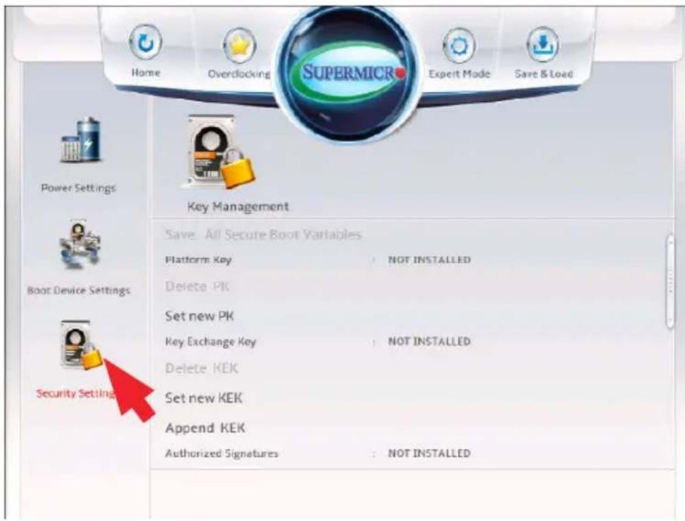
text_image
Home Overclocking SUPERMICR Expert Mode Save & Load Power Settings Key Management Save All Secure Boot Variables Platform Key NOT INSTALLED Delete PK Set new PK Key Exchange Key NOT INSTALLED Delete KEK Set new KEK Append KEK Authorized Signatures NOT INSTALLED(if Secure Boot Mode is set to 'Custom')
Key Management allows experienced users to modify Secure Boot Variables.
Platform Key
This item displays the current Platform Key status.
Delete PK
This item deletes a previously installed Platform Key.
Set New PK
This item uploads and installs a secure Platform Key. You may insert a factory default key or load from a file. The file formats accepted are:
1) Public Key Certificate
a. EFI Signature List
b. EFI CERT X509 (DER Encoded)
c. EFI CERT RSA2048 (bin)
d. EFI SERT SHA256 (bin)
2) EFI Time Based Authenticated Variable
When prompted, select "Yes" to load Factory Defaults or "No" to load from a file.
Key Exchange Key
This item displays the current Key Exchange Key status.
Delete KEK
This item deletes a previously installed Key Exchange Key.
Set New KEK
This item uploads and installs a Key Exchange Key. You may insert a factory default key or load from a file. When prompted, select "Yes" to load Factory Defaults or "No" to load from a file.
Append KEK
This item uploads and adds a Key Exchange Key into the Key Management. You may insert a factory default key or load from a file. When prompted, select "Yes" to load Factory Defaults or "No" to load from a file.
Authorized Signatures
This item displays the current Authorized Signatures status.
Delete DBT
This item deletes a previously installed Authorized Signature.
Set New DBT
This item uploads and installs an Authorized Signature. You may insert a factory default key or load from a file. The file formats accepted are:
1) Public Key Certificate
a. EFI Signature List
b. EFI CERT X509 (DER Encoded)
c. EFI CERT RSA2048 (bin)
d. EFI SERT SHA256 (bin)
2) EFI Time Based Authenticated Variable
When prompted, select "Yes" to load Factory Defaults or "No" to load from a file.
Append DBT
This item uploads and adds an Authorized Signature into the Key Management. You may insert a factory default key or load from a file. When prompted, select "Yes" to load Factory Defaults or "No" to load from a file.
Forbidded Signatures
This item displays the current Forbidden Signatures status.
Delete DBX
This item deletes a previously installed Forbidden Signature.
Set New DBX
This item uploads and installs a Forbidden Signature. You may insert a factory default key or load from a file. The file formats accepted are: 1) Public Key Certificate
a. EFI Signature List
b. EFI CERT X509 (DER Encoded)
c. EFI CERT RSA2048 (bin)
d. EFI SERT SHA256 (bin)
2) EFI Time Based Authenticated Variable
When prompted, select "Yes" to load Factory Defaults or "No" to load from a file.
Append DBX
This item uploads and adds an Forbidden Signature into the Key Management. You may insert a factory default key or load from a file. When prompted, select "Yes" to load Factory Defaults or "No" to load from a file.
4-10 Management
Set all options for the Overclocking in this section.
ACPI Settings
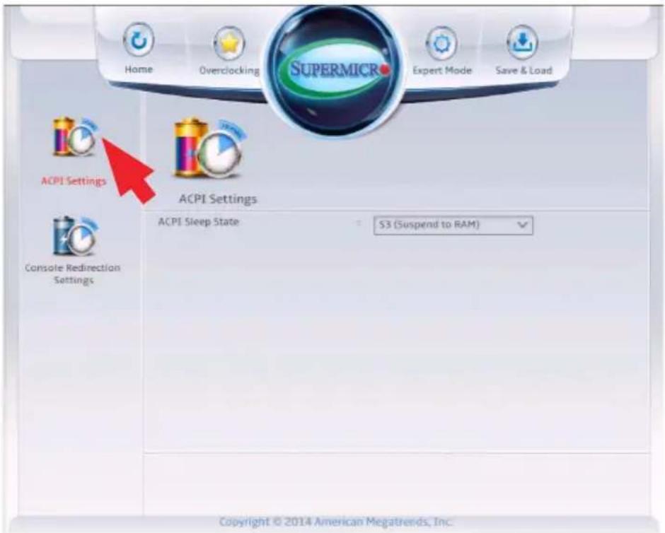
text_image
Home Overclocking SUPERMICR Expert Mode Save & Load ACPI Settings ACPI Settings ACPI Sleep State S3 (Suspend to RAM) Console Redirection Settings Copyright © 2014 American Megatrends, Inc.ACPI Sleep State
This feature selects the ACPI Sleep State that the system will enter into when the suspend button is activated. The options are Suspend Disabled, and S3 (Suspend to RAM).
Console Redirection Settings
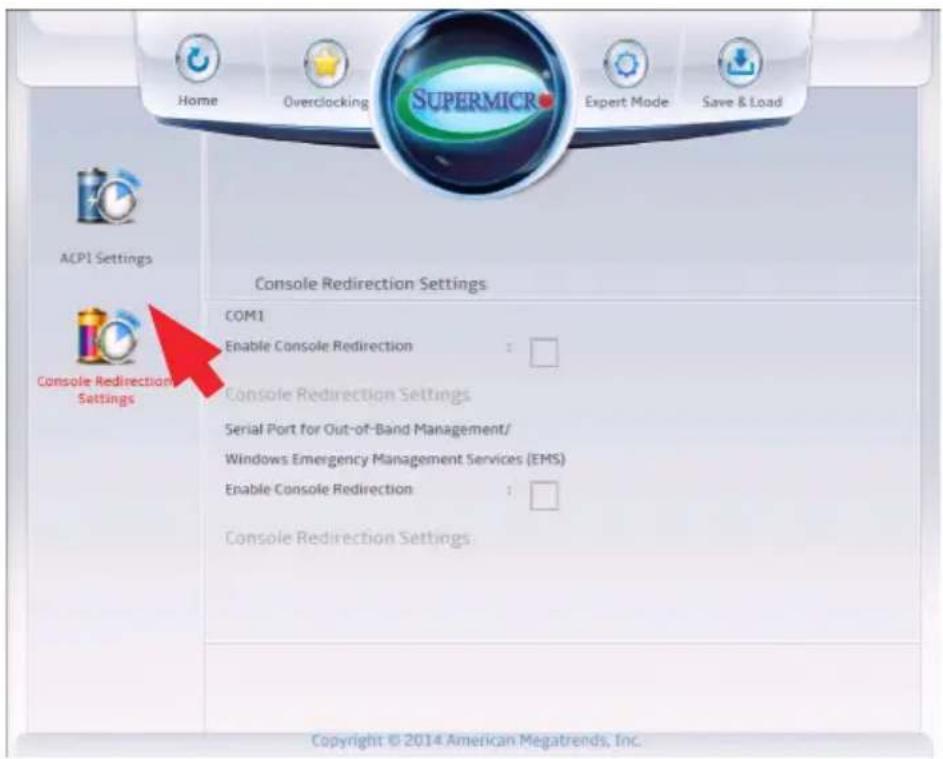
text_image
Home Overclocking SUPERMICR Expert Mode Save & Load ACPI Settings Console Redirection Settings COM1 Enable Console Redirection : Console Redirection Settings Serial Port for Out-of-Band Management/ Windows Emergency Management Services (EMS) Enable Console Redirection : Console Redirection Settings: Copyright © 2014 American Megatrends, Inc.COM1
Enable Console Redirection
This feature enables console redirection for COM1 to support remote management. The default is unchecked (Off).
Console Redirection Settings
Serial Port for Out-of-Band Management/Windows Emergency Management Services (EMS)
The submenu allows the user to configure Console Redirection settings to support Out-of-Band Serial Port management.
Enable Console Redirection
Check this box to use a COM port selected by the user for Console Redirection. The default is unchecked (Off).
Console Redirection Settings
Out-of-Band Management Port
The feature selects a serial port in a client server to be used by the Windows Emergency Management Services (EMS) to communicate with a remote host server. The options are COM1 and SOL (Disabled).
Terminal Type
Use this feature to select the target terminal emulation type for Console Redirection. Select VT100 to use the ASCII character set. Select VT100+ to add color and function key support. Select ANSI to use the extended ASCII character set. Select VT-UTF8 to use UTF8 encoding to map Unicode characters into one or more bytes. The options are ANSI, VT100, VT100+, and VT-UTF8.
Bits Per Second
This item sets the transmission speed for a serial port used in Console Redirection. Make sure that the same speed is used in both host computer and the client computer. A lower transmission speed may be required for long and busy lines. The options are 9600, 19200, 57600, and 115200 (bits per second).
Flow Control
Use this item to set the flow control for Console Redirection to prevent data loss caused by buffer overflow. Send a "Stop" signal to stop data-sending when the receiving buffer is full. Send a "Start" signal to start data-sending when the receiving buffer is empty. The options are None, Hardware RTS/CTS, and Software Xon/Xoff.
The setting for each these features is displayed:
Data Bits, Parity, Stop Bits
4-11 IPMI
IPMI
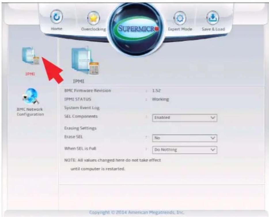
text_image
Home Overclocking SUPERMIC Expert Mode Save & Load IPMI IPMI BMC Network Configuration BMC Firmware Revision : 1.52 IPMI STATUS : Working System Event Log SEL Components : Enabled ✓ Erasing Settings Erase SEL : No ✓ When SEL is Full : Do Nothing ✓ NOTE: All values changed here do not take effect until computer is restarted. Copyright © 2014 American Megatrends, Inc.The following items will be displayed:
- BMC Firmware Version - indicates the current version of the Baseboard Management Controller.
- IPMI Status - this item indicates the current state of the IPMI feature.
System Event Log
Enabling/Disabling Options
SEL Components
Select Enabled to enable all system event logging support at bootup. The options are Enabled and Disabled.
Erasing Settings
Erase SEL
Select Yes, On next reset to erase all system event logs upon next system reboot. Select Yes, On every reset to erase all system event logs upon each system reboot. Select No to keep all system event logs after each system reboot. The options are No, Yes, On next reset, and Yes, On every reset.
When SEL is Full
This feature allows the user to determine what the BIOS should do when the system event log is full. Select Erase Immediately to erase all events in the log when the system event log is full. The options are Do Nothing and Erase Immediately.
Note: After making changes on a setting, be sure to reboot the system for the changes to take effect.
BMC Network Configuration
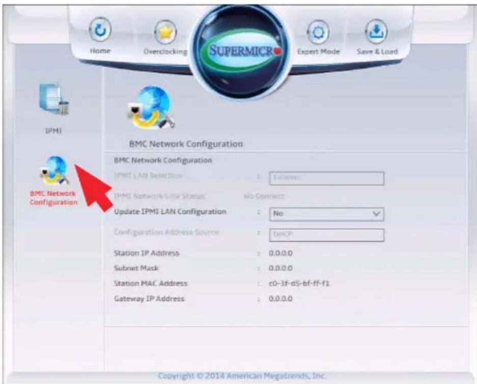
text_image
Home Overclocking SUPERMICR Expert Mode Save & Load IPMI BMC Network Configuration BMC Network Configuration IPMI LAN Selection: Followers IPMI Network Site Status: No Connect Update IPMI LAN Configuration: No Configuration Address Source: DHCP Station IP Address: 0.0.0.0 Subnet Mask: 0.0.0.0 Station MAC Address: c0-3f-d5-bf-ff-f1 Gateway IP Address: 0.0.0.0 Copyright © 2014 American Megatrends, Inc.BMC Network Configuration
Select Yes for the system BIOS to automatically reset the following IPMI settings at next system boot. The options are Yes and No.
The following items will be displayed:
- IPMI Network Status - Displays the current connection status of the IPMI network.
Update IPMI LAN Configuration
Select Yes for the system to allow following IPMI settings below be changed. The options Yes and No.
Configuration Address Source (Available when the item above - Update IPMI LAN Configuration is set to Yes)
Use this item to select the IP address source for this computer. If Static is selected, you will need to know the IP address of this computer and enter it to the system manually in the field. If DHCP is selected, AMI BIOS will search for a DHCP (Dynamic Host Configuration Protocol) server attached to the network and request the next available IP address for this computer. The options are DHCP Unspecified, and Static.
Station IP Address
This item displays the Station IP address for this computer. This should be in decimal and in dotted quad form (i.e., 192.168.10.253).
Subnet Mask
This item displays the sub-network that this computer belongs to. The value of each three-digit number is separated by dots and it should not exceed 255.
Station MAC Address
This item displays the Station MAC address for this computer. Mac addresses are 6 two-digit hexadecimal numbers.
Gateway IP Address
This item displays the Gateway IP address for this computer. This should be in decimal and in dotted quad form (i.e., 192.168.10.253).
Appendix A
BIOS Error Beep Codes
During the POST (Power-On Self-Test) routines, which are performed each time the system is powered on, errors may occur.
Non-fatal errors are those which, in most cases, allow the system to continue with bootup. The error messages normally appear on the screen.
Fatal errors will not allow the system to continue to bootup. If a fatal error occurs, you should consult with your system manufacturer for possible repairs.
These fatal errors are usually communicated through a series of audible beeps. The numbers on the fatal error list correspond to the number of beeps for the corresponding error.
A-1 BIOS Error Beep Codes
| BIOS Error Beep Codes | ||
| Beep Code/LED Error | Message Description | |
| 1 beep Refresh Circuits | have been reset. | (Ready to power up) |
| 5 short beeps + 1 long beep | Memory error No | memory detected in the system |
| 5 short beeps Display error System display error | ||
| OH LED On System OH | System Overheat | |
Notes
Appendix B
Software Installation Instructions
B-1 Installing Drivers
After you've installed the Windows Operating System, a screen as shown below will appear. You are ready to install software programs and drivers that have not yet been installed. To install these software programs and drivers, click the icons to the right of these items. (Note: To install the Windows Operating System, please refer to the instructions posted on our website at http://www.supermicro.com/support/manuals/.)
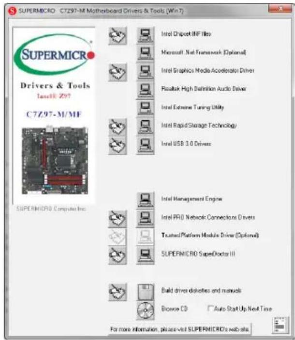
text_image
SUPERMICRO C7Z97-M Motherboard Drivers & Tools (Win 7) SupersMCRC Drivers & Tools Install Z97 C7Z97-M/MF SUPERSMCRC Computer Inc. Intel Chipset.INF Files Microsoft .Net Framework [Optional] Intel Graphics Media Accelerator Driver Realtek High Definition Audio Driver Intel Extensive Tuning Utility Intel Rapid Storage Technology Intel USB 3.0 Drivers Intel Management Engine Intel PRO Network Connections Drivers Trusted Platform Module Driver (Optional) SUPERMICRO SuperDoctor III Build driver disklines and manuals Browse CD Auto Start Up Next Time For more information, please visit SUPERMICRC's web siteDriver/Tool Installation Display Screen

Note 1. Click the icons showing a hand writing on the paper to view the readme files for each item. Click on a computer icon to the right of an item to install this item (from top to the bottom), one at a time. After installing each item, you must reboot the system before proceeding with the next item on the list. The bottom icon with a CD on it allows you to view the entire contents of the CD.
Note 2. When making a storage driver diskette by booting into a Driver CD, please set the SATA Configuration to "Compatible Mode" and configure SATA as IDE in the BIOS Setup. After making the driver diskette, be sure to change the SATA settings back to your original settings.
B-2 Configuring SuperDoctor® III
The SuperDoctor III program is a Web-based management tool that supports remote management capability. It includes Remote and Local Management tools. The local management tool is called the SD III Client. The SuperDoctor III program included on the CDROM that came with your motherboard allows you to monitor the environment and operations of your system. SuperDoctor III displays crucial system information such as CPU temperature, system voltages and fan status. See the Figure below for a display of the SuperDoctor III interface.

Note: 1 The default user name and password are ADMIN.
Note 2: In the Windows OS environment, the SuperDoctor III settings take precedence over the BIOS settings. When first installed, SuperDoctor III adopts the temperature threshold settings previously set in BIOS. Any subsequent changes to these thresholds must be made within SuperDoctor, since the settings override the BIOS settings. For the Windows OS to adopt the BIOS temperature threshold settings, please change the SD III Client settings to be the same as those set in BIOS.
SuperDoctor III Interface Display Screen-I (Health Information)
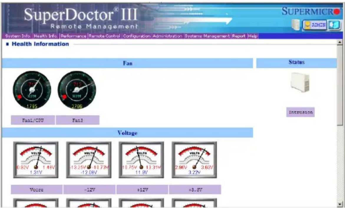
text_image
SuperDoctor® III Remote Management System Info Health Info Performance Remote Control Configuration Administration Systems Management Report Help ■ Health Information Fan Status 1795 2786 FanL/CPU Fan3 Intrusion Voltage 0.82V 1.48V 1.31V -13.25V -10.73V -12.08V 10.75V 13.31V 11.8V 2.96V 3.63V 3.22V Vccre -12V +12V +3.8VSuperDoctor III Interface Display Screen-II (Remote Control)
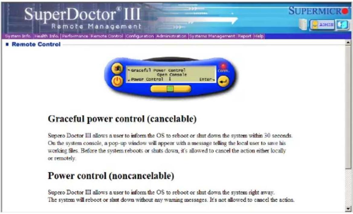
text_image
SuperDoctor® III Remote Management System Info Health Info Performance Remote Control Configuration Administration Systems Management Report Help ■ Remote Control Graceful Power Control Open Console Power Control 1 Enter Power control (noncancelable) Supero Doctor III allows a user to inform the OS to reboot or shut down the system within 30 seconds. On the system console, a pop-up window will appear with a message telling the local user to save his working files. Before the system reboots or shuts down, it's allowed to cancel the action either locally or remotely.
Note: The SuperDoctor III software and manual may be downloaded from our Website at:
http://www.supermicro.com/products/accessories/software/Super-DoctorIII.cfm.
For Linux, we still recommend that you use SuperDoctor II, this version is also available for download at the link above.
Notes
Appendix C
UEFI BIOS Recovery Instructions
! Attention! Do not upgrade the BIOS unless your system has a BIOS-related issue. Flashing the wrong BIOS can cause irreparable damage to the system. In no event shall Supermicro be liable for direct, indirect, special, incidental, or consequential damages arising from a BIOS update. If you need to update the BIOS, do not shut down or reset the system while the BIOS is updating to avoid possible boot failure.
C-1 An Overview to the UEFI BIOS
The Unified Extensible Firmware Interface (UEFI) specification provides a software-based interface between the operating system and the platform firmware in the pre-boot environment. The UEFI specification supports an architecture-independent mechanism for add-on card initialization to allow the UEFI OS loader, which is stored in the add-on card, to boot up the system. UEFI offers a clean, hands-off control to a computer system at bootup.
C-2 How to Recover the UEFI BIOS Image (-the Main BIOS Block)
A UEFI BIOS flash chip consists of a recovery BIOS block, comprised of two boot blocks and a main BIOS block (a main BIOS image). The boot block contains critical BIOS codes, including memory detection and recovery codes for the user to flash a new BIOS image if the original main BIOS image is corrupted. When the system power is on, the boot block codes execute first. Once that is completed, the main BIOS code will continue with system initialization and bootup.

Note: Follow the BIOS Recovery instructions below for BIOS recovery when the main BIOS boot crashes. However, when the BIOS boot block crashes, you will need to follow the procedures in Appendix D.
C-3 To Recover the Main BIOS Block Using a USB-Attached Device
This feature allows the user to recover a BIOS image using a USB-attached device without additional utilities used. A USB flash device such as a USB Flash Drive, or a USB CD/DVD ROM/RW device can be used for this purpose. However, a USB Hard Disk drive cannot be used for BIOS recovery at this time.
To perform UEFI BIOS recovery using a USB-attached device, follow the instructions below.
- Using a different machine, copy the "Super.ROM" binary image file into the disc Root "\" Directory of a USB device or a writeable CD/DVD.

Note: If you cannot locate the "Super.ROM" file in your driver disk, visit our website at www.supermicro.com to download the BIOS image into a USB flash device and rename it "Super ROM" for BIOS recovery use.
- Insert the USB device that contains the new BIOS image ("Super.ROM") into any available USB port
- Set the JBR1 switch on the motherboard to recovery mode and power on the system. If the screen appears as below, press
to continue.
Version 2.16.1243. Copyright (C) 2013 American Megatrends, Inc.
Supermicro CTZ57-OCE BIOS Date:04/25/2014 Rev:1.0
CPU : Intel(R) Core(TM) i7-4765T CPU @ 2.00GHz
Speed : 2.00 GHz
The IMC is operating with DDR3L 1393 MHz
Setup default has been loaded.
Press <DEL> to run Setup
Press <F1> to Continue Booting
- After locating the new BIOS binary image, the system will enter the BIOS Recovery menu as shown below.

text_image
Home Overclocking SUPERMICR Expert Mode Save & Load Recovery ROM Image update allowed HOM Image Verification passed Flash Update Parameters Reset NYRAM : ✓ Boot Block Update : ✓ Proceed with flash update
Note: At this point, you may decide if you want to start with BIOS Recovery. If you decide to proceed with BIOS Recovery, follow the procedures below.
- To continue with BIOS Recovery, select the item- "Proceed with flash update". You will see the progress of BIOS Recovery as shown on the screens below.
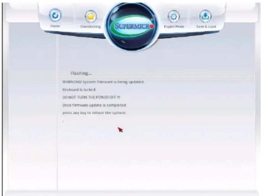
text_image
Home Overdocking SUPERMICR Expert Mode Save & Load Flashing... WARNING? System firmware is being updated. Keyboard is locked. DO NOT TURN THE POWER OFF!! Once firmware update is completed pruck any key to reboot the system .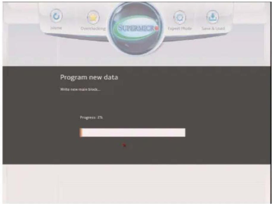
text_image
Home Overclocking SUPERMICR Expert Mode Save & Load Program new data Write new main block... Progress: 2%
Note: Do not interrupt the BIOS programming until it is completed.
- After the BIOS Recovery process is complete, click OK to reboot the system.
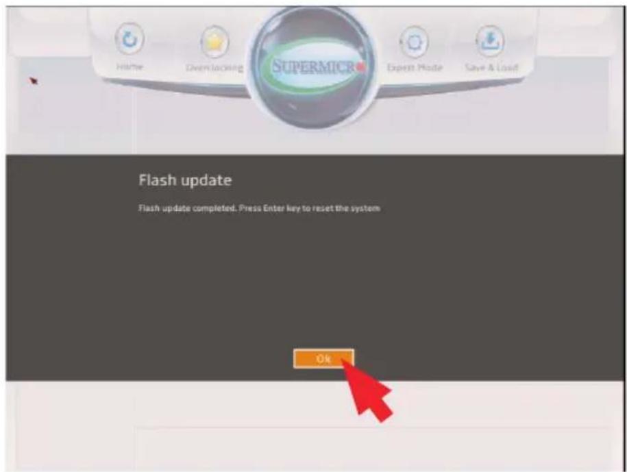
text_image
Home Overlocking SUPERMCR Expert Mode Save & Load Flash update Flash update completed. Press Enter key to reset the system OkAppendix D
Dual Boot Block
D-1 Introduction
This motherboard supports the Dual Boot Block feature, which is the last-ditch mechanism to recover the BIOS boot block. This section provides an introduction to the feature.
BIOS Boot Block
A BIOS boot block is the minimum BIOS loader required to enable necessary hardware components for the BIOS crisis recovery flash that will update the main BIOS block. An on-call BIOS boot-block corruption may occur due to a software tool issue (see image below) or an unexpected power outage during BIOS updates.
AMI Firmware Update Utility vX.XX.XX Copyright (C)XXXX American Megatrends Inc. All Rights Reserved.
Reading flash .... done
-- ME Data Size checking . ok
-- FFS checksums .... ok
Erasing Boot Block .... done
__Updating Boot Block .... 0x00A91000 (13%)
BIOS Boot Block Corruption Occurrence
When a BIOS boot block is corrupted due to an unexpected power outage or a software tool malfunctioning during BIOS updates, you can still reboot the system by activating switch JBR1 on the motherboard. When JBR1 is activated, the system will boot from a backup boot block pre-loaded in the BIOS by the manufacturer.
D-2 Steps to Reboot the System by switch JBR1
- Power down the system.
- On switch JBR1 slide switch to ON, and power on the system.
- Follow the BIOS recovery SOP listed in the previous chapter (Appendix C).
- After completing the steps above, power down the system.
- Turn OFF switch JBR1, and power on the system.
(Disclaimer Continued)
The products sold by Supermicro are not intended for and will not be used in life support systems, medical equipment, nuclear facilities or systems, aircraft, aircraft devices, aircraft/emergency communication devices or other critical systems whose failure to perform be reasonably expected to result in significant injury or loss of life or catastrophic property damage. Accordingly, Supermicro disclaims any and all liability, and should buyer use or sell such products for use in such ultra-hazardous applications, it does so entirely at its own risk. Furthermore, buyer agrees to fully indemnify, defend and hold Supermicro harmless for and against any and all claims, demands, actions, litigation, and proceedings of any kind arising out of or related to such ultra-hazardous use or sale.