
ND1404HXEA - Air-conditioner SAMSUNG - Free user manual and instructions
Find the device manual for free ND1404HXEA SAMSUNG in PDF.


User questions about ND1404HXEA SAMSUNG
0 question about this device. Answer the ones you know or ask your own.
Ask a new question about this device
Download the instructions for your Air-conditioner in PDF format for free! Find your manual ND1404HXEA - SAMSUNG and take your electronic device back in hand. On this page are published all the documents necessary for the use of your device. ND1404HXEA by SAMSUNG.
USER MANUAL ND1404HXEA SAMSUNG
QUESTIONS OR COMMENTS?
| COUNTRY CALL | OR VISIT US ONLINE AT | COUNTRY CALL | OR VISIT US ONLINE AT | ||
| ALBANIA | 42 27 5755 www.samsung.com | RUSSIA 8-800-555-55-55 | www.samsung.com | ||
| AUSTRIA | 0810 - SAMSUNG (7267864, € 0.07/min) | www.samsung.com | GEORGIA 8-800-555-555 | www.samsung.com | |
| BELGIUM 02-20 | -24-18 | www.samsung.com/be (Dutch)www.samsung.com/be_fr (French) | ARMENIA 0-800-05-555 | www.samsung.com | |
| BOSNIA 05 133 | 1999 | www.samsung.com | AZERBAIJAN 088-55-55-555 | www.samsung.com | |
| BULGARIA 070 | 01 33 11 | www.samsung.com KAZAKHSTAN | 8-10-800-500-55-500(GSM: 7799) | www.samsung.com | |
| CROATIA | 062 SAMSUNG (062 726 7864) | www.samsung.com | UZBEKISTAN 8-10-800-500-55-500 | www.samsung.com | |
| CZECH | 800 - SAMSUNG (800-726786) | www.samsung.com KYRGYZSTAN | 00-800-500-55-500 | www.samsung.com | |
| DENMARK | 70 70 19 70 | www.samsung.com | TADJIKISTAN 8-10-800-500-55-500 | www.samsung.com | |
| FINLAND | 030 - 6227 515 | www.samsung.com | MONGOLIA | www.samsung.com | |
| FRANCE | 01 48 63 00 00 | www.samsung.com | UKRAINE | 0-800-502-000 | www.samsung.com/ua www.samsung.com/ua_ru |
| GERMANY | 01805 - SAMSUNG(726-7864 € 0,14/Min) | www.samsung.com | BELARUS | 810-800-500-55-500 | www.samsung.com |
| CYPRUS | 8009 4000 only from landline | www.samsung.com | MOLDOVA | 0-800-614-40 | www.samsung.com |
| GREECE | 80111-SAMSUNG (80111 726 7864) only from land line (+30) 210 6897691 from mobile and land line | www.samsung.com | CANADA | 1-800-SAMSUNG(726-7864) | www.samsung.com/ca www.samsung.com/ca_fr (French) |
| HUNGARY | 06-80-SAMSUNG(726-7864) | www.samsung.com | MEXICO | 01-800-SAMSUNG(726-7864) | www.samsung.com |
| ITALIA | 800-SAMSUNG(726-7864) | www.samsung.com | U.S.A | 1-800-SAMSUNG(726-7864) | www.samsung.com |
| KOSOVO | +381 0113216899 | www.samsung.com | ARGENTINE | 0800-333-3733 | www.samsung.com |
| LUXEMBURG 2 | 61 03 710 | www.samsung.com | BRAZIL | 0800-124-421 4004-0000 | www.samsung.com |
| MACEDONIA | 023 207 777 | www.samsung.com | CHILE | 800-SAMSUNG(726-7864) From mobile 02-482 82 00 | www.samsung.com |
| MONTENEGRO | 020 405 888 | www.samsung.com | BOLIVIA | 800-10-7260 | www.samsung.com |
| NETHERLANDS | 0900-SAMSUNG (0900-7267864) (€ 0,10/Min) | www.samsung.com | COLOMBIA | 01-8000112112 | www.samsung.com |
| NORWAY | 815-56 480 | www.samsung.com | COSTA RICA | 0-800-507-7267 | www.samsung.com |
| POLAND | 0 801-1SAMSUNG(172-678) +48 22 607-93-33 | www.samsung.com | DOMINICA | 1-800-751-2676 | www.samsung.com |
| PORTUGAL | 808 20-SAMSUNG (808 20 7267) | www.samsung.com | ECUADOR | 1-800-10-7267 | www.samsung.com |
| ROMANIA | 08010 SAMSUNG (08010 726 7864) only from landline (+40) 21 206 01 10 from mobile and land line | www.samsung.com | EL SALVADOR | 800-6225 | www.samsung.com |
| SERBIA | 0700 Samsung (0700 726 7864) | www.samsung.com | GUATEMALA 1-800-299-0013 | www.samsung.com | |
| SLOVAKIA | 0800 - SAMSUNG(0800-726 786) | www.samsung.com | HONDURAS | 800-27919267 | www.samsung.com |
| SPAIN | 902 - 1 - SAMSUNG (902 172 678) | www.samsung.com | JAMAICA | 1-800-234-7267 | www.samsung.com |
| SWEDEN | 0771 726 7864 (SAMSUNG) | www.samsung.com | NICARAGUA | 00-1800-5077267 | www.samsung.com |
| SWITZERLAND | 0848 - SAMSUNG(7267864, CHF 0.08/min) | www.samsung.com/chwww.samsung.com/ch_fr (French) | PANAMA | 800-7267 | www.samsung.com |
| U.K | 0330 SAMSUNG (7267864) | www.samsung.com | PERU | 0-800-777-08 | www.samsung.com |
| EIRE | 0818 717100 | www.samsung.com | PUERTO RICO | 1-800-682-3180 | www.samsung.com |
| LITHUANIA | 8-800-77777 | www.samsung.com | TRINIDAD & TOBAGO | 1-800-SAMSUNG(726-7864) | www.samsung.com |
| LATVIA | 8000-7267 | www.samsung.com | VENEZUELA | 0-800-100-5303 | www.samsung.com |
| ESTONIA | 800-7267 | www.samsung.com | |||
Cassette Type Series
4 Way cassette
Air Conditioner user manual

100%
Recycled Paper
This manual is made with 100% recycled paper.

imagine the possibilities
Thank you for purchasing this Samsung product.
To receive more complete service, please register your product at
www.samsung.com/register
○○○IFSE P G Ne Po Hu R DB98-33473A(4)
features of your new air conditioner
• Cool Summer Offer
On those hot sweltering summer days and long restless nights, there is no better escape from the heat than the cool comforts of home. Your new air conditioner brings an end to exhausting hot summer days and lets you rest. This summer, beat the heat with your own air conditioner.
- Cost Efficient System
Your new air conditioner not only provides maximum cooling power in the summer, but can also be an efficient heating method in the winter with the advanced "Heat pump" system. This technology is up to 300% more efficient than electrical heating, so you can further reduce its running cost. Now, meet year-round needs with one air conditioner.
• A Look for Everywhere
The elegant and harmonious design gives priority to the esthetics of your space and complements any of your existing interior décor. With its soft color and rounded-edge shape, the new air conditioner adds class to any room. Enjoy what your air conditioner offers both functionally and esthetically.
- Compact and easy-to-use Cassette type
Designed to be installed into most types of suspended ceiling, the cassette type air conditioner is ideal for business and commercial accommodations. Fresh cool/warm air can be provided through the controllable 1, 2 or 4 sides of the unit. All functions of the air conditioner will be controlled easily via a remote control.
SAMSUNG
For easy future reference write the model and serial number down. You will find your model number on the right side of the air conditioner.
Model #
Serial #
02\_features
safety information
To prevent electric shock, disconnect the power before servicing, cleaning, and installing the unit.
SAFETY INFORMATION
Before using your new air conditioner, please read this manual thoroughly to ensure that you know how to safely and efficiently operate the extensive features and functions of your new appliance.
Because the following operating instructions cover various models, the characteristics of your air conditioner may differ slightly from those described in this manual. If you have questions, call your nearest contact center or find help and information online at www.samsung.com.
What the icons and signs in this user manual mean:
 WARNING WARNING | Risk of death or serious personal injury. |
| [DSHT]CAUTION | Potential risk of personal injury or material damage. |
 CAUTION CAUTION | To reduce the risk of fire, explosion, electric shock, or personal injury when using your air conditioner, follow these basic safety instructions: |
| [ASK4] | Do NOT attempt. |
| Do NOT disassemble. | |
| [8WS7] | Do NOT touch. |
| Follow directions carefully. | |
| [KS7H] | Unplug the power plug from the wall socket. |
| Make sure the machine is grounded to prevent electric shock. | |
| Call the contact center for help. | |
| [6C0Z] | Recommended instructions or useful information for use. |
These warning signs are here to prevent injury to you and others.
Please follow them carefully.
After reading this section, keep it in a safe place for future reference.

SEVERE WARNING SIGNS

Do not place the air conditioner near hazardous substances or equipment that releases free flames to avoid fire, explosions or injuries.
• Potential risk of fire hazard or explosion.
Do not block or place items in front of the air conditioner. Do not step, hang onto, or place heavy items on the air conditioner.
• Potential risk of personal injury.
Do not install the outdoor unit at an unstable place or elevated surface where there is potential risk of falling.
- If the outdoor unit falls, it may cause personal injury or loss or property.
Any changes or modifications performed not following by the installation manual, failure or damage may occur on the condition. In this case, user will be responsible for all the repair expenses.
safety information

SEVERE WARNING SIGNS

If any gas or impurities other than R410A refrigerant come into the refrigerant pipe, serious problem may occur and it may cause injury.
Do not spray flammable gases such as insecticide near the air conditioner.
- Potential risk of electric shock, fire or unit malfunction.
Do not insert anything such as fingers or branches into the air conditioner vents.
- Keep children away from the air conditioner. Potential risk of personal injury.
Do not cut the power plug and connect to a different power cable.
Never attempt to lengthen the power cable.
• Potential risk of fire or electric shock.
Do not yank the power cable and touch the power plug with hands.
• Potential risk of fire or electric shock.
Never use a damaged power plug, power cable, or loosened power receptacle.
• Potential risk of fire or electric shock.
The electric work must be done by qualified service technician in accordance with the national wiring regulations with rated cables.
- If the capacity of the power cable is insufficient or electric work have not done properly, electric shock or fire may occur.
You should connect the power cable into the power cable terminal and fasten it with a clamp.

Do not connect the air conditioner with heating apparatus or attempt to disassemble, remodel or repair it by yourself.
- Potential risk of malfunction, electric shock or fire. If repairs are needed, consult the contact center.
Consult the place of purchase or a contact center to disassemble or reinstall the air conditioner.
- Potential risk of unit malfunction, water leakage, electric shock, or fire.

Consult the place of purchase or contact center to install the air conditioner.
- Improper installation carries a risk of unit malfunction, water leakage, electric shock or fire.
- If installing in specialty areas, such as a factory complex or saline coastal area, consult the place of purchase or contact center for specific installation details.
Install the air conditioner with the support bracket securely fastened to use for an extended period of time.
- If the air conditioner falls, it may cause personal injury or loss of property.
If the indoor unit gets wet, turn the power off immediately and call your nearest contact center.
• Potential risk of fire or electric shock.
Install an exclusive circuit breaker and short-circuit breaker for the air conditioner.
• Potential risk of electric shock or fire.
If the power cable is damaged, the manufacturer or a qualified service technician must replace it.
Always make sure that the power supply is compliant with current safety standards. Always install the air conditioner in compliance with current local safety standards.
Verify that the voltage and frequency of the power supply comply with the specifications and that the installed power is sufficient to ensure the operation of any other domestic appliance connected to the same electric lines.
04\_ safety information

The air conditioner must be installed in accordance with national wiring regulations and safety regulations wherever applicable.
Install the supplied cables firmly. Fix them securely so that external force is not exerted to the terminal block.
- If the connection is loose, heat may generate and cause electric shock or fire.
Use a rated circuit breaker only.
- Never use steel wires or copper wires as a circuit breaker. It may cause fire or unit malfunction.
Use an exclusive power source for the air conditioner.
• Potential risk of electric shock or fire.
Do not put undue stress or place heavy object on the power cable.
Do not bend the power cable excessively.
• Potential risk of fire or electric shock.
Always verify that electric connections (cable entry, section of leads, protections...) are compliant with the electric specifications and with the instructions provided in the wiring scheme.
Always verify that all connections comply with the standards applicable to the installation of air conditioners.

Use a receptacle that has a ground terminal. The receptacle must be used exclusively for the air conditioner.
- Improper electrical grounding may cause electric shock or fire.
Be sure to ground the unit. Do not connect the ground wire to gas or water pipes, lighting rods, or telephone grounding lines.
- If the unit is not properly grounded, electric shock may result.
Always verify that a suitable grounding connection is available.

Disconnect the air conditioner from power supply before it is repaired or disassembled.

CAUTION SIGNS

Connect the refrigerant tubes first then the electrical lines, when installing the unit.
Always disassemble the electric lines before the refrigerant tubes.
Verify that the air conditioner is connected to the power supply in accordance with the instructions provided in the wiring diagram included in the manual.
The manufacturer shall not be responsible for damage originating from unauthorized changes or the improper connection of electric and hydraulic lines.
Failure to comply with these instructions or to comply with the requirements set forth in the “Operating limits” table, included in the manual, and shall immediately invalidate the warranty.
Ensure no water gets into the air conditioner.
• Potential risk or electric shock.
Turn off the air conditioner using the provided remote control or control accessory (if provided). Do not unplug to turn off the unit (unless there is an immediate danger).
Do not open the front grille during operation.
- Potential risk of electric shock or unit malfunction.
Cool air should not flow directly towards people, pets, and plants.
- It is harmful to your health, pets, and plants.
Do not run the air conditioner for an extended period of time in a room with the door closed or with babies, elderly or disabled people.
- Open the door or windows to ventilate your room at least once an hour to prevent oxygen shortage.
Do not drink drain water coming out of the air conditioner.
• Potential risk of health hazard.
safety information

CAUTION SIGNS

Do not expose the dust filter to direct sunlight while drying.
• Strong direct sunlight may deform the dust filter.
Do not allow children to climb on the air conditioner.
Use only rated accessories and install the air conditioner with rated equipments.
- If you do not use the rated accessories, the air conditioner may drop from its place, water may leak or electric shock or fire may occur.
Do not use the air conditioner as a cooling precision instrument for food, pets, plants, cosmetics or machinery.
Do not give excessive shock to the air conditioner.
- Potential risk of fire or unit malfunction.
Do not spray water directly on the air conditioner or use benzene, thinner or alcohol to clean the surface of the unit.
• Potential risk of electric shock or fire.
• Potential risk of damage to the air conditioner.
Do not place any objects, especially containers with liquid.

Do not touch the pipe connected to the air conditioner.

This appliance should be installed according to the provided installation manual.
Install the shortest possible length of pipe.
- If the length of pipe gets unnecessarily long, the life of air conditioner can be shorten and become inefficient.
Install the power cable and communication cable of the indoor and outdoor unit at least 1m away from the electric appliance.
Install the indoor unit away from lighting apparatus using the ballast.
- If you use the wireless remote control, reception error may occur due to the ballast of the lighting apparatus.
For maximum safety, installers should always carefully read the following warnings.
Do not install the air conditioner in following places.
- Place where there is mineral oil or arsenic acid.
- Resin parts flame and the accessories may drop or water may leak. The capacity of the heat exchanger may reduce or the air conditioner may be out of order.
- The place where corrosive gas such as sulfurous acid gas generates from the vent pipe or air outlet.
- The copper pipe or connection pipe may corrode and refrigerant may leak.
- The place where there is a machine that generates electromagnetic waves. The air conditioner may not operate normally due to control system.
- The place where there is a danger of existing combustible gas, carbon fiber of flammable dust.
- The place where thinner or gasoline is handled Gas may leak and it may cause fire.
If the air conditioner is installed in a small room, measures must be taken to prevent the refrigerant concentration in the room from exceeding the safety limit in the event of refrigerant leakage. Consult a dealer regarding the appropriate measures to prevent the allowable concentration from being exceeded.
- If the refrigerant leaks, and cause the concentration limit to be exceeded, hazards due to lack of oxygen in the room may result.
Install the air conditioner away from direct exposure to sunlight, heating apparatus, and humid places. - Hang curtains on windows to boost cooling efficiency and to avoid the risk of electric shock.
The air conditioner is composed of moving parts. Keep children away from the unit to avoid physical injury.
Check for damage on delivery. If damaged, do not install the air conditioner and call the place of purchase immediately.
Insert the dust filter before operating the air conditioner.
- If there is no dust filter inside the air conditioner, accumulated dust may shorten the life of the air conditioner and cause electricity waste.
06\_ safety information

Keep indoor temperatures stable and not extremely cold, especially where there are children, elderly or disabled people.
Clean the dust filter every 2 weeks. Clean the filter more frequently if the air conditioner is operated in dusty areas.
The packaging material and used batteries of the remote controller (optional) must be disposed of in accordance with the national standards.
The refrigerant used in the air conditioner must be treated as chemical waste. Dispose the refrigerant following national standards.
Have a qualified service technician install the air conditioner and perform a trial operation.
Firmly connect the drain hose to the air conditioner for proper water drainage.
Install the outdoor unit where operating noise and vibration will not disturb your neighbor and in a well-ventilated area with no obstacle.
• Potential risk of malfunction.
- Operating noise may disturb your neighbor.
Make sure that children take precautions against access to the air conditioner and they do not play with the unit.
When using a wireless remote control, the distance should not be more than 7 meters from the air conditioner.
If the remote control is not used for a long period of time, remove the batteries to prevent leakage of electrolyte.
When cleaning the outdoor unit, touch the heat exchanger radiator fins with extreme care.
- Wearing thick gloves can protect your hands.
Make sure that the condensed water dripping from the drain hose runs out properly and safely.
Store the operation and installation manual in a safe location and remember to hand it over to the new owner if the air conditioner is sold or transferred.
All the materials used for the manufacture and packaging of the air conditioner are recyclable.
After completing the installation, always carry out a functional test and provide the instructions on how to operate the air conditioner to the user.
The appliance is not intended for use by young children or infirm persons without supervision: Young children should be supervised to ensure that they do not play with the appliance.
Clean the air conditioner after the inner fan stops operating.
• Potential risk of injury or electric shock.
Inspect the condition, electric connections, pipes and external case of the air conditioner regularly by a qualified service technician.
Do not open doors and windows in the room being cooled during operation unless necessary.
Do not block the air conditioner vents. If objects block the air flow, it may cause unit malfunction or poor performance.
Make sure there are no obstacles under the indoor unit.
• Potential risk of fire or loss of property.
Make sure that there are no obstacles or covers that block the air conditioner.
Allow sufficient space for air circulation.
• Insufficient ventilation may result in poor performance.
This appliance is not intended for use by persons (including children) with reduced physical, sensory or mental capabilities, or lack of experience and knowledge, unless they have been given supervision or instruction concerning use of the appliance by a person responsible for their safety. Children should be supervised to ensure that they do not play with the appliance.
When the product operates in heat mode during winter time, it operates protection mode when the outdoor temperature drops below 0^ C. Therefore, supply the power during winter time. If the power is not supplied, compressor protection mode will not operate and cause product malfunction.
safety information

CAUTION SIGNS

Make sure the voltage and frequency of the electric system are compatible with the air conditioner.
If a power outage occurs while the air conditioner is working, turn off the power source immediately.
Max current is measured according to IEC standard for safety and current is measured according to ISO standard for energy efficiency.
The unit must be plugged into an independent circuit if applicable or connect the power cable to the auxiliary circuit breaker. An all pole disconnection from the power supply must be incorporated in the fixed wiring with a contact opening of >3mm.
After connecting the power cable between the indoor/outdoor unit, attach the cover of component box securely and make sure it is not loose.
For the power cable, use the grade of H07RN-F or H05RN-F materials.
The unbalanced power must be maintained within 10% of supply rating among whole indoor units.
If the power is unbalanced greatly, it may shorten the life of the condenser.
If the unbalanced power is exceeded over 10% of supply rating, the indoor unit is protected, stopped and the error mode indicates.
To protect the product from water and possible shock, you should keep the power cable and the connection cord of the indoor and outdoor units in the protection tube.
Connect the power cable to the auxiliary circuit breaker.
You must keep the cable in a protection tube.
Keep distances of 50mm or more between power cable and communication cable.
Maximum length of power cable is decided within 10% of power drop. If it exceeds, you must consider another power supplying method.
The circuit breaker (MCCB, ELB) should be considered more capacity, if many indoor units are connected from one breaker.
Use solderless ring terminal to connect the power cable to the power terminal block.
Use an appropriate screwdriver for tightening the terminal screws.
Over-tightening the terminal screws may break them.
The air conditioner should be used only for the applications for which it has been designed: the indoor unit is not suitable to be installed in areas used for laundry.
Our units must be installed in compliance with the spaces indicated in the installation manual to ensure either accessibility from both sides or ability to perform routine maintenance and repairs. The units' components must be accessible and that can be disassembled in conditions of complete safety either for people or things. For this reason, where it is not observed as indicated into the Installation Manual, the cost necessary to reach and repair the unit (in safety, as required by current regulations in force) with slings, trucks, scaffolding or any other means of elevation won't be considered in-warranty and charged to end user.

Ensure the off-on and protection switches are properly installed.
Do not use the air conditioner if damaged. If problems occur, immediately stop operation and disconnect the plug from the power supply.
If the air conditioner will not be used for an extended period of time (for example, over several months), unplug the power from the wall.

Call the place of purchase or a contact center if repairs are needed.
- Potential risk of fire or electric shock if disassembly or repairs are attempted by a non-qualified service technician.
If you smell burning plastic, hear strange sounds, or see smoke coming from the unit, unplug the air conditioner immediately and call a contact center.
• Potential risk of fire or electric shock.
08_ safety information
contents
VIEWING THE PARTS
10
10 Main parts
10 Indicator
USING YOUR AIR CONDITIONER
11
11 Tips on using your air conditioner
CLEANING AND MAINTAINING THE AIR CONDITIONER
12
12 Cleaning the exterior
13 Cleaning air filter and grille
14 Maintaining your air conditioner
14 Periodical checks
15 Internal protections via the unit control system
APPENDIX
16
16 Troubleshooting
17 Operation ranges
INSTALLATION PART
18
18 Indoor Unit Installation
18 Performing Leak Test & Insulation
19 Drain pipe and Drain Hose Installation
20 Wiring Work
21 Setting an indoor unit address and installation option
This product has been determined to be in compliance with the Low Voltage Directive (2006/95/EC), and the Electromagnetic Compatibility Directive (2004/108/EEC) of the European Union.
Correct Disposal of This Product (Waste Electrical & Electronic Equipment)
(Applicable in the European Union and other European countries with separate collection systems)
This marking shown on the product or its literature, indicates that it should not be disposed with other household wastes at the end of its working life. To prevent possible harm to the environment or human health from uncontrolled waste disposal, please separate this from other types of wastes and recycle it responsibly to promote the sustainable reuse of material resources.
Household users should contact either the retailer where they purchased this product, or their local government office, for details of where and how they can take this item for environmentally safe recycling.
Business users should contact their supplier and check the terms and conditions of the purchase contract. This product should not be mixed with other commercial wastes for disposal.
contents _09
viewing the parts
MAIN pARTS
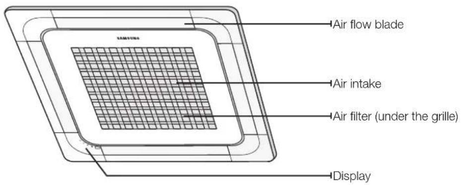
text_image
Air flow blade Air intake Air filter (under the grille) DisplayINDICATOR
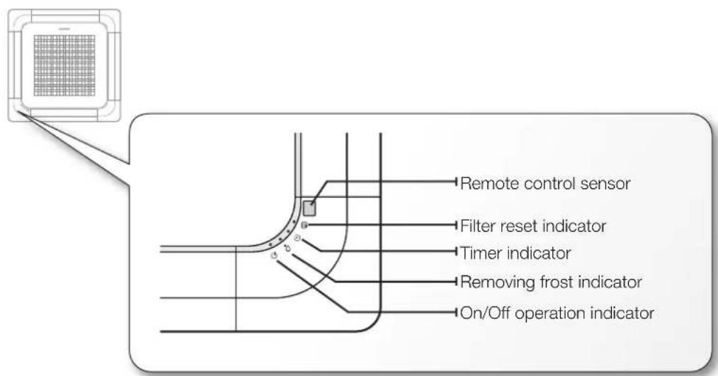
text_image
Remote control sensor Filter reset indicator Timer indicator Removing frost indicator On/Off operation indicator
Your air conditioner and display may look slightly different from the illustration shown above depending on your model.
10_ viewing the parts
using your air conditioner
TIPS ON USING AIR CONDITIONER
Here are some tips that you would follow when using your air conditioner.
| TOPIC RECOMMENDATION | |
| Cooling | ·If current outside temperatures are much higher than the selected indoor temperature, it may take time to bring the inner temperature to the desired coolness.·Avoid drastically turning down the temperature. Energy is wasted and the room does not cool faster. |
| Heating | ·Since the air conditioner heats the room by taking heat energy from outdoor air, the heating capacity may decrease when outdoor temperatures are extremely low. If you feel the air conditioner insufficiently heats, using an additional heating appliance in combination with the air conditioner is recommended. |
| Frost & De-ice | ·When the air conditioner runs in Heat mode, due to temperature difference between the unit and the outside air, frost will form.If this happens:- The air conditioner stops heating.- The air conditioner will operate automatically in De-ice mode for 10 minutes.- The steam produced on the outdoor unit in De-ice mode is safe.No intervention is required; after about 10 minutes, the air conditioner operates again normally. [IMAGE]the unit will not operate when it starts to de-ice. |
| Fan | ·Fan may not operate for about 3~5 minutes at the beginning to prevent any cold blasts while the air conditioner is warming up. |
| High indoor/outdoor temperatures | ·If both indoor and outdoor temperatures are high and the air conditioner is running in Heat mode, the outdoor unit's fan and compressor may stop at times. This is normal; wait until the air conditioner turns on again. |
| Power failure | ·If a power failure occurs during the operation of the air conditioner, the operating immediately stops and unit will be off. When power returns, the air conditioner will run automatically. |
| Protection mechanism | ·If the air conditioner has just been turned on after operation stops or being plugged in, cool/warm air does not come out for 3 minutes to protect the compressor of the outdoor unit. |
cleaning and maintaining the air conditioner
CLEANING THE ExTERIOR
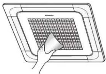
Wipe the surface of the unit with a slightly wet or dry cloth when needed. Wipe off dirt of odd-shaped area by using a soft brush.
natural_image
Hand holding a small object over a grid-patterned surface, enclosed in a rectangular frame (no text or symbols)Do not use Benzene or Thinner. They may damage the surface of the air conditioner and can create a risk of fire.
12_ cleaning and maintaining the air conditioner
CLEANING AIR FILTER AND GRILLE
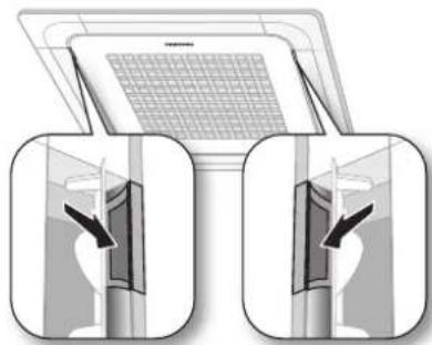
Open the front grille.
▶ Open the blades on the left and right side of the Samsung logo. Press both of the levers and pull the grille downward. Two safety clips are mounted to the front grille to prevent it from dropping.
natural_image
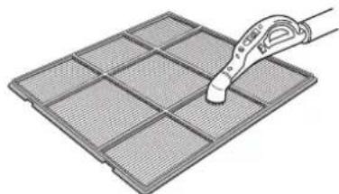
Illustration of two identical views of a room with a patterned ceiling and a laptop (no text or symbols)Clean the grille and Air filter with a vacuum cleaner or soft brush. If dust is too heavy, then rinse it with running water and dry it in a ventilated area.
▶ For best conditions, repeat every two weeks.
If the Air filter dries in a confined (or humid) area, odors may generate. If it occurs, re-clean and dry it in a well-ventilated area.
natural_image
Illustration of a pipette inspecting a grid-patterned material (no text or symbols)Insert the Air filter back in its original position.
▶ You will hear a click sound when the Air filter is properly placed.
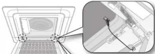
Detach the front grille.
Remove the safety clip first and then remove the hinge. Pull the green switch on the hinge part down and then press and pull the hinge part to remove the grillae. (There are two hinges on the grille and you must apply this step on both of them to remove the grille.)
※ If you want to clean the filter only, you do not have to detach the grille. Follow step 4 and 5
natural_image
Diagram showing a laptop with a screen and a close-up of its interior panel (no text or symbols visible)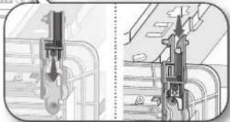
natural_image
Technical illustration of a mechanical component with cross-sectional views (no text or symbols)Pull out the Air filter.
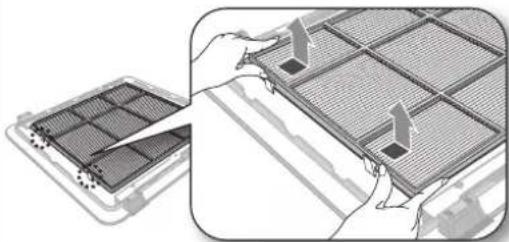
natural_image
Illustration of a device's internal grid structure being processed, showing hand placement and alignment (no text or symbols)Attach the front grille.
▶ Reverse the above steps to attach the front grille.

- The illustration shown above may differ from yours depending on your model.
- After cleaning the filter, press the Filter Reset button on the remote control for 2 seconds to reset the filter schedule. Filter sign indicator will be on for cleaning time.
- If the angle on the air flow blades has been changed by user due to opening the front grille for installation or maintenance, you must turn off the circuit breaker and turn it on again before using the air conditioner. Otherwise, angles of the each angle can be different or some of the blade may not close when the product is off.
cleaning and maintaining the air conditioner
MAINTAINING YOUR AIR CONDITIONER
If the air conditioner will not be used for an extended period of time, dry the air conditioner to maintain it in best condition.
- Dry the air conditioner thoroughly by operating in Fan mode for 3 to 4 hours and disconnect the power plug. There may be internal damage if moisture is left in components.
- Before using the air conditioner again, dry the inner components of the air conditioner again by running in Fan mode for 3 to 4 hours. This helps remove odors which may have generated from dampness.
periodical checks
Refer to the following chart to maintain the air conditioner properly.
| Type Description Monthly | Every 4 months | Once a year | ||
| Indoor unit | Clean the air filter (1) | ● | ||
| Clean the condensate drain pan (2) | ● | |||
| Thoroughly clean the heat exchanger (2) | ● | |||
| Clean the condensate drain pipe (2) | ● | |||
| Replace the remote control batteries (1) | ● | |||
| Outdoor unit | Clean the heat exchanger on the outside of the unit (2) | ● | ||
| Clean the heat exchanger on the inside of the unit (2) | ● | |||
| Clean the electric components with jets of air (2) | ● | |||
| Verify that all the electric components are firmly tightened (2) | ● | |||
| Clean the fan (2) | ● | |||
| Verify that all the fan assembly is firmly tightened (2) | ● | |||
| Clean the condensate drain pan (2) | ● | |||

The checks and maintenance operations described are essential to guarantee the efficiency of the air conditioner. The frequency of these operations varies according to the characteristics of the area, the amount of dust, etc.
(1) The described operations should be performed more frequently if the area of installation is very dusty.
(2) These operations must always be performed by qualified personnel. For more detailed information, see the Installation Manual.
14\_ cleaning and maintaining
Internal protections via the unit control system
This internal protection operates if an internal fault occurs in the air conditioner.
| TypeDescription | |
| Against cold air | The internal fan will be off to against cold air when the heat pump is heating. |
| De-ice cycle | The internal fan will be off to against cold air when the heat pump is heating. |
| Anti-protection of internal battery | The compressor will be off to protect internal battery when the air conditioner operates in Cool mode. |
| Protect compressor | The air conditioner does not start operating immediately to protect the compressor of the outdoor unit after it has been started. |

If the heat pump is operating in Heat mode, De-ice cycle is actuated to remove frost from an outdoor unit that may have deposited at low temperatures.
The internal fan is switched off automatically and restarted only after the de-ice cycle is completed.
appendix
TROUBLESHOOTING
Refer to the following chart if the air conditioner operates abnormally. This may save time and unnecessary expenses.
| PROBLEM SOLUTION | |
| The air conditioner does not operate immediately after it has been restarted. | Because of the protective mechanism, the appliance does not start operating immediately to keep the unit from overloading.The air conditioner will start in 3 minutes. |
| The air conditioner does not work at all. | Check that the power plug is properly connected. Insert the power plug into the wall socket correctly.Check if the circuit breaker is switched off.Check if there is a power failure.Check your fuse. Make sure it is not blown out. |
| The temperature does not change. | Check if you selected Fan mode.Press the Mode button on the remote control to select another mode. |
| The cool (warm) air does not come out of the air conditioner. | Check if the set temperature is higher (lower) than the current temperature. Press the Temperature button on the remote control to change the set temperature. Press the Temperature button to decrease or increase the temperature.Check if the air filter is blocked by dirt. Clean the air filter every two weeks.Check if the air conditioner has just been turned on. If so, wait 3 minutes. Cool air does not come out to protect the compressor of the outdoor unit.Check if the air conditioner is installed in a place with a direct exposure to sunlight. Hang curtains on windows to boost cooling efficiency.Check if the cover or any obstacle is not near the outdoor unit.Check if the refrigerant pipe is too long.Check if the air conditioner is only available in Cool mode.Check if the remote control is only available for cooling model. |
| The fan speed does not change. | Check if you selected Auto or Dry mode.The air conditioner automatically adjusts the fan speed to Auto in Auto/Dry mode. |
| Timer function does not set. | Check if you press the Power button on the remote control after you have set the time. |
| Odors permeate in the room during operation. | Check if the appliance is running in a smoky area or if there is a smell entering from outside. Operate the air conditioner in Fan mode or open the windows to air out the room. |
| The air conditioner makes a bubbling sound. | A bubbling sound may be heard when the refrigerant is circulating through the compressor. Let the air conditioner operate in a selected mode.When you press the Power button on the remote control, noise may be heard from the drain pump inside the air conditioner. |
| Water is dripping from the air flow blades. | Check if the air conditioner has been cooling for an extended period of time with the air flow blades pointed downwards. Condensation may generate due to the difference in temperature. |
| Remote control is not working. | Check if your batteries are depleted.Make sure batteries are correctly installed.Make sure nothing is blocking your remote control sensor.Check that there are strong lighting apparatus near the air conditioner. Strong light which comes from fluorescent bulbs or neon signs may interrupt the electric waves. |
| The air conditioner does not turn on or off with the wired remote control. | Check if you set the wired remote control for group control. |
| The wired remote control does not operate. | Check if TEST indicator is displayed on the wired remote control. If so, turn off the unit and switch off the circuit breaker. Call your nearest contact center. |
| The indicators of the digital display flashes. | Press the Power button on the remote control to turn the unit off and switch the circuit breaker off. Then, switch it on again. |
16\_ appendix
Operation RANGES
The table below indicates the temperature and humidity ranges the air conditioner can be operated within. Refer to the table for efficient use.
| MODE | OUTDOOR TEMPERATURE | INDOOR TEMPERATURE | INDOOR HUMIDITY REMARKS |
| COOLING | -5°C/23°F to 43°C/109°F | 18°C/64°F to 32°C/90°F 80% or less - | |
| HEATING | -20°C/-4°F to 24°C/75°F | 27°C/81°F or less - - | |
| DRYING | -5°C/23°F to 43°C/109°F | 18°C/64°F to 32°C/90°F - - |

The standardized temperature for heating is 7^ C/ 45^ F. If the outdoor temperature drops to 0^ C/ 32^ F or below, the heating capacity can be reduced depending on the temperature condition.
If the cooling operation is used at over 32^ C/ 90^ F (indoor temperature), it does not cool at its full capacity.
Installation Part
Indoor Unit Installation
When deciding on the location of the air conditioner with the owner, the following restrictions must be taken into account.
- Determine the position of the pipe and drain hose hole as seen in the picture and drill the hole with an inner diameter of 65mm so that it slants slightly downwards.
Note
Since the diagram is made of paper, it may shrink or stretch slightly due to temperature or humidity. For this reason, before drilling the holes maintain the correct dimensions between the markings.
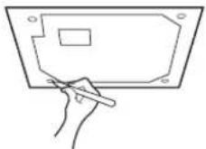
- Insert bolt anchors, use existing ceiling supports or construct a suitable support as shown in figure.
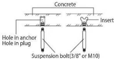
text_image
Concrete Insert Hole in anchor Hole in plug Suspension bolt(3/8" or M10)- Install the suspension bolts depending on the ceiling type.

Ensure that the ceiling is strong enough to support the weight of the indoor unit. Before hanging the unit, test the strength of each attached suspension bolt.
◆
If the length of suspension bolt is more than 1.5m, it is required to prevent vibration.
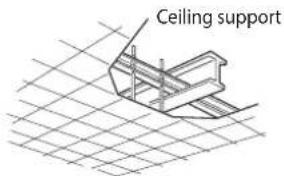
text_image
Ceiling support- Screw eight nuts to the suspension bolts making space for hanging the indoor unit.

You must install all the suspension rods.
is important to leave sufficient space in the false ceiling to allow access for maintenance or repairs to the drainage pipe connection, the refrigerant pipe connection, or to remove the unit if necessary.
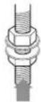
18_ installing your air conditioner
- Hang the indoor unit to the suspension bolts between two nuts.
Note
Piping must be laid and connected inside the ceiling when suspending the unit. If the ceiling is already constructed, lay the piping into position for connection to the unit before placing the unit inside the ceiling.
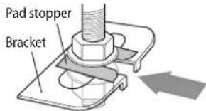
text_image
Pad stopper Bracket-
Screw the nuts to suspend the unit. Cut a pad stopper and place it on the bracket at this time.
-
Adjust the unit to the appropriate position considering the installation area for the front panel.
1) Place the pattern sheet on the indoor unit.
2) Adjust a space between the ceiling and the indoor unit by using the gauge of dimensions.
3) Fix the indoor unit securely after adjusting level of the unit by using a leveler.
4) Remove the pattern sheet, connect the other cables and install the front panel.
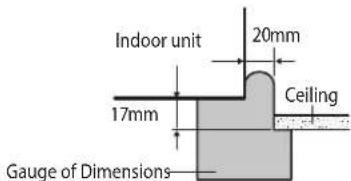
text_image
Indoor unit 20mm 17mm Ceiling Gauge of DimensionsPerforming Leak Test & Insulation
Leak test
LEAK TEST WITH NITROGEN(before opening valves) In order to detect basic refrigerant leaks, before recreating the vacuum and recirculating the R410A, it's responsible of installer to pressurize the whole system with nitrogen(using a pressure regulator) at a pressure above 4.1MPa(gauge).
LEAK TEST WITH R410A(after opening valves) Before opening valves, discharge all the nitrogen into the system and create vacuum. After opening valves check leaks using a leak detector for refrigerant R410A.
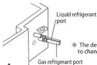
text_image
Liquid refrigerant port * The design to change Gas refrigerant port
Discharge all the nitrogen to create a vacuum and charge the system.
Insulation
Once you have checked that there are no leaks in the system, you can insulate the piping and hose.
- To avoid condensation problems, place T13.0 or thicker Acrylonitrile Butadien Rubber separately around each refrigerant pipe.
Note
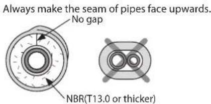
text_image
Always make the seam of pipes face upwards. No gap NBR(T13.0 or thicker)- Wind insulating tape around the pipes and drain hose avoiding to compress the insulation too much.
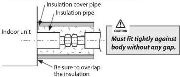
text_image
Insulation cover pipe Insulation pipe Indoor unit Be sure to overlap the insulation CAUTION Must fit tightly against body without any gap.-
Finish wrapping insulating tape around the rest of the pipes leading to the outdoor unit.
-
The pipes and electrical cables connecting the indoor unit with the outdoor unit must be fixed to the wall with suitable ducts.

All refrigerant connection must be accessible, in order to permit either unit maintenance or removing it completely.
- Select the insulation of the refrigerant pipe.
◆ Insulate the gas side and liquid side pipe referring to the thickness according to the pipe size.
The thickness according to the pipe size is a standard of the indoor temperature of 27^ C and humidity of 80%. If installing in an unfavorable conditions, use thicker one.
◆ Insulator's heat-resistance temperature should be more than 120°C.
| Pipe | Pipe size | Insulation Type (Heating/Cooling) | Remarks | |
| Standard[30°C, 85%] | High humidity[30°C, over 85%] | |||
| EPDM, NBR | ||||
| Liquid pipe | ∅6.35~∅9.52 | 9t | ← | Internal temperature is higher than 120°C |
| ∅12.7~∅50.80 | 13t | ← | ||
| Gas pipe | ∅6.35 13t | 19t | ||
| ∅9.52~∅25.40 | 19t | 25t | ||
| ∅28.58~∅44.45 | 32t | |||
| ∅50.80 25t | 38t | |||
When installing insulation in places and conditions below, use the same insulation that is used for high humidity conditions.
- High humidity places such as shoreline, hot spring, near lake or river, and ridge (when the part of the building is covered by earth and sand.)
- Restaurant ceiling, sauna, swimming pool etc.
- The ceiling frequently exposed to moisture and cooling is not covered.
e.g. The pipe installed at a corridor of a dormitory and studio or near an exit that opens and closes frequently. - The place where the pipe is installed is highly humid due to the lack of ventilation system.

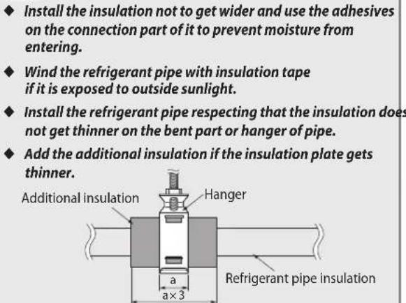
text_image
Install the insulation not to get wider and use the adhesives on the connection part of it to prevent moisture from entering. Wind the refrigerant pipe with insulation tape if it is exposed to outside sunlight. Install the refrigerant pipe respecting that the insulation does not get thinner on the bent part or hanger of pipe. Add the additional insulation if the insulation plate gets thinner. Additional insulation Hanger a a×3 Refrigerant pipe insulationDrain pipe and Drain Hose Installation
- Install the drain pipe as shortly as possible.
◆ Give a slightly slant to the drainpipe for proper drainage of condensate water.
There must be no gap on the connected part so that the drainpipe is not separated from the flexible hose.
- Insulate the drainpipe, and then fix it as indicated.
Whole drainpipe should be insulated by 5t(or more) insulation to prevent water condensation.
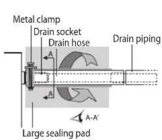
text_image
Metal clamp Drain socket Drain hose Drain piping Large sealing pad A-A'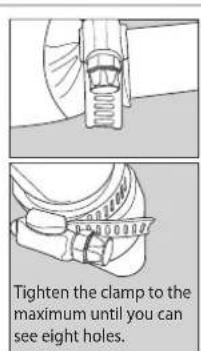
text_image
Tighten the clamp to the maximum until you can see eight holes.* Flexible hose Installation
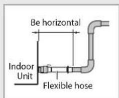
text_image
Be horizontal Indoor Unit Flexible hose◆ Install horizontally
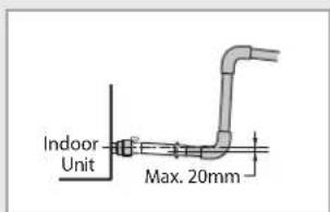
text_image
Indoor Unit Max. 20mm◆ Max. allowable axis gap
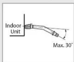
text_image
Indoor Unit Max. 30"◆ Max. allowable bending angle
installing your air conditioner _19
Drainpipe Connection
- The drain pipe should be installed within 100mm from the flexible hose, lift up from 100mm to 550mm and lift down 20mm or more.
- Install horizontal drainpipe with a slope of 1/100 or more and fix it by hanger space of 1\~1.5m.
- Install the air vent in the horizontal drainpipe to prevent water flow back to the indoor unit.
Note You may not need to install it if there were proper slope in the horizontal drainpipe. - The flexible hose should not be installed upward position, it may cause water flow back to the indoor unit.
- Install U-trap at the end of the drainpipe to prevent a nasty smell to reach the indoor unit.
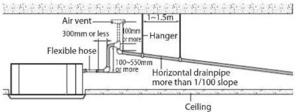
text_image
Air vent 300mm or less Flexible hose 100mm or more 100~550mm or more 1~1.5m Hanger Horizontal drainpipe more than 1/100 slope CeilingCentralized Drainage
- Install main air vent at the front of the farthest indoor unit from the main drain when installed indoor units are more than 3.
- You may need to install individual air vent to prevent water flow back at the top of each indoor unit drainpipe.
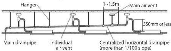
text_image
Hanger 1~1.5m Main air vent 550mm or less Main drainpipe Individual air vent Centralized horizontal drainpipe (more than 1/100 slope)Wiring Work
Power and communication cable connection
- Before wiring work, you must turn off all power source.
- Indoor unit power should be supplied through the breaker(MCCB, ELB) separated by the outdoor power.
- The power cable should be used only copper wires.
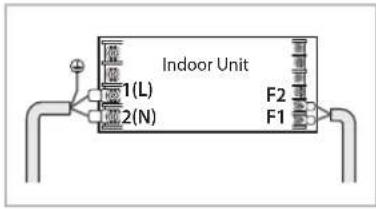
- Connect the power cable{1(L), 2(N)} among the units within maximum length and communication cable(F1, F2) each.
- Connect V1, V2(for DC12V) and F3, F4(for communication) when installing the wired remote Control.
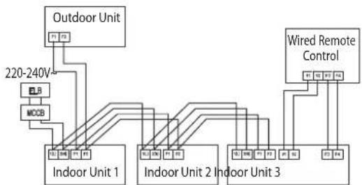
flowchart
graph TD
    A["Outdoor Unit"] --> B["Indoor Unit 1"]
    A --> C["Indoor Unit 2"]
    A --> D["Indoor Unit 3"]
    E["Wired Remote Control"] --> F["Indoor Unit 3"]
    G["220-240V"] --> H["MCBS"]
    H --> I["Indoor Unit 1"]
    H --> J["Indoor Unit 2"]
    H --> K["Indoor Unit 3"]
ELB : Essential Installation
◆ Using the correct tools, connect the cables to the terminal board securely within the range of rated torque, so the cable is firm and cannot be moved by external force or pressure.
Make sure the cables are placed in the correct position so that they can be covered firmly, without the cover lifting off, or touching other parts.
If the terminal is loose, then overheating, electric shock or fire may occur.
| Tightening Torque (kgf·cm) | |
| M3 | 5~6 |
| M3.5 | 8~10 |
| M4 | 12~15 |
Selecting compressed ring terminal
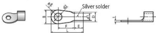
text_image
Silver solder R D F E L| Nominal dimensions for cable (mm) | Nominal dimensions for screw (mm) | BD d1 EFL d2 t | |||||||||||
| Standard dimension (mm) | Allowance (mm) | Standard dimension (mm) | Allowance (mm) | Standard dimension (mm) | Allowance (mm) | Min. | Min. | Max. | Standard dimension (mm) | Allowance (mm) | Min. | ||
| 1.5 | 4 6.6 | ±0.2 | 3.4 | +0.3-0.2 | 1.7 | ±0.2 | 4.1 | 6 | 16 | 4.3 | +0.20 | 0.7 | |
| 4 | 8 | ||||||||||||
| 2.5 | 4 6.6 | ±0.2 | 4.2 | +0.3-0.2 | 2.3 | ±0.2 | 6 | 6 | 17.5 | 4.3 | +0.20 | 0.8 | |
| 4 8.5 | |||||||||||||
| 4 | 4 9.5 | ±0.2 | 5.6 | +0.3-0.2 | 3.4 | ±0.2 | 6 | 5 | 20 | 4.3 | +0.20 | 0.9 | |
Specification of electronic wire
| Power supply | MCCB | ELB | Power cable | Earth cable | Communication cable |
| Max : 242VMin : 198V | XA | XA, 30mmA0.1 sec | 2.5mm^2 | 2.5mm^2 | 0.751.5mm^2 |
◆ Decide the capacity of ELB and MCCB by below formula.
$$ \text { The capacity of ELB, MCCB } X [ \mathrm{A} ] = 1. 2 5 \times 1. 1 \times \Sigma \mathrm{Ai} $$
* X: The capacity of ELB, MCCB
* Σ Ai : Sum of Rating currents of each indoor unit.
* Refer to each installation manual about the rating current of indoor unit.
◆ Decide the power cable specification and maximum length within 10% power drop among indoor units.
$$ \sum_ {k = 1} ^ {n} \left(\frac {\text { Coef } \times 3 5 . 6 \times L _ {k} \times i _ {k}}{1 0 0 0 \times A _ {k}}\right) < \frac {1 0 \% \text { of input }}{\text { voltage[V] }} $$
* Coef: 1.55
* Lk: Distance among each indoor unit[m],
Ak: Power cable specification[mm²], ik: Running current of each unit[A]
20_ installing your air conditioner
Setting an indoor unit address and installation option
Set the indoor unit address and installation option with remote controller option.
Set the each option separately since you cannot set the ADDRESS setting and indoor unit installation setting option at the same time. You need to set twice when setting indoor unit address and installation option.
The procedure of option setting
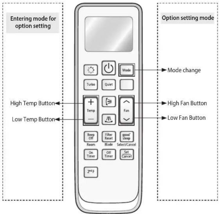
text_image
Entering mode for option setting High Temp Button Low Temp Button Option setting mode Mode change High Fan Button Low Fan Button Beep Off Filter Reset good' sleep Room Blade Select/Cancel On Timer Off Timer Set Cancel 2nd FStep 1. Entering mode to set option
- Remove batteries from the remote controller.
- Insert batteries and enter the option setting mode while pressing High Temp button and Low Temp button.
- Check if you have entered the option setting status.

Step 2. The procedure of option setting
After entering the option setting status, select the option as listed below.

Option setting is available from SEG1 to SEG 24
◆ SEG1, SEG7, SEG13, SEG19 are not set as page option.
◆ Set the SEG2\~SEG6, SEG8\~SEG12 as ON status and SEG14\~18, SEG20\~24 as OFF status.
| SEG1 | SEG2 | SEG3 | SEG4 | SEG5 | SEG6 | SEG7 | SEG8 | SEG9 | SEG10 | SEG11 | SEG12 | ||
| 0XX | XXXX | 1 | XXXXX | ||||||||||
| SEG13 | SEG14 | SEG15 | SEG16 | SEG17 | SEG18 | SEG19 | SEG20 | SEG21 | SEG22 | SEG23 | SEG24 | ||
| 2XX | XXXX | 3 | XXXXX |
| On(SEG1~12) Off(SEG13~24) | |
| Auto | Auto |
| SN 00 | OFF 00 |
Setting an indoor unit address and installation option
| Option setting Status | ||
| 1. Setting SEG2, SEG3 optionPress Low Fan button(√) to enter SEG2 value.Press High Fan button(✗) to enter SEG3 value.Each time you press the button ·s will be selected in rotation. | 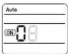 | 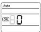 |
| SEG2 SEG3 | ||
| 2. Setting Cool modeModePress Mode button to be changed to Cool mode in the ON status. | 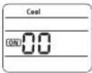 | |
| 3. Setting SEG4, SEG5 optionPress Low Fan button(√) to enter SEG4 value.Press High Fan button(✗) to enter SEG5 value.Each time you press the button ·s will be selected in rotation. | 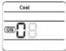 | 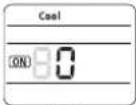 |
| SEG4 | SEG5 | |
| 4. Setting Dry modeModePress Mode button to be changed to DRY mode in the ON status. | 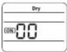 | |
| 5. Setting SEG6, SEG8 optionPress Low Fan button(√) to enter SEG6 value.Press High Fan button(✗) to enter SEG8 value.Each time you press the button ·s will be selected in rotation. | 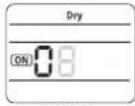 | 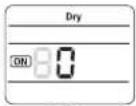 |
| SEG6 | SEG8 | |
| 6. Setting Fan modeModePress Mode button to be changed to FAN mode in the ON status. | 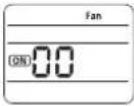 | |
| 7. Setting SEG9, SEG10 optionPress Low Fan button(√) to enter SEG9 value.Press High Fan button(✗) to enter SEG10 value.Each time you press the button ·s will be selected in rotation. | 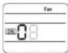 | 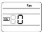 |
| SEG9 | SEG10 | |
| 8. Setting Heat modeModePress Mode button to be changed to HEAT mode in the ON status. |  | |
| 9. Setting SEG11, SEG12 optionPress Low Fan button(√) to enter SEG11 value.Press High Fan button(✗) to enter SEG12 value.Each time you press the button ·s will be selected in rotation. | 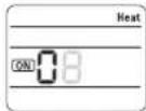 | 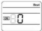 |
| SEG11 | SEG12 | |
| 10. Setting Auto modeModePress Mode button to be changed to AUTO mode in the OFF status. | 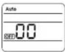 | |
| 11. Setting SEG14, SEG15 optionPress Low Fan button(√) to enter SEG14 value.Press High Fan button(✗) to enter SEG15 value.Each time you press the button ·s will be selected in rotation. | 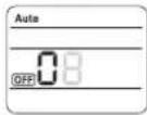 | 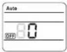 |
| SEG14 | SEG15 | |
22\_ installing your air conditioner
| Option setting Status | |
| 12. Setting Cool modeModePress Mode button to be change to Cool mode in the OFF status. | 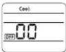 |
| 13. Setting SEG16, SEG17 optionPress Low Fan button(√) to enter SEG16 value.Press High Fan button(∧) to enter SEG17 value.Each time you press the button ·s will be selected in rotation. | 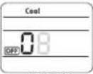 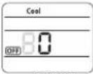 SEG16 SEG17 SEG16 SEG17 |
| 14. Setting Dry modeModePress Mode button to be change to Dry mode in the OFF status. | 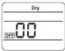 |
| 15. Setting SEG18, SEG20 optionPress Low Fan button(√) to enter SEG18 value.Press High Fan button(∧) to enter SEG20 value.Each time you press the button ·s will be selected in rotation. | 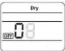 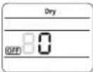 SEG18 SEG20 SEG18 SEG20 |
| 16. Setting Fan modeModePress Mode button to be change to Fan mode in the OFF status. | 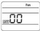 |
| 17. Setting SEG21, SEG22 optionPress Low Fan button(√) to enter SEG21 value.Press High Fan button(∧) to enter SEG22 value.Each time you press the button ·s will be selected in rotation. | 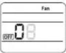 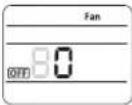 SEG21 SEG22 SEG21 SEG22 |
| 18. Setting Heat modeModePress Mode button to be change to HEAT mode in the OFF status. | 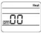 |
| 19. Setting SEG23, SEG24 modePress Low Fan button(√) to enter SEG23 value.Press High Fan button(∧) to enter SEG24 value.Each time you press the button ·s will be selected in rotation. | 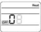 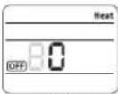 SEG23 SEG24 SEG23 SEG24 |
Step 3. Check the option you have set
After setting option, press Mode button to check whether the option code you input is correct or not.

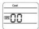
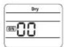
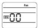
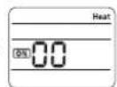
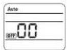
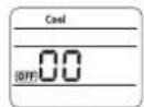
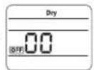
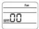
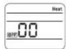
Step 4. Input option
Press operation button ⏻ with the direction of remote control for set.
For the correct option setting, you must input the option twice.
Step 5. Check operation
-
Reset the indoor unit by pressing the RESET button of indoor unit or outdoor unit.
-
Take the batteries out of the remote controller and insert them again and then press the operation button.
Setting an indoor unit address and installation option
Setting an indoor unit address (MAIN/RMC)
- Check whether power is supplied or not.
- When the indoor unit is not plugged in, there should be additional power supply in the indoor unit.
- The panel(display) should be connected to an indoor unit to receive option.
-
Before installing the indoor unit, assign an address to the indoor unit according to the air conditioning system plan.
-
Assign an indoor unit address by wireless remote controller.
- The initial setting status of indoor unit ADDRESS(MAIN/RMC) is "0A0000-100000-200000-300000".

text_image
Indoor Unit 1(L) 2(N) F2 F1Option No.: 0AXXXX-1XXXXX-2XXXXX-3XXXXX
| Option SEG1 SEG2 SEG3 SEG4 SEG5 SEG6 | ||||||||||||
| Explanation PAGE MODE Setting | Main address | 100-digit of indoor unit address | 10-digit of indoor unit | The unit digit of an indoor unit | ||||||||
| Remote Controller Display | 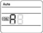 | 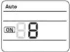 | 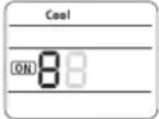 | 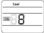 | 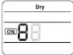 | |||||||
| Indication and Details | Indication | Details | Indication | Details Indication Details | Indication Details | Indication Details | Details Indication Details | Indication Details | Details Indication Details | |||
| 0 | A | 0 | No Main address | 0~9 | 100-digit | 0~9 | 10-digit | 0~9 | A unit digit | |||
| 1 | Main address setting mode | |||||||||||
| Option | SEG7 | SEG8 | SEG9 | SEG10 | SEG11 | SEG12 | ||||||
| Explanation | PAGE | Setting RMC address | Group channel(*16) | Group address | ||||||||
| Remote Controller Display | ||||||||||||
| Indication and Details | Indication | Details | Indication | Details Indication Details | Indication Details | Indication Details | Details Indication Details | Indication Details | Details Indication Details | |||
| 1 | 0 | No RMC address | RMC1 | 0~2 | RMC2 | 0~F | ||||||
| 1 | RMC address setting mode | |||||||||||

When "A"\~"F" is entered to SEG5\~6, the indoor unit MAIN ADDRESS is not changed.
If you set the SEG 3 as 0, the indoor unit will maintain the previous MAIN ADDRESS even if you input the option value of SEG5\~6.
If you set the SEG 9 as 0, the indoor unit will maintain previous RMC ADDRESS even if you input the option value of SEG11\~12.
24\_ installing your air conditioner
Setting an indoor unit installation option (suitable for the condition of each installation location)
- Check whether power is supplied or not.
- When the indoor unit is not plugged in, there should be additional power supply in the indoor unit.
-
The panel(display) should be connected to an indoor unit to receive option.
-
Set the installation option according to the installation condition of an air conditioner.
- The default setting of an indoor unit installation option is "020010-100000-200000-300000".
- Individual control of a remote controller(SEG20) is the function that controls an indoor unit individually when there is more than one indoor unit.
- Set the indoor unit option by wireless remote controller.
text_image
Indoor Unit 1(L) 2(N) F2 F1| SEG1 SEG2 SEG3 SEG4 SEG5 SEG6 | ||||
| 0 2 Robot cleaning | Exterior temperature sensor | Central control FAN | RPM compensation | |
| SEG7 SEG8 SEG9 SEG10 SEG11 SEG12 | ||||
| 1 Drain pump Hot water heater | Electronic heater | Opening the electronic expansion valve | Master / Slave | |
| SEG13 SEG14 SEG15 SEG16 SEG17 SEG18 | ||||
| 2 | External control | External control output | S-Plasma ion | Buzzer |
| SEG19 SEG20 SEG21 SEG22 SEG23 SEG24 | ||||
| 3 | Individual control of a remote controller | Heating setting compensation | EEV opening of an indoor unit stopped during oil return or Defrost operation. | - Human sensor |
◆ 1WAY/2WAY/4WAY MODEL: Drain pump(SEG8) will be set to 'USE + 3minute delay' even if the drain pump is set to 0.
◆ 1 WAY/2WAY/4WAY, DUCT MODEL : Number of hours using filter(SEG18) will be set to '1000hour' even if the SEG18 is set to except for 2 or 6.
If you input a number other than 0\~4 of the individual control of the indoor unit(SEG20), the indoor is set as "indoor 1".
◆ SEG5 central control option is basically set as 1 (Use), so you don't need to set the central control option additionally. However, if the central control is not connected but it doesn't indicate an error message, you need to set the central control option as 0 (Disuse) to exclude the indoor unit from the central control.
Setting an indoor unit address and installation option
Option No.: 02XXXX-1XXXXX-2XXXXX-3XXXXX
| Option SEG1 SEG2 SEG3 SEG4 SEG5 SEG6 | |||||||||||
| Explanation | PAGE MODE | Use of robot cleaning | Use of external temperature sensor | Use of central control | FAN RPM compensation | ||||||
| Remote Controller Display | 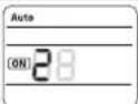 | 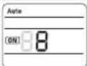 | 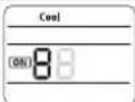 | [ycy7] |  | ||||||
| Indication and Details | Indication Details Indication Details Indication Details Indication Details Indication Details Indication Details | ||||||||||
| 0 | 2 | 0 | Disuse | 0 | Disuse | 0 | Disuse | 0 | Disuse | ||
| 1 | Use | 1 | Use | 1 | Use | 2 | High ceiling KIT | ||||
| Option | SEG7 | SEG8 | SEG9 | SEG10 | SEG11 | SEG12 | |||||
| Explanation | PAGE Use of drain pump | Use of hot water heater | Use of electronic heater | Opening the electronic expansion valve of an indoor unit when heating operation stops | Master / Slave | ||||||
| Remote Controller Display |  |  |  | 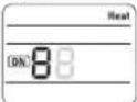 | 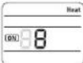 | ||||||
| Indication and Details | Indication | Details | Indication | Details | Indication | Details | Indication | Details | Indication | Details | Indication |
| 1 | 0 | Disuse | 0 | Disuse | 0 | Disuse | 0 | 0 | slave | ||
| 1 | Use | 1 | Use | 1 | Use | 1 | 80 | master | |||
| 2 | Use + 3minute delay | ||||||||||
| Option | SEG13 | SEG14 | SEG15 | SEG16 | SEG17 | SEG18 | |||||
| Explanation | PAGE | Use of external control | Setting the output of external control | S-Plasma ion | Buzzer control | Number of hours using filter | |||||
| Remote Controller Display | 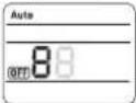 | 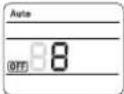 |  |  |  | ||||||
| Indication and Details | Indication | Details | Indication | Details | Indication | Details | Indication | Details | Indication | Details | Indication |
| 2 | 0 | Disuse | 0 | Thermo on | 0 | Disuse | 0 | Mixed operation control/Use buzzer | 2 | ||
| 1 | ON/OFF Control | 1 | Operation on | 1 | Use | 1 | Mixed operation control/ Disuse of buzzer | 6 | |||
| 2 | Mixed operation control/Use buzzer | ||||||||||
| 2 | OFF Control | 3 | Mixed operation control/ Disuse of buzzer | ||||||||
| Option | SEG19 | SEG20 | SEG21 | SEG22 | SEG23 | SEG24 | |||||
| Explanation | PAGE | Individual control of a remote controller | Heating setting compensation | EEV opening of an indoor unit stopped during oil return or defrost operation. | Human sensor | ||||||
| Remote Controller Display |  | 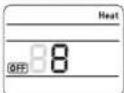 | 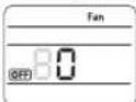 | 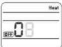 | 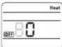 | ||||||
| Indication and Details | Indication | Details | Indication | Details | Indication | Details | Indication | Details | Indication | Details | Indication |
| 3 | 0 or 1 | channel 1 | 0 | Disuse | 0 | 150 step | 8 | ||||
| 2 | channel 2 | 1 | 2°C | 1 | 0 step | 9 | |||||
| 3 | channel 3 | 2 | 5°C | ||||||||
| 4 | channel 4 | ||||||||||
26_ installing your air conditioner
Changing a particular option
You can change each digit of set option.
| Option SEG1 SEG2 SEG3 SEG4 SEG5 SEG6 | |||||||||||
| Explanation | PAGE MODE | The option mode you want to change | The tens' digit of an option SEG you will change | The unit digit of an option SEG you will change | The changed value | ||||||
| Remote Controller Display | 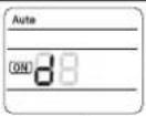 | 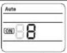 | 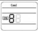 | 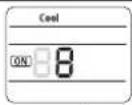 | 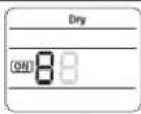 | ||||||
| Indication and Details | Indication | Details Indication Details Indication Details Indication Details Indication Details Indication Details | |||||||||
| 0 | D | Option mode | 0~F | Tens' digit of SEG | 0~9 | Unit digit of SEG | 0~9 | The changed value | 0~F | ||
Note
- When changing a digit of an indoor unit address setting option, set the SEG3 as 'A'.
- When changing a digit of indoor unit installation option, set the SEG3 as '2'.
Ex) When setting the 'buzzer control' into disuse status.
| Option SEG1 | SEG2 | SEG3 | SEG4 | SEG5 | SEG6 | |||||
| Explanation PAGE MODE | The option mode you want to change | The tens' digit of an option SEG you will change | The unit digit of an option SEG you will change | The changed value | ||||||
| Indication 0 D | 2 | 1 | 7 | 1 | ||||||