1573021 - Pressure washer North Star - Free user manual and instructions
Find the device manual for free 1573021 North Star in PDF.


User questions about 1573021 North Star
0 question about this device. Answer the ones you know or ask your own.
Ask a new question about this device
Download the instructions for your Pressure washer in PDF format for free! Find your manual 1573021 - North Star and take your electronic device back in hand. On this page are published all the documents necessary for the use of your device. 1573021 by North Star.
USER MANUAL 1573021 North Star
Pressure Washer: Machine that cleans dirty surfaces with high pressure water.

WARNING
Read this manual.
Serious injury or death can result if safety instructions are not followed.

text_image
STOPPump is shipped with oil.
- Remove shipping tape from pump oil fill cap. (Cat Pumps)
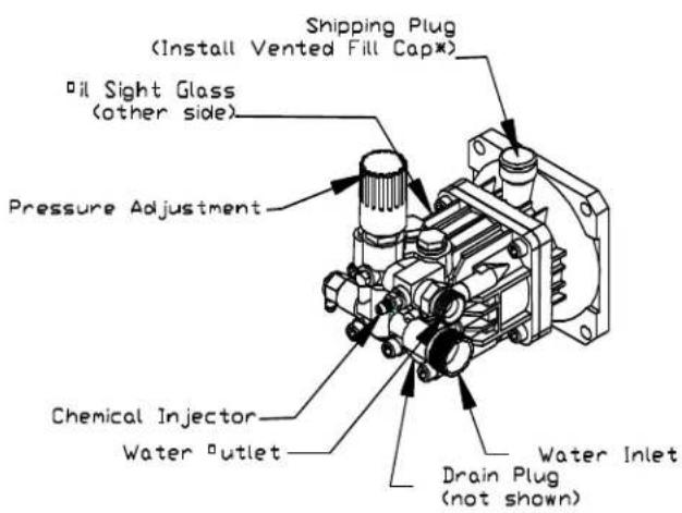
- Remove shipping plug and install vented fill cap. (Comet Pumps)
- See pump oil cap section of this manual.
Closely inspect all components.
-If you have damaged components: Contact the freight company that delivered the unit and file a claim.
-If you have missing components: Contact Customer Service at 1-800-270-0810.
Hazard Signal Word Definitions
 | This is the safety alert symbol. It is used to alert you to potential personal injury hazards. Obey all safety messages that follow this symbol to avoid possible injury or death. |
 | DANGER (red) indicates an imminently hazardous situation which, if not avoided, will result in death or serious injury. |
 | WARNING (orange) indicates a potentially hazardous situation which, if not avoided, could result in death or serious injury. |
 | CAUTION (yellow) indicates a potentially hazardous situation which, if not avoided, may result in minor or moderate injury. |
 | CAUTION (yellow) used without the safety alert symbol indicates a potentially hazardous situation which, if not avoided, may result in property damage. fig01453 |
Table of Contents
Important Safety Instructions.... 4
Grounding Instructions.... 5
Warning Label Locations.... 6
Assembly Instructions.... 7-9
Machine Component Identification.... 10
Pump Component Identification.... 11
Operation Instructions.... 12-15
Water Supply.... 12
Start-Up/Shut-Down Instructions.... 12
Spray Gun Safety Lock and Attaching the Lance..... 13
Installing Nozzles and Quick Connect hoses.... 14
Applying Chemicals.... 15
Maintenance and Storage.... 16-18
Maintenance Mode and Maintenance Schedule.... 16
Pump Oil Change.... 17
Winter Storage.... 18
Troubleshooting.... 19
Specifications.... 20
Wiring Diagram.... 20-21
Parts Explosions.... 22
Pump Exploded Views.... 24-27
Limited Warranty.... 29
California Proposition 65
Information.... 30
Important Safety Instructions
WARNING
- Risk of Injection or Injury to Persons - Do Not Direct Discharge Stream at Persons. - Do not use a hose if exterior damage is evident.
- Risk of explosion. - Do not spray flammable liquids. - Do not operate in a flammable environment.
CAUTION - Gun kicks back. Hold with both hands.
- To reduce the risk of injury, read operating instructions carefully before use.
⚠ WARNING - When using this product basic precautions should always be followed, including the following:
1.) Read all the instructions before using the product.
2.) To reduce the risk of injury, close supervision is necessary when the product is used near children. Do not allow irresponsible use by children. Always stop the product and bleed pressures before leaving unattended, disconnecting hoses or servicing the pump.
3.) Know how to stop the product and bleed pressures quickly. Be thoroughly familiar with the controls.
4.) Stay alert - watch what you are doing.
5.) Do not operate the product when fatigued or under the influence of alcohol or drugs.
6.) Keep operating area clear of all persons.
7.) Do not overreach or stand on unstable support. Keep good footing and balance at all times. Wear footwear capable of maintaining a good grip on wet surfaces - Do not place the machine on soft or unstable ground.
8.) Follow the maintenance instructions specified in all manuals. Do not run machine without sufficient lubrication or sufficient water to cool the pump.
9.) Wear safety glasses, gloves, face protection and appropriate clothing when operating the machine.
10.) Do not operate this machine with broken or missing parts. - Never alter the manufacturer's original design or deactivate any safety device on the machine.
11.) Risk of exposure to dangerous chemicals. Wear protective gloves when handling and cleaning with chemicals. Follow the chemical manufacturer's directions. Understand all safety hazards and first aid for all chemicals being used. Check whether dangerous chemicals have been used and take any precautions that may have been recommended by the supplier of these chemicals when cleaning filters. Do not pump highly abrasive fluids or use with incompatible chemicals or solvents.
12.) Know the pressure and temperature limits of your machine. Be sure all high pressure accessories meet or exceed your machine's limits. Do not set the pressure relief valve above the machine's limit.
13.) Do not move this machine by pulling on the hose. Do not use the pump to support other items of equipment that impose unacceptable loads on the pump. Do not attempt to use this machine as a prop.
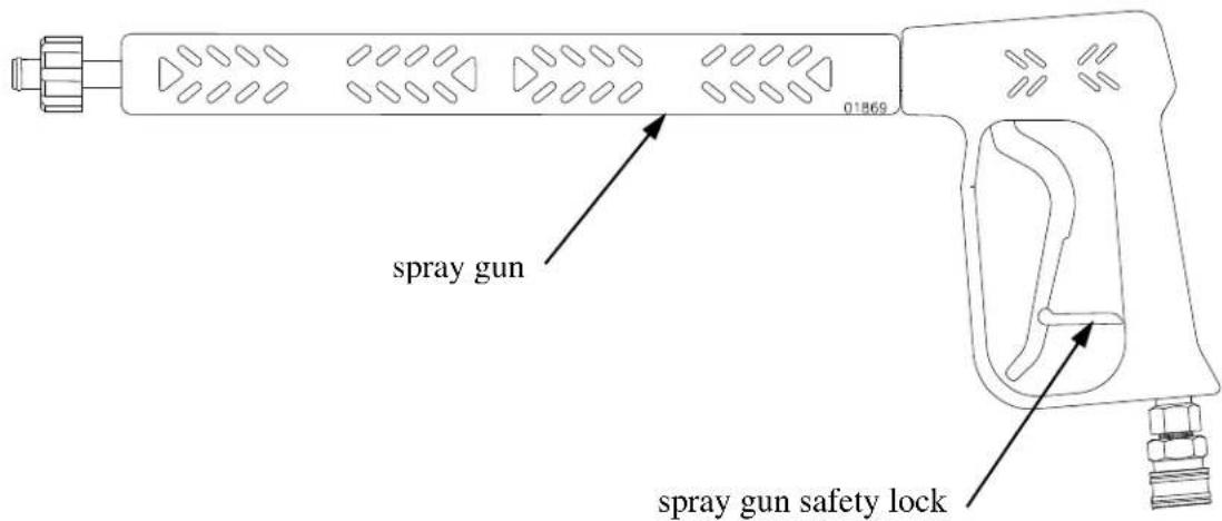
14.) To reduce risk of injury, do not secure the spray gun open. Your spray gun is equipped with a built-in trigger safety latch to guard against accidental trigger release and potentially dangerous high pressure spray. Rotate the safety latch to the locked position when not spraying.
15.) Do not clean this machine with its own spray. Cleaning should be done with a damp sponge with the motor OFF.
16.) Always make sure all switches and controls are in the OFF position prior to plugging in the electrical cord. Do no stand in water while plugging and unplugging electrical cord.
17.) This product is provided with a ground fault circuit interrupter built into the power cord plug. If replacement of the plug or cord is needed, use only identical replacement parts.
18.) Keep a fire extinguisher rated "ABC" nearby.
SAVE THESE INSTRUCTIONS
Grounding Instructions
This product must be grounded. If it should malfunction or breakdown, grounding provides a path of least resistance for electric current to reduce the risk of electrical shock. This product is equipped with a cord having an equipment-grounding conductor and a grounding plug. The plug must be plugged into an appropriate outlet that is properly installed and grounded in accordance with all local codes and ordinances.
DANGER - Improper connection of the equipment - grounding conductor can result in a risk of electrocution. Check with a qualified electrician or service personnel if you are in doubt as to whether the outlet is properly grounded. Do not modify the plug provided with the product - if it will not fit the outlet; have a proper outlet installed by a qualified electrician. Do not use any type adapter with this product.
1. For a product rated 125 volts or less:
GROUND FAULT CIRCUIT INTERRUPTER PROTECTION
This pressure washer is provided with a ground fault circuit interrupter (GFCI) built into the plug of the power supply cord. This device provides additional protection from the risk of electric shock. Should replacement of the plug or cord become necessary, use only identical replacement parts that include GFCI protection.
2. For a product rated more than 125 volts:
GROUND FAULT CIRCUIT INTERRUPTER PROTECTION
To comply with the National Electric Code (NFPA 70) and to provide additional protection from the risk of electric shock, this pressure washer should only be connected to a receptacle that is protected by a ground fault circuit interrupter (GFCI).
Extension Cords
Use only 3-wire extension cords that have 3 prong grounding-type plugs and 3-pole cord connectors that accept the plug from the product. Use only extension cords that are intended for outdoor use. These extension cords are identified by a marking “Acceptable for use with outdoor appliances; store indoors while not in use.” Use only extension cords having an electrical rating not less than the rating of the product. Do not abuse extension cord and do not yank on any cord to disconnect. Keep cord away from heat and sharp edges. Always disconnect the extension cord from the receptacle before disconnecting the product from the extension cord.
⚠ WARNING - To reduce the risk of electrocution, keep all connections dry and off the ground. Do not touch plug with wet hands.
SAVE THESE INSTRUCTIONS
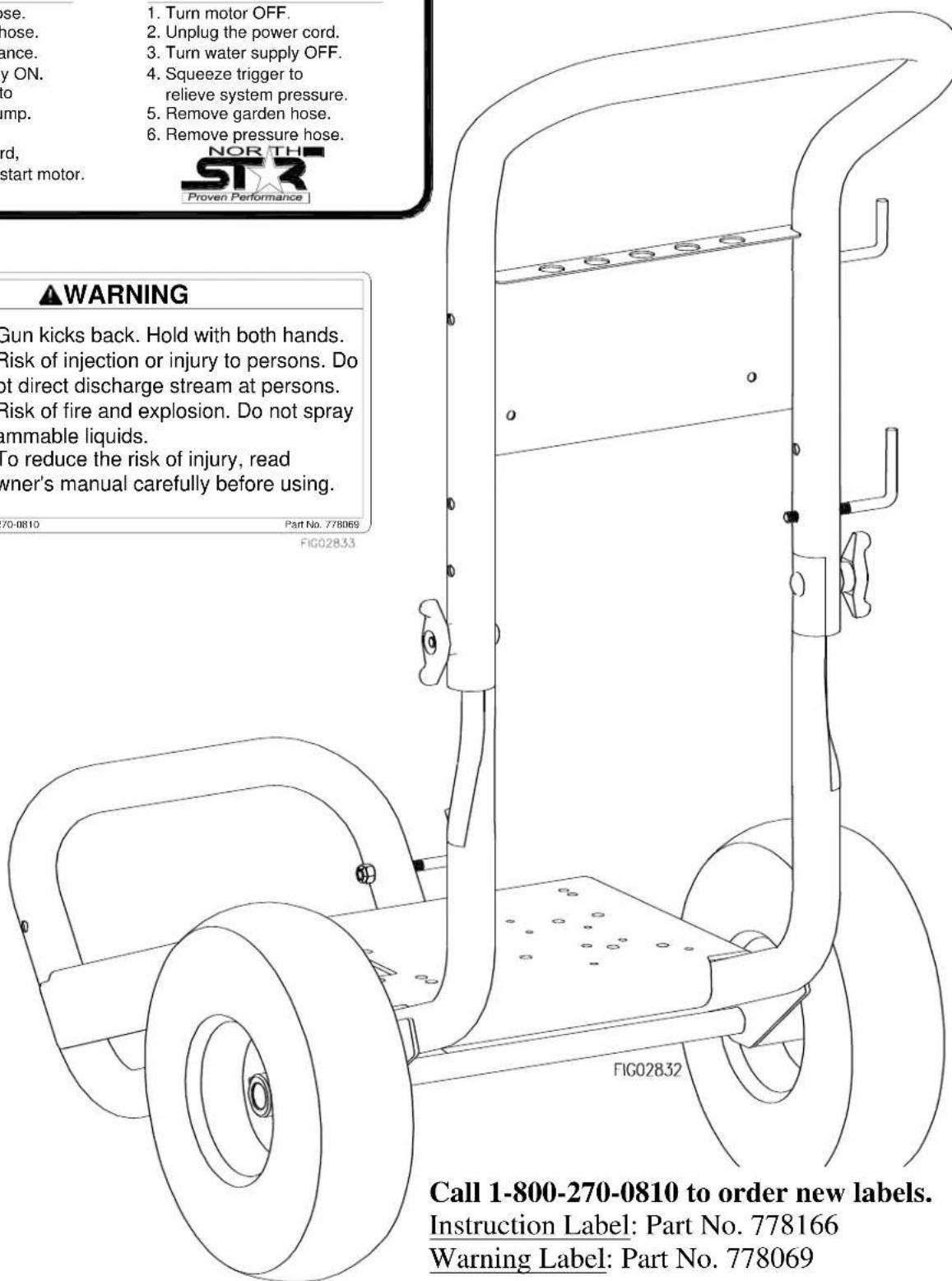
Warning Label Locations
START-UP INSTRUCTIONS
- Attach garden hose.
- Attach pressure hose.
- Attach gun and lance.
- Turn water supply ON.
- Squeeze trigger to purge air from pump.
- Insert nozzle.
- Plug in power cord, reset the GFCI, start motor.
SHUT-DOWN INSTRUCTIONS
- Turn motor OFF
- Unplug the power cord.
- Turn water supply OFF.
- Squeeze trigger to
relieve system pressure. - Remove garden hose.
- Remove pressure hose.
WARNING


©2008 NT+E Co. 800-270-0810
♦Gun kicks back. Hold with both hands.
- Risk of injection or injury to persons. Do not direct discharge stream at persons.
- Risk of fire and explosion. Do not spray flammable liquids.
◆To reduce the risk of injury, read owner's manual carefully before using.
Part No. 778069
FIG02833
text_image
1. Turn motor OFF. 2. Unplug the power cord. 3. Turn water supply OFF. 4. Squeeze trigger to relieve system pressure. 5. Remove garden hose. 6. Remove pressure hose. NOR THE STAR Proven Performance ▲WARNING Gun kicks back. Hold with both hands. Risk of injection or injury to persons. Do not direct discharge stream at persons. Risk of fire and explosion. Do not spray mammable liquids. To reduce the risk of injury, read owner's manual carefully before using. 70-0810 Part No. 778069 FIG02833 FIG02832 Call 1-800-270-0810 to order new labels. Instruction Label: Part No. 778166 Warning Label: Part No. 778069Call 1-800-270-0810 to order new labels.
Instruction Label: Part No. 778166
Warning Label: Part No. 778069
Assembly Instructions
I.) Unpack
Your pressure washer is shipped in one box. Separate and identify the components found in both boxes.
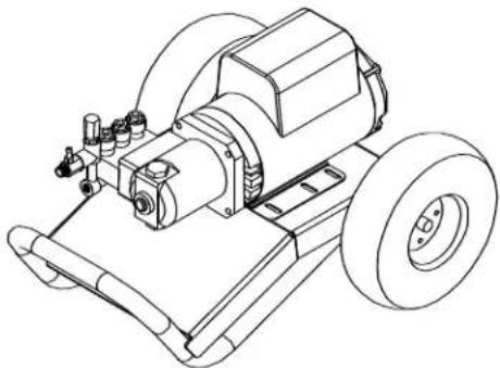 Motor/Pump/Base Assembly Motor/Pump/Base Assembly | 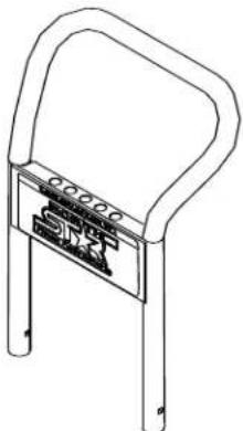 Handle Handle | 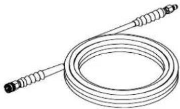 Pressure Hose Pressure Hose | |
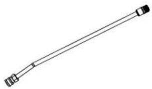 Lance Lance |  Spray Gun Spray Gun | 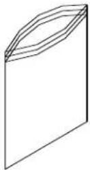 Hardware Bag Hardware Bag | |
* Figures shown are for representation only. Actual components will vary by model.
fig02299
Assembly Instructions
I.) Hardware Bag
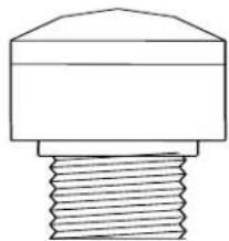
natural_image
Simple line drawing of a mechanical component with a threaded base (no text or symbols)Vented fill cap (1573001 only)

Flange Nut – Qty 2
Part # 82019
natural_image
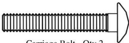
Pure technical line drawing of a screw with a pointed tip (no text or symbols)Carriage Bolt - Qty 2 Part # 82233
natural_image
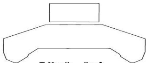
Simple line drawing of a mechanical part with no text or symbolsT-Handle - Qty 2 Part # 38578

Nylock Nut - Qty 4
Part # 777495

Gun Hook - Qty 1
Part # 38509
natural_image
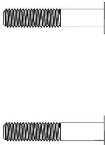
Two identical threaded fasteners with a flat shaft, shown from different angles (no text or symbols)Hose Hook - Qty 2 Part # 779761
natural_image
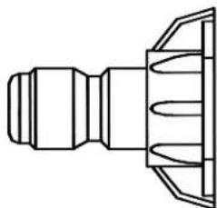
Technical line drawing of a mechanical connector or fitting (no text or symbols)Nozzle - Qty 2 Part # varies by model
Grommet - Qty 5
Part # 35198
Assembly Instructions
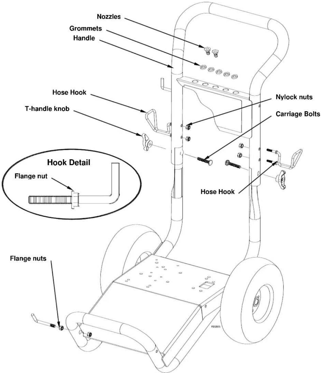
III.) Handle Assembly
1.) Attach handle to base with two carriage bolts and t-handle knobs.
2.) Spin a flange nut backwards onto gun hook. (see hook detail)
3.) Mount the hose hooks onto the handle and gun hook onto the base as shown.
4.) Insert grommets into the holes on the handle nameplate.
5.) Press nozzles into grommets according to the colors indicated on the handle decal.
text_image
Nozzles Grommets Handle Hose Hook T-handle knob Hyok Detail Flange nut Flange nuts Nylock nuts Carriage Bolts Hose HookMachine Component Identification
text_image
Technical diagram of a water heater with numbered components for identification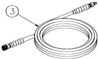
natural_image
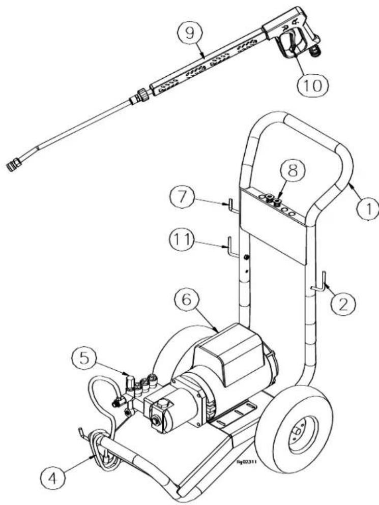
Diagram of a coiled cable with two connectors and a numbered label (3), no text or symbols present.1.) Handle. Designed for easy cart movement.
2.) Hose Hook. Store hose on hook.
3.) Pressure Hose. Attach quick couplers to gun and water outlet.
4.) Chemical Hose. Submerge in cleaning solution.
5.) Water Pump. Inspect for loose/broken parts prior to each use.
6.) Motor. Leeson motor provides years of reliable use.
7.) Gun Hook. Store gun on hook.
8.) Nozzles.
9.) Spray Gun. Always use two hands for safe operation.
10.) Trigger. Actuate to allow pressurized water to flow out of spray gun.
11.) Cord Hook. Store electrical cord on hook.
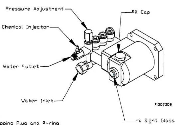
Pump Component Identification
1573001
text_image
Shipping Plug (Install Vented Fill Cap*) Oil Sight Glass (other side) Pressure Adjustment Chemical Injector Water Outlet Water Inlet Drain Plug (not shown)1573011 & 1573021
text_image
Pressure Adjustment Chemical Injector Water outlet Water Inlet pping Plug and P-ring Oil Cap FIG02309 Oil Sight GlassNote: Discard Shipping Plug and -ring
Operation Instructions
Water Supply
1.) Make sure the water supply is clean. Debris can cause excess pump wear and reduce performance.
2.) An insufficient water supply will damage your pump. Make sure the water supply is steady and is 20% over the rated flow of your pump. Use a stopwatch to time how long it takes to fill a 5-gallon bucket with your garden hose. The bucket must fill faster than the times listed in the table below.
| Model | Time to fill a 5 gal. bucket |
| 1573001 | 150 seconds |
| 1573011 | 160 seconds |
| 1573021 | 96 seconds |
3.) The water supply garden hose must have an inside diameter of at least 5/8". If the hose is more than 100 ft. long, the diameter must be at least 3/4".
4.) Never use a reservoir tank as a water source. Drawing water out of a tank may cause pump cavitation and damage to your pump. This pressure washer is designed for a pressurized water source such as a city water faucet. However, the water source pressure must not exceed 115 psi (8 bar).
Always use a flexible rubber hose for your water supply. Do not use rigid piping.
START-UP INSTRUCTIONS
- Attach garden hose.
- Attach pressure hose.
- Attach gun and lance.
- Turn water supply ON.
-
Squeeze trigger to purge air from pump.
-
Insert nozzle.
-
Plug in power cord
-
Reset the GFCI button on the cord
-
Start motor.
SHUT-DOWN INSTRUCTIONS
- Turn motor OFF.
- Unplug the power cord.
- Turn water supply OFF.
- Squeeze trigger to relieve system pressure.
- Remove garden hose.
- Remove pressure hose.

WARNING
Skin puncture hazard.
High pressure fluid can inject under skin resulting in serious injury including amputation. Do not direct spray at people or animals.
-If skin injection happens, seek IMMEDIATE surgical treatment.
-Do not check for leaks with hand. Instead, use a piece of cardboard to check for leaks.
-Do not use unit if exterior hose damage is evident. Make sure all fittings are tight before starting. Relieve system pressure before servicing.
-Know how to stop engine and bleed pressures quickly. Be thoroughly familiar with the controls.
-Make sure accessories meet the unit's temperature and pressure limits.
-Stop engine and bleed pressures before leaving unit unattended.
fig01863
Operation Instructions
Spray Gun Safety Lock
When not spraying, use the spray gun safety lock to prevent accidental high-pressure discharge.
text_image
01869 spray gun spray gun safety lock* Note: Depending on model, gun may appear differently.
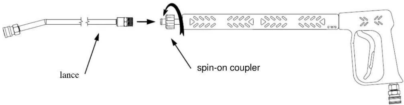
Attaching the Lance
text_image
lance spin-on couplerTighten spin-on coupler hand tight.
Note: The o-rings make the seal so there is no need to tighten with a wrench.
Operation Instructions
Installing Nozzles
To install a nozzle pull back the collar and push the nozzle into the coupler. Once the connection is made, pull on the nozzle to make sure it is secure.
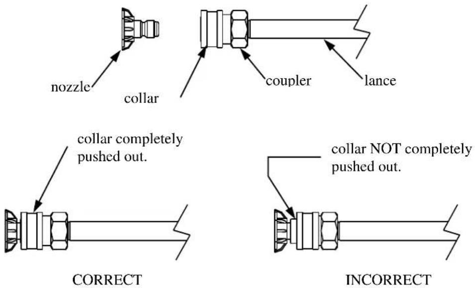
WARNING
Flying objects.
Make sure nozzle is secure before squeezing trigger. If nozzle is not secure it will become a projectile. Serious injury can occur.
fig01864
Attach Quick Connect Couplers
- To install the hose onto the pump, pull back the collar and push the hose into the coupler on the pump.
- To install the hose onto the spray gun, pull back the collar on the spray gun and push the hose into the coupler on the spray gun.
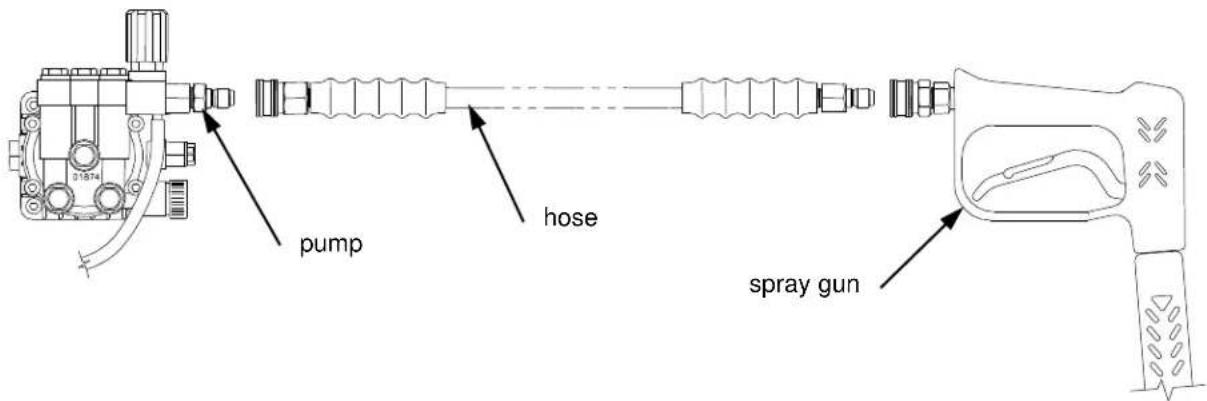
text_image
pump hose spray gunOnce the connections are made, pull on the hose to make sure it is secure.
Operation Instructions
Applying Chemicals
1.) Install the black nozzle when applying chemicals onto the cleaning surface.
2.) Start the pressure washer according to the start-up instructions.
3.) Submerge the chemical hose in cleaning solution. (See Pump Component Identification section for chemical injector location.)
4.) Squeeze the spray gun trigger. The chemical injector will draw the chemical into the water stream.
5.) Apply chemicals evenly onto the cleaning surface. Allow the chemicals to react with the dirt, then clean at high pressure with high pressure (green or yellow) nozzle.
6.) Never use more chemical than is necessary to clean the surface.
7.) To clean the chemical injector, draw water through the strainer until all the chemical is purged from the system.
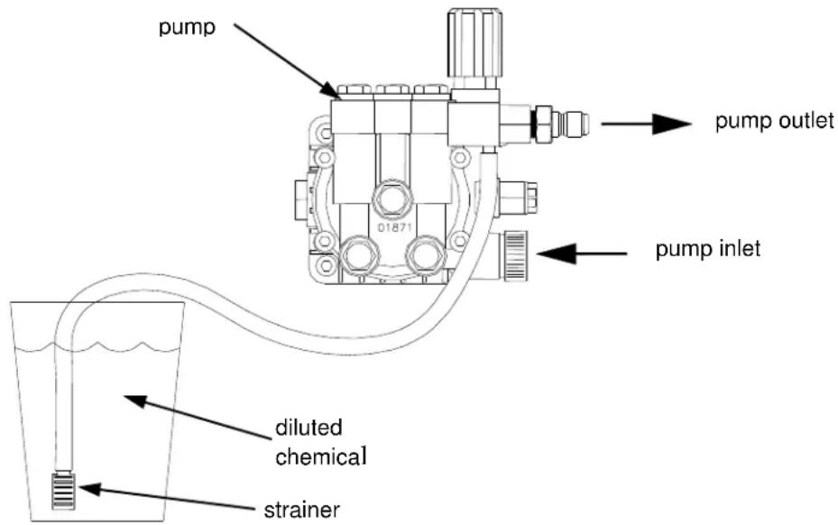
text_image
pump 01871 pump outlet pump inlet diluted chemical strainer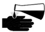
WARNING
Risk of exposure to dangerous chemicals.
Serious injury or death can result if chemical manufacturer instructions are not followed.
-Wear protective gloves when handling and cleaning with chemicals.
-Understand all safety hazards and first aid for all chemicals being used.
-When cleaning filters, check if chemicals have been used and take any precautions that are recommended by the chemical manufacturer.
-Different chemicals may interact dangerously with each other, always follow chemical manufacturer directions before switching chemicals.
-Calculate the correct amount of chemical to mix, dispose of excess chemical per the manufacturer instructions.
-Never spray flammable liquids.
fig01846
Maintenance and Storage
Maintenance Mode
Read and follow these safety rules whenever you will be servicing the pressure washer:
- Turn off / unplug / relieve pressure first. Always turn off and unplug the pressure washer and relieve system pressure before inspection or maintenance.
- Replace guards. Make sure all guards and cover shields are replaced after servicing the pressure washer.
• Major repair. Major service, including the installation or replacement of parts, should be performed only by a qualified electrical service technician. Obtain factory-approved parts from NorthStar Product Support at 1-800-270-0810. - Replacement parts. If a part needs replacement, only use factory approved repair parts. Replacement parts that do not meet specifications may result in a safety hazard or poor operation of the pressure washer and will void the warranty.
Maintenance Schedule
| What to Check | When To Check | What to Do |
| Inlet Filter | Each Use | Visually inspect and clean inlet filter with clear water. |
| Pressure Hose | Each Use | Visually inspect pressure hose and hose couplings. Replace hose if any of the following is evident:hose coupling is damaged, wire mesh is exposed or damaged, hose is permanently kinked or flattened, outer hose cover is blistered or loose. |
| Bolts | Each Use | Tighten any loose bolts. |
| Pump Oil | After 1 ^st 50hrs, then 3mo/500hr | Change pump oil. See pump oil change instructions on next page. |
natural_image
Abstract black-and-white diagram of intersecting curved lines with directional arrows, no text or symbols present⚠ WARNING
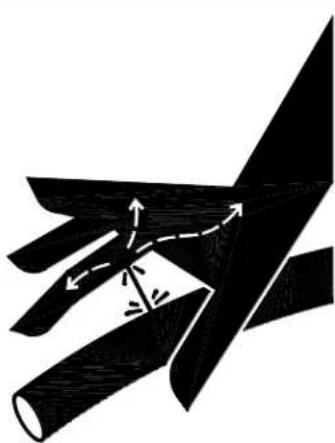
Skin injection hazard.
High pressure fluid can inject under skin resulting in serious injury including amputation.
-Make sure all fittings are tight before applying pressure. Relieve system pressure before servicing.
-Do not check for leaks with hand. Instead, use a piece of cardboard to check for leaks.
-If skin injection happens, seek immediate "Surgical Treatment".
fig01454
Maintenance and Storage
Pump Oil Change
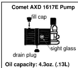
1.) Place a suitable container below the pump to catch the used oil, then remove the oil fill cap and oil drain plug.
2.) Allow the used oil to drain completely, then reinstall the drain plug and tighten securely.
3.) Please dispose of used oil in a manner that is compatible with the environment. We suggest you take used oil in a sealed container to your local recycling center or service station for reclamation. Do not throw it in the trash; pour it on the ground or down the drain.
4.) With the pump in a level position, fill to the halfway point on the oil sight glass (see pump oil capacities below). For Comet pumps use Universal Tractor Transmission Oil or Mobil 1 15W50 synthetic oil. For Cat pumps use SAE30 non-detergent oil or Cat Pump Oil Item# 22158.
text_image
Comet AXD 1617E Pump fill cap sight glass drain plug Oil capacity: 4.3oz. (.13L)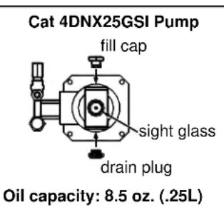
text_image
Cat 4DNX25GSI Pump fill cap sight glass drain plug Oil capacity: 8.5 oz. (.25L)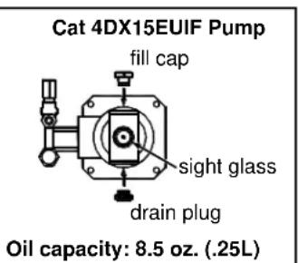
text_image
Cat 4DX15EUIF Pump fill cap sight glass drain plug Oil capacity: 8.5 oz. (.25L)FIG05038
Maintenance and Storage
Winter Storage
Protect your pump, hose and gun from freezing.
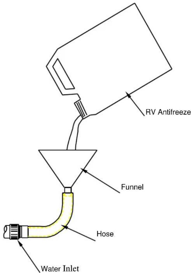
Items needed: 12" piece of garden hose or equivalent, funnel and RV antifreeze (approximately 6 oz.)
1.) Follow the storage instructions listed above.
2.) Make sure the motor start switch is OFF.
3.) Attach the garden hose with funnel to the pump inlet (see illustration).
4.) Pour RV antifreeze into the funnel, run motor until antifreeze comes out the pump outlet.
5.) Drain all water from the high pressure hose. Depress trigger on gun and drain all water out of gun/lance.
text_image
RV Antifreeze Funnel Hose Water InletTroubleshooting
| Problem | Solution |
| Motor will not start | SOLUTION: A,B |
| Low/Surging pressure or no water flow | SOLUTION: C,D,E,F,G,H |
| No chemical injection | SOLUTION: I,J,K,L |
| Cause | Solution |
| A- Tripped GFCI cord | Reset GFCI cord |
| B- Tripped motor relay | Reset motor |
| C- Insufficient water supply | See water supply section of this manual |
| D- Plugged pump inlet filter | See maintenance section of this manual |
| E- Wrong nozzle | Make sure high pressure nozzle is being used |
| F- Plugged nozzle | Remove nozzle, check for blockage |
| G- Worn nozzle | Replace nozzle |
| H- Leak in pressure hose | Replace pressure hose |
| I- Wrong nozzle | Make sure chemical nozzle is being used |
| J- Back pressure from extra-long discharge hose | Try shorter hose |
| K- Leak in chemical siphon hose | Replace hose – use hose clamps if necessary |
| L- Chemical strainer not submerged | Make sure strainer is completely submerged |
The manufacturer reserves the right to make improvements in design and/or changes in specifications at any time without incurring any obligation to install them on units previously sold.
Any Questions, Comments, Problems or Parts Orders
Call NorthStar Product Support 1-800-270-0810
Specifications
1573001
| PSI (bar) | 1700 (117) |
| GPM (l/min) | 1.5 (5.7) |
| Max Water Temp | 140°F (60°C) |
| DimensionsL x W x H | 34” x 21” x 38”(864mm x 534mm x 965mm) |
| Weight | 95 lb. (44kg) |
1573011
| PSI (bar) | 2000 (138) |
| GPM (l/min) | 1.5 (5.7) |
| Max Water Temp | 140°F (60°C) |
| DimensionsL x W x H | 34” x 21” x 38”(864mm x 534mm x 965mm) |
| Weight | 115 lb. (44kg) |
1573021
| PSI (bar) | 3000 (207) |
| GPM (l/min) | 2.5 (9.4) |
| Max Water Temp | 140°F (60°C) |
| DimensionsL x W x H | 34” x 21” x 38”(864mm x 534mm x 965mm) |
| Weight | 139 lb. (55kg) |
Wiring Diagram
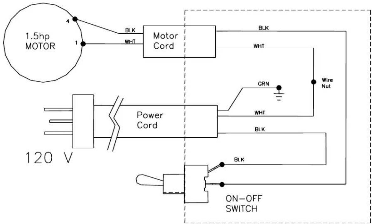
1573001
text_image
1.5hp MOTOR 4 1 BLK WHT Motor Cord BLK WHT Power Cord GRN WHT BRK ON-OFF SWITCH 120 VFIG02323
Wiring Diagram
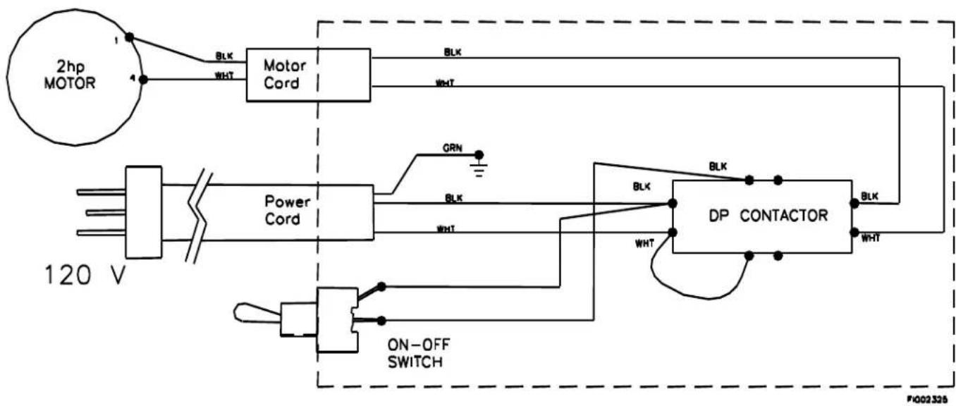
1573011
flowchart
graph TD
    A["2hp MOTOR"] -->|1 BLK WHT| B["Motor Cord"]
    B -->|BLK WHT| C["DP CONTACTOR"]
    C -->|BLK WHT| D["ON-OFF SWITCH"]
    D --> E["Power Cord"]
    E -->|GRN WHT| C
    style A fill:#f9f,stroke:#333
    style B fill:#ccf,stroke:#333
    style C fill:#cfc,stroke:#333
    style D fill:#fcc,stroke:#333
    style E fill:#ffc,stroke:#333
    style_F["120 V"] --> G["Ground"]
    style G --> H["ON-OFF SWITCH"]
    style H --> I["Power Cord"]
    I --> J["On-OFF SWITCH"]
    style_K["F4002326"]
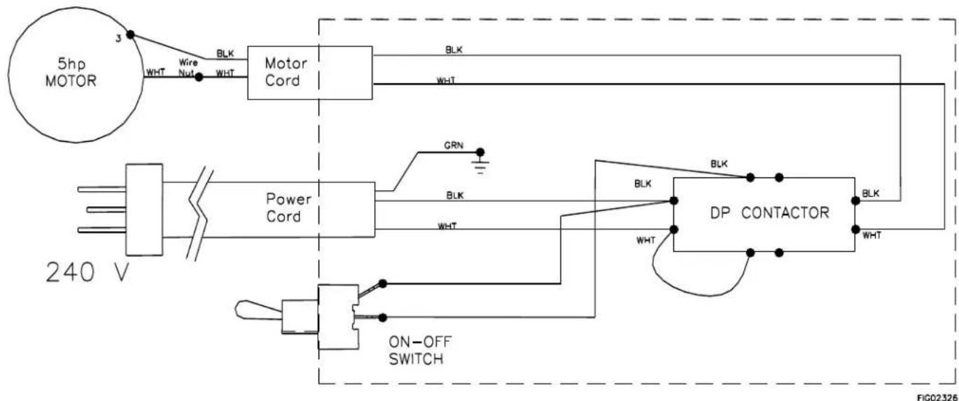
1573021
flowchart
graph TD
    A["5hp MOTOR"] -->|3 WHT| B["Motor Cord"]
    B -->|BLK WHT| C["Power Cord"]
    C -->|GRN| D["DP CONTACTOR"]
    D -->|BLK WHT| E["ON-OFF SWITCH"]
    E --> F["Ground"]
    style A fill:#f9f,stroke:#333
    style B fill:#ccf,stroke:#333
    style C fill:#cfc,stroke:#333
    style D fill:#fcc,stroke:#333
    style E fill:#cff,stroke:#333
    style F fill:#ffc,stroke:#333
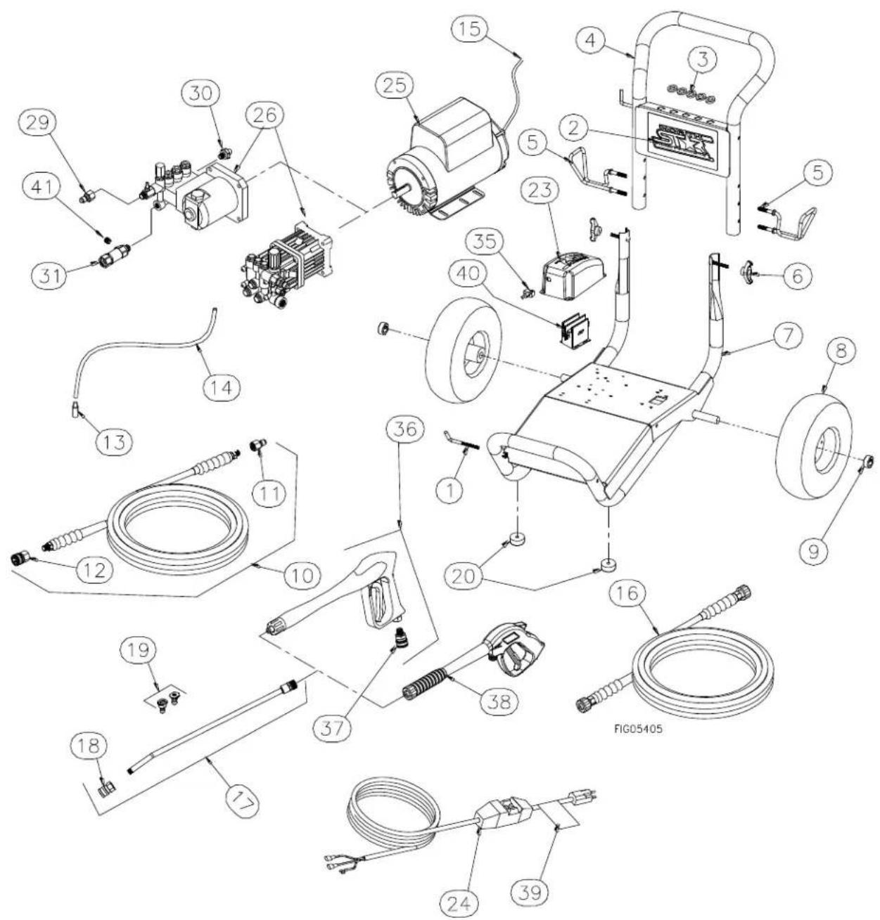
Parts Explosion M1573001 - Rev N.1
text_image
Exploded view diagram of a mechanical assembly with numbered components and labeled partsParts Explosion M1573001 - Rev N.1
| ITEM # | PART # | DESCRIPTION | QTY | MODELS |
| 1 | 38509 | Threaded Gun Hook | 1 | All |
| 2 | 779826 | NorthStar Decal | 1 | All |
| 3 | 35198 | 7/16 ID Grommet | 5 | All |
| 4 | 780223 | Handle | 1 | All |
| 5 | 779761 | Hose/Cord Hook | 2 | All |
| 6 | 38578 | T-Handle Knob | 2 | All |
| 7 | 779924 | Base | 1 | All |
| 8 | 788813 | Tire Wheel Assembly | 2 | All |
| 9 | 305200 | Wheel Retainer | 2 | All |
| 10 | 38524 | 5/16 x 25' Gray Hose | 1 | 1573011,1573021 |
| 11 | 777915 | 3/8" Quick Connect Nipple | 1 | 1573011,1573021 |
| 12 | 777914 | 3/8" Quick Connect Coupler | 1 | 1573011,1573021 |
| 13 | 221222 | Chemical Strainer | 1 | All |
| 14 | 777165 | 1/4" Braided Chemical Hose | 3 ft. | All |
| 15 | 778146 | Motor Cord, 14-2 AWG SJTW | 1 | 1573001 |
| 778147 | Motor Cord, 12-2 AWG SJTW | 1 | 1573011,1573021 | |
| 16 | 780841 | 1/4 x 25' Black Hose | 1 | 1573001 |
| 17 | 791309 | 18.5" Lance | 1 | All |
| 18 | 791308 | 1/4" Quick Connect | 1 | All |
| 19 | 778150 | Nozzle 2 pack #2.0 | 1 | 1573001,1573011 |
| 38530 | Nozzle 2 pack #3.0 | 1 | 1573021 | |
| 20 | 2215 | Bumpers | 2 | All |
| 23 | 779564 | Electric Control Box Cover | 1 | All |
| 24 | 778140 | GFCI Cord, 120V/15A | 1 | 1573001 |
| 778141 | GFCI Cord 120V/ 20A | 1 | 1573011 | |
| 799485 | GFCI Cord, 240V/30A | 1 | 1573021 | |
| 25 | 795953 | Motor, 1.5 HP Leeson | 1 | 1573001 |
| 794765 | Motor, 2.0 HP Leeson | 1 | 1573011 | |
| 793902 | Motor, 5.0 HP Leeson | 1 | 1573021 | |
| 26 | 790693 | Pump, Comet AXD 1617E GH | 1 | 1573001 |
| 792420 | Pump, Cat 4DX | 1 | 1573011 | |
| 789205 | Pump, Cat 4DNX | 1 | 1573021 | |
| 29 | 777915 | QC 3/8" Female Nipple | 1 | 1573011,1573021 |
| 30 | 35918 | Thermal Protector | 1 | 1573011,1573021 |
| 31 | 38596 | Inlet Filter | 1 | 1573011,1573021 |
| 35 | 777855 | Toggle Switch | 1 | All |
| 5260 | On-Off Plate | 1 | All | |
| 36 | 38527 | Gun, Consumer, QC | 1 | 1573011,1573021 |
| 37 | 313107 | 3/8" Male NPT Coupler | 1 | 1573011,1573021 |
| 38 | 38526 | Gun, 2700 PSI, 22mm | 1 | 1573001 |
| 39 | 778070 | Cord Warning | 1 | All |
| 40 | 778151 | DP Contactor 120V/25A | 1 | 1573011 |
| 778152 | DP Contactor 230V/30A | 1 | 1573021 | |
| 41 | 777838 | 1⁄4" Hex plug counter sunk | 1 | 1573011, 1573021 |
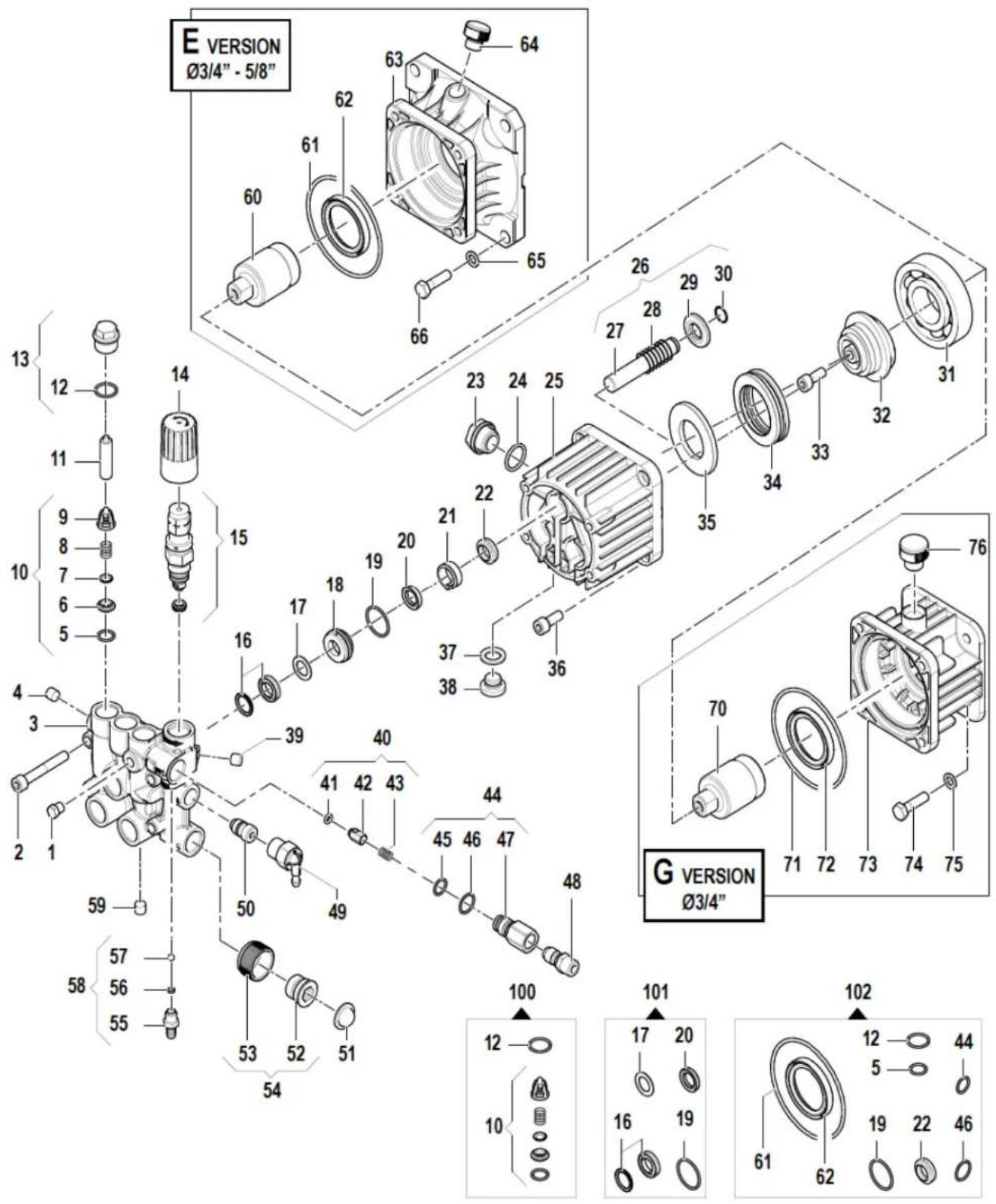
Pump Exploded Views
Part # 790693
Comet AXD 1617E GH
text_image
E VERSION Ø3/4" - 5/8" 13 12 11 9 8 7 6 5 10 4 3 2 1 59 58 57 56 55 14 15 16 17 18 19 20 21 22 23 24 25 26 27 28 29 30 31 32 33 34 35 36 37 38 40 41 42 43 44 45 46 47 48 50 49 53 52 51 54 100 101 102 103 104 105 106 107 108 109 110 111 112 113 114 115 116 117 118 119 120 121 122 123 124 125 126 127 128 129 130Pump Exploded Views
| Ref # | Part # | Description | Qty |
| 1 | CO3202001800 | CAP | 1 |
| 2 | CO3609001400 | SCREW, M8 X 55 | 4 |
| 3 | CO3218032700 | MANIFOLD | 1 |
| 4 | CO3202001800 | CAP | 1 |
| 5 | CO1210004900 | O-RING,OIL PLUG - WOBBLE PUMP | 6 |
| 6 | SEE PART # 10 | VALVE SEAT | 6 |
| 7 | CO3604002800 | SUCTION/DEL. VALVE | 6 |
| 8 | CO1802019200 | SPRING, AXD | 6 |
| 9 | CO1205003300 | VALVE CAGE, AXD | 6 |
| 10 | CO1220004500 | VALVE - AXD PUMP | 6 |
| 11 | CO0601027300 | AXD SPACER | 2 |
| 12 | CO1210015100 | O-RING, AXD3020 | 6 |
| 13 | CO3202031100 | VALVE CAP & O-RING | 6 |
| 14 | CO1817006400 | HANDLE | 1 |
| 15 | CO1215058500 | REG.VALVE KIT & SEAT | 1 |
| 16 | CO1241005900 | PACKING - GXD1617 | 3 |
| 17 | CO0009036900 | RING | 3 |
| 18 | CO0009021900 | RING(RETAINER) - WOBBLE PUMP | 3 |
| 19 | CO1210035600 | O-RING,SEAL CONTAINER - WOBBLE | 3 |
| 20 | CO1241005700 | BACK PACKING | 3 |
| 21 | CO0601030800 | OIL SEAL SPACER | 3 |
| 22 | CO0019005800 | SEALING RING(OIL) - WOBBLE PLA | 3 |
| 23 | CO3201002700 | OIL SIGHT GLASS | 1 |
| 24 | CO1210004800 | O-RING, 2.62 X 20.24MM | 1 |
| 25 | NOT AVAILABLE | PUMP CRANKCASE | 1 |
| 26 | CO2409015600 | PISTON KIT | 3 |
| 27 | CO2409008900 | PISTON - AXD3020G | 3 |
| 28 | CO1802015300 | SPRING, AXD | 3 |
| 29 | CO0009022100 | RING FOR AXD | 3 |
| 30 | CO0009022000 | 14MM RING FOR AXD | 3 |
| 31 | CO0438007600 | BALL BEARING - AXD | 1 |
| 32 | CO0001054800 | ECCENTRIC SHAFT - AXD | 1 |
| 33 | CO3609000500 | SCREW, M8 X 20 - AXD | 1 |
| 34 | CO0436001700 | BEARING | 1 |
| 35 | CO2816008800 | THRUST BEARING | 1 |
| 36 | CO3609002800 | SCREW M8 X 22 | 4 |
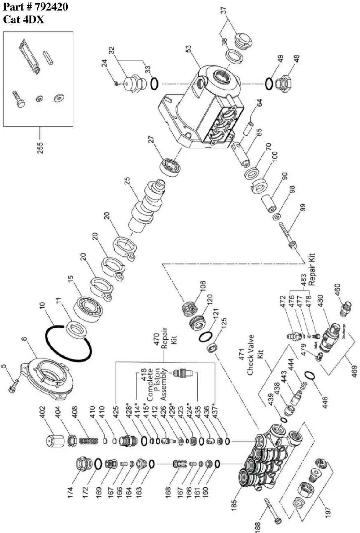
Pump Exploded Views
text_image
Part # 792420 Cat 4DX 255 32 33 24 53 37 38 49 48 64 65 70 100 90 98 99 27 25 20 25 20 20 15 10 8 5 11 10 402 404 408 410 410 425 428* 414* 415* 412 Complete Piston Assembly 426 429* 423 424* 435 436 437* 470 Repair Kit 106 120 121 125 471 Check Valve Kit 472 476 477 478 480 460 469 439 438 443 444 479 inlet O O O O O O O O O O O O O O O O O O O O O O O O O O O O O O O O O O O O OPump Exploded Views
| Ref# | P/N | DESCRIPTION | QTY |
| 5 | Not Available | Screw | 3 |
| 8 | CA547153 | Bearing Cover | 1 |
| 10 | CA14041 | O-Ring, Bearing Cover | 1 |
| 11 | CA55337 | Oil Seal | 1 |
| 15 | CA14488 | Inner Ball Bearing | 1 |
| 20 | CA547048 | Connecting Rod | 3 |
| 24 | Not Available | Oil Plug Cap | 1 |
| 25 | Not Available | Crankshaft | 1 |
| 27 | CA15710 | Ball Bearing | 1 |
| 32 | CA547961 | Cap | 1 |
| 33 | CA14179 | O-ring for Oil Filter Cap | 1 |
| 37 | CA92241 | Gauge, Bubble Oil w/Gasket | 1 |
| 38 | CA44428 | Gasket, Flat Flex Oil Gauge | 1 |
| 48 | CA44842 | Drain Plug | 1 |
| 49 | CA14179 | O-Ring for Drain Plug | 1 |
| 53 | Not Available | Crankcase | 1 |
| 64 | CA46229 | Crosshead Pin | 3 |
| 65 | CA132190 | Plunger Rod | 3 |
| 70 | CA47215 | Oil Seal | 3 |
| 90 | CA542403 | Plunger | 3 |
| 98 | CA46730 | Washer | 3 |
| 99 | CA542405 | Retainer, Plunger | 3 |
| 100 | CA46233 | Retainer, Seal | 3 |
| 106 | CA48222 | Seal | 3 |
| 120 | CA547357 | Seal Case | 3 |
| 121 | CA13976 | O-Ring for Seal Case | 3 |
| 125 | CA46240 | Seal | 3 |
| 160 | CA13965 | O-Ring, Inlet | 3 |
| 161 | CA545177 | Seat, Inlet | 3 |
| 163 | CA19285 | O-Ring | 3 |
| 164 | CA545178 | Seat, Discharge | 3 |
| 166 | CA46764 | Valve | 6 |
| 167 | CA46865 | Spring | 6 |
| 168 | CA543988 | Retainer, Spring, Inlet | 3 |
| 169 | CA49764 | Retainer, Spring, Discharge | 3 |
| 172 | CA142807 | O-Ring for Plug | 3 |
| 174 | CA547104 | Plug, Valve w/o-ring | 3 |
| 185 | Not Available | Head, Manifold w/Unloader Body | 1 |
| 188 | Not Available | Screw | 6 |
| Ref# | P/N | DESCRIPTION | QTY |
| 197 | CA941516 | Inlet Fitting Assembly | 1 |
| 255 | CA30516 | Bolt Mount Assembly | 1 |
| 401 | CA32088 | Handle Adjustable (Not Shown) | 1 |
| 402 | CA46570 | Adjusting Cap | 1 |
| 404 | CA45070 | Lock Nut | 1 |
| 408 | CA33394 | Pressure Spring | 1 |
| 410 | CA549352 | Spring Retainer | 1 |
| 412 | CA46251 | Piston Stem | 1 |
| 414 | CA28338 | Back Up Ring | 1 |
| 415 | CA22056 | O-Ring, Piston Stem | 1 |
| 418 | Not Available | Piston Assy (Included in # 470) | 1 |
| 423 | CA46249 | Retainer Valve | 1 |
| 424 | CA13966 | O-Ring, Valve Retainer (Outer) | 1 |
| 425 | CA46248 | Piston Retainer | 1 |
| 426 | CA46250 | Washer | 1 |
| 428 | CA26133 | O-Ring | 1 |
| 429 | CA17399 | O-Ring, Valve Retainer | 1 |
| 435 | CA548193 | Valve | 1 |
| 436 | CA46253 | Seat | 1 |
| 437 | CA13963 | O-Ring, Seat | 1 |
| 438 | CA46254 | Seat, Check Valve | 1 |
| 439 | CA13963 | O-Ring, Check Valve Seat | 1 |
| 443 | CA541060 | Valve, Check | 1 |
| 444 | CA45924 | Spring | 1 |
| 446 | CA26133 | O-Ring | 1 |
| 460 | CA107681 | Discharge Fitting | 1 |
| 469 | CA7231 | Chemical Fixed Injector | 1 |
| 470 | CA76031 | Unloader Repair Kit Inclds: 418, 428, 436, 437 | 1 |
| 471 | CA76146 | Check Valve Kit Inclds: 438, 439, 443, 444, 446 | 1 |
| 472 | CA46630 | Barb | 1 |
| 476 | Not Available | Barb O-Ring | 1 |
| 477 | Not Available | Ball | 1 |
| 478 | Not Available | Spring | 1 |
| 479 | Not Available | Orifice | 1 |
| 480 | Not Available | Body | 1 |
| 483 | CA76176 | Repair Kit | 1 |
| Kit #1 | CA33053 | Seal Kit Inclds: 98, 106, 121, 125 | 1 |
| Kit #2 | CA76978 | Valve Kit Inclds: 160, 161, 162, 163, 164, 166, 167, 168, 169, 172 | 1 |
| * | CA76754 | O-ring Kit Inclds: 414, 415, 424, 428, 429, 437 | 1 |
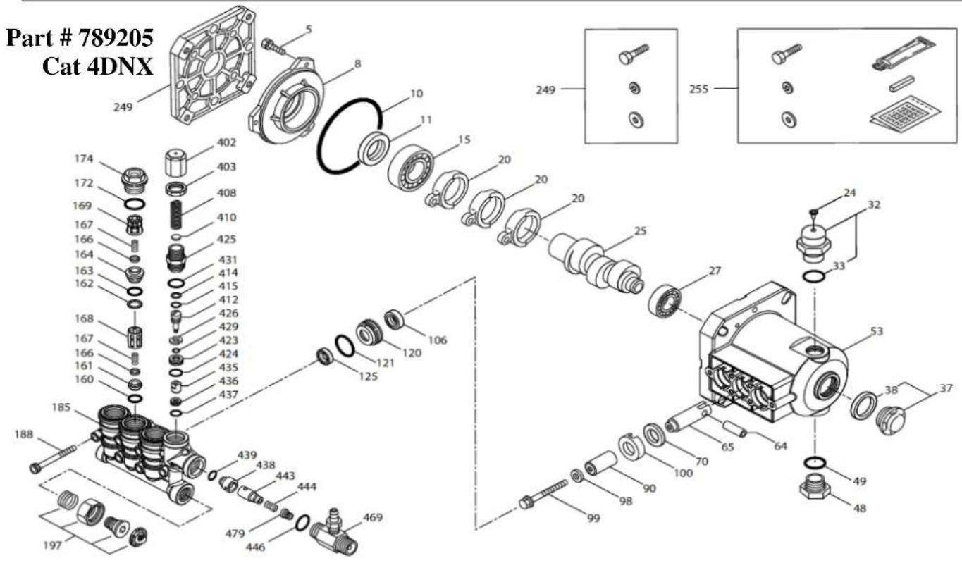
Pump Exploded Views
text_image
Part # 789205 Cat 4DNX 249 174 172 169 167 166 164 163 162 168 167 166 161 160 185 188 197 5 8 10 11 15 20 20 20 25 249 255 27 33 32 53 38 37 64 65 70 90 98 99 49 48 439 438 443 444 479 446 469 431 414 415 412 426 429 423 424 435 436 437 120 121 125 106| Ref# | P/N | DESCRIPTION | QTY |
| 5 | Not Available | Screw | 3 |
| 8 | CA547153 | Bearing Cover | 1 |
| 10 | CA14041 | O-Ring, Bearing Cover | 1 |
| 11 | CA55337 | Oil Seal | 1 |
| 15 | CA14488 | Inner Ball Bearing | 1 |
| 20 | CA547048 | Connecting Rod | 3 |
| 24 | Not Available | Oil Plug Cap | 1 |
| 25 | CA549446 | Crankshaft | 1 |
| 27 | CA56084 | Ball Bearing | 1 |
| 32 | CA547961 | Cap | 1 |
| 33 | CA14179 | O-ring for Oil Filter Cap | 1 |
| 37 | CA92241 | Gauge, Bubble Oil w/Gasket | 1 |
| 38 | CA44428 | Gasket, Flat Flex Oil Gauge | 1 |
| 48 | CA44842 | Drain Plug | 1 |
| 49 | CA14179 | O-Ring for Drain Plug | 1 |
| 53 | Not Available | Crankcase | 1 |
| 64 | CA46229 | Crosshead Pin | 3 |
| 65 | CA542402 | Plunger Rod | 3 |
| 70 | CA47215 | Oil Seal | 3 |
| 90 | CA547091 | Plunger | 3 |
| 98 | CA46730 | Washer | 3 |
| 99 | CA542405 | Retainer, Plunger | 3 |
| 100 | CA46233 | Retainer, Seal | 3 |
*One Kit will Complete One Pump*
| Ref# | P/N | DESCRIPTION | QTY |
| 106 | Kit #1 | Seal | 3 |
| 120 | Not Available | Seal Case | 3 |
| 121 | CA13976 | O-Ring for Seal Case | 3 |
| 125 | Kit #1 | Seal | 3 |
| 160 | CA17428 | O-Ring, Inlet | 3 |
| 161 | CA547077 | Seat, Inlet | 3 |
| 162 | CA48361 | Back-up Ring | 3 |
| 163 | CA43358 | O-Ring | 3 |
| 164 | CA547076 | Seat, Discharge | 3 |
| 166 | CA547098 | Valve | 6 |
| 167 | CA46865 | Spring | 6 |
| 168 | CA543988 | Retainer, Spring, Inlet | 3 |
| 169 | Kit #2 | Retainer, Spring, Discharge | 3 |
| 172 | CA142807 | O-Ring for Plug | 3 |
| 174 | CA547104 | Plug, Valve w/o-ring | 3 |
| 185 | Not Available | Head, Manifold w/Unloader Body | 1 |
| 188 | Not Available | Screw | 6 |
| 197 | CA941516 | Inlet Fitting Assembly | 1 |
| 249 | CA30520 | Adapter Mount Assembly | 1 |
| 255 | CA30516 | Bolt Mount Assembly | 1 |
| 403 | CA45070 | Lock Nut | 1 |
| 469 | CA7332 | Chemical Fixed Injector | 1 |
KITS
| Kit#1 | CA76975 | Seal Kit: Inclds: 98, 106, 121, 125 | 1 |
| Kit#2 | CA76976 | Valve Kit: Inclds: 160, 161, 162, 163, 164, 166, 167, 168, 169, 172 | 1 |
Limited Warranty
Dear Valued Customer:
The NorthStar Product you just purchased is built with the finest material and craftsmanship. Use this product properly and enjoy the benefits from its high performance. By purchasing a NorthStar product, you show a desire for quality and durability. Like all mechanical equipment this unit requires a due amount of care. Treat this unit like the high quality piece of machinery it is. Neglect and improper handling may impair its performance. Please thoroughly read the instructions and understand the operation before using your product.
Limited Warranty
NorthStar shall warranty any piece of equipment manufactured, or parts of equipment manufactured, to be free from defects in material or workmanship for a period of:
| Item # | Warranty Period |
| 1573001 | 1 year from date of purchase by user |
| 1573011, 1573021 | 2 years from date of purchase by user |
NorthStar shall warranty any wear item, including, but not limited to, valves, seals, pump diaphragms, hoses, and filter elements to be free from defects in material or workmanship for a period of 90 days from the date of purchase by user. This warranty applies to the original purchaser of the equipment and is non transferable. Verification of purchase is the responsibility of the buyer. Parts will be replaced or repaired at no charge, except when the equipment has failed due to lack of proper maintenance. Any misuse, abuse, alteration or improper installation or operations will void warranty. Determining whether a part is to be replaced or repaired is the sole decision of NorthStar.
NOTE: Some services performed by parties other than NorthStar may void warranty.
This warranty covers parts only. It will not provide for replacement of complete products due to defective parts. Components not manufactured by NorthStar are guaranteed by their manufacturer and can be serviced at factory-authorized locations near you. Any costs incurred due to replacement or repair of items outside of a NorthStar approved facility is the responsibility of the buyer and not covered under warranty. NorthStar can supply you with the service center location in your area.
This warranty specifically excludes the following; failure of parts due to damage caused by accident, fire, flood, windstorm, acts of God, applications not approved by NorthStar in writing, corrosion caused by chemicals, use of replacement parts which do not conform to manufacturer's specifications, and damage caused by vandalism. Additional exclusions: loss of running time, inconvenience, loss of income, or loss of use, including any implied warranty of merchantability of fitness for a specific use.
Warranty does not cover items subject to normal wear such as tires, receptacles or any part subject to direct physical contact by the public. This warranty does not cover any personal injury or damage to surrounding property caused by failure of any part.
This warranty is in lieu of any other warranty expressed or implied and NorthStar assumes no other responsibility or liability outside that expressed within this warranty.
Please fill in the following information and have it on hand when you call in on a warranty claim.
Customer Number:
Date of Purchase:
NorthStar Serial Number:
Item Number:
⚠ WARNING: This product can expose you to soots, tars, and mineral oils (untreated and mildly treated oils and used engine oils), which are known to the State of California to cause cancer.
For more information go to www.P65Warnings.ca.gov.

text_image
NORTH STAR®Proven Performance
Manufactured by Northern Tool + Equipment Co., 2800 SouthCross Drive West P.O. Box 1499 Burnsville, MN 55337-0499