
NEX110SODFFSS/C - Cooker RANGEMASTER - Free user manual and instructions
Find the device manual for free NEX110SODFFSS/C RANGEMASTER in PDF.


User questions about NEX110SODFFSS/C RANGEMASTER
0 question about this device. Answer the ones you know or ask your own.
Ask a new question about this device
Download the instructions for your Cooker in PDF format for free! Find your manual NEX110SODFFSS/C - RANGEMASTER and take your electronic device back in hand. On this page are published all the documents necessary for the use of your device. NEX110SODFFSS/C by RANGEMASTER.
USER MANUAL NEX110SODFFSS/C RANGEMASTER
natural_image
Close-up of a stainless steel kitchen air conditioner with control switches and buttons (no visible text or symbols)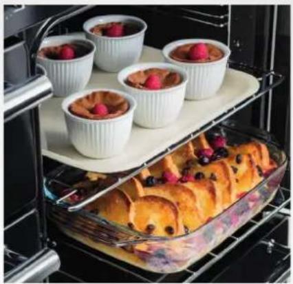
natural_image
Interior view of an oven with baked pastries and a tray of colorful toppings (no text or symbols visible)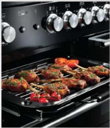
natural_image
Interior view of a modern kitchen oven with multiple ovens and meat plates on a grating tray (no visible text or symbols)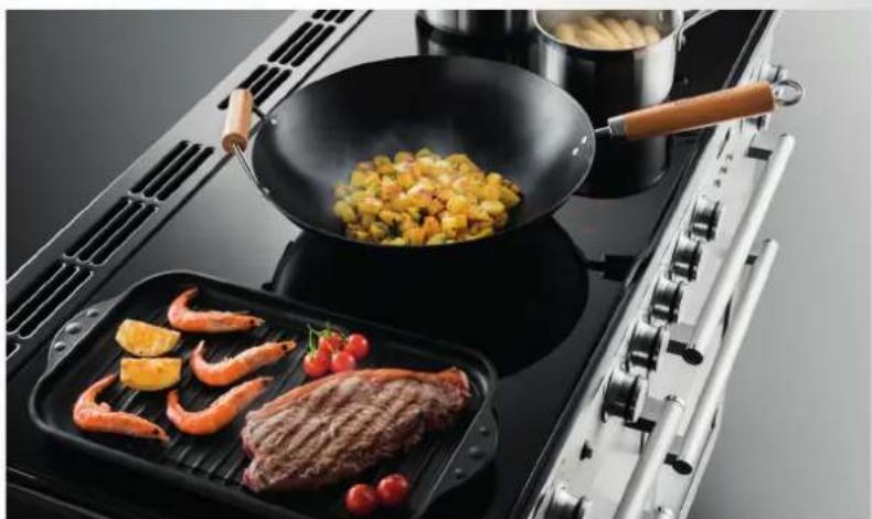
natural_image
Exterior view of a modern electric stove with a frying pan, shrimp, and grilled meat on the grating (no signage or text visible)USER GUIDE & INSTALLATION INSTRUCTIONS
Nexus 110 Dual Fuel / Steam
Show off your kitchen with ...
This is
RANGEmaster
#MyRangemaster
Simply snap and share a picture of your kitchen and tag #MyRangemaster for the chance to win £200 of Rangemaster cookware. If selected we will also send a photographer round to professionally photograph you at home with your range. You might even feature in some of the UK's top home interest titles!
To enter all you have to do is send in photos of your Rangemaster kitchen and tell us in one sentence what makes Rangemaster the heart of your kitchen? Entries can be posted on our Facebook page, Instagram or Twitter by tagging @RangemasterUK and using #MyRangemaster. Or, if you prefer, simply send in your entry via e-mail to marketing@agarangemaster.co.uk.
Rangemaster will feature a number of entries on the website online gallery and on the Rangemaster Facebook page, and some kitchens may be selected to be professionally photographed.
Terms & Conditions Apply
text_image
and tag end a you at someTo enter simply
SNAP
text_image
Illustration showing two smartphones with social media icons (Facebook, Twitter, Instagram, Pinterest, YouTube) connected by a dashed line, illustrating a messaging or interaction between devices.and
SHARE
MyRangemaster
natural_image
Cooking scene with a wok containing mixed ingredients on a gas stove (no text or symbols visible)RANGEMaster COOKWARE
Our range cookers are well known for providing the best possible cooking performance and years of faithful service. However, a great cooker alone cannot guarantee perfect results every time. The other vital ingredients are of course enthusiasm and quality cookware.
We offer cookware to work perfectly with all fuel types manufactured by Rangemaster, including induction hobs. You can be assured of functionality with style, as well as the quality and meticulous attention to detail you expect from the pioneers of range cooking.
Visit www.rangemastercookshop.co.uk
1. Before You Start... 1
Personal Safety 1
Electrical Connection Safety 1
If You Smell Gas 3
Peculiar Smells 3
Cooling Fan 3
Ventilation 3
Maintenance 3
Hob Care 6
Grill/Glide-out Grill™ Care 6
Cooker Care 6
Cleaning 7
2. Cooker Overview 8
Hotplate Burners 8
Wok Burner 9
The Wok Cradle 9
The Ceramic Hotplate 10
The Griddle 11
The Glide-out Grill ^™ 12
Bread Proving Drawer 13
Cleaning 14
3. The Multifunction Oven 15
Operating the Multifunction Oven 15
Accessories 17
Cooking Tips 20
Cooking Table 21
4. The Steam Cavity 22
Operating the Steam Cavity 23
Steam Cavity Functions 24
Program Modes 24
The Clock / Timer 25
5. Cleaning Your Cooker 26
Essential Information 26
Hotplate Burners 26
Ceramic Hotplate 27
The Griddle 27
Grills 28
Multifunction Oven 29
Steam Cavity 30
Cleaning Table 31
6. Troubleshooting 32
7. Installation 35
Dear Installer 35
Safety Requirements and Regulations 35
Provision of Ventilation 35
Location of Cooker 36
Conversion 36
Positioning the Cooker 37
Moving the Cooker 37
Fitting the Stability Bracket or Chain 38
Repositioning the Cooker Following 29
Connection 38
Conversion to Another Gas 39
Levelling 39
Gas Connection 40
Electrical Connection 41
Final Checks 41
Final Fitting 41
Customer Care 41
8. Conversion to LP Gas 42
Pressure Testing 43
9. Circuit Diagram 44
Power PCB 45
1. Before You Start...
Your cooker should give you many years of trouble-free cooking if installed and operated correctly. It is important that you read this section before you start.
Personal Safety
This appliance is for cooking purposes only. It must not be used for other purposes, for example heating a room. Using it for any other purpose could invalidate any warranty or liability claim. Besides invalidating claims this wastes fuel and may overheat the control knobs.
This appliance is for use in Great Britain and the Republic of Ireland. It is a Cat II 2 H 3+ cooker and is set for G20 at 20 mbar. (A conversion kit for LPG is available for the cooker).
- This appliance can be used by children aged from 8 years and above and persons with reduced physical, sensory or mental capabilities or lack of experience and knowledge if they have been given supervision or instruction concerning use of the appliance in a safe way and understand the hazards involved.
- WARNING: Children less than 8 years of age should be kept away unless continuously supervised. Children shall not play with the appliance. Cleaning and user maintenance shall not be made by children without supervision.
- The cooker should not be placed on a base.
- This appliance is designed for domestic cooking only. Use for any other purpose could invalidate any warranty or liability claim.
- Before operating the ovens please refer to the oven shelf installation, in the Accessories section.
- WARNING: The appliance and its accessible parts become hot during use
and will retain heat even after you have stopped cooking. Care should be taken to avoid touching heating elements. Children less than 8 years of age shall be kept away unless continuously supervised.
- CAUTION: A long term cooking process has to be supervised from time to time. A short term cooking process has to be supervised continuously.
- At the risk of fire DO NOT store items on the cooking surfaces.
- To avoid overheating, DO NOT install the cooker behind a decorative door.
- WARNING: Accessible parts will become hot during use and will retain heat even after you have stopped cooking. Keep babies and children away from the cooker and never wear loose-fitting or hanging clothes when using the appliance.
- DO NOT use a steam cleaner on your cooker.
• Always keep combustible materials, e.g. curtains, and flammable liquids a safe distance away from the cooker. - DO NOT spray aerosols in the vicinity of the cooker while it is on.
Electrical Connection Safety
A Gas Safe registered engineer should service the cooker and only approved spare parts should be used.
The electrical installation must be installed in accordance with all relevant British Standards/Codes of Practice, BS 7671. Or with the relevant national and local regulations and with the local gas and electricity supply companies' requirements.
Otherwise, all installations must be in accordance with the relevant instructions in this booklet.
text_image
Fig. 1.1 L N 10 mm² max L N 6 mm² max 230 V ac 50 Hz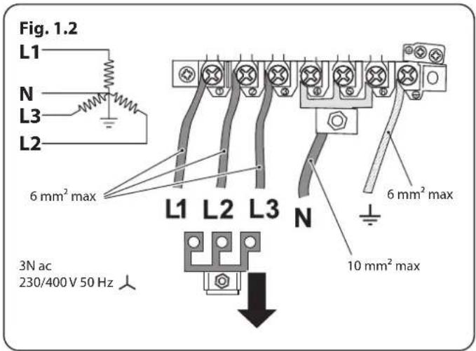
text_image
Fig. 1.2 L1 N L3 L2 6 mm² max L1 L2 L3 N 6 mm² max 10 mm² max 3N ac 230/400V 50 HzWARNING: THE APPLIANCE MUST BE EARTHED.
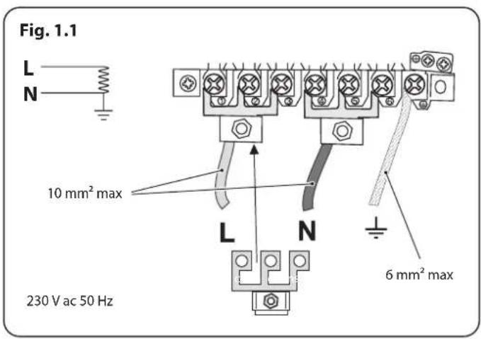
Note: The cooker must be connected to the correct electrical supply as stated on the voltage label on the cooker, through a suitable cooker control unit incorporating a double-pole switch, having a contact separation of at least 3 mm in all poles.
The cooker MUST NOT be connected to an ordinary domestic power point.
Access to the mains terminal is gained by removing the electrical terminal cover box on the back panel. Connect the mains cable to the correct terminals for your electrical supply type (Fig. 1.1 and Fig. 1.2). Check that the links are correctly fitted and that the terminal screws are tight. Secure the mains cable using the cable clamp.
Minimum temperature rating T105.
Read the instructions before installing or using this appliance.
Gas Connection Safety
• This cooker is a Class 2 Subclass 1 appliance.
• This appliance can be converted for use on another gas.
- Before installation, make sure that the cooker is suitable for your gas type and supply voltage. See the data badge.
• DO NOT use reconditioned or unauthorised gas controls.
- Disconnect from the electricity and gas supply before servicing.
- When servicing or replacing gas-carrying components disconnect from the gas supply before starting operation. Check the appliance is gas sound after completion.
• Make sure that the gas supply is turned on and that the cooker is wired in and switched on.
- In your own interest and that of safety, it is law that all gas appliances be installed by a qualified person(s).
- An appliance for use on LPG must not be installed in a room or internal space below ground level, e.g. in a basement.
This cooker must be installed in accordance with:
• British Standards/Codes of Practice, BS 5440 Part 2
• Natural Gas: BS 6172 and BS 6891
- LP Gas: BS 5482-1 (when the installation is in a permanent dwelling)
• Gas Safety (Installation and Use) regulations
• Relevant Building/IET regulations
If You Smell Gas
• DO NOT turn electric switches on or off
• DO NOT smoke
• DO NOT use naked flames
- Turn off the gas at the meter or cylinder
- Open doors and windows to get rid of the gas
- Keep people away from the area affected
- Call your gas supplier
• If you are using Natural Gas in the UK, ring the National Grid on: 0800 111 999
Peculiar Smells
When you first use your cooker it may give off an odour. This should stop after use.
Before using for the first time, make sure that all packing materials have been removed and then, to dispel manufacturing odours, turn the ovens to 200 °C and run for at least an hour.
Before using the grill for the first time you should also turn on the grill and run for 30 minutes with the grill pan in position, pushed fully back and the grill door open.
Make sure the room is well ventilated to the outside air (see 'Ventilation' below). People with respiratory or allergy problems should vacate the area for this brief period.
Cooling Fan
This appliance may have a cooling fan. When the grill or ovens are in operation the fan will run to cool the fascia and control knobs.
Ventilation
The use of a cooking appliance results in the production of heat and moisture in the room in which it is installed. Therefore, make sure that the kitchen is well ventilated: keep natural ventilation holes open or install a powered cookerhood that vents outside. If you have several hotplates/burners on, or use the cooker for a long time, open a window or turn on an extractor fan
Maintenance
- It is recommended that this appliance is serviced annually.
- WARNING: Before replacing the bulb, turn off the power supply and make sure that the oven is cool.
- DO NOT use cooking vessels on the hotplate that overlap the edges.
- Unless specified otherwise in this guide, always allow the cooker to cool and then switch it off at the mains before cleaning or carrying out any maintenance work.
• DO NOT use the control knobs to manoeuvre the cooker. - NEVER operate the cooker with wet hands.
- DO NOT use a towel or other bulky cloth in place of a glove – it might catch fire if brought into contact with a hot surface.
- DO NOT use hotplate protectors, foil or hotplate covers of any description. These may affect the safe use of your hotplate burners and are potentially hazardous to health.
- NEVER heat unopened food containers. Pressure build up may make the containers burst and cause injury.
- WARNING: Use only hob guards designed by the manufacturer of the cooking appliance or indicated by the manufacturer of the appliance in the instructions for use as suitable or hob guards incorporated in the appliance. The use of inappropriate guards can cause accidents.
- DO NOT use unstable saucepans. Always make sure that you position the handles away from the edge of the hotplate.
- NEVER leave the hotplate unattended at high heat settings. Pans boiling over can cause smoking, and greasy spills may catch on fire. Use a deep fat thermometer whenever possible to prevent fat overheating beyond the smoking point.
WARNING: Unattended cooking on a hob with fat or oil can be dangerous and may result in fire.
- NEVER try to extinguish a fire with water, but switch off the appliance and then cover the flame e.g. with a lid or a fire blanket.
- NEVER leave a chip pan unattended. Always heat fat slowly, and watch as it heats. Deep fry pans should be only one third full of fat.
- WARNING: Danger of fire: do not store items on the cooking surfaces.
- NEVER try to move a pan of hot fat, especially a deep fat fryer. Wait until the fat is cool. Filling the pan too full of fat can cause spill over when food is added. If you use a combination of oils or fats in frying, stir them together before heating, or as the fats melt.
- Foods for frying should be as dry as possible. Frost on frozen foods or moisture on fresh foods can cause hot fat to bubble up and over the sides of the pan. Carefully watch for spills or overheating of foods when frying at high or medium high temperatures.
- DO NOT use the top of the flue (the slot along the back of the cooker) for warming plates, dishes, drying tea towels or softening butter.
- DO NOT use water on grease fires and never pick up a flaming pan. Turn the controls off and then smother a flaming pan on a surface unit by covering the pan completely with a well fitting lid or baking tray. If available, use a multi-purpose dry chemical or foam-type fire extinguisher.
- DO NOT modify this appliance. This appliance is not intended to be operated by means of external timer or separated remote-control system.
- If flammable materials are stored in the drawer, oven(s) or grill(s) it may explode and result in fire or property damage.
Oven Care
- When the oven is not in use and before attempting to clean the cooker always be certain that the control knobs are in the OFF position.
- Use oven gloves to protect your hand from potential burns.
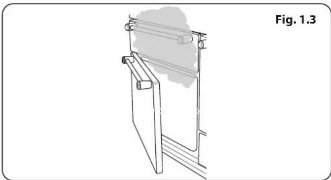
- Cooking high moisture content foods can create a 'steam burst' when the oven door is opened (Fig. 1.3). When opening the oven, stand well back and allow any steam to disperse.
- The inside door face is constructed with toughened safety glass. Take care NOT to scratch the surface when cleaning the glass panel.
• Accidental damage may cause the door glass panel to fracture.
- Keep oven vent ducts unobstructed.
- DO NOT use harsh abrasive cleaners or sharp metal scrapers to clean the oven door glass since they can scratch the surface, which may result in shattering of the glass.
• Make sure the shelves are pushed firmly to the back of the oven. DO NOT close the door against the oven shelves.
• DO NOT use aluminium foil to cover shelves, linings or the oven roof.
- When the oven is on, DO NOT leave the oven door open for longer than necessary, otherwise the control knobs may become very hot.
• DO NOT use the timed oven if the adjoining oven is already warm.
• DO NOT place warm food in the oven to be timed.
• DO NOT use a timed oven that is already warm.
- Use dry oven gloves when applicable – using damp gloves might result in steam burns when you touch a hot surface.
Oven Shelves
To fit the glide-out shelf, hook the front of the shelf onto the runners as shown (Fig. 1.4). The rear of the shelf should rest on the runners, in front of the rear stop (Fig. 1.4).
Steam oven shelves can be fitted by lining up the shelf with a groove in the oven ladders. Push the shelf back until the ends hit the shelf stop. Lift the front so the shelf clears the stops, then lower the front so the shelf is level and push it fully back.
natural_image
Technical line drawing of a mechanical assembly with no visible text or symbols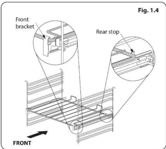
text_image
Front bracket Rear stop FRONT Fig. 1.4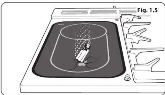
natural_image
Diagram of a laboratory apparatus with a beaker and filter, labeled Fig. 1.5 (no text or symbols on the diagram itself)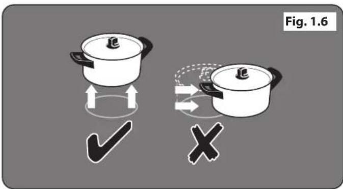
text_image
Fig. 1.6Warming Zone Care
- NEVER attempt to cook directly on the heating zone.
- DO NOT use the heating zone surface as a cutting board.
- DO NOT leave utensils, foodstuff or combustible items on the heating zone when it is not in use (e.g. tea towels, frying pans containing oil).
- DO NOT place plastic or aluminium foil, or plastic containers, on the heating zone.
- DO NOT leave the heating zone switched on unless being used for warming.
- DO NOT stand or rest heavy objects on the heating zone.
Although the ceramic surface is very strong, a sharp blow or sharp falling object (e.g. a salt cellar) might cause the surface to crack or break (Fig. 1.5)
WARNING: If the surface is cracked, switch off the appliance to avoid the possibility of electric shock.
WARNING: Should a crack appear in the surface, disconnect the cooker immediately from the supply and arrange for its repair.
Always LIFT pans off the heating zone. Sliding pans may cause marks and scratches (Fig. 1.6). Always turn the control to the 'OFF' position before removing a pan.
- DO NOT place anything between the base of the pan and the heating zone surface (e.g. asbestos mats, aluminium foil, wok cradle).
• Take care NOT to place metallic objects such as knives, forks, spoons and lids on the hob surface since they can get hot. - The appliance is not intended to be operated by means of external timer or separated remote-control system.
- Avoid warming an empty pan. Doing so may damage both the heating zone and pan.
Only certain types of glass, glass-ceramic, earthenware or other glazed containers are suitable for use on the heating zone; others may break because of the sudden change in temperature.
Hob Care
- NEVER allow anyone to climb or stand on the hob.
- DO NOT use the hob surface as a cutting board.
- DO NOT leave utensils, foodstuffs or combustible items on the hob when it is not in use (e.g. tea towels, frying pans containing oil).
- DO NOT place plastic or aluminium foil, or plastic containers on the hob.
- Always turn the control to the OFF position before removing a pan.
- Avoid heating an empty pan. Doing so may damage both the hob and pan.
Grill/Glide-out Grill™ Care
- When using the grill, make sure that the grill pan is in position and pushed fully in, otherwise the control knobs may become very hot.
- DO NOT leave the grill on for more than a few moments without the grill pan underneath it, otherwise the knobs may become hot.
- NEVER close the grill door when the grill is on.
- Accessible parts may be hot when the grill is in use. Young children should be kept away
Cooker Care
As steam can condense to water droplets on the cool outer trim of the oven, it may be necessary during cooking to wipe away any moisture with a soft cloth. This will also help to prevent soiling and discolouration of the oven exterior by cooking vapours.
Cleaning
- Isolate the electricity supply before carrying out any thorough cleaning. Allow the cooker to cool.
- In the interests of hygiene and safety, the cooker should be kept clean at all times as a build up in fats and other food stuff could result in a fire.
- Clean only the parts listed in this guide.
- Clean with caution. If a wet sponge or cloth is used to wipe spills on a hot surface, be careful to avoid steam burns. Some cleaners can produce noxious fumes if applied to a hot surface.
- NEVER use paint solvents, washing soda, caustic cleaners, biological powders, bleach, chlorine based bleach cleaners, coarse abrasives or salt.
- DO NOT mix different cleaning products – they may react together with hazardous results.
- All parts of the cooker can be cleaned with hot soapy water.
• Take care that no water seeps into the appliance. - Before you remove any of the grill parts for cleaning, make sure that they are cool or use oven gloves.
- DO NOT use any abrasive substances on the grill and grill parts.
- DO NOT put the side runners in a dishwasher.
• DO NOT put the burner heads in a dishwasher.
- NEVER use caustic or abrasive cleaners as these will damage the surface.
- DO NOT use steel wool, oven cleaning pads or any other materials that will scratch the surface.
- NEVER store flammable materials in the drawer. This includes paper, plastic and cloth items, such as cookbooks, plastic ware and towels, as well as flammable liquids.
- DO NOT store explosives, such as aerosol cans, on or near the appliance.
- DO NOT use steel wool, oven cleaning pads, or any other materials that will scratch the surface.
- DO NOT attempt to disassemble or clean around any burner while another burner is on, otherwise an electric shock could result.
2. Cooker Overview
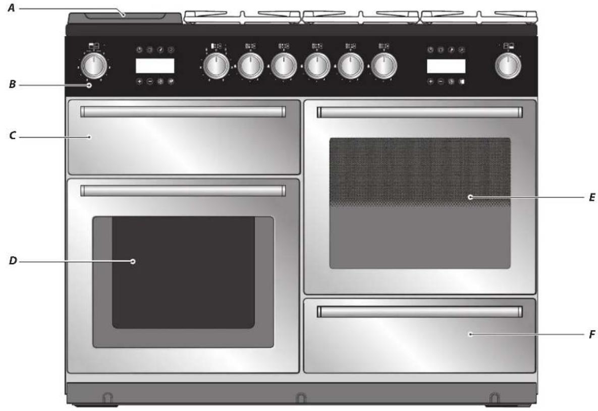
Fig. 2.1
text_image
A B C D E FFig. 2.2
natural_image
Diagram showing a circular device with an arrow indicating rotation, surrounded by arrows and icons (no text or symbols)The 110 dual fuel cooker (Fig. 2.1) has the following features:
A. 4 hotplate burners, a Wok Burner and a Ceramic Multizone hotplate
B. Control Panel
C. Glide-out Grill™ with 4 position Trivet
D. Multifunction Oven
E. Steam cavity
F. Bread Proving/Storage Drawer
Hotplate Burners
The labels by each of the control knobs indicates which area that knob controls.
Each burner has a Flame Supervision Device (FSD) that prevents the flow of gas if the flame goes out.
When a hotplate control knob is pressed in, sparks will be made at every burner – this is normal. Do not attempt to disassemble or clean around any burner while another burner is on, otherwise an electric shock could result.
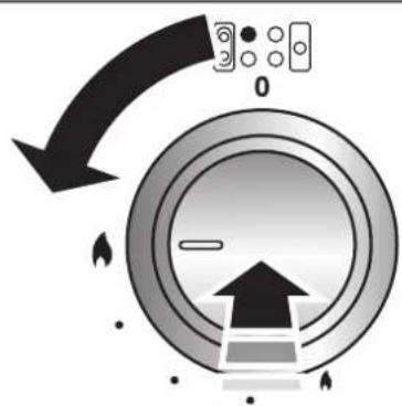
To light a burner, push in and turn the associated control knob to the high position as indicated by the large flame symbol (▲), (Fig. 2.2).
The igniter should spark and light the gas. Continue to press in the knob to let the gas through to the burner for about ten seconds.
If and when you let go of the control knob or the burner goes out, then the FSD has not been bypassed. Turn the control knob to the OFF position and wait for one minute before you try again, this time making sure to hold in the control knob for slightly longer.
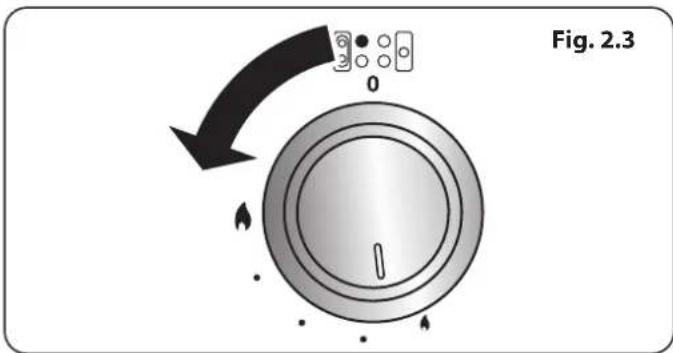
Adjust the flame height to suit by turning the knob counterclockwise (Fig. 2.3). On this cooker the low position is beyond high, NOT between high and off.
If a burner flame goes out, turn off the control knob and leave it for one minute before relighting it.
Make sure that the flames are under the pans. Using a lid will help the contents boil more quickly (Fig. 2.4).
Large pans should be spaced well apart.
Pans and kettles with concave bases or down-turned base rims should not be used (Fig. 2.5).
Simmering aids, such as asbestos or mesh mats, are NOT recommended (Fig. 2.6). They will reduce burner performance and could damage the pan supports.
You should also avoid using unstable and misshapen pans that may tilt easily, and pans with a very small base diameter, e.g. milk pans, single egg poachers (Fig. 2.7).
The minimum recommended pan diameter is 120 mm. The maximum allowable pan base diameter is 260 mm.
DO NOT use cooking vessels on the hotplate that overlap the edges.
Wok Burner
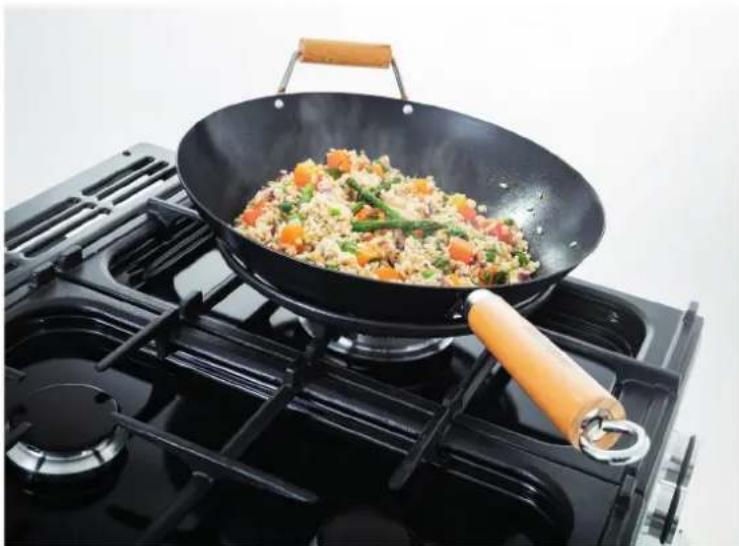
The Wok Burner is designed to provide even heat over a large area. It is ideal for large pans and stir-frying (Fig. 2.8).
For heating smaller pans, the aforementioned hotplate burners may be more efficient.
You should wipe the enamel top surface of the cooker around the hotplate burners as soon as possible after spills occur. Try to wipe them off while the enamel is still warm.
NOTE: The use of aluminium pans may cause metallic marking of the pan supports. This does not affect the durability of the enamel and may be cleaned off with a suitable metal cleaner.
The Wok Cradle
The Wok Cradle is designed to fit a 35 cm wok. If you use a different wok, make sure that it fits the cradle. Woks vary very widely in size and shape. It is important that the wok sits down on the pan support – however, if the wok is too small, the cradle will not support it properly (Fig. 2.9).
The cradle should be used on the wok burners only. When you fit the cradle, check that it is supported properly on a pan support and that the wok is sitting level in the cradle (Fig. 2.10).
The cradle will get very hot in use – allow plenty of time for it to cool before you pick it up.
text_image
Fig. 2.3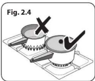
natural_image
Illustration of two cooking pots on a gas stove, one marked with a cross and the other with a checkmark (no text or symbols)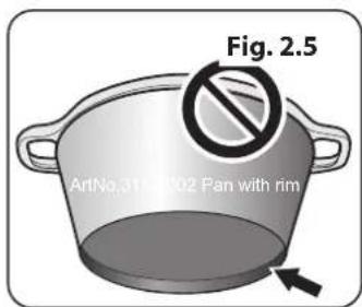
text_image
Fig. 2.5 ArtNo.31-0102 Pan with rim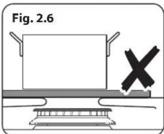
text_image
Fig. 2.6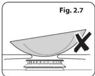
natural_image
Illustration of a satellite dish with a cross symbol, labeled Fig. 2.7 (no text or symbols on the dish itself)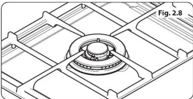
natural_image
Technical line drawing of a mechanical component with no visible text or symbols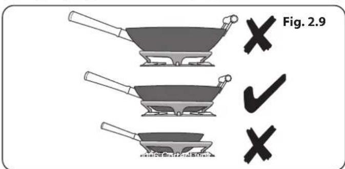
text_image
Fig. 2.9 ✓ ✓ ✓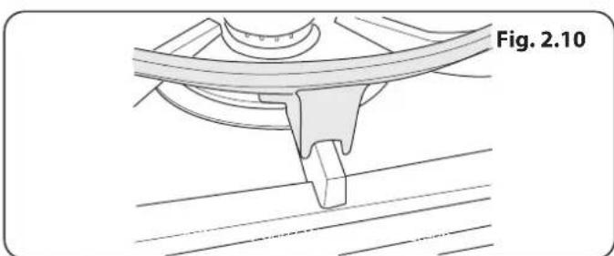
natural_image
Technical line drawing of a mechanical component with no visible text or symbols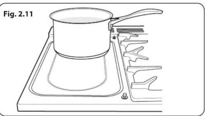
natural_image
Line drawing of a cooking pot on a stovetop with a side panel (no text or symbols)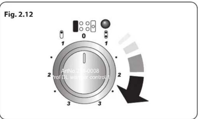
text_image
Fig. 2.12 ArtNo 2014-0008 Prof DL wanner control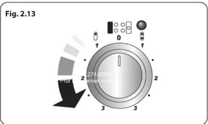
text_image
Fig. 2.13 274-0008 Internet control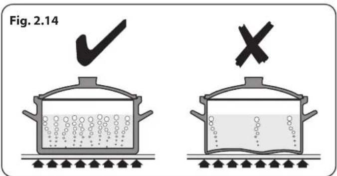
text_image
Fig. 2.14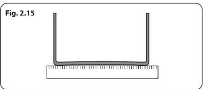
natural_image
Simple diagram of a U-shaped object placed on a ruler, labeled Fig. 2.15 (no text or symbols on the object itself)The Ceramic Hotplate
The hotplate area on the left-hand side is dual purpose. It can be used either as a ceramic hob to heat a pan in the usual way (Fig. 2.11) or it can be used to heat the supplied griddle plate.
The rear area, marked with a ring, is for cooking with a pan.
There are two elements that allow either the whole of the area to be heated or just the rear half.
To heat the whole area, turn the hotplate control clockwise (Fig. 2.12).
To use the rear ring only, turn the hotplate control counterclockwise (Fig. 2.13).
The neon indicator light above the control knob will come on when the hotplate control is turned on and stay lit while the surface cools.
You can also place a large fish kettle across both heating zones.
Always take care before touching the surface even when it is turned off – it may be hotter than you think.
Use only pans that are suitable for ceramic hobs.
We recommend stainless steel and enamelled steel pans because pots and pans with copper or aluminium bases leave traces on the hob that are difficult to remove.
Pots and pans should have thick, smooth, flat bottoms (Fig. 2.14). This makes sure the maximum heat transfer from the hob to the pan, making cooking quick and energy efficient. Never use a round-bottomed wok, even with a stand.
The very best pans have bases that are very slightly curved up when cold. If you hold a ruler across the bottom you will see a small gap in the middle (Fig. 2.15). When they heat up the metal expands and lies flat on the cooking surface.
Make sure that the base of the pan is clean and dry to prevent any residue burning onto the hob panel. This also helps prevent scratches and deposits.
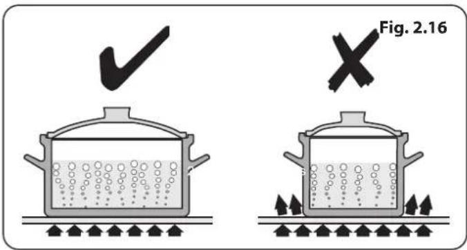
Always use pans that are the same size as (or slightly larger than) the areas marked on the hob top (Fig. 2.16). Using smaller pans wastes heat, and any spillage will be burnt on. Using a lid will help the contents boil more quickly.
Always lift pans off the hob. Sliding pans may cause marks and scratches. Always turn the control to the 'OFF' position before removing a pan.
When cooking on the hob you may see the hob area you are using switch off and on. This is caused by a safety device that limits the temperature of the hob. It is quite normal, especially when cooking at high temperatures. If it happens a lot with a particular pan however it may mean the pan is not suitable – perhaps too small or too uneven – for a ceramic hob.
For best results, preheat a covered serving dish for 10 minutes before adding food to it.
Use only heat-resistant dishes.
The Griddle Plate
The griddle plate (Fig. 2.17) is designed to fit securely on the locating pins over the ceramic heating area (Fig. 2.18). DO NOT try to use it over one of the gas burners. It will not be securely held and you may damage the non-stick finish.
To heat the whole area, turn the hotplate control clockwise (Fig. 2.19).
The neon indicator light above the control knob will come on when a hob control is turned on and stay lit while the surface cools.
It is designed for cooking food on directly. DO NOT use pans of any kind on it. The griddle plate surface is non-stick and metal cooking utensils (e.g. spatulas) will damage the surface. Use heat resistant plastic or wooden utensils.
The griddle plate can be lightly brushed with cooking oil before use.
Preheat the griddle plate for a maximum of 5 minutes before adding food. Leaving it longer may cause damage.
There is a gap at the right-hand rear corner of the griddle plate (Fig. 2.20) so you can pour off excess fat after cooking.

Be careful – it may be very hot.
After cooking, allow the griddle plate to cool before cleaning.
text_image
Fig. 2.16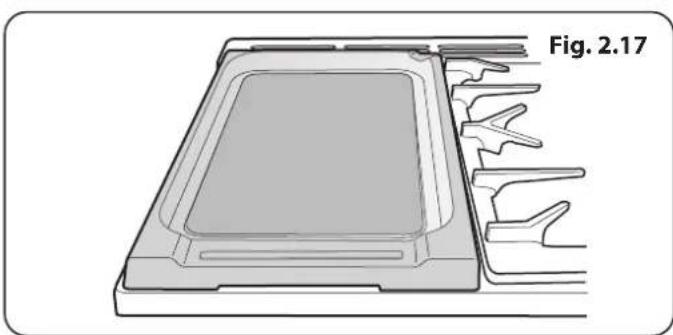
natural_image
Technical diagram of a mechanical component with labeled part 'Fig. 2.17' (no other text or symbols)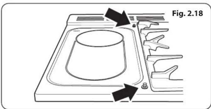
text_image
Fig. 2.18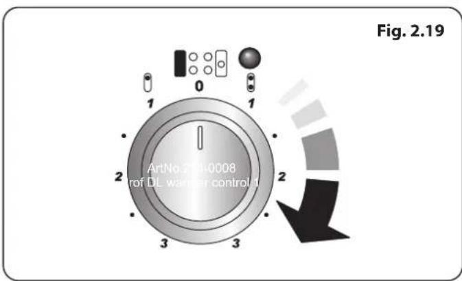
text_image
Fig. 2.19 ArtNo 20040008 of DL warning control 1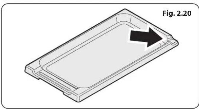
natural_image
3D diagram of a rectangular tray with an arrow indicating direction, labeled 'Fig. 2.20' (no text or symbols on the tray itself)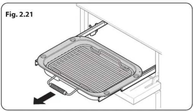
natural_image
Technical diagram of a mechanical device with a grid-patterned plate and attached lever, labeled Fig. 2.21 (no text or symbols on the diagram itself)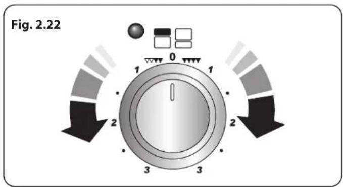
text_image
Fig. 2.22 1 0 1 2 3 3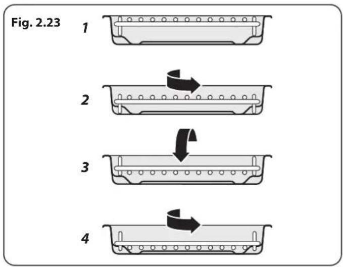
flowchart
graph TD
    A["1"] --> B["2"]
    B --> C["3"]
    C --> D["4"]
    style A fill:#f9f,stroke:#333
    style B fill:#ccf,stroke:#333
    style C fill:#cfc,stroke:#333
    style D fill:#fcc,stroke:#333
The Glide-out Grill™
Open the door and pull the grill pan carriage forward using the handle (Fig. 2.21).
The grill has two elements that allow either the whole area of the pan to be heated or just the right-hand half.
Adjust the heat to suit by turning the control knob. To heat the whole grill, turn the knob clockwise (Fig. 2.22).
To heat the right-hand half, turn the knob counter-clockwise. The neon indicator light by the grill control will come on.
For best results, slide the carriage back into the grill chamber and preheat the appropriate part(s) of the grill for two minutes. The grill trivet can be removed and the food placed on it while you are waiting for the grill to preheat.
DO NOT leave the grill on for more than a few moments without the grill pan underneath it, otherwise the knobs may become hot.
Once the grill has preheated, slide the carriage out again. With the trivet back in place with the food on it, slide the carriage back into the grill chamber. Make sure that it is pushed right in.
CAUTION: Accessible parts may be hot when the grill is in use. Young children should be kept away.
The grill pan trivet can be set to four different grilling heights by a combination of turning it back to front and turning it upside down (Fig. 2.23).
DO NOT leave the grill on for more than a few moments, without the grill pan underneath it.
Never close the grill door when the grill is on.
CAUTION: This appliance is for cooking purposes only. It must not be used for other purposes, for example room heating.
Bread Proving Drawer
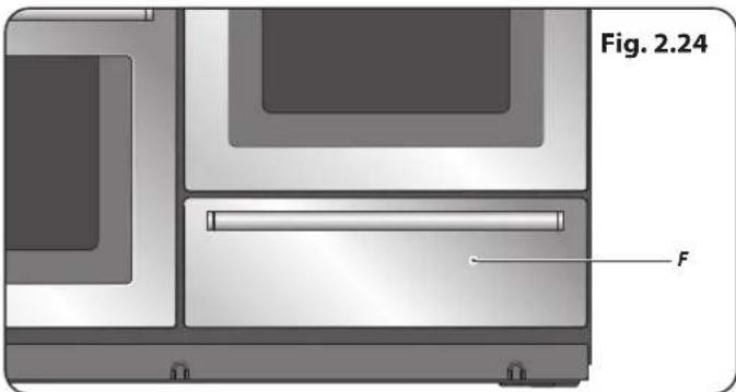
The Bread Proving Drawer is found on the right at the base of the cooker (Fig. 2.24). Within the Bread Proving Drawer there are slots in the base to allow warmed air to flow through into the drawer from the element underneath.
The Bread Proving Drawer temperature is ideal for proving all sorts of yeast dough from sweet to savoury, gluten free to sourdough, dough made from fresh yeast and dried, bread mixes and recipes from the Rangemaster Good Housekeeping Cookery book.
Pre-heat the drawer so that it is warm and ready for your dough.
Turn the knob clockwise (Fig. 2.25). There is no need to set the temperature, this is already set.
The Bread Proving Drawer has space for:
- Baking trays, no larger than 340mm x 340mm, to prove bread rolls or buns; these can then be put straight into a preheated oven after proving.
- To prove 2 trays at once in the drawer use a cooling rack or trivet over the top of one tray with the other on top, remember to allow space for the dough to expand during the proving time.
• 3 litre bowl full of dough - 3 x 2 pound loaf tins
- 4 x 1 pound loaf tins
The time needed for proving will depend upon the dough type and the amount. Refer to the recipe for guidance and check the dough during the proving time.
If a large baking tray is used, place a cooling rack on to the base of the drawer, and put the tray on top, this will allow the warmed air to reach the dough.
When preparing larger quantities of yeast dough, containing 500g or over of flour, divide the dough into 2 bowls or containers, this will make proving in the drawer easier.
Keep an eye on the dough while it is proving; fresh yeast can work quickly especially if it has had a first fermentation stage (sometimes called sponging). Sponging can help produce a slightly lighter loaf.
TOP TIPS
Not sure of the capacity of your loaf tins?
• A one pound loaf tin will hold 800ml of water
• A two pound loaf tin will hold 1.5 litres of water.
- Cover the dough while it is proving with greased cling film, be careful not to anchor the cling film too tightly so that it prevents the dough from rising.
The Bread Proving Drawer can be used for storage. If you have used the Bread Proving Drawer, switch it off and wait until the drawer cools before storing any items.
text_image
Fig. 2.24 F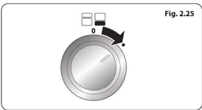
text_image
Fig. 2.25Cleaning
Clean the inside of the drawer with hot soapy water and a soft cloth, rinse and dry.
The Bread Proving Drawer is ideal for storing baking trays and other cooking utensils.
It can get warm, so do not store anything in it that may melt or catch fire.
Never store flammable materials in the drawer. This includes paper, plastic and cloth items, such as cookbooks, plastic ware and towels, as well as flammable liquids.
Do not store explosives, such as aerosol cans, on or near the appliance.
Flammable materials may explode and result in fire or property damage.
3. The Multifunction Oven
The clock must be set to the time of day before the oven will work. See the section on 'The Clock' for instructions on setting the time of day.
References to 'left-hand' and 'right-hand' ovens apply as viewed from the front of the appliance.
The left-hand oven is a multifunction oven, while the right-hand is a steam cavity.
The Multifunction Oven (left-hand)
As well as the oven fan and fan element, multifunction ovens are fitted with two extra heating elements, one visible in the top of the oven and the second under the oven base. Take care to avoid touching the top element and element deflector when placing or removing items from the ovens.
Table 3.1 gives a summary of the multifunction modes.
The multifunction oven has many varied uses. We suggest you keep a careful eye on your cooking until you are familiar with each function. Remember, not all functions will be suitable for all food types.
Operating the Multifunction Oven
Fig. 3.1 shows the left hand, touch sensitive control panel, for the multifunction oven.
To select a cooking function
Touch and hold the "Standby" button (1). The display will show the fan oven mode and a temperature setting of 180^ C. The oven will start cooking in this mode after 5 seconds.
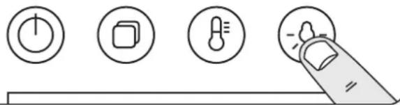
The oven light will turn on for 2 minutes and then go off. The oven light can be turned off at any time by tapping button (4).
To change the cooking function touch and hold the "Mode" button (2) until the cooking symbol begins to flash.
Change the cooking function using the [+] or [-] buttons (5 or 6). The oven will start cooking after 5 seconds.
Note: Cycling through the oven functions will re-set the oven temperature to the default 180°C.
To adjust cooking temperature
Touch and hold the "Temperature" button (3) until the display begins to flash.
Select your desired temperature using the [+] or [-] buttons (5 or 6). The oven will start to cook at the new temperature after 5 seconds.
If a lower cooking temperature is chosen there will be a time period required for the cavity to cool down.
Note: Tap the "Temperature" button during cooking to display the current temperature in the oven cavity.
To turn the Multifunction oven off
The multifunction oven is turned off by tapping the "Standy / On" button (1).
| Symbol | Function Use | |
| [XCX0] | Fan | A full cooking function, even heat throughout, great for baking |
 | Duo | Gentle form of heating using base heat and fan. Suitable for pastries, cakes and open tarts, for example, quiches |
 | Conventional | A full cooking function for roasting and baking in the lower half of the oven |
 | Base heat | To crisp up the bases of quiche, pizza or pastry |
 | Grill | This function radiates the heat from the grill element |
 | Fanned grilling | Grilling meat and fish with the door closed |
 | Fan assisted | A full cooking function good for roasting and baking |
 | Delicate | To cook delicate items; creme brulee, blind baking, bain marie |
 | ECO mode | Energy saving function for foods requiring 45 minutes or less |
| [463B] | Defrost | To thaw small items in the oven without heat |
Table 3.1

text_image
12 56Fig. 3.1
| 1 Standby / On 5 Increase | |||
| 2 Mode 6 Decrease | |||
| 3 Temperature 7 Timer / Minute Minder | |||
| 4 Oven Light 8 | Rapid Heat, only usable with fan cooking | ||
Fig. 3.2
natural_image
Simple line drawing of a finger pressing down on a toolbar with four icons: power button, square, thermometer, and magnifying glass (no text or symbols)ECO Mode
This setting saves energy, cooking in fanned mode, for foods requiring a cooking time of 45 minutes or less. No preheating.
Note: The oven door must remain closed during ECO mode. Failure to do so will result in the oven continuing to cook after the pre-set 45 minutes.
The following foods are recommended for the ECO setting:
- Ready prepared meals - meals should have the maximum duration of 45 minutes from chilled, and must not be frozen.
- Cookies, brownies and similar non-yeast baked food.
We always recommend that any food is checked to ensure it is fully cooked through. If in doubt please allow extra time.
Rapid Heat
The "Rapid Heat" setting (8) enables you to preheat the oven faster than normal. It uses the fan oven element with additional heat from one of the elements in the top of the oven.
When the oven cavity has reached the set temperature an alarm will sound, the rapid heat cycle will end and the selected cook mode will be activated.
Rapid heat mode can only be activated when the Fan function is selected.
Oven Lights
Tap the button to turn the oven light on (Fig. 3.2).
If the oven light fails, turn off the power supply before changing the bulb. See the 'Troubleshooting' section for details on how to change the bulb.
DisplayLock
To lock the display touch and hold the [+] and [-] buttons simultaneously. This will prevent the buttons being used. The lock symbol [☐] will be displayed.
To unlock the display touch and hold the [+] and [-] buttons again. The lock symbol will go out.
Accessories
Glide-out Oven Shelves
The left-hand oven is supplied with 2 glide-out oven shelves.
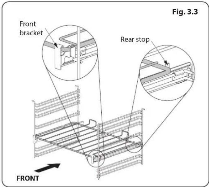
To fit the glide-out shelf, hook the front of the shelf onto the runners as shown (Fig. 3.3). The rear of the shelf should rest on the runners, in front of the rear stop (Fig. 3.3).
The glide-out shelf and runners can be easily removed or repositioned.
To remove the glide-out shelf
Raise the rear of the shelf, so that it clears the rear stops. Then unhook from the front locating bracket.
To remove the glide-out runners
Twist to unclip the base of the runners from the shelf supports. Then unhook the runner from the top rung of the shelf support and remove (Fig. 3.4).
To refit the glide-out runners
Hook the rear of the runner over the top rung of a pair of shelf supports. Then hook the front of the runner onto the same rung. Push to clip under the bottom rung (Fig. 3.5).
Ensure that the shelf runners are fitted in the same position on each side (Fig. 3.6).
The front of the shelf runners can be identified by the bracket (Fig. 3.3).

DO NOT put the glide-out shelf runners in a dishwasher.
Steam cavity Shelves
The steam cavity shelves (Fig. 3.7) are retained when pulled forward but can be easily removed and refitted.
Pull the shelf forward until the back of the shelf is stopped by the shelf stop bumps in the oven sides (Fig. 3.8).
Lift up the front of the shelf so the back of the shelf will pass under the shelf stop and then pull the shelf forward (Fig. 3.9).
To refit the shelf, line up the shelf with a groove in the oven ladders and push the shelf back until the ends hit the shelf stop. Lift up the front so the shelf ends clear the shelf stops, and then lower the front so that the shelf is level and push it fully back (Fig. 3.10).
text_image
Front bracket Rear stop FRONT Fig. 3.3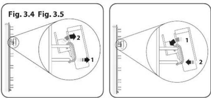
text_image
Fig. 3.4 Fig. 3.5 1 2 1 1 2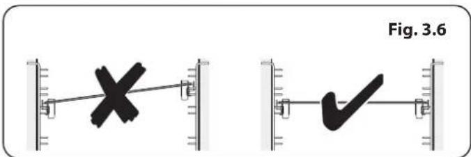
text_image
Fig. 3.6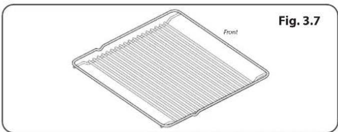
natural_image
Technical line drawing of a rectangular plate with internal grooves and labeled 'Front' (no text or symbols beyond label)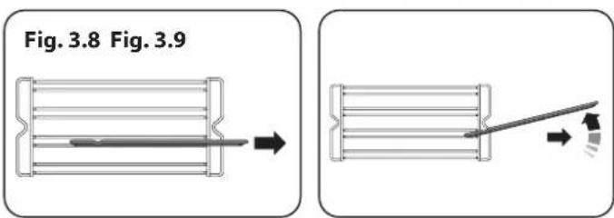
text_image
Fig. 3.8 Fig. 3.9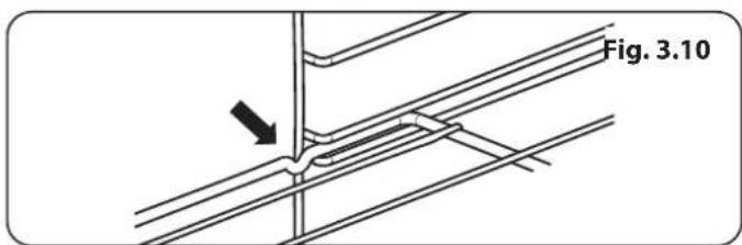
text_image
Fig. 3.10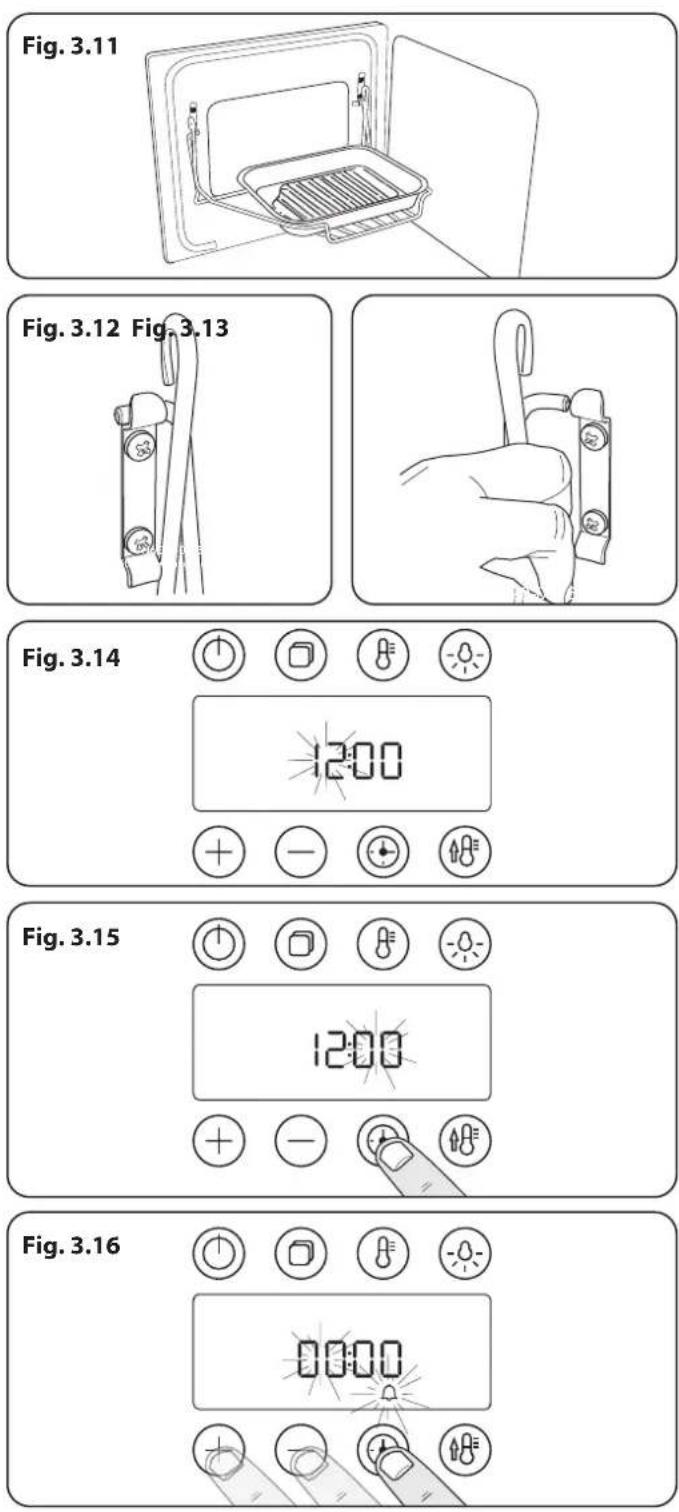
The Handyrack (Optional extra)
The Handyrack (Fig. 3.11) fits to the left-hand oven door only. Food cooking on it is easy to attend to, because it is accessible when the door is open.
The maximum weight that can be held by the Handyrack is 5.5 kg (12 lb). It should only be used with the supplied roasting tin, which is designed to fit the Handyrack. Any other vessel could be unstable.
It can be fitted at two different heights. One of the oven shelves must be removed and the other positioned to suit.
When the Handyrack is used in its highest position, other dishes can be cooked on the bottom shelf position or base of the oven.
When the Handyrack is used in its lowest position, other dishes can be cooked on the second shelf position or base of the oven.
To fit the Handyrack, locate one side of it on the door bracket (Fig. 3.12).
Then spring the other side out to clip it onto the other bracket (Fig. 3.13).
The Clock / Timer
The clock must be set to the time of day before the multifunction oven or steam cavity will work.
Setting the clock
- Once the cooker is connected and switched on, the hours in the display will flash (Fig. 3.14).
- Whilst the hours are flashing tap either the [+] or [-] buttons to set the hour.
- Tap the 'timer' button and the minutes will flash. Use the [+] or [-] buttons to set the minutes (Fig. 3.15).
To re-set the time, touch and hold the 'timer' button until the hours begin to flash then repeat the procedure described above using the [+] or [-] buttons.
Note: If no button is tapped, the current time will be saved by the clock, after 5 seconds.
Setting the minute minder
The minute minder can be set as a reminder when the main oven is on or off.
The minute minder provides the ability to set a countdown from 00:01h to 23:59h, at the end of which an alarm will sound. The timer shows hours:minutes.
- Tap the timer button once to enter the minute minder (Fig. 3.16).
- The hours will start to flash. Set the hours using the [+] or [-] buttons (Fig. 3.16).
-
Tap the timer button again, the minutes will flash. Set the minutes using the [+] or [-] buttons. The countdown will automatically begin after 3 seconds and the [☐] symbol will show in the display.
-
Once the specified time has elapsed an alarm will sound. It will stop automatically after 10 seconds.
- To cancel the minute minder, and enter a new time, tap the clock button whilst the [ Symbol is active.
To stop the multifunction oven after a specific time
- Set the cooking function and temperature (see "Operating the Multifunction Oven" on page 15).
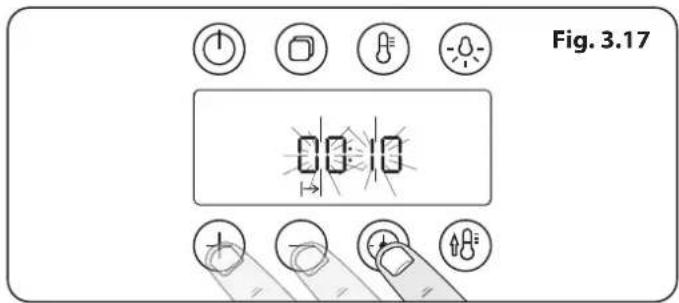
- Touch and hold the 'timer' button until the cook period symbol [▶] is displayed (Fig. 3.17). Set the hours using the [+] or [-] buttons.
- Tap the timer button again to set the minutes using the [+] or [-] buttons. Cooking will automatically start after 5 seconds and the remaining cook period will be displayed.
- At the end of the cooking period an alarm will sound and the oven will stop cooking. 'End' will show in the display. Remove the cooked food from the oven and close the oven door.
- If the alarm is not stopped it will repeat twice before stopping automatically.
To start and then stop the multifunction oven
Set the multifunction oven to automatically start and stop using a combination of the 'cook period' and 'stop time'.
You cannot set a start time directly – this is set automatically by a combination of the 'cook period' and 'stop time'.
- Set the cooking function and temperature (see "Operating the Multifunction Oven" on page 15).
- Touch and hold the 'timer' button until the cook period symbol [▶] is displayed. Set the hours using the [+] or [-] buttons. Tap the timer button again to set the minutes using the [+] or [-] buttons (Fig. 3.17).
- Tap the 'timer' button to select the 'stop time' [ ] set the time you would like to stop cooking using the [+] or [-] buttons. Tap the 'timer' button again to set the minutes using the [+] or [-] buttons.
- The oven will enter Standby Mode after 3 seconds, the display will show the 'cook period' (Fig. 3.18) and the 'stop time' (Fig. 3.19). Changing the cooking function will clear the selection.
- When the 'stop time' is reached an alarm will sound and the oven will stop cooking. 'End' will show in the display. Remove the cooked food from the oven and close the oven door.
- If the alarm is not stopped it will repeat twice before stopping automatically.
Note: Fig. 3.18 and Fig. 3.19 show conventional heat function for illustration. All other modes are available.
text_image
Fig. 3.17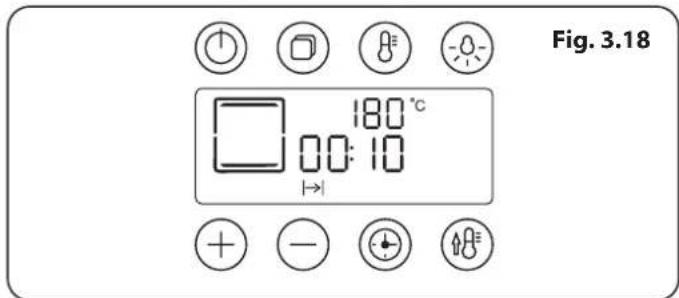
text_image
Fig. 3.18 180 °C 00:10 → + - +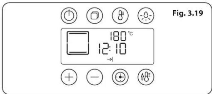
text_image
Fig. 3.19 180 °C 12:10 →Cooking Tips
Tips on cooking with the timer
If you want to cook more than one dish, choose dishes that require approximately the same cooking time. However, dishes can be 'slowed down' slightly by using small containers and covering them with aluminium foil, or 'speeded up' slightly by cooking smaller quantities or placing them in larger containers.
Very perishable foods such as pork or fish should be avoided if a long delay period is planned, especially in hot weather.

DO NOT place warm food in the oven to be timed.

DO NOT use a timed oven that is already warm.

DO NOT use the timed oven if the adjoining oven is already warm.
Whole poultry must be thoroughly defrosted before being placed in the oven. Check that meat and poultry are fully cooked before serving.
General oven tips
The wire shelves should always be pushed firmly to the back of the oven.
Baking trays with food cooking on them should be placed level with the front edge of the oven's wire shelves. Other containers should be placed centrally. Keep all trays and containers away from the back of the oven, as overbrowning of the food may occur.
For even browning, the maximum recommended size of a baking tray are:
- depth: 340 mm (13 38 ") by width: 340 mm (13 38 ") in the main oven
When the oven is on, DO NOT leave the door open for longer than necessary, otherwise the knobs may get very hot.
- Always leave a "finger's width" between dishes on the same shelf. This allows the heat to circulate freely around them.
- To reduce fat splashing when you add vegetables to hot fat around a roast, dry them thoroughly or brush lightly with cooking oil.
- Where dishes may boil and spill over during cooking, place them on a baking tray.
- The 'Cook & Clean' oven liners (see 'Cleaning Your Cooker') work better when fat splashes are avoided. Cover meat when cooking.
- Sufficient heat rises out of the oven while cooking to warm plates in the grill compartment.
- If you want to brown the base of a pastry dish, preheat the baking tray for 15 minutes before placing the dish in the centre of the tray.
Cooking Table
The oven control settings and cooking times given in the table below are intended to be used as a guide only. Individual tastes may require the temperature to be altered to provide a preferred result.
Food is cooked at lower temperature in a fan oven than in a conventional oven. When using recipes, reduce the fan oven temperature by 10 °C and the cooking time by 5-10 minutes. The temperature in the fan oven does not vary with height in the oven so you can use any shelf.
Top (T)
Centre (C)
Base (B)
Oven Shelf Positions
| Food Conventional Oven°C (Shelf Position) | Fan Oven Temperature | Approximate Cooking Time | ||
| Meat | ||||
| Beef (no bone) | 160 (C) | 150 °C | 30-35 minutes per 500g +30-35 minutes. | Thoroughly thaw frozen joints before cooking. Meat may be roasted at 220°C (210°C for fan oven) and the cooking time adjusted accordingly. For stuffed and rolled meats, add approximately 10 minutes per 500g, or cook at 200°C (190°C) for 20 minutes then 160°C (150°C) for the remainder. |
| 200 (C) | 190 °C | 20-25 minutes per 500g +20-25 minutes. | ||
| Lamb | 160 (C) | 150 °C | 30-35 minutes per 500g +30-35 minutes. | |
| 200 (C) | 190 °C | 25-30 minutes per 500g +25-30 minutes. | ||
| Pork | 160 (C) | 150 °C | 35-40 minutes per 500g +35-40 minutes. | |
| 200 (C) | 190 °C | 25-30 minutes per 500g +25-30 minutes. | ||
| Poultry | 160 (C) | 150 °C | 20-25 minutes per 500g +20-25 minutes. | For stuffed poultry, you could cook at 200°C (190°C) for 20 minutes then 160°C (150°C) for remainder. Do not forget to include the weight of the stuffing. |
| Chicken | 200 (C) | 190 °C | 15-20 minutes per 500g +15-20 minutes. | |
| 160 (C) | 150 °C | 20 minutes per 500g +20 minutes. | ||
| Turkey | 200 (C) | 190 °C | 15 minutes per 500g +15 minutes. | |
| 160 (C) | 150 °C | 25-30 minutes per 500g. | For fresh or frozen prepacked poultry, follow instructions on the pack. Thoroughly thaw frozen poultry before cooking. | |
| Duck | 200 (C) | 190 °C | 20 minutes per 500g. | |
| Casserole 140-150 (C) 130 °C-140 °C 2-4 hours according to recipe. | ||||
Yorkshire Pudding 220 (C) 210 °C Large tins 30-35 minutes; individual 10-20 minutes.
| Cake | ||||
| Very rich fruit - Christmas, wedding, etc. | 140 (C/B) | 130 °C | 45-50 minutes per 500g of mixture. | Using the conventional oven: when two tier cooking leave at least one runner space between shelves. |
| Fruit 180 mm tin | 150 (C/B) | 140 °C | 2-2 12 hours. | |
| Fruit 230 mm tin | 150 (C/B) | 140 °C | Up to 3 12 hours. | |
| Madeira 180 mm | 160 (C/B) | 150 °C | 80-90 minutes. | Position the baking tray with the front edge along the front of the oven shelf. |
| Queen cakes | 190 (C/B) | 180 °C | 15-25 minutes. | |
| Scones | 220 (C/B) | 210 °C | 10-15 minutes. | Up to three tiers can be cooked in a fan oven at the same time but make sure to leave at least one runner space between each shelf being cooked on. |
| Victoria sandwich | ||||
| 180 mm tin | 180 (C/B) | 170 °C | 20-30 minutes. | |
| 210 mm tin | 180 (C/B) | 170 °C | 30-40 minutes. | |
Desserts
| Shortcrust tarts | 200 (C/B) | 190 °C | 20-30 minutes on a preheated tray. | |
| Fruit pies | 200 (C/B) | 190 °C | 35-45 minutes. | |
| Tartlets | 200 (C/B) | 190 °C | 10-20 minutes according to size. | |
| Puff pastry | 210 (C/B) | 200 °C | 20-40 minutes according to size. | |
| Meringues | 100 (C/B) | 90 °C | 2-3 hours. | Up to three tiers can be cooked in a fan oven at the same time but make sure to leave at least one runner space between each shelf being cooked on. |
| Baked egg custard | 160 (C/B) | 150 °C | 45-60 minutes. | |
| Baked sponge pudding | 180 (C/B) | 170 °C | 40-45 minutes. | |
| Milk pudding | 140-150 (C/B) | 130 °C-140 °C | 2 to 3 hours. |
Bread 210 (C) 200 °C 20-30 minutes.
| Fish | Fanned Grilling | ||
| Fillet | 190 (C/B) | 190 °C (C/B) | 15-20 minutes |
| Whole | 190 (C/B) | 190 °C (C/B) | 15-20 minutes per 500g. |
| Steak | 190 (C/B) | 190 °C (C/B) | Steaks according to thickness. |
4. The Steam Cavity
Fig. 4.1
text_image
A B C D E F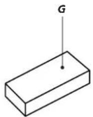
natural_image
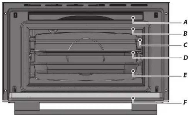
Simple 3D diagram of a rectangular block with a vertical line labeled 'G' at its top (no other text or symbols)| Key | |
| A Water Tank | |
| B Door Seal | |
| C 1 x Rack | |
| D 1 x Pan | |
| E 1 x Perforated Pan | |
| F Door | |
| G Sponge | |
Fig. 4.2
text_image
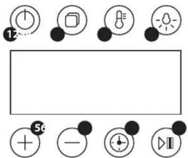
12 56| 1 | Standby/On | 5 Increase |
| 2 Mode 6 Decrease | ||
| 3 Temperature 7 Timer | ||
| 4 Oven Light 8 Start / Pause | ||
Fig. 4.3
text_image
g. 4.3 MAX MIN Water tank lidThe Steam Cavity (right-hand)
The steam cavity is shown in Fig. 4.1.
Fig. 4.2 shows the touch sensitive control panel for the steam cavity.
Water Level
To fill the water tank or check the water level lift and pull the water tank from the oven cavity (Fig. 4.1).
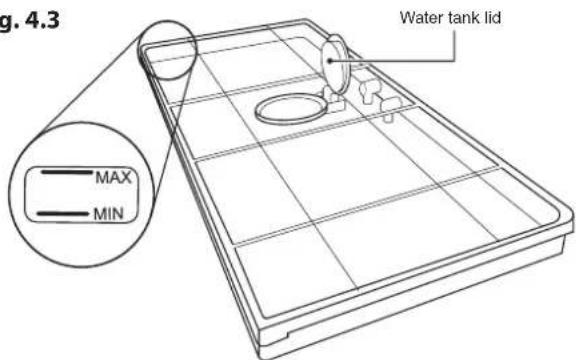
Lift the lid and carefully fill from the tap or a small jug up to the maximum marker (Fig. 4.3). Wipe clean if the water overflows.
The clock, on the left hand oven, must be set to the time of day before the oven will work. See the section on 'The Clock/Timer' for instructions on setting the time of day.
References to 'left-hand' and 'right-hand' ovens apply as viewed from the front of the appliance.
The left-hand oven is a multifunction oven, while the right-hand oven is a steam cavity.
Note: The time of day is not displayed on the steam cavity control.
DisplayLock
To lock the display touch and hold the [+] and [-] buttons simultaneously. This will prevent the buttons being used. The lock symbol [☐] will be displayed.
To unlock the display touch and hold the [+] and [-] buttons again.
Hygiene
Please remember to:
- Change the water in the tank before use. The display will remind you (Fig. 4.9).
- Clean the steam cavity after every cook cycle.

The base of the steam cavity will remain HOT after use. Take extra care when cleaning.
- Observe the descaling interval.
Operating the Steam Cavity
Note: The steam cavity may start a pump out cycle (Fig. 4.12) when first turned on. This is normal and it should be allowed to complete. The cycle will take approximately 2 minutes.
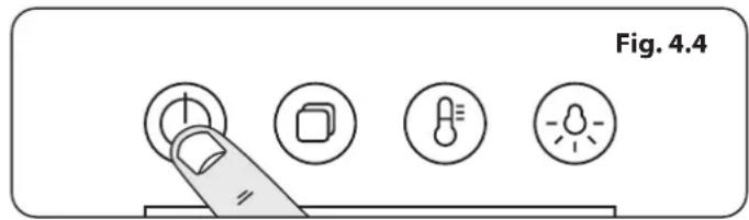
- Touch and hold the standby button to switch the steam cavity on (Fig. 4.4). The display will show the maximum tempertaure; 100^ C, a 15 minute cook time and the steam icon will flash (Fig. 4.5).
- To adjust the temperature, touch and hold the temperature button (Fig. 4.6) and use the [+] or [-] buttons to adjust (Fig. 4.7).
- To adjust the cook period, tap the timer button once, to adjust the hours use the [+] or [-] buttons (Fig. 4.8). Tap the timer button again to adjust the minutes.
- Tap the start / pause button. You will be advised to change the water in the tank (Fig. 4.9). See 'Water Level' on page 22. If you are already using fresh water touch start or wait to continue.
The appliance will begin to pump water, from the water tank, into the boiler (Fig. 4.10).
- The oven cavity will begin to heat up to your set temperature. You can check the current temperature in the oven cavity by tapping the temperature button (Fig. 4.6).
When the oven has reached the pre-set temperature, the cook cycle will begin and the decimal points in the timer will flash.
Once cooking has completed, [EMD] will be displayed and 10 beeps will be emitted. This will be repeated twice. Also, the cavity light will turn on and the cooker fan will run for 2 minutes.
- At the end of the cooking cycle the display will show H2O HOT (Fig. 4.11), this indicates the water in the boiler is hot and will be pumped back into the water tank once it has reached a pre-set temperature. When the water is being pumped out H2O OUT (Fig. 4.12) will be displayed.
Please allow the cycle to complete.
- You can immediately re-use your steam cavity by tapping the [+] or [-] buttons.
- The cooking cycle can be suspended at any time by tapping the pause button.
Note: It is normal for steam to be emitted from the steam cavity. This is not harmful.
text_image
Fig. 4.4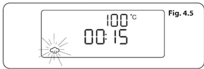
text_image
Fig. 4.5 100 °C 00:15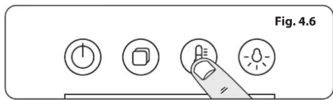
text_image
Fig. 4.6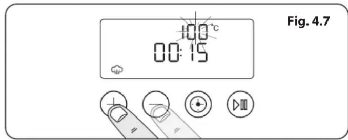
text_image
Fig. 4.7 100°C 00:15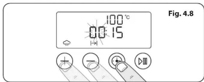
text_image
Fig. 4.8 100 °C 00:15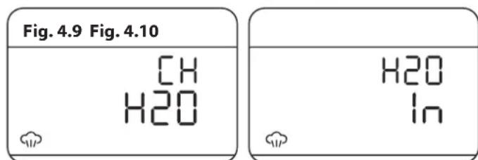
text_image
Fig. 4.9 Fig. 4.10 CH H2O H2O In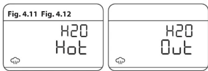
text_image
Fig. 4.11 Fig. 4.12 H20 Hot H20 OutFig. 4.13
text_image
Diagram showing control buttons and a finger pointing to a rectangular interface with plus, minus, clock, and play symbols.Steam Cavity Functions
The steam cavity has three main functions:
steam

grill

descale

Switch the oven on and tap the [+] or [-] buttons to scroll through these functions.
Program Modes
The steam cavity has pre-programmed modes for different food types.
To access these modes touch and hold the standby button to switch the steam cavity on.
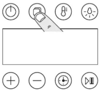
Touch and hold the program button (Fig. 4.13). [A1] will show in the display. Scroll through the programs using the [+] or [-] buttons.
Touch and hold the program button again to access the next set of programs for fish. [b1] will be displayed.
Touch and hold the program button a third time to access the programs for meat. [C1] will be displayed.
See Table 4.1 for an overview of the program functions.
Vegetables
| Program Type of vegetables Temperature (°C) Time (min) Container Level | ||||
| A1 | Medium broccoli florets 100 8 Perforated 2 | |||
| A2 | Carrot batons 100 8 Perforated 2 | |||
| A3 | New potatoes 100 | 18 | Perforated 2 | |
| A4 | Green beans | 100 6 Perforated 2 | ||
| A5 | Asparagus | 100 4 Perforated 2 | ||
Fish
| Program | Type of fish | Temperature (°C) | Time (min) | Container | Level |
| b1 | 120g salmon fillet | 90 | 4 Perforated 2 | ||
| b2 | Raw tiger prawns | 90 | 5 Perforated 2 | ||
| b3 | Kippers | 100 6 Perforated 2 | |||
| b4 | Cod/Haddock Fillets | 100 8 Perforated 2 | |||
| b5 | Mussels | 90 | 8 Perforated | 1/2 |
Meat
| Program | Type of meat | Temperature (°C) | Time (min) | Container | Level |
| C1 | Meatballs | 100 8 | Solid | 2 | |
| C2 | Turkey Escalope and chicken breasts | 100 | 10 | Solid | 2 |
| C3 | Bratwurst / hot dogs 100 | 10 | Perforated | 2 | |
| C4 | Large soft boiled egg(s) (at room temperature) | 100 6 Perforated | 2 | ||
| C5 | Large hard-boiled egg(s) (at room temperature) | 100 | 10 | Perforated | 2 |
Items to be cooked should be spread evenly on the cooking trays.
Table 4.1
The Clock / Timer
The clock above the multi-function oven must be set to the time of day before the multi-function oven or steam cavity will work.
See "Setting the clock" on page 18.
Note: The steam cavity control does not show the time of day. This is automatically set from the multi-function oven control.
The display will remain blank until the steam cavity is turned on.
To stop the steam cavity at a specific time of day
- Switch the cavity on and set the temperature (see 'Operating the Steam Cavity' on page 23).
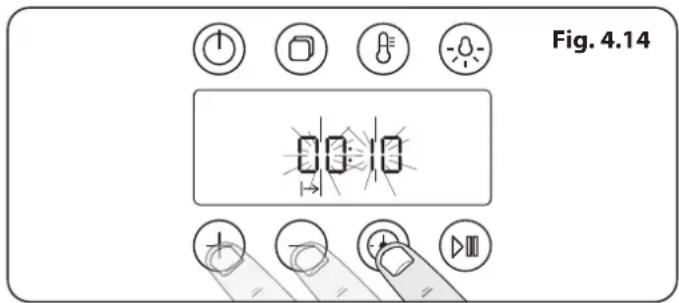
- Tap the timer button to set the 'cook period' hours using the [+] or [-] buttons. Tap the timer button again to set the minutes using the [+] or [-] buttons (Fig. 4.14).
- Tap the Start / Pause button.
To start and then stop the steam cavity
Set the steam cavity to automatically start and stop using a combination of the 'cook period' and 'stop time'.
You cannot set a start time directly – this is set automatically by a combination of the 'cook period' and 'stop time'.
- Switch the oven on and set the temperature (see 'Operating the Steam Cavity' on page 23).
- Tap the 'timer' button, the cook period symbol [ ] displayed. Set the hours using the [+] or [-] buttons. Tap the timer button again to set the minutes using the [+] or [-] buttons.
- Tap the 'timer' button to select the 'stop time' [ ] set the time you would like to stop cooking using the [+] or [-] buttons. Tap the 'timer' button again to set the minutes using the [+] or [-] buttons.
- Tap the Start / Pause button. The display will show the 'cook period' (Fig. 4.15) and the 'stop time' (Fig. 4.16).
- When the 'stop time' is reached an alarm will sound and the oven will stop cooking. 'End' will show in the display.
Tap the 'temperature' button during the cooking cycle to display the current oven temperature.
text_image
Fig. 4.14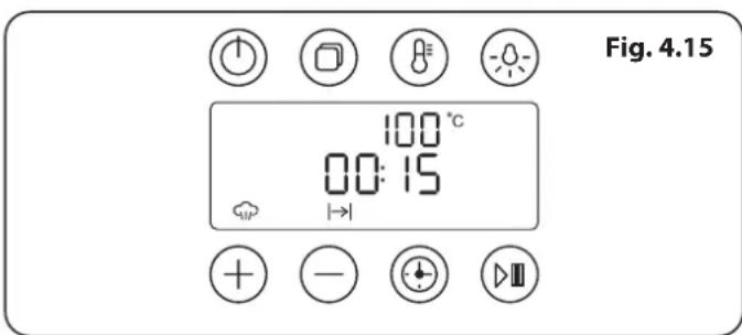
text_image
Fig. 4.15 100 °C 00:15 + - + - +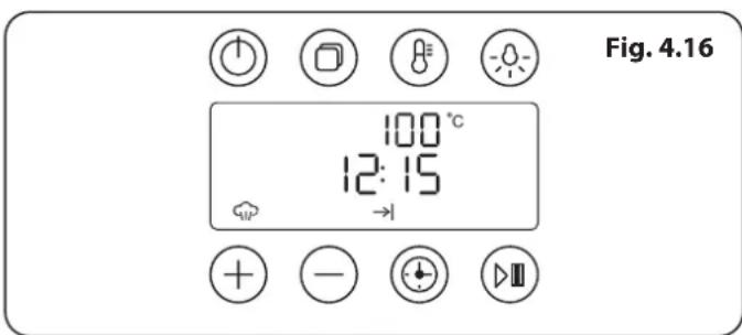
text_image
Fig. 4.16 100 °C 12:15 →5. Cleaning Your Cooker
Fig. 5.1
text_image
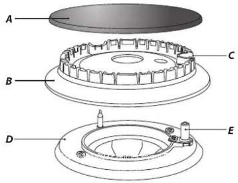
A B C D EA - Cap, B - Head, C - Notch, D - Base, E - Electrode
Fig. 5.2
text_image
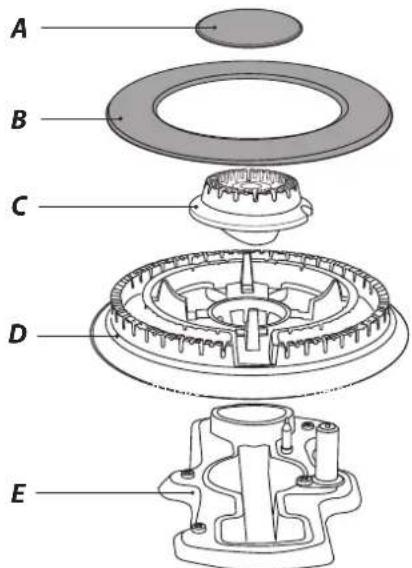
A B C D EA – Inner burner cap, B – Outer burner cap, C – Inner burner head, D – Outer burner head, E – Wok burner base
Fig. 5.3
text_image
3 6Fig. 5.4
text_image
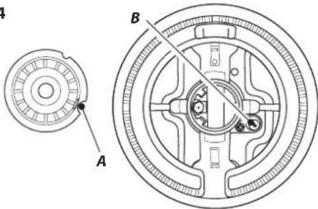
Technical diagram of a mechanical component with labeled parts A and B, showing cross-sectional view and assembly details.A - Electrode notch, B - Ignition electrode
Essential Information
Isolate the electricity supply before carrying out any thorough cleaning. Allow the cooker to cool.

Never use paint solvents, washing soda, caustic cleaners, biological powders, bleach, chlorine based bleach cleaners, coarse abrasives or salt.

Do not mix different cleaning products – they may react together with hazardous results.
All parts of the cooker can be cleaned with hot soapy water – but take care that no surplus water seeps into the appliance.
Remember to switch on the electricity supply and reset the clock before re-using the cooker.
Hotplate Burners
The burner heads and caps can be removed for cleaning.

DO NOT put the burner heads in a dishwasher.
Make sure they are absolutely dry before replacing them.
The Single Ring Burners
When refitting the burner head, make sure that the notch lines up with the electrode or hole in the base. Check that the burner head is level and that the cap is fitted centrally on the burner head (Fig. 5.1).
The Wok Burner
The wok burner can also be taken apart for cleaning.
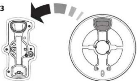
When reassembling the wok burner (Fig. 5.2), turn over the large base ring and find the 'D' shaped area (Fig. 5.3). Turn the head until the 'D' matches the one on the burner base. Flip the burner over once again and place it on the burner base.
To fit the small inner burner, find the larger electrode notch in the burner rim. Line this up with the white ignition electrode and place the inner burner on the large base ring (Fig. 5.4).
Now fit the two burner caps, making sure that they are seated properly.
Check the burner ports are not blocked. If a blockage occurs, remove stubborn particles using a piece of fuse wire.
The Wok Cradle
Recommended cleaning materials are hot soapy water, a moistened soap pad, cream cleaner or a nylon scourer.
Ceramic Hotplate
Daily Care
First of all, make sure that the heat indicator light is off and that the cooking surface is cool.
Apply a small dab of ceramic cleaning cream in the centre of the area to be cleaned. Dampen a clean paper towel and work the cream onto the cooking surface. As a final step, wipe the cooking surface with a clean, dry paper towel.
Cleaning Spills
For spills and boil-overs that occur while cooking, turn off the unit and wipe the area surrounding the hot zone with a clean paper towel. If a spill (other than a sugary substance) is on the hot zone, do not clean until the unit has completely cooled down, and then follow the instructions below, 'Cleaning Burned-on Spills'.
If you accidentally melt anything on the surface or if you spill foods with a high sugar content (preserves, tomato sauce, fruit juice, etc.), remove the spill IMMEDIATELY with a razor scraper, while the unit is still hot.
IMPORTANT: Use an oven glove to protect your hand from potential burns.
Scrape the major spill or melted material from the cooking zone and push into a cold area. Then, turn the unit 'OFF' and allow to cool before cleaning further. After the cooking surface cools down and the heat indicator lights go off, follow the 'Daily Care' procedure outlined above.
Cleaning Burned-on Spills
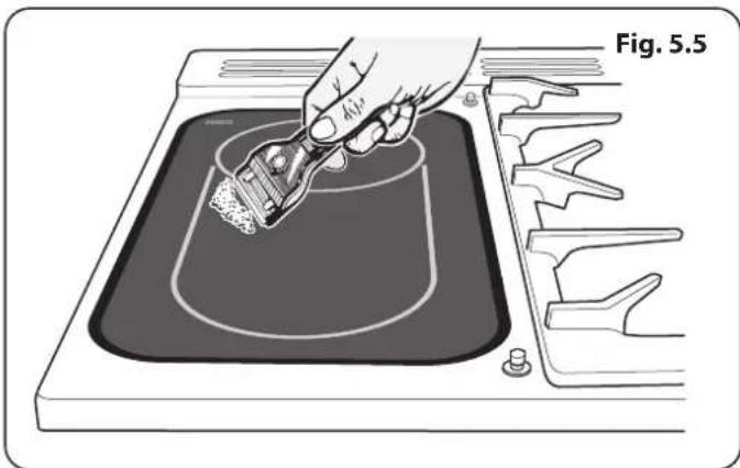
Make sure that the heat indicator lights are off and that the hob is cool. Remove the excess burned-on substance with a single-edged razor scraper. Hold the scraper at an angle of about 30° to the surface and then scrape off the burned-on matter (Fig. 5.5).
Once you have removed as much as possible with the scraper, follow the 'Daily Care' procedure outlined above.
To Remove Metal Rub-off
Sliding pans on the hob – especially aluminium or copper pans – can leave marks on the ceramic surface. These marks often appear like scratches, but can easily be removed (see 'Cleaning Spills'). If the rub-off marks are especially stubborn, use a cleaning cream together with the razor.
The Griddle Plate
Always clean the griddle plate after use. Allow it to cool completely before removing. Immerse the griddle plate in hot soapy water. Use a soft cloth or, for stubborn stains, a nylon washing up brush.
Note: If the griddle plate is washed in a dishwasher then some dishwasher residue may appear on the back. This is normal and will not affect the performance of your griddle plate.
natural_image
Illustration of a hand using a paintbrush to apply material in a mold, with no visible text or symbols.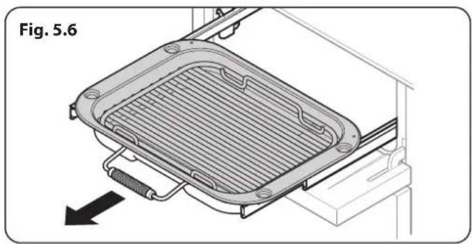
natural_image
Technical diagram of a heat exchanger or cooling unit with a mesh cover and directional arrow (no text or symbols)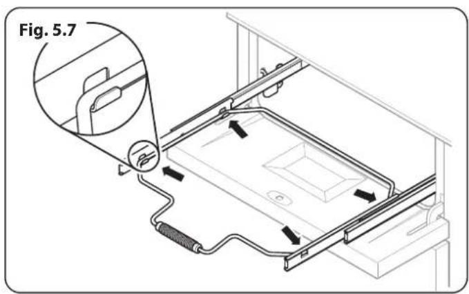
text_image
Fig. 5.7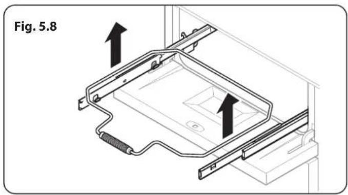
text_image
Fig. 5.8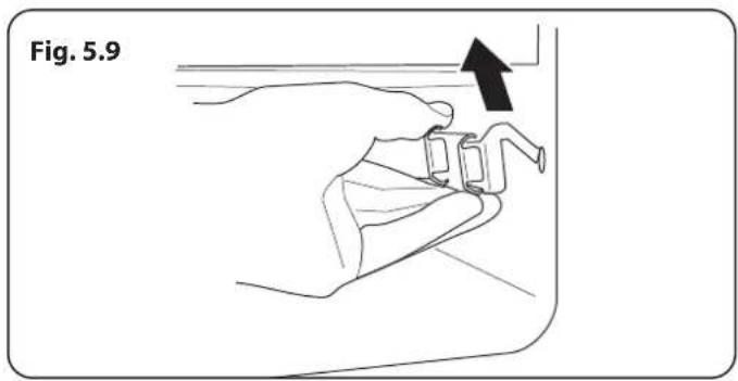
text_image
Fig. 5.9Grills
The grill pan and trivet should be washed in hot soapy water. Alternatively, the grill pan can be washed in a dishwasher.
After grilling meats or any foods that soil, leave to soak for a few minutes immediately after use. Stubborn particles may be removed from the trivet using a nylon brush.

Before you remove any of the grill parts for cleaning, make sure that they are cool, or use oven gloves.

DO NOT use any abrasive substances.
Cleaning the Glide-out Grill
The grill pan can be easily removed for cleaning as follows. Remove the grill pan support frame by pulling the grill pan forward (Fig. 5.6).
Lift the grill pan clear of the support frame. The support frame is held to the side rails by two clips on each side (Fig. 5.7).
For each side, support the side rail with one hand and with the other hand lift the frame up and out of the side clips (Fig. 5.8).
For safety, push the side rails back into the grill chamber.
If you need to remove the side rails to allow cleaning of the grill chamber, you can unhook them from the grill chamber sides (Fig. 5.9) and wipe the sides clean with a soft cloth and mild detergent.

DO NOT put the side runners in a dishwasher.
Once you have finished, hook the side rails back onto the sides of the chamber. To refit the frame, pull the side rails forward and, for each side in turn, support the side rail and press the frame down into the side rails.
Control Panel and Doors
Avoid using any abrasive cleaners, including cream cleaners. For best results, use a liquid detergent.
The same cleaner can also be used on the doors. Alternatively, use a soft cloth wrung out in clean hot soapy water. You can use the same method for cleaning the control panel and knobs. After cleaning, polish with a dry cloth.
Glass Fronted Door Panels
The oven door front panels can be taken off so that the glass panels can be cleaned. Move the cooker forward to gain access to the sides (see the 'Moving the Cooker' section under 'Installation').
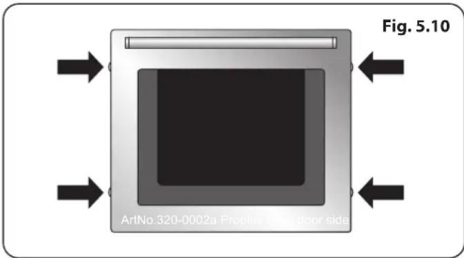
Open the oven door slightly and remove the front panel fixing screws from the door sides, two each side (Fig. 5.10).
Carefully lift off the outer door panel. The inside face of the glass panels can now be cleaned – take care not to disturb or wet the door insulation.
Note: If the door is triple glazed then the inner two panels are fixed together and should not be separated. After cleaning, carefully refit the outer door panel and replace the side fixing screws.

DO NOT use harsh abrasive cleaners or sharp metal scrapers to clean the oven door glass since they can scratch the surface, which may result in shattering of the glass.
Multifunction Oven
'Cook & Clean' Panels
The ovens have side ‘Cook & Clean’ panels which have been coated with a special enamel that partly cleans itself. This does not stop all marks on the lining, but helps to reduce the amount of manual cleaning needed.
These panels work better above 200 °C . If you do most of your cooking below this temperature, occasionally remove the panels and wipe with a lint free cloth and hot soapy water. The panels should then be dried and replaced and the oven heated at 200 °C for about one hour. This will make sure that the panels are working effectively.
Removing the Panels to Clean the Enamel Interior
Some of the lining panels can be removed for cleaning.
If you wish to clean the enamel interior of the oven, you will need to remove the shelves before removing the 'Cook & Clean' panels. To remove the side panels, simply lift the panel and slide forwards (Fig. 5.11).
Once the panels have been removed, the oven enamel interior can be cleaned.

DO NOT use steel wool, oven cleaning pads, or any other materials that will scratch the surface.
Refit in the reverse order.
text_image
Fig. 5.10 ArtNo.320-0002a Proplus door side
natural_image
Diagram of a device with a screen and arrow, labeled Fig. 5.11 (no text or symbols on the diagram itself)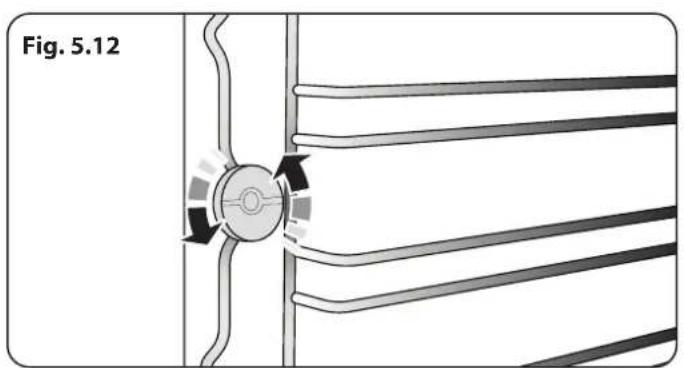
natural_image
Diagram of a mechanical component with directional arrows indicating motion, labeled Fig. 5.12 (no text or symbols on the diagram itself)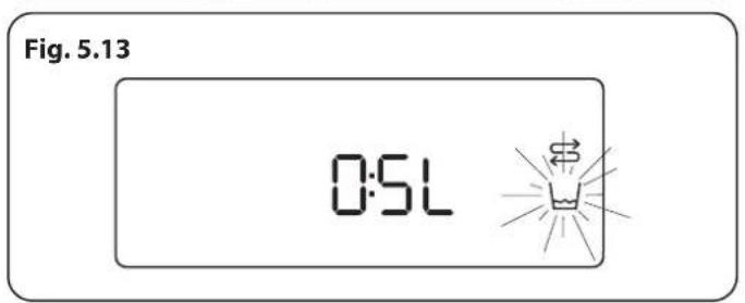
text_image
Fig. 5.13 0:5L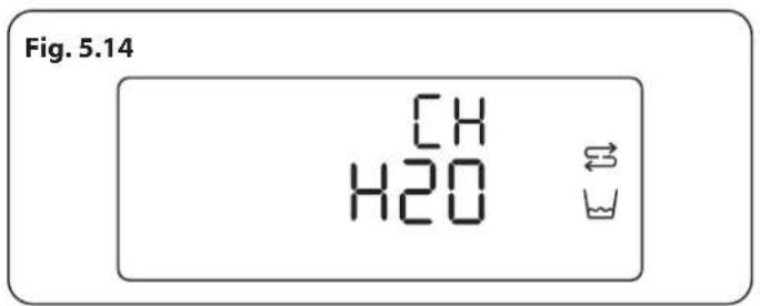
text_image
Fig. 5.14 CH H2OSteam Cavity
Before cleaning your oven or performing maintenance, please switch off the power supply. In order to prolong the service life of steam cavity, please note the following points:
The enameled or stainless steel parts should be washed with lukewarm water without using any abrasive powders or corrosive substances which could scratch, stain and damage the oven. After cleaning, it is advisable to rinse thoroughly and dry.
The inside of the oven should preferably be cleaned immediately after use, when it is still warm, with hot water and soap. After cleaning, it is advisable to rinse thoroughly and dry.
The base of the steam cavity will remain HOT after use. Take extra care when cleaning.
To remove the ladders unscrew the retaining screws (Fig. 5.12).
Avoid using abrasive detergents (for example cleaning powders, etc) and abrasive sponges for dishes or acids (such as lime scale remover, etc) as these could damage the enamel. If the grease spots and dirt are particularly tough to remove, use a special product for oven cleaning, following the instructions provided on the packet.
Never use a steam cleaner for cleaning inside the oven.
Use a descale product which is suitable for descaling a coffee machine. Do not use a foam cleaner.
Avoid using grinding sand mold cleaner, such as wash mat, steel wire ball, etc, as this may damage the surface.
Important: please do not clean the water tank in the dishwasher.
Descale (manual)
Note: Once the descale cycle is started it cannot be stopped and has to complete (approx. 30 minutes).
Touch and hold the 'Standby' button to switch the display on, use the [+] or [-] buttons to select the descale function [→].
Tap the 'Start / Pause' button to begin the descale cycle.
Fill the water tank with 0.5 litres of descaling solution (Fig. 5.13). Once the water tank is replaced the cycle will begin
The cycle will take 30 minutes to complete, at the end of which, you will be asked to change the water (Fig. 5.14) twice, whilst it is pumped though the boiler to remove the descaler solution.
Once completed the unit will beep and the display will show [End].
Descale (automatic)
After 48 hours of boiler use your steam oven will request a descale. Follow the instructions detailed above under "Descale (manual)".
Cleaning Table
Cleaners listed (Table 5.1) are available from supermarkets or electrical retailers as stated.
For enamelled surfaces use a cleaner that is approved for use on vitreous enamel.
Regular cleaning is recommended. For easier cleaning, wipe up any spillages immediately.
| Hotplate | ||
| Part Finish Recommended Cleaning Method | ||
| Hob top (including burner heads and caps) | Enamel, stainless steel, aluminium | Hot soapy water, soft cloth. Any stubborn stains remove gently with a nylon scourer. |
| Ceramic/Induction hob Toughened glass | Hot soapy water; cream cleaner/scourer if necessary. | |
| Griddle plate (some models only) Non-stick surface | Allow to cool. Wash in hot soapy water. Do not use abrasive cleaners/ scourers. Dishwasher. | |
| Warming zone (some models only) Toughened glass Hot soapy water, cream cleaner/scourer if necessary. | ||
| Outside of Cooker | ||
| Part Finish Recommended Cleaning Method | ||
| Door, door surround and storage drawer exterior | Enamel or paint | Hot soapy water, soft cloth.Any stubborn stains, remove gently with a liquid detergent. |
| Stainless steel E-cloth (electrical retailers) or microfibre all-purpose cloth (supermarket). | ||
| Sides and plinth Painted surface Hot soapy water, soft cloth. | ||
| Splashback/rear grille | Enamel or stainless steel | Hot soapy water, soft cloth. Cream cleaner, with care, if necessary. |
| Control panel | Paint, enamel or stainless steel | Warm soapy water. Do not use abrasive cleaners on lettering. |
| Control knobs/handles & trims | Plastic/chrome, copper or lacquered brass | Warm soapy water, soft cloth. |
| Brass | Brass polish. | |
| Oven door glass/glass lid (some models only) | Toughened glass Hot soapy water, cream cleaner/scourer if necessary. | |
| Oven and Grill | ||
| Part Finish Recommended Cleaning Method | ||
| Sides, floor & roof of oven NOT COOK & CLEAN OVEN PANELS (see below) | Enamel | Any proprietary oven cleaner that is suitable for enamel.CAUTION: CORROSIVE/CAUSTIC OVEN CLEANERS: FOLLOW MANUFACTURER'S INSTRUCTIONS.Do not allow contact with the oven elements. |
| Cook & Clean oven panels (some models only) | Special enamel that partly cleans itself | This surface cleans itself at 200 °C and above, or the panels can be removed and washed with hot soapy water and a nylon brush. |
| Oven shelves, Handyrack, Grill trivet, Handygrill rack (some models only) | Chrome | An oven interior cleaner that is suitable for chrome. Soap filled pad.Dishwasher. |
| Grill pan/meat tin (some models only) | Enamel | Hot soapy water. Soap filled pad. Dishwasher. |
Table 5.1
6. Troubleshooting
Hotplate/Cooktop ignition or hotplate burners faulty
Is the power on? Is the clock illuminated?
If not, there maybe something wrong with the power supply.
Are the sparker (ignition electrode) or burner slots blocked by debris?
Are the burner trim and caps correctly located? See the section on 'Cleaning'.
Hotplate/Cooktop burners will not light
Make sure that the burner parts have been replaced correctly after wiping or removing for cleaning.
Check that there is not a problem with your gas supply. You can do this by making sure that other gas appliances you may have are working.
Do the burners spark when you push the button?
If not, verify that the power is on by checking that the clock is illuminated.
Steam is coming from the oven
When cooking foods with high water content (e.g. oven fries) there may be some steam visible at the rear grille.
Take care when opening the oven door, as there may be a momentary puff of steam when the oven door is opened. Stand well back and allow any steam to disperse.
What cleaning materials are recommended for the cooker?
See the 'Cleaning' section for recommended cleaning materials.

Never use caustic or abrasive cleaners as these will damage the surface.
An oven fan is noisy
The note of the oven fan may change as the oven heats up – this is perfectly normal.
If there is an installation problem and I don't get my original installer to come back to fix it who pays?
You do. Service organisations will charge for their call outs if they are correcting work carried out by your original installer. It is in your interest to track down your original installer.
Power failure
In the event of a failure in the electrical supply, remember to reset the clock to make sure that the timed oven continues to operate.
Food is cooking too slowly, too quickly, or burning
Cooking times may differ from your previous oven.
Check that you are using the recommended temperatures and shelf positions – see the oven cooking guide. The oven control settings and cooking times are intended to be used only as a guide.
Individual tastes may require the temperature to be altered either way, to get the results you want.
The oven is not cooking evenly
DO NOT use a baking tray with dimensions larger than those specified in the section on 'General Oven Tips'.
If you are cooking a large item, be prepared to turn it round during cooking.
If two shelves are used, check that space has been left for the heat to circulate. When a baking tray is put into the oven, make sure that it is placed centrally on the shelf.
Check that the door seal is not damaged and that the door catch is adjusted so that the door is held firmly against the seal.
A dish of water when placed on the shelf should be the same depth all over. (For example, if it is deeper at the back, then the back of the cooker should be raised up or the front lowered.) If the cooker is not level, arrange for your supplier to level it for you.
Oven not coming on
Is the power on? Is the clock illuminated? If not, there may be something wrong with the power supply.
Is the cooker supply on at the isolator switch?
Has the time of day been set?
Oven temperature getting hotter as the cooker gets older
If turning the temperature down using the oven control knob has not worked, or has only worked for a short time, then you may need a new thermostat. This should be fitted by a qualified service person.
The fascia gets hot when I use the oven or grill
The cooker is cooled by a fan. If the fascia becomes excessively hot when the cooker is in use then the cooling fan may have failed. Should this occur please contact your installer, a qualified repair engineer or Customer Service to arrange for its repair.
The knobs get hot when I use the oven or the grill. Can I avoid this?
Yes, this is caused by heat rising from the oven or the grill, and heating them up. DO NOT leave the oven door open.
Make sure that the grill pan is pushed right back to the 'back stop' when grilling.
Always grill with the grill compartment door open.
Multifunction oven light is not working
The bulb has probably burnt out. You can buy a replacement bulb (which is not covered under the warranty) from a good electrical shop. Ask for a 40W - 230V halogen lamp (G9) (Fig. 6.1).
Before removing the existing bulb, turn off the power supply and make sure that the oven and bulb have cooled. Open the oven door and remove the oven shelves.
Remove the bulb cover by turning it a quarter turn, counterclockwise. It may be very stiff (Fig. 6.2).
Pull the existing bulb to remove it. When handling the replacement bulb, avoid touching the glass with your fingers, as oils from your hands can cause premature failure. Push, click in the replacement bulb.
Replace the bulb cover by turning it a quarter turn, clockwise. Turn on the circuit breaker and check that the bulb now lights.
The left-hand oven door is misaligned
The bottom hinge of the left-hand oven door can be adjusted to alter its angle (Fig. 6.3).
Loosen the bottom hinge fixing screws and use the notch and a flat bladed screwdriver to move the position of the hinge to set the hinge position (Fig. 6.4).
Retighten the hinge screws.
Steam cavity light is not working
The bulb has probably burnt out. You can buy a replacement bulb (which is not covered under the warranty) from a good electrical shop. Ask for a 25W - 230V halogen lamp (G9) (Fig. 6.1).
WARNING: Before removing the existing bulb, turn off the power supply and make sure that the oven and bulb have cooled. Open the oven door and remove the oven shelves.
Remove the bulb cover by turning it, counter-clockwise. It may be very stiff (Fig. 6.5).
Pull the existing bulb to remove it. When handling the replacement bulb, avoid touching the glass with your fingers, as oils from your hands can cause premature failure. Push, click in the replacement bulb.
Replace the bulb cover by turning it clockwise. Turn on the circuit breaker and check that the bulb now lights.
Moisture visible on the steam cavity door
This is normal. Wipe away excess moisture once cooking is complete.
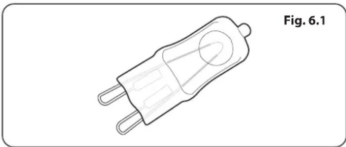
natural_image
Line drawing of a mechanical component with two leads and a circular end cap, labeled Fig. 6.1 (no text or symbols on the diagram itself)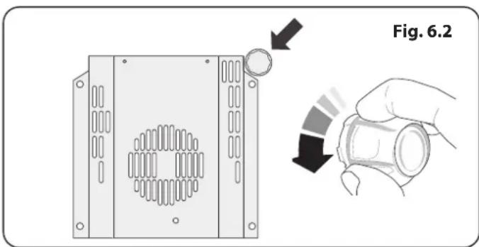
text_image
Fig. 6.2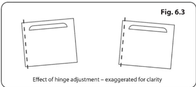
text_image
Fig. 6.3 Effect of hinge adjustment – exaggerated for clarity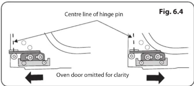
text_image
Centre line of hinge pin Fig. 6.4 Oven door omitted for clarity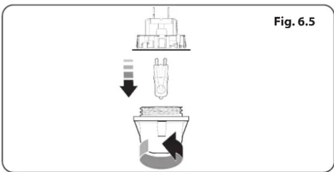
text_image
Fig. 6.5Error Codes
| Multifunction oven | ||
| Error Code Error description Comment | ||
| HE 1 Oven sensor NTC short circuit or open circuit | ||
| HE 2 Meat probe short circuit Not applicable | ||
| HE 3 Communication problem between UI and power PCB | ||
| Steam cavity | ||
| Error Code Error | description Comment | |
| HE 1 Oven sensor NTC short circuit or open circuit | ||
| HE 2 Water boiler sensor open circuit or short circuit | ||
| HE 3 Water level sensor switch cut - Hi or Low Sensor | ||
| HE 4 After press button 8, door switch short circuit | ||
| HE 5 Water tank empty | ||
| HE 6 Failure of the door switch (short circuit) | ||
INSTALLATION
Check the appliance is electrically safe and gas sound when you have finished.
7. Installation
Dear Installer
Before you start your installation, please complete the details below, so that, if your customer has a problem relating to your installation, they will be able to contact you easily.
| Installer's Name |
| Installer's Company |
| Installer's Telephone Number |
| Appliance Serial Number |
Safety Requirements and Regulations
This cooker must be installed in accordance with the relevant instructions in this booklet, with the relevant national and local regulations, and with the local gas and electricity supply companies' requirements.
This cooker is a Class 2 Subclass 1 appliance.
Before installation, make sure that the cooker is suitable for your gas type and supply voltage. See the data badge.
The appliance must be installed in accordance with the regulations in force and only in a well ventilated space.
Read the instructions before installing or using this appliance.
In your own interest and that of safety, it is law that all gas appliances be installed by competent persons. Failure to install the appliance correctly could invalidate any warranty or liability claims and lead to prosecution.
This appliance can be converted for use on another gas.
In the UK the cooker must be installed in accordance with:
- All relevant British Standards / Codes of Practice, in particular BS 5440 Part 2.
- For Natural Gas – BS 6172 and BS 6891.
- For LP Gas – BS 5482-1 (when the installation is in a permanent dwelling), BS 5482-2 (when the installation is in a caravan or other non-permanent dwelling), or BS 5482-3 (when the installation is in a boat).
- The Gas Safety (Installation and Use) regulations.
• The relevant Building / IET regulations.
In the Republic of Ireland the cooker must be installed in accordance with:
The installation must be carried out by a competent person and installed in accordance with the current edition of IS 813 "Domestic Gas Installations", the current Building Regulations and reference should be made to the current ETCI rules for electrical installation.
Provision of Ventilation
This appliance is not connected to a combustion products evacuation device. Particular attention shall be given to the relevant requirements regarding ventilation.
All rooms require a window that can be opened, or equivalent, while some rooms require a permanent vent in addition to the window.
In the UK:
The room containing the cooker should have an air supply in accordance with BS 5440 Part 2. All rooms require an openable window or equivalent, while some rooms require a permanent vent in addition to the openable window. The cooker should not be installed in a bedsitting room with volume less than 20 m^3 . If it is installed in a room of volume less than 5 m^3 an air vent of effective area 100 cm^2 is required; if it is installed in a room of volume between 5 m^3 and 10 m^3 , an air vent of effective area 50 cm^2 is required; while if the volume exceeds 11 m^3 , no air vent is required.
If there are other fuel burning appliances in the same room, BS 5440 Part 2 should be consulted to determine the requisite air vent requirements.
In the Republic of Ireland:
Reference should be made to the current edition of IS 813, which makes clear the conditions that must be met to demonstrate that sufficient ventilation is available.
INSTALLATION
Check the appliance is electrically safe and gas sound when you have finished.
Location of Cooker
The cooker may be installed in a kitchen/kitchen diner but NOT in a room containing a bath or shower.
This appliance is designed for domestic cooking only. Use for any other purpose could invalidate any warranty or liability claim.
Note: An appliance for use on LPG must not be installed in a room or internal space below ground level, e.g. in a basement.
Conversion
This appliance is supplied set for G20 20 mbar Cat II_2H3+ .
A conversion kit for another gas is available for the cooker on request.
If the appliance is to be converted to another gas we recommend that this is carried out before installation.
After converting the appliance, please attach the Gas Conversion sticker over the appropriate area of the data badge – this will identify the gas type for which the appliance is now set.
You will need the following equipment to complete the cooker installation satisfactorily:
- Stability bracket: If the cooker is to be supplied with gas through a flexible hose, a stability bracket or chain must be fitted. These are not supplied with the cooker but are available at most builders' merchants.
• Gas pressure tester/manometer. - Flexible gas hose: Must be in accordance with the relevant standards.
- Multimeter: For electrical checks.
You will also need the following tools:
- Electric drill
- Masonry drill bit (only required if fitting the cooker on a stone or concrete floor)
- Wall plugs (only required if fitting the cooker on a stone or concrete floor)
- Steel tape measure
- Cross head screwdriver
- Flat head screwdriver
- Spirit level
- Pencil
- Adjustable spanner
- Screws for fitting stability bracket
- 13 mm spanner or socket wrench
Checking the parts:
| 3 pan supports Wok cradle | |
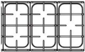 | 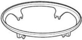 |
| Griddle plate Grill pan and trivet | |
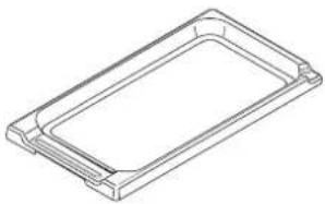 | 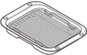 |
| Flat shelves Plinth | |
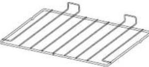 | 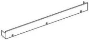 |
| Stability location bracket | |
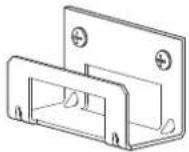 | |
INSTALLATION
Check the appliance is electrically safe and gas sound when you have finished.
Positioning the Cooker
Fig. 7.1 and Fig. 7.2 shows the minimum recommended distance from the cooker to nearby surfaces.
The cooker should not be placed on a base.
Fig. 7.1 and Fig. 7.2 Cookers installed into recess: The cooker must have side clearance ABOVE hob level of 75mm up to a height of 410mm . This can be reduced to 25mm if the surface is made from a non-combustible material.
A minimum space of 650 mm is required between the top of the hob and a horizontal combustible surface.
*Any cookerhood should be installed in accordance with the hood manufacturer's instructions.
**Any splashback must be fitted in accordance with the manufacturers instructions. Allowance should be made for the additional height of the flue trim, which is fitted to the cooker hob.
Surfaces of furniture and walls at the sides and rear of the appliance should be heat, splash and steam resistant. Certain types of vinyl or laminate kitchen furniture are particularly prone to heat damage and discolouration. We cannot accept responsibility for damage caused by normal use of the cooker to any material that de-laminates or discolours at temperatures less than 65 °C above room temperature.
DO NOT box the cooker in – it must be possible to move the cooker in and out for cleaning and servicing.
To allow the oven doors to open, a clearance of 130 mm is required if the cooker is near a corner of the kitchen (Fig. 7.3). The actual opening of the doors is slightly less, but this allows for some protection of your hand as you open the door.
Moving the Cooker

On no account try and move the cooker while it is plugged into the electricity supply.

The cooker is very heavy, so take great care.
We recommend that two people manoeuvre the cooker. Make sure that the floor covering is firmly fixed, or removed, to prevent it being disturbed when moving the cooker around.
To help you, there are two levelling rollers at the back, and two screw-down levelling feet at the front.
Remove the polystyrene base pack. From the front, tilt the cooker backwards and remove the front half of the polystyrene base (Fig. 7.4).
Repeat from the back and remove the rear half of the polystyrene base.
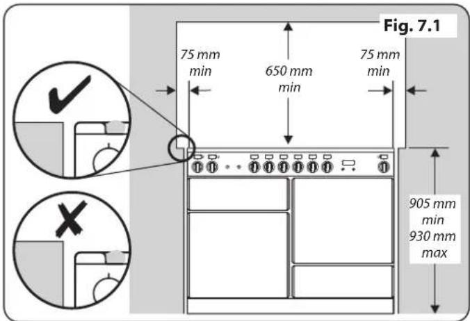
text_image
Fig. 7.1 75 mm min 650 mm min 75 mm min 905 mm min 930 mm max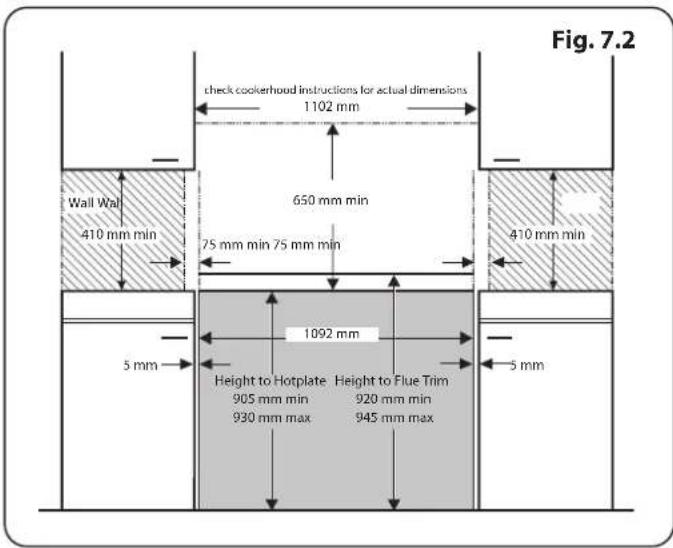
text_image
Fig. 7.2 check cookerhood instructions for actual dimensions 1102 mm 650 mm min Wall Wall 410 mm min 75 mm min 75 mm min 410 mm min 1092 mm 5 mm Height to Hotplate Height to Flue Trim 905 mm min 920 mm min 930 mm max 945 mm max 5 mm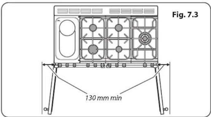
text_image
Fig. 7.3 130 mm min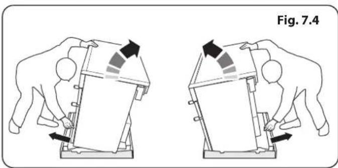
natural_image
Two diagrams showing hands operating a device with arrows indicating motion, labeled Fig. 7.4 (no text or symbols on the devices themselves)INSTALLATION
Check the appliance is electrically safe and gas sound when you have finished.
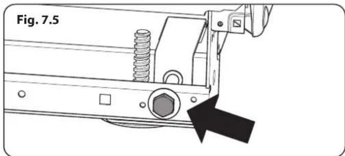
text_image
Fig. 7.5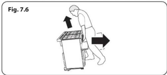
text_image
Fig. 7.6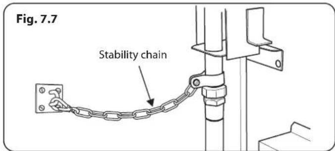
text_image
Fig. 7.7 Stability chain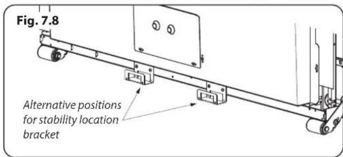
text_image
Fig. 7.8 Alternative positions for stability location bracket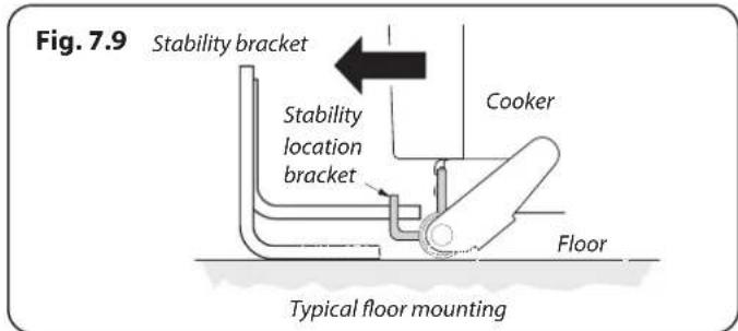
text_image
Fig. 7.9 Stability bracket Stability location bracket Cooker Floor Typical floor mounting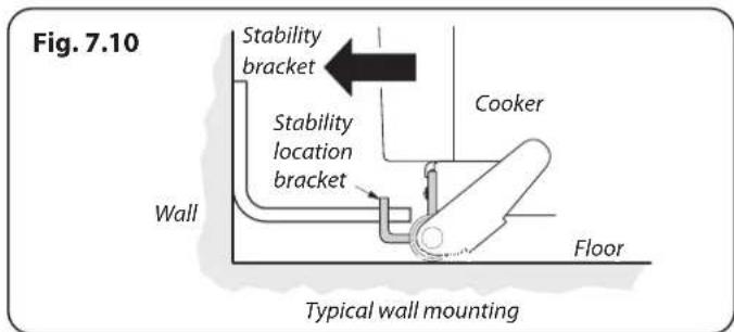
text_image
Fig. 7.10 Stability bracket Stability location bracket Wall Cooker Floor Typical wall mountingLowering the Two Rear Rollers
To adjust the height of the rear of the cooker, first fit a 13 mm spanner or socket wrench onto the hexagonal adjusting nut (Fig. 7.5). Rotate the nut – clockwise to raise – counterclockwise to lower.
Make 10 complete (360°) turns clockwise.
Make sure you lower BOTH REAR ROLLERS.
Completing the Move
Unfold the rear edge of the cardboard base tray. Open the oven doors so that you can get a good grip on the bottom of the fascia panel as you move the oven (Fig. 7.6).
Carefully push the cooker backwards off the base tray. Remove the base tray.
Position the cooker close to its final position, leaving just enough space to get behind it.

DO NOT use the door handles or control knobs to manoeuvre the cooker.
Fitting the Stability Bracket or Chain
Unless otherwise stated, a cooker using a flexible gas connector must be secured with a suitable stability device.
Suitable stability devices are shown in Fig. 7.7, Fig. 7.8, Fig. 7.9 and Fig. 7.10.
If you are using a stability chain (Fig. 7.7) then the chain should be kept as short as is practicable and fixed firmly to the rear of the cooker.
If you are using a stability bracket; first attach the bracket location device to the rear of the cooker (Fig. 7.8). Then adjust the bracket to engage through the slot of the device (Fig. 7.9 and Fig. 7.10).
Repositioning the Cooker Following Connection
If you need to move the cooker once it has been connected then you need to unplug it and, having gripped under the fascia panel and lifted the front of the cooker slightly (Fig. 7.6), you need to check behind the cooker to make sure that the gas hose is not caught.
As you progress, make sure that both the electricity cable and gas hose always have sufficient slack to allow the cooker to move.
With a stability chain fitted, release it as you ease the cooker out. Do not forget to refit it when you replace the cooker.
When you replace the cooker, again check behind to make sure that the electricity cable and gas hose are not caught or trapped.
INSTALLATION
Check the appliance is electrically safe and gas sound when you have finished.
Conversion to Another Gas
If the appliance is to be converted to another gas do the conversion at this point. See the conversion section of these instructions.
Levelling
You are recommended to use a spirit level on a shelf in one of the ovens to check for level.
Place the cooker in its intended position taking care not to twist it within the gap between the kitchen units as damage may occur to the cooker or the units.
The front feet and rear rollers can be adjusted to level the cooker.
To adjust the height of the rear of the cooker use a 13 mm spanner or socket wrench to turn the adjusting nuts at the front bottom corners of the cooker.
To set the front, turn the feet bases to raise or lower.
INSTALLATION
Check the appliance is electrically safe and gas sound when you have finished.
Fig. 7.11
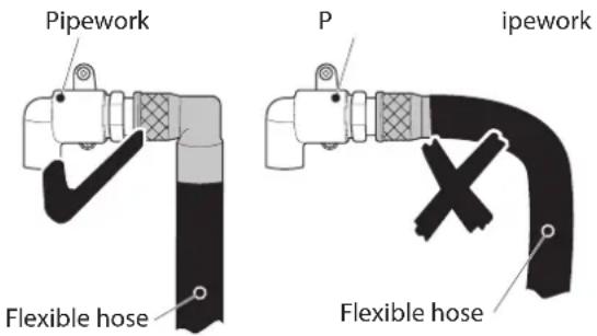
text_image
Pipework P ipework Flexible hose Flexible hoseFig. 7.12
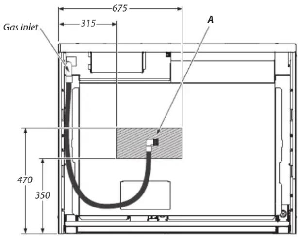
text_image
Gas inlet 675 315 A 470 350All dimensions in millimetres
Gas Connection
This must be in accordance with the relevant standards.
The flexible hose (not supplied with the cooker) must be in accordance with the relevant standards. Hoses may be purchased at most builders' merchants.
We recommend that a Micropoint gas hose is used when installing this appliance.
The gas supply needs to terminate with a down facing bayonet (Fig. 7.11).
The connector is located just below the hotplate level at the rear of the cooker. If in doubt contact your supplier.
The rear cover boxes limit the position of the supply point.
Because the height of the cooker can be adjusted and each connection is different, it is difficult to give precise dimensions.
Although a 900 mm hose can be used, a 1100 mm hose will allow slightly more flexibility in the positioning of the bayonet and make moving the cooker easier.
The hose should be fitted so that both inlet and outlet connections are vertical so that the hose hangs downwards in a 'U' shape.
Ideally the hose supply connection should be within the shaded area 'A' (Fig. 7.12).
For Natural Gas, the flexible hose must be in accordance with BS 669. For LP Gas, it should be capable of 50 mbar pressure and 70 °C temperature rise. If in doubt contact, your supplier.
Screw connect the threaded end of the hose into the gas inlet.
After completing the gas connection, make sure that the cooker is gas sound with a pressure test.
Pressure Testing
The gas pressure can be measured at one of the hotplate burner injectors (not the wok burner).
Lift off a burner head. Fit the pressure gauge to the injector. Turn on and light one of the other hotplate burners.
Turn on the control knob for the burner with the pressure gauge fitted to let gas through.
See the data badge for test pressures.
Turn off the burners. Make sure that you reassemble the burner top in the correct way on the burner body.
INSTALLATION
Check the appliance is electrically safe and gas sound when you have finished.
Electrical Connection
The cooker must be installed by a qualified electrician, in accordance with all relevant British Standards/Codes of Practice (in particular BS 7671), or with the relevant national and local regulations.

WARNING: THE APPLIANCE MUST BE EARTHED.
NOTE: The cooker must be connected to the correct electrical supply as stated on the voltage label on the cooker, through a suitable cooker control unit incorporating a double-pole switch, having a contact separation of at least 3 mm in all poles.

The cooker MUST NOT be connected to an ordinary domestic power point.
Access to the mains terminal is gained by removing the electrical terminal cover box on the back panel. Connect the mains cable to the correct terminals for your electrical supply type (Fig. 7.13 and Fig. 7.14). Check that the links are correctly fitted and that the terminal screws are tight. Secure the mains cable using the cable clamp.
Final Checks
Hob Check
Check each cooking zone in turn. Be sure to use pans of the correct size and material.
Grill Check
Turn on the grill control and check that the grill heats up.
Oven Check
Set the clock as described earlier, and then turn on the ovens. Check the oven fans start to turn and that the ovens heat up.
Final Fitting
Fitting the Plinth
Loosen the 3 screws along the front bottom edge of the cooker. Twist and fit each end keyhole over their respective screws. Tighten the fixing screws (Fig. 7.15).
Customer Care
Installer: Please complete your details in this guide, inform the user how to operate the cooker and hand over the instructions.
Thank you.
Current Operated Earth Leakage Breakers
The combined use of your induction cooker and other domestic appliances may cause nuisance tripping, so we recommend that the cooker is protected on an individual RCD (Residual Current Device) or RCBO (Residual Current Breaker with Overload).
IF IN DOUBT, PLEASE CONSULT A SUITABLY QUALIFIED ELECTRICIAN.
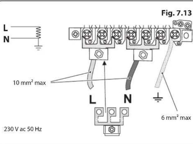
text_image
L N Fig. 7.13 10 mm² max L N 6 mm² max 230 V ac 50 Hz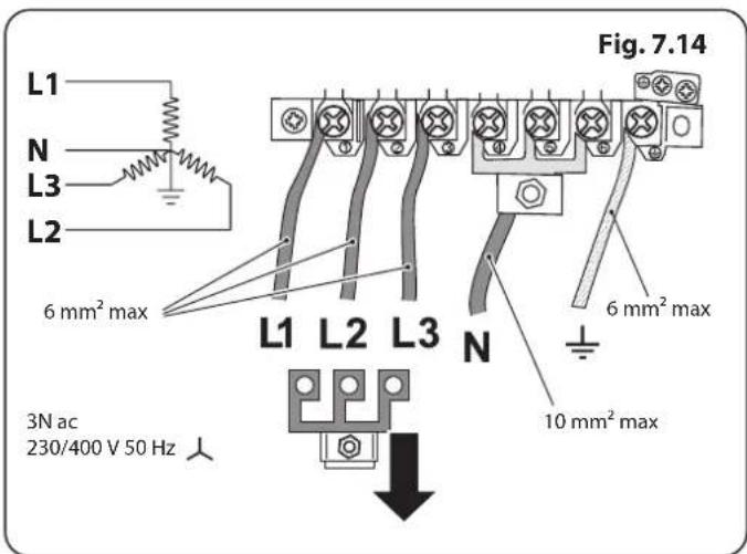
text_image
Fig. 7.14 L1 N L3 L2 6 mm² max L1 L2 L3 N 6 mm² max 10 mm² max 3N ac 230/400 V 50 Hz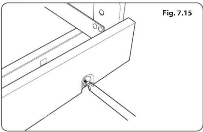
natural_image
Technical line drawing of a mechanical bracket with mounting holes and a close-up detail (no text or symbols)WARNING – SERVICING TO BE CARRIED OUT ONLY BY AN AUTHORISED PERSON
Disconnect from electricity and gas before servicing. Check appliance is safe when you have finished.
8. Conversion to LP Gas
Fig. 8.1
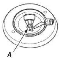
natural_image
Technical diagram of a mechanical component with concentric rings and a labeled section A (no text or symbols beyond label)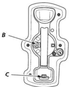
text_image
B CA - Jet, B - Internal injector, C - External injector
Fig. 8.2
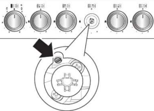
text_image
Diagram showing a circular device with labeled control knobs and an arrow pointing to a component, likely illustrating a mechanical or electrical setup.Check the 'Technical Data' section at the back of the book that the hob is convertible to the gas you want to use.
A suitably competent person must perform the conversion. After conversion the installation must comply with the relevant regulations and also the local electricity supply company requirements. Read the instructions before converting this appliance.
Failure to convert the appliance correctly could invalidate any warranty or liability claims and lead to prosecution.
When servicing or replacing gas-carrying components disconnect from the gas supply before starting operation. Check the appliance is gas sound after completion.
DO NOT use reconditioned or unauthorised gas controls.
⚠️ Disconnect from the electricity and gas supply before servicing.
Before electrical reconnection, check that the appliance is electrically safe.
Injectors
Remove the burner caps and heads. Remove the old jets (Fig. 8.1). Fit the new jets (see 'Technical Data' section at the back of this book for the correct jets). Reassemble in the reverse order.
Bypass Screw Adjustment
Remove the control knobs and turn the bypass screw on each control clockwise to the stop (Fig. 8.2). Refit the control knobs.
Stick on Label
Stick the LP gas label over the natural gas part of the appliance data label.
WARNING – SERVICING TO BE CARRIED OUT ONLY BY AN AUTHORISED PERSON
Disconnect from electricity and gas before servicing. Check appliance is safe when you have finished.
Pressure Testing
Connect the appliance to the gas supply.
The gas pressure can be measured at one of the hotplate injectors (not a wok burner).
Lift off a burner head. Fit the pressure gauge to the jet. Turn on and light one of the other burners. Turn on and press in the control knob for the burner with the pressure gauge fitted.
The pressure should be 29 mbar for Butane and 37 mbar for Propane. After checking the pressure, turn off the taps and replace the burner head.
Reassemble burner top, making sure it is reassembled in the correct way on the burner body.
Check operation of all the burners.
Check the appliance is gas sound.
9. Circuit Diagram
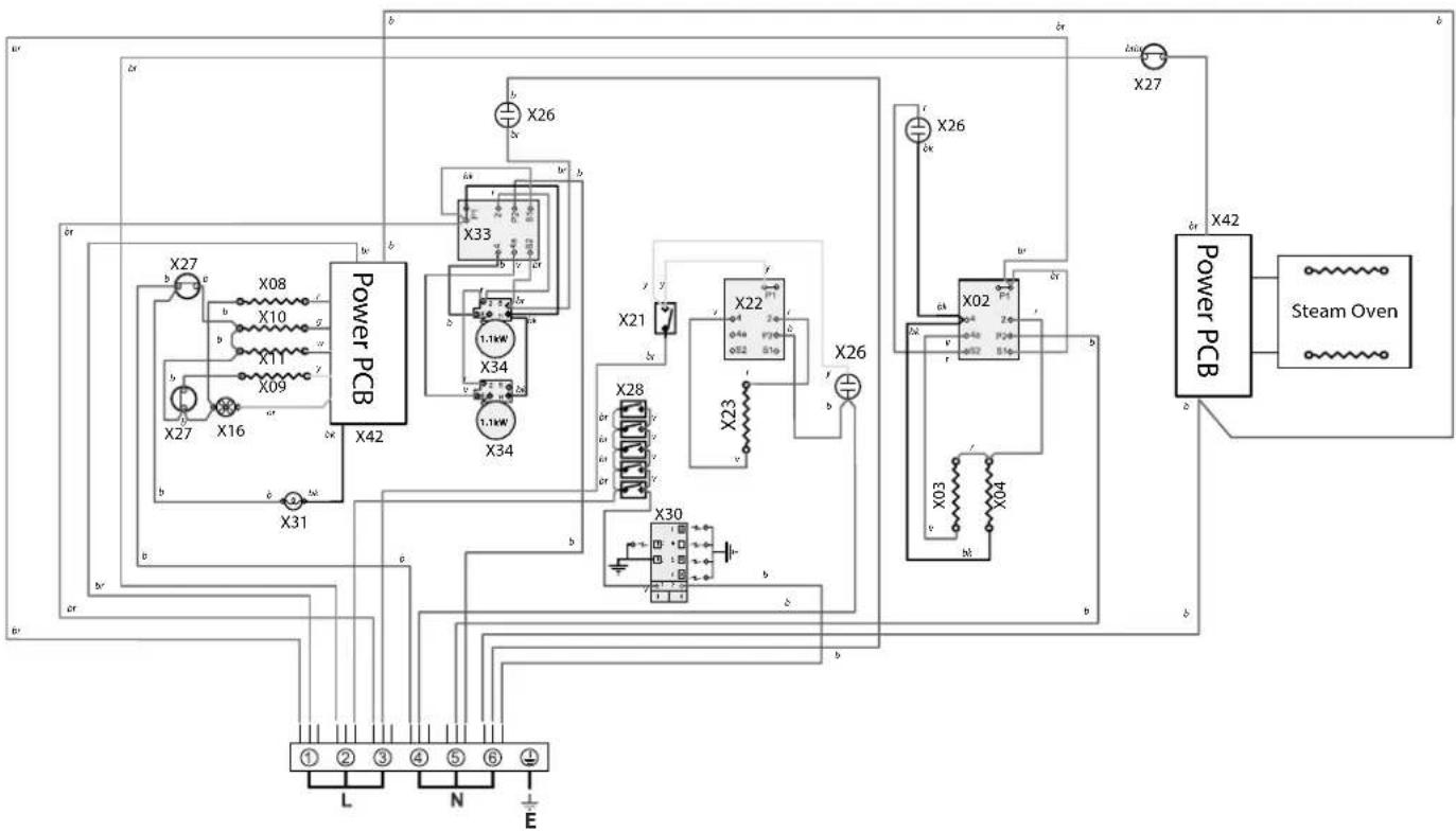
flowchart
graph TD
    subgraph Power PCB
        X08["X08"] -->|b| PowerPCB["X42"]
        X10["X10"] -->|b| PowerPCB
        X11["X11"] -->|b| PowerPCB
        X09["X09"] -->|b| PowerPCB
        X27["X27"] -->|b| PowerPCB
        X16["X16"] -->|b| PowerPCB
        X31["X31"] -->|b| PowerPCB
    end

    subgraph Power PCB
        X33["X33"] -->|b| PowerPCB
        X34["X34"] -->|b| PowerPCB
        X21["X21"] -->|y| PowerPCB
        X28["X28"] -->|y| PowerPCB
        X30["X30"] -->|y| PowerPCB
    end

    subgraph Steam Oven
        X02["X02"] -->|b| PowerPCB
        X03["X03"] -->|b| PowerPCB
        X42["Power PCB"] -->|b| Steam Oven
    end

    PowerPCB --> PowerPCB
    PowerPCB --> PowerPCB
    PowerPCB --> PowerPCB
    PowerPCB --> PowerPCB
    PowerPCB --> PowerPCB
    PowerPCB --> PowerPCB
    PowerPCB --> PowerPCB
    PowerPCB --> PowerPCB
    PowerPCB --> PowerPCB
    PowerPCB --> PowerPCB
    PowerPCB --> PowerPCB
    PowerPCB --> PowerPCB
Key
The connections shown in the circuit diagram are for single-phase. The ratings are for 230V 50 Hz.
| Code | Description |
| X02 | Grill Energy Regulator |
| X03 | Left Hand Grill Element |
| X04 | Right Hand Grill Element |
| X08 | Left Hand Oven Base Element |
| X09 | Left Hand Oven Fan Element |
| X10 | Left Hand Oven Top Outer Element |
| X11 | Left Hand Oven Top Inner Element |
| X16 | Oven Fan |
| X21 | Proving Drawer Switch |
| X22 | Proving Drawer Energy Regulator |
| X23 | Proving Drawer Element |
| Code | Description |
| X26 | Neon |
| X27 | Thermal Cut-Out |
| X28 | Ignition Switches |
| X30 | Spark Generator |
| X31 | Oven Light |
| X33 | Hob Energy Regulator |
| X34 | Hob Element |
| X42 | Power PCB (Steam and MF Oven) |
| Code | Colour |
| b | Blue |
| br | Brown |
| bk | Black |
| or | Orange |
| r | Red |
| v | Violet |
| w | White |
| y | Yellow |
| g/y | Green/Yellow |
| gr | Grey |
Power PCB
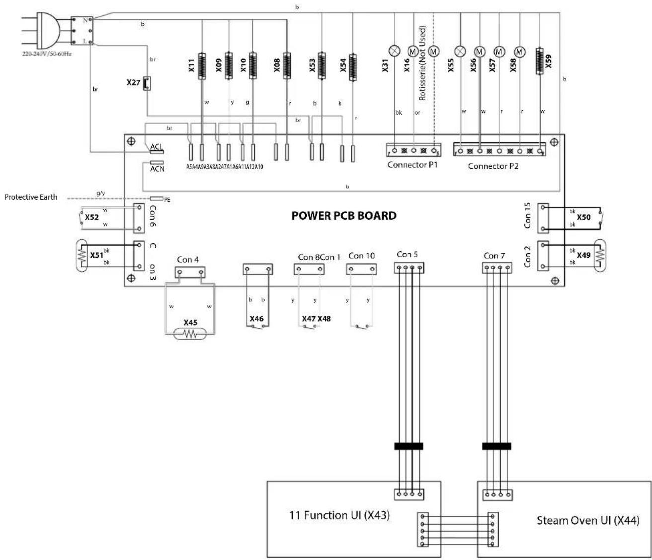
text_image
220L-240V/50-60Hz X27 br X11 X09 X10 X08 X53 X54 X31 X16 Rotisserie(Not Used) X55 X56 X57 X58 X59 b br w y g r b k r bk or w w r r w ACN A5A4A9A3A8A2A7A1A6A11A12A10 Connector P1 Connector P2 Protective Earth g/y x52 w x51 bk bk PE Con 6 C on 3 Con 4 w x45 h b x46 y y x47 x48 y y Con 8Con 1 Con 10 Con 5 Con 7 Con 15 Con 2 bk bk bk bk bk bk bk bk bk bk bk bk bk bk bk bk bk bk bk bk bk bk bk bk bk bk bk bk bk bk bk bk bk bk bk bk bk bk bk bk bk bk bk bk bk bk bk bk bk bk bk bk bk bk bk bk bk bk bk bk bk bk bk bk bk bk bk bk bk bk bk bk bk bk bk bk bk bk bk bk bk bk bk bk bk bk bk bk bk bk bk bk bk bk bk bk bk bk bk bk bk dkKey
The connections shown in the circuit diagram are for single-phase. The ratings are for 230V 50 Hz.
| Code | Description |
| X43 | User Interface (UI) MF Oven |
| X44 | User Interface (UI) Steam Cavity |
| X45 | Water Boiler Sensor |
| X46 | Water Tank Switch |
| X47 | Water Sense (Low) |
| X48 | Water Sense (High) |
| X49 | MF Oven Temperature Sensor |
| X50 | MF Oven Door Sensor |
| X51 | Steam Cavity Temeprature Sensor |
| X52 | Steam Cavity Door Sensor |
| Code | Description |
| X53 | Water Boiler Element |
| X54 | Steam Cavity Top Element |
| X55 | Steam Cavity Light |
| X56 | Water Pump In |
| X57 | Water Pump Out |
| X58 | Steam Cavity Cooling Fan |
| X59 | Steam Cavity Base Element |
| Code | Colour |
| b | Blue |
| br | Brown |
| bk | Black |
| or | Orange |
| r | Red |
| v | Violet |
| w | White |
| y | Yellow |
| g/y | Green/Yellow |
| gr | Grey |
10. Technical Data
THE COOKER IS CATEGORY: CatII _2 H3+.
It is supplied set for group H natural gas. A conversion kit from NG to LP is available for the cooker.
INSTALLER: Please leave these instructions with the user.
DATA BADGE LOCATION: Cooker back, serial number repeater badge below oven door opening.
COUNTRY OF DESTINATION: GB, IE.
Connections
| Gas (Rp 1⁄2 at rear right-hand side) Electric | ||
| Natural Gas 20 mbar | 230/400V50HzButane 29 mbar | |
| Propane 37 mbar | ||
See the appliance badge for test pressures.
Dimensions
| Model NEXUS 110 Dual Fuel / Steam | ||
| Overall height minimum 905 mm maximum 930 mm | mm | |
| Overall width | 1092 mm | |
| Overall depth | 608 mm excluding handles, 648 mm including handles | |
| Minimum height above the hotplate | 650 mm | |
Hotplate Ratings
| Hotplate | Bypass Screw* | Natural Gas 20 mb | L.P. Gas | ||
| Injector | Injector | ||||
| Wok burner | 57 | 3.5 kW | internal 78 | 3.5 kW (246 g/h) | internal 53 |
| external 126 | external 82 | ||||
| Rapide/ Large Burner | 40 | 3 kW | 134 | 3.0 kW (210 g/h) | 87 |
| Semi Rapide / Medium Burner | 32 | 1.7 kW | 109 | 1.7 kW (119 g/h) | 68 |
| Auxiliary / Small Burner | 28 | 1 kW | 75 | 1.0 kW (70 g/h) | 51 |
* The valves in this cooker are fitted with adjustable bypass screws. The cooker is supplied with the bypass screws set for Natural Gas. For LPG conversion the bypass screws must be screwed all the way down.
Hotplate energy saving tips
Use cookware with a flat base.
Use the correct size cookware.
Use cookware with a lid.
Minimise the amount of liquid or fat.
When liquid starts boiling, reduce the setting.
Consumption is based on G30.
Oven energy saving tips
Cook meals together, if possible.
Keep the pre-heating time short.
Do not lengthen cooking time.
Do not open the oven door during the cooking period.
Do not forget to turn the appliance off at the end of cooking.
Hotplate Efficiency
| Brand Rangemaster | |
| Model Identification Nexus | |
| Size 110 | |
| Type Dual Fuel / Steam | |
| Type of Hob Gas | |
| Number of gas burners 5 | |
| Auxiliary / Small Burner (EE gas burner) - | |
| Semi Rapide / Medium Burner (EE gas burner) 58% | |
| Semi Rapide / Medium Burner (EE gas burner) 58% | |
| Rapide / Large Burner (EE gas burner) 56% | |
| Rapide / Large Burner (EE gas burner) - | |
| Wok (EE gas burner) 53% | |
| Wok (EE gas burner) - | |
| Hotplate EE gas hob (*) - | |
| Type of Hob | Radiant |
| Number of electric zones | 2 |
| Zone 1 - ∅ cm | 14.5 |
| Heating Technology | |
| Energy Consumption (ECElectric cooking) - Wh/kg | 180 |
| Zone 2 - ∅ cm | 14.5 |
| Heating Technology | |
| Energy Consumption (ECElectric cooking) - Wh/kg | 180 |
| Energy Consumption (ECElectric hob) - Wh/kg (*) | - |
Information marked thus (*) is not required with mixed fuel hobs
Oven Data
| Brand Rangemaster | ||
| Model identification Nexus | ||
| Type of oven Electric | ||
| Mass kg 133 | ||
| Number of cavities 2 | ||
| Left-hand Efficiency | ||
| Fuel type Electric | ||
| Cavity type Multifunction | ||
| Power - conventional 2.2 | ||
| Power - forced air convection 2.5 | ||
| Volume Litres 79 | ||
| Energy consumption (electricity) - conventional kWh / cycle 1.01 | ||
| Energy consumption (electricity) - forced air convection kWh / cycle 0.88 | ||
| Energy efficiency index - conventional | 114 | |
| Energy efficiency index - forced air convection | 100 | |
| Energy efficiency index - ECO mode | kWh / cycle | 87 |
| Energy class | A | |
| Additional Information | |
| The oven complies with EN 60350-1 | |
| Maximum output @ 230V 50Hz | |
| Conventional | 2.2 kW |
| Multifunction | 2.5 kW |
| Multifunction (with Rapid Response) | - |
| Forced Air Convection | 2.5 kW |
| Steam cavity Grill | 1.5 kW |
| Steam cavity Base Heat | 0.4 kW |
| Steam cavity Water Boiler | 1.2 kW |
| Grill | 2.3 kW |
| Slow Oven | - |
| Bread Proving Drawer | 0.2 kW |
| Maximum total electrical load at 230 V (approximate total including hob, oven lights, oven fan, etc.): | 6.95 kW* |
* Arithmetic mean value when measured under full load stabilised conditions, Clause 10 EN 60335.
| Name of Appliance & Colour* |
| Appliance Serial Number* |
| Natural Gas LP GasFuel Type*Dual Fuel Electric |
| Retailer's Name & Address |
| Date of Purchase |
| Installer's Name & Address |
| Installer's Telephone Number |
| Date of Installation |
* This information is on the appliance data badge - look in the appliance instructions to find out where the data badge is located.
CONSUMER SERVICE
If you have any product enquiries, or in the event of a problem with your appliance once it has been installed, please telephone 01926 457628.
CONSUMER SERVICE LINES OPEN:
Monday to Thursday 8am–6pm
Friday 8am-5pm
WARRANTY
Your manufacturer warranty covers goods of our own brand for defective workmanship and materials for a period of 1 year from the date of purchase. This warranty covers mechanical breakdown and proven cosmetic and manufacturing defects.
You will receive an additional FREE full 12 months guarantee by registering your purchase using the FREEPOST form provided. Alternatively, call free on 0800 587 5747, quoting reference RMGX57A, or register online at www.rangemaster.co.uk.
Any damage, blemishes or chips identified upon receipt of the product must be reported within 7 days – proof of purchase may be required to establish validity. Scratches on the surface of ceramic hobs must be reported within 7 days. Scratches caused by usage are not covered. Accidental damage is not covered by the manufacturer's warranty.
For warranty compliance, the requirements are that the appliance:
- Has been correctly installed in accordance with current legislation, relevant British and European Standards and Codes of Practice, by a suitably competent person registered with Gas Safe or equivalent body and, where applicable, a qualified electrician.
- Has been used solely for domestic cooking purposes.
- If in use in the UK*, has not been taken abroad as a personal export. (In the Republic of Ireland conditions may vary, so consult your retailer.)
- Is not second-hand or a refurbished appliance. The manufacturer's warranty is not transferable.
- Has not been subject to misuse, accidental damage or modification, and has not deteriorated due to normal domestic wear and tear, and the manufacturer's recommendations concerning cleaning materials have been followed.
- Has not been repaired by persons or organisations other than those authorised to act on behalf of AGA Rangemaster.
Exceptions:
- Items not included under the free 1 year guarantee include pan supports, griddles, wok rings, baking trays, grill pans, trivets, filters, light bulbs and other consumable accessories.
- Any damage caused other than through normal use.
- Breakdowns associated with cooking spillage.
- Cosmetic deterioration deemed to be normal wear and tear.
This warranty is in addition to your Statutory Rights.
* Only certain models can be adapted for use with Mains Gas supplied in the Channel Islands and Isle of Man.
OUT OF WARRANTY
We recommend that Rangemaster appliances are serviced regularly throughout their life to maintain optimum performance and efficiency. Service work should only be carried out by technically competent and suitably qualified personnel.
For your own safety, always make sure that work is carried out by a Gas Safe registered engineer for gas appliances or an approved electrician for electrical models.
For a competitive quote and to arrange for a Rangemaster approved engineer to attend, call Consumer Services on: 01926 457628.
SPARE PARTS
To maintain optimum and safe performance, we recommend that only genuine Rangemaster spare parts are used. These are available from most major spares stockists, including ourselves.
Contact Consumer Services on 01926 457628, who will be happy to help.
STANDARDS
Rangemaster cookers are designed and manufactured to a recognised international quality standard, which meets the requirements of BS EN ISO 9001, BS EN ISO 14001 and OHSAS 18001 for continually improving environmental procedures.
Rangemaster cookers comply with the essential requirements of the appropriate European Directives, and carry the CE mark.
RANGEmaster
UNRIVALLED PERFORMANCE
Clarence Street
Royal Leamington Spa
Warwickshire
CV31 2AD
England
Consumer Services: +44 (0)1926 457628.
Fax: +44 (0)1926 450526
E-mail: consumers@agarangemaster.co.uk
www.rangemaster.co.uk
For UK Trade Enquiries Tel: +44 (0)115 946 4000
Fax: +44 (0)115 973 6602
E-mail: sales@agarangemaster.co.uk
For ROI Enquiries Tel: 1850 302 502
Rangemaster is a trading name of AGA Rangemaster Limited
Registered in England and Wales. Registration No. 354715
Registered Office: c/o Aga Rangemaster, Meadow Lane, Long Eaton, Nottingham, NG10 2GD