
MCU-R4NEK0N - Air-conditioner SAMSUNG - Free user manual and instructions
Find the device manual for free MCU-R4NEK0N SAMSUNG in PDF.


User questions about MCU-R4NEK0N SAMSUNG
0 question about this device. Answer the ones you know or ask your own.
Ask a new question about this device
Download the instructions for your Air-conditioner in PDF format for free! Find your manual MCU-R4NEK0N - SAMSUNG and take your electronic device back in hand. On this page are published all the documents necessary for the use of your device. MCU-R4NEK0N by SAMSUNG.
USER MANUAL MCU-R4NEK0N SAMSUNG
- Thank you for purchasing this Samsung air conditioner.
- Before operating this unit, please read this user manual carefully and retain it for future reference.
Contents
Safety Information 3
Safety Information 3
Preparation 9
Preparing the installation 9
Accessories
Selecting the refrigerant pipe for installation
HR Changer, MCU, Indoor and outdoor unit compatible table
Installation 12
Space requirements 12
Installing the unit 14
Method and cautions on brazing the pipe
Refrigerant piping works 19
Method and cautions on refrigerant pipe insulation
Installing the circuit breaker and wires
Wiring works 23
Appendix 30
Commissioning 30
The safety information and precautions below must be kept for the safety of users and installers.
Before installing an air conditioner, please read this manual thoroughly to ensure that you know how to safely and efficiently install a new appliance.
• DVM S air conditioner uses R-410A refrigerant.
- When using R-410A, moisture or foreign substances may affect the capacity and reliability of the product.
Safety precautions must be taken when installing the refrigerant pipe.
- The designing pressure of the system is 4.1MPa. Select appropriate material and thickness according to the regulations.
- R-410A is a quasi-azeotrope of two refrigerants.
Make sure to charge with liquid phase when filling refrigerant.
If you charge gaseous refrigerant, it may affect the capacity and reliability of the product as a result of change formation of the refrigerant.
- Connect the indoor units for R-410A refrigerant. Check whether the indoor units can be connected with the product's catalogue. (When incorrect indoor units are connected, they cannot operate normally.)
※ After installation and trial operation, explain to the customer how to use the air conditioner and give the installation manual to the user.
※ The manufacturer is not responsible for accidents due to incorrect installation. Any claims caused by failing to keep the safety precautions are installer's responsibility. (The installer is responsible for the service cost.)
※ After installation and trial operation, explain to the customer how to use the air conditioner and give the installation manual to the user. ※ The manufacturer is not responsible for accidents due to incorrect installation. Any claims caused by failing to keep the safety precautions are installer's responsibility. (The installer is responsible for the service cost.)

WARNING
In case of not following the safety precautions, the service agent or the user may get the risk of serious wound or death.

CAUTION
In case of not following the safety precautions, the service agent or the user may get the risk of injury or loss of property.
FOR INSTALLATION
WARNING
Installation must be done by the installer or its service agent.
▶ Installation by an unqualified person may cause a water leakage, electric shock or fire and so on.
Install the unit correctly according to the installation manual.
▶ An incorrect installation may cause a water leakage, electric shock or fire.
When installing the unit in a small place, take measures in order to keep the refrigerant concentration from exceeding allowable safety limits in the event of a refrigerant leak.
▶ Excessive refrigerant concentration can lead to suffocation.
If any gas or impurities except R-410A refrigerant get into the refrigerant pipe, serious problems may occur and this may cause injury.
When installing the unit, only use the components and tools which are specified for the installation.
▶ Using the uncertified components and tools may cause a unit fall, water leakage, electric shock, and a fire. (Never use the components and pipe for R-22 refrigerant)
Install the unit safely on a place that can support its weight.
▶ If the place cannot support its weight, the unit may fall down and cause injury.
Check out the safety precautions below before installing or fixing the unit.
Before welding the unit, you must remove all the hazardous materials around the unit that may cause an explosion and a fire.
When refrigerant is in the product or the pipe before welding the unit, you must remove the refrigerant.
- If you weld the unit when there is refrigerant inside, the increased pressure of refrigerant may explode or break the leaking spot so that causes serious injuries.
When welding the unit, please use nitrogen gas to prevent oxide from generating in the pipe
Make sure to cut off all the power supply before installing, fixing, and cleaning the unit.
When the electric wire is damaged, you must exchange it by the manufacturer or its service agent, or a person who has the equivalent qualification.
When turning on the power, make sure to connect the power supply to the circuit breaker designated for indoor units. (ELCB, ELB, MCCB)
▶ If you do not install the circuit breaker for HR Changer(ELCB, ELB, MCCB), excessive current or failure to blocking the power supply may cause electric shock, a fire.
FOR INSTALLATION
WARNING
Make sure to connect wires thoroughly and fix them firmly so that no outer pressure of the wires would put on the terminal block.
▶ If the terminal is loose, it may generate heat and cause a fire.
Supplied power should be more or less than 2% of the rated power.
If the power is supplied unevenly, a life span of the storage battery shortens. If the supplied power is more than 4 % of the rated power, the unit terminates and indicates errors to protect it.
Make sure the interior power supply shouldn't be over the maximum voltage or under the minimum voltage.
▶ Otherwise, it could result in malfunction of the unit due to damaged electrical components or decreased function of components.
Only use copper wire as the power cable and all wiring, components and materials should comply with the applicable local and national codes.
Make sure that all wiring is properly installed.
▶ Otherwise, the unit can be heated and cause a fire.
Never use the pipe and flare parts for R-22 refrigerant.
In case of a refrigerant gas leakage during installation, please ventilate the area.
If refrigerant gas combines with inflammable materials, toxic gases can be generated.
The electric work must be done by service agent or qualified persons according to national wiring regulations and use only rated cable.
▶ Voltage drop, shortage of power supply, improper electric work and using unapproved wires can cause an electric shock or a fire.
FOR INSTALLATION
CAUTION
Make sure to earth.
Do not connect the earth wire to the gas pipe, lighting rod or telephone wire.
▶ If earthing is incomplete, electric shock or fire may occur.
Make sure that the condensed water from the drain hose runs out properly based on this installation manual and insulate the drain pipe so that frost does not generate.
If the draining work is done incompletely, property damage may occur due to a leakage.
Install the power cable and communication cable of HR Changer at least 1m away from the electric appliances and at least 2m away from the lightning rod.
However, you may hear a noise 1 meter away from the unit depending on the condition of the electric wave.
Install HR Changer away from lighting apparatus using the ballast.
If you use the wireless remote control, it may not operate normally.
Do not install the unit in following places.
The place packed with mineral oil and the place where there are lots of moisture, or arsenic acid: The resin parts may burn and cause the fall of the components or a refrigerant leakage.
The place where corrosive gas such as sulfurous acid gas generates from the vent pipe or air outlet: The copper pipe or connection pipe may corrode and refrigerant may leak.
The place where there is a machine that generates electromagnetic waves: The unit may not operate normally due to malfunction in the control system.
The place where there is a possibility of combustible gas leakage, and where inflammable materials like thinner or gasoline is handled. The place where a carbon fiber or inflammable dust is floating in the air: If the gas leaks and stays around the main valve, it may result in a fire.
The places where have a possibility of the HR Changer corrosion like a spa and a shore.
When there is a possibility that the place in which HR Changer is installed could be the shelter of small animals, take proper measures to prevent this situation in advance.
If small animals contact the unit, this may result in malfunction of the unit or cause a fire and smoke. Please remind users of cleaning the place around HR Changer.
※ Any claims caused by failing to keep the safety precautions are installer's responsibility. (The installer is responsible for the service cost.)
Please check if items below are included in installation accessories.
| Name | Insulation (for pipe) | Insulation (for base) | Installation manual | Pattern sheet | Cable tie Tube Cap | |
| Shape |  |  |  |  |  |  |
※ Please purchase Y-connector separately. (Not included)
| Name | Y-connector[∅ 9.52 mm (3/8"): DB96-23143A ], [∅ 15.88 mm (5/8"): DB96-23144A ] |
| Shape | 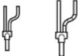 |
Selecting the refrigerant pipe for installation
The design pressure of MCU for R-410A is about 4.1 MPa. For safe use of the product, please refer to the table below in selecting the installation pipe.
| Outer diameter Minimum thickness | Temper grade | ||||
| mm inch mm inch | |||||
| 6.35 | 1/4 | 0.70 0.028 | Annealed | ||
| 9.52 | 3/8 | 0.70 0.028 | |||
| 12.70 | 1/2 | 0.80 0.031 | |||
| 15.88 | 5/8 | 1.00 0.093 | |||
| 91.05 | 3/4 | 0.90 0.035 | Drawn | ||
| 22.22 | 7/8 | 0.90 0.035 | |||

- For pipes larger than ∅91.05mm(3/4"), drawn type (C1220T-1/2H or C1220TH type copper pipe must be used. If an annealed type (C1220T-O) copper pipe is used, pipe may break due to its low pressure resistance and cause personal injury.

HR Changer, MCU, Indoor and outdoor unit compatible table
Before installing MCU and HR Changer, refer to the compatible table below and find the model before installation
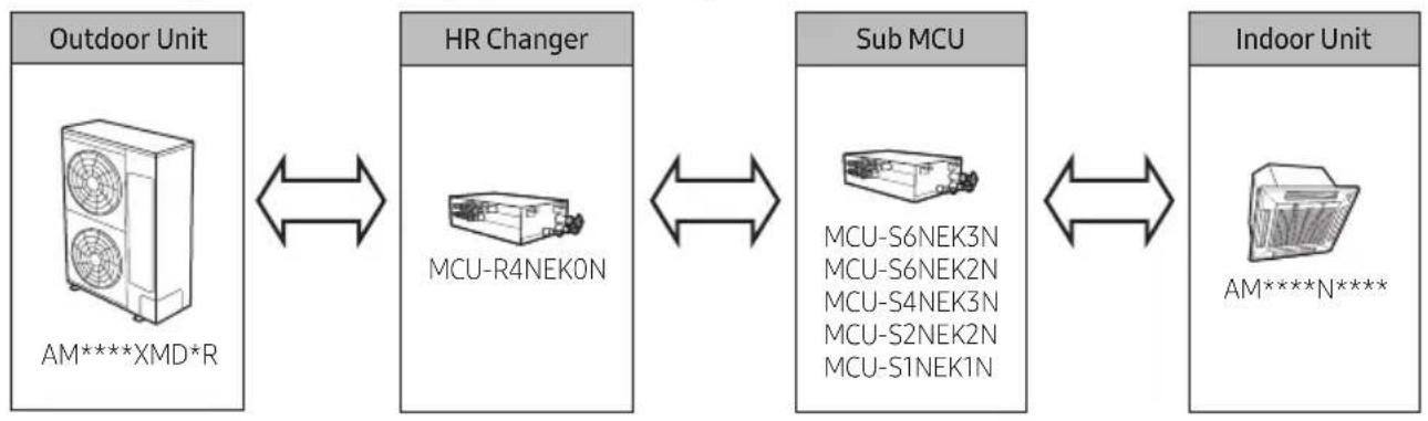
flowchart
graph LR
    A["Outdoor Unit\nAM*****XMD*R"] <--> B["HR Changer\nMCU-R4NEK0N"]
    B <--> C["Sub MCU\nMCU-S6NEK3N\nMCU-S6NEK2N\nMCU-S4NEK3N\nMCU-S2NEK2N\nMCU-S1NEK1N"]
    C <--> D["Indoor Unit\nAM*****N****"]

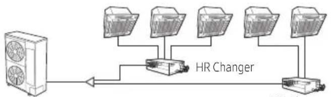
- HR Changer can be installed in series or in parallel.
- For serial installation, the order of HR Changer and MCU is very important. HR Changer must be installed after the outdoor unit. If MCU is installed first after the outdoor unit, it wii not work properly.
- For parallel installation, HR Changer must be installed after the Y-joint. If you don't install HR Changer after the Y-joint, it wii not work properly.
- If you install only MCU without HR Changer, it happen to occur the error(E214). Cooling only indoor units must be installed behind the HR Changer.

※ About MCU-S6NEK3N, MCU-S6NEK2N, MCU-S4NEK3N, MCU-S2NEK2N, MCU-S1NEK1N, please refer to those own installation manual
text_image
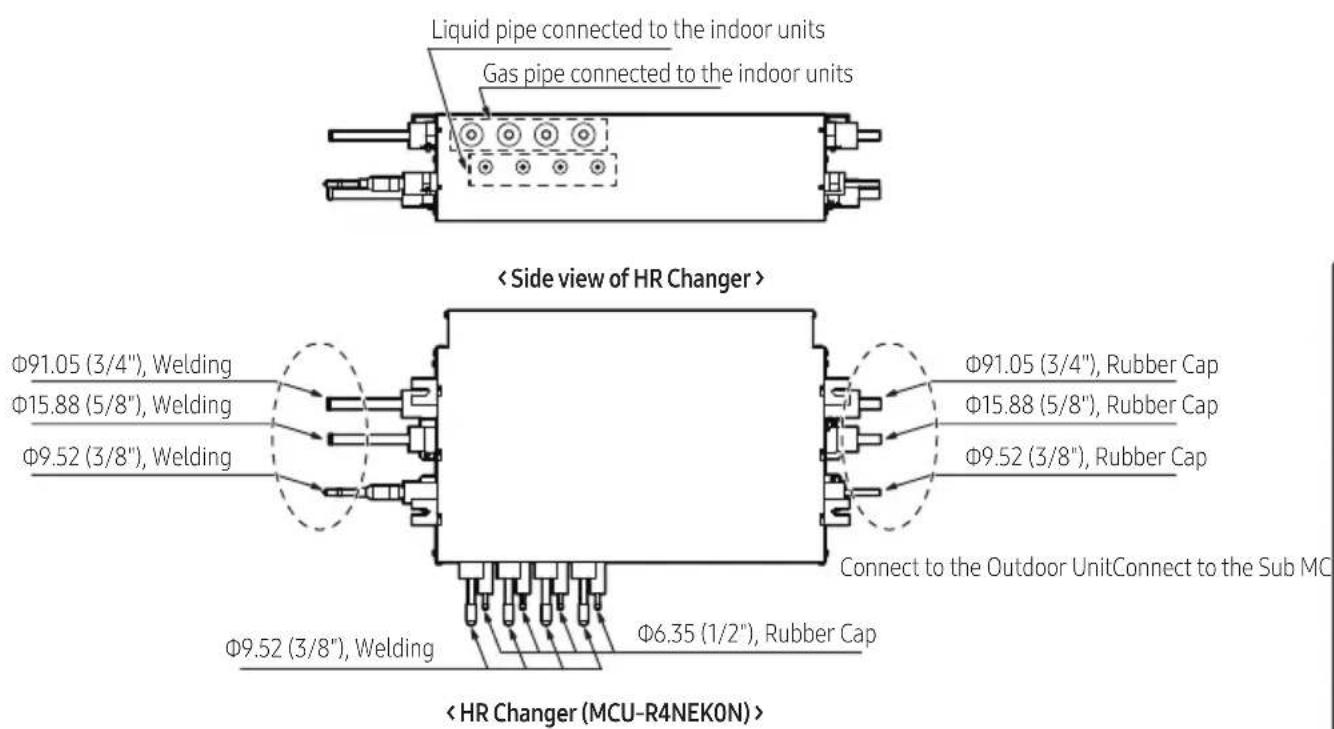
Liquid pipe connected to the indoor units Gas pipe connected to the indoor units < Side view of HR Changer > Φ91.05 (3/4"), Welding Φ15.88 (5/8"), Welding Φ9.52 (3/8"), Welding Φ9.52 (3/8"), Welding Φ6.35 (1/2"), Rubber Cap Φ91.05 (3/4"), Rubber Cap Φ15.88 (5/8"), Rubber Cap Φ9.52 (3/8"), Rubber Cap Connect to the Outdoor UnitConnect to the Sub MCU-R4NEKON> < HR Changer (MCU-R4NEKON ) >Space requirements
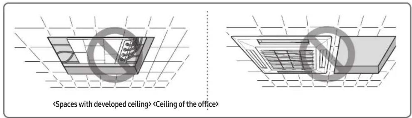
- Since refrigerant noise can be generated during the HR Changer operation, do not install the unit on the ceiling of the places that requires silence such as bedrooms, libraries, hospitals and offices etc.
- Do not install the HR Changer in the ceiling of the living area. Otherwise, noise generated from the HR Changer may disturb people in that area and cause inconvenience.
text_image
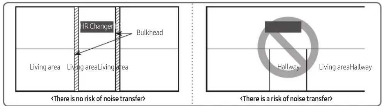
- It is normally recommended to install HR Changer in a hallway but a bulkhead should be installed to minimize the noise from being transferred to living area. (Refer to the below figure)
flowchart
graph TD
    A["HR Change"] --> B["Bulkhead"]
    C["Living area"] --> D["Living areaLiving area"]
    E["<There is no risk of noise transfer>"] --> F["<There is a risk of noise transfer>"]
    G["Hallway"] --> H["<There is a risk of noise transfer>"]
    I["Living areaHallway"] --> J["<There is a risk of noise transfer>"]
※ Soundproof and soundproofing materials
The place where HR Changer is installed and the interior walls should have a high soundproof ability. (Bricks, Concretes, Cement)
The ceiling where HR Changer is installed should be coated with quality Tex that has a good soundproof function.
▶ Minimize the size of the hole between the walls and the pipe connection. After the installation, block the gap to prevent noise from leaking.
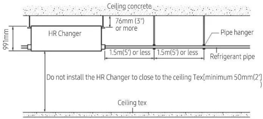
- Secure over 0.25m(0.82') of space when HR Changer is being fixed to the concrete of the ceiling.
- HR Changer may generate noise so don't install it too close to the ceiling Tex.
- Each pipe hanger should be placed at 1.5m(4.92') interval to support its weight firmly. If the pipe or the hanger isn't fixed firmly, the unit may fall and cause a property damage or loss of life.
- When 'Low temperature cooling range expansion' option is set for constant cooling operation throughout the year, noise of the HR Changer may get louder during winter time. Therefore, above installation conditions must be complied.
- Select the place where HR Changer supporting structure can support the weight of the indoor unit and have strong vibration resistance without any slope.
(If the structure is not strong enough, HR Changer may fall down and break, which can cause injury to your body.)
text_image
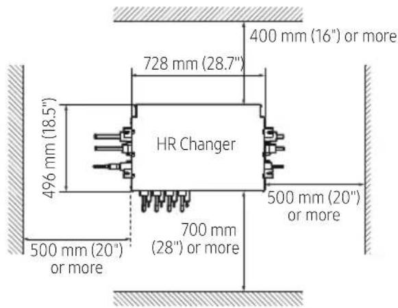
Ceiling concrete 76mm (3") or more 991mm HR Changer Pipe hanger 1.5m(5') or less 1.5m(5') or less Refrigerant pipe Do not install the HR Changer to close to the ceiling Tex[minimum 50mm(2')] Ceiling tex- Select a place with enough space for repairing and services. (Leave enough space between sidewalls in installation.-refer to the picture below)
text_image
400 mm (16") or more 728 mm (28.7") HR Changer 496 mm (18.5") 500 mm (20") or more 700 mm (28") or more 500 mm (20") or more- HR Changer specification
| Classification Unit HR Changer | ||
| Model name - MCU-R4NEKON | ||
| The exterior - | 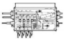 | |
| The number of branches | EA 4 | |
| The maximum number of the connectable indoor unit per branch | EA | 3 |
| The maximum capacity of the connectable indoor unit per branch | kW 5.6 | |
| The maximum capacity of connectable indoor units per branch (Using Y-Joint) | kW 14 | |
| The maximum capacity of connectable indoor units kW 22.4 | ||
| Internal EEV - | Not includedCannot connect indoor unit without internal EEV |
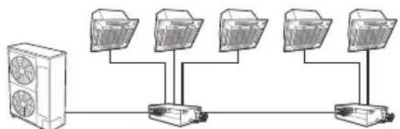
- Installing the indoor unis
flowchart
graph LR
    A["Central Device"] --> B["Computer 1"]
    A --> C["Computer 2"]
    A --> D["Computer 3"]
    A --> E["Computer 4"]
    A --> F["External Device"]
HR Changer MCU
flowchart
graph LR
    A["Fan Unit"] --> B["HR Change"]
    B --> C["Monitor 1"]
    B --> D["Monitor 2"]
    B --> E["Monitor 3"]
    B --> F["Monitor 4"]
    B --> G["Monitor 5"]
If the capacity of the indoor unit is under 5.6kW, don't use Y-connector.
If the capacity of the indoor unit is between 5.6 kW and 14.0 kW, use Y-connector for the gas and liquid line.
In case of using Y-connector, it is only connectable for port combination as the followings;
- Cconnectable port combination for Y-connector : A + B port, C + D port, E + F port
- Non-connectable port combination for Y-connector : B + C port, D + E port, non-continuous port
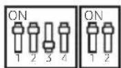
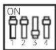
Set Dip Switch option for using Y-connector
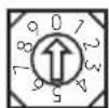
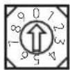
MCU address swich
DIP switch
A B C D E F
S/W Option DIP switch
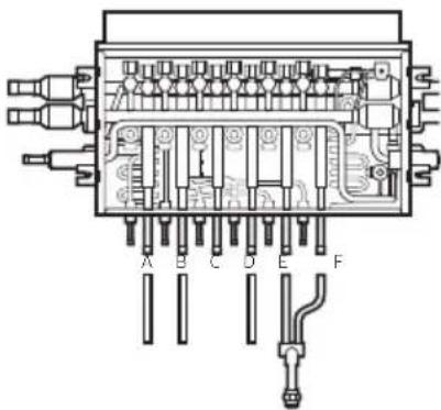
text_image
A B C D E FS/W Option S/W Option S/W Option S/W Option
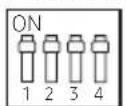
Default
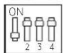
Combination of A+B port

Combination of C+D port
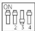
Combination of E+F port
- Preparation before installation.
1) Place the pattern sheet on the ceiling at the spot where you want to install the indoor unit.

- Since the diagram is made of paper, it may shrink or stretch slightly due to temperature or humidity. For this reason, before drilling the holes maintain the correct dimensions between the markings.
2) Insert bolt anchors, use existing ceiling supports or construct a suitable support as shown in figure.
3) Install the suspension bolts depending on the ceiling type.

- Ensure that the ceiling is strong enough to support the weight of the indoor unit. Before hanging the unit, test the strength of each attached suspension bolt.
- If the length of suspension bolt is more than 1.5m(4.92'), it is required to prevent vibration.
- If this is not possible, create an opening on the false ceiling in order to be able to use it to perform the required operations on the indoor unit.

text_image
Concrete Insert Hole in anchor Hole in plug Suspension bolt(3/8" or M10)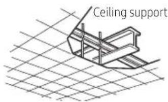
text_image
Ceiling support- Cautions about HR Changer installation.
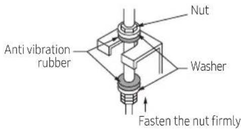
When fixing the unit at the upper place using suspension bolts, use a nut and washer to vertically fasten the unit.
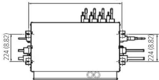
There are four spots to fix the suspension bolts. Make sure every spot is fixed.
The upper and the lower side of HR Changer is distinguished, so be careful not to turn the unit upside down when installing the unit. Otherwise, noise may be generated or the product may be damaged.
764 (30.08) (Between the locations of suspension bolts)
text_image
224 (8.82) 224 (8.82)Unit: mm (inch)
text_image
Anti vibration rubber Nut Washer Fasten the nut firmly5. How to connect the pipe line.
text_image
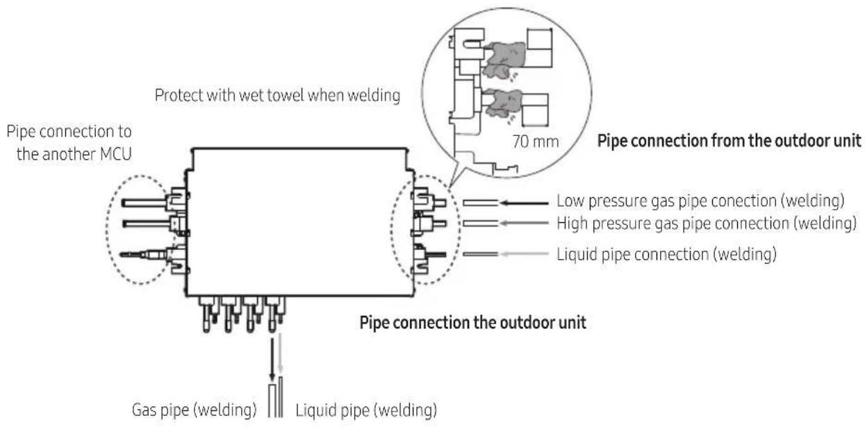
Pipe connection to the another MCU Protect with wet towel when welding 70 mm Pipe connection from the outdoor unit Low pressure gas pipe connection (welding) High pressure gas pipe connection (welding) Liquid pipe connection (welding) Pipe connection the outdoor unit Gas pipe (welding) Liquid pipe (welding)When installing HR Changer, use the pattern sheet for installation that is provided with the product. When welding the gas pipes, protect the product with the flame-proof sheet.

- When connecting the HR Changer with outdoor units, be attention to the direction. Please connect the pipes to the HR Changer referring to the label with the direction of connection on the HR Changer.

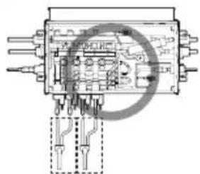
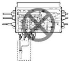
6. How to connet Y-connector
In case of connecting one indoor with Y-Connector to HR Changer, Y-Connector must be connected in series.
natural_image
Pure electrical circuit lines without any symbolsIndoor #1 Indoor #2
text_image
Electrical component diagram with no visible text or symbols, including a prohibition symbol overlay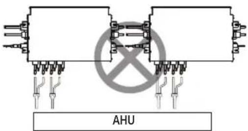
text_image
AHUMethod and cautions on brazing the pipe
Keeping refrigerant pipe clean and dry
To prevent foreign materials or water from entering the pipe, it is important to keep the refrigerant pipe clean, dry and sealed during installation.
| Exposure place Exposure time Sealing type | ||
| Outside exposure | Longer than one month Pipe pinch | |
| Shorter than one month Taping | ||
| Inside exposure - Taping | ||
Brazing the pipe
▶ Make sure that there is no moisture inside the pipe.
▶ Make sure that there are no foreign materials and impurities in the pipe.
▶ Make sure that there is no leak.
▶ Make sure to follow the instruction when brazing the pipe.
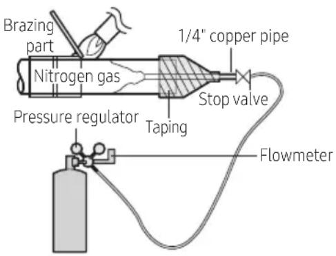
The use of Nitrogen gas
- Use Nitrogen gas when brazing the pipes as shown in the picture.
- If you don't use Nitrogen gas when brazing the pipes, oxide may form inside the pipe. It can cause the damage of the compressor and valves.
- Adjust the flow rate of the nitrogen gas with a pressure regulator to maintain 0.05 m^3/h 1.77 ft^3/h or less.
Direction of the pipe when brazing
- Performing the brazing of the pipe should be headed downwards or horizontally.
text_image
Brazing part Nitrogen gas Pressure regulator Taping 1/4" copper pipe Stop valve FlowmeterMethod and cautions on refrigerant pipe insulation
Make sure to check for gas leakage before completing the installation (hose and pipe insulation) and insulate hoses and pipes when there is no sign of leakage.
- To avoid condensation problems, place T13.0(1/2") or thicker Acrylonitrile Butadien Rubber separately around each refrigerant pipe.

• Always make the seam of pipes face upwards.
- Wind insulating tape around the pipes and drain hose avoiding to compress the insulation too much.
- Finish wrapping insulating tape around the rest of the pipes leading to the outdoor unit.
- The pipes and electrical cables connecting the indoor unit with the outdoor unit must be fixed to the wall with suitable ducts.

- All refrigerant connection must be accessible, in order to permit either unit maintenance or removing it completely.

text_image
Insulation cover pipe Insulation pipe Indoor unit Be sure to overlap the insulation
- Must fit tightly against body without any gap.

- Select the insulation of the refrigerant pipe.
▶ Insulate the gas side and liquid side pipe referring to the thickness according to the pipe size.
Indoor temperature of 30^ C(86°F) and humidity of 85% is the standard condition. If install in a high humidity condition, use one grade thicker insulator by referring to the table below. If installing in an unfavorable conditions, use thicker one.
Insulator's heat-resistance temperature should be more than 120°C(248°F).
| Pipe | Outer diameter | Insulator (Cooling, Heating) | Remarks | ||||
| General[30°C (86°F), 85%] | High humidity[30°C (86°F), over 85%] | ||||||
| EPDM, NBR | |||||||
| mm inch | mm inch mm inch | ||||||
| Liquid pipe | 6.35~9.52 | 1/4~3/89 | 3/89 | 3/8 | Heating resisting temperature over 120°C (248°F) | ||
| 12.70~50.80 | 1/2~2 | 13 | 1/2 | 13 | 1/2 | ||
| Gas Pipe | 6.35 | 1/4 | 13 | 1/2 | 91 | 3/4 | |
| 9.52~25.4 | 3/8~1 | 19 | 3/4 | 25 | 1 | ||
| 28.58~44.45 | 11/8~13/4 | 91 | 3/4 | 32 | 11/4 | ||
| 50.80 | 2 | 25 | 1 | 38 | 11/2 | ||
Refrigerant pipe before EEV kit and HR Changer or without EEV kit and HR Changer
▶ You can contact the gas side and liquid side pipes but the pipes should not be pressed.
When contacting the gas side and gas side pipe, use 1 grade thicker insulator.
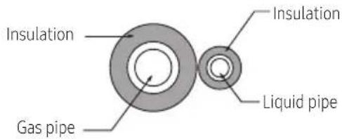
text_image
Insulation Gas pipe Insulation Liquid pipeRefrigerant pipe after EEV kit and HR Changer
▶ Install the gas side and liquid side pipes, leave 10mm(3/8") of space.
When contacting the gas side and liquid side pipe, use 1 grade thicker insulation.
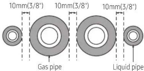
text_image
10mm(3/8") 10mm(3/8") 10mm(3/8") Gas pipe Liquid pipe
- Install the insulation not to get wider and use the adhesives on the connection part of it to prevent moisture from entering.
- Wind the refrigerant pipe with insulation tape if it is exposed to outside sunlight.
• Install the refrigerant pipe respecting that the insulation does not get thinner on the bent part or hanger of pipe. - Add the additional insulation if the insulation plate gets thinner.

text_image
Hanger insulation a a×3 Refrigerant pipe insulation
Installing the circuit breaker and wires
| Power supply M | MCCB ELB Power cable Earth cable Communication cable | ||||
| Max : 242VMin : 918V | XA | XA, 30mmA0.1 sec | 0.0093inch2(2.5mm2) | 0.0093inch2(2.5mm2) | 0.0012~0.0023inch2(0.75~1.5mm2) |
Installing the wire
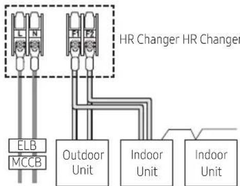
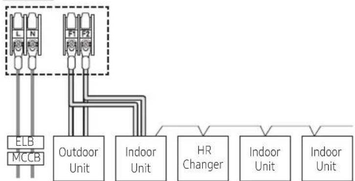
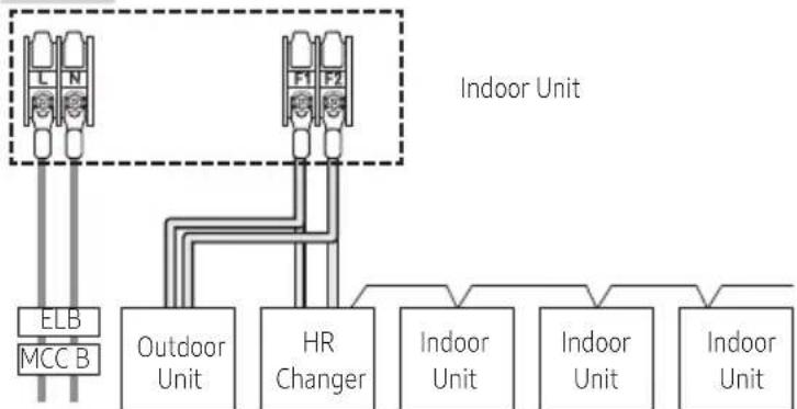
▶ Supply the 220-240V/208-230V power to L1, L2 (L, N) of HR Changer separately
▶ Connect the communication cable from the outdoor unit to F1, F2 of HR Changer.
▶ Power Line and communication line must be connected as shown in drawing.
Case 1 Case 2
flowchart
graph TD
    A["ELB"] --> B["MCCB"]
    C["Outdoor Unit"] --> D["F1"]
    C --> E["F2"]
    F["Indoor Unit"] --> G["Indoor Unit"]
    H["HR Changer HR Changer"] --> I["HR Changer HR Changer"]
220-240V/208-230V / Single Phase (Supply separately)
flowchart
graph TD
    A["ELB"] --> B["MCCB"]
    C["Outdoor Unit"] --> D["Indoor Unit"]
    E["HR Changer"] --> F["Indoor Unit"]
    G["Indoor Unit"] --> H["Indoor Unit"]
220-240V/208-230V / Single Phase (Supply separately)
Case 3
flowchart
graph TD
    A["ELB MCC B"] --> B["Outdoor Unit"]
    C["F1 F2"] --> D["HR Changer"]
    B --> E["Indoor Unit"]
    D --> F["Indoor Unit"]
    E --> G["Indoor Unit"]
    F --> H["Indoor Unit"]
220-240V/208-230V / Single Phase (Supply separately)
▶ Power Line and communication line must be installed as shown in drawing
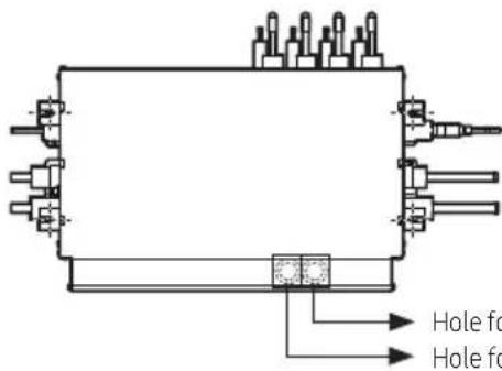
▶ Hole size is 43.7 mm
text_image
Hole for Hole forHole for communication
Hole for HR Changer main power supply
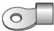
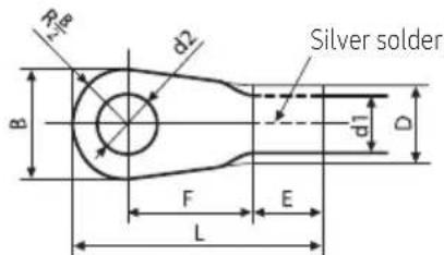
▶ Choose the compressed socket based on the cross-section of the connecting wire.
text_image
R d2 Silver solder B d1 D F E L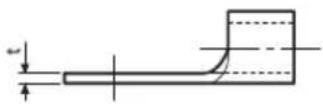
| Nominal dimensions for cable [mm2 (inch2)] | 1.5 (0.002) | 2.5 (0.003) | 4 (0.006) | ||
| Nominal dimensions for screw [mm (inch)] | 4 (0.157) | 4 (0.157) | 4 (0.157) | 4 (0.157) | |
| B | Standard dimension [mm (inch)] | 6.6 (0.295) | 8 (0.314) | 6.6 (0.295) | 8.5 (0.334) |
| Allowance [mm (inch)] | ±0.2 (0.007) | ±0.2 (0.007) | ±0.2 (0.007) | ||
| D | Standard dimension [mm (inch)] | 3.4 (0.134) | 4.2 (0.165) | 5.6 (0.220) | |
| Allowance [mm (inch)] | +0.3 (0.011) | +0.3 (0.011) | +0.3 (0.011) | ||
| -0.2 (-0.007) | -0.2 (-0.007) | -0.2 (-0.007) | |||
| d1 | Standard dimension [mm (inch)] | 1.7 (0.066) | 2.3 (0.900) | 3.4 (0.133) | |
| Allowance [mm (inch)] | +0.2 (±0.007) | +0.2 (±0.007) | +0.2 (±0.007) | ||
| 0 | 0 | 0 | |||
| E | Min. [mm (inch)] | 4.1 (0.161) | 6 (0.236) | 6 (0.236) | |
| F | Min. [mm (inch)] | 6 (0.236) | 6 (0.236) | 5 (0.916) | |
| L | Max. [mm (inch)] | 16 (0.692) | 17.5 (0.688) | 20 (0.787) | |
| d2 | Standard dimension [mm (inch)] | 4.3 (0.196) | 4.3 (0.196) | 4.3 (0.196) | |
| Allowance [mm (inch)] | +0.2 (±0.007) | +0.2 (±0.007) | +0.2 (±0.007) | ||
| 0 | 0 | 0 | |||
| t | Min. [mm (inch)] | 0.7 (0.027) | 0.8 (0.031) | 0.9 (0.035) | |
Setting HR Changer address and port
| Process | ||||||||||||
| 1. HR Changer address setting | Set HR Changer address by rotary switch.Example> If you want to set HR Changer address to 21, set upside rotary switch to 2 and set bottom rotary switch to 1HR Changer Address HR Changer Address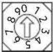 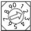 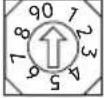 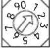 Default Setting HR Changer adress to 21 Rotary switch for HR Changer ADDRESS Default Setting HR Changer adress to 21 Rotary switch for HR Changer ADDRESS 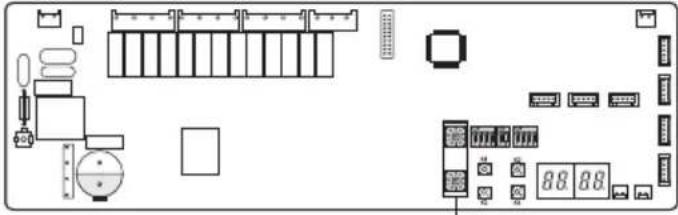 | |||||||||||
| 2. DIP switch setting for using each port | Set using each port (connected to indoor unit) by DIP switchExample> If you want to connect indoor units at A,B,C,F port, set DIP switch 1,2,3,2 to 'ON'DIP S/W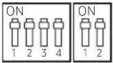 Default Default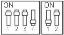 Using A, B, C, F port Using A, B, C, F port 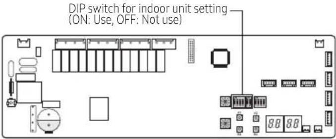 | |||||||||||
| 3. DIP switch setting for using Y-connector | In case of using Y-connector to connect 2 port, Set DIP Switch S/W optionExample> If you want to connect A port and B port with Y-connector, set DIP switch 1 to 'ON'S/W Option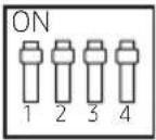 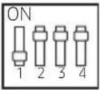 Default Combination of A+B port Default Combination of A+B port 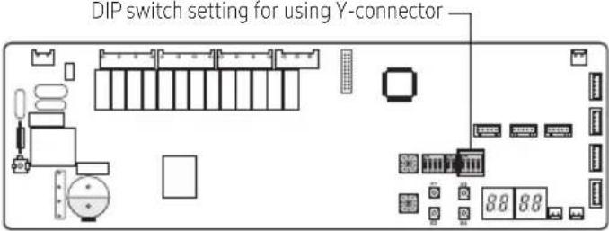 | |||||||||||
| 4. HR Changer address and port setting for indoor unit | Auto setting : refer to 'auto pipe pairing' Manual setting : 1. Wireless remote controller 1) Enter mode to set option 2) Assign an indoor unit HR Changer port address by wireless remote controller - The initial setting status of indoor unit ADDRESS(MAIN/RMC/HR Changer port) is "0A0000-100000-200000-300000" | |||||||||||
| Option | SEG1 | SEG2 | SEG3 | SEG4 | SEG5 | SEG6 | ||||||
| Explanation | PAGE | Mode | Setting Main address | 100-digit of indoor unit address | 10-digit of indoor unit | |||||||
| Remote Controller Display | an Auto | an Auto | an Cool | an Cool | ||||||||
| Indication and Details | Indication | Details | Indication | Details | Indication | Details | Indication | Details | Indication | Details | ||
| 0 | A | Address setting mode | 0 | No Main address | 0~9 | 100-digit | 0~9 | 10-digit | 0~9 | |||
| 1 | Main address setting mode | |||||||||||
| Option | SEG7 | SEG8 | SEG9 | SEG10 | SEG11 | SEG12 | ||||||
| Explanation | PAGE | - | Setting RMC address | - | Group channel(*16) | |||||||
| Remote Controller Display | 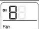 | 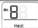 | ||||||||||
| Indication and Details | Indication | Details | Indication | Details | Indication | Details | ||||||
| 1 | 0 | No RMC address | RMC1 | 0~F | ||||||||
| 1 | RMC address setting mode | |||||||||||
| Option | SEG13 | SEG14 | SEG15 | SEG16 | SEG17 | |||||||
| Explanation | PAGE | - | Setting HR Changer PORT address | 10-digit of HR Changer | The unit digit of HR Changer | |||||||
| Remote Controller Display | 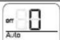 | 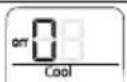 | 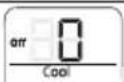 | |||||||||
| Indication and Details | Indication | Details | Indication | Details | Indication | Details | Indication | Details | ||||
| 0 | No HR Changer port address | 0~1 | 10-digit | 0~9 | A unit digit | |||||||
| 1 | HR Changer port address setting mode | A~F | ||||||||||
| Example> If you want to set the indoor unit to 'A' port of HR Changer #1. 0A0000 - 100000 - 20101A -30000 | ||||||||||||
-
HR Changer address and port setting for indoor unit
-
Wireled remote controller
- Setting for MWR-WE11N
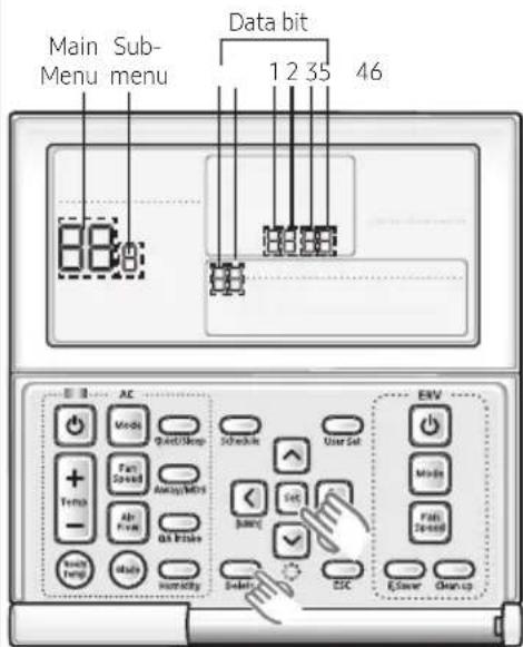
1) Press the Delete and Set buttons at the same time for more than three seconds. Then you will enter the additional function settings, and the [main menu] will be displayed.
2) Assign an indoor unit HR Changer port address with main menu 4, sub menu 7 (HR Changer address is assigned to SEG 12, Port address is assigned to SEG 4) If you want to know the detailed operation of MWR-WE11N, refer to installation manual for MWR-WE11N
text_image
Main Sub- Menu menu Data bit 1 2 35 46 88:0 AC Mode Fast/Stop Schedule User Set + Fast Speed + Air Flow + Air Brake + Active Power + Active Humidity Set Junction ESC ENV Multi Fail Control E-Stop Clean-up| Main menu | Sub menu | Function | Setting value | ||
| Description | Factory default | ||||
| 4 | 1 | Indoor unit/Ventilator(ERV) option setting | Setting/Checking the address | MAIN address (00H~4FH) | None |
| 2 | Setting/Checking the product option | MAIN address (00H~4FH) | None | ||
| 3 | Setting/Checking the installation option 1 | Refer to the installation manual of the connected indoor unit/ventilator (ERV) | None | ||
| 4 | Setting/Checking the installation option 2 | None | |||
| 7 | HR Changer address setting/checking Port address setting/checking | HR Changer address (00~15) Port address (A~F) | None | ||
- Setting for MWR-SH10N
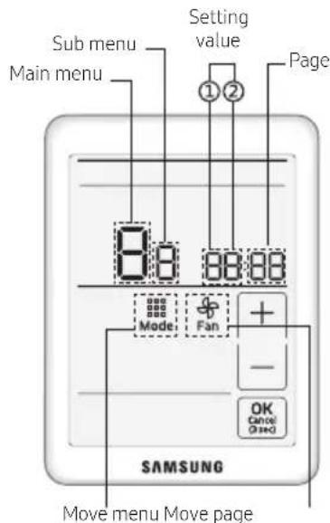
1) Press the top right corner hidden button) of the display for more than 3 seconds and drop it. Then you can press [ + ]/[- -] buttons and select No.3 and press [ OK ] button.
2) Assign an indoor unit HR Changer port address with main menu 4, sub menu 7 (HR Changer address is assigned to SEG 12, Port address is assigned to SEG 4). If you want to know the detailed operation of MWR-SH10N, refer to installation manual for MWR-SH10N
text_image
Sub menu Main menu Setting value ①② Page 8:8 88:88 Mode Fan + - OK Cancel Closed SAMSUNG Move menu Move page| Main menu | Sub menu | Function | Setting value | ||
| value | Factory default | ||||
| 4 | 1 | Setting address/option | Target address setting | Target address of indoor unit (Example: 20 02 1F) | None |
| 2 | Main address setting/Checking | 0~4F(in hexadecimal digits) | |||
| 3 | RMC address setting/Checking | 0x00~0xFE | None | ||
| 4 | Basic option setting/Checking | Option code | |||
| 5 | Install option setting/Checking | Option code None | |||
| 6 | Install(2) option setting/Checking | Option code None | |||
| 7 | HR Changer address setting/checkingPort address setting/checking | HR Changer address (00~15)Port address (A~F) | None | ||
- Setting by using S-NET Pro 2
Set the pipe addresses by using Add-on > Change address on S-NET Pro 2. (For more information, see the S-NET Pro 2 Help.)

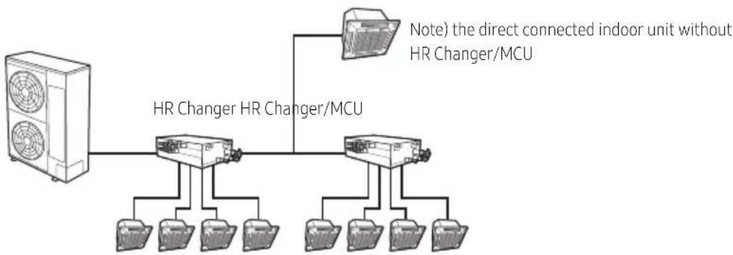
- The Direct-connected indoor unit without HR Changer like below picture, be sure to set their options to "Cooling only unit setting" and then connect them to a low pressure gas pipe and a liquid pipe. This indoor unit only operate to cooling mode.
flowchart
graph TD
    A["HVAC"] --> B["HR Changer"]
    B --> C["HR Changer/MCU"]
    B --> D["Note) the direct connected indoor unit without HR Changer/MCU"]
    B --> E["Output"]
    B --> F["Output"]
    B --> G["Output"]
Set to Cooling Only Unit
- Check whether power is supplied or not.
- When the indoor unit is not plugged in, there should be additional power supply in the indoor unit.
-
The panel(display) should be connected to an indoor unit to receive option.
-
Enter mode to set option (※ Detail method of entering option mode refer to indoor unit installation manual)
-
Set the 05 series installation option at SEG3 to '2' like this '050200 - 100000 - 20000 - 30000'.
(The default setting of an indoor unit 05 series installation is '050000 - 100000 - 20000 - 30000')

- When setting the "Cooling only unit" option, be sure to set the SEG 9 Hot water heater) of 02 Series installation to "0".
- When "Cooling only unit" option is set, heating operation is not performed when the controller (wireless remote controller, central controller) is set to the heating mode.

text_image
Display HR Changer status K1 K2 Display indoor unit's address K3 K4 EEV valve passive control| K1(Pushed time) | Display Contents | Display segment | Remarks | |||
| 1 | 2 | 3 | 4 | |||
| 1 HR Changer address 0 | Blank 0 0 HR Changer address 0 | |||||
| Blank 0 1 HR Changer address 1 | ||||||
| Blank 0 2 HR Changer address 2 | ||||||
| Blank 1 1 HR Changer address 11 | ||||||
| Blank 1 5 HR Changer address 15 | ||||||
| 2 | Mode switching EEV1 step | 1 | 4 | 8 | 0 | Ex) 480 steps |
| 3 Mode switching EEV2 step 2 4 8 | 0 | Ex) 480 steps | ||||
| 4 | Mode switching EEV3 step | 3 | 4 | 8 | 0 | Ex) 480 steps |
| 5 Mode switching EEV4 step 4 4 8 | 0 | Ex) 480 steps | ||||
| 6 | Mode switching EEV5 step | 5 | 4 | 8 | 0 | Ex) 480 steps |
| 7 | Mode switching EEV6 step | 6 | 4 | 8 | 0 | Ex) 480 steps |
| 8 | Subcooler EEV step | 7 | 4 | 8 | 0 | Ex) 480 steps |
| 9 Subcooler-in sensor temperature 8 | - | 0 | 1 | Ex) -1°C | ||
| Blank 1 0 Ex) 10°C | ||||||
| 10 | Subcooler-out sensor temperature | 9 | - | 0 | 1 | Ex) -1°C |
| Blank 1 0 Ex) 10°C | ||||||
| 11 | On/Off for solenoid valve A_C, A_H | A | - | * _C: Cooling solenid valve of port * | ||
| 12 | On/Off for solenoid valve B_C, B_H | B | * _H: Heating solenid valve of port * | |||
| 13 | On/Off for solenoid valve C_C, C_H | C | 3rd segment: Cooling solenid valve On: 1 / Off: 0 | |||
| 14 | On/Off for solenoid valve D_C, D_H | D | 4th segment: Heating solenoid valve On: 1 / Off: 0 | |||
| 15 | On/Off for solenoid valve E_C, E_H | E | ||||
| 16 | On/Off for solenoid valve F_C, F_H | F | ||||
| 17 | On/Off for liquid by pass solenoid valve | G | Blank 0 N Ex) On | |||
| 0 F F Ex) Off | ||||||
| 18 | Version | 8 | A | 2 | 0 | Ex) October 20, 2008 → 8A 20 |
| 91 | End of K1 display | |||||
| K2(Pushed time) | Display Contents | Display segment | Remarks | |||
| 1 | 2 | 3 | 4 | |||
| 1 | Indoor unit main address for matching with port A | A | - | 0 | 0 | Indoor unit main address of port A: 0 |
| 2 | Indoor unit main address for matching with port B | B | - | 0 | 3 | Indoor unit main address of port B: 3 |
| 3 | Indoor unit main address for matching with port C | C | - | 0 | 6 | Indoor unit main address of port C: 6 |
| 4 | Indoor unit main address for matching with port D | D | - | 0 | 9 | Indoor unit main address of port D: 9 |
| 5 | Indoor unit main address for matching with port E | E | - | 1 | 1 | Indoor unit main address of port E: 11 |
| 6 | Indoor unit main address for matching with port F | F | - | 1 | 5 | Indoor unit main address of port F: 15 |
| 7 End of K2 display | ||||||
K4 Switch (Electronic Valve Manual Control)
According to the push time of K4 Switch, A_C, A_H, ..., F_C, F_H, Liquid bypass solenoid valve opens in order.
In Electronic Valve Manual Control mode, valve operates by K4 Push time irrespective of indoor operation mode.
In Electronic Valve Manual Control mode, push K1 Switch makes DATA DISPLAY MODE to start and valves will operate following indoor operation mode.
| K4(Push time) | Display Contents | Display segment | ||||
| 1 | 2 | 3 | 4 | |||
| 1 A_C sol valve ON, other sol valve Off P A | 1 | 0 | ||||
| 2 A_H sol valve ON, other sol valve Off P A | 0 | 1 | ||||
| 3 B_C sol valve ON, other sol valve Off P B | 1 | 0 | ||||
| 4 B_H sol valve ON, other sol valve Off P B | 0 | 1 | ||||
| 5 C_C sol valve ON, other sol valve Off P C | 1 | 0 | ||||
| 6 C_H sol valve ON, other sol valve Off P C | 0 | 1 | ||||
| 7 D_C sol valve ON, other sol valve Off P D | 1 | 0 | ||||
| 8 D_H sol valve ON, other sol valve Off P D | 0 | 1 | ||||
| 9 | E_C sol valve ON, other sol valve Off | P | E | 1 | 0 | |
| 10 | E_H sol valve ON, other sol valve Off | P | E | 0 | 1 | |
| 11 | F_C sol valve ON, other sol valve Off | P | F | 1 | 0 | |
| 12 | F_H sol valve ON, other sol valve Off | P | F | 0 | 1 | |
| 13 Liquid b/p sol valve ON, other sol valve Off | P | S | 1 | 0 | ||
| 14 | sol valve Manual Control MODE end | P | Communication DATA Display | |||
※ After installing HR Changer, check those items below. If you find something unfulfilled, refer to the manual to complete it.
| Item Check | |
| 1. If the gas leaking test has been completed or not. | |
| 2. If HR Changer has been fixed securely enough to avoid the danger of vibration and falling or not. | |
| 3. The Insulation condition of the pipe. (Refrigerant pipe, Pipe connection.) | |
| 4. If the R-410A refrigerant has been charged or not.If the subsidiary unit for R-410A has been used or not. | |
| 5. Checking malfunction of the wire and the communication line. | |
| 6. If the HR Changer frame has been installed upside-down or not. | |
| 7. If the wire earthing work has been done or not. | |
| 8. If the space between sidewalls, ceiling concrete, and the ceiling Tex has been secured enough or not to install the HR Changer frame. | |
| 9. If the supporting tool of the HR Changer pipe has been safely placed in 1.5m intervals or not. | |
| 10. If the prescribed wire has been used or not. | |
| 11. If the supplied power is proper or not. | |
| 12. If the additional refrigerant is proper or not.(Refer to the installation manual of the HR outdoor unit.) |