
MIM-D00 - Air-conditioner SAMSUNG - Free user manual and instructions
Find the device manual for free MIM-D00 SAMSUNG in PDF.


User questions about MIM-D00 SAMSUNG
0 question about this device. Answer the ones you know or ask your own.
Ask a new question about this device
Download the instructions for your Air-conditioner in PDF format for free! Find your manual MIM-D00 - SAMSUNG and take your electronic device back in hand. On this page are published all the documents necessary for the use of your device. MIM-D00 by SAMSUNG.
USER MANUAL MIM-D00 SAMSUNG
natural_image
Abstract geometric design with a white rectangular shape and a dotted pattern, no text or symbols present.Safety Precautions
- Before using the DMS, read carefully these instructions.
- After reading the instructions, keep this user's manual in a handy and safe place. If a user is changed, you must hand over the manuals.
- Never attempt to install the air conditioning system or to move the DMS by yourself.

WARNING
◆ Do not attempt to install or repair this DMS by yourself.
◆ This DMS contains no user-serviceable parts.
Always consult authorized service personnel for repairs.
When moving, consult authorized service personnel for disconnection and installation of the DMS.
◆ Ensure that the wall is strong enough to support the weight of the DMS.
◆ Must install the DMS with rated power supply.
◆ In the event of a malfunction (burning smell, etc.), immediately stop operation, turn off the electrical breaker, and consult authorized service personnel.

CAUTION
◆ Do not use inflammable gases near the DMS.
◆ Do not spill water into the DMS.
◆ Do not operate the DMS with wet hands.
Do not install the DMS in a location where it will come into contact with the combustible gases, machine oil, sulphide gas, etc.
◆ Do not press buttons with a pointed thing.
◆ Do not pull or bend the DMS cable excessively.
◆ Do not use this DMS for other purpose.
- Do not spray an insecticide or other combustible things on the DMS.
Do not clean the DMS with benzene, solvents or other chemicals.
- Do not give a shock to the DMS or disassemble it by yourself.
Contents
General Description
◆ INTRODUCTION OF DMS 4
◆ ADVANTAGES OF DMS SYSTEM 4
◆ TERMS 5
Main Function
◆ INTERFACE WITH UPPER LEVEL CONTROLLER 6
♦ SAVE ERROR HISTORY 6
◆ SET AND RUN SCHEDULE 7
♦ SAVE INTEGRATED POWER DISTRIBUTION DATA 8
■ Overview 8
■ System Architecture 8
■ Time Segmentation 9
Using the DMS through the Web
♦ SETTING THE WEB ENVIRONMENT ....10
◆ USING THE DMS THROUGH THE WEB 10
■ Login 11
■ Monitoring and Control ....12
■ Monitoring and Control (ERV System) ......16
■ View Error History ......20
■ Set, Run and View Schedule ......21
■ Setting and Viewing the Power Distribution Function.....24
■ Setting and Viewing the Power Distribution Environment...26
■ Inquire Power Distribution Result ......29
■ Viewing Power Distribution Result ....31
■ Setting the Indoor Unit Restriction ....33
■ Setting and Viewing the System Environment ....37
■ Log 41
■ Tracking ....42
■ User Management ....47
Software
◆ SOFTWARE LICENSE USED IN THIS PRODUCT ....50
INTRODUCTION OF DMS (DATA MANAGEMENT SERVER)
The DMS is an Internet based device for central management of Samsung system air-conditioners. It supports LAN & WAN and operates 24 hours without a separate PC.
ADVANTAGES OF DMS SYSTEM
The DMS provides the following advantages:
◆ Everyday Device –The DMS is operational all year long 24 hours.
◆ Independent Operation–The DMS can operate schedule control, peak power control, and power distribution without a PC.

In order to run peak power control and power distribution, relevant controllers need to be installed.
- Internet Control
Web – The DMS has a built-in web server function and can be accessed from a remote location to operate status monitoring, control, error history, and schedule setting of the system air-conditioners.
√ Using an Upper Level Controller—When a separate upper level controller (S-NET series) is used, a number of DMS can be controlled with one central management system.
◆ Data Storage –The DMS has its own database built-in, therefore, error history, indoor unit installation information, and power distribution data can be saved and retrieved.
◆ Large Scale Management—At most 256 indoor units can be connected to one DMS and therefore, only one DMS can manage small and medium size buildings.
◆ Automatic "e-mail" sending–When an error is occurred, inform the error details to an e-mail saved on DMS.
TERMS
DMS
The abbreviation of Data Management Server.
■ UPPER CONTROLLER
It means S-NET Series, a local controller of the DVM system. S-NET 3, S-NET mini and S-NET i are linked to a DMS.
CENTRALIZED CONTROLLER
A device that controls 16 groups of the DVM air conditioner. A central control device of a DVM system which is located between a DMS and an outdoor unit transmitter.
TRANSMITTER
A data transmitter of a DVM system which is located between a central controller and an outdoor unit.
SIM
The Abbreviation of Signal input Module. A device that transmits power usage of an outdoor unit by being inputted it from a watt-hour meter to a DMS.
Interface with Upper Level Controller
The DMS receives control data from the upper level controller and sends the received data to the lower level system.
The upper level controllers of the DMS are the S-NET series and the connectible S-NET series are S-NET 3, S-NET i and S-NET mini. S-NET 3 is a program that is used by installing on a PC: S-NET mini and S-NET i are touch screen type controllers.
Save Error History
The DMS saves at most 256 cases of error history. If the number of errors exceeds 256, only the latest 256 cases are stored by deleting the oldest error history. The following errors can be detected by the DMS:
| Device | Type |
| Indoor Unit | Indoor unit communication errorIndoor unit sensor related errorOther errors |
| Outdoor Unit | Outdoor unit communication errorPipe inspection errorOutdoor unit sensor related errorOutdoor unit related other errors |
| Solution Products such as the Centralized Controller | Solution device related communication error |
※ Device name, address, time when error occurred, time when error was fixed, and error contents are saved on error history.
The error history can be viewed through the Web or the connected upper level controller.
* When an error is occurred, inform the error details to an e-mail saved on DMS.
Set and Run Schedule
The schedule function of the DMS can be set through the Web or using the upper level controller.
Weekly/Yearly schedules can be set and the following information can be assigned to each schedule:
| Item | Content | Remark |
| Schedule Period | Starting and ending date of a schedule | |
| Exception Day Setup | Set an exception day within a schedule period to ignore the schedule control | |
| Indoor unit to be applied | Select indoor units to receive schedule control | |
| Event | Set indoor unit operation modes- Indoor unit On time- Indoor unit Off time- Set temperature- Control mode: Heat, Cool, Dry, Fan, and Auto- Enable/Disable the use of remote controllers Both the On time and the Off time can not be set at the same time and only one must be set. | Weekly Repeat: Maximum 10 events per dayDaily Repeat: Maximum 70 events |
* Each schedule can be used selectively by using the run schedule/stop schedule order.
At most 256 schedules can be set.
The indoor units can be controlled by the schedule function of the DMS in at least 1 min. intervals.
Save Integrated Power Distribution Data
Overview
The DMS calculates and distributes the power consumed by each indoor unit by receiving the total power usage from the watt-hour meter interface modules (SIM) and taking into account the operation status of the indoor units.
The DMS saves at most 93 days worth of data. After 93 days, the oldest data is deleted and the latest data is saved. This data can be viewed through the built-in Web page of the DMS or by S-NET 3.
System Architecture
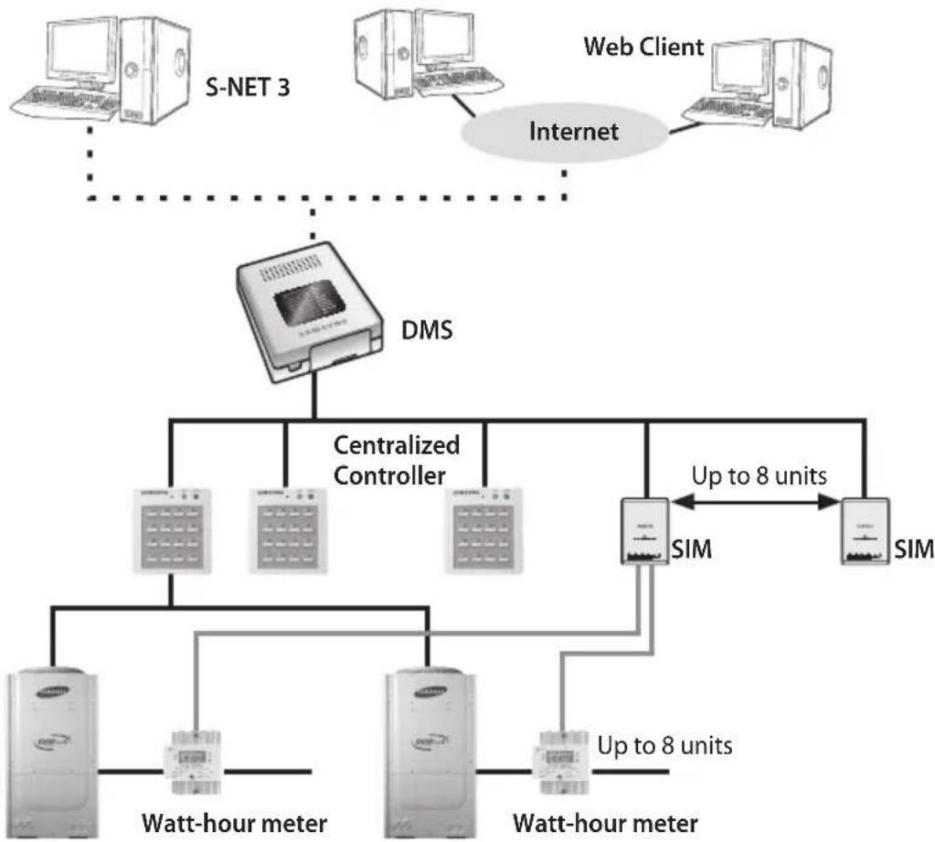
flowchart
graph TD
    A["S-NET 3"] --> B["Internet"]
    C["Web Client"] --> B
    B --> D["DMS"]
    D --> E["Centralized Controller"]
    E --> F["Sim"]
    F --> G["SIM"]
    H["Watt-hour meter"] --> I["Sim"]
    J["Watt-hour meter"] --> K["Sim"]
    L["Up to 8 units"] --> F
    M["Up to 8 units"] --> K
* In order to use the power distribution function in the DMS, relevant devices as shown above must be installed. (Consult the installers.)
Time Segmentation
◆ Time segmentation is used to divide 24 hours into different sections and to distribute power according to each section.
This function is used when the power consumption fee is different according to different time slots or when a building is charged differently depending on the consumption time.
◆ Time can be divided into 1 section (a), 2 sections (a,b,a), and 3 sections (a,b,c,b,a).
- When the time is divided into 2 or 3 sections, you should install S-NET 3 to calculate or view the distributed power on each section.
◆ DMS will always show the result of the power distribution on section 1, regardless of section 2 or 3.
◆ For 2 sections, 24 hours can be divided as follow:
00:00 08:30 17:30 24:00
Time Division A Time Division B Time Division A
CAUTION
If communication error occurs between DMS and the lower level controllers, actual power usage and the result of power distribution value may not be same.
◆ Communication error example:
- Between DMS and SIM transmitter
- Between SIM transmitter and Watt-hour meter
- Between DMS and Centralized controller
- Between Centralized controller and Transmitter
- Between Transmitter and indoor/outdoor units
Setting the Web Environment
◆ hstall JRE 1.3.1 or later version
Java Runtime Environment 1.3.1 or a later version must be installed on the PC.
JRE is installed automatically if the PC is connected to the Internet and when the DMS is accessed for the first time. JRE can also be downloaded from http://java.sun.com/j2se
◆ Install Internet Explorer 6.0 or later version
IE6.0 or later version must be installed on the PC. Please install IE6.0 or later version through Windows Update.
Using the DMS through the Web
◆ Access Method In order to access the DMS, type in the following address on the web browser: http://"DMS IP" (The default DMS IP is set to 192.168.0.2.)
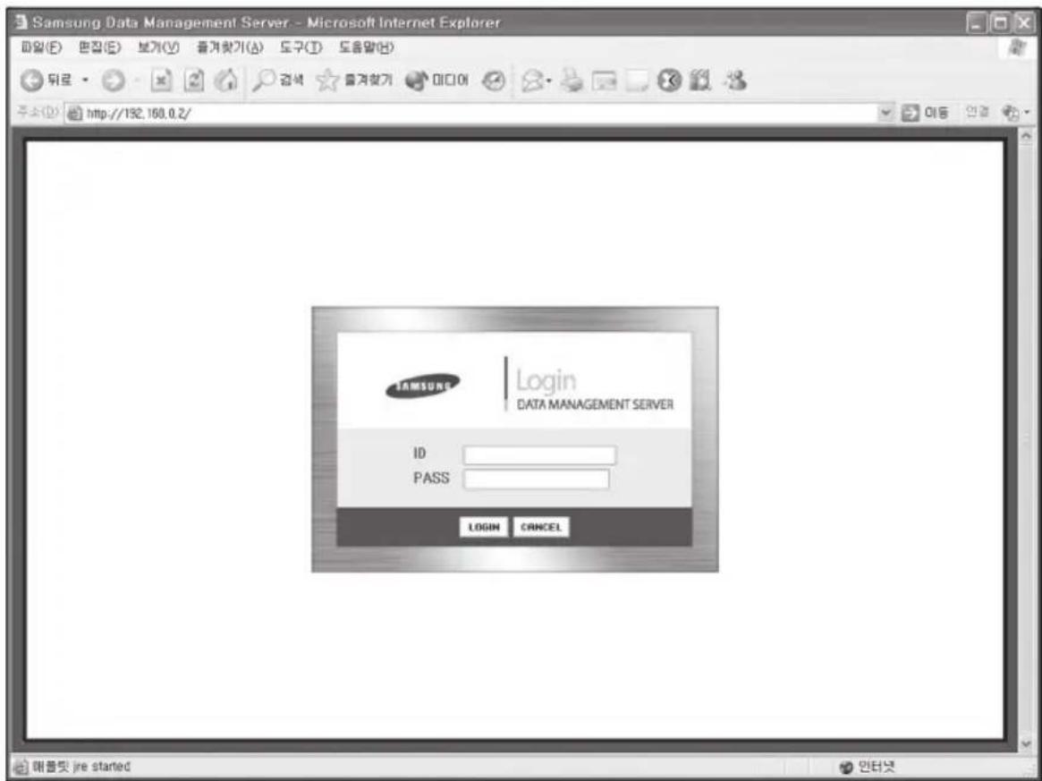
* Refer to "3.2.9 Setting and Viewing the System Environment" or the installation manual on how to set the IP address of the DMS.
Login
Function Details
◆ Login allows only authorized users to access the web page.
There is no limit on the number of users that can access the DMS at the same time, however, less than 5 users are recommended for access speed reasons.
Login
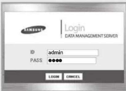
1 Type in an ID and a password and click on the LOGIN button.
2 If an ID and a password are valid, the monitoring and control page will be displayed.
3 If the ID and the password are not matched, the LOGIN page is displayed again.
4 If the CANCEL button is pressed after typing in the ID and the password, the ID and password fields are cleared.
5 The default DMS user setting as follow:
ID : admin
♦ PASS: 1234
Change the ID and the password for security reasons.
* Refer to 3.2.11 for user management.
Menu Organization
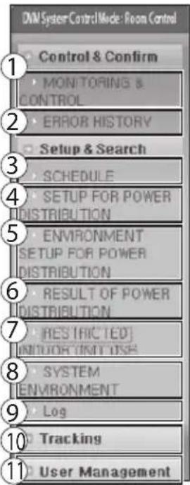
If Login is successful, the following menu appears.
Click on the menu to move to the corresponding page.
text_image
DAM System Control Mode: Room Control Control & Confirm MONITORING & CONTROL ERROR HISTORY Setup & Search SCHEDULE SETUP FOR POWER DISTRIBUTION ENVIRONMENT SETUP FOR POWER DISTRIBUTION RESULT OF POWER DISTRIBUTION RES TRICTED UNICOR UNITS USE SYSTEM ENVIRONMENT Log Tracking User Management① Monitoring and Control
② Viewing the Error History
③ Set, Run and View schedule
④ Setting the Power Distribution function
⑤ Environment Setup for Power Distribution
⑥ Viewing the Power Distribution Data
⑦ Setting the indoor unit restriction
⑧ Setting the Viewing the System Environment
⑨ Log
⑩ Tracking
⑪ User Management
text_image
LOGIN DATA MANAGEMENT SERVER ID admin PASS ●●●● LOGIN CANCELUsing the DMS through the Web (Continued)
Monitoring and Control
Function Details
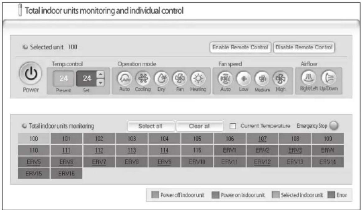
On this screen users can monitor the operation status of all indoor units and control each indoor unit. (But, if the ERV system is installed, can check the whole ERV control status.)
Monitoring and Control
text_image
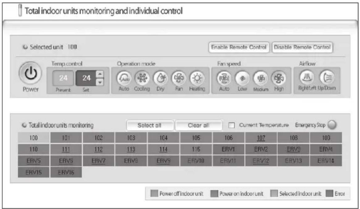
Total indoor units monitoring and individual control Selected unit 100 Enable Remote Control Disable Remote Control Temp control 24 Present Set Operation mode Auto Cooling Dry Fan Heating Fan speed Auto Low Medium High Airflow Right/Left Up/Down Power Total indoor units monitoring Select all Clear all Current Temperature Emergency Stop 100 101 102 103 104 105 106 107 108 109 110 111 112 113 114 115 ERV1 ERV2 ERV3 ERV4 ERV5 ERV6 ERV7 ERV8 ERV9 ERV10 ERV11 ERV12 ERV13 ERV14 ERV15 ERV16 Power off Indoor unit Power on indoor unit Selected Indoor unit Error1 The status of all indoor units can be viewed from the 'Monitor all indoor units.' The color of the squares represents the following meaning and the name of each indoor unit is displayed inside of squares.

text_image
Power off indoor unit Power on indoor unit Selected indoor unit Error Gray Blue Green Red2 Select and click on the indoor unit and the background color of the indoor unit is changed to green. The operation status of the selected indoor unit is displayed on the upper part. Displayed items are as follow:
| Selected indoor unit address | Displays the name of the selected indoor unit. | |
 Error Error | Displays whether there is an error on the selected indoor unit. (Only when an error is occurred, it is displayed as red. During the normal operation, it is not displayed on the screen.) | |
 Power Power | Click on this button to turn on and turn off the selected indoor unit. | |
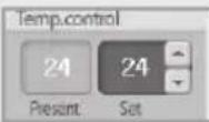 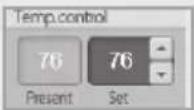 Celsius(°C) Fahrenheit(°F)Temperature Control Celsius(°C) Fahrenheit(°F)Temperature Control | The current temperature of the selected indoor unit can be monitored and the desired temperature can be set by clicking the and buttons next to the desired temperature.Temperature unit of the DMS will be set on either Celsius or Fahrenheit depending on the temperature unit used by the indoor unit. | |
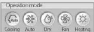 Mode Set Mode Set | The current mode of the selected indoor unit is displayed in light blue. Click on the desired mode to change modes.When controlling the operation mode, indoor unit will be controlled in the last controlled value of the operation mode.(Ex: If you have recently controlled the indoor unit in heat mode, at 20°C(60°F) with low fan speed and air swing on, it will be controlled in the same value when you control it in heat mode again.) | |
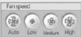 Fan Speed Fan Speed | The current fan speed of the selected indoor unit is displayed in light blue. Click on the desired fan speed to control the fan speed. | |
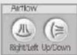 Air Swing Air Swing | The current air swing of the selected indoor unit is displayed in light blue. Both air swings can be selected at once. Click on the desired air swing to control the airflow. | |
Using the DMS through the Web (Continued)
text_image
Total indoor units monitoring and individual control Selected unit 100 Enable Remote Control Disable Remote Control Temp control Operation mode Fan speed Airflow 24 24 Auto Cooling Dry Fan Heating Auto Low Medium High Right/Left Up/Down Power Present Set Total indoor units monitoring Select all Clear all Current Temperature Emergency Stop 100 101 102 103 104 105 106 107 108 109 110 111 112 113 114 115 ERV1 ERV2 ERV3 ERV4 ERV5 ERV6 ERV7 ERV8 ERV9 ERV10 ERV11 ERV12 ERV13 ERV14 ERV15 ERV16 Power off Indoor unit Power on indoor unit Selected Indoor unit Error3 Enable/Disable Remote Control.
When pressing the button, selected indoor unit will be underlined.
When pressing the Disable Remote Control button, underline on selected indoor unit will disappear.
◆ If remote control LEVEL1 is set on upper level controller, selected indoor unit will be underlined.
4 Select All/Clear all.
◆ The simultaneous control of whole installed indoor units is possible.
If you want to control all the indoor units, press the button on the indoor unit control screen. If ERV system is connected and is selected with indoor units, only the power ON/OFF and the Disable Remote Control / control are possible for the ERV.
In order to select the indoor unit only if the indoor unit is installed by mixing with the ERV, select the indoor unit you want by the mouse while pressing the keyboard Ctrl key.
◆ To deselect all, press the button.
5 [Current Temperature] Selection.
- When selecting the check box, display the current temperature of the whole installed indoor units.
◆ In order to return to the monitoring screen, select again the [Current Temperature].
6 Emergency Stop status button is displayed in red if the DMS is currently in the emergency stop status. In the emergency stop status, the indoor units may be monitored but not controlled.
(The emergency stop function can only be used when the external contact control of the DMS is used.)
◆ Consult the installer to use the emergency stop function.
Refer to the installation manual for explanation about the emergency stop.
7 Communication Error Display.
When a communication error between the DMS and the lower controller is occurred, a message as below is displayed as red.
“!!! Communication error→Please check the error history menu for error reference.”
During the normal operation, it is not displayed on the screen.
Note
When the advanced functions (such as sleep mode, Energy saving function) are selected through wired/wireless remote controllers, temperature on the remote controllers and DMS may be displayed differently.
When you control the indoor units through DMS, all the advanced function will be disabled.
Using the DMS through the Web (Continued)
Monitoring and Control (ERV System)
Function Details
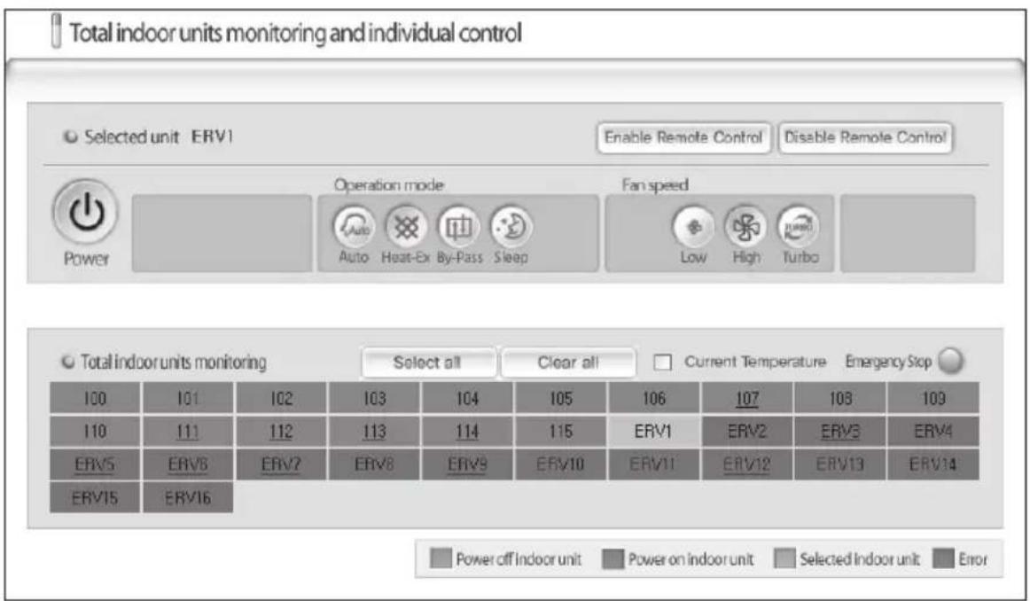
◆ On this screen users can monitor the operation status of all ERVs and control each ERV.
Monitoring and Control
text_image
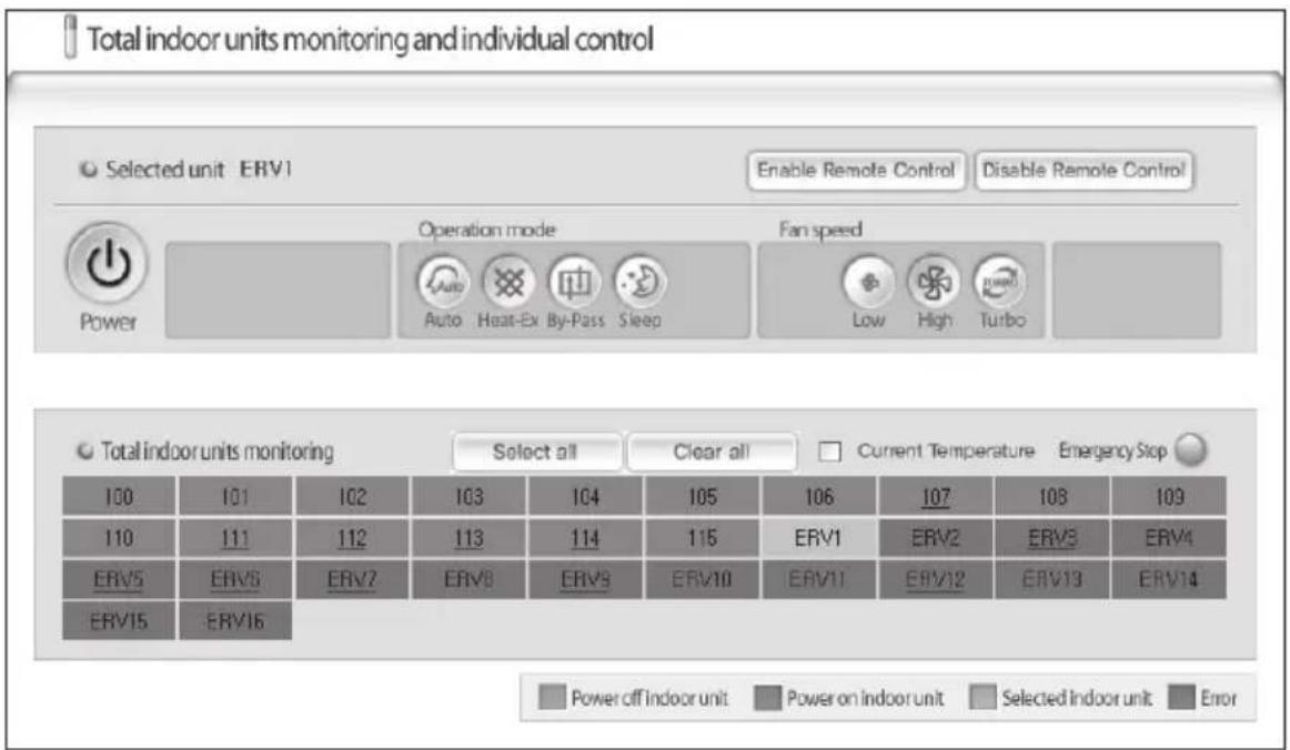
Total indoor units monitoring and individual control Selected unit: ERV1 Enable Remote Control Disable Remote Control Operation mode Fan speed Power Auto Heat-Ex By-Pass Sleep Low High Turbo Total indoor units monitoring Select all Clear all Current Temperature Emergency Stop 100 101 102 103 104 105 106 107 108 109 110 111 112 113 114 115 ERV1 ERV2 ERV3 ERV4 ERV5 ERV6 ERV7 ERV8 ERV9 ERV10 ERV11 ERV12 ERV13 ERV14 ERV15 ERV16 Power off Indoor unit Power on indoor unit Selected Indoor unit Error1 The status of all ERVs can be viewed from the 'Monitor all indoor units.' The color of the squares represents the following meaning and the name of each ERV is displayed inside of squares.

text_image
Power off indoor unit Power on indoor unit Selected indoor unit Error Gray Blue Green Red2 Select and click on the ERV and the background color of the ERV is changed to green. The operation status of the selected ERV is displayed on the upper part. Displayed items are as follow:
 Selected indoor unit address Selected indoor unit address | Displays the name of the selected ERV. |
 Error Error | Displays whether there is an error on the selected ERV. (Only when an error is occurred, it is displayed as red. During the normal operation, it is not displayed on the screen.) |
 Power Power | Click on this button to turn on and turn off the selected ERV. |
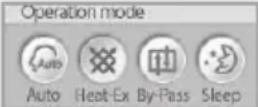 Mode Set Mode Set | The current mode of the selected ERV is displayed in light blue. Click on the desired mode to change modes.When controlling the ERV operation mode, DMS saves the last value of each operation mode and applies it when controlling the operation mode again.(Ex: If you have recently controlled the indoor unit in heat-ex mode with medium fan speed, it will be controlled in the same value when you control it in heat-ex mode with medium fan speed again even if you changed the operation mode previously.) |
 Fan Speed Fan Speed | The current fan speed of the selected ERV is displayed in light blue. Click on the desired fan speed to control the fan speed. |
Note
◆ What is ERV (Energy Recovery Ventilator)? It is a ventilating system compensating the air, humidity all together.
◆ Must turn on the power because the ERV control is not performed under the power-off.
◆ The color displaying the ERV status on the monitoring and the control screen are displayed differently from the indoor unit.
Using the DMS through the Web (Continued)
text_image
Total indoor units monitoring and individual control Selected unit: ERV1 Enable Remote Control Disable Remote Control Operation mode Fan speed Power Auto Heat-Ex By-Pass Sleep Low High Turbo Total indoor units monitoring Select all Clear all Current Temperature Emergency Stop 100 101 102 103 104 105 106 107 108 109 110 111 112 113 114 115 ERV1 ERV2 ERV3 ERV4 ERV5 ERV6 ERV7 ERV8 ERV9 ERV10 ERV11 ERV12 ERV13 ERV14 ERV15 ERV16 Power off indoor unit Power on indoor unit Selected indoor unit Error3 Enable Remote Control/Disable Remote Control.
When pressing the button, cannot control the ERV by the wired remote control in each room and can control the ERV only on the DMS webpage screen.
When ending the DMS after selecting the on the DMS webpage screen, cannot use the ERV in each room. In order to control the ERV in each room, a user must press the Enable Remote Control on the DMS webpage screen.
- When pressing the button, can use the wired remote control in each room. (Default: Enable Remote Control)
4 Select All/Clear all.
◆ The simultaneous control of whole installed ERV's is possible.
If you want to control all the ERV units, press the button on the ERV control screen. If indoor unit is connected and is selected with ERV, only the power ON/OFF and the /control are possible for the indoor unit.
◆ The indoor unit will run in the mode selected when last used.
In order to select the ERV only if the ERV is installed by mixing with the indoor unit, select the ERV you want by the mouse while pressing the keyboard Ctrl key.
◆ To deselect all, press the button.
5 [Current Temperature] Selection.
- When selecting the check box on the ERV system, display with “--”.
◆ In order to return to the monitoring screen, select again the [Current Temperature.]
6 Emergency Stop status button is displayed in red if the DMS is currently in the emergency stop status. In the emergency stop status, the indoor units may be monitored but not controlled.
(The emergency stop function can only be used when the external contact control of the DMS is used.)
◆ Consult the installer to use the emergency stop function.
Refer to the installation manual for explanation about the emergency stop.
7 Communication Error Display.
When a communication error between the DMS and the lower controller is occurred, a message as below is displayed as red.
"!!! Communication error> Please check the error history menu for error reference."
During the normal operation, it is not displayed on the screen.
Using the DMS through the Web (Continued)
View Error History
Function Details
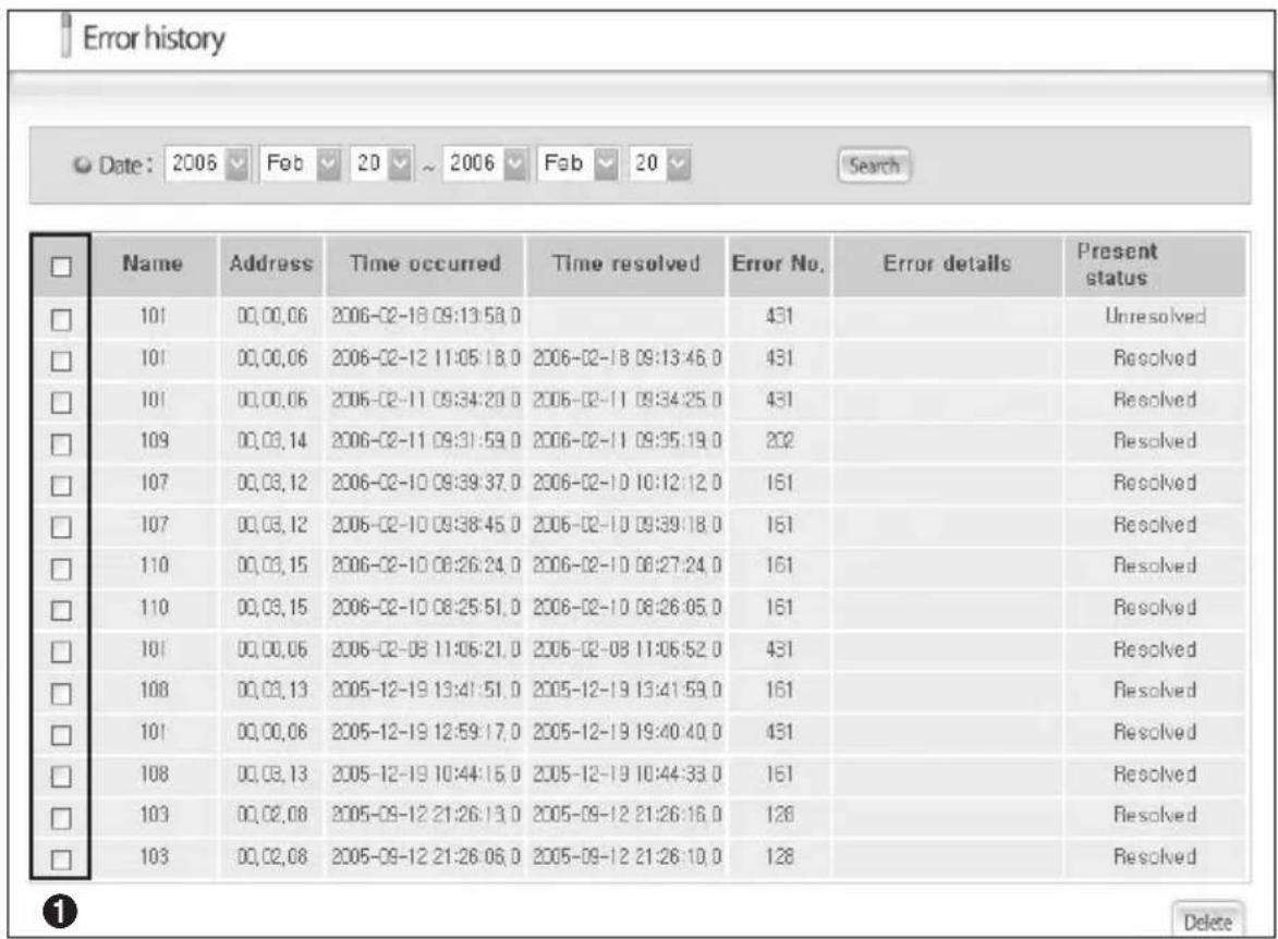
◆ The DMS users can view and delete error history of the DVM system. The DMS saves up to 256 errors.
Viewing the Error History
text_image
Error history Date: 2006 Feb 20 ~ 2006 Fab 20 Search Name Address Time occurred Time resolved Error No. Error details Present 101 00,00,06 2006-02-18 09:13:58.0 431 Unresolved 101 00,00,06 2006-02-12 11:05:18.0 2006-02-18 09:13:46.0 431 Resolved 101 00,00,06 2006-02-11 09:34:20.0 2006-02-11 09:34:25.0 431 Resolved 109 00,03,14 2006-02-11 09:31:59.0 2006-02-11 09:35:19.0 202 Resolved 107 00,03,12 2006-02-10 09:39:37.0 2006-02-10 10:12:12.0 161 Resolved 107 00,03,12 2006-02-10 09:38:45.0 2006-02-10 09:39:18.0 161 Resolved 110 00,03,15 2006-02-10 08:26:24.0 2006-02-10 08:27:24.0 161 Resolved 110 00,03,15 2006-02-10 08:25:51.0 2006-02-10 08:26:05.0 161 Resolved 101 00,00,06 2006-02-08 11:05:21.0 2006-02-08 11:06:52.0 431 Resolved 108 00,03,13 2005-12-19 13:41:51.0 2005-12-19 13:41:59.0 161 Resolved 101 00,00,06 2005-12-19 12:59:17.0 2005-12-19 19:40:40.0 431 Resolved 108 00,03,13 2005-12-19 10:44:15.0 2005-12-19 10:44:33.0 161 Resolved 103 00,02,08 2005-09-12 21:26:13.0 2005-09-12 21:26:16.0 128 Resolved 13 0O,O,O8 2O O5-ON-12 2I:26:O6. O 2O O5-ON-12 2I:26:IO. O 128 Resolved Delete1 All error history can be checked from the 'View Error History' page.
2 The error history can be viewed according to date. Select the date in the list box and press the 'Search' button to view the error history according to the selected period.
3 The error history includes the device name, address, time when error occurred, time when error was fixed, error code, error contents, and status (solve/unsolved.)
4 Select and 'delete' errors by selecting the check boxes in area ①.
Set, Run and View Schedule
Function Details
◆ Users can set, edit, and delete schedules for controlling the DVM system.
Using the Schedule Function
text_image
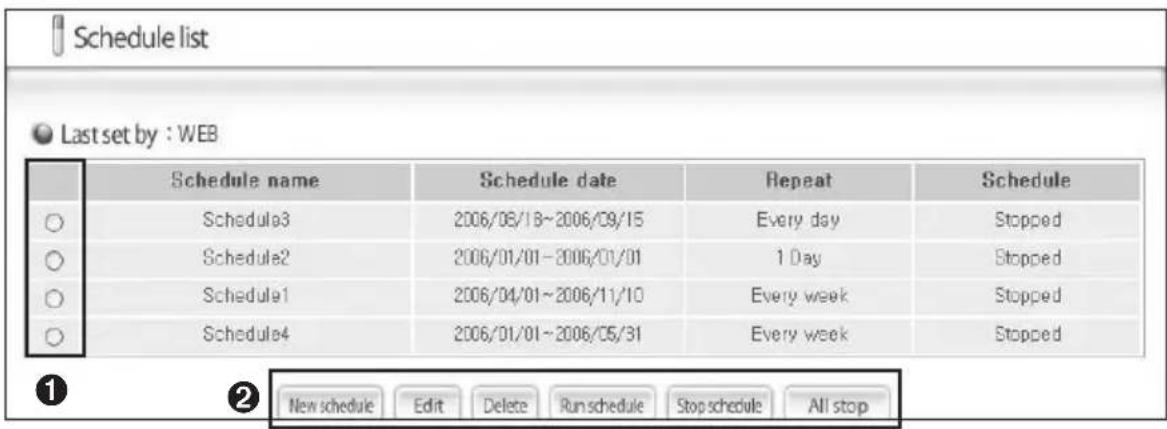
Schedule list Last set by : WEB Schedule name Schedule date Repeat Schedule Schedule3 2006/08/18~2006/09/15 Every day Stopped Schedule2 2006/01/01-2006/01/01 1 Day Stopped Schedule1 2006/04/01~2006/11/10 Every week Stopped Schedule4 2006/01/01~2006/05/31 Every week Stopped New schedule Edit Delete Runs schedule Stop schedule All stopThe Schedule List screen shows all current schedule information saved in the DMS.
1 On the schedule screen, a schedule can be created, edited, viewed, and deleted.
2 Press the 'New schedule' button i② to create a new schedule. (Refer to Adding a Schedule)
3 Press the 'Edit' button in② after selecting a schedule in① to edit a set schedule. (Refer to Adding a Schedule)
4 Press the 'Delete' button i② after selecting a schedule in① to delete the selected schedule.
5 Press the 'Run schedule' button in② after selecting a schedule in ① to run the selected schedule.
6 Press the 'Stop schedule' button in ② after selecting a schedule in ① to stop running the selected schedule.
7 Press the 'All stop' button i② to stop running all the schedules.
Using the DMS through the Web (Continued)
Adding a New Schedule
text_image
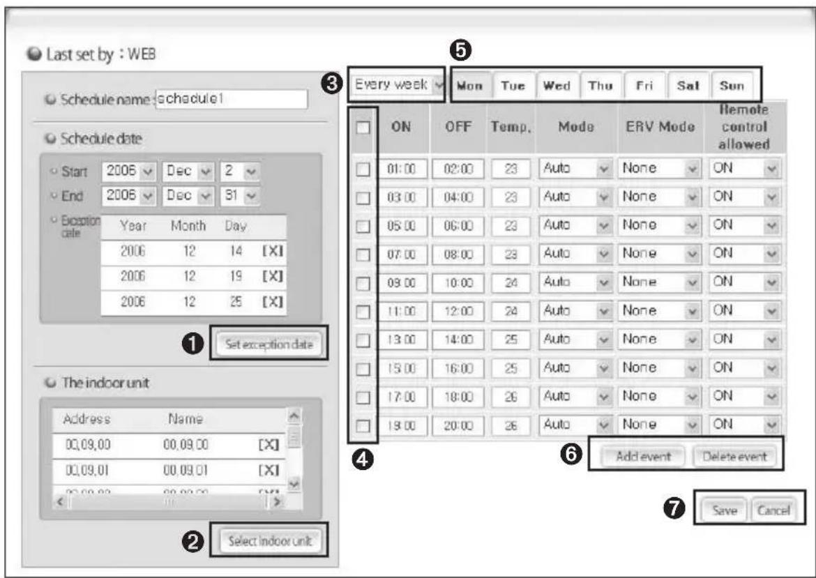
Last set by : WEB Schedule name: schedule1 Schedule date Start 2006 Dec 2 End 2006 Dec 31 Exception date Year Month Day 2006 12 14 [X] 2006 12 19 [X] 2006 12 25 [X] ① Set exception date The indoor unit Address Name 00.09.00 00.09.00 [X] 00.09.01 00.09.01 [X] < 11 >> ② Select indoor unit Every week Mon Tue Wed Thu Fri Sat Sun ON OFF Temp. Mode ERV Mode Iremote control allowed 01:00 02:00 23 Auto None ON 03:00 04:00 23 Auto None ON 05:00 06:00 23 Auto None ON 07:00 08:00 23 Auto None ON 09:00 10:00 24 Auto None ON 11:00 12:00 24 Auto None ON 13:00 14:00 25 Auto None ON 15:00 16:00 25 Auto None ON 17:00 18:00 26 Auto None ON 19:00 20:00 26 Auto None ON Add event Delete event Save CancelOn the Create New Schedule screen, users can set the Schedule Name, Schedule Period, Applied Indoor Unit, and Event.
1 For the event, users can set the Repeat or not, Day, On Time, Off Time, Temperature, Mode, ERV Mode and Remote Control Allow or not. Users can assign the maximum 10 events. (Set the ERV mode only when the ERV is connected.)
◆ When setting the remote control, operated as below.
- ON: Allow the Remote Control Use.
(Can use the wired/wireless remote control and the indoor unit button in each room)
- OFF: Disallow the Remote Control Use.
(Cannot use the wired/wireless remote control and the indoor unit button in each room)
- LEVEL1: a. When turning ON by the centralized controller or DMS
- Allow the remote control use.
b. When turning OFF by the centralized controller or DMS
- Disallow the remote control use.
2 When pressing the 'Set exception date' button from the users can set up the schedule exception day.
3 When pressing the 'Select indoor unit' button from the, users can select the schedule indoor unit.
4 Users can set one of schedule repetition or not, which are every week, every day, and one day from the drop down menu ③. If setting to one day, assign the same date of starting date and ending date.
5 When pressing the 'Add Event' button from the ⑥, a new event is added. When pressing the 'Delete Event' button from the ⑥ after selecting a check box from the ④, the selected event is deleted.
6 When pressing the 'Save' button from the ⑦ after setting all schedule information, the schedule information is saved to the DMS.
7 When pressing the 'Cancel' button from th, turn back to the schedule list screen.
Note
If you do not set the end date, the schedule does not have period limit and the end date will not appear on the screen.
◆ Temperature unit of the DMS will be set on either Fahrenheit or Celsius depending on the temperature unit used by the indoor unit.
To edit existing schedule, click 'Edit' from the Schedule screen. You may edit the existing schedule in the same way as adding a new schedule.
Using the DMS through the Web (Continued)
Setting and Viewing the Power Distribution Function
Function Explanation
◆ Users can set, inquire, and edit the information of power distribution section.
* Refer to pg. 4 for more information on the Power Distribution Function.
Using the power Distribution Function
text_image
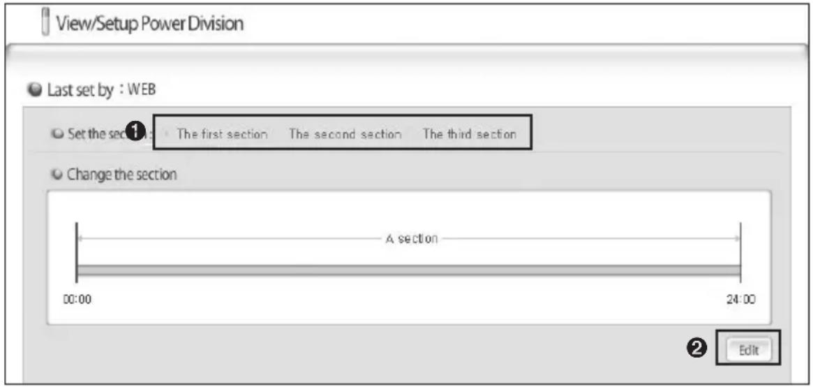
View/Setup Power Division Last set by : WEB Set the section 1: The first section The second section The third section Change the section A section 00:00 24:00 Edit1 If clicking the 'Edit' button from the ②, area ① is activated and users can set the desired section. Select one of possible settings which are 1 section, 2 sections, and 3 sections.
Set the section: The first section The second section The third section
2 As shown in the above picture, only Section A is existed. It is from 00:00 to 24:00.
text_image
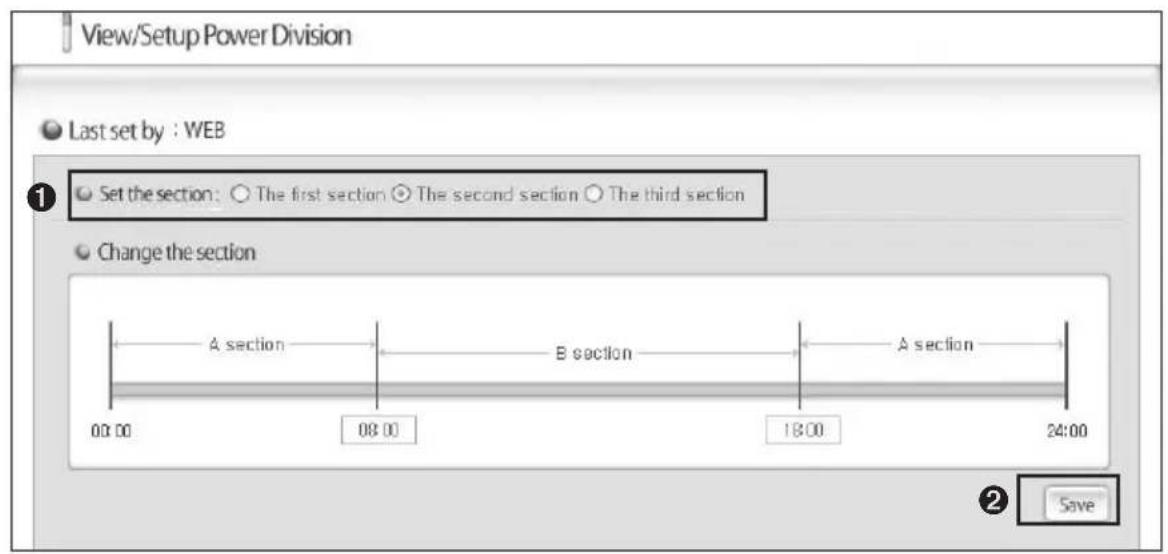
View/Setup Power Division Last set by : WEB Set the section: ○ The first section ◦ The second section ○ The third section Change the section A section B section A section 00:00 08:00 18:00 24:00 ② Save3 Section A and Section B are existed in 2 Sections. Can inquire and set the border time between Section A and Section B. When pressing the 'Save' button from the ^② after editing the border time from the area ^① , set time is adopted. If the border time between Section A and Section B is 08:00, Section A is 00:00\~08:00 and Section B starts from 08:01.
text_image
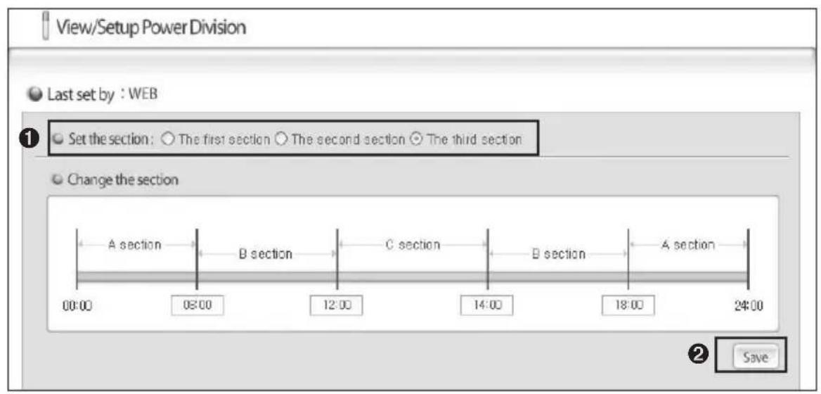
View/Setup Power Division Last set by : WEB Set the section: ○ The first section ○ The second section ○ The third section Change the section A section B section C section B section A section 00:00 03:00 12:00 14:00 18:00 24:00 ② Save4 3 Sections are classified into Section A, Section B, and Section C. The setting method is same as 2 sections' setting method.
Using the DMS through the Web (Continued)
Setting and Viewing the Power Distribution Environment
Function Explanation
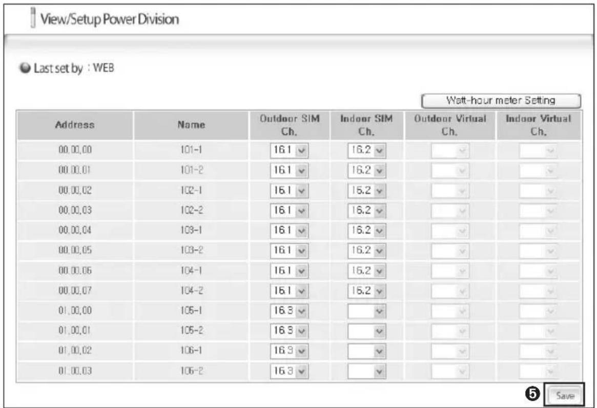
◆ Users can view or edit the connection between the indoor units and assigned watt-hour meter. DMS will distribute power based on the information which has been set up from this menu.
text_image
View/Setup Power Division Last set by : WEB Watt-hour meter Setting Address Name Outdoor SIM Ch. Indoor SIM Ch. Outdoor Virtual Ch. Indoor Virtual Ch. 00.00.00 101-1 16.1 16.2 00.00.01 101-2 16.1 16.2 00.00.02 102-1 16.1 16.2 00.00.03 102-2 16.1 16.2 00.00.04 103-1 16.1 16.2 00.00.05 103-2 16.1 16.2 00.00.06 104-1 16.1 16.2 00.00.07 104-2 16.1 16.2 01.00.00 105-1 16.3 01.00.01 105-2 16.3 01.00.02 106-1 16.3 01.00.03 106-2 16.3 Save1 Check the address and the channel on the SIM transmitter that is connected to the watt-hour meter.
◆ SIM Transmitter with the address 0\~7 will be displayed as 16\~23 on DMS when tracking.
◆ Channel information of the terminal, with SIM transmitter and the watt-hour meter connections, displayed as follows (Terminal block on the very left of the SIM transmitter is Terminal block 1):
| Terminal block 1 | Terminal block 2 | Terminal block 3 | Terminal block 4 | |
| Top | 1 2 3 4 | |||
| Bottom | 5 6 7 8 |
2 Check the indoor/outdoor units connected to the watt-hour meter.
3 Check the SIM transmitter channel (watt-hour meter).
◆ If the indoor unit power is supplied from the outdoor unit, set the 'Outdoor SIM ch.' only.
('Outdoor SIM ch.' signifies the watt-hour meter connected to the outdoor unit.)
◆ If the indoor unit power is supplied separately, set both 'Outdoor SIM ch.' and the 'Indoor SIM ch.'.
('Indoor SIM ch.' signifies the watt-hour meter connected to the indoor unit.)
4 Set the indoor units that the power will be distributed.
◆ If you do not set up the indoor unit information, result of the power distribution will displayed as 0.
5 Press 'Save'.
◆ Changed power distribution setting will be saved on DMS.
Caution
Information of the watt-hour meter, connected to the indoor unit, should be correct. If the watt-hour meter information is incorrect when you set up the indoor unit channel, error may occur on result of the power distribution.
◆ If you wish to distribute power on certain indoor unit, you must set the SIM channel. If you do not set the SIM channel, power will not be distributed and result of the power distribution will be 0.
◆ Consult installer if any information change occurs on the watt-hour meter with indoor/outdoor unit connection.
Note
- Indoor/Outdoor unit SIM channel setting
- If there is SIM transmitter connected to the DMS, user can set up the SIM channel.
- User will not have to inspect the watt-hour meter since power distribution will be done automatically.
- Indoor/Outdoor unit Virtual channel setting
- When there is no SIM transmitter connected to the DMS, user can set up the Virtual channel.
- In order to execute power distribution, value from the watt-hour meter should be manually inspected.
- Virtual channel should be set on each watt-hour meter.
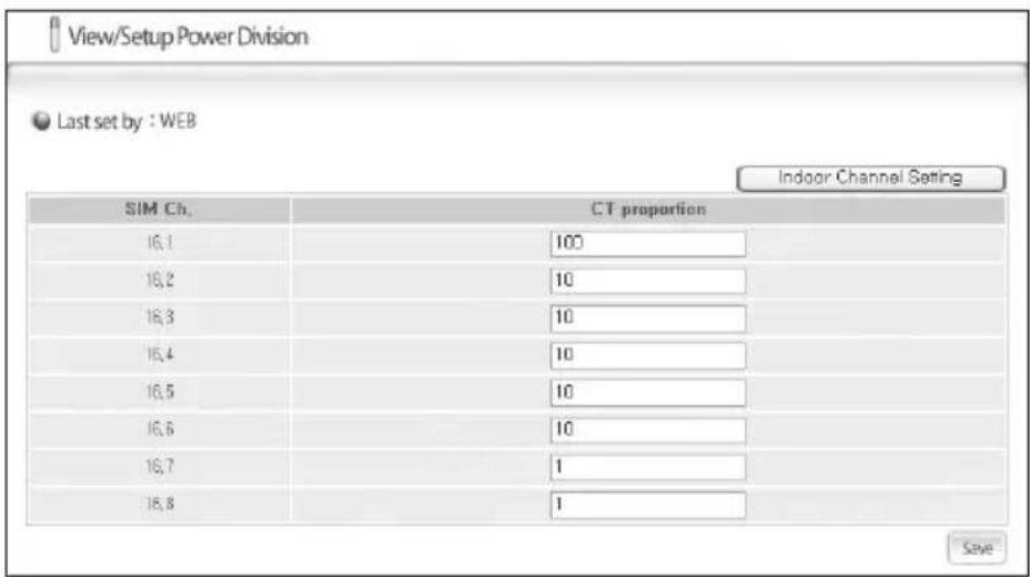
◆ Watt-hour meter setting
- If CT watt-hour meter is used, click 'Watt-hour meter Setting' to set the CT proportion for each watt-hour meter.
- SIM transmitter should be installed to use this setting.
text_image
View/Setup Power Division Last set by : WEB Indoor Channel Setting SIM Ch. CT proportion 16, 1 100 16, 2 10 16, 3 10 16, 4 10 16, 5 10 16, 6 10 16, 7 1 16, 8 1 Save- You may click 'Indoor Channel Setting' to return to the Indoor unit channel setting.
- When using the CT watt-hour meter, current ratio error may cause slight difference in actual power usage.

Inquire Power Distribution Result
Function Explanation
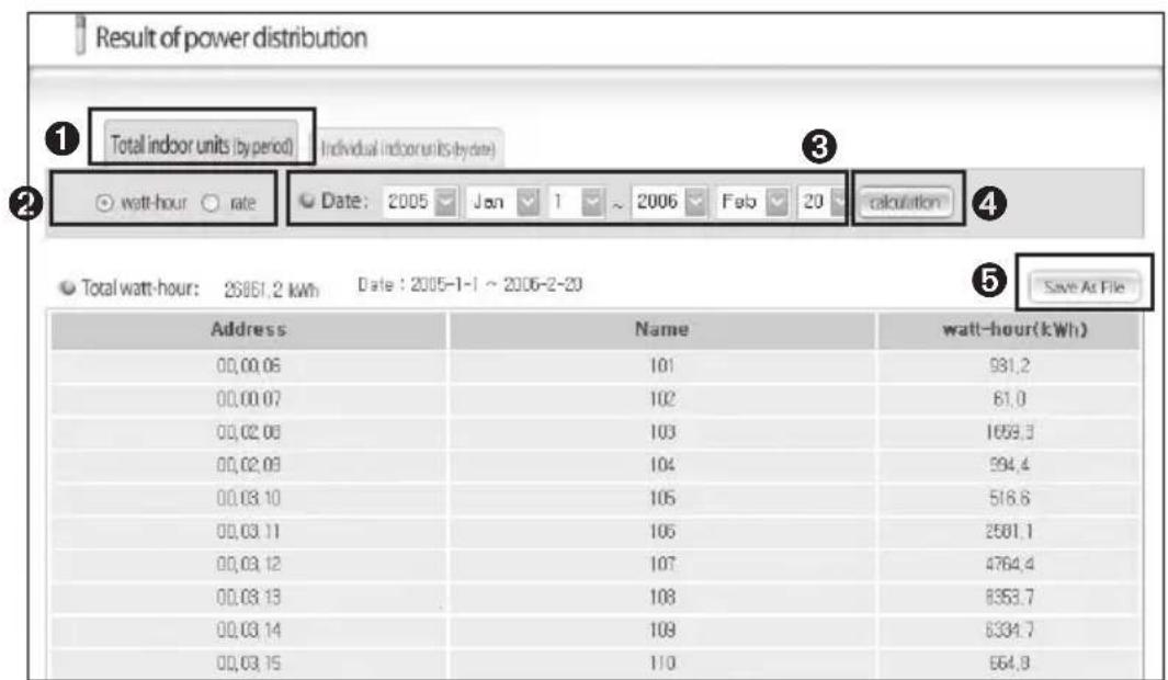
◆ Users can inquire operation breakdowns and power usage by indoor units that is saved in the DMS.
Inquiring the result
text_image
Result of power distribution ① Total indoor units (by period) Individual indoor units (by date) ② watt-hour rate Date: 2005 Jan 1 ~ 2006 Feb 20 calculation ③ ④ ⑤ Save As File Total watt-hour: 23851.2 kWh Date: 2005-1-1 ~ 2006-2-20 Address Name watt-hour(kWh) 00,00,06 101 981,2 00,00,07 102 61,0 00,02,08 103 1658,3 00,02,09 104 594,4 00,03,10 105 516,6 00,03,11 106 2501,1 00,03,12 107 4764,4 00,03,13 108 8353,7 00,03,14 109 6334,7 00,03,15 110 664,8Total Indoor units (by period)
1 Select 'Total Indoor units (by period)' in ① to check the power consumption and the rate by period for all the indoor units.
2 Select whether to check the power consumption or the rate for all indoor units (by period) in②.
Total power consumption can be checked only when the watt-hour meters are connected. If not, only the consumption ratio can be checked.
3 Select the time period to check in③.
(Only data of the maximum of 93 days is saved on DMS)
4 Press 'Calculation' in④ to display the result.
5 Press 'Save As File' ir⑤ to save the result in MS Excel file format. (It is recommended to save the power distribution data regularly.)
Using the DMS through the Web (Continued)
text_image
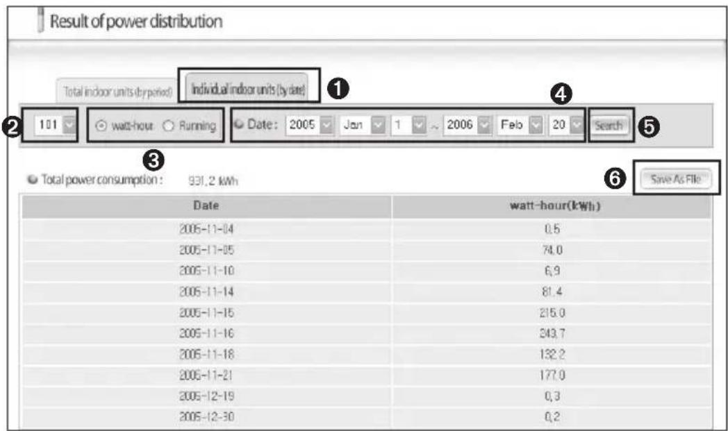
Result of power distribution Total indoor units (by date) Individual indoor units (by date) 101 wash-hour Running Date: 2005 Jan 1 2006 Feb 20 Search Total power consumption : 931.2 kWh Save As File Date watt-hour(kWh) 2005-11-04 0.5 2005-11-05 74.0 2005-11-10 6.9 2005-11-14 81.4 2005-11-15 216.0 2005-11-16 243.7 2005-11-18 132.2 2005-11-21 177.0 2005-12-19 0.3 2005-12-30 0.2Individual Indoor unit (by period)
1 Select 'Individual indoor units (by date)' in ① to check the power consumption and the running rate by date for individual indoor unit.
2 Select the indoor unit to check in? (If the DMS is set to group mode and one group has more than two indoor units, each individual indoor unit will be checked.)
3 Select 'watt-hour' or 'Running' (Power consumption or running time per date of the selected indoor unit)
4 Select the time period to check in ④.
5 Press 'Search' in⑤ to display the result.
6 Press 'Save As File' to save the result in MS Excel file format. (It is recommended to save the power distribution data regularly.)
Viewing Power Distribution Result
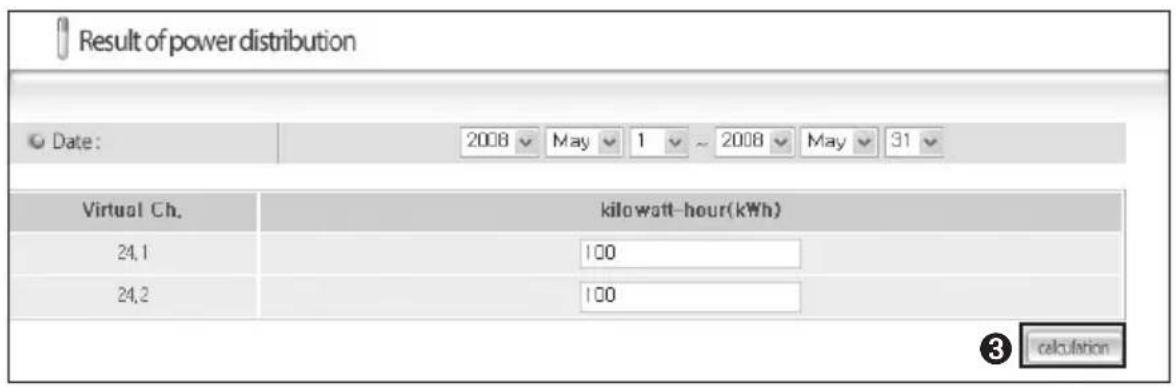
text_image
Result of power distribution Date: 2008 May 1 ~ 2008 May 31 Virtual Ch. kilowatt-hour(kWh) 24.1 100 24.2 100 ③ calculation1 Click 'SETUP FOR POWER DISTRIBUTION' on the DMS web page.
2 When the Virtual channel for the Indoor/Outdoor unit is set, above screen will appear.
3 Select the time period and click 'calculation' to display the result.
Using the DMS through the Web (Continued)
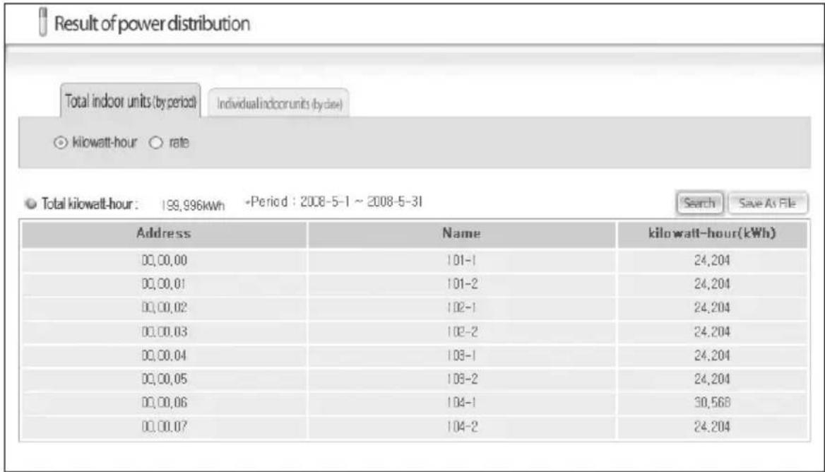
text_image
Result of power distribution Total indoor units (by period) Individual indoor units (cycle) ○ kilowatt-hour ○ rate ○ Total kilowatt-hour: 199,996kWh -Period: 2008-5-1 ~ 2008-5-31 Search Save As File Address Name kilowatt-hour(kWh) 00,00,00 101-1 24,204 00,00,01 101-2 24,204 00,00,02 102-1 24,204 00,00,03 102-2 24,204 00,00,04 103-1 24,204 00,00,05 103-2 24,204 00,00,06 104-1 30,568 00,00,07 104-2 24,2044 Check the result of power distribution.
◆ Click 'Search' to re-enter the power usage for each channel.
◆ Click 'Save As File' to save the result as excel file.
◆ Select 'rate' to check the result of power distribution in rate.
◆ If you use virtual channel, you cannot check the power usage for individual day.
- You may check the individual indoor unit's daily operation time regardless of the channel type or settings.
Caution
Due to rounding up the value, there could be slight difference to the actual power usage.
Setting the Indoor Unit Restriction
Function Explanation
◆ The DMS users can restrict the indoor unit as cool only or heat only.
Setting the Indoor Unit Restriction

Restricted indoor unit use

Last set by : WEB
| Address | Name | Operation mode limit | Control mode | Lower limit temperature (Cool) | Upper limit temperature (Heat) |
| 00,00,00(00) | 00,00,00 | None | None None | Cancel Apply 25 | Cancel Apply 25 |
| 00,00,01(01) | 00,00,01 | None | None None | Cancel Apply 25 | Cancel Apply 25 |
| 00,00,02(02) | 00,00,02 | None | None None | Cancel Apply 25 | Cancel Apply 25 |
| 00,00,03(03) | 00,00,03 | None | None None | Cancel Apply 25 | Cancel Apply 25 |
| 00,00,04(04) | 00,00,04 | None | None None | Cancel Apply 25 | Cancel Apply 25 |
| 00,00,05(05) | 00,00,05 | None | None None | Cancel Apply 25 | Cancel Apply 25 |
| 00,00,06(06) | 00,00,06 | None | None None | Cancel Apply 25 | Cancel Apply 25 |
| 00,00,07(07) | 00,00,07 | None | None None | Cancel Apply 25 | Cancel Apply 25 |
| 00,00,08(08) | 00,00,08 | None | None None | Cancel Apply 25 | Cancel Apply 25 |
| 00,00,09(09) | 00,00,09 | None | None None | Cancel Apply 25 | Cancel Apply 25 |
| 00,00,10(10) | 00,00,10 | None | None None | Cancel Apply 25 | Cancel Apply 25 |
| 00,00,11(11) | 00,00,11 | None | None None | Cancel Apply 25 | Cancel Apply 25 |
| 00,00,12(12) | 00,00,12 | None | None None | Cancel Apply 25 | Cancel Apply 25 |
| 00,00,13(13) | 00,00,13 | None | None None | Cancel Apply 25 | Cancel Apply 25 |
| 00,00,14(14) | 00,00,14 | None | None None | Cancel Apply 25 | Cancel Apply 25 |
| 00,00,15(15) | 00,00,15 | None | None None | Cancel Apply 25 | Cancel Apply 25 |

Edit
1 Click 'RESTRICTED INDOOR UNIT USE' on the DMS web page.
2 Click 'Edit' on the restricted indoor unit use screen.
◆ 'Edit' will change to 'Save'.
Using the DMS through the Web (Continued)

Restricted indoor unit use

Last set by :WEB
| Address | Name | Operation mode limit | Control mode | Lower limit temperature (Cool) | Upper limit temperature (Heat) |
| 00,00,00(00) | 00,003 | Cool only √NoneCool onlyHeat onlyCool only √ | ○Fan ○ Cool | ○Cancel ○ Apply 25 | ○Cancel ○ Apply 25 |
| 00,00,01(01) | 00,00,01 | ○Fan ○ Cool | ○Cancel ○ Apply 25 | ○Cancel ○ Apply 25 | |
| 00,00,02(02) | 00,00,02 | ○Fan ○ Cool | ○Cancel ○ Apply 25 | ○Cancel ○ Apply 25 | |
| 00,00,03(03) | 00,00,03 | Cool only √ | ○Fan ○ Cool | ○Cancel ○ Apply 25 | ○Cancel ○ Apply 25 |
| 00,00,04(04) | 00,00,04 | Cool only √ | ○Fan ○ Cool | ○Cancel ○ Apply 25 | ○Cancel ○ Apply 25 |
| 00,00,05(05) | 00,00,05 | Cool only √ | ○Fan ○ Cool | ○Cancel ○ Apply 25 | ○Cancel ○ Apply 25 |
| 00,00,06(06) | 00,00,06 | Cool only √ | ○Fan ○ Cool | ○Cancel ○ Apply 25 | ○Cancel ○ Apply 25 |
| 00,00,07(07) | 00,00,07 | Cool only √ | ○Fan ○ Cool | ○Cancel ○ Apply 25 | ○Cancel ○ Apply 25 |
| 00,00,08(08) | 00,00,08 | Cool only √ | ○Fan ○ Cool | ○Cancel ○ Apply 25 | ○Cancel ○ Apply 25 |
| 00,00,09(09) | 00,00,09 | Cool only √ | ○Fan ○ Cool | ○Cancel ○ Apply 25 | ○Cancel ○ Apply 25 |
| 00,00,10(10) | 00,00,10 | Cool only √ | ○Fan ○ Cool | ○Cancel ○ Apply 25 | ○Cancel ○ Apply 25 |
| 00,00,11(11) | 00,00,11 | Cool only √ | ○Fan ○ Cool | ○Cancel ○ Apply 25 | ○Cancel ○ Apply 25 |
| 00,00,12(12) | 00,00,12 | Cool only √ | ○Fan ○ Cool | ○Cancel ○ Apply 25 | ○Cancel ○ Apply 25 |
| 00,00,13(13) | 00,00,13 | Cool only √ | ○Fan ○ Cool | ○Cancel ○ Apply 25 | ○Cancel ○ Apply 25 |
| 00,00,14(14) | 00,00,14 | Cool only √ | ○Fan ○ Cool | ○Cancel ○ Apply 25 | ○Cancel ○ Apply 25 |
| 00,00,15(15) | 00,00,15 | Cool only √ | ○Fan ○ Cool | ○Cancel ○ Apply 25 | ○Cancel ○ Apply 25 |

3 Click [▼] to select operation mode limit.
◆ Users can select 'None', 'Cool only' or 'Heat only'.
4 Set the control mode.
If you set the control mode, indoor unit operating in limited operation mode will be automatically set to operate in pre-set control mode. You can set the different control mode to each of the indoor units.
- Cool only indoor unit : Users can select between fan and cool mode.
- Heat only indoor unit: Users can select between fan and heat mode.
(Ex: When the cool only indoor unit with the control mode set to fan mode is changed to heat mode, DMS will perceive it and control the indoor unit in fan mode.)
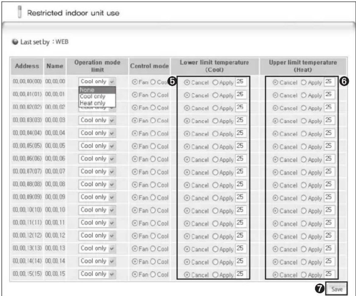
text_image
Restricted indoor unit use Last set by : WEB Address Name Operation mode limit Control mode Lower limit temperature (Cool) Upper limit temperature (Heat) 00.00.00(00) 00.00.00 Cool only ○Fan ○ Cool ○Cancel ○ Apply 25 ○Cancel ○ Apply 25 00.00.01(01) 00.00.01 None Cool only ○Fan ○ Cool ○Cancel ○ Apply 25 ○Cancel ○ Apply 25 00.00.02(02) 00.00.02 Cool only ○Fan ○ Cool ○Cancel ○ Apply 25 ○Cancel ○ Apply 25 00.00.03(03) 00.00.03 Cool only ○Fan ○ Cool ○Cancel ○ Apply 25 ○Cancel ○ Apply 25 00.00.04(04) 00.00.04 Cool only ○Fan ○ Cool ○Cancel ○ Apply 25 ○Cancel ○ Apply 25 00.00.05(05) 00.00.05 Cool only ○Fan ○ Cool ○Cancel ○ Apply 25 ○Cancel ○ Apply 25 00.00.06(06) 00.00.06 Cool only ○Fan ○ Cool ○Cancel ○ Apply 25 ○Cancel ○ Apply 25 00.00.07(07) 00.00.07 Cool only ○Fan ○ Cool ○Cancel ○ Apply 25 ○Cancel ○ Apply 25 00.00.08(08) 00.00.08 Cool only ○Fan ○ Cool ○Cancel ○ Apply 25 ○Cancel ○ Apply 25 00.00.09(09) 00.00.09 Cool only ○Fan ○ Cool ○Cancel ○ Apply 25 ○Cancel ○ Apply 25 00.00.10(10) 00.00.10 Cool only ○Fan ○ Cool ○Cancel ○ Apply 25 ○Cancel ○ Apply 25 00.00.11(11) 00.00.11 Cool only ○Fan ○ Cool ○Cancel ○ Apply 25 ○Cancel ○ Apply 25 00.00.12(12) 00.00.12 Cool only ○Fan ○ Cool ○Cancel ○ Apply 25 ○Cancel ○ Apply 25 00.00.13(13) 00.00.13 Cool only ○Fan ○ Cool ○Cancel ○ Apply 25 ○Cancel ○ Apply 25 00.00.14(14) 00.00.14 Cool only ○Fan ○ Cool ○Cancel ○ Apply 25 ○Cancel ○ Apply 25 00.00.15(15) 00.00.15 Cool only ○Fan ○ Cool ○Cancel ○ Apply 25 ○Cancel ○ Apply 25 Save5 Set lower limit temperature(Cool).
- You can set the lower limit temperature by selecting 'Cancel' or 'Apply'.
If the desired temperature is lower than lower limit temperature when the indoor unit is operating in cool mode, DMS controls the desired temperature in the lower limit temperature. - You can set the lower limit temperature between 18°C(65°F) and 30°C(86°F).
6 Set upper limit temperature(Heat).
- You can set the upper limit temperature by selecting 'Cancel' or 'Apply'.
If the desired temperature is higher than the upper limit temperature when indoor unit is operating in heat mode, DMS controls the desired temperature in the upper limit temperature. - You can set the upper limit temperature between 18°C(65°F) and 30°C(86°F).
7 Click 'Save'.
◆ Changed settings will be saved.
Using the DMS through the Web (Continued)
Note
◆ Mixed operation can occur even if you set control mode limit.
If the indoor unit with control mode limit is in mixed operation, DMS will solve the problem automatically by controlling it in control mode limit.
CAUTION
All indoor units under the same outdoor unit should be on same control mode limit in the following situations.
Mixed operation can occur continuously when you set some of indoor unit as cool only and the other as heat only.
- If the centralized controller is MIM-A202 and is in group mode
- If the centralized controller is in group mode and the transmitter is MIM-B13 or MIM-B04A
Except above situations, DMS changes the control mode limit of all indoor units under the same outdoor unit to same control mode limit.
- If the centralized controller is in group mode and is above MIM-M202A, and all the transmitters under the centralized controller are above MIM-B13A
- If the centralized controller is in individual mode
If you set the operation mode limit to 'Heat only', DMS may show the operation status of the cooling only indoor units between Cooling→Heating repeatedly.
Setting and Viewing the System Environment
Function Explanation
◆ The DMS users can set and view information related to the DMS system installation and operation. (The installer must complete the system environment setup when installing the DMS.)
System environment setup
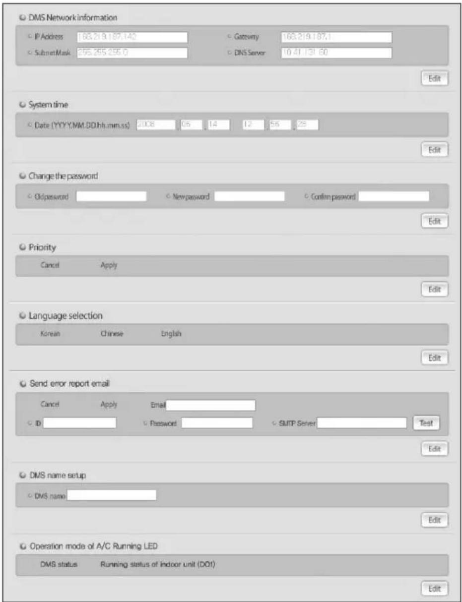
text_image
DMS Network information IP Address 163.21.9.187.142 Gateway 163.219.187.1 Submit Mask 255.255.255.0 DNS Server 10.41.131.60 Edit System time Date (YYYY/MM-DD)(hh:mm:ss) 2008 05 14 12 55 28 Edit Change the password Oldpassword New password Confirm password Edit Priority Cancel Apply Edit Language selection Korean Chinese English Edit Send error report email Cancel Apply Email ID Password SMTP Server Test Edit DMS name setup DMS name Edit Operation mode of A/C Running LED DMS status Running status of indoor unit (DO1) EditUsing the DMS through the Web (Continued)
1 DMS Network Information
Change the set information by inquiring the existing set network information from the DMS network information and clicking the 'Edit' button. If this information is changed, the DMS is restarted automatically.
2 System Time
Change the system time by inquiring the current system time and clicking the Edit button. (The time is set when the DMS is installed and it is recommended not to be modified if possible. The schedule function and the power distribution function may be affected by changing the time.)
3 Change Password
For the safety, passwords exchange between the DMS and the upper controller (S-NET Series). At this time, users can change passwords of devices that are connected to the DMS.
4 Priority
If a DMS is connected with several upper controllers, users set to allow a setting to only one unit having the higher priority or to allow a setting to all controllers by setting a priority between each upper controller. When delivering, it is set to 'Do not use priority.'
5 Language selection
Can set using languages. (Default: English)
6 Send error report email
In order to send automatically to an e-mail when an error of the air conditioner is occurred, input an e-mail address, ID, password, and SMTP server information by clicking the 'Edit' button.
When an input is completed, must check whether an e-mail is arrived to an inputted e-mail address by pressing the 'Test' button after pressing the 'Apply'.
(When the delivery: It is set to 'Cancel.')
CAUTION
When changing the password of the relevant site account (e-mail address,) must change the DMS.

The SMTP server is a mail server of an Internet portal site that a user registered. Ask the correct name of the mail server to the relevant Internet company.
7 DMS name Setup
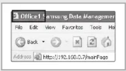
You can manage more conveniently by inputting the name that you want. The DMS name that you set on the upper side of the DMS webpage screen is displayed.
text_image
Office1 Samsung Data Manager File Edit View Favorites Tools Help Back Address http://192.168.0.7/mainPageUsing the DMS through the Web (Continued)
text_image
DMM System Control Mode: Room Control Control & Confirm MONITORING & CONTROL ERROR HISTORY Setup & Search SCHEDULE SETUP FOR POWER DISTRIBUTION ENVIRONMENT SETUP FOR POWER DISTRIBUTION RESULT OF POWER DISTRIBUTION RESTRICTED INDOOR UNIT USE SYSTEM ENVIRONMENT Log Tracking User ManagementSetting the Operation mode of A/C Running LED
text_image
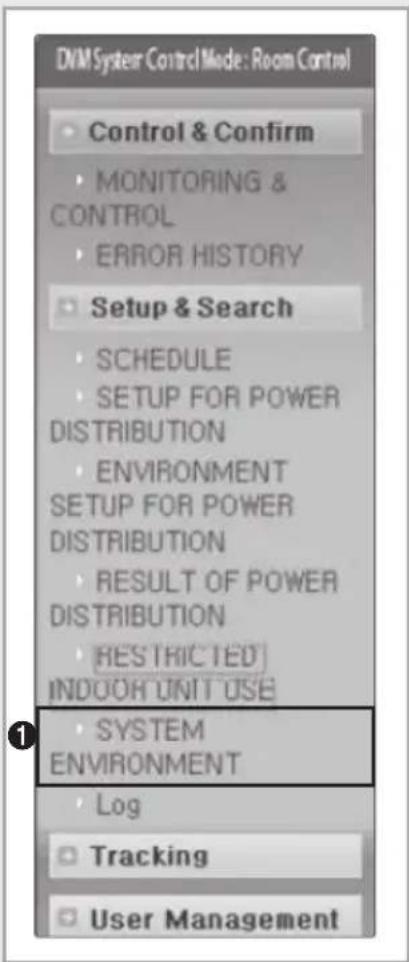
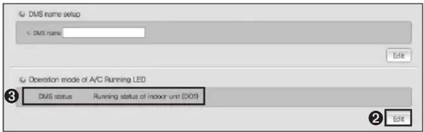
DMS name setup DMS name Edit Operation mode of A/C Running LED DMS status Running status of indoor unit (DO19) Edit1 Click 'SYSTEM ENVIRONMENT' on the DMS web page.
2 Click 'Edit' on the Operation mode of A/C Running LED.
◆ 'Edit' will change to 'Save'.
3 Select the mode you wish to set.
◆ DMS status: indicates whether or not DMS operates normally. Green light will flicker every 5 seconds when DMS operates normally.
◆ Running status of indoor unit (DO1): Solid green light will turn on if there is at least one indoor unit operating. DMS will output signal to DO1.
4 Click 'Save'.
◆ Changed setting will be saved.
Log
Function Explanation
◆ You can view the history of all the settings.
Log
| Date | Upper Controller | Item | Contents | etc. |
| 2008-02-27-21,09,47 | WEB | Power Division Environment Setting | Power Division Environment Setting | |
| 2008-02-27-16,16,43 | WEB | Power Division Environment Setting | Power Division Environment Setting | |
| 2008-02-21-13,46,55 | WEB | Tracking | individual, success, 218 Indoor units,0 indoor units(out of centralized control) | |
| 2008-02-19-13,15,01 | WEB | Power Division Environment Setting | Power Division Environment Setting | |
| 2008-02-19-13,07,50 | WEB | Tracking | Individual, success, 217 Indoor units,0 indoor units(out of centralized control) | |
| 2008-02-19-12,07,45 | WEB | Power Division Environment Setting | Power Division Environment Setting | |
| 2008-02-19-12,06,26 | WEB | Power Division Environment Setting | Power Division Environment Setting | |
| 2008-02-19-12,02,14 | WEB | Tracking | Individual, success, 217 Indoor units,0 indoor units(out of centralized control) | |
| 2008-02-19-11,48,19 | WEB | Power Division Environment Setting | Power Division Environment Setting | |
| 2008-02-19-11,33,41 | WEB | Tracking | Individual, success, 217 Indoor units,0 indoor units(out of centralized control) | |
| 2008-02-19-11,31,37 | WEB | Tracking | Individual, success, 217 Indoor units,0 indoor units(out of centralized control) | |
| 2008-02-16-15,59,24 | WEB | Power Division Environment Setting | Power Division Environment Setting | |
| 2008-02-16-15,54,02 | WEB | Tracking | Individual, success, 217 Indoor units,0 indoor units(out of centralized control) | |
| 2008-02-16-13,26,11 | WEB | Tracking | individual, success, 217 Indoor units,0 indoor units(out of centralized control) |
1 Check the setting history from the Log window.
◆ DMS saves maximum 256 histories of each setting. If the number of history exceeds 256, DMS will delete the oldest history.
Setting history will be saved in following categories: Tracking, Power distribution setting, Power distribution environment setting and Time setting.
◆ If you want to check Power distribution setting, be aware that you can only check the latest saved setting if there were number of changes made within a day.
Tracking
Function Details
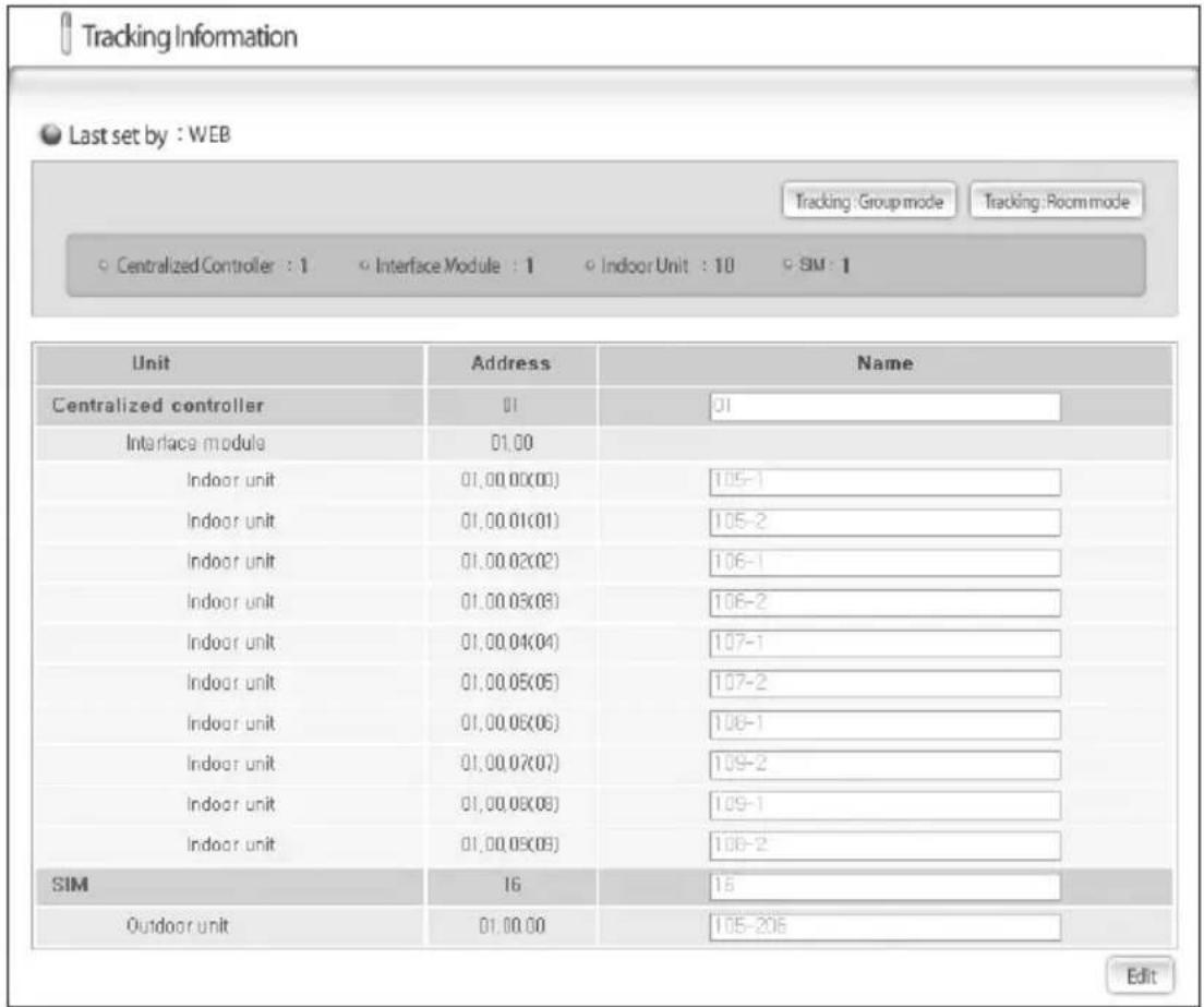
◆ Tracking is the most initial stage that a DMS recognizes the DVM indoor/outdoor units. When performing a Tracking, some information may be lost; thus, use with care. User can order the Retry of a Tracking and manage the name of devices on the Tracking information screen. (Information may be lost if 'Tracking' is executed. Consult the installer if possible when executing 'Tracking.')
text_image
Tracking Information Last set by : WEB Tracking: Group mode Tracking: Room mode Centralized Controller : 1 Interface Module : 1 Indoor Unit : 10 SM : 1 Unit Address Name Centralized controller 01 01 Interface module 01.00 Indoor unit 01,00.00(00) 105-1 Indoor unit 01,00.01(01) 105-2 Indoor unit 01,00.02(02) 106-1 Indoor unit 01,00.03(03) 106-2 Indoor unit 01,00.04(04) 107-1 Indoor unit 01,00.05(05) 107-2 Indoor unit 01,00.06(06) 108-1 Indoor unit 01,00.07(07) 109-2 Indoor unit 01,00.08(08) 109-1 Indoor unit 01,00.09(09) 109-2 SIM 16 15 Outdoor unit 01,00.00 105-206 Edit1 Press 'Tracking Group mode' or 'Tracking Room mode'.
◆ Group mode: Tracking by searching the indoor unit RMC address.
◆ Room mode: Tracking by searching the indoor unit Main address.
text_image
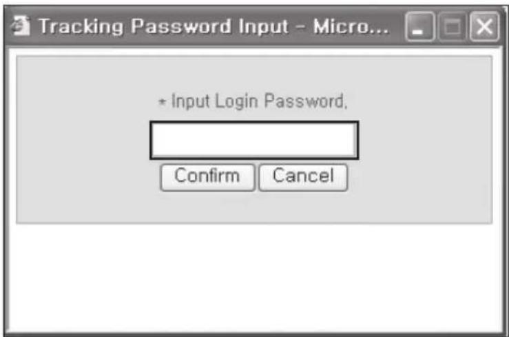
Tracking Password Input - Micro... * Input Login Password, Confirm Cancel2 When the Tracking Password Input window appears, enter the password.
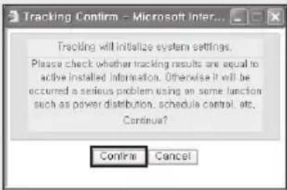
3 When the Tracking Confirm window appears, press 'Confirm'.
◆ Tracking will start.
text_image
Tracking Confirm - Microsoft Inter... Tracking will initialize system settings. Please check whether tracking results are equal to active installed information. Otherwise it will be occurred a serious problem using an some function such as power distribution, schedule control, etc. Continue? Continue CancelUsing the DMS through the Web (Continued)
text_image
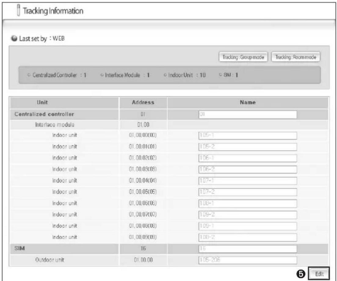
Tracking Information Last set by : WEB Tracking:Groupmode Tracking:Roommode Centralized Controller : 1 Interface Module : 1 Indoor Unit : 10 SM : 1 Unit Address Name Centralized controller 01 01 Interface module 01.00 Indoor unit 01,00,00(00) 105-1 Indoor unit 01,00,01(01) 105-2 Indoor unit 01,00,02(02) 106-1 Indoor unit 01,00,03(03) 106-2 Indoor unit 01,00,04(04) 107-1 Indoor unit 01,00,05(05) 107-2 Indoor unit 01,00,06(06) 108-1 Indoor unit 01,00,07(07) 109-2 Indoor unit 01,00,08(08) 109-1 Indoor unit 01,00,09(09) 108-2 SIM 16 16 Outdoor unit 01.00.00 105-206 5 Edit4 Notification with 'Now tracking, please wait' sign will appear.
◆ Tracking may take from few seconds up to 3 minutes. Tracking time may differ depending on the number for controllers.
5 When the tracking is done, press 'Edit'.
◆ When the tracking fails, re-start the tracking.
◆ 'Edit' button will change to 'Save' button.
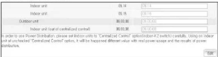
◆ Following window will appear when there are indoor units not using the centralized control.
text_image
Indoor unit 09.14 09.14 Indoor unit 09.15 09.15 Outdoor unit 09.00.00 09.00.00 Indoor unit (out of centralized control) 09.00.00 09.00.00 In order to use Power Distribution, please set Indoor units to "Centralized Control" option(indoor-K2 switch) carefully. Using on indoor unit of unchecked "Centralized Control" option, it will be happened different value with real power usage and the results of power distribution. Edit◆ If you have selected 'Tracking Room mode', indoor unit RMC address will be displayed.
◆ If there are MIM-A202A and MIM-B13A transmitters connected to the DMS, outdoor unit information on tracking result will show as below.

text_image
Outdoor unit(09,00) 60,00,00 12,01,00 Outdoor unit(09,00) 10,02,00 10,02,00 Outdoor unit(09,00) 11,01,00 11,01,00 Edit* 09.00 transmitter, 10.02 transmitter, 11.01 transmitter is connected to the same outdoor unit.
text_image
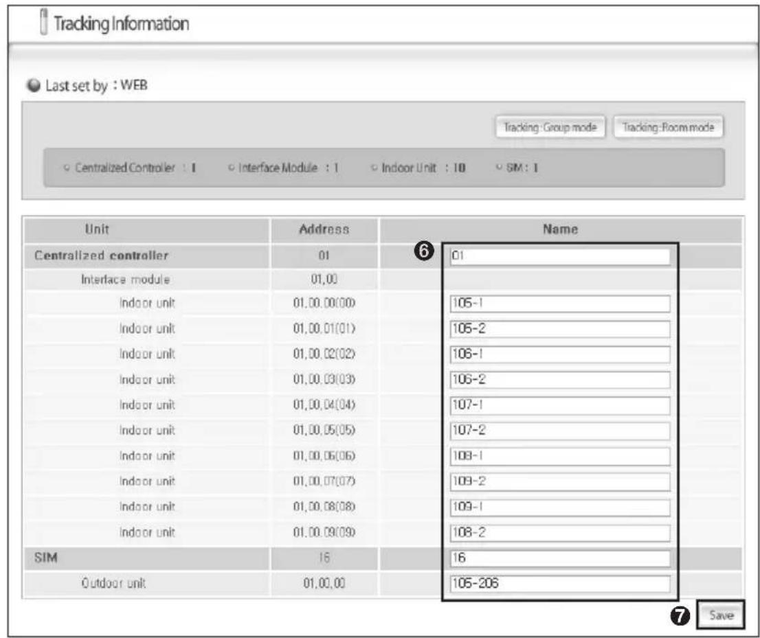
Tracking Information Last set by : WEB Tracking:Group mode Tracking:Room mode Centralized Controller : 1 Interface Module : 1 Indoor Unit : 10 SIM : 1 Unit Address Name Centralized controller 01 6 01 Interface module 01,00 Indoor unit 01,00.00(00) 105-1 Indoor unit 01,00.01(01) 105-2 Indoor unit 01,00.02(02) 106-1 Indoor unit 01,00.03(03) 106-2 Indoor unit 01,00.04(04) 107-1 Indoor unit 01,00.05(05) 107-2 Indoor unit 01,00.06(06) 108-1 Indoor unit 01,00.07(07) 109-2 Indoor unit 01,00.08(08) 109-1 Indoor unit 01,00.09(09) 108-2 SIM 16 16 Outdoor unit 01,00,00 105-206 Save6 Enter the name of the centralized controller and the indoor units.
7 Press 'Save'.
◆ Changed name of the centralized controller and the indoor unit will be saved on DMS.
Using the DMS through the Web (Continued)
Note Do not run Tracking except for the following conditions:
◆ After initial installation.
- After initial installation, run Tracking for DMS to recognize the installation structure.
- Make sure actual system air conditioner information matches the Tracking information displayed on DMS.
- When the actual system air conditioner information does not match the Tracking information on DMS, check the installation.
◆ Changes in installation
- After additional installation of the unit, if Tracking has not been performed, DMS cannot recognize the additional units and the controlling, monitoring and power distribution to the unit will not be available.
- After removing of the unit, if Tracking has not been performed, DMS may distribute power to the removed unit and the error on power distribution result may occur.
CAUTION
Make sure actual system air conditioner information matches the Tracking information displayed on DMS.
- When the actual system air conditioner information does not match the Tracking information on DMS, check the installation.
- When the actual information does not match the Tracking information on DMS, power distribution result error may occur, and abnormal Peak power management may lead to Peak occurrence.
- If you do not know whether information matches or not, do not run Tracking.
◆ Run Tracking when there are no communication errors between each devices and the DMS.
- Device with communication error will not be recognized on DMS therefore, monitoring, controlling and power distribution cannot be done.
- If Tracking has been run and there are communication error between centralized controller and the transmitter, you cannot bring information on the indoor units connected to the Transmitter.
- If Tracking has been run and there are communication error between centralized controller and the DMS, you cannot bring information on the indoor units connected to the Centralized controller.
Do not run Tracking when the outdoor unit circuit breaker switch is off.
- If Tracking has been run when the outdoor unit circuit breaker switch is off, DMS can not recognize the outdoor unit.
- Since DMS cannot recognize the outdoor unit, all the indoor units connected to this outdoor unit can not be recognized as well and therefore controlling, monitoring and the power distribution is not available.
◆ Do not run Tracking when the Centralized controller is off.
- If Tracking has been run when the outdoor Centralized controller is off, DMS can not recognize the centralized controller.
- Since DMS cannot recognize the Centralized controller, all the indoor units connected to this centralized controller can not be recognized as well and therefore controlling, monitoring and the power distribution is not available.
User Management
Adding New User

User account management
| No. | ID | Password | Description | |
| 0 | admin | ********** | admin | |
| 1 | user1 | ********** | user1 | |
| 2 | user2 | ********** | user2 |


text_image
ID : Password : Description :
Add
Edit
Delete
1 Click 'USER MANAGEMENT' on the DMS web page.
2 When User Management screen appears, enter user ID, Password and Description.
ID should be 4\~10 letters long, starting with a alphabet and can be used with numbers.
3 Click 'Add'.
◆ There are no limits on number of users.
◆ Entered user information will be saved on DMS.
Note
DMS manager should change the ID and the password for security and maintenance.
Using the DMS through the Web (Continued)
Editing User
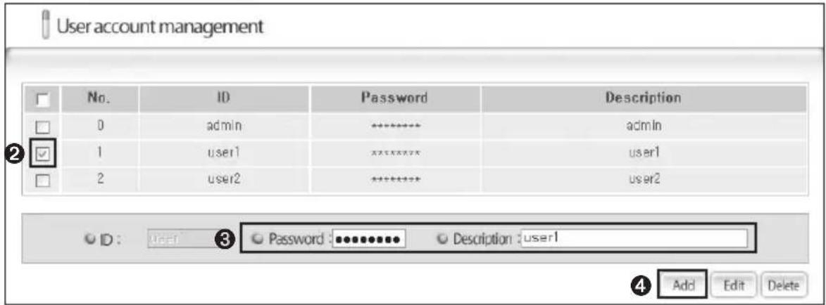
text_image
User account management No. ID Password Description 0 adults statistically admin 1 user1 statistically user1 2 user2 statistically user2 ID: User 3 Password: Statistical Description: user1 4 Add Edit Delete1 Click 'USER MANAGEMENT' on the DMS web page.
2 When User Management screen appears, select the user you wish to edit.
- You can select number of users at once or select individual user.
3 Edit the Password and the Description on selected ID.
◆ ID cannot be edited.
4 Click 'Edit'.
◆ Edited user information will be saved on DMS.
Deleting User
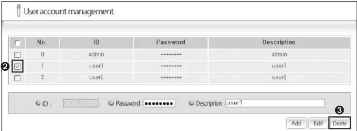
text_image
User account management No. ID Password Description 0 admin---------------------------- admin 1 User1---------------------------- user1 2 user2---------------------------- user2 ID: User1 Password: ********... Description: user1 Add Edit Delete1 Click 'USER MANAGEMENT' on the DMS web page.
2 When User Management screen appears, select the user you wish to delete.
◆ You can select number of users at once or select individual user.
3 Click 'Delete'.
- If confirmation window appears, click 'OK' to delete selected user.
Software License used in this product
This product uses softwares distributed under GPL and LGPL license. Therefore, you can receive the source code of GPL and LGPL used in this product by requesting the email address below.
▶ E-mail : oss.request@samsung.com
GPL Software
- Monta Vista Linux Kernel 2.4.20
- PeerSec Networks MatrixSSL Evaluation
- busybox-1.00
- yaffs
- vivi
- console-tools-0.2.3
- commerr-dev-1.2.7
- e2fsprogs-1.27
-gcc-3.3.1
- samba-2.2.8
- pam-0.72
- procps-2.0.14
-dhcpcd
- ifupdown-0.6.4
▶ LGPL software
- glibc-2.3.2
- util-linux-2.11h
◆ The software used in this product is developed from Apache Software Foundation (http://www.apache.org/)
This product includes software developed by the Indiana University Extreme! Lab. For further information, please visit http://www.extreme.indiana.edu/
◆ This product uses the cryptographic software developed by Eric Young(eay@cryptsoft.com)
- Jaxen and Mail4me are used in this product.
This product uses the software developed by OpenSSL Project for the use of OpenSSL Tookit.
◆ Berkeley DB software is used in this product. The source code of Berkeley DB software can be received when request to the following email address or can be downloaded from the website.
E-mail: oss.request@samsung.com
▶ Berkeley DB software : db-3.2.9
◆ Refer to 'APPENDIX' for original text of licence.
(1) GPL2.0
(2) LGPL2.1
(3) ApacheLicense1.1
(4) Enhydra Public License 1.1
(5) dom4j-license
(6) ISC-license
(7) jaxen-license
(8) ncurses-license
(9) pullparser2-license
(10) OracleBerkleyDBLicense
(11) libxml2License
(12) pam-license
(13) OpenSSL Combined License
(14) tcp-wrapper license
(15) BSD-license
(16) pure-ftpd license
(17) OpenSSH license