
MIM-B16N - Air-conditioner SAMSUNG - Free user manual and instructions
Find the device manual for free MIM-B16N SAMSUNG in PDF.


User questions about MIM-B16N SAMSUNG
0 question about this device. Answer the ones you know or ask your own.
Ask a new question about this device
Download the instructions for your Air-conditioner in PDF format for free! Find your manual MIM-B16N - SAMSUNG and take your electronic device back in hand. On this page are published all the documents necessary for the use of your device. MIM-B16N by SAMSUNG.
USER MANUAL MIM-B16N SAMSUNG
Air Conditioner installation manual
imagine the possibilities
Thank you for purchasing this Samsung product.
Contents
Before installation
Safety Precautions ....3
Accessories 4
Viewing the Parts ....5
PIM System Architecture 8
Installing the product
Installing the PIM 9
Setting the PIM 15
PIM Menu Description....16
Safety Precautions
This installation manual describes how to install the PIM. For installation of other optional accessories, refer to the appropriate installation manual.
 WARNING WARNING | Hazards or unsafe practices that may result in severe personal injury or death. |
 CAUTION CAUTION | Hazards or unsafe practices that may result in minor personal injury or property damage. |

WARNING
Read carefully this installation manual before installation and check if the PIM is installed correctly after installation.
▶ Do not attempt to install or repair this PIM by yourself.
This PIM contains no user-serviceable parts.
Always consult authorized service personnel for repairs.
▶ When moving, consult authorized service personnel for disconnection and installation of the PIM.
▶ Ensure that the wall is strong enough to support the weight of the PIM.
▶ Must install the PIM with rated power supply.
The PIM must be installed according to the national electrical rules by an installation specialist.
▶ If you wish to uninstall the PIM, consult an authorized installation center.

CAUTION
▶ Do not use inflammable gases near the PIM.
▶ Do not install the PIM in a location where it will come into contact with combustible gases, machine oil, sulphide gas, etc.
▶ Avoid locations where acid/alkali solution or special spray is used.
▶ Choose a location that is dry and sunny, but not exposed to direct sunlight. Suitable temperature is between 0^(32^) and 39^(102.2^) .
▶ Do not spill water into the PIM.
▶ Do not apply tensile strength to the cable to avoid cable damage.
▶ Do not press the buttons with a sharp object.
▶ Do not connect the power cable to the control terminal.
▶ If the PIM is installed in a hospital or other special places, it should not affect other electronic devices.
Accessories
Make sure you have each item. Supplied items may vary depending on your country or service provider. The type and quantity may differ depending on the specifications.
| Item PIM | Adapter Power cable | M4x16 Screw | Installation manual | Cable tie | ||
| Quantity 1 | 1 6 1 1 | |||||
| Shape |  | 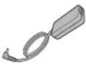 | 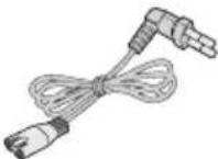 |  |

• The PIM must be installed by a trained installer.
• Ensure the main power is turned off before installing the PIM.
• Be sure to use adapter and power cable we provide.
- The power cable and the communication cable must be installed according to the national electrical wiring regulations. (Use 2C x 0.75mm ^2 communication cable.)
Viewing the Parts
Main Parts
PIM Exterior
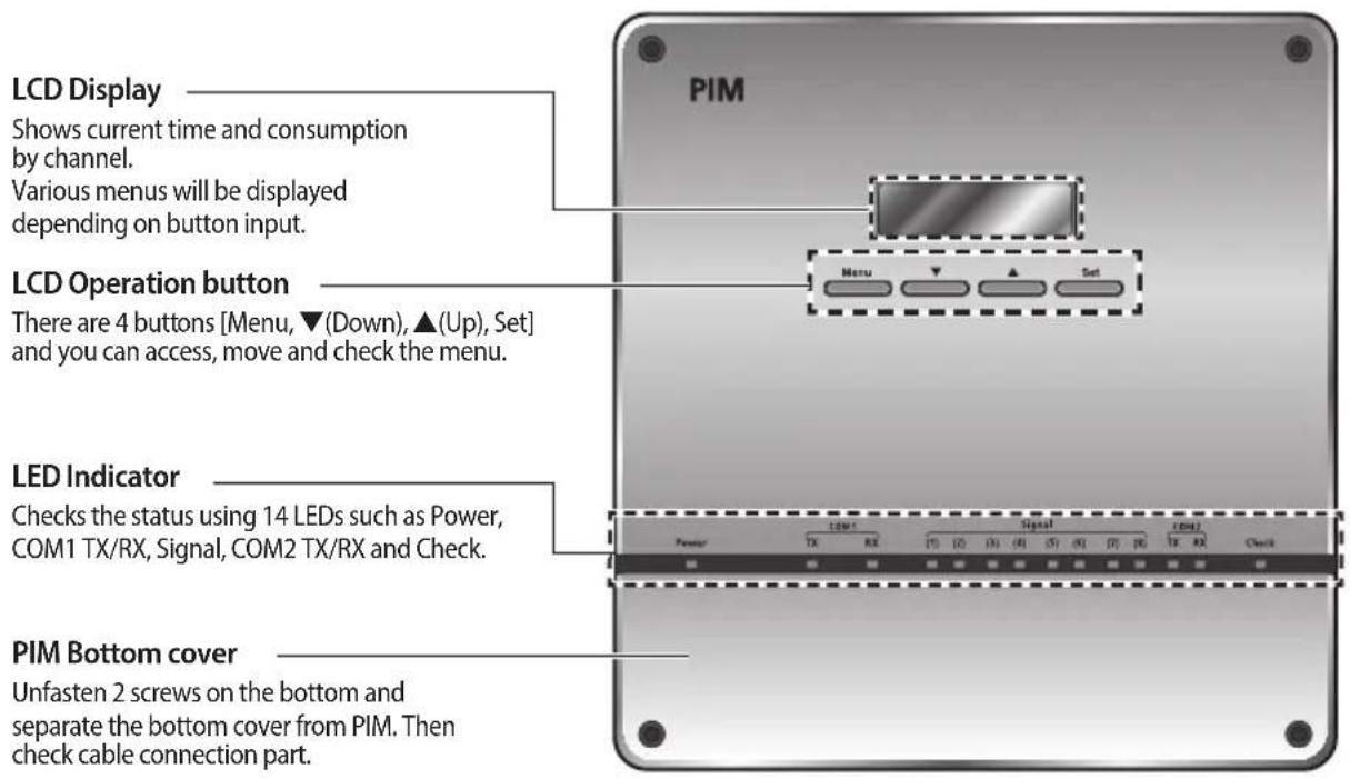
text_image
LCD Display Shows current time and consumption by channel. Various menus will be displayed depending on button input. LCD Operation button There are 4 buttons [Menu, ▼(Down), ▲(Up), Set] and you can access, move and check the menu. LED Indicator Checks the status using 14 LEDs such as Power, COM1 TX/RX, Signal, COM2 TX/RX and Check. PIM Bottom cover Unfasten 2 screws on the bottom and separate the bottom cover from PIM. Then check cable connection part.Explanation of LED Indicator
| Item Name Status | ||
| Power Power indicator | Turns blue when the power is supplied. | |
| COM1 TX/RX | Data transmission/reception with DMS indicator | Blinks in orange during the normal transmission/reception. |
| Signal (1)~(8) Input pulse | Indicator | Blinks in orange when a normal pulse is input from the meter. |
| COM2 TX/RX Reserved | Reserved | |
| Check Error indicator | Blinks in orange when the error occurs. (It will be off when the error is cleared.) | |
Viewing the Parts
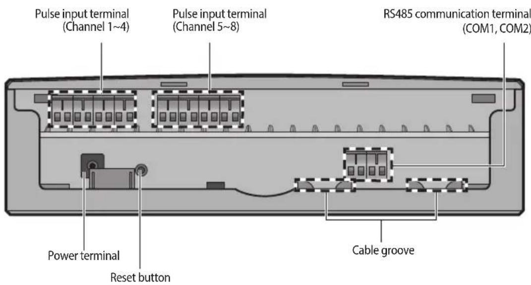
PIM Cable Connection Part
text_image
Pulse input terminal (Channel 1~4) Pulse input terminal (Channel 5~8) RS485 communication terminal (COM1, COM2) Power terminal Reset button Cable groove| Name Description | |
| Pulse input terminal(CH1~CH8) | Terminal that the pulse from Meter is inputted(Channel1~Channel8)※ Dry contact must be connected. |
| Power terminal Terminal to connect PIM adapter | |
| Reset button Button used to reset PIM | |
| RS485 Communication terminal | COM1: Connection terminal for RS485 communication with DMS※ COM2 : Not in use (It will be used for MODBUS in the future) |
| Cable groove Groove for arranging cables | |
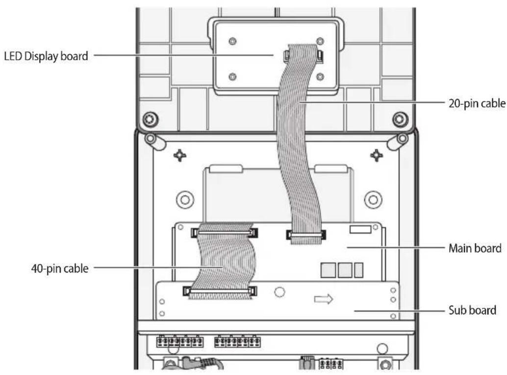
text_image
LED Display board 20-pin cable 40-pin cable Main board Sub boardProduct Dimensions
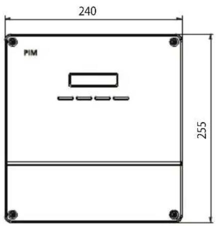
text_image
240 PIM 255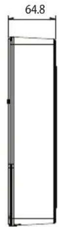
text_image
64.8(Unit: mm)
PIM System Architecture
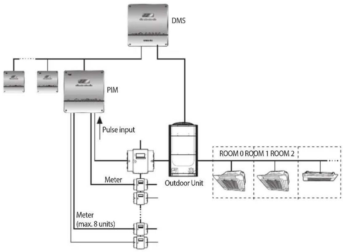
flowchart
graph TD
    A["Outdoor Unit"] -->|Pulse input| B["PIM"]
    B --> C["DMS"]
    C --> D["Room 0 Room 1 Room 2"]
    B --> E["Meter (max. 8 units)"]
    E --> F["Room 1 Room 2"]
    style A fill:#f9f,stroke:#333
    style B fill:#ccf,stroke:#333
    style C fill:#cfc,stroke:#333
    style D fill:#fcc,stroke:#333
    style E fill:#cff,stroke:#333
    style F fill:#ffc,stroke:#333
▶ Maximum 8 PIM units can be connected to DMS.
▶ Maximum 8 meter(Power/Gas/Water) can be connected to PIM.
Installing the PIM
Installing the PIM on the Wall
-
Separate the installation plate on the rear side of PIM.
-
Fix the installation plate on the wall using 4 screws.
-
Hang the PIM on the groove which is on the top of the installation plate.
-
Open the bottom cover and fix the installation plate and PIM using 2 screws.
-
Depending on the installation environment, open the top cover and fix PIM using assistant holes. (Screws for assistant hole are not provided.)
-
If you install PIM inside of the wall or wiring from the rear side is needed, use wiring groove on the bottom of PIM.
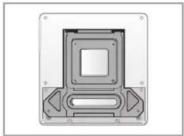
natural_image
Technical diagram of a mechanical component with mounting holes and internal cavities (no text or symbols)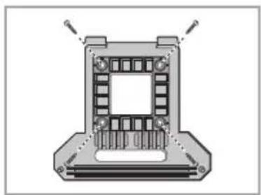
natural_image
Mechanical component diagram showing a rectangular housing with internal slots and mounting base (no text or symbols)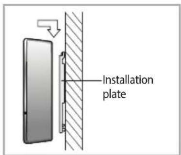
text_image
Installation plate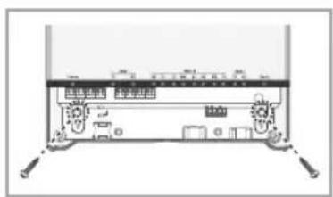
text_image
经典读取 经典读取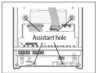
text_image
Assistant hole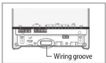
text_image
Wiring groove
• To prevent breakdown and damage of PIM and for safe usage, it is recommended to install PIM on the wall.
Installing the PIM
Connecting a Meter, PIM and DMS
Connecting a Meter and PIM
-
Unfasten the 2 screws on the bottom of the PIM front cover. Hold the bottom 2 sides of the PIM and push downwards to slide open the cover.
-
Connect the adapter to the power terminal.
-
Arrange the adapter as shown in the figure.
-
Connect PIM and a Meter as many as you want. In this step, use communication cable and 8 terminal blocks which are attached to the pulse input terminal of PIM.
-
For the communication cable connection instruction of a Meter or additional setting instruction, refer to the installation manual of a Meter.
- Connect the communication cable considering the polarity. [Left:(+), Right:(-)]
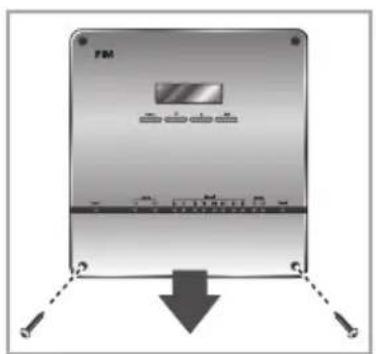
text_image
FM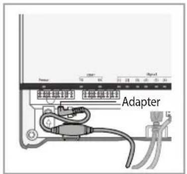
text_image
Server Adapter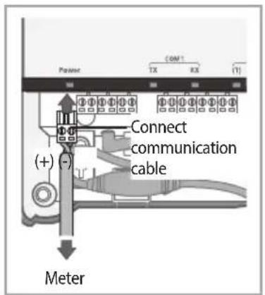
text_image
Carrier COM1 TX RX (1) Connect communication cable (+) (-) Meter
CAUTION
• Maximum 8 meter(Power/Gas/Water) can be connected to 1 PIM.
• Use 2Cx0.75mm communication cable.
Meter without Separate External Output
▶ If the pulse constant(Wh/Pulse/Pulse or L/Pulse) value is an integer, connection is possible.
e.g. Pulses per kWh : 1,000 converted to → 1Wh/Pulse, Connection is possible!
e.g. Pulses per kWh : 10,000 converted to → 0.1Wh/Pulse, Connection is not possible!
Meter with Separate External Output
▶ Connect according to the pulse output specification.
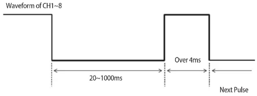
Meter must have more than 4ms Delay Between the First Pulse Input and the Next Pulse
text_image
Waveform of CH1~8 Over 4ms 20~1000ms Next Pulse
Limit of Connectable Meter
- Pulse constant range
- Power : 1Wh/Pulse \~ 10,000Wh/Pulse
- Gas : 0.001m³/Pulse \~ 10m³/Pulse
- Water : 1L/Pulse \~ 10.000L/Pulse
• Pulse width range: 20\~1000ms.
Installing the PIM
Connecting PIM to DMS
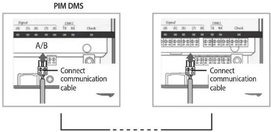
- Connect 'COM1' terminal of PIM and DMS terminal block with communication cable.
- Pay special attention about the polarity when connecting RS485 communication. (A of PIM ↔ A of DMS, B of PIM ↔ B of DMS)
text_image
PIM DMS Signal COM2 TX RX Check A/B Connect communication cable Signal COM2 TX RX Check Connect communication cable- Close the bottom cover and fix it using 2 screws.
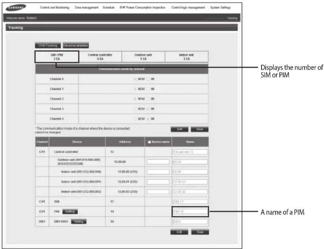
▶ When execute tracking with PIM which connected to DMS
text_image
Control and Monitoring Zone management Schedule EHP Power Consumption Inspection Control logic management System Settings Tracker arm: SIM/AT Tracking Oracle Tracking Declared allowed SIM /PIM 2 EA Central controller 0 EA Outdoor unit 1 EA Indoor unit 3 EA Communication mode by channel Channel 0 NEW IR Channel 1 NEW IR Channel 2 NEW IR Channel 3 NEW IR Channel 4 NEW IR * The communication mode of a channel where the device is connected cannot be changed. Edit Save Channel Device Address Device name Name: CH1 Central controller 52 VirtualCode-12 Outdoor unit (001.016.000.000) (EEEEEEEEEEEE) Indoor unit (001.032.000.000) Indoor unit (001.032.000.001) Indoor unit (001.032.000.002) CH1 SIM 17 SIM-17 CH1 PM Seling 18 PM-18 DNS DNS BDD Seling 34 INFO Edit Save Displays the number of SIM or PIM A name of a PIM* For the further information about tracking, refer to the DMS user manual.
▶ If PIM is connected to DMS, PIM setting through DMS web is possible.
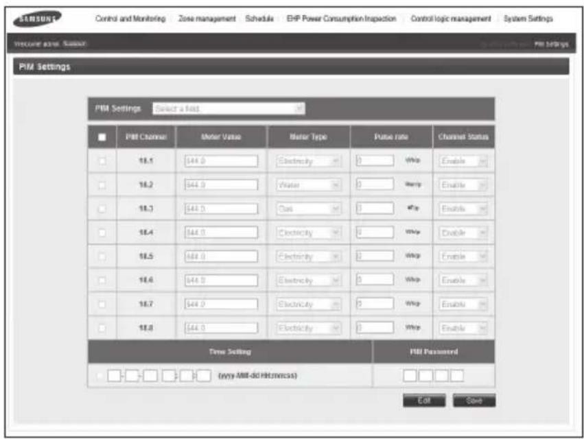
text_image
SANSUN Control and Monitoring Zone management Schedule EHP Power Consumption Inspection Control logic management System Settings Welcome empty Support PMI Settings PMI Settings Select a load PMI Channel Motor Value Motor Type Pulse rate Channel Status 18.1 544.0 Electricity 0 Whip Enable 18.2 544.0 Water 0 Help Enable 18.3 544.0 Gas 1 Whip Enable 18.4 544.0 Electricity 0 Whip Enable 18.5 544.0 Electricity 1 Whip Enable 18.6 544.0 Electricity 0 Whip Enable 18.7 544.0 Electricity 2 Whip Enable 18.8 544.0 Electricity 1 Whip Enable Time Setting PMI Password (why AMI-do Hidemncss) Edit Save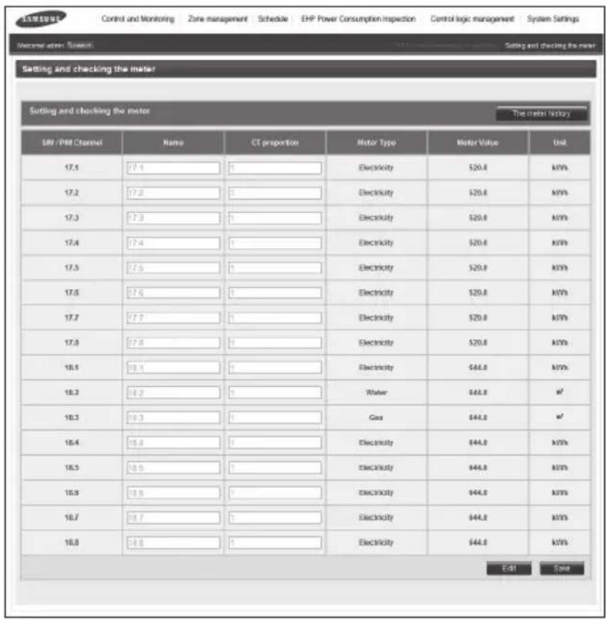
text_image
SAMSUNG Control and Monitoring Zone management Schedule EHP Power Consumption Inspection Control logic management System Settings Welcome at: 500mm Setting and checking the meter Setting and checking the meter The meter history SN / PM Channel Name CT proportion Motor Type Motor Value Unit 17.1 17.4 0 Electricity $20.0 MWh 17.2 17.3 0 Electricity $20.0 MWh 17.3 17.3 0 Electricity $20.0 MWh 17.4 17.4 0 Electricity $20.0 MWh 17.5 17.5 0 Electricity $20.0 MWh 17.6 17.6 0 Electricity $20.0 MWh 17.7 17.7 0 Electricity $20.0 MWh 17.8 17.8 0 Electricity $20.0 MWh 18.1 18.1 0 Electricity $44.0 MWh 18.2 18.2 0 Water $44.0 m² 18.3 18.3 0 Gas $44.0 m² 18.4 18.4 0 Electricity $44.0 MWh 18.5 18.5 0 Electricity $44.0 MWh 18.6 18.6 0 Electricity $44.0 MWh 18.7 18.7 0 Electricity $44.0 MWh 18.8 18.8 0 Electricity $44.0 MWh E-51 SaveInstalling the PIM
Installing more than 2 PIM Units to 1 DMS
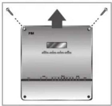
- Unfasten the 2 screws on the top of the PIM. Hold the top 2 sides of the PIM and pull it the cover upwards to open the cover.
text_image
FM www.nanm.cfm-veilms-
Set the PIM address using rotary switch of main PCB. (Default setting: 30H)
-
Rotary Switch #1 : Not in use
- Rotary Switch #2:0 \~ F (30H \~ 3FH)
| Rotary Switch #1 | Communication Address | Rotary Switch #2 | Communication Address | DMS Address |
| 0 N/A | 0 30H 16 | |||
| 1 N/A | 1 31H 17 | |||
| 2 N/A | 2 32H 18 | |||
| 3 N/A | 3 33H 19 | |||
| 4 N/A | 4 34H 20 | |||
| 5 N/A | 5 35H 21 | |||
| 6 N/A | 6 36H 22 | |||
| 7 N/A | 7 37H 23 | |||
| 8 | N/A | 8 | 38H | * The PIM communication addresses on the left side (8~F) are assigned for system extension in the future. Therefore, do not set the addresses as they will not be recognized with a DMS. |
| 9 N/A | 9 39H | |||
| A N/A | A 3AH | |||
| B N/A | B 3BH | |||
| C N/A | C 3CH | |||
| D N/A | D 3DH | |||
| E N/A | E 3EH | |||
| F N/A | F 3FH |


- Close the top PIM cover and fix it using 2 screws.
Error Codes
| Display Explanation | |
| E613 Error which occurs when there is no communication between DMS and PIM for 15 minutes. | |
| E632 | Error which occurs when the pulse was input differently from the PIM setting.(If the pulse was inputted at the value outside of 10 ms ~ 1500 ms range for more than 15 times or when high pulse was inputted for over 3 minutes) |
| E654 | Memory Read/Write error. |
| E108 | Error which occurs when same address was assigned to different devices. |
Setting the PIM
Setting the PIM(Mandatory)
It is mandatory when you connect Meter and PIM.
Setting the Password
2.1 Password Password Set
Set your P/W

Main menu → 2. Configuration → 2.1 Password.
Default:0000
For the further information, refer to page 20.
Setting the Date/Time
Set Current Date 2010.01.05
Set Current Time 11:25:09(PM)
Main menu → 2. Configuration → 2.4 Date&Time
For the further information, refer to page 24\~25.
▶ The display above is an example.
Setting for the Connected meter type and pulse rate
Setting the meter type
- Configuratuion 2.2 Meter Type
For the further information, refer to page 22.
Setting the meter pulse rate
- Configuratuion 2.3 Pulse Rate
2.3 Pulse Rate CH1:00100Wh/P
Main menu → 2. Configuration → 2.3 Pulse Rate
For the further information, refer to page 23.
PIM Menu Description
Menu Configuration

flowchart
graph TD
    A["Normal Display"] --> B["Current Time"]
    B --> C["CH1: 00000.0kWh\nCH2: 00000.0kWh\n...\nCH8: 00000.0kWh"]
    C --> D["1. Monitoring 1.1 Address"]
    D --> E["1.2 Option S/W"]
    D --> F["1.3 Micom Ver."]
    D --> G["1.4 DB Code"]
    C --> H["2. Configuration"]
    H --> I["2.1 Password"]
    H --> J["2.2 Meter Type"]
    H --> K["2.3 Pulse Rate"]
    H --> L["2.4 Date&Time"]
    H --> M["2.5 Channel Use"]
    H --> N["2.6 Value Set"]
    H --> O["2.7 Value Clear"]
    C --> P["3. Check"]
    P --> Q["3.1 Pulse Input"]
    P --> R["3.2 COM' Check"]
    P --> S["3.3 Pulse Width"]
    style A fill:#ccc,stroke:#333
    style P fill:#ccc,stroke:#333
Normal Display
-
When the power is connected, current PIM address and software version will be displayed.
-
Example display: PIM address 58 30 FF
Software version DB91-01128A - "Address:58 30 FF" is an example. It is subject to change according to the setting.
Device Info.
Type:PIM
Device Info.
Addr.: 58 30 FF
Device Info.
DBC:DB91-01128A
- Consumption of pulse input CH1\~CH8 will be displayed in order.
CH1:00000.0kWh
CH2:00000.0kWh
- Current time will be displayed after the consumption of CH8.
It displays CH1\~CH8 and current time repeatedly.
- You can make the display stop moving with using [Set] button for easy view.
- You can find which channel you want to see with using the [▲], [▼] buttons.
PIM Menu Description
Monitoring Menu
Address
- Access to main menu by pressing the [Menu] button from the normal display. Then select '1.Monitoring' by pressing the [Set] button.
Main Menu
-
Monitoring
-
To check the Address, press the [Set] button when '1.1 Address' appears.
-
Monitoring
1.1 Address
1.1 Address
58 30 FF

NOTE
"58 30 ff" is an example. It is subject to change according to the setting.
• Make sure to reset the PIM after changing the rotary switch.
- First byte represents PIM (58), second byte represents assigned address (between 30\~3F) and last byte is fixed to FF.
- After checking, press the [Menu] button to move to upper menu or cancel the setting.
- All menus will return to the normal display if there is no input for 1 minute.
Option Switch(for monitoring only)
-
Access to main menu by pressing the [Menu] button from the normal display. Then select '1.Monitoring' by pressing the [Set] button.
-
Monitoring
1.2 Option S/W
- Move to '1.2 Option S/W' menu by pressing the [▲], [▼] buttons, then select it by pressing the [Set] button.
1.2 Option S/W
1X

NOTE
Example display : 1X
- After the checking, press the [Menu] button to move to upper menu or cancel the setting.
- All menus will return to the normal display if there is no input for 1 minute.
- Access to main menu by pressing the [Menu] button from the normal display. Then select '1.Monitoring' by pressing the [Set] button.
Main Menu 1. Monitoring
-
To check the Micom Version, press the [Set] button when '1.3 Micom Ver.' appears.
-
Monitoring 1.3 Micom Ver.
1.3 Micom Ver. 130123

• "130123" is an example.
- After checking, press the [Menu] button to move to upper menu or cancel the setting.
- All menus will return to the normal display if there is no input for 1 minute.
DB Code
- Access to main menu by pressing the [Menu] button from the normal display. Then select '1.Monitoring' by pressing the [Set] button.
Main Menu 1. Monitoring
-
To check the DB Code, press the [Set] button when '1.4 DB Code' appears.
-
Monitoring 1.4 DB Code
1.4 DB Code DB91-01128A

- "DB91-01128A" is an example.
- After checking, press the [Menu] button to move to upper menu or cancel the setting.
- All menus will return to the normal display if there is no input for 1 minute.
PIM Menu Description
Configuration menu
Setting the Password
▶ You should enter the password to use Configuration menu.
Password Set
- Access to main menu by pressing the [Menu] button from the normal display. Then select '2.Configuration' by pressing the [▲], [▼] buttons, and press the [Set] button.
Main Menu 2.Configuration
- Enter the password using the [▲], [▼] buttons and press the [Set] button.
- The default password is '0000'.
Enter your P/W 0:0:0:0
-
Select '2.1 Password' by pressing the [Set] button.
-
Configuration 2.1 Password
-
Select 'Password Set' by pressing the [Set] button to set the new password.
2.1 Password Password Set
- Set the new password using the [▲], [▼] buttons and press the [Set] button.
Set your P/W ■: ■: ■: ■
- Press the [Set] button to save the setting.
Save Settings 0:0:0:0
- After the setting, press the [Menu] button to move to upper menu or cancel the setting.
- All menus will return to the normal display if there is no input for 1 minute.
Password Reset
- Access to main menu by pressing the [Menu] button from the normal display. Then select '2.Configuration' by pressing the [▲], [▼] buttons, and press [Set] button.
Main Menu 2.Configuration
- Enter the password using the [▲], [▼] buttons and press the [Set] button.
- The default password is '0000'.
Enter your P/W 0:0:0:0
-
Select '2.1 Password' by pressing the [Set] button.
-
Configuration 2.1 Password
-
Select 'Password Reset' by pressing the [Set] button to reset the password.
2.1 Password Password Reset
- Press the [Set] button to reset the password. To cancel resetting, press the [Menu] button.
- If you press the [Set] button, the password will reset to '0000'.
Are you sure? YES:Set, NO:Menu
Password Reset 0:0:0:0
- After the setting, press the [Menu] button to move to upper menu or cancel the setting.
- All menus will return to the normal display if there is no input for 1 minute.
PIM Menu Description
Setting the Meter Type
▶ You can set the meter type.
- Access to main menu by pressing the [Menu] button from the normal display. Then select '2.Configuration' by pressing the [▲], [▼] buttons, and press the [Set] button.
Main Menu 2.Configuration
- Enter the password using the [▲], [▼] buttons and press the [Set] button.
- The default password is '0000'.
Enter your P/W 0:0:0:0
-
Select '2.2 Meter Type' by pressing the [▲], [▼] buttons and then press the [Set] button.
-
Configuration 2.2 Meter Type
-
Move to the channel you want to set by pressing the [▲], [▼] buttons, and then press the [Set] button.
- You can select each channel or all channel altogether.
-
Modify the meter type by pressing the [▲], [▼] buttons.
-
Dafult value: Power Meter
- Type: Power Meter, Gas meter, Water Meter
- To apply same type of the meter to all channels at once, select 'ALL Channel' in step 4.
-
Press the [Set] button to save the setting.
-
After the setting, press the [Menu] button to move to upper menu or cancel the setting.
- All menus will return to the normal display if there is no input for 1 minute.
▶ You can set the pulse constant (Wh/Pulse/Pulse or L/Pulse) value of the meter connected to each channel.
- Access to main menu by pressing the [Menu] button from the normal display. Then select '2.Configuration' by pressing the [▲], [▼] buttons, and press the [Set] button.
Main Menu 2.Configuration
- Enter the password using the [▲], [▼] buttons and press the [Set] button.
- The default password is '0000'.
Enter your P/W 0:0:0:0
-
Select '2.3 Pulse Rate' by pressing the [▲], [▼] buttons and then press the [Set] button.
-
Configuratuion 2.3 Pulse Rate
-
Move to the channel you want to set by pressing the [▲], [▼] buttons, and then press the [Set] button.
- You can select each channel or all channel altogether.
2.3 Pulse Rate CH1:00001Wh/P
- Modify the digit by pressing the [▲], [▼] buttons.
You can move to the next digit by pressing the [Set] button.
Default
- Power : 1Wh/P
- Gas : 0.001m³/P
- Water : 1L/P
Constant range
- Power: 1Wh/P \~ 10,000Wh/P
- Gas: 0.001 m^3/P 10 m^3/P
- Water : 1L/P \~ 10,000L/P
Set CH1 Value CH1:00001Wh/P
- Press the [Set] button to save the setting.
- After the setting, press the [Menu] button to move to upper menu or cancel the setting.
- All menus will return to the normal display if there is no input for 1 minute.
PIM Menu Description
Setting the Date and Time
Date setting
- Access to main menu by pressing [Menu] button from the normal display. Then select '2.Configuration' by pressing the [▲], [▼] buttons, and press [Set] button.
Main Menu 2.Configuration
- Enter the password using the [▲], [▼] buttons and press the [Set] button.
- The default password is '0000'.
Enter your P/W 0:0:0:0
- Select'2.4 Date&Time' by pressing the [▲], [▼] buttons and then press the [Set] button.
2.4 Date&Time Current Date
-
Select 'Current Date' to set the date by pressing the [Set] button.
-
Previously set date will be displayed. Press the [Set] button to set the current date. (Y/M/D) - Press the [Menu] button to return to the upper menu.
Current Date 2010.01.05
- Modify the date in order of year, month and day by pressing the [▲], [▼] buttons. You can move to the next item by pressing the [Set] button.
Set Current Date 2010.01.05
- Press the [Set] button to save the setting.
- Press the [Menu] button to return to the upper menu.
Save Settings 2010.01.05
- After the setting, press the [Menu] button to move to upper menu or cancel the setting.
- All menus will return to the normal display if there is no input for 1 minute.
Time setting
- Access to main menu by pressing [Menu] button from the normal display. Then select '2.Configuration' by pressing the [▲], [▼] buttons, and press [Set] button.
Main Menu 2.Configuration
- Enter the password using the [▲], [▼] buttons and press the [Set] button.
- The default password is '0000'.
Enter your P/W 0:0:0:0
- Select '2.4 Date&Time' by pressing the [▲], [▼] buttons and then press the [Set] button.
2.4 Date&Time Current Time
-
Select 'Current Time' to set the time by pressing the [▲], [▼] buttons and then press the [Set] button.
-
Previously set time will be displayed. Press the [Set] button to set the current time. (H/M/S)
- Press the [Menu] button to return to the upper menu.
Current Time 11:25:14(PM)
- Modify the date in order of hour, minute and second by pressing the [▲], [▼] buttons. You can move to the next item by pressing the [Set] button.
Set Current Time 11:25:09(PM)
- Press the [Set] button to save the setting.
- Press the [Menu] button to return to the upper menu.
Save Settings 11:25:17(PM)
- After the setting, press the [Menu] button to move to upper menu or cancel the setting.
- All menus will return to the normal display if there is no input for 1 minute.
PIM Menu Description
Setting the Enable/Disable Status of Channel
▶ Enable/Disable the 8 pulse input channels.
- Access to main menu by pressing the [Menu] button from the normal display. Then select '2.Configuration' by pressing [▲], [▼] buttons, and press the [Set] button.
Main Menu 2.Configuration
- Enter the password the [▲], [▼] buttons and then press the [Set] button.
- The default password is '0000'.
Enter your P/W 0:0:0:0
-
Select '2.5 Channel Use' by pressing the [▲], [▼] buttons and then press the [Set] button.
-
Configuration 2.5 Channel Use
-
Move to the channel you want to set by pressing the [▲], [▼] buttons, and then press the [Set] button.
- You can select each channel or all channel altogether.
2.5 Channel Use Channel1:En
- Enable : Press the [Set] button when 'Enable Channel#' appears.
Disable : Press the [▲], [▼] buttons and then press [Set] button when 'Disable Channel#' appears.
- To enable/disable all channels, select 'ALL' in step 4.
- Disabled channel will not be displayed on the normal display.
Enable Channel1 YES:Set, NO:Menu
Disable Channel1 YES:Set, NO:Menu
- After the setting, press the [Menu] button to move to upper menu or cancel the setting.
- All menus will return to the normal display if there is no input for 1 minute.
▶ You can set the initial value for each channel.
- Access to main menu by pressing the [Menu] button from the normal display. Then select '2.Configuration' by pressing the [▲], [▼] buttons, and press the [Set] button.
Main Menu 2.Configuration
Enter your P/W 0:0:0:0
- Enter the password the [▲], [▼] buttons and then press the [Set] button.
-
The default password is '0000'.
-
Select '2.6 Value Set' by pressing the [▲], [▼] buttons and then press the [Set] button.
-
Configuration 2.6 Value Set
2.6 Value Set CH1:00000.0kWh
- Move to the channel you want to set by pressing the [▲], [▼] buttons, and then press the [Set] button.
-
You can select each channel or all channel altogether.
-
Modify the digit by pressing the [▲], [▼] buttons. You can move to next digit by pressing the [Set] button.
- You can modify the initial value of the channel you wish to change.
- If you modify the setting, saved value will be reset and the device will re-calculate the value according to the modified value.
- To set the initial value for all channels, select 'ALL Channel' in step 4.
Set Ch1 kWh CH1:00000.0kWh
Save Settings CH1:00000.0kWh
-
Press the [Set] button to save the setting.
-
After the setting, press the [Menu] button to move to upper menu or cancel the setting.
- All menus will return to the normal display if there is no input for 1 minute.
PIM Menu Description
Initializing the usage value for each channel
- Access to main menu by pressing the [Menu] button from the normal display. Then select '2.Configuration' by pressing the [▲], [▼] buttons, and press the [Set] button.
Main Menu 2.Configuration
- Enter the password the [▲], [▼] buttons and then press the [Set] button.
- The default password is '0000'.
Enter your P/W 0:0:0:0
-
Select '2.7 Value Clear' by pressing the [▲], [▼] buttons and then press the [Set] button.
-
Configuration 2.7 Value Clear
-
Move to the channel you want to set by pressing the [▲], [▼] buttons, and then press the [Set] button.
- You can select each channel or all channel altogether.
2.7 Value Clear CH1:00000.0kWh
-
Press the [Set] button to initialize the selected channel when the caution message appears.
-
Clear : Initializes the consumption calculated so far.
- To cancel the initialization, press the [Menu] button.
- To initialize all channels, you can select 'ALL Channel' in step 4.
Are you Sure? YES:Set, No:Menu
Save Settings Clear CH1 Value
-
Press the [Set] button to save the setting.
-
After the setting, press the [Menu] button to move to upper menu or cancel the setting.
- All menus will return to the normal display if there is no input for 1 minute.
Check Menu
Pulse Input Status Check
▶ You can check the status of pulse which is input to each channel.
- Access to main menu by pressing the [Menu] button from the normal display. Then select '3. Check' by pressing the [▲], [▼] buttons, and press [Set] button.
Main Menu
-
Check
-
Select '3.1 Pulse Input' by pressing the [Set] button.
-
Check
3.1 Pulse Input
- Move to the channel you want to check by pressing the [▲], [▼] buttons, and then press the [Set] button.
- You can select each channel or all channel altogether.
Result: You can check pulse input status of the selected channel.
- If there is no pulse width limit and high lever signal is input, the result will be calculated.
3.1 Pulse Input
CH1 Check OK
CH1 Check Start
Checking...
-
The result regarding the pulse input of the channel will be displayed.(OK/NG)
-
NG will be displayed when there is no input within 10 seconds after selecting the channel.
- If the pulse input is normal : Displayed in number
If there is no pulse input : Displayed 'X' - CH1, 3, 4, 6, 8: No pulse input
-CH2,5,7:OK
- PIM does not calculate the consumption during the inspection. Calculation will start after the inspection and returning to the upper menu.
- To check the status of all channels, select 'All Check OK' in step 4.
CH1 Check End
NG
All Check End
X2XX5X7X
- After the setting, press the [Menu] button to move to upper menu or cancel the setting.
- All menus will return to the normal display if there is no input for 1 minute.
PIM Menu Description
Check the RS485 Circuit of PIM itself for Test or Service
▶ You can check if the RS485 circuit is normal when you have doubt the main board.
Before checking, connect COM1 and COM2 terminal with wire as you see the right figure.

natural_image
Pure electrical circuit lines without any symbols- Access to main menu by pressing the [Menu] button from the normal display. Then select '3. Check' by pressing the [▲], [▼] buttons, and press the [Set] button.
Main Menu
-
Check
-
Select '3.2 COM'Check' by pressing the [▲], [▼] buttons and then press the [Set] button.
-
Inspect the packet transmission/reception status with DMS.
-
Check 3.2 COM' Check
COM' Check Start Checking...
- Communication inspection result will be displayed. (OK/NG)
COM' Check End OK
- After the inspection, press the [Menu] button to move to upper menu or cancel the setting.
- All menus will return to the normal display if there is no input for 1 minute.
Checking the Pulse Width Setting Error
It checks if the pulse width setting for each channel and the pulse width of actually connected Meter are same or not.
- Access to main menu by pressing the [Menu] button from the normal display. Then select '3. Check' by pressing the [▲], [▼] buttons, and press the [Set] button.
Main Menu
-
Check
-
Select'3.3 Pulse Width' by pressing the [▲], [▼] buttons and then press the [Set] button.
-
Check
3.3 Pulse Width
- Move to the channel you want to check by pressing the [▲], [▼] buttons, and then press the [Set] button.
- It will check the status of pulse input. Then it will show the result of pulse input.
3.3 Pulse Width
CH1 Check OK
CH1 Check Start
Checking...
- The result of pulse input for the selected channel will be displayed. (OK/NG, setting, measurement)
OK: When the pulse is valid (pulse is valid when high pulse between 20 \~ 1000msec), OK (M:#####msec) will be displayed. #### represent the duration of the high pulse.
NG: When the pulse is invalid (pulse is valid when high pulse is between 20 \~1000msec), or when there's no pulse input for 10 seconds, NG (M: 0000msec) will be displayed.
- PIM does not calculate the consumption during the checking process. Calculation will start after the check and returning to the upper menu.
CH1 Check End
NG (M:0000msec)
- After the checking, press the [Menu] button to move to upper menu or cancel the setting.
- All menus will return to the normal display if there is no input for 1 minute.