
RC090MHXEA - Air-conditioner SAMSUNG - Free user manual and instructions
Find the device manual for free RC090MHXEA SAMSUNG in PDF.


| Product Type | Air-to-Water Heat Pump (Monobloc) |
| Model | RC090MHXEA |
| Power Source | 1P, 220~240 VAC, 50 Hz |
| Compressor | Rotary Inverter |
| Refrigerant | R410A, 1400 g |
| Dimensions (WxHxD, net) | 940 x 998 x 330 mm |
| Weight (net/gross) | 75 kg / 83 kg |
| Noise Level (Heat/Cool) | 63 dBA / 60 dBA |
| Water Connection (In/Out) | 1.0 inch / 1.0 inch |
| Leaving Water Temperature Range | Cooling: 5~25°C, Heating: 25~55°C |
| Operating Ambient Temperature | Heating: -20~35°C, Cooling: 10~46°C |
| Heating Performance at -10°C | 90% rated capacity |
| Frost Protection | Reliable at -20°C |
| COP (Coefficient of Performance) | 4.60 (12 kW floor heating system) |
| Energy Saving | Up to 33.3% running cost reduction vs gas boiler |
| Integrated Heating & Cooling | Plate Heat Exchanger integrated for space heating/cooling |
| Domestic Hot Water (DHW) | Supported with optional DHW tank |
| DHW Modes | Economic, Standard, Powerful |
| Water Law Function | Automatic supply temperature based on outdoor temperature |
| Schedule Programming | 7-day weekly and daily schedules for heating/cooling/DHW |
| Outing Mode | Holiday mode with reduced target temperatures |
| Urgent DHW Mode | Full capacity for hot water on demand |
| Backup Heater | Optional electric backup heater for low ambient |
| Field Setting Mode | Customizable parameters via wired remote controller |
| Safety Features | Anti-freeze, defrost, child lock, error code display |
| Wired Remote Controller | Included with LCD display and touch buttons |
| Installation | Requires qualified technician; water pipes only, no refrigerant lines |
| Maintenance | Annual check by technician; clean remote controller with soft cloth |
| Standards Compliance | Low Voltage Directive, EMC Directive, Machinery Directive (EU) |
Frequently Asked Questions - RC090MHXEA SAMSUNG
User questions about RC090MHXEA SAMSUNG
0 question about this device. Answer the ones you know or ask your own.
Ask a new question about this device
Download the instructions for your Air-conditioner in PDF format for free! Find your manual RC090MHXEA - SAMSUNG and take your electronic device back in hand. On this page are published all the documents necessary for the use of your device. RC090MHXEA by SAMSUNG.
USER MANUAL RC090MHXEA SAMSUNG
QUESTIONS OR COMMENTS?
| COUNTRY CALL OR VISIT US ONLINE AT | ||
| AUSTRIA 0800 - SAMSUNG (0800 - 7267864) www.samsung.com/at/support | ||
| BELGIUM 02-201-24-18 | www.samsung.com/be/support (Dutch)www.samsung.com/be_fr/support (French) | |
| BOSNIA 051 331 999 www.samsung.com/support | ||
| BULGARIA 800 111 31, Безплатна телефонна линия www.samsung.com/bg/support | ||
| CROATIA 072 726 786 www.samsung.com/hr/support | ||
| CZECH 800 - SAMSUNG (800-726786) www.samsung.com/cz/support | ||
| DENMARK | 70 70 19 70 | www.samsung.com/dk/support |
| FINLAND 030-6227 515 www.samsung.com/fi/support | ||
| FRANCE | 01 48 63 00 00 | www.samsung.com/fr/support |
| GERMANY | 0180 6 SAMSUNG bzw.0180 6 7267864 ^* (*0,20 €/Anruf aus dem dt. Festnetz, aus dem Mobilfunkmax. 0,60 €/Anruf) | www.samsung.com/de/support |
| CYPRUS | 8009 4000 only from landline, toll free | www.samsung.com/gr/support |
| GREECE | 80111-SAMSUNG (80111 726 7864) only from land line(+30) 210 6897691 from mobile and land line | www.samsung.com/gr/support |
| HUNGARY | 0680SAMSUNG (0680-726-786)0680PREMIUM (0680-773-648) | http://www.samsung.com/hu/support |
| ITALIA | 800-SAMSUNG (800.7267864) | www.samsung.com/it/support |
| LUXEMBURG | 261 03 710 | www.samsung.com/support |
| MONTENEGRO | 020 405 888 www.samsung.com/support | |
| SLOVENIA | 080 697 267090 726 786 | www.samsung.com/si/support |
| NETHERLANDS | 0900-SAMSUNG (0900-7267864) (€0,10/Min) | www.samsung.com/nl/support |
| NORWAY | 815 56480 | www.samsung.com/no/support |
| POLAND | 0 801-172-678 ^* lub +48 22 607-93-33 ^* * (koszt połączenia według taryfy operatora) | www.samsung.com/pl/support |
| PORTUGAL | 808 20 7267 www.samsung.com/pt/support | |
| ROMANIA | 08008 726 78 64 (08008 SAMSUNG )Apel GRATUIT | www.samsung.com/ro/support |
| SERBIA | 011 321 6899 | www.samsung.com/rs/support |
| SLOVAKIA | 0800 - SAMSUNG(0800-726 786) | www.samsung.com/sk/support |
| SPAIN | 0034902172678 | www.samsung.com/es/support |
| SWEDEN | 0771 726 7864 (SAMSUNG) | www.samsung.com/se/support |
| SWITZERLAND | 0800 726 78 64 (0800-SAMSUNG) | www.samsung.com/ch/support (German)www.samsung.com/ch_fr/support (French) |
| U.K | 0330 SAMSUNG (7267864) | www.samsung.com/uk/support |
| EIRE 0818 717100 | www.samsung.com/ie/support | |
| LITHUANIA | 8-800-77777 www.samsung.com/it/support | |
| LATVIA | 8000-7267 | www.samsung.com/lv/support |
| ESTONIA | 800-7267 | www.samsung.com/ee/support |
SAMSUNG ELECTRONICS CO., LTD.
107, Hanamsandan 6beon-ro, Gwangsan-gu, Gwangju-si, Korea 506-723
Samsung Electronics (UK) Ltd, Euro QA Lab.
Blackbushe Business Park. Saxony Way, Yateley, Hampshire. GU46 6GG United Kingdom
Air to Water Heat Pump -Mono Control Unit User manual

100% Recycled Paper
This manual is made with 100% recycled paper.
imagine the possibilities
Thank you for purchasing this Samsung product.
EN ES FR IT PT DE DB98-34412A-06
Features of your Air to water heat pump
- Easy installation
No need to install the refrigerant lines in the system. Users can run the system after connecting water pipes only.
- Integrated Heating & Cooling system
Plate Heat exchanger is an integral part of a heating & cooling system.
For user's convenience, PHE is integrated into the system. This concept will help space saving and lower costs for pipe line reduction.
- Running Costs-Reduction of Up to 33.3%
Samsung EHS, known for its world class efficiency (12kW floor heating system with COP of 4.60), can reduce 33.3% of your running costs as compared to a gas boiler.
• High Performance at Low Temperature
Samsung EHS is made up of an inverter compressor optimally operated according to the outdoor temperature, offering heating performance of 90% at -10^ C and reliable frost protection at -20^ C.
SAMSUNG
For easy future reference, write the model and serial number down. You will find your model number on the bottom right side of the air conditioner.
Model #
Serial #
02\_Features
Contents
SAFETY PRECAUTIONS
OUTDOOR UNIT SPECIFICATION
OVERVIEW
CHECKING THE FUNCTION OF BUTTONS AND INDICATORS
17 TEMPERATURE ADJUSTMENT
18 HOT KEY
19 SCHEDULE
20 STATUS INDICATOR
21 OPTIONAL FUNCTION INDICATOR
22 AVAILABLE MODE
This product has been determined to be in compliance with the Low Voltage Directive (2006/95/EC), the Electromagne Compatibility Directive (2004/108/EC) and the Machinery Directive (2006/42/EC) of the European Union.

Correct Disposal of This Product
(Waste Electrical & Electronic Equipment)
(Applicable in countries with separate collection systems)
This marking on the product, accessories or literature indicates that the product and its electronic accessories (e.g. charger, headset, USB cable) should not be disposed of with other household waste at the end of their working life. To prevent possible harm to the environment or human health from uncontrolled waste disposal, please separate these items from other types of waste and recycle them responsibly to promote the sustainable reuse of material resources.
Household users should contact either the retailer where they purchased this product, or their local government office, for details of where and how they can take these items for environmentally safe recycling.
Business users should contact their supplier and check the terms and conditions of the purchase contract. This product and its electronic accessories should not be mixed with other commercial wastes for disposal.
Contents _03
Safety precautions
Before using your new air conditioner, please read this manual thoroughly to ensure that you know how to safely and efficiently operate the extensive features and functions of your new appliance.
Because the following operating instructions cover various models, the characteristics of your air conditioner may differ slightly from those described in this manual. If you have any questions, call your nearest contact center or find help and information online at www.samsung.com.
Important safety symbols and precautions:
| WARNING | Hazards or unsafe practices that may result in severe personal injury or death. |
| CAUTION | Hazards or unsafe practices that may result in minor personal injury or property damage. |
| Follow directions. | |
| Do NOT attempt. | |
| Make sure the machine is grounded to prevent electric shock | |
| Unplug the power plug from the wall socket. | |
| Do NOT disassemble. |
FOR INSTALLATION
WARNING
Plug the power cord into a wall socket with the power specifications of the product or higher and use the socket for this appliance only. In addition, do not use an extension cord.
Sharing a wall socket with other appliances using a power strip or extending the power cord may result in electric shock or fire.
▶ Do not use an electric transformer. It may result in electric shock or fire.
▶ If the voltage/frequency/rated current condition is different, it may cause fire.
04_Safety precautions
The installation of this appliance must be performed by a qualified technician or service company.
▶ Failing to do so may result in electric shock, fire, explosion, problems with the product, or injury.
Install a switch and circuit breaker dedicated to the air conditioner.
▶ Failing to do so may result in electric shock or fire.
Fix the outdoor unit firmly so that the electric part of the outdoor unit is not exposed.
▶ Failing to do so may result in electric shock or fire.
Do not install this appliance near a heater, inflammable material. Do not install this appliance in a humid, oily or dusty location, in a location exposed to direct sunlight and water (rain drops). Do not install this appliance in a location where gas may leak.
This may result in electric shock or fire.
Never install the outdoor unit in a location such as on a high external wall where it could fall.
▶ If the outdoor unit falls, it may result in injury, death or property damage.
This appliance must be properly grounded. Do not ground the appliance to a gas pipe, plastic water pipe, or telephone line.
▶ Failure to do so may result in electric shock, fire, an explosion, or other problems with the product.
▶ Never plug the power cord into a socket that is not grounded correctly and make sure that it is in accordance with local and national codes.
Safety precautions
FOR INSTALLATION
CAUTION
This appliance should be positioned in such a way that it is accessible to the power plug.
▶ Failing to do so may result in electric shock or fire due to electric leakage.
Install your appliance on a level and hard floor that can support its weight.
▶ Failing to do so may result in abnormal vibrations, noise, or problems with the product.
Install the draining hose properly so that water is drained correctly.
▶ Failing to do so may result in water overflowing and property damage.
When installing the outdoor unit, make sure to connect the draining hose so that draining is performed correctly.
The water generated during the heating operation by the outdoor unit may overflow and result in property damage. In particular, in winter, if a block of ice falls, it may result in injury, death or property damage.
Our units must be installed in compliance with the spaces indicated in the installation manual to ensure either accessibility from both sides or ability to perform routine maintenance and repairs. The units' components must be accessible and that can be disassembled in conditions of complete safety either for people or things. For this reason, where it is not observed as indicated into the Installation Manual, the cost necessary to reach and repair the unit (in safety, as required by current regulations in force) with slings, trucks, scaffolding or any other means of elevation won't be considered in-warranty and charged to end user.
06_Safety precautions
Remove all foreign substances such as dust or water from the power plug terminals and contact points using a dry cloth on a regular basis.
▶ Unplug the power plug and clean it with a dry cloth.
▶ Failing to do so may result in electric shock or fire.
Plug the power plug into the wall socket in the right direction so that the cord runs towards the floor.
▶ If you plug the power plug into the socket in the opposite direction, the electric wires within the cable may be damaged and this may result in electric shock or fire.
When the appliance or power plug or power cord is damaged, contact your nearest service center.
Plug the power plug into the wall socket firmly. Do not use a damaged power plug, damaged power cord or loose wall socket.
This may result in electric shock or fire.
Do not pull the power cord, when unplugging the power plug.
▶ Unplug the power plug by holding the plug.
▶ Failing to do so may result in electric shock or fire.
Do not pull or excessively bend the power cord. Do not twist or tie the power cord. Do not hook the power cord over a metal object, place a heavy object on the power cord, insert the power cord between objects, or push the power cord into the space behind the appliance.
This may result in electric shock or fire.
FOR POWER SUPPLY
CAUTION
When not using the air conditioner for a long period of time or during a thunder/lightning storm, cut the power at the circuit breaker.
▶ Failing to do so may result in electric shock or fire.
Safety precautions
FOR USING
WARNING
If the appliance is flooded, please contact your nearest service center.
▶ Failing to do so may result in electric shock or fire. If the appliance generates a strange noise, a burning smell or smoke, unplug the power plug immediately and contact your nearest service center.
▶ Failing to do so may result in electric shock or fire. In the event of a gas leak (such as propane gas, LP gas, etc.), ventilate immediately without touching the power plug. Do not touch the appliance or power cord.
▶ Do not use a ventilating fan.
▶ A spark may result in an explosion or fire.
To reinstall the air conditioner, please contact your nearest service center.
- Failing to do so may result in problems with the product, water leakage, electric shock, or fire. - A delivery service for the product is not provided. If you reinstall the product in another location, additional construction expenses and an installation fee will be charged.
▶ Especially, when you wish to install the product in an unusual location such as in an industrial area or near the seaside where it is exposed to the salt in the air, please contact your nearest service center.
Do not touch the power plug or the circuit breaker with wet hands.
This may result in electric shock.
08_Safety precautions

Do not unplug the power plug or turn the air conditioner off with the circuit breaker while it is operating.
▶ Plugging the power plug into the wall outlet or turning the conditioner on from the circuit breaker may cause a spark and result in electric shock or fire.
After unpacking the air conditioner, keep all packaging materials well out of the reach of children, as packaging materials can be dangerous to children.
If a child places a bag over its head, it may result in suffocation.
Do not insert your fingers or foreign substances into the outlet when the air conditioner is operating.
▶ Take special care that children do not injure themselves by inserting their fingers into the product.
Do not touch the air flow blade with your hands or fingers during the heating operation.
This may result in electric shock or burns.
Do not insert your fingers or foreign substances into the air inlet/outlet of the air conditioner.
▶ Take special care that children do not injure themselves by inserting their fingers into the product.
Do not strike or pull the air conditioner with excessive force.
This may result in fire, injury, or problems with the product.
Do not place an object near the outdoor unit that allows children to climb onto the machine.
This may result in children seriously injuring themselves.
Do not use this air conditioner for long periods of time in badly ventilated locations or near infirm people.
▶ Since this may be dangerous due to a lack of oxygen, Open a window at least once an hour.
Safety precautions
FOR USING
WARNING
If any foreign substance such as water has entered the appliance, cut the power by unplugging the power plug and turning the circuit breaker off and then contact your nearest service center.
▶ Failing to do so may result in electric shock or fire.
Do not attempt to repair, disassemble, or modify the appliance yourself.
▶ Do not use any fuse (such as cooper, steel wire, etc.) other than the standard fuse.
▶ Failing to do so may result in electric shock, fire, problems with the product, or injury.
FOR USING
CAUTION
Check that the installation frame of the outdoor unit is not broken at least once a year.
▶ Failing to do so may result in injury, death or property damage.
Max current is measured according to IEC standard for safety and current is measured according to ISO standard for energy efficiency.
Do not stand on top of the appliance or place objects (such as laundry, lighted candles, lighted cigarettes, dishes, chemicals, metal objects, etc.) on the appliance.
This may result in electric shock, fire, problems with the product, or injury.
Do not operate the appliance with wet hands.
This may result in electric shock.
Do not spray volatile material such as insecticide onto the surface of the appliance.
As well as being harmful to humans, it may also result in electric shock, fire or problems with the product.

Do not drink the water from the air conditioner.
The water may be harmful to humans.
Do not apply a strong impact to the remote controller and do not disassemble the remote controller.
Do not touch the pipes connected with the product.
This may result in burns or injury.
Do not use this air conditioner to preserve precision equipment, food, animals, plants or cosmetics, or for any other unusual purposes.
This may result in property damage.
Avoid directly exposing humans, animals or plants from the air flow from the air conditioner for long periods of time.
This may result in harm to humans, animals or plants.
This appliance is not intended for use by persons (including children) with reduced physical, sensory or mental capabilities, or lack of experience and knowledge, unless they have been given supervision or instruction concerning use of the appliance by a person responsible for their safety. Children should be supervised to ensure that they do not play with the appliance.
For use in Europe: This appliance can be used by children aged from 8 years and above and persons with reduced physical, sensory or mental capabilities or lack of experience and knowledge if they have been given supervision or instruction concerning use of the appliance in a safe way and understand the hazards involved. Children shall not play with the appliance. Cleaning and user maintenance shall not be made by children without supervision.
Safety precautions
FOR CLEANING
WARNING
Do not clean the appliance by spraying water directly onto it. Do not use benzene, thinner or alcohol to clean the appliance.
This may result in discoloration, deformation, damage, electric shock or fire. Before cleaning or performing maintenance, unplug the air conditioner from the wall socket and wait until the fan stops.
▶ Failing to do so may result in electric shock or fire.
FOR CLEANING
CAUTION
Take care when cleaning the surface of the heat exchanger of the outdoor unit since it has sharp edges.
▶ To avoid cutting your fingers, wear thick cotton gloves when cleaning it.
Do not clean the inside of the air conditioner by yourself.
▶ For cleaning inside the appliance, contact your nearest service center.
When cleaning the internal filter, refer to the descriptions in the 'Cleaning the air conditioner' section.
▶ Failure to do may result in damage, electric shock or fire.
012_Safety precautions
Outdoor unit specification
| Type Unit | RC090MHXEA | RC120MHXEA RC120MHXGA | RC140MHXEA RC140MHXGA | RC160MHXEA RC160MHXGA | |
| Power source - | 1P, 220~240VAC 50Hz | 1P, 220~240VAC 50Hz3P, 380~415VAC 50Hz | 1P, 220~240VAC 50Hz3P, 380~415VAC 50Hz | 1P, 220~240VAC 50Hz3P, 380~415VAC 50Hz | |
| Compressor - | Rotary inverter Rotary inverter | Rotary inverter Rotary inverter | |||
| Condenser - | Brazing type 48 plates | Brazing type 72 plates | Brazing type 72 plates | Brazing type 72 plates | |
| Evaporator - | ∅7, FP 1.6, L850 ∅7, FP 1.7, | L950 ∅7, FP 1.7, L950 ∅7, FP 1.7, L950 ∅7, FP 1.7, L950 ∅7, FP 1.7, L950 ∅7, FP 1.7, L950 ∅7, FP 1.7, L950 ∅7, FP 1.7, L950 ∅7, FP 1.7, L9 | 50 ∅7, FP 1.7, L950 ∅7, FP 1.7, L950 ∅7, FP 1.7, L950 ∅7, FP 1.7, L950 ∅7, FP 1.7, L950 ∅7, FP 1.7, L950 ∅7, FP 1.7, L95 | 50 ∅7, FP 1.7, L950 ∅7, FP 1.7, L950 ∅7, FP 1.7, L950 ∅7, FP 1.7, L950 ∅7, FP 1.7, L950 ∅7, FP 1.7, L95 | |
| Fan & Motor - | Propeller, ∅520, 3-blade BLDC Inverter | Propeller, ∅520, 3-blade BLDC Inverter | Propeller, ∅520, 3-blade BLDC Inverter | Propeller, ∅520, 3-blade BLDC Inverter | |
| Flow switch LPM | 16 ± 1.5 Magnetic (decreasing) | 16 ± 1.5 Magnetic (decreasing) | 16 ± 1.5 Magnetic (decreasing) | 16 ± 1.5 Magnetic (decreasing) | |
| Base heater | W | 150 | 150 | 150 | 150 |
| Refrigerant | g | 1,400 (R410A) | 2,200 (R410A) | 2,200 (R410A) | 2,200 (R410A) |
| Noise (Heat/Cool, Pressure) | dBA | 63/ 60 | 64/62 | 64 / 62 | 64 / 62 |
| Water connection (In/Out) | Inch | 1.0 / 1.0 | 1.0 / 1.0 | 1.0 / 1.0 | 1.0 / 1.0 |
| Leaving water temperature | °C | Cooling : 5 ~ 25 Heating : 25 ~ 55 | Cooling : 5 ~ 25 Heating : 25 ~ 55 | Cooling : 5 ~ 25 Heating : 25 ~ 55 | Cooling : 5 ~ 25 Heating : 25 ~ 55 |
| Operating range (Heat/Cool) | °C | -20~35 / 10~46 | -20~35 / 10~46 | -20~35 / 10~46 | -20~35 / 10~46 |
| Weight (net/gross) | Kg | 75 / 83 | 103 / 113 | 103 / 113 | 103 / 113 |
| Size (WxHxD, net) | mm | 940 x 998 x 330 | 940 x 1,420 x 330 | 940 x 1,420 x 330 | 940 x 1,420 x 330 |
Outdoor unit specification _013
Overview
CONTROL PANEL
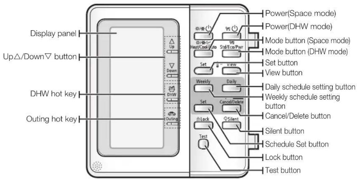
text_image
Display panel Up△/Down▽ button DHW hot key Outing hot key Up Down DHW Outing Power(Space mode) Power(DHW mode) Mode button (Space mode) Mode button (DHW mode) Set button View button Weekly Daily Daily schedule setting button Weekly schedule setting button Cancel/Delete button Cancel/Delete button Silent button Schedule Set button Lock button Test button
Correct disposal of batteries in this product
(Applicable in countries with separate collection systems)
This marking on the battery, manual or packaging indicates that the batteries in this product should not be disposed of with other household waste at the end of their working life. Where marked, the chemical symbols Hg, Cd or Pb indicate that the battery contains mercury, cadmium or lead above the reference levels in EC Directive 2006/66. If batteries are not properly disposed of, these substances can cause harm to human health or the environment.
To protect natural resources and to promote material reuse, please separate batteries from other types of waste and recycle them through your local, free battery return system.
014\_ Overview
Checking the function of buttons and indicators
| Mode Button Display Function | |||
| Operation mode | Space heating & cooling Operation | It can supply heating and cooling to the space when the Power (Space mode) button is on.Results: The heat pump will run in heating or cooling mode. | |
| Space modeHeatCool/Auto | Heating Using this wired remote controller, only A2W can be operating with heating mode.When the outdoor unit is connected with an external room thermostat, this button will not work. | ||
| Cooling Using this wired remote controller, only A2W can be operating with cooling mode.When the outdoor unit is connected with an external room thermostat, this button will not work. | |||
| Water law The supply water temperature to the heating space is operating according to outdoor temperature. | |||

- When you push the Power (Space mode) button, it has no influence on the domestic water heating. Domestic water heating only switched on or off according to the Power (DHW mode) button.
Checking the function of buttons and indicators
DHW OPERATION MODE

text_image
Open Display Delete SME Set Down Down Set Set Set Set Set Set Set Set Set Set Set Set Set Set Set Set Set Set Set Set Set Set Set Set Set Set Set Set Set Set Set Set Set Set Set Set Set Set Set Set Set Set Set Set Set Set Set Set Set Set SME Start Cash/Auto Start Cash/Auto/Pow Set -1 - View Send to: Send to: Send to: Send to: Send to: Send to: Send to: Send to: Send to: Send to: Send to: Send to: Send to: Send to: Send to: Send to: Send to: Send to: Send to: Send to: Send to: Send to: Send to: Send to: Send to: Send to: Send to: Send to: Send to: Send to: Send to: Send to: Send to: Send to: SME Send to: Send to: Send to: Send to: Send to: Send to: Send to: Send to: Send to: Send to: Send to: Send to: Send to: Send to: Send to: Send to: Send to: Send to: Send to: Send to: Send to: Send to: Send to: Send to: Send to: Send to: Send to: Send to: Send to: Send to: Send to: Send to: Send to:| Mode Button Display Function | ||||
| Operation mode | Water heating Operation | 💡💡 | It can supply warm water to the DHW tank when the Power (DHW mode) button is pressed.Results: Heat pump will be turned on with the domestic water heating mode. | |
DHW mode | Economic [IMAGE] | Economic [IMAGE] | DHW mode, which is heat pump only, saving energy consumption. | |
| Standard [IMAGE] | Standard [IMAGE] | DHW mode, which is operated by both heat pump and heater. However heater operating time is still restricted. | ||
| Powerful [IMAGE] | Powerful [IMAGE] | HW mode, which is operated by both heat pump and heater. In order to supply warm water more quickly, electric heater is operating immediately. | ||

- When you push the Power (Space mode) button, it has no influence on the domestic water heating. Domestic water heating only switched on or off according to the Power (DHW mode) button.
- If the DHW tank is not installed, the DHW operation mode will not be available.
16 Checking the function
text_image
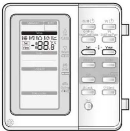
冰箱温度 Set -188.8℃ View Stop Cash/Auto Stop no/Par Set -1 View Stop Cash/Auto Stop no/Par Stop Cash/Auto Stop no/Par Stop Cash/Auto Stop no/Par Stop Cash/Auto Stop no/Par Stop Cash/Auto Stop no/Par Stop Cash/Auto Stop no/Par Stop Cash/Auto Stop no/Par Stop Cash/Auto Stop no/Par Stop Cash/Auto Stop no/Par Stop Cash/Auto Stop no/Par Stop Cash/Auto Stop no/Part Stop Cash/Auto Stop no/Part Stop Cash/Auto Stop no/Part Stop Cash/Auto Stop no/Part Stop Cash/Auto Stop no/Part Stop Cash/Auto Stop no/Part Stop Cash/Auto Stop no/Part Stop Cash/Auto Stop no/Part Stop Cash/Auto Stop no/Part Stop Cash/Auto Stop no/Part Stop Cash/Auto Stop no/ Part Stop Cash/Auto Stop no/ Part Stop Cash/Auto Stop no/ Part Stop Cash/Auto Stop no/ Part Stop Cash/Auto Stop no/ Part Stop Cash/Auto Stop no/ Part Stop Cash/Auto Stop no/ Part Stop Cash/Auto Stop no/ Part Stop Cash/Auto Stop no/ Part Stop Cash/Auto Stop no/ Part Stop Cash/Auto Stop no/Part Stop Cash/Auto Stop no/Part Stop Cash/Auto Stop no/Part Stop Cash/Auto Stop no/Part Stop Cash/Auto Stop no/Part Stop Cash/Auto Stop no/Part Stop Cash/Auto Stop no/Part Stop Cash/Auto Stop no/Part Stop Cash/Auto Stop no/Part Stop Cash/Auto Stop no/Port Stop Cash/Auto Stop no/Port Stop Cash/Auto Stop no/Port Stop Cash/Auto Stop no/Port Stop Cash/Auto Stop no/Port Stop Cash/Auto Stop no/Port Stop Cash/Auto Stop no/Port Stop Cash/Auto Stop no/Port Stop Cash/ Auto| modeButtonDisplayFunction | |||
| Operation mode | Temperature Adjust | To push up view | and down, modulate the water (Air) temperature. Supply water temperature to the load Domestic water temperature Room temperature Outdoor temperature Water law temperature Results: The set will be displayed on the controller. |
| Set This button is used to find the current setting point Set | set | which you want to change. According to Dip switch setting and operating modes, available setting points will be displayed by pressing buttons in order. | |
| View Find the temperature view | view | which you want to view. Results: Current temperature will be displayed in order. | |
Checking the function of buttons and indicators
HOT KEY

text_image
Open heat Up Up -188.8 °C Load Down DHW Outfall Control panel Control panel Control panel Control panel Control panel Control panel Control panel Control panel Control panel Control panel Control panel Control panel Control panel Control panel Control panel Control panel Control panel Control panel Control panel Control panel Control panel Control panel Control panel Control panel Control panel Control panel Control panel Control panel Control panel Control panel Control panel Control panel Control panel Control panel| modeButtonDisplayFunction | |||
| Hot key Up | To adjust set point | temperature express arrows up or down. | |
| Up | -188.8 | Results: The temperature can be set ranges from 5°C to 55°C and be adjusted by 0.5°C increments. | |
| Down | |||
| Down | |||
| DHW | →→: | When DHW mode is available, the mono unit under booster heater “ON” will work with maximum capacity only for domestic water heating . Results: The heat pump is operating for the domestic water only. | |
| DHW | |||
| Outing Lowers each | target temperature of operation modes with pre-defined values stored in the Field Setting Value sector of Wired Remote Controller. Keeps the house at lower temperature to save your running cost, you can use this button while having a vacation. | ||
| Outing | |||
18\_Checking the function
text_image
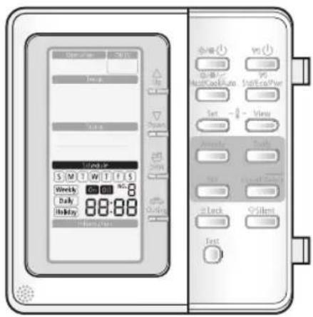
Operation 70/15 Hours Hours Hours S M T W T I S Weekly - 0 No. Daily 88:88 Holiday Outside Standard S M T W T I S Weekly - 0 No. Daily 88:88 Outside Standard Auto Stand-Up/Per Set - 0 View Annoty Tools Add Lock Control ≤ Silent Test| modeButtonDisplayFunction | |||
| Schedule | The system operates according to a certain schedule which is pre-defined by users or installers.These schedule setting button is used to program the controller. | ||
Checking the function of buttons and indicators
STATUS INDICATOR
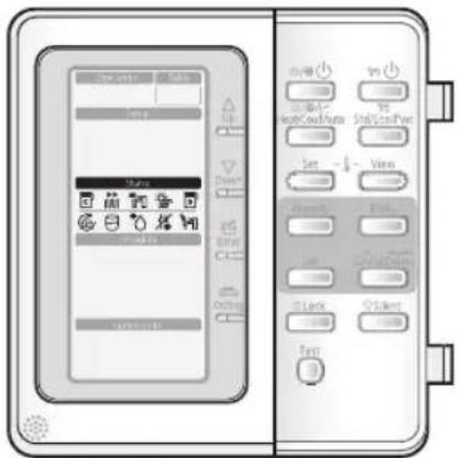
text_image
Diagram of a device control panel with labeled buttons and icons, showing front and back views with Chinese labels.| ModeStatusDisplayFunction | ||
| Status Compressor On This | icon indicates that the compressor in the outdoor unit is running. | |
| Back-up heaterOn | This icons indicate that the backup heater of the unit is operating, when there is a high demand for heating capacity. The backup heater provides extra heating capacity in case of low ambient outdoor temperature (high heating load). | |
| Booster heaterOn | This icon indicates that the booster heater is active. The booster heater provides auxiliary heating for the domestic hot water tank. The booster heater is located in the domestic hot water tank. The icon is not used when the domestic hot water tank is not installed. | |
| Solar thermal panel On | It indicates when the solar panel is powered on. DHW mode is stopping while solar panel is on in order to save your energy cost. | |
| Back up boilerOn | The Back up boiler shall start to work as soon as outdoor temperature reach to the targeted temperature. Users can adjust the temperature to allow the back up boiler work. The icon shall not be displayed without the Installation of the back up boiler. | |
| Water pump On | This icon indicates that the circulation pump is active. | |
| Domestic waterOn | This icon indicates when the domestic water heating mode is operating. | |
| Defrost operation On | This icon indicates that the defrost mode is active. | |
| Anti freezing operation On | The system automatically maintains the water temperature above a freezing point to prevent from freezing-fracture of piping system. | |
| Sanitary operation On | This function disinfects the DHW tank by periodically heating the domestic water to a specific temperature. | |
20 Checking the function
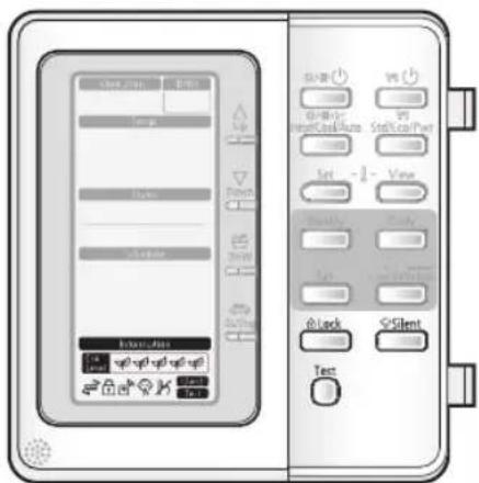
| modeButtonDisplayFunction | |||
| Optional function | Child Lock The remote controller  | buttons can be locked to prevent children from changing the settings or from pressing the buttons by accident. | |
| Thermostat connected | [7ABC] | When the room thermostat is connected, the Water-Law operation is active and the water temperature is determined automatically depending upon the outdoor temperature. The more cold the outdoor temperature, the more warm water will be supplied. vice versa. | |
Silent mode  | To maintain the outdoor unit to operate quietly, fan and compressor speed will be limited to a certain value of the speed at a normal operating. | ||
| Not available |  | This icon is displayed whenever a non-installed option is addressed or a function is not available. | |
| Test Press this button 5 sec to test | set Field setting values. | ||
| Energy Indicator | [4600] [CT03] | It indicates 5 Eco-level of energy consumption according to heat resources (Solar thermal, Backup boiler and heat pump) and outdoor temperature. | |
Operating basic function
AVAILABLE MODE
Samsung air to water heat pump system's operation modes are listed as below. Heating mode and cooling mode are not available at the same time.
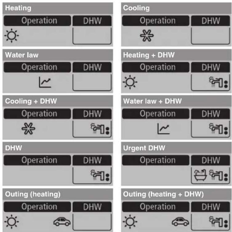
In this mode, heating function will be activated as required by target water temperature. Target water temperature is determined in 2 ways as described below.
- Change set value manually.
-
Use mode of "Water Law" (Auto mode).
-
Press Power (Space mode) button to turn on the heat pump unit.
The heat pump will be turned on in the mode you select.
• Space water heating devices: Radiator or Fan coil unit (field supply)

In winter season, the heat pump sometimes goes into defrost mode to prevent from the freezing of the outdoor heat exchanger.

The heat pump has a built-in protection mechanism to prevent the unit from being damaged when it is started immediately after being plugged in or stopped, the heat pump will start up after 3 minutes.
text_image
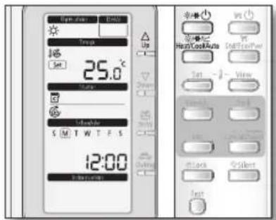
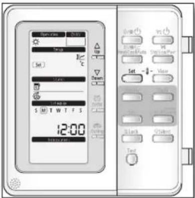
Open-up Temp Set 25.0°C Stop S M T W T E S 12:00 Balance Air/Cond/Auto Air/Cond/Par Air/Cond/Par Air/Cond/Par Air/Cond/Par Air/Cond/Par Air/Cond/Par Air/Cond/Par Air/Cond/Par Air/Cond/Par Air/Cond/Par Air/Cond/Par Air/Cond/Par Air/Cond/Par Air/Cond/Par Air/Cond/Par Air/Cond/Par Air/Cond/Par Air/ cond Air cond Air cond Air cond Air cond Air cond Air cond Air cond Air cond Air cond Air cond Air cond Air cond Air cond Air cond Air cond Air cond Air cond Air cond Air cond Air cond Air cond Air cond Air cond Air cond Air cond Air cond Air cond Air cond Air cond Air cond Air cond Air cond Air cond Air Cond Air Cond Air Cond Air Cond Air Cond Air Cond Air Cond Air Cond Air Cond Air Cond Air Cond Air Cond Air Cond Air Cond Air Cond Air Cond Air Cond Air Cond Air Cond Air Cond Air Cond Air Cond Air Cond Air Cond Air Cond Air Cond Air Cond Air Cond Air Cond Air Cond Air Cond Air Cond Air Cond Air Cond- Press the Mode (Space mode) button once to select the space heating mode.
The heat pump will run on heating mode.
- Press Up△ or Down▽ button to set the desired temperature.
The temperature can be set between 15^ C and 55^ C.

The temperature is adjusted by 0.5^ C.
Operating basic function
In this mode, heating function will be activated as required by target water temperature. Target water temperature is determined in 2 ways as described below.
- Change set value manually.
- Press Power (Space mode) button to turn on the heat pump unit.
The heat pump will be turned on in the mode you select.
• Space water cooling devices: Radiator or Fan coil unit (field supply)

- Heating and cooling mode can not be selected at the same time.
- Space cooling operation is not possible if the installation is a heating only installation.

The heat pump has a built-in protection mechanism to prevent the unit from being damaged when it is started immediately after being plugged in or stopped, the heat pump will start up after 3 minutes.
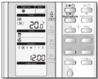
text_image
Open now 20.0°C Set Up Up High/Cool Auto High/Cool Pair Set -1 View Sound Sound Back Silent Test- Press the Mode (Space mode) button twice to select the space cooling mode.
The heat pump will run on cooling mode.
- Press Up△ or Down▽ button to set the desired temperature.
The temperature can be set between 5^ C and 25^ C.

The temperature is adjusted by 0.5°C.
- Operating basic function
WATER LAW
In this mode, heating function will be activated as required by target water temperature. Target water temperature is determined in 2 ways as described below.
- Change set value manually.
-
Use mode of "Water Law" (Auto mode).
-
Press Power (Space mode) button to turn on the heat pump unit.
The heat pump will be turned on in the mode you select.
• Space air heating devices: Radiator or Fan coil unit (field supply)
- Press the Mode (Space mode) button three times to select the mode.
The heat pump will run on heating mode according to the outdoor temperature.
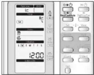
text_image
Open temp Hi/Hz Set Temperature S M T W T F S 12:00 S M T W T F S Up Down S S S S S S S S S S S S S S S S S S S S S S S S S S S S S S S S S S S S S S S S S S S S S S S S S S T 5 1 2 3 4 5 6 7 8 9 10 11 12 13 14 15 16 17 18 19 20 21 22 23 24 25 26 27 28 29 30 31 32 33 34 35 36 37 38 39 40 41 42 43 44 45 46 47 48 49 50 51 52 53 54 55 56 57 58 59 60 61 62 63 64 65 66 67 68 69 70 71 72 73 74 75 76 77 78 79 80 81 82 83 84 85 86 87 88 89 90 91 92 93 94 95 96 97 98 99 100
When "Water Law" is active, the target supply water temperature will be determined automatically depending on the outdoor temperature: For heating mode, colder outdoor temperatures will result in warmer water.
- Press Up△ or Down▽ button to set the desired temperature.
When "Water Law" is active, the user has the possibility to shift up or down the target water temperature by a maximum of 5°C.

The field setting temperature is adjusted by 0.5°C.

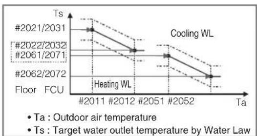
line
| Year | Temperature (Ts) | |------|------------------| | #2011 | 2021/2031 | | #2012 | 2022/2032 | | #2051 | 2061/2071 | | #2052 | 2062/2072 |- All the Field Setting Values needed to re-design the water law for floor or FCU(radiator) can be changed by using Wired Remote Controller's Field Setting Mode.
- There are 2 types of water law for each mode, one for floor application, the other for FCU(radiator). Both of them can be selected by using Wired Remote Controller's Field Setting Mode.
- The target water temperatures exceeding the operation limit of heat pump(5\~55°C) after reflecting user's arbitrary input(temperature shift) will be neglected, and be kept maximum or minimum respectively.
Operating basic function
In this mode, domestic water heating will be activated as required by the water temperature set point.
- The set point can be set manually.
- Press Power (DHW mode) button to turn on DHW tank.
The priority between heating/cooling/water-law and DHW modes are depending upon the user's input of Field Setting Value of Wired Remote Controller. The default priority is on the DHW mode.

- This mode can not be used when the DHW tank is not installed.
- The Power (Space mode) button and the Power (DHW mode) button can be selected at the same time.
- In order to provide domestic hot water throughout the day, it is advised to keep the domestic water heating operation on continuously.
- When the icon is displayed, hot water is delivered to the DHW tank by the solar panel. The operation between solar panel and heat pump can be determined by using Wired Remote Controller's Field Setting Mode.
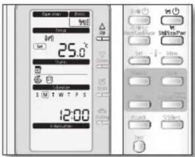
text_image
Open temp 400 Temp 300 Set 25.0°C State S M T W T F S 12:00 Status Up Down Reset Reset/Load/Power State/Load/Pow Set -1 Vice Reset Reset/Load/Pow State Reset/Load/Pow Reset Reset/Load/Pow Reset- Press Mode (DHW mode) button until required operating mode is displayed.
The heat pump will run on selected domestic water heating mode.
• Economic domestic water heating
• Standard domestic water heating
• Powerful domestic water heating



- Press Up△ or Down▽ button to set the desired temperature.
The temperature can be set between 30^ C and 70^ C.

The temperature is adjusted by 0.5°C.
TARGET ROOM AIR TEMPERATURE OPERATION
In this mode, heating and cooling fuction will be activated as required by target indoor air temperature. If the indoor's temperature couldn't be satisfied, change the water law shift value. If the thermostat isn't used, the remote controller can be used 2 ways as described below.
- Operate with target water temperature.
-
Operate with target indoor air temperature.
-
Operation of target water temperature is described at page 16\~17.
-
Operation of target indoor air temperature is needed to change the setting of the remote controller's dip switch.

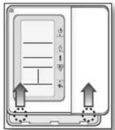
- Please slide the remote controller upper direction, and then the remote controller's rear cover will be separated.
- Please remove the white plastic sheet from PBA.
- Turn on the dip s/w #2 only.
- Turn off the main power and a few second later, turn on the main power again.
text_image
走 走 走 走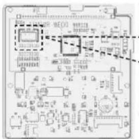
text_image
WED LED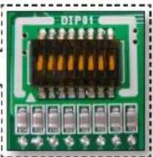
natural_image
Green circuit board with orange connectors and terminal blocks (no readable text or symbols)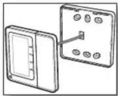
natural_image
Diagram showing two electrical components with a switch and three labeled pins (no text or symbols present)- At the space heating or cooling operation only mode, press the Set button, and then setting target indoor air temperature and water law shift value are displayed in the remote controller. Press the Up or Down button to set the desired indoor temperature or water law shift value.
- At the space heating or cooling + DHW operation mode, press the Set button, and then setting target indoor air temperature, water law shift value and DHW's water temperature are displayed in the order. Press the Up or Down button to set the desired indoor temperature, water law shift value or DHW's water temperature.
text_image
Down rate Up Set Down Set - View S M T W T F S 12:00 Down rate Up Set Down Set - View S M T W T F S TextOperating hot key function
URGENT DHW MODE
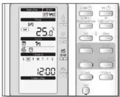
If you want to enjoy a leisurely bath or need a lot of warm water urgently, select the DHW hot key. When this mode is enabled, it is assured that the full capacity of the heat pump is only delivered for domestic water heating.
The full capacity of the heat pump is only delivered to the DHW tank.
The booster heater is forced to operate until the temperature of DHW tank reaches the set point.

- This hot function can not be used when the DHW tank is not installed.
- If the Power (DHW mode) button has not been turned on, this DHW key does not work.
- In this DHW function mode, both space heating and floor heating are not available. The icon is blinking for 3 seconds.
- This hot function remains available when the solar operation.
- The temperature set point is determined by user's input during urgent DHW mode. However, you can adjust the desired temperature using Up or Down keys.
text_image
Open/Open Temp M0 (Set) 25.0 °C Current M S M T W T F S 12:00 Tint/Off Control Start/Stop Reset/Control Start/Stop/Pump Set View Control Close Close Close Close Close Close Close Close1. Press DHW Hot key once again to exit.
The heat pump is returned to normal operation.

By default field setting value option, this function will not be turned off automatically. If you want a hot key function for a certain amount of duration time, change the field setting value of remote controller.
OUTING MODE
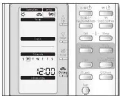
If you want to take a vacation, you can use the Outing hot key. When this mode is enabled, it is assured that the heat pump maintains your house at a lower temperature to save energy cost.
1. Press Outing Hot key.
The heat pump delivers heat at a low temperature.

If the Power (Space mode) button has not been turned on, this key does not work.
To cancel the outing mode
1. Press Outing Hot key once again to exit.
The heat pump is returned to normal operation.

It will return to a normal heating mode or DHW mode.
text_image
Open/Down Control Up Down State S M T W T F S 12:00 37:00(50) Outing Control Up Down State S M T W T F S 12:00 37:00(50)28\_Operating hot key function
Operating advanced function
SETTING THE TIME
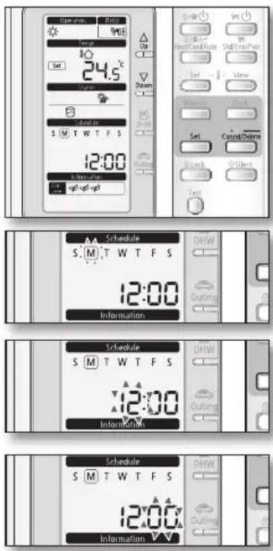
Your monobloc unit contains a clock used to start and stop the unit automatically at a given time. You must set the time when you purchase the monobloc unit or reset this system.
-
Push the Set button for 3 seconds.
-
Mode: Normal operation.
- When setting the time, you can only use Up ^ , Down ^ , Set, Cancel/Delete button.
-
To cancel the setting, press the Cancel/Delete button.
-
Set the day by pressing Up△ or Down▽ button.
The 'day' indicator will blink. Set the day and press Set button to save the setting.
- Set the hour by pressing Up△ or Down▽ button.
The 'hour' indicator will blink. Set the hour and press Set button to save the setting.
- Set the minute by pressing Up△ or Down▽ button.
The 'minute' indicator will blink. Set the minute and press Set button to save the setting.
After setting the minute, the operation returns to normal.
Operating advanced function
SETTING THE 7-DAY(WEEKLY) SCHEDULE
Set the schedules for ON/OFF timer to be repeated each week.
Maximum 7 schedules may be set for each day.

- When using room thermostat, it is impossible to reserve.
- If weekly schedule reserved 7 items is on the same day, it is impossible to reserve. In that case, When pressing the Weekly button, change the View mode of reservation.
- Setting the weekly schedule is for "Cool & Heat" Mode only.
- It is impossible to reserve several times for the same day and same time.
-
Weekly schedule cannot be used with the room thermostat.
-
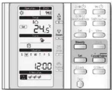
Press the Weekly button.
The mode changes to the weekly schedule.
In this mode, you can only use Up△, Down▽, Weekly, Set, Cancel/Delete button.
To cancel the setting, press the Cancel/Delete button.
- Set the day by pressing Up△ or Down▽ button.
The On/Off indicator will blink. Set the On/Off status and press Set button to save the setting.
- Set the On/Off by pressing Up△ or Down▽ button.
The 'On/Off' indicator will blink. Set the On/Off status and press Set button to save the setting.
- Set the operation mode by pressing Up△ or Down▽ button.
The 'operation indicator' will blink. Set the day and press Set button to save the setting.

- To set the "Off" reservation, move to the step 6.
- It is impossible to set the Auto() mode.
- Set the temperature by pressing the Up△ or Down▽ button.
The 'temperature' will blink. Set the temperature and press Set button to save the setting.
text_image
Open-up 24.5°C Set S M T W T F S 12:00 Up Down 3.50-7.50 up up up Up Drawn Set View Weekly Set Cancel/Delete Check Check Test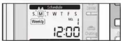
text_image
Schedule S.M.T W T F S Weekly 12:00 NDL DHW Outing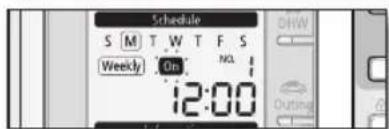
text_image
Schedule S M T W T F S Weekly On NCL 12:00
text_image
Operation DHW Temp Set 24.5°C Status Up Down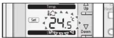
text_image
Temp Set 24.5° Set Up Down
The setting temperature is decided according to Dip S/W #2 of remote controller.
- Dip S/W #2 On : Setting the temperature of indoor.
- Dip S/W #2 Off : Setting the temperature of water outlet.
Continue to the next page
30_ Operating advanced function
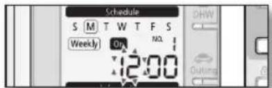
- Set the hour by pressing the Up△ or Down▽ button.
The 'hour' indicator will blink. Set the hour and press Set button to save the setting.
- Set the minute by pressing the Up△ or Down▽ button.
The 'minute' indicator will blink. Set the minute and press Set button to save the setting.
- Confirm the Schedule.
After step 7, all indicators are blinking except "Reservation No", "Weekly". Then press the Set button.
text_image
Schedule S M T W T F S Weekly Op MCL 12:00 OUTING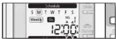
text_image
Schedule S M T W T F S Weekly On NO. 12:00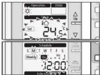
text_image
Operation DHW Up Set 24.5°C Schedule S: M T W T F S Weekly On NCL 12:00 Init me on
- On this step, you can only use Set, Cancel/Delete button.
- If there is a reservation on the same day and time, it will not be confirmed and "Not Available" indicator will blink for 3 seconds. In this case, go back to the step 6.
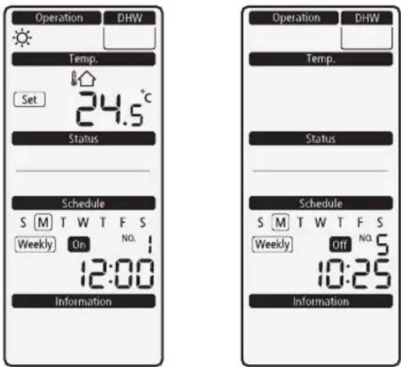
Viewing the 7-day(Weekly) Schedule (On / Off) Display
On Reservation Off Reservation
text_image
Operation DHW Temp. Set 24.5 °C Status Schedule S M T W T F S Weekly On NO. 1 12:00 Information Operation DHW Temp. Status Schedule S M T W T F S Weekly Off NO. 5 10:25 InformationOperating advanced function
SETTING THE 7-DAY(WEEKLY) SCHEDULE
Deleting the 7-day (Weekly) schedule
- Select the schedule from Reservation View Mode.
- Push the Cancel/Delete button for 3 seconds.
- The LCD pictures changes to the reservation mode after delete the schedule.
Operating the 7-day (Weekly) schedule
- Operate automatically according to schedule.
- If On schedule starts during the Urgent DHW mode, the Urgent DHW mode will change to DHW mode.
- If Off schedule starts during the Heat/Cool/Auto mode, the operation will stop.

In the following conditions, the schedule function will not operate.
- Outing
- Tracking of communication
• Installation of room thermostat
SETTING THE DAILY SCHEDULE
Set the daily schedule to reserve On / Off timer of DHW (Eco/Std/Power) and Silent mode. At most 15 schedules may be set for day.

- If the field setting is for no use DHW and use other manufacturer tank, it is impossible to reserve "DHW" mode.
- If daily schedule reserved 15 schedules is on the same day, it is impossible to reserve. In that case, when pressing the Daily button, change the View mode of reservation.
-
It is impossible to reserve several times for the same time.
-
Press the Daily button.
The mode changes to the Daily schedule.
In this mode, you can only use Up△, Down▽, Daily, Set, Cancel/Delete button.
To cancel the setting, press Cancel button.
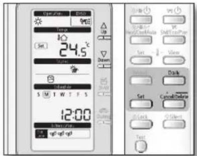
text_image
Open/Off RHO 900K Up Set 24.5°C Down S M T W T F S 12:00 Up up 900K Down Set 12:00 Up Up 900K Down Set 12:00 Up Up 900K Down Set 12:00 Up Up 900K- Set the On/Off by pressing Up△, Down▽ button.
The 'On/Off' indicator will blink. Set the On/Off status and press Set button to save the setting.
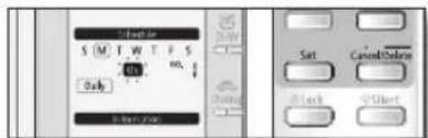
text_image
Start S M T W T F S 0% Only Set Cancel/Select Black Q-Short- Set the operation mode by pressing Up△ or Down▽ button.
The 'operation indicator' will blink. Set the operation mode and press Set button to save the setting.
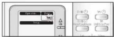
text_image
Open OK 300% Temp Up Control Heat Control Ind Temperature Set 12 Hold
- When using other company DHW Tank or setting no use DHW mode, the reservation mode is fixed to "Silent" mode.
- When setting use DHW mode, the mode is changed as followings with Up or Down button.
- "On" Mode ; → → → (→) → → Pwr mode (if selected in "Booster heater On"
- "Off" Mode ; ➕ ➕ ➕:
Continue to the next page
Operating advanced function
Operating advanced function
SETTING THE DAILY SCHEDULE
- Set the hour by pressing the Up△ or Down▽ button. The 'hour' indicator will blink. Set the hour and press Set button to save the setting.
- Set the minute by pressing the Up△ or Down▽ button. The 'minute' indicator will blink. Set the minute and press Set button to save the setting.
- Confirm the Schedule. After step 5, all indicators are blinking except "Reservation No", "Daily". Then press Set button.
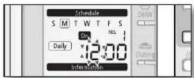
text_image
Schedule S M T W T F S Daily On No. 12:00 Information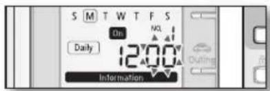
text_image
S M T W T F S On Daily 12:00 Information Outing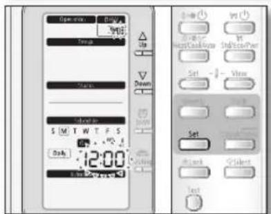
text_image
Open max Temp Temperature S M T W T F S Daily 12:00 S M T W T F S Up Down Set Set Select Test
- On this step, you can only use Set or Cancel/Delete button.
- If there is a reservation on the same day and time, it will not be confirmed and "Not Available" indicator will blink for 3 seconds. In this case, go back to the step 4.
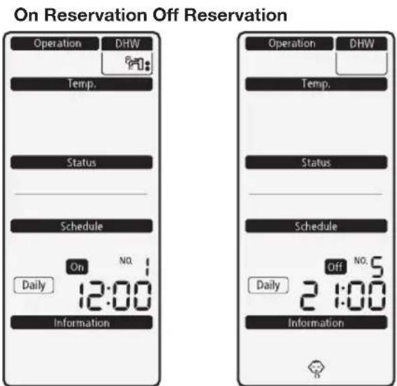
Viewing the Daily Schedule (On / Off) Display
text_image
On Reservation Off Reservation Operation DHW Temp. Status Schedule On No. Daily 12:00 Information Operation DHW Temp. Status Schedule On No.5 Daily 2 1:00 Information34. Operating advanced function
Deleting the daily schedule
- Select the schedule from Reservation View Mode.
-
Push the Cancel/Delete button for 3 seconds.
-
The LCD pictures change to the reservation mode after deleting the schedule.
Operating the daily schedule
- Operate automatically according to schedule.
- If On schedule starts during the Urgent DHW mode, the Urgent DHW mode will be turned off.

In the following conditions, the schedule function will not operate.
- Outing
- Tracking of communication
• Installation of room thermostat - If the field setting is set for without DHW or another manufacturers tank is used, it is not possible to reserve DHW mode.
- If the field setting is set for not using the booster heater, it is not possible to reserve Pwr DHW mode.
Operating advanced function
FIELD SETTING MODE
Setting the Field Setting Value of wired remote controller
Field setting mode is to adjust specific functions in accordance with customer's demands.
Field setting mode is easy-to-access and programmable by the wired remote controller.
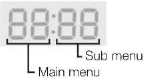
Field setting values are consisted of 4 digits.
text_image
88:88 Main menu Sub menuAdjusting filed setting values is available in the unit operation.
- Press the Test button for 5 seconds.
The mode changes to the field setting.

In this mode, you can only use Up△, Down▽, Set, Cancel/Delete button.
To cancel the setting, press Cancel/Delete button.
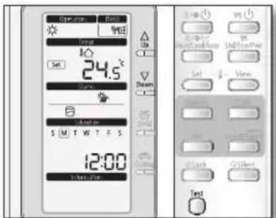
text_image
Oper Day 24.5°C Set 24.5°C Start 8 Start in S M T W T F S 12:00 3:00-4:00 Down Up Yes Stop Start/Stop/Auto Start/Stop/Auto Set View Stop/Stop/Auto Start/Stop/Auto Stop/Stop/Auto Test- Set the Main Menu by pressing Up△ or Down▽ button.
The "Number" will blink. Set the Main menu and press Set button to save the setting.
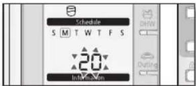
text_image
Schedule S M T W T F S 20 Information- Set the Sub Menu by pressing Up△ or Down▽ button.
The "Number" will blink. Set the Sub menu by pressing Up△ or Down▽ button. Then press Set button to save the setting.
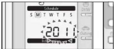
text_image
Schedule S M T W T F S 20:11 Information- Set the Operation Range(Field Setting) by pressing Up△ or Down▽ button.
The digits in "Temp" category will blink. Set the Field Setting Value by pressing Up△ or Down▽ button. Then press Set button to save the settings. After 5 seconds, The LCD shall go back to initial display. If no input for setting value changes, the LCD shall go back to initial display after 30 seconds.
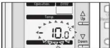
text_image
Operation Power Temp -10.0 °C Up DownField Setting Value (FSV) Table

Reset the power after changing the Field Setting Value.
- Code 10** : Upper and lower temperature limits of each operation mode of wired remote controller Heating(Water Out, Room), Cooling(Water Out, Room), DHW(Tank)
- Code 20**: Water law design and external room thermostat Heating(2 WL's for floor & FCU), Cooling(2 WL's for floor & FCU), WL & Thermostat types
| Field Setting Value | |||||||
| Main Menu & Code | Sub Menu Function Description | Option Sub Code | Default Min | Max Step Unit | |||
| Remote Controller Setting Range Code 10** | Water Out Temp for Cooling | Max **11 | 25 18 | 25 1 °C | |||
| Min **12 | 16 5 | 18 1 °C | |||||
| Room Temp for Cooling | Max **21 | 30 24 | 30 1 °C | ||||
| Min **22 | 18 18 | 22 1 °C | |||||
| Water Out Temp for Heating | Max **31 | 55 37 | 55 1 °C | ||||
| Min **32 | 25 15 | 37 1 °C | |||||
| Room Temp for heating | Max **41 | 30 24 | 30 1 °C | ||||
| Min **42 | 16 16 | 22 1 °C | |||||
| DHW Tank Temp | Max **51 | 50 50 | 70 1 °C | ||||
| Min **52 | 40 30 | 40 1 °C | |||||
| Back light timer | Time **61 | 5 0 30 1 | sec | ||||
| Water Law Code 20** | Outdoor Temp for Water Law (Heating) | Point 1 | **11 | -10 | -20 | 5 1 °C | |
| Point 2 | **12 | 15 10 | 20 1 °C | ||||
| Water Out Temp for WL1 Heating (WL1-Floor) | Point 1 | **21 | 40 17 | 55 1 °C | |||
| Point 2 | **22 | 25 17 | 55 1 °C | ||||
| Water Out Temp for WL2 Heating (WL2-Fan Coil Unit) | Point 1 | **31 | 50 17 | 55 1 °C | |||
| Point 2 | **32 | 35 17 | 55 1 °C | ||||
| Heating Water Law for Auto Mode | WL Type | **41 | 1(WL1) | 1 | 2(WL2) | - | |
| Outdoor Temp for Water Law (Cooling) | Point 1 | **51 | 30 25 | 35 1 °C | |||
| Point 2 | **52 | 40 | 35 45 1 °C | ||||
| Water Out Temp for WL1 Cooling (WL1-Floor) | Point 1 | **61 | 25 | 18 25 1 °C | |||
| Point 2 | **62 | 18 | 5 18 1 °C | ||||
| Water Out Temp for WL2 Cooling (WL2-Fan Coil Unit) | Point 1 | **71 | 18 | 18 25 1 °C | |||
| Point 2 | **72 | 5 | 5 18 1 °C | ||||
| Cooling Water Law | WL Type | **81 | 1(WL1) | 1 | 2(WL2) | - | |
| External Thermostat Application | #1(Floor) | **91 | 0(No) | 0 | 1(Yes) | - | |
| #2(FCU) | **92 | 0(No) | 0 | 1(Yes) | - | ||
- 2021 and 2022 value is influenced by each other. becuase 2021 is Max. Value and 2022 is Min Value. so the 2022 Value can't set over than 2021 Value and the 2021 Value can't set under than 2022 Value. 2031, 2032 is same.
Operating advanced function
Operating advanced function
FIELD SETTING MODE
- Code 30**: User's options for domestic hot water(DHW) tank heating
3011: Application of DHW tank in user's system
302* : Heat pump variables for tank temp. control and combination with booster heater
303* : Booster heater variables for combination with heat pump
304*: Periodical disinfection heating of water tank
305*: Off timer for power DHW mode by hot key of wired remote controller
3061 : Combination of external field solar panel for with heat pump for DHW heating
307* : Default direction of the DHW valve or Zone #1, #2 valve
When the 3way valve is applied to DHW Valve terminal block instead of 2way valve, default direction is Space Heating (Room)
| Field Setting Value | ||||||||
| Main Menu & Code | Sub Menu Function Description Sub Code Default Min Max Step Unit | |||||||
| DHW Code 30** | Domestic Hot Water Tank | Application **11 0(No) 0 1(Yes) - | ||||||
| Heat Pump | Max Temp | **21 | 50 | 45 | 50 | 1 | °C | |
| Stop | **22 | 2 | 2 | 10 | 1 | °C | ||
| Start | **23 | 5 | 5 | 20 | 1 | °C | ||
| Min. Space heating operation time | **24 | 5 | 1 | 20 | 1 | min | ||
| Max. DHW operation time | **25 | 30 | 5 | 95 | 5 | min | ||
| Max. Space heating operation time | **26 | 3 | 0.5 | 10 | 0.5 | hour | ||
| Booster Heater | Application | **31 | 1(On) | 0(OFF) | 1 | - | - | |
| Delay Time | **32 | 20 | 20 | 95 | 5 | min | ||
| Overshoot | **33 | 0 | 0 | 4 | 1 | °C | ||
| Compensation Temp | **34 | 10 | 0 | 20 | 1 | °C | ||
| Disinfection | Application | **41 | 1(On) | 0(OFF) | 1 | - | - | |
| Interval | **42 | Sat | Mon | Sun | 1(All) | day | ||
| Start Time | **43 | 23 | 0 | 23 | 1 | o'clock | ||
| Target Temp | **44 | 70 | 40 | 70 | 5 | °C | ||
| Duration | **45 | 10 | 5 | 60 | 5 | min | ||
| Power DHW by User Input | Timer OFF Function | **51 | 0(Off) | 0 | 1(On) | - | - | |
| Timer Duration | **52 | 60 | 30 | 300 | 10 | min | ||
| Solar Panel | H/P Combination | **61 | 0 | 0 | 1(Yes) | - | - | |
| Direction of 2Way valve | DHW valve | **71 | 0(Close) | 0 | 1(Open) | - | - | |
38_Operating advanced function
- Code 40**: User's options for heating devices including internal backup heater and external boiler
401*: Space/DHW heating priority and control variables
402*: Backup/Booster heater priority and control variables
403*: Additional backup boiler operating variables
- Code 50**: User's options for extra functions
501*: New target temperatures of each mode by "Outgoing" hot key of remote controller
5021: Temperature difference between before & after values in "Economic" DHW mode
504*: Power Peak control for Smart Grid
| Field Setting Value | ||||||||
| Main Menu & Code | Sub Menu Function | Description Sub Code Default | Min Max | Step Unit | ||||
| Heating Code 40** | Heat Pump | Heating/DHW Priority | **11 | 0(DHW) | 0 | 1(Heating) | - | - |
| Outdoor Temp for Priority | **12 | 0 | -15 | 20 | 1 | °C | ||
| Heating Off | **13 | 35 | 14 | 35 | 1 | °C | ||
| Overshoot | **14 | 2 | 1 | 4 | 1 | °C | ||
| Backup Heater | Application | **21 | 0(No) | 0 | 1(Yes) | - | - | |
| BUH/BSH Priority | **22 | 0(Both) | 0 | 2(BSH) | 1 | - | ||
| Cold weather compensation | **23 | 1(On) | 0(Off) | 1 | - | - | ||
| Threshold Temp | **24 | 0 | -15 | 35 | 1 | °C | ||
| Backup Boiler | Application | **31 | 0(No) | 0 | 1(Yes) | - | - | |
| Boiler Priority | **32 | 0(Off) | 0 | 1(On) | - | - | ||
| Threshold Temp | **33 | -15 | -20 | 5 | 1 | °C | ||
| Others Code 50** | Outing | Water Out Temp for Cooling | **11 | 25 | 5 | 25 | 1 | °C |
| Room Temp for Cooling | **12 | 30 | 18 | 30 | 1 | °C | ||
| Water Out Temp for Heating | **13 | 15 | 15 | 55 | 1 | °C | ||
| Room Temp for Heating | **14 | 16 | 16 | 30 | 1 | °C | ||
| Auto Cooling WL1 Temp | **15 | 25 | 5 | 25 | 1 | °C | ||
| Auto Cooling WL2 Temp | **16 | 25 | 5 | 25 | 1 | °C | ||
| Auto Heating WL1 Temp | **17 | 15 | 15 | 55 | 1 | °C | ||
| Auto Heating WL2 Temp | **18 | 15 | 15 | 55 | 1 | °C | ||
| Target Tank Temp | **19 | 30 | 30 | 70 | 1 | °C | ||
| DHW Saving Mode | Temp Difference | **21 | 5 | 0 | 40 | 1 | °C | |
| Power Peak Control | Application | **41 | 0(No) | 0 | 1(Yes) | - | - | |
| Select forced off parts | **42 | 0 | 0 | 2 | 1 | - | ||
| Using input voltage | **43 | 1(High) | 0(Low) | 1 | - | - | ||
- Code 5042
| [D-00] | Compressor | Back up heater | Booster heater |
| 0 (Default) | Forced off | Forced off | Forced off |
| 1 | Forced off | Forced off | Permitted |
| 2 | Permitted | Forced off | Forced off |
Operating advanced function
FIELD SETTING MODE
Remote Controller Setting Range : Code 10**
| Field Setting Value | ||||||||
| Main Menu & Code | Sub Menu Function Description | Sub Code Default | Min Max | Step Unit | ||||
| Remote Controller Setting Range Code 10** | Water Out Temp for Cooling | Max | **11 | 25 | 18 | 25 | 1 | °C |
| Min | **12 | 16 | 5 | 18 | 1 | °C | ||
| Room Temp for Cooling | Max | **21 | 30 | 24 | 30 | 1 | °C | |
| Min | **22 | 18 | 18 | 22 | 1 | °C | ||
| Water Out Temp for Heating | Max | **31 | 55 | 37 | 55 | 1 | °C | |
| Min | **32 | 25 | 15 | 37 | 1 | °C | ||
| Room Temp for heating | Max | **41 | 30 | 24 | 30 | 1 | °C | |
| Min | **42 | 16 | 16 | 22 | 1 | °C | ||
| DHW Tank Temp | Max | **51 | 50 | 50 | 70 | 1 | °C | |
| Min | **52 | 40 | 30 | 40 | 1 | °C | ||
| Back light timer | Time | **61 | 5 | 0 | 30 | 1 | sec | |
Space Cooling
- Target water outlet temperature : Upper limit(#1011, Default 25°C, Range : 18 \~ 25°C), Lower limit(#1012, Default 16°C, Range : 5 \~ 18°C)
- With this default FSV settings, user can change the target water outlet temperature within the range of 5 \~ 25°C for cooling
- Target room temperature : Upper limit(#1021, Default 30°C, Range : 24 \~ 30°C), Lower limit(#1022, Default 18°C, Range : 18 \~ 22°C)
- With this default FSV settings, user can change the target room temperature within the range of 18 \~ 30°C for cooling.

- The #1 DIP switch in the wired remote controller should be set to "OFF"(Default) for cooling operation of heat pump.
- The #2 DIP switch in the wired remote controller should be set to "OFF"(Default) to control the water outlet temperature.
- The #2 DIP switch in the wired remote controller should be set to "ON" to control the room temperature.
Space Heating
- Target water outlet temperature : Upper limit(#1031, Default 55°C, Range : 37 \~ 55°C), Lower limit(#1032, Default 25°C, Range : 15 \~ 37°C)
- With this default FSV settings, user can change the target water outlet temperature within the range of 25 \~ 55°C for heating.
- Target room temperature : Upper limit(#1041, Default 30°C, Range : 24 \~ 30°C), Lower limit(#1042, Default 16°C, Range : 16 \~ 22°C)
- With this default FSV settings, user can change the target room temperature within the range of 16 \~ 30°C for heating.

- The #2 DIP switch in the wired remote controller should be set to "OFF"(Default) to control the water outlet temperature.
- The #2 DIP switch in the wired remote controller should be set to "ON" to control the room temperature.
DHW Heating
- Target DHW tank temperature: Upper limit(#1051, Default 50°C, Range: 50 \~ 80°C), Lower limit(#1052, Default 40°C, Range: 30 \~ 40°C)
- With this default FSV settings, user can change the target tank temperature within the range of 40 \~ 50°C for DHW heating.

The FSV #3011 in the wired remote controller should be set to "1(Yes)" to use DHW function.
Back Light
- Remote controller's back light timer: #1061, Default 5sec, Range: 0 \~ 30sec
- With this FSV settings, user can change the time to back light within the range of 0 \~ 30sec.
40\_ Operating advanced function
Water Law & Room Thermostat : Code 20**
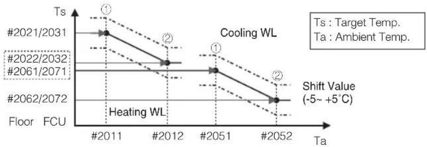
line
| Year | Temperature | Time to State | | ---------- | ----------- | ------------- | | #2021/2031 | #2021 | Ts | | #2022/2032 | #2022 | Ts | | #2061/2071 | #2061 | Ts | | #2062/2072 | #2062 | Ts | | #2051 | #2051 | Ts | | #2052 | #2052 | Ts || Field Setting Value | ||||||||
| Main Menu & Code | Sub Menu Function Descripti on | Sub Code | Default | Min Max | Step | Unit | ||
| Water Law Code 20** | Outdoor Temp for Water Law (Heating) | Point 1 | **11 - | 0 -20 5 | 1 °C | |||
| Point 2 | **12 15 | 10 20 | 1 °C | |||||
| Water Out Temp for WL1 Heating (WL1-Floor) | Point 1 | **21 40 | 17 55 | 1 °C | ||||
| Point 2 | **22 25 | 17 55 | 1 °C | |||||
| Water Out Temp for WL2 Heating (WL2-Fan Coil Unit) | Point 1 | **31 50 | 17 55 | 1 °C | ||||
| Point 2 | **32 35 | 17 55 | 1 °C | |||||
| Heating Water Law for Auto Mode WL Type **41 1(WL1) | 2(WL2) | - | - | |||||
| Outdoor Temp for Water Law (Cooling) | Point 1 | **51 30 | 25 35 | 1 °C | ||||
| Point 2 | **52 40 | 35 45 | 1 °C | |||||
| Water Out Temp for WL1 Cooling (WL1-Floor) | Point 1 | **61 25 | 18 25 | 1 °C | ||||
| Point 2 | **62 18 | 5 18 1 | °C | |||||
| Water Out Temp for WL2 Cooling (WL2-Fan Coil Unit) | Point 1 | **71 18 | 18 25 | 1 °C | ||||
| Point 2 | **72 | 5 5 1 | 8 1 °C | |||||
| Cooling Water Law | WL Type **81 1(WL1) | 1 | 2(WL2) | - | - | |||
| External Thermostat Application | #1(Floor) | **91 | 0(No) | 0 | 1(Yes) | - | - | |
| #2(FCU) | **92 | 0(No) | 0 | 1(Yes) | - | - | ||
• 2021 and 2022 value is influenced by each other.
becuase 2021 is Max. Value and 2022 is Min Value.
so the 2022 Value can't set over than 2021 Value and the 2021 Value can't set under than 2022 Value.
2031, 2032 is same.
Water Law for Heating
- Outdoor air temperature range : Lower limit ①(#2011, Default -10°C, Range : -20 \~ 5°C), Upper limit ②(#2012, Default 15°C, Range : 10 \~ 20°C)
- With this default settings, the water outlet temperature by heating water law can be changed within the outdoor temperature range of -10 \~ 15°C.
- Water out temperature range for floor/FCU applications respectively: Upper limit ①(#2021/2031, Default 40/50°C, Range : 17 \~ 55°C), Lower limit ②(#2022/2032, Default 25/35°C, Range : 17 \~ 55°C)
- With this default settings, the water outlet temperature by heating water law can be changed within the range of 25/35 \~ 40/50°C.
- Type of water law for according to heating devices(floor/FCU): #2041(Default "1"(WL1 for floor)), "2"(WL2 for FCU or radiator)

- The #2 DIP switch in the wired remote controller should be set to "OFF"(Default) to control the water outlet temperature.
- The operation mode of the wired remote controller should be set to "AUTO"(I) to use the weather dependent water law scheme.
Operating advanced function
Operating advanced function
FIELD SETTING MODE
Water Law for Cooling
- Outdoor air temperature range : Lower limit ①(#2051, Default 30°C, Range : 25 \~ 35°C), Upper limit ②(#2052, Default 40°C, Range : 35 \~ 45°C)
- With this default settings, the water outlet temperature by cooling water law can be changed within the outdoor temperature range of 30 \~ 40°C.
- Water out temperature range for floor/FCU applications respectively: Upper limit ①(#2061/2071, Default 25/18°C, Range : 18 \~ 25°C), Lower limit ②(#2062/2072, Default 18/5°C, Range : 5 \~ 18°C)
- With this default settings, the water outlet temperature by cooling water law can be changed within the range of 18/5 \~ 25/18°C.
- Type of water law for according to cooling devices(floor/FCU) : #2081(Default "1"(WL1 for floor), "2"(WL2 for FCU or radiator)

- The #1 DIP switch in the wired remote controller should be set to "OFF"(Default) for cooling operation of heat pump.
- The #2 DIP switch in the wired remote controller should be set to "OFF"(Default) to control the water outlet temperature.
- Only heating WL operation could be used through "Auto" mode of wired remote controller.
External Room Thermostat (Field Option)
- Terminal #1(#2091, Default "0" for no usage), #2(#2092, Default "0" for no usage)
- To use wired remote controller for heating/cooling operation, both of the above settings should be set to "0" simultaneously. If not, thermostat controls system.
- Types of water law used by room thermostat operation will follow the FSV settings defined in #2041(heating) and #2081(cooling) respectively.
- During the thermostat operation, the user has the possibility to shift up or down the target water temperature within the range of -5 +5^ .
- When the remote controller is used, floor valve should be connected to zone #1 and the FCU valve should be separately connected to zone #2 of the control kit PBA.
- When only floor cooling/heating is installed and if the Water Law or outlet water temperature is too low, 2way valve may closed and E911 error may occur.
- When the floor and FCU units are installed together and operating in cooling mode, floor valve may close and E911 may occur to prevent floor condensation when the outlet water temperature is below 16°C. Therefore FCU should secure minimum value for the flow rate.
- Thermostat #2 which controls FCU has the priority for operation modes and the discharge water temperature.
- Samsung is not responsible for the accidents such as floor condensations which can occur by not connecting the valve to the zone #1 port of the control kit PBA.
42\_ Operating advanced function
text_image
T_U < T_HP MAX T(C) #3021 T_HP MAX T_U = T_HP OFF T_HP ON #3023 Tu : User : T(C) : TemTu : User set temp. T(C) : Temp. (Celcius)
line
| Event | Time Period | Value | | ---------------------- | ----------- | ----- | | Space heating request | t=3026 | 1 | | Space heating request | t=3025 | 0 | | DHW request | t=3026 | 1 | | DHW request | t=3025 | 0 | | DHW operation | t=3026 | 1 | | DHW operation | t=3025 | 0 | #3024 | t=3026 | 1 |Operating advanced function
FIELD SETTING MODE
| Field Setting Value | ||||||||
| Main Menu & Code | Sub Menu Function Description | Sub Code | Default | Min Max | Step Unit | |||
| DHW Code 30** | Domestic Hot Water Tank | Application **11 0(No) 0 | 1(Yes) | - | ||||
| Heat Pump | Max Temp | **21 | 50 | 45 | 50 | 1 | °C | |
| Stop | **22 | 2 | 2 | 10 | 1 | °C | ||
| Start | **23 | 5 | 5 | 20 | 1 | °C | ||
| Min. Space heating operation time | **24 | 5 | 1 | 20 | 1 | min | ||
| Max. DHW operation time | **25 | 30 | 5 | 95 | 5 | min | ||
| Max. Space heating operation time | **26 | 3 | 0.5 | 10 | 0.5 | hour | ||
| Booster Heater | Application **31 1(On) | 0(OFF) | 1 | - | ||||
| Delay Time | **32 | 20 | 20 | 95 | 5 | min | ||
| Overshoot | **33 | 0 | 0 | 4 | 1 | °C | ||
| Compensation Temp | **34 | 10 | 0 | 20 | 1 | °C | ||
| Disinfection | Application | **41 | 1(On) | 0(OFF) | 1 | - | - | |
| Interval | **42 | Sat | Mon | Sun | 1(All) | day | ||
| Start Time | **43 | 23 | 0 | 23 | 1 | o'clock | ||
| Target Temp | **44 | 70 | 40 | 70 | 5 | °C | ||
| Duration | **45 | 10 | 5 | 60 | 5 | min | ||
| Power DHW by User Input | Timer OFF Function | **51 | 0(Off) | 0 | 1(On) | - | - | |
| Timer Duration | **52 | 60 | 30 | 300 | 10 | min | ||
| Solar Panel | H/P Combination | **61 | 0 | 0 1(Yes) | - | |||
| Direction of 2Way valve | DHW valve | **71 | 0(Close) | 0 | 1(Open) | - | - | |
DHW Application
The FSV #3011 in the wired remote controller should be set to "1(Yes)" to use DHW function.
Heat Pump Variables for Controlling DHW Tank
- Maximum DHW tank temperature with R410A(refrigerant) heat pump operation : FSV #3021, Default 50°C, Range : 45 \~ 50°C.
- Temperature difference determining the heat pump OFF temperature : FSV #3022, Default 2°C, Range : 2 \~ 10°C.
- Temperature difference determining the heat pump ON temperature : FSV #3023, Default 5°C, Range : 5 \~ 20°C.
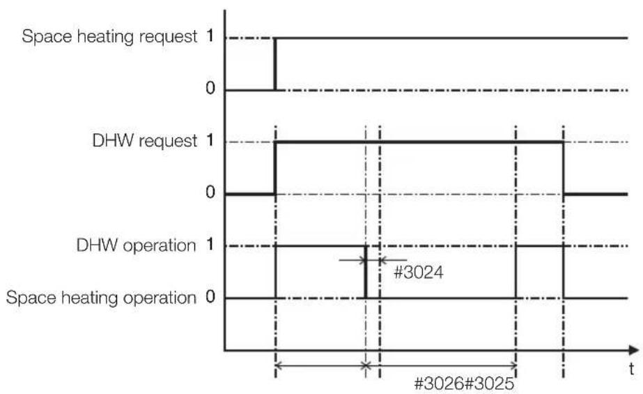
- DHW heating mode timer : Mode timer manage the operation terms when there are simultaneous requests of space heating/cooling and DHW.
- FSV #3024(minimum Space heating operating time, Default 5 min., Range 1 \~ 20 min.), #3025(maximum DHW time, Default 30 min., Range 5 \~ 95 min.), #3026(maximum space heating operation time, Default 3 hour, Range 0.5 \~ 10 hour)
- Maximum operation time is applied only when both DHW and Space heating request operation. DHW or Space heating operates continuously until reaching at target temperature without time limitation in the single operation.

The FSV #4011 for DHW priority should be set to "0(DHW)" (Default). Space heating gets a priority by setting FSV #4011 "1", but this is only valid when the outdoor temperature is lower than the specified temperature defined by FSV #4012.
44\_Operating advanced function
other
| Operation | Value | | ---------------- | ----- | | Heating request | 1 | | DHW request | 1 | | H/P operation | 1 | | Booster operation| 1 |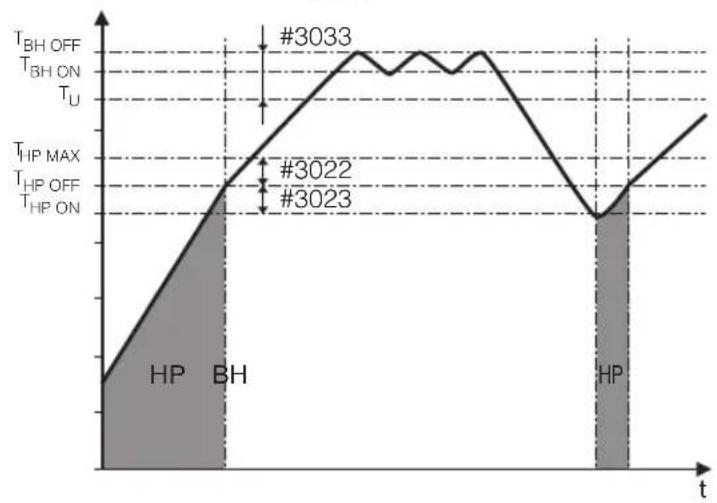
line
| Point | Time | Temperature | |-------|------|-------------| | #3033 | ~1.5 | Peak value | | #3022 | ~1.0 | Lower point | | #3023 | ~1.0 | Lower point |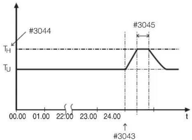
line
| Time | Value | |-------|-------| | 00.00 | T_H | | 22.00 | T_H | | 24.00 | T_H | | 24.00 | T_U | | 24.00 | #3043 | | 24.00 | #3045 |Operating advanced function
FIELD SETTING MODE
Booster Heater Variables for Controlling DHW Tank
- The FSV #3031 should be set to "1(On)" (Default) to use booster heater as an additional heat source for DHW tank.
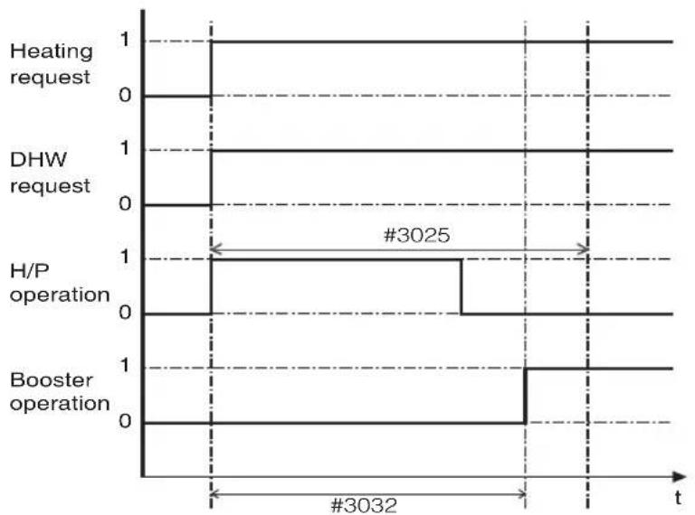
- Booster heater startup delay timer : In case of DHW request, this timer will delay the operation of booster heater compared to heat pump.
- FSV #3032(Default 20 min., Range 20 \~ 95 min.), In "Power" DHW mode, the delay timer will be neglected, and the booster starts immediately.
- In “Economic” DHW mode, the DHW heating will be conducted only with heat pump.
-
3032 should be smaller than the maximum H/P time(#3025). If the delay time is set too high, it might take very long time for DHW heating.
- Temperature difference determining the booster heater OFF temperature(T_BH OFF = Tu + #3033) : FSV #3033, Default 0°C, Range : 0 \~ 4°C.
- Temperature difference determining the booster heater ON temperature(T_BH ON = T_BH OFF - 2)
- DHW compensation temperature in case of space heating/cooling priority : FSV #3034 will be explained in next page.

The FSV #4022 for booster heater priority should be set to "0(both)" (Default) or "2"(booster) to use booster heater.
If not (backup heater priority), the booster heater can be operated in case of no backup heater demand.
Disinfection Function
- The FSV #3041 should be set to "1(On)" (Default) to use disinfection function.
- Scheduling : Day(#3042, Default "Friday"), starting time(#3043, Default "23:00"), target tank temp. (#3044, Default "70°C"), duration(#3045, Default 10 min.)

Disinfection function can be performed only with Samsung's DHW tank installation.
Urgent DHW by User's Input (Hot Key of Wired Remote Controller)
- Urgent DHW mode can be activated by changing setting value from the default setting (#3011, "0"(No)).
- Urgent DHW mode shall be working depending on Timer setting(#3051, #3052).
Additional Solar Panel Installation for DHW with Heat Pump (Field Option)
- Solar panel and heat pump are able to operate simultaneously by default setting value. (FSV #3061, "1"(Yes))
- Solar panel gets a priority by setting "0" in FSV #3061.
- Zone #1 and #2 valve always keep open except DHW mode in "ON" when the power is "ON" unless changing the FSV #3071. Default: Room direction valves are open and DHW valve is closed.
- Zone #1 and #2 can be open separately or simultaneously but all three zone valves can not be open or closed at the same time.
- There is one minute delay of 2-way valve closing whereas no delay of valve opening.
- Individual zone control is only available with external thermostat.
Operating advanced function
FIELD SETTING MODE
Space Heating : Code 40**
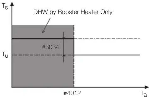
line
| Ta | Ts | | ---- | --- | | #4012 | #3034 | | Ta | || Field Setting Value | ||||||||
| Main Menu & Code | Sub Menu Function | Description Sub Code Default | Min Max | Step Unit | ||||
| Heating Code 40** | Heat Pump | Heating/DHW Priority **1 | 0(DHW) 0 | 1(Heating) | -- | |||
| Outdoor Temp for Priority | **12 | 0 | -15 | 20 | 1 | °C | ||
| Heating Off | **13 | 35 | 14 | 35 | 1 | °C | ||
| Overshoot | **14 | 2 | 1 | 4 | 1 | °C | ||
| Backup Heater | Application | **21 0 | (No) 0 | 1(Yes) | -- | |||
| BUH/BSH Priority | **22 | 0(Both) | 0 | 2(BSH) | 1 | - | ||
| Cold weather compensation | **23 1 | (On) 0(Off) | 1 | -- | ||||
| Threshold Temp | **24 | 0 | -15 | 35 | 1 | °C | ||
| Backup Boiler | Application | **31 0 | (No) 0 | 1(Yes) | -- | |||
| Boiler Priority | **32 | 0(Off) | 0 | 1(On) | - | - | ||
| Threshold Temp | **33 | -15 | -20 | 5 | 1 | °C | ||
Heat Pump Variables for Space Heating
- FSV #4011 for DHW priority is set to "0(DHW)" (Default) as a default. Space heating gets a priority by setting FSV #4011 "1", but this is only valid when the outdoor temperature is lower than the specified temperature defined by FSV #4012.
- Cold weather compensation is applied when the space heating gets a priority (FSV #4011=1). It is due to position of heating coil and booster heater in the water tank. Heating coil is at the bottom part of the water tank and the booster heater is located at the middle part of the tank. So the heating coil is efficient to heat the whole water in the tank. Chances that hot water flows through the heating coil decrease with the space heating priority. And lower part of water in the tank might not get enough heat with the booster heater. Cold weather compensation is raising the booster heater target temperature by temperature of FSV #3034 (default=10°C) higher than the user setting.
- Space heating off temperature(FSV #4013, Default "35°C", Range 14 \~ 35°C): At high outdoor temperature above this value, the space heating will be turned off, to avoid overheating.
- Overshoot temperature(FSV #4014, Default "2°C", Range 1 \~ 4°C): N/A yet
48\_Operating advanced function
Backup Heater Variables for Space Heating
- The FSV #4021 should be set to "1(On)" to use 2-stage electric backup heater in hydro unit as an additional heat source.
- To compensate the lowered heat pump heating performance under very cold weather conditions, the FSV #4023 should be set to "1(On)" (Default).
- The threshold temperature to use backup heater for cold weather compensation: FSV #4024. Default "0°C". Range -15 \~ 35°C
- The backup heater operation is restricted to save energy in the threshold temperature range.
- The FSV #4022 for backup heater priority should be set to "0(both)" (Default) or "1" (backup) to use backup heater. If not (booster heater priority), the backup heater can be operated in case of no booster heater demand.

To use both heaters together at the same time, please check the capacity of the power circuit breaker of your house before use.
External Backup Boiler for Space Heating (Field Option)
- The FSV #4031 should be set to "1(Yes)" to use a backup boiler as an additional heat source. (default: "0 (No installation)")
- Priority of backup boiler and heat pump is defined by FSV #4032 (default: "0(OFF)")
- To compensate the lowered heat pump heating performance under very cold weather conditions, the backup boiler operates instead of heat pump under the threshold temperature (FSV #4033. Default “-15°C”, Range -20 \~ 5°C).
Operating advanced function
FIELD SETTING MODE
Others : Code 50**
| Field Setting Value | ||||||||
| Main Menu & Code | Sub Menu Function | Description Sub Code Default | Min Max | Step Unit | ||||
| Others Code 50** | Outing | Water Out Temp for Cooling | **11 | 25 | 5 | 25 | 1 | °C |
| Room Temp for Cooling | **12 | 30 | 18 | 30 | 1 | °C | ||
| Water Out Temp for Heating | **13 | 15 | 15 | 55 | 1 | °C | ||
| Room Temp for Heating | **14 | 16 | 16 | 30 | 1 | °C | ||
| Auto Cooling WL1 Temp | **15 | 25 | 5 | 25 | 1 | °C | ||
| Auto Cooling WL2 Temp | **16 | 25 | 5 | 25 | 1 | °C | ||
| Auto Heating WL1 Temp | **17 | 15 | 15 | 55 | 1 | °C | ||
| Auto Heating WL2 Temp | **18 | 15 | 15 | 55 | 1 | °C | ||
| Target Tank Temp | **19 | 30 | 30 | 70 | 1 | °C | ||
| DHW Saving Mode | Temp Difference | **21 | 5 | 0 | 40 | 1 | °C | |
| Power Peak Control | Application | **41 | 0(No) | 0 | 1(Yes) | - | - | |
| Select forced off parts | **42 | 0 | 0 | 2 | 1 | - | ||
| Using input voltage | **43 | 1(High) | 0(Low) | 1 | - | - | ||
Outing Mode (Hot Key of Wired Remote Controller)
- All the target temperatures – space heating and cooling, water law, DHW, Room temperature – are set to the values defined in the above table under the holiday mode (outing hot key)

With the lowered target temperatures (FSV #5011 \~ #5019), the system operates normally.
- DHW heating only by the heat pump to save energy. Target DHW temperature is lower than the temperature set by user. The temperature difference is defined by FSV #5021. (default: 5°C)
- If user sets the temperature 45^ C, the system sets the target temperature 40^ C with the default setting.
50_ Operating advanced function
Peak Power Control
- If users make contracts with local electric power company for limiting the amount of power consumption when a surge in power usage, users can set FSV of “Forced off”.
- According to FSV (#5041), Default is Non-usage. And According to FSV (#5042), If input is "0(default)", all the thermal applications are unavailable while external contacts is high. If input is "1", Only the booster heater is available. If input is "2", Only the back up heater is available.
- Applying the control when power voltage of input contact is high is default. According to FSV (#5043), it is available to adopt this logic in low condition exceptionally.
- When applying to this logic, SAMSUNG controller come to get "Thermo off" condition for all operation.
- If not used for a long time, anti-freeze fluid shall be used for preventing damage to the unit in cold condition.
Appendix
TEMPERATURE TABLE
Available operation range
| Mode | Target temperature | Display Setting range | Current display | Setting method | Control method | ||||
| Set View D | Default Available | ||||||||
| Cooling | Leaving water O O 16~25°C | Min : 5~18°CMax : 18~25°C | -50~94°C | Up/Down - | |||||
| Heating | Leaving water O O 25~55°C | Min : 15~37°CMax : 37~55°C | -50~94°C | Up/Down - | |||||
| Water Law | Cooling | Outdoor X X 30~40°C | Min : 25~35°CMax : 35~45°C | -50~94°C | Field Setting ModeSET/VIEW mode | Thermostat(Th-1 : Floor,Th-2 : FCU) | |||
| Leaving water (WL1-Floor) | XX | 25~18°C | Min : 18~25°CMax : 5~18°C | -50~94°C | |||||
| Leaving water (WL2-FCU) | XX | 18~5°C | Min : 18~25°CMax : 5~18°C | -50~94°C | |||||
| Heating | Outdoor XX | -10~15°C | Min : -20~5°CMax : 10~20°C | -50~94°C | |||||
| Leaving water (WL1-Floor) | XX | 40~25°C | Min : 17~55°CMax : 17~55°C | -50~94°C | |||||
| Leaving water (WL2-FCU) | XX | 50~35°C | Min : 17~55°CMax : 17~55°C | -50~94°C | |||||
| Temperature Shifting | O | X | -5~5°C | Default | - | Up/Down | - | ||
| DHW | DHW tank | O O | 40~50°C | Min : 30~40°CMax : 50~65°C | -50~94°C | Up/Down - | |||
| Outdoor temperature | X | O | - | - | -50~94°C | - | |||
DIP SWITCH SETTING
| S/W | OFF (Default) | ON |
| S/W #1 | Heating and Cooling | Heating only |
| S/W #2 | Target temp : Water outlet Temp. | Target temp : Indoor air Temp. |
| S/W #4 | MASTER remote controller | SLAVE remote controller |
| S/W #5 | Self Test Mode is NOT available | Self Test Mode is available |
| S/W #6 | No Use | No Use |
| S/W #7 | No Use | No Use |
| S/W #8 | No Use | No Use |
52\_ Appendix
Maintenance activities
- In order to ensure optimal availability of the unit, a number of checks and inspections on the unit and the field wiring have to be carried out at regular intervals, preferably yearly. This maintenance should be carried out by SAMSUNG local technician. Besides keeping the remote controller clean by means of a soft damp cloth, no maintenance is required by the operator.

During longer periods of standstill, e.g. during summer with a heating only application, it is very important NOT TO SWITCH OFF THE POWER SUPPLY towards the unit.
Switching off the power supply stops the automatic repetitive movement of the motor in order to prevent it from getting jammed.
This product contains fluorinated greenhouse gases covered by the Kyoto Protocol.
Refrigerant type: R-410A
GWP(1) value: 2088 (GWP = global warming potential)
- Periodical inspections for refrigerant leaks may be required depending on European or local legislation. Please contact your local dealer for more information.
Appendix
TROUBLESHOOTING TIPS
If the unit has some problem to work properly, error codes will be displayed on the wired remote controller.
The following table describes the explanation of the error codes.
| DisplayExplanation | |
| 122 | EVA Inlet temp sensor SHORT or OPEN |
| 123 | EVA Outlet temp sensor SHORT or OPEN |
| 653 | Wired remote controller temp sensor SHORT or OPEN |
| 654 | FRAM Read/Write Error(Wired remote controller data error) |
| 901 | Water Inlet temp sensor SHORT or OPEN |
| 902 | PHE Outlet temp sensor SHORT or OPEN |
| 903 | Water outlet (Back up Heater) temp sensor SHORT or OPEN |
| 904 | Water TANK temp sensor SHORT or OPEN |

flowchart
graph TD
    A["EVA inlet E122"] -->|Tr1| B["Tw2"]
    C["Ref' In"] -->|Ref' Out| D["Tw1"]
    B --> E["PHE"]
    D --> F["Outdoor Unit"]
    B --> G["Water Outlet E902"]
    D --> H["Water inlet E901"]
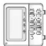
Wired remote controller
temp sensor
E653
E654
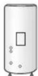
Water tank
temp sensor
E904
54\_ Appendix
Communication
| Display Explanation | |
| 604 | Abnormal communication B/W Wired remote controller & Control Kit |
| 604 | Communication tracking error B/W Wired remote controller & Control Kit |
| 654 | FRAM Read/Write Error(Wired remote controller data error) |
E601, E604
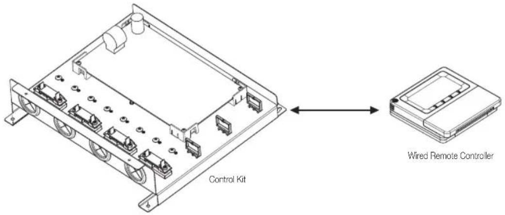
text_image
Control Kit Wired Remote ControllerE654
- Wrong data transmit B/W micom & IC07(eeprom)
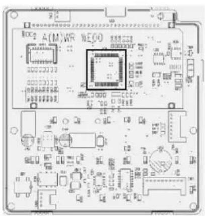
natural_image
Top-down view of a printed circuit board (PCB) with integrated circuits and components, no readable text or symbols present.Appendix
TROUBLESHOOTING TIPS
Water pump & Flow S/W
| Display Explanation | |
| 911 | Flow S/W OFF error (In case of flow S/W OFF in 10s during water pump signal is ON) |
| 912 | Flow S/W OFF error (In case of flow S/W ON in 60s during water pump signal is OFF) |
E911
• Water pump ON (Flow S/W off)
• Water pump ON (Flow S/W off) : NOT enough water flow
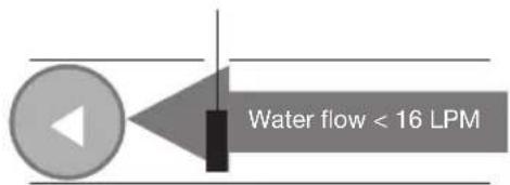
text_image
Water flow < 16 LPME912
• Water pump OFF (Flow S/W on)
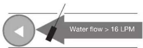
text_image
Water flow > 16 LPMERROR CODES
If the unit has some problems and does not work normally, error code is shown on the OUTDOOR UNIT main PBA or LCD of the wired remote controller.
| Display Explanation Error Source | ||
| 101 CONTROL KIT / OUTDOOR UNIT wire connection error | CONTROL KIT, OUTDOOR UNIT | |
| 162 EEPROM Error CONTROL KIT | ||
| 201 | CONTROL KIT/OUTDOOR UNIT communication error (Matching error) | CONTROL KIT, OUTDOOR UNIT |
| 202 CONTROL KIT/OUTDOOR UNIT communication error (3 min) | CONTROL KIT, OUTDOOR UNIT | |
| 203 Communication error between INVERTER and MAIN MICOM (6 min) OUTDOOR UNIT | ||
| 221 OUTDOOR UNIT temperature sensor error OUTDOOR UNIT | ||
| 231 condenser temperature sensor error OUTDOOR UNIT | ||
| 251 Discharge temperature sensor error OUTDOOR UNIT | ||
| 320 OLP sensor error OUTDOOR UNIT | ||
| 403 | Detection of OUTDOOR UNIT compressor freezing (During cooling operation) | OUTDOOR UNIT |
| 404 | Protection of OUTDOOR UNIT when it is overload (during Safety Start, Normal operation state) | OUTDOOR UNIT |
| 416 Discharge of a compressor is overheated OUTDOOR UNIT | ||
| 419 OUTDOOR UNIT EEV operation error OUTDOOR UNIT | ||
| 425 Power source line missing error (only for 3-phase model) OUTDOOR UNIT | ||
| 440 Heating operation blocked (outdoor temperature over 35°C) OUTDOOR UNIT | ||
| 441 Cooling operation blocked (outdoor temperature under 9°C) | OUTDOOR UNIT | |
| 458 OUTDOOR UNIT fan1 error | OUTDOOR UNIT | |
| 461 [Inverter] Compressor startup error | OUTDOOR UNIT | |
| 462 [Inverter] Total current error/PFC over current error | OUTDOOR UNIT | |
| 463 OLP is overheated | OUTDOOR UNIT | |
| 464 [Inverter] IPM over current error | OUTDOOR UNIT | |
| 465 Compressor V limit error | OUTDOOR UNIT | |
| 466 DC LINK over/low voltage error | OUTDOOR UNIT | |
| 467 [Inverter] Compressor rotation error | OUTDOOR UNIT | |
| 468 [Inverter] Current sensor error | OUTDOOR UNIT | |
| 469 [Inverter] DC LINK voltage sensor error | OUTDOOR UNIT | |
| 470 EEPROM read/write error | OUTDOOR UNIT | |
| 471 [Inverter] OTP error | OUTDOOR UNIT | |
| 474 IPM(IGBT Module) or PFCM temperature sensor Error | OUTDOOR UNIT | |
| 475 OUTDOOR UNIT fan2 error | OUTDOOR UNIT | |
Appendix _57
Appendix
ERROR CODES
| Display Explanation Error Source | ||
| 484 PFC Overload Error OUTDOOR UNIT | ||
| 485 Input current sensor error OUTDOOR UNIT | ||
| 500 IPM is overheated OUTDOOR UNIT | ||
| 554 Gas leak error OUTDOOR UNIT | ||
| 601 | Communication error between the CONTROL KIT and wired remote controller | Wired Remote Controller |
| 602 Wired remote controller Master/Slave setting error | Wired Remote Controller | |
| 604 | Communication tracking error between the CONTROL KIT and wired remote controller | CONTROL KIT, Wired Remote Controller |
| 607 | Communication error between the Master and Salve wired remote controllers | Wired Remote Controller |
| 901 Water inlet (PHE) temperature sensor error(open/short) OUTDOOR UNIT | ||
| 902 Water outlet (PHE) temperature sensor error(open/short) OUTDOOR UNIT | ||
| 903 Water outlet (backup heater) temperature sensor error. CONTROL KIT | ||
| 904 DHW tank temperature sensor error CONTROL KIT | ||
| 906 Refrigerant gas inlet (PHE) temperature sensor (open/short) OUTDOOR UNIT | ||
| 911 | Flow switch and water pump error (F/S signal is OFF for 10 sec. during the water pump signal is ON) | CONTROL KIT |
| 912 | Flow switch and water pump error (Water pump signal is OFF for 60sec during the F/S signal is ON) | CONTROL KIT |
58\_ Appendix
Memo
ENGLISH
Memo _59