
MIM-N00 - Air-conditioner SAMSUNG - Free user manual and instructions
Find the device manual for free MIM-N00 SAMSUNG in PDF.


User questions about MIM-N00 SAMSUNG
0 question about this device. Answer the ones you know or ask your own.
Ask a new question about this device
Download the instructions for your Air-conditioner in PDF format for free! Find your manual MIM-N00 - SAMSUNG and take your electronic device back in hand. On this page are published all the documents necessary for the use of your device. MIM-N00 by SAMSUNG.
USER MANUAL MIM-N00 SAMSUNG
Air Conditioner installation manual
imagine the possibilities
Thank you for purchasing this Samsung product.
SAMSUNG
Safety Information
This installation manual explains how to install an interface module that is connected to an outdoor unit of your Samsung system air conditioner. Please read this manual thoroughly before installing the product. (Please refer to an appropriate installation manual for any optional product installation.)
| WARNING | Hazards or unsafe practices that may result in severe personal injury or death. | ||
| CAUTION | Hazards or unsafe practices that may result in minor personal injury or property damage. | ||
| Must follow directions. | Unplug the power plug from the wall socket. | ||
| Do NOT attempt. Do NOT disassemble | |||
| Make sure the machine is grounded to prevent electric shock. | |||
FOR INSTALLATION
WARNING

Contact a service center for installation.
▶ Failure to do so may result in product malfunction, water leakage, electric shock and fire.
You must use the supplied wire for installation.
▶ Failure to do so may result in fire or damage to an interface module.
All electric work should comply with local regulations and installation work carried out by a qualified technician.
▶ Installation by an unqualified technician may result in product malfunction, electric shock, and fire.
Check whether the installation work is performed in accordance with the installation instructions.
▶ Incorrect installation of an interface module may result in electric shock or fire.
FOR INSTALLATION
CAUTION

When connecting a wire, do not tighten it too much.
▶ Failure to do so may result in breakage of the wire.
Make sure the interface module installation doesn't cause interference with other electrical appliances, particularly in a hospital etc.
▶ Failure to do so may result in abnormal operation.

Do not install the product in an area where combustible gas leaks or possible gas leakage is expected.
▶ Failure to do so may result in fire or explosion.
Do not install the product in conditions where it is exposed to oil, steam etc.
▶ Use of the product in an area exposed to oil, steam, sulfuric acid gas etc may result in component damage or product malfunction.
Do not install the product in a place where acid or alkali liquid or special sprays are used.
▶ Failure to do so may result in electric shock or abnormal operation.
FOR OPERATION
WARNING

Do not remodel or repair the interface module yourself.
▶ Failure to do so may result in product malfunction, electric shock and fire, so contact a service center for repair.
When disposing of an interface module, contact a service center.

Do not move or reinstall an installed interface yourself.
▶ Failure to do so may result in electric shock or fire.
FOR OPERATION
CAUTION

Make sure that water does not permeate inside the interface module.
▶ Failure to do so may result in electric shock or fire.

Do not connect power cable to the control cable terminal.
▶ Failure to do so may result in fire.
Interface module installation
Interface module
Product and components
| Name | Interface module | DC power cable (12 V) | Communication cable | Case | Cable tie | |
| Outdoor unit | Indoor unit | |||||
| Shape | 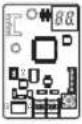 | 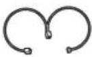 | 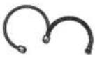 | 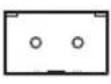 |  |  |
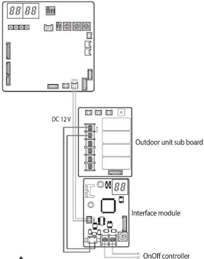
Diagram of connection between an interface module and DVM
- After attaching a case to the side of the indoor unit's electric equipment section, install the interface module.
- Connect the power cable and communication cable of the interface module.
When using a onOff controller with the interface module installed, the centralized control of all indoor units that are connected to an outdoor unit is available.
Outdoor unit main board
text_image
88 88 DC 12V Outdoor unit sub board Interface module OnOff controller
You should switch off the power supply and disconnect the power cable. (Abnormal operation of the product may occur due to the electric problem.)
Interface module installation
3. Setting an interface module address
The address for each interface module should be set differently.

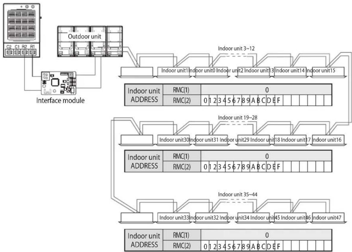
- The distance between the OnOff controller and the first interface module or the last interface module should be within 1000 m.
- You should switch off the power supply before installation.
- The wiring should be installed in accordance with electric wiring regulations and should be placed inside the wall so that users cannot touch them.
When installing 48 DVM
OnOff controller
flowchart
graph TD
    A["Outdoor unit"] --> B["Interface module"]
    B --> C["Indoor unit 3~12"]
    C --> D["Indoor unit 1"]
    C --> E["Indoor unit 0"]
    C --> F["Indoor unit 2"]
    C --> G["Indoor unit 3"]
    C --> H["Indoor unit 14"]
    C --> I["Indoor unit 15"]
    D --> J["Indoor unit ADDRESS"]
    E --> K["Indoor unit 19~28"]
    F --> L["Indoor unit 30"]
    F --> M["Indoor unit 31"]
    F --> N["Indoor unit 29"]
    F --> O["Indoor unit 18"]
    F --> P["Indoor unit 17"]
    F --> Q["Indoor unit 16"]
    G --> R["Indoor unit ADDRESS"]
    H --> S["Indoor unit 35~44"]
    I --> T["Indoor unit 45"]
    J --> U["Indoor unit 33"]
    K --> V["Indoor unit 32"]
    L --> W["Indoor unit 34"]
    M --> X["Indoor unit 46"]
    N --> Y["Indoor unit 47"]
    O --> Z["Indoor unit 45"]
    P --> AA["Indoor unit 46"]
    Q --> AB["Indoor unit 47"]
    R --> AC["Indoor unit ADDRESS"]
    S --> AD["Indoor unit 35~44"]
    T --> AE["Indoor unit 45"]
    U --> AF["Indoor unit 46"]
    V --> AG["Indoor unit 47"]
Checking operation
LED Indication
- When resetting the power supply, the interface module will not respond to the upper level communication for up to 10 minutes. (Please wait until the communication of the indoor unit, outdoor unit and interface module becomes normal.)
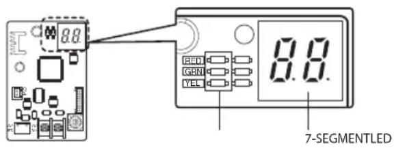
text_image
8.8 RED GBN YEL 8.8. 7-SEGMENTLED- When the upper level communication (e.g. Between an OnOff controller and an interface module) is detected as valid communication, the led indicator will show on and off.
7-SEGMENT indication
- When initializing power supply, 88 will be indicated after indicating the program cord.
- After receiving valid communication more than once, 80 will be indicated.
- When the communication is normal, the MAIN ADDRESS of indoor units that can be controlled by the interface module is indicated in order.
- When there is no communication between indoor units and outdoor units for more than 3 minutes EF EI will be indicated alternately.
- When there is no communication between an interface module and an upper level controller for more than 3 minutes, Er Er will be indicated alternately.
- When the interface module tracking is not completed after the tracking of indoor unit and outdoor unit tracking is completed, Er Er will be indicated alternately.
- When there's error on EEPROM of the interface module, EF EH will be indicated alternately.
- When same address was set to multiple interface modules, EF EF will be indicated alternately.
Checking operation
Notes on interface module installation
- Address of the indoor unit should be set between 00\~47.
- Indoor unit and ERV (ventilator) should not be installed to the same communication line (F1F2).
- Interface module for ERV (ventilator) is different, make sure MIM-N10 model is connected to ERV.
- Hydro units and function controllers (MCM-A100) are not compatible. However, DVM HE models are compatible.
- If the lower temperature limit for cooling, upper temperature limit for heating and exclusive operation mode (cooling/heating) was set from the upper level controller, setting must be done again when the interface module has been replaced due to failure.
Setting option switch and address switch
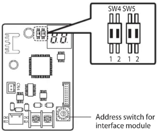
text_image
SW4 SW5 1 2 1 2 Address switch for interface module- SW4 #1: Option switch, which sets automatic/manual address setting when new communication upper level controller has been installed.(New communication upper level controller Interface module Old communication products)
2: Option switch, Sets temperature in Celsius/Fahrenheit
- SW5 #1: Option switch, Enable or disable downloading
- SW1: Address switch, set the address within 0\~F (0\~15) (Address between each interface module should be set differently)
Descriptions of option switch
SW4
1: OFF (Automatic address setting, switch must be down)
1: ON (Manual address setting, switch must be up)
* This function is only applicable when new communication upper level controller is connected.
2: OFF (Set temperature in Celsius, switch must be down)
2: ON (Set temperature in Fahrenheit, switch must be up)
SW4 SW5
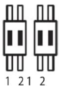
SW5
1: OFF (Disable downloading, switch must be down)
1: ON (Enable downloading, switch must be up)
* Switch must be set to OFF when downloading is complete.
2: OFF (Not in use)
2: ON (Not in use)





SAMSUNG

