MXJ-HA3115M - Air-conditioner SAMSUNG - Free user manual and instructions
Find the device manual for free MXJ-HA3115M SAMSUNG in PDF.


User questions about MXJ-HA3115M SAMSUNG
0 question about this device. Answer the ones you know or ask your own.
Ask a new question about this device
Download the instructions for your Air-conditioner in PDF format for free! Find your manual MXJ-HA3115M - SAMSUNG and take your electronic device back in hand. On this page are published all the documents necessary for the use of your device. MXJ-HA3115M by SAMSUNG.
USER MANUAL MXJ-HA3115M SAMSUNG
Air Handling Unit Application Kit
Installation manual
MXD-K100XN
- Thank you for purchasing this Samsung air conditioner.
- Before operating this unit, please read this user manual carefully and retain it for future reference.
Contents
Preparation 3
Safety Information 3
External Appearance 6
Accessories 7
Before Installation 8
AHU-KIT Structure Diagram
Installation 9
Control-KIT Installation • Control-KIT Function • Control-KIT Circuit Diagram •
External Controller Diagram (MIM-B14) • Simple BMS • Connecting the Power Terminal •
Control-KIT Connections • Brazing the Pipe • Sensor Installation
Function Setting 21
Setting an indoor unit address and installation option
After Installation 30
AHU-KIT Installation Check • Test Operation
Appendix 31
Troubleshooting 31
Initial Check-up • EEPROM Error • Sensor Error • Fan Error • In-tracking Error
Safety Information
The following safety precautions must be taken when installing the unit.
Be aware that AHU-KIT has to be combined with
"AC026MXADKH/EU, AC035MXADKH/EU, AC052MXADKH/EU, AC071MXADKH/EU, AC100MXADKH/EU,
AC100MXADNH/EU, AC120MXADKH/EU, AC120MXADNH/EU, AC140MXADKH/EU, AC140MXADNH/EU,
AC180JXAPNH/EU, AC200KXAPNH/EU, AC250KXAPNH/EU" outdoor unit only.
Use R410A refrigerant.
- When using R410A, moisture or foreign substances may affect the capacity and reliability of the product. Safety precautions must be taken when installing the refrigerant pipe.
● R410A is a quasi-azeotrope of two refrigerants. Make sure to charge liquid one when adding refrigerant. (If you charge gaseous refrigerant, it may affect the capacity and reliability of the product as a result of change in formation of the refrigerant.)

Risk of death or serious personal injury.

CAUTION WARNING
Potential risk of personal injury or material damage.

CAUTION
Turn off the power before installation, service, and cleaning.
The installation must be done by the manufacturer or its service agent or a similar qualified person in order to avoid a hazard.
● Installation by an unqualified person may cause a water leakage, electric shock or fire.
Install the outdoor unit correctly according to the installation manual.
Manufacturer is not responsible for accidents due to incorrect installation by unqualified person.
- An incorrect installation may cause a water leakage, electric shock or fire and so on.
Use only rated parts and tools.
- If you don't use the rated parts and tools, it can cause trouble with the product and bring about injury.
When adding the refrigerant, use the R410A refrigerant only.
- If any gas or impurities except R410A refrigerant come into the refrigerant pipe, serious problem may occur and it may cause injury.
Use the pipe or flare part for R410A refrigerant only. When there were leakage during installation, you must ventilate the area.
● Toxic gas may generate when refrigerant gas contacts with fire.
If the power cable or cord is damaged, the manufacturer, a qualified service technician must replace it to avoid a potential risk.
The electric work must be done by service agent or similarly qualified persons according to national wiring regulations and use only rated cable.
- If the capacity of the power cable is insufficient or electric work is not properly completed, electric shock or fire may occur.

CAUTION
Arrange the cables between the AHU-KIT and outdoor unit after connecting. Attach the cover securely so that the electrical component box cover does not get loosen.
- If the cover is attached incompletely, it can cause trouble with a heat generation, electric shock or fire of the terminal board.
Install the cables with supplied cables firmly. Fix them securely so that external force is not exerted to the terminal board.
- If the connection or fixing is incomplete, it can cause trouble with a heat generation, electric shock or fire.
Use the copper wire for the power cable and use only rated cables and parts.
Install designated ELB for AHU when installing the power cable.
- If you do not install designated ELB for AHU, electric shock or fire may occur.
Make sure that the power for AHU-KIT is under maximum, and over minimum voltage allowed.
- It may cause electrical component malfunction which can damage the product.
Make sure electrical circuit is correctly connected.
● Overheating may cause fire.
Make sure there is no leakage after installation.
● Toxic gas may generate when refrigerant gas contacts with fire.

WARNING
Make sure of a earthing.
- Do not connect the earth wire to the gas pipe, water pipe, lighting rod or telephone wire.
- If earthing is incomplete, electric shock or fire may occur.
Follow the instructions in this manual to make sure that the condensed water dripping from the drain hose runs out properly and insulate the drain pipe so that dew condensate does not generate.
● Household goods may get wet if the drain pipe is not properly installed.
Install the power cable and communication cable of the AHU-KIT at least 1m away from electric appliances.
- Noise may heard depending on the electric wave though the cables are installed away from electric appliances.
- Keep the space in front of AHU-KIT for maintenance.

WARNING
Do not install the AHU-KIT in following places.
●The place where there is mineral oil or arsenic acid.
- There is a chance that parts may get damaged due to burned resin.
● The place where corrosive gas such as sulfurous acid gas generates from the vent pipe or air outlet.
- The copper pipe or connection pipe may corrode and refrigerant may leak.
●The place where there is a machine that generates electromagnetic waves.
- The air conditioner may not operate normally due to control system.
● The place where there is a danger of existing combustible gas, thinner or gasoline is handled.
- The place where carbon fiber or flammable dust is.
● The place where like spa and shore.
● The place with direct contact of sunlight, rain, outdoor humidity, dust and temperature.
* The manufacturer is not responsible for the damage occurred by not keeping standard of the installation.
Samsung will notice a below legal disclaimer. Do you agree this?
1) Local system design and AHU design responsibility
Samsung does not accept any responsibility or liability for the performance and regulatory compliance of the local system design and AHU design.
2) Regulatory compliance
HVAC solution provider must ensure that the local system design and AHU design comply with all applicable regulations.
The Declaration of Conformity for Samsung's outdoor units and interface is available from the relevant factories.
External Appearance
Control-KIT
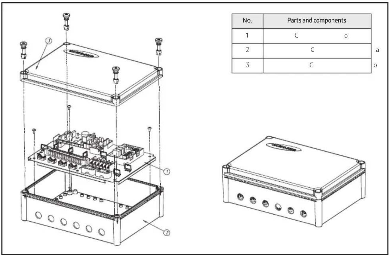
| No. | Parts and components |
| 1 | C o |
| 2 | C |
| 3 | C |
a
Accessories
| ITEM | Room/EVA IN sensor (10 m) | EVA OUT sensor (10 m) | EVA IN sensor holder (OD ∅ 6.8 mm) | EVA OUT sensor holder (OD ∅ 7.8 mm) | Sensor clip | |
| QUANTITY 1 | 1 | 1 | 1 | 2 | ||
| IMAGE | 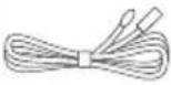 | 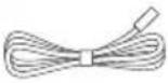 |  | 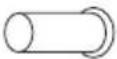 | 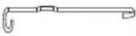 | |
| ITEM Aluminum tape Rubber tape Insulator | ||||||
| QUANTITY 4 | 2 | 2 | ||||
| IMAGE | 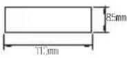 | 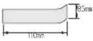 | 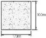 | |||
| ITEM | Cable-tie | Cable-nut | Bracket Base | Installation Manual | Screw plug | Wired Remote Controller (optional) |
| PG16 PG16 | ||||||
| QUANTITY | 8 | 6 | 4 | 1 | 1 | |
| IMAGE |  |  |  |  |  |  |
AHU-KIT Structure Diagram
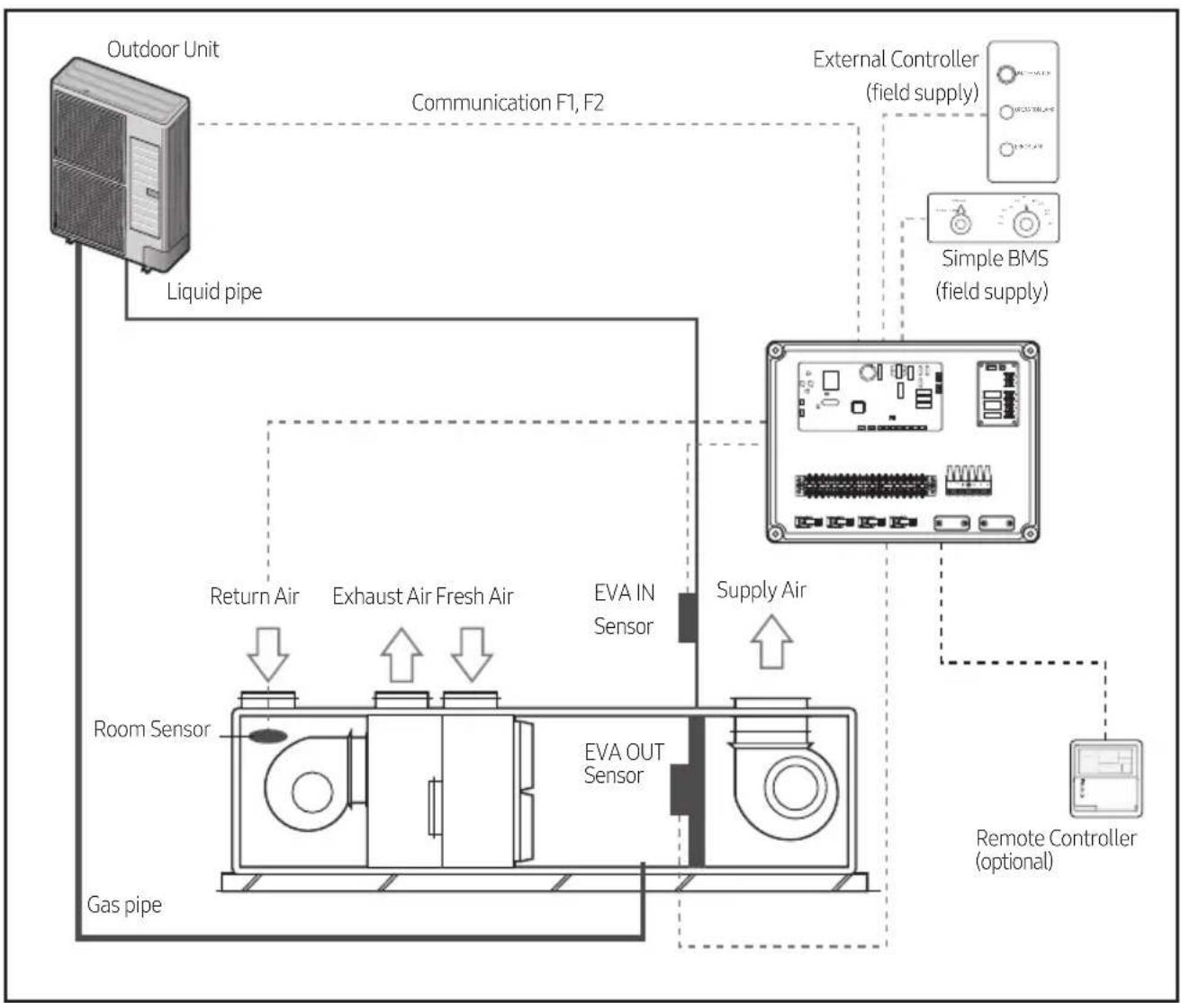
flowchart
graph TD
    A["Outdoor Unit"] -->|Liquid pipe| B["Room Sensor"]
    B -->|Return Air| C["Gas pipe"]
    B -->|Exhaust Air Fresh Air| D["EVA OUT Sensor"]
    D -->|Supply Air| E["External Controller (field supply)"]
    E --> F["Remote Controller (optional)"]
    F --> G["Simple BMS (field supply)"]
    G --> H["External Controller (field supply)"]
    H --> I["External Controller (field supply)"]
    style A fill:#f9f,stroke:#333
    style B fill:#ccf,stroke:#333
    style C fill:#cfc,stroke:#333
    style D fill:#fcc,stroke:#333
    style E fill:#cff,stroke:#333
    style F fill:#ffc,stroke:#333
    style G fill:#cfc,stroke:#333
    style H fill:#fcc,stroke:#333

CAUTION
- When the controllers (External Controller, simple BMS, Remote Controller) are installed simultaneously, AHU-KIT doesn't have the priority of control and operates according to the final signal. (SIMPLE BMS may indicate the different condition of AHU, if AHU was controlled by other controller finally.)
Control-KIT Installation

CAUTION
• Supplied sensor in the Accessory box is 10m.
- Close the box with the cover and cable-nut securely so that Control-KIT is fireproofed.
- Avoid installing the unit in a location exposed to direct sunlight or rain.
1) Drill 4 holes on the correct position of the wall and fix the Control-KIT securely. (refer to the dimension of figure below.)
2) Open the box and connect the cables according to the diagram.
(Wires should be pulled through the Cable-nut, before connecting to the terminal.
Refer to the figure below.)
3) Fix the cable firmly with Cable-tie after connecting.
4) Close the box.
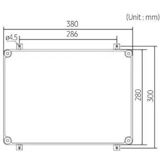
text_image
380 286 (Unit: mm) Ø4.5 280 300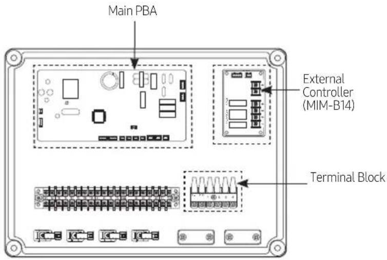
text_image
Main PBA External Controller (MIM-B14) Terminal Block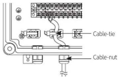
text_image
Cable-tie Cable-nutControl-KIT Function
- Control-KIT controls the system through outdoor unit and wired remote controller.
- Control-KIT outputs the contact signal for AHU fan operation.
Terminal block 1, 2 (Refer to page 11) outputs the AHU fan ON contact signal 220 - 240 V(208 - 230 V for US) for AHU when operating in Cool/Heat/Fan mode. This contact signal output can not be used as power supply for the motor.
- Terminal block 3, 4 (Refer to page 11) is for AHU-KIT control to receive the fan operation status. This input signal should be simple OPEN/SHORT signal without any extra voltage.
- Normal fan operation : Terminal block 3, 4 is in SHORT.
- Fan is not in operation : Terminal block 3, 4 is in OPEN.
- To use fan feedback to protect your system, set the 05 series installation option SEG21(Refer to page 28) to "1".
- Connect 220 - 240 V, 50 / 60 Hz (208 - 230 V, 60 Hz for US) to terminal block 1(L)/2(N).
- You should connect outdoor unit communication cable to communication line (F1, F2)(Refer to page 11).
- F3, F4(Refer to page 11) is communication line for wired remote controller(12 V).
Control-KIT Circuit Diagram
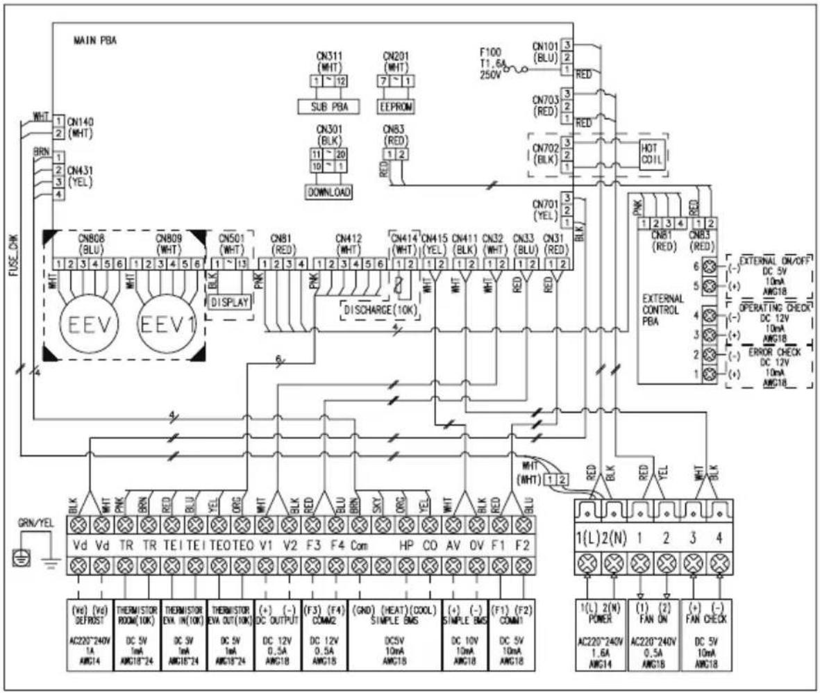
text_image
MAIN PBA WHT 1 2 3 4 WN140 (MHT) BRN 1 2 3 4 CN431 (YEL) FUSE-DW CN808 (BLU) 1 2 3 4 5 6 1 2 3 4 5 6 WN1 EEV EEV1 CN501 (WHT) 1 ~ 13 PNK DISPLAY CN81 (RED) 1 2 3 4 5 6 1 2 3 4 5 6 DNK1 CN412 (WHT) 1 2 3 4 5 6 1 2 3 4 5 6 DNK1 DN414 (WHT) 1 2 3 4 5 6 1 2 3 4 5 6 DNK1 DN415 (WHT) 1 2 3 4 5 6 1 2 3 4 5 6 DNK1 DN411 (BLK) 1 2 3 4 5 6 1 2 3 4 5 6 DNK1 DN32 (WHT) 1 2 3 4 5 6 1 2 3 4 5 6 DNK1 DN33 (BLU) 1 2 3 4 5 6 1 2 3 4 5 6 DNK1 DN31 (RED) 1 2 3 4 5 6 1 2 3 4 5 6 DNK1 DN703 (RED) 1 RED 1 RED 1 RED ON702 (BLK) HOT COIL ON701 (YEL) 1 BLK DNK81 (RED) 6 5 4 3 2 1 OUTERNAL CONTROL PBA EXTERNAL ON/OFF DC 5V 10mA ANG18 OPERATING CHECK DC 12V 10mA ANG18 ERROR CHECK DC 12V 10mA ANG18 MHT (MHT) 1.2 RED BLK RED YEL MHT BLK VL Vd Vd TR TR TEI TEI TEO TEO V1 V2 F3 F4 Com HP CO AV OV F1 F2 (Ve) (Ve) SET/OST AC220~240V 1A ANG14 THERM/STOR ROOM(10K) DC SV 1mA ANG18~24 THERM/STOR EVA IN(10K) DC SV 1mA ANG18~24 THERM/STOR EVA OUT(10K) DC SV 1mA ANG18~24 (+ ) (-) DC OUTPUT (F3) (F4) COM2 (GND) (HEAT) (COOL) SIMPLE BMS (DCSV) 0.5A ANG18 (SIMPLE BMS) (Simple BMS) (DC SV) 0.5A ANG18 (SIMPLE BMS) (DC SV) 0.5A ANG18 (SIMPLE BMS) (DC SV) 0.5A ANG18 (SIMPLE BMS) (DC SV) 0.5A ANG18 (SIMPLE BMS) (DC SV) 0.5A ANG18 (SIMPLE BMS) (DC SV) 0.5A ANG18 (SIMPLE BMS) (DC SV) 0.2N AIC220~240V 1.6A ANG14 (AC220~240V) 0.5A ANG18 (AC220~240V) 0.5A ANG18 (AC220~240V) 0.5A ANG18 (AC220~240V) 0.5A ANG18 (AC220~240V) 0.5A ANG18 (AC220~240V) 0.5A ANG18 (AC22C~240V) 0.5A ANG18 (AC22C~240V) 0.5A ANG18 (AC22C~240V) 0.5A ANG18 (AC22C~240V) 0.5A ANG18 (AC22C~240V) 0.5A ANG18 (AC22C~240S) 0.5A ANG18 (AC22C~240S) 0.5A ANG18 (AC22C~240S) 0.5A ANG18 (AC22C~240S) 0.5A ANG18 (AC22C~240S) 0.5A ANG18 (AC22C~240S) 0.5B N/A CENCK DRYD DRYD DRYD DRYD DRYD DRYD DRYD DRYD DRYD DRYD DRYD DRYD DRYD DRYD DRYD DRYD DRYD DRYD DRYD DRYD DRYD DRYD DRYD DRYD DRYD DRYD DRYD DRYD DRYD DRYD DRYD DRYD DRYD DRYD
RESISTANCE VALUE OF TEMPERATURE SENSOR :
10Kohm at 25 °C(77 °F)
External Controller Diagram (MIM-B14)
Circuit diagram of external controller's output
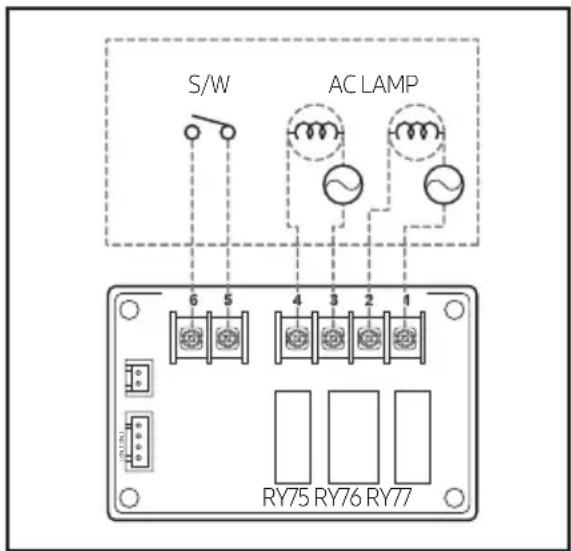
text_image
S/W AC LAMP 6 5 4 3 2 1 RY75 RY76 RY77Operation specification according to AHU-KIT PBA Install option set up
| WIRE NO. | Signal Install option | |
| 1, 2 Error check output - | ||
| 3, 4 Operation check output SEG 15 | ||
| 5, 6 ON/OFF input SEG 14 | ||

CAUTION
- In order for AHU-KIT to be controlled by External control, change a digit of indoor unit installation option, set the SEG14 as "1". (ON / OFF control)
Simple BMS
Simple BMS setting
- Simple BMS control is not influenced by DMS's restrictions on operation mode, set temperature or remote controller usage.
- If you want to set Room temperature by using Simple BMS, setting Buzzer control option as "Disuse buzzer" is recommended.
Circuit diagram of Simple BMS
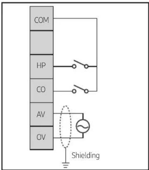
text_image
COM HP CO AV OV Shielding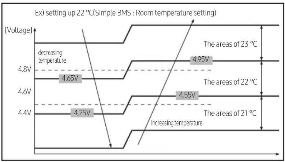
line
| Temperature Level | Voltage | | ----------------- | ------- | | 21 °C | 4.25V | | 22 °C | 4.55V | | 23 °C | 4.95V |
CAUTION
- Hysteresis is applied to the end of voltage range in order to stabilize the analog input. The amount of Hysteresis - Room temperature setting: 0.15 V
Operational Voltage range against Setting temperature
Room temperature setting
| Simple BMS Voltage Range | Set Temperature | |
| Heating Cooling | ||
| 10.0 V~9.6 V 30 °C 30 °C | ||
| 9.6 V~9.2 V 30 °C 30 °C | ||
| 9.2 V~8.8 V 30 °C 30 °C | ||
| 8.8 V~8.4 V 30 °C 30 °C | ||
| 8.4 V~8.0 V 30 °C 30 °C | ||
| 8.0 V~7.6 V 30 °C 30 °C | ||
| 7.6 V~7.2 V 29 °C 29 °C | ||
| 7.2 V~6.8 V 28 °C 28 °C | ||
| 6.8 V~6.4 V 27 °C 27 °C | ||
| 6.4 V~6.0 V 26 °C 26 °C | ||
| 6.0 V~5.6 V 25 °C 25 °C | ||
| 5.6 V~5.2 V 24 °C 24 °C | ||
| 5.2 V~4.8 V 23 °C 23 °C | ||
| 4.8 V~4.4 V 22 °C 22 °C | ||
| 4.4 V~4.0 V 21 °C 21 °C | ||
| 4.0 V~3.6 V 20 °C 20 °C | ||
| 3.6 V~3.2 V 19 °C 19 °C | ||
| 3.2 V~2.8 V 18 °C 18 °C | ||
| 2.8 V~2.4 V 18 °C 18 °C | ||
| 2.4 V~2.0 V 18 °C 18 °C | ||
| 2.0 V~1.6 V 18 °C 18 °C | ||
| 1.6 V~1.2 V 18 °C 18 °C | ||
| 1.2 V~0.8 V 18 °C 18 °C | ||
| 0.8 V~0.4 V 18 °C 18 °C | ||
| 0.4 V~0.0 V 18 °C 18 °C | ||
Setting the temperature
- Keep the power supply of Simple BMS in 10V ± 0.2V .
- If the Simple BMS uses variable resistor(VR), make the electric resistance of VR under 1k .
- Simple BMS which uses variable resistor(VR) need to be connected to the AHU-KIT with 1:1 link.
- Use the Simple BMS which outputs voltage so that one Simple BMS controls several AHU-KIT at the same time.
Available Not Available
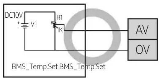
text_image
DC10V + V1 R1 1K AV OV BMS_Temp.Set BMS_Temp.Set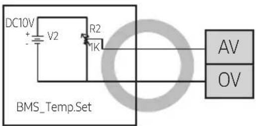
text_image
DC10V + - V2 R2 IK BMS_Temp.Set AV OV
text_image
DC0V ~DC10V + - v1 BMS_Temp.Set AV OV AV OV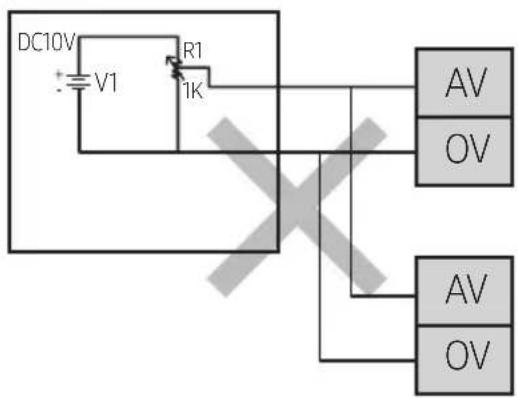
text_image
DC10V V1 R1 1K AV OV AV OVCAUTION
- Make sure that Simple BMS is connected to DC power supply before installing.
Never connect Simple BMS to AC power supply.
Connecting the Power Terminal
Connecting Power/Communication cable
- Turn off the power before connecting the power terminal.
- Maximum cable length and the amount of voltage drop for AHU power/communication cables should be under 10 %.
- Consider power usage of the AHU when installing the ELB.
- Connect F3, F4 on AHU-KIT to the communication line (F3, F4) on wired remote controller. (Refer to page 17)
- Use the appropriate tools for wiring and make sure to connect them tightly within the tightening torque to withstand the external pressure. Arrange the wires so that cover or other parts does not get loose. They may cause overheating, electric shock or fire.
- Connect the power cable to the ELB.
| Tightening torque (kgf·cm) | |
| M4 | 12.0 ~ 18.0 |

CAUTION
- Power supply for AHU-KIT should be separate from outdoor unit.
- Do not connect the terminal block power line from one indoor unit to more than one AHU-KIT.
- When peeling the power cable, use the appropriate tools to prevent damaging the wire.
- Communication cable should be installed separately from power cable or other cables.
| Description Type of cable Maximum length(m) Specifications | ||||
| Vd / Vd | DEFROST Signal 2 x 1.5 mm2 | - | 1 phase 220 - 240 V, 50 / 60 Hz(208 - 230V, 60 Hz for US) | |
| TR/TR | Thermistor Room 2 x 0.75 mm2 accessory, 10 m - | |||
| TEI/TEI | Thermistor EVA IN(Liquid pipe) | 2 x 0.75 mm2 accessory, 10 m - | ||
| TEO/TEO | Thermistor EVA OUT(Gas pipe) | 2 x 0.75 mm2 accessory, 10 m - | ||
| F3/F4 | Communication to RemoteController | 2 x 0.75 mm2 -- | ||
| COM/HP/CO | Simple BMS --- | |||
| AV/OV | Simple BMS(Setting Temperature) | 2 x 0.75 mm2 - Simple BMS Power | ||
| F1/F2 | Communication toOutdoor unit | 2 x 0.75 mm2 -- | ||
| L/N | Power supply | 3 x over 1.5 mm2 | - | 1 phase 220 - 240 V, 50 / 60 Hz(208 - 230V, 60 Hz for US) |
| 1/2 | Fan on | 2 x 0.75 mm2 - | 1 phase 220 - 240 V, 50 / 60 Hz(208 - 230V, 60 Hz for US) | |
| 3/4 | Fan check | 2 x 0.75 mm2 - Non-voltage contact signal | ||
Control-KIT Connections

natural_image
Front view of an electronic device chassis showing internal components and connectors (no text or symbols visible)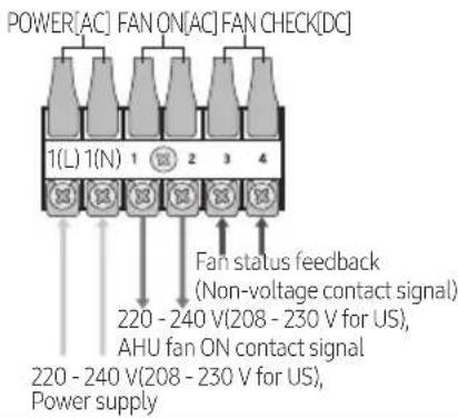
text_image
POWER[AC] FAN ON[AC] FAN CHECK[DC] 1(L) 1(N) 1 2 3 4 Fan status feedback (Non-voltage contact signal) 220 - 240 V(208 - 230 V for US), AHU fan ON contact signal 220 - 240 V(208 - 230 V for US), Power supply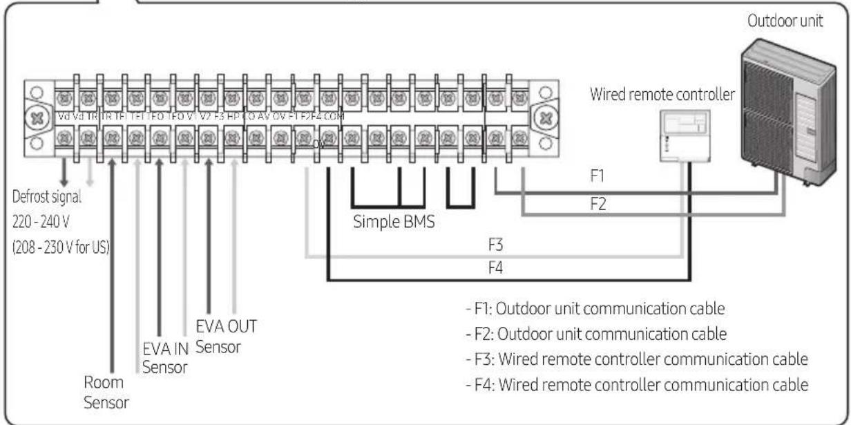
text_image
Defrost signal 220 - 240 V (208 - 230 V for US) Room Sensor EVA IN Sensor Vd Vd TR IR TE TFI FO FO V V2 F3 HP FO AV OV F1F2F4 COM Simple BMS F1 F2 F3 F4 Wired remote controller Outdoor unit F1: Outdoor unit communication cable F2: Outdoor unit communication cable F3: Wired remote controller communication cable F4: Wired remote controller communication cableBrazing the Pipe
• Make sure that there is no moisture inside the pipe.
- Make sure that there are no foreign materials and impurities in the pipe.
• Make sure that there is no leak.
- Be sure to follow the instruction when brazing the pipe.
The use of Nitrogen gas
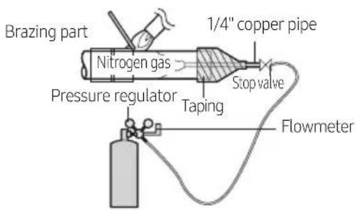
1) Use Nitrogen gas when brazing the pipes as shown in the picture.
2) If you do not use Nitrogen gas when brazing the pipes, oxide may form inside the pipe. It can cause the damage of the compressor, valves.
3) Adjust the flow rate of the Nitrogen gas with a pressure regulator to maintain 0.05m3/h or less.
text_image
Brazing part Nitrogen gas Pressure regulator Taping 1/4" copper pipe Stop valve FlowmeterSensor Installation

CAUTION
- Please check sensor usage in label.
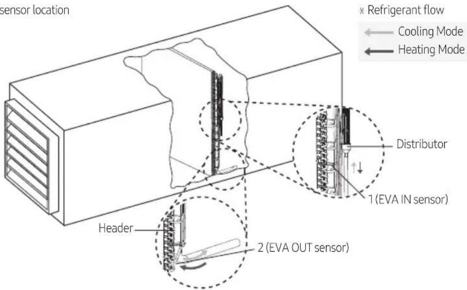
1) EVA IN sensor should be attached after the distributor, on the coldest part of the heat exchanger pipe.
2) EVA Out sensor should be attached on the middle of inlet and outlet ports.
3) EVA IN/OUT sensor should be insulated for optimized system performance.
4) Room temperature sensor should be basically installed where room air enters(A), It could be also installed at the supplay air side(B), especially with outdoor fresh air conditioning application.
In that case, installation option 05 series SEG15 and SEG16 function setting should be considered. (Refer to page 28)
Select EVA IN/OUT sensor location
text_image
sensor location × Refrigerant flow ← Cooling Mode ← Heating Mode Distributor 1 (EVA IN sensor) Header 2 (EVA OUT sensor)Example of room temperature sensor installation
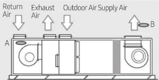
text_image
Return Air Exhaust Air Outdoor Air Supply Air A BA or B : Room temperature sensor location
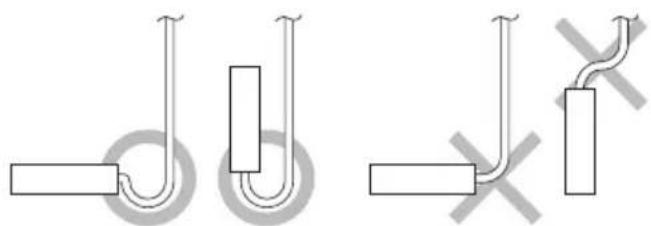
natural_image
Pure electrical circuit lines without any symbols
NOTE
- Braze the sensor holder at location suggested above and fix the sensor with sensor clip.
- EVA IN/OUT sensor should be installed where temperature of heat exchanger can be measured accurately.
Sensor installation example 1
1) Check the sensor and the sensor holder.

NOTE
| Type Sensor | OD(mm) Sensor holder ID (mm) |
| EVA IN sensor ∅ 6 ∅ 6.8 | |
| EVA OUT sensor ∅ 7 ∅ 7.8 |
2) Braze the sensor holder on the selected location of the pipe. Sensor attachment method.

NOTE
- Choose the location where temperature can be measured correctly. (Refer to page 18)
- Try to attach closely to the contact surface before brazing.
- Distinguish EVA IN/OUT sensor and attach it. (EVA IN/OUT sensor size is different.)
3) Insert sensor and the sensor clip in the sensor holder.
4) Bend end of the sensor clip to fix the sensor.
5) Attach the insulator around the sensor.
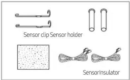
text_image
Sensor clip Sensor holder SensorInsulator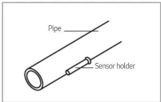
text_image
Pipe Sensor holder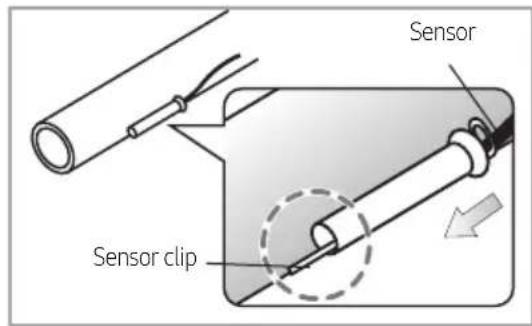
text_image
Sensor Sensor clip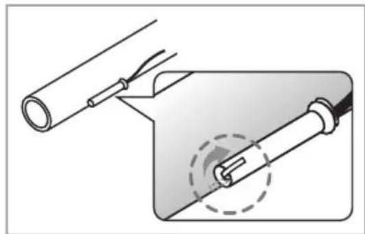
natural_image
Diagram showing a pipe being inserted into a device with a dashed circular component (no text or symbols)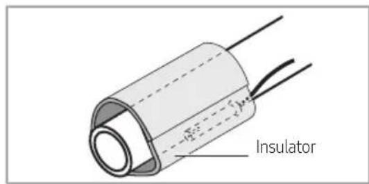
text_image
InsulatorSensor installation example 2
1) Check the sensor and the sensor holder.

NOTE
| Type Sensor | OD (mm) | Sensor holder ID (mm) |
| EVA IN sensor ∅ | 6 ∅ 6.8 | |
| EVA OUT sensor ∅ | 7 ∅ 7.8 |
2) Put the sensor on the pipe.

NOTE
Sensor attachment method.
- Choose the location where temperature can be measured correctly. (Refer to page 18)
- Try to attach closely to the contact surface.
- Do not use the sensor holder.
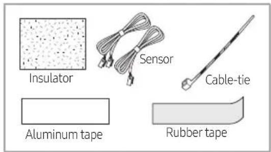
3) Hold the sensor and put aluminum tape around to fix the sensor.
4) Put rubber tape around the sensor.
5) Use cable-tie to tighten the sensor around the pipe.
6) Attach the insulator around the sensor.
text_image
Insulator Sensor Cable-tie Aluminum tape Rubber tape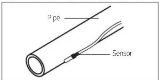
text_image
Pipe Sensor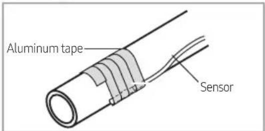
text_image
Aluminum tape Sensor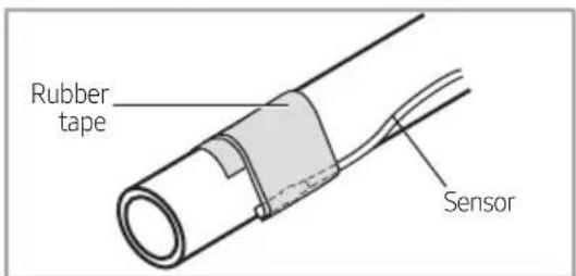
text_image
Rubber tape Sensor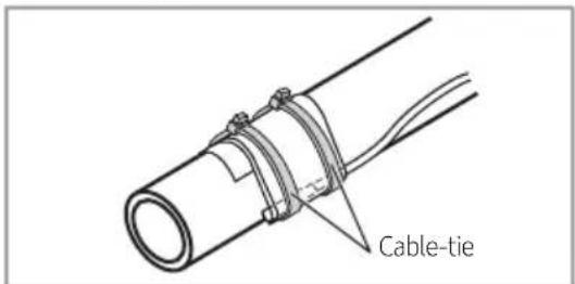
text_image
Cable-tie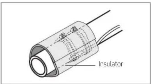
text_image
InsulatorSetting an indoor unit address and installation option
▶ Set the indoor unit address and installation option with remote controller option.
▶ Set the each option separately since you cannot set the ADDRESS setting and indoor unit installation setting option at the same time. You need to set twice when setting indoor unit address and installation option.
The reception part of a remote controller is built in the AHU KIT PBA.
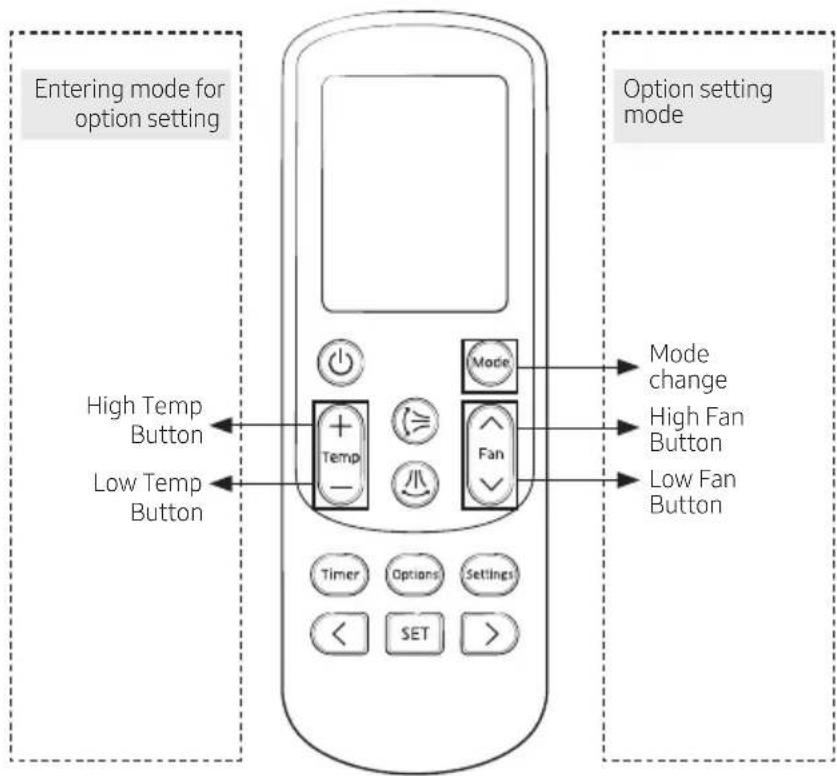
The procedure of option setting
text_image
Entering mode for option setting High Temp Button Low Temp Button Option setting mode Mode change High Fan Button Low Fan Button Timer Options Settings < SET >Step 1. Entering mode to set option
- Remove batteries from the remote controller.
- Insert batteries while pressing High Temp button and Low temp button to enter the option setting mode.
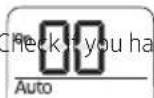
- Check if you have entered the option setting status.

Step 2. The procedure of option setting
After entering the option setting status, select the option as listed below.

CAUTION
Option setting is available from SEG1 to SEG 24
- SEG1, SEG7, SEG13, SEG19 are not set as page option.
- Set the SEG2\~SEG6, SEG8\~SEG12 as ON status and SEG14\~18, SEG20\~24 as OFF status.
| SEG1 | SEG2 | SEG3 | SEG4 | SEG5 | SEG6 | SEG7 | SEG8 | SEG9 | SEG10 | SEG11 | SEG12 | |||
| 0 | X | X | X | X | X | X | 1 | X | X | X | X | X | X | X |
| SEG13 | SEG14 | SEG15 | SEG16 | SEG17 | SEG18 | SEG19 | SEG20 | SEG21 | SEG22 | SEG23 | SEG24 | |||
| 2 | X | X | X | X | X | X | 3 | X | X | X | X | X | X | X |
| On(SEG1~12) Off(SEG13~24) | |
| Option setting Status | ||
| 1. Setting SEG2, SEG3 optionPress Low Fan button(∨) to enter SEG2 value.Press High Fan button(∧) to enter SEG3 value.Each time you press the button,0→8→.E 6 will be selected in rotation. | 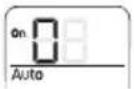 SEG2 SEG3 SEG2 SEG3 |  |
| 2. Setting Cool modeMade Press Mode button to be changed to Cool mode in the ON status. | 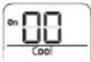 | |
| 3. Setting SEG4, SEG5 optionPress Low Fan button(∨) to enter SEG4 value.Press High Fan button(∧) to enter SEG5 value.Each time you press the button,0→8→...E→F will be selected in rotation. | 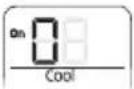 SEG4 SEG4 | 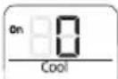 SEG5 SEG5 |
| 4. Setting Dry modeMade Press Mode button to be changed to DRY mode in the ON status. | 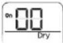 | |
| 5. Setting SEG6, SEG8 optionPress Low Fan button(∨) to enter SEG6 value.Press High Fan button(∧) to enter SEG8 value.Each time you press the button,0→8→.E 6 will be selected in rotation. | 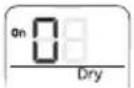 SEG6 SEG8 SEG6 SEG8 | 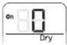 |
| 6. Setting Fan modeMade Press Mode button to be changed to FAN mode in the ON status. | 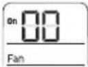 | |
| 7. Setting SEG9, SEG10 optionPress Low Fan button(∨) to enter SEG9 value.Press High Fan button(∧) to enter SEG10 value.Each time you press the button,0→8→.E 6 will be selected in rotation. | 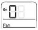 SEG9 SEG10 SEG9 SEG10 | 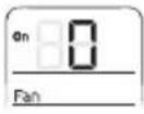 |
| 8. Setting Heat modeMade Press Mode button to be changed to HEAT mode in the ON status. | 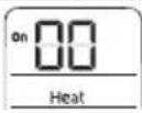 | |
| 9. Setting SEG11, SEG12 optionPress Low Fan button(∨) to enter SEG11 value.Press High Fan button(∧) to enter SEG12 value.Each time you press the button,0→8→.E 6 will be selected in rotation. | 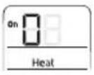 SEG11 SEG12 SEG11 SEG12 | 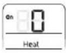 |
| 10. Setting Auto modeMade Press Mode button to be changed to AUTO mode in the OFF status. | 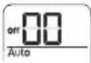 | |
| 11. Setting SEG14, SEG15 optionPress Low Fan button(∨) to enter SEG14 value.Press High Fan button(∧) to enter SEG15 value.Each time you press the button,0→8→.E 6 will be selected in rotation. | 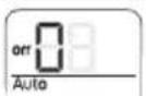 SEG14 SEG14 | 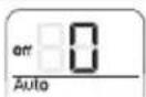 SEG15 SEG15 |
| 12. Setting Cool modeMade Press Mode button to be change to Cool mode in the OFF status. | 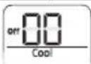 | |
| 1. Setting SEG16, SEG17 optionPress Low Fan button(∨) to enter SEG16 value.Press High Fan button(∧) to enter SEG17 value.Each time you press the button,0→8→.E P will be selected in rotation. | 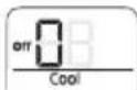 SEG16 SEG17 SEG16 SEG17 | 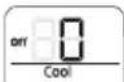 |
| 2. Setting Dry modePress Mode button to be change to Dry mode in the OFF status. | 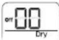 | |
| 3. Setting SEG18, SEG20 optionPress Low Fan button(∨) to enter SEG18 value.Press High Fan button(∧) to enter SEG20 value.Each time you press the button,0→8→.E P will be selected in rotation. | 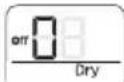 SEG18 SEG20 SEG18 SEG20 | 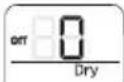 |
| 4. Setting Fan modePress Mode button to be change to Fan mode in the OFF status. | 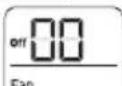 | |
| 5. Setting SEG21, SEG22 optionPress Low Fan button(∨) to enter SEG21 value.Press High Fan button(∧) to enter SEG22 value.Each time you press the button,0→8→.E P will be selected in rotation. | 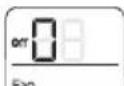 SEG21 SEG22 SEG21 SEG22 | 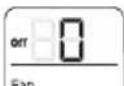 |
| 6. Setting Heat modePress Mode button to be change to HEAT mode in the OFF status. |  | |
| 7. Setting SEG23, SEG24 modePress Low Fan button(∨) to enter SEG23 value.Press High Fan button(∧) to enter SEG24 value.Each time you press the button,0→8→.E P will be selected in rotation. | 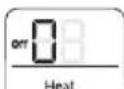 SEG23 SEG24 SEG23 SEG24 | 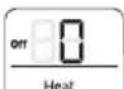 |
Step 3. Check the option you have set
After setting option, press Mode button to check whether the option code you input is correct or not.
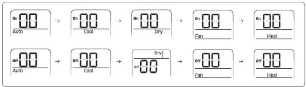
flowchart
graph LR
    A["On Auto"] --> B["On Cool"]
    B --> C["On Dry"]
    C --> D["On Fan"]
    D --> E["On Heat"]
    F["Off Auto"] --> G["Off Cool"]
    G --> H["Off Dry"]
    H --> I["Off Fan"]
    I --> J["Off Heat"]
Step 4. Input option
Press operation button ⏻ with the direction of remote control for set.
For the correct option setting, you must input the option twice.
Step 5. Check operation
1) Reset the indoor unit by pressing the RESET button of indoor unit or outdoor unit.
2) Take the batteries out of the remote controller and insert them again and then press the operation button.
Setting an indoor unit address (MAIN/RMC)
- Check whether power is supplied or not.
- When the indoor unit is not plugged in, there should be additional power supply in the indoor unit.
-
The reception part of a remote controller is built in the AHU KIT PBA.
-
Before installing the indoor unit, assign an address to the indoor unit according to the air conditioning system plan.
-
Assign an indoor unit address by wireless remote controller.
- The initial setting status of indoor unit ADDRESS(MAIN/RMC) is "0A0000-100000-200000-300000".
Option No.: 0AXXXX-1XXXXX-2XXXXX-3XXXXX
| Option | SEG1 | SEG2 SEG3 SEG4 | SEG5 | SEG6 | ||||||||
| Explanation | PAGE MODE Setting Main address | 100-digit of indoor unit address | 10-digit of indoor unit | The unit digit of an indoor unit | ||||||||
| Indication and Details | Indication | Details | Indication | Details Indication Details | Details Indication Details | Indication | Details Indication Details | Details Indication Details | ||||
| 0 | A | 0 | No Main address | 0~9 | 100-digit | 0~9 10-digit 0~9 | A unit digit | |||||
| 1 | Main address setting mode | |||||||||||
| Option | SEG7 | SEG8 SEG9 SEG10 | SEG11 | SEG12 | ||||||||
| Explanation | PAGE | - | Setting RMC address | - | Group channel(*16) | Group address | ||||||
| Indication and Details | Indication | Details | - | Indication | Details | - | Indication | Details Indication Details | ||||
| 1 | 0 | No RMC address | RMC1 | 0~2 | RMC2 | 0~F | ||||||
| 1 | RMC address setting mode | |||||||||||

CAUTION
- When "A"\~"F" is entered to SEG5\~6, the indoor unit MAIN ADDRESS is not changed.
- If you set the SEG 3 as 0, the indoor unit will maintain the previous MAIN ADDRESS even if you input the option value of SEG5\~6.
- If you set the SEG 9 as 0, the indoor unit will maintain previous RMC ADDRESS even if you input the option value of SEG11\~12.
Setting an indoor unit installation option (suitable for the condition of each installation location)
- Check whether power is supplied or not.
- When the indoor unit is not plugged in, there should be additional power supply in the indoor unit.
-
The reception part of a remote controller is built in the AHU KIT PBA.
-
Set the installation option according to the installation condition of an air conditioner.
- The default setting of an indoor unit installation option is "020000-100000-200000-300000
- Set the indoor unit option by wireless remote controller.
02 series installation option
| SEG1 SEG2 SEG3 SEG4 SEG5 SEG6 | ||||
| 0 2 - Exterior temperature sensor Central control | - | |||
| SEG7 SEG8 SEG9 | SEG10 SEG11 | SEG12 | ||
| 1 | - | Hot water heater | Use of Heater | Controller variables for auxiliary heater |
| SEG13 | SEG14 | SEG15 | SEG16 | SEG17 |
| 2 | External control | External control output | - | Buzzer |
| SEG19 | SEG20 | SEG21 | SEG22 | SEG23 |
| 3 | - | - | - | - |
When setting the option other than above SEG values, the option will be set as "0".
Option No.: 02XXXX-1XXXXX-2XXXXX-3XXXXX
| Option | SEG1 | SEG2 | SEG3 | SEG4 | SEG5 | SEG6 | ||||
| Explanation | PAGE | MODE | - | Use of external Temperature sensor | Use of central control | - | ||||
| Indication and Details | Indication | Details | Indication | Details | - | Indication | Details | Indication | Details | - |
| 0 | 2 | 0 | Disuse | 0 | Disuse | |||||
| 1 | Use | 1 | Use | |||||||
| Option | SEG7 | SEG8 SEG9 | SEG10 | (*) | SEG11 SEG12 | |||||||||
| Explanation | PAGE- | Use of hot water heater | Use of Heater Controller variables for auxiliary heater Master / Slave | |||||||||||
| Indication and Details | Indication | Details | - | Indication | Details Indication Details Indication | Details | Indication Details | |||||||
| Set temperature for auxiliary heat on | Time delay for auxiliary heat on | |||||||||||||
| 1 | 0 Disuse 0 Disuse 0 | No temperature offset | No delay | 0 | slave | |||||||||
| 1 | Use | 1 | Use | 1 | No temperature offset | 10 minutes | 1 | master | ||||||
| 2 | Use (Heater Time Delay) | 2 | No temperature offset | 20 minutes | ||||||||||
| 3 | 1.5 °C No delay | |||||||||||||
| 4 | 1.5 °C 10 minutes | |||||||||||||
| 5 | 1.5 °C 20 minutes | |||||||||||||
| 6 | 3 °C | No delay | ||||||||||||
| 7 | 3 °C | 10 minutes | ||||||||||||
| 8 | 3 °C | 20 minutes | ||||||||||||
| 9 | 4.5 °C No delay | |||||||||||||
| A | 4.5 °C | 10 minutes | ||||||||||||
| B | 4.5 °C | 20 minutes | ||||||||||||
| C | 6 °C | No delay | ||||||||||||
| D | 6 °C | 10 minutes | ||||||||||||
| E | 6 °C | 20 minutes | ||||||||||||
| Option | SEG13 | SEG14 | SEG15 | SEG16 | SEG17 | SEG18 | ||||||||
| Explanation | PAGE | Use of external control | Setting the output of external control | - | Buzzer control | - | ||||||||
| Indication and Details | Indication | Details | Indication | Details | Indication | Details | - | Indication | Details | - | ||||
| 2 | 0 | Disuse | Slave, Existing Control | 0 | Thermo on | 0 Use buzzer | ||||||||
| 1 | On/Off | |||||||||||||
| 2 | Off | 1 | Disuse buzzer | |||||||||||
| 3 | Window | |||||||||||||
| 4 | Disuse | Master, Existing Control | ||||||||||||
| 5 | On/Off | |||||||||||||
| 6 | Off | |||||||||||||
| 7 | Window | |||||||||||||
| 8 | Disuse | Slave, Existing Control | 1 | Operation on | ||||||||||
| 9 | On/Off | |||||||||||||
| A | Off | |||||||||||||
| B | Window | |||||||||||||
| C | Disuse | Master, Existing Control | ||||||||||||
| D | On/Off | |||||||||||||
| E | Off | |||||||||||||
| F | Window | |||||||||||||
| Option | SEG19 | SEG20 | SEG21 | SEG22 | SEG23 | SEG24 | ||||||||
| Explanation | PAGE | - | - | - | - | - | ||||||||
| Indication and Details | Indication | Details | - | - | - | - | - | |||||||
| 3 | ||||||||||||||
(*1) Heater operation when the SEG10 of 02 series installation option is set to using external heater.
e.g. 1) Setting 02 series SEG10="2" / Setting 02 series SEG11="0": External heater is turned on at the same time as the heating thermostat is on, and turned off when the heating thermostat is off.
e.g. 2) Setting 02 series SEG10 = "2" / Setting 02 series SEG11 = "A":
Room temp. ≤ set temp. + fheating compensation temp?
- External heater is turned on when the temperature is maintained as 4.5 °C(8.1 °F) for 10 minutes. Room temp. > set temp. + fheating compensation temp?
- External heater is turned off when the temperature is maintained as 4.5 °C(8.1 °F) + 1 °C(1.8 °F) [1 °C(1.8 °F) is the Hysteresis for On/Off selection.]
■ 05 series installation option
| SEG1 SEG2 SEG3 SEG4 SEG5 SEG6 | |||||
| 0 | 5 | - | - | - | |
| SEG7 SEG8 SEG9 SEG10 SEG11 SEG12 | |||||
| 1 | - | - | - | - | |
| SEG13 SEG14 | SEG15 | SEG16 SEG17 SEG18 | |||
| 2 | Heating setting temp. Offset | Cooling thermo off Hysteresis | Heating thermo off Hysteresis | - | - |
| SEG19 | SEG20 | SEG21 | SEG22 | SEG23 | SEG24 |
| 3 | - | Fan Feedback | Defrost Signal | Skip the prevention of cold air | - |
■ 05 series installation option(Detailed)
Option No.: 05XXXX-1XXXXX-2XXXXX-3XXXXX
| Option | SEG1 | SEG2 | SEG3 | SEG4 | SEG5 | SEG6 | |
| Explanation | 0 | 5 | - | - | - | - | |
| Indication and Details | - | - | - | - | - | - | |
| Option | SEG7 | SEG8 | SEG9 | SEG10 | SEG11 | SEG12 | |
| Explanation | 1 | - | - | - | - | - | |
| Indication and Details | Indication | Details | - | - | - | - | - |
| - | |||||||
Function Setting
| Option | SEG13 SEG | 14 SEG15 SEG16 SEG17 SEG18 | |||||||||
| Explanation | 2 | Heating setting temp. Offset | Cooling thermo off Hysteresis | Heating thermo off Hysteresis | - | - | |||||
| Indication and Details | - | Indication | Details | Indication | Details | Indication | Details | - | - | ||
| 0 0 °C | 0 0 °C | 0 0 °C | |||||||||
| 1 -2 °C | 11 °C | 11 °C | |||||||||
| 2 | -1 °C | 2 | 2 °C | 2 | 2 °C | ||||||
| 3 | 1 °C | 3 | 3 °C | 3 | 3 °C | ||||||
| 4 | 2 °C | 4 | 4 °C | 4 | 4 °C | ||||||
| 5 | 3 °C | 5 | 5 °C | 5 | 5 °C | ||||||
| 6 | 4 °C | 6 | 6 °C | 6 | 6 °C | ||||||
| 7 | 5 °C | 7 | 7 °C | 7 | 7 °C | ||||||
| 8 8 °C | 8 8 °C | ||||||||||
| 9 | 9 °C | 9 | 9 °C | ||||||||
| A | 10 °C | A | 10 °C | ||||||||
| Option | SEG19 | SEG20 | SEG21 | SEG22 | SEG23 | SEG24 | |||||
| Explanation | PAGE | - | Fan Feedback | Defrost Signal | Skip the prevention of cold air | - | |||||
| Indication and Details | Indication | Details | - | Indication | Details | Indication | Details | Indication | Details | - | |
| 3 | 0 | Disuse | 0 | Disuse | 0 | Disuse | |||||
| 1 | use 1 | Defrost valve 1 use | |||||||||
| - | 2 | Defrost signal | - | ||||||||
| - | |||||||||||
Changing a particular option
You can change each digit of set option.
| Option | SEG1 | SEG2 | SEG3 | SEG4 | SEG5 | SEG6 | ||||||
| Explanation | PAGE MODE | The option mode you want to change | The tens' digit of an option SEG you will change | The unit digit of an option SEG you will change | Changed value | |||||||
| Indication and Details | Indication | Details Indication Details Indication Details Indication Details Indication Details Indication Details | ||||||||||
| 0 | D | Option mode | 1~6 | Tens' digit of SEG | 0~9 | Unit digit of SEG | 0~9 | The changed value | 0~F | |||

NOTE
- When changing a digit of an indoor unit address setting option, set the SEG3 as 'A'.
- When changing a digit of indoor unit installation option, set the SEG3 as '2'.
Ex) When setting the 'buzzer control' into disuse status.
| Option | SEG1 | SEG2 | SEG3 | SEG4 | SEG5 | SEG6 | |
| Explanation | PAGE | MODE | The option mode you want to change | The tens' digit of an option SEG you will change | The unit digit of an option SEG you will change | Changed value | |
| Indication | 0 | D | 2 | 1 | 7 | 1 | |
AHU-KIT Installation Check
1) Ensure that Control-KIT is correctly installed.
- You can choose the built-in type or auxiliary type depending on installation environment.
- Ensure that the Control-KIT cables are correctly connected.
- Control-KIT should be fireproofed and avoid direct sunlight upon installation. (Especially for individual type)
- Avoid installing the unit in a location exposed to direct sunlight or rain.
- Do not install the Control-KIT in or on the outdoor unit.
2) Ensure that EVA IN/OUT sensor is correctly attached.
- EVA IN sensor should be attached after the distributor, on the coldest part of the heat exchanger piping. Ensure that the sensor is insulated.
- EVA Out sensor should be installed on the middle of inlet and outlet ports.
Test Operation
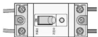
1) Before turning the power on, use DC 500V insulation tester to check the power terminal (L,N) and the earthing on AHU-KIT.
- Resistance value should be over 30MΩ.
2) Test the voltage of power(L, N) before turning on the power.

CAUTION
• Insulation tester may damage the communication circuit.
- Communication terminal should be tested with ordinary circuit tester to check the short circuit.
220V
natural_image
Front view of a mechanical or electrical component with two terminals and a central control panel (no visible text or symbols)3) Check the list below after installation and make sure the AHU-KIT units are properly operating.
• Installation environment (resistance level etc.)
• Refrigerant leak test
- Power cable
• Insulation on refrigerant pipe.
- Drainage
• Circuit breaker connection and earthing
• Normal system operation
Initial Check-up
1) Check the connection status between Indoor unit and the AHU-KIT.
- Make sure you have followed instructions and wiring diagram shown in the installation manual.
- Make sure AHU-KIT PBA is installed in a place where there are no influence from outdoor humidity, dust and temperature.
2) Ensure that power voltage is AC 187V\~AC 253V.
3) Check each of the accessories and make sure they are in good condition.
• CN32 : DC 11\~13V (both ends)
- IC02 G/O : DC 4.5\~5.5V (both ends)
• TRANS Output : AC 16\~18V
EEPROM Error
| Outdoor unit display | E162 |
| Explanation Internal communication error between EEPROM and MICOM | |
| Reason Require to change PBA due to Bad EEPROM | |

NOTE
- Wired remote controller will show the same error shown in the outdoor unit.
Sensor Error
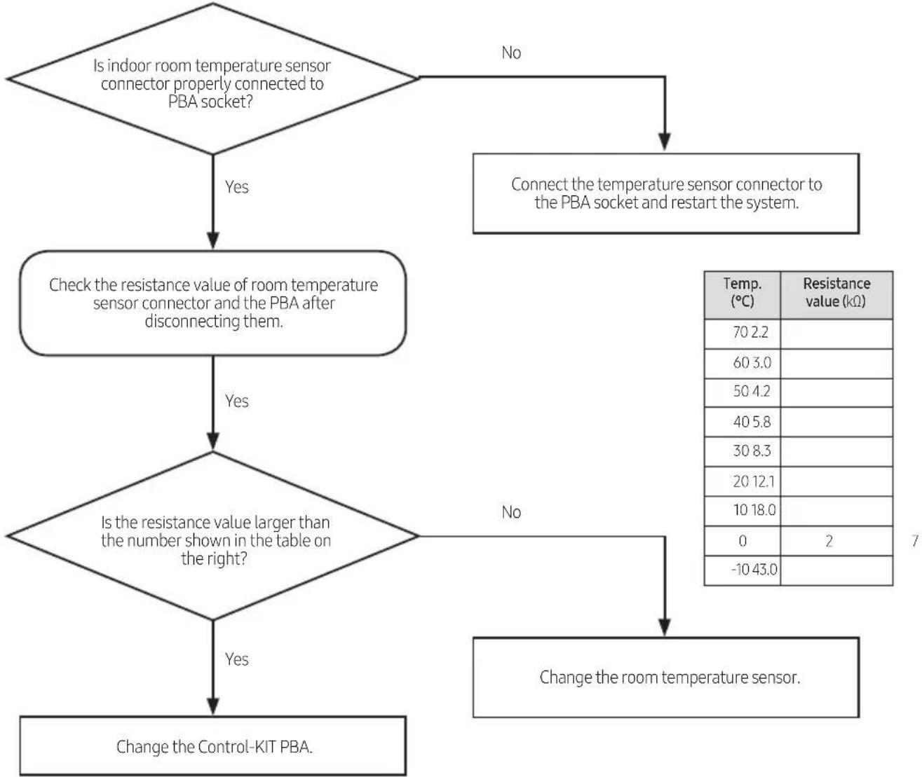
AHU-KIT temperature sensor OPEN/SHORT error
| Outdoor unit display | E8123 (ROOM sensor OPEN/SHORT)E8122 (EVA IN sensor OPEN/SHORT)E8123 (EVA OUT sensor OPEN/SHORT) |
| Explanation When OPEN/SHORT signal is received for temperature sensor of AHU-KIT | |
| Reason Poor connection between sensor and the PBA, or poor conditioned sensor. | |
1) Self check
flowchart
graph TD
    A{Is indoor room temperature sensor connector properly connected to PBA socket?}
    B["Connect the temperature sensor connector to the PBA socket and restart the system."] --> C{Is the resistance value larger than the number shown in the table on the right?}
    C -->|Yes| D["Change the Control-KIT PBA."]
    C -->|No| E["No"]
    D --> F["Check the resistance value of room temperature sensor connector and the PBA after disconnecting them."]
    F --> G{Is the resistance value larger than the number shown in the table on the right?}
    G -->|Yes| H["Change the control-KIT PBA."]
    G -->|No| I["Change the room temperature sensor."]
    I --> J["End"]

NOTE
- Wired remote controller will show the same error shown in the outdoor unit.
Fan Error
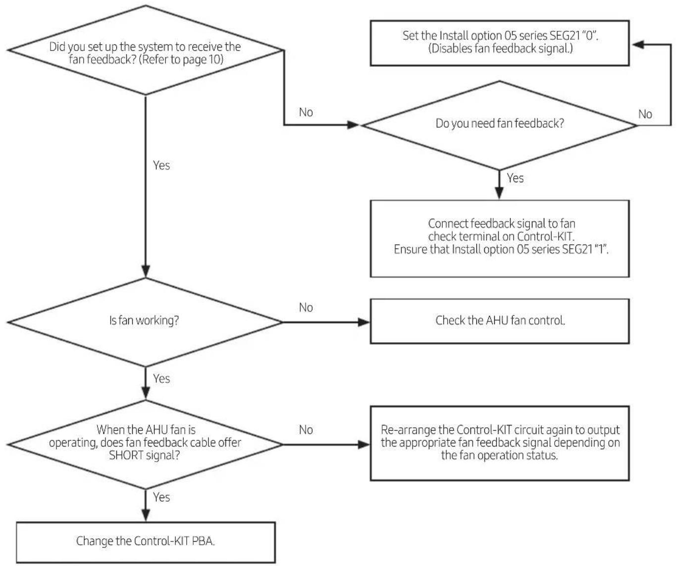
| Outdoor unit display | E8154 |
| Explanation | When Control-KIT outputs fan operation status signal and the fan feedback signal stays OPEN for more than 10 seconds.( AHU-KIT only) |
| Reason | Poor AHU fan operationMissing or Incorrect circuit system for fan feedback check. |
1) Self check
flowchart
graph TD
    A["Did you set up the system to receive the fan feedback? (Refer to page 10)"] -->|Yes| B{Is fan working?}
    A -->|No| C["Set the Install option 05 series SEG21 "0". (Disables fan feedback signal)."]
    C --> D{Do you need fan feedback?}
    D -->|Yes| E["Connect feedback signal to fan check terminal on Control-KIT. Ensure that Install option 05 series SEG21 "1"."]
    D -->|No| F["Check the AHU fan control."]
    B -->|Yes| G{When the AHU fan is operating, does fan feedback cable offer SHORT signal?}
    B -->|No| H["Change the Control-KIT PBA."]
    G -->|Yes| I["Re-arrange the Control-KIT circuit again to output the appropriate fan feedback signal depending on the fan operation status."]
    G -->|No| I

CAUTION
- Fan feedback check terminal should only receive OPEN/SHORT contact signal without voltage. When the fan feedback check terminal receives contact signal with voltage may damage the Control-KIT.
In-tracking Error
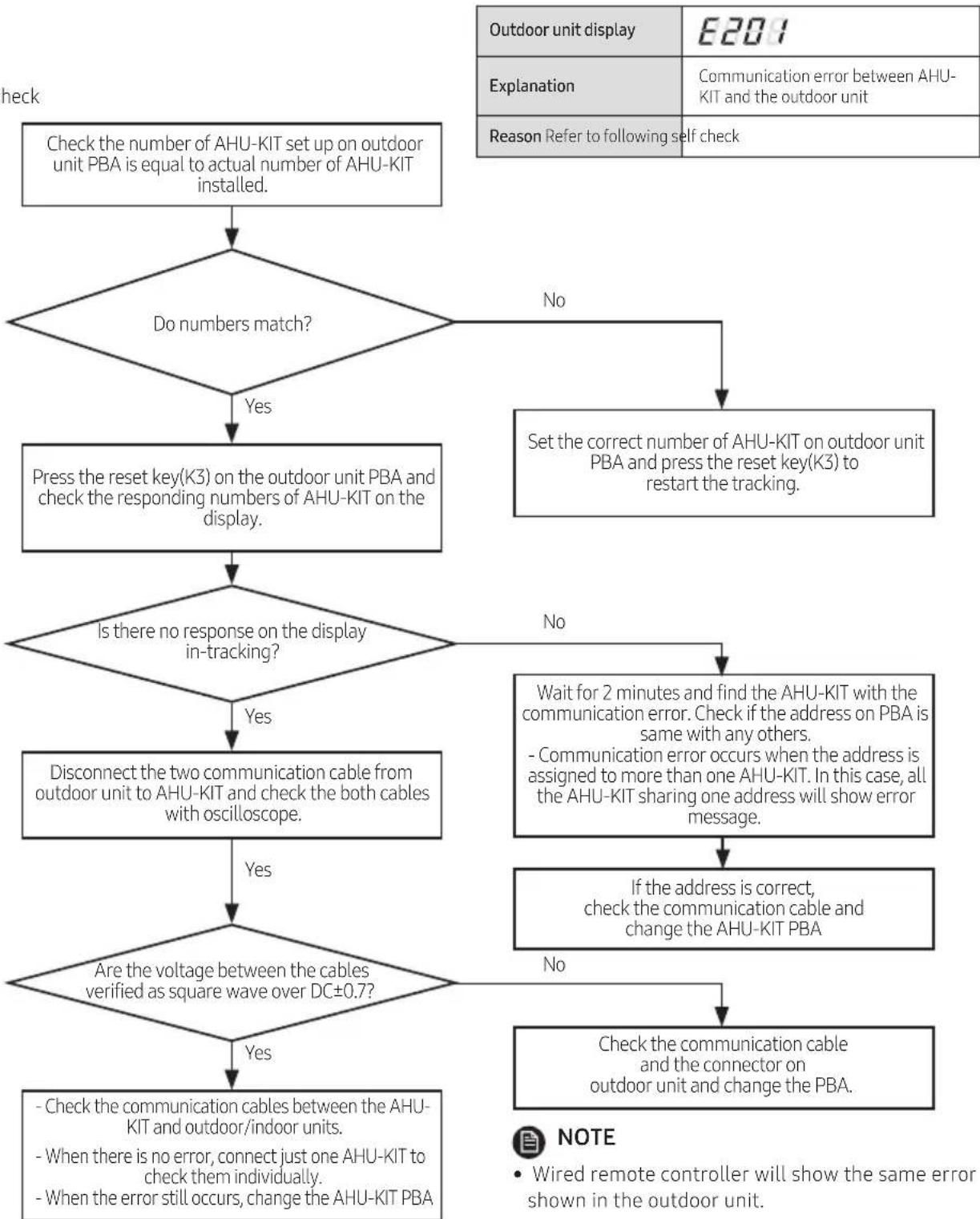
Error between AHU-KIT and outdoor unit at the beginning of operation(in tracking)
1) Self check
flowchart
graph TD
    A["Check the number of AHU-KIT set up on outdoor unit PBA is equal to actual number of AHU-KIT installed."] --> B{Do numbers match?}
    B -->|No| C["Set the correct number of AHU-KIT on outdoor unit PBA and press the reset key(K3) to restart the tracking."]
    B -->|Yes| D["Press the reset key(K3) on the outdoor unit PBA and check the responding numbers of AHU-KIT on the display."]
    D --> E{Is there no response on the display in-tracking?}
    E -->|No| F["Wait for 2 minutes and find the AHU-KIT with the communication error. Check if the address on PBA is same with any others.<br>- Communication error occurs when the address is assigned to more than one AHU-KIT. In this case, all the AHU-KIT sharing one address will show error message."]
    E -->|Yes| G["Disconnect the two communication cable from outdoor unit to AHU-KIT and check the both cables with oscilloscope."]
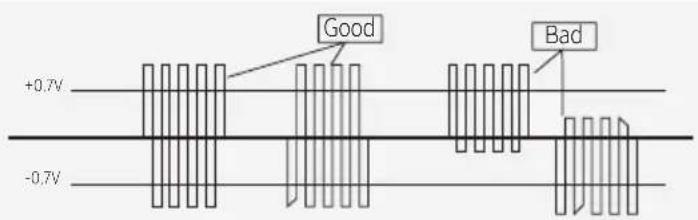
    G --> H{Are the voltage between the cables verified as square wave over DC±0.7?}
    H -->|No| I["Check the communication cable and the connector on outdoor unit and change the PBA."]
    H -->|Yes| J["- Check the communication cables between the AHU-KIT and outdoor/indoor units.<br>- When there is no error, connect just one AHU-KIT to check them individually.<br>- When the error still occurs, change the AHU-KIT PBA"]
    C --> K["Outdoor unit display E201"]
    F --> L["Note: Wired remote controller will show the same error shown in the outdoor unit."]
Error between AHU-KIT and outdoor unit during operation(after tracking)
| Outdoor unit display | E202 |
| Explanation | Communication is off for 2 minutes between AHU-KIT and the outdoor unit during operation. (Ensure room) |
| Reason | Communication error between AHU-KIT and the outdoor or incorrect AHU-KIT number setting |
1) Self check
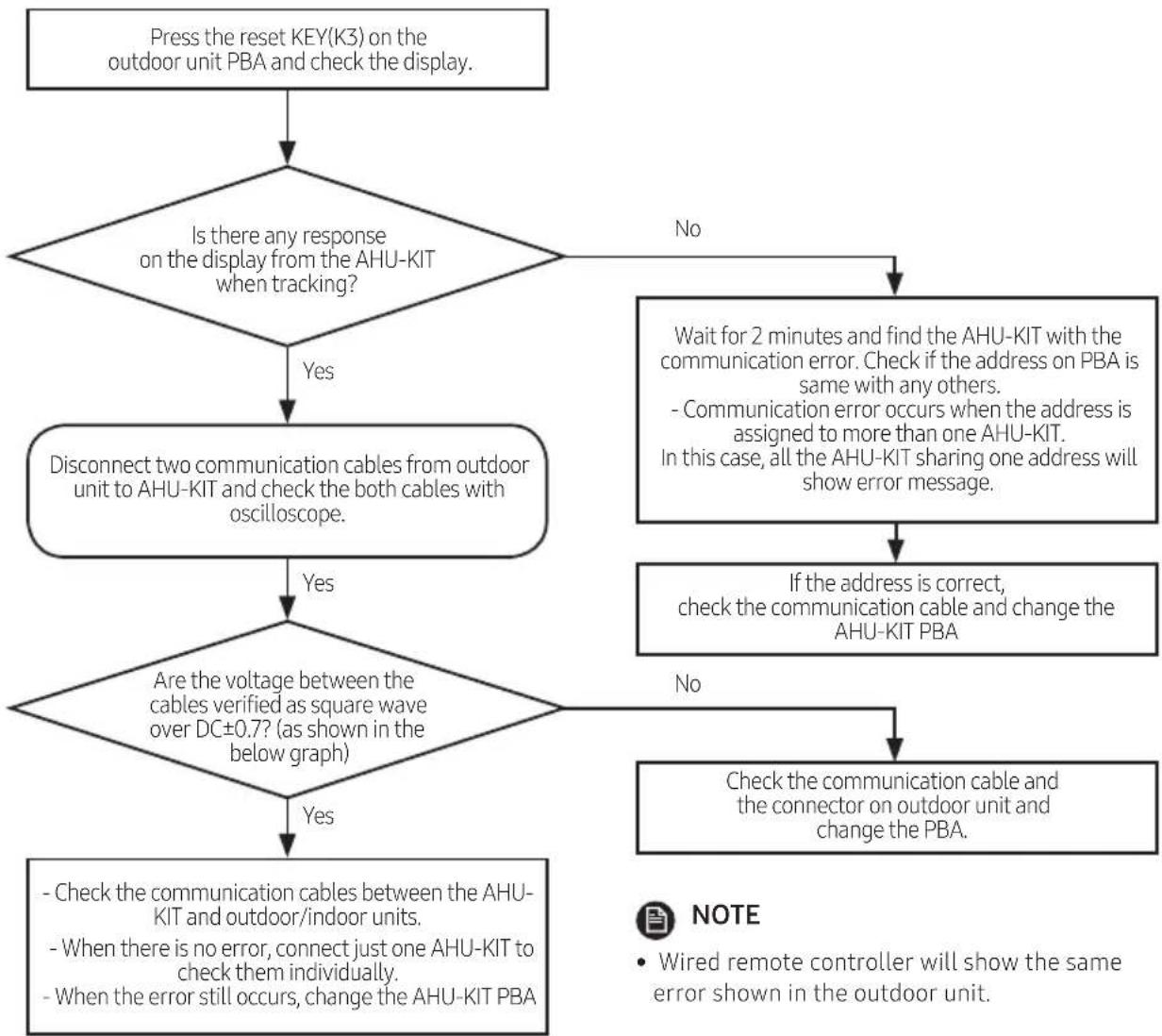
flowchart
graph TD
    A["Press the reset KEY(K3) on the outdoor unit PBA and check the display."] --> B{Is there any response on the display from the AHU-KIT when tracking?}
    B -->|Yes| C["Disconnect two communication cables from outdoor unit to AHU-KIT and check the both cables with oscilloscope."]
    B -->|No| D["Wait for 2 minutes and find the AHU-KIT with the communication error. Check if the address on PBA is same with any others.<br>- Communication error occurs when the address is assigned to more than one AHU-KIT.<br>In this case, all the AHU-KIT sharing one address will show error message."]
    C -->|Yes| E{Are the voltage between the cables verified as square wave over DC±0.7? (as shown in the below graph)}
    C -->|No| F["If the address is correct,<br>check the communication cable and change the AHU-KIT PBA"]
    E -->|Yes| G{- Check the communication cables between the AHU-KIT and outdoor/indoor units.
- When there is no error, connect just one AHU-KIT to check them individually.
- When the error still occurs, change the AHU-KIT PBA}
    E -->|No| H["Check the communication cable and the connector on outdoor unit and change the PBA."]
    F --> H
    G --> I["- Check the communication cables between the AHU-KIT and outdoor/indoor units.<br>- When there is no error, connect just one AHU-KIT to check them individually.<br>- When the error still occurs, change the AHU-KIT PBA"]
    H --> I