
MLC-2701 - Monitor DENVER - Free user manual and instructions
Find the device manual for free MLC-2701 DENVER in PDF.


| Product Type | Monitor |
| Brand | Denver |
| Model | MLC-2701 |
| Screen Size | 27 inches |
| Resolution | 1920 x 1080 (Full HD) |
| Refresh Rate | 60 Hz |
| Panel Type | IPS |
| Aspect Ratio | 16:9 |
| Brightness | 250 cd/m² |
| Contrast Ratio | 1000:1 |
| Viewing Angle | 178° horizontal / 178° vertical |
| Response Time | 5 ms |
| Connectivity | VGA, HDMI |
| Power Consumption | 30 W (typical) |
| Dimensions (with stand) | 615 x 450 x 200 mm |
| Weight (with stand) | 5.5 kg |
| Stand Adjustment | Tilt only |
| VESA Mount Compatible | Yes (100 x 100 mm) |
| Built-in Speakers | 2 x 2 W |
| Energy Class | A |
Frequently Asked Questions - MLC-2701 DENVER
User questions about MLC-2701 DENVER
0 question about this device. Answer the ones you know or ask your own.
Ask a new question about this device
Download the instructions for your Monitor in PDF format for free! Find your manual MLC-2701 - DENVER and take your electronic device back in hand. On this page are published all the documents necessary for the use of your device. MLC-2701 by DENVER.
USER MANUAL MLC-2701 DENVER
natural_image
Modern flat-screen monitor with a metallic stand and tripod base (no text or symbols visible)
Read this booklet thoroughly before using and save it for future reference
Section 1: Product Overview
1.1 - Monitor Buttons
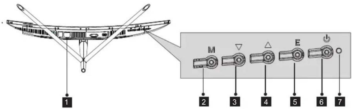
1 : Insert the power cable to supply power to the monitor. Power Connector
2 : Press to display the OSD menu or enter sub-menus. M Menu Button
3 ▼Press to move down in the menus. Down Button
4 ▲Press to move up in the menus. Up Button
5 : Press to exit. E Exit Button
6 Power Button: Press to turn the monitor on/off.
7 : Changes colors to indicate status. Refer to Section 6. LED Indicator
The E button can also be used to switch between two color gamuts when a compatible graphics card and either HDMI or DP connections are in use.
1.2 - Monitor Ports
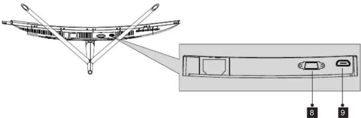
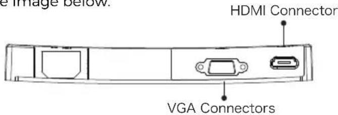
8 VGA Connector: Insert one end of the VGA cable into the computer's VGA output and connect the other end to the monitor's VGA port.
9 HDMI Connector: Insert one end of the HDMI cable into the computer's HDMI output and connect the other end to the monitor's HDMI port.
Section 2: Stand Installation

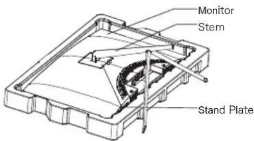
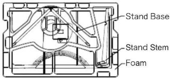
Keep the foam over the monitor before attaching the stand. Follow the steps below to finish the installation.
- Open the package, take out the product with foam still attached, and gently place it on a desktop or table.
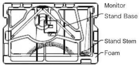
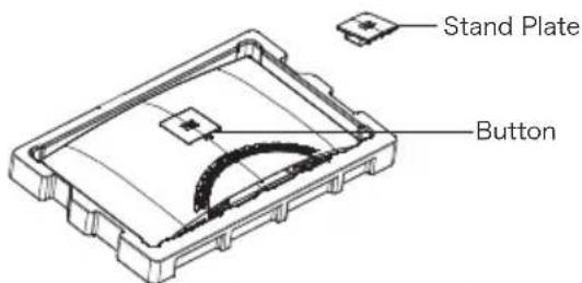
- Take out the two parts of the stand, remove the foam covering the back of the monitor, and press the button to remove the stand plate.
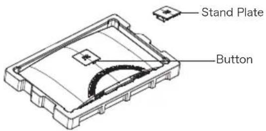
- Use the screwdriver and two 12mm NO.1 screws to fasten the stand plate to the stem. Next, use the remaining 14mm stand screws to fasten the base to the stem.
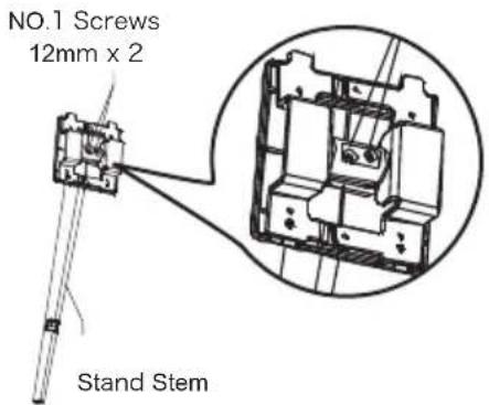
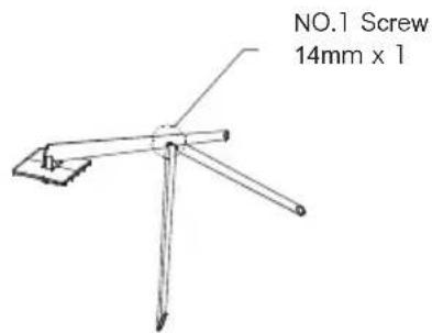
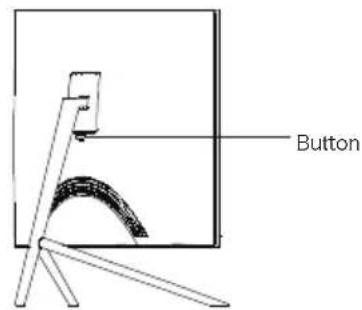
- Insert the stand's plate into the opening on the back of the monitor. It should click into place. Make sure the stand is securely attached to the back of the monitor then remove the monitor from the remaining foam section and stand it up on a table or desk as desired.

If needed, the stand can easily be detached from the monitor by pressing the button near the stand plate. Make sure the monitor is laid on a flat surface before removing the stem.
Eng-4
Section 3: Mount Installation

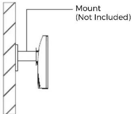
This monitor ONLY includes screws which may be used when attaching the monitor to a VESA 75x75mm type mount. No VESA mount or mounting accessory is included.
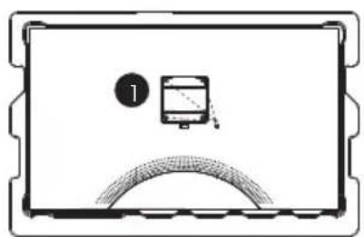
- Open the package, take out the product with foam still attached, and gently place it on a desktop or table. If the monitor is attached to the stand, remove the stand.
- Take out the two parts of the stand, remove the foam covering the back of the monitor, and press the button to remove the stand plate.
-
Remove the original screws x 4 ( ) from the opening in the back of the monitor, then use the NO. 2 screws provided to secure the rear panel.
-
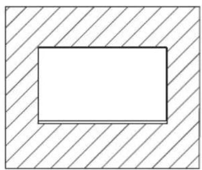
Follow the directions received with your VESA mount stand or accessory and install the monitor on the wall or fixture as desired. Remember to use the included NO. 2 screws when attaching anything to the back of the monitor. Refer to the image (2) for correct screw placement when attaching the monitor to a mount.
natural_image
Simple line drawing of a monitor with a circular button labeled '1' and a curved base (no text or symbols)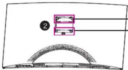
Use the 30mm -NO. 2 Screws x 2 -Use the 26mm NO. 2 Screws x 2

- Use only the NO. 2 Screws (30 mm x 2 pcs, 26mm x 2 pcs) provided with this type of installation.
- Do not discard the original screws as these may be needed for future use.
natural_image
Simple geometric diagram with a rectangle inside a square, no text or symbols presentEng-5
Section 4: Connectivity Options
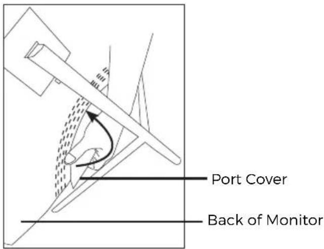
4.1 - Removing the Port Cover
Before connecting any cables, remove the port cover first.
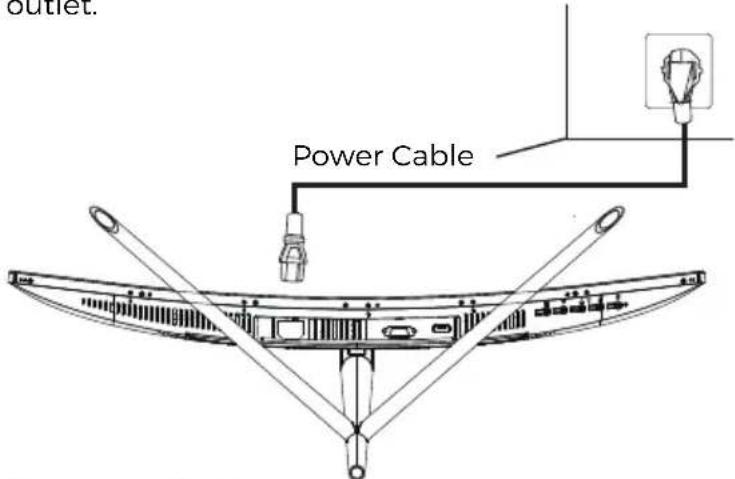
4.2 - Connecting the Power Cable
Connect the included power cable to the power connector, and then plug the other end into an wall outlet.
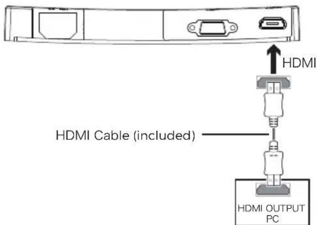
4.3 - HDMI Connectivity
In order for the monitor to receive HDMI signals from the computer, use the HDMI cable to connect the monitor to the computer.
Eng-6
Section 5: Basic Operation
- Insert one end of the HDMI cable into your PC's graphics card.

For optimal refresh rate (or "performance"), it is recommended to use a HDMI (display port) cable with the monitor's corresponding connector.
- Connect the other end of the cable to the corresponding connector on your monitor. See the image below.
-
Connect the power cable to your monitor then connect the other end to your power source. It is recommended that you use a surge protector with adequate voltage if a wall outlet cannot be reached directly.
-
Locate the power button on the monitor and press it to turn the monitor on.

If you cannot locate the power button, please refer to Section 1.1.
Section 6: Indicator Light
This light is located on the bottom of the monitor.
Bottom View
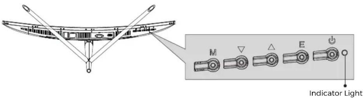
Solid blue light indicates power is on and the monitor is operating normally. Flashing blue light indicates no video source has been detected. Red light indicates that no horizontal or vertical signal has been detected or voltage is low. Please ensure your computer is on and all video cables are fully inserted and/or connected.
Section 7: ECO Modes and Gameplus Switching
- Press any one of the buttons (M, .▼, ▲) to activate the navigation window.

natural_image
Blue background with five black-and-white icons: home, game controller, car, grid, and power button (no text or symbols)- Press ▼button to switch Gameplus modes. According to the needs of your game, choose the corresponding game icon. These game icons are primarily designed to optimize your aim during shooting games, though they can be used for other scenarios.
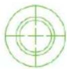
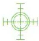
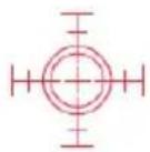
- Press ▲button to switch ECO modes. These modes include Standard, Text, Movie, Game, FPS and RTS modes and can be used to optimize settings according to your activity. Standard mode is suitable for most activities.
DENVER®
www.denver-electronics.com


natural_image
Symbol of a trash bin crossed out by two diagonal lines (no text or numbers present)
Electric and electronic equipment contains materials, components and substances that can be hazardous to your health and the environment, if the waste material (discarded electric and electronic equipment) is not handled correctly.
Electric and electronic equipment is marked with the crossed out trash can symbol, seen below. This symbol signifies that electric and electronic equipment should not be disposed of with other household waste, but should be disposed of separately.
All cities have established collection points, where electric and electronic equipment can either be submitted free of charge at recycling stations and other collection sites, or be collected from the households. Additional information is available at the technical department of your city.



- Section 1: Product Overview
- - Monitor Buttons
- - Monitor Ports
- Section 2: Stand Installation
- Section 3: Mount Installation
- Section 4: Connectivity Options
- - Removing the Port Cover
- - Connecting the Power Cable
- - HDMI Connectivity
- Section 5: Basic Operation
- Section 6: Indicator Light
- Section 7: ECO Modes and Gameplus Switching
- DENVER®
Brand : DENVER
Model : MLC-2701
Category : Monitor