CMS440 - Support pour écran plat Chief - Free user manual and instructions
Find the device manual for free CMS440 Chief in PDF.


| Product Type | Flat Panel Mount |
| Brand | Chief |
| Model | CMS440 |
| VESA Compatibility | 75x75mm to 200x200mm |
| Max Screen Size | 42 inches |
| Max Weight Capacity | 80 lbs (36 kg) |
| Mount Type | Fixed (low profile) |
| Distance from Wall | 0.5 inches (1.3 cm) |
| Material | Steel with powder coat finish |
| Color | Black |
| Installation | Wall plate and screen brackets included |
| Hardware Included | Mounting bolts, spacers, and level |
| Features | Quick-release tab for easy screen removal |
| Security | Integrated security lock with padlock hole (padlock not included) |
| Cable Management | Integrated cable clips for neat routing |
| Leveling | Self-leveling technology for easy installation |
| Compliance | UL listed for safety |
| Repairability | Spare parts available via Chief customer service |
| Warranty | Limited lifetime warranty |
Frequently Asked Questions - CMS440 Chief
User questions about CMS440 Chief
0 question about this device. Answer the ones you know or ask your own.
Ask a new question about this device
Download the instructions for your Support pour écran plat in PDF format for free! Find your manual CMS440 - Chief and take your electronic device back in hand. On this page are published all the documents necessary for the use of your device. CMS440 by Chief.
USER MANUAL CMS440 Chief
INSTALLATION INSTRUCTIONS
natural_image
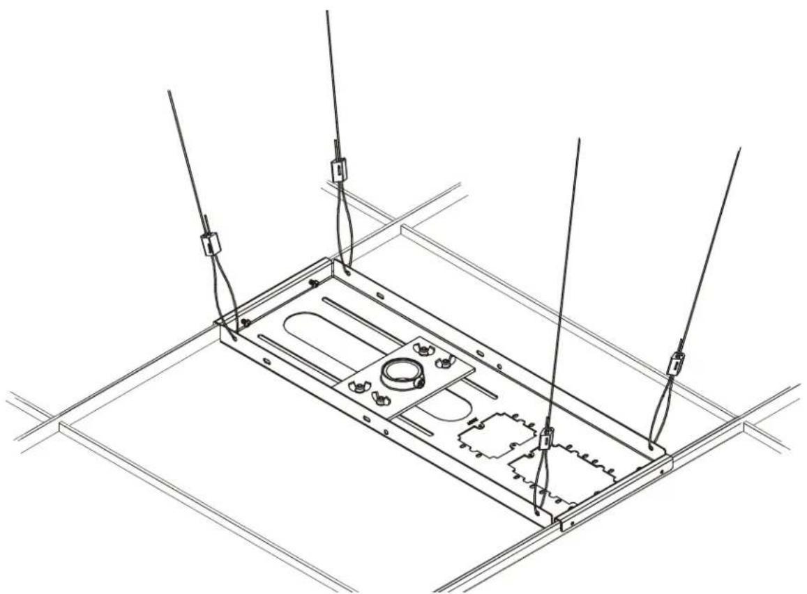
Technical line drawing of a mechanical assembly with mounting brackets and wiring (no text or symbols)Lightweight Suspended Ceiling Kit
DISCLAIMER
Milestone AV Technologies and its affiliated corporations and subsidiaries (collectively "Milestone"), intend to make this manual accurate and complete. However, Milestone makes no claim that the information contained herein covers all details, conditions or variations, nor does it provide for every possible contingency in connection with the installation or use of this product. The information contained in this document is subject to change without notice or obligation of any kind. Milestone makes no representation of warranty, expressed or implied, regarding the information contained herein. Milestone assumes no responsibility for accuracy, completeness or sufficiency of the information contained in this document.
Chief® is a registered trademark of Milestone AV Technologies. All rights reserved.
DEFINITIONS
MOUNTING SYSTEM: A MOUNTING SYSTEM is the primary Chief product to which an accessory and/or component is attached.
ACCESSORY: AN ACCESSORY is the secondary Chief product which is attached to a primary Chief product, and may have a component attached or setting on it.
COMPONENT: A COMPONENT is an audiovisual item designed to be attached or resting on an accessory or mounting system such as a video camera, CPU, screen, display, projector, etc.

WARNING: A WARNING alerts you to the possibility of serious injury or death if you do not follow the instructions.

CAUTION: A CAUTION alerts you to the possibility of damage or destruction of equipment if you do not follow the corresponding instructions.

IMPORTANT SAFETY INSTRUCTIONS

WARNING: Failure to read, thoroughly understand, and follow all instructions can result in serious personal injury, damage to equipment, or voiding of factory warranty! It is the installer's responsibility to make sure all mounting systems are properly assembled and installed using the instructions provided.

WARNING: Failure to provide adequate structural strength for this mounting system can result in serious personal injury or damage to equipment! It is the installer's responsibility to make sure the structure to which this mounting system is attached can support five times the combined weight of all equipment. Reinforce the structure as required before installing the mounting system.

WARNING: Exceeding the weight capacity can result in serious personal injury or damage to equipment! It is the installer's responsibility to make sure the combined weight of all components attached to the CMS440 does not exceed 50 lbs (22 kg).

WARNING: Use this mounting system only for its intended use as described in these instructions. Do not use attachments not recommended by the manufacturer.

WARNING: Never operate this mounting system if it is damaged. Return the mounting system to a service center for examination and repair.

WARNING: Do not use this product outdoors.
IMPORTANT ! : The CMS440 has been designed to be mounted recessed into a suspended ceiling secured by a WireVice system.
IMPORTANT ! : The CMS440 has been designed to support a single electrical receptacle, a double electrical receptacle or both.
NOTE: It is the installer's responsibility to ensure that the enclosure is bonded to the ground in the switch box, in accordance with the National Electric Code, ANSI/NFPA 70 or Canadian Electrical Code, CSA C22.1.
--SAVE THESE INSTRUCTIONS--
DIMENSIONS
text_image
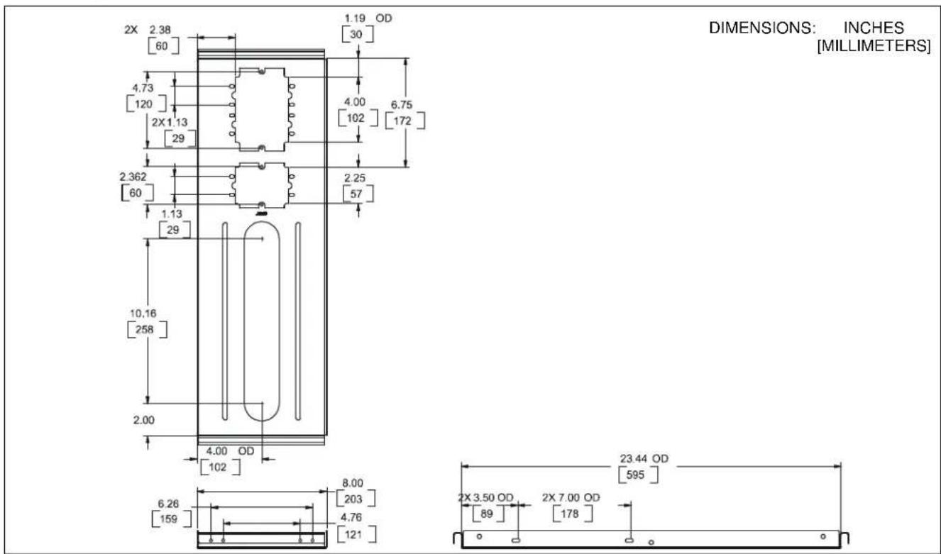
DIMENSIONS: INCHES [MILLIMETERS] 2X 2.38 [60] 4.73 [120] 2X1.13 [29] 2.362 [60] 1.13 [29] 10.16 [258] 2.00 4.00 OD [102] 8.00 [203] 6.26 [159] 4.76 [121] 1.19 OD [30] 4.00 [102] 6.75 [172] 2.25 [57] 23.44 OD [595]LEGEND
 | Tighten Fastener |  | Pencil Mark |
| Apretar elemento de fijación | Marcar con lápiz | ||
| Befestigungsteil festziehen | Stiftmarkierung | ||
| Apertar fixador | Marcar com lápis | ||
| Serrare il fissaggio | Segno a matita | ||
| Bevestiging vastdraaien | Potloodmerkteken | ||
| Serrez les fixations | Marquage au crayon | ||
 | Loosen Fastener |  | Drill Hole |
| Aflojar elemento de fijación | Perforar | ||
| Befestigungsteil lösen | Bohrloch | ||
| Desapertar fixador | Fazer furo | ||
| Allentare il fissaggio | Praticare un foro | ||
| Bevestiging losdraaien | Gat boren | ||
| Desserrez les fixations | Percez un trou | ||
 | Phillips Screwdriver |  | Adjust |
| Destornillador Phillips | Ajustar | ||
| Kreuzschlitzschraubendreher | Einstellen | ||
| Chave de fendas Phillips | Ajustar | ||
| Cacciavite a stella | Regolare | ||
| Kruiskopschroevendraaier | Afstellen | ||
| Tournevis à pointe cruciforme | Ajuster | ||
 | By Hand |  | Optional |
| A mano | Opcional | ||
| Von Hand | Optional | ||
| Com a mão | Opcional | ||
| A mano | Opzionale | ||
| Met de hand | Optie | ||
| À la main | En option | ||
 | Target of Projector |  | Security Wrench |
| Punto de enfoque del proyector | Llave de seguridad | ||
| Ziel des Projektors | Sicherheitsschlüssel | ||
| Mira do projector | Chave de segurança | ||
| Punto di proiezione | Chiave di sicurezza | ||
| Doel van de projector | Veiligheidssleutel | ||
| Cible du projecteur | Clé de sécurité | ||
 | Hammer | ||
| Martillo | |||
| Hammer | |||
| Martelo | |||
| Martello | |||
| Hamer | |||
| Marteau | |||
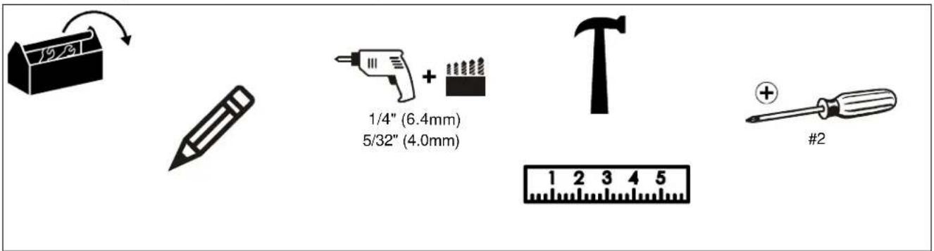
TOOLS REQUIRED FOR INSTALLATION
text_image
19/3 1/4" (6.4mm) 5/32" (4.0mm) T 1 2 3 4 5 #2PARTS
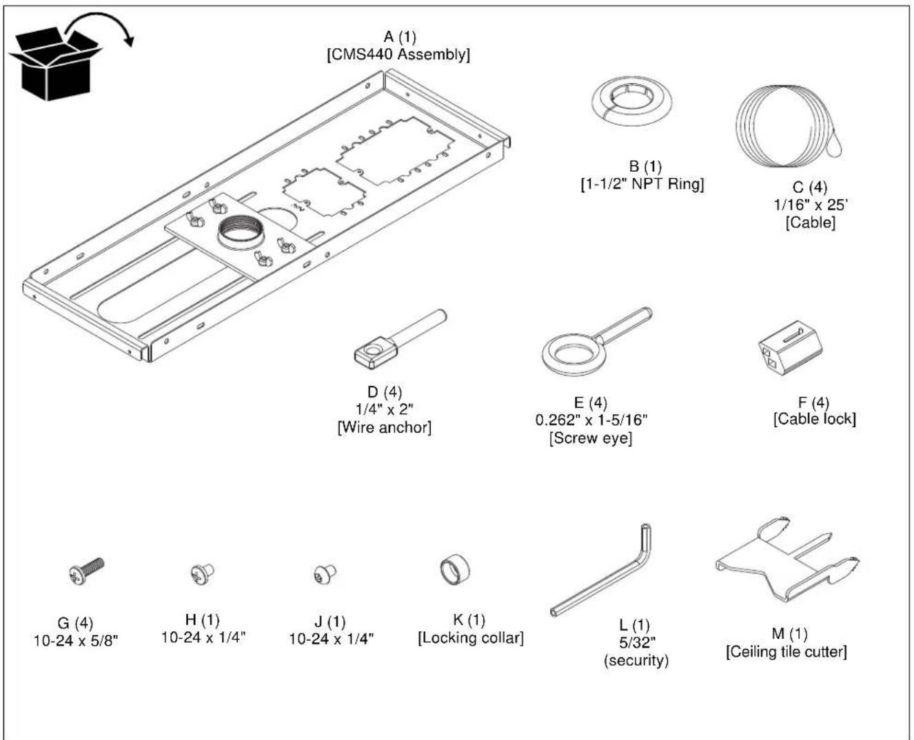
text_image
A (1) [CMS440 Assembly] B (1) [1-1/2" NPT Ring] C (4) 1/16" x 25' [Cable] D (4) 1/4" x 2" [Wire anchor] E (4) 0.262" x 1-5/16" [Screw eye] F (4) [Cable lock] G (4) 10-24 x 5/8" H (1) 10-24 x 1/4" J (1) 10-24 x 1/4" K (1) [Locking collar] L (1) 5/32" (security) M (1) [Ceiling tile cutter]PREPARATION
NOTE: The CMS440 has been designed to be mounted recessed into a suspended ceiling secured by a WireVice system.
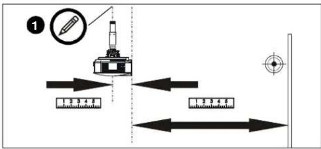
- Determine exact location of extension column (not included) on suspended ceiling. Mark location on lower (finished) side of ceiling tile with pencil. (See Figure 1)
Be sure to consider the following items when determining column location:
- Dimensional offset of display/projector relative to column (due to mount and/or interface).
- For Projectors: Any recommended dimensions of projector relative to target (See installation instructions included with the projector).
text_image
1 1 2 3 4 5 1 2 3 4 5Figure 1
- Remove affected ceiling tile and any adjacent tiles required for access.
- Press center tip of ceiling tile cutter (M) into finished side of ceiling tile at marked location. Cut extension column hole through tile using back and forth hand twisting motion.
- Reinstall ceiling tile with extension column hole. Ensure tile is oriented for proper location of hole.
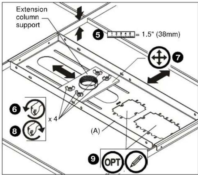
- Install CMS440 assembly (A) on top of ceiling tile so that end brackets engage primary (1-1/2" (38mm) high) rails of ceiling framework. (See Figure 2)
text_image
Extension column support ⑤ = 1.5" (38mm) ⑦ ⑥ x 4 ⑧ (A) ⑨ OPTFigure 2
- Loosen four wing nuts in upper side of CMS440 assembly (A). (See Figure 2)
- Position CMS440 assembly (A) and/or extension column support (as required) to center support over ceiling tile hole. (See Figure 2)
- Tighten wing nuts (See Figure 2).
- OPTIONAL: Mark location of electrical cutout on ceiling tile with pencil. (See Figure 2)
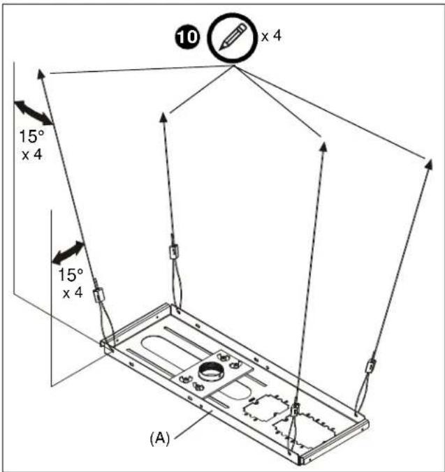
- Examine ceiling structure (concrete, steel truss, or wood) above CMS440 assembly (A) to identify four support cable anchor locations. Each location should be approximately 15° outboard of support holes in CMS440 assembly (A) (See Figure 3). Mark locations with pencil.
text_image
10 x 4 15° x 4 15° x 4 (A)Figure 3
- Remove CMS440 assembly (A) and ceiling tile.
- OPTIONAL: Cut electrical box opening in ceiling tile at marked location. Install UL Listed Raco 560 or equivalent UL Listed electrical box (not included) to CMS440 (A) following instructions included with electrical box.
SUPPORT CABLE INSTALLATION

WARNING: Failure to provide adequate structural strength for this component can result in serious personal injury or damage to equipment! It is the installer's responsibility to make sure the structure to which this component is attached can support five times the combined weight of all equipment. Reinforce the structure as required before installing the component.
Solid Concrete Ceiling Structure

WARNING: Anchors must be installed into structurally sound solid concrete with a minimum thickness of 1.75" (44.5mm) or greater. Installation into hollow concrete block, mortar, or concrete that exhibits cracking, spalling, or other defects may result in failure of anchor and serious personal injury or damage to equipment!
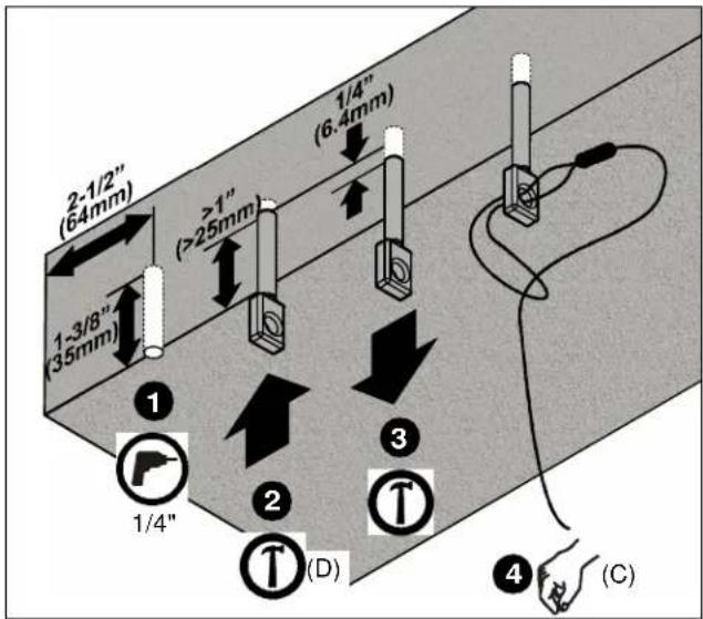
- Drill 1/4" diameter x 1-3/8" deep hole at each marked cable anchor support location (See Figure 4). Ensure hole is at least 2-1/2" from nearest concrete edge. Remove debris from hole.
text_image
2-1/2" (64mm) 1-3/8" (35mm) >1" (>25mm) 1/4" (6.4mm) ① 1/4" ② ③ ④ (C)Figure 4
- Tap anchor (D) into each hole to a depth of at least 1" (25mm). (See Figure 4)

WARNING: Failure to properly set anchor may result in failure of anchor and serious personal injury or damage to equipment!
-
Using claw portion of hammer, set each anchor (D) by pulling it out of hole approximately 1/4" (6.4mm). (See Figure 4)
-
Insert portion of manufactured loop on cable (C) through hole in anchor (D) (See Figure 4). Insert end of cable (C) through loop. Repeat for 3 remaining support locations.
Steel Truss Ceiling Structure
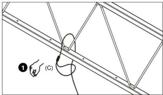
- Route end of cable (C) over truss at marked cable anchor support location and then through cable loop. (See Figure 5) Repeat for 3 remaining support locations.
text_image
(C)Figure 5
Wood Ceiling Structure

WARNING: Anchors must be installed into wood with a minimum thickness of 1-1/2" (38.1 mm) or greater.
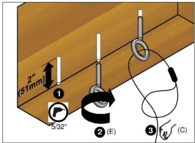
- Drill 5/32" diameter x 2" deep hole at each marked cable anchor support location (See Figure 6). Remove debris from hole.
text_image
2" (51mm) ① 5/32" ② (E) ③ (C)Figure 6
-
Fully thread eye lag (E) into each hole (See Figure 6).
-
Route end of cable (C) through eye lag (E) and then through cable loop (See Figure 6). Repeat for 3 remaining support locations.
TRAY INSTALLATION
- Reinstall ceiling tile with extension column hole. Ensure tile is oriented for proper location of hole.
- Reinstall CMS440 assembly (A) on top of ceiling tile so that extension column support is centered over hole in tile.
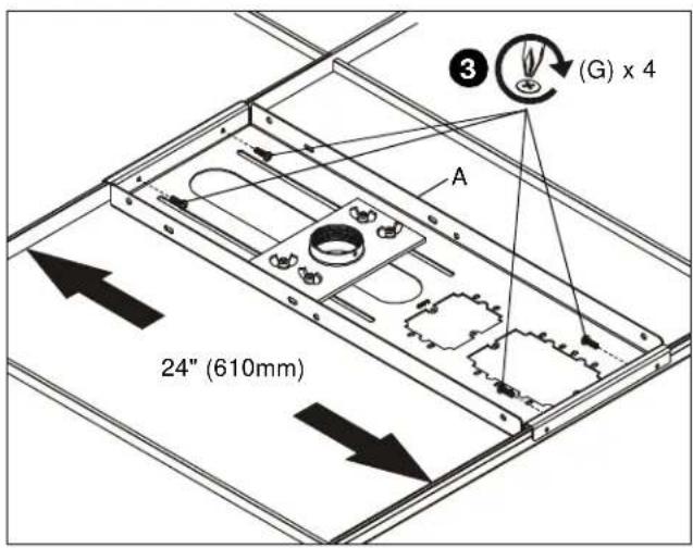
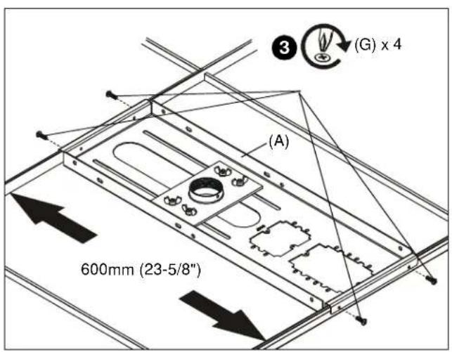
- Position CMS440 assembly (A) with four screws (G) as required:
- For 24" (610mm) Framework: Install screws through end bracket inside holes (See Figure 7).
- For 600mm (23-5/8") Framework: Install screws through end bracket outside holes (See Figure 8).
text_image
3 (G) x 4 A 24" (610mm)Figure 7
text_image
600mm (23-5/8") (A) (G) x 4 ③Figure 8

CAUTION: Failure to properly tension cables (C) may result in damage to ceiling tile framework!
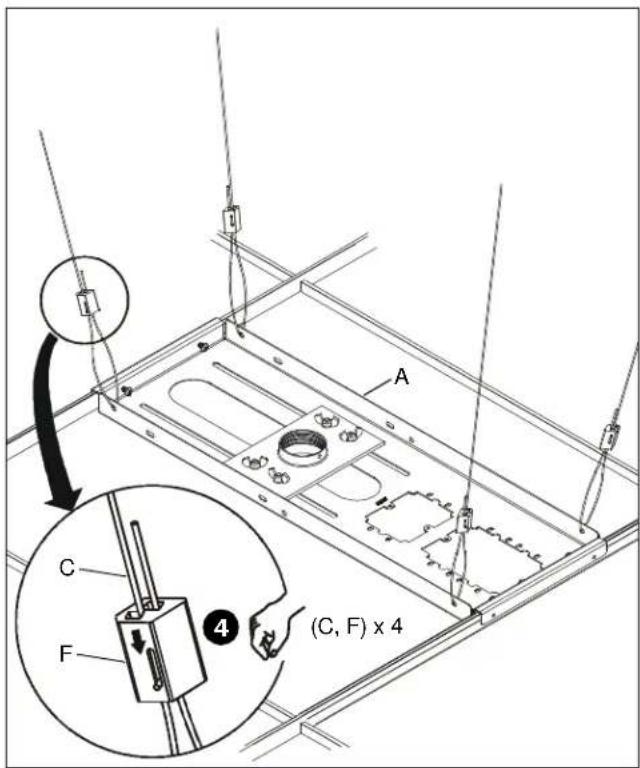
- Thread each cable (C) completely through cable lock (F), corresponding hole in corner of CMS440 assembly (A), and completely through opposite side of cable lock (F) (See Figure 9). Adjust cable tension until CMS440 assembly (A) is supported entirely and evenly by all four support cables, but not so tight as to distort ceiling tile framework.
NOTE: Cable lock (F) will allow cable to enter from only one direction per side, indicated by arrows on lock. Depress spring loaded pins on cable lock (F) to release cable tension.
text_image
A C F (C, F) x 4Figure 9
EXTENSION COLUMN INSTALLATION

WARNING: Exceeding the weight capacity can result in serious personal injury or damage to equipment! It is the installer's responsibility to make sure the combined weight of all components attached to the CMS440 up to (and including) the display/projector, does not exceed 50 lbs (22 kg).
- Install 1-1/2" NPT or NPSM following ANSI/ASME B1.20.1 (Schedule 40, 0.154" minimum thickness aluminum - ASTM B221) threaded extension column (not included) into extension column support until tight, with a minimum of four threads engaged.
NOTE: If installation instructions are not available, contact Chief Manufacturing for assistance.
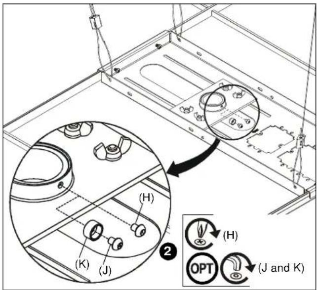
- Secure extension column by one of the following methods (See Figure 10):
• Install one 10-24 x 1/4" Phillips pan head screw (H) into extension column support, tightening firmly against column.
- OPTIONAL: Install one 10-24 x 1/4" button head security screw (J) through locking collar (K) into extension column support, tightening firmly against column.
NOTE: Locking collar (K) is designed to spin, even when screw (J) is tight.
text_image
(H) (H) (K) (J) (J and K)Figure 10
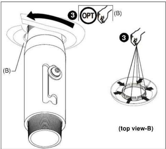
- Install NPT ring (B) on extension column below ceiling tile (See Figure 11). If necessary, bend six tabs inward to secure ring to column.
text_image
(B) (B) ③ OPT (B) ③ (top view-B)Figure 11
- Reinstall remaining ceiling tiles as required.