PT-HDBT-210 - Audio/video extender PureTools - Free user manual and instructions
Find the device manual for free PT-HDBT-210 PureTools in PDF.


User questions about PT-HDBT-210 PureTools
0 question about this device. Answer the ones you know or ask your own.
Ask a new question about this device
Download the instructions for your Audio/video extender in PDF format for free! Find your manual PT-HDBT-210 - PureTools and take your electronic device back in hand. On this page are published all the documents necessary for the use of your device. PT-HDBT-210 by PureTools.
USER MANUAL PT-HDBT-210 PureTools
text_image
APC NO Pure Tools 20000 PRO NO IN NO PRO TEST/NO OFF PR PRODT PureTools TX HD80xT Extender 4K (60Hz 4X14) Upscaling and Decombidding PT-HD8T-210-TX ON OFF ON 1 2 3 4 1 0 Text Pattern 1000P → 4K FW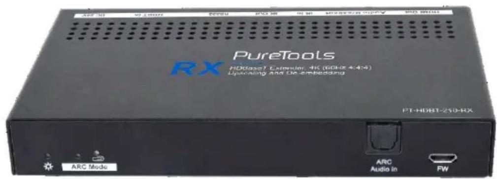
text_image
ARC Mode ARC Audio in FW PureTools RX HD802T Extensor 4K (60Hz 4.424) Upscaling and De-embedding PT-HDBT-210-RXUser Manual
18G HDMI Extender with Audio Breakout
Model PT-HDBT-210
Designed in Germany
Preface
Read this user manual carefully before using this product. Pictures shown in this manual are for reference only. Different model layouts and specifications are subject to the physical product.
This manual is for operation instructions only, not for any maintenance usage.
In the constant effort to improve our product, we reserve the right to make changes in functions or parameters without prior notice or obligation.
Trademarks
Product model and logo are trademarks. Any other trademarks mentioned in this manual are acknowledged as the properties of the trademark owner. No part of this publication may be copied or reproduced without the prior written consent.
FCC Statement
This equipment generates, uses and can radiate radio frequency energy and, if not installed and used in accordance with the instructions, may cause harmful interference to radio communications. It has been tested and found to comply with the limits for a Class B digital device, pursuant to part 15 of the FCC Rules. These limits are designed to provide reasonable protection against harmful interference in a commercial installation.
Operation of this equipment in a residential area is likely to cause interference, in which case the user at their own expense will be required to take whatever measures may be necessary to correct the interference.
Any changes or modifications not expressly approved by the manufacture would void the user's authority to operate the equipment.
REACH | 1907/2006/EU
ROHS | 2011/65/EU
PureLink hereby declares that this product PureTools PT-HDBT-210 complies with Directives 1907/2006/EU und 2011/65/EU.
EMC / LVD (Electro Magnetic Compatibility / Low Voltage Directive)
PureLink GmbH hereby declares that this product PureTools PT-HDBT-210 complies with Directives 2014/30/EU and 2014/35/EU. The full text of the EU Declaration of Conformity is available at the following Internet address:
http://www.purelink.de/ce/4251364718407_CE.pdf

SAFETY PRECAUTIONS
To ensure the best from the product, please read all instructions carefully before using the device. Save this manual for further reference.
- Unpack the equipment carefully and save the original box and packing material for possible future shipment.
- Follow basic safety precautions to reduce the risk of fire, electrical shock and injury to persons.
- Do not dismantle the housing or modify the module. It may result in electrical shock or burn.
- Using supplies or parts not meeting the products' specifications may cause damage, deterioration or malfunction.
- Refer all servicing to qualified service personnel.
- To prevent fire or shock hazard, do not expose the unit to rain, moisture or install this product near water.
- Do not put any heavy items on the extension cable in case of protrusion.
- Do not remove the housing of the device as opening or removing the housing may expose you to dangerous voltage or other hazards.
- Install the device in a place with sufficient ventilation to avoid damage caused by overheat.
- Keep the module away from liquids.
- Spillage into the housing may result in fire, electrical shock, or equipment damage. If an object or liquid falls or spills on to the housing, unplug the module immediately.
- Do not twist or pull by force ends of the optical cable. It can cause malfunction.
- Do not use liquid or aerosol cleaners to clean this unit. Always unplug the power to the device before cleaning.
- Unplug the power cord when left unused for a long period of time.
- Information on disposal for scrapped devices: do not burn or mix with general household waste, please treat them as normal electrical wastes.
Product Introduction
Thanks for choosing the PT-HDBT-210 HDMI 2.0 via HDBaseT Extender, which consists of a transmitter and a receiver module. It can extend 4K video to a distance up to 40 meters and 1080p video to distances up to 70 meters over a single CATx cable. It supports audio de-embedding and ARC. It also supports bidirectional IR and RS232 to be passed through to control source or display device remotely. The PoC feature allows the transmitter and the receiver to be powered by only one power adapter in the system. Besides passing EDID information from the display, there are multiple built-in EDID settings that can be selected by the 4-pin DIP switch on the front panel of the transmitter. Further, the extender supports convenient firmware upgrades using the Micro-USB port.
Features
• Supports HDMI 2.0 and the HDMI video resolutions up to 4K@60Hz 4:4:4 HDR.
- HDMI input supports HDCP 2.2 and the output supports HDCP Active / Passive mode.
- Extends 4K signals to distances up to 131 feet (40 meters) and 1080p signals to distances up to 70 meters (229 ft.) over a single CATx cable.
- Supports video resolution up-scaling for 1080p inputs to be automatically upscaled to 4K output.
- S/PDIF output on receiver for source audio de-embedding.
• 18Gbps high bandwidth.
- Advanced EDID management: multiple built-in EDID settings can be selected.
- Built-in 4K & 1080p test pattern images for troubleshooting.
- Bidirectional IR, RS232 and 24V PoC.
- Supports ARC.
• Supports CEC pass-through.
- Provides LEDs indicators of the current operating status.
- Firmware upgrade by Micro-USB port.
Packing List
• 1x PT-HDBT-210-TX Transmitter
- 2x TX Mounting Ears with 4 Screws
- 4x TX Plastic Cushions
- 1x 3-pin Terminal Block
- 1x User Manual
• 1x PT-HDBT-210-RX Receiver
- 2x RX Mounting Ears with 4 Screws
- 4x RX Plastic Cushions
• 1x Power Adapter (24V DC 1.25A)
Note: Please contact your distributor immediately if any damage or defect in the components is found.
Transmitter Panel Description
text_image
Test Pattern 1000P → 4.6K DN DIP 1 2 3 4 FW 5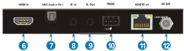
text_image
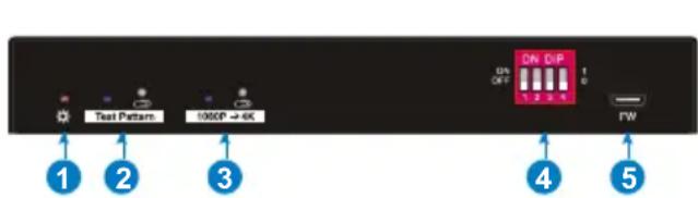
HDMI In ARC Audi o Out R In R Out RS232 HDB TO ut DC 24V 6 7 8 9 10 11 12 LINKHDCE- Power LED: The LED illuminates red when power is applied.
- Test Pattern: Press the button with a paper clip or another pointy tool to enable test patterns - The left LED illuminates blue and the product generates an image of 1080p/60Hz (color bars) as output signal. Press this button again and the left LED blinks blue at an interval of 500ms while the product generates a 4K@60Hz (4:4:4) color bar test pattern to be output. Press and hold this button for three seconds to exit the test pattern mode.
- 1080p → 4K Upscaling: Press and hold the button at least three seconds with paper clip or other sharp tool to enable 1080P to 4K up-scaling, and then the left LED illuminates blue. Press and hold it again to exit.
-
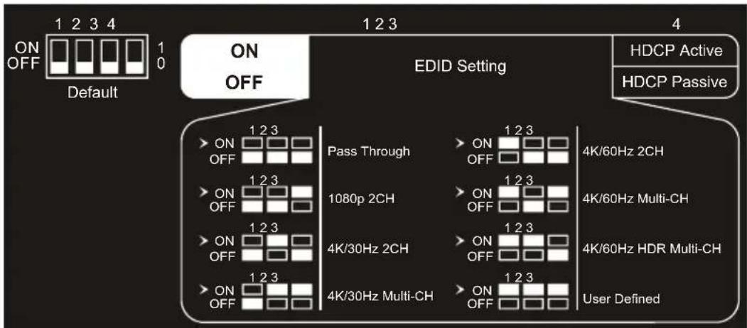
EDID: 4-pin DIP switch for EDID setting and HDCP mode selection. Please refer to the chapter EDID Management for more details.
-
FW: Micro-USB port for firmware updates and user-defined EDID upload.
- HDMI In: Type-A female HDMI input port to connect an HDMI source.
- ARC Audio Out: Toslink connector to connect speaker or amplifier for ARC audio output.
- IR In: 3.5mm jack to connect the IR receiver for IR pass-through.
- IR Out: 3.5mm jack to connect the IR emitter for IR pass-through.
- RS232: 3-pin terminal block to connect the RS232 control device (e.g. PC) or a third-party device to be controlled.
- HDBT Out: RJ45 port to connect the HDBT input port of receiver with a CATx Ethernet cable. The LINK LED illuminates orange when there is a valid HDBaseT link between the transmitter and the receiver. The HDCP LED illuminates green when the video contains HDCP content.
- DC 24V: DC connector for the power adapter connection.
Receiver Panel Description

text_image
ABC Mode ABC Audio In FM HDMI Out Audio Breakout IR In IR Out RS232 HDBT In DC 24V Tx + Rx HOOP LINK 1 2 3 4 5 6 7 8 9 10 11- Power LED: The LED illuminates red when power is applied.
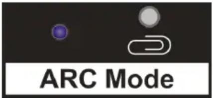
- ARC Mode: Press the button with a paper clip or another pointy tool to enable the ARC mode - the left LED illuminates blue. Press the button again to exit ARC mode - the LED turns off.
- ARC Audio In: Toslink connector to connect ARC audio source device (e.g. TV).
-
FW: Micro-USB port for firmware updates.
-
HDMI Out: Type-A female HDMI output port to connect HDMI display (e.g. TV).
- Audio Breakout: If ARC mode is turned off, the Toslink connector is connected to the speaker or amplifier for HDMI source audio de-embedding. Note, that if ARC mode is enabled, this port does not output audio.
- IR In: 3.5mm jack to connect the IR receiver for IR pass-through.
- IR Out: 3.5mm jack to connect the IR emitter for IR pass-through.
- RS232: 3-pin terminal block to connect the RS232 control device (e.g. PC) or a third-party device to be controlled.
- HDBT In: RJ45 port to connect to the HDBaseT output port of the transmitter using a CATx Ethernet cable. The Link LED illuminates orange when there is a valid HDBaseT link between the transmitter and the receiver. The HDCP LED illuminates green when the video contains HDCP content.
- DC 24V: DC connector for the power adapter connection.
DIP Switch Operation
EDID Management
The Extended Display Identification Data (EDID) is used by the source device to match its video resolution with the connected display. By default, the source device obtains its EDID from the first connected display. Meanwhile, since the displays with different capabilities are connected to the extender, the DIP switch on the front panel of transmitter can be used to set the EDID to a fixed value to ensure the compatibility in video resolution and aspect-ratio.
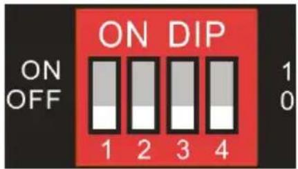
The switch represents "0" when in the lower (OFF) position, and it represents "1" when putting the switch in the upper (ON) position.
text_image
ON DIP ON OFF 1 2 3 4 1 0Switch 1\~3 are used for EDID settings. The DIP switch status and its corresponding setting are shown at the back of the product.
flowchart
graph TD
    A["Default ON/OFF"] --> B["Pass Through"]
    A --> C["1080p 2CH"]
    A --> D["4K/30Hz 2CH"]
    A --> E["4K/30Hz Multi-CH"]
    F["HDCP Active"] --> G["EDID Setting"]
    H["HDCP Passive"] --> G
    I["User Defined"] --> G
    style A fill:#f9f,stroke:#333
    style F fill:#ccf,stroke:#333
    style H fill:#cfc,stroke:#333
| Switch Status | Video Resolution | Audio Format |
| 000 | Pass Through | |
| 001 | 1080p | 2CH |
| 010 | 3840x2160@30Hz | 2CH |
| 011 | 3840x2160@30Hz | Multi-CH |
| 100 | 3840x2160@60Hz | 2CH |
| 101 | 3840x2160@60Hz | Multi-CH |
| 110 | 3840x2160@60Hz HDR | Multi-CH (Supports PCM 2CH, PCM5.1, Dolby Digital 5.1,DTS 2CH) |
| 111 | User-defined EDID (Upload the EDID by Micro-USB port) | |
Note:
• 2CH: Supports LPCM 2CH.
- Multi-CH: Supports LPCM 8CH, Dolby TrueHD, DTS-HD, Dolby Digital5.1, DTS 5.1, Dolby Digital Plus.
- User-defined EDID Setting
Except directly invoking the built-in EDID, the specific EDID can be customized by following the process below..
1) Rename the user-defined EDID according to the following format.
EC\_XX\_XXXXX\_XXXX\_XXX.bin
- EC: Fixed value
- xx: EDID ID. It is "15".
- xxxxx: Video resolution.
- xxx: Refresh rate.
- xxx: Audio format.
Example: EC_15_3840x2160_60Hz_Dolby.bin
2) Connect the USB port of the transmitter to the PC using a USB cable and then power on the transmitter. The PC will automatically detect a virtual disk named "BOOTDISK".
3) Double-click to open the disk, a file named of "READY.TXT" will be showed.
4) Copy the user-defined EDID (such as EC_15_3840x2160_60Hz_Dolby.bin) to the "BOOTDISK" disk.
5) Reopen the disk to check if the filename "READY.TXT" has changed to "SUCCESS.TXT". If yes, the user-defined EDID was successfully imported into the transmitter and saved as its corresponding EDID successfully.
6) Remove the USB cable, and then reboot the transmitter.
7) Now the new EDID can be invoked by setting the DIP switch status to "111".
HDCP Mode
Switch the DIP 4 into "ON" position to select HDCP Active mode or into "OFF" position for HDCP Passive mode.
| Switch Status | Mode | HDCP |
| OFF (0) | Passive (Default) | Automatically follows the HDCP version of source device. |
| ON (1) | Active | If the input video has HDCP content, the HDCP version of HDMI output is HDCP 1.4 for a greater display compatibility.If the input video has no HDCP content, the HDMI output has no HDCP too. |
ARC Mode
The front panel of receiver provides a buttons to enable or disable ARC mode, as shown below:
text_image
ARC ModePress the button with paper clip or other sharp tool to enable the ARC mode, and then the left LED illuminates blue. Press it again to exit the ARC mode and the LED is off.
| ARC Mode | Display (e.g.TV) | Audio Transmission Path |
| ON | ARC is supported. | The TV audio is transmitted from the TV back to the receiver directly using a standard HDMI cable, and then it will be output by the ARC Audio Out port of transmitter. |
| ARC is not supported. | Connect the TV to the ARC Audio In port of receiver with an audio cable. The TV audio istransmitted from the TV back to the receiver via the audio cable, and will be output by the ARC Audio Out port of the transmitter. Note that if the ARC mode is ON, the Audio Breakout port of the receiver has no audio output. | |
| OFF | / | The TV audio is not routed back to the ARC Audio Out port of transmitter. The Audio Breakout port of receiver is connected to speaker or amplifier for HDMI source audio de-embedding. |
System Connection
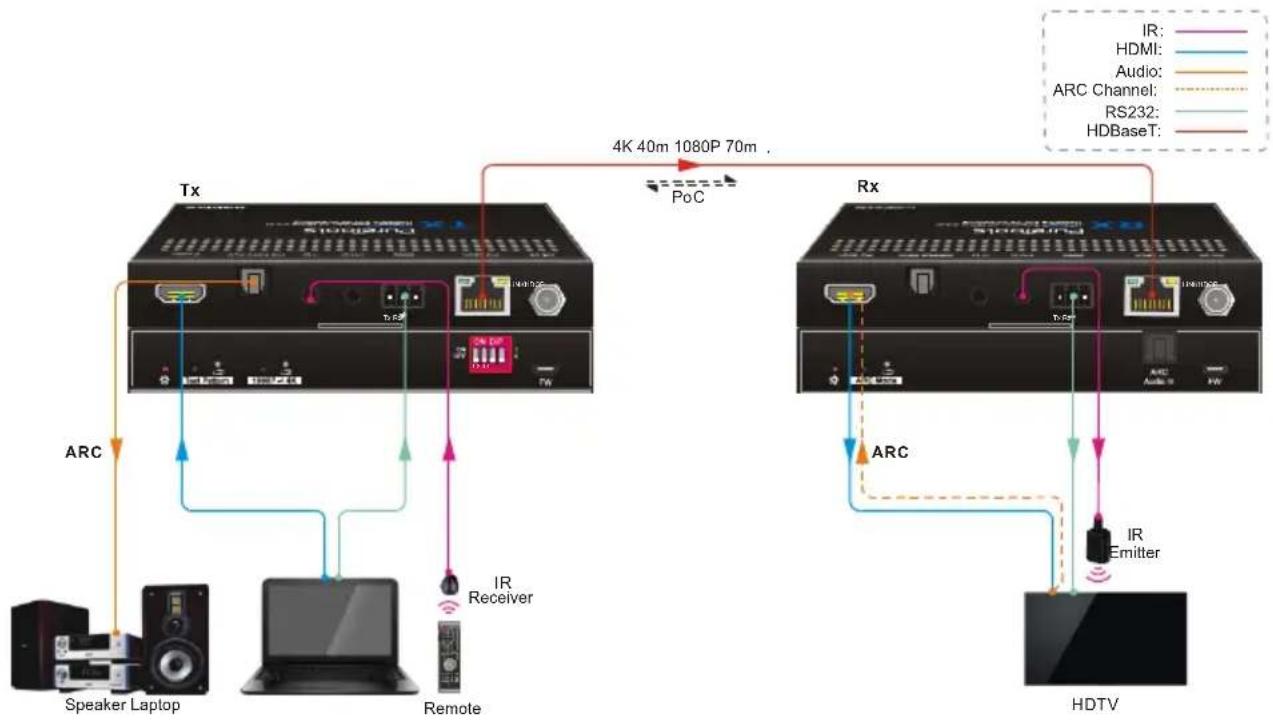
The following diagram illustrates the typical input and output connections of the extender:
1) The ARC mode of receiver is ON, and the display device (e.g. HDTV) supports ARC. The TV audio is transmitted from the TV back to the receiver via HDMI cable, and then it will be output by the ARC Audio Out port of transmitter.
flowchart
graph TD
    Tx["Tx"] -->|4K 40m 1080P 70m.| PoC["PoC"]
    PoC --> Rx["Rx"]
    Tx -->|ARC| Speaker["Lpeaker"]
    Tx -->|ARC| Laptop["Laptop"]
    Tx --> Remote["Remote"]
    Rx -->|ARC| HDTV["HDTV"]
    Rx -->|IR Emitter| HDTV
    Tx -->|IR Receiver| Speaker
    Rx -->|ARCS| Remote
    style Tx fill:#f9f,stroke:#333
    style Rx fill:#bbf,stroke:#333
2) The ARC mode of receiver is ON, but the display device (e.g. HDTV) doesn't support ARC. The TV audio is transmitted from the TV back to the receiver via the audio cable, and then it will be output by the ARC Audio Out port of transmitter.

flowchart
graph TD
    Tx["Tx"] -->|4K 40m 1080P 70m.| PoC["PoC"]
    PoC --> Rx["Rx"]
    Tx -->|ARC| Speaker["Lpeaker"]
    Tx -->|ARC| Laptop["Laptop"]
    Tx --> Remote["Remote"]
    Rx -->|ARC| HDTV["HDTV"]
    Rx -->|ARC| HDTV
    Tx -->|IR Receiver| Remote
    Tx -->|Audio: ARC Channel: RS232: HDBaseT: HDMI: HDMI: Audio: ARC Channel: ARC: ARIC: ARIC: ARIC: ARIC: ARIC: ARIC: ARIC: ARIC: ARIC: ARIC: ARIC: ARIC: ARIC: ARIC: ARIC: ARIC: ARIC: ARIC: ARIC: ARIC: ARIC: ARIC: ARIC: ARIC: ARIC: ARIC: ARIC: ARIC: ARIC: ARIC: ARIC: ARIC: ARIC: ARIC
Note: The STP cable is recommended to be used to ensure optimal machine performance in ARC mode.
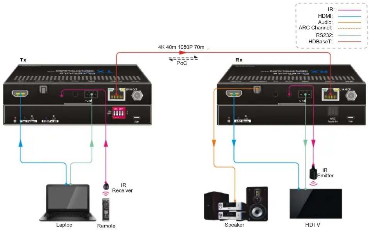
3) The ARC mode of receiver is OFF. The TV audio can't be back to the ARC Audio Out port of transmitter. The Audio Breakout port of receiver is connected to speaker or amplifier for HDMI source audio de-embedding.
flowchart
graph TD
    subgraph Tx
        A["Laptop"] -->|IR Receiver| B["Remote"]
        B --> C["USB"]
        C --> D["Tx"]
        D --> E["4K 40m 1080P 70m"]
        E --> F["PoC"]
        F --> G["Rx"]
        G --> H["Speaker"]
        H --> I["HDTV"]
        I --> J["IR Emitter"]
        J --> K["ARC Channel"]
        K --> L["Audio"]
        L --> M["HDMI"]
        M --> N["IR"]
    end
    subgraph Rx
        O["Laptop"] --> P["Remote"]
        P --> Q["Tx"]
        Q --> R["Tx"]
        R --> S["Tx"]
        S --> T["Tx"]
        T --> U["Tx"]
        U --> V["Tx"]
        V --> W["Tx"]
        W --> X["Tx"]
        X --> Y["Tx"]
        Y --> Z["Tx"]
        Z --> AA["Tx"]
        AA --> AB["Tx"]
        AB --> AC["Tx"]
        AC --> AD["Tx"]
        AD --> AE["Tx"]
        AE --> AF["Tx"]
        AF --> AG["Tx"]
        AG --> AH["Tx"]
        AH --> AI["Tx"]
        AI --> AJ["Tx"]
        AJ --> AK["Tx"]
        AK --> AL["Tx"]
        AL --> AM["Tx"]
        AM --> AN["Tx"]
        AN --> AO["Tx"]
        AO --> AP["Tx"]
        AP --> AQ["Tx"]
        AQ --> AR["Tx"]
        AR --> AS["Tx"]
        AS --> AT["Tx"]
        AT --> AU["Tx"]
        AU --> AV["Tx"]
        AV --> AW["Tx"]
        AW --> AX["Tx"]
        AX --> AY["Tx"]
    end
Technical Specification
| Video | Transmitter | Receiver |
| Input | (1) HDMI | (1) HDBT |
| Input Connector | (1) Type-A female HDMI | (1) RJ45 |
| Input Resolution | Up to 4Kx2K@60Hz 4:4:4 8bit HDR10 | Up to 4Kx2K@60Hz 4:2:0 |
| Output | (1) HDBT Out | (1) HDMI |
| Output Connector | (1) RJ45 | (1) Type-A female HDMI |
| Output Resolution | Up to 4Kx2K@60Hz 4:2:0 | Up to 4Kx2K@60Hz 4:4:4 8bit HDR10 |
| Audio | ||
| Input | - | (1) ARC Audio In |
| Input Connector | - | (1) Toslink Connector |
| Output | (1) ARC Audio Out | (1) Audio Breakout |
| Output Connector | (1) Toslink connector | (1) Toslink connector |
| Audio Format | Supports PCM, Dolby Digital, Dolby True-HD, DTS and DTS-HD. | |
| Frequency Response | 20Hz - 20KHz, ±3dB | |
| Max Output Level | 2.0Vrms ± 0.5dB. 2V = 16dB headroom above -10dBV (316mV) nominal consumer line level signal | |
| THD+N | < 0.05% (-80dB), 20Hz - 20KHz bandwidth, 1KHz sine at 0dBFS level (or max level) | |
| SNR | >85dB, 20Hz-20 kHz bandwidth | |
| Crosstalk Isolation | >70dB, 10KHz sine at 0dBFS level (or max level before clipping) | |
| L-R Level Deviation | < 0.3dB, 1KHz sine at 0dBFS level (or max level before clipping) | |
| Frequency Response Deviation | < ± 0.5dB 20Hz - 20KHz | |
| Output Load Capability | 1KΩ and higher (Supports 10x paralleled 10KΩ loads) | |
| Stereo Channel Separation | >70dB@1KHz | |
| Control | ||
| Control Part | (1) Test Pattern button,(1)1080p → 4K button,(1) EDID 4-pin DIP switch,(1) FW, (1) IR In, (1) IR Out,(1) RS232 | (1) ARC Mode button, (1) FW,(1) IR In, (1) IR Out, (1) RS232 |
| Control Connector | (1) Micro-USB port,(2) 3.5mm jacks,(1) 3-pin terminal block | (1) Micro-USB port,(2) 3.5mm jacks,(1) 3-pin terminal block |
| General | ||
| Bandwidth | 18Gbps | |
| HDMI Standard | 2.0 | |
| HDCP Version | 2.2, 1.4 compliant | |
| CEC | Pass-through | |
| Bidirectional PoC | Supported | |
| HDMI 2.0 Cable Length | 4K@60Hz 4:4:4 ≤ 5m, 4K@60Hz 4:2:0 ≤ 15m, 1080p ≤ 20m | |
| Transmission Standard | HDBaseT | |
| Transmission Distance | 1080p@60Hz up to 70 meters (229 ft.)4K@60Hz up to 40 meters (131 ft.) | |
| Operation Temperature | -5~ +55°C | |
| Storage Temperature | -25 ~ +70°C | |
| Relative Humidity | 10%-90% | |
| Power Supply | Input:100V~240V AC; Output:24V DC 1.25A | |
| Power Consumption | 12W (Max) | |
| Dimension (W*H*D) | TX/RX: 140mm x 19.5mm x 84mm | |
| Net Weight | TX:275g, RX:290g | |
Note: Please adopt high-quality HDMI cables, fully compliant with HDMI 2.0 for a reliable transmission and connection.
After-Sales Service
If problems appear when using the product, please deal with the problems referring to this user manual. During the warranty period, any transport costs are borne by the customer.
1) Product Limited Warranty: The product will be free from defects in materials and workmanship for two years (The purchase invoice shall prevail).
Proof of purchase in the form of a bill of sale or receipted invoice which is evidence that the unit is within the Warranty period must be presented to obtain warranty service.
2) What the warranty does not cover (servicing available for a fee):
- Warranty expiration.
- Factory applied serial number has been altered or removed from the product.
-
Damage, deterioration or malfunction caused by:
-
Normal wear and tear.
- Use of supplies or parts not meeting our specifications.
- No certificate or invoice as the proof of warranty.
-
The product model shown on the warranty card does not match with the model of the product for repairing or had been altered.
-
Damage caused by force majeure.
- Servicing not authorized by distributor.
- Any other causes which does not relate to a product defect.
- Delivery, installation or labor charges for installation or setup of the product.
3) Technical Support: For any questions or problems, contact your distributor or reseller and tell them the respective product name and version, the detailed failure situation as well as the formation of the cases.
Asking for Assistance
Technical Support:
Phone: +49 5971 800299 - 0
Fax: +49 5971 800299 - 99
Technical Support Hours:
8:30 AM to 5:00 PM Monday thru Thursday
8:30 AM to 4:00 PM Friday
Write to:
PureLink GmbH