
Q-Class 12L7 - Subwoofer KICKER - Free user manual and instructions
Find the device manual for free Q-Class 12L7 KICKER in PDF.


| Product Type | Subwoofer |
| Brand | KICKER |
| Model | Q-Class 12L7 |
| Category | Car Audio Subwoofer |
| Rated Impedance | 2 or 4 Ohms (dual voice coil) |
| Sensitivity (1W, 1m) | 86.9 dB |
| Continuous Power Handling (RMS) | 900 Watts |
| Frequency Response | 20 - 100 Hz |
| Resonant Frequency (Fs) | 34 Hz |
| Total Q (Qts) | 0.539 |
| Equivalent Compliance (Vas) | 1.92 ft³ (54.27 L) |
| DC Resistance (Re) | 6.8 Ohms |
| Outer Frame Dimensions | 12-9/16" (32 cm) diameter |
| Mounting Depth | 7-7/8" (20 cm) |
| Mounting Cutout | 11-1/16" (28.1 cm) diameter |
| Voice Coil Configuration | Dual 2Ω or Dual 4Ω |
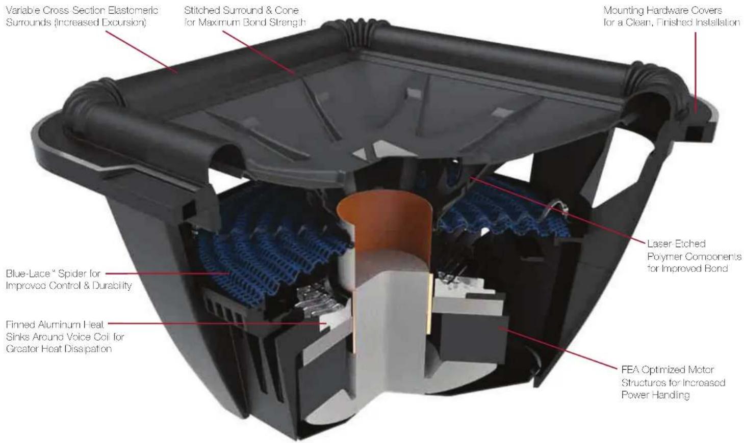
| Surround Material | Variable Cross Section Elastomeric |
| Spider Material | Blue-Lace™ for improved control |
| Heat Dissipation | Finned aluminum heat sinks around voice coil |
| Motor Structure | FEA Optimized for increased power handling |
| Recommended Sealed Enclosure | 1.0 - 2.0 ft³ (28.3 - 56.6 L) |
| Recommended Vented Enclosure | Compact: 1.75 ft³ / SQ: 3.25 ft³ |
| Break-in Time | 2 weeks for optimum performance |
| Safety Warning | Prolonged distorted operation may cause overheating/fire |
Frequently Asked Questions - Q-Class 12L7 KICKER
User questions about Q-Class 12L7 KICKER
0 question about this device. Answer the ones you know or ask your own.
Ask a new question about this device
Download the instructions for your Subwoofer in PDF format for free! Find your manual Q-Class 12L7 - KICKER and take your electronic device back in hand. On this page are published all the documents necessary for the use of your device. Q-Class 12L7 by KICKER.
USER MANUAL Q-Class 12L7 KICKER
Owner's Manual | English
L7 SUBWOOFER OWNER'S MANUAL
Models: 8L7 | 10L7 | 12L7 | 15L7
Authorized KICKER Dealer:
Purchase Date:
Speaker Model Number:
Speaker Serial Number:
Note: All specifications and performance figures are subject to change. Please visit www.kicker.com for the most current information. To get the best performance from your new KICKER Subwoofer, we recommend using genuine KICKER Accessories and Wiring. Please allow two weeks of break-in time for the subwoofer to reach optimum performance.
Sound Check: Poor bass response? Check the system phasing by reversing the positive and negative speaker connections on the subwoofer. If the bass improves, then the subwoofer was out of phase in reference to the rest of the audio system.
SPECIFICATIONS
| Model 8L7 | 10L7 | 12L7 | 15L7 | |
| Rated Impedance [Ω] 2 or 4 2 or 4 2 or 4 2 or 4 | ||||
| Fs [Hz] | 47.2 | 37.5 | 34 | 26.3 |
| Sensitivity [1W, 1m] | 82.4 | 85.9 | 86.9 | 88.6 |
| Qts | 0.735 | 0.507 | 0.539 | 0.539 |
| Qms | 8.828 | 9.791 | 9.488 | 11.868 |
| Qes | 0.802 | 0.535 | 0.571 | 0.565 |
| Re [Ω] | 6.6 | 7.9 | 6.8 | 7 |
| Vas [ft3, L] | .322, 9.127 | 1, 28.32 | 1.92, 54.274 | 5.263, 149.048 |
| Continuous Power Handling [Watts RMS] | 500 | 750 | 900 | 1200 |
| Outer Frame Dimension [in, cm] | 8-13/16, 22.4 | 10-11/16, 27.2 | 12-9/16, 32 | 15-5/8, 39.6 |
| Mounting Depth [in, cm] | 5-7/16, 13.8 | 6-7/8, 17.5 | 7-7/8, 20 | 9 3/8, 23.9 |
| Mounting Cutout [n, cm] | 7 1/4, 18.4 | 9-5/16, 23.7 | 11 1/16, 28.1 | 13 3/4, 34.9 |
| Frequency Response [Hz] | 28 - 100 | 24 - 100 | 20 - 100 | 18 - 100 |
US Patent - www.kicker.com
WIRING
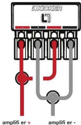
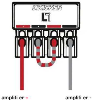
Use the push terminals to wire your subwoofer in series or parallel.
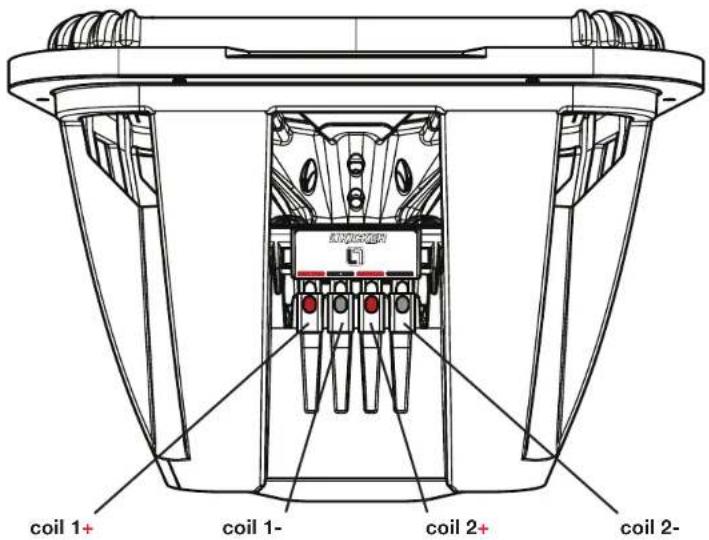
L7 subwoolers are available with dual 2Ω (ohm) or dual 4Ω voice coils. Both coils must be connected to a source of amplification. The dual 2Ω woofer will generate a 1Ω load if the coils are wired in parallel or a 4Ω load in series. The dual 4Ω woofer will provide a 2Ω load wired in parallel or 8Ω load wired in series. The terminals with the white dots are for the first voice coil. The terminals with solid-roof and solid-clock markings are for the second voice coil.
Paralleled Wiring Series Wiring
Dual 2Ω Voice Coils = 1Ω Load Dual 4Ω Voice Coils = 2Ω Load
Dual 2Ω Voice Coils = 4Ω Load Dual 4Ω Voice Coils = 8Ω Load
Pro Tip: With a KICKER IQ amplifier, a pair of KICKER QS speakers, and a few KICKER cables, you're looking at a full system upgrade that will dominate! KICKER amplifiers and accessories make it easy to upgrade with your existing or stock source unit. Ask your dealer about KICKER amplifiers and speaker upgrades to complete your system!
Paralleled Voice Coils, Woofers in Parallel
Dual 2Ω Voice Coils in Dual Subwoofer configuration = 0.5Ω Load Dual 4Ω Voice Coils in Dual Subwoofer configuration = 1Ω Load
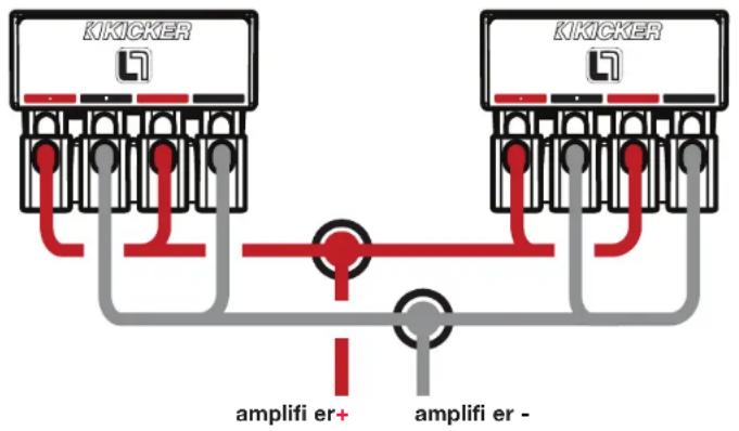
Series Voice Coils, Woofers in Parallel
Dual 2Ω Voice Coils in Dual Subwoofer Configuration = 2Ω Load
Dual 4Ω Voice Coils in Dual Subwoofer Configuration = 4Ω Load
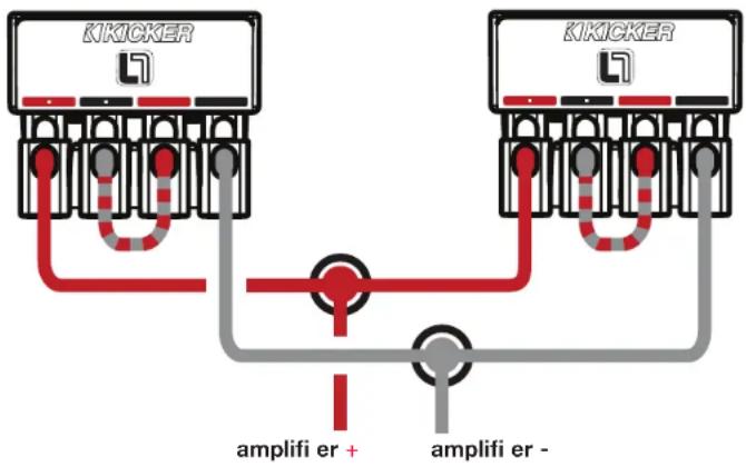
WARNING: If you are using multiple subwoofers that are wired in series to one another, each subwoofer must be in a separate chamber. If not, the subwoofers could become damaged, resulting in loss of warranty.
SEALED ENCLOSURE APPLICATIONS
The L7 generates more sound pressure than an equivalently-sized round speaker and excels when used in the recommended sealed boxes. These sealed enclosure designs give the smoothest response with increased energy at the lowest frequencies, 20Hz–30Hz. These designs deliver massive amounts of highly-accurate bass and can be driven with punishing levels of amplifier power. The high performance suspension system can operate in a larger sealed enclosure. This maximum enclosure volume application is ideal for ultra sound quality installations. The maximum enclosure generates a very flat response curve and superbly extends the sub-bass response.
L7 wofers perform well in any size sealed enclosure between the minimum and maximum volume recommendations. These systems will exhibit benefits of both designs: Minimum produces high-impact bass, and maximum generates low bass frequency protraction. Overall, the system will sound more like the recommended enclosure design it is closest to in enclosure volume. These enclosure recommendations have been calculated with the airspace inside the enclosure and include the displacement of the woofer. All sealed-enclosure airspace should be filled to 50% loose poly-fill (polyester fiberfill) stuffing. Do not make the airspace greater than the maximum enclosure volume recommendation.
Minimum Sealed
| Model | Volume ft ^a (L) | Power Handling |
| 8L7 | .4 (11.33) | 500W RMS |
| 10L7 | .8 (22.65) | 750W RMS |
| 12L7 | 1 (28.32) | 900W RMS |
| 15L7 | 1.75 (19.56) | 1200W RMS |
Maximum Sealed
| Model | Volume ft3 (L) | Power Handling |
| 8L7 .75 (21.24) | 500W RMS | |
| 10L7 | 1.25 (35.4) | 750W RMS |
| 12L7 | 2 (56.64) | 900W RMS |
| 15L7 | 6 (169.9) | 1200W RMS |
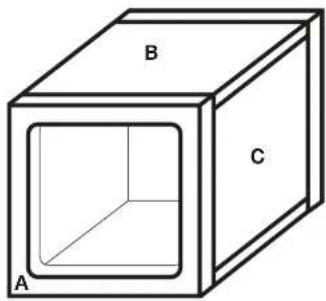
Panel Dimensions for Minimum Sealed Enclosures using 3/4" (1.9cm) thick MDF
| Model | Box Volume [ H^3,L ] | Panel A [in, cm] | Panel B [in, cm] | Panel C [in, cm] |
| 8L7 | .4 (11.33) | 11x11, 27.9x27.9 | 11x7.75, 27.9x19.69 | 9.5x7.75, 24.13x19.69 |
| 10L7 | .8 (22.65) | 13.5X13.5, 34.3X34.3 | 13.5x9.5, 34.5x24.13 | 12x9.5, 30.5x24.13 |
| 12L7 | 1 (28.32) | 13.5X13.5, 34.3X34.3 | 13.5x12, 34.3x30.5 | 12x12, 30.5x30.5 |
| 15L7 | 1.75 (49.56) | 16.5x16.5, 42x42 | 16.5x13.5, 42x34.3 | 15X13.5, 38.1X34.3 |
natural_image
Simple line drawing of a cube with labeled faces A, B, and C (no text or symbols beyond labels)VENTED ENCLOSURE APPLICATIONS
These boxes are the enclosure of choice for outrageous bass, so if space is not a problem and you want to get the most from your L7, try one of these vented designs. L7 subwoofers will handle massive amounts of power in any of the recommended enclosures, minimum or maximum. The smaller enclosures are best for use in limited-space applications. The larger recommended enclosures will yield slightly more bass at the lowest frequencies.
The vented minimum design increases bass efficiency and fits in many space-limited applications. Although it is the smallest recommended vented enclosure, the output from 30Hz–80Hz will be considerably higher than that of a sealed box. The maximum vented design has even more output in this frequency band. The maximum vented enclosure is the largest and most efficient design.
| Vented Compact 8L7 | 10L7 | 12L7 | 15L7 | |
| Box Volume, I^3 (L) + port displacement , .66 (18.69) 1.25 (35.4) 1.75 (49.6) 3.0 (85) | ||||
| Port Opening Size, in x in (cm x cm) 1.5x9.5 (3.8x24) 2.5x11.25 (6.4x29) 2.5x13.25 (6.4x34) 2.5x16.25 (6.4x41) | ||||
| Port Length, in (cm) 19.25 (49) 19.75 (50) 22.5 (57) 19.5 (50) | ||||
| Power | Handling, | RMS | 500 | /50 |
| Vented SQ 8L7 | 10L7 | 12L7 | 15L7 | |
| Box Volume, I^3 (L) + port displacement , 1 (28.32) 2.25 (63.7) 3.25 (92) 6.0 (170) | ||||
| Port Opening Size, in x in (cm x cm) | 2x9.5 (5.1x24) | 3x11.25 (7.6x29) | 3x13.25 (7.6x34) | 3.5x16.25 (8.9x41) |
| Port Length, in (cm) 21.25 (54) 18 (46) | 14.5 (37) 13.75 (35) | |||
| Power | Handling, | RMS | 500 | /50 |
BOX BUILDING NOTES
Use 3/4" (1.9cm) or thicker MDF (medium density fiberboard) and seal the joints with silicone. Use the "template" inside your L7's shipping carton to mark the mounting hole, then cut directly on the line. See Figure 1.
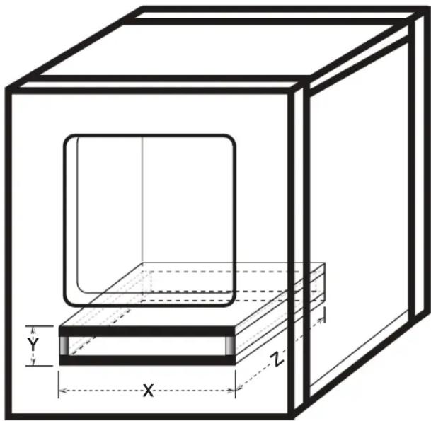
These designs need internal bracing. Add triangular bracing between each of the larger unsupported panels. See Figure 2
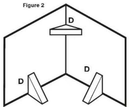
D = 3" x 3" for 12L7, 15L7
D = 2" x 2" for 8L7, 10L7
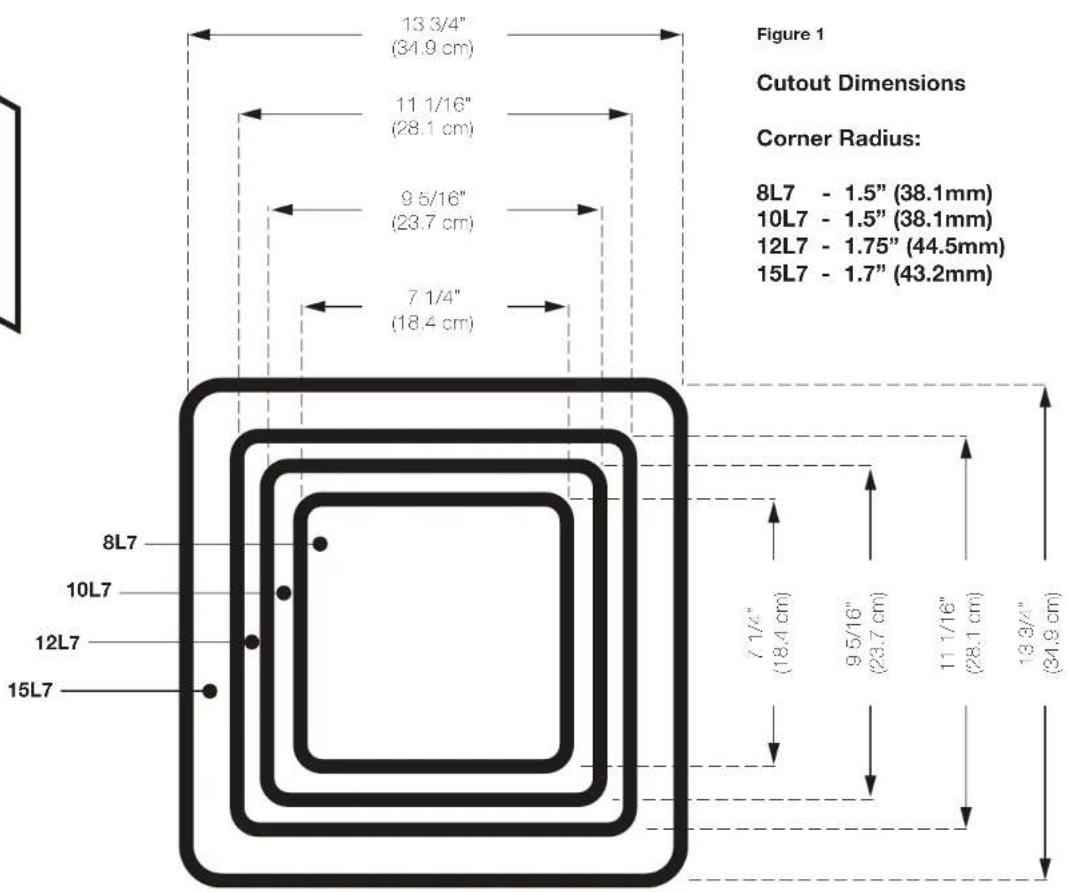
8L7 - 1.5" (38.1mm)
10L7 - 1.5" (38.1mm)
12L7 - 1.75" (44.5mm)
15L7 - 1.7" (43.2mm)
All the cubic feet (L) measurements in this manual include the displacement of the woofer. For the vented enclosures the displacement of the port must be calculated and added to the internal volume of the final design. Use the outer dimensions of the vent and multiply "X x Y x Z", and convert to cubic feet, for example the 12L7 vented Compact design's external vent dimensions are, using 3/4" (1.9cm) MDF:
[(13.25" + 1.5" total MDF wall thickness) x (2.5" + 1.5" total MDF wall thickness) x 22.5"] x (1 ft ^3 / 1728 in ^3 ) = .77 ft ^3
Add this number to the internal volume of the enclosure. The 12L7 is:
1.75ft^3 + .77ft^3 = 2.52ft^3
Due to the necessary length of these vents, you may want to fold the vent along the bottom and back walls. It will be impractical to use round vents for these designs. Do not install a vent opening against a solid surface, such as an internal brace, back-panel or trunk wall, seal or interior panel of your vehicle. The vent opening must remain unobstructed. Use the smallest dimension of the rectangular vent as the minimum amount of space between the vent opening and any solid surface to insure unrestricted airflow.
If you prefer an ultra-smooth bass response, you should loosely fill your L7 enclosure with poly-fi I stuffi ng. Vented designs will require covering the end of the port (located inside the box) with grill cloth, chicken wire, or expanded metal to prevent the poly-fi I from exiting the port. The use of poly-fi I will slightly decrease efficiency, but will deepen and extend the low frequency output.
For more advice on box building, refer to your Authorized Kicker Dealer, or click on the Support tab on the Kicker homepage, www.kicker.com. Please e-mail support@kicker.com or call Technical Support at (405) 624-8583 for specific or unanswered questions.
WARNING: KICKER products are capable of producing sound levels that can permanently damage your hearing! Turning up a system to a level that has audible distortion is more damaging to your ears than listening to an undistorted system at the same volume level. The threshold of pain is always an indicator that the sound level is too loud and may permanently damage your hearing. Please use common sense when controlling volume.
IMPORTANT SAFETY WARNING – PROLONGED CONTINUOUS OPERATION OF AN AMPLIFIER IN A DISTORTED OR CLIPPED MANNER CAN CAUSE YOUR AUDIO SYSTEM TO OVERHEAT, POSSIBLY CATCHING FIRE AND RESULTING IN SERIOUS DAMAGE TO YOUR COMPONENTS AND/OR VEHICLE.
natural_image
Technical line drawing of a 3D rectangular box with internal cavity and labeled dimensions X, Y, Z (no text or symbols beyond labels)KICKER®
MANUAL DEL PROPIETARIO DE ALTAVOZ SUBWOOFER L7
Modelos: 8L7 | 10L7 | 12L7 | 15L7
natural_image
Technical line drawing of a 3D rectangular box with internal cutout and labeled dimensions X, Y, Z (no text or symbols beyond labels)IMPORTANTE ADVERTENCIA DE SEGURIDAD: EL FUNCIONAMIENTO CONTINUO PROLONGADO DE UN AMPLICADOR DE MANERA DISTORSIONADA O RECORTADA PUEDE CAUSAR EL RECALENTAMIENTO DE SU SISTEMA DE AUDIO, POSIBLEMENTE PUEDE PRENDERSE FUEGO Y RESULTAR EN UN DAÑO SERIO A SUS COMPONENTES Y/O VEHÍCULO.
©2015 Stillwater Designs

Brand : KICKER
Model : Q-Class 12L7
Category : Subwoofer