
PKG-RSE3DVD - Dash cam ALPINE - Free user manual and instructions
Find the device manual for free PKG-RSE3DVD ALPINE in PDF.

| Product Type | Overhead Monitor DVD Entertainment System |
| Model | PKG-RSE3DVD |
| Brand | Alpine |
| Display Size | 10.1 inches |
| Display Type | TFT-LCD Active Matrix with LED Backlight |
| Resolution | 1024 x 600 (WSVGA) |
| Aspect Ratio | 16:9 |
| Monitor Dimensions (Closed) | 290 mm (W) x 290 mm (D) x 45 mm (H) |
| Monitor Weight | 2.27 kg (5.0 lbs) |
| Power Supply | 10-16 V DC (12V typical) |
| Power Consumption | 2.35 A (max), 1.60 A (typ), 140 mA (standby) |
| Operating Temperature | -20°C to +70°C (-4°F to +158°F) |
| Video System | NTSC/PAL compatible (auto select) |
| Disc Playback | DVD, CD (including dual-layer and two-sided DVDs) |
| Audio Output | FM modulator (88.1-92.1 MHz), IR wireless headphones (channels A/B) |
| Inputs | AUX1 (Video + Audio L/R), AUX2 (game port) |
| Outputs | AUX OUT (Video + Audio L/R), Remote Out |
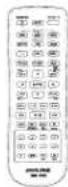
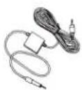
| Remote Control | Included (RUE-4159 Universal Remote) |
| Wireless Headphones | Included (SHS-N106, pair) - uses 2 AAA batteries each |
| Built-in Dome Light | White LED, with switch (On/Off/Door) and polarity selectable |
| Installation | Overhead mount with metal bracket and trim ring; interchangeable color covers (Black, Gray, Tan) |
| Safety Features | No video while driving (requires parking brake signal); laser warning for disc player |
| Accessories Included | Remote, headphones, installation bracket, screws, trim ring, AAA batteries, FM switching box, quick start guide, installation manual |
| Warranty and Support | Contact Alpine dealer or service center; serial number on bottom of unit |
Frequently Asked Questions - PKG-RSE3DVD ALPINE
User questions about PKG-RSE3DVD ALPINE
0 question about this device. Answer the ones you know or ask your own.
Ask a new question about this device
Download the instructions for your Dash cam in PDF format for free! Find your manual PKG-RSE3DVD - ALPINE and take your electronic device back in hand. On this page are published all the documents necessary for the use of your device. PKG-RSE3DVD by ALPINE.
USER MANUAL PKG-RSE3DVD ALPINE
Please read before using this equipment.
MANUAL DE OPERACIÓN
Torrance, California 90501 U.S.A.
Tel.: 1-800-ALPINE-1 (1-800-257-4631)
ALPINE ELECTRONICS (BENELUX) GmbH
Leuvensesteenweg 510-B6,
1930 Zaventem, Belgium
Tel.: 02-725 1315
ALPINE ELECTRONICS OF AUSTRALIA PTY, LTD.
161-165 Princess Highway, Hallam
Victoria 3803, Australia
Tel.: 03-8787-1200
ALPINE ELECTRONICS GmbH
Fletchamstead Highway, Coventry CCV4 9TW, U.K.
Tel.: 0870-33 33 763
ALPINE ELECTRONICS FRANCE S.A.R.L.
(RCS PONTOISE B 338 101 280)
- Rue de la Belle Etoile, Z.I. Paris Nord II,
B.P. 50016, 95945 Roissy Charles de Gaulle
Cedex, France
Tel.: 01-48638989
Designed by Alpine Electronics of America, Inc.
Printed In China
WARNING

WARNING
This symbol means important instructions. Failure to heed them can result in serious injury or death.
DO NOT WATCH VIDEO WHILE DRIVING.
Watching the video may distract the driver from looking ahead of the vehicle and cause an accident.
DO NOT OPERATE ANY FUNCTION THAT TAKES YOUR ATTENTION AWAY FROM SAFELY DRIVING YOUR VEHICLE.
Any function that requires your prolonged attention should only be performed after coming to a complete stop. Always stop the vehicle in a safe location before performing these functions. Failure to do so may result in an accident.
KEEP THE VOLUME AT A LEVEL WHERE YOU CAN STILL HEAR OUTSIDE NOISE WHILE DRIVING.
Failure to do so may result in an accident.
MINIMIZE DISPLAY VIEWING WHILE DRIVING.
Viewing the display may distract the driver from looking ahead of the vehicle and cause an accident.
DO NOT DISASSEMBLE OR ALTER.
Doing so may result in an accident, fire or electric shock.
USE ONLY IN CARS WITH A 12 VOLT NEGATIVE GROUND.
(Check with your dealer if you are not sure.) Failure to do so may result in fire, etc.
KEEP SMALL OBJECTS SUCH AS BATTERIES OUT OF THE REACH OF CHILDREN.
Swallowing them may result in serious injury. If swallowed, consult a physician immediately.
USE THE CORRECT AMPERE RATING WHEN REPLACING FUSES.
Failure to do so may result in fire or electric shock. If the fuse(s) blows more than once, carefully check all electrical connections for shorted circuitry. Also have your vehicle's voltage regulator checked.
DO NOT BLOCK VENTS OR RADIATOR PANELS.
Doing so may cause heat to build up inside and may result in fire.
USE THIS PRODUCT FOR MOBILE 12V APPLICATIONS.
Use for other than its designed application may result in fire, electric shock or other injury.
DO NOT PLACE HANDS, FINGERS OR FOREIGN OBJECTS IN INSERTION SLOTS OR GAPS.
Doing so may result in personal injury or damage to the product.
INSTALL THE PRODUCT CORRECTLY SO THAT THE DRIVER CANNOT WATCH TV/VIDEO UNLESS THE VEHICLE IS STOPPED AND THE EMERGENCY BRAKE IS APPLIED.
It is dangerous (and illegal in many states) for the driver to watch the TV/Video while driving the vehicle. The driver may be distracted from looking ahead and an accident could occur. If the product is not installed correctly, the driver will be able to watch the TV/Video while driving the vehicle and may be distracted from looking ahead causing an accident. The driver or other people could be severely injured.

CAUTION
This symbol means important instructions. Failure to heed them can result in injury or material property damage.
HALT USE IMMEDIATELY IF A PROBLEM APPEARS.
Failure to do so may cause personal injury or damage to the product. Return it to your authorized Alpine dealer or the nearest Alpine Service Center for repairing.
DO NOT MIX NEW BATTERIES WITH OLD BATTERIES. INSERT WITH THE CORRECT BATTERY POLARITY.
When inserting the batteries, be sure to observe proper polarity (+ and -) as instructed. Rupture or chemical leakage from the battery may cause fire or personal injury.
CAUTION
CAUTION-Laser radiation when open, DO NOT STARE INTO BEAM
(Bottom side of player)

PRECAUTIONS
Product Cleaning
Use a soft dry cloth for periodic cleaning of the product. For more severe stains, please dampen the cloth with water only. Anything else has the chance of dissolving the paint or damaging the plastic.
Temperature
Do not operate your unit in ambient temperature above +70°C (+158°F) or below -20°C (-4°F).
Moisture Condensation
You may notice the disc playback sound wavering due to condensation. If this happens, remove the disc from the player and wait about an hour for the moisture to evaporate.
Damaged Disc
Do not attempt to play cracked, warped, or damaged discs. Playing a bad disc could severely damage the playback mechanism. Do not attempt to load more than one disc at a time.
Maintenance
If you have problems, do not attempt to repair the unit yourself. Return it to your Alpine dealer or the nearest Alpine Service Station for servicing.
Characteristics of LCD Panel
• After turning the system off, a slight ghost of the image will remain temporarily. This is an effect peculiar to LCD technology and is normal.
- Under cold temperature conditions, the screen may lose contrast temporarily. After a short warm-up period, it will return to normal.
- The LCD panel is manufactured using an extremely high precision manufacturing technology. Its effective pixel ratio is over 99.99%. This means that 0.01% of the pixels could be either always ON or OFF.
Using Wireless Headphones
If ACC or the monitor's power source is turned off, a loud noise is produced through the headphones. Be sure to remove the wireless headphones from your ears before you turn the monitor off.
Never Attempt the Following
Do not grip or pull out the disc while it is being pulled back into the player by the automatic reloading mechanism. Do not attempt to insert a disc into the unit when the unit power is off.
Getting Started
Overhead Monitor
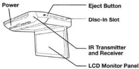
LCD Monitor Panel
This is a 10.1 inch, Wide SVGA, Active Matrix LCD with LED backlight.
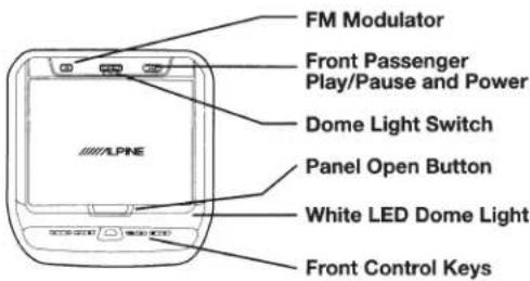
Panel Open Button
Press the Panel Open Button to release the Monitor Panel. The Panel will drop down slightly allowing you to fully open to its 90 degree or greater position. To close, firmly press the LCD Monitor Panel back up into the housing until a click is heard.
White LED Dome Light
White LED Dome Light illuminates when the Dome Light Switch is on or when triggered by the vehicle door (if connected).
Front Control Keys
White, back-lit button illuminates when the overhead monitor main power is on. DVD overhead monitor and other devices can be controlled by using these buttons.
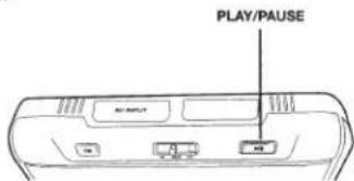
Front Passenger Control Buttons
FM : FM modulator ON/OFF switch
The audio is transmitted to the radio's FM Tuner, when FM button is on. The radio must be tuned to the proper frequency. The FM transmitter function in the System menu must be ON to use the FM modulator.
▶ / II : Play/pause and power switch
The front passenger can play/pause the DVD. It also allows turning on the unit. The unit can be turned off by pressing and holding this switch.
Dome Light Switch
Dome light switch turns on/off the dome light. When the switch is set to Door, the dome light turns on when the door is open.
IR Transmitter and Receiver
IR transmitter sends the sound to the Headphone. IR receiver receives the signal from the remote control. The Infrared Wireless Headphone Transmitter and Remote Control Receiver are located in front of the unit.
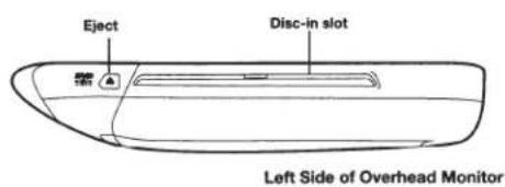
Eject Button
Pressing Eject button unloads Disc.
Basic Operations
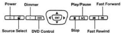
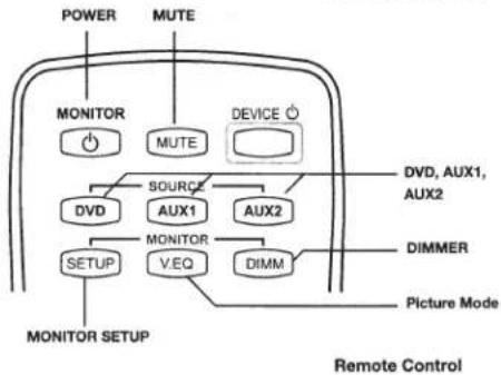
Front Control Keys
flowchart
graph TD
    A["MONITOR"] --> B["Power"]
    A --> C["MUTE"]
    D["MONITOR Setup"] --> E["MONITOR"]
    F["DVD"] --> G["SOURCE"]
    H["AUX1"] --> I["AUX2"]
    J["MONITOR V.EQ"] --> K["DIMM"]
    L["DIVD, AUX1, AUX2"] --> M["Device Icon"]
    N["DIMMER"] --> O["Picture Mode"]
    P["MONITOR Setup"] --> Q["MONITOR Setup"]
    R["Power"] --> S["Power Supply"]
    T["MUTE"] --> U["MUTE Supply"]
    V["DEVICE Icon"] --> W["Device Icon"]
Turning Power ON/OFF
The power state of the monitor is memorized when Ignition/ACC is turned off. When Ignition/ACC is turned back on, the monitor returns to the memorized power state (either ON or OFF), including DVD playback position.
Front Control Keys
- Press POWER ( ⏻ ) to turn ON the monitor.
- To turn off power, press and hold POWER ( ⏻ ) again.
- While the power is ON, press POWER ( + ) to activate the Mute function.
Remote Control
- Press POWER to turn ON and OFF
Front Passenger Controls
- Press PLAY/PAUSE button to turn ON.
• To turn off the power, press and hold PLAY/PAUSE.
Loading and Unloading Discs
Turn on the power before loading and unloading discs.
Loading discs
1 Insert the disc with the label side facing upwards.
2 Once the disc is partially inserted, it is drawn in automatically. Playback starts.
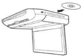
natural_image
Line drawing of a computer monitor with an open lid and button, no text or symbols present- For two-sided DVDs, play one side of the disc to the end, then unload the disc, turn it over and reload it to play the other side.
- If wrong disc, upside-down discs or dirty discs have been inserted, "Bad Disc" is displayed. Press ▲ and eject the disc.
Unloading discs
Press ▲.
Be sure to remove the disc.
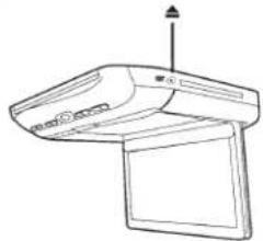
natural_image
Line drawing of a computer monitor with an open screen and indicator lights (no text or symbols)- If the disc is not removed within a few moments, it will be reloaded automatically.
- During ACC OFF or while the disc is being loaded ("LOADING" is displayed), the disc will not be ejected even if you press ▲.
Muting the Audio
Front Control Keys
While the power is ON, press POWER ( ⏻ ) to activate the Mute function.
Press POWER ( ⏻ ) again to turn OFF the Mute function.
Remote Control
Press MUTE to turn it ON and OFF.
Adjusting the Volume
Volume can be controlled from the headphone or your own radio volume function.
1 Turn on POWER on the headphone.
2 Adjust the volume level by turning clockwise for louder and counter-clockwise for lower on the headphone.
- Refer to the "Wireless Headphones" section on page 6 for additional information.
4-EN
Switching the Source
Front Control Keys
1 Press SELECT (☐) to display the Source Select Menu.
2 Press SELECT (☐) again to cycle through the different sources.
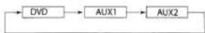
Remote Control
Press DVD, AUX1 or AUX2 to change each source directly.
- OSD (On Screen Display) will turn OFF automatically after 5 seconds without use.
- When the source is changed, the power is turned OFF or the ACC is turned OFF, the device remembers the scene where the internal DVD stopped and playback will resume from that point.
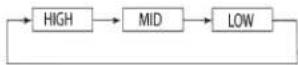
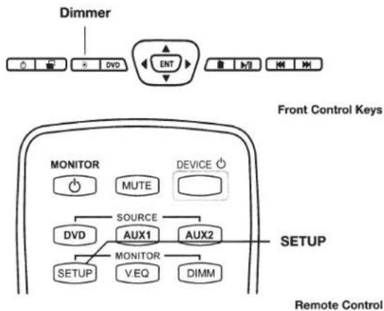
Setting the Backlight Brightness
1 Press Dimmer ( • ) on the Front Control Keys, the DIMM button on the remote control, or select the Backlight tab in the Picture Settings Menu (refer to Monitor Setup instructions page 5).
2 From the Picture Settings menu, press ◀ or ▶ to cycle through High/Mid/Low.
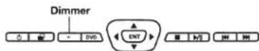
Front Control Keys
Wait 8 seconds until OSD disappears; the adjustment will be saved automatically (if the brightness is adjusted directly using the Dimmer (•) key on the Front Control Keys, the OSD will disappear after 3 seconds)
DVD Control
Press the DVD button on the Front Control Keys to access the DVD Control menu.
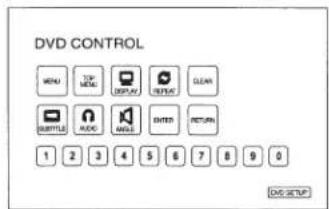
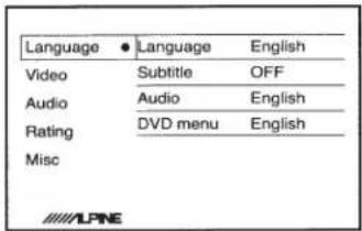
DVD Setup
Press and hold the DVD button or press the DVD Setup button on the DVD Control screen to enter the DVD Setup menu to adjust Language, Video, Audio, Rating and Misc. settings. You may also press and hold the Menu button on the remote control to access the DVD Setup menu.
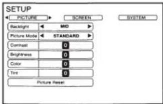
Monitor Setup
Picture Mode, brightness, color, tint and contrast are adjustable.
To access the Settings menus, press and hold the DIMMER ( • ) button on the Front Control Keys for at least 2 seconds and then press ◀ or ▶ to select the Picture Settings, Screen Settings, or System Settings menus.
You may also press the SETUP button on the remote control to access these menus.
Wait 8 seconds until OSD disappears; any adjustments will be saved automatically.
Picture Settings
Setting the Backlight Brightness
Refer to "Setting the Backlight" section on page 5 for detailed instructions.
From the Picture Settings menu, press ◀ or ▶ to cycle through High/Mid/Low.
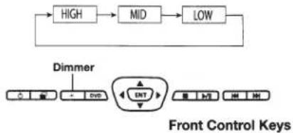
flowchart
graph TD
    A["HIGH"] --> B["MID"]
    B --> C["LOW"]
    D["Dimmer"] --> E["ENT"]
    E --> F["Control Signals"]
    style E fill:#f9f,stroke:#333
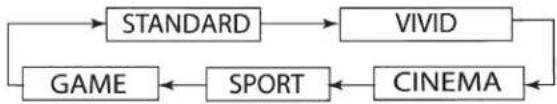
Setting the Picture Mode
To change the Picture Mode, press◀ or ▶ to cycle through the OSD and select from STANDARD, VIVID, CINEMA, SPORT and GAME. (Default: STANDARD)
flowchart
graph TD
    A["STANDARD"] --> B["VIVID"]
    A --> C["GAME"]
    C <--> D["SPORT"]
    D <--> E["CINEMA"]
    B --> E
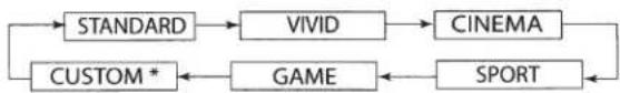
If any of the picture settings (Contrast, Brightness, Color, and Tint) of any mode are adjusted, "CUSTOM" mode will be created and set as the new value.
flowchart
graph LR
    A["STANDARD"] --> B["VIVID"]
    B --> C["CINEMA"]
    C --> D["SPORT"]
    D --> E["GAME"]
    E --> F["CUSTOM *"]
    F --> A
Adjusting the Contrast/Brightness/Color/Tint
Press ▲ or ▼ to select the desired setting.
Press ◀ or ▶ to adjust the chosen setting. Each setting can be adjusted from -7(MIN) to +7(MAX).
Resetting the Picture Settings
Press ▲ or ▼ until "Picture Reset" is selected.
Press ENTER to reset all picture settings to their factory default values. This will only reset the current Source Setting (DVD, AUX 1 or AUX 2).
Screen Settings
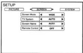
Setting the Screen Mode and TV System
Display mode on the screen can be adjusted to Wide, Cinema or Normal. (Default: WIDE)
- Press ◀ or ▶ to select WIDE/CINEMA/NORMAL
The Video Signal Standard (TV System) can be manually switched.
- Press ◀ or ▶ to select AUTO/NTSC/PAL. (Default: AUTO)
System Setting
The IR transmitter, FM modulator and frequency can be adjusted for all available sources.
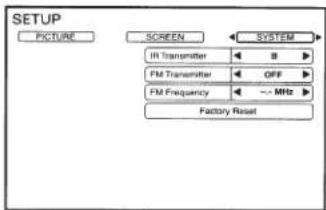
Setting the IR Transmitter
Press ◀ or ▶ to select A/B/OFF. (Default: A)
CHANNEL A : 2.3 MHz/ 2.8 MHz
CHANNEL B : 3.2 MHz/ 3.8 MHz
Setting the FM Modulator
Press ◀ or ▶ to select FM Radio region
(OFF/USA/OTHERS). (Default: OFF)
Setting the FM Frequency
Press ◀ or ▶ to select desired FM Radio
Frequencies between 88.1 MHz to 92.1 MHz.
(Default: 89.1 MHz)
USA frequency step is 0.2MHz and other countries is 0.1MHz.
Resetting to the Factory Default
Press ENTER Key, the system changes to Factory Default System Setting. Entire settings include Picture, Picture Mode, Display Mode are also reset DVD Setup values will not be affected.
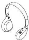
Wireless Headphones
Headphone Receivers
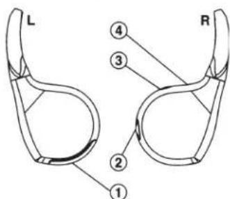
1) Battery Cover
2) Volume Control
3) Power Switch
4) Power Indicator LED
Operation
Read carefully to prevent damage to the headphone or your ears:
WARNING: Before turning on the power, remove headphones and turn the volume down as low as possible.
1) Be sure the batteries are properly installed in the headphones.
2) Turn the headphones volume completely cown before placing it on your ears and turning on the power.
3) Turn on the headphone power and adjust the headphone volume to a comfortable level (You can increase the audio source volume if needed).
Battery Installation
Place two AAA batteries into the battery compartment of the headphone(s), making sure that the battery polarity is correct.
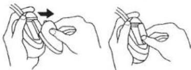
natural_image
Two hand-drawn diagrams showing a finger manipulation technique (no text or symbols)Note
If ACC or the monitor's power source is turned off, a loud noise is produced through the headphones. Be sure to remove the wireless headphones from your ears before you turn the monitor off.
Accessories
Check accessory parts.
RUE-4159 Universal Remote Control
SHS-N106 Single Source Fold -Flat Wireless Headphone
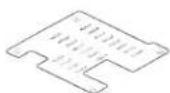
Installation Bracket*1
X2
Screws (for Trim Ring)
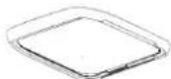
Trim Ring
Screws (for Installation Bracket)


×4
X5
Quick Start Guide, Installation Manual, Registration Card
AAA Battery
FM Switching Box

Sold Separately
×6
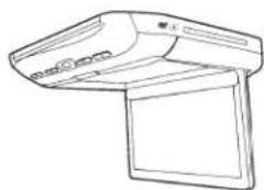
TMX-R3300DVD Overhead Monitor
Wireless Transmitter Wire
natural_image
Line drawing of a flat-screen computer with ventilation slots and screen (no text or symbols)
Left side
interchangeable
cover
Rear
interchangeable
cover
Top
interchangeable
cover
Right side
interchangeable
cover

×3
×3
×3
×3
(Black, Gray and Tan colored covers)
Specifications
Video Display System NTSC/PAL Compatibility
DISPLAY SCREEN
| Size | 10.1" |
| Width | 221mm (8.70") |
| Height | 132mm (5.20") |
| Aspect Ratio | 16:9 |
| Type Transparent type TN | |
| Liquid Crystal Display | |
| System | TFT-LCD, Active Matrix |
| Number of Elements | 1024(W) x 600(H) x 3 |
| 1.84M Pixels (WSVGA) | |
| Effective Number of Elements | 99.9% or more |
| Back Light | LED |
GENERAL
| Operating Voltage | 10 - 16 V DC(Typical: 12V) |
| Power Consumption | 2.35A (MAX)1.60A (TYP)140mA (Stand by) |
| Video Input | 1.0V p-p 75ohm |
| Audio Input | 2.0V rms (max) |
| IR Transmitter | CH A: 2.3MHz / 2.8MHzCH B: 3.2 MHz / 3.8MHz |
| FM Modulator | 88.1MHz - 92.1MHzPLL FrequencySynthesizer |
| Operating Temperature | -4 °F to +158 °F (-20 °Cto + 70 °C) |
MONITOR
| Width | 290 mm (11.42") |
| Depth | 290 mm (11.42") |
| Height (LCD Panel Closed) | 45 mm (1.7") |
| Height (LCD Panel Open) | 204.2 mm (8.04") |
| Weight | 2.270 Kg (5.0lbs) |
Note
For more detailed information or instructions about how to use the PKG-RSE3DVD, please visit Alpine's web site to download the complete Owner's Manual.

Manufactured under license from Dolby Laboratories. Dolby and the double-D symbol are trademarks of Dolby Laboratories.
This product incorporates copyright protection technology that is protected by U.S. patents and other intellectual property rights. Use of this copyright protection technology must be authorized by Rovi Corporation, and is intended for home and other limited viewing uses only unless otherwise authorized by Rovi Corporation. Reverse engineering and disassembly are prohibited.
ALPINE®
DVD Entertainment System
PKG-RSE3DVD
INSTALLATION MANUAL

DOLBY.
DIGITAL


Please read before installing this equipment.
MANUAL DE OPERACIÓN
Torrance, California 90501 U.S.A.
Tel.: 1-800-ALPINE-1 (1-800-257-4631)
ALPINE ELECTRONICS (BENELUX) GmbH
Leuvensesteenweg 510-B6,
1930 Zaventem, Belgium
Tel.: 02-725 1315
ALPINE ELECTRONICS OF AUSTRALIA PTY, LTD.
161-165 Princess Highway, Hallam
Victoria 3803, Australia
Tel.: 03-8787-1200
ALPINE ELECTRONICS GmbH
Fletchamstead Highway, Coventry CCV4 9TW, U.K.
Tel.: 0870-33 33 763
ALPINE ELECTRONICS FRANCE S.A.R.L.
(RCS PONTOISE B 338 101 280)
- Rue de la Belle Etoile, Z.I. Paris Nord II,
B.P. 50016, 95945 Roissy Charles de Gaulle
Cedex, France
Tel.: 01-48638989
Designed by Alpine Electronics of America, Inc.
Printed In China
Installation and Connections
Before installing or connecting the unit, please read the following thoroughly for proper use.

Warning
MAKE THE CORRECT CONNECTIONS.
Failure to make the proper connections may result in fire or product damage.
USE ONLY IN CARS WITH A 12 VOLT NEGATIVE GROUND.
(Check with your dealer if you are not sure.) Failure to do so may result in fire, etc.
BEFORE WIRING, DISCONNECT THE CABLE FROM THE NEGATIVE BATTERY TERMINAL.
Failure to do so may result in electric shock or injury due to electrical shorts.
DO NOT ALLOW CABLES TO BECOME ENTANGLED IN SURROUNDING OBJECTS.
Arrange wiring and cables in compliance with the manual to prevent obstructions when driving. Cables or wiring that obstruct or hang up on places such as the steering wheel, gear lever, brake pedals, etc., can be extremely hazardous.
DO NOT SPLICE INTO ELECTRICAL CABLES.
Never cut away cable insulation to supply power to other equipment. Doing so will exceed the current carrying capacity of the wire and result in fire or electric shock.
DO NOT DAMAGE PIPE OR WIRING WHEN DRILLING HOLES.
When drilling holes in the chassis for installation, take precautions so as not to contact, damage or obstruct pipes, fuel lines, tanks or electrical wiring. Failure to take such precautions may result in fire.
DO NOT USE BOLTS OR NUTS IN THE BRAKE OR STEERING SYSTEMS TO MAKE GROUND CONNECTIONS.
Bolts or nuts used for the brake or steering systems (or any other safety-related system), or tanks should NEVER be used for installations or ground connections. Using such parts could disable control of the vehicle and cause fire, etc.
KEEP SMALL OBJECTS SUCH AS BATTERIES OUT OF THE REACH OF CHILDREN.
Swallowing them may result in serious injury. If swallowed, consult a physician immediately.
DO NOT INSTALL IN LOCATIONS WHICH MIGHT HINDER VEHICLE OPERATION, SUCH AS THE STEERING WHEEL OR SHIFT LEVER.
Doing so may obstruct forward vision or hamper movement, etc., and result in a serious accident.
CAUTION
CAUTION-Laser radiation when open, DO NOT STARE INTO BEAM

Caution
HAVE THE WIRING AND INSTALLATION DONE BY EXPERTS.
The wiring and installation of this unit requires special technical skill and experience. To ensure safety, always contact the dealer where you purchased this product to have the work done.
USE SPECIFIED ACCESSORY PARTS AND INSTALL THEM SECURELY.
Be sure to use only the specified accessory parts. Use of other than designated parts may damage this unit internally or may not securely install the unit in place. This may cause parts to become loose resulting in hazards or product failure.
ARRANGE THE WIRING SO IT IS NOT CRIMPED OR PINCHED BY A SHARP METAL EDGE.
Route the cables and wiring away from moving parts (like the seat rails) or sharp or pointed edges. This will prevent crimping and damage to the wiring. If wiring passes through a hole in metal, use a rubber grommet to prevent the wires insulation from being cut by the metal edge of the hole.
DO NOT INSTALL IN LOCATIONS WITH HIGH MOISTURE OR DUST.
Avoid installing the unit in locations with high incidence of moisture or dust. Moisture or dust that penetrates into this unit may result in product failure.
Precautions
- Be sure to disconnect the cable from the (-) battery post before installing your PKG-RSE3DVD. This will reduce any chance of damage to the unit in case of a short-circuit.
- Be sure to connect the color coded leads according to the diagram. Incorrect connections may cause the unit to malfunction or damage to the vehicle's electrical system.
- When making connections to the vehicle's electrical system, be aware of the factory installed components (e.g. on-board computer). Do not tap into these leads to provide power for this unit. When connecting the PKG-RSE3DVD to the fuse box, make sure the fuse for the intended circuit of the PKG-RSE3DVD has the appropriate amperage. Failure to do so may result in damage to the unit and/or the vehicle. When in doubt, consult your ALPINE dealer.
- The PKG-RSE3DVD uses female RCA-type jacks for connection to other units (e.g. AV head unit) having RCA connectors. You may need an adaptor to connect other units. If so, please contact your authorized ALPINE dealer for assistance.
IMPORTANT
Please record the serial number of your unit in the space provided below and keep it as a permanent record. The serial number plate is located on the bottom of the unit.
SERIAL NUMBER:
INSTALLATION DATE:
INSTALLATION TECHNICIAN:
PLACE OF PURCHASE:
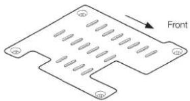
Installing the Overhead Monitor
1 Install the metal installation bracket to the ceiling.
4 screws will be used to attach the bracket to the ceiling. The protruding screw holes should be facing down, away from the ceiling. Ensure that the bracket is affixed to the roof supports behind the headliner and exercise caution to avoid drilling into the roof of the vehicle.
natural_image
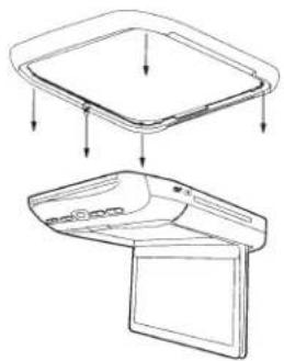
Isometric view of a mechanical component with notches and mounting holes, labeled 'Front' (no text or symbols on the part itself)2 Install the top interchangeable color cover.
Open the monitor lid.
Attach the cover to the monitor from the front (side facing the panel open button).
Push the sides of the cover into place.
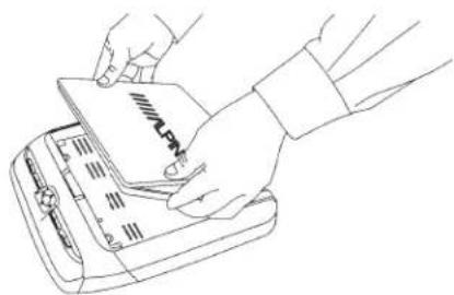
natural_image
Line drawing of hands inserting a card into a notebook (no text or symbols)Close the monitor lid and push the back of the cover into place.
natural_image
Line drawing of a hand pressing down on a device component (no text or symbols)3 Install both side panels of the interchangeable color covers.
Align and insert the notches on the panels into the grooves on the monitor body.
Slide the cover in the direction towards the front control keys at the front of the unit and snap the notch into place. A click should be heard.
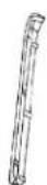
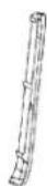
Optional
Install trim ring before attaching the overhead monitor to the metal installation bracket.
natural_image
Technical line drawing of a device with two views: top shows a rectangular tray, bottom shows a flat panel (no text or symbols)Trim Ring is used to make the monitor suitable to your vehicles ceiling shape at the time of installing the monitor. Ask ALPINE dealer for detail.
Screw the shroud to the monitor body using the provided screws.
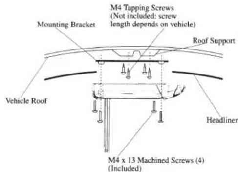
4 Install the overhead monitor to the ceiling.
Connect the cables and then install 4 screws to the metal installation bracket.
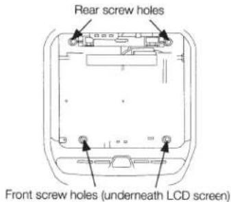
natural_image
Technical line drawing of a mechanical assembly with mounting brackets and support columns (no text or symbols)(Left rear screw not illustrated)

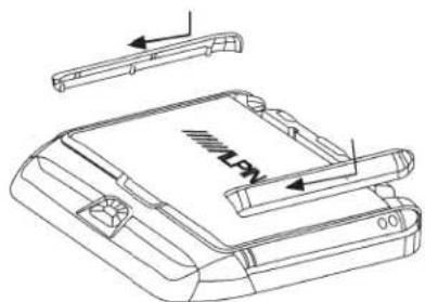
5 Install the rear interchangeable color cover.
Align the openings on the cover with the rear button panel. Press down firmly to snap the cover into place. Ensure that all notches have gone into their grooves properly.
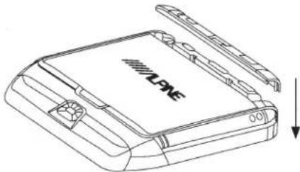
natural_image
Line drawing of a device with a labeled 'LONE' and an arrow indicating downward motion (no text or symbols beyond the label)Removing Interchangeable Color Cover
1 Remove the rear interchangeable color cover.
Reach across the monitor body and grasp the rear panel.
Gently lift the panel until it snaps off from the body
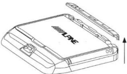
natural_image
Line drawing of a device with a labeled 'LIVE' on the cover and an upward arrow indicating motion (no text or symbols beyond label)2 Remove both side panels of the interchangeable color covers.
Grasp side cover as illustrated.
Raise the corner touching the rear control panel a few millimeters and gently slide the cover out.
Do not immediately lift the cover before sliding it. The notches will be damaged.
A small flat screwdriver or similar tool can be used to raise the corner of the panel.
natural_image
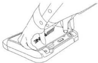
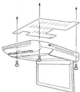
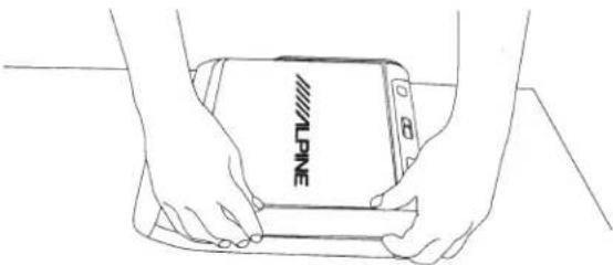
Line drawing of two hands holding a smartphone with 'WLPINE' branding (no additional text or symbols)3 Remove the top interchangeable color cover.
Exercise caution when removing the top plate.
- The LCD screen must be closed during removal.
- Begin removal from the rear of the panel (side facing the 3 button panel).
- Removal by hand or by using soft tools is recommended as hard tools may scratch the panel surface.
- Grasp the cover by the indentations and pull gently until the cover snaps off from the LCD screen.

natural_image
Line drawing of two hands holding a device with 'VLANE' branding on the cover (no text or symbols beyond branding)Connections
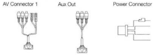
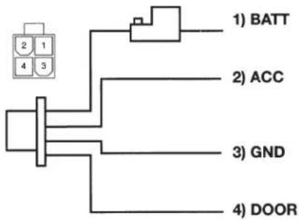
Power Connector
flowchart
graph TD
    A["2 1 4 3"] --> B["BATT"]
    A --> C["ACC"]
    A --> D["GND"]
    A --> E["DOOR"]
ALPINE's PKG-RSE3DVD needs the following power connections to assure proper operation of the monitor.
| Yellow | Battery LeadConnect this lead to the positive (+) post of the vehicle's battery. |
| Red | ACCConnect this line to the vehicle's ACC line.(Switched 12V, ignition) |
| Black | GNDConnect this line to the vehicle's GND line. |
| Green | DoorConnect this lead to the vehicle door(polarity selectable, see following page) |
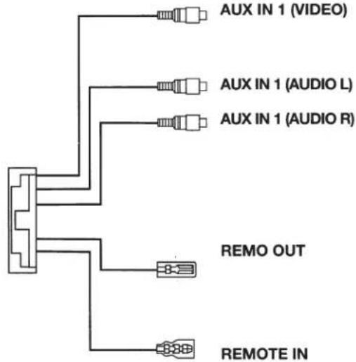
AV Connector 1
flowchart
graph TD
    A["AUX IN 1 (VIDEO)"] --> B["Resistor"]
    C["AUX IN 1 (AUDIO L)"] --> D["Resistor"]
    E["AUX IN 1 (AUDIO R)"] --> F["Resistor"]
    G["REMO OUT"] --> H["Resistor"]
    I["REMOTE IN"] --> J["Resistor"]
| Yellow | Video Input ConnectorConnects to the video output of other video products. |
| White (L)Red (R) | Audio Input ConnectorsConnects to the audio output of other video products. |
| White/Brown | Remote OutTo control ALPINE DVD player, TV tuner or AV head unit, connect to each REMOTE IN. |
| White/Brown | Remote InTo control ALPINE PKG-RSE3DVD from AV head unit in the front area of the vehicle, connect this line to the ALPINE DVD-HU or LCD monitor REMOTE OUT. |
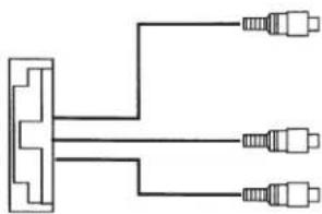
AV Connector 2
natural_image
Pure electrical circuit lines without any symbols| AUX OUT (VIDEO) | Yellow | • Video Output ConnectorConnects to the video inputs of other video products. |
| AUX OUT (AUDIO L) | White (L) | • Audio Output ConnectorsConnects to the audio inputs of other audio or video products. |
| AUX OUT (AUDIO R) | Red (R) |
Mount Side
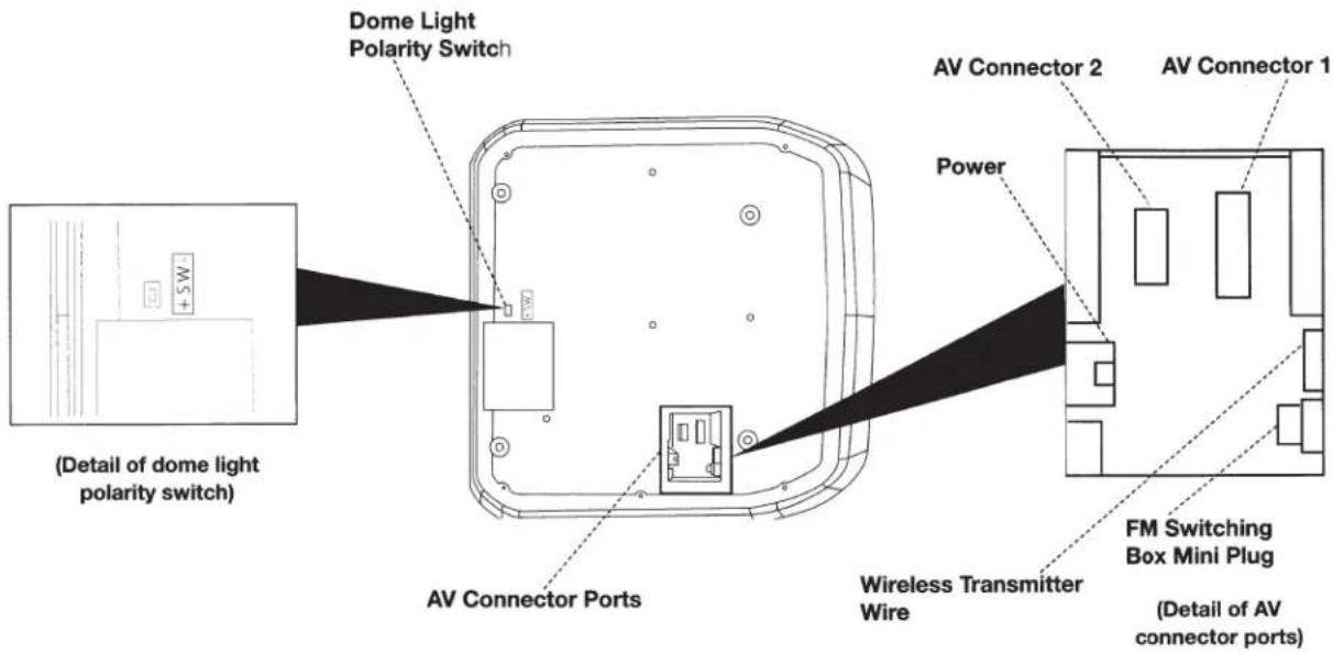
Dome Light Wire
Dome light wire connects the built-in dome light to the cable from the vehicle's dome light Switch. Polarity change switch is located on the top surface that mounts into the headliner.
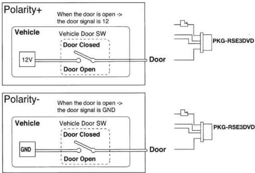
Vehicle door polarity depends on the vehicle type. The polarity can be changed by the "Door SW polarity" switch. (Default: Negative Switched System)
Polarity +: When door open, door signal is 12V Polarity -: When door open, door signal is GND
flowchart
graph TD
    A["12V"] --> B["Door Closed"]
    B --> C["Door Open"]
    D["Polarity+"] --> E["When the door is open --> the door signal is 12"]
    F["Polarity-"] --> G["When the door is open --> the door signal is GND"]
    H["Vehicle"] --> I["Vehicle Door SW"]
    I --> J["Door Closed"]
    J --> K["Door Open"]
    L["PKG-RSE3DVD"] --> M["Output"]
    N["PKG-RSE3DVD"] --> O["Output"]
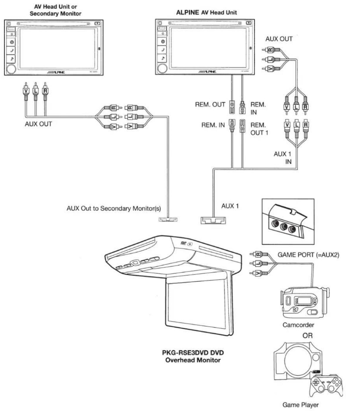
System Connections
flowchart
graph TD
    A["AV Head Unit or Secondary Monitor"] --> B["AUX OUT"]
    C["ALPINE AV Head Unit"] --> D["AUX OUT to Secondary Monitor(s)"]
    D --> E["AUX 1"]
    E --> F["PKG-RSE3DVD DVD Overhead Monitor"]
    F --> G["Game Port (=AUX2)"]
    F --> H["Camcorder OR"]
    F --> I["Game Player"]
POWER CONNECTOR
natural_image
Technical line drawing of a mechanical assembly with a checkmark and dashed outline (no text or symbols)DO NOT ALLOW THE MOUNTING SURFACE TO CONTACT THE POWER CONNECTOR. PRESSURE APPLIED TO THIS CONNECTOR WILL RESULT IN DAMAGE TO THE UNIT.
Mounting the unit directly to a hard, flat surface (as shown above) can result in permanent, irreparable damage to the unit and its power connector.
The power connector protrudes slightly from the monitor body. Pressure from the mounting surface is transferred to this connector causing damage to the connector and to its mounting location on the circuit board.
Always mount the unit using the metal mounting bracket and trim ring, if possible, in order to avoid causing damage to the power connector.
If the metal bracket and shroud cannot be used, ensure that the surface to which the unit is affixed has a large enough opening to avoid contact with the power connector.
SPANISH

- WARNING
- DO NOT WATCH VIDEO WHILE DRIVING.
- DO NOT OPERATE ANY FUNCTION THAT TAKES YOUR ATTENTION AWAY FROM SAFELY DRIVING YOUR VEHICLE.
- KEEP THE VOLUME AT A LEVEL WHERE YOU CAN STILL HEAR OUTSIDE NOISE WHILE DRIVING.
- MINIMIZE DISPLAY VIEWING WHILE DRIVING.
- DO NOT DISASSEMBLE OR ALTER.
- USE ONLY IN CARS WITH A 12 VOLT NEGATIVE GROUND.
- KEEP SMALL OBJECTS SUCH AS BATTERIES OUT OF THE REACH OF CHILDREN.
- USE THE CORRECT AMPERE RATING WHEN REPLACING FUSES.
- DO NOT BLOCK VENTS OR RADIATOR PANELS.
- USE THIS PRODUCT FOR MOBILE 12V APPLICATIONS.
- DO NOT PLACE HANDS, FINGERS OR FOREIGN OBJECTS IN INSERTION SLOTS OR GAPS.
- INSTALL THE PRODUCT CORRECTLY SO THAT THE DRIVER CANNOT WATCH TV/VIDEO UNLESS THE VEHICLE IS STOPPED AND THE EMERGENCY BRAKE IS APPLIED.
- CAUTION
- HALT USE IMMEDIATELY IF A PROBLEM APPEARS.
- DO NOT MIX NEW BATTERIES WITH OLD BATTERIES. INSERT WITH THE CORRECT BATTERY POLARITY.
- PRECAUTIONS
- Product Cleaning
- Temperature
- Moisture Condensation
- Damaged Disc
- Maintenance
- Characteristics of LCD Panel
- Using Wireless Headphones
- Never Attempt the Following
- Getting Started
- LCD Monitor Panel
- Panel Open Button
- White LED Dome Light
- Front Control Keys
- Front Passenger Control Buttons
- Dome Light Switch
- IR Transmitter and Receiver
- Eject Button
- Turning Power ON/OFF
- Remote Control
- Front Passenger Controls
- Loading and Unloading Discs
- Loading discs
- Unloading discs
- Press ▲.
- Muting the Audio
- Adjusting the Volume
- 4-EN
- Switching the Source
- Setting the Backlight Brightness
- DVD Control
- DVD Setup
- Monitor Setup
- Picture Settings
- Setting the Picture Mode
- Adjusting the Contrast/Brightness/Color/Tint
- Resetting the Picture Settings
- Screen Settings
- Setting the Screen Mode and TV System
- System Setting
- Setting the IR Transmitter
- Setting the FM Modulator
- Setting the FM Frequency
- Resetting to the Factory Default
- Wireless Headphones
- Headphone Receivers
- Operation
- Battery Installation
- Note
- Accessories
- Specifications
- ALPINE®
- DVD Entertainment System
- PKG-RSE3DVD
- INSTALLATION MANUAL
- Installation and Connections
- MAKE THE CORRECT CONNECTIONS.
- BEFORE WIRING, DISCONNECT THE CABLE FROM THE NEGATIVE BATTERY TERMINAL.
- DO NOT ALLOW CABLES TO BECOME ENTANGLED IN SURROUNDING OBJECTS.
- DO NOT SPLICE INTO ELECTRICAL CABLES.
- DO NOT DAMAGE PIPE OR WIRING WHEN DRILLING HOLES.
- DO NOT USE BOLTS OR NUTS IN THE BRAKE OR STEERING SYSTEMS TO MAKE GROUND CONNECTIONS.
- DO NOT INSTALL IN LOCATIONS WHICH MIGHT HINDER VEHICLE OPERATION, SUCH AS THE STEERING WHEEL OR SHIFT LEVER.
- HAVE THE WIRING AND INSTALLATION DONE BY EXPERTS.
- USE SPECIFIED ACCESSORY PARTS AND INSTALL THEM SECURELY.
- ARRANGE THE WIRING SO IT IS NOT CRIMPED OR PINCHED BY A SHARP METAL EDGE.
- DO NOT INSTALL IN LOCATIONS WITH HIGH MOISTURE OR DUST.
- IMPORTANT
- Installing the Overhead Monitor
- Install the metal installation bracket to the ceiling.
- Install the top interchangeable color cover.
- Install both side panels of the interchangeable color covers.
- Optional
- Install the overhead monitor to the ceiling.
- Install the rear interchangeable color cover.
- Removing Interchangeable Color Cover
- Remove the rear interchangeable color cover.
- Remove both side panels of the interchangeable color covers.
- Remove the top interchangeable color cover.
- Connections
- Mount Side
- Dome Light Wire
- System Connections
- SPANISH
Brand : ALPINE
Model : PKG-RSE3DVD
Category : Dash cam