
Thunderbird (1997) - Automotive FORD - Free user manual and instructions
Find the device manual for free Thunderbird (1997) FORD in PDF.


User questions about Thunderbird (1997) FORD
0 question about this device. Answer the ones you know or ask your own.
Ask a new question about this device
Download the instructions for your Automotive in PDF format for free! Find your manual Thunderbird (1997) - FORD and take your electronic device back in hand. On this page are published all the documents necessary for the use of your device. Thunderbird (1997) by FORD.
USER MANUAL Thunderbird (1997) FORD
Your satisfaction is our #1 goal. If you have questions or concerns with your vehicle, we suggest you follow these steps:
- Contact your Sales Representative or Service Advisor at your selling/servicing dealership.
- If the inquiry or concern remains unresolved, contact the Sales Manager or Service Manager at the dealership.
- If the inquiry or concern cannot be resolved at the dealership level, please contact the Ford Customer Assistance Center.
In the United States:
Ford Motor Company
Customer Assistance Center
300 Renaissance Center
P.O. Box 43360
Detroit, MI 48243
1-800-392-3673 (FORD)
TDD for the hearing impaired: 1-800-232-5952
In Canada:
Ford Motor Company of Canada, Limited
Customer Assistance Centre
P.O. Box 2000
Oakville, Ontario L6J 5E4
1-800-565-3673 (FORD)
Outside the U.S. or Canada:
Ford Motor Company
Worldwide Export Operations
1555 Fairlane Drive
Fairlane Business Park #3
Allen Park, Michigan 48101
Telephone: (313) 594-4857
Fax: (313) 390-0804
All rights reserved. Reproduction by any means, electronic or mechanical, including photocopying, recording, or by any information storage and retrieval system or translation in whole or part is not permitted without written authorization from Ford Motor Company.
Copyright © 1996 Ford Motor Company
Table of Contents
Introduction ...... 1
Instrumentation 7
Electronic Sound Systems 25
Controls and Features 59
Seating and Safety Restraints 99
Starting 139
Driving 145
Roadside Emergencies 165
Maintenance and Care 195
Capacities and Specifications 247
Reporting Safety Defects (U.S. Only) 253
Customer Assistance 255
Accessories 267
Quick Index 277
Index 287
Service Station Information 308
Introduction
Ford's Commitment to You
At Ford Motor Company, excellence is the continuous commitment to achieve the best result possible. It is dedication to learning what you want, determination to develop the right concept, and execution of that concept with care, precision, and attention to detail. In short, excellence means being the standard by which others are judged.
Our Guiding Principles
☐Quality comes first. For your satisfaction, the quality of our products and services must be our number one priority.
☐You are the focus of everything we do. Our work must be done with you in mind, providing better products and services than our competition.
☐Continuous improvement is essential to our success. We must strive for excellence in everything we do: in our products — in their safety and value — and in our services, our human relations, our competitiveness, and our profitability.
□Employee involvement is our way of life. We are a team. We must treat one another with trust and respect.
☐Dealers and suppliers are our partners. We must maintain mutually beneficial relationships with dealers, suppliers, and our other business associates.
☐Integrity is never compromised. Our conduct worldwide must be pursued in a manner that is socially responsible and commands respect for its integrity and for its positive contributions to society.
Things to Know About Using This Guide
Congratulations on the purchase of your new vehicle. This guide has information about the equipment and the options for your new vehicle. You may not have bought all of the options available to you. If you do not know which information applies to your vehicle, talk to your dealer.
This guide describes equipment and gives specifications for equipment that was in effect when this guide was approved for printing. Ford may discontinue models or change specifications or design without any notice and without incurring obligation.
NOTES and WARNINGS
NOTES give you additional information about the subject matter you are referencing.
WARNINGS remind you to be especially careful in those areas where carelessness can cause damage to your vehicle or personal injury to yourself, your passengers or other people. Please read all WARNINGS carefully.
| ⚠ WARNING |
Finding Information in This Guide
After you have read this guide once, you will probably return to it when you have a specific question or need additional information. To help you find specific information quickly, you can use the Quick Index or the Index.
The Quick Index at the end of the book provides a page number following each item which indicates where detailed information can be found.
To use the Index, turn to the back of the book and search in the alphabetical listing for the word that best describes the information you need. If the word you chose is not listed, think of other related words and look them up. We have designed the Index so that you can find information under a technical term.
Canadian Owners — French Version
French Owner Guides can be obtained from your dealer or by writing to Ford Motor Company of Canada, Limited, Service Publications, P.O. Box 1580, Station B, Mississauga, Ontario L4Y 4G3.
Your Maintenance Schedule and Record Booklet
The Maintenance Schedule booklet lists the services that are most important for keeping your vehicle in good condition. A record log is also provided to help you keep track of all services performed.
About the Warranties
Your vehicle is covered by three types of warranties: Basic Vehicle Warranty, Extended Warranties on certain parts, and Emissions Warranties.
Read your Warranty Information Booklet carefully to find out about your vehicle's warranties and your basic rights and responsibilities.
If you lose your Warranty Information Booklet, you can get a new one free of charge. Contact any Ford or Lincoln-Mercury dealer, or refer to the addresses and phone numbers on the first page of this Owner's Guide.
Ford Extended Service Plan
More Protection for Your Vehicle
You can get more protection for your new car or light truck by purchasing a Ford Extended Service Plan (Ford ESP). Ford ESP is the only extended service program with the Ford name on it and the only service contract backed by Ford Motor Company.
Ford ESP is an optional service contract, backed and administered by Ford. It provides:
□protection against repair costs after your Bumper to Bumper Warranty expires;
and
☐other benefits during the warranty period (such as: reimbursement for rentals; coverage for certain maintenance and wear items).
You may purchase Ford ESP from any participating Ford Motor Company dealer. There are several Ford ESP plans available in various time-and-mileage combinations. Each plan can be tailored to fit your own driving needs, including reimbursement benefits for towing and rental. (In Hawaii, rules vary. See your dealer for details.)
When you buy Ford ESP, you receive peace-of-mind protection throughout the United States and Canada, provided by a network of more than 5,100 participating Ford Motor Company dealers.
NOTE: Repairs performed outside the United States and Canada are not eligible for ESP coverage.
This information is subject to change. Ask your dealer for complete details about Ford ESP coverage.
Breaking Your Vehicle In
Your new vehicle goes through an adjustment or break-in period during the first 1,000 miles (1,600 km) that you drive it. During the break-in period, you need to pay careful attention to how you drive your vehicle.
☐ Avoid sudden stops. Because your vehicle has new brake linings, you should take these steps:
— Watch traffic carefully so that you can anticipate when to stop.
— Begin braking well in advance.
— Apply the brakes gradually.
The break-in period for new brake linings lasts for 100 miles (160 km) of city driving or 1,000 miles (1,600 km) of highway driving.
☐ Use only the type of engine oil that Ford recommends. See Engine oil recommendations in the Index. Do not use special “break-in” oils.
Your vehicle is equipped with an Electronic Powertrain Control Module that limits engine and/or vehicle speeds with a cut-out mode to promote durability.
The instrument panel

text_image
Lights Turn signal and wiper control Speed control Driver-side air bag Ashtray Radio Horn Cluster switch Rear window defrost system Climate control Clock Passenger-side air bagInstruimentation
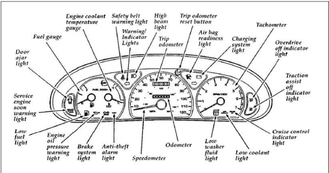
The instrument panel (dashboard) on your vehicle is divided into several different sections. The illustrations on the following pages show the major parts of the instrument panel that are described in this chapter. Some items shown may not be on all vehicles.
In your vehicle, the warning lights and gauges are grouped together on the instrument panel. We call this grouping a cluster.
Mechanical cluster
text_image
Fuel gauge Door ajar light Service engine soon warning light Low fuel light Engine oil pressure warning light Engine coolant temperature gauge Brake system light Anti-theft alarm light Safety belt warning light Warning/Indicator Lights High beam light Trip odometer Trip odometer reset button Air bag readiness light Charging system light Tachometer Overdrive off indicator light Traction assist off indicator light Cruise control indicator light Odometer Low washer fluid light Low coolant light SpeedometerThe Mechanical Cluster
The following warning lights and gauges are on the mechanical cluster. All of the warning lights and gauges alert you to possible problems with your vehicle. Some of the lights listed are optional. The following sections detail what each of these indicators means.
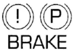
Brake System Warning Light
The warning light for the brakes can show two things — that the parking brake is not fully released, or that the brake fluid level is low in the master cylinder reservoir. If the fluid level is low, the brake system should be checked by a qualified service technician.
text_image
! P BRAKEThe brake system warning light
This light comes on when the parking brake is set, or if it is not set, it comes on briefly when you turn the ignition key to START. It normally goes off shortly after the engine starts and you release the parking brake. If the light stays on after you have fully released the parking brake, have the hydraulic brake system serviced.
⚠ WARNING
The BRAKE light indicates that the brakes may not be working properly. Have the brakes checked immediately.
Anti-Lock Brake System Light (If equipped)
This warning light will go on each time you start your vehicle. If it remains on for longer than five seconds, you should shut off your engine and restart. If the anti-lock brake light stays on, this indicates that the anti-lock feature is disabled and should receive immediate attention by a qualified service technician. Normal braking is not affected unless the brake warning light is also lit.
The Anti-Lock Brake System has self-check capabilities. As previously described, the system turns on the anti-lock light each time you start your engine. After the engine is started and the anti-lock light is out, the system performs another test the first time the vehicle reaches 14 mph (22 km/h). The system turns on the Anti-Lock Brake System (ABS) pump motor for approximately 1/2 second. At this time a mechanical noise may be heard. This is a normal part of the self-check feature. If a malfunction is found during this check the anti-lock light will come on.
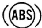
The anti-lock brake system light
⚠ WARNING
If the anti-lock brake system warning light remains on or comes on while driving, have the braking system checked by a qualified service technician as soon as possible.
NOTE: If a fault occurs in the anti-lock system, and the brake warning light is not lit, the anti-lock system is disabled but normal brake function remains operational.
Safety Belt Warning Light and Chime
This warning light and chime remind you to fasten your safety belt. The following conditions will take place:
☐If the safety belt is not buckled when the key is turned to the ON position, the light will come on for 1 to 2 minutes and the chime will sound for 4 to 8 seconds.
☐If the safety belt is buckled while the light is on and the chime is sounding, both the light and chime will turn off.
☐If the safety belt is buckled before the key is turned to the ON position, the light will not come on and the chime will not sound.

The safety belt warning light
Air Bag Readiness Light
The air bag system uses a readiness light and a tone to indicate the condition of the system. The readiness light is in the instrument cluster. When you turn the ignition key to the ON position, this light will light up for six (6) seconds and then turn off. This indicates that the system is operating normally. NOTE: Regularly scheduled maintenance of the air bag system is not required.
If the light fails to illuminate, continues to flash, remains on, or you hear a beeping sound, have the system serviced at your Ford or Lincoln-Mercury dealer immediately.

The air bag readiness light
Low Coolant Light
This light tells you that the coolant is low inside the coolant recovery bottle and that you should add more coolant.
This light comes on for a few seconds when your ignition key is turned to start, but should turn off when the engine starts. If this light stays on, check the level of coolant inside the recovery bottle. See Engine Coolant in the Index.
LOW COOLANT
The low coolant light
Charging System Light
This light indicates that your battery is not being charged and that you need to have the electrical system checked.
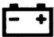
The charging system light
This light illuminates every time you turn the ignition to the ON or START position (engine off). The light should go off when the engine starts and the alternator begins to charge.
If the light stays on or illuminates when the engine is running, have the electrical system checked as soon as possible.
Overdrive Off Indicator
O/D OFF
The overdrive off indicator light
This light tells you that the Transmission Control Switch (TCS) has been pushed. When the light is on, the transmission will not shift into overdrive. Depressing the button will return the vehicle to "overdrive on" mode. The transmission will be in the "overdrive on" mode when the vehicle is started even if the O/D OFF mode was selected when the vehicle was last shut off.
NOTE: If the light does not come on when the TCS is depressed or if the light flashes when you are driving, have your vehicle serviced at the first opportunity. If this condition persists, damage could occur to the transmission.
Traction Assist Off Indicator

The traction assist off indicator
This light comes on when the Traction Assist system has been turned off.
High Beam Light
This light illuminates when the headlamps are turned to high beam or when you flash the lights.

The high beam light
Service Engine Soon Warning Light
This light illuminates when the engine's Emission Control System requires service. It will also illuminate when the ignition key is in the ON position and the engine is off.
The service engine soon warning light
Anti-Theft Alarm Light (If equipped)
THEFT
Anti-theft alarm light
This light is used when you set the anti-theft alarm system. See Anti-Theft System in the Controls and Features chapter for more information.
Turn Signal Indicator Lights
The turn signal arrow will flash to indicate the direction in which you are going to be turning.

The turn signal indicator light
Cruise Control Indicator Light
This light comes on when the cruise control system is actively maintaining the set speed. It will go off when the brakes are used or if the cruise control is turned off.
CRUISE ON
The cruise control indicator light
This light does not indicate any problems but is only a convenience to tell when the cruise control is active.
Door Ajar Light (If equipped)
This light tells you when any door is not completely shut. It glows when the key is in the ON position.
The door ajar light
Engine Oil Pressure Light
This light indicates the engine oil pressure, not the oil level. However, if your engine's oil level is low, it could affect the oil pressure. The light should come on every time your ignition key is turned to ON or START, and should go out when the engine starts. If the light stays on or turns on while the engine is running, you have lost oil pressure and continued operation will cause severe engine damage.
natural_image
Simple line drawing of a cooking pot with a lid and handle (no text or symbols)The engine oil pressure light
If you lose engine oil pressure:
- Pull off the road as soon as safely possible.
-
Shut off the engine immediately. If you do not stop the engine as soon as safely possible, severe engine damage could result.
-
Check the engine's oil level, following the instructions on checking and adding engine oil, see Engine Oil in the Index. If you do not follow these instructions, you or others could be injured. To assure an accurate reading, your vehicle should be on level ground.
- If the level is low, add only as much oil as necessary before you start the engine again. Do not overfill. Do not operate the engine if the light is on, regardless of the oil level. Contact your nearest dealer for service as soon as possible.
For more information about adding oil, see Adding engine oil in the Maintenance and Care chapter of this guide.
Low Fuel Light
This light comes on when your fuel gauge indicates approximately 1/8 to 1/16 of a tank. Your vehicle must be turned to ON for this light to come on. This light will either flicker or glow steadily.
The low fuel light
Washer Fluid Low Light
This light comes on if the reservoir is less than a quarter full when you turn on the windshield washers.
The washer fluid low light
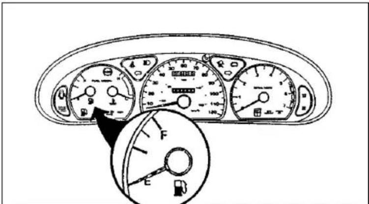
Fuel Gauge
text_image
Diagram of a car dashboard with labeled gauges and fuel gauge, showing front and side views with Chinese labels.The fuel gauge
The fuel gauge displays approximately how much fuel is in the fuel tank only when the ignition switch is ON. For proper fuel gauge indication after adding fuel, turn the ignition switch OFF while refueling the vehicle.
The fuel gauge indicator may vary slightly when the vehicle is in motion. The most accurate reading is obtained with the vehicle on level ground.
With ignition switch OFF, the fuel gauge indicator may drift from the ignition switch ON position.
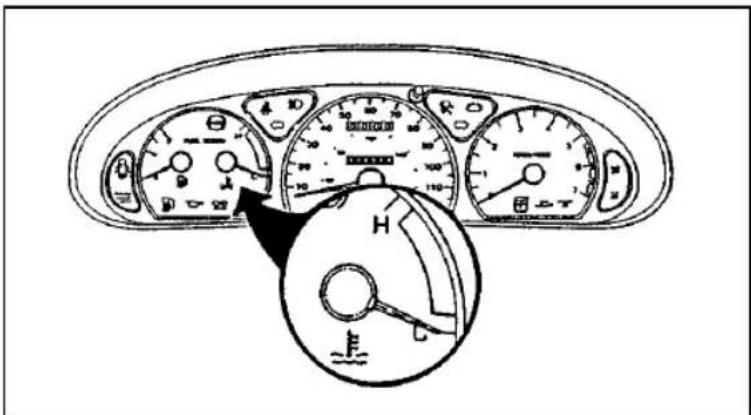
Engine Coolant Temperature Gauge
This gauge indicates the temperature of the engine coolant, not the coolant level. If the coolant is not at its proper level or mixture, the gauge indication will not be accurate.
The pointer moves from the C (cold) mark into the normal band as your engine coolant warms up. Under normal driving conditions, the pointer should stay in the normal band. It is acceptable for the pointer to fluctuate within the normal band under normal driving conditions, and under certain driving conditions such as, heavy stop and go traffic, or driving up hills in hot weather, for the pointer to indicate at the top of the normal band.
If, under any circumstances, the pointer moves above the normal band, the engine is overheating and continued operation may cause engine damage.
text_image
Diagram of car dashboard with labeled gauges and a hand valve, showing speedometer readings and control buttons.The engine coolant temperature gauge
If your engine overheats:
- Pull off the road as soon as safely possible.
- Turn off the engine.
- Let the engine cool. DO NOT REMOVE COOLANT SYSTEM FILL CAP UNTIL THE ENGINE IS COOL.
- Check the coolant level following the instructions on checking and adding coolant to your engine, see Engine Coolant in the Index. If you do not follow these instructions, you or others could be injured.
If the coolant continues to overheat, have the coolant system serviced.
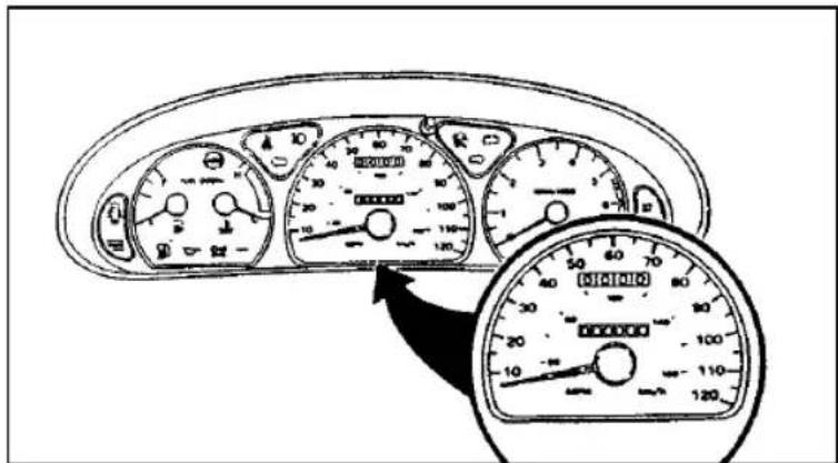
Speedometer
text_image
Diagram of a car dashboard with multiple gauges and a magnified view showing the front view of the dashboard.The speedometer
The speedometer tells you how many miles (kilometers) per hour your vehicle is moving.
Odometer
The odometer tells you the total number of miles (kilometers) your vehicle has been driven.
Trip Odometer
If you want to track your mileage up to 999.9 miles (kilometers), use the trip odometer. Simply set the trip odometer to zero by pressing the reset control firmly when beginning the distance you wish to measure.
Since the trip odometer displays distance independent of the odometer it will not always advance to the next mile (kilometer) at the same time as the odometer.
Tachometer
text_image
RPMa1000The tachometer
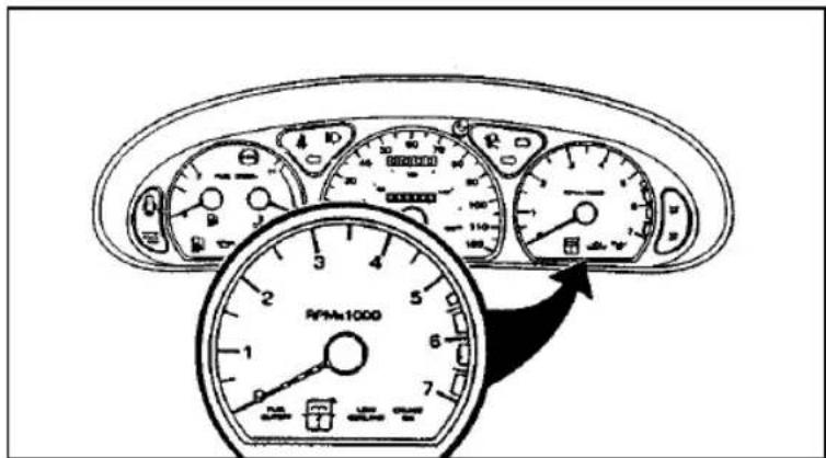
The tachometer displays the approximate engine revolutions per minute (rpm), or how fast the engine is running.
You can drive your vehicle at most rpm points on the tachometer but you must stay out of the red zone.
Regardless of the type of transmission in your vehicle, if you drive with the tachometer pointer in the red zone, you may damage the engine.
Compact Disc Radio
text_image
Paper Elect Compression AM/FM Automatic preset Disc door Display Reverse Play stop Fast forward Volume Audio Power EJECT COMP AM/FM AUDIO AUTO Preset AUTOMATIC DNR 1 2 3 4 5 6 REVIEW FF SCAN TUNE SEEK Scan tune Memory preset buttons VolumeElectronic Sound Systems
Compact Disc Radio
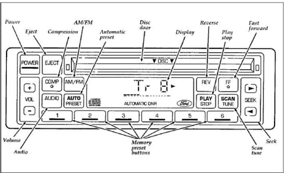
The Compact Disc Radio combines the Electronic Stereo Radio with the Ford Compact Disc Player.
Using the Controls on Your New Compact Disc Radio
Most of the features of this unit work for both radio and CD operation. Also, some of the knobs and buttons control several different functions, so be sure to read all of the operating instructions carefully.
How to turn the radio on and off
Press the "POWER" button to turn the radio on. Press it again to turn it off.
How to adjust the volume
Press the (+/−) side of the “VOL” button to increase/decrease the volume. Bars illuminate in the display to show the relative volume level.
NOTE: If the volume level is set above a certain listening level when the ignition switch is turned off, when the ignition switch is turned back on, the volume will come back to a “nominal” listening level. However, if the radio power is turned off, the volume will remain in the position it was set at when radio power was switched off.
Selecting the AM or FM frequency band
Push the “AM/FM” button to select the desired frequency band. When in the radio mode, pushing the button more than once will alternate between AM, FM1 and FM2. These functions are used with the station memory buttons described under How to tune radio stations.
How to tune radio stations
There are four ways for you to tune in a particular station. You can manually locate the station using the "SCAN/TUNE" button, "SEEK" the station, "SCAN" to the station or select the station by using the memory buttons, which you can set to any desired frequency. These four methods are described below.
□Using the "SCAN/TUNE" button to manually tune
You can change the frequency up or down one increment at a time (FM changes in increments of 200kHz; AM changes in increments of 10kHz) by first pressing the "SCAN/TUNE" button twice (display shows "TUNE"), then — within approximately five seconds —pressing and releasing either the top ▶ or bottom ◀ half of the "SEEK" button. To change frequencies quickly, press and hold down either the top or bottom half of the "SEEK" button. While you are manually tuning, the display will show a blinking "M".
Manual tuning adjusts your radio to any allowable broadcast frequency, whether or not a station is present on that frequency. (See All About Radio Frequencies in this section.)
□Using the "SEEK" function
This feature on your radio allows you to automatically select listenable stations up or down the frequency band. Press the top ▶ half of the "SEEK" button to select the next listenable station up the frequency band. Press the bottom ◀ half of the button to select the next listenable station down the frequency band. By pressing and holding the button, listenable stations can be passed over to reach the desired station.
□Using the "SCAN/TUNE" button to scan radio stations
Pressing the "SCAN/TUNE" button once enters the scan mode (display will indicate "SCN"). Pushing the top ▶ half of the "SEEK" button will begin the scan mode up the frequency band, stopping on each listenable station for approximately five seconds. Pushing the bottom ◀ half of the "SEEK" button will begin the scan mode down the frequency band, again stopping on each listenable station for approximately five seconds.
To stop the scan mode on the presently sampled station, press the "SCAN/TUNE" button again.
☐Setting the Station Memory Preset buttons
Your radio is equipped with 6 station memory buttons. These buttons can be used to select up to 6 preset AM stations and 12 FM stations (6 in FM1 and 6 in FM2).
Follow the easy steps below to set these buttons to the desired frequencies:
- Select a band, then select a frequency.
- Press one of the memory preset buttons and hold the button until the sound returns. That station is now held in memory on that button.
- Follow the two steps above for each station memory preset button you want to set.
☐ Using the Automatic Memory Load feature If no stations are in memory preset, you can activate the Auto Memory Load feature by pressing and holding the "AUTO PRESET" button for approximately three seconds. Auto Memory Load sets all memory buttons in AM, FM1 and FM2 sequentially by seeking out the first six strong stations for the respective band and storing them in memory buttons 1-5. (FM2 will store the second set of strong stations from the FM band.)
With Auto Memory Store, you can continually set strong stations into your memory buttons without losing your existing memory presets, which is especially helpful while traveling. Your radio will automatically set your memory buttons to the strong local stations so you don't have to continually manually tune to existing stations.
Activate Auto Memory Store by pushing the "AUTO PRESET" button once. Your radio will set the first five strong stations of the band you are in (AM, FM1 or FM2) into the memory buttons. The display will show "AUTO," then run through the frequencies, stopping
momentarily on the stations being set into the memory buttons. The radio is now in the "AUTO" mode and the display will show "AUTO" each time a preset is activated.
NOTE: If there are fewer than five strong stations in the frequency band, the remaining unfilled buttons will store the last strong station detected on the band.
After all stations have been filled, the radio will begin playing the station stored on memory button 1.
To deactivate the Auto Memory Store mode and return to the manually-set memory button stations (or those stations set using Auto Memory Load), simply push the "AUTO PRESET" button. Display will show "AUTO" then "OFF." The next time Auto Memory Store is activated on that band, the radio will store the next set of five strong stations.
Adjusting the tone balance and speaker output of your radio
☐ Increasing or decreasing bass response
Push the “AUDIO” button repeatedly until the display reads “BASS”. Push the top (+) side of the “VOLUME” button to increase bass (more “lows”), and push the bottom (-) side to decrease bass (less “lows”).
□Increasing or decreasing treble response
Push the “AUDIO” button repeatedly until the display reads “TREB”. Push the top (+) side of the “VOLUME” button to increase treble (more “highs”), and push the bottom (-) side to decrease treble (less “highs”).
□Adjusting speaker balance
Balance control allows you to adjust the sound distribution between the right and left speakers. Push the “AUDIO” button repeatedly until the display reads “BAL”. Push the top (+) side of the “VOLUME” button to shift the sound to the right speakers, and push the bottom (-) side to shift the sound to the left speakers.
□Adjusting speaker fader
Fade control allows you to adjust the sound distribution between the front and rear speakers. Push the "AUDIO" button repeatedly until the display reads "FADE". Push the top (+) side of the "VOLUME" button to shift the sound to the front speakers, and push the bottom (-) side to shift the sound to the rear speakers.
NOTE: Illuminated bars in the display show relative levels of bass and treble, and positions of speaker balance and fader functions (left to right, front to rear).
Using the Controls on Your New Compact Disc Player
Your new Ford Compact Disc Player is capable of playing 12 cm or 8 cm discs, without an adapter. The player operates when the power is on and a disc is inserted (label side up). Handle the disc by its edge only. (Be sure to read and follow all of the care and cleaning instructions under How To Take Care of and Clean Your CD Player and Discs.)
NOTE: If after you insert a disc, the disc is ejected and "ERROR" begins scrolling in the display, remove the disc and reinsert it right side up (label side up).
The digital display on your CD player will either show the track (selection) number or the elapsed time. (The display mode can be selected by pressing the memory preset button #6.) Indicators for play ◀, stop ■ and compression on ("C") are also in the display. (These features are described later.)
Once a disc is inserted, operation of the CD player will override that of the radio.
NOTE: The volume, bass, treble, balance and fader controls on the radio are also used with the CD player. Refer to earlier operating instructions on these controls.
How to insert a disc and begin play
Insert one disc, label side up into the disc opening. When inserted, the disc automatically loads into the unit and play starts at the beginning of the first track (selection).
When the disc reaches the end, the disc player automatically returns to the beginning of the disc and resumes playing.
How to change the track being played
Press the top ▶ side of the "SEEK" button to seek forward to the next track of the disc. If the button is held and the last track is reached, the disc player will automatically begin playing the last track of the disc.
Press the bottom ◀ side of the "SEEK" button to seek the previous track on the disc.
NOTE: Once a disc is inserted, the disc opening is secured to prevent the accidental insertion of a second disc.
NOTE: The CD player has heat protection circuitry to protect the laser diode. If the temperature of the player reaches 167^ F ( 75^ C), the heat detection circuit will shut off the player and “TOO HOT” will scroll in the display for approximately five seconds (radio will resume playing). When the temperature returns to normal operating range, the CD player will again be operational.
How to stop and restart the CD player
When a disc is loaded, the unit automatically enters the play mode and the play indicator illuminates. To stop temporarily, press the "PLAY/STOP" button or the "AM/FM" button. The stop indicator ■ in the display illuminates and operation returns to the radio mode. To resume CD play, press the "PLAY/STOP" button once again.
NOTE: If the ignition key is turned OFF during play and then is set to the ON or ACCESSORY position, the CD player will resume playing in the mode it was in when ignition was turned off.
How to fast forward or reverse your CD player
To quickly search for a particular point in a selection, press the "FF" button (to fast forward) or the "REV" button (to reverse). While either button is pressed, the disc goes forward or backward at two different speeds depending on how long the button is held down. (Pressing either button for more than three seconds will speed up the process.) Release the button at the desired point (found by watching the elapsed playing time in the display or by listening to the
sound during fast forward or reverse). When you have reached the beginning of track 1, the CD player will begin playing.
When you have reached the end of the disc by keeping the fast forward button pressed, the display will show "END" and the player will go into pause mode. Push the "PLAY/STOP" button to begin playing the first track of the disc, press the "REV" button to back up from the end of the disc, or use the "SEEK" function to locate a desired track.
Using the "SCAN" function
Press the "SCAN/TUNE" button to enter the scan mode. Once in the scan mode, press the top
▶ or bottom ◀ half of the “SEEK” button to scan forward or reverse, respectively. The CD player will begin scanning the disc, stopping on each listenable track for approximately eight seconds. This continues until you press the “SCAN/TUNE” button a second time. While in the scan mode, the display shows the current sampled track number.
Special features of your CD player
□Compression
The compression feature will bring soft and loud passages closer together for a more consistent listening level.
To turn the compression on, press the "COMP" button. When on, the compression indicator ("C") will appear in the display. Press the button again to turn off.
□Automatic Disc Storage
If the disc is ejected from the CD player but is not removed from the disc opening within approximately 10 seconds, the player will automatically reload the disc for storage, unless the disc is automatically ejected due to a “focus error” (disc inserted upside down). In this case, the disc will not be automatically reloaded.
How to eject the disc
Push the "EJECT" button to stop play, eject the disc and resume radio operation of your audio system.
NOTE: You can eject the disc while the radio power and/or ignition is on or off.
Electronic Stereo Radio with Cassette
text_image
Power Volume level indicator Display AM/FM Eject Scan Reverse Fast forward FM 1 9.8.5 ST POWER AUDIO AM/FM 1 2 3 SCAN AMS VOLUME CLOCK SEEK Audio Volume Memory preset buttons Clock Seek Automatic music search Dolby® ClockElectronic Stereo Cassette Radio
Using the Controls on Your New Radio
How to turn the radio on and adjust the volume
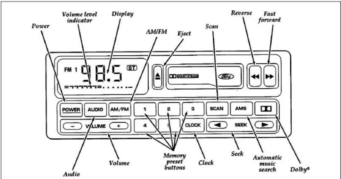
Press the "POWER" button to turn the radio on. Press it again to turn it off.
Press the right (+) side of the "VOLUME" button to increase the volume. Press the left (−) side of the button to decrease the volume. Illuminated bars in the display show the relative volume level.
NOTE: If the volume level is set above a certain listening level when the ignition switch is turned off, when the ignition switch is turned back on, the volume will come back to a “nominal” listening level. However, if the radio power is turned off, the volume will remain in the position it was set at when radio power was switched off.
Selecting the AM or FM frequency band
Push the “AM/FM” button to select the desired frequency band or to stop/store cassette tape (when in cassette mode). Pushing the button more than once will alternate between AM, FM1 and FM2. These functions are used with the station memory buttons described under How to tune radio stations.
How to tune radio stations
There are four ways for you to tune in to a particular station. You can manually locate the station by using the Automatic Music Search ("AMS") button, "SEEK" the station, "SCAN" to the station or select the station by using the memory buttons, which you can set to any desired frequency.
□Using the "AMS" function to manually tune your radio
You can change the frequency up or down one increment at a time by first pressing the "AMS" button, (display shows "TUNE") then pressing and releasing either the right ▶ or left ◀ side of the "SEEK" button. To change frequencies quickly, press and hold down either the right or left side of the "SEEK" button.
Manual tuning adjusts your radio to any allowable broadcast frequency, whether or not a station is present on that frequency. (See All About Radio Frequencies in this section.)
□Using the "SEEK" function
This feature on your radio allows you to automatically select listenable stations up or down the frequency band. Press the right (▶) side of the "SEEK" button to select the next listenable station up the frequency band. Press the left (◀) side of the button to select the next listenable station down the frequency band. By holding the button down, listenable stations can be passed over to reach the desired station.
□Using the "SCAN" function
Press the “SCAN” button to enter the scan mode. The radio will begin scanning up the frequency band, stopping on each listenable station for approximately a five-second sampling. This continues until you press the “SCAN” button a second time. The display flashes “AM” or “FM.”
☐Setting the Station Memory Preset buttons
Your radio is equipped with 6 station memory buttons. These buttons can be used to select up to 6 preset AM stations and 12 FM stations (6 in FM1 and 6 in FM2).
Follow the easy steps below to set these buttons to the desired frequencies:
- Select a band, then select a frequency.
- Press one of the memory preset buttons and hold the button until the sound returns. That station is now held in memory on that button.
- Follow the two steps above for each station memory preset button you want to set.
NOTE: If the vehicle's battery is disconnected, the station memory preset buttons will need to be reset.
Adjusting the tone balance and speaker output of your radio
☐ Increasing or decreasing bass response Push the “AUDIO” button repeatedly until the display reads “BASS.” Push the right (+) side of the “VOLUME” button to increase bass (more “lows”), and push the left (−) side to decrease bass (less “lows”).
☐ Increasing or decreasing treble response Push the "AUDIO" button repeatedly until the display reads "TREB." Push the right (+) side of the "VOLUME" button to increase treble (more "highs"), and push the left (−) side to decrease treble (less "highs").
Speaker features and operation
□Adjusting speaker balance
Balance control allows you to adjust the sound distribution between the right and left speakers. Push the “AUDIO” button repeatedly until the display reads “BAL.” Push the right (+) side of the “VOLUME” button to shift the sound to the right speakers, and push the left (−) side to shift the sound to the left speakers.
□Adjusting speaker fader
Fade control allows you to adjust the sound distribution between the front and rear speakers. Push the “AUDIO” button repeatedly until the display reads “FADE.” Push the right (+) side of the “VOLUME” button to shift the sound to the front speakers, and push the left (−) side to shift the sound to the rear speakers.
NOTE: Illuminated bars in the display show relative levels of bass and treble, and positions of speaker balance and fader functions (left to right, front to rear).
Using the Controls of Your Cassette Tape Player
How to insert a tape
Insert a cassette (with the open edge to the right) firmly into the tape door opening, making sure the cassette is completely in and “seated.”
How to locate a desired track on the tape
NOTE: The tape track or side number indicated in the display does not necessarily correspond to the tape track or side number on the cassette label. It is used only to indicate when the tape mechanism reverses tracks.
NOTE: Depending on your vehicle, the display of your radio may show arrows (▶▶ or ◀◀) or numerals ("1" or "2") to indicate the direction of tape travel. In either case, at the end of the tape, the direction automatically reverses and plays the other side of the tape.
□Using the Automatic Music Search ("AMS")(If your display shows numerals)
Press and hold the "AMS" button ("AMS" will appear in the display). Then, push the left button to rewind to the beginning of the current selection or press the right button to fast forward to the beginning of the next selection.
□Fast forwarding the tape (if your display shows numerals)
Push the right ▶▶ button to fast forward the tape.
□Rewinding the tape (if your display shows numerals)
Push the left ◀◀ button to rewind the tape.
□Using the Automatic Music Search ("AMS") (if your display shows arrows)
Press and hold the “AMS” button. Then, push the appropriate fast-wind button, depending upon the direction of the tape travel arrow in the display. For example, if the tape travel arrow is pointing to the left, push the left ◀◀ button to rewind to the beginning of the current selection. If the tape travel arrow is pointing to the right, press the right ▶▶ button to fast forward to the beginning of the next selection.
☐Fast forwarding the tape (if your display shows arrows)
To fast forward the tape, press the fast-wind button with the arrows pointing in the same direction as indicated in the display. For example, if the tape travel arrow in the display is pointing to the left, press the left ◀◀ button to fast forward the tape. To return to the play mode, press the opposite fast-wind button momentarily, until fast forward stops.
□Rewinding the tape (if your display shows arrows)
To rewind the tape, press the fast-wind button with the arrows pointing in the opposite direction as indicated in the display. For example, if the tape travel arrow in the display is pointing to the left, press the right ▶▶ button to rewind the tape. To return to the play mode, press the opposite fast-wind button momentarily, until rewind stops.
□How to change the side of the tape being played
The alternate track (other side) of the tape can be selected at any time by pushing both fast-wind buttons ◀◀ and ▶▶ at the same time.
How to eject the tape
To stop the tape and eject the cassette, press the eject (▲) button. The radio will resume playing.
Using the Dolby® B noise reduction feature
NOTE: Noise reduction system manufactured under license from Dolby Labs Licensing Corporation. "Dolby" and double-D symbol are trademarks of Dolby Laboratories Licensing Corporation.
Push the ☐☐ button to activate. Push again to deactivate.
Tips on Caring for the Cassette Player and Tapes
In order to keep your cassette tape player performing the way it was meant to, read and follow these simple precautions:
□ Using a Ford Cassette Cleaning Cartridge or equivalent to clean the tape player head after 10-12 hours of play will help maintain the best playback sound and proper tape operation.
Only cassettes that are 90 minutes long or less should be used. Tapes longer than 90 minutes are thinner and subject to breakage or may jam the tape player mechanism.
☐Protect cassettes from exposure to direct sunlight, high humidity and extreme heat or cold. If they are exposed to extreme conditions, allow them to reach a moderate temperature before playing.
☐If a tape is loose inside the cassette, tighten it before playing by putting your finger or a pencil into one of the holes and turning the hub until the tape is tight.
☐ Loose labels on cassette tapes can become lodged in the mechanism. Remove any loose label material before inserting a cassette.
☐Do not leave a tape in the cassette tape player when not in use. High heat in the vehicle can cause the cassette to warp.
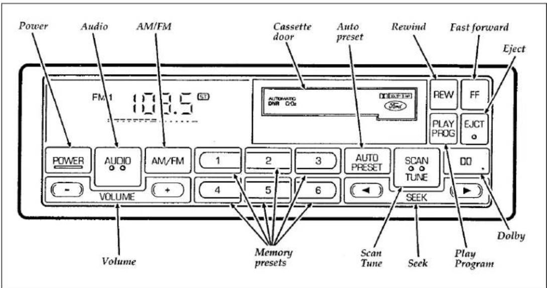
High-Level Audio System
text_image
Power Audio AM/FM Cassette door Auto preset Rewind Fast forward Eject FM 1 10.3.5 SD AUTOATG DNR C/Cx REW FF PLAY PROG EJCT DO VOLUME 1 2 3 AUTO PRESET SCAN TUNE DO SEEK Dolby Volume Memory presets Scan Tune Seek Play ProgramHigh-Level Audio System
Using the Controls on Your New Radio
How to turn the radio on and off
Press the "POWER" button to turn the radio on. Press it again to turn it off.
How to adjust the volume
Press the + / - side of the "VOLUME" button to increase/decrease volume. Bars illuminate in the display to show the relative volume level.
NOTE: If the volume level is set above a certain listening level when the ignition switch is turned off, when the ignition switch is turned back on, the volume will come back to a “nominal” listening level. However, if the radio power is turned off, the volume will remain in the position it was set at when radio power was switched off.
Selecting the AM or FM frequency band
Push the “AM/FM” button to select the desired frequency band or to stop/store cassette tape (when in cassette mode). Pushing the button more than once will alternate between AM, FM1 and FM2. These functions are used with the station memory buttons described under How to tune radio stations.
How to tune radio stations
There are four ways for you to tune in a particular station. You can manually locate the station using the "SCAN/TUNE" button, "SEEK" the station, "SCAN" to the station or select the station by using the memory buttons, which you can set to any desired frequency. These four methods are described below.
□Using the "TUNE" function
You can change the frequency up or down one increment at a time (FM changes in increments of 200 kHz; AM changes in increments of 10 kHz) by first pressing the "SCAN/TUNE" button twice (display shows "TUNE"), then — within approximately five seconds —pressing and releasing either the right ▶ or left ◀ side of the "SEEK" button. To change frequencies quickly, press and hold down either the right or left side of the "SEEK" button.
Manual tuning adjusts your radio to any allowable broadcast frequency, whether or not a station is present on that frequency. (See All About Radio Frequencies in this section.)
□Using the "SEEK" function
This feature on your radio allows you to automatically select listenable stations up or down the frequency band. Press the right ▶ side of the “SEEK” button to select the next listenable station up the frequency band. Press the left ◀ side of the button to select the next listenable station down the frequency band. By holding the button down, listenable stations can be passed over to reach the desired station.
□Using the "SCAN" function
Pressing the "SCAN/TUNE" button once enters the scan mode (display will indicate "SCN"). Pushing the right ▶ side of the "SEEK" button will begin the scan mode up the frequency band, stopping on each listenable station for approximately a five-second sampling. Pushing the left ◀ side of the "SEEK" button will begin the scan mode down the frequency band, again stopping on each listenable station for approximately a five-second sampling.
To stop the scan mode on the presently sampled station, press the "SCAN/TUNE" button again.
☐Setting the Station Memory Preset buttons
Your radio is equipped with 6 station memory buttons. These buttons can be used to select up to 6 preset AM stations and 12 FM stations (6 in FM1 and 6 in FM2).
Follow the easy steps below to set these buttons to the desired frequencies:
- Select a band, then select a frequency.
- Press one of the memory preset buttons and hold the button until the sound returns. That station is now held in memory on that button.
- Follow the two steps above for each station memory preset button you want to set.
□Using the Automatic Memory Load feature
If no stations are in memory preset, you can activate the Auto Memory Load feature by pressing and holding the "AUTO PRESET" button for approximately three seconds.
Auto Memory Load sets all memory buttons in AM, FM1 and FM2 sequentially by seeking out the first six strong stations for the respective band and storing them in memory buttons 1-5. (FM2 will store the second set of strong stations from the FM band.)
With Auto Memory Store, you can continually set strong stations into your memory buttons without losing your existing memory presets, which is especially helpful while traveling. Your radio will automatically set your memory buttons to the strong local stations so you don't have to continually manually tune to existing stations.
Activate Auto Memory Store by pushing the "AUTO PRESET" button once. Your radio will set the first five strong stations of the band you are in (AM, FM1 or FM2) into the memory buttons. The display will show "AUTO," then run through the frequencies, stopping momentarily on the stations being set into the memory buttons. The radio is now in the "AUTO" mode and the display will show "AUTO" each time a preset is activated.
NOTE: If there are fewer than five strong stations in the frequency band, the remaining unfilled buttons will store the last strong station detected on the band.
After all stations have been filled, the radio will begin playing the station stored on memory button 1.
To deactivate the Auto Memory Store mode and return to the manually-set memory button stations (or those stations set using Auto Memory Load), simply push the "AUTO PRESET" button. Display will show "AUTO" then "OFF." The next time Auto Memory Store is activated on that band, the radio will store the next set of five strong stations.
Adjusting the tone balance and speaker output of your radio
☐ Increasing or decreasing bass response
Push the "AUDIO" button repeatedly until the display reads "BASS." Push the right (+) side of the "VOLUME" button to increase bass (more "lows"), and push the left (−) side to decrease bass (less "lows").
□Increasing or decreasing treble response
Push the “AUDIO” button repeatedly until the display reads “TREB.” Push the right (+) side of the “VOLUME” button to increase treble (more “highs”), and push the left (−) side to decrease treble (less “highs”).
□Adjusting speaker balance
Balance control allows you to adjust the sound distribution between the right and left speakers. Push the "AUDIO" button repeatedly until the display reads "BAL." Push the right (+) side of the "VOLUME" button to shift the sound to the right speakers, and push the left (−) side to shift the sound to the left speakers.
□Adjusting speaker fader
Fade control allows you to adjust the sound distribution between the front and rear speakers. Push the "AUDIO" button repeatedly until the display reads "FADE." Push the right (+) side of the "VOLUME" button to shift the sound to the front speakers, and push the left (−) side to shift the sound to the rear speakers.
NOTE: Illuminated bars in the display show relative levels of bass and treble, and positions of speaker balance and fader functions (left to right, front to rear).
Using the Controls of Your Cassette Tape Player
NOTE: Radio power must be on to use the cassette tape player or eject a tape.
NOTE: Adjust the volume, treble, bass, balance and fader controls in the same manner as for radio stations.
How to insert a tape
Your cassette tape player is equipped with power loading. Once you insert a tape and push slightly (with the open edge to the right), the loading mechanism draws the tape the rest of the way in and play will begin after a momentary tape tightening process. Display indicates “M” (for metal/ CrO_2 ) while tape is playing.
NOTE: A cassette tape can be loaded and stored with the ignition and radio power off.
How to locate a desired track on the tape
There are four ways to quickly locate a desired selection on the tape. You can use the fast forward, rewind, "SEEK" or "SCAN" function. Following are brief descriptions of each.
□Fast forwarding the tape
To fast forward the tape, press the "FF" button. The radio will automatically begin playing until fast forward is manually stopped (by pushing the "PLAY PROG" button) or the end of the tape is reached.
At the end of the tape, the direction automatically reverses and plays the other side of the tape.
□Fast rewinding the tape
To rewind the tape, press the "REW" button. The radio will automatically begin playing when rewind is manually stopped (by pushing the "PLAY PROG" button) or the beginning of the tape is reached.
□Using the "SEEK" function with your cassette tape player
While in the tape mode, push the right ▶ side of the "SEEK" button to seek forward to the next selection on the tape. Push the left ◀ side to seek the beginning of the current tape selection.
NOTE: If you want to restart a currently playing tape selection, press the left side of the "SEEK" button after approximately three seconds into the current selection.
Whirling sprockets in the display 00 indicate the direction of tape travel.
□Using the "SCAN" function with your cassette tape player
Press the "SCAN/TUNE" button to enter the scan mode (display indicates "SCN").
Pushing the right ▶ side of the "SEEK" button will begin the forward scan mode on the tape currently playing, stopping on each tape selection for approximately an eight-second sampling.
Pushing the left ◀ side of the "SEEK" button will begin the reverse scan mode, stopping on each previous tape selection for approximately an eight-second sampling. While scanning, the display indicates whirling sprockets plus an "S" or 5.
To stop the scan mode on the presently sampled tape selection, press the "SCAN/TUNE" button again.
□How to change the side of the tape being played
The alternate side of the tape can be selected at any time by pressing the "PLAY/PROG" button.
How to eject the tape
To stop the tape and eject the cassette, press the "EJCT" button. The radio will resume playing if the radio power is on. The tape cartridge can be ejected with radio power (and/or ignition) on or off.
How to store the tape
Press the "AM/FM" button to stop the tape player and resume radio play. The cassette will be stored in the tape player and the ■ symbol in the display will be lit until you push the "PLAY PROG" button to resume tape play. Fast forward and fast rewind can be used while the tape is in storage mode without interrupting radio play.
Using the Dolby ^® B noise reduction feature
NOTE: Noise reduction system manufactured under license from Dolby Labs Licensing Corporation. "Dolby" and double-D symbol are trademarks of Dolby Laboratories Licensing Corporation.
Push the □□ button to activate Dolby B Noise Reduction. Push again to deactivate.
Tape error messages
Your cassette tape player is equipped to diagnose certain problems you may experience. Error codes are as follows:
Error 0 — Communication error between the radio controller and the tape controller. The cassette player will eject the tape. Insert the tape again. If the same error code appears, turn the ignition off, then back on again and insert the tape.
Error 1 — Possible problem cartridge. The cassette tape player will eject the tape. Insert the tape again. If the same error code appears in the display, try a different cartridge.
Error 2 — Tape eject or load failure. Your cassette tape player will go into the pause mode. Push “EJCT” to eject the tape. If the tape doesn’t eject, refer the problem to qualified personnel for service.
Tips on Caring for the Cassette Player and Tapes
In order to keep your cassette tape player performing the way it was meant to, read and follow these simple precautions:
☐ Using a Ford Cassette Cleaning Cartridge or equivalent to clean the tape player head after 10-12 hours of play will help maintain the best playback sound and proper tape operation.
Only cassettes that are 90 minutes long or less should be used. Tapes longer than 90 minutes are thinner and subject to breakage or may jam the tape player mechanism.
☐Protect cassettes from exposure to direct sunlight, high humidity and extreme heat or cold. If they are exposed to extreme conditions, allow them to reach a moderate temperature before playing.
☐ Loose labels on cassette tapes can become lodged in the mechanism. Remove any loose label material before inserting cassette.
☐Do not leave a tape in the cassette tape player. High heat in the vehicle can cause the cassette to warp.
Common Radio Reception Conditions
Several conditions prevent FM reception from being completely clear and noise-free, such as the following:
1. Distance/Strength
The strength of the FM signal is directly related to the distance the signal must travel. The listenable range of an average FM signal is approximately 25 miles (40 kilometers). Beyond this distance, the radio is operating in a fringe area and the signal becomes weaker.
NOTE: Always make sure your antenna is fully extended to the maximum length for proper reception. If your antenna is not fully extended, you may experience signal loss while traveling in fringe reception areas.
2. Terrain
The terrain (hilly, mountainous, tall buildings) of the area over which the signal travels may prevent the FM signal from being noise-free.
If there is a building or large structure between the antenna and station, some of the signal "bends" around the building, but certain spots receive almost no signal. Moving out of the "shadow" of the structure will allow the station to return to normal.
When the radio waves are reflected off objects or structures, the reflected signal cancels the normal signal, causing the antenna to pick up noise and distortion. Cancellation effects are most prominent in metropolitan areas, but also can become quite severe in hilly terrain and depressed roadways.
To minimize these conditions, a stereo/mono blend circuit has been incorporated into this system. This feature automatically switches a weak stereo signal to a clearer monaural signal, which improves the quality of reception.
Several sources of static are normal conditions on AM frequencies. These can be caused by power lines, electric fences, traffic lights and thunderstorms.
Another reception phenomenon is Strong Signal Capture and Overload. This can occur when listening to a weak station and when passing another broadcast tower. The close station may capture the more distant station, although the displayed frequency does not change. While passing the tower, the station may switch back and forth a few times before returning to the original station.
When several broadcast towers are present (common in metropolitan areas), several stations may overload the receiver, resulting in considerable station changing, mixing and distortion.
Automatic gain control circuitry for both AM and FM bands has been incorporated into this system to reduce strong signal capture and overload.
All About Radio Frequencies
The Federal Communications Commission (FCC) and the Canadian Radio Telecommunications Commission (CRTC) establish the frequencies that AM and FM radio stations may use for their broadcasts. The allowable frequencies are, AM: 530, 540...1600, 1610 kHz in 10 kHz steps; FM: 87.9, 88.1...107.7, 107.9 MHz in 0.2 MHz steps.
Not all frequencies will be assigned to a given area. This radio will tune to each of these frequencies using manual tune and no fine tuning is necessary as radio stations may not use other frequencies.
Some FM radio stations advertise a “rounded-off” frequency which is not the frequency they actually broadcast on. For example, a radio station that is assigned a frequency of 98.7 MHz may call itself “Radio 99” even though 99.0 MHz is not an allowable FM broadcast frequency.
Important Warranty and Service Information
□Warranty
Your sound system is warranted for three years or 36,000 miles (60,000 kilometers), whichever comes first. Consult your vehicle warranty booklet for further information. Ask your dealer for a copy of this limited warranty.
□Service
At Ford, we stand behind our audio systems with a comprehensive service and repair program. If anything should go wrong with your Ford audio system, return to your dealer for service. There is a nationwide network of qualified Ford authorized repair centers to assist you.
Controls and Features
The main controls for the climate control system, clock, and radio are on the instrument panel.
NOTE: Any cleaner or polish that increases the gloss (shine) of the upper part of the instrument panel should be avoided. The dull finish in this area is to help protect the driver from undesirable windshield reflection.
Your vehicle has a variety of features designed for your comfort, convenience and safety. Read this chapter to find out about standard and optional features.
The Climate Control Systems
Your vehicle has one of two different climate control systems. The two systems are:
☐ a manual heating and air conditioning system
□a semi-automatic temperature control system (if equipped)
If you are not sure which system your vehicle has, see the diagrams on the following pages.
The Manual Heating and Air Conditioning System
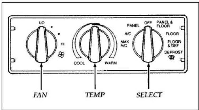
You can heat the inside of your vehicle, defrost the windshield, and turn on the air conditioning with the three controls in the center of the instrument panel:
FAN
TEMP
□SELECT
text_image
LO HI COOL WARM FAN TEMP SELECT PANEL A/C MAX A/G OFF PANEL & FLOOR FLOOR FLOOR & DEF DEFROSTThe controls for the manual heating and air conditioning system
To heat the interior of your vehicle, turn the SELECT control to FLOOR, turn the TEMP control to the end of the red range (full right) and turn the FAN control to HI. Temperature and fan speed can be adjusted as desired.
To defrost the windshield and side windows, turn the SELECT control to defrost ⏻, turn the TEMP control to the end of the red range (full right) and turn the FAN control to HI. Temperature and fan speed can be adjusted as desired.
To heat the interior and defrost the windshield and side windows, at the same time, turn the SELECT control to FLOOR & DEF, turn the TEMP control to the end of the red range (full right) and turn the FAN control to HI.
To direct either heated or cooled air to the panel registers and the floor at the same time, turn the SELECT control to PANEL & FLOOR, turn the TEMP control for the temperature desired and set the fan speed as desired.
To cool your vehicle using outside air, turn the SELECT control to A/C, turn the TEMP control all the way to the end of the blue range (full
left) and turn the FAN control to the desired speed between LO and HI. A/C provides quieter system operation than MAX A/C, but it is not as efficient as MAX A/C which uses recirculated air.
To ventilate your vehicle with outside air, during mild weather, turn the SELECT control to PANEL, turn the TEMP control for the temperature desired and set the FAN control to the speed desired.
Under normal conditions, the SELECT control should be left in any position other than MAX A/C or OFF when the vehicle is parked. This allows the vehicle to “breathe” through the outside air inlet duct.
To cool your vehicle quickly in warm weather, turn the SELECT control to MAX A/C, turn the TEMP control all the way to the end of the blue range (full left) and turn the FAN control to HI. MAX A/C uses recirculated air and is the most fuel efficient way to cool your vehicle and can also be used in heavy traffic to prevent exhaust fumes from entering the vehicle. MAX A/C can also be used in high humidity areas for more efficient operation.
If the interior of your vehicle is very warm, drive for the first few minutes with the windows open. This forces most of the hot, stale air out of the vehicle and allows the air conditioning to work faster.
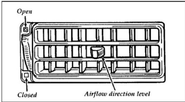
Adjusting the panel register airflow
The instrument panel registers may be adjusted to your comfort needs. The thumbwheel controls the volume of air and the control in the center of the register controls direction up or down or side to side.
text_image
Open Closed Airflow direction levelControlling the airflow from panel registers
The Semi Automatic Temperature Control System (If equipped)
System Characteristics
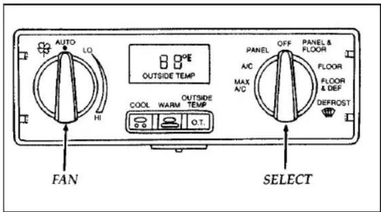
The Semi Automatic Temperature Control System (SATC) is designed to provide comfort consistent with the temperature setting you select. The discharge air temperature and fan speed will be automatically controlled to bring the vehicle to the desired set temperature, as fast as possible, and then gradually be changed to maintain that temperature. The system also gives you the capability of manually adjusting the location of the discharge air and fan speed for desired comfort or specific operating requirements.
text_image
AUTO LO HI OUTSIDE TEMP COOL WARM OUTSIDE TEMP O.T. PANEL OFF PANEL & A/C FLOOR MAX A/C FLOOR & DEFROST FAN SELECTThe controls for the Semi-Automatic Temperature Control system
System Controls
This display also has a metric conversion option. To change from English to Metric, set the control to MAX A/C and the Fan to HI. Simultaneously press the WARM, COOL, and OUTSIDE TEMP controls for 3/4 of a second, then release. Repeat this procedure to change the display back to English.
Digital display
The temperature you select for your driving comfort is displayed here. You can change the temperature by pressing either the COOL or the WARM control. You may also display outside temperature for four seconds by depressing the OUTSIDE TEMP control.
Cool control
This control is used to LOWER the temperature setting. Press the button once to lower the displayed temperature one degree. Holding the control in will continuously reduce the temperature setting in one degree increments until you either release it or 65^ F ( 18^ C) is reached.
If the control is pressed after 65^ F ( 18^ C) is reached, only 60^ F ( 16^ C) will be displayed and the system will provide continuous maximum cooling.
Warm control
This control is used to RAISE the temperature setting. Press the control once to raise the displayed temperature one degree. Holding the control in will continuously increase the temperature setting in one degree increments until you either release it or 85^ F ( 29^ C) is reached.
If the control is pressed after 85^ F ( 29^ C) is reached, only 90^ F ( 32^ C) will be displayed and the system will provide continuous maximum heating.
System Operation
To heat the inside of your vehicle, turn the SELECT control to FLOOR and turn the FAN control to AUTO. The fan will remain off until the engine reaches operating temperature or until 3-1/2 minutes have elapsed. As the interior of your vehicle warms up, the discharge air temperature and the fan speed will be automatically and gradually changed to maintain the set temperature. If you prefer a fixed fan speed, turn the fan speed control to the desired setting.
To defrost the windshield and side windows, turn the SELECT control to Defrost ⏻, turn the FAN control to HI and set the temperature as necessary to clear the windshield.
To direct either cooled or heated air to the panel registers and the floor at the same time, turn the SELECT control to PANEL & FLOOR, push the COOL or WARM control for the desired temperature and set the FAN speed as desired.
To cool your vehicle quickly in warm weather, turn the SELECT control to MAX A/C and turn the FAN control to AUTO. As the vehicle interior cools down, the discharge air temperature and fan speed will automatically and gradually be changed to maintain the set temperature with airflow from the instrument panel registers.
If the interior of your vehicle is very warm, drive for the first few minutes with the windows open. This will force the hot, stale air out and allow the air conditioning to work faster.
To cool your vehicle with outside air, turn the SELECT control to A/C and turn the FAN control to AUTO or to a fixed speed setting as you desire. Cooling your vehicle in this manner provides a quieter system operation, but it will not cool as efficiently and is not as fuel efficient as MAX A/C which uses recirculated air.
To ventilate your vehicle with outside air, turn the SELECT control to PANEL and the FAN control to AUTO. The fan will remain off until the engine is warm enough to provide heat. However, if the interior temperature is above the set temperature, the fan will turn on immediately. Temperature may be set as desired and FAN speed can be selected.
A/C compressor override
The A/C compressor can be disengaged for more economical driving. This can be done by turning the SELECT control to PANEL. The A/C compressor is automatically engaged by the control in MAX A/C, PANEL & FLOOR, NORM A/C, FLOOR & DEF, and DEFROST positions if the outside temperature is above 45^ F ( 7^ C).
Rear Window Defroster (If equipped)
The defroster for the rear window clears frost, fog, or thin ice from both the inside and outside of the rear window.
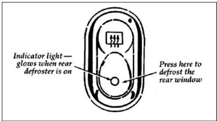
The control for the rear window defroster is located on the lower right side of the instrument panel, just left of the climate control panel.
text_image
Indicator light — glows when rear defroster is on Press here to defrost the rear windowThe control for the rear window defroster
Clear away any snow that is on the rear window before using the defroster. With the engine running, push the defrost button.
After approximately 10 minutes, the defroster will turn off. If the window is still not clear, turn the defroster on again.
The defroster will turn off when the ignition key is turned to the OFF position.
The heating elements are bonded to the inside of the rear window. Do not use sharp objects to scrape the inside of the rear window or use abrasive cleaners to clean it. Doing so could damage the heating elements.
The Interior and Exterior Lights
Daytime Running Light System
(Canadian vehicles only)
The Daytime Running Light (DRL) system turns the high beam headlamps on, with a reduced light output, when:
☐The headlamp system is in the OFF position, and
□The vehicle is running, and
☐The vehicle has a fully released parking brake.
NOTE: If you have a vehicle with an automatic lighting system, the DRL system is active until the automatic system turns on the headlamps.
NOTE: The high beam indicator will not turn on in the flash-to-pass mode during nighttime driving.
NOTE: You may notice that the lights flicker when the vehicle is turned on or off. This is a normal condition.
| ⚠WARNING |
| The Daytime Running Light (DRL) system will not illuminate the tail lamps and parking lamps. Turn on your headlamps at dusk. Failure to do so may result in a collision. |
Turning On the Exterior Lights
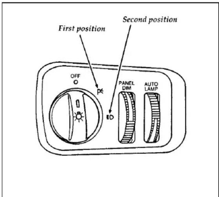
To turn on the headlamps, parking lamps, side markers, license plate lamps and tail lamps, use the rotary knob that is to the left of the steering wheel.
text_image
First position Second position OFF P ED PANEL DIM AUTO LAMPThe knob that controls the headlamps and parking lamps (shown with autolamp feature — other models similar)
To turn on the parking lamps, license plate lamps, tail lamps and marker lamps, move the knob to the first position.
To turn on the headlamps, parking lamps, license plate lamps, tail lamps and marker lamps, move the knob to the second position.
For more information about how the high beams work, see the high beam section later in this chapter.
Chime for headlamps on
This chime sounds if the driver or any passenger door is open when the parking lamps or headlamps are on. The chime sounds until you close the door, turn off the lamps or turn the ignition to the ON position.
Setting the Autolamp Delay System (If equipped)
The autolamp sets the headlamps to turn on and off automatically. You can use the autolamp to:
□turn on the lamps automatically at night
□turn off the lamps automatically during daylight
□keep the lamps on for up to three minutes after you turn the key to OFF.
text_image
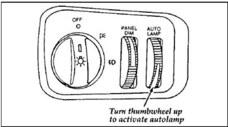
OFF O P ED PANEL DIM AUTO LAMP Turn thumbwheel up to activate autolampThe controls for the autolamp
To set the autolamp:
- Make sure the headlamp knob is in the OFF position. If the knob for the headlamps is ON, you cancel the autolamp.
-
Turn the ignition key to ON or start your vehicle.
-
Find the autolamp thumbwheel to the right of the panel dim thumbwheel.
- Turn the thumbwheel up to the beginning of the MAX position (within the DELAY range).
- The autolamp automatically turns the lamps on and off for you.
Do not put any articles on top of the photocell that is located in the top right corner of the instrument panel. This photocell controls the autolamp. If you cover it, the photocell reacts as if it is nighttime, and the lamps turn on.
To turn the autolamp off, move the thumbwheel back to OFF.
You can set the autolamp so the lamps stay on for up to three minutes after you turn your vehicle off.
To keep the lamps on after you leave your vehicle, turn the thumbwheel as far into the MAX range as you want.
If you move the thumbwheel only slightly into the DELAY area, your lamps will stay on for only a moment after you turn your vehicle off. The further you move the thumbwheel into the DELAY area (toward the MAX position), the longer the lamps will stay on after you turn your vehicle off.
Lighting Up the Interior and Instrument Panel
Manual operation
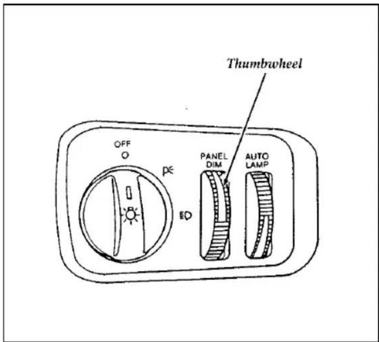
With the light knob in the parking lamps or the headlamps position, you can brighten or dim the lights in the instrument panel. To do this, use the thumbwheel to the left of the steering wheel. This wheel also turns on the interior lights with the light knob on or off.
Turn the thumbwheel down to dim the instrument panel light and up to brighten. Turn thumbwheel fully upward to turn on interior lights.
text_image
OFF O PC ED PANEL DIM AUTO LAMP ThumbwheelThe thumbwheel controls the light on the instrument panel and the interior light
text_image
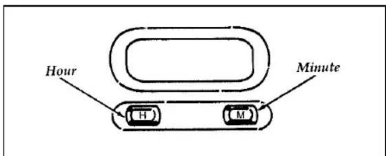
Hour Minute H MThe digital clock
-
To set the hour, press and hold the H button. When the desired hour appears, release the button.
-
To set the minutes, press and hold the M button. When the desired minute appears, release the button.
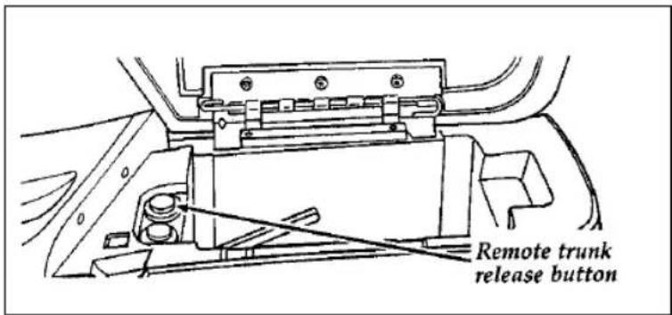
Using the Remote Control for the Trunk (If equipped)
With the ignition switch in the ON or ACC position, you can use the remote control under your console armrest to unlock and open the trunk.
text_image
Remote trunk release buttonThe trunk release button located under the armrest
ion
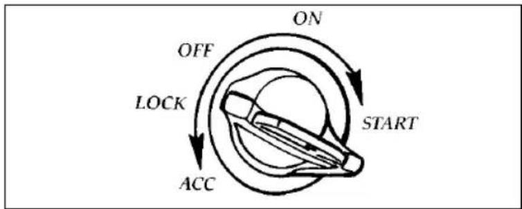
Understanding the Positions of the Ignition
flowchart
graph TD
    A["Start"] --> B["ON"]
    B --> C["OFF"]
    C --> D["LOCK"]
    D --> E["ACC"]
    E --> A
The positions of the key in the ignition
ACC allows some of your vehicle's electrical accessories such as the radio and the windshield wipers to operate while the engine is not running.
LOCK locks the steering wheel. It also locks the automatic transmission gearshift lever.
LOCK is the only position that allows you to remove the key. The LOCK feature helps to protect your vehicle from theft.
OFF allows you to shut off the engine and all accessories without locking the steering wheel or the automatic transmission gearshift lever.
ON allows you to test your vehicle's warning lights (except the brake system warning light) to make sure they work before you start the engine. The key returns to the ON position once the engine is started and remains in this position while the engine runs.
START cranks the engine. Release the key once the engine starts so that you do not damage the starter. The key should return to ON when you release it. The START position also allows you to test the brake warning light.
Removing the Key From the Ignition
- Put the gearshift in P (Park).
- Set the parking brake fully.
- Turn the ignition key to LOCK.
- Remove the key.
NOTE: The automatic transmission gearshift must be in P (Park) to move the key to the lock position.
If the key is stuck in the LOCK position, move the steering wheel left or right until the key turns freely.
If the driver's door is open while the key is still in the ignition, a warning chime sounds.
| WARNING |
| Always set the parking brake fully and make sure the gearshift is latched in P (Park). Turn off the ignition whenever you leave your vehicle. |
| ⚠ WARNING |
| Do not leave children, unreliable adults, or pets unattended in your vehicle. |
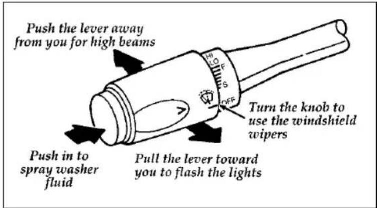
The Turn Signal Lever
You can use the turn signal lever on the left side of the steering column to:
□operate the turn signals
□turn the high beams on/off
□flash the lamps
□turn the windshield wipers and washer on/off
text_image
Push the lever away from you for high beams Turn the knob to use the windshield wipers Push in to spray washer fluid Pull the lever toward you to flash the lightsThe turn signal lever
Turn Signals
Move the lever up to signal a right turn. Move it down to signal a left turn. The corresponding indicator light in the instrument cluster will flash.
If the turn signal stays on after you turn, move the lever back to the center (off) position.
For lane changes, move the lever far enough to signal but not to latch. The lever will return to the off position when you release it.
High Beams
To turn on the high beams, turn the headlamp control knob to the headlamp ON position and push the turn signal lever away from you until it latches. When the high beams are ON, the high beam indicator light on the instrument panel comes on.
To turn off the high beams, pull the lever toward you until it latches. The high beam indicator light turns off.
Flashing the Lights
To flash the headlamps, pull the lever toward you for a moment and then release it. The headlamps will flash whether the headlamp knob is in the on or off position.
Windshield Wipers and Washer
To turn on the windshield wipers, the ignition key must be turned to the ON or ACC position.
Rotate the end of the lever away from you to activate the wipers. The first seven detents are interval wipe positions, the eighth detent is the LO position and the ninth detent is the HI position.
To turn the wipers off, turn the knob toward you to the OFF position.
Variable Interval Wipers
In addition to two speed wipers, your vehicle has wipers that you can set to operate at varying intervals. For example, you can set the interval so they wipe less often when it drizzles or more often in heavier rain.
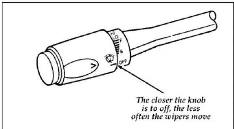
text_image
The closer the knob is to off, the less often the wipers moveThe variable interval wiper on the turn signal lever
To set the interval wipers, turn the knob at the end of the turn signal lever toward or away from you until the wipers are going at the desired interval.
Windshield Washer
To clean the windshield, push in the end of the wiper knob. For a constant spray, keep the knob pushed in. After you release the knob, the wipers operate for two to three cycles before turning off (if the wipers were OFF) or returning to HI, LO, or the interval setting selected.
If the washer does not work, check the washer fluid level and fill it if it is low. See the Maintenance and Care chapter. If there is enough fluid, consult your nearest Ford or Lincoln-Mercury dealer.
Do not try to clean the windshield when the washer fluid container is empty or activate the washers at any time for more than 15 seconds continuously. This could damage the washer pump system.
WARNING
Always warm up the windshield with the defroster before you use the washer fluid. In freezing weather, the washer solution may freeze on the windshield and obscure your vision.
For information about refilling the washer fluid or replacing your windshield wiper blades, see Windshield washer fluid and Wipers in the Index.
Hazard Flasher
The hazard flasher serves as a warning to other drivers to be careful when approaching or passing your vehicle.
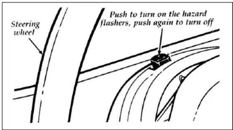
text_image
Steering wheel Push to turn on the hazard flashers, push again to turn offThe control for the hazard flashers
n
To sound the horn, push the center pad area of the steering wheel.
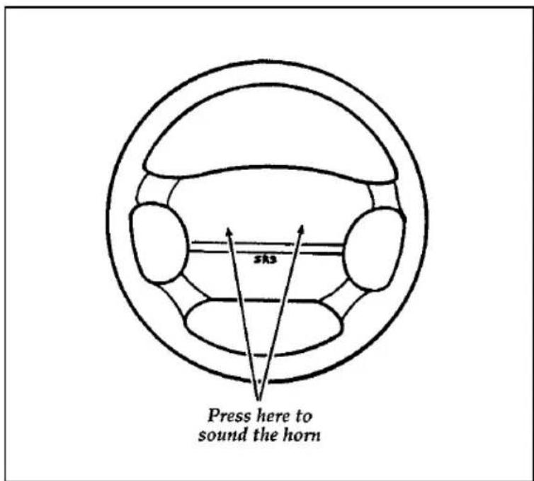
text_image
Press here to sound the hornThe horn on the steering wheel
Tilt Steering
| ⚠WARNING |
| Never adjust the steering wheel when the vehicle is moving. |
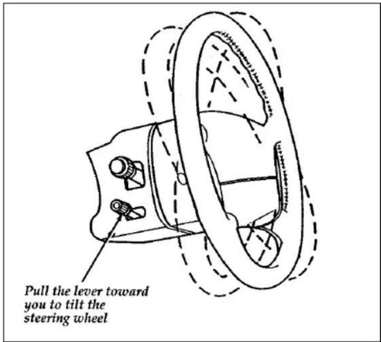
text_image
Pull the lever toward you to tilt the steering wheelThe lever to tilt the steering wheel
To change the position of the steering wheel, pull the release lever on the column toward you. Tip the steering wheel to the desired position. Release the lever to lock the steering wheel in place.
Speed Control (If equipped)
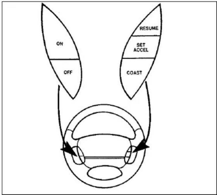
flowchart
graph TD
    A["ON"] --> B["OFF"]
    C["RESUME"] --> D["SET ACCEL"]
    E["COAST"] --> F["Car Window"]
    style A fill:#f9f,stroke:#333
    style B fill:#ccf,stroke:#333
    style C fill:#cfc,stroke:#333
    style D fill:#fcc,stroke:#333
    style E fill:#ffc,stroke:#333
    style F fill:#cff,stroke:#333
The speed control switches on the steering wheel
To Turn Speed Control Off
□Press OFF OR
□Turn off the vehicle ignition.
Once speed control is switched off, the previously programmed set speed will be erased.
To Turn Speed Control On
□Press ON
To Set a Speed
Press SET ACCEL. For speed control to operate, the speed control must be ON and the vehicle speed must be greater than 30 mph (48 km/h).
If you drive up or down a steep hill, your vehicle speed may vary momentarily slower or faster than the set speed. This is normal.
Speed control cannot reduce the vehicle speed if it increases above the set speed on a downhill. If your vehicle speed is faster than the set speed while driving on a downhill in Overdrive, you may want to shift to the next lower gear to reduce your vehicle speed.
If your vehicle slows down more than 10 mph (16 km/h) below your set speed on an uphill, your speed control will disengage. This is normal. Pressing Resume will re-engage it.
⚠ WARNING
To keep your vehicle under control, do not use speed control in heavy traffic or on roads that are winding, slippery, or unpaved.
To Set a Higher Set Speed
☐Press and hold SET ACCEL. Release the switch when the desired vehicle speed is reached. OR
☐Press and release SET ACCEL. Each press will increase the set speed by 1 mph (1.6 km/h). OR
☐Accelerate with your accelerator pedal, then press SET ACCEL.
You may accelerate with the accelerator pedal at any time during speed control usage. Releasing the accelerator pedal will return your vehicle speed to the previously programmed set speed.
To Set a Lower Set Speed
☐Press and hold COAST. Release the switch when the desired vehicle speed is reached. OR
☐Press and release COAST. Each press will decrease the set speed by 1 mph (1.6 km/h). OR
☐Depress the brake pedal. When the desired vehicle speed is reached press SET ACCEL.
To Disengage Speed Control
□Depress the brake pedal.
Disengaging the speed control will not erase the previously programmed set speed.
To Return to a Set Speed
☐Press RESUME. For RESUME to operate, the vehicle speed must be faster than 30 mph (48 km/h).
Indicator Light
Lights when either the SET ACCEL or RESUME switches are pressed and remains lit until it is either disengaged or turned off.
Map and Reading Lamps
Your vehicle has two map lamps for the passenger and the driver. To turn on the map lamps, push the switch next to each lamp.
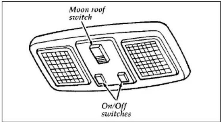
text_image
Moon roof switch On/Off switchesMap lamp (with optional moon roof)
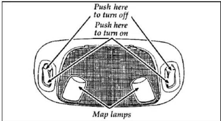
text_image
Push here to turn off Push here to turn on Map lampsFront seat map and dome lamps (without optional moon roof)
The dual beam map lamps are located on each side of the dome lamp. Each map lamp can be turned on by the switches on the lamp.
Moon Roof (If equipped)
You can move the moon roof back to open the glass panel, or you can tilt it up to ventilate the vehicle.
The rocker type control is used to open and close the moon roof. You must press and hold the control until the desired position is reached. At fully open and closed positions, the motor will automatically turn off. Release the control at this time to avoid motor damage.
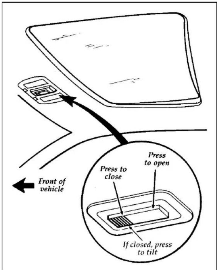
text_image
Press to close Press to open If closed, press to tilt Front of vehicleThe control for the moon roof
The moon roof has an express open feature.
To open the moon roof, press and release the rear portion of the control. The glass panel will move to the full open position and stop. To stop the glass at a partially open position, press the control again while the glass is moving.
To close the moon roof, press and hold the front portion of the control. The glass panel will move to the intermediate position and stop. Press and hold the front of the control again and the panel will move to the fully closed position and stop.
To tilt the moon roof into vent position when the glass panel is closed, press the front portion of the control.
To close from vent position, press and hold the rear portion of the control.
Occasionally wiping the outside guide rail covers of the moon roof with a clean cloth will help keep the moon roof working properly.
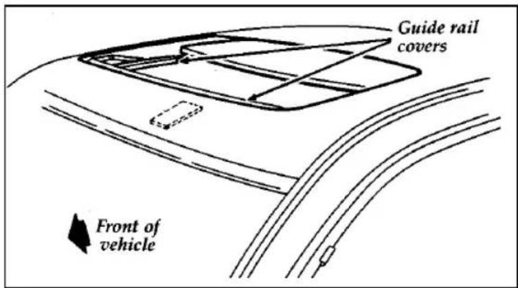
text_image
Guide rail covers Front of vehicleThe moon roof
| ⚠WARNING |
| Do not let children play with the moon roof. They may seriously hurt themselves. |
Sliding Shade
The moon roof has a sliding shade that you can manually open or close to block the sun when the glass panel is shut.
To close the sliding shade, pull the shade toward the front of the vehicle. The shade automatically opens and locks when the moon roof is opened.
You can adjust your rearview mirror in any direction. The special swivel bracket lets you move the mirror up or down and from side to side.
WARNING
Make sure you can see clearly through the rearview mirror at all times. Do not block your vision. If you cannot see through the mirror, it could result in a collision, injuring yourself and others.
Sun Visors
Turning on the Mirror Light on the Sun Visors (If equipped)
To turn on the visor mirror light, lift the mirror cover.
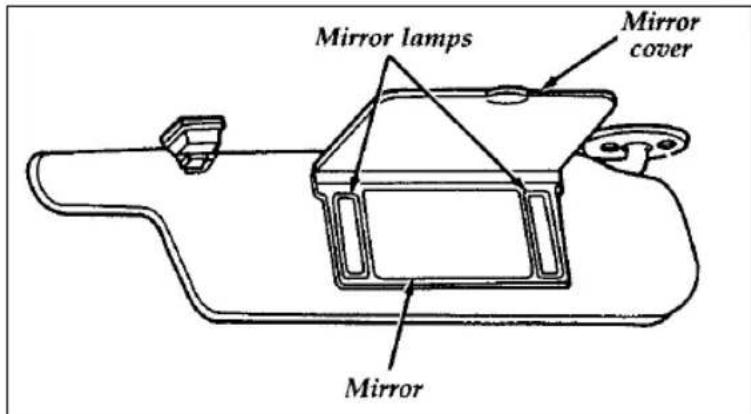
text_image
Mirror lamps Mirror cover MirrorThe mirror on the sun visor
Power Door Locks (If equipped)
If your vehicle has power door locks, the controls to lock the doors are on the trim panel of the front door. When you close the doors after you set the door locks, the doors remain locked. If the power mechanism fails, the manual door locks will override the power controls. Pulling on a front inside door handle will automatically override and release the front door lock.
Power door locks on vehicles equipped with keyless entry will activate when the interior courtesy/dome lamps are turned on or off using the instrument panel dimmer or thumbwheel control.
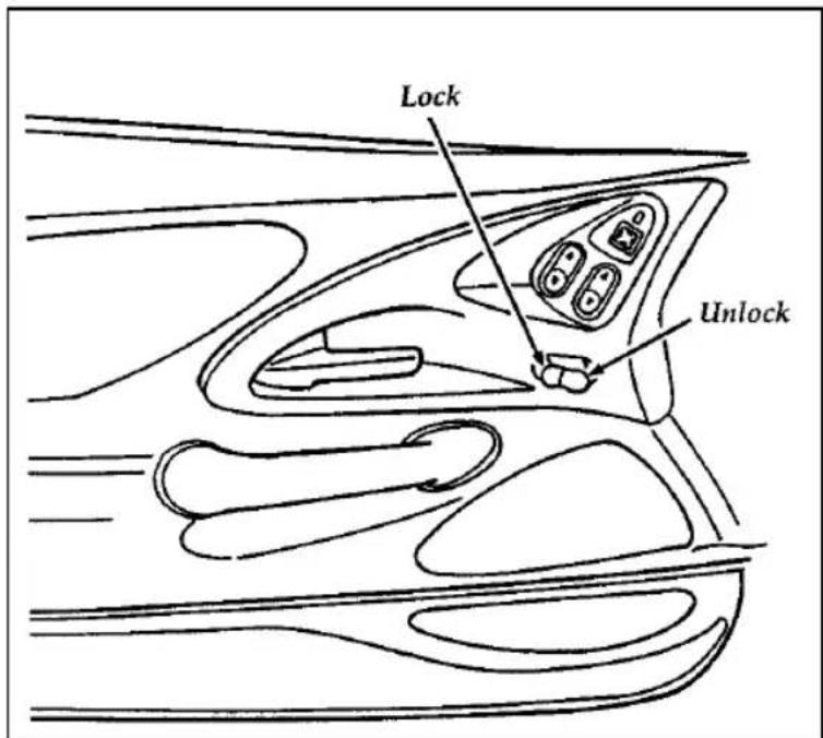
text_image
Lock UnlockThe power locks on the driver's door
Using the Illuminated Entry System (If equipped)
The interior lights turn on when you lift the outside door handle on the driver's side door or when you press UNLOCK, TRUNK, or PANIC on a programmed remote entry transmitter if your vehicle is equipped with remote entry.
These lights automatically turn off after 25 seconds or when you turn the ignition key to ON or ACC. The inside lights will not turn off if you have turned them on manually or if a door is opened.
dows
Using the Power Windows
Each door has a power control that opens and closes the window on that door. The driver's door has a master control panel that operates the windows.
Power windows can only be opened or closed when the ignition switch is in the ON or ACC position.
| ⚠WARNING |
| Do not let children play with the power windows. |
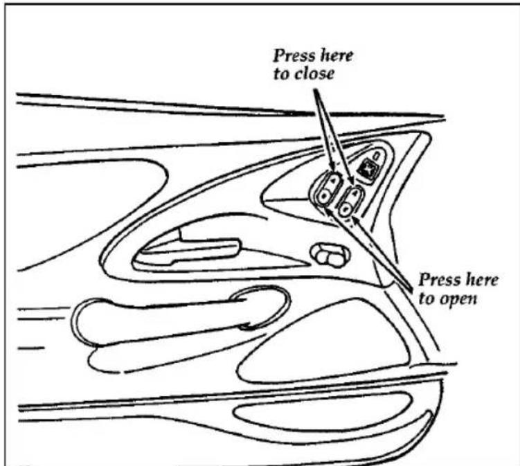
text_image
Press here to close Press here to openThe master controls on the driver's door
Adjusting the Dual Electric Remote Control Mirrors
The switch for controlling the dual electric remote control mirrors is located on the driver's door.
Do not clean the housing or glass of any mirror with harsh abrasives, fuel or other petroleum-based cleaning products.
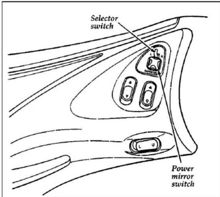
text_image
Selector switch Power mirror switchThe mirror controls on the driver's door
To adjust the side mirrors:
- Find the control switch in the driver's door panel.
- Select the right or left mirror by moving the selector switch to R or L.
- Move the knob in the direction you want to move the mirror.
- Return the selector switch to the middle position to keep the mirror in place.
The Right Side Convex Mirror
The side view mirror on the right is a convex mirror. This mirror gives you a wider view of the lanes on your right and behind you.
⚠ WARNING
The right side view mirror makes objects appear smaller and farther away than they actually are.
sole
Your vehicle has a full console. The full console has the features shown in the illustration below.
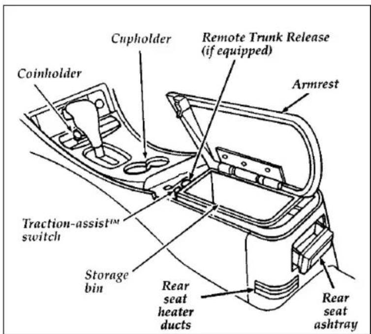
text_image
Coinholder Cupholder Remote Trunk Release (if equipped) Armrest Traction-assist™ switch Storage bin Rear seat heater ducts Rear seat ashtrayThe features on the full console
Positive Location Floor Mat
When installing or removing the driver's side floor mat you must attach/detach the positive location grommet from the hook on the floor. The hook is just forward of the left hand track of the driver's seat.
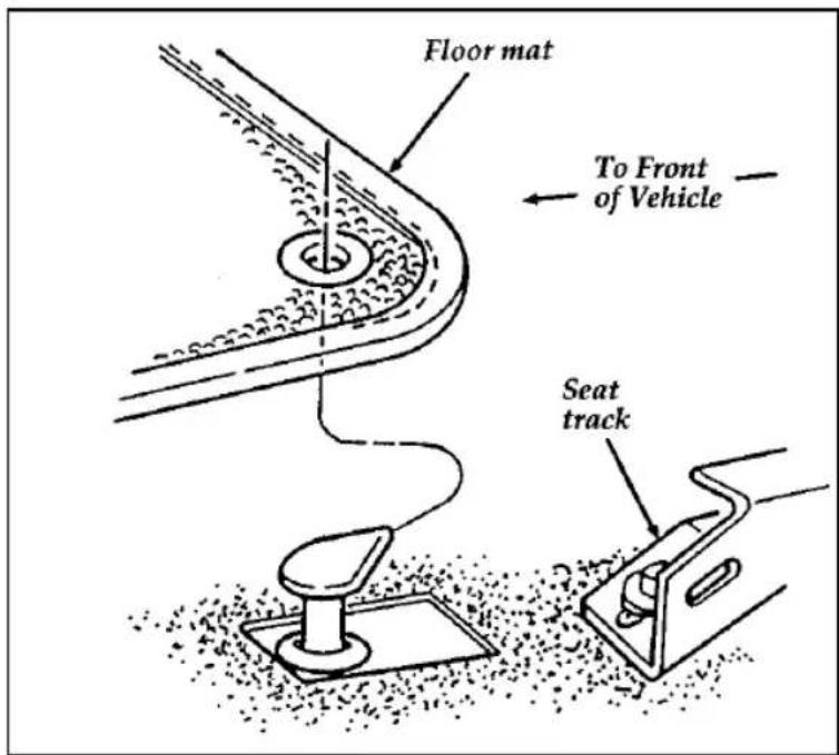
text_image
Floor mat To Front of Vehicle Seat trackThe positive location floor mat hook
Anti-Theft Alarm System (If equipped)
When armed, this system helps protect your vehicle against break-ins or theft.
When an unauthorized entry occurs, the system triggers and will:
□flash the parking lamps, and alarm indicator lamp
□honk the horn
□disable the starting circuit to prevent the vehicle from being started
To tell the difference between a PANIC alarm and a triggered Anti-theft alarm:
□only the Anti-Theft alarm will cause the alarm indicator lamp (located in the instrument cluster) to flash on and off.
□only the Anti-Theft alarm will disable the start circuit so that the vehicle can not be started.
□the Anti-Theft alarm will not stop by pushing the PANIC control on the Remote Entry transmitter.
For more information on the PANIC alarm, see Remote Entry System in the Index.
Arming the system
To arm the system, do the following steps in sequence:
- Remove the key from the ignition. The hood must be closed to arm the system.
At this point, the anti-theft system automatically monitors the ignition keylock cylinder. If the lock cylinder is forcibly removed, the anti-theft alarm system will trigger. To arm the remaining portion of the system, follow steps 2-4.
-
Open any door. The alarm indicator light will start flashing to remind you to arm the system.
-
Lock the doors by using the power door lock switch or by pressing the remote entry transmitter LOCK control.
The alarm indicator will now glow steadily.
- Close all doors. The alarm indicator light will then remain on steadily for approximately 30 seconds and then go out. When the light goes out, the system is armed.
NOTE: Be sure to close all doors completely. If not, the alarm indicator light will remain on. Remember, your anti-theft system is armed only after the alarm indicator light remains on steadily for approximately 30 seconds after the last door is closed, and then goes out.
You can also arm the anti-theft system by following this sequence:
- Remove key from ignition.
- Close all of the doors.
- Press the remote entry transmitter LOCK control. The alarm indicator will come on for 30 seconds to show the alarm is arming and then turn off to show that the alarm has armed.
The anti-theft system is designed to work with the factory installed remote entry system. It may not work with other remote entry systems.
Disarming an Untriggered Anti-Theft System
You can disarm the system by:
□unlocking a door with the key (turn the key all the way to the end of travel or the system may not disarm.
□ using the UNLOCK control on the remote entry transmitter
☐if remaining in the vehicle, turn the ignition switch to ON or ACC
Triggering the Alarm System
The armed system will be triggered if:
□any door is opened without disarming the system first (see previous paragraphs)
□the trunk lock cylinder is removed
NOTE: You can open the trunk with your key without setting off the alarm.
□the ignition key lock cylinder is forcibly removed from the steering column.
Disarming a Triggered System
The alarm can be disarmed by:
□unlocking a front door with the key
□ using the UNLOCK control on the remote entry transmitter
NOTE: The flashing lights and honking horn will shut off automatically within 2 minutes 45 seconds after the system is triggered. It will trigger again if another intrusion occurs. However, the starter circuit remains disabled until the system is disarmed.
Remote Entry System (If equipped)
If your vehicle has the remote entry system, you can lock and unlock the vehicle doors and open the trunk without using a key. The remote also has a personal alarm feature. The controls for the system are located on the hand held transmitter(s) that came with your vehicle.
The system will work with up to four transmitters. Your vehicle came with two transmitters. Additional transmitters can be ordered from your dealer.
The remote entry features only operate with the ignition in the OFF position.
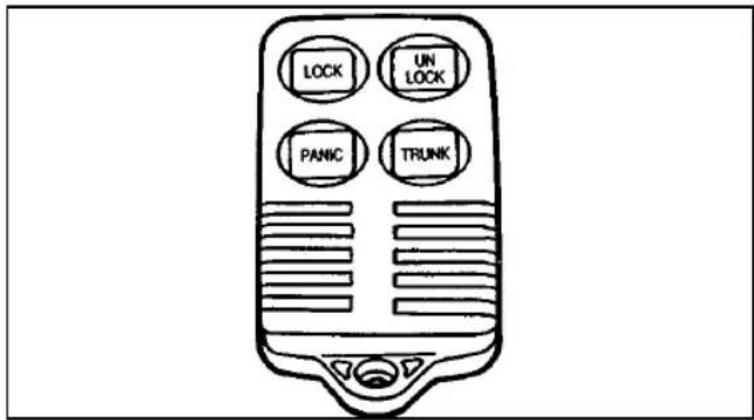
text_image
LOCK UN LOCK PANIC TRUNKRemote entry transmitter
Unlocking the doors and opening the trunk
To unlock the driver's door, press the UNLOCK control.
To unlock the other doors, press the UNLOCK control a second time within five seconds of unlocking the driver's door.
To open the trunk, press the TRUNK control.
Locking the doors
To lock all the doors, press the LOCK control.
If you would like a signal that the doors are being locked, press the LOCK control again within five seconds. The doors will lock again and the horn will beep.
Activating the remote personal alarm
If you wish to activate the remote personal alarm, press the PANIC control. This will honk the horn and flash the parking lamps and tail lamps for approximately two minutes and forty-five seconds. You can turn it OFF by pressing the PANIC control again or by turning the ignition key to the RUN position.
When you use the remote entry UNLOCK, TRUNK or PANIC controls, the illuminated entry system turns on the interior lights for 25 seconds. You can turn these lights off with the LOCK control or by turning the ignition to the RUN position. The interior lights will not turn off if you have turned them on manually or if a door is open.
Replacing the Batteries
The remote entry transmitter is powered by two coin type three-volt lithium 2016 batteries (included) that should last for several years of normal use. If you notice a significant decrease in operating range, the batteries should be replaced. Replacement batteries can be purchased at most pharmacies, watch stores or at your Ford or Lincoln-Mercury dealer.
NOTE: The operating range of the remote entry system can also be affected by weather conditions (such as very cold temperatures) or structures around the vehicle (buildings, other vehicles, radio and TV towers, etc.). Typical operating range will allow you to be up to 33 feet (10 meters) away from your vehicle.
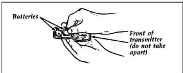
text_image
Batteries Front of transmitter (do not take apart)Replacing the batteries
The transmitter can be snapped apart to replace the batteries by twisting a thin coin between the two halves of the transmitter. DO NOT TAKE THE FRONT PART OF THE TRANSMITTER APART. When installing the new batteries, be sure to place the positive (+) side down as marked. Snap the two halves back together.
Replacement/additional transmitters
In the event a transmitter is lost, return the remaining transmitters to your dealer for reprogramming of your remote entry system. This is necessary to prevent further unauthorized use of the lost transmitter.
Additional transmitters may be purchased from your dealer (remote entry system will work with up to four transmitters). Return your existing transmitters to your dealer so the remote entry system can be reprogrammed with your new and existing transmitters.
THIS DEVICE COMPLIES WITH PART 15 OF THE FCC RULES. OPERATION IS SUBJECT TO THE FOLLOWING TWO CONDITIONS: (1) THIS DEVICE MAY NOT CAUSE HARMFUL INTERFERENCE, AND (2) THIS DEVICE MUST ACCEPT ANY INTERFERENCE RECEIVED, INCLUDING INTERFERENCE THAT MAY CAUSE UNDESIRED OPERATION.
Seating and Safety Restraints
:S
Head Restraints
If you use them properly, head restraints will help protect your head and neck in a collision.
A head restraint helps protect you best if you position it behind your head and not behind your neck.
Standard head restraints
You can adjust the head restraints for your comfort and protection.
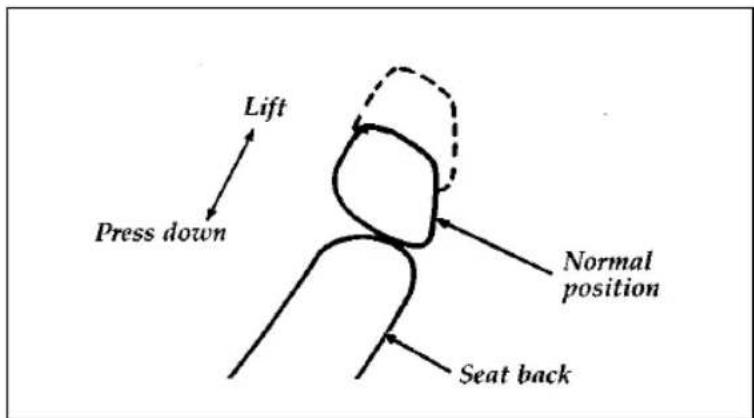
text_image
Lift Press down Normal position Seat backAdjusting the head restraint
Adjusting Manual Seats
In the front seats, you can move the whole seat forward or backward or tilt the back of the seat forward or backward.
To move the seats forward or backward:
- Find the adjustment bar underneath the front part of the seat.
- Lift the bar to unlatch the seat.
- Move the seat to the desired position.
- Release the bar to latch the seat in its new position. Make sure the seat locks securely in place.
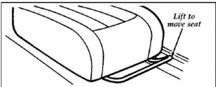
text_image
Lift to move seatThe front seat adjustment bar
To recline the front manual seats:
- On the side of the seat, find the handle for the recliner.
- Lift the handle up and hold it in place.
- Lean against the back of the seat and adjust it to the position you want. You can tilt the seat back or bring it forward.
- Release the handle to lock the seat in its new position.
| ⚠ WARNING |
| Never adjust the driver's seat or seatback when the vehicle is moving. |
| ⚠WARNING |
| Always drive and ride with your seatback upright and the lap belt snug and low across the hips. |
Seatback Recline
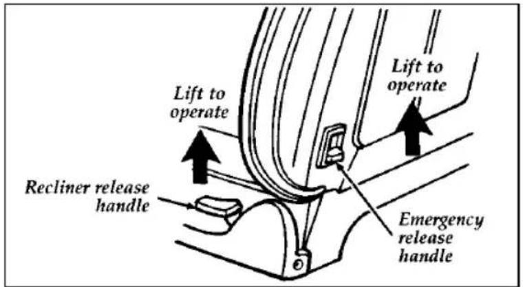
text_image
Lift to operate Recliner release handle Lift to operate Emergency release handleFront seatback release levers
It is not necessary to use the emergency seatback release lever for rear seat entry or exit. The seatback remains unlocked with normal usage and locks only during emergency stopping, upon impact, or on steep downhill grades. The inertia seatback latch will allow the seatback to rotate approximately 5° forward before it locks. The release is provided only to unlock the seatback when parked on steep downhill grades or after a collision.
⚠ WARNING
Check to see that the seat and seatback are latched securely in position. Keep floor area free of objects that would prevent proper seat engagement. Never attempt to adjust the seat while the vehicle is in motion.
Using the Power Seats (If equipped)
If your vehicle has power seats, you can adjust them in several directions. The controls are on the side of the seats.
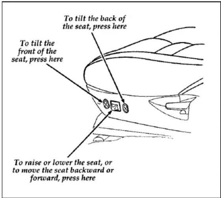
text_image
To tilt the back of the seat, press here To tilt the front of the seat, press here To raise or lower the seat, or to move the seat backward or forward, press hereThe power controls on the driver's seat
Rear Seat Entry
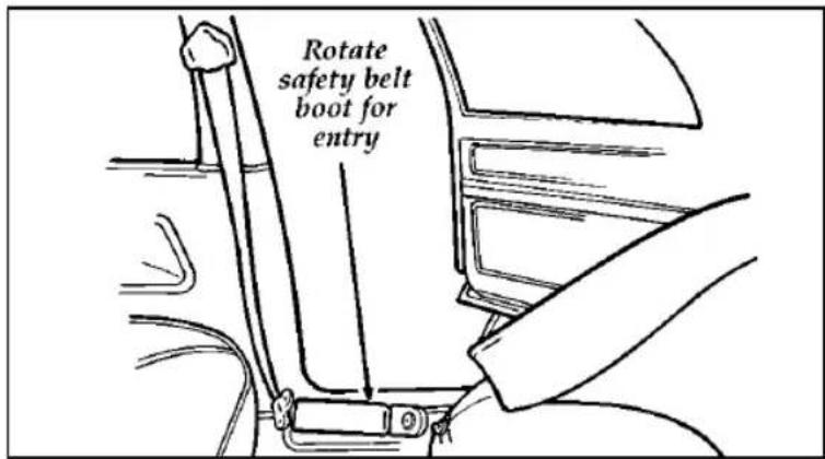
text_image
Rotate safety belt boot for entryEntering the rear seat
The rotating boot on the lap belt is designed to allow rear seat entry/exit. To enter the rear seat:
- Rotate the safety belt boot rearward.
- Enter the rear seat in front of the safety belt.
- Rotate the safety belt boot forward to allow use by the front seat passengers.
Important Safety Belt Information
The use of safety belts helps to restrain you and your passengers in case of a collision. In most states and in Canada the law requires their use.
Safety belts provide best restraint when:
□the seatback is upright
□the occupant is sitting upright (not slouched)
□the lap belt is snug and low on the hips
□the shoulder belt is snug against the chest
□the knees are straight forward
To help you remember to fasten your safety belt, a warning light may come on and a chime may sound. See Safety Belt Warning Light and Chime in the Instrumentation chapter.
See the following sections in this chapter for directions on how to properly use these safety belts. Also see Safety Restraints for Children in this chapter for special instructions about using safety belts for children.
| ⚠ WARNING |
| It is extremely dangerous to ride in a cargo area, inside or outside of a vehicle. In a collision, people riding in these areas are more likely to be seriously injured or killed. Do not allow people to ride in any area of your vehicle that is not equipped with seats and safety belts. Be sure everyone in your vehicle is in a seat and using a safety belt properly. |
| ⚠ WARNING |
| Always drive and ride with your seatback upright and the lap belt snug and low across the hips. |
| ⚠ WARNING |
| Ford recommends that all safety belt assemblies and attaching hardware should be inspected by a qualified technician after any collision. Safety belt assemblies not in use during a collision should also be inspected and replaced if either damage or improper operation is noted. |
| Children should always ride with the seatback in the fully upright position. |
| ⚠WARNING |
| Never let a passenger hold a child on his or her lap while the vehicle is moving.The passenger cannot protect the child from injury in a collision. |
| ⚠WARNING |
| Lock the doors of your vehicle before driving to lessen the risk of the door coming open in a collision. |
Combination Lap and Shoulder Belts
While your vehicle is in motion, the combination lap and shoulder belt adjusts to your movement. However, if you brake hard, corner hard or if your vehicle receives an impact of 5 mph (8 km/h) or more, the lap and shoulder belt locks and helps reduce your forward movement.
After you get into your vehicle, close the door and lock it. Then adjust the seat to the position that suits you best.
To fasten the belt, pull the lap/shoulder belt from the retractor so that the shoulder portion of the belt crosses your shoulder and chest. Be sure the belt is not twisted. If it is, remove the twist. Insert the belt tongue into the proper buckle until you hear a snap and feel it latch. Make sure the tongue is securely fastened in the buckle.
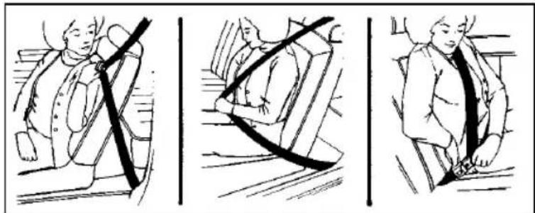
natural_image
Three-panel illustration showing a person seated in a seatbelt, with no text or symbols present.Fastening the front seat combination lap and shoulder belt
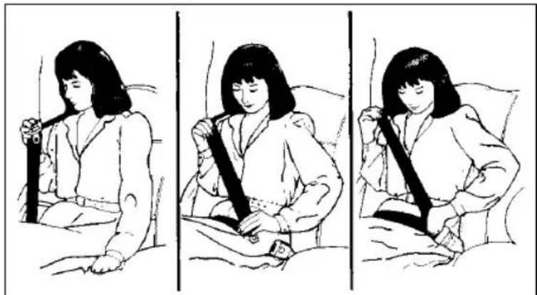
natural_image
Three-panel illustration showing a woman adjusting a seatbelt in bed, with no text or symbols present.Fastening the rear seat combination lap and shoulder belt
NOTE: Be sure to read and understand Important Safety Belt Information in this chapter.
Safety Belts for the Front Passenger Outboard Seating Positions
Your vehicle is equipped with a dual locking mode retractor on the shoulder belt portion of the combination lap/shoulder safety belt for front seat passengers and a locking “cinch tongue” for rear outboard passengers.
Dual locking mode retractors operate in two ways:
Vehicle sensitive (emergency) locking mode
In this operating mode, the shoulder belt retractor will allow the occupant freedom of movement, locking tight only on hard braking, hard cornering or impacts of approximately 5 mph (8 km/h) or more. The retractor can also be made to lock by pulling/jerking on the belt.
Automatic locking mode
In this operating mode, the shoulder belt retractor will be automatically locked and remain locked when the combination lap/shoulder safety belt is buckled, and does not allow the occupant freedom of movement. This mode provides the following:
☐ A tight lap/shoulder belt fit on the occupant.
□Child seat or infant carrier installation restraint.
⚠ WARNING
Rear-facing child seats or infant carriers should never be placed in the front seats.
This mode must be used when installing a child safety seat on the front passenger seat and rear outboard seats where dual locking retractors are provided.
To switch the retractor from the emergency locking mode to the automatic locking mode, perform the following steps:
- Buckle the lap/shoulder combination belt.
- Grasp the shoulder portion of the belt and pull downward until all of the belt is extracted and, when allowed to retract, a clicking sound is heard. At this time, the belt retractor is in the automatic locking mode (child restraint mode).
- A clicking sound will continue to be heard as the belt is allowed to retract.
NOTE: When the combination lap/shoulder belt is unbuckled and allowed to retract completely, the retractor will switch back to the vehicle sensitive (emergency) locking mode. See the detailed instructions under Safety Seats for Children in this chapter.
Safety Belts with Locking Cinch Tongue for Rear Outboard Seating Positions
Your vehicle is equipped with safety seat belts containing a cinch tongue at the rear outboard seating positions.
The locking cinch tongue will slide up and down the belt webbing when the belt is in the stowed position or while putting seat belts on. When the locking cinch tongue of the lap/shoulder combination seat belt is latched into the buckle, the cinch tongue will allow the lap portion to become shorter, but locks the webbing in place to restrict it from becoming longer.
Before you can reach and latch a combination lap and shoulder belt having a cinch tongue into the buckle, you may have to lengthen the lap belt portion of it. To lengthen the lap belt, pull some webbing out of the shoulder belt retractor. While holding the webbing below the tongue, grasp the tip (metal portion) of the tongue so that it is parallel to the webbing and slide the tongue upward. Provide enough lap belt length so that the tongue can reach the buckle.
NOTE: If you grasp the tongue by the tongue cover to lengthen the belt, the tongue cover will grab the webbing, making it difficult to slide.
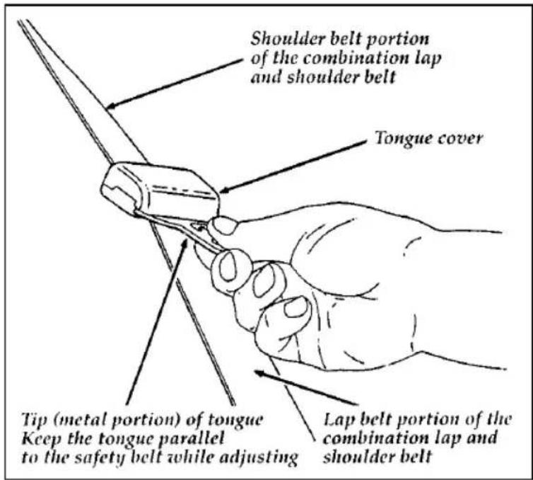
text_image
Shoulder belt portion of the combination lap and shoulder belt Tongue cover Tip (metal portion) of tongue Keep the tongue parallel to the safety belt while adjusting Lap belt portion of the combination lap and shoulder beltAdjusting the cinch tongue rear combination lap and shoulder belt
To fasten a cinch tongue, pull the combination lap and shoulder belt from the retractor so that the shoulder belt portion of the safety belt crosses your shoulder and chest. Be sure the belt is not twisted. If the belt is twisted remove the twist. Insert the belt tongue into the proper buckle for your seating position until you hear a snap and feel it latch. Make sure the tongue is securely fastened to the buckle by pulling on the tongue.
| ⚠ WARNING |
| The lap belts should fit snugly and as low as possible around the hips, not around the waist. |
| ⚠ WARNING |
| Front and rear seat occupants, including pregnant women, should wear safety belts for optimum protection in an accident. |
| ⚠ WARNING |
| Each seating position in your vehicle has a specific safety belt assembly which is made up of one buckle and one tongue that are designed to be used as a pair. 1) Use the shoulder belt on the outside shoulder only. Never wear the shoulder belt under the arm. 2) Never swing it around your neck over the inside shoulder. 3) Never use a single belt for more than one person. |
Due to folding rear seats, sometimes the buckles and tongues toward the center of the vehicle may be hidden by the rear edge of the seat cushion. Pull them out so they will be accessible.
While you are fastened in the seat belt, the combination lap/shoulder belt with a cinch tongue adjusts to your movement. However, if you brake hard, turn hard, or if your vehicle receives an impact of 5 mph (8 km/h) or more, the safety belt will become locked and help reduce your forward movement.
To unfasten all the belts:
- Push the release button on the end of the buckle. This allows the tongue to unlatch from the buckle.
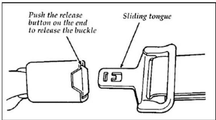
text_image
Push the release button on the end to release the buckle Sliding tongueUnfastening the front outboard lap/shoulder belts
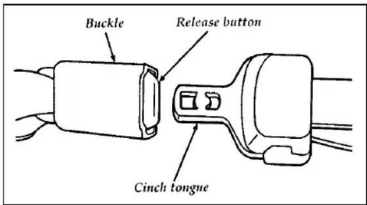
text_image
Buckle Release button Cinch tongueUnfastening the rear outboard lap/shoulder belts
- While the belt retracts, guide the tongue to its stowed position. If you do not guide the tongue, it may strike you or part of the vehicle.
Lap Belts — Rear Center Seating Positions
The lap belt in the center of the rear seat does not adjust automatically. You must adjust it to fit snugly and as low as possible around your hips. Do not wear it around your waist.
Pull the belt across your hips and insert the tongue into the correct buckle on your seat until you hear a snap and feel it lock. Make sure the buckle is securely fastened.
If you need to lengthen the belt, unfasten it and tip the belt tongue at a right angle to the belt. Pull the belt tongue over your lap until it reaches the buckle.
If you need to shorten the belt, pull on the loose end of the webbing until the belt fits snugly.
To unfasten the belt, push the release button on the buckle. This allows the tongue to unlatch from the buckle.
Because the center lap belt does not have a retractor, it should be shortened and fastened when not in use.
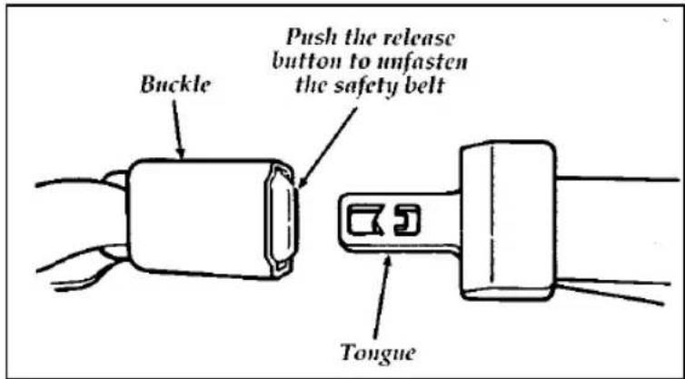
text_image
Buckle Push the release button to unfasten the safety belt TongueUnfastening center rear seat lap belt
Safety Belt Extension Assembly
For some people, the safety belt may be too short even when it is fully extended. You can add about eight inches (20 cm) to the belt length with a safety belt extension assembly (part number 611C22). Safety belt extensions are available at no cost from your dealer.
| WARNING |
| Failure to follow these instructions will affect the performance of the safety belts and increase the risk of personal injury. |
Use only extensions manufactured by the same supplier as the safety belt. Manufacturer identification is located at the end of the webbing on the label. Also, use the safety belt extension only if the safety belt is too short for you when fully extended. Do not use extension to change the fit of the shoulder belt across the torso.
Safety Belt Maintenance
Check the safety belt systems periodically to make sure that they work properly and are not damaged.
All safety belt assemblies, including retractors, buckles, front seat belt buckle support assemblies (slide bar) (if equipped), child safety seat tether bracket assemblies (if equipped), and attaching hardware, should be inspected after any collision. Ford recommends that all safety belt assemblies used in vehicles involved in a collision be replaced. However, if the collision was minor and a qualified technician finds that the belts do not show damage and continue to operate properly, they do not need to be replaced. Safety belt assemblies not in use during a collision should also be inspected and replaced if either damage or improper operation is noted.
Air Bag Supplemental Restraint System (SRS)
Important Air Bag Precautions
Your vehicle is equipped with a supplemental restraint system designed to work with the safety belts to help protect you and your right front seat passenger in the event of a collision. The Air Bag Supplemental Restraint System is primarily designed to reduce certain upper body injuries.
| ⚠ WARNING |
| All occupants of the vehicle, including the driver, should always wear their safety belts, failure to do so may increase the risk of personal injury in the event of a collision. |
| Do not place objects or mount equipment on or near the air bag covers that may come into contact with an inflating air bag. Failure to follow these instructions may increase the risk of personal injury in the event of a collision. |
| WARNING |
| Do not attempt to service, repair, or modify the air bag Supplemental Restraint System or its fuses. See your Ford or Lincoln-Mercury dealer. |
| ⚠ WARNING |
| If you are close to an inflating air bag, it could seriously injure you. Position your seat such that it is as far back from the steering wheel as possible but still allows you to properly control the vehicle. |
Children and Air Bags
NOTE: For additional important safety information on the proper use of seat belts, child seats, and infant seats, please read the entire Safety Restraints section in this owner guide.
| ⚠ WARNING |
| Children should always wear their safety belts. Failure to follow these instructions may increase the risk of personal injury in the event of a collision. |
⚠ WARNING
Rear-facing child seats and infant carriers should never be placed in the front seats.
How Does the Air Bag Supplemental Restraint System Work?
The Air Bag Supplemental Restraint System is designed to activate when the vehicle is in a collision similar to hitting a fixed barrier head on at 8-14 mph (13-23 km/h). The fact that the air bags did not inflate in a collision does not mean that something is wrong with the system. Rather, it means the forces were not of the type sufficient to cause acitivation.
If the vehicle is in a moderate or severe frontal collision, the system is activated and the air bags inflate rapidly. After the air bag inflates, it will quickly deflate. After the air bag deployment, you may notice a smoke-like, powdery residue or smell the burnt propellant. This is normal. The residue may consist of cornstarch or talcum powder (which is used to lubricate the air bag) or sodium compounds, such as sodium carbonates (e.g. baking soda) that result from the combustion process that inflates the air bag. Small amounts of sodium hydroxide may be present which may irritate the skin and eyes, but none of the residue is toxic. The Air Bag Supplemental Restraint System will reduce, but not eliminate all injuries in an accident.
⚠ WARNING
Several air bag system components get hot after inflation. Do not try to touch them after inflation.
⚠ WARNING
The air bag will inflate only once. The system is designed to function on a one-time-only basis. If the air bag is inflated, THE AIR BAG WILL NOT FUNCTION AGAIN AND MUST BE REPLACED IMMEDIATELY. If the air bag is not replaced, this will increase the risk of injury in a subsequent collision.
The Air Bag Supplemental Restraint System consists of:
□driver and passenger air bag modules (which include the inflators and air bags),
□one or more impact and safing sensors,
□a system diagnostic module,
□a readiness light and tone,
☐ and the electrical wiring which connects the components.
The diagnostic module monitors its own circuits, the air bag electrical system, the air bag readiness light, the air bag power, and the air bag inflators.
Determining if System Is Operational
The Air Bag Supplemental Restraint System uses a readiness light and a tone to indicate the condition of the system. The readiness light is in the instrument cluster. When you turn the ignition key to ON, this light will illuminate for approximately six (6) seconds and then turn off. This indicates that the system is operating normally. NOTE: Routine maintenance of the air bag system is not required.
A problem with the system is indicated by one or more of the following:
□the readiness light will either flash or stay lit,
□the readiness light will not light immediately after ignition is turned on,
☐a group of five beeps will be heard. The tone pattern will repeat periodically until the problem and light are repaired.
If any of these things happen, even intermittently, have the Air Bag Supplemental Restraint System serviced at your Ford or Lincoln-Mercury dealer immediately. Unless serviced, the system may not function properly in the event of a collision.
Disposal of Air Bags and Air Bag Equipped Vehicles
For disposal of air bags or air bag equipped vehicles, see your local Ford or Lincoln-Mercury dealer. Air bags MUST BE disposed of by qualified personnel.
Safety Restraints for Children
In the U.S. and Canada, you are required by law to use safety restraints for children. If small children ride in your vehicle — this generally includes children who are four years old or younger and who weigh 40 pounds (18 kg) or less — you must put them in safety seats that are made specially for children. Safety belts alone do not provide maximum protection for these children. Check your local and state laws for specific requirements.
| ⚠ WARNING |
| Never let a passenger hold a child on his or her lap while the vehicle is moving.The passenger cannot protect the child from injury in a collision. |
| ⚠ WARNING |
| Cargo should always be secured to prevent it from shifting and causing damage to the vehicle or harm to passengers. |
When possible, put children in the rear seat of your vehicle. Accident statistics suggest that children are safer when properly restrained in the rear seating positions than in the front seating positions.
| ⚠ WARNING |
| Carefully follow all of the manufacturer's instructions included with the safety seat you put in your vehicle. If you do not install and use the safety seat properly, the child may be injured in a sudden stop or collision. |
| ⚠ WARNING |
| Safety belts and seats can become hot in a vehicle that has been closed up in sunny weather; they could burn a small child. Check seat covers and buckles before you place a child anywhere near them. |
| ⚠ WARNING |
| Do not leave children, unreliable adults, or pets unattended in your vehicle. |
⚠ WARNING
When using forward-facing child seats move the passenger seat as far back from the instrument panel as possible. Never secure rear-facing infant seats in the front seat.
Safety Seats for Children
Use a safety seat that is recommended for the size and weight of the child. Always follow the safety seat manufacturer's instructions when installing and using the safety seat.
When installing a child safety seat, be sure to use the correct safety belt buckle for that seating position, and make sure the tongue is securely fastened in the buckle. For a shoulder/lap belt combination with a sliding tongue, make sure the retractor is in the automatic locking mode.
Children weighing less than 40 lbs. (18 kg) should use child or infant seats. Forward facing child seats must have the passenger seat moved as far back from the instrument panel as possible.
⚠ WARNING
Rear-facing child seats or infant carriers should never be placed in the front seats.
All child restraint systems are designed to be secured in vehicle seats by lap belts or by the lap portion of a lap-shoulder belt.
| ⚠ WARNING |
| If you do not properly secure the safety seat, the child occupying the seat may be injured during a collision or sudden stop. An unsecured safety seat could also injure other passengers. |
| ⚠ WARNING |
| Carefully follow all of the manufacturer's instructions included with the safety seat you put in your vehicle. If you do not install and use the safety seat properly, the child may be injured in a sudden stop or collision. |
| ⚠WARNING |
| Always keep the buckle release button pointing upward and away from the child seat, with the tongue between the child seat and the release button as shown in the following illustration. |
Installing Safety Seats in the Front Outboard Passenger Seating Position
For seating positions equipped with a dual locking mode retractor, use the following procedure.
If you choose to install a forward-facing child safety seat in the front seating positions, move vehicle seat as far back as possible.
-
Position the child seat in the center of the passenger seating position.
-
Pull down on shoulder belt, then grasp shoulder belt and lap belt together. See Figure 1.
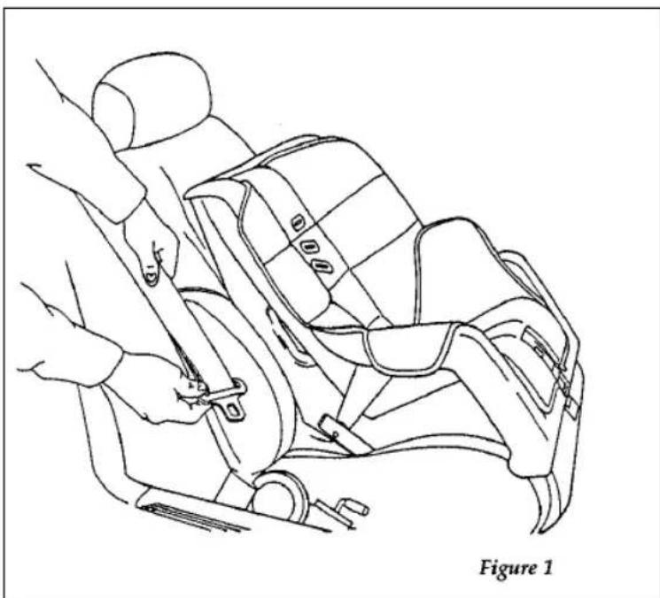
natural_image
Line drawing of a car seat assembly with hands adjusting the seatbelt (no text or symbols)Pulling out belt webbing
- While holding the shoulder and lap belt portions together, route the tongue through the child seat according to the child seat manufacturer's instructions. See Figure 2. Be sure that the belt webbing is not twisted.
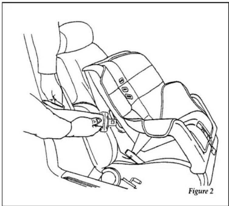
natural_image
Line drawing of a car seatbelt assembly with hands adjusting the seat (no text or symbols)Routing the lap/shoulder belt
- Insert the belt tongue into the buckle for that seating position until you hear and feel the latch engage. See Figure 3. Make sure tongue is latched securely to buckle by pulling on tongue.
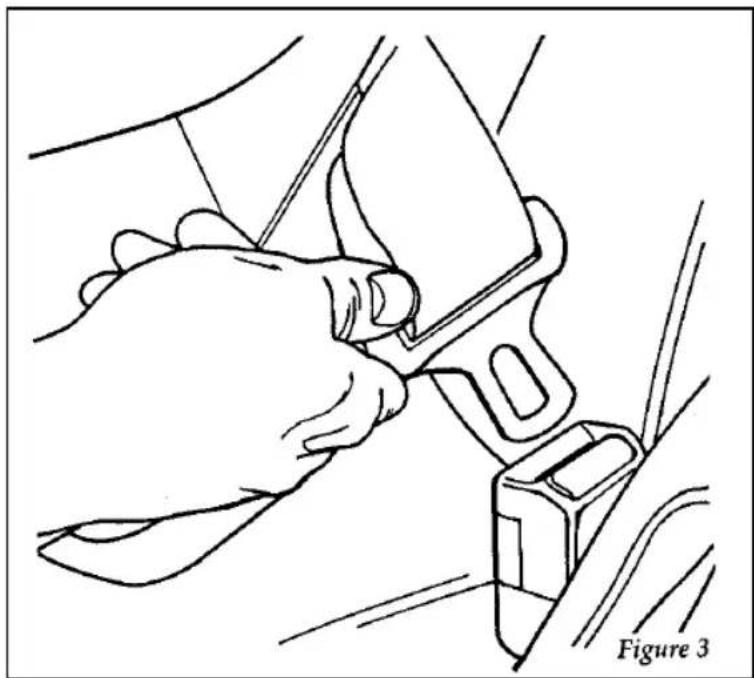
natural_image
Line drawing of a hand adjusting a car seatbelt component (no text or symbols)Buckling the belt
- Grasp the shoulder portion of the belt and pull downward until all of the belt is extracted and a click is heard. At this time, the retractor is in the automatic locking mode (child seat restraint mode). See Figure 4.
NOTE: The dual-locking mode retractor must be in the automatic locking mode to properly restrain a child.
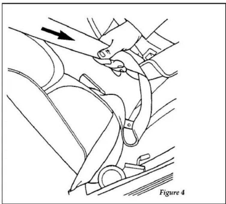
natural_image
Line drawing of a car seatbelt mechanism with hand placement and belt, labeled Figure 4 (no text or symbols on diagram)Setting the retractor to automatic locking mode
- Allow the belt to retract. Pull up on the shoulder webbing. A clicking sound will be heard as the belt retracts. This indicates the retractor is in the automatic locking mode. Push down on the child seat while you pull up on the belt to remove any slack in the belt. See Figures 5 and 6.

natural_image
Line drawing of a person using a seatbelt to adjust the seat (no text or symbols)Allowing shoulder belt to retract
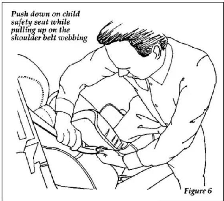
text_image
Push down on child safety seat while pulling up on the shoulder belt webbing Figure 6Removing slack from belt
- Before placing the child in the child seat, forcibly tilt the seat from side to side, and tug it forward to make sure that the seat is securely held in place. See Figure 7.
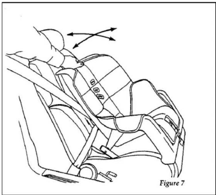
natural_image
Line drawing of a car seatbelt with directional arrows indicating movement (no text or symbols)Checking that the seat is secure
- Double check that the retractor is in the automatic locking mode. Try to pull more belt out of the retractor. If you cannot, the belt is in the automatic locking mode. See Figure 8.
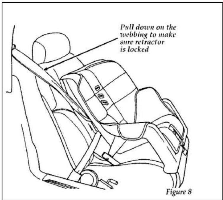
text_image
Pull down on the webbing to make sure retractor is locked Figure 8Checking the retractor
- Check to make sure that the child seat is properly secured prior to each use. If the retractor is not locked, repeat steps 4 through 7.
Installing Child Safety Seats in the Rear Outboard Seating Positions
Your rear outboard seating positions are equipped with a cinch tongue on the safety belts. Use the following procedure for installing a child safety seat in these locations.
- Grasp the belt webbing below the tongue and pull as much of the belt out of the retractor as possible. Hold the belt out. See Figure 1.
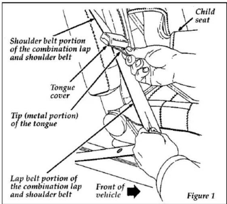
text_image
Child seat Shoulder belt portion of the combination lap and shoulder belt Tongue cover Tip (metal portion) of the tongue Lap belt portion of the combination lap and shoulder belt Front of vehicle Figure 1NOTE: The belt webbing below the tongue is the lap belt portion of the combination lap/shoulder belt, and the belt webbing above the tongue is the shoulder belt portion of the combination lap/shoulder belt.
- With your other hand, grasp the tip (metal portion) of the tongue (not the cover) and slide the tongue up the webbing as far as it will go. See Figure 1. Release the tongue, but do not let go of the lap portion of the belt webbing.
- While still holding the belt webbing below the tongue in one hand, use your other hand to grasp the tip (metal portion) of the tongue and belt webbing together, and again pull out as much of the belt as possible. Then, let go of the lap portion of the belt webbing.
- While holding the shoulder and lap belt portions together, route the tongue and webbing through the child seat according to the child seat manufacturer's instructions. See Figure 2. Be sure that the belt webbing is not twisted.
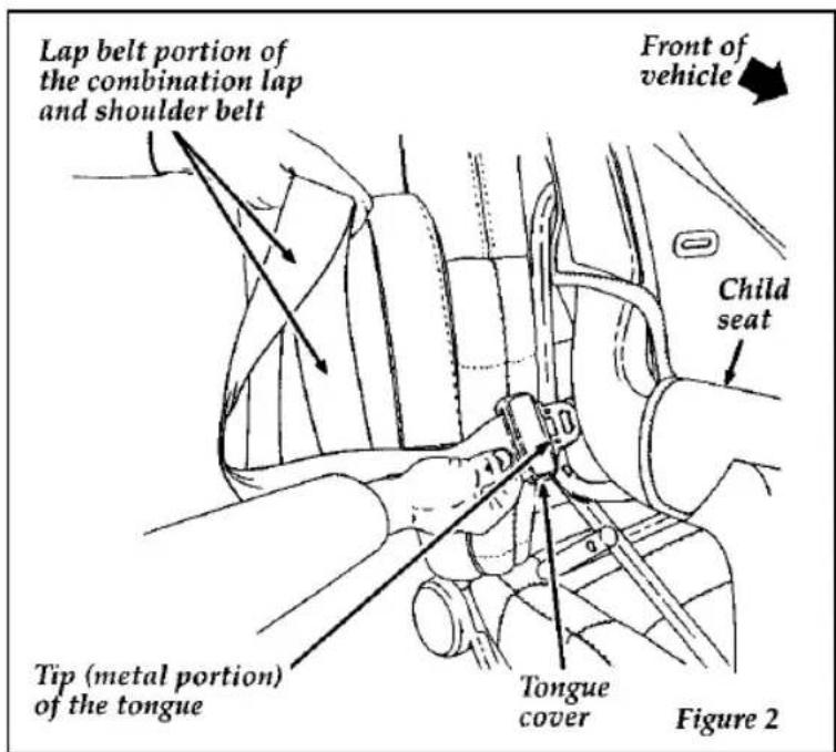
text_image
Lap belt portion of the combination lap and shoulder belt Front of vehicle Child seat Tip (metal portion) of the tongue Tongue cover Figure 2- Insert the belt tongue into the proper buckle for that seating position until you hear a snap and feel it latch. Make sure the tongue is securely latched to the buckle by pulling on the tongue. See Figure 3.
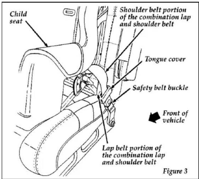
text_image
Child seat Shoulder belt portion of the combination lap and shoulder belt Tongue cover Safety belt buckle Front of vehicle Lap belt portion of the combination lap and shoulder belt Figure 3- Push down on the child seat and pull up on the shoulder belt portion to tighten the lap belt portion of the combination lap and shoulder belt. See Figure 4.
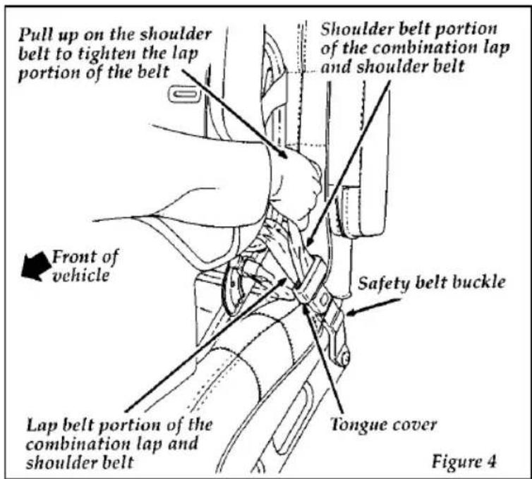
text_image
Pull up on the shoulder belt to tighten the lap portion of the belt Shoulder belt portion of the combination lap and shoulder belt Front of vehicle Safety belt buckle Lap belt portion of the combination lap and shoulder belt Tongue cover Figure 4- Grasp belt close to child seat and pull on the shoulder belt portion of the combination lap/shoulder belt, then allow the belt to retract and remove all slack to securely tighten the child safety seat in the vehicle. See Figure 5.
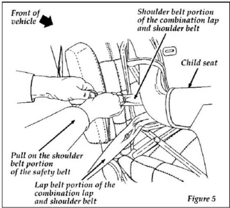
text_image
Front of vehicle Shoulder belt portion of the combination lap and shoulder belt Child seat Pull on the shoulder belt portion of the safety belt Lap belt portion of the combination lap and shoulder belt Figure 5- Before placing the child into the child seat, forcibly tilt the child seat from side-to-side and in forward directions to make sure that the seat is held securely in place. See Figures 6 and 7. If the child seat moves excessively, repeat steps 6 through 8, or properly install the child seat in a different seating position.
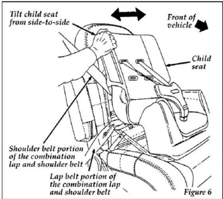
text_image
Tilt child seat from side-to-side Front of vehicle Child seat Shoulder belt portion of the combination lap and shoulder belt Lap belt portion of the combination lap and shoulder belt Figure 6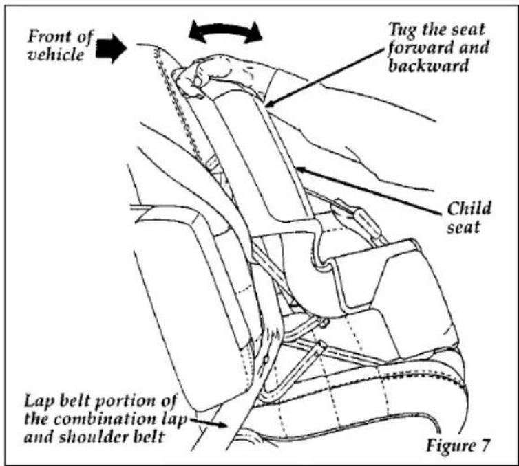
text_image
Front of vehicle Tug the seat forward and backward Child seat Lap belt portion of the combination lap and shoulder belt Figure 7- Check from time to time to be sure that there is no slack in the lap/shoulder belt. The shoulder belt must be snug to keep the lap belt tight during a collision.
Installing a Child Safety Seat at the Rear Center Seating Position with Adjustable Lap Belt
-
Lengthen the lap belt. To lengthen the belt, hold the tongue so that its bottom is perpendicular to the direction of webbing while sliding the tongue up the webbing.
-
Place the child safety seat in the center seating position.
-
Route the tongue and webbing through the child seat according to the child seat manufacturer's instructions.
-
Insert the belt tongue into the proper buckle for the center seating position until you hear a snap and feel it latch. Make sure the tongue is securely fastened to the buckle by pulling on tongue.
-
Push down on the child seat while pulling on the loose end of the lap belt webbing to tighten the belt.
-
Before placing the child into child seat, forcibly tilt the child seat from side-to-side and in forward direction to ensure that the seat is held securely in place. If the child seat moves excessively, repeat steps 5 through 6, or properly install the child seat in a different position.
Attaching Safety Seats with Tether Straps
Some manufacturers make safety seats that include a tether strap that goes over the back of the vehicle seat and attaches to an anchoring point. Other manufacturers offer the tether strap as an accessory. Contact the manufacturer of your child safety seat for information about ordering a tether strap.
Tether anchorage hardware
Attachment holes (at each rear seating position) have been provided in your vehicle to attach anchor hardware, if required. Tether anchor hardware kits (Part number 613D74), including instructions, may be obtained at no charge from any Ford or Lincoln-Mercury dealer. All vehicles built for sale in Canada include a tether anchor hardware kit.
Safety Belts for Children
Children who are too large for child safety seats should always wear safety belts. (See instructions with your child seat, or contact its manufacturer, to determine maximum size of child that will safely fit in the seat.)
⚠ WARNING
If safety belts are not properly worn and adjusted as described, the risk of serious injury to the child in a collision will be much greater.
If the shoulder belt portion of one of the lap and shoulder belts can be positioned so that it does not cross or rest in front of the child's face or neck, the child should wear the lap and shoulder belt. Moving the child closer to the center of the vehicle may help provide a good shoulder belt fit.
| ⚠ WARNING |
| If the shoulder belt cannot be properly positioned, the child should sit in the center rear seat and use the lap belt. |
To improve the fit of lap and shoulder belts on children who have outgrown child safety seats, Ford recommends use of a belt-positioning booster seat that is labelled as conforming to all Federal motor vehicle safety standards. Belt-positioning booster seats raise the child and provide a shorter, firmer seating cushion that encourages safer seating posture and better fit of lap and shoulder belts on the child. A belt-positioning booster should be used if the shoulder belt rests in front of the child's face or neck, or if the lap belt does not fit snugly on both thighs, or if the thighs are too short to let the child sit all the way back on the seat cushion when the lower legs hang over the edge of the seat cushion. You may wish to discuss the specific needs of your child with your pediatrician.
| ⚠WARNING |
| Do not use a belt-positioning booster with a lap-only belt. |
Lap belts and the lap belt portion of lap and shoulder belts should always be worn snugly and below the hips, touching the child's thighs.
| ⚠ WARNING |
| Children should always ride with the seatback in the fully upright position. |
Starting
Fuel-Injected Engines
When starting a fuel-injected engine, the most important thing to remember is to avoid pressing down on the accelerator before or during starting. Only use the accelerator when you have problems getting your vehicle started. See Starting Your Engine in this chapter for details about when to use the accelerator while you start your vehicle.
Starting Your Vehicle
Preparing to Start Your Vehicle
| ⚠ WARNING |
| Do not start your vehicle in a closed garage or in other enclosed areas. Exhaust fumes can be toxic. Always open the garage door before you start the engine. |
Before you start your vehicle, do the following:
- Make sure all occupants in the vehicle buckle their safety belts. See Safety Restraints in the Index for more details.
- Make sure the headlamps and other accessories are turned off when starting.
- Make sure that the gearshift is in P (Park) and the parking brake is set before you turn the key.
Before you start your vehicle, you should test the warning lights on the instrument panel to make sure that they work. Refer to the Instrumentation chapter.
Starting Your Engine
To start your engine:
- Follow the steps under Preparing to Start Your Vehicle at the beginning of this section.
- Turn the ignition key to the ON position.
- DO NOT depress the accelerator pedal when starting your engine. DO NOT use the accelerator while the vehicle is parked.
- Turn the key to the START position (cranking) until the engine starts. Allow the key to return to the ON position after the engine has started.
If you have difficulty in turning the key, rotate the steering wheel slightly because it may be binding.
For a cold engine:
☐ At temperatures 10^ F ( -12^ C) and below: If the engine does not start in fifteen (15) seconds on the first try, turn the key to OFF, wait approximately ten (10) seconds so you do not flood the engine, then try again.
☐ At temperatures above 10^ F (-12°C): If the engine does not start in five (5) seconds on the first try, turn the key to OFF, wait approximately ten (10) seconds so you do not flood the engine, then try again.
For a warm engine:
☐Do not hold the key in the START position for more than five (5) seconds at a time. If the engine does not start within five (5) seconds on the first try, turn the key to the OFF position. Wait a few seconds after the starter stops, then try again.
Whenever you start your vehicle, release the key as soon as the engine starts. Excessive cranking could damage the starter.
After you start the engine, let it idle for a few seconds. Keep your foot on the brake pedal and put the gearshift lever in gear. Release the parking brake. Slowly release the brake pedal and drive away in the normal manner.
NOTE: Your vehicle has an interlock that prevents you from shifting out of P (Park) unless your foot is on the brake pedal.
If the engine does not start after two attempts:
- Turn the ignition key to the OFF position.
- Press the accelerator all the way to the floor and hold it.
- Turn the ignition key to the START position.
- Release the ignition key when the engine starts.
- Release the accelerator gradually as the engine speeds up.
If the engine still does not start, the fuel pump shut-off switch may have been triggered. For directions on how to reset the switch see Fuel Pump Shut-Off Switch in the Index.
A computer system controls the engine's idle speed. When you start your vehicle, the engine's idle speed normally runs higher than when it's warmed up. These faster engine speeds will make your vehicle move slightly faster than its normal idle speed. It should, however, slow down after a short time. If it does not, have the idle speed checked.
If the engine idle speed does not slow down automatically, do not allow your vehicle to idle for more than 10 minutes. Have the vehicle checked.
| ⚠ WARNING |
| Extended idling at high engine speeds can produce very high temperatures in the engine and exhaust system, creating the risk of fire or other damage. |
| WARNING |
| Do not park, idle, or drive your vehicle in dry grass or other dry ground cover. The emission system heats up the engine compartment and exhaust system, which can start a fire. |
If you consistently start your vehicle in subzero temperatures, use an engine block heater (if your vehicle has this option).
Engine Block Heater (If equipped)
Engine block heaters are strongly recommended if you live in a region where temperatures reach -10^ F ( -23^ C) or below. An engine block heater warms the engine coolant, which improves starting, warms up the engine faster, and allows the heater-defrost system to respond quickly.
To turn the heater on, simply plug it into a grounded 110-volt outlet. Ford recommends that you use a 110-volt circuit that is protected by a ground fault circuit interrupter.
⚠ WARNING
To prevent electrical shock, do not use your heater with ungrounded electrical systems or two-pronged (cheater) adapters.
For best results, plug the heater in at least three hours before you start your vehicle. Using the heater for longer than three hours will not damage the engine, so you can plug it in at night to start your vehicle the following morning.
NOTE: Be sure to disconnect the engine block heater before driving your vehicle.
Guarding Against Exhaust Fumes
Carbon monoxide, although colorless and odorless, is present in exhaust fumes. Take precautions to avoid its dangerous effects.
⚠ WARNING
Do not start your vehicle in a closed garage or in other enclosed areas. Exhaust fumes can be toxic. Always open the garage door before you start the engine.
⚠ WARNING
If you smell exhaust fumes inside your vehicle, have your dealer inspect your vehicle immediately. Do not drive if you smell exhaust fumes.
Have the exhaust and body ventilation systems checked whenever:
□ your vehicle is raised for service
□the sound of the exhaust system changes
□your vehicle has been damaged in a collision
Improve your ventilation by keeping all air inlet vents clear of snow, leaves, and other debris.
If the engine is idling while you are stopped in an open area for long periods of time, open the windows at least one inch (2.5 cm). Also, the heating or air conditioning system should be set to any function except MAX A/C or AUTO.
☐If you use the heater, set the fan speed on MEDIUM or HIGH with the function control on any position except OFF and the temperature control at any desired position.
☐If you use the air conditioner, set the fan speed on MEDIUM or HIGH with the function control on any position except OFF or MAX and the temperature control at any desired position.
Vehicles with automatic transmissions cannot be started by pushing. Follow the directions under If Your Vehicle Needs a Jump-Start.
Driving
ces
Applying the Brakes
Braking non ABS models
Your vehicle has standard power front disc brakes and rear drum brakes, (anti-lock disc brakes on all four wheels are optional). They adjust automatically as the brake pads or linings wear down.
Apply the brake pedal gradually. Use the "squeeze" technique — push on the brake pedal with a steadily increasing force. This allows the wheels to continue to roll while you are slowing down, which lets you steer properly.
On vehicles without anti-lock brakes, extreme braking can make the wheels lock and slide, possibly decreasing your control of the steering. If you lock the wheels, release the brake pedal and repeat the “squeeze” technique.
Braking with ABS brakes
On vehicles with anti-lock brakes, the wheels will not lock and slide when you press down hard on the brake pedal. The anti-lock brakes automatically start releasing and reapplying the front brakes independently and the rear brakes together whenever your wheels start to lock. Do not “pump” the brake pedal on vehicles equipped with anti-lock brakes. When this happens, you will feel the brake pedal pulse. This “pulse” may be an unfamiliar feeling but it is normal and indicates the ABS is working as designed.
Do not drive with your foot resting on the brake pedal; you will wear out the linings and increase your vehicle's stopping distance. Brake rotor damage may also eventually occur.
NOTE: If you are driving down a long or steep hill, shift to a lower gear and do not apply your brakes continuously. If you apply your brakes continuously, they may overheat and become less effective.
Occasional brake squeal during light to moderate stops does not affect the function of the brake system and is normal. However, if the squeal becomes louder or more frequent, have your brakes inspected by your dealer or a qualified service technician.
Ford Motor Company has not found any detrimental effects of popular mobile radio transmitting equipment installed on vehicles with the anti-lock brake system, if the equipment is installed according to the manufacturer's instructions. However, if mobile radio transmitting equipment is installed in your vehicle and, if either the anti-lock brake system cycles or the check anti-lock light comes on at any time other than right after you turn the key to ON or during a sudden stop, have your mobile radio dealer inspect the installation.
Parking Brake
The parking brake should be used whenever you park your vehicle.
The parking brake pedal is suspended just below the bottom of the instrument panel to the left of the brake pedal.
To set the parking brake while parking your vehicle, apply the brake pedal with your right foot and hold it while you push the parking brake down firmly with your left foot. The brake system warning light will glow.
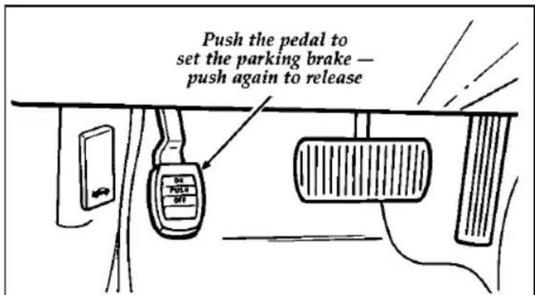
text_image
Push the pedal to set the parking brake — push again to releaseThe parking brake
| WARNING |
| Always set the parking brake fully and make sure the gearshift is latched in P (Park). Turn off the ignition whenever you leave your vehicle. |
To release the parking brake, press down on the pedal until you hear a click. Lift your foot off the pedal. The brake is now released and will reset to lock the next time you press the pedal, located below the lower left corner of the instrument panel. The Brake System Warning Light will glow if the parking brake is not fully released when the engine is running.
Always check the Brake Warning Light each time you start your engine. Driving with the parking brake on will cause the brakes to wear out quickly and will reduce the fuel economy.
| ⚠ WARNING |
| If the parking brake is fully released, but the Brake System light remains on, have the brakes checked immediately. They may not be working properly. |
The parking brake system is designed for static parking only and is not designed to stop a moving vehicle, but you can use the parking brake to stop your vehicle in an emergency if the normal brakes fail. However, since the parking brake applies only the rear brakes, the stopping distance will increase greatly and the handling of your vehicle will be adversely affected.
Traction-Lok Axle (If equipped)
This axle provides added traction on slippery surfaces, particularly when one wheel is on a poor traction surface. Under normal conditions the Traction-Lok axle functions as a standard rear axle.
Extended use of other than matching size tires on a Traction-Lok rear axle could result in a permanent reduction in effectiveness. This loss of effectiveness does not affect normal driving and should not be noticeable to the driver.
| ⚠WARNING |
| To avoid injury, never run the engine with one wheel off the ground, such as when changing a tire. |
Traction Assist™ (If equipped)
Your vehicle may be equipped with the optional Traction Assist™ system. This system helps prevent wheel spin in order to improve tire traction and is an especially useful feature when you drive in hilly areas or on slippery, icy or snowy roads.
Traction Assist ^™ works automatically by rapidly applying and releasing the brakes to prevent one or both of the rear drive wheels from spinning during acceleration.
The Traction Assist ^TM system can be manually turned off, to allow wheelspin if you want, by pushing the traction assist switch (located in the console). When the vehicle is not in the Traction Assist ^TM mode the “T/A OFF” indicator light (located on the cluster) will illuminate to indicate the system is off. The Traction Assist ^TM system will automatically be on each time the engine is started. During ordinary driving, it is recommended to leave the system turned on. The Traction Assist ^TM system will then always be ready to operate when needed.
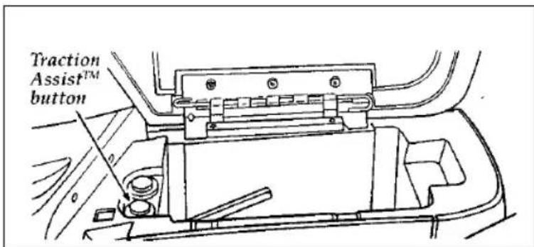
text_image
Traction Assist™ buttonThe Traction Assist ^TM Switch
During the Traction Assist ^TM function, which most often occurs during low speed acceleration on slippery surfaces, a noise may be heard coming from the engine compartment. This noise is created by the ABS pump and is normal and may last for a few seconds during the acceleration of the vehicle.
In general, this system improves your vehicle's stability and acceleration performance when road conditions warrant. Traction Assist ^TM is fully effective up to approximately 25 mph (40 km/h). At 25 mph (40 km/h) the function begins to taper off until it no longer operates above 34 mph (55 km/h).
If the Traction Assist ^TM system is cycled excessively, the system will shut down to prevent the rear brakes from overheating. During this shutdown period, the word OFF in the traction assist switch will be illuminated showing that the traction assist system is inoperative. A cooling down period is required to prevent damage to the rear brakes. This time period varies and depends on brake usage during the cooling down period. Anti-Lock braking is not affected and will function normally during the cool down period.
Steering Your Vehicle
Your vehicle comes with power steering. Power steering uses energy from the engine to help steer your vehicle.
If the amount of effort needed to steer your vehicle changes at a constant vehicle speed, have the power steering system checked. If the power steering system breaks down (or if the engine is turned off), you can steer the vehicle manually but it takes more effort.
Never hold the steering wheel to the extreme right or left for more than five seconds if the engine is running. This can damage the power steering pump.
Speed Sensitive Power Steering (If equipped)
The steering system in 4.6L engine vehicles is speed sensitive. This means that the steering effort is light for parking and heavier for highway driving. However, if you have to swerve around an object or another vehicle, your steering will have full power assist.
Driving with an Automatic Overdrive Transmission
The gearshift lever is floor mounted.
The automatic overdrive transmission operates very much like a regular automatic transmission, except it offers the extra overdrive feature.
Putting Your Vehicle in Gear
| ⚠WARNING |
| Hold the brake pedal down while you move the gearshift lever from position to position. If you do not hold the brake pedal down, your vehicle may move unexpectedly and injure someone. |
To move the shifter out of P (Park), the ignition key must be turned to the ON position and the shift lever thumb button must be pushed in.
To operate:
- Start the engine.
- Depress and hold the brake pedal.
- Move the gearshift lever out of P (Park).
Your vehicle is equipped with a Brake Shift Interlock safety feature. This feature prevents the gearshift from being moved from the P (Park) position until the brake pedal is depressed. This feature is active when the ignition is in the ON position. If the gearshift lever CANNOT be moved from P (Park) with the brake pedal depressed:
- Turn the engine off and remove the ignition key.
- Apply parking brake.
- Reinsert the ignition key and turn clockwise to the first position.
- Depress the brake pedal, move the gearshift lever to N (Neutral) and start the engine.
| ⚠WARNING |
| DO NOT DRIVE YOUR VEHICLE UNTIL YOU VERIFY THAT THE BRAKELAMPS ARE WORKING. |
If you need to shift out of P (Park) by using the alternate procedure described above, it is possible that a fuse has blown and that your brakelamps may also not be functional. Please refer to the chapter titled Roadside Emergencies in this Owner Guide for instructions on checking and replacing fuses.
The console-mounted gearshift will lock in P (Park) when you turn the key to the LOCK position. When the gearshift is in any position except P (Park), the ignition key cannot be turned to LOCK or removed from the steering column. TO REMOVE THE KEY, the gearshift lever must be in P (Park).
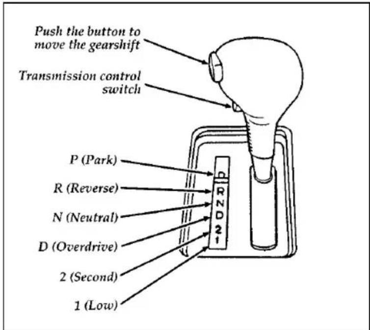
text_image
Push the button to move the gearshift Transmission control switch P (Park) R (Reverse) N (Neutral) D (Overdrive) 2 (Second) 1 (Low)The positions of the console-mounted gearshift
Once the gearshift is secure in the desired position, release the brake pedal and use the accelerator as necessary.
R (Reverse)
With the gearshift in the R (Reverse) position, the vehicle will move backward. You should always come to a complete stop before shifting into or out of R (Reverse).
N (Neutral)
As in P (Park), there is no power transferred through the transmission. However, the final drive is not locked so the wheels are free to rotate. The vehicle may be started in the N position, but the ignition key cannot be removed.
Driving
Your vehicle's gearshift is console-mounted on the floor. The Transmission Control Switch (TCS) is located on the gearshift handle. The Transmission Control Indicator Light (O/D OFF) is located on the instrument panel. You can put the gearshift lever in any of the several positions.
The OVERDRIVE OFF light is off (not illuminated) during normal vehicle operation. This allows the transmission to upshift and downshift from 1st through 4th gears. When the TCS is pressed, the Transmission Control Indicator Light will illuminate (O/D OFF) on the instrument panel. When this O/D OFF is illuminated the transmission will upshift and downshift from 1st through 3rd gears.
If the O/D OFF light does not come “on” when the TCS is depressed or if the light “FLASHES” when you are driving, have your vehicle serviced at the first opportunity. If this condition persists, damage could occur to the transmission.
To return the transmission to normal operation (1st through 4th gear) depress the TCS again. This switch may be used to cancel overdrive any time the vehicle is being driven. Each time your vehicle is started, the overdrive system will automatically be in the normal overdrive mode and the light will not be illuminated.
When to use D (Overdrive)
Overdrive is the usual driving position for an automatic overdrive transmission. It works the same way Drive works, automatically upshifting or downshifting as the vehicle speeds or slows.
However, Overdrive also shifts into a fourth gear—an overdrive gear—when your vehicle cruises at an appropriate consistent speed for any length of time. This fourth gear will increase your fuel economy when you travel at cruising speeds.
When to use D (Overdrive) — with transmission control switch activated (O/D OFF light illuminated)
Overdrive may not be appropriate for certain terrain. If the transmission shifts back and forth between Third and Fourth gears while you are driving on hilly roads or if your vehicle does not have adequate power for climbing hills, depress the TCS.
You can depress the TCS at any speed.
When to use 2 (Second)
Use 2 (Second) for start-up on slippery roads or to give you more engine braking to slow your vehicle on downgrades.
When to use 1 (Low)
Use 1 (Low) when driving down steep grades. It gives more engine braking to slow your vehicle than 2 (Second) on the downgrades. You can upshift from 1 (Low) to 2 (Second) or from 1 (Low) to Overdrive at any speed.
P (Park)
Always come to a complete stop before you shift into P (Park). Make sure that the gearshift is securely latched in P (Park). This locks the transmission and prevents the rear wheels from rotating.
| ⚠ WARNING |
| Always set the parking brake fully and make sure the gearshift is latched in P (Park). Turn off the ignition whenever you leave your vehicle. |
| ⚠ WARNING |
| Never leave your vehicle unattended while it is running. |
You can tell a console-mounted gearshift is securely latched in P (Park) if the lever is adjacent to the P (Park) and you cannot move it without pushing in the thumb button.
Driving With a Heavy Load
There are limits to the amount of weight your vehicle can carry or tow. The total weight of your vehicle, plus the weight of the passengers and cargo, should never be more than the Gross Vehicle Weight Rating (GVWR). Also, the weight that your vehicle carries over the front axle and rear axle should never be more than the Gross Axle Weight Rating (GAWR) for the respective axle.
You can find your vehicle's GVWR and GAWR on the Safety Compliance Certification Label on the left front door lock facing or the door latch post pillar.
The weight limits of your vehicle's tires affect the GVWR or GAWR limitations. Usage of replacement tires with higher weight limits than originals does not increase GVWR or GAWR. Usage of lower capacity replacement tires may lower GVWR and GAWR limitations.
⚠ WARNING
Do not exceed the GVWR or the GAWR specified on the Safety Compliance Certification Label.
Limiting Your Vehicle's Load
The load that you add to your vehicle must not exceed the maximum load stated on the Safety Compliance Certification Decal attached to the left front door pillar.
To figure the weight of your vehicle's load, add the weights of:
□the driver and passengers
☐ luggage and any other items that you put in your vehicle
□the tongue load of the loaded trailer
□the weight of any equipment that has been added to your vehicle since it was delivered to your dealer
If you do not know the actual weights of these items, use the following procedure to figure the weight of a load:
- Weigh your vehicle without the driver, passengers and luggage. You might take your vehicle to a shipping company or an inspection station for trucks.
- Then weigh your vehicle with the driver, passengers and luggage.
- Subtract the first reading from the second to figure the total weight of the load.
After determining this load, you must also make sure that the total weight of your vehicle, plus the load it carries, is less than its GVWR. Also, make sure that the weight your vehicle carries over each axle is less than the GAWR for the respective axle.
If your vehicle exceeds the GVWR, remove cargo from your vehicle accordingly. If your vehicle exceeds the GAWR for either axle, shift the load or remove cargo accordingly.
⚠ WARNING
Improper distribution of your vehicle's load or carrying weight in excess of the amount shown on the tire decal can cause rapid tire wear or loss of vehicle control.
Trailer Towing
Your vehicle does not come from the factory fully equipped to tow. No towing packages are available through Ford or Lincoln/Mercury dealers.
Because towing a trailer puts extra strain on your vehicle, you must follow certain precautions for your safety and the good of your vehicle:
□Stay within the load limits for towing your vehicle. (See Trailer towing specifications in this chapter.)
□Carefully and thoroughly prepare your vehicle for towing, making sure to use the right equipment and to attach it properly. (See Preparing to Tow in this chapter.)
□Use extra caution when driving your vehicle while you tow. (See Driving while you tow in this chapter.)
□Service your vehicle more frequently if you tow a trailer. (See Servicing your vehicle if you tow in this chapter.)
Ten to 15% of the loaded trailer's weight should be on the tongue. However, the tongue load should never exceed 10% of the maximum weight that your vehicle can safely tow.
| ⚠ WARNING |
| Do not tow a trailer when using a temporary spare tire. |
Your vehicle is classified as a light duty towing vehicle. The amount of weight that you can safely tow depends on the optional equipment on your vehicle. See the following chart.
Trailer towing specifications
| If your vehicle's engine is this size... | ...Your loaded trailer should weigh no more than... | |
| 3.8L | 2,000 lbs. | 907 kg. |
| 4.6L | 2,000 lbs. | 907 kg. |
Preparing to Tow
For your safety and for the good of your vehicle, use the right equipment for the type of trailer you tow. Also, make sure that all towing equipment is properly attached to your vehicle. If you are not certain that you are using the right equipment in the proper manner, see your Ford or Lincoln-Mercury dealer.
Do not use hitches that clamp onto your vehicle's bumper. The bumper is not designed to bear the load.
Always check the pressure in all your vehicle's tires when preparing to tow (see inflation recommendation on the tire label).
Using the hitch
Your vehicle uses a load carrying hitch. Because this type of hitch places the tongue load of a trailer on the rear wheels of your vehicle, you must distribute the load in your trailer so that only 10 to 15% of the total weight of the trailer is on the tongue.
Tie down the load so that it does not shift and change the weight on the hitch. This will prevent damage to your vehicle and make your vehicle easier to handle.
Connecting the safety chains
Always attach the trailer's safety chains to your vehicle. They help protect your trailer if the hitch breaks.
To connect the trailer's safety chains:
-
Cross the chains under the trailer tongue and attach them to your vehicle's frame or hook retainers. Never attach the safety chains to your vehicle's bumper. The bumper is not designed to bear the weight of a trailer.
-
Make sure that you leave enough slack in the chains to allow you to turn corners.
If you use a rental trailer, follow the instructions that the rental agency gives you.
Connecting the trailer's brakes
Electric brakes and manual, automatic, or surge-type hydraulic brakes are safe if you install them properly and adjust them according to the manufacturer's instructions. Be sure that your trailer's brakes meet local and federal regulations.
⚠ WARNING
Do not connect a trailer's hydraulic brake system directly to your vehicle's brake system. Your vehicle may not have enough braking power and your chances of having a collision greatly increase.
Connecting the trailer's lights
Do not connect a trailer's lighting system wiring directly to your vehicle's lighting system wiring. To get the proper equipment for hooking up your trailer's lights, see your local trailer dealer and your Ford dealer. Be sure to follow their instructions carefully.
If you do not install trailer lights correctly, you may cause damage to the vehicle's lighting system.
Driving While You Tow
Be especially careful when driving while you tow a trailer. Never drive faster than 45 mph (70 km/h) when you tow in hilly country on hot days. Also, anticipate stops so that you can brake gradually.
If you tow in Overdrive while riding through hilly country, your vehicle may frequently shift between Overdrive and Third gears. To prevent your vehicle from shifting too much, depress the
Transmission Control Switch (TCS). This will also give the engine more power going up hills and better engine braking going down hills.
If you use the speed control while you are towing on very long, steep grades, the speed control may shut off.
Servicing Your Vehicle If You Tow
If you tow a trailer for a long distance, your vehicle will need to be serviced more frequently than usual. Refer to the Maintenance Schedule booklet for additional information.
Driving Under Special Conditions
Tips for Safe Driving
As with any new vehicle, yours may drive and handle differently from your previous vehicle. Use care until you become accustomed to its various features and driving characteristics.
Operate your vehicle within reasonable limits. Sudden acceleration, deceleration, turning, or combinations of these maneuvers can cause a vehicle to behave differently than anticipated.
Driving in Bad Weather
Slippery roads
Drive cautiously on wet or snowy roads:
☐Do not quickly move the steering wheel unless necessary.
□Drive slower than you normally would.
☐Do not use speed control.
□Give your vehicle more distance to stop.
□Pump the brake pedal steadily and evenly to avoid locking your wheels. (Does not apply to vehicles with anti-lock brakes.)
☐Consider using one of the lower gears.
⚠ WARNING
To avoid skidding and losing control on slippery roads, do not downshift into 1 (First) when you are moving faster than 20 mph (30 km/h).
⚠ WARNING
Do not use the speed control in heavy traffic or on roads that are winding, slippery, or unpaved.
If your vehicle gets stuck (for example, in mud or snow), you may try to “rock” it out of the spot. Shift, in a steady rhythm, between forward and reverse gears. At the same time, press lightly on the accelerator.
⚠ WARNING
Do not spin the wheels at over 35 mph (55 km/h). The tires may fail and injure a passenger or bystander.
By moving the vehicle backward and forward, you may gain enough momentum to move out of the spot. Do not rock the vehicle for more than a few minutes. This may overheat the engine, damage the transmission, or damage the tires. If you are still stuck after a minute or two of rocking, call for a tow truck.
High water
Do not drive through flooded areas unless you are sure that the water is below the bottom of the wheel rims.
If you must drive through high water, drive slowly. You may have limited traction or wet brakes, so allow extra stopping distance because your vehicle will not stop as quickly as usual.
After you drive through the standing water, apply your brakes gently several times as your vehicle moves slowly. This helps to dry the brakes.
Roadside Emergencies
Hazard Flashers
The flashers work whether your vehicle is running or not. The flashers work for up to two hours when the battery is fully charged and in good condition without draining the battery excessively. If the flashers run for longer than two hours or if the battery is not fully charged, the battery can be drained.
Fuses, High Current Fuses and Circuit Breakers
Fuses (conventional and high current) and circuit breakers protect your vehicle's wiring system from overloading. If electrical parts in your vehicle are not working, the system may have been overloaded and blown a fuse or tripped a circuit breaker. Before you replace or repair any electrical parts, check the appropriate fuses (conventional and high current) or circuit breakers.
The following charts tell you which fuses or circuit breakers protect the wiring for each electrical part of your vehicle. If a fuse blows or a circuit breaker opens a circuit, all the parts of your vehicle that use that circuit will not work.
Once you have determined which fuses or circuit breakers to check, follow the procedures under Checking and replacing fuses or Checking and replacing circuit breakers in this chapter.
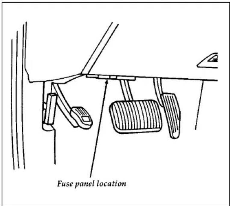
text_image
Fuse panel locationThe instrument panel fuse panel location
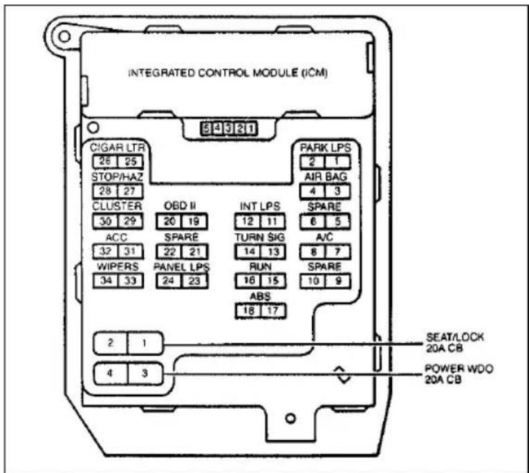
text_image
INTEGRATED CONTROL MODULE (ICM) CIGAR LTR 28 25 STOP/HAZ 28 27 CLUSTER 30 29 ACC 32 31 WIPERS 34 33 OBD II 20 19 SPARE 22 21 PANEL LPS 24 23 INT LPS 12 11 TURN SIG 14 13 RUN 16 15 ABS 18 17 PARK LPS 2 1 AIR BAG 4 3 SPARE 6 5 A/C 8 7 SPARE 10 9 SEAT/LOCK 20A CB POWER WDO 20A CBThe instrument panel fuse panel
The Instrument Panel Fuses, Circuit Breakers and Relays
| Fuse | Amps | Circuits Protected |
| CIGAR | 20A | • Cigar Lighter |
| STOP/HAZARD | 15A | • Turn/Stop/Hazard Lamps |
| CLUSTER | 5A | • Instrument Cluster |
| ACC | 10A | • Warning Chime• Radio |
| Wipers | 30A | • Interval Wiper• Washer |
| OBD II | 10A | • Data Link Connector (DLC) |
| Panel LPS | 5A | • Instrument Illumination |
| INT LPS | 10A | • Instrument Illumination• Courtesy Lamps |
| POWER WDO | 20A CB | • Power Windows |
| TURN SIG | 10A | • Backup Lamps• Turn/Stop/Hazard Lamps |
| ANTI-LOCK | 10A | • Anti-lock Power Relay• Anti-lock Brake Control Module |
| PARK LPS | 10A | • Exterior Lamps |
| AIR BAG | 10A | • Air Bags |
| A/C | 10A | • A/C |
| SEAT/LOCK | 20A CB | • Power Door Locks• Remote Keyless Entry• Power Seats• Anti-Theft |
| RUN | 5A | • Shift Lock• DRL• EVO• ABS• Air Bag• Washer Fluid Level Sensor |
High Current Fuses
High current fuses are circuit protectors that are part of the wiring harness for some electrical equipment. These, like fuses, open when the circuit load exceeds their amperage rating. High current fuses may be purchased from your Ford or Lincoln-Mercury dealer.
The high current fuse panel is located in the engine compartment on the left-hand fender apron.
| ⚠ WARNING |
| Always disconnect the battery before servicing high current fuses. |
Ford recommends that high current fuses be replaced by a qualified technician.
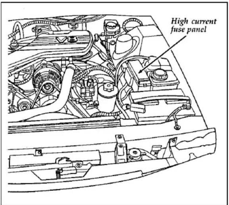
text_image
High current fuse panelThe high current fuse panel location
The high current fuse panel
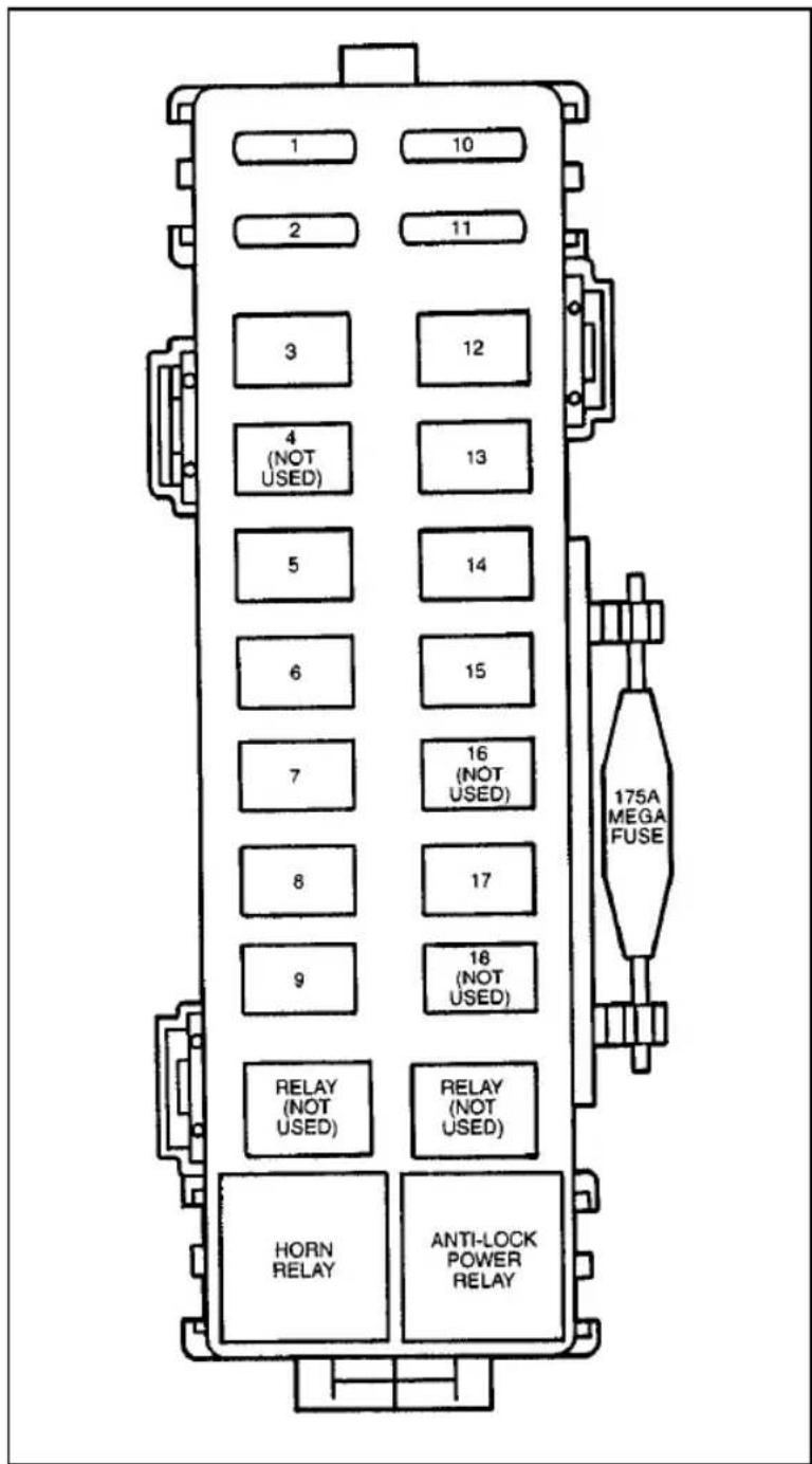
text_image
1 2 3 4 (NOT USED) 5 6 7 8 9 RELAY (NOT USED) HORN RELAY 10 11 12 13 14 15 16 (NOT USED) 17 18 (NOT USED) RELAY (NOT USED) ANTI-LOCK POWER RELAY 175A MEGA FUSEThe high current fuses and relays
| Fuse Location | Amp Rating | Description |
| 1 | 15A | • DRL module |
| 2 | 5A | • SATC• Power Antenna• Digital Clock |
| 3 | 20A | • Ignition• Constant Control Relay Module (CCRM) |
| 4 | - | Not Used |
| 5 | 60A | • Constant Control Relay Module (CCRM: EDF & HEDF) |
| 6 | 40A | • ABS motor |
| 7 | 60A | • Main Light Switch• Courtesy Lamps• RKE Module• Integrated Control Module (ICM)• Power Mirror• Autolamp• Air Bag Diagnostic Monitor |
| 8 | 20A | • ABS Module• ABS Relay |
| 9 | 60A | • Ignition Switch |
| 10 | 15A | • Horn Relay |
| 11 | 15A | • Radio |
| 12 | 40A | RadioMobile TelephoneMulti-Function SwitchBOO SwitchDLC Cigar LighterTrunk Lid ReleaseRKEDoor LockPower SeatsAnti-Theft |
| 13 | 20A | Constant Control Relay Module (CCRM: Fuel Pump Relay) |
| 14 | 40A | Rear Window Defrost |
| 15 | 20A | Powertrain Control Module (PCM) MemoryConstant Control Relay Module (CCRM: PCM Relay) |
| 16 | - | Not Used |
| 17 | 60A | Ignition SwitchBlower Motor |
| 18 | - | Not Used |
Checking and Replacing Fuses
If you need to check a fuse, follow these steps:
- Find the fuse panel underneath the instrument panel, to the left of the steering column.
- Check the fuse to see if it is blown. Look through the clear side of the fuse to see if the metal wire inside is separated. If it is, the fuse should be replaced.
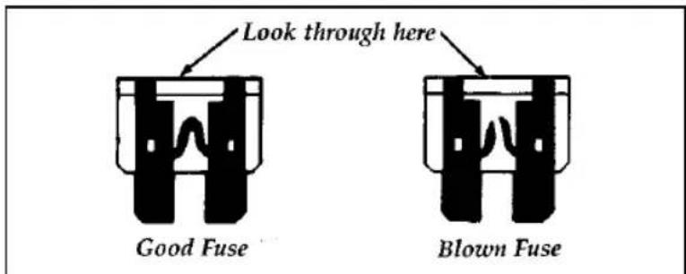
text_image
Look through here Good Fuse Blown FuseThe side view of a fuse
- Replace the fuse with one that has the right amperage rating. (See the following chart.) To remove the fuse use the pulling tool attached to the inside cover of the fuse panel. There are also four spare fuses attached to the cover.
| InstrumentPanel Fuse Color | Amperage |
| Tan | 5A |
| Red | 10A |
| Blue | 15A |
| Yellow | 20A |
| Natural | 25A |
| Green | 30A |
| Fuselink Cartridge Color | Amperage |
| Blue | 20A |
| Pink | 30A |
| Green | 40A |
| Red | 50A |
| Yellow | 60A |
⚠ WARNING
Always replace a fuse with one that has the specified amperage rating. Using a fuse with a higher amperage rating can cause severe wire damage and could start a fire.
4. Close the cover.
Even after you replace a fuse, it may continue to blow if you do not find what caused the overload. If the fuse continues to blow, have your electrical system checked.
Circuit Breakers
If you need to check a circuit breaker that is on the fuse panel, see Checking and replacing fuses in this chapter to find out how to locate the fuse panel.
Circuit breakers will reset themselves and allow the electrical parts to work again once the overload on the circuit is removed. If the circuit breakers continue to cut off electricity, have your vehicle's electrical system checked.
Diagnostic equipment is needed to check circuit breakers. Refer to the manufacturer's instructions.
If you replace a circuit breaker, use one with the same amperage rating. To remove a circuit breaker mounted in the fuse panel, grip it with your finger and thumb and pull it straight out of its socket.
If the Engine Cranks but Does Not Start or Does Not Start After a Collision
Fuel System Shut-off Switch
If the engine cranks but does not start or does not start after a collision, the fuel system shut-off switch may have been activated. The shut-off switch is a device intended to stop the fuel system when your vehicle has been involved in a substantial jolt.
Once the shut-off switch is activated, you must reset the switch by hand before you can start your vehicle. The switch is on the left side of the trunk.
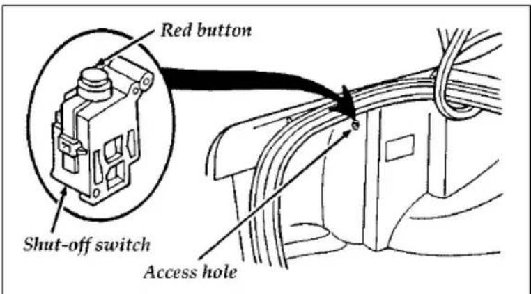
text_image
Red button Shut-off switch Access holeThe fuel pump shut-off switch
| ⚠ WARNING |
| If you see or smell fuel, do not reset the switch or try to start your vehicle. Have all the passengers get out of the vehicle and call the local fire department or a towing service. |
If your engine cranks but does not start after a collision or substantial jolt:
- Turn the ignition key to the OFF position.
- Check under the vehicle for leaking fuel.
- If you do not see or smell fuel, push the red reset button down. If the button is already set, you may have a different mechanical problem.
- Turn the ignition key to the ON position for a few seconds, then turn it to the OFF position.
- Check under the vehicle again for leaking fuel. If you see or smell fuel, do not start your vehicle again. If you do not see or smell fuel, you can try to start your vehicle again.
- Check all vehicle warning lights before driving the vehicle.
Changing a Tire
If you get a flat tire while you are driving, do not apply the brake heavily. Instead, gradually decrease the speed. Hold the steering wheel firmly and slowly move to a safe place on the side of the road. Park on a level spot, turn off the ignition, set the parking brake, and turn on the hazard flashers.
The Temporary Spare Tire
You have a high pressure temporary spare tire. This spare tire is smaller than a regular tire and is designed for emergency use only. Use it only when you get a flat tire and replace it as soon as you can. This spare tire is marked with the words “TEMPORARY USE ONLY” so that you can easily identify it.
NOTE: Extended use of other than conventional spare tires on a Traction-Lok rear axle could result in a permanent reduction in effectiveness. This loss of effectiveness does not affect normal driving and should not be noticeable to the driver.
⚠ WARNING
If you use the temporary spare tire continuously or do not follow these precautions, the tire could fail, causing you to lose control of the vehicle, possibly injuring yourself or others.
When you drive with the temporary spare tire, DO NOT:
□exceed 50 mph (80 km/h) under any circumstances.
□load your vehicle so that it is heavier than the maximum vehicle load rating listed on the tire decal.
□tow a trailer.
□use tire chains on this tire.
□try to repair the temporary spare tire or remove it from its wheel.
□use the wheel for any other type of vehicle.
□drive through an automatic car wash with this tire. Because the temporary spare tire is smaller than a conventional tire, it reduces the ground clearance. Your vehicle may get caught in the rails and it could be damaged.
Spare Tire Location
The spare is stored in the trunk.
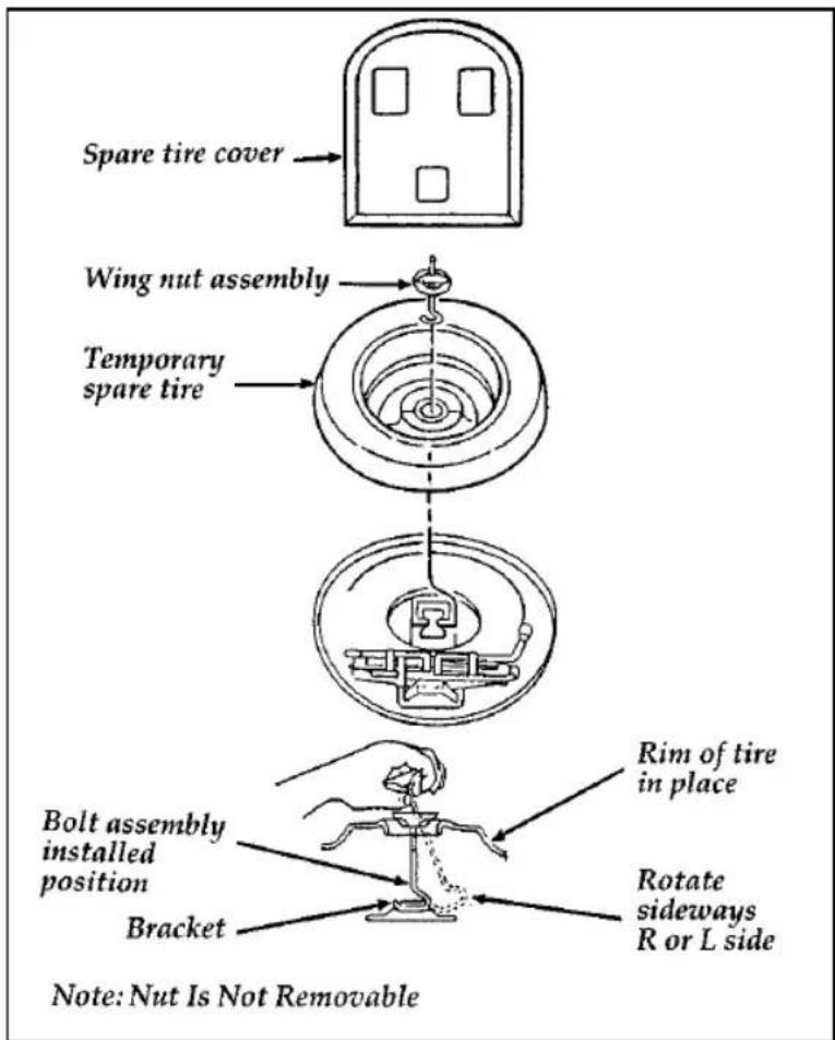
text_image
Spare tire cover Wing nut assembly Temporary spare tire Bolt assembly installed position Bracket Rim of tire in place Rotate sideways R or L side Note: Nut Is Not RemovableThe spare tire location
To remove the spare tire:
- Remove the spare tire cover.
- Unscrew the wing-nut holding down the spare tire.
NOTE: Wing-nut is not removable.
- Lift out the spare tire, jack, and lug wrench.
Preparing to Change the Tire
- Make sure that your vehicle will not move or roll. Put the gearshift in P (Park). Set the parking brake and block the wheel that is diagonally opposite the tire that you are changing.
When one of the back wheels is off the ground, the transmission alone will not prevent the vehicle from moving or slipping off the jack, even if the vehicle is in P (Park). To prevent the vehicle from moving when you change a tire, be sure the parking brake is set, then block the wheel (both directions) that is diagonally opposite (other side and end of the vehicle) to the tire being changed.
| ⚠ WARNING |
| If the vehicle slips off the jack, you or someone else could be seriously injured. |
| ⚠ WARNING |
| To avoid injury, never run the engine with one wheel off the ground, such as when changing a tire. |
- Get out the spare tire and jack.
-
Remove any optional wheel covers or hubcaps with the tapered end of a wheel nut wrench. Insert the handle of the wrench and twist it against the inner wheel cover flange. For more about removing wheel covers, see the information later in this chapter.
-
Loosen each wheel lug nut one-half turn counterclockwise, but do not remove them until the tire is raised off the ground. You should pull up on the handle rather than push to develop maximum force to loosen wheel lug nuts. See Anti-Theft Wheel Lug Nuts later in this chapter for information on removing anti-theft lug nuts.
Removing and Replacing the Tire
- Find the underbody notches closest to the wheel to be removed. Center the jack between (2) underbody notches and turn the handle of the jack clockwise until the wheel is completely off the ground.
| ⚠ WARNING |
| To lessen the risk of personal injury, do not put any part of your body under the vehicle while changing a tire. Do not start the engine when your vehicle is on the jack. The jack is only meant for changing the tire. |
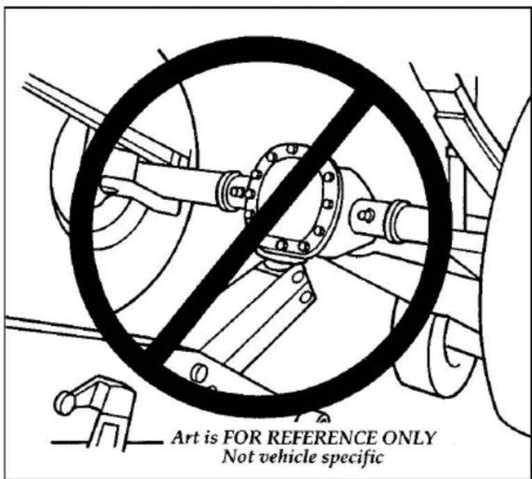
text_image
Art is FOR REFERENCE ONLY Not vehicle specificThe improper lift point
NOTE: Never use the differential housing as a lift point.
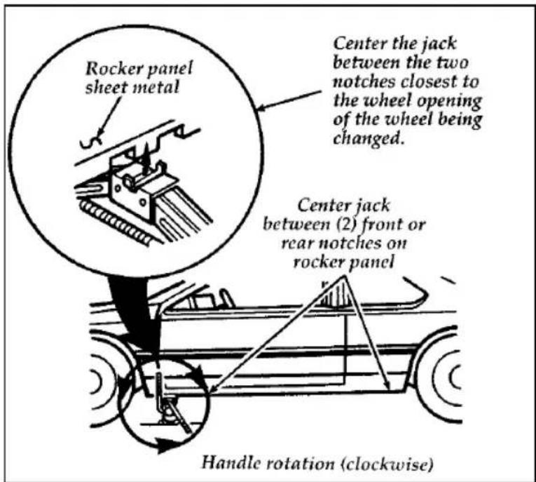
text_image
Rocker panel sheet metal Center the jack between the two notches closest to the wheel opening of the wheel being changed. Center jack between (2) front or rear notches on rocker panel Handle rotation (clockwise)The notches for the jack
- Turn the jack handle clockwise until the wheel clears the ground. Remove the wheel lug nuts.
- Replace the flat tire with the spare tire, making sure that the air valve stem is facing outward.
- Reinstall the lug nuts, tightening until the wheel is snug against the hub. The beveled edges on the lug nuts face inward. Do not fully tighten the lug nuts until you lower the vehicle. If you do, you could force the vehicle off the jack.
-
Lower the vehicle by turning the jack handle counterclockwise.
-
Remove the jack and fully tighten the lug nuts in the order shown in the following illustration. As soon as possible, have your dealer or a qualified service technician check the lug nuts for proper torque specifications.
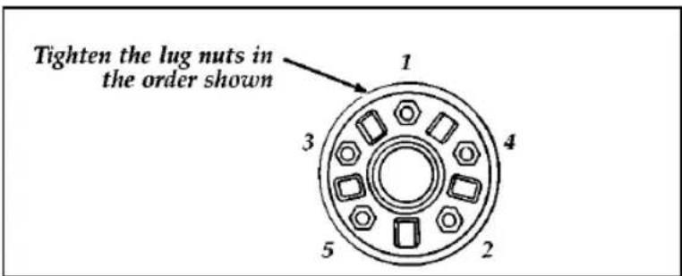
text_image
Tighten the lug nuts in the order shown 1 3 4 5 2The lug nuts on the wheel
- Place any wheel covers and ornaments in the trunk.
- Put the tire, jack, and wrench away. Make sure the jack is securely fastened so it does not rattle when you drive.
- Unblock the wheels.
Aluminum Road Wheel Ornaments (If equipped)
To remove the ornament, stick the tapered end of the jack handle between the ornament and wheel and pry off the ornament.
To replace the ornament, stick one side of the ornament into the center of the wheel and strike the other side with the palm of your hand.
Center Wheel Cover
To remove the wheel cover:
-
Pry the center ornament from the wheel cover using the tapered end of the jack handle. Do not use a screwdriver or any other tool. If you do, you may damage the cover. The wheel, with the wheel cover still attached, may now be removed from the vehicle by removing the five lug nuts.
-
If the tire needs to be removed from the wheel, remove the five screws, using a Phillips head screwdriver. Then pull the wheel cover off the wheel.
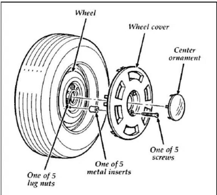
text_image
Wheel Wheel cover Center ornament One of 5 screws One of 5 metal inserts One of 5 lug nutsThe center attachment wheel cover
To replace the wheel cover:
-
Place the tire valve stem hole in the wheel cover over the tire valve stem. Align the holes in the wheel cover mounting pad with the center holes in the metal inserts. Install and tighten the five screws.
-
Align the legs of the ornament with the slots on the wheel cover. Strike the ornament with the palm of your hand.
Anti-Theft Wheel Lug Nuts (If equipped)
If your vehicle has this option, one of the lug nuts on each wheel locks and must be unlocked with a special key. The key and registration card are attached to the lug wrench and stored with the spare tire. If you lose the key, send the registration card to the manufacturer (not the dealer) to get a replacement key.
NOTE: If entire lug wrench/lug nut key assembly is lost, see your nearest Ford or Lincoln-Mercury dealer who has access to a master set of keys.
NOTE: DO NOT USE A POWER IMPACT WRENCH ON THE LUG NUT KEY.
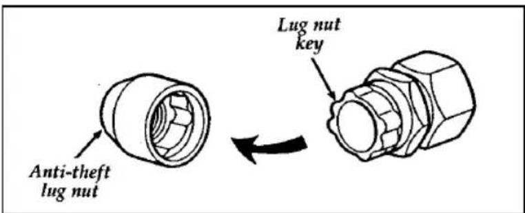
text_image
Anti-theft lug nut Lug nut keyThe anti-theft lug nut and key
Removing the anti-theft lug nut
Insert the key over the locking lug nut. Make sure that you hold the key square to the lug nut. If you hold the key on an angle, you may damage the key and the lug nut.
Place the lug nut wrench over the lug nut key and apply pressure on the key with the wrench. Turn the wrench in a counterclockwise direction to remove the lug nut.
Reinstalling the anti-theft lug nut
Insert the key over the locking lug nut. Place the lug nut wrench over the lug nut key and, while applying pressure on the key, install the lug nut.
Jump-Starting Your Vehicle
Your vehicle's battery may die if you leave the lights on or any electrical equipment on after you turn the engine off. If this happens, you may be able to jump-start your vehicle with a booster battery.
| ⚠ WARNING |
| The gases around the battery can explode if exposed to flames, sparks, or lit cigarettes. An explosion could result in injury or vehicle damage. |
| ⚠ WARNING |
| To protect yourself when charging a battery, always shield your face and eyes.Make sure that you can breathe fresh air. |
⚠ WARNING
Applying too much pressure on the ends when lifting a battery could cause acid to spill. Lift the battery with a carrier or with your hands on the opposite corners.
⚠ WARNING
Batteries contain sulfuric acid which burns skin, eyes, and clothing.
If the acid touches someone's skin, eyes, or clothing, immediately flush the area with water for at least 15 minutes. If someone swallows the acid, have him or her drink lots of milk or water first, then Milk of Magnesia, a beaten egg, or vegetable oil. Call a doctor immediately.
To avoid damaging your vehicle or your battery, and to avoid injury to yourself, follow these directions for preparing your vehicle to jump-start and connecting the jumper cables in the order they are given. If in doubt, call for road service.
Preparing Your Vehicle
NOTE: also see label on battery.
-
Your vehicle has a 12-volt starting system, so you need to use a 12-volt jumper system. You will damage your starting motor, ignition system, and other electrical parts if you connect them to a 24-volt power supply (either two 12-volt batteries in series or a 24-volt generator set).
-
Do not disconnect the battery of the disabled vehicle. You could damage the vehicle's electrical system.
-
Park the booster vehicle close to the hood of the disabled vehicle. Make sure the vehicles do not touch each other. Set the parking brake on both vehicles and stay clear of the engine cooling fan and other moving parts.
-
Check all battery terminals and remove any excessive corrosion before you attach the jumper cables.
-
Turn on the heater fan in both vehicles. Turning on the fan helps protect the electrical system from voltage surges. Turn off all other switches and lights in both vehicles to prevent possible damage to either vehicle's electrical systems.
Connecting the jumper cables
-
Connect one end of the first jumper cable to the positive (+) terminal of the discharged battery. (You can connect either jumper cable to the positive (+) terminal, as long as you use the same cable for both positive terminals.) Most jumper cables have a red cable and a black cable. The red cable is generally used for the positive terminals and the black for the negative ones.
-
Connect the other end of the first cable to the positive (+) terminal of the booster battery.
-
Connect one end of the second cable to the negative (−) terminal of the booster battery — NOT to the discharged battery.
- Connect the other end of that cable to a good metallic surface on the engine or frame of the disabled vehicle making sure it is clear of any rotating engine components. The following illustrations show where you can find a metallic surface.
⚠ WARNING
Do not connect the end of the second cable to the negative (−) terminal of the battery to be jumped. A spark may cause an explosion of the gases that surround the battery.
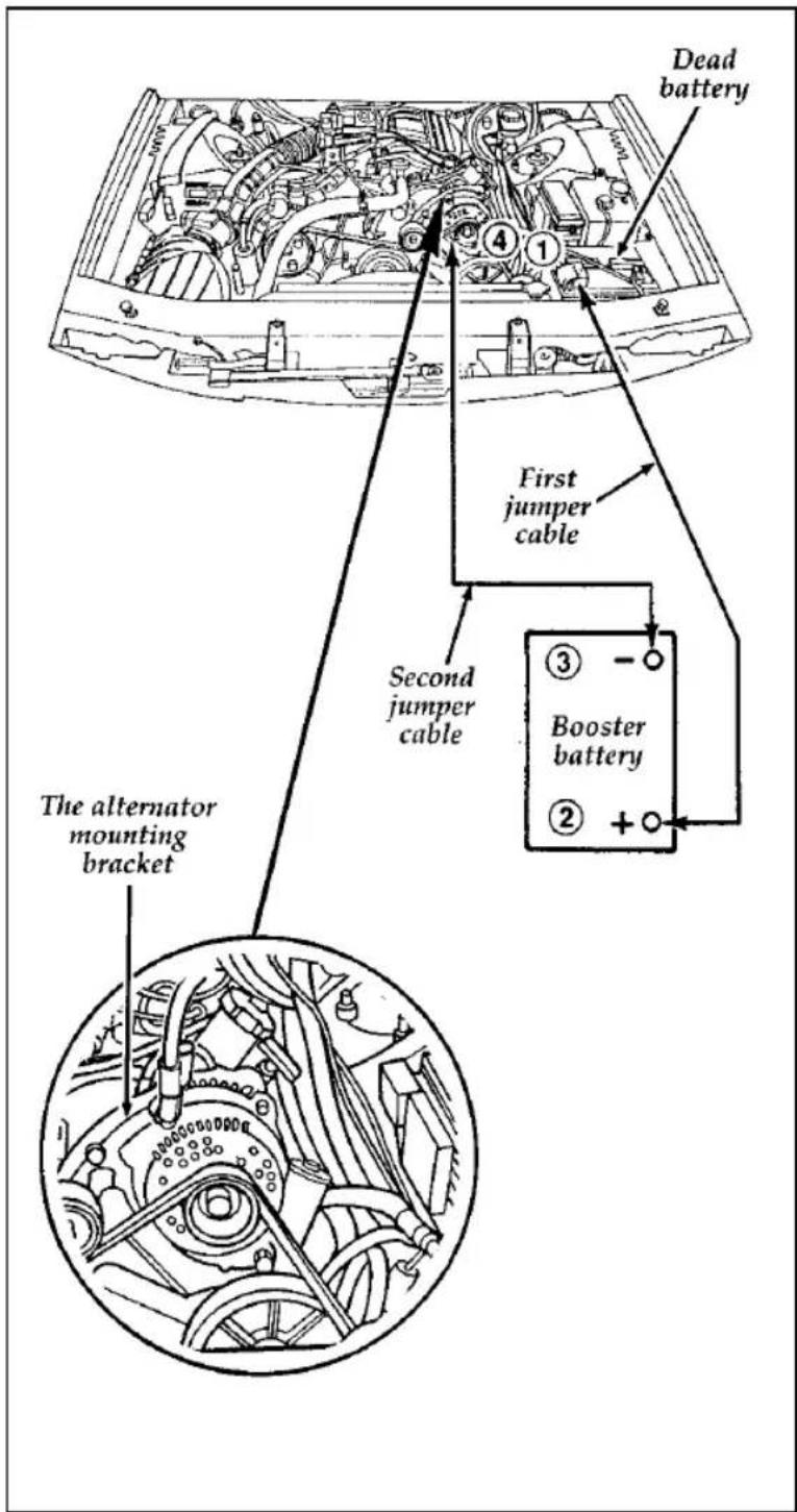
text_image
Dead battery First jumper cable Second jumper cable Booster battery The alternator mounting bracketThe 3.8L SFI engine
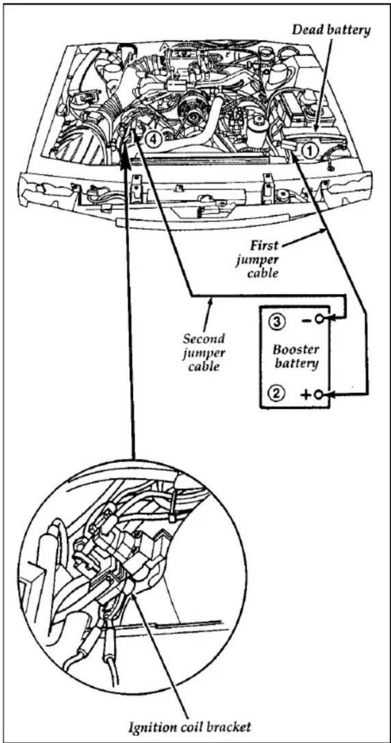
text_image
Dead battery First jumper cable Second jumper cable Booster battery Ignition coil bracketThe 4.6L SFI Engine
Jump-Starting
- Make sure that the jumper cables are not in the way of moving engine parts, then start the booster vehicle. Run the engine at a moderate speed.
- Let the discharged battery charge for a few minutes and then start the disabled vehicle. It may take a couple of tries before the vehicle starts. If the vehicle does not start after several attempts, there may be a different problem.
- When both vehicles are running, let them idle for a few minutes to charge the discharged battery.
Removing jumper cables
- Always remove the jumper cables in the reverse order. Remove the negative (−) end of the jumper cable from the metallic surface on the engine or frame of the disabled vehicle.
- Remove the negative (−) cable from the booster battery.
- Remove the positive (+) cable from the booster battery.
- Remove the other end of the positive (+) cable from the discharged battery.
After the vehicle is started, let it idle for a while to let the engine “relearn” its idle conditions. Drive it around for a while with all electrical accessories turned off to let the battery recharge. Driveability may be deteriorated slightly until all drive modes are “relearned.” You may need to use a battery charger to fully recharge the battery.
Towing Your Vehicle
If you need to have your vehicle towed, contact a professional towing service or, if you are a member, your roadside assistance center.
Do not tow with slingbelt equipment when towing your Thunderbird from the rear. Ford Motor Company has not developed or approved a T-hook sling-type procedure. When slingbelt towing from the front, the towbar will deform the soft fascia (bumper). However, it will return to an acceptable shape. In both cases, wheel lift or flatbed equipment is recommended.
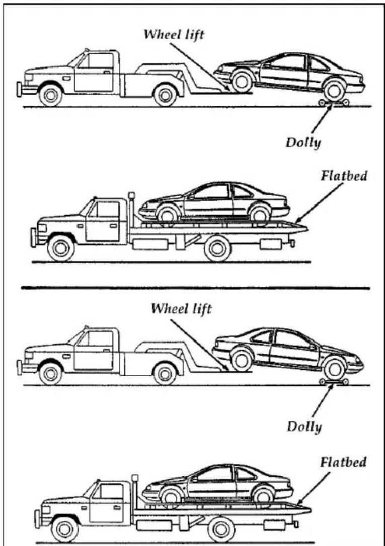
text_image
Wheel lift Dolly Flatbed Wheel lift Dolly FlatbedWhen calling for a tow truck, tell the operator what kind of vehicle you have. A towing manual is available from Ford Motor Company for all authorized tow truck operators. Have your tow truck driver refer to this manual for the proper hook-up and towing procedures for your vehicle.
Maintenance and Care
Service Made Easy
Ford has two goals for servicing your vehicle.
- When we can, we design parts that do not need to be serviced.
- We want to make servicing your vehicle as easy as possible. To help you:
☐ We highlight do-it-yourself items in yellow in the engine compartment so that you can find them easily.
□When possible, we design parts that can be replaced without tools.
☐We give you a Maintenance Schedule that makes tracking routine service for your vehicle easy. The maintenance schedule is located in the Maintenance Schedule booklet.
This chapter tells you about the basic parts that you need to check and service regularly.
If your vehicle needs professional servicing, your dealership can provide the parts and service required. Check your Warranty Information Booklet to find out which parts and services are covered. Also see the Customer Assistance chapter of this Owner Guide.
Ford Motor Company recommends that the Owner Maintenance Checks listed in the Maintenance Schedule booklet be performed for the proper operation of your vehicle. In addition to the conditions listed in the Owner Maintenance Checklist, be alert for any unusual noise,
vibration, or other indication that your vehicle may need service. If you do notice something unusual, see that your vehicle is serviced promptly.
Use only recommended fuels, lubricants, fluids, and service parts conforming to Ford specifications. Motorcraft parts are designed and built to provide the best performance in your vehicle. Using these parts for replacement is your assurance that Ford-built quality stays in your vehicle.
NOTE: Always dispose of used automotive fluids in a responsible manner. Follow your community's standards for disposing of these types of fluids. Call your local recycling center to find out about recycling automotive fluids.
Precautions When Servicing Your Vehicle
Be especially careful when inspecting or servicing your vehicle. Here are some general precautions for your safety:
☐Do not work on a hot engine. The engine cooling fan may come on unexpectedly. Always turn the engine off and let it cool.
⚠ WARNING
The cooling fan is automatic and may come on at any time. Always disconnect the negative terminal of the battery before working near the fan.
☐If you must work with the engine running, avoid wearing loose clothing or jewelry that could get caught in moving parts. Take appropriate precautions with long hair.
☐Do not work on a vehicle in an enclosed space with the engine running, unless you are sure you have enough ventilation.
□Never get under a vehicle while it is supported only by a jack. If you must work under a vehicle, use safety stands.
□Keep all lit cigarettes and other smoking materials away from the battery and all fuel-related parts.
If you disconnect the battery, the engine must "relearn" its idle conditions before your vehicle will drive properly. To find out how the engine does this, see Battery in this chapter.
Working with the engine off:
- Set the parking brake fully and make sure that the gearshift is securely latched in P (Park).
- Remove the key from the ignition after you turn the engine off.
- Block the wheels. This will prevent your vehicle from moving unexpectedly.
Working with the engine on:
-
Set the parking brake fully and make sure that the gearshift is securely latched in P (Park).
-
Block the wheels. This will prevent your vehicle from moving unexpectedly.
| ⚠ WARNING |
| Do not start your engine with the air cleaner removed and do not remove it while the engine is running. |
Opening the Hood
-
Inside the vehicle, pull the hood release located under the lower left corner of the instrument panel.
-
Go around to the front of the vehicle, and release the auxiliary catch that is located under the front edge of the hood at the center of the vehicle.
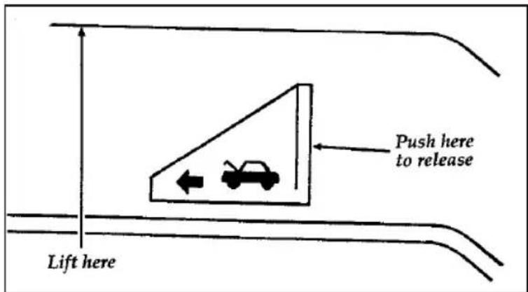
text_image
Push here to release Lift hereThe auxiliary catch under the front edge of the hood
- Lift the hood until the counterbalanced hinges hold it open.
Whenever you close the hood, latch it securely.
NOTE: Apply lubricant to the hood latch at six-month intervals to maintain smooth and trouble-free operation.
Engine Compartment
Your vehicle has one of these types of engines:
□a 3.8 liter SFI engine
□a 4.6 liter SFI engine
The following pages show diagrams of each engine type and where to find items that you should regularly service.
A 3.8 liter SFI engine
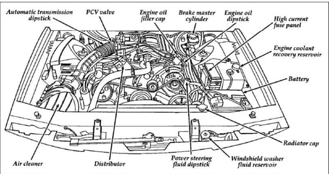
text_image
Automatic transmission dipstick PCV valve Engine oil filler cap Brake master cylinder Engine oil dipstick High current fuse panel Engine coolant recovery reservoir Battery Radiator cap Air cleaner Distributor Power steering fluid dipstick Windshield washer fluid reservoir200
A 4.6 liter SFI engine
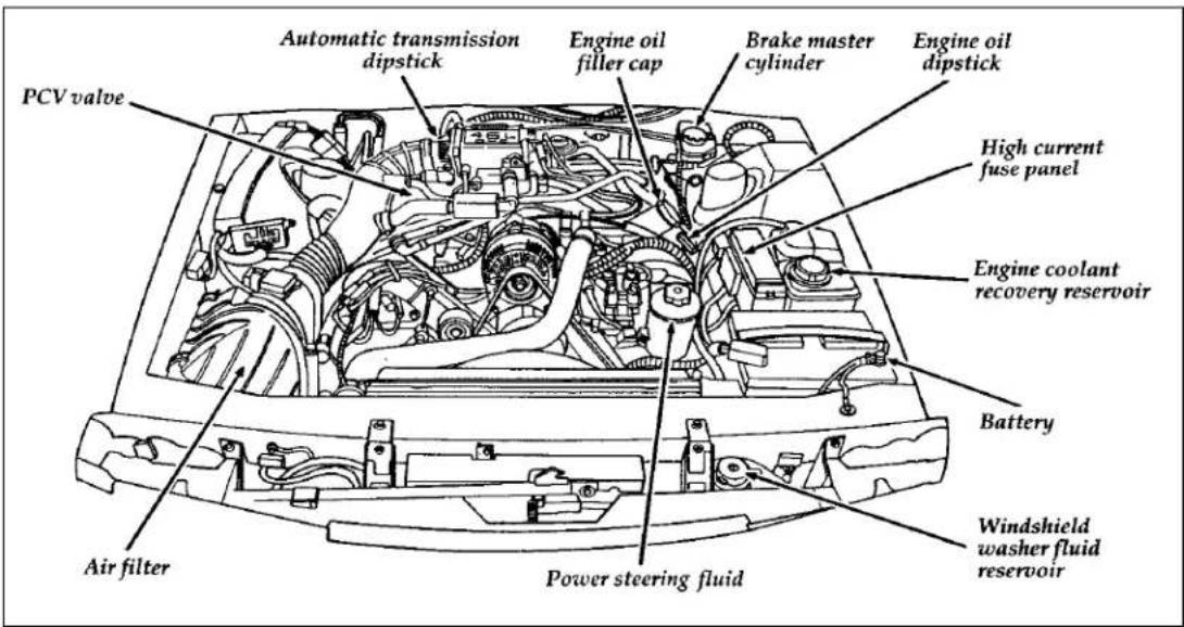
text_image
PCV valve Automatic transmission dipstick Engine oil filler cap Brake master cylinder Engine oil dipstick High current fuse panel Engine coolant recovery reservoir Battery Air filter Power steering fluid Windshield washer fluid reservoirEngine Oil Recommendations
We recommend using Motorcraft oil or an equivalent oil meeting Ford Specification WSS-M2C153-F and displaying the American Petroleum Institute CERTIFICATION MARK on the front of the container.
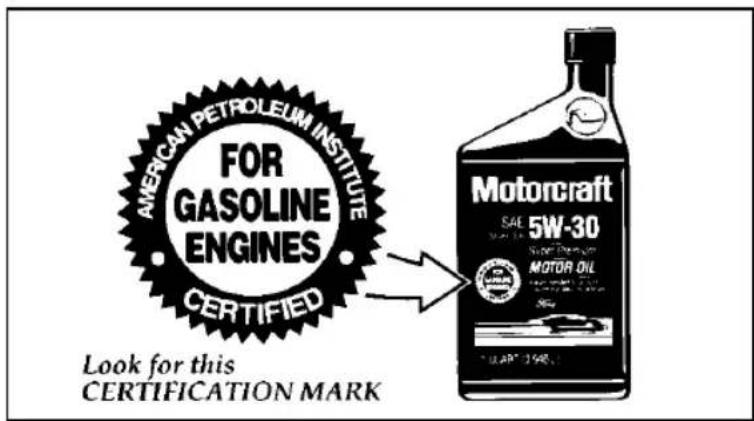
text_image
AMERICAN PETROLEUM INSTITUTE FOR GASOLINE ENGINES CERTIFIED Look for this CERTIFICATION MARK Motorcraft 5W-30 MOTOR OILThe API Certification Mark
Never use:
□“Non-Detergent” oils
☐Oils labeled API SA, SB, SC, SD, SE, SF or SG
☐ Additional engine oil additives, oil treatments or engine treatments
Engine oils with an SAE 5W-30 viscosity are PREFERRED for your vehicle. They provide the best engine performance, fuel economy and engine protection for all climates down to -15°F (-25°C).
Synthetic engine oils which are CERTIFIED and of the preferred viscosity may be used in your engine. The engine oil and oil filter must still be changed according to the maintenance schedule.
Checking and Adding Engine Oil
Since the proper amount of engine oil is important for safe engine operation, check the oil using the dipstick each time you put fuel in your vehicle. Remember the engine must be off, the oil must be warm and the vehicle must be parked on level ground.
Checking the engine oil level:
- Turn the engine off after it has warmed up and allow a few minutes for the engine oil to drain back into the oil pan.
- Set the parking brake, making sure the gearshift is securely latched in P (Park).
- Open the hood. Protect yourself from engine heat.
- Locate the engine oil dipstick (highlighted in yellow) and carefully pull it out of the engine.
- Wipe the dipstick clean and put it back into position, making sure it is fully seated.
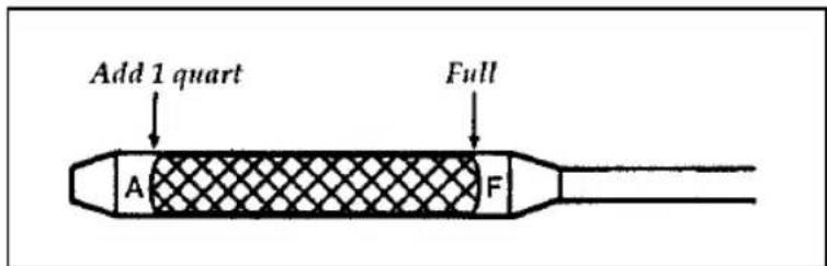
text_image
Add 1 quart Full A FEngine oil dipstick — 4.6 liter engines
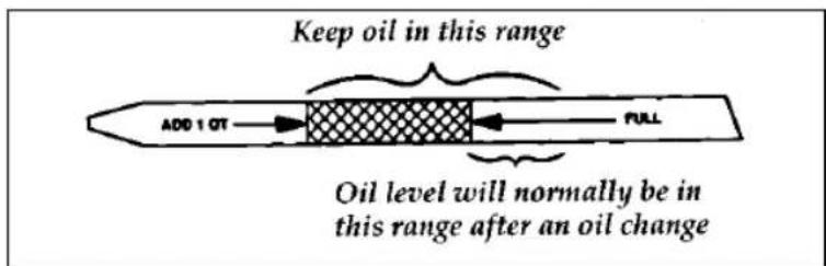
text_image
Keep oil in this range ADD 1 QT FULL Oil level will normally be in this range after an oil changeEngine oil dipstick — 3.8 liter engines
- Carefully pull the dipstick out again. If the oil level is below the "ADD 1 QT" line, add engine oil as necessary. If the oil level is beyond the letter "F" in Full, engine damage or high oil consumption may occur and some oil must be removed from the engine.
- Put the dipstick back in and make sure it is fully seated.
It may be necessary to add some oil between oil changes. Make sure you use a CERTIFIED engine oil of the preferred viscosity. Your vehicle's warranty coverage may not apply if engine damage is caused by the use of improper engine oil.
Add engine oil through the oil filler cap highlighted in yellow. To add oil, remove the filler cap and use a funnel to pour oil into the opening. Be careful not to overfill the engine. Recheck the oil level after you finish adding oil.
Changing the Engine Oil and the Oil Filter
Change the engine oil and oil filter per the following, whichever occurs first.
5,000 MILES (8,000 KM) OR 6 MONTHS NORMAL SCHEDULE
3,000 MILES (5,000 KM) OR 3 MONTHS SEVERE DUTY SCHEDULE
EXTENSIVE IDLING TRAILER TOWING DRIVING IN SEVERE DUST POLICE, TAXI, OR DELIVERY
NOTE: Ford production and after market (Motorcraft) oil filters are designed for added engine protection and long life. If a replacement oil filter is used that does not meet Ford magerial and design specifications, startup engine noises or knock may be experienced. It is recommended you use the appropriate "Motorcraft" oil filter (or another brand meeting Ford specifications) for your engine application.
Refer to the Maintenance Schedule booklet for additional information.
NOTE: Always dispose of used automotive fluids in a responsible manner. Follow your community's standards for disposing of these types of fluids. Call your local recycling center to find out about recycling automotive fluids.
| ⚠WARNING |
| Continuous contact with USED motor oil has caused cancer in laboratory mice. |
Protect your skin by washing with soap and water.
ke Fluid
Under normal circumstances, your vehicle should not use up brake fluid rapidly. However, expect the level of the brake fluid to slowly fall as you put more mileage on your vehicle and the brake lining wears.
Check the brake fluid at each scheduled engine oil change or at least once a year. You can do this by looking at the fluid level in the plastic reservoir on the master cylinder. Also, see label
on reservoir cap. (To locate the master cylinder, see The Engine Types in the Index.) The fluid level should be between the MAX fill mark and 3/8" below the MAX fill line.
WARNING
Brake fluid is toxic.
If brake fluid contacts eyes, flush eyes with running water for 15 minutes. Get medical attention if irritation persists. If taken internally, drink water and induce vomiting. Get medical attention immediately.
If the fluid is low, carefully clean and remove the filler cap from the reservoir. Fill the reservoir to the MAX line with Ford High Performance DOT 3 Brake Fluid C6AZ-19542-AB or DOT 3 equivalent fluid meeting Ford specification ESA-M6C25-A.
⚠ WARNING
If you use a brake fluid that is not DOT 3, you will cause permanent damage to your brakes.
Do not fill the reservoir above the MAX line.
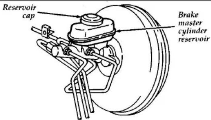
text_image
Reservoir cap Brake master cylinder reservoirThe brake system fluid reservoir
If you find that the fluid level is excessively low — below the seam or ridge on the outside of the plastic reservoir — have the brake system inspected.
WARNING
Do not let the reservoir for the master cylinder run dry. This may cause the brakes to fail.
Windshield Washer Fluid
Washer Fluid
Check the level of the windshield washer fluid periodically. The reservoir for washer fluid is located on the driver's side of the engine compartment. Do not operate the washer when the reservoir is empty.
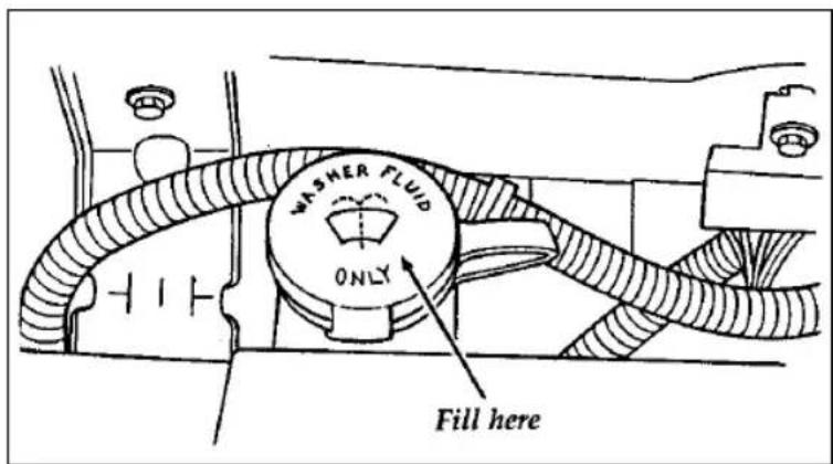
text_image
WASHER FLUID ONLY Fill hereThe reservoir for the windshield washer fluid
WARNING
Do not put windshield washer fluid in the container for the engine coolant.
Use specially formulated windshield washer fluid rather than plain water, because specially formulated washer fluids contain additives that
dissolve road grime. For safety reasons, washer fluids containing an appropriate antifreeze such as methanol should be used in freezing weather (temperatures below 32^ F [0°C]). State or local regulations on Volatile Organic Compounds (VOCs) may restrict use of the most common antifreeze, methanol. Washer fluids containing non-methanol antifreeze agents should be used only if they provide cold weather protection without damaging the vehicle's paint finish, wiper blades, and windshield washer system.
Engine Coolant
Checking the Engine Coolant
NOTE: Be sure to read and understand Precautions When Servicing Your Vehicle at the beginning of this chapter.
| ⚠ WARNING |
| The cooling fan is automatic and may come on at any time. Always disconnect the negative terminal of the battery before working near the fan. |
Your vehicle's coolant protects your engine from overheating in the summer and from freezing in the winter. Check the level of the coolant at least once a month. Simply look at the engine coolant reservoir located in the engine compartment. To locate the reservoir, see the diagram of your vehicle's engine under Engine Type, in this chapter.
The coolant additives also protect the entire cooling system from internal passageway corrosion and these additives lubricate the water pump. The coolant should be serviced as noted in the Maintenance Schedule booklet.
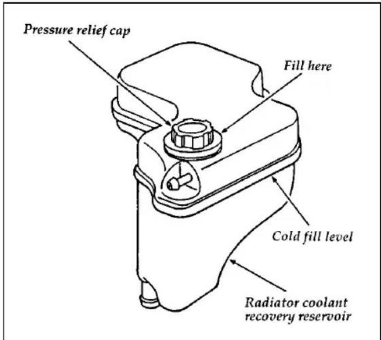
text_image
Pressure relief cap Fill here Cold fill level Radiator coolant recovery reservoirThe engine coolant reservoir
Checking Hoses
Inspect all engine and heater system hoses and hose connections for deterioration, leaks, and loose hose clamps as specified in the Maintenance Schedule booklet. Repair or replace with Motorcraft hoses or equivalent as necessary.
Adding Engine Coolant
| ⚠ WARNING |
| Do not put engine coolant in the container for the windshield washer fluid. |
If sprayed to clean the glass, engine coolant or antifreeze could make it difficult to see through the windshield.
⚠ WARNING
Never remove the radiator cap or vent plug while the engine is running or hot.
Follow these steps to avoid personal injury that can be caused by escaping steam or engine coolant.
- Before you remove the cap, turn the engine off and let it cool. Even when the engine is cool, be careful when you remove the radiator cap or vent plug.
- When the engine is cool, wrap a thick cloth around the cap and turn it slowly counterclockwise to unscrew.
- Step back while the pressure releases.
- When you are sure that all the pressure has been released, use the cloth to press the cap down, turn it counterclockwise, and remove it.
- Stand away from the radiator opening. Hot steam may blow out or hot engine coolant may even splash out.
Use Ford Premium Cooling System Fluid E2FZ-19549-AA (in Canada, Motorcraft CXC-8-B) or an equivalent premium engine coolant that meets Ford specification ESE-M97B44-A. Ford Premium Engine Coolant is an optimized formula that will protect all metals and rubber elastomers used in Ford cooling systems for 4 years or 50,000 miles (80,000 km).
Do not use alcohol or methanol antifreeze or any engine coolants mixed with alcohol or methanol antifreeze. Do not use supplemental coolant additives in your vehicle. These additives may harm your engine cooling system. The use of an improper coolant may void the warranty of your vehicle's engine cooling system.
Recycled engine coolant
Ford Motor Company recommends that Ford and Lincoln-Mercury dealers use recycled engine coolant produced by Ford-approved processes. Not all coolant recycling processes produce coolant which meets Ford specification ESE-M97B44-A, and use of such coolant may harm engine and cooling system components.
Always dispose of used automotive fluids in a responsible manner. Follow your community's regulations and standards for recycling and disposing of automotive fluids.
Coolant refill capacity
To find out how much fluid your vehicle's cooling system can hold, refer to Refill Capacities in the Capacities and Specifications chapter.
Have your dealer check the engine cooling system for leaks if you have to add more than a quart (liter) of engine coolant per month.
Severe winter climate
If you drive in extremely cold climates (less than -34^ [-36^] ), it may be necessary to increase the coolant concentration above 50%. Refer to the chart on the coolant container to ensure the coolant concentration in your vehicle is such that the coolant will not freeze at the temperature level in which you drive during winter months. Never increase the engine coolant concentration above 60%. Leave a 50/50 mixture of engine coolant and water in your vehicle year-round in non-extreme climates.
Engine Coolant Drain and Flush
Proper procedures for a complete coolant drain and flush of the cooling system can be found in the Car Service Manual. Following these recommended procedures will ensure that the specified coolant level and a 50/50 or appropriate mixture of coolant and water is maintained.
Engine Coolant Refill Procedure
When the entire cooling system is drained and refilled, the following procedure should be used to ensure a complete fill:
NOTE: It is imperative the following procedure be adhered to. Failure to do so could result in damage to your engine.
3.8L engine only
□Open the vent plug.
☐Remove coolant recovery reservoir cap.
□Remove radiator pressure cap.
☐With the engine off and cool, add a 50/50 mixture of recommended cooling system fluid and water to the radiator until full, then add to the reservoir until the reservoir is at the FULL-HOT level.
□Close the vent plug.
☐Reinstall the coolant recovery reservoir cap by installing the cap to the fully installed position.
☐Reinstall the pressure cap to the pressure relief position by installing the cap to the fully installed position, and then backing off to the first stop.
☐ Start and idle engine until the radiator upper hose is warm (this indicates the thermostat is open and coolant is flowing through the entire system).
☐Immediately shut off engine. Cover cap completely with a thick cloth and cautiously remove radiator pressure cap and add a 50/50 mixture of recommended coolant and water until system is full.
☐Reinstall the radiator cap securely.
☐Remove the cap from the engine coolant recovery reservoir and add a 50/50 mixture of recommended cooling system fluid and water to the FULL-HOT mark on the engine coolant recovery reservoir. Check that reservoir hose is not kinked.
☐Reinstall the reservoir cap.
☐Check for leaks at the draincock, block plug and vent plug.
☐Recheck the engine coolant level, using the recommended procedure, after one or two occasions of vehicle use.
4.6L engine only
☐With the engine OFF and cool, remove the pressure cap, located on the coolant reservoir. Remove the heater hose and clamp, located on the rear of the intake manifold.
☐ Add a 50/50 mixture of specified coolant and water to the coolant reservoir. Refer to Refill Capacities later in this chapter for the correct amount. Add coolant to the reservoir until the coolant continuously flows out of the tube in the rear of engine. Reattach hose and secure clamp.
☐Continue to fill the reservoir until the coolant is at the FULL COLD level.
☐Reinstall the pressure cap to the fully installed position.
☐ Start and idle the engine until the radiator upper hose is warm (this indicates the thermostat is open and coolant is flowing through the entire system).
☐Immediately shut off the engine and let cool. Cautiously remove the pressure relief cap and add a 50/50 mixture of specified coolant and water until the coolant is at the COLD FILL level in the coolant reservoir.
☐Reinstall the pressure cap securely.
☐Check for leaks at the draincock.
☐Recheck the engine coolant level, using the recommended procedure, after one or two occasions of vehicle use.
Power Steering Fluid
Check the level of the power steering fluid at least twice a year (i.e., every Spring and Fall).
Checking and Adding Power Steering Fluid
3.8L SFI engine
- Start the engine and let it run until the power steering fluid reaches normal operating temperature. The power steering fluid will be at the right temperature when the engine coolant temperature gauge in the instrument cluster is near the center of the NORMAL operating temperature range.
- While the engine idles, turn the steering wheel back and forth several times. Make sure that the cap assembly is installed at this time.
- Turn the engine off.
- Check the fluid level on the dipstick (which is highlighted in yellow in your vehicle). The fluid level should be between the arrows in the FULL HOT range, which is marked on the side of the dipstick, opposite the side marked FULL COLD. Do not add fluid if the level is within the FULL HOT range.
- If the power steering fluid is low, add fluid in small amounts, continuously checking the level, until you reach the FULL HOT range. Do not overfill.
- When you are finished, put the dipstick back in and make sure that it fits snugly.
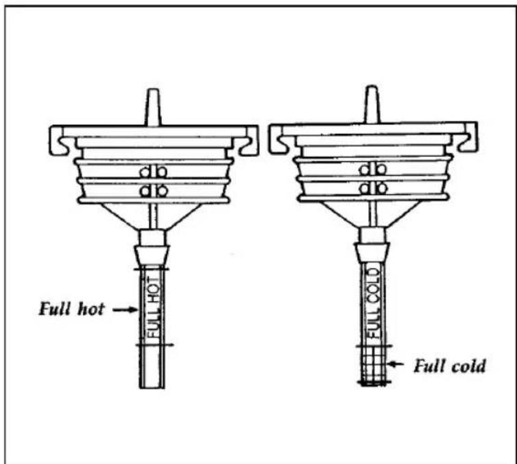
text_image
db db Full hot Full hot db db Full cold Full coldThe dipstick for power steering fluid
Use only power steering fluid that meets Ford Specification Mercon® ATF XT-2-QDX or an equivalent.
If the power steering fluid is low, do not drive your vehicle for a long period of time before adding fluid. This can damage the power steering pump.
If you check the power steering fluid when it is cold, make sure that the fluid reaches the FULL COLD range on the dipstick. The reading will only be accurate if the fluid temperature is approximately 50 to 85°F (10 to 30°C).
4.6L SFI engine
-
Check the fluid level when the system is COLD (allow at least one half hour after driving for the power steering fluid to cool).
-
Locate the power steering reservoir mounted to the front upper left-hand corner of the engine.
-
Visually verify that the fluid level is above the MIN line adjacent to the reservoir "sight window."
-
If the power steering fluid is below the MIN line, remove the cap and add fluid in small amounts until the level is between the MIN and MAX lines.
-
Reinstall the reservoir cap.
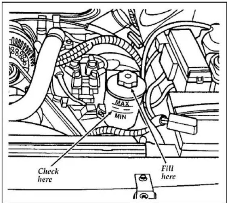
text_image
MAX MIN Check here Fill hereFluid level for power steering
Use only power steering fluid that meets Ford Specification Mercon® ATF XT-2-QDX or an equivalent.
NOTE: If the power steering fluid is low, do not drive your vehicle for a long period of time before adding fluid. This can damage the power steering pump.
Automatic Transmission Fluid
Under normal circumstances, you do not need to check the fluid level of the transmission, since your vehicle does not use up transmission fluid. Refer to the Maintenance Schedule booklet for replacement intervals. However, if the transmission is not working properly — for instance, the transmission may slip or shift slowly, or you may notice some sign of fluid leakage — the fluid level should be checked.
Checking the Automatic Transmission Fluid
It is preferable to check the transmission fluid level at normal operating temperature 150^ F- 170^ F ( 66^ C- 77^ C), after approximately 20 miles (30 km) of driving. However, if necessary, you can check the fluid level without having to drive 20 miles (30 km) to obtain a normal operating temperature if outside temperatures are above 50^ F ( 10^ C).
With the vehicle on a level surface, start the engine and, while fully applying the brake pedal, move the transmission shift selector through all of the gear ranges allowing sufficient time for each position to engage. Securely latch the transmission shift selector in the P (Park) position, fully set the parking brake and leave the engine running.
NOTE: Your vehicle should not be driven if the fluid level is below the low cold reading on the dipstick.
Wipe off the dipstick cap, pull the dipstick out and wipe the indicator end clean. Put the dipstick back into the filler tube and make sure it is fully seated. Pull the dipstick out and read the fluid level.
When checking fluid at normal operating temperature 150^ F- 170^ F ( 66^ C- 77^ C), the fluid level should be within the hot notched area on the dipstick. When the vehicle has not been driven, and the fluid is at room temperature 50^ F- 95^ F ( 10^ C- 35^ C), the fluid level should be within the cold notched area.
NOTE: If the vehicle has been operated for an extended period at high speeds or in city traffic during hot weather, or pulling a trailer, the vehicle should be turned off for about 30 minutes to allow the fluid to cool before checking.
Adding Automatic Transmission Fluid
Before adding any fluid, be sure that the correct type will be used. Use only MERCON ^® fluid.
Add fluid in 1/2 pint (.25L) increments through the filler tube to bring the level to the correct area on the dipstick. DO NOT OVERFILL. If the level is above the top hole on the dipstick, excess fluid should be removed by a qualified technician.
NOTE: Always dispose of used automotive fluids in a responsible manner. Follow your community's standards for disposing of these types of fluids. Call your local recycling center to find out about recycling automotive fluids.
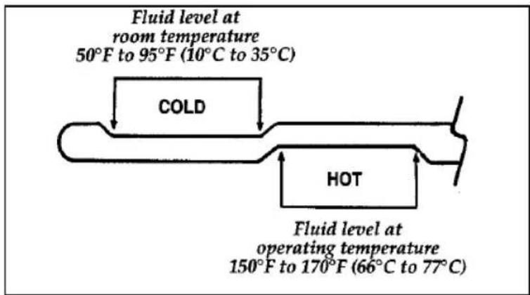
text_image
Fluid level at room temperature 50°F to 95°F (10°C to 35°C) COLD HOT Fluid level at operating temperature 150°F to 170°F (66°C to 77°C)Detail of the automatic transmission dipstick
ery
Your vehicle may have a Motorcraft maintenance-free battery. When the original equipment battery is replaced under warranty, it may be replaced by a Motorcraft Low-Maintenance Battery.
The Low-Maintenance Battery has removable vent caps for checking the electrolyte level and for adding water, if necessary. The electrolyte level should be checked at least every 24 months or 24,000 miles (40,000 km) in temperatures up to 90°F (32°C) and more often in temperatures above 90°F (32°C). Keep the electrolyte level in each cell up to the level indicator. Do not overfill.
If the level gets low, you can add tap water to the battery, provided the water isn't hard or doesn't have a high mineral or alkali content. However, if possible you should refill the battery with distilled water. If the battery needs water quite often, have the charging system checked for a possible malfunction.
Help Us Protect Our Environment
Ford Motor Company strongly recommends that used lead-acid batteries be returned to an authorized recycling facility for disposal.

text_image
LEAD RETURN RECYCLEBattery recycling symbol
Because your vehicle's engine is electronically controlled by a computer, some control conditions are maintained by power from the battery. If you ever disconnect the battery or install a new battery, you must allow the computer to "relearn" its idle conditions before your vehicle will drive properly. To let the engine do this, put the gearshift in P (Park), turn off all the accessories, and start the vehicle. Let the engine idle for at least one minute. (Engine must be warm in order to "learn.") Also, allow approximately 10 miles (16 km) of stop and go traffic for your vehicle's engine to completely "relearn" its idle.
er Blades
Check the windshield wiper blades at least twice a year. Also check them whenever they seem less effective than usual. Substances such as tree sap and some hot wax treatments used by commercial car washes reduce the effectiveness of wiper blades.
If the blades do not wipe properly, clean both the windshield and the wiper blades. Use undiluted windshield washer solution or a mild detergent. Rinse thoroughly with clear water. Do
not use fuel, kerosene, paint thinner, or other solvents to clean your wiper blades. These will damage your blades.
To make reaching the wiper blades easy, simply turn the ignition to the ACC position and turn your wipers on. Wait for them to reach a vertical position and turn the ignition to the OFF position. Do not move the wipers manually. Manually moving the wipers across the windshield may damage them.
Wiper blade replacement
If the wiper blades still do not work properly after you clean them, you may need to replace the wiper blade assembly or the blade element. When replacing the wiper blade assembly, blade refill, or wiper arm always use a Motorcraft part or equivalent. To replace the blades, follow the instructions that come with them.
Checking Tire Pressure
□Use an accurate tire pressure gauge.
☐Check the tire pressure when tires are cold, after the vehicle has been parked for at least one hour or has been driven less than 3 miles (5 km).
□Adjust tire pressure to recommended specifications found on the Safety Compliance Certification Label.
| ⚠ WARNING |
| Improperly inflated tires can affect vehicle handling and can fail suddenly, possibly resulting in loss of vehicle control. |
Tire Rotation
Because your vehicle's front and rear tires perform different jobs, they often wear differently. To make sure your tires wear evenly and last longer, rotate them as indicated in the following diagram.
For tire rotation intervals, see the Maintenance Schedule booklet. If you notice that the tires wear unevenly, have them checked.
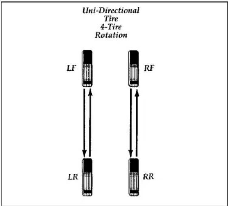
flowchart
graph TD
    A["Uni-Directional Tire 4-Tire Rotation"] --> B["LF"]
    A --> C["RF"]
    A --> D["LR"]
    A --> E["RR"]
    B <--> C
    B <--> D
    C <--> E
Rotating the tires
Replacing the Tires
Replace any tires that show wear bands. When your tire shows a wear band, it has only 1/16 inch (2 mm) of tread left.

text_image
Wear BandA worn-out tire
Because your vehicle's tires may wear unevenly, you may need to replace them before a wear band appears across the entire tread.
| ⚠ WARNING |
| When replacing full size tires, never mix radial, bias-belted, or bias-type tires. Use only the tire sizes that are listed on the tire pressure decal. Make sure that all tires are the same size, speed rating, and load-carrying capacity. Use only the tire combinations recommended on the decal. If you do not follow these precautions, your vehicle may not drive properly and safely. |
Tires that are larger or smaller than your vehicle's original tires may also affect the accuracy of your speedometer.
Information About Tire Quality Grades
New vehicles are fitted with tires that have their Tire Quality Grade (described below) molded into the tire's sidewall. These Tire Quality Grades are determined by standards that the United States Department of Transportation has set.
Tire Quality Grades apply to new pneumatic tires for use on passenger cars. They do not apply to deep tread, winter-type snow tires, space-saver or temporary use spare tires, tires with nominal rim diameters of 10 to 12 inches or limited production tires as defined in Title 49 Code of Federal Regulations Part 575.104(c)(2).
U.S. Department of Transportation — Tire quality grades: The U.S. Department of Transportation requires Ford to give you the following information about tire grades exactly as the government has written it.
Treadwear
The treadwear grade is a comparative rating based on the wear rate of the tire when tested under controlled conditions on a specified government test course. For example, a tire graded 150 would wear one and one-half (1 1/2) times as well on the government course as a tire graded 100. The relative performance of tires depends upon the actual conditions of their use, however, and may depart significantly from the norm due to variations in driving habits, service practices and differences in road characteristics and climate.
Traction A B C
The traction grades, from highest to lowest, are A, B, and C, and they represent the tire's ability to stop on wet pavement as measured under controlled conditions on specified government test surfaces of asphalt and concrete. A tire marked C may have poor traction performance.
⚠ WARNING
The traction grade assigned to this tire is based on braking (straight ahead) traction tests and does not include cornering (turning) traction.
Temperature A B C
The temperature grades are A (the highest), B, and C, representing the tire's resistance to the generation of heat and its ability to dissipate heat when tested under controlled conditions on a specified indoor laboratory test wheel. Sustained high temperature can cause the material of the tire to degenerate and reduce tire life, and excessive temperature can lead to sudden tire failure. The grade C corresponds to a level of performance which all passenger car tires must meet under the Federal Motor Vehicle Safety Standard No. 109. Grades B and A represent higher levels of performance on the laboratory test wheel than the minimum required by law.
⚠ WARNING
The temperature grade for this tire is established for a tire that is properly inflated and not overloaded. Excessive speed, underinflation, or excessive loading, either separately or in combination, can cause heat buildup and possible tire failure.
⚠ WARNING
Driving too fast for conditions creates the possibility of loss of vehicle control. Driving at very high speeds for extended periods of time may result in damage to vehicle components.
Snow Tires and Chains
The tires on your vehicle have all-weather treads that provide traction in rain or snow. However, during the winter months in some climates, you may need to use snow tires and occasionally chains for your tires.
⚠ WARNING
Snow tires must be the same size and grade as the tires you currently have on your vehicle.
Use chains on the tires only in an emergency or if the law requires them where you live. If you choose to use chains on your vehicle's tires, be aware of the following:
☐ Make sure the chains are the right size for your tires. Use only SAE Class "S" chains. Other types may damage your vehicle.
□Put the chains on tightly with the ends held down securely. Verify that no chain touches any wiring, brake lines, or fuel lines. Follow the chain manufacturer's instructions.
□Drive slowly. If you can hear the chains rub or bang against your vehicle, stop the vehicle and tighten the chains. If you continue to hear the chains rub or bang against your vehicle, remove the chains to prevent damage to your vehicle.
□Avoid fully loading your vehicle if possible.
☐Remove tire chains at the first opportunity after using them on snow and ice. Do not use the chains on dry roads.
Filling the Fuel Tank
The fuel door is outside the car on the passenger side near the back. To fill the fuel tank:
- After opening the fuel filler door, remove the cap carefully and slowly by turning it counterclockwise 1/2 to 3/4 turn.
| ⚠ WARNING |
| The fuel system may be under pressure. If the fuel cap is venting vapor or if you hear a hissing sound, wait until it stops before completely removing the cap. |
- Put the nozzle all the way inside the fuel filler pipe before pumping the fuel.
NOTE: If you spill any fuel on the body of your vehicle, clean it off immediately. The fuel may dull or soften the paint if you do not wash it off.
- Replace the fuel cap completely when you are finished. Turn it clockwise 1/4 turn until it is tight. It will click when it is fully tightened.
- Push the fuel door closed.
⚠ WARNING
If you do not use the proper fuel cap, the pressure in the fuel tank can damage the fuel system or cause it to work improperly in a collision.
NOTE: If you replace your fuel cap with an aftermarket fuel filler cap, the customer warranty may be void for any damage to the fuel tank and/or fuel system.
Choosing the Right Fuel
Use only UNLEADED FUEL. The use of leaded fuel is prohibited by law and could damage your vehicle. The damage may not be covered by your warranty.
Your vehicle was not designed to use fuel containing manganese-based additives such as MMT. Additionally, vehicles certified to California emission standards (indicated on the underhood Vehicle Emissions Control Information label) are designed to operate on California reformulated gasolines. If California reformulated gasoline is not available when you refuel, your vehicle can be operated on non-California fuels. However, even though your engine will perform adequately on other gasolines, the performance of the emission control devices and systems may be adversely affected. Repair of damage caused by using a fuel that your vehicle was not designed for may not be covered by your warranty.
Octane recommendation
Your vehicle is designed to use regular gasoline with an (R+M)/2 octane rating of 87. We do not recommend gasolines labeled as “regular” in high altitude areas that are sold with octane ratings of 86 or even less.
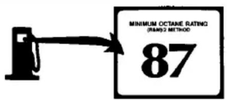
text_image
MINIMUM OCTANE RATING (RMS)/2 METHOD 87Do not be concerned if your vehicle sometimes knocks lightly. However, if it knocks heavily under most driving conditions on the recommended octane fuel, see your dealer or a qualified service technician to prevent any engine damage.
Fuel quality
If you are experiencing starting, rough idle or hesitation problems try a different brand of fuel. If the condition persists, see your dealer or a qualified service technician.
The American Automobile Manufacturers Association (AAMA) issued a gasoline specification to provide information on high quality fuels that optimize the performance of your vehicle. We recommend the use of gasolines that meet the AAMA specification if they are available.
It should not be necessary to add any aftermarket products to your fuel tank if you continue to use a high-quality fuel.
Clean air
Ford approves the use of gasolines to improve air quality, including reformulated gasolines that contain oxygenates such as a maximum of 10% ethanol or 15% MTBE. There should be no more than 5% methanol with cosolvents and additives to protect the fuel system.
Safety Information Relating to Automotive Fuels
| ⚠ WARNING |
| Automotive fuels can cause serious injury or death if misused or mishandled. |
□Turn vehicle off when refueling.
☐Do not smoke when refueling. Fuels are extremely flammable.
□Do not siphon any fuel by mouth.
| ⚠ WARNING |
| Gasoline or gasoline blended with methanol can cause blindness and possible death when swallowed. If any fuel is swallowed, call a physician or poison control center immediately. |
□Avoid breathing vapors while refueling.
□If fuel is splashed on the skin, wash with soap and water.
☐If fuel is splashed in the eyes, remove contact lenses (if worn), flush with water for 15 minutes, and seek medical attention.
Gasoline and gasoline blends may contain small amounts of carcinogens, such as benzene. Long-term exposure to unleaded gasoline vapors has caused cancer in laboratory animals.
If you are taking the medication “Antabuse” or other forms of disulfiram for the treatment of alcoholism, vapor or skin contact with a gasoline-methanol blend may cause the same kind of adverse reaction as drinking an alcoholic beverage. In sensitive individuals, serious personal injury or sickness could result. Consult a physician promptly if you experience an adverse reaction.
Running Out of Fuel
NOTE: Avoid running out of fuel because this situation may have an adverse effect on modern powertrain components.
You may need to crank the engine several times before the fuel system starts to pump fuel from the tank to the engine.
Calculating Fuel Economy
Fuel economy is an estimate of the efficiency of your vehicle, and can be calculated as Miles Per Gallon (MPG) or Liters Per 100 Kilometers (L/100K).
Do not calculate fuel economy during your vehicle's break-in period. This would not be an accurate estimate of how much fuel your vehicle will normally use.
To calculate fuel economy:
- Fill the fuel tank completely and record the initial odometer reading.
- Every time you buy fuel, record the amount (in gallons or liters) purchased.
-
After at least 3-5 tankfuls, fill the fuel tank and record the final odometer reading.
-
Use these equations to calculate your fuel economy:
☐ English: MPG = (total miles driven) ÷ (gallons used)
☐Metric: L/100k = (liters used) ÷ (100 kilometers)
Comparisons With EPA Estimates
EPA fuel economy figures are obtained from laboratory tests under simulated road conditions and may not reflect the actual conditions you experience or your style of driving. The EPA fuel economy estimate is not a guarantee that you will achieve the fuel economy shown.
The following decrease fuel economy:
☐Lack of regular, scheduled maintenance
☐Rapid acceleration and excessive speed
□Driving with your foot on the brake
□Sudden stops
□Extended engine idling
□Using speed control in hilly terrain
☐Extended use of the A/C, defroster, rear window defroster and other accessories
□Underinflated tires
□Heavy loads
□Aftermarket add-ons such as bike, ski or luggage racks, bug deflectors, etc.
Self-Service Pointers
If you choose to do your own fueling, you should also perform a few simple maintenance routines. This extra effort will save you additional money and contribute to the driving efficiency of your vehicle.
The following procedures require only a tire gauge, a rag, an oil can spout and windshield washer fluid.
☐Check the engine oil at every refueling stop
□Clean the windshield, outside mirrors and headlights
☐Check windshield washer fluid
☐Check tires for excessive wear or worn edges
☐Check the tire pressure at least monthly
Emission Control System
Your vehicle is equipped with a catalytic converter which enables your vehicle to comply with applicable exhaust emission requirements.
| ⚠ WARNING |
| Exhaust leaks may result in the entry of harmful and potentially lethal fumes into the passenger compartment. Under extreme conditions excessive exhaust temperatures could damage the fuel system, the interior floor covering, or other vehicle components, possibly causing a fire. |
To make sure that the catalytic converter and the other emission control parts continue to work properly:
□Use only unleaded fuel.
□Avoid running out of fuel.
☐Do not turn off the ignition while your vehicle is moving, especially at high speeds.
☐Do not push start your vehicle.
☐Have the services listed in the Maintenance Schedule booklet performed according to the specified schedule. The scheduled maintenance services are required because they are considered essential to the life and performance of your vehicle and to its emissions system.
In general, maintenance, replacement, or service of the emissions control devices or systems in your new Ford Motor Company vehicle or engine may be performed at your expense by any automotive repair establishment or individual using automotive parts equivalent to those which your vehicle or engine was originally equipped.
Ford strongly recommends the use of genuine Ford replacement parts. If other than Ford or Motorcraft parts or Ford authorized remanufactured parts are used for maintenance replacements or for the service of components affecting emission control, such non-Ford parts should be equivalent to genuine Ford Motor Company parts in performance and durability. It is the owner's responsibility to determine the equivalency of such parts. Please consult your warranty booklet for complete warranty information.
⚠ WARNING
Do not park, idle, or drive your vehicle in dry grass or other dry ground cover. The emission system heats up the engine compartment and exhaust system, which can start a fire.
Watch for fluid leaks, strange odors, smoke, loss of oil pressure, the charge warning light, the check engine light, or the temperature warning light. These sometimes indicate that the emission system is not working properly.
Do not make any unauthorized changes to your vehicle or engine. Changes that cause more unburned fuel to reach the exhaust system can increase the temperature of the engine or exhaust system.
By law, anyone who manufactures, repairs, services, sells, leases, trades vehicles, or supervises a fleet of vehicles is not permitted to intentionally remove an emission control device or prevent it from working. In some of the United States and in Canada, vehicle owners may be liable if their emission control device is removed or is prevented from working.
Never use a metal exhaust collector when you service your vehicle. If the metal collector contacts any of your vehicle's plastic trim or bumper parts they could melt or deform.
Do not drive your vehicle if it does not operate properly. See your dealer if the engine runs on for more than five seconds after you shut it off or if it misfires, surges, stalls, or backfires.
Information about your vehicle's emission control system is on the Vehicle Emission Control Information decal located on or near the engine. This decal identifies engine displacement and gives some tune-up specifications.
How to Prepare Your Vehicle for Inspection/Maintenance (I/M) Testing
In some localities it may become a legal requirement to pass an Inspection/Maintenance (I/M) test of the On-Board Diagnostic (OBD) II system. If the vehicle's powertrain system or its battery has just been serviced, the OBD II system is reset to a not ready for I/M testing condition. To prepare for I/M testing, the law specifies that additional city and highway driving is necessary to complete the check of the OBD II system.
The driving modes required to reach the ready condition consist of a minimum of 30 minutes of city and highway driving as described below:
□At least twenty minutes driving in stop and go, city type traffic with at least four idle periods.
□At least ten minutes of driving on an expressway or highway.
Before completing the above driving modes, the engine must be warmed up and at operating temperature. Once started, the vehicle must not be turned off during these driving modes.
Lights and Bulb Replacement
It is a good idea to check the operation of the following lights frequently:
□headlamps
□tail lamps
□brakelamps
□hazard flasher
□high-mount brakelamp
□turn signals
☐ license plate lamps
The alignment of your headlamps should be checked if:
□oncoming motorists frequently signal you to turn off your vehicle's high beams when you do not have the high beams on
□the headlamps do not seem to give you enough light to see clearly at night
□the headlamp beams are pointed substantially away from a position slightly down and to the right
Headlamp Bulb
The headlamps on your vehicle use replaceable bulbs. When the lamp burns out, simply replace the bulb, rather than the whole lamp.
⚠ WARNING
Handle a halogen headlamp bulb carefully and keep out of children's reach. Grasp the bulb only by its plastic base and do not touch the glass. The oil from your hand could cause the bulb to break the next time the headlamps are operated.
Do not remove the burned-out bulb unless you can immediately replace it with a new one. If a bulb is removed for an extended period of time, contaminants may enter the headlamp housing and affect its performance.
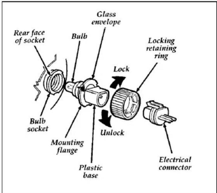
text_image
Rear face of socket Bulb Glass envelope Lock Locking retaining ring Bulb socket Mounting flange Unlock Plastic base Electrical connectorParts of a headlamp
Removing the headlamp bulb
- Make sure that the headlamp switch is in the OFF position.
- Lift the hood and find the bulb in the headlamp socket.
- Remove the electrical connector from the bulb by grasping the wire with a quick pull rearward.
- Remove the retaining ring by turning it 1/8 of a turn to free it from the socket. Then slide the ring off the plastic base. Keep the ring. You must use it again to hold the new bulb in place.
Installing the headlamp bulb
- With the flat side of the bulb's plastic base facing upward, insert the glass end of the bulb into the socket. You may need to turn the bulb left or right to line up the grooves in the plastic base with the tabs in the socket. When the grooves are aligned, push the bulb into the socket until the plastic base contacts the rear of the socket.
- Slip the bulb retaining ring over the plastic base until it contacts the rear of the socket. Lock the ring into the socket by rotating it clockwise until you feel a "stop."
- Push the electrical connector into the rear of the plastic base until it snaps, locking it into position.
- Turn the headlamps on and make sure that they work properly. If the headlamp was correctly aligned before you changed the bulb, you should not need to align it again.
High-Mount Brakelamp Bulbs
Your vehicle has a brakelamp mounted in the rear window, called a high-mount brakelamp. You may need to remove this lamp at times to replace the brakelamp bulb or to clean the rear window.
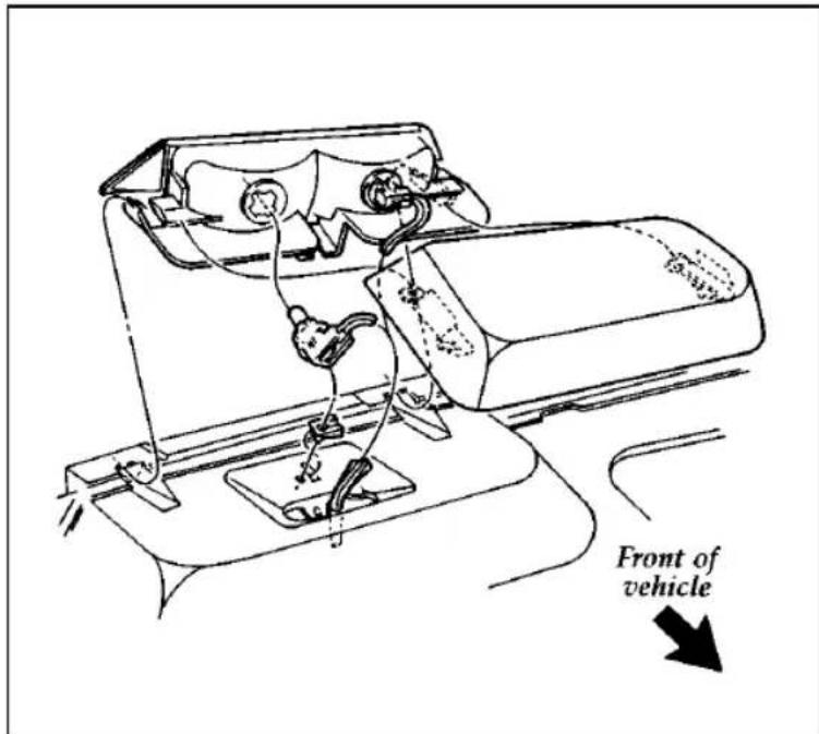
text_image
Front of vehicleParts of the high-mount brakelamp
To remove the high-mount brakelamp:
- Slide the trim cover toward the front of the vehicle to disengage the retaining clips.
- Twist the socket counterclockwise and remove from lamp.
- Pull bulb out of socket.
- Remove the retaining screw.
- Lift the lamp above the carpet and slide away from the rear window.
- Replace the burned out bulbs.
To install the high-mount brakelamp:
- Slide the lamp into slots, toward the rear window.
- Install the screw.
- Push bulb into the socket.
- Install the bulb and socket into the lamp and twist socket clockwise until it locks.
- Slide the trim cover toward rear of vehicle to engage the retaining clips.
Using the Right Bulbs
| Function | Trade number |
| Exterior lights | |
| Rear | |
| Tail lamp, brakelamp, turn lamp side marker | 3357K* |
| Front | |
| Parklamp, turn lamp, side marker | 3157NA** |
| Backup lamp | 3156K* |
| License plate lamp | 194 |
| High-mounted brakelamp | 921 |
| Headlamps | |
| Lo beam/Hi beam | 9007 |
| Interior lights | |
| Luggage compartment lamp | 912 |
| Dome lamp | 912 |
| Dome/map lamp | |
| Dome | 912 |
| Map | 105 |
| Courtesy lamps | 98 |
| Door courtesy lamp | 168 |
| Floor console storage bin lamp | T1865 |
| Ashtray lamp | 1893 |
| Engine compartment lamp (opt.) | 906 |
| Visor vanity lamp | 194 |
| Instrument panel lights | |
| Glove compartment | 194 |
| High beam indicator | 194 |
| Cigar lighter lamp | 161 |
| Radio illumination | • |
| Warning lights (all) | 194 |
| Turn signal indicator | 194 |
| Fan | 1892 |
| "PRND21" bulb | 194 |
| Heater or Heater A/C | 37 |
| Semi automatic climate control | 37 |
| Instrument cluster lights | |
| Mechanical | 194/37 |
* K means Kripton longer life bulb
**NA means Natural Amber
- Refer bulb replacement to a Ford authorized radio service center.
Cleaning Your Vehicle
Pollen, bird droppings and tree sap can damage the paint, especially in hot weather. Wash your vehicle as often as necessary to keep it clean.
Take similar precautions if your vehicle is exposed to chemical industrial fallout.
Paint damage resulting from fallout is not related to a defect in paint materials or workmanship and therefore is not covered by warranty. Ford, however, believes that continual improvement in customer satisfaction is a high priority. For this reason, Ford has authorized its dealers to repair, at no charge to the owner, the surfaces of new vehicles damaged by environmental fallout within 12 months or 12,000 miles (20,000 km) of purchase, whichever comes first. Customers may be required to bring their vehicle in for inspection by a Ford representative.
Washing and Polishing Your Vehicle
Wash the outside of your vehicle, including the underside, with a mild detergent.
DO NOT:
□Wash your vehicle with hot water
□Wash your vehicle while it sits in direct sunlight
□Wash your vehicle while the body is hot
Polish your vehicle to remove harmful deposits and protect the finish.
Cleaning Chrome and Aluminum Parts
Wash chrome and aluminum parts with a mild detergent. Do not use steel wool, abrasive cleaners, fuel, or strong detergents.
Cleaning Plastic Parts
Some of your vehicle's exterior trim parts are plastic. Clean with a tar and road oil remover if necessary. Use a vinyl cleaner for routine cleaning.
Do not clean plastic parts with thinners, solvents or petroleum-based cleaners.
If you have your vehicle rustproofed, remove oversprayed rustproofing with a tar and road oil remover. If rustproofing is not removed from plastic and rubber parts, it can cause deterioration.
Cleaning the Safety Belts
Clean the safety belts with any mild soap solution that is recommended for cleaning upholstery or carpets. Do not bleach or dye the belt webbing because this may weaken it.
Cleaning the Exterior Lamps
Do not use dry paper towel, chemical solvents or abrasive cleaners to clean the lamps, as these may cause scratches or crack the lamps.
Cleaning the Interior Lamps
Your interior dome lamps and map lamps are plastic and should be cleaned with a mild detergent diluted in water. Rinse them with clear water.
Cleaning the Instrument Panel Lens
Clean the instrument panel lens with a soft cloth and a glass cleaner, such as Ford Ultra-Clear Spray Glass Cleaner, or equivalent. Do not use paper towel or any abrasive cleaner to clean the lens as these may cause scratches.
Cleaning the Seats
Leather and vinyl
For routine cleaning, wipe the surface with a soft, damp cloth. For more thorough cleaning, wipe the surface with a leather and vinyl cleaner or a mild soap.
Fabric
Remove dust and loose dirt with a whisk broom or a vacuum cleaner. Remove fresh spots immediately. Follow the directions that come with the cleaner.
NOTE: Before using any cleaner, test it on a small, hidden area of fabric. If the fabric's color or texture is adversely affected by a particular cleaner, do not use it.
Cleaning the Engine
A clean engine is more efficient because a buildup of grease and dirt acts as an insulator, keeping the engine warmer than usual.
☐Extreme care must be used if a power washer is used to clean the engine. The high pressure fluid could penetrate sealed parts and assemblies causing damage or malfunctions.
☐In order to avoid possible cracking of the engine block or fuel injection pump, do not spray a hot engine or injection pump with cold water.
☐The alternator, distributor and air intake must be covered. Covering these components will help prevent water damage.
□Never wash or rinse the engine while it is running. Water getting into the engine may cause internal damage.
Cleaning the Wheels
Wash the wheels with the same detergent you use to wash your vehicle's body. Do not use acid-based wheel cleaners, steel wool, abrasives, fuel, or strong detergents. These substances will damage protective coatings. Use tar and road oil remover to remove grease and tar.
NOTE: Before going to a car wash, find out if the brushes are abrasive.
Capacities and Specifications
Refill Capacities, Motorcraft Parts, and Lubricant Specifications
Motorcraft Parts
| Component | Part Number | |
| 3.8L SFI Engine | 4.6L SFI Engine | |
| Spark plug* | AWSF-44EE** | AWSF-32PP |
| Air filter | FA-1061 | FA-1061 |
| Fuel filter | FG-881 | FG-881 |
| Oil filter | FL400-S | FL820-S |
| PCV valve | EV-153 | EV-98 |
| BatteryAuto. trans.Optional | BXT-58BXT-65-650 | BXT-65-650BXT-65-750 |
| *Refer to Vehicle Emission Control Information (VECI) decal for spark plug and gap specifications.**AWSF-44PP for California vehicles. | ||
If a spark plug is removed for examination, it must be reinstalled in the same cylinder.
For 3.8L engines:
Cylinders #1, #2, #3 have an EG suffix.
Cylinders #4, #5, #6 have an E suffix.
For 4.6L (2V) engines:
Cylinders #1, #2, #3, #4 have a PG suffix.
Cylinders #5, #6, #7, #8 have a P suffix.
If a spark plug needs to be replaced, use only spark plugs with the service number suffix letter as shown on the engine decal.
Fluid Specifications and Capacities
| FLUID | FORD PART NAME | VEHICLE TYPE | CAPACITY |
| Brake Fluid | High Performance DOT 3 Brake Fluid | All | Fill to line in reservoir ^2 |
| Engine Coolant (including heater) | Premium Cooling System Fluid | 3.8L4.6L | 12.6 qts (11.9L)14.1 qts (13.3L) |
| Engine Oil | Motorcraft Motor Oil 5W-30 Super Premium | 3.8L4.6L | 5.0 qts ^1 (4.7L)5.0 qts ^1 (4.7L) |
| Fuel | N/A | All | 18.0 gal (68.1L) |
| Power Steering Fluid | Motorcraft MERCON® ATF | All | 1.6 pints (68.1L) |
| Rear Axle | Motorcraft Premium Rear Axle Lubricant | Conventional7.5" ring gear8.8" ring gearTraction-Lok ^3 7.5" ring gear8.8" ring gear | 3.00 pints ^4 (1.4L)3.50 pints ^4 (1.7L)2.75 pints ^4 (1.3L)3.25 pints ^4 (1.5L) |
| Transmission Fluid Automatic | Motorcraft MERCON® ATF | 4R70W | 13.9 qts (13.1L) |
| Windshield Washer | Ultra-Clear Windshield Washer Concentrate | All | Fill to top of reservoir ^2 |
1: Includes 1/2 qt for filter replacement
2: Refer to Index for refill instructions
3: For Traction-Lok add 4 oz. C8AZ-19B546-A Friction Modifier, Ford Specification EST-M2C118-A for complete refill of independent rear suspension (IRS) rear axle.
4: Service refill capacities are determined by filling the rear axle bottom of filler hole.
NOTE: Rear axle lube quantities must be replaced every 100,000 miles (160,000 km) or if the axle has been submerged in water. Otherwise, the lube should not be checked or changed unless a leak is suspected or repair required.
Lubricant Specifications
| FLUID | FORD PART NAME OR EQUIVALENT | FORD PART NUMBER | FORD SPECIFICATION |
| Brake Fluid | High Performance DOT 3 Brake Fluid | C6AZ-19542-AA | ESA-M6C25-A |
| Door Weatherstrips | Silicone Lube | C0AZ-19553-AA | ESR-M13P4-A |
| Engine Coolant | Premium Engine Coolant | E2FZ-19549-AA CXC-8-B* | ESE-M97B44-A |
| Engine Oil | Motorcraft Motor Oil 5W-30 Super Premium | XO-5W30-QSP | WSS-M2C153-F with API Certification Mark |
| Hinges, Hinge Checks and Pivots | Multi-Purpose Grease Spray | D7AZ-19584-AA | ESR-M1C159-A |
| Power Steering Fluid | Motorcraft MERCON® ATF | XT-2-QDX | MERCON® |
| Rear Axle Lubricant | Thermally Stable Premium Rear Axle Lube | XY-80W90-QL | WSP-M2C197-A |
| Throttle Valve (TV) Linkage or Kickdown Linkage | Long Life Grease | XG-1-C | ESA-M1C75-B |
| Transmissions Fluid | Motorcraft MERCON® ATF | XT-2-QDX | MERCON® |
| Windshield Washer Fluid | Ultra-Clear Windshield Washer Concentrate | C9AZ-19550-AA or BA | ESR-M17P5-A |
- Canada
Vehicle Storage
Maintenance Tips
If you plan on storing your vehicle for an extended period of time (60 days or more), refer to the following maintenance recommendations to ensure your vehicle stays in good operating condition.
General
□Store all vehicles in a dry, ventilated place.
□Protect from sunlight, if possible.
□If vehicles are stored outside, they require regular maintenance to protect against rust and damage.
Body
□Wash vehicle thoroughly to remove dirt, grease, oil, tar or mud from exterior surfaces, rear wheel housing and underside of front fenders.
☐Periodically wash vehicles stored in exposed locations.
☐Touch-up raw or primed metal to prevent rust.
☐ Cover chrome and stainless steel parts with a thick coat of auto wax to prevent discoloration. Re-wax as necessary when the vehicle is washed.
□Lubricate all hood, door and trunk lid hinges and latches with a light grade oil.
☐ Cover interior soft trim to prevent fading.
□Keep all rubber parts free from oil and solvents.
Engine
☐ Start engine every 15 days. Run at fast idle until it reaches normal operating temperature.
□With your foot on the brake, shift through all the gears while the engine is running.
Fuel system
☐Fill fuel tank with high-quality unleaded fuel until the first automatic shutoff of the fuel pump nozzle.
NOTE: During extended periods of vehicle storage (60 days or more), fuel may deteriorate due to oxidation. This can damage rubber and other polymers in the fuel system and may also clog small orifices.
Ford Gas Stabilizer should be added whenever actual or expected storage periods exceed 60 days. Follow the instructions on the label. The vehicle should then be operated at idle speed to circulate the additive throughout the fuel system.
Cooling system
□Protect against freezing temperatures.
Battery
☐Check and recharge as necessary.
□Keep connections clean and covered with a light coat of grease.
☐If storing your vehicle for more than 30 days without recharging the battery, it may be advisable to disconnect the battery cables to ensure battery charge is maintained for quick starting.
NOTE: If battery cables are disconnected, it will be necessary to reset memory features.
Brakes
□Make sure brakes and parking brake are fully released.
Tires
□Maintain recommended air pressure.
Miscellaneous
□Make sure all linkages, cables, levers and clevis pins under vehicle are covered with grease to prevent rust.
□Move vehicles at least 25 feet (8 m) every 15 days to lubricate working parts and prevent corrosion.
Reporting Safety Defects (U.S. Only)
If you believe that your vehicle has a defect which could cause a crash or could cause injury or death, you should immediately inform the National Highway Traffic Safety Administration (NHTSA) in addition to notifying Ford Motor Company.
If NHTSA receives similar complaints, it may open an investigation, and if it finds that a safety defect exists in a group of vehicles, it may order a recall and remedy campaign. However, NHTSA cannot become involved in individual problems between you, your dealer, or Ford Motor Company.
To contact NHTSA, you may either call the Auto Safety Hotline toll-free at 1-800-424-9393 (or 366-0123 in the Washington, D.C. area) or write to: NHTSA, U.S. Department of Transportation, 400 Seventh Street, Washington D.C. 20590. You can also obtain other information about motor vehicle safety from the Hotline.
Customer Assistance
Roadside Assistance
Ford Motor Company has set up a 24-hour, seven-day-a-week hotline with trained operators who put you in touch with the help you need if you experience a problem with your vehicle. This complimentary service is provided to you throughout your warranty period of 3 years or 36,000 miles (60,000 km), whichever comes first. To purchase Roadside Assistance coverages beyond this period (available through Ford Auto Club in the United States or Ford and Lincoln-Mercury dealers in Canada), contact your Ford or Lincoln-Mercury dealer. Additional Roadside Assistance coverage is unavailable in Puerto Rico and the Virgin Islands.
Roadside Assistance will cover the following:
□Mount your spare if you have a flat tire.
☐ Jump-start your battery if it is dead.
☐Unlock your vehicle if you are locked out.
□Bring you fuel if you run out.
□Tow your vehicle if you are stranded. Even non-warranty related tows, like accidents or getting stuck in mud or snow, are covered (some exclusions apply, such as impound towing and repossession).
How to use Roadside Assistance
Your Roadside Assistance identification card can be found in the Owner Guide portfolio in your glove compartment. Complete the card and place it in your wallet for quick reference.
To receive roadside assistance in the United States call 1-800-241-FORD (in Canada call 1-800-665-2006).
Should you need to arrange for roadside assistance yourself, Ford Motor Company will reimburse the reasonable cost. To obtain information about reimbursement call 1-800-241-FORD (in Canada call 1-800-665-2006).
If You Have a Service Problem
Ford Motor Company has authorized Ford and Lincoln-Mercury dealerships that can service your vehicle for you. This chapter tells you how to get service or maintenance for your vehicle.
Service/Maintenance Concerns (U.S. or Canada)
Ford recommends taking your vehicle to your selling dealer who wants to ensure your continued satisfaction. You may, however, take your vehicle to any authorized Ford or Lincoln-Mercury dealer. In most cases, your dealer will be able to resolve your concern.
If you are not satisfied with the service you received from your dealership's service department, talk to the service manager at the dealership, or if you still are not satisfied, talk to the owner or general manager of the dealership. In most cases, you will have your concern resolved at this level.
If you are away from home when your vehicle needs to be serviced, or if you need more help than the dealer gave you, contact the Ford Customer Assistance Center to find an authorized dealership that may be able to help.
In the U.S., contact:
Ford Motor Company
Customer Assistance Center
300 Renaissance Center
P.O. Box 43360
Detroit, Michigan 48243
1-800-392-3673 (FORD)
TDD for the hearing impaired: 1-800-232-5952
If you live in Canada and have any questions or concerns that the dealership cannot answer, contact the Customer Assistance Centre.
Customer Assistance Centre
Ford Motor Company of Canada, Limited
P.O. Box 2000
Oakville, Ontario L6J 5E4
1-800-565-3673 (FORD)
Please have the following information available when contacting Ford Customer Assistance:
□your telephone number (both business and home)
□the name of the dealer and the city where the dealership is located
□the year and make of your vehicle
□the date purchased
□the current mileage on your vehicle
□your Vehicle Identification Number (VIN) listed on your vehicle ownership license

text_image
A/R B/A/B 100% 100% 100%Vehicle Identification Number (VIN/Serial Number)
If you still have a complaint involving a warranty dispute, you may wish to contact the Dispute Settlement Board (U.S. only) or the Canadian Motor Vehicle Arbitration Plan (CAMVAP) in Canada.
A warranty dispute must be submitted to the Dispute Settlement Board before taking action under the Magnuson-Moss Warranty Act, or to the extent allowed by state law, before pursuing replacement or repurchase remedies provided by certain state laws. This dispute handling procedure is not required prior to enforcing state created rights or other rights which are independent of the Magnuson-Moss Warranty Act or state replacement or repurchase laws.
The Dispute Settlement Board (U.S. Only)
The Dispute Settlement Board is:
□an independent, third party arbitration program for warranty disputes
□available free to owners and lessees of qualifying Ford Motor Company vehicles
The Dispute Settlement Board may not be available in all states. Ford Motor Company reserves the right to change eligibility limitations, modify procedures and/or to discontinue this service without notice and without incurring obligations.
What Kind of Cases Does the Board Review?
The Board reviews all warranty performance complaints on Ford, Mercury and Lincoln cars and Ford and Mercury light trucks under the new vehicle limited warranty that have not been resolved by either a dealer or Ford Motor Company, except those involving:
□a non-Ford product
□a non-Ford dealership
□ a vehicle sales transaction
☐request for reimbursement of consequential expenses. Expenses incidental to the warranty complaint being reviewed are eligible for consideration.
□items not covered by the new vehicle limited warranty
□items covered by a service contract
□alleged liability claims
□property damage where the damage is significant when compared to the economic loss alleged under the warranty dispute
□cases currently in litigation
□vehicles not used primarily for family, personal, or household purposes (except in states where the Dispute Settlement Board is required to review commercial vehicles)
Complaints involving vehicles in which applicable new vehicle limited warranties have expired at receipt of your application are not eligible. Eligibility may differ according to state law. For example, see the unique brochures for California and Wisconsin purchasers/lessees.
How does the Board Work?
The Board consists of:
□three consumer representatives
□a Ford or Lincoln/Mercury dealer
Consumer candidates for Board membership are recruited and trained by an independent consulting firm. Dealers are chosen because of their business leadership qualities.
What the Board needs
To have your case reviewed you must complete the application in the DSB brochure and mail it to the address provided on the application form.
Your application is reviewed and, if it is determined to be eligible, you will receive an acknowledgment indicating:
□the file number assigned to your application
□the toll-free phone number of the DSB's independent administrator
Your dealership and a Ford Motor Company representative are asked to submit statements at this time.
To review your case properly, the Board needs the following information:
☐legible copies of all documents and maintenance or repair orders relevant to the case
□the year, make, model, and Vehicle Identification Number (VIN) listed on your vehicle ownership license
□the date of repair(s) and mileage at the time of occurrence(s)
□the current mileage
□the name of the dealer who sold or serviced the vehicle
□a brief description of your unresolved concern
□a brief summary of the action taken with the dealer and Ford Motor Company
□the names (if known) of all the people you contacted at the dealership
□a description of the action you expect to resolve your concern
Should your case NOT qualify for review, a letter of explanation will be mailed to you.
Oral presentations
If the involved vehicle is within 36 months and 36,000 miles of the warranty start date, you have the right to make an oral presentation before the Board. Indicate your choice to do so on the application. Oral presentations may also be requested by the Board.
Making a decision
Board members will review all available information related to the complaint, including oral presentations, if necessary. They then arrive at a fair and impartial decision, decided by a simple majority vote.
Because the Board usually meets only once a month, some cases may take longer than 30 days to be reviewed. The Board makes every effort to resolve each case within 40 days of receiving the consumer application form.
After your case is reviewed, the Board mails you a decision letter. The Board also provides a form on which to accept or reject the Board's decision. The decisions of the Board are binding on the dealer and Ford, but not on consumers who elect to pursue other remedies available to them under state or federal law. Decisions of the Board may be presented as evidence by any party in subsequent legal proceedings that may be initiated, where allowed by law.
To Request a DSB Brochure/Application
For a brochure/application, speak to your dealer or write to the Board at the following address:
Dispute Settlement Board
P.O. Box 5120
Southfield, MI 48086-5120
Ford of Canada Customer Assistance
Ford Motor Company of Canada, Limited
If you live in Canada and have any questions or concerns that the dealership cannot answer, contact the Customer Assistance Centre.
Customer Assistance Centre Ford Motor Company of Canada, Limited P.O. Box 2000 Oakville, Ontario L6J 5E4 1-800-565-3673 (FORD)
Mediation/Arbitration Program (Canada Only)
In those cases where you continue to feel that the efforts by Ford and the dealer to resolve a factory-related vehicle service concern have been unsatisfactory, Ford of Canada participates in an impartial third party mediation/arbitration program administered by the Canadian Motor Vehicle Arbitration Plan (CAMVAP).
The CAMVAP program is a straight-forward and relatively speedy alternative to resolve a disagreement when all other efforts to produce a settlement have failed. This procedure is without cost to you and is designed to eliminate the need for lengthy and expensive legal proceedings.
In the CAMVAP program, impartial third-party Arbitrators conduct hearings at mutually convenient times and places in an informal environment. These impartial Arbitrators review the positions of the parties, make decisions and, where appropriate, render awards to resolve
disputes. CAMVAP decisions are fast, fair and final as the arbitrator's award is binding on both you and Ford of Canada.
CAMVAP services are available in all territories and provinces, except Quebec. For more information, without charge or obligation, call your CAMVAP Provincial Administrator directly at 1-800-207-0685.
Getting Help Outside the U.S. and Canada
Before you export your vehicle to a foreign country, contact the appropriate foreign embassy or consulate to make sure local regulations do not prevent you from registering your vehicle. Officials at the embassy can also help you decide whether you should import your vehicle to that country.
Officials at the embassy or consulate can tell you where to get unleaded fuel. If you cannot get unleaded fuel or can get only fuel with an anti-knock index that is lower than your vehicle needs, contact a district or owner relations office before you leave the U.S. or Canada.
Use of leaded fuel in your vehicle without a proper conversion may damage the effectiveness of your emissions control system and may cause engine knocking or serious engine damage. Ford Motor Company is not responsible for any damage that is caused by use of improper fuel.
You may also have difficulty importing your vehicle back into the U.S. if you use leaded fuel.
If your vehicle must be serviced while you are traveling or living in Central or South America, the Caribbean, or the Middle East, contact the nearest Ford dealership. If the dealership cannot help you, write to:
FORD MOTOR COMPANY WORLDWIDE EXPORT OPERATIONS
1555 Fairlane Drive
Fairlane Business Park #3
Allen Park, Michigan 48101 U.S.A.
Telephone: (313) 594-4857
Fax: (313) 390-0804
If you are in other foreign countries, contact the nearest Ford dealership. If the dealership cannot help you, they can direct you to the appropriate Ford affiliate office.
If you buy your vehicle in North America and then relocate outside of the U.S. or Canada, register your Vehicle Identification Number and new address with Ford Motor Company Export Operations.
Accessories
Ford Accessories for Your Vehicle
Ford has many fine products available from your dealer to clean your vehicle and protect its finishes. For best results, use the following, or products of equivalent quality: Ford Custom Clear Coat Polish Ford Custom Silicone Gloss Polish Ford Custom Vinyl Protectant Ford Deluxe Leather and Vinyl Cleaner Ford Extra Strength Spot and Stain Remover Ford Extra Strength Tar and Road Oil Remover Ford Extra Strength Upholstery Cleaner Ford Extra Strength Whitewall Tire Cleaner Ford Multi-Purpose Cleaner Ford Premium Car Wash Concentrate Ford Triple Clean Ford Ultra-Clear Spray Glass Cleaner
A wide selection of accessories is available through your local authorized dealer. These fine accessories have been engineered specifically to fulfill your automotive needs. They are custom designed to complement the style and aerodynamic appearance of your Ford-built vehicle. In addition, each accessory is made from high quality materials and meets or exceeds Ford's rigid engineering and safety specifications. That is why Ford brand accessories are warranted for up to 12 months or 12,000 miles (20,000 km), whichever comes first. See your dealer for complete warranty information and accessory availability.
Safety, Comfort, and Convenience
Travel
Heavy-duty battery
Multi-sport removable rack
- Bike adapter
- Ski/snowboard adapter
- Water sport adapter
Soft luggage cover
Comfort and convenience
Engine block heater
Compact disc radio
Protection and appearance
Cargo net
Chemicals and paints
Door edge guards
Floor mats
Front-end cover
Mini mask
Molded splash guards (front only)
Remote keyless entry system
Side window deflectors
Super Seal fabric protector (in U.S. only)
Super Seal undercoating (in U.S. only)
Styled wheel protector locks
Vehicle security system
Wheel splash guards (flat)
NOTE: When adding accessories, equipment, passengers, and luggage to your vehicle, do not exceed the total weight capacity of the vehicle or of the front or rear axle (GVWR, GAWR as shown on the Safety Compliance Certification Label). Consult your dealer for specific weight information.
NOTE: The Federal Communications Commission (FCC) or in Canada the Canadian Radio Telecommunications Commission (CRTC) regulates the use of mobile communications systems — such as two-way radios, telephones, and theft alarms — that are equipped with radio transmitters. Any such equipment installed in your vehicle should comply with FCC regulation and should be installed only by a qualified technician.
NOTE: Mobile communications systems may harm the operation of your vehicle, particularly if they are not properly designed for automotive use or are not properly installed. For example, when operated, such systems may cause the engine to stumble or stall. In addition, such systems may themselves be damaged or their operation affected by operating your vehicle. (Citizens band [CB] transceivers, garage door openers, and other transmitters whose power output is 5 watts or less will not ordinarily affect your vehicle's operation.)
NOTE: Because we have no control over the installation, design, or manufacture of such systems, Ford cannot assume responsibility for any adverse effects or damage that may result if you use this equipment.
FOR INFORMATION ON ORDERING SERVICE PUBLICATIONS, CONTACT:
U.S. RESIDENTS
CALL
HELM, INCORPORATED
1-800-782-4356
Monday - Friday 8:00 A.M. - 6:30 P.M. EST
For Credit Card Holder Orders Only
CANADIAN RESIDENTS
CALL
Ford Motor Company of Canada, Ltd.
1-800-387-4966
Monday - Friday 8:00 A.M. - 6:30 P.M. EST
For Credit Card Holder Orders Only
All rights reserved. Reproduction by any means, electronic or mechanical including photocopying, recording or by any information storage and retrieval system or translation in whole or part is not permitted without written authorization from Ford Motor Company.
Copyright © 1996 Ford Motor Company
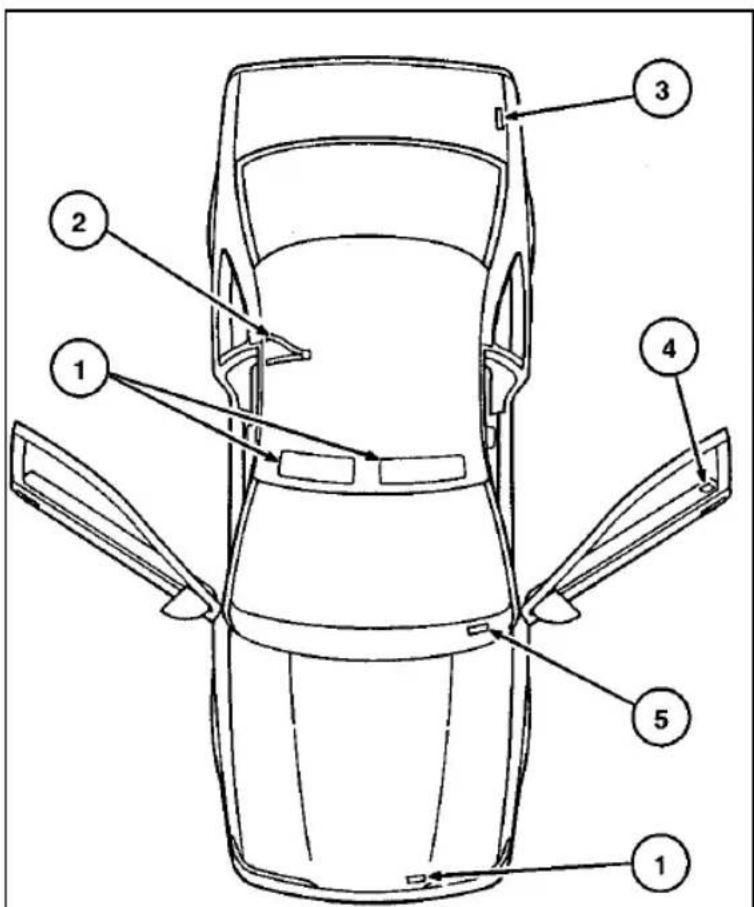
text_image
Technical diagram of a car with numbered parts labeled for identification| No. | Description | Refer to this label for information regarding: |
| 1 | Air Bag Warning Labels | Air bag precautions |
| 2 | Child Seat Label | Child seat installation precautions |
| 3 | Fuel Pump Shut-Off Label | Fuel pump shut off location |
| 4 | Safety Compliance Certification Label | Name and date of manufacturer, GVWR*, GAWR** |
| 5 | Vehicle Identification Information Number (VIN) Label | Servicing or warranty information specific to your vehicle |
*Gross Vehicle Weight Rating
**Gross Axle Weight Rating
Label locations
278
Front Exterior View
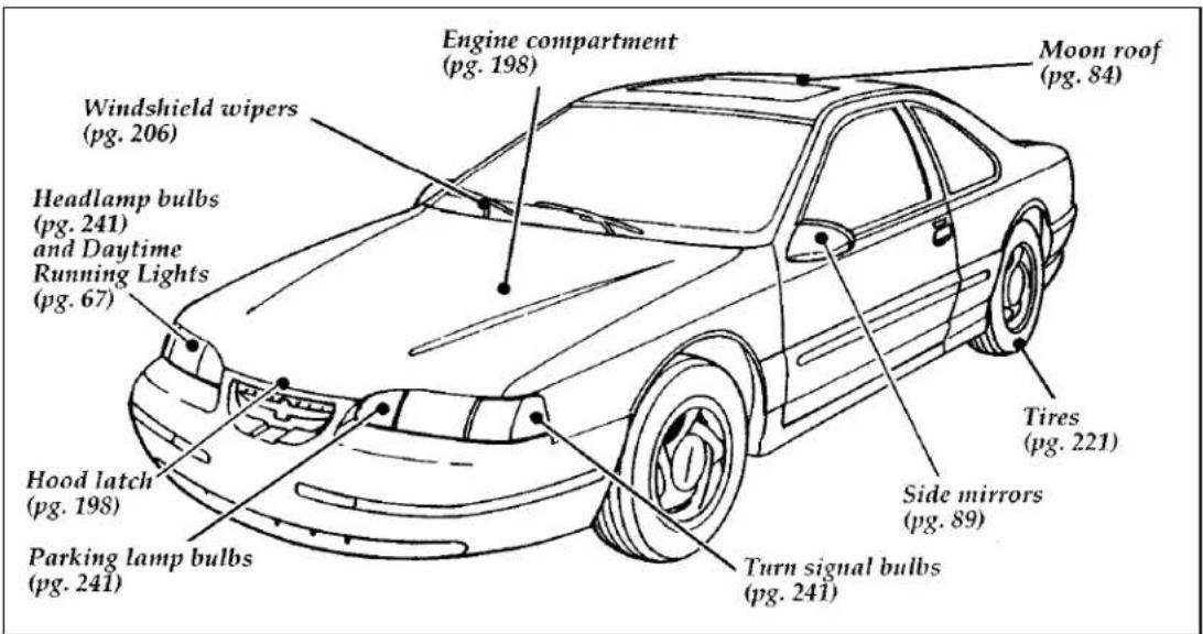
text_image
Engine compartment (pg. 198) Windshield wipers (pg. 206) Headlamp bulbs (pg. 241) and Daytime Running Lights (pg. 67) Hood latch (pg. 198) Parking lamp bulbs (pg. 241) Moon roof (pg. 84) Tires (pg. 221) Side mirrors (pg. 89) Turn signal bulbs (pg. 241)Rear Exterior View
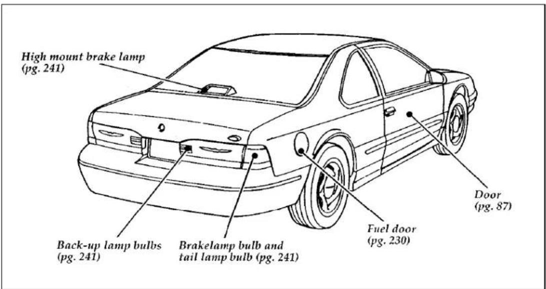
text_image
High mount brake lamp (pg. 241) Back-up lamp bulbs (pg. 241) Brakelamp bulb and tail lamp bulb (pg. 241) Fuel door (pg. 230) Door (pg. 87)
text_image
x m0z - x0 - c0280
Entrance View
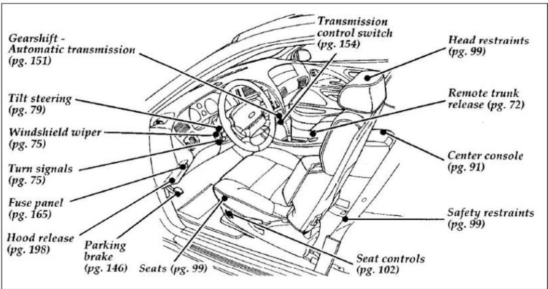
text_image
Gearshift - Automatic transmission (pg. 151) Tilt steering (pg. 79) Windshield wiper (pg. 75) Turn signals (pg. 75) Fuse panel (pg. 165) Hood release (pg. 198) Parking brake (pg. 146) Transmission control switch (pg. 154) Head restraints (pg. 99) Remote trunk release (pg. 72) Center console (pg. 91) Safety restraints (pg. 99) Seats (pg. 99) Seat controls (pg. 102)Driver's Door
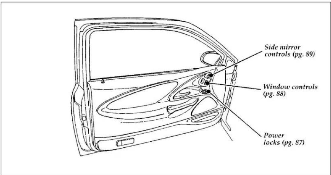
text_image
Side mirror controls (pg. 89) Window controls (pg. 88) Power locks (pg. 87)
text_image
x m0z - x0 - c0282
Instrument Panel
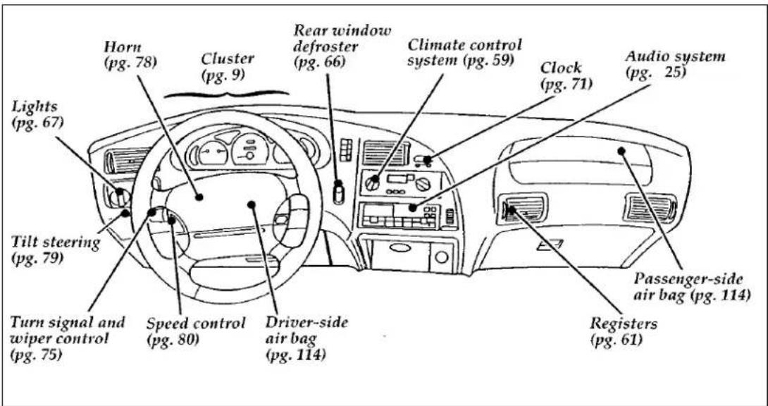
text_image
Horn (pg. 78) Cluster (pg. 9) Rear window defroster (pg. 66) Climate control system (pg. 59) Clock (pg. 71) Audio system (pg. 25) Lights (pg. 67) Tilt steering (pg. 79) Turn signal and wiper control (pg. 75) Speed control (pg. 80) Driver-side air bag (pg. 114) Passenger-side air bag (pg. 114) Registers (pg. 61)Instrument Cluster
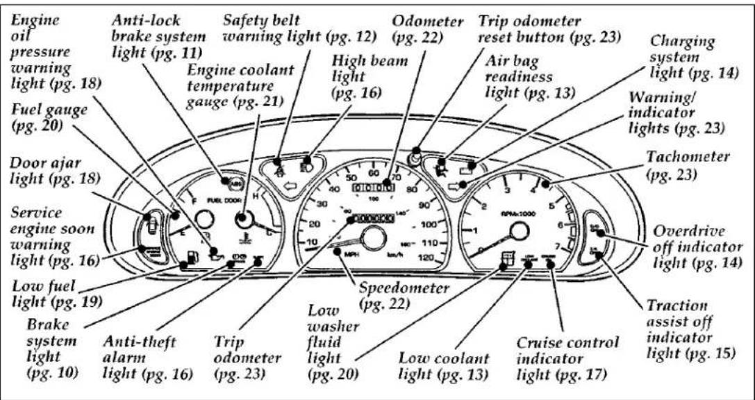
text_image
Engine oil pressure warning light (pg. 18) Fuel gauge (pg. 20) Door ajar light (pg. 18) Service engine soon warning light (pg. 16) Low fuel light (pg. 19) Brake system light (pg. 10) Anti-lock brake system light (pg. 11) Safety belt warning light (pg. 12) Engine coolant temperature gauge (pg. 21) High beam light (pg. 16) Odometer (pg. 22) High beam light (pg. 16) Speedometer (pg. 22) Low washer fluid light (pg. 20) Low cooler light (pg. 13) Trip odometer reset button (pg. 23) Air bag readiness light (pg. 13) Overdrive off indicator light (pg. 14) Charging system light (pg. 14) Warning/ indicator lights (pg. 23) Tachometer (pg. 23) Cruise control indicator light (pg. 17) Traction assist off indicator light (pg. 15)
text_image
xmoz-xo-co284
Trunk
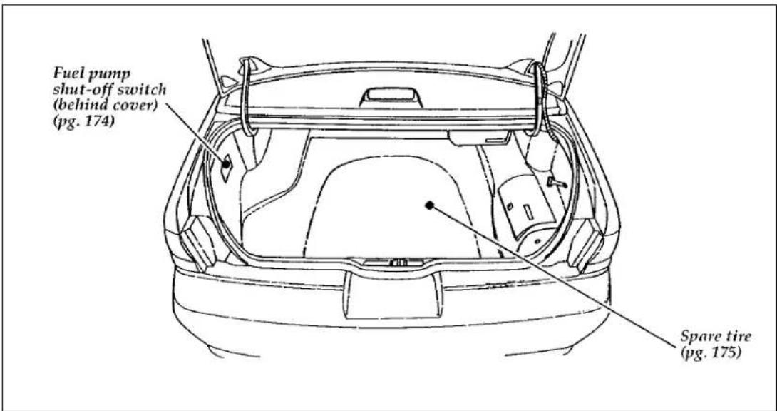
text_image
Fuel pump shut-off switch (behind cover) (pg. 174) Spare tire (pg. 175)3.8L Engine Compartment

text_image
Automatic transmission fluid dipstick (pg. 217) Engine oil (pg. 201) Brake master cylinder (pg. 204) Engine oil dipstick (pg. 202) Air filter (pg. 198) Engine coolant reservoir (pg. 207) High current fuse panel (pg. 168) Battery (pg. 219) Hood safety release (pg. 198) Power steering fluid reservoir (pg. 214) Windshield washer fluid reservoir (pg. 206)
text_image
x m0z - x0 - c0
text_image
Automatic transmission fluid dipstick (pg. 217) Air filter (pg. 198) Hood safety release (pg. 198) Engine oil (pg. 201) Power steering fluid reservoir (pg. 214) Brake master cylinder (pg. 204) Engine oil dipstick (pg. 202) High current fuse panel (pg. 168) Engine coolant reservoir (pg. 207) Battery (pg. 219) Windshield washer fluid reservoir (pg. 206)Index
A
ABS warning light
(see Anti-lock brake system) . . . . . . . 1 1
Accessory position on the ignition . . . . . 7 2
Additives, engine oil. 201
Air bag supplemental restraint system . . 114
and child safety seats . . . . . . . . 1 2 0
description. 1 1 4
driver air bag. 1 1 4
indicator light. 1 3
operation. 1 1 6
passenger air bag. 1 1 7
service and information labels . . . . . 1 1 6
tone generator. 1 1 8
Air cleaner filter
location. 1 9 8
specifications. 2 4 7
Air conditioning
manual heating and air conditioning system . . . . . . . . . 5 9
semi-automatic temperature control system. 6 2
Alarm, activating remote personal . . . . . 9 7
Antenna, radio (see Electronic sound system) 2 5
Antifreeze (see Engine coolant) ..... 2 0 7
Anti-lock brake system (ABS) description ..... 1 4 5
see also Brake. 1 4 5
warning light. 1 1
Anti-theft lug nuts and key . . . . . . . 1 8 4
Anti-theft system arming the system . . . . . . . . . . . 9 3 description . . . . . . . . . . . . . . 9 2 disarming an untriggered system. . . . . 9 4
Anti-theft system (continued)
disarming a triggered system. ..... 9 5
triggering. 9 2
warning light. 1 6
Appeals (see Dispute settlement board) .. 258
Assistance (see Customer assistance). . . . 2 5 5
Audio system (see Electronic
sound system)....25
Autolamp system (see Headlamps) ..... 6 7
Automatic transmission
driving an automatic overdrive. . . 151, 154
fluid, adding. 2 1 8
fluid, checking . . . . . . . . . . . 2 1 7
fluid, refill capacities ..... 2 4 8
fluid, specification. 2 4 9
Axle
lubricant specifications. 2 4 9
refill capacities 2 4 8
traction lok. 1 4 8
B
Backing up. 1 5 3
Basic vehicle warranty ..... 4
Battery 2 1 9
acid, treating emergencies ..... 1 8 6
charging system warning light . . . . . . 1 4
d is c o n n e c t i n g. . . . . . . . . . 191,220
how to service. 2 1 9
jumping a disabled battery. . . . . . . 1 8 5
maintenance-free. 2 1 9
proper disposal, recycling ..... 2 2 0
replacement, specifications . . . . . . . 2 4 7
servicing. 2 1 9
voltage gauge. 1 4
when storing your vehicle. . . . . . . 2 5 1
Brake fluid 204
brake warning light . . . . . . . . . . . 1 0
checking and adding. 2 0 4
description 204
specifications . . . . . . . . . . . 205, 249
Brakelamp. 2 3 9
bulb replacement. 239, 241
high-mountbrakelamp. . . . . . . . 2 3 9
Brakes. 1 4 5
adjustment. 1 4 5
anti-lock. 1 4 5
anti-lock brake system (ABS) warning light . . . . . . . . . . . . 1 1
applying the brakes. 1 4 5
brake warning light. 10
fluid, checking and adding . . . . . . 2 0 4
fluid, refill capacities . . . . . . . 204, 248
fluid, specifications . . . . . . . . 205, 249
front disc. 1 4 5
if brakes do not grip well. . . . . . . 1 4 5
master cylinder. 204
new brake linings. 6
noise. 1 4 5
parking. 1 4 6
power braking. 1 4 5
servicing. 1 4 5
stopping distances. 1 6 2
trailer. 1 6 1
when storing your vehicle. . . . . . . 2 5 2
Brake-shift interlock. 1 5 2
Break-in period. 6
Brights (high beams) 16
Bulbs, replacing. 2 3 6
halogen. 2 3 7
headlamps. 2 3 7
high-mountbrakelamp. . . . . . . . 239
specifications. 2 4 2
C
Canada, customer assistance ..... 2 6 3
Canada, warranty information. . . . . . . 4
Canadian Motor Vehicle Arbitration Plan
(CAMVAP). 2 6 3
Capacities for refilling fluids. . . . . . . 2 4 8
Carbon monoxide in exhaust. . . . . . . 1 4 3
Car seats for children
(see Child safety seats)....120
Cassette tape player (see Electronic
sound system) . . . . . . . 3 6 , 4 0 , 4 5 , 5 1
Catalytic converter. 2 3 3
CD player (see Electronic
sound system). . . . . . . . . . . 2 5 , 3 1
Chains, tires . . . . . . . . . . . . . . 2 2 6
Changing a tire. 1 7 5
Charging system warning light . . . . . . 1 4
Child safety restraints . . . . . . . . . 1 1 8
child safety belts. 1 3 6
child safety seats. 1 2 0
Child safety seats. 1 2 0
and air bags. 1 2 0
automatic locking mode
(retractor) 107, 120
in front seat . . . . . . . . . . . . 1 2 0
in rear outboard seat . . . . . . . . 1 2 9
in rear seat. 120, 135
tether anchorage hardware. . . . . . . 1 3 6
Chime
key in ignition. 7 3
safety belt 1 2
Circuit breakers
checking and replacing . . . . . . . . 1 7 3
see also fuses. 1 6 5
Cleaning your vehicle. 2 4 3
chrome and aluminum parts . . . . . . 2 4 3
engine compartment. 2 4 5
exterior. 2 4 3
exterior lamps. 2 4 4
fabric. 2 4 5
headlamps 2 4 4
instrument panel . . . . . . . . . 5 9 , 2 4 5
instrument panel lens. 2 4 5
interior. 2 4 5
interior lamps. 2 4 4
| Cleaning your vehicle (continued) | |
| mirrors | 8 9 |
| plastic parts | 2 4 4 |
| polishing. | 2 4 3 |
| rustproofing | 2 4 3 |
| safety belts. | 2 4 4 |
| tail lamps | 2 4 4 |
| upholstery and interior trim | 2 4 5 |
| washing | 2 4 3 |
| waxing | 2 4 3 |
| wheels. | 2 4 6 |
| Climate control system | 5 9 |
| air conditioning | 5 9 , 6 2 |
| heating | 5 9 , 6 2 |
| Clock | 7 1 |
| Cold engine starting. | 1 4 0 |
| Combination lap and shoulder belts | 105 |
| Compact disc player (see Electronic sound system) | 2 6 |
| Compact disc radio (see Electronic sound system) | 2 6 |
| Console, description | 9 1 |
| Controls | |
| mirrors | 8 6 |
| power seat | 1 0 2 |
| Coolant (see Engine coolant) | 2 0 7 |
| checking and adding | 2 0 7 |
| drain and flush. | 2 1 1 |
| preparing for storage | 2 5 1 |
| proper solution | 2 0 9 |
| refill capacities | 2 4 8 |
| specifications | 2 4 9 |
| temperature gauge | 2 1 |
| warnings. | 2 0 7 |
Cooling fan. 196
Customer Assistance Center, Ford (U.S.) .. 257
Customer Assistance Centre,
Ford of Canada . . . . . . . . . 257, 263
D
Daytime running light system ..... 6 7
Defrost
rear window. 6 6
windshield. 60
Dipstick. 2 0 2
automatic transmission fluid . . . . . . 2 1 7
engine oil. 202
power steering fluid. 2 1 4
Disabled vehicle (see Towing) . . . . . . 1 9 2
Dispute Settlement Board. 2 5 8
Doors. 87
door ajar warning light. . . . . . . . . 1 8
lubricant specifications. 2 4 9
Driving under special conditions ..... 1 6 2
bad weather. 1 6 2
heavy load. 1 5 6
high water. 1 6 4
slippery roads. 1 6 2
tips for safe driving. 1 6 2
towing a trailer. 1 5 8
E
Electrical system
circuit breakers. 173
fuses. 1 6 5
Electronic sound system
tuning the radio 27, 37, 46
warranty and service information. . . . . 5 8
Electronic stereo cassette radio (see Electronic
sound system) 37
Emergencies, roadside
assistance. 2 5 5
battery acid spills. 186
292 Index
Emergencies, roadside (continued)
fuel. 2 3 0
jump-starting. 185
towing. 192
Emergency brake (parking brake). . . . . 1 4 6
Emission control system . . . . . . . . . 2 3 3
catalytic converter. 2 3 3
emissions warranty. . . . . . . . . 4 , 2 3 3
Engine
does not start. 1 4 1
fuel injected engine, starting . . . . . . 1 3 9
fuel pump shut-off switch . . . . . . . 1 7 4
preparing to start. 1 3 9
refill capacities. 2 4 8
service points. 1 9 5
starting. 1 4 0
starting after a collision. . . . . . . . 1 7 4
storing your vehicle. 2 5 0
Engine block heater. 1 4 2
Engine coolant 207
checking and adding . . . . . . . . . 2 0 7
checking hoses. 208
disposal. 1 9 6
drain and flush. 2 1 1
low coolant warning light. . . . . . . . 1 3
preparing for storage. . . . . . . . . 2 5 1
proper solution. . . . . . . . 196, 209, 211
recovery reservoir. . . . . . . . 198, 207
refill capacities. 2 4 8
specifications. 2 4 9
temperature gauge. 2 1
Engine coolant temperature gauge ..... 2 1
description. 2 1
mechanical. 2 1
Engine fan. 1 9 6
Engine oil. 201
changing oil and oil filter. 2 0 3
checking and adding. 2 0 2
dipstick. 2 0 2
disposal. 204
engine oil pressure warning light. . . . . 1 8
filter, specifications . . . . . . . . . 2 4 7
refill capacities. 2 4 8
specifications. 201, 249
synthetic oil. 201
"break-in" oils. 6
viscosity. 201
Entry system
illuminated. 8 8
remote. 9 5
Exhaust fumes 143
Extended Service Plan, Ford . . . . . . . 4
F
F a n . . . . . . . . . . . . . . . . . 1 9 6
engine fan, avoiding injury. . . . . . . 1 9 6
Federal Communications Commission . . . . 5 7
Flashers, hazard . . . . . . . . . . . . . . 7 7
Flashing the lights. 7 5
Flat tire. 175
Floor mats. 9 2
Fluid refill capacities. 2 4 8
Ford Customer Assistance Center . . . . . 2 5 7
Ford Dispute Settlement Board . . . . . . 2 5 8
Ford Extended Service Plan ..... 4
Ford Motor Company of Canada . . . . . 2 6 3
Ford of Canada Customer
Assistance Centre. 2 6 3
Foreign registration. 2 6 4
French owner guides, how to obtain . . . . 3
Fuel. 2 2 7
capacity. 2 4 8
choosing the right fuel. 2 2 7
filling your vehicle with fuel. . . . . . 2 2 6
filter, specifications . . . . . . . . . . 2 4 7
Fuel (continued)
fuel filler door release lever. . . . . . 2 2 7
fuel gauge. 20
low fuel warning light. . . . . . . . . 1 9
octane rating. 2 2 9
quality. 2 2 9
running out of fuel . . . . . . . . . . 2 3 1
safety information relating to automotive fuels. 2 3 0
storing your vehicle. 2 5 1
treating emergencies. 2 3 0
Fuel cap. 2 2 7
removing. 2 2 7
replacing. 2 2 7
Fuel filler door. 2 2 7
remote release. 2 2 7
Fuel filter, specifications . . . . . . . . . 2 4 7
Fuel gauge. 20
Fuel pump shut-off switch engine does not start. . . . . . . . . 1 7 4
starting after a collision. . . . . . . . 1 7 4
Fuse panels engine compartment ..... 1 6 8
high current fuse panel. . . . . . . . 1 6 9
instrument panel. 1 6 5
Fuses charts . . . . . . . . . . . . . . 167, 171
checking and replacing . . . . . . . . 1 7 1
circuit breakers. 1 7 3
G
Gas cap (see Fuel cap). 2 2 7
Gas mileage (see Fuel economy) . . . . . 2 3 1
Gasoline (see Fuel)....2 2 7
Gauges, Mechanical
engine coolant temperature gauge . . . . 2 1
fuel gauge. 2 0
odometer. 2 2
speedometer. 2 2
tachometer. 2 3
trip odometer. 2 3
GAWR (Gross Axle Weight Rating)
calculating. 1 5 7
definition. 1 5 6
driving with a heavy load . . . . . . . 1 5 6
location. 1 5 6
Gearshift
automatic operation. 1 5 1
console-mounted 153
locking the gearshift. 7 2
positions. 1 5 1
shifting the gears. 1 5 1
shift-lock. 1 5 2
GVWR (Gross Vehicle Weight Rating) . . . 156
calculating. 1 5 7
definition. 1 5 6
driving with a heavy load. . . . . . . 1 5 6
location. 1 5 6
H
Hazard flashers. 7 7
Headlamps
aiming. 2 3 6
autolamp system 6 9
bulb specification. 2 4 2
checking alignment. 2 3 6
cleaning 2 4 4
daytime running lights. . . . . . . . . 6 7
flashing. 7 5
high beam. 7 5
replacing bulbs. 2 3 6
turning on and off. 6 8
Head restraints . . . . . . . . . . . . . . 9 9
Heating
manual heating and air conditioning system . . . . . . . . . 5 9
semi-automatic system . . . . . . . . 6 2
High beams
indicator light. 1 6
operation. 6 7 , 7 5
High-mountbrakelamp. . . . . . . . . 2 3 9
description. 2 3 9
replacing the bulb. 2 3 9
Hitch. 1 6 0
Hood. 198
latch location. 198
lubrication specifications. 2 4 9
release lever. 1 9 8
working under the hood. 196
Horn. 78
Hoses, checking. 2 0 8
I
Identification Number, Vehicle (VIN) . . . 258
Idle, relearning . . . . . . . . . 191, 196, 220
Ignition
chime. 7 3
positions of the ignition. . . . . . . . . 7 2
removing the key. 7 3
Indicator lights and chimes (see Lights) . . . 8
Infant seats (see Safety seats). . . . . . . 1 1 8
Instrument cluster, mechanical . . . . . . 9
Instrument panel. 5 9
cleaning. 2 4 5
lighting up panel and interior . . . . . . 7 0
Interval wipers. 7 5
J
Jack. 177
operation. 178
positioning. 1 7 9
storage....177
Jump-starting your vehicle
attaching cables....187
disconnecting cables. 1 9 1
K
Keys
key in ignition chime . . . . . . . . . 7 3
positions of the ignition. 7 2
removing from the ignition. . . . . . . 7 3
stuck in lock position. . . . . . . . . . 7 3
L
Lamps
autolamp delay system. . . . . . . . . 6 9
bulb replacement specifications chart .. 242
checking....236
daytime running light system ..... 6 7
dome lamps. 7 0
flashing the lamps. 7 5
hazard flashers 7 7
headlamps 68
high beams. 7 5
high-mount brakelamp 239
illuminated entry system. 8 8
illuminated mirrors 8 6
instrument panel, dimming ..... 7 0
interior lamps. 67,70
replacing bulbs. 2 3 6
trailer 161
Lane change indicator
(see Turn signal)....74
Lap belts. 1 1 2
Lights, warning and indicator
a i r b a g . . . . . . . . . . . . . . . . . 1 3
anti-lock brakes (ABS). 1 1
anti-theft. 16
brake. 10
charging system. 1 4
door ajar. 1 8
engine oil pressure. 1 8
hazard warning light. 7 7
high beam. 1 6
low coolant. 1 3
low fuel. 19
low washer fluid. 20
oil pressure. 18
overdrive off. 1 4
safety belt. 1 2
service engine soon. 16
theft system 16
turn signal indicator. 17
Load limits. 1 5 6
GAWR. 1 5 6
GVWR. 1 5 6
trailer towing. 1 5 8
Lubricant specifications. . . . . . . . . 2 4 9
Lug nuts. 1 7 8
anti-theft. 184
standard. 179
tightening sequence. 182
M
Maintenance schedule and record
(see separate Maintenance Schedule
booklet) 3
Maintenance (see Servicing) . . . . . . . 1 9 5
Master cylinder, brakes . . . . . . . . 2 0 4
Mirrors. 8 6
rearview....86
Mirrors (continued)
side view mirrors. 8 6
side view mirrors (power) . . . . . . . . 8 9
vanity mirror, illuminated . . . . . . . 8 6
Moon roof. 8 4
Motorcraft parts. 2 4 7
N
New vehicle break-in. 6
O
Octane rating. 2 2 7
Odometer. 2 2
description. 2 2
trip odometer. 2 3
Oil filter. 203, 247
Oil (see Engine oil) . . . . . . . . . . . 2 0 1
Oil viscosity. 201
On-board diagnostic (OBD II) system . . . 236
Overdrive. 1 5 4
Overseas offices. 2 6 4
P
Panic alarm feature, remote entry system .. 97
Parking brake. 1 4 6
operation. 1 4 6
warning light. 1 0
Parts (see Motorcraft Parts). 2 4 7
PCV valve, specifications. 2 4 7
Power distribution box (see Fuses) . . . . 1 6 5
Power door locks. 8 7
Power features
door locks 87
mirrors. 86,89
moon roof 8 4
seats. 102
windows....88
Power steering
dipstick. 2 1 4
driving with power steering. . . . . . 1 5 0
fluid, checking and adding. . . . . . 2 1 4
fluid, refill capacity . . . . . . . . . 2 4 8
fluid, specifications. 2 4 9
servicing. 1 5 0
Prop rod, hood. 1 9 8
R
Radio (see Electronic sound systems) . . . . 2 5
Rear axle
lubricant specification. 2 4 9
refill capacity. 2 4 8
Rear window....88
defroster. 6 6
Refill capacities for fluids. 2 4 8
Relays....165
Remote control, trunk ..... 7 2
Remote entry system. 9 5
locking/unlocking doors. 9 6
opening the trunk. 9 6
panic alarm. 9 7
replacement/additional transmitters . . . 98
replacing the batteries. 97
Restraints, safety (see Safety restraints)
adult. 103
child. 1 1 8
head. 9 9
infant 1 1 8
Roadside assistance ..... 2 5 5
Roadside emergencies. 1 6 5
Rotating the tires . . . . . . . . . . . . 2 2 2
S
Safe driving tips. 1 6 2
Safety belts (see Safety restraints) . . . . . 1 0 3
Safety chains, when towing a trailer. . . . 1 6 0
Safety information relating to automotive fuels. 2 3 0
Safety restraints
adjusting the safety belts. 105, 108, 112
automatic locking mode ..... 1 0 7
automatic locking mode (retractor) ... 107
center rear lap belt. 1 1 2
cleaning the safety belts. 2 4 4
extension assembly....1 1 3
for adults. 103
for children. 1 1 8
for infants. 118, 120
for pregnant women. 103
head. 9 9
lap and shoulder belts. . . . . . . 103, 105
maintenance. 1 1 4
proper use. 103
replacement 1 1 4
warning light and chime. . . . . . . . . 1 2
Safety seats for children. 1 2 0
and air bags. 1 2 0
automatic locking mode (retractor)....107, 120
in center seating positions . . . . . . . 1 3 5
in front seat. 1 2 0
in rear outboard . . . . . . . . 120, 129
in rear seat. 1 2 0
Seat belts (see Safety restraints)....103
Seats 9 9
adjusting the seat, manual . . . . . . 1 0 0
adjusting the seats, power . . . . . . . 1 0 2
child safety seats . . . . . . . . . . . 1 2 0
cleaning upholstery. 2 4 5
head restraints. 9 9
Seats (continued)
rear seat access. 103
reclining the seat. 101
Serial number (VIN). 2 5 8
Service concerns. 2 5 6
Servicing your vehicle. 1 9 5
precautions when servicing. . . . . . 1 9 6
servicing when you tow. . . . . . . . 1 9 2
Shift-lock system. 1 5 2
Shift positions (see Gearshift). ..... 1 5 1
Shoulder and lap belts (see Safety restraints) ..... 103, 105
Shoulder belts (see Safety restraints) . . . 105
Side mirrors. 8 6
adjusting. 8 9
Sliding moon roof (see Moon roof) . . . . . 8 4
Snow tires and chains. 2 2 5
Spare tire. 175
changing the tire . . . . . . . . . 175, 178
conventional spare ..... 1 7 7
finding the spare. 1 7 7
removing the spare tire . . . . . . . . 1 7 7
storing the flat tire ..... 177, 179
temporary spare....175
Spark plugs, specifications . . . . . . . . 2 4 7
Special driving conditions ..... 1 6 2
Specification chart, lubricants. ..... 2 4 9
Speed control
turning off. 80
when towing a trailer. . . . . . . . . 1 6 1
Speedometer 2 2
Starting your vehicle
preparing to start your vehicle. . . . . 1 3 9
starting a cold engine. 1 4 0
starting after a collision . . . . . . . . 1 7 4
starting a warm engine . . . . . . . . 1 4 1
starting your vehicle if the battery is disabled. 1 8 5
Steering, power . . . . . . . . . . . . . 1 5 0
Steering wheel
horn. 7 8
locking. 7 2
tilting. 7 9
Storage compartments, center console . . . . 9 1
Storing your vehicle. 2 5 0
Sunroof (moon roof)....84
Supplemental air bag readiness light . . . . 1 3
Supplemental Restraint System (SRS) . . . 114
T
Tachometer. 2 3
Tail lamps
bulb replacement. 2 3 6
cleaning. 2 4 4
Temperature control (see Climate control) .. 59
Tilt steering wheel. 7 9
Tires. 2 2 1
changing. 175
checking the pressure. 2 2 1
cleaning. 2 4 6
inspection and maintenance . . . . . . 2 2 1
replacing. 2 2 3
rotating. 2 2 2
snow tires and chains. 2 2 5
spare tire. 177
storing your vehicle. 2 5 2
tire grades. 2 2 4
treadwear. 2 2 4
wear bands. 2 2 3
Towing a trailer (see Trailer towing) . . . 158
Towing your vehicle. 192
using wheel dollies. 1 9 2
with a tow truck. 1 9 2
Traction assist. 1 4 9
Traction-lok rear axle . . . . . . . . . 1 4 8
Trailer towing. 1 5 8
calculating maximum trailer weight . . . . . . . . . . . 1 5 8
safety chains. 1 6 0
tips. 1 6 1
trailer brakes. 1 6 1
trailer lamps. 1 6 1
Transmission automatic operation. 1 5 1
fluid, checking and adding (automatic)....2 1 7
fluid, refill capacities ..... 2 4 8
lubricant specifications. . . . . . . . 2 4 9
Transmission control switch . . . . . . 1 5 4
Transmitter (see Remote entry) ..... 9 5
Trip odometer. 2 3
Trunk remote release lever. 7 2
using the remote entry system to open .. 96
Tune-up specifications (VECI) . . . . . . 2 3 5
Turn signal. 7 4
indicator lights . . . . . . . . . . . . . 1 7
lever 74
U
Used engine oil, disposal . . . . . . . 2 0 4
V
Vanity mirror. 8 6
Variable interval wipers. 7 5
VECI (Vehicle Emission Control Information) decal 2 3 5
Vehicle Identification Number (VIN) ... 258
Vehicle loading automatic transmissions ..... 1 5 7
calculating the load . . . . . . . . . 1 5 7
understanding loading information . . . 156
Vehicle storage. 2 5 0
Ventilating your vehicle (see Climate control) . . . . . . . . 5 9 , 6 5
Viscosity (see Engine oil). 2 0 1
Voltmeter (see Battery voltage gauge) . . . . 1 4
W
Warm engine, starting . . . . . . . . . 1 4 1
Warning chimes key in ignition . . . . . . . . . . . . . . 7 3 safety belt . . . . . . . . . . . . . . 1 2
Warning lights (see Lights) . . . . . . . . . 8
Warranties. 4
basic. 4
Canada. 4
radio. 5 8
Warranty Information Booklet. . . . . . . 4
Washer fluid . . . . . . . . . . . . . . . 7 5
rear window reservoir. 206
reservoir. 206
warning light. 20
windshield. 206
Weight limits (GAWR, GVWR) . . . . . . 1 5 6
Wheel dollies (see Towing) . . . . . . . . 1 9 2
Wheels
anti-theft lugnuts. 1 8 4
cleaning. 2 4 6
covers. 178, 182
inspection and maintenance ..... 2 2 1
lug nuts 178
ornaments....182
Windows. 8 8
manual windows, operating . . . . . . . 8 8
power windows, operating ..... 8 8
rear, defrosting. 6 6
Windshield, washing ..... 7 5
Windshield washer fluid and wipers . . . . 7 5
checking and adding fluid. 2 0 6
checking and replacing wiper blades . . 220
low washer fluid light. 20
operation....75
reservoir. 206
specifications. 206, 249
variable interval wipers. . . . . . . . . 7 6
Windshield wipers and washer. . . . . . . 7 5
Wrecker towing. 192
Service Station Information
| Engine | 3.8L SFI | 4.6L SFIOHC V8 |
| Fuel | UNLEADED FUEL ONLY — Octane 87 | |
| Fuel Tank Capacity | 18.0 gallons (68.1 Liters) | |
| Tire Size | See tire pressure decal below the right door jamb | |
| Tire Pressure | See tire pressure decal below the right door jamb | |
| Hood Release | Pull handle under left side of dash | |
| Engine Oil | Use only engine oil displaying the American Petroleum Institute Certification Mark — SAE 5W-30 preferred | |
| Engine OilCapacity w/filter | 5.0 quarts (4.7 Liters) | |
| AutomaticTransmission | Motorcraft Mercon® (ATF)13.9 quarts (13.1 Liters) | |
| Power Steering Fluid | Use only power steering fluid that meets Ford's Specification Motorcraft Mercon® (ATF). | |
| Engine Coolant | 12.6 quarts(11.9 Liters) | 14.1 quarts(13.3 liters) |