
F-53 Motorhome Chassis (2003) - Automotive FORD - Free user manual and instructions
Find the device manual for free F-53 Motorhome Chassis (2003) FORD in PDF.


User questions about F-53 Motorhome Chassis (2003) FORD
0 question about this device. Answer the ones you know or ask your own.
Ask a new question about this device
Download the instructions for your Automotive in PDF format for free! Find your manual F-53 Motorhome Chassis (2003) - FORD and take your electronic device back in hand. On this page are published all the documents necessary for the use of your device. F-53 Motorhome Chassis (2003) by FORD.
USER MANUAL F-53 Motorhome Chassis (2003) FORD
Warning and control lights 8
Gauges 11
Lights 14
Headlamps 14
Bulb replacement 15
Driver controls 16
Windshield wiper/washer control 16
Speed control (Cruise control) 17
Driving 20
Starting 20
Brakes 23
Transmission operation 27
Vehicle loading 31
Trailer towing 33
Roadside emergencies 36
Hazard flasher switch 36
Fuel pump shut-off switch 36
Fuses and relays 38
Changing tires 45
Jump starting 48
Wrecker towing 52
Table of contents
Customer assistance 53
Cleaning 54
Maintenance and specifications 55
Engine compartment 56
Engine oil 57
Battery 59
Fuel information 67
Air filter(s) 83
Part numbers 88
Refill capacities 89
Lubricant specifications 91
Reporting safety defects (U.S. only) 93
Reporting safety defects (U.S. only) 93
Index 94
All rights reserved. Reproduction by any means, electronic or mechanical including photocopying, recording or by any information storage and retrieval system or translation in whole or part is not permitted without written authorization from Ford Motor Company. Ford may change the contents without notice and without incurring obligation.
Copyright © 2002 Ford Motor Company
Introduction
CALIFORNIAProposition65Warning

WARNING: Engine exhaust, some of its constituents, and certain vehicle components contain or emit chemicals known to the State of California to cause cancer and birth defects or other reproductive harm. In addition, certain fluids contained in vehicles and certain products of component wear contain or emit chemicals known to the State of California to cause cancer and birth defects or other reproductive harm.
CONGRATULATIONS
Congratulations on acquiring your new Ford. Please take the time to get well acquainted with your vehicle by reading this handbook. The more you know and understand about your vehicle the greater the safety and pleasure you will derive from driving it.
For more information on Ford Motor Company and its products visit the following website:
• In the United States: www.ford.com
• In Canada: www.ford.ca
• In Australia: www.ford.com.au
• In Mexico: www.ford.com.mx
Additional owner information is given in separate publications.
This Owner's Guide describes every option and model variant available and therefore some of the items covered may not apply to your particular vehicle. Furthermore, due to printing cycles it may describe options before they are generally available.
Remember to pass on the Owner's Guide when reselling the vehicle. It is an integral part of the vehicle.

Fuelpumpshut-offswitchIn the event of an accident the safety switch will automatically cut off the fuel supply to the e. The switch can also be activated through sudden vibration (e.g. on when parking). To reset the switch, refer to the Fuelpump offswitchin the Roadsideemergencieschapter.
Introduction
SAFETY AND ENVIRONMENT PROTECTION

Warning symbols in this guide
How can you reduce the risk of personal injury and prevent possible damage to others, your vehicle and its equipment? In this guide, answers to such questions are contained in comments highlighted by the warning triangle symbol. These comments should be read and observed.

Warning symbols on your vehicle
When you see this symbol, it is imperative that you consult the relevant section of this guide before touching or attempting adjustment of any kind.

Protecting the environment
We must all play our part in protecting the environment. Correct vehicle usage and the authorized disposal of waste cleaning and lubrication materials are significant

steps towards this aim. Information in this respect is highlighted in this guide with the tree symbol.
BREAKING-IN YOUR VEHICLE
Your vehicle does not need an extensive break-in. Try not to drive continuously at the same speed for the first 1,600 km (1,000 miles) of new vehicle operation. Vary your speed to allow parts to adjust themselves to other parts.
Drive your new vehicle at least 800 km (500 miles) before towing a trailer.
Do not add friction modifier compounds or special break-in oils during the first few thousand kilometers (miles) of operation, since these additives may prevent piston ring seating. See Engineoil in the Maintenance and care chapter for more information on oil usage.
Introduction
SPECIAL NOTICES
Emission warranty
The New Vehicle Limited Warranty includes Bumper-to-Bumper Coverage, Safety Restraint Coverage, Corrosion Coverage, and 7.3L Power Stroke Diesel Engine Coverage. In addition, your vehicle is eligible for Emissions Defect and Emissions Performance Warranties. For a detailed description of what is covered and what is not covered, refer to the WarrantyGuidethat is provided to you along with your Owner's Guide.
Notice to owners of Class A Motorhome Vehicles
The Ford Motorhome Chassis is not suitable for producing ambulances or school buses. In addition, Ford urges manufacturers to follow the recommendations of the “Ford Incomplete Vehicle Manual,” the “Ford Truck Body Builder’s Layout Book,” and other pertinent supplements.
Notification of delayed warranty start date and accumulated mileage
Verify that your recreational vehicle dealer has submitted a Notification of Delayed Warranty Start Date and Accumulated Mileage (FCS 900) to Ford Motor Company.
Introduction
These are some of the symbols you may see on your vehicle.
Safety Alert

See Owner's Guide
Fasten Safety Belt Air Bag-Flint

Air Bag-Side Child Seat

Child Seat Installation Warning

Child Seat Lower Anchor
Child Seat Tether Anchor

Brake System
Anti-Lock Brake System

Brake Fluid - Non-Petroleum Based
Traction Control Advance

Master Lighting Switch Hazard Warning Flasher

Fog Lamps-Front Fuse Compartment

Fuel Pump Reset Windshield Wash/Wipe

Windshield Defrost/Demist

Rear Window Defrost/Demist
Power Windows Front/Rear

Power Window Lockout


Introduction
Child Safety Door Lock/Unlock
Panic Alarm Engine Oil
Engine Coolant
Do Not Open When Hot Bat
Avoid Smoking, Flames, or Sparks
Explosive Gas Fan Warning
Power Steering Fluid
Emission System Engine A
Passenger Compartment Air Filter
Check fuel cap Low tire wa


Interior Luggage Compartment Release Symbol
Engine Coolant Temperature
Battery Acid
Maintain Correct Fluid Level
Jack


Instrumentation
WARNING LIGHTS AND CHIMES
text_image
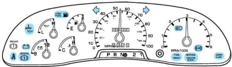
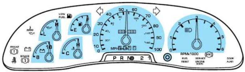
LOW FUEL L H E 40 50 60 70 30 60 100 120 80 40 20 40 90 MPH-100 100 2 3 4 RPMV1000 FUEL RESET SERVICE ENGINE SUV DEOR AJN PR N 2 1Warning lights and gauges can alert you to a vehicle condition that may become serious enough to cause expensive repairs. A warning light may illuminate when a problem exists with one of your vehicle's functions. Many lights will illuminate when you start your vehicle to make sure the bulb works. If any light remains on after starting the vehicle, have the respective system inspected immediately.
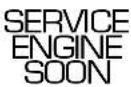
Serviceenginesoon: If this light illuminates while driving, it is a possible indication that one of the engine's emission control systems has failed.
Brakesystemwarninglight: To confirm the brake system warning light is functional, it will momentarily illuminate when the

ignition is turned to the ON position when the engine is not running, or in a position between ON and START, or by applying the parking brake when the ignition is turned to the ON position. If the brake system warning light does not illuminate at this time, seek service immediately from your dealership. Illumination after releasing the parking brake indicates low brake fluid level and the brake system should be inspected immediately by your servicing dealership.
Driving a vehicle with the brake system warning light on is dangerous. A significant decrease in braking performance may occur. It will take you longer to stop the vehicle. Have the vehicle checked by your dealer immediately.
Instrumentation
Brakereservesystemwarning
BRAKE
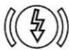
(ifequipped):Illuminates to indicate normal Hydromax booster reserve system activation when the engine is OFF and the service brake pedal is applied.
This light may also illuminate momentarily if the engine is running and the driver turns the steering wheel fully in one direction while braking.
If the light remains on while the engine is running, this indicates inadequate hydraulic booster pressure or reserve pump system failure. Stop the vehicle safely as soon as possible and seek service immediately.
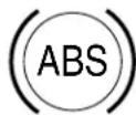
Anti-lockbrakesystem: If the
ABS light stays illuminated or continues to flash, a malfunction has been detected, have the system serviced immediately. Normal braking is still functional unless the b illuminated.
Safetybelt: Reminds you to fasten your safety belt. A chime will also sound to remind you to fasten your safety belt.
Chargingsystem: Illuminates when the battery is not charging properly.

Oilpressure/Enginecoolant:
Illuminates when any of the following conditions has occurred:

- The engine coolant temperature is high.
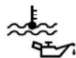
• The engine oil pressure is low.
Check the engine oil and coolant level refer to Addingengineoiland Addingcoolant in the Maintenance and Specifications chapter.
Instrumentation
Lowfuel:lluminates when the fuel level in the fuel tank is at, or near empty (refer to Fuelgauge in this chapter).
Fuelreset: Illuminates when the fuel pump shut-off switch has been triggered. For more information refer to Fuelpumpshut-offswitch in the RoadsideEmergencies chapter.
Doorajar: Illuminates when the ignition is in the ON position and any door is open.
Turnsignal: Illuminates when the left or right turn signal or the hazard lights are turned on. If the indicators stay on or flash faster, check for a burned out bulb.
Highbeams: Illuminates when the high beam headlamps are turned on.


Key-in-ignitionwarningchime: Sounds when the key is left in the ignition in the OFF/LOCK or ACC position and the driver's door is opened.
Headlampsonwarningchime: Sounds when the headlamps or parking lamps are on, the ignition is off (and the key is not in the ignition) and the driver's door is opened.
Instrumentation
GAUGES
text_image
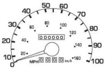
LOW FUEL E 20 30 40 50 60 70 80 90 100 110 120 130 140 150 160 170 180 190 200 210 220 230 240 250 260 270 280 290 300 310 320 330 340 350 360 370 380 390 400 410 420 430 440 450 460 470 480 490 500 510 520 530 540 550 560 570 580 590 600 610 620 630 640 650 660 670 680 690 700 710 720 730 740 750 760 770 780 790 800 810 820 830 840 850 860 870 880 890 900 910 920 930 940 950 960 970 980 990 1000 RPMX 1000 FUEL RESET SERVICE ENGLIC SOUND SCOR AJARISpeedometer: Indicates the current vehicle speed.
text_image
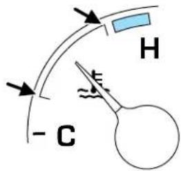
0 20 40 60 80 100 120 140 160 MPH km/hEnginecoolanttemperature gauge:Indicates engine coolant temperature. At normal operating temperature, the needle will be in the normal range (between "H" and "C"). Ifitenterstheredsection, theengineisoverheating.Stop thevehiclecassoonassafely possible,switchofftheengine andlettheenginecool.
text_image
- C H
Never remove the coolant reservoir cap while the engine is running or hot.
Instrumentation
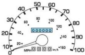
Odometer: Registers the total
kilometers (miles) of the vehicle.
Tripodometer: Registers the kilometers (miles) of individual journeys. To reset, depress the control.
Tachometer: Indicates the engine speed in revolutions per minute. Driving with your tachometer pointer continuously at the top of the scale may damage the engine.
Batteryvoltagegauge:Indicates the battery voltage when the ignition is in the ON position. If the pointer moves and stays outside the normal operating range (as indicated by arrows), have the vehicle's electrical system checked as soon as possible.
text_image
40 50 60 70 80 90 100 120 140 20 22 24 26 28 30 32 34 36 38 40 42 44 46 48 50 52 54 56 58 60 62 64 66 68 70 72 74 76 78 80 82 84 86 88 90 92 94 96 98 100 MPH 160 km/h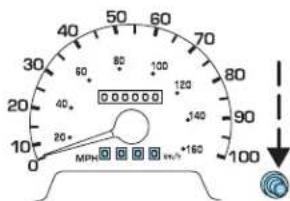
text_image
40 50 60 70 80 90 100 110 120 130 140 150 160 20+ 20- MPa 160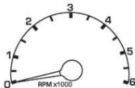
radar
| RPM (x1000) | | :--- | | 0 | | 1 | | 2 | | 3 | | 4 | | 5 | | 6 |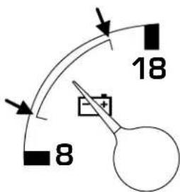
text_image
18 8Instrumentation
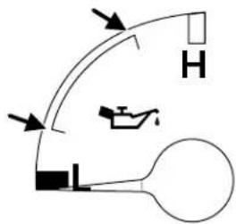
Engineoilpressuregauge:
Indicates engine oil pressure. The needle should stay in the normal operating range (between "L" and "H"). If the needle falls below the normal range, stop the vehicle, turn off the engine and check the engine oil level. Add oil if needed. If the oil level is correct, have your vehicle checked at your dealership or by a qualified technician.
Fuelgauge:Indicates
approximately how much fuel is left in the fuel tank (when the ignition is in the ON position).
text_image
Diagram showing a curved path with directional arrows and labeled components including a tank, car, and a bulb.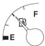
Lights
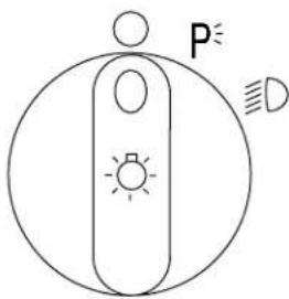
HEADLAMP CONTROL
○ Turns the lamps off.
P≤ Turns on the parking lamps, instrument panel lamps, license plate lamps and tail lamps.
D Turns the headlamps on.
text_image
P DDaytime running lamps (DRL) (if equipped)
The daytime running light system turns the headlamps on, with a reduced light output, when:
• the vehicle is running and
- the headlamp system is in the OFF position or parking lamp position.
Always remember to turn on your headlamps at dusk or during inclement weather. The Daytime Running Light (DRL) System does not activate your tail lamps and generally may not provide adequate lighting during these conditions. Failure to activate your headlamps under these conditions may result in a collision.
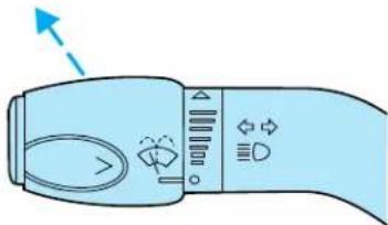
High beams D
Push the lever toward the instrument panel to activate. Pull the lever towards you to deactivate.
natural_image
Illustration of a handheld device with control buttons and a directional arrow (no text or symbols)Lights
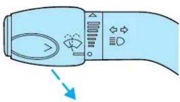
Flash to pass
Pull toward you slightly to activate and release to deactivate.
natural_image
Diagram of a handheld device with control buttons and a blue arrow pointing to the left side (no text or symbols)PANEL DIMMER CONTROL

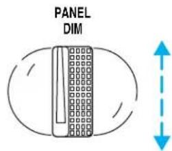
Use to adjust the brightness of the instrument panel and all applicable switches in the vehicle during headlamp and parklamp operation.
Move the control to the full upright position, past detent, to turn on the interior lamps.
Move the control to the full down position, past detent, to prevent the interior lights from illuminating when the doors are opened.
text_image
PANEL DIMBULBS
Replacing exterior bulbs
Check the operation of all the bulbs frequently.
Driver controls
MULTI-FUNCTION LEVER
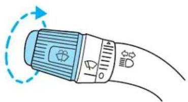
Windshieldwiper: Rotate the end of the control away from you to increase the speed of the wipers; rotate towards you to decrease the speed of the wipers.
natural_image
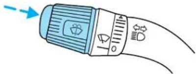
Illustration of a medical or cosmetic device with blue cap and orange handle, showing curved lines and a circular arrow indicating rotation (no text or symbols)Windshieldwasher: Push the end of the stalk:
- briefly: causes three swipes of the wipers without washer fluid.
- a quick push and hold: the wipers will swipe four times with washer fluid.
natural_image
Illustration of a handheld device with a blue handle and control knob, emitting a blue arrow (no text or symbols)- a long push and hold: the wipers and washer fluid will be activated for up to ten seconds.
TILT STEERING WHEEL (IF EQUIPPED)
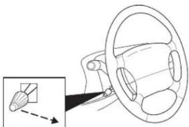
To adjust the steering wheel:
- Pull and hold the steering wheel release control toward you.
- Move the steering wheel up or down until you find the desired location.
- Release the steering wheel release control. This will lock the steering wheel in position.
natural_image
Diagram of a car steering wheel and dashboard with an inset showing a component (no text or symbols)
Never adjust the steering wheel when the vehicle is moving.
Driver controls
SPEED CONTROL (IF EQUIPPED)
With speed control set, you can maintain a speed of 48 km/h (30 mph) or more without keeping your foot on the pedal. Speed control does not work at speeds below 48 km/h (30 mph).

Do not use the speed control in heavy traffic or on roads that are winding, slippery or unpaved.
SETTING SPEED CONTROL
The controls for using your speed control are located on the steering wheel for your convenience.
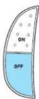
- Press the ON control and release it.
-
Accelerate to the desired speed.
-
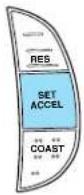
Press the SET ACCEL control and release it.
-
Take your foot off the accelerator pedal.
-
The indicator light on the instrument cluster will turn on.
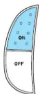
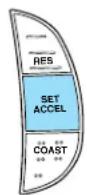
Note:
- Vehicle speed may vary momentarily when driving up and down a steep hill.
- If the vehicle speed increases above the set speed on a downhill, you may want to apply the brakes to reduce the speed.
- If the vehicle speed decreases more than 16 km/h (10 mph) below your set speed on an uphill, your speed control will disengage.
Driver controls
RESUMING A SET SPEED
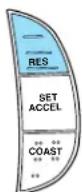
Press the RES (resume) control and release it. This will automatically return the vehicle to the previously set speed. The RES control will not work if the vehicle speed is not faster than 48 km/h (30 mph).
INCREASING SPEED WHILE USING SPEED CONTROL
There are two ways to set a higher speed:
- Press and hold the SET ACCEL control until you get to the desired speed, then release the control. You can also use the SET
ACCEL control to operate the Tap-Up function. Press and
release this control to increase the vehicle set speed in small amounts by 1.6 km/h (1 mph).
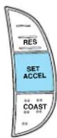
- Use the accelerator pedal to get to the desired speed. When the vehicle reaches that speed press and release the SET ACCEL control.
REDUCING SPEED WHILE USING SPEED CONTROL
There are two ways to reduce a set speed:
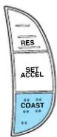
- Press and hold the COAST control until you get to the desired speed, then release the control. You can also use the COAST control to operate the Tap-Down function. Press and
release this control to decrease the vehicle set speed in small amounts by 1.6 km/h (1 mph).
Driver controls
- Depress the brake pedal until the desired vehicle speed is reached, press the SET ACCEL control.
There are two ways to turn off the speed control:
- Depress the brake pedal or the clutch pedal (if equipped). This will not erase your vehicles previously set speed.
- Press the speed control OFF control.
Note: When you turn off the speed control or the ignition, your speed control set speed memory is erased.
Driving
STARTING
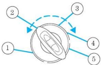
Positions of the ignition
- ACCESSORY, allows the electrical accessories such as the radio to operate while the engine is not running.
- LOCK, locks the automatic transmission gearshift lever and allows key removal.
- OFF, shuts off the engine and all accessories without locking the steering wheel. This position also
allows the automatic transmission shift lever to be moved from the P (Park) position without the brake pedal being depressed.
flowchart
graph TD
    1 --> 2
    2 --> 3
    3 --> 4
    4 --> 5
    5 --> 1

In the ignition OFF position, the automatic transmission shift lever can be moved from the P (Park) position without the brake depressed. To avoid unwanted vehicle movement, always set the g brake.
- ON, all electrical circuits operational. Warning lights illuminated. Key position when driving.
- START, cranks the engine. Release the key as soon as the engine starts.
Preparing to start your vehicle
Engine starting is controlled by the powertrain control system. This system meets all Canadian Interference-Causing Equipment standard requirements regulating the impulse electrical field strength of radio noise.
When starting a fuel-injected engine, avoid pressing the accelerator before or during starting. Only use the accelerator when you have difficulty starting the engine. For more information on starting the vehicle, refer to Startingtheengine in this chapter.

Extended idling at high engine speeds can produce very high temperatures in the engine and exhaust system, creating the risk or other damage.
Driving

Do not park, idle, or drive your vehicle in dry grass or other dry ground cover. The emission system heats up the engine compartment and exhaust system, which can start a fire.

Do not start your vehicle in a closed garage or in other enclosed areas. Exhaust fumes can be toxic. Always open the garage door to you start the engine. See Guardingagainstexhaustfumesin chapter for more instructions.

If you smell exhaust fumes inside your vehicle, have your dealer inspect your vehicle immediately. Do not drive if you smell last fumes.
Important safety precautions
A computer system controls the engine's idle revolutions per minute (RPM). When the engine starts, the idle RPM runs higher than normal in order to warm the engine. If the engine idle speed does not slow down automatically, have the vehicle checked. Do not allow the vehicle to idle for more than 10 minutes.
Before starting the vehicle:
- Make sure all vehicle occupants have buckled their safety belts.
- Make sure the headlamps and vehicle accessories are off.
- Make sure the parking brake is set.
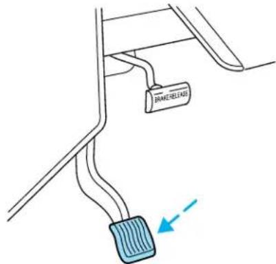
text_image
BRANE-RELEASEDriving
-
Make sure the gearshift is in P (Park).
-
Turn the key to 4 (ON) without turning the key to 5 (START).

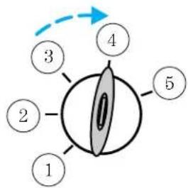
flowchart
graph TD
    1 --> 2
    2 --> 3
    3 --> 4
    4 --> 5
    5 --> 4
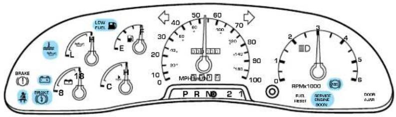
text_image
LOW FUEL E 30 60 40 50 60 70 100 120 80 20 20° 140 MPH 185 100 2 3 4 5 6 BRAKE BRAKE 8 18 C PR ND 2 1 RPMX1000 FUJ RESET SPAYC DRGUE SUNN DOOR AVRMake sure the corresponding lights illuminate or illuminate briefly. If a light fails to illuminate, have the vehicle serviced.
- If the driver's safety belt is fastened, the
light may not illuminate.
Starting the engine
- Turn the key to 4 (ON) without turning the key to 5 (START).
- Turn the key to 5 (START), then release the key as soon as the engine starts. Excessive cranking could damage the starter.
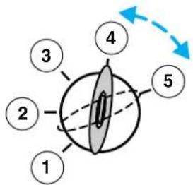
flowchart
graph TD
    1 --> 2
    2 --> 3
    3 --> 4
    4 --> 5
    style 1 fill:#fff,stroke:#000
    style 2 fill:#fff,stroke:#000
    style 3 fill:#fff,stroke:#000
    style 4 fill:#fff,stroke:#000
    style 5 fill:#fff,stroke:#000
Driving
Note: If the engine does not start within five seconds on the first try, turn the key to 3 (OFF), wait 10 seconds and try again. If the engine still fails to start, press the accelerator to the floor and try again; this will allow the engine to crank with the fuel shut off in case the engine is flooded with fuel.
Using the engine block heater (if equipped)
Use of an engine block heater is strongly recommended if you live in a region where temperatures reach -23^ C ( -10^ F) or below. For best results, plug the heater in at least three hours before starting the vehicle. The heater can be plugged in the night before starting the vehicle.

To prevent electrical shock, do not use your heater with ungrounded electrical systems or two-pronged (cheater) ers.
Guarding against exhaust fumes
Carbon monoxide is present in exhaust fumes. Take precautions to avoid its dangerous effects.

If you smell exhaust fumes inside your vehicle, have your dealer inspect your vehicle immediately. Do not drive if you smell last fumes.
Important ventilating information
If the engine is idling while the vehicle is stopped in an open area for long periods of time, open the windows at least 2.5 cm (one inch).
Adjust the heating or air conditioning (if equipped) to bring in fresh air.
Improve vehicle ventilation by keeping all air inlet vents clear of snow, leaves and other debris.
BRAKES
Your service brakes are self-adjusting. Refer to the Scheduled maintenance guide for scheduled maintenance.
Occasional brake noise is normal and often does not indicate a performance concern with the vehicle's brake system. In normal operation, automotive brake systems may emit occasional or intermittent squeal or groan noises when the brakes are applied. Such noises are usually heard during the first few brake applications in the morning;
Driving
however, they may be heard at any time while braking and can be aggravated by environmental conditions such as cold, heat, moisture, road dust, salt or mud. If a “metal-to-metal,” “continuous grinding” or “continuous squeal” sound is present while braking, the brake linings may be worn-out and should be inspected by a qualified service technician.

If you are driving down a long or steep hill, shift to a lower gear.
Do not apply your brakes continuously, as they may overheat
and become less effective.
Anti-lock brake system (ABS)
On vehicles equipped with an anti-lock braking system (ABS), a noise from the hydraulic pump motor and pulsation in the pedal may be observed during ABS braking events. Pedal pulsation coupled with noise while braking under panic conditions or on loose gravel, bumps, wet or snowy roads is normal and indicates proper functioning of the vehicle's anti-lock brake system. The ABS performs a self-check after you start the engine and begin to drive away. A brief mechanical noise may be heard during this test. This is normal. If a malfunction is found, the ABS warning light will come on. If the vehicle has continuous vibration or shudder in the steering wheel while braking, the vehicle should be inspected by a qualified service technician.
The ABS operates by detecting the onset of wheel lockup during brake applications and compensates for this tendency. The wheels are prevented from locking even when the brakes are firmly applied. The accompanying illustration depicts the advantage of an ABS equipped vehicle (on bottom) to a non-ABS equipped vehicle (on top) during hard braking with loss of front braking traction.
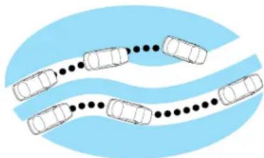
natural_image
Diagram of cars on a curved road with black dots, set against a light blue oval background (no text or symbols)UsingABS
- In an emergency or when maximum efficiency from the four-wheel ABS is required, apply continuous force on the brake. The four wheel ABS will be activated immediately, thus allowing you to retain full steering control of your vehicle and, providing there is sufficient space, will enable you to avoid obstacles and bring the vehicle to a controlled stop.
Driving
- The anti-lock system does not reduce stopping distance. Always leave enough room between your vehicle and the vehicle in front of you to stop.
- We recommend that you familiarize yourself with this braking technique. However, avoid taking any unnecessary risks.
Hydraulicbrakeboostersystem(HydroboostorHydromax)
The Hydroboost and Hydromax systems receive fluid pressure from the power steering pump to provide power assist during braking.
The Hydromax booster receives backup pressure from the reserve system electric pump whenever the fluid in the power steering system is not flowing. When the engine is OFF, the pump will turn on if the brake pedal is applied, or if the ignition is turned to the ON position.
The sound of the pump operating may be heard by the driver, but this is a normal characteristic of the system.
The reserve system provides reduced braking power, so the vehicle should be operated under these conditions with caution, and only to seek service repair and remove the vehicle from the roadway.
ForHydromax-equippedvehiclesoperatingundernormal
conditions, the noise of the fluid flowing through the booster may be heard whenever the brake is applied. This condition is normal. Vehicle service is not required.
If braking performance or pedal response becomes very poor, even when the pedal is strongly depressed, it may indicate the presence of air in the hydraulic system or leakage of fluid. Stop the vehicle safely as soon as possible and seek service immediately.
ABSwarninglamp

The (ABS) warning lamp in the instrument cluster momentarily illuminates when the ignition is turned to the ON position. If the light remains on after the vehicle is started, continues to flash or fails to illuminate, have the system serviced immediately. With the ABS light on, the anti-lock brake system is disabled and normal braking is still effective unless the brake warning light also remains illuminated.
With the ABS light on, the anti-lock brake system is disabled and normal braking is still effective unless the brake warning light also remains
BRAKE

illuminated with parking brake released. (If your brake warning lamp illuminates, have your vehicle serviced immediately.)
Driving
Parking brake (P)
Apply the parking brake whenever the vehicle is parked. Push pedal downward to set the parking brake.
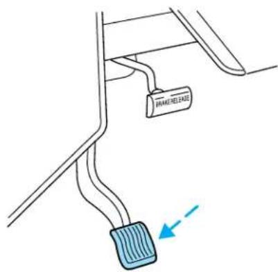
text_image
FRAME-RELEASEThe BRAKE warning lamp in the instrument cluster illuminates and remains illuminated (when the ignition is turned ON) until the parking brake is released.
BRAKE
( ! )

Always set the parking brake fully and make sure the gearshift is latched in P (Park). Turn the ignition to the LOCK position and we the key whenever you leave your vehicle.
The parking brake is not recommended to stop a moving vehicle. However, if the normal brakes fail, the parking brake can be used to stop your vehicle in an emergency. Since the parking brake applies only the transmission mounted parking brake assembly, the vehicle's stopping distance will increase greatly and the handling of your vehicle will be adversely affected.
Driving
Push the service brake pedal with your foot and pull the parking brake release handle to release the parking brake.
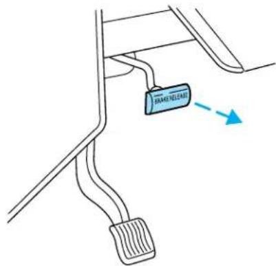
text_image
DRAGON LIME →This vehicle is equipped with a brake-shift interlock feature that prevents the gearshift lever from being moved from P (Park) when the ignition is in the ON position unless the brake pedal is depressed.
If you cannot move the gearshift lever out of P (Park) with ignition in the ON position and the brake pedal depressed:
- Apply the parking brake, turn ignition key to LOCK, then remove the key.
- Insert the key and turn it to OFF. Applythebrakepedalandshift toN(Neutral).
In the ignition OFF position, the automatic transmission shift lever can be moved from the P (Park) position without the brake pedal depressed. To avoid unwanted vehicle movement, always set the parking brake.
- Start the vehicle.
If it is necessary to use the above procedure to move the gearshift lever, it is possible that a fuse has blown or the vehicle's brakelamps are not operating properly. Refer to Fusesandrelaysin the Roadside emergencieschapter.
Driving

Do not drive your vehicle until you verify that the brakelamps are working.

Always set the parking brake fully and make sure the gearshift is latched in P (Park). Turn the ignition to the LOCK position and we the key whenever you leave your vehicle.

If the parking brake is fully released, but the brake warning lamp remains illuminated, the brakes may not be working properly. Our dealer or a qualified service technician.
Driving with a 4-speed automatic transmission
Understandinggearshiftpositions
To put your vehicle in gear, start the engine, depress the brake pedal, then move gearshift lever out of P (Park).

Hold the brake pedal down while you move the gearshift lever from P (Park) to another position. If you do not hold the brake down, your vehicle may move unexpectedly and injure someone.
P(Park)
Always come to a complete stop before shifting into P (Park). Make sure the gearshift lever is securely latched in P (Park). This position locks the transmission and prevents the rear wheels from turning.
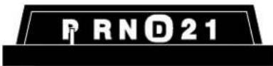

Always set the parking brake fully and make sure the gearshift lever is latched in P (Park). Turn off the ignition whenever you your vehicle.
R(Reverse)
With the gearshift lever in R (Reverse), the vehicle will move backward. Always come to a complete stop before shifting into and out of R (Reverse).
N(Neutral)
With the gearshift lever in N (Neutral), the vehicle can be started and is free to roll. Hold the brake pedal down while in this gear.
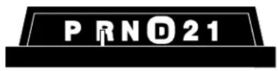
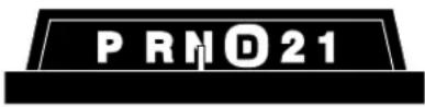
(D) (Overdrive)
The normal driving position for the best fuel economy. Transmission operates in gears one through four.
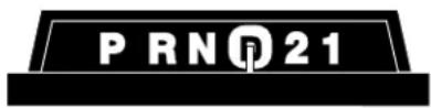
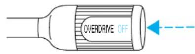
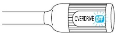
(D) (Overdrive) can be deactivated by pressing the transmission control switch (TCS) on the end of the gearshift lever.
text_image
OVERDRIVE OFFThe transmission control indicator light (TCIL) (the word OFF) on the end of the gearshift lever will illuminate.
text_image
OVERDRIVE OFFDrive- Not shown on the display. Activate by pressing the transmission control switch (TCS) on the end of the gearshift lever with the gearshift in the position. The TCIL (the word OFF) will illuminate on the gearshift lever. Transmission operates in gears one through three. (Drive) provides more engine braking than ( verdrive) and is useful when:
- driving with a heavy load.
- towing a trailer up or down steep hills.
- additional engine downhill braking is desired. If towing a trailer, refer to Driving while you tow in the Trailer towing section.
To return to Ⓓ (Overdrive) mode, press the transmission control switch (TCS). The TCIL (the word OFF) will no longer be illuminated.
Driving
Each time the vehicle is started, the transmission will automatically return to normal overdrive mode.
Every time the vehicle is shut off and restarted, you must press the transmission control switch to cancel overdrive operation if driving in overdrive is not desired.
2(Second)
Use 2 (Second) to start-up on slippery roads or to provide additional engine braking on downgrades.
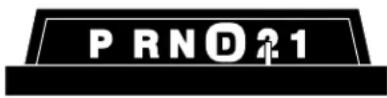
1(First)
Use 1 (Low) to provide maximum engine braking on steep downgrades. Upshifts can be made by shifting to 2 (Second) or to
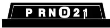
(Overdrive). Selecting 1 (Low) at higher speeds causes the transmission to shift to a lower gear, and will shift to 1 (Low) after vehicle decelerates to the proper speed.
ForcedDownshifts
To gain acceleration in Ⓓ (Overdrive) or Drive (O/D OFF) when passing another vehicle, push the accelerator to the floor. The transmission will downshift to the appropriate gear: third, second or first gear.
Ifyourvehiclegetsstuckinmudorsnow
If your vehicle gets stuck in mud or snow, it may be rocked out by shifting from forward and reverse gears, stopping between shifts in a steady pattern. Press lightly on the accelerator in each gear.
Donotrockthevehicleiftheengineisnotatnormaloperating temperatureordamagetothetransmissionmayoccur.
Donotrockthevehicleformorethanaminiteordamagetothe transmissionandtiresmayoccur,ortheenginemayoverheat.
DRIVING THROUGH WATER
Do not drive quickly through standing water, especially if the depth is unknown. Traction or brake capability may be limited and if the ignition system gets wet, your engine may stall. Water may also enter your engine's air intake and severely damage your engine.
Driving
If driving through deep or standing water is unavoidable, proceed very slowly. Never drive through water that is higher than the bottom of the hubs (for trucks) or the bottom of the wheel rims (for cars).
Once through the water, always try the brakes. Wet brakes do not stop the vehicle as effectively as dry brakes. Drying can be improved by moving your vehicle slowly while applying light pressure on the brake pedal.
Drivingthroughdeepwaterwherethetransmissionventtubeis submergedmayallowwaterintothetransmissionandcause internaltransmissiondamage.Havethefluidcheckedand,if waterisfound,replacethefluid.
VEHICLE LOADING
Your vehicle's load capacity is designed by weight, not volume, so you cannot necessarily use all available space with large or heavy loads. Maximum safe vehicle weights as well as tire, rim sizes and inflation pressures are specified for your vehicle on the Safety Compliance Certification Label. A Certification Label was supplied by Ford Motor Company to the Motorhome Manufacturer. The manufacturer uses this information and supplies a Certification Label which is located inside the vehicle to the left of the driver.
Before loading a vehicle, familiarize yourself with the following terms:
- BaseCurbWeight: Weight of the vehicle including any standard equipment, fluids, lubricants, etc. It does not include occupants or aftermarket equipment.
- Payload: Combined maximum allowable weight of cargo, occupants and optional equipment. The payload equals the gross vehicle weight rating minus base curb weight.
- GVW(GrossVehicleWeight):Base curb weight plus payload weight. The GVW is not a limit or a specification.
- GVWR(GrossVehicleWeightRating): Maximum permissible total weight of the base vehicle, occupants, optional equipment and cargo. The GVWR is specific to each vehicle and is listed on the Certification Label, located near the driver's seat or on the driver's door pillar.
- GAWR(GrossAxleWeightRating): Carrying capacity for each axle system. The GAWR is specific to each vehicle and is listed on the Certification Label, located near the driver's seat or on the driver's door pillar.
- GCWR(GrossCombinedWeightRating): Maximum permissible combined weight of towing vehicle (including occupants and cargo) and the loaded trailer.
Driving
- MaximumTrailerWeightRating:Maximum weight of a trailer the loaded vehicle (including occupants and cargo) is permitted to tow. The maximum trailer weight rating is determined by subtracting the vehicle curb weight for each engine/transmission combination, any required option weight for trailer towing and the weight of the driver from the GCWR for the towing vehicle.
- TrailerWeightRange: Specified weight range that the trailer must fall within that ranges from zero to the maximum trailer weight rating.
Remember to figure in the tongue load of your loaded trailer when figuring the total weight.

Exceeding any vehicle weight rating limitation could result in serious damage to the vehicle loss of vehicle control, vehicle er, and/or personal injury.
Do not use replacement tires with lower weight capacities than the originals because they may lower the vehicle's GVWR and GAWR limitations. Replacement tires with a higher weight limit than the originals do not increase the GVWR and GAWR limitations.
Calculating the load your vehicle can carry/tow
- Use the appropriate maximum gross combined weight rating (GCWR) chart to find the maximum GCWR for your type engine and rear axle ratio.
- Weigh your vehicle as you customarily operate the vehicle without cargo. To obtain correct weights, try taking your vehicle to a shipping company or an inspection station for trucks.
- Subtract your loaded vehicle weight from the maximum GCWR on the following charts. This is the maximum combined cargo and trailer weight your vehicle can carry/tow and must fall below the maximum shown under maximum trailer weight on the chart. Refer to the definition of Maximum Trailer Weight below Vehicle Loading in this chapter to determine the maximum trailer weight permitted for a loaded vehicle.
TRAILER TOWING
Your vehicle may tow a class I, II or III trailer provided the maximum trailer weight is less than or equal to the maximum trailer weight listed for your engine and rear axle ratio on the following chart:
| GCWR(GrossCombinedWeightRating)/TrailerWeights | ||||
| Engine | Rear axle ratio | Maximum GCWR-kg (lbs.) | Trailerweight range-kg (lbs.) (0-Maximum) | Maximum FrontalArea ofTrailer-m ^2 (ft ^2 ) ^2 |
| 6.8L 5.38 | 11794 (26000) | 0-4763 (0-10000) | 5.6 (60) | |
| For high altitude operation reduce GCW by 2% per 300 meters (1000 ft) elevation. To determine the maximum trailer weight designed for your particular vehicle as equipped, follow the sectionCalculatingtheload yourvehiclecancarry/towearlier in this chapter. | ||||
Preparing to tow
Use the proper equipment for towing a trailer and make sure it is properly attached to your vehicle. See your dealer or a reliable trailer dealer if you require assistance.
Hitches
You must distribute the load in your trailer so that 10 - 15% of the total weight of the trailer is on the tongue.
Load equalizing hitch
When hooking up a trailer using a load equalizing hitch, always use the following procedure:
- Park the unloaded vehicle on a level surface. With the ignition on and all doors closed, allow the vehicle to stand for several minutes so that it can level.
- Measure the height of a reference point on the front and rear bumpers at the center of the vehicle.
- Attach the trailer to the vehicle and adjust the hitch equalizers so that the front bumper height is within 0–13 mm (0.5 in) of the reference point. After proper adjustment, the rear bumper should be no higher than in Step 2.
Note: Adjusting an equalizing hitch so the rear bumper of the vehicle is higher than it was unloaded will defeat the function of the load equalizing hitch and may cause unpredictable handling.
Driving
Safety chains
Always connect the trailer's safety chains to the frame or hook retainers of the vehicle hitch. To connect the trailer's safety chains, cross the chains under the trailer tongue and allow slack for turning corners.
If you use a rental trailer, follow the instructions that the rental agency gives to you.
Donotattachsafetychainstothebumper.
Trailer brakes
Electric brakes and manual, automatic or surge-type brakes are safe if installed properly and adjusted to the manufacturer's specifications. The trailer brakes must meet local and Federal regulations.
Do not connect a trailer's hydraulic brake system directly to your vehicle's brake system. Your vehicle may not have enough braking power and your chances of having a collision greatly increase.
Thetowingvehiclebrakingsystemisratedforoperationatthe GVWR,nottheGCWR.
Separatefunctioningbrakesystemsarerequiredforsafecontrol oftowedvehiclesandtrailersweighingmorethan680kg(1500 lbs)whenloaded.
Trailer lamps
Trailer lamps are required on most towed vehicles. Make sure your trailer lamps conform to local and Federal regulations. See your dealer or trailer rental agency for proper instructions and equipment for hooking up trailer lamps.
Driving while you tow
When towing a trailer:
- Turn off the speed control. The speed control may shut off automatically when you are towing on long, steep grades.
- Consult your local motor vehicle speed regulations for towing a trailer.
- To eliminate excessive shifting, use a lower gear. This will also assist in transmission cooling.
- Anticipate stops and brake gradually.
Servicingaftertowing
If you tow a trailer for long distances, your vehicle will require more frequent service intervals. Refer to your scheduled maintenance guide for more information.
Driving
Trailer towing tips
- Practice turning, stopping and backing up before starting on a trip to get the feel of the vehicle trailer combination. When turning, make wider turns so the trailer wheels will clear curbs and other obstacles.
- Allow more distance for stopping with a trailer attached.
- If you are driving down a long or steep hill, shift to a lower gear. Do not apply the brakes continuously, as they may overheat and become less effective.
- The trailer tongue weight should be 10–15% of the loaded trailer weight.
- After you have traveled 80 km (50 miles), thoroughly check your hitch, electrical connections and trailer wheel lug nuts.
- To aid in engine/transmission cooling and A/C efficiency during hot weather while stopped in traffic, place the gearshift lever in P (Park).
- Vehicles with trailers should not be parked on a grade. If you must park on a grade, place wheel chocks under the trailer's wheels.
Roadside emergencies
HAZARD LIGHTS CONTROL
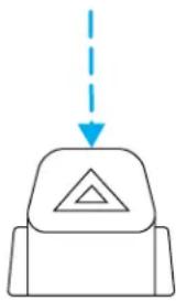
Use only in an emergency to warn traffic of vehicle breakdown, approaching danger, etc. The hazard flashers can be operated when the ignition is off.
- The hazard lights control is located on top of the steering column.
- Depress hazard lights control to activate the hazard flashers.
- Depress control again to turn the flashers off.
natural_image
Simple line drawing of a mechanical component with a downward arrow and triangle symbol (no text or labels)FUEL PUMP SHUT-OFF SWITCH FUEL RESET
This device stops the electric fuel pump from sending fuel to the engine when your vehicle has had a substantial jolt.
After an accident, if the engine cranks but does not start, this switch may have been activated.
Roadside emergencies
The fuel pump shut-off switch is located on a bracket above the brake pedal.

text_image
Technical diagram showing a mechanical component with an inset view highlighting a specific assembly or connection point.Use the following procedure to reset the fuel pump shut-off switch.
- Turn the ignition to the OFF position.
- Check the fuel system for leaks.
- If no fuel leak is apparent, reset the fuel pump shut-off switch by pushing in on the reset button.
- Turn the ignition to the ON position. Pause for a few seconds and return the key to the OFF position.
- Make a further check for leaks in the fuel system.
Roadside emergencies
FUSES AND RELAYS
Standard fuse amperage rating and color
| COLOR | |||||
| Fuse rating | Mini fuses | Standard fuses | Maxi fuses | Cartridge maxi fuses | Fuselink cartridge |
| 2A Grey — — | — | ||||
| 3A Violet Violet — — | |||||
| 4A Pink Pink — — | — | ||||
| 5A Tan Tan — — | |||||
| 7.5A Brown Brown — — | |||||
| 10A Red Red — — | |||||
| 15A Blue Blue — — | |||||
| 20A | Yellow | Yellow | Yellow | Blue | Blue |
| 25A | Natural | Natural | ——— | ||
| 30A | Green | Green | Green Pink Pink | ||
| 40A — — | Orange | Green | Green | ||
| 50A — — | Red | Red | Red | ||
| 60A — — | Blue | — Yellow | |||
| 70A — — | Tan — Brown | ||||
| 80A — — | Natural | — | Black | ||
Passenger compartment fuse panel
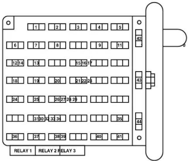
The fuse panel is located below and to the left of the steering wheel by the brake pedal. Remove the panel cover to access the fuses.
To remove a fuse use the fuse puller tool provided on the fuse panel cover.
Roadside emergencies
text_image
1 2 3 4 5 6 7 8 9 11 12 14 13 15 16 17 18 19 20 21 22 23 24 25 26 27 28 29 31 30 32 33 34 36 37 38 39 40 41 42 43 44 RELAY 1 RELAY 2 RELAY 3The fuses are coded as follows.
| Fuse/Relay Location | FuseAmp Rating | PassengerCompartmentFuse PanelDescription |
| 1 20A Turn signal relay coil, Turn indicators, Body builder rear turn/stop feeds | ||
| 2 — Not used | ||
| 3 — Not used | ||
| 4 15A Courtesy lamp relay, Interior lamp feed | ||
| 5 10A Body builder accessory feed (accessory and run) | ||
| 6 10A Trailer tow left stop/turn feed | ||
| 7 15A Blower motor relay coil | ||
| 8 — Not used | ||
Roadside emergencies
| Fuse/Relay Location | FuseAmp Rating | PassengerCompartmentFuse PanelDescription |
| 9 20A Stoplamps: Trailer tow | Electric Brake controller feed, Body builder rear turn/stop feeds, Body builder stop lamp feed, Trailer turn/stop fuse feeds | |
| 10 5A Instrument cluster memory, Power brake assist lamp* | ||
| 11 30A Wiper/Washer module, Wiper feed | ||
| 12 10A Trailer tow stop/turn feed | ||
| 13 10A ABS module | ||
| 14 10A Warning chime module, Power brake assist module*, Instrument cluster power, Instrument cluster warning lamps, Transmission control switch | ||
| 15 15A Left turn signal feed | ||
| 16 20A Body builder battery (+12V) feed | ||
| 17 5A Body builder radio feed | ||
| 18 — Not used | ||
| 19 5A DRL relays | ||
| 20 — Not used | ||
| 21 15A Right turn signal feed | ||
| 22 — Not used | ||
| 23 — Not used | ||
| 24 — Not used | ||
| 25 10A Right-hand low beam headlamp feed | ||
| 26 10A Speed control module | Brake shift interlock actuator | |
| 27 — Not used | ||
| 28 — Not used | ||
| 29 — Not used | ||
Roadside emergencies
| Fuse/Relay Location | FuseAmp Rating | PassengerCompartmentFuse PanelDescription |
| 30 — Not used | ||
| 31 10A Left-hand low beam headlamp feed | ||
| 32 10A Backup lamp feed | ||
| 33 — Not used | ||
| 34 — Not used | ||
| 35 20A Body builder high beam feed, High beam indicator | ||
| 36 — Not used | ||
| 37 — Not used | ||
| 38 10A Body builder accessory feed (run only) | ||
| 39 — Not used | ||
| 40 — Not used | ||
| 41 10A Instrument illumination | ||
| 42 — Not used | ||
| 43 — Not used | ||
| 44 — Not used | ||
| Relay 1 — Left turn signal relay | ||
| Relay 2 — Courtesy lamps relay | ||
| Relay 3 Right turn signal relay | ||
| *Vehicles with Hydromax brake assist only | ||
Power distribution box
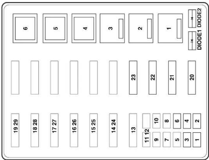
The power distribution box is located in the engine compartment. The power distribution box contains high-current fuses that protect your vehicle's main electrical systems from overloads.

Always disconnect the battery before servicing high current fuses.
Alwaysreplacethecovertothepowerdistributionboxbefore reconnectingthebatteryorrefillingfluidreservoirs
If the battery has been disconnected and reconnected, refer to the Batterysection of the Maintenanceandspecificationschapter.
Roadside emergencies
text_image
19 29 18 28 17 27 16 26 15 25 14 24 13 11 12 9 7 5 3 1 6 5 4 3 2 22 8 6 4 20 DIODE1 DIODE2The high-current fuses are coded as follows.
| Fuse/Relay Location | FuseAmp Rating | PowerDistributionBox Description |
| 1 5A* Power brake assist module*** | ||
| 2 10A* A/C system | ||
| 3 20A* Transmission, Vapor ManagementValve (VMV) solenoid, Heated exhaust gas oxygen (HEGO) sensors | ||
| 4 5A* Powertrain Control Module (PCM)memory | ||
| 5 15A* PCM power, Fuel pump relay coil,Fuel injectors, Mass Air Flow (MAF) sensor with IAT, A/C system relay coil | ||
Roadside emergencies
| Fuse/Relay Location | FuseAmp Rating | PowerDistributionBox Description |
| 6 20A* Parklamp feeds, Instrument panel fuse #41, Warning chime module, Trailer tow running lamp relay coil, I/P dimmer module | ||
| 7 15A* Starter relay coil, BB neutral sense | ||
| 8 10A* Stoplamp switch (logic): Brake pressure switch, Power brake assist module***, Speed control module, PCM, Anti-lock Brake System (ABS) module, Brake shift interlock actuator | ||
| 9 5A* Alternator | ||
| 10 20A* Daytime Running Lamps (DRL) | ||
| 11 30A* Ignition coils, Radio capacitors #1 and #2, PCM relay | ||
| 12 20A* Trailer tow running lamps feed, Trailer tow back-up lamps feed, IP - backup lamp feed | ||
| 13 30A** Trailer tow electric brake controller feed | ||
| 14 60A** IP battery feed (fuse #9, 15, 21) | ||
| 15 -- Not used | ||
| 16 60A** ABS module | ||
| 17 -- Not used | ||
| 18 20A** Horn feed | ||
| 19 -- Not used | ||
| 20 40A** PCM relay | ||
| 21 20A** Fuel pump motor | ||
| 22 20A** Diagnostic tool connector, Cigar lighter feed | ||
| 23 40A** Blower motor feed | ||
Roadside emergencies
| Fuse/Relay Location | FuseAmp Rating | PowerDistributionBox Description |
| 24 40A** IP battery feed (fuses #4, 10, 16) | ||
| 25 50A** Ignition switch feed | (IP fuses #1, 5, 7, 11, 13, 14, 17, 19, PDB fuses #7, 9, 11) | |
| 26 60A** Ignition switch feed | (IP fuses #5, 11, 17, 26, 32, 38) | |
| 27 30A** Multifunction switch (headlamps) | ||
| 28 — Not used | ||
| 29 60A** Power brake assist motor*** | ||
| Relay 1 — DRL on/off relay | ||
| Relay 2 — Fuel pump relay | ||
| Rclay 3 — Horn relay | ||
| Relay 4 — A/C system relay | ||
| Relay 5 — Blower motor relay | ||
| Relay 6 — PCM relay | ||
| Diode 1 — PCM diode | ||
| Diode 2 — Park brake diode | ||
| * Mini Fuses ** Maxi Fuses *** Vehicles with Hydromax brake assist only | ||
Relay module
The relay box is located by the power distribution box in front of the radiator in the engine compartment.
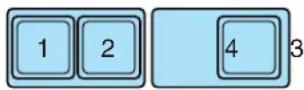
The relays are coded as follows:
| RelaylocationDescription | |
| 1 Back up Lamp | |
| 2 Running Lamp | |
| 3 Not Used | |
| 4 Headlamp DRL | |
Roadside emergencies
CHANGING THE TIRES
If you get a flat tire while driving, do not apply the brake heavily. Instead, gradually decrease your speed. Hold the steering wheel firmly and slowly move to a safe place on the side of the road.

The use of tire sealants is not recommended and may compromise the integrity of your tires.
Tire change procedure
Preparingtochangethetire

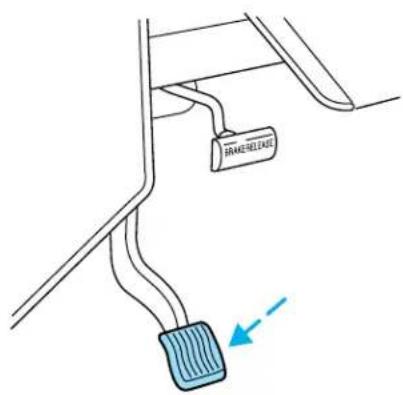
To prevent the vehicle from moving when you change a tire, be sure the parking brake is set, then block (in both directions) that is diagonally opposite (other side and end of the vehicle) to be being changed.
- Park on a level surface.
- Activate the warning flashers.
- Place the gearshift in P (Park).
- Apply the parking brake and turn engine OFF.
text_image
BRAKERLEASE →Roadside emergencies
- Block the wheel that is diagonally opposite the tire you are changing.
The parking brake is on the transmission. Therefore, the vehicle will not be prevented from moving when a rear wheel is lifted, even if
the parking brake is applied. Be sure to block both directions of the wheel that is diagonally opposite to the wheel that is being lifted.
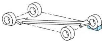
natural_image
Diagram of three wheels connected by dashed lines, with one wheel partially visible below (no text or symbols)
If the vehicle slips off the jack, you or someone else could be seriously injured.
-
Remove the spare tire and jack from the storage location.
-
Loosen the wheel nut by pulling up on the handle of the lug nut wrench about one-half turn (counterclockwise). Do not remove the wheel lug nuts until you raise the tire off the ground.
Replacingthetire

To lessen the risk of personal injury, do not put any part of your body under the vehicle while changing a tire. Do not start the time when your vehicle is on the jack. The jack is only meant for giving the tire.
- Position the jack to raise the front or rear wheel.
- Neverusethefrontorrear differentialasajackingpoint.
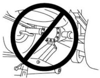
text_image
Diagram showing a prohibition symbol crossed out by a car, indicating no restrictions on vehicle or mechanical components.Roadside emergencies
Rearaxlejackingpoints:
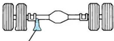
natural_image
Diagram of a vehicle suspension system with four wheels and a central shaft (no text or labels)Frontaxlejackingpoints:
Place the jack under the front axle.
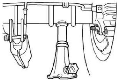
natural_image
Technical line drawing of a mechanical assembly with no visible text or symbols- Raise the vehicle until the wheel is completely off the ground.
- Remove the lug nuts with the lug nut wrench.
- Replace the flat tire with the spare tire.
- Use the lug nut wrench to screw the lug nut snugly against the wheel.
- Lower the vehicle.
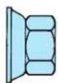
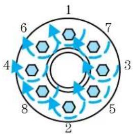
- Remove the jack and fully tighten the lug nuts in the following pattern:
Never use wheels or lug nuts different than the original equipment as this could damage the wheel or mounting system. This damage could allow the wheels to come off while the vehicle is being driven.
flowchart
graph TD
    A["1"] --> B["2"]
    B --> C["3"]
    C --> D["4"]
    D --> E["5"]
    E --> F["6"]
    F --> G["7"]
    G --> H["8"]
    H --> A
    style A fill:#f9f,stroke:#333
    style B fill:#f9f,stroke:#333
    style C fill:#f9f,stroke:#333
    style D fill:#f9f,stroke:#333
    style E fill:#f9f,stroke:#333
    style F fill:#f9f,stroke:#333
    style G fill:#f9f,stroke:#333
- Replace any wheel trim.
- Stow the jack, handle and lug wrench.
- Unblock the wheels.
Roadside emergencies
On vehicles equipped with dual rear wheels, retighten the wheel lug nuts to the specified torque at 160 km (100 miles), and again at 800 km (500 miles) of new vehicle operation and after any wheel disturbance (tire rotation, changing a flat tire, wheel removal, etc.).
| BoltsizeWheelingnuttorque* | ||
| M14 x 1.5 200-225 150-165 | ||
| * Torque specifications are for nut and bolt threads free of dirt and rust. Use only Ford recommended replacement fasteners. | ||
On all two-piece flat wheel nuts, apply one drop of motor oil between the flat washer and the nut. Do not apply motor oil to the wheel nut threads or the wheel stud threads.
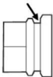
When a wheel is installed, always remove any corrosion, dirt or foreign materials present on the mounting surfaces of the wheel or the surface of the front disc brake hub and rotor that contacts the wheel. Installing wheels without correct metal-to-metal contact at the wheel mounting surfaces can cause the wheel nuts to loosen and the wheel to come off while the vehicle is in motion, resulting in loss of control.
The gases around the battery can explode if exposed to flames, sparks, or lit cigarettes. An explosion could result in injury or vehicle damage.
Batteries contain sulfuric acid which can burn skin, eyes and clothing, if contacted.
Donotattempttopush-startyourvehicle.Automatic transmissionsdonothavepush-startcapability;also,the catalyticconvertertermaybecomedamaged.
Preparing your vehicle
When the battery is disconnected or a new battery is installed, the transmission must relearn its shift strategy. As a result, the transmission may have firm and/or soft shifts. This operation is considered normal and will not affect function or durability of the transmission. Over time, the adaptive learning process will fully update transmission operation.
Roadside emergencies
- Useonlya12-voltsupplytostartyourvehicle.
- Do not disconnect the battery of the disabled vehicle as this could damage the vehicle's electrical system.
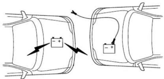
- Park the booster vehicle close to the hood of the disabled vehicle making sure the two vehicles donottouch. Set the parking brake on both vehicles and stay clear of the engine cooling fan and other moving parts.
- Check all battery terminals and remove any excessive corrosion before you attach the battery cables. Ensure that vent caps are tight and level.
- Turn the heater fan on in both vehicles to protect any electrical surges. Turn all other accessories off.
Connecting the jumper cables
text_image
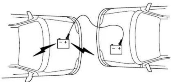
Diagram showing two battery charging scenarios with positive and negative charge indicators, illustrating charging behavior.- Connect the positive (+) booster cable to the positive (+) terminal of the discharged battery.
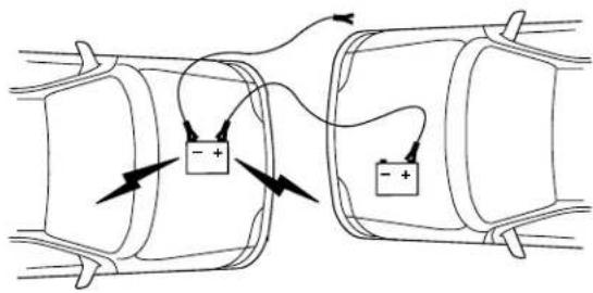
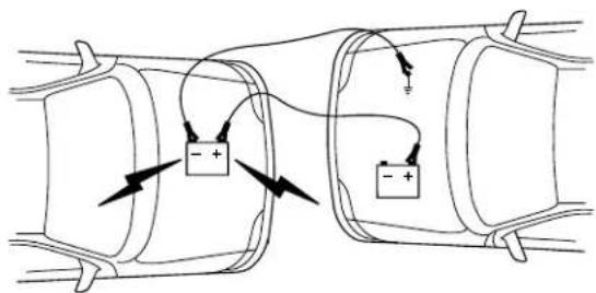
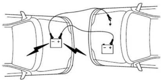
Note: In the illustrations, lightningbolts are used to designate the assisting (boosting) battery.
text_image
Diagram showing two battery charging scenarios with positive and negative charge indicators, illustrating electrical or mechanical setup.- Connect the other end of the positive (+) cable to the positive (+) terminal of the assisting battery.
Roadside emergencies
text_image
Diagram showing two connected cylindrical tanks with positive and negative charge indicators, indicating electrical or mechanical connections.- Connect the negative (-) cable to the negative (-) terminal of the assisting battery.
natural_image
Diagram of two cylindrical batteries connected in series with positive and negative charges, showing circuit connections (no text or symbols)- Make the final connection of the negative (-) cable to an exposed metal part of the stalled vehicle's engine, away from the battery and the carburetor/fuel injection system. Donotuse fuel lines, engine rocker covers or the intake manifold as groundingpoints.

Do not connect the end of the second cable to the negative (-) terminal of the battery to be jumped. A spark may cause an ion of the gases that surround the battery.
- Ensure that the cables are clear of fan blades, belts, moving parts of both engines, or any fuel delivery system parts.
Roadside emergencies
Jump starting
- Start the engine of the booster vehicle and run the engine at moderately increased speed.
- Start the engine of the disabled vehicle.
- Once the disabled vehicle has been started, run both engines for an additional three minutes before disconnecting the jumper cables.
Removing the jumper cables
text_image
Diagram showing two cylindrical conductors with positive and negative terminals, connected by wires and arrows indicating current flow.Removethejumpercablesinthereverseorderthattheywere connected.
- Remove the jumper cable from the groundmetal surface. Note: In the illustrations, lightningbolts are used to designate the assisting (boosting) battery.
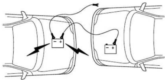
text_image
Diagram showing two connected cylindrical tanks with positive charge carriers and directional arrows indicating flow or movement.- Remove the jumper cable on the negative (-) connection of the booster vehicle's battery.
Roadside emergencies
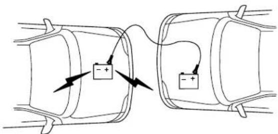
text_image
Diagram showing two cylindrical batteries connected by a wire, with positive and negative charges indicated.- Remove the jumper cable from the positive (+) terminal of the booster vehicle's battery.
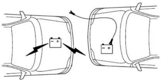
text_image
Diagram showing two battery charging scenarios with positive and negative charge indicators, illustrating electric field lines.- Remove the jumper cable from the positive (+) terminal of the disabled vehicle's battery.
After the disabled vehicle has been started and the jumper cables removed, allow it to idle for several minutes so the engine computer can relearn its idle conditions.
WRECKER TOWING
If you need to have your vehicle towed, contact a professional towing service or, if you are a member, your roadside assistance center.
It is recommended that your vehicle be towed with a wheel lift or flatbed equipment.
If the vehicle is stowed by other means or incorrectly, vehicle damagemay occur.
When calling for a tow truck, tell the operator what kind of vehicle you have.
Customer assistance
IF YOU HAVE A SERVICE CONCERN, PLEASE FOLLOW THESE STEPS:
- Call our Motor Home Customer Assistance Center (1-800-444-3311) which is available 24 hrs/day. If inspections or repairs are required let the assistance center make an appointment for you at the most appropriate repair location in your area. Please have the following information ready before you call:
•VehicleIdentificationNumber
- CurrentMileage
• ASummaryofYourConcern
-
When you arrive at the repair location explain your concern fully to the service writer. If your concern is resolved please contact (1-800-444-3311) and advice them accordingly. If not...
-
Ask to see the Service Manager and review your concern with him. If you are still not satisfied...
- Contact (1-800-444-3311) and our Motor Home Customer Assistance Center will assist you and or the repair location as needed.
Cleaning
ALUMINUM WHEELS AND WHEEL COVERS
Aluminum wheels or covers are coated with a clearcoat paint finish. In order to maintain their shine:
- Clean weekly with Motorcraft Wheel and Tire Cleaner (ZC-37-A), which is available from your dealer. Heavy dirt and brake dust accumulation may require agitation with a sponge. Rinse thoroughly with a strong stream of water.
- Never apply any cleaning chemical to hot or warm wheel rims or covers.
- Some automatic car washes may cause damage to the finish on your wheel rims or covers. Chemical-strength cleaners, or cleaning chemicals, in combination with brush agitation to remove brake dust and dirt, could wear away the clearcoat finish over time.
- Do not use hydrofluoric acid-based or high caustic-based wheel cleaners, steel wool, fuels or strong household detergent.
- To remove tar and grease, use Ford Extra Strength Tar and Road Oil Removal (B7A-19520-AA), available from your dealer.
ENGINE
Engines are more efficient when they are clean because grease and dirt buildup keep the engine warmer than normal. When washing:
- Take care when using a power washer to clean the engine. The high-pressure fluid could penetrate the sealed parts and cause damage.
- Do not spray a hot engine with cold water to avoid cracking the engine block or other engine components.
- Spray Motorcraft Engine Shampoo and Degreaser (ZC-20) on all parts that require cleaning and pressure rinse clean.
- Never wash or rinse the engine while it is running; water in the running engine may cause internal damage.
UNDERBODY
Flush the complete underside of your vehicle frequently. Keep body and door drain holes free from packed dirt.
Maintenance and specifications
SERVICE RECOMMENDATIONS
To help you service your vehicle:
- We highlight do-it-yourself items in the engine compartment for easy location.
- We provide a scheduled maintenance guide which makes tracking routine service easy.
If your vehicle requires professional service, your dealership can provide the necessary parts and service. Check your WarrantyGuide/Owner InformationGuideto find out which parts and services are covered.
Use only recommended fuels, lubricants, fluids and service parts conforming to specifications. Motorcraft parts are designed and built to provide the best performance in your vehicle.
PRECAUTIONS WHEN SERVICING YOUR VEHICLE
- Do not work on a hot engine.
- Make sure that nothing gets caught in moving parts.
- Do not work on a vehicle with the engine running in an enclosed space, unless you are sure you have enough ventilation.
- Keep all open flames and other lit material away from the battery and all fuel related parts.
Working with the engine off
- Set the parking brake and shift to P (Park).
- Turn off the engine and remove the key.
- Block the wheels.
Working with the engine on
- Set the parking brake and shift to P (Park).
- Block the wheels.
Note: Do not start your engine with the air cleaner removed and do not remove it while the engine is running.
Maintenance and specifications
IDENTIFYING COMPONENTS IN THE ENGINE COMPARTMENT
6.8L V10 engine
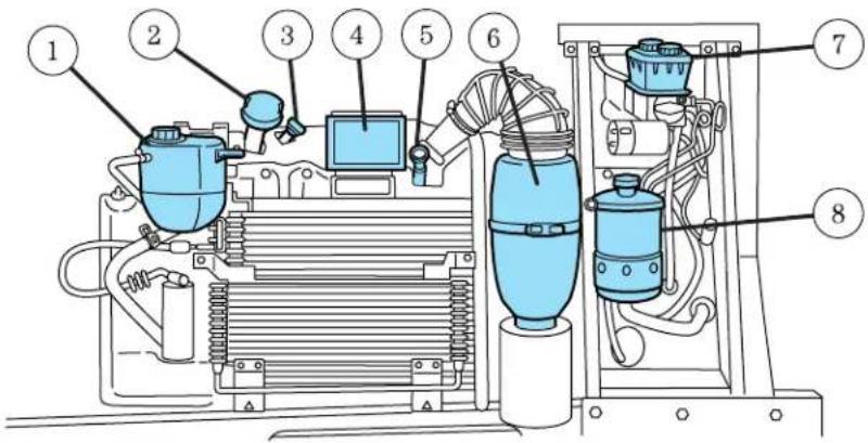
text_image
Technical diagram of an industrial machine with numbered components for identification- Engine coolant reservoir
- Engine oil filler cap
- Automatic transmission fluid dipstick
- Power distribution box
- Engine oil dipstick
- Air filter assembly
- Brake fluid reservoir
- Power steering fluid reservoir
Maintenance and specifications
ENGINE OIL
Checking the engine oil
Refer to the scheduled maintenance guide for the appropriate intervals for checking the engine oil.
- Make sure the vehicle is on level ground.
- Turn the engine off and wait a few minutes for the oil to drain into the oil pan.
- Set the parking brake and ensure the gearshift is securely latched in P (Park).
-
Open the hood. Protect yourself from engine heat.
-
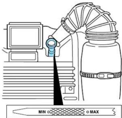
Locate and carefully remove the engine oil level indicator (dipstick).
text_image
MIN O O MAX-
Wipe the indicator clean. Insert the indicator fully, then remove it again.
-
If the oil level is between the MIN and MAX marks, the oil level is acceptable. DONOTADDOIL.
- If the oil level is below the MIN mark, add enough oil to raise the level within the MIN-MAX range.
-
Oil levels above the MAX mark may cause engine damage. Some oil must be removed from the engine by a service technician.
-
Put the indicator back in and ensure it is fully seated.
Adding engine oil
- Check the engine oil. For instructions, refer to Checkingtheengine oilin this chapter.
Maintenance and specifications
- If the engine oil level is not within the MIN and MAX ranges, add only certified engine oil of the recommended viscosity. Remove the engine oil filler cap and use a funnel to pour the engine oil into the opening.
- Recheck the engine oil level. Make sure the oil level is not above the MAX mark on the engine oil level indicator (dipstick).
- Install the indicator and ensure it is fully seated.
- Fully install the engine oil filler cap by turning the filler cap clockwise until three clicks can be heard.
To avoid possible oil loss, DONOT operates the vehicle with the engine oil level indicator and/or the engine oil filler cap removed.
Engine oil and filter recommendations
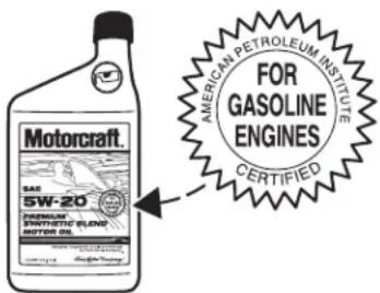
Look for this certification trademark.
text_image
Motorcraft. GAS 5W-20 SPINATIC FLEEP MOTOR OIL AMERICAN PETROLEUM INSTITUTE FOR GASOLINE ENGINES CERTIFIEDSAE5W-20engineoilisrecommended.
Only use oils “Certified For Gasoline Engines” by the American Petroleum Institute (API). Use Motorcraft or an equivalent oil meeting Ford specification WSS-M2C153-H. SAE5W-20oilprovidesoptimum fueleconomyanddurabilityperformancemeetingall requirementsforyourvehicle'sengine.
Do not use supplemental engine oil additives, oil treatments or engine treatments. They are unnecessary and could, under certain conditions, lead to engine damage which is not covered by your warranty.
Change your engine oil and filter according to the appropriate schedule listed in the scheduled maintenance guide.
Ford production and aftermarket (Motorcraft) oil filters are designed for added engine protection and long life. If a replacement oil filter is used that does not meet Ford material and design specifications, start-up engine noises or knock may be experienced.
It is recommended you use the appropriate Motorcraft oil filter (or another brand meeting Ford specifications) for your engine application.
Maintenance and specifications
BATTERY - +
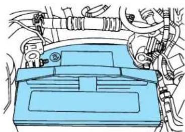
Your vehicle is equipped with a Motorcraft maintenance-free battery which normally does not require additional water during its life of service.
natural_image
Technical line drawing of a car interior with hoses and dashboard (no text or symbols)However, for severe usage or in high temperature climates, check the battery electrolyte level. Refer to the scheduled maintenance guide for the service interval schedules.
Keep the electrolyte level in each cell up to the "level indicator". Donotoverfill the battery cells.
If the electrolyte level in the battery is low, you can add plain tap water to the battery, as long as you do not use hard water (water with a high mineral or alkali content). If possible, however, try to only fill the battery cells with distilled water. If the battery needs water often, have the charging system checked.
If your battery has a cover/shield, makes sure it is reinstalled after the battery has been cleaned or replaced.
For longer, trouble-free operation, keep the top of the battery clean and dry. Also, make certain the battery cables are always tightly fastened to the battery terminals.
If you see any corrosion on the battery or terminals, remove the cables from the terminals and clean with a wire brush. You can neutralize the acid with a solution of baking soda and water.
Batteries normally produce explosive gases which can cause personal injury. Therefore, do not allow flames, sparks or lighted substances to come near the battery. When working near the battery, always shield your face and protect your eyes. Always provide proper ventilation.
Maintenance and specifications
When lifting a plastic-cased battery, excessive pressure on the end walls could cause acid to flow through the vent caps, resulting in personal injury and/or damage to the vehicle or battery. Lift the battery with a battery carrier or with your hands on opposite corners.
Keep batteries out of reach of children. Batteries contain sulfuric acid. Avoid contact with skin, eyes or clothing. Shield your eyes when working near the battery to protect against possible splashing of acid solution. In case of acid contact with skin or eyes, flush immediately with water for a minimum of 15 minutes and get prompt medical attention. If acid is swallowed, call a physician immediately.
Battery posts, terminals and related accessories contain lead and lead compounds. Washhandsafterhandling.
To account for customer driving habits and conditions, your automatic transmission (4R100) electronically controls the shift quality by using an adaptive learning strategy. The adaptive learning strategy is maintained by power from the battery. When the battery is disconnected or a new battery is installed, the transmission must relearn its adaptive strategy. Optimal shifting will resume within a few hundred kilometers (miles) of operation.
If the shift quality does not improve with a few hundred kilometers (miles) of operation, or if the down shifts and other throttle conditions do not function normally or after along deceleration period, see your dealer or a qualified service technician as soon as possible.
Because your vehicle's engine is also electronically controlled by a computer, some control conditions are maintained by power from the battery. When the battery is disconnected or a new battery is installed, the engine must relearn its idle and fuel trim strategy for optimum driveability and performance. To begin this process:
- With the vehicle at a complete stop, set the parking brake.
- Put the gearshift in P (Park), turn off all accessories and start the engine.
- Run the engine until it reaches normal operating temperature.
- Allow the engine to idle for at least one minute.
Maintenance and specifications
- Turn the A/C on and allow the engine to idle for at least one minute.
- With your foot on the brake pedal and with the A/C on, put the vehicle in D (Drive) and allow the engine to idle for at least one minute.
-
Drive the vehicle to complete the relearning process.
-
The vehicle may need to be driven 16 km (10 miles) or more to relearn the idle and fuel trim strategy.
- If you don ot allow the engine to relearn its idle trim, the idle quality of your vehicle may be adversely affected until the idle trim is eventually relearned.
If the battery has been disconnected or a new battery has been installed, the clock and the preset radio stations must be reset once the battery is reconnected.
• Always dispose of automotive batteries in a responsible manner. Follow your local authorized standards for disposal. Call your local authorized recycling center to find out more about recycling automotive batteries.
flowchart
graph TD
    A["LEAD"] --> B["RETURN"]
    B --> C["End"]
RECYCLE
ENGINE COOLANT
Checking engine coolant
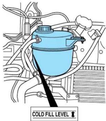
The concentration and level of engine coolant should be checked at the mileage intervals listed in the scheduled maintenance guide. The coolant concentration should be maintained at 50/50 coolant and distilled water, which equates to a freeze point of -36^ C ( -34^ F). Coolant concentration testing is possible with a hydrometer or antifreeze tester (such as the Rotunda Battery and Antifreeze Tester, 014–R1060). The level of coolant should be maintained at the “cold full” of “cold fill range” level in the coolant reservoir. If the level falls below, add coolant per the instructions in the Addingenginecoolantsection.
Your vehicle was factory-filled with a 50/50 engine coolant and water concentration. If the concentration of coolant falls below 40% or above 60%, the engine parts could become damaged or not work properly. A 50–50mixtureofcoolantandwaterprovidesthefollowing:
- Freezeprotectiondownto-36°C(-34°F).
• Boilingprotectionupto129°C(265°F).
Maintenance and specifications
- Protectionagainstrustandotherformsofcorrosion.
- Enablescalibratedgaugestoworkproperly.
When the engine is cold, check the level of the engine coolant in the reservoir.
text_image
COLD FILL LEVEL ↑- The engine coolant should be at the “cold fill level” or within the “cold fill range” as listed on the engine coolant reservoir (depending upon application).
- Refer to the Scheduled Maintenance Guide for service interval schedules.
- Be sure to read and understand Precautionswhenservicingyour vehicle in this chapter.
If the engine coolant has not been checked at the recommended interval, the engine coolant reservoir may become low or empty. If the reservoir is low or empty, add engine coolant to the reservoir. Refer to Adding enginecoolant in this chapter.
Note: Automotive fluids are not interchangeable; do not use engine coolant, antifreeze or windshield washer fluid outside of its specified function and vehicle location.
Adding engine coolant
When adding coolant, make sure it is a 50/50 mixture of engine coolant and distilled water. Add the mixture to the coolant reservoir, whenthe engineiscool, until the appropriate fill level is obtained.
Maintenance and specifications

Do not add engine coolant when the engine is hot. Steam and scalding liquids released from a hot cooling system can burn you. Also, you can be burned if you spill coolant on hot engine parts.

Do not put engine coolant in the windshield washer fluid container. If sprayed on the windshield, engine coolant could it difficult to see through the windshield.
The cooling system in your vehicle is filled with either green-colored Motorcraft Premium Engine Coolant meeting Ford specification ESE-M97B44-A or yellow-colored Motorcraft Premium Gold Engine Coolant meeting Ford Specification WSS-M97B51-A1. To determine your vehicle's coolant type (color), check your coolant reservoir.
- AddMotorcraftPremiumEngineCoolant(green-colored), VC-4-A(U.S.)orCXC-10(Canada)orMotorcraftPremium GoldEngineCoolant(yellow-colored),VC-7-A(VC-7-Bin Oregon),dependingonthetypeofcoolantoriginallyequipped inyourvehicle.If you are unsure which type of coolant your vehicle requires, check your coolant reservoir or contact your local dealer.
Note: Use of Motorcraft Cooling System Stop Leak Pellets, VC-6, darkens the color of Motorcraft Premium Gold Engine Coolant from yellow to golden tan.
- Donotadd/mixanorange-colored,extendedlifecoolantsuch asMotorcraftSpecialityOrangeEngineCoolant,VC-2(US)or CXC-209(Canada),meetingFordspecificationWSS-M97B44-D withthefactory-filledcoolant.Mixing Motorcraft Speciality Orange Engine Coolant or any orange-colored extended life product with your factory filled coolant can result in degraded corrosion protection.
- A large amount of water without engine coolant may be added, in case of emergency, to reach a vehicle service location. In this instance, the cooling system must be drained and refilled with a 50/50 mixture of engine coolant and distilled water as soon as possible. Water alone (without engine coolant) can cause engine damage from corrosion, overheating or freezing.
- Donotusealcohol, methanol, brineoranyenginecoolants mixed with alcoholormethanolantifreeze(coolant). Alcohol and other liquids can cause engine damage from overheating or freezing.
- Donotaddextrainhibitorsoradditivestothecoolant. These can be harmful and compromise the corrosion protection of the engine coolant.
Maintenance and specifications
- DonotmixwithrecycledcoolantunlessfromaFord-approved recyclingprocess(seeUseofRecycledenginecoolantsection).
For vehicles with overflow coolant systems with a non-pressurized cap on the coolant recovery system, add coolant to the coolant recovery reservoir when the engine is cool. Add the proper mixture of coolant and water to the "cold full" level. For all other vehicles, which have a coolant degas system with a pressurized cap, or if it is necessary to remove the coolant pressure relief cap on the radiator of a vehicle with an overflow system, follow these steps to add engine coolant.
To reduce the risk of personal injury, make sure the engine is cool before unscrewing the coolant pressure relief cap. The cooling system is under pressure; steam and hot liquid can come out forcefully when the cap is loosened slightly.
- Before you begin, turn the engine off and let it cool.
- When the engine is cool, wrap a thick cloth around the coolant pressure relief cap on the coolant reservoir (an opaque plastic bottle). Slowly turn cap counterclockwise (left) until pressure begins to release.
- Step back while the pressure releases.
- When you are sure that all the pressure has been released, use the cloth to turn it counterclockwise and remove the cap.
- Fill the coolant reservoir slowly with the proper coolant mixture (see above), to within the "cold fill range" or the "cold full" level on the reservoir. If you removed the radiator cap in an overflow system, fill the radiator until the coolant is visible and radiator is almost full.
- Replace the cap. Turn until tightly installed. (Cap must be tightly installed to prevent coolant loss.)
After any coolant has been added, check the coolant concentration, refer to CheckingEngineCoolantsection. If the concentration is not 50/50 (protection to -34^ / -36^ ), drain some coolant and adjust the concentration. It may take several drains and additions to obtain a 50/50 coolant concentration.
Whenever coolant has been added, the coolant level in the coolant reservoir should be checked the next few times you drive the vehicle. If necessary, add enough 50/50 concentration of engine coolant and distilled water to bring the liquid level to the proper level.
If you have to add more than 1.0 liter (1.0 quart) of engine coolant per month, have your dealer check the engine cooling system. Your cooling
Maintenance and specifications
system may have a leak. Operating an engine with a low level of coolant can result in engine overheating and possible engine damage.
Recycled engine coolant
Ford Motor Company recommends the use of a recycled engine coolant produced by Ford-approved processes in vehicles originally equipped with Motorcraft Premium Engine Coolant (green-colored). However, not all coolant recycling processes produce coolant that meets Ford specification ESE-M97B44-A. Use of such coolant may harm the engine and cooling system components.
Ford Motor Company does NOT recommend the use of recycled engine coolant in vehicles originally equipped with Motorcraft Premium Gold Engine Coolant since a Ford-approved recycling process is not yet available.

Used engine coolant should be disposed of in an appropriate
manner. Follow your community's regulations and standards for recycling and disposing of automotive fluids.
Coolant refill capacity
To find out how much fluid your vehicle's cooling system can hold, refer to Refillcapacities in this chapter.
Fill your engine coolant reservoir as outlined in Addingenginecoolant in this chapter.
Severe climates
If you drive in extremely cold climates (less than -36^ C [-34^ F]):
- Itmaybenecessarytoincreasethecoolantconcentration above50%.
- NEVERincreasethecoolantconcentrationabove60%.
- Increasedenginecoolantconcentrationsabove60% will decrease the overheat protection characteristics of the engine coolant and may cause engineered damage.
- Refertothechartonthecoolantcontainertoensurethe coolantconcentrationinyourvehiclewillprovideadequate freezeprotectionatthetemperaturesinwhichyoudriveinthe wintermonths.
If you drive in extremely hot climates:
- Itisstillnecessary to maintain the coolant concentration above 40% .
Maintenance and specifications
- NEVERdecreasethecoolantconcentrationbelow40%.
- Decreasedenginecoolantconcentrationsbelow 40% will decreasethecorrosionprotectioncharacteristicsoftheengine coolantandmaycauseenginedamage.
- Decreasedenginecoolantconcentrationsbelow 40% will decreasethefreezeprotectioncharacteristicsoftheengine coolantandmaycauseenginedamage.
- Refertothechartonthecoolantcontainertoensurethe coolantconcentrationinyourvehiclewillprovideadequate protectionatthetemperaturesinwhichyoudrive.
Vehicles driven year-round in non-extreme climates should use a 50/50 mixture of engine coolant and distilled water for optimum cooling system and engine protection.
What you should know about fail-safe cooling
If the engine coolant supply is depleted, this feature allows the vehicle to be driven temporarily before incremental component damage is incurred. The “fail-safe” distance depends on ambient temperatures, vehicle load and terrain.
Howfail-safecoolingworks
If the engine begins to overheat:
- The engine coolant temperature gauge will move to the red (hot) area.
• The symbol will illuminate.
•The symbol will illuminate.
•The ServiceEngineSoon indicator light will illuminate.
If the engine reaches a preset over-temperature condition, the engine will automatically switch to alternating cylinder operation. Each disabled cylinder acts as an air pump and cools the engine.
When this occurs the vehicle will still operate. However:
•The engine power will be limited.
• The air conditioning system will be disabled.
Continued operation will increase the engine temperature and the engine will completely shut down, causing steering and braking effort to increase.
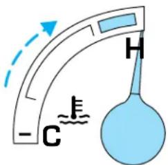
text_image
-C H EMaintenance and specifications
Once the engine temperature cools, the engine can be re-started. Take your vehicle to a service facility as soon as possible to minimize engine damage.
Whenfail-safemodeisactivated
You have limited engine power when in the fail-safe mode, so drive the vehicle with caution. The vehicle will not be able to maintain high-speed operation and the engine will run rough. Remember that the engine is capable of completely shutting down automatically to prevent engine damage, therefore:
- Pull off the road as soon as safely possible and turn off the engine.
- Arrange for the vehicle to be taken to a service facility.
- If this is not possible, wait a short period for the engine to cool.
- Check the coolant level and replenish if low.

Never remove the coolant reservoir cap while the engine is running or hot.
- Re-start the engine and take your vehicle to a service facility.
Drivingthevehiclewithoutrepairingtheengineproblem increasesthechanceofenginedamage.Takeyourvehicletoa servicefacilityassoonaspossible.
WHAT YOU SHOULD KNOW ABOUT AUTOMOTIVE FUELS

Important safety precautions

Do not overfill the fuel tank. The pressure in an overfilled tank may cause leakage and lead to fuel spray and fire.

The fuel system may be under pressure. If the fuel filler cap is venting vapor or if you hear a hissing sound, wait until it stops completely removing the fuel filler cap. Otherwise, fuel may out and injure you or others.

If you do not use the proper fuel filler cap, excessive pressure or vacuum in the fuel tank may damage the fuel system or cause fuel cap to disengage in a collision, which may result in possible mal injury.
Maintenance and specifications

Automotive fuels can cause serious injury or death if misused or mishandled.

Gasoline may contain benzene, which is a cancer-causing agent.
Observe the following guidelines when handling automotive fuel:
- Extinguish all smoking materials and any open flames before fueling your vehicle.
• Always turn off the vehicle before fueling. - Automotive fuels can be harmful or fatal if swallowed. Fuel such as gasoline is highly toxic and if swallowed can cause death or permanent injury. If fuel is swallowed, call a physician immediately, even if no symptoms are immediately apparent. The toxic effects of fuel may not be visible for hours.
- Avoid inhaling fuel vapors. Inhaling too much fuel vapor of any kind can lead to eye and respiratory tract irritation. In severe cases, excessive or prolonged breathing of fuel vapor can cause serious illness and permanent injury.
- Avoid getting fuel liquid in your eyes. If fuel is splashed in the eyes, remove contact lenses (if worn), flush with water for 15 minutes and seek medical attention. Failure to seek proper medical attention could lead to permanent injury.
- Fuels can also be harmful if absorbed through the skin. If fuel is splashed on the skin and/or clothing, promptly remove contaminated clothing and wash skin thoroughly with soap and water. Repeated or prolonged skin contact with fuel liquid or vapor causes skin irritation.
- Be particularly careful if you are taking “Antabuse” or other forms of disulfiram for the treatment of alcoholism. Breathing gasoline vapors, or skin contact could cause an adverse reaction. In sensitive individuals, serious personal injury or sickness may result. If fuel is splashed on the skin, promptly wash skin thoroughly with soap and water. Consult a physician immediately if you experience an adverse reaction.
Maintenance and specifications

When refueling always shut the engine off and never allow sparks or open flames near the filler neck. Never smoke while ing. Fuel vapor is extremely hazardous under certain conditions. should be taken to avoid inhaling excess fumes.

The flow of fuel through a fuel pump nozzle can produce static electricity, which can cause a fire if fuel is pumped into an unded fuel container.
Use the following guidelines to avoid static build-up when filling an ungrounded fuel container:
- Place approved fuel container on the ground.
- DO NOT fill a fuel container while it is in the vehicle (including the cargo area).
- Keep the fuel pump nozzle in contact with the fuel container while filling.
- DO NOT use a device that would hold the fuel pump handle in the fill position.
Choosing the right fuel
Use only UNLEADED FUEL. The use of leaded fuel is prohibited by law and could damage your vehicle.
Do not use fuel containing methanol. It can damage critical fuel system components.
Your vehicle was not designed to use fuel or fuel additives with metallic compounds, including manganese-based compounds containing MMT.
Repairs to correct the effects of using a fuel for which your vehicle was not designed may not be covered by your warranty.
Octane recommendations
Your vehicle is designed to use
"Regular" unleaded gasoline with pump (R+M)/2 octane rating of 87.
We do not recommend the use of gasolines labeled as "Regular" that
are sold with octane ratings of 86 or lower in high altitude areas.
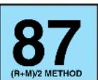
Do not be concerned if your engine sometimes knocks lightly. However, if it knocks heavily under most driving conditions while you are using fuel
Maintenance and specifications
with the recommended octane rating, see your dealer or a qualified service technician to prevent any engine damage.
Fuel quality
If you are experiencing starting, rough idle or hesitation driveability problems during a cold start, try a different brand of “Regular” unleaded gasoline. “Premium” unleaded gasoline is not recommended (particularly in the United States) because it may cause these problems to become more pronounced. If the problems persist, see your dealer or a qualified service technician.
It should not be necessary to add any aftermarket products to your fuel tank if you continue to use high quality fuel of the recommended octane rating. Aftermarket products could cause damage to the fuel system. Repairs to correct the effects of using an aftermarket product in your fuel may not be covered by your warranty.
Many of the world's automakers issued the World-wide Fuel Charter that recommends gasoline specifications to provide improved performance and emission control system protection for your vehicle. Gasolines that meet the World-wide Fuel Charter should be used when available. Ask your fuel supplier about gasolines that meet the World-wide Fuel Charter. In Canada look for fuels that display the AutoMakers'Choice® logo.

text_image
San Francisco Union Gains des services centers TinAMCCleaner air
Ford endorses the use of reformulated “cleaner-burning” gasolines to improve air quality.
Running out of fuel
Avoid running out of fuel because this situation may have an adverse effect on powertrain components.
If you have run out of fuel:
- You may need to cycle the ignition from OFF to ON several times after refueling, to allow the fuel system to pump the fuel from the tank to the engine.
- Your “Service Engine Soon” indicator may come on. For more information on the “Service Engine Soon” indicator, refer to the Instrumentclusterchapter.
Maintenance and specifications
Fuel filter replacement
The fuel filter assembly is located inside the driver side frame rail, near the transmission.
The fuel filter should be replaced every 24 000 km (15 000 miles).
Removal
If the fuel filter is being serviced with the rear of the vehicle higher than the front, or if the fuel tank is pressurized, fuel leakage or siphoning from the tank fuel tubes could occur. To prevent this condition, maintain the vehicle front end at or above the level of the rear of the vehicle.
Do not smoke or carry lighted tobacco or open flame of any type when working on or near any fuel related component. Highly flammable mixtures are always present and may be ignited, resulting in possible personal injury.
Fuel in the fuel system remains under high pressure even when the engine is not running. Before servicing or disconnecting any of the fuel lines or fuel system components, the fuel system pressure must be relieved in order to prevent accidental spraying of fuel, causing personal injury or a fire hazard.
- Shut the engine off and relieve the fuel system pressure.
- Remove the Schrader valve cap (located at the right rear of intake manifold) and install the EFI/CFI Fuel Pressure Gauge. The EFI/CFI Fuel Pressure Gauge 310-012 (T80L-9974-B) is available at a certified Ford parts dealer.
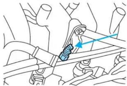
natural_image
Mechanical assembly diagram showing a spring-loaded component with blue arrows indicating motion direction (no text or labels)Maintenance and specifications
- Open the manual valve slowly on the EFI/CFI Fuel Pressure Gauge and relieve the fuel pressure. This will drain some fuel out of the system; place the fuel in a suitable container.
- Use the fuel line disconnect tool to disconnect the fuel lines from the fuel filter. The Fuel Line Disconnect Tool 310-S039 (T90T-9550-S) is available at a certified Ford parts dealer.
- Disconnect the safety clip from the male hose.
• Install the fuel line disconnect tool and push into the fitting. - Separate the fittings. Clean the fittings and inspect the fittings for damage.
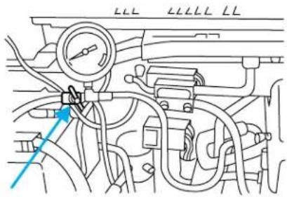
text_image
Technical diagram of an engine cylinder with labeled components and directional arrows indicating flow or movement.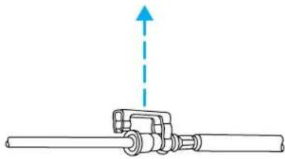
natural_image
Mechanical assembly diagram showing a shaft with a lever and a blue upward arrow indicating motion (no text or symbols)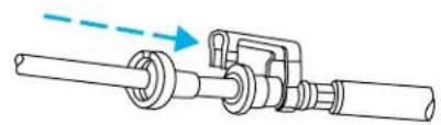
natural_image
Mechanical assembly diagram showing a shaft and housing with a blue dashed arrow indicating direction (no text or symbols)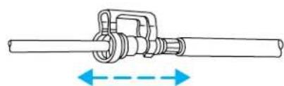
natural_image
Technical line drawing of a mechanical shaft with flange and housing (no text or symbols)- Remove fuel filter.
Maintenance and specifications
Installation
- Install the fuel filter.
- Lubricate the tube end with clean engine oil meeting Ford specification WSS-M2C153-Hto ease assembly.
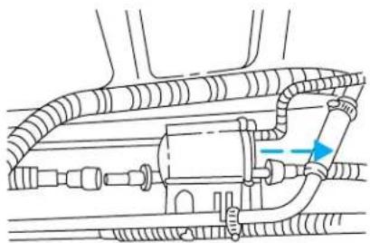
natural_image
Technical diagram of a mechanical assembly with hoses and connectors (no text or labels)- Pull on the fitting to make sure it is fully engaged, then install safety clip.
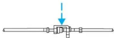
natural_image
Pure mechanical assembly diagram showing a shaft with a central component and a downward arrow indicating force or direction (no text or symbols)- Align and push the tube into the fitting until you hear a click.
- Remove the EFI/CFI Fuel Pressure Gauge.
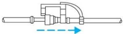
natural_image
Pure mechanical diagram showing a shaft and lever assembly without any text, numbers, or symbols- Install the Schrader valve cap securely.
ESSENTIALS OF GOOD FUEL ECONOMY
Measuring techniques
Your best source of information about actual fuel economy is you, the driver. You must gather information as accurately and consistently as possible. Fuel expense, frequency of fill-ups or fuel gauge readings are NOT accurate as a measure of fuel economy. We do not recommend taking fuel economy measurements during the first 1,600 km (1,000 miles) of driving (engine break-in period). You will get a more accurate measurement after 3,000 km–5,000 km (2,000 miles–3,000 miles).
Filling the tank
The advertised fuel capacity of the fuel tank on your vehicle is equal to the rated refill capacity of the fuel tank as listed in the Refillcapacities section of this chapter.
The advertised capacity is the amount of the indicated capacity and the empty reserve combined. Indicated capacity is the difference in the
Maintenance and specifications
amount of fuel in a full tank and a tank when the fuel gauge indicates empty. Empty reserve is the small amount of fuel remaining in the fuel tank after the fuel gauge indicates empty.
Theamountofusablefuelintheemptyreservevariesandshould notbereliedupontoincreasedrivingrange.Whenrefuelingyour vehicleafterthefuelgaugeindicatesempty,youmightnotbe abletorefuelthefullamountoftheadvertisedcapacityofthe fueltankduetotheemptyreservestillpresentinthetank.
For consistent results when filling the fuel tank:
- Turn the engine/ignition switch to the off position prior to refueling, an error in the reading will result if the engine is left running.
- Use the same filling rate setting (low — medium — high) each time the tank is filled.
- Allow no more than 2 automatic click-offs when filling.
- Always use fuel with the recommended octane rating.
- Use a known quality gasoline, preferably a national brand.
- Use the same side of the same pump and have the vehicle facing the same direction each time you fill up.
- Have the vehicle loading and distribution the same every time.
Your results will be most accurate if your filling method is consistent.
Calculating fuel economy
- Fill the fuel tank completely and record the initial odometer reading (in kilometers or miles).
- Each time you fill the tank, record the amount of fuel added (in liters or gallons).
- After at least three to five tank fill-ups, fill the fuel tank and record the current odometer reading.
- Subtract your initial odometer reading from the current odometer reading.
- Follow one of the simple calculations in order to determine fuel economy:
Calculation 1: Multiplylitersusedby100,thendividebytotal kilometerstraveled.
Calculation 2: Dividetotalmilestraveledbytotalgallonsused.
Keep a record for at least one month and record the type of driving (city or highway). This will provide an accurate estimate of the vehicle's fuel
Maintenance and specifications
economy under current driving conditions. Additionally, keeping records during summer and winter will show how temperature impacts fuel economy. In general, lower temperatures give lower fuel economy.
Driving style — good driving and fuel economy habits
Give consideration to the lists that follow and you may be able to change a number of variables and improve your fuel economy.
Habits
- Smooth, moderate operation can yield up to 10% savings in fuel.
- Steady speeds without stopping will usually give the best fuel economy.
- Idling for long periods of time (greater than one minute) may waste fuel.
- Anticipate stopping; slowing down may eliminate the need to stop.
- Sudden or hard accelerations may reduce fuel economy.
- Slow down gradually.
- Driving at reasonable speeds (traveling at 88 km/h [55 mph] uses 15% less fuel than traveling at 105 km/h [65 mph]).
- Revving the engine before turning it off may reduce fuel economy.
- Using the air conditioner or defroster may reduce fuel economy.
- You may want to turn off the speed control in hilly terrain if unnecessary shifting between third and fourth gear occurs. Unnecessary shifting of this type could result in reduced fuel economy.
- Warming up a vehicle on cold mornings is not required and may reduce fuel economy.
- Resting your foot on the brake pedal while driving may reduce fuel economy.
- Combine errands and minimize stop-and-go driving.
Maintenance
- Keep tires properly inflated and use only recommended size.
- Operating a vehicle with the wheels out of alignment will reduce fuel economy.
- Use recommended engine oil. Refer to Lubricantspecifications in this chapter.
Maintenance and specifications
- Perform all regularly scheduled maintenance items. Follow the recommended maintenance schedule and owner maintenance checks found in your vehicle scheduled maintenance guide.
Conditions
- Heavily loading a vehicle or towing a trailer may reduce fuel economy at any speed.
- Carrying unnecessary weight may reduce fuel economy (approximately 0.4km / L [1 mpg] is lost for every 180kg [400 lb] of weight carried).
- Adding certain accessories to your vehicle (for example bug deflectors, rollbars/light bars, running boards, ski/luggage racks) may reduce fuel economy.
- Using fuel blended with alcohol may lower fuel economy.
- Fuel economy may decrease with lower temperatures during the first 12–16 km (8–10 miles) of driving.
- Driving on flat terrain offers improved fuel economy as compared to driving on hilly terrain.
- Transmissions give their best fuel economy when operated in the top cruise gear and with steady pressure on the gas pedal.
- Close windows for high speed driving.
EPA window sticker
Every new vehicle should have the EPA window sticker. Contact your dealer if the window sticker is not supplied with your vehicle. The EPA window sticker should be your guide for the fuel economy comparisons with other vehicles.
It is important to note the box in the lower left corner of the window sticker. These numbers represent the Range of L/100 km (MPG) expected on the vehicle under optimum conditions. Your fuel economy may vary depending upon the method of operation and conditions.
Your vehicle is equipped with various emission control components and a catalytic converter which will enable your vehicle to comply with applicable exhaust emission standards. To make sure that the catalytic converter and other emission control components continue to work properly:
- Use only the specified fuel listed.
- Avoid running out of fuel.
Maintenance and specifications
- Do not turn off the ignition while your vehicle is moving, especially at high speeds.
- Have the items listed in your scheduled maintenance guide performed according to the specified schedule.
The scheduled maintenance items listed in the scheduled maintenance guide are essential to the life and performance of your vehicle and to its emissions system.
If other than Ford, Motorcraft or Ford-authorized parts are used for maintenance replacements or for service of components affecting emission control, such non-Ford parts should be equivalent to genuine Ford Motor Company parts in performance and durability.

Do not park, idle, or drive your vehicle in dry grass or other dry ground cover. The emission system heats up the engine compartment and exhaust system, which can start a fire.
Illumination of the “Service Engine Soon” light, charging system warning light or the temperature warning light, fluid leaks, strange odors, smoke or loss of engine power, could indicate that the emission control system is not working properly.

Exhaust leaks may result in entry of harmful and potentially lethal fumes into the passenger compartment.
Do not make any unauthorized changes to your vehicle or engine. By law, vehicle owners and anyone who manufactures, repairs, services, sells, leases, trades vehicles, or supervises a fleet of vehicles are not permitted to intentionally remove an emission control device or prevent it from working. Information about your vehicle's emission system is on the Vehicle Emission Control Information Decal located on or near the engine. This decal identifies engine displacement and gives some tune up specifications.
Please consult your WarrantyGuide for complete emission warranty information.
Readiness for Inspection/Maintenance (I/M) testing
In some localities, it may be a legal requirement to pass an I/M test of the on-board diagnostics system. If your “Check Engine/Service Engine Soon” light is on, refer to the description in the Warninglightsand chimessection of the Instrumentclusterchapter. Your vehicle may not pass the I/M test with the “Check Engine/Service Engine Soon” light on.
Maintenance and specifications
If the vehicle's powertrain system or its battery has just been serviced, the on-board diagnostics system is reset to a "not ready for I/M test" condition. To ready the on-board diagnostics system for I/M testing, a minimum of 30 minutes of city and highway driving is necessary as described below:
- First, at least 10 minutes of driving on an expressway or highway.
- Next, at least 20 minutes driving in stop-and-go, city-type traffic with at least four idle periods.
Allow the vehicle to sit for at least eight hours without starting the engine. Then, start the engine and complete the above driving cycle. The engine must warm up to its normal operating temperature. Once started, do not turn off the engine until the above driving cycle is complete.
CHECKING AND ADDING POWER STEERING FLUID
Check the power steering fluid. Refer to the scheduled maintenance guide for the service interval schedules. If adding fluid is necessary, use only MERCON® ATF.
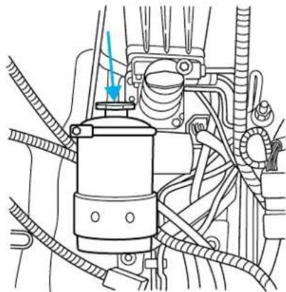
natural_image
Technical line drawing of a mechanical assembly with hoses and components (no text or symbols)- Start the engine and let it run until it reaches normal operating temperature (the engine coolant temperature gauge indicator will be near the center of the normal area between H and C).
- While the engine idles, turn the steering wheel left and right several times.
- Turn the engine off.
Maintenance and specifications
- Check the fluid level on the dipstick. It should be between the arrows in the FULL range on the side of the dipstick with the words MAX. HOT at the top. Do not add fluid if the level is within this range.
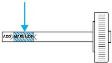
text_image
ADD MAKUHDT- If the fluid is low, add fluid in small amounts, continuously checking the level until it reaches the FULL range. Be sure to put the dipstick back in the reservoir.
BRAKE FLUID
Checking and adding brake fluid
Brake fluid should be checked and refilled as needed. Refer to the scheduled maintenance guide for the service interval schedules.
•Hydroboost brake fluid reservoir
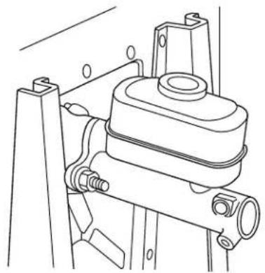
natural_image
Technical line drawing of a mechanical assembly with no visible text or symbolsMaintenance and specifications
•Hydromax brake fluid reservoir
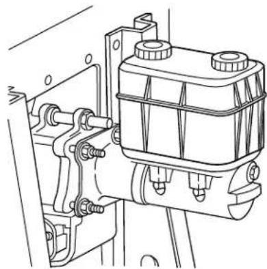
natural_image
Technical line drawing of a mechanical assembly with no visible text or symbols- Clean the reservoir cap before removal to prevent dirt or water from entering the reservoir.
- Visually inspect the fluid level.
- If necessary, add brake fluid from a clean un-opened container until the level reaches MAX. Do not fill above this line.
- Use only a DOT 3 brake fluid certified to meet Ford specification ESA-M6C25-A. Refer to Lubricantspecifications in this chapter.
Brake fluid is toxic. If brake fluid contacts the eyes, flush eyes with running water for 15 minutes. Seek medical attention if irritation persists. If taken internally, drink water and induce vomiting. Seek medical attention immediately.
If you use a brake fluid that is not DOT 3, you will cause permanent damage to your brakes.
Do not let the reservoir for the master cylinder run dry. This may cause the brakes to fail.
Brake system fluid should be replaced on a regular basis to maintain optimum braking performance, especially under heavy-duty driving conditions such as frequent steep grades or heavy towing loads. Refer to the scheduled maintenance guide for the service interval schedules.
Maintenance and specifications
TRANSMISSION FLUID
Checking automatic transmission fluid (if equipped)
Refer to your scheduled maintenance guide for scheduled intervals for fluid checks and changes. Your transmission does not consume fluid. However, the fluid level should be checked if the transmission is not working properly, i.e., if the transmission slips or shifts slowly or if you notice some sign of fluid leakage.
Automatic transmission fluid expands when warmed. To obtain an accurate fluid check, drive the vehicle until it is at normal operating temperature (approximately 30 km [20 miles]). If your vehicle has been operated for an extended period at high speeds, in city traffic during hot weather or pulling a trailer, the vehicle should be turned off for about 30 minutes to allow fluid to cool before checking.
- Drive the vehicle 30 km (20 miles) or until it reaches normal operating temperature.
- Park the vehicle on a level surface and engage the parking brake.
- With the parking brake engaged and your foot on the brake pedal, start the engine and move the gearshift lever through all of the gear ranges. Allow sufficient time for each gear to engage.
- Latch the gearshift lever in P (Park) and leave the engine running.
- Remove the dipstick, wiping it clean with a clean, dry lint free rag. If necessary, refer to Identifyingcomponentsintheenginecompartment in this chapter for the location of the dipstick.
- Install the dipstick making sure it is fully seated in the filler tube.
- Remove the dipstick and inspect the fluid level. The fluid should be in the designated area for normal operating temperature or ambient temperature.
Lowfluidlevel
Do not drive the vehicle if the fluid level is at the bottom of the dipstick and the ambient temperature is above 10^ C ( 50^ F).
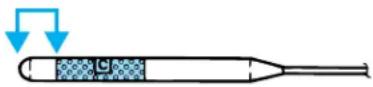
Correctfluidlevel
The transmission fluid should be checked at normal operating temperature 66^ C- 77^ C ( 150^ F- 170^ F) on a level surface. The normal operating temperature can be reached after approximately 30 km (20 miles) of driving.
Maintenance and specifications
You can check the fluid without driving if the ambient temperature is above 10^ C ( 50^ F). However, if fluid is added at this time, an overfill condition could result when the vehicle reaches normal operating temperature.
The transmission fluid should be in this range if at normal operating temperature (66°C-77°C [150°F-170°F]).
The transmission fluid should be in this range if at ambient temperature (10°C-35°C [50°F-95°F]).
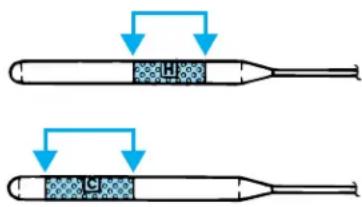
text_image
Diagram showing two cylindrical devices with internal components and directional arrows indicating flow or process.Highfluidlevel
Fluid levels above the safe range may result in transmission failure. An overfill condition of transmission fluid may cause shift and/or
engagement concerns and/or possible damage.
High fluid levels can be caused by an overheating condition.
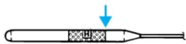
Adjusting automatic transmission fluid levels
Before adding any fluid, make sure the correct type is used. The type of fluid used is normally indicated on the dipstick and also in the Lubricantspecificationssection in this chapter.
Useofanon-approvedautomatictransmissionfluidmaycause internaltransmissioncomponentdamage.
If necessary, add fluid in 250 ml (1/2 pint) increments through the filler tube until the level is correct.
If an overfill occurs, excess fluid should be removed by a qualified technician.
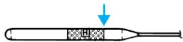
Anoverfillconditionof transmissionfluidmaycauseshiftand/orengagementconcerns and/orpossibledamage.
Do not use supplemental transmission fluid additives, treatments or cleaning agents. The use of these materials may affect transmission operation and result in damage to internal transmission components.
DRIVELINE UNIVERSAL JOINT AND SLIP YOKE
If the original universal joints are equipped with grease fittings. Lubrication will be necessary. Refer to the scheduled maintenance guide for maintenance intervals.
Maintenance and specifications
AIR FILTER MAINTENANCE
Refer to the scheduled maintenance guide for the appropriate intervals for changing the air filter element.
When changing the air filter element, use only the Motorcraft air filter element listed. Refer to MotorcraftPartNumbers.
Note: Do not start your engine with the air cleaner removed and do not remove it while the engine is running.
Changing the air filter element
- Loosen the clamp that secures the air filter element in place.
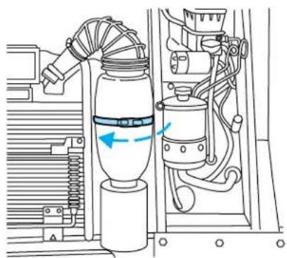
natural_image
Technical line drawing of a mechanical assembly with hoses and components, no visible text or symbols-
Carefully separate the two halves of the air filter housing.
-
Remove the air filter element from the open end of the air filter housing.
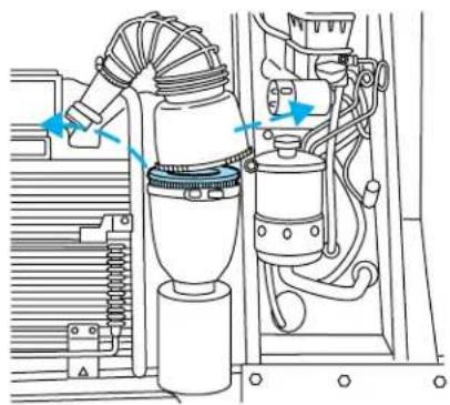
natural_image
Technical line drawing of a mechanical assembly with no visible text or symbolsMaintenance and specifications
- Install a new air filter element, ensuring the arrow on the top half of the air filter housing lines up with the notch on the bottom half of air filter housing. Be careful not to crimp the filter element edges between the air filter housing. This could cause filter damage and allow unmetered air to enter the engine if not properly seated.
- Replace the two halves of the air filter housing and secure the clamp.
INFORMATION ABOUT UNIFORM TIRE QUALITY GRADING
New vehicles are fitted with tires that have a rating on them called Tire Quality Grades. The Quality grades can be found where applicable on the tire sidewall between tread shoulder and maximum section width. For example:
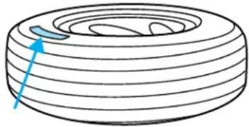
natural_image
Diagram of a tire with a blue arrow pointing to the center (no text or symbols)•Treadwear200TractionAATemperatureA
These Tire Quality Grades are determined by standards that the United States Department of Transportation has set.
Tire Quality Grades apply to new pneumatic tires for use on passenger cars. They do not apply to deep tread, winter-type snow tires, space-saver or temporary use spare tires, tires with nominal rim diameters of 10 to 12 inches or limited production tires as defined in Title 49 Code of Federal Regulations Part 575.104(c)(2).
U.S. Department of Transportation-Tirequality grades: The U.S. Department of Transportation requires Ford to give you the following information about tire grades exactly as the government has written it.
Treadwear
The treadwear grade is a comparative rating based on the wear rate of the tire when tested under controlled conditions on a specified government test course. For example, a tire graded 150 would wear one and one-half (1 1/2) times as well on the government course as a tire graded 100. The relative performance of tires depends upon the actual conditions of their use, however, and may depart significantly from the norm due to variations in driving habits, service practices, and differences in road characteristics and climate.
Maintenance and specifications
Traction AA A B C
The traction grades, from highest to lowest are AA, A, B, and C. The grades represent the tire's ability to stop on wet pavement as measured under controlled conditions on specified government test surfaces of asphalt and concrete. A tire marked C may have poor traction performance.

The traction grade assigned to this tire is based on straight-ahead braking traction tests, and does not include eration, cornering, hydroplaning or peak traction characteristics.
Temperature A B C
The temperature grades are A (the highest), B and C, representing the tire's resistance to the generation of heat and its ability to dissipate heat when tested under controlled conditions on a specified indoor laboratory test wheel. Sustained high temperature can cause the material of the tire to degenerate and reduce tire life, and excessive temperature can lead to sudden tire failure. The grade C corresponds to a level of performance which all passenger car tires must meet under the Federal Motor Vehicle Safety Standard No. 109. Grades B and A represent higher levels of performance on the laboratory test wheel than the minimum required by law.

The temperature grade for this tire is established for a tire that is properly inflated and not overloaded. Excessive speed, inflation, or excessive loading, either separately or in inflation, can cause heat buildup and possible tire failure.
Maintenance and specifications
SERVICING YOUR TIRES
Tire inflation information
This vehicle is equipped with a tire that is an all-steel radial. All-steel radial tires utilize steel cords in the sidewalls, and also require increased inflation pressures of up to 95 psi (refer to the Certification Label for recommended tire pressure). As such, they cannot be treated like normal light truck tires. Tire service, including adjusting tire pressure, must be performed by personnel trained, supervised and equipped according to Federal Occupational Safety and Health Administration (OSHA) regulations. For example, during any procedure involving tire inflation, the technician or individual must utilize a remote inflation device, and insure that all persons are clear of the trajectory area.
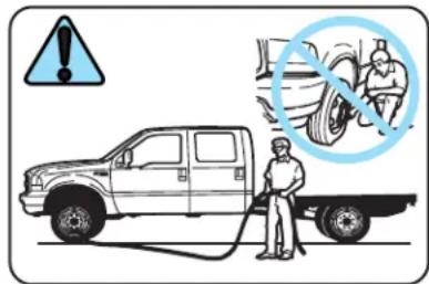
text_image
Diagram showing a truck being charged with an explosion warning, alongside a photo of a mechanic working on a tire.
WARNING An inflated tire and rim can be very dangerous if improperly used, serviced or maintained. To avoid serious injury, never attempt to re-inflate a tire which has been run flat or seriously under-inflated without first removing the tire from the wheel assembly for inspection. Do not attempt to add air to tires or replace tires or wheels without first taking precautions to protect persons and property.
Tire rotation
Because your vehicle's tires perform different jobs, they often wear differently. To make sure your tires wear evenly and last longer, rotate them as indicated in the scheduled maintenance guide. If you notice that the tires wear unevenly, have them checked.
Your front tires should be rotated from side to side. If the spare tire is used in the rotation, the pattern should be; left front to right front; right front to the spare and the spare to left front.
Donotrotatethedualtires.
Maintenance and specifications
Replacing the tires
Replace the tires when the wear band is visible through the tire treads.

natural_image
Diagram of a tire cross-section showing concentric rings with hatched patterns and an arrow indicating direction (no text or symbols)When replacing full size tires, never mix radial bias-belted, or bias-type tires. Use only the tire sizes that are listed on the Certification Label. Make sure that all tires are the same size, speed rating, and load-carrying capacity. Use only the tire combinations recommended on the label. If you do not follow these precautions, your vehicle may not drive properly and safely.
Make sure that all replacement tires are of the same size, type, load-carrying capacity and tread design (e.g., "All Terrain", "Touring", etc.), as originally offered by Ford.
Failure to follow these precautions may adversely affect the handling of the vehicle, and increase the risk of loss of vehicle control, vehicle rollover and/or personal injury.
Tires that are larger or smaller than your vehicle's original tires may also affect the accuracy of your speedometer. The tires on your vehicle have been match mounted to the original equipment wheels. Replacement tires should be mounted so that the match mount mark on the tire aligns with the small dimple in the face of the wheel rim.
SNOW TIRES AND CHAINS
Snow tires must be the same size and grade as the tires you currently have on your vehicle.
The tires on your vehicle have all weather treads to provide traction in rain and snow. However, in some climates, you may need to use snow tires and chains. If you need to use chains, it is recommended that steel wheels (of the same size and specifications) be used, as chains may chip aluminum wheels.
Maintenance and specifications
Follow these guidelines when using snow tires and chains:
- Use only SAE Class S chains.
- Install chains securely, verifying that the chains do not touch any wiring, brake lines or fuel lines.
- Drive cautiously. If you hear the chains rub or bang against your vehicle, stop and re-tighten the chains. If this does not work, remove the chains to prevent damage to your vehicle.
- If possible, avoid fully loading your vehicle.
- Remove the tire chains when they are no longer needed. Do not use tire chains on dry roads.
- The suspension insulation and bumpers will help prevent vehicle damage. Do not remove these components from your vehicle when using snow tires and chains.
MOTORCRAFT PART NUMBERS
| Component6.8LV10engine | |
| Air filter element FA-1634 | |
| Battery BXT-65-750 | |
| Fuel filter FG-986B | |
| Oil filter FL-820-S | |
| PCV valve EV-233 | |
| Spark plugs* AWSF-22E |
*Refer to Vehicle Emissions Control Information (VECI) decal for spark plug gap information.
Maintenance and specifications
REFILL CAPACITIES
| FluidFordPart | Name | ApplicationCapacity | |
| Brake fluid Motorcraft High Performance DOT 3 Motor Vehicle Brake Fluid | All Fill to line on | reservoir | |
| Engine oil (includes filter change) | Motorcraft SAE 5W-20 Premium Synthetic Blend Motor Oil | All 5.7L | (6.0 quarts) |
| Engine coolant^1 | Motorcraft Premium Engine Coolant (green-colored) orMotorcraft Premium Gold Engine Coolant (yellow-colored) | All 29.0L | (30.6 quarts) |
| Power steering fluid | Motorcraft MERCON®ATF | All Keep in FULL | range on dispstick |
| Rear axle^2 | Motorcraft SAE 75W-90 Rear Axle Lubricant | Dana 80 3.9L | (4.0 quarts) ^3 |
| Motorcraft SAE 80W-90 Synthetic Rear Axle Lubricant | Dana 135 and Dana 145 | 11.7L (12.0 quarts) ^3 | |
| Fuel tank N/A All | 284.0L | (75.0 gallons) | |
| Transmission^4 | Motorcraft MERCON®ATF | All 16.8L | (17.7 quarts) ^5 |
Maintenance and specifications
Your vehicle's rear axle is filled with a synthetic rear axle lubricant and is considered lubricated for life. These lubricants do not need to be checked or changed unless a leak is suspected, service is required or the axle assembly has been submerged in water. The axle lubricant should be changed any time the rear axle has been submerged in water.
^1 Add the coolant type originally equipped in your vehicle.
^2 Fill 6 mm to 14 mm (1/4 inch to 9/16 inch) below bottom of fill hole.
^3 Fill Dana rear axles to 6 mm to 14 mm (1/4 inch to 9/16 inch) below bottom of fill hole.
^4 Ensure the correct automatic transmission fluid is used. Transmission fluid requirements are indicated on the dipstick or on the dipstick handle. Check the container to verify the fluid being added is of the correct type. Refer to your scheduled maintenance guide to determine the correct service interval.
Some transmission fluids may be labeled as dual usage, such as MERCON® and MERCON®V. These dual usage fluids are not to be used in an automatic transmission that requires use of the MERCON® type fluid. However, these dual usage fluids may be used in transmissions that require the MERCON®V type fluid.
MERCON® and MERCON® V typefluids are not interchangeable. DONOTmix MERCON® and MERCON® V. Use of fatransmission fluid that indicates dual usage (MERCON® and MERCON® V) in an automatic transmission application requiring MERCON® may cause transmission damage. Use of any fluid other than the recommended fluid may cause transmission damage.
^5 Indicates only approximate dry-fill capacity. Some applications may vary based on cooler size and if equipped with in-tank cooler. The amount of transmission fluid and fluid level should be set by the indication on the dipstick's normal operating range.
Maintenance and specifications
LUBRICANT SPECIFICATIONS
| ItemFordpart | name | Fordpart number | Ford specification |
| Brake fluid Motorcraft High Performance DOT 3 Motor Vehicle Brake Fluid | PM-1 ESA-M6C25-A and DOT 3 | ||
| Engine coolant Motorcraft Premium Engine Coolant (green-colored) | VC-4-A (in Canada, Motorcraft CXC-10) | ESE-M97B44-A | |
| VC-7-A WSS-M97B51-A1 | |||
| Engine oil Motorcraft SAE 5W-20 Premium Synthetic Blend Motor Oil | XO-5W20-QSP WSS-M2C153-H with API Certification Mark | ||
| Automatic transmission (4R100) ^1 | Motorcraft MERCON® ATF | XT-2-QDX MERCON® | |
| Power steering fluid | Motorcraft MERCON® ATF | XT-2-QDX MERCON® | |
| Parking brake assembly | Motorcraft MERCON® | XT-2-QDX MERCON® | |
| Dana 80 Axlc Motorcraft SAE 75W-90 Synthetic Rear Axle Lubricant | XY-75W90-GLS — | ||
| Dana 135 Axlc Motorcraft SAE 80W-90 Rear Axle Lubricant | XY-80W90-QL WSL-M2C197-A | ||
Maintenance and specifications
^1 Ensure the correct automatic transmission fluid is used. Transmission fluid requirements are indicated on the dipstick or on the dipstick handle. Check the container to verify the fluid being added is of the correct type. Refer to your scheduled maintenance guide to determine the correct service interval.
Some transmission fluids may be labeled as dual usage, such as MERCON® and MERCON®V. These dual usage fluids are not to be used in an automatic transmission that requires use of the MERCON® type fluid. However, these dual usage fluids may be used in transmissions that require the MERCON®V type fluid.
MERCON® and MERCON® V typefluids are not interchangeable. DONOTmix MERCON® and MERCON® V. Use of transmission fluid that indicates dual usage (MERCON® and MERCON® V) in an automatic transmission application requiring MERCON® may cause transmission damage. Use of any fluid other than the recommended fluid may cause transmission damage.
ENGINE DATA
| Engine6.8LV10engine | |
| Cubic inches 415 | |
| Required fuel 87 octane | |
| Firing order 1-6-5-10-2-7-3-8-4-9 | |
| Spark plug gap 1.3-1.4 mm (0.052-0.056 inch) | |
| Ignition system Coil on plug | |
| Compression ratio 9.0:1 | |
IDENTIFYING YOUR VEHICLE
Certification label for incomplete vehicles
On completed derivations of incomplete vehicles, the certification label is affixed at a location determined by a subsequent stage manufacturer of the completed vehicle. In these cases the completed vehicle is manufactured in two or more stages by two or more separate manufacturers.
Vehicle Identification Number
The vehicle identification number is attached to a metal tag and is located on the front firewall to the right of the air filter.
If you ever find it necessary to communicate with Ford Motor Company about your vehicle, always include the VIN in your communication.
Reporting safety defects (U.S. only)
REPORTING SAFETY DEFECTS (U.S. ONLY)
If you believe that your vehicle has a defect which could cause a crash or could cause injury or death, you
Ford Motor Company
should immediately inform the National Highway Traffic Safety Administration (NHTSA) in addition to notifying Ford Motor Company.
If NHTSA receives similar complaints, it may open an investigation, and if it finds that a safety defect exists in a group of vehicles, it may order a recall and remedy campaign. However, NHTSA cannot become involved in individual problems between you, your dealer, or Ford Motor Company.
To contact NHTSA, you may either call the Auto Safety Hotline toll-free at 1-800-424-9393 (or 366-0123 in the Washington D.C. area) or write to:
NHTSA
U.S. Department of Transportation Washington, D.C. 20590
You can also obtain other information about motor vehicle safety from the Hotline.
Index
A
ABS (see Brakes) 24
Air cleaner filter 83, 88
Ambulance packages ....5
Antifreeze (see
Engine coolant) ....61
Anti-lock brake system
(see Brakes) 24
Automatic transmission
driving an automatic
overdrive 28
fluid, adding 81
fluid, checking 81
fluid, refill capacities .....89
fluid, specification .....92
Axle
lubricant specifications .....91–92
refill capacities 89
B
Battery 59
acid, treating emergencies .....59
jumping a disabled battery .....48
maintenance-free 59
replacement, specifications .....88
servicing 59
Brakes 23, 25
anti-lock 24
anti-lock brake system
(ABS) warning light 25
fluid, checking and adding .....79
fluid, refill capacities .....89
fluid, specifications .....91–92
lubricant specifications .....91–92
shift interlock 27
Bulbs 15
C
Calculating load ....32
Capacities for refilling fluids .....89
Changing a tire 45
Cleaning your vehicle
engine compartment ....54
wheels 54
Coolant
checking and adding 61
refill capacities 65, 89
specifications .....91–92
Cruise control
(see Speed control) .....17
D
Daytime running lamps
(see Lamps) 14
Dipstick
automatic transmission fluid ...81
engine oil 57
Doors
lubricant specifications .....91
Driveline universal joint
and slip yoke 82
Driving under special
conditions ....30
through water 30
E
Emergencies, roadside
jump-starting 48
Emission control system .....76
Engine 92
cleaning 54
coolant 61
fail-safe coolant ....66
idle speed control ....59
lubrication specifications ...91–92
refill capacities 89
service points ....56
starting after a collision .....36
Index
Engine block heater ....23
Engine oil 57
checking and adding ....57
dipstick 57
filter, specifications .....58, 88
recommendations ....58
refill capacities 89
specifications 91-92
Exhaust fumes ......23
F
Fail safe cooling ....66
Fluid capacities 89
Fuel 67
calculating fuel economy .....73
capacity 89
choosing the right fuel .....69
comparisons with EPA fuel
economy estimates 76
detergent in fuel 70
filling your vehicle
with fuel 67, 73
filter, specifications .....71, 88
fuel pump shut-off switch .....36
improving fuel economy .....73
octane rating 69, 92
quality 70
running out of fuel 70
safety information relating to
automotive fuels 67
Fuses 38
G
Gas mileage (see
Fuel economy)....73
Gauges 11
GAWR (Gross Axle
Weight Rating) ....31
calculating 32
definition 31
driving with a heavy load .....31
location 31
GVWR (Gross Vehicle
Weight Rating) 31
calculating 31-32
definition 31
driving with a heavy load .....31
location 31
H
Hazard flashers ....36
Headlamps 14
daytime running lights .....14
flash to pass 15
high beam 14
turning on and off ....14
I
Ignition 20,92
Inspection/maintenance
(I/M) testing 77
Instrument panel
cluster 8
lighting up panel and
interior 15
J
Jack 45
positioning 45
storage 45
Jump-starting your vehicle .....48
K
Keys
positions of the ignition .....20
L
Lamps
cargo lamps ....15
Index
daytime running light .....14
headlamps 14
headlamps, flash to pass .....15
instrument panel, dimming .....15
replacing bulbs ....15
Lights, warning and indicator .....8
anti-lock brakes (ABS) .....25
Load limits 31
GAWR 31
GVWR 31
trailer towing 31
Lubricant specifications .....91–92
M
Motorcraft parts .....71, 88
0
Octane rating 69
Oil (see Engine oil) 57
P
Parking brake 26
Parts (see Motorcraft parts) .....88
Power distribution box (see Fuses) 41
Power steering fluid, checking and adding .....78 fluid, refill capacity .....89 fluid, specifications .....91–92
R
Relays 38,44
S
Safety defects, reporting .....93
Servicing your vehicle .....55
Spark plugs, specifications ...88, 92
Special notice 5, 53
Specification chart, lubricants ....91–92
Speed control ....17
Starting your vehicle ....20–22 jump starting ....48
Steering wheel tilting ....16
T
Tires 45, 84–86
changing 45
replacing 46,87
rotating 86
snow tires and chains .....87
tire grades 85
treadwear 84
Towing 33
trailer towing ....33
wrecker 52
Transmission 27
fluid, checking and adding (automatic) ....81 fluid, refill capacities ....89 lubricant specifications .....91–92
V
Vehicle Identification Number (VIN) 92
Vehicle loading ....31
Ventilating your vehicle .....23
W
Warning lights (see Lights) .....8
Water, Driving through .....30
Windshield washer fluid and wipers 16
Wrecker towing ....52