
M75-4 - Receiver Sound Ordnance - Free user manual and instructions
Find the device manual for free M75-4 Sound Ordnance in PDF.


| Product Type | Car Audio Amplifier (Receiver) |
| Model | M75-4 |
| Brand | Sound Ordnance |
| Number of Channels | 4 |
| Power Output (RMS) @ 4 ohms | 4 x 75 W |
| Power Output (RMS) @ 2 ohms | 4 x 110 W |
| Power Output (RMS) Bridged @ 4 ohms | 2 x 160 W |
| Total Maximum Power | 440 W |
| Frequency Response | 20 Hz – 20,000 Hz |
| Signal-to-Noise Ratio | > 100 dB |
| High-Pass Crossover | 50 Hz – 750 Hz (adjustable) |
| Low-Pass Crossover | 50 Hz – 750 Hz (adjustable) |
| Bass EQ | 0 – 12 dB boost @ 45 Hz |
| Input Type | RCA |
| Power Supply | 12 V DC (negative ground) |
| Dimensions (W x H x D) | 179 x 44 x 120 mm (7.05 x 1.73 x 4.73 in) |
| Protection Indicators | Power LED and Protect LED |
| Installation Location | Car trunk, under seats, or bulkhead (dry, ventilated) |
| Recommended Fuse | External fuse near battery (not included) |
| Warranty | Void if safety instructions not followed |
Frequently Asked Questions - M75-4 Sound Ordnance
User questions about M75-4 Sound Ordnance
0 question about this device. Answer the ones you know or ask your own.
Ask a new question about this device
Download the instructions for your Receiver in PDF format for free! Find your manual M75-4 - Sound Ordnance and take your electronic device back in hand. On this page are published all the documents necessary for the use of your device. M75-4 by Sound Ordnance.
USER MANUAL M75-4 Sound Ordnance
Thank you for purchasing Sound Ordnance
You're now ready to win the battle for great sound.

To ensure safe operation, always follow the instructions and guidelines in this manual.
Keep this manual handy for reference.
www.soundordnance.com
All rights reserved.
TABLE OF CONTENTS
Overview of Connections and Controls 4
Intended Use 4
Safety Instructions 5
Setup and Installation 6
Power Connections 8
Connecting the Inputs 8
Connecting the Speaker Outputs 10
Operation 12
Initial Startup 13
Safe Operation Guidelines 14
Maintenance 14
Troubleshooting 15
Technical Specifications 18
OVERVIEW OF CONNECTIONS AND CONTROLS
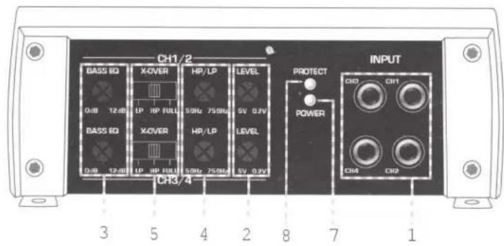
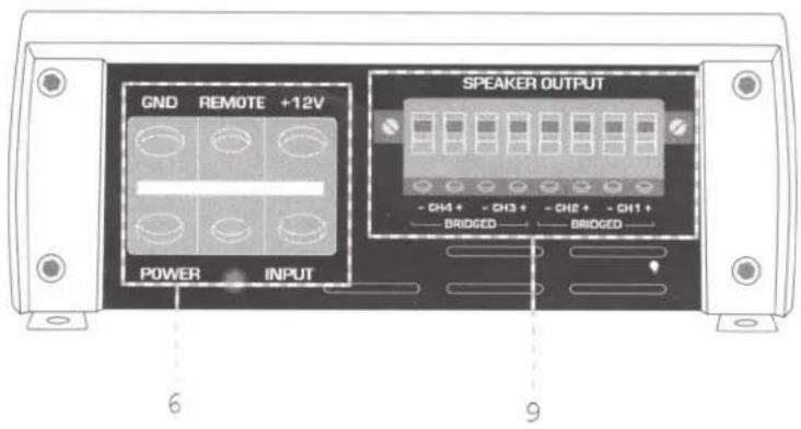
1) RCA connections INPUT
2) LEVEL control
3) BASS EQ
4) HP/LP filter
(high-pass/low-pass filter)
5) X-over switch
6) Power Input
7) Power Indicator
8) Protect Indicator
9) Speaker Output
INTENDED USE
Sound Ordnance amplifiers are to be used for the amplification of low level audio signals in vehicles. This product is designed for operation with a 12V DC car power supply with the negative terminal of the battery grounded to the vehicle's body. It should only be installed and operated in passenger cars and trucks provided with this kind of power source. The amplifier is not designed for marine applications.
Any use other than that described above can lead to damage to this product and can involve other risks such as short circuit, fire, or electric shock, which may damage the product or cause bodily injury. The amplifier should not be changed or modified in any way. Do not open the housing.
SAFETY INSTRUCTIONS

The product's warranty is rendered void in cases of damage resulting from failure to comply with safety and operating instructions. We do not accept any liability for consequential damages. We do not accept any liability for personal injury or damage to property caused by incorrect handling of the device or failure to observe the safety and operating instructions. In such cases the warranty is rendered void.
An exclamation mark in a triangle indicates important information in these operating instructions which must be strictly followed. Please read the complete operating instructions before installation and use.
- For safety reasons, do not attempt to modify the amplifier.
- Only a 12V DC car supply system (negative ground) should be used. Never connect the amplifier to any other voltage supply.
- Extra care should be taken when first turning on the amplifier after installation. Please follow the operating instructions carefully.
- Keep water and other liquids away from the vicinity of the amp. This could result in a fire or a fatal electrical shock. If liquids get into the amplifier, immediately disconnect the power to the amplifier.
-
Do not expose the amplifier to high temperatures, strong vibrations or heavy loads.
-
Keep open flames away from the amplifier.
- Call 1-800-955-9094 if you have questions about how the equipment operates or about how to connect it safely.
- Do not leave packaging material unattended around children.
- Observe the safety and operating instructions of this amplifier and any other devices connected to the amplifier.
- Exposure to high volume levels can cause hearing damage or loss. Use care and caution when setting volume levels.
SETUP AND INSTALLATION

To ensure proper operation, please read these instructions carefully before installing and using this amplifier.
Modifications to the vehicle required by installation of the amplifier or other components should always be done in a way that does not affect the road safety or the designed stability of the car. If you are in doubt when selecting a place for installation, consult your local car dealership.
Since the amplifier generates heat, be sure to install in a heat-resistant location. There must also be an open area of 1/4" around the amplifier's housing for adequate ventilation. Air circulation may not be obstructed by objects such as magazines, blankets, maps, etc.
Before drilling any holes in your car, make sure that electric cables, brake lines, fuel tank or similar systems will not be damaged.
When installing the car audio components, consider the danger of parts breaking loose during an accident. Make sure each component of your system is fastened tightly, and located at a place where it cannot become a risk for passengers in the event of an accident.
Select a suitable position for mounting the amplifier. A suitable place for mounting has the following features:
• dry
• as free from dust as possible
- minimal vibration
• good air circulation
- heat-resistant environment

Good places for installation are the car trunk or the free space under the seats. Another good place for installation is the bulkhead between the trunk and the passenger compartment. Make sure that the amplifier is accessible after installation so you can access the controls.
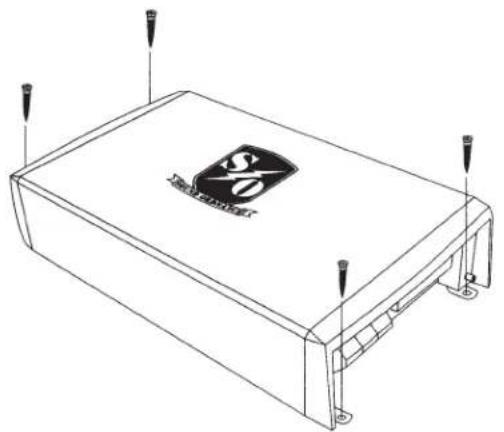
- Mark the holes for the screws at the place of installation. The simplest way to do this is place the amp where you want it and use it as a pattern.
- Drill the holes for the fastening screws.
- Secure the amplifier with sheet metal screws.

To avoid short circuits and resulting damages to your amplifier, you must disconnect the negative terminal (ground) of the car battery first. Before reconnecting the negative terminal to the battery, make sure that the amplifier has been completely connected. For some newer cars, this may require a service call to reset some functions. Check with your car dealer.
You should only use a digital voltmeter or a diode test lamp for checking the voltage present at car cables. A normal test lamp draws too much current and can damage the electronic system of the car.
Make sure that the connection cables are not damaged by sharp edges. Use rubber bushings for points passing through metal. Call us at 1-800-955-9094 if you have questions during setup.
Use heavy-gauge cable for connecting the power supply and the ground of the amplifier. The gauge of the cable depends on the power requirements of the components connected. If the gauge is too light, the cable could burn. Moreover, the increased resistance can lead to unnecessary power losses.
An additional fuse in the amp's positive connection is necessary (fuse and fuse holder not included.) The fuse should be installed close to the battery. In case of short circuit (e.g. if the connection cable is worn through), this fuse disconnects the
positive lead and thus avoids damage to the battery and prevents the supply cable from burning.
The amperage rating of the fuse depends on the power consumption of the connected devices of the car audio system.
In order to reduce interference or noise in the system, the amplifier should be directly powered by the car battery. Do not supply other electric loads, such as the cooling fan, windshield washer etc., via the same cable as the amplifier.
POWER CONNECTIONS
Connect the "+12V" connector of the power supply's terminal directly to the car battery's positive terminal
Connect the "REMOTE" or "REM" connector to the terminal on the power supply, to the remote control connector, or to the antenna control output of the car's radio. The amplifier will be switched on via this input when +12V current is applied. Almost all car radios have an output which provides a +12V current when the radio is turned on.
Connect the "GND" connector of the power supply to the car body. Note: Since electrical conductivity is limited by the use of glue and paint
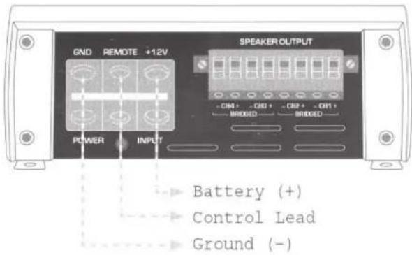
on metal parts, not every metal component is suitable to function as a grounding point.

Distribute the power supply in a star-shaped way, i.e. the connections of the negative leads start from the same point for all components in the car's audio system. This method of distribution avoids ground loops and interference. Connect the positive leads in the same way.
CONNECTING THE INPUTS
ALL MODELS These amplifiers use RCA inputs for connection to your car stereo's preamp outputs. Car radios with RCA outputs can be directly connected to the input sockets. If your car radio only has speaker outputs, you can use an optional adapter or line output converter to make the connection.
4-CHANNEL MODELS
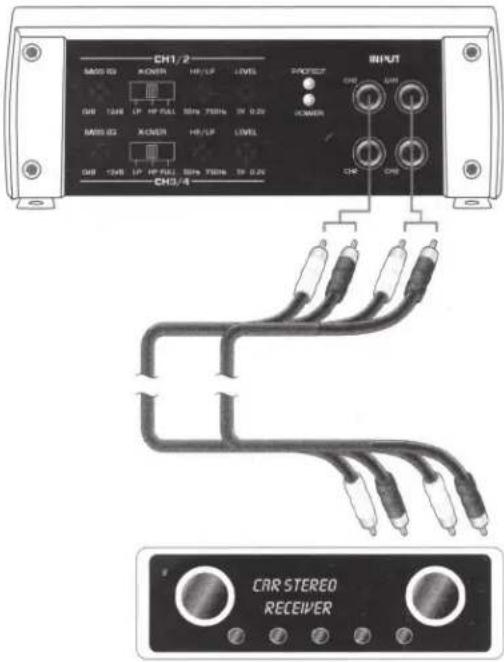
Connect the RCA outputs of your car radio to the RCA connections INPUT (1) of the amplifier.
Front car stereo outputs > connect to amplifier Channels 1 and 2
Rear car stereo outputs > connect to amplifier Channels 3 and 4
Pay attention to the marking on the RCA connections:
L > left
R > right
If your car radio does not have 4 preamp outputs, use an optional Y-adapter. You will not be able to fade signal front to back when connected in this way.
2-CHANNEL AND MONO AMPS
Connect the RCA outputs of your car radio to the RCA connections INPUT (1) of the amplifier.
Pay attention to the marking on the RCA connections:
L > left
R > right
Keep the length of the connection cables as short as possible.
Do not install the RCA cables close to other cables to avoid interference at the amplifier input.
Please note the connection loads in the Technical Specifications.
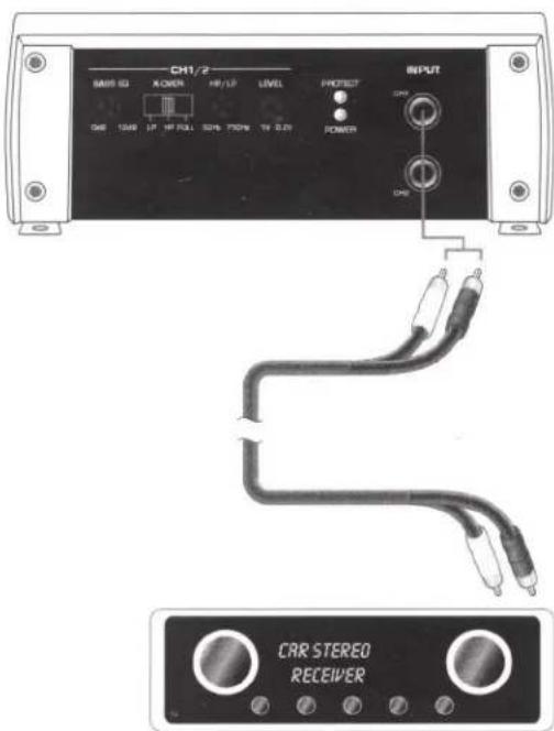

When connecting the RCA inputs, use only shielded RCA cables suitable for this purpose. The use of any other type of cable may cause interference.
CONNECTING THE SPEAKER OUTPUTS
Depending on your model, Sound Ordnance amplifiers have outputs for four speakers, two speakers, or one speaker.
You can bridge the 2-channel amplifier to mono mode to power a single speaker, or the 4-channel amp to 2-channel mode to power a pair of speakers. You'll get more power by bridging the amp.
Strip the insulation from the cables on the ends. Make sure that there are no sharp edges which may damage the cables. Only use speakers whose power handling matches the amp's output (see Technical Specifications).
Always connect the speakers with the correct polarity.
Speaker wires are usually coded. Some loudspeaker manufacturers indicate the (+) wire by means of an additional color stripe, others use a corrugated cable for the (+) terminal and a smooth one for the (-) terminal.
Sound Ordnance amplifiers have been designed for a loudspeaker impedance of at least 2 ohms (in standard operating mode) or 4 ohms (in bridged mode). Never connect speakers with a lower impedance.
Depending on the model and mode of operation, connect the loudspeaker outputs according to the following schemes. Observe the minimum impedance given for the corresponding mode of operation.
MODEL M75-4
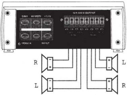
Stereo Mode - 2 ohm minimum impedance
MODEL M75-4
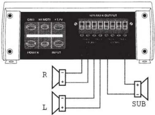
Stereo/Bridged Mode - 4 ohm minimum impedance bridged
MODEL M75-4
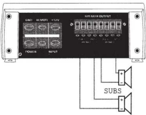
Bridged Mode - 4 ohm minimum impedance
MODEL M100-2
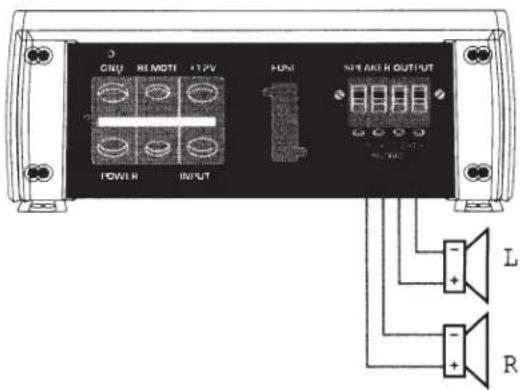
Stereo Mode - 2 ohm minimum impedance
MODEL M100-2
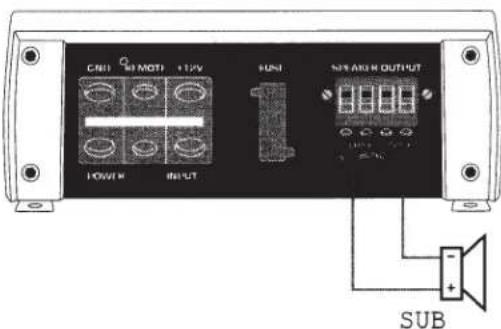
Bridged Mode - 4 ohm minimum impedance
MODEL M350-1
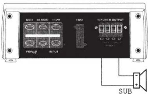
2 ohm minimum impedance
OPERATION
Active Crossover
M75-4
This amplifier is provided with active crossovers which let you switch to a high-pass or a low-pass filter for the front and rear channels. The cut-off frequencies can be continuously adjusted; each crossover operates independently, so one can be set high and the other low or both can be high or low.
M100-2
This amplifier is provided with an active crossover which lets you switch to a high-pass or low-pass filter for the two channels. The cut-off frequencies can be continuously adjusted.
M350-1
This amplifier is provided with a low-pass filter for the output. The cut-off frequency can be continuously adjusted.
FULL:
Crossover switched off, the amplifier plays back the complete frequency range.
HP:
High-pass crossover switched on, the amplifier only plays back the frequency range above the frequency set via the HP (4) control unit.
LP:
Low-pass crossover switched on, the amplifier only plays back the frequency range below the frequency set via the LP control unit (4).
Bass EQ
The amplifier has a bass EQ adjustment to emphasize the low-bass frequencies. This option can give smaller bass loudspeakers or subwoofers a little more volume in the low-bass range.
The BASS EQ (3) controls the low-bass amplification. The Bass EQ's range is from 0 to 12dB for the M100-2 and M75-4 models and 0-18 dB for the M350-1.
INITIAL STARTUP
After you have checked the cable connections, reconnect the negative terminal of the battery.
Turn the LEVEL control unit (2) counterclockwise to minimum.
Slide the frequency crossover switch X-OVER (5) into the position corresponding to your configuration.
Set the cut-off frequencies for the connected loudspeakers via the HP/LP control unit (4).
(see "Active Crossover")
The cut-off frequencies can be set continuously within their specified ranges.
During setup, pay attention to the frequency range of the speakers.
Switch on your car receiver and play some music.
If the indicator POWER LED (7) lights up, set the volume of the car radio to about 75% of the maximum volume.
Now, use the LEVEL control (2) to adjust the maximum volume of the loudspeakers to a level that is comfortable for you and does not distort the music. If you use several amplifiers, match the volumes of the different amplifiers one to the other.
Then, set an average volume level via the volume control unit of the car radio.
If the low-bass playback is too weak, you can activate a low-bass boost via the BASS EQ control (3).
If the indicator PROTECT LED (8) lights, an error has occurred. The amplifier should be switched off immediately. Check all connections and loudspeakers. If you cannot detect an error, please call us at 1-800-955-9094 for help.
Take care that the maximum volume is within the power capacities of the speakers and amplifier. Excessive volume can damage the speakers and amplifier.
Make sure that the frequency ranges of the speakers aren't exceeded during this process.
If you use a subwoofer, changing polarity may improve the sound quality. Often reversing the terminal connections result in better bass (depending on the location of the subwoofer).
- Excessive volume inside the car can drown out emergency vehicle sirens and other external audio warnings. This can put you and other motorists in danger. For auto safety, keep the volume at a reasonable level.
- Inattentiveness in traffic can lead to serious accidents. Make sure your car's audio system doesn't pull your attention away from the road.
- The amplifier must be ventilated sufficiently.
- Do not listen to excessively loud music for long periods of time. This can damage your hearing and lead to permanent hearing loss.
- Observe local laws and noise ordinances when using this equipment.
MAINTENANCE
Check the amplifier regularly for damage to the connection cables or to the housing.
If the amplifier is in such a condition that it can no longer be operated safely, it should be turned off. Make sure the amp is disconnected from the power system.
You should no longer use the amplifier if:
- there is visible damage on the amplifier
- the amplifier does not function for some reason, or
- the amplifier has been subjected to considerable stress during shipment.

Circuitry that carries electric current may be exposed if the amp's cover is opened or components are removed. The amplifier must be disconnected from all voltage sources before carrying out servicing or repair works.
Remember that capacitors in the amplifier may retain an electric charge even after disconnecting them from all power sources. Repair work should always be carried out by Sound Ordnance.
If you have to replace fuses, make sure you only use fuses of the same type and rated current (see "Technical Specifications"). Do not attempt to repair fuses or bypass the fuse holder.
After disconnecting the amplifier from the power source, carefully remove the fuse from the fuse holder and replace only with a fuse of the same type.
TROUBLESHOOTING
In purchasing a Sound Ordnance amplifier you have acquired a quality product which has been designed to deliver years of service.
Problems and malfunctions may, however arise. Here are some common problems that you can repair yourself.
Problem
No function, the POWER LED (7) does not light up:
Solution
- The GND connection is not connected to the car body.
- The REMOTE or REM connection is not connected to the REM output or the antenna control output of the car radio.
- +12V current is not applied at the +12V connection.
- The amplifier's fuse or the fuse in the amp wiring is defective.
| The POWER LED (7) lights, but there's no sound: | · The volume control unit of the car radio is set to minimum.· The LEVEL control unit (2) of the amplifier is set to minimum.· The speakers are not properly connected. |
| The PROTECT LED (8) lights, and there's no sound: | · The short-circuit protection of the amplifier has been triggered due to a short circuit at the speaker output.· The temperature protection of the amplifier has been triggered due to overheating. Allow the device to cool down. |
| One channel does not function: | · Check the RCA connections INPUT (1):· Check the connection of the speakers at the terminals and at the speakers.· The balance control at the car radio is not set to the center position. |
| Static or unwanted noise: | · Bad ground connection of the ground cable. Remove rust or paint from the contact surfaces.· The ground point of the car radio and the amplifier aren't at the same potential. Try different ground points.· The cables of the amplifier are positioned too close to the cables for the ignition system of the vehicle.· The ignition system is not shielded.· The cables of the amplifier input are positioned too close to the power cables. |
The device turns on and off during operation:
- Bad ground contact of the ground connection cable, the ground point of the cable or of the battery terminal is corroded.
- Voltage too low at the +12V connection of the power supply's connection terminal, the ground point of a cable or corroded battery terminal, battery too weak.
- Intermittent contact at the REMOTE cable, REMOTE or REM connection of the power supply's connection terminal.
There's no bass:
• One speaker is connected with the wrong polarity.
- The bass control unit of the car radio is set to minimum.
- The active crossover is not set correctly.
There's no midrange or highs:
- The active crossover is not set correctly.
- The high-range control unit of the car radio is set to minimum.

Repairs other than those just described should only be performed by Sound Ordnance.
Always follow safety instructions!
TECHNICAL SPECIFICATIONS
| M100-2 | M75-4 | M350-1 | |
| Total maximum power | 280 W | 440 W | 350 W |
| Output power into 4 ohms (RMS) | 2x110 W | 4x75 W | 1x290 W |
| Output power into 2 ohms (RMS) | 2x140 W | 4x110 W | 1x350 W |
| Output power into 4 ohms, bridged (RMS) | 1x200 W | 2x160W | n/a |
| S/N ratio | >100 dB | >100 dB | >100 dB |
| Frequency Response | 20-20000 Hz | 20-20000 Hz | 20-20000 Hz |
| HP Crossover Frequency | 50Hz-750Hz | 50Hz-750Hz | n/a |
| LP Crossover Frequency | 50Hz-750Hz | 50Hz-750Hz | 35Hz-150Hz |
| Subsonic Filter | n/a | n/a | 15Hz-55Hz |
| Bass EQ | 0-12dB@45Hz | 0-12dB@45Hz | 0-18dB@45Hz |
| DimensionsW x H x D mm (inches) | 179x44x120(7.05x1.73x4.73) | 179x44x120(7.05x1.73x4.73) | 179x44x120(7.05x1.73x4.73) |

To ensure safe operation, always follow the instructions and guidelines in this manual.
Keep this manual handy for reference.
www.soundordnance.com
All rights reserved.


- THANK YOU FOR PURCHASING SOUND ORDNANCE
- TABLE OF CONTENTS
- OVERVIEW OF CONNECTIONS AND CONTROLS
- INTENDED USE
- SAFETY INSTRUCTIONS
- SETUP AND INSTALLATION
- POWER CONNECTIONS
- CONNECTING THE INPUTS
- 4-CHANNEL MODELS
- 2-CHANNEL AND MONO AMPS
- CONNECTING THE SPEAKER OUTPUTS
- OPERATION
- ACTIVE CROSSOVER
- M75-4
- M100-2
- M350-1
- FULL
- HP
- LP
- BASS EQ
- INITIAL STARTUP
- MAINTENANCE
- TROUBLESHOOTING
- PROBLEM
- SOLUTION
- TECHNICAL SPECIFICATIONS
Brand : Sound Ordnance
Model : M75-4
Category : Receiver