PTS1 - Radio NavAtlas - Free user manual and instructions
Find the device manual for free PTS1 NavAtlas in PDF.


User questions about PTS1 NavAtlas
0 question about this device. Answer the ones you know or ask your own.
Ask a new question about this device
Download the instructions for your Radio in PDF format for free! Find your manual PTS1 - NavAtlas and take your electronic device back in hand. On this page are published all the documents necessary for the use of your device. PTS1 by NavAtlas.
USER MANUAL PTS1 NavAtlas
natural_image
Three electronic components: a black USB drive case labeled 'PTS1', a metallic circular button with red ring, and a gray USB chip with engraved text (no readable text or symbols beyond labels)INSTALLATION / OWNER'S MANUAL
PTS1 Smart Key
Smartest way to start your UTV/ATV Push-to-Start keyless System for your UTV/ATV makes starting you vehicle safe and convenient
NavAtlas™
Contents
- Product and its accessory
- How to start the engine and use Fob Key
- How to Register Fob and cancel Fob key
- Wire Connection/Installation
- How to change the battery of Fob Key
1. Product and its Accessory
PDM Module & Wire harness
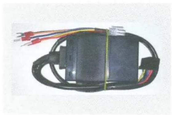
natural_image
Black electrical component with coiled wires and red connectors, no visible text or symbolsSSB Asss'y
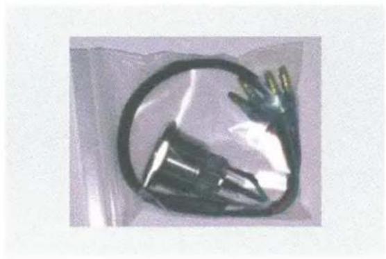
natural_image
Close-up of a black plastic electrical plug wrapped in a transparent plastic bag (no text or symbols visible)FOB(2EA)
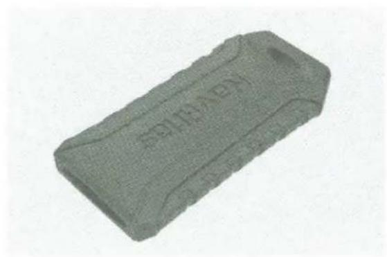
natural_image
3D rendered image of a rectangular eraser with embossed markings (no readable text or symbols)Controller
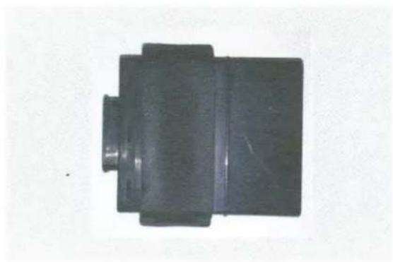
natural_image
Top-down view of a black mechanical component with a small protrusion (no visible text or symbols)2. How to start the engine and use Smart Key
1. How to start engine
When SSB is pressed more than 1 seconds with the FOB in range of the receiver, engine will turn on or off.
2. ACC ON/OFF
Once SSB button is pressed down less than 1 second, ACC will turn on/off. (If you push down SSB button more than 1 second while ACC is on, engine will start at that moment and SSB will turn off)
3. How to stop engine
Once you push down SSB more than 2 seconds, SSB is powered off and engine start will stop. (Normally it is not possible to stop the engine because SSB operation and FOB search will not work when the vehicle is in drive mode. To stop engine, SSB operation and FOB search should be available when the vehicle is in parking mode.) (However, in UTV/ATV vehicles, the parking signal cannot be generated, so pressing down SSB button more than 2 seconds means that you are going to stop the engine.)
4. How to stop starting in Emergency
When Fob is not available or is broken suddenly while engine is starting, pushing SSB button for more than 5 seconds will force to turn off start power of engine.
PTS1 Smart Key
3. How to Register/ Remove an FOB
How to Register Fob key
1) Remove control module case and cover, and connect the power.
2) Place the Fob near module(antenna).
3) Press reset button in the module.
4) Registration is completed when you hear 'Be-be-beep' sound.
How to Remove Fob key
1) Remove control module case and cover, and connect the power.
2) Press reset button in the module for about 3 seconds. Press start button(SSB) when you hear 'Be-Beep' sound.
3) Release will be completed when you hear ' Be-be-be-be-beep-be-be-
4. Wiring connection
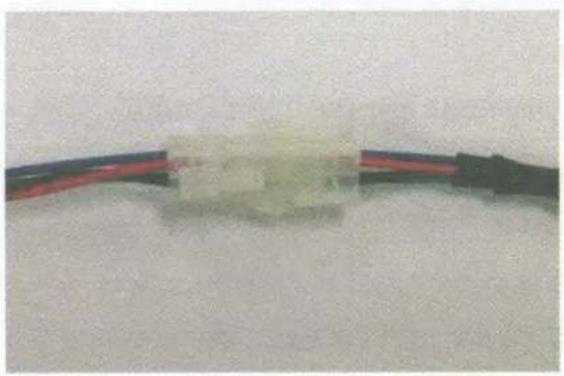
* Please refer to the pictures.
- Connect SSB/PDM module wires to same colored connecting wires of control module.
natural_image
Close-up of a thin, flexible electronic component with two black wires attached (no visible text or symbols)* Make sure to match wire to wire with same colors. Otherwise, it may cause the damage to the product.
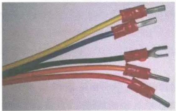
- Connect PDM module wires to same colored connecting wires of UTV/ATV.
natural_image
Close-up of multiple colored electrical wires with copper contacts and terminal leads (no text or symbols visible)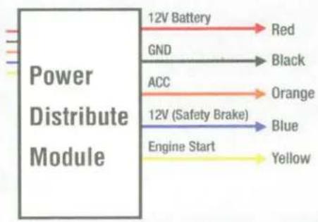
flowchart
graph LR
    A["Power Distribute Module"] --> B["12V Battery"]
    A --> C["GND"]
    A --> D["ACC"]
    A --> E["12V (Safety Brake)"]
    A --> F["Engine Start"]
    B --> G["Red"]
    C --> H["Black"]
    D --> I["Orange"]
    E --> J["Blue"]
    F --> K["Yellow"]
5. How to change the battery of Fob key
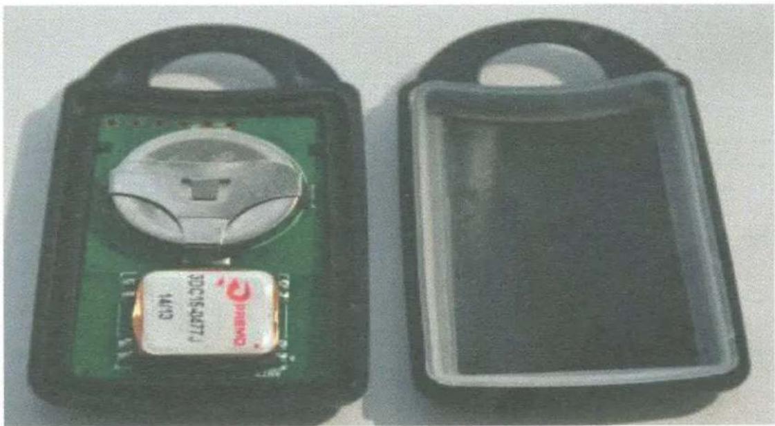
Battery normally can be used for about 2\~3 years, however if needed, change the battery.
natural_image
Two black plastic enclosures: one with a green circuit board and label '10C 154471', the other empty with no visible text or symbols.- Open the cases of Smart key by using small coin.
- Replace it with one CR2032 battery. PIs make sure of polarity (+, -).
- Assemble it again in the same way you opened it.
- When a new battery is replaced, make sure Fob key works, in some cases it may need to be registered again.
NavAtlas™
www.navatlas.net
©2016 Namsung America Inc. 250 International Pkwy, Heathrow, FL 32746
Specifications are subject to change without notice.
All trademarks are the property of their respective owners.
California Office, 12155 Mora Drive, Suite 4 Santa Fe Springs, CA 90670