
Force 57 - Outboard motor GARMIN - Free user manual and instructions
Find the device manual for free Force 57 GARMIN in PDF.

User questions about Force 57 GARMIN
0 question about this device. Answer the ones you know or ask your own.
Ask a new question about this device
Download the instructions for your Outboard motor in PDF format for free! Find your manual Force 57 - GARMIN and take your electronic device back in hand. On this page are published all the documents necessary for the use of your device. Force 57 by GARMIN.
USER MANUAL Force 57 GARMIN
© 2019 Garmin Ltd. or its subsidiaries
All rights reserved. Under the copyright laws, this manual may not be copied, in whole or in part, without the written consent of Garmin. Garmin reserves the right to change or improve its products and to make changes in the content of this manual without obligation to notify any person or organization of such changes or improvements. Go to www.garmin.com for current updates and supplemental information concerning the use of this product.
Garmin ^5 , the Garmin logo, and ActiveCaptain ^6 are trademarks of Garmin Ltd. or its subsidiaries, registered in the USA and other countries. Force ^™ is a trademark of Garmin Ltd. or its subsidiaries. These trademarks may not be used without the express permission of Garmin.
Wi-Fi ^® is a registered mark of Wi-Fi Alliance Corporation.
Table of Contents
Getting Started.... 1
Deploying the Motor from the Stowed Position.... 1
Adjusting the Depth of the Trolling Motor.... 1
Stowing the Motor from the Deployed Position.... 1
Securing the Safety Strap....
Trolling Motor Display Panel....
Status Indicator....2
Calibrating the Trolling Motor....2
Setting the Bow Offset.... 2
Connecting to a Chartplotter....2
Remote Control....3
Installing Batteries 3
Attaching a Lanyard.... 3
Remote Control Keys....3
Remote Control Screen.... 3
Navigating the Menu....4
Calibrating the Remote Control....4
Pairing the Remote Control....4
Foot Pedal....4
Installing Batteries....4
Pairing the Foot Pedal....5
Status Indicator 5
Operation....5
Turning the Propeller On and Off....5
Adjusting the Speed of the Motor 5
Maintaining Your Speed....5
Operating the Propeller When Partially Deployed.... 5
Steering....6
Steering the Trolling Motor Manually....6
Maintaining Your Heading....6
Holding Your Position....6
Gesture Controls......
Waypoints....7
Creating a Waypoint....7
Navigating to a Waypoint....7
Viewing Waypoint Details....7
Editing a Waypoint Name....7
Deleting a Waypoint....7
Routes....7
Navigating a Route....7
Viewing Route Details....
Editing a Route Name......7
Deleting a Route....7
Tracks....7
Saving the Active Track....
Clearing the Active Track....7
Navigating to the Start of the Active Track....7
Navigating a Saved Track....8
Viewing Saved Track Details....8
Editing a Saved Track Name....8
Deleting a Saved Track....8
Navigating....8
Pausing and Resuming Navigation....8
Stopping Navigation....8
Settings......8
Trolling Motor Settings....8
Wireless Network Settings......8
Remote Control Settings....8
Backlight Settings....9
Maintenance Needs and Schedule....9
Motor Information....9
Getting Started with the ActiveCaptain App....9
Updating Software with the ActiveCaptain App.... 9
Stowed Dimensions....9
Deployed Dimensions....9
Registering Your Device.... 10
Contacting Garmin Support.... 10
Specifications.... 10
Trolling Motor....10
Motor Thrust and Current-Draw Information.... 10
Remote Control....10
Foot Pedal....11
Index....12
Getting Started
WARNING
Do not run the motor when the propeller is out of the water. Contact with the rotating propeller may result in severe injury.
Do not use the motor in areas where you or other people in the water may come into contact with the rotating propeller.
Always disconnect the motor from the battery before cleaning or servicing the propeller to avoid injury.
CAUTION
When stowing or deploying the motor, be aware of the risk of entrapment or pinching from moving parts, which can result in injury.
When stowing or deploying the motor, be aware of slick surfaces around the motor. Slipping when stowing or deploying the motor may result in injury.
NOTICE
After using the motor in salt water or brackish water, you must rinse off the entire motor with fresh water, and apply a water-based silicone spray using a soft cloth. You should avoid spraying jets of water at the cap on the top of the shaft when rinsing the motor.
Deploying the Motor from the Stowed Position
1 Disengage the safety strap.
2 Pull the pull-cable back until it stops to release the latch, and continue to hold it tight.
3 Lift the motor up and forward using the pull-cable, then lower it slowly into the deployed position.
4 If necessary, push down on the mount arm to lock the motor in the deployed position.
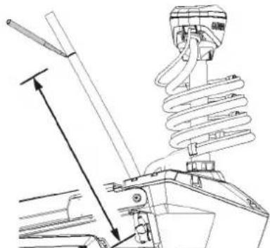
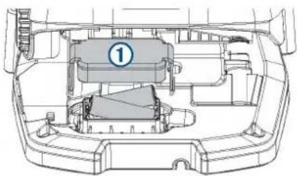
Adjusting the Depth of the Trolling Motor
1 Move the motor so that it stops halfway between the stowed and deployed positions.
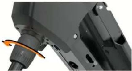
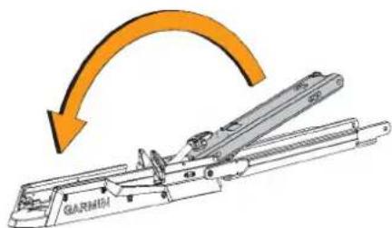
2 Loosen the collar at the base of the steering system housing.
natural_image
Close-up of a mechanical component with a highlighted orange arrow indicating rotation (no visible text or symbols)NOTE: You should be prepared for the motor to slide down when you loosen the collar.
3 Raise or lower the depth of the trolling motor.
NOTICE
Do not set the motor depth so low that it compresses the coiled cable. When the coiled cable is compressed, it may be damaged by friction as the motor steers.
4 Tighten the collar at the base of the steering system housing.
5 Select an action:
- If you are deploying the trolling motor, move the motor to the fully deployed position to check the depth.
- If you are stowing the trolling motor, move the motor to the stowed position to check the depth.
6 Repeat this procedure if necessary to set the correct depth for the deployed or stowed position.
Stowing the Motor from the Deployed Position
NOTICE
You must allow the motor to stop rotating completely before moving it to the stowed position. If the motor is rotating when you move it to the stowed position, it may damage the steering system.
1 Pull the pull-cable up until it stops to release the latch, and continue to hold it tight.
2 Lift the pull-cable up and backward to lift and lower the motor slowly into the stowed position.
NOTE: You may need to adjust the depth of the trolling motor so it rests correctly on the mount base in the stowed position (Adjusting the Depth of the Trolling Motor, page 1). If it is adjusted too shallow, it may press on the gas spring. If it is adjusted too deep, it may hang off the end of the mount base.
3 If necessary, push down on the steering system housing to lock it in the stowed position.
4 Secure the safety strap (Securing the Safety Strap, page 1).
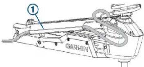
Securing the Safety Strap
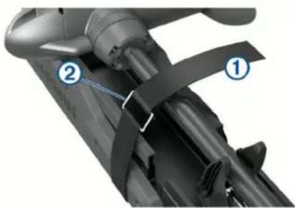
The safety strap holds the motor securely to the base in the stowed position and prevents unintended deployment.
1 With the motor in the stowed position, lift the long end of the strap over the top of the motor.
natural_image
Close-up of a mechanical component with labeled parts (1 and 2), showing no visible text or symbols beyond labels.2 Feed the end of the strap through the buckle ② on the other end of the strap.
3 Pull the strap through the buckle until it holds the motor securely to the mount.
4 Pull the strap away from the buckle, and push down to fasten it to the other side of the strap.
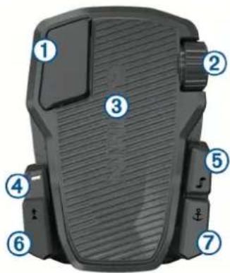
Trolling Motor Display Panel
The display panel on the trolling motor mount shows important information at a glance.
NOTE: The backlight on the display panel reacts to the ambient light, and dims automatically at night.
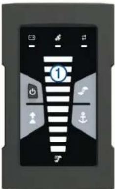
| 1Speed | Shows the motor speed level (Adjusting the Speed of the Motor, page 5). |
| Trolling motor battery status | Green: the motor battery voltage is good.Yellow: the motor battery voltage is low.Red: the motor battery voltage is critically low. |
| GPS signal status | Green: the motor has a good GPS signal.Yellow: the motor has a poor GPS signal.Red: the motor does not have a GPS signal. |
| Motor status | Shows the status of the trolling motor (Status Indicator, page 2 ). |
| Power | Hold to turn the motor off.NOTE: By default, the trolling motor turns on automatically when it receives power. It is not necessary to push this button to turn it on. This can be changed in the settings (Trolling Motor Settings, page 8).The trolling motor turns off automatically when it is in the stowed position for two hours.When the propeller is turning, press to stop the propeller.Press three times to enter pairing mode. |
| Propeller status | Illuminates when the propeller is on (Turning the Propeller On and Off, page 5). |
| Heading hold status | Illuminates when heading hold is on (Maintaining Your Heading, page 6). |
| Anchor lock status | Illuminates when anchor lock is on (Holding Your Position, page 6). |
Status Indicator
The LED indicates the motor status.
| Green | Normal operation |
| Red Solid | system bootingBlinking: system error |
| Blue Pairing mode | |
| Yellow | Recovery mode (for software updates and recovery procedures) |
Calibrating the Trolling Motor
You must calibrate the compass in the trolling motor before you can use the autopilot features. For the best results, you should calibrate the motor on a day with little or no wind on calm water. You can repeat the calibration process if the autopilot features are not performing as expected.
1 Drive the boat to an open area of calm water and stop moving.
The boat must be stationary to begin the calibration process.
2 If necessary, deploy the trolling motor (Deploying the Motor from the Stowed Position, page 1).
3 On the remote control, select ≡ Settings > Trolling Motor > Calibrate > Compass.
4 Using the foot pedal or outboard motor to steer, follow the on-screen instructions.
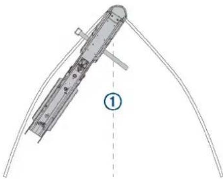
Setting the Bow Offset
Based on the installation angle, the trolling motor may not align with the center line of your boat. For the best results, you should set the bow offset.
1 Using the remote control, adjust the angle of the trolling motor ① so it aligns with the center line of your boat ② pointing straight forward.
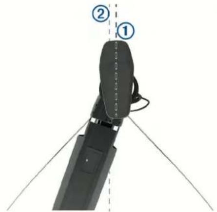
2 On the remote control, select ≡ Settings > Trolling Motor > Calibrate > Bow Offset.
3 Repeat this procedure if necessary.
Connecting to a Chartplotter
Your compatible Garmin® chartplotter must have the latest software version installed before you can connect the trolling motor.
You can connect the trolling motor wirelessly to a compatible Garmin chartplotter on your boat. After you connect to a compatible chartplotter, you can control the trolling motor from the chartplotter in addition to the remote control and foot pedal.
1 Turn on the chartplotter and the trolling motor.
2 Make sure that the chartplotter is hosting a wireless network. NOTE: If you have multiple chartplotters installed, only one is the wireless network host. Consult your chartplotter's owner's manual for more information.
3 On the chartplotter, select Settings > Communications > Wireless Devices > Garmin Trolling Motor > Start.
4 On the trolling motor display panel, press ⏻three times to enter pairing mode.
on the trolling motor display panel illuminates blue as it searches for a connection to the chartplotter, and changes to green when the connection is successful.
A confirmation message appears on the chartplotter when the connection is successful.
5 After the chartplotter and trolling motor connect successfully, enable the trolling motor bar on the chartplotter to control the motor.
See the latest version of your chartplotter's owner's manual for complete operation instructions.
Remote Control
Installing Batteries
The remote control operates using two AA batteries (not included). Use lithium batteries for best results.
1 Turn the D-ring counter-clockwise, and pull up to remove the cover.
2 Insert two AA batteries, observing polarity.
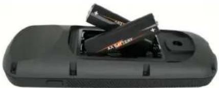
natural_image
Close-up of a black electronic device with two stacked batteries (no visible text or symbols)3 Replace the battery cover, and turn the D-ring clockwise.
Attaching a Lanyard
1 Starting from the back of the remote control, insert the loop of the lanyard through the slot.
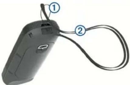
natural_image
Close-up of a black handheld device with two labeled connectors (1 and 2) and a cable, no visible text or symbols.2 Thread the other end of the lanyard ② through the loop, and pull it tight.
3 If necessary, place the lanyard around your neck or wrist to tether it during use.
Remote Control Keys
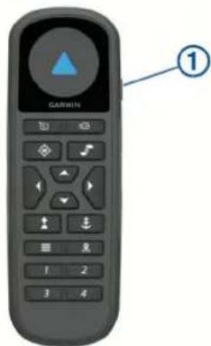
Key Description
| 1 | Hold to turn the remote control on and off. |
| Press to turn on and set the cruise control at the current speed over ground (SOG) (Maintaining Your Speed, page 5).Press to disable the cruise control and return to manual speed control. |
| Key Description | |
| If the propeller is on, press to set it to full speed (Toggling Full Speed, page 5).If the propeller is off, press to enable the propeller and set it to full speed.Press again to return to the previous speed and propeller state. | |
| Press for manual control (Steering the Trolling Motor Manually, page 6).Hold to steer using gestures (Using Gesture Controls to Steer, page 6). | |
| Press to turn the propeller on and off (Turning the Propeller On and Off, page 5). | |
| Press to navigate the menu (Navigating the Menu, page 4).When in the menu, press to select a menu item, and press (to go back.When in anchor lock, press to jog the anchor lock position forward, backward, left, or right in 1.5 m (5 ft.) increments.When in heading hold or manual control, press (and) for single-degree step turns, or hold for steering in five-degree increments.Press and for incremental speed changes, or hold for continuous speed changes. | |
| Press to turn on heading hold (set and maintain the current heading) (Maintaining Your Heading, page 6).Press to turn off heading hold, stop the propeller, and resume manual control.Hold to set the heading hold by pointing the remote (Using Gesture Controls to Adjust the Heading Hold, page 6). | |
| Press to turn on anchor lock. Anchor lock uses the trolling motor to hold your position (Holding Your Position, page 6).When in anchor lock, press to turn off anchor lock and return to the previous steering mode.Hold to jog the anchor lock position by pointing the remote (Using Gesture Controls to Adjust Your Held Position, page 6). | |
| Press to open the menu.Press to exit the menu. | |
| Press to mark a waypoint. | |
| 1 through 4 | Press to open the shortcut for the Garmin chartplotter assigned to the key.1 |
Remote Control Screen
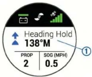
| 1 | Shows the operational status of the trolling motor. For example, when in manual control, Manual is shown, and when the heading hold is on, Heading Hold is shown, along with the heading-hold set point in degrees. |
| Shows the trolling motor battery status. Green: the motor battery voltage is good. Yellow: the motor battery voltage is low. Red: the motor battery voltage is critically low. TIP: You can view the remote control battery level by pressing ≡Shows the status of the propeller.When the propeller icon is shown, the propeller is on. When the propeller icon is not shown, the propeller is off. | |
| Shows the GPS signal strength of the trolling motor. | |
| PROP | Shows the speed level of the propeller (Adjusting the Speed of the Motor, page 5). |
| SOG | Shows the measured speed over ground (SOG) in the specified units. |
Navigating the Menu
You can use the menu and arrow keys to navigate the menu on the remote control.
• To open the menu, press .
• To move between different menu items, press and .
• To select a menu item, press .
• To move back to a previous menu item, press .
• To exit the menu, press , press repeatedly until you reach the main screen.
Calibrating the Remote Control
NOTICE
Calibrate the electronic compass outdoors. To improve heading accuracy, do not stand near objects that influence magnetic fields, such as vehicles, buildings, and overhead power lines.
You must calibrate the compass in the remote control before you can control the motor using gestures. If the gesture controls are not working properly after calibration, you can repeat this process as often as needed.
1 Select □ Settings > Remote Control > Calibrate.
2 Select Start, and follow the on-screen instructions.
Pairing the Remote Control
The remote control is paired with the trolling motor at the factory, but you may need to pair them again if the connection is broken.
1 Turn on the trolling motor.
2 On the trolling motor display panel, press ⏻ three times to enter pairing mode.
on the trolling motor display panel illuminates blue as it searches for a connection.
3 Bring the remote control within 1 m (3 ft.) of the display panel on the trolling motor.
4 Turn on the remote control.
5 On the remote control, select ≡ Settings > Remote Control > Pair > Start.
on the trolling motor display panel illuminates green when the connection is successful.
Foot Pedal
You can use the foot pedal to operate the trolling motor.
| 1 | Momentary propeller control | Hold to turn on the propeller at the set speed. Release to turn off the propeller. |
| 2 | Speed wheel | Rotate the wheel away from you to increase the propeller speed or cruise control speed. Rotate the wheel toward you to decrease the propeller speed or cruise control speed.NOTE: The speed wheel is inactive when anchor lock is on. |
| 3 | Steering pedal | Push the pedal with your toes to turn the motor clockwise.Push the pedal with your heel to turn the motor counter-clockwise.NOTE: When anchor lock or heading hold is on, or you are following a route, press the pedal to resume manual control at the previous propeller speed. |
| 4 | Status indicator | Shows the status of the foot pedal (Status Indicator, page 5). |
| 5 | Continuous propeller control | Press to turn the propeller on and off (Turning the Propeller On and Off, page 5). |
| 6 | Heading hold | Press to set and maintain the current heading (Maintaining Your Heading, page 6).Press to turn off heading hold, stop the propeller, and resume manual control. |
| 7 | Anchor lock | Press to turn on anchor lock. Anchor lock uses the trolling motor to hold your position (Holding Your Position, page 6).Press to turn off anchor lock and return to the previous steering mode. |
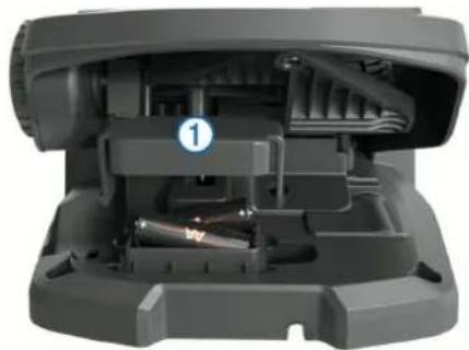
Installing Batteries
The foot pedal can operate using two AA alkaline, NiMH, or lithium batteries (not included). Use lithium batteries for best results.
1 Lift up the front of the foot pedal as far as possible.
2 Pinch the sides of the battery cover ① and pull up to remove it.
natural_image
Interior view of a mechanical device showing internal components and a numbered label (1), no readable text or symbols present.3 Insert two AA batteries, observing polarity.
4 Place the battery cover over the batteries, and push down until both sides snap into place.
Pairing the Foot Pedal
The foot pedal is paired with the trolling motor at the factory, but you may need to pair them again if the connection is broken.
1 Turn on the trolling motor.
2 On the trolling motor display panel, press three times to enter pairing mode.
on the trolling motor display panel illuminates blue as it searches for a connection.
3 Bring the foot pedal within 1 m (3 ft.) of the display panel on the trolling motor.
4 Connect the foot pedal to power using the power cable, or insert batteries to turn it on.
5 Within 30 seconds of turning on the foot pedal, hold \$until the status LED on the foot pedal illuminates blue.
6 Release ↓
The status LED on the foot pedal illuminates blue as it searches for a connection, then turns off when it pairs successfully with the trolling motor.
→ on the trolling motor display panel changes to green when the connection is successful.
Status Indicator
The LED on the foot pedal indicates the foot pedal status.
| Illuminates green The foot pedal is powering on. | |
| Illuminates blue The foot pedal is pairing. The LED turns off when it connects to the trolling motor or the pairing process times out without connecting. | |
| Flashes green when pushing a button | The foot pedal is connected to the trolling motor and sending a command for the button being pushed. |
| Flashes red when pushing a button | The foot pedal is not connected to the trolling motor. |
| Off The LED turns off when the pedal is connected to the trolling motor and not sending commands. This prolongs battery life. | |
Operation
You can use the remote control, the foot pedal, a compatible Garmin chartplotter, or a combination of these devices to operate the trolling motor.
In general, most of the instructions provided for the remote control also apply to a connected chartplotter. For specific chartplotter instructions, see the latest owner's manual for your chartplotter.
NOTE: Some features available when using the remote control and chartplotter are not available when using the foot pedal only.
Turning the Propeller On and Off
WARNING
Do not use the motor in areas where you or other people in the water may come into contact with the rotating propeller.
1 If necessary, deploy the trolling motor (Deploying the Motor from the Stowed Position, page 1).
NOTE: The propeller cannot turn on when the trolling motor is in the stowed position.
2 On the remote control or foot pedal, press to turn on the propeller.
3 Press to turn off the propeller.
Adjusting the Speed of the Motor
You can adjust the speed of the trolling motor using the remote control or the foot pedal.
1 If necessary, press 🔒 on the remote control, or steer with the foot pedal, to enter manual mode.
2 Select an option:
- On the remote control, press and to increase and decrease the speed of the motor.
- On the foot pedal, rotate the speed wheel away from you and toward you to increase and decrease the speed of the motor.
- On the remote control, press and to increase and decrease the speed of the motor. - On the foot pedal, rotate the speed wheel away from you and toward you to increase and decrease the speed of the motor.
The PROP field on the remote control and the bars on the display panel indicate the propeller speed (Trolling Motor Display Panel, page 1).
3 If necessary, turn on the propeller (Turning the Propeller On and Off, page 5).
The propeller speed you selected is retained if the propeller is turned off or if you start another function of the motor such as cruise control or anchor lock.
Toggling Full Speed
1 On the remote control, press ∃ The trolling motor propeller speed quickly increases to full speed.
2 Press to return to the previous propeller speed.
TIP: When at full speed, you can press on the remote control to slowly decrease the propeller speed.
Maintaining Your Speed
Before you can use the cruise control feature, you must calibrate the trolling motor (Calibrating the Trolling Motor, page 2).
The cruise control feature is an autopilot function that sets and maintains a specific speed over ground, adjusting for changes in current and wind automatically.
NOTE: You can enable the cruise control feature from the remote control only, but can control the speed and direction from both the remote control and foot pedal.
1 On the remote control, press 📋.
Cruise control is enabled at the present speed.
2 Using the remote control or foot pedal, adjust the speed as needed.
3 Using the remote control or foot pedal, adjust the heading as needed.
TIP: You can use cruise control to set the speed while using the heading hold feature (Maintaining Your Heading, page 6) or following a route (Navigating a Route, page 7).
To disable cruise control and turn off the propeller, you must press 🔒.
Operating the Propeller When Partially Deployed
You can operate the trolling motor propeller with the motor only partially deployed for specific situations, such as when you pass over weeds or submerged obstacles.
1 With the trolling motor in the deployed position, pull the pull-cable up until it stops to release the latch, and continue to hold it tight.
2 Lift the pull-cable up and backward to lift the motor slowly until it is in position to pass over the weeds or obstacle. The propeller stops rotating, and the motor turns to the side.
3 Use the remote control or foot pedal to turn on the propeller, and steer the motor as needed.
NOTE: If you raise the motor beyond the halfway point, the propeller automatically stops as a safety measure, but the motor does not turn to the side.
4 When you are past the obstacle, slowly lower the motor to the deployed position, or raise the motor to the stowed position.
After operating the motor when partially deployed, you may need to turn the motor to one side manually before raising it to the stowed position so it rests properly on the mount rails.
Steering
Steering the Trolling Motor Manually
Manual mode is the default operational mode of the trolling motor. In manual mode, you can adjust the direction and speed of the trolling motor as needed.
NOTE: The trolling motor is in manual mode by default when you turn it on.
1 If necessary, on the remote control, select ⚙
2 Select an action:
• Using the remote control, press and to steer.
NOTE: You can also use gesture controls to steer the boat manually using the remote control (Using Gesture Controls to Steer, page 6).
- Using the foot pedal, push the pedal with your toes and heel to steer.
Maintaining Your Heading
Before you can use the heading hold feature, you must calibrate the trolling motor (Calibrating the Trolling Motor, page 2).
The heading hold feature is an autopilot function that sets and maintains the current heading of the boat. You can set the behavior of the heading hold feature when accounting for drift (Changing the Heading Hold Behavior, page 6).
1 Steer the boat in the direction you want to go.
2 On the remote control or foot pedal, select
NOTE: You can adjust the direction of the heading hold by pressing ◀ and ▶ or by using gesture controls (Using Gesture Controls to Adjust the Heading Hold, page 6).
To disable heading hold and return to manual mode, you must select ↑ or step on the foot pedal.
Changing the Heading Hold Behavior
You can change the how heading-hold feature maintains the heading of your boat when it is affected by the wind or the current.
1 On the remote control, select ☑ Settings > Trolling Motor > Heading Hold.
2 Select an option:
- To keep the boat pointing in the same direction regardless of drift, select Vessel Align.
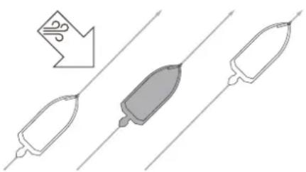
natural_image
Diagram showing three elongated objects with a downward arrow and a gray central object, connected by parallel lines (no text or symbols)- To keep the boat pointing in the same direction while accounting for drift, select Go To.
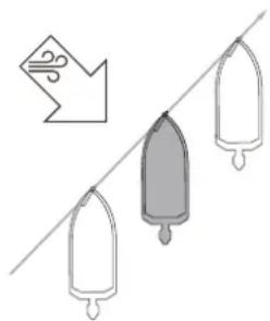
natural_image
Illustration of three vertical bars hanging on a diagonal line with an arrow pointing to the left (no text or symbols)Holding Your Position
Before you can use the anchor lock feature, you must calibrate the trolling motor (Calibrating the Trolling Motor, page 2).
The anchor lock feature is an autopilot function that uses GPS to set and maintain your position using the trolling motor, acting as if you deployed a physical anchor.
1 If necessary, drive the boat to a location you want to set the anchor lock.
2 On the remote control or foot pedal, select ↓
NOTE: You can adjust the anchor lock position 1.5 m (5 ft.) by pressing an arrow key on the remote control, or by using gesture controls (Using Gesture Controls to Adjust Your Held Position, page 6).
To disable anchor lock, you can press again, or steer with the foot pedal.
Gesture Controls
You can point or move the remote control to interact with the trolling motor. You must calibrate the compass in the trolling motor (Calibrating the Trolling Motor, page 2), and the compass in the remote control (Calibrating the Remote Control, page 4) before you can use gesture controls.
Using Gesture Controls to Steer
You can steer the motor by pointing the remote control.
1 If necessary, turn on the propeller (Turning the Propeller On and Off, page 5).
2 Hold M
3 While holding ⚙point the remote control to the left or right to steer port or starboard.
4 Release to stop steering.
Using Gesture Controls to Adjust the Heading Hold
You can move the remote control to adjust your heading hold (Maintaining Your Heading, page 6).
1 If necessary, turn on the propeller (Turning the Propeller On and Off, page 5).
2 Hold ↑
3 Point the remote control toward where you want to adjust the heading.
4 Release ↑ to set the heading direction.
Using Gesture Controls to Adjust Your Held Position
You can move the remote control to adjust your position when using the anchor lock feature (Holding Your Position, page 6).
1 If necessary, turn on the anchor lock feature.
2 Hold
3 Point the remote control in the direction you want to move your position.
Your position jogs 1.5 m (5 ft.) in the direction you point.
4 Release
5 Repeat this procedure until the you are in the position you want.
Waypoints
Waypoints are used to mark locations so you can return to them later.
When you connect the trolling motor to a chartplotter, the waypoints stored on the chartplotter are synchronized with the waypoints stored on the trolling motor. Adding, deleting, or editing waypoints on one device automatically changes the waypoints stored on the other device.
You can save up to 5000 waypoints.
Creating a Waypoint
You can save your current location as a waypoint.
1 If necessary, drive to a location you want to save as a waypoint.
2 On the remote control, press 🔒
Navigating to a Waypoint
1 On the remote control, select ≡ Waypoints. A list of the ten closest waypoints is shown.
2 Select a waypoint.
3 Select Navigate To.
4 Turn on the propeller (Turning the Propeller On and Off, page 5). The trolling motor drives to the waypoint location (Navigating, page 8).
Viewing Waypoint Details
1 On the remote control, select ≡ Waypoints. A list of the ten closest waypoints is shown.
2 Select a waypoint.
3 Select Review.
Editing a Waypoint Name
1 On the remote control, select ≡ Waypoints. A list of the ten closest waypoints is shown.
2 Select a waypoint.
3 Select Edit.
4 Enter a new name for the waypoint.
Deleting a Waypoint
1 On the remote control, select ≡> Waypoints. A list of the ten closest waypoints is shown.
2 Select a waypoint.
3 Select Delete.
Routes
A route is a sequence of locations that leads you to your final destination.
When you connect the trolling motor to a chartplotter, the routes stored on the chartplotter are synchronized with the routes stored on the trolling motor. Deleting or editing routes on one device automatically changes the routes stored on the other device. You can create routes on the chartplotter only.
You can save up to 100 routes.
Navigating a Route
1 On the remote control, select ≡ Routes. A list of the ten closest routes is shown.
2 Select a route.
3 Select Navigate To.
4 Select an option:
• To navigate the route from the starting point used when the route was created, select Forward.
- To navigate the route from the destination point used when the route was created, select Backward. - To navigate from your current location to the beginning of the route, then navigate the route, select From Start.
5 Turn on the propeller (Turning the Propeller On and Off, page 5).
The trolling motor drives along the route in the chosen direction (Navigating, page 8).
Viewing Route Details
1 On the remote control, select ≡> Routes. A list of the ten closest routes is shown.
2 Select a route.
3 Select Review.
Editing a Route Name
1 On the remote control, select ≡ Routes. A list of the ten closest routes is shown.
2 Select a route.
3 Select Edit.
4 Enter a new name for the route.
Deleting a Route
1 On the remote control, select ≡> Routes. A list of the ten closest routes is shown.
2 Select a route.
3 Select Delete.
Tracks
A track is a recording of the path of your boat. The track currently being recorded is called the active track, and it can be saved. You can save up to 50 tracks.
When you connect the trolling motor to a chartplotter, the active track and saved tracks stored on the chartplotter are synchronized with the active track and saved tracks stored on the trolling motor. Adding, deleting, or editing active and saved tracks on one device automatically changes the active and saved tracks stored on the other device.
Saving the Active Track
The track currently being recorded is called the active track. You can save the active track and navigate it later.
You can save up to 50 tracks on the trolling motor.
1 On the remote control, select ≡ Tracks > Save Active Track. The active track is saved with the current date as the track name.
2 Change the name for the saved track (optional).
Clearing the Active Track
Select ≡ Tracks > Clear Active Track.
The track memory is cleared, and the active track continues to be recorded.
Navigating to the Start of the Active Track
The track currently being recorded is called the active track. You can navigate from your current position back to the starting point of the active track along the path you traveled.
1 Select □>Tracks >Backtrack.
2 Turn on the propeller (Turning the Propeller On and Off, page 5).
The trolling motor navigates back to the starting point of the active track along the path you traveled (Navigating, page 8).
Navigating a Saved Track
1 Select ➕ Tracks > Saved Tracks.
A list of the ten closest saved tracks is shown.
2 Select a saved track.
3 Select Navigate To.
4 Select an option:
• To navigate the saved track from the beginning of the track to the end, select Forward.
- To navigate the saved track from the end of the track back to the beginning, select Backward.
5 Turn on the propeller (Turning the Propeller On and Off, page 5).
The trolling motor drives along the saved track in the chosen direction (Navigating, page 8).
Viewing Saved Track Details
1 On the remote control, select ≡>Tracks > Saved Tracks.
A list of the ten closest saved tracks is shown.
2 Select a saved track.
3 Select Review.
Editing a Saved Track Name
1 On the remote control, select ≡>Tracks > Saved Tracks.
A list of the ten closest saved tracks is shown.
2 Select a saved track.
3 Select Edit.
4 Enter a new name for the saved track.
Deleting a Saved Track
1 On the remote control, select ≡ Tracks > Saved Tracks.
A list of the ten closest saved tracks is shown.
2 Select a saved track.
3 Select Delete.
Navigating
Before you can navigate, you must calibrate the trolling motor (Calibrating the Trolling Motor, page 2).
The trolling motor uses GPS to steer the boat to a waypoint location or to follow a route or a track.
1 On the remote control, select an option:
- Begin navigating to a saved waypoint ( Navigating to a Waypoint, page 7).
- Begin navigating a saved route (Navigating a Route, page 7).
- Begin retracing the active track (Navigating to the Start of the Active Track, page 7).
- Begin navigating a saved track (Navigating a Saved Track, page 8).
NOTE: You can also use the trolling motor to follow autoguidance paths when navigation is started from a connected chartplotter. See your chartplotter owner's manual for more information.
Navigating is shown on the remote control screen, and the trolling motor automatically steers the boat to the destination.
2 Adjust the speed as needed.
Pausing and Resuming Navigation
1 While navigating, on the remote control, select an option:
- To pause navigation while continuing in the same direction at the same speed, select ≡ > Standby.
- To pause navigation and set anchor lock, select Navigation stops, and the trolling motor returns to manual mode or maintains your position in anchor lock.
2 Select 📋 Follow Route or press ⚠ to resume navigation.
3 If necessary, start the propeller.
Stopping Navigation
Select ≡ Stop Nav .
Navigation stops, and the trolling motor returns to manual mode.
Settings
Trolling Motor Settings
On the remote control, select ≡> Settings > Trolling Motor.
Wi-Fi: Sets the wireless network preferences for the trolling motor (Wireless Network Settings, page 8).
Calibrate: Calibrates the trolling motor compass (Calibrating the Trolling Motor, page 2) and sets the trolling motor bow offset (Setting the Bow Offset, page 2).
Units: Sets the units of measure.
Prop Stow Side: Sets which side of the trolling motor the propeller rotates to when stowing the trolling motor. This is helpful when you store other items near the stowed propeller.
Auto Power On: Turns on the trolling motor when you apply power to the system.
Heading Hold: Sets the behavior of the heading hold feature (Changing the Heading Hold Behavior, page 6).
Anchor Gain: Sets the response of the trolling motor when in anchor lock mode. If you need the trolling motor to be more responsive and move quicker, increase the value. If the motor is moving too much, decrease the value.
Navigation Gain: Sets the response of the trolling motor when navigating. If you need the trolling motor to be more responsive and move quicker, increase the value. If the motor is moving too much, decrease the value.
Clear User Data: Deletes all saved waypoints, routes, tracks, and you active track.
NOTE: If you are connected to a chartplotter, selecting this clears user data from both the trolling motor and the connected chartplotter.
Restore Defaults: Resets the trolling motor settings to the factory default values.
Wireless Network Settings
On the remote control, select ≡> Settings > Trolling Motor > Wi-Fi.
NOTE: The active Wi-Fi ^® mode is shown at the top of the screen.
Mode: Sets the Wi-Fi mode. You can turn off Wi-Fi technology, join the network of a chartplotter, or create a wireless access point to use the ActiveCaptain ^® app (Getting Started with the ActiveCaptain App, page 9).
Setup > Name: Sets the name of the wireless access point on the trolling motor (ActiveCaptain mode only).
Setup > Password: Sets the password for the wireless access point on the trolling motor (ActiveCaptain mode only).
Remote Control Settings
On the remote control, select ≡> Settings > Remote Control.
Backlight: Adjusts the backlight settings. (Backlight Settings, page 9)
Beeper: Sets the beeper to sound for key presses and alarms.
Power: Sets the length of time before the remote control turns off automatically.
Calibrate: Calibrates the remote control for the gesture-control features (Calibrating the Remote Control, page 4).
Pair: Pairs the remote control with the trolling motor (Pairing the Remote Control, page 4).
Language: Sets the on-screen text language.
Restore Defaults: Resets the remote control to factory default settings. This restores the default configuration settings on the remote control, but does not remove saved user data.
Backlight Settings
On the remote control, select ≡ Settings > Remote Control > Backlight.
Keys: Sets the backlight to turn on when a key is pressed.
Alarms: Sets the backlight to turn on when an alarm sounds on the remote control.
Timeout: Sets the length of time before the backlight turns off.
Brightness: Sets the brightness level of the backlight.
Maintenance Needs and Schedule
NOTICE
After using the motor in salt water or brackish water, you must rinse off the entire motor with fresh water, and apply a water-based silicone spray using a soft cloth. You should avoid spraying jets of water at the cap on the top of the shaft when rinsing the motor.
To maintain your warranty, you must perform a series of routine maintenance tasks as you prepare your motor for the season. If you use or transport the motor in dry, dusty environments (traveling on gravel roads, for example) you should perform these tasks more often during the season.
For detailed procedures and information on service and replacement parts, download the Force Trolling Motor Maintenance Manual from www.garmin.com/manuals/force_trolling_motor.
- Examine the power cable for wear, and patch or repair as necessary ①
- Check the power terminals, and clean them if necessary. ②
- Lubricate the hinges and bushings .③
- Clean and lubricate the stow and deploy latch mechanism .④
- Check the mount rails, and replace them if necessary. ⑤
- Check the mount bumper, and replace it if necessary. ⑥
- Clean or replace the anodes in the propeller drive motor. ⑦
Motor Information
Getting Started with the ActiveCaptain App
You can connect a mobile device to the trolling motor using the ActiveCaptain app. The app provides a quick and easy way for you to interact with your trolling motor and update the device software.
1 On the remote control, select □> Settings > Trolling Motor > Wi-Fi > Mode > ActiveCaptain > Setup.
2 Enter a name and password for this network.
3 From the application store on your mobile device, install and open the ActiveCaptain app.
4 Bring the mobile device near the trolling motor.
5 From your mobile device settings, open the Wi-Fi connections page and connect to the trolling motor, using the name and password you entered in the previous step.
Updating Software with the ActiveCaptain App
NOTICE
Software updates may require the app to download large files. Regular data limits or charges from your Internet service provider apply. Contact your Internet service provider for more information about data limits or charges.
The installation process can take several minutes.
1 Connect the mobile device to the trolling motor (Getting Started with the ActiveCaptain App, page 9).
2 When a software update is available and you have internet access on your mobile device, select Software Updates > Download.
The ActiveCaptain app downloads the update to the mobile device. When you reconnect the app to the trolling motor, the update is transferred to the trolling motor. After the transfer is complete, you are prompted to install the update.
3 When you are prompted on the remote control, select OK to install the update.
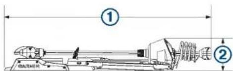
Stowed Dimensions
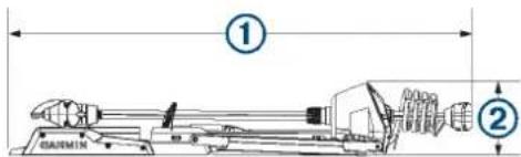
| Item 50 in. Model 57 in. Model | ||
| 1 | 1.558 m ( 61^5/_16 in.) min.1.811 m ( 71^5/_16 in.) max. | 1.712 m ( 67^3/_8 in.) min.2.066 m ( 81^5/_16 in.) max. |
| 2 | 300 mm ( 11^13/_16 in.) 340 mm (13 | ^3/_8 in.) |
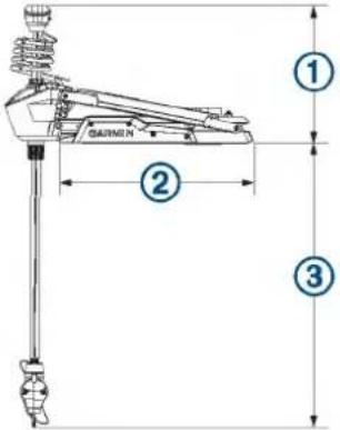
Deployed Dimensions
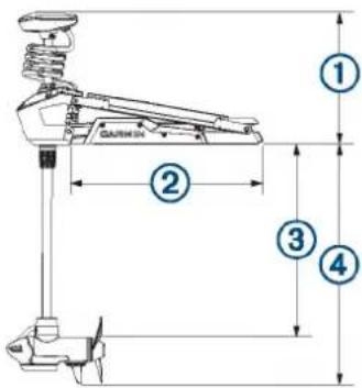
| Item 50 in. Model 57 in. Model | ||
| 1 | 461 mm ( 18^1/_8 in.) min.721 mm ( 28^3/_8 in.) max. | 488 mm ( 19^3/_16 in.) min.817 mm ( 32^1/_8 in.) max. |
| 2 | 708 mm ( 27^7/_8 in.) 799 mm (31 | ^7/_16 in.) |
| Item 50 in. Model 57 in. Model | ||
| 3 | 648 mm ( 25^1/_2 in.) min.889 mm (35 in.) max. | 737 mm (29 in.) min.1.07 mm (42 in.) max. |
| 4 | 839 mm ( 33^1/_16 in.) min.1.1 m ( 43^5/_16 in.) max. | 920 mm ( 36^3/_16 in.) min.1.18 m ( 46^1/_2 in.) max. |
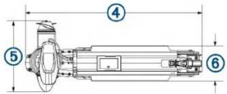
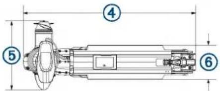
| Item 50 in. Model 57 in. Model | ||
| 4 | 931 mm ( 36^11/_16 in.) 1.022 m (40 | ^1/_4 in.) |
| 5 | 402 mm ( 15^13/_16 in.) 402 mm (15 | ^13/_16 in.) |
| 6 | 203 mm (8 in.) 203 mm (8 in.) | |
Registering Your Device
Help us better support you by completing our online registration today. Keep the original sales receipt, or a photocopy, in a safe place.
1 Go to my.garmin.com/registration.
2 Sign in to your Garmin account.
Contacting Garmin Support
- Go to support.garmin.com for help and information, such as product manuals, frequently asked questions, videos, and customer support.
• In the USA, call 913-397-8200 or 1-800-800-1020.
• In the UK, call 0808 238 0000.
• In Europe, call +44 (0) 870 850 1241.
Specifications
Trolling Motor
| Weight (motor, mount, and cables) | 50 in. model: 30 kg (66 lb.)57 in. model: 31.75 kg (70 lb.) |
| Weight (stabilizer) 0.54 kg (1.2 lb.) | |
| Operating temperature | From -5° to 40°C (from 32° to 104°F) |
| Storage temperature | From -40° to 85°C (-40° to 185°F) |
| Material Mount and motor housing: aluminumShaft cap, display panel, and side panels: plasticMotor shaft: fiberglass | |
| Water rating Shaft cap: IEC 60529 IPX51Steering motor housing: IEC 60529 IPX72Display panel housing: IEC 60529 IPX7Propeller drive motor housing: IEC 60529 IPX83 | |
| Compass safe distance | 91 cm (3 ft.) |
| Power cable length 50 | in. model: 1.2 m (4 ft.)57 in. model: 1.1 m (3.5 ft.) |
| Input voltage From 20 | to 45 Vdc |
| Input amperage 60 A | continuous |
| Breaker (not included) | 42 VDC or greater, suitable for 60 A continuousNOTE: You can protect the system buy using a larger circuit breaker, not to exceed 90 A, if you are operating under high temperatures or if you are sharing the circuit with other devices. You should verify that your boat wiring meets marine wiring standards using a larger breaker before changing it. |
| Main power usage at 36 Vdc 60 A | Off: 72 mWFull power: 2160 W |
| Radio frequency 2.4 GHz @ 28 dBm nominal | |
Motor Thrust and Current-Draw Information
You can refer to these tables to understand the relationship between the throttle level, output power, and current consumption of the motor. These values assume you are using an official Garmin power propeller, in relatively calm water, with the motor deployed deeply enough not to ventilate, and with tolerances of ±7 N-m (5 lbf) and ±5 A.
24.0 Vdc Power Source
| Throttle Level Thrust | Current | |
| 10% | 25 N-m (6 lbf) | 2 A |
| 20% | 45 N-m (10 lbf) | 3 A |
| 30% | 70 N-m (16 lbf) | 6 A |
| 40% | 101 N-m (23 lbf) | 9 A |
| 50% | 140 N-m (31 lbf) | 14 A |
| 60% | 184 N-m (41 lbf) | 21 A |
| 70% | 233 N-m (52 lbf) | 29 A |
| 80% | 287 N-m (65 lbf) | 40 A |
| 90% | 345 N-m (78 lbf) | 54 A |
| 100% | 355 N-m (80 lbf) | 57 A |
36.0 Vdc Power Source
| Throttle Level | Thrust | Current |
| 10% | 21 N-m (5 lbf) | 1 A |
| 20% | 41 N-m (9 lbf) | 2 A |
| 30% | 69 N-m (16 lbf) | 4 A |
| 40% | 103 N-m (23 lbf) | 6 A |
| 50% | 144 N-m (32 lbf) | 10 A |
| 60% | 191 N-m (43 lbf) | 15 A |
| 70% | 246 N-m (55 lbf) | 21 A |
| 80% | 307 N-m (69 lbf) | 29 A |
| 90% | 375N-m (84 lbf) | 39 A |
| 100% | 445 N-m (100 lbf) | 54 A |
Remote Control
| Dimensions (W×H×D) | 152 x 52 x 32 mm (6 x 2 x 1^1/_4 in.) |
| Weight | 109 g (3.8 oz.) without batteries |
| Material | Glass-filled nylon |
| Display type | Sunlight-visible, transflective memory-in-pixel (MIP) |
| Display resolution | R240 x 240 pixels |
| Display size (diameter) | 30.2 mm ( 1^3/_16 in.) |
| Operating temperature | From -15° to 55°C (5° to 131°F) |
| Storage temperature | From -40° to 85°C (-40° to 185°F) |
| Battery type | 2 AA (not included) |
| Battery life | 240 hr., typical use |
| Radio frequency | 2.4 GHz @ -0.8 dBm nominal |
| Water rating | IEC 60529 IPX7 |
| Compass-safe distance | 15 cm (6 in.) |
Foot Pedal
| Dimensions (L×W×H) 303 × 221 × 110 mm (11 ^15/_16 × 8 ^11/_16 × 4 ^5/_16 in. | |
| Weight 1.8 kg (4 lb) | |
| Operating temperature From -15° to 55°C (5° to 131°F) | |
| Storage temperature From -40° to 85°C (-40° to 185°F) | |
| Water rating IEC 60529 IPX7 | |
| Material Plastic | |
| Input voltage From 10 to 45 Vdc | |
| Typical input current < 1 mA @ 12 Vdc | |
| Max input current 10 mA @ 12 Vdc | |
| Fuse (on the power cable) 2 A mini-blade type | |
| Power cable length 2 m (6.6 ft.) | |
| Battery type Two AA batteries (Alkaline, NiMH, or lithium. Not included.) | |
| Battery life At least 1 year | |
| Radio frequency 2.4 GHz @ 0.8 dBm nominal | |
| Compass-safe distance 60 cm (2 ft.) | |
Index
A
ActiveCaptain 9
updating software 9
anchor lock 6
B
battery, installing 3
C
calibrating, motor 2
chartplotter, connecting 2
cruise control 5
D
depth, adjusting 1
device, registration 10
display panel 1
F
foot pedal, pairing 5
G
Garmin product support. See product support
gesture controls 6
H
heading, holding 6
help. See product support
K
keys 3,4
L
LED 5
locations, saving 7
M
manual mode 6
menu key 4
N
navigation 8
pausing 8
stopping 8
P
product registration 10
product support 10
propeller
out of the water 5
turning on 5
R
registering the device 10
remote control 6
button actions 3
pairing 4
screen 3
routes 7
deleting 7
editing 7
navigating 7
S
settings 8,9
software, updating 9
speed 5
adjusting 5
full 5
steering mode 6
support. See product support
T
tracks 7,8
clearing 7
deleting 7,8
editing 8
navigating 7,8
saving 7
U
updating, software 9
W
waypoints 7
deleting 7
editing 7
navigating 7
saving 7
Wi-Fi technology 8
Wi-Fi 9
wireless devices
connecting to a wireless device 9
network configuration 8
support.garmin.com
GARMIN. FORCE™ TROLLING MOTOR INSTALLATION INSTRUCTIONS
Getting Started
WARNING
Do not run the motor when the propeller is out of the water. Contact with the rotating propeller may result in severe injury.
Do not use the motor in areas where you or other people in the water may come into contact with the rotating propeller.
Always disconnect the motor from the battery before cleaning or servicing the propeller to avoid injury.
CAUTION
When stowing or deploying the motor, be aware of the risk of entrapment or pinching from moving parts, which can result in injury.
When stowing or deploying the motor, be aware of slick surfaces around the motor. Slipping when stowing or deploying the motor may result in injury.
Always wear safety goggles, ear protection, and a dust mask when drilling, cutting, or sanding.
NOTICE
When drilling or cutting, always check what is on the opposite side of the surface.
To avoid damage to your boat, this device should be installed by a qualified marine installer. Specific knowledge of marine electrical systems is required for proper installation.
Tools and Supplies Needed
- Drill and a ^5/_16 in. (8 mm) drill bit
- #1 and #2 Phillips screwdrivers
- 3 mm and 4 mm hex bits or wrenches (two 4 mm recommended)
- ^9/_16 in. (14 mm) socket
- Torque wrench
• Circuit breaker rated for continuous 60 A
- Trolling motor plug and receptacle rated for 60 A or greater (optional)
- 6, 4, or 2 AWG (16, 25, or 35mm^2 ) wire for extended runs of the power cable
- Solder and heat-shrink tubing, if extending the power cable
- Stainless steel pan head ^1/_4 -20 (M6x1) bolts (if the included bolts are not long enough to mount the motor to the deck)
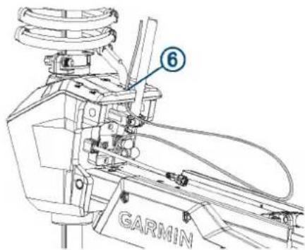
Installation Preparation
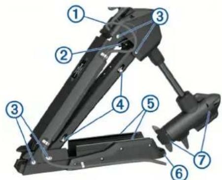
Device Overview
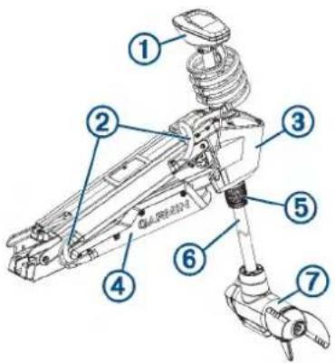
| 1 | Shaft cap |
| 2 | Power and transducer cables |
| 3 | Steering system |
| 4 | Mount |
| 5 | Depth-adjustment collar |
| 6 | Shaft |
| 7 | Propeller drive motor |
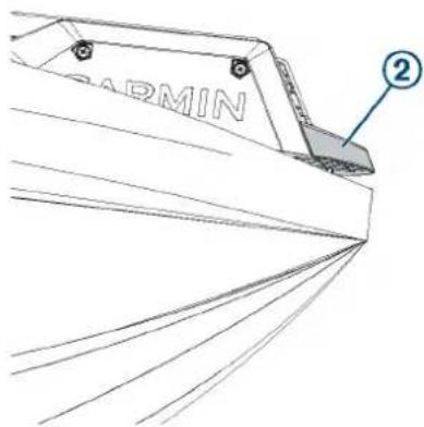
Mounting Considerations
When selecting a mounting location, observe these considerations.
- You must install the motor on the bow of your boat.
- It is recommended to install the motor on the port side of the bow, but you can install it on the starboard side if necessary.
- You should install the mount so the deployed motor is as close to the center of the boat ☑ as possible.
natural_image
Technical line drawing of a mechanical component with curved base and labeled point (1), no readable text or symbols present.- You must install the mount with the bumper overhanging the gunwale of the boat.
- The motor secures to the deck of the boat using bolts, so you must have room to secure the mount from the underside using washers and nuts.
- The motor must have clearance to move from the deployed to the stowed position and back again, so the installation location must be clear of obstacles.
Parts Bags
The installation hardware for the trolling motor is included in numbered bags. As you complete the installation process, each procedure begins with a reference to the parts bag needed to complete the procedure. You can use this table to review or verify the parts bags needed for the installation procedures.
 | Contains the safety strap and the hardware used to secure the mount base to the boat deck. |
 | Contains the hardware needed to secure the steering system to the lower half of the mount. |
 | Contains the hardware needed to secure the upper and lower gas springs. |
 | Contains the hardware needed to secure the steering system to the upper half of the mount. |
 | Contains the pull-cable handle hardware. |
 | Contains the hardware needed to secure the cables to the mount. |
Connection Considerations
When making the wiring connections, observe the following considerations.
- You must connect the trolling motor to a 24 or 36 Vdc battery bank capable of supplying 60 A continuously.
- You must connect to the power source through a circuit breaker rated for continuous 60 A (not included).
- If necessary, you can extend the power cable using the appropriate wire gauge based on the length of the extension (Power Cable Extension, page 6).
- For convenience, you can install a trolling motor plug and receptacle rated for 60 A or greater (not included) in the bulkhead to make it easier to disconnect the motor from the power source.
Installation Procedures
NOTICE
When assembling the motor, you must use hand tools to install all of the parts, observing the torque specifications when
provided. Using power tools to assemble the motor may damage the components, and voids the warranty.
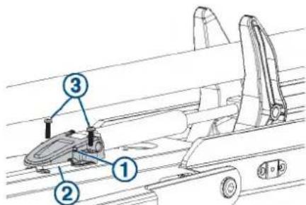
Installing the Mount on the Deck
Label identifying the parts bag required for this procedure:

NOTE: If the supplied bolts are not long enough for the mounting surface, you must obtain the appropriate length stainless steel pan head 14 -20 (M6x1) bolts.
1 Select a mounting location on the bow of your boat, according to the mounting considerations.
2 Pivot the top parts of the mount up and back so you can access the mounting holes on the mount base.
3 With the mount bumper overhanging the gunwale or the edge of the boat deck, place the mount base in the selected location.
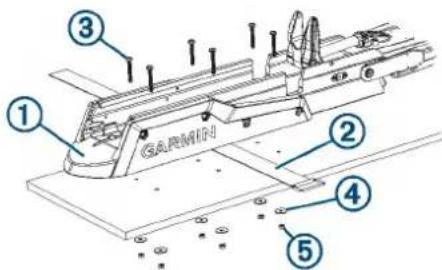
4 Using the mount base as a template, mark the mounting hole locations on the boat deck.
5 Remove the mount base from the boat deck, because you must not drill through the base.
6 Using a 516 in. (8 mm) drill bit, drill the pilot holes.
7 Place the safety strap ② under the mount base near the center, with the hook and loop fasteners facing downward.
NOTE: You must place the safety strap under the mount before you secure it to the surface. If you do not install the safety strap at this time, you may need to partially disassemble the motor later to install it correctly.
8 Place the mount base on the boat deck on top of the safety strap, aligning the holes on the mount with the mounting holes.
9 Secure the mount to the deck using the included bolts ③ washers ④ and locking nuts . ⑤
10 Tighten the nuts to 10.85 N m (8 lbf-ft.).
Installing the Steering System on the Mount
Label identifying the parts bag required for this procedure:

1 Pivot the lower half of the mount forward until it locks into the base.
2 Push the two safety rods ① into the mount as far as possible.
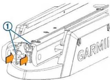
3 From the inside out, insert the bushings ② into the lower holes ③ on the steering system housing.
4 Holding the pull cable ④p, place the steering system housing onto the lower half of the mount, aligning the lower holes on the housing with the holes on the mount.
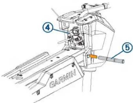
5 While lifting up on the steering system housing, push the pivot pin ⑤ through the housing and the mount to hold it in place.
NOTICE
Do not hit the pin with a hammer or other object. Do not drill or modify the holes. Although it is a snug fit, the pin slides in completely when pushed by hand. Damage caused by hammering the pin or modifying the holes is not covered under warranty.
6 Route the pull cable upward through the top of the steering system housing ⑥.
Securing the Upper Gas Spring
Label identifying the parts bag required for this procedure:

1 Push the safety rod toward the steering system housing as far as possible.
2 If necessary, pivot the upper gas spring ①oward the bottom of the mount so the base of the gas spring aligns with the safety rod and mounting holes.
NOTE: If you must rotate the gas spring so the base aligns with the mount, rotate the spring in a clockwise direction only. Rotating the gas spring in a counter-clockwise direction may loosen the fittings.
3 Align the single hole on the base of the gas spring ③ with the safety rod, and press down.
The screw holes on the base should align with the holes on the bottom of the mount.
4 Using a #2 Phillips screwdriver, secure the base of the gas spring to the bottom of the mount using the included screws ⑤.
Keep the remaining screws in the parts bag. You must use them when securing the other gas spring in a later procedure.
Installing the Top of the Mount
Label identifying the parts bag required for this procedure:

1 Remove the tape that secures the data cable to the steering system housing.
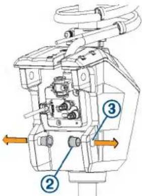
2 From the outside in, insert the bushings ②n the upper holes on the steering system housing.
3 Pivot the top of the mount forward.
4 Tip the top of the steering system housing inward so the holes on the top of the mount and the housing align.
5 Push the pin through the holes on the top of the mount and the steering system housing.
natural_image
Technical line drawing of a mechanical assembly with no visible text or symbols6 Using a 4 mm hex bit or hex wrench, secure the pin using the screws and washers on both sides.
NOTE: To properly secure the pin, you should use two hex bits or wrenches so the pin does not rotate as you tighten the screws.
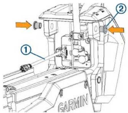
Connecting the Motor to the Display Panel
NOTICE
You must connect the cable from the steering system to the display panel before proceeding further with the installation. If you do not make this connection now, the unsecured cable may damage the display panel when moving the mount.
1 Route the cable from the steering system housing to the display panel on the top of the mount.
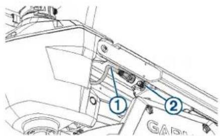
2 Push the connector onto the port on the display panel, and rotate the locking ring clockwise to secure it.
NOTE: The connector is keyed to fit into the port one way only, and will fit easily when aligned correctly. Do not force the connector into the port.
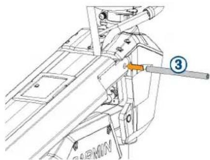
Installing the Handle on the Pull Cable
Label identifying the parts bag required for this procedure:
E
1 Insert the pull cable ① through the bottom half of the handle ②.
2 Insert the pull cable through the washer ③.
3 Push the R-pin ④ through the hole on the end of the pull cable.
4 Pull the cable down so that the washer and R-pin rest in the bottom half of the handle.
NOTE: The R-pin fits in the bottom half of the handle one way only.
5 Using a #1 Philips screwdriver, secure the top of the handle ⑤ to the bottom using the screws ⑥
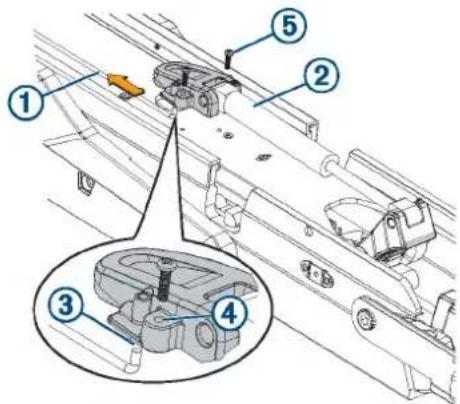
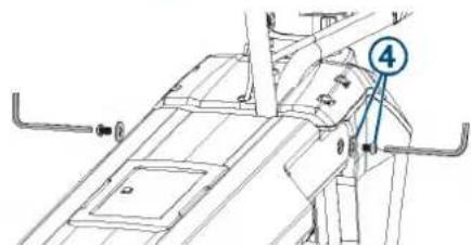
Routing the Power and Transducer Cables Through the Mount
Label identifying the parts bag required for this procedure:
F
NOTICE
To avoid damaging the power and transducer cables when deploying and stowing the trolling motor and to avoid interference with the GPS and heading sensors in the motor, you must route the cables through the right (starboard) side of the mount and secure them using the included hardware. You must not route the power cable through the left (port) side of the mount, and it is not possible to install the included brackets on the left (port) side. The left (port) side is reserved for additional accessories or transducer cables that you may install in the future.
1 Measure 40 cm (16 in.) on the power cable from where it connects to the steering system housing, and mark the cable with a marker or tape.
natural_image
Technical line drawing of a mechanical assembly with spring and lever components (no text or symbols)2 With the motor in the deployed position, route the transducer cable through the channel along the right (starboard) side of the mount ①
TIP: To determine the right (starboard) side of the mount, stand in a location where you can read the information on the display panel.
3 Route the power cable through the channel above the transducer cable.
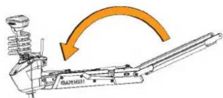
4 Using the pull cable, carefully lift the motor from the deployed position to the stowed position.
CAUTION
Because only one of the lift-assist gas springs is secured at this point in the installation, you must use caution when lifting the motor to the stowed position. The weight of the motor may cause the mount to move quickly and pinch or crush hands or fingers.
5 Leaving a rounded bend in the cables ② hold them against the side of the mount where they enter the channel.
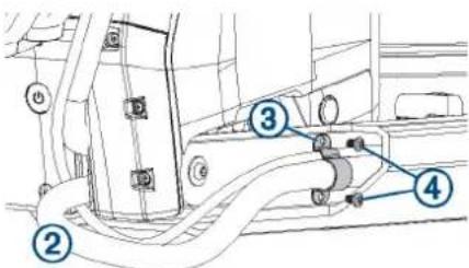
6 At the location on the power cable you marked in step 1, place one of the brackets that has two screw holes over the cables and against the mount, aligning the holes on the bracket with the holes on the mount.
7 Using a 3 mm hex bit or wrench, secure the bracket to the mount using two screws ④.
8 Hold the cables against the bottom of the mount where they exit the channel.
9 Place the other bracket that has two screw holes ⑤ over the cables and against the mount, aligning the holes on the bracket with the holes on the mount.
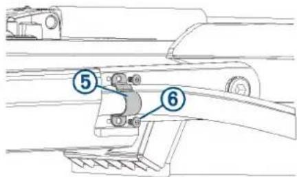
10 Using a 3 mm hex bit or wrench, secure the bracket to the mount using two screws ⑥
11 Hold the cables against the plastic portion of the mount base, close to the boat deck.
12 Insert the lower tab on the remaining bracket into a slot below the cables ⑦ and rotate the bracket toward the mount base to hold the cables.
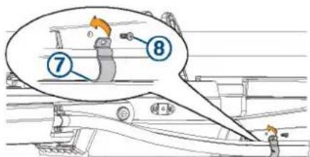
13 Using a #1 Phillips screwdriver, secure the upper tab of the bracket to the mount base using a single screw ⑧
14 Install additional plastic cable clips to secure the transducer cable to the power cable where needed (optional).
Two plastic cable clips are included in the parts bag.
Securing the Lower Gas Spring
Label identifying the parts bag required for this procedure:

NOTE: This procedure uses the rest of the hardware in the parts bag that you used when installing the upper gas spring.
1 Align the hole on the base of the lower gas spring ① with the safety rod ② and press down.
You may need to lift up the mount and flip over the gas spring if it was positioned on the other side of the mount during the previous installation steps.
NOTE: If you must rotate the gas spring so the base aligns with the mount, rotate the spring in a clockwise direction only. Rotating the gas spring in a counter-clockwise direction may loosen the fittings.
2 Using a #2 Phillips screwdriver, secure the base of the lower gas spring to the mount using the included screws ③
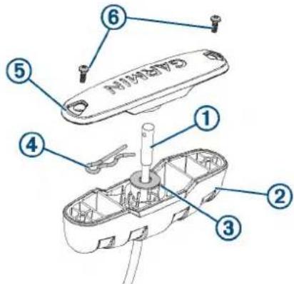
Installing the Propeller
The parts bag containing the hardware needed for this procedure is included in the box with the propeller and does not have a label.
1 Insert the pin through the propeller motor shaft. ②
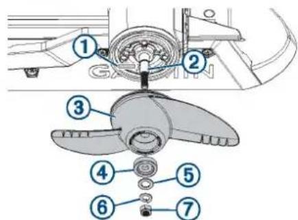
2 If necessary, rotate the motor shaft to orient the pin horizontally so it is less likely to fall out during installation.
3 Align the channel on the inside of the propeller ③with the pin, and slide the propeller onto the motor shaft.
4 Place the anode ④ washer, lock washer, and nut onto the end of the motor shaft.
5 Using a 916 in. (14 mm) socket, tighten the lock nut to 6 lbf-ft (8.13 N-m) to secure the propeller.
Connecting to Power
1 Route the power cable to the breaker panel or the location where you plan to install the breaker.
2 If necessary, extend the power cable using the appropriate wire gauge based on the length of the extension (Power Cable Extension, page 6) using solder and heat-shrink tubing.
3 Install a trolling motor plug and receptacle rated for 60 A or greater where the power cable enters a bulkhead (optional).
4 Connect the power cable to a circuit breaker rated for 60 A (continuous).
WARNING
The circuit breaker must be in the off position before you connect the power cables from the trolling motor.
5 If necessary, connect the circuit breaker to a 60 A, 24 or 36 Vdc power source.
Power Cable Extension
You can extend the power cable using the appropriate gauge of wire based on the length of the extension.
NOTICE
Power cable extensions must use single-conductor wire, with a minimum 75^ C ( 167^ F) insulation, that is not bundled, not sheathed, and not run through conduit. If you are using wire with 105^ C ( 221^ F) insulation or better, you can bundle up to three conductors inside a sheath or conduit outside of engine spaces. When installing the power cable extension, you must follow industry standards and best practices.
Extension length Minimum wire gauge Optimal wire gauge
| 0 to 3 m (0 to 10 ft.) 6 AWG (16 mm) | 2) 6 AWG (16 mm) | 2) |
| 3 to 4.6 m (10 to 20 ft.) 6 AWG (16 mm) | 2) 4 AWG (25 mm) | 2) |
| 4.6 to 9.1 m (20 to 30 ft.) 6 AWG (16 mm) | 2) 2 AWG (35 mm) | 2) |
Connecting the Transducer to a Chartplotter
The built-in 12-pin transducer is compatible with select Garmin* chartplotter models. Go to www.garmin.com or contact your Garmin dealer for more information.
1 Route the transducer cable to the installed chartplotter.
2 Install the locking collar on the end of the transducer cable.
3 Connect the transducer cable to the transducer port on the back of the chartplotter.
You can refer to the instructions provided with your chartplotter to identify the transducer port.
Stabilizer Installation
The stabilizer is an optional accessory that can help stabilize and provide additional support for the trolling motor when it is in the stowed position.
Installation instructions for the stabilizer are provided in the stabilizer box.
Foot Pedal Installation
The foot pedal connects to the trolling motor wirelessly and is paired at the factory.
Detailed mounting and power instructions are included in the Force Trolling Motor Foot Pedal Installation Instructions, in the foot pedal box. Operation instructions are included in the Force Trolling Motor Quick Start Manual.
Remote Control Installation
The remote control connects to the trolling motor wirelessly and is paired at the factory.
Operation instructions are included in the Force Trolling MotorQuick Start Manual.
Maintenance Needs and Schedule
To maintain your warranty, you must perform a series of routine maintenance tasks as you prepare your motor for the season. If you use or transport the motor in dry, dusty environments (traveling on gravel roads, for example) you should perform these tasks more often during the season.
For detailed procedures and information on service and replacement parts, download the Force Trolling Motor Maintenance Manual from www.garmin.com/manuals/force_trolling_motor.
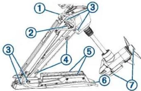
- Examine the power cable for wear, and patch or repair as necessary ①
- Check the power terminals, and clean them if necessary. ②
- Lubricate the hinges and bushings .③
- Clean and lubricate the stow and deploy latch mechanism .④
- Check the mount rails, and replace them if necessary. ⑤
- Check the mount bumper, and replace it if necessary. ⑥
- Clean or replace the anodes in the propeller drive motor. ⑦
Motor Information
Stowed Dimensions
| Item 50 in. Model 57 in. Model | ||
| 1 | 1.558 m (61 ^5 / _16 in.) min.1.811 m (71 ^5 / _16 in.) max. | 1.712 m (67 ^3 / _8 in.) min.2.066 m (81 ^5 / _16 in.) max. |
| 2 | 300 mm (11 ^13 / _16 in.) 340 mm (13 | ^3 / _8 in.) |
Deployed Dimensions
| Item 50 in. Model 57 in. Model | ||
| 1 | 461 mm ( 18^1/_8 in.) min.721 mm ( 28^3/_8 in.) max. | 488 mm ( 19^3/_16 in.) min.817 mm ( 32^1/_8 in.) max. |
| 2 | 708 mm ( 27^7/_8 in.) 799 mm (31 | ^7/_16 in.) |
| 3 | 839 mm ( 33^1/_16 in.) min.1.1 m ( 43^5/_16 in.) max. | 1.724 m ( 67^7/_8 in.) max.920 mm ( 36^3/_16 in.) min. |
| Item 50 in. Model 57 in. Model | ||
| 4 | 931 mm ( 36^11/_16 in.) 1.022 m (40 | ^1/_4 in.) |
| 5 | 402 mm ( 15^13/_16 in.) 402 mm (15 | ^13/_16 in.) |
| 6 | 203 mm (8 in.) 203 mm (8 in.) | |
Registering Your Device
Help us better support you by completing our online registration today. Keep the original sales receipt, or a photocopy, in a safe place.
1 Go to my.garmin.com/registration.
2 Sign in to your Garmin account.
Contacting Garmin Support
- Go to support.garmin.com for help and information, such as product manuals, frequently asked questions, videos, and customer support.
• In the USA, call 913-397-8200 or 1-800-800-1020.
• In the UK, call 0808 238 0000.
• In Europe, call +44 (0) 870 850 1241.
Specifications
Trolling Motor
| Weight (motor, mount, and cables) | 50 in. model: 30 kg (66 lb.)57 in. model: 31.75 kg (70 lb.) |
| Weight (stabilizer) 0.54 kg (1.2 lb.) | |
| Operating temperature | From -5° to 40°C (from 32° to 104°F) |
| Storage temperature | From -40° to 85°C (-40° to 185°F) |
| Material Mount and motor housing: aluminumShaft cap, display panel, and side panels: plasticMotor shaft: fiberglass | |
| Water rating Shaft cap: IEC 60529 IPX51Steering motor housing: IEC 60529 IPX72Display panel housing: IEC 60529 IPX7Propeller drive motor housing: IEC 60529 IPX83 | |
| Compass safe distance | 91 cm (3 ft.) |
| Power cable length 50 in. model: 1.2 m (4 ft.)57 in. model: 1.1 m (3.5 ft.) | |
| Input voltage From 20 to 45 Vdc | |
| Input amperage 60 A continuous | |
| Breaker (not included) | 42 VDC or greater, suitable for 60 A continuousNOTE: You can protect the system buy using a larger circuit breaker, not to exceed 90 A, if you are operating under high temperatures or if you are sharing the circuit with other devices. You should verify that your boat wiring meets marine wiring standards using a larger breaker before changing it. |
| Main power usage at 36 Vdc 60 A | Off: 72 mWFull power: 2160 W |
| Radio frequency | 2.4 GHz @ 28 dBm nominal |
Remote Control
| Dimensions (W×H×D) | 152 x 52 x 32 mm (6 x 2 x 1^1/_4 in.) |
| Weight | 109 g (3.8 oz.) without batteries |
| Material | Glass-filled nylon |
| Display type Sunlight-visible, transflective memory-in-pixel (MIP) | |
| Display resolution | R240 x 240 pixels |
| Display size (diameter) | 30.2 mm ( 1^3/_16 in.) |
| Operating temperature | From -15° to 55°C (5° to 131°F) |
| Storage temperature | From -40° to 85°C (-40° to 185°F) |
| Battery type | 2 AA (not included) |
| Battery life | 240 hr., typical use |
| Radio frequency | 2.4 GHz @ 3.4 dBm nominal |
| Water rating IEC 60529 | IPX7 ^4 |
| Compass-safe distance | 15 cm (6 in.) |
© 2019 Garmin Ltd. or its subsidiaries
Garmin ^7 , the Garmin logo, and ActiveCaptain ^™ are trademarks of Garmin Ltd. or its subsidiaries, registered in the USA and other countries. Force ^™ is a trademark of Garmin Ltd. or its subsidiaries. These trademarks may not be used without the express permission of Garmin.
You should reference United States Code of Federal Regulations: 33 CFR 183 - Boats and Associated Equipment and ABYC E-11: AC and DC Electrical Systems on Boats when installing this trolling motor.
GARMIN. FORCE™ TROLLING MOTOR FOOT PEDAL
INSTALLATION INSTRUCTIONS
Getting Started
WARNING
Do not run the motor when the propeller is out of the water. Contact with the rotating propeller may result in severe injury. Do not use the motor in areas where you or other people in the water may come into contact with the rotating propeller. Always disconnect the motor from the battery before cleaning or servicing the propeller to avoid injury.
CAUTION
When stowing or deploying the motor, be aware of the risk of entrapment or pinching from moving parts, which can result in injury.
When stowing or deploying the motor, be aware of slick surfaces around the motor. Slipping when stowing or deploying the motor may result in injury.
Always wear safety goggles, ear protection, and a dust mask when drilling, cutting, or sanding.
NOTICE
When drilling or cutting, always check what is on the opposite side of the surface.
To avoid damage to your boat, this device should be installed by a qualified marine installer. Specific knowledge of marine electrical systems is required for proper installation.
Tools Needed
- Two AA alkaline, NiMH, or lithium batteries (if powering with batteries)
- Four 5 mm (#10) stainless steel self-tapping screws (to secure the pedal to the boat deck)
- A drill and a 3 mm ( ^1/_8 in.) drill bit (to secure the pedal to the boat deck)
- Marine sealant (to seal the screws when securing the pedal to the boat deck)
Mounting and Power Considerations
When selecting a location for the foot pedal, observe these considerations.
- The foot pedal communicates wirelessly with the trolling motor, so you do not need to connect it to the motor using a cable.
- You can power the foot pedal by connecting it to a power source using the provided cable, or by using two AA batteries.
- If you prefer, you can mount the foot pedal to the boat deck. Mounting hardware is not provided.
- If your boat has a built-in or aftermarket foot pedal well, you can install the pedal in the well. Installation hardware is not provided.
Installation Procedures
Connecting to Power
You can power the foot pedal by connecting it to the boat battery. If you prefer a completely wireless installation, you can power the foot pedal using AA batteries.
NOTICE
If you connect the foot pedal to the boat battery, you should not install AA batteries. Batteries left in the foot pedal for long periods may corrode and cause damage.
1 Route the included power cable to the boat battery or circuit breaker, and to the location where you plan to mount or use the foot pedal.
If needed, you can extend the power cable using 18 AWG (0.82 mm ^4 ) wire.
NOTE: If you extend the power cable, you must first remove the fuse and a re-install it between the boat battery or circuit breaker and the cable extension.
2 Connect the red wire to the positive terminal of the battery or breaker, and connect the black wire to the negative terminal.
3 Push the connector on the power cable onto the port on the bottom of the foot pedal, and turn the locking ring clockwise to secure it.
4 Route the power cable through the channel on the bottom of the foot pedal.
natural_image
Technical line drawing of a mechanical or electronic component with no visible text, numbers, or symbols.Installing Batteries
The foot pedal can operate using two AA alkaline, NiMH, or lithium batteries (not included). Use lithium batteries for best results.
1 Lift up the front of the foot pedal as far as possible.
2 Pinch the sides of the battery cover ① and pull up to remove it.
natural_image
Technical line drawing of a car interior showing engine compartment and structural components (no text or symbols)3 Insert two AA batteries, observing polarity.
4 Place the battery cover over the batteries, and push down until both sides snap into place.
Mounting the Foot Pedal on the Boat Deck
NOTICE
You are not required to mount the foot pedal to the deck, but it is highly recommended, especially if you are powering it using batteries. An unsecured foot pedal may slide on the deck and fall off of the boat.
1 Determine the appropriate mounting hardware for your boat deck.
You should use 5 mm (#10) stainless steel self-tapping screws whose length is determined by the material of your boat deck.
2 Place the included mounting template in the selected location.
3 Using a 3 mm ( ^1/_8 in.) bit, drill the pilot holes indicated on the template, and remove the template.
4 Select an action:
- If you are powering the foot pedal using batteries, check the weather cap on the power connector on the bottom of the foot pedal to make sure it is secured.
- If you are powering the foot pedal using the included cable, connect the cable to the bottom of the foot pedal if you have not done so already.
5 Apply marine sealant to the pilot holes to prevent water from entering the boat deck (optional).
6 Secure the foot pedal to your boat deck using the mounting hardware.
Mounting the Foot Pedal in a Foot Pedal Tray
Before you can mount the foot pedal in a tray, you must install the tray in the deck of your boat following the instructions provided with the tray.
If you plan to secure the foot pedal inside the tray, you must purchase the appropriate mounting hardware for the tray material.
NOTE: You should use 5 mm (#10) stainless steel self-tapping screws that are long enough to pass through any shim used and through the tray material.
1 Place the foot pedal into the tray and test the height of the pedal.
2 If necessary, place temporary shims under the pedal until it is at the height you want.
After you determine the height, you should fabricate a permanent shim to install in the tray with the foot pedalFabricating a Permanent Shim, page 2.
3 Select an action:
- If you are powering the foot pedal using the included cable, connect the cable to the bottom of the foot pedal if you have not done so already.
- If you are powering the foot pedal using batteries, check the weather cap on the power connector on the bottom of the foot pedal to make sure it is secured.
4 If you are using a shim to raise the height of the pedal, secure the shim to the bottom of the foot pedal (optional).
5 If you do not plan to secure the foot pedal to the bottom of the tray, place the pedal into the tray to complete the installation.
6 If you plan to secure the foot pedal to the bottom of the tray, trim and place the included mounting template in the tray.
7 Using an appropriate drill bit for the tray material and the mounting hardware, drill the pilot holes indicated on the template, and remove the template.
8 Apply marine sealant to the pilot holes to prevent water from entering the boat deck.
9 Secure the foot pedal (and shim, if necessary) to the tray using the mounting hardware.
Fabricating a Permanent Shim
If you are installing the foot pedal in a tray and you would like to raise the height, you should fabricate a permanent shim to install under the pedal.
1 Purchase a suitable shim material, such as marine grade PVC, of the appropriate thickness for your installation.
2 Trace the shape of the tray on the shim material or a piece of paper.
3 Cut the shim from the material.
4 Place the shim into the tray to check the fit, and trim the edges as needed.
5 Locate the drain hole in the tray, mark the location of the hole on the shim, and drill a hole through the shim to allow water to drain properly.
Adjusting the Tension
You can adjust the tension on the foot pedal if it moves too easily or not easily enough.
1 Locate the tension adjustment screw ① on the left side of the foot pedal.
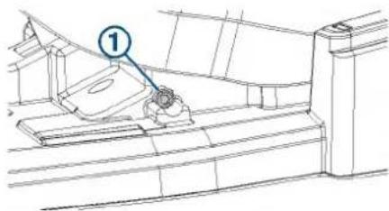
2 Select an action:
- Turn the screw clockwise to increase the tension.
- Turn the screw counterclockwise to decrease the tension.
3 Test the foot pedal, and repeat the previous step until the foot pedal moves like you want it to.
Specifications
| Dimensions (L×W×H) 303 × 221 × 110 mm (11 ^15/_16 × 8 ^11/_16 × 4 ^5/_16 in. | |
| Weight 1.8 kg (4 lb) | |
| Operating temperature From -15 to 70°C (From 5 to 158°F) | |
| Water rating IEC 60529 IPX7 | 1 |
| Material Plastic | |
| Input voltage From 10 to 45 Vdc | |
| Typical input current < 1 mA @ 12 Vdc | |
| Max input current 10 mA @ 12 Vdc | |
| Fuse (on the power cable) 2 A mini-blade type | |
| Power cable length 2 m (6.6 ft.) | |
| Battery type Two AA batteries (Alkaline, NiMH, or lithium. Not included.) | |
| Battery life At least 1 year | |
| Radio frequency 2.4 GHz @ 2.5 dBm nominal | |
| Compass-safe distance 60 cm (2 ft.) | |
© 2019 Garmin Ltd. or its subsidiaries
Garmin ^7 , the Garmin logo, and GPSMAP ^8 are trademarks of Garmin Ltd. or its subsidiaries, registered in the USA and other countries. ActiveCaptain ^9 , ECHOMAP ^10 ,
and Force ^™ are trademarks of Garmin Ltd. or its subsidiaries. These trademarks may not be used without the express permission of Garmin.
GARMIN.
Tools, Supplies, and Equipment Needed
The tools, supplies, and equipment needed to service and repair the trolling motor depend on the service or repair needed. Not all of the items listed are applicable for every procedure.
Tools, Supplies, and Equipment Needed for Maintenance
When performing routine maintenance, you must have the following tools and supplies.
• #2 Phillips screwdriver
- 4 mm and 3 mm hex bits or wrenches
• 10 and 15 mm sockets
• ^9/_16 in. socket
- For removing the propeller
- A 15 mm socket is acceptable, if necessary
- Replacement anodes (010-12832-35)
- Wire brush
• Silicone lubricating grease - Non-stick, dry-film lubricant (such as DuPont ^TM Dry Film Lubricant with Teflon®)
- Dielectric grease
- Isopropyl alcohol (for cleaning areas before applying touch-up paint)
- Liquid polyurethane paint (for touching up nicks and scratches)
Tools, Supplies, and Equipment Needed for Repair
When performing repair or replacement procedures, you must have the following tools and supplies.
-
Suitable workbench or table
-
Must be at least 8 ft. long for working on the 50 in. models
-
Must be at least 10 ft. long for working on the 57 in. models
-
1 Phillips screwdriver
• #2 Phillips screwdriver
- 3 mm and 4 mm and 8 mm hex bits or wrenches
• 10 and 15 mm socket
• ^9/_16 in. socket
-
For removing the propeller
• A 15 mm socket is acceptable, if necessary -
36 mm or adjustable wrench (for replacing the coil cable)
- Torque wrench
With 4 mm and 8 mm hex bits
- Capable of measuring torque from 5 kgf-cm (4.3 lbf-in) to 55 N-m (40.5 lbf-in.)
- Silicone lubricating grease (for replacing the latching mechanism)
- Needle-nose pliers
• Dielectric grease (for replacing the power cable or coil cable) - Shaft and motor hardware service kit
S00-01000-35
- For replacing the shaft or propeller drive motor
• Metal parts accessory kit
S00-01000-20
- Contains all of the metal parts, such as brackets and screws, that may be needed when performing repairs
- Plastic parts accessory kit
S00-01000-46
- Contains all of the plastic parts, such as washers and bushings, that may be needed when performing repairs
Overview and Part Locations
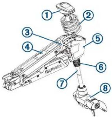
Item Description
| 1 | Shaft cap |
| 2 | Coil cable (and transducer cable) |
| 3 | Power cable (and transducer cable) |
| 4 | Display panel |
| 5 | Steering servo housing |
| 6 | Depth-adjustment collar |
| 7 | Shaft |
| 8 | Drive motor and propeller |
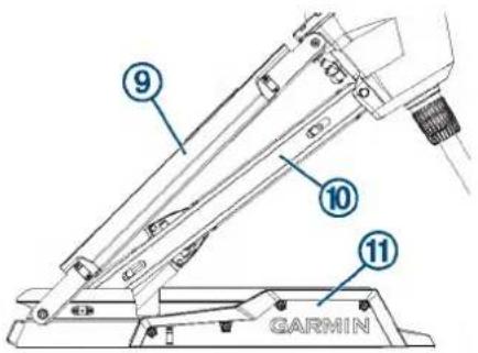
Item Description
| 9 | Upper link of the mount |
| 10 | Lower link of the mount |
| 11 | Mount base |
Maintenance Needs and Schedule
CAUTION
Use extreme care when following the procedures in this section. Some maintenance tasks require you to move the motor from the stowed to the deployed position multiple times, which presents a potential for hands or fingers to be crushed by the weight of the motor.
NOTICE
After using the motor in salt water or brackish water, you must rinse off the entire motor with fresh water, and apply a water-based silicone spray using a soft cloth. You should avoid spraying jets of water at the cap on the top of the shaft when rinsing the motor.
To maintain your warranty, you must perform a series of routine maintenance tasks as you prepare your motor for the season. If you use or transport the motor in dry, dusty environments (traveling on gravel roads, for example) you should perform these tasks more often during the season.
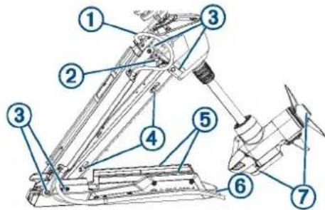
- Examine the power cable for wear, and patch or repair as necessary ①
- Check the power terminals, and clean them if necessary (Checking and Cleaning the Power Terminals, page 3).
- Lubricate the hinges and bushings ③ (Lubricating the Hinges and Bushings, page 2).
- Clean and lubricate the stow and deploy latch mechanism (Cleaning and Lubricating the Locking Mechanism, page 2).
- Check the mount rails, and replace them if necessary (Checking and Replacing the Mount Rails, page 3).
- Check the mount bumper, and replace it if necessary (Checking and Replacing the Mount Bumper, page 4).
- Clean or replace the anodes in the propeller drive motor (Servicing the Anodes, page 3).
Cleaning and Lubricating the Locking Mechanism
CAUTION
This procedure is best performed with the motor halfway between the stowed and deployed positions. When in this position, the motor is not secured, so you should support the motor and use extreme caution to avoid pinching or crushing hands or fingers.
1 Place the motor between the stowed and deployed positions so the base is oriented vertically and you can access both locking mechanisms ①
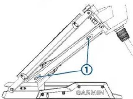
2 Support the weight of the motor so it cannot fall and crush your hands or fingers.
3 Clean any debris, dirt, and build up from all of the locking mechanism channels.
4 Apply a silicone lubricating grease to the locking mechanisms and the channels.
5 Pull and release the pull cable a number of times to move the mechanisms in the channels and distribute the grease.
6 If necessary, apply additional grease and repeat the previous step.
7 Clean any debris, dirt, and build up from the latch receivers ② on the front of the mount base.
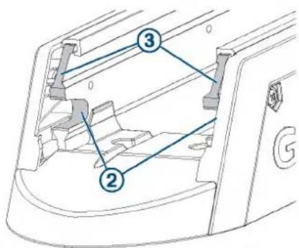
8 Apply a silicone lubricating grease to the upper surface of the latch receivers on the front of the mount base, so the locking mechanisms slide smoothly into the receivers.
9 Repeat the previous two steps for the latch receivers on the back of the mount base ④
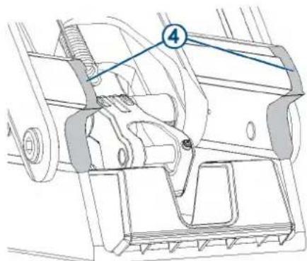
10 Return the motor to the stowed or deployed position.
Lubricating the Hinges and Bushings
There are a number of hinges and bushings that allow the motor to transition smoothly from the stowed to deployed position and back again. You should lubricate these areas as needed.
1 Locate the four primary hinge points ①
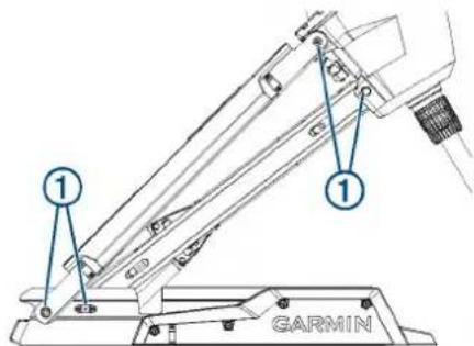
2 Apply a non-stick, dry-film lubricant to each hinge point, in the space between the moving parts ② and allow it to dry according to the instructions provided with the product.
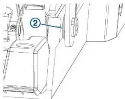
3 Move the motor from the stowed to the deployed position and back a number of times to distribute the lubricant.
4 If necessary, apply additional lubricant and repeat the previous step.
Servicing the Anodes
The anodes protect the motor components from corrosion, and each season they must be examined and cleaned or replaced if necessary.
1 Using a ^9/_16 in (15 mm) socket, loosen the nut on the end of the propeller.
2 Remove the nut, lock washer, flat washer, and anode ①
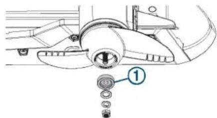
3 Examine the anode, and complete an action:
- If the anode is more than half of the original size, clean the anode using a wire brush or sandpaper.
- If the anode is less than half of the original size, discard the anode and purchase a replacement.
4 Place the cleaned or new anode on the propeller shaft, and secure the propeller with the lock washer, flat washer, and nut.
5 Using a ^9/_16 in (15 mm) socket, tighten the nut to 8.13 N-m (6 lbf-ft).
6 Using a 4 mm hex bit or wrench, remove the skeg from the bottom of the motor.
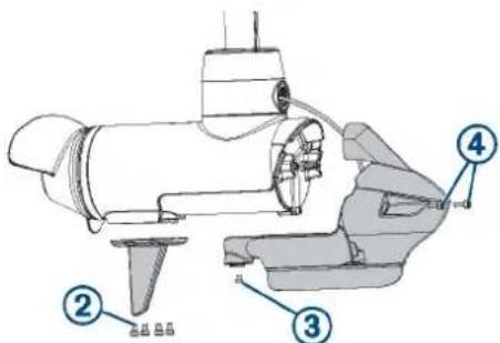
7 Using a 3 mm hex bit or wrench, remove the screw that secures the transducer and nose cone to the bottom of the motor.
8 Using a 4 mm hex bit or wrench, remove the screws ④ to disconnect the nose cone from the front of the motor.
9 Using a 3 mm hex bit or wrench, remove the screw and anode on the front of the motor.
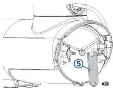
10 Examine the anode, and complete an action:
- If the anode is more than half of the original size, clean the anode using a wire brush or sandpaper. - If the anode is less than half of the original size, discard the anode and purchase a replacement.
11 Place the cleaned or new anode on the screw and secure it to the motor.
12 Secure the nose cone to the front of the motor.
13 Install the screw that secures the transducer and nose cone to the bottom of the motor.
14 Install the skeg on the bottom of the motor.
Checking and Cleaning the Power Terminals
1 With the motor in the deployed position, pull the rubber shields away from the positive and negative power terminals ①.
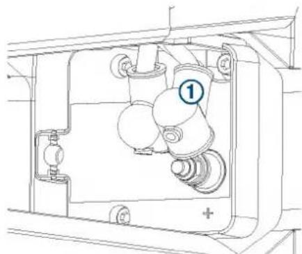
natural_image
Technical line drawing of a mechanical assembly with no visible text or symbols2 If necessary, clean any corrosion from the terminals using a wire brush.
NOTE: In cases of heavy corrosion, you may need to remove the power cables for an effective cleaning (Removing the Power Cable from the Steering Servo Housing, page 21).
3 Cover the connections with dielectric grease.
4 Securely place the rubber shields back over the power terminals.
Checking and Replacing the Mount Rails
The rails protect the propeller drive motor and the mount from impact when stowing the motor, and may become worn over time. If the rails are damaged or worn and the mount base is visible through them, you must replace them.
1 With the motor in the stowed position, examine the rails for wear and damage.
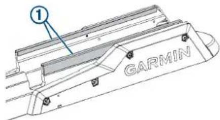
2 Select an action:
- If the rails are in good condition, and you cannot see the metal mount base though any worn areas, no further action is needed.
- If the rails are damaged or if you can see the metal mount base through worn areas in the rails, proceed to the next step to replace them.
3 Using a 4 mm hex bit or wrench, remove the screws that secure the shrouds to the mount base.
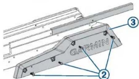
4 Slide the damaged rails off of the mount base.
5 Slide the replacement rails onto the mount base.
6 Secure the shrouds to the mount base using the screws you removed previously.
Checking and Replacing the Mount Bumper
The mount bumper is the part of the mount base that overhangs the bow of the boat.
1 Place the motor between the stowed and deployed positions, and check the mount bumper for damage.
2 Select an action:
- If the mount bumper is undamaged, no further action is needed.
- If the mount bumper is damaged, proceed to the next step to replace it.
3 Using a 4 mm hex bit or wrench, remove the two screws that secure the mount bumper to the mount base.
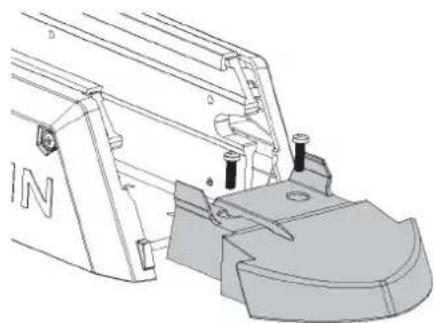
natural_image
Technical line drawing of a mechanical assembly with no visible text or symbols4 Install a replacement mount bumper, and secure it to the mount base using the screws provided with the replacement part.
Replacing the Propeller
If the propeller is damaged, you must replace it.
1 Using a 15 mm socket, remove the nut that secures the propeller.
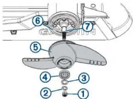
2 Remove the lock washer ② flat washer, anode, and damaged propeller ⑤
3 Service the anode, if necessary (Servicing the Anodes, page 3).
4 If necessary, install the pin ⑥ in the propeller motor shaft . ⑦
5 Install a replacement propeller.
6 Place the anode, flat washer, lock washer, and nut onto the end of the motor shaft.
7 Using a ^9/_16 in (15 mm) socket, tighten the nut to 8.13 N-m (6 lbf-ft) to secure the propeller.
Fixing Paint Scratches
Over time, parts of the motor may become scratched or dinged. You can use paint to touch up these areas for cosmetic purposes.
1 Using isopropyl alcohol, throughly clean the areas where the paint has been scratched or damaged.
2 Apply liquid polyurethane touch-up paint to the scratched or damaged areas.
3 Follow the instructions on the paint, and allow for proper drying before using the motor.
Service Parts
You can use these diagrams to identify and order service parts. You can follow the links where provided for detailed disassembly and replacement procedures.
To order the service parts listed in this manual, contact Garmin ^® at 1-800-800-1020 or go to support.garmin.com to place an order using email.
Shaft and Cable Parts
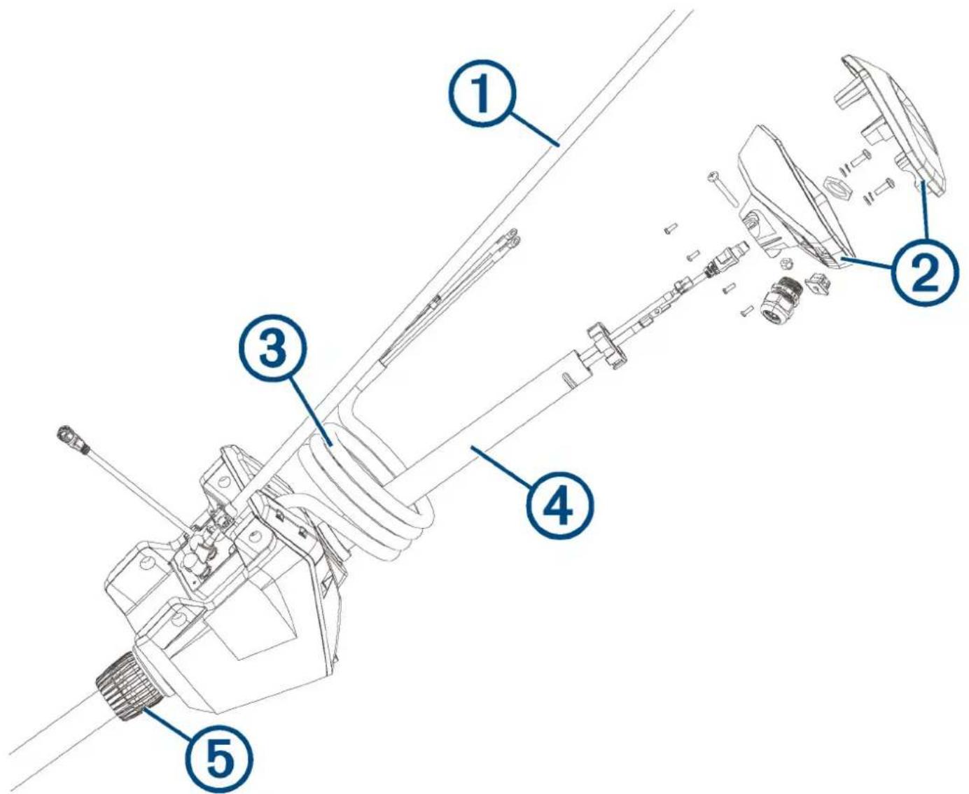
| Item Description Service Part Number Details | |||
| 1 | Power cable | S00-01000-22 | Removing the Power Cable from the Steering Servo Housing, page 21 |
| 2 | Shaft cap S00-01000-12 The service kit contains the internal hardware, cable grip, and grommet.Removing the Shaft Cap, page 11 | ||
| 3 | Coil cable | S00-01000-48 | Removing the Coil Cable from the Steering Servo Housing, page 22 |
| 4 | Shaft 50 in. model: | S00-01000-0257 in. model:S00-01000-07 | Removing the Propeller Drive Motor and Nose Cone from the Shaft, page 12 |
| 5 | Depth adjustment collar | S00-01000-41 | Removing the Depth-Adjustment Collar, page 12 |
| Not shown | Pull cable and handle | 010-12832-30 | Installing a New Pull Cable, page 9 |
| Not shown | 60 A circuit breaker accessory 010-12832-40 Instructions are provided with the circuit breaker. | ||
| Not shown | Power cable plug accessory 010-12832-41 Instructions are provided with the power cable plug. | ||
| Not shown | Power cable receptacleaccessory | 010-12832-42 Instructions are provided with the power cable socket. | |
| Not shown | Foot pedal power cablereplacement | 010-12832-10 Installation instructions are provided with your foot pedal. | |
Propeller Drive Motor Parts
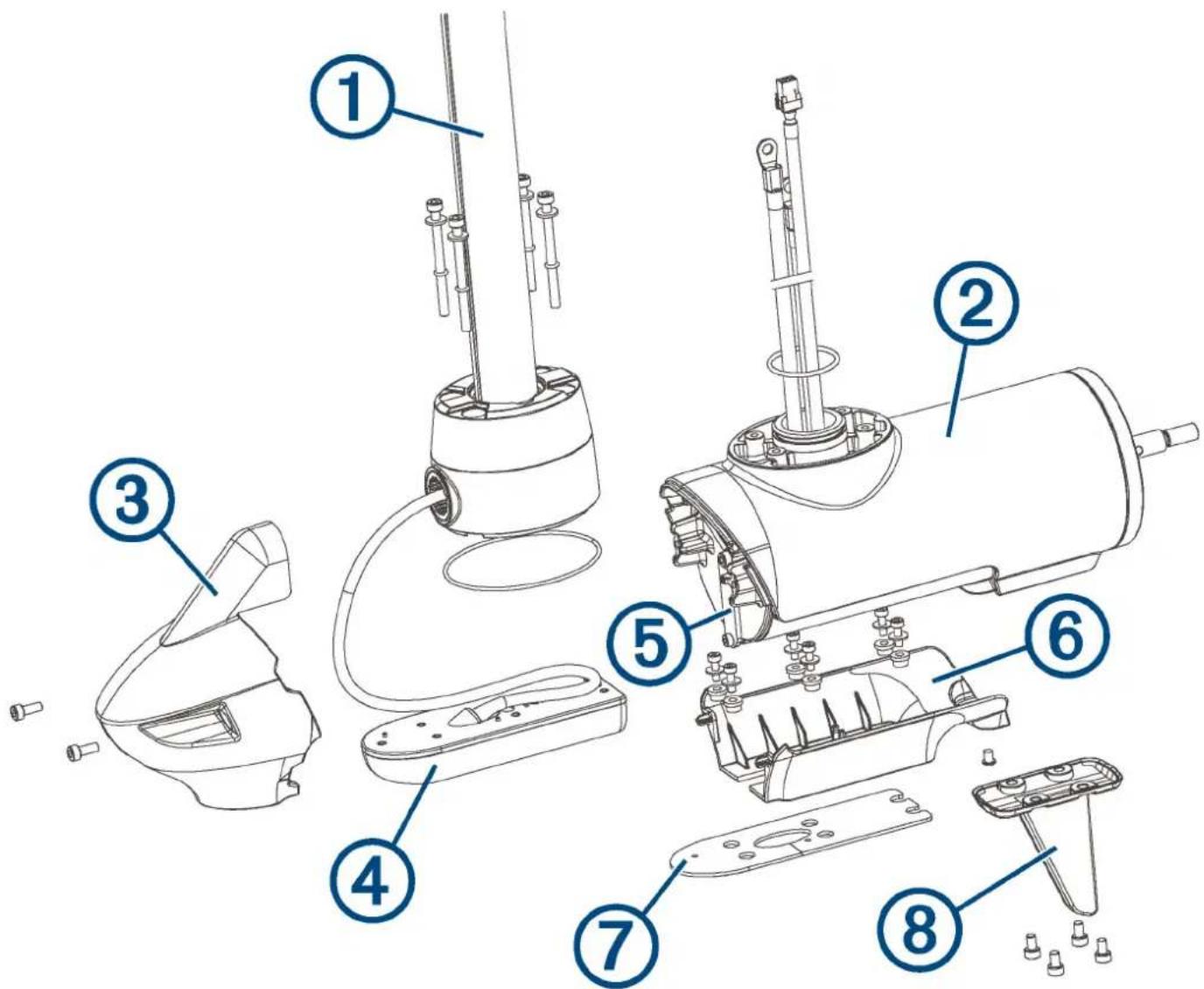
| Item Description Service Part Number Details | |||
| 1 | Shaft 50 in. model: S00-01000-0257 in. model: S00-01000-07 | Removing the Propeller Drive Motor and Nose Cone from the Shaft, page 12 | |
| 2 | Propeller drive motor N/A This part is replaceable by an authorized repair technician only. | ||
| 3 | Nose cone Transducer: 010-12832-20No transducer: 010-12832-22 | One of two parts included with a replacement nose cone.(Replacing the Nose Cone, page 13) | |
| 4 | Transducer Contact Garmin support for replacement transducer options.Transducer replacement kit:010-12832-25 | The replacement transducer and transducer replacement kit are sold separately.Detailed replacement instructions (190-02521-94) are included with the transducer replacement kit. | |
| 5 | Motor anode 010-12832-35 The anode kit contains the motor anode and the propeller anode (not shown).Servicing the Anodes, page 3 | ||
| 6 | Lower nose cone Transducer: 010-12832-20No transducer: 010-12832-22 | One of two parts included with a replacement nose cone.(Replacing the Nose Cone, page 13) | |
| 7 | Transducer pad 010-12832-25 Included in the transducer replacement kit. | ||
| 8 | Skeg 010-12832-18 Removing the Skeg and Nose Cone, page 12 | ||
| Not shown | Propeller Power propeller: 010-12832-00Weedless propeller: 010-12832-01 | Replacing the Propeller, page 4 | |
Mount Parts
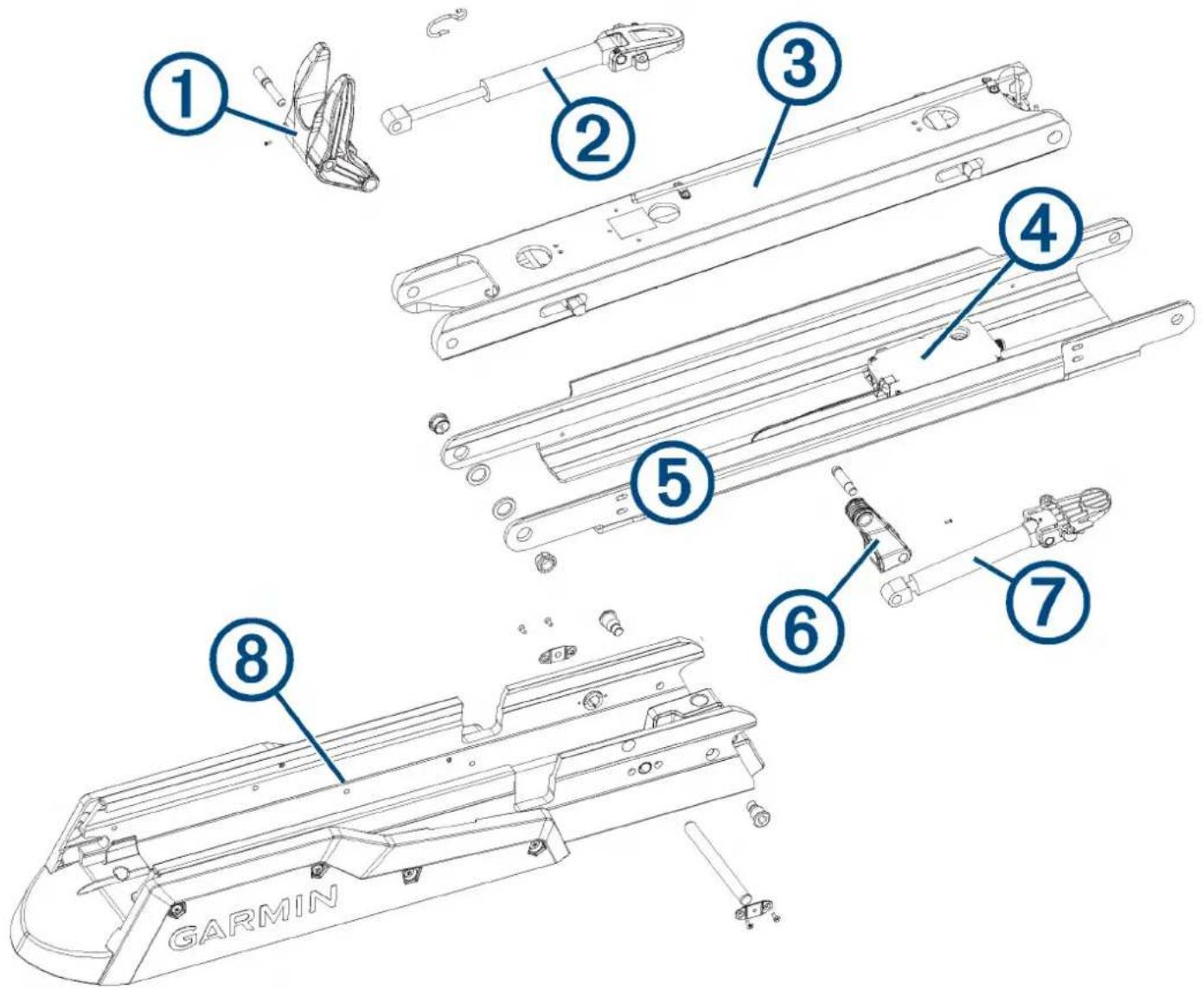
| Item Description Service Part Number Details | |||
| 1 | Lower gas spring arm and shaft stabilizer | S00-01000-18 Disconnecting the Lower Gas Spring, page 17 | |
| 2 | Lower gas spring (deploy) | S00-01000-37 | Disconnecting the Lower Gas Spring, page 17 |
| 3 | Mount lower link Lower link and latching components assembled,50 in. model: S00-01000-04Latching components only, 50 in. model:S00-01000-45Lower link and latching components assembled,57 in. model: S00-01000-09Latching components only, 57 in. model:S00-01000-11 | Removing the Lower Link from the Mount Base,page 23 | |
| 4 | Display panel (Ebox) S00-01000-39 (Replacing the Display Panel, | page 22) | |
| 5 | Mount upper link 50 in. model: S00-01000-0357 in. model: S00-01000-08 | Removing the Upper Link from the Mount Base,page 23 | |
| 6 | Upper gas spring arm | S00-01000-17 | Disconnecting the Upper Gas Spring, page 18 |
| 7 | Upper gas spring (stow) 50 in. model: S00-01000-3857 in. model: S00-01000-40 | Disconnecting the Upper Gas Spring, page 18 | |
| 8 | Mount base See Mount Base Parts , page 8 for mount baseservice part numbers. | Mount Base Parts, page 8 | |
Mount Base Parts
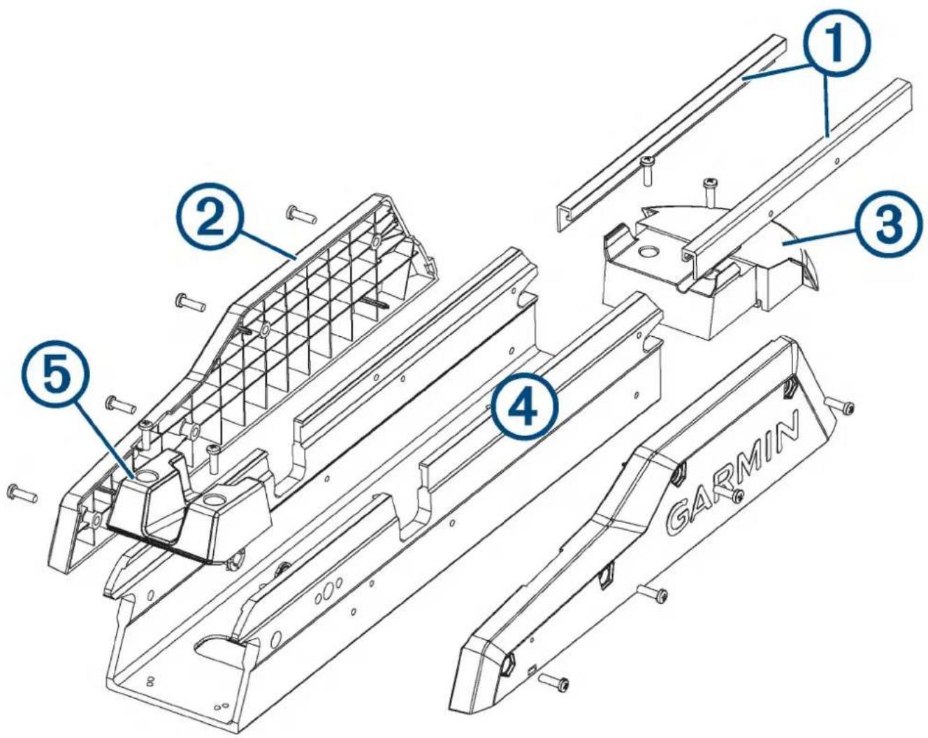
| Item Description Service Part Number Details | |||
| 1 | Mount base rails 50 in. model: S00-01000-3357 in. model: S00-01000-34 | Replacing the Mount Rails, page 25 | |
| 2 | Mount base shrouds | S00-01000-14 | Replacing the Mount Shrouds, page 24 |
| 3 | Motor bumper S00-01000-19 | Replacing the Mount Bumper, page 25 | |
| 4 | Mount base 50 in. model: S00-01000-0557 in. model: S00-01000-10 | This replacement part includes the base and all of the plastic parts, including the shrouds, rails, stow support, and motor bumper, fully assembled.Replacing the Mount Base, page 24 | |
| 5 | Mount base stow support | S00-01000-47 | Replacing the Stow Support, page 25 |
Service Procedures
Replacing the Pull Cable
You can replace the pull cable without disassembling the motor.
1 If necessary, remove the handle from the pull cable (Removing the Pull Cable Handle, page 8).
2 Remove the pull cable from the mount (Removing the Pull Cable, page 9).
3 Install the new pull cable on the mount (Installing a New Pull Cable, page 9).
4 Install the handle on the new pull cable (Installing the Handle on the Pull Cable, page 9).
Removing the Pull Cable Handle
1 Using a #1 Phillips screwdriver, remove the two screws ① that secure top of the handle.
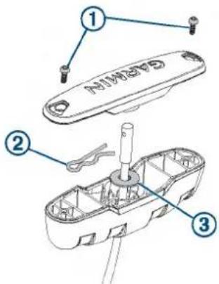
2 Push the pull cable up from the bottom of the handle, and remove the R-pin ②
3 Pull the cable through the washer and the bottom of the handle.
Removing the Pull Cable
Before you can remove the pull cable, you must remove the pull cable handle (Removing the Pull Cable Handle, page 8).
1 Transition the motor to the stowed position.
CAUTION
You should leave the motor in the stowed position until you have connected the new pull cable. If the mount is not securely locked in the deployed position, it may shift and crush your hands or fingers.
2 Locate the access hole on the underside of the mount base.
3 Using needle-nose pliers, remove the R-pin that secures the pull cable to the locking mechanism.
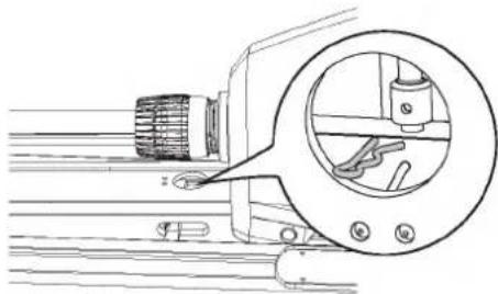
natural_image
Technical line drawing of a mechanical component with a magnified circular detail showing internal components (no text or symbols)4 Remove the pull cable from the mount base, and pull it through the steering servo housing.
Installing a New Pull Cable
Before you can install a new pull cable, you must remove the existing pull cable (Removing the Pull Cable, page 9).
CAUTION
After you have removed the existing pull cable, should leave the motor in the stowed position until you have connected the new pull cable. If the mount is not securely locked in the deployed position, it may shift and crush your hands or fingers.
1 Feed the end of the new pull cable into the mount base, and place it over the stud on the locking mechanism.
2 Using needle-nose pliers, push the R-pin through the hole on the end of the pull cable to secure it to the locking mechanism.
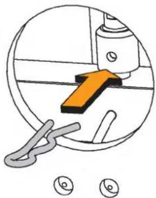
natural_image
Diagram showing a mechanical component with an orange arrow and two circular icons below (no text or symbols)3 Feed the other end of the pull cable through the steering servo housing, routing the cable between the upper link of the mount and the pivot pin.
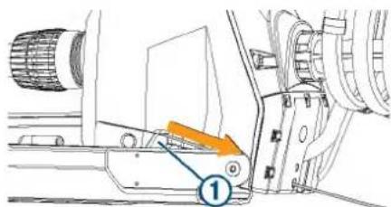
Installing the Handle on the Pull Cable
1 Insert the pull cable ① through the bottom half of the handle ②.
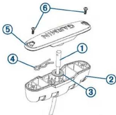
2 Insert the pull cable through the washer ③
3 Push the R-pin ④ through the hole on the end of the pull cable.
4 Pull the cable down so that the washer and R-pin rest in the bottom half of the handle.
NOTE: The R-pin fits in the bottom half of the handle one way only.
5 Using a #1 Philips screwdriver, secure the top of the handle ⑤ to the bottom using the screws ⑥
Removing the Power and Transducer Cables From the Mount
You should remove the power and transducer cables from the mount if you are replacing a damaged cable, transducer, or shaft.
1 Disconnect the motor from the power source.
2 With the motor in the stowed position, using a #1 Phillips screwdriver, remove the single screw that secures the upper tab of the bracket to the mount base, and remove the bracket.
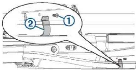
3 Using a 3 mm hex bit or wrench, remove the four screws ③ that secure the two brackets ④ to the mount on both sides of the cable channel.
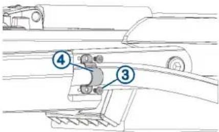
4 Pull the power cable out of the channel along the side of the mount.
5 Pull the transducer cable out of the channel along the side of the mount.
Routing the Power and Transducer Cables Through the Mount
After you have installed a replacement power cable, transducer, or shaft, you should route the power and transducer cables through the mount.
NOTICE
To avoid damaging the power and transducer cables when deploying and stowing the trolling motor and to avoid interference with the GPS and heading sensors in the motor, you must route the cables through the right (starboard) side of the mount and secure them using the included hardware. You must not route the power cable through the left (port) side of the mount, and it is not possible to install the included brackets on the left (port) side. The left (port) side is reserved for additional accessories or transducer cables that you may install in the future.
1 Measure approximately 40 cm (16 in.) on the power cable from where it connects to the steering servo housing, and look for the mark on the cable applied at the factory.
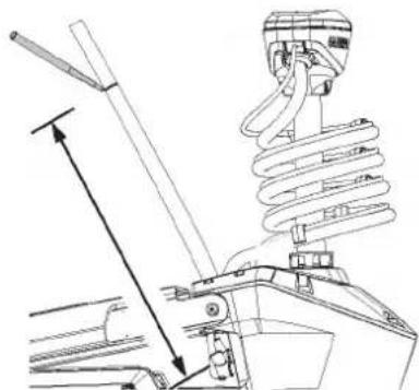
natural_image
Technical line drawing of a mechanical assembly with spring and lever components (no text or symbols)2 If you do not see a mark on the cable, or if the mark is not approximately 40 cm (16 in.) from the connection, make a mark with a marker or tape.
3 With the motor in the deployed position, route the transducer cable through the channel along the right (starboard) side of the mount ①
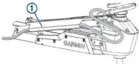
TIP: To determine the right (starboard) side of the mount, stand in a location where you can read the information on the display panel.
4 Route the power cable through the channel above the transducer cable.
5 Using the pull cable, carefully lift the motor from the deployed position to the stowed position.
NOTICE
You must secure the cables to the mount with the motor in the stowed position. If you complete this procedure with the motor in the deployed position, the cables are not at their fully extended length, and the added stress may damage the cables during use.
6 Leaving a rounded bend in the cables ② hold them against the side of the mount where they enter the channel.
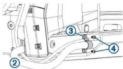
7 At the marked location on the power cable, place one of the brackets that has two screw holes over the cables and against the mount, aligning the holes on the bracket with the holes on the mount.
8 Using a 3 mm hex bit or wrench, secure the bracket to the mount using two screws ④
9 Hold the cables against the bottom of the mount where they exit the channel.
10 Place the other bracket that has two screw holes over the cables and against the mount, aligning the holes on the bracket with the holes on the mount.
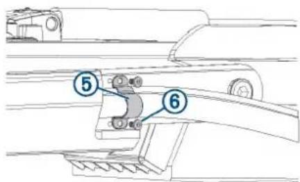
11 Using a 3 mm hex bit or wrench, secure the bracket to the mount using two screws ⑥
12 Hold the cables against the plastic portion of the mount base, close to the boat deck.
13 Insert the lower tab on the remaining bracket into a slot below the cables ⑦ and rotate the bracket toward the mount base to hold the cables.
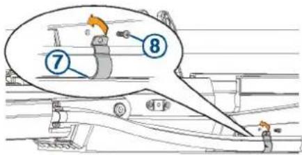
14 Using a #1 Phillips screwdriver, secure the upper tab of the bracket to the mount base using a single screw ⑧
Removing the Shaft and Propeller Drive Motor from the Steering System
Before you can remove the shaft and propeller drive motor, you must remove the transducer cable from the mount, if applicable (Removing the Power and Transducer Cables From the Mount, page 9).
1 Disconnect the motor from the power source.
2 Open the shaft cap (Opening the Shaft Cap, page 11).
3 Disconnect the cables in the shaft cap (Disconnecting the Cables in the Shaft Cap, page 11).
4 Remove the transducer cable from the shaft cap (Removing the Transducer Cable from the Shaft Cap, page 11).
5 Remove the shaft cap (Removing the Shaft Cap, page 11).
6 Remove the shaft from the steering system (Removing the Shaft from the Steering Servo, page 12).
Opening the Shaft Cap
NOTICE
Before you open the shaft cap, you must disconnect the motor from the power source.
1 Using a #2 Phillips screwdriver, remove the four screws that secure the lid of the shaft cap.
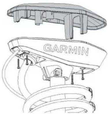
natural_image
Technical line drawing of a car engine component with 'GARMIN' branding (no other text or symbols)You should place these screws in a safe place, because you must use them to close the shaft cap.
2 Lift up to remove the lid of the shaft cap.
Disconnecting the Cables in the Shaft Cap
Before you can disconnect the cables in the shaft cap, you must open the shaft cap (Opening the Shaft Cap, page 11).
1 Using a #3 Phillips screwdriver, remove the two screws ① that secure the power cables in the shaft cap.
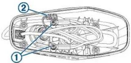
You should keep these screws in a safe place, because you must use them when reconnecting the cables.
2 Release the latch and pull the connectors apart to disconnect the data cable.
Removing the Transducer Cable from the Shaft Cap
Before you can remove the transducer cable from the shaft cap, you must open the shaft cap (Opening the Shaft Cap, page 11).
1 Disconnect the transducer cable from the chartplotter.
2 Remove the power and transducer cables from the mount (Removing the Power and Transducer Cables From the Mount, page 9).
3 Remove the plastic cable clamps that secure the transducer cable to the coiled power cable.
You should keep these cable clamps in a safe place, because you must reinstall later.
4 Straighten the transducer cable so you can easily pull it through the shaft cap.
5 Push from the inside out to remove the square grommet ① that holds the transducer cable ② in the shaft cap.
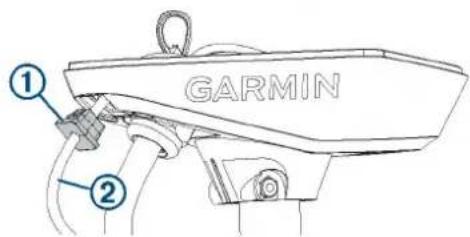
6 Remove the grommet from the transducer cable.
The grommet is split on one side to make it easy to remove from the cable.
You should keep the grommet in a safe place, because you must reinstall it later.
7 Feed the transducer cable through the shaft cap from the outside in until it is no longer routed through the square hole.
Removing the Shaft Cap
Before you can remove the shaft cap, you must remove the transducer cable from the shaft cap (Removing the Transducer Cable from the Shaft Cap, page 11) and disconnect the cables in the shaft cap (Disconnecting the Cables in the Shaft Cap, page 11).
1 Count and write down the number of coils in the coil cable that wraps around the shaft.
When re-assembling the shaft and shaft cap, it is beneficial to use the same number of coils around the shaft.
2 Using a 4 mm hex bit or wrench, remove the 1/4 -20 bolt ① and nut ② that secure the shaft cap to the shaft.
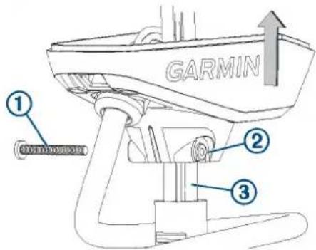
You should keep this bolt and nut in a safe place, because you must use them when reinstalling the shaft cap.
3 Lift up on the shaft cap to disconnect it from the shaft.
4 Pull the cables ③ from the shaft completely through the shaft cap, taking care to avoid damaging the data cable connector when you pull it through.
Removing the Shaft from the Steering Servo
Before you can remove the shaft from the steering servo, you must remove the shaft cap (Removing the Shaft from the Steering Servo, page 12).
This procedure is best performed with two people.
1 Loosen the depth adjustment collar on the base of the steering servo ①
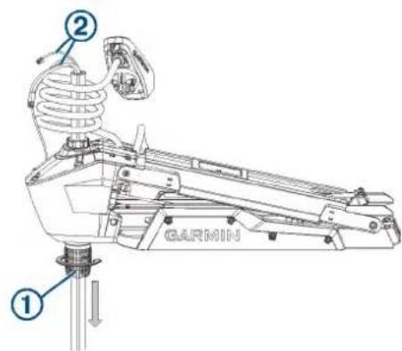
2 Slide the shaft down and out of the steering servo, taking care not to damage the skeg and transducer or snag the cables or connectors ② as you pull it through.
TIP: Depending on the height of your trailer, you may find it easier to remove the shaft if you transition the mount halfway between the deployed and stowed positions.
Removing the Depth-Adjustment Collar
Before you can remove the depth-adjustment collar, you must remove the shaft from the steering servo (Removing the Shaft from the Steering Servo, page 12).
Turn the depth-adjustment collar counter-clockwise to remove it from the steering servo.
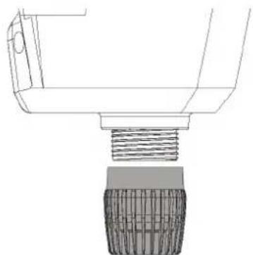
natural_image
Technical line drawing of a mechanical component with threaded base and textured body (no text or symbols)Removing the Propeller Drive Motor and Nose Cone from the Shaft
Before you can remove the propeller drive motor and transducer from the shaft, you must remove the shaft from the steering servo (Removing the Shaft and Propeller Drive Motor from the Steering System, page 11).
1 Remove the skeg and nose cone from the propeller drive motor (Removing the Skeg and Nose Cone, page 12).
2 Remove the propeller drive motor from the shaft (Removing the Propeller Drive Motor, page 12).
3 Remove the nose cone and transducer from the shaft (Removing the Nose Cone and Transducer, page 13).
Removing the Skeg and Nose Cone
1 Using a 4 mm hex bit or wrench, remove the four screws ① that secure the skeg ② to the propeller drive motor.
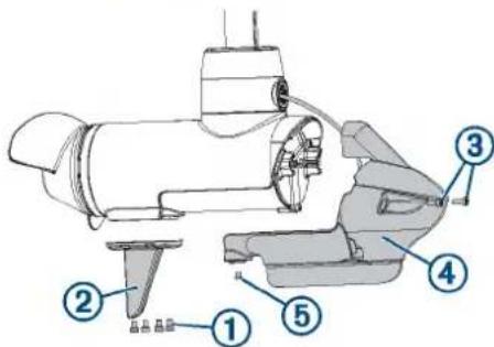
2 Remove the skeg.
3 Using a 4 mm hex bit or wrench, remove the two screws ③ that secure the front of the nose cone ④ the propeller drive motor.
4 Using a 3 mm hex bit or wrench, remove the single screw ⑤ that secures the bottom of the nose cone to the propeller drive motor.
You should keep all of these screws and parts in a safe place, because you must reinstall them when reassembling the skeg and nose cone.
Removing the Propeller Drive Motor
Before you can remove the propeller drive motor, you must remove the shaft from the steering servo (Removing the Shaft from the Steering Servo, page 12).
NOTE: When removing the propeller drive motor, using a ball-head hex bit or wrench is highly recommended because of the angle needed to reach the head of the screws.
1 Using the tool ① included in the shaft and motor hardware service kit, remove the recessed nut ② that secures the transducer cable to the shaft.
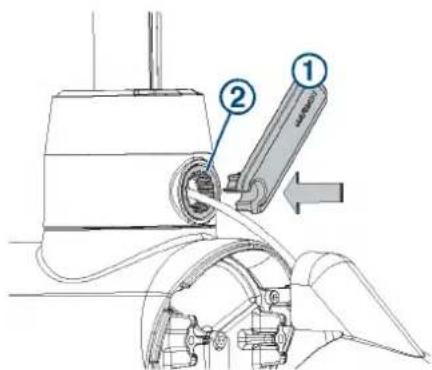
2 Using a ball-head 4 mm hex bit or wrench, remove the four screws that secure the shaft base to the propeller drive motor.
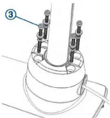
When replacing the transducer, you should dispose of these four screws. New screws, washers, and O-rings are provided in the shaft and motor hardware service kit.
3 Straighten the cables at the top of the shaft, and slowly pull the propeller drive motor away from the shaft base until you can see the power and data cables connected to the propeller drive motor.
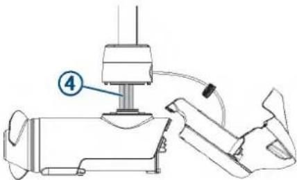
4 Holding the cables only, slowly pull them through the shaft, taking care that the ring terminals and data cable connector do not get caught on the top of the shaft.
NOTICE
When removing the propeller drive motor from the shaft, you must pull the cables themselves, and not the motor. Pulling on the propeller drive motor may damage the cable connections inside the motor.
The power and data cables should pull through the shaft, but the transducer cable should mostly stay in place.
Removing the Nose Cone and Transducer
Before you can remove the nose cone and transducer, you must remove the propeller drive motor (Removing the Propeller Drive Motor, page 12).
1 Carefully pull the transducer cable straight down through the bottom of the shaft until it is completely removed from the shaft.
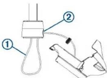
2 After you pull the transducer cable out of the shaft, pull it through the hole in the front of the shaft base ② along with the rubber cable gland and the recessed nut.
3 Dispose of the cable gland and recessed nut.
The shaft and motor hardware service kit contains a new cable gland and recessed nut.
Disassembling the Nose Cone
Before you can disassemble the nose cone, you must remove the skeg and nose cone from the propeller drive motor (Removing the Skeg and Nose Cone, page 12).
1 Using a 3 mm hex bit or wrench, remove the six screws that secure the transducer to the nose cone.
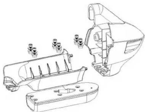
natural_image
Technical line drawing of a mechanical assembly with exploded view and internal components (no text or symbols)2 Remove the transducer and transducer pad from the nose cone.
If you are not replacing the transducer, you should keep the transducer pad and six screws so you can secure the transducer to the replacement nose cone.
Replacing the Nose Cone
Before you can replace the nose cone, you must disassemble the nose cone (Disassembling the Nose Cone, page 13).
1 Place the transducer pad ① on the transducer.
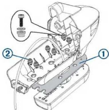
2 Using a 3 mm hex bit or wrench, secure the transducer to the nose cone using the six screws and bushings ②
3 Install the nose cone and skeg on the shaft (Installing the Nose Cone and Skeg, page 15).
Installing the Propeller Drive Motor in the Shaft
You must perform these actions to reassemble the propeller drive motor in the shaft.
NOTICE
The screws, replacement seals, and grease packet are included in the motor hardware service kit (S00-01000-35). You should use the new parts from the kit instead of reusing the screws and seals you removed with the propeller drive motor.
1 Install the nose cone and transducer in the shaft (Installing the Nose Cone and Transducer in the Shaft, page 14).
2 Install the propeller drive motor on the shaft (Installing the Propeller Drive Motor, page 14).
3 Install the nose cone and skeg on the propeller drive motor (Installing the Nose Cone and Skeg, page 15).
Installing the Nose Cone and Transducer in the Shaft
NOTICE
The shaft and motor hardware service kit contains new seals. You should use the new parts from the kit instead of reusing the seals you removed with the nose cone and transducer.
NOTE: If you are performing this procedure because you are removing the transducer completely, you should complete only the first step.
1 Place the 25 mm (1 in.) O-ring on the recessed nut from the shaft and motor hardware service kit.
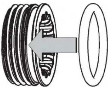
natural_image
Diagram of a mechanical gear assembly showing a rotating shaft and housing (no text or labels)2 With the O-ring facing the transducer, feed the replacement transducer cable through the recessed nut and the hole in the front of the shaft base, but do not feed it up through the shaft.
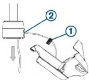
3 After you have fed all but approximately 60 cm (2 ft.) of the transducer cable through the hole in the shaft base, feed the transducer cable up through the shaft.
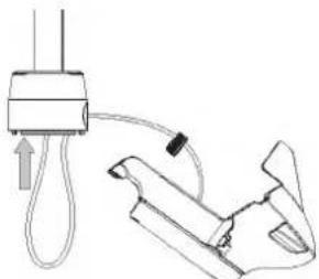
natural_image
Diagram of a medical or laboratory procedure showing a device connected to a tool with a cable, no text or symbols present.Installing the Propeller Drive Motor
Before you can install the propeller drive motor in the shaft, you must route the transducer cable through the shaft (if applicable) (Installing the Nose Cone and Transducer in the Shaft, page 14).
1 Remove the large 78 mm (3 in.) O-ring on the shaft base, and discard it.
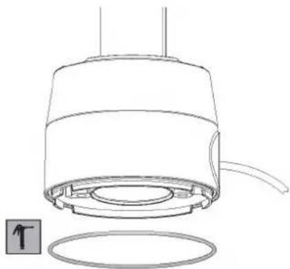
natural_image
Technical line drawing of a mechanical component with a circular base and internal components (no text or symbols)2 Using the packet included in the shaft and motor hardware service kit, apply grease to the new 78 mm (3 in.) O-ring in the shaft and motor hardware service kit.
3 Place the new 78 mm (3 in.) O-ring in the groove on the shaft base.
4 Using canned compressed air or an air compressor, blow out any dirt or debris in the four threaded holes on the top of the propeller drive motor.
5 Apply a medium-strength thread-locking compound such as LOCTITE® 243™ to the threads in the four threaded holes on the top of the propeller drive motor.
NOTICE
Thread-locking compound is required in these holes to maintain a tight connection between the shaft base and the propeller drive motor.
6 Remove the 36 mm ( 1^7/16 in.) O-ring from the top of the propeller drive motor, and discard it.
7 Thread the cables from the propeller drive motor through the new 36 mm (1 ^7 / 16 in.) O-ring in the shaft and motor hardware service kit.
8 Using the packet included in the shaft and motor hardware service kit, apply grease to the new 36 mm (17/16 in.) O-ring.
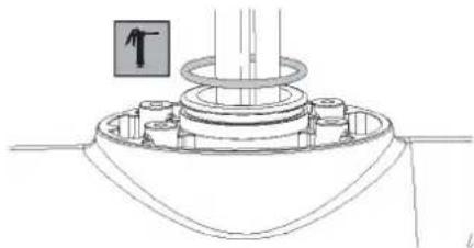
natural_image
Technical line drawing of a mechanical assembly with no visible text or symbols9 Place the new 36 mm (1 ^7 / _16 in.) O-ring in the groove on the top of the propeller drive motor.
10 If the power and data cables from the propeller drive motor are not already aligned and bundled, straighten, align, and bundle them with tape.
If the power and data cables are not straight and aligned, they may not feed through the shaft smoothly.
11 Feed the power and data cables from the propeller drive motor up through the shaft until they emerge from the top.
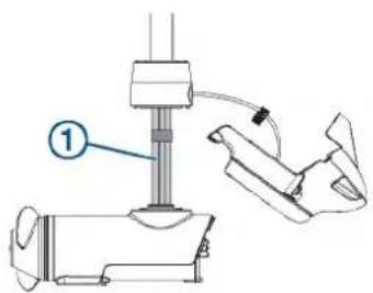
12 Gently pull the ends of the power and data cables as you feed them the rest of the way through the shaft.
NOTICE
When feeding the cables, you must pull on the cable and not on the cable connectors. The data cable connector is fragile and may break if you pull on the connector.
13 Prepare the four bolts ② in the shaft and motor hardware service kit by placing a washer ③ and a 4.75 mm ( ^3/_16 in.) O-ring ④ on each one.
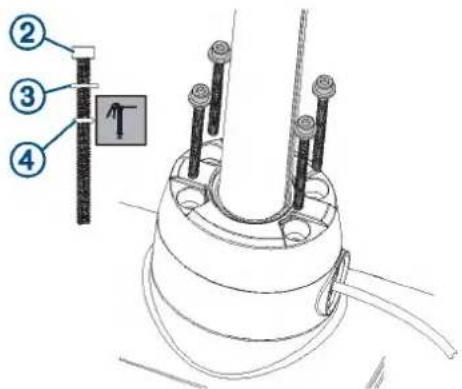
14 Using the grease packet included in the shaft and motor hardware service kit, apply grease to the 4.75 mm (3/16 in.) O-ring on each bolt.
Avoid getting grease on the bolt threads.
NOTE: If you did not previously apply thread-locking compound in the four mounting holes for these bolts, you must apply it before installing these bolts.
15 Using a ball-head 4 mm hex bit or wrench, thread all four of the prepared bolts approximately halfway to make sure that the shaft base and the propeller drive motor are properly aligned.
16 With the shaft base and the propeller drive motor properly aligned, lightly tighten all four bolts by hand.
17 Using a torque wrench, tighten all four bolts to 4 N-m (35 lbf-in).
Installing the Nose Cone and Skeg
Before you can install the nose cone and skeg, you must install the propeller drive motor on the shaft base (Installing the Propeller Drive Motor, page 14).
1 From the shaft and motor hardware service kit, select the cable gland that fits your transducer cable:
- For a 4-pin transducer, select the cable gland with the smaller hole.
- For an 8- or 12-pin transducer, select the cable gland with the larger hole.
NOTE: A cable gland without a hole is provided if you are not installing a transducer or not routing the transducer cable through the shaft.
2 Pull the transducer cable ① straight, and measure a 38 cm (15 in.) from the where the cable enters the transducer.
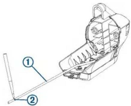
3 Using a permanent marker, mark the measured location on the cable ②
4 Using the packet included in the shaft and motor hardware service kit, apply grease completely to all surfaces of the cable gland you selected to fit your transducer cable.
5 Place the cable gland ③at the marked location on the transducer cable.
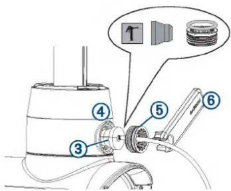
6 While keeping the cable gland aligned with the mark on the transducer cable, gently pull the excess cable through the top of the shaft until the cable gland fits into the hole on the shaft base ④
7 Using the packet included in the shaft and motor hardware service kit, apply grease to the 25 mm (1 in.) O-ring on the recessed nut on the transducer cable.
8 Place the recessed nut into the hole on the shaft base, and tighten it using the included tool ⑥
9 Tighten the recessed nut until it stops, then loosen it 114 of a turn.
NOTE: For reference, the notches inside the recessed nut are centered 114 of a turn apart.
10 Route the transducer cable through the nose cone so it will fit correctly onto the propeller drive motor.
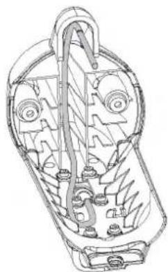
natural_image
Technical line drawing of a mechanical component with internal gears and shafts (no text or symbols)11 Place the nose cone onto the propeller drive motor.
12 Using a 4 mm hex bit or wrench, secure the front of the nose cone to the propeller drive motor using the existing two screws ⑦
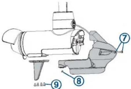
13 Using a 3 mm hex bit or wrench, secure the bottom of the nose cone to the propeller drive motor using the existing screw Ⓗ.
14 Using a 4 mm hex bit or wrench, secure the skeg to the bottom of the propeller drive motor using the existing four screws ⑨
Installing the Drive Motor and Shaft
You should perform these actions to reassemble the trolling motor after replacing the shaft or transducer.
1 Install the shaft in the steering servo housing (Installing the Shaft in the Steering Servo Housing, page 16).
2 Install the shaft cap on the shaft (Installing the Shaft Cap, page 16).
3 Install the transducer cable in the shaft cap (Installing the Transducer Cable in the Shaft Cap, page 16).
4 Connect the cables in the shaft cap (Connecting the Cables in the Shaft Cap, page 16).
5 Close the shaft cap (Closing the Shaft Cap, page 17).
6 Route the power and transducer cables through the mount (Routing the Power and Transducer Cables Through the Mount, page 10).
7 Connect the motor to the power source.
Installing the Shaft in the Steering Servo Housing
If you removed the depth-adjustment collar (Removing the Depth-Adjustment Collar, page 12), you must reinstall it before you install the shaft in the steering servo housing.
This procedure is best performed with two people.
1
2 Feed the cables ① up through the steering servo housing.
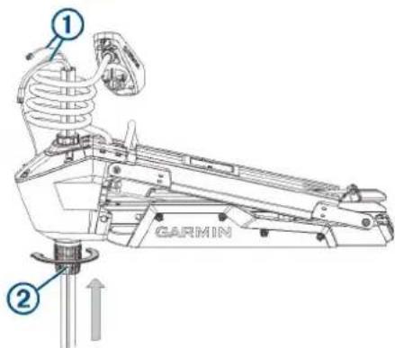
TIP: Depending on the height of your trailer or workbench, you may want to move the motor mount up about halfway to make it easier to install the shaft.
3 Insert the shaft into the bottom of the steering servo housing, and push it up through the top.
NOTE: The shaft is keyed to fit in the steering servo housing one way only.
4 Tighten the depth adjustment collar on the base of the steering servo housing ②
Installing the Shaft Cap
1 Pull the cables from the shaft completely through the shaft cap.
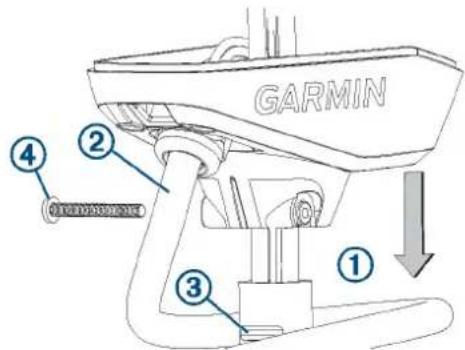
2 Using the coil count you recorded when you removed the shaft cap, wrap the coil cable around the shaft the appropriate number of times.
3 Place the shaft cap on the shaft, aligning the coil cable extending from the shaft cap ② with the groove on the shaft ③.
4 Using a 4 mm hex bit or wrench, install the 1/4 -20 bolt and nut to secure the shaft cap to the shaft.
Installing the Transducer Cable in the Shaft Cap
Before you can install the transducer cable in the shaft cap, you must install the shaft cap (Installing the Shaft Cap, page 16).
1 Feed the transducer cable ① completely through the square hole in the shaft cap.
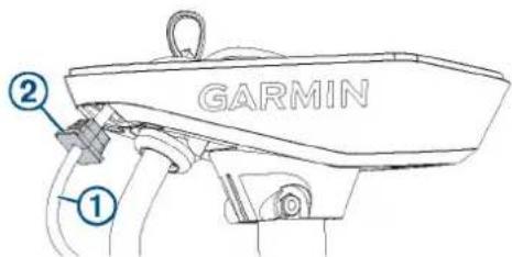
2 Install the grommet ② on the transducer cable.
The grommet is split on one side to make it easy to install on the cable.
3 Push from the outside to secure the square grommet in the shaft cap.
4 Route the transducer cable alongside the coil cable, using the cable clamps to hold the cables together.
5 Route the transducer cable through the mount base alongside the coil cable, using the cable clamps to secure the cables to the base.
6 Route the transducer cable to the chartplotter, and connect it.
Connecting the Cables in the Shaft Cap
Before you can connect the cables in the shaft cap, you must install the shaft cap (Installing the Shaft Cap, page 16).
1 Align the rings on the ends of the cables according to color. You must stack the red cables together and stack the black cables together, aligning the flat sides of the connectors ① on the cables.
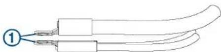
natural_image
Diagram of two elongated mechanical components with a numbered label (1) pointing to one end, no text or symbols present.NOTE: If the cables are stacked incorrectly, you cannot close the shaft cap cover.
2 Place the stacked cables ② over the stand outs in the shaft cap.
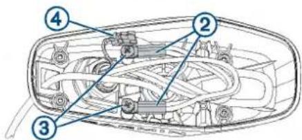
3 Using a #3 Phillips screwdriver, install the two screws and lock washers ③ to secure the power cables onto the stand outs in the shaft cap.
4 Align both sections of the data cable connector ④ and push together to connect them.
Closing the Shaft Cap
Before you can close the shaft cap, you must connect the cables inside the shaft cap (Connecting the Cables in the Shaft Cap, page 16).
1 Place the lid on the shaft cap.
2 Using a #2 Phillips screwdriver, install the four screws to secure the lid of the shaft cap.
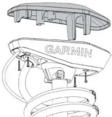
natural_image
Technical line drawing of a car suspension system with GARMIN branding (no text or symbols beyond branding)Removing the Steering Servo from the Mount
Before you can remove the steering servo from the mount, you must remove the power and transducer cables from the mount (Removing the Power and Transducer Cables From the Mount, page 9).
1 Disconnect the lower gas spring (Disconnecting the Lower Gas Spring, page 17).
2 Disconnect the upper link of the mount (Disconnecting the Upper Link of the Mount, page 17).
3 Disconnect the upper gas spring (Disconnecting the Upper Gas Spring, page 18).
4 Disconnect the lower link of the mount (Disconnecting the Lower Link of the Mount from the Steering Servo, page 18).
Disconnecting the Lower Gas Spring
1 Place the trolling motor in the stowed position.
2 Using a #2 Phillips screwdriver, remove the screws that secure the lower gas spring clevis to the lower link of the mount.
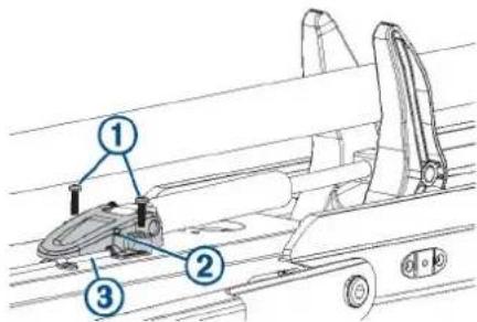
3 Lift the lower gas spring clevis off of the safety rod ③
Replacing the Lower Gas Spring
Before you can replace the lower gas spring, you must disconnect it from the mount (Disconnecting the Lower Gas Spring, page 17).
1 Using a #0 Phillips screwdriver, remove the set screw that secures the gas spring pin to the shaft stabilizer on the mount.
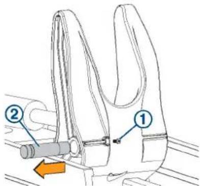
2 Slide out the gas spring pin and lift up on the gas spring to remove it.
3 Place the end of the replacement gas spring into the shaft stabilizer on the mount.
4 Slide the gas spring pin into the shaft stabilizer, through the end of the gas spring, until it is flush with the edge of the shaft stabilizer.
5 Install the set screw in the shaft stabilizer to secure the gas spring pin.
6 Place the lower gas spring clevis ③ on the lower link of the mount, fitting it over the safety rod ④
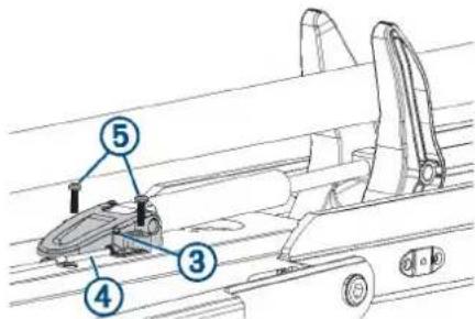
7 Using a #2 Phillips screwdriver, install the screws that secure the lower gas spring clevis to the lower link of the mount.
Disconnecting the Upper Link of the Mount
Before you can disconnect the upper link of the mount, you must remove the power and transducer cables from the mount (Removing the Power and Transducer Cables From the Mount, page 9).
1 With the motor in the deployed position, disconnect the cable ① from the display panel on the upper link of the mount ②
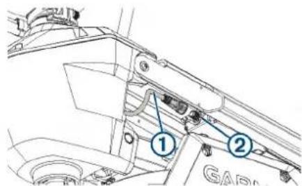
2 Using an 4 mm hex bit or wrench, remove a screw and washer from one side of the upper pin the steering servo housing.
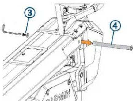
TIP: It is helpful to use another 4 mm hex wrench to hold one end of the upper pin stationary while you remove one screw.
3 Remove the upper pin from the steering servo housing.
4 Pivot the upper link away from the steering servo housing.
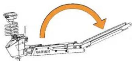
5 Remove the bushings from the upper holes in the steering servo housing.
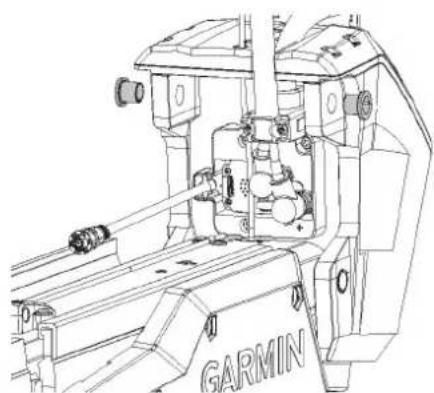
natural_image
Technical line drawing of a GARMIN robotic arm assembly (no text or symbols)Disconnecting the Upper Gas Spring
Before you can disconnect the upper gas spring, you must disconnect the upper link of the mount (Disconnecting the Upper Link of the Mount, page 17) and disconnect the lower gas spring (Disconnecting the Lower Gas Spring, page 17).
1 Using a #2 Phillips screwdriver, remove the two screws ① that secure the lower gas spring clevis ② to the lower link of the mount.
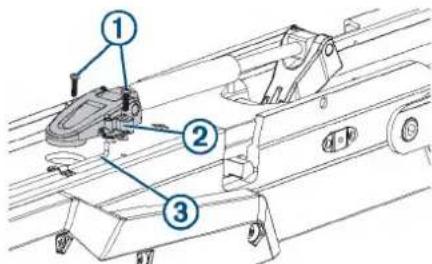
2 Lift the upper gas spring clevis off of the safety rod ③ Replacing the Upper Gas Spring
Before you can replace the upper gas spring, you must disconnect it from the mount (Disconnecting the Upper Gas Spring, page 18).
1 Using a #0 Phillips screwdriver, remove the set screw that secures the gas spring pin 20 the upper gas spring arm . 3
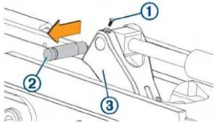
2 Slide out the gas spring pin and lift up on the gas spring to remove it.
3 Place the end of the replacement gas spring into the upper gas spring arm.
4 Slide the gas spring pin into the upper gas spring arm, through the end of the gas spring, until it is flush with the edge of the upper gas spring arm.
5 Install the set screw in the upper gas spring arm to secure the gas spring pin.
6 Place the upper gas spring clevis ④ on the lower link of the mount, fitting it over the safety rod ⑤
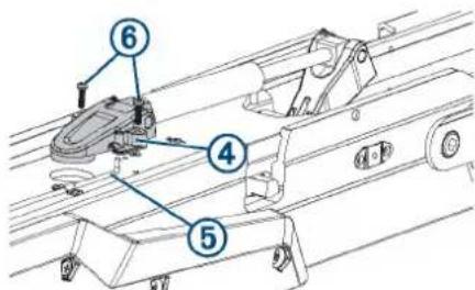
7 Using a #2 Phillips screwdriver, install the two screws that secure the lower gas spring clevis to the lower link of the mount.
Disconnecting the Lower Link of the Mount from the Steering Servo
Before you can disconnect the lower link of the mount from the steering servo, you must disconnect the lower gas spring (Disconnecting the Lower Gas Spring, page 17) and you must disconnect the upper gas spring (Disconnecting the Upper Gas Spring, page 18).
CAUTION
The lower pin is the final piece connecting the steering servo to the mount. When you remove the pin, the steering servo, and the drive motor and shaft, if they are still installed, may fall causing injury or damage. Use caution to support the weight of the steering servo before you remove the pin.
NOTE: This procedure is best performed with two people.
1 Slide the safety rods away from the steering servo to release the lower pivot pin.
NOTE: The two safety rods don't need to move very far to release the lower pivot pin. If either gas spring is still connected to the lower link, however, the safety rods lock the lower pivot pin in place, and it cannot be removed.
2 While supporting the weight of the steering servo, push the lower pin out from one side, and pull to remove it completely.
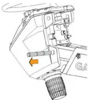
natural_image
Technical line drawing of a mechanical assembly with no visible text or symbolsThe steering servo is no longer connected to the mount.
Connecting the Steering Servo to the Mount
If you removed the steering servo from the mount for service, you can follow these procedures to reconnect it.
1 Connect the steering servo to the lower link of the mount (Installing the Steering Servo on the Lower Link of the Mount, page 19).
2 Secure the upper gas spring (Securing the Upper Gas Spring, page 20).
3 Connect the upper link of the mount to the steering servo (Connecting the Upper Link of the Mount to the Steering Servo Housing, page 20).
4 Connect the motor to the display panel (Connecting the Motor to the Display Panel, page 20).
5 Secure the lower gas spring (Securing the Lower Gas Spring, page 21).
6 Route the power and transducer cables through the mount (Routing the Power and Transducer Cables Through the Mount, page 10).
Installing the Steering Servo on the Lower Link of the Mount
1 Pivot the lower link of the mount forward until it locks into the base.

2 Push the two safety rods into the lower link as far as possible.
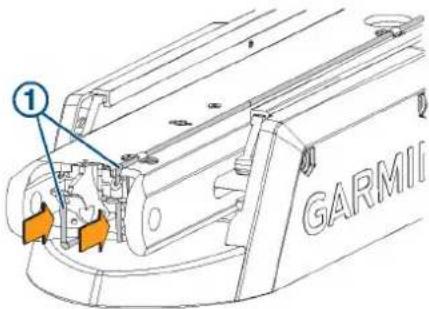
3 From the inside out, insert the bushings ② into the lower holes ③ on the steering servo housing.

4 Holding the pull cable ④p, place the steering servo housing onto the lower link of the mount, aligning the lower holes on the housing with the holes on the link.
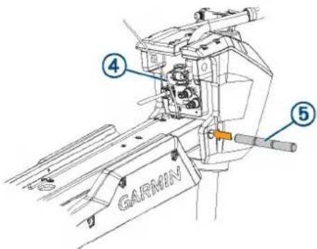
5 While lifting up on the steering servo housing, push the pivot pin ⑤ through the housing and the link to hold it in place.
NOTICE
Do not hit the pin with a hammer or other object. Do not drill or modify the holes. Although it is a snug fit, the pin slides in completely when pushed by hand. Damage caused by hammering the pin or modifying the holes is not covered under warranty.
6 Route the pull cable upward through the top of the steering servo housing ⑥.
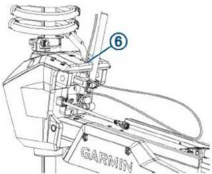
Securing the Upper Gas Spring
1 Push the safety rod ① toward the steering servo housing as far as possible to lock the lower pivot pin in place.
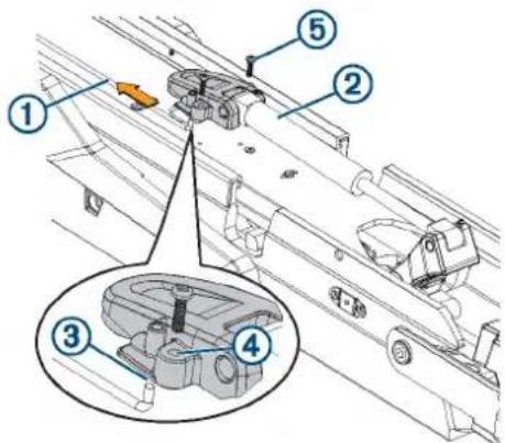
2 If necessary, pivot the upper gas spring ②oward the lower link of the mount so the base of the gas spring aligns with the safety rod and mounting holes.
NOTE: If you must rotate the gas spring so the base aligns with the mount, rotate the spring in a clockwise direction only. Rotating the gas spring in a counter-clockwise direction may loosen the fittings.
3 Align the single hole on the base of the gas spring ③ with the safety rod, and press down.
The screw holes on the base should align with the holes on the bottom of the mount.
4 Using a #2 Phillips screwdriver, secure the base of the gas spring to the lower link of the mount using the included screws ⑤
Connecting the Upper Link of the Mount to the Steering Servo Housing
1 Make sure that the data cable is accessible, and not trapped by any part of the mount.
2 From the outside in, insert the bushings ②n the upper holes on the steering servo housing.

3 Pivot the upper link of the mount forward.
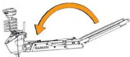
4 Tip the top of the steering servo housing inward so the holes on the upper link and the housing align.
5 Push the pin ③ through the holes on the upper link of the mount and the steering servo housing.
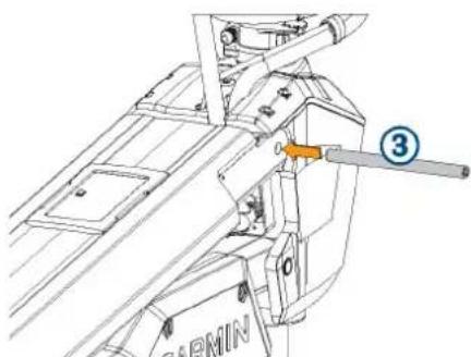
natural_image
Technical line drawing of a mechanical assembly with no visible text or symbols6 Using a 4 mm hex bit or hex wrench, secure the pin using the screws and washers ④n both sides.
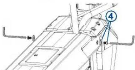
NOTE: To properly secure the pin, you should use two hex bits or wrenches so the pin does not rotate as you tighten the screws.
Connecting the Motor to the Display Panel
NOTICE
You must connect the cable from the steering servo to the display panel before proceeding further with assembly. If you do not make this connection now, the unsecured cable may damage the display panel when moving the mount.
1 Route the cable from the steering servo housing to the display panel on the upper link of the mount.
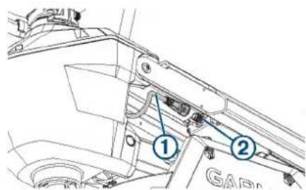
2 Push the connector onto the port on the display panel, and rotate the locking ring clockwise to secure it.
NOTE: The connector is keyed to fit into the port one way only, and will fit easily when aligned correctly. Do not force the connector into the port.
Securing the Lower Gas Spring
1 Transition the trolling motor from the deployed to the stowed position.
2 Align the hole on the base of the lower gas spring ① with the safety rod ② and press down.
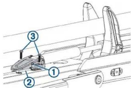
You may need to lift up the mount and flip over the gas spring if it was positioned on the other side of the mount during the previous steps.
NOTE: If you must rotate the gas spring so the base aligns with the mount, rotate the spring in a clockwise direction only. Rotating the gas spring in a counter-clockwise direction may loosen the fittings.
3 Using a #2 Phillips screwdriver, secure the base of the lower gas spring to the mount using the screws you removed when disconnecting the gas spring ③
Removing the Power Cable from the Steering Servo Housing
Before you can remove the power cable from the steering servo housing, you must remove the power and transducer cables from the mount (Removing the Power and Transducer Cables From the Mount, page 9).
1 Disconnect the upper link of the mount from the steering servo housing (Disconnecting the Upper Link of the Mount, page 17).
2 Pivot the upper link away from the steering servo housing.
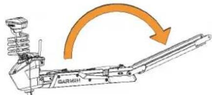
3 Using a #2 Phillips screwdriver, remove the bracket that secures the power cable to the steering servo housing.
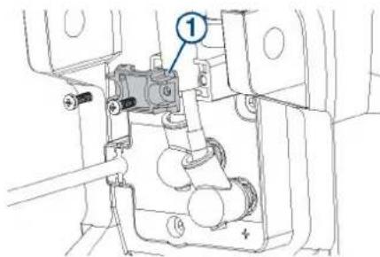
4 Pull the rubber shields ② away from the power cable connectors.
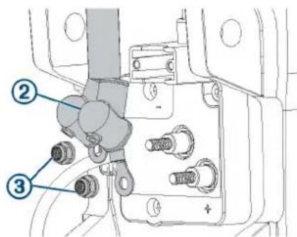
5 Using a 10 mm socket, remove the nuts ③ that secure the power cable connectors.
6 Remove the power cable from the steering servo housing.
Reconnecting the Power Cable
If you are replacing the power cable, you must first remove the existing power cable from the steering servo housingRemoving the Power Cable from the Steering Servo Housing, page 21.
1 Pull the rubber shields away from the power cable connectors.
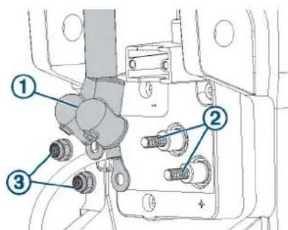
2 Apply dielectric grease to the power cable connectors ②nd bolts ③n the steering servo housing.
3 Place the power cable connectors over the bolts on the steering servo housing, with the red cable on the positive (+) terminal, and the black cable on the negative (-) terminal.
4 Using a 10 mm socket, install the nuts ③ that secure the power cable connectors.
5 Tighten the nuts to 30 kgf-cm (26 lbf-in).
6 Pull the rubber shields down to cover the power cable connectors.
7 Using a #2 Phillips screwdriver, install the bracket ④ that secures the power cable to the steering servo housing.
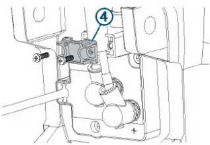
8 Tighten the screws to 5 kgf-cm (4.3 lbf-in).
9 Reconnect the upper link to the steering servo housing (Reconnecting the Upper Link to the Mount Base, page 23).
Removing the Coil Cable from the Steering Servo Housing
Before you can remove the coil cable, you must disconnect the power cable from the steering servo housing (Removing the Power Cable from the Steering Servo Housing, page 21).
1 Using a 4 mm hex bit or screwdriver, remove the three screws that secure the coil cable block to the steering servo housing.
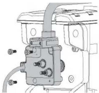
natural_image
Mechanical assembly diagram showing a valve or connector with bolts and wiring (no text or symbols visible)2 Pull the coil cable block away from the steering servo housing to remove it.
CAUTION
The coil cable block connects to the PCB in the steering servo housing. When removing the block take care to avoid damaging the connector on the PCB.
Reconnecting the Coil Cable
1 If you are replacing the coil cable, remove the coil cable from the shaft cap (Removing the Coil Cable from the Shaft Cap, page 22).
2 If necessary, install the replacement coil cable in the shaft cap (Installing the Coil Cable in the Shaft Cap, page 22).
3 Place the coil cable block over the connector on the steering servo housing, and push it into place, taking care to avoid damaging the connector.
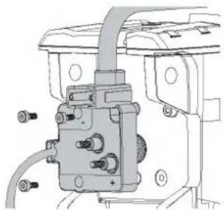
natural_image
Mechanical assembly diagram showing a valve and housing components (no text or labels)4 Using a 4 mm hex bit or screwdriver, insert and tighten the three screws to secure the coil cable block to the steering servo housing.
5 tighten the three screws to 20 kgf-cm (17.4 lbf-in)
6 Reconnect the power cable (Reconnecting the Power Cable, page 21).
Removing the Coil Cable from the Shaft Cap
Before you can remove the coil cable from the shaft cap, you must disconnect the cables in the shaft cap (Disconnecting the Cables in the Shaft Cap, page 11).
1 Using a 36 mm or adjustable wrench, remove the plastic nut ① on the coil-cable connector inside the shaft cap.
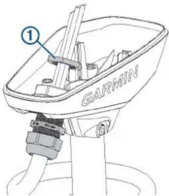
2 Pull the coil cable out of the shaft cap to remove it.
Installing the Coil Cable in the Shaft Cap
1 Feed the cables from the existing or replacement coil cable into the hole on the shaft cap.
2 Using the existing plastic nut or the nut provided with the replacement coil cable, secure the coil-cable connector to the shaft cap.
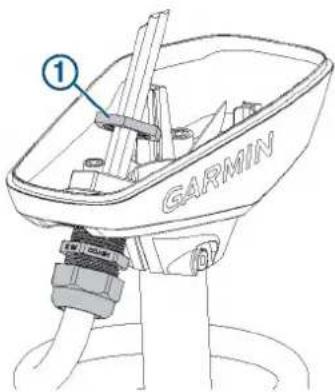
3 Using a 36 mm or adjustable wrench, tighten the plastic nut on the coil-cable connector inside the shaft cap
Replacing the Display Panel
Before you can remove the display panel from the upper link of the mount, you must disconnect the upper link of the mount from the steering servo housing (Disconnecting the Upper Link of the Mount, page 17).
1 Using a #0 Phillips screwdriver, remove the position sensor ① from the upper link of the mount.
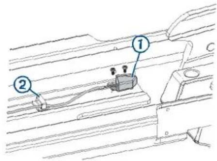
2 Open the cable clips to remove the position-sensor cable.
3 Pinch the tabs on the side of the display panel, and push it out of the upper link from the back.
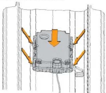
natural_image
Technical diagram of a mechanical assembly with directional arrows indicating force or movement (no text or symbols present)4 Install the replacement display panel by placing it in the upper link from the front and pushing until it snaps into place.
5 Using a #0 Phillips screwdriver, secure the position sensor to the mount.
6 Route the position sensor cable through the cable clips and snap them closed to secure the cable.
Removing the Upper Link from the Mount Base
Before you can remove the upper link from the mount base, you must disconnect the upper link from the steering servo housing (Disconnecting the Upper Link of the Mount, page 17).
1 Using an 8 mm hex bit or wrench, loosen the two bolts that secure the upper link to the mount base.
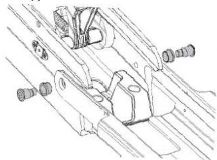
natural_image
Technical line drawing of mechanical components or assemblies (no text or symbols)TIP: The bolts that secure the upper link to the mount base are fastened very securely at the factory. You may need to use a ratchet to hold the 8 mm hex bit to provide the leverage needed to loosen these bolts.
2 Remove the bolts, bushings, and washers from both sides of the upper link.
Reconnecting the Upper Link to the Mount Base
1 Place the plastic bushings over the bolts ^② you removed with the original upper link, or over the two bolts supplied with the replacement upper link.
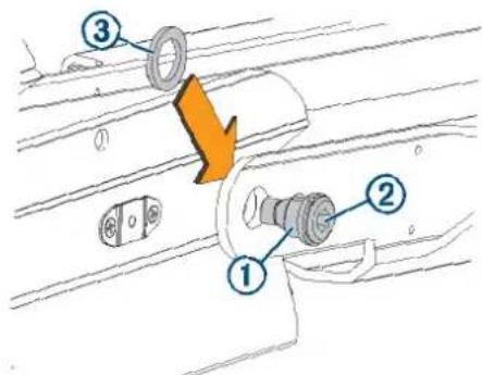
2 Place a plastic washer that you removed with the original upper link or a washer supplied with the replacement upper link between the upper link and the mount base.
NOTE: Replacement plastic washers may have adhesive on one side. If your washers have adhesive, you can stick them to the mount base to make installing the bolts easier.
3 Push one of the bolts with a plastic bushing through the upper link and washer, and using an 8 mm hex bit or wrench, screw it into the mount base.
4 Repeat the previous step on the other side of the mount.
5 Tighten the bolts to 55 Nm (40.5 lbf-ft.).
Removing the Lower Link from the Mount Base
Before you can remove the lower link from the mount base, you must remove the steering servo from the mount (Removing the Steering Servo from the Mount, page 17).
1 Rotate the lower link up so you can access the latching mechanism spring.
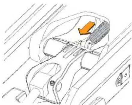
natural_image
Technical line drawing of a car interior showing seatbelt, dashboard, and exhaust pipe (no text or symbols)2 Using needle-nose pliers, disconnect the spring from the hook on the base of the gas spring.
3 Using a #2 Phillips screwdriver, remove the pin covers from the sides of the mount base.
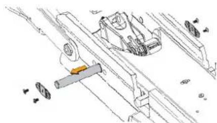
natural_image
Technical line drawing of mechanical components and assembly (no text or symbols)4 Push the pin out from one side and pull to remove it from the mount base.
5 Lift up to remove the lower link from the mount base.
Replacing the Locking Mechanism in the Lower Link
Before you can replace the locking mechanism in the lower link, you must remove the lower link from the mount base (Removing the Lower Link from the Mount Base, page 23).
1 If it is still connected, remove the pull cable from the latching mechanism (Removing the Pull Cable, page 9).
2 Using a pair of needle-nose pliers, remove the pins that secure the latch bars to the central rod.
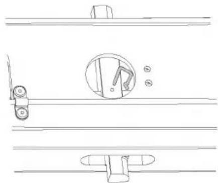
natural_image
Technical line drawing of a door lock mechanism with no text or symbolsCAUTION
Take note of the orientation of the latch pins prior to removing them. Installing the latch pins incorrectly may cause damage.
3 Slide the central rod out of either end of the lower link.
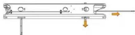
natural_image
Mechanical assembly diagram showing a lever system with rotating components and directional arrows (no text or labels)4 Slide the two latch bars out of the lower link.
CAUTION
Take note of the orientation of the latch bars prior to removing them. Installing the latch bars incorrectly may cause damage.
5 Apply a silicon-based lubricating grease to the replacement latch bars.
6 Insert the replacement latch bars into the lower link, with the rounded ends of the latch bars facing the hinge end of the lower link.
7 Insert the replacement rod into either end of the lower link, feeding it through the holes in the two latch bars.
8 Reinstall the pins to secure the latch bars to the central rod.
Reconnecting the Lower Link to the Mount Base
1 If necessary, install the bushings in the mount base from the inside.
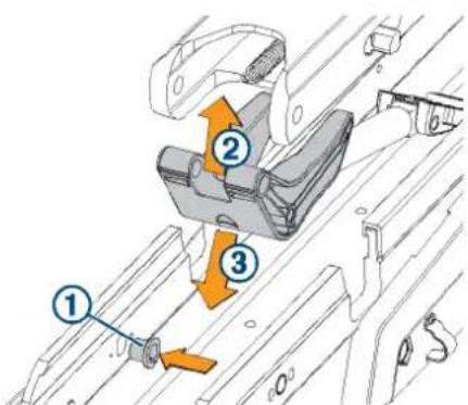
2 Insert the lower gas spring assembly into the lower link ② with the shaft stabilizer pointing toward the front of the lower link.
3 Insert the combined lower link and lower gas spring into the mount base ③
4 Push the pin ④ into the mount base, feeding it through one side of the lower link and shaft stabilizer.
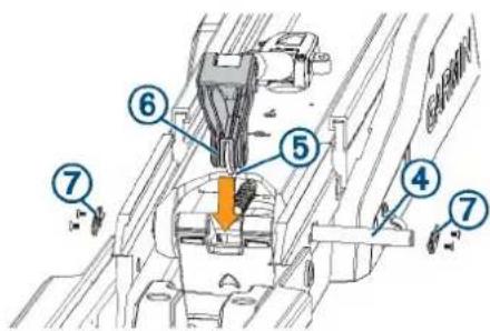
5 Holding the spring hook towards the lower link, place the upper gas spring arm into the shaft stabilizer, and push the pin the rest of the way through all of the parts, until it is flush with the sides of the mount base.
6 Using a #2 Phillips screwdriver, install the pin covers ⑦ on the sides of the mount base.
7 Rotate the lower link up so you can access the latching mechanism.
8 Using needle-nose pliers, connect the spring from the latching mechanism to the hook on the base of the gas spring.
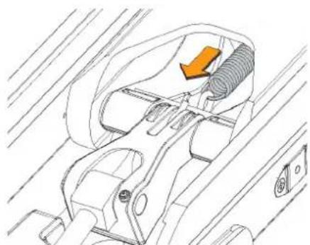
natural_image
Technical line drawing of a mechanical component with no visible text or symbols9 Install the steering servo on the mount (Connecting the Steering Servo to the Mount, page 19).
Replacing the Mount Base
1 Remove the steering servo from the mount (Removing the Steering Servo from the Mount, page 17).
2 Remove the upper link from the mount base (Removing the Upper Link from the Mount Base, page 23).
3 Remove the lower link from the mount base (Removing the Lower Link from the Mount Base, page 23).
4 Uninstall the fasteners that secure the mount base to the boat.
5 Secure the replacement mount base to the deck of the boat, replacing the existing mounting hardware if necessary.
6 Install the lower link on the mount base (Reconnecting the Lower Link to the Mount Base, page 24).
7 Install the upper link on the mount base (Reconnecting the Upper Link to the Mount Base, page 23).
8 Install the steering servo on the mount (Connecting the Steering Servo to the Mount, page 19).
Replacing the Mount Shrouds
1 Using a 4 mm hex bit or wrench, remove the screws that secure the mount shrouds to the mount base.
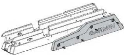
natural_image
Technical line drawing of a mechanical component with no visible text or symbols2 Secure the replacement shrouds to the mount base using the screws provided with the replacement shrouds.
Replacing the Mount Rails
Before you can replace the mount rails, you must remove the shrouds from the mount base (Replacing the Mount Shrouds, page 24).
1 Slide the two mount rails off of the mount base.
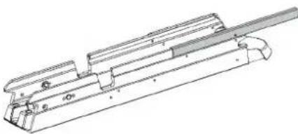
natural_image
Technical line drawing of a mechanical assembly with no visible text or symbols2 Slide the replacement rails onto the mount base.
3 Reinstall the shrouds.
Replacing the Mount Bumper
1 Using a 4 mm hex bit or wrench, remove the two screws that secure the mount bumper to the mount base.
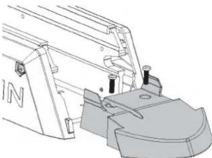
natural_image
Technical line drawing of a mechanical assembly with no visible text or symbols2 Install the replacement mount bumper, and secure it to the mount base using the screws provided with the replacement part.
Replacing the Stow Support
1 Using a 4 mm hex bit or wrench, remove the screws securing the stow support to the mount base.
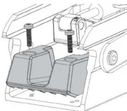
natural_image
Technical line drawing of a mechanical assembly with two components and mounting holes (no text or symbols)2 Install the replacement stow support using the screws provided with the replacement part.
© 2019 Garmin Ltd. or its subsidiaries
Garmin ^5 , the Garmin logo, and ActiveCaptain ^6 are trademarks of Garmin Ltd. or its subsidiaries, registered in the USA and other countries. Force ^™ is a trademark of Garmin Ltd. or its subsidiaries. These trademarks may not be used without the express permission of Garmin.
DuPont ^™ and Teflon ^™ are trademarks of E. I. du Pont de Nemours and Company or its affiliates.
GARMIN
Force™ Trolling Motor Stabilizer
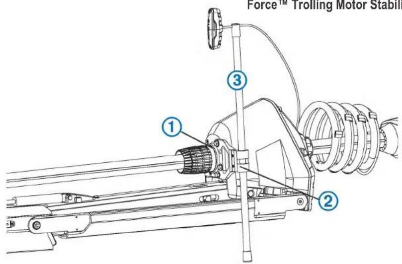
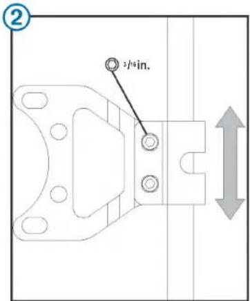
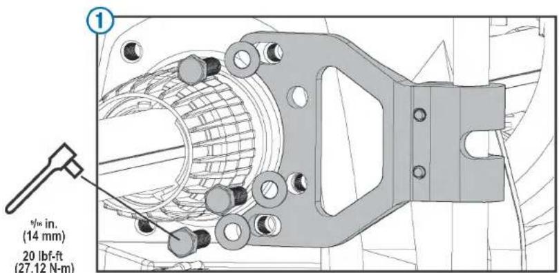
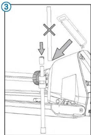
July 2019 Printed in Taiwan 190-02521-13_0A
© 2019 Garmin Ltd. or its subsidiaries

Securing the Stabilizer to the Motor
This is an optional accessory that can help stabilize and provide additional support for the trolling motor when it is in the stowed position.
1 Place the trolling motor into the stowed position.
2 Attach the bracket to either side of the motor steering housing using the included bolts , tightening them to 20 lbf-ft (27 N-m).
3 Insert the rod so that it contacts the boat deck when applying light pressure.
NOTE: Setting the length of the rod too deep may apply pressure on the motor latch system and make it difficult to transition from the stowed to the deployed position.
4 Tighten the two screws that clamp the stabilizer rod in the bracket.
5 Move the motor between the stowed and deployed position to test for interference, and make any needed adjustments.
6 (Optional) Remove the excess length from the top of the rod, leaving enough room to install the cap.
Printing a Mounting Template
NOTICE
It is not recommended that you print a mounting template on your own. Use the template that came in the product box.
If you do print the template, you must follow these instructions for printing a mounting template precisely. To print large templates, you need large enough paper and printer. Failure to have the correct sized paper and printer, or a failure to follow these instructions, may result in an incorrectly sized template and therefore an incorrect cutout (too large or too small) on the mounting surface of your boat.
1 Select File > Print.
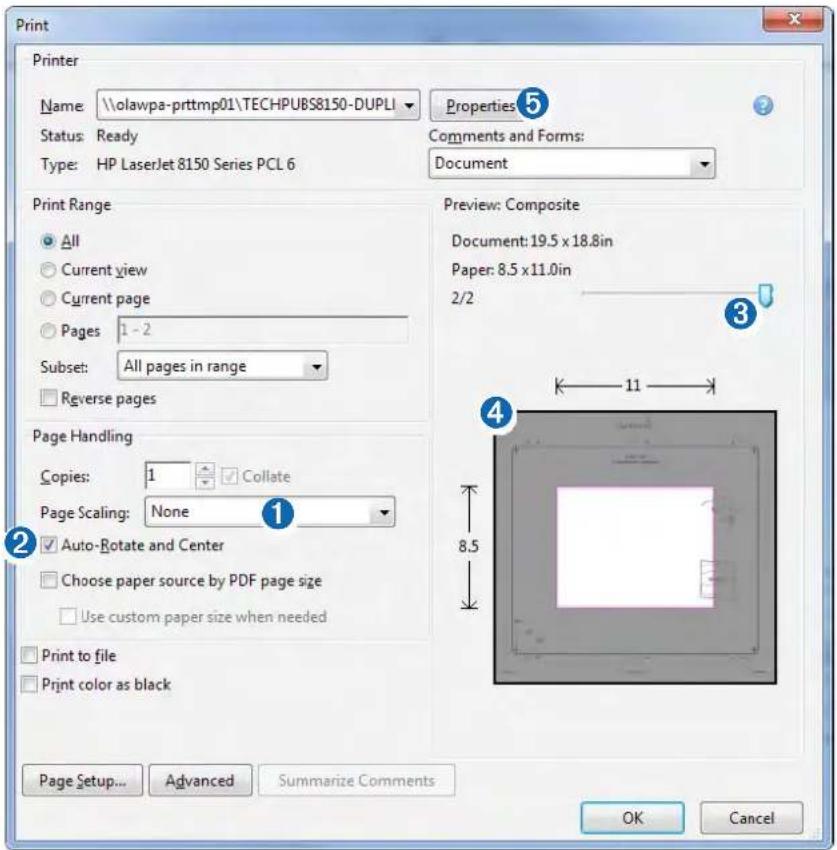
2 Select None for Page Scaling 1.
3 Ensure the check mark is next to Auto-Rotate and Center ②.
4 Drag the arrow ③ to the right, to view page 2 in the window below.
4 Verify that the paper size is larger than the template ④.
In this example, the paper is not larger than the template.
5 If the paper size is not large enough, select Properties ⑤ and select a Page Size that is larger than the template.
NOTICE
Garmin is not responsible for any damages or expenses resulting from a miscut mounting surface arising from a failure to follow these instructions.
Force Trolling Motor Foot Pedal Mounting Template
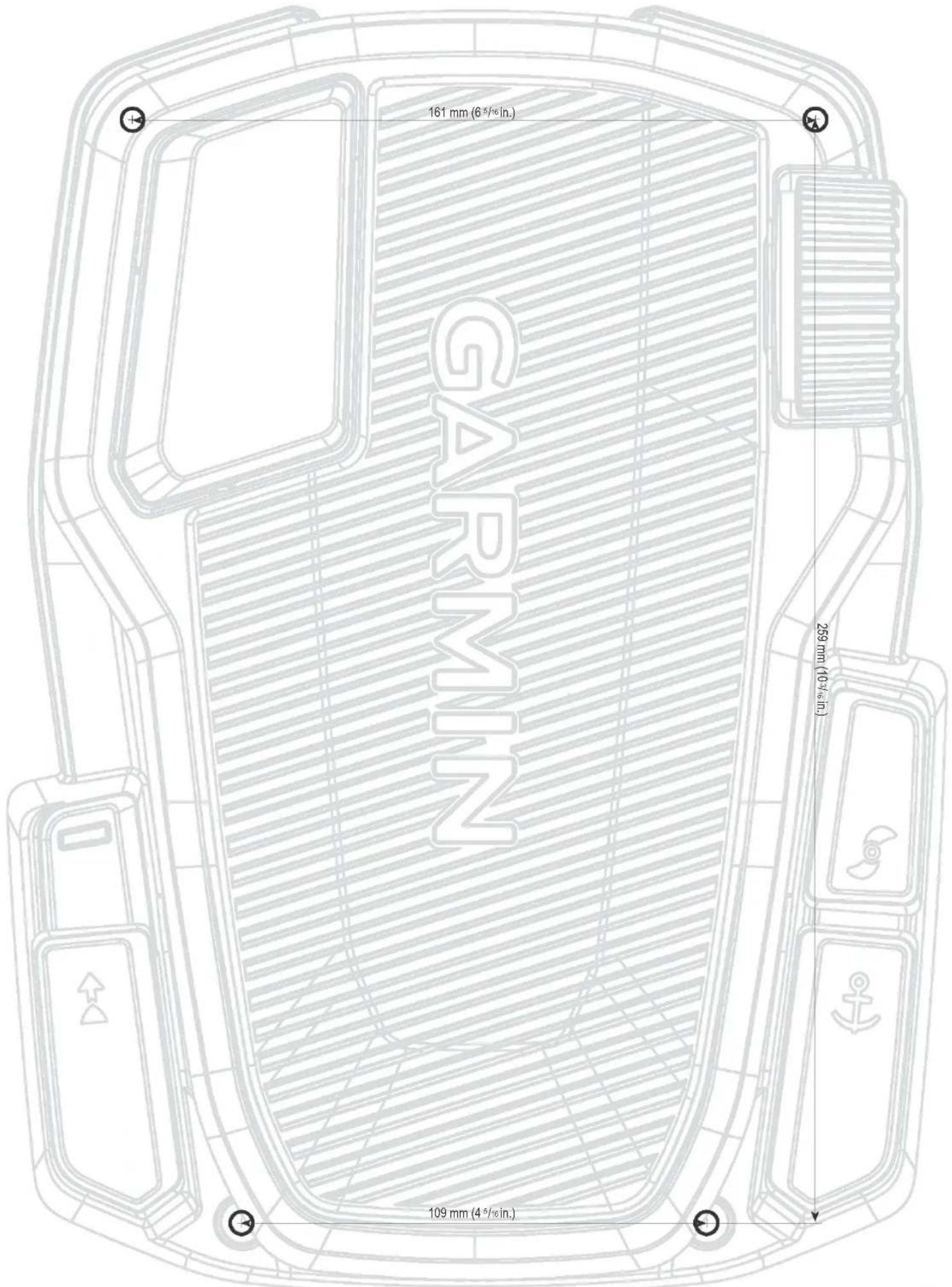
Important Safety and Product Information 2
Important Safety and Product Information
WARNING
Failure to heed the following warnings could result in an accident or collision resulting in death or serious injury.
Trolling Motor Warnings
- Do not run the motor when the propeller is out of the water. Contact with the rotating propeller may result in severe injury.
- You are responsible for the safe and prudent operation of your vessel. The autopilot features on the trolling motor are tools that enhance your capability to operate your boat. They do not relieve you of the responsibility of safely operating your boat. Avoid navigational hazards and never leave the motor controls unattended.
- Learn to operate the autopilot features on calm and hazard-free open water.
- Use caution when using operating the trolling motor near hazards in the water, such as trees, shallow rocks, docks, pilings, and other boats.
- Always disconnect the motor from the battery before cleaning or servicing the propeller to avoid injury.
- Do not use the motor in areas where you or other people in the water may come into contact with the rotating propeller.
Battery Warnings
Replaceable lithium, alkaline, or NIMH batteries can be used with the remote control and foot pedal. If these guidelines are not followed, batteries may experience a shortened life span or may present a risk of damage to the device, fire, chemical burn, electrolyte leak, and/or injury.
- Do not disassemble, modify, remanufacture, puncture or damage the device or batteries.
- Do not expose the device or batteries to fire, explosion, or other hazard.
- Do not use a sharp object to remove the removable batteries.
- KEEP BATTERIES AWAY FROM CHILDREN.
NEVER PUT BATTERIES IN MOUTH. Swallowing can lead to chemical burns, perforation of soft tissue, and death. Severe burns can occur within 2 hours of ingestion. Seek medical attention immediately.
- Only replace batteries with correct replacement batteries. Using other batteries presents a risk of fire or explosion.
△CAUTION
Failure to heed the following cautions could result in minor or moderate injury
Trolling Motor Cautions
- When using the autopilot features, be prepared for sudden stops, acceleration, and turns.
- When stowing or deploying the motor, be aware of the risk of entrapment or pinching from moving parts, which can result in injury.
- When stowing or deploying the motor, be aware of slick surfaces around the motor. Slipping when stowing or deploying the motor may result in injury.
NOTICE
Failure to heed the following notice could result in personal or property damage, or negatively impact the device functionality.
Battery Notice
Contact your local waste disposal department to dispose of the device/batteries in accordance with applicable local laws and regulations.
GPS Notice
The navigation device may experience degraded performance if you use it in proximity to any device that uses a terrestrial broadband network operating close to the frequencies used by any Global Navigation Satellite System (GNSS), such as the Global Positioning Service (GPS). Use of such devices may impair reception of GNSS signals.
Product Environmental Programs
Information about the Garmin ^™ product recycling program and WEEE, RoHS, REACH, and other compliance programs can be found at www.garmin.com/aboutGarmin/environment.
Declaration of Conformity
Hereby, Garmin declares that this product is in compliance with the Directive 2014/53/EU. The full text of the EU declaration of conformity is available at the following internet address: www.garmin.com /compliance.
FCC Compliance
This device complies with part 15 of the FCC Rules. Operation is subject to the following two conditions: (1) this device may not cause harmful interference, and (2) this device must accept any interference received, including interference that may cause undesired operation. This equipment has been tested and found to comply with the limits for a Class B digital device, pursuant to part 15 of the FCC rules. These limits are designed to provide reasonable protection against harmful interference in a residential installation. This equipment generates, uses, and can radiate radio frequency energy and may cause harmful interference to radio communications if not installed and used in accordance with the instructions. However, there is no guarantee that interference will not occur in a particular installation. If this equipment does cause harmful interference to radio or television reception, which can be determined by turning the equipment off and on, the user is encouraged to try to correct the interference by one of the following measures:
• Reorient or relocate the receiving antenna.
- Increase the separation between the equipment and the receiver.
- Connect the equipment into an outlet on a circuit different from that to which the receiver is connected.
- Consult the dealer or an experienced radio/TV technician for help.
This product does not contain any user-serviceable parts. Repairs should only be made by an authorized Garmin service center. Unauthorized repairs or modifications could result in permanent damage to the equipment, and void your warranty and your authority to operate this device under Part 15 regulations.
Radio Frequency Radiation Exposure
This device is a mobile transmitter and receiver that uses an internal antenna to send and receive low levels of radio frequency (RF) energy for data communications. The device emits RF energy below the published limits when operating in its maximum output power mode and when used with Garmin authorized accessories. To comply with RF exposure compliance requirements, the device should be installed and operated with a minimum of 20cm (7.87 in.) between the device and your body. The device should not be used in other configurations. This device must not be co-located or operated in conjunction with any other transmitter or antenna.
Innovation, Science and Economic Development Canada Compliance
This device complies with Innovation, Science and Economic Development Canada license-exempt RSS standard(s). Operation is subject to the following two conditions: (1) this device may not cause interference, and (2) this device must accept any interference, including interference that may cause undesired operation of the device.
Software License Agreement
BY USING THE DEVICE, YOU AGREE TO BE BOUND BY THE TERMS AND CONDITIONS OF THE FOLLOWING SOFTWARE LICENSE AGREEMENT. PLEASE READ THIS AGREEMENT CAREFULLY.
Garmin Ltd. and its subsidiaries ("Garmin") grant you a limited license to use the software embedded in this device (the "Software") in binary executable form in the normal operation of the product. Title, ownership rights, and intellectual property rights in and to the Software remain in Garmin and/or its third-party providers.
You acknowledge that the Software is the property of Garmin and/or its third-party providers and is protected under the United States of America copyright laws and international copyright treaties. You further acknowledge that the structure, organization, and code of the Software, for which source code is not provided, are valuable trade secrets of Garmin and/or its third-party providers and that the Software in source code form remains a valuable trade secret of Garmin and/or its third-party providers. You agree not to decompile, disassemble, modify, reverse assemble, reverse engineer, or reduce to human readable form the Software or any part thereof or create any derivative works based on the Software. You agree not to export or re-export the Software to any country in violation of the export control laws of the United States of America or the export control laws of any other applicable country.
Third-Party Software Licenses
This product may include the following third-party software: XySSL (© 2006-2007 Christophe Devine), hostap / WPA Supplicant (© 2002-2010, Jouni Malinen), NGINX (© 2002-2015 Igor Sysoev, © 2011-2015 Nginx, Inc.), nano-pb (© 2011 Petteri Almonen), all distributed under the BSD License; mDNSResponder software (© Apple), distributed under the Apache, BSD, and NICTA licenses; libcurl (© 1996 - 2015, Daniel Stenberg), cjon (© 2009 Dave Gamble), expat (© 1998, 1999, 2000 Thai Open Source Software Center Ltd, and Clark Cooper, © 2001, 2002, 2003 Expat maintainers) software all distributed under the MIT license.
THE THIRD-PARTY SOFTWARE IS PROVIDED "AS IS", WITHOUT WARRANTY OF ANY KIND, EXPRESS OR IMPLIED, INCLUDING BUT NOT LIMITED TO THE WARRANTIES OF MERCHANTABILITY, FITNESS FOR A PARTICULAR PURPOSE AND NONINFRINGEMENT OF THIRD PARTY RIGHTS. IN NO EVENT SHALL THE AUTHORS OR COPYRIGHT HOLDERS BE LIABLE FOR ANY CLAIM, DAMAGES OR OTHER LIABILITY, WHETHER IN AN ACTION OF CONTRACT, TORT OR OTHERWISE, ARISING FROM, OUT OF OR IN CONNECTION WITH THE SOFTWARE OR THE USE OR OTHER DEALINGS IN THE SOFTWARE.
Limited Warranty
THIS LIMITED WARRANTY GIVES YOU SPECIFIC LEGAL RIGHTS, AND YOU MAY HAVE OTHER LEGAL RIGHTS, WHICH VARY FROM STATE TO STATE (OR BY COUNTRY OR PROVINCE). GARMIN DOES NOT EXCLUDE, LIMIT OR SUSPEND OTHER LEGAL RIGHTS YOU MAY HAVE UNDER THE LAWS OF YOUR STATE (OR COUNTRY OR PROVINCE). FOR A FULL UNDERSTANDING OF YOUR RIGHTS YOU SHOULD CONSULT THE LAWS OF YOUR STATE, COUNTRY OR PROVINCE.
Limited Warranty for Non-Commercial, Recreational Use
For non-commercial, recreational use, Garmin Trolling Motor products are warranted to be free from defects in materials or workmanship for three (3) years from the date of purchase. Within this period, Garmin will, at its sole option, repair or replace any components that fail in normal use. Such repairs or replacement will be made at no charge to the customer for parts or labor, provided that the customer shall be responsible for any transportation cost to return the defective product to Garmin.
Limited Warranty for Commercial Use
For Garmin Trolling Motor products used for commercial use are warranted to be free from defects in materials or workmanship for one (1) year from the date of purchase. Commercial use means any usage associated with income-producing activities or other activities associated with the operation of a business.
Limited Warranty for the Composite Shaft
For non-commercial, recreational use, the composite shaft of the Garmin Trolling Motor products is warranted to be free from defects in materials or workmanship for the lifetime of the customer. This limited warranty for the composite shaft is for the lifetime of the original customer and is non-transferrable. Within this period, Garmin will, at its sole option, provide a replacement composite shaft for any material or workmanship defects confirmed by Garmin. The customer will be responsible for any costs associated with the removal of the original shaft and installation of the replacement shaft.
Exclusions
This Limited Warranty does not apply to: (i) damage resulting from or caused by inadequate cleaning or improper service of products used in saltwater or brackish water (ii) damage due to normal wear and tear; (iii) cosmetic damage, such as scratches, nicks and dents; (iv) products that have not been maintained as required by the applicable Trolling Motor Maintenance Manual; (v) costs associated with performing maintenance required by the applicable Trolling Motor Maintenance Manual; (vi) damage caused by accident, incorrect installation, incorrect stowing, abuse, misuse, water, flood, fire, other acts of nature or external causes, or failure to obtain required annual maintenance service; (vii) damage caused by service performed by anyone who is not an authorized service provider of Garmin; (viii) damage to a product that has been modified or altered without the written permission of Garmin; or (ix) damage to a product that has been connected to power and/or data cables that are not supplied by Garmin or damage to a product that has been connected to cables that are not certified by UL (Underwriters Laboratories) and are not labeled as Limited Power Source (LPS). In addition, Garmin reserves the right to refuse warranty claims against products or services that are obtained and/or used in contravention of the laws of any country.
General Conditions
Repairs performed by Garmin, or an authorized service provider of Garmin, have a 90 day warranty. If the product sent for repair is still under its original warranty, then the new warranty is the longer of: (i) 90 days, or (ii) to the end of the original warranty period under this Limited Warranty, such as a 3 year product warranty for non-commercial, recreational use, a 1 year warranty for commercial use, or a non-transferrable limited lifetime composite shaft warranty for non-commercial, recreational use. This Limited Warranty also does not apply to, and Garmin is not responsible for, any degradation in the performance of any Garmin navigation product resulting from its use in proximity to any handset or other device that utilizes a terrestrial broadband network operating on frequencies that are close to the frequencies used by any Global Navigation Satellite System (GNSS) such as the Global Positioning Service (GPS). Use of such devices may impair reception of GNSS signals.
TO THE MAXIMUM EXTENT PERMITTED BY APPLICABLE LAW, THE WARRANTIES AND REMEDIES CONTAINED IN THIS LIMITED WARRANTY ARE EXCLUSIVE AND IN LIEU OF, AND GARMIN EXPRESSLY DISCLAIMS, ALL OTHER WARRANTIES AND REMEDIES, WHETHER EXPRESS, IMPLIED, STATUTORY, OR OTHERWISE, INCLUDING WITHOUT LIMITATION ANY IMPLIED WARRANTY OF MERCHANTABILITY OR FITNESS FOR A PARTICULAR PURPOSE, STATUTORY REMEDY OR OTHERWISE. THIS LIMITED WARRANTY GIVES YOU SPECIFIC LEGAL RIGHTS, AND YOU MAY HAVE OTHER LEGAL RIGHTS, WHICH VARY FROM STATE TO STATE.
IF IMPLIED WARRANTIES CANNOT BE DISCLAIMED, THEN SUCH WARRANTIES ARE LIMITED IN DURATION TO THE DURATION OF THIS LIMITED WARRANTY. SOME STATES DO NOT ALLOW LIMITATIONS ON HOW LONG AN IMPLIED WARRANTY LASTS, SO THE ABOVE LIMITATION MAY NOT APPLY TO YOU.
IN NO EVENT SHALL GARMIN BE LIABLE IN A CLAIM FOR BREACH OF WARRANTY FOR ANY INCIDENTAL, SPECIAL, INDIRECT OR CONSEQUENTIAL DAMAGES, WHETHER RESULTING FROM THE USE MISUSE OR INABILITY TO USE THIS PRODUCT OR FROM DEFECTS IN THE PRODUCT. SOME STATES DO NOT ALLOW THE EXCLUSION OF INCIDENTAL OR CONSEQUENTIAL DAMAGES, SO THE ABOVE LIMITATIONS MAY NOT APPLY TO YOU. Garmin retains the exclusive right to repair or replace (with a new or newly-overhauled replacement product) the product (or have the product repaired or replaced by an authorized service provider of Garmin) or offer a full refund of the purchase price at its sole discretion. SUCH REMEDY SHALL BE YOUR SOLE AND EXCLUSIVE REMEDY FOR ANY BREACH OF WARRANTY.
To obtain warranty service, contact your local Garmin-authorized dealer or call Garmin Product Support for shipping instructions and an RMA tracking number. Securely pack the product and a copy of the original sales receipt, which is required as the proof of purchase for warranty repairs. Write the tracking number clearly on the outside of the package. Send the product, freight charges prepaid, to any Garmin warranty service station.
Online Auction Purchases: Online auction confirmations are not accepted for warranty verification. To obtain warranty service, an original or copy of the sales receipt from the original retailer is required. Garmin will not replace missing components from any package purchased through an online auction. International Purchases: A separate warranty may be provided by international distributors for products purchased outside the United States depending on the country. If applicable, this warranty is provided by the local in-country distributor and this distributor provides local service for your product. Distributor warranties are only valid in the area of intended distribution. Products purchased in the United States or Canada must be returned to the Garmin service center in the United Kingdom, the United States, Canada, or Taiwan for service.
Marine Warranty Policy: Certain Garmin Marine products in certain areas have a longer warranty period and additional terms and conditions. Go to www.garmin.com/support/warranty_marine for more details and to see if your product is covered under the Garmin Marine Warranty Policy. Australian Purchases: Our goods come with guarantees that cannot be excluded under the Australian Consumer Law. You are entitled to a replacement or refund for a major failure and for compensation for any other reasonably foreseeable loss or damage. You are also entitled to have the goods repaired or replaced if the goods fail to be of acceptable quality and the failure does not amount to a major failure. The benefits under our Limited Warranty are in addition to other rights and remedies under applicable law in relation to the products. Garmin Australasia, 30 Clay Place, Eastern Creek, NSW 2766, Australia. Phone: 1800 235 822.