
DA 3496 EXT - Range hood MIELE - Free user manual and instructions
Find the device manual for free DA 3496 EXT MIELE in PDF.


User questions about DA 3496 EXT MIELE
0 question about this device. Answer the ones you know or ask your own.
Ask a new question about this device
Download the instructions for your Range hood in PDF format for free! Find your manual DA 3496 EXT - MIELE and take your electronic device back in hand. On this page are published all the documents necessary for the use of your device. DA 3496 EXT by MIELE.
USER MANUAL DA 3496 EXT MIELE
Operating and installation instructions Rangehood
natural_image
Black-and-white photo of a cooking pot with steam rising, no visible text or symbolsTo prevent the risk of accidents or damage to the appliance, it is essential to read these instructions before it is installed and used for the first time.
Contents
Warning and Safety instructions.... 4
Caring for the environment 13
Guide to the appliance.... 14
Description of the functions.... 16
Operation.... 17
Switching the fan on.... 17
Selecting a power setting.... 17
Fan run-on after cooking 17
Switching the cooktop lighting on/off 17
Power management 18
Switching Power management on/off 18
Safety switch-off 18
Energy saving tips.... 19
Cleaning and care 20
Housing 20
Grease filter 21
NoSmell active charcoal filter.... 23
Disposing of the charcoal filter.... 23
Changing a lamp 24
Installation.... 25
Before installation.... 25
Assembly parts.... 26
Appliance dimensions 28
Safety distance (S) 29
Installation recommendations 30
Attaching the front panel.... 35
Aligning the deflector plate.... 36
Fitting the grease filter.... 36
Set up for extraction mode.... 37
Set up for recirculation mode.... 38
Mains connection 39
Electrical connection 40
Connection for air extraction 41
Condensate trap.... 42
Silencer.... 42
After sales service and warranty 44
Position of the data plate 44
Warranty 44
Technical data.... 45
This appliance complies with all relevant local and national safety requirements. Inappropriate use can, however, lead to personal injury and damage to property.
To avoid the risk of accidents and damage to the appliance, please read these instructions carefully before using it for the first time. They contain important notes on the safety, installation, use and maintenance of the appliance. Miele cannot be held liable for non-compliance with these instructions.
Keep these instructions in a safe place and ensure that all users are familiar with the contents. Pass them on to any future owner of the appliance.
Correct application
This rangehood is designed for domestic use and for use in similar environments by guests in hotel or motel rooms, bed & breakfasts and other typical living quarters. This does not include common/shared facilities or commercial facilities within hotels, motels or bed & breakfasts.
The appliance is not suitable for outdoor use.
It must only be used to extract vapours and remove odours from cooking.
Any other usage is at the owner's risk. Miele cannot be held liable for damage resulting from incorrect or improper use or operation.
▶ Where a recirculation rangehood is fitted above a gas cooktop, please ensure that there is an adequate supply of fresh air into the room in which it is installed. Please seek the advice of a qualified gas fitter if necessary.
This appliance is not intended for use by persons (including children) with reduced physical, sensory or mental capabilities, or lack of experience and knowledge, unless they have been given supervision or instruction concerning its use by a person responsible for their safety, and are able to recognise the dangers of misuse.
Safety with children
▶ Young children must not be allowed to use this appliance.
▶ Older children may only use the appliance when its operation has been clearly explained to them and they are able to use it safely, recognising the dangers of misuse.
▶ Cleaning work may only be carried out by older children under the supervision of an adult.
Children should be supervised near the appliance. Ensure that they do not play with the appliance.
The cooktop lighting is very intense.
Ensure, in particular, that babies/small children do not look directly at the light.
▶ Danger of suffocation!
Whilst playing, children may become entangled in packaging material (such as plastic wrapping) or pull it over their head with the risk of suffocation. Keep packaging material away from children.
Technical safety
▶ Unauthorised installation, maintenance and repairs can cause considerable danger for the user. Installation, maintenance and repairs must only be carried out by a Miele authorised technician.
▶ A damaged appliance can be dangerous. Check it for visible signs of damage. Do not use a damaged appliance.
The electrical safety of this appliance can only be guaranteed when continuity is complete between it and an effective earthing system. It is most important that this basic safety requirement is present and tested regularly and, where there is any doubt, the household wiring system should be inspected by a qualified electrician.
▶ Reliable and safe operation of this rangehood can only be assured if it has been connected to the mains electricity supply.
The connection data (voltage and frequency) on the data plate of the rangehood must match the mains electricity supply in order to avoid the risk of damage to the rangehood.
Compare this before connecting the appliance to the mains electricity. If in doubt, consult a qualified electrician.
Do not connect the appliance to the mains electricity supply by a multi-socket unit or an extension lead. Extension leads are a fire hazard and do not guarantee the required safety of the appliance.
EXT model rangehoods are connected to their external motor using a special connection cable and plug connectors.
These appliances may only be combined with a Miele external motor.
For safety reasons, this appliance may only be used after it has been built in.
This rangehood must not be installed and operated in mobile installations (e.g. on a ship).
▶ Tampering with electrical connections or components and mechanical parts is highly dangerous to the user and can cause operational faults.
Only open the housing as described in the instructions given in the installation sheet and in the “Cleaning and care” section of this booklet. Under no circumstances should any other parts of the housing be opened.
The manufacturer's warranty will be invalidated if the appliance is not repaired by a Miele approved service technician.
▶ Faulty components must only be replaced by genuine Miele spare parts. The manufacturer can only guarantee the safety of the appliance when Miele replacement parts are used.
If the mains connection cable is damaged, it must only be replaced by a Miele authorised service technician or suitably qualified electrician in order to avoid a hazard.
During installation, maintenance and repair work, the appliance must be disconnected from the mains electricity supply. It is only completely isolated from the electricity supply when:
– the mains circuit breaker is switched off, or
- it is switched off at the wall socket and the plug is withdrawn from the socket. Do not pull the mains connection cable but the mains plug to disconnect your appliance from the mains electricity supply.
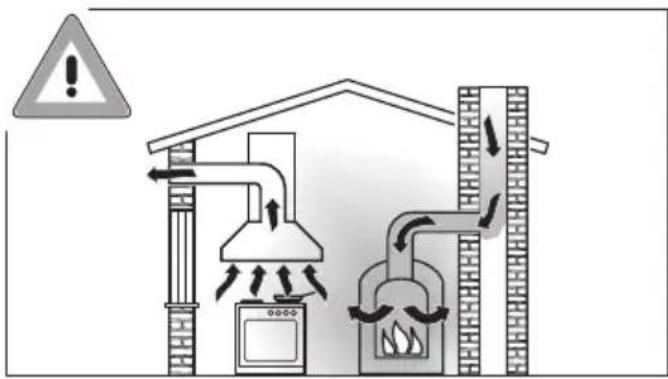
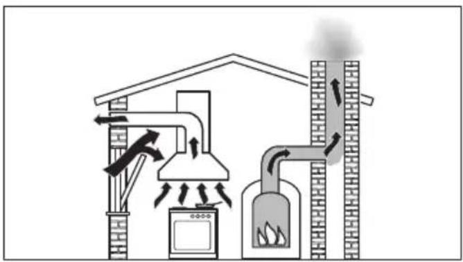
Using at the same time as another heating appliance that depends on the air from the room
text_image
Diagram illustrating a heating system with labeled components including a stove, air vent, and heat exchanger, accompanied by a warning triangle.da1474b
natural_image
Diagram of a greenhouse gasifier with cooling fans, steam heating, and exhaust pipe (no text or labels)Danger of toxic fumes!
Great care should be taken when using the rangehood in the same room or the same area of the house as another heating appliance that depends on the air from the room.
Such heating appliances draw in air from the room and duct exhaust gases out through a chimney or extraction ducting. They include gas, oil, wood and coal-fired boilers and heaters, continuous flow or other water heaters, gas cooktops and ovens.
The rangehood draws in air from the kitchen and from neighbouring rooms. This applies to the following modes of operation:
- extraction mode,
- extraction mode with an external motor,
- recirculation mode with a recirculation box installed outside the room.
If there is insufficient air, an underpressure will occur. The heating appliance may be starved of oxygen. This impairs combustion.
Harmful gases could be drawn from the chimney or extraction ducting back into the room, with potentially fatal consequences.
Risk of death!
In order to ensure safe operation and to prevent gases given off by a heating appliance from being drawn back into the room, when the rangehood and the heater are both operated simultaneously, an underpressure in the room of 0.04 mbar (4 Pa) is the maximum permissible.
Sufficient ventilation can be maintained by air inlets which cannot be blocked, e.g. in windows, doors and outside wall vents. The diameter of the inlet openings must enable sufficient ventilation. A ventilation brick alone is not generally sufficient to ensure safe ventilation.
The overall ventilation condition of the dwelling must be taken into account. If in any doubt, the advice of a competent builder, or for gas, a qualified gas fitter should be sought.
If the rangehood is being operated in recirculation mode, whereby the air is redirected into the room in which it is installed, the above restrictions do not apply.
Correct use
▶ Never use an open flame beneath the rangehood. To avoid the danger of fire, do not flambé or grill over an open flame.
When switched on, the rangehood could draw flames into the filter. Fat deposits could ignite, presenting a fire hazard.
The rangehood can become damaged when exposed to excessive heat.
- When using the rangehood over a gas cooktop, ensure that any burners in use are always covered by a pan. Switch the cooking zone off when a pan is removed, even for a short time.
- Select a pan which is suitable for the size of the burner.
- Regulate the flame so that it does not burn up the sides of the pan.
- Avoid overheating the pan (e.g. when cooking with a wok).
▶ Always switch the rangehood on when a cooking zone is in use, otherwise condensation may collect in the rangehood, which could cause corrosion.
▶ Overheated oil and fat can ignite, causing fire damage to the rangehood.
When cooking with oil or fat, chip pans and deep fat fryers etc., do not leave the pans unattended. Similarly, never leave an open grill unattended when grilling.
Do not use the rangehood without the filters in place. This way you will avoid the risk of grease and dirt getting into the appliance and hindering its smooth operation.
The rangehood can get very hot during cooking due to heat rising from the cooktop.
Do not touch the housing or the grease filters until the rangehood has cooled down.
Correct installation
▶ Refer to the cooktop manufacturer's instructions as to whether a rangehood may be operated above the cooktop.
▶ Safety regulations prohibit the fitting of a rangehood over solid fuel stoves.
An insufficient safety distance between the stovetop and the rangehood can result in damage to the rangehood.
The minimum safety distances between the top of the stovetop and the bottom of the rangehood given in the “Installation” section of this booklet must be observed, unless the stovetop manufacturer states that a greater safety distance is required.
If more than one cooking appliance is fitted beneath the rangehood, and they have different minimum safety distances to the rangehood, select the greater distance.
The distances given in “Installation” must be observed when fitting the rangehood.
All ducting, pipework and fittings must be of non-flammable material. These can be obtained from builders' merchants.
The appliance must not be connected to a chimney or vent flue which is in current use for exhausting fumes from appliances burning gas or other fuels. Neither should it be connected to ducting which ventilates rooms with fireplaces.
If exhaust air is to be extracted into a chimney or ventilation duct no longer used for other purposes, seek professional advice.
Cleaning and care
There is a risk of fire if cleaning is not carried out as described in these operating instructions.
In areas which may be subject to infestation by cockroaches or other vermin, pay particular attention to keeping the machine and its surroundings in a clean condition at all times. Any damage which may be caused by cockroaches or other vermin will not be covered by the machine warranty.
Do not use a steam cleaning appliance to clean this appliance. The steam could reach electrical components and cause a short circuit.
Accessories
▶ Use only genuine original Miele spare parts. If spare parts or accessories from other manufacturers are used, the warranty will be invalidated, and Miele cannot accept liability.
Disposal of the packing material
The transport and protective packaging has been selected from materials which are environmentally friendly for disposal, and can normally be recycled.
Recycling the packaging reduces the use of raw materials in the manufacturing process and also reduces the amount of waste in landfill sites. Ensure that any plastic wrappings, bags etc. are disposed of safely and kept out of the reach of babies and young children. Danger of suffocation.
Disposing of your old appliance
Electrical and electronic appliances often contain valuable materials. They also contain specific materials, compounds and components, which were essential for their correct function and safety. These could be hazardous to human health and to the environment if disposed of with your domestic waste or if handled incorrectly. Please do not, therefore, dispose of your old appliance with your household waste.
Please dispose of it at your local community waste collection / recycling centre for electrical and electronic appliances. You are also responsible for deleting any personal data that may be stored on the appliance prior to disposal. Please ensure that your old appliance poses no risk to children while being stored prior to disposal.
Guide to the appliance
0813411
text_image
Exploded view diagram of a microwave oven with numbered components for identification
text_image
Miele ⑦ - 1 2 3 B + ⑧ ⑨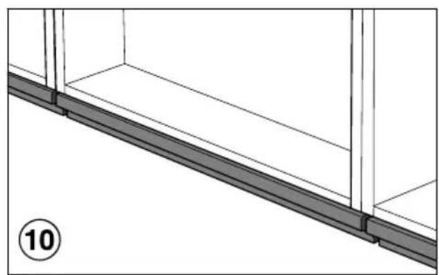
natural_image
Architectural detail showing a beam supported by two vertical supports, with no visible text or symbols.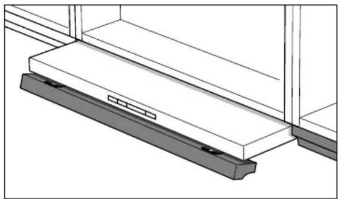
natural_image
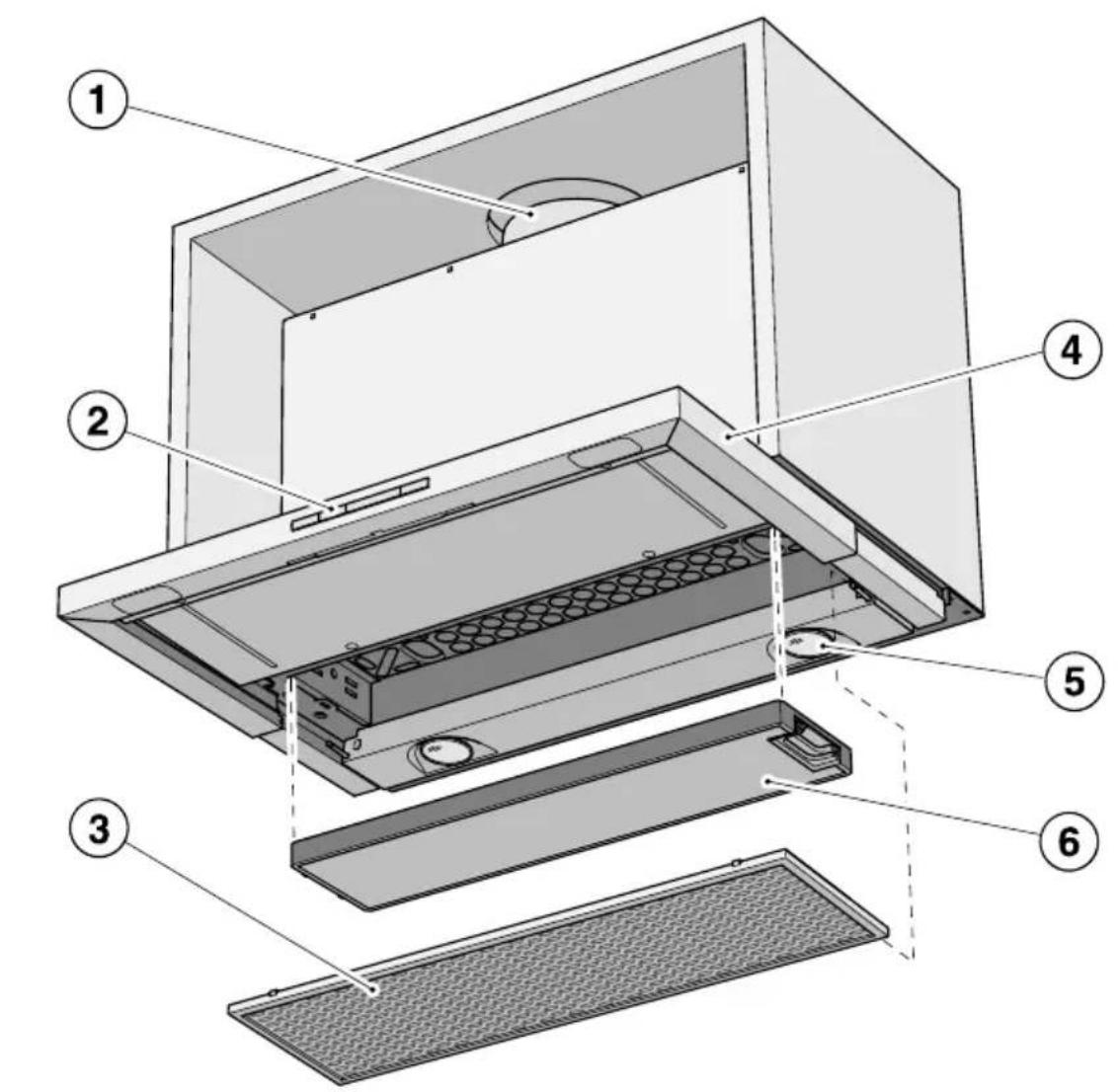
Technical line drawing of a mechanical assembly with two plates and a handle (no text or symbols)① Exhaust connection for air extraction/recirculation
② Touch controls
③ Grease filter
④ Pull-out deflector plate
⑤ Cooktop lighting
⑥ NoSmell active charcoal filter (special accessory for recirculation mode)
⑦ On/Off touch control for the fan
⑧ Touch controls to select the fan power setting
⑨ On/Off touch control for the cooktop lighting
⑩ Drop-down front panel
A front panel to match your kitchen furniture may be fitted instead of this panel (DML 400 installation kit required).
Depending on the model of the rangehood, the following options are available:
Air extraction mode
natural_image
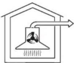
Simple line drawing of a house with a chimney and airflow arrow (no text or symbols)The air is drawn in and cleaned by the grease filter and directed outside.
Non-return flap
The non-return flap is designed to prevent the exchange of room and outside air taking place.
The flap is closed when the rangehood is switched off.
When the rangehood is switched on, the non-return flap opens for the cooking vapours to be blown directly outside.
If the on-site ventilation system does not have a non-return flap, the non-return flap supplied must be fitted.
Recirculation mode
(available as an optional extra with a conversion kit and charcoal filter: see "Technical Data")
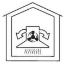
natural_image
Simple line drawing of a house with a roof and a central air vent (no text or symbols)
The air is drawn in and cleaned first by the grease filter and then by a charcoal filter. The cleaned air is then recirculated back into the kitchen.
Operation with an external motor
(...EXT model rangehoods.
...EXT models are only available in selected countries.)
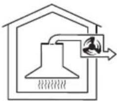
natural_image
Simple line drawing of a house with a chimney and airflow path (no text or symbols)
Rangehoods set up for operation with an external motor have to be connected to a Miele external motor located in a suitable position outside the room in which the rangehood is installed. The external motor is linked to the rangehood via a control cable and then operated using the controls on the rangehood.
■ Pull out the deflector plate. For optimum extraction with minimum noise levels, always pull the deflector plate out to its full extent.
The fan will switch on at setting 2. The ⏻ symbol and 2 will light up in the power setting display.
Selecting a power setting
For light to heavy cooking vapours and odours, select from power settings 1 to 3.
For short periods of cooking food with intensive vapours and a strong aroma, e.g. when searing meat, select Booster setting B.
■ Select the power level you want by pressing the — or + controls.
Reducing power down from the Booster setting
If Power management is activated (default setting), the fan automatically switches back to level 3 after 5 minutes.
Fan run-on after cooking
■ It is advisable to run the fan for a few minutes after cooking has finished to neutralise any lingering vapours and odours in the air.
■ Turn off the fan by pushing the deflector plate back in. The next time the deflector plate is pulled out, the range hood will switch on at setting 2 again.
■ Press the On/Off touch control ⏻ to switch the fan off.
The ⏻ symbol will go out.
Switching the cooktop lighting on/off
The cooktop lighting can be switched on and off independently of the fan.
■ You can switch the cooktop lighting on and off by pulling the deflector plate out and pushing it in or by pressing the lighting control ⚙️.
The ⚙ symbol will light up when the cooktop lighting is switched on.
Power management
The rangehood features a Power management system to help save energy. The fan power setting is reduced and the lighting is switched off automatically.
- If the Booster setting has been selected, the fan will automatically switch to setting 3 after 5 minutes.
- From settings 3, 2 or 1 the power will be reduced by one setting after 2 hours and then in 30-minute stages until the fan finally switches off.
- The cooktop lighting will switch off automatically after 12 hours.
Switching Power management on/off
You can deactivate the Power management.
Keep in mind that this may increase energy consumption.
■ To set this option, both the fan and the cooktop lighting must be switched off.
■ Press the — and + controls at the same time for approx. 10 seconds, until the 1 lights up.
■ Then press in turn:
- the lighting control ⚙,
- then the — touch control, and
- the lighting control ♀ again.
If Power management is switched on, the 1 and B indicators light up constantly.
When it is switched off, the 1 and B indicators flash.
■ Press — to switch Power management off.
The 1 and B indicators will flash.
■ To switch it on, press +.
The 1 and B indicators will light up constantly.
■ Confirm your choice with the On/Off control ⏻.
All the indicator lights will go out.
If you don't confirm your selection within 4 minutes, the rangehood will automatically revert to the previous setting.
Safety switch-off
If Power management has been deactivated, the rangehood will switch itself off automatically after 12 hours if it has been left on (fan and cooktop lighting).
■ To switch it back on press the On/Off ⏻ control or the lighting control ⚙️.
This rangehood operates very efficiently and economically. The following will help you to save even more energy when using it:
- Ensure that there is sufficient ventilation in the kitchen when cooking. In extraction mode, if there is insufficient air flow the rangehood cannot operate efficiently and this causes increased operating noise levels.
- Always cook with the lowest possible setting. This produces fewer cooking vapours, so you can use a lower rangehood power level and therefore benefit from reduced energy consumption.
- Check the power level selected on the rangehood. A lower power level is generally sufficient for the majority of cooking. Only use the Booster setting when necessary.
- When a large volume of cooking vapours are being produced, switch to a high power level in good time. This is more efficient than operating the rangehood for longer to try to capture cooking vapours which have already been distributed throughout the kitchen.
- Make sure that you switch the rangehood off after use.
- Clean or change the filters at regular intervals. Heavily soiled filters reduce performance, increase the risk of fire and are unhygienic.
⚠️ Before proceeding with any maintenance or cleaning task, the rangehood must be disconnected from the power supply (see “Warning and Safety instructions”).
Housing
General
⚠️ The surfaces and controls are susceptible to scratches and abrasion. Please observe the following cleaning instructions.
■ All external surfaces and controls can be cleaned using warm water with a small amount of washing-up liquid applied with a well wrung-out soft sponge or cloth.
Do not use too much water when cleaning the controls. Water could penetrate into the electronics and cause damage.
■ After cleaning, wipe the surfaces dry using a soft cloth.
Do not use:
- cleaning agents containing soda, acids, chlorides or solvents,
- abrasive cleaning agents, e.g. powder cleaners or cream cleaners and abrasive sponges, as well as pot scourers or sponges which have been used previously with abrasive cleaning agents. These will damage the surface material.
Important for appliances with stainless steel surfaces
(This information does not apply to the controls)
■ Stainless steel surfaces can be cleaned with a proprietary non-abrasive cleaning agent designed specifically for use on stainless steel, e.g. Original Miele ceramic and stainless steel cooktop cleaner.
■ To help prevent re-soiling, a proprietary conditioning agent for stainless steel (Original Miele Care product for stainless steel) can also be used.
Apply sparingly with a soft cloth following the instructions on the packaging.
Important for the controls
Do not leave soiling on the controls for any length of time. Otherwise they may suffer discolouration or damage. Remove any soiling immediately.
■ Observe the general notes on cleaning earlier in this section.
Do not use stainless steel cleaning agents on the controls.
Grease filter
The re-usable metal grease filter in the appliance removes solid particles from the kitchen vapours (grease, dust, etc.) preventing soiling of the rangehood.
The grease filter must be cleaned at regular intervals.
A heavily soiled grease filter hinders air extraction and will lead to increased levels of soiling in the rangehood and in the kitchen.

Fire hazard!
An oversaturated grease filter is a fire hazard.
Clean the grease filter at regular intervals.
Grease filter cleaning intervals
Accumulated grease solidifies over a longer period of time and makes cleaning more difficult. The grease filter should therefore be cleaned at least every 3 to 4 weeks.
Removing the grease filter

When handling the grease filter, reful not to drop it.
This can result in damage to the filter and the cooktop below.
Make sure you hold the filter securely at all times when handling it.
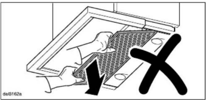
text_image
da3162aWhen removing the grease filter do not tilt it downwards at an angle.
This can damage the retaining pins.
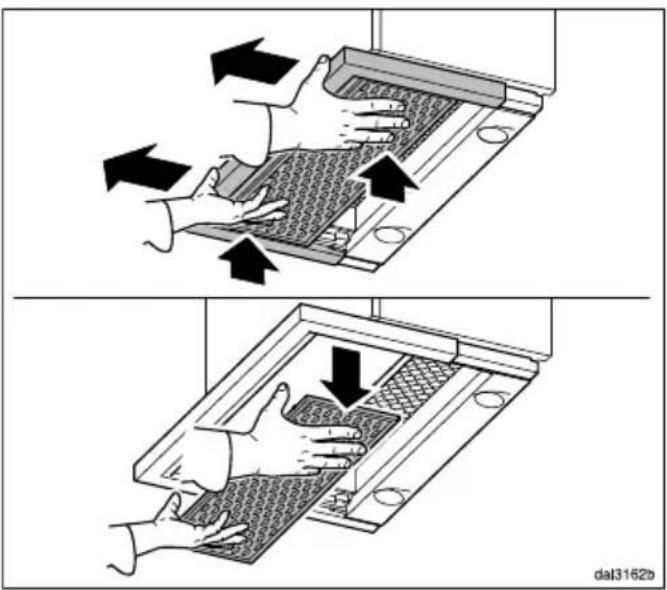
text_image
Diagram illustrating hand press application on a device, showing two steps with arrows indicating movement and a labeled page 'dal3162b'.■ With the deflector plate pushed in, grip the front of the deflector plate and hold the grease filter securely. Whilst holding the grease filter, pull the deflector plate out as shown.
■ Then pull the filter downwards to remove it.
■ Switch off the fan.
Cleaning the grease filter by hand
■ Clean the grease filter with a soft nylon brush in a mild solution of hot water and a small amount of washing-up liquid. Do not use undiluted washing-up liquid.
Cleaning and care
Unsuitable cleaning agents
Unsuitable cleaning agents can cause damage to the surface of the filters if used regularly.
Do not use:
- cleaning agents containing descaling agents,
- powder cleaners or cream cleaners,
- aggressive all-purpose cleaning agents or spray cleaners for grease,
- oven sprays.
Cleaning the grease filter in the dishwasher
■ Place the grease filter upright or slightly inclined in the lower basket. Ensure the spray arm is not obstructed.
■ Use a standard household dishwasher detergent.
■ Select a dishwasher programme with a wash temperature between 50 °C and 65 °C.
Depending on the detergent used, cleaning the grease filter in a dishwasher can cause permanent discolouration to the internal surfaces of the filter. This will not affect the functioning of the grease filter in any way.
After cleaning
■ After cleaning, leave the grease filter to dry on an absorbent surface before refitting it.
■ When removing the filter for cleaning, also clean off any residues of oil or fat from the now accessible casing to prevent the risk of these catching fire.
Fitting the grease filter
text_image
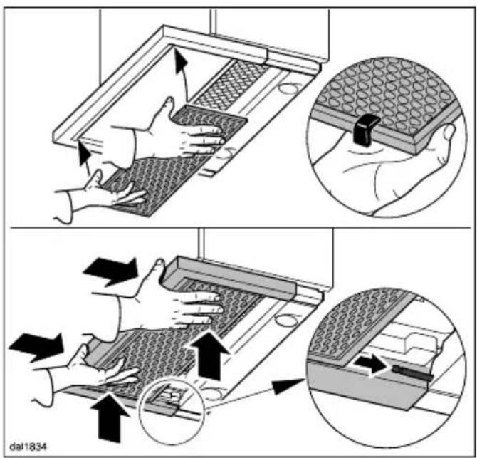
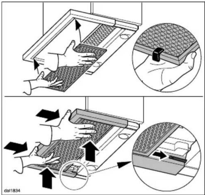
dal1834■ When fitting the grease filter, make sure that the red plastic guides are at the front and facing upwards.
■ Place the grease filter in the front of the deflector plate, press it upwards and push it in together with the deflector plate. It will slide onto the retaining pins at the back. Finally, push the grease filter back a little more.
NoSmell active charcoal filter
If the rangehood is connected for recirculation, a charcoal filter must be inserted in addition to the grease filter. The charcoal filter is designed to absorb cooking odours. It is fitted in the canopy above the grease filter.
Charcoal filters are available to order via the Miele Webshop (see end of this booklet for contact details) or directly from Miele.
The part number of the charcoal filter required is listed under "Technical data".
Fitting and replacing the charcoal filter
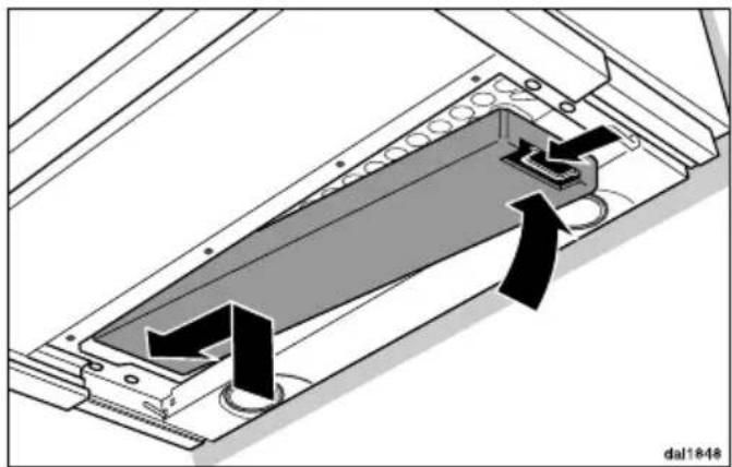
■ Before fitting or replacing the charcoal filter, the grease filter must first be taken out (see previous section for instructions on how to do this).
■ Unwrap the charcoal filter from its packaging.
natural_image
Technical diagram of a mechanical assembly with directional arrows indicating movement or force (no text or symbols present)■ Fit the charcoal filter into the frame.
■ Replace the grease filter.
When to change the NoSmell active charcoal filter
■ Replace the charcoal filter when it no longer absorbs kitchen odours effectively. It should be replaced at least every 6 months.
Disposing of the charcoal filter
■ The used charcoal filter can be disposed of with the normal household waste.
Changing a lamp
The lamps should be replaced with the following:
Manufacturer ...... EGLO
Lamp type ...... GU10
Specification.... 12981
Wattage 3 W
These lamps are available from Miele or from specialist retailers.
■ Pull out the deflector plate, and remove the grease filter as described earlier.
■ Switch off the fan and the lighting.
Note that lamps become hot when in use.
Allow the lamps to cool down for a few minutes before changing them.
■ Remove the charcoal filter if the rangehood is being used in recirculation mode.
■ Disconnect the rangehood from the mains electrical supply before replacing the lamps (see “Warning and Safety instructions”).
natural_image
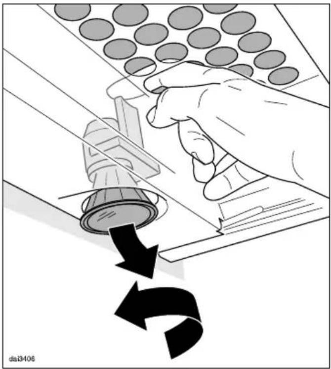
Illustration of a hand using a tool to press down a component, with arrows indicating motion (no text or symbols)■ Push down the lighting unit slightly via the opening in the safety panel.
■ Turn the lamp anti-clockwise and pull it out.
■ Screw the new lamp into the socket and push it upwards. Please follow the manufacturer's safety instructions.
■ Replace the grease filter and, if being used in recirculation mode, the charcoal filter.
Before installation
⚠️ Before installation, it is important to read the information given on the following pages as well as the “Warning and Safety instructions” at the beginning of this booklet.
Assembly parts
dai2016
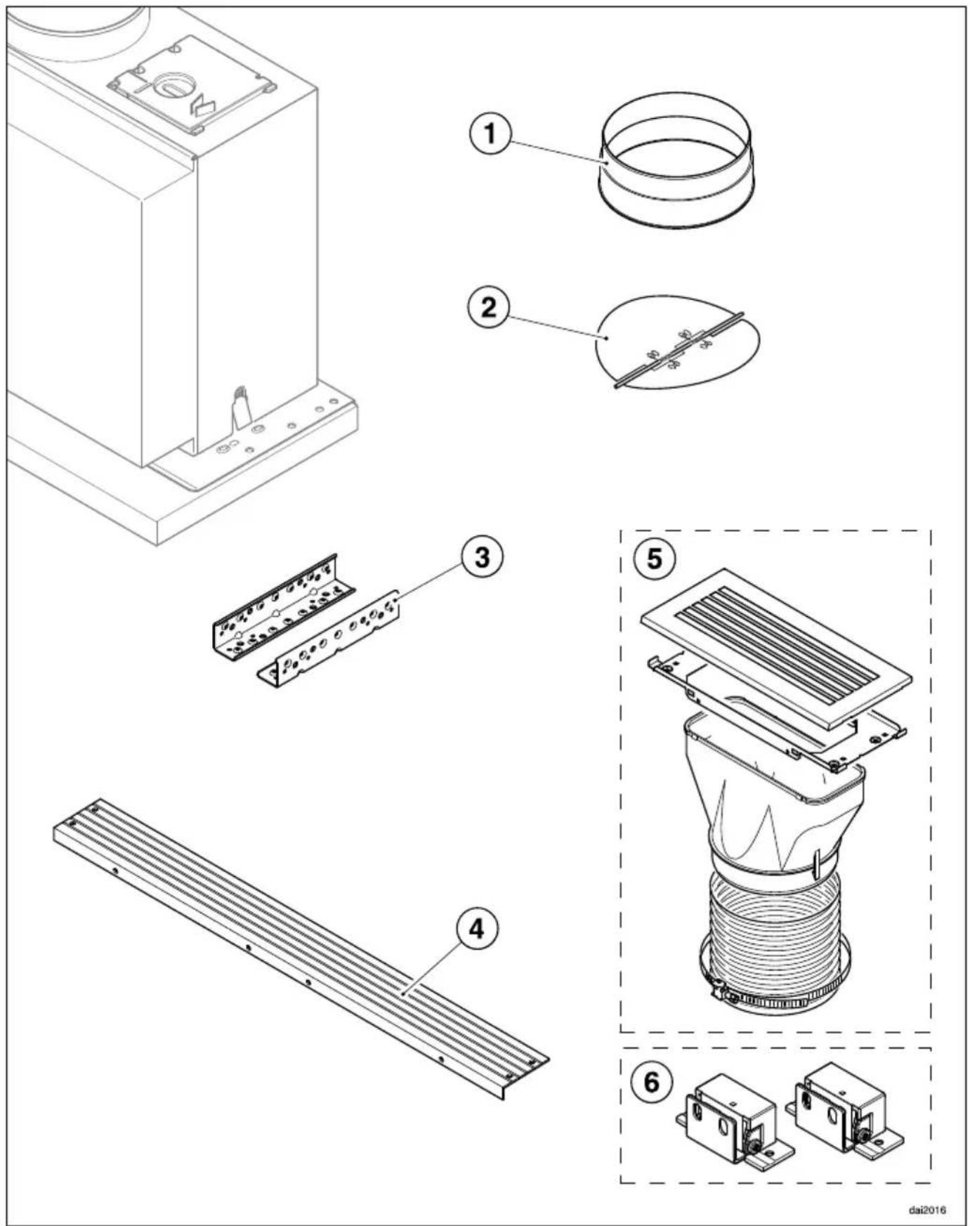
① 1 exhaust connection for exhaust ducting ∅ 150 mm.
② 1 non-return flap
for fitting into the exhaust
connection on the motor unit (not
needed for recirculation mode).
③ 2 brackets
for securing the rangehood in the wall unit.
④ 1 spacer strip
for concealing the gap between the rear of the appliance and the wall.
⑤ Conversion kit for recirculation mode
(not supplied, but available as an optional accessory - see "Technical data"). The kit contains an exhaust grille and flexible aluminium hose with hose clips.
⑥ DML 400 installation kit for fitting a drop-down front panel
(not supplied but available as an optional accessory). Contains hinging and screws for fitting a front panel to match kitchen furniture.
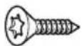
04932511
8 screws 4 x 15 mm for securing the rangehood in the wall unit.
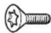
07270730
8 screws M4 x 12 mm
for securing the rangehood to the brackets.
4 of the screws can be used instead of the plastic rivets to secure the spacer strip.
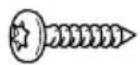
01056271
2 screws 4 x 15 mm for securing the rangehood to the rear wall.
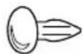
08269410
4 plastic rivets
for securing the spacer strip.
Appliance dimensions
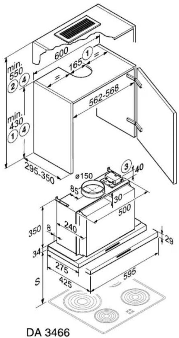
text_image
min. 550 ② 4 600 1 = 165 = 562-568 min. 430 ① 4 295-350 Ø150 3 40 85 30 500 240 350 8 34 275 S 425 595 29 DA 3466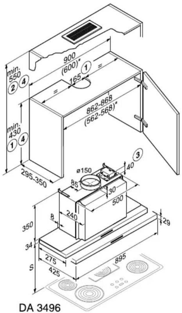
text_image
min. 550 ② 4 900 (600)* 1 = 165 = 862-868 (562-568)* min. 430 ① 4 295-350 Ø150 40 ③ 85 30 500 240 8 350 34 275 S 425 895 29 DA 3496dai3407au
① Extraction mode: the height of the wall unit and cut-out dimensions must allow for any accessories fitted (e.g. silencer, DSM module).
② Recirculation mode with conversion kit DUU 151.
③ DSM 400 accessory.
④ When installing the rangehood with a DAR 3000 drop-down frame, make sure that you note the different wall unit height (please refer to the dimensions given in the DAR 3000 building-in diagram).
* The rangehood can also be installed in a 600 mm wide unit (a DAR 3000 drop-down frame cannot be used in this instance).
Safety distance (S)
The minimum distances between the top of a cooktop (excluding trivets, dials - depending on model) and the bottom of the rangehood are as follows, unless a greater distance is specified by the manufacturer of your cooking appliance. See also “Warning and Safety instructions”.
| Cooking appliance Minimum distance S | |
| Electric cooktop 600 mm (AU, NZ) | 450 mm (HK, MY, SG) |
| Electric grill, deep fat fryer (electric) 650 mm | |
| Multi-burner gas cooktop with maximum 45.4 MJ/h total output, with no burner having a greater output than 16.2 MJ/h. | 650 mm |
| Multi-burner gas cooktop with total output greater than 45.4 MJ/h, but with a maximum of 77.8 MJ/h, with no burner having a greater output than 17.3 MJ/h. | 760 mm |
| Multi-burner gas cooktop with total output greater than 77.8 MJ/h, with a single burner having a greater output than 17.3 MJ/h. | Not possible |
| Single burner gas cooktop with a maximum output of 21.6 MJ/h. | 650 mm |
| Single burner gas cooktop with an output greater than 21.6 MJ/h, but with a maximum of 29.2 MJ/h. | 760 mm |
| Single burner gas cooktop with an output greater than 29.2 MJ/h. | Not possible |
If you are fitting a front panel made of wood or plastic to the rangehood, observe the safety distances given by the cooktop manufacturer regarding the use of easily flammable materials.
Installation recommendations
- To achieve optimum vapour extraction, the rangehood must be positioned centrally over the cooktop, not to the side.
- The cooktop should be no wider than the rangehood and, if possible, it should be narrower, especially for safety distances greater than 750 mm.
- The installation area must be easily accessible. The rangehood should be easily accessible and easy to dismantle in the event that service is required. This should be taken into consideration when planning the position of cupboards, shelves, ceilings or features in the vicinity of the rangehood.
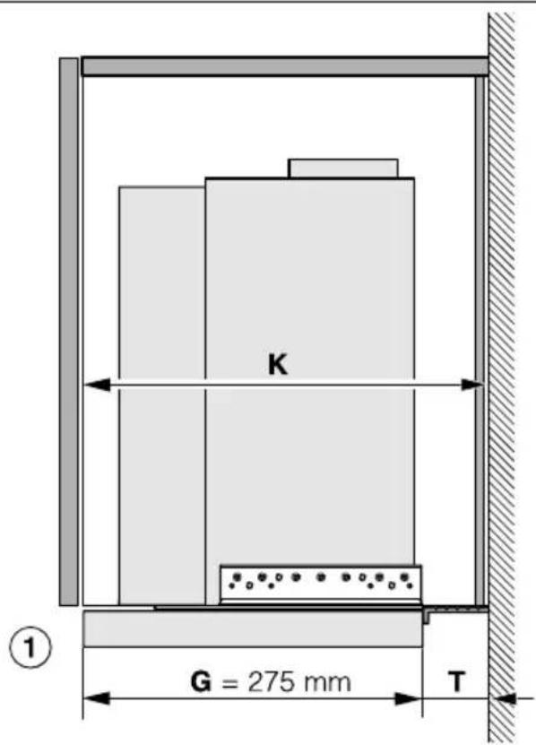
text_image
K G = 275 mm T ①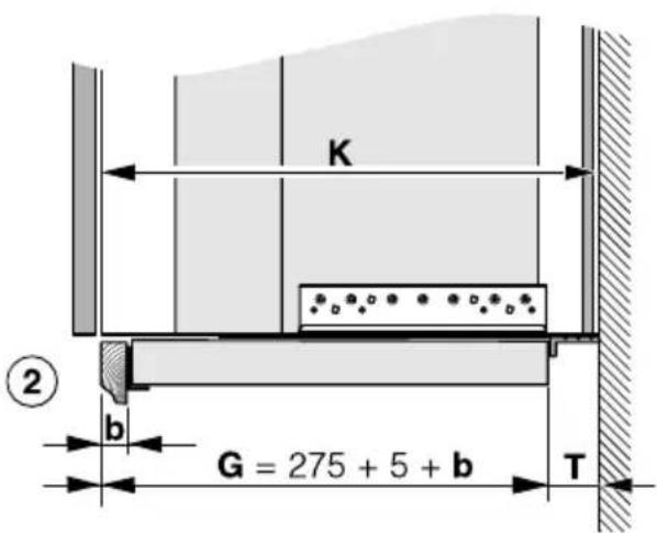
text_image
K ② b G = 275 + 5 + b T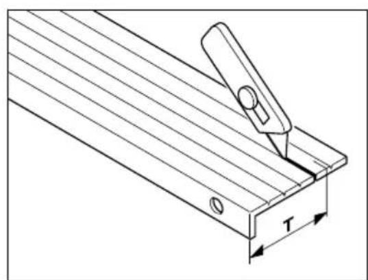
natural_image
Technical line drawing of a mechanical clamp or bracket with a T-shaped cutout and mounting holes (no text or symbols)① Example: Installation without a front panel fitted and with the front edge of the deflector plate flush with the front edge of the furniture housing unit.
② Example: Installation with a front panel to match the kitchen furniture. This installation requires dimension b for the front panel plus 5 mm for the DML 400 fixing bracket to be added to the shelf dimension.
To position the rangehood correctly, cut the spacer strip to the required depth T and then attach it to the back of the appliance:
T= Depth of furniture unit K minus depth of appliance G
■ Cut the spacer strip supplied to measurement T. Score along the groove for the smaller measurement as shown, and remove the surplus.
text_image
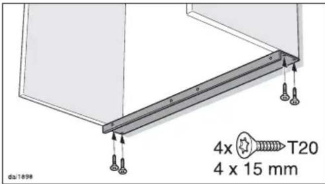
4x T20 4 x 15 mm dal1898- Secure the spacer strip underneath the housing unit sides, flush with the rear wall.
natural_image
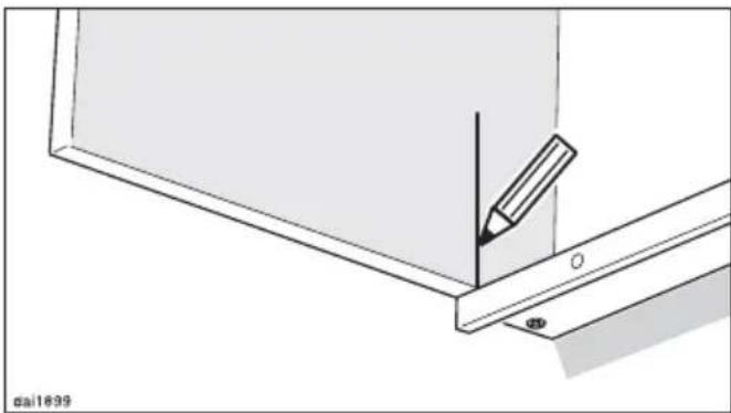
Technical line drawing showing a pencil inserted into a bracket with a small hole, no text or symbols present■ Draw a vertical line up both inside walls of the housing from the front of the spacer strip.
text_image
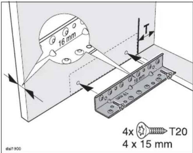
16 mm T 4x 4x T20 4 x 15 mm dai1900■ The brackets are designed for 16 and 19 mm thick unit sides. Orientate the bracket so that the vertical depth matches the thickness of the unit side.
Screw the brackets onto the right and left inside walls of the housing unit as shown. The back edge of the bracket should align with the vertical line drawn up from the front of the spacer strip and the lower edge should align with the lower edge of the housing unit side wall.
text_image
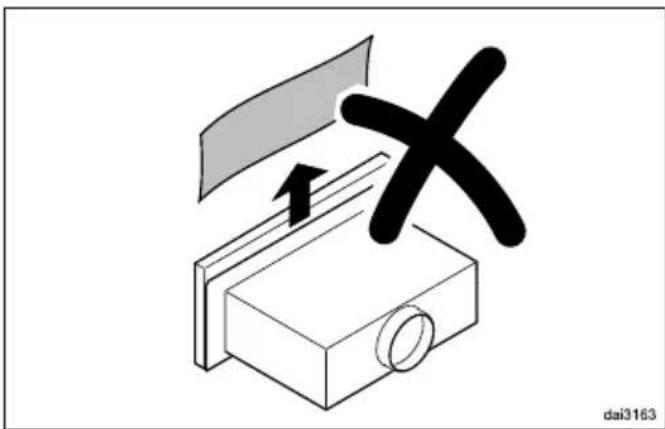
dai3163To avoid scratching the deflector plate, do not remove the protective film between the deflector plate and the casing until the rangehood has been placed in the housing unit.
■ Installation of the rangehood is carried out without the grease filter placed in position. If the grease filter has already been fitted, then it should be removed (see “Cleaning and care”).
natural_image
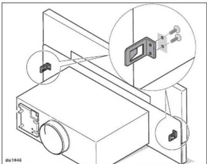
Technical line drawing of a mechanical assembly with inset close-up views (no text or symbols)■ When fitting a 90 cm wide rangehood in a 60 cm wide wall unit, whilst the deflector plate is pulled out, unscrew the two deflector plate spring mounts.
natural_image
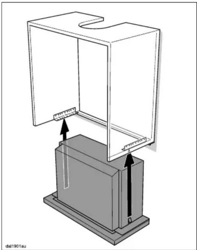
Technical diagram of a mechanical assembly with a transparent enclosure and a rectangular base, showing directional arrows indicating movement or force (no text or symbols present)- Lift the appliance up into the housing unit from below until the spring mounts at the side engage in the brackets. - Push the rangehood back against the spacer strip.
text_image
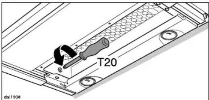
T20 da1906■ Note for dismantling the rangehood: Undoing the screws on the left and right inside the housing releases the spring mounts, allowing the appliance to be removed from the unit.
text_image
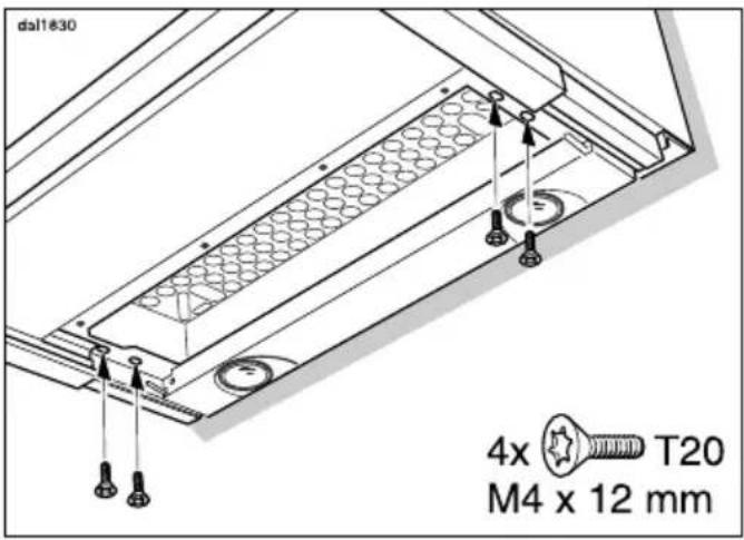
dal1830 4x T20 M4 x 12 mm- Secure the rangehood to the brackets from below using two screws on each side.
natural_image
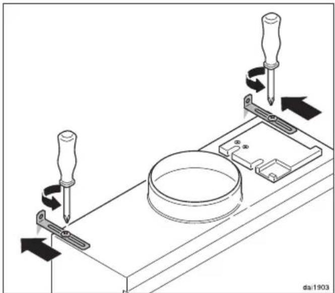
Technical diagram showing screwdriver fastening a mechanical component with arrows indicating motion (no text or symbols)■ Loosen the retaining bracket screws and push the brackets back against the rear wall.
text_image
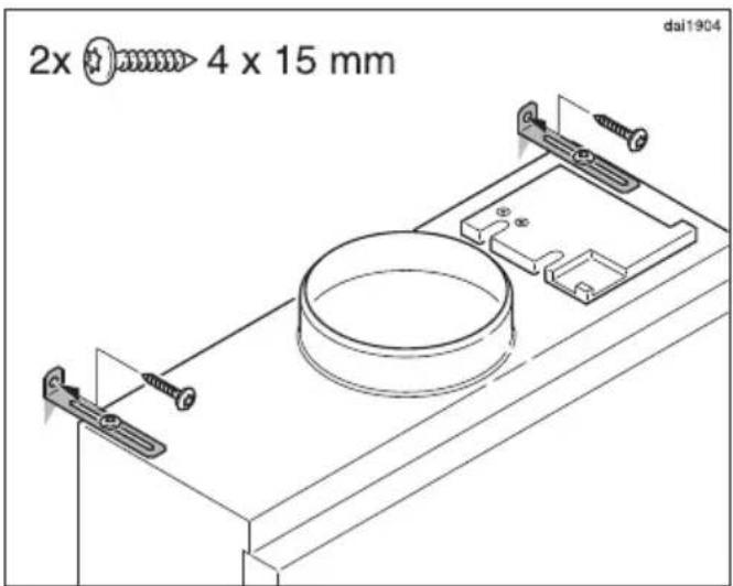
2x 4 x 15 mm dai1904■ Secure the retaining brackets to the rear wall using the screws supplied.
The housing must be secured firmly to the rear wall of the furniture unit. If this is not ensured, the housing may lean forwards and the canopy could be damaged when it is pulled out and pushed back in.
If the furniture unit does not have a non-yielding rear wall, the retaining brackets must be attached to the kitchen wall. To do this, suitable means of attachment must be used.
natural_image
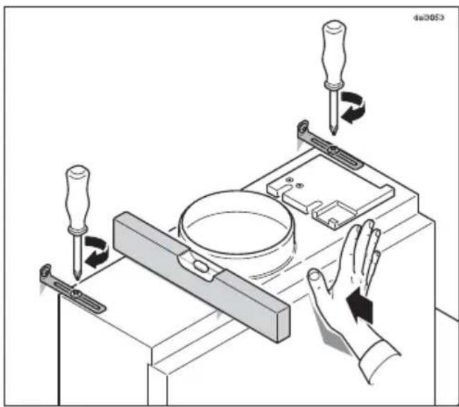
Technical illustration of a mechanical assembly with tool holders and a hand interacting with a component (no text or symbols)■ Align the housing and screw on the retaining brackets.
text_image
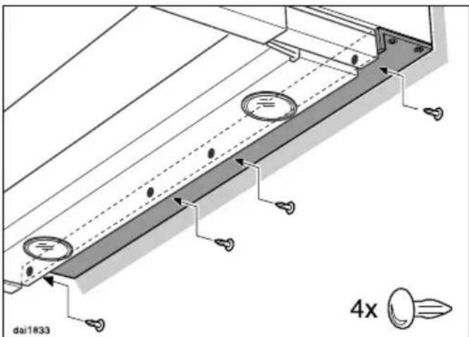
dai1833 4x■ Secure the spacer strip to the back of the appliance from behind using 4 plastic rivets as shown.
Attaching the front panel
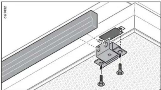
The front of the deflector plate can be fitted with a front panel to match existing kitchen furniture units. The weight of the front panel must not exceed 1300 g. This applies to front panels with a depth of up to 30 mm. For larger and heavier front panels, the weight must be reduced, e.g. by machining it away at the back.
A DML 400 installation kit is required for fitting a front panel. It is available as an optional accessory.
text_image
da1832■ Follow the installation instructions supplied.
Aligning the deflector plate
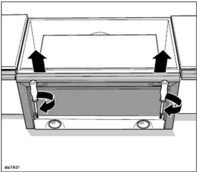
The position of the deflector plate can be brought forward by up to 35 mm using the adjusting screws on either side of the deflector plate. This allows the deflector plate to be aligned to the front of the kitchen furniture units on either side.
natural_image
Diagram of a mechanical device with rotating components and directional arrows indicating motion (no text or symbols)■ Use a screwdriver to align the deflector plate correctly.
Fitting the grease filter
natural_image
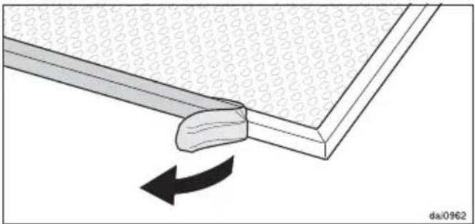
Diagram showing a mechanical component with an arrow indicating rotation, no text or symbols present■ Remove the protective foil around the edge of the grease filter.
text_image
dal1834■ When fitting the grease filter, make sure that the red plastic guides are at the front and facing upwards.
■ Place the grease filter in the front of the deflector plate, press it upwards and push it in together with the deflector plate. It will slide onto the retaining pins at the back. Finally, push the grease filter back a little more.
Set up for extraction mode
natural_image
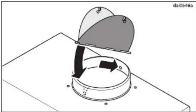
Diagram showing a mechanical or electrical component with arrows indicating motion, no readable text or symbols present.If required, install the non-return flap. Check that the flap opens easily and closes by itself. Depending on the model of rangehood, the non-return flap may already be installed.
natural_image
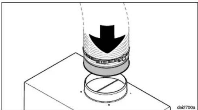
Diagram of a mechanical press or clamping device with a downward arrow and circular base, no readable text or symbols present.■ Place the exhaust ducting on the exhaust connection for the rangehood.
■ See “Connection for air extraction” for further instructions on fitting the ducting.
text_image
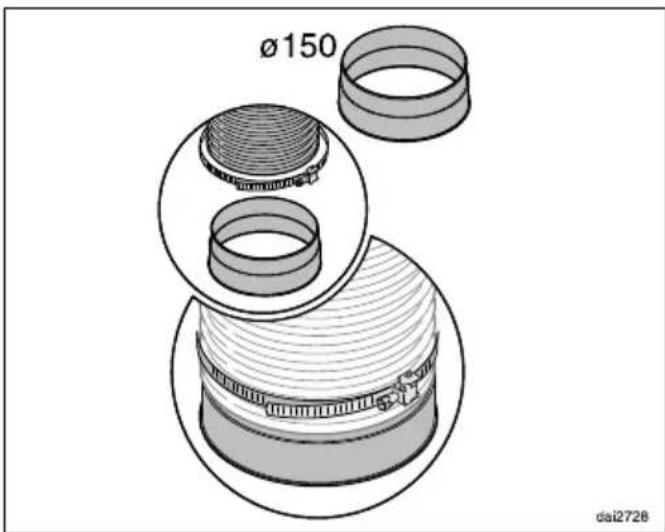
Ø150 dai2728- Secure the exhaust ducting to the exhaust connection, e.g. with a hose clip (available as an optional accessory) on flexible ducting.
Set up for recirculation mode
If site conditions are not suitable for the rangehood to be used with air extraction, the appliance must be set up for recirculation. The DUU 151 conversion kit, available from Miele, is required for operating the rangehood in recirculation mode. You will also need a charcoal filter (see “Technical data”).
When using the rangehood in recirculation mode, do not fit a return flap. Depending on the model of rangehood, the non-return flap may already be fitted.
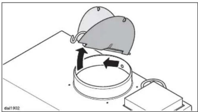
natural_image
Diagram showing a mechanical assembly with two caps and a rotating component (no text or symbols)■ Remove the non-return flap from the exhaust connection.
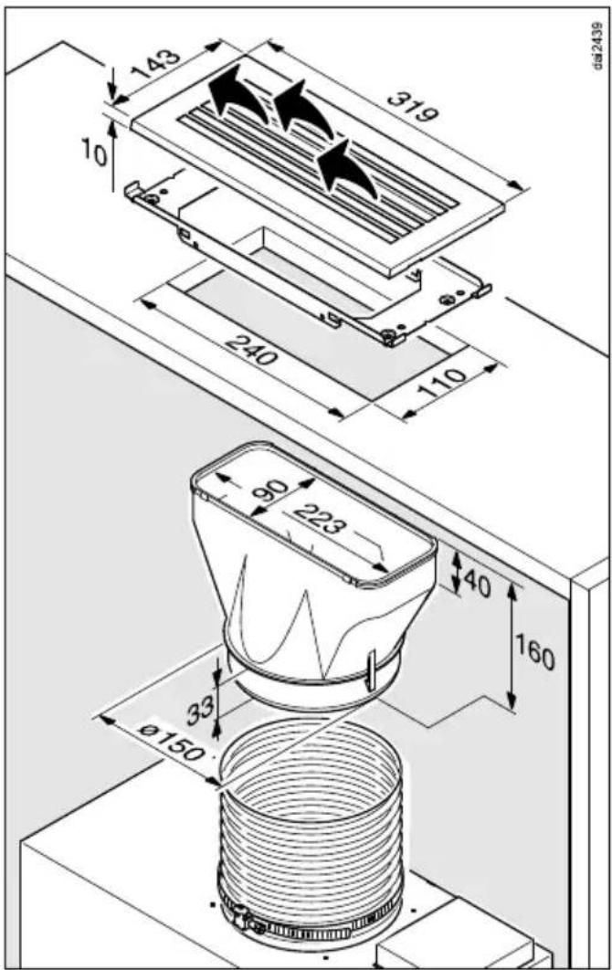
text_image
143 319 10 240 110 90 223 40 160 33 ø150 dai2439■ Fit the conversion kit as described in the installation instructions supplied with the kit. Make sure that the slats in the exhaust grille point towards the centre of the room and not towards a wall or the ceiling.
A non-return flap is not used in recirculation mode.
■ Fit the charcoal filter (see “Cleaning and care”).
Mains connection
Refer to the notes in “Electrical connection” and “Warning and Safety instructions” before connecting to the electricity supply.
■ For appliances connected to an external motor (EXT models): Connect the rangehood and the external motor using the connection cable and the six-pole plug connector.
- Plug the connection cable into an electrical socket.
All electrical work must be undertaken by a suitably qualified and competent person in strict accordance with current national and local safety and building code regulations. Installation, repairs and other work by unqualified persons could be dangerous, for which the manufacturer cannot be held liable. Ensure power is not supplied to the appliance until after installation or repair work has been carried out.
The rangehood must be connected to a suitably earthed socket (AC 230 V, 50 Hz).
For extra safety it is advisable to install a residual current device (RCD) with a trip current of 30 mA.
Connection of this appliance must be made via a suitable isolator switch which provides disconnection on all poles and which complies with national and local safety regulations. The isolator switch should be easily accessible after the appliance has been built in.
If the mains socket is not accessible after installation, an additional means of disconnection must be provided for all poles. There must be an all-pole contact gap of 3 mm in the switch (including switch, fuses and relays).
The connection data is given on the data plate (See “After sales service”). Ensure that this data matches the household mains supply.
⚠️ Before installation, it is important to read the information given on the following pages as well as the “Appliance dimensions” and the “Warning and Safety instructions” at the beginning of this booklet. This is particularly crucial when using the rangehood at the same time as a heating appliance that relies on oxygen from the same room, which could result in the build-up of toxic fumes.
The rangehood should be installed according to local and national building regulations. Seek approval from the building inspector where necessary.
Only use smooth pipes or flexible ducting made from approved non-flammable materials for exhaust ducting.
When using an external motor, make sure that the exhaust ducting is sufficiently rigid. The external motor can cause an underpressure which can result in the exhaust ducting distorting.
To achieve the greatest possible air extraction with the lowest noise level, please note the following:
- The diameter of the exhaust ducting should not be less than 150 mm.
- If flat ducting is being used, the cross-sectional area must not be smaller than the cross-sectional area of the exhaust connection.
-
The exhaust ducting should be as short and straight as possible.
-
Only use wide radius bends.
- The exhaust ducting must not be kinked or compressed.
- Ensure that all connections are strong and airtight.
Remember that any constriction of the airflow will reduce extraction performance and increase operating noise.
■ If the exhaust is ducted through an outside wall, a telescopic wall vent or a roof vent (available as an optional accessory) is recommended.
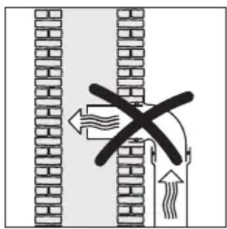
text_image
Diagram showing a cross-shaped object with arrows indicating flow or movement, possibly representing a mechanical or fluid system.da2538
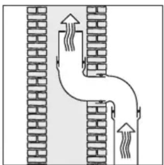
natural_image
Diagram of a pipe system with two brick walls and upward arrows indicating flow direction (no text or labels)■ If the exhaust air is to be ducted into a vent flue, the ducting must be directed in the flow direction of the flue.
■ Where ducting is horizontal, it must be laid to slope away at at least 1 cm per metre. This is to ensure that condensate cannot drain back into the rangehood.
If the exhaust ducting is to run through rooms, ceiling space etc. there may be great variations in temperature between the different areas. The problem of condensation will need to be addressed. The exhaust ducting will need to be suitably insulated.
Condensate trap
text_image
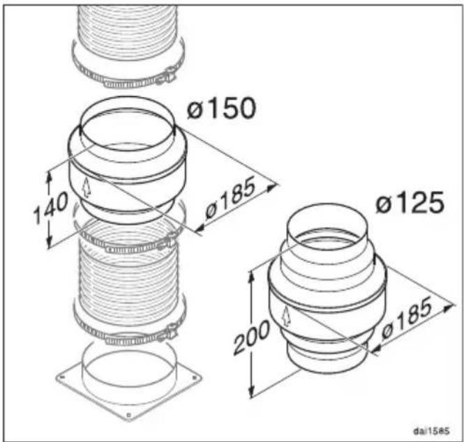
Ø150 140 Ø185 Ø125 200 Ø185 da/1585In addition to insulating the exhaust ducting, we recommend that a suitable condensate trap is also installed to collect and evaporate any condensate which may occur.
Condensate traps are available for 125 mm or 150 mm ducting.
■ When installing a condensate trap, ensure that it is positioned vertically and, if possible, directly above the exhaust socket.
The arrow on the housing indicates the direction of airflow.
The condensate trap will be integrated in rangehoods which are designed to be connected to an external motor (...EXT models).
Silencer
text_image
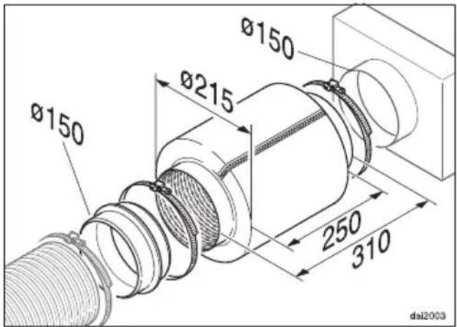
Ø150 Ø215 Ø150 250 310 dai2003To achieve even further reductions in noise levels, a special silencer (optional accessory) can be fitted in the ducting system.
Air extraction mode
text_image
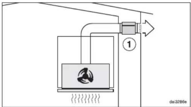
da:3286eThe silencer not only reduces noise from the motor outside the house, but also sounds from outside (e.g. traffic noise). For this reason, the silencer must be positioned as close as possible to the ducting exit ①.
Recirculation mode
text_image
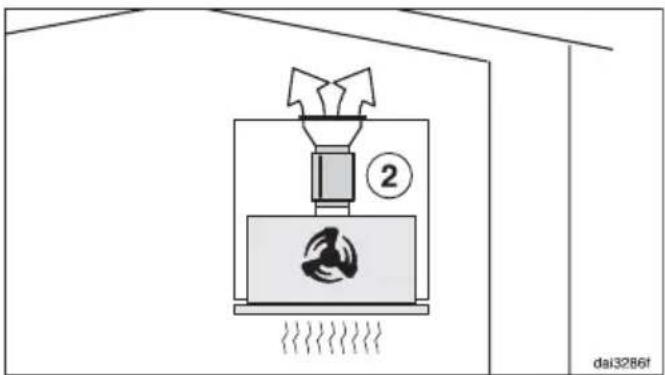
2 dai3286fThe silencer needs to be positioned between the exhaust connection and the exhaust grille ②. Ensure there is adequate space for fitting it.
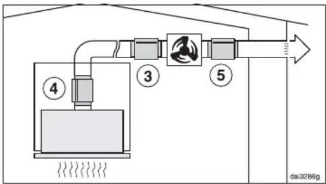
Air extraction with external motor
flowchart
graph LR
    A["Drain Tank"] --> B["Tank 3"]
    B --> C["Control Unit"]
    C --> D["Drain Line"]
    style A fill:#f9f,stroke:#333
    style D fill:#bbf,stroke:#333
To minimise noise from the motor in the kitchen, the silencer should be positioned in front of the external motor ③ if possible, or, if the ducting is long, above the exhaust connection inside the rangehood ④. In the case of an external motor located inside the house, fitting a silencer behind the external motor ⑤ reduces the noise of the motor outside the house.
After sales service and warranty
In the event of a fault which you cannot remedy yourself, please contact Miele.
The contact details for Miele are given at the back of these instructions.
When contacting Miele, please quote the model and serial number of your appliance.
These can be found on the data plate.
Position of the data plate
The data plate is visible after removing the grease filter.
Warranty
AU, NZ:
The manufacturer's warranty for this appliance is 2 years.
For further information, please refer to your warranty booklet.
Other countries:
For information on the appliance warranty specific to your country please contact Miele. See the end of this booklet for contact details.
| Fan motor* see data plate | |
| Cooktop lighting | |
| Total rated load* | |
| Voltage, frequency AC 230 V, 50 Hz | |
| Fuse rating 10 A | |
| Mains connection cable length 1.5 m | |
| Weight | |
| DA 3466 12 kg | |
| DA 3496 14 kg | |
| DA 3466 EXT 10 kg | |
| DA 3496 EXT 11.5 kg | |
* For EXT models, the rated load will depend on the type of external motor fitted.
Length of connection cable to external motor: 1.9 m
Special accessories for recirculation mode:
Conversion kit DUU 151 and charcoal filter DKF 13-1.
Miele Australia Pty. Ltd.
ACN 005 635 398
ABN 96 005 635 398
Miele Experience Centre and
Head Office Melbourne:
1 Gilbert Park Drive
Knoxfield, VIC 3180

1300 4 MIELE (1300 464 353)
www.miele.com.au
Miele (Hong Kong) Limited
41/F - 4101, Manhattan Place
23 Wang Tai Road
Kowloon Bay
Hong Kong
Tel.: (852) 2610 1025
Fax: (852) 3579 1404
E-mail: customerservices@miele.com.hk
Website: www.miele.hk
Singapore
Miele Pte. Ltd.
163 Penang Road
# 04 - 03 Winsland House II
Singapore 238463
Tel.: +65-67351191
Fax: +65-67351161
E-mail: info@miele.com.sg
Internet: www.miele.sg
Miele New Zealand Limited
IRD 98 463 631
Head Office:
Level 2, 10 College Hill
Freemans Bay, Auckland 1011
Telephone:
0800 464 353 (0800 4 MIELE)
www.miele.co.nz
Malaysia
Miele Sdn Bhd
Suite 12-2, Level 12
Menara Sapura Kencana Petroleum
Solaris Dutamas No. 1, Jalan Dutamas 1
50480 Kuala Lumpur, Malaysia
Phone: +603-6209-0288
Fax: +603-6205-3768
Thailand
BHIRAJ TOWER at EmQuartier
43rd Floor Unit 4301-4303
689 Sukhumvit Road
North Klongton Sub-District
Vadhana District
Bangkok 10110, Thailand
Miele Global Headquarters Germany
Miele & Cie. KG Carl-Miele-Straße 29, 33332 Gütersloh, Federal Republic of Germany
Miele
DA 3466
DA 3496
DA 3466 EXT
DA 3496 EXT