UF-910 - Firewall LANCOM - Free user manual and instructions
Find the device manual for free UF-910 LANCOM in PDF.


User questions about UF-910 LANCOM
0 question about this device. Answer the ones you know or ask your own.
Ask a new question about this device
Download the instructions for your Firewall in PDF format for free! Find your manual UF-910 - LANCOM and take your electronic device back in hand. On this page are published all the documents necessary for the use of your device. UF-910 by LANCOM.
USER MANUAL UF-910 LANCOM
natural_image
Two overlapping blue document sheets with white outlines, no text or symbols present01/2020
Contents
1 About This Manual....4
1.1 Target Audience....5
1.2 What is in this Manual....5
1.3 Conventions....5
1.4 Related Resources....6
2 Getting Started....7
2.1 Initial setup....7
2.2 Configuring the Internet Connection....12
2.2.1 Dial-up Connection....12
2.2.2 Cable or Router Connection with Dynamic IP Address....14
2.2.3 Static Connection with Static IP Address....14
2.3 Enabling Internet Access....15
2.3.1 Creating an Internet Object....15
2.3.2 Configuring Your Local Network Connection....15
2.3.3 Creating a Network Object....16
2.3.4 Configuring Firewall Rules for Internet Access....16
2.3.5 Activating the Desktop Configuration....16
3 User Interface....17
3.1 Web Client Components....17
3.1.1 Header....18
3.1.2 Navigation Pane....18
3.1.3 Desktop....19
3.1.4 Information panel....20
3.2 Icons and buttons....21
3.3 Firewall Rule Settings....23
3.3.1 Setting Up a Connection....23
3.3.2 Setting Up a Firewall Rule....23
3.4 Menu Reference....25
3.4.1 Firewall....25
3.4.2 Monitoring & Statistics....54
3.4.3 Network....67
3.4.4 Desktop....87
3.4.5 UTM....101
3.4.6 VPN....115
3.4.7 Certificate Management....129
3.4.8 Diagnostic Tools....136
Copyright
© 2020 LANCOM Systems GmbH, Würselen (Germany). All rights reserved.
While the information in this manual has been compiled with great care, it may not be deemed an assurance of product characteristics. LANCOM Systems shall be liable only to the degree specified in the terms of sale and delivery.
The reproduction and distribution of the documentation and software supplied with this product and the use of its contents is subject to written authorization from LANCOM Systems. We reserve the right to make any alterations that arise as the result of technical development.
Windows® and Microsoft® are registered trademarks of Microsoft, Corp.
LANCOM, LANCOM Systems, LCOS, LANcommunity and Hyper Integration are registered trademarks. All other names or descriptions used may be trademarks or registered trademarks of their owners. This document contains statements relating to future products and their attributes. LANCOM Systems reserves the right to change these without notice. No liability for technical errors and/or omissions.
This product contains separate open-source software components which are subject to their own licenses, in particular the General Public License (GPL). If the respective license demands, the source files for the corresponding software components will be provided on request. Please send an e-mail to gpl@lancom.de.
Products from LANCOM Systems include software developed by the "OpenSSL Project" for use in the "OpenSSL Toolkit" (www.openssl.org).
Products from LANCOM Systems include cryptographic software written by Eric Young (eay@cryptsoft.com).
Products from LANCOM Systems include software developed by the NetBSD Foundation, Inc. and its contributors.
Products from LANCOM Systems contain the LZMA SDK developed by Igor Pavlov.
LANCOM Systems GmbH
Adenauerstr. 20/B2
52146 Wuerselen
Germany
www.lancom-systems.com
1 About This Manual
1 About This Manual
LCOS FX is the operating system for the LANCOM R&S® Unified Firewalls and is part of the LANCOM operating systems family.
The LANCOM operating systems are the trusted basis for the entire LANCOM product portfolio. Each operating system embodies the LANCOM values of security, reliability, and future viability.
Maximum security for your networks
as each LANCOM operating system is carefully maintained and developed in-house and with the accustomed quality. They are all guaranteed backdoor-free.
Reliability of the highest order
as they receive regular Release Updates, Security Updates, and Major Releases over their entire product lifetime.
Future viability for your networks
according to the LANCOM Lifecycle Policy, i. e. they are free of charge for all LANCOM products and come with major new features.
The LANCOM R&S ^® Unified Firewall User Manual describes the functionalities of LANCOM R&S ^® Unified Firewalls.
LANCOM R&S ^® Unified Firewalls integrate firewall, intrusion prevention, application control, web filtering, malware protection and many more functions in a single system.

natural_image
Stacked LANCOM cybersecurity equipment units with visible network ports and indicator lights (no readable text or symbols)Figure 1: LANCOM R&S ^® Unified Firewalls
This document applies to all LANCOM R&S ^® Unified Firewall models.

There are license-based features that distinguish individual product models from one another. For more information about your specific model, see the information on the relevant data sheet.
See the topics below for further information about this document.
1.1 Target Audience
This manual is for the networking or computer technician responsible for installing and configuring LANCOM R&S ^® Unified Firewalls and employees that use the web client to define traffic filtering rules.
To use this document most effectively, you need to have the following knowledge and abilities depending on your responsibilities:
To install and configure the hardware, you must be familiar with telecommunications equipment and installation procedures. You need to be sufficiently trained and experienced in network and / or system administration.
To define filtering rules, you need to understand basic TCP/IP networking concepts.
1.2 What is in this Manual
The contents of this manual are designed to assist you in configuring LANCOM R&S ^® Unified Firewalls.
This document includes the following chapters:
Getting Started on page 7
Log on to your LANCOM R&S ^® Unified Firewall to set up the system for your network.
User Interface on page 17
The sections in this chapter describe the components of the user interface of LANCOM R&S ^® Unified Firewalls.
We are committed to providing documentation that meets your needs. To help us improve the documentation, send us any errors, suggestions, or comments via our support portal:
https://support.lancom-systems.com/.
When submitting your feedback, include the document title and the document date located on the title page.
1.3 Conventions
This chapter explains the typographic conventions and other notations used to represent information in this manual.
Elements of the web-based graphical user interface (GUI, or "web interface") are indicated as follows:
| DescriptionConvention | |
| Graphical user interface elements | All names of graphical user interface elements on the screen, such as menu items, buttons, check boxes, dialog boxes, list names are displayed in bold typeface. |
| Top-level menu item > submenu element | A sequence of menu commands is indicated by greater than symbols between menu items and the whole sequence displayed in bold typeface. Select the submenu element from the top-level menu item. |
| Key names are enclosed in square brackets.[Keys] | |
| List options, literal text, filenames, commands, program code | List options, literal text, filenames, commands, coding samples and screen output are written in monspaced font. |
| Links | Links that you can click (e. g. references to other parts within this manual) are displayed in blue font. |
1 About This Manual
| DescriptionConvention | |
| References | References to parts of the product documentation are displayed in italics. |
| Parameters and placeholders are capitalized in monospaced font. They are enclosed in angle brackets. | |
| ZIP archive | File types are written in capital letters.PDF file |
Notes
The following types of notes are used in this manual to indicate information that expands on or calls attention to a particular point:
This annotation provides additional information that can help make your work easier.
This is a note. The content of a note provides important additional information regarding the use of the product or the product itself.
This annotation contains safety-related information. Non-observance can damage LANCOM R&S® Unified Firewalls or put your network security at risk.
1.4 Related Resources
This section contains additional documents and further sources of information for LANCOM R&S ^® Unified Firewalls.
Refer to the following related documents and resources:
Data Sheets summarize the technical characteristics of the different LANCOM R&S®Unified Firewall hardware models.
Release Notes provide the latest information on each release of LCOS FX.
For further documentation, e. g. technical specifications, please visit our product website.
2 Getting Started
This document provides all the required information on how to set up and configure your LANCOM R&S ^® Unified Firewall device.
To get started, please follow the steps described below.

When first started after delivery or a new installation, your LANCOM R&S ^® Unified Firewall runs as a test version for 30 days. For more information, see License on page 36.
2.1 Initial setup
-
Remove the preinstalled LANCOM R&S ^® Unified Firewall device from the packaging.
-
Connect a patch cable to the port labeled eth1 on the front of your LANCOM R&S ^® Unified Firewall device and the Ethernet port of your computer.
-
Connect a patch cable to the port labeled eth0 on the front of your LANCOM R&S® Unified Firewall device and the LAN port of the device (e.g. your router, DSL or cable modem) that you received from your Internet access provider. Make sure this device is switched on.
-
Make sure the network adapter of your computer is set to "Automatically configure the IP address".
-
Switch on your LANCOM R&S ^® Unified Firewall device.
-
Start a web browser on your computer.
-
Enter the following into the address bar of the browser: https://192.168.1.254:3438.
-
Create an exception for the certificate warning.
The LANCOM R&S ^® Unified Firewall login page appears.
- On the login page of the LANCOM R&S ^® Unified Firewall web client, enter admin as User Name and the default Password admin.
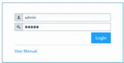
text_image
admin a Login User ManualFigure 2: Login page of the LANCOM R&S ^® Unified Firewall web client
10. Click on Login.
- After the first login with the default credentials, the system prompts you to accept the End User License Agreement (EULA) and then change the following two passwords:
The password for the user admin – you need this password to login to the LANCOM R&S® Unified Firewall web client.
The support password – the support password is the password used by the technical supporter to login to your LANCOM R&S® Unified Firewall. Keep it secure and protected from unauthorized access.
2 Getting Started
The new user password and support password must contain no less than eight and no more than 255 characters. You can use Latin letters, including German umlauts, as well as numbers and special characters. Do not use Cyrillic or other alphabets. You must use characters from at least three of the categories capital letters, lowercase letters, numbers, and special characters.

This step is mandatory.
- Click on Accept & Login to accept the new passwords and the EULA.
The setup wizard appears.

With the exception of the language selection at the start of the setup wizard, you can cancel the wizard at any time with the Cancel Wizard button. After canceling the wizard, you can continue with a manual setup following the steps Configuring the Internet Connection on page 12 and Enabling Internet Access on page 15.
For most of the setup wizard, you can use the Back and Next buttons to navigate.
- Select the language for the setup wizard and web client. You can switch the language of the web client later as required.
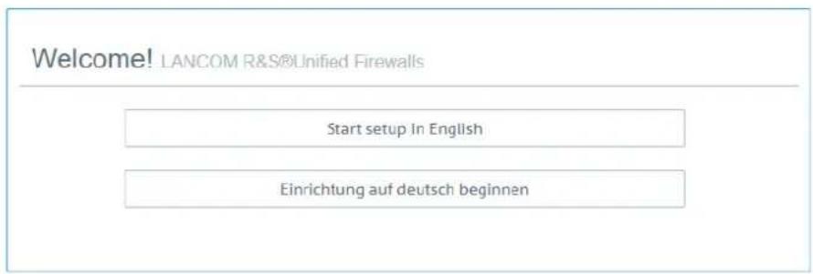
Figure 3: Welcome page of the setup wizard
- To restore the configuration from a previous installation, click on Select to choose a backup file. Enter the associated backup password. Then click Restore the backup and restart.
The setup wizard is then closed, the configuration is restored from the backup, and the firewall restarts.
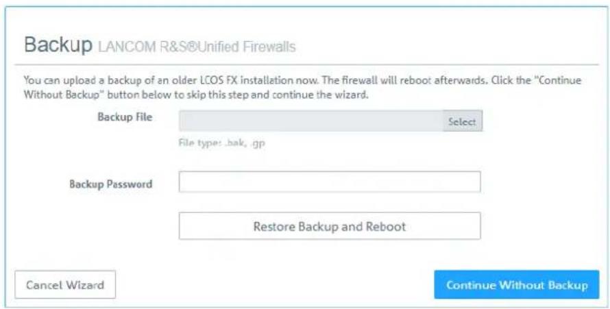
text_image
Backup LANCOM R&S®Unified Firewalls You can upload a backup of an older LCOS FX installation now. The firewall will reboot afterwards. Click the "Continue Without Backup" button below to skip this step and continue the wizard. Backup File File type: bak, gp Backup Password Restore Backup and Reboot Cancel Wizard Continue Without BackupFigure 4: Optional: Restore a previous configuration from a backup
Alternatively, you can continue with a new installation with Continue without backup.
- Configure the following general firewall settings:
Firewall hostname
Give your firewall a name to be used as the host name.
Time zone
The time zone is preset with the time zone currently set in the browser. Change this setting if necessary.
Send usage statistics
You can optionally allow information about the firewall's load and state to be recorded and sent to LANCOM Systems GmbH. No personal information or any of the firewall traffic will be transmitted.
You can change this setting later. See also General settings on page 26.
Send crash reports
In the event of a crash, you can optionally allow general information about the system status, current system configuration and the occurring error to be transmitted to LANCOM Systems GmbH. The data is used solely for error analysis and is then deleted. No data is disclosed to any third parties.
You can change this setting later. See also General settings on page 26.
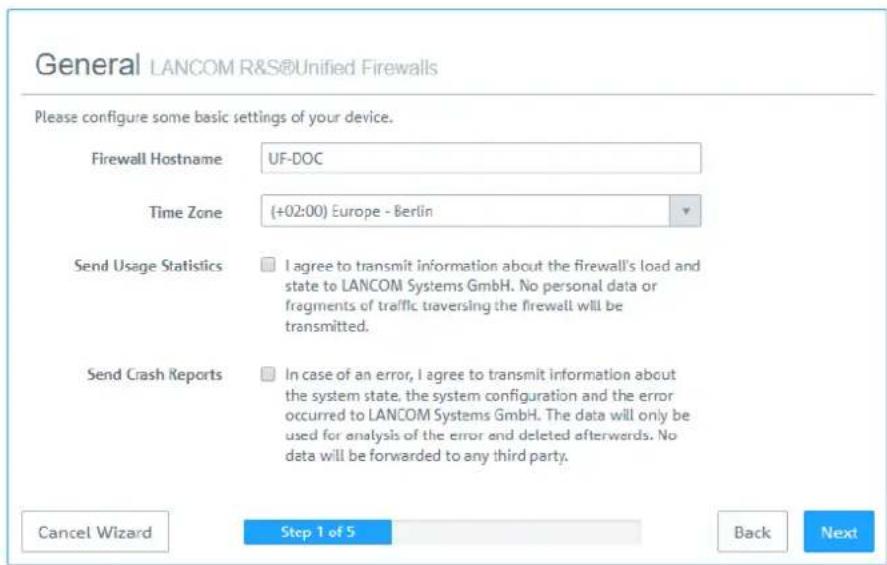
text_image
General LANCOM R&S®Unified Firewalls Please configure some basic settings of your device. Firewall Hostname UF-DOC Time Zone (+02:00) Europe - Berlin Send Usage Statistics I agree to transmit information about the firewall's load and state to LANCOM Systems GmbH. No personal data or fragments of traffic traversing the firewall will be transmitted. Send Crash Reports In case of an error, I agree to transmit information about the system state, the system configuration and the error occurred to LANCOM Systems GmbH. The data will only be used for analysis of the error and deleted afterwards. No data will be forwarded to any third party. Cancel Wizard Step 1 of 5 Back NextFigure 5: General settings of the firewall
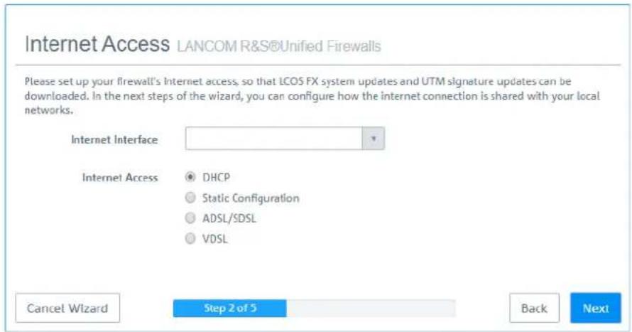
- Set the Internet interface as the firewall port (default: eth0) that is connected to the device supplied by your Internet service provider. You then enter your option for Internet access:
Depending on your selection, you can configure the relevant data.
DHCP
The IP address for this interface is obtained via DHCP.
Static configuration
Enter the IP address with prefix length (CIDR notation), the default gateway and the DNS server.
ADSL / SDSL
Enter the username and the password that you have received from your Internet service provider.
2 Getting Started
VDSL
Enter the VLAN ID, the username and the password that you have received from your Internet service provider.
text_image
Internet Access LANCOM R&S®Unified Firewalls Please set up your firewall's Internet access, so that LCOS FX system updates and UTM signature updates can be downloaded. In the next steps of the wizard, you can configure how the internet connection is shared with your local networks. Internet Interface Internet Access DHCP Static Configuration ADSL/SDSL VDSL Cancel Wizard Step 2 of 5 Back NextFigure 6: Internet access
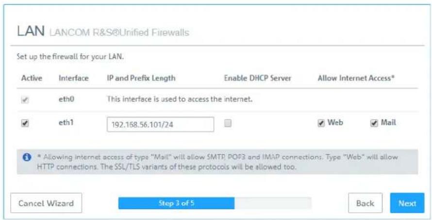
- Here you configure the local network to which the firewall is (to be) connected. Each line corresponds to a network interface of the firewall (Interface column).
You can enable/disable an interface, depending on whether you want to use it or not (Active column). The Internet interface cannot be deactivated.
In the field IP and prefix length, enter the IP that the firewall should use on this interface, together with the prefix length (CIDR notation). If you leave the field blank, the firewall will not have an IP connection on this interface. If this is the case, you will be unable to use this interface to access the firewall and you cannot provide a DHCP server, web or mail access for clients connected via this interface. Each interface should have its own subnet.
To enable a DHCP server on an interface, select the appropriate checkbox Enable DHCP server. The DHCP pool depends on the firewall IP associated with this port and is preset to the largest continuous range available on the subnet.
You can permit typical Internet applications (Web and Mail) for clients connected to an interface by selecting the corresponding checkbox. Web allows clients to connect to the Internet via HTTP. Mail enables SMTP, POP3 and IMAP traffic. This includes the SSL/TLS versions of these protocols.
text_image
LAN LANCOM R&S®Unified Firewalls Set up the firewall for your LAN. Active Interface IP and Prefix Length Enable DHCP Server Allow Internet Access* ✓ eth0 This interface is used to access the internet. ✓ eth1 192.158.56.101/24 ✓ Web ✓ Mail * Allowing internet access of type "Mail" will allow SMTP, POP3 and IMAP connections. Type "Web" will allow HTTP connections. The SSL/TLS variants of these protocols will be allowed too. Cancel Wizard Step 3 of 5 Back NextFigure 7: Local networks
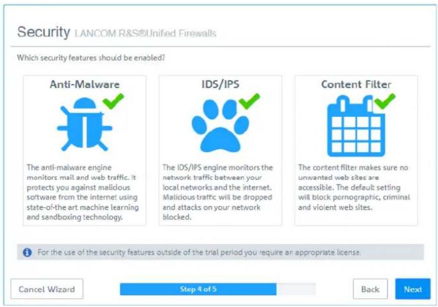
- Select the security features Anti-Malware, IDS/IPS and/or Content Filter, which are to be activated. Depending on your device, not all features may be available.

After being started for the first time, or following a re-installation, the LANCOM R&S ^® Unified Firewall runs for 30 days as a demo version. You cannot perform a backup during the trial period. At the end of the trial period, the firewall will retain your configuration. The UTM features will be disabled and you can no longer save any changes.
For more information, please see License on page 36.
text_image
Security LANCOM R&S®Unified Firewalls Which security features should be enabled? Anti-Malware The anti-malware engine monitors mail and web traffic. It protects you against malicious software from the internet using state-of-the-art machine learning and sandboxing technology. IDS/IPS The IDS/IPS engine monitors the network traffic between your local networks and the internet. Malicious traffic will be dropped and attacks on your network blocked. Content Filter The content filter makes sure no unwanted web sites are accessible. The default setting will block pornographic, criminal and violent web sites. For the use of the security features outside of the trial period you require an appropriate license. Cancel Wizard Step 4 of 5 Back NextFigure 8: Security features
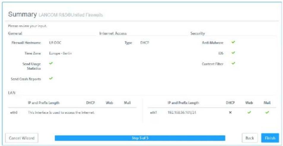
- Here you see a summary of your settings and, if necessary, you can go back and adjust them. Click Finish if everything is to your satisfaction.
text_image
Summary LANCOM R&S®Unified Firewells Please review your input. General Internet Access Security Firewall Hostname UF-DOC Type DHCP Anti-Malware ✓ Time Zone Europe - Berlin IOS ✓ Send Usage ✓ Content Filter ✓ Statistics Send Crash Reports ✓ LAN IP and Prefix Length DHCP Web Mail IP and Prefix Length DHCP Web Mail eth0 This interface is used to access the internet. eth1 192.168.56.101/24 ✗ ✓ ✓ Cancel Wizard Step 5 of 5 Back FinishFigure 9: Summary of settings
- Wait for the setup wizard to finish. You will then see the links to use to access the web client after the setup wizard has completed. You can either click these links or click OK to go to the web client.
2 Getting Started
If you want to use the automatically generated certificate for the web proxy, download it and roll it out to your clients.

text_image
Finishing up LANCOM R&S®Unified Firewalls The settings you made in the previous steps are now being applied. Below we compiled the most Important Information about the next steps of the setup for you. Web Client Access The firewall's web client will be available on these addresses from now on. • https://192.108.56.101:3438 Roll out Proxy CA The security features you enabled are also Inspecting SSL/TLS encrypted traffic and require a Proxy CA certificate trusted by your clients. You can either setup the web proxy to use a Proxy CA certificate that is already trusted by your clients, or you can keep using the auto-generated web proxy CA and roll that out to your clients. You can download the auto-generated CA certificate here. E+ Download Web Proxy CA Certificate Get Help The firewall comes with an extensive user manual PDF including a detailed menu reference. It can always be accessed via the "Help" menu item in the top right area of the web client's header bar. OKFigure 10: Finishing up
If you want to use the setup wizard again, you will need to reset your firewall to its factory defaults. See also Header on page 18.
2.2 Configuring the Internet Connection
This chapter describes how you can configure your Internet connection.
- Connect a patch cable to the eth0 port on the front of your LANCOM R&S ^® Unified Firewall and to the LAN port of the device that you received from your provider to access the Internet (e.g. your router, DSL or cable modem).
- In the navigation bar, go to Network > Connections.
The item list bar on the right of the navigation bar opens. - Click » in the upper right corner of the item list bar to see which network connection is assigned to which interface. The item list bar expands.
- Delete the default connection on eth0 by clicking 📄(Click to delete) in the last table column in the same row.
- Depending on the type of your Internet access, proceed corresponding to one of the following three approaches:
Dial-up Connection
Cable or Router Connection with Dynamic IP
Static Internet Connection with Static IP
2.2.1 Dial-up Connection
Configuring the network connection
Proceed with this step if you want to configure a PPTP connection. For PPPoE connections, this step does not apply.
- To create a new network connection, click ●(Create a new item) in the item list bar.
The Network Connection dialog opens. It allows you to configure a network connection.
- Enter a name for your network connection in the Name field.
- From the Interface drop-down list, select eth0.
- From the Type drop-down list, select the Static menu item.
- Enter the IP address and the subnet mask for the network connection in the IP Addresses field.
This IP address is the client/NIC IP address you received from your provider.
-
Click ☐ on the right to add your entry to the list of IP addresses.
-
Click Create
The Network Connection dialog closes. The new interface is added to the list of available network connections in the item list bar.
Creating a PPP interface
- Navigate to Network > Interfaces > PPP Interfaces.
- To create a new PPP interface, click ⚙️(Create a new item) in the item list bar.
The PPP Interface dialog opens. It allows you to configure a PPP interface.
-
From the Master Interface drop-down list, select eth0.
-
Unless stated otherwise by your provider, leave the other settings on default value.
-
Click Create.
The PPP Interface dialog closes. The new interface is added to the list of available PPP interfaces in the item list bar.
Creating a PPP connection
- Navigate to Network > Connections > PPP Connections.
- To create a new PPP connection, click ⚠️(Create a new item) in the item list bar.
The PPP Connection dialog opens. It allows you to configure a PPP connection.
- Enter a name for your PPP connection in the Name field.
- From the Interface drop-down list, select the PPP interface you created under Creating a PPP interface on page 13.
- From the Type drop-down list, select your connection type.
- Enter the credentials predefined by your provider.
If you are creating a PPTP connection, enter the IP address of the modem you received from your provider into the PPTP Server IP input field.
-
Unless stated otherwise by your provider, leave the other settings on default value.
-
Click Create.
The PPP Connection dialog closes. The new connection is added to the list of available PPP connections in the item list bar.
- Click √ Activate in the toolbar at the top of the desktop to apply your configuration changes.
You have configured your Internet connection.
2 Getting Started
2.2.2 Cable or Router Connection with Dynamic IP Address
- Navigate to Network > Connections > Network Connections.
-
To create a new network connection, click + (Create a new item) in the item list bar.
The Network Connection dialog opens. It allows you to configure a network connection. -
Enter a name for your network connection in the Name field.
-
From the Interface drop-down list, select eth0.
-
From the Type drop-down list, select the DHCP menu item.
-
Select the Obtain DNS Server check box
-
Select the Obtain Domain check box
-
Click Create.
The Network Connection dialog closes. The new connection is added to the list of available network connections in the item list bar.
- Click √ Activate in the toolbar at the top of the desktop to apply your configuration changes. You have configured your Internet connection.
2.2.3 Static Connection with Static IP Address
Configuring the network connection
- Navigate to Network > Connections > Network Connections.
- To create a new network connection, click 🧑️(Create a new item) in the item list bar.
The Network Connection dialog opens. It allows you to configure a network connection. - Enter a name for your network connection in the Name field.
- From the Interface drop-down list, select eth0.
- From the Type drop-down list, select the Static menu item.
- Enter the IP address and the subnet mask for your network connection in the IP Addresses field.

You receive the IP address from your provider.
- Click ☐ on the right to add your entry to the list of IP addresses.
Configuring DNS settings
- Go to the WAN tab in the Network Connection window.
- Select the Set Default Gateway check box
- Enter your default gateway IP address in the Default Gateway input field.
- Click Create.
The Network Connection dialog closes. The new connection is added to the list of available network connections in the item list bar.
- Navigate to Network > DNS Settings.
The DNS Settings dialog opens. You can use it to configure DNS settings for your LANCOM R&S ^® Unified Firewall.
- Clear the Acquire DNS server check box.
You can now edit the 1. Nameserver/2. Nameserver input field.
- Enter the IP addresses of the DNS servers you received from your provider in the 1. Nameserver and 2. Nameserver input fields.
- Click Save to store your settings.
The DNS Settings dialog closes. - Click √ Activate in the toolbar at the top of the desktop to apply your configuration changes.
You have configured your Internet connection.
2.3 Enabling Internet Access
2.3.1 Creating an Internet Object
- Navigate to Desktop > Desktop Objects > Internet Objects.
- In the item list bar, click 📍 Create a new item) to create a new Internet object.
The Internet Object dialog opens. It allows you to configure an Internet object. - Under Object Name, enter a name for your Internet object.
- From the Connections drop-down list, select your Internet connection.
You can find more information on creating an Internet connection under Configuring the Internet Connection on page 12. -
Click ☐ on the right to add your entry to the list of connections.
-
Click Create.
The Internet Object dialog closes. The new object is added to the list of available Internet objects in the item list bar.
For more information, see Desktop Objects on page 88.
2.3.2 Configuring Your Local Network Connection
-
Connect a patch cable to one of the ports labeled ethX (except eth0 as it is used for the Internet connection) on the front of your LANCOM R&S® Unified Firewall device and to one of the Ethernet ports on your network switch.
-
Navigate to Network > Connections > Network Connections.
-
In the item list bar, click 🧑️ Create a new item) to create a new Internet connection.
The Network Connection dialog opens. It allows you to configure a network connection.
-
Enter a name for your network connection in the Name field.
-
Under Interface, select the port to which you have connected your network switch from the drop-down list.
-
From the Type drop-down list, select the Static type.
-
Under IP Addresses, enter the IP address of this connection in CIDR notation (IP address followed by a slash "/" and the number of bits set in the subnet mask, for example 192.168.50.1/24).
-
Click ☐ on the right to add your entry to the list of IP addresses.
-
Click Create.
The Network Connection dialog closes.
2 Getting Started
2.3.3 Creating a Network Object
- Navigate to Desktop > Desktop Objects > Networks.
-
To create a new network object, click ⚙️(Create a new item) in the item list bar.
The Network dialog opens. It allows you to configure a network object. -
Enter a name for your network object in the Name field.
-
From the Interface drop-down list, select the network connection that you have created under Configuring Your Local Network Connection on page 15.
-
Under Network IP, enter the IP address of your local network.
-
Click Create.
The Network dialog closes. The new object is added to the list of available network objects in the item list bar.
For more information, see Desktop Objects on page 88.
2.3.4 Configuring Firewall Rules for Internet Access
- Set up a connection between the network object (see Creating a Network Object on page 16) and the Internet object (see Creating an Internet Object on page 15) that you have just created:
a. Click the Button in the toolbar at the top of the desktop. The desktop objects which can be selected for this connection and possible connections between them are highlighted and marked by dotted circles and lines.
b. Select the network object as the source object of the connection by clicking the corresponding desktop object.
c. Select the Internet object as the target object of the connection by clicking the corresponding desktop object.
You are automatically forwarded to Desktop > Desktop Connections. The Connection editor panel opens.
Alternatively, you can click the "button" in the circular menu of the source object on the desktop and then select the target object.
- Set up a firewall rule with HTTP and/or HTTPS, depending on your needs:
a. The services that you can apply firewall rules to are displayed in the service selection list bar on the right side of the browser window. This list is divided into categories that combines similar services.
Into the Filter input field, enter HTTP or HTTPS. As you type in the input field, the web client reduces the list to show only those services and service groups that contain the characters you are typing.
To add HTTP and HTTPS from the Internet category, click +.
The selected services are removed from the service selection list bar and are displayed in the table in the Rules tab.
b. Click Create.
c. The Connection dialog closes. The new desktop connection is added to the list of available desktop connections in the item list bar.
For more information, see Firewall Rule Settings on page 23.
2.3.5 Activating the Desktop Configuration
- Click √ Activate in the toolbar at the top of the desktop to apply your configuration changes.
The Internet access through your LANCOM R&S ^® Unified Firewall is activated.
3 User Interface
The sections in this chapter describe the components of the user interface of LANCOM R&S ^® Unified Firewalls.

The LANCOM R&S ^® Unified Firewall web client requires a minimum display resolution of 1024 x 786 pixels (XGA).
The following browser versions (or newer) are supported, with JavaScript enabled:
Google Chrome 10
Chromium 10
Mozilla Firefox 12
Web Client Components on page 17 provides an overview of the main components of the web client.
Icons and buttons on page 21 explains the meaning of the icons and buttons commonly used on the user interface and throughout this manual.
Firewall Rule Settings on page 23 describes how to set up a firewall rule for a connection between two desktop objects.
Menu Reference on page 25 reflects the arrangement of the menu items in the navigation bar on the left side of the user interface. For information on the available options, see the corresponding section.
3.1 Web Client Components
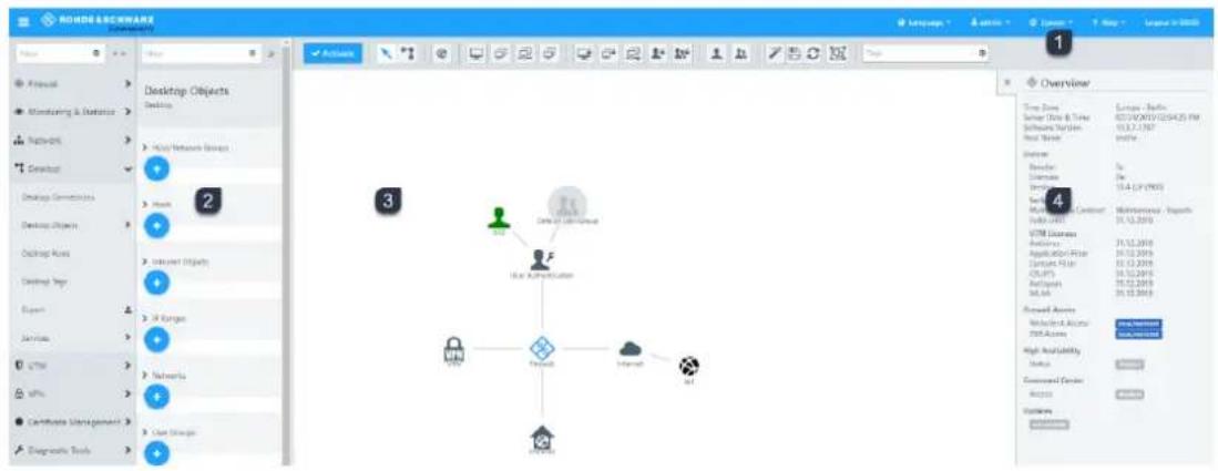
The web client of LANCOM R&S ^® Unified Firewalls uses a standard four-pane page layout with a common header area, a navigation pane on the left a main content pane (desktop) and an info area on the right.
text_image
ROROS SOFTWARE File Edit View Tools Help Tools Help Tools Help Tools Help Tools Help Tools Help Tools Help Tools Help Tools Help Tools Help Tools Help Tools Help Tools Help Tools Help Tools Help Tools Help Tools Help Tools Help Tools Help Tools Help Tools Help Tools Help Tools Help Tools Help Tools Help Tools Help Tools Help Tools Help Tools Help Tools Help Tools Help Tools Help Tools Help Tools Help Tools Help Tools Help Tools Help Tools Help Tools Help Tools Help Tools Help Tools Help Tools Help Tools Help Tools Help Tools Help Tools Help Tools Help Tools Help Tools Help Tools help Desktop Objects Desktop HKEY Network Object Desktop Conversions Desktop Objects Desktop Maps Desktop Maps Expert Services UTM VIPS Certificate Management Diagnostic Tools 3 2 1 3 4 Overview Time Zone Server Data & Timer Software System Real Server User Member Application Services Network Control System 2015 UTM Devices Application Application Filter Contact File USB/FTP Accession MIL-66 Forward Access Networks & Accounts FTP Access High Availability Setup Commanded Service Access Customs Preprocessing- Header area
- Navigation pane
- Desktop
- Info area
Figure 11: LANCOM R&S ^® Unified Firewall web client.
The following sections contain information about each area.
3 User Interface
3.1.1 Header
The header (1) contains the following items (from left to right):

text_image
1 ROHDE & SCHWARZ Cybersecurity 2 Language 3 admin 4 System 5 Help 6 Logout In 09:15 7Figure 12: Header of the LANCOM R&S ^® Unified Firewall web client
- ≡ button shows or hides the navigation bar.
- Rohde & Schwarz ^® Cybersecurity GmbH logo.
- Language menu that allows you to select the language of the web client.
- User menu that allows you to quit the current session and return to the login page.
- System menu with which you shut down or restart the LANCOM R&S ^® Unified Firewall, or reset it to factory settings.
- A help menu with links to the PDF version of the LANCOM R&S ^® Unified Firewall User Manual.
- Time remaining before the automatic logout from the web client.
The header also indicates that there are unsaved changes to the configuration, i.e. if you closed an editing window by pressing the [Esc] key. If you have closed an editing window by clicking the ✗ button in the upper right-hand corner of the window, there is no indication of any unsaved changes.

The current version of the LANCOM R&S ^® Unified Firewall User Manual is also available on the login page. Click on the User Manual link to open the file.
About the automatic logout
You will be automatically logged out after 10 minutes of inactivity, i.e. if no HTTP requests are sent to the server. The timer restarts following any action, such as opening a dialog or saving settings or regularly updated logs (for example, the Alert log on page 59). Exceptions are background requests that do not restart the timer.

If you change settings in a dialog, do not save your changes and leave the dialog open, you will automatically be logged out after 10 minutes.
3.1.2 Navigation Pane
The navigation pane (2) is on the left side of the web client. Depending on your selection in the first bar, a second bar is displayed to the right of the first one. The menu items in the left navigation bar provide access to the LANCOM R&S® Unified Firewall settings. The item list bar on the right is displayed when you select a menu item in the navigation bar. The item list bar is used to display information on the current desktop configuration.
Both bars contain a Filter input field at the top which helps you quickly find a particular menu item or item list entry. Each input field only works for the bar it is part of. As you type in one of the input fields, your LANCOM R&S® Unified Firewall reduces the corresponding list to show only those menu items or item list entries that contain the characters you are typing. Click ☑ the input field to delete the search string and display an unfiltered view of the bar.
You can expand all menus in the navigation bar at once by clicking √ or collapse them by clicking iThe upper right corner of the navigation bar. Furthermore, you can hide the navigation bar by clicking ≡ the header area. For more information, see Header on page 18.
The information displayed in the item list bar depends on the menu item selected in the navigation bar and on how much information you desire to be displayed. You can unfold more detailed information by clicking »or reduce the amount of information presented by clicking «in the upper right corner of the item list bar.
See Menu Reference on page 25 for details on the options available in each view.
3.1.3 Desktop
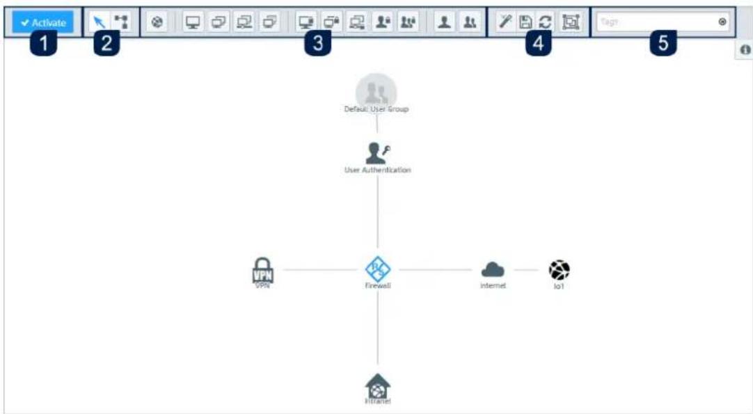
The desktop (3) fills the main portion of the screen below the header area and to the right of the navigation pane. The highlighted nodes and connections depend on the item selected in the navigation pane or on the desktop.
flowchart
graph TD
    A["Default User Group"] --> B["User Authentication"]
    B --> C["Firewall"]
    C --> D["VPN"]
    C --> E["Internet"]
    C --> F["Io1"]
    C --> G["HI/NTel"]
Figure 13: LANCOM R&S ^® Unified Firewall web client desktop.
On the desktop, you have an overview of your configured network. You can edit various settings in this pane or view the details of a configuration.
A toolbar at the top of the desktop provides quick access to frequently used functions (from left to right):
- Confirmation button
- Selection tool, connection tool
- Tools for creating desktop objects
- Tools for saving, restoring and arranging desktop objects
- Filter/search tool
All toolbar buttons use mouse-over pop-up labels for easy identification.
For more information, see Icons and buttons on page 21.
Saving the system configuration (1)
If the system configuration changes, the √ Activate button in the first section of the toolbar is highlighted, prompting you to update your configuration. Click this button to save your current desktop configuration changes and to activate them on your LANCOM R&S® Unified Firewall.
Selecting or connecting desktop objects (2)
Use the selection tool for all actions on the desktop, such as moving objects or selecting certain functions. With the connection tool, you can create or edit a connection between two desktop objects. For more information, see Firewall Rule Settings on page 23.
When you left-click a desktop object, several buttons appear in the circular menu, depending on the type of the desktop object. Use these buttons to adjust the settings for an existing object and to create or edit a connection between two existing objects. Furthermore, you can hide or display objects attached to another object, unpin an object from a specific location on the desktop or remove an object from the desktop.
3 User Interface
Creating a desktop object (3)
To create a desktop object, click the respective button. An editor panel opens where you can enter the object's data.
Customizing the desktop layout (4)
You can customize the desktop layout by dragging the objects to the desired position where they are automatically pinned. You can save and restore your customized layout or arrange the objects automatically.
Searching desktop objects (5)
The Tags filter input field in the last section of the toolbar helps you quickly identify desktop objects on the desktop, based on previously assigned desktop tags. Click the input field to open a drop-down list containing the names of configured desktop tags. You can either select one of the list items directly to add it to the filter input field or use the input field to search for a particular desktop tag. As you type in the input field, your LANCOM R&S ^® Unified Firewall reduces the drop-down list to show only those list items that contain the characters you are typing. You can add as many desktop tags to the filter input field as you like.
LANCOM R&S ^® Unified Firewall confines the desktop objects shown depending on the chosen desktop tags. Desktop nodes along the path from the Firewall root node to a node matching the selected desktop tags are always displayed, even if their tag set does not match the search criteria.
Click ☑ in the input field to delete the search string or all selected desktop tags and display an unfiltered view of the desktop. For more information, see Desktop Tags on page 98.
3.1.4 Information panel
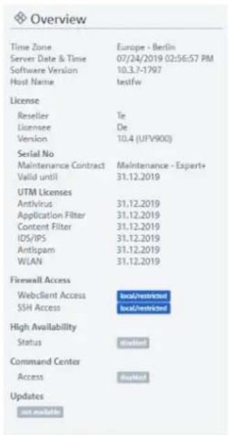
The information area (4) is located on the right-hand side of the desktop.
text_image
Overview Time Zone Europe - Berlin Server Date & Time 07/24/2019 02:56:57 PM Software Version 10.3.7-1797 Host Name testfw License Reseller Tie Licensee De Version 10.4 (UFV900) Serial No Maintenance Contract Maintenance - Expert+ Valid until 31.12.2019 UTM Licenses Antivirus 31.12.2019 Application Filter 31.12.2019 Content Filter 31.12.2019 IDS/IPS 31.12.2019 Antispam 31.12.2019 WLAN 31.12.2019 Firewall Access WebClient Access local/restricted SSH Access local/restricted High Availability Status PASTERS Command Center Access PASTERS Updates BIPRANTESFigure 14: Information panel of the LANCOM R&S ^® Unified Firewall web client
After logging in, the information panel is visible and displays basic firewall information.
Select a desktop object to display its details in information panel, e.g.:
Description
Tags
IP addressesGroup members
Current VPN connections
The amount and type of information displayed differs for the different types of desktop objects (hosts, Internet objects, users, etc.). Dynamic information (e.g. the status of a VPN connection) is updated automatically.
Click on >> to minimize the information panel. Click on the info icon to show the information panel again.

If the information panel shows not available for marked objects, the logged in user does not have appropriate rights to view this information.
3.2 Icons and buttons
This section explains the icons and buttons used on the user interface and throughout this guide.
Hovering over the buttons with your mouse pointer will display pop-up labels for easy identification.
| DescriptionIcon / button | |
| ≡ | Show or hide the navigation bar. |
| Move objects or select objects or features on the desktop. | |
| Create or edit a connection between two desktop objects. | |
| Create an Internet object. | |
| Create a host. | |
| Create a host group. | |
| Create a network. | |
| Create an IP pool. | |
| Create a VPN host. | |
| Create a VPN group. | |
| Create a VPN network. | |
| Create a VPN user. | |
| Create a VPN user group. | |
| Create a user. | |
| Create a user group. | |
| Reset all manual layout changes on the desktop and restore the default layout. | |
| Save the current desktop layout. | |
| Restore the last saved desktop layout.Restore a backup.Restore a certificate by importing a new certificate. | |
| Adjust the entire network to the desktop size. | |
| Highlights a menu item with settings that can be configured in the navigation bar. | |
| Highlights a table column containing actions available for a table entry. | |
| ✝ | Detach a desktop object to drag & drop it across the desktop together with its corresponding desktop node. |
| ✝ | View and edit the settings for a desktop object, list item, or table entry. |
| ✝ | Create a list item or table entry from a copy of an existing entry. |
| ✝ | Delete a desktop object or list entry from the system after confirming the security prompt.Permanently revoke a certificate. |
| ✝ | Delete a customized firewall rule from the system.Remove a firewall rule with a predefined service from the firewall rules table. |
| ✝ | Import a certificate or blacklist/whitelist from a file.Sign a certificate signing request. |
| ✝ | Export a certificate or blacklist/whitelist to a file. |
| ✝ | Import a backup from a file. |
| ✝ | Export a backup to a file. |
| ✝ | Create a list item in the object bar. |
| ✝ | Expand a menu item in the navigation bar to show child items.Expand a web filter category to show its subcategories.Expand a firewall-rule service category to show child services.Expand a statistic or table. |
| ✝ | Hide a menu item in the navigation bar to show child items.Hide the subcategories of a web filter category.Hide the child services in a firewall-rule service category.Hide a statistic or table. |
| ✝ | Expand detailed information in the object bar. |
| ✝ | Reduce information in the object bar. |
| ✝ | Collapse all menus in the navigation bar.Expand a desktop node to display its associated desktop objects. |
| ✝ | Expand all menus in the navigation bar.Collapse a desktop node to hide its associated desktop objects. |
| ✝ | Indicates that a certificate is still valid. |
| ✝ | Indicates that a certificate has expired. |
| ✝ | Verify a certificate. |
| ✝ | Temporary suspension of a certificate or CA. |
| ✝ | Reactivate a suspended certificate. |
| ✝ | Renew a certificate with changed validity. |
| ✝ | Close a pop-up window. |
| Reset filter search criteria to show all results. | |
| This marks all objects and settings that are managed by the LANCOM Management Cloud (LMC). These can be viewed with the web client, but cannot be edited. Objects managed by the LMC cannot be referenced. This means, for example, that an application filter profile created by the LMC cannot be used in a self-created desktop connection. |
3.3 Firewall Rule Settings
This section describes how to create a firewall rule for a connection between two desktop objects.
3.3.1 Setting Up a Connection
To set up a connection between two desktop objects, proceed as follows::
- Click the button in the toolbar at the top of the desktop.
The desktop objects which can be selected for this connection and possible connections between them are highlighted and marked by dotted circles and lines.
-
Select the source object of the connection by clicking the corresponding desktop object.
-
Select the target object of the connection by clicking the corresponding desktop object.
The Connection editor panel opens, displaying, if applicable, existing firewall rules for this connection.
Alternatively, you can click the "button" in the circular menu of the source object on the desktop and then select the target object.
3.3.2 Setting Up a Firewall Rule
To set up a firewall rule, proceed as follows::
- In the Rules tab of the Connection editor panel, select at least one of the services to which you want to apply the firewall rule.
The services that are available for the connection are displayed in the service selection list bar on the right side of the browser window. The list bar is subdivided into categories of services which serve a similar purpose. You can collapse and expand the categories by clicking the corresponding icon.
For more information, see Icons and buttons on page 21.
The Filter input field at the top of the service selection list bar helps you quickly find a particular service or service group. As you type in the input field, your LANCOM R&S ^ Unified Firewall reduces the list to show only those services and service groups that contain the characters you are typing. Click On the input field to delete the search string and display an unfiltered view of the list.
a. There are two ways to add services to a firewall rule:
To add an individual service, click the button in front of the corresponding service in the service selection list bar.
Click the Add filtered services) button directly below the header of a category to add all services belonging to that category at once.
The selected services are displayed in the table in the Rules tab.
b. To adjust the settings of a firewall rule, click ⚙(Click to edit this rule).
3 User Interface
An editor panel for the particular service opens.
- The editor panel displays the following information and allows you to configure the following elements of the firewall rule:
a. Under Description, you can enter additional information regarding the firewall rule for internal use.
b. In the Ports / Protocols tab, you can see which ports and protocols were defined to be used for the service. For more information, see Services on page 99.
c. In the Schedule tab, you can specify the time when the firewall rule is active. The tab provides the following options:
Set specific times and weekdays using the sliders.
Click Always On – the rule is always active.
Click Always Off – the rule is always inactive.
d. The Advanced settings tab provides the following options:
| DescriptionInput Field | |
| Proxy | For firewall rules with predefined services only if the predefined services allow a proxy (HTTP, HTTPS, FTP, SMTP, SMTPS, POP3 or POP3S): Select this check box to activate the proxy for this rule.For firewall rules with user-defined services only: From the drop-down list, select a proxy for this rule. To delete a proxy, click ✗ the right of the entry. |
| NAT / Masquerading | For NAT/masquerading, enter the desired direction (bi-directional, left-to-right or right-to-left) or deactivate (Off) the feature for this rule by selecting the respective radio button. The default setting depends on the source and target objects selected for the connection. |
| New source IP | Optional: If you have multiple outgoing IP addresses, specify the IP address to be used for Source NAT. If you do not specify the IP address, the system automatically chooses the main IP address of the outgoing interface. |
| Enable DMZ / Port Forwarding for this service | If the target of the firewall rule is a single host object, you can select this check box to enable DMZ and port forwarding for this rule. |
| External IP address | Optional: Specify the destination IP address of the traffic to be manipulated. The DMZ rule is only applied to this type of traffic. This IP address must be one of the IP addresses of the firewall. |
| External Port | Displays the original destination port of the traffic to be manipulated, depending on the port defined in thePorts / Protocolstab. |
| Destination IP address | Displays the new destination IP address of the traffic (after its manipulation). |
| Optional: Enter the destination port of the traffic (after its manipulation).Destination P | |
e. The buttons at the bottom right of the editor panel allow you to confirm your changes to an existing rule (OK), reject the editing of an existing rule (Cancel) and discard your changes (Reset).
The configured rule is displayed in the table in the Rules tab. To delete a rule from the table, click the ● button (Click to delete this rule) in the last column.
- For more information on the URL / Content Filter and Application Filter tabs, see Desktop Connections on page 87
- The buttons at the bottom right of the editor panel allow you to close (Close) the editor panel as long as no changes have been made and to save (Save) or to discard (Reset) your changes.
- Click Activate in the toolbar at the top of the desktop to apply your configuration changes.
For more information, see Icons and buttons on page 21.
3.4 Menu Reference
This reference chapter describes each menu item in the navigation bar on the left side of the browser window. The license acquired from LANCOM Systems determines which menu items are available on your LANCOM R&S ^® Unified Firewall. Features that are not included in your LANCOM R&S ^® Unified Firewall license are grayed out in the navigation bar.
Refer to the sections below for information on the options available in each view.
3.4.1 Firewall
Use the settings under ✿Firewall to configure your LANCOM R&S ^® Unified Firewall for your local environment. In addition, you can set up access to your LANCOM R&S ^® Unified Firewall from external networks or the Internet and connect your LANCOM R&S ^® Unified Firewall to an Command Center server.
Administrators
Use the Administrators settings to define administrators and their access to certain services.
You can find more information in the following sections.
Administrators Overview
Navigate to Firewall > Administrators to display a list of administrators that are currently defined in the system in the item list bar.
Click +above the list to add new administrators.
In the expanded view, the first table column displays the Name of the administrator. The Admin column shows one of the following status indicators:
Green – The administrator has been granted access to the web client.
Orange – The administrator has not been granted access to the web client.
The buttons in the last column allow you to view and to adjust the settings for an existing administrator. Furthermore, the buttons allow you to create an administrator based on a copy of an existing administrator or delete an administrator from the system.
For more information, see Icons and buttons on page 21
Administrators Settings
Under Firewall > Administrators, you can add a new or edit an existing administrator.

You cannot delete or rename the default user admin. Furthermore, access rights of this user on the web client cannot be withdrawn.
The Administrator configuration dialog allows you to configure the following elements:
| DescriptionInput field | |
| Enter a unique name for the administrator.Name | |
| Optional: Enter additional information regarding the administrator for internal use.Description | |
On the Client Access tab:
| DescriptionInput field | |
| Select this check box to allow the administrator access to the web client.Granting access | |
| Password | For new administrators and only if theGranting accesscheck box is selected: Enter a password and confirm it.For edited administrators and only if theChangecheck box is selected: Enter a password and confirm it. |
| Change | Optional and for edited administrators and only if theGranting accesscheck box is selected: Select this check box to change the administrator's password. |
| Show Password | Optional and for new administrators and only if theGranting accesscheck box is selected: Select this check box to verify the password.Optional and for edited administrators and only if theChangecheck box is selected: Select this check box to verify the password. |
| Require password change after next login | Optional and for new administrators and only if theGranting accesscheck box is selected: Select this check box if you want to require the user to change the password after the next login.Optional and for edited administrators and only if theChangecheck box is selected: Select this check box if you want to require the user to change the password after the next login. |
On the Webclient Permissions tab, you can specify what the administrator is allowed to do in specified areas of the web client.
You can choose between the following permissions by selecting the respective radio button:
Forbidden – The administrator has no access to the specified area of the web client.
Read / Open – The administrator can open and read the entities in the specified area of the web client but cannot change them.
Write / Execute – The administrator has full access to the entities in the specified area of the web client.
The buttons at the bottom right of the editor panel depend on whether you add a new administrator or edit an existing one. For a newly configured administrator, click Create to add it to the list of available administrators or Cancel to discard your changes. To edit an existing administrator, click Save to store the reconfigured administrator or Reset to discard your changes.
If you have modified these settings, use the buttons at the bottom right of the editor panel to confirm (Save) or to discard your changes (Reset). Otherwise, you can close the dialog (Close).
General settings
Navigate to Firewall > General settings to open an editing window where you can adjust some of the central settings for your LANCOM R&S® Unified Firewall.
In the General settings editing window you can modify the following parameters:
| DescriptionInput box | |
| Host name of the firewall.Host name | |
| Domain | Domain of the firewall. If the firewall is connected to an Active Directory, enter the corresponding Active Directory domain here. |
| Send usage statistics | Collect information about the load and the state of the firewall and send this to LANCOM Systems GmbH. |
| No personal information or any of the firewall traffic will be transmitted. | |
| Send crash reports | In the event of an error, general information about the system status, the current system configuration and the error that occurred is transferred to LANCOM Systems GmbH.The data is used solely for error analysis and is then deleted. No data is disclosed to any third parties. |
If you have made changes, you can use the buttons at the bottom right of the edit window to save them (Save) or discard them (Reset). Otherwise you can close the window (Close).
Backup
Your LANCOM R&S ^® Unified Firewall stores your settings in configuration files which are automatically created whenever settings are changed in the web client. The options under Backup allow you to schedule regular backups of the current system configuration, to back up the system configuration manually and to restore previous configurations.

You can create backups at any time at the time a license is imported (i. e. not within the 30 day trial period).
For more detailed information on backups, see the following sections.
Automatic Backup Settings
The Auto Backup settings allow you to set up a connection to a remote backup server on which you want to store automatically created backups. Furthermore, this panel lets you schedule how often the firewall configuration is backed up automatically. There are no restrictions on the amount or interval of backup creation.

Before you proceed, make sure that you set the time zone for your LANCOM R&S ^® Unified Firewall as described under Time Settings on page 41 Otherwise, the backups are created according to Europe - Berlin (CET/UTC +1) instead of the time specified by you in the automatic backup settings.
Navigate to Firewall > Backup > Auto Backup to open an editor panel to display and edit the settings for automatic backups.
The Auto Backup panel allows you to configure the following elements:
| DescriptionInput field | |
| Server Address | Enter the IP address of the remote backup server on which you want to store automatically created backups. |
| Enter the name of the user on the remote backup server.Usage | |
| Enter the user's password for the remote backup server if necessary.Password | |
| Optional: Select this check box to verify the user's password.Show Password | |
| Server Type | Select the respective radio button to specify which network protocol is used to upload the backups to the server. This option is set to FTP by default, but you can adjust the settings to SCP if necessary. |
| Enter a name for automatically created backup files.Filename | |
| Encryption Password | Enter a password for the encryption of the backup files. The password can consist of up to 32 characters (allowed are letters of the English alphabet, integers and the special characters \- ] [/. ,~!@#$%^* () + : ?>< } { } |
| Optional: Select this check box to verify the encryption password.Show Encryption Pass | |
| Options | Select the respective radio button to specify what is added to the filenames to distinguish the backups from each other. This option is set to Append current date to filename by default, but you can adjust the settings to the other value as necessary:> Append current date to filename – The date and the time stamp of the creation of a backup is added to the filename (e. g. |
sword
| DescriptionInput field | |
| Backup_20171130-1527.gp). As these filenames never repeat, old backup files are never overwritten.> Max. file count – A number (backup number) is added to the filename. Specify the maximum number of backup files to be stored by entering an integer in the input field below this option. This option is set to 20 by default. Once the defined number is reached, counting starts anew and the oldest backup file is automatically overwritten. | |
| Specify how often the firewall configuration is backed up automatically.ScheduleUnder Start, click the input field to set the date and time of the first backup to be created automatically. A pop-up window with a calender and input fields for setting the date and time opens. You can enter a date in the MM/DD/YYYY format or choose a date from the calendar. You can also set a time by entering the time in the hh:mm:ss format.Under Interval and Unit, define how often the configuration is backed up automatically. Set the interval by entering a number or using the up and down arrows. This option is set to 1 by default. Then, select one of the unit options from the drop-down list. This option is set to days by default, but you can adjust the settings to one of the other values as necessary:> Once> Hours> Days> MonthsClick Add to add the schedule to the list.You can edit or delete individual entries in the list by clicking the corresponding button next to an entry. For more information, see Icons and buttons on page 21. | |
| If you edit a schedule, a check mark appears on the right of the entry. You have to click the check mark before being able to save the settings of the certificate. | |
To check the connection to the configured backup server, click the Test Server Settings button at the bottom left of the editor panel. The system tries to save a test file (file name_test) on the backup server. If this test is successful, a text file is saved on the server and a pop-up window with a success message appears. You can delete this text file after the test.
If you have modified these settings, use the buttons at the bottom right of the editor panel to confirm (Save) or to discard your changes (Reset). Otherwise, you can close the dialog (Close).
Click ↕activate in the toolbar at the top of the desktop to apply your configuration changes.
Backup Export
The Export settings allow you to create and export a manual backup of the current firewall configuration. Use this function, for example, to reload a configuration after a system update.
Navigate to Firewall > Backup > Export to open an editor panel to create and transfer a manual backup in GP file format to your computer so you can restore the configuration contained in it later if necessary.
The Export configuration dialog allows you to configure the following elements:
| DescriptionInput field | |
| Encryption Password | Enter a password for the encryption of the backup file and confirm it. The password can consist of up to 32 characters (allowed are letters of the English alphabet, integers and the special characters \- ] [ / . , ~ ! @ # $ § ^ * () _ + : ? > < } {).Optional: Select this check box to verify the password.Show Password |
| Use auto backup password | Optional: Select this check box if you want to use the password for automatic backup file encryption (see Automatic Backup Settings on page 27) instead of inserting a new password. |
If you want to export the backup file, click Export. Otherwise, click Cancel to close the editor panel.
Backup Import
Your LANCOM R&S ^® Unified Firewall allows you to upload a previously downloaded backup file to restore the system configuration (e. g. after a new installation).
Navigate to Firewall > Backup > Import to load and activate a firewall configuration from a backup file that was created earlier.
To upload an automatically created backup file stored on the backup server, you first have to transfer the backup file from the backup server to your local disk.
The Import configuration dialog allows you to configure the following elements:
| DescriptionInput field | |
| Backup File | Click Select to open the local disk search. Select a backup file in GP file format to transfer from your local disk. Click Open to close the local disk search. The name of the backup file appears in the field. |
| Enter the encryption password which you chose for the export of the file.Password | |
| Optional: Select this check box to verify the password.Show Password | |
If you want to import the backup file, click Import. Otherwise, click Cancel to close the editor panel.
If the upload was successful, a success message appears. Confirm that you want to reboot the system by clicking Reboot. The system restarts, logs you out and opens the LANCOM R&S ^® Unified Firewall login page. Enter your login credentials and click Login. The web client appears.
Command Center
LANCOM R&S ^® UF Command Center allows you to administrate multiple LANCOM R&S ^® Unified Firewalls devices in one application.
Navigate to Firewall > Command Center to open an editor panel to connect your LANCOM R&S ^® Unified Firewall to an LANCOM R&S ^® UF Command Center through a VPN connection.

To establish the VPN connection, you need VPN certificates for all devices that were signed by the same certificate authority (CA). Therefore, it is advisable to manage the VPN CA and the VPN certificates on one site and then export and import the VPN certificates from there to the other sites.
For information on how to create, export and import certificates, see Certificates on page 131.
The Command Center configuration dialog allows you to configure the following elements:
| DescriptionInput field | |
| I/O | A slider switch indicates whether the connection to your LANCOM R&S®UF Command Center is active (1) or inactive (0). Click the slider switch to change the status of the connection. The connection to your LANCOM R&S®UF Command Center is deactivated by default. |
| Host | Enter the host name or IP address under which your LANCOM R&S®UF Command Center is reachable from your LANCOM R&S®Unified Firewall. |
| Port | Enter the port number under which your LANCOM R&S®UF Command Center is reachable (usually port number 11940). |
| Command Center CA | From the drop-down list, select the CA that was used to sign the LANCOM R&S®UF Command Center certificate. |
| From the drop-down list, select the VPN certificate for your LANCOM R&S®Unified Firewall.Firewa | |
| Latitude/Longitude | Optional: Enter the grid coordinates of the location of your LANCOM R&S®Unified Firewall in decimal degrees, e.g. 53.555483. The grid coordinates are used to display your LANCOM R&S®Unified Firewall in a map in your LANCOM R&S®UF Command Center. |
I Certificate
If you have modified these settings, use the buttons at the bottom right of the editor panel to confirm (Save) or to discard your changes (Reset). Otherwise, you can close the dialog (Close).
E-mail settings
The e-mail settings are necessary for using the notification system. You can use this to receive e-mail messages about specific types of notification, either immediately or regularly in an aggregated form. Further details are available under Notification settings on page 55.
Navigate to Firewall > E-mail settings to open an editing window where you can configure the sender and message encryption. Optionally, settings are available for a relay server if e-mails cannot be sent directly.
In the E-mail settings editing window you can adjust the following parameters:
| DescriptionInput box | |
| I/O | A slider button indicates whether the E-mail settings are enabled (I) or disabled (O). Click on the slider button to change this. |
| Sender e-mail address of the firewall system.Sender address | |
| Connection security | Choose one of the possible options None. TLS or StartTLS. |
| Validate remote certificate | If enabled, the firewall verifies the certificate of the destination server or relay. |
| S/MIME certificate | If this is specified, then the firewall encrypts all outgoing e-mails with the public key of the selected certificate. |
On the Relaytab you can configure preset values for the following items:
| DescriptionInput box | |
| The address of the e-mail server.Server | |
| The port used by the e-mail server.Port | |
| Name used by the firewall to log in to the e-mail server.User name | |
| Password used by the firewall to log in to the e-mail server.Password |
You can test your settings by using the button Send test mail. A dialog opens where you can enter a recipient address. You then click the send button.

If you are using a relay server, please note that the subsequent status message only tells you if the relay server accepted the e-mail. If the relay server is unable to deliver the message, this can only be seen on the relay server itself.
If you have made changes, you can use the buttons at the bottom right of the edit window to save them (Save) or discard them (Reset). Otherwise you can close the window (Close).
High Availability
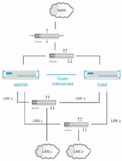
The Firewall > High Availability configuration dialog allows you to connect two independent LANCOM R&S® Unified Firewall systems in a master/slave configuration through a dedicated interface. The so-called HA cluster provides failover. If the master device becomes unavailable, the standby device (slave) takes over its tasks.
The master and slave systems are connected via a Cluster Interconnect cable that allows them to communicate with one another and monitor the status of the paired system. The slave node's configuration is synced with the master node's configuration. Certain rules are applied to the slave device, that allow network communication with the master node only. If the slave system fails to detect a "heartbeat" signal from the master, it takes over the role of the master system (in the event of a power outage or hardware failure/shutdown).

In this case, the slave device removes specific blockades and sends a gratuitous ARP request. The switch connected to your LANCOM R&S ^® Unified Firewall must allow the ARP command. It may take several seconds for the client device in the network to update its ARP cache and for the new master to be reachable.
The following figure illustrates a typical network environment with a redundant master/slave configuration for High Availability.
flowchart
graph TD
    WAN["LAN"] --> ROUTER["Router"]
    ROUTER --> SWITCH1["Switch"]
    SWITCH1 --> MASTER["MASTER"]
    SWITCH1 --> SLAVE["SLAVE"]
    MASTER -->|Cluster Interconnect| SLAVE
    SLAVE -->|LAN 1| SWITCH2["Switch"]
    SLAVE -->|LAN 2| SWITCH3["Switch"]
    SWITCH2 --> LAN1["LAN 1"]
    SWITCH2 --> LAN2["LAN 2"]
    SWITCH3 --> LAN1
    SWITCH3 --> LAN2
Figure 15: Sample network setup for High Availability.

High Availability is not available for the LANCOM R&S® Unified Firewall models UF-50 and UF-100.
You can find more information regarding high availability in the following sections.
High Availability Settings
Use the High Availability settings to specify the connection parameters for the master/slave configuration.
The High Availability feature requires two identical systems of the same hardware type (for example UF-200 with UF-200 or UF-500 with UF-500) and software version. Furthermore, a free network interface (NIC) is required on both systems
3 User Interface
that is not in use by any other interface (like VLAN or bridge) or any network connection. For more information, see Interfaces on page 77 and Network Connections on page 67. You have to use the same NIC on both systems for cluster interconnection.
The master system synchronizes its initial configuration and any subsequent configuration changes to the slave system to ensure that the same configuration is used in the event of failure.

High Availability can only be activated if no background processes, such as updates or backups, are running.
Navigate to Firewall > High Availability configure the high availability settings.
The High Availability configuration dialog allows you to configure the following elements:
| DescriptionInput field | |
| I/O | A slider switch indicates whether the High Availability feature is active (1) or inactive (0). By clicking the slider switch, you can toggle the state of High Availability. High Availability is deactivated by default. |
| Status | Displays the High Availability status of your LANCOM R&S®Unified Firewall. The following statuses are available:➢ Disabled – High Availability is not enabled on the firewall.➢ No connection – High Availability is enabled on the firewall but the other firewall cannot be reached.➢ Not synced – High Availability is enabled on the firewall and the other firewall can be reached, but the configuration from the master system has not been synchronized to the standby (slave) system yet.➢ Synchronized and ready – High Availability is enabled on the firewall. The other firewall can be reached and is synchronized.➢ Updating – High Availability is enabled on the firewall. The other firewall can be reached. Both systems are being updated.The update process consists of multiple steps that can be tracked in Update Settings dialog and in the Info Area. |
| Initial Role | Select the respective radio button to specify the role which your LANCOM R&S®Unified Firewall is to play in the HA cluster:➢Master– The LANCOM R&S®Unified Firewall is active and synchronizes its configuration to the LANCOM R&S®Unified Firewall being the slave.➢Slave– The LANCOM R&S®Unified Firewall is not active (i. e. it cannot be reached using the web client) but it receives the master configuration and is prepared for taking over. |
| HA Interface | From the drop-down list, select the interface to be used for the HA cluster communication. This interface cannot be used for any other firewall services. |
| The same interface (NIC) must be used on both LANCOM R&S®Unified Firewall systems for Cluster Interconnection. | |
| Local IP | Enter the IP address which you want to assign to the HA interface on the LANCOM R&S®Unified Firewall in CIDR notation (IP address followed by a slash "/" and the number of bits set in the subnet mask, e. g. 192.168.50.1/24). |
| Remote IP | Enter the IP address under which the LANCOM R&S®Unified Firewall can reach the other LANCOM R&S®Unified Firewall of the HA cluster. |
Local IP and Remote IP must be in the same subnet. HA cluster communication is not supported for routed networks.
If you have modified these settings, use the buttons at the bottom right of the editor panel to confirm (Save) or to discard your changes (Reset). Otherwise, you can close the dialog (Close).
Click ▼activate in the toolbar at the top of the desktop to apply your configuration changes.
Before you connect the slave system to the master with the cluster interconnect cable and configure High Availability on the slave, the configuration of the master system must be complete and activated.
Connect the slave system with the same "WAN" and "LAN" network components as the master system (see Figure 15: Sample network setup for High Availability. on page 31).
Only the master system can be reached and configured using the web client.
If you want to change the High Availability configuration (for example to change the HA interface), first disable High Availability, then change the configuration. Then, turn High Availability back on with the new configuration.
To use both firewalls with your LANCOM R&S ^® UF Command Center, you need to configure them separately. When High Availability (HA) is enabled, the LANCOM R&S ^® UF Command Center settings are synchronized using the slave node to configure your LANCOM R&S ^® UF Command Center only once. For more information see Command Center on page 29
To make the HA feature work properly, the time settings of both firewalls need to be in sync. When you enable the HA feature, the settings are configured as follows:
- The NTP client and server are activated on both firewalls.
- Cluster link IP addresses are added to both nodes of the NTP server list.
You can find more information under Time Settings on page 41
To remove the slave system from the High Availability configuration and operate it as a standalone system, click the slider switch to deactivate the HA feature. The configuration settings of the slave node and the IP addresses of the network interface are set to default.
It is possible that the default IP addresses of the slave node are in conflict with the IP addresses of the master node after the reset. For more information, see Getting Started on page 7. Contact our Support team to let them reconfigure the settings of the master node before deactivating the HA feature.
Operating the HA Features
In this chapter, you will receive information on how you can set up and operate the HA feature for your LANCOM R&S® Unified Firewall.
Initial Setup
To use the HA feature, you require a dedicated cluster link for firewall-to-firewall communication. This link is essential to make the HA feature work properly. Use a redundant interface, e.g. a bond interface that is provided through link aggregation.
The following interfaces cannot be used as cluster links: VLAN, WLAN, PPP, Bridge interface
Use a switch to separate the cluster link to smoothly monitor the master node and the slave node through SNMP.
Synchronization
In this chapter, you will find information on how to sync the master node and the slave node with regards to the HA configuration, to connection tracking, to logs and statistics and on sync constraints.
3 User Interface
Configuration
All configuration changes are synced with the slave node. During the synchronization and activation process, the HA feature is displayed as Not in sync. A role switch during the synchronization process can lead to data loss or loss of configuration changes.
Configuration changes are synced after a 15 second delay to prevent unnecessary activations in the slave node.
Click ✅activate in the toolbar at the top of the desktop to to start a full sync.
Connection Tracking
Connection-based protocols, as TCP, are tracked in the firewall. The tracking tables are automatically synced with the slave node. Therefore, connections remain after a role switch, e.g. during a downloading process.
Logs and Statistics
Your LANCOM R&S ^® Unified Firewall synchronizes the log and statistics databases between the master and slave system. Logs of the slave node are not stored, as the slave database only provides read permissions.
Constraints
The UTM features only save the status of connections through the firewall.
Example: The DPI engine stored meta data of packets that have already been analyzed until the connection ends.
Your LANCOM R&S ^® Unified Firewall does not synchronize this connection status, but stores it in the master node. After a role switch, all connections that have been analyzed by the UTM feature, are interrupted.
Example: A loss of meta data makes the DPI engine reject new packets of an older connection as unknown.
Role Switch
For the active-passive HA feature, LANCOM R&S ^® Unified Firewall provides the following roles:
Master node
The master node actively processes network traffic. The master node is also responsible for forwarding all configuration and status changes to the slave node to ensure both systems are in sync.
Slave node
The slave node is a passive node that is used as a hot-standby replacement that takes over the master's tasks if it is out of service. The slave node detects configuration and status changes and applies and activates them.
If the firewall does not work properly, e. g. due to hardware or kernel issues, the HA feature ensures a smooth feature failover by the slave. This prevents network downtimes. The failover is effected through Gratuitous ARP packets to all hosts in each broadcast domain of the firewall. These hosts acquire that the IP requests are responded by the new master node.

Using the HA feature is useful if you want to supply your firewalls with new hardware without experiencing downtimes, e. g. for network modules or SSD disks.
Licensing
Your LANCOM R&S ^® Unified Firewall devices need to be digitally licensed for each device. If you have purchased two LANCOM R&S ^® Unified Firewall devices to use them in a HA environment, you will only receive one license. Both firewalls need to be configured and put into operation as HA clusters during the licensing process. Otherwise, the firewall might reject the license.
Updates
Installing an update in a HA environment can be effected with high reliability and without downtimes, even if the update fails.

reate a backup of your configuration before initiating an update. For more information on updates, refer to Updates Settings on page 42.
The master node controls the update process as follows:
- Downloading the update or upgrade
This step will be skipped if you have already downloaded the update or upgrade or if you have installed the upgraded firmware on the firewall manually, e. g. in an offline environment.
-
Synchronizing the update or upgrade with the slave node through the cluster link.
-
Installing the update on the slave node
The master node initiates the update or upgrade installation on the slave node. If an error occurs, the master node continues to work while the update process is being suspended. Contact our Support team to support you in case of downtimes.
- Installing the update on the slave node
After installing the update on the slave node, it is installed on the master node.

Automatic updates are allowed when HA is enabled to prevent data loss or network downtimes as a successful role switch cannot be guaranteed after a failed installation of the update.
If both systems are not in sync, updates cannot be initiated.
Update with reboot
Most updates require a reboot after the installation. Rebooting the system in a HA environment triggers a role switch. We therefore recommend an administrator's assistance for the update process.
The master node controls the update process with reboot as follows:
- Downloading the update
- Synchronizing the update with the slave node through the cluster link.
- Installing the update on the slave node
-
Restarting the slave node
The slave node restarts automatically after the installation. -
Waiting for user confirmation
The web client prompts the administrator to proceed with the update process. Errors that occur prior to this step can be fixed. Contact our Support team if you need assistance.
-
Installing the update on the slave node
-
Restarting the master node
The master node automatically reboots after the installation. The role switch is effected on reboot.
Upgrade
To install an upgrade, your LANCOM R&S ^® Unified Firewall reboots. The reboot initiates the upgrade installation that provides the system with the latest version. An upgrade also initiates a role switch. We therefore recommend an administrator's assistance for the upgrade process.
The master node controls the upgrade process as follows:
- Downloading the update or upgrade
3 User Interface
- Synchronizing the update or upgrade with the slave node through the cluster link.
- Installing the update on the slave node
- Upgrading the slave node
The slave node reboots and initiates the upgrade installation automatically.
- Waiting for user confirmation
The web client prompts the administrator to proceed with the update process. Errors that occur on the slave node prior to this step can be fixed. Contact our Support team if you need assistance.
-
Installing the update on the master node
-
Upgrading the master node
The master node automatically reboots after the installation and initiates the upgrade installation automatically. The role switch is automatically effected upon reboot.
Synchronization
Prior to the installation of the update, your LANCOM R&S ^® Unified Firewall deactivates synchronization to ensure that the new version of the slave node is configured after reboot. All changes that you have made after the installation of the update has already started are applied after the update.
During the upgrade, your LANCOM R&S ^® Unified Firewall synchronizes all logs and statistics from the old version and the new version.
Monitoring
If a device goes offline and is not able to reconnect, e. g. due to hardware issues, the administrator needs to react immediately and solve the issue or replace the defective device. A cluster that does not work properly is not able to prevent downtimes. It is therefore necessary to monitor the firewalls when HA is activated. This can be effected as follows:
Web client
You can monitor the HA feature in the Info area and in the HA menu (see High Availability on page 31). You can identify the firewall that is currently set as the master node from the local IP address.
SNMP
SNMP is the de-facto standard for monitoring the firewall. Refer to SNMP Settings on page 62 for more information on the firewall configuration and how to download the necessary MIB files. SNMP requests towards the firewall will help you to identify the firewall that is currently active by identifying the IP address of the cluster link.
You can only monitor the slave node through the cluster link. To get access to this interface, use a switch as described in Initial Setup on page 33.
Remote Syslog Server
You can use a remote syslog server to monitor HA events as cluster messages are included in the syslogs. Role switches are clearly logged. You can get the master IP address from the logs as well.
The logs for the slave node are not sent to the remote syslog server. The logs for the master node are sufficient for retrieving all necessary information.
Command Center
Use the LANCOM R&S ^® UF Command Center to monitor the HA status of several firewalls, including the license status and hardware resources.
License
The features provided by your LANCOM R&S ^® Unified Firewall software depend on the license you have purchased from your supplier.
The following features can be individually licensed with the purchased license file:
Anti-spam (UTM license)
Anti-virus (UTM license)
Application filter
Content filter
IDS/IPS (UTM license)
Wireless LAN
Navigate to Firewall > License to open the License Manager, which you can use to view the validity period of your LANCOM R&S ^® Unified Firewall license and additional feature licenses, or upload new licenses.

After being started for the first time, or following a re-installation, the LANCOM R&S ^® Unified Firewall runs for 30 days as a demo version. You cannot perform a backup during the trial period. At the end of the trial period, the firewall will retain your configuration. The UTM features will be disabled and you can no longer save any changes.
The system checks the expiry dates of licenses in the license file at regular intervals. If a license expires or a trial period ends, all licensable features will be disabled until you upload a new license with the web client. After the license expires, web and mail traffic is blocked or forwarded by the LANCOM R&S ^® Unified Firewall without being filtered. In the first case, you will immediately see that you need to download a new license if your current license data has expired. If you operate the system in an unsecured mode after the license expires, you will only be notified on the LANCOM R&S ^® Unified Firewall user interface. You can configure this in the License Manager:
End-of-License Behavior
Web and Mail Traffic
- Redirect web access to an error page. Block mails if the mail proxy is enabled.
Allow insecure web and mail traffic
Figure 16: Configuring end-of-license behavior
Regardless of how the end-of-license behavior is configured, features in the user interface are always disabled when the main license has expired.
After a feature license expires, the corresponding feature will be disabled. The settings dialog for this feature can still be opened. The dialog will indicate that the license has expired. If you try to make changes, an error message appears.

The license information in the information panel of the web client appears in red as soon as the license expiry period is less than 30 days.
For an unlicensed LANCOM R&S ^® Unified Firewall, a temporary serial number is displayed in the information panel. This will be replaced by a valid license number after a license is purchased.
If the LANCOM R&S ^® Unified Firewall is installed on a virtual machine, the UUID of the virtual machine is displayed in the information panel.
Under License Upload you can upload a new license for your LANCOM R&S ^® Unified Firewall software. Please proceed as follows to do this:
- Next to the Select File input field, click on License File.
The search function for the local data medium opens.
- Select a license file in GPLF or LIC format.
3 User Interface
The new license must correspond to the version number of the LANCOM R&S ^® Unified Firewall software and hardware.
- Click on Open.
The search function for the local data medium closes.
- To upload the license file, click Save.
The license is uploaded. If the upload was successful, all licenses and related information will automatically be transferred to your LANCOM R&S ^® Unified Firewall and a success message is displayed.
- Confirm that you want to log out by clicking OK.
You will be logged out. The login page of the firewall opens.
-
Enter your login credentials.
-
Click on Login.
The web client appears.
You can also download the uploaded license again. To start the file download, simply click on the license file which is displayed as a link further up next to Download.
The Details tab shows you more detailed license information about your LANCOM R&S ^® Unified Firewall software, e.g. information about the UTM licenses.
LANCOM Management Cloud settings
These are the settings for the configuration and monitoring of your device via the LANCOM Management Cloud (LMC).
Navigate to Firewall > LMC Settings to open an editing window where you can view and modify the settings for the LMC.
In the LMC Settings editing window you can adjust the following parameters:
| DescriptionInput box | |
| I/O | A slider button indicates whether firewall management via the LANCOM Management Cloud is enabled (1) or disabled (0). Click on the slider button to change the status of this option. |
| LMC domain | Enter the domain name for the LMC here. By default, the domain is set to the Public LMC for the first connection. If you wish to manage your device with your own Management Cloud ("Private Cloud" or "on-premises installation"), please enter your LMC domain. |
| Activation code | As an alternative to entering the serial number and the cloud PIN supplied with the device, it can also be assigned to a project in the LMC by means of an activation code.In the LMC go to Devices, click on Activation codes and then on Create activation code. This creates a temporary activation code. While it remains valid, this code can be used to activate any number of LANCOM devices, i.e. to transfer them to the LMC. |
Firewall Access
The Firewall Access settings allow you to define how your LANCOM R&S ^® Unified Firewall can be accessed from external networks or the Internet. In addition, you can determine how your LANCOM R&S ^® Unified Firewall reacts, for example, to ping requests.
The Firewall Access settings only apply to external access to your LANCOM R&S ^ Unified Firewall for defined users. Accessing your LANCOM R&S ^ Unified Firewall from the internal network is always possible.
Navigate to Firewall > Firewall Access to determine whether and how access from external networks or the Internet to your LANCOM R&S ^® Unified Firewall is allowed.
For more detailed information on the Firewall Access settings, see the following sections.
Ping Settings
The Ping Settings allow you to specify how your LANCOM R&S ^® Unified Firewall handles ICMP echo requests (ping) to the firewall from the internal network and the Internet.
Navigate to Firewall > Firewall Access > Ping Settings to open an editor panel to display and edit the ping settings.
| DescriptionInput field | |
| Ping (ICMP to Firewall) | Select the respective radio button to specify how your LANCOM R&S ^ Unified Firewall handles ICMP echo requests to the firewall from the internal network and the Internet. The option is set to Allow by default, but you can adjust the settings to the other value as required:➢ Deny – The LANCOM R&S ^ Unified Firewall does not respond to ICMP echo requests to the firewall from the internal network and the Internet.➢ Allow – The LANCOM R&S ^ Unified Firewall reponds to ICMP commands to the firewall from the internal network and the Internet. |
| While blocking ICMP echo requests can improve the security of your LANCOM R&S ^ Unified Firewall, it also makes any troubleshooting in the network difficult. Therefore, if an error occurs in the network, we recommended setting this option to Allow before you start troubleshooting. | |
If you modify the settings, click Save to store your changes or Reset to discard them. Otherwise, click Close to shut the editor panel.
Click ✕activate in the toolbar at the top of the desktop to apply your configuration changes.
SSH Settings
The SSH Settings allow you to configure SSH access to your LANCOM R&S ^® Unified Firewall from the Internet.
Navigate to Firewall > Firewall Access > SSH Settings to open an editor panel to display and edit the SSH settings.
The SSH Settings panel allows you to configure the following elements:
| DescriptionInput field | |
| I/O | A slider switch indicates whether the SSH service is active (1) or inactive (0). By clicking the slider switch, you can toggle the state of the service. The SSH service is activated by default. |
| Set the listening port by entering the port number. The default setting is port 22.Port | |
| Password Authentication | Password authentication allows you to login to your LANCOM R&S®Unified Firewall via SSH using a password. Password authentication is activated by default. |
| ! Password authentication can only be deactivated if at least one SSH public key is actively used for key authentication. | |
| SSH Public Keys | This table displays the SSH public keys that are used to authenticate a user without a password. Click Add to open the SSH Key panel and add a new key.On this panel, you can define the following settings:> In the Key field, enter or paste the SSH public key.> In the Title field, enter a name for the SSH public key.Your LANCOM R&S®Unified Firewall only support keys in Secure Shell (SSH) Public Key File Format.If you modify these settings, clickSaveto save your changes orResetto discard them. Otherwise, clickCloseto close the editor panel.The SSH public key appears as a list entry (Fingerprint). You can edit or delete single entries in the list by clicking the corresponding button next to an entry. For more information, seeIcons and buttonson page 21. |
| You can use these authentication methods (Password Authentication, SSH Public Keys) alone or in combination. | |
| Access Restrictions | This table displays user-defined IP addresses or IP networks that can be allowed access to the LANCOM R&S®Unified Firewall (whitelist mode).Select the check box next to an entry to allow access.To add an IP address or network to the list, enter aTitleandSourceand clickAdd.The new entry is added to the list and is activated automatically.The following entries are predefined and cannot be removed:Local Networksrepresents the internal access and is activated by default.Internetprovides SSH access to the LANCOM R&S®Unified Firewall from the Internet.In certain circumstances, this may grant attackers access to your LANCOM R&S®Unified Firewall. Therefore, we do not recommend using this option as a permanent solution.VPN TunnelsThe following default entries include network sections for the customer support. These entries are deactivated by default.Rohde & Schwarz Internet GatewayRohde & Schwarz Cybersecurity Customer Support |
If you modify the settings, click Save to store your changes or Reset to discard them. Otherwise, click Close to shut the editor panel.
Click ▼Activate in the toolbar at the top of the desktop to apply your configuration changes.
Webclient Settings
The Webclient Settings allow you to configure external web access to your LANCOM R&S ^® Unified Firewall from the Internet.
Navigate to Firewall > Firewall Access > Webclient Settings to open an editor panel to display and edit the webclient settings.
The Webclient Settings panel allows you to configure the following elements:
| DescriptionInput field | |
| Set the listening port by entering the port number. The default setting is port 3438. Port | |
| Select a webclient certificate that is used to verify the SSL connection. Webclient Certificate | |
| ! If you do not select a webclient certificate, an auto-generated, self-signed system certificate is used. The system certificate is not part of the certificate management. To avoid certificate warnings from your browser when connectingto the webclient, select a certificate that was signed by a CA trusted by your browser. | |
| Access Restrictions | This table displays user-defined IP addresses or IP networks to allow access for these addresses only (whitelist mode).Enter aTitleandSource.ClickAddto add the IP address to the list.The following entries are read-only, but can be activated or deactivated.>Local Networksrepresents the internal access and is activated by default.>Internetprovides SSH access to the LANCOM R&S®Unified Firewall from the Internet.⚠In certain circumstances, this may grant attackers access to your LANCOM R&S®Unified Firewall. Therefore, we do not recommend using this option as a permanent solution.>VPN TunnelsThe following default entries include network sections for the customer support. The entries are deactivated by default.>Rohde & Schwarz Internet Gateway>Rohde & Schwarz Cybersecurity Customer SupportOptional: Clear the check box next to an entry to restrict access for it. |
| The webclient access is the main access type to the server. You have to select at least one entry in the list of IP addresses. | |
If you modify the settings, click Save to store your changes or Reset to discard them. Otherwise, click Close to shut the editor panel.
Click ▼activate in the toolbar at the top of the desktop to apply your configuration changes.
Time Settings
Your LANCOM R&S ^® Unified Firewall works with time-sensitive rules. Furthermore, the system time is particularly important for services such as logging that rely on accurate timestamps. Therefore, it is necessary to set the date and time correctly.
Navigate to Firewall > Time Settings to open an editor panel to display and edit the system date and time settings.
The Time Settings configuration dialog allows you to configure the following elements:
| DescriptionInput field | |
| Time Zone | From the drop-down list, select one of the predefined time zones. The time zone is set to (+01:00) Europe - Berlin by default, but you can adjust the settings to one of the other values as necessary. |
| Current Time | Check the current system date (MM/DD/YYYY) and time (hh:mm:ss) of the LANCOM R&S®Unified Firewall. |
| Date & Time | Optional: Click the input field to set a new system date or time manually. A pop-up window with a calender and input fields for changing the date and time opens. You can enter a date in the MM/DD/YYYY format or choose a date from the calendar.. You can also set a new time by entering the time in the hh:mm:ss format. |
| To set the system time manually, NTP has to be disabled (in other words, the NTP Client check box must be cleared). Otherwise, the time will be reset automatically as soon as the system sends the next NTP request. | |
| NTP Client | Optional: Select the check box to use remote network time protocol servers to set the system date and time automatically. |
| NTP Servers | Optional and only available if the NTP Client check box is selected: You can either use the predefined NTP servers or add your own NTP servers to the list.The standard NTP servers are: de.pool.ntp.org and europe.pool.ntp.org.You can add as many NTP servers as you like. Enter the IP address or the fully qualified domain name of an NTP server in the input field. Then, click Add to add the NTP server to the list.You can edit or delete individual entries in the list by clicking the corresponding button next to an entry. For more information, see Icons and buttons on page 21. |
| ! If you edit an NTP server, a check mark appears on the right of the entry. You have to click the check mark before being able to save the settings of the NTP server. | |
| ! If more than one NTP server is configured, the LANCOM R&S®Unified Firewall automatically synchronizes the system clock with the server that transmits the best time signal. | |
| Serve as local NTP server | Optional and only available if the NTP Client check box is selected: Select this check box if you want to make the system time of the LANCOM R&S®Unified Firewall available in the internal network. The LANCOM R&S®Unified Firewall then acts as an internal, local NTP server. |
If you modify the settings, click Save to save your changes or Reset to discard them. Otherwise, click Close to close the editor panel.
Click ✅activate in the toolbar at the top of the desktop to apply your configuration changes.
Updates Settings
The Updates Settings panel allows you to keep your LANCOM R&S® Unified Firewall up to date at all times. New versions of the operating systems LCOS FX, security updates, and new functionalities can be automatically downloaded from the update server and installed on the firewall quickly and easily. The update system is equipped with various functions for notifying the system administrator if there are new updates available. Furthermore, you can view the history of imported updates.
To prevent any unauthorized or malicious updates from being installed on the firewall, all LCOS FX updates are signed digitally. Only updates with a valid signature are displayed and installed.
Navigate to Firewall > Updates Settings to open an editor panel to display the list of available updates with information about them and their status on the Updates tab.
The Filter input field allows you to narrow the list of results in the table below it. As you type in the input field, your LANCOM R&S® Unified Firewall automatically refreshes the list to show only those entries that contain the characters you are typing as a name, type or description. Click Ⓧ in the input field to delete the search string or all selected desktop tags and to display an unfiltered view of the desktop.
The table columns of the updates list contain the following information:
| DescriptionColumn | |
| Displays the name of the available update.Name | |
| Displays the type of the update.TypeThe update system differentiates between four types of updates:> Security – contains corrections concerning the security of the firewall>Recommended-contains corrections as well as performance and stability optimizations>Hotfix-contains enhancements of single modules of the firewall and new features>Upgrade-contains an upgrade to the next LCOS FX software version | |
| Displays a text field with more information about the update.DescriptionClick the text field to expand it and to display all information about the update. | |
| Reboot | Indicates whether a reboot of the system is required after the update has been installed successfully. |
| Displays the release date of the update.Release Date | |
| Distinguishes between updates and updates which have already been installed.Status | |
| !An update cannot be installed more than once. | |
| Action / Dependency | If all dependencies are met, the action Install becomes available. Otherwise, a list of dependencies is displayed. To meet the dependencies, install the listed updates. |
Click Refresh Updates List to update the list of available updates with the latest versions manually.
The Settings tab allows you to configure the following elements:
| DescriptionInput field | |
| Search for New Updates Automatically | Select this check box to refresh the list of available updates with the latest versions automatically. |
| Interval | From the drop-down list, select the desired frequency with which the list of updates is refreshed. This option is set toDailyby default, but you can adjust the settings to one of the other values as necessary::>Hourly>Daily>Weekly |
| Update Time | Enter the date and time for the first automatic refresh of the updates list and the first automatic update. A pop-up window with a calender and input fields for setting the date and time opens. You can enter a date in the MM/DD/YYYY format or choose a date from the calendar. You can also set a new time by entering the time in the format hh:mm:ss. |
| !If you have activated automatic updates as below, all of the following updates are executed at the mentioned time. | |
| Install Updates Automatically | Select the respective radio button to specify which updates you want to be imported and installed automatically on your LANCOM R&S®Unified Firewall. This function is limited to security updates and recommended hotfixes. This option is set to None by default, but you can adjust the settings to one of the other values as necessary. |
| The standard update server is:Update Servershttp://www.gateprotect.com/updateserverYou can add as many update servers as you like. In the input field, enter the update server's URL and clickAdd. The server will be added to the list.! If the URL contains a fully qualified domain name (FQDN), you need to configure the DNS settings. Otherwise, the FQDN cannot be resolved.You can edit or delete individual entries in the list by clicking the corresponding button next to an entry. For more information, seeIcons and buttonson page 21. | |
| ! If you edit an update server, a check box appears on the right of the entry. You have to click the check box before being able to save the settings of the update server. | |
The History tab displays the update history of your LANCOM R&S ^® Unified Firewall.
If you modify the settings, click Save to save your changes or Reset to discard them. Otherwise, click Close to close the panel and return to the overview of your entire configured network.
Click ▼activate in the toolbar at the top of the desktop to apply your configuration changes.

For information on the installation of system updates in a High Availability configuration, see Updates on page 35.
User Authentication
The User Authentication settings determine the list of users who can be authorized to utilize your network resources, such as Internet access and VPN tunnels. Furthermore, these settings allow you to set up local users and to connect your LANCOM R&S ^® Unified Firewall to an external directory service from where it can retrieve individual users and user groups. This allows you to set firewall regulations not just for computers but also for individual users and user groups.
Navigate to Firewall > User Authentication to display a list of users in the item list bar that are currently defined in the system.
You can find more information regarding user authentication in the following sections.
Technical Background and Preparations
Purpose of user authentication
With user authentication, firewall rules can be assigned to users when they log in. Only one user per IP address can be logged in. If another user logs in from an IP address which is already in use for a session, the other user is logged out and the new user is logged in.
Logging on to the firewall
Your LANCOM R&S ^® Unified Firewall runs a special web server which only processes user logins. It receives the user name and password. With a user database which is created locally on your LANCOM R&S ^® Unified Firewall, an authentication service first verifies whether the user name and password are admissible. If this login fails and a Microsoft Active Directory server or an openLDAP server are configured on your LANCOM R&S ^® Unified Firewall, the authentication service additionally queries those directory servers via Kerberos protocol to see whether the user can be authenticated. If the authentication is successful, the firewall rules for this user are assigned to the IP address from which the request was sent.
Users who are registered in the local database of the LANCOM R&S ^® Unified Firewall can change their password over the web server. The password can consist of up to 248 characters. Longer passwords are accepted, but they are cut off automatically.
Certain computers, such as terminal servers on which many users work at the same time or servers to which only administrators log in, can be excluded from the user authentication. In this case, web servers and the authentication service do not accept any user logins from the IP addresses of these computers.
Since all users have the same IP address on a terminal server, the LANCOM R&S® Unified Firewall cannot identify individual users in the network. For this purpose, Microsoft offers the so-called Remote Desktop IP Virtualization for Server 2008 R2 and newer versions. With this application, every user obtains their own IP address from a pool of IP addresses, similar to DHCP.
Authentication server
For smaller companies without central user management, the LANCOM R&S ^® Unified Firewall provides local user management. You can always use the local user database. However, it is also possible to use an external directory service, such as Microsoft Active Directory server or an openLDAP server. Both Microsoft Active Directory and openLDAP use the Kerberos protocol to validate the credentials provided by any of the user authentication clients.
Active Directory groups
If you are using a Microsoft Active Directory server for authentication, the Active Directory groups are displayed in the user authentication item list bar as well. Active Directory groups are a powerful tool to set up and maintain security policies for each user. For example, you can allocate Active Directory users to certain Active Directory groups and then create firewall rules for these groups on your LANCOM R&S ^® Unified Firewall.
Logging in
There are three different ways users can log in to LANCOM R&S ^® Unified Firewalls:
Logging on using a web browser
Logging on using the LANCOM R&S® Unified Firewall's User Authentication Client
Logging on using the LANCOM R&S ^ Unified Firewall's Single Sign-On Client
Logging in using a web browser
Once users have been set up as desktop objects and firewall rules for these users have been configured, they can act according to these rules using the so-called landing page. The login with a web browser method works with any browser and is SSL-encrypted.
To log in to your LANCOM R&S ^ Unified Firewall with a web browser, proceed as follows:
- Start a web browser.
- Make sure cookies are activated.
- In the address bar, enter the IP address of your LANCOM R&S ^® Unified Firewall, for example https://192.168.12.1 (using the default port 443).
A special web page presenting the LANCOM R&S ^® Unified Firewall's landing page appears.
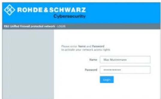
text_image
ROHDE & SCHWARZ Cybersecurity R&S Unified Firewall protected network - LOGIN Please enter Name and Password to activate your network access rights Name Max Mustermann Password ********** LoginFigure 17: User authentication with a web browser
- Enter the Name.
3 User Interface
If the user is an LDAP user, the user's login name has to exactly match the user name specified in the sAMAccountName attribute of the user. Otherwise, the name in the user-specific firewall rules will not correspond to the user logging in to the client and the rules will not match.
- Enter the user's Password.
- Click Login.
The authentication proceeds.

For security reasons, the browser window that was used to log in must remain open during the whole session. Otherwise, the user is logged out automatically after one minute. This is to prevent unauthorized persons from accessing the firewall from a computer where a user forgot to log out of.
Logging in using the LANCOM R&S ^® Unified Firewall's User Authentication Client
The Windows-based LANCOM R&S ^ Unified Firewall's User Authentication client is located in the UA Client directory on the USB flash drive.
To log in to your LANCOM R&S ^® Unified Firewall with the LANCOM R&S ^® Unified Firewall's User Authentication client, proceed as follows:
- Install the LANCOM R&S ^® Unified Firewall's User Authentication client.
- Start the LANCOM R&S ^® Unified Firewall's User Authentication client.
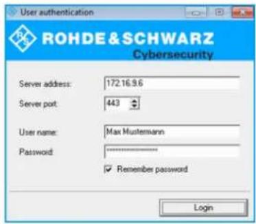
text_image
User authentication ROHDE & SCHWARZ Cybersecurity Server address: 172.16.9.6 Server port: 443 User name: Max Mustemann Password: ******** ✓ Remember password LoginFigure 18: LANCOM R&S® Unified Firewall's User Authentication client.
- Under Server Address, enter the IP address of your LANCOM R&S ^® Unified Firewall.
- Enter the User Name.
If the user is an LDAP user, the user's login name has to exactly match the user name specified in the sAMAccountName attribute of the user. Otherwise, the name in the user-specific firewall rules will not correspond to the user logging in to the client and the rules will not match.
- Enter the user's Password.
-
Optional: Select the Remember password check box to save the password for future logins.
-
Optional: Adjust the period of time for reconnection under Settings by right-clicking the system tray icon in the Windows taskbar.
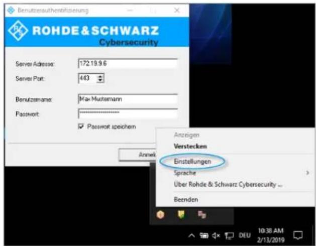
The authentication proceeds.

For security reasons, it is strongly recommended to always update the LANCOM R&S ^ Unified Firewall's User Authentication client to the latest version available. However, a compatibility mode that allows older versions of the LANCOM R&S ^ Unified Firewall's User Authentication client to work with LCOS FX version 10 or higher can be enabled. For more information, see User authentication settings on page 50.
Logging in using the LANCOM R&S ^® Unified Firewall's Single Sign-On Client
When using Single Sign-On (SSO), domain users from the Active Directory domain log in to a Windows client. Firewall rules configured on your LANCOM R&S ^® Unified Firewall concerning these users are then automatically applied.
To realize SSO with your LANCOM R&S ^® Unified Firewall in an Active Directory environment, the following preconditions have to be met:
-
As Kerberos is time-critical, make sure to set the same time/NTP server for all components of SSO (domain controller, Windows client and your LANCOM R&S® Unified Firewall).
-
Creating the user gpLogin
It is necessary to create a normal domain user in the user management under "CN=Users" in the Active Directory. A so-called Service Principal Name (SPN) needed for the authentication of your LANCOM R&S ^® Unified Firewall on the server is then assigned to this user. The user does not need any specific rights.
3 User Interface
a. Open the domain controller.
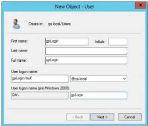
text_image
New Object - User Create in: qa.local/Users First name: gpLogin Initials: Last name: Full name: gpLogin User logon name: gpLogin/suf @qa.local User logon name (pre-Windows 2000): QA\ gpLogin < Back Next > CancelFigure 20: Creating a user
b. Under First name, enter gpLogin.
With this name, it will be easier to find the user in the user overview.
c. Under User logon name, enter gpLogin/
In the example above, the host name (
d. Under User logon name (pre-Windows 2000), enter gpLogin.
e. Click Next.
f. Enter a password for the user and confirm it.

text_image
New Object - User Create in: qa.local/Users Password: ********** Confirm password: ********** User must change password at next logan User cannot change password Password never express Account is disabled < Back Next > CancelFigure 21: Domain controller user password
g. Select the Password never expires check box
h. Click Next.
i. Verify the information relating to the new user by clicking Finish.
The user gpLogin is created.
- Logging in using the gpLogin user to query the Active Directory
In the User Name input field under Authentication Server, enter gpLogin.
- Configuring the Service Principal Name (SPN)
Assign an SPN to the newly created user so that your LANCOM R&S®Unified Firewall is able to create a position of trust regarding the domain controller. To do so, run the following command on the domain controller: setspn-A gpLogin/rsuf gpLogin
5. Generating a Kerberos key
Using the LANCOM R&S ^ Unified Firewall's Single Sign-On client, a user's login on the Windows domain can be forwarded to the LANCOM R&S ^ Unified Firewall. With the Kerberos key, your LANCOM R&S ^ Unified Firewall is able to check the forwarded information and activate the user-specific firewall rules. To create the Kerberos key, proceed as follows:
a. Log in to your LANCOM R&S ^® Unified Firewall.
b. Navigate to Firewall > User Authentication > Settings.
The User Authentication Settings editor panel opens.
c. To enable the user authentication settings, set the slider switch to I.
d. On the Kerberos tab, click the Create Kerberos Key button to generate the Kerberos key.
The Active Directory is queried to validate the specified AD user and to obtain the relevant information, such as the Kerberos key version number. With that information, your LANCOM R&S ^® Unified Firewall is able to generate a valid Kerberos key locally.
6. Activating SSO on your LANCOM R&S ^® Unified Firewall
To activate SSO on your LANCOM R&S ^® Unified Firewall, proceed as follows:
a. On the Kerberos tab, select the Active check box
b. Click Save to save your settings.
7. Preparing the Windows client
You can find the Windows Installer Single Sign-On ZIP archive at:
https://www.lancom-systems.com/downloads/
There are three ways to install the LANCOM R&S ^® Unified Firewall's Single Sign-On client:
Copy the UAClientSSO.exe standalone application to your desired target location.
Run the UAClientSSOSetup.exe setup program and install the UAClientSSO.exe standalone application under C:\Program Files\R&S Cybersecurity\UA Client\3.0\
Install the client through the domain, using the UAClientSSO.msi Microsoft installer in a group policy object.

In all cases, the UAClientSSO.exe standalone application will be installed on the Windows PC. It can then be executed provided that the following parameters are given:
The host name of your LANCOM R&S® Unified Firewall (for more information, see User authentication settings on page 50).
The IP address of your LANCOM R&S ^® Unified Firewall in the network of the client computer.
Example: The host name of your LANCOM R&S ^® Unified Firewall is rsuf. The IP address of the network of the client computer is 192.168.0.1. The target path for the installation of the LANCOM R&S ^® Unified Firewall's Single Sign-On client then is C:\Program Files\R&S Cybersecurity\UAClient\3.0\UAClientSSO.exe rsuf 192.168.0.1.
User authentication settings
The User Authentication Settings allow you to enable or disable user authentication in general. You can also specify the connection parameters for the directory server used to manage the LDAP users on your network.
Navigate to Firewall > User Authentication > Settings to open an editing window where you can create the general settings for the user authentication and directory service.
In the User Authentication Settings editing window you can modify the following parameters:
| DescriptionInput box | |
| I/O | A slider button indicates whether the user authentication is enabled (I) or disabled (O). You can change the status of the user authentication by clicking the slider button. User authentication is disabled by default. |
On tab General:
| DescriptionInput box | |
| Log Logins | Activate this checkbox if you want to log every authentication on the LANCOM R&S®Unified Firewall. You can view the login events under Monitoring & Statistics > Logs > System Log. |
| Choose one of the following four options:Login Mode> Single Login (deny new login) – No user can login from more than one IP address at a time.> Single Login (disconnect old login) – All previous logins are logged off when the user logs in from a different IP address.> Multiple Logins – Users can login from up to 254 different IP addresses simultaneously.> Multiple Logins (with warning in report) – Users can log in from up to 254 different IP addresses simultaneously, and alerts are displayed in the report. | |
| Web Login Port | Specify the HTTPS port for the web login by navigating up/down using the arrow key or by entering the port number. The default is port 443. |
| Compatibility Mode | Enable this checkbox if you want to log in to the LANCOM R&S®Unified Firewall with user authentication clients older than version 3.0.0. |
| ! Enabling this checkbox puts your network security at risk. Please refer to User Authentication on page 44 for further information. | |
| Show Landing Page | Optional: Enable this checkbox to display a landing page when an unauthorized user attempts to access the Internet. |
Each individual IP address supports just one user login, even if the mode Multiple Logins is activated.
The tab Authentication Server allows you to specify which database type you want to use. You can use the local user database in the LANCOM R&S ^® Unified Firewall either independently or in combination with an external user database such as Microsoft Active Directory Server or the openLDAP server with Kerberos.
If you select Microsoft Active Directory Server you can configure the following items:
| DescriptionInput box | |
| Enter the host name or the IP address of the directory server.Host | |
| ! If you enter the host name of the directory server, you must configure the DNS settings. Otherwise, the name cannot be resolved. | |
| Port | Enter the port number of the directory server to be used for communication. You can also select the port number with the up/down arrow. |
| User Name | Enter the name of a read-only user to retrieve the list of domain users from Active Directory. This input field must match the user attribute sAMAccountName. The user must be listed in "CN=Users". Please refer to Logging in using the LANCOM R&S®Unified Firewall's Single Sign-On Client on page 47 for further information. |
| Enter the password of the read-only user.Password | |
| We recommend that you create a dedicated user for this purpose. | |
| Enter the domain name of the Active Directory.Domain Name | |
To check the settings configured for Microsoft Active Directory Server, click Test AD Settings.
If you select OpenLDAP Server you can configure the following items:
| DescriptionInput box | |
| Enter the host name or the IP address of the directory server.Server Address | |
| !If you enter the host name of the directory server, you must configure the DNS settings. Otherwise, the name cannot be resolved. | |
| Port | Enter the port number of the directory server to be used for communication. You can also select the port number with the up/down arrow. |
| Enter the user domain name of a read-only account.User DN | |
| iYou do not have to enter the complete user domain name. If you click Save, the system automatically adds the domain components from the Base DN entry. | |
| Enter the password of the read-only user.Password | |
| Base DN | Enter a unique name (Base-DN) together with Relative Distinguished Names (RDN) separated by commas. For example, three domain components: dc=ldap, dc=example, dc=com specify the location in the directory where you want to start the directory search. |
| Optional: Specify the filter to be used to retrieve the list of users.User Query | |
| User ID | Optional: Set the attributes from which the user identifier is retrieved. The user name displayed in the web client is derived from this LDAP-user attribute. By default, the user identifier is taken from the attribute sAMAccountName. |
| Optional: Set the attribute from which the user name is retrieved.User name | |
| Optional: Set the attribute from which the user group is retrieved.User group | |
| Optional: Set the attribute from which the user primary group is retrieved.User Primary Group | |
| Optional: Specify the filter to be used to retrieve the e-mail list.Mail Query | |
| Optional: Set the attribute from which the e-mail name is retrieved.Mail Name | |
| Optional: Specify the filter to be used to retrieve the list of groups.Group Query | |
| Optional: Set the attribute from which the e-mail name is retrieved.Group Name | |
| Optional: Set the attribute from which the group ID is retrieved.Group ID | |
| Optional: Set the attribute from which the group primary ID is retrieved.Group Primary ID | |
| Optional: Set the attribute from which the parent group is retrieved.Group Parent | |
If you click Save, the system adds default values to any optional fields which you have not filled.
If you want to operate single-sign-on with Kerberos, the username must be gpLogin. The host name and domain of your firewall is taken from the general settings. See General settings on page 26. Please refer to Logging in on page 45 for further information.
On tab Kerberos:
| DescriptionInput box | |
| Select this checkbox to enable the Kerberos service.Active | |
| Kerberos Key | Displays the service name, host name, and domain name for the userPrincipalName of the most recently created Kerberos key, also called a keytab. Please refer to Logging in on page 45 for further information. |
Users
Just like computers, users and LDAP groups can be set up on the desktop as individual users or user groups.
For these desktop objects, you then define the rules to be assigned to the users as soon as they log in. If users log in from a computer to which certain rules are assigned, the rules of this computer and the user-specific rules are applied to these users. You can select users and LDAP groups from the local user database on the LANCOM R&S ^® Unified Firewall and from the openLDAP or Active Directory authentication server and add them to the user groups on the desktop. There is also a special Default User Group which can be selected on the desktop. No users can be added to this user group. It comprises all users who are able to log in but have not been set up as individual users or members of other user groups on the desktop. If such a default user group is set up on the desktop and if you have assigned rules to it, users who are later created in the Active Directory server are automatically allocated to this default user group. After login, the default rules are automatically assigned to these new users without any additional administration effort for each individual user.
LDAP Groups
It is possible to connect your LANCOM R&S ^® Unified Firewall to an external directory server using the Lightweight Directory Access Protocol (LDAP) to retrieve user groups from there. You can include these user groups in group-specific firewall rules.
LDAP can be used by medium to large companies to access directory services and to manage user data.
Connect to a directory server as described under User authentication settings on page 50.
Navigate to Firewall > User Authentication > LDAP Groups to display a list of LDAP groups in the item list bar that are currently available in the directory server.
To make LDAP groups in this list available for use in connections and group-specific firewall rules, the groups have to be assigned to a user group desktop object. For more information, see User Groups on page 92.
LDAP Users
It is possible to connect your LANCOM R&S ^® Unified Firewall to an external directory server using the Lightweight Directory Access Protocol (LDAP) to retrieve users from there. You can include these users in user-specific firewall rules.
LDAP can be used by medium to large companies to access directory services and to manage user data.
Connect to a directory server as described under User authentication settings on page 50.
Navigate to Firewall > User Authentication > LDAP Users to display a list of LDAP users in the item list bar that are currently available in the directory server.
To make LDAP users in this list available for use in connections and group-specific firewall rules, the groups have to be assigned to a user desktop object. For more information, see User Groups on page 92.
Local Users
LANCOM R&S ^® Unified Firewalls offer local user administration for smaller companies without central administration. Use the settings under Local Users to specify user names and passwords. This way, you can define and manage users.
Navigate to Firewall > User Authentication > Local Users to display a list of local users in the item list bar that are currently defined in the system.
In the expanded view, the columns of the table display the Name of the local user and an additional Description, if available. The buttons in the last column allow you to view and to adjust the settings for a local user, to create a new user by copying an existing user or to delete a user from the system.
For more information, see Icons and buttons on page 21.
Under Firewall > User Authentication > Local Users, you can add an administrator or edit an existing local user.
The Local User Authentication configuration dialog allows you to configure the following elements:
| DescriptionInput field | |
| Enter a unique name for the local user. This name will be the login name.User NameImportant:The user's login name has to exactly match the User Name (case-sensitive). Otherwise, the name in the user-specific firewall rules will not correspond to the user logging in to the client and the rules will not match. | |
| Optional: The information given here is for internal use for the administrator only.Description | |
| Password | Enter a password for the user and confirm it. The password must consist of at least six characters. |
| Optional: Select this check box to verify the password.Show Password | |
| Require password change after next login | Optional: Select this check box if you want to require the user to change the password after the next login. If selected, the web server will redirect the user from the login page to a page for changing the password. |
The buttons at the bottom right of the editor panel depend on whether you add a new local user or edit an existing one. For a newly configured local user, click Create to add it to the list of available local users or Cancel to discard your changes.
If you have modified these settings, use the buttons at the bottom right of the editor panel to confirm (Save) or to discard your changes (Reset). Otherwise, you can close the dialog (Close).
The local users defined here are available for use in desktop objects, for example VPN users.
Unassigned Users
Navigate to Firewall > User Authentication > Unassigned Users to view LDAP users that are assigned to user desktop objects, but that cannot be retrieved from the directory service.
Application Examples
Using a Windows domain
If you have a Windows domain, you can connect the user authentication to the Windows domain controller.
To connect the user authentication to the Windows domain controller, proceed as follows:
-
Navigate to Firewall > User Authentication > Settings.
-
Click Authentication Server.
-
Enter the data of your domain controller.
All users in the specified domain appear on the user list.
3 User Interface
- Drag user icons onto the configuration desktop and assign rules to them.
To log in, users must enter the URL with https:// and the IP address of the firewall in the address bar of their browser. A login page appears. After a successful login, the firewall rules for the user are assigned to the supplied IP address. When the browser window is closed, the session cookie expires and the rules lose their validity.
Excluding the Terminal Server from User Authentication
If you are using a terminal server, exclude it from the user authentication. Otherwise, all previous users are logged out when a new user logs in.
To exclude the terminal server from the user authentication, proceed as follows:
- Click the host group icon in the toolbar at the top of the desktop.
- Clear the check box in the Login Allowed column.
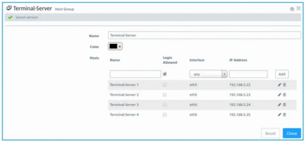
text_image
Terminal-Server Host Group Saved version Name Terminal-Server Color Hosts Name Login Allowed Interface IP Address any Add Terminal-Server 1 eth5 192.168.5.22 Terminal-Server 2 eth5 192.168.5.23 Terminal-Server 3 eth5 192.168.5.24 Terminal-Server 4 eth5 192.168.5.25 Reset CloseFigure 22: Object settings – terminal server

If your users do need authentication on the terminal server, you can activate Remote Desktop IP Virtualization on the terminal server. This way, all users are assigned their own IP address during a session.
3.4.2 Monitoring & Statistics
The Ⓧ Monitoring & Statistics settings display detailed information about the traffic flowing through your LANCOM R&S® Unified Firewall. These settings allow you to set up remote SNMP and syslog servers to forward log messages generated by different message sources. You can furthermore configure how your LANCOM R&S® Unified Firewall should handle detected event types and for which event types statistics shall be recorded.
Statistics Settings
Navigate to Monitoring & Statistics > Settings to adjust the statistics settings.
You can furthermore configure how LANCOM R&S ^® Unified Firewall should handle detected event types and for which event types statistics shall be recorded. From the drop-down lists of event types, select one of the following options:
| DescriptionMode | |
| No data is collected for this event type.Disabled | |
| Event data is collected to create statistics.Create Statistics | |
| Send Raw Data to External Syslog | Data from occurring events is collected to create statistics and passed on to a configured external syslog server. |
| Save Raw Data Locally | Data from occurring events is collected to create statistics, passed on to a configured external syslog server and stored on the device. |
| This mode can cause the storage of the device to fill up rapidly. | |
Hover the mouse over the next to the event type label to find an explanation of what graph a particular event is used for. Use the All Event Types drop-down list to set all event types simultaneously to the same mode.
If you have modified these settings, use the buttons at the bottom right of the editor panel to confirm (Save) or to discard (Reset). Otherwise, you can close the dialog (Close).
Click ✅Activate in the toolbar at the top of the desktop to apply your configuration changes.
Notification settings
The notification systems sends e-mail messages about specific types of notification, either immediately or regularly in an aggregated form. This requires an active e-mail function in which at least one sender is set. Security comes with the optional settings Validate remote certificate to verify the remote site before sending e-mail and S/MIME certificate to encrypt the outgoing mail. Further details are available under E-mail settings on page 30
Navigate to Monitoring & statistics > Notification settings to open an editing window where you can configure the following items:
Table 1: General
| DescriptionInput box | |
| I/O | A slider button indicates whether the notification settings are enabled (1) or disabled (0). Click on the slider button to change this. |
| Notification language | Set the language used in the notification e-mails. If the dialog is opened for the first time, the language is set to that used for the web client. |
| Set the subject of the notification e-mails.Subject template | |
| Recipients | List of recipient addresses where the notifications are sent. Click on ☑n the right-hand side to add your entry to the list. |
In the Aggregated notifications editing window you can modify the following items:
| DescriptionInput box | |
| Aggregation interval | The events are collected and summarized in an e-mail at a specified interval. Enter the interval in minutes in which events are collected before they are sent as a message. |
| Max. number of notifications per mail | Here you specify how many events are combined in an e-mail. This determines how many mails are sent at the end of each aggregation interval. At the same time, this limits the maximum size of the e-mail. |
| If necessary, observe any spam guidelines of the recipient. |
In the Instant notifications editing window you can modify the following items:
| DescriptionInput box | ||
| Max. number of mails per hour | In the occurrence of an event of a type flagged for Instant notification, an e-mail is sent to the recipient immediately. Depending on the settings in the Notification Types section and the events that occur, large numbers of e-mails could be sent in a short time. This could lead to them being blocked if provider policies at the receiving end are infringed. To avoid this, you can use this item to limit the number of instant notifications sent per hour. | |
 | All instant notifications are also sent in the next aggregated e-mail. | |
In the Notification types editing window you can modify the following items:
| DescriptionInput box | |
| The displayed notification fields can be filtered by their name and set value.Filter | |
| Set for all selected notifications | All currently displayed notification fields are adjusted to the value set here. For example, to set all of the fields for IPSec toInstant, go toFilterand enter “ipsec”, and you can change all of the IPSec-related notification fields toInstant. |
| Notification when the system is restarted as expected.Expected system restart | |
| Notification when the system is restarted unexpectedly.Unexpected system restart | |
| Notification when a role switch is performed in high availability mode.HA role switch | |
| Notification when disconnected from the Internet.Internet connection offline | |
| Backup Internet connection activated | Notification when the default Internet connection is disconnected and the backup connection takes over. |
| Notification when connecting to the Internet.Internet connection online | |
| restored | Notification when the default Internet connection is in use again.Default Internet connection |
| online | Notification when an IPSec site-to-site tunnel is established.IPSec site-to-site tunnel |
| offline | Notification when an IPSec site-to-site tunnel is disconnected.IPSec site-to-site tunnel |
If you have made changes, you can use the buttons at the bottom right of the edit window to save them (Save) or discard them (Reset). Otherwise you can close the window (Close).
Connection Tracking
The Connection Tracking panel allows you to view and interact with the in-kernel connection tracking system to get a list of all active connections on your LANCOM R&S ^® Unified Firewall.
Navigate to Monitoring & Statistics > Connection Tracking to open an editor panel to view all connections tracked in the system.
The filter section allows you to narrow the list of results in the table below it. First, select one of the options in a drop-down list or type in one of the input fields. Then, click Reload to refresh the list to show only those entries that contain the selected option or the characters you have typed. Click ✗n the drop-down list or Ⓗ the input field to delete the selected option or the search string or click Reset Filter to delete all entries and display an unfiltered view of the list.

Filter options are AND-connected.
The table columns of the currently active connections list contain the following information:
| DescriptionColumn | |
| Displays a consecutive number for the table row.# | |
| Protocol | Displays the IP protocol type used by the connection. The type can either be TCP or UDP. |
| TTL | Displays the lifetime of the conntrack entry in seconds. Once this time span has elapsed, the entry is discarded. |
| Displays the current state of the TCP connection. The TCP state can be as follows.TCP State> SYN_SENT> SYN_RECV> ESTABLISHED> FIN_WAIT> CLOSE_WAIT> LAST_ACK> TIME_WAIT> CLOSE> LISTEN | |
| Displays the source IP address and port of the connection request.Source | |
| Displays the destination IP address and port of the connection request.Destination | |
| Packets | Displays the number of packets sent in the original direction for the given connection. In this case, original direction means from source to destination. |
| Bytes | Displays the number of bytes sent in the original direction for the given connection. In this case, original direction means from source to destination. |
| State | Displays the state of the connection in the original direction. In this case, original direction means from source to destination.The state can be one of the following:> ASSURED> ESTABLISHED - This connection has been established.> EXPECTED - This is an expected connection. There have not yet been any matching packets, but the firewall expects such packets soon.> FIXED_TIMEOUT> INVALID - This connection does not follow the expected behavior of a connection and is, therefore, considered invalid.> NEW - This connection is starting.> RELATED - This connection has already been expected.> SEEN_REPLY - The first answer packet from the destination was seen, but the handshake has not yet been completed.> UNREPLIED - An initial packet from the source was seen, but it has not yet been replied.> UNSET> UNTRACKED - This connection is not tracked. |
| State (Reply) | Displays the state of the connection in the reply direction. In this case, reply direction means from destination to source. The status can be one of the following:> ASSURED> ESTABLISHED - This connection has been established.> EXPECTED - This is an expected connection. There have not yet been any matching packets, but the firewall expects such packets soon.> FIXED_TIMEOUT> INVALID - This connection does not follow the expected behavior of a connection and is, therefore, considered invalid.> NEW - This connection is starting.> RELATED - This connection has already been expected.> SEEN_REPLY - The first answer packet from the source was seen, but the handshake has not yet been completed.> UNREPLIED - An initial packet from the source was seen, but it has not yet been replied.> UNSET> UNTRACKED - This connection is not tracked. |
| Source (Reply) | Displays the source IP address and port expected of the return packets (usually the same as under Destination). |
| Destination (Reply) | Displays the destination IP address and port expected of the return packets (usually the same as under Source). |
| Packets (Reply) | Displays the number of packets sent in the reply direction for the given connection. In this case, reply direction means from destination to source. |
| Bytes (Reply) | Displays the number of bytes sent in the reply direction for the given connection. In this case, reply direction means from destination to source. |
| Displays the connection mark. The mark is set by your LANCOM R&S®Unified Firewall.M | |
| Used | Displays the conntrack Use field. |
Click Reload to refresh the connections list in the table.
The Close button at the bottom of the editor panel allows you to shut the panel and return to the complete overview of your entire configured network.
Logs
Your LANCOM R&S ^® Unified Firewall stores records of system events, status information, errors and other communication in a log database. Navigate to Monitoring & Statistics > Logs to view the event logs. The Logs panels display the contents of the logs. In these logs, you can find technical details about the cause of a problem.
The logs are automatically reloaded to get the latest entries by default. You can disable the automatic reload to focus on older entries by clicking the AUTORELOAD ON slider switch. Click Manual Reload to update the item list bar manually. To enable automatic reload again, click the slider switch.
Use the filter options above the tables to reduce the list of results to items that include a certain search string. Toggle the options to specify search criteria in the input fields. The Message and User filters return all results that contain the input string. The remaining filter fields return exact matches only. The available options depend on the log type. With filter options set, the logs are always automatically reloaded.

To filter the contents of a log by a customized time range, click the Time input field. A new window opens where you can either select a predefined time range or enter a custom time range. Click Custom to open a calendar and drop-down list for changing the date and time. Set the date and time as desired. Click Apply to save your changes and to view the filtered log or click Cancel to discard your changes.
To view the complete logs again, click Reset, which deletes all search criteria, or click the ✗ button on the right side of a selected drop-down list entry or the ⏻ button in the input fields.
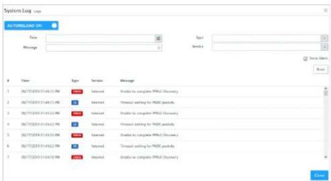
text_image
System Log Log AU TORRELOAD ON Time Message Type ServiceUser Type Service Message
1 06/15/2019 01:06:31 PMI - INRIN - InSAIL - InSAIL - InSAIL to complete PMR4 Discovery 2 06/15/2019 01:06:31 PMI - INRIN - InSAIL - InSAIL to complete PMR4 Discovery 3 06/15/2019 01:06:31 PMI - INRIN - InSAIL - InSAIL to complete PMR4 Discovery 4 06/15/2019 01:06:31 PMI - INRIN - InSAIL - InSAIL to complete PMR4 Discovery 5 06/15/2019 01:06:31 PMI - INRIN - InSAIL - InSAIL to complete PMR4 Discovery 6 06/15/2019 01:06:31 PMI - INRIN - InSAIL - InSAIL to complete PMR4 Discovery 7 06/15/2019 01:06:31 PMI - INRIN - InSAIL - InSAIL to complete PMR4 DiscoveryFigure 23: Sample filtered system log
The Close button at the bottom of the log panels allows you to shut the log panels and return to the complete overview of your configured network.
You can find more information regarding the event logs in the following sections.
Alert log
Navigate to Monitoring & Statistics > Logs > Alert Log to view the event logs for alerts and to set up display filters. In the Alert Log editing window, you can see what traffic is blocked by your LANCOM R&S® Unified Firewall or how traffic was transmitted through the firewall.
The column headers contain the following information:
Table 2: Filter types
| DescriptionColumn | |
| Timestamp of the log entry.Time | |
| Event category, which can be one of the following:Category> Application filter> Connection blocked> Connection finished> IDPS> Mail malware> Spam> Web filter allowed> Web filter blocked> Web malware | |
| Message | The log message itself. If necessary. the ☑ in the right-hand side of a message performs actions directly. For example, in the category IDPS messages about blocked services are displayed. These messages are displayed along with the signature ID that would be required in a rule to stop blocking this service. Exceptions can therefore be added directly from the log. |
3 User Interface
Filtering
You can use More Filters on the input field with different search criteria and options to narrow down the results. These filters relate to the time interval that you set under Time.

text_image
Alert Log AUTORELOAD OFF Manual Reload Time More Filter C Category Connection Field/EndTime Categories Message
127 05/16/2019 04:31:41 PM Connection Blocked Denied Access dropped-input file-gp90 OUT+ SRC-74.82.47.34 265-05.312.194.122 PROTO-TCP SPT-44326 DPT-6380.12Q-912062882 ACK-9 WINDOW-V655/5 VPK LENGTH 128 05/16/2019 04:31:40 PM Connection Blocked Denied Access dropped-input file-dFT OUT+ SRC-0.8.6.0 265-255.255.255 PROTO-UDP SPT-9346 DPT-4344 129 05/16/2019 04:31:40 PM Connection Blocked Denied Access dropped-input file-df206e91 OUT+ SRC-0.8.6.0 265-255.255.255 PROTO-UDP SPT-41561 DPT-4344Figure 24: Alert log with applied filter
Proceed as follows to create a filter:
- Click in the input field.
The web client displays suggested filters.
The available filter types, input formats and default values can be found in the Filter types table.
- Select one of the suggested filters from the drop-down list, or enter any search text to receive further suggestions.
For each suggestion, you can specify whether to use this as an inclusion filter ( AND) or exclusion filter ( AND-NOT).
After selection, the suggested filter is inserted into the input field as a search criterion.
The list of log messages is adapted to the search query. Matching log entries are highlighted.
Repeat the above steps until you have added the desired filter criteria to your query.
Only entries that match all filter criteria are displayed.
To delete a filter criterion in a search query, click on ✗
You can add multiple lines to your search by clicking on + OR next to the input field. You can choose to insert a new blank line or to copy the last created line. Each line is a separate search query, which is ORed with the other lines.

text_image
More Filters ( ) Category: Conversion Finished or + Category: Conversion Finished + Source ID: 10.106.33.252 + CR ResetFigure 25: Combined filter query
Delete the line by clicking 📋 next to the line.
Filter types
| SubtypesDefault valuesInput formatFi | |||
| Log entryFree textTextDomain / URI (log entries from HTTP proxies, virus scanners and the URL / Content Filter) | |||
| ICMP, TCP, UDPFree textProtocol | |||
| SubtypesDefault valuesInput formatFi | |||
| Transport protocols or protocols detected by the Application Filter | |||
| Numbers from 0 to 65535Port | TCP / UDP source or destination port of IPDS or firewall messages | ||
| IPv4 | Valid IP address or parts thereof | Source or destination IP address of mail proxy, IDPS, application filter, or firewall messages | |
| Category | Free text or selection from the More Filters drop-down list | > Application filter > Connection blocked > Connection finished > IDPS > Mail malware > Spam > Web filter allowed > Web filter blocked > Web malware | |
Audit Log
The Audit Log creates records about every configuration change made on your LANCOM R&S® Unified Firewall (e. g. updating the VPN settings), executed actions (e. g. importing a backup) and what caused the change or action. To display the logs, Monitoring permissions are necessary.. For more information on web client permissions, see Administrators Settings on page 25.
The table columns contain the following information:
| DescriptionColumn | |
| Time stamp of the log entry.Time | |
| Event log category, which can be one of the following:Action> Call-Executing a certain action (e. g. importing a backup)> Delete-Deleting a configuration element (e. g. deleting an expired IPsec connection)> Insert-Inserting a new configuration element (e. g. inserting a host group)> Update-Changing a configuration element (e. g. adjusting the antivirus settings) | |
| User | Name of the user that created the entry, e. g. admin. |
| Message | The log entry itself. The message content depends on theActiontype:> If theActionis Call,Messagestarts with the called endpoint.> If theActionis Delete,Messageindicates the name and the internal type of the removed configuration element.> If theActionis Insert,Messageindicates the name and the internal type of the new configuration element. It also contains the entire payload of the message that is used to create the configuration element and that contains the exact used settings.> If theActionis Update,Messageindicates the name and the internal type of the modified configuration element. It also contains the exact changes for a specific path in italics. The path identifies the settings of a configuration element which have been changed. |
System Log
The System Log displays a list of recent system events.
The table columns contain the following information:
| DescriptionColumn | |
| Time stamp of the log entry.Time | |
| Message type which can be one of the following:Type> OK - The service is working correctly.> Error - An error occurred. An error message is displayed. | |
| Name of the service that created the entry. The following filters are available:Service> Server - Firewall services, including kernel, DHCP server, DNS server, SNMP server and Wi‑Fi access point messages> VPN - IPsec and SSL tunnels> Internet - NTP, DynDNS and DSL connection status> User - Terminal login, SSH login and super user actions (sudo)> Connections - Connections that were established successfully. These message are only stored if Connection Finished in theMonitoring & Statistics > Settingsis set to Save Raw Data Locally.> Proxy - Messages regarding web and mail proxies> Updates - All messages regarding the firewall software> Appfilter - Application filter messages> IDPS - IDS/IPS messages> Alerts - Alerts related to security, irrespective of the generating engine (e. g. when the anti-malware engine detects a virus or when the IDS/IPS engine detects a thread)Alerts will only be shown in the Alerts category, even if they also belong to another category.Example: Appfilter generates an alert. The alert will only be shown in Alerts, but not in Appfilter. | |
| The log entry itself.MessageSelect Alerts in theServicecolumn to filter IDS/IPS log messages.Tip: You can use log messages to add an IDS/IPS rule to the list of ignored rules on theRulestab of theIDS/IPSeditor panel. Click ⚙n the respective IDS/IPS log message. A drop-down list opens. Select theIgnore ruleentry. The IDS/IPS rule is automatically added to the list of ignored rules on theRulestab of theIDS/IPSeditor panel. For more information, seeIDS/IPSon page 107. | |
Select the Show Alerts check box to display alerts regardless of the selected service on top of the displayed log messages.

Alerts can contain additional information about events to identify the source of an error.
SNMP Settings
SNMP (Simple Network Management Protocol) is a networking protocol that is used to offer and receive status information across a network. The participants of the SNMP-based information exchange are the SNMP manager (e.g. Nagios) and
the SNMP clients (devices such as your LANCOM R&S ^® Unified Firewall that are meant to be monitored by the SNMP manager).
The SNMP manager requests, receives and monitors information. SNMP clients respond to information requests (e.g. "What is the current CPU load/memory usage of the device?"). Status information offered by managed devices is organized like a tree (the so-called Management Information Base, short MIB), with each leaf being a retrievable piece of information. Every single leave can be addressed and requested individually via its own unique numeric address. A file containing a mapping of these numeric address snippets to meaningful names, and thereby a declaration of all information available on a managed device, can be provided to the SNMP manager to increase human usability (e.g. 29577.1.1 represents RSCS.SystemLoad.cpuLoad).
The SNMP Settings allow you to configure the following elements:
| DescriptionInput field | |
| I/O | A slider switch indicates whether the SNMP is active (1) or inactive (0). Click the slider switch to change the status. SNMP is deactivated by default. |
| Listening IP | Optional: Enter a local IP address the service will be listening on. If you retain the pre-defined IP address 0.0.0.0, requests will be accepted on all IP addresses. |
| Listening Port | Optional: Specify the port number the service will be listening on. The default port number is 161. |
| Protocol Version | From the drop-down list, select the version of the SNMP protocol you want to use. Depending on the selected version, the following options are available. v2c is selected by default. |
| Community String | Only available if the selectedProtocol Versionis v2c: Enter the pre-shared key that every SNMP manager/client has to use to authenticate to the SNMP service of the access zone. |
| Show Community String | Only available if the selectedProtocol Versionis v2c: Select this check box to verify the pre-shared key. |
| Username | Only available if the selectedProtocol Versionis v3: Enter the username that every SNMP manager/client software has to use to identify to the SNMP service of the access zone. |
| The username is created and used by the SNMP service internally. | |
| Authentication Protocol | Only available if the selectedProtocol Versionis v3: From the drop-down list, select the hashing algorithm that is used for authentication purposes. You can choose between No Authentication, MD5 and SHA. |
| Authentication Password | Only available if the selectedProtocol Versionis v3 and if the selectedAuthentication Protocolis MD5 or SHA: Enter the password you want to use for authentication. The password must consist of at least eight characters. |
| Show Authentication Password | Optional and only available if the selectedProtocol Versionis v3 and if the selectedAuthentication Protocolis MD5 or SHA: Select this check box to verify the authentication password. |
| Privacy Protocol | Optional and only available if the selectedProtocol Versionis v3 and if the selectedAuthentication Protocolis MD5 or SHA: From the drop-down list, select the hashing algorithm that is used to encrypt the communication with the SNMP service. You can choose between the encryption algorithms 3DES and AES. This option is set to No Encryption. |
| Privacy Password | Only available if the selectedProtocol Versionis v3, if the selectedAuthentication Protocolis MD5 or SHA and if the selectedPrivacy Protocolis 3DES or AES: Enter the password that is used to encrypt the communication with the SNMP service with the selected encryption algorithm. |
| Show Privacy Password | Optional and only available if the selectedProtocol Versionis v3, if the selectedAuthentication Protocolis MD5 or SHA and if the selectedPrivacy Protocolis 3DESor AES: Select this check box to verify the privacy password. |
| Location | Optional: Enter a fixed value which your LANCOM R&S®Unified Firewall returns for requests to certain Object Identifiers (OIDs) of the standard Management Information Base (MIB):sysLocation. |
| Contact | Optional: Enter a fixed value which your LANCOM R&S®Unified Firewall returns for requests to certain Object Identifiers (OIDs) of the standard Management Information Base (MIB):sysContact. |
If you have modified these settings, use the buttons at the bottom right of the editor panel allow to confirm (Save) or to discard your changes (Reset). Otherwise, you can close the dialog (Close).
Click ↕activate in the toolbar at the top of the desktop to apply your configuration changes.
Statistics
The Statistics panels contain graphics and tables. You can control several aspects of the presentation and data on these statistics.
The Statistics right is required to access the statistics and configure the settings related to them. For more information on web client permissions, see Administrators Settings on page 25.

When analyzing the statistics and configuring the settings related to them, the administrator must comply with data security regulations.
There are two ways to access the individual statistics panels:
You can use the links in the navigation bar to navigate to the detailed statistics panels, e. g. via Monitoring & Statistics > Statistics > Blocked Connections.
You can click the Details link in the top right corner of one of the chart panels on the Statistics overview. The link forwards you to the detailed statistics panel for that chart. For more information, see Overview on page 65.
Working with statistics
There are two types of statistics:
Counters are displayed as line charts on the Blocked Connections and Blocked Content statistics panels. The charts contain several counters each.
Toplists provide a ranking for different events types and are displayed as a pie chart or an area chart, depending on the selected data period. Data for the Day period is displayed as a pie chart, while data for Month and Year is displayed as a stacked area chart.
A tabular display of the graphical data complements each statistics panel. In the case of counters, the data table always displays the same data as the chart. Each statistics element creates a column in the data table. In the case of toplists, the data table displays the values of the statistics elements.
The charts and tables in the statistics panels share common functions to adjust the data display and allow you to focus on the data you are most interested in:
Under Period in the header area of the statistics panels, you can set the desired temporal scope of the data to be displayed. Use the buttons to toggle between the different data periods available. You can choose between Day, Month and Year. This option is set to Day by default.
Toplists typically contain an input field in the header area of the panels. Use the Entries field to adjust the maximum number of items to be displayed in the chart. This option is set to 5 by default. You can enter a different value or use the up and down arrows in the input field to change the value.
Regardless of the value set for the chart, the data table always displays up to 1,000 entries.
You can collapse and expand charts and tables by clicking the corresponding icon in the header area of a chart or table to expand the table or hide unnecessary details. For more information, see Icons and buttons on page 21.
Click ≡ the top right corner of a chart to access various export options (print view, PNG, JPEG, SVG, PDF, CSV and XLS) for the data displayed in the chart.
If you use the XLS export function available for toplist charts, only the data used by that chart is exported, taking into account the value you have selected for the maximum number of toplist items.
Line and area charts include a legend. The legend is color-coded and can be used as a filter for the chart. Click items in the legend below the chart to activate and deactivate them in the chart. If clicking has no effect and the legend item remains gray, data collection for the underlying event type was disabled in the statistics settings and, therefore, no data is available. For more information, see Statistics Settings on page 54.
Tooltips provide details on specific points in the graphical statistics. Hover the cursor of your mouse over the chart to see the exact values for a specific point in time.
The sections below provide further information on the data available in the statistics overview, on each detailed statistics panel and on the settings.
Blocked Connections
The Blocked Connections configuration dialog allows you to configure the following elements:
| DescriptionStatistics Element (Event Type) | |
| Rule Set Inbound (Blocked Inbound Traffic) | Number of connections blocked by input rules |
| Rule Set Outbound/Forward (Blocked Forwarded Traffic) | Number of connections blocked by forwarding rules |
| Number of IDS/IPS alerts.IPS/IDS (IDPS Alert)If the IDS/IPS mode is set to "IDS", "IPS Drop" or "IPS Reject", then this statistics element displays the number of dropped packets. For more information, see IDS/IPS on page 107. |
Blocked Content
The Blocked Content configuration dialog allows you to configure the following elements:
| DescriptionStatistics Element (Event Type) | |
| Virus (Mail) (Malware Alert (Mail)) | Number of viruses detected in e-mails |
| Virus (Other) (Malware Alert (HTTP and FTP)) | Number of viruses detected in HTTP or FTP traffic |
| Spam (Spam Alert) | Number of spam e-mails detected |
| Web Access (Web Content Blocked) | Web access blocked by content filter |
| Appfilter (Appfilter Alert) | Number of alerts regarding blocked application-specific traffic |
Overview
Navigate to Monitoring & Statistics > Statistics > Overview to view a summary of all available statistics charts. It can be considered a dashboard for Statistics and is intended to provide an initial answer to the most common questions regarding the events that your LANCOM R&S ^® Unified Firewall can detect.
3 User Interface
The following special features apply only to this panel (diverging from the description of the individual statistics panels in Statistics on page 64):
Under Period in the header area of the statistics window, you can define the desired time span to be used for all data displayed in charts.
You can click the Details link in the top right corner of an individual chart panel to be forwarded to the detailed statistics panel for the respective chart.
The number of entries for toplist charts is set to a fixed value of 5.
Top Domains Accessed
The Top Domains Accessed panel shows the web sites that have been accessed the most by local network users, if you enable your LANCOM R&S ^® Unified Firewall to collect this data and if you activate the Web Content Allowed event type. These statistics are used to determine whether web-browsing habits match the company policy and the goals of the business.
Top Domains Blocked
The Top Domains Blocked panel shows the top websites that are blocked, if you enable your LANCOM R&S ^® Unified Firewall to collect this data, by activating the Web Content Blocked event type.
Top Data Traffic per Source
The Top Traffic per Source panel shows the traffic volume for the top data traffic sources if you allow your LANCOM R&S® Unified Firewall to collect this kind of data by enabling the Connection Finished event type.
Syslog Servers
Your LANCOM R&S ^® Unified Firewall can be used to configure multiple external syslog servers to forward log messages generated by different message sources for reporting purposes.
Syslog messages are sent in cleartext (not encrypted) usually via port number 514 and either via the User Datagram Protocol (UDP) or the Transmission Control Protocol (TCP) to the remote syslog server.
You can find more information regarding external syslog servers in the following sections.
Syslog Servers Overview
Navigate to Monitoring & Statistics > Syslog Servers to display a list of remote syslog servers that are currently defined in the system and displayed in the item list bar.
In the expanded view, the table displays the server address of the external syslog server which consists of the IP address and the port. For example, the server address 192.168.124.5:514 corresponds to the IP address 192.168.124.5 using the port number 514. Furthermore, the protocol type used for the transmission of the text message is displayed. The buttons in the last column allow you to view and to adjust the settings for an existing external syslog server, create a new syslog server based on a copy of an existing syslog server or delete a syslog server from the system.
For more information, see Icons and buttons on page 21.
Syslog Servers Settings
The Syslog Servers settings allow you to specify connection details for multiple remote syslog servers to forward log messages generated by different message sources.
Under Monitoring & Statistics > Syslog Servers, you can add a new or edit an existing remote syslog server.
The Syslog Servers configuration dialog allows you to configure the following elements:
| DescriptionInput field | |
| Enter the IP address of the server.Destination IP | |
| Specify the port number to be used by entering an integer value.Destination Port | |
| From the drop-down list, select the protocol type you want to use.Transport Protocol | |
The buttons at the bottom right of the editor panel depend on whether you add a new remote syslog server or edit an existing one. For a newly configured server, click Create to add the server to the list of available remote syslog servers or Cancel to discard your changes.
If you have modified these settings, use the buttons at the bottom right of the editor panel to confirm (Save) or to discard your changes (Reset). Otherwise, you can close the dialog (Close).
Click ▼activate in the toolbar at the top of the desktop to apply your configuration changes.
3.4.3 Network
The Network settings allow you to organize your network by configuring interfaces, connections, WLAN, routing policies and DHCP settings. Furthermore, you can to set up the WAN access of your LANCOM R&S ^® Unified Firewall by configuring DNS settings, DynDNS accounts and QoS settings.
Connections
The Desktop Connections settings allow you to configure the network and PPP connections for your LANCOM R&S ^® Unified Firewall.
Network Connections
The Network Connections configuration dialog allows you to configure network connections. The system offers default connections for all available Ethernet interfaces.
You can find more information regarding the network connections in the following sections.
Network Connections Overview
Navigate to Network > Connections > Network Connections to display the list of network connections that are currently defined in the system and displayed in the item list bar.
In the expanded view, the first column of the table displays the Name of the network connection. The Status column shows one of the following status indicators:
Green – The network connection is enabled.
Gray – The network connection is disabled.
Red – The network connection is disconnected.
Furthermore, the Interface that the network connection is assigned to and the connection Type are displayed. The buttons in the last column allow you to view and to adjust the settings for an existing network connection, create a new connection based on a copy of an existing network connection or delete a network connection from the system.
For more information, see Icons and buttons on page 21.
Network Connections Settings
Use the Network Connections settings to configure custom network connections.
Under Network > Connections > Network Connections, you can add a new or edit an existing network connection.
The Network Connection panel displays the following information and allows you to configure the following elements:
| DescriptionInput field | |
| I/O | A slider switch indicates whether the network connection is active (1) or inactive (0). Click the slider switch to change the status of the connection. A new connection is active by default. |
| Enter a name for the network connection.Name | |
| ! If you leave this field empty, the name will be generated automatically from the selected interface and connection type. | |
| Interface | From the drop-down list, select the interface that you want to assign to the connection. You may select an Ethernet, VLAN or bridge interface. |
| Type | From the drop-down list, select the connection type. This option is set to Static by default, but you can adjust the settings to one of the other values as necessary:➢ Static – This mode is used to specify a fixed IP address for the connection.➢ DHCP – This mode is used to assign IP addresses dynamically. |
| ! Once you click Create to establish the network connection, you will no longer be able to change the connection type. | |
| i The elements in the Network tab depend on the selected connection type. | |
| Displays the components that use the network connection.Used by | |
| Displays the status of the network connection.StatusThe status can be one of the following:> up – The network connection is enabled.> disabled – The network connection is disabled.> disconnected – The network connection is disconnected. | |
On the Network tab:
| DescriptionInput field | |
| IP Addresses | Assign one or multiple IP addresses to the network connection. Enter an IP address in CIDR notation (IP address followed by a slash "I" and the number of bits set in the subnet mask, e. g. 192.168.50.1/24). Click Add to add the IP address to the list.You can edit or delete individual entries in the list by clicking the corresponding button next to an entry. For more information, see Icons and buttons on page 21. |
| ! If you edit an IP address, a check mark appears on the right of the entry. You have to click the check mark before being able to save the settings of the IP address.Click ▲to change the order of the IP addresses in the list. | |
| ! The IP address which is listed first in the list is used as the default source IP address for NAT and for IPsec connections. | |
| Obtain Gateway | Optional and only available if the selected connection Type is DHCP. Select this check box if you want your LANCOM R&S®Unified Firewall to obtain a gateway for the connection from the DHCP server. |
| Obtain DNS Server | Optional and only available if the selected connection Type is DHCP. Select this check box if you want your LANCOM R&S®Unified Firewall to obtain a DNS server for the connection. |
| Obtain Domain | Optional and only available if the selected connection Type is DHCP. Select this check box if you want your LANCOM R&S® Unified Firewall to obtain a domain for the connection from the DHCP server. |
| Obtained via DHCP | Optional and only available if the selected connection Type is DHCP.Displays one of the following states:➢ If the connection is working, the IP address is displayed.➢ Connection not yet saved-A new connection is being created.➢ Failed-The DHCP connection could not be established. |
On the WAN tab:
| DescriptionInput field | |
| Set Default Gateway | Optional and only available if the selected connection Type is Static. Select this check box if you want to set a default gateway for the network connection. |
| ! If you select DHCP as the connection type, this check box is always enabled and grayed out as the gateway is obtained from the DHCP server. | |
| Default Gateway | Optional and only available if the selected connection Type is Static. Enter the default gateway for this connection. |
| ! If you select DHCP as the connection type, this check box is always enabled and grayed out and displays the gateway that is obtained from the DHCP server. | |
| Time Restrictions | Optional: Select this check box if you want to set a time limit for which the connection is enabled.Click Edit to open the Time Restriction editor panel which provides the following options: > Set specific times and weekdays using the sliders.> Always On – The connection is always enabled.> Always Off – The connection is always disabled.The buttons at the bottom right of the editor panel allow you to confirm your time limit changes (OK) and to discard your changes (Cancel). The editor panel closes and the chosen option is displayed on the left of the Edit button: Restricted, Always On or Always Off. |
| Multi WAN Weight | Specify how much of the Internet traffic is routed through this connection by entering a value from 1 to 256. The higher the set value, the higher the percentage of Internet traffic routed through the connection. Setting the same value for all connections results in equal traffic distribution across all connections. |
| Desktop Object | From the drop-down list, select an Internet object that is used in firewall rules for this WAN connection. For more information, see Internet Objects on page 90. |
On the Failover tab:
| DescriptionInput field | |
| Specify how you want to test the state of the connection by adding tests.HeartbeatsThe default settings contain a ping test with the Google server (8.8.8.8). ClickAddto add another test to the list. For more information on configuring the reachability test, seeHeartbeat Settingson page 70.You can edit or delete individual entries in the list by clicking the corresponding button next to an entry. For more information, seeIcons and buttonson page 21. | |
| Use as backup connection | Optional: Select this check box to configure this connection as a backup Internet connection. |
| Backup connections | Select any backup connection you wish to assign to the connection and specify itsPriority.If the current connection fails, your LANCOM R&S®Unified Firewall switches to the available backup connection with the highest priority. ClickAddto add the backup connection to the list.You can edit or delete individual entries in the list by clicking the corresponding button next to an entry. For more information, seeIcons and buttonson page 21. |
| !If you edit a backup connection, a check mark appears on the right of the entry. You have to click the check mark before being able to save the settings of the backup connection. | |
The buttons at the bottom right of the editor panel depend on whether you add a new network connection or edit an existing one. For a newly configured connection, click Create to add it to the list of available connections or Cancel to discard your changes. To edit an existing network connection, click Save to store the reconfigured connection or Reset to discard your changes. You can click Close to shut the editor panel as long as no changes have been made on it.
Click ↕Activate in the toolbar at the top of the desktop to apply your configuration changes.
Heartbeat Settings
The Heartbeat editor panel allows you to set up automatic heartbeat tests to check the connection state. In the editor panel, you can configure the following elements:
| DescriptionInput field | |
| From the drop-down list, select the type of reachability test you want to run:Type> ping-This mode sends ping signals to the target.> tcp_probe-This mode tests the capacity of a TCP connection. | |
| Specify the timeout for the test in seconds.Timeout | |
| Set the overall number of tries to be performed.Number of tries | |
| Number of successful tries | Set the number of successful tries required for a successful heartbeat. |
| Arguments | Specify the arguments to be used in the test, e. g. IP addresses that you want to ping. |

If you have created a backup Internet connection on the Failover tab and the automatic heartbeat test defines the state of the connection as disconnected, your LANCOM R&S ^® Unified Firewall automatically switches to the backup connection with the highest priority available.
The buttons at the bottom right of the editor panel allow you to confirm your changes to the heartbeat test (OK) and to run the connection test manually (Test). You can also reject (Cancel) your changes to the test, close the editor panel and return to the Network Connection editor panel. The specified test is displayed as an entry in the list under Heartbeats on the Failover tab.
PPP Connections
Use the PPP Connections settings to configure existing connections using the Point-to-Point Protocol and to add new connections.
You can find more information regarding PPP connections in the following sections.
PPP Connections Overview
Navigate to Network > Connections > PPP Connections to display a list of PPP connections that are currently defined in the system and displayed in the item list bar.
In the expanded view, the columns of the table display the Name of the connection and the Type of the connection and if it is Active or not. The buttons in the last column allow you to view and adjust the settings for an existing PPP connection, create a new connection based on a copy of an existing PPP connection or delete a PPP connection from the system.
For more information, see Icons and buttons on page 21.
PPP Connections Settings
Under Network > Connections > PPP Connections, you can add a new or edit an existing network connection.
The PPP Connections connection settings contain the following elements:
| DescriptionInput field | |
| I/O | A slider switch indicates whether the PPP connection is active (1) or inactive (0). Click the slider switch to change the status of the connection. New PPP connections are activated by default. |
| Enter the name of the network connection.NameIf you leave this field empty, the name will be generated automatically from the selected interface and connection type. | |
| Interface | Assign an interface to the connection. You can only select a PPP interface that is not being used by another connection. |
| Type | From the drop-down list, select the connection type, depending on your Internet provider: PPPoE or PPTP. Use the PPPoE mode to connect using the Point-to-Point Protocol over Ethernet. PPPoE is typically used to share a broadband connection, such as a single DSL line or cable modem. Use the PPTP mode to connect using the Point-to-Point Tunneling Protocol. |
| ! Once you click Create to establish the PPP connection, you will no longer be able to change the connection type. | |
| i The elements in the Configuration tab depend on the selected connection type. | |
| Displays the components that use the PPP connection.Used by | |
| Status | Displays the status of the connection (up, disconnected or disabled). |
On the Configuration tab:
| DescriptionInput field | |
| Auth. Method | Select an authentication method for the connection, depending on your Internet service provider:➢ None➢ auto - Automatically selects the authentication method which best matches the Internet service provider.➢ pap-only - password authentication➢ chap-only - handshake authentication➢ ms-chap2 - handshake authentication for Microsoft |
| Enter the username required to connect to your Internet service provider.Usage | |
| Enter the password required to connect to your Internet service provider.Password | |
| If you chose PPTP as connection type, enter the IP address of the PPTP server.PPTP Server IP | |
| MPPE | If you chose PPTP as connection type, select the Microsoft Point-to-Point Encryption key length: > mppe-40 > mppe-56 > mppe-128 |
| Local IP | Optional: Enter your local IP address only if explicitly required by your Internet service provider. |
| Remote IP | Optional: Enter your remote IP address only if explicitly required by your Internet service provider. |
| AC Hardware Address | Optional: Enter the hardware MAC address of the Access Concentrator used by your Internet service provider. Only do so if your Internet service provider explicitly requires this. |
| Force disconnect | Optional: Select this check box if you want to enforce a disconnect process at a specified time. To enter the time, use the HH:MM:SS format. Some Internet service providers force a disconnect at specific intervals (usually every 24 hours). With this setting enabled, your LANCOM R&S ^ Unified Firewall disconnects at a specific time thereby preventing the auto-disconnect from the Internet service provider. This allows you to control when the disconnect happens. |
On the WAN tab:
| DescriptionInput field | |
| Time Restrictions | Select this check box if you want to set a time limit for which the connection is enabled.Click Edit to open the Time Restrictions editor panel which provides the following options:> Set specific times and weekdays using the sliders.> Always On - The connection is always enabled.> Always Off - The connection is always disabled. |
| Multi WAN Weight | Specify how much of the Internet traffic is routed through this connection by entering a value from 1 to 256. The higher the set value, the higher the percentage of Internet traffic routed through the connection. Setting the same value for all connections results in equal traffic distribution across all connections. |
| Desktop Object | From the drop-down list, select an Internet object that is used in firewall rules for this connection. For more information, see Internet Objects on page 90. |
On the Failover tab:
| DescriptionInput field | |
| Specify how you want to test the state of the connection by adding ping tests.HeartbeatsThe default settings contain a ping test with the Google server (8.8.8.8). ClickAddto add another test to the list. For more information on configuring the reachability test, seeHeartbeat Settingson page 73.You can edit or delete individual entries in the list by clicking the corresponding button next to an entry. For more information, seeIcons and buttonson page 21. | |
| Use as backup connection | Select this check box to configure this connection as a backup Internet connection. |
| Backup connections | Select any backup connection you wish to assign to the connection and specify itsPriority.If the current connection fails, your LANCOM R&S®Unified Firewall switches to the available backup connection with the highest priority. ClickAddto add the backup connection to the list.You can edit or delete individual entries in the list by clicking the corresponding button next to an entry. For more information, see Icons and buttons on page 21. |
Heartbeat Settings
The Heartbeats panel allows you to configure automatic heartbeat tests. The editor panel contains the following elements:
| DescriptionInput field | |
| From the drop-down list, select the type of reachability test you want to run:Type> ping - This mode sends ping signals to the target.> tcp_probe - This mode tests the capacity of a TCP connection. | |
| Specify the timeout for the test in seconds.Timeout | |
| Set the overall number of tries to be performed.Number of tries | |
| Number of successful tries | Set the number of successful tries required for a successful heartbeat. |
| Arguments | Specify the arguments to be used in the test, e. g. IP addresses that you want to ping. |
Click Test to run the connection test manually. Click OK to save your settings and to return to the Network Connection panel.
The buttons at the bottom right of the editor panel depend on whether you add a new PPP connection or edit an existing one. For a newly configured connection, click Create to add it to the list of available PPP connections or Cancel to discard your changes. To edit an existing PPP connection, click Save to store the reconfigured connection or Reset to discard your changes. You can click Close to shut the editor panel as long as no changes have been made on it.
Click ✅activate in the toolbar at the top of the desktop to apply your configuration changes.
DHCP Settings
Navigate to Network > DHCP Settings to configure the DHCP settings on your LANCOM R&S ^® Unified Firewall.
| DescriptionInput field | |
| I/0 | A slider switch indicates whether DHCP is active (1) or inactive (0). Click the slider switch to change the status. |
| Operation Mode | Choose if you want to set up a DHCP server or a DHCP relay. The remaining fields on the screen depend on the chosen operation mode. |
DHCP Server Settings
With the DHCP server running on your LANCOM R&S ^® Unified Firewall, you can assign IP addresses and transfer them to other configuration parameters (Gateway, DNS server, NTP server, etc.). Alternatively, it is possible to forward DHCP requests to an existing DHCP server on another network.
Configure the following elements for the DHCP server:
| DescriptionInput field | |
| Default Lease Time | Enter the default lease time (in seconds) to determine the amount of time that the IP address of a computer is valid. |
| Enter the maximum lease time (in seconds).Maximum Lease Time | |
| Prevent IP Conflicts | Select this check box to have the DHCP server ping an IP address to verify that it is not yet in use before assigning it to a new client. |
| Interfaces | This table displays all interfaces (Ethernet, VLAN and bridge) on which a static connection has been configured and their DHCP settings.Click to open the DHCP Settings editor panel of the respective interface. |
The DHCP Settings configuration dialog allows you to configure the following elements for an interface:
| DescriptionInput field | |
| I/O | A slider switch indicates whether the DHCP server is active (I) or inactive (O) for this interface. By clicking the slider switch, you can toggle the state of the DHCP server for this interface. |
On the General tab:
| DescriptionInput field | |
| Network | From the drop-down list, select the subnet whose IP addresses are distributed by the DHCP server. By selecting the subnet, theRange Start IPand theRange End IPinput fields are automatically prefilled with the respective IP range. |
| Range Start IP | If the prefilled start IP address does not meet your requirements, adjust the entry to specify the range of IP addresses that are distributed to the client computers. |
| Range End IP | If the prefilled end IP address does not meet your requirements, adjust the entry to specify the range of IP addresses that are distributed to the client computers. |
| Make sure that the permanent IP addresses are not within the IP address range of the DHCP server as permanent IP addresses are not excluded automatically during dynamic address assignment. Otherwise, addresses may be assigned twice. | |
| Lease Time | Specify the time (in minutes) that the IP address of a computer is valid. The default lease time is 60 minutes. |
| Gateway | If the prefilled gateway IP address to be pushed to the client does not meet your requirements, adjust the entry. The default gateway IP address is usually the IP address of your LANCOM R&S®Unified Firewall. |
| WINS server | Optional: If there is a WINS server in the network, use this input field to communicate it to the clients. |
| Preferred NTP server / Alternative NTP server | Optional: Clients may use NTP servers to determine the exact time. This is particularly important for user authentication via Windows servers. |
| Preferred DNS server / Alternative DNS server | If your LANCOM R&S®Unified Firewall does not carry out name resolution, enter internal DNS servers that are located in the network or the Internet. Otherwise, the clients are allocated the IP address of your LANCOM R&S®Unified Firewall as their DNS server. |
| DNS Search Domains | Specify a DNS search domain that the DNS service uses to resolve host names that are not fully qualified domain names.Clickto add the DNS search domain to the list.You can edit or delete individual entries in the list by clicking the corresponding button next to an entry. For more information, seeIcons and buttonson page 21. |
| If you edit an entry, a check box appears on the right of the entry. Activate the check box to apply your changes. |
On the Static IP Addresses tab:
| DescriptionInput field | |
| MAC Address / IP Address / Host Name | Specify a static IP address for a host in the network by entering the host's MAC address and IP address. Additionally, you can enter the host name. Click Add to add the static IP address to the list.You can edit or delete individual entries in the list by clicking the corresponding button next to an entry. For more information, see Icons and buttons on page 21. |
| ! If you edit an entry, a check box appears on the right of the entry. Activate the check box to apply your changes. | |
| Add from ARP Cache | From the drop-down list, select the addresses that you want to add to the ARP cache. |
Click OK to save your settings and to return to the DHCP Settings panel.
DHCP Relay Settings
A DHCP relay redirects incoming requests to a DHCP server to another network as DHCP requests cannot be routed.
| DescriptionInput field | |
| DHCP Server IP Address | Enter the IP address of the server to which the DHCP requests will be redirected. |
| Relay through these interfaces | Select one or more interfaces from which DHCP requests will be forwarded. Also, select the interface that the DHCP server is connected to. |
If you modify these settings, click Save to save your changes or Reset to discard them. Otherwise, click Close to close the editor panel.
Click ▼Activate in the toolbar at the top of the desktop to apply your configuration changes.
DNS Settings
Navigate to Network > DNS Settings to configure the DNS settings on your LANCOM R&S ^® Unified Firewall.

Usually, the DNS server settings are provided by the WAN connection. You should have to configure the DNS server settings only if you cannot obtain them over the WAN connection.
The DNS Settings configuration dialog allows you to configure the following elements:
| DescriptionInput field | |
| Acquire DNS server | Select this check box to connect to a DNS server selected by the provider's router. |
| ! If you use several Internet lines from different providers, make sure that the DNS servers you use can be reached from all lines. If necessary, use public DNS servers on the Internet. | |
| Specify an alternative DNS server by entering its IP address.Nameserver | |
If you modify these settings, click Save to save your changes or Reset to discard them. Otherwise, click Close to close the editor panel.
Click ↕Activate in the toolbar at the top of the desktop to apply your configuration changes.
DynDNS Accounts
To connect to your LANCOM R&S ^® Unified Firewall from the external network, e. g. with a VPN connection, the IP address of your device has to be recognized on the Internet. Using dynamic DNS ("DynDNS"), your LANCOM R&S ^® Unified Firewall retrieves a fixed host name (e. g. yourcompany.dyndns.org) on the Internet, even if it has no fixed public IP address. This is accomplished by sending the current IP address to a DynDNS provider that maps it to a domain name so that the firewall is accessible using that domain name. If, for example, the IP address changes due to a DSL disconnect forced by your Internet service provider, the IP address is re-sent to the DynDNS provider. This behavior ensures that the dynamic DNS always points to the current IP address.

To set up DynDNS on your LANCOM R&S ^® Unified Firewall, you require a configured DynDNS account with a DynDNS provider. For more information about dynamic DNS and to register for the dynamic DNS process, go to www.dyndns.org.
You can find more information regarding dynamic DNS accounts in the following sections.
DynDNS Accounts Overview
Navigate to Network > DynDNS Accounts to display a list of DynDNS accounts that are currently defined in the system and displayed in the item list bar.
In the expanded view, the columns of the table display the DynDNS account's Hostname, Server Type and Status. The buttons in the last column allow you to view and to adjust the settings for an existing DynDNS account, create a new account based on a copy of an existing account or delete an account from the system.
For more information, see Icons and buttons on page 21.
DynDNS Accounts Settings
Under Network > DynDNS Accounts, you can add a new or edit an existing DynDNS account for WAN access in general.
The DynDNS Account configuration dialog allows you to configure the following elements:
| DescriptionInput field | |
| I/O | A slider switch indicates whether the DynDNS account is active (1) or inactive (0). Click the slider switch to change the status of the DynDNS account. A new DynDNS account is activated by default. |
| Internet Connection | From the drop-down list, select the Internet connection used by this account. |
| Server Type | From the drop-down list of supported DynDNS services, select the type of server to be used. |
| Hostname | DynDNS services provide a domain name entry under their authority. Consequently, a registered host always has the suffix of the service provider (e.g. yourname.dynamicdns.org). Enter the entire host name into this input field. |
| Enter the user name with which your account is registered with the DynDNS provider.Usage | |
| Enter the password with which your account is registered with the DynDNS provider.Password | |
| Optional: Select this check box to verify the password.Show Password | |
| Custom Server Address | Optional: Enter the address of the server if your DynDNS provider requires the definition of a different server address. |
| Optional: If you want to use an MX record, enter its IP address or host name.MX Record | |
| Wildcards | Optional: Select this check box to activate the use of wildcards in host names if you plan to use subdomains of your DynDNS account (Example:*.yourname.dynamicdns.org will resolve for any domain ending with yourname.dynamicdns.org). |
The buttons at the bottom right of the editor panel depend on whether you add a new DynDNS account or edit an existing one. For a newly configured account, click Create to add the account to the list of available DynDNS accounts or Cancel to discard your changes. To edit an existing account, click Save to store the reconfigured account or Reset to discard your changes. You can click Close to shut the editor panel as long as no changes have been made on it.
Click ✅activate in the toolbar at the top of the desktop to apply your configuration changes.
Interfaces
Navigate to Network > Interfaces to configure Ethernet, VLAN, Bridge, PPP and WLAN interfaces. The item list bar displays an overview of all interfaces, that are currently defined in the system.
Bond Interfaces
Use the Bond Interfaces settings to combine multiple physical Ethernet interfaces into one logical bond interface. Depending on its mode of operation, a bond interface offers the following two advantages:
Load balancing – A bond interface provides increased bandwidth by using all aggregated Ethernet interfaces in parallel to transmit data.
High availability – If one Ethernet interface fails, data can still be received and transmitted on the remaining Ethernet interfaces.
You can add as many bond interfaces as you like as long as there are available Ethernet interfaces that are not used by other interfaces or in any network connections.
You can find more information regarding bond interfaces in the following sections.
Bond Interfaces Overview
Navigate to Network > Interfaces > Bond Interfaces to display a list of bond interfaces that are currently defined in the system and displayed in the item list bar.
In the expanded view, the first column of the table displays the Name of the bond interfaces. The Status column shows one of the following status indicators:
Green – The bond interface is up.
Gray – The bond interface is disabled.
Furthermore, the webclient shows the Ports (i. e. Ethernet interfaces) that are assigned to the bond interface. The buttons in the last column allow you to view and to adjust the settings for an existing bond interface or to delete one from the system.
For more information, see Icons and buttons on page 21.
Bond Interfaces Settings
Use the Bond Interfaces settings to configure user-defined bond interfaces.
Under Network > Interfaces > Bond Interfaces, you can add a new or edit an existing bond interface.
The Bond Interface panel displays the following information and allows you to configure the following elements:
| DescriptionInput field | |
| I/O | A slider switch indicates whether the bond interface is active (1) or inactive (0). Click the slider switch to change the status of the bond interface. New bond interfaces are activated by default. |
| Name | Displays the name of the bond interface. The name is filled in automatically. Bond interfaces are numbered in the order they are created, starting with bond0. |
| Displays the hardware address (MAC address) of the bond interface.Hardware Address | |
| Used by | Display the network components (e. g. connections, other interfaces, etc.) that use the bond interface. |
| Mode | From the drop-down list, select the mode of operation for the bond interface, specifying how the multiple Ethernet interfaces are to be aggregated.The option is set to IEEE 802.1AX (LACP, Direct connection) by default, but you can adjust the settings to the other values as necessary:> Balance - Round-Robin (Trunk, Direct connection)- This mode provides load balancing and high availability. Packets are transmitted in sequential order from the first available aggregated Ethernet interface through the last, then continuing with the first aggregated Ethernet interface again.> Active-Backup (Bridge, Direct connection) -This mode provides high availability only. Data is transmitted and received by the active Ethernet interface (i. e. the first Ethernet interface in the list) only as long as it is not faulty. When the first Ethernet interface fails, the next Ethernet interface in the list is used to transmit and receive data.> Balance - XOR (Trunk, Direct connection) -This mode provides load balancing and high availability. Packets are transmitted on all Ethernet interfaces. A simple algorithm (layer2+3 XOR) is applied to decide which Ethernet interface is used to transmit the data.> Broadcast (Trunk, Direct connection) -This mode provides high availability only. Packets are transmitted simultaneously on all Ethernet interfaces.> IEEE 802.1AX (LACP, Direct connection) -This mode provides load balancing and high availability by using the LACP (Link Aggregation Control Protocol) standard. Packets are transmitted on all Ethernet interfaces. A simple algorithm (layer2+3 XOR) is applied to decide which Ethernet interface is used to transmit the data.> Balance - TLB (Bridge) -This mode provides load balancing and high availability. In addition to the simple selection algorithm (layer 2+3 XOR), the current load of the Ethernet interface is taken into account when deciding which Ethernet interface is to be used to transmit the data.> Balance - ALB (Bridge) -This mode provides load balancing and high availability. Data is received using ARP negotiation. In addition to the simple selection algorithm (layer 2+3 XOR), the current load of the Ethernet interface is taken into account when deciding which Ethernet interface is to be used to transmit the data. |
| Ports | Add the Ethernet interfaces that you want to aggregate into one logical link by clicking the input field. You can add as many available Ethernet interfaces as you like. |
| You can select only Ethernet interfaces that are not used by other interfaces or in any network connections.The selected Ethernet interfaces are displayed in a table at the bottom of the panel.To delete an element from the input field, click × to the left of the entry. | |
| MTU | Set the maximum size of each packet (in bytes). The maximum transmission unit can be any integer from 64 to 16384. |
The buttons at the bottom right of the editor panel depend on whether you add a bond interface or edit an existing one. For a newly configured bond interface, click Create to add it to the list of available bond interfaces or Cancel to discard your changes. To edit an existing bond interface, click Save to save the reconfigured interface or Reset to discard your changes. You can click Close to shut the editor panel as long as no changes have been made on it.
Click ▼activate in the toolbar at the top of the desktop to apply your configuration changes.
Bridge Interfaces
Use the Bridge Interfaces settings to connect two interfaces and their networks on Layer 2, forming a common broadcast domain.
You can find more information regarding bridge interfaces in the following sections.
Bridge Interfaces Overview
Navigate to Network > Interfaces > Bridge Interfaces to display a list of bridge interfaces that are currently defined in the system and displayed in the item list bar.
In the expanded view, the first table column displays the Name of the bridge interface. The Status column shows one of the following status indicators:
Green – The bridge interface is enabled.
Orange – The bridge interface is disabled.
Furthermore, the web client shows the Ports that are assigned to the bridge interface. The buttons in the last column allow you to view and to adjust the settings for an existing bridge interface, create a bridge interface based on a copy of an existing bridge interface or delete a bridge interface from the system.
For more information, see Icons and buttons on page 21.
Bridge Interfaces Settings
Use the Bridge Interfaces settings to configure custom bridge interfaces.
Under Network > Interfaces > Bridge Interfaces, you can add a new or edit an existing bridge interface.
The Bridge Interface panel displays the following information and allows you to configure the following elements:
| DescriptionInput field | |
| I/O | A slider switch indicates whether the bridge interface is active (1) or inactive (0). Click the slider switch to change the status of the bridge interface. New bridge interfaces are activated by default. |
| Name | Displays the name of the bridge interface. The name is generated automatically. Bridges are numbered in the order they are created, starting with br0. |
| Displays the hardware address of the bridge interface.Hardware Address | |
| Used by | Displays the network components (e. g. connections, other interfaces, etc.) that use the bridge interface. |
| Ports | Add the ports that the interface will bridge by clicking the input field. You can select any number of VLAN interfaces or other bridge interfaces.To delete an element from the input field, click × to the left of the entry.The selected ports are displayed in a table at the bottom of the panel. |
| !Bridges cannot be created using interfaces which are already used in another bridge. | |
| MTU | Set the maximum size of each packet (in bytes). The maximum transmission unit can be any integer from 64 to 16384. |
| Spanning Tree Protocol | Optional: Select this check box to enable the Spanning Tree Protocol. It is disabled by default. |
| Priority | Only available ifSpanning Tree Protocolis enabled: Set the bridge priority. Enter a multiple of 4096 in the range of 4096 to 61440. |
| Hello Interval | Only available ifSpanning Tree Protocolis enabled: Set the hello interval (in seconds). Enter any integer from 1 to 10.This table displays the ports selected in the bridge interface. PortsIf Spanning Tree Protocol is enabled, the buttons on the right of each entry allow you to configure the Priority and the Cost for the respective port, and to remove the port from the bridge interface. |
The buttons at the bottom right of the editor panel depend on whether you add a bridge interface or edit an existing one. For a newly configured bridge interface, click Create to add it to the list of available bridge interfaces or Cancel to discard your changes. To edit an existing bridge interface, click Save to store the reconfigured bridge or Reset to discard your changes. You can click Close to shut the editor panel as long as no changes have been made on it.
Click ↕activate in the toolbar at the top of the desktop to apply your configuration changes.
Ethernet Interfaces
The physical Ethernet Interfaces receive the following default IP addresses: 192.168.X.254/24 (X being the number of the interface, i.e. the IP address of eth0 is 192.168.0.254).
You can find more information regarding Ethernet interfaces in the following sections.
Ethernet Interfaces Overview
Navigate to Network > Interfaces > Ethernet Interfaces to display a list of Ethernet interfaces that are currently defined in the system and displayed in the item list bar.
In the expanded view, the first table column displays the Name of the Ethernet interface. The Status column shows one of the following status indicators:
Green – The Ethernet interface is up.
Gray – The Ethernet interface is disabled.
Furthermore, the Speed of the Ethernet interface is displayed. The button in the last column allows you to view and to adjust the settings for an existing Ethernet interface.
For more information, see Icons and buttons on page 21.
Ethernet Interfaces Settings
Under Network > Interfaces > Ethernet Interfaces, you can display more detailed information on the available Ethernet interfaces and adjust the settings.
The Ethernet Interface panel displays the following information and allows you to configure the following elements:
| DescriptionInput field | |
| Name | Displays the name of the Ethernet interface, e. g. eth0. |
| Displays a short description of the Ethernet interface.Description | |
| Displays the hardware address (Ethernet MAC address) of the Ethernet interface.Hardware Address | |
| Displays the connection that is currently using the Ethernet interface.Used by | |
| Displays the status of the Ethernet interface.StatusThe status can be one of the following:> up – The Ethernet interface is enabled.> disabled – The Ethernet interface is disabled. | |
| Displays the speed (e. g. in Gbit/s) of the Ethernet interface.Speed | |
| Duplex | Displays the duplex mode of the Ethernet interface, e. g. full. |
| Type | Displays the type of wiring connected to the interface, e. g. twisted pair. |
| I/O | A slider switch indicates whether the Ethernet interface link is active (I) or inactive (O). Click the slider switch to change the status of the Ethernet interface link. |
| MTU | Set the maximum size of each packet (in bytes). The maximum transmission unit can be any integer from 64 to 16384. |
If you modify the settings, click Save to save your changes or Reset to discard them. Otherwise, click Close to close the editor panel.
Click ✕Activate in the toolbar at the top of the desktop to apply your configuration changes.
PPP Interfaces
The PPP Interfaces settings allow you to create interfaces that use the point-to-point protocol.
You can find more information regarding PPP interfaces in the following sections.
PPP Interfaces Overview
Navigate to Network > Interfaces > PPP Interfaces to display a list of PPP interfaces that are currently defined in the system and displayed in the item list bar.
In the expanded view, the first column of the table displays the Name of the PPP interface. The Status column shows one of the following status indicators:
Green – The PPP interface is enabled.
Orange – The PPP interface is disabled.
Furthermore, the Master Interface that the PPP interface is associated with is displayed. The buttons in the last column allow you to view and to adjust the settings for an existing PPP interface, create a PPP interface based on a copy of an existing PPP interface or delete a PPP interface from the system.
For more information, see Icons and buttons on page 21.
PPP Interfaces Settings
Use the PPP Interfaces settings to configure custom PPP interfaces.
Under Network > Interfaces > PPP Interfaces, you can add a new or edit an existing PPP interface.
The PPP Interfaces configuration dialog allows you to configure the following elements:
| DescriptionInput field | |
| I/O | A slider switch indicates whether the PPP interface is active (1) or inactive (0). Click the slider switch to change the status of the PPP interface link. New PPP interfaces are activated by default. |
| Master Interface | From the drop-down list, select the Ethernet, VLAN or bridge interface that the PPP interface is associated with. |
| LCP Echo Interval | Specify at which interval (in seconds) your LANCOM R&S®Unified Firewall sends an echo request to the peer by entering an integer value from 1 to 1800. |
| LCP Echo Failure | Specify the number of LCP echo failures after which the peer is considered dead by entering an integer value from 0 to 64. If you enter 0, failures are ignored. |
| MTU | Set the maximum size of each packet (in bytes). The maximum transmission unit can be any integer from 64 to 16384. |
| MRU | Specify the maximum receive unit by entering an integer value from 128 to 16384. |
The buttons at the bottom right of the editor panel depend on whether you add a new PPP interface or edit an existing one. For a newly configured PPP interface, click Create to add it to the list of available PPP interfaces or Cancel to discard your changes. To edit an existing PPP interface, click Save to store the reconfigured interface or Reset to discard your changes. You can click Close to shut the editor panel as long as no changes have been made on it.
Click ✅activate in the toolbar at the top of the desktop to apply your configuration changes.
VLAN Interfaces
The VLAN Interfaces configuration dialog allows you to configure to add custom virtual local area network (VLAN) tags to all traffic to a given interface.
You can use this method to create "virtual interfaces" that allow you to put several logical network zones on one physical interface. When you associate a VLAN tag with a network interface, the tag is added to all outgoing packets that are sent through this virtual interface and stripped from the incoming packets that are received on this VLAN. You can associate several VLANs with each network interface. Packets with different tags can be processed and associated with the corresponding interface.
You can find more information regarding VLAN interfaces in the following sections.
VLAN Interfaces Overview
Navigate to Network > Interfaces > VLAN Interfaces to display a list of VLAN interfaces that are currently defined in the system and displayed in the item list bar.
In the expanded view, the first column of the table displays the Name of the VLAN interface. The Status column shows one of the following status indicators:
Green – The VLAN interface is enabled.
Orange – The VLAN interface is disabled.
Furthermore, the Master Interface that the VLAN is associated with and the VLAN Tag are displayed. The buttons in the last column allow you to view and to adjust the settings for an existing VLAN interface, create an interface based on a copy of an existing one or delete an interface from the system.
For more information, see Icons and buttons on page 21.
VLAN Interfaces Settings
Use the VLAN Interfaces settings to configure custom VLAN tags to be added to all traffic on a given interface.
Under Network > Interfaces > VLAN Interfaces, you can add a new or edit an existing VLAN interface.
The VLAN Interface panel displays the following information and allows you to configure the following elements:
| DescriptionInput field | |
| I/O | A slider switch indicates whether the VLAN interface is active (1) or inactive (0). Click the slider switch to change the status of the VLAN interface link. New VLAN interfaces are activated by default. |
| Name | Displays the name of the VLAN interface. The name is generated automatically and contains the VLAN Tag and the underlying Master Interface. |
| Hardware Address | For edited VLAN interfaces only: Displays the hardware address (MAC address) of the underlying Master Interface. |
| Used by | Displays the network components (e. g. connections, other interfaces, etc.) that use the VLAN interface. |
| Master Interface | For edited VLAN interfaces only: From the drop-down list, select the Ethernet or bridge interface that the VLAN interface is associated with.For edited VLAN interfaces only: Displays the Ethernet or bridge interface that is associated with the VLAN interface. |
| VLAN Tag | Enter the text content of the VLAN tag. The tag may contain any integer from 1 to 4094. |
| MTU | Set the maximum size of each packet (in bytes). The maximum transmission unit is limited to the MTU value of the underlying master interface. |
| ! Due to a kernel restriction, the maximum MTU value is limited by the MTU value of the underlying interface. | |
The buttons at the bottom right of the editor panel depend on whether you add a new VLAN interface or edit an existing one. For a newly configured VLAN interface, click Create to add it to the list of available VLAN interfaces or Cancel to discard your changes. To edit an existing VLAN interface, click Save to save the reconfigured VLAN interface or Reset to discard your changes. You can click Close to close the editor panel as long as no changes have been made on it.
Click ✅activate in the toolbar at the top of the desktop to apply your configuration changes.
Quality of Service (QoS)
Under Network > QoS you can set up Quality of Service for your Internet connections, in other words, for the network and PPP connections for which you configured a default gateway.
Quality of Service (QoS) prioritizes the processing of queued network packets in your LANCOM R&S® Unified Firewall based on Type of Service (ToS) flags. This way, performance-critical applications like Voice over IP (RTP) can be prioritized.
A precondition for Quality of Service is that applications or devices (such as VoIP telephone systems) set the ToS field in IP data packets. Your LANCOM R&S ^® Unified Firewall then sorts the packets based on the value of the ToS field and assigns them to several queues with different priorities. Data packets from the queue with the highest priority are forwarded immediately. Data packets from queues with lower priority are only forwarded when all the queues with higher priority have been emptied.
QoS Settings
Navigate to Network > QoS > QoS Settings to open en editor panel to view, activate and adjust the Quality of Service settings.
The QoS Settings configuration dialog allows you to configure the following elements:
| DescriptionInput field | |
| I/O | A slider switch indicates whether Quality of Service is active (1) or inactive (0). Click the slider switch to change the status of QoS. |
| QoS Services | Enter a Service for which you want to activate QoS. Specify the hexadecimal Value of the ToS field which defines the application or the device for the service.Click ➕ to add the service to the list. You can edit or delete individual entries in the list by clicking the corresponding button next to an entry. For more information, see Icons and buttons on page 21. |
| ⚠️ If you edit an entry, a check box appears on the right of the entry. Activate the check box to apply your changes.Click ▲ of drag and drop an entry to change the priority of the services. The service which is listed first in the list has the highest priority. |
If you modify these settings, click Save to save your changes or Reset to discard them. Otherwise, click Close to close the editor panel.
QoS Connections
The Connections configuration dialog allows you to configure Quality of Service connections.

QoS connections are only established if Quality of Service is enabled for Internet connections. For more information, see QoS Settings on page 83.
You can find more information regarding QoS connections in the following sections.
QoS Connections Overview
Navigate to Network > QoS > Connections to display a list of QoS connections that are currently defined in the system and displayed in the item list bar.
In the expanded view, the columns of the table display the connection's name and the download and upload bandwidth thresholds. The buttons in the last column allow you to view and to adjust the settings for an existing QoS connection or to delete a connection from the system.
For more information, see Icons and buttons on page 21.
QoS Connections Settings
The QoS Connection configuration dialog allows you to configure the following elements for Quality of Service:
| DescriptionInput field | |
| Internet Connection | From the drop-down list, select the Internet connection you want to configure Quality of Service for. |
| Download Rate/Upload Rate | To activate Quality of Service, enter the bandwidth thresholds that you want to reserve for QoS services for this connection. The input fields define the maximum download and upload bandwidth (in Kbit/s).If you set both values to 0, Quality of Service will not be used for this connection. |
If you have modified these settings, use the buttons at the bottom right of the editor panel to confirm (Save) or to discard your changes (Reset). Otherwise, you can close the dialog (Close).
Routing
Use the Routing settings to configure routing tables and routing rules.
The routing settings allow you to define custom routes that are used to reach devices on a given destination network.

Routes between network objects are created automatically and hidden. You should not normally need to create routes unless you have an upstream router that requires special routes. To influence traffic between network objects, create a firewall rule as described under Firewall Rule Settings on page 23.
Routing Rules
Routing rules specify which packets are managed by which routing table. This allows for more differentiated routing as routing rules include more fields of the IP header in the routing decision, whereas routing tables only consider the destination IP address.
Routing Rules Overview
Navigate to Network > Routing Rules to display the list of routing rules that are currently defined on the system.
The plus button +above the filter settings allows you to add new routing rules.
The Filter Settings allow you to narrow down the list of results in the table to display only entries that include a certain search string. You can filter the contents by selecting the required options from the drop-down list and/or entering search strings in the respective input fields. Click Apply to make use of the selected filter options. The list of routing rules is adjusted to reflect your filter results. Click Reset to delete the selected filter options and display an unfiltered view of the list of routing rules.
The table columns of the routing rules list display the priority of the routing rule, the selectors that can be used to define which traffic should be routed where and whether it is a system rule or not. The buttons in the last column allow you to view and adjust the settings of a routing rule or to delete a rule from the system.
For more information, see Icons and buttons on page 21.

System routing rules cannot be modified or deleted.
To close the Routing Rules panel, click ✗ in the upper right corner of the panel.
Routing Rules Settings
Under Network > Routing Rules, you can add a new or edit an existing routing rule.
The Routing Rule configuration dialog allows you to configure the following elements:
| DescriptionInput field | |
| Priority | Set the priority of the routing rule by entering an integer value from 64 to 32767 for custom rules.The rules are sorted by priority in ascending order. This means the system runs through the rules list starting with the system rule with priority 0 until all selectors in a rule match the packet. The action of this rule is then carried out. |
| Source Subnet | Optional: Enter the IP address of the source subnet in CIDR notation (IP address followed by a slash "/” and the number of bits set in the subnet mask, e. g. 192.168.50.0/24). |
| Destination Subnet | Optional: Enter the IP address of the destination subnet in CIDR notation (IP address followed by a slash "/” and the number of bits set in the subnet mask, e. g. 192.168.50.0/24). |
| Input Interface | Optional: Select one of the interfaces defined on your LANCOM R&S®Unified Firewall as the input interface. |
| Output Interface | Optional: Select one of the interfaces defined on your LANCOM R&S®Unified Firewall as the output interface. |
| TOS | Optional: Specify the Type of Service value by entering a hexadecimal number from 0 to FF. |
| Specify the rule action:Action> Goto – Enter the Priority of another routing rule. If a packet matches the selectors in the rule, it goes to the rule with the specified goto priority.> Table – Enter the number of a routing table. If a packet matches the selectors in the rule, it runs through the specified routing table. If one of the routes in the table matches the packet, it is routed accordingly. Otherwise, the packet continues to run through the routing rules list.This parameter is displayed in the Action Parameter table column of the routing rules list (for more information, seeRouting Rules Overviewon page 84). | |

If you specify none of the selectors, the entire traffic matches the rule.
The buttons at the bottom right of the editor panel depend on whether you add a new routing rule or edit an existing one. For a newly configured routing rule, click Create to add the rule to the list of available routing rules or Cancel to
reject the creation of the new rule. To edit an existing rule, click Save to store the reconfigured rule or Reset to discard your changes. You can click Close to shut the editor panel as long as no changes have been made on it.
Routing Tables
Routing tables route packets through the network based on the destination IP address.
You can find more information regarding routing tables in the following sections.
Routing Tables Overview
Navigate to Network > Routing > Routing Tables to display the list of routing tables that are currently defined in the system and displayed in the item list bar.
Clear the Show configurable tables only check box to display all tables on the system. Otherwise, only tables that can be edited are displayed.
The following tables are preset on the system:
Table 254 is the main routing table. You can add custom routes to this table. The entries are then adopted for all existing routing tables.
Table 255 contains local routes for all configured interfaces.
Tables 1 to 63 are reserved for the management of the Internet connections.
Tables 64 to 250 are reserved for routes with a source address and appear with a source IP address during the set-up of routes.
Table 293 is reserved for the transparent proxy.
In the expanded view, the columns of the table display the name of the routing table. The buttons in the last column allow you to view and adjust the settings of a routing table or to delete a table from the system.
For more information, see Icons and buttons on page 21.
Routing Tables Settings
The Routing Tables settings allow you to add a new or edit existing routing tables.
The Routing Table configuration dialog allows you to configure the following elements:
| DescriptionInput field | |
| Table Number | Enter an ID for the routing table. Custom routing tables receive the ID 512 or higher. You must configure routing rules pointing to custom routing tables, otherwise those tables are not used (seeRouting Ruleson page 84). |
| Routes | This table displays the custom routes that are specified in the routing table. ClickAddto open theEdit Routepanel and define a new route. You can edit or delete individual entries in the list by clicking the corresponding button next to an entry. |
The Edit Route configuration dialog allows you to configure the following elements:
| DescriptionInput field | |
| Destination | Enter the IP address of the destination network in CIDR notation (IP address followed by a slash “/” and the number of bits set in the subnet mask, e. g. 192.168.50.0/24). |
| Select an interface for the route.Interface | |
| Gateway | Enter an IP address as the gateway for this route. Traffic from the source zone to the destination network will be routed using this gateway (rather than the standard gateway). |
| Select the address type from the drop-down list.Type | |
| Only packets with the selected sender address will be routed.Preferred Source | |
| Metric | Define the costs for the route. The value entered here concerns routing protocols. A higher metric means the route is considered costly and is less likely to be chosen. |
Click OK to save your routing settings and to return to the Routing Table panel.
The buttons at the bottom right of the editor panel depend on whether you add a new routing table or edit an existing one. For a newly configured routing table, click Create to add the table to the list of available routing tables or Cancel to discard your changes. To edit an existing routing table, click Save to store the reconfigured table or Reset to discard your changes. You can click Close to shut the editor panel as long as no changes have been made on it.
3.4.4 Desktop
The 📄 Desktop settings display a list of all available services and the firewall rules defined in the system.
Desktop Connections
Navigate to Desktop > Desktop Connections to display and edit the connections between various desktop objects that are defined on the system.
Desktop Connections Overview
In the expanded view, the columns of the table display the nodes of the desktop connection. The buttons in the last column allow you to view and to adjust the settings for an existing desktop connection, create a connection based on a copy of an existing desktop connection or delete a connection from the system.
For more information, see Icons and buttons on page 21.

Copied desktop connections are always set up between the same nodes as the original.
Desktop Connections Settings
When you edit a desktop connection, the Connection panel opens. Under Description, you can enter additional information regarding the desktop connection for internal use.
On the Rules tab, you can modify the rule set for this connection. For more information on creating firewall rules, see Firewall Rule Settings on page 23.
The URL / Content Filter tab allows you to configure the URL and content filter for this connection:
| DescriptionInput field | |
| Block all by default | Select this check box to add all URL filters that are currently defined on the system to the blacklist and to select all content filters. |
| Displays the name of the URL and content filter.Name | |
| URL Filter Black/White | Add the URLs in the respective filters to the blacklist or whitelist by clicking the corresponding check boxes. |
| Select the content filters by clicking the corresponding check boxes.Content Filter | |
| Schedule | Displays whether the filter is always active, always inactive or active on a customized time schedule.Click the entry to modify the schedule. |
If you have created application filter profiles (see Application Filter on page 104), you can enable or disable the application filter for this desktop connection. On the Application Filter tab, you can set the Mode of the application filter to Blacklist or Whitelist or disable the application filter for each selected profile by selecting the respective radio button.
3 User Interface
If you modify these settings, click Save to save your changes or Reset to discard them. Otherwise, click Close to close the editor panel.
Click ✅activate in the toolbar at the top of the desktop to apply your configuration changes.
For more information on URL, content and application filters, see URL/Content Filter on page 113 and Application Filter on page 104.
Desktop Objects
Use the Desktop Objects settings to organize your network by setting up single and group objects for hosts, users, networks, VPN and IP ranges. The created objects are displayed as nodes on the desktop and can be used as sources and/or destinations in connections to apply firewall rules.
The item list bar displays an overview of all desktop objects, subdivided into types of desktop objects, that are currently defined on the system. When you click an entry in the item list bar, the nodes of all desktop objects that this desktop tag is assigned to are highlighted on the desktop.
To create a desktop object, click the ✕ button at the top of the respective section in the item list bar. Alternatively, click the respective desktop object icon in the toolbar at the top of the desktop.
For more information, see Icons and buttons on page 21.
The sections below provide further information on the various types of desktop objects.
Host/Network Groups
Create desktop objects for host and network groups that can be used to create connections between multiple hosts or networks and other desktop objects (such as VPN objects, etc.). Host and network groups can be used as sources and/or destinations to apply firewall rules and web filters to multiple computers.
Host/Network Groups Overview
Navigate to Desktop > Desktop Objects > Host/Network Groups to display the list of host and network group objects that are currently defined in the system and displayed in the item list bar.
In the expanded view, the first table column displays the Name of the host or network group object. The buttons in the last column allow you to view and to adjust the settings for an existing host or network group object, create an object based on a copy of an existing object or delete an object from the system.
For more information, see Icons and buttons on page 21.
Host/Network Groups Settings
The Host / Network Group settings allow you to configure the following elements:
| DescriptionInput field | |
| Specify a name for the host or network group object.Name | |
| Description | Optional: Enter additional information on the host or network group object for internal use. |
| Tags | Optional: From the drop-down list, select the desktop tags that you want to assign to the host or network group object. For more information, see Desktop Tags on page 98. |
| Select the color to be used for this object on the desktop.Color | |
| Hosts / Networks | Specify the hosts or networks that you want to add to the host or network group object. Define the Name, whether login is allowed, the Interface, and the IP address of the host or network. Click Add to add a host or network to the list.You can edit or delete individual entries in the list by clicking the corresponding button next to an entry. For more information, see Icons and buttons on page 21.! If you edit an entry, a check box appears on the right of the entry. Activate the check box to apply your changes. |
The buttons at the bottom right of the editor panel depend on whether you add a new host or network group object or edit an existing object. For a newly configured object, click Create to add the object to the list of available host and network groups or Cancel to discard your changes. To edit an existing object, click Save to store the reconfigured object or Reset to discard your changes. You can click Close to shut the editor panel as long as no changes have been made on it.
Click ▼Activate in the toolbar at the top of the desktop to apply your configuration changes.
Hosts
Create a host object that can be used to create connections between the host and other desktop objects (such as VPN objects etc.). A host (for example a printer or a VoIP phone) can be assigned a dedicated IP address so that firewall rules can be specifically applied to it. For more information on creating firewall rules, see Firewall Rule Settings on page 23.
Hosts Overview
Navigate to Desktop > Desktop Objects > Hosts to display the list of host objects that are currently defined in the system and displayed in the item list bar.
In the expanded view, the columns of the table display the Name and the IP of the host object and to which interface it is connected. The buttons in the last column allow you to view and to adjust the settings for an existing host object, create an object based on a copy of an existing host object or delete an object from the system.
For more information, see Icons and buttons on page 21.
Hosts Settings
The Host configuration dialog allows you to configure the following elements:
| DescriptionInput field | |
| Specify a name for the host object.Name | |
| Optional: Enter more information on how to use the host object internally.Description | |
| Tags | Optional: From the drop-down list, select the desktop tags that you want to assign to the host object. For more information, see Desktop Tags on page 98. |
| Select the color to be used for this object on the desktop.Color | |
| Allow login | Select this check box to allow users to log in to your LANCOM R&S®Unified Firewall using the IP address range of this host object. This allows your LANCOM R&S®Unified Firewall to apply user-specific firewall rules to the user currently logged on. |
| Select an icon to represent the host on the desktop.Icon | |
| Select an interface that the host is connected to-connected to | |
| Enter the IP address of the host object.IP Address | |
The buttons at the bottom right of the editor panel depend on whether you add a new host object or edit an existing object. For a newly configured object, click Create to add the object to the list of available host objects or Cancel to discard your changes. To edit an existing object, click Save to store the reconfigured object or Reset to discard your changes. You can click Close to shut the editor panel as long as no changes have been made on it.
Click ▼activate in the toolbar at the top of the desktop to apply your configuration changes.
Internet Objects
Create Internet objects for your Internet connections. Internet objects are used to create connections between other desktop objects (such as VPN objects) and the Internet.
Internet Objects Overview
Navigate to Desktop > Desktop Objects > Internet Objects to display the list of Internet objects that are currently defined in the system and displayed in the item list bar.
In the expanded view, the first table column displays the Object Name of the Internet object. The buttons in the last column allow you to view and to adjust the settings for an existing Internet object, create an object based on a copy of an existing one or delete an Internet object from the system.
For more information, see Icons and buttons on page 21.
Internet Objects Settings
The Internet Object configuration dialog allows you to configure the following elements:
| DescriptionInput field | |
| Specify a name for the Internet object.Object Name | |
| Optional: Enter additional information on the Internet object for internal use.Description | |
| Tags | Optional: From the drop-down list, select the desktop tags that you want to assign to the Internet object. For more information, seeDesktop Tagson page 98. |
| Select the color to be used for this object on the desktop.Color | |
| Connections | Select the Internet connection(s) that this object is part of. For more information, seeNetwork Connections Settingson page 67. |
The buttons at the bottom right of the editor panel depend on whether you add a new Internet object or edit an existing object. For a newly configured object, click Create to add the object to the list of available Internet objects or Cancel to discard your changes. To edit an existing object, click Save to store the reconfigured object or Reset to discard your changes. You can click Close to shut the editor panel as long as no changes have been made on it.
Click ✕activate in the toolbar at the top of the desktop to apply your configuration changes.
For more information on creating Internet objects, see Enabling Internet Access on page 15.
IP Ranges
Create an IP address range object to group hosts by indicating a start and end IP address. If a DHCP server is configured for the selected interface, you can also use the address range of the DHCP server.
IP Ranges Overview
Navigate to Desktop > Desktop Objects > IP Ranges to display the list of IP range objects that are currently defined in the system and displayed in the item list bar.
In the expanded view, the columns of the table display the Object Name of the IP range object, the Interface it is connected to, as well as its Start IP and End IP. The buttons in the last column allow you to view and to adjust the settings for an existing IP range object, create an object based on a copy of an existing IP range object or delete an object from the system.
For more information, see Icons and buttons on page 21.
IP Ranges Settings
The IP Range settings allow you to configure the following elements:
| DescriptionInput field | |
| Specify a name for the IP range object.Name | |
| Optional: Enter additional information on the IP range object for internal use.Description | |
| Tags | Optional: From the drop-down list, select the desktop tags that you want to assign to the IP range object. For more information, see Desktop Tags on page 98. |
| Select the color to be used for this object on the desktop.Color | |
| Allow login | Select this check box to allow the user to log in to your LANCOM R&S®Unified Firewall using the IP range of this object. This allows your LANCOM R&S®Unified Firewall to apply user-specific firewall rules to the user currently logged in. |
| Interface | Select an interface to assign it to the IP range object. Select any if you do not want to assign this object to a certain interface. This way, all interfaces will accept packets from the IP range of this object. |
| Specify the start IP address of the IP range.Start IP | |
| Specify the end IP address of the IP range.End IP | |
If you want to use the IP address range of the DHCP server of the selected interface, click the Use DHCP IP range button at the bottom left of the editor panel.
The buttons at the bottom right of the editor panel depend on whether you add a new IP range object or edit an existing object. For a newly configured object, click Create to add the object to the list of available IP range objects or Cancel to discard your changes. To edit an existing object, click Save to store the reconfigured object or Reset to discard your changes. You can click Close to shut the editor panel as long as no changes have been made on it.
Click ↕Activate in the toolbar at the top of the desktop to apply your configuration changes.
Networks
Create a network object that can be used to create connections between the network and other desktop objects (such as VPN objects, etc.).
Networks Overview
Navigate to Desktop > Desktop Objects > Networks to display a list of network objects that are currently defined in the system and displayed in the item list bar.
In the expanded view, the columns of the table display the Name and the IP of the network objects and to which Interface it is connected. The buttons in the last column allow you to view and to adjust the settings for an existing network object, create an object based on a copy of an existing network object or delete an object from the system.
For more information, see Icons and buttons on page 21.
Networks Settings
The Network configuration dialog allows you to configure the following elements:
| DescriptionInput field | |
| Enter a name for the network object.Name | |
| Optional: Enter additional information on the network object for internal use.Description | |
| Tags | Optional: From the drop-down list, select the desktop tags that you want to assign to the network object. For more information, see Desktop Tags on page 98. |
| Select the color to be used for this object on the desktop.Color | |
| Allow login | Select this check box to allow the user to log in to your LANCOM R&S®Unified Firewall using the IP address of this network object. This setting allows your LANCOM R&S®Unified Firewall to apply user-specific firewall rules to the current user. |
| Select the interface that the network is connected to.Interface | |
| Network IP | Enter the IP address of the network in CIDR notation (IP address followed by a slash "/” and the number of bits set in the subnet mask, for example 192.168.50.0/24). |
The buttons at the bottom right of the editor panel depend on whether you add a new network object or edit an existing object. For a newly configured object, click Create to add the object to the list of available network objects or Cancel to discard your changes. To edit an existing network, click Save to store the reconfigured network or Reset to discard your changes. You can click Close to shut the editor panel as long as no changes have been made on it.
Click ✅activate in the toolbar at the top of the desktop to apply your configuration changes.
User Groups
Create desktop objects for user groups that can be used to create connections between multiple users and other desktop objects (such as VPN objects etc.) applying a common rule set to multiple users.
User Groups Overview
Navigate to Desktop > Desktop Objects > User Groups to display a list of user group objects that are currently defined in the system and displayed in the item list bar.
In the expanded view, the first table column displays the Name of the user group object. The buttons in the last column allow you to view and to adjust the settings for an existing user group object, create an object based on a copy of an existing one or delete a user group object from the system.
For more information, see Icons and buttons on page 21.
User Groups Settings
The User Group configuration dialog allows you to configure the following elements:
| DescriptionInput field | |
| Specify a name for the user group object.Name | |
| Description | Optional: Enter more information on how to use the user group object for internal use. |
| Tags | Optional: From the drop-down list, select the desktop tags that you want to assign to the user group object. For more information, seeDesktop Tagson page 98. |
| Select the color to be used for this object on the desktop.Color | |
| Select the users you want to add to the user group.UserThe left-hand list displays the users in the group. The right-hand list displays the users available in the system that are not part of the group.To add a user to the group, clickClickadd all available users at once.To remove a user from the group, click>clicktoremove all users at once.Use theFilterfield to narrow down the list of users to display only entries that include a certain search string. Clickto display an unfiltered view of the list of users. | |
| !Users may belong to several groups. | |
The buttons at the bottom right of the editor panel depend on whether you add a new user group or edit an existing group. For a newly configured group, click Create to add the group to the list of available user groups or Cancel to discard your changes. To edit an existing group, click Save to store the reconfigured group or Reset to discard your changes. You can click Close to shut the editor panel as long as no changes have been made on it.
Click ✅Activate in the toolbar at the top of the desktop to apply your configuration changes.
Users
Create desktop objects for users that can be used to display the users on the desktop and to create connections between the users and other desktop objects (such as VPN objects etc.).

The menu Desktop > Desktop Objects > Users only serves to create desktop objects for users that already exist in the system. For information on how to add and manage users, see User Authentication on page 44.
Users Overview
Navigate to Desktop > Desktop Objects > Users to display a list of user objects that are currently defined in the system and displayed in the item list bar.
In the expanded view, the columns of the table display the user object's Name and the User Name related to it. The buttons in the last column allow you to view and to adjust the settings for an existing user object, create an object based on a copy of an existing user object or delete a user object from the system.
For more information, see Icons and buttons on page 21.
Users Settings
The User configuration dialog allows you to configure the following elements:
| DescriptionInput field | |
| Specify a name for the user object.Object Name | |
| Optional: Enter additional information on the user object for internal use.Description | |
| Tags | Optional: From the drop-down list, select the desktop tags that you want to assign to the user object. For more information, seeDesktop Tagson page 98. |
| Select the color to be used for this object on the desktop.Color | |
| Select the user to be used for the object.User Name | |
| !Users may belong to several user objects. | |
The buttons at the bottom right of the editor panel depend on whether you add a new user object or edit an existing object. For a newly configured object, click Create to add the object to the list of available user objects or Cancel to discard your changes. To edit an existing object, click Save to store the reconfigured object or Reset to discard your changes. You can click Close to shut the editor panel as long as no changes have been made on it.
Click ↕Activate in the toolbar at the top of the desktop to apply your configuration changes.
VPN Groups
Create a VPN group object that can be used to create connections between multiple VPN connections and other desktop objects applying a common rule set to multiple VPN connections.
VPN Groups Overview
Navigate to Desktop > Desktop Objects > VPN Groups to display the list of VPN group objects that are currently defined in the system and displayed in the item list bar.
In the expanded view, the first table column displays the Name of the VPN user group object. The buttons in the last column allow you to view and to adjust the settings for an existing VPN user group object, create an object based on a copy of an existing one or delete a VPN user group object from the system.
For more information, see Icons and buttons on page 21.
Settings for VPN groups
The VPN Group settings allow you to adjust the following parameters:
| DescriptionInput box | |
| Enter an name for the VPN group object here.Name | |
| Optional: Enter further information about the VPN group object for internal use.Description | |
| Tags | Optional: From the drop-down list, select the desktop tags you want to assign to the VPN group object. Please refer to Desktop Tags on page 98 for further information. |
| Select the color to use for this object on the desktop.Color | |
| Select the VPN connections you want to add to the VPN group.VPN ConnectionsFirst select the Type of the VPN connection you want to add from the drop-down list. In the next field, select the desired connection from the drop-down list. In the case of IPSec connections, the last box lets you choose whether the connection should use all of the configured remote networks, or just a specific one. The desktop rules are then applied accordingly. Click on Add to add the connection to the list.You can edit or delete any entry in the lists by clicking on the appropriate icon. Please refer to Icons and buttons on page 21 for further information. | |
| When you edit an entry, a checkmark will appear to the right of the entry. Click the checkmark to accept the change. | |
| VPN connections can be assigned to multiple VPN groups. | |
The buttons available at the bottom right of the edit box depend on whether you are adding a new VPN group object or editing an existing object. For a new object, click Create to add it to the list of VPN group objects, or Cancel to discard your changes. To edit an existing object, click Save to save the newly configured object, or Reset to discard your changes. If no changes have been made, you can click Close to close the editing window.
Click ↕Activate in the toolbar at the top of the desktop to apply your configuration changes.
VPN Hosts
Create a VPN host object that can be used to configure firewall rules for VPN Client-to-Site connections.
VPN Hosts Overview
Navigate to Desktop > Desktop Objects > VPN Hosts to display a list of VPN host objects that are currently defined in the system and displayed in the item list bar.
In the expanded view, the columns of the table display the Name of the VPN host object, the Type of VPN connection and the VPN connection that the VPN host belongs to. The buttons in the last column allow you to view and to adjust the settings for an existing VPN host object, create an object based on a copy of an existing VPN host object or delete an object from the system.
For more information, see Icons and buttons on page 21.
VPN Hosts Settings
The VPN Host configuration dialog allows you to configure the following elements:
| DescriptionInput field | |
| Specify a name for the VPN host object.Name | |
| Optional: Enter additional information on the VPN host object for internal use.Description | |
| Tags | Optional: From the drop-down list, select the desktop tags that you want to assign to the VPN host object. For more information, see Desktop Tags on page 98. |
| Select the color to be used for this object on the desktop.Color | |
| Select an icon to represent the VPN host object on the desktop.Icon | |
| Select the type of VPN connection by clicking the respective radio button.VPN Connection Type | |
| IPsec Connection /VPN-SSL Connection | This field depends on the selected VPN connection type. Select the connection you want to associate to the VPN host object from the drop-down list. |
The buttons at the bottom right of the editor panel depend on whether you add a new VPN host object or edit an existing object. For a newly configured object, click Create to add the object to the list of available VPN host objects or Cancel to discard your changes. To edit an existing object, click Save to store the reconfigured object or Reset to discard your changes. You can click Close to shut the editor panel as long as no changes have been made on it.
Click ↕activate in the toolbar at the top of the desktop to apply your configuration changes.
VPN Networks
Create a VPN network object that can be used to configure firewall rules for VPN Site-to-Site connections.
VPN Networks Overview
Navigate to Desktop > Desktop Objects > VPN Networks to display a list of VPN network objects that are currently defined in the system and displayed in the item list bar.
In the expanded view, the columns of the table display the Name of the VPN network object, the Type of VPN connection and the VPN connection that the VPN network belongs to. The buttons in the last column allow you to view and to adjust the settings for an existing VPN network object, create an object based on a copy of an existing VPN network object or delete an object from the system.
For more information, see Icons and buttons on page 21.
Settings for VPN networks
In the VPN Network editing window you can modify the following parameters:
| DescriptionInput box | |
| Enter an name for the VPN network object here.Name | |
| Optional: Enter further information about the VPN network object for internal use.Description | |
| Tags | Optional: From the drop-down list, select the desktop tags you want to assign to the VPN network object. Please refer to Desktop Tags on page 98 for further information. |
| Select the color to use for this object on the desktop.Color | |
| Select the type of VPN connection by selecting the appropriate radio button.VPN Connection Type | |
| IPsec Connection / VPN-SSL Connection | This field depends on the selected connection type. From the drop-down list, select the VPN connection you want to assign to the VPN network object. |
| Remote networks | If you have selected an IPSec connection, you can either use all of the configured remote networks or explicitly add the remote networks to be used. |
The buttons available at the bottom right of the edit box depend on whether you are adding a new VPN network object or editing an existing object. For a new object, click Create to add it to the list of VPN network objects, or Cancel to
3 User Interface
discard your changes. To edit an existing object, click Save to save the newly configured object, or Reset to discard your changes. If no changes have been made, you can click Close to close the editing window.
Click ✅activate in the toolbar at the top of the desktop to apply your configuration changes.
VPN User Groups
Create desktop objects for VPN user groups that can be used to create connections between multiple users and other desktop objects applying a common rule set to multiple VPN users. VPN user groups are displayed at the VPN node on the desktop.
VPN User Groups Overview
Navigate to Desktop > Desktop Objects > VPN User Groups to display a list of VPN user group objects that are currently defined in the system and displayed in the item list bar.
In the expanded view, the first table column displays the Name of the VPN user group object. The buttons in the last column allow you to view and to adjust the settings for an existing VPN user group object, create an object based on a copy of an existing one or delete a VPN user group object from the system.
For more information, see Icons and buttons on page 21.
VPN User Groups Settings
The VPN User Group configuration dialog allows you to configure the following elements:
| DescriptionInput field | |
| Specify a name for the VPN user group.Name | |
| Description | Optional: Enter additional information on the VPN user group object for internal use. |
| Tags | Optional: From the drop-down list, select the desktop tags that you want to assign to the VPN user group. For more information, seeDesktop Tagson page 98. |
| Select the color to be used for this object on the desktop.Color | |
| Select the users you want to add to the VPN user group.UserThe left-hand list displays the users in the group. The right-hand list displays the users available in the system that are not part of the group.To add a user to the group, clickClickadd all available users at once.To remove a user from the group, click>clicktoremove all users at once.Use theFilterfield to narrow down the list of users to display only entries that include a certain search string. Clickto display an unfiltered view of the list of users. | |
| !Users may belong to several VPN user groups. | |
The buttons at the bottom right of the editor panel depend on whether you add a new VPN user group or edit an existing group. For a newly configured group, click Create to add the group to the list of available VPN user groups or Cancel to discard your changes. To edit an existing group, click Save to store the reconfigured group or Reset to discard your changes. You can click Close to shut the editor panel as long as no changes have been made on it.
Click ▼activate in the toolbar at the top of the desktop to apply your configuration changes.
VPN Users
Create desktop objects for users that can be used in VPN connections. VPN users are displayed at the VPN node on the desktop.

The menu Desktop > Desktop Objects > VPN Users only serves to create desktop objects for users that already exist in the system. For information on how to add and manage users, see User Authentication on page 44.
VPN Users Overview
Navigate to Desktop > Desktop Objects > VPN Users to display a list of VPN user objects that are currently defined in the system and displayed in the item list bar.
In the expanded view, the columns of the table display the Object Name of the VPN user object and the User Name. The buttons in the last column allow you to view and to adjust the settings for an existing VPN user object, create an object based on a copy of an existing VPN user object or delete an object from the system.
For more information, see Icons and buttons on page 21.
VPN Users Settings
The VPN User settings allow you to configure the following elements:
| DescriptionInput field | |
| Specify a name for the VPN user object.Object Name | |
| Optional: Enter additional information on the VPN user object for internal use.Description | |
| Tags | Optional: From the drop-down list, select the desktop tags that you want to assign to the VPN user object. For more information, seeDesktop Tagson page 98. |
| Select the color to be used for this object on the desktop.Color | |
| Select the user to be used for the VPN user object.User Name | |
| !Users may belong to multiple user objects. | |
The buttons at the bottom right of the editor panel depend on whether you add a new VPN user object or edit an existing object. For a newly configured object, click Create to add the object to the list of available VPN user objects or Cancel to discard your changes. To edit an existing object, click Save to store the reconfigured object or Reset to discard your changes. You can click Close to shut the editor panel as long as no changes have been made on it.
Click ✅activate in the toolbar at the top of the desktop to apply your configuration changes.
Desktop Rules
Use the Desktop Rules settings to display and modify the rules which are used to manage network traffic. For more detailed information on firewall rules, see Firewall Rule Settings on page 23.
Navigate to Desktop > Desktop Rules to display the list of rules that are currently defined on the system.
The Filter Settings allow you to narrow down the list of rules to display only rules that include a certain search string. You can filter the contents by selecting the required options from the drop-down lists and/or entering search strings in the respective input fields. Click Apply to make use of the selected filter options. The list of firewall rules is adjusted to reflect your filter results. Click Reset to delete your selected filter options and display an unfiltered view of the list of rules.
The table columns of the rules list display the following information:
| DescriptionColumn | |
| This column indicates the source object in the connection.Object A | |
| This column displays the direction in which the rule is applied.Direction | |
| This column indicates the destination object in the connection.Object B | |
| This column displays the name of the service of the rule.Service | |
The buttons in the last column allow you to view and to adjust the settings for an existing rule. Click 🔔 and the Connection dialog opens. For more detailed information on how to create firewall rules and editing connections, see Firewall Rule Settings on page 23 and Desktop Connections on page 87.
To close the Desktop Rules panel and return to the desktop, click ✗ in the upper right corner of the panel.
Desktop Tags
Under Desktop Tags you can create a list of tags that you can assign to any of the desktop objects, except to the Firewall root node and the main nodes (for example Intranet). You can use these tags to display a filtered desktop for a customized overview of your configured network. For more information, see Desktop on page 19.

When restoring a backup from an LCOS FX version prior to 10.0, the layers and regions that were defined in the desktop configuration are converted to tags. All desktop objects which lie on a layer or region are tagged with the converted tags.
Desktop Tags Overview
Navigate to Desktop > Desktop Tags to display the list of desktop tags that are currently defined in the system and displayed in the item list bar.
In the expanded view, the first column of the table displays the Name of the desktop tag. The buttons in the last column allow you to view and adjust the settings for an existing desktop tag, create a tag based on a copy of an existing desktop tag or delete a tag from the system.
For more information, see Icons and buttons on page 21.
When you click an entry in the item list bar, the nodes of all desktop objects that this desktop tag is assigned to are highlighted on the desktop. When you click a desktop object node on the desktop with the Desktop Tags item list bar being open, the desktop tags that are assigned to this desktop object are highlighted in the item list bar.
Desktop Tags Settings
Under Desktop > Desktop Tags, you can add a new or edit an existing desktop tag.
The Desktop Tag configuration dialog allows you to configure the following elements:
| DescriptionInput field | |
| Enter a name for the desktop tag.Name | |
The buttons at the bottom right of the editor panel depend on whether you add a new desktop tag or edit an existing one. For a newly configured desktop tag, click Create to add the tag to the list of available desktop tags or Cancel to discard your changes. To edit an existing desktop tag, click Save to store the reconfigured tag or Reset to discard your changes. You can click Close to shut the editor panel as long as no changes have been made on it.
Click ✅Activate in the toolbar at the top of the desktop to apply your configuration changes.
Desktop Export
Navigate to Desktop > Export to create a report of the current desktop configuration and to transfer the report to your computer.
The Export panel allows you to choose between the PDF and the HTML file format by selecting the respective radio button.
text_image
Export Desktop Export Desktop Configuration as PDF HTML Cancel ExportFigure 26: Desktop export – Selecting the file format for the report
The export file contains a reproduction of the current desktop and a table containing all configured firewall rules, including additional information such as NAT, DMZ, IP addresses of host objects and the content of the description fields of the configured desktop objects and desktop connections.
| Source | Action | NAT | Destination | Service | Rule Settings | Connection Settings |
| external_malgate 100.249.1.25 | - | - | WaspBank | SMTP 25 kbp | CPZ: Apache Port: 35 | |
| - | - | IMAP4 140 kbp, 999 kbp, 585 kbp | CPZ: Apache Port: 35 | |||
| supplier_portal 100.249.1.25 | - | SAP 192.368.13.27 | SAP 5000 - 2390 kbp, 3300 - 2300 kbp, 4000 - 4899 kbp, 8000 - 8899 kbp | |||
| SupplierX MIL Support2 | - | supplier_portal 197.368.1.25 | HTTPS 444 kbp | |||
| roederriers Software_Simark (SSL) | - | Malbervers 192.368.1.25 - 192.368.1.26 | SMTP 25 kbp | |||
| - | IMAP4 140 kbp, 999 kbp, 585 kbp | |||||
| Office 100.249.33/629 | - | Malbervers-Backend nulbanw2: 192.268.1.25 nulbanw2: 192.268.1.24 | SMTP 27 kbp | |||
| - | IMAP4 140 kbp, 999 kbp, 585 kbp | |||||
| roederriers Software_Simark (SSL) | - | SAP 197.368.11.27 | SAP 5000 - 1294 kbp, 1300 - 2364 kbp, 8000 - 4899 kbp, 8000 - 8899 kbp |
Figure 27: Desktop export example

Desktop objects will only be included if they are connected to other desktop objects.
If you want to create and transfer the export file, click Export. Otherwise, click Cancel to close the editor panel.
Services
Navigate to Desktop > Services to display a list of services and service groups that are currently defined in the system and displayed in the item list bar. Services are protocols or combinations of protocols and ports (if protocols use ports, such as TCP and UDP). When you click an entry in the item list bar, the nodes of all desktop objects that this desktop tag is assigned to are highlighted on the desktop. When you click an object on the desktop, the system highlights the services it uses in the list of services.
To create a user-defined service or a service group, click the ✕ button at the top of the respective section in the item list bar.
For more information, see Icons and buttons on page 21.
The sections below provide further information on the various types of services and on service groups.
Predefined Services
Navigate to Desktop > Services > Predefined Services to display a list of predefined services that are currently defined in the system and displayed in the item list bar.
In the expanded view, the columns of the table display the Name of the service, indicate whether the service is used in a connection (green) or not (orange), and show the Ports used by the service.
The predefined services are available for use in custom firewall rules (see Setting Up a Firewall Rule on page 23).
Service Groups
Use the Service Groups settings to group predefined and user-defined services in a service group. This way, you can assign a similar set of rules to different connections without having to add each service individually.
Service Groups Overview
Navigate to Desktop > Services > Service Groups to display the list of service groups that are currently defined in the system and displayed in the item list bar.
In the expanded view, the table columns display the Name of the service group and the number of Services belonging to this group. The buttons in the last column allow you to view and to adjust the settings for an existing service group, create a new group based on a copy of an existing service group or delete a service group from the system.
For more information, see Icons and buttons on page 21.
Service Groups Settings
Use the Service Groups settings to configure service groups.
Under Desktop > Services > Service Groups, you can add a new or edit an existing service group.
The Service Group configuration dialog allows you to view and to configure the following elements:
| DescriptionInput field | |
| Enter a name for the service group.Name | |
| Services | Along with theService Grouppanel, a service selection list bar with all services that are currently defined on the system opens on the right side ofthe browser window. The list bar is subdivided into categories of services which serve a similar purpose. You can collapse and expand the categories by clicking the corresponding icon. For more information, seeIconsand buttonson page 21.TheFilterinput field at the top of the service selection list bar helps you quickly find a particular service. As you type in the input field, your LANCOM R&S®Unified Firewall reduces the list to show only the services that contain the characters you are typing. Click 📄 the input field to delete the search string and display an unfiltered view of the list.To add an individual service to the service group, click 📋 front of the service in the service selection list bar. Click thebutton directly below the header of a category to add all services belonging to that category at once.The services appear along with the ports and/or protocols assigned to them as entries in the list. To remove a service from the service group, click 📋 next to the entry. |
| TheClear servicesbutton at the bottom left of the panel allows you to delete all services from the group at once. | |
The buttons at the bottom right of the editor panel depend on whether you add a new service group or edit an existing group. For a newly configured service group, click Create to add the group to the list of available service groups or Cancel to reject the creation of a new service group. To edit an existing service group, click Save to store the reconfigured group or Reset to discard your changes. You can click Close to shut the editor panel as long as no changes have been made on it.
Click ✅activate in the toolbar at the top of the desktop to apply your configuration changes.
The service groups defined here are available for use in custom firewall rules (see Setting Up a Firewall Rule on page 23 for further information).
User-defined Services
If you require a port or protocol that is not covered by any of the predefined services (see Predefined Services on page 99), you can create a custom service to be applied to a connection.
Navigate to Desktop > Services > User-defined Services to display the list of user-defined services that are currently defined in the system and displayed in the item list bar.
User-defined Services Overview
In the expanded view, the columns of the table display the Name of the service, indicate whether the service is used in a connection (green) or not (orange), and show the Ports and protocols used by the service. The buttons in the last column allow you to view and to adjust the settings of a user-defined service, create a service based on a copy of an existing user-defined service or delete a user-defined service from the system.
For more information, see Icons and buttons on page 21.
User-defined Services Settings
Under Desktop > Services > User-defined Services, you can add a new or edit an existing user-defined service.
The User-defined Services configuration dialog allows you to configure the following elements:
| DescriptionInput field | |
| Enter a name for the user-defined service.Name | |
| Ports / Protocols | To extend the user-defined service to apply to traffic to certain ports/port ranges and/or protocols, click Add to open the Edit Service panel.On this panel, you can define the ports and protocols to be used:For TCP and UDP, specify individual ports or ranges to extend the service to apply to traffic being transmitted to a certain destination port. Use the Port From and To input fields to enter a value. The value can be any integer from 1 to 65535.Port From and To form a port range. To enter an individual port, use the same value for both fields or leave To blank.Specify a protocol to apply the service to by selecting the corresponding check boxThe buttons at the bottom right of the editor panel allow you to confirm your changes (OK) and to discard your changes (Cancel). The Edit Service panel shuts automatically.The specified ports/port ranges and/or the protocol appear as a list entry. You can edit or delete individual entries in the list by clicking the corresponding button next to an entry. For more information, see Icons and buttons on page 21. |
The buttons at the bottom right of the editor panel depend on whether you add a new user-defined service or edit an existing one. For a newly configured user-defined service, click Create to add it to the list of available services or Cancel to discard your changes. To edit an existing user-defined service, click Save to store the reconfigured service or Reset to discard your changes. You can click Close to shut the editor panel as long as no changes have been made on it.
Click ✅Activate in the toolbar at the top of the desktop to apply your configuration changes.
The user-defined services defined here are available for use in custom firewall rules (see Setting Up a Firewall Rule on page 23).
3.4.5 UTM
The UTM settings allow you to create and edit application filter profiles, define URL/content filters and to configure antivirus, e-mail security settings, and proxies to protect your network.
Antivirus Settings
Your LANCOM R&S ^® Unified Firewall protects your internal network against computer viruses with an integrated Avira virus scanner.

The virus scanner is included in the UTM license. When you boot your LANCOM R&S ^® Unified Firewall for the first time, the virus scanner runs as a test version for 30 days. When this period has expired, the virus scanner is deactivated automatically. For more information, see License on page 36.
Navigate to UTM >Antivirus Settings to open an editor panel to display, activate and adjust the antivirus settings for your web and e-mail proxy.
In the Antivirus Settings dialog you can view and configure the following information:
| DescriptionInput field | |
| This field displays the license information for your virus scanner.License | |
| Updates | This field shows the date on which the virus scanner tried to update last. ClickUpdate now to update the virus scanner manually. |
| Last Successful Update | This field shows the time and date of the last successful update of the virus scanner. |
Scanner
On the Scanner tab, you can activate or deactivate the virus scanner for e-mails, HTTP(s) and FTP and modify the antivirus settings.
| DescriptionInput field | |
| I/O | A slider switch indicates whether the virus scanner is active (1) or inactive (0) for e-mails, HTTP(s) and FTP.Click the slider switch to change the status.This option is activated for all services by default. |
| Enable Cloud Scan | This check box is not selected by default. Activate the check box to allow the scanning of files on Avira Protection Cloud.If the local antivirus application does not identify a file as a threat but as a risk, the file is hashed and will be sent to the Avira Protection Cloud. If the hash is known, this information is sent back as a result If the hash is unknown, the file is uploaded to the Avira Protection Cloud and checked. |
| This comparison only happens if the local antivirus application assesses the file's risk class as sufficiently high. | |
| Scan archived files | This check box is selected by default. Clear the check box if you do not want the virus scanner to check archived files for viruses. |
| Block files if scan fails | Activate this check box to block e-mails and the download of HTTP(S) and FTP files that the virus scanner could not check successfully.If an error occurs during the check, the e-mail will be blocked and the recipient will be informed. If you clear the check box, the recipient will receive a substitute e-mail with the original e-mail as an encrypted attachment, together with the password to decrypt it. |
| Heuristic analysis | Select the depth of the heuristic analysis from the drop-down list. Binary files are checked for code whose characteristics resemble those of viruses, or if they could cause any other kind of damage. In that way, virus sub-categories can be detected, even if they have no signature of their own. |
Whitelist
On the Whitelist tab, you can add trusted hosts and servers to a whitelist. Data transferred from these hosts via HTTP or FTP as well as e-mail addresses will not be checked for viruses.
Enter the IP address or domain name of the trusted host or server in the input field Trusted HTTP / FTP Sources.
If you wish to include subdomains, you can use place holders (* and . for complete words, ? for single characters).
Click +o add the host or server to the list.
You can edit or delete single entries in the list by clicking the corresponding button next to an entry.
If you edit an entry, a check box will appear on the right of the entry. Click the check box to apply your changes.
For more information, see Icons and buttons on page 21.
Click [→ Export to export your whitelist to the file system. Click →] Import to import a whitelist.
On Trusted Mail Addresses, you can add trusted e-mail addresses by selecting one of the following options:
> Sender
All e-mails sent from this e-mail addresses will be excluded from the virus scanner.
> Recipient
All e-mails sent to these e-mail addresses will be excluded from the virus scanner.
> Sender / Recipient
All e-mails sent from OR sent to these e-mail addresses will be excluded from the virus scanner.
Click +o add the e-mail address to the list.
You can edit or delete single entries in the list by clicking the corresponding button next to an entry.
If you edit an entry, a check box will appear on the right of the entry. Click the check box to apply your changes.
Updates
On the Updates tab, you can configure automatic updates for the virus scanner:
| DescriptionInput field | |
| The default update server is:Update Servershttp://cybersecurity.rohde-schwarz.com/updateserver/avAdd as many update servers as you wish. In the input field, enter the server's URL and click+. The server will be added to the list. | |
| ! The list of update servers is processed top-down. When an update server can be reached, the other servers will not be contacted during this update process.You can edit or delete single entries in the list by clicking the corresponding button next to an entry.If you edit an entry, a check boxk will appear on the right of the entry. Click the check box to apply your changes.For more information, seeIcons and buttonson page 21. | |
| Automatic Updates | Enter a date and time for the first automatic update of the virus scanner. You can enter a date in the MM/DD/YYYY format or choose a date from the calendar. Set a time using the format hh:mm:ss.Enter aIntervalin hours, with wich the virus scanner is to be updated. If you enter 0 h, the update is carried out immediately. Click 📊 to add the update plan to the list.You can edit or delete single entries in the list by clicking the corresponding button next to an entry.If you edit an entry, a check box will appear on the right of the entry. Click the check box to apply your changes.For more information, seeIcons and buttonson page 21. |
If you have modified these settings, use the buttons at the bottom right of the editor panel to confirm (Save) or to discard your changes (Reset). Otherwise, you can close the dialog (Close).
Click ▼Activate in the toolbar at the top of the desktop to apply your configuration changes.

The antivirus settings for specific protocols (HTTP, FTP, e-mail) only apply if a proxy for the corresponding protocol is configured and active. To configure a proxy, navigate to the proxy settings and create/edit a firewall rule to activate the proxy for the corresponding protocol (see also HTTP(S) Proxy Settings on page 109 and E-mail Security on page 105).
Application Filter
Application filters provide a way of filtering the network traffic based on the behavior of the data stream. This way, applications like Skype can be systematically filtered, even if they are encrypted.

In some cases, for example with Skype, the application filter can only classify applications after a certain number of packets has been exchanged. This means that a first contact cannot be prevented. However, any subsequent packets are blocked.
Application Filter Settings
Use the Application Filter Settings to activate or deactivate filters.
| DescriptionInput field | |
| I/O | A slider switch indicates whether the Application Filter is active (I) or inactive (O). Click the slider switch to change the status. The application filter is disabled by default. |
| License | Displays the license information for your application filter. For more information, see License on page 36. |
If you have modified these settings, use the buttons at the bottom right of the editor panel to confirm (Save) or to discard your changes (Reset). Otherwise, you can close the dialog (Close).
Click ▼activate in the toolbar at the top of the desktop to apply your configuration changes.
Application Filter Profiles
Navigate to UTM > Application Filter > Profiles to display a list of application filter profiles that are currently defined in the system and displayed in the item list bar.
In the expanded view, the columns of the table display the Name of the profile and the number of selected protocols and applications. The buttons in the last column allow you to view and to adjust the settings for an existing application filter profile, create a profile based on a copy of an existing profile or delete a profile from the system.
For more information, see Icons and buttons on page 21.
The Application Filter Profile settings allow you to configure the following options:
| DescriptionInput field | |
| Enter a name for the application filter profile.Profile Name | |
| SSL Interception | Select this check box to enable SSL interception. SSL interception enables your LANCOM R&S®Unified Firewall to evaluate inbound traffic that has been routed through SSL connections and to apply the configured application filter profile to the traffic. |
| Rules | Select the protocols and applications you want to add to the profile. The table groups the protocols and applications byCategory.Use theFilterinput field to narrow down the list of protocols and applications to display only entries that correspond to your search string. Click 📞do display an unfiltered view of the list of protocols and applications.Click ➤next to a category to display the protocols and applications it contains along with a short description for each of them. Choose entire categories or single protocols or applications by selecting the corresponding check boxes. Clear the check box next to a category, protocol or application to remove it from the application filter profile. To hide protocols and applications, click ➤next to the category. |
The buttons at the bottom right of the editor panel depend on whether you add a new application filter profile or edit an existing profile. For a newly configured application filter profile, click Create to add it to the list of available profiles or Cancel to discard your changes.
If you have modified these settings, use the buttons at the bottom right of the editor panel to confirm (Save) or to discard your changes (Reset). Otherwise, you can close the dialog (Close).
Click ▼Activate in the toolbar at the top of the desktop to apply your configuration changes.
The application filter profiles defined here are available for use in custom firewall rules where the selected protocols and applications are blacklisted or whitelisted (see Firewall on page 25 and Desktop Connections Settings on page 87 for more information).
E-mail Security
Navigate to UTM > Email Security to change the settings of your email and spam filters.
Antispam Settings
Configure your LANCOM R&S ^® Unified Firewall to protect your system from spam e-mail.

The spam filter is included in the UTM license. When you boot your LANCOM R&S ^® Unified Firewall for the first time, the spam filter runs as a test version for 30 days. When this period has expired, the spam filter is deactivated automatically. For more information on licenses, see License on page 36.
Navigate to UTM > Email Security > Antispam Settings to open an editor panel to display, activate and adjust the spam filter settings.
The Antispam Settings configuration dialog allows you to view and to configure the following elements:
| DescriptionInput field | |
| I/O | A slider switch indicates whether antispam is active (1) or inactive (0). Click the slider switch to change the status. This option is activated by default. |
| This field displays the license information for your spam filter.License | |
| To select one of the following options, click the respective button:Spam Detection>Confirmed– E-mails that contain known and verified spam patterns are classified as spam.> Bulk – Complimentary to the Confirmed setting, e-mails sent by mail accounts that generally send mass e-mail are classified as spam (default).> Suspect – Complimentary to the Confirmed and Bulk setting, mails sent from accounts that generally send large of e-mails are classified as spam. | |
| To decide how you want to mark e-mails as spam, select one of the following options:SpamTag> Header – The original e-mail is marked as spam in the mail header.> Subject – The original e-mail is marked as spam in the mail header. The subject is changed according to the formatting settings (default).> Attachment – An e-mail identified as spam is attached to a new e-mail that is marked as spam in the mail header and in the heading according to the formatting settings. | |
| Subject Tag format | Define how you want to mark e-mails that are classified as spam. Enter an individual text to mark the subject of an e-mail. Use the following variables: %SUBJECT% (original subject of the email), %SPAMCLASS% and %SPAMCLASSNUM% (category). Click ⬆ to mark the subject of an email according to the default settings (***** SPAM***** [%SUBJECT%]). |
| Mail Lists | To create a blacklist and/or a whitelist, add any amount of e-mail addresses to the respective list. You can apply both lists at the same time. You can add e-mail addresses to both lists.> To add e-mail addresses manually, enter an e-mail address into the input field and click Add.> You can also import email addresses from a text file. On the respective list, click Import and open the desired file. By default, the maximum size of an import file is 1 Megabyte. Every line that is not empty adds an entry to the respective list.To export an address list to your local disk as a text file, click Export below the list.For more information, see Icons and buttons on page 21. |
| In every address list, you can add the following placeholders: * for words, ? for single characters. | |
If you have modified these settings, use the buttons at the bottom right of the editor panel to confirm (Save) or to discard your changes (Reset). Otherwise, you can close the dialog (Close).
Click ✅Activate in the toolbar at the top of the desktop to apply your configuration changes.

The antispam settings for the e-mail protocol only apply to traffic that corresponds to a rule of a proxy for the current protocol. Additionally, you have to activate the proxy as described in Mail Filter Settings on page 106.
Mail Filter Settings
To activate the mail proxy of your LANCOM R&S ^® Unified Firewall, navigate to UTM > Email Security > Mail Filter Settings. After you have activated the mail proxy, you can filter e-mails according to their target address. When these e-mails are filtered, they will not be forwarded to the recipient and/or mail server.
The Mail Filter Settings configuration dialog allows you to configure the following elements:
| DescriptionInput field | |
| I/0 | A slider switch indicates whether the mail proxy is active (1) or inactive (0). Click the slider switch to change the status. This option is deactivated by default. |
| Filter Mode | Choose the option that contains the desired filter mode. If you selectBlacklist (default), all e-mails contained in the blacklist (see below) will not be forwarded to the mail server. If you selectWhitelist, only whitelist addresses (see below) will be forwarded to the mail server. |
| Action | Select the button with the action you wish to be applied to the filtered e-mails. WhileReject emails (default) rejects e-mails using an RFC-compliant answer,Delete emails discards unwanted e-mails and makes the sender believe that the e-mail was forwarded to the mail server. |
| TheDelete emailsoption is NOT RFC-compliant. A faulty configuration may cause important e-mails to be deleted. | |
| Blacklist/Whitelist | According to on the selected filter mode, you can add as many e-mail addresses to a blacklist or whitelist as you like.You can add e-mail addresses to both lists in the following ways:To add e-mail addresses manually, enter an e-mail address intothe input field and clickAdd.Alternatively, clickimportto import e-mail addresses from a text file. By default, the maximum size of an import file is 1 Megabyte. Every line that is not empty adds an entry to the respective list.You can edit or delete individual entries in the list by clicking the corresponding button next to an entry.For more information, seeIcons and buttonson page 21.To export the entire list of mail filters to your local disk as a text file, clickExportbelow the list. |
| In every address list, you can add the following placeholders: * for words, ? for single characters. | |
If you have modified these settings, use the buttons at the bottom right of the editor panel to confirm (Save) or to discard your changes (Reset). Otherwise, you can close the dialog (Close).
Click ↕Activate in the toolbar at the top of the desktop to apply your configuration changes.

The other mail filter, antispam and antivirus settings are only active if you activate the mail proxy. For more information, see Antispam Settings on page 105 and Antivirus Settings on page 101.

If you use SSL inspection in both the mail filter and in firewall rules, you need to add your certification authority to the trust store of your LANCOM R&S ^® Unified Firewall and to your client devices.
IDS/IPS
The Intrusion Detection/Prevention System ("IDS/IPS") maintains a database of known threats to protect the computers on your network from a wide range of hostile attack scenarios, to generate alerts when any such threats are detected, and to terminate communication from hostile sources. The network threat detection and prevention system is based on Suricata.
The threat database consists of an extensive rule set provided by ProofPoint. This rule set includes blacklisted IP addresses, patterns to recognize malware in communication links, patterns to scan networks, patterns to detect brute-force attacks and many more. In IDS mode, the IDS/IPS engine only generates alerts if the traffic matches one of the rules. In IPS mode, the IDS/IPS engine generates alerts and additionally blocks malicious traffic. Once you activate IDS/IPS, all rules are activated by default. If any of the services in the network are falsely blocked by the IDS/IPS, you can configure the IDS/IPS engine to ignore the rule that caused the false positive. For more information on the categories, see FAQ Emerging Threats.
When enabled, the IDS/IPS engine continuously scans traffic on all interfaces.

IDS/IPS is included in the UTM license. When you boot your LANCOM R&S ^® Unified Firewall for the first time, IDS/IPS runs as a test version for 30 days. When this period has expired, IDS/IPS is deactivated automatically. For further information on the licenses, see License on page 36.
Navigate to UTM > IDS/IPS to open a configuration dialog to display, activate and adjust the IDS/IPS settings.
The IDS/IPS configuration dialog allows you to configure the following elements:
| DescriptionInput field | |
| I/O | A slider switch indicates whether IDS/IPS is active (1) or inactive (0). Click the slider switch to toggle the state of IDS/IPS. IDS/IPS is deactivated by default. |
| This field displays your license information for IDS/IPS. IDS/IPS License | |
| Mode | Select the desired IDS/IPS mode by clicking the respective radio button. The following modes are available:➢ IDS (log events) – This mode is used to only log events. It does not prompt any action.➢ IPS Drop (drop and log packets) – When an event is triggered, the packets which are related to this event are dropped without any response to the sender. A log entry is created.➢ IPS Reject (reject and log packets) – When an event is triggered, the packets which are related to this event are rejected. For TCP connections, your LANCOM R&S® Unified Firewall sends an RST packet to the source and creates a log entry (see also Logs on page 58). |
Under Rules you can specify the IDS/IPS rules which you want to be ignored. You can add as many rules as you like.
| DescriptionInput field | |
| SID | Enter the unique signature ID (SID) of a rule and click 📋 add the rule to the list. You can edit or delete individual entries in the list by clicking the corresponding button next to an entry. You can fetch a rule's SID from the respective log entry (see Logs on page 58).For more information, see Icons and buttons on page 21. |
| Description | Optional: In the input field, enter additional information regarding the IDS/IPS rule to be ignored. If you leave the text field blank, it will be automatically filled as soon as your LANCOM R&S®Unified Firewall finds a rule that matches the signature ID. |
Alternatively, you can add IDS/IPS rules which you want to be ignored by selecting the respective rules in the system log. For more information, see System Log on page 62.
The Clear Ignored Rules button at the bottom left of the panel allows you to delete all ignored IDS/IPS rules at once.
On the Updates tab, you can create profiles for automatic IDS/IPS updates:
| DescriptionInput field | |
| Enter the date and time for the first automatic IDS/IPS update.FromYou can enter a date in the MM/DD/YYYY format or choose a date from the calendar.Set a time using the hh:mm:ss format. | |
| Interval | Specify the interval for IDS/IPS updates in hours. If you enter 0 hours, the update is carried out immediately. |
Click Add to add the profile to the list. You can edit or delete individual entries in the list by clicking the corresponding button next to an entry.
For more information, see Icons and buttons on page 21.
If you have modified these settings, use the buttons at the bottom right of the editor panel to confirm (Save) or to discard your changes (Reset). Otherwise, you can close the dialog (Close).
Click ↕activate in the toolbar at the top of the desktop to apply your configuration changes.
Proxy
Under UTM > Proxy, you can manage your HTTP(S), mail and VoIP proxy settings.
HTTP(S) Proxy Settings
Your LANCOM R&S ^® Unified Firewall uses the Squid proxy. This proxy serves as an interface to the content filter and the antivirus scanner (see URL/Content Filter on page 113 and Antivirus Settings on page 101).
Under UTM > Proxy > HTTP Proxy Settings, you can configure the HTTP(S) proxy for your LANCOM R&S ^® Unified Firewall.
The HTTP(S) proxy serves as a man-in-the-middle. For this purpose, it establishes a connection to the web server, generates a pseudo certificate for the website using its own HTTP(S) Proxy CA, and uses this pseudo certificate to establish a connection to the browser. This way, the proxy can analyze the traffic, apply the URL/content filter and scan for viruses.
When the HTTP(S) proxy is active, make sure that the DNS server of your LANCOM R&S ^® Unified Firewall is able to correctly resolve the domains to be accessed. Furthermore, import the HTTP(S) Proxy CA of your LANCOM R&S ^® Unified Firewall as a trusted CA into the browsers of all clients.
| DescriptionInput field | |
| I/O | A slider switch indicates whether the HTTP(S) proxy is active (I) or inactive (O). Click the slider switch to toggle the state of this service regardless of the configured proxy modes. The HTTP(S) proxy is deactivated by default. |
| ! Activating or deactivating the HTTP(S) proxy will also activate or deactivate the FTP proxy. | |
| To deactivate the HTTP proxy, select the "Disable Proxy" option.Plain HTTP ProxyIf you choose Transparent, your LANCOM R&S®Unified Firewall automatically forwards all requests which arrive on port 80 (HTTP) through the proxy (default setting). If you choose Intransparent, the HTTP proxy of your LANCOM R&S®Unified Firewall must explicitly be addressed on port 10080. | |
| HTTPS Proxy | To deactivate the HTTPS proxy, select the Disable Proxy option. |
| i You can configure the HTTP(S) proxy independently from the HTTP proxy.If you select Transparent, your LANCOM R&S®Unified Firewall forwards all requests which arrive on port 443 (HTTPS) automatically through the proxy (default setting).If you choose Intransparent, the HTTP(S) proxy of R&S Unified Firewall must explicitly be addressed on port 10443. | |
| The CA is used by the HTTP(S) proxy to generate the pseudo certificates.Proxy CADepending on the certificate type, the LANCOM R&S®Unified Firewall will make a proposal on which certificates are useful and which are not. | |
| ! The CA will only be shown if HTTPS Proxy is set to Transparent or Intransparent. | |
| DescriptionInput field | |
| Client Authentication | Only available ifPlain HTTP Proxyor HTTPS Proxyare set toIntransparent: Select this check box to enable HTTP(S) client authentication using the LANCOM R&S®Unified Firewall user management. |
| When you enableClient Authentication, the FTP proxy will be disabled. In that case, a warning will be displayed. | |
| The proxy can only process HTTP data packets. If a program tries to transmit data packets of other protocols through this port, the packets are blocked. | |
| Whitelist | You can specify a list of domains (whitelist) that you want to be excluded from SSL interception, antivirus scanning and URL filtering.Domains in the whitelist are accepted by the HTTP(S) proxy without analysis and become directly available to the users' browser. No certificates are created. This is necessary for services which employ strict Certificate Pinning, such as Windows Update (windowsupdate.com).You can add as many domains as you like. Enter a domain in the input field and click⊕to put the domain on the list.You can edit or delete individual entries in the list by clicking the corresponding button next to an entry.For more information, seeIcons and buttonson page 21. |
| The domains can contain wildcards: * and . for whole words, ? for single characters. | |
If you have modified these settings, use the buttons at the bottom right of the editor panel to confirm (Save) or to discard your changes (Reset). Otherwise, you can close the dialog (Close).
Click ▼Activate in the toolbar at the top of the desktop to apply your configuration changes.
Mail Proxy Settings
With the Mail proxy, you can use your LANCOM R&S ^® Unified Firewall as a proxy for e-mails.
Under UTM > Proxy > Mail Proxy Settings, you can configure the mail proxy for your LANCOM R&S ^® Unified Firewall software:
| DescriptionInput field | |
| I/O | A slider switch indicates whether the mail proxy is active (1) or inactive (0). Click the slider switch to change the status. This option is activated by default. |
| Verify Server Certificates | Select this check box if you want the mail proxy of your LANCOM R&S ^ Unified Firewall to validate server certificates. |
| Use StartTLS (SMTP) | Select this check box to activate StartTLS for SMTP connections through the proxy. |
| Certificates | Select the certificate type that you want to use for the mail proxy by selecting the respective radio button. The following options are available:➢ Create certificates automaticallyYour LANCOM R&S ^ Unified Firewall creates pseudo certificates automatically for each mail server.➢ Select certificateYour LANCOM R&S ^ Unified Firewall uses a certificate for all servers.From the Proxy Certificate drop-down list, select a certificate.You can find more information on creating these certificates under Certificate Management on page 129. |
| Only non-CA certificates with a private key are allowed. | |
If you have modified these settings, use the buttons at the bottom right of the editor panel to confirm (Save) or to discard your changes (Reset). Otherwise, you can close the dialog (Close).
Click ✅activate in the toolbar at the top of the desktop to apply your configuration changes.
VoIP Proxy Settings
With the VoIP proxy, you can use your LANCOM R&S ^® Unified Firewall as proxy for VoIP connections.
Under UTM > Proxy > VoIP Proxy Settings, you can configure the VoIP proxy for your LANCOM R&S ^® Unified Firewall:
| DescriptionInput field | |
| Internal Net | From the drop-down list, select your local network interface that you want to use for phone calls. |
| Internet Connection | Select the Internet connection from the drop-down list which your LANCOM R&S®Unified Firewall uses to forward the VoIP connections. |
| Activate SIP Proxy | Select this check box if you want your LANCOM R&S®Unified Firewall to serve as VoIP proxy for the SIP. It can be reached on port 5060. |
| Forward data to an External SIP Proxy | Select this check box to forward VoIP data in the SIP to an external SIP proxy. |
| Enter the IP address of the external SIP proxy.Address of External Proxy | |
| Enter the port of the external SIP proxy.Port | |
To use the VoIP proxy, you have to enter the IP address of your LANCOM R&S® Unified Firewall with port 5060 in your VoIP devices. For further details, see the documentation of your VoIP terminal devices.
If you have modified these settings, use the buttons at the bottom right of the editor panel to confirm (Save) or to discard your changes (Reset). Otherwise, you can close the dialog (Close).
Click ✅Activate in the toolbar at the top of the desktop to apply your configuration changes.
Reverse Proxy
Under UTM > Reverse Proxy you can manage your backends, frontends and reverse proxy settings.
A reverse proxy is useful when a public website is hosted on your own network.
When the reverse proxy is active, the LANCOM R&S ^® Unified Firewall device accepts the website request from external networks (e. g. the Internet). Then, it will relay it according to your configuration to on or more of your internal web servers.
The LANCOM R&S ^® Unified Firewall reverse proxy allows you to host multiple domains on one IP address. Additionally, it provides load balancing and failover when you use multiple internal servers.
Reverse Proxy Settings
Use the UTM > Reverse Proxy > Reverse Proxy Settings to activate or deactivate the reverse proxy.
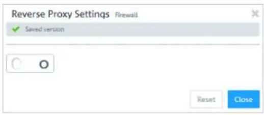
text_image
Reverse Proxy Settings Firewall Saved version Reset CloseFigure 28: Reverse proxy settings
| DescriptionInput field | |
| I/O | A slider switch indicates whether the reverse proxy settings are active (1) or inactive (0). Click the slider switch to change the status of the reverse proxy. The reverse proxy is deactivated by default. |
Backends
Navigate to UTM > Reverse Proxy > Backends to define at least one backend with one server. A backend consists of one or more internal web servers serving your website.
The Reverse Proxy Backend configuration dialog allows you to view and to configure the following elements:
| DescriptionInput field | |
| Enter a name for the backend.Name | |
| Select this check box to enable SSL.SSLIf SSL is enabled, the connection between the reverse proxy and the backend will be encrypted. | |
| Server | Assign one or more servers to the backend. Enter a server address. Click ⬆ add the server's IP address to the list. |
The buttons at the bottom right of the editor panel allow you to cancel (Cancel) the process or to create (Create) a new backend.
Click ▼Activate in the toolbar at the top of the desktop to apply your configuration changes.
Frontends
Navigate to UTM > Reverse Proxy > Frontends to configure your frontends.

To configure a frontend, you have to define at least one backend with at least one server.
After having created a backend, you can create a frontend in the Reverse Proxy Frontend. Each configured frontend represents one website with its external IP address, port, domain and certificate (if SSL is enabled).
The Reverse Proxy Frontend configuration dialog allows you to view and to configure the following elements:
| DescriptionInput field | |
| I/O | A slider switch indicates whether the reverse proxy is active (1) or inactive (0). Click the slider switch to change the status of the reverse proxy. The reverse proxy is deactivated by default. |
| Enter the name of the domain or the IP address the frontend is assigned to.Domain or IP address | |
| Select a connection. You can choose a network connection and a PPP connection.Connection | |
| Port | Configure the external listen port for the reverse proxy, e. g. the port that is reachable from external networks.Select this check box to enable SSL.SSLIf SSL is enabled, the reverse proxy will serve the website with SSL encryption, using the configured certificate for its authentication. |
| Certificate | Select a certificate with a private key. This option is only available if SSL is enabled. |
| Select a configured backend.Proxy PathsEnter a URL path. The URL path has to be absolute, i. e. it has to start with /.You can now forward requests matching the URL parameters to the configured backend. | |
| Blocks requests which match the URL parameter.Blocked PathsEnter a URL path. The URL path has to be absolute, i. e. it has to start with /. |
The buttons at the bottom right of the editor panel allow you to cancel (Cancel) the process or to create (Create) a new frontend.
Click ↕Activate in the toolbar at the top of the desktop to apply your configuration changes.
URL/Content Filter
URL and content filters determine which websites are available to computers on the protected network.
The URL filter function of your LANCOM R&S ^® Unified Firewall checks Internet addresses (URLs) received in the HTTP traffic for allowed and/or not allowed terms according to their classification in the blacklists and whitelists.
A "blacklist" approach defines a list of sites to block, and grants access to all sites that have not been forbidden explicitly. For example, if the URL of a website is on a blacklist, access to this site is blocked. Therefore, with the category Ordering being blacklisted, the URL http://www.amazon.de is blocked.
A "whitelist" approach can be used to limit access to a list of sites that have specifically been approved for usage and block all others. For example, if the subcategory Shopping is on the blocking list but you want to allow access to the URL http://www.amazon.de, this URL must be entered into a whitelist.
If websites do not contain any verifiable terms in their URLs, a URL filter itself is not sufficient. Therefore, your LANCOM R&S ^® Unified Firewall also filters the HTTP data communication by the content of the websites. Similar to a search engine, the content filter searches websites available on the Internet, analyzes and categorizes them and compiles the results in a database.

To use the URL and content filter, the HTTP proxy is essential. The HTTP data communication of a connection can only be filtered by URL lists and content if the HTTP proxy is activated for this connection in the rules editor.
The URL and content filters defined here are available for use in custom firewall rules (see Firewall Rule Settings on page 23 for more information).
You can find more information regarding URL and content filters in the following sections.
URL/Content Filter Settings
Navigate to UTM > URL/Content Filter > Settings to configure the URL and content filters for your LANCOM R&S® Unified Firewall.
| DescriptionInput field | |
| This field displays the license information for your content filter.Content Filter License | |
| URLs | Select this check box to exclude sections behind a ? (which serves to transfer variable values in PHP) from blacklists and whitelists. |
| Safesearch | Select this check box to automatically configure the setting SafeSearch=strict for searches using the search engines Google, Bing and Yahoo to hide any adult content in search requests. This setting cannot be changed by the users. |
| SafeSearch only works if the HTTPS proxy is active as most search engine providers use encrypted HTTPS connections on their websites. | |
| Duration of override by user | When a website is blocked, you can override the blocking mechanisms of the content filter for a certain timespan.Enter the timespan in minutes for a content filter category of a profile to be deactivated. |
| Only the current URL/content filter category of a profile is overridden to non-blocking for a defined period of time. | |
If you have modified these settings, use the buttons at the bottom right of the editor panel to confirm (Save) or to discard your changes (Reset). Otherwise, you can close the dialog (Close).
Click ✕activate in the toolbar at the top of the desktop to apply your configuration changes.
URL/Content Filter Overview
Navigate to UTM > URL/Content Filter > URL/Content Filter to display a list of URL and content filters that are defined in the system.
In the expanded view, the columns of the table display the Name of the filter and the number of selected entries in content filters, blacklists and whitelists. The buttons in the last column allow you to view and to adjust the settings for existing content filters, create a filter based on a copy of an existing filter or delete a filter from the system.
For more information, see Icons and buttons on page 21.
URL/Content Filter Settings
The settings allow you to configure the following options:
| DescriptionInput field | |
| Enter a name for the URL and content filter.Name | |
| Override by user | Select this check box to mark a content filter profile as overrideable. You can set the duration as described inURL/Content Filter Settingson page 113. |
| This option is only available for non-standard profiles. | |
Content Filter
In the Content Filter, you can determine which websites should be available to users on the network and which should be blocked.
Click ➤ next to a category to display its subcategories. Choose entire categories or single subcategories by selecting the corresponding check boxes. Clear the check box next to a category or a subcategory to remove it from the blacklist or whitelist. To hide the subcategories, click the button next to the category.
URL Filter
In the URL Filter section, you can blacklist and/or whitelist filters for URLs.
| DescriptionInput field | |
| Blacklist / Whitelist | To create a blacklist and/or a whitelist, add any amount of terms to the respective list. If both lists are applied at the same time, the whitelist has the higher priority.You can add terms to both lists in the following ways:To add search terms manually, just enter a term into the input field.Alternatively, clickimportto import search terms from a text file. By default, the maximum size of an import file is 1 Megabyte. Every line that is not empty adds an entry to the respective list.You can edit or delete individual entries in the list by clicking the corresponding button next to an entry.For more information, seeIcons and buttonson page 21.To export a term list to your local disk as a text file, clickExportbelow the list. |
| The terms in either list can contain placeholders: * for whole words, ? for single characters. |
To create the Blacklist or Whitelist, you can enter the search terms directly or use regular expressions (RegExp).
| ExampleDescriptionRegEx | ||
| ho.me - e.g. home, holePlaceholder for any single character.. | ||
| * | Any number of repetitions of the character. | hom* - e.g. hom, homm |
| ho.*e - e.g. home, houseAny number of characters.. * | ||
| ^home - home only at the start of the lineStart of a line.^ | ||
| home- home only at the end of the lineEnd of a line. | ||
The buttons at the bottom right of the editor panel depend on whether you add a new URL and content filter or edit an existing one. For a newly configured URL and content filter click Create to add it to the list of available services or Cancel to discard your changes.
If you have modified these settings, use the buttons at the bottom right of the editor panel to confirm (Save) or to discard your changes (Reset). Otherwise, you can close the dialog (Close).
Click ▼activate in the toolbar at the top of the desktop to apply your configuration changes.
3.4.6 VPN
With the settings under VPN you can configure your LANCOM R&S ^® Unified Firewall as a Virtual Private Network server to provide client-to-site (C2S) VPN connections. This allows computers in another location to use IPSec and VPN-SSL to securely access resources on the local network. A site-to-site (S2S) VPN gateway can use IPSec and VPN-SSL to establish a secure communication channel between two remote networks via the Internet.
Client-to-site VPN connections
A client-to-site VPN connection provides access to the corporate network from the outside. Authentication is performed either via IPSec with issued certificates, by means of a PSK (pre-shared key), or via VPN-SSL with certificates.
Client-to-site connections over IPSec and VPN-SSL operate in one of two modes, depending on the client settings:
In the split-tunnel mode, the only communication to pass through the firewall is that between the client and the internal network (e.g. a company network). Clients can reach devices in the internal network through the tunnel. For other destinations (e.g. the Internet), the packets are not routed by the LANCOM R&S ^ Unified Firewall.
3 User Interface
Example: A user dials in to a corporate network remotely from a hotel's wireless network using a VPN software client. Split tunneling allows the user to connect to file servers, database servers, mail servers, and other company network resources through the VPN connection. If the user connects to Internet resources (websites, FTP sites, etc.), the connection request is sent directly through the hotel network gateway.
In the full-tunnel mode all traffic is routed back to your LANCOM R&S® Unified Firewall, including communication with the Internet.
Full tunneling does not allow the user to access the Internet directly through hotel networks. All of the traffic sent by the client will be sent to the firewall while the VPN connection is active.
C2S connections over IPSec are established using a normal VPN client, such as the LANCOM Advanced VPN Client. Please refer to IPSec connection settings on page 122 for further information.
VPN-SSL C2S connections are established using a normal VPN client. Please refer to VPN SSL connection settings on page 127 for further information.
Site-to-site VPN connections
In the case of a site-to-site connection, two locations are connected via an encrypted tunnel to form a virtual network and they exchange data through this tunnel. The two locations can have fixed IP addresses. Authentication is performed either via IPSec with issued certificates, by means of a PSK (pre-shared key), or via VPN-SSL with certificates.
IPSec
Internet protocol security (IPSec) is a set of protocols that operates at the network layer or the link layer and secures the exchange of packets over untrusted networks (such as the Internet) by authenticating and encrypting each IP packet in a communication session. IPSec meets the highest security requirements.
VPN-SSL
VPN over SSL provides a fast and secure way to get a roadwarrior connected. The biggest advantage of VPN-SSL is that all traffic passes through a TCP or UDP port and, unlike IPSec, no other special protocols are required.
Before setting up VPN connections, make sure that you have installed the necessary certificates as described in Certificate Management on page 129.
IPSec
The IPSec (Internet Protocol Security) suite operates on the network layer and uses the authentication and encryption of IP packets to secure communication in untrusted networks.
For a site-to-site connection over IPSec, you need two VPN-IPSec-enabled servers. For a client-to-site connection, you need separate client software.
Your LANCOM R&S ^® Unified Firewall is able to use the IPSec protocol suite to establish and operate secure connections. This is made possible by ESP in tunnel mode. The key exchange can be performed using either version 1 of the IKE protocol or the newer IKEv2. You can chose between using pre-shared keys or X.509-standard certificates. IKEv1 also allows authentication via XAUTH. IKEv2 additionally supports authentication via EAP.
IPSec settings
You can enable IPSec and configure the settings under VPN > IPsec > IPsec Settings:
Table 3: General
| DescriptionInput box | |
| I/O | A slider button indicates whether IPSec is enabled (I) or disabled (O). Click on the slider button to change the status of this option. |
| Excluded interfaces | This selection list is used to select interfaces that should not be used by the IPSec service. If nothing is entered here, then all interfaces are excluded on the system, including those that are newly created or generated automatically.Usually, exception interfaces and IP addresses are required when all traffic is sent to the central office through an IPsec tunnel. In a case like this, you have to be careful to ensure that the local networks remain accessible. By default, IPSec has a higher priority than normal routes. Consequently, even packets destined for local area networks could be sent to the VPN tunnel instead. Under normal circumstances, the default setting which excludes all local interfaces means that the local networks can always be reached. |
| Excluded IP address | Enter the IP addresses in CIDR format. Under no circumstances will packets for these networks be routed to a tunnel, even if a tunnel is configured for the destination address.Click on ☑n the right-hand side to add your entry to the list of IP addresses. |
| Proxy ARP | If this option is enabled, the firewall will respond to ARP requests from local networks for virtual IP addresses for IPSec clients by sending its own MAC address. |
Table 4: DHCP server
| DescriptionInput box | |
| Active | IPSec can use a DHCP server to assign virtual IP addresses to the connected IPSec clients. You can enable this function here.To use this for an IPSec connection, go toVirtual IP pooland select the option DHCP virtual IP pool. |
| IP address | Enter the IP address of the DHCP server. This can be either the address of a DHCP server or a broadcast address of a network. |
Table 5: RADIUS server
| DescriptionInput box | |
| Active | In conjunction with EAP or XAUTH, IPSec can use the user management of a RADIUS server to authenticate the connection. Also, the RADIUS server can assign IP addresses to IPSec clients. To do this for an IPSec connection, go toVirtual IP pooland select the optionRADIUS virtual IP pool.You can enable this function here. |
| IP address of the RADIUS serverIP address | |
| The port the RADIUS server.Port | |
| Passwordfor accessing the RADIUS server.Password | |
If you have made changes, you can use the buttons at the bottom right of the edit window to save them (Save) or discard them (Reset). Otherwise you can close the window (Close).
Click ↕activate in the toolbar at the top of the desktop to apply your configuration changes.
Security profiles
Under VPN > IPSec > Security profiles you will find a list of predefined profiles that you can extend with custom profiles.
The predefined profiles cannot be edited or deleted.
If used security profiles are changed, all related connections can be restarted in the extended list bar. Security profiles are selected in the templates and connections.
Click on +to add a new security profile.
Table 6: General settings
| DescriptionInput box | |
| Give the security profile a descriptive name.Name | |
| Indicates the IPSec connections currently using this profile.Used in | |
| Data compression | If you select data compression here, it will be activated for all connections using this profile.This saves bandwidth, but it also increases the CPU load. |
| ! If you enable data compression, it must also be activated at the remote site. | |
ISAKMP (IKE)
This tab is used to define security settings for the IKE phase. IKE defines how security parameters are negotiated and shared keys exchanged
Table 7: ISAKMP (IKE)
| DescriptionInput box | |
| Select IKEv1 or IKEv2IKE version | |
| Encryption algorithms | From the available encryption algorithms, select the ones you want to use from the list. |
| Authentication algorithms | From the available authentication algorithms, select the ones you want to use from the list. |
| DH groups | From the available Diffie-Hellman groups, select the ones you want to use from the list. |
| Enter the SA lifetime in seconds.SA lifetime | |
| Mobile IKE (IKEv2 only) | This option is available for IKEv2 only and allows you to change IP addresses without disconnecting. |
The encryption algorithms, authentication algorithms, and DH groups defined here are used in establishing the IPSec connection to negotiate an encryption-authentication combination with the remote site. The more entries are defined here, the higher the number of possible combinations.
With IKEv1, the number of possible combinations is limited to just over 200. There is no limit with IKEv2.
IPSec (ESP)
Encapsulating Security Payload (ESP) provides mechanisms to ensure the authenticity, integrity and confidentiality of the transmitted IP packets. These settings thus determine the encryption and authentication algorithms used for the actual IP packets.
Table 8: IPSec (ESP)
| DescriptionInput box | |
| Encryption algorithms | From the available encryption algorithms, select the ones you want to use from the list. |
| Authentication algorithms | From the available authentication algorithms, select the ones you want to use from the list. |
| DH-Groups | From the available Diffie-Hellman groups, select the ones you want to use from the list. |
| Enter the SA lifetime in seconds.SA lifetime | |
Click on Create.
The Security profile dialog closes. The new security profile is added to the list of available security profiles in the object bar.
Virtual IP pools
Virtual IP pools can be used to send IP address configurations to connected clients. The virtual IP pools are available for selection on the Tunnel tab of the templates and connections.
Under VPN > IPSec > Virtual IP pools you will find, on the one hand, the predefined and non-modifiable virtual IP pools for the DHCP and RADIUS servers, and on the other hand the Default virtual IP pool that you can modify. Alternatively you can click on +o add a new virtual IP pool.
The predefined profiles cannot be edited or deleted.
Table 9: Virtual IP pool
| DescriptionInput box | |
| Give the virtual IP pool a descriptive name.Name | |
| Indicates the IPSec connections currently using this virtual IP pool.Used in | |
| Network address from which IP addresses are sent to the clients.IP pool | |
| IP address of the preferred DNS serverPreferred DNS server | |
| IP address of the alternative DNS serverAlternate DNS server | |
| IP address of the preferred WINS serverPreferred WINS server | |
| IP address of the alternative WINS serverAlternate WINS server | |
| DNS search domains | List of DNS search domains. Click on n the right-hand side to add your entry to the list of DNS search domains. |
Click on Create.
The Virtual IP pool dialog closes. The new pool is added to the list of available virtual IP pools in the object bar.
If used virtual IP pools are changed, all related connections can be restarted in the extended list bar.
Templates
Connection templates are useful for pre-defining values for connections that are commonly used. Except for the template name, all values are optional and populate the various fields of a VPN connection created using this template.
Various templates have been predefined, such as the template "LANCOM Advanced VPN Client" to simplify IPSec connections with this client. The template "(empty)" is used if the values of an existing connection should be deleted.
The predefined templates cannot be edited or deleted.
Under VPN > IPSec > Templates you can open the window IPSec connection template. Use the IPSec connection template windows to view and configure the following information:
Table 10: IPSec connection template
| DescriptionInput box | |
| Give the template a descriptive name.Name | |
| Select one of the predefined security profiles.Security profile | |
On the Connection tab you can configure the presets for the following fields:
Table 11: Connection
| DescriptionInput box | |
| Connection | By optionally selecting a network or Internet connection, its IP addresses will be used for the IPSec connection. |
| Listening IP addresses | As an alternative to Connection, you can also enter user-specified IP addresses. If IP addresses are entered here, the Connection setting is ignored. If neither Connection nor Listening IP addresses are set, the IPSec service will automatically use one of the configured IP addresses of all connections. |
| Remote gateway | This address is necessary for the Initiate connection option in order to determine the address of the remote site. |
| Initiate connection | The firewall will connect to the address specified in the Remote gateway field. |
| Force NAT-T | NAT-T is usually set automatically if the connection requires it. If that mechanism fails, this option forces the use of NAT-T on a connection. |
On the Tunnels tab you can configure the presets for the following fields:
Table 12: Tunnel
| DescriptionInput box | |
| Local networks to be connected to the remote site.Local networks | |
| Remote networks to connect to the local area networks.Remote networks | |
| All of the configured local networks are connected to all of the configured remote networks. For IKEv1 connections and IKEv2 connections with the option IKEv2 compatibility mode enabled, the maximum number of combinations is limited to 25. There is no limit for IKEv2 with the option IKEv2 compatibility mode disabled. | |
| The remote site is assigned an IP address from the configured IP pool.Virtual IP pool | |
| IKEv2 compatibility mode | Instead of sending all configured local and remote networks through a single tunnel, a single tunnel is created for each connection between two networks (as with IKEv1). This option only applies to IKEv2 connections. |
On the Authentication tab you can configure the presets for the following fields:
Table 13: Authentication
| DescriptionInput box | |
| Specify the authentication type. Possible values:Authentication type> Certificate – authentication is based on a local and a remote certificate.> Certificate Authority – authentication is performed through a local and a remote certificate signed by the selected CA.> PSK (preshared key) – authentication is based on the entry of a password. | |
| PSK (preshared key) | For authentication type PSK (preshared key) only – specify the required password here. |
| Local certificate | The certificate of the firewall for authentication. This must contain a private key. |
| Local identifier | If this field is empty, PSK authentication automatically uses the outgoing IP address of the firewall and, for certificate authentication, the distinguished name (DN) of the selected local certificate.> For PSK authentication, the following values are allowed: IP addresses, fully qualified domain names (FQDN), e-mail addresses (FQUN), and free text between quotation marks (").> For certificate authentication, the following values are allowed: The distinguished name (DN) of the selected certificate, wildcard DN – all DN items must be present (in the correct order), but may be specified as a wildcard (e.g. CN=*) – any subject alternative names (SAN) of the selected certificate. |
| Extended Authentication | Enables the optional use of extended user authentication. Once you have selected a security profile, the following options are available:>No Extended Authentication– Do not perform extended authentication.>XAUTH (IKEv1)– Either the local user database or a RADIUS server is used (depending on whether or not RADIUS is active in the IPSec settings).>EAP First Round– An external RADIUS server is used, which must be enabled in the IPSec settings. The configuration for the RADIUS server is made in the IPSec settings.The settings in theLocalsection are used to authenticate the firewall at the remote terminal. The remote terminal only authenticates itself via EAP.>EAP Second Round– An external RADIUS server is used, which must be enabled in the IPSec settings. The configuration for the RADIUS server is made in the IPSec settings.The settings in theLocalsection are used to authenticate the firewall at the remote terminal. The remote party authenticates to the firewall using the PSK or a certificate and then performs EAP authentication.>EAP-TLS– Corresponds to theEAP First Roundvariant with the difference that a TLS certificate is used for EAP authentication. |
| i> For IKEv1, the optionsNo Extended Authenticationand XAUTH (IKEv1)are available regardless of the authentication type.> For IKEv2 with certificate or PSK authentication, all options are available except XAUTH (IKEv1).> For IKEv2 with CA authentication, the optionsNo Extended AuthenticationandEAP Second Roundare available. | |
| Only with authentication type "Certificate": Certificate of the remote site.Remote certificate | |
| Certificate authority | Only with authentication type "Certificate Authority": A CA whose signed certificates can be used for authentication. |
| Remote identifier | If this field is empty, PSK authentication automatically uses the IP address of the remote gateway (if set). For certificate authentication, the distinguished name (DN) of the selected remote certificate.> For PSK authentication, the following values are allowed: IP addresses, fully qualified domain names (FQDN), e-mail addresses (FQUN), and free text between quotation marks (").> For certificate authentication, the following values are allowed: The distinguished name (DN) of the selected certificate, wildcard DN – all DN items must be present (in the correct order), but may be specified as a wildcard (e.g. CN=*) – any subject alternative names (SAN) of the selected certificate. |
Click on Create.
The IPSec connection template dialog closes. The new template is added to the list of available templates in the object bar.
IPSec connections
Your LANCOM R&S ^® Unified Firewall is able to provide remote clients with VPN access via IPSec (IPSec client-to-site) and to create a secure tunnel between two remote networks (IPSec site-to-site).
Overview of IPSec connections
Navigate to VPN > IPsec > Connections to display the list of IPSec connections available on the system in the object bar.
In the expanded view, the table columns display the Name and the Status of the IPSec connection. Furthermore, the columns indicate the authentication method chosen for this connection. Use the buttons in the last column to view and modify the settings for a IPSec connection or to delete a connection from the system.
Please refer to Icons and buttons on page 21 for further information.
IPSec connection settings
Under VPN > IPsec > Connections you can add an IPSec connection or edit an existing connection.
In the Connection editing window you can modify the following parameters:
| DescriptionInput box | |
| I/O | A slider button indicates whether the IPSec connection is enabled (1) or disabled (0). Click on the slider button to change the status of this connection. A new connection is enabled by default. |
| Name | Enter a unique name for this connection. This must consist of 1-63 alphanumeric characters and underscores. |
| Template | Optionally you can select one of the predefined templates. All settings are then taken from the template. Values that were not set in the template are reset. The template “(empty)” can be used to reset all values. |
| Select one of the predefined security profiles.Security profile | |
On the Connection tab you can configure the presets for the following fields:
Table 14: Connection
| DescriptionInput box | |
| Connection | By optionally selecting a network or Internet connection, its IP addresses will be used for the IPSec connection. |
| Listening IP addresses | As an alternative to Connection, you can also enter user-specified IP addresses. Click on ⊕ on the right-hand side to add your entry to the list. If IP addresses are entered here, theConnection setting is ignored. If neither Connection nor Listening IP addresses are set, the IPSec service will automatically use one of the configured IP addresses of all connections. |
| Remote gateway | This address is necessary for the Initiate connection option in order to determine the address of the remote site. |
| Initiate connection | The firewall will connect to the address specified in the Remote gateway field. |
| Force NAT-T | NAT-T is usually set automatically if the connection requires it. If that mechanism fails, this option forces the use of NAT-T on a connection. |
On the Tunnels tab you can configure the presets for the following fields:
Table 15: Tunnels
| DescriptionInput box | |
| Local networks | Local networks to be connected to the remote site. Click on ☑n the right-hand side to add your entry to the list. |
| Remote networks | Remote networks to connect to the local area networks. Click on ☑n the right-hand side to add your entry to the list. |
| ! All of the configured local networks are connected to all of the configured remote networks. For IKEv1 connections and IKEv2 connections with the option IKEv2 compatibility mode enabled, the maximum number of combinations is limited to 25. There is no limit for IKEv2 with the option IKEv2 compatibility mode disabled. | |
| The remote site is assigned an IP address from the configured IP pool.Virtual IP pool | |
| Assign a specific IP address to the remote site.Virtual IP | |
| ! The options Remote networks. Virtual IP pool and Virtual IP should not be used together | |
| IKEv2 compatibility mode | Instead of sending all configured local and remote networks through a single tunnel, a single tunnel is created for each connection between two networks (as with IKEv1). This option only applies to IKEv2 connections. |
On the Authentication tab you can configure the presets for the following fields:
Table 16: Authentication
| DescriptionInput box | |
| Specify the authentication type. Possible values:Authentication type> Certificate – authentication is based on a local and a remote certificate.> Certificate Authority – authentication is performed through a local and a remote certificate signed by the selected CA.> PSK (preshared key) – authentication is based on the entry of a password. | |
| PSK (preshared key) | For authentication type PSK (preshared key) only – specify the required password here. |
| Local certificate | The certificate of the firewall for authentication. This must contain a private key. |
| Local identifier | If this field is empty, PSK authentication automatically uses the outgoing IP address of the firewall and, for certificate authentication the default is the distinguished name (DN) of the selected local certificate.> For PSK authentication, the following values are allowed: IP addresses, fully qualified domain names (FQDN), e-mail addresses (FQUN), and free text between quotation marks (").> For certificate authentication, the following values are allowed: The distinguished name (DN) of the selected certificate, wildcard DN – all DN items must be present (in the correct order), but may be specified as a wildcard (e.g. CN=*) – any subject alternative names (SAN) of the selected certificate. |
| Extended Authentication | Enables the optional use of extended user authentication. Once you have selected a security profile, the following options are available:> No Extended Authentication – Do not perform extended authentication.> XAUTH (IKEv1) – Either the local user database or a RADIUS server is used (depending on whether or not RADIUS is active in the IPSec settings).> EAP First Round – An external RADIUS server is used, which must be enabled in the IPSec settings. The configuration for the RADIUS server is made in the IPSec settings.The settings in the Local section are used to authenticate the firewall at the remote terminal. The remote terminal only authenticates itself via EAP.> EAP Second Round – An external RADIUS server is used, which must be enabled in the IPSec settings. The configuration for the RADIUS server is made in the IPSec settings.The settings in the Local section are used to authenticate the firewall at the remote terminal. The remote party authenticates to the firewall using the PSK or a certificate and then performs EAP authentication.> EAP-TLS – Corresponds to the EAP First Round variant with the difference that a TLS certificate is used for EAP authentication. |
| i> For IKEv1, the options No Extended Authentication and XAUTH (IKEv1) are available regardless of the authentication type.> For IKEv2 with certificate or PSK authentication, all options are available except XAUTH (IKEv1).> For IKEv2 with CA authentication, the options No Extended Authentication and EAP Second Round are available. | |
| Only with authentication type “Certificate”: Certificate of the remote site.Remote certificate | |
| Certificate authority | Only with authentication type “Certificate Authority”: A CA whose signed certificates can be used for authentication. |
| Remote identifier | If this field is empty, PSK authentication automatically uses the IP address of the remote gateway (if set). For certificate authentication, the distinguished name (DN) of the selected remote certificate.> For PSK authentication, the following values are allowed: IP addresses, fully qualified domain names (FQDN), e-mail addresses (FQUN), and free text between quotation marks (“).> For certificate authentication, the following values are allowed: The distinguished name (DN) of the selected certificate, wildcard DN – all DN items must be present (in the correct order), but may be specified as a wildcard (e.g. CN=*) – any subject alternative names (SAN) of the selected certificate. |
The buttons available at the bottom right of the edit box depend on whether you are adding a new VPN IPSec connection or editing an existing connection. For a new network connection, click Create to add the connection to the list of available IPSec network connections, or Cancel to cancel the creation of a new network connection.
If you have made changes, you can use the buttons at the bottom right of the edit window to save them (Save) or discard them (Reset). Otherwise you can close the window (Close).
Click ↕activate in the toolbar at the top of the desktop to apply your configuration changes.
Setting up an IKEv2 VPN connection with the LANCOM Advanced VPN Client
Scenario: The LANCOM R&S ^® Unified Firewall is connected directly to the Internet and has a public IPv4 address:
A company wants its sales representatives to have access to the corporate network via an IKEv2 client-to-site connection.
The notebooks used by the sales representatives have the LANCOM Advanced VPN Client installed on them.
The company headquarters has a LANCOM R&S ^ Unified Firewall as a gateway with an Internet connection with the fixed public IP address 81.81.81.81.
The local network at the headquarters has the IP address range 192.168.3.0/24.
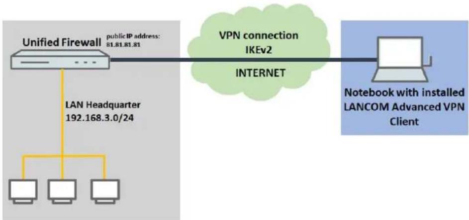
flowchart
graph LR
    A["Unified Firewall"] -->|LAN Headquarter 192.168.3.0/24| B["Computer"]
    A -->|public IP address: 81.81.81.81| C["Internet"]
    C --> D["VPN connection IKEv2"]
    D --> E["Notebook with installed LANCOM Advanced VPN Client"]
Among other scenarios, this is one of the scenarios explained in the LANCOM Support Knowledge Base. Click on the following link for step-by-step instructions:
https://support.lancom-systems.com/knowledge/pages/viewpage.action?pageld=37455360
VPN-SSL
VPN over SSL provides a fast and secure way to get a roadwarrior connected. The biggest advantage of VPN-SSL is that all traffic passes through a TCP or UDP port and no other special protocols are required.
Your LANCOM R&S ^® Unified Firewall is able to offer VPN access to remote client computers (C2S, "client-to-site") or a secure connection between two remote networks (S2S, "site-to-site") by means of the VPN-SSL protocol.
VPN SSL settings
Under VPN > VPN SSL Settings, you can enable VPN-SSL and configure the general settings on your LANCOM R&S® Unified Firewall:
| DescriptionInput box | |
| I/O | A slider button indicates whether VPN SSL is enabled (I) or disabled (0). Click on the slider button to change the status of this option. |
| Host certificate | Select a host certificate that your LANCOM R&S®Unified Firewall uses for all VPN SSL connections. |
| Optional: Enter a DNS server to be used by clients for client-to-site connections.DNS | |
| Optional: Enter a WINS server to be used by clients for client-to-site connections.WINS | |
| Timeout | Enter the timeout in seconds. The tunnel is disconnected if there is no data flow before the timeout expires. The default is 0. The tunnel is thus kept open permanently. |
| Log Level | Set the event log level here. For troubleshooting, event log level 5 is recommended. |
| Routes | Enter routes for the VPN SSL tunnels to be created by the clients or the remote end of the connection. These routes will be used for all VPN SSL connections.Click onAddto add the route to the list. You can edit or delete any entry in the list by clicking on the appropriate icon.Please refer toIcons and buttonson page 21 for further information. |
| When you edit an entry, a checkmark will appear to the right of the entry. Click the checkmark to accept the change. | |
On tab Client-to-Site:
| DescriptionInput box | |
| Select the protocol with the appropriate radio button.Protocol | |
| Specify the VPN SSL listening port to be used for incoming connections.Port | |
| This port number also has to be specified in the client software. | |
| Address pool | Specify the address range from which IP addresses are assigned to clients. This address range must not overlap with your local networks. |
| Encryption algorithm | Use the drop-down list to select the encryption algorithm to use for C2S connections over VPN SSL. |
| Key renegotiation | To increase security, a VPN SSL connection renegotiates the session key while the connection is in progress. Enter the interval for key renegotiation in seconds. |
| Compression | Optional: Uncheck this box to disable LZO (Lempel-Ziv-Oberhumer, an algorithm for lossless data compression). This checkbox is enabled by default. |
On tab Site-to-Site:
| DescriptionInput box | |
| Select the protocol with the appropriate radio button.Protocol | |
| Specify the VPN SSL listening port to be used for incoming connections.Port | |
| The same port number must be specified at the remote end of the connection. | |
| Address pool | Specify the address range from which IP addresses are to be used for S2S connections. This address range must not overlap with your local networks. |
| Encryption algorithm | Use the drop-down list to select the encryption algorithm to use for S2S connections over VPN SSL. |
| Key renegotiation | To increase security, a VPN SSL connection renegotiates the session key while the connection is in progress. Enter the interval for key renegotiation in seconds. |
| Compression | Optional: Uncheck this box to disable LZO (Lempel-Ziv-Oberhumer, an algorithm for lossless data compression). This checkbox is enabled by default. |
If you have made changes, you can use the buttons at the bottom right of the edit window to save them (Save) or discard them (Reset). Otherwise you can close the window (Close).
Click ✅activate in the toolbar at the top of the desktop to apply your configuration changes.
VPN SSL connections
You can create and manage VPN SSL connections under VPN >VPN Connections >VPN SSL Connections.
Your LANCOM R&S ^® Unified Firewall is able to provide VPN access by means of VPN-SSL to remote clients (client-to-site) and to create a secure tunnel between two remote networks (site-to-site).
Overview of VPN SSL connections
Navigate to VPN >VPN Connections >VPN SSL Connections to display the list of VPN SSL connections available on the system in the object bar.
In the expanded view, the table columns display the Name of the VPN SSL connection, the Certificate used for the connection, as well as the Type and the Status of the connection. Use the buttons in the last column to view and modify the settings for a VPN SSL connection or to delete a connection from the system.
Please refer to Icons and buttons on page 21 for further information.
VPN SSL connection settings
Under VPN > VPN Connections > VPN SSL Connections you can add a VPN SSL connection or edit an existing connection.
With the settings under VPN SSL Connections you can adjust the following parameters:
| DescriptionInput box | |
| I/O | A slider button indicates whether the VPN SSL connection is enabled (1) or disabled (0). Click on the slider button to change the status of this connection. Newly created connections are enabled by default. |
| Name | Enter a unique name for this connection. The name has to consist of alphanumeric characters (i.e. letters excepting ä, ö, ü and β, numbers and special characters). |
| Select the server certificate for VPN SSL connections from the drop-down list.CertificateThe VPN certificate must be signed by the same Certificate Authority (CA) at all locations. It is therefore advisable to administer the VPN certification authority and the VPN certificates at one location and to export the VPN certificates from there to all other locations. | |
| Connection type | Select the connection type and the function of the LANCOM R&S®Unified Firewall by selecting the appropriate radio button.You can choose from the following three types:Client-to-Site– A C2S connection is established (e.g. for full tunneling).This connection type can, for example, be used with the OpenVPN client, primarily to connect mobile clients to your local network.Site-to-Site (Server)– An S2S connection is established with your LANCOM R&S®Unified Firewall acting as a server.Site-to-Site (Client)– An S2S connection is established. Your LANCOM R&S®Unified Firewall acts as a client. |
The items displayed in the settings depend on the connection type selected:
You can configure the following items for client-to-site connections:
| DescriptionInput box | |
| Set default gateway | Check this box to use the VPN SSL tunnel as the default route (for example, for full tunneling). |
| Optional: Enter the IP address where the client can be reached.Client IP | |
| Additional remote networks | The local area networks to which the client sets up connection routes must be specified in valid CIDR notation (IP address followed by a slash "/" and the number of bits specified in the subnet mask, e.g. 192.168.1.0/24).Click onAddto add a network to the list.You can edit or delete any entry in the list by clicking on the appropriate icon.Please refer toIcons and buttonson page 21 for further information. |
| When you edit an entry, a checkmark will appear to the right of the entry. Click the checkmark to accept the change. | |
For site-to-site connections where your LANCOM R&S® Unified Firewall acts as a server, you can configure the following items:
| DescriptionInput box | |
| Address pool | Specify the address range from which IP addresses will be used for this connection. The address range is specified in the VPN SSL settings. Please refer toVPN-SSLon page 125 for further information. |
| Optional: Enter the IP address of the remote end of the connection.Remote IP | |
| Remote Networks | Specify the networks available at the remote end of the connection. Once the connection is successfully established, the server creates routes to these networks.Click onAddto add a network to the list.You can edit or delete any entry in the list by clicking on the appropriate icon.Please refer toIcons and buttonson page 21 for further information. |
| When you edit an entry, a checkmark will appear to the right of the entry. Click the checkmark to accept the change. | |
| Additional Local Networks | Specify any additional local networks. Once the connection is successfully established, the server creates routes to these networks.Click onAddto add a network to the list.You can edit or delete any entry in the list by clicking on the appropriate icon.Please refer toIcons and buttonson page 21 for further information. |
| When you edit an entry, a checkmark will appear to the right of the entry. Click the checkmark to accept the change. |
For site-to-site connections where your LANCOM R&S® Unified Firewall acts as a client, you can configure the following items:
| DescriptionInput box | |
| Address pool | Specify the address range from which IP addresses will be used for this connection. The address range is specified in the VPN SSL settings. Please refer toVPN-SSLon page 125 for further information. |
| Enter the IP address where the remote end of the connection can be reached.Server AddressClick onAddto add a network to the list. If you add more than one network, an automatic failover will be triggered if the first network becomes unreachable. In this case, your LANCOM R&S®Unified Firewall will try to reach the other networks in the list one by one until a network is found.You can edit or delete any entry in the list by clicking on the appropriate icon. | |
| Please refer to Icons and buttons on page 21 for further information. | |
| When you edit an entry, a checkmark will appear to the right of the entry. Click the checkmark to accept the change. | |
| Enter the port number used at the remote end of this connection.Server Port | |
| Try establishing connection for | Specify the timeout in minutes after which no further connection attempts will be made. If this option is set to 0, the connection attempts will continue without interruption. |
The buttons available at the bottom right of the edit box depend on whether you are adding a new VPN SSL connection or editing an existing connection. For a new connection, click Create to add the connection to the list of available VPN SSL connections, or Cancel to discard your changes.
If you have made changes, you can use the buttons at the bottom right of the edit window to save them (Save) or discard them (Reset). Otherwise you can close the window (Close).
Click ✅activate in the toolbar at the top of the desktop to apply your configuration changes.
3.4.7 Certificate Management
The ● Certificate Management settings allow you to control the certificates used by the web client, the built-in SSL proxy and the OpenVPN server, to create templates to ease the creation of certificates and to enable OCSP/CRL services.
Certificate Signing Requests
You can use your LANCOM R&S ^® Unified Firewall to create and export a Certificate Signing Request, e. g. to sign a certificate on another firewall.
Certificate Signing Requests Overview
Navigate to Certificate Management > Certificate Requests to display a list of Certificate Signing Requests that are currently defined in the system in the item list bar.
The buttons above the list allow you to create a new Certificate Signing Request and to sign a Certificate Signing Request.
In the expanded view, the first table column displays the Common Name of the Certificate Signing Request. The buttons in the last column allow you to view the settings for an existing Certificate Signing Request or delete a CSR from the system.
For more information, see Icons and buttons on page 21.
Certificate Signing Requests Settings
Under Certificate Management > Certificate Requests, you can add a new or edit an existing Certificate Signing Request.
The Generate Certificate Request settings allow you to configure the following elements (some fields are only displayed for certain certificate types):
| DescriptionInput field | |
| Type | From the drop-down list, select the certificate type you want to use for the Certificate Signing Request. The following three types are available:➢ Secondary CA➢ VPN Certificate➢ Webserver Certificate (R&S Cybersecurity UA Client)For more information, seeTypes of Certificateson page 134. |
| Private Key Encryption | Decide whether to use the pre-selected RSA (Rivest-Shamir-Adleman) or the selectable DSA (Digital Signature Algorithm) as the encryption algorithm for the private key. Due to limitations of OpenVPN, DSA is not available for VPN certificates. |
| ! DSA with a private key size of 1024 bits or lower is not accepted by most clients. | |
| Private Key Size | Decide whether to use the default value (2048 Bit) or to select a different bit length for the private key. Longer keys are more secure but they take longer to create. |
| Enter a password to secure the private key.Private Key Password | |
| Show Private Key Password | Optional: Select the check box below to make the password visible for verification. |
| Fill from Template | From the drop-down list, select a template to fill in the input fields regarding theDistinguished Name(seeTemplateson page 135). Alternatively, you can manually enter the information. |
| Specify a name for the certificate.Common Name (CN) | |
| Optional: Enter the two-letter code denoting the country.Country (C) | |
| Optional: Enter the name of the state.State (ST) | |
| Optional: Enter the name of the city.City (L) | |
| Optional: Enter the name of the organization.Organization (O) | |
| Optional: Enter the name of the unit within the organization.Organizational Unit (OU) | |
| Subject Alternative Name (SAN) | Optional: Enter as many custom subject alternative names (SAN) as you like for the certificate for specific usage and select the corresponding types from the drop-down list. Available types are: E-Mail, DNS, DirName, URI and IPv4. Click⊕to put a subject alternative name (SAN) on the list. You can edit or delete individual entries in the list by clicking the corresponding button next to an entry.For more information, seeIcons and buttonson page 21. |
| ! If you edit a subject alternative name (SAN), a check box appears on the right of the entry. You have to activate the check box before being able to save the settings of the certificate. | |
| OCSP | Optional and only available for secondary CAs: Select the check box to activate validation via OCSP (Online Certificate Status Protocol) for the CA and for secondary certificates. For more information, seeOCSP/CRLon page 134. |
| CRL | Optional and only available for secondary CAs: Select the respective check box to activate validation via CRL (Certificate Revocation List) for the secondary CA. For more information, seeOCSP/CRLon page 134. |
| Addresses for OCSP Responder / CRL Download | Optional and only available for secondary CAs: Define base URLs for OCSP and CRL by entering a URL in the input field and clicking⊕The actual URLs for the certificates are built from the base URL (protocol://hostname/) and are appended withocsp/for OCSP URLs and with /crls/.crl for the CRL download URL. The base URL has to point to the LANCOM R&S®Unified Firewall or to any host providing the CRL (when the CRL is mirrored).You can edit or delete individual entries in the list by clicking the corresponding button next to an entry.For more information, seeIcons and buttonson page 21. |
| ! If you edit a URL, a check mark appears on the right of the entry. You have to click the check mark before being able to save the settings of the certificate.To activate the OCSP and CRL services, seeOCSP/CRLon page 134. | |
The buttons at the bottom right of the editor panel allow you to generate a new certificate signing request and to add it to the list of available certificate signing requests or to reject (Cancel) the creation of the new certificate signing request.
After creating a Certificate Signing Request, you are prompted to store it in a local PEM file.
Signing a Certificate Signing Request
To sign a certificate signing request, proceed as follows:
- Navigate to Certificate Management > Certificate Requests.
The list of certificate signing requests which are currently defined on the system opens.
- In the item list header, click (Sign certificate request).
The Sign Certificate Request editor panel opens.
- Click Select File next to the Request File input field.
The local disk search opens.
-
Select a certificate signing request file in PEM format from the local disk.
-
Click Open.
The local disk search closes.
- Under Validity, define the initial period of time for which the new certificate should be considered valid. You can enter a date as MM/DD/YYYY (e.g. 04/20/2017) or use the date picker to set the validity period of the certificate.
The validity period of the certificate must not exceed the validity period of the signing CA.
-
Under Signing CA, select the certificate authority that you want to use to sign the new certificate from the drop-down list. This CA will be the parent CA that is used to verify or to revoke the certificate.
-
Under CA Password, enter the password for the private key of the signing CA. The password is necessary as the signing of the public key of the new certificate is done with the private key of the signing certificate authority.
-
Optional: Select the Show CA Password check box to verify the signing CA's password.
-
Click Sign to sign the certificate signing request.
The certificate signing request is signed.
After signing the certificate signing request, the system prompts you to save the certificate to the local disk. You can also export the certificate as described in Certificates on page 131.
Certificates
The Certificates configuration dialog allows you to manage the certificates used by the LANCOM R&S ^® Unified Firewall web client, the built-in SSL proxy and the OpenVPN server.
To secure encrypted connections, your LANCOM R&S ^® Unified Firewall uses digital certificates as per the X.509 standard.
The LANCOM R&S ^® Unified Firewall itself acts as a certification authority. Therefore, a so-called CA certificate is required. To centralize the management of the certificates, it is advisable to create a CA certificate on a central firewall and use it to sign every certificate used for the application directly. This is called a single-staged certification chain.
All certificates for applications have to be signed by the central firewall. If a certificate is needed for another firewall, you have to create a request on it. This request has to be signed by the central firewall. The signed request which you created has to be imported by the other firewalls to use it.
If the other firewalls require the ability to create certificates for mostly local purposes which are however recognized as valid to your whole organization, you can use multi-staged certification chains. Therefore, you need a so-called root CA certificate on your central firewall with which you sign the secondary CA certificates. You need to create requests for
these secondary CA certificates on your other firewalls. After importing the signed CA certificates, the other firewalls themselves are able to sign certificates for applications. To display these hierarchies clearly, your LANCOM R&S ^® Unified Firewall shows them in a tree view.
Certificates Overview
Navigate to Certificate Management > Certificates to display the list of certificates that are currently defined in the system in a tree of authorities in the item list bar.
The buttons above the list allow you to create a new certificate and to import a certificate from a file.
Upon first boot and after a reinstallation, there are four certificates created by default:
| DescriptionName of the Certificate | |
| Certificate authority for the creation of subordinate certificates used by the HTTPS proxy. HTTPS Proxy CA | |
| Pre-configured certificate for the HTTPS proxy. HTTPS Proxy Initialization | |
| Certificate authority for the creation of subordinate certificates used by the mail proxy.Mail Proxy CA | |
| Pre-configured certificate for the mail proxy.Mail Proxy Initialization | |
In the expanded view, the item list bar displays the name of the certificate and its dependency. The buttons behind the individual certificates show you the validity status and the type of each certificate. Click the buttons to view the details of each certificate, replace a certificate by importing a new certificate, export and verify a certificate, temporarily suspend or renew the validity of a certificate, and permanently revoke the certificate.
For more information, see Icons and buttons on page 21.
Certificate Settings
The Certificates manage the certificates used by your LANCOM R&S ^® Unified Firewall.
Click +bove the list to add a new certificate.
The certificate settings allow you to configure the following elements (some fields are only displayed for certain certificate types):
| DescriptionInput field | |
| Type | From the drop-down list, select what kind of certificate to create. For more information, see Types of Certificates on page 134. |
| Signing CA | If you set the certificate type to VPN Certificate, Webserver Certificate, Secondary CA or HTTPS Proxy CA, you can select the certificate authority that you want to use to sign the new certificate. This CA will be the parent CA that is used to verify or to revoke the certificate. |
| Private Key Encryption | Decide whether to use the pre-selected RSA (Rivest-Shamir-Adleman) or the selectable DSA (Digital Signature Algorithm) as the encryption algorithm for the private key. (DSA is not available for VPN certificates due to limitations of OpenVPN.) |
| ! DSA with a private key size of 1024 bits or lower is not accepted by most clients. | |
| Private Key Size | Decide whether to use the default value (2048 Bit) or to select a different bit length for the private key. Longer keys are more secure but they take longer to create. |
| Validity | Define the initial period of time for which the certificate should be considered valid. The input fields are pre-filled with the current date as the date issued and the same day one year later as the date of expiry. To define a different period of time, enter the new date in the following format: MM/DD/YYYY (e.g. 04/20/2017). |
| CA Password | Optional: Enter a password for the private key of the signing CA if the certificate type was set to VPN Certificate, Webserver Certificate, Secondary CA or HTTPS Proxy CA. The password is necessary as the signing of the public key of the new certificate is done with the private key of the signing certificate authority. |
| Optional: Select this check box to verify the signing CA's password.Show CA Password | |
| Optional: Enter a password to secure the private key.Private Key Password | |
| Optional: Select the check box to verify the password.Show Private Key Password | |
| Fill from Template | From the drop-down list, select a template to fill in the input fields regarding the Distinguished Name (see Templates on page 135). Alternatively, you can manually enter the information. |
| Specify a name for the certificate.Common Name (CN) | |
| Optional: Enter the two-letter code denoting the country.Country (C) | |
| Optional: Enter the name of the state.State (ST) | |
| Optional: Enter the name of the city.City (L) | |
| Optional: Enter the name of the organization.Organization (O) | |
| Optional: Enter the name of the unit within the organization.Organizational Unit (OU) | |
| Subject Alternative Name | Optional: Enter as many custom subject alternative names (SAN) as you like for the certificate for specific usage and select the corresponding types from the drop-down list. The following types are available: E-Mail, DNS, DirName, URI and IPv4. Click ⊕ to put a subject alternative name (SAN) on the list. You can edit or delete individual entries in the list by clicking the corresponding button next to an entry.For more information, seeIcons and buttons on page 21. |
| !If you edit a subject alternative name, a check mark appears on the right of the entry. You have to click the check mark before being able to save the settings of the certificate. | |
| OCSP | Optional and only available for CAs: Select the check box to activate validation via OCSP (Online Certificate Status Protocol) for the CA and for subordinate certificates. For more information, see OCSP/CRL on page 134. |
| CRL | Optional and only available for CAs: Select the check box to activate validation via CRL (Certificate Revocation List) for the CA. For more information, see OCSP/CRL on page 134. |
| Addresses for OCSP Responder / CRL Download | Optional and only available for CAs: Define base URLs for OCSP and CRL by entering a URL in the input field and clicking⊕The actual URLs for the certificates are built from the base URL (protocol://hostname/) and are appended with ocsp/for OCSP URLs and with /crls/.crl for the CRL download URL. The base URL has to point to the firewall or to any host providing the CRL (when the CRL is mirrored).For more information, seeIcons and buttons on page 21.You can edit or delete individual entries in the list by clicking the corresponding button next to an entry. |
| !If you edit a URL, a check mark appears on the right of the entry. You have to click the check mark before being able to save the settings of the certificate.To activate OCSP and CRL services, see OCSP/CRL on page 134. | |
The buttons at the bottom right of the editor panel allow you to create a new certificate and to add it to the list of available certificates or to reject (Cancel) the creation of the new certificate.
Types of Certificates
Your LANCOM R&S ^® Unified Firewall offers various certificate types to choose from when creating a certificate.
| DescriptionCertificate type | |
| VPN Certificate | Creates a certificate that is used to identify VPN clients and servers. A suitable parent CA has to be selected. |
| Webserver Certificate (UA client) | Creates a certificate that is used for webservers. A suitable parent CA has to be selected. |
| CA for VPN / Webserver Certificates | Creates a certificate authority that can directly sign VPN and webserver certificates. No subordinate authorities can be attached. This CA can become a subordinate authority itself by exporting a signing request and reimporting the newly signed public certificate, thus signing it externally. |
| CA with secondary CAs | Creates a certificate authority that can sign subordinate CAs and client certificates for VPN and webservers. |
| Secondary CA | Creates a subordinate CA that can be used to sign VPN and webserver certificates. A parent CA of the kind CA with secondary CAs has to be selected. |
OCSP/CRL
Enable the OCSP and/or CRL services to allow clients to verify the validity of certificates issued by the central firewall.
If co-workers quit their job or a private key gets lost, the corresponding certificate must be blocked to assure the company's security. This has to be done on the firewall which issued the certificate. The deletion of the certificate on the issuing firewall always includes the revocation of the certificate. To make the status of a certificate accessible to other firewalls, your LANCOM R&S ^® Unified Firewall offers two distinct services:
OCSP (Online Certificate Status Protocol) – The remote firewall requests the status of the certificate from the issuing firewall at the moment the certificate is needed.
CRL (Certificate Revocation List) – The firewall is able to provide static revocation lists in predefined intervals which can be downloaded by remote firewalls. Then the application only has to check whether the current CRL lists the certificate as blocked.
To use OCSP and/or CRL, the services in general have to be activated once with the necessary settings. While creating or renewing a CA, you have to declare whether OCSP and/or CRL requests should be sent and under which addresses (URLs) these services should be offered. These options are stored in the certificates themselves, so applications or remote firewalls know where to check the status of a certificate. For more information, see Certificates on page 131.
The OCSP/CRL settings allow you to configure the following elements:
| DescriptionInput field | |
| I/O | A slider switch indicates whether the service is active (I) or inactive (O). Click the slider switch to toggle the state of both services individually. Both options are deactivated by default. |
| Allow access to OCSP / CRL service from Internet | Select this check box to allow access to the respective service from the Internet. |
| Specify the port that is reachable from the Internet.Port | |
| Validity Period | Specify the cache time (in hours) which is sent in the HTTP header to requesting firewalls. After this period has elapsed, new requests will be answered. The default cache time is set to 168 hours. |
| Update Interval | Specify the update interval in hours. The default interval is set to 48 hours. |
If you modify these settings, click Save to save your changes or Reset to discard them. Otherwise, click Close to close the editor panel.
Click ↕Activate in the toolbar at the top of the desktop to apply your configuration changes.
Templates
To ease the creation of new certificates, you can use templates to prepopulate the input fields regarding the Distinguished Name and the Subject Alternative Names.
Templates Overview
Navigate to Certificate Management > Templates to display a list of templates in the item list bar that are currently defined in the system.
In the expanded view, the columns of the table display the name and the settings of the template. The buttons in the last column allow you to view and to adjust the settings for an existing template, create a new template based on a copy of an existing template or delete a template from the system.
For more information, see Icons and buttons on page 21.
Templates Settings
The Templates configuration dialog allows you to configure the following elements:
| DescriptionInput field | |
| Specify a name for the template.Name | |
| Optional: Enter the two-letter code denoting the country.Country (C) | |
| Optional: Enter the name of the state.State (ST) | |
| Optional: Enter the name of the city.Location (L) | |
| Optional: Enter the name of the organization.Organization (O) | |
| Optional: Enter the name of the unit within the organization.Organizational Unit (OU) | |
| Subject Alternative Names | Optional: Enter as many custom subject alternative names (SAN) as you like for the certificate for specific usage and select the corresponding types from the drop-down list. The following types are available: E-Mail, DNS, DirName, URI and IPv4. ClickAddto put a subject alternative name (SAN) on the list. You can edit or delete individual entries in the list by clicking the corresponding button next to an entry.For more information, seeIcons and buttonson page 21. |
| !If you edit a subject alternative name, a check mark appears on the right of the entry. You have to click the check mark before being able to save the settings of the certificate. | |
The buttons at the bottom right of the editor panel depend on whether you add a new template or edit an existing one. For a newly configured template, click Create to add the template to the list of available templates or Cancel to discard your changes. To edit an existing template, click Save to store the reconfigured template or Reset to discard your changes.
Trusted Proxy CAs
Navigate to Certificate Management > Trusted Proxy CAs to display the list of custom and system certificate authorities that are currently defined in the system and displayed in the item list bar and that the SSL proxy trusts for external connections.
In the expanded view, the first column of the table displays the Name of the CA certificate. The buttons in the last column allow you to view the settings for an existing CA certificate or delete a CA certificate from the system.
For more information, see Icons and buttons on page 21.
To send a custom CA to your LANCOM R&S ^® Unified Firewall, click the Import) button in the item list header, select the desired PEM file and click Import. The imported custom certificate is added to the list of available trusted proxy CAs.
Click ▼activate in the toolbar at the top of the desktop to apply your configuration changes.
3.4.8 Diagnostic Tools
Navigate to the ✿ Diagnostic Tools menu to use diagnostic tools if communication problems occur between your LANCOM R&S® Unified Firewall and other devices.
Use the diagnostic tools to verify whether your LANCOM R&S ^® Unified Firewall can communicate with a computer or other device with a specific network address (ping), or to trace a message's route through the network (traceroute).

To allow diagnostic analysis between zones, a firewall rule with the ICMP protocol or the ICMP Ping application has to be active in the corresponding direction.
You can find more information regarding diagnostic tools in the following sections.
Ping
Navigate to Diagnostic Tools > Ping to use the ping command to check if your LANCOM R&S ^® Unified Firewall can communicate with a computer or other device at a specific network address.
Ping is a diagnostic tool that continuously sends ping signals to the target to check if it is able to receive data. Pinging can help you debug communication problems by verifying connectivity between your LANCOM R&S® Unified Firewall and the remote device.
The Ping configuration dialog allows you to configure the following elements:
| DescriptionInput field | |
| Enter a valid network address to ping.Destination | |
| Request Count | Select the number of ICMP echo request packets to be sent to the target. You can choose any integer from 1 to 10 from the drop-down list. The default number is set to 4. |
Click Run to start pinging. The Output area displays the output of the ping command. If the other device responds to the ping, your LANCOM R&S ^® Unified Firewall can reach the device.
The Close button at the bottom of the panel allows you to shut the panel and return to the complete overview of your entire configured network.
Traceroute
Navigate to Diagnostic Tools > Traceroute to use the traceroute command to track the path a message takes through the network.
Packets sent from your LANCOM R&S ^® Unified Firewall may pass through many other devices on the way to their final destination, which can make it difficult to figure out where problems are occurring if connectivity cannot be established. The traceroute command allows you to trace the routes of your LANCOM R&S ^® Unified Firewall packets to a certain host.
The Traceroute settings allow you to configure the following Parameters:
| DescriptionInput field | |
| Enter the IP address of the final destination.Destination | |
| Max Hops | Enter the maximum number of nodes (routers or other devices) to be traversed on the way to thedestination. The number is set to 30 by default, but you can enter any integer from 1 to 255. If the destination is not reached before this threshold, probe packets are discarded. |
Click Run to start tracerouting. The Output area displays the list of gateways traversed along the way.
The Close button at the bottom of the panel allows you to shut the panel and return to the complete overview of your entire configured network.