Legion T530-28APR - Desktop computer LENOVO - Free user manual and instructions
Find the device manual for free Legion T530-28APR LENOVO in PDF.


User questions about Legion T530-28APR LENOVO
0 question about this device. Answer the ones you know or ask your own.
Ask a new question about this device
Download the instructions for your Desktop computer in PDF format for free! Find your manual Legion T530-28APR - LENOVO and take your electronic device back in hand. On this page are published all the documents necessary for the use of your device. Legion T530-28APR by LENOVO.
USER MANUAL Legion T530-28APR LENOVO
Legion T730/T530 Series
User Guide
Machine Type (MT): 90JF, 90JL, 90JU, 90JY, 90K0
Energy Star MT: 90JF, 90JL, 90JY
text_image
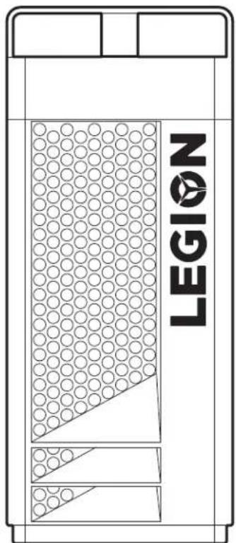
LEGIONFront and top view of the computer
text_image
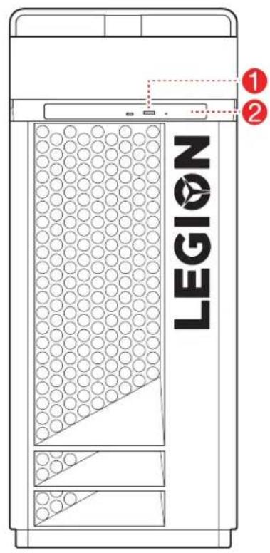
LEGION ① ②① Optical drive eject button (selected models only)
② Optical drive (selected models only)
text_image
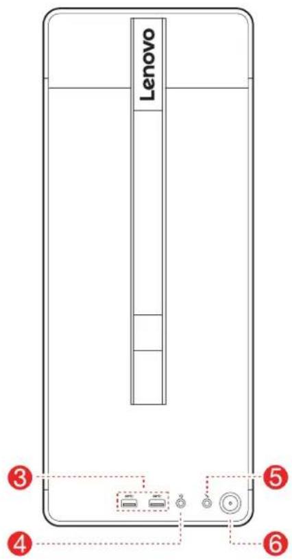
Lenovo ③ ④ ⑤ ⑥③ USB 3.1 Gen 1 connectors (2)
4 Headset connector
⑤ Microphone connector
6 Power button
ATTENTION: Be sure not to block any air vents on the computer. Blocked air vents may cause thermal problems.
NOTE: This computer only can be placed in a vertical position.
T730-28ICOT530-
text_image
Diagram of a computer tower rear panel with numbered components and labeled connectors2
4
3
6
7
7
[Non-Text]
8
(
©
9
text_image
Technical diagram of an internal device with labeled components and a numbered marker '5' pointing to a component.2
2
4
6
7
7
-
8
(
9
text_image
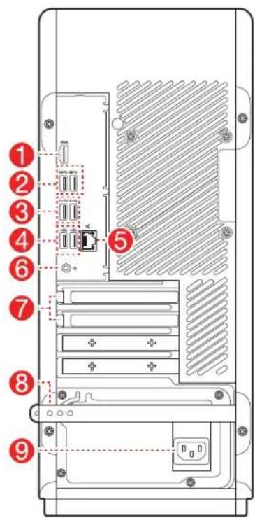
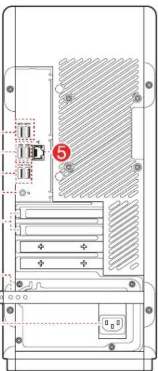
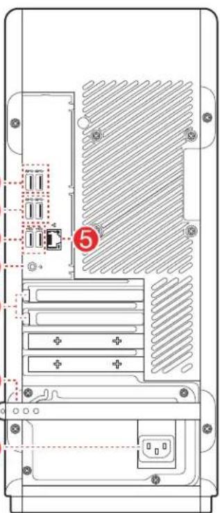
Technical diagram of a computer tower rear panel with labeled components and numbered annotation '5'① HDMI-out connector
② USB 3.1 Gen 1 connectors (2)
③ USB 3.1 Gen 2 connectors (2)
4 USB 2.0 connectors (2)
⑤ Ethernet connector
6 Headset connector
⑦ Expansion card slots (such as graphic card)
8 Rubber cable tie
9 Power connector
NOTE: If your model has two VGA monitor connectors, be sure to use the connector on the graphics adapter.
Safety information for replacing CRUs
Do not open your computer or attempt any repairs before reading the “Important safety information” in the Safety, Warranty, Environment, Recycling Information Guide and Important Product Information Guide that was included with your computer.
If you no longer have this copy of the Safety, Warranty, Environment, Recycling Information Guide and Important Product Information Guide, you can obtain one online from the website at http://www.lenovo.com/UserManuals.
Pre-disassembly instructions
Before proceeding with the disassembly procedure, make sure that you do the following:
- Turn off the power to the system and all peripherals.
- Unplug all power and signal cables from the computer.
- Place the system on a flat, stable surface.
CRUs for your computer include:
- keyboard
- mouse
- power cord
- computer cover
- hard disk drive
- optical drive
- solid state drive
- heat sink and fan assembly
- PCI express adapter
- memory module
- coin-cell battery
- power supply
This part contains instructions for replacing the following parts:
- Hard disk drive (Follow steps: 3 4 6
• Optical drive (Follow steps: ③ ④ ⑦ - Solid state drive (Follow steps: 3 4 8)
• Heat sink and fan assembly (Follow steps: 3 4 9 - PCI express adapter (Follow steps: 3 4 10)
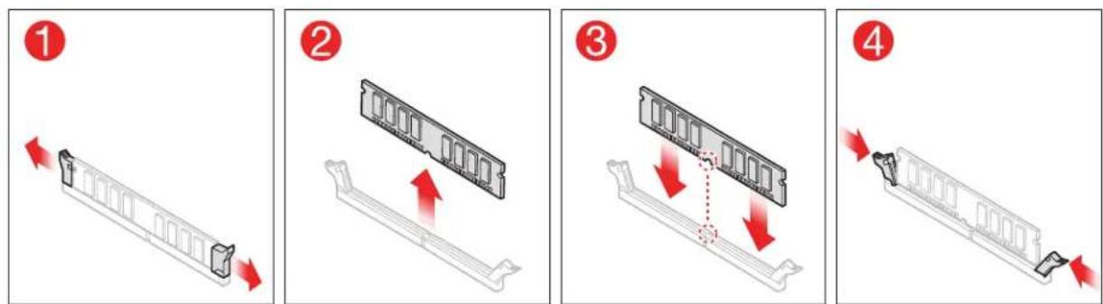
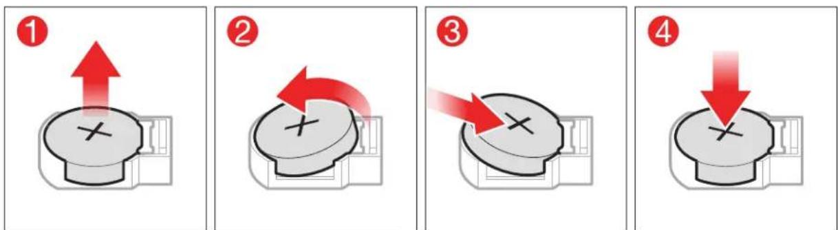
• Memory module (Follow steps: 3 4 11) - Coin-cell battery (Follow steps: 3 4 12
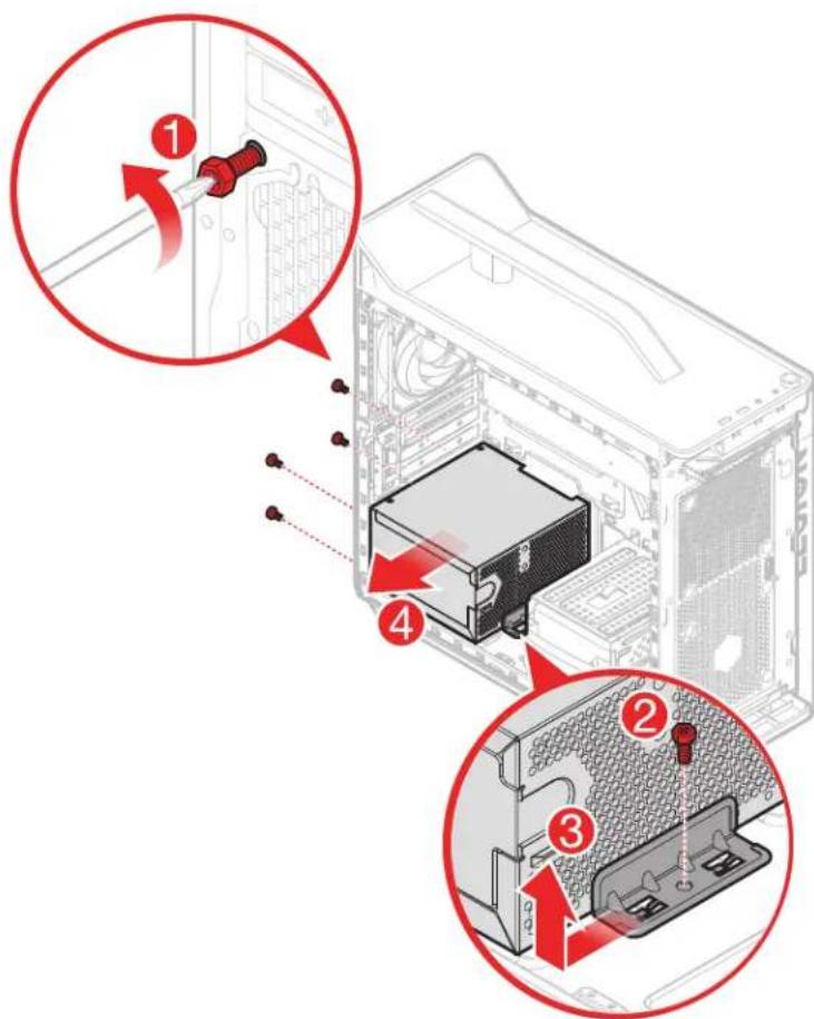
• Power supply (Follow steps: ③ ④ ⑬
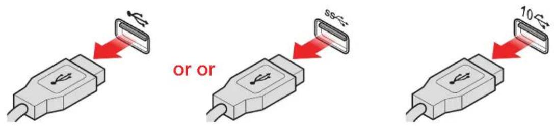
① Removing the keyboard
text_image
or or 10kΩ② Removing the mouse
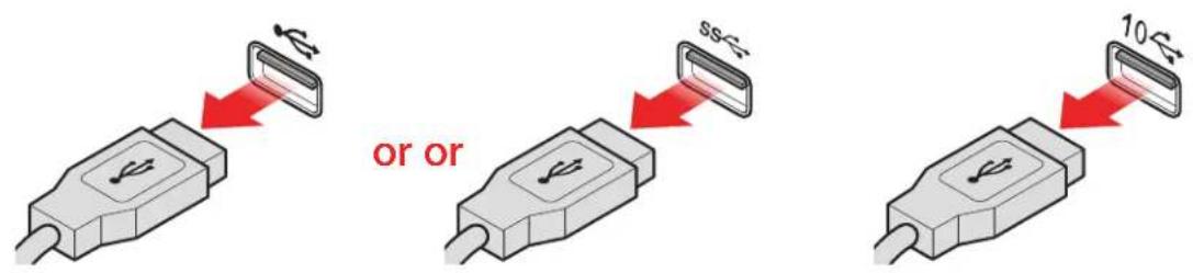
text_image
or or 5Ω 10Ω③ Removing the power cord
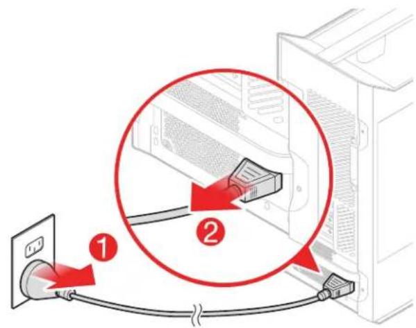
text_image
Diagram showing cable connection between server rack and power outlet, with numbered annotations indicating cable routing or connection points.4 Removing the computer cover
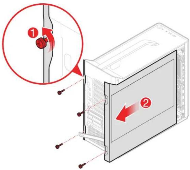
text_image
Diagram showing a device with two labeled parts (1 and 2) indicating a switch or adjustment mechanism, with arrows highlighting the process.⑤ Removing the front bezel
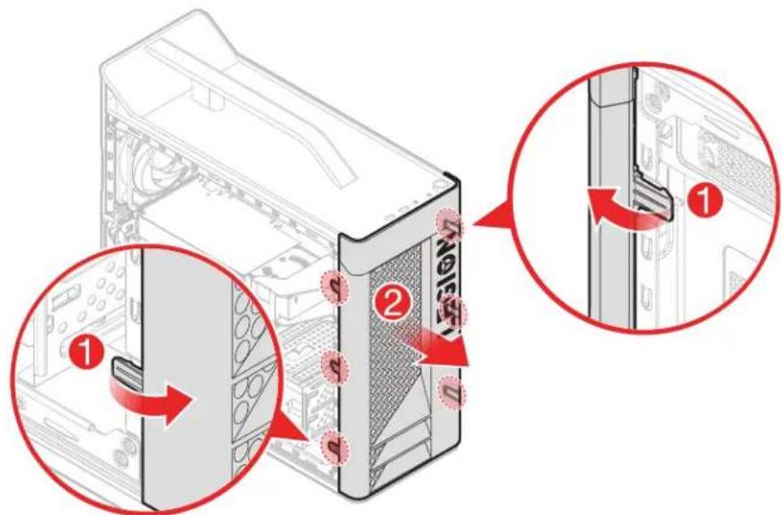
text_image
Diagram showing server rack with labeled components and directional arrows indicating assembly or movement steps⑥ Replacing a hard disk drive
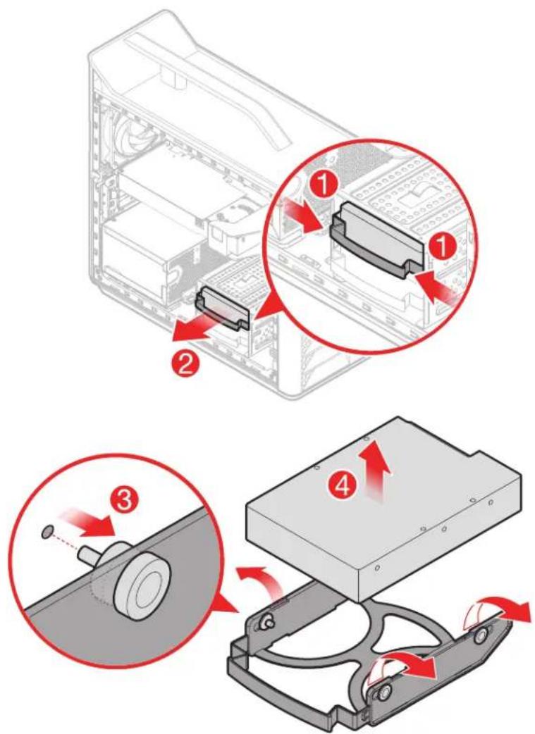
text_image
Technical diagram illustrating four steps of device assembly or mounting process, labeled 1 to 4 with red arrows indicating motion.⑦ Replacing the optical drive
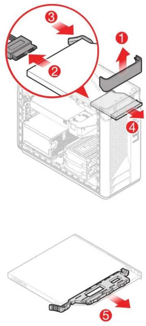
⑧ Replacing the solid state drive
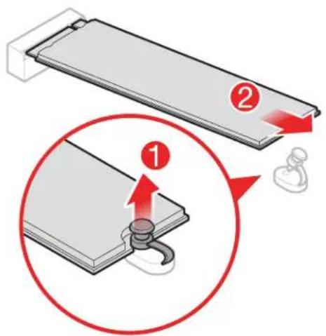
text_image
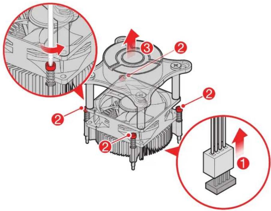
Diagram illustrating a mechanical assembly with labeled parts and a magnified view showing a component being inserted.9 Replacing the heat sink and fan assembly
- Type 1
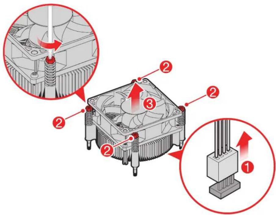
text_image
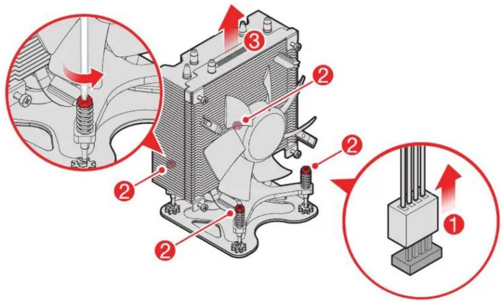
Diagram of a CPU cooling system with numbered components and red arrows indicating force application or adjustment.- Type 2
text_image
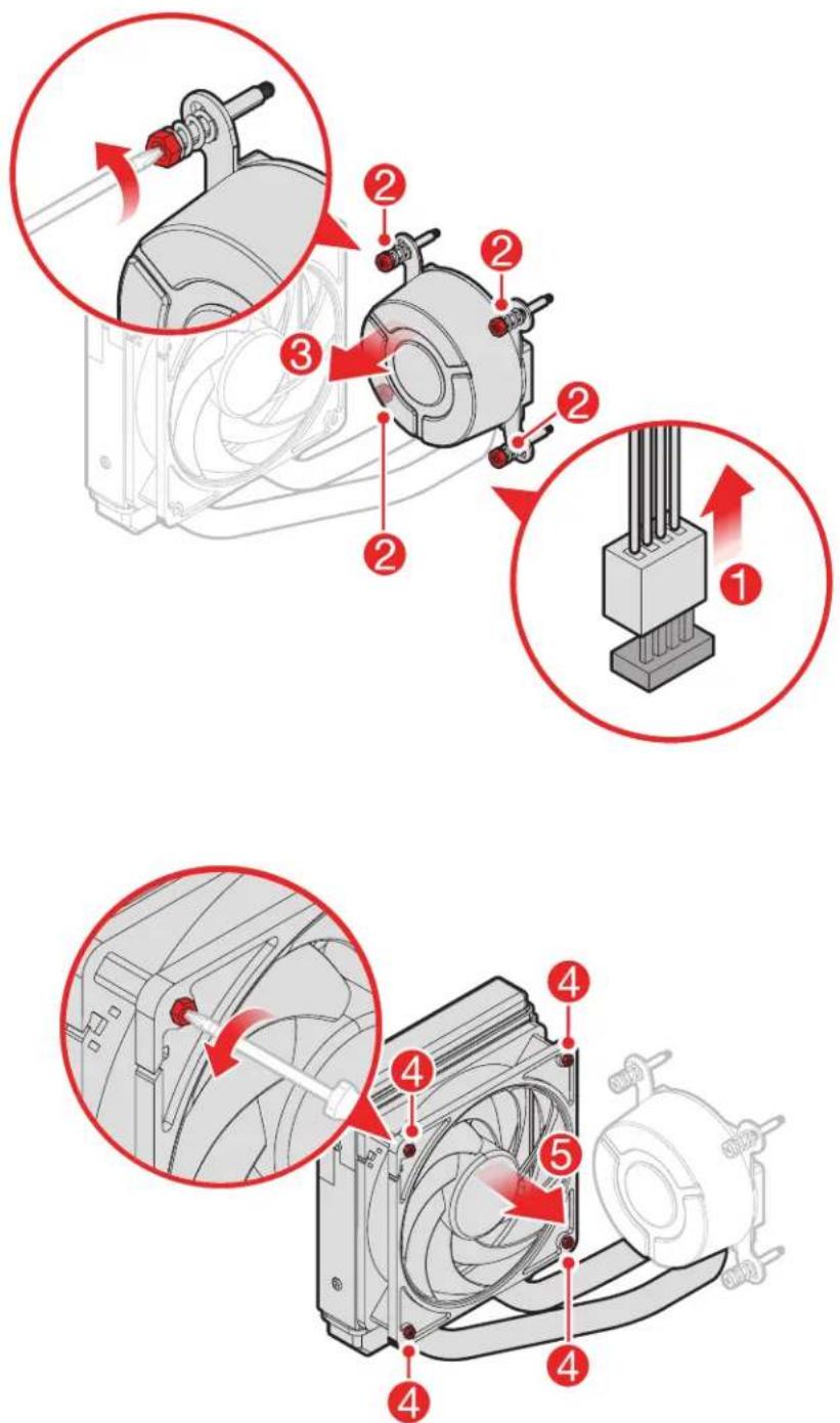
Technical diagram of a CPU cooling system with numbered components and directional arrows indicating assembly steps.- Type 3
text_image
Technical diagram of a mechanical cooling system with numbered components and red arrows indicating motion or force directions.- Type 4
text_image
Technical diagram showing mechanical assembly steps with numbered annotations for each step10 Replacing a PCI express adapter
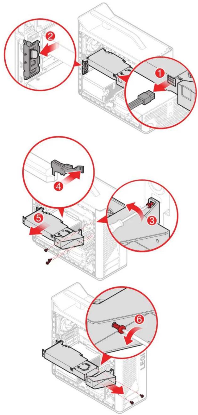
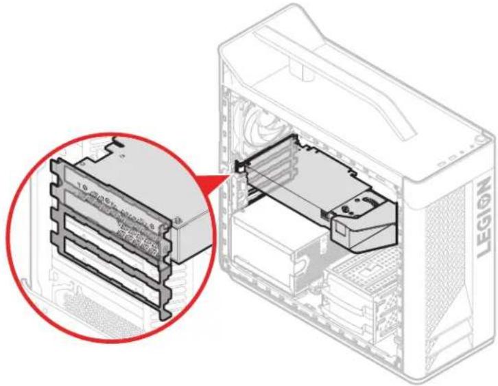
NOTE: When you install the PCI express adapter, place the PCI port area toward the EMI gasket with the correct orientation.
natural_image
Diagram of a computer tower internal structure showing internal components and a magnified view of the base panel (no text or symbols present)11 Replacing the memory module
12 Replacing the coin-cell battery
13 Replacing a power supply