
Ultra IPC-HFW7442H-Z - Security Camera Dahua Technology - Free user manual and instructions
Find the device manual for free Ultra IPC-HFW7442H-Z Dahua Technology in PDF.


| Product Type | Security Camera |
| Brand | Dahua Technology |
| Model | Ultra IPC-HFW7442H-Z |
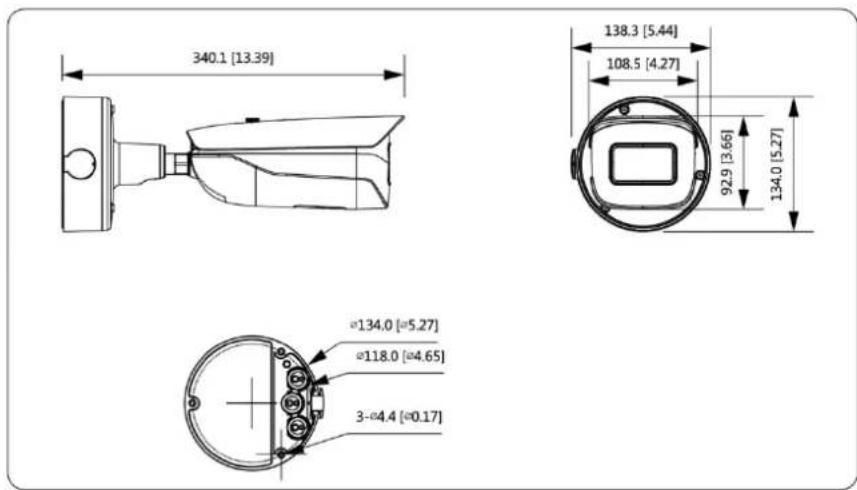
| Dimensions (H x W x D) | 340.1 mm × 138.3 mm × 108.5 mm |
| Weight | Approx. 1.5 kg |
| Power Supply | DC 12V or AC 24V, PoE (IEEE 802.3af) |
| Resolution | 4 MP (2560 × 1440) |
| Main Features | Alarm input/output, audio in/out, RS-485, analog video out, SD card slot, PoE, wide dynamic range |
| Lens | Motorized varifocal, 2.7-12 mm |
| IR Distance | Up to 50 m |
| Storage | Micro SD card slot (up to 256 GB) |
| Network Interface | RJ-45 10/100 Base-T |
| Audio Interface | 1 audio input, 1 audio output (3.5 mm) |
| Alarm Interface | 3 alarm inputs, 2 alarm outputs |
| Video Output | 1 analog video output (BNC) |
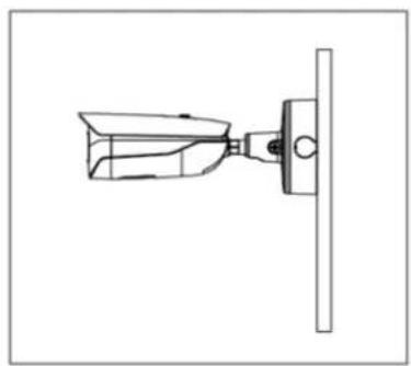
| Installation Type | Wall mount, ceiling mount, pole mount |
| Operating Temperature | -30°C to +60°C |
| Protection Rating | IP67 |
| Maintenance & Cleaning | Clean lens with air blower or soft cloth with alcohol. Body with mild detergent. Avoid volatile solvents. |
| Safety Compliance | FCC Part 15 Class A, SELV power supply |
| Spare Parts & Repairability | Standard accessories available; contact service for repairs. |
Frequently Asked Questions - Ultra IPC-HFW7442H-Z Dahua Technology
User questions about Ultra IPC-HFW7442H-Z Dahua Technology
0 question about this device. Answer the ones you know or ask your own.
Ask a new question about this device
Download the instructions for your Security Camera in PDF format for free! Find your manual Ultra IPC-HFW7442H-Z - Dahua Technology and take your electronic device back in hand. On this page are published all the documents necessary for the use of your device. Ultra IPC-HFW7442H-Z by Dahua Technology.
USER MANUAL Ultra IPC-HFW7442H-Z Dahua Technology
This manual introduces the functions, installation, and operations of the camera.
Safety Instructions
The following categorized signal words with defined meaning might appear in the manual.
| Signal Words | Meaning |
 | Indicates a medium or low potential hazard which, if not avoided, could result in slight or moderate injury. |
 | Indicates a potential risk which, if not avoided, could result in property damage, data loss, lower performance, or unpredictable result. |
 | Provides additional information as the emphasis and supplement to the text. |
Revision History
| Version | Revision Content | Release Time |
| V1.0.1 | Change the pictures of Figure 1-1.Delete the mode the Angle-mounted installation type in "3.3.1 Installation Type."Add "3.3.3 Threading Cable" and "3.3.5 Wrapping Waterproof Tape (Optional)." | April 2019 |
| V1.0.0 | First release. | November 2018 |
Privacy Protection Notice
As the device user or data controller, you might collect personal data of others such as face, fingerprints, car plate number, Email address, phone number, GPS and so on. You need to be in compliance with the local privacy protection laws and regulations to protect the legitimate rights and interests of other people by implementing measures include but not limited to: providing clear and visible identification to inform data subject the existence of surveillance area and providing related contact.
About the Manual
- The Manual is for reference only. If there is inconsistency between the manual and the actual product, the actual product shall prevail.
• We are not liable for any loss caused by the operations that do not comply with the manual.
- The manual would be updated according to the latest laws and regulations of related regions. For detailed information, see the paper manual, CD-ROM, QR code or our official website. If there is inconsistency between paper manual and the electronic version, the electronic version shall prevail.
- All the designs and software are subject to change without prior written notice. The product updates might cause some differences between the actual product and the manual. Please contact the customer service for the latest program and supplementary documentation.
- There still might be deviation in technical data, functions and operations description, or errors in print. If there is any doubt or dispute, please refer to our final explanation.
- Upgrade the reader software or try other mainstream reader software if the manual (in PDF format) cannot be opened.
- All trademarks, registered trademarks and the company names in the manual are the properties of their respective owners.
- Please visit our website, contact the supplier or customer service if there is any problem occurred when using the device.
- If there is any uncertainty or controversy, please refer to our final explanation.
Electrical Safety
- All installation and operation should conform to your local electrical safety codes.
- The power source shall conform to the Safety Extra Low Voltage (SELV) standard, and supply power with rated voltage which conforms to Limited power Source requirement according to IEC60950-1. Please note that the power supply requirement is subject to the device label.
- Make sure the power supply is correct before operating the device.
- A readily accessible disconnect device shall be incorporated in the building installation wiring.
- Prevent the power cable from being trampled or pressed, especially the plug, power socket and the junction extruded from the device.
Environment
- Do not aim the device at strong light to focus, such as lamp light and sun light; otherwise it might cause over brightness or light marks, which are not the device malfunction, and affect the longevity of Complementary Metal-Oxide Semiconductor (CMOS).
- Do not place the device in a damp or dusty environment, extremely hot or cold temperatures, or the locations with strong electromagnetic radiation or unstable lighting.
- Keep the device away from any liquid to avoid damage to the internal components.
- Keep the indoor device away from rain or damp to avoid fire or lightning.
- Keep sound ventilation to avoid heat accumulation.
- Transport, use and store the device within the range of allowed humidity and temperature.
- Heavy stress, violent vibration or water splash are not allowed during transportation, storage and installation.
- Pack the device with standard factory packaging or the equivalent material when transporting the device.
- Install the device in the location where only the professional staff with relevant knowledge of safety guards and warnings can access. The accidental injury might happen to the non-professionals who enter the installation area when the device is operating normally.
Operation and Daily Maintenance
- Do not touch the heat dissipation component of the device to avoid scald.
-
Carefully follow the instructions in the Guide when performing any disassembly operation about the device; otherwise, it might cause water leakage or poor image quality due to unprofessional disassemble. Please contact after-sale service for desiccant replacement if there is condensed fog found on the lens after unpacking or when the desiccant turns green. (Not all models are included with the desiccant).
-
It is recommended to use the device together with lightning arrester to improve lightning protection effect.
- It is recommended to ground the device to enhance reliability.
- Do not touch the image sensor directly (CMOS). Dust and dirt could be removed with air blower, or you can wipe the lens gently with soft cloth that moistened with alcohol.
- Device body can be cleaned with soft dry cloth, which can also be used to remove stubborn stains when moistened with mild detergent. To avoid possible damage on device body coating which could cause performance decrease, do not use volatile solvent such as alcohol, benzene, diluent and so on to clean the device body, nor can strong, abrasive detergent be used.
- Dome cover is an optical component, do not touch or wipe the cover with your hands directly during installation or operation. For removing dust, grease or fingerprints, wipe gently with moisten oil-free cotton with diethyl or moisten soft cloth. You can also air blower to remove dust.

- Please strengthen the protection of network, device data and personal information by adopting measures which include but not limited to using strong password, modifying password regularly, upgrading firmware to the latest version, and isolating computer network. For some device with old firmware versions, the ONVIF password will not be modified automatically along with the modification of the system password, and you need to upgrade the firmware or manually update the ONVIF password.
- Use standard components or accessories provided by manufacturer and make sure the device is installed and maintained by professional engineers.
- The surface of the image sensor should not be exposed to laser beam radiation in an environment where a laser beam device is used.
- Do not provide two or more power supply sources for the device unless otherwise specified. A failure to follow this instruction might cause damage to the device.
The regulatory information herein might vary according to the model you purchased. Some information is only applicable for the country or region where the product is sold.
FCC Information

CAUTION
Changes or modifications not expressly approved by the party responsible for compliance could void the user's authority to operate the equipment.
FCC conditions:
This device complies with part 15 of the FCC Rules. Operation is subject to the following two conditions:
- This device may not cause harmful interference.
- This device must accept any interference received, including interference that may cause undesired operation.
FCC compliance:
This equipment has been tested and found to comply with the limits for a digital device, pursuant to part 15 of the FCC Rules. This equipment generate, uses and can radiate radio frequency energy and, if not installed and used in accordance with the instructions, may cause harmful interference to radio communication.
- For class A device, these limits are designed to provide reasonable protection against harmful interference in a commercial environment. Operation of this equipment in a residential area is likely to cause harmful interference in which case the user will be required to correct the interference at his own expense.
-
For class B device, these limits are designed to provide reasonable protection against harmful interference in a residential installation. However, there is no guarantee that interference will not occur in a particular installation. If this equipment does cause harmful interference to radio or television reception, which can be determined by turning the equipment off and on, the user is encouraged to try to correct the interference by one or more of the following measures:
-
Reorient or relocate the receiving antenna.
- Increase the separation between the equipment and receiver.
- Connect the equipment into an outlet on a circuit different from that to which the receiver is connected.
- Consult the dealer or an experienced radio/TV technician for help.
Foreword ...... I
Important Safeguards and Warnings .... III
Regulatory Information......V
1 Introduction....1
1.1 Device Ports....1
1.2 Connecting Alarm Input/output 2
2 Network Configuration....4
2.1 Initializing Device 4
2.2 Modifying Device IP Address 5
2.3 Logging in Web Interface 6
3 Installation....7
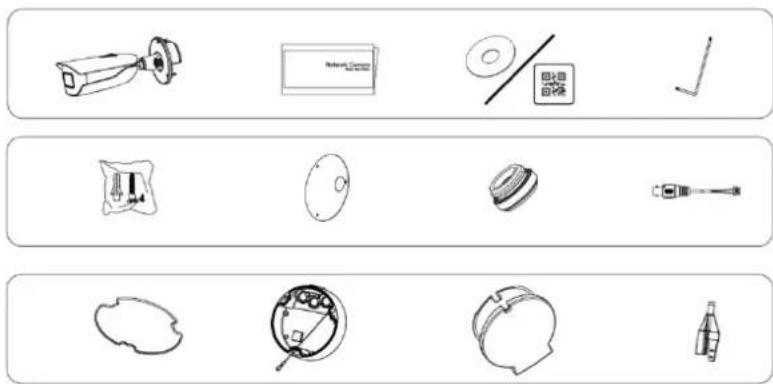
3.1 Packing List....7
3.2 Dimension 7
3.3 Installing Device 8
3.3.1 Installation Type 8
3.3.2 Installing SD Card (Optional) 8
3.3.3 Threading Cable 8
3.3.4 Attaching Device 9
3.3.5 Wrapping Waterproof Tape (Optional)....11
3.3.6 Adjusting Sunshade Cap 12
3.3.7 Adjusting Lens Angle 13
Device Ports 1.1
• Device ports might vary with different models, and the actual product shall prevail.
- Do waterproof to all the cable joints with insulating tape and waterproof tape to avoid short circuit and water damage. For the detailed operation, see the FAQ Manual.
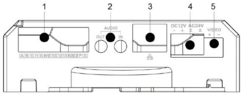
Device ports Figure 1-1
text_image
1 2 3 4 5 AUDIO OUT IN DC12V AC24V - + ≡ VIDEO + -For more information about device ports, see Table 1-1.
Table 1-1 Device ports information
| No. | Port Name | Function |
| 1 | A | RS-485_A, controls external devices, such as PTZ. |
| B | RS-485_B, controls external devices, such as PTZ. | |
| G | Ground connection of port I1, port I2 and port I3.. | |
| I1 | Receives the switch signal of external alarm source. | |
| I2 | ||
| I3 | ||
| N1 | Outputs alarm signal to alarm device.N1/N2: Normally opened alarm output port.C1/C2: General alarm output port.You can only connect N1 to C1, and N2 to C2. | |
| C1 | ||
| N2 | ||
| C2 | ||
| P | Outputs 12V DC 2W power. P is for positive pole, and G is for negative pole. | |
| G (close to P) | ||
| 2 | AUDIO OUT | 3.5 mm port, and can connect to speaker to output audio signal. |
| AUDIO IN | 3.5 mm port, and can connect to sound-pick-up device to receive audio signal. | |
| 3 | LANOPT | LAN: Connects to network with network cable;provides power to the device with PoE.OPT: Connects to OPT devices to connect to the network. |
| 4 | DC 12V or AC 24V | Inputs 12V DC or 24V AC power. Please be sure to supply power as instructed in the Guide. Device abnormality or damage could occur if power is not supplied correctly. Device abnormality or damage could occur if power is not supplied correctly. |
| 5 | VIDEO | Outputs analog video signal. |
Connecting Alarm Input/output 1.2
Alarm input/output is available on select models.
Connect alarm input device to the alarm input end of the I/O port. Step 1
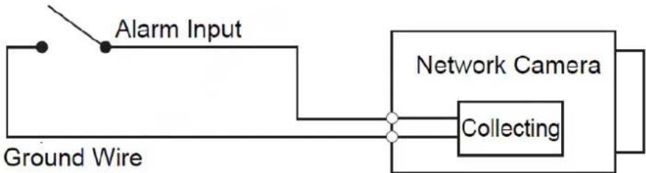
Device collects different states of alarm input port when the input signal is idling and being connected to the ground.
• Device collects logic "1" when input signal is connecting to +3V to +5V or idling.
● Device collects logic "0" when input signal being connected to the ground.
Alarm input Figure 1-2
flowchart
graph LR
    A["Ground Wire"] --> B["Alarm Input"]
    B --> C["Network Camera"]
    C --> D["Collecting"]
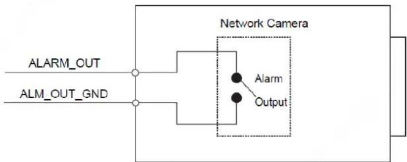
____ Connect alarm output device to the alarm output end of the I/O port. The alarm output Step 2 is relay switch output, which can only connect to NO alarm devices.
The ALARM_OUT port and the ALARM_OUT_GND port with the same number constitute a switch for alarm output. See Figure 1-3. The switch is open normally and closes when there is alarm output.
Alarm output Figure 1-3
flowchart
graph LR
    A["ALARM_OUT"] --> B(( ))
    C["ALM_OUT_GND"] --> D(( ))
    B --> E["Network Camera"]
    D --> E
    E --> F["Alarm"]
    E --> G["Output"]
Log in web interface, and configure alarm input and alarm output in alarm setting. Step 3
- The alarm input in the web interface is corresponding to the alarm input end of the I/O port. There will be high level and low level alarm signal generated by the alarm input device when alarm occurs, set the input mode to "NO" (default) if the alarm
input signal is logic "0" and to "NC" if the alarm input signal is logic "1".
- The alarm output in the web interface is corresponding to the alarm output end of the device, which is also alarm output end of the I/O port.
Device initialization and IP address setting can be finished with the "ConfigTool" or in web interface. For more information, see the WEB operation manual.

- Device initialization is available on select models, and it is required at first use or after the device being reset.
- Device initialization is available only when the IP addresses of the device (192.168.1.108 by default) and the PC stay in the same network segment.
- Plan useable network segment properly to connect the device to the network.
- The following figures and interfaces are for reference only, and the actual product shall prevail.
Initializing Device 2.1
Double-click "ConfigTool.exe" to open the tool. Step 1
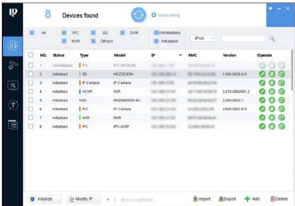
Click Step 2
The Modify IP interface is displayed. See Figure 2-1.
Figure 2-1 Modify IP
text_image
8 Devices found All IPC SD DVR Uninitialized IPV4 NVR Cthers Initialized NO. Status Type Model IP MAC Version Operate 1 Uninitialized IPC IPC-HF5421E 2 Initialized SD HDZ302DIN 1.000.0026.0.R 3 Initialized P Camera IP Camera 4 Initialized HCVR XVR 3.218.0000001.2 5 Initialized NVD NVD0405DH-4K 3.200.0002.1 6 Initialized IPC IP Camera 2.600.0003.0.R 7 Initialized NVR NVR 8 Initialized IPC IPC-A35PStep 3 Click Search setting.
The Setting interface is displayed.
Step 4 Enter the start IP address and end IP address of the network segment in which you want to search devices, and then click OK.
All the devices found in the network segment are listed.
Step 5 Select one or several devices with Status shows Uninitialized, and then click Initialize.
The Device initialization interface is displayed.
Select the devices that need initialization, and then click Initialize. Step 6
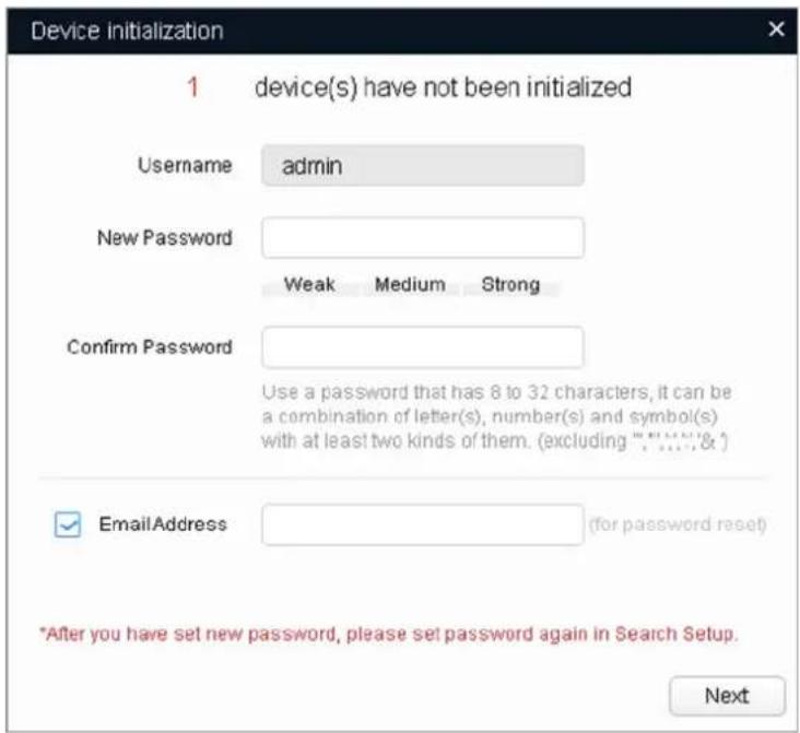
The password setting interface is displayed. See Figure 2-2.
Password setting Figure 2-2
text_image
Device Initialization 1 device(s) have not been initialized Username admin New Password Weak Medium Strong Confirm Password Use a password that has 8 to 32 characters, it can be a combination of letter(s), number(s) and symbol(s) with at least two kinds of them. (excluding "..", ..., & ) EmailAddress (for password reset) *After you have set new password, please set password again in Search Setup. NextSet and confirm the password of the devices, then enter a valid email address, and Step 7 then click Next.
The final setting interface is displayed.

Password can be modified or reset in System Settings.
Select the options according to your needs, and then click OK. Step 8
The Initialization interface is displayed after initialization is completed. Click the success icon () or the failure icon () for the details.
Click Finish. Step 9
The device status in the Modify IP interface (Figure 2-1) turns to Initialized.
Modifying Device IP Address 2.2

- You can modify IP address of one or multiple devices in one time. This section is based on modifying IP addresses in batch.
- Modifying IP addresses in batch is available only when the corresponding devices have the same login password.
Step 1 Do "Step 1" to "Step 4" in "2.1 Initializing Device" to search devices in your network segment.

After clicking Search setting, enter the username and password, and please make sure they are the same as what you set during initialization, otherwise there will be "wrong password" notice.
Step 2 Select the devices which IP addresses need to be modified, and then click Modify IP.
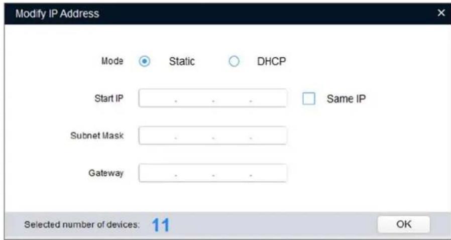
The Modify IP Address interface is displayed. See Figure 2-3.
Modify IP Address Figure 2-3
text_image
Modify IP Address Mode Static DHCP Start IP . . . . Same IP Subnet Mask . . . . Gateway . . . . Selected number of devices: 11 OKStep 3 Select Static mode, and then enter start IP, subnet mask, and gateway.

- IP addresses of multiple devices will be set to the same if you select the Same IP checkbox.
- If DHCP server is available in the network, devices will automatically obtain IP addresses from DHCP server when you select DHCP.
Click OK. Step 4
Logging in Web Interface 2.3
____ Open IE browser, then enter the IP address of the device in the address bar, and then Step 1 press Enter.
If the setup wizard is displayed, finish the settings as instructed.
____ Enter the user name and password in the login box, and then click Login. Step 2
Step 3 For first time login, click Click Here to Download Plugin, and then install the plugin as instructed.
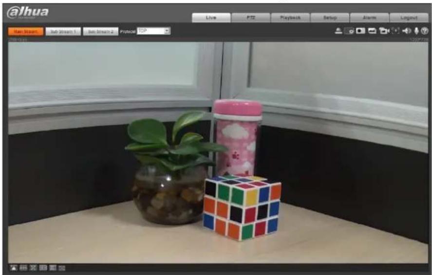
The main interface is displayed when the installation is finished. See Figure 2-4.
Main interface Figure 2-4
text_image
@lhua Live PTZ Playback Setup Alarm Logout Run Stream Sub Stream 1 Sub Stream 2 Protocol TCP 13906004Packing List 3.1
- The tool required for the installation such as electric drill is not provided in the packing.
- The operation manual and related tool are contained in the disk or the QR code, and the actual packing shall prevail.
natural_image
Collection of technical diagrams showing various mechanical and electrical components (no text or labels)Dimension 3.2
Following figures are for reference only, and the actual product shall prevail.
Unit (mm [inch])
text_image
340.1 [13.39] 138.3 [5.44] 108.5 [4.27] 92.9 [3.66] 134.0 [5.27] Ø134.0 [Ø5.27] Ø118.0 [Ø4.65] 3-Ø4.4 [Ø0.17]Installing Device 3.3
3.3.1 Installation Type
natural_image
Simple line drawing of a mechanical lever or bracket with a vertical bar (no text or symbols)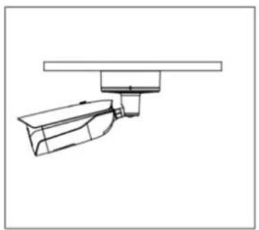
natural_image
Technical line drawing of a mechanical assembly or mounting bracket (no text or symbols)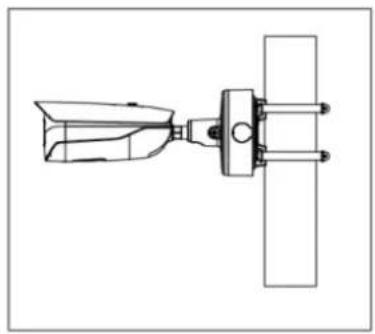
natural_image
Technical line drawing of a mechanical assembly with no visible text or symbols3.3.2 Installing SD Card (Optional)

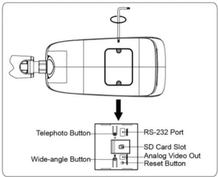
- Pull the power plug off before installing or removing the SD card.
- Press and hold the button for 10 s to reset the camera.
text_image
Telephoto Button RS-232 Port Wide-angle Button SD Card Slot Analog Video Out Reset Button3.3.3 Threading Cable
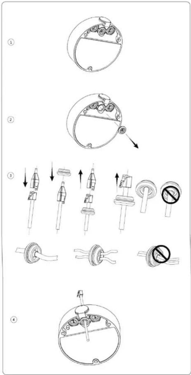
This section takes threading network cable for example.
text_image
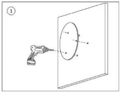
Technical diagram illustrating the step-by-step assembly of a mechanical component with labeled parts and directional arrows.3.3.4 Attaching Device

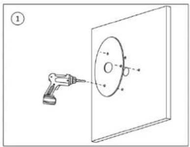
Make sure the mounting surface is strong enough to hold at least three times of the weight of the device and bracket.
Cable going through the mounting surface
natural_image
Diagram of a precision optical instrument interacting with a circular target on a screen (no text or symbols)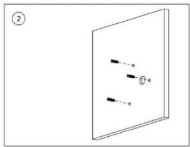
text_image
② θ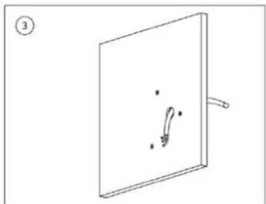
natural_image
Simple line drawing of a rectangular panel with a handle and internal symbols, no text or labels present.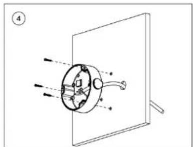
text_image
Technical diagram showing a mechanical assembly with labeled components and motion indicators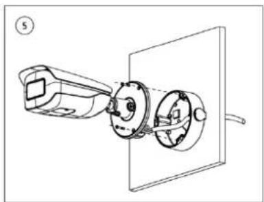
natural_image
Technical line drawing of a mechanical assembly with a tool and rotating components (no text or symbols)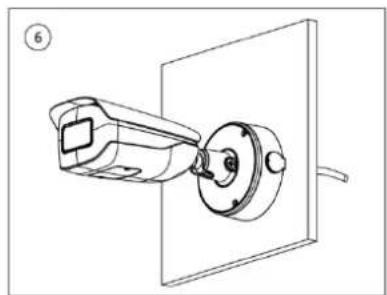
natural_image
Technical line drawing of a mechanical assembly with a cylindrical component inserted into a rectangular housing (no text or symbols)Cable going through the side cable tray
natural_image
Diagram of a robotic arm projecting a circular target onto a rectangular panel (no text or symbols)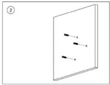
natural_image
Simple line drawing of a rectangular panel with three vertical lines and dots, no text or symbols present.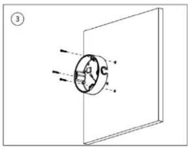
natural_image
Diagram showing light rays interacting with a circular object inside a rectangular frame (no text or symbols)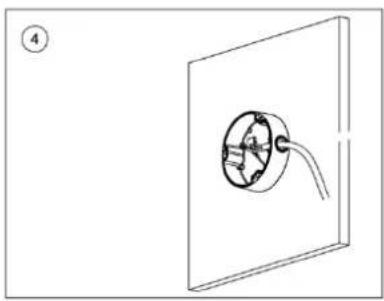
natural_image
Simple line drawing of a circular component with a curved tube inside, mounted on a rectangular frame (no text or symbols)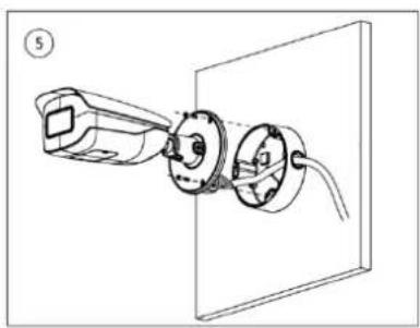
natural_image
Technical line drawing of a wall-mounted electrical socket connected to a terminal block (no text or symbols)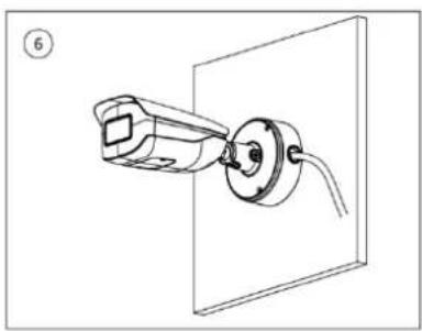
natural_image
Technical line drawing of a mechanical assembly with a cylindrical component mounted on a wall (no text or symbols)3.3.5 Wrapping Waterproof Tape (Optional)

This part is needed when the cable connector is out of the junction box.
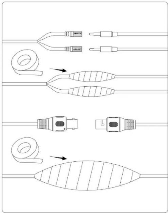
text_image
Technical diagram showing cable installation and component assembly with labeled connectors and directional arrows indicating assembly steps.3.3.6 Adjusting Sunshade Cap
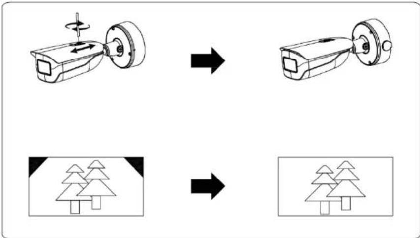
flowchart
graph TD
    A["Step 1: Rotation of a device"] --> B["Step 2: Rotation of a device"]
    B --> C["Step 3: Transformation to final state"]
    C --> D["Final state"]
3.3.7 Adjusting Lens Angle
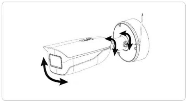
natural_image
Technical line drawing of a mechanical device with directional arrows indicating motion (no text or symbols)ZHEJIANG DAHUA VISION TECHNOLOGY CO., LTD.
Address: No.1199, Bin'an Road, Binjiang District, Hangzhou, P.R. China
Postcode: 310053
Tel: +86-571-87688883
Fax: +86-571-87688815
Email: overseas@dahuatech.com
Website: www.dahuasecurity.com