
Pro IPC-HDW5831R-ZE - Security Camera Dahua Technology - Free user manual and instructions
Find the device manual for free Pro IPC-HDW5831R-ZE Dahua Technology in PDF.


User questions about Pro IPC-HDW5831R-ZE Dahua Technology
0 question about this device. Answer the ones you know or ask your own.
Ask a new question about this device
Download the instructions for your Security Camera in PDF format for free! Find your manual Pro IPC-HDW5831R-ZE - Dahua Technology and take your electronic device back in hand. On this page are published all the documents necessary for the use of your device. Pro IPC-HDW5831R-ZE by Dahua Technology.
USER MANUAL Pro IPC-HDW5831R-ZE Dahua Technology
Dahua Network Camera Web 3.0 Operation Manual
Dahua Network Camera Web3.0 Operation Manual
Version 1.0.1
Dahua Vision Technology CO., LTD
Dahua Network Camera Web 3.0 Operation Manual
Table of Contents
1 Network Config....1
1.1 Network Connection .... 1
1.2 Log in .... 1
2 Live....6
2.1 Encode Setup....6
2.2 System Menu....7
2.3 Video Window Function Option 7
2.4 Video Window Setup 8
2.4.1 Image Adjustment....8
2.4.2 Original Size....9
2.4.3 Full Screen....9
2.4.4 Width and Height Ratio....10
2.4.5 Fluency Adjustment....10
2.4.6 Rules Info 10
2.4.7 Zoom and Focus 10
2.4.8 Fisheye/Trigger Track 10
3 PTZ Control....15
3.1 Scan....16
3.2 Preset....17
3.3 Tour....17
3.4 Pattern....18
3.5 Assistant....19
3.6 Light Wiper....19
4 Playback....20
4.1 Playback....20
4.1.1 Function of Play....21
4.1.2 Playback File 22
4.1.3 Playback Cut....24
4.1.4 Record Type 24
4.1.5 Progress Bar....24
4.1.6 Assistant Function 25
4.2 Picture Playback 25
4.2.1 Play 26
4.2.2 Playback File 26
4.2.3 Snapshot Type 28
5 Setup....30
5.1 Camera....30
@ahua
Dahua Network Camera Web 3.0 Operation Manual
5.1.1 Conditions....30
5.1.2 Video 42
5.1.3 Audio 54
5.2 Network....56
5.2.1 TCP/IP 56
5.2.2 Connection 59
5.2.3 PPPoE 61
5.2.4 DDNS 62
5.2.5 IP filter 64
5.2.6 SMTP (e-mail) 64
5.2.7 UPnP 66
5.2.8 SNMP 67
5.2.9 Bonjour 69
5.2.10 Multicast 70
5.2.11 4G 70
5.2.12 WIFI....72
5.2.13 802.1x 75
5.2.14 QoS....76
5.2.15 HTTPS....77
5.3 Event 86
5.3.1 Video detection....86
5.3.2 Audio Detection....93
5.3.3 Smart Plan....95
5.3.4 Intelligence Behavior Analytics 95
5.3.5 Face Detection 103
5.3.6 People Counting 105
5.3.7 Heat Map 107
5.3.8 Alarm 110
Dahua Network Camera Web 3.0 Operation Manual
5.5.6 Remote control 132
5.5.6 Auto Maintenance....133
5.5.7 Upgrade 134
5.6 Information....134
5.6.1 Version....134
5.6.2 Log....135
5.6.3 Online User....135
6 Alarm....137
7 Log out....139
Dahua Network Camera Web 3.0 Operation Manual
Important
The following functions are for reference only. Some series products may not support all the functions listed below.
Dahua Network Camera Web 3.0 Operation Manual
1 Network Config
1.1 Network Connection
Network camera and PC connection mainly has two ways, see Figure 1-1 and Figure 1-2.
Figure 1-1
Figure 1-2
Before you access network camera via the Internet, you need to have its IP address. User can use Config Tool to search IP of the network camera. Please refer to Config Tool manual.
1.2 Log in
It needs to install WEB plug-in when you use WEB client for the first time, the exact operation steps are shown as follows:
Open IE and input network camera address in the address bar. (The factory default IP address is 192.168.1.108).
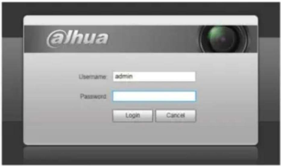
After successful connection, the login interface is shown as in Figure 1-3; input your user name and password. Default factory username is admin and password is admin.
text_image
@Jhua Username: admin Password: Login CancelFigure 1-3
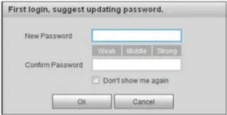
The system will display "Update Password" prompt box for your first login, users need to modify the password and save it properly.
text_image
First login, suggest updating password. New Password Weak Middle Strong Confirm Password Don't show me again Ok CancelFigure 1-4
After successful login, you may see the interface shown as in Figure 1-5.
Dahua Network Camera Web 3.0 Operation Manual
Figure 1-5
Click on “Please click here to download and install the plug-in”. The system pops up warning information to ask you whether run or save this plug-in. See Figure 1-6.
Dahua Network Camera Web 3.0 Operation Manual
Figure 1-6
You must either run or save the file to local and install it. Follow the following steps. Click on run, you will see Figure 1-7 and Figure 1-8.
Figure 1-7
Dahua Network Camera Web 3.0 Operation Manual
Figure 1-8
When plug-in installation completes, the installation page closes automatically. The web-end will refresh automatically, and then you can view video captured by the camera.
Figure 1-9
Dahua Network Camera Web 3.0 Operation Manual
2 Live
After you logged in, you can see the live monitor window. See Figure 2-1.
1
2
3
4
Figure 2-1
There are four sections:
Section 1: Encode setup bar
Section 2: System menu
Section 3: Window function option bar
Section 4: Window adjust bar
2.1 Encode Setup
Note: Some series don't support sub stream 2.
The encode setup interface is shown as in Figure 2-2.
Figure 2-2
Please refer to the following sheet for detailed information.
Dahua Network Camera Web 3.0 Operation Manual
| Parameter | Function |
| Main stream | Click it to enable main stream video monitoring and click again to disable it. Generally for storage and monitor. |
| Sub Stream 1 | Click it to enable Sub Stream1 video monitoring and click again to disable it. When network bandwidth is insufficient, it substitutes main stream for monitoring. |
| Sub Stream 2 | Click it to enable Sub Stream 2 video monitoring and click again to disable it. When network bandwidth is insufficient, it substitutes main stream for monitoring. |
| Protocol | You can select stream media protocol from the dropdown list.There are three options: TCP/UDP/Multicast |
2.2 System Menu
System menu is shown as in Figure 2-3.
Please refer to chapter 2 Live, chapter 3 PTZ, chapter 4 Playback, chapter 5 Setup, chapter 6 Alarm, chapter 7 Log out for detailed information.
Figure 2-3
2.3 Video Window Function Option
The interface is shown as below. See Figure 2-4.
1 2 3 4 5 6 7 8 9
Figure 2-4
Please refer to the following sheet for detailed information.
| SN | Parameter | Function |
| 1 | Relay-out | It shows if there is any alarm output, status description is as follows:Red: means there is alarm output.Grey: means alarm is over.Click on the button to force alarm to be on or off. |
Dahua Network Camera Web 3.0 Operation Manual
| 2 | Digital Zoom | When the video is in the original status, click it you can select any zone to zoom in. In the non-original status, you can drag the zoom-in zone in specified range. Right click mouse to restore previous status.Click it; you can use the middle button of the mouse to zoom in/out the video size. |
| 3 | Snapshot | Click on the button to snapshot, save picture to path in Ch 5.1.2.5. |
| 4 | Triple Snapshot | Click it to take snapshot upon the video at the frequency of one picture per second. All images are saved to path in Ch 5.1.2.5. |
| 5 | Record | Click it to record the video. All videos are saved to path in Chapter 5.1.2.5. |
| 6 | Easy focus | Click it, you can see there are two parameters on the preview video : AF Peak and AF Max.AF Peak: It is to display the video definition during the focus process.AF Max: It is the most suitable value for the video definition.The close the AF Peak and AF Max is, the better the focus effect is. |
| 7 | Audio | Turn on or off audio when you are monitoring. |
| 8 | Talk | Click it to start or end bidirectional talk. |
| 9 | Help | Click it to open help file. |
2.4 Video Window Setup
The interface is shown as in Figure 2-5.
Figure 2-5
2.4.1 Image Adjustment
See Figure 2-6 for image adjustment.
Dahua Network Camera Web 3.0 Operation Manual
Figure 2-6
Click this button to display/hide image control interface. Click it to open picture setup interface. This interface is on the top right pane.
Please refer to the following sheet for detailed information.
| Parameter | Function | |
| Video setup | It is to adjust monitor video brightness. | Note:All the operations here apply to WEB end only.Please go to Setup->Camera->Conditions to adjust corresponding items. |
| It is to adjust monitor video contrastness. | ||
| It is to adjust monitor video hue. | ||
| It is to adjust monitor video saturation. | ||
| Reset | Restore brightness, contrastness saturation and hue to system default setup. |
2.4.2 Original Size
Click this button to go to original size. It is to display the actual size of the video stream. It depends on the resolution of the bit stream.
2.4.3 Full Screen
Click it to go to full-screen mode. Double click the mouse or click the Esc button to exit the full screen.
2.4.4 Width and Height Ratio
Click it to restore original ratio or suitable window.
2.4.5 Fluency Adjustment
There are three levels of fluency for you to select (Realtime, Normal, and Fluency). The default is normal.
2.4.6 Rules Info
Click the button, preview image will display intelligent rules after enabling; it is "enable" by default.
2.4.7 Zoom and Focus
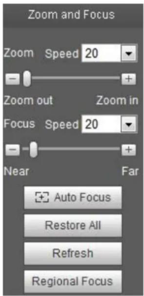
Click this button and the focus zooming interface appears on the right of preview interface, as shown in Figure 2-7, click left mouse button to adjust focus zooming configuration.
Note:
- The product series which support motorized zoom, synchronous focus and back focus have this button.
• Auto-focus after zoom and focus adjustment.
2.4.8 Fisheye/Trigger Track
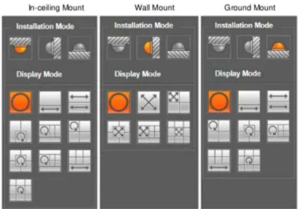
Click the button, installation mode and display mode interface will show up on the right of the preview interface, see Figure 2-8 and Figure 2-9, single click to switch different installation mode and display mode, or different display modes, it is enabled by default.
Note:
It is only supported by some models.
text_image
Zoom and Focus Zoom Speed 20 - Zoom out Zoom in Focus Speed 20 - Near Far Auto Focus Restore All Refresh Regional FocusFigure 2-7
| Parameter | Function |
| Zoom | Adjust the focal length of the lens by clicking or long pressing "+" - "buttons.Step length is used to adjust the length of one step with one click. |
| Focus | Adjust the sharpness of the lens by clicking or long pressing "+"、"-" buttons.Step length is used to adjust the length of one step with one click. |
| Auto-focus | Click to adjust the image definition automatically.Note:Other lens operations are not allowed during the process of auto-focus. |
| Reset All | Reset the lens to zero position to eliminate the accumulative error of lens.Note:Please reset when the image adjustment is not clear or operating zoom focus many times. |
| Refresh | Synchronize the location of drag slider of lens and zoom focus after hardware zoom focusing. |
| Regional Focus | Click it and use the mouse to select a zone, then the device can auto focus within the specific region. |
text_image
In-ceiling Mount Wall Mount Ground Mount Installation Mode Display Mode Installation Mode Display Mode Installation Mode Display ModeFigure 2-8
| parameter | Note | |
| Installation Mode | Three modes which are ceiling mount, wall mount and ground mount. | |
| Display Mode | It represents the display mode of the current image (default supports original image mode), the display modes may be different according to different installation modes. It is shown as follows:Ceiling: 1P+1、2P、1+2、1+3、1+4、1P+6、1+8.Wall: 1P、1P+3、1P+4、1P+8.Ground: 1P+1、2P、1+3、1+4、1P+6、1+8.Note:The default displays original image mode when switching installation mode. | |
| In-ceiling/Wall/Ground |  Originalimage Originalimage | It menas the original image without de-warping |
| In-ceiling/Ground |  1P+1 1P+1 | 360° expanded rectangular panorama + independent sub image, the sub image and the subbox in the expanded rectangular panorama support zoom and movement, for the expanded rectangular panorama also supports left and right starting point movement. |
 2P 2P | Two related 180° expanded rectangular pictures, two subwindows form 360° panorama anytime, which is also called "dual panorama". Two expanded rectangular pictures both support left and right movement starting point, which are also linked by eachother. | |
 | Original image + 2 independent sub images, both the sub image and the subbox in the original image support zoom and movement. The original image also | |
Dahua Network Camera Web 3.0 Operation Manual
| parameter | Note | |
| 1P+6 | 360° expanded rectangular panorama +6 independent sub image, both the sub image and the subbox in the expanded rectangular panorama support zoom and movement, for the expanded rectangular panorama also supports left and right starting point movement. Original image + 8 independent sub images, both the sub image and the subbox in the original image support zoom and movement. The original image also supports changing starting point by rotation | |
| 1+8 | ||
| 1P | From left to right 180° expanded rectangular panorama, which supports up and down movement and changes vertical angle of view. | |
| 1P+3 | 180° expanded rectangular panorama+3 independent sub images, both the sub images and the sub box in the expanded rectangular panorama support zoom and movement, expanded rectangular panorama supports up and down movement and changes vertical angle of view. | |
| Wall | 180° expanded rectangular panorama+4 independent sub images, both the sub images and the sub box in the expanded rectangular panorama support zoom and movement, expanded rectangular panorama supports up and down movement and changes vertical angle of view. | |
| 1P+4 | ||
| 1P+8 | 180° expanded rectangular panorama+8 independent sub images, both the sub images and the sub box in the expanded rectangular panorama support zoom and movement, expanded rectangular panorama supports up and down movement and changes vertical angle of view. |
Figure 2-9
Enable the trigger track on the interface of tripwire or intrusion, and draw the rule of tripwire or intrusion, the scene of trigger track window will change according to the moving object when it triggers rule alarm until the moving object disappears from the view range of the camera. Please refer to “5.3.4 IVS” for more details about the rules drawing and parameter config of tripwire and intrusion.
Trigger track includes three modes which are 1P, 1P+3 and 1P+5.
Dahua Network Camera Web 3.0 Operation Manual
1P: Original picture
1P+3: Original picture and three trigger track windows, it can adjust the location and size of three trigger track windows on the original picture.
1P+5: Original picture and five trigger track windows, it can adjust the location and size of five trigger track windows on the original picture.

Dahua Network Camera Web 3.0 Operation Manual
3 PTZ Control
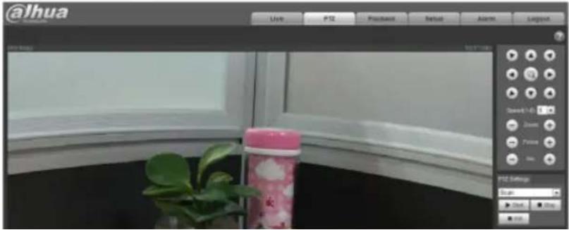
Here you can view direction keys, speed, zoom, focus, iris, preset, tour, scan, pattern, aux on, off and PTZ setup button. See Figure 3-1.
Note:
Before PTZ operation, please make sure you have properly set PTZ protocol. (Please refer to Ch 5.5.3). Currently only IPC-HFXXXX series and -PT series products can support PTZ function.
| Parameter | Note |
| PTZ direction | ● PTZ supports eight directions: left/right/up/down/upper left/upper right/bottom left/bottom right. |
| Speed | It controls rotation speed. The longer the step length, the higher the speed.Step length control PTZ, zoom, focus and iris. |
| Use mouse to draw a box in monitoring video, PTZ will rotate and focus to quickly positioning. |
text_image
@Ihua Use PID Position Setup Alarm Layout Speed: 100% Draws Frames OK PID Settings Run: Start Stop SaveDahua Network Camera Web 3.0 Operation Manual
Figure 3-2
PTZ setting interface is shown as in Figure 3-3.
Here you can set scan, preset, tour, pattern, assistant function and light and wiper plus view coordinate.
Figure 3-3
3.1 Scan
Scan interface is shown in Figure 3-4.

text_image
PTZ Settings Scan ► Start ■ Stop ◆ Set Set Left Set RightFigure 3-4
Steps to scan are:
Step 1. Click on Set button, display icon. Set Left Set Right
Step 2. Move via direction key to select left, click on Set Left to set left border of camera
Step 3. Move via direction key to select right, click on Set Right to set right border of camera.
Step 4. Complete scan path setup.
3.2 Preset
Preset interface is shown in Figure 3-5.

text_image
PTZ Settings Preset 0 0~255 Go to Set Preset + Add - DelFigure 3-5
Steps to preset are:
Step 1. In preset box, input preset value.
Step 2. Click on Go to, camera rotates to preset position.
Step 3. Use direction key to rotate camera, and in preset box input preset value.
Step 4. Click on Add to add a preset. Range of preset relates to PTZ protocol.
3.3 Tour
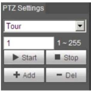
Tour interface is shown in Figure 3-6.
text_image
PTZ Settings Tour 1 1 ~ 255 ► Start ■ Stop + Add - DelFigure 3-6
Steps to tour are:
Step 1. In tour box, input tour path value.
Step 2. Click on Add. Range of tour relates to PTZ protocol.
Step 3. In preset box, input preset value.
Step 4. Click on Add as to add a preset in this tour. If click on Del, it deletes this preset in tour.
Note:
You can add more than one preset here, or delete more than one preset.
3.4 Pattern
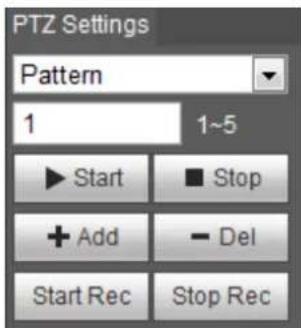
Pattern interface is shown in Figure 3-7.
text_image
PTZ Settings Pattern 1 1~5 ► Start ■ Stop + Add - Del Start Rec Stop RecFigure 3-7
Steps to set pattern are shown as follows:
Step 1
Input pattern serial number value in the box, click "Add" and it will display "Start Rec" and "Stop Rec".
Step 2
Click "Start Rec" to implement a series of operations such as zoom, focus, iris, direction and so on.
Step 3
Click "Stop Rec" to complete the setting of a pattern path.
Step 4
Dahua Network Camera Web 3.0 Operation Manual
Click “Start” and it will start pattern according to the pattern spot which has been set; click “Stop” and the pattern ends.
3.5 Assistant
Assistant interface is shown in Figure 3-8.
Figure 3-8
Steps to assistant are:
Step 1. In assistant box input assistant value.
Step 2. Click on Aux On to turn on aux function.
Click on Aux off to turn off aux function.
3.6 Light Wiper
Light wiper interface is shown in Figure 3-9.
Figure 3-9
Steps to light wiper are:
Click on Enable to enable light wiper function.
Click on Disable to disable light wiper function.
Dahua Network Camera Web 3.0 Operation Manual
4 Playback
Web client playback supports video playback and picture playback.
Note:
Before playback, user shall set storage management as in Ch. 5.4.
4.1 Playback
The playback interface is shown as in Figure 4-1.
6
2
1
3
4 5
Figure 4-1
There are four sections:
Section 1: Function of play
Section 2: Playback file
Section 3: Play time cut
Section 4: Record type
Section 5: Progress bar
Section 6: Assistant function
20

Dahua Network Camera Web 3.0 Operation Manual
4.1.1 Function of Play
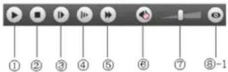
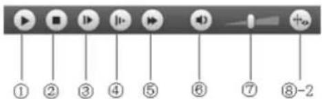
The function of play is shown as in Figure 4-2 and Figure 4-3.
text_image
① ② ③ ④ ⑤ ⑥ ⑦ ⑧-1Figure 4-2
text_image
① ② ③ ④ ⑤ ⑥ ⑦ ⑧-2Figure 4-3
| Parameter | Function |
| 1 Play | When you see this button, it means pause or not played record. Click on this button, switch to normal play status. |
| 2 Stop | Click this button to stop playing. |
| 3 Play by frame | Click on this button to go to next frame.Note:You shall pause record when you use this function. |
Dahua Network Camera Web 3.0 Operation Manual
4.1.2 Playback File
In calendar, blue date represents data currently has video record or snapshot. See Figure 4-4.
Figure 4-4
| Parameter | Function |
| File Type | Select “dav”, as video playback.Select “jpg” as picture playback. |
| Data Source | Default is SD card. |
Step 1. Click on data in blue, time axis displays record file progress bar in color. While, green represents normal record, yellow represents motion detect record, red represents alarm record, and blue represents manual record.
Step 2. Click on certain time on progress bar, playback starts from this time. See Figure 4-5.
Figure 4-5
Step 3. Click on file list, select date file will be displayed in list.
Step 4. Double click on file in list, playback this file and display file size, start time and end time. See Figure 4-6..
Dahua Network Camera Web 3.0 Operation Manual
Figure 4-6
Parameter
Search
Download
Format
Function
It means records within searched start time and end time on the date.
There are two formats: dav, mp4.
Dahua Network Camera Web 3.0 Operation Manual
| Parameter | Function |
| Download | click the download button and download file to path in Ch. 5.1.2.5.System does not support download and playback at the same time. |
| Back | Click on back button to go to calendar interface. |
4.1.3 Playback Cut
Note:
Playback cut function will automatically pause playing record as playback cut and playback cannot be at the same time.
Step 1. Click on start time to cut on time axis. This time must be within progress bar range.
Step 2. Move mouse to cut icon. You will be ask to select start time. Click on cur icon as finish cutting.
Step 3. Click on playback cut end time on time axis. This time must be within progress bar range.
Step 4. Move mouse to cut icon you will be asked to select end time. Click on cut icon as finish cutting.
Step 5. Click on Save button to save file cut to path in Ch 5.1.2.5. See Figure 4-7.
Figure 4-7
4.1.4 Record Type
After checking record file type, only selected file will be displayed in progress bar and file list. Users can also select the record type to be displayed via the dropdown box which is above the file list. See Figure 4-8.
Figure 4-8
4.1.5 Progress Bar

Figure 4-9
| Parameter | Function | |
 | 24 hours | Click on it, means video in past 24 hours. |
 | 2 hours | Click on it, means video in past 2 hours. |
 | 1 hour | Click on it, means video in past 1 hour. |
 | 30 min | Click on it, means video in past 30 min. |
4.1.6 Assistant Function
Video playback assistant function is shown in Figure 4-10.
Figure 4-10
| Parameter | Function | |
 | Digital Zoom | Click on it, video in playback status if is in original size, user can zoom in any area, If it is not in its original size, Right mouse click to restore its original size.Click on this button, you can scroll to zoom in. |
 | Snapshot | Click on this button, you can snapshot video under playback status. Snapshot will be saved to path in Ch. 5.1.2.5. |
4.2 Picture Playback
Web client picture playback interface has the following three functions:
| Parameter | Function |
| 1 | Play function bar |
| 2 | Playback file bar |
| 3 | Snapshot type bar |
Dahua Network Camera Web 3.0 Operation Manual
See Figure 4-11.
Figure 4-11
4.2.1 Play
Figure 4-12
Default icon is and it means pause or not played picture. Click on play button to switch to
normal play status. Icon become
Click on it to pause.
4.2.2 Playback File
Dahua Network Camera Web 3.0 Operation Manual
Figure 4-13
Step 1. Click on file list, select snapshot file of the date.
Step 2. Double click on file in list, to play this snapshot.
Parameter
Function
Search
It means all snapshot files within the start time and end time of selected date.
Dahua Network Camera Web 3.0 Operation Manual
| Parameter | Function |
| Download | Click the download button to open snapshot file or directly download to local according to the browser types. |
| Back | Click the back button to return to calendar interface and re-select time. |
Figure 4-14
4.2.3 Snapshot Type
Dahua Network Camera Web 3.0 Operation Manual
After checking snapshot file type, in file list only display file of selected type. Users can also select the snapshot type to be displayed via the dropdown box above the file list. See Figure 4-15.
Figure 4-15
Dahua Network Camera Web 3.0 Operation Manual
5 Setup
Web client setup support camera, network, time, storage, system and system info view.
5.1 Camera
The camera setting includes conditions, profile management, zoom and focus.
5.1.1 Conditions
Note:
The camera parameter may be different according to different models, please refer to the actual product for more details.
5.1.1.1 Picture
Note:
The device which supports true WDR fails to support long exposure when true WDR is enabled.
Step 1
Select “Setup > Camera > Conditions > Picture” and the system will display the “Picture” image which is shown in Figure 5-1.
Figure 5-1
Step 2
Set picture parameters; please refer to the following sheet for more details about parameter setting.
Parameter
Note
Style
It is to set the picture style, which includes standard, soft and vivid.
Dahua Network Camera Web 3.0 Operation Manual
| Parameter | Note |
| Brightness | It is to adjust the image overall brightness via linear adjustment mode.The larger the number is, the brighter the picture is, and on the contrary it is opposite. The picture get blurry easily when the value is set too big. |
| Contrast | It is to adjust the picture contrast. The bigger the value is, the bigger the bright contrast becomes, and on the contrary it is smaller. The dark area becomes darker and the bright area becomes overexposed easily when the value is set too big. The picture becomes blurry when the value is set too small. |
| Saturation | It is to adjust the color darkness and lightness. The color becomes darker when the value is bigger; on the contrary it becomes lighter. The value causes no influence to the overall brightness of the image. |
| Sharpness | It is to adjust the sharpness level of the picture edge. The bigger the sharpness value is, the more obvious the image edge becomes, the image is likely to generate noise more easily when the value is set too big. |
| Gamma | It is to change image brightness and improve the dynamic display range of the image via nonlinear adjustment mode. The bigger the value is, the brighter the picture becomes, and on the contrary it is opposite. |
| Mirror | After mirror is enabled, the monitoring image will be displayed invertedly.It is to change the display direction of the monitoring image.It includes following options:Normal: The monitoring picture is normally displayed.Flip mode 1: The monitoring picture is displayed with clockwise rotation 90^ Flip mode 2: The monitoring picture is displayed with anticlockwise rotation 90^ 180^ : The monitoring picture is displayed upside down.Note:Please set the video resolution as 1080P or lower when applying flip mode for some devices. |
| EIS | It can realize electronic anti-flicker function via comparison algorithm of image difference, which can effectively solve the problem of image jittering during application and it can make the image clearer. |
Step 3
Click "Save" and complete the image parameter config of the camera.
Dahua Network Camera Web 3.0 Operation Manual
5.1.1.2 Exposure
Step 1
Select “Setup > Camera > Conditions > Exposure”. The system will display the “Exposure” interface which is shown in Figure 5-2.
Figure 5-2
Step 2
It is to set the exposure parameter, please refer to the following sheet for more details.
| Parameter | Note |
| Anti-flicker | You can switch to exposure mode when it is in outdoor mode, it can realize the result in the corresponding exposure mode.50Hz: When the current is 50Hz, system can auto adjust the exposure according to the environment brightness in case there is any stripe.60Hz: When the current is 60Hz, system can auto adjust the exposure according to the environment brightness in case there is any stripe. |
Dahua Network Camera Web 3.0 Operation Manual
| Parameter | Note |
| It is the camera exposure mode. | |
| Note:When “Anti-flicker” is “Outdoor”, the “exposure mode” can be set as “gain priority” or “shutter priority” mode.Different devices have different exposure modes; please refer to the actual interface. | |
| It includes the following options:Auto: It can auto adjust the image brightness according to the environment.Gain priority: The device can auto adjust according to the gain range which is set by priority during normal exposure range according to the different scene brightness. The device will auto adjust shutter value if the image brightness fails to reach the effect and the gain value has reached to upper limit or lower limit, which is to make the image reach the best brightness.Shutter priority: The device can auto adjust according to the shutter range which is set by priority during normal exposure range according to the different scene brightness. The device will auto adjust shutter value if the image brightness fails to reach the effect and the shutter value has reached to upper limit or lower limit, which is to make the image reach the best brightness.Iris priority: Iris value is fixed, the device can auto adjust the shutter value if the image brightness fails to reach effect and the shutter value has reached the upper limit or lower limit, the device can auto adjust the gain value to make the image reach the best brightness.Manual: It is to manually set gain value and shutter value, adjust the displayed brightness of the image. | |
| Mode | |
| Auto Iris | The lens iris can auto adjust the size according to the environment after auto iris is enabled, then the image brightness will change accordingly.The iris value reaches the max when disabling auto iris, the lens iris will not change according to the environment brightness. |
| 3D NR | It is to process the image with multiframe (at least two frames), it can realize noise reduction of the image by using the interframe information between the previous and latter frame. |
| Grade | It can set the parameter when “3D NR” is enabled.The bigger the grade is, the better NR effect it can realize. |
Dahua Network Camera Web 3.0 Operation Manual
Step 3
Click "Save" to complete the parameter config of camera exposure.
5.1.1.3 Backlight
Backlight mode can be divided into BLC, WDR and HLS.
BLC: it can avoid cucoloris phenomenon of the darker area in the backlight environment.
WDR: It can suppress the overbright area and compensate darker area by enabling WDR, which can make the overall image clear.
HLC: It is to weaken the high light, which can be applied in the areas such as toll gate, entrance and exit of the parking lot and etc. As for extreme light, it can snapshot the human face in the dark environment and it can realize better effect for the details of the plate number.
Step 1
Select “Setup > Camera > Condition > Backlight”, the system will display the interface of “Backlight” which is shown in Figure 5-3.
Figure 5-3
Step 2
Set the backlight parameter.
When the “Mode” is set as “Scene Self-adaptation”, the system will auto adjust the image brightness according to the environmental brightness, which is to make the object display clearly in the scene.
When the “Mode” is set as “BLC”, it can select default mode or customized mode.
When selecting “Default” mode, the system can realize auto exposure according to the environment, which is to make the image in the darkest area clear to be seen.
Dahua Network Camera Web 3.0 Operation Manual
When selecting “Customized” mode, the system can realize exposure upon the selected area after it set customized area, which is to make the image of the selected area reach appropriate brightness.
When the “Mode” is set as “WDR”, it will lower the brightness of the area with high brightness and enhance the brightness of the area with low brightness, which is to make the objects in both high brightness and low brightness area display clearly.
Note:
There may be video loss of a few seconds when the camera is switched from non WDR mode to WDR mode.
When the “Mode” is set as “HLC”, the system will constrain the brightness of the area with high brightness and decrease the size of the halo area, which is to lower the brightness of the whole image.
Step 3
Click "Save" to complete the config of the backlight mode.
5.1.1.4 WB
WB is used to restore the white object in the scene by the camera, after WB mode is set, it can make the white object look white in different environments.
Step 1
Select “Setup > Camera > Conditions > WB”, the system will display the interface of “WB”, which is shown in Figure 5-4.
Figure 5-4
Step 2
Set WB mode.
Dahua Network Camera Web 3.0 Operation Manual
When the “Mode” is set as “Auto”, the system can auto compensate white balance upon different color temperatures, which is to make the image color normal.
When the “Mode” is set as “Natural”, the system can auto compensate white balance to the scene without artificial light, which is to make the image color normal.
When the “Mode” is set as “Street Lamp”, the system can auto compensate white balance to the outdoor scene at night, which is to make the image color normal.
When the “Mode” is set as “Outdoor”, the system can auto compensate white balance to the most outdoor scenes with natural light and artificial light, which is to make the image color normal.
When the “Mode” is set as “Manual”, it can manually set the value of red gain and blue gain; the system can compensate the different color temperatures in the environment according to the settings.
When the “Mode” is set as “Regional Custom”, it is to set customized area, the system can compensate white balance to different color temperature of the images in the area, which is to make the image color normal.
Step 3
Click "Save" to complete the config of WB mode.
5.1.1.5 Day & Night
It is to set the switch between color mode and black & white mode.
Step 1
Select “Setup > Camera > Conditions > Day & Night” and the system will display the interface of “Day & Night”, which is shown in Figure 5-5.
Figure 5-5
Dahua Network Camera Web 3.0 Operation Manual
Step 2
Set day & night parameter; please refer to the following sheet for more details.
| Parameter | Note |
| It is to set the camera image displayed as color or black & white mode. Note: The setting of “Day/Night Mode” is not affected by the setting of “Profile Management”. | |
| Mode | It includes the following options: Color: The camera image is displayed as color image. Auto: The camera can auto select color image or black & white image to be displayed according to the environmental brightness. Black & white: The camera image is displayed as black & white image. The parameter can be set when the “Day/Night Mode” is “Auto”. |
| Sensitivity | It is to set the sensitivity of the switch between image color display and black & white display. The parameter can be set when the “Day/Night Mode” is “Auto”. |
| Delay | It is to set the switch delay between image color display and white & black display. The smaller the delay is, the faster of the switch becomes between color display and black & white display. |
Step 3
Click "Save" to complete the config of day/night mode.
5.1.1.6 Defog
The image quality will become weak when the device is in the environment with fog or haze, you can enable defog function to adjust the image definition.
Step 1
Select “Setup > Camera > Conditions > Defog” and the system will display the interface of “Defog” which is shown in Figure 5-6.
Dahua Network Camera Web 3.0 Operation Manual
Figure 5-6
Step 2
It is to set defog mode according to the actual scene.
When the “Mode” is set as “Manual”, it is to manually set intensity and air light mode, the system will adjust the image definition according to the intensity and air light mode which have been set previously. As for air light mode, you can set manual or auto.
When the “Mode” is set as “Auto”, the system will auto adjust the image definition according to the actual scene.
When the “Mode” is set as “Off”, then the defog function is disabled.
Step 3
Click "Save" to complete the config of defog mode.
5.1.1.7 IR Light
You can directly set the mode of IR light if the device is equipped with IR light.
Step 1
Select “Setup > Camera > Conditions > IR Light” and the system will display the interface of “IR Light” which is shown in Figure 5-7.
Dahua Network Camera Web 3.0 Operation Manual
Figure 5-7
Step 2
It is to set IR light mode according to the actual scene.
When the “Mode” is set as “Manual”, it can manually set the brightness of IR light; the system will realize light compensation to the image according to the IR light intensity.
When the “Mode” is set as “Smart IR”, the system can adjust the light brightness according to the actual scene.
When the “Mode” is set as “Zoomprio”, the system can auto adjust the IR light according to the brightness change of the actual scene.
The system will enable near light by priority when the actual scene becomes dark, the system will enable the far light when the near light fails to meet the requirement of scene brightness even if it is adjusted to the brightest.
The system will adjust far light brightness by priority to off and then adjust the brightness of near light when the actual scene becomes bright. The system will always disable far light when the focal length of the lens is adjusted to a certain wide angle, which is to avoid near overexposure. Meanwhile, it can manually set light compensation to slightly adjust the brightness of IR light.
When the “mode” is set as “Off”, it will not enable the IR light.
Step 3
Click "Save" and complete the config of IR light.
Dahua Network Camera Web 3.0 Operation Manual
5.1.1.8 Profile Management
Step 1
Select “Setup > Camera > Conditions > Profile Management” and the system will display the interface of “Profile Management”.
Step 2
Set profile management.
When the “Profile Management” is set as “Normal”, the system will monitor according to the normal config.
Figure 5-8
When the “Profile Management” is set as “Full Time”, you can select “Always Enable” in “Day” or “Night”, the system will monitor according to the config of “always enable”.
Figure 5-9
When the “Profile Management” is set as “Schedule”, you can set some period as day and another period as night, for example, if it sets 0:00\~12:00 as day, 12:00\~24:00 as night, then the system will monitor by adopting corresponding config in different periods.
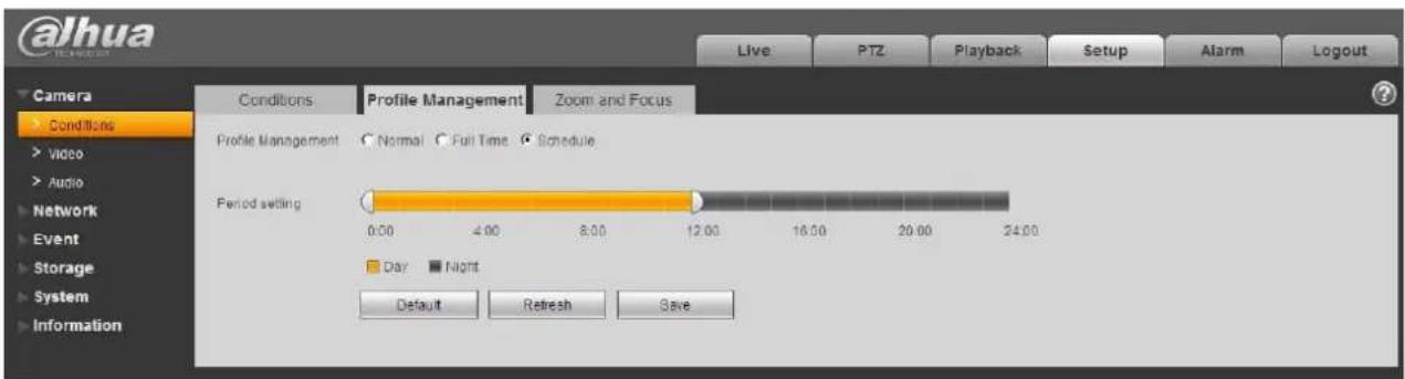
text_image
@alhua Live PTZ Playback Setup Alarm Logout Camera Conditions Video Audio Network Event Storage System Information Conditions Profile Management Zoom and Focus Profile Management Normal Full Time Schedule Period setting 0:00 4:00 8:00 12:00 16:00 20:00 24:00 Day Night Default Refresh SaveFigure 5-10
Step 3
Click "Save" to complete the settings of profile management.
Note:
Click "Default" to restore the device to default config; click "Refresh" to check the latest config file of the device.
5.1.1.9 Zoom and Focus
Note:
Only motorized vari-focal devices support focus and zoom function.
Step 1
Select "Setup > Camera > Conditions > Zoom and Focus" and the system will display the interface of "Zoom and Focus" which is shown in Figure 5-11.
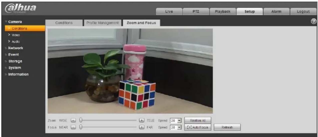
text_image
@Jhua TOMMORARY Live PTZ Playback Setup Alarm Logout Camera Conditions Video Audio Network Event Storage System Information Conditions Profile Management Zoom and Focus Zoom WDE 0 TELE Speed 20 Restore All Focus NEAR 0 FAR Speed 20 Auto Focus RefreshFigure 5-11
Dahua Network Camera Web 3.0 Operation Manual
Step 2
Adjust the focal length of the lens.
After it is zoomed, set "Speed" and press "+" or drag the sliding block directly to adjust.
Step 3
Adjust the lens definition.
After it is focused, set "Speed" and press "+" or drag the sliding block directly to adjust.
Note:
Speed is used to set the length by pressing “+” and “-”.
After adjusting the focal length of the lens or click “Auto Focus”, the device will auto adjust the image definition, it is not allowed to implement other lens operation during auto focus.
After several times of zoom and focus, the image fails to be adjusted clear, click “Restore All” to reset the lens to zero and remove the accumulative error of the lens.
Click “Refresh” and the device will automatically synchronize the hardware to the location of sliding block of lens zoom and focus.
5.1.2 Video
5.1.2.1 Video
Step 1
Select “Setup > Camera > Video > Video” and the system will display the interface of “Video” which is shown in Figure 5-12 or Figure 5-13.
Figure 5-12 (Non fisheye)
Figure 5-13 (Fisheye)
Step 2
Set video bit stream, please refer to the following sheet for more details about the parameters.
Parameter
Function
It will display the parameter when the device is fisheye. There are three installation modes for fisheye which are ceiling, wall mount and ground installation, please select installation mode according to the actual installation scene of the fisheye.
Installation Mode
The system will begin to switch after switching installation mode, it will prompt successfully saved after it is switched successfully.
Note:
The device end will output the dewarped video stream after configuring installation and record mode, when the device is accessed to third-party platform, it will directly display the dewarped image on the third-party platform.
Dahua Network Camera Web 3.0 Operation Manual
| Parameter | Function |
| It will display the parameter when the device is fisheye. The system will begin to switch after record mode is switched, it will prompt saved successfully after it is switched successfully. | |
| The record mode will change according to the different installation modes. | |
| 1O: the original picture which is not dewarped. | |
| 1P: 360°rectangular panorama. | |
| 2P: The mode can be set when the “Installation Mode” is set as “Ceiling” or “Ground”. It is the 2 related 180°rectangular image, the two subwindows can both form 360°panorama anytime. | |
| 1O+3R: original image + 3 independent sub images, both the sub image and sub boxes in the original image can support zoom and movement. | |
| Record Mode | 1R: Original image + independent sub image, the sub boxes of the original image support zoom and movement. |
| 4R: original image + 4 independent sub images, both the sub image and sub boxes in the original image support zoom and movement. | |
| 2R: Original image + 2 independent sub images, the sub boxes of the original image can support zoom and movement, the sub image supports up and down movement, which can change the vertical angle of view. | |
| Note: | |
| The device end will output dewarped video stream after configuring installation and record mode, when the device is accessed to the third-party platform, it will directly display the dewarped image on the third-party platform. | |
| Sub Stream Enable | Select “Enable” to enable sub stream. |
| The device supports enabling sub stream 1 and sub stream 2 at the same time. | |
| Smart Codec | It can enhance image compression performance and reduce storage space by enabling intelligent encoding. |
| Note: | |
| After intelligent encoding is enabled, the device will not support third stream, ROI or intelligent event detection, please refer to the actual interface for more details. |
Dahua Network Camera Web 3.0 Operation Manual
| Parameter | Function |
| Encode mode | There are five options: H.264 (main profile standard, H.264H (high profile standard), H.264B (Baseline Profile), H.265 (main profile standard) and MJPEG encode.The H.264, H.264H both are H264 bit stream.H.264 is the Main Profile encode and you need to enable the sub stream function in your camera and set the resolution as CIF. Then you can monitor via the Blackberry cell phone.The H.265 is the main profile encode mode.MJPEG: In this encode mode, the video needs to large bit stream to guarantee the video definition. You can use the max bit stream value in the recommend bit to get the better video output effect. |
| Resolution | There are multiple resolutions. You can select from the dropdown list.For each resolution, the recommended bit stream value is different.Note: When video is under rotating status, you cannot set resolution higher than 1080P (excluding 1080P). |
| Video Clip | The function is only supported by sub stream 2, please refer to "Video Clip" for more details below the sheet. |
| Frame Rate (FPS) | PAL: 1~25l/s. 1-50l/s NTSC: 1~30l/s or 1~60l/s.The frame rate may vary due to different resolutions. |
| Bit Rate Type | There are two options: VBR and CBR.Please note, you can set video quality in VBR mode.Under MJPEG mode, only CBR is available. |
| Recommended Bit | Recommended bit rate value according to the resolution and frame rate you have set. |
| Bit Rate | In CBR, the bit rate here is the max value. In |
Dahua Network Camera Web 3.0 Operation Manual
| Parameter | Function |
| Watermark Settings | Select “Watermark Setting” and enable watermark function. After the watermark function is enabled, you can check if the video is tampered via verifying watermark character. |
| Watermark Character | It is the character of watermark verification, it is DigitalCCTV by default. |
Video Clip
- Select "Sub Stream 2" in the drop-down box, click "Enable".
- Enable "Video Clip", click
The system will display the interface of “Area”, which is shown in Figure 5-14.
Figure 5-14
Dahua Network Camera Web 3.0 Operation Manual
- Select the needed resolution and clip the needed image on the interface, which is shown in Figure 5-15.
- Click "Save". You can check the clipped video in the preview interface (the sub stream 2 preview interface only displays the clipped area), which is shown in Figure 5-15.
Figure 5-15
Step 3
Click "Save" to complete video stream setup.
5.1.2.2 Snapshot
The snapshot interface is shown as in Figure 5-16.
Figure 5-16
Dahua Network Camera Web 3.0 Operation Manual
Please refer to the following sheet for detailed information.
| Parameter | Function |
| Snapshot type | There are two modes: general (schedule) and Event (activation). |
| Image size | It is the same as the resolution of main stream. |
| Quality | It is to set the image quality. There are six levels. |
| Interval | It is to set snapshot frequency. Optional1~7s/picture, customized. |
5.1.2.3 Video Overlay
The video overlay interface is shown as in Figure 5-17.
Figure 5-17
Dahua Network Camera Web 3.0 Operation Manual
Figure 5-18
Figure 5-19
Dahua Network Camera Web 3.0 Operation Manual
Figure 5-20
Figure 5-21
Figure 5-22
Please refer to the following sheet for detailed information.
| Parameter | Function |
| Privacy Masking | Here you can privacy mask the specified video in the monitor video. |
| System max supports 4 privacy mask zones. | |
| Time Title | You can enable this function so that system overlays time information in video window. |
| You can use the mouse to drag the time tile position. | |
| Channel Title | You can enable this function so that system overlays channel information in video window. |
| You can use the mouse to drag the channel tile position. | |
| Text Overlay | You can enable this function to overlay text in video window. |
| Private protocol is connected to mobile NVR, support GPS information overlay. | |
| You can use the mouse to drag location box to adjust its position. Alignment include align left and align right. | |
| Picture Overlay | You can enable this function to display overlay picture. Click on disable to turn it off. |
| Click on Upload Picture to overlay local picture into monitoring window. You can drag the yellow box to move it. | |
| Note: | |
| You cannot enable text and picture overlay at the same time. |
Dahua Network Camera Web 3.0 Operation Manual
| Counting | Check “Enable” to display the counting statistics data in the video monitoring window; check “Disable” not to display.There are enter number and leave number for statistics type and left align and right align for OSD info. |
| Refresh | Set privacy mask, channel title, time title, location, overlay and save the change. You can click on Refresh to see effect. |
| Default | Click it to restore default config. |
| Save | Click it to complete video settings. |
5.1.2.4 ROI
Note: Some series don't support ROI setup function.
Figure 5-23
Dahua Network Camera Web 3.0 Operation Manual
Figure 5-24
Parameters Note
Enable Check “Enable”, then it will display the ROI in the video monitoring window; Check “Disable”, then it won’t display.
Set the image quality of ROI, ranging from 1 \~ 6, default is 6.
Image Note:
Quality For fisheye device, it ranges from 1\~6 (best), default is 6 (best) Able to set area block, max 4 areas.
5.1.2.5 Path
The storage path interface is shown as in Figure 5-25.
Here you can set snap image saved path and the record storage path.
The default monitor image path is C:\Users\admin\WebDownload\LiveSnapshot.
The default monitor record path is C:\Users\admin\WebDownload\LiveRecord.
The default playback snapshot path is C:\Users\admin\WebDownload\PlaybackSnapshot.
The default playback download path is C:\Users\admin\WebDownload\PlaybackRecord.
The default playback cut path is: C:\Users\admin\WebDownload\VideoClips.
Note:
Admin is locally logged in PC account.
Please click the Save button to save current setup.
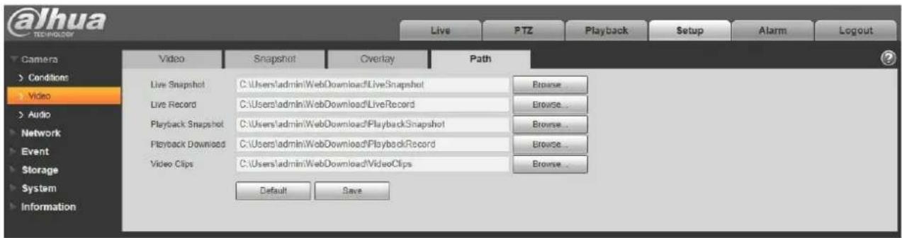
text_image
@lhua TECHNOLOGY Live PTZ Playback Setup Alarm Logout Camera Conditions Video Audio Network Event Storage System Information Video Snapshot Overlay Path Live Snapshot C:\Users\admin\WebDownload\LiveSnapshot Browse... Live Record C:\Users\admin\WebDownload\LiveRecord Browse... Playback Snapshot C:\Users\admin\WebDownload\PlaybackSnapshot Browse... Playback Download C:\Users\admin\WebDownload\PlaybackRecord Browse... Video Clips C:\Users\admin\WebDownload\VideoClips Browse... Default SaveFigure 5-25
5.1.3 Audio
Please note some series devices do not support audio function.
5.1.3.1 Audio
The audio interface is shown as below. See Figure 5-26.
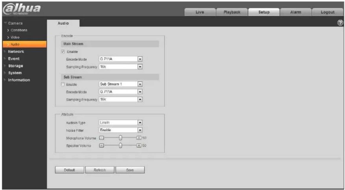
text_image
@Jhua Live Playback Setup Alarm Logout Audio Encode Main Stream Enable Encode Mode G.711A Sampling Frequency 16k Sub Stream Enable Sub Stream 1 Encode Mode G.711A Sampling Frequency 16k Attribute Audition Type Lineln Noise Filter Enable Microphone Volume 50 Speaker Volume 50 Default Refresh SaveFigure 5-26
Please refer to the following sheet for detailed information.
Dahua Network Camera Web 3.0 Operation Manual
| Parameter | Function |
| Enable | You can enable audio only when video is enabled.After selecting the “Enable” of main stream or sub stream, the network transmission stream is the audio/video composite stream, otherwise it only includes video image. |
| Encode mode | The encode mode of the main stream and extra stream include G.711A, G.711Mu, G.726 and ACC. The default mode is G.711A.The setup here is for audio encode mode and the bidirectional talk encode both. |
| Sampling Frequency | The sampling frequency of audio. It includes the following options:8K16K32K48K64K |
| AudioIn Type | Two modes to select: LineIn, Mic.Device needs to connect external audio input source under LineIn mode, and it doesn’t need to connect external audio input source under Mic mode. |
| Noise Filter | Enable the function and it can filter relevant noise. |
| Microphone Volume | Adjust microphone volume from 0 ~ 100.Note:Supported by some devices. |
| Speaker Volume | Adjust speaker volume from 0 ~ 100.Note:Supported by some devices. |
5.1.3.2 Alarm audio
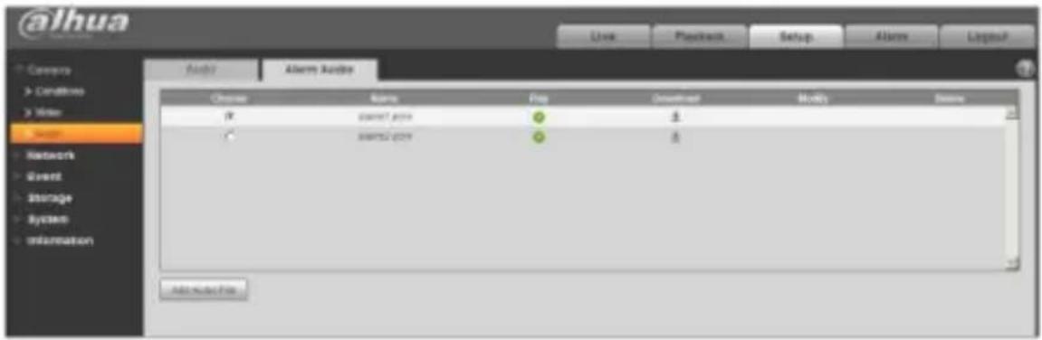
text_image
@alhua Audio Alert Audio Choose Rating Frag Download Modify Namecom/RT.pptn ● #
AMPS2.pptn ● #
Add new fileFigure 5-27
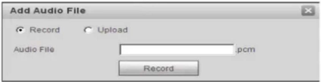
text_image
Add Audio File Record Upload Audio File .pcm RecordFigure 5-28
Audio management currently supports PCM format to record and PCM, wav two forms to upload, and can select an audio file for the audio alarm linkage.
The way to download the web alarm playback audio file into local is as follows:
Step 1 Use the left mouse button to click the hollow circle in the "choice" column on the left, and shows , which means effective choice of alarm audio.
Step 2 Use the right mouse button to click ♂, select "save target as" to download.
5.2 Network
5.2.1 TCP/IP
The TCP/IP interface is shown as in Figure 5-29. It supports IPv4 and IPv6. IPv4 supports static IP and DHCP. IPv6 supports static IP only. When users manually modify IP address, WEB will automatically jump to the new IP address.
Figure 5-29
Please refer to the following sheet for detailed information.
| Parameter | Function |
| Host Name | It is to set current host device name. It max supports 15 characters. |
| Ethernet Card | Please select the Ethernet port. Default is wired.Please note you can modify the default Ethernet card if there is more than one card. |
| Mode | There are two modes: static mode and the DHCP mode. Select DHCP mode, it auto searches IP, and you cannot set IP/subnet mask/gateway. Select static mode, you must manually set IP/subnet mask/gateway. |
| Mac Address | It is to display hose Mac address. |
| IP Version | It is to select IP version. IPV4 or IPV6.You can access the IP address of these two versions. |
| IP Address | Please use the keyboard to input the corresponding number to modify the IP address and then set the corresponding subnet mask and the default gateway. |
| Preferred DNS | DNS IP address. |
| Alternate DNS | Alternate DNS IP address. |

Dahua Network Camera Web 3.0 Operation Manual
| Enable ARP/Ping set device IP address service. | You can use ARP/Ping command to modify or set the device IP address if you know the device MAC address.Before the operation, please make sure the network camera and the PC in the same LAN. This function is on by default.You can refer to the steps listed below.Step 1: Get an IP address. Set the network camera and the PC in the same LAN.Step 2: Get the physical address from the label of the network camera.Step 3: Go to the Run interface and then input the following commands.arp -s <IP Address> <MAC>ping -l 480 -t <IP Address>Such as: arp -s 192.168.0.125 11-40-8c-18-10-11 ping -l 480 -t 192.168.0.125Step 4: Reboot the device.Step 5: You can see the setup is OK if you can see there are output information such as "Reply from 192.168.0.125 ..." from the command output lines. Now you can close the command line.Step 6: Open the browse and then input http://<IP address>.Click the Enter button, you can access now. |
5.2.1.1 Easy4ip
Click "Enable" to connect the device to network, and then you can connect to the device via mobile client of Easy4ip after "Online" is displayed on the interface (connection mode: add device serial number or scan QR code). See Figure 5-30.

text_image
@ihua Camera HUAU Cayng Live Playback Setup Name LayoutDahua Network Camera Web 3.0 Operation Manual
5.2.2 Connection
5.2.2.1 Connection
The connection interface is shown as in Figure 5-31.
Figure 5-31
Please refer to the following sheet for detailed information.
| Parameter | Function |
| Max connection | It is the max Web connection for the same device. The value ranges from 1 to 20. Default connection amount is 10. |
| TCP port | Port range is 1025~65534. The default value is 37777. You can input the actual port number if necessary. |
| UDP port | Port range is 1025~65534. The default value is 37778. You can input the actual port number if necessary. |
| HTTP port | Port range is 1025~65524. The default value is 80. You can input the actual port number if necessary. |

Dahua Network Camera Web 3.0 Operation Manual
| RTSP port | The default value is 554. Please leave blank if use default. User uses QuickTime or VLC can play the following formats. BlackBerry can play too.Real-time monitoring URL format, please require real-time RTSP media server, require channel no., bit stream type in URL. You may need username and password.User uses BlackBerry need to set encode mode to H.264B, resolution to CIF and tum off audio.URL format is:rtsp://username:password@ipport/cam/realmonitor?channel=1&subtype=0Username/password/IP and portThe IP is device IP and the port default value is 554. You can leave it in blank if it is the default value.Follow standard RTP protocol and when encode mode is MJPEG, the max resolution only supports 2040*2040. |
| HTTPS Port | HTTPS communication port, range is 1025-65534, default is 443. |
Note:
- 0\~1024, 37780\~37880, 1900, 3800, 5000, 5050, 9999, 37776, 39999, 42323 are all special ports. User cannot modify them.
- Avoid using default port value of other ports.
5.2.2.2 ONVIF
ONVIF (Open Network Video Interface Forum), this standard describes network video mode, interface, data type and data interaction mode. ONVIF Standard's aim is to achieve a network video frame agreement and makes the network video products (including video front-end, video equipment, etc.) from different manufacturers completely compatible.
Dahua Network Camera Web 3.0 Operation Manual
Figure 5-32
5.2.3 PPPoE
The PPPoE interface is shown as in Figure 5-33.
Enter the PPPoE username and password which are provided by ISP (Internet Service Provider), and click “Enable”. The network camera will automatically establish network connection in the mode of PPPoE after it is enabled, after it is successful, the IP of the “IP Address” will be automatically modified into the dynamic IP address of the acquired WAN.
Note:
After PPPoE dial-up is successful, it needs to log in the device via the IP which is set before dial-up; in the PPPoE setup interface, it will display the registered IP address, and then it can visit the IP address via client.
Please disable UPnP when clicking PPPoE enable, which is to avoid causing influence to PPPoE dial-up.
@ahua
Dahua Network Camera Web 3.0 Operation Manual
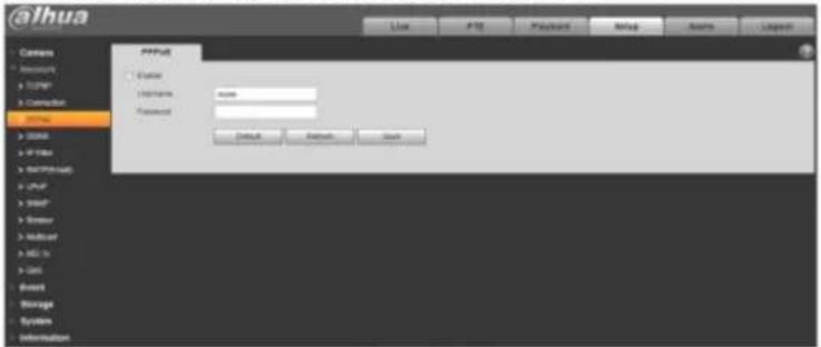
text_image
@ihua Access Access TURR* Correction Status Status If there Bathminder User User User User User System Information PPTM Enable Name: name Password: Default Default AutoFigure 5-33
5.2.4 DDNS
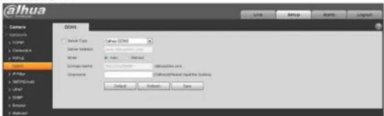
The DDNS interface is shown as in Figure 5-34.
The DDNS is to set to connect the various servers so that you can access the system via the server. Please go to the corresponding service website to apply a domain name and then access the system via the domain. It works even your IP address has changed. When the device connects to WLAN, you should disable UPnP.
text_image
@ihua Camera Networks Photo Connection PDFS Class X: IP-10a Y: HTTP-Web Z: URL X: DBP Y: Webpage X: Webpage DSWS DOSWS DOSWS DOSWS (COS) DOSWS (COS) DOSWS (COS) DOSWS (COS) DOSWS (COS) DOSWS (COS) DOSWS (COS) DOSWS (COS) DOSWS (COS) DOSWS (COS) DOSWS (COS) DOSWS (COS) DOSWS (COS) DOSWS (COS) DOSWS (COS) DOD Default Refresh Save
Dahua Network Camera Web 3.0 Operation Manual
| Parameter | Function |
| Server Type | You can select DDNS protocol from the dropdown list: CN99 DDNS, NO-IP DDNS, Dyndns DDNS, Dahua DDNS, the default is Dahua DDNS. |
| Server Address | DDNS server IP addressCN99 DDNSServer address: www.3322.orgNO-IP DDNSServer address: dynupdate.no-ip.comDyndns DDNSServer address: members.dyndns.orgDahua DDNSServer address: www.dahuaddns.com |
| Mode | Default is auto, able to choose manual |
| Domain Name | Both auto and manual are "MAC address.s.dahuaddns.com"by default, able to set prefix manually. |
| Username | The user name you input to log in the server, optional. |
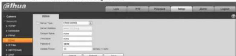
The CN99 DDNS interface is shown as in Figure 5-35.
text_image
@lhua Camera Networks > TCPMP Connection > Print DSL > IP Files > IP (Print)... DSL DOSI Serial Type: CDSI DOSI Server Address: www.lsd.org Address Name: none Description: none Password: ****** Version Period: 10 Mbps (> 600)alhua
Dahua Network Camera Web 3.0 Operation Manual
| Parameter | Function |
| Server Type | You can select CN99 DDNS protocol |
| Server Address | Under CN99 DDNS the default server address is "www.3322.org" |
| Domain Name | Self-defined domain name |
| Username | The user name you input to log in the server. |
| Password | The password you input to log in the server |
| Refresh Period | The refresh period of the connection between the device IP and the server, default is 10 minutes. |
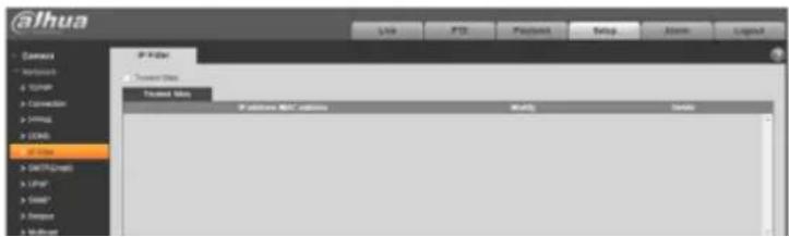
5.2.5 IP filter
The IP filter interface is shown as in Figure 5-36.
You can enable IP filter function so that some specified IP/MAC user can access the network camera.
You can add IP address or IP segment.
If you do not check the box here, it means there is on access limit.
Here you can add IP address and MAC address. You must add these addresses before enabling the trusted sites.
Please note: You must set MAC address in the same network segment.
text_image
@lhua Camera Networks Turner Conversion Image USB Access Access Web Treated Web IP filter: BLT options Modify EnableFigure 5-37
Please refer to the following sheet for detailed information.
| Parameter | Function |
| SMTP Server | Input server address and then enable this function. |
| Port | Default value is 25. You can modify it if necessary. |
| Anonymity | For the server which supports the anonymity email function, it won’t display the information of the sender. |
| User Name | The user name of the sender email account. |
| Password | The password of sender email account. |
| Sender | Sender email address. |
| Authentication (Encryption mode) | You can select SSL, TLS or none. |
| Title (Subject) | Input email subject here. |
| Attachment | System can send out the email of the snapshot picture once you check the box here. |
| Mail receiver | Input receiver email address here. Max three addresses. |
Dahua Network Camera Web 3.0 Operation Manual
| Parameter | Function |
| Interval | The send interval ranges from 0 to 3600 seconds. 0 means there is no interval.Please note system will not send out the email immediately when the alarm occurs. When the alarm, motion detection or the abnormality event activates the email, system sends out the email according to the interval you specified here. This function is very useful when there are too many emails activated by the abnormality events, which may result in heavy load for the email server. |
| Health mail enable | Please check the box here to enable this function. |
| Email test | The system will automatically sent out a email once to test the connection is OK or not .Before the email test, please save the email setup information. |
5.2.7 UPnP
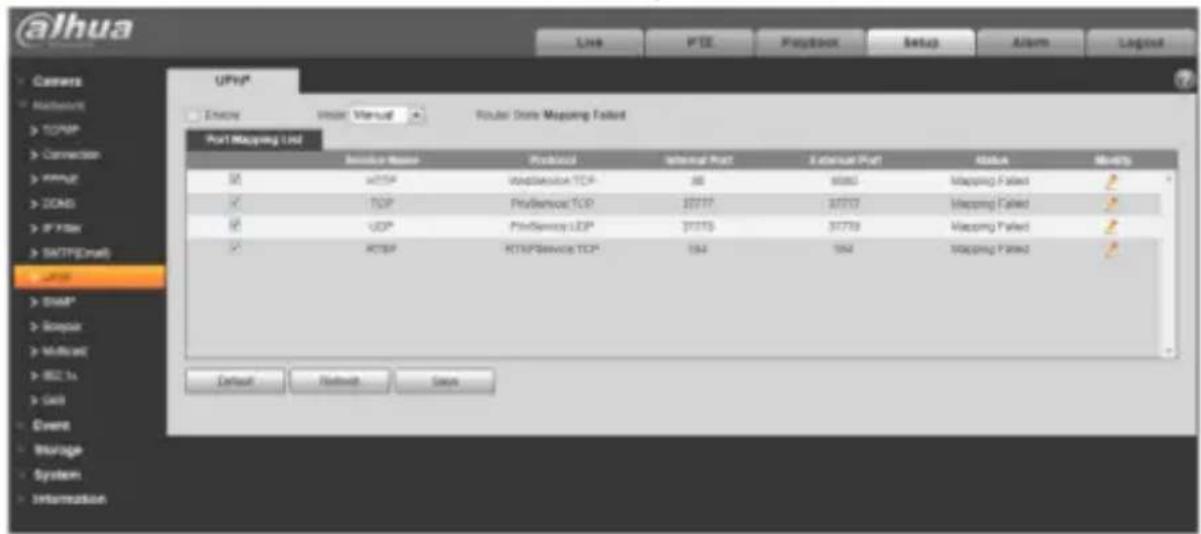
It allows you to establish the mapping relationship between the LAN and the public network.
Here you can also add, modify or remove UPnP item. For UPnP on different routers, you must disable UPnP function. See Figure 5-38.
In the Windows OS, From Start->Control Panel->Add or remove programs. Click the "Add/Remove Windows Components" and then select the "Network Services" from the Windows Components Wizard. Click the Details button and then check the "Internet Gateway Device Discovery and Control client" and "UPnP User Interface". Please click OK to begin installation.
Enable UPnP from the Web. If your UPnP is enabled in the Windows OS, the network camera can auto detect it via the "My Network Places".
Under manual mode, you can modify external port. Under auto mode, select idle port for auto port mapping without user modification.
text_image
alhua Connects Network TCP/IP Connection VPPG COMS IP FTR SMTP(Email) USB USBP System Information UPnP* Exchange Internal Internal Port Router State Mapping Failed Port Mapping List Service Name Protocol Internal Port External Port Status Identity RTI 400 WebService TCP 88 6885 Mapping Failed 2 TCP PreServices TCP 37777 37777 Mapping Failed 2 UDP PreServices UDP 37773 37779 Mapping Failed 2 RTSP RTSP Service TCP 192 192 Mapping Failed 2 Default Network SaysFigure 5-38
5.2.8 SNMP
The SNMP interface is shown as in Figure 5-39 and Figure 5-40.
The SNMP allows the communication between the network management work station software and the proxy of the managed device. Please install the software such as MG MibBrowser 8.0c software or establish the SNMP service before you use this function. You need to reboot the device to activate the new setup.
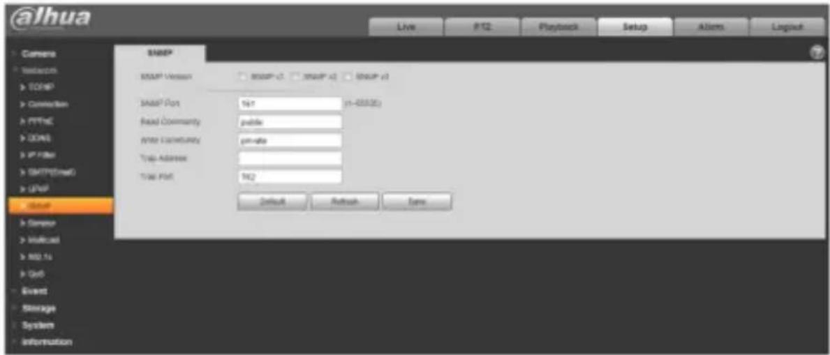
text_image
@lhua Live PT2 Playback Setup Actions Logitech SNMP SNMP Version SNMP v1 SNMP v2 SNMP v3 SNMP Port 967 (1-000.00) Read Community public Write Community pin-site Trip Address # Time Port 962 Default Refresh Save Current Network MCCs GoS Event Storage System InformationFigure 5-39
Please refer to the following sheet for detailed information.
Dahua Network Camera Web 3.0 Operation Manual
| Parameter | Function |
| SNMP Version | Check SNMP v1, device only process v1 info.Check SNMP v2, device only process v2 info.Check SNMP v3, can set username, password and encryption method. Server calibrate corresponding username, password and encryption method too access device and v1/v2 are unavailable. |
| SNMP port | The listening port of the proxy program of the device. It is a UDP port not a TCP port. The value ranges from 1 to 65535. The default value is 161 |
| Community | It is a string, as command between management and proxy, , defining a proxy, and a manager's authentication. |
| Read community | Read-only access to all SNMP targets, default is public. Note: Only number, letter, _, and – supported. |
| Write community | Read/write access to all SNMP targets, default is private. Note: Only number, letter, _, and – supported. |
| Trap address | The destination address of the Trap information from the proxy program of the device. |
| Trap Address | Address where to send Trap message. |
| Trap Port | Port which send Trap message, default is 162, range 1~65535. |
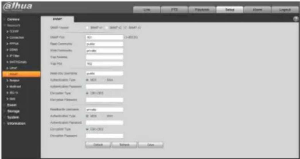
text_image
@lhua Ceres Resource > TERRP > Connection > PPPM > CENS > X-Filter > Install/Linkup > LWP > Install > Response > Multimod > RIO To > Shift Event > Storage > System > Information DANIP Gmail Version: 0247-01-01 (0247-01-01) Gmail Type: 923-15-855364 Real Community: public Water Community: private Type Address: Type PMI: 922 Real City Destination: public Authentication Type: MCI - Data Authentication Password: Chrystaler Type: 080-0805 Chrystaler Password: Real Estate Location: private Authentication Type: MCI - 2014 Authentication Password: Chrystaler Type: 080-0805 Chrystaler Password: Default Refresh GainFigure 5-40
Check SNMP v3 version and SNMP port, read community, write community, Trap address, Trap port are same with SNMP v1 and SNMP v2 versions. Only when SNMP version is SNMP v3, users need to configure parameter in chart.
| Parameter | Function |
| SNMP Version | SNMP v3 |
| Read-only Username | Default is public.Note:Name only can be number, letter and underline. |
| Read/Write Username | Default is private.Note:Name only can be number, letter and underline. |
| Authentication | You may select MD5 or SHA, default is MD5. |
| Authentication Password | Password not less than 8 characters. |
| Encryption | Default is CBC-DES. |
| Encryption Password | Password not less than 8 characters. |
5.2.9 Bonjour
The Bonjour interface is shown as below. See Figure 5-41.
Bonjour is based on the multicast DNS service from the Apple. The Bonjour device can automatically broadcast its service information and listen to the service information from other device.
You can use the browse of the Bonjour service in the same LAN to search the network camera device and then access if you do not know the network camera information such as IP address.
You can view the server name when the network camera is detected by the Bonjour. Please note the safari browse support this function. Click the "Display All Bookmarks: and open the Bonjour, system can auto detect the network camera of the Bonjour function in the LAN.
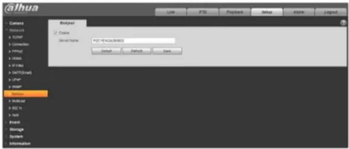
text_image
@lhua Backgoet ✓ Create Service Name: PSC IP address(Windows) Default Pathback Save Backgoet Multicast RCC to Grid Stream Message System Information
Dahua Network Camera Web 3.0 Operation Manual
Figure 5-41
5.2.10 Multicast
The multicast interface is shown as in Figure 5-42.
Multicast is a transmission mode of data packet. When there is multiple-host to receive the same data packet, multiple-cast is the best option to reduce the broad width and the CPU load. The source host can just send out one data to transit. This function also depends on the relationship of the group member and group of the outer.
Note:
- Open preview, streaming media protocol, select multicast, and monitor via multicast format.
- Here you can set multicast address and port. You also need to go to Live interface to set the protocol as Multicast.
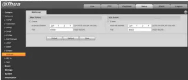
text_image
alhua Caspia Networks U-TCP Connector FPGA LPG P-View MUTICOS S100 MUTICOS 224 1 2 4 (2014.03.09.00.00.00.00.00) Port: 6500 (1925-85754) Sub Texts MUTICOS Main Texts Private MUTICOS Sub Private Multi-LAT Textes 224 1 2 4 (2014.03.09.00.00.00.00) Port: 6502 (1925-85754) Default Default DataFigure 5-42
Please refer to the following sheet for detailed information.
Dahua Network Camera Web 3.0 Operation Manual
Note: This function is only for series with 4G module.
4G is a mobile communication system which makes wireless communication integrates with Internet and multimedia communication.
5.2.11.1 Dialing Setting
Figure 5-43
| Parameter | Function |
| Wireless Net Type | Auto, WCDMA, FDD-LTE optional, you can select according to the operator. |
| Enable | Check to enable 4G module. |
| APN | It shall be acquired from the operator according to the setup of operator. |
| Authentication Mode | Auto, PAP and CHAP, the authentication algorithm is different according to different operators. |
| Dial-up Number | The number is different according to different operator, it can be acquired from operator. |
| User name | It shall be acquired from the operator. |
| Password | It shall be acquired from the operator. |
| Update Period | It is the period beyond the dial-up period which has been set, it is 30s by default, which means the device can auto acquire 4G dial-up status, cut off dial-up to save flow. |
Dahua Network Camera Web 3.0 Operation Manual
| Time Range | It is the time period to set dial-up. It can activate the function via message to enable/disable dial-up function if it is beyond the time period. |
| IP Address | It will display the acquired IP after the dial-up is successful via 4G. |
5.2.11.2 Mobile Setting
Figure 5-44
Please refer to the following sheet for detailed information.
| Parameter | Function |
| Message Send | In the event, after the corresponding message activation is enabled, it will send message to the phone of receiver when event happens. It needs to enable the function of message activation function in the event interface when using the function. |
| Message Activation | It can send message ON/OFF to the SIM card inside the device by the mobile phone in the list, which is to enable /disable the dial-up function and send REBOOT to restart the device. |
| Phone Activation | You can use the mobile phone in the calling list to call the SIM card inside the device to enable dial-up function. |
5.2.12 WIFI
alhua
Dahua Network Camera Web 3.0 Operation Manual
Note:
Some series devices don't support WIFI and WPS function.
WPS function is supported by the devices with WPS button.
5.2.12.1 WIFI
WIFI info can show the name, status, IP information of the Current Hot Spot. Usually please "Refresh" WIFI work information after reconnection to ensure the real-time display of the work status, because it often takes some time to connect WIFI Hot Spot, which depends on the network signal strength.
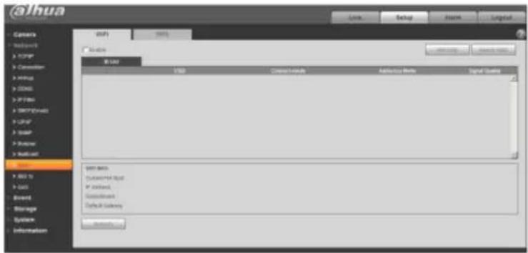
text_image
@ihua Camera Networks TCP/IP Connection Winus DNS IP Micro SNET/OS/MS LSPF USB Server Remote System USB to Out Event Storage System Information USB I/O Channel/MIK Address/OS/MS Digital Security USB Black Custom/MIK Red IP Internet Connect/OS Default Security System SecurityFigure 5-45
WIFI setting method is as follows:
@ahua
Dahua Network Camera Web 3.0 Operation Manual
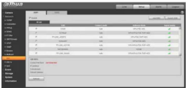
text_image
@alhua Networks Networks TCP/IP Connection A: WiFi B: TCP/IP C: WiFi D: TCP/IP E: TCP/IP F: TCP/IP G: TCP/IP H: TCP/IP I: TCP/IP J: TCP/IP K: TCP/IP L: TCP/IP M: TCP/IP N: TCP/IP O: TCP/IP P: TCP/IP Q: TCP/IP R: TCP/IP S: TCP/IP T: TCP/IP U: TCP/IP V: TCP/IP W: TCP/IP X: TCP/IP Y: TCP/IP Z: TCP/IP WIP/XPV: Current IP Data - unconnected If necessary Unconnected Default Connections CopyrightFigure 5-46
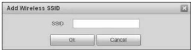
Step 3 Click "Add SSID" when need to add a wireless network manually pop out an interface in the figure below, and enter network ID in the dialog box.
text_image
Add Wireless SSID SSID: Ok CancelFigure 5-47
Step 4 Double click on one can pop out the signal intensity and authentication of the hot spot.
alhua
Dahua Network Camera Web 3.0 Operation Manual
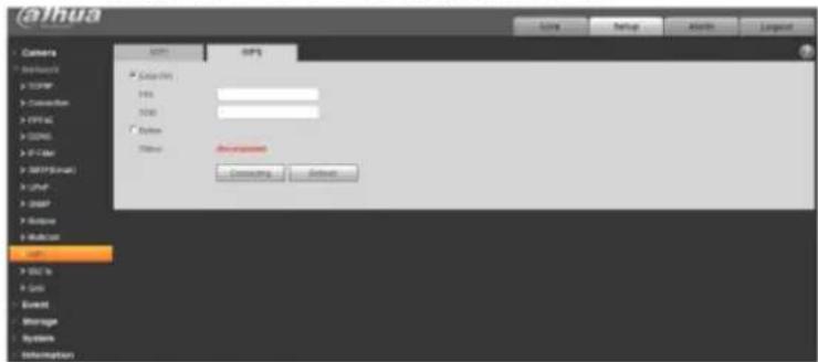
text_image
@thua Camera @thua.com > TCP/IP > Connection > FIPS > CDNS > X1-04 > MSIP(Shan) > Unif > UserP > Update > Buildbox Email > BSC to > Suts Event Storage System InformationFigure 5-48
PIN Number and SSID are both acquired from the router, please "refresh" the work information of WIFI to ensure the real-time display of work state after filling in correctly.
5.2.13802.1x
802.1x (port based network access control protocol) supports manual selection of authentication method to control if device connected to LAN can join the LAN. It well supports authentication, charging, safety and management requirement of network.

text_image
@lhua Login PTZ Playback Setup Alam Layout Camera Networks > T20MP > Connection > WiFi > Install 800.1x Enable Administration: PEAP License: none Password: ****
Dahua Network Camera Web 3.0 Operation Manual
| Parameter | Function |
| Authentication | PEAP (protected EAP protocol). |
| Username | It needs the username to login, which is authenticated by the server. |
| Password | Please input password here. |
5.2.14 QoS
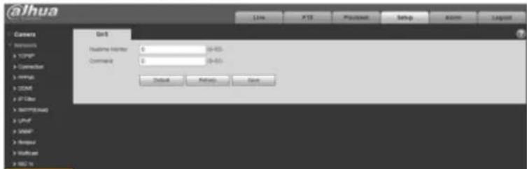
The QoS interface is shown as below. See Figure 5-50.
Qos (Quality of Service) is network security mechanism. It is a technology to fix the network delay and jam problem and etc. For the network service, the quality of service includes the transmission bandwidth, delay, the packet loss and etc. We can guarantee the transmission bandwidth, lower the delay, and reduce the loss of the data packet and anti-dither to enhance the quality.
We can set the DSCP (Differentiated Services Code Point) of the IP to distinguish the data packet so that the router or the hub can provide different services for various data packets. It can select the different queues according to the priority (64 different priority levels) of the packets and select the bandwidth of the each queue. Level 0 is the lowest, and level 63 is the highest. It can also discard at the different ratio when the broad bandwidth is jam.
text_image
@lhua Users Default Indicator: 0 (0-03) Command: 0 (0-03) Default Finish SaveDahua Network Camera Web 3.0 Operation Manual
| Parameter | Function |
| Command | The value ranges from 0 to 63. The router or the switcher can provide different service for various data packets. |
| Enable Wireless QoS | Check it to enable QoS. |
5.2.15 HTTPS
In the HTTPS setting interface, users can make PC log in normally via HTTPS by creating certificate or uploading signed certificate, which is to guarantee the security of communication data and provide safeguard for user information and device security with reliable and stable technical means.
Step 1
Create certificate or upload the signed certificate.
Please refer to the following steps if you select "Create Certificate".
- Select “Setup > Network > HTTPS”, and the system will display the interface of HTTPS, which is shown in Figure 5-51.
Figure 5-51
- Click "Create" and it will pop out the dialog box of "HTTPS", which is shown in Figure 5-52.
Figure 5-52
- Fill in corresponding “Country”, “Province” and some other information, click “Create” after filling in. It will show the prompt of “Create Successfully”, which means the server certificate has been successfully created.
Note:
Make sure the “IP or domain name” is the same as that of the device.
- Click "Install" and it will install the certificate on the device end, which is shown in Figure 5-53.
Dahua Network Camera Web 3.0 Operation Manual
Figure 5-53
- Click "Download". It will pop out the dialog box of "Save as", save the file into the computer.
Figure 5-54
Dahua Network Camera Web 3.0 Operation Manual
- Double click the downloaded icon of "RootCert.cer". The system will display the information interface of "Certificate", which is shown in Figure 5-55.
Figure 5-55
- Click "Install Certificate" and it will pop out the interface of "Certificate Import Wizard", which is shown in Figure 5-56.
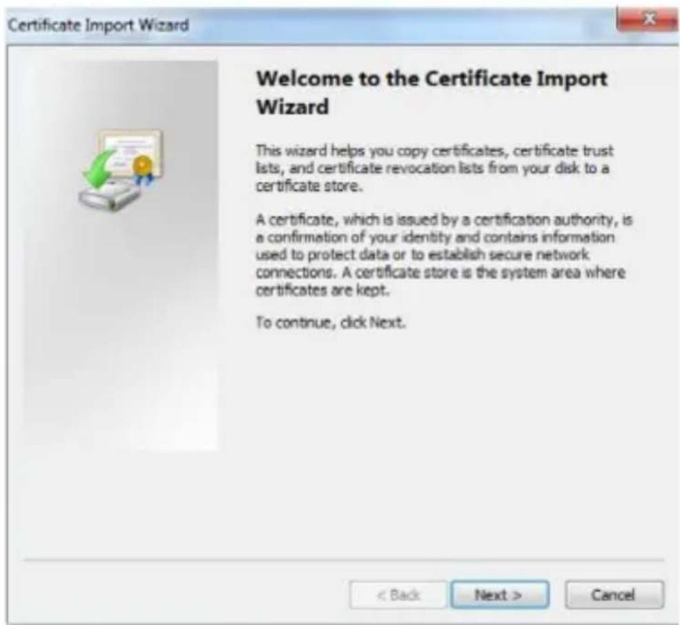
text_image
Certificate Import Wizard Welcome to the Certificate Import Wizard This wizard helps you copy certificates, certificate trust lists, and certificate revocation lists from your disk to a certificate store. A certificate, which is issued by a certification authority, is a confirmation of your identity and contains information used to protect data or to establish secure network connections. A certificate store is the system area where certificates are kept. To continue, click Next.Figure 5-56
- Click "Next". Select "Trusted Root Certification Authorities", which is shown in Figure 5-57.

Dahua Network Camera Web 3.0 Operation Manual
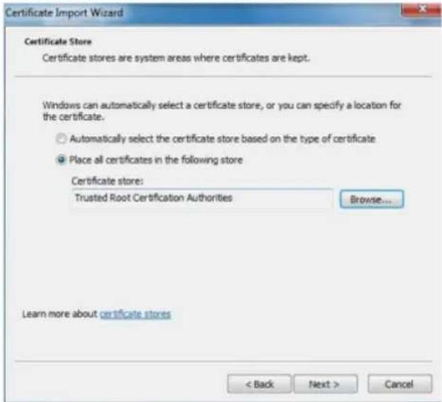
text_image
Certificate Import Wizard Certificate Store Certificate stores are system areas where certificates are kept. Windows can automatically select a certificate store, or you can specify a location for the certificate. ○ Automatically select the certificate store based on the type of certificate ● Place all certificates in the following store Certificate store: Trusted Root Certification Authorities Browse... Learn more about certificate stores < Back Next > CancelFigure 5-57
- Click "Next". The system will display the interface of "Completing the Certificate Import Wizard", which is shown in Figure 5-58.
@ahua
Dahua Network Camera Web 3.0 Operation Manual

text_image
Certificate Import Wizard Completing the Certificate Import Wizard The certificate will be imported after you click Finish. You have specified the following settings: Certificate Store Selected by User Trusted Root Certificate Content Certificate < Back Finish CancelFigure 5-58
- Click "Finish", and it will pop out the dialog box of "Security Warning", which is shown in Figure 5-59.

Dahua Network Camera Web 3.0 Operation Manual
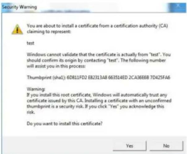
text_image
Security Warning You are about to install a certificate from a certification authority (CA) claiming to represent: test Windows cannot validate that the certificate is actually from "test". You should confirm its origin by contacting "test". The following number will assist you in this process: Thumbprint (sha1): 6D811FD2 E82313A8 663514ED 2CA36E6B 7D425FA6 Warning: If you install this root certificate, Windows will automatically trust any certificate issued by this CA. Installing a certificate with an unconfirmed thumbprint is a security risk. If you click "Yes" you acknowledge this risk. Do you want to install this certificate? Yes NoFigure 5-59
- Click "Yes". It will pop out the dialog box of "Import Successful", click "Ok" to complete downloading certificate, which is shown in Figure 5-60.
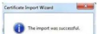
Figure 5-61
- Select signed certificate and certificate key path respectively via "Browse", click "Upload".
- Install root certificate, please refer to step 6\~11 for more details.
- Check "Enable HTTPS", click "Save". The system will display the dialog box of "Need to reboot the device", and then the config is valid.
Figure 5-62
5. Use HTTPS
Use HTTPS to log in.
Enter https://xx.xx.xx.xx in the browser, and it will pop out normal login interface; the browser will prompt certificate error if the certificate is not installed, which is shown in Figure 5-63.
@ahua
Dahua Network Camera Web 3.0 Operation Manual
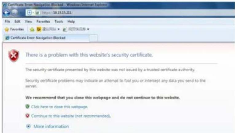
text_image
Certificate Error: Navigation Blocked - Windows Internet Explorer File Edit View Favorites Tools Help Favorites Certificate Error: Navigation Blocked There is a problem with this website's security certificate. The security certificate presented by this website was not issued by a trusted certificate authority. Security certificate problems may indicate an attempt to fool you or intercept any data you send to the server. We recommend that you close this webpage and do not continue to this website. Click here to close this webpage, Continue to this website (not recommended), More informationFigure 5-63
Note:
"xx.xx.xx.xx" is corresponding to your IP or domain name.
5.3 Event
5.3.1 Video detection
Select "Setup > Event > Video Detection > Motion Detection" and the system will display the interface of "Motion Detection" which is shown in Figure 5-64.
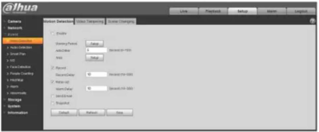
text_image
@Ihua Live Playback Setup Main Longload Camera Network River Video Connection Audio Detection Smart Plan NIS Face Detection People Counting PMLM Impers Residuals Storage System Information Motion Detection Video Transparency Scene Charging Enable Working Period Setup... Anti-Counter 5 Recorded (18-193) New Setup Record Record Delay 10 Recorded (18-200) Water-up Water Delay 10 Recorded (18-200) Send Event Snapshot Default Refresh NoneFigure 5-64
Step 2
Select "Enable" to enable motion detection function.
Step 3
Set motion detection area.
- Click "Setup" and the system will pop out the interface of "Setting Area", which is shown in Figure 5-65
@ahua
Dahua Network Camera Web 3.0 Operation Manual
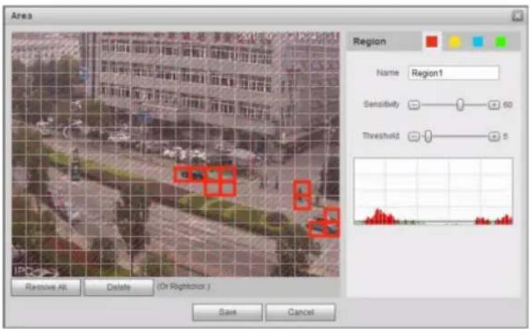
text_image
Area Region Name Region1 Sensitivity 60 Threshold 5 Remove All Delete (Or Rightside) Save CancelFigure 5-65
- Set area name, it is to set valid area of motion detection according to the actual situation, and it can set the value of sensitivity and threshold respectively.
The bigger the sensitivity is, the easier it is to generate motion detection, the smaller the threshold is, the easier it is to generate motion detection; the entire video image is the valid area of motion detection by default.
Note:
● Different colors represent different areas: each area can set different detection area.
@ahua
Dahua Network Camera Web 3.0 Operation Manual
| Parameter | Function |
| Working Period | Note:It is to set the alarm period, it can enable alarm event only during the period range which has been set.1. Click "Setup" and the system will pop out the interface of "Working Period".2. It is to set working period according to the following methods:You can input time numerical value or press the left mouse button to drag on the setup interface to set.There are six periods to be set every day, select the check box in front of the period, and then the period is valid.Select week number (it selects Sunday by default, if it selects the whole week, then it means the setup can be applied to the whole week, you can also select the check box in front of the week number to implement independent setting for some days).3. Click "Save" to complete the setup of working period. |
| Anti-dither | System only memorizes one event during the anti-dither period. The value ranges from 0s to 100s. |
| Area | 1. Click "Setup" and the system will pop out the interface of "Set Area".2. Set the area name, it is to set the valid area of motion detection according to the actual situation, and it can set its sensitivity and threshold respectively. The higher the sensitivity is, the easier it is to trigger motion detect, the smaller the area threshold is, the easier it is to generate motion detect, the whole video image is the valid area of the motion detect by default.Note:Different colors represent different areas; each area can set different detection areas.The red line in the Oscillogram means triggering motion detect, the green line means not triggering motion detect.3. Click "Save" to complete area setup. |
| Record | Check it and so when alarm occurs, system will auto record. You shall set record period in Storage>Schedule and select auto record in record control interface. |
Dahua Network Camera Web 3.0 Operation Manual
| Parameter | Function |
| PTZ | Here you can set PTZ movement when alarm occurs. Such as go to preset x when there is an alarm.The event type includes: preset, tour and pattern. |
| Snapshot | You need to check the box here so that system can backup motion detection snapshot file. You shall set snapshot period in Storage>Schedule. |
Step 5
Click "Save" to complete the setting of motion detection.
5.3.1.2 Video Tampering
Step 1
Select “Setup > Event > Video Detection > Video Tampering” and the system will display the interface of “Video Tampering” which is shown in Figure 5-66.
Figure 5-66
Step 2
Set the parameter of video tampering; please refer to the following sheet for more details.
| Parameter | Function |
| Enable video tampering | You need to check the box to enable video mask detection alarm. |
| Enable defocus detection | You need to check the box to enable defocus detection alarm. |
Dahua Network Camera Web 3.0 Operation Manual
| Parameter | Function |
| Working Period | Note:It is to set the alarm period, it can enable alarm event only during the period range which has been set.1. Click "Setup" and the system will pop out the interface of "Working Period".2. It is to set working period according to the following methods:You can input time numerical value or press the left mouse button to drag on the setup interface to set.There are six periods to be set every day, select the check box in front of the period, and then the period is valid.Select week number (it selects Sunday by default, if it selects the whole week, then it means the setup can be applied to the whole week, you can also select the check box in front of the week number to implement independent setting for some days).3. Click "Save" to complete the setup of working period. |
| Record | Check it and so when alarm occurs, system will auto record. You shall set record period in Storage>Schedule and select auto record in record control interface. |
| Record Delay | System can delay the record for specified time after alarm ended. The value ranges from 10s to 300s. |
| Relay out | Enable alarm activation function. You need to select alarm output port so that system can activate corresponding alarm device when alarm occurs. |
| Alarm Delay | System can delay the alarm output for specified time after alarm ended. The value ranges from 10s to 300s. |
| Send Email | If you enabled this function, System can send out email to alert you when alarm occurs and ends. User can set email address in Network>SMTP. |
| Audio linkage | Check it and the system will play alarm audio file when alarm occurs. Use can set the recorded or uploaded audio file in "camera setting > audio > alarm audio". |
| Flash linkage | Check it and the flash will be on when alarm occurs, and the flash will be off until the end of alarm after corresponding delay. |
| PTZ | Here you can set PTZ movement when alarm occurs. Such as go to preset x when there is an alarm.The event type includes: preset, tour and pattern. |
| Snapshot | You need to check the box here so that system can backup motion detection snapshot file. You shall set snapshot period in Storage>Schedule. |
Step 3
Click "Save" to complete the setup of video tampering.
5.3.1.3 Scene Changing
Step 1
Select "Setup > Event > Video Detection > Scene Changing" and the system will display the interface of "Scene Changing" which is shown in Figure 5-67.
Figure 5-67
Step 2
Check “Enable” to enable the function of scene changing.
Step 3
It is to set the parameters of scene changing, please refer to the following sheet for more details.
| Parameter | Function |
| Working Period | Note:It is to set the alarm period, it can enable alarm event only during the period range which has been set.1. Click “Setup” and the system will pop out the interface of “Working Period”.2. It is to set working period according to the following methods:You can input time numerical value or press the left mouse button to drag on the setup interface to set.There are six periods to be set every day, select the check box in front of the period, and then the period is valid.Select week number (it selects Sunday by default, if it selects the whole week, then it means the setup can be applied to the whole week, you can also select the check box in front of the week number to implement independent setting for some days).3. Click “Save” to complete the setup of working period. |
| Record | Check it and so when alarm occurs, system will auto record. You shall set record period in Storage>Schedule and select auto record in record control interface. |
| Record Delay | System can delay the record for specified time after alarm ended. The value ranges from 10s to 300s. |
| Relay out | Enable alarm activation function. You need to select alarm output port so that system can activate corresponding alarm device when alarm occurs. |
| Alarm Delay | System can delay the alarm output for specified time after alarm ended. The value ranges from 10s to 300s. |
| Send Email | If you enabled this function, System can send out email to alert you when alarm occurs and ends. User can set email address in Network>SMTP. |
Dahua Network Camera Web 3.0 Operation Manual
| Parameter | Function |
| PTZ | Here you can set PTZ movement when alarm occurs. Such as go to preset x when there is an alarm.The event type includes: preset, tour and pattern. |
| Snapshot | You need to check the box here so that system can backup motion detection snapshot file. You shall set snapshot period in Storage>Schedule. |
Step 4
Click "Save" to complete the setup of scene changing.
5.3.2 Audio Detection
Step 1
Select “Setup > Event > Audio Detection” and the system will display the interface of “Audio Detection” which is shown in Figure 5-68.
Figure 5-68
Step 2
It is to set the parameters of audio detect, please refer to the following sheet for more details.
| Parameter | Function |
| Enable input abnormal | Select “Enable Input Abnormal” and it will trigger alarm when it detects audio input abnormality. |
| Enable intensity change | Select “Enable Intensity Change” and it will trigger alarm when it detects that audio intensity change exceeds the threshold. |
Dahua Network Camera Web 3.0 Operation Manual
| Parameter | Function |
| Sensitivity | It can be judged as audio abnormality when the input volume change exceeds continuous environment volume; users need to adjust according to the actual environment test. |
| Threshold | It is to set the filtered environment volume intensity, if the environmental noise is too big, then the value needs to be set higher, users can adjust according to the actual environment test. |
| Working Period | Note:It is to set the alarm period, it can enable alarm event only during the period range which has been set.Click “Setup” and the system will pop out the interface of “Working Period”.It is to set working period according to the following methods:You can input time numerical value or press the left mouse button to drag on the setup interface to set.There are six periods to be set every day, select the check box in front of the period, and then the period is valid.Select week number (it selects Sunday by default, if it selects the whole week, then it means the setup can be applied to the whole week, you can also select the check box in front of the week number to implement independent setting for some days).Click “Save” to complete the setup of working period. |
| Anti-dither | System only memorizes one event during the anti-dither period. The value ranges from 0s to 100s. |
| Record | Check it and so when alarm occurs, system will auto record. You shall set record period in Storage>Schedule and select auto record in record control interface. |
| Record Delay | System can delay the record for specified time after alarm ended. The value ranges from 10s to 300s. |
| Relay out | Enable alarm activation function. You need to select alarm output port so that system can activate corresponding alarm device when alarm occurs. |
| Alarm Delay | System can delay the alarm output for specified time after alarm ended. The value ranges from 10s to 300s. |
| Send Email | If you enabled this function, System can send out email to alert you when alarm occurs and ends. User can set email address in Network>SMTP. |
| PTZ | Here you can set PTZ movement when alarm occurs. Such as go to preset x when there is an alarm.The event type includes: preset, tour and pattern. |
| Snapshot | You need to check the box here so that system can backup motion detection snapshot file. You shall set snapshot period in Storage>Schedule. |
Dahua Network Camera Web 3.0 Operation Manual
5.3.3 Smart Plan
Smart plan is the master switch for intelligent analysis such as “Face Detection”, “Heat Map”, “IVS”,
“People Counting” and so on, the corresponding intelligent functions can be valid after smart plan is enabled.
Step 1
Select “Setup > Event > Smart Plan”. The system will display the interface of “Smart Plan”, which is shown in Figure 5-69.
Figure 5-69
Step 2
Click "Save" to complete the config of smart plan.
5.3.4 Intelligence Behavior Analytics
The basic requirements of scene selection.
The total proportion of the target shall not exceed 10% of the image.
The target size in the image can't be less than 10 pixel × 10 pixel, the size of abandoned target can't be less than 15 pixel × 15 pixel (CIF image); The height and width of the target can't exceed 1/3 of the image; it is recommended that the target height is about 10% of the image height.
The difference of brightness value between target and background can't be less than 10 gray levels. Make sure the target appears at least over 2 seconds continuously in the field; the movement distance has to be bigger than the width of the target itself and makes sure it is no less than 15 pixels (CIF image).
Try to lower the complexity of the monitoring scene analysis if it is possible; it is not advised to use IVS functions in the environment where the targets are dense and light change is very frequent.
Try to keep away from the areas such as glass, ground reflected light, water surface, branch, shadow, mosquito disturbance and etc. try to keep away from the backlight scene to avoid direct light.
alhua
Dahua Network Camera Web 3.0 Operation Manual
5.3.4.1 IVS
5.3.4.1.1 Tripwire
It will trigger alarm when the target crosses the warning line according to the movement direction which has been set.
It needs some time from when the target appears to when the target is confirmed, so it has to leave some space on both sides of the warning line when setting the warning line, please do not set the warning line near the obstructions.
Application scene: it can be applied to the scene with sparse target and there is barely any blocks between the targets, such as the unmanned perimeter defense.
Step 1
Select "Setup > Event > IVS > IVS" and the system will display the interface of "IVS".
Step 2

to set rule name and select the rule type as "Tripwire" which is shown in Figure 5-70.
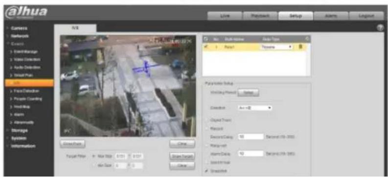
text_image
Alhua Camera Network Events Event/Manage Video Detection Audio Detection Trigger Plan File Face Detection People Counting Work Map Alarm Intermitts Storage System Information A/B File Name: Alhua Web2023 PC File Type: Top-View Play button: Top view Poly button Setup: Window Player: Switch Correction: An >0 Circuit Trunc Maxout Record Delay: 100 Seconds (15h - 200s) Max-up time: 100 seconds (15h - 200s) Alarm Delay: 100 seconds (15h - 200s) Send Print Refreshalhua
Dahua Network Camera Web 3.0 Operation Manual
| Parameter | Function |
| Object tracking | Select "Object tracking" to enable the function, refer to "2.4 Video Window Adjustment" for more details.Note:The function is only supported by some models. |
| Working Period | Note:It is to set the alarm period, it can enable alarm event only during the period range which has been set.1. Click "Setup" and the system will pop out the interface of "Working Period".2. It is to set working period according to the following methods:You can input time numerical value or press the left mouse button to drag on the setup interface to set.There are six periods to be set every day, select the check box in front of the period, and then the period is valid.Select week number (it selects Sunday by default, if it selects the whole week, then it means the setup can be applied to the whole week, you can also select the check box in front of the week number to implement independent setting for some days).3. Click "Save" to complete the setup of working period. |
| Direction | It is to set the direction of tripwire, you can select A->B、B->A、A<->B. |
| Object Track | Select "Object Track" and it will enable the function of object track; when the moving object triggers rule and generates alarm, it will select the display mode of object track such as 1P+3 or 1P+5 in the preview interface, the scene of tracking window will follow the moving object till the object leaves the view range of the camera. Please refer to "2.4.8 Fisheye/Trigger Track" for more details. |
| Record | Check it and so when alarm occurs, system will auto record. |
| Record Delay | System can delay the record for specified time after alarm ended. |
| Relay out | Enable alarm activation function. You need to select alarm output port so that system can activate corresponding alarm device when alarm occurs. |
Dahua Network Camera Web 3.0 Operation Manual
- Cross means that it will trigger alarm when the target enters or exits the area.
● Appears means that it will trigger alarm when the target appears in the area. - As for the report interval of the IVS function in the area, the system will trigger an alarm if it detects same event happened during the interval; the alarm counter will become zero if there is no same event happened in the interval.
It needs to leave some space for target movement for the area periphery if it is to detect enter & exit event, which is similar to the warning line.
Application scene; it can be applied to the scene where the target is sparse and there is barely any obstruction between the targets, such as the unmanned perimeter defense.
Step 1
Select "Setup > Event > IVS > IVS" and the system will display the interface of "IVS".
Step 2
Click “+” to set rule name, select the rule type as “Intrusion” which is shown in Figure 5-71.

text_image
@lhuα TECHNOLOGY Live Playback Setup Alarm Logout Camera Network Event Event Manage Video Detection Audio Detection Smart Plan IVS Face Detection People Counting Heat Map Alarm Abnormality Storage System Information Draw Rule Clear Target Filter: MaxSize 8191 8191 Min Size 0 0 Draw Target Clear No. Rule Name Rule Type 1 Rule1 Intrusion Parameter Setup Worning Period Setup Action Appears Cross Direction Enter&Exit Object Track Record Record Delay: 10 Second (10-300): Relay-out Alarm Delay 10 Second (10-300) Send Email Snapshot Default Refresh SaveFigure 5-71
Step 3
Click "Draw Rule" to draw an area in the monitoring image.
Step 4
Click "Draw Target" to draw the size model of filtered target in the video image.
Step 5
It is to set the parameters of intrusion, please refer the following sheet for more details.
alhua
Dahua Network Camera Web 3.0 Operation Manual
| Parameter | Function |
| Object tracking | Select "Object tracking" to enable the function, refer to "2.4 Video Window Adjustment" for more details.Note:The function is only supported by some models. |
| Working Period | Note:It is to set the alarm period, it can enable alarm event only during the period range which has been set.1. Click "Setup" and the system will pop out the interface of "Working Period".2. It is to set working period according to the following methods:● You can input time numerical value or press the left mouse button to drag on the setup interface to set.● There are six periods to be set every day, select the check box in front of the period, and then the period is valid.● Select week number (it selects Sunday by default, if it selects the whole week, then it means the setup can be applied to the whole week, you can also select the check box in front of the week number to implement independent setting for some days).3. Click "Save" to complete the setup of working period. |
| Action | It is to set the action of intrusion, you can select appears and cross. |
| Direction | It is to set the direction of intrusion, you can select enter, exit and enter&exit. |
| Object Track | Select "Object Track" and it will enable the function of object track; when the moving object triggers rule and generates alarm, it will select the display mode of object track such as 1P+3 or 1P+5 in the preview interface, the scene of tracking window will follow the moving object till the object leaves the view range of the camera. Please refer to "2.4.8 Fisheye/Trigger Track" for more details. |
| Record | Check it and so when alarm occurs, system will auto record. |
| Record Delay | System can delay the record for specified time after alarm ended. |
alhua
Dahua Network Camera Web 3.0 Operation Manual
5.3.4.3 Abandoned Object
Abandoned object means the system will trigger alarm if the abandoned object in the monitoring scene exceeds the time which has been set by the users.
Abandoned object and missing object can be confusing in a situation where both foreground and background are complicated.
It also triggers alarm as abandoned object if there is pedestrian or vehicle staying still for too long. In order to filter this kind of alarm, generally the abandoned object is smaller than people and vehicle; therefore it can filter the people and vehicle via setting size. Besides, it can avoid the false alarm caused by short stay of people via extending alarm time properly.
Application scene: It can be applied to the scene where the target is sparse and there is no obvious and frequent light change. False alarm will be increased in the scene with high target density and frequent blocking; false alarm will be increased in the scene where there are more people staying. As for the detection area, try to make it simple, the function is not suitable for the area which is too complicated.
Step 1
Select "Setup > Event > IVS > IVS" and the system will display the interface of "IVS".
Step 2
Click 🧑️ to set rule name, select the rule type as "Abandoned Object" which is shown in Figure 5-72.
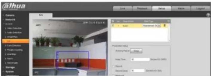
text_image
@lhua Camera Networks Account Video Connection Audio Connection Smart Plus Top Core Connection Play Flag Clamping View Filter Assets Remote Storage Options 2019-05-04 15:41:30 View Show status Show Type Add/Remove Add/Remove (Down) Add/Remove Status Accessing Period: 0.0000 Insert Time: 00 Second to 0000s Record Record Group: 00 Second to 000s| Parameter | Function |
| Working Period | Note:It is to set the alarm period, it can enable alarm event only during the period range which has been set.1. Click "Setup" and the system will pop out the interface of "Working Period".2. It is to set working period according to the following methods:You can input time numerical value or press the left mouse button to drag on the setup interface to set.There are six periods to be set every day, select the check box in front of the period, and then the period is valid.Select week number (it selects Sunday by default, if it selects the whole week, then it means the setup can be applied to the whole week, you can also select the check box in front of the week number to implement independent setting for some days).3. Click "Save" to complete the setup of working period. |
| Keep time | It is to set the shortest time from when the object is abandoned to when it triggers alarm. |
| Record | Check it and so when alarm occurs, system will auto record. |
| Record Delay | System can delay the record for specified time after alarm ended. |
| Relay out | Enable alarm activation function. You need to select alarm output port so that system can activate corresponding alarm device when alarm occurs. |
| Alarm Delay | System can delay the alarm output for specified time after alarm ended. |
| Send Email | If you enabled this function, System can send out email to alert you when alarm occurs and ends. User can set email address in Network>SMTP. |
| Snapshot | Select "Snapshot" and the system will auto trigger alarm and snapshot when alarm occurs. |
alhua
Dahua Network Camera Web 3.0 Operation Manual
Application scene: it can be applied to the scene where the target is sparse and there is no obvious and frequent light change. False alarm will be increased in the scene where the target density is high and there is frequent obstruction; the false alarm will be increased in the scene where there are more people staying. As for the detection area, try to make it simple, the function is not suitable for the area which is too complicated.
Step 1
Select "Setup > Event > IVS > IVS" and the system will display the interface of "IVS".
Step 2

to set rule name and select rule type as "Missing Object", which is shown in Figure 5-73.
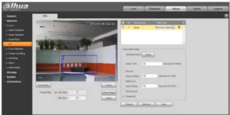
text_image
@ihua Camera Network Event Video Detection Audio Detection SmartStar Alt Face Detection Photo Tracking Noise Astrs Geometry Escape System Information 2014/05-18 13:41 AM FCA Close Data Target Flow Alt Size Alt Size Close Content Close Model Missing ImageC Parameter Setup: Hearing Material Value Size: 10 Resolution (0x1000) Received Present (Output) 10 Resolution (0x1000) Random out Maximum Output 10 Resolution (0x1000) Select Email Unadjusted Cancel Default ShowFigure 5-73
Step 3
Click "Draw Rule" to draw an area in the monitoring scene.
@ahua
Dahua Network Camera Web 3.0 Operation Manual
| Parameter | Function |
| Working Period | Note:It is to set the alarm period, it can enable alarm event only during the period range which has been set.1. Click "Setup" and the system will pop out the interface of "Working Period".2. It is to set working period according to the following methods:You can input time numerical value or press the left mouse button to drag on the setup interface to set.There are six periods to be set every day, select the check box in front of the period, and then the period is valid.Select week number (it selects Sunday by default, if it selects the whole week, then it means the setup can be applied to the whole week, you can also select the check box in front of the week number to implement independent setting for some days).3. Click "Save" to complete the setup of working period. |
| Keep time | It is to set the shortest time from when the object is missing to when it triggers alarm. |
| Record | Check it and so when alarm occurs, system will auto record. |
| Record Delay | System can delay the record for specified time after alarm ended. |
| Relay out | Enable alarm activation function. You need to select alarm output port so that system can activate corresponding alarm device when alarm occurs. |
| Alarm Delay | System can delay the alarm output for specified time after alarm ended. |
| Send Email | If you enabled this function, System can send out email to alert you when alarm occurs and ends. User can set email address in Network>SMTP. |
| Snapshot | Select "Snapshot" and the system will auto trigger alarm and snapshot when alarm occurs. |
Step 5
Click "Save" to complete the setup of missing object.
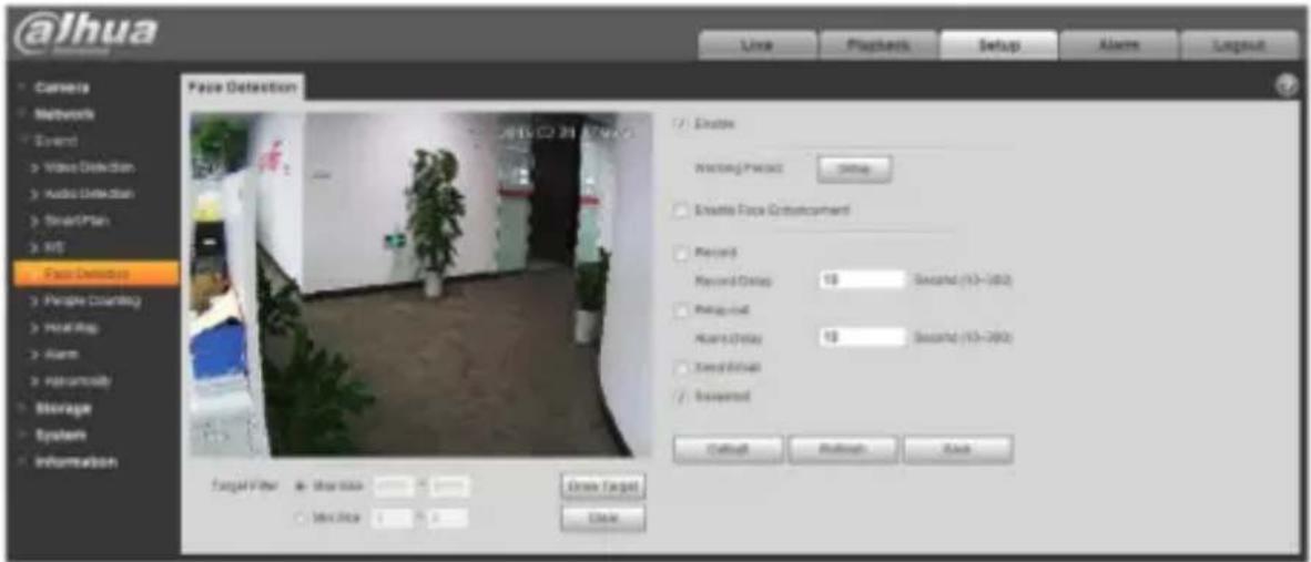
text_image
@lhua Line Playback Setup Alarm Layout Camera Networks Event Video Detection Audio Detection StreamPlan Wt Face Detection People Counting MealRing Alarm Paramount Storage System Information Face Detection Enable Warning/Prevent Setup Enable Face Environment Record Record Date: 10 Second (10-2002) Protocol Alert/Delay: 10 Second (10-2002) Speed Event Reserved Default Refresh Ask Target Filter: Max Time Min Time Close Target DeleteFigure 5-74
Step 2
Select "Enable" to enable face detection function.
Step 3
Click "Draw Target" to draw the size model of target filter in the video image.
Step 4
It is to set the parameters of face detection, please refer to the following sheet for more details.
| Parameter | Function |
| Working Period | Note:It is to set the alarm period, it can enable alarm event only during the period range which has been set.1. Click “Setup” and the system will pop out the interface of “Working Period”.2. It is to set working period according to the following methods:● You can input time numerical value or press the left mouse button to drag on the setup interface to set.● There are six periods to be set every day, select the check box in front of the period, and then the period is valid.● Select week number (it selects Sunday by default, if it selects the whole week, then it means the setup can be applied to the whole week, you can also select the check box in front of the week number to implement independent setting for some days).3. Click “Save” to complete the setup of working period. |
| Enable Face Enhancement | Select “Enable Face Enhancement” and it will guarantee that the face is clear by priority when the stream is set very low. |
| Record | Check it and so when alarm occurs, system will auto record. |
| Record Delay | System can delay the record for specified time after alarm ended. |
@ahua
Dahua Network Camera Web 3.0 Operation Manual
| Parameter | Function |
| Relay out | Enable alarm activation function. You need to select alarm output port so that system can activate corresponding alarm device when alarm occurs. |
| Alarm Delay | System can delay the alarm output for specified time after alarm ended. |
| Send Email | If you enabled this function, System can send out email to alert you when alarm occurs and ends. User can set email address in Network>SMTP. |
| Snapshot | Select "Snapshot" and the system will auto trigger alarm and snapshot when alarm occurs. |
Step 5
Click "Save" to complete the setup of face detection.
5.3.6 People Counting
5.3.6.1 People Counting
Step 1
Select "Setup > Event > People Counting > People Counting" and the system will display the interface of "Entrance/Exit", which is shown in Figure 5-75.
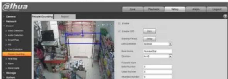
text_image
@lhua People Counting Enable Enable USD Binding Packet Links Direction Main Name: Children Flower name: Driver Number: Leave Number: Number Number:@alhua
Dahua Network Camera Web 3.0 Operation Manual
Click "Draw Rule" to draw an area in the monitoring image.
Step 4
Click "Draw Target" to draw the size model of filtered target in the video image.
Step 5
It is to set the parameters of entrance and exit, please refer to the following sheet for more details.
| Parameter | Function |
| Enable OSD | Select "Enable OSD" and it will display the people number statistics of entrance and exit in the monitoring image. |
| Working Period | Note:It is to set the alarm period, it can enable alarm event only during the period range which has been set.1. Click "Setup" and the system will pop out the interface of "Working Period".2. It is to set working period according to the following methods:You can input time numerical value or press the left mouse button to drag on the setup interface to set.There are six periods to be set every day, select the check box in front of the period, and then the period is valid.Select week number (it selects Sunday by default, if it selects the whole week, then it means the setup can be applied to the whole week, you can also select the check box in front of the week number to implement independent setting for some days).3. Click "Save" to complete the setup of working period. |
| Installation Mode | It is to select wall mount if there is an angle between device lens and horizontal surface, select ceiling if the device lens face downward vertically. |
| Rule Name | It is to set the name of rule. |
| Direction | It is to select the direction of entrance and exit statistics; A->B or B->A, the arrow direction always means the entrance direction. |
| Flowrate Alarm | It is to set the enter number, leave number, stranded number; it will trigger alarm when it exceeds the limited number. |
| Record | Check it and so when alarm occurs, system will auto record. |

Dahua Network Camera Web 3.0 Operation Manual
5.3.6.2 Report
It is to generate a form of report according to the number statistics.
Step 1
Select "Setup > Event > People Counting > Report" and the system will display the interface of "Report", which is shown in Figure 5-76.
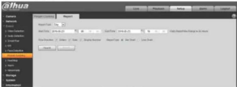
text_image
@lhua Camera Network Exposure Video Detection Audio Detection Small Filter AVI Face Detection Front Channels Heading Item Accessibility Storage System Information Report Summary Report Report Type Copy Real Time 2014-06-23 Text 100 Cash Time 2014-06-25 Text 100 Cash Times/Background Storage to Set Options File Description: Auto Type Display Number Report Type at: Save Chart - Live Chart SearchFigure 5-76
Step 2
It is to set search condition, please refer to the following sheet for more details.
| Parameter | Note |
| Report Type | Can select day report, month report and year report; also can select bar chart or line chart to display the report. |
| Time | It can set the begin/end time within the range of statistics time. |
| Flow Direction | It can select enter, leave and display number; the data of checked item can be displayed in the report. |
| Search | Search flow statistics data according to the setting to form report. |
Step 1
Select "Setup > Event > Heat Map > Heat Map" and the system will display the interface of "Heat Map", which is shown in Figure 5-77.
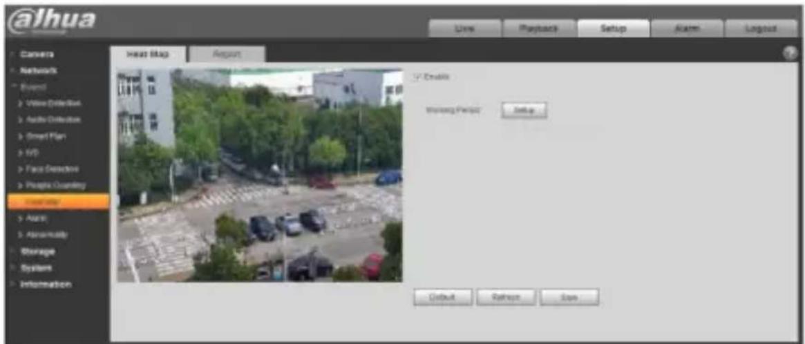
text_image
@lhua Searchbox SearchMap Report View Playback Setup Alarm Logout Camera Networks Event Video Dilef/Sat Audio-Dilef/Box Smart Plan Info Face Detector People Clanking System Auto Abnormality Storage System Information Head Map About Create Myron Project Setup Default Refresh SaveFigure 5-77
Step 2
Select "Enable" to enable heat map function.
Step 3
It is to set the working period.
- Click "Setup" and the system will display the interface of "Working Period", which is shown in Figure 5-78.

Dahua Network Camera Web 3.0 Operation Manual
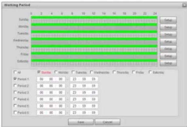
text_image
Working Period Sunday Monday Tuesday Wednesday Thursday Friday Saturday All Period 1 Period 2 Period 3 Period 4 Period 5 Period 6 S星期 Sunday Sunday Tuesday Wednesday Thursday Friday Saturday Save CancelFigure 5-78
-
It is to set working period according to the following methods:
-
You can input time numerical value or press the left mouse button to drag on the setup interface to set.
- There are six periods to be set every day, select the check box in front of the period, and then the period is valid.
- Select week number (it selects Sunday by default, if it selects the whole week, then it means the setup can be applied to the whole week, you can also select the check box in front of the week number to implement independent setting for some days).
- Click "Save" to complete the setup of working period.
@ahua
Dahua Network Camera Web 3.0 Operation Manual
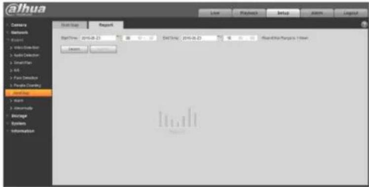
text_image
@ihua Start Menu Report StartTime: 2016-08-23 08:00:00 StartTime: 2016-08-23 08:00:00 ReadAndRunTarget: 7.15mm StartTime: StartTime: 2016-08-23 08:00:00 ReadAndRunTarget: 7.15mm StartTime: StartTime: 2016-08-23 08:00:00 ReadAndRunTarget: 7.15mm StartTime: StartTime: 2016-08-23 08:00:19 ReadAndRunTarget: 7.15mm StartTime: StartTime: 2016-08-23 08:00:19 ReadAndRunTarget: 7.15mm StartTime: StartTime: 2016-08-23 08:00:19 ReadAndRunTarget: 7.15mm StartTime: StartTime: 21.44mm 08:00:19 ReadAndRunTarget: 7.15mm StartTime: StartTime: 21.44mm 08:00:19 ReadAndRunTarget: 7.15mm StartTime: StartTime: 21.44mm 08:00:19 ReadAndRunTarget: 7.15mm StartTime: StartTime: 19.44mm 08:00:19 ReadAndRunTarget: 7.15mm StartTime: StartTime: 19.44mm 08:00:19 ReadAndRunTarget: 7.15mm StartTime: StartTime: 19.44mm 08:00:19 ReadAndRunTarget: 7.15mm StartTime: End Time:Figure 5-79
Step 2
It is to set begin time and end time.
Step 3
Click "Search" to complete report statistics, click "Export" to export the statistics report.
5.3.8 Alarm
Please note some series products do not support this function.
5.3.2.1 PIR alarm
The alarm activation interface PIR alarm is shown as in figure 5-80.
Figure 5-80
Please refer to the following sheet for detailed information.
| Parameter | Function |
| Enable | After enabled, relay activation will work. Check it and enable the PIR alarm. |
| Working period | This function becomes activated in the specified periods.There are six periods in one day. Please draw a circle to enable corresponding period.Select date. If you do not select, current setup applies to today only. You can select all week column to apply to the whole week.Click OK button, system goes back to motion detection interface; please click save button to exit.Note: User can set via dragging mouse while not releasing left mouse. |
| Anti-dither | System only memorizes one event during the anti-dither period.The value ranges from 0s to 100s. |
| Flash | After enabling, the system will automatically turn on the flash when alarm occurs. |
| Flash Delay | The flash will be off with a period of time delay when the alarm linkage is over.Time is calculated by unit of second and ranges from 10s~300s. |
| Record | System auto activates motion detection channel to record once alarm occurs (working with motion detection function). |
| Record Delay | System can delay the record for specified time after alarm ended.The value ranges from 10s to 300s. |

Dahua Network Camera Web 3.0 Operation Manual
| Parameter | Function |
| Relay out | Enable alarm activation function. You need to select alarm output port so that system can activate corresponding alarm device when alarm occurs. |
| Alarm delay | System can delay the alarm output for specified time after alarm ended. The value ranges from 10s to 300s. |
| Send Email | After this function is enabled, system can send out email to alert you when alarm occurs and ends. |
| Audio Linkage | Check it and the system will play alarm audio file when alarm occurs. Users can set recorded audio file in "Camera Setting > Audio > Alarm Audio". |
| Snapshot | After you enabled snapshot, the system will automatically snapshot if alarm occurs. |
5.3.8.1 Alarm Linkage
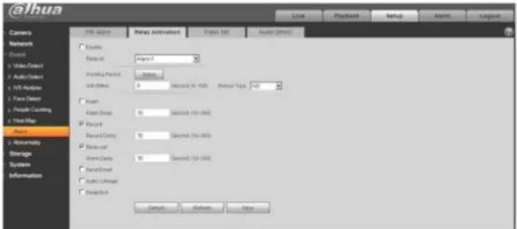
text_image
@jhua File Edit View Activation Status Set Audio Options Camera Network Event Video/Direct Audio/Direct APIs/Options Face Direct People Counting Home Map Balance Storage Systems Information Basic None Access Access Date: August 2017 Record Date: September 2018 Record Date: September 2019 Record Date: September 2020 Record Date: September 2021 Record Date: September 2022 Default Refresh Stopalhua
Dahua Network Camera Web 3.0 Operation Manual
| Parameter | Function |
| PTZ | Check it and set PTZ movement when alarm occurs. Such as go to preset x when there is an alarm.The event type includes: preset, tour and pattern and so on. |
5.3.8.2 Flash Set

text_image
@ihua Camera Network Audio Video Detect Audio Detect MIL Analyzer Face Detect People Counting Next Map Aram Annuity Storage System Information PPI Agent Array Activation Flash Set Audio Click Post 1 String Balance Balance Audio Endwhere Impulse Drop Balance Default Default SaveFigure 5-82
| Parameter | Function |
| ON/OFF | ON means flash is on; OFF means flash is off. |
| Weak-strong bar | Via dragging this bar to adjust flash brightness. |
| All | Check and it means the day flash works. |
@ahua
Dahua Network Camera Web 3.0 Operation Manual
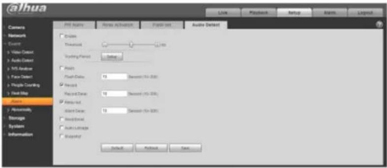
text_image
@jhua Camera Network Event Video Output Audio Detector MT Analyzer Face Detect People Recording Foot Map Audio Abnormally Storage Systems Information PRS Accuracy Rearer Activation Project Set Audio Detector Options Flash-Delta: 10 Seconds (75-800) Record Record-Delta: 10 Seconds (75-800) Record-Not Record-Delta: 10 Seconds (75-800) Audio-Stream Audio Linkage Audio-Not Default Refresh SaveFigure 5-83
| parameter | Function |
| Enable | Check it and enable audio detection. |
| Threshold | It will trigger alarm and set up a series of linkage when volume exceeds the set threshold. |
5.3.9 Abnormity
Abnormity includes No SD Card, Capacity Warning, SD Card Error, Disconnection, IP Conflict and Unauthorized Access.
Note:
Only device with SD card function has these three statuses: No SD card, capacity warning, and SD card error. Device without SD card function does not have the above three statuses. See Figure 5-84 to
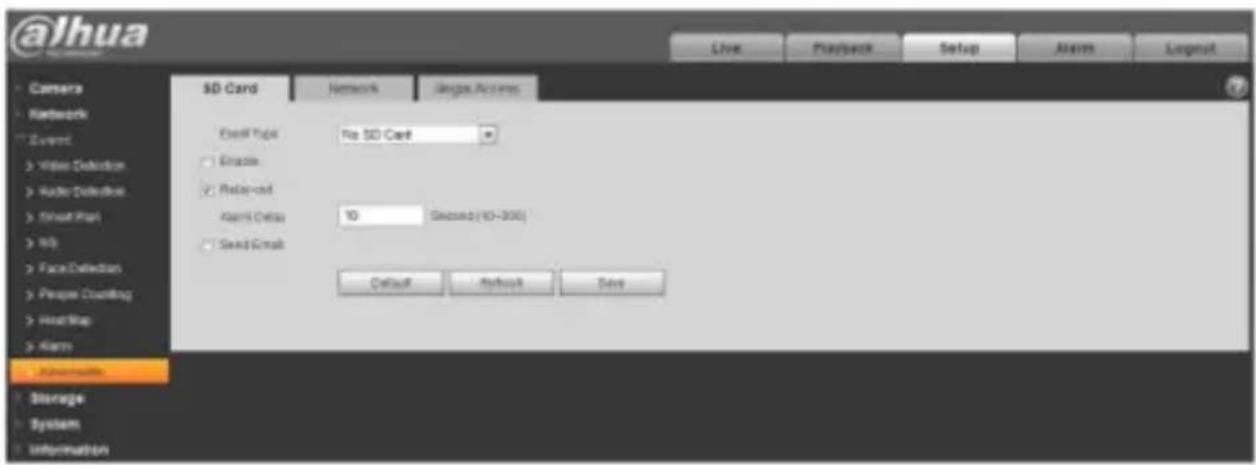
text_image
@lhua Camera Network Event Water Detection Radio Detection Smart Hall Job Face Detection People Counting HeadMap Alarm Information Storage System Information SD Card Network Images Access File Format No SD Card Oracle Relay-out Alarm Delta 10 Second (40-300) Seed Script Default Refresh Deep Live Playback Setup Alerts LogoutFigure 5-84
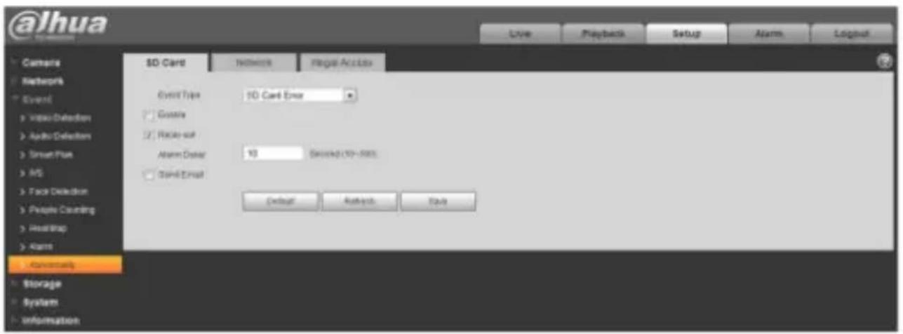
text_image
@Jhua Cathars Networks Event Video Detachment Audio Detachment Smart Plus MS Face Detection People Counting HeadTrap Alarm Automatically Storage System Information SD Card Networks Regular Address Event Type: 10 Card Error Camera Radio-out Alarm Date: 10 Seconds (10-500) Send Email Default Refresh SaveFigure 5-85
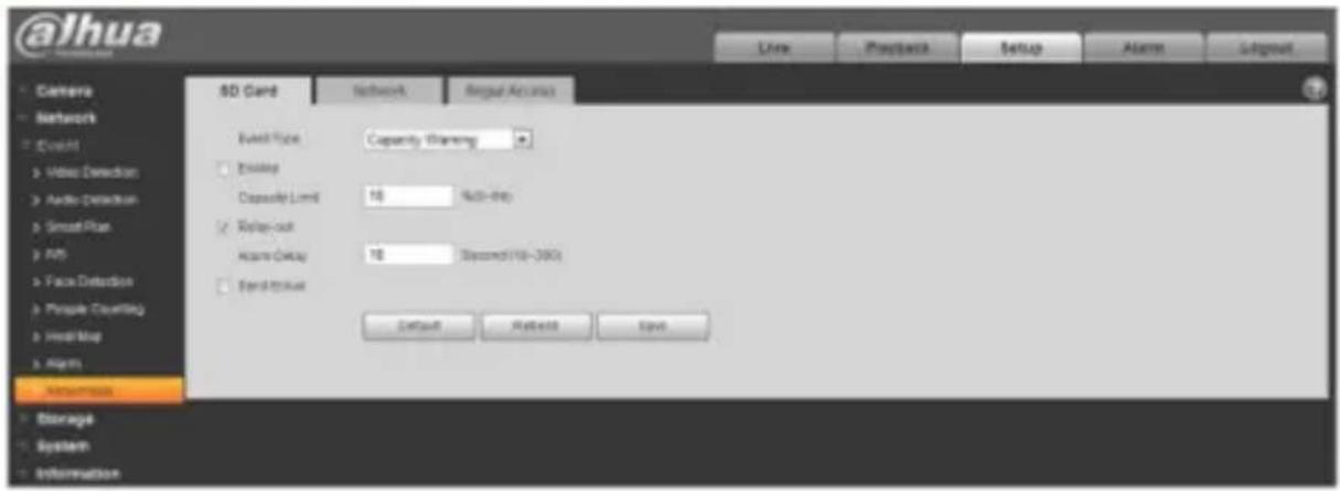
text_image
@lhua SD Card Network Signal Build Type Capacity Planning Enable Capacity Limit 10 NcN-thy Relay-out Name: Gray 10 Second (10-300) Send/Show Default Network Save Camera Network C-mail Video Detection Audio Detection Smooth Plan Info Face Detection People Counting HeadMap Alarms Automotive Storage System InformationFigure 5-86
Please refer to the following sheet for detailed information.
| Parameter | Function |
| Enable | Check to alarm when SD card is abnormal. |
| Relay-out | Check to enable relay-out alarm. |
| Relay out delay | The alarm output can delay for the specified time after alarm stops. The value ranges from 10s to 300s.Note:No SD card, capacity warning, SD card error, relay-out delay all start from alarm occurs. |
| Send email | After you enabled this function, the system can send out email to alarm the specified user.This function is invalid when network is offline or IP conflict occurs. |
| SD Card Capacity Limit | User can set SD card capacity that is left free. When SD card space left is smaller than this limit, alarm occurs. |
When device is offline or IP conflicts, the abnormal alarm is similar with case of SD card error.
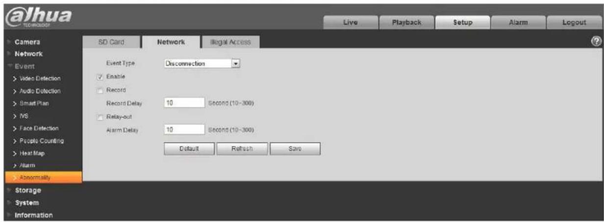
text_image
@lhua TECHNOLOGY Live Playback Setup Alarm Logout Camera SD Card Network Illegal Access Network Event Video Detection Audio Detection Smart Plan IVS Face Detection People Counting Heat Map Alarm Abnormality Storage System Information Event Type Disconnection Enable Record Record Delay 10 Second (10-300) Relay-out Alarm Delay 10 Second (10-300) Default Refresh SaveFigure 5-87
When login password keep been wrong for a few times, unauthorized access alarm occurs. This operation is similar to SD card error. Allow login error times as when it exceeds this limit, user account will be locked.
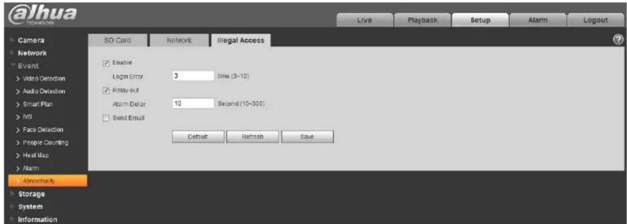
text_image
@Jhua Live Playback Setup Alarm Logout Camera SD Card Network Illegal Access Network Event Video Detection Enable Audio Detection Login Error 3 时间 (3~10) Smart Plan Relay-out IVS Alarm Delay 10 Second (10-300) Face Detection Send Email People Counting Heat Map Alarm Abnormality Storage System Information Default Refresh SaveFigure 5-88
5.4 Storage Management
5.4.1 Schedule
Before schedule setup, user must set record mode is auto or manual.
Note:
If record mode in record control is off, then device will not snapshot according to schedule.
5.4.1.1 Record Schedule
Record schedule steps:
Step 1. Click on Record Schedule, see Figure 5-89.
@ahua
Dahua Network Camera Web 3.0 Operation Manual
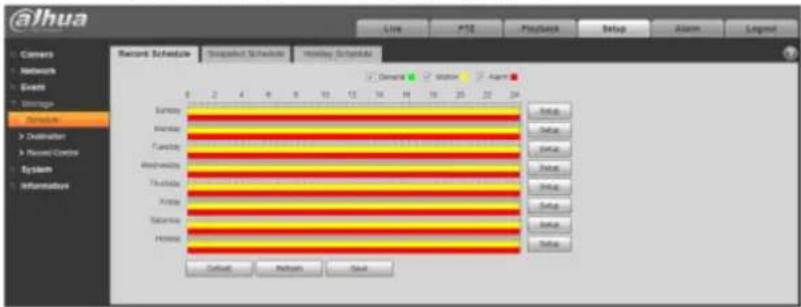
text_image
@jhua Live PSE Playback Setup Alarm Legend Record Schedule Dispatched Schedule Implied Schedule Sunday Monday Tuesday Wednesday Thursday Friday Saturday Sunday Hawaii Default Refresh BackFigure 5-89
Step 2. From Monday to Sunday select record time, click on setup on the right, see Figure 5-90.
- Set period according to actual need. There are six periods available each day.
- By checking or unchecking, you can add or delete three types of record schedule: General, Motion, and Alarm.
Note:
Period setup can be done by dragging in record schedule interface while not releasing left mouse.
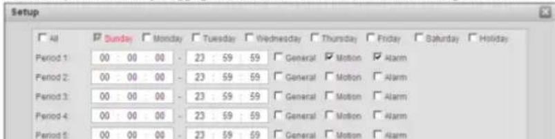
text_image
Setup All Sunday Monday Tuesday Wednesday Thursday Friday Saturday Holiday Period 1 00 00 00 - 23 59 59 General Motion Alarm Period 2 00 00 00 - 23 59 59 General Motion Alarm Period 3 00 00 00 - 23 59 59 General Motion Alarm Period 4 00 00 00 - 23 59 59 General Motion Alarm Period 5 00 00 00 - 23 59 59 General Motion Alarm@alhua
Dahua Network Camera Web 3.0 Operation Manual
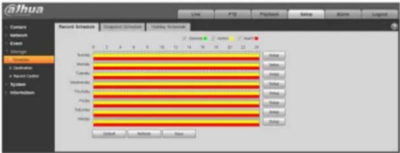
text_image
@Jhua Live P12 Playback Setup Alarms Legend Record Schedule Scheduled Schedule Holiday Schedule Switch Monday Tuesday Wednesday Thursday Friday Saturday Sunday Monday Default Network CaseFigure 5-91
Step 4. In record schedule interface, click on OK. System prompts it is successfully saved.
5.4.1.2 Snapshot Schedule
Snapshot setup as:
Step 1. Click on Snapshot Schedule tab, see Figure 5-92.
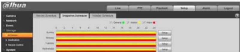
text_image
@ihua Camera Network Event Storage Schloss Destination Record Control System News Schedule Snapshot Schedule Holiday Schedule General Water Action Kurley Monday Tuesday Wednesday Wednesday Status Status Status StatusDahua Network Camera Web 3.0 Operation Manual
- By checking or unchecking, user can add or delete three types of snapshot schedule: General, Motion and Alarm.
Note: Period setup can be done by dragging in snapshot schedule interface while not releasing left mouse.
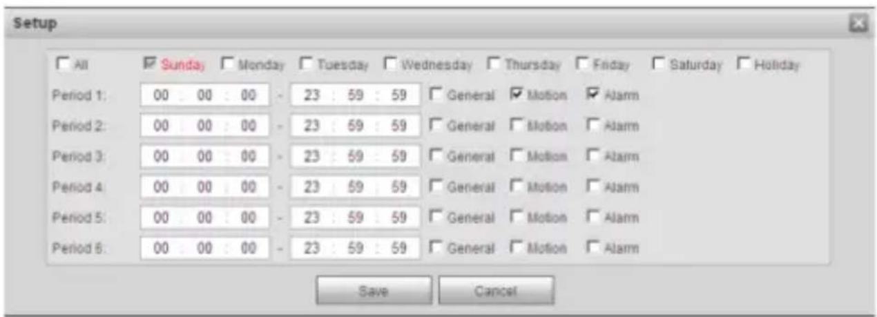
text_image
Setup All Sunda Monday Tuesday Wednesday Thursday Friday Saturday Holiday Period 1: 00 00 00 - 23 : 59 : 59 General Motion Alarm Period 2: 00 00 00 - 23 : 59 : 59 General Motion Alarm Period 3: 00 00 00 - 23 : 59 : 59 General Motion Alarm Period 4: 00 00 00 - 23 : 59 : 59 General Motion Alarm Period 5: 00 00 00 - 23 : 59 : 59 General Motion Alarm Period 6: 00 00 00 - 23 : 59 : 59 General Motion Alarm Save CancelFigure 5-93
Step 3. Click on OK, return to snapshot schedule interface. See Figure 5-94.
● Green color stands for the general record/snapshot.
● Yellow color stands for the motion detect record/snapshot.
● Red color stands for the alarm record/snapshot.
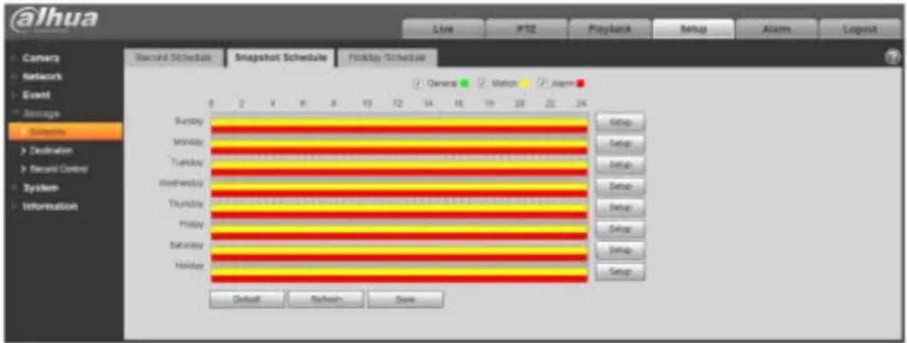
text_image
@lhua Live PTZ Playback Setup Alarm Logout Camera Network Event Setrange Sunday Sunday Monday Monday Tuesday Tuesday Wednesday Wednesday Thursday Thursday Friday Friday Saturday Saturday Holiday Default Refresh SaveFigure 5-94
Step 5. In snapshot interface, click on OK. System prompts it is successfully saved.
5.4.1.3 Holiday Schedule
Holiday schedule can set specific date as holiday.
Step 1. Click on Holiday Schedule tab, see Figure 5-95.
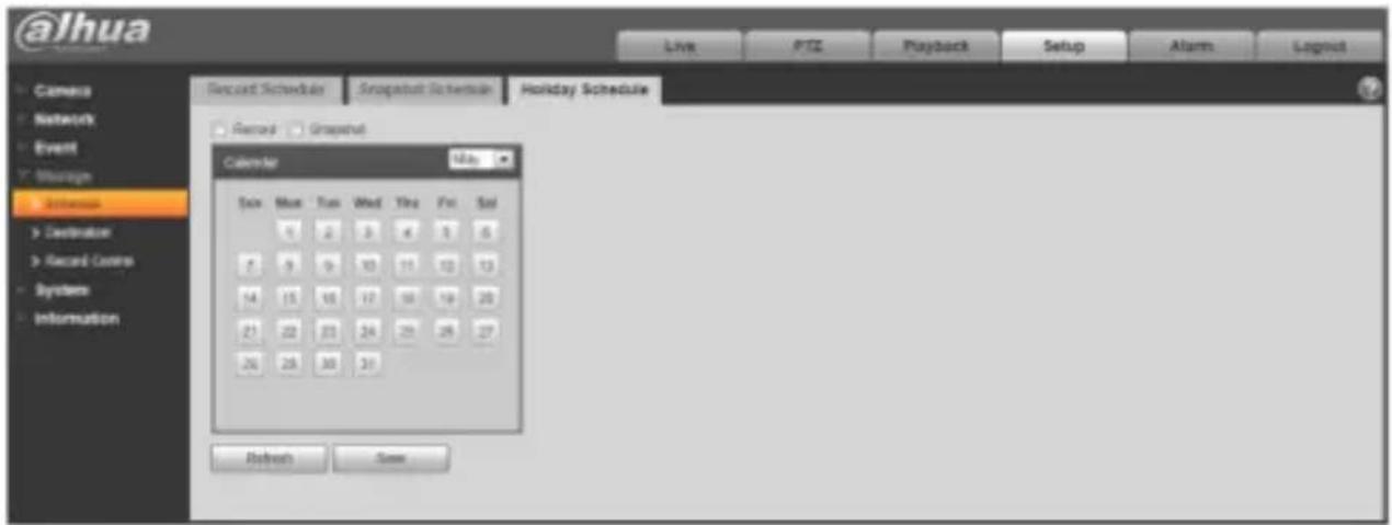
text_image
@lhua Live PTC Playback Setup Alarms Logout Record Schedule Snapchat Schematic Holiday Schedule Remed Snapchat Calendar 12:00 Sun Mon Tue Wed Thu Fri Sat 6 2 3 4 5 6 7 9 10 11 12 13 14 15 16 17 18 19 20 21 22 23 24 25 26 27 26 28 30 31 Refresh SaveFigure 5-95
Step 2. Select date to set as holiday. The selected date will be highlighted in yellow.
Step 3. Check Record/Snapshot, click on Save. System prompts it is successfully saved.
Step 4. Check Record Schedule/Snapshot Schedule interface, click on setup next to Holiday, and refer to setup of Monday to Sunday.
Step 5. Complete setup of holiday, then it records/snapshots according to date in holiday schedule.
5.4.2 Destination
5.4.2.1 Path
The destination interface is shown as in Figure 5-96.
Path can config record and snapshot storage path. There are three options: Local, FTP and NAS. You can only select one mode. System can save according to the event types. It is corresponding to the three modes (general/motion/alarm) in the Schedule interface. Please check the box to enable the save functions.
Note: Only device supports SD card has local.
alhua
Dahua Network Camera Web 3.0 Operation Manual
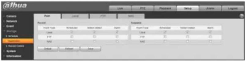
text_image
@ihua Path Event Event Type Event Count Event Select Event Select Event Select Event Select Event Select Event Select Event Select Event Select Event Select Event Select Event Select Event Select Event Select Event Select Event Select Event Select Event Select Event Select Event Select Event Select Event Select Event Select Event Select Event Select Event Select Event Select Event Select Event Select Event Select Event Select Event Select Event Select Event Select Event SelectFigure 5-96
Please refer to the following sheet for detailed information.
| Parameter | Function |
| Event Type | It includes: scheduled, motion detect and alarm. |
| Local | It saved in the SD card. |
| FTP | It saved in the FTP server. |
| NAS | It saved in NAS disk. |
5.4.2.2 Local
The local interface is shown as in Figure 5-97.
Here you can view local Micro SD card or NAS disk information. You can also operate the read-only, write-only, hot swap and format operation.

text_image
@lhua Camera Network Event Fish Local 210 NAS Default Name Insks Attacks User Type By Value Capital By Default Normal Pre & Inv SIDI NETS/5% 78Dahua Network Camera Web 3.0 Operation Manual
5.4.2.3 FTP
The FTP interface is shown as in Figure 5-98.
You need to check the box to enable the FTP function. When network disconnect occurred or there is malfunction. Emergency storage can save the record/snapshot picture to the local SD card. Click the test button to check if the FTP server can be connected for test.
Figure 5-98
5.4.2.4 NAS
You need to check the box to enable the NAS function. Select NAS storage, fill in NAS server address and corresponding store path, then you can store video file or pictorial information in the NAS server.
Select NAS storage as to same file to NAS disk. See Figure 5-99.
Figure 5-99
Parameter Function
Server Address Set IP address of NAS server.
Dahua Network Camera Web 3.0 Operation Manual
| Parameter | Function |
| Remote Directory | Set storage directory, videos and pictures can be stored in to corresponding server directory. |
5.4.3 Record control
The record control interface is shown as in Figure 5-100.

text_image
@lhua Live PTZ Playback Setup Alarm Logout Camera Network Event Storage Schedule Destination Record Control System Information Record Control Track Duration 0 Minutes (1-120) Play event period 0 Seconds (3-5) Use Full Outwrite Record Mode Auto Manager Off Record Stream Mean Stream Default Refresh SaveFigure 5-100
Please refer to the following sheet for detailed information.
| Parameter | Function |
| Pack Duration | Here you can select file size within 1min~120min. Default setup is 8 minutes. |
| Pre-record | Please input pre-record value here.For example, system can record the four seconds video in the buffer.The record begins from the fifth second.Note:Configure pre-record time, when alarm or motion detection occurs, if there is no record, system will record the preceding n seconds record. |
| Disk Full | There are two options: stop recording or overwrite the previous files when HDD is full.Stop: Current working HDD is overwriting or current HDD is full, it will stop record.Overwrite: Current working HDD is full; it will overwrite the previous file. |
| Record mode | There are three modes: Auto/manual/close. |
| Record stream | There are two options: main stream and sub stream. |

Dahua Network Camera Web 3.0 Operation Manual
5.5 System
5.5.1 General
The General interface is shown as in Figure 5-101.
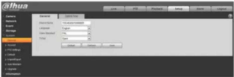
text_image
@ihua General Default Time Select Name: Y3C40201968888 + Address: Engers Video Standard: Poly T Vital: Open Default Settings BackFigure 5-101
Please refer to the following sheet for detailed information.
| Parameter | Function |
| Device Name | It is to set device name.Note: Different devices have different names. |
| Video Standard | This is to display video standard such as PAL |
| Language | You can select the language from the dropdown list. |
| TV Out | You can open or close the function, it can only be supported by the devices with TV Out. |
©
Dahua Network Camera Web 3.0 Operation Manual
5.5.2 Account
For user name and user group, the max length is 31 characters, which can be made up of digit, letter, underline, hyphen, dot and @.
Password can be 0\~32 characters in number and letter only. User can modify other user's password.
User and group can be manually added to 18 and 8 respectively.
User management adopts group/user modes. The user name and the group name shall be unique.
One user shall be included in only one group.
Currently logged in user cannot change his/her own right.
5.5.2.1 Username
In this interface you can enable anonymity login, add/remove user and modify user name. See Figure 5-103.
Figure 5-103
Enable anonymity login: Enable anonymity login, and input IP. No username or password is required, you can log in by anonymity (with limited rights). You can click logout to end your session.
Add user: It is to add a name to group and set the user rights. See Figure 5-86.
Hidden user “default” is for system interior use only and cannot be deleted. When there is no login user, hidden user “default” automatically login. You can set some rights such as monitor for this user so that you can view some channel view without login.
Here you can input the user name and password and then select one group for current user.
@ahua
Dahua Network Camera Web 3.0 Operation Manual
Please note the user rights shall not exceed the group right setup.
For convenient setup, please make sure the general user has the lower rights setup than the admin.
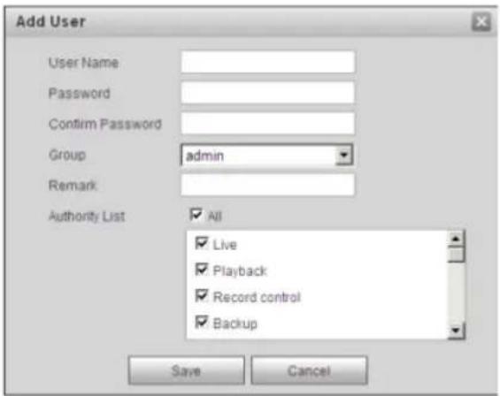
text_image
Add User User Name Password Confirm Password Group admin Remark Authority List All Live Playback Record control Backup Save CancelFigure 5-104
Modify user
It is to modify the user property, belonging group, password and rights. See Figure 5-103.
Modify password
It is to modify the user password. You need to input the old password and then input the new password twice to confirm the new setup. Please click the OK button to save.

Dahua Network Camera Web 3.0 Operation Manual
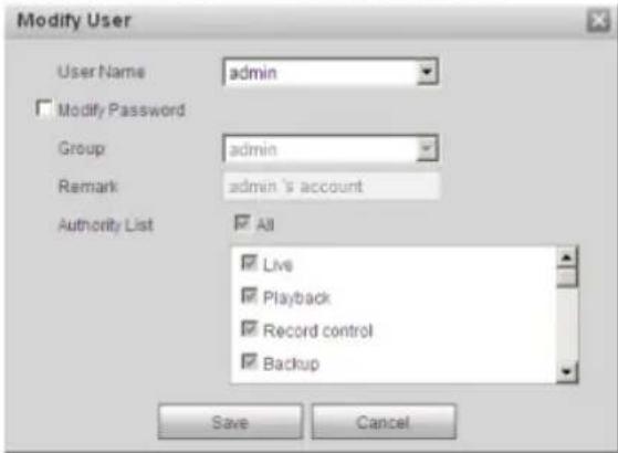
text_image
Modify User User Name admin Modify Password Group admin Remark admin's account Authority List All Live Playback Record control Backup Save CancelFigure 5-105
5.5.2.2 Group
The group management interface can add/remove group, modify group password and etc.
The interface is shown as in Figure 5-106.
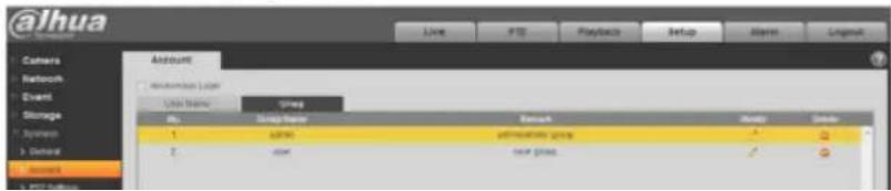
text_image
@ihua Camera Network Event Storage Systems General Access Account Account Number Use Name Show No. Setup Name Remark Balance Cancel 1 32000 administrative group ✓ ✓ 2 user new group ✓ ✓Dahua Network Camera Web 3.0 Operation Manual
Please input the group name and then check the box to select the corresponding rights. It includes: preview, playback, record control, PTZ control and etc.
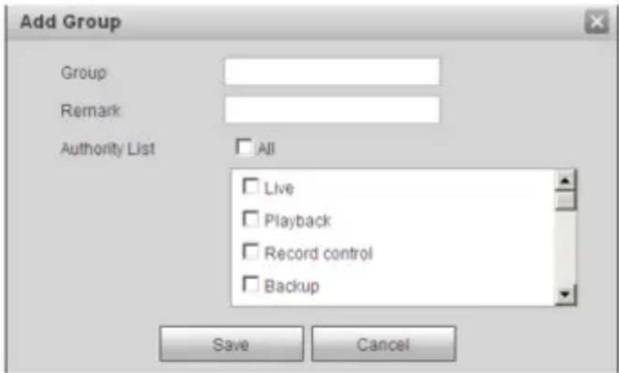
text_image
Add Group Group Remark Authority List All Live Playback Record control Backup Save CancelFigure 5-107
Modify group
Click the modify group button, you can see an interface is shown as in Figure 5-108. Here you can modify group information such as remarks and rights.
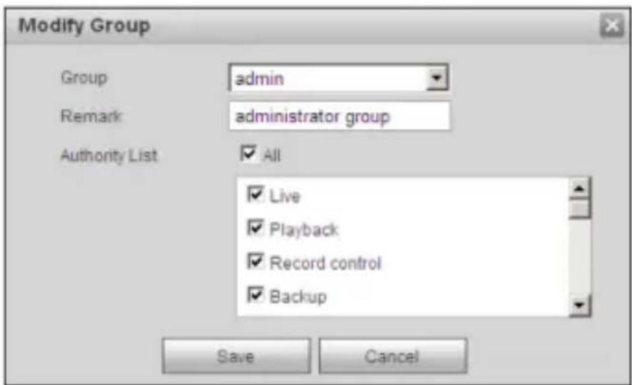
text_image
Modify Group Group admin Remark administrator group Authority List All Live Playback Record control Backup Save CancelFigure 5-108
5.5.3 PTZ
Please note only some series products support this function.
The PTZ settings interface is shown as in Figure 5-109.
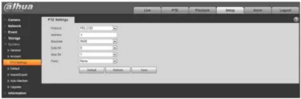
text_image
@lhua PTZ Settings Protocol: PELOOD Address: 1 Excode: 9400 Data: 8 Setup Bit: 5 Party: Alone Default Refresh SolveFigure 5-109
Please refer to the following sheet for detailed information.
| Parameter | Function |
| Protocol | Select the corresponding dome protocol. |
| Address | Set corresponding dome address. Default value is 1.Please note your setup here shall comply with your dome address; otherwise you cannot control the speed dome. |
| Baud Rate | Select the dome baud rate. Default setup is 9600. |
| Data Bit | Default setup is 8. |
| Stop bit | Default setup is 1. |
| Parity | Default setup is none. |
5.5.4 Default
The default setup interface is shown as in Figure 5-110.
Please note system cannot restore some information such as network IP address, account and so on.
Figure 5-110
5.5.5 Import/Export
The interface is shown as in Figure 5-109.
Figure 5-111
Please refer to the following sheet for detailed information.
Parameter Function
Import It is to import the local setup files to the system.
Export It is to export the corresponding system setup to your local PC.
5.5.6 Remote control
Note:
It is supported by some devices.
alhua
Dahua Network Camera Web 3.0 Operation Manual
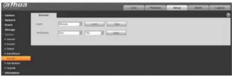
text_image
@hua Remote Layer: Name: Name: Name: Name: Name: Name: Name: Name: Name: Name: Name: Name: Name: Name: Name: Name: Name: Name: Name: Name: Name: Name: Name: Name: Name: Name: Name: Name: Name: Name: Name: Name: Name: Name: Name: Name: Name: Name: Name: Name: Name: Name: Name: Name: Name: Name: Name: Name: Name: Name: Name: Name: Name: Name: Name: Name: Name: Name: Name: Name: Name: Name: Name: Name: Name: Name: Name: Name: Name: Name: Name: Name: Name: Name: Name: Name: Name: Name: Name: Name: Name: Name: Name: Name:Figure 5-112
| Parameter | Function |
| Learn | Bind remote control or wireless alarm with equipment. |
| Clear | Unbind remote control with equipment. |
| Arm/Disarm | Start arm after the time you choose, disarm comes into effect immediately. Note: With disarm status, all the following alarms won't trigger: motion detect alarm, masking alarm, local alarm, PIR alarm, wireless alarm. |
5.5.6 Auto Maintenance
The auto maintenance interface is shown as in Figure 5-113.
Here you can select auto reboot and auto delete old files interval from the dropdown list.
If you want to use the auto delete old files function, you need to set the file period.

text_image
@lhua User PT2 Playbox Setup Alarm Layout Camera Auto Mentionalhua
Dahua Network Camera Web 3.0 Operation Manual
| Parameter | Function |
| Auto Reboot | Check it and set auto reboot time. |
| Auto Delete Old Files | Check it and set period within 1~31 days. |
5.5.7 Upgrade
The upgrade interface is shown as in Figure 5-114.
Please select the upgrade file (file extension is ".bin") and then click the update button to begin firmware update.
Important
Improper upgrade program may result in device malfunction!
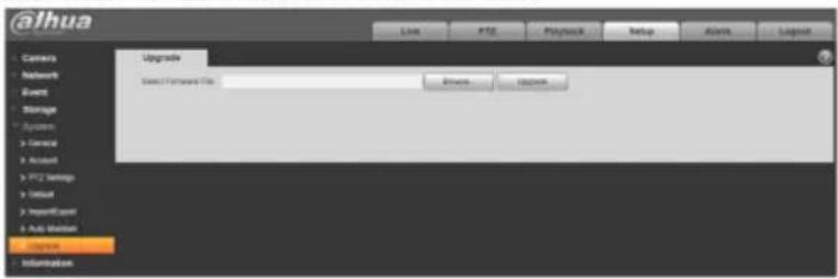
text_image
@ihua Camera Network Event Storage System General Account PTZ Savings Initial ImportExpert Add Status Options Information Upgrade Select Forward File Browse... OptionsFigure 5-114
5.6 Information
5.6.1 Version
The version interface is shown as in Figure 5-115.
Dahua Network Camera Web 3.0 Operation Manual
5.6.2 Log
Here you can view system log. See Figure 5-116.
Figure 5-116
Please refer to the following sheet for log parameter information.
| Parameter | Function |
| Start time | Set the start time of the requested log. (The earliest time is 2000/1/1) |
| End time | Set the end time of the requested log. (The latest time is 2037/12/31) |
| Type | Log type. |
| Search | You can select log type from the drop down list and then click search button to view the list.You can click the stop button to terminate current search operation. |
| Log information | You can select one item to view the detailed information. |
| Clear | You can click this button to delete all displayed log files. Please note system does not support clear by type. |
| Backup | You can click this button to backup log files to current PC. |
5.6.3 Online User
The online user interface is shown as in Figure 5-117.
Here you can view current online user, group name, IP address and login time.
Dahua Network Camera Web 3.0 Operation Manual
Figure 5-117
6 Alarm
Please note some series product does not support this function.
Click alarm function, you can see an interface is shown as in Figure 6-1.
Here you can set device alarm type and alarm sound setup.
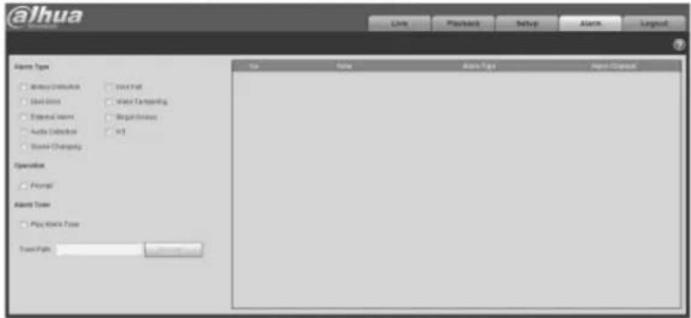
text_image
@ihua Volume Type □ Write Email/Host □ 2014 Total □ Send Items □ Mail Captioning □ External Name □ Regularize □ Audio Checklist □ iOS □ Sound Channeling Operation □ Prompt Alert Type □ Play Work Type Travel Type: Live Playback Setup Alarm Layout Name Type Alert Type Alert Address Start PageFigure 6-1
Please refer to the following sheet for detailed information.
| Type | Parameter | Function |
| Alarm type | Motion detection | System alarms when motion detection alarm occurs. |
| Disk full | System alarms when disk is full. | |
| Disk Error | System records alarm info when disk error happens. | |
| Video | System alarms when video is tampering. |
Dahua Network Camera Web 3.0 Operation Manual
| TypeOperation | ParameterPrompt | FunctionWhen alarm is triggered, there will be sinmain menu of alarm interface and system automatically records alarm info. The icon disappears when user click on alarm menu bar.Note:If alarm interface is displayed, when alarm is triggered, there will be no image prompt, but alarm record will be in list on the right. |
| Alarm Tone | Play Alarm Tone | Click it and select the path of audio file to be played in the tone path, when the subscribed alarm event triggers, it will play the selected audio file to prompt that there is alarm event which has been triggered. |
| Tone Path | You can customize the storage path of the alarm tone. |
alhua
Dahua Network Camera Web 3.0 Operation Manual
7 Log out
Click log out button, system goes back to log in interface. See Figure 7-1.
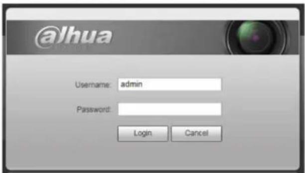
text_image
@lhua Username: admin Password: Login CancelFigure 7-1
Note:
● This manual is for reference only. Slight difference may be found in user interface.
- All the designs and software here are subject to change without prior written notice.
- All trademarks and registered trademarks mentioned are the properties of their respective owners.
- If there is any uncertainty or controversy, please refer to the final explanation of us.
- Please visit our website for more information.