X11DPH-i - Motherboard Supermicro - Free user manual and instructions
Find the device manual for free X11DPH-i Supermicro in PDF.


User questions about X11DPH-i Supermicro
0 question about this device. Answer the ones you know or ask your own.
Ask a new question about this device
Download the instructions for your Motherboard in PDF format for free! Find your manual X11DPH-i - Supermicro and take your electronic device back in hand. On this page are published all the documents necessary for the use of your device. X11DPH-i by Supermicro.
USER MANUAL X11DPH-i Supermicro
The information in this user's manual has been carefully reviewed and is believed to be accurate. The vendor assumes no responsibility for any inaccuracies that may be contained in this document, and makes no commitment to update or to keep current the information in this manual, or to notify any person or organization of the updates. Please Note: For the most up-to-date version of this manual, please see our website at www.supermicro.com.
Super Micro Computer, Inc. ("Supermicro") reserves the right to make changes to the product described in this manual at any time and without notice. This product, including software and documentation, is the property of Supermicro and/or its licensors, and is supplied only under a license. Any use or reproduction of this product is not allowed, except as expressly permitted by the terms of said license.
IN NO EVENT WILL SUPER MICRO COMPUTER, INC. BE LIABLE FOR DIRECT, INDIRECT, SPECIAL, INCIDENTAL, SPECULATIVE OR CONSEQUENTIAL DAMAGES ARISING FROM THE USE OR INABILITY TO USE THIS PRODUCT OR DOCUMENTATION, EVEN IF ADVISED OF THE POSSIBILITY OF SUCH DAMAGES. IN PARTICULAR, SUPER MICRO COMPUTER, INC. SHALL NOT HAVE LIABILITY FOR ANY HARDWARE, SOFTWARE, OR DATA STORED OR USED WITH THE PRODUCT, INCLUDING THE COSTS OF REPAIRING, REPLACING, INTEGRATING, INSTALLING OR RECOVERING SUCH HARDWARE, SOFTWARE, OR DATA.
Any disputes arising between manufacturer and customer shall be governed by the laws of Santa Clara County in the State of California, USA. The State of California, County of Santa Clara shall be the exclusive venue for the resolution of any such disputes. Supermicro's total liability for all claims will not exceed the price paid for the hardware product.
FCC Statement: This equipment has been tested and found to comply with the limits for a Class A digital device pursuant to Part 15 of the FCC Rules. These limits are designed to provide reasonable protection against harmful interference when the equipment is operated in industrial environment. This equipment generates, uses, and can radiate radio frequency energy and, if not installed and used in accordance with the manufacturer's instruction manual, may cause harmful interference with radio communications. Operation of this equipment in a residential area is likely to cause harmful interference, in which case you will be required to correct the interference at your own expense.
California Best Management Practices Regulations for Perchlorate Materials: This Perchlorate warning applies only to products containing CR (Manganese Dioxide) Lithium coin cells. "Perchlorate Material-special handling may apply. See www.dtsc.ca.gov/hazardouswaste/perchlorate".

WARNING: This product can expose you to chemicals including lead, known to the State of California to cause cancer and birth defects or other reproductive harm. For more information, go to www.P65Warnings.ca.gov.
The products sold by Supermicro are not intended for and will not be used in life support systems, medical equipment, nuclear facilities or systems, aircraft, aircraft devices, aircraft/emergency communication devices or other critical systems whose failure to perform be reasonably expected to result in significant injury or loss of life or catastrophic property damage. Accordingly, Supermicro disclaims any and all liability, and should buyer use or sell such products for use in such ultra-hazardous applications, it does so entirely at its own risk. Furthermore, buyer agrees to fully indemnify, defend and hold Supermicro harmless for and against any and all claims, demands, actions, litigation, and proceedings of any kind arising out of or related to such ultra-hazardous use or sale.
Manual Revision 1.3b
Release Date: November 03, 2021
Unless you request and receive written permission from Super Micro Computer, Inc., you may not copy any part of this document. Information in this document is subject to change without notice. Other products and companies referred to herein are trademarks or registered trademarks of their respective companies or mark holders.
Copyright © 2020 by Super Micro Computer, Inc.
All rights reserved.
Printed in the United States of America
Preface
About This Manual
This manual is written for system integrators, IT technicians, and knowledgeable end users. It provides information for the installation and use of the X11DPH-i/T(q) motherboard.
About This Motherboard
The X11DPH-i/X11DPH-T/X11DPH-Tq motherboard supports dual Intel® Xeon Scalable-SP and 2nd Generation Intel® Xeon Scalable-SP (Socket P) processors with the TDP (Thermal Design Power) of up to 205W and three UltraPath Interconnect (UPI) links of up to 10.4 GT/s. With the Intel C621/C622/C627* chipset built-in, this motherboard supports seven PCIe 3.0 x16/x8 slots, two PCIe 3.0 x4 M.2 slots, ten SATA3 ports, seven USB 3.0 connections, and up to 4TB of 3DS LRDIMM/LRDIMM/3DS RDIMM/RDIMM/NV-DIMM DDR4 ECC 2933**/2666/2400/2133 MHz memory in 16 memory slots. (See Notes 1, 2 below.) It also supports up to 5TB memory with DCPMM*** modules. (See Note 3 below.) This motherboard is optimized for PCIe expansion with flexible IO support, and is ideal for high-performance, general-purpose server platforms. Please note that this motherboard is intended to be installed and serviced by professional technicians only. For processor/memory updates, please refer to our website at http://www.supermicro.com/products/.

Notes:
- Intel C621 is used for X11DPH-i, C622 for X11DPH-T, and C627 for X11DPT-Tq.
- 2933 MHz memory is supported by the 2nd Generation Intel Xeon Scalable-SP (82xx/62xx series) processors only.
- DCPMM memory is supported by the 2nd Generation Intel Xeon Scalable-SP (82xx/62xx/52xx/42xx series) processors only.
- UPI/memory speeds are dependent on the processors installed in your system.
Manual organization
Chapter 1 describes the features, specifications, and performance of the motherboard. It provides detailed information on the Intel processors and chipset.
Chapter 2 provides hardware installation instructions. Read this chapter when installing the processor, memory modules, and other hardware components into the system.
Chapter 3 describes troubleshooting procedures for video, memory, and system setup stored in the CMOS.
Chapter 4 includes an introduction to the BIOS, and provides detailed information on running the CMOS setup utility.
Appendix A provides BIOS Error Beep codes.
Appendix B lists software installation instructions.
Appendix C lists standardized warning statements in various languages.
Appendix D contains UEFI BIOS Recovery instructions.
Appendix E provides information on how to configure VROC RAID settings.
Appendix F provides information on how to configure secure boot settings.
Appendix G provides information on how to configure iSCSI settings.
Appendix H provides information on how to configure Network Interface Card (NIC) settings.
Contacting Supermicro
Headquarters
Address: Super Micro Computer, Inc.
980 Rock Ave.
San Jose, CA 95131 U.S.A.
Tel: +1 (408) 503-8000
Fax: +1 (408) 503-8008
Email: marketing@supermicro.com (General Information)
support@supermicro.com (Technical Support)
Website: www.supermicro.com
Europe
Address: Super Micro Computer B.V.
's-Hertogenbosch, The Netherlands
Tel: +31 (0) 73-6400390
Fax: +31 (0) 73-6416525
Email: sales@supermicro.nl (General Information)
support@supermicro.nl (Technical Support)
rma@supermicro.nl (Customer Support)
Website: www.supermicro.nl
Asia-Pacific
Address: Super Micro Computer, Inc.
3F, No. 150, Jian 1st Rd.
Zhonghe Dist., New Taipei City 235
Taiwan (R.O.C)
Tel: +886-(2) 8226-3990
Fax: +886-(2) 8226-3992
Email: support@supermicro.com.tw
Website: www.supermicro.com.tw
Table of Contents
Chapter 1 Introduction
1.1 Checklist....8
1.2 Processor and Chipset Overview....18
1.3 Special Features ....19
1.4 System Health Monitoring....19
1.5 ACPI Features....20
1.6 Power Supply ....20
1.7 Advanced Power Management....20
Intel® Intelligent Power Node Manager (IPNM)....20
Management Engine (ME) 21
1.8 Intel® QuickAssist Technology (For the X11DPH-Tq only)....21
1.9 Intel® Optane DC Persistent Memory Overview .....21
Chapter 2 Installation
2.1 Static-Sensitive Devices....22
2.2 Motherboard Installation....23
2.3 Processor and Heatsink Installation....25
2.4 Memory Support and Installation ....33
2.5 Rear I/O Ports ....40
2.6 Front Control Panel 45
2.7 Connectors....50
2.8 Jumper Settings ....60
2.9 LED Indicators....63
Chapter 3 Troubleshooting
3.1 Troubleshooting Procedures ......65
3.2 Technical Support Procedures 69
3.3 Battery Removal and Installation 70
3.4 Frequently Asked Questions ....71
3.5 Returning Merchandise for Service....73
Chapter 4 UEFI BIOS
4.1 Introduction....74
4.2 Main Setup....75
4.3 Advanced Setup Configurations....77
4.4 Event Logs ....124
4.5 IPMI 126
4.6 Security Settings ....129
4.7 Boot Settings....133
4.8 Save & Exit....136
Appendix A BIOS Codes
A.1 BIOS Error POST (Beep) Codes ....138
A.2 Additional BIOS POST Codes....139
Appendix B Software
B.1 Microsoft Windows OS Installation....140
B.2 Driver Installation....142
B.3 SuperDoctor ^® 5....143
B.4 IPMI....144
B.5 Logging into the BMC (Baseboard Management Controller)....144
Appendix C Standardized Warning Statements
Appendix D UEFI BIOS Recovery
D.1 Overview....148
D.2 Recovering the UEFI BIOS Image....148
D.3 Recovering the Main BIOS Block with a USB Device....149
Appendix E Configuring VROC RAID Settings
E.1 All Intel VMD Controllers Menu....153
E.2 Configuring RAID Settings ....157
E.3 Use of Journaling Drive....173
Appendix F Secure Boot Settings
F.1 Boot mode select Feature....177
F.2 Secure Boot/ Secure Boot Mode/ CSM Support Features....178
F.3 Secure Boot Settings ....179
F.4 Key Management Settings....182
Appendix G Configuring iSCSI Settings
G.1 PCIe/PCI/PnP Features....199
G.2 Configuring iSCSI Settings....202
Appendix H Configuring Network Interface Card (NIC) Settings
H.1 Network Interface Card (NIC) Settings 222
Chapter 1
Introduction
Congratulations on purchasing your computer motherboard from an industry leader. Supermicro motherboards are designed to provide you with the highest standards in quality and performance.
In addition to the motherboard, several important parts that are included with your shipment are listed below. If anything listed is damaged or missing, please contact your retailer.
1.1 Checklist
| Main Parts List | ||
| Description Part Number Quantity | ||
| Supermicro motherboard (X11DPH-i/X11DPH-T/X11DPH-Tq) MNL-1912 1 | ||
| SATA cables CBL-0044L (x2) 2 | ||
| I/O Shield MCP-260-00042-ON 1 | ||
Important Links
For your system to work properly, please follow the links below to download all necessary drivers/utilities and the user's manual for your motherboard.
• Supermicro product manuals: http://www.supermicro.com/support/manuals/
- Product drivers and utilities: http://www.supermicro.com/wftp
- Product safety info: http://www.supermicro.com/about/policies/safety_information.cfm
- A secure data deletion tool designed to fully erase all data from storage devices can be found at our website: https://www.supermicro.com/about/policies/disclaimer.cfm?url=/wftp/utility/Lot9_Secure_Data_Deletion_Utility/
- If you have any questions, please contact our support team at: support@supermicro.com
This manual may be periodically updated without notice. Please check the Supermicro website for possible updates to the manual revision level.
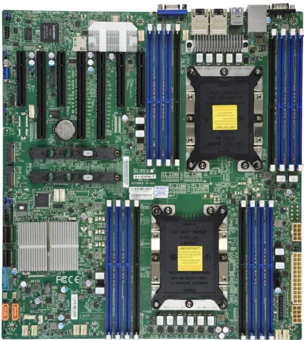
X11DPH-i/T(q) Motherboard Image
natural_image
Close-up of a green computer motherboard with visible CPU socket, memory chips, and indicator lights (no readable text or symbols)
Note: All graphics shown in this manual were based upon the latest PCB revision available at the time of publication of the manual. The motherboard you received may or may not look exactly the same as the graphics shown in this manual.
text_image
BMC ASPEED AST2500 LEPM1 JPM2 JPME2 USB 6 (3.0) JPMB1 CPU Slot1 PCCE 30 x8 CPU Slot2 PCCE 30 x16 JNCSI JPM81 Battery BT1 LAN CTRL CPU Slot4 PCCE 3.0 x16 CPU Slot6 PCCE 3.0 x8 JHSSI CPU Slot7 PCCE 3.0 x8 FAN8 CPU Slot8 PCCE 3.0 x8 P2-BIMMA2 P2-BIMMFI P2-DIMM1 P2-DIMM2 P2-DIMM1 P2-DIMM1 P2-DIMM1 P2-DIMM1 P2-DIMM1 P2-DIMM1 P2-DIMM1 P2-DIMM1 P2-DIMM1 P2-DIMM1 P2-DIMM1 P2-DIMM1 P2-DIMM1 P2-DIMM1 P2-DIMM1 SUSPERX11DPH-i REV: 1.10 MAC CODE BAR CODE CPU1 FECE INTEL PCH BIOS JBT1 FAN3 FAN4 FAN3 IFMI CODE L-SD2 S-SATAU VBOC JRK1 STBY1 L-SD1 S-SATAU VBOC JRK1 STBY1 I-SD3 S-SATAU VBOC JRK1 STBY1
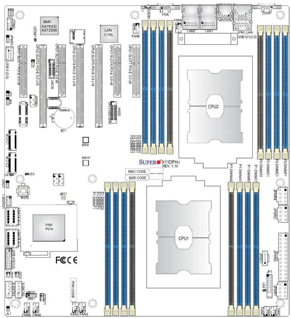
Note: All graphics shown in this manual were based upon the latest PCB revision available at the time of publication of the manual. The motherboard you received may or may not look exactly the same as the graphics shown in this manual.
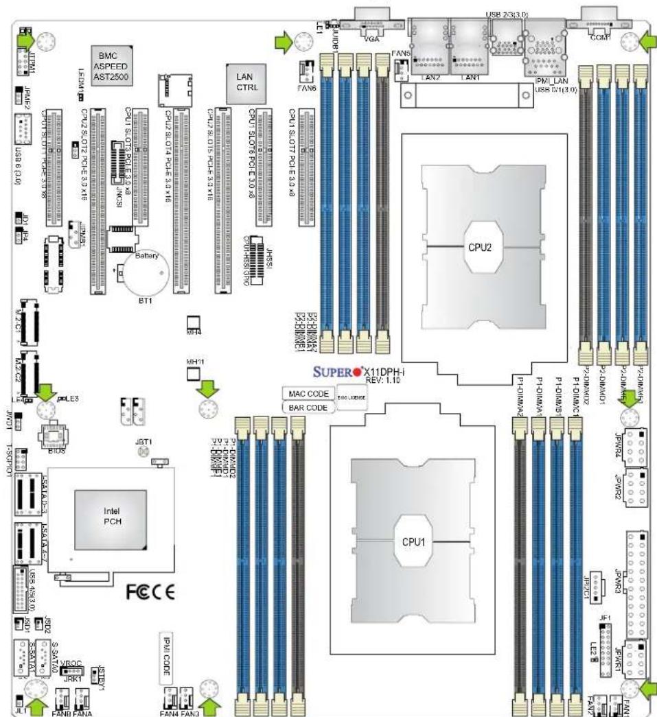
X11DPH-i/T(q) Motherboard Layout
(not drawn to scale)
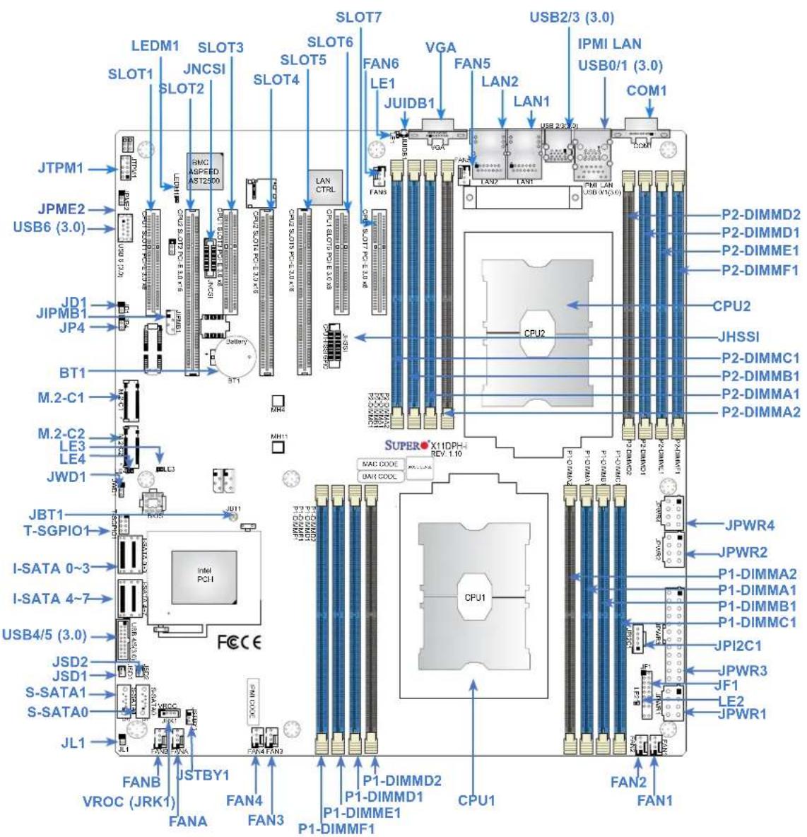
text_image
LEDM1 SLOT1 JNCSI SLOT2 RMC ASPEED AST12300 SLOT3 SLOT4 SLOT5 SLOT6 SLOT7 VGA LE1 JUIDB1 LAN2 LAN1 USB2/3 (3.0) IPMI LAN USB0/1 (3.0) COM1 JTPM1 JPME2 USB6 (3.0) JD1 JIPMB1 JP4 BT1 M.2-C1 M.2-C2 LE3 LE4 JWD1 JBT1 T-SGPIO1 I-SATA 0~3 I-SATA 4~7 USB4/5 (3.0) JSD2 JSD1 S-SATA1 S-SATA0 JL1 FANB VROC (JRK1) USTBY1 FANA FAN4 FAN3 P1-DIMMD2 P1-DIMMD1 P1-DIMME1 P1-DIMMF1 CPU2 CPU2 CPU2 CPU2 CPU2 CPU2 CPU2 CPU2 CPU2 CPU2 CPU2 CPU2 CPU2 CPU2 CPU2 CPU2 CPU2 CPU2 CPU2 CPU2 CPU2 CPU2 CPU2 CPU2 CPU2 CPU2 CPU2 CPU2 CPU2 CPU2 CPU2 CPU2 CPU2 CPU2
Notes:
- See Chapter 2 for detailed information on jumpers, I/O ports, and JF1 front panel connections.
- "indicates the location of Pin 1."
- Jumpers/LED indicators not documented in this user manual are reserved for internal testing only.
- Use only the correct type of onboard CMOS battery as specified by the manufacturer. Do not install the onboard battery upside down to avoid possible explosion.
Quick Reference Table
Jumper Description Default Setting
| JBT1 CMOS Clear Open (Normal) |
| JPME2 ME Manufacturing Mode Pins 1-2 (Normal) |
| JWD1 Watch Dog Timer Enable Pins 1-2 (Reset) |
Connector Description
| BT1 Onboard CMOS battery | |
| COM1 COM port on the I/O back panel | |
| FAN1-6, FANA/FANB System/cooling fan headers | |
| IPMI_LAN Dedicated IPMI LAN port | |
| I-SATA0~3, I-SATA4~7 | SATA 3.0 Ports supported by the Intel PCH |
| JD1 | Speaker/buzzer header (use in conjunction with an external speaker/buzzer) (optional) |
| JF1 | Front control panel header |
| JHSSI | High-Speed Serial Interface (HSSI) card header |
| JIPMB1 | 4-pin External I^2C Header (for an IPMI card) |
| JL1 | Chassis intrusion header (For this feature to work properly, please connect an optional external speaker to the onboard speaker header at JD1.) |
| JNCSI Network Controller Sideband Interface (NCSI) header | |
| JPI^2C1 | Power I^2C System Management Bus (SMBus) header |
| JPWR1, JPWR2, JPWR4 | 8-pin power supply connectors |
| JPWR3 | 24-pin ATX main power supply connector |
| JRK1 | Intel RAID key for NVMe SSD (Solid State Devices) |
| JSD1, JSD2 | SATA DOM (Device-on-Module) power connectors |
| JSTBY1 | Standby power header |
| JTPM1 | Trusted Platform Module (TPM)/Port 80 connector |
| JUIDB1 | Unit Identifier (UID) switch |
| LAN1, LAN2 10GbE LAN ports (for the X11DPH-T(q)) and Gigabit LAN ports (for the X11DPH-i) | |
| M.2-C1, M.2-C2 | PCIe M.2 slots (w/VMD support) (See the notes below.) |
| MH4, MH11 | M.2 mounting holes |
| (CPU1) SLOT1, SLOT3, SLOT6, SLOT7 | PCIe 3.0 x8 Slots supported by CPU1 (See the notes below.) |
| (CPU2) SLOT2, SLOT4, SLOT5 | PCIe 3.0 x16 Slot supported by CPU2 (See the notes below.) |
| S-SATA0, S-SATA1 | Powered SATA 3.0 ports with support of Supermicro SuperDOM (Disk-On-Module) |
| T-SGPIO1 | Serial_Link General Purpose I/O (GPI/O) port |

Note 1: Intel VMD is supported by PCIe Slot 1 - Slot 7, M.2-C1, and M.2-C2 slots. 2: After you've enabled VMD in the BIOS on a PCIe slot of your choice, this PCIe slot will be dedicated for VMD use only, and it will no longer support any PCIe device. To re-activate this slot for PCIe use, please disable VMD in the BIOS. 3: To avoid interference with other components, please be sure to use an add-on card that is fully compliant with the PCI Standards on a PCI slot.
Connector Description
USB0/1, USB2/3 Back Panel Universal Serial Bus (USB) 3.0 ports
USB4/5 Internal USB 3.0 header with two USB (USB4/5) connections supported for front access
USB6 Type A USB 3.0 header for front access
VGA VGA port
VROC (JRK1) Intel VROC RAID key header for NVMe SSD
LED Description Status
LE1 Unit Identifier (UID) LED Solid Blue: Unit Identified
LE2 Onboard power LED Solid Green: Power On
LEDM1 BMC Heartbeat LED Blinking Green: BMC normal
Motherboard Features
| Motherboard Features | |
| CPU | |
| Dual Intel Xeon Scalable-SP or 2nd Generation Intel Xeon Scalable-SP (Socket P) processors with support of three UltraPath Interconnect (UPI) links of up to 10.4 GT/s. (Note: QAT is supported by X11DPH-Tq only.) | |
| Note: Both processors need to be installed for full access to the PCIe slots, DIMM slots, and onboard controllers. Refer to the block diagram to determine which slots or devices may be affected. | |
| Memory | |
| Integrated memory controller supports up to 4TB of 3DS Load Reduced DIMM (3DS LRDIMM), Load Reduced DIMM (LRDIMM), 3DS Registered DIMM (3DS RDIMM), Registered DIMM (RDIMM), Non-Volatile DIMM (NV-DIMM) DDR4 (288-pin) ECC memory with speeds of 2933*/2666/2400/2133 in 16 slotsNotes: 1. Up to 5TB of memory is supported with DCPMM modules installed. 2. 2933 MHz memory is supported by 2nd Gen Intel Xeon Scalable-SP (82xx/62xx series) processors only. | |
| DIMM Size | |
| Up to 256GB at 1.2V | |
| Note 1: Memory speed support depends on the processors used in the system. | |
| Note 2: For the latest CPU/memory updates, please refer to our website at http://www.supermicro.com/products/motherboard. | |
| Chipset | |
| Intel C621/C622/C627 Chipset (C621: is for X11DPH-i, C622 for X11DPH-T, and C627: X11DPT-Tq.) | |
| Expansion Slots | |
| Four (4) PCIe 3.0 X8 slots supported by CPU1 (SLOT1, SLOT3, SLOT6, SLOT7 3; No Slot1 for X11DPH-Tq)Three (3) PCIe 3.0 X16 slots supported by CPU2 (SLOT2, SLOT4, SLOT5) | |
| Baseboard Management Controller (BMC) | |
| ASPEED AST2500 BMC with IPMI 2.0 support | |
| Graphics | |
| Graphics controller via ASPEED AST2500 BMC | |
| Network Connection | |
| Intel C627 supports two 10 Gigabit LAN ports on the X11DPH-TqIntel C622 supports two 10 Gigabit LAN ports on the X11DPH-TIntel C621 supports two Gigabit LAN ports (X11DPH-i)One (1) Dedicated IPMI LAN located on the rear I/O panel | |
| I/O Devices | |
| Serial (COM) Port | One (1) serial port on the rear I/O panel |
| SATA 3.0 | Eight (8) SATA 3.0 ports (I-SATA0~3, I-SATA4~7)Two (2) SATA 3.0 ports with SATA DOM power (S-SATA0, S-SATA1) |
| RAID (PCH) RAID 0, 1, 10 | |

Note: Please refer to the Memory Configuration User Guide for the X11 UP/DP/MP Motherboards posted on our website for detailed information on memory support.
Motherboard Features
Peripheral Devices
• Four (4) USB 3.0 ports on the I/O back panel (USB 0/1, USB2/3)
• One (1) USB 3.0 header with two (2) USB connections for front access (USB4/5)
• One (1) USB 3.0 Type A header (USB6)
BIOS
• 64MB SPI AMI BIOS® SM Flash UEFI BIOS
- ACPI 3.0 or later, USB keyboard, Plug-and-Play (PnP), SPI dual/quad speed support, and SMBIOS 2.7 or later
Power Management
• ACPI power management
- SuperDoctor® 5
• Power button override mechanism
• Power-on mode for AC power recovery
- Intel® Intelligent Power Node Manager 4.0 (available when the Supermicro Power Manager [SPM] is installed and a special power supply is used
• Management Engine (ME)
System Health Monitoring
- Onboard voltage monitoring for +5V, +/-12V, +3.3V Standby, +5V Standby, HT, memory, PCH temperature, system temperature, and memory temperature
• 6+1 CPU switch phase voltage regulator for CPU1
• 5+1 CPU switch phase voltage regulator for CPU2
• CPU thermal trip support
• Status monitor for on/off control
• CPU Thermal Design Power (TDP) support of up to 165W
Fan Control
• Fan status monitoring via IPMI
• Eight 4-pin fan headers
- Dual cooling zone
• Multi-speed fan control via onboard BMC
System Management
• Trusted Platform Module (TPM) support
• PECI (Platform Environment Control Interface) 2.0 support
• System resource alert via SuperDoctor® 5
• SuperDoctor® 5, Watch Dog, NMI, RoHS
• Power supply monitoring
- Chassis intrusion header and detection (when an optional external speaker is connected to the onboard speaker header at JD1)
Motherboard Features
LED Indicators
- CPU/Overheating
• Power/Suspend-state indicator - Fan failure
- UID/remote UID.
- HDD activity
• LAN activity.
Dimensions
• 13" (W) x 12" (L) (330.2 mm x 304.8 mm)

Note 1: The CPU maximum thermal design power (TDP) is subject to chassis and heatsink cooling restrictions. For proper thermal management, please check the chassis and heatsink specifications for proper CPU TDP sizing.
Note 2: For IPMI configuration instructions, please refer to the Embedded IPMI Configuration User's Guide available at http://www.supermicro.com/support/manuals/.
Note 3: It is strongly recommended that you change BMC log-in information upon initial system power-on. The manufacturer default username is ADMIN and the password is ADMIN. For proper BMC configuration, please refer to http://www.supermicro.com/products/info/files/IPMI/Best_Practices_BMC_Security.pdf
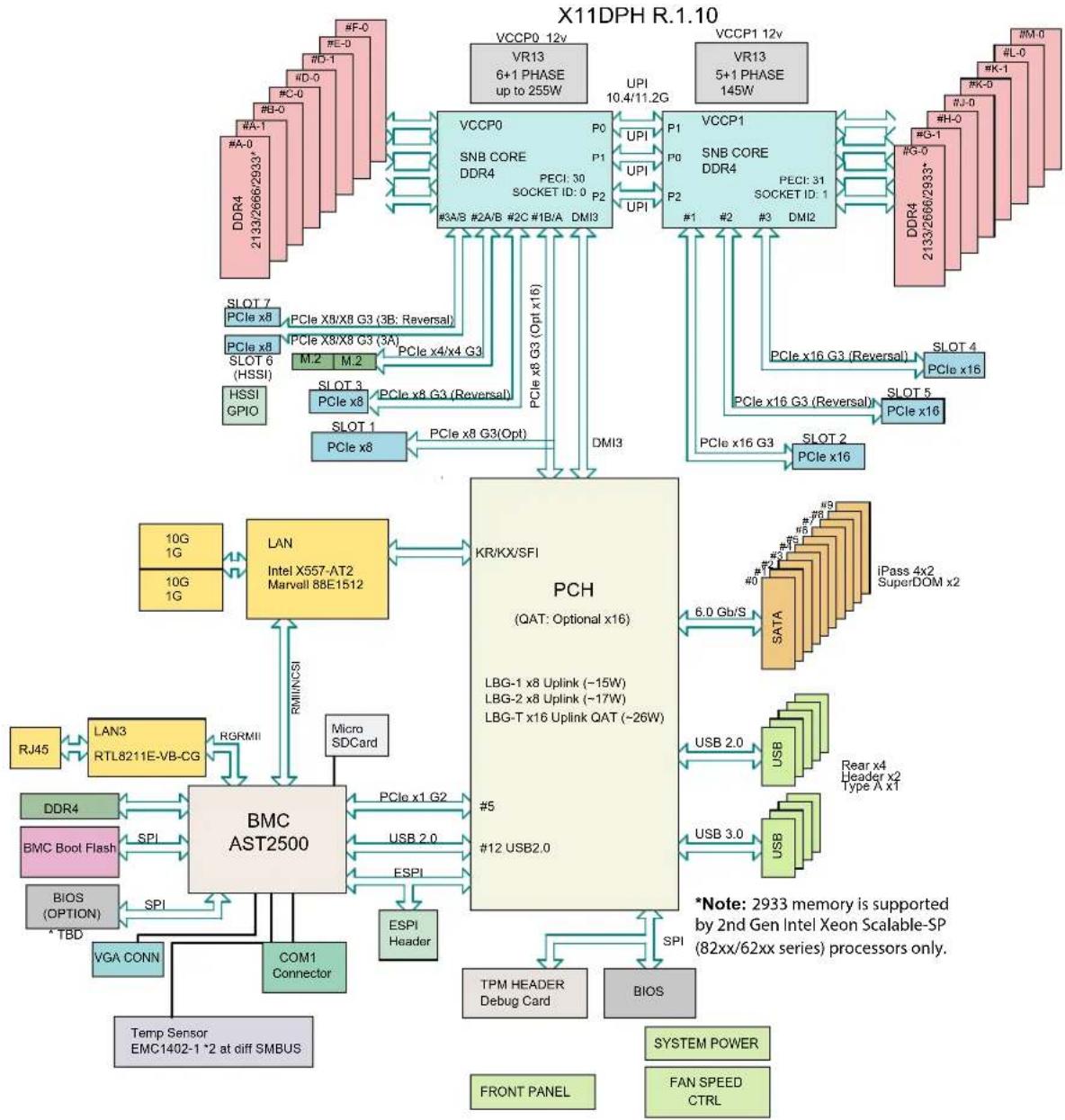
System Block Diagram
flowchart
```mermaid
graph TD
    subgraph X11DPH_R.1.10
        A["VCCP0 12v"] --> B["VR13 6+1 PHASE up to 259W"]
        C["VCCP1 12v"] --> D["VR13 5+1 PHASE 145W"]
        E["VCCP0"] --> F["SNB CORE DDR4"]
        G["VCCP1"] --> H["SNB CORE DDR4"]
        I["PCIe x8"] --> J["PCIe X8/X8 G3 (3B; Reversal)"]
        K["PCIe x8"] --> L["PCIe x8/G3 (3A)"]
        M["PCIe x8"] --> N["PCIe x4/x4 G3"]
        O["PCIe x8"] --> P["PCIe x8 G3 (Reversal)"]
        Q["PCIe x8"] --> R["PCIe x8 G3(Opt)"]
        S["PCIe x8"] --> T["PCIe x8 G3(Opt)"]
        U["PCIe x8"] --> V["PCIe x8 G3(Opt)"]
        W["PCIe x8"] --> X["PCIe x8 G3(Opt)"]
        Y["PCIe x8"] --> Z["PCIe x8 G3(Opt)"]
        AA["PCIe x8"] --> AB["PCIe x8 G3(Opt)"]
        AC["PCIe x8"] --> AD["PCIe x8 G3(Opt)"]
        AE["PCIe x8"] --> AF["PCIe x8 G3(Opt)"]
        AG["PCIe x8"] --> AH["PCIe x8 G3(Opt)"]
        AI["PCIe x8"] --> AJ["PCIe x8 G3(Opt)"]
        AK["PCIe x8"] --> AL["PCIe x8 G3(Opt)"]
        AM["PCIe x8"] --> AN["PCIe x8 G3(Opt)"]
        AO["PCIe x8"] --> AP["PCIe x8 G3(Opt)"]
        AQ["PCIe x8"] --> AR["PCIe x8 G3(Opt)"]
        AS["PCIe x8"] --> AT["PCIe x8 G3(Opt)"]
        AU["PCIe x8"] --> AV["PCIe x8 G3(Opt)"]
        AW["PCIe x8"] --> AX["PCIe x8 G3(Opt)"]
        AY["PCIe x8"] --> AZ["PCIe x8 G3(Opt)"]
        BA["PCIe x8"] --> BB["PCIe x8 G3(Opt)"]
        BC["PCIe x8"] --> BD["PCIe x8 G3(Opt)"]
        BE["PCIe x8"] --> BF["PCIe x8 G3(Opt)"]
        BG["PCIe x8"] --> BH["PCIe x8 G3(Opt)"]
        BI["PCIe x8"] --> BJ["PCIe x8 G3(Opt)"]
        BK["PCH (QAT: Optional x16)"] --> BL["KR/KX/SFI"]
    end

    subgraph X11DPH_R.1.10
        B
        D
        F
        H
        I
        J
        K
        L
        M
        N
        O
        P
        Q
        R
        S
        T
        U
        V
        W
        X
        Y
        Z
    end

    subgraph X11DPH_R.1.10
        AA
        AB
        AC
        AD
    end

    subgraph X11DPH_R.1.10
        AE
        AF
    end

    subgraph X11DPH_R.1.10
        AG
        AH
    end

    subgraph X11DPH_R.1.10
        AI
        AJ
    end

    subgraph X11DPH_R.1.10
        AK
        AL
    end

    subgraph X11DPH_R.1.10
        AM
        AN
    end

    subgraph X11DPH_R.1.10
        AO
        AP
    end

    subgraph X11DPH_R.1.10
        AQ
    end

    subgraph X11DPH_R.1.10
        AR
    end

    subgraph X11DPH_R.1.10
        AS
    end

    subgraph X11DPH_R.1.10
        AT
    end

    subgraph X11DPH_R.1.10
        AU
    end

    subgraph X11DPH_R.1.10
        AV
    end

    subgraph X11DPH_R.1.10
        AW
    end

    subgraph X11DPH_R.1.10
        AX
    end

    subgraph X11DPH_R.1.10
        AY
    end

    subgraph X11DPH_R.1.10
        AZ
    end

    subgraph X11DPH_R.1.10
        BA
    end

    subgraph X11DPH_R.1.10
        BB
    end

    subgraph X11DPH_R.1.10
        BC
    end

    subgraph X11DPH_R.1.10
        DA
    end

    subgraph X11DPH_R.1.10
        DB
    end

    subgraph X11DPH_R.1.10
        DC
    end

    subgraph X11DPH_R.1.10
        DD
    end

    subgraph X11DPH_R.1.10
        DE
    end

    subgraph X11DPH_R.1.10
        FD
    end

    subgraph X11DPH_R.1.10
        EG
    end

    subgraph X11DPH_R.1.10
        EH
    end

    subgraph X11DPH_R.1.10
        EI
    end

    subgraph X11DPH_R.1.10
        AJ
    end

    subgraph X11DPH_R.1.10
        BA
    end

    subgraph X11DPH_R.1.10
        BB
    end

    subgraph X11DPH_R.1.10
        BC
    end

    subgraph X11DPH_R.1.10
        DA
    end

    subgraph X11DPH_R.1.
    AE
    end

    subgraph X11DPH_R.1.10
        AF
    end

    subgraph X11DPH_R.1.10
        AG
    end

    subgraph X11DPH_R.1.10
        AH
    end

    subgraph X11DPH_R.1.10
        AI
    end

    subgraph X11DPH_R.1.10
        AJ
    end

    subgraph X11DPH_R.1.10
        BA
    end

    subgraph X11DPH_R.1.10
        BB
    end

    subgraph X11DPH_R.1.10
        AC
    end

    subgraph X11DPH_R.1.10
        AD
    end

    subgraph X11DPH_R.1.10
        AE
    end

    subgraph X11DPH_R.2.
    AF
    end

    subgraph X11DPH_R.2.
    AG
    end

    subgraph X11DPH_R.2.
    AH
    end

    subgraph X11DPH_R.2.
    AI
    end

    subgraph X11DPH_R.2.
    AJ
    end

    subgraph X11DPH_R.2.
    AC
    end

    subgraph X2933Memory_2933Memory_2933Memory_2933Memory_2933Memory_2933Memory_2933Memory_2933Memory_2933Memory_2933Memory_2933Memory_2933Memory_2933Memory_2933Memory_2933Memory_2933Memory_2933Memory_2937X62XX series processors only.

    note right of A: 2933 memory is supported by 2nd Gen Intel Xeon Scalable-SP (82xx/62xx series) processors only.

    note right of B: 2933 memory is supported by 2nd Gen Intel Xeon Scalable-SP (82xx/62xx series) processors only.

    note right of C: 2933 memory is supported by 2nd Gen Intel Xeon Scalable-SP (82xx/62xx series) processors only.

    note right of D: 2933 memory is supported by 2nd Gen Intel Xeon Scalable-SP (82xx/62xx series) processors only.

    note right of E: 2933 memory is supported by 2nd Gen Intel Xeon Scalable-SP (82xx/62xx series) processors only.

    note right of F: 2933 memory is supported by 2nd Gen Intel Xeon Scalable-SP (82xx/62xx series) processors only.

    note right of G: 2933 memory is supported by 2nd Gen Intel Xeon Scalable-SP (82xx/62xx series) processors only.

    note right of H: 2933 memory is supported by 2nd Gen Intel Xeon Scalable-SP (82xx/62xx series) processors only.

    note right of I: 2933 memory is supported by 2nd Gen Intel Xeon Scalable-SP (82xx/62xx series) processors only.

    note right of J: 2933 memory is supported by 2nd Gen Intel Xeon Scalable-SP (82xx/62xx series) processors only.

    note right of K: 2933 memory is supported by 2nd Gen Intel Xeon Scalable-SP (82xx/62xx series) processors only.

    note right of L: 2933 memory is supported by 2nd Gen Intel Xeon Scalable-SP (82xx/62xx series) processors only.

    note right of M: 2933 memory is supported by 2nd Gen Intel Xeon Scalable-SP (82xx/62xx series) processors only.

    note right of N: 2933 memory is supported by 2nd Gen Intel Xeon Scalable-SP (82xx/62xx series) processors only.

    note right of O: 2933 memory is supported by 2nd Gen Intel Xeon Scalable-SP (82xx/62xx series) processors only.

    note right of P: 2933 memory is supported by 2nd Gen Intel Xeon Scalable-SP (82xx/62xx series) processors only.

    note right of Q: 2933 memory is supported by 2nd Gen Intel Xeon Scalable-SP (82xx/62xx series) processors only.

    note right of R: 2933 memory is supported by 2nd Gen Intel Xeon Scalable-SP (82xx/62xx series) processors only.

    note right of S: 2933 memory is supported by 2nd Gen Intel Xeon Scalable-SP (82xx/62xx series) processors only.

    note right of T: 2933 memory is supported by 2nd Gen Intel Xeon Scalable-SP (82xx/62xx series) processors only.

    note right of U: 2933 memory is supported by 2nd Gen Intel Xeon Scalable-SP (82xx/62xx series) processors only.

    note right of V: 2933 memory is supported by 2nd Gen Intel Xeon Scalable-SP (82xx/62xx series) processors only.

    note right of W: 2933 memory is supported by 2nd Gen Intel Xeon Scalable-SP (82xx/62xx series) processors only.

    note right of X: 2933 memory is supported by 2nd Gen Intel Xeon Scalable-SP (82xx/62xx series) processors only.

    note right of Y: 2933 memory is supported by 2nd Gen Intel Xeon Scalable-SP (82xx/62xx series) processors only.

    note right of Z: 2933 memory is supported by 2nd Gen Intel Xeon Scalable-SP (82xx/62xx series) processors only.

    note right of AA: 2933 memory is supported by 2nd Gen Intel Xeon Scalable-SP (82xx/62xx series) processors only.

    note right of AB: 2933 memory is supported by 2nd Gen Intel Xeon Scalable-SP (82xx/62xx series) processors only.

    note right of AC: 2933 memory is supported by 2nd Gen Intel Xeon Scalable-SP (82xx/62xx series) processors only.

    note right of AD: 2933 memory is supported by 2nd Gen Intel Xeon Scalable-SP (82xx/62xx series) processors only.

    note right of AE: 2933 memory is supported by 2nd Gen Intel Xeon Scalable-SP (82xx/62xx series) processors only.

    note right of AF:
      AE, AC, AD, AE, AC, AE, AC, AE, AC, AE, AC, AE, AC, AE, AC, AE, AC, AE, AC, AE, AC, AE, AC, AE, AC, AE, AC, AE, AC, AE, AC, AE, AC, AE, AC, AE, AC, AE, AC, AE, AC, AE, AC, AE, AC, AE, AC, AE, AC, AE, AC, AE, AC, AE, Ac, AC, AC, AC, AC, AC, AC, AC, AC, AC, AC, AC, AC, AC, AC, AC, AC, AC, AC, AC, AC, AC, AC, AC, AC, AC, AC, AC, AC, AC, AC, AC, AC, AC, AC, AC, AC, AC, AC, AC, AC, AC, AC, AC, AC, AC, AC, AC, AC, AC, AC, Ac, Ac, Ac, Ac, Ac, Ac, Ac, Ac, Ac, Ac, Ac, Ac, Ac, Ac, Ac, Ac, Ac, Ac, Ac, Ac, Ac, Ac, Ac, Ac, Ac, Ac, Ac, Ac, Ac, Ac, Ac, Ac, Ac, Ac, Ac, Ac, Ac, Ac, Ac, Ac, Ac, Ac, Ac, Ac, Ac, Ac, Ac, Ac, Ac, Ac, Atc SMBUS & SVM Power & System Power & FAN SPEED CTRL & FOI & ARM POWER & SYSTEM POWER & SYSTEM POWER & SYSTEM POWER & SYSTEM POWER & SYSTEM POWER & SYSTEM POWER & SYSTEM POWER & SYSTEM POWER & SYSTEM POWER & SYSTEM POWER & SYSTEM POWER & SYSTEM POWER & SYSTEM POWER & SYSTEM POWER & SYSTEM POWER & SYSTEM POWER & SYSTEM POWER & SYSTEM POWER & SYSTEM POWER & SYSTEM POWER & SYSTEM POWER & SYSTEM POWER & SYSTEM POWER & SYSTEM POWER & SYSTEM POWER & SYSTEM POWER & SYSTEM POWER & SYSTEM POWER & SYSTEM POWER & SYSTEM POWER & SYSTEM POWER & SYSTEM POWER & SYSTEM POWER & SYSTEM Power & SYSTEM POWER & SYSTEM POWER & SYSTEM POWER & SYSTEM POWER & SYSTEM POWER & SYSTEM POWER & SYSTEM POWER & SYSTEM POWER & SYSTEM POWER & SYSTEM POWER & SYSTEM POWER & SYSTEM POWER & SYSTEM POWER & SYSTEM POWER & SYSTEM POWER & SYSTEM POWER & SYSTEM POWER & SYSTEM POWER & SYSTEM POWER & SYSTEM POWER & SYSTEM POWER & SYSTEM POWER & SYSTEM POWER & SYSTEM POWER & SYSTEM POWER & SYSTEM POWER & SYSTEM POWER & SYSTEM POWER & SYSTEM POWER & SYSTEM POWER & SYSTEM POWER & SYSTEM POWER & SYSTEM POWER& SYSTEM POWER & SYSTEM POWER & SYSTEM POWER & SYSTEM POWER & SYSTEM POWER & SYSTEM POWER & SYSTEM POWER & SYSTEM POWER & SYSTEM POWER & SYSTEM POWER & SYSTEM POWER & SYSTEM POWER & SYSTEM POWER & SYSTEM POWER & SYSTEM POWER & SYSTEM POWER & SYSTEM POWER & SYSTEM POWER & SYSTEM POWER & SYSTEM POWER & SYSTEM POWER & SYSTEM POWER & SYSTEM POWER & SYSTEM POWER & SYSTEM POWER & SYSTEM POWER & SYSTEM POWER & SYSTEM POWER & SYSTEM POWER & SYSTEM POWER & SYSTEM POWER & SYSTEM POWER & SYSTEM POWER & Systems Power & Systems Power & Systems Power & Systems Power & Systems Power & Systems Power & Systems Power & Systems Power & Systems Power & Systems Power & Systems Power & Systems Power & Systems Power & Systems Power & Systems Power & Systems Power & Systems Power & Systems Power & Systems Power & Systems Power & Systems Power & Systems Power & Systems Power & Systems Power & Systems Power & Systems Power & Systems Power & Systems Power & Systems Power & Systems Power & Systems Power & Systems Power & Systems Power & Systems Power |

    subgraph_Legend_Series_4["LAN"] and Notes_TBDR_MIMNCSI;
      RJ45; LAN=RTL&RV&CG; DDR=RGB; SPI=SPI; BIOS(TBDR); COM=Connector; TCP=SPI; VGA=COMN; Temp=EMC=EMC=EMC=EMC=EMC=EMC=EMC=EMC=EMC=EMC=EMC=EMC=EMC=EMC=EMC=EMC=EMC=EMC=EMC=EMC=EMC=EMC=EMC=EMC=EMC=EMC=EMC=EMC=EMC=EMC=EMC=EMC=EMC=EMC =ESPI / ESPI / ESPI / ESPI / ESPI / ESPI / ESPI / ESPI / ESPI / ESPI / ESPI / ESPI / ESPI / ESPI / ESPI / ESPI / ESPI / ESPI / ESPI / ESPI / ESPI / ESPI / ESPI / ESPI / ESPI / ESPI / ESPI / ESPI / ESPI / ESPI / ESPI / ESPI / ESPI / ESPI / ESII |

    Note left of B: BMC Boot Flash; BIRC Boot Flash; BIOS(TBDR); COM Connector; VGA Connector; Temp Connector; COM Connector; VGA Connector; Temp Connector; Temp Connector; Temp Connector; Temp Connector; Temp Connector; Temp Connector; Temp Connector; Temp Connector; Temp Connector; Temp Connector; Temp Connector; Temp Connector; Temp Connector; Temp Connector; Temp Connector; Temp Connector; Temp Connector; Temp Connector; Temp Connector; Temp Connector; Temp Connector; Temp Connector; Temp Connector; Temp Connector; Temp Connector; Temp Connector; Temp Connector; Temp Connector; Temp Connector; Temp Connector; Temp Connector; Temp Connector; Temp Connector; Temp Controller; Temp Controller; Temp Controller; Temp Controller; Temp Controller; Temp Controller; Temp Controller; Temp Controller; Temp Controller; Temp Controller; Temp Controller; Temp Controller; Temp Controller; Temp Controller; Temp Controller; Temp Controller; Temp Controller; Temp Controller; Temp Controller; Temp Controller; Temp Controller; Temp Controller; Temp Controller; Temp Controller; Temp Controller; Temp Controller; Temp Controller; Temp Controller; Temp Controller; Temp Controller; Temp Controller; Temp Controller; Temp Controller; Temp Controller;

    Note left of AB: BMC Boot Flash; BIRC Boot Flash; BIOS(TBDR); COM Connector; ESPS/TBDR; Comp Connector; COM Connector; TVDAR/DVDAR/DVDAR/DVDAR/DVDAR/DVDAR/DVDAR/DVDAR/DVDAR/DVDAR/DVDAR/DVDAR/DVDAR/DVDAR/DVDAR/DVDAR/DVDAR/DVDAR/DVDAR/DVDAR/DVDAR/DVDAR/DVDAR/DVDAR/DVDAR/DVDAR/DVDAR/DVDAR/DVDAR/DVDAR/DVDAR/DVDAR/DVDAR/DVDAR/DVDAB/DVDAB/DVDAB/DVDAB/DVDAB/DVDAB/DVDAB/DVDAB/DVDAB/DVDAB/DVDAB/DVDAB/DVDAB/DVDAB/DVDAB/DVDAB/DVDAB/DVDAB/DVDAB/DVDAB/DVDAB/DVDAB/DVDAB/DVDAB/DVDAB/DVDAB/DVDAB/DVDAB/DVDAB/DVDAB/DVDAB/DVDAB/DVDAB/DVDAB/TDDR_DVDAR_DVDAR_DVDAR_DVDAR_DVDAR_DVDAR_DVDAR_DVDAR_DVDAR_DVDAR_DVDAR_DVDAR_DVDAR_DVDAR_DVDAR_DVDAR_DVDAR_DVDAR_DVDAR_DVDAR_DVDAR_DVDAR_DVDAR_DVDAR_DVDAR_DVDAR_DVDAR_DVDAR_DVDAR_DVDAR_DVDAR_DVDAR_DVDAR_DVDAR_TDDR_DVDAR_DVDAR_DVDAR_DVDAR_DVDAR_DVDAR_DVDAR_DVDAR_DVDAR_DVDAR_DVDAR_DVDAR_DVDAR_DVDAR_DVDAR_DVDAR_DVDAR_DVDAR_DVDAR_DVDAR_DVDAR_DVDAR_DVDAR_DVDAR_DVDAR_DVDAR_DVDAR_DVDAR_DVDAR_DVDAR_DVDAR_DVDAR_DVARD_BMCBootFlash_BMCBootFlash_BMCBootFlash_BMCBootFlash_BMCBootFlash_BMCBootFlash_BMCBootFlash_BMCBootFlash_BMCBootFlash_BMCBootFlash_BMCBootFlash_BMCBootFlash_BMCBootFlash_BMCBootFlash_BMCBootFlash_BMCBootFlash_BMCBootFlash_BMCBootFlash_BMCBootFlash_BMCBootFlash_BMCBootFlash_BMCBootFlash_BMCBootFlash_BMCBootFlash_BMCBootFlash_BMCBoot{{PCle x7}
            |
            |
            |
            |
            |
            |
            |
            |
            |
            |
            |
            |
            |
            |
            |
            |
            |
            |
            |
            |
            |
            |
            |
            |
            |
            |
            |
            |
            |
            |
            |
            |
            |
            |
            |
            |
            |
            |
            |
            |
            |
            |
            |
            |
            |
            |
            |
            |
            |
            |
            |

Note right of AB: BMC Boot Flash with SPI=SPI and ESPS/TBDR in EMIC Control Panel for each component and the corresponding components are used to create a diagrammatic representation using the diagrammatic representation as a key function.

Note: This is a general block diagram and may not exactly represent the features on your motherboard. See the previous pages for the actual specifications of your motherboard.
1.2 Processor and Chipset Overview
Built upon the functionality and capability of Intel Xeon Scalable-SP and 2nd Generation Intel Xeon Scalable-SP processors (Socket P) with support of the Intel C621/C622/C627 chipset (Note 1), the X11DPH-i/X11DPH-T/X11DPH-Tq motherboard provides superb system performance, efficient power management, and a rich feature set based on cutting-edge technologies to address the needs of next-generation computer users. It offers innovative solutions with unprecedented system reliability and scalability to meet the demands of High Performance Computing (HPC) platforms.
Features Supported by Intel Xeon Scalable-SP Processors
Intel Xeon Scalable-SP processors support the following features:
• Intel AVX-512 instruction support to handle complex workloads
• 1.5x memory bandwidth increased to 6 channels
• Hot plug and enclosure management with Intel Volume Management Device (Intel VMD)
- Rich set of available IOs with increased PCIe lanes (48 lanes)
- Integrated Intel Ethernet Connection X722 with iWARP RDMA
New features supported by 2nd Generation Intel Xeon Scalable-SP Processors
2nd Generation Intel Xeon Scalable-SP processors support the following features:
- Higher performance for a wider range of workloads with per-core performance increase
- Support of Optane DC Persistent Memory (DCPMM) with affordable, persistent, and large capacity
- Up to 2993 MHz memory supported (Refer to Section 1.9 for details.)
- Vector Neural Network Instruction (VNNI) support for Accelerate Deep Learning & Artificial Intelligence (AI) workloads
- Speed Select Technology provides multiple CPU profiles that can be set in the BIOS. (This feature is available on select CPU SKUs).
- Seamless hardware security mitigations & performance/frequency flexibility

Notes: 1. Intel C621 is used for X11DPH-i, C622 for X11DPH-T, and C627 for X11DPT-Tq. 2. DCPMM memory is supported by 2nd Gen Intel Xeon Scalable-SP (82xx/62xx/52xx/42xx series) processors. 3. 2933 MHz memory is supported by 2nd Gen Intel Xeon Scalable-SP (82xx/62xx series) processors only.
1.3 Special Features
This section describes the health monitoring features of the motherboard. The motherboard has an onboard ASPEED AST 2500 Baseboard Management Controller (BMC) that supports system health monitoring.
Recovery from AC Power Loss
The Basic I/O System (BIOS) provides a setting that determines how the system will respond when AC power is lost and then restored to the system. You can choose for the system to remain powered off (-in which case you must press the power switch to turn it back on), or for it to automatically return to the power-on state. See the Advanced BIOS Setup section for this setting. The default setting is Last State.
1.4 System Health Monitoring
This section describes the health monitoring features of the X11DPH-i/T(q) motherboard. The motherboard has an onboard Baseboard Management Controller (BMC) chip that supports system health monitoring.
Onboard Voltage Monitors
The onboard voltage monitor will continuously scan crucial voltage levels. Once a voltage becomes unstable, it will give a warning or send an error message to the IPMI WebGUI and IPMIView. Real time readings of these voltage levels are all displayed in the BIOS.
Fan Status Monitor with Firmware Control
The system health monitor embedded in the BMC chip can check the RPM status of the cooling fans. The CPU and chassis fans are controlled via IPMI.
Environmental Temperature Control
System Health sensors in the BMC monitor the temperatures and voltage settings of onboard processors and the system in real time via the IPMI interface. Whenever the temperature of the CPU or the system exceeds a manufacturer-defined threshold, system/CPU cooling fans will be turned on to prevent the CPU or the system from overheating.

Note: To avoid possible system overheating, please be sure to provide adequate airflow to your system.
System Resource Alert
This feature is available when used with Supermicro® SuperDoctor 5. SuperDoctor 5 is used to notify the user of certain system events. For example, you can configure SuperDoctor 5 to provide you with warnings when the system temperature, CPU temperatures, voltages and fan speeds go beyond a predefined range.
1.5 ACPI Features
ACPI stands for Advanced Configuration and Power Interface. The ACPI specification defines a flexible and abstract hardware interface that provides a standard way to integrate power management features throughout a computer system including its hardware, operating system and application software. This enables the system to automatically turn on and off peripherals such as network cards, hard disk drives and printers.
In addition to enabling operating system-directed power management, ACPI also provides a generic system event mechanism for Plug and Play, and an operating system-independent interface for configuration control. ACPI leverages the Plug and Play BIOS data structures while providing a processor architecture-independent implementation that is compatible with appropriate Windows operating systems. For detailed information on OS support, please refer to our website at www.supermicro.com.
1.6 Power Supply
As with all computer products, a stable power source is necessary for proper and reliable operation. It is even more important for processors that have high CPU clock rates. It is recommended that you also install a power surge protector to help avoid problems caused by power surges.
1.7 Advanced Power Management
The following new advanced power management features are supported by the motherboard.
Intel® Intelligent Power Node Manager (IPNM)
Intel's Intelligent Power Node Manager (IPNM) provides your system with real-time thermal control and power management for maximum energy efficiency. IPNM is available when the Supermicro Power Manager (SPM) is installed. Although IPNM Specification Version 2.0 or 3.0 is supported by the BMC (Baseboard Management Controller), your system must also have the IPNM-compatible Management Engine (ME) firmware installed to use this feature.

Note: Support for IPNM 2.0/3.0 is dependent on the power supply used in the system.
Management Engine (ME)
The Management Engine, which is an ARC controller embedded in the IOH (I/O Hub), provides Server Platform Services (SPS) to your system. The services provided by SPS are different from those provided by the ME on client platforms.
1.8 Intel® QuickAssist Technology (For the X11DPH-Tq only)
This X11DPH-T(q) supports Intel QuickAssist Technolog (QAT) that offers a software-based platform for data compression, security, and authentication. These features greatly enhance system performance and efficiency across applications and platforms. The improvements include data symmetric/asymmetric encryption, authentication, public key functions, data compression and decompression. With Intel QAT technology support, this motherboard is optimized for the following applications:
For High Computing Platform (HCP):
- This motherboard offers secure browsing, email searching, data transferring, and multi-tenancy.
For Networking:
- This motherboard offers secure routing, firewalls, web proxy, WAN optimization, authentication, and 3G/4G wireless.
For Big Data:
• This motherboard supports Affinity Analytic (HADOOP).
For Storage:
- This motherboard provides real-time data compression and secure storage.
1.9 Intel® Optane DC Persistent Memory Overview
2nd Generation Intel Xeon Scalable-SP (82xx/62xx/52xx/42xx series) processors support new DCPMM (Optane™ DC Persistent Memory Modules) technology that offers data persistence with higher capacity than existing memory modules and lower latency than NVMe SSDs. DCPMM memory provides hyper-speed storage capability for high performance computing platforms with flexible configuration options.
Chapter 2
Installation
2.1 Static-Sensitive Devices
Electrostatic Discharge (ESD) can damage electronic components. To avoid damaging your motherboard and your system, it is important to handle it very carefully. The following measures are generally sufficient to protect your equipment from ESD.
Precautions
- Use a grounded wrist strap designed to prevent static discharge.
- Touch a grounded metal object before removing the motherboard from the antistatic bag.
- Handle the motherboard by its edges only; do not touch its components, peripheral chips, memory modules or gold contacts.
- When handling chips or modules, avoid touching their pins.
- Put the motherboard and peripherals back into their antistatic bags when not in use.
- For grounding purposes, make sure that your chassis provides excellent conductivity between the power supply, the case, the mounting fasteners, and the motherboard.
- Use only the correct type of CMOS onboard battery as specified by the manufacturer. Do not install the CMOS battery upside down, which may result in a possible explosion.
Unpacking
The motherboard is shipped in antistatic packaging to avoid static damage. When unpacking the motherboard, make sure that the person handling it is static protected.
2.2 Motherboard Installation
All motherboards have standard mounting holes to fit different types of chassis. Make sure that the locations of all the mounting holes for both the motherboard and the chassis match. Although a chassis may have both plastic and metal mounting fasteners, metal ones are highly recommended because they ground the motherboard to the chassis. Make sure that the metal standoffs click in or are screwed in tightly.
Tools Needed


Screws (9) Standoffs (9) as Needed
text_image
BMW ASPEED AST2500 CZL2-07.012PCE-3.3 X16 CPU2 SLOTA PCLE-3.3 X16 BATBARY BT1 LAN CTRL FAN6 CPU-SLOTA PCLE-3.3 X16 FAN5 CPU-SLOTA PCLE-3.3 X16 CPU2 CPU2 CPU2 CPU2 CPU2 CPU2 CPU2 CPU2 CPU2 CPU2 CPU2 CPU2 CPU2 CPU2 CPU2 CPU2 CPU2 CPU2 CPU2 CPU2 CPU2 CPU2 CPU2 CPU2 CPU2 CPU2 CPU2 CPU2 CPU2 CPU2 CPU2 CPU2 CPU2 CPU2Location of Mounting Holes

Notes: 1. To avoid damaging the motherboard and its components, please do not use a force greater than 8 lb/inch on each mounting screw during motherboard installation. 2. Some components are very close to the mounting holes. Please take precautionary measures to avoid damaging these components when installing the motherboard to the chassis.
Installing the Motherboard
- Install the I/O shield into the back of the chassis if needed.
- Locate the mounting holes on the motherboard. See the previous page for the location.
text_image
Chassis Chassis- Locate the matching mounting holes on the chassis. Align the mounting holes on the motherboard against the mounting holes on the chassis.
text_image
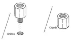
3x6 Motherboard Chassis Motherboard Chassis- Install standoffs in the chassis as needed.
- Install the motherboard into the chassis carefully to avoid damaging other motherboard components.
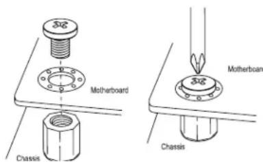
- Using the Phillips screwdriver, insert a Pan head #6 screw into a mounting hole on the motherboard and its matching mounting hole on the chassis.
- Repeat Step 5 to insert Pan head #6 screws into all mounting holes.
- Make sure that the motherboard is securely placed in the chassis.

Note: Images displayed in this manual are for illustration only. Your chassis or components might look different from those shown in this manual.
2.3 Processor and Heatsink Installation
Warning: When handling the processor package, avoid placing direct pressure on the label area of the CPU or CPU socket. Also, improper CPU installation or socket misalignment can cause serious damage to the CPU or motherboard which may result in RMA repairs. Please read and follow all instructions thoroughly before installing your CPU and heatsink.

Notes:
- Always connect the power cord last, and always remove it before adding, removing, or changing any hardware components. Please note that the processor and heatsink should be assembled together first to form the Processor Heatsink Module (PHM), and then install the entire PHM into the CPU socket.
- When you receive a motherboard without a processor pre-installed, make sure that the plastic CPU socket cap is in place and that none of the socket pins are bent; otherwise, contact your retailer immediately.
• Refer to our website at www.Supermicro.com for CPU support updates. - Please follow the instructions given in the ESD Warning section on the first page of this chapter before handling, installing, or removing system components.
Intel Xeon Scalable-SP and 2nd Gen Intel Xeon Scalable-SP Processors
natural_image
Technical line drawing of a rectangular electronic component with mounting holes and internal structure (no text or symbols)
Note: All graphics, drawings, and pictures shown in this manual are for illustration only. The components that came with your system may or may not look exactly the same as those shown in this manual.
Overview of the Processor Socket Assembly
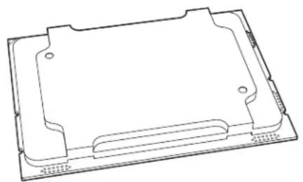
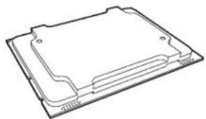
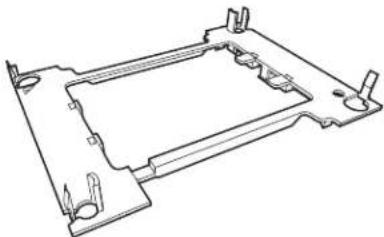
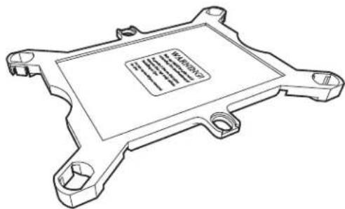
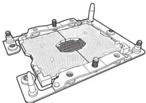
The processor socket assembly contains 1) the Intel Xeon Scalable-SP or 2nd Generation Intel Xeon Scalable-SP processor, 2) the narrow processor clip, 3) the dust cover, and 4) the CPU socket.
- Intel Processor
natural_image
Technical line drawing of a rectangular electronic component or enclosure (no text or symbols)- Narrow processor clip (the plastic processor package carrier used for the CPU)
natural_image
Technical line drawing of a mechanical bracket or frame structure (no text or symbols)- Dust Cover
natural_image
Line drawing of a microprocessor base with mounting holes and a central slot (no text or symbols)- CPU Socket
natural_image
Technical line drawing of a mechanical component with mounting holes and internal grid structure (no text or symbols)
Note: Be sure to cover the CPU socket with the dust cover when the CPU is not installed.
Overview of the Processor Heatsink Module (PHM)
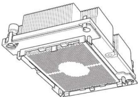
The Processor Heatsink Module (PHM) contains 1) a heatsink, 2) a narrow processor clip, and 3) Intel Xeon Scalable-SP or 2nd Generation Intel Xeon Scalable-SP processor.
1. Heatsink
2. Narrow processor clip
3. Intel Processor
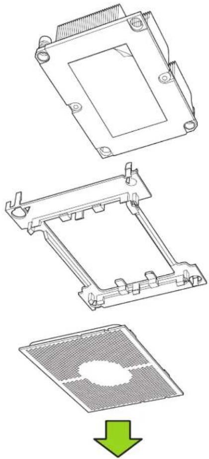
Processor Heatsink Module (PHM)
natural_image
Technical line drawing of a mechanical component with a meshed base and mounting holes (no text or symbols)(Bottom View)
Attaching the Processor to the Narrow Processor Clip to Create the Processor Package Assembly
To properly install the CPU into the narrow processor clip, please follow the steps below.
-
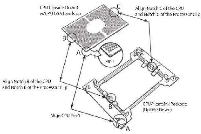
Locate pin 1 (notch A), which is the triangle located on the top of the narrow processor clip. Also locate notch B and notch C on the processor clip.
-
Locate pin 1 (notch A), which is the triangle on the substrate of the CPU. Also, locate notch B and notch C on the CPU as shown below.
-
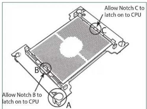
Align pin 1 (the triangle on the substrate) of the CPU with pin 1 (the triangle) of the narrow processor clip. Once they are aligned, carefully insert the CPU into the processor clip by sliding notch B of the CPU into notch B of the processor clip, and sliding notch C of the CPU into notch C of the processor clip.
-
Examine all corners of the CPU to ensure that it is properly seated on the processor clip. Once the CPU is securely attached to the processor clip, the processor package assembly is created.

Note: Please exercise extreme caution when handling the CPU. Do not touch the CPU LGA-lands to avoid damaging the LGA-lands or the CPU. Be sure to wear ESD gloves when handling components.
flowchart
graph TD
    A["CPU (Upside Down) w/CPU LGA Lands up"] --> B["A"]
    B --> C["B"]
    C --> D["A"]
    D --> E["C"]
    E --> F["C"]
    F --> G["C"]
    G --> H["B"]
    H --> I["A"]
    I --> J["B"]
    J --> K["A"]
    K --> L["B"]
    L --> M["A"]
    M --> N["B"]
    N --> O["A"]
    O --> P["B"]
    P --> Q["A"]
    Q --> R["B"]
    R --> S["A"]
    S --> T["B"]
    T --> U["A"]
    U --> V["B"]
    V --> W["A"]
    W --> X["B"]
    X --> Y["A"]
    Y --> Z["B"]
    Z --> AA["A"]
    AA --> AB["B"]
    AB --> AC["A"]
    AC --> AD["B"]
    AD --> AE["A"]
    AE --> AF["B"]
    AF --> AG["A"]
    AG --> AH["B"]
    AH --> AI["A"]
    AI --> AJ["B"]
    AJ --> AK["A"]
    AK --> AL["B"]
    AL --> AM["A"]
    AM --> AN["B"]
    AN --> AO["A"]
    AO --> AP["B"]
    AP --> AQ["A"]
    AQ --> AR["B"]
    AR --> AS["A"]
    AS --> AT["B"]
    AT --> AU["A"]
    AU --> AV["B"]
text_image
Allow Notch C to latch on to CPU Allow Notch B to latch on to CPUProcessor Package Carrier (w/CPU mounted on the Processor Clip)
Attaching the Processor Package Assembly to the Heatsink to Form the Processor Heatsink Module (PHM)
After you have made a processor package assembly by following the instructions on the previous page, please follow the steps below to mount the processor package assembly onto the heatsink to create the Processor Heatsink Module (PHM).
-
Locate "1" on the heatsink label and the triangular corner next to it on the heatsink. With your index finger pressing against the screw at this triangular corner, carefully hold and turn the heatsink upside down with the thermal-grease side facing up. Remove the protective thermal film if present, and apply the proper amount of the thermal grease as needed. (Skip this step if you have a new heatsink because the necessary thermal grease is pre-applied in the factory.)
-
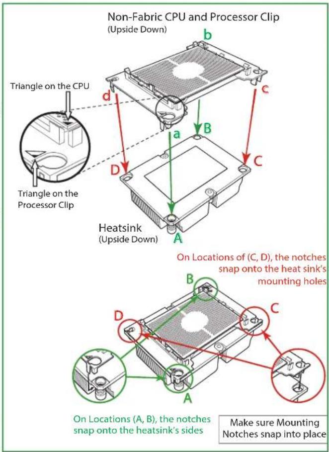
Holding the processor package assembly at the center edge, turn it upside down. With the thermal-grease side facing up, locate the hollow triangle located at the corner of the processor carrier assembly ("a" in the graphic). Note a larger hole and plastic mounting clicks located next to the hollow triangle. Also locate another set of mounting clicks and a larger hole at the diagonal corner of the same (reverse) side of the processor carrier assembly ("b" in the graphic). Non-Fabric CPU and Processor Clip
-
With the back of heatsink and the reverse side of the processor package assembly facing up, align the triangular corner on the heatsink ("A" in the graphic) against the mounting clips next to the hollow triangle ("a") on the processor package assembly.
-
Also align the triangular corner ("B") at the diagonal side of the heatsink with the corresponding clips on the processor package assembly ("b").
-
Once the mounting clips on the processor package assembly are properly aligned with the corresponding holes on the back of heatsink, securely attach the heatsink to the processor package assembly by snapping the mounting clips at the proper places on the heatsink to create the processor heatsink module (PHM).
text_image
Non-Fabric CPU and Processor Clip (Upside Down) Triangle on the CPU Triangle on the Processor Clip Heatsink (Upside Down) On Locations of (C, D), the notches snap onto the heat sink's mounting holes On Locations (A, B), the notches snap onto the heatsink's sides Make sure Mounting Notches snap into placePreparing the CPU Socket for Installation
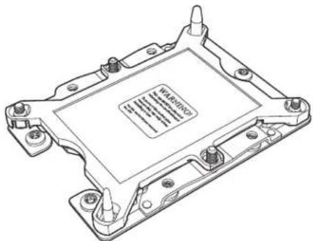
This motherboard comes with the CPU socket pre-assembled in the factory. The CPU socket contains 1) a dust cover, 2) a socket bracket, 3) the CPU (P0) socket, and 4) a back plate. These components are pre-installed on the motherboard before shipping.
natural_image
Technical line drawing of a computer processor casing with visible internal components and mounting holes (no text or symbols)CPU Socket w/Dust Cover On
Removing the Dust Cover from the CPU Socket
Remove the dust cover from the CPU socket, exposing the CPU socket and socket pins as shown on the illustration below.

Note: Do not touch the socket pins to avoid damaging them, causing the CPU to malfunction.
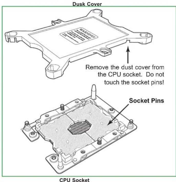
text_image
Dusk Cover Remove the dust cover from the CPU socket. Do not touch the socket pins! Socket Pins CPU SocketInstalling the Processor Heatsink Module (PHM)
-
Once you have assembled the processor heatsink module (PHM), you are ready to install the processor heatsink module (PHM) into the CPU socket on the motherboard. To install the PHM into the CPU socket, follow the instructions below.
-
Locate the triangle (pin 1) on the CPU socket, and locate the triangle (pin 1) at the corner of the PHM that is closest to "1." (If you have difficulty locating pin 1 of the PHM, turn the PHM upside down. With the LGA-lands side facing up, you will note the hollow triangle located next to a screw at the corner. Turn the PHM right side up, and you will see a triangle marked on the processor clip at the same corner of hollow triangle.)
-
Carefully align pin 1 (the triangle) on the PHM against pin 1 (the triangle) on the CPU socket.
-
Once they are properly aligned, insert the two diagonal oval holes on the heatsink into the guiding posts.
-
Using a T30 Torx-bit screwdriver, install four screws into the mounting holes on the socket to securely attach the PHM onto the motherboard starting with the screw marked "1" (in the sequence of 1, 2, 3, and 4).

Note: Do not use excessive force when tightening the screws to avoid damaging the LGA-lands and the processor.
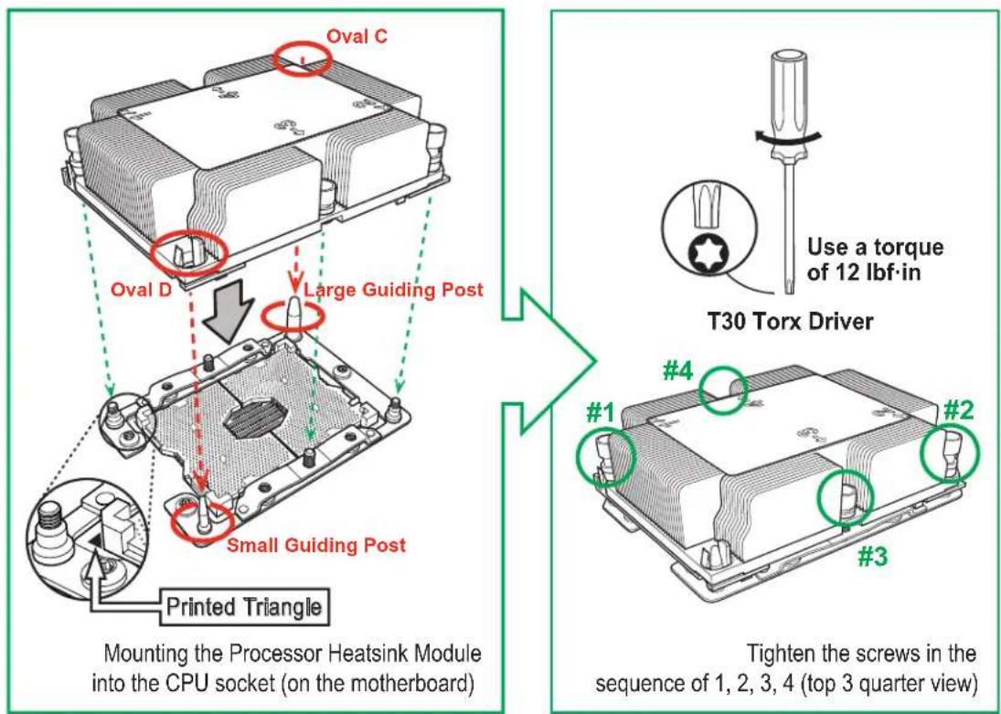
text_image
Oval C Oval D Large Guiding Post Small Guiding Post Printed Triangle Mounting the Processor Heatsink Module into the CPU socket (on the motherboard) T30 Torx Driver Use a torque of 12 lbf-in #1 #2 #3 Tighten the screws in the sequence of 1, 2, 3, 4 (top 3 quarter view)Removing the Processor Heatsink Module (PHM) from the Motherboard
Before removing the processor heatsink module (PHM), unplug power cord from the power outlet.
- Using a T30 Torx-bit screwdriver, turn the screws on the PHM counterclockwise to loosen them from the socket, starting with screw marked #4 (in the sequence of 4, 3, 2, 1).
- After all four screws are removed, wiggle the PHM gently and pull it up to remove it from the socket.

Note: To properly remove the processor heatsink module, be sure to loosen and remove the screws on the PHM in the sequence of 4, 3, 2, 1 as shown below.
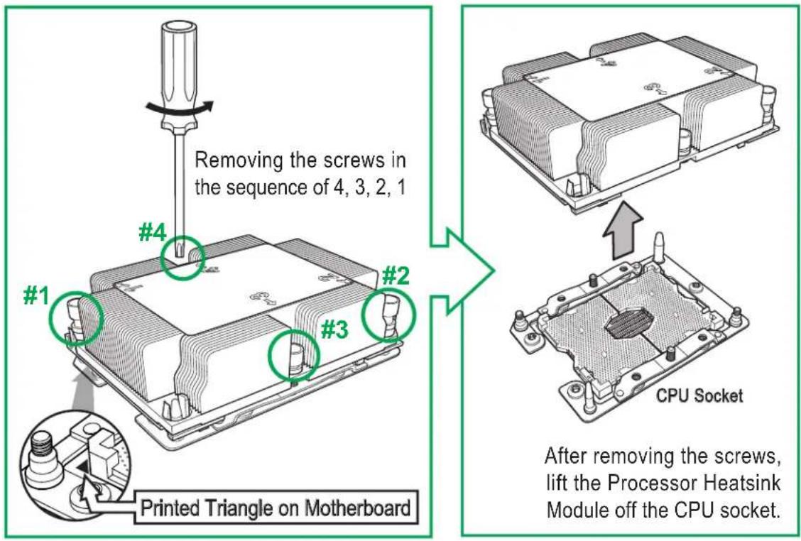
text_image
Removing the screws in the sequence of 4, 3, 2, 1 #1 #2 #3 #4 Printed Triangle on Motherboard CPU Socket After removing the screws, lift the Processor Heatsink Module off the CPU socket.2.4 Memory Support and Installation

Note: Check Supermicro's website for recommended memory modules. Exercise extreme care when installing or removing DIMM modules to prevent any damage.
Memory Support
The motherboard supports up to 4TB of 3DS Load Reduced DIMM (3DS LRDIMM), Load Reduced DIMM (LRDIMM), 3DS Registered DIMM (3DS RDIMM), Registered DIMM (RDIMM), Non-Volatile DIMM (NV-DIMM) DDR4 (288-pin) ECC 2933*/2666/2400/2133 MHz memory in 16 slots (*Note below). This motherboard also supports up to 5TB memory with DCPMM modules installed based on the DCPMM population table on page 38.

Notes: 1. 2933 MHz memory is supported by 2nd Gen Intel Xeon Scalable-SP (82xx/62xx series) processors only. 2. Populating DDR4 memory modules in a two-DIMMs per-channel (2DPC) configuration on this motherboard will affect memory bandwidth and performance.
Memory Installation Sequence
Memory modules for this motherboard are populated using the "Fill First" method. The blue memory slot of each channel is considered the "first DIMM module" of the channel, and the black slot, the second module of the channel. When installing memory modules, be sure to populate the blue memory slots first and then populate the black slots.
General Memory Population Requirements
- Be sure to use the memory modules of the same type and the same speed on the same motherboard. Mixing of memory modules of different types and speeds is not allowed.
- Using unbalanced memory topology such as populating two DIMMs in one channel while populating one DIMM in another channel on the same motherboard will result in reduced memory performance.
- Populating memory slots with a pair of DIMM modules of the same type and size will result in interleaved memory, which will improve memory performance.
DDR4 Memory Support for Intel Xeon Scalable-SP Processors
| DDR4 Memory Support | ||||||
| Type | Ranks Per DIMM & Data Width | DIMM Capacity (GB) | Speed (MT/s); Voltage (V); Slots Per Channel (SPC) and DIMMs Per Channel (DPC) | |||
| 1 Slot Per Channel 2 Slots Per Channel | ||||||
| DRAM Density | 1DPC (1-DIMM Per Channel) | 1DPC (1-DIMM Per Channel) | 2DPC (2-DIMM Per Channel) | |||
| 4Gb* 8Gb | 1.2 V 1.2 V 1.2 V | |||||
| RDIMM SRx4 | 4GB 8GB 2666 2666 | 2666 | ||||
| RDIMM SRx8 | 8GB 16GB 2666 2666 | 2666 | ||||
| RDIMM DRx8 | 8GB 16GB 2666 2666 | 2666 | ||||
| RDIMM DRx4 | 16GB 32GB 2666 2666 | 2666 | ||||
| RDIMM 3Ds | QRX4 | N/A | 2H-64GB | 2666 | 2666 | 2666 |
| RDIMM 3Ds | 8RX4 | N/A | 4H-128GB | 2666 | 2666 | 2666 |
| LRDIMM QRx4 | 32GB 64GB 2666 2666 | 2666 | ||||
| LRDIMM 3Ds | QRX4 | N/A | 2H-64GB | 2666 | 2666 | 2666 |
| LRDIMM 3Ds | 8Rx4 | N/A | 4H-128GB | 2666 | 2666 | 2666 |
DDR4 Memory Support for 2nd Gen Intel Xeon Scalable-SP Processors
| DDR4 Memory Support | |||||||
| Type | Ranks Per DIMM & Data Width | DIMM Capacity (GB) | Speed (MT/s); Voltage (V); Slots Per Channel (SPC) and DIMMs Per Channel (DPC) | ||||
| 1 Slot Per Channel | 2 Slots Per Channel | ||||||
| DRAM Density | 1DPC (1-DIMM Per Channel) | 1DPC (1-DIMM Per Channel) | 2DPC (2-DIMM Per Channel) | ||||
| 4Gb^* | 8Gb | 16Gb | 1.2 V | 1.2 V | 1.2 V | ||
| RDIMM | SRx4 | 4GB | 8GB | 16GB | 2933 | 2933 | 2933 |
| RDIMM | SRx8 | 8GB | 16GB | 32GB | 2933 | 2933 | 2933 |
| RDIMM | DRx8 | 8GB | 16GB | 32GB | 2933 | 2933 | 2933 |
| RDIMM | DRx4 | 16GB | 32GB | 64GB | 2933 | 2933 | 2933 |
| RDIMM 3Ds | QRX4 | N/A | 2H-64GB | 2H-128GB | 2933 | 2933 | 2933 |
| RDIMM 3Ds | 8RX4 | N/A | 4H-128GB | 4H-256GB | 2933 | 2933 | 2933 |
| LRDIMM | QRx4 | 32GB | 64GB | 128GB | 2933 | 2933 | 2933 |
| LRDIMM 3Ds | QRX4 | N/A | 2H-64GB | 2H-128GB | 2933 | 2933 | 2933 |
| LRDIMM 3Ds | 8Rx4 | N/A | 4H-128GB | 4H-256GB | 2933 | 2933 | 2933 |

Notes: 1. 2933 MHz memory support in two-DIMMs per-channel (2DPC) configuration can be achieved by using memory purchased from Supermicro. 2. 2933 MHz memory is supported by 2nd Gen Intel Xeon Scalable-SP (82xx/62xx series) processors only.
DIMM Population Guidelines for Optimal Performance
For optimal memory performance, follow the instructions listed in the tables below when populating memory modules.
Key Parameters for DIMM Configuration
| Key Parameters for DIMM Configurations | |
| Parameters Possible Values | |
| Number of Channels 1, 2, 3, 4, 5, or 6 | |
| Number of DIMMs per Channel 1DPC (1 DIMM Per Channel) or 2DPC (2 DIMMs Per Channel) | |
| DIMM Type RDIMM (w/ECC), 3DS RDIMM, LRDIMM, 3DS LRDIMM | |
| DIMM Construction non-3DS RDIMM Raw Cards: A/B (2Rx4), C (1Rx4), D (1Rx8), E (2Rx8)3DS RDIMM Raw Cards: A/B (4Rx4)non-3DS LRDIMM Raw Cards: D/E (4Rx4)3DS LRDIMM Raw Cards: A/B (8Rx4) | |
DIMM Mixing Guidelines
| General DIMM Mixing Guidelines | |
| DIMM Mixing Rules | |
| All DIMMs must be all DDR4 DIMMs.x4 and x8 DIMMs can be mixed in the same channel.Mixing of LRDIMMs and RDIMMs is not allowed in the same channel, across different channels, and across different sockets.Mixing of non-3DS and 3DS LRDIMM is not allowed in the same channel, across different channels, and across different sockets. | |
| Mixing of DIMM Types within a Channel | |||
| DIMM Types | RDIMM LRDIMM 3DS LRDIMM | ||
| RDIMM Allowed Not Allowed Not Allowed | |||
| LRDIMM | Not Allowed Allowed | Not Allowed | |
| 3DS LRDIMM | Not Allowed | Not Allowed | Allowed |
DIMM Population Table

Note. Unbalanced memory configuration decreases memory performance and is not recommended for Supermicro motherboards.
DDR4 Memory Population Table for the Motherboard Using Intel Xeon Scalable-SP and 2nd Gen Intel Xeon Scalable-SP Processors
| Memory Population Table for the X11DP Motherboard w/16 DIMM Slots Onboard | |
| When 1 CPU is used: Memory | Population Sequence |
| 1 CPU & 1 DIMM CPU1: P1-DIMMA1 | |
| 1 CPU & 2 DIMMs CPU1: P1-DIMMA1/P1-DIMMD1 | |
| 1 CPU & 3 DIMMs CPU1: P1-DIMMC1/P1-DIMMB1/P1-DIMMA1 | |
| 1 CPU & 4 DIMMs CPU1: P1-DIMMB1/P1-DIMMA1/P1-DIMMD1/P1-DIMME1 | |
| 1 CPU & 5 DIMMs(Unbalanced: not recommended) | CPU1: P1-DIMMC1/P1-DIMMB1/P1-DIMMA1/P1-DIMMD1/P1-DIMME1 |
| 1 CPU & 6 DIMM CPU1: P1-DIMMC1/P1-DIMMB1/P1-DIMMA1/P1-DIMMD1/P1-DIMME1/P1-DIMMF1 | |
| 1 CPU & 7 DIMMs(Unbalanced: not recommended) | CPU1:P1-DIMMC1/P1-DIMMB1/P1-DIMMA1/P1-DIMMA2/P1-DIMMD1/P1-DIMME1/P1-DIMMF1 |
| 1 CPU & 8 DIMMs(Unbalanced: not recommended) | CPU1: P1-DIMMC1/P1-DIMMB1/P1-DIMMA1/P1-DIMMA2/P1-DIMMD2/P1-DIMMD1/P1-DIMME1/P1-DIMMF1 |
| When 2 CPUs are used: Memory | Population Sequence |
| 2 CPUs & 2 DIMMs | CPU1: P1-DIMMA1CPU2: P2-DIMMA1 |
| 2 CPUs & 4 DIMMs | CPU1: P1-DIMMA1/P1-DIMMD1CPU2: P2-DIMMA1/P2-DIMMD1 |
| 2 CPUs & 6 DIMMs | CPU1: P1-DIMMC1/P1-DIMMB1/P1-DIMMA1CPU2: P2-DIMMC1/P2-DIMMB1/P2-DIMMA1 |
| 2 CPUs & 8 DIMMs | CPU1: P1-DIMMB1/P1-DIMMA1/P1-DIMMD1/P1-DIMME1CPU2: P2-DIMMB1/P2-DIMMA1/P2-DIMMD1/P2-DIMME1 |
| 2 CPUs & 10 DIMMs | CPU1: P1-DIMMC1/P1-DIMMB1/P1-DIMMA1/P1-DIMMD1/P1-DIMME1/P1-DIMMF1CPU2: P2-DIMMB1/P2-DIMMA1/P2-DIMMD1/P2-DIMME1 |
| 2 CPUs & 12 DIMMs | CPU1: P1-DIMMC1/P1-DIMMB1/P1-DIMMA1/P1-DIMMD1/P1-DIMME1/P1-DIMMF1CPU2: P2-DIMMC1/P2-DIMMB1/P2-DIMMA1/P2-DIMMD1/P2-DIMME1/P2-DIMMF1 |
| 2 CPUs & 14 DIMMs(Unbalanced: not recommended) | CPU1: P1-DIMMC1/P1-DIMMB1/P1-DIMMA1/P1-DIMMA2/P1-DIMMD1/P1-DIMME1/P1-DIMMF1CPU2: P2-DIMMC1/P2-DIMMB1/P2-DIMMA1/P2-DIMMA2/P2-DIMMD1/P2-DIMME1/P2-DIMMF1 |
| 2 CPUs & 16 DIMMs(Unbalanced: not recommended) | CPU1: P1-DIMMC1/P1-DIMMB1/P1-DIMMA1/P1-DIMMA2/P1-DIMMD2/P1-DIMMD1/P1-DIMME1/P1-DIMMF1CPU2: P2-DIMMC1/P2-DIMMB1/P2-DIMMA1/P2-DIMMA2/P2-DIMMD2/P2-DIMMD1/P2-DIMME1/P2-DIMMF1 |

Note: Please refer to the Memory Configuration User Guide for the X11 UP/DP/MP Motherboards that is posted on our website for detailed information on memory support for this motherboard.
Memory Rank Sparing Tables
| Dual Rank Memory Rank Sparing (16GB DIMM) | ||
| Memory Population Total R | AM Detected | |
| One Rank Configuration Two Rank Configuration | ||
| A1 8GB 8GB | ||
| A1+B1 16GB 16GB | ||
| A1+B1+C1 24GB 24GB | ||
| A1+B1+C1+D1 32GB 32GB | ||
| A1+B1+C1+D1+E1 40GB 40GB | ||
| A1+B1+C1+D1+E1+F1 49GB | 49GB | |
| A1+A2+B1+C1+D1+D2+E1+F1 80GB 64GB | ||
| Quad Rank Memory Rank Sparing (64GB DIMM) | ||
| Memory Population Total R | AM Detected | |
| One Rank Configuration Two Rank Configuration | ||
| A1 48GB 32GB | ||
| A1+B1 96GB 64GB | ||
| A1+B1+C1 144GB 96GB | ||
| A1+B1+C1+D1 192GB 128GB | ||
| A1+B1+C1+D1+E1 240GB | 60GB | |
| A1+B1+C1+D1+E1+F1 288GB | 192GB | |
| A1+A2+B1+C1+D1+D2+E1+F1 416GB 320GB | ||
DCPMM Memory Population Tables for 2nd Gen Intel Xeon Scalable-SP Processors

Note: Only 2nd Gen Intel Xeon Scalable-SP (82xx/62xx/52xx/4215 series) processors support DCPMM memory.
| Symmetric Population within 1 CPU Socket | |||||||||
| Modes | P1-DIMMF1 | P1-DIMME1 | P1-DIMMD1 | P1-DIMMD2 | P1-DIMMA2 | P1-DIMMA1 | P1-DIMMB1 | P1-DIMMC1 | Channel Config. |
| AD | DRAM1 | DRAM1 | DRAM1 | DCPMM | DCPMM | DRAM1 | DRAM1 | DRAM1 | 2-1-1 |
| MM | DRAM2 | DRAM2 | DRAM2 | DCPMM | DCPMM | DRAM2 | DRAM2 | DRAM2 | 2-1-1 |
| AD + MM | DRAM3 | DRAM3 | DRAM3 | DCPMM | DCPMM | DRAM3 | DRAM3 | DRAM3 | 2-1-1 |
| AD | DCPMM | DRAM1 | DRAM1 | - | - | DRAM1 | DRAM1 | DCPMM | 1-1-1 |
| MM | DCPMM | DRAM1 | DRAM1 | - | - | DRAM1 | DRAM1 | DCPMM | 1-1-1 |
| AD + MM | DCPMM | DRAM3 | DRAM3 | - | - | DRAM3 | DRAM3 | DCPMM | 1-1-1 |
| Asymmetric Population within 1 CPU Socket | |||||||||
| Modes | P1-DIMMF1 | P1-DIMME1 | P1-DIMMD1 | P1-DIMMD2 | P1-DIMMA2 | P1-DIMMA1 | P1-DIMMB1 | P1-DIMMC1 | Channel Config. |
| AD | DRAM1 | DRAM1 | DRAM1 | - | DCPMM | DRAM1 | DRAM1 | DRAM1 | 2-1-1 |
| AD^A | DRAM1 | DRAM1 | DRAM1 | - | DCPMM | DRAM1 | DRAM1 | DRAM1 | 2-1-1 |
| Legend(for the two tables above) | |||||
| DDR4 Type | Capacity | ||||
| DRAM1 | RDIMM | 3DS RDIMM | LRDIMM | 3DS LRDIMM | Refer to Validation Matrix (DDR4 DIMMs validated with DCPMM) below. |
| DRAM2 | RDIMM | - | - | - | |
| DRAM3 | RDIMM | 3DS RDIMM | LRDIMM | - | |

Note: DDR4 single rank x8 is not available for DCPMM Memory Mode or App-Direct Mode.
| Legend(for the first two tables above) | |
| Capacity | |
| DCPMM | Any Capacity (Uniformly for all channels for a given configuration) |
• * 2nd socket has no DCPMM DIMM
- For MM, general NM/FM ratio is between 1:4 and 1:16. Excessive capacity for FM can be used for AD. (NM = Near Memory; FM = Far Memory)
- For each individual population, rearrangements between channels are allowed as long as the resulting population is compliant with the X11 memory population rules for the 2nd Gen Intel Xeon Scalable-SP processors.
- For each individual population, please use the same DDR4 DIMM in all slots.
- For each individual population, sockets are normally symmetric with exceptions for 1 DCPMM per socket and 1 DCPMM per node case. Currently, DCPMM modules operate at 2666 MHz.
- No mixing of DCPMM and NVMDIMMs within the same platform is allowed.
• These DCPMM population tables target a balanced DCPMM-to-DRAM-cache ratio in MM and MM + AD modes.
| Validation Matrix (DDR4 DIMMs Validated w/DCPMM) | |||
| DIMM Type | Ranks Per DIMM & Data Width (Stack) | DIMM Capacity (GB) | |
| DRAM Density | |||
| 4Gb | 8Gb | ||
| RDIMM | 1Rx4 | 8GB | 16GB |
| 2Rx8 | 8GB | 16GB | |
| 2Rx4 | 16GB | 32GB | |
| LRDIMM | 4Rx4 | N/A | 64GB |
| LRDIMM 3DS | 8Rx4 (4H) | N/A | 128GB |
DIMM Installation
- Follow the instructions given in the memory population tables provided in the previous section to install memory modules on your motherboard. For the system to work properly, please use memory modules of the same type and speed on the motherboard.
- Push the release tabs outwards on both ends of the DIMM slot to unlock it.
- Align the key of the DIMM module with the receptive point on the memory slot.
- Align the notches on both ends of the module against the receptive points on the ends of the slot.
- Use two thumbs together to press both ends of the module straight down into the slot until the module snaps into place.
- Press the release tabs to the lock positions to secure the DIMM module into the slot.

text_image
Circuit board layout diagram with labeled components including CPU, memory, and peripheral modules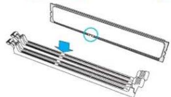
natural_image
Technical illustration of a mechanical component with a circular annotation and arrow indicating assembly (no text or symbols present)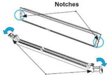
text_image
NotchesRelease Tabs
DIMM Module Removal
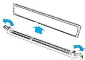
Press the release tabs on both ends of the DIMM socket to release the DIMM module from the socket as shown in the drawing on the right.
natural_image
Diagram of a mechanical component with blue arrows indicating rotation or movement (no text or symbols)Warnings: 1. Please do not use excessive force when pressing the release tabs on the ends of the DIMM socket to avoid causing any damage to the DIMM module or the DIMM socket. 2. Please handle DIMM modules with care. Carefully follow all the instructions given on Page 1 of this chapter to prevent ESD-related damages to your memory modules or components.
2.5 Rear I/O Ports
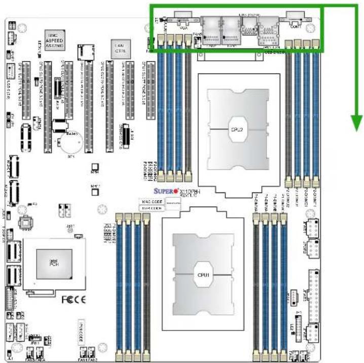
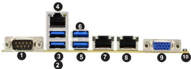
See the drawings below for the locations and descriptions of the various I/O ports on the rear side of your system.
text_image
MAC ASPEED AS LIME TEN CPU1 TOP 2 SUPER AL10CH CPU10 CPU2 MAC EDGE MAC EDGE CPU1 CPU1 CPU1 CPU1 CPU1 CPU1 CPU1 CPU1 CPU1 CPU1 CPU1 CPU1 CPU1 CPU1 CPU1 CPU1 CPU1 CPU1 CPU1 CPU1 CPU1 CPU1 CPU1 CPU1 CPU1 CPU1 CPU1 CPU1 CPU1 CPU1 CPU1 CPU1 CPU1 CPU1Back panel I/O Port Locations and Definitions
text_image
Diagram showing 10 labeled network ports and connectors, including VGA, Ethernet, and USB interface components| Back Panel I/O Ports | |||
| No. | Description No. | Description | |
| 1. | COM1 6. USB 3 (USB 3.0) | ||
| 2. | USB 0 (USB 3.0) 7. | GLAN1 (X11DPH-i), 10G_LAN1 (X11DPH-T/X11DPH-Tq) | |
| 3. | USB 1 (USB 3.0) 8. | GLAN2 (X11DPH-i), 10G_LAN2 (X11DPH-T/X11DPH-Tq) | |
| 4. | IPMI LAN 9. VGA | ||
| 5. | USB 2 (USB 3.0) 10. | Unit Identifier Switch (UID) | |
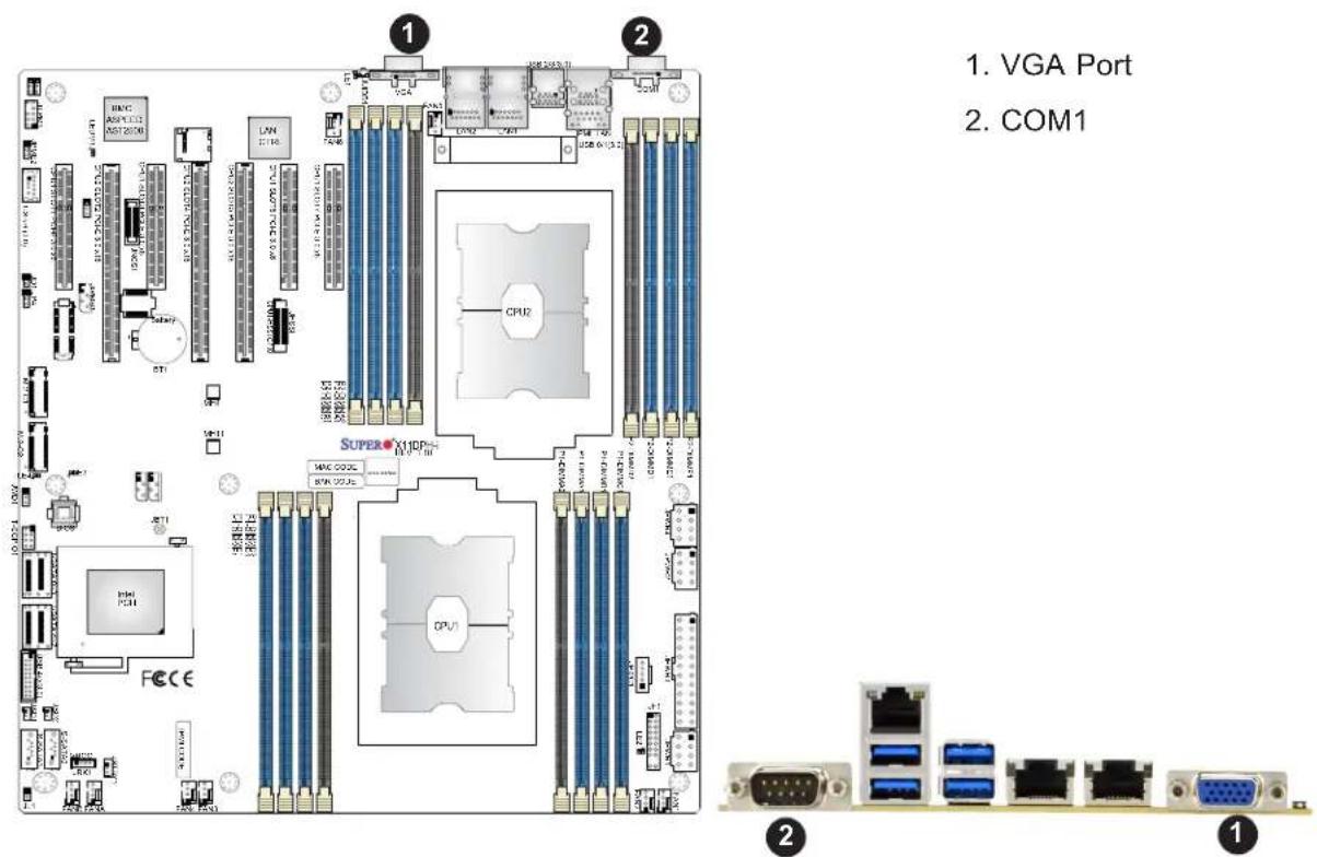
VGA Port
The onboard VGA port is located next to IPMI LAN port on the I/O back panel. Use this connection for VGA display.
Serial Port
There is one COM port (COM1) on the I/O back panel on the motherboard. The COM port provides serial communication support. See the table below for pin definitions.
| Pin# | Definition | Pin# | Definition |
| 1 | DCD | 6 | DSR |
| 2 | RXD | 7 | RTS |
| 3 | TXD | 8 | CTS |
| 4 | DTR | 9 | RI |
| 5 | Ground | 10 | N/A |
text_image
1. VGA Port 2. COM1 1 2 1 2 1 2 1 2 1 2 1 2 1 2 1 2 1 2 1 2 1 2 1 2 1 2 1 2 1 2 1 2 1 2 1 2 1 2 1 2 1 2 1 2 1 2 1 2 1 2 1 1 2 1 2 1 2 1 2 1 2 1 2 1 2 1 2 1 2 1 2 1 2 1 2 1 2 1 2 1 2 1 2 1 2 1 2 1 2 1 2 1 2 1 2 1 2 1 2 1Universal Serial Bus (USB) Ports
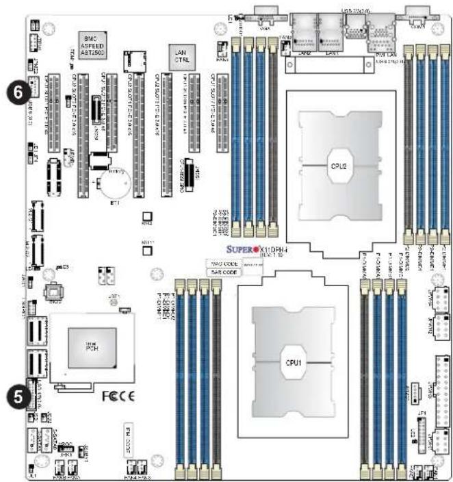
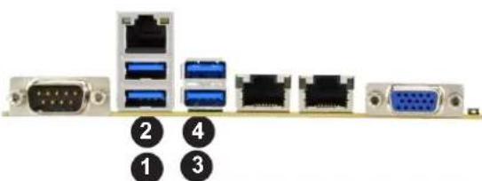
Four USB 3.0 ports (USB 0/1, USB 2/3) are located on the I/O back panel. An internal USB header, located next to SATA 4\~7, provides two USB 3.0 connections (USB2/3) for front access. In addition, A Type A USB header (USB6), next to PCIe Slot 1, also provides USB 3.0 connection for front access. The onboard headers can be used to provide front USB access with appropriate cables (not included).
| Back Panel USB 0/1, 2/3 (3.0)Pin Definitions | |||
| Pin# | Definition | Pin# | Definition |
| A1 VB | JS B1 Power | ||
| A2 D- | B2 USB_N | ||
| A3 D+ | B3 USB_P | ||
| A4 GND | B4 GND | ||
| A5 Stda | SSRX- B5 USB3_RN | ||
| A6 Stda | SSRX+ B6 USB3_RP | ||
| A7 GND | B7 GND | ||
| A8 Stda | SSTX- B8 USB3_TN | ||
| A9 Stda | SSTX+ B9 USB3_TP | ||
| Front Panel USB 4/5 (3.0) Pin Definitions | |||
| Pin# | Definition | Pin# | Definition |
| 1 | VBUS | 19 | Power |
| 2 | Stda_SSRX- | 18 | USB3_RN |
| 3 | Stda_SSRX+ 17 | USB3_RP | |
| 4 | GND | 16 | GND |
| 5 | Stda_SSTX- | 15 | USB3_TN |
| 6 | Stda_SSTX+ | 14 | USB3_TP |
| 7 | GND | 13 | GND |
| 8 | D- | 12 | USB_N |
| 9 | D+ | 11 | USB_P |
| 10 | x | ||
text_image
SAC ASPEED ASTL30C LAN CTRL CPU2 SUPERX108H4 CPU1 FCCCE 5| Type A USB 6 (3.0)Pin Definitions | |||
| Pin# | Definition | Pin# | Definition |
| 1 VBUS 5 SSRX- | |||
| 2 USB_N 6 SSRX+ | |||
| 3 USB_P 7 GND | |||
| 4 Ground 8 SSTX- | |||
| 9 SSTX+ | |||
- USB0 (3.0)
- USB1 (3.0)
- USB2 (3.0)
- USB3 (3.0)
- USB4/5 (3.0)
- USB6 (3.0)
natural_image
Diagram of server rack components with labeled ports (no text or symbols beyond numbered labels)Unit Identifier Switch/UID LED Indicator
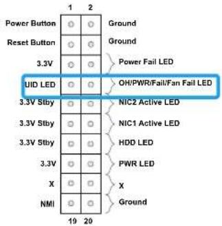
A Unit Identifier (UID) switch and a rear UID LED (LE1) are located on the I/O back panel. A front UID switch is located on pins 7 & 8 of the front panel control (JF1). When you press the front or the rear UID switch, both front and rear UID LEDs will be turned on. Press the UID switch again to turn off the LED indicators. The UID indicators provide easy identification of a system that may be in need of service. (Note: UID can also be triggered via IPMI on the motherboard. For more information, please refer to the IPMI User's Guide posted on our website at http://www.supermicro.com.)
| UID Switch Pin Definitions | |
| Pin# | Definition |
| 1 | Ground |
| 2 | Ground |
| 3 | Button In |
| 4 | Button In |
| UID LEDPin Definitions | |
| Color | Status |
| Blue: On | Unit Identified |
text_image
Power Button Reset Button 3.3V UID LED 3.3V Stby 3.3V Stby 3.3V Stby X NMI 1 2 Ground Ground Power Fail LED OH/PWR/Fail/Fan Fail LED NIC2 Active LED NIC1 Active LED HDD LED PWR LED X Ground 19 20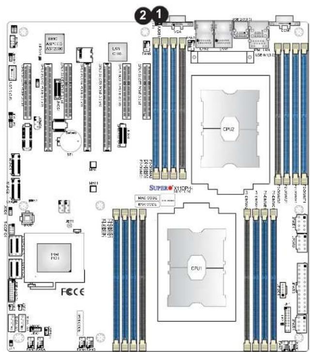
text_image
2 1 EPC ASP13 ASP200 LAN CIN CPU2 SUPER® X11CP+ MCC ODSL MCC ODSL CPU1 FCE CE 10.024 10.024 10.024 10.024 10.024 10.024 10.024 10.024 10.024 10.024 10.024 10.024 10.024 10.024 10.024 STI MHI MHI MHI MHI MHI MHI MHI MHI MHI MHI MHI MHI MHI MHI MHI MHI MHI MHI MHI MHI MHI MHI MHI MHI MHI MHI MHI MHI MHI MHI MHI MHI MHI MHI- UID
- UID LED
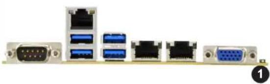
natural_image
Front view of a computer tower rear panel showing multiple Ethernet ports and connectors (no text or labels visible)Ethernet Ports
Two Ethernet ports (LAN1, LAN2) are located on the I/O back panel. These Ethernet ports support 10GbE LAN connections on the X11DPH-T/X11DPH-Tq, and 1 GbE LAN connections on the X11DPH-i. In addition, an IPMI-dedicated LAN that supports 1 GbE LAN is located above USB 0/1 ports on the back panel. All Ethernet ports accept RJ45 type cables. Please refer to the LED Indicator section for LAN LED information.
| LAN Ports Pin Definition | |||
| Pin# | Definition | Pin# | Definition |
| 1 | P2V5SB | 10 | SGND |
| 2 | TD0+ | 11 | Act LED |
| 3 | TD0- | 12 | P3V3SB |
| 4 | TD1+ | 13 | Link 100 LED (Yellow, +3V3SB) |
| 5 | TD1- | 14 | Link 1000 LED (Yellow, +3V3SB) |
| 6 | TD2+ | 15 | Ground |
| 7 | TD2- | 16 | Ground |
| 8 | TD3+ | 17 | Ground |
| 9 | TD3- | 18 | Ground |
(NC: No Connection)
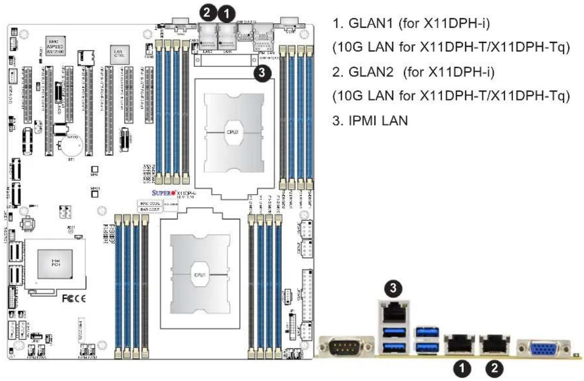
text_image
1. GLAN1 (for X11DPH-i) (10G LAN for X11DPH-T/X11DPH-Tq) 2. GLAN2 (for X11DPH-i) (10G LAN for X11DPH-T/X11DPH-Tq) 3. IPMI LAN SUPER-X11DPH- MOS COM BAR CODES CPU2 CPU1 FCEC 1 2 3 1 22.6 Front Control Panel
JF1 contains header pins for various buttons and indicators that are normally located on a control panel at the front of your system. These connectors are designed specifically for use with Supermicro chassis. See the drawing below for the descriptions of the front control panel buttons and LED indicators.
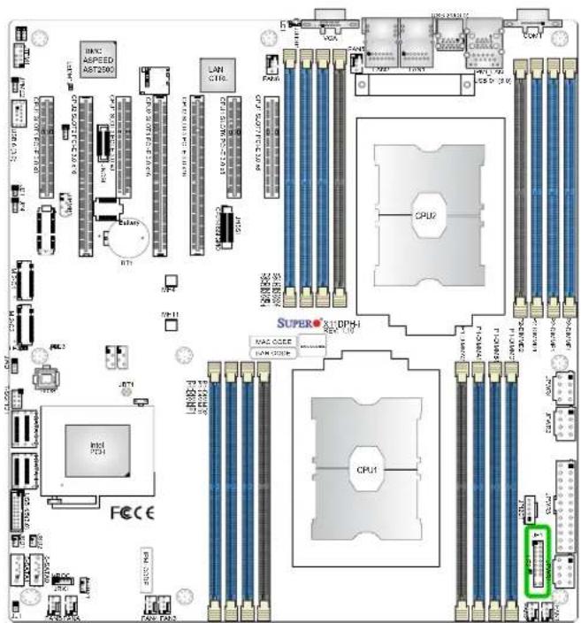
text_image
MINI ASPEED AST2500 LAN C116 CPU1 SUPERC DPH-1 MAC ODER LAWO CPU1 FCC E INTL P324 INTL P325 FCC E INTL P326 FCC E INTL P327 FCC E INTL P328 FCC E INTL P329 FCC E INTL P330 FCC E INTL P331 FCC E INTL P332 FCC E INTL P333 FCC E INTL P334 FCC E INTL P335 FCC E INTL P336 FCC E INTL P337 FCC E INTL P338 FCC E INTL P339 FCC E INTL P340 FCC E INTL P341 FCC E INTL P342 FCC E INTL P343 FCC E INTL P344 FCC E INTL P345 FCC E INTL P346 FCC E INTL P347 FCC E INTL P348 FCC E INTL P349 FCC E INTL P350 FCC EJF1 Header Pins
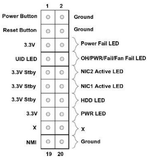
text_image
Power Button Reset Button 3.3V UID LED 3.3V Stby 3.3V Stby 3.3V Stby X NMI 19 20 Ground Ground Power Fail LED OH/PWR/Fail/Fan Fail LED NIC2 Active LED NIC1 Active LED HDD LED PWR LED X GroundPower Button
The Power Button connection is located on pins 1 and 2 of JF1. Momentarily contacting both pins will power on/off the system. This button can also be configured to function as a suspend button (with a setting in the BIOS - see Chapter 4). To turn off the power when the system is in the suspend mode, press the button for 4 seconds or longer. Refer to the table below for pin definitions.
| Power ButtonPin Definitions (JF1) | |
| Pins Definition | |
| 1 Signal | |
| 2 Ground | |
Reset Button
The Reset Button connection is located on pins 3 and 4 of JF1. Attach it to a hardware reset switch on the computer case to reset the system. Refer to the table below for pin definitions.
| Reset ButtonPin Definitions (JF1) |
| Pins Definition |
| 3 Reset |
| 4 Ground |
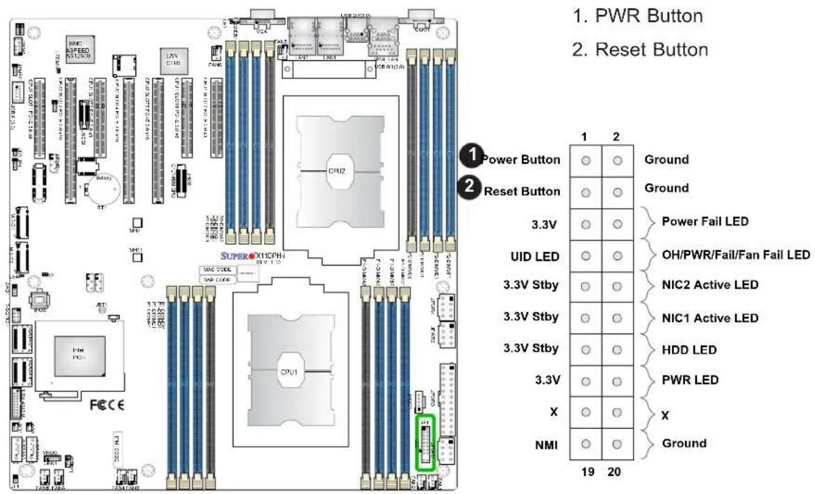
text_image
1. PWR Button 2. Reset Button 1 Power Button 2 Reset Button 1 2 Ground Ground 3.3V Power Fail LED UID LED 3.3V Stby NIC2 Active LED 3.3V Stby NIC1 Active LED 3.3V Stby HDD LED 3.3V PWR LED X NMI Ground 19 20Power Fail LED
The Power Fail LED connection is located on pins 5 and 6 of JF1. Refer to the table below for pin definitions.
| Power Fail LEDPin Definitions (JF1) | |
| Pin# | Definition |
| 5 | 3.3V |
| 6 | PWR Supply Fail |
OH/Fan Fail/PWR Fail/UID LED
Connect an LED cable to pins 7 and 8 of the Front Control Panel (JF1) to use the UID/Overheat/Fan Fail/PWR Fail LED connections. Pin 7 of JF1 (blue LED) is used as Front UID LED. Pin 8 of JF1 (red LED) provides warnings for possible overheating, power failure, or fan failure. Refer to the tables below for more information.
| Information LED (UID/OH/PWR Fail/Fan Fail LED)Pin Definitions (Pin 7 & Pin 8 of JF1) | |
| Status Description | |
| Solid red An overheat condition has occurred. (This may be caused by cable congestion). | |
| Blinking red (1Hz) Fan failure: check for an inoperative fan. | |
| Blinking red (0.25Hz) Power failure: check for a non-operational power supply | |
| Solid blue Local UID is activated. Use this function to locate a unit in a rack mount environment that might be in need of service. | |
| Blinking blue (300 msec) | Remote UID is on. Use this function to identify a unit from a remote location that might be in need of service. |
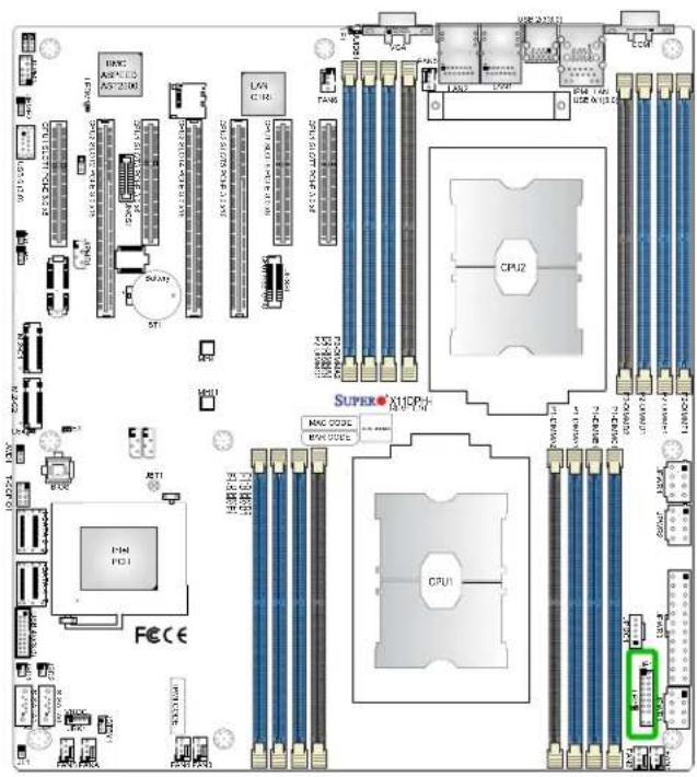
text_image
TOP 2340 CPU2 SUPERX X16P3 CPU1 MAG 0225C MAG 0225C MAG 0225C MAG 0225C MAG 0225C MAG 0225C MAG 0225C MAG 0225C MAG 0225C MAG 0225C MAG 0225C MAG 0225C-
Power Fail LED
-
UID/OH/PWR Fail/Fan Fail LED
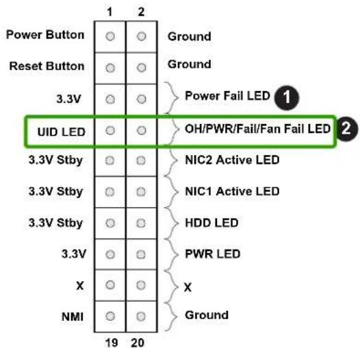
text_image
Power Button Reset Button 3.3V UID LED 3.3V Stby 3.3V Stby 3.3V Stby X NMI 19 20 Ground Ground Power Fail LED ① OH/PWR/Fail/Fan Fail LED ② NIC2 Active LED NIC1 Active LED HDD LED PWR LED X GroundThe NIC (Network Interface Controller) LED connection for LAN port 1 is located on pins 11 and 12 of JF1, and LAN port 2 is on pins 9 and 10. Attach the NIC LED cables here to display network activity. Refer to the table below for pin definitions.
| LAN1/LAN2 LEDPin Definitions (JF1) | |
| Pin# | Definition |
| 9 NIC | 2 Activity LED |
| 11 NIC | 1 Activity LED |
HDD LED
The HDD LED connection is located on pins 13 and 14 of JF1. Attach a cable here to show hard drive activity. Refer to the table below for pin definitions.
| HDD LEDPin Definitions (JF1) |
| Pins Definition |
| 13 3.3V Stdby |
| 14 HDD Active |
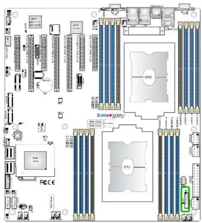
text_image
Circuit board layout diagram with labeled components including CPU, memory chips, and connected modules- NIC2 LED
- NIC1 LED
- HDD LED
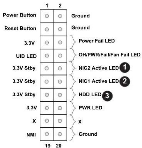
text_image
Power Button Reset Button 3.3V UID LED 3.3V Stby 3.3V Stby 3.3V X NMI 19 20 Ground Ground Power Fail LED OH/PWR/Fail/Fan Fail LED NIC2 Active LED 1 NIC1 Active LED 2 HDD LED 3 PWR LED X GroundPower LED
The Power LED connection is located on pins 15 and 16 of JF1. Refer to the table below for pin definitions.
| Power LEDPin Definitions (JF1) |
| Pins Definition |
| 15 3.3V |
| 16 PWR LED |
NMI Button
The non-maskable interrupt (NMI) button header is located on pins 19 and 20 of JF1. Refer to the table below for pin definitions.
| NMI ButtonPin Definitions (JF1) |
| Pins Definition |
| 19 Control |
| 20 Ground |
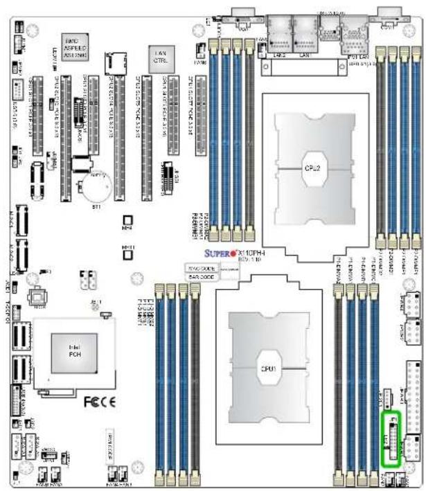
text_image
FCC HAC POWER CPU SFP CPU2 SUPERX10PH FCC FCC FCC FCC FCC FCC FCC FCC FCC FCC FCC FCC FCC FCC FCC FCC FCC FCC FCC FCC FCC FCC FCC FCC FCC FCC FCC FCC FCC FCC FCC FCC FCC FCC-
PWR LED
-
NMI
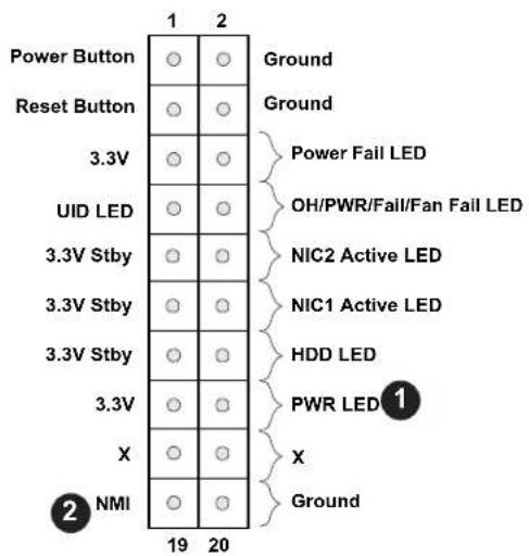
text_image
Power Button Reset Button 3.3V UID LED 3.3V Stby 3.3V Stby 3.3V X NMI 19 20 Ground Ground Power Fail LED OH/PWR/Fail/Fan Fail LED NIC2 Active LED NIC1 Active LED HDD LED PWR LED 1 X Ground2.7 Connectors
Power Connector
ATX Main Connector
JPWR3 is the 24-pin ATX main power supply connector. This primary power supply connector meets the ATX SSI EPS 24-pin specification. You must also connect the 8-pin (JPWR1/JPWR2/JPWR4) power connectors to your power supply (See the next page for more info on 8-pin power connectors.)
ATX Power 24-pin Connector Pin Definitions
| Pin# Definition Pin# Definition |
| 13 +3.3V 1 +3.3V |
| 14 NC 2 +3.3V |
| 15 Ground 3 Ground |
| 16 PS_ON 4 +5V |
| 17 Ground 5 Ground |
| 18 Ground 6 +5V |
| 19 Ground 7 Ground |
| 20 Res (NC) 8 PWR_OK |
| 21 +5V 9 5VSB |
| 22 +5V 10 +12V |
| 23 +5V 11 +12V |
| 24 Ground 12 +3.3V |
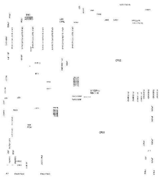
- ATX 24-pin Power Supply (JPWR3)
12V 8-pin CPU Power Connectors
JPWR1, JPWR2 and JPWR4 are 8-pin 12V DC power input connectors designated for CPU use. These power connectors can also be used as alternative single power source for a special enclosure when the 24-pin ATX power is not in use. Refer to the table below for pin definitions.
| 12V 8-pin Power Pin Definitions |
| Pin# Definition |
| 1 - 4 Ground |
| 5 - 8 +12V |
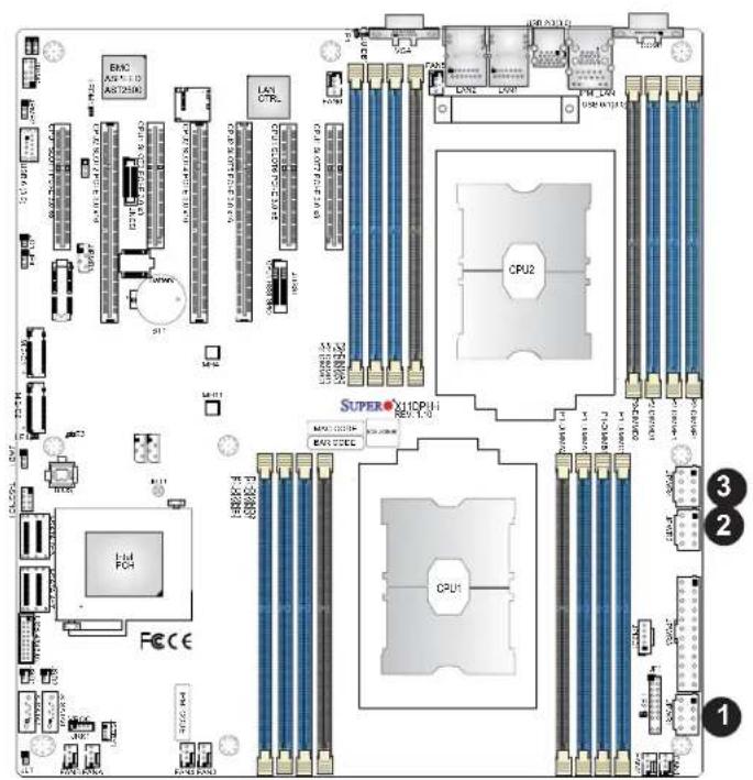
text_image
LAN CTRL CPU2 SUPER X10CPU+ CPU1 3 2 1- JPWR1
- JPWR2
- JPWR4
Headers
Onboard Fan Header
Eight 4-pin fan headers (FAN1-6, FANA, FANB) are located on the motherboard to provide CPU/system cooling. These fan headers support both 3-pin fans and 4-pin fans; however, onboard fan speed control is available only when all 4-pin fans are used in the motherboard. Fan speed control is supported by a thermal management setting in the BMC (Baseboard Management Controller). See the table below for pin definitions.
| Fan Header Pin Definitions | |
| Pin# | Definition |
| 1 | Ground (Black) |
| 2 | +12V (Red) |
| 3 | Tachometer |
| 4 | PWM Control |
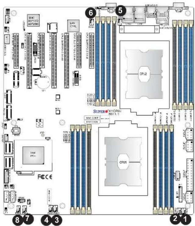
text_image
SNC ASPEED AST250C LAN CTRL CPU 3.07P/1.04 CPU 3.07P/1.04 CPU 3.07P/1.04 CPU 3.07P/1.04 CPU 3.07P/1.04 CPU 3.07P/1.04 CPU 3.07P/1.04 CPU 3.07P/1.04 CPU 3.07P CPU 3.07P CPU 3.07P CPU 3.07P CPU 3.07P CPU 3.07P CPU 3.07P CPU 3.07P CPU 3.07P CPU 3.07P CPU 3.07P CPU 3.07P CPU 3.07P CPU 6 SUPERO X15PHI REV 1.2 CPU2 MAC CODEF MAC CODEF FECE 8 7 4 3 2 1 2 1- FAN1
- FAN2
- FAN3
- FAN4
- FAN5
- FAN6
- FANA
- FANB
TPM Header
The JTPM1 header is used to connect a Trusted Platform Module (TPM)/Port 80, which is available from Supermicro. A TPM/Port 80 connector is a security device that supports encryption and authentication in hard drives. It allows the motherboard to deny access if the TPM that is associated with the hard drive is not installed in the system. See the layout below for the location of the TPM header.
Speaker Header (Optional for an External Speaker/Buzzer)
A speaker header, located at JD1, can be used in conjunction with an external speaker (optional). Use an appropriate cable to connect this header to an external speaker or buzzer for support of BIOS beep codes and system alarms. See the layout below for JD1 location.
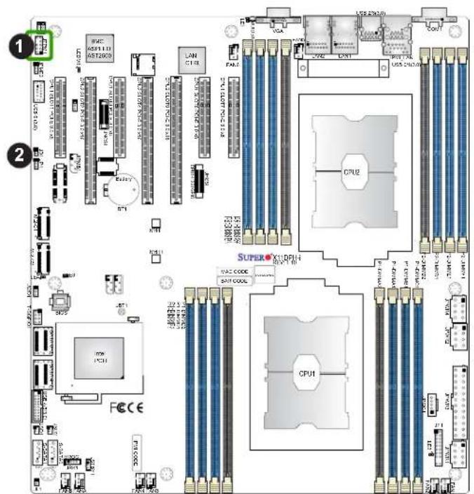
text_image
Circuit board layout diagram with labeled components including CPU, memory chips, and peripheral connectors-
TPM/Port 80 Header
-
Speaker Header
SATA DOM Power Connector
The SATA Disk-On-Module (DOM) power connectors at JSD1 and JSD2 provide 5V power to solid-state storage devices connected to the SATA ports. See the table below for pin definitions.
| DOM PWRPin Definitions | |
| Pin# | Definition |
| 1 | +5V |
| 2 | Ground |
| 3 | Ground |
Power SMB (I²C) Header
The Power System Management Bus (I²C) connector (JPI²C1) monitors power supply, cooling fan, and system temperatures. Refer to the table below for pin definitions.
| Power SMB Header Pin Definitions | |
| Pin# | Definition |
| 1 | Clock |
| 2 | Data |
| 3 | PMBUS_Alert |
| 4 | Ground |
| 5 | +3.3V |
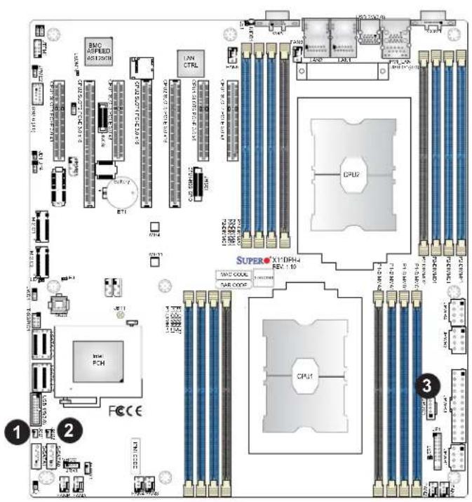
text_image
BMO ASPEED AS12000 LAN CTRL CPU1 SUPERX X1:DPH4 REV. 10 CPU2 SAP3000 SAP3000 SAP3000 CPU1 FECE 1 2 3- JSD1
- JSD2
- Power SMB
VROC RAID Key Header
A VROC RAID Key header is located at JRK1 on the motherboard. Install a VROC RAID Key on JRK1 for NVMe RAID support as shown in the illustration below. Please refer to the layout below for the location of JRK1.
| Intel VROC Key Pin Definitions | |
| Pin# | Definition |
| 1 | Ground |
| 2 | 3.3V Standby |
| 3 | Ground |
| 4 | PCH RAID Key |
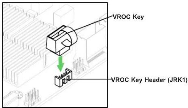
text_image
VROC Key VROC Key Header (JRK1)
Note: The graphics contained in this user's manual are for illustration only. The components installed in your system may or may not look exactly the same as the graphics shown in the manual.
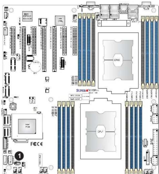
text_image
BMC ASPEED AS125038 LAN CTRL CPU2 SUPERX11DP+ MPC OUS BAR GDDR CPU1 Intel PCH FCCCE 1- VROC (JRK1)
4-pin BMC External I²C Header
A System Management Bus header for IPMI 2.0 is located at JIPMB1. Connect the appropriate cable here to use the IPMB I²C connection on your system. Refer to the table below for pin definitions.
| Pin# | Definition |
| 1 | Data |
| 2 | Ground |
| 3 | Clock |
| 4 | No Connection |
Chassis Intrusion (Available when an Optional External Speaker is Installed)
A Chassis Intrusion header is located at JL1 on the motherboard. Connect an appropriate cable from JL1 to the chassis so that you can be informed of a chassis intrusion when the system case is opened. Please note that this feature will work properly when an optional external speaker is connected to the onboard speaker header located at JD1. Refer to the table below for pin definitions.
| Chassis Intrusion Pin Definitions | |
| Pin# | Definition |
| 1 | Intrusion Input |
| 2 | Ground |
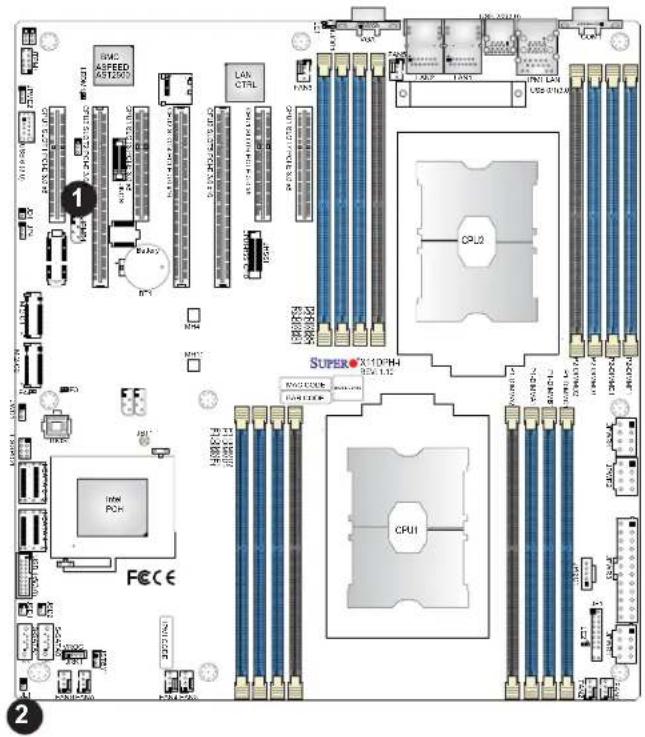
text_image
MAC ASPEED AST2.000 LAN CTRL CPU2 SUPER-X10/PH CPU1 FECE 1 2 3 4 5 6 7 8 9 10 11 12 13 14 15 16 17 18 19 20 21 22 23 24 25 26 27 28 29 30 31 32 33 34 35 36 37 38 39 40 41 42 43 44 45 46 47 48 49 50 51 52 53 54 55 56 57 58 59 60 61 62 63 64 65 66 67 68 69 70 71 72 73 74 75 76 77 78 79 80 81 82 83 84 85 86 87 88 89 90 91 92 93 94 95 96 97 98 99 100- BMC External I²C Header
- Chassis Intrusion (external speaker is required)
Standby Power
The Standby Power header is located at JSTBY1 on the motherboard. You must have a card with a Standby Power connector and a cable to use this feature. Refer to the table below for pin definitions.
| Standby Power Pin Definitions | |
| Pin# | Definition |
| 1 | +5V Standby |
| 2 | Ground |
| 3 | No Connection |
T-SGPIO1 Header
The T-SGPIO (Serial General Purpose Input/Output) header is used for the onboard SATA devices to communicate with the enclosure management chip on the back panel. See the table below for more information.
| T-SGPIO1 Header Pin Definitions | |||
| Pin# | Definition | Pin# | Definition |
| 1 | NC | 2 | NC |
| 3 | Ground | 4 | DATA Out |
| 5 | Load | 6 | Ground |
| 7 | Clock | 8 | NC |
NC = No Connection
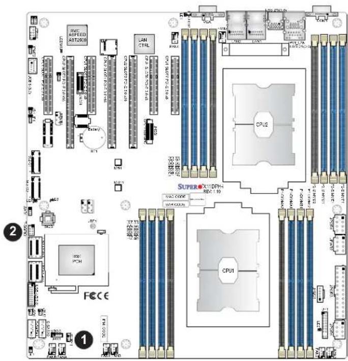
text_image
IWE AFFEED AST2500 LH CTRL CPU2 SUPERX1DPH- REV 1.10 VAC CODE VAC CODE CPU1 FCCCE 1 2 3 4 5 6 7 8 9 10 11 12 13 14 15 16 17 18 19 20 21 22 23 24 25 26 27 28 29 30 31 32 33 34 35 36 37 38 39 40 41 42 43 44 45 46 47 48 49 50 51 52 53 54 55 56 57 58 59 60 61 62 63 64 65 66 67 68 69 70 71 72 73 74 75 76 77 78 79 80 81 82 83 84 85 86 87 88 89 90 91 92 93 94 95 96 97 98 99 100- Standby Power
- T-SGPIO1
PCIe M.2 Slots
This motherboard has two PCIe M.2 slots (M.2-C1/M.2-C2). M.2, formerly known as "Next Generation Form Factor (NGFF)," replaces a mini PCIe slot. M.2 allows for a variety of card sizes and offers increased functionality and spatial efficiency. The M.2 sockets on the motherboard support PCIe 3.0 X4 (32 Gb/s) SSD cards in the 2260, 2280 and 22110 form
factors.
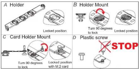
text_image
A Holder Locked position B Holder Mount Turn 90 degrees to lock Locked position C Card Holder Mount Turn 90 degrees to lock Locked position with M.2 card D Plastic screw STOP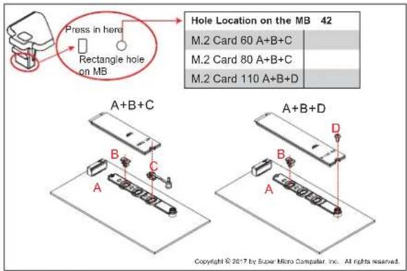
text_image
Press in here Rectangle hole on MB Hole Location on the MB 42 M.2 Card 60 A+B+C M.2 Card 80 A+B+C M.2 Card 110 A+B+D A+B+C A+B+D Copyright © 2017 by Super Micro Computer, Inc. All rights reserved.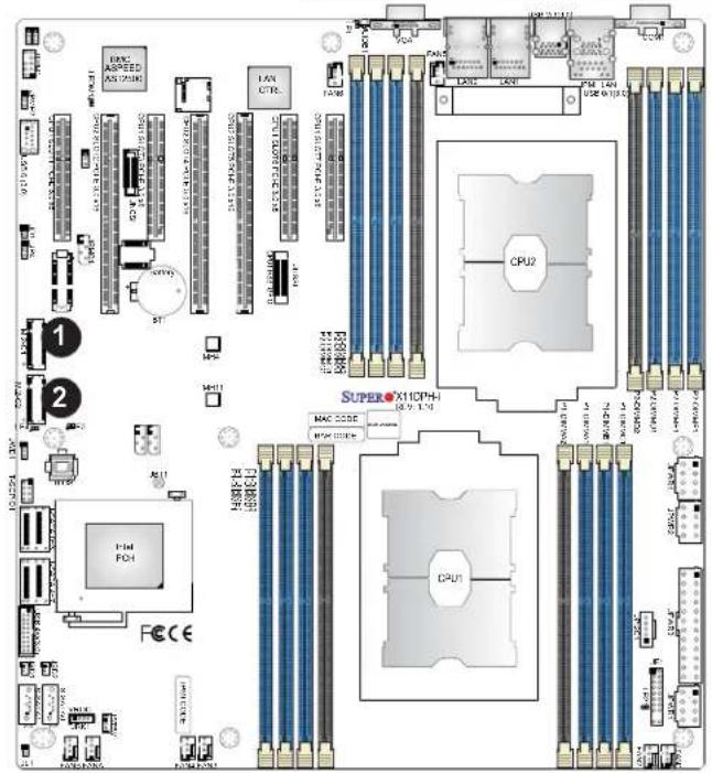
text_image
1 2 1 2 CPU2 SUPERC X10PH MAC CODE CPU1 F-14 FCH FECE- M.2-C1 Slot
- M.2-C2 Slot
I-SATA 3.0 and S-SATA 3.0 Ports
This motherboard has ten SATA 3.0 ports (I-SATA0-3, 4-7) and S-SATA0/S-SATA1. These SATA ports are supported by the Intel C621/C622/C627 chipset. S-SATA1/2 can be used with Supermicro SuperDOMs, which are yellow SATA DOM connectors with power pins built in, and do not require external power cables. Supermicro SuperDOMs are backward-compatible with regular SATA HDDs or SATA DOMs that need external power cables.
| SATA 3.0 Port Pin Definitions | |
| Pin# | Signal |
| 1 | Ground |
| 2 | SATA_TXP |
| 3 | SATA_TXN |
| 4 | Ground |
| 5 | SATA_RXN |
| 6 | SATA_RXP |
| 7 | Ground |
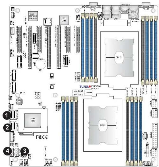
text_image
1 2 3 4 FCC E MAC ASPIRED ADC 2019 LAN CTR CPU2 SUPERCX16DPH MAC CASE MAC CASE CPU1- I-SATA0-3
- I-SATA4-6
- S-SATA1 (SuperDOM)
- S-SATA2 (SuperDOM)
2.8 Jumper Settings
How Jumpers Work
To modify the operation of the motherboard, jumpers can be used to choose between optional settings. Jumpers create shorts between two pins to change the function of the connector. Pin 1 is identified with a square solder pad on the printed circuit board. See the diagram at right for an example of jumping pins 1 and 2. Refer to the motherboard layout page for jumper locations.
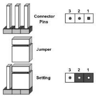
text_image
Connector Pins Jumper Setting 3 2 1 3 2 1
Note: On two-pin jumpers, "Closed" means the jumper is on and "Open" means the jumper is off the pins.
Manufacturing Mode Select
Close JPME2 to bypass SPI flash security and force the system to use Manufacturing Mode, which will allow you to flash the system firmware from a host server to modify system settings. See the table below for jumper settings.
| Manufacturing Mode Select Jumper Settings | |
| Jumper Setting | Definition |
| Pins 1-2 | Normal (Default) |
| Pins 2-3 | Manufacturing Mode |
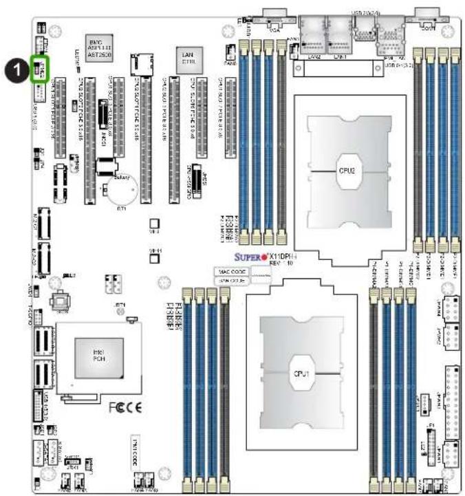
text_image
1 BXP A01.1.1 ABT25.0 LAN E710 CPU2 SUPERO X1DP4 REV 10 MAC CODE CPU1 FCCCE- Manufacturing Mode Select
CMOS Clear
JBT1 is used to clear CMOS, which will also clear any passwords. Instead of pins, this jumper consists of contact pads to prevent accidentally clearing the contents of CMOS.
To Clear CMOS
-
First power down the system and unplug the power cord(s).
-
Remove the cover of the chassis to access the motherboard.
-
Remove the onboard battery from the motherboard.
-
Short the CMOS pads with a metal object such as a small screwdriver for at least four seconds.
-
Remove the screwdriver (or shorting device).
-
Replace the cover, reconnect the power cord(s), and power on the system.

Note: Clearing CMOS will also clear all passwords.
Do not use the PW_ON connector to clear CMOS.

JBT1 contact pads
- Clear CMOS
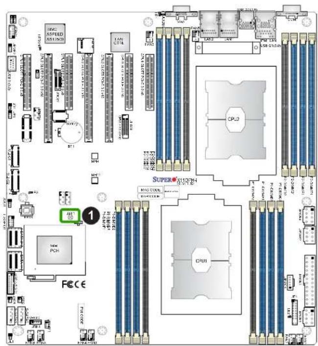
text_image
IAC ASPEED AS1203B LAN CT14 LAN 2 LAN USB CT12.6 CPU2 SUPER-110PH CPU1 1 1000000000000000000000000000000000000000000000000000000000000000000000000000000000 FCE CE 12.5.12.5.12.5.12.5.12.5.12.5.12.5.12.5.12.5.12.5.12.5.12.5.12.5.12.5.12.5.12.5.12.5.12.5.12.5.12.5.12.5 M7 8 9 10 11 12 13 14 15 16 17 18 19 20 21 22 23 24 25 26 27 28 29 30 31 32 33 34 35 36 37 38 39 40 41 42 43 44 45 46 47 48 49 50 51 52 53 54 55 56 57 58 59 60 61 62 63 64 65 66 67 68 69 70 71 72 73 74 75 76 77 78 79 80 M4 8 M3 8 M2 8 M1 8 M0 8 M9 8 M8 8 M7 8 M6 8 M5 8 M4 8 M3 8 M2 8 M1 8 M0 8 M9 8 M8 8 M7 8 M6 8 M5 8 M4 8 M3 8 M2 8 M1 8 M9 8 M8 8 M7 8 M6 8 M5 8 M4 8 M3 8 M2 8 M1 8 M9 8 M8 8 M7 8 M6 8 M5 8 M4 8 M3 8 M2 8 M1 8 M9 8 M7 8 M6 8 M5 8 M4 8 M3 8 M2 8 M1 8 M9 8 M7 8 M6 8 M5 8 M4 8 M3 8 M2 8 M1 8 M9 8 M7 8 M6 8 M5 8 M3 8 M2 8 M1 8 M9 8 M7 8 M6 8 M5 8 M4 8 M3 8 M2 8 M1 8 M9 8 M7 8 M6 8 M5 8 M4 8 M3 8 M2 8 M1 8 M79-CCDC DND CND CND CND CND CND CND CND CND CND CND CND CND CND CND CND CND CND CND CND CND CND CND CND CND CND CND CND CND CND CND CND CND CND CND CND CND CND CND CND CND CND CND CND CND CND CND CND CND CND CNDWatch Dog
JWD1 controls the Watch Dog function. Watch Dog is a monitor that can reboot the system when a software application hangs. Jumping pins 1-2 will cause Watch Dog to reset the system if an application hangs. Jumping pins 2-3 will generate a non-maskable interrupt signal for the application that hangs. Watch Dog must also be enabled in BIOS. The default setting is Reset.

Note: When Watch Dog is enabled, the user needs to write their own application software to disable it.
| Watch DogJumper Settings | |
| Jumper Setting | Definition |
| Pins 1-2 | Reset |
| Pins 2-3 | NMI |
| Open | Disabled |
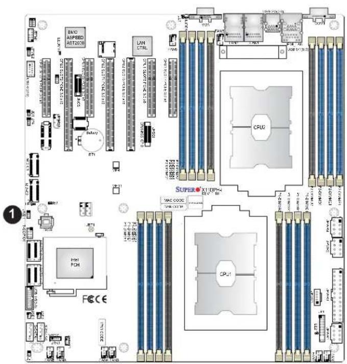
text_image
BMO ASPEED AST2020 LAN CTRL CPU2 SUPER X10P4 MAC CODE CPU1 FCH FCECE 1- Watch Dog
2.9 LED Indicators
LAN LEDs
The LAN ports are located on the IO Backplane on the motherboard. Each Ethernet LAN port has two LEDs. The green blinking LED on the right indicates activity. The Link LED, located on the left side of the LAN port, may be green, amber or off, indicating the speed of the connection. See the tables at right for more information.
IPMI-Dedicated LAN LEDs
In addition to LAN 1/LAN 2, an IPMI-dedicated LAN is located on the I/O Backplane of the motherboard. The amber blinking LED on the right indicates activity, while the LED on the left indicates the speed of the connection. See the tables at right for more information.
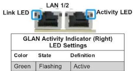
text_image
LAN 1/2 Link LED Activity LED GLAN Activity Indicator (Right) LED Settings Color State Definition Green Flashing Active| LAN Link Indicator (Left)LED Settings | |
| LED Color | Definition |
| Off | No Connection, 10 or 100 Mbps |
| Green | 10 Gbps (X11DPH-T/Tq Only) |
| Amber | 1 Gbps |
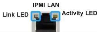
| IPMI LAN Link LED (Left) & Activity LED (Right) | ||
| Color | State | Definition |
| Link (Left) | Green: Solid | 100 Mbps |
| Activity (Right) | Amber: Blinking | Active |
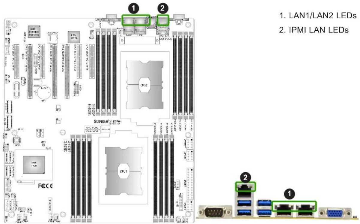
text_image
1. LAN1/LAN2 LEDs 2. IPMI LAN LEDs 1. 2 1. 2 1 IPMI LAN LEDs 1 2 1 2 1 2 1 2 1 2 1 2 1 2 1 2 1 2 1 2 1 2 1 2 1 2 1 2 1 2 1 2 1 2 1 2 1 2 1 2 1 2 1 2 1 2 1 2 1 2 1 1 2 1 2 1 2 1 2 1 2 1 2 1 2 1 2 1 2 1 2 1 2 1 2 1 2 1 2 1 2 1 2 1 2 1 2 1 2 1 2 1 2 1 2 1 2 1 2 1 3BMC Heartbeat LED
LEDM1 is the BMC heartbeat LED. When the LED is blinking green, BMC is functioning normally. See the table below for the LED status.
| Onboard Power LED Indicator | |
| LED Color | Definition |
| Green:Blinking | BMC Normal |
Onboard Power LED
The Onboard Power LED is located at LE2 on the motherboard. When this LED is on, the system is on. Be sure to turn off the system and unplug the power cord before removing or installing components. Refer to the table below for more information.
| Onboard Power LED Indicator | |
| LED Color | Definition |
| Off | System Off(power cable not connected) |
| Green | System On |
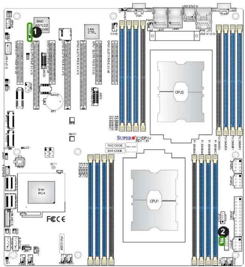
text_image
BMC ASPEED 2500 1 CPU 3.07 PCE 1.0 V AC-30 8T1 LAN CTRL CPU 6.07 PCE 1.0 V CPU 6.07 PCE 1.0 V CPU 6.07 PCE 1.0 V CPU 6.07 PCE 1.0 V CPU 6.07 PCE 1.0 V CPU 6.07 PCE 1.0 V CPU 6.07 PCE 1.0 V CPU 6.07 PCE 1.0 V FAN6 FAN5 FAN4 FAN3 FAN2 FAN1 FAN0 CPU2 CPU1 X11DPH4- PCV 1.10 MHC1 MHC2 MHC3 MHC4 MHC5 MHC6 MHC7 MHC8 MHC9 MHC10 MHC11 MHC12 MHC13 MHC14 MHC15 MHC16 MHC17 MHC18 MHC19 MHC20 MHC21 MHC22 MHC23 MHC24 MHC25 MHC26 MHC27 MHC28 MHC29 MHC30 MHC31 MHC32 MHC33 MHC34 MHC35 MHC36 MHC37 MHC38 MHC39 MHC40 MHC41 MHC42 MHC43 MHC44 MHC45 MHC46 MHC47 MHC48 MHC49 MHC50 MHC51 MHC52 MHC53 MHC54 MHC55 MHC56 MHC57 MHC58 MHC59 MHC60 MHC61 MHC62 MHC63 MHC64 MHC65 MHC66 MHC67 MHC68 MHC69 MHC70 MHC71 MHC72 MHC73 MHC74 MHC75 MHC76 MHC77 MHC78 MHC79 MHC80 MHC81 MHC82 MHC83 MHC84 MHC85 MHC86 MHC87 MHC88 MHC89 MHC90 MHC91 MHC92 MHC93 MHC94 MHC95 MHC96 MHC97 MHC98 MHC99 MHC100- BMC Heartbeat LED
- Onboard Power LED
Chapter 3
Troubleshooting
3.1 Troubleshooting Procedures
Use the following procedures to troubleshoot your system. If you have followed all of the procedures below and still need assistance, refer to the 'Technical Support Procedures' and/or 'Returning Merchandise for Service' section(s) in this chapter. Always disconnect the AC power cord before adding, changing or installing any non hot-swap hardware components.
Before Power On
- Check that the power LED on the motherboard is on.
- Make sure that the power connector is connected to your power supply.
- Make sure that no short circuits exist between the motherboard and chassis.
- Disconnect all cables from the motherboard, including those for the keyboard and mouse.
- Remove all add-on cards.
- Install a CPU, a heatsink*, and connect the power LED to the motherboard. Check all jumper settings as well. (Make sure that the heatsink is fully seated.)
- Use the correct type of onboard CMOS battery as recommended by the manufacturer. To avoid possible explosion, do not install the CMOS battery upside down.
No Power
- Make sure that there are no short circuits between the motherboard and the chassis.
- Verify that all jumpers are set to their default positions.
- Check that the 115V/230V switch on the power supply is properly set.
- Turn the power switch on and off to test the system.
- The battery on your motherboard may be old. If it is too old, replace it with a new one.
No Video
- If the power is on but you have no video, remove all the add-on cards and cables.
- Use the speaker to determine if any beep codes exist. (For error beep codes to function properly, please connect an optional external speaker/buzzer to the onboard speaker header located at JD1.) Refer to Appendix A for details on beep codes.
System Boot Failure
If the system does not display POST (Power-On-Self-Test) or does not respond after the power is turned on, check the following:
-
Check for any error beep from the motherboard. (For error beep codes to function properly, please connect an optional external speaker/buzzer to the onboard speaker header located at JD1.)
-
If there is no error beep, try to turn on the system without DIMM modules installed. If there is still no error beep, replace the motherboard.
- If there are error beeps, clear the CMOS settings by unplugging the power cord and contacting both pads on the CMOS Clear Jumper (JBT1). Refer to chapter 2.
- Remove all components from the motherboard, especially the DIMM modules. Make sure that system power is on and that memory error beeps are activated.
- Turn on the system with only one DIMM module installed. If the system boots, check for bad DIMM modules or slots by following the Memory Errors Troubleshooting procedure in this Chapter.
Memory Errors
- Make sure that the DIMM modules are properly and fully installed.
- Confirm that you are using the correct memory. Also, it is recommended that you use the same memory type and speed for all DIMMs in the system. See Section 2.4 for memory details.
- Check for bad DIMM modules or slots by swapping modules between slots and noting the results.
- Check the power supply voltage 115V/230V switch.
Losing the System's Setup Configuration
- Make sure that you are using a high quality power supply. A poor quality power supply may cause the system to lose the CMOS setup information. Refer to Section 1.6 for more information on power supplies.
- The battery on your motherboard may be old. If it is too old, replace it with a new one.
- If the above steps do not fix the setup configuration problem, contact your vendor for repairs.
When the System Becomes Unstable
A. If the system becomes unstable during or after OS installation, check the following:
- CPU/BIOS support: Make sure that your CPU is supported and that you have the latest BIOS installed in your system.
- Memory support: Make sure that the memory modules are supported by testing the modules using memtest86 or a similar utility.

Note: Refer to the product page on our website at http://www.supermicro.com for memory and CPU support and updates.
- HDD support: Make sure that all hard disk drives (HDDs) work properly. Replace the bad HDDs with good ones.
- System cooling: Check the system cooling to make sure that all heatsink fans and CPU/system fans, etc., work properly. Check the hardware monitoring settings in the IPMI to make sure that the CPU and system temperatures are within the normal range. Also check the front panel Overheat LED and make sure that it is not on.
- Adequate power supply: Make sure that the power supply provides adequate power to the system. Make sure that all power connectors are connected. Please refer to our website for more information on the minimum power requirements.
-
Proper software support: Make sure that the correct drivers are used.
B. If the system becomes unstable before or during OS installation, check the following: -
Source of installation: Make sure that the devices used for installation are working properly, including boot devices such as CD.
-
Cable connection: Check to make sure that all cables are connected and working properly.
-
Using the minimum configuration for troubleshooting: Remove all unnecessary components (starting with add-on cards first), and use the minimum configuration (but with a CPU and a memory module installed) to identify the trouble areas. Refer to the steps listed in Section A above for proper troubleshooting procedures.
- Identifying bad components by isolating them: If necessary, remove a component in question from the chassis, and test it in isolation to make sure that it works properly. Replace a bad component with a good one.
- Check and change one component at a time instead of changing several items at the same time. This will help isolate and identify the problem.
- To find out if a component is good, swap this component with a new one to see if the system will work properly. If so, then the old component is bad. You can also install the component in question in another system. If the new system works, the component is good and the old system has problems.
3.2 Technical Support Procedures
Before contacting Technical Support, please take the following steps. Also, note that as a motherboard manufacturer, we do not sell directly to end-users, so it is best to first check with your distributor or reseller for troubleshooting services. They should know of any possible problem(s) with the specific system configuration that was sold to you.
- Please review the 'Troubleshooting Procedures' and 'Frequently Asked Questions' (FAQs) sections in this chapter or see the FAQs on our website before contacting Technical Support.
- BIOS upgrades can be downloaded from our website. Note: Not all BIOS can be flashed depending on the modifications to the boot block code.
-
If you still cannot resolve the problem, include the following information when contacting us for technical support:
-
Motherboard model and PCB revision number
- BIOS release date/version (this can be seen on the initial display when your system first boots up)
- System configuration
An example of a Technical Support form is posted on our website.
Distributors: For immediate assistance, please have your account number ready when contacting our technical support department by e-mail.
3.3 Battery Removal and Installation
Battery Removal
To remove the onboard battery, follow the steps below:
- Power off your system and unplug your power cable.
- Using a tool such as a pen or a small screwdriver, push the battery lock outwards to unlock it. Once unlocked, the battery will pop out from the holder.
- Remove the battery.
Proper Battery Disposal
Please handle used batteries carefully. Do not damage the battery in any way; a damaged battery may release hazardous materials into the environment. Do not discard a used battery in the garbage or a public landfill. Please comply with the regulations set up by your local hazardous waste management agency to dispose of your used battery properly.
Battery Installation
To install an onboard battery, follow the steps below:
- Power off your system and unplug your power cable.
- Locate the onboard battery as shown below.
- Identify the battery's polarity. The positive (+) side should be facing up.
- Insert the battery into the battery holder and push it down until you hear a click to ensure that the battery is securely locked.

Note: When replacing a battery, be sure to only replace it with the same type. Important: When replacing a battery, be sure to only replace it with the same type.
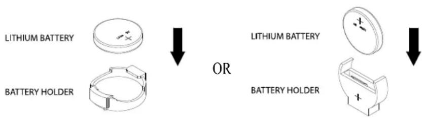
text_image
LITHIUM BATTERY BATTERY HOLDER OR LITHIUM BATTERY BATTERY HOLDER3.4 Frequently Asked Questions
Question: What type of memory does my motherboard support?
Answer: This motherboard supports up 4TB of 3DS Load Reduced DIMM (3DS LRDIMM), Load Reduced DIMM (LRDIMM), 3DS Registered DIMM (3DS RDIMM), Registered DIMM (RDIMM), Non-Volatile DIMM (NV-DIMM) DDR4 (288-pin) ECC 2933*/2666/2400/2133 MHz memory in 16 slots (*Note below.) See Section 2.4 for details on installing memory.

Note: 2933 MHz memory is supported by the 2nd Generation Intel Xeon Scalable-SP (82xx/62xx series) processors only.
Question: Why can't I turn off the power using the momentary power on/off switch?
Answer: The instant power off function is controlled in BIOS by the Power Button Mode setting. When the On/Off feature is enabled, the motherboard will have instant off capabilities as long as the BIOS is in control of the system. When the Standby or Suspend feature is enabled or when the BIOS is not in control such as during memory count (the first screen that appears when the system is turned on), the momentary on/off switch must be held for more than four seconds to shut down the system. This feature is required to implement the ACPI features on the motherboard.
Question: How do I update my BIOS?
Answer: It is recommended that you do not upgrade your BIOS if you are not experiencing any problems with your system. Updated BIOS files are located on our website at http://www.supermicro.com/ResourceApps/BIOS_IPMI_Intel.html. Please check our BIOS warning message and the information on how to update your BIOS on our website. Select your motherboard model and download the BIOS file to your computer. Also, check the current BIOS revision to make sure that it is newer than your BIOS before downloading. Please refer to the following section for the instructions on how to update your BIOS under UEFI Shell.

Note: The SPI BIOS chip used on this motherboard cannot be removed. Send your motherboard back to our RMA Department at Supermicro for repair. For BIOS Recovery instructions, please refer to the AMI BIOS Recovery Instructions posted at http://www.supermicro.com/support/manuals/.
Question: How do I update my BIOS under UEFI Shell?

Note: We do not recommend that you update your BIOS if you are not experiencing a BIOS-related problem. If you need to update your BIOS, please follow the steps below to properly update your BIOS under UEFI Shell.
- Download and save the BIOS update package to your computer.
- Extract the files from the UEFI folder of the BIOS package to a USB stick.

Note: The USB stick doesn't have to be bootable; however, it has to be formatted with the FAT/FAT32 file system.
- Insert the USB stick into a USB port, boot to the UEFI Built-In Shell, and enter the following commands to start the BIOS update:
Shell> fs0:
fs0:> cd UEFI
- The FLASH.NSH script will compare the Flash Descriptor Table (FDT) code in the new BIOS with the existing one in the motherboard:
a. If a different FDT is found
- A new file, STARTUP.NSH, will be created, and the system will automatically reboot in 10 seconds without you pressing any key. BIOS will be updated after the system reboots.
- You can also press
to force an immediate system reboot to shorten the process. During system reboot, press the key to invoke the boot menu and boot into the build-in UEFI Shell. Your BIOS will be updated automatically.
b. If the FDT is the same
• BIOS update will be immediately performed without a system reboot initiated.
Warning: Do not shut down or reset the system while updating the BIOS to prevent possible system boot failure!)
- Perform an A/C power cycle after the message indicating the BIOS update has completed.
- Go to the BIOS setup utility, and restore the BIOS settings.
3.5 Returning Merchandise for Service
A receipt or copy of your invoice marked with the date of purchase is required before any warranty service will be rendered. You can obtain service by calling your vendor for a Returned Merchandise Authorization (RMA) number. When returning to the manufacturer, the RMA number should be prominently displayed on the outside of the shipping carton and mailed prepaid or hand-carried. Shipping and handling charges will be applied for all orders that must be mailed when service is complete.
For faster service, RMA authorizations may be requested online (http://www.supermicro.com/support/rma/).
This warranty only covers normal consumer use and does not cover damages incurred in shipping or from failure due to the alteration, misuse, abuse or improper maintenance of products.
During the warranty period, contact your distributor first for any product problems.
Chapter 4
UEFI BIOS
4.1 Introduction
This chapter describes the AMIBIOS ^™ setup utility for the X11DPH-i/X11DPH-T/X11DPH-Tq motherboard. The BIOS is stored on a chip and can be easily upgraded using a flash program.

Note: Due to periodic changes to the BIOS, some settings may have been added or deleted and might not yet be recorded in this manual. Please refer to the Manual Download area of our website for any changes to the BIOS that may not be reflected in this manual.
Starting the Setup Utility
To enter the BIOS setup utility, press the
The Main BIOS screen has two main frames. The left frame displays all the options that can be configured. "Grayed-out" options cannot be configured. The right frame displays the key legend. Above the key legend is an area reserved for a text message. When an option is selected in the left frame, it is highlighted in white. Often a text message will accompany it. (Note that BIOS has default text messages built in. We retain the option to include, omit, or change any of these text messages.) Settings printed in Bold are the default values.
A "▶" indicates a submenu. Highlighting such an item and pressing the
The BIOS setup utility uses a key-based navigation system called hot keys. Most of these hot keys (
4.2 Main Setup
When you first enter the AMI BIOS setup utility, you will see the Main setup screen. You can always return to the Main setup screen by selecting the Main tab on the top of the screen. The Main BIOS setup screen is shown below.
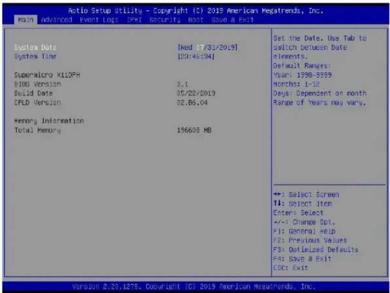
text_image
Action Setup Utility - Copyright (C) 2015 American Megatrends, Inc. Main Advanced Event Logs IPMI Security Boot Save & Exit System Date [Red 07/31/2019] System Time [20:46:94] Superalcro X11DPH BIOS Version 3.1 Build Date 05/22/2019 CFLD Version 02.86.04 Memory Information Total Memory 196608 MB Set the Date. Use Tab to switch between Date elements. Default Ranges: Year: 1998-3599 Months: 1-12 Days: Dependent on month Range of Years may vary. +: Select Screen ++: Select Item Enter: Select +/-: Change Opt. F1: General Help F2: Previous Values F3: Optimized Defaults F4: Save & Exit EBC: Exit Version 2.20.1275. Copyright (C) 2015 American Megatrends, Inc.System Date/System Time
Use this item to change the system date and time. Highlight System Date or System Time using the arrow keys. Enter new values using the keyboard. Press the

Note: The time is in the 24-hour format. For example, 5:30 P.M. appears as 17:30:00. The date's default value is the BIOS build date after the RTC (Real Time Clock) reset.
Supermicro X11DPH
BIOS Version
This feature displays the version of the BIOS ROM used in the system.
Build Date
This feature displays the date when the version of the BIOS ROM used in the system was built.
CPLD Version
This feature displays the version of the CPLD (Complex-Programmable Logical Device) used in the system.
Memory Information
Total Memory
This feature displays the total size of memory available in the system.
Memory Speed
This feature displays the default speed of the memory modules installed in the system.
4.3 Advanced Setup Configurations
Use the arrow keys to select the Advanced submenu and press
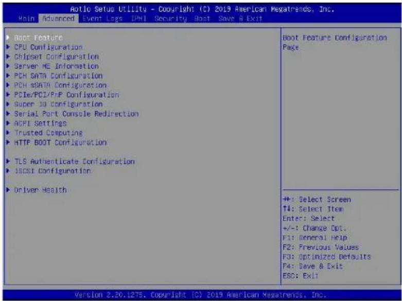
text_image
Arolo Setup Utility - Copyright (C) 2019 American Megatrends, Inc. Main Advanced Event Logs DPHI Security Boot Save & Exit Boot Feature CPU Configuration Chipset Configuration Server HE Information PCH SATA Configuration PCH sSATA Configuration PCIe/PCI/PnP Configuration Super ID Configuration Serial Port Console Redirection ACPI Settings Trusted Computing HTTP BOOT Configuration TLS Authenticate Configuration ISCSI Configuration Driver Health Boot Feature Configuration Page +: Select Screen T4: Select Item Enter: Select +/-: Change Opt. F1: General Help F2: Previous Values F3: Optimized Defaults F4: Save & Exit ESC: Exit Version 2.20.1275. Copyright (C) 2019 American Megatrends, Inc.Warning: Take Caution when changing the Advanced settings. An incorrect value, an improper DRAM frequency, or a wrong BIOS timing setting may cause the system to malfunction. When this occurs, restore the setting to the manufacturer default setting.
▶Boot Configuration
Quiet Boot
Use this feature to select the screen between displaying POST messages or the OEM logo at bootup. Select Disabled to display the POST messages. Select Enabled to display the OEM logo instead of the normal POST messages. The options are Enabled and Disabled.

Note: POST message is always displayed regardless of the item setting.
Option ROM Messages
Use this feature to set the display mode for the Option ROM. Select Keep Current to use the current AddOn ROM display settings. Select Force BIOS to use the Option ROM display mode set by the system BIOS. The options are Force BIOS and Keep Current.
Bootup NumLock State
Use this feature to set the Power-on state for the Numlock key. The options are Off and On.
Wait For 'F1' If Error
Select Enabled to force the system to wait until the
INT19 Trap Response
Interrupt 19 is the software interrupt that handles the boot disk function. When this feature is set to Immediate, the ROM BIOS of the host adaptors will "capture" Interrupt 19 at bootup immediately and allow the drives that are attached to these host adaptors to function as bootable disks. If this item is set to Postponed, the ROM BIOS of the host adaptors will not capture Interrupt 19 immediately to allow the drives attached to these adaptors to function as bootable devices at bootup. The options are Immediate and Postponed.
Re-try Boot
When EFI (Extensible Firmware Interface) Boot is selected, the system BIOS will automatically reboot the system from an EFI boot device after an initial boot failure. Select Legacy Boot to allow the BIOS to automatically reboot the system from a Legacy boot device after an initial boot failure. The options are Disabled, Legacy Boot, and EFI Boot.
Install Windows 7 USB Support
Select Enabled to install Windows 7 and the XHCI drivers for USB keyboard/mouse support. After you've installed the Windows 7 and XHCI drivers, be sure to set this feature to "Disabled" (default). The options are Disabled and Enabled.
Port 61h Bit-4 Emulation
Select Enabled for I/O Port 61h-Bit 4 emulation support to enhance system performance. The options are Enabled and Disabled.
Power Configuration
Watch Dog Function
Select Enabled to allow the Watch Dog timer to reboot the system when it is inactive for more than 5 minutes. The options are Enabled and Disabled.
Restore on AC Power Loss
Use this feature to set the power state after a power outage. Select Power Off for the system power to remain off after a power loss. Select Power On for the system power to be turned on after a power loss. Select Last State to allow the system to resume its last power state before a power loss. The options are Stay Off, Power On, and Last State.
Power Button Function
This feature controls how the system shuts down when the power button is pressed. Select 4 Seconds Override for the user to power off the system after pressing and holding the power button for 4 seconds or longer. Select Instant Off to instantly power off the system as soon as the user presses the power button. The options are 4 Seconds Override and Instant Off.
▶CPU Configuration
Warning: Setting the wrong values in the following sections may cause the system to malfunction.
▶Processor Configuration
The following CPU information will be displayed:
- Processor BSP Revision
- Processor Socket
- Processor ID
- Processor Frequency
- Processor Max Ratio
- Processor Min Ratio
- Microcode Revision
- L1 Cache RAM
- L2 Cache RAM
- L3 Cache RAM
- Processor 0 Version
- Processor 1 Version
Hyper-Threading (ALL)
Select Enable to use Intel Hyper-Threading Technology to enhance CPU performance. The options are Enable and Disable.
Core Enabled
Use this feature to enable or disable CPU cores in the processor specified by the user. Use the <+> key and the <-> key on the keyboard to set the desired number of CPU cores you want to enable in a processor. Please note that the maximum of 16 CPU cores are currently available in each CPU package. The default setting is 0.
Monitor/Mwait
Select Enable to support Monitor and Mwait, which are two instructions in Streaming SIMD Extension 3 (SSE3), to improve synchronization between multiple threads for CPU performance enhancement. The options are Auto, Enable, and Disable.
Execute Disable Bit (Available if supported by the OS & the CPU)
Select Enable for Execute Disable Bit support which will allow the processor to designate areas in the system memory where an application code can execute and where it cannot, thus preventing a worm or a virus from flooding illegal codes to overwhelm the processor, damaging the system during a virus attack. The options are Enable and Disable. (Refer to Intel and Microsoft websites for more information.)
Intel Virtualization Technology (Available when two processors are installed on the motherboard)
Select Enable to use Intel Virtualization Technology which will allow multiple workloads to share the same set of common resources. On shared virtualized hardware, various workloads (or tasks) can co-exist, sharing the same resources, while functioning in full independence from each other, and migrating freely across multi-level infrastructures and scale as needed. The settings are Enable and Disable.
PPIN Control
Select Unlock/Enable to use the Protected-Processor Inventory Number (PPIN) in the system. The options are Unlock/Enable and Lock/Disable.
Hardware Prefetcher (Available when supported by the CPU)
If this feature is set to Enable, the hardware prefetcher will prefect data from the main system memory to Level 2 cache to help expedite data transaction for memory performance enhancement. The options are Disable and Enable.
Adjacent Cache Prefetch (Available when supported by the CPU)
Select Enable for the CPU to prefetch both cache lines for 128 bytes as comprised. Select Disable for the CPU to prefetch both cache lines for 64 bytes. The options are Disable and Enable.

Note: Please power off and reboot the system for the changes you've made to take effect. Please refer to Intel's website for detailed information.
DCU Streamer Prefetcher (Available when supported by the CPU)
If this feature is set to Enable, the DCU (Data Cache Unit) streamer prefetcher will prefetch data streams from the cache memory to the DCU (Data Cache Unit) to speed up data accessing and processing to enhance CPU performance. The options are Disable and Enable.
DCU IP Prefetcher
This feature allows the system to use the sequential load history, which is based on the instruction pointer of previous loads, to determine whether the system will prefetch additional lines. The options are Enable and Disable.
LLC Prefetch
If this feature is set to Enable, LLC (hardware cache) prefetching on all threads will be supported. The options are Disable and Enable.
Extended APIC (Extended Advanced Programmable Interrupt Controller)
Based on the Intel Hyper-Threading technology, each logical processor (thread) is assigned 256 APIC IDs (APIDs) in 8-bit bandwidth. When this feature is set to Enable, the APIC ID will be expanded from 8 bits to 16 bits to provide 512 APIDs to each thread to enhance CPU performance. The options are Disable and Enable.
AES-NI
Select Enable to use the Intel Advanced Encryption Standard (AES) New Instructions (NI) to ensure data security. The options are Enable and Disable.
▶Advanced Power Management Configuration
Power Technology
Select Energy Efficient to support power-saving mode. Select Custom to customize system power settings. Select Disabled to disable power-saving settings. The options are Disable, Energy Efficient, and Custom.
Power Performance Tuning (Available when "Power Technology" is set to Custom)
Select BIOS to allow the system BIOS to configure the Power-Performance Tuning Bias setting. The options are BIOS Controls EPB and OS Controls EPB.
ENERGY\_PERF\_BIAS\_CFG Mode (ENERGY PERFORMANCE BIAS CONFIGURATION Mode) (Available when "Power Performance Tuning" is set to BIOS Controls EPB)
Use this feature to configure the optimal operation setting for your machine by achieving the desired system performance level and energy saving (efficiency) level at the same time. Select Maximum Performance to maximize system performance to its highest potential; however, this may consume maximal amount of power as energy is needed to fuel the processor frequency. (In other words, system performance is gained at the cost of system power efficiency, depending on the workload.) Select Maximum Power Efficiency to minimize power use; however, system performance will be greatly impacted as the result of power saving. The options are Maximum Performance, Performance, Balanced Performance, Balanced Power, Power, and Max (Maximum) Power Efficient.
▶CPU P State Control (Available when "Power Technology" is set to Custom)
SpeedStep (P-States)
EIST (Enhanced Intel SpeedStep Technology) allows the system to automatically adjust processor voltage and core frequency in an effort to reduce power consumption and heat dissipation. Please refer to Intel's website for detailed information. The options are Disable and Enable.
*If SpeedStep (P-States) is set to Enable, the following items will display:
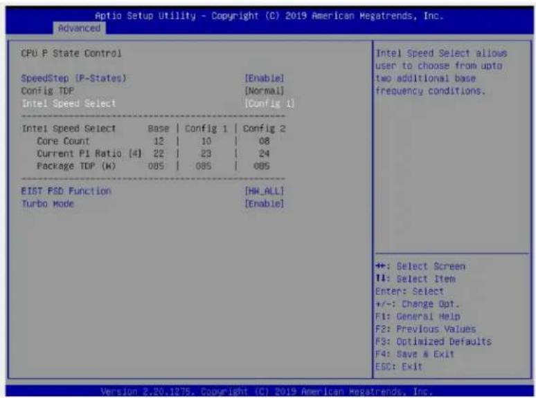
text_image
Aptio Setup Utility - Copyright (C) 2019 American Megatrends, Inc. Advanced CPU P State Control SpeedStep (P-States) [Enable] Config TDP [Normal] Intel Speed Select [Config 1] Intel Speed Select Base Config 1 Config 2 Core Count 12 10 08 Current P1 Ratio [4] 22 23 24 Package TDP (k) 085 085 085 EIST PSD Function [HM_ALL] Turbo Mode [Enable] Intel Speed Select allous user to choose from upto two additional base frequency conditions. +: Select Screen II: Select Item Enter: Select +/-: Change Opt. F1: General Help F2: Previous Values F3: Optimized Defaults F4: Save & Exit ESC: Exit Version 2.20.1275. Copyright (C) 2019 American Megatrends, Inc.Config (Configuring) TDP (Available when SpeedStep is set to Enable and when the 2nd Gen Intel Xeon Scalable-SP 8260Y/6240Y/4214Y Processors are Used)
This feature allows the user to configure the maximum CPU TDP (Thermal Design Power) level for the system. The TDP level is subject to chassis and heatsink cooling restrictions. For proper thermal management, please check the chassis and heatsink specifications for proper CPU TDP sizing. The options are Normal, Level 1 and Level 2.
Intel Speed Select (Available when SpeedStep is set to Enable and when the 2nd Gen Intel Xeon Scalable-SP 8260Y/6240Y/4214Y Processors are Used)
This feature allows the user to configure up to two additional base frequency settings for the processors used in your system as shown in the display below. The options are Base, Config (Configuration) 1 and Config (Configuration) 2.
Activate PBF (Available when SpeedStep is set to Enable and when the 2nd Gen Intel Xeon Scalable-SP 6252N/6230N/5218N Processors are Used)
Select Enable to support Prioritized Base Frequency (PBF), which will increase the base frequency on high-priority cores and decrease the base frequency on low-priority cores to improve CPU performance. The options are Disable and Enable.
Configure PBF (Available when Activate PBF is set to Enable)
Select Enable to allow the BIOS to configure high priority CPU cores as Prioritized Base Frequency (PBF) so that software programs do not have to configure the PBF settings. This feature is available when it is supported by the CPUs used in the system. The options are Enable and Disable.
EIST PSD Function (Available when SpeedStep is set to Enable)
Use this feature to configure the processor's P-State coordination settings. During a P-State, the voltage and frequency of the processor will be reduced when it is in operation. This makes the processor more energy efficient, resulting in further energy gains. The options are HW_ALL, SW_ALL and SW-ANY.
Turbo Mode (Available when SpeedStep is set to Enable)
Select enable to allow the CPU to operate at the manufacturer-defined turbo speed by increasing CPU clock frequency. This feature is available when it is supported by the CPUs used in the system. The options are Disable and Enable.
▶Hardware PM (Power Management) State Control (Available when "Power Technology" is set to Custom)
Hardware P-States
If this feature is set to Disable, system hardware will choose a P-state setting for the system based on an OS request. If this feature is set to Native Mode, hardware will choose a P-state setting based on OS guidance. If this feature is set to Native Mode with No Legacy Support, system hardware will choose a P-state setting independently without OS guidance. The options are Disable, Native Mode, Out of Band Mode, and Native Mode with No Legacy Support.
▶CPU C State Control
Autonomous Core C-State
Select Enable to support Autonomous Core C-State control which will allow the processor core to control its C-State setting automatically and independently. The options are Disable and Enable.
CPU C6 Report (Available when Autonomous Core C-State is set to Disable)
Select Enable to allow the BIOS to report the CPU C6 state (ACPI C3) to the operating system. During the CPU C6 state, power to all caches is turned off. The options are Auto, Enable, and Disable.
Enhanced Halt State (C1E) (Available when Autonomous Core C-State is set to Disable)
Select Enable to enable "Enhanced Halt State" support, which will significantly reduce the CPU's power consumption by minimizing CPU's clock cycles and reduce voltage during a "Halt State." The options are Disable and Enable.
▶Package C State Control (Available when "Power Technology" is set to Custom)
Package C State
This feature is used to optimize and reduce CPU package power consumption in idle mode. Please note that the changes you've made in this setting will affect all CPU cores or the circuits of the entire system. The options are C0/C1 state, C2 state, C6 (non-Retention) state, C6 (Retention) state, No Limit, and Auto.
▶CPU T State Control Available when "Power Technology" is set to Custom)
Software Controlled T-States
If this feature is set to Enable, CPU throttling settings will be supported by the software of the system. The options are Enable and Disable.
▶Chipset Configuration
Warning: Setting the wrong values in the following items may cause the system to malfunction.
▶North Bridge
This feature allows the user to configure the settings for the Intel North Bridge.
▶UPI (Ultra Path Interconnect) Configuration
This section displays the following UPI General Configuration information:
• Number of CPU
• Number of Active UPI Link
• Current UPI Link Speed
• Current UPI Link Frequency
• UPI Global MMIO Low Base/Limit
• UPI Global MMIO High Base/Limit
• UPI PCIe Configuration Base/Size
Degrade Precedence
Use this feature to select the degrading precedence option for Ultra Path Interconnect (UPI) connections. Select Topology Precedent to degrade UPI features if system options are in
conflict. Select Feature Precedent to degrade UPI topology if system options are in conflict. The options are Topology Precedence and Feature Precedence.
Link L0p Enable
Select Enable for the system BIOS to enable Link L0p support which will allow the CPU to reduce the UPI links from full width to half width in the event when the CPU's workload is low in an attempt to save power. This feature is available for the system that uses Intel processors with UPI technology support. The options are Disable, Enable, and Auto.

Note: You can change the performance settings for non-standard applications by using this parameter. It is recommended that the default settings be used for standard applications.
Link L1 Enable
Select Enable for the BIOS to activate Link L1 support which will power down the UPI links to save power when the system is idle. This feature is available for the system that uses Intel processors with UPI technology support. The options are Disable, Enable, and Auto.

Note: Link L1 is an excellent feature for an idle system. L1 is used during Package C-States when its latency is hidden by other components during a wakeup.
IO Directory Cache (IODC)
Select Enable for the IODC (I/O Directory Cache) to generate snoops instead of generating memory lockups for remote IIO (InvIToM) and/or WCiLF (Cores). Select Auto for the IODC to generate snoops (instead of memory lockups) for WCiLF (Cores). The options are Disable, Auto, Enable for Remote InvItoM Hybrid Push, InvItoM AllocFlow, Enable for Remote InvItoM Hybrid AllocNonAlloc, and Enable for Remote InvItoM and Remote WCiLF.
SNC
Select Enable to use "Sub NUMA Clustering" (SNC), which supports full SNC (2-cluster) interleave and 1-way IMC interleave. Select Auto for 1-cluster or 2-cluster support depending on the status of IMC (Integrated Memory Controller) Interleaving. The options are Disable, Enable, and Auto.
XPT Prefetch
Select Enable for XPT (Extended Prediction Table) Prefetch support which will allow an LLC request to be duplicated and sent to an appropriate memory controller based on the recent LLC history to reduce latency. The options are Enable, and Disable.
KTI Prefetch
If this feature is set to Enable, the KTI prefetcher will preload the L1 cache with data deemed relevant to allow the memory read to start earlier on a DDR bus in an effort to reduce latency. The options are Enable and Disable.
Local/Remote Threshold
This feature allows the user to set the threshold for the Interrupt Request (IRQ) signals, which handle hardware interruptions. The options are Disable, Auto, Low, Medium, and High.
Stale AtoS (A to S)
The in-memory directory has three states: I, A, and S states. The I (-invalid) state indicates that the data is clean and does not exist in the cache of any other sockets. The A (-snoop All) state indicates that the data may exist in another socket in an exclusive or modified state. The S state (-Shared) indicates that the data is clean and may be shared in the caches across one or more sockets. When the system is performing "read" on the memory and if the directory line is in A state, we must snoop all other sockets because another socket may have the line in a modified state. If this is the case, a "snoop" will return the modified data. However, it may be the case that a line "reads" in an A state, and all the snoops come back with a "miss". This can happen if another socket reads the line earlier and then has silently dropped it from its cache without modifying it. If the "Stale AtoS" feature is enabled, a line will transition to the S state when the line in the A state returns only snoop misses. That way, subsequent reads to the line will encounter it in the S state and will not have to snoop, saving the latency and snoop bandwidth. Stale "AtoS" may be beneficial in a workload where there are many cross-socket reads. The options are Disable, Enable, and Auto.
LLC Dead Line Alloc
Select Enable to opportunistically fill the deadlines in the LLC. The options are Enable, Disable, and Auto.
Isoc Mode
Select Enable to enable Isochronous support to meet QoS (Quality of Service) requirements. This feature is especially important for the Virtualization Technology. The options are Disable, Enable, and Auto.
▶Memory Configuration
Enforce POR (Plan of Record)
Select POR to enforce POR restrictions for DDR4 memory frequency and voltage programming. The options are POR and Disable.
PPR Type
Post Package Repair (PPR) is a new feature available for the DDR4 Technology. PPR provides additional spare capacity within a DDR4 DRAM module that is used to replace faulty cell areas detected during system boot. PPR offers two types of memory repairs. Soft Post Package Repair (sPPR) provides a quick, temporary fix on a raw element in a bank group of a DDR4 DRAM device, while hard Post Package Repair (hPPR) will take a
longer time to provide a permanent repair on a raw element. The options are Auto, Soft PPR, Hard PPR, and PPR Disabled.
Memory Frequency
Use this feature to set the maximum memory frequency for onboard memory modules. The options are Auto, 1866, 2000, 2133, 2400, 2666, and 2933*. (Note: Support for 2933 MHz is dependent on the CPU SKU.)
Data Scrambling for DDR4
Select Enable to enable data scrambling for DDR4 memory to enhance system performance and security. Select Auto for the default setting of the Memory Reference Code (MRC) to set configure data scrambling for DDR4 setting. The options are Auto, Disable, and Enable.
tCCD\_L Relaxation
If this feature is set to Auto, SPD (Serial Presence Detect) will automatically override tCCD_L ("Column to Column Delay-Long", or "Command to Command Delay-Long" on the column side) based on memory frequency. If this feature is set to Disable, tCCD_L will be enforced based on the memory frequency. The options are Auto, and Disable.
tRWSR (Read to Write turnaround time for Same Rank) Relaxation
Select Enable to use the same tRWSR DDR timing setting among all memory channels, and in which case, the worst case value among all channels will be used. Select Disable to use different values for the tRWSR DDR timing settings for different channels as trained. The options are Disable, and Enable.
2X Refresh
Select Enable for memory 2X refresh support to enhance memory performance. The options are Enable, and Auto.
Page Policy
Use this feature to set the page policy for onboard memory support. The options are Closed, Adaptive, and Auto.
IMC Interleaving
Use this feature to configure interleaving settings for the IMC (Integrated Memory Controller), which will improve memory performance. The options are 1-way Interleave, 2-way Interleave, and Auto.
▶Memory Topology
This item displays the information of onboard memory modules as detected by the BIOS (See figure below).
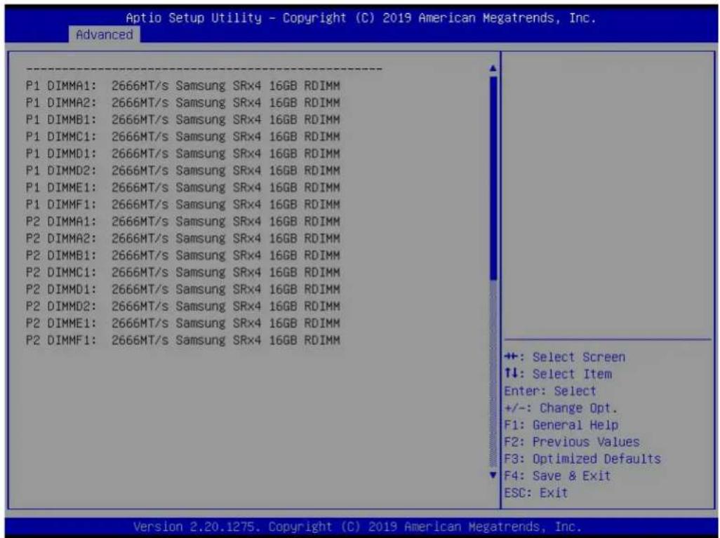
text_image
Optio Setup Utility - Copyright (C) 2019 American Megatrends, Inc. Advanced P1 DIMMA1: 2666MT/s Samsung SRx4 16GB RDIMM P1 DIMMA2: 2666MT/s Samsung SRx4 16GB RDIMM P1 DIMMB1: 2666MT/s Samsung SRx4 16GB RDIMM P1 DIMMC1: 2666MT/s Samsung SRx4 16GB RDIMM P1 DIMMD1: 2666MT/s Samsung SRx4 16GB RDIMM P1 DIMMD2: 2666MT/s Samsung SRx4 16GB RDIMM P1 DIMME1: 2666MT/s Samsung SRx4 16GB RDIMM P1 DIMMF1: 2666MT/s Samsung SRx4 16GB RDIMM P2 DIMMA1: 2666MT/s Samsung SRx4 16GB RDIMM P2 DIMMA2: 2666MT/s Samsung SRx4 16GB RDIMM P2 DIMMB1: 2666MT/s Samsung SRx4 16GB RDIMM P2 DIMMC1: 2666MT/s Samsung SRx4 16GB RDIMM P2 DIMMD1: 2666MT/s Samsung SRx4 16GB RDIMM P2 DIMMD2: 2666MT/s Samsung SRx4 16GB RDIMM P2 DIMME1: 2666MT/s Samsung SRx4 16GB RDIMM P2 DIMMF1: 2666MT/s Samsung SRx4 16GB RDIMM ++: Select Screen ↑↓: Select Item Enter: Select +/-: Change Opt. F1: General Help F2: Previous Values F3: Optimized Defaults F4: Save & Exit ESC: Exit Version 2.20.1275. Copyright (C) 2019 American Megatrends, Inc.▶Memory RAS (Reliability\_Availability\_Serviceability) Configuration
Use this submenu to configure the following Memory RAS settings.
Static Virtual Lockstep Mode
Select Enable to support Static Virtual Lockstep mode to enhance memory performance. The options are Enable and Disable.
Mirror Mode
Use this feature to configure the mirror mode settings for all 1LM/2LM memory modules installed in the system which will create a duplicate copy of data stored in the memory to increase memory security, but it will reduce the memory capacity into half. The options are Disable, Mirror Mode 1LM, and Mirror Mode 2LM.
Memory Rank Sparing
Select Enable to support memory-rank sparing to optimize memory performance. The options are Enable and Disable.

Note: This item will not be available when memory mirror mode is set to Mirror Mode 1LM or an AEP device is plugged in.
Correctable Error Threshold
Use this item to enter the threshold value for correctable memory errors. The default setting is 512.
Intel Run Sure
Select Enable to use Intel Run Sure Technology which will enhance critical data protection and increase system uptime and resiliency. The options are Enable and Disable.
SDDC/SDDC Plus One
SDDC (Single Device Data Correction) checks and corrects single-bit or multiple-bit (4-bit max.) memory faults that affect an entire single x4 DRAM device. SDDC Plus One, an enhanced feature to SDDC, copies data stored in a faulty DRAM device to a spare device when an SDDC event has occurred. After the event, the SDDC+1 ECC mode is activated to protect against any additional memory failure caused by a 'single-bit' error in the same memory rank. The options are Enable and Disable. (Note: SDDC or SDDC Plus One is available when it is supported by the processors installed on the motherboard.)
ADDDC Sparing (Available when Intel Run Sure is set to Enable)
Select Enable for ADDDC (Adaptive Double Device Data Correction) support, which will not only provide memory error checking and correction but will also prevent the system from issuing a performance penalty before a device fails. Please note that virtual lockstep mode will only start to work for ADDDC after a faulty DRAM module is spared. The options are Enable and Disable.
Patrol Scrub
Patrol Scrubbing is a process that allows the CPU to correct correctable memory errors detected in a memory module and send the corrections to the requestor (the original source). When this feature is set to Enable, the IO hub will read and write back one cache line every 16K cycles if there is no delay caused by internal processing. By using this method, roughly 64 GB of memory behind the IO hub will be scrubbed every day. The options are Enable and Disable.
Patrol Scrub Interval (Available when Patrol Scrub is set to Enable)
Use this item to specify the number of hours (between 0 to 24) required for the system to complete a full patrol scrubbing. Enter 0 for patrol scrubbing to be performed automatically. The default setting is 24.
▶IIO Configuration
EV DFX (Device Function On-Hide) Features
When this feature is set to Enable, the EV_DFX Lock Bits that are located in a processor will always remain clear during electric tuning. The options are Disable and Enable.
▶CPU1 Configuration/CPU2 Configuration
IOU0 (IIO PCIe Br1)
Use this feature to configure the PCIe Bifurcation setting for a PCIe port specified by the user. The options are x4x4x4x4, x4x4x8, x8x4x4, x8x8, x16, and Auto.
IOU1 (IIO PCIe Br2)
Use this feature to configure the PCIe Bifurcation setting for a PCIe port specified by the user. The options are x4x4x4x4, x4x4x8, x8x4x4, x8x8, x16, and Auto.
IOU2 (IIO PCIe Br3)
Use this feature to configure the PCIe Bifurcation setting for a PCIe port specified by the user. The options are x4x4x4x4, x4x4x8, x8x4x4, x8x8, x16, and Auto.
▶CPU1 PCIe Br0D00F0 - Port 0/DMI (Available for CPU 1 Configuration only)
Link Speed
Use this feature to configure the link speed of a PCIe port specified by the user. The options are Auto, Gen 1 (Generation 1) (2.5 GT/s), Gen 2 (Generation 2) (5 GT/s), and Gen 3 (Generation 3) (8 GT/s)
The following information will be displayed:
- PCIe Port Link Status
- PCIe Port Link Max
- PCIe Port Link Speed
PCIe Port Max (Maximum) Payload Size (Available for CPU 1 Configuration only)
Select Auto for the system BIOS to automatically set the maximum payload value for a PCIe device specified by to user for system performance enhancement. The options are Auto, 128B, and 256B.
▶IOAT Configuration
Disable TPH
TPH (TLP Processing Hint) is used for data-tagging with a destination ID and a few important attributes. It can send critical data to a particular cache without writing through to memory. Select No in this item for TLP Processing Hint support, which will allow a "TPL request" to provide "hints" to help optimize the processing of each transaction occurred in the target memory space. The options are Yes and No.
Prioritize TPH (TLP Processing Hint)
Select Yes to prioritize the TPL requests that will allow the "hints" to be sent to help facilitate and optimize the processing of certain transactions in the system memory. The options are Enable and Disable.
Relaxed Ordering
Select Enable to allow certain transactions to be processed and completed before other transactions that have already been enqueued. The options are Disable and Enable.
▶Intel VT for Directed I/O (VT-d)
Intel® VT for Directed I/O (VT-d)
Select Enable to use Intel Virtualization Technology support for Direct I/O VT-d by reporting the I/O device assignments to the VMM (Virtual Machine Monitor) through the DMAR ACPI tables. This feature offers fully-protected I/O resource sharing across Intel platforms, providing greater reliability, security and availability in networking and data-sharing. The options are Enable and Disable.
ACS (Access Control Services) Control
Select Enable to program Access Control Services to Chipset PCIe Root Port Bridges. Select Disable to program Access Control Services to all PCIe Root Port Bridges. The options are Enable and Disable.
Interrupt Remapping
If this feature is set to Enable, I/O DMA transfer remapping and device-generated interrupts will be supported. The options are Enable and Disable.
PassThrough DMA
Select Enable for the Non-Isoch VT-d engine to pass through DMA (Direct Memory Access) to enhance system performance. The options are Enable and Disable.
ATS
Select Enable to enable ATS (Address Translation Services) support for the Non-Isoch VT-d engine to enhance system performance. The options are Enable and Disable.
Posted Interrupt
Select Enable to support VT_D Posted Interrupt which will allow external interrupts to be sent directly from a direct-assigned device to a client machine in non-root mode to improve virtualization efficiency by simplifying interrupt migration and lessening the need of physical interrupts. The options are Enable and Disable.
Coherency Support (Non-Isoch)
Select Enable for the Non-Isoch VT-d engine to pass through DMA (Direct Memory Access) to enhance system performance. The options are Enable and Disable.
Intel® VMD Technology
This section describes the configuration settings for the Intel Volume Management Device (VMD) Technology.
Notes: 1. After you've enabled VMD in the BIOS on a PCIe slot of your choice, this PCIe slot will be dedicated for VMD use only, and it will no longer support any PCIe device. To re-activate this slot for PCIe use, please disable VMD in the BIOS. 2. PCIe slots and naming differ depending on the PCIe devices installed on your motherboard.
Intel® VMD for Volume Management Device on CPU1
VMD Configuration for PStack0/VMD Configuration for PStack1/VMD Configuration for PStack2
Intel® VMD for Volume Management Device for PStack0/Intel® VMD for Volume Management Device for PStack1/Intel® VMD for Volume Management Device for PStack2
Select Enable to enable Intel Volume Management Device Technology support for the root port specified by the user. The options are Enable and Disable.
*If Intel® VMD for Volume Management Device for PStack0 is set to Enable, the following item will display.
CPU1 Slot1 PCIe 3.0 x 8 VMD
Select Enable to enable Intel Volume Management Device Technology support for the PCIe slot specified by the user. The options are Enable and the Disable.
Hot Plug Capable
Select Enable to enable Hot Plug support for the root ports specified by the user, which will allow the user to change the devices on those root ports without shutting down the system. The options are Disable and Enable.
*If Intel® VMD for Volume Management Device for PStack1 is set to Enable, the following item will display.
CPU1 M.2 C-2 PCIe 3.0 x 4 VMD
Select Enable to enable Intel Volume Management Device Technology support for the PCIe slot specified by the user. The options are Enable and the Disable.
CPU1 M.2 C-1 PCIe 3.0 x 4 VMD
Select Enable to enable Intel Volume Management Device Technology support for the PCIe slot specified by the user. The options are Enable and the Disable.
CPU1 Slot3 PCIe 3.0 x 8 VMD
Select Enable to enable Intel Volume Management Device Technology support for the PCIe slot specified by the user. The options are Enable and the Disable.
Hot Plug Capable
Select Enable to enable Hot Plug support for the root ports specified by the user, which will allow the user to change the devices on those root ports without shutting down the system. The options are Disable and Enable.
*If Intel® VMD for Volume Management Device for PStack2 is set to Enable, the following item will display.
CPU1 Slot6 PCIe 3.0 x 8 VMD/CPU1 Slot7 PCIe 3.0 x 8 VMD
Select Enable to enable Intel Volume Management Device Technology support for the PCIe slot specified by the user. The options are Enable and the Disable.
Hot Plug Capable
Select Enable to enable Hot Plug support for the root ports specified by the user, which will allow the user to change the devices on those root ports without shutting down the system. The options are Disable and Enable.
Intel® VMD for Volume Management Device on CPU2
VMD Configuration for PStack0/VMD Configuration for PStack1/VMD Configuration for PStack2
Intel® VMD for Volume Management Device for PStack0/Intel® VMD for Volume Management Device for PStack1/Intel® VMD for Volume Management Device for PStack2
Select Enable to enable Intel Volume Management Device Technology support for the root port specified by the user. The options are Enable and Disable.
*If Intel® VMD for Volume Management Device for PStack0 is set to Enable, the following item will display.
CPU2 Slot2 PCIe 3.0 x16 VMD
Select Enable to enable Intel Volume Management Device Technology support for the PCIe slot specified by the user. The options are Enable and the Disable.
Hot Plug Capable
Select Enable to enable Hot Plug support for the root ports specified by the user, which will allow the user to change the devices on those root ports without shutting down the system. The options are Disable and Enable.
*If Intel® VMD for Volume Management Device for PStack1 is set to Enable, the following item will display.
CPU2 Slot5 PCIe 3.0 x16 VMD
Select Enable to enable Intel Volume Management Device Technology support for the PCIe slot specified by the user. The options are Enable and the Disable.
Hot Plug Capable
Select Enable to enable Hot Plug support for the root ports specified by the user, which will allow the user to change the devices on those root ports without shutting down the system. The options are Disable and Enable.
*If Intel® VMD for Volume Management Device for PStack2 is set to Enable, the following item will display.
CPU2 Slot4 PCIe 3.0 x16 VMD
Select Enable to enable Intel Volume Management Device Technology support for the PCIe slot specified by the user. The options are Enable and the Disable.
Hot Plug Capable
Select Enable to enable Hot Plug support for the root ports specified by the user, which will allow the user to change the devices on those root ports without shutting down the system. The options are Disable and Enable.
▶IIO-PCIE Express Global Options
IIO-PCIE Express Global Options
The section allows the user to configure the following PCIe global option:
PCIe Completion Timeout (Global) Disable
Use this feature to select the PCIe Completion Time-out settings. The options are Yes, No, and Per-Port.
▶ South Bridge
The following South Bridge information will display:
- USB Module Version
- USB Devices
Legacy USB Support
Select Enabled to support onboard legacy USB devices. Select Auto to disable legacy support if there are no legacy USB devices present. Select Disable to have all USB devices available for EFI applications only. The options are Enabled, Disabled and Auto.
XHCI Hand-Off
This is a work-around solution for operating systems that do not support XHCI (Extensible Host Controller Interface) hand-off. The XHCI ownership change should be claimed by the XHCI driver. The options are Disabled and Enabled.
Port 60/64 Emulation
Select Enabled for I/O port 60h/64h emulation support, which in turn, will provide complete legacy USB keyboard support for the operating systems that do not support legacy USB devices. The options are Enabled and Disabled.
PCIe PLL SSC
Select Enabled for PCH PCIe Spread Spectrum Clocking support, which will allow the BIOS to monitor and attempt to reduce the level of Electromagnetic Interference caused by the components whenever needed. The options are Enabled and Disabled.
▶Server ME (Management Engine) Configuration
This feature displays the following system ME configuration settings.
- General ME Configuration
• Oper. (Operational) Firmware Version - Backup Firmware Version
• Recovery Firmware Version
• ME Firmware Status #1/ME Firmware Status #2 - Current State
- Error Code
- Suppress PTT Commands (Disable)
PTT Support (Available when TPM Configuration is set to Disable.)
Select Enable to support Intel® Platform Trust Technology (PTT) to enhance system security and data integrity. Intel PTT technology integrates the Host software stack, the system BIOS, Manageability Engine (ME) features, and the PCH to run on Intel's TCG (Trusted Computing Group) in conjunction with the TPM (Trusted Platform Module) firmware installed in your system to ensure data security and integrity. The options are Disable and Enable.
Suppress PTT Commands (Available when PTT Support is set to Enable.)
Select Enable to bypass TPM2 commands and submit the system to the PTT (Platform Trust Technology) Firmware.
▶PCH SATA Configuration
When this submenu is selected, the AMI BIOS automatically detects the presence of the SATA devices that are supported by the Intel PCH chip and displays the following items:
SATA Controller
This item enables or disables the onboard SATA controller supported by the Intel PCH chip. The options are Enable and Disable.
Configure SATA as (Available when SATA Controller is set to Enable)
Select AHCI to configure a SATA drive specified by the user as an AHCI drive. Select RAID to configure a SATA drive specified by the user as a RAID drive. The options are AHCI and RAID. (Note: This item is hidden when the SATA Controller item is set to Disabled.)
SATA HDD Unlock (Available when SATA Controller is set to Enable)
Select Enable to unlock SATA HDD password in the OS. The options are Enable and Disable.
SATA RSTe Boot Select (Available when Configure SATA as is set to RAID)
Select Enable for full int13h support which will allow the system to boot using a device attached to the SATA controller. The options are Disable and Enable.
Aggressive Link Power Management
When this feature is set to Enable, the SATA AHCI controller manages the power use of the SATA link. The controller will put the link in a low power mode during an extended period of I/O inactivity, and will return the link to an active state when I/O activity resumes. The options are Enable and Disable.
SATA RAID Option ROM/UEFI Driver (Available when Configure SATA as is set to RAID)
Select EFI to load the EFI driver for system boot. Select Legacy to load a legacy driver for system boot. The options are Disable, EFI, and Legacy.
SATA Port 0 - SATA Port 7
Hot Plug
Select Enable to support Hot-plugging for the device installed on a selected SATA port which will allow the user to replace the device installed in the slot without shutting down the system. The options are Enable and Disable.
Spin Up Device
When this feature is set to Enable, the SATA device installed on the SATA port specified by the user will start a COMRESET initialization when an edge is detected from 0 to 1. The options are Enable and Disable.
SATA Device Type
Use this feature to specify if the device installed on the SATA port specified by the user should be connected to a Solid State drive or a Hard Disk Drive. The options are Hard Disk Drive and Solid State Drive.
▶ PCH sSATA Configuration
When this submenu is selected, the AMI BIOS automatically detects the presence of the sSATA devices that are supported by the sSATA controller and displays the following items:
sSATA Controller
This item enables or disables the onboard sSATA controller supported by the Intel PCH. The options are Enable and Disable.
Configure sSATA as (Available when sSATA Controller is set to Enable)
Select AHCI to configure an sSATA drive specified by the user as an AHCI drive. Select RAID to configure an sSATA drive specified by the user as a RAID drive. The options are AHCI and RAID. (Note: This feature is hidden when the sSATA Controller item is set to Disabled.)
SATA HDD Unlock (Available when sSATA Controller is set to Enable)
Select Enable to unlock sSATA HDD password in the OS. The options are Enable and Disable.
SATA RSTe Boot Select (Available when Configure SATA as is set to RAID)
Select Enable for full int13h support which will allow the system to boot using a device attached to the SATA controller. The options are Disable and Enable.
Aggressive Link Power Management
When this feature is set to Enable, the sSATA AHCI controller manages the power use of the sSATA link. The controller will put the link in a low power mode during an extended period of I/O inactivity, and will return the link to an active state when I/O activity resumes. The options are Disable and Enable.
sSATA RAID Option ROM/UEFI Driver (Available when Configure sSATA as is set to RAID)
Select EFI to load the EFI driver for system boot. Select Legacy to load a legacy driver for system boot. The options are Disable, EFI, and Legacy.
sSATA Port 4 - sSATA Port 5
Hot Plug
Select Enable to support Hot-plugging for the device installed on an sSATA port specified by the user which will allow the user to replace the device installed in the slot without shutting down the system. The options are Enable and Disabled.
Spin Up Device
This setting allows the SATA device installed on the SATA port specified by the user to start a COMRESET initialization when an edge is detected from 0 to 1. The options are Enable and Disable.
sSATA Device Type
Use this feature to specify if the device installed on the sSATA port specified by the user should be connected to a Solid State drive or a Hard Disk Drive. The options are Hard Disk Drive and Solid State Drive.
▶PCIe/PCI/PnP Configuration
The following PCI information will be displayed:
• PCI Bus Driver Version
• PCI Devices Common Settings
Above 4G Decoding (Available if the system supports 64-bit PCI decoding)
Select Enabled to decode a PCI device that supports 64-bit in the space above 4G Address.
The options are Enabled and Disabled.
SR-IOV Support (Available if the system supports Single-Root Virtualization)
Select Enabled for Single-Root IO Virtualization support. The options are Enabled and Disabled.
MMIOHBase
Use this feature to select the base memory size according to memory-address mapping for the IO hub. The options are 56T, 40T, 24T, 16T, 4T, and 1T.
MMIO High Granularity Size
Use this feature to select the high memory size according to memory-address mapping for the IO hub. The options are 1G, 4G, 16G, 64G, 256G, and 1024G.
Maximum Read Request
Select Auto for the system BIOS to automatically set the maximum size for a read request for a PCIe device to enhance system performance. The options are Auto, 128 Bytes, 256 Bytes, 512 Bytes, 1024 Bytes, 2048 Bytes, and 4096 Bytes.
MMCFG Base
This feature determines how the lowest MMCFG (Memory-Mapped Configuration) base is assigned to onboard PCI devices. The options are 1G, 1.5G, 1.75G. 2G, 2.25G, and 3G.
NVMe Firmware Source
This feature determines which type of the NVMe firmware should be used in your system. The options are Vendor Defined Firmware and AMI Native Support.
VGA Priority
Use this feature to select the graphics device to be used as the primary video display for system boot. The options are Onboard and Offboard.
PCI Devices Option ROM Settings
CPU1 Slot 1 PCIe 3.0 x8 OPROM/CPU2 Slot 2 PCIe 3.0 x16 OPROM/CPU1 Slot 3 PCIe 3.0 x8 OPROM/CPU2 Slot 4 PCIe 3.0 x16 OPROM/CPU2 Slot 5 PCIe x16 OPROM/CPU1 Slot 6 PCIe 3.0 x 8 OPROM/CPU1 Slot 7 PCIe 3.0 x 8 OPROM/M.2-C1 PCIe 3.0 x4 OPROM/M.2-C2 PCIe 3.0 x4 OPROM
Select EFI to allow the user to boot the computer using an EFI (Extensible Firmware Interface) device installed on the PCIe slot specified by the user. Select Legacy to allow the user to boot the computer using a legacy device installed on the PCIe slot specified by the user. The options are Disabled, Legacy and EFI. (Note: Riser card names may differ in each system.)
Bus Master Enable
If this setting is set to Enabled, the PCI Bus Driver will enable the Bus Master Attribute for DMA transactions. If this setting is set to Disabled, the PCI Bus Driver will disable the Bus Master Attribute for Pre-Boot DMA protection. The options are Disabled and Enabled.
Onboard LAN Device
Select Enable to use onboard LAN devices. The options are Disabled and Enabled.
Onboard LAN1 Option ROM
Use this feature to select the type of device installed in LAN Port1, which will be used for system boot. The options are PXE, iSCSI, EFI and Disabled.
Onboard LAN2 Option ROM
Use this feature to select the type of device installed in LAN Port2, which will be used for system boot. The options are PXE and Disabled.
Onboard Video OPROM (Option ROM)
Use this feature to select the Onboard Video Option ROM type. The options are Disabled, Legacy and UEFI.
▶Network Stack Configuration
Network Stack
Select Enabled to enable PXE (Preboot Execution Environment) or UEFI (Unified Extensible Firmware Interface) for network stack support. The options are Enabled and Disabled.
*If "Network Stack" is set to Enabled, the following items will display:
IPv4 PXE Support
Select Enabled to enable IPv4 PXE boot support. If this feature is disabled, it will not create the IPv4 PXE boot option. The options are Disabled and Enabled.
IPv4 HTTP Support
Select Enabled to enable IPv4 HTTP boot support. If this feature is disabled, it will not create the IPv4 HTTP boot option. The options are Enabled and Disabled.
IPv6 PXE Support
Select Enabled to enable IPv4 PXE boot support. If this feature is disabled, it will not create the IPv4 PXE boot option. The options are Disabled and Enabled.
IPv6 HTTP Support
Select Enabled to enable IPv4 HTTP boot support. If this feature is disabled, it will not create the IPv4 HTTP boot option. The options are Enabled and Disabled.
PXE Boot Wait Time
Use this feature to select the wait time to press the
Media Detect Time
Use this feature to select the wait time in seconds for the BIOS ROM to detect the LAN media (Internet connection or LAN port). The default is 1.
▶Super IO Configuration
Super IO Chip AST2500
▶ Serial Port 1 Configuration
Serial Port 1
Select Enabled to enable Serial Port 1. The options are Enabled and Disabled.
Device Settings (Available when the item above "Serial Port (1)" is set to Enabled)
This item displays the base I/O port address and the Interrupt Request address of a serial port specified by the user.
Change Settings
This feature specifies the base I/O port address and the Interrupt Request address of Serial Port 1. Select Auto for the BIOS to automatically assign the base I/O and IRQ address to a serial port specified.
The options for Serial Port 1 are Auto, (IO=3F8h; IRQ=4), (IO=2F8h; IRQ=4), (IO=3E8h; IRQ=4), and (IO=2E8h; IRQ=4).
▶ Serial Port 2 Configuration
Serial Port 2
Select Enabled to enable Serial Port 2. The options are Enabled and Disabled.
Device Settings (Available when the item above "Serial Port ((2)") is set to Enabled)
This feature displays the base I/O port address and the Interrupt Request address of a serial port specified by the user.
Change Settings
This feature specifies the base I/O port address and the Interrupt Request address of Serial Port 2. Select Auto for the BIOS to automatically assign the base I/O and IRQ address to a serial port specified.
The options for Serial Port 2 are Auto, (IO=2F8h; IRQ=3), (IO=3F8h; IRQ=3), (IO=3E8h; IRQ=3); and (IO=2E8h; IRQ=3).
Serial Port 2 Attribute
Select SOL to use COM Port 2 as a Serial_Over_LAN (SOL) port for console redirection. The options are COM and SOL.
▶Serial Port Console Redirection
COM 1 Console Redirection
Select Enabled to enable COM Port 1 for Console Redirection, which will allow a client machine to be connected to a host machine at a remote site for networking. The options are Enabled and Disabled.
*If the item above set to Enabled, the following items will become available for configuration:
COM 1
▶Console Redirection Settings (for COM 1)
Terminal Type
Use this feature to select the target terminal emulation type for Console Redirection. Select VT100 to use the ASCII Character set. Select VT100+ to add color and function key support. Select ANSI to use the Extended ASCII Character Set. Select VT-UTF8 to use UTF8 encoding to map Unicode characters into one or more bytes. The options are ANSI, VT100, VT100+, and VT-UTF8.
Bits Per second
Use this feature to set the transmission speed for a serial port used in Console Redirection. Make sure that the same speed is used in the host computer and the client computer. A lower transmission speed may be required for long and busy lines. The options are 9600, 19200, 38400, 57600 and 115200 (bits per second).
Data Bits
Use this feature to set the data transmission size for Console Redirection. The options are 7 (Bits) and 8 (Bits).
Parity
A parity bit can be sent along with regular data bits to detect data transmission errors. Select Even if the parity bit is set to 0, and the number of 1's in data bits is even. Select Odd if the parity bit is set to 0, and the number of 1's in data bits is odd. Select None if you do not want to send a parity bit with your data bits in transmission. Select Mark to add a mark as a parity bit to be sent along with the data bits. Select Space to add a Space as a parity bit to be sent with your data bits. The options are None, Even, Odd, Mark and Space.
Stop Bits
A stop bit indicates the end of a serial data packet. Select 1 Stop Bit for standard serial data communication. Select 2 Stop Bits if slower devices are used. The options are 1 and 2.
Flow Control
Use this feature to set the flow control for Console Redirection to prevent data loss caused by buffer overflow. Send a "Stop" signal to stop sending data when the receiving buffer is full. Send a "Start" signal to start sending data when the receiving buffer is empty. The options are None and Hardware RTS/CTS.
VT-UTF8 Combo Key Support
Select Enabled to enable VT-UTF8 Combination Key support for ANSI/VT100 terminals. The options are Enabled and Disabled.
Recorder Mode
Select Enabled to capture the data displayed on a terminal and send it as text messages to a remote server. The options are Disabled and Enabled.
Resolution 100x31
Select Enabled for extended-terminal resolution support. The options are Disabled and Enabled.
Legacy OS Redirection Resolution
Use this feature to select the number of rows and columns used in Console Redirection for Legacy OS support. The options are 80x24 and 80x25.
Putty KeyPad
This feature selects Function Keys and KeyPad settings for Putty, which is a terminal emulator designed for the Windows OS. The options are VT100, LINUX, XTERMR6, SCO, ESCN, and VT400.
Redirection After BIOS Post
Use this feature to enable or disable Legacy Console Redirection after BIOS POST. When the option-Bootloader is selected, Legacy Console Redirection is disabled before booting the OS. When the option-Always Enable is selected, Legacy Console Redirection remains enabled upon OS bootup. The options are Always Enable and Bootloader.
SOL (Serial-Over-LAN)/COM2
Console Redirection (for SOL/COM2)
Select Enabled to use the SOL port for Console Redirection. The options are Enabled and Disabled.
*If the item above set to Enabled, the following items will become available for user's configuration:
▶ Console Redirection Settings (for SOL/COM2)
Use this feature to specify how the host computer will exchange data with the client computer, which is the remote computer used by the user.
Terminal Type
Use this feature to select the target terminal emulation type for Console Redirection. Select VT100 to use the ASCII Character set. Select VT100+ to add color and function key support. Select ANSI to use the Extended ASCII Character Set. Select VT-UTF8 to use UTF8 encoding to map Unicode characters into one or more bytes. The options are ANSI, VT100, VT100+, and VT-UTF8.
Bits Per second
Use this feature to set the transmission speed for a serial port used in Console Redirection. Make sure that the same speed is used in the host computer and the client computer. A lower transmission speed may be required for long and busy lines. The options are 9600, 19200, 38400, 57600 and 115200 (bits per second).
Data Bits
Use this feature to set the data transmission size for Console Redirection. The options are 7 (Bits) and 8 (Bits).
Parity
A parity bit can be sent along with regular data bits to detect data transmission errors. Select Even if the parity bit is set to 0, and the number of 1's in data bits is even. Select Odd if the parity bit is set to 0, and the number of 1's in data bits is odd. Select None if you do not want to send a parity bit with your data bits in transmission. Select Mark to add a mark as a parity bit to be sent along with the data bits. Select Space to add a Space as a parity bit to be sent with your data bits. The options are None, Even, Odd, Mark and Space.
Stop Bits
A stop bit indicates the end of a serial data packet. Select 1 Stop Bit for standard serial data communication. Select 2 Stop Bits if slower devices are used. The options are 1 and 2.
Flow Control
Use this feature to set the flow control for Console Redirection to prevent data loss caused by buffer overflow. Send a "Stop" signal to stop sending data when the receiving buffer is full. Send a "Start" signal to start data-sending when the receiving buffer is empty. The options are None and Hardware RTS/CTS.
VT-UTF8 Combo Key Support
Select Enabled to enable VT-UTF8 Combination Key support for ANSI/VT100 terminals. The options are Enabled and Disabled.
Recorder Mode
Select Enabled to capture the data displayed on a terminal and send it as text messages to a remote server. The options are Disabled and Enabled.
Resolution 100x31
Select Enabled for extended-terminal resolution support. The options are Disabled and Enabled.
Legacy OS Redirection Resolution
Use this feature to select the number of rows and columns used in Console Redirection for Legacy OS support. The options are 80x24 and 80x25.
Putty KeyPad
This feature selects Function Keys and KeyPad settings for Putty, which is a terminal emulator designed for the Windows OS. The options are VT100, LINUX, XTERMR6, SCO, ESCN, and VT400.
Redirection After BIOS Post
Use this feature to enable or disable Legacy Console Redirection after BIOS POST. When the option-Bootloader is selected, Legacy Console Redirection is disabled before booting the OS. When the option-Always Enable is selected, Legacy Console Redirection remains enabled upon OS bootup. The options are Always Enable and Bootloader.
▶ Legacy Console Redirection Settings
Legacy Console Redirection Settings
Use this feature to select the COM port to display redirection of Legacy OS and Legacy OPROM messages. The options are COM1 and COM2/SOL.
Serial Port for Out-of-Band Management/Windows Emergency Management Services (EMS)
The feature allows the user to configure Console Redirection settings to support Out-of-Band Serial Port management.
Console Redirection (for EMS)
Select Enabled to use a COM port specified by the user for EMS Console Redirection. The options are Enabled and Disabled.
*If the item above set to Enabled, the following items will become available for user's configuration:
▶Console Redirection Settings (for EMS)
Out-of-Band Management Port
This feature selects a serial port in a client server to be used by the Windows Emergency Management Services (EMS) to communicate with a remote host server. The options are COM1 (Console Redirection) and COM2/SOL (Console Redirection).
Terminal Type
Use this feature to select the target terminal emulation type for Console Redirection. Select VT100 to use the ASCII character set. Select VT100+ to add color and function key support. Select ANSI to use the extended ASCII character set. Select VT-UTF8 to use UTF8 encoding to map Unicode characters into one or more bytes. The options are ANSI, VT100, VT100+, and VT-UTF8.
Bits Per Second
This feature sets the transmission speed for a serial port used in Console Redirection. Make sure that the same speed is used in both host computer and the client computer. A lower transmission speed may be required for long and busy lines. The options are 9600, 19200, 57600, and 115200 (bits per second).
Flow Control
Use this feature to set the flow control for Console Redirection to prevent data loss caused by buffer overflow. Send a "Stop" signal to stop data-sending when the receiving buffer is full. Send a "Start" signal to start data-sending when the receiving buffer is empty. The options are None, Hardware RTS/CTS, and Software Xon/Xoff.
The setting for each these features is displayed:
Data Bits, Parity, Stop Bits
▶ ACPI Settings
Use this feature to configure Advanced Configuration and Power Interface (ACPI) power management settings for your system.
NUMA Support (Available when the OS supports this feature)
Select Enabled to enable Non-Uniform Memory Access support to enhance system performance. The options are Enabled and Disabled.
WHEA Support
Select Enabled to support the Windows Hardware Error Architecture (WHEA) platform and provide a common infrastructure for the system to handle hardware errors within the Windows OS environment to reduce system crashes and to enhance system recovery and health monitoring. The options are Enabled and Disabled.
High Precision Timer
Select Enabled to activate the High Precision Event Timer (HPET) that produces periodic interrupts at a much higher frequency than a Real-time Clock (RTC) does in synchronizing multimedia streams, providing smooth playback and reducing the dependency on other timestamp calculation devices, such as an x86 RDTSC Instruction embedded in the CPU. The High Performance Event Timer is used to replace the 8254 Programmable Interval Timer. The options are Enabled and Disabled.
▶Trusted Computing (Available when a TPM device is installed and detected by the BIOS)
When a TPM (Trusted-Platform Module) device is detected in your machine, the following information will be displayed.
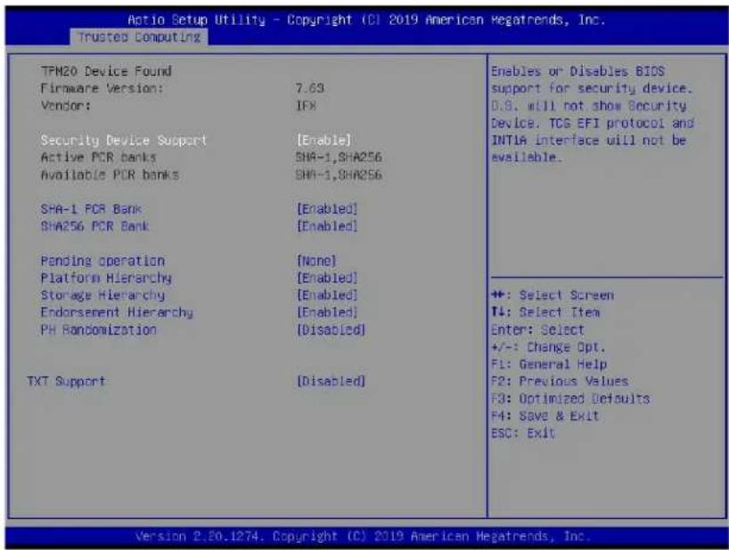
text_image
Action Setup Utility - Copyright (C) 2019 American Megatrends, Inc. Trusted Computing TPM20 Device Found Firmware Version: 7.63 Vendor: IFX Security Device Support [Enable] Active PCR banks SHA-1,SHA256 Available PCR banks SHA-1,SHA256 SHA-1 PCR Bank [Enabled] SHA256 PCR Bank [Enabled] Pending operation [None] Platform Hierarchy [Enabled] Storage Hierarchy [Enabled] Endorsement Hierarchy [Enabled] PH Randomization [Disabled] TXT Support [Disabled] Enables or Disables BIOS support for security device. D.B. will not show Security Device. TCG EFI protocol and INTLA Interface will not be available. +: Select Screen T4: Select Item Enter: Select +/-: Change Opt. F1: General Help F2: Previous Values F3: Optimized Defaults F4: Save & Exit ESC: Exit Version 2.20.1274. Copyright (C) 2019 American Megatrends, Inc.- TPM2.0 Device Found
- Firmware Version
- Vendor
Security Device Support
If this feature and the TPM jumper (JPT1) on the motherboard are both enabled, the onboard security (TPM) device will be enabled in the BIOS to enhance data integrity and system security. Please note that the OS will not show the security device. Neither TCG EFI protocol nor INT1A interaction will be made available for use. If you have made changes on the setting on this item, be sure to reboot the system for the change to take effect. The options are Disable and Enable. If this option is set to Enable, the following screen and items will display:
• Active PCR Banks
• Available PCR Banks
SHA-1 PCR Bank
Select Enabled to enable SHA-1 PCR Bank support to enhance system security and data integrity. The options are Enabled and Disabled.
SHA256 PCR Bank
Select Enabled to enable SHA256 PCR Bank support to enhance system security and data integrity. The options are Enabled and Disabled.
Pending Operation
Use this feature to schedule a TPM-related operation to be performed by a security (TPM) device at the next system boot to enhance system data integrity. Your system will reboot to carry out a pending TPM operation. The options are None and TPM Clear.

Note: Your system will reboot to carry out a pending TPM operation.
Platform Hierarchy (for TPM Version 2.0 and above)
Select Enabled for TPM Platform Hierarchy support which will allow the manufacturer to utilize the cryptographic algorithm to define a constant key or a fixed set of keys to be used for initial system boot. These early boot codes are shipped with the platform and are included in the list of "public keys". During system boot, the platform firmware uses the trusted public keys to verify a digital signature in an attempt to manage and control the security of the platform firmware used in a host system via a TPM device. The options are Enabled and Disabled.
Storage Hierarchy
Select Enabled for TPM Storage Hierarchy support that is intended to be used for non-privacy-sensitive operations by the platform owner such as an IT professional or the end user. Storage Hierarchy has an owner policy and an authorization value, both of which can be set and are held constant (-rarely changed) through reboots. This hierarchy can be cleared or changed independently of the other hierarchies. The options are Enabled and Disabled.
Endorsement Hierarchy
Select Enabled for Endorsement Hierarchy support, which contains separate controls to address the user's privacy concerns because the primary keys in this hierarchy are certified by the TPM or a manufacturer to be constrained to an authentic TPM device that is attached to an authentic platform. A primary key can be an encrypted, and a certificate can be created using TPM2_ActivateCredential. It allows the user to independently enable "flag, policy, and authorization value" without involving other hierarchies. A user with privacy concerns can disable the endorsement hierarchy while still using the storage hierarchy for TPM applications and permitting the platform software to use the TPM. The options are Enabled and Disabled.
PH (Platform Hierarchy) Randomization (for TPM Version 2.0 and above)
Select Enabled for Platform Hierarchy Randomization support, which is used only during the platform developmental stage. This feature cannot be enabled in the production platforms. The options are Disabled and Enabled.
TXT Support
Select Enabled to enable Intel Trusted Execution Technology (TXT) support to enhance system security and data integrity. The options are Disabled and Enabled.

Note 1: If the option for this item (TXT Support) is set to Enabled, be sure to disable EV DFX (Device Function On-Hide) support for the system to work properly. (EV DFX is under "IIO Configuration" in the "Chipset/North Bridge" submenu).
Note 2: For more information on TPM, please refer to the TPM manual at http://www.supermicro.com/manuals/other.
▶HTTP Boot Configuration
This feature allows the user to configure HTTP Boot settings. When you select this submenu and press
Http Boot One Time
Select Enabled for your machine to automatically boot into HpptBoot at the first system boot after you've created the Http Boot Option. The options are Enabled and Disabled. If this feature is set to Enabled, the following items will display:
Input the Description
Boot URI
▶TLS Authenticate Configuration
When this submenu is selected, the following items will be displayed:
▶Server CA Configuration
This feature allows the user to configure the client certificate that is to be used by the server.
▶Enroll Certification
This feature allows the user to enroll the certificate in the system.
▶Enroll Cert (Certification) Using File
This feature allows the user to enroll the security certificate in the system by using a file.
Cert (Certification) GUID (Global Unique Identifier)
This feature displays the GUID for this system.
▶Commit Changes and Exit
Select this feature to keep the changes you have made and exit from the system.
▶Discard Changes and Exit
Select this feature to discard the changes you have made and exit from the system.
▶Delete Certification
If this feature is set to Enable, the certificate enrolled in the system will be deleted. The options are Enable and Disable.
▶Client Certification Configuration
This feature allows the user to configure the client certificate to be used by the server.
▶Enroll Certification
This feature allows the user to enroll the certificate in the system.
▶Enroll Cert (Certification) Using File
This feature allows the user to enroll the security certificate in the system by using a file.
Cert (Certification) GUID (Global Unique Identifier)
This feature displays the GUID for this system.
▶Commit Changes and Exit
Select this feature to keep the changes you have made and exit from the system.
▶Discard Changes and Exit
Select this feature to discard the changes you have made and exit from the system.
▶Delete Certification
If this feature is set to Enable, the certificate enrolled in the system will be deleted. The options are Enable and Disable.
iSCSI Initiator Name
Use this item to enter the name of the iSCSI Initiator, which is a unique name used in the world. The name must in the IQN format.
The following submenu will be available for configuration:
▶ Add an Attempt
▶ Delete Attempts
▶Change Attempt Order
▶Driver Health
This submenu displays health status of the drivers/controllers installed in the system.
Intel® Optane® DC Persistent Memory Configuration
When you select this submenu and press
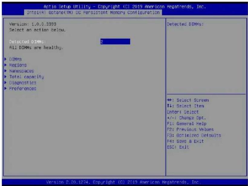
text_image
Antio Setup Utility - Copyright (CI 2019 American Megatrends, Inc. Intel(R) Octane(TM) DC Persistent Memory Configuration Version: 1.0.0.3893 Select an action below. Detected DIMMS: All DIMMs are healthy. ► DIMMs ► Regions ► Namespaces ► Total capacity ► Diagnostics ► Preferences Detected DIMMs: +: Select Screen T↓: Select Item Enter: Select +/-: Change Opt. F1: General Help F2: Previous Values F3: Optimized Defaults F4: Save & Exit ESC: Exit Version 2.20.1274. Copyright (C) 2019 American Megatrends, Inc.- Version: This feature displays the version of DCPMM used in the system.
- Select an action below
- Detected DIMMs: This feature displays the number of DCPMM memory modules detected by the BOS.
- All DIMMs are healthy (The health status of the DCPMM is displayed.)
DIMMs
This submenu allows the user to view and configure the settings of the DCPMM memory modules installed in the system. Select this submenu and press
- Select a specific DIMM that you want to view.
• DIMMs on Socket 0x0000:
• DIMMs on Socket 0x0001:
DIMM ID
This submenu allows the user to view and to perform an action on a DCPMM module specified by the user. When this submenu is selected, the following items will display:
- DIMM UID: This feature displays the unique ID of the DCPMM module.
- DIMM Handle: This feature displays the unique handle that the CPU assigns to the DCPMM module.
- DIMM Physical ID: This feature displays the physical ID of the DCPMM module.
- Manageability State: This feature indicates the manageability state of the DCPMM module.
• Health State: This feature indicates the health state of the DCPMM module. - Health State Reason: This feature indicates the reason that effectuates the health state of the DCPMM module.
- Capacity: This feature indicates the capacity of the DCPMM module.
- Firmware Version: This feature indicates the firmware version of the DCPMM module.
- Firmware API Version: This feature indicates the firmware API version of the DCPMM module.
- Lock State: This feature indicates the lock state of the DCPMM module.
- Staged Firmware Version: This feature indicates the staged firmware version of the DCPMM module.
- Firmware Update Status: This feature indicates the firmware update status of the DCPMM module.
- Manufacturer: This feature indicates the manufacturer of the DCPMM module.
Show More Details
Select Enabled to view more detailed information on the DCPMM module. The options are Disabled and Enabled.
*If this option is set to Enabled, the following items will display:
- Serial Number
- Part Number
- Socket
• Memory Controller ID - Vendor ID
- Device ID
- System Vendor ID
- Subsystem Vendor ID
-
Subsystem Device ID
-
Device Locator
- Subsystem Revision ID
• Interface Format Code
• Manufacturing Information Valid
• Manufacturing Date
• Manufacturing Location - Memory Type
• Memory Bank Label
• Data Width Label [b] - Total Width [b]
- Speed [MHz]
- Channel ID
- Channel Position
- Revision ID
- Form Factor
- Manufacturer ID
• Controller Revision ID - IS New
- Memory Capacity
- APP Direct Capacity
• Unconfigured Capacity - Inaccessible Capacity
- Reserved Capacity
• Peak Power Budget [mW]
• Avg (Average) Power Budget [mW]
• Max Average Power Budget [mW]
• Package Sparing Capable
• Package Sparing Enabled
• Package Spares Available
- Configuration Status
- SKU Violation
- ARS Status
• Overwrite DIMM Status
- Last Shutdown Time
- First Fast Refresh
- Viral Policy Enable
- Viral State
- Latched Last Shutdown Status
- Unlatched Last Shutdown Status
• Security Capabilities
- Modes Supported
- Boot Status
- AIT DRAM Enabled
- Error Injection Enabled
• Media Temperature Injection Enabled
- Software Triggers Enabled
- Software Triggers Enabled Details
• Poison Error Injections Counter
• Poison Error Clear Counter
• Media Temperature Injections Counter
- Software Triggers Counter
• Master Passphrase Enabled
▶Monitor Health
Select this submenu to view the health status and thresholds of the DCPMM module specified by the user.
- Sensor Type: This feature displays the type of health items that are being monitored.
- Value: This feature displays the value of the monitor sensor mentioned above.
- Non-critical Thresholds: This feature displays the normal threshold value for the DCPMM module to maintain normal operations.
- Critical Lower Threshold: This feature displays the lowest threshold value for the DCPMM module to maintain normal operations.
- Critical Upper Threshold: This feature displays the higher threshold value for the DCPMM module to maintain normal operations.
- Fatal Threshold: This feature indicates the highest value allowed for the DCPMM module to remain functional. Beyond this value, the DCPMM selected will become non-operational.
• State: This feature indicates the health state of the DCPMM module. - Alarm Enabled State: This feature indicates the status of the non-critical threshold alarm for the DCPMM module specified by the user.
- Modify Non-critical Thresholds: Use this feature to modify non-critical thresholds.
- Controller Temperature: This feature displays the controller temperature in Celsius.
• Media Temperature: This feature displays the media temperature in Celsius.
• Percentage Remaining
▶Apply Changes
Use this feature to apply changes that you've made on the DCPMM modules to the system.
▶Back to Main Menu
Select this feature and press
▶Update Firmware
Use this feature to select the firmware image to be loaded on the DCPMM module. Once it is loaded to the system, please reboot the system and select update for the firmware to take effect. The following items will display:
- Current Firmware Version: This feature displays the current firmware version.
- Selected Firmware Version: This feature allows the user to select a new firmware version to use.
- File: This feature allows the user to specify the file path in the root directory that contains the new firmware for firmware update.
- Staged Firmware Version: This feature indicates the staged firmware version of the DCPMM module specified by the user.
▶Update
Select this feature to update the firmware settings.
▶Back to Main Menu
Select this feature and press
▶Configure Security
Use this feature to configure the security settings for all onboard DCPMM modules.
State
Select Enabled to configure the security settings for the DCPMM modules installed in the system. The options are Disabled and Enabled.
- Enable Security: Use this feature to enable security settings for the onboard DCPMM modules.
- Secure Erase: Use this feature to erase all the persistent data saved in the DCPMM modules.
- Freeze Lock: Use this feature to enable the security lock for the onboard DCPMM modules.
▶Back to Main Menu
- Select this feature and press
▶Configure Data Policy
Use this feature to configure the data policy settings for all onboard DCPMM modules.
First Fast Fresh State
Select Enabled to display the First Fast Fresh state for onboard DCPMM modules.
▶Enable First Fast Fresh State
Select Enabled to support the first fast fresh state of DCPMM data policy.
▶Disable First Fast Fresh State
Select Disable to disable the first fast fresh state of DCPMM data policy.
▶Back to Main Menu
Select this feature and press
▶Regions
Current Configuration
▶Region ID
When this submenu is selected, the following items will display:
- Region ID: This feature displays the Region ID of the DCPMM module.
- DIMM ID: This feature displays the DIMM ID of the DCPMM module.
- ISet ID: This feature displays the ISet ID of the DCPMM module.
- Persistent Memory Type: This feature indicates the persistent memory type of the DCPMM module.
- Capacity: This feature indicates the capacity of the DCPMM module.
- Free Capacity: This feature indicates the capacity of the DCPMM module that is available for use.
• Health: This feature indicates the health state of the DCPMM module. - Socket ID: This feature displays the Socket ID of the DCPMM module.
Persistent Memory Type
Capacity
Free Capacity
▶Create Goal Configuration
When this submenu is selected, the following items will display:
- Create Goal Configuration for: Use this feature to select the target to create goal configuration for the DCPMM modules. The options are Platform and Socket.
- Reserved [%]: Use this feature to reserve a percentage of the DCPMM capacity for a particular purpose and keep this portion of memory space from being mapped into the physical address of system for system use.
- Memory Mode [%]: Use this feature to reserve a percentage of the DCPMM capacity for special use in a specific Memory Mode. Please note that this value can be automatically set by the system.
Persistent Memory Type
This feature allows the user to specify the type of DCPMM memory capacity to be created.
The options are App Direct and App Direct Not Interleave.
Namespace Label Version
Use this feature to view and modify the namespace label version to initialize when creating goals. The options are 1.2 and 1.1.
▶Back to Regions Menu
Select this feature and press
▶Back to Main Menu
Select this feature and press
▶Namespaces
This subsection allows the user to select a namespace to view the following information on the selected namespace
Namespace ID/Name/Heath Status
▶0x00000101/0x00000201/0x00000301
Select this feature and press
- UUID
• ID - Name
- Region
- Health
- Mode
- Block Size
- Units: Use this feature to change the namespace capacity (in the unit of B, MB, MiB, GB, GiB, TB, and TiB.)
- Capacity
- Label Version
▶Save: After configuring the settings for the namespace above, click on
▶Delete After configuring the settings for the namespace above, click on
▶Back to Namespaces
▶Back to Main Menu
▶Create Namespace
Use this submenu to create a namespace. The following information will display:
Name
Region ID
This feature displays the region ID of the DCPMM module. The options are 0x0001 and 0x0002.
Mode
Use this item to set the Namespace mode. The options are None and Sector.
Capacity Input
Select Remaining to use the maximum memory capacity currently available as system memory capacity. Select Manual to enter the system memory capacity manually. The options are Remaining and Manual.
Units
Use this feature to select the type of unit to use when inputting namespace capacity in the system.
The options are B, MB, MiB, GB, GiB, TB, and TiB.
- Capacity: This feature displays the namespace capacity.
▶Back to Namespace
Select this feature and press
▶Back to Main Menu
Select this feature and press
▶Total Capacity
This feature allows the user to set the total DCPMM resource capacity allocated across all segments in the host server.
- Raw Capacity: This feature specifies the raw capacity of the DCPMM module.
- App. Direct Capacity: This feature specifies the App. direct capacity of the DCPMM module.
- Memory Capacity: This feature specifies the memory capacity of the DCPMM module.
- Unconfigured Capacity: This feature specifies the capacity of the DCPMM module that has not been configured.
- Inaccessible Capacity: This feature specifies the capacity of the DCPMM memory that is not accessible to the user.
- Reserved Capacity: This feature specifies the capacity of the DCPMM memory that is reserved for a particular use.
▶Back to Main Menu
Select this feature and press
▶ Diagnostics
Perform Diagnostic Tests on DIMMs
When you select this submenu and press
Choose Diagnostics Type:
Quick Diagnostics
Select Enabled for the quick diagnostics test to be performed on the DCPMM module installed in the system when needed. The options are Enabled and Disabled.
DIMM ID 0x0101/DIMM ID 0x0111/DIMM ID 0x0121D
Select Enabled for the quick diagnostics test to be performed on the DCPMM module. The options are Enabled and Disabled. (Note: More DIMM IDs will appear If more DCPMM modules are installed on the motherboard.)
Config (Configure) Diagnostics
Select Enabled for the platform configuration diagnostics test to be performed on the DCPMM module. The options are Enabled and Disabled.
FW (Firmware) Diagnostics
Select Enabled for the firmware diagnostics test to be performed on the DCPMM module. The options are Enabled and Disabled.
Security Diagnostics
Select Enabled for the security diagnostics test to be performed on the DCPMM module. The options are Enabled and Disabled.
▶ Execute Tests
Select this feature and press
- TestName
- State
- Message
▶Back to Main Menu
Select this feature and press
▶Preferences
View and/or modify user preferences
Default DIMM ID
This feature allows the user to view and to modify the default DIMM ID as displayed on the screen. The options are Handle and UID.
Capacity Units
This feature allows the user to view and to set the default capacity unit of the selected DCPMM to be displayed on the screen. The options are Auto, Auto_10, B, MB, MiB, GB, GiB, TB, and TiB.
App Direct Settings
This feature displays the Application Direct Settings. The default setting is 4KB_4KB (Recommended).
App Direct Granularity
This feature allows the user to view and modify the minimum App Direct Granularity for each DIMM installed on the motherboard. The default setting is Recommended and 1.
▶Back to Main Menu
Use this feature to go back to the Intel® Optane® DC Persistent Memory Configuration menu.
4.4 Event Logs
Use this feature to configure Event Log settings.

Note: After you've made a change on a setting below, please be sure to reboot the system for the change to take effect.
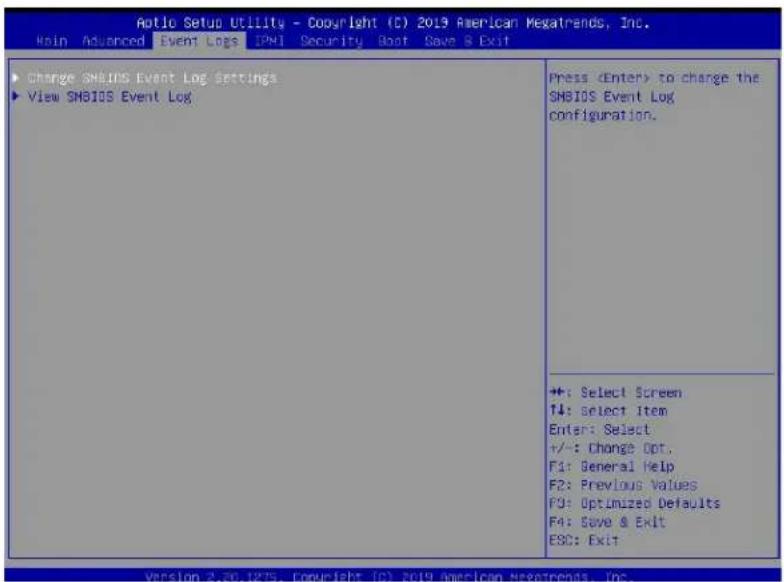
text_image
Aptio Setup Utility - Copyright (C) 2019 American Mesatrends, Inc. Main Advanced Event Logs IPMI Security Boot Save & Exit Change SMBIOS Event Log Settings View SMBIOS Event Log Press▶Change SMBIOS Event Log Settings
Enabling/Disabling Options
SMBIOS Event Log
Select Enabled to enable SMBIOS (System Management BIOS) Event Logging during system boot. The options are Enabled and Disabled.
Erasing Settings
Erase Event Log
Select "No" to keep the event log without erasing it upon next system bootup. Select "Yes, Next Reset" to erase the event log upon next system reboot. The options are "No", "Yes, Next Reset", and "Yes, Every Reset".
When Log is Full
Select Erase Immediately to immediately erase all errors in the SMBIOS event log when the event log is full. Select Do Nothing for the system to do nothing when the SMBIOS event log is full. The options are Do Nothing and Erase Immediately.
SMBIOS Event Log Standard Settings
Log System Boot Event
Select Enabled to log system boot events. The options are Enabled and Disabled.
MECI (Multiple Event Count Increment)
Enter the increment value for the multiple event counter. Enter a number between 1 to 255. The default setting is 1.
METW (Multiple Event Count Time Window)
This feature is used to determine how long (in minutes) should the multiple event counter wait before generating a new event log. Enter a number between 0 to 99. The default setting is 60.
▶View System Event Log
This feature allows the user to view the event in the system event log. Select this item and press
4.5 IPMI
Use this feature to configure Intelligent Platform Management Interface (IPMI) settings.
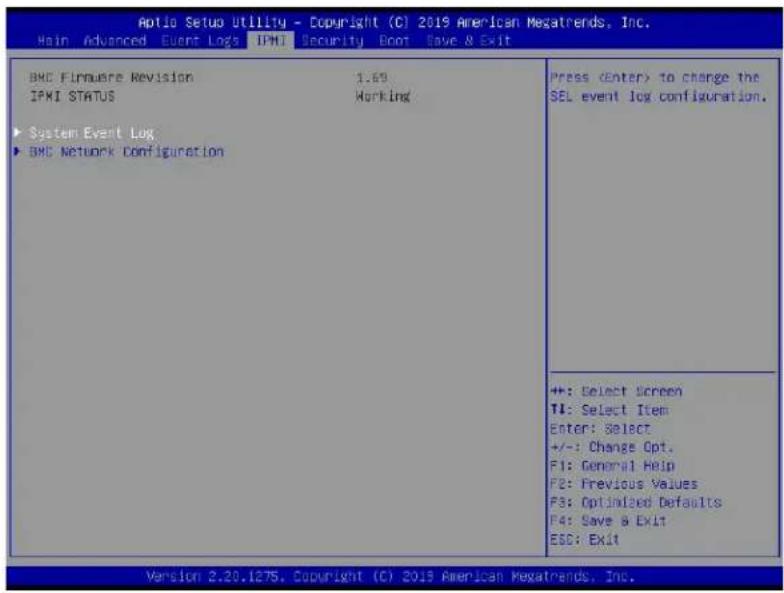
text_image
Aptio Setup Utility - Copyright (C) 2019 American Megatrends, Inc. Hain Advanced Event Logs IPMI Security Boot Save & Exit BMC Firmware Revision 1.69 IPMI STATUS Working ► System Event Log ► BMC Network Configuration PressWhen you select this submenu and press the
- BMC Firmware Revision: This feature indicates the BMC firmware revision used in your system.
- IPMI Status: This feature indicates the status of the IPMI (Intelligent Platform Management Interface) installed in your system.
▶System Event Log
Enabling/Disabling Options
SEL Components
Select Enabled to enable all system event logging upon system boot. The options are Enabled and Disabled.
Erasing Settings
Erase SEL
Select "Yes, On next reset" to erase all system event logs upon next system boot. Select "Yes, On every reset" to erase all system event logs upon each system reboot. Select "No" to keep all system event logs after each system reboot. The options are "No", "Yes, On next reset", and "Yes, On every reset".
When SEL is Full
This feature allows the user to determine what the BIOS should do when the system event log is full. Select Erase Immediately to erase all events in the log when the system event log is full. The options are Do Nothing and Erase Immediately.
▶BMC Network Configuration
The following items will be displayed:
Configure IPv4 Support
- IPMI LAN Selection: This feature displays the IPMI LAN setting. The default setting is Failover.
- IPMI Network Link Status: This feature displays the IPMI Network Link status. The default setting is Dedicated LAN.
- Configuration Address Source: Use this feature to select the IP address source for this computer. If Static is selected, you will need to know the IP address of this computer and enter it to the system manually in the field. If DHCP is selected, AMI BIOS will search for a DHCP (Dynamic Host Configuration Protocol) server attached to the network and request the next available IP address for this computer. The options are DHCP and Static.
- Station IP Address: This feature displays the Station IP address for this computer. This should be in decimal and in dotted quad form (i.e., 172.31.41.69).
- Subnet Mask: This feature displays the sub-network that this computer belongs to. The value of each three-digit number separated by dots should not exceed 255.
- Station MAC Address: This feature displays the Station MAC address for this computer. Mac addresses are 6 two-digit hexadecimal numbers.
- Gateway IP Address: This feature displays the Gateway IP address for this computer. This should be in decimal and in dotted quad form (i.e., 172.31.0.1).
- VLAN: This feature displays the status of VLAN support. The default setting is Disable.
Configure IPv6 Support
- IPv6 Address Status: This feature displays the IPv6 address status. The default setting is Disabled.
-
IPv6 Support: The default setting is Enabled.
-
Configuration Address Source: Use this feature to select the IP address source for this computer. If Static is selected, you will need to know the IP address of this computer and enter it to the system manually in the field. If DHCP is selected, AMI BIOS will search for a DHCP (Dynamic Host Configuration Protocol) server attached to the network and request the next available IP address for this computer. The options are DHCP and Static.
- Station IPv6 Address: This feature displays the station IPv6 address.
- Prefix Length: This item displays the prefix length.
- IPv6 Router IP Address: This feature displays the IPv6 router IP address.
4.6 Security Settings
This menu allows the user to configure the following security settings for the system.
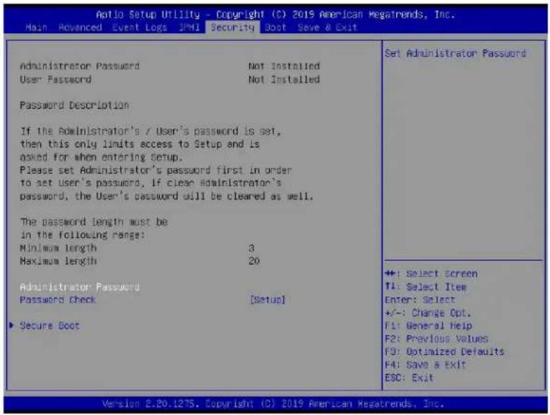
text_image
Antio Setup Utility - Copyright (C) 2019 American Megatrends, Inc. Main Advanced Event Logs JPMI Security Boot Save & Exit Administrator Password Not Installed User Password Not Installed Password Description If the Administrator's / User's password is set, then this only limits access to Setup and is asked for when entering Setup. Please set Administrator's password first in order to set User's password, if clear Administrator's password, the User's password will be cleared as well. The password length must be in the following range: Minimum length 3 Maximum length 20 Administrator Password Password Check [Setup] ▶ Secure Boot Set Administrator Password ++: Select screen TI: Select Item Enter: Select +/-: Change Opt. F1: General Help F2: Previous Values F3: Optimized Defaults F4: Save & EXIT ESC: Exit Version 2.20.1275. Copyright (C) 2019 American Megatrends, Inc.Administrator Password
Use this feature to set the administrator password which is required to enter the BIOS setup utility. The length of the password should be from 3 characters to 20 characters long.
User Password
Use this feature to set the user password which is required to enter the BIOS setup utility. The length of the password should be from 3 characters to 20 characters long.
Password Check
Select Setup for the system to check for a password at Setup. Select Always for the system to check for a password at system boot and upon entering the BIOS Setup utility. The options are Setup and Always.
▶Secure Boot
When you select this submenu and press the
- System Mode
Secure Boot
Select Enabled to use Secure Boot settings. The options are Enabled and Disabled.
Secure Boot Mode
Use this feature to select the desired secure boot mode for the system. The options are Standard and Custom.
CMS Support
If this feature is set to Enabled, legacy devices will be supported by the system. The options are Enabled and Disabled.
Select Yes to restore manufacturer default keys used to ensure system security. The options are Yes and No.
▶Reset to Setup Mode
Select Yes to reset the system to the Setup Mode. The options are Yes and No.
▶Key Management
Vendor Keys
Factory Key Provision
Select Yes to install manufacturer default keys for system security use. The options are Enabled and Disabled.
Select Yes to restore all manufacturer default keys for system security use. The options are Yes and No.
▶Reset to Setup Mode
This feature resets the system to Setup Mode.
▶Export Secure Boot Variables
This feature is used to copy the NVRAM content of Secure Boot variables to a storage device.
▶Enroll EFI Image
Select this feature and press
Device Guard Ready
▶Remove 'UEFI CA' from DB
Select Yes to remove UEFI CA from the database. The options are Yes and No.
Select Yes to restore database variables to the manufacturer default settings. The options are Yes and No.
Secure Boot Variable/Size/Keys/Key Source
▶Platform Key (PK)
This feature allows the user to enter and configure a set of values to be used as platform firmware keys for the system. The sizes, keys numbers, and key sources of the platform keys will be indicated as well. Select Update to update the platform key.
▶Key Exchange Keys
This feature allows the user to enter and configure a set of values to be used as Key-Exchange-Keys for the system. The sizes, keys numbers, and key sources of the Key-Exchange-Keys will be indicated as well. Select Update to update your "Key Exchange Keys". Select Append to append your "Key Exchange Keys".
▶Authorized Signatures
This feature allows the user to enter and configure a set of values to be used as Authorized Signatures for the system. These values also indicate the sizes, keys numbers, and the sources of the authorized signatures. Select Update to update your "Authorized Signatures". Select Append to append your "Authorized Signatures". The settings are Update and Append.
▶Forbidden Signatures
This feature allows the user to enter and configure a set of values to be used as Forbidden Signatures for the system. These values also indicate sizes, keys numbers, and key sources
of the forbidden signatures. Select Update to update your "Forbidden Signatures". Select Append to append your "Forbidden Signatures". The settings are Update and Append.
▶Authorized TimeStamps
This feature allows the user to set and save the timestamps for the authorized signatures which will indicate the time when these signatures are entered into the system. Select Update to update your "Authorized TimeStamps". Select Append to append your "Authorized TimeStamps". The settings are Update, and Append.
▶Os Recovery Signatures
This feature allows the user to set and save the authorized signatures used for OS recovery. Select Update to update your "OS Recovery Signatures". Select Append to append your "OS Recovery Signatures". The settings are Update, and Append.
4.7 Boot Settings
Use this feature to configure Boot Settings:
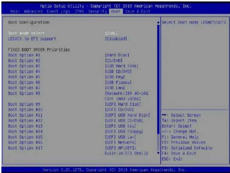
text_image
Aptio Setup Utility - Copyright (C) 2019 American Megatrends, Inc. Main Advanced Event Logs IPNI Security Boot Save & Exit Boot Configuration Boot mode select [BUAL] LEGACY to EFI support [Disabled] FIXED BOOT ORDER Priorities Boot Option #1 [Hard Disk] Boot Option #2 [CD/DVD] Boot Option #3 [USB Hard Disk] Boot Option #4 [USB CD/DVD] Boot Option #5 [USB Key] Boot Option #6 [USB Floppy] Boot Option #7 [USB Lan] Boot Option #8 [Network: IBA 40-10G Slot 1000 v1066] Boot Option #9 [UEFI Hard Disk] Boot Option #10 [UEFI CD/DVD] Boot Option #11 [UEFI USB Hard Disk] Boot Option #12 [UEFI USB CD/DVD] Boot Option #13 [UEFI USB Key] Boot Option #14 [UEFI USB Floppy] Boot Option #15 [UEFI USB Lan] Boot Option #16 [UEFI Network] Boot Option #17 [UEFI AP-UEFI: Built-in EFI Shell] Select boot node LEGACY/UEFI ++: Select Screen T4: Select Item Enter: Select +/-: Change Opt. F1: General Help F2: Previous Values F3: Optimized Defaults F4: Save & Exit ESC: Exit Version 2.20.L275. Copyright (C) 2019 American Megatrends, Inc.Boot Mode Select
Use this feature to select the type of devices from which the system will boot. The options are Legacy, UEFI (Unified Extensible Firmware Interface), and Dual.
Legacy to EFI Support
Select Enabled for the system to boot from an EFI OS when the Legacy OS fails. The options are Enabled and Disabled.
Fixed Boot Order Priorities
This feature prioritizes the order of a bootable device from which the system will boot. Press
When the item above - "Boot Mode Select" is set to Dual (default), the following items will be displayed for user's configuration:
- Boot Option #1 - Boot Option #17
When the item above - "Boot Mode Select" is set to Legacy, the following items will be displayed for configuration:
• Boot Option #1 - Boot Option #8
When the item above - "Boot Mode Select" is set to UEFI, the following items will be displayed for configuration:
- Boot Option #1 - Boot Option #9
Add New Boot Option
This feature allows the user to add a new boot option to the boot priority features for system boot.
Add Boot Option
Use this item to specify the name for the new boot option.
Path for Boot Option
Use this feature to enter the path for the new boot option in the format fsx:\path\filename.efi.
Boot Option File Path
Use this feature to specify the file path for the new boot option.
Create
After the name and the file path for the boot option are set, press
▶ Delete Boot Option
Use this feature to select a boot device to delete from the boot priority list.
Delete Boot Option
Use this feature to remove an EFI boot option from the boot priority list.
▶ Add New Driver Option
Use this feature to select a new driver to add to the boot priority list.
Add Driver Option
Use this feature to specify the name of the driver to be added to the boot priority list.
Path for Drover Option
Use this feature to specify the path to the driver that will be added to the boot priority list.
Driver Option File Path
Use this feature to specify the file path of the driver that will be added to the boot priority list.
Create
After the driver option name and the file path are set, press
▶ Delete Driver Option
Use this item to select a boot driver to delete from the boot priority list.
Delete Drive Option
Select the target boot driver to delete from the boot priority list.
▶UEFI Application Boot Priorities
- Boot Option #1
4.8 Save & Exit
Select the Save & Exit menu from the BIOS setup screen to configure the settings below.
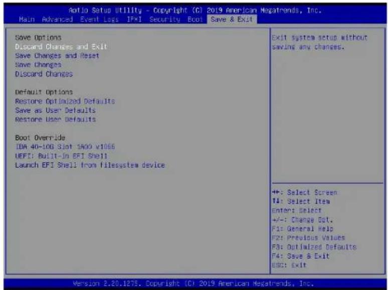
text_image
Aotio Setup Utility - Copyright (C) 2019 American Megatrends, Inc. Main Advanced Event Loss IPWI Security Boot Save & Exit Save Options Discard Changes and Exit Save Changes and Reset Save Changes Discard Changes Default Options Restore Optimized Defaults Save as User Defaults Restore User Defaults Boot Override IDA 40-108 Slot 1A00 v1066 UEFI: Built-In EFI Shell Launch EFI Shell from filesystem device Exit system setup without saving any changes. ++: Select Screen T4: Select Item Enter: Select +/-: Change Opt. F1: General Help F2: Previous Values F3: Optimized Defaults F4: Save & Exit ESC: Exit Version 2.20.1275. Copyright (C) 2019 American Megatrends, Inc.Save Options
Discard Changes and Exit
Select this option to exit from the BIOS setup utility without making any permanent changes to the system configuration and reboot the computer.
Save Changes and Reset
When you have completed the system configuration changes, select this option to leave the BIOS setup utility and reboot the computer for the new system configuration parameters to become effective.
Save Changes
When you have completed the system configuration changes, select this option to save all changes made. This will not reset (reboot) the system.
Discard Changes
Select this option and press
Default Options
Restore Optimized Defaults
To set this feature, select Restore Defaults from the Exit menu and press
Save As User Defaults
To set this feature, select Save as User Defaults from the Exit menu and press
To set this feature, select Restore User Defaults from the Exit menu and press
Boot Override
This feature allows the user to override the Boot priorities sequence in the Boot menu, and immediately boot the system with a device specified by the user instead of the one specified in the boot list. This is a one-time override.
Appendix A
BIOS Codes
A.1 BIOS Error POST (Beep) Codes
Note: For BIOS beep codes to work properly, please connect an optional external speaker to the speaker/buzzer header located at JD1. Please refer to Chapter 2 for more information on JD1.
During the POST (Power-On Self-Test) process, which is performed each time the system is powered on, system errors may be detected.
Non-fatal errors are those which, in most cases, allow the system to continue with the boot-up process. The error messages normally appear on the screen.
Fatal errors are those which will not allow the system to continue with bootup. If a fatal error occurs, you should consult with your system manufacturer for possible repairs.
The fatal errors are usually communicated through repeated patterns of audible beeps. Each pattern of audible beeps listed below corresponds to its respective error.
| BIOS Beep (POST) Codes | ||
| Beep Code Error | Message Description | |
| 1 beep Refresh Circuits have been reset (Ready to power up) | ||
| 1 long continuous System Overheat System overheat | ||
| 5 short, 1 long Memory error No memory detected in system | ||
| 5 long, 2 short Display memory read/write error Video adapter missing or with faulty memory | ||
A.2 Additional BIOS POST Codes
The AMI BIOS supplies additional checkpoint codes, which are documented online at http://www.supermicro.com/support/manuals/ ("AMI BIOS POST Codes User's Guide").
When BIOS performs the Power On Self Test, it writes checkpoint codes to I/O port 0080h. If the computer cannot complete the boot process, a diagnostic card can be attached to the computer to read I/O port 0080h (Supermicro p/n AOC-LPC80-20).
For information on AMI updates, please refer to http://www.ami.com/products/.
Appendix B
Software
After the hardware has been installed, you can install the Operating System (OS), configure RAID settings and install the drivers.
B.1 Microsoft Windows OS Installation
If you will be using RAID, you must configure RAID settings before installing the Windows OS and the RAID driver. Refer to the RAID Configuration User Guides posted on our website at www.supermicro.com/support/manuals.
Installing the OS
- Create a method to access the MS Windows installation ISO file. That might be a DVD, perhaps using an external USB/SATA DVD drive, or a USB flash drive, or the IPMI KVM console.
- Retrieve the proper RST/RSTe driver. Go to the Supermicro web page for your motherboard and click on "Download the Latest Drivers and Utilities", select the proper driver, and copy it to a USB flash drive.
- Boot from a bootable device with Windows OS installation. You can see a bootable device list by pressing F11 during the system startup.
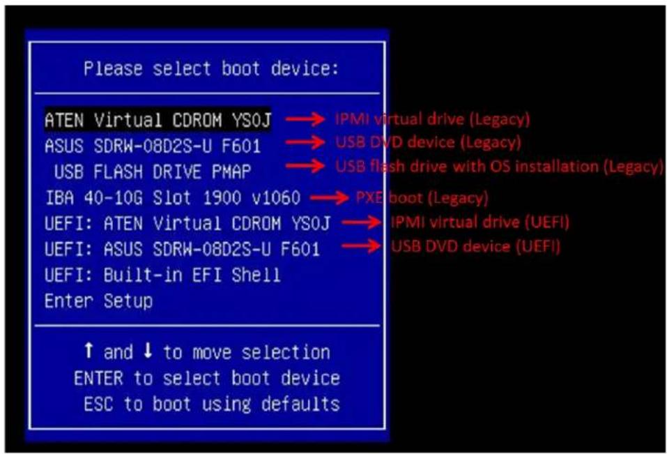
text_image
Please select boot device: ATEN Virtual CDROM YSOJ → IPMI virtual drive (Legacy) ASUS SDRW-08D2S-U F601 → USB DVD device (Legacy) USB FLASH DRIVE PMAP → USB flash drive with OS installation (Legacy) IBA 40-10G Slot 1900 v1060 → PXE boot (Legacy) UEFI: ATEN Virtual CDROM YSOJ → IPMI virtual drive (UEFI) UEFI: ASUS SDRW-08D2S-U F601 → USB DVD device (UEFI) UEFI: Built-in EFI Shell Enter Setup ↑ and ↓ to move selection ENTER to select boot device ESC to boot using defaults- During Windows Setup, continue to the dialog where you select the drives on which to install Windows. If the disk you want to use is not listed, click on "Load driver" link at the bottom left corner.
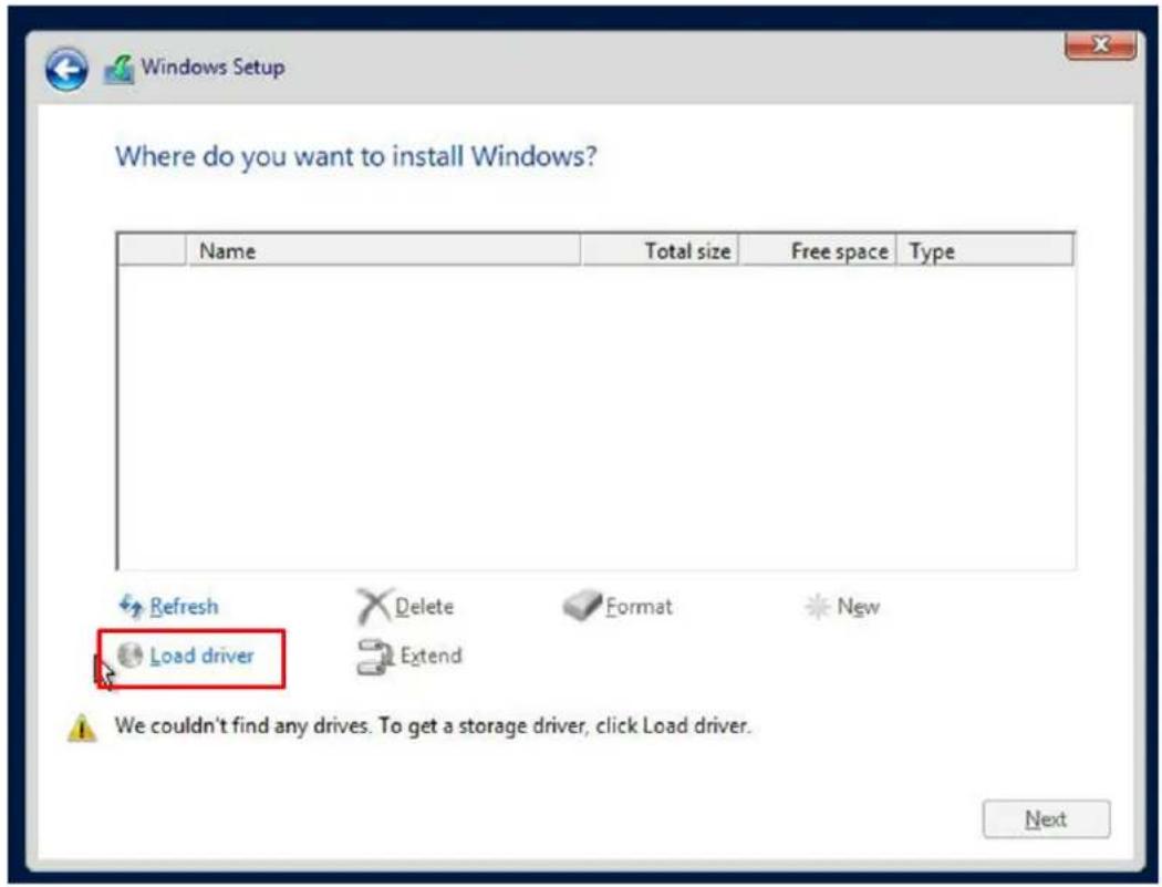
text_image
Where do you want to install Windows? Name Total size Free space Type Refresh Delete Format New Load driver Extend We couldn't find any drives. To get a storage driver, click Load driver. NextTo load the driver, browse the USB flash drive for the proper driver files.
- For RAID, choose the SATA/sSATA RAID driver indicated then choose the storage drive on which you want to install it.
-
For non-RAID, choose the SATA/sSATA AHCI driver indicated then choose the storage drive on which you want to install it.
-
Once all devices are specified, continue with the installation.
- After the Windows OS installation has completed, the system will automatically reboot multiple times.
B.2 Driver Installation
The Supermicro website contains drivers and utilities for your system at https://www.supermicro.com/wftp/driver. Some of these must be installed, such as the chipset driver.
After accessing the website, go into the CDR_Images (in the parent directory of the above link) and locate the ISO file for your motherboard. Download this file to a USB flash drive or a DVD. (You may also use a utility to extract the ISO file if preferred.)
Another option is to go to the Supermicro website at http://www.supermicro.com/products/. Find the product page for your motherboard, and "Download the Latest Drivers and Utilities".
Insert the flash drive or disk and the screenshot shown below should appear.
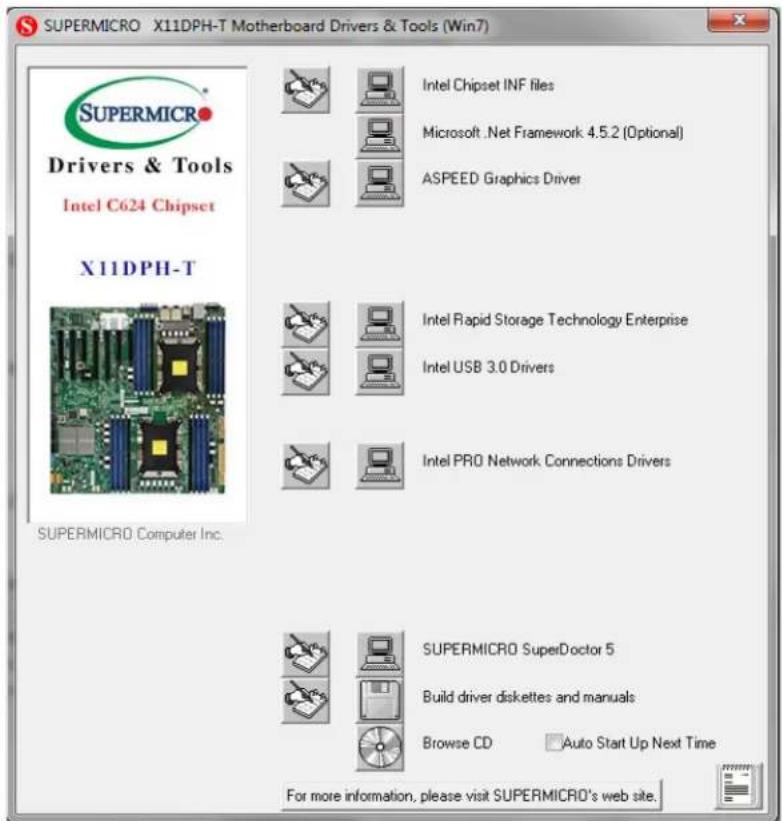
text_image
SUPERMICRO X11DPH-T Motherboard Drivers & Tools (Win7) SupersMCRO Drivers & Tools Intel C624 Chipset X11DPH-T SUPERSMICRO Computer Inc. Intel Chipset INF files Microsoft .Net Framework 4.5.2 (Optional) ASPEED Graphics Driver Intel Rapid Storage Technology Enterprise Intel USB 3.0 Drivers Intel PRO Network Connections Drivers SUPERMICRO SuperDoctor 5 Build driver diskettes and manuals Browse CD Auto Start Up Next Time For more information, please visit SUPERMICRO's web site.
Note: Click the icons showing a hand writing on paper to view the readme files for each item. Click the computer icons to the right of these items to install each item (from top to the bottom) one at a time. After installing each item, you must re-boot the system before moving on to the next item on the list. The bottom icon with a CD on it allows you to view the entire contents.
B.3 SuperDoctor® 5
The Supermicro SuperDoctor 5 is a program that functions in a command-line or web-based interface for Windows and Linux operating systems. The program monitors such system health information as CPU temperature, system voltages, system power consumption, fan speed, and provides alerts via email or Simple Network Management Protocol (SNMP).
SuperDoctor 5 comes in local and remote management versions and can be used with Nagios to maximize your system monitoring needs. With SuperDoctor 5 Management Server (SSM Server), you can remotely control power on/off and reset chassis intrusion for multiple systems with SuperDoctor 5 or IPMI. SuperDoctor 5 Management Server monitors HTTP, FTP, and SMTP services to optimize the efficiency of your operation.

Note: The default User Name and Password for SuperDoctor 5 is ADMIN / ADMIN.
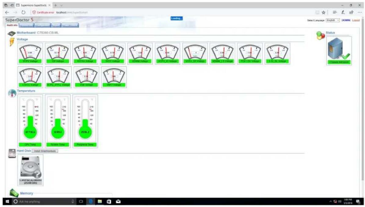
text_image
SuperMicro SuperDocks Certificate error localhost:144/SuperDocks SuperDoctor 5 Health My Connection Connection Connection Motherboard: C78360-CB.ML Voltage Temperature Hard Disk Memory Select Language English ASCII Layout Status Growing Attention CPU Time CPU_TIME CPU_TIME CPU_TIME CPU_TIME CPU_TIME CPU_TIME CPU_TIME CPU_TIME CPU_TIME CPU_TIME CPU_TIME CPU_TIME CPU_TIME CPU_TIME CPU_TIME CPU_TIME CPU_TIME CPU_TIME CPU_TIME CPU_TIME CPU_TIME CPU_TIME CPU_TIME CPU_TIME CPU_TIME CPU_TINE CPU_TINE CPU_TINE CPU_TINE CPU_TINE CPU_TINE CPU_TINE CPU_TINE CPU_TINE CPU_TINE CPU_TINE CPU_TINE CPU_TINE CPU_TINE CPU_TINE CPU_TINE CPU_TINE CPU_TINE CPU_TINE CPU_TINE CPU_TINE CPU_TINE CPU_TINE CPU_TINE CPU_TINE CPU_TINCE CPU_TINCE CPU_TINCE CPU_TINCE CPU_TINCE CPU_TINCE CPU_TINCE CPU_TINCE CPU_TINCE CPU_TINCE CPU_TINCE CPU_TINCE CPU_TINCE CPU_TINCE CPU_TINCE CPU_TINCE CPU_TINCE CPU_TINCE CPU_TINCE CPU_TINCE CPU_TINCA CPU_TINCA CPU_TINCA CPU_TINCA CPU_TINCA CPU_TINCA CPU_TINCA CPU_TINCA CPU_TINCA CPU_TINCA CPU_TINCA CPU_TINCA CPU_TINCA CPU_TINCA CPU_TINCA CPU_TINCA CPU_TINCA CPU_TINCA CPU_TINCA CPU_TINCA CPU_TINCE CPU_TINCE CPU_TINCE CPU_TINCE CPU_TINCE CPU_TINCE CPU_TINCE CPU_TINCE CPU_TINCE CPU_TINCE CPU_TINCE CPU_TINCE CPU_TINCE CPU_TINCE CPU_TINCE CPU_TINCE CPU_TINCE CPU_TINCE CPU_TINCE CPU_TINC1A1A1A1A1A1A1A1A1A1A1A1A1A1A1A1A1A1A1A1A1A1A1A1A1A1A1A1A1A1A1A1A1A1A1A1A1A1A1A1A1A1A1A1A1A1A1A1A1A1A1C20000000000000000000000000000000000000000000000000000000000000000000000000000000000000000000000000000B.4 IPMI
This motherboard supports the Intelligent Platform Management Interface (IPMI). IPMI is used to provide remote access, monitoring and management. There are several BIOS settings that are related to IPMI.
For general documentation and information on IPMI, please visit our website at: http://www.supermicro.com/products/nfo/IPMI.cfm.
B.5 Logging into the BMC (Baseboard Management Controller)
Supermicro ships standard products with a unique password for the BMC user. This password can be found on a label on the motherboard.
When logging in to the BMC for the first time, please use the unique password provided by Supermicro to log in. You can change the unique password to a user name and password of your choice for subsequent logins.
For more information regarding BMC passwords, please visit our website at http://www.supermicro.com/bmcpassword.
Appendix C
Standardized Warning Statements
The following statements are industry standard warnings, provided to warn the user of situations where bodily injury might occur. Should you have questions or experience difficulty, contact Supermicro's Technical Support department for assistance. Only certified technicians should attempt to install or configure components.
Read this section in its entirety before installing or configuring components.
These warnings may also be found on our website at http://www.supermicro.com/about/policies/safety_information.cfm.
Battery Handling

Warning! There is the danger of explosion if the battery is replaced incorrectly. Replace the battery only with the same or equivalent type recommended by the manufacturer. Dispose of used batteries according to the manufacturer's instructions
電池の取り扱い
Warning! Ultimate disposal of this product should be handled according to all national laws and regulations.
製品の廃棄
Warning: Do not upgrade the BIOS unless your system has a BIOS-related issue. Flashing the wrong BIOS can cause irreparable damage to the system. In no event shall Supermicro be liable for direct, indirect, special, incidental, or consequential damages arising from a BIOS update. If you need to update the BIOS, do not shut down or reset the system while the BIOS is updating to avoid possible boot failure.
D.1 Overview
The Unified Extensible Firmware Interface (UEFI) provides a software-based interface between the operating system and the platform firmware in the pre-boot environment. The UEFI specification supports an architecture-independent mechanism that will allow the UEFI OS loader stored in an external storage device to boot the system. The UEFI offers clean, hands-off management to a computer during system boot.
D.2 Recovering the UEFI BIOS Image
A UEFI BIOS flash chip consists of a recovery BIOS block and a main BIOS block (a main BIOS image). The recovery block contains critical BIOS codes, including memory detection and recovery codes for the user to flash a healthy BIOS image if the original main BIOS image is corrupted. When the system power is turned on, the recovery block codes execute first. Once this process is complete, the main BIOS code will continue with system initialization and the remaining POST (Power-On Self-Test) routines.

Note 1: Follow the BIOS recovery instructions in Section D.3 for BIOS recovery when the main BIOS block crashes.
Note 2: If the recovery instructions in Section D.3 for BIOS recovery fail, you may use the Supermicro Update Manager (SUM) Out-of-Band (OOB) (https://www.supermicro.com.tw/products/nfo/SMS_SUM.cfm) to reflash the BIOS.
Note 3: If the recovery block processes stated in Note 1 and Note 2 above fail, you will need to follow the procedures to make a Returned Merchandise Authorization (RMA) request. Refer to Section 3.5 for more information about the RMA request.
D.3 Recovering the Main BIOS Block with a USB Device
This feature allows the user to recover the main BIOS image using a USB-attached device without additional utilities used. A USB flash device such as a USB Flash Drive, or a USB CD/DVD ROM/RW device can be used for this purpose. However, a USB hard disk drive cannot be used for BIOS recovery at this time. The file system supported by the recovery block is FAT (including FAT12, FAT16, and FAT32) which is installed on a bootable or non-bootable USB-attached device.
To perform UEFI BIOS recovery using a USB-attached device, follow the instructions below.
- Please use a different machine to download the BIOS package for your motherboard or your system from the product page available on our website at www.supermicro.com.
- Extract the BIOS package to a USB device and rename the BIOS ROM file [BIOSname#.###] that is included in the BIOS package to SUPER.ROM for BIOS recovery use.
- Copy the SUPER.ROM file into the Root "\" directory of the USB device.
Note: Before recovering the main BIOS image, confirm that the SUPER.ROM file you have is the same version or a close version meant for your motherboard.
- Insert the USB device that contains the SUPER.ROM file into the system before you power on the system or when the following screen appears.
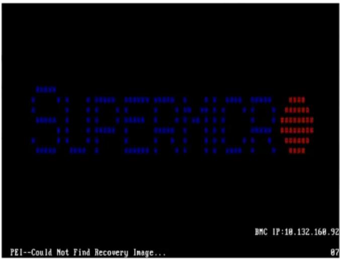
text_image
PEI-- BMC IP:10.132.160.92 PEI--Could Not Find Recovery Image... 87- After locating the SUPER.ROM file, the system will enter the BIOS Recovery menu as shown below.
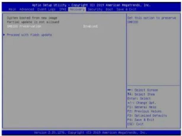
text_image
Option Setup Utility - Copyright (C) 2019 American Megatrends, Inc. Main Advanced Event Loss IPM Recovery Security Back Save a Exit System booted from new image Partial update is not allowed Update Preservation [Unloaded] ▶ Processed with Flash update Set this option to preserve OneIOS +:- Select Screen II: Select Item Enter Select +/-: Change Opt. P1: General Help P2: Previous Values P3: Optimized Defaults P4: Save & Exit ESC: Exit Version 2.20.1276. Copyright (C) 2019 American Megatrends, Inc.Note: At this point, you may decide if you want to start the BIOS recovery. If you decide to proceed with BIOS recovery, follow the procedures below.
- When the screen as shown above displays, use the arrow keys to select the item "Proceed with flash update" and press the
key. You will see the BIOS recovery progress as shown in the screen below.
Note: Do not interrupt the BIOS flashing process until it is complete.
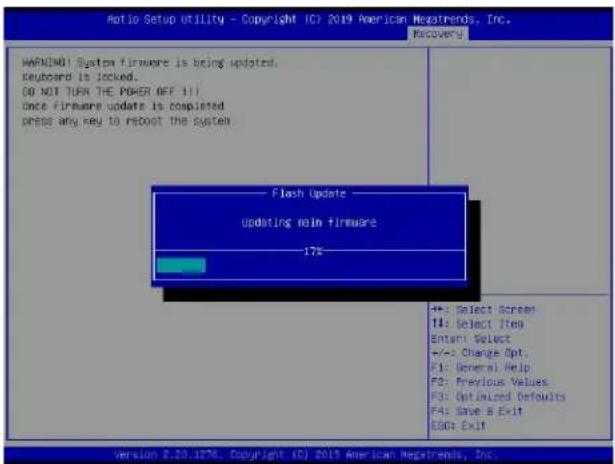
text_image
Ratio Setup Utility - Copyright (C) 2019 American MegaTrends, Inc. Recovery WARNING System firmware is being updated. Keyboard is locked. DO NOT TURN THE POWER OFF 11 Once firmware update is completed press any key to reboot the system Flash Update updating main firmware 17% +: Select Screen T4: Select Item Enter: Select +/-: Change Opt. F1: General Help F2: Previous Values F3: Optimized Defaults F4: Save & Exit E00: Exit Version 8.20.1876. Copyright (C) 2019 American MegaTrends, Inc.- After the BIOS recovery process is complete, press any key to reboot the system.
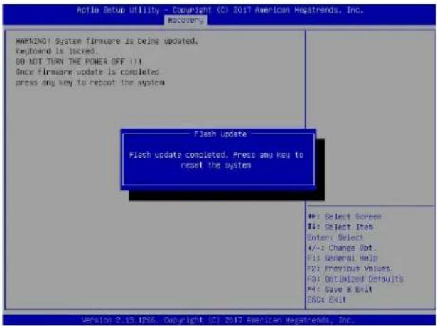
text_image
Active Setup Utility - Copyright (CI 2017 American Regatrends, Inc. Recovery WARNING System firmware is being updated. Keyboard is locked. DO NOT TURN THE POWER OFF !!! Once firmware update is completed. press any key to reboot the system Flash update Flash update completed. Press any key to reset the system +: Select Screen T4: Select Item Enter: Select +/-: Change Opt. F1: General Help F3: Previous Values- F4: Optimized Defaults F4: Save & Exit ESO: Exit Version 2.15.1956. Copyright (CI) 2017 American Regatrends, Inc.
Note: It is recommended that you update your BIOS after BIOS recovery. Please refer to Chapter 3 for BIOS update instructions.
- Press
during system boot to enter the BIOS Setup utility. From the top of the tool bar, select Boot to enter the submenu. From the submenu list, select Boot Option #1 as shown below. Then, set Boot Option #1 to [UEFI AP:UEFI: Built-in EFI Shell]. Pressto save the settings and exit the BIOS Setup utility.
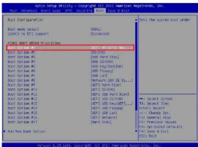
text_image
Aptio Setup Utility - Copyright (CI 2017 American Megatrends, Inc. Main Advanced Event Loss IPM Security ESCOT Save & Exit Boot Configuration Boot mode select [00ML] LEGACY to EFI support [Disabled] FIXED BOOT ORDER Priorities Boot Option #1 [UEFI MP/UEFI: No...] Boot Option #2 [GO/DVD] Boot Option #3 [UGS Hard Disk] Boot Option #4 [USB CD/DVD] Boot Option #5 [USB Key/SanDisk] Boot Option #6 [UBS Floppy] Boot Option #7 [USB Lan] Boot Option #8 [Network: IBM SE SI...] Boot Option #9 [UEFI Hard Disk] Boot Option #10 [UEFI CD/DVD] Boot Option #11 [UEFI USB Hard Disk] Boot Option #12 [UEFI USB CD/DVD] Boot Option #13 [UEFI USB Key: UEFI...] Boot Option #14 [UEFI USB Floppy] Boot Option #15 [UEFI USB Lan] Boot Option #16 [UEFI Network] Boot Option #17 [Hard Disk] Add New Boot Option Sets the system boot order +:- Select Screen T4: Select Item Enteri Select +/-: Change Opt. F1: General Help F2: Previous Values F3: Optimized Defaults F4: Save & Exit ESC: Exit Version 2.19.126. Copyright (C) 2017 American Megatrends, Inc.- When the UEFI Shell prompt appears, type fs# to change the device directory path. Go to the directory that contains the BIOS package you extracted earlier from Step 1. Enter flash.nsh BIOSname#.### at the prompt to start the BIOS update process.
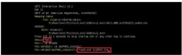
text_image
LEFI Interactive Shell v2.1 ESK 11 LEFI v2.50 (American Regatrends, 0x0089XXC) Mapping table: F50: K106(0):H0D(F0):BLK1; PcJ001(0x0)/PcI(0x14,0x0)/US$(0x11,0x0)/H01_MER_0xG7901072_0x806_0x1 OR3532) BLK0: K106(0): PcJ001(0x0)/PcI(0x14,0x0)/US$(0x11,0x0) Press ESCR is 1 seconds to skip startup.moh or any other key to continue. Shell (f50) F50: CD BLKOS F50:VAPLOOS> CD SKAPME2.0362017 F50:VAPLOOS/SKAPME2.0362017 flash.nsh X13P07.5X
Note: Do not interrupt this process until the BIOS flashing is complete.
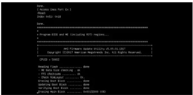
text_image
Done. [Access Oms Port Ex] Index 0x51: 0x18 Done. ********************************************************************** * Program BIOS and ME (including RDT) regions... ********************************************************************** AMI Firmware Update Utility v5.09.01.1317 Copyright ©2017 American Registrends Inc. All Rights Reserved. OPUD = 50652 Reading Flash ......... done - ME Data Size checking . ok - FFS checksums ......... Ok - Check BookLayout ......... Ok Erasing Boot Block ......... done Updating Boot Block ......... done Verifying Boot Block ......... done Zroving Mesh Block ......... 0x00152000 (OK)- The screen above indicates that the BIOS update process has completed. Reboot the system when you see the screen below.
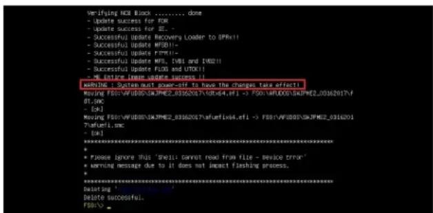
text_image
Verifying NCR Book ....... done - Update success for FEM - Update success for EE - - Successful Update Recovery Loader to (PRx!! - Successful Update MFSB!! - Successful Update RTM!! - Successful Update NFs, [081 and 19021] - Successful Update FLOD and UTOX!! - ME entire (new update success !!) wRIVINC : System must power-sif to have the changes take effect! Moving F501:WFUD005/SKJPME2_03162037/40x64,efi -> F501:WFUD005/SKJPME2_03162017/f df.sac - [cA] Moving F501:WFUD005/SKJPME2_03162037/aufemfix4,efi -> F501:WFUD005/SKJPME2_0316201 ?afuefu1.sac - [cA] ****************************************************************************************** * * Please ignore this 'shell cannot read from file - device error' * Warning message due to it does not impact flashing process. * ****************************************************************************************** putating ' ', Delete successful. F501->Appendix E
Configuring VROC RAID Settings
Intel® Virtual RAID on CPU (Intel® VROC) is a RAID (Redundant Array of Independent Disks) solution that integrates with Intel® Volume Management Device (Intel® VMD) for Non-Volatile Memory Express (NVMe) solid-state drives (SSDs). The E.1 section provides instructions on how to access the All Intel VMD Controller menu. The E.2 section provides instructions on how to configure RAID settings. The E.3 section describes the use of journaling drive for the RAID5 volume (parity based RAID).

Note 1: Only use NVMe devices that have been validated by Supermicro. For the latest updates, please contact us or refer to our website at https://www.supermicro.com.
Note 2: Depending on the version of driver/utility/package, it may or may not have exactly the same as the BIOS settings/features shown in the appendix.
E.1 All Intel VMD Controllers Menu
The following section provide you with instructions on how to access the All Intel VMD Controllers menu which will allow you to enable a selected PCI slot for VMD support.
Enabling a PCI Slot for VMD Support in the BIOS Setup Utility
- Press
during system boot to enter the BIOS Setup utility. - Use the arrow key to select Advanced on top of the BIOS menu bar.
- Use the down arrow key to select Chip Configuration and press
. - Select North Bridge and press
. -
Use the down arrow key to select IIO Configuration and press
. -
When the following screen displays, use the down arrow key to select Intel® VMD Technology and press
to enter the Intel® VMD Technology submenu.
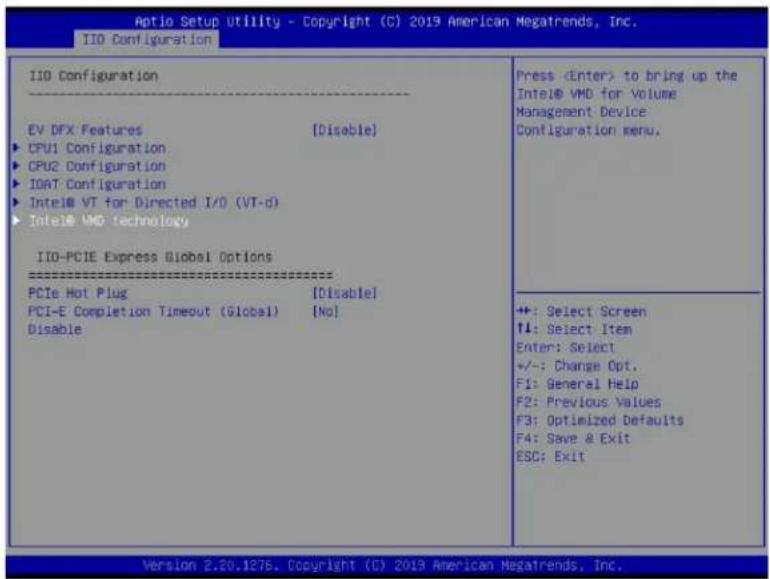
text_image
Aptio Setup Utility - Copyright (C) 2019 American Megatrends, Inc. IIO Configuration Press- When the Intel® VMD Technology submenu appears, it will display all the PCI slots that can be configured for VMD support on the screen.
- From the available PCI slots displayed on the screen, select a PCI slot you want to use for a VMD device by highlighting it.
- Select the option [Enable] and press
to enable the selected slot for VMD support. - Repeat Step 8 \~ Step 9 to select and enable all the PCI slots of your choice for VMD support.
- After enabling all PCI slots for VMD support on the BIOS Setup utility, install the VMD devices (such as add-on cards) on the slots that you've configured for VMD support on the motherboard. For the changes to take effect,
- Press
to save the settings and exit the BIOS Setup utility. Press during system boot to enter the BIOS Setup utility.

Note: After you've enabled VMD in the BIOS on a PCIe slot of your choice, this PCIe slot will be dedicated for VMD use only, and it will no longer support any PCIe device. To re-activate this slot for PCIe use, please disable VMD in the BIOS.
- Navigate to the Advanced tab.
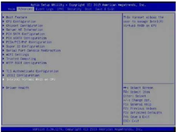
text_image
Ratio Setup Utility - Copyright (C) 2015 American Vegetrends, Inc. Main Advanced Event Logs IPMI Security Boot Save & Exit - Boot Features - CPU Configuration - Chipset Configuration - Server NE Information - PCH-SHTR Configuration - PCH-starch Configuration - PCIe/PCE/PCI/PCI/PCI/PCI/PCI/PCI/PCI/PCI/PCI/PCI/PCI/PCI/PCI/PCI/PCI/PCI/PCI/PCI/PCI/PCI/PCI/PCI/PCI/PCI/PCI/PCI/PCI/PCI/PCI/PCI/PCI/PCI/PCI/PCI/PCI/PCI/PCI/PCI/PCI/PCI/PCI/PCI/PCI/PCI/PCI/PCI/PCI/PCI/PCI/PCI/PC - Super ID Configuration - Serial Fort Console Redirection - ACFI Settings - Trusted Computing - HTTP BOOT Configuration - TLS Authentication Configuration - I/O/DI Configuration - Intel(R) Virtual RIO on CPU - Driver Health This format allows the user to manage Intel(R) virtual RAID on CPU +: Select Screen II: Select Item Enter: Select +/-: Change Ret. F3: General Help F2: Previous Values F3: Defaulted Defaults F4: Save & Exit ESC: Exit Version 8.20.1274. Copyright CIE 2019 American Resafonds, Inc.- Use the arrow keys to select Intel(R) Virtual RAID on CPU and press
to access the menu items. The following screen will appear showing that the feature "All Intel VMD Controllers" has become available.
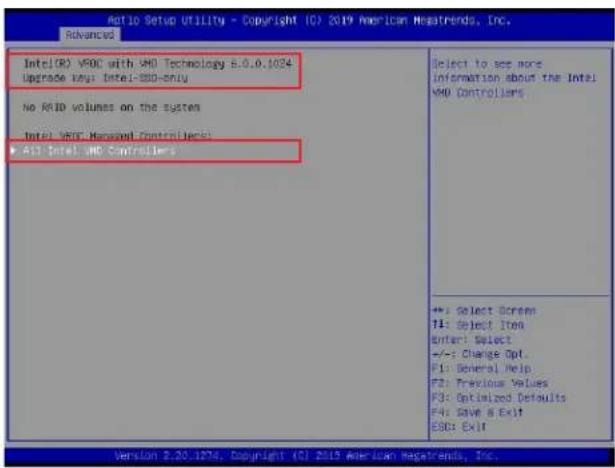
text_image
Intel(R) V80C with V8D Technology 8.0.0.1024 Upgrade key: Intel-SSD-only No RFID volumes on the system Intel: V80C Managed Controllers! All Intel V8D Controllers Select to see more information about the Intel V80D Controllers +: Select Screen T1: Select Item Enter: Select +/-: Change Opt. F1: General Help F2: Previous Values F3: Optimized Defaults F4: Save & Exit ESD: Exit Version 2.20.1274, Copyright (C) 2019 American Newstrands, Inc.
Note 1: The license and header (on the motherboard) for Intel® VROC hardware key are required. Also, be sure the version of Intel® Rapid Storage Technology enterprise (Intel® RSTe) VROC utility is 5 or above (look for Intel(R) VROC with VMD Technology x.x.x.xxxx shown on the screen).
Note 2: Intel® VROC Premium hardware key is used in the appendix to demonstrate RAID settings.
- Use the arrow keys to select All Intel VMD Controllers and press
to access the menu items. The following screen will appear. It allows the user to create RAID volumes and configure settings of NVMe devices as detected by the system.
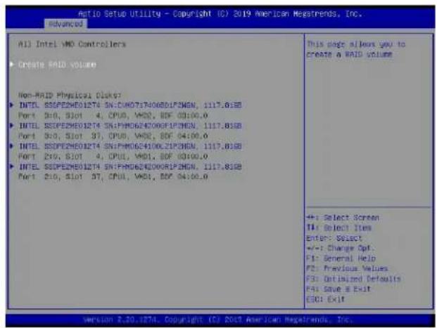
text_image
All Intel VMD Controllers ► Create RAID volume Non-RAID Physical Disk? ► INTL SSPEZME01274 SN:DM071740080LP6NGN, 1117.81SB Port 3:0, Slot 4, CPU, VMD, BDF 03:00.0 ► INTL SSPEZME01274 SN:FM0624200GELP6NGN, 1117.81SB Port 3:0, Slot 97, CPU, VMD, BDF 04:00.0 ► INTL SSPEZME01274 SN:FM0624100CLZIPNGN, 1117.81SB Port 2:0, Slot 4, CPU, VMD, BDF 03:00.0 ► INTL SSPEZME01274 SN:FM0624200ARIP6NGN, 1117.81SB Port 2:0, Slot 97, CPU, VMD, BDF 04:00.0 This page allows you to create a RAID volume +: Select Screen #: Select Items Enter: Select +/-: Change Opt. F1: General Help F2: Previous Values F3: Optimized Defaults F4: Save & Exit ESU: Exit version 2.20.1274. Copyright (C) 2019 American Regalrends, Inc.Note : A single Intel® VMD supported processor supplies 48 PCIe lanes and contains three Intel® VMD controllers (domains). Refer to the following illustration for more information.
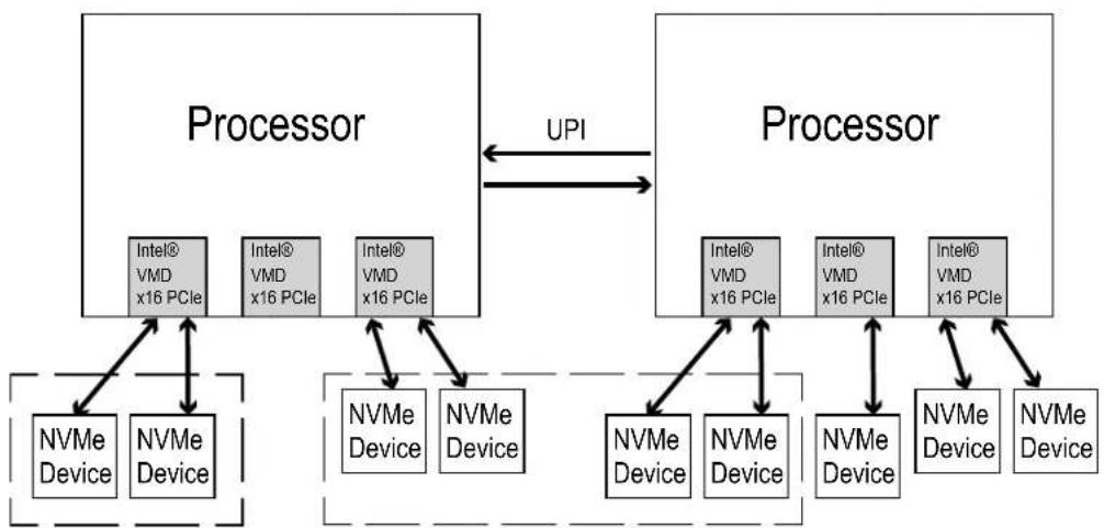
flowchart
graph TD
    A["Processor"] -->|UPI| B["Processor"]
    A --> C["NVMe Device"]
    A --> D["NVMe Device"]
    B --> E["NVMe Device"]
    B --> F["NVMe Device"]
    C <--> G["Intel® VMD x16 PCIe"]
    D <--> H["Intel® VMD x16 PCIe"]
    E <--> I["NVMe Device"]
    F <--> J["NVMe Device"]
    G <--> K["Intel® VMD x16 PCIe"]
    H <--> L["Intel® VMD x16 PCIe"]
    I <--> M["NVMe Device"]
    J <--> N["NVMe Device"]
    K <--> O["NVMe Device"]
    L <--> P["NVMe Device"]
    M <--> Q["NVMe Device"]
    N <--> R["NVMe Device"]
    style A fill:#f9f,stroke:#333
    style B fill:#f9f,stroke:#333
    style C fill:#ccf,stroke:#333
    style D fill:#ccf,stroke:#333
    style E fill:#cfc,stroke:#333
    style F fill:#cfc,stroke:#333
    style G fill:#fcc,stroke:#333
    style H fill:#fcc,stroke:#333
    style I fill:#cff,stroke:#333
    style J fill:#cff,stroke:#333
    style K fill:#ffc,stroke:#333
    style L fill:#ffc,stroke:#333
    style M fill:#ffc,stroke:#333
    style N fill:#ffc,stroke:#333
* Data RAID will be allowed to cross VMDs and processors. * Boot RAID will NOT be
able to cross VMDs.
E.2 Configuring RAID Settings
Follow the instructions stated in the E.1 section to access the All Intel VMD Controllers menu items, the following screen will appear. Please carefully follow the instructions listed in this section to configure RAID settings for your devices as desired.
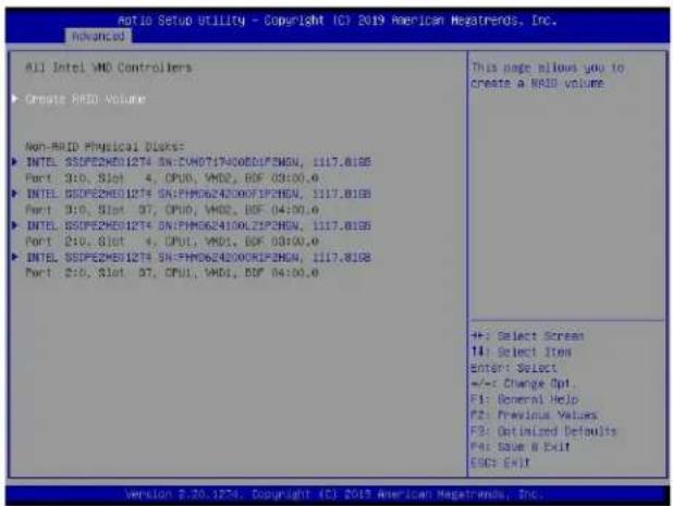
text_image
All Intel VMD Controllers ► Create RAID Volume Non-RMID Physical DLK5: ► INTEL SSPE2ME01274 SN:FM00717400EDLP36N, 1117.818B Port 3:0, Slot 4, CPU0, VMD, BIF 03:00.0 ► INTEL SSPE2ME01274 SN:FM006243000FIP36N, 1117.818B Port 3:0, Slot 97, CPU0, VMD, BIF 04:00.0 ► INTEL SSPE2ME01274 SN:FM00624100LZIP36N, 1117.818B Port 2:0, Slot 4, CPU1, VMD, BIF 03:00.0 ► INTEL SSPE2ME01274 SN:FM006243000KIP36N, 1117.818B Port 2:0, Slot 97, CPU1, VMD, BIF 04:00.0 This page allows you to create a RAID volume +: Select Screen T4: Select Item Enter: Select +/-: Change Opt. F1: General Help F2: Previous Values F3: Optimized Defaults Far: Save O Exit ESC: Exit Version 2.20.1274. Copyright (C) 2019 American MegaTrends, Inc.To Create a RAID Volume
Use the arrow keys to select Create RAID Volume from the screen above and press
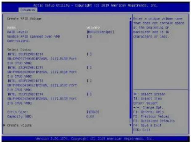
text_image
Ratio Setup Utility - Copyright (C) 2019 American Netatrends, Inc. Advanced Create RAID Volume NAME: RAID Levels: Enable RAID spanned over VMD Controllers: Select Disks: INTEL SSDPE2ME1274 SN:CMFD1740080IP26GN, 1117.81GB Port 3:0 CPU0 VMD2 INTEL SSDPE2ME1274 SN:PMDB5N200IFIP26GN, 1117.81GB Port 3:0 CPU0 VMD2 INTEL SSDPE2ME1274 SN:PMDB5N400LZIP26GN, 1117.81GB Port 3:0 CPU0 VMD1 INTEL SSDPE2ME1274 SN:PMDB5N200IFIP26GN, 1117.81GB Port 3:0 CPU0 VMD1 Strip Size: Capacity (GB): Create Volume VOLUME [REDA(Stripe)] I I I I I I I I [179KB] 0.60 Enter a unique volume now that does not contain space at the beginning or backslash and is in characters or less. +: Select Screen T4: Select Item Enter: Select +/-: Change Apt. F1: General Help F2: Previous Values F3: Optimal Defaults F4: Save & Exit ESC: ExitTo Enter a Name for the RAID Volume
From the Create RAID Volume submenu as shown on the previous screen, use the arrow keys to select Name and press
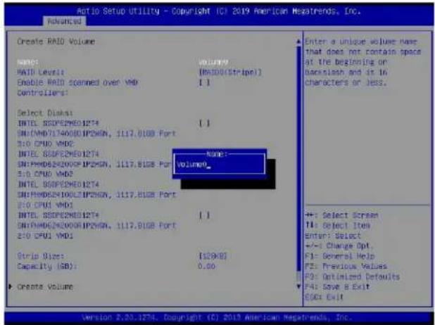
text_image
Auto Setup Utility - Copyright (C) 2019 American Newsrends, Inc. PROVANCED Create RAID Volume NAME: RAID Level: Volume Enable RAID scanned over VMD [Risid(Stripe)] Controllers: Select Disk1 INTEL SSDPE2MEO1274 SND:AMD7134000IP25NGN, 1117.01GB Port S10 CPU0 VMD INTEL SSDPE2MEO1274 SND:AMD8242000IP25NGN, 1117.01GB Port S10 CPU0 VMD INTEL SSDPE2MEO1274 SND:AMD8242000IP25NGN, 1117.01GB Port S10 CPU0 VMD INTEL SSDPE2MEO1274 SND:AMD8242000IRP25NGN, 1117.01GB Port S10 CPU0 VMD Strip Size: [129x8] Capacity (SB): 0.66 Create Volume Enter a unique volume name that does not contain space at the beginning or backslash and is in characters or less. +: Select Screen I: Select Item enter: Select +/- Change Opt. F1: Several Help F2: Previous Values F3: Optimized Defaults F4: Save & Exit GSDs Exit Version 2.25.1274. Copyright (C) 2019 American Newsrends, Inc.When the screen above displays, enter a unique name for the RAID volume.
To Set the RAID Level for the RAID Volume
From the Create RAID Volume submenu, select RAID Level and press
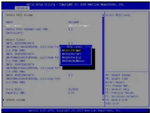
text_image
Add IO Setup Utility - Copyright (C) 2019 American Hega Trends, Inc. Advanced Create RAID Volume Name: RAID Level: Enable RAID soarmed over VMD Controllers: Select Disk: INTEL SSDPE2ME01274 SH:CMWD1340000IP2MEN, 1117.81GB Port 310 CPU0 VMD2 INTEL SSDPE2ME01274 SH:PAHDS2E2000IP2MEN, 1117.81GB Port 310 CPU0 VMD2 INTEL SSDPE2ME01274 SH:PAHDS2E100LZIP2MEN, 1117.81GB Port 2:0 CPU1 VMD1 INTEL SSDPE2ME01274 SH:PAHDS2E2000IP2MEN, 1117.81GB Port 2:0 CPU1 VMD1 Strip Size: Capacity (SB): Create Volume Volume9 (RADD(Stripe)) I 1 RAID Level: RAIDO(Stripe) RAID(Mirror) RAIDS(Parity) RAID(RAID=1) I 1 I(3KB) 0.00 Select RAID Level +: Select Screen T4: Select Item Enter: Select +/-: Change Opt. F1: General Help F2: Previous Values F3: Default Defaults F4: Save & Exit ESC: ExitUse the arrow keys to select the desired RAID level for the RAID volume that you've created. The options are RAID0(Stripe), RAID1(Mirror), RAID5(Parity), and RAID10(RAID0+1).

Note 1: The RAID level(s) displayed is(are) based on the number of NVMe devices connected to the system.
Note 2: For RAID0/RAID1/RAID5/RAID10, the minimum number of NVMe devices required is two/two/three/four respectively.
Note 3: Use Intel® VROC Standard hardware key to support RAID 0/1/10. Use Intel® VROC Premium hardware key (or Intel SSD Only hardware key) to support RAID 0/1/5/10.
Enabling RAID Spanned over VMD Controllers
From the Create RAID Volume submenu, use the arrow keys to select Enter RAID spanned over VMD Controllers and press
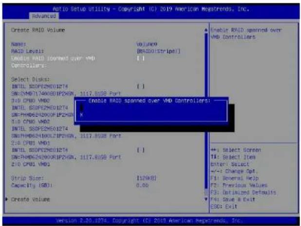
text_image
Ratio Setup Utility - Copyright (C) 2019 American MegaTrends, Inc. Advanced Create RAID Volume Name: Volume9 RAID Level: [RAIDotStriper] Enable RAID spanned over VMD Controllers: Select Disks: INTEL SSDPE2ME01274 [ ] SN:SMD7140080IP2HON, 1117.81GB Port 310 CPU6 VMD INTEL SSDPE2ME01274 SN:PHD654200CFIP2HON K 310 CPU6 VMD INTEL SSDPE2ME01274 SN:PHD654300LFIP2HON, 1117.81GB Port 310 CPU6 VMD INTEL SSDPE2ME01274 [ ] SN:PHD654200ORIP2HON, 1117.81GB Port 310 CPU6 VMD Strip Size: [1/24KB] Capacity (SD): 0.00 Create Volume Enable RAID spanned over VMD Controllers: +: Select Screen TI: Select Item Enter: Select +/-: Change Opt. F1: General Help F2: Previous Values F3: Optimized Defaults F4: Save & Exit ESO: Exit Version 2.20.1874. Copyright (C) 2019 American MegaTrends, Inc.Enter a desired setting for your RAID volume in the pop-up menu. The options are (not selected) and X (selected). Please set this feature to X if the RAID level you selected earlier from Step 3 will cross VMD domains.

Note: For a bootable RAID volume, do not cross VMD domains.
To Select Disks for the RAID Volumes
From the Create RAID Volume submenu, use the arrow keys to highlight Select Disk: and press
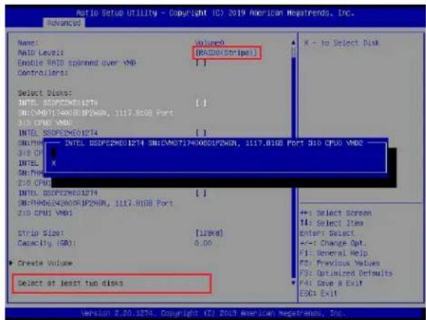
text_image
Ratio Setup Utility - Copyright (C) 2019 American Newsrends, Inc. Advanced Name: RAID Level: Enable RAID scanned over VMD Controllers: Select Disk: INTIL SSDPE2MEO1274 SN:CMV0T1740065IP2WGN, 1117.81GB Port 310 CPU0 VMD INTIL SSDPE2MEO1274 SN:PMI INTIL SSDPE2MEO1274 SN:RMDC24006IP2WGN, 1117.81GB Port 310 CPU0 VMD Strip Size: Capacity (GB): Create Volume Select at least two disks Volume: (RAIDO(Stripe)) X - to Select Disk +: Select Screen T4: Select Item Enter: Select +/-: Change Opt. F1: General Help F2: Previous Values F3: Optimized Defaults F4: Save & Exit ESC: Exit Version 2.20.2274. Copyright (C) 2019 American Newsrends, Inc.The options are (not selected) and X (selected). Set the features one by one to X to select the desired RAID disks for your RAID volumes.
To Set Strip Size for the RAID Volume
From the Create RAID Volume submenu, use the arrow keys to select Strip Size: and press
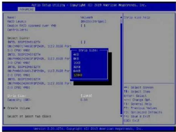
text_image
Auto Setup Utility - Copyright (C) 2019 American Megatrends, Inc. Advanced Name: RAID Layer1 Enable RAID spanned over VMD Controllers: Select Disks: INTEL SSPE2ME01274 SN:CMDDT17A00EIP0CHN, 1117.8108 Port 310 CPU0 VMD INTEL SSPE2ME01274 SN:PHDGS4A00CF IP2CHN, 1117.8108 Port 310 CPU0 VMD INTEL SSPE2ME01274 SN:PHDGS4A00CF IP2CHN, 1117.8108 Port 310 CPU0 VMD INTEL SSPE2ME01274 SN:PHDGS4A00CF IP2CHN, 1,117.8108 Port 310 CPU0 VMD Strip Size: 4KB 8KB 16KB 32KB 64KB 120KB Strip Size: Capacity [SB]: 0.00 Create Volume Select at least two disks Strip size help +: Select Screen T1: Select Item Enter: Select +/-: Change Opt. F1: General Help F2: Previous Values F3: Optimized Defaults F4: Save & Exit ESDr Exit Version 2.20.1274. Copyright (C) 2013 American Megatrends, Inc.From the pop-up menu as shown above, select the desired RAID strip size for your RAID volume and press

Note: For RAID5, the options are 4KB, 8KB, 16KB, 32KB, 64KB, and 128KB. For RAID10, the options are 4KB, 8KB, 16KB, 32KB, and 64KB.
To Set the Capacity (GB) for the RAID Volume
From the Create RAID Volume submenu, use the arrow keys to select Capacity (GB): and press
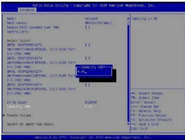
text_image
AutoIO Setup Utility - Copyright (C) 2019 American MegaThreads, Inc. advanced Name: Volume0 RAID Levels: [RAIDOLStripe1] Enable RAID spanned over VMD [ ] Controllers: Select disks: INTEL: SSDPE2M6E12T4 [ ] SIN:DMDT17A0D8IP2VKN, 1117.81GB Port 310 CPU0 VMD2 INTEL: SSDPE2M6E12T4 [ ] SIN:PMDD62400UF IP2VKN, 1117.81GB Port 310 CPU0 VMD2 Capacity (SB):- 0.00 SIN:PMDD62400ULIP2VKN, 1117.81GB Port 310 CPU1 VMD1 SIN:SRPE2M6E12T4 [ ] SIN:PMDD62400RP IP2VKN, 1117.81GB Port 310 CPU1 VMD1 Strip Size: [12KB] Capacity (GB): 0.00 Create Volume Select at least two disks Capacity in GB ++ Select Screen TA: Reject Item Enter: Select +/-: Change Opt. F1: General Help F2: Previous Values F3: Optimized Defaults F4: Save & Exit ESC: Exit Version 3.20.1274, Copyright (C) 2019 American MegaThreads, Inc.Enter the desired RAID capacity (in GB) in the pop-up menu to set the capacity for your RAID volume.
To Create Volumes
To finalize your RAID volume configuration, select Create Volume from the Create RAID Volume submenu as shown on the screen below.
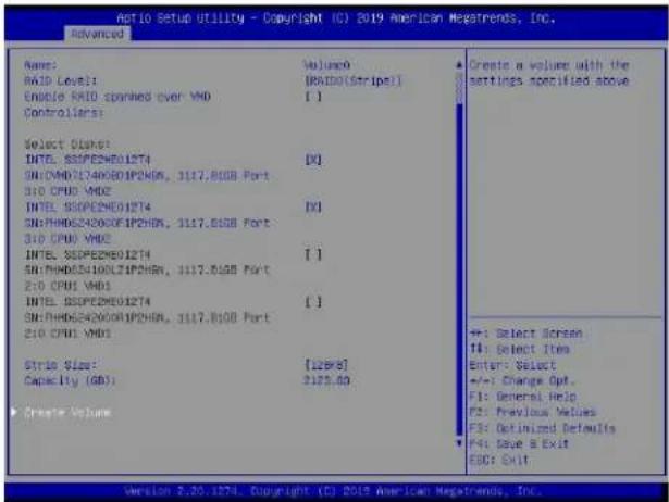
text_image
Notio Setup Utility - Copyright (C) 2019 American Megatrends, Inc. Advanced Name: RMD Levels Enable RAID spyned over VMD Controllers: Select Signal: INTL. SSPECNE01274 SN:CMD37400BZIP2HEN, 3117.81GB Port 310 CPU6 VMD INTL. SSPECNE01274 SN:MHDC54000DFIP2HEN, 3117.81GB Port 310 CPU6 VMD INTL. SSPECNE01274 SN:MHDC5400LZIP2HEN, 3117.81GB Port 210 CPU6 VMD INTL. SSPECNE01274 SN:MHDC5400ORIP2HEN, 3117.81GB Port 210 CPU6 VMD Strike Size: Capacity (GB): Create Volume Volume: (RAIDOSnripe) [ ] DQ IVI [ ] [ ] [128KB] 2173.00 Create a volume with the settings specified above +1: Select Screen T4: Select Item Enter: Select +/-: Change Opt. F1: General Help F2: Previous Values F3: Optimized Defaults F4: Save & Exit ESC: Exit Version 2.20.1274. Copyright (C) 2019 American Megatrends, Inc.After selecting Create Volume, press
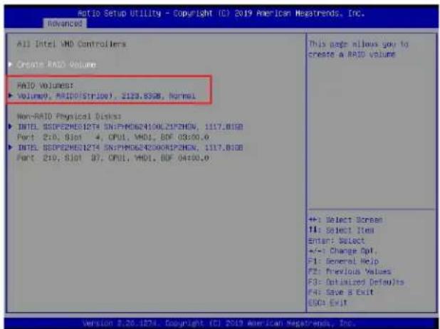
text_image
All Intel VMD Controllers ► Create RAID Volume RAID Volumes: ► Volume0, RAID0/STILO7, 2133.83GB, Normal Non-RAID Physical Blocks: ► INTEL SSDPE2MDS12T4 SN:FM0624100LZIPZHEN, 1117.81GB Port 2:0, Slot 4, CPU1, VMD1, BDF 03:00.0 ► INTEL SSDPE2MDS12T4 SN:FM0624200RIPZHEN, 1117.81GB Port 2:0, Slot 37, CPU1, VMD1, BDF 04:00.0 This page allows you to create a RAID volume +: Select Screen T4: Select Item Enter: Select +/-: Change Opt. F1: General Help F2: Previous Values F3: Optimized Defaults F4: Save & Exit ESC: Exit Version 2.20.1874. Copyright (C) 2019 American Negatrends, Inc.To Display RAID Volumes
For detailed RAID volume information, use the arrow keys to select the desired RAID volume as shown below.
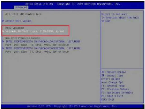
text_image
All Intel VIO Controllers ► Create RAID Volume RAID Volumes ► Volume0, RAID(Strip), 2128.83GB, Normal Non-RAID Physical Disks: ► INTEL SSPEZMEO12T4 SN:FM06241006.21F2HGN, 1117.83GB Port 2:0, Slot 4, CPU1, VM01, EBF 03:00.0 ► INTEL SSPEZMEO12T4 SN:FM06240008R1P3HGN, 1117.83GB Port 2:0, Slot 3T, CPU1, VM01, EBF 04:00.0 Select to see more Information about the RAID VOLUME +: Select Screen 14: Select Item Enter: Select +/-: Change Opt. F1: General Help F2: Previous Values F3: Optimized Defaults F4: Save & Exit EUG: ExitTo Display RAID VOLUME Information
When the screen above appears, press
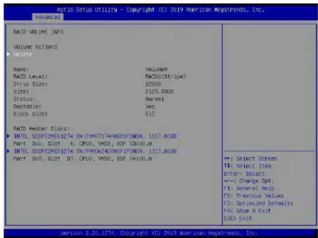
text_image
Audio Setup Utility - Copyright (C) 2019 American Meastrends, Inc. Advanced RAID VOLUME INFO VOLUME ACTIONS Delete Name: Volume0 RAID Level: RATIO(Stripe) Strip Size: 12000 Size: 2123.83GB Status: Normal Bootable: Yes Block Size: 512 RAID Header Disk: INTEL SODPE2ME01274 SN:CM0717400601PONON, 1117.81GB Port 3x0, Slot 4, CPU0, VMOS, SDF 03:00.0 INTEL SODPE2ME01274 SN:FHDAS4200F2PONON, 1117.81GB Port 3x0, Slot 37, CPU0, VMOS, SDF 04:00.0 +: Select Screen 1#: Select Item Enter: Select +/-: Change Opt. F1: General Help F2: Previous Values F3: Optimized Defaults F4: Save & Exit ESO: ExitTo Delete a RAID Volume
On the RAID VOLUME INFO menu, use the arrow keys to select Delete and press
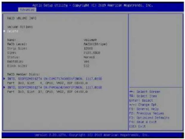
text_image
Auto Setup Utility - Copyright TC2 2019 American Megatrends, Inc. Advanced RAID VOLUME INFO VOLUME ACTIONS Delete Name: Volume0 RAID Level: RAID(Stripe) Strip Size: 12GB Size: 21KB/3GB Status: Normal Portable: Yes Block Size: 512 RAID Member Discs: INTEL SSDPE2MEO12T4 SN-CMO7174008DIP2MEN, 1117.01GB Port S10, Slot 4, CPU0, VM2, RSP 03100.0 INTEL SSDPE2MEO12T4 SN-PH0664200AFJP2MEN, 1117.01GB Port S10, Slot 37, CPU0, VM2, RSP 04100.0 +: Select Screen F1: Select Item Enter: Select +/-: Change Opt. F1: General Help F2: Frevious Values F3: Optimized Defaults F4: Save & Exit ESC: ExitThe following screen will appear to confirm if you want to delete the RAID Volume. Select Yes to delete the RAID Volume. The options are Yes and No.
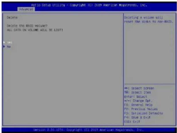
text_image
Ratio Setup Utility - Copyright (C) 2019 American MegaTrends, Inc. Advanced Delete Delete the RAID volume? ALL DATA ON VOLUME WILL BE LOST! Yes No Ordering a volume will reset the disk to non-RAID. +: Select Screen T4: Select Item Enter: Select +/-: Change Opt. F1: General Help F2: Previous Values F3: Optimized Defaults F4: Save E Exit F5: Exit Version 2.30.1876. Copyright (C) 2019 American MegaTrends, Inc.To Reset the RAID Volume to non-RAID
On the RAID VOLUME INFO submenu shown on the bottom screen of page 165, select the desired NVMe device from the list of RAID Member Disks and press
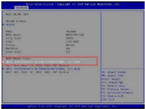
text_image
AIO Setup Utility - Copyright (C) 2019 American MegaTrends, Inc. RAID VOLUME INFO Volume Actions ► Delete Name: Volume RAID Level: RATIO (Stripe) Strip Size: 120KB Size: S123.80GB Status: Normal Bootable: Yes Block size: 512 RAID Member Disk: ► INTEL SSDPE2MEI1274 SN:CAN07174X6DIP3CMN, 1117.8108 Port: 310, Slot 4, CPU0, WNS, BOP 03:00.0 ► INTEL SSDPE2MEI1274 SN:PHD624300FIP3CMN, 1117.8108 Port: 310, Slot 37, CPU0, WNS, BOP 04:00.0 +: Select Screen T1: Select Item Enter: Select +/-: Change Opt. F1: General Help F2: Previous Values F3: Optimized Defaults F4: Save a Exit E00: Exit Version 2.20.1274. Copyright (C) 2019 American MegaTrends, Inc.Select Reset to Non-RAID from the screen below and press
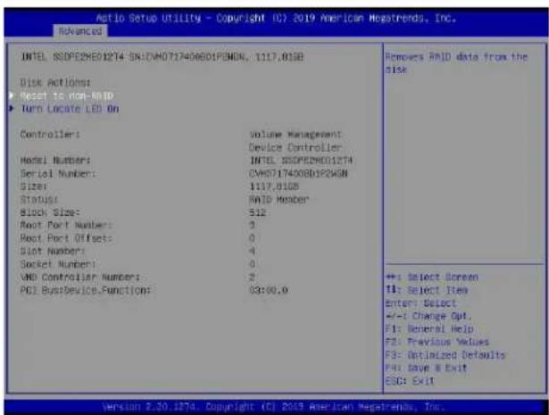
text_image
Auto Setup Utility - Copyright (C) 2019 American Megatrends, Inc. Advanced INTEL SODPEDMED12T4 SN:CVMD717406B01P0NDN, 1117.013B Disk Actions: Reset to non-RESET Turn Locate LED On Controllers: Volume Management: Device Controller: Model Numbers: INTEL SODPEDMED12T4 Serial Number: CVMD717406B01P0NDN Size: 1117.013B Status: PAID Member Block Size: 512 Boot Port Number: 3 Boot Port Offsets: 0 Slot Number: 4 Socket Number: 0 VDD Controller Number: 2 PCI BusDevice.Function: 03:00.0 Remove RAID data from the risk +: Select Screen T1: Select Item Enter: Select +/-: Change Opt. F1: General Help F2: Previous Values F3: Optimized Defaults Full Save & Exit ESD: Exit Version 2.20.1874. Copyright (C) 2019 American Megatrends, Inc.When the following screen appears, select Yes to confirm that you want to set the selected NVMe device to non-RAID. The options are Yes and No.
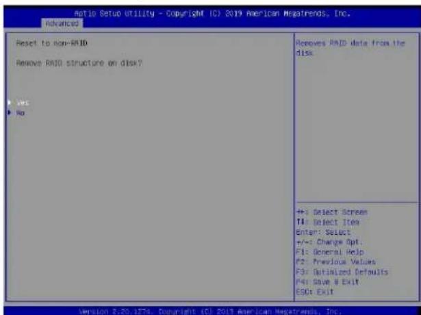
text_image
Ratio Setup Utility - Copyright (C) 2019 American Megatrends, Inc. Advanced Reset to non-RAID Remove RAID structure on disk? Yes No Receives RAID data from the disk +: Select Screen T4: Select Item Enter: Select +/-: Change Opt. F1: General Help F2: Previous Values F3: Optimized Defaults F4: Save & Exit ESC: Exit Version 5.20.1876. Copyright (C) 2019 American Megatrends, Inc.To Turn on the Disk Locator LED
Follow the instructions stated in the E.1 section to access the All Intel VMD Controllers menu. When the following screen displays, select a non-RAID physical disk to turn on the disk locator LED to locate a selected device.
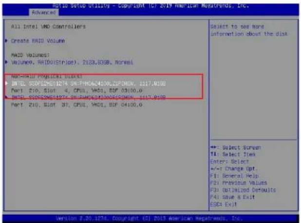
text_image
All Intel VMD Controllers Create RAID Volume VIAID Volumes: Volume9, R(Do(Strike), 2023,8GB, Normal) Non-MSOLED PAGLIC Litter INTEL SSD/PROM/1974 SE-FH/MOS/4100.CSP/ENK, 1177.0100 Port Z10, Slot 4, CPU, WD1, BOP 04100.0 INTEL SSD/PROM/1974 SE-FH/MOS/4100.CSP/ENK, 1177.0100 Port Z10, Slot 37, CPU, WD1, BOP 04100.0 Select to see non information about the disk +: Select Screen TI: Select Item Enter: Select +/-: Change Opt. F1: Several Help F2: Previous Values F3: Optimized Defaults F4: Save & Exit ESC: Ex)!You can also select a RAID member disk to locate the selected device.
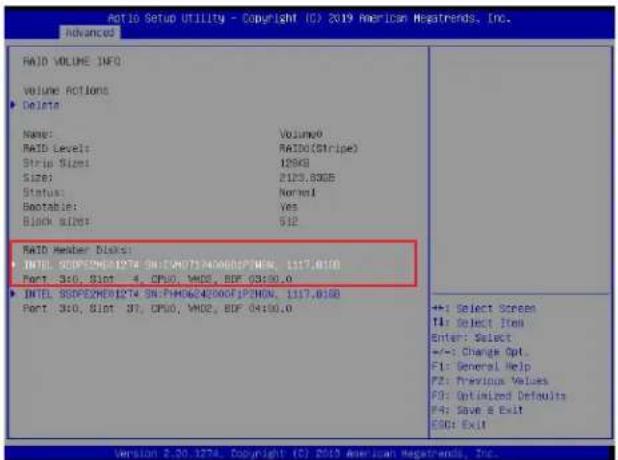
text_image
RAID VOLUME INFO Volume Actions Delete Name: Volume0 RAID Levels: RAID(Stripe) Strip Size: 125KB Size: 2123.83GB Status: Normal Bootable: Yes Block Size: $12 RAID Member Blocks INTL: SCIF/SPX/0174 SN-FH0754000SP/MEN, 1117.0188 Port: 360, 81st 4, CPU0, WHO, BOP 03190.0 INTL: SSPEX/0174 SN-FH0624000FIP/HON, 1117.0188 Port: 360, 81st 37, CPU0, WHO, BOP 04190.0 ++: Select Screen TI: Select Item Enter: Select +/-: Change Opt. F1: General Help F2: Previous Values F3: Optimized Defaults F4: Save & Exit ESG: ExitWhen the following screen appears, use the arrow keys to select Turn Locate LED On. Press
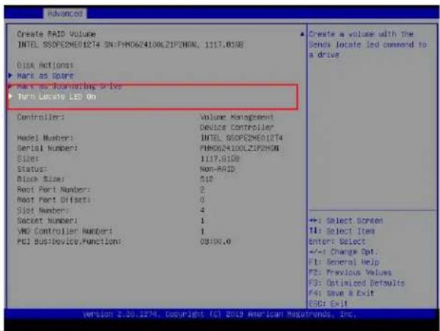
text_image
Create RAID Volume INTEL SSOPESME01274 3N:PHO624100LZIPDHGM, 1117.0108 Disk Actions ► Mark as Open ► Make as Journals Drive ► Turn Locate LED On Controller: Volume Management Device Controller Model Number: INTEL SSOPESME01274 Serial Number: PHO624100LZIPDHGM Size: 1117.0108 Status: Non-RAID Block Size: 512 Root Port Number: 2 Root Port Offset: 0 Slot Number: 4 Socket Number: 1 VND Controller Number: 1 PCI BusDeviceFunctions: 08500.0 ▲ Create a volume with the Sends locate led command to a drive +: Select Screen T1: Select Item Enter: Select +/-: Change Opt. F1: General Help F2: Previous Values F3: Optimized Defaults F4: Save & Exit ESC: Exit version 2.20.1274, Copyright © 2019 American Regatronics, Inc.To Mark a RAID Volume as Spare
Follow the instructions stated in the E.1 section to access the All Intel VMD Controllers menu. When the following screen appears, select a desired NVMe device from the list of Non-RAID Physical Disks.
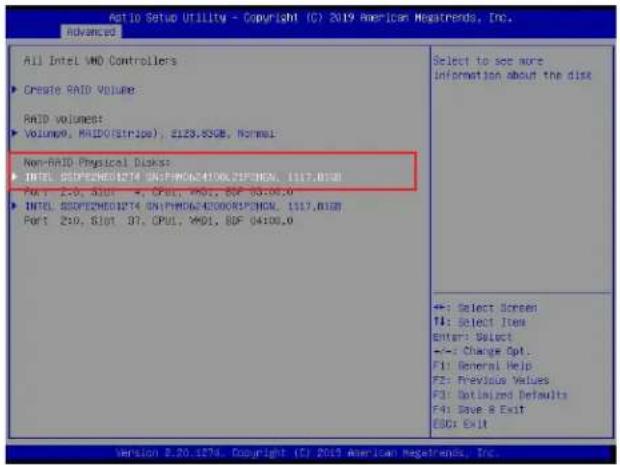
text_image
Aio Setup Utility - Copyright (C) 2019 American Megatrends, Inc. Advanced All Intel VMD Controllers ► Create RAID Volume: RAID volume: ► Volume:0, RAID(Stripe), E123.85GE, Normal Non-RAID Physical Disk: ► INTEL SDFP2M01274 ONIPWD624100JEPONCL, 1117.0130 Port 210, 310T 47, OPUI, VMOI, BGF 04100,0 ► INTEL SDFP2M01274 ONIPWD624100JEPONCL, 1117.0130 Port 210, 310T 37, OPUI, VMOI, BGF 04100,0 Select to set more information about the disk +: Select Screen T1: Select Item Enter: Select +/-: Change Opt. F1: General Help F2: Previous Values F3: Optimized Defaults F4: Save & Exit ESC: Exit Version 3.20.1274. Copyright (C) 2019 American Megatrends, Inc.After a NVMe device is selected, press
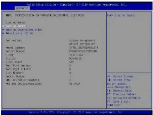
text_image
Ratio Setup Utility - Copyright (C) 2019 American Megatrends, Inc. Advanced INTEL SSDPE29E012T4 SN:PH0624100LZIF2HON, 1117.81GB Disk Actions: ► Make as Stamp ► Make as Journaling Drive ► Turn Locate LED On Controller: Model Number: Serial Number: SIZE: Status: Block Size: Boot Port Number: Boot Port Offsets: Slot Number: Socket Number: VMD Controller Number: PCI Bus/Device/Function: Volume Management Device Controller INTEL SSDPE29E012T4 PH0624100LZIF2HON 1117.81GB Non-RAID 512 2 0 4 1 1 03:00.0 Mark disk as Spare +: Select Screen F4: Select Item Enter: Select +/-: Change Opt. F1: General Help F2: Previous Values F3: Optimized Defaults F4: Save & Exit ESC: Exit Version 2.30.1874. Copyright (C) 2019 American Megatrends, Inc.When the following screen appears, select Yes to confirm that you want the selected device to be used as a spare device. The options are Yes and No.
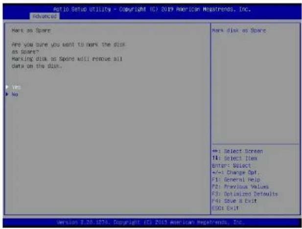
text_image
Ratio Setup Utility - Copyright (C) 2019 American Megatrends, Inc. Advanced Hark as Spare Are you sure you want to mark the disk as Spare? Marking disk as Spare will remove all data on the disk. ► yes ► No Mark disk as Spare +: Select Screen F1: Select Item Enter: Select +/-1 Change Opt. F1: General Help F2: Previous Values F3: Optimized Defaults F4: Save a Exit ESC: Exit Version 8.20.1876. Copyright (C) 2019 American Megatrends, Inc.Note: A spare disk is used for automatic RAID volume rebuilds when status of failed, missing, or at risk is detected on the array disk. For a RAID0 volume, only status of at risk will trigger automatic RAID volume rebuilds.
To Mark a RAID Volume as a Journaling Drive
Refer to the instructions stated in the E.1 section to access the All Intel VMD Controllers menu. When the following screen appears, select a desired NVMe device from the list of Non-RAID Physical Disks for use as a journaling drive.
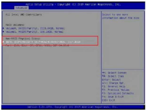
text_image
Ratio Setup Utility - Copyright (C) 2019 American Megatrends, Inc. Advanced All Intel VMD Controllers RAID Volumes: ► Volume0, RAIDS(Parity), 2133.04GB, Normal ► Volume1, RAIDS(Parity), 106.18GB, Normal Non-RAID Physical Docks: ► INTL SPCY2NDISTE 50+PMM24500RICHEN, 1127.802 F4: 210, 8bit - 97, 8bit, VMD1, 56 - 14.00.0 Select to see more Information about the disk +: Select Screen T1: Select Item Enter: Select +/-1 Change Opt. F1: General Help F2: Previous Values F3: Optimized Defaults F4: Drive & Exit ESC: EXIT Version 3.20.1874. Copyright (C) 2019 American Megatrends, Inc.After selecting a NVMe device, press
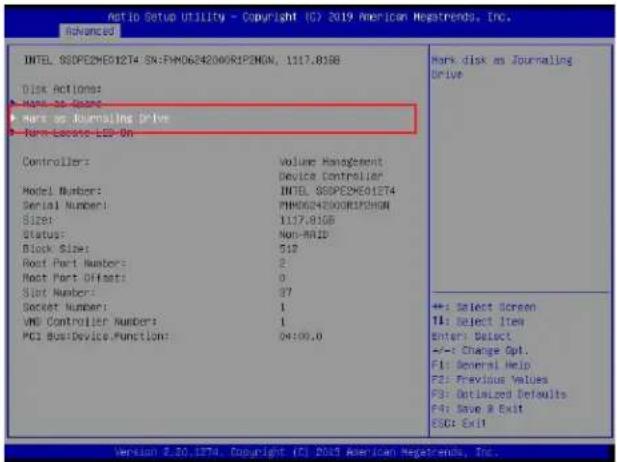
text_image
Intel SGP2E2ME012T4 SX:FM0654200R1P2MGN, 1117.819B Disk Actions: ► Make as Drive ► Make as Journaling Drive ► Make Lasso LED On Controllers: Model Number: Serial Number: Size: Status: Block Size: Root Part Number: Root Part Offsets: Slot Number: Socket Number: VND Controller Number: PCI Bus/Device Function: Volume Management Device Controller INTEL SGP2E2ME012T4 FM0654200R1P2MGN 1117.819B Non-MAID 510 2 0 37 1 1 04:00.0 Mark disk as Journaling Drive +=: Select Screen TI: Select Item Enter: Select +--: Change Opt. F1: General Help F2: Previous Values F3: Dutilized Defaults F4: Save & Exit ESC: Exit Version 2.20.1374. Copyright (C) 2017 American Newsrends, Inc.When the following screen appears, select Yes to confirm that the selected device is to be used as a journaling drive. The options are Yes and No.
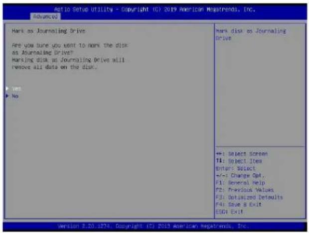
text_image
Auto Setup Utility - Copyright (C) 2019 American Newsrends, Inc. Advanced Mark as Journaling Drive Are you sure you want to mark the disk as Journaling Drive? Marking disk as Journaling Drive will Remove all data on the disk. ▶ Yes ▶ No Mark disk as Journaling Drive ++: Select Screen TI: Select Item Enter: Select +/-: Change Opt. F1: General Help F2: Previous Values F3: Optimized Defaults F4: Save & Exit ESOG Exit Version 5.20.1876. Copyright (C) 2019 American Newsrends, Inc.
Note: RAID Write Hole (RWH) is a condition associated with a power/drive-failure/crash while writing to a RAID5 volume. The use of journaling drive that contains partial parity logging (PPL) can reduce the potential data loss. Refer to the following illustration for the use of journaling drive.
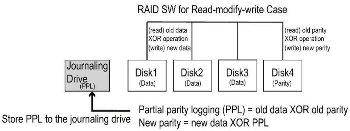
flowchart
graph TD
    A["Journaling Drive (PPL)"] --> B["Disk1 (Data)"]
    A --> C["Disk2 (Data)"]
    A --> D["Disk3 (Data)"]
    A --> E["Disk4 (Parity)"]
    B --> F["(read) old data XOR operation (write) new data"]
    C --> G["(read) old parity XOR operation (write) new parity"]
    D --> H["(read) old parity XOR operation (write) new parity"]
    I["Store PPL to the journaling drive"] --> A
    J["Partial parity logging (PPL) = old data XOR old parity\nNew parity = new data XOR PPL"] --> A
E.3 Use of Journaling Drive
The following section describes the use of a journaling drive for the RAID5 volume, which is a parity-based RAID.
Step 1. Refer to the instructions stated in the E.1 section to access All Intel VMD Controllers menu items. When the following screen appears, use the arrow keys to select the desired RAID5 volume.
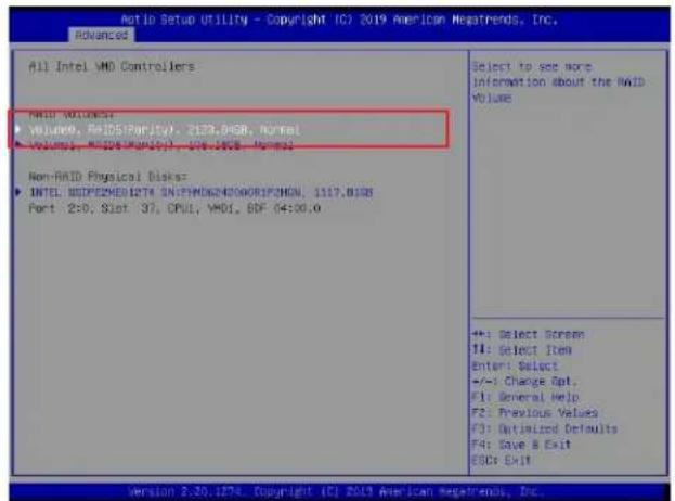
text_image
Ratio Setup Utility - Copyright IC? 2019 American Megatrends, Inc. Advanced All Intel VMD Controllers VMD VOLUME: • VOLUME, RUIDS(Parity), 2123.0458, Normal • VOLUME, RMS(DNA)(P1), V76.1858, Normal Non-RAID Physical Disk: • INTEL, BIOSPEEMES1274, ON:PHO62NDOORIPUSHON, 1117.B138 Port 2:0; Slot 37; OPUL, VMD, SDF 04:00.0 Select to see more information about the RAID VOLUME +: Select Screen II: Select Item Enter: Select +/-: Change Opt. F1: General Help F2: Previous Values F3: Optimized Defaults F4: Save & Exit ESC: Exit Version 2.30.1274. Copyright (C) 2019 American Megatrends, Inc.Press
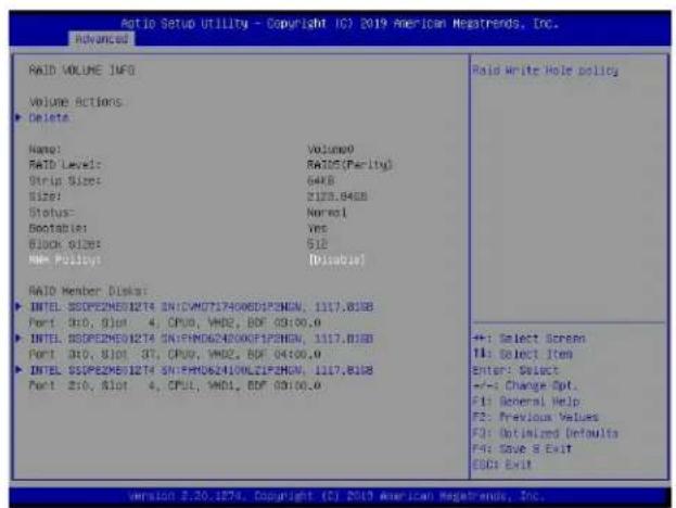
text_image
Auto Setup Utility - Copyright (C) 2019 American Regatrends, Inc. advanced RAID VOLUME INFO Volume Actions Delete Name: Volume0 RAID Level: RAID5(Parity) Strip Size: 64KB Size: 2125.84GB Status: Normal Bootable: Yes Block Size: 51B NRF Policy: [Disable] RAID Member Disk: INTEL SSPE2ME01274 SNICVM0717400EDIP3HGN, 1117.813B Port 010, 91ot 4, CPU, VND, BDF 03:00.0 INTEL SSPE2ME01274 SNIFND624000EFIP3HGN, 1117.813B Port 010, 81ot 37, CPU, VND, BDF 04:00.0 INTEL SSPE2ME01274 SNIFRD62410NLZIF2HGN, 1117.813B Port 2:0, 81ot 4, CPU, VND, BDF 03:00.0 RAID Write Hole policy +1: Select Screen T1: Select Item Enter: Select +/-: Change Opt. F1: General Help F2: Previous Values F3: Optimized Defaults F4: Save & Exit ESC: Exit Version 2.20.1874. Copyright (C) 2019 American Regatrends, Inc.Step 2. Use the arrow keys to select RWH Policy. RWH is a scenario related to a power/drive-failure/crash.
RWH Policy
Press
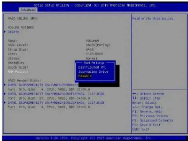
text_image
Ratio Setup UTILITY - Copyright (C) 2019 American Megatrends, Inc. Advanced RAID VOLUME INFO Volume Actions Delete Name: Volume0 RAID Level: RAIDS(Parity) Strip Size: 64KB Size: 2183.84GB Status: Normal Bectable: Block Slides: SMH Policy: MMS Pulsifier: SMH Policy: Distributed FPL Journaling Drive Disable RAID Member Disk: INTEL SSDPEZMED1274 SN:CM07174008DF5E Port 310, Slot 4, CPU0, VMD, SDF 03:00.0 INTEL SSDPEZMED1274 SN:FM062N00AFCHGN, 1117.83SB Port 310, Slot 3T, CPU0, VMD, SDF 04:00.0 INTEL SSDPEZMED1274 SN:FM062L00LZFCHGN, 1117.83SB Port 210, Slot 4, CPU1, VMD, SDF 03:00.0 RAID Write Hole policy +: Select Screen F1: Select Item Enter: Select +/-: Change Apt. F1: General Help F2: Previous Values F3: Optimized Defaults F4: Save & Exit ESO: Exit Version 2.20.1274. Copyright (C) 2019 American Megatrends, Inc.If no device has been set as a journaling drive, the options are Distributed PPL and Disable.
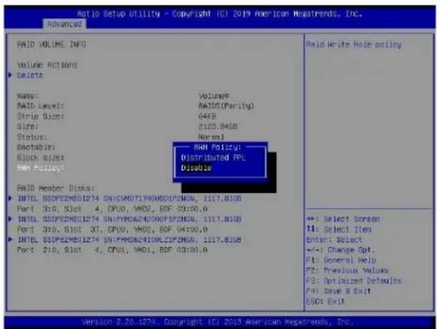
text_image
Ratio Setup Utility - Copyright (CI) 2019 American MegaTrends, Inc. Advanced RAID VOLUME INFO Volume Actions Delete Name: RAID Level: Strip Size: Size: Status: Bootable: Block B/S RAM Policy: RAID Member Disks: INTEL SSPEEEMES1274 SN:CAN07174008DPZEN, 1117.8108 Port 3:0, Slot 4, CPU0, VAD2, BDF 03:00.0 INTEL SSPEEEMES1274 SN:PM0624100CLIPZEN, 1117.8108 Port 3:0, Slot 37, CPU0, VAD2, BDF 04:00.0 INTEL SSPEEEMES1274 SN:FM0624100CLIPZEN, 1117.8108 Port 2:0, Slot 4, CPU1, VAD1, BDF 03:00.0 Volume9 RAID(Parity) 64KB 2125.840B Normal RAM Policy: Distributed FPL Disable RAID Write Hole policy +: Select Screen TI: Select Item Enter: Select +/-: Change Opt. F1: General Help F2: Previous Values F3: Optimized Defaults F4: Save & Exit ESC: Exit Version 2.20.1274. Copyright (CI) 2019 American MegaTrends, Inc.
Note 1: Partial parity logging (PPL) can be defined as the result of XOR calculation of old data and old parity. PPL is a feature available for RAID5 volumes. While a power/drive-failure/crash occurring, PPL information helps rebuild the RAID volume and reduce the potential data loss.
Note 2: For the RWH condition, the Intel® RSTe 5.X or above RWH closure algorithm provides the option of use of an additional NVMe device for RAID volume rebuilds (Journaling Drive RWH closure mode). Without the use of an additional NVMe device, PPL distributed RWH closure mode can be utilized to close the RWH by using the parity drive for example.
Step 3. Set the feature, RWH Policy, to Journaling Drive.
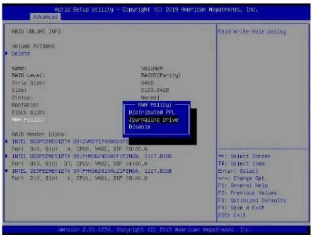
text_image
Ratio Setup Utility - Copyright (C) 2019 American Megatrends, Inc. Advanced RAID VOLUME INFO Volume Actions Delete Name: RAID Level: Strip Size: Sizes: Status: Bootable: Block Bides RMM Policy: RAID Member Disks: INTEL SEDPEEMED1274 SN:CAVDT140080523 Port: 3x0, Slot 4, CPU0, VH02, BDF 03:00.0 INTEL SEDPEEMED1274 SN:PHO624000FIP2HGN, 1117.81GB Port: 3x0, Slot 3T, CPU0, VH02, BDF 04:00.0 INTEL SEDPEEMED1274 SN:PHO624100LZIP2HGN, 1117.81GB Port: 2x0, Slot 4, CPU0, VH01, BDF 03:00.0 RAID Policy: Distributed FPL Journaling Drive Disable RAID Write Hole policy +:- Select Screen TI: Select Item Enter: Select +/-: Change Opt. F1: General Help F2: Previous Values F3: Optimized Defaults F4: Save & Exit ESC: Exit Version 3.20.1274. Copyright (C) 2019 American Megatrends, Inc.Press
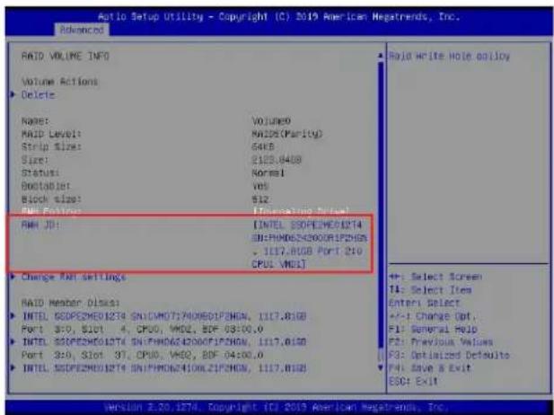
text_image
Aptio Setup Utility - Copyright (C) 2019 American Megatrends, Inc. Advanced RAID VOLUME INFO Volume Actions ► Delete Name: VOLUME9 RAID Level: MAX(Parity) Strip Size: 64KB Size: $125.840B Status: Normal Bootablet: Yes Block Size: $12 REV FOUNT: (Reinforcing Cable) RAM JD: INTEL SODPE2ME01274 SIN:PHM062420001F2HGN, 1117.81GB Port 210 CPOL: VMDJ] ► Change RAM Settings RAID Member DISS: INTEL SODPE2ME01274 SNICAM072700801F3HGN, 1117.81GB Port 3:0, $101 4, CPOL, VMD2, BDF 03:00,0 INTEL SODPE2ME01274 SNIFPM062420001F2HGN, 1117.81GB Port 3:0, Slot 3T, CPOL, VMD2, BDF 04:00,0 INTEL SODPE2ME01274 SNIFPM0624100L2F3HGN, 1117.81GB ► Select Screen TI: Select Item Enter Select +/-1 Charge Opt. P1: General Hold P2: Previous Values P3: Optimized Defaults P4: Save a Exit ESO: ExitRWH JD
Use the arrow keys to select RWH JD. Press
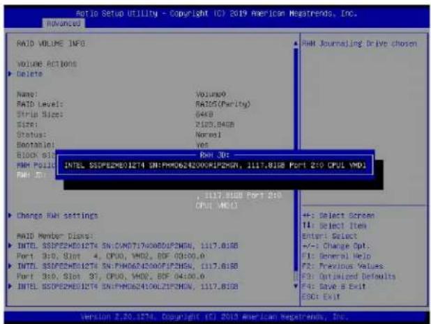
text_image
Auto Setup Utility - Copyright (C) 2019 American Negatrends, Inc. Advanced RAID VOLUME INFO VOLUME ACTIONS Delete Name: RAID Level: Strip Size: Size: Status: Bootstrap: Block Size: RAM POUL RAM POUL RAM ID: Volume: RAID(Parity) 64KB 2107.84GB Normel Yes Port 3D: INTEL SSDPE2ME012T4 SN:FMH0624200XIP2CHN, 1117.81SB PORT 210 CPUL VMD1 , 1117.81SB PORT 210 CPUL VMD1 Change RAM settings RAM Member Disks: INTEL SSDPE2ME012T4 SN:VMDD71740080LPZHN, 1117.81SB Port 3D: Slot 4, CPU0, VMD2, BDF 04:00.0 INTEL SSDPE2ME012T4 SN:FMH0624200XIP2CHN, 1117.81SB Port 3D: Slot 3D, CPU0, VMD2, BDF 04:00.0 INTEL SSDPE2ME012T4 SN:FMH0624100LZIP3HN, 1117.81SB F: Select Screen F1: Select Item Enter: Select +/-: Change Opt. F1: General Help F2: Previous Values F3: Optimized Defaults F4: Save & Exit EOD: Exit Version 2.20.1274. Copyright (C) 2019 American Negatrends, Inc.Step 4. Use the arrow keys and press
Step 5. For the changes to take effect, use the arrow keys to select Change RWH settings and press

text_image
Ad10 Setup Utility - Copyright (C) 2019 American Megatrends, Inc. Advanced RAID VOLUME INFO Volume Actions Delete Name: RAID Level: Strip Size: Size: Status: Bootable: Block Size: RAM Policy: RAM ID: Change Rate Settings RAID Member Disks: INTL SSPE2M01274 SN:CU0717400001F2NGN, 1117.8168 Port 3:0, Slot 4, CPU0, VMO2, BDF 03:00.0 INTL SSPE2M01274 SN:PHD624200F1NGN, 1117.8168 Port 3:0, Slot 37, CPU0, VMO2, BDF 04:00.0 INTL SSPE2M01274 SN:PHD624200L1F3NGN, 1117.8168 Volume: RAID(Parity) 64KB 2125.84GB Normal Ves 512 [Journaling Drive] [INTEL SSPE2M01274 SN:PHD624200R1F2NGN, 1117.8168 Port 240 CPU1 MD1] +: Select Screen T1: Select Item Enter: Select +/-: Change Opt. F1: General Help F2: Previous Values F3: Optimized Defaults F4: Save R Exit ESC4 Exit Version 2.20.1274. Copyright (C) 2019 American Megatrends, Inc.Your computer will return to the main screen of All Intel VMD Controllers as shown below.
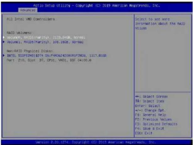
text_image
All Intel VMD Controllers RAID Volumes: Volume0, RAIDS(Parity), 213.86GB, Normal Volume1, RAIDS(Parity), 105.18GB, Normal Non-RAID Physical Disks: INTEL: RSPEZMEO1274 SN:PHC624200GIF29CM, 1117.81GB Port 2:0, 8Jot NT, OPUI, VMD, BDF 04:00.0 Select to see here Information about the RAID VOLUME +/-: Select Screen I#: Select IBox Enter: Select +/-: Change Opt. F1: General Help F2: Previous Values F3: Optimized Defaults F4: Save A Exit ESC: Exit Version 2.20.1274 Copyright (C) 2013 American Megatrends, Inc.Appendix F
Secure Boot Settings
Secure boot is a feature of UEFI (Unified Extensible Firmware Interface) that ensures boot loaders are digitally signed and validated. The F.1, F.2, and F.3 sections provide instructions on how to enable the secure boot features. The F.4 section states Key Management settings.
F.1 Boot mode select Feature
Press during system boot to enter the BIOS Setup utility. Navigate to the Boot tab. Use the arrow keys to select Boot mode select and press
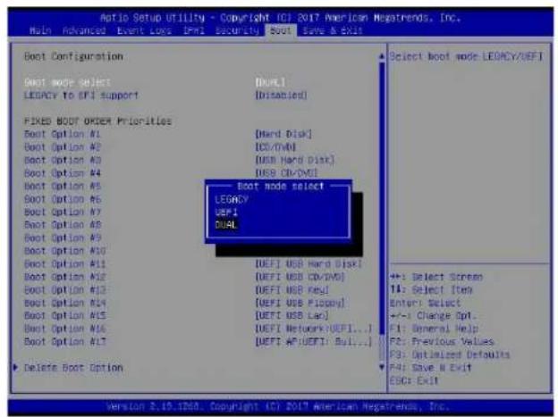
text_image
Aio Setup Utility - Copyright ICI 2017 American Megatrends, Inc. Main Advanced Event Loss IPM Security Boot Save & Exit Boot Configuration Boot mode select LEGACY to EFI Support [Default] [Disabled] FIXED BOOT ORDER Priorities Boot Option #1 [Hard Disk] Boot Option #2 [CD/DVD] Boot Option #3 [USB Hard Disk] Boot Option #4 [USB Ch/DVI] Boot Option #5 [Multi-Size] Boot Option #6 [Multi-Size] Boot Option #7 [Multi-Size] Boot Option #8 [Multi-Size] Boot Option #9 [Multi-Size] Boot Option #10 [Multi-Size] Boot Option #11 [Multi-Size] Boot Option #12 [Multi-Size] Boot Option #13 [Multi-Size] Boot Option #14 [Multi-Size] Boot Option #15 [Multi-Size] Boot Option #16 [Multi-Size] Boot Option #17 [Multi-Size] Boot mode select LEGACY UEFI DUAL ▶ Delete Boot Option Select boot mode LEGACY/DEFI +/-: Select Screen T1: Select Item Enter: Select +/-: Change Opt. F1: General Help F2: Previous Values F3: Optimized Defaults F4: Save N Exit ESC: Exit Version 2.19.1208. Copyright (C) 2017 American Megatrends, Inc.F.2 Secure Boot/ Secure Boot Mode/ CSM Support Features
Press during system boot to enter the BIOS Setup utility. Navigate to the Security tab as shown below.
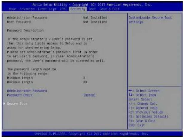
text_image
Aptio Setup Utility - Copyright (C) 2017 American Negatrends, Inc. Main Advanced Event logs IPNL Security Boot Save & Exit Administrator Password Not Installed User Password Not Installed Password Description If the Administrator's / User's password is set, then this only limit access to Setup and is asked for when entering Setup. Please set Administrator's password first in order to set user's password, if clear Administrator's password, the User's password will be cleared as well. The password length must be: in the following range: Minimum length 3 Maximum length 20 Administrator Password Password Check [Setup] Secure Boot Customizable Secure Boot settings +; Select Screen F4; Select Item Enter Select +/-; Change Opt. F1; General Help F2; Previous Values F3; Optimized Defaults F4; Save & Exit EIC: Exit Version 2.19.1268 Copyright © 2017 American Negatrends, Inc.Use the arrow keys to select Secure Boot and press
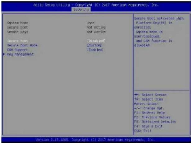
text_image
Auto Setup Utility - Copyright (C) 2017 American Newsrends, Inc. Security System Mode User Secure Boot Not Active Vendor Keys Not Active Secure Boot [Disabled] Secure Boot Mode [Custom] COM Support [Enabled] Key Management Secure Boot activated when Platform Key(FC) is enrolled, System mode is user/Deployed, and CSM function is disabled +F: Select Screen F1: Select Item Enter: Select +/-: Change Opt. F1: General Help F2: Previous Values F3: Optimized Defaults F4: Save & Exit ESC: Exit Version 2.19.1208. Copyright (C) 2017 American Newsrends, Inc.Secure Boot
This feature is available when the platform key (PK) is pre-registered where the platform operates in the User mode and compatibility support module (CSM) support is disabled in the BIOS Setup utility. Select Enabled for secure boot flow control. The options are Disabled and Enabled.
Secure Boot Mode
Use this feature to set the secure boot mode. The options are Standard and Custom. Select Standard to load manufacturer's default secure variables. Select Custom to change the image execution policy and to manage secure boot keys.
CSM Support
Select Enabled to support the legacy CSM, which provides compatibility support for traditional legacy BIOS for system boot. The options are Disabled and Enabled.
F.3 Secure Boot Settings
To have the secure boot support, be sure to follow the steps below (Step 1 \~ Step 4).
Step 1. Set Secure Boot Mode to Standard. Press Yes to install factory default keys as needed.
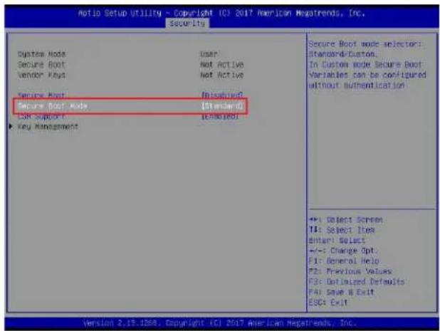
text_image
Auto Setup UTILITY - Copyright ICI 2017 American Megatrends, Inc. Security System Mode User Secure Boot Not Active Vendor Keys Not Active Secure Root Not Disabled Secure Boot Mode Standard COR Support Not Enabled Key Management Secure Boot mode selector: Standard-Duston. In Custom mode Secure Boot Variables can be configured without authentication +/-: Select Screen T#: Select Item Enter: Select +/-: Change Opt. F1: General Help F2: Previous Values F3: Defaulted Defaults F4: Save & Exit ESC: Exit Version 2.19.1866. Copyright ICI 2017 American Megatrends, Inc.
text_image
Aio Setup Utility - Copyright (C) 2017 American Megatrends, Inc. Security System Mode Secure Boot Vendor Keys Secure Boot Secure Boot Mode CSM Support Key Management User Not Active Not Active [Disabled] [Custom] [Enabled] Secure Boot mode selector: Standard/Custom, In Custom mode Secure Boot Variables can be configured without authentication Install factory defaults - Press "Yes" to install factory default keys Yes No +: Select Screen T1: Select Item Enter: Select +/-: Change Opt. F1: General Help F2: Previous Values F3: Optimized Defaults F4: Save & Exit ESC: Exit Version 2.13.1208, Copyright (C) 2017 American Megatrends, Inc.
Note: The Key Management menu will become unavailable when Secure Boot Mode is set to Standard.
Step 2. For the changes to take effect, press
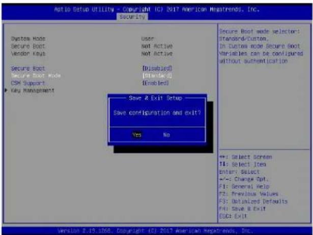
text_image
Ato Setup Utility - Copyright IC? 2017 American Megatrends, Inc. Security System Hode User Secure Boot Not Active Vendor Keys Not Active Secure Boot Disabled Secure Boot Mode Standard Di CSM Support Enabled Key Management Save & Exit Setup Save configuration and exit? Yes No Secure Boot mode selector: Standard-Duston, In Custom mode Secure Boot Variables can be configured without authentication ++: Select screen TI: Select Item Enter: Select +/-: Change Opt. F1: General Help F2: Previous Values F3: Defaulted Defaults F4: Save & Exit ESC: Exit Version 2.19.1368. Copyright (C) 2017 American Megatrends, Inc.Step 3. Press during system boot to enter the BIOS Setup utility. Navigate to the Security tab and enter the Secure Boot menu. Set CSM Support to Disabled.
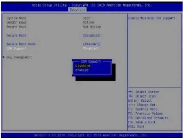
text_image
Automatic Setup Utility - Copyright (C) 2019 American Megatrends, Inc. SECURITY System Mode User Vendor Keys Active Secure Boot Not Active Secure Boot [Disabled] Secure Boot Mode [Standard ID] CSM Support [Enabled] Key Management CSM Support Disabled Enabled Enable/Disable CSH Support. +: Select Screen T4: Select Item Enter: Select +/-: Change Opt. F1: General Help F2: Previous Values F3: Optimized Defaults F4: Save & Exit ESC: Exit Version 3.20.1874. Copyright (C) 2019 American Megatrends, Inc.For the changes to take effect, press
Step 4. Press during system boot to enter the BIOS Setup utility. Navigate to the Security tab and enter the Secure Boot menu. Set Secure Boot to Enabled.
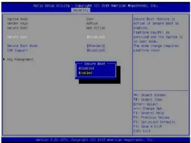
text_image
Auto Setup Utility - Copyright TCP 2019 American Netsatrends, Inc. Security System Mode User Vendor Keys Active Secure Boot Not Active Secure Boot Disabled Secure Boot Node [Standard] OSK Support [Disabled] Key Management Secure Boot Disabled Enabled Secure Boot Feature is Active if Secure Boot is Enabled. Platform Key (PK) is enrolled and the System is in User mode. The mode change requires platform reset +: Select Screen TI: Select Item Enter: Select +/-: Change Opt. F1: Several Help F2: Previous Values F3: Optimized Defaults F4: Save A Exit ESC: Exit Version 2.20.1874. Copyright (C) 2019 American Netsatrends, Inc.For the changes to take effect, press during system boot to enter the BIOS Setup utility. Navigate to the Security tab and enter the Secure Boot menu. The following screen will appear.
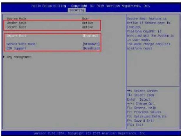
text_image
Ratio Setup Utility - Copyright (C) 2019 American Megatrends, Inc. Security System Mode User Vendor Keys Active Secure Boot Active Secure Boot Enrolled Secure Boot Mode [Standard] OK Support [Unabled] Key Management Secure Boot Feature is Active if Secure Boot is Enabled, Platform Cry(PK) is enrolled and the System is In User mode. The mode change requires platform reset +: Select Screen 14: Select Item Enter: Select +/-: Change Opt. P1: General Help P2: Previous Values P3: Optimized Defaults P4: Save & Exit EOP: Exit
Note: Once Secure Boot is enabled, CSM Support will become disabled and the legacy environment is no longer valid. The authorized UEFI support such as UEFI OS, AOC UEFI FW, and UEFI PXE server are allowed.
F.4 Key Management Settings
The Key Management menu as shown below, which is available when Secure Boot Mode is set to Custom, allows the secure boot keys to be installed via the external device and be involved in the secure boot process.
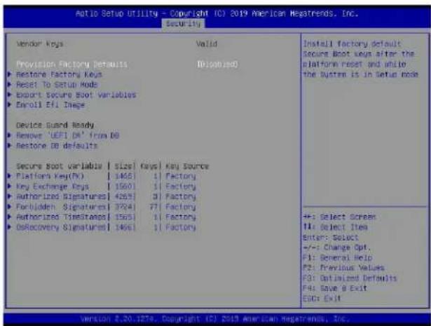
text_image
Auto Setup Utility - Copyright (C) 2019 American News trends, Inc. Security Vendor Keys Valid Provision Factory Defaults Discontinued ► Restore Factory Keys ► Reset To Setup Mode ► Export Secure Boot Variables ► Enroll Efi Image Device Guard Ready ► Removes 'UEFI DR' from DB ► Restore DB defaults Secure Boot Variable | Size | Keys | Key Source ► Platform Key(Hx) | 3468 | 1 Factory ► Key Exchange Keys | 1560 | 1 Factory ► Authorized Signatures | 4264 | 3 Factory ► Forbidden Signatures | 3724 | 77 Factory ► Authorized Timestamp | 1563 | 1 Factory ► DoRecovery Signatures | 1466 | 1 Factory Install Factory default Secure Boot keys after the platform reset and while the System is in Setup mode +: Select Screen #: Select Item Enter: Select +/-: Change Opt. F1: General Help F2: Previous Values F3: Optimized Defaults F4: Save & Exit END: Exit version 8.20.1876. Copyright (C) 2019 American News trends, Inc.Provision Factory Defaults
This feature is to provision the default secure boot keys set by the manufacturer when system is in the Setup mode. The options are Disabled and Enabled.
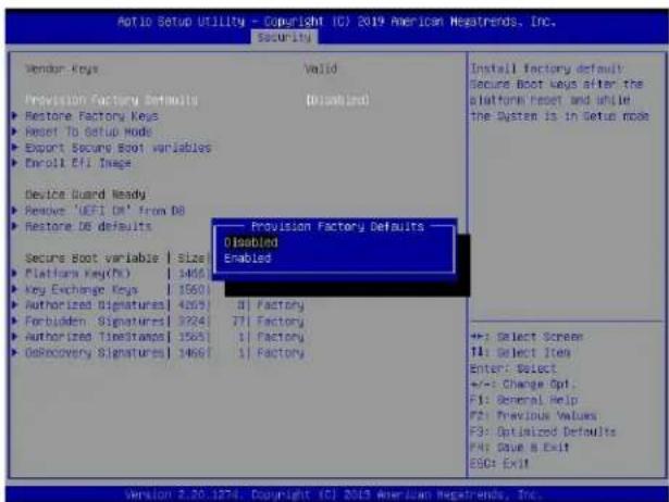
text_image
Aotio Setup Utility - Copyright (C) 2019 American Hesatrends, Inc. Security Vendor Keys Valid Provision Factory Defaults Disabled Restore Factory Keys Reset To Setup Mode Export Security Boot variables Enroll Efi Image Device Guard Ready Remove 'UEFI CM' from DB Restore DB defaults Secure Boot variable | Size Platform Key(No) | 1466 Key Exchange Keys | 1560 Authorized Signatures | 4269 Forbidden Signatures | 3224 Authorized Timestamps | 1563 GoRecovery Signatures | 1466 Provision Factory Defaults Disabled Enabled +/-: Select Screen T1: Select Items Enter: Select +/-: Change Opt. F1: General Help F2: Previous Values F3: Optimized Defaults F4: Save & Exit ESO: ExitSelect and press Yes to restore factory default secure boot keys and key variables. Also, it will reset the system to the User mode. The options are Yes and No.
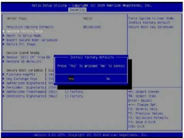
text_image
Notio Setup Utility - Copyright (C) 2019 American Megatrends, Inc. Security Vendor Keys Valid Force System to User Mode. Installation factory default Secure Boot key databases Provision Factory Defaults D:\snj\esJ Restore Factory Keys Reset To Setup Mode Export Secure Boot variables Enroll Eff. Image Device Guard Ready Remove 'LEFI DA' from (A) Restore DB defaults Secure Boot Variable | 612 Platform Key(PK) | 148 Key Exchange Keys | 156 Authorized Signatures | 426 Forbidden Signatures | 3724 Authorized Timetamos | 15051 | 1 Factory DeRecovery Signatures | 14661 | 1 Factory Install factory defaults - Press 'Yes' to proceed 'No' to cancel Yes No +/- Select Screen TI: Select Item Enter: Select +/- Change Opt. F1: General Help F2: Previous Values F3: Optimized Defaults F4: Save & Exit ESC: Exit Version 2.20.1874, Copyright (C) 2019 American Megatrends, Inc.▶Reset To Setup Mode (available when the System Mode is in User mode)
Select and press Yes to clear all secure boot variables and reset the system to the Setup mode. The options are Yes and No.
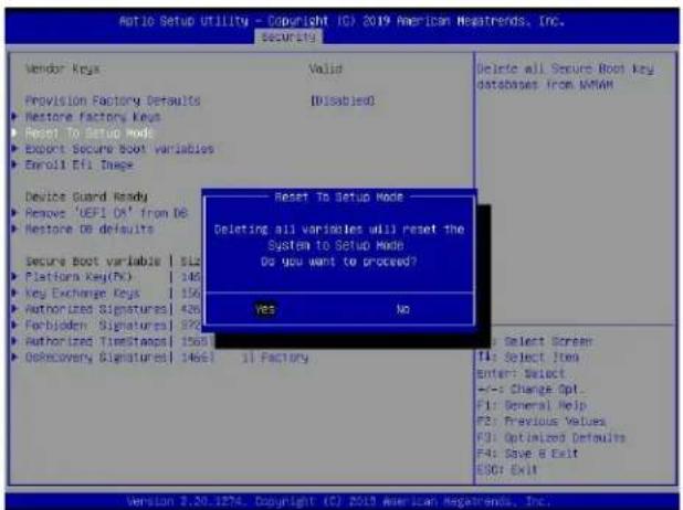
text_image
Ratio Setup Utility - Copyright (C) 2019 American Netatrends, Inc. Security Vendor Keys Valid Provision Factory Defaults [Disabled] Restore factory keys Reset To Setup Mode Export Secure Boot variables Enroll Efi Image Device Guard Ready Remove 'UEFI OK' from OE Restore DO defaults Secure Boot variable | S12 Platform Key(K) 148 Key Exchange Keys | 156 Authorization Signatures | 426 Forbidden Signatures | 372 Authorized TimeStamps | 1561 OsRecovery Signatures | 1465 | 1 Factory Reset To Setup Mode Deleting all variables will reset the System to Setup Mode Do you want to proceed? Yes No Select Screen T1: Select Item Enter: Select --: Change Opt. F1: General Help F2: Previous Values F3: Optimized Defaults F4: Save B Exit ESC: Exit Version 2.20.1274. Copyright (C) 2019 American Netatrends, Inc.▶Export Secure Boot variables
Use this feature to export NVRAM content of secure boot variables to files in a root folder on a file system device.
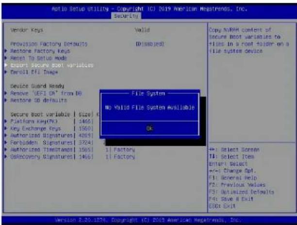
text_image
Natio Setup Utility - Copyright (C) 2019 American Megatrends, Inc. Security Vendor Keys Valid Provision Factory Defaults (D:\mbo\es) Restore Factory Keys Reset To Setup Mode Export Secure Boot variables Enroll Ftl Image Device Guard Ready Remove 'UEFI DR' from DQ Restore DB defaults Secure Boot Variable | Size | Platform Key(PV) | 1466 Key Exchange Keys | 15601 Authorized Signatures[ 4269] Forbidden Signatures[ 3724] Authorized Timetants[ 15651] DelRecovery Signatures[ 1466] File System No Valid File System Available OK +: Select Screen T1: Select Item Enter: Select +/-: Change Opt. F1: General Help F2: Previous Values F3: Optimized Defaults F4: Save A Exit ESO: Exit Version 2.20.1874, Copyright (C) 2019 American Megatrends, Inc.▶Enroll Efi Image
This feature is to enroll SHA256 hash of the binary into the Authorized Signature Database (DB) and to allow the image to run in the secure boot mode.
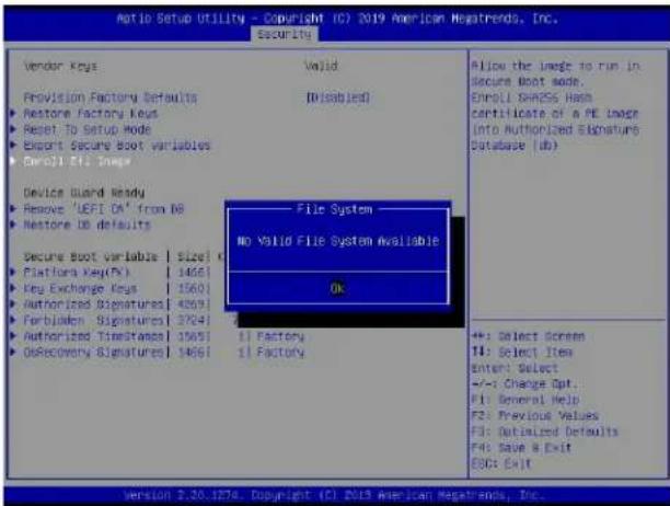
text_image
Ratio Setup Utility - Copyright (C) 2019 American Megatrends, Inc. Securities Vendor Keys Valid Provision Factory Defaults [Disabled] Restore factory keys Reset To Setup Mode Export Secure Boot variables Enroll Efi Images Device Guard Ready Remove 'UEFI DA' from DB Restore ID defaults Secure Boot Variable | Size | Platform Key(Ps) 14661 Key Exchange Keys 15601 Authorized Signatures[14661] Forbinden Signatures[3764] Authorized Timestamps[15651] GoRecovery Timestamps[14661] File System No Valid File System Available Ok Allow the Image to run in Secure Boot mode. Enroll SHNCS Hash certificate of a PE Image Into Authorized Signature Database (db) +: Select Screen T4: Select Item Enter: Select +/-: Change Opt... F1: General Help F2: Previous Values F3: Optimized Defaults F4: Save & Exit E80: Exit Version 2.20.1874. Copyright (C) 2013 American Megatrends, Inc.▶Remove 'UEFI CA' from DB (available when the system is not in Device Guard Ready)
Select and press Yes to remove Microsoft UEFI CA certificate from the DB. The options are Yes and No.
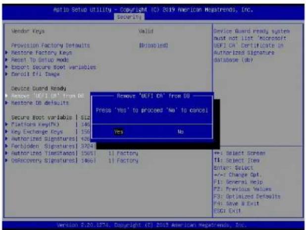
text_image
Auto Setup Utility - Copyright (C) 2019 American Megatrends, Inc. Security Vendor Keys Valid Device Guard Newy system Must not list 'Microsoft' UEFI CA' Certificate in Authorized Signature database (db) Provision Factory Defaults ID:disabled Restore Factory Keys Reset To Setup Mode Export Secure Boot variables Enroll Efi Dange Device Guard Ready Remove 'UEFI CA' from DB Restore DB defaults Secure Boot variable | SLS Platform Key(Hx) | 140 Key Exchange Keys | 150 Authorized Signatures | 426 Forbidden Signatures | 3724 Authorized Timestamps | 15651 | 1 Factory OsRecovery Signatures | 14661 | 1 Factory Remove 'UEFI CA' from DB Press 'Yes' to proceed 'No' to cancel Yes No +/- Select Screen T1: Select Item Enter: Select +/- Change Opt. F1: General Help F2: Previous Values F3: Optimized Defaults F4: Save & Exit ESC: Exit Version 2.20.1874. Copyright (C) 2019 American Megatrends, Inc.Select and press Yes to restore the DB variables to factory defaults. The options are Yes and No.
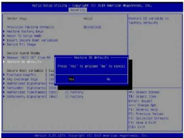
text_image
Auto Setup Utility - Copyright (C) 2019 American Netsatrends, Inc. Security Vendor Keys Valid Provision Factory Defaults IDssolled Restore Factory Keys Reset To Setup Mode Export Secure Boot variables Enroll Eff Image Device Guard Ready Remove 'UEFI CH' from DB Restore DB defaults Secure Boot variable | SLa Platform Key(fk) 146 Key Exchange Keys | 100 Authorized Signatures[ 465] Forbidden Signatures[ 3724] Authorized TimeStampel | 15691 DoRecovery Signatures[ 1466] Restore DB variable to factory defaults Press 'Yes' to proceed 'No' to cancel Yes No +/- Select Screen T1: Select Item Enter: Select +/-: Change Opt. F1: General Help F2: Previous Values F3: Optimized Defaults F4: Save & Exit ESD: Exit Version 2.20.1874. Copyright (C) 2019 American Netsatrends, Inc.*Refer to the following settings for keys and signatures related to secure boot.
▶ Platform Key (PK)
The Platform Key (PK), which is pre-installed in firmware during manufacturing, provides full control of the secure boot key hierarchy. The options are Details, Export, Update, and Delete. Select Details to display detailed information of PK. Select Export to save the current PKs to a FAT formatted USB flash drive. Select Update to load the factory defaults or load PKs from a file on the external device. Select Delete to clear the current PKs and reset the system to the Setup mode. See the following for more information of each option.
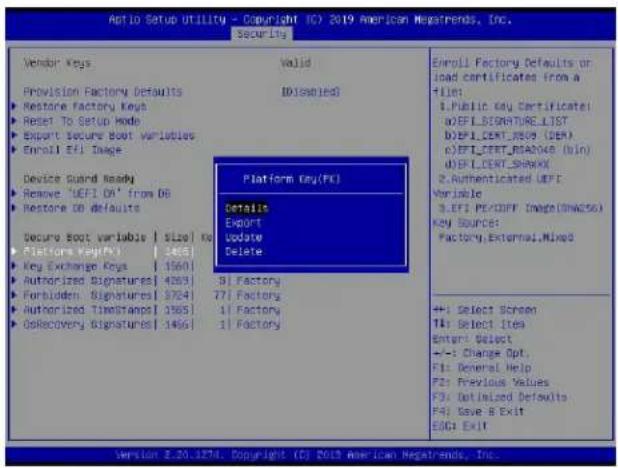
text_image
Aptio Setup Utility - Copyright (C) 2019 American Megatrends, Inc. Security Vendor Keys Valid Provision Factory Defaults ID:isabled Restore factory keys Reset To Setup Mode Export Secure Boot Variables Enroll EFI Image Device Guard Ready Remove 'UEFI DA' from DB Restore DB defaults Secure Boot variable | Size | No Platform Key(FX) 1465 Key Exchange Keys 15601 Authorized Signatures[ 4263 ] Forbidden Signatures[ 3764 ] Authorized TimeStamp[ 3565 ] DelRecovery Signatures[ 1466 ] Platform Key(FC) Details Export Update Delete Platform Key(FC) EVI EVI.CERT.SHAWX 2. Authenticated EVI Variable 3. EFI PE-OFF Image(SWASS) KEY SOURCE: Factory External,Mixed +1 Select Screen T4: Select Item Enter: Select +-- Change Opt. F1: General Help F2: Previous Values F3: Optimized Defaults F4: Save B Exit ESC: Exit Version 2.20.1274. Copyright (C) 2019 American Megatrends, Inc.Details: Use the arrow keys to select Details and press
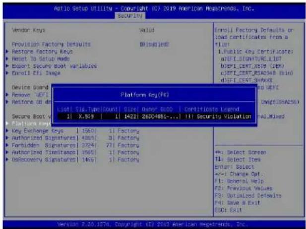
text_image
Atrio Setup Utility - Copyright (C) 2019 American Hegatrends, Inc. Security Vendor Keys valid Provision Factory Defaults ID(splied) Restore Factory Keys Reset To Setup mode Export Secure Boot variables Enroll Effi Image Device Guard Remove 'UEFI' Restore to do Secure Boot v 11 X.508 | 11 1423 28DC4851... || Security Violation Platform Key Key Exchange Keys | 1560 | 1 Factory Authorized Signatures | 4003 | 3 Factory Forbidden Signatures | 3724 | 71 Factory Authorized Time stamp | 1565 | 1 Factory DeRecovery Signatures | 1467 | 1 Factory Platform Key (FK) List: Sig.TypeCount | Size: Owner Build | Certificates Legend Main.Mixed Enroll Factory Defaults or load certificates from a *List 1.Public key certificate: a)EFLSIGNATURE_LIST b)EF1_CERT_XS09 (DEK) c)EF1_CERT_RSAD040 (bin) d)EF1_CERT_SHAYXX and DEF1 Image(ShN25G) Platform Key (FK) +: Select Screen TI: Select Item Enter: Select +/-1 Change Opt. F1: General Help F2: Previous Values F3: Optimized Defaults F4: Save & Exit ESC: ExitExport: Use the arrow keys to select Export. It is to save the current PKs to a FAT formatted USB flash drive.
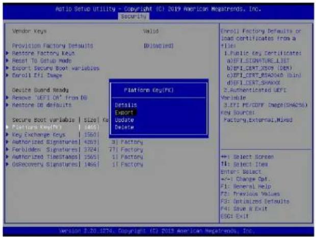
text_image
Aio Setup Utility - Copyright (C) 2019 American Megatrends, Inc. Security Vendor Keys Valid Provision Factory Defaults [Disagued] ► Restore Factory Keys ► Reset To Setup Mode ► Export Security Boot variables ► Enroll Effi Damage Device Guard Ready Platform Key(PK) ► Remove 'UEFI OK' from DB Details ► Restore OB defaults Export Secure Boot variable | Size | Ke Update Delete Platform Key(PK) ► Key Exchange Keys | 1560 ► Authorized Signatures | 4269 | 3 | Factory ► Forbidden Signatures | 3224 | 7 | Factory ► Authorized Timestamps | 1565 | 1 | Factory ► ORecovery Signatures | 1465 | 1 | Factory Platform Key(PK) Details Export Update Delete Enroll Factory Defaults or load certificates from a +File: 1. Public key Certificates: a) EIFI DESIGNATURE_LIST b) EIFI CERT_XS09 (DER) c) EIFI CERT_XS0408 (BIN) d) EIFI CERT_SHAWX 2. Authenticated UEPI Variable: 3. EIFI PE/COFF (Image(SHA256)) Key Source: Factory,External,Mixed ++: Select Screen F1: Select Item Enter: Select +/-: Change Opt. F1: General Help F2: Provision Values FG: Optimized Defaults F4: Save & Exit ESC: Exit Version 3.20.1874, Copyright (C) 2019 American Megatrends, Inc.Press
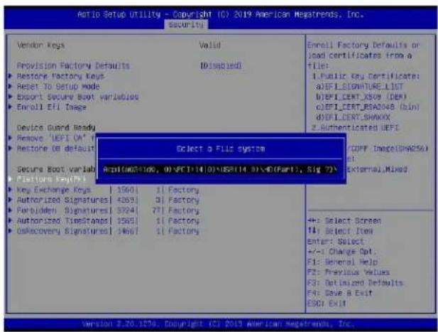
text_image
Ratio Setup Utility - Copyright (C) 2019 American Megatrends, Inc. Security Vendor Keys Valid Provision Factory Defaults Disapplied Restore Factory Keys Reset TO Setup Mode Export Secure Boot variables Enroll Eli Image Device Wizard Ready Remove 'UEFI ON' Restore OE default Secure Boot Variable Platform Key(s) Key Exchange Keys | 1560 | 1 Factory Authorized Signatures | 4263 | 3 Factory Perbidden Signatures | 3724 | 71 Factory Authorized TimeStamps | 1565 | 1 Factory OSRecovery Signatures | 1465 | 1 Factory Select a Fills system Appl(a)24100, 01\FC11410\USE(14.0)\E(Fart1, Sig 7) Enroll Factory Defaults or load certificates from a file: Public key Certificate: a)EFILIDENTURE_LIST d)EFILERT_XSUS (DER) c)EFILERT_BSAO(N8 (DIN) d)EFILERT_SHAWAY 2 Authenticated UEFI COFF Image(DNA256) External,Mixed +: Select Screen T1: Select Item Enter: Select +/-: Change Opt. F1: General Help F2: Previous Values F3: Optimized Defaults F4: Save & Exit ESC: Exit Version 2.20.1276. Copyright (C) 2019 American Megatrends, Inc.
Note: Refer to the right panel of the screen for the file formats accepted.
Update: Use the arrow keys to select Update. It is to load the factory defaults or load PKs from a file on the external device.
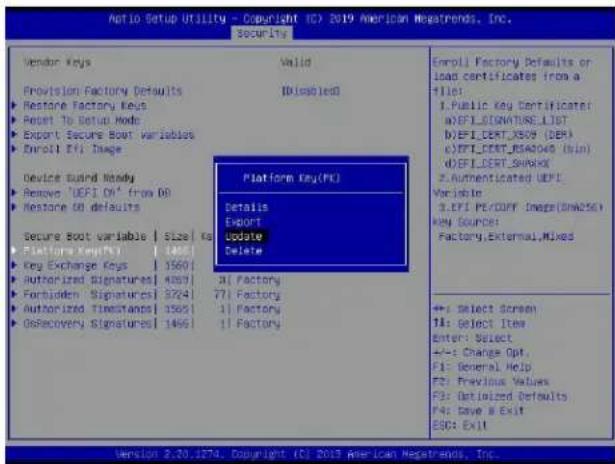
text_image
Ratio Setup Utility - Copyright (C) 2019 American Megatrends, Inc. Security Vendor Keys Valid Provision Factory Defaults ID(Enabled) Restore Factory Keys Reset To Setup Mode Export Secure Boot Variables Enroll Efi Image Device Build Moddy Remove 'UEFI OK' from DB Restore DB defaults Secure Boot Variable | Size Ka Platform Key(PC) 1465 Key Exchange Keys | 1560 Authorized Signatures[1] 4367 Forbidden Signatures[1] 3724 Authorized Timestamps[1] 1565 GoRecovery Signatures[1] 1465 Platform Key(PC) Details Export Update Delete 1 Factory 71 Factory 1 Factory 1 Factory Enroll Factory Defaults or load certificates from a file: IPublic Key Certificate: uEFI-SONATURE_LIST vEFI_CERT_XS09 (DERA) cYFT_CERT_BS4040 (Upin) vEFI_CERT_SNWKX 2.Aumenticated UEFI Variable: 3.EFI PE/COFF Image(SNA256) KEY Source: Factory,External,Mixed +: Select Screen T1: Select Item Enter: Select +/-: Change Opt. F1: General Help F2: Previous Values F3: Optimized Defaults F4: Save & Exit ESGA Exit Version 2.20.1274. Copyright (C) 2019 American Megatrends, Inc.Press
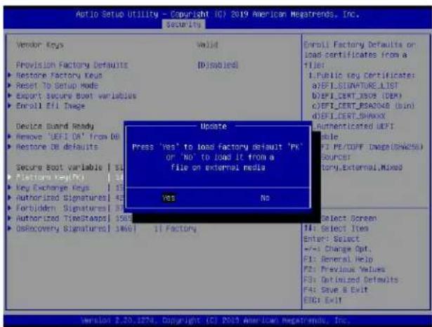
text_image
Autio Setup Utility - Copyright (C) 2019 American Megatrends, Inc. Security Vendor Keys Valid Provision Factory Defaults (Dissubled) Restore Factory Keys Reset TO Setup Mode Export Secure Boot variables Enroll Eff Image Device Guard Ready Remove 'UEFI OE' from DB Restore DB defaults Secure Boot variable | 51 Fistural Key(s) Key Exchange Keys Authorized Signatures Fortidden Signatures Authorized TimeStamps | 1568 OsRecovery Signatures | 1469 Update Press 'Yes' to load factory default 'PK' OR 'No' to load it from a file on external media Yes No 11 Factory Enroll Factory Defaults on load certificates from a TIE: I.Public key certificates: a:REF1:SIGNATURE_LIST b:REF1:CENT_USER (DEM) c:REF1:CERT_PE200A0 (bind d:REF1:CERT_SHIKOX) Authenticated UEFI Rule: FI PE/COFF IMAGE(SHA255) Sources: tory,External,Mixed Select Screen Enter: Select +/-: Change Opt. F1: General Help F2: Previous Values F3: Optimized Defaults F4: Save & Exit EXIT: ExitTo load the factory defaults, navigate to Yes and press
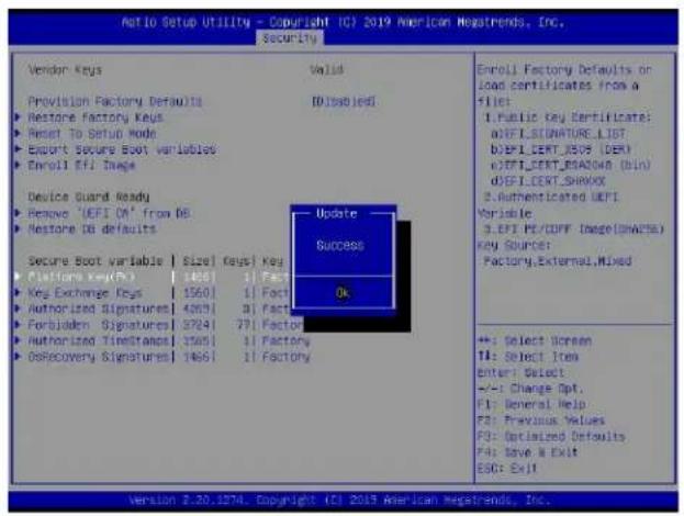
text_image
Antio Setup Utility - Copyright (C) 2019 American Megastrends, Inc. Security Vendor Keys Valid Provision Factory Defaults D:\sob\eds Restore Factory Keys Reset To Setup Mode Export Secure Boot variables Enroll Efi Image Device Guard Ready Remove 'UEFI ON' from DB Restore DB defaults Secure Boot variable | Size | keys | Key Configuration Key(Ex) 1560 | 1 Fact Key Exchange Keys | 1560 | Fact Authorized Signatures1 4263 | 3 Fact Forbidden Signatures1 3724 | 71 Fact Authorized Timestamps1 3505 | 1 Factory GoRecovery Signatures1 466 | 1 Factory Update Success Ok Enroll Factory Defaults or load certificates from a file: 1. Public Key Certificate: aDFI.SIGNATURE_LIST bDFI.CERT_JBSV (DER) cDFI.CERT_BSAC048 (BIN) dDFI.CERT_SHAWX 2. Authenticated UEPI Variable: 3. EPI HT/CFFF (Image(SHACK)) Key Source: Factory,External,Mixed ++: Select Screen T4: Select Item Enter: Select +/-: Change Opt. F1: General Help F2: Previous Values F3: Optimized Defaults F4: Move & Exit ESC: Exit Version 2.30.1874. Copyright (C) 2019 American Megastrends, Inc.To load PKs from a file on the external device, navigate to No and press
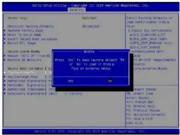
text_image
Audio Setup Utility - Copyright (C) 2019 American Newsrends, Inc. Security Vendor Keys Modified Provision Factory Defaults D:\100\167 Restore Factory Keys Reset To Setup Mode Export Secure Boot variables Enroll Efi Dags Device Guard Ready Remove 'UEFI ON' from No Restore OR defaults Secure Boot variable | S Fisfora Key(No) Key Exchange Keys Authorized Signatures Forbidden Signatures Authorized TimeStamps | 356 ORecovery Signatures | 3466 | Update Press 'Yes' to load factory default 'PK' or 'No' to load it from a file on external media Yes No 11: Select Item Enter: Select +/-: Change Opt. F1: General Help F2: Previous Values F3: Optimized Defaults F4: Save & Exit F5: ExitWhen the following screen appears, select the USB flash drive that contains the desired file.
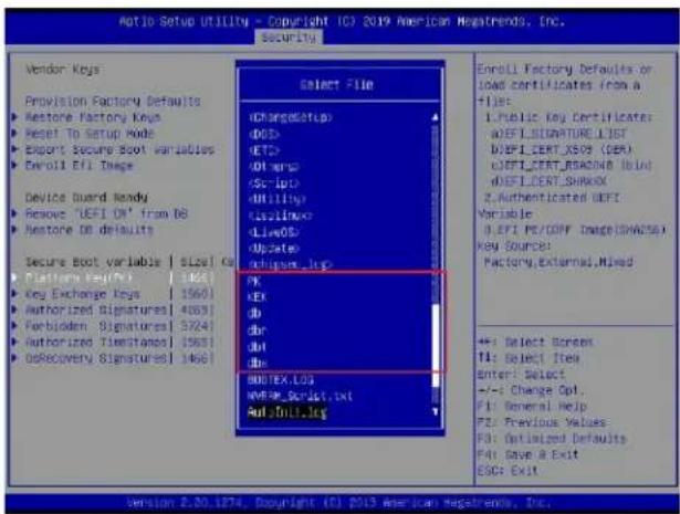
text_image
AutoIO Setup Utility - Copyright (C) 2019 American Negatrends, Inc. security Vendor Keys Provision Factory Defaults Restore Factory Keys Reset To Setup Mode Export Secure Boot variables Devoll Effi Image Device Guard Nendy Remove 'UEFI OK' from DB Restore DB defaults Secure Boot variable | Size | Ka Platform Key(P) Key Exchange Keys Authorized Signatures[1560] Forbidden Signatures[468] Authorized Timestamps[3724] DoRecovery Signatures[1563] SELECT File (ChargeSetup) (QED) (RET) (DH mrs) (Sc-lnt) (Hilll) (Issllmox) (LiveDS) (Uptate) (Angipure_lsg) PK KEX db dbr dvt db BDOTEX.LGS NVR/SPG/Sqnlkt.Int AutoIcon.lsg Enroll Factory Defaults or load certificates from a file: Public Key Certificates: ADEFI_SIGNATURELIST DEFEICERT_XSO9 (DER) DEFEICERT_BRASNB blind DEFEICERT_SHARMX 2. Authenticated UEFI Variable: 0.EFI PE/GOFF IMAGE(DNAZS) Key Source: Factory,External,Mixed +: Select Screen T1: Select Item Enter: Select +/-: Change Opt. F1: General Help F2: Previous Values F3: Optimized Defaults F4: Save & Exit ESC: Exit Version 2.00.1274, Copyright (C) 2019 American negatrends, Inc.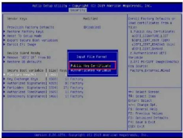
text_image
Ratio Setup Utility - Copyright (C) 2019 American Negatrends, Inc. security Vendor Keys Provision Factory Defaults ► Restore Factory Keys ► Reset To Setup Mode ► Export Secure Boot variables ► Earnell Efi Image Device Guard Ready ► Remove 'UEFI OR' from DB ► Restore DB defaults Secure Boot variable | Size | Keys ► Factors Key(%) | 1468 | ► Key Exchange Keys | 1560 | ► Authorized Signatures[ ] 4203 | ► Forbidden Signatures[ ] 3241 | ► Authorized TimeStamp[ ] 1565 | ► DoRecovery Signatures[ ] 1466 | Import File Format Public Key Certificates MUTHEPOTicated Variable Enroll Factory Defaults or Load certificates from a + - 1. Public Key Certificates: aOFFI SIGNATURE_LIST bEFT CERT_XSOP (DB) c)EFT CERT_BAS04B (bind) dEFT CERT_SHOW? 2. Authenticated UEFI Variable: 3. EFI PE/COFF Image(SNA256) Key Source: Factory.External_Mixed +: Select Screen T1: Select Item Enter: Select +/-: Change Opt. F1: General Help F2: Previous Values F3: Optimized Defaults F4: Save & Exit GSD: Exit version 2.26.182% Copyright (C) 2019 American Negatrends, Inc.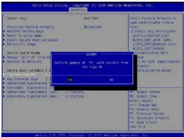
text_image
Motio Setup Utility - Copyright (C) 2019 American Negatrends, Inc. Security Vendor Keys Modified Provision Factory Defaults [Disabled] Restore Factory Keys Reset To Setup Mode Export Secure Boot variables Enroll Efi Image Device Guard Ready Remove 'DEFI OR' from Eti Restore DO defaults Secure Boot variable | 1 Platform Key(1) Key Exchange Keys | 1 Authorized Signatures | 1 Forboden Signatures | 3/4 Authorized Time stamp | 1563 | 1 Factory Get Recovery Signatures | 1463 | 1 Factory Update Confirm update of "PK" with content from the file PK Yes No Enroll Factory Defaults or load certificates from a file: 1.Public Key Certificates: uBFI_SIGNATURE_LIST uBFI_CERT_X809 (DBM) cBFI_CERT_ROA8N4a Inini uBFI_CERT_SHARKX Authenticated UERF able (1) PE/COFF IMAGE(SHA256) SOURCE: Sory.External,Mixed +:- Select Screens T:- Select Item Enter: Select +:- Change Opt. P1: General Help P2: Previous Values P3: Optimized Defaults P4: Save A Exit ESG: ExitPress
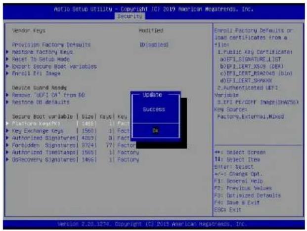
text_image
Netto Setup utility - Copyright IC7 2019 American Meastrends, Inc. Security Vendor Keys Provision Factory Defaults ■ Restore Factory Keys ■ Reset To Setup Mode ■ Export Secure Boot variables ■ Enroll Effi Image Device Guard Ready ■ Remove 'UFI DA' from DB ■ Restore ID defaults Secure Boot variable | Size | Keys | Key Platform Key(s) ■ Key Exchange Keys | 1560 | 1 Fact ■ Authorized Signatures | 4263 | 3 Fact ■ Forbidden Signatures | 8741 | 77 Fact ■ Authorized Timetramps | 1565 | 1 Fact ■ Oshecvery Signatures | 1465 | 1 Fact Modified ID (selected) Update Success OK Enroll Factory Defaults or load certificates from a file: I.Public key Certificate: a) EFL SIGNATURE_LIST b) EFL CERT_XS09 (DER) c) EFL CERT_RBAC049 (bin) d) EFL CERT_SHAWX 2. Authenticated UFI's Variable: 3. Effi PE/COFF Image(DNA25): Key Source: Factory, External,Mixed +: Select Screen T4: Select Item Enter: Select +/-: Change Opt. F1: Several Help F2: Previous Values F3: Optimized Defaults F4: Save & Exit! ESC: Exit Version 2.20.1876. Copyright (C) 2013 American Megatrends, Inc.Delete: Use the arrow keys to select Delete and press
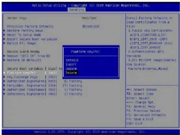
text_image
Ratio Setup Utility - Copyright (C) 2019 American Megatrends, Inc. Security Vendor Keys Modified Provision Factory Defaults [0/10/2019] Restore Factory Keys Reset To Setup Mode Export Secure Boot variables Enroll Effi Image Device Guard Ready Remove 'UEFI OK' from OD Restore ID defaults Secure Boot variable | Size | No Platform Key(No) Key Exchange Keys | 15601 Authorized Signatures | 42693 Forbidden Signatures | 37241 Authorized Timestamps | 15651 OsRecovery Signatures | 14667 Platform Key(No) Details Export Update Delete Entry: Factory Defaults or load certificates from a file: 1. Public Key Certificates: a) EFE LECNATURE_LIST b) EFE CERT_XS09 (DER) c) EFE CERT_BEAD040 (BIN) d) EFE CERT_SHAWX 2. Authenticated EFEI Variable: 3. EFE PC/OFF Image(SHAESG) KEY SOURCE: Factory: External,Mixed +: Select Screen TI: Select Item Enter: Select +/-: Change Opt. F1: General Help F2: Previous Values F3: Optimized Defaults F4: Save & Exit ESC: Exit Version 2.20.1274. Copyright (E) 2019 American Megatrends, Inc.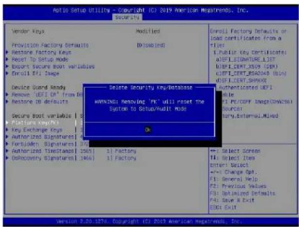
text_image
Ratio Setup Utility - Copyright (C) 2019 American Megatrends, Inc. Security Vendor Keys Modified Provision Factory Defaults ID=DISABLED Restore Factory Keys Reset To Setup Mode Export Secure Boot variables Enroll Efi Image Device Guard Ready Remove 'EEFI CM' from D Restore OD defaults Secure Boot variable | S Platform KeyPin Key Exchange Keys | 1 Authorized Signatures | 4 Forbloden Signatures | 37 Authorized TimeStamps | 1563 | 1 Factory OsRecovery Signatures | 1465 | 1 Factory Delete Security Key/Database WARNING: Removing 'FK' will reset the System to Setup/Audit Mode OK Enroll Factory Defaults or load certificates from a file: Public key certificate: a)EFLSIGNATURE_LIST b)EFL CERT_XS0A (DB) c)EFL CERT_BREAD48 (bin) d)EFL CERT_SHAWX Authenticated UEFI File F1 PE/DOFF Image(CHWESG) Source: Binary.External.HMixed +=: Select Screen T1: Select Item Enter: Select +/-: Change Opt. F1: General Help F2: Previous Values F3: Optimized Defaults F4: Save & Exit EICI Exit Version 2.20.1274. Copyright (C) 2019 American Megatrends, Inc.▶Key Exchange Key
The Key Exchange Key (KEK), which is held by the operating system vendor, can be updated by the holder of the PK and be used by secure boot to protect access to signatures databases. The options are Details, Export, Update, Append, and Delete. Select Details to display detailed information of KEKs. Select Export to save the current KEKs to a FAT formatted USB flash drive. Select Update to load the factory defaults or load KEKs from a file on the external device. Select Append to load the factory defaults or load KEKs from a file on the external device. Select Delete to clear the current KEKs or to delete only one certificate from the key database. (Refer to page 187 for the Export process. Refer to pages 188, 189, 190, and 191 for the Update process.)
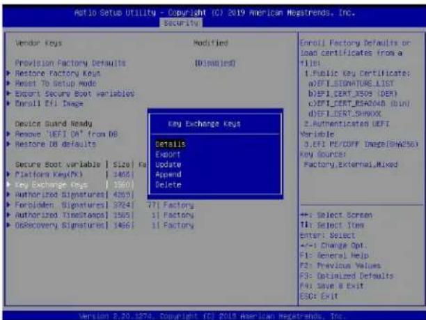
text_image
ATIO Setup Utility - Copyright (C) 2019 American Hegstrends, Inc. Security Vendor Keys Modified Provision Factory Defaults (Dimabled) Restore Factory Keys Reset To Setup Mode Export Security Boot Variable Enroll Efi Image Device Guard Ready Remove 'EFI DA' from DB Restore DB defaults Secure Boot variable | Size | Pa Platform Key(N) | 1468 Key Exchange Keys | 1560 Authorized Signatures1 4263 Forbidden. Signatures1 3264 Authorized TimeStamps1 1563 OSRecovery Signatures1 1465 Details Export Update Append Delete Key Exchange Keys Details Export Update Append Delete Configuration Details Factory External,Mixed +:- Select Screen T1: Select Item Enter: Select +/-: Change Opt. F1: General Help F2: Previous Values F3: Optimized Defaults F4: Save a Exit ESG: ExitAppend: Use the arrow keys to select Append.
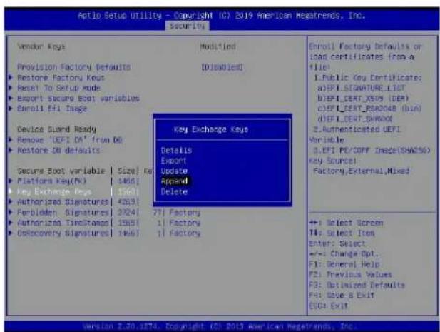
text_image
Aptio Setup Utility - Copyright (C) 2019 American Hestrends, Inc. Security Vendor Keys Provision Factory Defaults Restore Factory Keys Reset To Setup Mode Export Secure Boot variables Enroll Efi Image Device Guard Ready Remove 'UEFI DA' from DB Restore DB defaults Secure Boot variable | Size | Ka Platform Key(N) | 3461 Key Exchange Keys | 1567 Authorized Signatures | 4593 Forbidden Signatures | 3724 Authorized Timestamp | 1585 Osccovery Signatures | 1466 Modified [010001ed] Key Exchange Keys Details Export Update Append Delete 71 Factory 1 Factory 1 Factory Enroll Factory Defaults or load certificates from a file: 1.Public Key Certificate: a)EFLSIGNATURE_LIST b)EFLCEPT_XSOS (DEP) c)EFTCEPT_BAS04B (bio) d)EFLCEPT_SHOOD 2pointsicated UEFI Variable: 3.EFI PC/OFF Image(SHA250) Key Source: Factory,External,Mixed +: Select Screen T#: Select Item Enter: Select +/-: Change Opt., F1: General Help F2: Previous Values F3: Optimized Defaults F4: Save & Exit ESQ: ExitPress
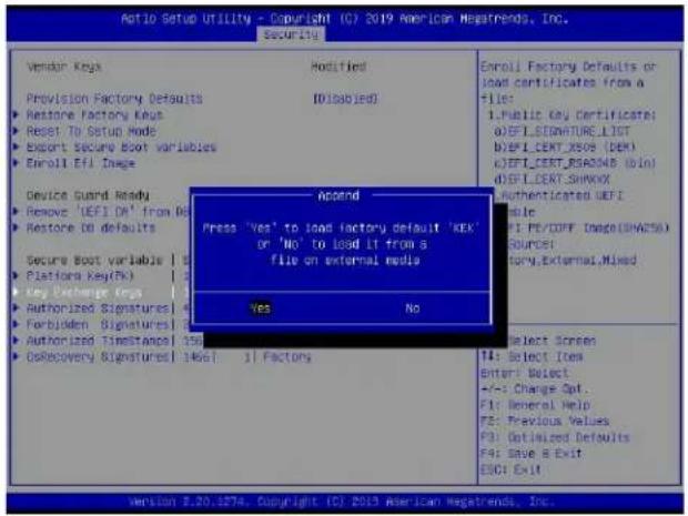
text_image
Ratio Setup Utility - Copyright (C) 2019 American Megatrends, Inc. Security Vendor Key Modified Provision Factory Defaults IDisabled Restore Factory Keys Reset To Setup Mode Export Secure Boot variables Enroll Efi Image Device Guard Ready Remove 'IEFI DR' from O Restore ID defaults Secure Boot variable | 1 Platforms Key(Th) Key Exchange Keys Authorized Signatures Forbidden Signatures Authorized Timestamps 156 Osbcovery Signatures 14661 Append Press 'Yes' to load factory default 'KEK' or 'No' to load LT from a file on external media Yes No Enroll Factory Defaults or load certificates from a file: 1.Public key certificate: a)IEFLSDVATURE_LIST b)IEFLCERT_X809 (DEM) c)IEFLCERT_BSADN8 (BIN) d)IEFLCERT_SHWXX Authenticated IUEFI able F1: PE/COFF Image(SHA25) Source: tary.External,Mixed Select Screen T4: Select Item Enter: Select +/-: Change Opt. F1: General Help F5: Previous Values F3: Optimized Defaults F4: Save & Exit ESC: ExitTo load the factory defaults, navigate to Yes and press
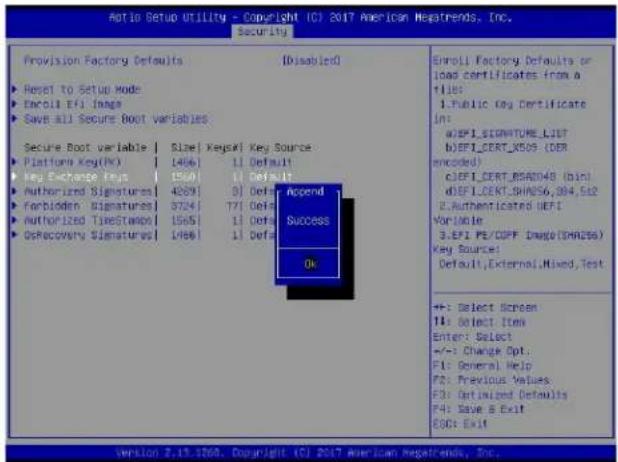
text_image
Atoio Setup Utility - Copyright (C) 2017 American Negatrends, Inc. Security Provision Factory Defaults [Disabled] Reset to Setup Mode Encoll Efi Image Save all Secure Boot variables Secure Boot variable | Size | KeySWI Key Source Platform Key(H) 1466 | 11 Default Key Exchange Keys | 1560 | 11 Default Authorized Signatures | 4289 | 91 Def Forbloden Signatures | 3724 | 771 Def Authorized TimeStamp | 1565 | 11 Def Oshccovery Signatures | 1466 | 11 Def Append Success OK Enroll Factory Defaults or load certificates from a file: 1.Public key Certificate in: a)EPI_SIGNATURE_LIST b)EPI_CERT_XSOS (DER encoded) c)EPI_CERT_BREAD4B (Din) d)EPI_LEKT_SHAS6_304_5t2 e)Authenticated HEFI Variable 3.EPI PE/COPF Image(SHAR266) Key Source: Default,External,Mixed,Test +: Select Screen TI: Select Item Enter: Select +/-: Change Opt: P1: General Help P2: Previous Values P3: Optimized Defaults P4: Save & Exit ECC: Exit version 2.19.1208. Copyright (C) 2017 American Negatrends, Inc.To load KEKs from a file on the external device, navigate to No and press
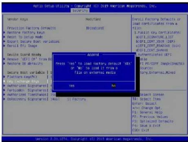
text_image
Auto Setup Utility - Copyright (C) 2019 American Megatrends, Inc. Security Vendor Keys Modified Provision Factory Defaults [0] [0] [0] Restore Factory Keys Result to Setup Mode Export Secure Boot variables Enroll Effi Image Device Guard Ready Remove 'UEFI OR' from Do Restore OS defaults Secure Boot variable | S Platform Key(s) Key Exchange Keys | 1 Authorized Signature(1) Forbidden Signature(1) Authorized Timestamp(1) OsRecovery Signature(1) [0] 11 Factory Append Press 'Yes' to load factory default 'KEK' or 'No' to load IT from a file on external media Yes No Enroll Factory Defaults or load certificates from a file: 1. Public Key Certificate: a) EFLLSIGNATURE_LIST b) EFL CERT_XSOS (DER) c) EFT CERT_EPAOBO (BIN) d) EFL CERT_SHAKXX Authenticated UEFI able: FI PE/DOFF Image(SHAWSE) Sources: tory.External,Mixed Select Screen 14: Select Item Enter: Select +/-: Change Opt. F1: General Help F2: Previous Values F3: Datalized Defaults F4: Save & Exit ESO: Exit Version 2.30.3874. Copyright (C) 2019 American Megatrends, Inc.Delete: Use the arrow keys to select Delete and press
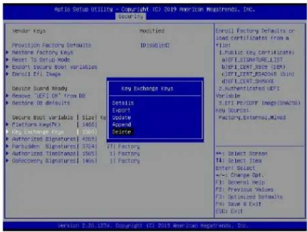
text_image
Ratio Setup Utility - Copyright (C) 2019 American Megatrends, Inc. Security Vendor Keys Provision Factory Defaults Restore factory keys Reset To Setup mode Export Secure Boot Variables Enroll Efi Image Device Guard Ready Remove 'UEFI OR' from DB Restore to defaults Secure Boot Variable | SLo# Ka Platform Key(Dy) | 1466 Key Exchange Keys | 3560 Authorized Signatures[ 4263] Forbidden Signatures[ 3724] Authorized TimeStrans[ 1563] OsRecovery Signatures[ 1466] Modified ID is possible Key Exchange keys Details Export Update Append Delete 71 Factory 1 Factory 1 Factory Enroll Factory Defaults or load certificates from a file: 1.Public Key Certificate) a)BEFLSIGNATURE_LIST b)BEFL_CERT_XSOS (DBM) c)BEFL_CERT_BEAD048 (bin) d)BEFL_CERT_SHAWX 2.Authenticated UEFI Variable 3.EFI PE/CERT Image(SHAES) KEY SOURCE: Factory.External,Mixed +/-: Select Screen TI: Select Item Enter: Select +/-: Change Opt: F1: General Help F2: Previous Values F3: Optimized Defaults F4: Save & Exit ESC: Exit version 2.20.1374. Copyright (C) 2019 American Megatrends, Inc.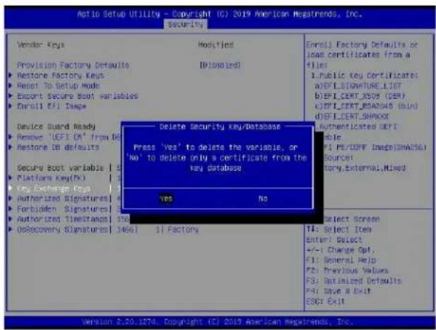
text_image
Notio Setup Utility - Copyright (C) 2019 American Megatrends, Inc. Security Vendor Keys Modified Provision Factory Defaults [Enabled] Restore Factory Keys Reset To Setup Mode Export Secure Boot variables Enroll Efi Damage Device Guard Ready Remove 'LEFT OR' from DE Restore On defaults Secure Boot Variable | S Platform Key(Dx) Key Exchange Keys Authorized Signatures Forbidden Signatures Authorized Timestamps | 356 OscDiscovery Signatures | 1461 1 Factory Delete Security Key/Database Press 'Yes' to delete the variable, or 'No' to delete only a certificate from the key database Yes No Enroll Factory Defaults or load certificates from a file: 1.Public key Certificate: a)EFLSIGNATURE_LIST b)EFL CERT_XSOS (DER) c)EFT CERT_BREAD08 (BIN) d)EFL CERT_SHAWXY Authenticated UEFI able: FI PE/IOFF Image(###)S& Source: tory.External,Mixed Select Screen TI: Select Item Enter: Select +/-: Change Opt. F1: General Help F2: Previous Values FS: Optimized Defaults F3: Save A Exit ESC: ExitNavigate to No and press
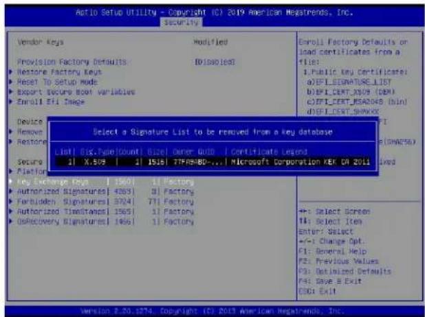
text_image
Aio Setup Utility - Copyright (C) 2019 American Hegatrends, Inc. security Vendor keys Modified Enroll Factory defaults on load certificates from a file: Provision Factory Defaults DIsabled 1Public Key Certificates aEPI_SIGNATURE LIST bEPI_COUNT_XSUI (DBM) cEPI_COUNT_REABOGS (bind) dEPI_COUNT_SPARKS Device Remove Restore Select a Signature List to be removed from a key database List: Six, PageCount | Size | owner QUID | Certificate Legend X.508 | 1 | 1516 | T7FMS-BD-... | Microsoft Corporation KEK CR 2011 Key Exchange Keys 1501 | 1 Factory Authorized Signatures 4263 | 3 Factory Forbidden Signatures 3924 | 71 Factory Authorized Timestamps 1565 | 1 Factory OSRecovery Signatures 1456 | 1 Factory +: Select screen 14: Select Item Enter: Select +/- Change Opt. C1: General Help P2: Previous Values P3: Optimized Defaults P4: Save & Exit CFG: Exit Version 2.20.1274. Copyright (C) 2019 American Hegatrends, Inc.▶ Authorized Signatures
Authorized Signature Database (DB) contains authorized signing certificates and digital signatures. The options are Details, Export, Update, Append, and Delete. Select Details to display detailed information of Authorized Signatures. Select Export to save the current DB to a FAT formatted USB flash drive. Select Update to load the factory defaults or load DB from a file on the external device. Select Append to add variables to the existing DB. Select Delete to clear the current DB or to delete only one certificate from the key database. (Refer to page 187 for the Export process. Refer to pages 188, 189, 190, and 191 for the Update process. Refer to pages 192 and 193 for the Append process. Refer to page 194 for the Delete process.)
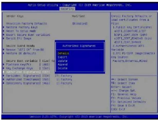
text_image
Notio Setup Utility - Copyright (C) 2019 American Negatrends, Inc. security Vendor Keys Provision Factory Defaults Restore Factory Keys Reset To Setup Mode Export Secure Boot variables Enroll Efi Image Device Guard Ready Remove 'EFT OK' from DB Restore DB defaults Secure Boot variable | Size Ka Platform Key(Th) | 1465 Key Exchange Keys | 1560 Authorized Signatures[ 4163] Forbidden Signatures[ 3724] Authorized Timestampos[ 1565] (Discovery Signatures)[ 1466] Modified (Displied) Authorized Signatures Details Export Update Append Delete +/- Select Screens T1: Select Item Enter: Select +/- Change Opt. F1: General Help F2: Previous Values F3: Defaulted Defaults F4: Save B Exit ESG: Exit Enroll Factory Defaults or load certificates from a file: 1.Public Key Certificates: aEFTLSNATURE_LIST bEFTLSERT_XS(FD) cEFTLSERT_RISROAD(Bind dEFTLSERT_SHRDX 2.Authenticates EFTI Variable: 3.EFT PE/DOY (Image(SHACSA)) KEY SOURCE: Factory,External,Mixed Version 2.20.1874, Copyright (C) 2019 American Negatrends, Inc.▶Forbidden Signatures
Forbidden Signature Database (DBX), which is the inverse of DB, contains forbidden certificates and digital signatures. The options are Details, Export, Update, Append, and Delete. Select Details to display detailed information of Forbidden Signatures. Select Export to save the current DBX to a FAT formatted USB flash drive. Select Update to load the factory defaults or load DBX from a file on the external device. Select Append to add variables to the existing DBX. Select Delete to clear the current DBX or to delete only one certificate from the key database. (Refer to page 187 for the Export process. Refer to pages 188, 189, 190, and 191 for the Update process. Refer to pages 192 and 193 for the Append process. Refer to page 194 for the Delete process.)
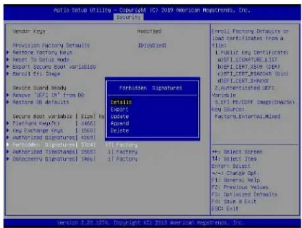
text_image
Auto Setup Utility - Copyright (C) 2019 American Guatemala, Inc. Security Vendor Keys Modified Provision Factory Defaults ID(Disabled) Restore Factory Keys Reset To Setup Mode Export Secure Boot variables Delroll Eff. Range Device Guard Ready Remove 'UEFI Oil' from DB Restore DB defaults Secure Boot Variable | $126 | Ka Platform Key(K) | 1465 Key Exchange Keys | 1560 Authorized Signatures | 4561 Forbidden Signatures Details Export Update Append Delete T/I Factory Authorized Timestamps | 1561 | 1 Factory OsRecovery Signatures | 1461 | 1 Factory Enroll Factory Defaults or load certificates from a FILE: LPublic key certificate: dIEFLSIGNATURE_LIST dIEFL CERT_XS09 (DER) dIEFL CERT_BSA048 (BIN) dIEFL CERT_SHAVXX 2 Authenticated UEFI Variable: 3.IFI PE/COFF Image(SWAP56) Key Source: Factory.Enternal,Mixed +: Select Screen TI: Select Item Enter Select +/-1 Change Opt: F1: General Help F2: Previous Values F3: Optimized Defaults F4: Save it Exit ESC: Exit Version 2.20.1274. Copyright (C) 2019 American Guatemala, Inc.▶ Authorized TimeStamps
Authorized Timestamp Database (DBT) is used to issue and check signed time stamp certificates. The options are Details, Export, Update, Append, and Delete. Select Details to display detailed information of Authorized Timestamps. Select Export to save the current DBT to a FAT formatted USB flash drive. Select Update to load the factory defaults or load DBT from a file on the external device. Select Append to add variables to the existing DBT. Select Delete to clear the current DBT or to delete only one certificate from the key database. (Refer to page 187 for the Export process. Refer to pages 188, 189, 190, and 191 for the Update process. Refer to pages 192 and 193 for the Append process. Refer to page 194 for the Delete process.)
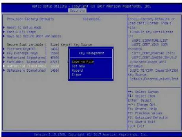
text_image
AdT10 Setup Utility - Copyright (C) 2017 American Nagestrends, Inc. Security Provision Factory Defaults [Disabled] Reset to Setup Mode Enroll Eff Image Save all Secure Boot Variables Secure Boot variable | Size | Keyset | Key Source Platform Key(DO) | 1456 Key Exchange Keys | 1550 Authorized Signatures | 4859 Forboden Signatures | 5724 Authorized Timingamp | 1556 OSRecovery Signatures | 1456 Key Management Save to File Set New Append Erase Enroll Factory Defaults or load certificates from a +1: 1.Public Key Certificate ins a:EPI_SIGNATURE_LIST b:EPI_CERT_X500 (DDR encoded) c:EPI_CERT_BHA204B (bin) d:EPI_CERT_SHA256,394,512 2.Authenticated UEFI Variable 3.EPI PE/COFF: Dwage(SHA256) Key Source: Default,External,Mixed,Test +: Select Screen T1: Select Item Enter: Select +/-: Change Opt. F1: General Help F2: Previous Values F3: Optimized Defaults F4: Save & Exit ESG: Exit Version 2.19.1288, Copyright (C) 2017 American Nagestrends, Inc.▶OsRecovery Signatures
OsRecovery Signatures Database (DBR) contains secure boot authorized recovery variables. The options are Details, Export, Update, Append, and Delete. Select Details to display detailed information of OsRecovery Signatures. Select Export to save the current DBR to a FAT formatted USB flash drive. Select Update to load the factory defaults or load DBR from a file on the external device. Select Append to add variables to the existing DBR. Select Delete to clear the current DBR or to delete only one certificate from the key database. (Refer to page 187 for the Export process. Refer to pages 188, 189, 190, and 191 for the Update process. Refer to pages 192 and 193 for the Append process. Refer to page 194 for the Delete process.)
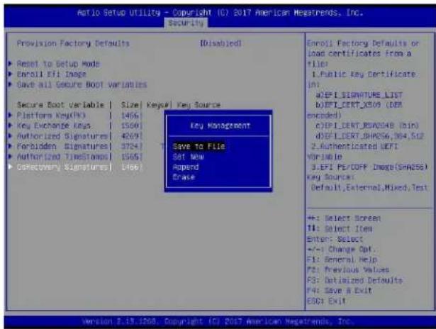
text_image
Avio Setup Utility - Copyright (C) 2017 American Negatrends, Inc. Security Provision Factory Defaults [Disabled] ► Reset to Setup Mode ► Encoll Eff Image ► Save all Secure Boot Variables Secure Boot Variable | Size | Key&I | Key Source ► Platform Key(OK) | 1466 ► Key Exchange Keys | 1566 ► Authorized Signatures | 4269 ► Forbidden Signatures | 3724 ► Authorized TimeStands | 1565 ► Discovery Signatures | 1466 Key Management Save to File Set New Append Erase Enroll Factory Defaults or Load certificates from a file: 1.Public Key Certificate in: a:EPI_SIGNATURE_LIST b:EPI_CERT_X509 (DEM encoded) c:EPI_COUNT_BXA0048 (bin) d:EPI_COUNT_SHA006_984_512 2.Authenticated EEFI WorldJe 3.EPI PERCOFF Images(SHA256) Key Source: Default,External,Mixed,Test +: Select Screen T1: Select Item Enter: Select +/-: Change Opt. F1: General Help F2: Previous Values F3: Datalized Defaults F4: Save & Exit GOD: Exit version 2.13.1208. Copyright (C) 2017 American Negatrends, Inc.Appendix G
Configuring iSCSI Settings
Internet small computer system interface (iSCSI) is a protocol that defines how block-level data transports between the iSCSI initiator and iSCSI target over an Internet protocol (IP) network. The iSCSI initiator (client/host) enables a connection to the iSCSI target and initiates I/O requests. The iSCSI target can be a group of storage devices or an intermediate device attached to storage devices. The iSCSI initiator and iSCSI target must connect to an IP network. To have iSCSI settings available, refer to instructions stated in the G.1 section. The G.2 section explains iSCSI settings.
G.1 PCIe/PCI/PnP Features
Press during system boot to enter the BIOS Setup utility. Navigate to the Advanced tab. Use the arrow keys to select PCIe/PCI/PnP Configuration and press
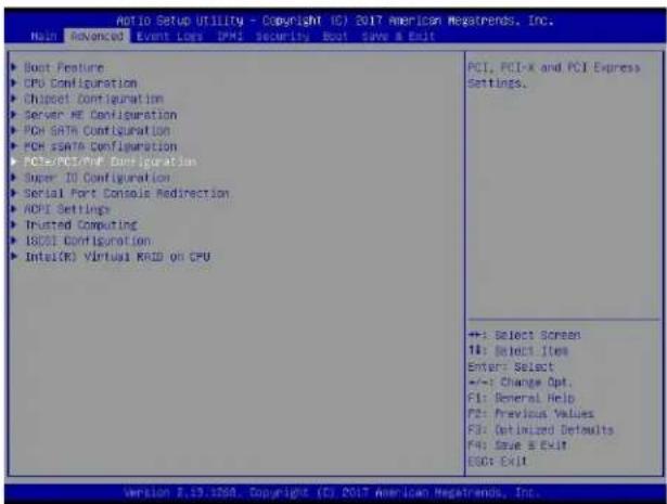
text_image
Ratio Setup Utility - Copyright (C) 2017 American Megatrends, Inc. Main Advanced Event Logs PMI Security Boot Save & Exit ▶ Boot Feature ▶ CPU Configuration ▶ Chipset Configuration ▶ Server ME Configuration ▶ PCH SATA Configuration ▶ PCH SATA Configuration ▶ PCIe/PCI/PDF Configuration ▶ Super III Configuration ▶ Serial Port Console Redirection ▶ ADMI Settings ▶ Trusted Computing ▶ ISCCI Configuration ▶ Intel(R) Virtual RFID on CPU PCI, PCI-X and PCI Express Settings. +/-: Select Screen 1#: Select Item Enter: Select +/-: Change Opt. F1: General Help F2: Previous Values F3: Optimized Defaults F4: Save & Exit ESG: Exit Version 2.13.1208. Copyright (C) 2017 American Megatrends, Inc.
Note: Be sure to have configuration information for the iSCSI initiator and iSCSI target before starting iSCSI settings.
Onboard LAN1 Option ROM
Use the arrow keys to select Onboard LAN1 Option ROM and press
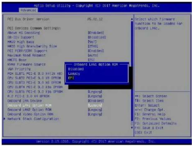
text_image
PCI Bus Driver Version PCI Devices Common Settings: Above 4G Decoding SR-10V Support MMID High Base MMID High Angularity Size PCI PERS/SEAK Support Maximum Read Request MMFD Bose NWE Firmware Source VDA Priority FOM SLDTI PCI-E 3.0 X4CIN X6 CPU SLOTS PCI-E 3.0 X5 DPM CPU SLOTS PCI-E 3.0 X6 DPM CPU SLOTS PCI-E 3.0 X16 DPM CPU SLOTS PCI-E 3.0 X16 DPM H2 PCI-E 3.0 X4 DPM Onboard LANX Device Onboard LANX Option ROM Onboard LANZ Option ROM Onboard Video Option ROM Network Stack Configuration A5.81.12 [Enabled] [Unloaded] [5s7] [2566] [Enabled] [Auto] [PG] Onboard LANX Option ROM Disabled Legacy EPC [Legacy] [Legacy] [Enabled] [Legacy] [Legacy] Select which firmware function to be loaded for onboard LAN1. +: Select Screen T1: Select Item Enter: Select +/-1 Change Opt. F1: General Help F2: Previous Values F3: Optimized Defaults F4: Save & Exit ESC: Exit Version 2.19.1208, Copyright (C) 2017 American Newsrends, Inc.Note: If Onboard LAN1 Option ROM is set to EFI, all features for onboard LAN option ROM will be set to EFI by the EFI driver. Additionally, these features will become unavailable except Onboard LAN1 Option ROM.
Network Stack Configuration
Use the arrow keys to select Network Stack Configuration and press
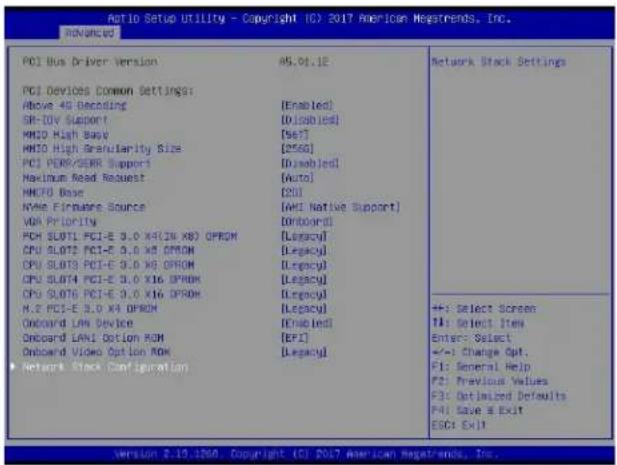
text_image
PCI Bus Driver Version PCI Devices Common Settings: Above 4G Decoding SR-10V Support MMCI High Audio MMCI High Granularity Size PCI PERS/SEER Support Maximum Read Request MMCI0 Base NAME Firmware Source VAR Priority PCI SLOTS PCI-E 3.0 X4(26 X8) OPRDM CPU SLOTS PCI-E 3.0 X5 OPRDM CPU SLOTS PCI-E 3.0 X6 OPRDM CPU SLOTS PCI-E 3.0 X16 OPRDM CPU SLOTS PCI-E 3.0 X16 OPRDM H.2 PCI-E 3.0 X4 OPRDM Onboard LAN Device Onboard LAN1 Option ROM Onboard Video Option ROM Network Stock Configuration AS.01.1E [Enabled] [Disabled] [Set] [2560] [Disabled] [Auto] [20] [AMI Native Support] [Onboard] [Legacy] [Legacy] [Legacy] [Legacy] [Legacy] [Legacy] [Legacy] [Legacy] [Legacy] [Legacy] [Legacy] [Legacy] [Legacy] [Legacy] [Legacy] [Legacy] [Legacy] [Legacy] [Legacy] [Legacy] [Legacy] [Legacy] [Legacy] [Legacy] [Legacy] [Legacy] [Legacy] [Legacy] [Legacy] [Legacy] [Legacy] [Legacy] [Legacy] [Legacy]Ipv4 PXE Support/Ipv6 PXE Support
To enable lpv4/lpv6 PXE boot support, use the arrow keys to select and set lpv4 PXE Support/Ipv6 PXE Support to Enabled.
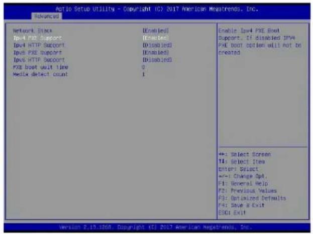
text_image
Antio Setup Utility - Copyright (C) 2017 American Megatrends, Inc. Advanced Network Stock [Enabled] IPv4 PXE Support [Enabled] IPv4 HTTP Support [Disabled] IPv6 PXE Support [Enabled] IPv6 HTTP Support [Disabled] PXE boot unit time 0 Media detect count 1 Enable IPv4 PXE Boot Support. If disabled IPv4 PXE boot option will not be created ++: Select Screen T4: Select Item Enter: Select +/-: Change Opt. F1: General Help F2: Previous Values F3: Optimized Defaults F4: Have B Exit ESQ: Exit Version 2.19.1808. Copyright (C) 2017 American Megatrends, Inc.Note: Enable both lpv4 PXE Support and lpv6 PXE Support to have iSCSI settings available. In some cases, enabling either one feature may also have iSCSI settings available depending on the configuration of iSCSI initiator and iSCSI target.
For the changes to take effect, save settings and restart the system. Press during system boot to enter the BIOS Setup utility. When the BIOS main screen appears, navigate to the Advanced tab. Use the arrow keys to select iSCSI Configuration and press
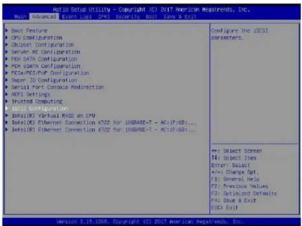
text_image
Auto Setup Utility - Copyright (C) 2017 American Megatrends, Inc. Main Advanced Event Logs IPMI Security Boot Save a Exit ▶ Boot Feature ▶ GPU Configuration ▶ Chipset Configuration ▶ Server NE Configuration ▶ PDS SATA Configuration ▶ PCH SATA Configuration ▶ FCIE/PCI/PDF Configuration ▶ Super IO Configuration ▶ Serial Port Console Redirection ▶ ADPI Settings ▶ Trusted Computing ▶ IECSI Configuration ▶ Intel(CK) Virtual RMS on CPU ▶ Intel(CK) Ethernet Connection X722 for 10GBASE-T - AC:IF:681... ▶ Intel(CK) Ethernet Connection X722 for 10GBASE-T - AC:IF:681... Configure the iSCSI parameters. +: Select Screen 14: Select Ives Enter: Select +/-: Change Opt. F1: General Help F2: Previous Values F3: Optimized Defaults F4: Save & Exit ESC: Exit Version 2.15.1298. Copyright (C) 2017 American Megatrends, Inc.G.2 Configuring iSCSI Settings
iSCSI Initiator Name
Use this feature to enter the unique initiator name in iSCSI qualified name (IQN) format.
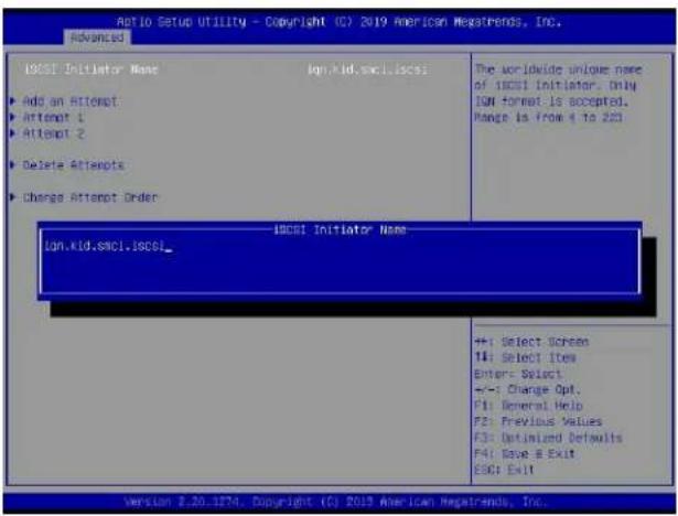
text_image
Ratio Setup Utility - Copyright (C) 2019 American Megatrends, Inc. Advanced ICSI Initiator Name Iqn.kid.sxc1.iscsl_ ► Add an Attempt ► Attempt 1 ► Attempt 2 ► Delete Attempts ► Change Attempt Order ICSI Initiator Name Iqn.kid.sxc1.iscsl_ + +: Select Screen T4: Select Item Enter: Select +:-: Change Opt. F1: General Help F2: Previous Values F3: Optimized Defaults F4: Save & Exit ESC4 Exit Version 2.20.1874. Copyright (C) 2019 American Megatrends, Inc.Add an Attempt
Use the arrow keys to select Add an Attempt.
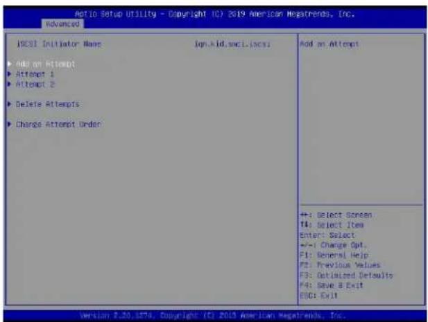
text_image
Add to Setup Utility - Copyright (C) 2019 American Negatrends, Inc. advanced ICSI Initiator Name ign kid.snc1.icsi Add on Attempt ► Add on Attempt ► Attempt 1 ► Attempt 2 ► Delete Attempts ► Change Attempt Order +: Select Screen #: Select Item Enter: Select +/-: Change Opt. F1: General Help F2: Previous Values F3: Optimized Defaults F4: Save & Exit E00: Exit Version 2.20.1874. Copyright (C) 2019 American Negatrends, Inc.Press
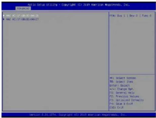
text_image
Auto Setup Utility - Copyright (C) 2019 American Megatrends, Inc. Advanced HAC AC:IF:SB:ED:00:05 HAC AC:IF:SB:ED:00:07 FFA: Bus 1 | Dev 0 | Func 0 +: Select Screen #4: Select Item Enter: Select +/-: Change Opt: F1: General Help F2: Previous Values F3: Optimized Defaults F4: Save & Exit E00: Exit Version 8.20.1274, Copyright (C) 2019 American Megatrends, Inc.Press
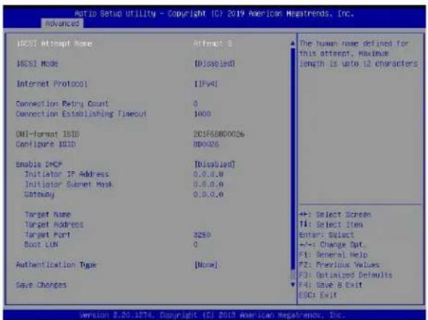
text_image
Ratio Setup Utility - Copyright 107 2019 American Megatrends, Inc. advanced ISC51 Attempt Name Attempt S ISC51 Mode [Disabled] Internet Protocol [IPv4] Connection Retry Count 0 Connection Establishing Timeout 1000 ONI-Format ISID 2C1F5B800026 Configure ISID 8D0026 Enable DHCP [Disabled] Initiator IP Address 0.0.0.0 Initiator Ethernet Mask 0.0.0.0 Gateway 0.0.0.0 Target Name Target Address Target Port 3250 Boot LIN 0 Authentication Type [None] Save Changes The human name defined for this attempt. Maximum length is up to 12 characters +: Select Screen TA: Select Item Enter: Select +/-: Change Opt. F1: General Help F2: Previous Values F3: Optimized Defaults F4: Save & Exit ESC: Exit Version 2.20.1274. Copyright (C) 2019 American Negatremos, Inc.iSCSI Attempt Name
This feature displays the iSCSI attempt name.
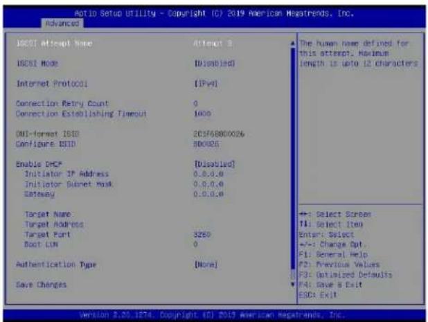
text_image
Aptio Setup Utility - Copyright (C) 2019 American Hgatrends, Inc. Advanced ISCEI Attempt Name ISCEI Mode Internet Protocol Connection Retry Count Connection Establishing Timeout OUI-format ISID Configure ISID Enable DHCP Initiator IP Address Initiator Ethernet Mask Gateway Target Name Target Address Target Port Boot LIN Authentication Type Save Changes Attempt 3 [Disabled] [IPV] 0 1000 20176800026 800026 [Disabled] 0.0.0.0 0.0.0.0 0.0.0.0 S250 0 [None] The human name defined for this attempt. Maximum length is (uto 12 characters) +: Select Screen T1: Select Item Enter: Select +/-: Change Opt. F1: General Help F2: Previous Values F3: Optimized Defaults F4: Save & Exit ESC: Exit Version 3.20.1874. Copyright (C) 2019 American Hgatrends, Inc.iSCSI Mode
Use this feature to set the iSCSI mode. The options are Disabled, Enabled, and Enabled for MPIO. Multipath I/O (MPIO) is a feature that allows the system to route I/O through the available paths if the active path fails (be sure to have more than one physical path connected to the system).
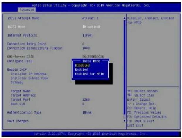
text_image
Aio Setup Utility - Copyright (C) 2019 American Megatrends, Inc. Advanced iSCSI Attempt Name Attempt 1 iSCSI Mode [Disabled] Internet Protocol [IPV4] Connection Retry Count 0 Connection Establishing Timeout 1000 OUI-format ISO 201568800026 Configure ISO ISCSI Mode Enable DHCP Initiator IP Address Initiator Subnet Mask Gateway Target Name Target Address Target Port $260 Boot LUN 0 Authentication Type [None] Save Changes Disabled, Enabled, Enabled for HP10 Enabled Enabled for HP10 ++: Select Screen T1: Select Item enter: Select --+: Change Opt. F1: General Help F2: Previous Values F3: Optimized Defaults F4: Save & Exit ESC: Exit Version 2.20.1876, Copyright (C) 2019 American Megatrends, Inc.
Note: Enabling the feature, iSCSI Mode, is required for iSCSI configuration.
Internet Protocol
Use this feature to set the Internet protocol. The options are IPv4, IPv6, and Autoconfigure.
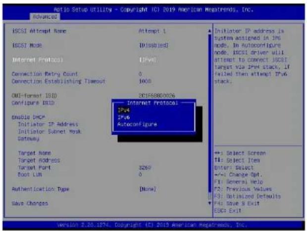
text_image
Ratio Setup Utility - Copyright (C) 2019 American Megatrends, Inc. Advanced ICSI Setup Utility - Copyright (C) 2019 American Megatrends, Inc. INTERTAL ISCSI Attempt Name INTERTAL ISCSI Mode [Disabled] Internet Protocol [IPv4] Connection Retry Count 0 Connection Establishing Timeout 1000 OMI-format ISO DC1F68800026 Configure ISO Internet Protocol IPv4 IPv6 Autoconfigure Enable DHCP Initiator IP Address Initiator Secret Mask Gateway Target Name Target Address Target Port 3269 Boot LUN 0 Authentication Type [None] Save Changes Initiator IP address is system assigned in JNS mode. In Autoconfigure mode, ICSI driver will attempt to connect ICSI target via IPv4 stack. If failed then attempt IPv6 stack. +:- Select Screen T1: Select Item Enter: Select -:- Change Opt. F1: General Help F2: Previous Values F3: Dutilized Defaults F4: Save & Exit ESC: ExitConnection Retry Count
The valid range is 0\~16. Use this feature to enter the number of logon sessions allowed for the iSCSI initiator to restart with the iSCSI target if the first logon connection fails.
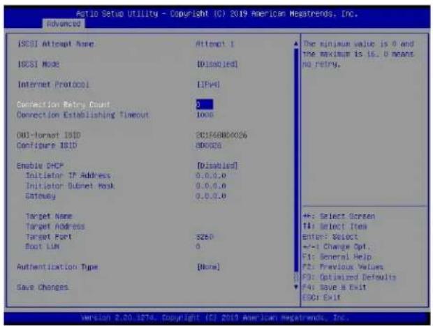
text_image
Actio Setup Utility - Copyright (C) 2019 American Megatrends, Inc. Advanced iSCSI Attempt Name Attempt 1 iSCSI Mode [0.0.0.0]# Internet Protocol [IPv4] Connection Retry Count 2 Connection Establishing Timeout 1000 UID-format UID 3CS760800026 Configure UID 800026 Enable DHCP [Disabled] Initiator IP Address 0.0.0.0 Initiator Subnet Mask 0.0.0.0 Status 0.0.0.0 Target Name Target Address Target Port 5250 Boot LIN 6 Authentication Type [None] Save Changes The minimum value is 0 and the maximum is 15.0 means no retry. +: Select Screen T4: Select Item Enter: Select +/-1 Change Opt.. F1: General Help F2: Previous Values F3: Optimized Defaults F4: Save it Exit ESC: Exit version 2.20.1874. Copyright (C) 2019 American Megatrends, Inc.Connection Establishing Timeout
Use this feature to set the logon connection establishing timeout (in milliseconds). The valid range is from 100 milliseconds to 20 seconds.

text_image
Action Setup Utility - Copyright (C) 2019 American Negatrends, Inc. Advanced ISCISI Attempt Name ISCISI Mode Internet Protocol Connection Retry Count Connection Establishing Timeout 0 1000 Oil-format ISID Configure ISID Enable DHCP Initiator IP Address Initiator Subset Mask Gateway Target Name Target Address Target Port Boot LIM Authentication Type Save Changes Attempt 1 (Disabled) [IPv4] 3250 0 [Disabled] 0.0.0.0 0.0.0.0 0.0.0.0 [More] The timeout value in milliseconds, The minimum value is 100 milliseconds and the maximum is 20 seconds. +: Select Screen F1: Select Item Enter: Select +/-: Change Opt. F1: General Help F2: Previous Values F3: Optimized Defaults F4: Save A Exit DSC: ExitOUI-format ISID
This feature displays the default ISID in OUI format. The value (in six bytes) is derived from the MAC address of the NIC port that you selected earlier.
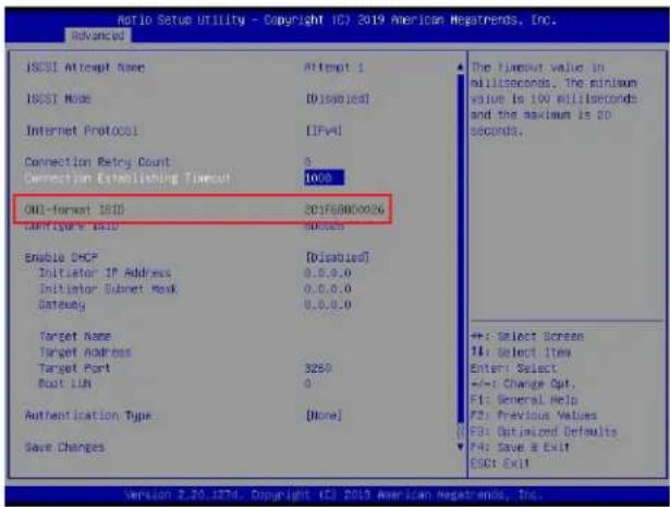
text_image
Ratio Setup Utility - Copyright (C) 2019 American Negatrends, Inc. Advanced ISCST Attempt Name Attempt 1 ISCST Mode [Displaced] Internet Protocol [IPvA] Connection Retry Count 0 Connection Establishment Timeout 1000 OUI-format ISID 201768800026 Connecticut ISID 0.0.0.0 Enable DHCP [Disabled] Initiator IP Address 0.0.0.0 Initiator Subnet Mask 0.0.0.0 Gateway 0.0.0.0 Target Name Target Address Target Port 3250 Boat LAN 0 Authentication Type Done! Save Changes The timeout value in milliseconds, The minimum value is 100 milliseconds and the maximum is 20 seconds. +: Select Screen #: Select Item Enter: Select +/-: Change Opt. F1: General Help F2: Previous Values F3: Optimized Defaults F4: Save & Exit ESCR ExitConfigure ISID
Press
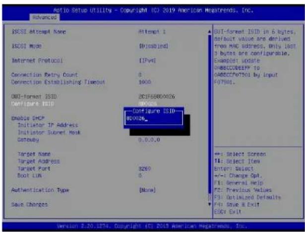
text_image
ATIO Setup Utility - Copyright (C) 2019 American Megatrends, Inc. Advanced ISO-80026 Interrupt 1 ISO-80 Mode [0:ISO1@1] Internet Protocol [IPv4] Connection Retry Count 0 Connection Establishing Timeout 10:00 OUT-format ISO DC3F68800026 Configure ISID Enable DHCP Initiator IP Address Initiator Secret Mask Gateway 0.0.0.0 Target Name Target Address Target Port Boot LIM B260 0 Authentication Type [None] Save Changes OUT-format ISO in 6 bytes, default value are derived from MRC address, Only .80T 3 bytes are configurable. Examplet update DBECCODEEFF to ORBECFO7501 by Input F07501. +: Select Screen 14: Select Item Enter: Select +/-: Change Opt. F1: General Help F2: Previous Values F3: Optimized Defaults F4: Save & Exit ISO: Exit Version 2.20.1874. Copyright (C) 2019 American Megatrends, Inc.Enable DHCP
Use this feature to disable/enable dynamic host configuration protocol (DHCP) server service for the iSCSI initiator. The options are Disabled and Enabled.
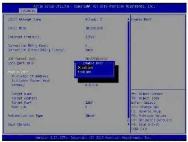
text_image
Antio Setup Utility - Copyright (C) 2019 American Megatrends, Inc. Advanced ISOI Attempt Name ISOI Mode Internet Protocol Connection Retry Count Connection Establishing Timeout OKI-format ISOI Configure ISOI Enable DHCP Initiator IP Address Initiator Subnet Mask Gateway Target Name Target Address Target Port Boot LIM Authentication Type Save Changes Attempt 3 [Disabled] [IPV4] 0 1000 2015688000& Enable DHCP* Disabled Enabled 0.0.0.0 +: Select Screen T4: Select Items Enter: Select +/-: Change Opt. F1: General Help. F2: Previous Values F3: Optimized Defaults F4: Save & Exit ESC: Exit Version 2.20.1274. Copyright (C) 2019 American Megatrends, Inc.
Note: Set the feature, Enable DHCP, to Disabled if you would like to specify the iSCSI initiator IP address/subnet mask/gateway.
Initiator IP Address (available when Enable DHCP is set to Disabled)
Use this feature to enter the desired iSCSI initiator IP address.
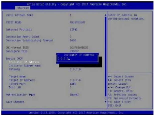
text_image
Aio Setup Utility - Copyright (C) 2017 American Megatrends, Inc. Advanced ISCSI Attempt Name 1 ISCSI Mode (Dissubled) Internet Protocol (IPA) Connection Retry Count 0 Connection Establishing Timeout 1000 DUI-format ISID 201F68W9E02E Configure IDU 09E02E Enable DHCP Initiator IP Address Initiator Subnet Mask Gateway 0.0.0.0 Target Name Target IP Address 0.0.0.0 Target Port 3250 Boot LUN 0 Authentication Type [None] Save Changes Enter IP address in dotted-derimai notation. +:- Select Screen T1: Select Item Enter: Select +/-: Change Opt. F1: General Help F2: Previous Values F3: Optimized Defaults F4: Save & Exit ESC: Exit Version 2.13.1268. Copyright (C) 2017 American Megatrends, Inc.Initiator Subnet Mask (available when Enable DHCP is set to Disabled)
Use this feature to enter the desired iSCSI initiator subnet mask.
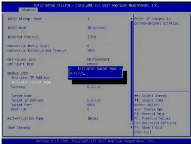
text_image
Aio Setup Utility - Copyright (C) 2017 American Megatrends, Inc. Advanced ISCST Attempt Name 1 ISCST Mode (Dissubied) Internet Protocol (IP4) Connection Retry Count 0 Connection Establishing Timeout 1000 OUT-format UID 2CJF600003E Configure UID ONICE Enable DHCP Initiator IP Address Initiator Ethernet Mask Gateway 0.0.0.0 Target Name Target IP Address 0.0.0.0 Target Port 3250 Boot LUN 0 Authentication Type [None] Save Changes Enter IP address in dotted-decimal notation. +: Select Screen 11: Select Item Enter: Select +/-: Change Opt. F1: General Help F2: Previous Values F3: Optimized Defaults F4: Save & Exit OSGA Exit Version 2.19.1208. Copyright (C) 2017 American Megatrends, Inc.Gateway (available when Enable DHCP is set to Disabled)
Use this feature to enter the desired iSCSI initiator gateway.
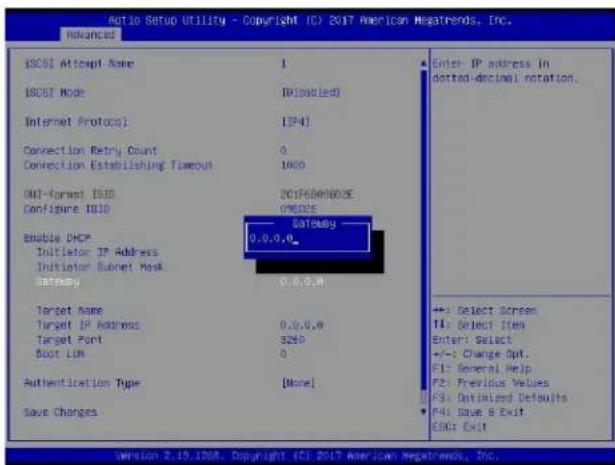
text_image
Initio Setup Utility - Copyright (C) 2017 American Megatrends, Inc. ADVANCED ISCISI Attempt Name 1 ISCISI Mode (Dissolved) Internet Protocol [IP4] Connection Retry Count 0 Connection Establishing Timeout 1000 OUT-Format ISID 2017600803E Configure ISID UNSD3E Enable DHCP Initiator IP Address 0.0.0.0_ Initiator Subset Mask setergy 0.0.0.0# Target Name 0.0.0.0 Target IP Address 3250 Target Port 0 Boot Lim Authentication Type [None] Save Changes Enter IP address in dotted-decimal rotation. +: Select Screen 11: Select Item Enter: Select +/-: Change Opt. F1: General Help F2: Previous Values F3: Optimized Defaults F4: Save & Exit ESR: Exit version 2.19.1208. Copyright (C) 2017 American Megatrends, Inc.Get target info via DHCP (available when Enable DHCP is set to Enabled)
Use this feature to disable/enable dynamic host configuration protocol (DHCP) server service for the iSCSI target. The options are Disabled and Enabled.
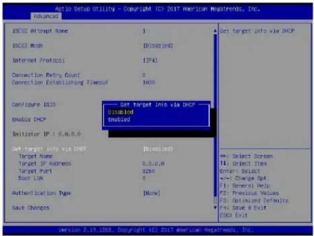
text_image
Auto Setup Utility - Copyright (C) 2017 American Megatrends, Inc. advanced IBCSI Attempt Name 1 IBCSI Mode [Disabled] Internet Protocol [IP4] Connection Retry Count 0 Connection Establishing Timeout 1000 Configure DHCP Enable DHCP Initiator IP: 0.0.0.0 Set target info via DHCP Target Name [Disabled] Target IP Address 0.0.0.0 Target Port 3250 Boot LAN 0 Authentication Type [None] Save Changes Get target info via DHCP Disabled Enabled +: Select Screen 11: Select Item Enter: Select +/-: Change Opt: F1: General Help F2: Previous Values F3: Optimized Defaults F4: Save & Exit GSD: Exit Version 2.15.1268. Copyright (C) 2017 American Megatrends, Inc.
Note 1: Set the feature, Get target info via DHCP, to Disabled if you would like to specify the iSCSI target name/IP address/boot LUN.
Note 2: LUN stands for logical unit number, which is used to identify a logical/physical disk.
Target Name
Use this feature to enter the desired iSCSI target name in IQN format.
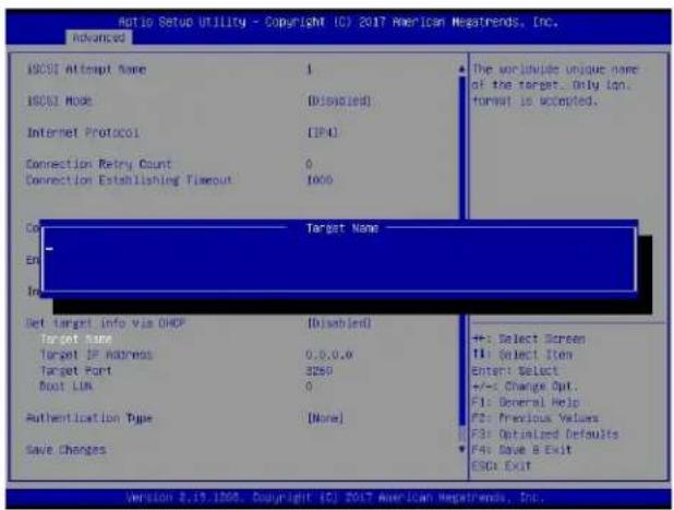
text_image
Ratio Setup Utility - Copyright (C) 2017 American Megatrends, Inc. Advanced ISCST Attempt Name 1 ISCST Mode (Disabled) Internet Protocol (IPA) Connection Retry Count 0 Connection Establishing Timeout 1000 Target Name En In Get target info via DHCP (Disabled) Target name Target IP address 0.0.0.0 Target Port 2259 Boot LAM 0 Authentication Type [None] Save Changes The worldwide unique name of the target... Only log, format is accepted. +: Select Screen T: Select Item Enter: Select +/-: Change Opt. F1: General Help F2: Previous Values F3: Optimized Defaults F4: Save B Exit GDA Exit Version 2.19.1808. Copyright (C) 2017 American Megatrends, Inc.Target Address
Use this feature to enter the desired iSCSI target IP address.
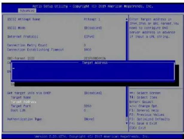
text_image
Add to Setup Utility - Copyright (C) 2019 American Negatrends, Inc. Advanced ICSST Attempt Name Attempt 1 ICSST Mode (Disabled) Internet Protocol [IPv4] Connection Retry Count 0 Connection Establishing Timeout 1000 ONL-Format ISO 2017680000& GO Target Address EN Set target info via DHCP (Disabled) Target name Target Address Target Port 3250 Boot LAN 0 Authentication Type (None) Enter Target address in IPv4, IPv5 or URL format. You need to configure ONE server address in advance If input a URL string. +: Select Screen T4: Select Item Enter: Select +/-: Change Opt. F1: General Help F2: Previous Values F3: Optimized Defaults F4: Save & Exit GSD: Exit Version 2.20.1874. Copyright (C) 2019 American Negatrends, Inc.Target Port
This feature displays the iSCSI target port.
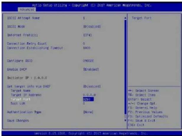
text_image
Ratio Setup Utility - Copyright (C) 2017 American Nestrends, Inc. Advanced BOSI Attempt Name 1 BOSI Mode (Disabled) Internet Protocol (IP4) Connection Retry Count 0 Connection Establishing Timeout 1000 Configure ISO OMODE Enable DHCP [Enabled] Initiator IP + 0.0.0.0 Get target info via DHCP (Disabled) Target Name Target IP readiness 0.0.0.0 Target Port 3250 Boot Lim 0 Authentication Type [None] Save Changes Target Port +: Select Screen 14: Select Item Enter: Select +/-: Change Opt. F1: General Help F2: Previous Values F3: Optimized Defaults F4: Save B Exit ESD: Exit Version 2.13.1908. Copyright (C) 2017 American Nestrends, Inc.Boot LUN
Use this feature to enter the LUN ID of boot LUN.
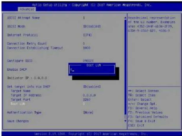
text_image
Ratio Setup Utility - Copyright (C) 2017 American Negatrends, Inc. Advanced ISOSI Attempt Name 1 ISOSI Mode [Disabled] Internet Protocol [IP4] Connection Retry Count 0 Connection Establishing Timeout 1000 Configure ISID ONDOSE Enable DHCP BOOT LUN Initiator IP: 0.0.0.0 Set target Info Via DHCP [Disabled] Target Name 0.0.0.0 Target IP address 3250 Target Port 0 BOOT LUN Authentication Type [None] Save Changes Hexadecimal representation of the LD number. Examples After 4762-594F-6826-899, G784-9-1564-127, 4186-9 ++: Select Screen I1: Select Item Enter: Select +/-: Change Opt. F1: General Help F2: Previous Values F3: Optimized Defaults F4: Save a Exit ESC: Exit Version 2.19.1908 Copyright (C) 2017 American Negatrends, Inc.Authentication Type
Use this feature to set the authentication method. The options are CHAP and None.
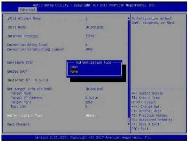
text_image
Atoio Setup Utility - Copyright (C) 2017 American Megatrends, Inc. advanced ISCSI Attempt Name 1 ISCSI Mode (D:\isoblcd) Internet Protocci (IP4) Connection Retry Count 0 Connection Establishing Timeout 1000 Configure ISID Authentication Type Enable DHCP DHAP Initiator IP : 0.0.0.0 None Get target info via DHCP (D:\isoblcd) Target Name Target IP Address 0,0,0,0 Target Port 3250 Boot LIN 0 Authentication Type (More) Save Changes Authentication method: DHAP, Kerberos, or None +:- Select Screen T1: Select Item Enter: Select +/-: Change Opt. F1: General Help F2: Previous Values F3: Optimized Defaults F4: Save & Exit ESC: Exit Version 2.19.1268. Copyright (C) 2017 American Megatrends, Inc.
Note: Challenge handshake authentication protocol (CHAP) is a protocol used to verify the identity of the peer of a connection.
CHAP Type (available when Authentication Type is set to CHAP)
Use this feature to set the CHAP type. The options are One way and Mutual.
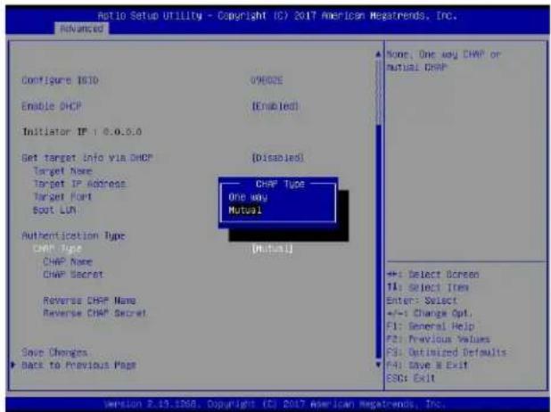
text_image
Ratio Setup Utility - Copyright (C) 2017 American Megatrends, Inc. Advanced Configure ISID Enable DHCP Initiator IP: 0.0.5.0 Set target Info via DHCP Target Name Target IP Address Target Port Boot LUN Authentication Type CHAP Type CHAP Name CHAP Secret Reverse CHAP Name Reverse CHAP Secret Save Changes Back to Previous Page None, One way CHAP or mutual CHAP CHAP Type One way Mutual [Mutual] +: Select Screen T4: Select Item Enter: Select +/-: Change Opt. F1: General Help F2: Previous Values F3: Optimized Defaults F4: Save & Exit ESC: Exit version 2.13.1908. Copyright (C) 2017 American Megatrends, Inc.
Note 1: If one way (unidirectional) CHAP authentication is performed, the iSCSI target authenticates the iSCSI initiator.
Note 2: If mutual (bidirectional) CHAP authentication is performed, the iSCSI target and iSCSI initiator authenticate each other.
CHAP Name (available when Authentication Type is set to CHAP)
Use this feature to enter the CHAP name authenticated by the iSCSI target.
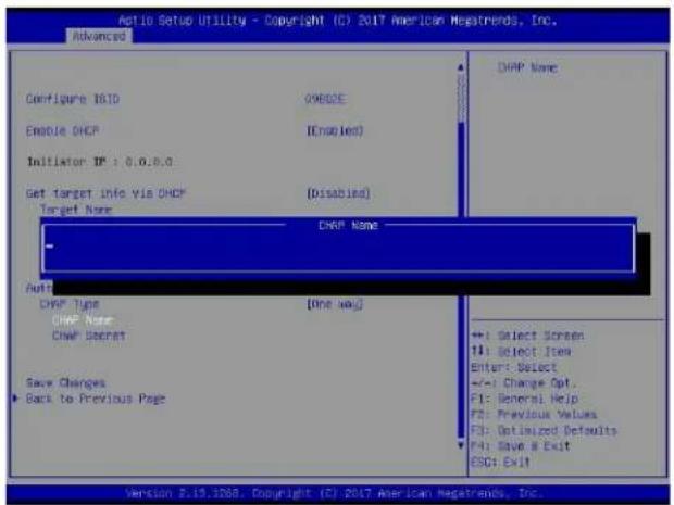
text_image
Auto Setup Utility - Copyright (C) 2017 American Megatrends, Inc. Advanced Configure ISO Enable DHCP Initiator IP: 0.0.0.0 Get target Info Via DHCP Target Name DHAP Name - Auto DHAP Type DHAP Name DHAP Secret Save Changes ► Back to Previous Page DHAP Name [One way] <<1: Select Screen 14: Select Item Enter: Select +/-1 Change Opt. F1: General Help F2: Previous Values F3: Optimized Defaults F4: Save & Exit ESC: Ex#11 Version 2.19.1268. Copyright (C) 2017 American Megatrends, Inc.CHAP Secret (available when Authentication Type is set to CHAP)
Use this feature to enter the CHAP secret (12\~16 characters) authenticated by the iSCSI target.
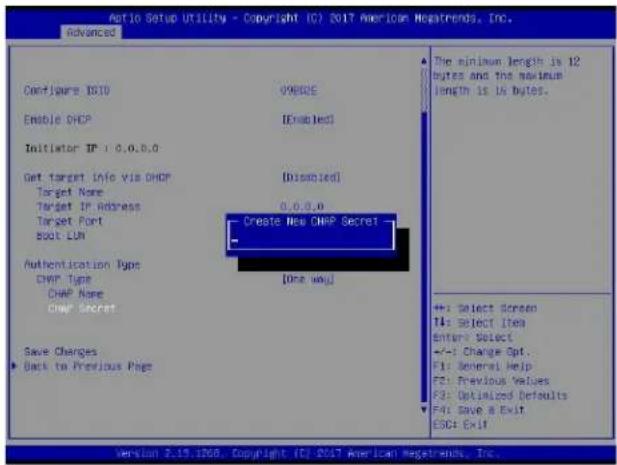
text_image
Auto Setup Utility - Copyright ISO 2017 American Megatrends, Inc. Advanced Configure ISID Enable DHCP Initiator IP: 0.0.0.0 Get target Info via DHCP Target Name Target IP Address Target Fort Boot LUN Authentication Type DHMP Type DHMP Name DHMP Secret Save Changes Back to Previous Page One way The minimum length is 12 bytes and the maximum length is 15 bytes. +: Select Screen T4: Select Item Enter Select +/-: Change Opt.. F1: General Help F2: Previous Values F3: Optimized Defaults F4: Save & Exit ESC: Exit Version 2.19.1208, Copyright [C] 2017 American Megatrends, Inc.CHAP Status
This feature displays the CHAP status.
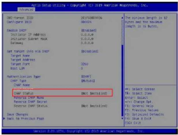
text_image
Auto Setup Utility - Copyright (C) 2019 American Megatrends, Inc. Advanced OUI-Format ISO Configure ISO Enable DHCP Initiator IP Address Initiator Subset Mask Gateway Get target Info via DHCP Target Name Target Address Target Port Boot LUN Authentication Type CHMP Type CHMP Name CHMP Status Reverse CHMP Name Reverse CHMP Secret Reverse CHMP Status Save Changes ► Back to Previous Page The minimum length is 12 bytes and the maximum length is 16 bytes. +:- Select screen T4: Select Item Enter: Select +/-: Change Opt. F1: General Help F2: Previous Values F3: Optimized Defaults F4: Save R Exit ESG: Exit Version 2.50.1873, Copyright (C) 2019 American Megatrends, Inc.Reverse CHAP Name (available when CHAP Type is set to Mutual)
Use this feature to enter the CHAP name authenticated by the iSCSI initiator.
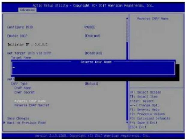
text_image
Auto Setup Utility - Copyright IC7 2017 American Megatrends, Inc. Advanced Configure ISID C9800E Enable DHCP [Enabled] Initiator IP: 0.0.0.0 Get target Info via DHCP [Disabled] Target Name Reverse DHCP Name Anti DHAP Type [Mutual] DHAP Name DHAP Secret Reverse DHCP Name Reverse DHCP Secret Save Changes ► Back to Previous Pass Reverse DHCP Name +: Select Screen F4: Select Item Enter: Select +/-: Change Opt... F1: General Help F2: Previous Values F3: Optimized Defaults F4: Save & Exit DHCI Exit version 2.19.1203, Copyright IC7 2017 American Megatrends, Inc.Reverse CHAP Secret (available when CHAP Type is set to Mutual)
Use this feature to enter the CHAP secret (12\~16 characters) authenticated by the iSCSI initiator.
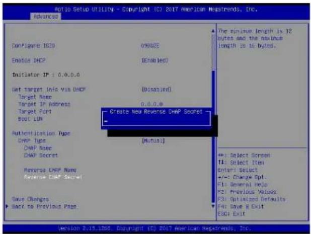
text_image
Netto Setup Utility - Copyright IC? 2017 American Megatrends, Inc. Advanced Configure ISIP Enable DHCP Initiator IP: 0.0.0.0 Get target Info Via DHCP Target Name Target IP Address Target Port Boot Lth Authentication Type CHAP Type CHAP Name CHAP Secret Reverse CHAP Name Reverse CHAP Secret Save Changes Back to Previous Page The minimum length is 12 bytes and the maximum length is 15 bytes. [Disabled] 0.0.0.0 Create New Reverse CHAP Secret [Mutual] ++: Select Screen T4: Select Item Enter: Select +/-: Change Opt. F1: General Help F2: Previous Values F3: Optimized Defaults For Save R Exit ESC: Exit Version 2.19.1265. Copyright (C) 2017 American Megatrends, Inc.Reverse CHAP Status (available when CHAP Type is set to Mutual)
This feature displays the reverse CHAP status.
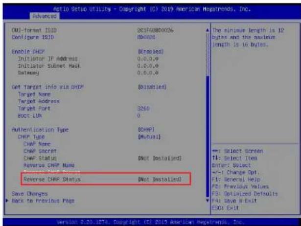
text_image
NOI-Format ISID Configure ISID Enable DHCP Initiator IP Address Initiator Subnet Mask Gateway Get Target Info via DHCP Target Name Target Address Target Port Boot-LUN Authentication Type DHIP Type DHIP Name DHIP Secret DHIP Status Reverse DHCP Name Reverse DHCP Status Reverse DHCP Status [Disabled] 3260 0 [CHIP] [Mutual] [Not Installed] [Not Installed] Save Changes Back to Previous Page The minimum length is 12 bytes and the maximum length is 16 bytes. +: Select Screen T1: Select Item Enter: Select +:-: Change Opt. F1: General Help F2: Previous Values F3: Optimized Defaults F4: Save B Exit ESQ: ExitSave Changes
Use the arrow keys to select Save Changes and press
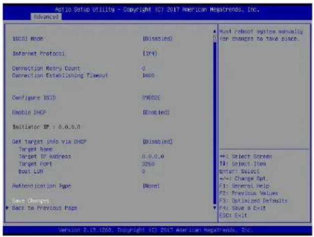
text_image
Ratio Setup Utility - Copyright (C) 2017 American Negatrends, Inc. Advanced ISCBI Mode [Disabled] Internet Protocol [IP4] Connection Retry Count 0 Connection Establishing Timeout 1000 Configure ISID 09802E Enable DHCP [Disabled] Initiator IP + 0.0.0.0 Get Target Info via DHCP [Disabled] Target Name Target IP Address 0.0.0.0 Target Port 3260 Spot LUN 0 Authentication Type [None] Save Changes ► Back to Previous Page Must reboot system manually for changes to take place. ++: Select Screen TA: Select Item Enter: Select +/-: Change Spt. F1: General Help F2: Previous Values F3: Optimized Defaults F4: Save & Exit ESC: Exit Version 2.19.1958, Copyright (C) 2017 American Negatrends, Inc.
Note: For the changes to take effect, save settings and restart the system.
Back to Previous Page
Use the arrow keys to select Back to Previous Page and press
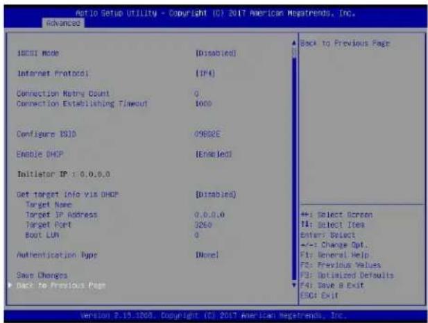
text_image
Ratio Setup Utility - Copyright IC? 2017 American Negatrends, Inc. Advanced HOSCI Mode [Disabled] Internet Protocol [IP4] Connection Retire Count 0 Connection Establishing Timeout 1000 Configure ISID 09802E Enable DHCP [Enabled] Initiator IP: 0.0.0.0 Get target Info via DHCP [Disabled] Target Name Target IP Address 0.0.0.0 Target Port 3260 Boot LUN 0 Authentication Type [None] Save Changes ▶ Back to Previous Page Back to Previous Page +:- Select Screen F1: Select Items Enter: Select +:- Change Opt. F1: General Help F2: Previous Values F2: Optimized Defaults F4: Save & Exit ESC: Exit Version 7.19.1208. Copyright (C) 2017 American Negatrends, Inc.The user will be returned to the main screen of iSCSI Configuration as shown below.
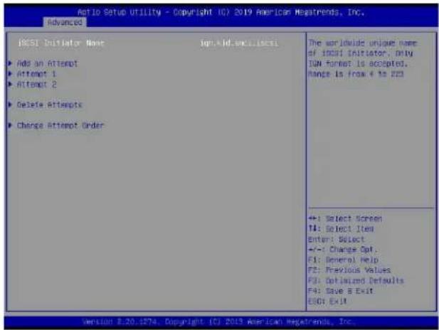
text_image
Ratio Setup Utility - Copyright IC7 2019 American MegaTrends, Inc. Advanced IQSI Initiator Name Iq: A Id. wcl. Iq: ► Add an Attempt ► Attempt 1 ► Attempt 2 ► Delete Attempts ► Change Attempt Order The worldwide unique name of IQSI Initiator, Only IQN format is accepted. Range is from 4 to 23 +:- Select Screen T4: Select Item Enter: Select +/-: Change Opt. F1: General Help F2: Previous Values F3: Optimized Defaults F4: Save & Exit ESC: Exit Version 8.20.1874, Copyright (C) 2019 American MegaTrends, Inc.Delete Attempts
Use the arrow keys to select Delete Attempts.
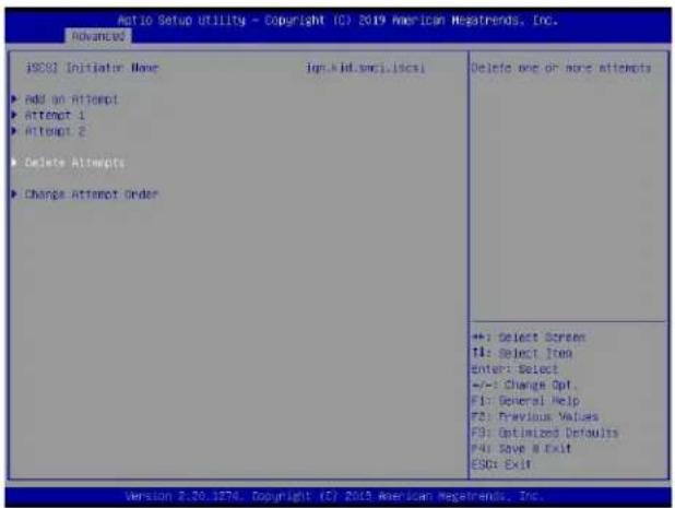
text_image
Ratio Setup Utility - Copyright (C) 2019 American Megatrends, Inc. Advanced iSCSI Initiator Name jpr.kid.smc1.iscsl Add an Attempt Attempt 1 Attempt 2 Delete Attempts Change Attempt Order Delete one or more attempts +: Select Screen TI: Select Item Enter: Select +/-: Change Opt. F1: General Help F2: Previous Values F3: Optimized Defaults F4: Save & Exit ESC: Exit Version 2.20.1876. Copyright (C) 2019 American Megatrends, Inc.Press
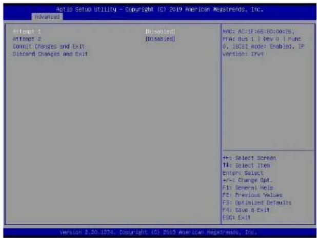
text_image
Automatic Setup Utility - Copyright (C) 2019 American Negatrends, Inc. Advanced Attempt 1 Attempt 2 Consult Changes and Exit Discard Changes and Exit Disabled (Disabled) HAC: AC:IF:68-60:00:05, PFAs Bus 1 | Dev 0 | Func 0, ISCB1 Mode: Enabled, IP version: IPv4 +: Select Screen T1: Select Item Enter: Select +/-: Change Opt. F1: General Help F2: Previous Values F3: Optimized Defaults F4: Save & Exit ESC1 Exit Version 2.20.1274, Copyright (C) 2019 American Negatrends, Inc.Attempt 1
Use the feature to disable/enable Attempt 1. The options are Disabled and Enabled.
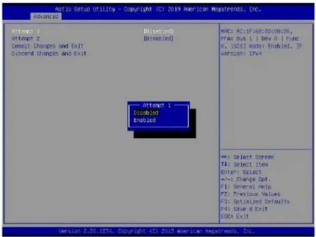
text_image
Ratio Setup Utility - Copyright (C) 2019 American Newsrends, Inc. Advanced Attempt 1 Attempt 2 Consult Changes and Exit Discard Changes And Exit Disabled Disabled Attempt 1 Disabled Enabled MAC: AC:1F:68:60:00:35, PPA Bus 1 | Dev 0 | Func 0, JOSI mode: Enabled, IP Version: IPv4 +: Select Screen T1: Select Item Enter: Select +/-: Change Opt. F1: General Help F2: Previous Values F3: Optimized Defaults F4: Save & Exit ESC: Exit Version 2.20.1874, Copyright (C) 2019 American Newsrends, Inc.Attempt 2
Use the feature to disable/enable Attempt 2. The options are Disabled and Enabled.
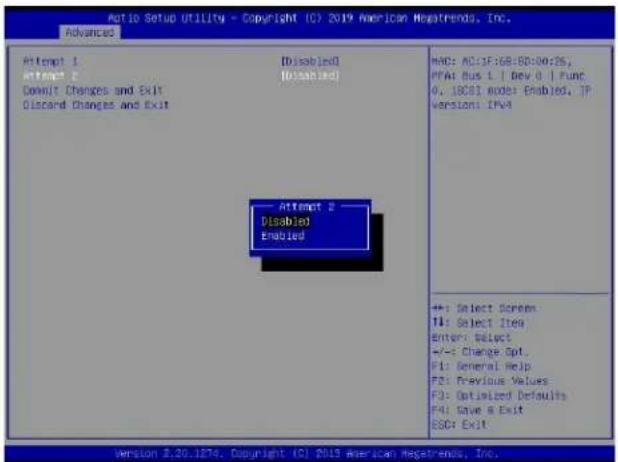
text_image
Ratio Setup Utility - Copyright (C) 2019 American Netsrends, Inc. Advanced Attempt 1 Attempt 2 Default Changes and Exit Discard Changes and Exit [Disabled] [Disabled] Attempt 2 Disabled Enabled HA6: AC:IF:68:60:00:26, PTAs bus 1 | Dev 0 | Func 0, ICSB1 mode Enabled, JP Version: IPv4 +: Select Screen TI: Select Item Enter: Select +/-: Change Opt. F1: General Help F2: Previous Values F3: Optimized Defaults F4: Save & Exit ESCY Exit Version 2.20.1876. Copyright (C) 2019 American Netsrends, Inc.Commit Changes and Exit
Press
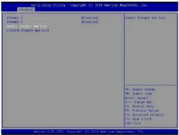
text_image
Ratio Setup Utility - Copyright (C) 2019 American Newsrends, Inc. Advanced Attempt 1 Attempt 2 Commit Changes and Exit Discord Changes And Exit [Disabled] [Disabled] Commit Changes and Exit +: Select Screen TI: Select Item Enter: Select +/-: Change Opt. F1: General Help F2: Previous Values F3: Optimized Defaults F4: Save & Exit ESC: Exit Version 2.20.1874. Copyright (C) 2019 American Newsrends, Inc.Discard Changes and Exit
Press

text_image
Aroio Setup Utility - Copyright (C) 2019 American Megatrends, Inc. Advanced Attempt 1 Attempt 2 Commit Changes and Exit Discard Changes and Exit Discard Changes and Exit +: Select Screen T4: Select Item Enter: Select +/-: Change Opt. F1: General Help F2: Previous Values F3: Optimized Defaults F4: Save & Exit ESC: Exit Version 2.20.1274. Copyright (C) 2019 American Megatrends, Inc.Change Attempt Order
Use the arrow keys to select Change Attempt Order.
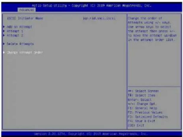
text_image
Ratio Setup Utility - Copyright (C) 2019 American Newsrends, Inc. advanced ISCBI Initiator Name + Add an Attempt - Attnent 1 - Attnent 2 - Delete Attempts - Change attempt Order Change the order of Attempts using +/- keys. Use drive keys to select the attempt then press +/- to move the attempt down in the attempt under list. +: Select Screen TA: Select Item Enter: Select +/-: Change Opt. F1: General Help F2: Previous Values F3: Optimized Defaults F4: Save & Exit ESC: Exit Version 3.20.1274, Copyright (C) 2019 American Newsrends, Inc.Press
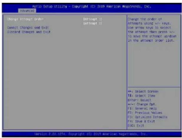
text_image
Ratio Setup Utility - Copyright (C) 2019 American Markets, Inc. advanced Change Attempt Order Attempt 11 Attempt 31 Consult Changes and Exit Discard Changes and Exit Change the order of Attempts using +/- keys. Use arrow keys to select the attempt then press +/- to move the attempt up/down in the attempt order list. +: Select Screen T4: Select Item Enter: Select +/-: Change Opt. F1: General Help F2: Previous Values F3: Optimized Defaults F4: Save & Exit ESC: Exit Version 2.20.187a. Copyright (C) 2019 American Markets, Inc.Change Attempt Order
This feature is to change the Attempt order. Use arrow keys to select the desired Attempt, then <+/-> keys to move up/down the selected Attempt. For instance, move up the selected Attempt by using <+> key. Move down the selected Attempt by using <-> key.
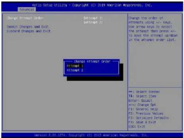
text_image
Ratio Setup Utility - Copyright (C) 2019 American Megatrends, Inc. Advanced Change Attempt Order Attempt 1 Attempt 2 Attempt Changes and Exit Discard Changes and Exit Change Attempt Order Attempt 1 Attempt 2 Change the order of Attempts using +/- keys. Use arrow keys to select the attempt then press +/- to move the attempt up/down in the attempt order list. +:- Select Stream T4: Select Item Enter: Select +/-: Change Opt. F1: General Help F2: Previous Values F3: Optimized Defaults F4: Save & Exit ESC: Exit Version 2.20.1874. Copyright (C) 2019 American Megatrends, Inc.Commit Changes and Exit
Press
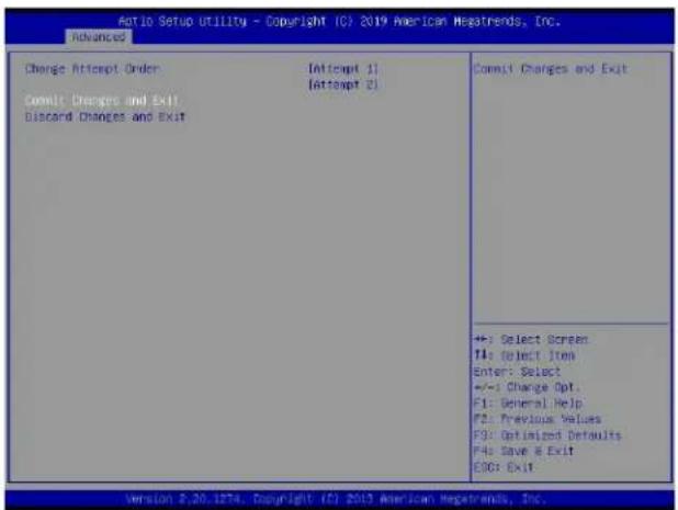
text_image
Auto Setup Utility - Copyright (C) 2019 American Megatrends, Inc. Advanced Change Attempt Order [Attempt 1] [Attempt 2] Commit Changes and Exit Discard Changes and Exit Commit Changes and Exit +:- Select Screen T4: Select Item Enter: Select +/-: Change Opt. F1: General Help F2: Previous Values F3: Optimized Defaults F4: Save & Exit EOC: Exit Version 2.20.1874. Copyright (C) 2019 American Megatrends, Inc.Discard Changes and Exit
Press
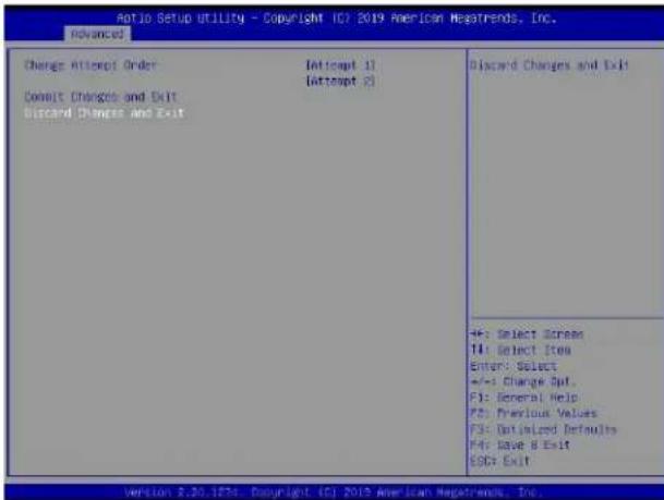
text_image
Ratio Setup Utility - Copyright 107 2019 American NewsTrends, Inc. Advanced Charge Attempt Order Attempt 1) Attempt 2) Consult Changes and Exit Discard Changes and Exit Discard Changes and Exit 46: Select Screen 14: Select Item Enter: Select +/-: Change Split F1: General Help F5: Previous Values F3: Optimized Defaults F4: Have 8 Exit ESC: Exit Version 2.30.1634, Copyright 107 2019 American NewsTrends, Inc.Appendix H
Configuring Network Interface Card (NIC) Settings
The appendix describes settings of onboard Intel® LAN devices via the BIOS Setup utility supported by the Unified Extensible Firmware Interface (UEFI) driver.
H.1 Network Interface Card (NIC) Settings
Press during system boot to enter the BIOS Setup utility. Navigate to the Advanced tab. Use the arrow keys to select PCIe/PCI/PnP Configuration and press
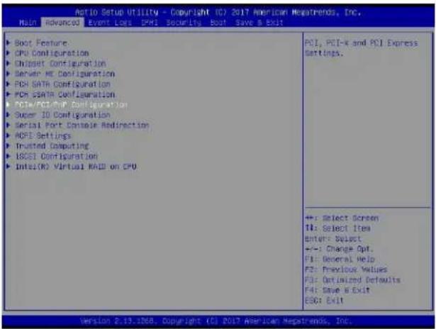
text_image
Ratio Setup Utility - Copyright (C) 2017 American Megatrends, Inc. Main Advanced Event Loss PMI Security Boot Save & Exit Boot Feature: CPU Configuration Chipset Configuration Server ME Configuration PCB SATA Configuration PCB sSNTR Configuration PCIe/PCIe/PCIe Configuration Super ID Configuration Serial Port Console Radirection ACPU Settings Trusted Computing LCCSI Configuration Intel(R) Virtual MAX on CPU PCI, PCI-X and PCI Express Settings. +: Select Screen TI: Select Item Enter: Select +:- Change Opt. FI: General Help FZ: Previous Values F3: Optimized Defaults F4: Save & Exit ESC: Exit Version 2.13.1268. Copyright (C) 2017 American Megatrends, Inc.Onboard LAN1 Option ROM (available when NIC(s) is(are) detected by the system)
Use the arrow keys to select Onboard LAN1 Option ROM and press
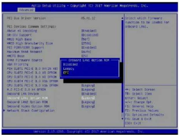
text_image
PCI Bus Driver Version PCI Devices Common Settings: Above 40 Decoding SR-IOV Support MND High Base MND High Regularity Size PCI PCRR/SEWR Support Maximum Read Request HMEF0 Bose NAME Firmware Source VMI Priority PCI0 SLOTI PCI-E 3.0 X4 (IN X8) CPU SLOT2 PCI-E 3.0 X8 DROM CPU SLOT3 PCI-E 3.0 X9 DROM CPU SLOT4 PCI-E 3.0 X10 DROM CPU SLOT6 PCI-E 3.0 X16 DROM H.D PCI-E 3.0 X4 DROM Onboard LAN Device Onboard LAN1 Option ROM Onboard LAN2 Option ROM Onboard Video Option ROM Network Stack Configuration [Enrolled] [Disabled] [Perf] [Enabled] [Auto] [ISO] Onboard LAN1 Option ROM Dissled Legacy EFC [Legacy] [Legacy] [Enabled] [Legacy] [Legacy] [Legacy] [Legacy] Select which firmware function to be loaded for onboard LAN1. +: Select Screen 14: Select Item Enter: Select +/-: Change Opt. F1: General Help F2: Previous Values F3: Optimized Defaults F4: Save & Exit ESC: Exit Version 7.19.1999, Copyright (C) 2017 American Megaplans, Inc.
Note : If Onboard LAN1 Option ROM is set to EFI, all features for onboard LAN option ROM will be set to EFI by the EFI driver. Additionally, these features will become unavailable except Onboard LAN1 Option ROM.
For the changes to take effect, press during system boot to enter the BIOS Setup utility. Navigate to the Advanced tab. The feature(s) for onboard Intel® LAN device(s) will become available for configuration as shown below.
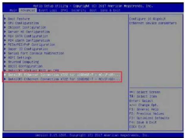
text_image
Ratio Setup Utility - Copyright ICI 2017 American Megatrends, Inc. Main Advanced Event Logs IPMI Security Boot Save & Exit Boot Feature CPU Configuration Chipset Configuration Server MT Configuration PCH SATA Configuration PCH stamn Configuration PCIe/PCI/PNP Configuration Super ID Configuration Serial Fort Console Redirection NDPI Settings Trusted Computing IBCSI Configuration IntelOCS Virtual EBIT mn CPU IntelOCS Ethernet Connection X722 for 10898E-T - WDIP168... IntelOCS Ethernet Connection X722 for 10898E-T - WDIP168... Configure 10 Bigabit Ethernet device parameters +/-: Select Screen T1: Select Item Enter: Select +/-: Change Opt. F1: General Help F2: Previous Values F3: Optimized Defaults F4: Save & Exit ESC: Exit version 2.13.1205. Copyright (C) 2017 American Megatrends, Inc.Use the arrow keys to select the desired onboard LAN device as shown below.
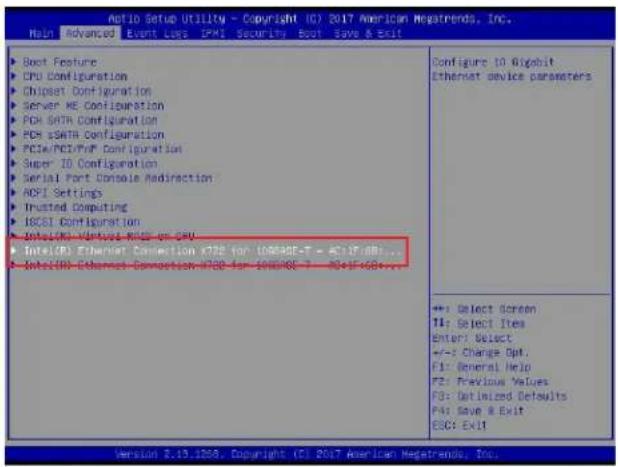
text_image
Notio Setup Utility - Copyright (C) 2017 American Megatrends, Inc. Main Advanced Event Loss PMI Security Boot Save & Exit ▶ Boot Feature ▶ CPU Configuration ▶ Chipset Configuration ▶ Server ME Configuration ▶ PCI SATH Configuration ▶ PCI sSATA Configuration ▶ PCIw/PCI/PoP Configuration ▶ Super 1D Configuration ▶ Serial Port Console Modirection ▶ AOCI Settings ▶ Trusted Computing ▶ IECSI Configuration ▶ NT5/NCI-VMHOS-NCI-NCI ▶ NT5/NCI Ethernet Connection x72E for 108948E-T = x71F/dB... ▶ NT5/NCI Ethernet Connection x73E for 108948E-T = x71F/dB... Configure 10 Gigabit Ethernet device parameters ++: Select Screen TI: Select Items Enter: Select +/-: Change Opt. FI: General Help FE: Previous Values FD: Optimized Defaults PA: Save & Exit ESC: Exit Version 2.13.1208. Copyright (C) 2017 American Megatrends, Inc.Press
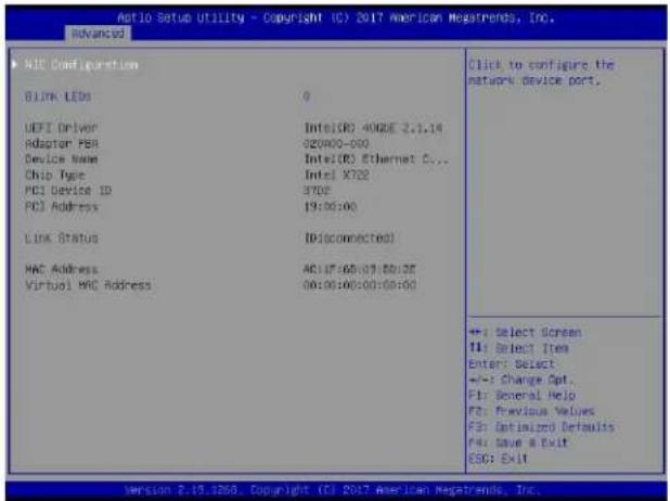
text_image
Aio Setup Utility - Copyright (C) 2017 American Megatrends, Inc. Advanced NIO Configuration BLINK LEDs 0 UEFI Driver Intel(R) 4000E 2.1.14 Adaptor PBA 92000-000 Device Name Intel(R) Ethernet C... Chip Type Intel X702 PCI Device ID 370E PCI Address 19:06:00 LINK STATUS ID disconnected) MAC Address AC:17:68:09:00:25 Virtual MAC Address 00:00:00:00:00:00 Click to configure the network device port. + : Select Screen T4: Select Item Enter: Select +:- : Change Opt. F1: General Help F2: Previous Values F3: Optimized Defaults F4: Save a Exit ESC: Exit Version 2.19.1268, Copyright (C) 2017 American Megatrends, Inc.Blink LEDs
This feature allows the user to set the LED blink duration (in seconds). The valid range is 0\~15 (seconds).
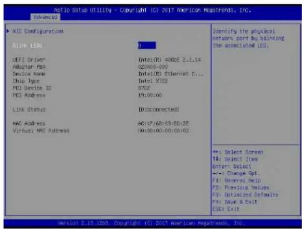
text_image
NIO Configuration DINK LEOs UEFI Driver Adaptor PBA Device Name Chip Type PCI Device ID PCI Address Link Status MAC Address Virtual MAC Address Identify the physical network port by blinking the associated LED. AC:17:68:05:50:2E 00:30:00:00:00:00 +: Select Screen TI: Select Item Enter Select +/-: Change Opt. F1: General Help F2: Previous Values F3: Utilized Defaults F4: Save & Exit ESC: Exit Version 2.13.1206 Copyright (C) 2017 American Megatrends, Inc.NIC Configuration
Use the arrow keys to select NIC Configuration.
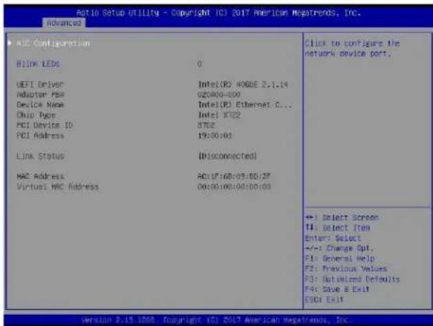
text_image
Ratio Setup Utility - Copyright (C) 2017 American Megatrends, Inc. RHOVANCED ▶ BIOS Configuration 81INK LEDs 0 UEFI Driver Intel(R) A00GE 2.1.14 Adaptor PBA 020400-000 Device Name Intel(R) Ethernet C... Chip Type Intel X102 PCI Device ID 3702 PCI Address 19:00:01 Link Status ID(connected) MAC Address AC(17):68:09:00:3F Virtual MAC Address 00:00:00:00:00:00 Click to configure the network device port. +:- Select Screen T1: Select Item Enter: Select +/-: Change Opt, F1: General Help F2: Previous Values F3: Optimized Defaults F4: Save & Exit E0G: Exit Version 2.15.1998 Copyright (C) 2017 American Megatrends, Inc.Press
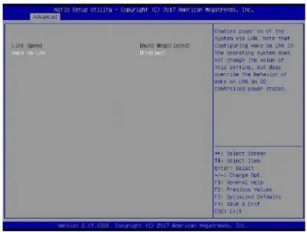
text_image
Action Setup Utility - Copyright (C) 2017 American News trends, Inc. Advanced Link Speed Here On LAN (Auto Negotiated) (Enabled) Enables power on of the system via LAN. Note that configuring Wake on LAN in the operating system does not change the value of this setting, but does override the behavior of Wake on LAN In OS controlled power states. +: Select Screen #: Select Item Enter: Select +/-: Change Opt, F1: General Help F2: Previous Values F3: Optimized Defaults F4: Save & Exit F5: Exit Version 2.19.1208. Copyright (C) 2017 American News trends, Inc.Wake on LAN
Use the arrow keys to select Wake On LAN and press