
X11SBA-LN4F/F - Motherboard Supermicro - Free user manual and instructions
Find the device manual for free X11SBA-LN4F/F Supermicro in PDF.


User questions about X11SBA-LN4F/F Supermicro
0 question about this device. Answer the ones you know or ask your own.
Ask a new question about this device
Download the instructions for your Motherboard in PDF format for free! Find your manual X11SBA-LN4F/F - Supermicro and take your electronic device back in hand. On this page are published all the documents necessary for the use of your device. X11SBA-LN4F/F by Supermicro.
USER MANUAL X11SBA-LN4F/F Supermicro
The information in this User's Manual has been carefully reviewed and is believed to be accurate. The vendor assumes no responsibility for any inaccuracies that may be contained in this document, and makes no commitment to update or to keep current the information in this manual, or to notify any person or organization of the updates. Please Note: For the most up-to-date version of this manual, please see our website at www.supermicro.com.
Super Micro Computer, Inc. ("Supermicro") reserves the right to make changes to the product described in this manual at any time and without notice. This product, including software and documentation, is the property of Supermicro and/or its licensors, and is supplied only under a license. Any use or reproduction of this product is not allowed, except as expressly permitted by the terms of said license.
IN NO EVENT WILL Super Micro Computer, Inc. BE LIABLE FOR DIRECT, INDIRECT, SPECIAL, INCIDENTAL, SPECULATIVE OR CONSEQUENTIAL DAMAGES ARISING FROM THE USE OR INABILITY TO USE THIS PRODUCT OR DOCUMENTATION, EVEN IF ADVISED OF THE POSSIBILITY OF SUCH DAMAGES. IN PARTICULAR, SUPER MICRO COMPUTER, INC. SHALL NOT HAVE LIABILITY FOR ANY HARDWARE, SOFTWARE, OR DATA STORED OR USED WITH THE PRODUCT, INCLUDING THE COSTS OF REPAIRING, REPLACING, INTEGRATING, INSTALLING OR RECOVERING SUCH HARDWARE, SOFTWARE, OR DATA.
Any disputes arising between manufacturer and customer shall be governed by the laws of Santa Clara County in the State of California, USA. The State of California, County of Santa Clara shall be the exclusive venue for the resolution of any such disputes. Supermicro's total liability for all claims will not exceed the price paid for the hardware product.
FCC Statement: This equipment has been tested and found to comply with the limits for a Class A digital device pursuant to Part 15 of the FCC Rules. These limits are designed to provide reasonable protection against harmful interference when the equipment is operated in a commercial environment. This equipment generates, uses, and can radiate radio frequency energy and, if not installed and used in accordance with the manufacturer's instruction manual, may cause harmful interference with radio communications. Operation of this equipment in a residential area is likely to cause harmful interference, in which case you will be required to correct the interference at your own expense.
California Best Management Practices Regulations for Perchlorate Materials: This Perchlorate warning applies only to products containing CR (Manganese Dioxide) Lithium coin cells. "Perchlorate Material-special handling may apply. See www.dtsc.ca.gov/hazardouswaste/perchlorate".
WARNING: Handling of lead solder materials used in this product may expose you to lead, a chemical known to the State of California to cause birth defects and other reproductive harm.
The products sold by Supermicro are not intended for and will not be used in life support systems, medical equipment, nuclear facilities or systems, aircraft, aircraft devices, aircraft/emergency communication devices or other critical systems whose failure to perform be reasonably expected to result in significant injury or loss of life or catastrophic property damage. Accordingly, Supermicro disclaims any and all liability, and should buyer use or sell such products for use in such ultra-hazardous applications, it does so entirely at its own risk. Furthermore, buyer agrees to fully indemnify, defend and hold Supermicro harmless for and against any and all claims, demands, actions, litigation, and proceedings of any kind arising out of or related to such ultra-hazardous use or sale.
Manual Revision 1.00
Release Date: November 6, 2015
Unless you request and receive written permission from Super Micro Computer, Inc., you may not copy any part of this document. Information in this document is subject to change without notice. Other products and companies referred to herein are trademarks or registered trademarks of their respective companies or mark holders.
Copyright © 2015 by Super Micro Computer, Inc.
All rights reserved.
Printed in the United States of America
Preface
About This Manual
This manual is written for system integrators, IT technicians and knowledgeable end users. It provides information for the installation and use of the X11SBA-LN4F/F motherboard.
About This Motherboard
The X11SBA-LN4F/F motherboard comes with the Intel® Pentium® Processor N3700. The Intel® Pentium® Processor N3700 has 2MB of L2 cache. It supports DDR3L memory at 1600MHz and has a thermal design power (TDP) of 6W. Based on the 14nm microarchitecture, the processor features the 8th Generation Intel HD graphics. This motherboard provides an increase in overall performance and improved power efficiency. Please note that this motherboard is intended to be installed and serviced by professional technicians only. For processor/memory updates, please refer to our website at http://www.supermicro.com/products/.
Conventions Used in the Manual
Special attention should be given to the following symbols for proper installation and to prevent damage done to the components or injury to yourself:

Warning! Indicates important information given to prevent equipment/property damage or personal injury.

Warning! Indicates high voltage may be encountered when performing a procedure.

Important: Important information given to ensure proper system installation or to relay safety precautions.

Note: Additional Information given to differentiate various models or provides information for correct system setup.
Contacting Supermicro
Headquarters
Address: Super Micro Computer, Inc.
980 Rock Ave.
San Jose, CA 95131 U.S.A.
Tel: +1 (408) 503-8000
Fax: +1 (408) 503-8008
Email: marketing@supermicro.com (General Information)
support@supermicro.com (Technical Support)
Website: www.supermicro.com
Europe
Address: Super Micro Computer B.V.
's-Hertogenbosch, The Netherlands
Tel: +31 (0) 73-6400390
Fax: +31 (0) 73-6416525
Email: sales@supermicro.nl (General Information)
support@supermicro.nl (Technical Support)
rma@supermicro.nl (Customer Support)
Website: www.supermicro.nl
Asia-Pacific
Address: Super Micro Computer, Inc.
3F, No. 150, Jian 1st Rd.
Zhonghe Dist., New Taipei City 235
Taiwan (R.O.C)
Tel: +886-(2) 8226-3990
Fax: +886-(2) 8226-3992
Email: support@supermicro.com.tw
Website: www.supermicro.com.tw
Table of Contents
Chapter 1 Introduction
1.1 Checklist....8
Quick Reference 11
Quick Reference Table....12
Motherboard Features....14
1.2 Processor and Chipset Overview....18
1.3 Special Features ....18
Recovery from AC Power Loss....18
1.4 System Health Monitoring....19
Onboard Voltage Monitors ....19
Fan Status Monitor with Firmware Control 19
Environmental Temperature Control ....19
System Resource Alert....19
1.5 ACPI Features....19
1.6 Power Supply 20
Chapter 2 Installation
2.1 Static-Sensitive Devices....21
Precautions ......21
Unpacking 21
2.2 Motherboard Installation....22
Tools Needed 22
Location of Mounting Holes 22
Installing the Motherboard....23
2.3 Installing Memory 24
Support....25
2.4 Rear I/O Ports 26
2.5 Front Control Panel 30
2.6 Connectors 33
Power Connections....33
Headers....35
2.7 Jumper Settings 43
How Jumpers Work....43
2.8 LED Indicators....47
Chapter 3 Troubleshooting
3.1 Troubleshooting Procedures ....50
Before Power On ....50
No Power 50
No Video ....51
System Boot Failure 51
Memory Errors ....51
Losing the System's Setup Configuration....52
When the System Becomes Unstable 52
3.2 Technical Support Procedures ....54
3.3 Frequently Asked Questions ....55
3.4 Battery Removal and Installation ....56
Battery Removal....56
Proper Battery Disposal....56
Battery Installation....56
3.5 Returning Merchandise for Service....57
Chapter 4 BIOS
4.1 Introduction....58
Starting the Setup Utility 58
4.2 Main Setup ....59
4.3 Advanced Setup Configurations....61
4.4 IPMI 80
4.5 Security....83
4.6 Boot....86
4.7 Save & Exit....88
Appendix A BIOS Codes
Appendix B Software Installation
B.1 Installing Software Programs 92
B.2 SuperDoctor ^® 5....93
Appendix C Standardized Warning Statements
Battery Handling....94
Product Disposal 96
Appendix D UEFI BIOS Recovery
Chapter 1
Introduction
Congratulations on purchasing your computer motherboard from an industry leader. Supermicro boards are designed to provide you with the highest standards in quality and performance.
Please check that the following items have all been included with your motherboard. If anything listed is damaged or missing, please contact your retailer.
1.1 Checklist
| Retail Box | ||
| Description Part Number Quantity | ||
| X11SBA Motherboard MBD-X11SBA 1 | ||
| I/O Cables (57.5CM SATA FLAT S-SPBF) CBL-0044L 2 | ||
| I/O Shield (Standard I/O Shield for X11SBA with EMI Gasket) | MCP-260-00058-0N | 1 |
| QRG sheet 1 | ||
Important Links
For your system to work properly, please follow the links below to download all necessary drivers/utilities and the user's manual for your server.
- Supermicro product manuals: http://www.supermicro.com/support/manuals/
- Product drivers and utilities: ftp://ftp.supermicro.com
- Product safety info: http://www.supermicro.com/about/policies/safety_information.cfm
- If you have any questions, please contact our support team at: support@supermicro.com
This manual may be periodically updated without notice. Please check the Supermicro website for possible updates to the manual revision level.
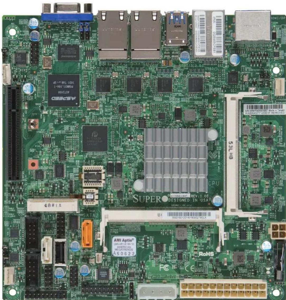
Figure 1-1. X11SBA-LN4F/F Motherboard Image
text_image
Close-up of a green printed circuit board with visible component labels and logos, including CPU, RAM, and processor branding.
Note: All graphics shown in this manual were based upon the latest PCB revision available at the time of publication of the manual. The motherboard you received may or may not look exactly the same as the graphics shown in this manual.
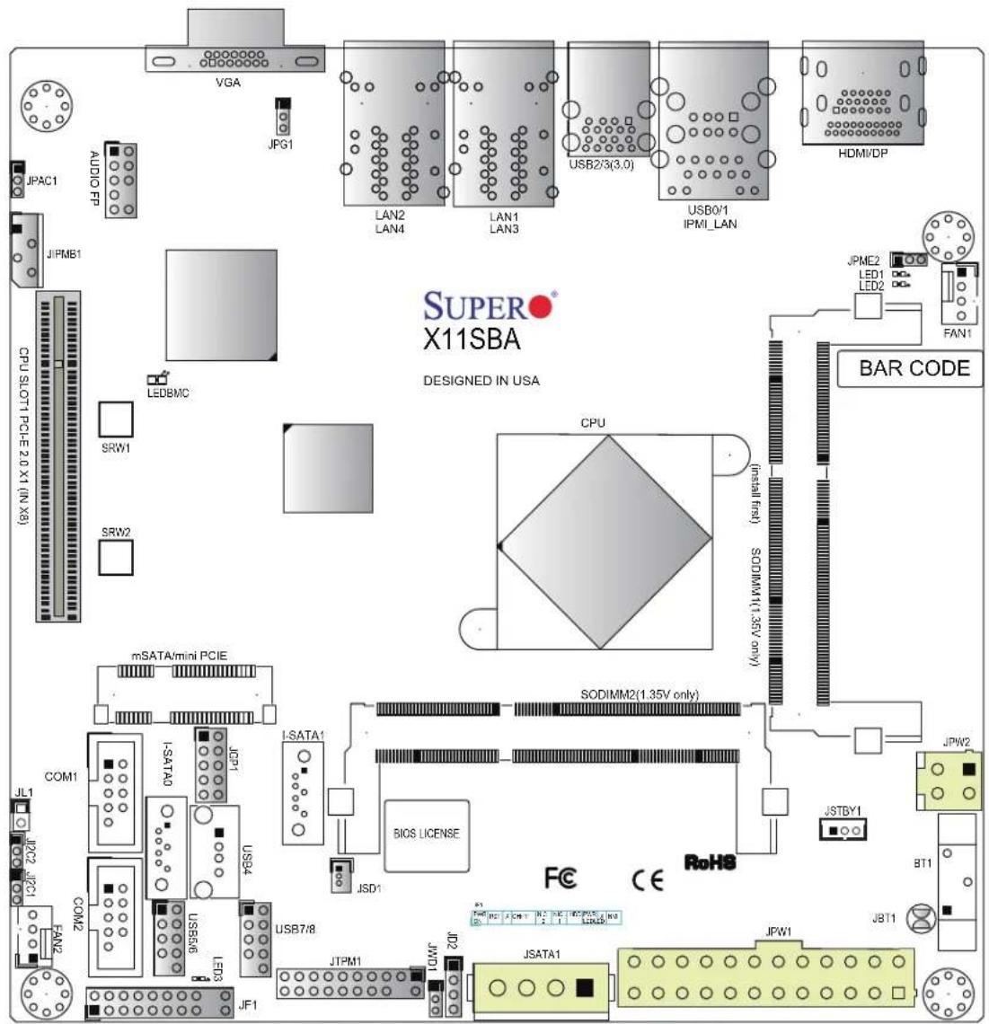
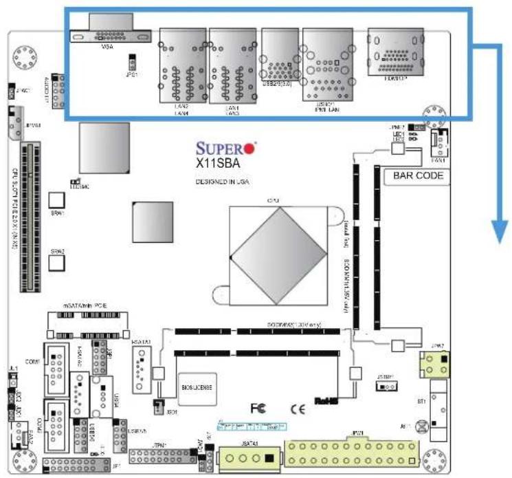
Figure 1-2. X11SBA-LN4F/F Motherboard Layout
(not drawn to scale)
text_image
SUPER X11SBA DESIGNED IN USA JPA1 AUDIO FP VGA JPG1 LAN2 LAN4 LAN1 LAN3 USB2/3(3.0) USB0/1 IPMI_LAN HDMI/DP JPM81 JPM2 LEDMC CPU SLOT1 PCIe 2.0 X1 (IN X8) SRW1 SRW2 mSATA/mini PCIE SODIMM2(1.35V only) CPU Install first) SODIMM1(1.35V only) BAR CODE JPM2 LED1 LED2 FAN1 JSTBY1 JST JBT1 JPTM1 JDT1 JSATA1 JFW1 JFW2 JST/8 JSD1 JSD4 JSD6 JSD7/8 JF1 JF2 JF3 JF4 JF5 JF6 JF7 JF8 JF9 JF10 JF11 JF12 JF13 JF14 JF15 JF16 JF17 JF18 JF19 JF20 JF21 JF22 JF23 JF24 JF25 JF26 JF27 JF28 JF29 JF30
Note: Components not documented are for internal testing only.
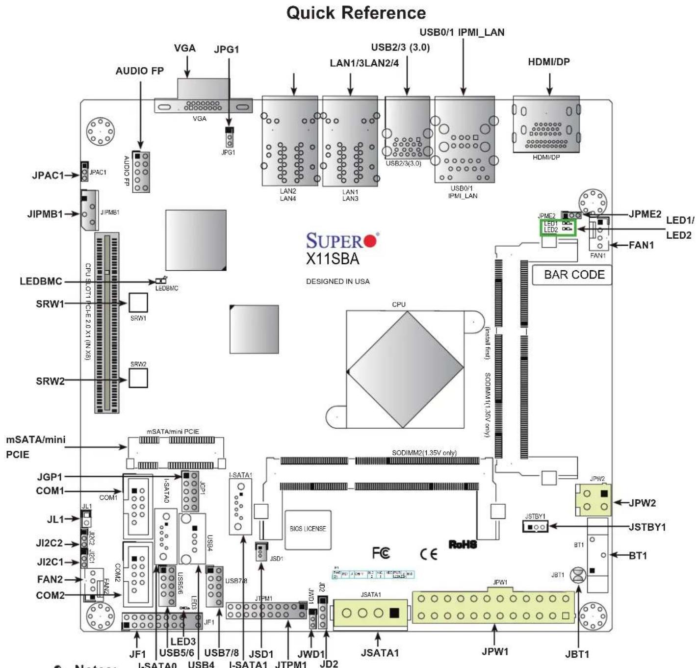
flowchart
graph TD
    A["Quick Reference"] --> B["VIDEO FP"]
    B --> C["VGA"]
    C --> D["JPG1"]
    D --> E["JPG1"]
    E --> F["LAN2 LAN4"]
    F --> G["LAN1 LAN3"]
    G --> H["USB2/3(3.0)"]
    H --> I["USB0/1 IPMI_LAN"]
    I --> J["HDMI/DP"]
    J --> K["LED1/LED2"]
    K --> L["FAN1"]
    L --> M["BAR CODE"]
    M --> N["JPME2 LED1/LED2"]
    N --> O["LED1/LED2"]
    O --> P["JPM2"]
    P --> Q["LED1/LED2"]
    Q --> R["FSI 1.35V only"]
    R --> S["SODIMM2(1.35V only)"]
    S --> T["FC CE RoHS"]
    T --> U["JBW1"]
    U --> V["JBT1"]
    V --> W["JBW2"]
    W --> X["JSTBY1"]
    X --> Y["BT1"]
    Y --> Z["JSTBY1"]
    Z --> AA["JBW2"]
    AA --> AB["JBW2"]
    AB --> AC["JSATA1"]
    AC --> AD["JSATA1"]
    AD --> AE["JSATA1"]
    AE --> AF["JSATA1"]
    AF --> AG["JSATA1"]
    AG --> AH["JSATA1"]
    AH --> AI["JSATA1"]
    AI --> AJ["JSATA1"]
    AJ --> AK["JSATA1"]
    AK --> AL["JSATA1"]
    AL --> AM["JSATA1"]
    AM --> AN["JSATA1"]
    AN --> AO["JSATA1"]
    AO --> AP["JSATA1"]
    AP --> AQ["JSATA1"]
    AQ --> AR["JSATA1"]
    AR --> AS["JSATA1"]
    AS --> AT["JSATA1"]
    AT --> AU["JSATA1"]
    AU --> AV["JSATA1"]
    AV --> AW["JSATA1"]
    AW --> AX["JSATA1"]
    AX --> AY["JSATA1"]
    AY --> AZ["JSATA1"]
    AZ --> BA["JSATA1"]
    BA --> BB["JSATA1"]
    BB --> BC["JSATA1"]
    BC --> BD["JSATA1"]
    BD --> BE["JSATA1"]
    BE --> BF["JSATA1"]
    BF --> BG["JSATA1"]
    BG --> BH["JSATA1"]
    BH --> BI["JSATA1"]
    BI --> BJ["JSATA1"]
    BJ --> BK["JSATA1"]
    BK --> BL["JSATA1"]
    BL --> BM["JSATA1"]
    BM --> BN["JSATA1"]
    BN --> BO["JSATA1"]
    BO --> BP["JSATA1"]
    BP --> BQ["JSATA1"]
    BQ --> BR["JSATA1"]
    BR --> BS["JSATA1"]
    BS --> BT["JSATA1"]
    BT --> BU["JSATA1"]
    BU --> BV["JSATA1"]
    BV --> BW["JSATA1"]
    BW --> BX["JSATA1"]
    BX --> BY["JSATA1"]
    BY --> BZ["JSATA1"]

Notes:
- See Chapter 2 for detailed information on jumpers, I/O ports, and JF1 front panel connections.
• " " indicates the location of Pin 1. - Jumpers/LED indicators not indicated are used for testing only.
- Use only the correct type of onboard CMOS battery as specified by the manufacturer. Do not install the onboard battery upside down to avoid possible explosion.
Quick Reference Table
Jumper Description Default Setting
| JBT1 CMOS Clear Open (Normal); Short: Clear CMOS | ||
| JI2C1/JI2C2 SMB to PCI-E Slots Enable/Disable Pins 1-2 (Enabled) | ||
| JPAC1 Audio Enable Pins 1-2 (Enabled) | ||
| JPG1 VGA Enable/Disable Pins 1-2 (Enabled) | ||
| JPME2 Manufacturing Mode Pins 1-2 (Normal) | ||
| JWD1 | Watch Dog Timer | Pins 1-2 (Reset) |
| LED | Description | Status |
| LED1 CPU Power LED | Blue On: Power On | |
| LED2 Standby Power LED | Green On: Power On | |
| LED3 Main Power LED | Green On: Power On | |
| LEDBMC | BMC Heartbeat LED | Blinking Green: BMC Normal |
| Connector | Description |
| AUDIO FP | Audio Front Panel Header |
| BT1 | Onboard Battery |
| COM1/COM2 | Serial COM Headers |
| FAN1/FAN2 | System/CPU Fan Headers |
| HDMI/DP | Back Panel High Definition Multimedia Interface/DisplayPort |
| IPMI_LAN | IPMI Dedicated LAN Port |
| I-SATA0/I-SATA1 | Intel® PCH SATA 3.0 Ports (I-SATA1 supports SuperDOM) |
| JGP1 General Purpose I/O Headers | |
| JD2 | External Speaker Header |
| JF1 | Front Panel Control Header |
| JIPMB1 | 4-pin BMC External I2C Header |
| JL1 | Chassis Intrusion Header |
| JPW1 | 24-pin ATX Power Connector |
| JPW2 | 4-pin 12V Power Connector (Optional Power Source when the 24-pin ATX power is not in use) |
| JSATA1 | 4-pin Connector for HDD use (to provide power from the motherboard to onboard devices) |
| JSD1 | SATA DOM Power Connector |
| JSTBY1 | Standby Power Header |
| JTPM1 | Trusted Platform Module/Port 80 Connector |
| LAN1 ~ LAN4 | LAN (RJ45) Ports (-F with dual LAN only) |
| mSATA/miniPCI-E | mSATA/mini-PCI-E Connector |
| SLOT1 | CPU Slot PCI-E 2.0 X1 (IN X8) |
| SRW1/SRW2 | mSATA Holding Screws |

Note: Table is continued on the next page.
Connector Description
USB0/1 Back panel Universal Serial Bus (USB) 2.0 Ports
USB2/3 Back Panel USB 3.0 Ports
USB4 USB Type A Header
USB5/6, USB7/8 Front Panel USB 2.0 Headers
VGA Back Panel VGA Port
Motherboard Features
| Motherboard Features | |
| CPU | |
| Intel® Pentium® Processor N3700 SoC (System on a Chip) in the FCBGA1170 format. | |
| Memory | |
| Supports up to 8 GB of DDR3L (1.35, Low Voltage) Dual Channel, Non-ECC SO-DIMM up to 1600MHz in two horizontal sockets. | |
| DIMM Size | |
| 1 GB, 2 GB, and 4 GB | |
| Expansion Slots | |
| One (1) PCI Express 2.0 X1 in x8 slot. One (1) mini-PCI-E slot with mSATA support | |
| Network | |
| Intel® i210 Gigabit Ethernet Controller | |
| Graphics | |
| Intel HD Graphics (HDMI version 1.4b, DisplayPort 1.1a)ASpeed 2400 BMC Graphics controller (VGA) | |
| Audio | |
| Audio Front Panel Header via Realtek@ ALC888S | |
| I/O Devices | |
| Serial (COM) PortSATA 3.0 | Two (2) serial port headersTwo (2) SATA 3.0 ports supported by Intel SoC (I-SATA0/I-SATA1) |

Note: The table above is continued on the next page.
Motherboard Features
Peripheral Devices
• Two (2) USB 2.0 ports on the rear I/O panel (USB 0/1)
• Two (2) USB 3.0 ports on the rear I/O panel (USB 2/3)
• Four (4) internal USB 2.0 ports with two (2) headers (USB 5/6, USB 7/8)
• One (1) Type-A USB 2.0 connector (USB 4)
BIOS
• 128Mb SPI AMI BIOS® SM Flash UEFI BIOS
• ACPI 3.0 or later, SMBIOS 2.7 or later, PCI F/W 3.0, BIOS Rescue Hot-key, RTC (Real Time Clock) Wakeup
Power Management
• Main switch override mechanism
• Power-on mode for AC power recovery
• Intel® Trusted Execution Engine (Intel® TXE)
• ACPI Power Mnagement
System Health Monitoring
- Onboard voltage monitoring for +3.3V, +5V, +12V, +3.3V Stdby, +5V Stdby, +1.05V Stdby, +1.2V, VBAT, CPU, GFX, Memory.
• System overheat LED and control
• CPU Thermal Trip support
• Status monitor for speed control
• Status monitor for on/off control
Fan Control
• Fan status monitoring via IPMI connections
• Low-noise fan speed control
• Pulse Width Modulation (PWM) fan control
• Fan Speed Control
System Management
• Trusted Platform Module (TPM) support
- SUM-InBand
• System resource alert via SuperDoctor® 5
• SuperDoctor® 5, Watch Dog, NMI
• Chassis intrusion header and detection

Note: The table above is continued on the next page.
Motherboard Features
LED Indicators
- System Overheating
• Power/Suspend-state Indicator - Fan Failure
• HDD Activity, LAN Activity
Dimensions
• 6.7" (L) x 6.7" (W) (170.18 mm x 170.18 mm)

Note 1: For IPMI configuration instructions, please refer to the Embedded IPMI Configuration User's Guide available at http://www.supermicro.com/support/manuals/.
Note 2: It is strongly recommended that you change BMC log-in information upon initial system power-on. The manufacture default username is ADMIN and the password is ADMIN. For proper BMC configuration, please refer to http://www.supermicro.com/products/info/files/IPMI/Best_Practices_BMC_Security.pdf
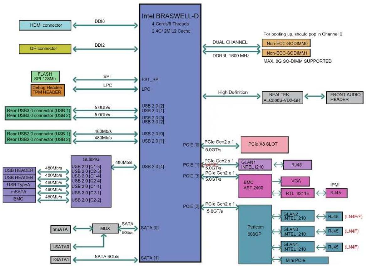
Figure 1-3. System Block Diagram
flowchart
graph TD
    A["HDMI connector"] <-->|DDI0| B["Intel BRASWELL-D 4 Cores/8 Threads 2.4G/2M L2 Cache"]
    C["DP connector"] <-->|DDI2| B
    D["FLASH SPI 128Mb"] <-->|SPI| B
    E["Debug Header/ TPM HEADER"] <-->|LPC| B
    F["Rear USB3.0 connector (USB 1) / Rear USB3.0 connector (USB 2)"] -->|5.0Gb/s| B
    G["Rear USB2.0 connector (USB 1) / Rear USB2.0 connector (USB 2)"] -->|480Mb/s| B
    H["USB HEADER"] -->|480Mb/s| I["GL854G USB 2.0 [C1-3"] USB 2.0["C2-3"] USB 2.0["C1-4"] USB 2.0["C2-4"] USB 2.0["C1-1"] USB 2.0["C2-1"] USB 2.0["C2-2"]]
    J["USB HEADER"] -->|480Mb/s| I
    K["USB TypeA mSATA BMC"] -->|480Mb/s| I
    L["mSATA"] --> M["MUX"]
    N["I-SATA0"] --> M
    O["I-SATA1"] --> P["SATA 6Gb/s"]
    Q["PCIe Gen2 x 1 5.0GT/s"] --> R["PCIe X8 SLOT"]
    S["PCIe Gen2 x 1 5.0GT/s"] --> T["GLAN1 INTEL I210"]
    U["PCIe Gen2 x 1 5.0GT/s"] --> V["BMC AST 2400"]
    W["PCIe Gen2 x 1 5.0GT/s"] --> X["Pericom 608GP"]
    Y["PCIe Gen2 x 1 5.0GT/s"] --> Z["IPMI"]
    AA["PCIe Gen2 x 1 5.0GT/s"] --> AA
    AB["PCIe Gen2 x 1 5.0GT/s"] --> AA
    AC["PCIe Gen2 x 1 5.0GT/s"] --> AA
    AD["PCIe Gen2 x 1 5.0GT/s"] --> AA
    AE["PCIe Gen2 x 1 5.0GT/s"] --> AA
    AF["PCIe Gen2 x 1 5.0GT/s"] --> AA
    AG["PCIe Gen2 x 1 5.0GT/s"] --> AA
    AH["PCIe Gen2 x 1 5.0GT/s"] --> AA
    AI["PCIe Gen2 x 1 5.0GT/s"] --> AA
    AJ["PCIe Gen2 x 1 5.0GT/s"] --> AA
    AK["PCIe Gen2 x 1 5.0GT/s"] --> AA
    AL["PCIe Gen2 x 1 5.0GT/s"] --> AA
    AM["PCIe Gen2 x 1 5.0GT/s"] --> AA
    AN["PCIe Gen2 x 1 5.0GT/s"] --> AA
    AO["PCIe Gen2 x 1 5.0GT/s"] --> AA
    AP["PCIe Gen2 x 1 5.0GT/s"] --> AA
    AQ["PCIe Gen2 x 1 5.0GT/s"] --> AA
    AR["PCIe Gen2 x 1 5.0GT/s"] --> AA
    AS["PCIe Gen2 x 1 5.0GT/s"] --> AA
    AT["PCIe Gen2 x 1 5.0GT/s"] --> AA
    AU["PCIe Gen2 x 1 5.0GT/s"] --> AA
    AV["PCIe Gen2 x 1 5.0GT/s"] --> AA
    AW["PCIe Gen2 x 1 5.0GT/s"] --> AA
    AX["PCIe Gen2 x 1 5.0GT/s"] --> AA
    AY["PCIe Gen2 x 1 5.0GT/s"] --> AA
    AZ["PCIe Gen2 x 1 5.0GT/s"] --> AA
    BA["PCIe Gen2 x 1 5.0GT/s"] --> AA
    BB["PCIe Gen2 x 1 5.0GT/s"] --> AA
    BC["PCIe Gen2 x 1 5.0GT/s"] --> AA
    BD["PCIe Gen2 x 1 5.0GT/s"] --> AA
    BE["PCIe Gen2 x 1 5.0GT/s"] --> AA
    BF["PCIe Gen2 x 1 5.0GT/s"] --> AA
    BG["PCIe Gen2 x 1 5.0GT/s"] --> AA
    BH["PCIe Gen2 x 1 5.0GT/s"] --> AA
    BI["PCIe Gen2 x 1 5.0GT/s"] --> AA
    BJ["PCIe Gen2 x 1 5.0GT/s"] --> AA
    BK["PCIe Gen2 x 1 5.0GT/s"] --> AA
    BL["PCIe Gen2 x 1 5.0GT/s"] --> AA
    BM["PCIe Gen2 x 1 5.0GT/s"] --> AA
    BN["PCIe Gen2 x 1 5.0GT/s"] --> AA
    BO["PCIe Gen2 x 1 5.0GT/s"] --> AA
    BP["PCIe Gen2 x 1 5.0GT/s"] --> AA
    BQ["PCIe Gen2 x 1 5.0GT/s"] --> AA
    CA["PCIe Gen2 x 1 5.0GT/s"] --> AA
    CB["PCIe Gen2 x 1 5.0GT/s"] --> AA
    CC["PCIe Gen2 x 1 5.0GT/s"] --> AA
    CD["PCIe Gen2 x 1 5.0GT/s"] --> AA
    CE["PCIe Gen2 x 1 5.0GT/s"] --> AA
    CF["PCIe Gen2 x 1 5.0GT/s"] --> AA
    CG["PCIe Gen2 x 1 5.0GT/s"] --> AA
    CH["PCIe Gen2 x 1 5.0GT/s"] --> AA
    CI["PCIe Gen2 x 1 5.0GT/s"] --> AA
    CJ["PCIe Gen2 x 1 5.0GT/s"] --> AA
    CK["PCIe Gen2 x 1 5.0GT/s"] --> AA
    CL["PCIe Gen2 x 1 5.0GT/s"] --> AA
    CM["PCIe Gen2 x 1 5.0GT/s"] --> AA
    CN["PCIe Gen2 x 1 5.0GT/s"] --> AA
    CO["PCIe Gen2 x 1 5.0GT/s"] --> AA
    CP["PCIe Gen2 x 1 5.0GT/s"] --> AA

Note: This is a general block diagram and may not exactly represent the features on your motherboard. See the previous pages for the actual specifications of your motherboard.
1.2 Processor and Chipset Overview
Built upon the functionality and capability of the Intel® Pentium® Processor N3700, Quad Core SoC (formerly Braswell) with Airmont processor technology, the X11SBA-LN4F/F motherboard provides system performance, power efficiency, and feature sets to address the needs of next-generation computer users. This motherboard is ideal for general purpose, network security, low cost web hosting and embedded appliance applications.
With support of 6 Watt only SoC in Mini-ITX small form factor solution and new Intel microarchitecture 14 nm process technology, the X11SBA-LN4F/F drastically increases system performance for a multitude of embedded or network applications.
The X11SBA-LN4F/F supports the following features:
• N3700 SoC, 6W TDP, 4 Core, 4 Threat, 2M Cache, Speed up to 2.40GHz
• VT-x with Extended Page Tables (EPT), AES-NI, 64-Bit
• Memory up to 8GB 1600MT/s 1.35V DDR3L in 2 SODIMM slots
• USB3.0, SATA3.0, GPIO, PCIex1 slot
• HDMI and DisplayPort via Intel@ HD Graphics
• Intel Gen 8 Graphics with 16EUs 700MHz
• Intel Quick Synch Video, PAVP 3.0, H.265, H.264, VP8
- Support for Intel® Trusted Execution Engine (TXE) and Secure boot
• 12V DC Input or ATX Power source option
• IPMI 2.0 with dedicated LAN port and VGA port for KVM support
• Mini-ITX small form factor
1.3 Special Features
This section describes the health monitoring features of the X11SBA-LN4F/F motherboard. The motherboard has an onboard System Hardware Monitor in BMC that supports system health monitoring.
Recovery from AC Power Loss
The Basic I/O System (BIOS) provides a setting that determines how the system will respond when AC power is lost and then restored to the system. You can choose for the system to remain powered off (in which case you must press the power switch to turn it back on), or
for it to automatically return to the power-on state. See the Advanced BIOS Setup section for this setting. The default setting is Last State.
1.4 System Health Monitoring
This section describes the health monitoring features of the X11SBA-LN4F/F motherboard. The motherboard has an onboard Baseboard Management Controller (BMC) chip that supports system health monitoring. Once a voltage becomes unstable, a warning is given or an error message is sent to the screen. The user can adjust the voltage thresholds to define the sensitivity of the voltage monitor.
Onboard Voltage Monitors
The onboard voltage monitor will continuously scan crucial voltage levels. Once a voltage becomes unstable, it will give a warning or send an error message to the screen. Users can adjust the voltage thresholds to define the sensitivity of the voltage monitor.
Fan Status Monitor with Firmware Control
The system health monitor embedded in the BMC chip can check the RPM status of the cooling fans. The CPU and chassis fans are controlled via IPMI.
Environmental Temperature Control
System Health sensors in the BMC monitor the temperatures and voltage settings of onboard processors and the system in real time via the IPMI interface. Whenever the temperature of the CPU or the system exceeds a user-defined threshold, system/CPU cooling fans will be turned on to prevent the CPU or the system from overheating.

Note: To avoid possible system overheating, please be sure to provide adequate airflow to your system.
System Resource Alert
This feature is available when used with SuperDoctor 5 ^® . SuperDoctor 5 is used to notify the user of certain system events. For example, you can configure SuperDoctor 5 to provide you with warnings when the system temperature, CPU temperatures, voltages and fan speeds go beyond a predefined range.
1.5 ACPI Features
ACPI stands for Advanced Configuration and Power Interface. The ACPI specification defines a flexible and abstract hardware interface that provides a standard way to integrate power management features throughout a computer system including its hardware, operating system
and application software. This enables the system to automatically turn on and off peripherals such as network cards, hard disk drives and printers.
In addition to enabling operating system-directed power management, ACPI also provides a generic system event mechanism for Plug and Play and an operating system-independent interface for configuration control.
1.6 Power Supply
As with all computer products, a stable power source is necessary for proper and reliable operation. It is even more important for processors that have high CPU clock rates. In areas where noisy power transmission is present, you may choose to install a line filter to shield the computer from noise. It is recommended that you also install a power surge protector to help avoid problems caused by power surges.

Note 1: The X11SBA Series motherboard alternatively supports a 4-pin 12V DC input power supply for embedded applications. The 12V DC input is limited to 12A by design. It provides up to 144W power input to the motherboard. Please keep onboard power use within the power limits specified above. Over-current DC power use may cause damage to the motherboard.
Note 2: Do not use the 4-pin DC power @JPW2 when the 24-pin ATX Power @JPW1 is connected to the power supply. Do not plug in both JPW1 and JPW2 at the same time.
Chapter 2
Installation
2.1 Static-Sensitive Devices
Electrostatic Discharge (ESD) can damage electronic components. To prevent damage to your motherboard, it is important to handle it very carefully. The following measures are generally sufficient to protect your equipment from ESD.
Precautions
- Use a grounded wrist strap designed to prevent static discharge.
- Touch a grounded metal object before removing the board from the antistatic bag.
- Handle the board by its edges only; do not touch its components, peripheral chips, memory modules or gold contacts.
- When handling chips or modules, avoid touching their pins.
- Put the motherboard and peripherals back into their antistatic bags when not in use.
- For grounding purposes, make sure that your chassis provides excellent conductivity between the power supply, the case, the mounting fasteners and the motherboard.
- Use only the correct type of CMOS onboard battery as specified by the manufacturer. Do not install the CMOS battery upside down, which may result in a possible explosion.
Unpacking
The motherboard is shipped in antistatic packaging to avoid static damage. When unpacking the motherboard, make sure that the person handling it is static protected.
2.2 Motherboard Installation
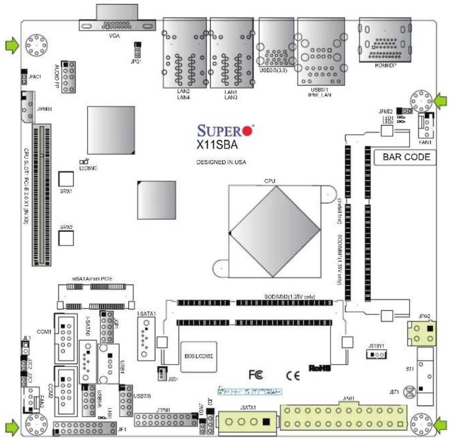
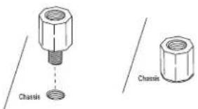
All motherboards have standard mounting holes to fit different types of chassis. Make sure that the locations of all the mounting holes for both the motherboard and the chassis match. Although a chassis may have both plastic and metal mounting fasteners, metal ones are highly recommended because they ground the motherboard to the chassis. Make sure that the metal standoffs click in or are screwed in tightly.
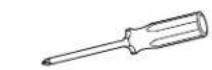
Philips
Screwdriver
(1)

Philips Screws (4)

Standoffs (4)
Only if Needed
Tools Needed
text_image
SUPER X11SBA DESIGNED IN USA VGA JPG LAN2 LAN4 LAN3 USB2/3(3.0) USB0/1 IFM1 LAN HOAMD? JFME2 LED2 HAN1 JPM81 CPU.SOT-PCLE 2.0 X1 (IN XB) LED8MC SRN1 SRN2 CPU mSATA@mi PCIE SOD/MM2(1.35V only) ISATA1 BIOS LICENSE JSD1 JSTRY1 JFY2 JET1 JF7I JF7I JF7I JF7I JF7I JF7I JF7I JF7I JF7I JF7I JF7I JF7I JF7I JF7I JF7I JF7I JF7I JF7I JF7I JF7I JF7 I JF7 I JF7 I JF7 I JF7 I JF7 I JF7 I JF7 I JF7 I JF7 I JF7 I JF7 I JF7 I JF7 I JF7 I JF7 I JF7 I JF7 I JF7 I JF7 I JF7ILocation of Mounting Holes

Note: 1) To avoid damaging the motherboard and its components, please do not use a force greater than 8 lb/inch on each mounting screw during motherboard installation. 2) Some components are very close to the mounting holes. Please take precautionary measures to avoid damaging these components when installing the motherboard to the chassis.
Installing the Motherboard
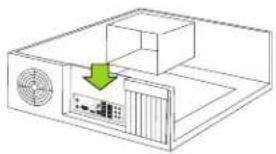
- Install the I/O shield into the back of the chassis.
natural_image
Diagram of a computer setup with a monitor, fan, and drive unit (no text or symbols)- Locate the mounting holes on the motherboard. See the previous page for the location.
text_image
Chassis Chassis- Locate the matching mounting holes on the chassis. Align the mounting holes on the motherboard against the mounting holes on the chassis.
text_image
3x5 Motherboard Chassis Motherboard Chassis-
Install standoffs in the chassis as needed.
-
Install the motherboard into the chassis carefully to avoid damaging other motherboard components.
-
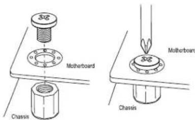
Using the Phillips screwdriver, insert a Phillips head #6 screw into a mounting hole on the motherboard and its matching mounting hole on the chassis.
-
Repeat Step 5 to insert #6 screws into all mounting holes.
-
Make sure that the motherboard is securely placed in the chassis.

Note: Images displayed are for illustration only. Your chassis or components might look different from those shown in this manual.
2.3 Installing Memory
Warning: To prevent possible damage, exercise extreme caution when installing or removing memory modules.
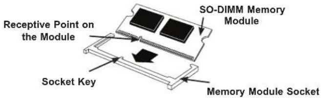
Installing a SO-DIMM Module into a Horizontal Socket
- Install SO-DIMM modules into slot SODIMM1 and then SODIMM2. Align the receptive point on the bottom of the SO-DIMM module against the key on the memory socket. Note the notches on the side of the SO-DIMM module and those on the socket to avoid causing damage.
Figure 2-1. SO-DIMM Installation Step 1
text_image
Receptive Point on the Module SO-DIMM Memory Module Socket Key Memory Module Socket- Line up the bottom of the SO-DIMM memory module with the edge of the horizontal socket.
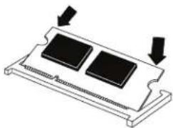
Figure 2-2. SO-DIMM Installation Step 2
natural_image
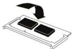
Diagram of a mechanical component with two black blocks and downward arrows indicating force or movement (no text or symbols)- Once they are lined up, push the memory module into the memory socket until the module is securely seated in the socket.
Figure 2-3. SO-DIMM Installation Step 3
natural_image
Diagram showing a device with two black components and an arrow indicating direction (no text or symbols)Support
The motherboard supports up to 8 GB of DDR3L Dual Non-ECC SODIMM of speeds up to 1600MHz.
| Channel0 Channel1 SoC Memory Speed | |
| 1333MHz x 1066MHz | |
| 1600MHz x 1600MHz | |
| 1333MHz 1333 MHz 1066MHz | |
| 1600MHz 1600 MHz 1600MHz | |
2.4 Rear I/O Ports
See Figure 2-4 below for the locations and descriptions of the various I/O ports on the rear of the motherboard.
text_image
SUPER X11SBA DESIGNED IN LGA BAR CODE PCU BOS LICENSE PCD CE PCD PCD PCD PCD PCD PCD PCD PCD PCD PCD PCD PCD PCD PCD PCD PCD PCD PCD PCD PCD PCD PCD PCD PCD PCD PCD PCD PCD PCD PCD PCD PCD PCD PCDFigure 2-4. I/O Port Locations and Definitions
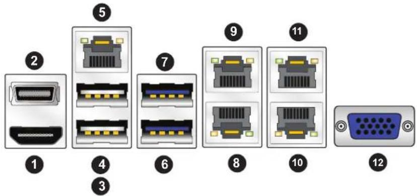
text_image
Diagram showing 12 labeled network device connectors including VGA, Ethernet, and GND| Rear I/O Ports | |||
| # Description # Description | |||
| 1. HDMI 7 USB3 (3.0) | |||
| 2. DisplayPort 8 LAN1 | |||
| 3 USB0 9 LAN3 | |||
| 4 USB1 10 LAN2 | |||
| 5 IPMI_LAN 11 LAN4 | |||
| 6 USB2 (3.0) 12 VGA Port | |||
HDMI & DP Ports
One HDMI and one DisplayPort are located next to the IPMI_LAN port on the I/O backpanel. These ports are used to display both high definition video and digital sound through an HDMI or DP-capable display, using a single HDMI or DP cable (not included). The X11SBA supports HDMI Specification version 1.4b and DP 1.1a via N3700 processor graphics controller.
VGA Port
The VGA controller is from AST2400 mainly for BMC KVM(Keyboard, Video and Mouse) remote control purpose.
LAN Ports
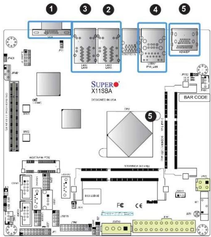
Four LAN ports (LAN1 \~ LAN4) are located on the I/O back panel. There is also a dedicated IPMI LAN port on the I/O back panel. These ports accept RJ45 type cables. See the table below for the pin definitions (-F SKU with LAN1 and LAN2 only).
| LAN PortPin Definition | ||
| Pin# Definition Pin# Definition | ||
| 1 TX_D1+ 5 BI_D3- | ||
| 2 TX_D1- 6 RX_D2- | ||
| 3 RX_D2+ 7 BI_D4+ | ||
| 4 BI_D3+ 8 BI_D4- | ||
text_image
1 3 2 4 5 SUPERX X11SBA DESIGNED IN USA CPU 5 BAR CODE JF401 JF402 JF403 JF404 JF405 JF406 JF407 JF408 JF409 JF410 JF411 JF412 JF413 JF414 JF415 JF416 JF417 JF418 JF419 JF420 JF421 JF422 JF423 JF424 JF425 JF426 JF427 JF428 JF429 JF430 JF431 JF432 JF433 JF434 JF435 JF436 JF437 JF438 JF439 JF440 JF441 JF442 JF443 JF444 JF445 JF446 JF447 JF448 JF449 JF450 JF451 JF452 JF453 JF454 JF455 JF456 JF457 JF458 JF459 JF460 JF461 JF462 JF463 JF464 JF465 JF466 JF467 JF468 JF469 JF470 JF471 JF472 JF473 JF474 JF475 JF476 JF477 JF478 JF479 JF480 JF481 JF482 JF483 JF484 JF485 JF486 JF487 JF488 JF489 JF490 JF491 JF492 JF493 JF494 JF495 JF496 JF497 JF498 JF499 JF500- VGA Port
- LAN1/LAN3
- LAN2/LAN4 (X11SBA-LN4F Only)
- IPMI_LAN
- HDMI/DisplayPort
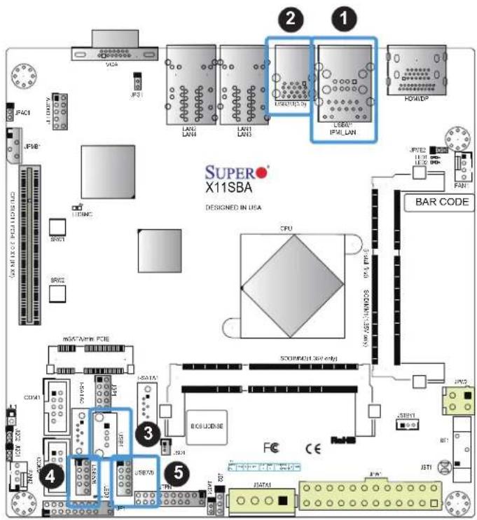
Universal Serial Bus (USB) Ports
There are two USB 2.0 ports (USB0/1) and two USB 3.0 ports (USB2/3) located on the I/O back panel. The motherboard also has two USB 2.0 headers for four (4) USB 2.0 ports (USB5/6 and USB7/8). The USB4 is one (1) USB 2.0 port in a Type A connector. The onboard headers can be used to provide front side USB access with a cable (not included).
| Back Panel USB(3.0)Pin Definitions | |
| Pin# Definition | |
| 1 VBUS | |
| 2 D- | |
| 3 D+ | |
| 4 Ground | |
| 5 StdA_SSRX- | |
| 6 StdA_SSRX+ | |
| 7 GND_DRAIN | |
| 8 StdA_SSTX- | |
| 9 StdA_SSTX+ | |
| Front Panel USB 2.0Header Pin Definitions | |||
| Pin# Definition Pin# Definition | |||
| 1 +5V | 2 +5V | ||
| 3 USB | PN2 4 USB | PN3 | |
| 5 USB | PP2 6 USB | PP3 | |
| 7 Ground | 8 Ground | ||
| 9 Key | 10 Ground | ||
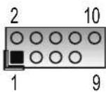
USB 2.0 Port Pin Layout
text_image
SUPER X11SBA DESIGNED IN USA CPU BAR CODE JPM2 LED LED LED LED LED LED JPM2 LED LED LED JPM2 LED LED JPM2 JPM2 JPM2 JPM2 JPM2 JPM2 JPM2 JPM2 JPM2 JPM2 JPM2 JPM2 JPM2 JPM2 JPM2 JPM2 JPM2 JPM2 JPM2 JPM2 JPM2 JPM2 JPM2 JPM2 JPM2 JPM1 JPM1 JPM1 JPM1 JPM1 JPM1 JPM1 JPM1 JPM1 JPM1 JPM1 JPM1 JPM1 JPM1 JPM1 JPM1 JPM1 JPM1 JPM1 JPM1 JPM1 JPM1 JPM1 JPM1 JPM1 JPM2 JPM2 JPM2 JPM2 JPM2 JPM2 JPM2 JPM2 JPM2 JPM2 JPM2 JPM2 JPM2 JPM2 JPM2 JPM2 JPM2 JPM2 JPM2 JPM2 JPM2 JPM2 JPM2 JPM2 JPM3 JPM3 JPM3 JPM3 JPM3 JPM3 JPM3 JPM3 JPM3 JPM3 JPM3 JPM3 JPM3 JPM3 JPM3 JPM3 JPM3 JPM3 JPM3 JPM3 JPM3 JPM3 JPM3- USB0/1
- USB2/3
- USB4
- USB5/6
- USB7/8
Serial Ports
There are two COM headers (COM1 and COM2) on the motherboard. See the table below for pin definitions.
| COM PortPin Definitions | |||
| Pin# Definition Pin# Definition | |||
| 1 DCD | 6 DSR | ||
| 2 RXD | 7 RTS | ||
| 3 TXD | 8 CTS | ||
| 4 DTR | 9 RI | ||
| 5 Ground | 10 N/A | ||
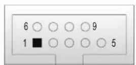
COM Port Pin Layout
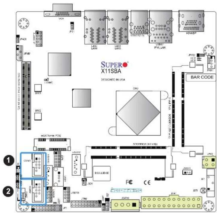
text_image
SUPER X11SBA DESIGNED IN USA CPU 500W/13 (36V only) BAR CODE JPN2 JPN1 JST1 JST2 JST3 JST4 JST5 JST6 JST7 JST8 JST9 JST10 JST11 JST12 JST13 JST14 JST15 JST16 JST17 JST18 JST19 JST20 JST21 JST22 JST23 JST24 JST25 JST26 JST27 JST28 JST29 JST30 JST31 JST32 JST33 JST34 JST35 JST36 JST37 JST38 JST39 JST40 JST41 JST42 JST43 JST44 JST45 JST46 JST47 JST48 JST49 JST50 JST51 JST52 JST53 JST54 JST55 JST56 JST57 JST58 JST59 JST60 JST61 JST62 JST63 JST64 JST65 JST66 JST67 JST68 JST69 JST70 JST71 JST72 JST73 JST74 JST75 JST76 JST77 JST78 JST79 JST80 JST81 JST82 JST83 JST84 JST85 JST86 JST87 JST88 JST89 JST90 JST91 JST92 JST93 JST94 JST95 JST96 JST97 JST98 JST99 JST100- COM1
- COM2
2.5 Front Control Panel
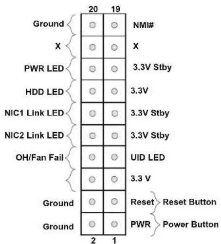
JF1 contains header pins for various buttons and indicators that are normally located on a control panel at the front of the chassis. These connectors are designed specifically for use with Supermicro chassis. See the figure below for the descriptions of the front control panel buttons and LED indicators.
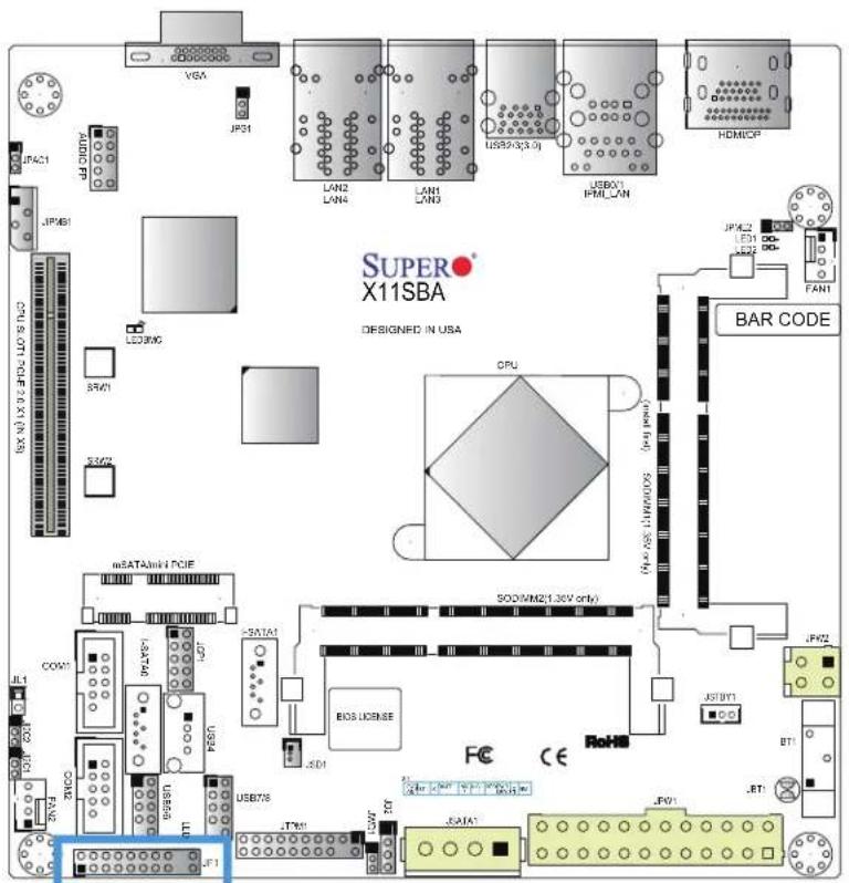
text_image
SUPER X11SBA DESIGNED IN USA CPU SODIM2(1.36V only) BOS LICENSE FC CE JPM2 JPM1 JPM0 JPM1 JPM2 JPM1 JPM2 JPM1 JPM2 JPM1 JPM2 JPM1 JPM2 JPM1 JPM2 JPM1 JPM2 JPM1 JPM2 JPM1 JPM2 JPM1 JPM2 JPM1 JPM2 JPM1 JPM2 JPM1 JPM2 JPM2 JPM1 JPM2 JPM1 JPM2 JPM1 JPM2 JPM1 JPM2 JPM1 JPM2 JPM1 JPM2 JPM1 JPM2 JPM1 JPM2 JPM1 JPM2 JPM1 JPM2 JPM1 JPM2 JPM1 JPM1 JPM2 JPM1 JPM2 JPM1 JPM2 JPM1 JPM2 JPM1 JPM2 JPM1 JPM2 JPM1 JPM2 JPM1 JPM2 JPM1 JPM2 JPM1 JPM2 JPM1 JPM2 JPM1 JPM2 JPM4Figure 2-3. JF1 Header Pins
text_image
Ground X PWR LED HDD LED NIC1 Link LED NIC2 Link LED OH/Fan Fail Ground Ground 20 19 NMI# X 3.3V Stby 3.3V 3.3V Stby 3.3V Stby 3.3V UID LED 3.3 V Reset Reset Button PWR Power Button 2 1Power LED
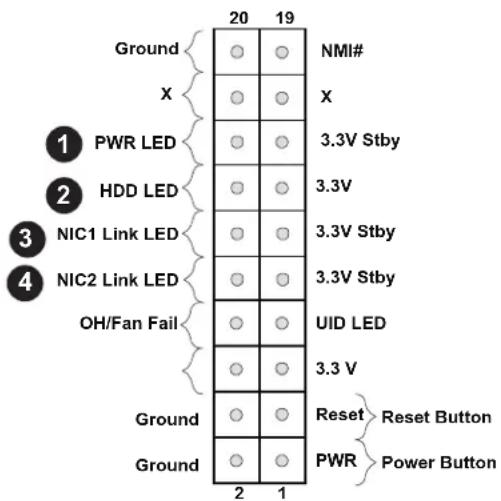
The Power LED connection is located on pins 15 and 16 of JF1. Refer to the table below for pin definitions.
| Power LEDPin Definitions (JF1) | |
| Pin# | Definition |
| 15 +3.3V Stby | |
| 16 PWRLED | |
HDD LED
The HDD LED connection is located on pins 13 and 14 of JF1. Attach a cable here to indicate the status of HDD-related activities, including IDE, SATA activities. See the table below for pin definitions.
| HDD LEDPin Definitions (JF1) | |
| Pin# | Definition |
| 13 +3.3 | V Stby |
| 14 HD | LED |
The NIC (Network Interface Controller) LED connection for LAN port 1 is located on pins 11 and 12 of JF1, and the LED connection for LAN Port 2 is on Pins 9 and 10. NIC1 LED and NIC2 LED are 2-pin NIC LED headers. Attach NIC LED cables to NIC1 and NIC2 LED indicators to display network activities. Refer to the table below for pin definitions.
| LAN1/LAN2 LEDPin Definitions (JF1) | |
| Pin# | Definition |
| 9/11 | 3.3V Stby |
| 10/12 | NIC Activity LED |
text_image
Ground X 1 PWR LED 2 HDD LED 3 NIC1 Link LED 4 NIC2 Link LED OH/Fan Fail Ground Ground 2 1 20 19 NMI# X 3.3V Stby 3.3V 3.3V Stby 3.3V Stby 3.3V UID LED 3.3 V Reset Reset Button PWR Power Button-
PWR LED
-
HDD LED
-
NIC1 LED
-
NIC2 LED
Reset Button
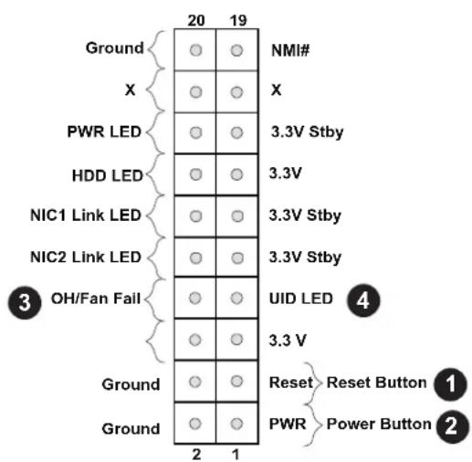
The Reset Button connection is located on pins 3 and 4 of JF1. Attach it to a hardware reset switch on the computer case to reset the system. Refer to the table below for pin definitions.
| Reset ButtonPin Definitions (JF1) | |
| Pin# | Definition |
| 3 Reset | |
| 4 Ground | |
Power Button
The Power Button connection is located on pins1 and 2 of JF1. Momentarily contacting both pins will power on/off the system. This button can also be configured to function as a suspend button (with a setting in the BIOS - see Chapter 4). To turn off the power in the suspend mode, press the button for at least 4 seconds. Refer to the table below for pin definitions.
| Power ButtonPin Definitions (JF1) | |
| Pin# | Definition |
| 1 Signal | |
| 2 Ground | |
Overheat (OH)/Fan Fail/UID LED
Connect an LED cable to pins 7 and 8 of Front Control Panel to use the Overheat/Fan Fail and UID LED connections. The blue LED on pin 7 works as the front panel UID LED indicator. The red LED on pin 8 works provides warnings of overheat or fan fail. The red LED takes precedence over the blue LED by default. Refer to the table below for pin definitions.
| Overheat (OH)/Fan Fail/UID Indicator Pin Definitions (JF1) | |
| Pin# | Definition |
| 7 Vcc/Blue | UID LED |
| 8 OH/Fan | Fail LED |
text_image
Ground X PWR LED HDD LED NIC1 Link LED NIC2 Link LED OH/Fan Fail Ground Ground 20 19 NMI# X 3.3V Stby 3.3V 3.3V Stby 3.3V Stby 3.3V 3.3 V UID LED Reset Reset Button PWR Power Button 2 1- Reset Button
- PWR Button
- OH/Fan Fail
- UID LED
2.6 Connectors
Power Connections
Main ATX Power Supply Connector
The primary power supply connector (JPW1) meets the ATX SSI EPS 24-pin specification.
| ATX Power 24-pin ConnectorPin Definitions | ||
| Pin# Definition Pin# Definition | ||
| 13 +3.3V 1 +3.3V | ||
| 14 NC 2 +3.3V | ||
| 15 Ground 3 Ground | ||
| 16 PS_ON 4 +5V | ||
| 17 Ground 5 Ground | ||
| 18 Ground 6 +5V | ||
| 19 Ground 7 Ground | ||
| 20 Res (NC) 8 PWR_OK | ||
| 21 +5V 9 5VSB | ||
| 22 +5V 10 +12V | ||
| 23 +5V 11 +12V | ||
| 24 Ground 12 +3.3V | ||
Required Connection NC = No Connection

text_image
SUPER X11SBA DESIGNED IN USA VSA LAN2 LAN4 LAN3 USB203.01 USB51 P81 LAN1 HDMOF JPM1 JPM2 JPM3 TANT BAR CODE CPU SODIMN2(1.35V max) SODIMN2(1.35V max) JPM1 JPM2 JPM3 JPM4 JPM5 JPM6 JPM7 JPM8 JPM9 JPM10 JPM11 JPM12 JPM13 JPM14 JPM15 JPM16 JPM17 JPM18 JPM19 JPM20 JPM21 JPM22 JPM23 JPM24 JPM25 JPM26 JPM27 JPM28 JPM29 JPM30 JPM31 JPM32 JPM33 JPM34 JPM35 JPM36 JPM37 JPM38 JPM39 JPM40 JPM41 JPM42 JPM43 JPM44 JPM45 JPM46 JPM47 JPM48 JPM49 JPM50 JPM51 JPM52 JPM53 JPM54 JPM55 JPM56 JPM57 JPM58 JPM59 JPM60 JPM61 JPM62 JPM63 JPM64 JPM65 JPM66 JPM67 JPM68 JPM69 JPM70 JPM71 JPM72 JPM73 JPM74 JPM75 JPM76 JPM77 JPM78 JPM79 JPM80 JPM81 JPM82 JPM83 JPM84 JPM85 JPM86 JPM87 JPM88 JPM89 JPM90 JPM91 JPM92 JPM93 JPM94 JPM95 JPM96 JPM97 JPM98 JPM99 JPM100- 24-Pin ATX Main PWR
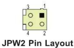
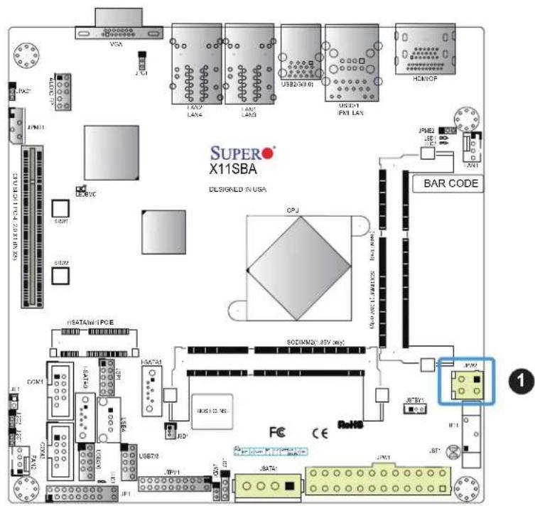
4-pin 12V Power Connector
JPW2 is the 12V DC power connector that provides alternative single power source for special enclosure when the 24-pin ATX power is not in use.
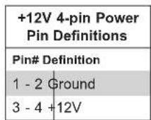
Required Connection
text_image
SUPER X11SBA DESIGNED IN USA USB250-61 USB31 PAN LAY HOMOP JPM2 LED XN1 BAR CODE CPU USB250-61 USB31 PAN LAY USB250-61 USB31 PAN LAY USB250-61 USB31 PAN LAY USB250-61 USB31 PAN LAY USB250-61 USB31 PAN LAY USB250-61 USB31 PAN LAY USB250-61 USB31 PAP USB250-61 USB31 PAP USB250-61 USB31 PAP USB250-61 USB31 PAP USB250-61 USB31 PAP USB250-61 USB31 PAP USB250-61 USB31 PAP USB250-61 FCE CE RoNO JPM2 JPM1 JST JPM7 JPM4 JPM3 JPM2- 4-Pin PWR

Note 1: The 12V DC input is limited to 12A by design. It provides up to 144W power input to the motherboard. Please keep onboard power use within the power limits specified above. Over-current DC power use may cause damage to the motherboard.
Note 2: Do not use the 4-pin DC power @JPW2 when the 24-pin ATX Power @JPW1 is connected to the power supply. Do not plug in both JPW1 and JPW2 at the same time..
Headers
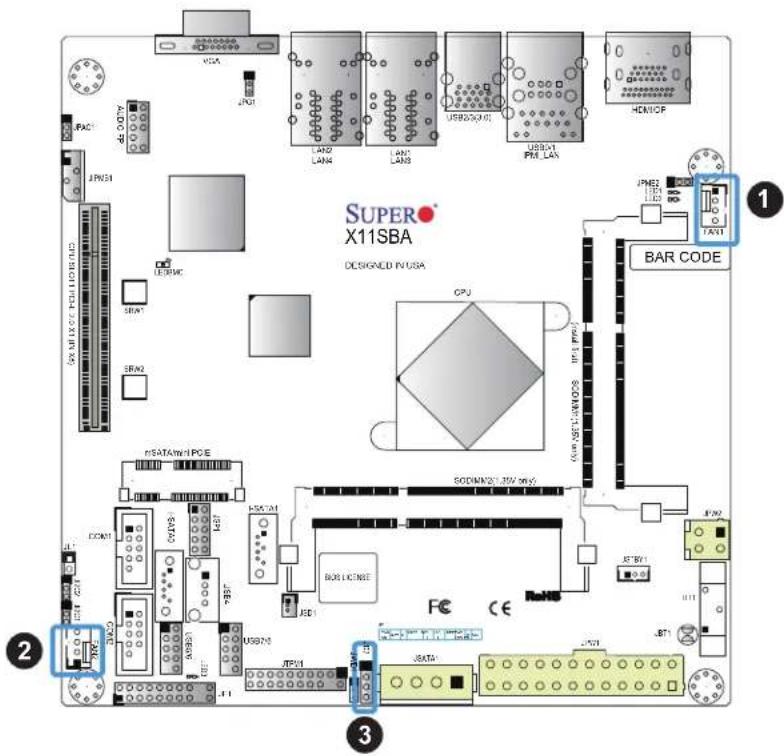
Fan Headers
There are two 4-pin fan headers on the motherboard. Although pins 1-3 of the fan headers are backward compatible with the traditional 3-pin fans, we recommend you use 4-pin fans to take advantage of the fan speed control via Pulse Width Modulation through the BMC. This allows the fan speeds to be automatically adjusted based on the motherboard temperature.
| Fan HeaderPin Definitions | |
| Pin# | Definition |
| 1 | Ground (Black) |
| 2 | +12V (Red) |
| 3 | Tachometer |
| 4 | PWM Control |
External Speaker
The JD2 header is for the external speaker. If you wish to use an external speaker, connect its cable to pins 1-4.
| External Speaker ConnectorPin Definitions |
| Pin Setting Definition |
| Pins 1-4 Speaker |
text_image
SUPER X11SBA DESIGNED IN USA JPN3 JPN2 JPN1 JNDA JNDA JNDA JNDA JNDA JNDA JNDA JNDA JNDA JNDA JNDA JNDA JNDA JNDA JNDA JNDA JNDA JNDA JNDA JNDA JNDA JNDA JNDA JNDA JNDA JNNA JNNA JNNA JNNA JNNA JNNA JNNA JNNA JNNA JNNA JNNA JNNA JNNA JNNA JNNA JNNA JNNA JNNA JNNA JNNA JNNA JNNA JNNA JNNA JNNA JNMA JNMA JNMA JNMA JNMA JNMA JNMA JNMA JNMA JNMA JNMA JNMA JNMA JNMA JNMA JNMA JNMA JNMA JNMA JNMA JNMA JNMA JNMA JNMA JNMA JNNA JNNA JNNA JNNA JNNA JNNA JNNA JNNA JNNA JNNA JNNA JNNA JNNA JNNA JNNA JNNA JNNA JNNA JNNA JNNA JNNA JNNA JNNA JNNA JNINA JNINA JNINA JNINA JNINA JNINA JNINA JNINA JNINA JNINA JNINA JNINA JNINA JNINA JNINA JNINA JNINA- FAN1
- FAN2
- External Speaker Header
GPIO Headers
The JGP1 (General Purpose Input/Output) header is located near the SATA connectors on the motherboard. The JGP1 header is a general-purpose I/O expander on a pin header from Intel SoC. See the table below for pin definitions. Refer to the board layout below for the locations of the headers.
| GPIO HeaderPin Definitions | |||
| Pin# Definition CFIO Name CFG0 CFG1 | |||
| 1 3V3 | STBY N/A N/A N/A | ||
| 3 GP0 | I2C0_SCL 0xFED85428 0xFED8542C | ||
| 5 GP1 | I2C0_SDA 0xFED85408 0xFED8540C | ||
| 7 GP2 | I2C1_SCL 0xFED85418 0xFED8541C | ||
| 9 GP3 | I2C1_SDA 0xFED85400 0xFED85404 | ||
| 2 GND | N/A N/A N/A | ||
| 4 GP4 | I2C2_SCL 0xFED85430 0xFED85434 | ||
| 6 GP5 | I2C2_SDA 0xFED85410 0xFED85414 | ||
| 8 GP6 | I2C3_SCL 0xFED85438 0xFED8543C | ||
| 10 | GP7 I2C3_SDA 0xFED85420 0xFED85424 | ||
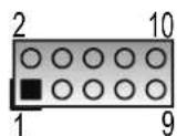
GPIO Header Pin Layout

Note: The "I2C#_SCL/SDA" are pin names of Intel N3700 SoC GPIO.
text_image
SUPER X11SBA DESIGNED IN USA CPU 500V/424.30V expd BOSUCENSE FC CE JPM2 JPM1 JPM0 JPM1 JPM2 JPM1 JPM2 JPM1 JPM2 JPM1 JPM2 JPM1 JPM2 JPM1 JPM2 JPM1 JPM2 JPM1 JPM2 JPM1 JPM2 JPM1 JPM2 JPM1 JPM2 JPM1 JPM2 JPM1 JPM2 JPM2 JPM1 JPM2 JPM1 JPM2 JPM1 JPM2 JPM1 JPM2 JPM1 JPM2 JPM1 JPM2 JPM1 JPM2 JPM1 JPM2 JPM1 JPM2 JPM1 JPM2 JPM1 JPM2 JPM1 JPM1 JPM2 JPM1 JPM2 JPM1 JPM2 JPM1 JPM2 JPM1 JPM2 JPM1 JPM2 JPM1 JPM2 JPM1 JPM2 JPM1 JPM2 JPM1 JPM2 JPM1 JPM2 JPM1 JPM2 JPM3- JGP1
Disk-On-Module Power Connector
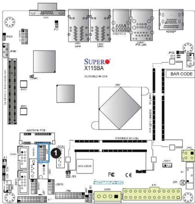
The Disk-On-Module (DOM) power connector at JSD1 provides 5V power to a solid-state DOM storage device connected to one of the SATA ports. See the table below for pin definitions.
| DOM Power Pin Definitions | |
| Pin# Definition | |
| 1 5V | |
| 2 Ground | |
| 3 Ground | |
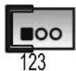
DOM Power Pin Layout
Audio Front Panel Header
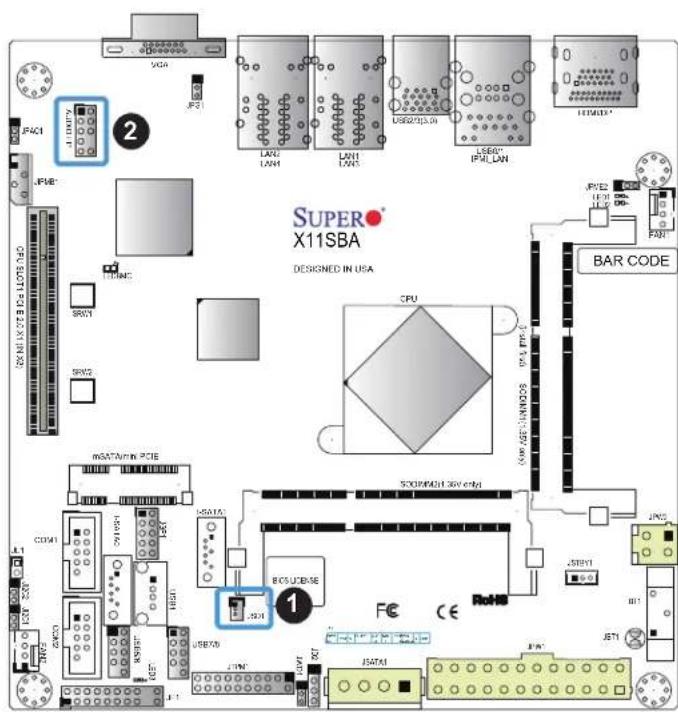
A 10-pin audio header located on the motherboard allows you to use the onboard sound chip (ALC888S) for audio function. Connect an audio cable to the this header to use this feature. See the table below for pin definitions.
| Audio HeaderPin Definitions | ||
| Pin# Definition Pin# Definition | ||
| 1 Microphone_Left 2 Audio_Ground | ||
| 3 Microphone_Right 4 Audio_Detect | ||
| 5 Line_2_Right 6 Ground | ||
| 7 Jack_Detect 8 Key | ||
| 9 Line_2_Left 10 | Ground | |
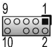
10-pin Audio Header Pin Layout
text_image
SUPER X11SBA DESIGNED IN USA CPU BAR CODE I/O JPM2 JPM3 JPM4 JPM5 JPM6 JPM7 JPM8 JPM9 JPM10 JPM11 JPM12 JPM13 JPM14 JPM15 JPM16 JPM17 JPM18 JPM19 JPM20 JPM21 JPM22 JPM23 JPM24 JPM25 JPM26 JPM27 JPM28 JPM29 JPM30 JPM31 JPM32 JPM33 JPM34 JPM35 JPM36 JPM37 JPM38 JPM39 JPM40 JPM41 JPM42 JPM43 JPM44 JPM45 JPM46 JPM47 JPM48 JPM49 JPM50 JPM51 JPM52 JPM53 JPM54 JPM55 JPM56 JPM57 JPM58 JPM59 JPM60 JPM61 JPM62 JPM63 JPM64 JPM65 JPM66 JPM67 JPM68 JPM69 JPM70 JPM71 JPM72 JPM73 JPM74 JPM75 JPM76 JPM77 JPM78 JPM79 JPM80 JPM81 JPM82 JPM83 JPM84 JPM85 JPM86 JPM87 JPM88 JPM89 JPM90 JPM91 JPM92 JPM93 JPM94 JPM95 JPM96 JPM97 JPM98 JPM99 JPM100- JSD1
- Audio Header
TPM Header
The JTPM1 header is used to connect a Trusted Platform Module (TPM). A TPM can securely store artifacts used to authenticate the platform. These artifacts can include passwords, certificates, or encryption keys. See the table below for pin definitions.
| Trusted Platform Module HeaderPin Definitions | ||
| Pin# Definition Pin# Definition | ||
| 1 LCLK 2 GND | ||
| 3 LFRAME# 4 No Pin | ||
| 5 LRESET# 6 +5V (X) | ||
| 7 LAD3 8 LAD2 | ||
| 9 3.3V 10 LAD1 | ||
| 11 LAD0 12 GND | ||
| 13 SMB_CLK4 (X) 14 SMB_DAT4 (X) | ||
| 15 P3V3_STBY 16 SERIRQ | ||
| 17 GND 18 GND | ||
| 19 P3V3_STBY 20 LDRQ# (X) | ||
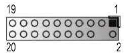
JTPM1 Pin Layout

text_image
SUPER X11SBA DESIGNED IN USA VGA JPM21 JPM61 L4X2 L4X4 L4X1 L4X3 US02(100) US8C1 FM LAN HOMOP FME2 LED LED FAN1 BAR CODE CPU 500W/24.37V 50Hz 500W/24.37V 50Hz 500W/24.37V 50Hz 500W/24.37V 50Hz 500W/24.37V 50Hz 500W/24.37V 50Hz 500W/24.37V 50Hz 50W/24.37V 50Hz 50W/24.37V 50Hz 50W/24.37V 50Hz 50W/24.37V 50Hz 50W/24.37V 50Hz 50W/24.37V 50Hz 50W/24.37V 50W/24.37V 50Hz 50W/24.37V 50Hz 50W/24.37V 50Hz 50W/24.37V 50Hz 50W/24.37V 50Hz 50W/24.37V 50Hz 50W/24.36V 50Hz 50W/24.36V 50Hz 50W/24.36V 50Hz 50W/24.36V 50Hz 50W/24.36V 50Hz 50W/24.36V 50Hz 50W/24.36V 50Hz 50W / 50W / 50W / 50W / 50W / 50W / 50W / 50W / 50W / 50W / 50W / 50W / 50W / 50W / 50W / 50W / 50W / 50W / 50W / 50W / 50W /- TPM Header
Standby Power
The Standby Power header is located at JSTBY1 on the motherboard. See the table below for pin definitions.
| Standby Power Pin Definitions | |
| Pin# Definition | |
| 1 +5V | Standby |
| 2 Ground | |
| 3 No Connection | |
4-pin BMC External I²C Header
A System Management Bus header for IPMI 2.0 is located at JIPMB1. Connect a cable to this header to use the IPMB I²C connection on your system. See the table below for pin definitions.
| External I2C Header Pin Definitions | |
| Pin# | Definition |
| 1 | Data |
| 2 | Ground |
| 3 | Clock |
| 4 | No Connection |
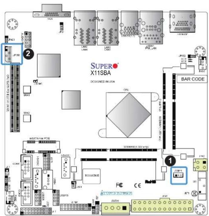
text_image
SUPER X11SBA DESIGNED IN USA CPU BAR CODE JPM2 JPM3 JPM4 JPM5 JPM6 JPM7 JPM8 JPM9 JPM10 JPM11 JPM12 JPM13 JPM14 JPM15 JPM16 JPM17 JPM18 JPM19 JPM20 JPM21 JPM22 JPM23 JPM24 JPM25 JPM26 JPM27 JPM28 JPM29 JPM30 JPM31 JPM32 JPM33 JPM34 JPM35 JPM36 JPM37 JPM38 JPM39 JPM40 JPM41 JPM42 JPM43 JPM44 JPM45 JPM46 JPM47 JPM48 JPM49 JPM50 JPM51 JPM52 JPM53 JPM54 JPM55 JPM56 JPM57 JPM58 JPM59 JPM60 JPM61 JPM62 JPM63 JPM64 JPM65 JPM66 JPM67 JPM68 JPM69 JPM70 JPM71 JPM72 JPM73 JPM74 JPM75 JPM76 JPM77 JPM78 JPM79 JPM80 JPM81 JPM82 JPM83 JPM84 JPM85 JPM86 JPM87 JPM88 JPM89 JPM90 JPM91 JPM92 JPM93 JPM94 JPM95 JPM96 JPM97 JPM98 JPM99 JPM100- Standby Power
- BMC External Header
Chassis Intrusion
A Chassis Intrusion header is located at JL1 on the motherboard. Attach the appropriate cable from the chassis to the header to inform you when the chassis is opened.
| Chassis Intrusion Pin Definitions | |
| Pins Definition | |
| 1 Intrusion Input | |
| 2 Ground |
4-pin Connector for HDD
This 4-pin power connector at JSATA1 provides power from the motherboard to internal SATA hard drive or SSD device. Refer to the table below for pin definitions.
| Pin Definitions | |
| Pin# Definition | |
| 1 12V | |
| 2 GND | |
| 3 GND | |
| 4 5V | |
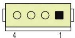
JSATA1 Pin Layout
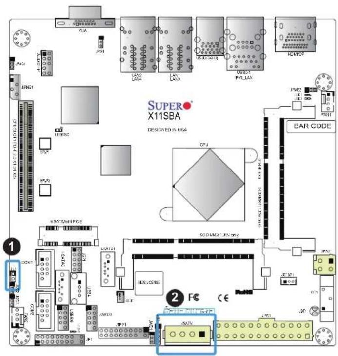
text_image
SUPER X11SBA DESIGNED IN USA CPU BAR CODE mDATA/MPCE DCOM1 USB70 USB70 JF1 JF2 JPM1 JPM2 JPM3 JPM4 JPM5 JPM6 JPM7 JPM8 JPM9 JPM10 JPM11 JPM12 JPM13 JPM14 JPM15 JPM16 JPM17 JPM18 JPM19 JPM20 JPM21 JPM22 JPM23 JPM24 JPM25 JPM26 JPM27 JPM28 JPM29 JPM30 JPM31 JPM32 JPM33 JPM34 JPM35 JPM36 JPM37 JPM38 JPM39 JPM40 JPM41 JPM42 JPM43 JPM44 JPM45 JPM46 JPM47 JPM48 JPM49 JPM50 JPM51 JPM52 JPM53 JPM54 JPM55 JPM56 JPM57 JPM58 JPM59 JPM60 JPM61 JPM62 JPM63 JPM64 JPM65 JPM66 JPM67 JPM68 JPM69 JPM70 JPM71 JPM72 JPM73 JPM74 JPM75 JPM76 JPM77 JPM78 JPM79 JPM80 JPM81 JPM82 JPM83 JPM84 JPM85 JPM86 JPM87 JPM88 JPM89 JPM90 JPM91 JPM92 JPM93 JPM94 JPM95 JPM96 JPM97 JPM98 JPM99 JPM100- Chassis Intrusion
- JSATA1
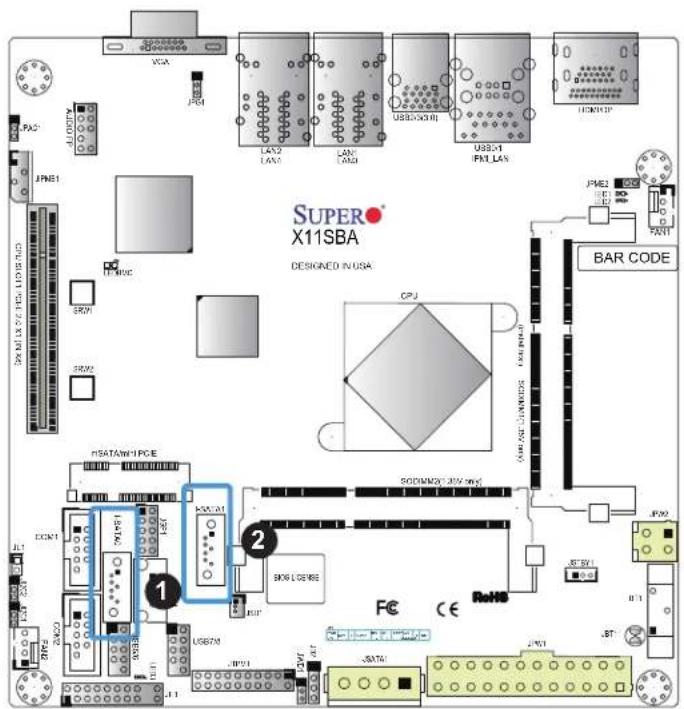
SATA Ports
The X11SBA-LN4F/F has two SATA 3.0 ports that are supported by the Intel SoC. I-SATA1 supports SuperDOM.
| SATA 3.0 PortPin Definitions |
| Pin# Signal |
| 1 Ground |
| 2 SATA_TXP |
| 3 SATA_TXN |
| 4 Ground |
| 5 SATA_RXN |
| 6 SATA_RXP |
| 7 Ground |
text_image
SUPER X11SBA DESIGNED IN USA CPU BAR CODE PSATAW1PCE 1 2 3 4 5 6 7 8 9 10 11 12 13 14 15 16 17 18 19 20 21 22 23 24 25 26 27 28 29 30 31 32 33 34 35 36 37 38 39 40 41 42 43 44 45 46 47 48 49 50 51 52 53 54 55 56 57 58 59 60 61 62 63 64 65 66 67 68 69 70 71 72 73 74 75 76 77 78 79 80 81 82 83 84 85 86 87 88 89 90 91 92 93 94 95 96 97 98 99 100- I-SATA0
- I-SATA1
Mini PCI-E Slot
The Mini PCI-E slot is used to install a compatible Mini PCI-E device. Refer to the table below for pin definitions.
The mSATA feature leverages the speed and reliability of the SATA interface to provide a high performance, cost-effective storage solution for smaller devices like notebooks and netbooks.
The specification maps SATA signals onto an existing small form factor connector, enabling more compact integration in a wide variety of applications for both hard disk (HDD) and solid state drives (SSDs). The mSATA connector allows you to increase the storage offerings of without compromising valuable space. The mSATA feature is mux with I-SATA0.
| Mini PCI-EPin Definitions | |||
| Pin# Definition Pin# Definition | |||
| 51 NC | 52 +3.3Vaux | ||
| 49 NC | 50 GND | ||
| 47 NC | 48 +1.5V | ||
| 45 NC | 46 NC | ||
| 43 NC | 44 NC | ||
| 41 +3.3Vaux 42 NC | |||
| 39 +3.3Vaux 40 GND | |||
| 37 GND 38 USB_D+ | |||
| 35 GND 36 USB_D- | |||
| 33 PETp0 34 GND | |||
| 31 PETn0 32 SMB_DATA | |||
| 29 GND 30 SMB_CLK | |||
| 27 GND 28 +1.5V | |||
| 25 PERp0 26 GND | |||
| 23 PERn0 24 +3.3Vaux | |||
| 21 DET_CARD_PLUG | 22 PERST# | ||
| 19 NC | 20 W_DISABLE# | ||
| 17 NC | 18 GND | ||
| 15 GND 16 NC | |||
| 13 REFCLK+ 14 NC | |||
| 11 REFCLK- 12 NC | |||
| 9 GND 10 NC | |||
| 7 CLKREQ# | 8 | NC | |
| 5 NC 6 | 1.5V | ||
| 3 NC 4 | GND | ||
| 1 WAKE# | 2 | 3.3Vaux | |
2.7 Jumper Settings
How Jumpers Work
To modify the operation of the motherboard, jumpers can be used to choose between optional settings. Jumpers create shorts between two pins to change the function of the connector. Pin 1 is identified with a square solder pad on the printed circuit board. See the diagram at right for an example of jumping pins 1 and 2. Refer to the motherboard layout page for jumper locations.

Note: On two-pin jumpers, "Closed" means the jumper is on and "Open" means the jumper is off the pins.
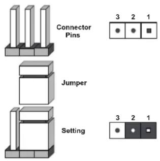
text_image
Connector Pins Jumper Setting 3 2 1 3 2 1CMOS Clear
JBT1 is used to clear CMOS, which will also clear any passwords. Instead of pins, this jumper consists of contact pads to prevent accidentally clearing the contents of CMOS.
To Clear CMOS
- First power down the system and unplug the power cord(s).
- Remove the cover of the chassis to access the motherboard.
- Remove the onboard battery from the motherboard.
- Short the CMOS pads with a metal object such as a small screwdriver for at least four seconds.
- Remove the screwdriver (or shorting device).
- Replace the cover, reconnect the power cord(s), and power on the system.

Note: Clearing CMOS will also clear all passwords.
Do not use the PW_ON connector to clear CMOS.

JBT1 contact pads
VGA Enable/Disable
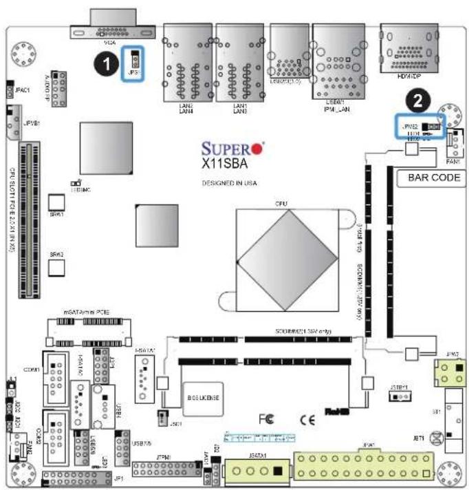
JPG1 allows you to enable or disable the VGA port using the onboard graphics controller. The default setting is Enabled.
| VGA Enable/Disable Jumper Settings | |
| Jumper Setting Definition | |
| Pins 1-2 Enabled | |
| Pins 2-3 Disabled |
Manufacturing Mode Select
Close JPME2 to bypass SPI flash security and force the system to use the Manufacturing Mode, which will allow you to flash the system firmware from a host server to modify system settings. See the table below for jumper settings.
| Manufacturing ModeJumper Settings | |
| Jumper Setting Definition | |
| Pins 1-2 Normal | (Default) |
| Pins 2-3 Manufacturing Mode | |
text_image
SUPER X11SBA DESIGNED IN USA CPU BAR CODE mSATArms PCE SCREW(01.35V eng) USB75 JPMI JDATA1 JPM2 JPM1 JPM2 JPM1 JPM2 JPM1 JPM2 JPM1 JPM2 JPM1 JPM2 JPM1 JPM2 JPM1 JPM2 JPM1 JPM2 JPM1 JPM2 JPM1 JPM2 JPM1 JPM2 JPM1 JPM2 JPM1 JFM1 JFM2 JPM1 JPM2 JPM1 JPM2 JPM1 JPM2 JPM1 JPM2 JPM1 JPM2 JPM1 JPM2 JPM1 JPM2 JPM1 JPM2 JPM1 JPM2 JPM1 JPM2 JPM1 JPM2 JPM1 JPM2 JFM1 JFM2 JPM1 JFM2 JPM1 JFM2 JPM1 JFM2 JFM1 JFM2 JFM1 JFM2 JFM1 JFM2 JFM1 JFM2 JFM1 JFM2 JFM1 JFM2 JFM1 JFM2 JFM1 JFM2 JFM1 JFM2 JFM1 JFM2 JFM1 JFM2 JFM1 JFM2 JFM1 JGM1 JGM2 JPM1 JGM2 JPM1 JGM2 JPM1 JGM2 JFM1 JFM2 JPM1 JFM2 JFM1 JFM2 JFM1 JFM2- VGA Enable/Disable
- Manufacturing Mode
PCI-E Slot SMB Enable (JI²C1/JI²C2)
JI ^2 C1 and JI ^2 C2 are used to enable PCI-E SMB (System Management Bus) support to improve system management for the onboard PCI-E slot.
| SMB to PCI-E Slots (JI2C1/JI2C2)Jumper Settings | |
| Jumper Setting | Definition |
| Pins 1-2 Enabled (Default) | |
| Pins 2-3 Disabled | |
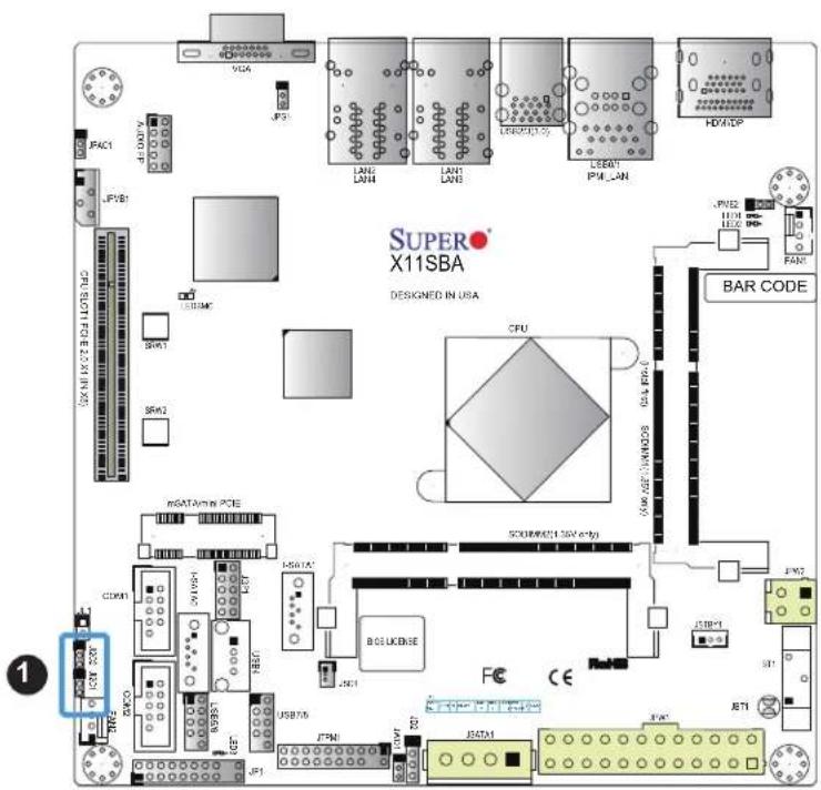
text_image
SUPER X11SBA DESIGNED IN USA JFAC1 JPYB1 USB230 SRW1 SRW2 mSATAV/MS PCIE CDKN1 ICDC 500 NOSB31 ICE USB75 JFMI JFCA1 JFCA LANE LAN4 LANE LAN3 LEMONDOS LEMONDOS PWM-LAN HDM/DP CPU SCRAM/CS1.36V e199 BAR CODE JPM2 JPM1 JPM0 JPM1 JPM2 JPM1 JPM2 JPM1 JPM2 JPM1 JPM2 JPM1 JPM2 JPM1 JPM2 JPM1 JPM2 JPM1 JPM2 JPM1 JPM2 JPM1 JPM2 JPM1 JPM2 JPM1 JPM2 JPM1 JPM2 JPM2 JPM1 JPM2 JPM1 JPM2 JPM1 JPM2 JPM1 JPM2 JPM1 JPM2 JPM1 JPM2 JPM1 JPM2 JPM1 JPM2 JPM1 JPM2 JPM1 JPM2 JPM1 JPM2 JPM1 JPM3- PCI-E Slot SMB Enable
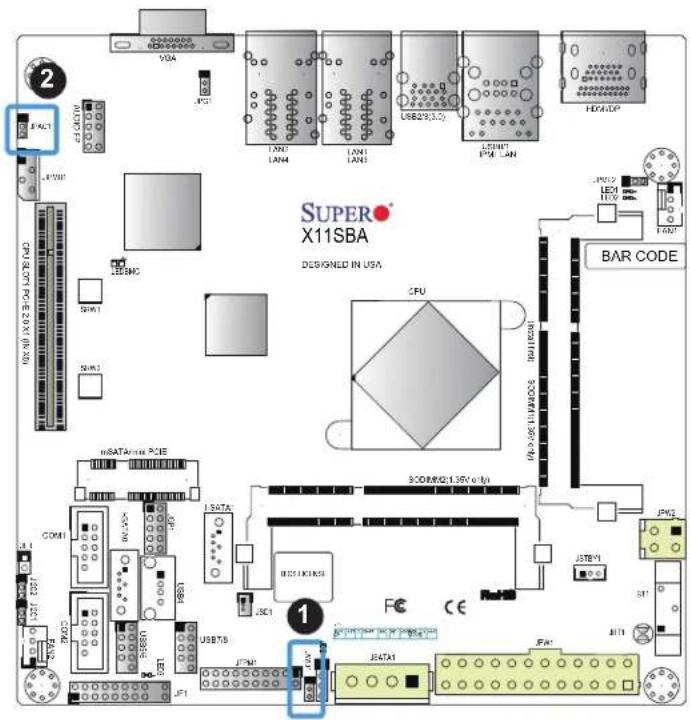
Watch Dog
JWD1 controls the Watch Dog function. Watch Dog is a monitor that can reboot the system when a software application hangs. Jumping pins 1-2 will cause Watch Dog to reset the system if an application hangs. Jumping pins 2-3 will generate a non-maskable interrupt signal for the application that hangs. Watch Dog must also be enabled in BIOS. The default setting is Reset.

Note: When Watch Dog is enabled, the user needs to write their own application software to disable it.
| Watch DogJumper Settings | |
| Jumper Setting Definition | |
| Pins 1-2 Reset | |
| Pins 2-3 NMI | |
| Open Disabled | |
Audio Enable
JPAC1 allows you to enable or disable the onboard audio support. The default position is on pins 1 and 2 to enable onboard audio connections. See the table below for jumper settings.
| Audio Enable/DisableJumper Settings | |
| Jumper Setting Definition | |
| Pins 1-2 Enabled | |
| Pins 2-3 Disabled | |
- Watch Dog
- Audio Enable
2.8 LED Indicators
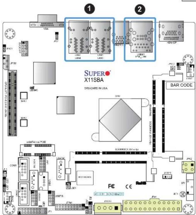
LAN1 \~ LAN4 LEDs
The Ethernet ports (located beside the VGA port) have two LEDs. On each port, one LED indicates activity when flashing while the other LED may be green, amber or off to indicate the speed of the connection.
| LAN1/2 LEDs(Connection Speed Indicator) | |
| LED Color Definition | |
| Off 10 Mb/s | |
| Green 100 Mb/s | |
| Amber 1 Gb/s | |
IPMI-Dedicated LAN LEDs
A dedicated IPMI LAN is also included on the motherboard. The amber LED on the right of the IPMI LAN port indicates activity, while the green LED on the left indicates the speed of the connection. See the table below for more information.
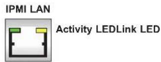
text_image
IPMI LAN Activity LEDLink LED| IPMI LAN LEDs | ||
| Color Status Definition | ||
| Off Off | NoConnection | |
| Green: Solid | Link/Speed (Left) | 100 Mb/s |
| Amber Blinking | Activity (Right) | Active |
text_image
1 2 SUPER X11SBA DESIGNED IN USA VGA LNG LNG4 LNG3 USB01 PWM_IN HD4-LP JPG1 LED LED LED FAN2 BAR CODE SCHU RIO/ASIN/MODOS SCORER21.5N V 4.0 JPG2 JPG1 STI STI JPG1 JPG1 JPG1 JPG1 JPG1 JPG1 JPG1 JPG1 JPG1 JPG1 JPG1 JPG1 JPG1 JPG1 JPG1 JPG1 JPG1 JPG1 JPG1 JPG1 JPG1 JPG1 JPG1 JPG1 JPG1 JPG2 JPG2 JPG2 JPG2 JPG2 JPG2 JPG2 JPG2 JPG2 JPG2 JPG2 JPG2 JPG2 JPG2 JPG2 JPG2 JPG2 JPG2 JPG2 JPG2 JPG2 JPG2 JPG2 JPG2 JPG2 JPG3 JPG3 JPG3 JPG3 JPG3 JPG3 JPG3 JPG3 JPG3 JPG3 JPG3 JPG3 JPG3 JPG3 JPG3 JPG3 JPG3 JPG3 JPG3 JPG3 JPG3 JPG3 JPG3 JPG3 JPG3 JPG4 JPG4 JPG4 JPG4 JPG4 JPG4 JPG4 JPG4 JPG4 JPG4 JPG4 JPG4 JPG4 JPG4 JPG4 JPG4 JPG4 JPG4 JPG4 JPG4 JPG4 JPG4 JPG4 JPG4 JPG4 JPG5 JPG5 JPG5 JPG5 JPG5 JPG5 JPG5 JPG5 JPG5 JPG5 JPG5 JPG5 JPG5 JPG5 JPG5 JPG5 JPG5 JPG5 JPG5 JPG5 JPG5 JPG5 JPG5 JPG5 JPG5 JPG6 JPG6 JPG6 JPG6 JPG6 JPG6 JPG6 JPG6 JPG6 JPG6 JPG6 JPG6 JPG6 JPG6 JPG6 JPG6 JPG6 JPG6 JPG6 JPG6 JPG6- LAN1 \~ LAN4 LEDs
- IPMI-Dedicated LAN LEDs
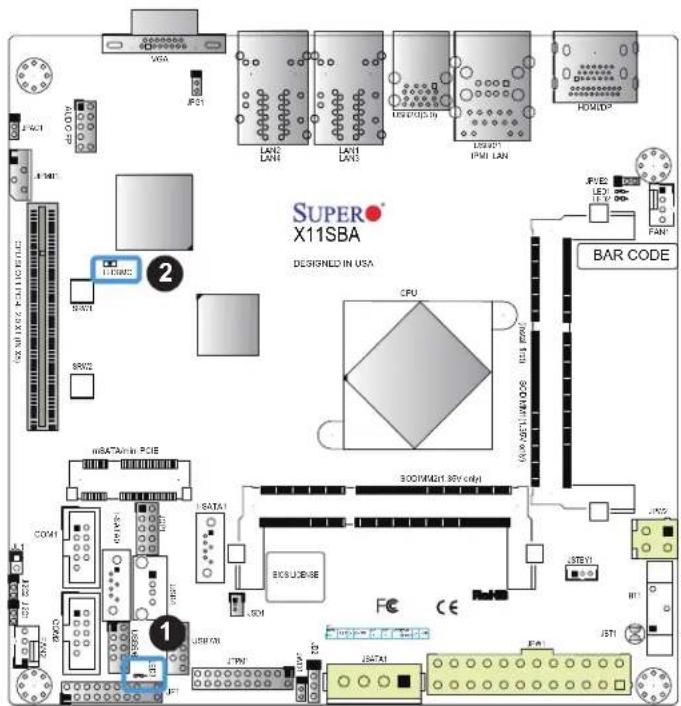
Main Power LED
A Main Power LED is located at LED3 on the motherboard. When this LED is on, the system power is on. Be sure to turn off the system power and unplug the power cord before removing or installing components. See the table below for more information.
| Main Power LED Indicator | |
| LED Color Definition | |
| Off | System Off (power cable not connected) |
| Green System Power On | |
| Green: Flashing Quickly ACPI S3 State | |
BMC Heartbeat LED
LEDBMC is the BMC heartbeat LED. When the LED is blinking green, BMC is functioning normally. See the table below for the LED status.
| Onboard Power LED Indicator | |
| LED Color Definition | |
| Green:Blinking | BMC Normal |
text_image
SUPER X11SBA DESIGNED IN USA CPU BITDAIN PCB BITDAI BITCUBE BITCUBE BITCUBE BITCUBE BITCUBE BITCUBE BITCUBE BITCUBE BITCUBE BITCUBE BITCUBE BITCUBE BITCUBE BITCUBE BITCUBE BITCUBE BITCUBE BITCUBE BITCUBE BITCUBE BITCUBE BITCUBE BITCUBE BITCUBE BITCUBE BITCUBATE BITCUBE BITCUBE BITCUBE BITCUBE BITCUBE BITCUBE BITCUBE BITCUBE BITCUBE BITCUBE BITCUBE BITCUBE BITCUBE BITCUBE BITCUBE BITCUBE BITCUBE BITCUBE BITCUBE BITCUBE BITCUBE BITCUBE BITCUBE BITCUBE BITCUME BITCUME BITCUME BITCUME BITCUME BITCUME BITCUME BITCUME BITCUME BITCUME BITCUME BITCUME BITCUME BITCUME BITCUME BITCUME BITCUME BITT10000000000000000000000000000000000000000000000000000000000000000000000000000000000000000000000000000- Main Power LED
- BMC Heartbeat LED
CPU Power LED
A CPU Power LED is located at LED1 on the motherboard. When this LED is on, the CPU Power is on. Be sure to turn off the system power and unplug the power cord before removing or installing components. See the table below for more information.
| LED1 Indicator | |
| LED Color Definition | |
| Off CPU Power Off | |
| Blue CPU Power On | |
Standby Power LED
A Standby Power LED is located at LED2 on the motherboard. When this LED is on, the Standby Power is on. Be sure to turn off the system power and unplug the power cord before removing or installing components. See the table below for more information.
| LED2 Indicator | |
| LED Color Definition | |
| Off | Standby Power Off (power cable not connected) |
| Green | Standby Power Cable Connected |
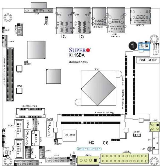
text_image
SUPER X11SBA DESIGNED IN USA 1 BAR CODE P01 LAN2 LAN4 LAN3 USB/DCBIII USB01 IPM1 LAY HCNOR 1 SATAWI-IPCE SODIMM21: 85V 20V SATAI BOB LENSE FCE CE COM1 HDATA1 JCP01 JCP1 JCP2 JCP3 JCP4 JCP5 JCP6 JCP7 JCP8 JCP9 JCP10 JCP11 JCP12 JCP13 JCP14 JCP15 JCP16 JCP17 JCP18 JCP19 JCP20 JCP21 JCP22 JCP23 JCP24 JCP25 JCP26 JCP27 JCP28 JCP29 JCP30 JCP31 JCP32 JCP33 JCP34 JCP35 JCP36 JCP37 JCP38 JCP39 JCP40 JCP41 JCP42 JCP43 JCP44 JCP45 JCP46 JCP47 JCP48 JCP49 JCP50- LED1/LED2
Chapter 3
Troubleshooting
3.1 Troubleshooting Procedures
Use the following procedures to troubleshoot your system. If you have followed all of the procedures below and still need assistance, refer to the 'Technical Support Procedures' and/or 'Returning Merchandise for Service' section(s) in this chapter. Always disconnect the AC power cord before adding, changing or installing any non hot-swap hardware components.
Before Power On
- Check that the power LED on the motherboard is on.
- Make sure that the power connector is connected to your power supply.
- Make sure that no short circuits exist between the motherboard and chassis.
- Disconnect all cables from the motherboard, including those for the keyboard and mouse.
- Remove all add-on cards.
- Connect the internal speaker and the power LED to the motherboard. Check all jumper settings as well. (Make sure that the heatsink is fully seated.)
- Use the correct type of onboard CMOS battery (CR2032) as recommended by the manufacturer. To avoid possible explosion, do not install the CMOS battery upside down.
No Power
- Make sure that no short circuits exist between the motherboard and the chassis.
- Verify that all jumpers are set to their default positions.
- Check that the 115V/230V switch on the power supply is properly set.
- Turn the power switch on and off to test the system.
- The battery on your motherboard may be old. Check to verify that it still supplies \~3VDC. If it does not, replace it with a new one.
No Video
-
If the power is on but you have no video, remove all the add-on cards and cables.
-
Use the speaker to determine if any beep codes exist. Refer to Appendix A for details on beep codes.

Note: If you are a system integrator, VAR or OEM, a POST diagnostics card is recommended. For I/O port 80h codes, refer to Appendix B.
System Boot Failure
If the system does not display POST (Power-On-Self-Test) or does not respond after the power is turned on, check the following:
-
Check for any error beep from the motherboard speaker.
-
If there is no error beep, try to turn on the system without DIMM modules installed. If there is still no error beep, replace the motherboard.
-
If there are error beeps, clear the CMOS settings by unplugging the power cord and contacting both pads on the CMOS Clear Jumper (JBT1). Refer to chapter 2.
-
Remove all components from the motherboard, especially the DIMM modules. Make sure that system power is on and that memory error beeps are activated.
-
Turn on the system with only one DIMM module installed. If the system boots, check for bad DIMM modules or slots by following the Memory Errors Troubleshooting procedure in this Chapter.
Memory Errors
- Make sure that the DIMM modules are properly and fully installed.
- Confirm that you are using the correct memory. Also, it is recommended that you use the same memory type and speed for all DIMMs in the system. See Section 2.4 for memory details.
- Check for bad DIMM modules or slots by swapping modules between slots and noting the results.
- Check the power supply voltage 115V/230V switch.
Losing the System's Setup Configuration
- Make sure that you are using a high quality power supply. A poor quality power supply may cause the system to lose the CMOS setup information. Refer to Section 1.5 for details on recommended power supplies.
- The battery on your motherboard may be old. Check to verify that it still supplies \~3VDC. If it does not, replace it with a new one.
- If the above steps do not fix the setup configuration problem, contact your vendor for repairs.
When the System Becomes Unstable
A. If the system becomes unstable during or after OS installation, check the following:
- BIOS support: Make sure that you have the latest BIOS installed in your system.
- Memory support: Make sure that the memory modules are supported by testing the modules using memtest86 or a similar utility.

Note: Refer to the product page on our website at http://www.supermicro.com for memory support and updates.
- HDD support: Make sure that all hard disk drives (HDDs) work properly. Replace the bad HDDs with good ones.
- System cooling: Check the system cooling to make sure that all heatsink fans and CPU/system fans, etc., work properly. Check the hardware monitoring settings in the IPMI to make sure that the CPU and system temperatures are within the normal range. Also check the front panel Overheat LED and make sure that it is not on.
- Adequate power supply: Make sure that the power supply provides adequate power to the system. Make sure that all power connectors are connected. Please refer to our website for more information on the minimum power requirements.
- Proper software support: Make sure that the correct drivers are used.
B. If the system becomes unstable before or during OS installation, check the following:
- Source of installation: Make sure that the devices used for installation are working properly, including boot devices such as CD/DVD and CD/DVD-ROM.
-
Cable connection: Check to make sure that all cables are connected and working properly.
-
Using the minimum configuration for troubleshooting: Remove all unnecessary components (starting with add-on cards first), and use the minimum configuration (but with a memory module installed) to identify the trouble areas. Refer to the steps listed in Section A above for proper troubleshooting procedures.
- Identifying bad components by isolating them: If necessary, remove a component in question from the chassis, and test it in isolation to make sure that it works properly. Replace a bad component with a good one.
- Check and change one component at a time instead of changing several items at the same time. This will help isolate and identify the problem.
- To find out if a component is good, swap this component with a new one to see if the system will work properly. If so, then the old component is bad. You can also install the component in question in another system. If the new system works, the component is good and the old system has problems.
3.2 Technical Support Procedures
Before contacting Technical Support, please take the following steps. Also, note that as a motherboard manufacturer, we do not sell directly to end-users, so it is best to first check with your distributor or reseller for troubleshooting services. They should know of any possible problem(s) with the specific system configuration that was sold to you.
- Please review the 'Troubleshooting Procedures' and 'Frequently Asked Questions' (FAQs) sections in this chapter or see the FAQs on our website before contacting Technical Support.
- BIOS upgrades can be downloaded from our website. Note: Not all BIOS can be flashed depending on the modifications to the boot block code.
-
If you still cannot resolve the problem, include the following information when contacting us for technical support:
-
Motherboard model and PCB revision number
- BIOS release date/version (this can be seen on the initial display when your system first boots up)
- System configuration
An example of a Technical Support form is posted on our website.
Distributors: For immediate assistance, please have your account number ready when contacting our technical support department by e-mail.
3.3 Frequently Asked Questions
Question: What type of memory does my motherboard support?
Answer: The X11SBA-LN4F/F motherboard supports up to 8 GB of DDR3L Dual Channel, Non-ECC SO-DIMM up to 1600MHz memory in two horizontal slots. See Section 2.3 for details on installing memory.
Question: How do I update my BIOS?
Answer: It is recommended that you do not upgrade your BIOS if you are not experiencing any problems with your system. Updated BIOS files are located on our website at http://www.supermicro.com. Please check our BIOS warning message and the information on how to update your BIOS on our website. Select your motherboard model and download the BIOS file to your computer. Also, check the current BIOS revision to make sure that it is newer than your BIOS before downloading. You can choose from the zip file and the .exe file. If you choose the zip BIOS file, please unzip the BIOS file onto a bootable USB device. Run the batch file using the format FLASH.BAT filename.rom from your bootable USB device to flash the BIOS. Then, your system will automatically reboot.
Question: Why can't I turn off the power using the momentary power on/off switch?
Answer: The instant power off function is controlled in BIOS by the Power Button Mode setting. When the On/Off feature is enabled, the motherboard will have instant off capabilities as long as the BIOS has control of the system. When the Standby or Suspend feature is enabled or when the BIOS is not in control such as during memory count (the first screen that appears when the system is turned on), the momentary on/off switch must be held for more than four seconds to shut down the system. This feature is required to implement the ACPI features on the motherboard.
3.4 Battery Removal and Installation
Battery Removal
To remove the onboard battery, follow the steps below:
- Power off your system and unplug your power cable.
- Locate the onboard battery as shown below.
-
Remove the battery.
-
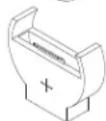
Using a tool such as a pen or a small screwdriver, push the battery lock outwards to unlock it. Once unlocked, the battery will pop out from the holder.
Proper Battery Disposal
Please handle used batteries carefully. Do not damage the battery in any way; a damaged battery may release hazardous materials into the environment. Do not discard a used battery in the garbage or a public landfill. Please comply with the regulations set up by your local hazardous waste management agency to dispose of your used battery properly.
Battery Installation
- To install an onboard battery, follow the steps 1 & 2 above and continue below:
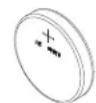
- Identify the battery's polarity. The positive (+) side should be facing up.
- Insert the battery into the battery holder and push it down until you hear a click to ensure that the battery is securely locked.

Important: When replacing a battery, be sure to only replace it with the same type.
LITHIUM BATTERY
BATTERY HOLDER
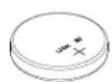
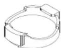

OR
LITHIUM BATTERY
BATTERY HOLDER

3.5 Returning Merchandise for Service
A receipt or copy of your invoice marked with the date of purchase is required before any warranty service will be rendered. You can obtain service by calling your vendor for a Returned Merchandise Authorization (RMA) number. When returning to the manufacturer, the RMA number should be prominently displayed on the outside of the shipping carton and mailed prepaid or hand-carried. Shipping and handling charges will be applied for all orders that must be mailed when service is complete.
For faster service, RMA authorizations may be requested online (http://www.supermicro.com/support/rma/).
This warranty only covers normal consumer use and does not cover damages incurred in shipping or from failure due to the alteration, misuse, abuse or improper maintenance of products.
During the warranty period, contact your distributor first for any product problems.
Chapter 4
BIOS
4.1 Introduction
This chapter describes the AMIBIOS™ Setup utility for the X11SBA-LN4F/F motherboards. The BIOS is stored on a chip and can be easily upgraded using a flash program.
Note: Due to periodic changes to the BIOS, some settings may have been added or deleted and might not yet be recorded in this manual. Please refer to the Manual Download area of our website for any changes to BIOS that may not be reflected in this manual.
Starting the Setup Utility
To enter the BIOS Setup Utility, hit the
The Main BIOS screen has two main frames. The left frame displays all the options that can be configured. "Grayed-out" options cannot be configured. The right frame displays the key legend. Above the key legend is an area reserved for a text message. When an option is selected in the left frame, it is highlighted in white. Often a text message will accompany it. (Note that BIOS has default text messages built in. We retain the option to include, omit, or change any of these text messages.) Settings printed in Bold are the default values.
A "▶" indicates a submenu. Highlighting such an item and pressing the
The BIOS setup utility uses a key-based navigation system called hot keys. Most of these hot keys (
4.2 Main Setup
When you first enter the AMI BIOS setup utility, you will enter the Main setup screen. You can always return to the Main setup screen by selecting the Main tab on the top of the screen. The Main BIOS setup screen is shown below.
The following Main menu items will be displayed:
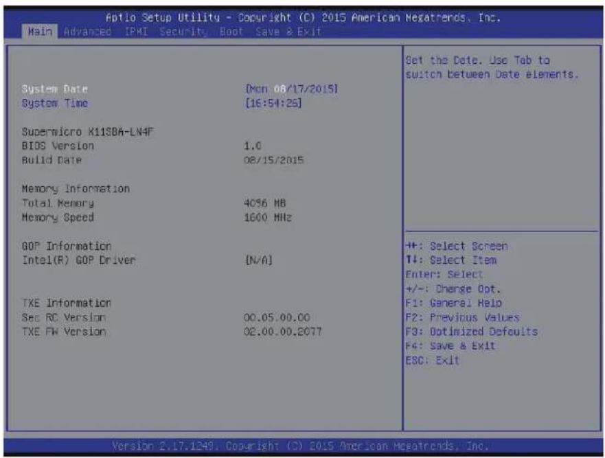
text_image
Aptio Setup Utility - Copyright (C) 2015 American Megatrends, Inc. Main Advanced IPMI Security Boot Save & Exit System Date [Mon 06/17/2015] System Time [16:54:25] Supermicro K11SBA-LN4F BIOS Version 1.0 Build Date 08/15/2015 Memory Information Total Memory 4056 MB Memory Speed 1600 MHz GOP Information Intel(R) GOP Driver [N/A] TXE Information Sec RC Version 00.05.00.00 TXE FW Version 02.00.00.2077 Set the Date. Use Tab to switch between Date elements. +#: Select Screen T#: Select Item Enter: Select +/-: Change Opt. F1: General Help F2: Previous Values F3: Optimized Defaults F4: Save & Exit ESC: Exit Version 2.17.1249. Copyright (C) 2015 American Megatrends, Inc.System Date/System Time
Use this option to change the system date and time. Highlight System Date or System Time using the arrow keys. Enter new values using the keyboard. Press the

Note: The time is in the 24-hour format. For example, 5:30 P.M. appears as 17:30:00.
Supermicro X11SBA-LN4F
BIOS Version
Build Date
Memory Information
Total Memory: This displays the total size of memory available in the system.
Memory Speed: This displays the memory speed.
GOP Information
Intel® GOP Driver: This displays the information of Intel Graphics onboard driver.
TXE Information
Sec RC Version
TXE FW Version
4.3 Advanced Setup Configurations
Use the arrow keys to select Advanced setup and press
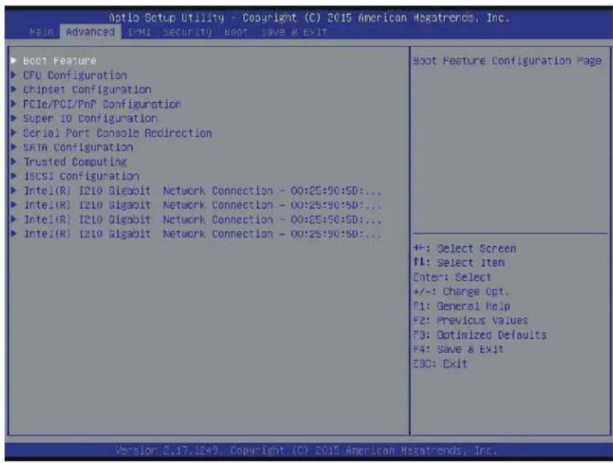
text_image
Aptio Setup Utility - Copyright (C) 2015 American Megatrends, Inc. Main Advanced IPMI Security Boot Save & Exit Boot Feature CPU Configuration Chipset Configuration PCIe/PCI/PnP Configuration Super IO Configuration Serial Port Console Redirection SATA Configuration Trusted Computing ISCSI Configuration Intel(R) I210 Gigabit Network Connection - 00:25:90:5D:... Intel(R) I210 Gigabit Network Connection - 00:25:90:5D:... Intel(R) I210 Gigabit Network Connection - 00:25:90:5D:... Intel(R) I210 Gigabit Network Connection - 00:25:90:5D:... Boot Feature Configuration Page +/-: Select Screen ↑↓: Select Item Enter: Select +/-: Charge Opt. F1: General Help F2: Previous Values F3: Optimized Defaults F4: Save & Exit ESC: Exit Version 2.17.1849. Copyright (C) 2015 American Megatrends, Inc.Warning: Take caution when changing the Advanced settings. An incorrect value, a very high DRAM frequency or an incorrect BIOS timing setting may cause the system to malfunction. When this occurs, restore the setting to the manufacture default setting.
▶Boot Feature
Quiet Boot
Use this feature to select the screen display between POST messages or the OEM logo at bootup. Select Disabled to display the POST messages. Select Enabled to display the OEM logo instead of the normal POST messages. The options are Enabled and Disabled.
AddOn ROM Display Mode
This feature sets the display mode for the Option ROM. Select Keep Current to use the current AddOn ROM display setting. Select Force BIOS to use the Option ROM display mode set by the system BIOS. The options are Force BIOS and Keep Current.
Bootup NumLock State
This feature selects the Power-on state for the Numlock key. The options are Off and On.
Wait For 'F1' If Error
This feature forces the system to wait until the 'F1' key is pressed if an error occurs. The options are Disabled and Enabled.
INT19 Trap Response
Interrupt 19 is the software interrupt that handles the boot disk function. When this item is set to Immediate, the ROM BIOS of the host adaptors will "capture" Interrupt 19 at bootup immediately and allow the drives that are attached to these host adaptors to function as bootable disks. If this item is set to Postponed, the ROM BIOS of the host adaptors will not capture Interrupt 19 immediately and allow the drives attached to these adaptors to function as bootable devices at bootup. The options are Immediate and Postponed.
Re-try Boot
If this item is enabled, the BIOS will automatically reboot the system from a specified boot device after its initial boot failure. The options are Disabled, Legacy Boot, and EFI Boot.
Power Configuration
Watch Dog Function
If enabled, the Watch Dog timer will allow the system to reboot when it is inactive for more than 5 minutes. The options are Enabled and Disabled.
Power Button Function
This feature controls how the system shuts down when the power button is pressed. Select 4 Seconds Override for the user to power off the system after pressing and holding the power button for 4 seconds or longer. Select Instant Off to instantly power off the system as soon as the user presses the power button. The options are 4 Seconds Override and Instant Off.
Restore on AC Power Loss
Use this feature to set the power state after a power outage. Select Power-Off for the system power to remain off after a power loss. Select Power-On for the system power to be turned on after a power loss. Select Last State to allow the system to resume its last power state before a power loss. The options are Power-On, Stay-Off and Last State.
▶CPU Configuration
The following CPU information will be displayed:
- Socket 0 CPU Configuration
- CPU Signature
- Microcode Patch
- CPU Speed
• Max (Maximum) CPU Speed
• Min (Minimum) CPU Speed - Processor Cores
• Intel HT (Hyper-Threading) Technology
• Intel VT-x (Virtualization) Technology - 64-bit
- L1 Data Cache
- L1 Code Cache
- L2 Cache
- L3 Cache
▶CPU Thermal Configuration
DTS
Select Enabled for the ACPI thermal management to use the DTS SMM mechanism to obtain CPU temperature values. Select Disabled for EC to report the CPU temperature values. The options are Disabled and Enabled.
Limit CPUID Maximum
Select Enabled to set the maximum CPU ID value and to boot a legacy OS that cannot support processors with extended CPUID functions. The options are Enabled and Disabled (for the Windows OS).
Intel® Virtualization Technology (Available when supported by the CPU)
Select Enabled to use the Intel Virtualization Technology to allow one platform to run multiple operating systems and applications in independent partitions, creating multiple "virtual" systems in one physical computer. The options are Enabled and Disabled.
Power Technology
This feature allows the user to configure power management settings. The options are Disabled, Energy Efficiency, and Custom.
*If the item above set to Custom, the following items will become available for user's configuration:
EIST (P-States)
EIST (Enhanced Intel SpeedStep Technology) allows the system to automatically adjust processor voltage and core frequency in an effort to reduce power consumption and heat dissipation. Please refer to Intel's website for detailed information. The options are Disabled and Enabled.
Turbo Mode
Select Enable for processor cores to run faster than the frequency specified by the manufacturer. The options are Disabled and Enabled.
P-state Coordination
Use this item to configure the processor's P-State coordination settings. During a P-State, the voltage and frequency of the processor will be reduced when it is in operation. This makes the processor more energy efficient, resulting in further energy gains. The options are HW_ALL, SW_ALL and SW-ANY.
Max CPU C-State
Use this feature to select the CPU C-state. The options are C7, C6, and C1.
▶Chipset Configuration
Warning: Setting the wrong values in the following sections may cause the system to malfunction.
▶ North Bridge
The following North Bridge information will be displayed:
- Total Memory
- SODIMM1
- SODIMM2
▶Intel IGD Configuration
This item displays the following graphics information:
GOP Configuration
Intel IGD Configuration
IGD (Integrated Graphics Device) Turbo
Select Enabled to enable the turbo mode support for integrated graphics devices. The options are Auto, Enabled, and Disabled.
Primary Display
Use this feature to select the graphics device to be used as the primary display. The options are IGD, PCIE, and Auto.
Primary PCIE (PCI-Express Graphics)
This feature allows the user to specify which graphics card to be used as the primary graphics card. The options are Auto, Onboard, and CPU SLOT1 PCIE 2.0 x1 (IN X8).
GFX Boost
Select Enabled to boost graphics performance. The options are Disabled and Enabled.
DVMT (Dynamic Video Memory Technology) Pre-Allocated
Dynamic Video Memory Technology (DVMT) allows dynamic allocation of system memory to be used for video devices to ensure best utilization of available system memory based on the DVMT 5.0 platform. The options are 32M, 64M, 96M, 128M, 160M, 192M, 224M, 256M, 288M, 320M, 352M, 384M, 416M, 448M, 480M, and 512M.
DVMT Total Gfx Mem
Use this feature to set the total memory size to be used by the internal graphics devices based on the DVMT 5.0 platform. The options are 128MB, 256MB and MAX.
Aperture Size
Use this feature to set the Aperture size, which is the size of system memory reserved by the BIOS for graphics device use. The options are 128MB, 256MB, and 512 MB.
GTT Size
Use this feature to set the memory size to be used by the graphics translation table (GTT). The options are 2MB, 4MB, and 8MB.
IGD Thermal
Use this feature to enable or disable the IGD thermal. The options are Disabled and Enabled.
Spread Spectrum Clock
If this feature is set to Enabled, the BIOS will monitor the level of electromagnetic interference caused by the components and will attempt to reduce the interference whenever needed. The options are Enabled and Disabled.
▶ Graphics Power Management Control
RC6 (Render Standby)
Select Enabled to enable render standby support. The options are Disabled and Enabled.
▶ Memory Configuration Options
MRC Fast Boot
Use this feature to enable or disable fast boot through the memory reference code (MRC). The options are Enabled and Disabled.
Scrambler
Select Enabled to enable memory scrambler support. The options are Enabled and Disabled.
RH Prevention
Select Enabled to prevent Row Hammer attacks by increasing the average time between sending REF commands to DRAM. The options are Enabled and Disabled.
Max TOLUD (Top of Low Usable DRAM)
This feature sets the maximum TOLUD value, which specifies the "Top of Low Usable DRAM" memory space to be used by internal graphics devices, GTT Stolen Memory, and TSEG, respectively, if these devices are enabled. The options are 2GB and 3GB.
▶ South Bridge
The following South Bridge information will be displayed:
▶Azalia Configuration
Audio Configuration
Audio Controller
Select Enabled to enable the Azalia Audio Controller. The settings are Enabled and Disabled.
Azalia VCi Enable
Select Enabled to enable the Virtual Channel 1 of the Azalia Audio Controller. The settings are Enabled and Disabled.
▶USB Configuration
XHCI Mode
Select Enabled to support the operation mode for the XHCI (Extensible Host Controller Interface) controller. The options are Enabled and Disabled.
USB2 PHY Power Gating
Use this feature to configure the power consumption for the USB 2.0 physical layer (PHY). The options are Disabled, Enabled, and Auto.
▶PCI Express Configuration
PCI Express Configuration
▶CPU SLOT1 PCIE 2.0 x1 (IN X8)
PCI Express Port 1
This item enables or disables the PCI Express Port 0 on the motherboard. The options are Enabled and Disabled.
ASPM
Use this item to set the Active State Power Management (ASPM) level for a PCI-E device. Select Auto for the system BIOS to automatically set the ASPM level based on the system configuration. Select Disabled to disable ASPM support. The options are Disabled, L0s, L1, L0sL1, and Auto.
PCIe Speed
This feature allows the user to set the PCIe port speed. The options are Auto, Gen 2, and Gen 1.
Detect Non-Compliance Device
Select Enabled for the AMI BIOS to automatically detect a PCI-E device that is not compliant with the PCI-E standards. The options are Enabled and Disabled.
L1 Substates
Use this feature to configure the PCI Express L1 Substates. The options are Disabled, L1.1, L1.2, and L1.1 & L1.2.
Non-Common Clock With SSC Enabled
Use this feature to configure the non-common clocking signal for Spread Spectrum Clocking (SSC). The options are Disabled and Enabled.
Tx Eq Deemphasis Selection
Use this feature to select the level of de-emphasis for an Upstream component. The options are 3.5dB and 6dB.
Native PCIE Enable
Select Enabled to enable the PCI Express Native support. This feature is only available on Windows® Vista. The options are Disabled and Enabled.
▶PCIe/PCI/PnP Configuration
PCI Bus Driver Version
PCI Devices Common Settings:
Above 4G Decoding
Select Enabled for 64-bit devices to be decoded above the 4GB address space If 64bit PCI decoding is supported by the system. The options are Disabled and Enabled.
CPU SLOT1 PCI-E 2.0 X1 (IN X8)
Use this feature to select the type of firmware to be loaded for the device installed on this slot. The options are Disabled, Legacy, and EFI.
Onboard LAN Option ROM Type
Select Enabled to enable Option ROM support to boot the computer using a network device specified by the user. The options are Legacy and EFI.
Onboard LAN1 Option ROM
Use this option to select the type of device installed in LAN Port1 used for system boot. The default setting for LAN1 Option ROM is PXE. The options are Disabled, PXE, and iSCSI.
Onboard LAN2 Option ROM
Use this option to select the type of device installed in LAN Port2 used for system boot. The default setting for LAN2 Option ROM is Disabled. The options are Disabled and PXE.
Onboard LAN3 Option ROM
Use this option to select the type of device installed in LAN Port3 used for system boot. The default setting for LAN3 Option ROM is Disabled. The options are Disabled and PXE.
Onboard LAN4 Option ROM
Use this option to select the type of device installed in LAN Port4 used for system boot. The default setting for LAN4 Option ROM is Disabled. The options are Disabled and PXE.
Onboard Video Option ROM
Use this item to select the Onboard Video Option ROM type. The options are Disabled, Legacy, and EFI.
Network Stack
Select Enabled to enable PXE (Preboot Execution Environment) or UEFI (Unified Extensible Firmware Interface) for network stack support. The options are Enabled and Disabled.
Ipv4 PXE Support (Available when Network Stack is set to Enabled)
Select Enabled to enable lpv4 PXE (Preboot Execution Environment) for boot support. If this feature is set to Disabled, lpv4 PXE boot option will not be supported. The options are Enabled and Disabled.
Ipv6 PXE Support (Available when Network Stack is set to Enabled)
Select Enabled to enable lpv6 PXE (Preboot Execution Environment) for boot support. If this feature is set to Disabled, lpv6 PXE boot option will not be supported. The options are Enabled and Disabled.
PXE boot wait time
Use this option to specify the wait time to press the ESC key to abort the PXE boot. Press "+" or "-" on your keyboard to change the value. The default setting is 0.
Media detect count
Use this option to specify the number of times media will be checked. Press "+" or "-" on your keyboard to change the value. The default setting is 1.
▶Super IO Configuration
Super IO Chip AST2400
▶ Serial Port 1 Configuration
Serial Port 1
Select Enabled to enable the onboard serial port specified by the user. The options are Enabled and Disabled.
Device Settings
This item displays the base I/O port address and the Interrupt Request address of a serial port specified by the user.
Change Port 1 Settings
This feature specifies the base I/O port address and the Interrupt Request address of Serial Port 1. Select Auto to allow the BIOS to automatically assign the base I/O and IRQ address to a serial port specified.
The options for Serial Port 1 are Auto, (IO=3F8h; IRQ=4), (IO=3F8h; IRQ=3, 4, 5, 6, 7, 9, 10, 11, 12), (IO=2F8h; IRQ=3, 4, 5, 6, 7, 9, 10, 11, 12), (IO=3E8h; IRQ=3, 4, 5, 6, 7, 9, 10, 11, 12), and (IO=2E8h; IRQ=3, 4, 5, 6, 7, 9, 10, 11, 12).
▶ Serial Port 2 Configuration
Serial Port 2
Select Enabled to enable the onboard serial port specified by the user. The options are Enabled and Disabled.
Device Settings
This item displays the base I/O port address and the Interrupt Request address of a serial port specified by the user.
Change Port 2 Settings
This feature specifies the base I/O port address and the Interrupt Request address of Serial Port 2. Select Auto to allow the BIOS to automatically assign the base I/O and IRQ address to a serial port specified.
The options for Serial Port 2 are Auto, (IO=3F8h; IRQ=4), (IO=3F8h; IRQ=3, 4, 5, 6, 7, 9, 10, 11, 12), (IO=2F8h; IRQ=3, 4, 5, 6, 7, 9, 10, 11, 12), (IO=3E8h; IRQ=3, 4, 5, 6, 7, 9, 10, 11, 12), and (IO=2E8h; IRQ=3, 4, 5, 6, 7, 9, 10, 11, 12).
Serial Port 2 Attribute
This feature specifies the attribute of Serial Port 2. The options are SOL and COM.
▶Serial Port Console Redirection
COM1 Console Redirection
Select Enabled to enable console redirection support for a serial port specified by the user. The options are Enabled and Disabled.
*If the item above set to Enabled, the following items will become available for user's configuration:
▶COM1 Console Redirection Settings
This feature allows the user to specify how the host computer will exchange data with the client computer, which is the remote computer used by the user.
Terminal Type
This feature allows the user to select the target terminal emulation type for Console Redirection. Select VT100 to use the ASCII Character set. Select VT100+ to add color and function key support. Select ANSI to use the Extended ASCII Character Set. Select VT-UTF8 to use UTF8 encoding to map Unicode characters into one or more bytes. The options are VT100, VT100+, VT-UTF8, and ANSI.
Bits Per second
Use this feature to set the transmission speed for a serial port used in Console Redirection. Make sure that the same speed is used in the host computer and the client computer. A lower transmission speed may be required for long and busy lines. The options are 9600, 19200, 38400, 57600, and 115200 (bits per second).
Data Bits
Use this feature to set the data transmission size for Console Redirection. The options are 7 (Bits) and 8 (Bits).
Parity
A parity bit can be sent along with regular data bits to detect data transmission errors. Select Even if the parity bit is set to 0, and the number of 1's in data bits is even. Select Odd if the parity bit is set to 0, and the number of 1's in data bits is odd. Select None if you do not want to send a parity bit with your data bits in transmission. Select Mark to add a mark as a parity bit to be sent along with the data bits. Select Space to add a Space as a parity bit to be sent with your data bits. The options are None, Even, Odd, Mark, and Space.
Stop Bits
A stop bit indicates the end of a serial data packet. Select 1 Stop Bit for standard serial data communication. Select 2 Stop Bits if slower devices are used. The options are 1 and 2.
Flow Control
Use this feature to set the flow control for Console Redirection to prevent data loss caused by buffer overflow. Send a "Stop" signal to stop sending data when the receiving buffer is full. Send a "Start" signal to start sending data when the receiving buffer is empty. The options are None and Hardware RTS/CTS.
VT-UTF8 Combo Key Support
Select Enabled to enable VT-UTF8 Combination Key support for ANSI/VT100 terminals. The options are Enabled and Disabled.
Recorder Mode
Select Enabled to capture the data displayed on a terminal and send it as text messages to a remote server. The options are Disabled and Enabled.
Resolution 100x31
Select Enabled for extended-terminal resolution support. The options are Disabled and Enabled.
Legacy OS Redirection Resolution
Use this feature to select the number of rows and columns used in Console Redirection for legacy OS support. The options are 80x24 and 80x25.
Putty KeyPad
This feature selects the settings for Function Keys and KeyPad used for Putty, which is a terminal emulator designed for the Windows OS. The options are VT100, LINUX, XTERMR6, SC0, ESCN, and VT400.
Redirection After BIOS Post
Use this feature to enable or disable legacy console redirection after BIOS POST. When set to Bootloader, legacy console redirection is disabled before booting the OS. When set to Always Enable, legacy console redirection remains enabled when booting the OS. The options are Always Enable and Bootloader.
SOL/COM2 Console Redirection
Select Enabled to use the SOL port for Console Redirection. The options are Enabled and Disabled.
*If the item above set to Enabled, the following items will become available for user's configuration:
▶SOL/COM2 Console Redirection Settings
Use this feature to specify how the host computer will exchange data with the client computer, which is the remote computer used by the user.
Terminal Type
Use this feature to select the target terminal emulation type for Console Redirection. Select VT100 to use the ASCII Character set. Select VT100+ to add color and function key support. Select ANSI to use the Extended ASCII Character Set. Select VT-UTF8 to use UTF8 encoding to map Unicode characters into one or more bytes. The options are VT100, VT100+, VT-UTF8, and ANSI.
Bits Per second
Use this feature to set the transmission speed for a serial port used in Console Redirection. Make sure that the same speed is used in the host computer and the client computer. A lower transmission speed may be required for long and busy lines. The options are 9600, 19200, 38400, 57600 and 115200 (bits per second).
Data Bits
Use this feature to set the data transmission size for Console Redirection. The options are 7 (Bits) and 8 (Bits).
Parity
A parity bit can be sent along with regular data bits to detect data transmission errors. Select Even if the parity bit is set to 0, and the number of 1's in data bits is even. Select Odd if the parity bit is set to 0, and the number of 1's in data bits is odd. Select None if you do not want to send a parity bit with your data bits in transmission. Select Mark to add a mark as a parity bit to be sent along with the data bits. Select Space to add a Space as a parity bit to be sent with your data bits. The options are None, Even, Odd, Mark and Space.
Stop Bits
A stop bit indicates the end of a serial data packet. Select 1 Stop Bit for standard serial data communication. Select 2 Stop Bits if slower devices are used. The options are 1 and 2.
Flow Control
Use this feature to set the flow control for Console Redirection to prevent data loss caused by buffer overflow. Send a "Stop" signal to stop sending data when the receiving buffer is full. Send a "Start" signal to start sending data when the receiving buffer is empty. The options are None and Hardware RTS/CTS.
VT-UTF8 Combo Key Support
Select Enabled to enable VT-UTF8 Combination Key support for ANSI/VT100 terminals. The options are Enabled and Disabled.
Recorder Mode
Select Enabled to capture the data displayed on a terminal and send it as text messages to a remote server. The options are Disabled and Enabled.
Resolution 100x31
Select Enabled for extended-terminal resolution support. The options are Disabled and Enabled.
Legacy OS Redirection Resolution
Use this feature to select the number of rows and columns used in Console Redirection for legacy OS support. The options are 80x24 and 80x25.
Putty KeyPad
This feature selects Function Keys and KeyPad settings for Putty, which is a terminal emulator designed for the Windows OS. The options are VT100, LINUX, XTERMR6, SCO, ESCN, and VT400.
Redirection After BIOS Post
Use this feature to enable or disable legacy Console Redirection after BIOS POST. When set to Bootloader, legacy Console Redirection is disabled before booting the OS. When set to Always Enable, legacy Console Redirection remains enabled when booting the OS. The options are Always Enable and Bootloader.
Serial Port for Out-of-Band Management/Windows Emergency Management Services (EMS)
The submenu allows the user to configure Console Redirection settings to support Out-of-Band Serial Port management.
EMS (Emergency Management Services) Console Redirection
Select Enabled to use a COM port selected by the user for EMS Console Redirection. The options are Enabled and Disabled.
*If the item above set to Enabled, the following items will become available for user's configuration:
▶EMS Console Redirection Settings
This feature allows the user to specify how the host computer will exchange data with the client computer, which is the remote computer used by the user.
Out-of-Band Management Port
The feature selects a serial port in a client server to be used by the Microsoft Windows Emergency Management Services (EMS) to communicate with a remote host server. The options are COM1 and SOL/COM2.
Terminal Type
Use this feature to select the target terminal emulation type for Console Redirection. Select VT100 to use the ASCII character set. Select VT100+ to add color and function key support. Select ANSI to use the extended ASCII character set. Select VT-UTF8 to use UTF8 encoding to map Unicode characters into one or more bytes. The options are VT100, VT100+, VT-UTF8, and ANSI.
Bits Per Second
This item sets the transmission speed for a serial port used in Console Redirection. Make sure that the same speed is used in the host computer and the client computer. A lower transmission speed may be required for long and busy lines. The options are 9600, 19200, 57600, and 115200 (bits per second).
Flow Control
Use this item to set the flow control for Console Redirection to prevent data loss caused by buffer overflow. Send a "Stop" signal to stop sending data when the receiving buffer is full. Send a "Start" signal to start sending data when the receiving buffer is empty. The options are None, Hardware RTS/CTS, and Software Xon/Xoff.
Data Bits
Use this feature to set the data transmission size for Console Redirection. The options are 7 (Bits) and 8 (Bits).
Parity
A parity bit can be sent along with regular data bits to detect data transmission errors. Select Even if the parity bit is set to 0, and the number of 1's in data bits is even. Select Odd if the parity bit is set to 0, and the number of 1's in data bits is odd. Select None if you do not want to send a parity bit with your data bits in transmission. Select Mark to add a mark as a parity bit to be sent along with the data bits. Select Space to add a Space as a parity bit to be sent with your data bits. The options are None, Even, Odd, Mark and Space.
Stop Bits
A stop bit indicates the end of a serial data packet. Select 1 Stop Bit for standard serial data communication. Select 2 Stop Bits if slower devices are used. The options are 1 and 2.
▶SATA Configuration
When this submenu is selected, the AMI BIOS automatically detects the presence of the SATA Devices and displays the following items:
SATA Controller
This item enables or disables the onboard SATA controller supported by the Intel PCH chip. The options are Enabled and Disabled.
Aggressive LPM (Link Power Management) Support
When this item is set to Enabled, the SATA AHCI controller manages the power usage of the SATA link. The controller will put the link in a low power mode during extended periods of I/O inactivity, and will return the link to an active state when I/O activity resumes. The options are Enabled and Disabled.
SATA Frozen
This item enables or disables the Freeze Lock Security feature. The options are Disabled and Enabled.
Port 0 Spin Up Device
When the value of an edge detect or the value of an image binary (pixel) of a device is from 0 to 1, select Enabled to allow the PCH to start a COMRESET initialization sequence on this device. The options are Enabled and Disabled.
Port 1 Spin Up Device
When the value of an edge detect or the value of an image binary (pixel) of a device is from 0 to 1, select Enabled to allow the PCH to start a COMRESET initialization sequence on this device. The options are Enabled and Disabled.
▶ Trusted Computing Configuration
Security Device Support
If this feature and the TPM jumper on the motherboard are both set to Enabled, onboard security devices will be enabled for TPM (Trusted Platform Module) support to enhance data integrity and network security. Please reboot the system for a change on this setting to take effect. The options are Disabled and Enabled.
TPM State
This feature changes the TPM State. The options are Disabled and Enabled. Note: The system will restart to change the TPM State.
Pending TPM operation
Use this item to schedule a TPM-related operation to be performed by a security device for system data integrity. Your system will reboot to carry out a pending TPM operation. The options are None and TPM Clear.
Device Select
Use this feature to select the TPM version. TPM 1.2 will restrict support to TPM 1.2 devices. TPM 2.0 will restrict support for TPM 2.0 devices. Select Auto to enable support for both versions. The default setting is Auto.
The following are informational status messages that indicate the current TPM State:
TPM Enabled Status
TPM Active Status
TPM Owner Status
▶iSCSi Configuration
iSCSI Initiator Name
This feature allows the user to enter the unique name of the iSCSI Initiator in IQN format. Once the name of the iSCSI Initiator is entered into the system, configure the proper settings for the following items.
▶ Add an Attempt
▶ Delete Attempts
▶ Change Attempt order
*If the Onboard LAN Option ROM Type feature is set to EFI, the following items will become available for user's configuration:
Intel I210 Gigabit Network connection - 00:25:90:xx:xx:xx
▶NIC Configuration
The following network information will display:
- Link Speed
- Wake On LAN
Blink LEDs
UEFI Driver
Adapter PBA
Device Name
Chip Type
PCI Device ID
PCI Address
Link Status
MAC Address
Virtual MAC Address
Intel I210 Gigabit Network connection - 00:25:90:xx:xx:xx
▶NIC Configuration
The following network information will display:
- Link Speed
- Wake On LAN
Blink LEDs
UEFI Driver
Adapter PBA
Device Name
Chip Type
PCI Device ID
PCI Address
Link Status
MAC Address
Virtual MAC Address
Intel I210 Gigabit Network connection - 00:25:90:xx:xx:xx
▶NIC Configuration
The following network information will display:
- Link Speed
- Wake On LAN
Blink LEDs
UEFI Driver
Adapter PBA
Device Name
Chip Type
PCI Device ID
PCI Address
Link Status
MAC Address
Virtual MAC Address
Intel I210 Gigabit Network connection - 00:25:90:xx:xx:xx
▶NIC Configuration
The following network information will display:
- Link Speed
- Wake On LAN
Blink LEDs
UEFI Driver
Adapter PBA
Device Name
Chip Type
PCI Device ID
PCI Address
Link Status
MAC Address
Virtual MAC Address
4.4 IPMI
Use this feature to configure Intelligent Platform Management Interface (IPMI) settings.
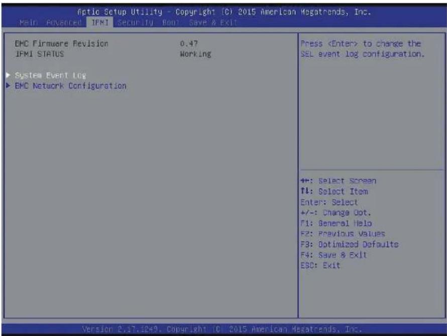
text_image
Optic Setup Utility - Copyright (C) 2015 American Megatrends, Inc. MAIN: ADVANCED: IFMI Security Book Save & Exit EMC Firmware Revision 0.47 IFMI STATUS Working ► System Event Log ► EMC Network Configuration PressBMC Firmware Revision
This item indicates the IPMI firmware revision used in your system.
IPMI Status (Baseboard Management Controller)
This item indicates the status of the IPMI firmware installed in your system.
▶System Event Log
Enabling/Disabling Options
SEL Components
Select Enabled for all system event logging at bootup. The options are Enabled and Disabled.
Erasing Settings
Erase SEL
Select Yes, On next reset to erase all system event logs upon next system reboot. Select Yes, On every reset to erase all system event logs upon each system reboot. Select No to keep all system event logs after each system reboot. The options are No, Yes, On next reset, and Yes, On every reset.
When SEL is Full
This feature allows the user to decide what the BIOS should do when the system event log is full. Select Erase Immediately to erase all events in the log when the system event log is full. The options are Do Nothing and Erase Immediately.

Note: After making changes on a setting, be sure to reboot the system for the changes to take effect.
▶BMC Network Configuration
BMC Network Configuration
IPMI LAN Selection
This item displays the IPMI LAN setting. The default setting is Failover.
IPMI Network Link Status
This item displays the IPMI Network Link status. The default setting is Shared LAN.
Update IPMI LAN Configuration
Select Yes for the BIOS to implement all IP/MAC address changes at the next system boot. The options are No and Yes
Configuration Address Source
This feature allows the user to select the source of the IP address for this computer. If Static is selected, you will need to know the IP address of this computer and enter it to the system manually in the field. If DHCP is selected, the BIOS will search for a DHCP (Dynamic Host Configuration Protocol) server in the network that is attached to and request the next available IP address for this computer. The options are DHCP and Static. The following items are assigned IP addresses automatically if DHCP is selected.
Current Configuration Address Source
This item displays the current configuration address for this computer.
Station IP Address
This item displays the Station IP address for this computer. This should be in decimal and in dotted quad form (i.e., 192.168.10.253).
Subnet Mask
This item displays the sub-network that this computer belongs to. The value of each three-digit number separated by dots should not exceed 255.
Station MAC Address
This item displays the Station MAC address for this computer. Mac addresses are 6 two-digit hexadecimal numbers.
Gateway IP Address
This item displays the Gateway IP address for this computer. This should be in decimal and in dotted quad form (i.e., 172.31.0.1).
- Chip Type
- PCI Device ID
• PCI Bus:Device:Function - Link Status
• Factory MAC Address
• Alternate MAC Address
4.5 Security
This menu allows the user to configure Security settings.
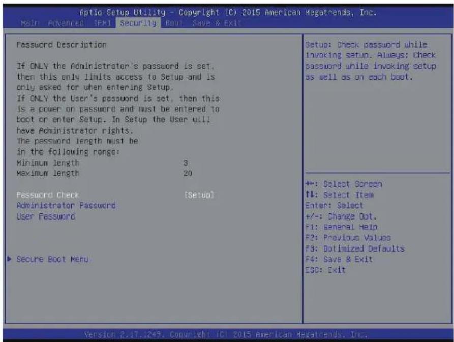
text_image
Aptio Setup Utility - Copyright (C) 2015 American Megatrends, Inc. Main Advanced IPK1 Security Boot Save & Exit Password Description If ONLY the Administrator's password is set, then this only limits access to Setup and is only asked for when entering Setup. If ONLY the User's password is set, then this is a power on password and must be entered to boot or enter Setup. In Setup the User will have Administrator rights. The password length must be in the following range: Minimum length 3 Maximum length 20 Password Check [Setup] Administrator Password User Password ▶ Secure Boot Menu Setup: Check password while invoking setup. Always: Check password while invoking setup as well as on each boot. ++: Select Screen ↑: Select Item Enter: Select +/-: Change Dot. F1: General Help F2: Previous Values F3: Optimized Defaults F4: Save & Exit E9C: Exit Version 2.17.1249. Copyright (C) 2015 American Megatrends, Inc.Password Check
Use this feature to determine when a password entry is required. Select Setup to require the password only when entering setup. Select Always to require the password when entering setup and at each bootup. The options are Setup and Always.
Administrator Password
Use this feature to set the administrator password which is required to enter the BIOS setup utility. The length of the password should be from 3 characters to 20 characters long.
User Password
Use this feature to set a user password which is required to log into the system and to enter the BIOS setup utility. The length of the password should be from 3 characters to 20 characters long.
▶ Secure Boot Menu
Secure Boot
Select Enable for secure boot support to ensure system security at bootup. The options are Enabled and Disabled.
Secure Boot Mode
This feature allows the user to select the desired secure boot mode for the system. The options are Standard and Custom.
CSM Support
Select Enabled to support the EFI Compatibility Support Module (CSM), which provides compatibility support for traditional legacy BIOS for system boot. The options are Enabled and Disabled. The options are Enabled and Disabled.
▶Key Management
This submenu allows the user to configure the following Key Management settings.
Provision Factory Default Keys
Select Enabled to install the default Secure Boot keys set by the manufacturer. The options are Disabled and Enabled.
▶Enroll All Factory Default Keys
Select Yes to install all default secure keys set by the manufacturer. The options are Yes and No.
▶Save All Secure Boot Variables
This feature allows the user to decide if all secure boot variables should be saved.
▶Platform Key (PK)
This feature allows the user to configure the settings of the platform keys.
Set New Key
Select Yes to load the new platform keys (PK) from the manufacturer's defaults. Select No to load the platform keys from a file. The options are Yes and No.
▶Key Exchange Key (KEK)
Set New Key
Select Yes to load the KEK from the manufacturer's defaults. Select No to load the KEK from a file. The options are Yes and No.
Append Key
Select Yes to add the KEK from the manufacturer's defaults list to the existing KEK. Select No to load the KEK from a file. The options are Yes and No.
▶Authorized Signatures
Set New Key
Select Yes to load the database from the manufacturer's defaults. Select No to load the DB from a file. The options are Yes and No.
Append Key
Select Yes to add the database from the manufacturer's defaults to the existing DB. Select No to load the DB from a file. The options are Yes and No.
▶Forbidden Signatures
Set New Key
Select Yes to load the DBX from the manufacturer's defaults. Select No to load the DBX from a file. The options are Yes and No.
Append Key
Select Yes to add the DBX from the manufacturer's defaults to the existing DBX. Select No to load the DBX from a file. The options are Yes and No.
▶Authorized TimeStamps
Set New Key
Select Yes to load the DBT from the manufacturer's defaults. Select No to load the DBT from a file. The options are Yes and No.
Append Key
Select Yes to add the DBT from the manufacturer's defaults list to the existing DBT. Select No to load the DBT from a file. The options are Yes and No.
4.6 Boot
Use this feature to configure Boot Settings:
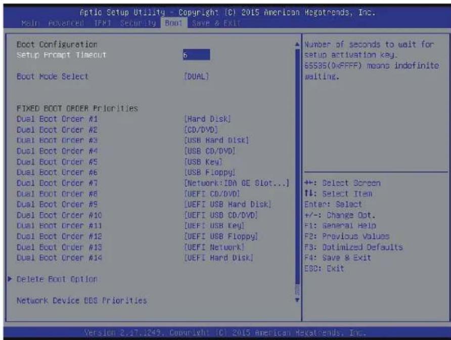
text_image
Aptio Setup Utility - Copyright (C) 2015 American Megatrends, Inc. Main Advanced IPMT Security Boot Save & Exit Boot Configuration Setup Prompt Timeout 6 Boot Mode Select [DUAL] FIXED BOOT ORDER Priorities Dual Boot Order #1 [Hard Disk] Dual Boot Order #2 [CD/DVD] Dual Boot Order #3 [USB Hard Disk] Dual Boot Order #4 [USB CD/DVD] Dual Boot Order #5 [USB Key] Dual Boot Order #6 [USB Floppy] Dual Boot Order #7 [Network: IBA GE Slot...] Dual Boot Order #8 [UEFI CD/DVD] Dual Boot Order #9 [UEFI USB Hard Disk] Dual Boot Order #10 [UEFI USB CD/DVD] Dual Boot Order #11 [UEFI USB Key] Dual Boot Order #12 [UEFI USB Floppy] Dual Boot Order #13 [UEFI Network] Dual Boot Order #14 [UEFI Hard Disk] ► Delete Boot Option Network Device OBS Priorities Number of seconds to wait for setup activation key. 65535(0xFFFF) means indefinite waiting. +: Select Screen ↑: Select Item Enter: Select +/-: Change Opt. F1: General Help F2: Previous Values F3: Optimized Defaults F4: Save & Exit EBO: Exit Version 2.17.1249. Copyright (C) 2015 American Megatrends, Inc.Setup Prompt Timeout
Use this item to indicate the length of time (the number of seconds) for the BIOS to wait before rebooting the system when the setup activation key is pressed. Enter the value of 65535 (0xFFFF) for the BIOS to wait indefinitely. The default setting is 6.
Boot Mode Select
Use this item to select the type of device that the system is going to boot from. The options are LEGACY, UEFI, and DUAL. The default setting is Dual.
Fixed Boot Order Priorities
This option prioritizes the order of bootable devices that the system can boot from. Press
• Legacy/UEFI/Dual/Boot Order #1
• Legacy/UEFI/Dual/Boot Order #2
• Legacy/UEFI/Dual/Boot Order #3
• Legacy/UEFI/Dual/Boot Order #4
• Legacy/UEFI/Dual/Boot Order #5
• Legacy/UEFI/Dual/Boot Order #6
• Legacy/UEFI/Dual/Boot Order #7
• Legacy/UEFI/Dual/Boot Order #8
• Legacy/UEFI/Dual/Boot Order #9
• Legacy/UEFI/Dual/Boot Order #10
• Legacy/UEFI/Dual/Boot Order #11
• Legacy/UEFI/Dual/Boot Order #12
• Legacy/UEFI/Dual/Boot Order #13
• Legacy/UEFI/Dual/Boot Order #14
• Legacy/UEFI/Dual/Boot Order #15
▶ Delete Boot Option
Use this feature to remove a pre-defined boot device from which the system will boot during startup.
The settings are [any pre-defined boot device].
▶Network Drive BBS Priorities
This feature allows the user to specify which Network devices are boot devices.
• Legacy Boot option #1
• Legacy Boot option #2
▶UEFI Application Boot Priorities
This feature allows the user to specify which UEFI devices are boot devices.
• UEFI Boot order #1
4.7 Save & Exit
Select the Exit tab from the BIOS setup utility screen to enter the Exit BIOS Setup screen.
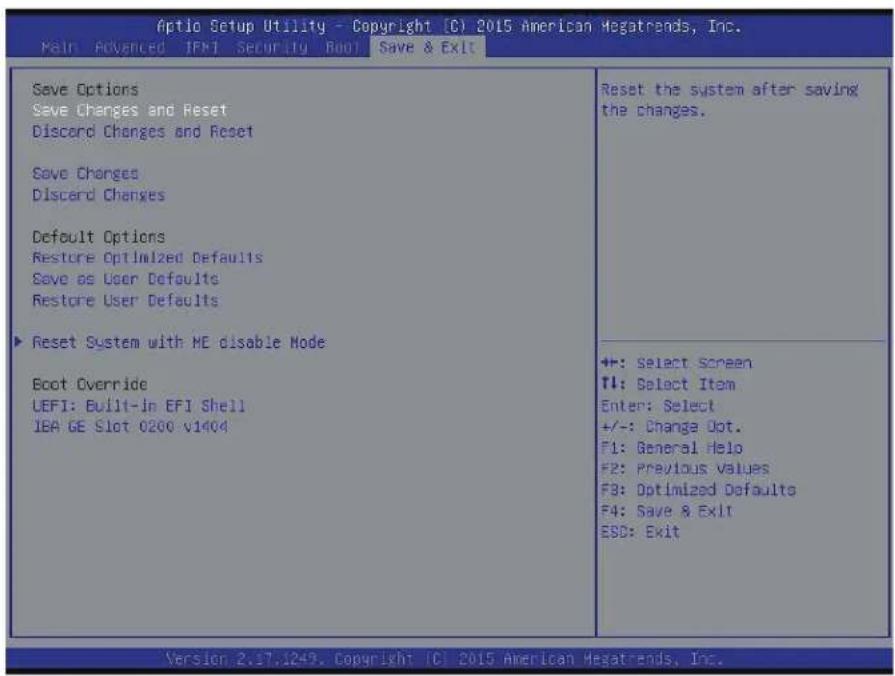
text_image
Optio Setup Utility - Copyright (C) 2015 American Hegatrends, Inc. Main Advanced IFM Security Boot Save & Exit Save Options Save Changes and Reset Discard Changes and Reset Save Changes Discard Changes Default Options Restore Optimized Defaults Save as User Defaults Restore User Defaults Reset System with HE disable Mode Boot Override LEFI: Built-in EFI Shell IBA GE Slot 0200 v1404 Reset the system after saving the changes. +:- Select Screen TI: Select Item Enter: Select +/-: Change Dot. F1: General Help F2: Previous Values F3: Optimized Defaults F4: Save & Exit ESD: Exit Version 2.17.1249. Copyright (C) 2015 American Hegatrends, Inc.Save Options
Save Changes and Reset
When you have completed the system configuration changes, select this option to leave the BIOS setup utility and reboot the computer for the new system configuration parameters to take effect. Select Save Changes and Reset from the Exit menu and press
Discard Changes and Reset
Select this option to quit the BIOS Setup without making any permanent changes to the system configuration, and reboot the computer. Select Discard Changes and Reset from the Exit menu and press
Save Changes
When you have completed the system configuration changes, select this option to save all changes made. This will not reset (reboot) the system.
Discard Changes
Select this option and press
Restore Optimized Defaults
To set this feature, select Restore Defaults from the Exit menu and press
Save As User Defaults
To set this feature, select Save as User Defaults from the Exit menu and press
To set this feature, select Restore User Defaults from the Exit menu and press
Reset System with ME disable Mode
Use this feature to update the Mangement Engine firmware.
Boot Override
This feature allows the user to override the Boot Option Priorities sequence in the Boot menu, and immediately boot the system with another device specified by the user. This is a one-time override.
UEFI: Built-in EFI Shell
IBA GE Slot 0200 v1404
Appendix A
BIOS Codes
A.1 BIOS Error POST (Beep) Codes
During the POST (Power-On Self-Test) routines, which are performed each time the system is powered on, errors may occur.
Non-fatal errors are those which, in most cases, allow the system to continue the boot-up process. The error messages normally appear on the screen.
Fatal errors are those which will not allow the system to continue the boot-up procedure. If a fatal error occurs, you should consult with your system manufacturer for possible repairs.
These fatal errors are usually communicated through a series of audible beeps. The numbers on the fatal error list (on the following page) correspond to the number of beeps for the corresponding error. All errors listed, with the exception of Beep Code 8, are fatal errors.
| BIOS Beep (POST) Codes | ||
| Beep Code Error | Message Description | |
| 1 beep Refresh Circuits have been reset (Ready to power up) | ||
| 5 short, 1 long Memory error No memory detected in system | ||
| 5 long, 2 short Display memory read/write error Video adapter missing or with faulty memory | ||
A.2 Additional BIOS POST Codes
The AMI BIOS supplies additional checkpoint codes, which are documented online at http://www.supermicro.com/support/manuals/ ("AMI BIOS POST Codes User's Guide").
When BIOS performs the Power On Self Test, it writes checkpoint codes to I/O port 0080h. If the computer cannot complete the boot process, a diagnostic card can be attached to the computer to read I/O port 0080h (Supermicro p/n AOC-LPC80-20).
For information on AMI updates, please refer to http://www.ami.com/products/.
Appendix B
Software Installation
B.1 Installing Software Programs
The Supermicro FTP site contains drivers and utilities for your system at ftp://ftp.supermicro.com. Some of these must be installed, such as the chipset driver.
After accessing the FTP site, go into the CDR_Images directory and locate the ISO file for your motherboard. Download this file to create a CD/DVD of the drivers and utilities it contains. (You may also use a utility to extract the ISO file if preferred.)
After creating a CD/DVD with the ISO files, insert the disk into the CD/DVD drive on your system and the display shown in Figure B-1 should appear.
Another option is to go to the Supermicro website at http://www.supermicro.com/products/. Find the product page for your motherboard here, where you may download individual drivers and utilities to your hard drive or a USB flash drive and install from there.

Note: To install the Windows OS, please refer to the instructions posted on our website at http://www.supermicro.com/support/manuals/.

text_image
SUPERMICRO X11SBA-LN4F Motherboard Drivers & Tools (Win7) Intel Chipset INF files Microsoft .Net Framework 4.5.2 (Optional) Intel Graphics Media Accelerator Driver Intel USB 3.0 Drivers Intel Management Engine Intel PRO Network Connections Drivers SUPERMICRO SuperDoctor 5 Build driver diskettes and manuals Browse CD Auto Start Up Next Time For more information, please visit SUPERMICRO's web site.Figure B-1. Driver/Tool Installation Display Screen
Click the icons showing a hand writing on the paper to view the readme files for each item. Click a computer icon to the right of an item to install an item (from top to the bottom) one at a time. After installing each item, you must reboot the system before proceeding with the next item on the list. The bottom icon with a CD on it allows you to view the entire contents of the CD.
When making a storage driver diskette by booting into a driver CD, please set the SATA Configuration to "Compatible Mode" and configure SATA as IDE in the BIOS Setup. After making the driver diskette, be sure to change the SATA settings back to your original settings.
B.2 SuperDoctor® 5
The Supermicro SuperDoctor 5 is a hardware monitoring program that functions in a command-line or web-based interface in Windows and Linux operating systems. The program monitors system health information such as CPU temperature, system voltages, system power consumption, fan speed, and provides alerts via email or Simple Network Management Protocol (SNMP).
SuperDoctor 5 comes in local and remote management versions and can be used with Nagios to maximize your system monitoring needs. With SuperDoctor 5 Management Server (SSM Server), you can remotely control power on/off and reset chassis intrusion for multiple systems with SuperDoctor 5 or IPMI. SD5 Management Server monitors HTTP, FTP, and SMTP services to optimize the efficiency of your operation.

Note: The default Username and Password for SuperDoctor 5 is admin / admin.
Figure B-2. SuperDoctor 5 Interface Display Screen (Health Information)
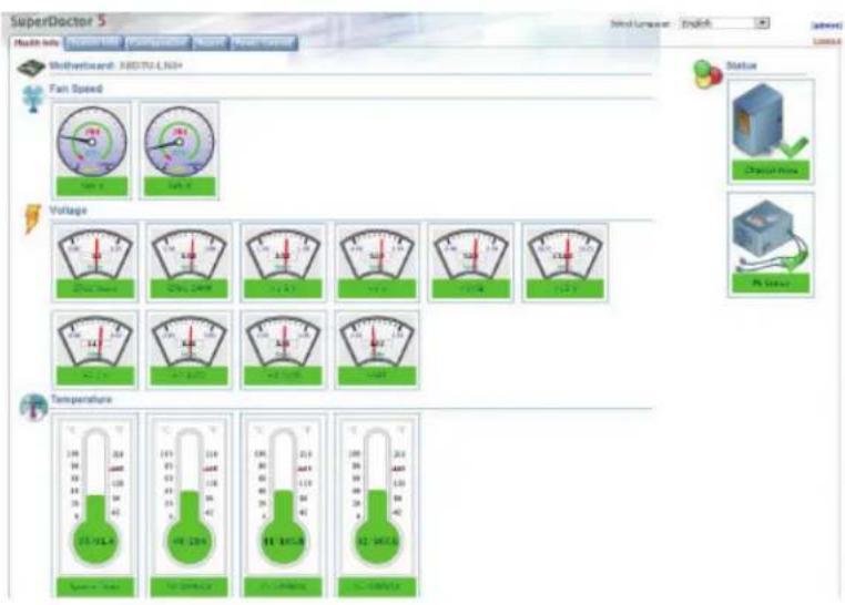
text_image
SuperDoctor 5 Machin Info Wind Unwashed EnSelect Status Chemical Power PV Power Fan Speed Voltage Temperature 100 V 200 V 300 V 400 V 500 V 600 V 700 V 800 V 900 V 1000 V 1100 V 1200 V 1300 V 1400 V 1500 V 1600 V 1700 V 1800 V 1900 V 2000 V 2100 V 2200 V 2300 V 2400 V 2500 V 2600 V 2700 V 2800 V 2900 V 3000 V 3100 V 3200 V 3300 V 3400 V 3500 V 3600 V 3700 V 3800 V 3900 V 4000 V 4100 V 4200 V 4300 V 4400 V 4500 V 4600 V 4700 V 4800 V 4900 V 5000 V 5100 V 5200 V 5300 V 5400 V 5500 V 5600 V 5700 V 5800 V 5900 V 6000 V 6100 V 6200 V 6300 V 6400 V 6500 V 6600 V 6700 V 6800 V 6900 V 7000 V 7100 V 7200 V 7300 V 7400 V 7500 V 7600 V 7700 V 7800 V 7900 V 8000 V 8100 V 8200 V 8300 V 8400 V 8500 V 8600 V 8700 V 8800 V 8900 V 9000 V 9100 V 9200 V 9300 V 9400 V 9500 V 9600 V 9700 V 9800 V 9900 V 1000V
Note: The SuperDoctor 5 program and user's manual can be downloaded from the Supermicro website at http://www.supermicro.com/products/nfo/sms_sd5.cfm.
Appendix C
Standardized Warning Statements
The following statements are industry standard warnings, provided to warn the user of situations which have the potential for bodily injury. Should you have questions or experience difficulty, contact Supermicro's Technical Support department for assistance. Only certified technicians should attempt to install or configure components.
Read this section in its entirety before installing or configuring components.
These warnings may also be found on our website at http://www.supermicro.com/about/policies/safety_information.cfm.
Battery Handling

Warning! There is the danger of explosion if the battery is replaced incorrectly. Replace the battery only with the same or equivalent type recommended by the manufacturer. Dispose of used batteries according to the manufacturer's instructions
電池の取り扱い
Warning! Ultimate disposal of this product should be handled according to all national laws and regulations.
製品の廃棄
Warning: Do not upgrade the BIOS unless your system has a BIOS-related issue. Flashing the wrong BIOS can cause irreparable damage to the system. In no event shall Supermicro be liable for direct, indirect, special, incidental, or consequential damages arising from a BIOS update. If you need to update the BIOS, do not shut down or reset the system while the BIOS is updating. Doing so may cause a boot failure.
D.1 Overview
The Unified Extensible Firmware Interface (UEFI) provides a software-based interface between the operating system and the platform firmware in the pre-boot environment. The UEFI specification supports an architecture-independent mechanism for add-on card initialization to allow the UEFI OS loader, which is stored in the add-on card, to boot the system. The UEFI offers clean, hands-off control to a computer system at bootup.
D.2 Recovering the UEFI BIOS Image
A UEFI BIOS flash chip consists of a recovery BIOS block and a main BIOS block (a main BIOS image). The boot block contains critical BIOS codes, including memory detection and recovery codes for the user to flash a new BIOS image if the original main BIOS image is corrupted. When the system power is on, the boot block codes execute first. Once it is completed, the main BIOS code will continue with system initialization and bootup.

Note: Follow the BIOS recovery instructions below for BIOS recovery when the main BIOS boot crashes. However, if the BIOS boot block crashes, you will need to follow the procedures below for BIOS recovery.
D.3 Recovering the BIOS Block with a USB Device
This feature allows the user to recover a BIOS image using a USB-attached device without the need for additional utilities. A USB flash device such as a USB flash drive or a USB CD/DVD device can be used for this purpose. A USB hard disk drive cannot be used for BIOS recovery at this time.
The file system supported by UEFI is FAT (including FAT12, FAT16, and FAT32) installed on a bootable or non-bootable USB-attached device. Note that the BIOS might need several
minutes to locate the SUPER.ROM file if the media size becomes too large because it contains too many folders and files.
To perform UEFI BIOS recovery using a USB-attached device, follow the instructions below.
- Using a different system, copy the "Super.ROM" binary image file into the disc Root "\" Directory of a USB device or a writeable CD/DVD.

Note: If you cannot locate the "Super.ROM" file in your driver disk, visit our website at www.supermicro.com to download the BIOS image into a USB flash device and rename it "Super.ROM".
- Insert the USB device that contains the new BIOS image ("Super.ROM") into your USB drive and power on the system.
- While powering on the system, please keep pressing
and simultaneously on your keyboard until the following screen (or a screen similar to the one below) displays.
Warning: Please stop pressing the
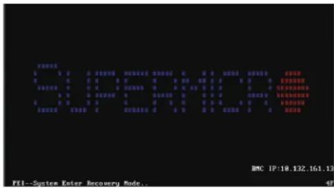
text_image
PETER 1 2 3 4 5 6 7 8 9 10 11 12 13 14 15 16 17 18 19 20 21 22 23 24 25 26 27 28 29 30 31 32 33 34 35 36 37 38 39 40 41 42 43 44 45 46 47 48 49 50 51 52 53 54 55 56 57 58 59 60 61 62 63 64 65 66 67 68 69 70 71 72 73 74 75 76 77 78 79 80 PETER 1 2 3 4 5 6 7 8 9 10 11 12 13 14 15 16 17 18 19 20 PETER 1 2 3 4 5 6 7 PETER 1 2 3 PETER 1 PETER 1 PETER 1 PETER 1 PETER 1 PETER 1 PETER 1 PETER 1 PETER 1 PETER 1 PETER 1 PETER 1 PETER 1 PETER 1 PETER 1 PETER 1 PETER 1 PETER 1 PETER 1 PETER 1 PETER 2 PETER 2 PETER 2 PETER 2 PETER 2 PETER 2 PETER 2 PETER 2 PETER 2 PETER 2 PETER 2 PETER 2 PETER 2 PETER 2 PETER 2 PETER 2 PETER 2 PETER 2 PETER 2 PETER 2 PETER 3 PETER 3 PETER 3 PETER 3 PETER 3 PETER 3 PETER 3 PETER 3 PETER 3 PETER 3 PETER 3 PETER 3 PETER 3 PETER 3 PETER 3 PETER 3 PETER 3 PETER 3 PETER 3 PETER 3 PETER 4 PETER 4 PETER 4 PETER 4 PETER 4 PETER 4 PETER 4 PETER 4 PETER 4 PETER 4 PETER 4 PETER 4 PETER 4 PETER 4 PETER 4 PETER 4 PETER 4 PETER
Note: On the other hand, if the following screen displays, please load the "Super. ROM" file to the root folder and connect this folder to the system. (You can do so by inserting a USB device that contains the new "Super.ROM" image to your machine for BIOS recovery.)
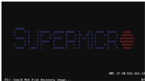
text_image
平台数据 D 0 0 0 对齐器控制 同步设置配置 自动调节器 0 0 0 0 0 0 0 0 0 0 0 0 0 0 0 0 0 0 D 0 0 0 0 0 0 0 0 0 0 0 0 0 0 0 0 0 0 0 0 0 系统设置 0 0 0 0 0 0 0 0 0 0 0 0 0 0 0 0 0 0 0 系统配置 0 0 0 0 0 0 0 0 0 0 0 0 0 0 0 0 0 系统配置配置 0 0 0 0 0 0 0 0 0 0 0 0 0 0 0 0 系统配置配置配置 0 0 0 0 0 0 0 0 0 0 0 0 0 0 0 系统配置配置配置配置配置配置配置配置配置配置配置配置配置配置配置配置配置配置配置配置配置配置配置配置配置配置配置配置配置配置配置配置配置配置配置配置配置配置配置配置配置配置配置配置配置配置配置配置配置配置配置配置配置配置配置配置配置配置配置配置配置配置配置配置配置配置配置配置配置配置配置配置配置配置配置配置配置配置配置配置配置配置配置配置配置配置配置配置配置配置配置配置配置配置配置配置配置配置配置配置配 BMC IF: 19.132.161.13 PEI--Could Not Find Recovery Image... 87- After locating the new BIOS binary image, the system will enter the BIOS Recovery menu as shown below.
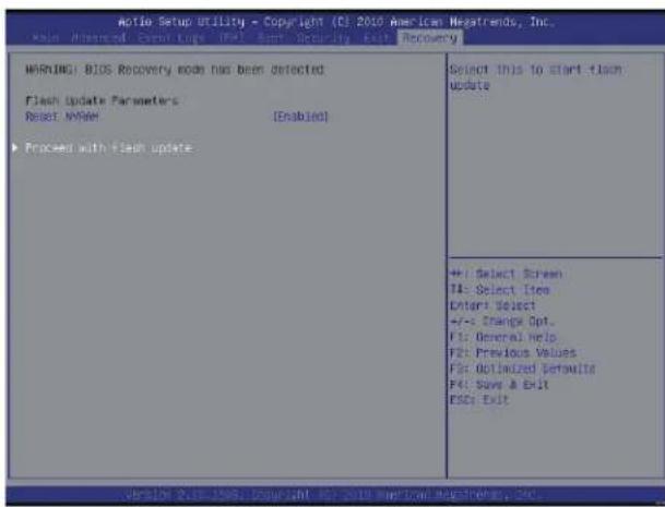
text_image
MORNING BIOS Recovery mode has been detected Flash Update Parameters Reset: NAME [Enabled] ► Proceed with flash update Select this to start flash update +: Select Screen T4: Select Item Enter Select +/- Change Opt. F1: General Help F2: Previous Values For Optimized Defaults F4: Save & Exit ESC: Exit Version 2.18.1996 Copyright 03/2018 American Statistics, Inc.
Note: At this point, you may decide if you want to start the BIOS recovery. If you decide to proceed with BIOS recovery, follow the procedures below.
- When the screen as shown above displays, use the arrow keys to select the item "Proceed with flash update" and press the
key. You will see the BIOS recovery progress as shown in the screen below.

Note: Do not interrupt the BIOS flashing process until it has completed.
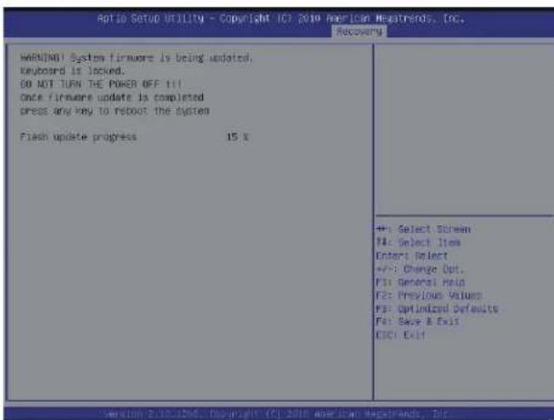
text_image
Aptio Setup UTILITY - Copyright (C) 2010 American Netstrends, Inc. Recovery WARNING! System firmware is being updated, Keyboard is locked. GO NOT TURN THE POWER OFF till Once firmware update is completed press any key to reboot the system Flash update progress 15% +: Select Screen T4: Select Item Enter: Select +/-: Change Opt. F3: General Help F2: Previous Values F3: Optimized Defaults F4: Save & Exit CDO: Exit Version: E:\10.1206\ Copyright (C) 2010 American Netstrends, Inc.- After the BIOS recovery process has completed, press any key to reboot the system.
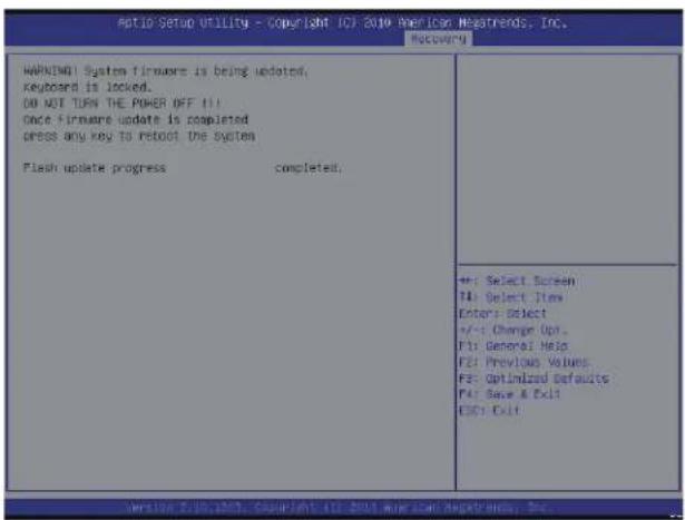
text_image
RATIO Setup Utility - Copyright ICF 2016 American Mapsrends, Inc. Recovery WARNING! System firmware is being updated, keyboard is locked. DO NOT TURN THE POWER OFF IT... Once firmware update is completed press any key to reboot the system Flash update progress completed: +: Select Screen TA: Select Item Enter: Select +/-: Change Up F1: General Help F2: Previous Values F3: Optimized Defaults F4: Save & Exit ESC: Exit Version: 7.10.2003; Group:John's 2016 American Mapsrends, Inc.-
Using a different system, extract the BIOS package into a bootable USB flash drive.
-
When a DOS prompt appears, enter FLASH.BAT BIOSname.### at the prompt.

Note: Do not interrupt this process until the BIOS flashing is complete.
-
After seeing the message that BIOS update has completed, unplug the AC power cable from the power supply, clear CMOS, then plug the AC power cable in the power supply again to power on the system.
-
Press
continuously to enter the BIOS Setup utility. -
Press
to load the default settings. -
After loading the default settings, press
to save the settings and exit the BIOS Setup utility.