
FS-AC-5005-B - Electrical cabinet APC - Free user manual and instructions
Find the device manual for free FS-AC-5005-B APC in PDF.


| Type of Product | Blanking Panel for air containment system |
| Model | FS-AC-5005-B |
| Brand | APC by Schneider Electric |
| Dimensions (Width x Height x Depth) | 300 mm (12 in.) x adjustable from 42 to 52 U (1867 – 2335 mm) x approx. 1.5 mm thickness |
| Material | Steel with polyester powder coating |
| Color | Black |
| Weight | Approximately 2.5 kg (5.5 lbs) |
| Compatible Rack Height | 42 to 52 U (adjustable) |
| Rack Standards | EIA-310-D |
| Primary Function | Seal unused rack space to prevent air bypass in hot/cold aisle containment |
| Accessories Included | Angle corner brackets (2), ground wire (2), serrated lock washer (M6), pan head T30 screws (M6x16), insert nuts (M6), low head Nylok T30 screws (M8x12) |
| Installation Location | Between vertical posts, attached to length beams and stop rail |
| Adjustability | Sliding mechanism to fit rack heights from 42 to 52 U |
| Safety Features | Ground wire for grounding; anti-static properties |
| Cleaning Instructions | Wipe with a damp cloth using mild detergent; do not use abrasive cleaners |
| Maintenance | Periodic inspection for damage; replace if deformed or broken |
| Repairability | Not user-repairable; replace entire panel if defective |
| Warranty | One-year factory warranty against defects |
| Compliance | RoHS, REACH |
| Package Contents | 1 blanking panel, mounting hardware |
Frequently Asked Questions - FS-AC-5005-B APC
User questions about FS-AC-5005-B APC
0 question about this device. Answer the ones you know or ask your own.
Ask a new question about this device
Download the instructions for your Electrical cabinet in PDF format for free! Find your manual FS-AC-5005-B - APC and take your electronic device back in hand. On this page are published all the documents necessary for the use of your device. FS-AC-5005-B by APC.
USER MANUAL FS-AC-5005-B APC
Publication Date: October 2018

natural_image
Technical line drawing of an electrical cabinet or enclosure structure with multiple doors and structural beams (no text or symbols)Schneider Electric Legal Disclaimer
The information presented in this manual is not warranted by the Schneider Electric to be authoritative, error free, or complete. This publication is not meant to be a substitute for a detailed operational and site specific development plan. Therefore, Schneider Electric assumes no liability for damages, violations of codes, improper installation, system failures, or any other problems that could arise based on the use of this Publication.
The information contained in this Publication is provided as is and has been prepared solely for the purpose of evaluating data center design and construction. This Publication has been compiled in good faith by Schneider Electric. However, no representation is made or warranty given, either express or implied, as to the completeness or accuracy of the information this Publication contains.
IN NO EVENT SHALL SCHNEIDER ELECTRIC, OR ANY PARENT, AFFILIATE OR SUBSIDIARY COMPANY OF SCHNEIDER ELECTRIC OR THEIR RESPECTIVE OFFICERS, DIRECTORS, OR EMPLOYEES BE LIABLE FOR ANY DIRECT, INDIRECT, CONSEQUENTIAL, PUNITIVE, SPECIAL, OR INCIDENTAL DAMAGES (INCLUDING, WITHOUT LIMITATION, DAMAGES FOR LOSS OF BUSINESS, CONTRACT, REVENUE, DATA, INFORMATION, OR BUSINESS INTERRUPTION) RESULTING FROM, ARISING OUT, OR IN CONNECTION WITH THE USE OF, OR INABILITY TO USE THIS PUBLICATION OR THE CONTENT, EVEN IF SCHNEIDER ELECTRIC HAS BEEN EXPRESSLY ADVISED OF THE POSSIBILITY OF SUCH DAMAGES. SCHNEIDER ELECTRIC RESERVES THE RIGHT TO MAKE CHANGES OR UPDATES WITH RESPECT TO OR IN THE CONTENT OF THE PUBLICATION OR THE FORMAT THEREOF AT ANY TIME WITHOUT NOTICE.
Copyright, intellectual, and all other proprietary rights in the content (including but not limited to software, audio, video, text, and photographs) rests with Schneider Electric or its licensors. All rights in the content not expressly granted herein are reserved. No rights of any kind are licensed or assigned or shall otherwise pass to persons accessing this information.
This Publication shall not be for resale in whole or in part.
Table of Contents
General Information ....1
Features....1
Loading Capacities....2
HyperPod SKU List....3
Documentation Information 4
Unpacking and Inspecting 4
Safety....5
Important Safety Information ....5
Safety Recommendations for the HyperPod System ....6
Planning the Installation....7
General Guidelines for Installation 7
Enclosures and Power Equipment 7
Layout and Positioning....8
List of Recommended Tools....9
Systems Overview ......10
Basic configuration 10
Component Identification ....11
HyperPod System Components 11
Raised-floor Stand 12
FS-FM-6001-B - Raised-floor Stand, 406 mm (16 in.)
FS-FM-6002-B - Raised-floor Stand, 610 mm (24 in.)
FS-FM-6003-B - Raised-floor Stand, 762 mm (30 in.)
FS-FM-6004-B - Raised-floor Stand, 914 mm (36 in.) .....12
Post Alignment Tool 13
FS-FM-1011-U - 1.2 m (4 ft) Aisle Post Alignment Tool
FS-FM-1012-U - 1.9 m (6 ft) Aisle Post Alignment Tool .....13
Vertical Posts 14
FS-FM-1001-B - Vertical Post Assembly, 2750 mm (9 ft), Short
FS-FM-1002-B - Vertical Post Assembly, 3200 mm (10.5 ft), Tall .....14
Width Beams 15
FS-FM-2002-B - 1.9 m (6 ft) Aisle Width Beam Assembly
FS-FM-2003-B - 1.2 m (4 ft) Aisle Width Beam Assembly .....15
Length Beam 16
FS-FM-3001-B - Length Beam Assembly ..... 16
End Cap Panels 17
FS-FM-4003-B - 1.9 m (6 ft) Aisle End Cap Assembly, Short
FS-FM-4004-B - 1.9 m (6 ft) Aisle End Cap Assembly, Tall .....17
FS-FM-4005-B - 1.2 m (4 ft) Aisle End Cap Assembly, Short
FS-FM-4006-B - 1.2 m (4 ft) Aisle End Cap Assembly, Tall .....17
Door Frame Assembly 18
FS-DR-2002-B - 1.9 m (6 ft) Aisle Standard Door Frame
FS-DR-2003-B - 1.2 m (4 ft) Aisle Standard Door Frame .....18
Door and Rail Assembly 19
FS-DR-1001-B - 1.2 m (4 ft) Aisle Door and rail assembly FS-DR-1003-B - 1.9 m (6 ft) Aisle Door and rail assembly .... 19
Windows, Rails, and Side Brushes 20
FS-WI-1001-U - Window Panel 305 mm (2 ft) FS-WI-1002-B - Window Rail Assembly FS-WI-1003-B - Window Frame Brush Strips FS-WI-1004-U - Window Brush Strip Pass-through .... 20
Row Length Brush Strip 21
FS-AC-2001-U 21
Roof Panel Assembly 22
FS-RF-2004-U - 1.9 m (6 ft) Aisle Simple Roof Panel, 300 mm (12 in.) FS-RF-2005-U - 1.9 m (6 ft) Aisle Simple Roof Panel, 600 mm (23.6 in.) FS-RF-2006-U - 1.9 m (6 ft) Aisle Simple Roof Panel for Sprinkler Option, 600 mm (23.6 in.) 22 FS-RF-2007-U - 1.2 m (4 ft) Aisle Simple Roof Panel, 300 mm (12 in.) FS-RF-2008-U - 1.2 m (4 ft) Aisle Simple Roof Panel, 600 mm (23.6 in.) FS-RF-2009-U - 1.2 m (4 ft) Aisle Simple Roof Panel for Sprinkler Option, 600 mm (23.6 in.) 22
Solid Roof Filler Panel Set 23
FS-RF-1002-B - 1.9 m (6 ft) Aisle FS-RF-1003-B - 1.2 m (4 ft) Aisle .... 23
Stop Rail 24
FS-FM-5001-B - Stop Rail Assembly 24
Air Seals 25
FS-AC-1001-U - Air Sealing Kit FS-AC-1002-U - H Seal for Blanking Panels FS-AC-1003-U - C Seal for Blanking Panels and Vertical Posts 25
Blanking Panels 26
FS-AC-5005-B - 300 mm (12 in.) FS-AC-5006-B - 600 mm (23.6 in.) FS-AC-5007-B - 750 mm (29.5 in.) FS-AC-5008-B - 800 mm (31.5 in) 26
Installation Procedure Overview.... 27
Safety 27
Customizing the Installation 28
Installation locations for width beams and length beams 28
Basic Frame Assembly 29
Floor stands 29
Frame end configuration 34
Length beam assembly 35
Temporary frame support 37
Secure the frame to the floor 38
End caps 39
Door frames 40
Doors 42
Frame seals 49
Window assemblies 50
Row length brush 52
Roof panels 54
Stop rails 55
Blanking panels 57
C seals and H seals 59
Accessory Kits.... 61
End Row Transition Cabinets....61
FS-AC-7001-B - Distribution Cabinet, MH50 61
FS-AC-7002-B - Distribution Cabinet, Split 61
FS-AC-7003-B - Distribution Cabinet, Solid 61
Drop Roof....62
FS-RF-3002-U - Drop Roof Mounting Rail, 300 mm (12 in.)
FS-RF-3004-U - Drop Roof Mounting Rail, 600 mm (23.6 in.)
FS-RF-3006-U - Drop Roof Mounting Rail, 750 mm (29.5 in.) ..... 62
FS-RF-3007-U - Drop Roof panel, 300 mm (12 in.)
FS-RF-3008-U - Drop Roof panel, 600 mm (23.6 in.)
FS-RF-3009-U - Drop Roof panel, 750 mm (29.5 in.) 62
Shrink Roof....63
FS-RF-6001-U - 1.2 m (4 ft) Aisle Shrink Roof panel, 610 mm (24 in.)
FS-RF-6002-U - 1.2 m (4 ft) Aisle Shrink Roof panel, 310 mm (12.2 in.) ..... 63
FS-RF-6003-U - 1.9 m (6 ft) Aisle Shrink Roof panel, 610 mm (24 in.)
FS-RF-6004-U - 1.9 m (6 ft) Aisle Shrink Roof panel, 310 mm (12.2 in.) . . . . . . 63
Ceiling Panel Lock Systems....64
ACDC2016 - Ceiling Panel Lock System, 100-120 V (with power supply) ..... 64
ACDC2017 - Ceiling Panel Lock System, 200-240 V (with power supply) ..... 64
ACDC2015 - Ceiling Panel Lock System, (without power supply) 65
Rack Height Adapters 66
FS-AC-8001-U - Rack Height Adapter, 300 mm (12 in.)
FS-AC-8002-U - Rack Height Adapter, 600 mm (23.6 in.)
FS-AC-8003-U - Rack Height Adapter, 750 mm (29.5 in.)
FS-AC-8004-U - Rack Height Adapter, 800 mm (31.5 in.) 66
Cantilever Support Arms 67
FS-AC-3001-B - Large Cantilever Support Arms 67
FS-AC-3003-B - Mini Cantilever Arms 67
FS-AC-3002-B - Overhead Support Frame, 2.4–3.6 m (8–12 ft) ..... 68
Power Raceway....69
FS-AC-4001-B - Power Raceway End Module
FS-AC-4002-B - Power Raceway Main Module
FS-AC-4003-B - 300 mm (12 in.) Side Cover Pack
FS-AC-4004-B - 50/150 mm (2/6 in.) Side Cover Pack
FS-AC-4005-B - Power Raceway Extension Module 69
Lighting kits 70
ACDC2018 - Lighting Kit with Power Supply
ACDC2019 - Lighting Kit without Power Supply 70
FS-AC-6001-B - Lighting Bracket Kit 71
Crossover Tray....72
FS-AC-4007-B - 1.9 m (6 ft) Aisle Crossover Tray
FS-AC-4008-B - 1.2 m (4 ft) Aisle Crossover Tray ..... 72
Single Swing Door Assembly....73
FS-DR-1002-U - Swing Door 73
Installation of Optional Accessories 74
Transition Cabinets 75
Crossover Tray....79
Mini Cantilever Arms 80
Power Raceway 83
Post Cantilevers and Suspension System 88
Possible configurations for Post Cantilevers: 88
Standard configuration installation 89
Shrink Roof 92
Drop Roof 93
Install the mounting rails 93
Install the ceiling panels 94
Solid Roof Filler Panel for Drop Roof 95
Ceiling Panel Lock System 96
System diagram 97
Power supply component identification 98
Install the power supply 98
Install electromagnetic locks 99
Install the temperature switches 100
Install electrical boxes and route cables 101
Install the alarm beacon 102
Install the smoke detector 103
Maintenance steps for dropout ceiling system: 105
Troubleshooting diagram 106
Lighting Kit 107
Lighting control unit installation options 108
Lighting brackets 109
Lighting System Setup and Operation 111
Rack Height Adapter.... 114
Single Swing Door 116
One-Year Factory Warranty 119
Terms of Warranty 119
Non-transferable Warranty 119
Exclusions.... 119
Warranty Claims 120
General Information
Features
The HyperPod™ is a freestanding air containment system. Fully configured racks can be deployed or removed from the HyperPod as necessary. Schneider Electric racks or other EIA-310-D racks can be used in a HyperPod system.
The HyperPod system includes the following features:
- Telescoping length beams can extend the HyperPod length (A) from 2.4 m (2421 mm or about 8 ft) to 3.6 m (3621 mm or about 12 ft).
Additional length beams can be added to the vertical posts to extend the Pod up to another 3.6 m (12 ft). - Two aisle widths (B) are available: 1.2 m (1268 mm or about 4 ft) and 1.9 m (1877 mm or about 6 ft).
- Two heights (C) are available for vertical posts: Tall = 3.2 m (3200 mm or about 10.5 ft) and Short = 2.8 m (2750 mm or about 9 ft).
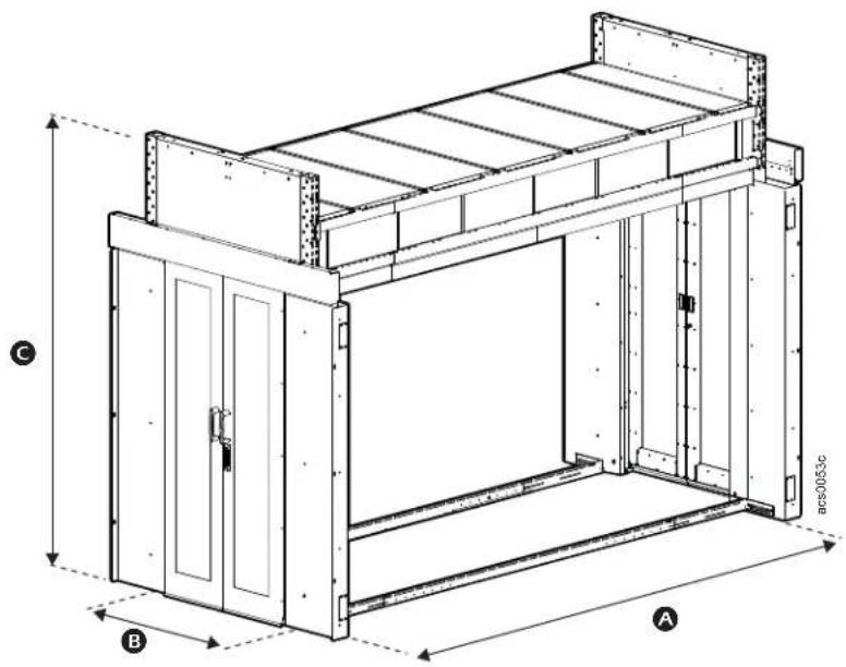
Possible configurations:
Dimension 1.2 m aisle, tall 1.2 m aisle, short 1.9 m aisle, tall 1.9 m aisle, short
| A | 2421–3621 mm(8–12 ft) | 2421–3621 mm(8–12 ft) | 2421–3621 mm(8–12 ft) | 2421–3621 mm(8–12 ft) |
| B | 1268 mm (4 ft) | 1268 mm (4 ft) | 1877 mm (6 ft) | 1877 mm (6 ft) |
| C | 3200 mm (10.5 ft) | 2750 mm (9 ft) | 3200 mm (10.5 ft) | 2750 mm (9 ft) |
The basic HyperPod can be customized with the following accessories:
- Power Raceways
- Rack space blanking panels
- Cantilever support arms
• Overhead support frame
• Bi-parting and single swing doors
• Height adapters accommodate multiple rack heights
• LED aisle lighting with motion sensor
• End-of-row power transition cabinets - Drop roof
- Shrink panels activated by heat
• End-of-aisle crossover tray
The HyperPod system provides a barrier between the hot exhaust and cold intake air streams in the IT environment. The separation of the hot and cold air streams in the environment increases the efficiency and effectiveness of the cooling system that supports the critical IT equipment. The separation will also allow for an elevated supply-air temperature to be provided by the cooling system since the mixing of hot and cold air is eliminated. The HyperPod system can be built using new or existing Schneider Electric equipment. This containment system is compatible with row, room, or external cooling solutions and available for cold or hot aisle containment.
This manual is a guide for the basic installation procedures for creating a HyperPod system
Loading Capacities
• End Frames (each): 249 kg (550 lbs.)
• Upper aisle length beams (each): 113 kg (250 lbs.)
• Large Cantilever (one side, system quantity is 2): 680 kg (1500 lbs.)
For balance, the load should be applied to both sides of the HyperPod. If Large Cantilevers are installed on only one side, the max loading rating is 441 kg (974 lbs.)
- Mini Cantilever (one side, system quantity is 6): 90 kg (200 lbs.)
• Total System: 1814 kg (4000 lbs.)
HyperPod SKU List
This manual includes inventory and installation information for the following assemblies:
FS-AC-1001-U Air sealing kit FS-FM-4005-B 1.2 m aisle end panel, short
FS-AC-1002-U H-seal FS-FM-4006-B 1.2 m aisle end panel, tall
FS-AC-1003-U C-seal FS-FM-5001-B Stop rail
FS-AC-2001-U Row length brush strip FS-FM-6001-B Raised-floor stand, 406 mm
FS-AC-3001-B Large cantilever arms FS-FM-6002-B Raised-floor stand, 610 mm
FS-AC-3002-B Overhead support frame FS-FM-6003-B Raised-floor stand, 762 mm
FS-AC-3003-B Mini cantilever arms FS-FM-6004-B Raised-floor stand support, 914 mm
FS-AC-4001-B Power raceway end module FS-FM-1011-U 1.2 m aisle post alignment tool
FS-AC-4002-B Power raceway main module FS-FM-1012-U 1.9 m aisle post alignment tool
FS-AC-4003-B Power raceway 300 mm side cover pack
FS-AC-4004-B Power raceway 50/150 mm side cover pack
FS-RF-1002-B 1.9 m aisle solid roof filler panel set
FS-AC-4005-B Power raceway extension module FS-RF-1003-B 1.2 m aisle solid roof filler panel set
FS-AC-4007-B 1.9 m aisle crossover tray FS-RF-2004-U 1.9 m aisle simple roof panel, 300 mm
FS-AC-4008-B 1.2 m aisle crossover tray FS-RF-2005-U 1.9 m aisle simple roof panel, 600 mm
FS-AC-5005-B Blanking panel, 300 mm
FS-AC-5006-B Blanking panel, 600 mm
FS-AC-5007-B Blanking panel, 750 mm
FS-AC-5008-B Blanking panel, 800 mm
FS-AC-6001-B Lighting bracket kit
FS-AC-7001-B Distribution cabinet, MH50
FS-AC-7002-B Distribution cabinet, Split
FS-AC-7003-B Distribution cabinet, Solid
FS-AC-8001-U Rack height adapter, 300 mm
FS-AC-8002-U Rack height adapter, 600 mm
FS-AC-8003-U Rack height adapter, 750 mm
FS-AC-8004-U Rack height adapter, 800 mm
FS-RF-2006-U 1.9 m aisle simple roof panel for sprinkler
FS-RF-2007-U 1.2 m aisle simple roof panel, 300 mm
FS-RF-2008-U 1.2 m aisle simple roof panel, 600 mm
FS-RF-2009-U 1.2 m aisle simple roof panel for sprinkler
FS-RF-3002-U Drop roof mounting rail, 300 mm
FS-RF-3004-U Drop roof mounting rail, 600 mm
FS-RF-3006-U Drop roof mounting rail, 750 mm
FS-RF-3007-U Drop roof panel, 300 mm
FS-RF-3008-U Drop roof panel, 600 mm
FS-RF-3009-U Drop roof panel, 750 mm
FS-RF-6001-U 1.2 m aisle shrink roof panel, 610 mm
FS-RF-6002-U 1.2 m aisle shrink roof panel, 310 mm
FS-RF-6003-U 1.9 m aisle shrink roof panel, 610 mm
FS-RF-6004-U 1.9 m aisle shrink roof panel, 310 mm
FS-DR-1002-U Swing door
FS-DR-1003-B 1.9 m aisle dual sliding doors
FS-DR-2002-B 1.9 m aisle door frame FS-WI-1002-B
FS-DR-2003-B 1.2 m aisle door frame FS-WI-1003-B
FS-WI-1001-U Window panel, 305 mm
Window rail assembly
Window frame brush strips
FS-WI-1004-U Window Brush strip pass-through
FS-FM-1001-B Vertical post, Short
FS-FM-1002-B Vertical post, Tall
ACDC2015 Ceiling panel lock system (without power supply)
ACDC2016 Ceiling panel lock system 100-120 V
ACDC2017 Ceiling panel lock system 200-240 V
FS-FM-2002-B 1.9 m aisle width beam
FS-FM-2003-B 1.2 m aisle width beam
FS-FM-3001-B Length beam ACDC2018
Lighting kit with power supply
FS-FM-4003-B 1.9 m aisle end cap panel, short
ACDC2019 Lighting kit without power supply
FS-FM-4004-B 1.9 m aisle end panel, tall
Documentation Information
All documentation is also available online at http://www.apc.com.
Check for updates to this manual on www.apc.com. Select Support > Resources & Tools > User Guides. Then select Airflow Management in the Product Name drop-down list, or select the part number for any HyperPod assembly in the Part Number drop-down list.
Unpacking and Inspecting
IMPORTANT: To avoid misplacing parts, do not leave boxes open following inspections. Reseal the boxes until those parts are ready to be installed. Follow the order of procedures in this manual to ensure proper installation.
If damage is noted to the shipping containers, inspect the contents for damage and notify the shipping carrier and Schneider Electric.
After opening a box, check the components in the box against the list of items in "Component Identification" beginning on page 11. If any components are missing, contact http://www.apc.com/support.

The shipping materials are recyclable. Save them for later use or dispose of them appropriately.
Important Safety Information
Read the instructions carefully to become familiar with the equipment before trying to install, operate, service, or maintain it. The following special messages may appear throughout this manual or on the equipment to warn of potential hazards or to call attention to information that clarifies or simplifies a procedure.
The addition of this symbol to a Danger or Warning safety label indicates that an electrical hazard exists which will result in personal injury if the instructions are not followed.

This is the safety alert symbol. It is used to alert you to potential personal injury hazards. Obey all safety messages that follow this symbol to avoid possible injury or death.
DANGER
DANGER indicates an imminently hazardous situation which, if not avoided, will result in death or serious injury.
WARNING
WARNING indicates a potentially hazardous situation which, if not avoided, can result in death or serious injury.
CAUTION
CAUTION indicates a potentially hazardous situation which, if not avoided, can result in minor or moderate injury.
NOTICE
NOTICE addresses practices not related to physical injury including certain environmental hazards, potential damage or loss of data.
Safety Recommendations for the HyperPod System
To reduce the possibility of injury or equipment damage, read and follow the safety recommendations.
Follow all local and agency safety requirements.
WARNING
TOOL USAGE HAZARD
Follow safety standards for all hand tools and power tools used. Read and follow the tool manufacturer's instructions. Follow the tool manufacturer's recommendations and recognized safety requirements for use of Personal Protection Equipment (PPE).
Failure to follow these instructions can result in death, serious injury, or equipment damage.
CAUTION
WORKING HEIGHT HAZARD
The working height for the assembly process can exceed 2.3 m (7.5 ft). The use of stepladders or scaffolding will be required during assembly.
Failure to follow these instructions can result in serious injury or equipment damage.
CAUTION
LIFTING HAZARD
At least two people are required to install this equipment. Some parts may be heavy and/or excessive in size. For items weighing more than 12kg (25 lbs), use more than one person.
Failure to follow these instructions can result in serious injury or equipment damage.
CAUTION
NO STEP HAZARD
Ceiling panels are not designed to support weight. Never lean or walk on the ceiling panels. DO NOT use ceiling panels to support power or data cables.
Failure to follow these instructions can result serious injury or equipment damage.
NOTE: The data center floor must be within 0.075^ from level for an 8-rack configuration, or within 0.035^ from level for a 16-rack configuration.
General Guidelines for Installation
Maintain a minimum clear space of 0.9 m (36 in.) required from the top of the frame to overhead obstructions.
Maintain a minimum working space around the frame perimeter. Be sure to factor in the depth of the racks you will install. Use your deepest rack when calculating the outside aisle space around the HyperPod (finished size perimeter + 1.2 m [4 ft] around all sides).
Install this equipment directly on a concrete floor, or use floor stands to support a raised-floor system.
WARNING
HEAVY EQUIPMENT HAZARD
Raised-floor stands are required if the combined weight of the HyperPod system and all installed equipment will exceed the structural capacity of your raised-floor system.
Failure to follow these instructions can result in death, serious injury, or equipment damage.

See the documentation provided with each Schneider Electric product for additional instructions on installation. All documentation is also available on www.apc.com.
Enclosures and Power Equipment

Refer to the instructions that come with your enclosures and power distribution equipment for information on how to install them.
Layout and Positioning
Referencing the ISX Designer report, determine the position of the main components, the total length of the planned Aisle Containment System and the aisle width. Use a chalk line or similar tool to lay out the perimeter making sure all corners are square.
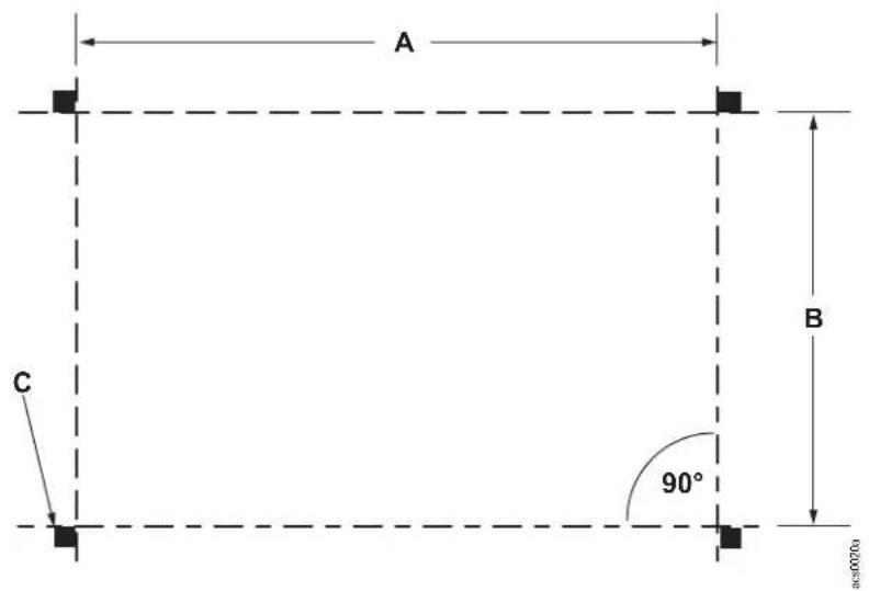
Dimension A will vary depending on the type and number of racks installed (2421–3621 mm or 8–12 ft). Dimension B is equal to 1268 mm for a 1.2 m (4 ft) aisle or 1877 mm for a 1.9 m (6 ft) aisle. Item C notes the locations of the post feet provided in SKUs FS-FM-1001-B and FS-FM-1002-B.
Observe a 1.2 m (4 ft) perimeter around the outside so that racks can be moved in and out of the pod
NOTE: A template is provided to assist proper drilling of holes into the floor to secure the vertical post feet.
List of Recommended Tools
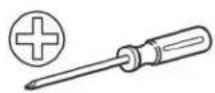
Screwdriver
P1 and
P2 Phillips
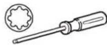
Screwdriver
T-30, T-20, T-15
TORX®
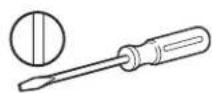
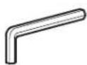
Standard screwdriver Hex wrench
3 mm, 4 mm, 6 mm
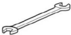
Wrench
6, 7, 8, 10, 11, 12
13, 14, 18, 19, and
20 mm
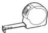
Tape measure Chalk line Hex socket
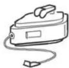
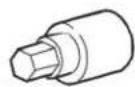
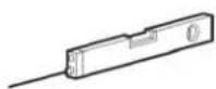
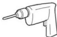
Level Drill with standard,
Phillips, TORX bits
6.3 mm, 7 mm,
10 mm, 15 mm
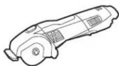
Rotary tool (e.g. Dremel®)

T-square
120 cm (48 in.)
minimum
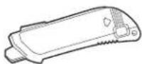
Self-retracting knife Miter saw Metal files

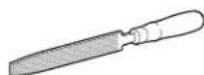
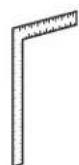
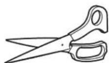
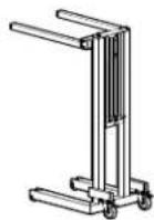
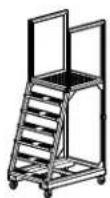
bits
T-square Scissors Lift Ladder Drill and concrete
Plumb bob
Systems Overview
Basic configuration
natural_image
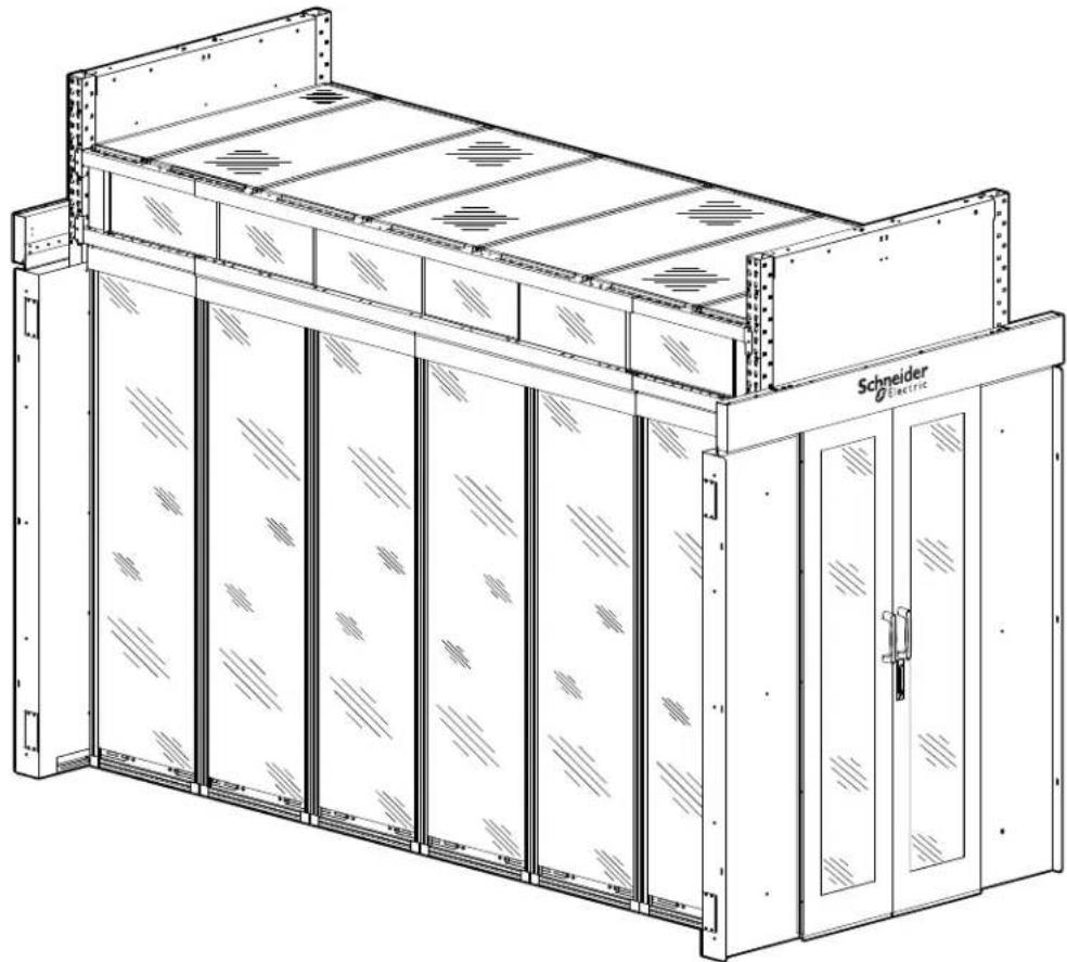
Technical line drawing of a Schneider Electric industrial control unit with multiple storage compartments and mounting brackets (no text or symbols on the diagram itself)The HyperPod ^TM is a freestanding air containment system.
This manual is a guide for the basic installation procedures for assembling a HyperPod system.
Multiple configurations are possible depending on your requirements. Please contact Schneider Electric at www.apc.com or your Schneider-Electric representative to explore your options.
Component Identification
HyperPod System Components
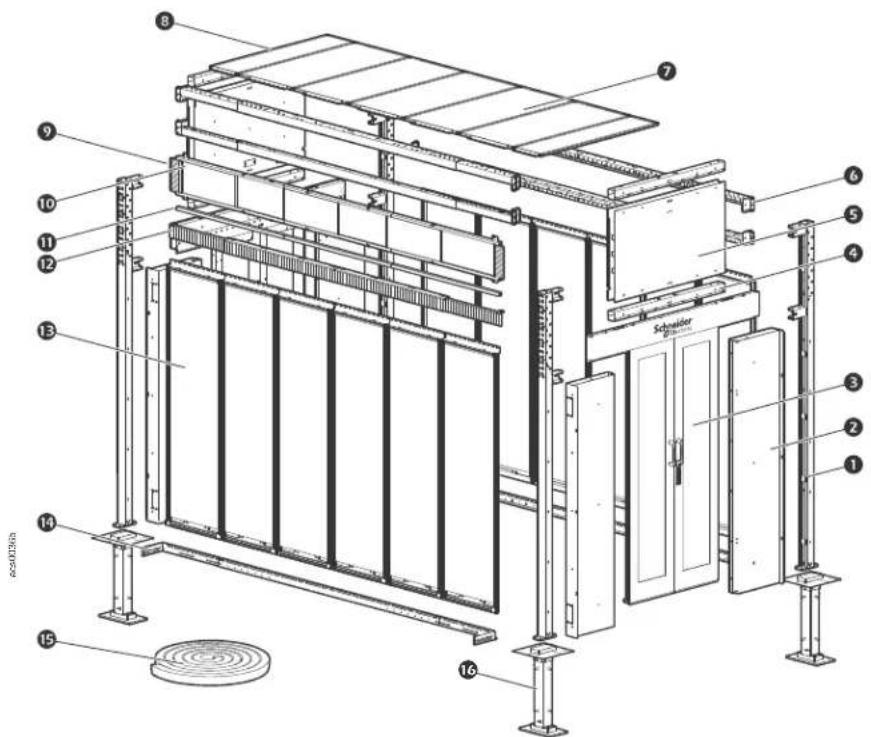
Short version shown
Item Description Quantity Required
1 Vertical post 4
② Door frame assembly 4
3 Dual sliding doors 2
4 Width beam, 1.2 m (4 ft) 4
5 Aisle end cap assembly 1.2 m (4 ft) 2
6 Telescoping length beam assembly, 2.4–3.6 m (8–12 ft) 4
7 Simple roof panel, 600 mm (23.6 in.), 1.2 m (4 ft) aisle 5
8 Simple roof panel, 300 mm (12 in.), 1.2 m (4 ft) aisle 2
9 Window frame brush strips 4
10 Window panels, 2 ft (contents, 2 panels) 6
⑪ Window rail assembly 2
12 Row length brush strip assembly 2
⑬ Blanking panel
14 Stop rail assembly, 2.4–3.6 m (8–12 ft) 2
15 Air sealing kit 1
16 Raised-floor stands 4
*Quantity determined by number of spaces not inhabited by racks.
Raised-floor Stand
FS-FM-6001-B - Raised-floor Stand, 406 mm (16 in.)
FS-FM-6002-B - Raised-floor Stand, 610 mm (24 in.)
FS-FM-6003-B - Raised-floor Stand, 762 mm (30 in.)
FS-FM-6004-B - Raised-floor Stand, 914 mm (36 in.)
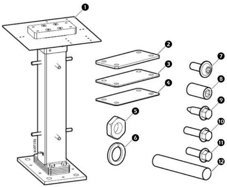
Item Description Quantity
1 Raised-floor stand 406 mm (16 in.), 610 mm (24 in.), 762 mm (30 in.), 914 mm (36 in.)
② Shim, 6 mm 4
③ Shim, 3 mm 2
4 Shim, 1.5 mm 2
5 Nut, M12 8
6 Spring ring 8
7 Button head cap screw, 30 mm, M10 x 1.58
8 Set cap screw, 20 mm, M10 x 1.5 12
9 Self drilling, flanged hex head screw, 22 mm 8
10 Flanged hex head screw, 25 mm, M12 x 1.75 8
11 Flanged hex head screw, 20 mm, M12 x 1.75 8
12 Rod, 100 mm, M12 8
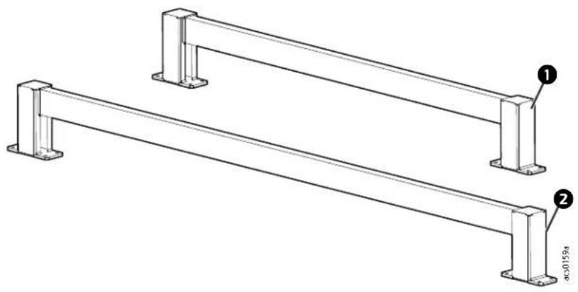
Post Alignment Tool
FS-FM-1011-U - 1.2 m (4 ft) Aisle Post Alignment Tool
FS-FM-1012-U - 1.9 m (6 ft) Aisle Post Alignment Tool
natural_image
Technical line drawing of two metal beams with mounting feet, labeled 1 and 2 (no text or symbols on the beams themselves)Item Description Quantity
| 1 | 1.2 m (4 ft) Aisle Post Alignment ToolFS-FM-1011-U | 1 |
| 2 | 1.9 m (6 ft) Aisle Post Alignment ToolFS-FM-1012-U | 1 |
Vertical Posts
FS-FM-1001-B - Vertical Post Assembly, 2750 mm (9 ft), Short FS-FM-1002-B - Vertical Post Assembly, 3200 mm (10.5 ft), Tall
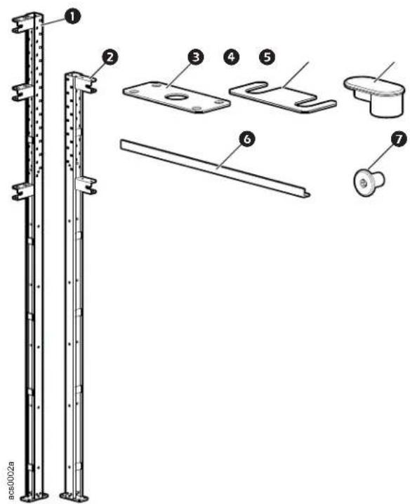
Item Description Quantity
| 1 | Vertical Post FS-FM-1002-B (Tall) 2 | |
| 2 | Vertical Post FS-FM-1001-B (Short) 2 | |
| 3 | Template* 1 | |
| 4 | Shim, 0.5 mm 2 | |
| 5 | Hole plug | |
| FS-FM-1001-B (Short) | 48 | |
| FS-FM-1002-B (Tall) | 88 | |
| 6 | Temporary support 1 | |
| 7 | Screw, M8 x 12, T30 8 |
*Template for drilling holes into floor to secure vertical posts.
NOTE: Fasteners for securing the vertical posts to your floor are not included.
Width Beams
FS-FM-2002-B - 1.9 m (6 ft) Aisle Width Beam Assembly
FS-FM-2003-B - 1.2 m (4 ft) Aisle Width Beam Assembly
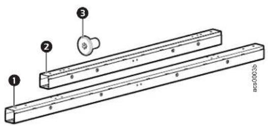
Item Description Quantity
Width Beam, 1.9 m (6 ft) aisle, FS-FM-2002-B 1
2 Width Beam, 1.2 m (4 ft) aisle, 1 FS-FM-2003-B
③ Screw, M8 x 12 T30 8
Length Beam
FS-FM-3001-B - Length Beam Assembly
Aisle length beams are attached to Front/Rear frame assemblies to form the basic frame.
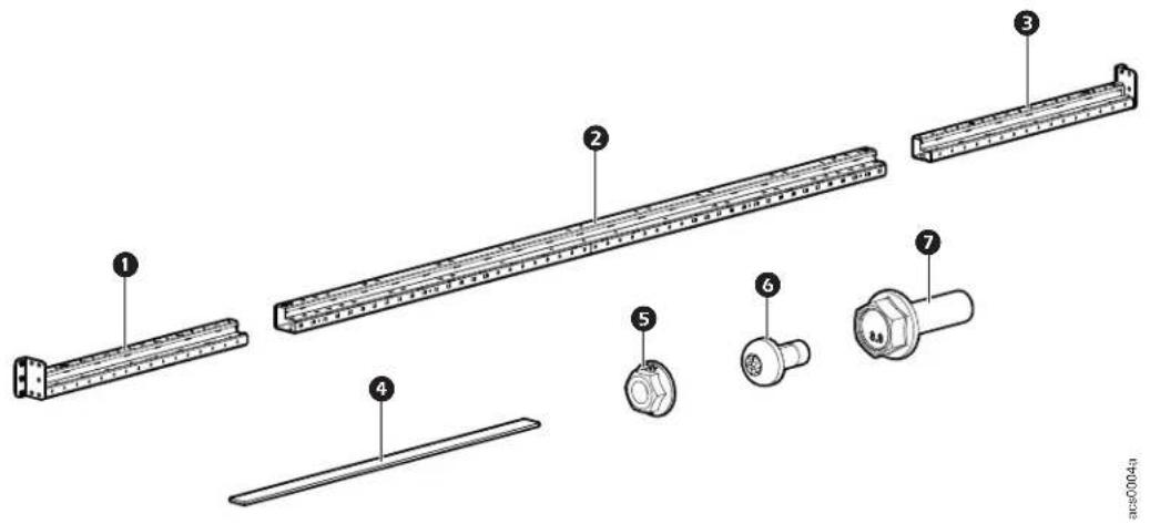
Item Description Quantity
Length beam end section 2
Length beam center section 2
3 Length beam end section 2
4 Self-adhesive foam seal strip 4
5 M8 Hex nut 4
6 Pan head T30 screw, M6 x 12 8
7 Hex head bolt, M8 x 25 4
NOTICE
Aisle length beams are marked to note the 2.4 m (8 ft) and 3.6 m (12 ft) lengths.
End Cap Panels
FS-FM-4003-B - 1.9 m (6 ft) Aisle End Cap Assembly, Short
FS-FM-4004-B - 1.9 m (6 ft) Aisle End Cap Assembly, Tall
FS-FM-4005-B - 1.2 m (4 ft) Aisle End Cap Assembly, Short
FS-FM-4006-B - 1.2 m (4 ft) Aisle End Cap Assembly, Tall
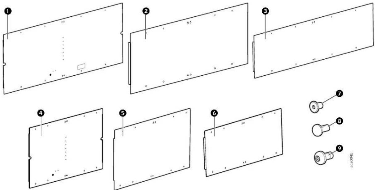
Item Description Quantity
Short: FS-FM-4003-B, FS-FM-4005-B
① Interior panel, 1.9 m (6 ft), FS-FM-4003-B 1
2 Exterior panel, 1.9 m, (6 ft), FS-FM-4003-B 1
4 Interior panel, 1.2 m (4 ft), FS-FM-4005-B 1
5 Exterior panel, 1.2 m (4 ft), FS-FM-4005-B 1
7 Low head Nylok® T30 screw, M8 x 12 16
⑧ Hole plug, 5 mm 1
9 Pan head T30 screw, M6 x 12 8
Tall: FS-FM-4004-B, FS-FM-4006-B
3 End cap panel, 1.9 m (6 ft), FS-FM-4004-B 2
6 End cap panel, 1.2 m (4 ft), FS-FM-4006-B 2
7 Low head Nylok T30 screw, M8 x 12 16
9 Pan head T30 screw, M6 x 12 8
NOTE: For short vertical posts, two short end cap assemblies are required per HyperPod. For tall vertical posts, two tall assemblies and two short assemblies are required per HyperPod. For example, for a tall HyperPod with a 1.9 m (6 ft) aisle, you need two FS-FM-4003 assemblies, and two FS-FM-4004 assemblies.
Door Frame Assembly
FS-DR-2002-B - 1.9 m (6 ft) Aisle Standard Door Frame
FS-DR-2003-B - 1.2 m (4 ft) Aisle Standard Door Frame
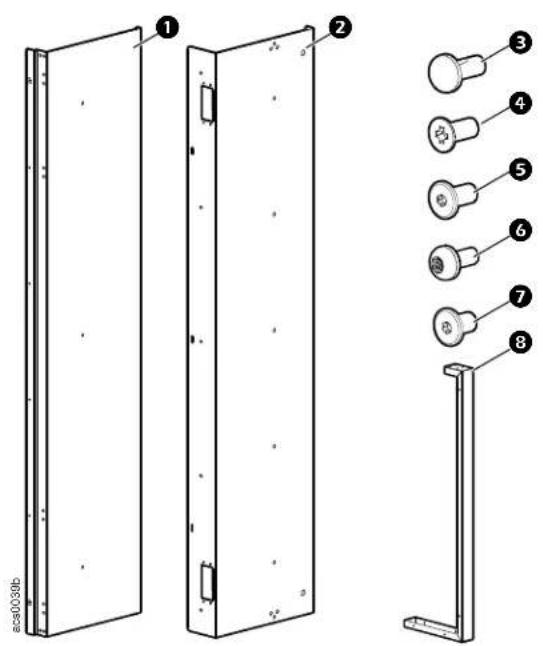
Item Description Quantity
① Door frame front panel 4
② Door frame rear panel cover 4
3 Hole plug, 5 mm diameter
FS-DR-2002-B 25
FS-DR-2003-B 2
4 M5 x 12 Flat under cut (U cut) flat head Phillips screw
FS-DR-2002-B 55
FS-DR-2003-B 8
5 Low head T30 screw, M8 x 12 33
6 Pan head T30 screw, M6 x 12 16
7 Low head screw, M5 x 10, FS-DR-2002-B 36
8 L Bracket, FS-DR-2002-B 4
Door and Rail Assembly
FS-DR-1001-B - 1.2 m (4 ft) Aisle Door and rail assembly
FS-DR-1003-B - 1.9 m (6 ft) Aisle Door and rail assembly
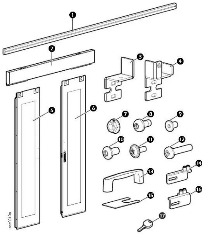
Item Description Quantity
Door side brush, 36 x 4 x 1920 mm 2
2 Door hanging rail assembly 1
3 Bracket, Left door to reel 1
4 Bracket, Right door to dumper 1
5 Left door panel 1
8 Pan head T30 screw, M6 x 12 5
9 Low head T30 screw, M8 x 12 5
10 Button head TORX screw, M4 x 8 10
11 Flanged TORX screw, M3 x 8 10
12 Pan head #2 Phillips screw, M5 x 25 5
13 Outside door handle 2
Windows, Rails, and Side Brushes
FS-WI-1001-U - Window Panel 305 mm (2 ft)
FS-WI-1002-B - Window Rail Assembly
FS-WI-1003-B - Window Frame Brush Strips
FS-WI-1004-U - Window Brush Strip Pass-through
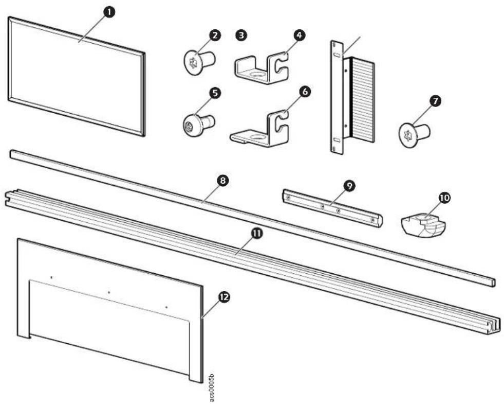
Item Description Quantity
① Ribbed 5 mm Lexan window, FS-WI-1001-U 2
2 Flat head T30 screw, M6 x 12, FS-WI-1002-B 18
3 Short rail bracket, FS-WI-1002-B 17
4 Side brush strip, FS-WI-1003-B 4
5 Pan head T30 screw, M6 x 10, FS-WI-1002-B 26
6 Long rail bracket, FS-WI-1002-B 9
7 Pan head T30 screw, M6 x 12, FS-WI-1003-B 8
8 Window rail block, FS-WI-1002-B 12
9 Connector with four M6 set screws, FS-WI-1002-B 8
10 Steel hammer head nut, M6, FS-WI-1002-B 26
⑪ Window rail, FS-WI-1002-B 12
12 Window Brush Strip Pass-through, FS-WI-1004-U 2
Row Length Brush Strip
FS-AC-2001-U
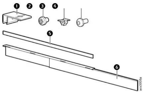
Item Description Quantity
① Clip for brush 8
② Pan head Phillips screw, M3 x 4 8
③ Insert nut, M6 5
4 Pan head T30 screw, M6 x 16 17
5 Self-adhesive foam seal strip 4
6 Brush strip 4
Roof Panel Assembly
FS-RF-2004-U - 1.9 m (6 ft) Aisle Simple Roof Panel, 300 mm (12 in.)
FS-RF-2005-U - 1.9 m (6 ft) Aisle Simple Roof Panel, 600 mm (23.6 in.)
FS-RF-2006-U - 1.9 m (6 ft) Aisle Simple Roof Panel for Sprinkler Option, 600 mm (23.6 in.)
FS-RF-2007-U - 1.2 m (4 ft) Aisle Simple Roof Panel, 300 mm (12 in.)
FS-RF-2008-U - 1.2 m (4 ft) Aisle Simple Roof Panel, 600 mm (23.6 in.)
FS-RF-2009-U - 1.2 m (4 ft) Aisle Simple Roof Panel for Sprinkler Option, 600 mm (23.6 in.)
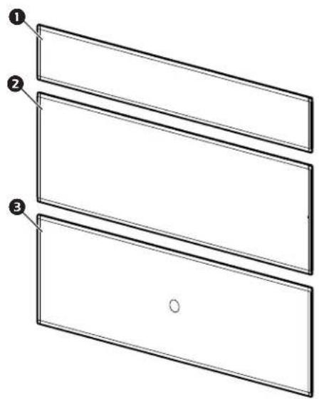
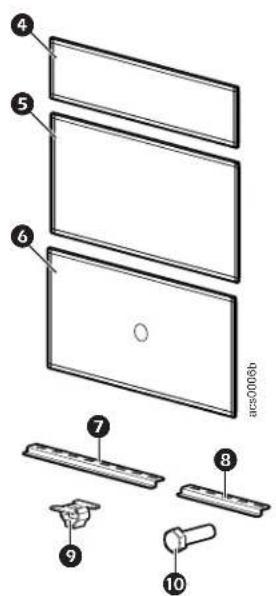
Item Description Quantity
1 Roof panel 300 mm (12 in.), FS-RF-2004-U 1
2 Roof panel 600 mm (23.6 in.), FS-RF-2005-U 1
3 Roof panel for sprinkler option, FS-RF-2006-U 1
4 Roof panel 300 mm (12 in.), FS-RF-2007-U 1
5 Roof panel 600 mm (23.6 in.), FS-RF-2008-U 1
6 Roof panel for sprinkler option, FS-RF-2009-U 1
7 Long roof panel bracket FS-RF-2005-U, FS-RF-2006-U, FS-RF-2008-U, FS-RF-2009-U
8 Short roof panel bracket, FS-RF-2004-U, FS-RF-2007-U 2
9 Insert nut, M6, all assemblies 4
10 Hex head screw, M6-1 x 16, all assemblies 4
2
Solid Roof Filler Panel Set
FS-RF-1002-B - 1.9 m (6 ft) Aisle
FS-RF-1003-B - 1.2 m (4 ft) Aisle
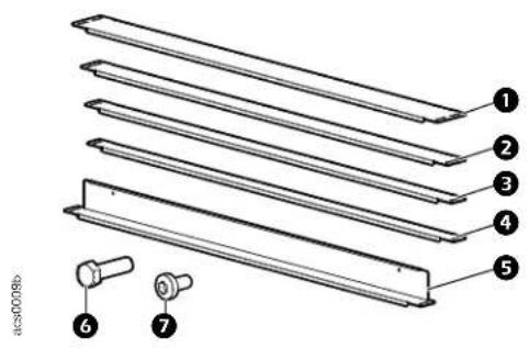
Item Description Quantity
Solid roof panel, 100 mm 1
2 Solid roof panel, 60 mm 1
3 Solid roof panel, 50 mm 2
4 Solid roof panel, 40 mm 1
5 Solid roof panel (drop) 50 mm, FS-RF-1003-B* 1
6 Hex head screw, M6-1 x 16 mm
FS-RF-1002-B 10
FS-RF-1003-B 12
7 Pan head TORX screw, M4 x 8, FS-RF-1003-B*
*Used for the drop roof option.
Stop Rail
FS-FM-5001-B - Stop Rail Assembly
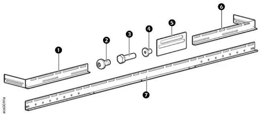
Item Description Quantity
1 Left end rail 2
2 Pan head T30 screw, M6 x 10 8
③ Hex head screw, M8 x 20 9
4 Low head T30 screw, M8 x 12 9
⑤ Mylar electrical isolation plate 4
6 Right end rail 2
7 Stop rail middle plate 2
Air Seals
FS-AC-1001-U - Air Sealing Kit
FS-AC-1002-U - H Seal for Blanking Panels
FS-AC-1003-U - C Seal for Blanking Panels and Vertical Posts
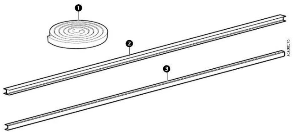
Item Description Quantity
1 Self adhesive foam seal, 10 mm x 10 mm 12 M
② H seal, FS-AC-1002-U 1
③ C seal, FS-AC-1003-U 1
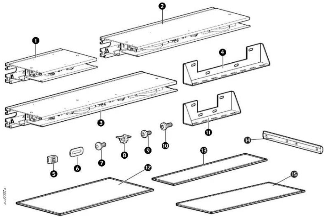
Blanking Panels
FS-AC-5005-B - 300 mm (12 in.)
FS-AC-5006-B - 600 mm (23.6 in.)
FS-AC-5007-B - 750 mm (29.5 in.)
FS-AC-5008-B - 800 mm (31.5 in.)
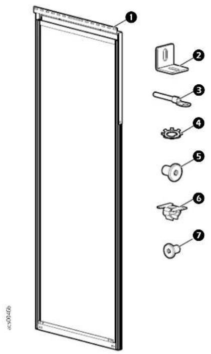
Item Description Quantity
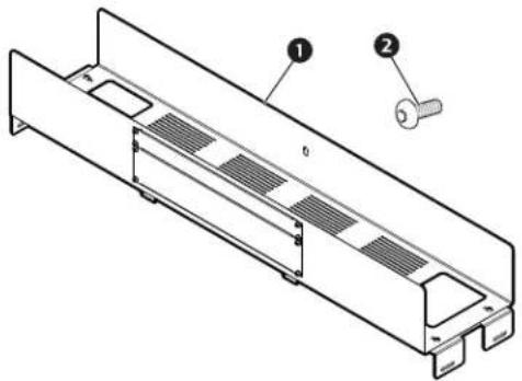
1 Blanking panel, 42–52 U
(300 mm, 600 mm, 750 mm, 800 mm)
② Angle corner bracket 2
3 Ground wire 4 in. 2
4 Serrated lock washer, M6 2
5 Pan head T30 screw, M6 x 16 3
6 Insert nut, M6 3
7 Low head Nylok T30 screw, M8 x12 3
Installation Procedure Overview
Safety
Read and follow these safety instructions.
| ⚠ WARNING |
| TOOL USAGE HAZARDFollow safety standards for all hand tools and power tools used. Read and follow the tool manufacturer's instructions. Follow the tool manufacturer's recommendations and recognized safety requirements for use of Personal Protection Equipment (PPE).Failure to follow these instructions can result in death, serious injury, or equipment damage. |
| WARNING |
| HEAVY EQUIPMENT HAZARDRaised-floor stands are required if the combined weight of the HyperPod system and all installed equipment will exceed the structural capacity of your raised-floor system.Failure to follow these instructions can result in death, serious injury, or equipment damage. |
| ⚠️ CAUTION |
| WORKING HEIGHT HAZARDThe working height for the assembly process can exceed 2.3 m (7.5 ft). The use of stepladders or scaffolding will be required during assembly.Failure to follow these instructions can result in serious injury or equipment damage. |
| ⚠ CAUTION |
| LIFTING HAZARDAt least two (2) people are required to install this enclosure. Some parts may be heavy and/or excessive in size. For items weighing more than 12 kg (25 lbs), use more than one person.Failure to follow these instructions can result in serious injury or equipment damage. |
| ⚠️ CAUTION |
| NO STEP HAZARDCeiling panels are not designed to support weight. Never lean or walk on the ceiling panels.DO NOT use ceiling panels to support power or data cables.Failure to follow these instructions can result serious injury or equipment damage. |
Customizing the Installation
Installation locations for width beams and length beams
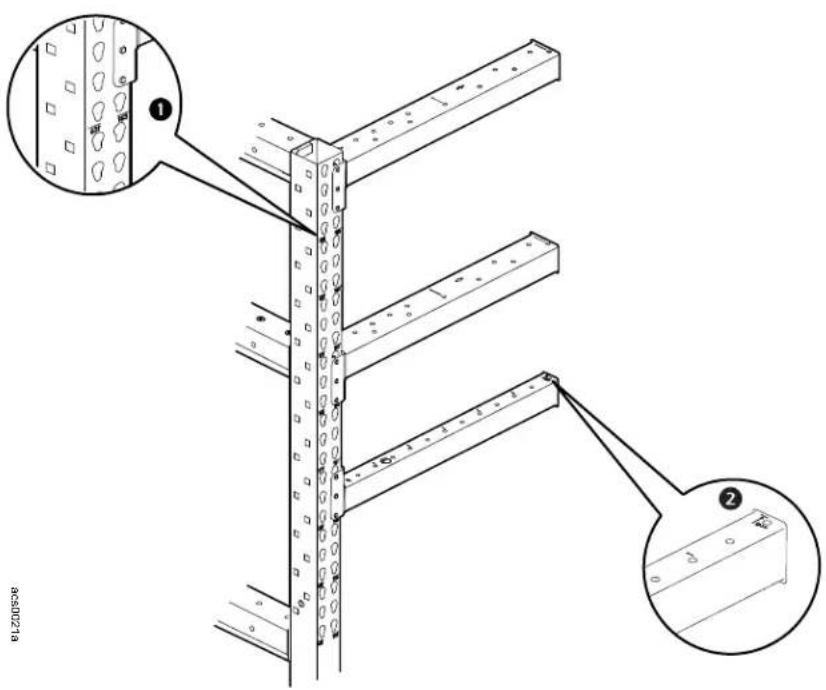
NOTICE
- Vertical posts are marked with height notation (1). (The tall vertical post is shown in the illustration above.)
- If 48 U or shorter racks are deployed in the tall HyperPod, 6 length beams are required. If racks are taller than 48 U, use 4 length beams.
• Tall HyperPod frames support racks up to 52 U. - Telescoping rails are marked to note 2.4 ~m (8 ft) and 3.6 ~m (12 ft) lengths (2).
Select the height of the length beams based on the height of the racks to be installed or your roof and ducting needs. Determine these requirements prior to assembly of the frame. Once the location of the lower length beam has been established, the (next) upper beam must be placed at the correct height to allow for installation of the windows.
Basic Frame Assembly
Floor stands
Use the floor stands for raised-floor configurations. For the regular floor option, see "Secure the frame to the floor" on page 38.
Configure the first two (2) floor stands.
- Remove tiles (and pedestals, if necessary) from the raised floor in the proposed locations for two (2) floor stands. Leave any stringers intact. If you remove any pedestals, save the fasteners.
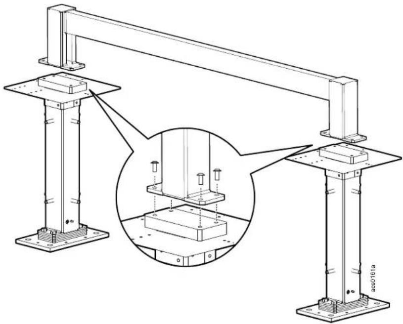
- Attach two (2) floor stands to the alignment tool with the provided button head cap screws, and place the floor stands in the desired locations.
natural_image
Technical line drawing of a structural support frame assembly with two vertical supports and a horizontal beam, showing internal detail (no text or symbols)- If the floor is not even or horizontally level, use the provided M10 x 1.5 set cap screws and a 4 mm Hex wrench to ensure that the floor stand is horizontally level.
natural_image
Technical diagram showing a structural assembly with mounting base and circular inset view of a metal plate (no text or symbols)-
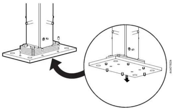
Secure the floor stands to the floor according to local and national standards. (The holes in the base of the floor stand will accommodate 20 mm fasteners). Remove the alignment tool.
-
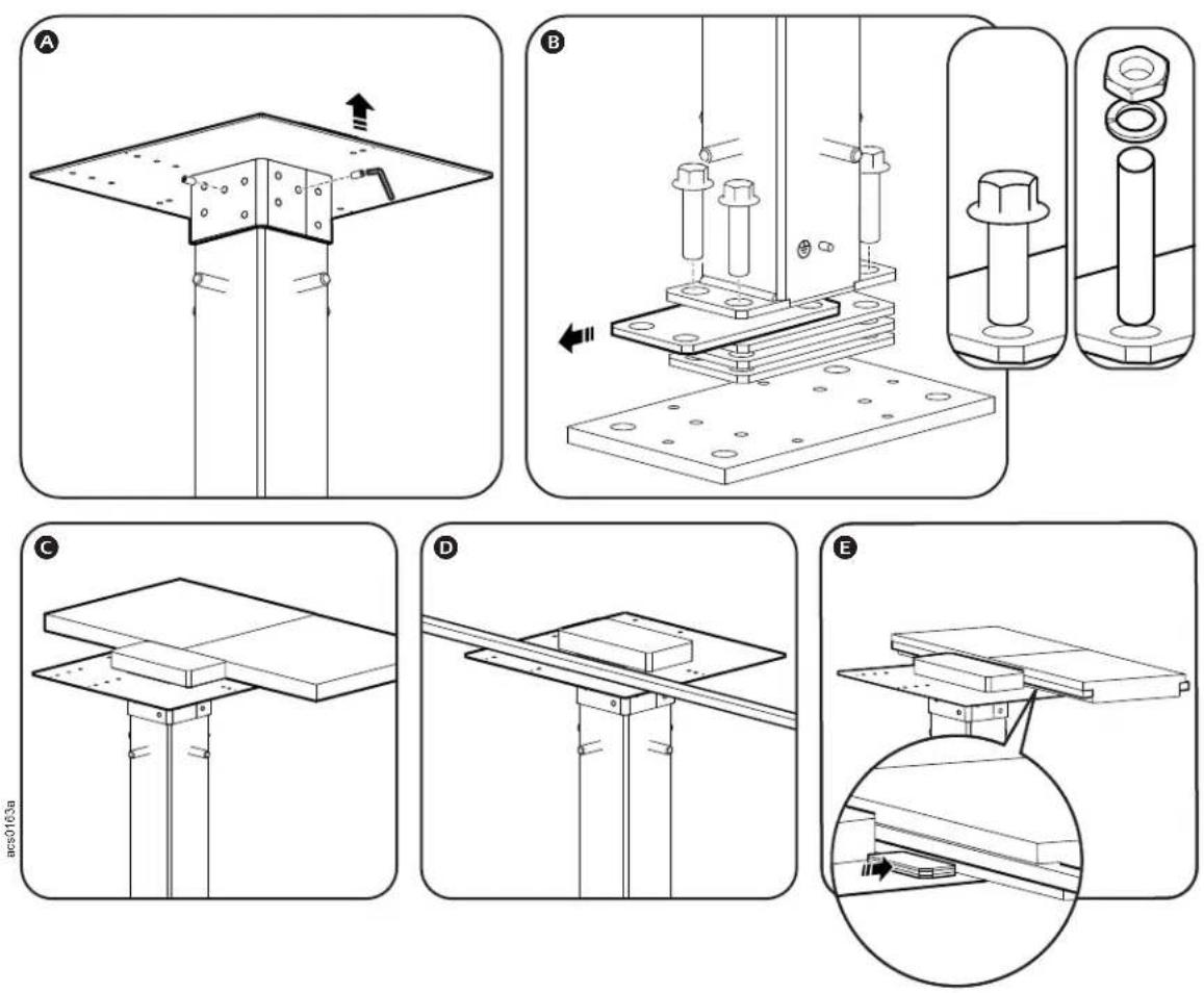
Adjust the height of the control plates: use a 4 mm Hex wrench to loosen and tighten the set screws (A).
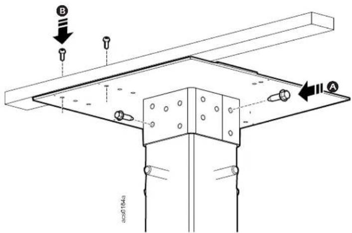
NOTE: If the height of the floor stand is too tall for your raised-floor system, remove the bottom shims (B). If the combined depth of the shims and vertical post foot is 25 mm (1 in.) or less, use the 20 or 25 mm M12 x 1.75 25 flanged hex head screws to secure the shims. If the combined depth of the shims and vertical post foot is 40 mm (1.6 in.) or more, use the 100 mm M12 rods, nuts, and spring rings to secure the shims.
- If no stringers are present, adjust the height of the control plates so that they rest against the bottom of the raised-floor tiles (C).
- If stringers are present, adjust the height of the control plates so that they rest against the bottom of the stringers (D).
- If stringers are present, but the floor tiles are thicker than the stringers, adjust the height of the control plates so that they rest against the bottom of the tiles. Place shims (not provided) between the stringers and the control plate so that the control plate supports the stringers (E).
-
Insert one 22 mm, self-drilling, flanged hex head screw on each side of the control plate collar (A).
-
Attach the control plate to each stringer with one or two (2) screws. The tapped holes in the control plate will accommodate M8 screws (B).
NOTE: Tighten the screws so that the heads are countersunk into the stringer, but the stringer is not deformed.
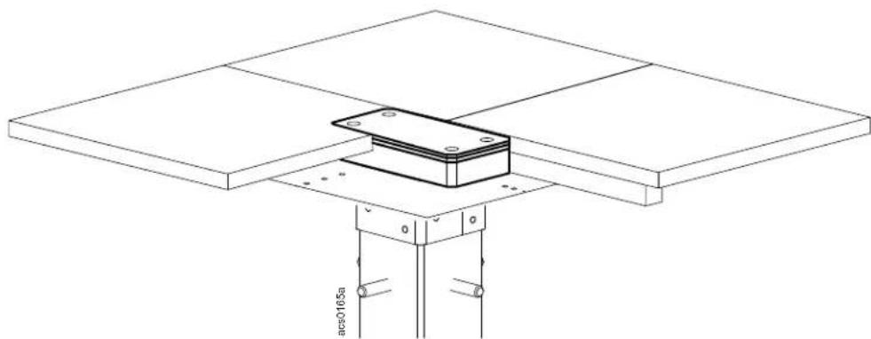
- Measure and cut the appropriate floor tiles so that the riser block can pass through them. Replace the tile(s). If the riser block is lower than the tiles, place the provided shims on top of the riser block until the top shim is flush with the surface of the tiles.
natural_image
Technical line drawing of a mechanical assembly with a central component and two vertical supports (no text or symbols)Configure subsequent floor stands.
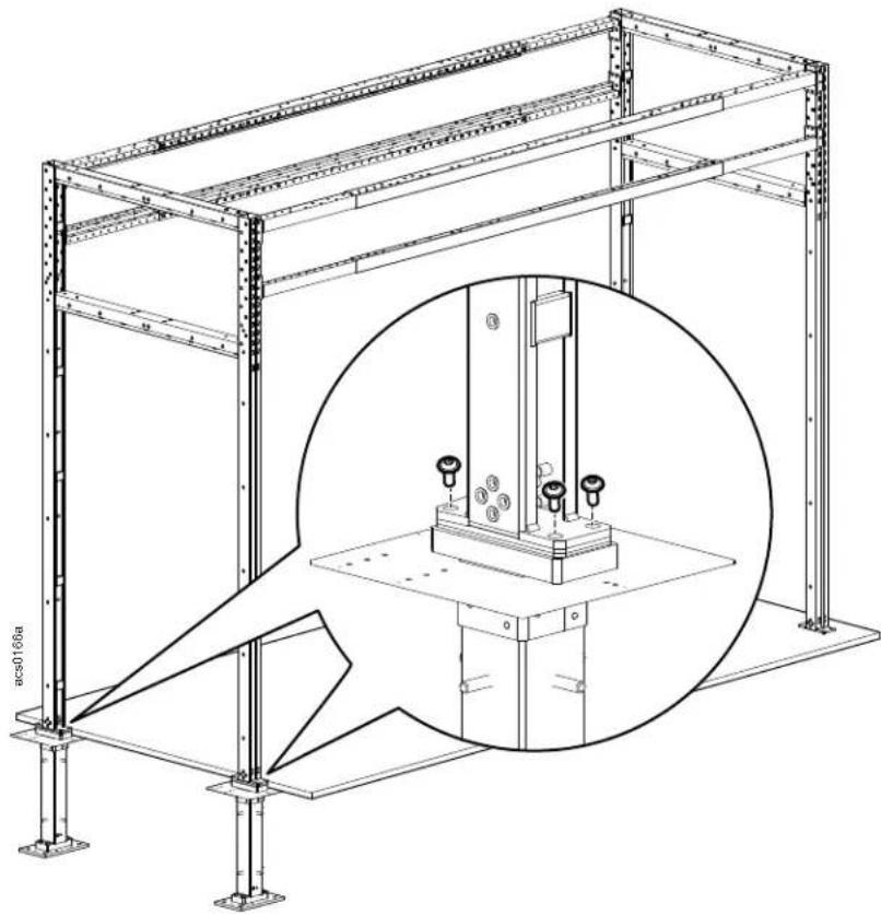
- Follow the instructions to configure the basic HyperPod frame (see "Frame end configuration" on page 34 and "Length beam assembly" on page 35). Construct the frame as close to the first set of floor stands as possible.
- Secure two (2) vertical posts to the installed floor stands with 30 mm, M10 x 1.5 button head-cap screws.
natural_image
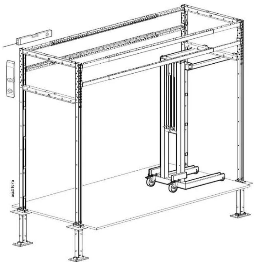
Technical line drawing of a mechanical assembly frame with a magnified inset showing internal components (no text or symbols)- Use a lift, or a rolling scaffold and a jack stand, to support the frame end that is not secured to the floor stands.
natural_image
Technical line drawing of a mechanical lifting frame with vertical supports and a central cart (no text or symbols)-
Configure a second set of floor stands. Follow the procedure to "Configure the first two (2) floor stands" on page 29 with one exception: use the HyperPod frame (instead of the alignment tool) to determine placement for the second set of floor stands.
-
Check the frame and floor stands for proper alignment. Then secure the floor stands to the floor according to local and national standards.
-
Secure the vertical posts to the floor stands with the 30 mm, M10 x 1.5 button head cap screws.
Alternate method for floor stand configuration.
-
Follow the instructions to configure the basic HyperPod frame (see "Frame end configuration" on page 34 and "Length beam assembly" on page 35). Ensure the frame is level, plumb, and in the correct location. Use tape or a pencil to mark the floor tiles around the vertical post feet (these markings can be used to cut the tiles).
-
Use a lift, or a rolling scaffold and a jack stand, to support one frame end (see "Configure subsequent floor stands", step 3 for an illustration).
-
Follow the procedure to "Configure the first two (2) floor stands" on page 29 with one exception: use the HyperPod frame (instead of the alignment tool) to determine placement for the floor stands.
-
Repeat steps 2 and 3 at the other end of the HyperPod frame.
Frame end configuration
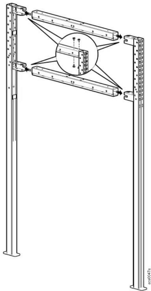
Assemble vertical posts to width beams (2 width beams for the Short HyperPod, 3 width beams for the Tall Hyperpod) using the M8 x 12 T30 screws provided.
NOTICE
Hole plugs are included with this assembly. It is recommended to wait until the accessories are installed before installing the hole plugs.
Assemble a second set of vertical posts and width beams.
NOTE: If needed, the temporary frame support can be installed to the assembly at this time. See "Temporary frame support" on page 37 for more information.
natural_image
Technical line drawing of a structural frame with beams and supports, no text or symbols present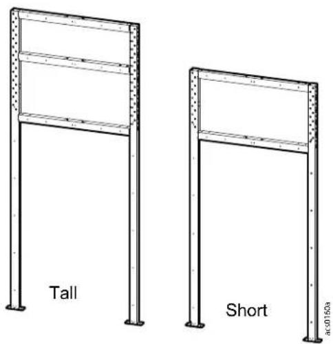
Length beam assembly
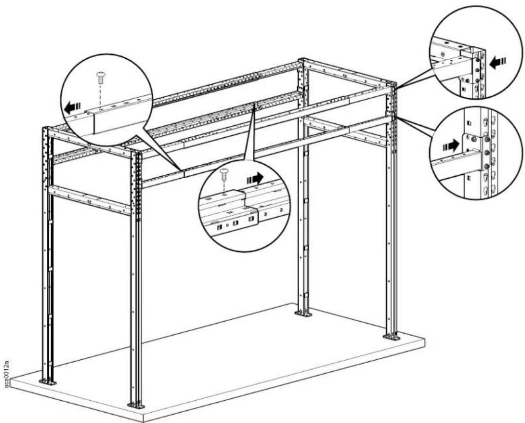
Install the telescoping horizontal beams to the vertical post assemblies.
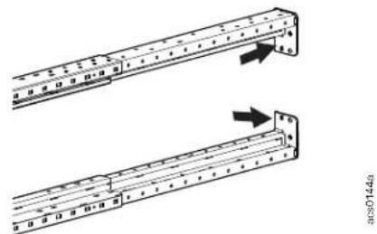
- Assemble the beam by sliding the end sections into the main beam. Make sure the bracket on the end is in the correct position for attaching to the vertical post.
natural_image
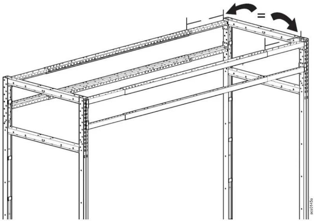
Technical line drawing of two mechanical components with arrows indicating motion direction (no text or symbols)- Slide the length beam to the desired length. The beam is marked at the 2.4 m (8 ft) and 3.6 m (12 ft) lengths. If the length of your HyperPod will be more than 2.4 m (8 ft) but less than 3.6 m (12 ft), measure and mark the length beams so they can be secured at the appropriate length.
NOTE: The left and right end inserts of the length beam can each be extended to add 600 mm (2 ft). When both end inserts are fully extended, the total length of the length beam is 3.6 m (12 ft). When setting up the length beams to the calculated length of the aisle you need in your HyperPod, make sure that the inserts on both ends of each length beam are extended the same length. For example, if the left end insert is extended by 50 mm (2 in.), then the right end insert should also be extended by 50 mm (2 in.).
natural_image
Technical line drawing of a metal shelving unit with structural beams and mounting holes (no text or symbols)-
Secure the small beam ends in place with M6 x 12 pan head T30 screws.
-
Secure the length beams to the vertical posts with four provided M8 x 25 hex head bolts and M8 nuts.
The lower length beam should be placed in a position that will allow you to install your tallest rack. The upper beam should be placed 3 U above the lower beam to provide space for the window assembly.
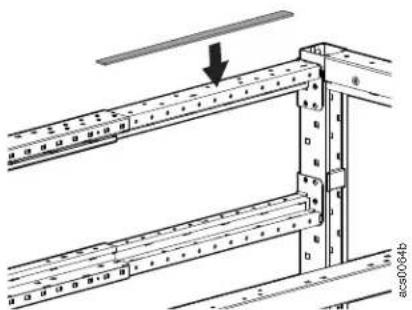
- The end inserts of the length beam are smaller than the main portion of the beam. Apply the self-adhesive foam seal to the gap on the extensions of the length beam to fill the space.
Temporary frame support
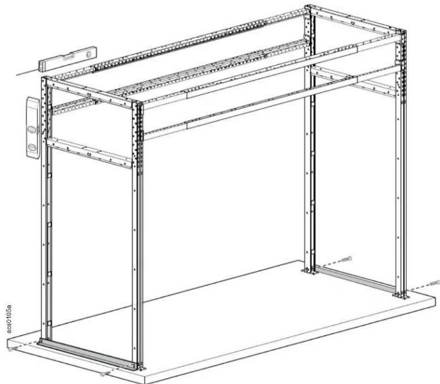
If you are not going to secure the frame to the floor at this time, attach the temporary support to the feet of the vertical posts with four M8 x 12 T30 screws per post to stabilize the frame while making sure the frame is level and plumb. The temporary frame support helps maintain the placement of the HyperPod system during assembly.
natural_image
Technical line drawing of a metal shelving unit with vertical supports and mounting bracket (no text or symbols)Secure the frame to the floor
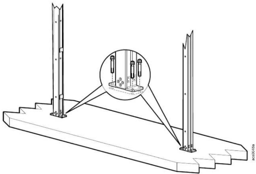
This procedure is for the regular floor option. If you have a raised floor, see "Configure the first two (2) floor stands" on page 29.
- To prepare to secure the frame to the floor, adjust the frame until level and plumb. Use the supplied shims as necessary. Use threaded screws (not provided) to raise the vertical post foot plate from the floor.
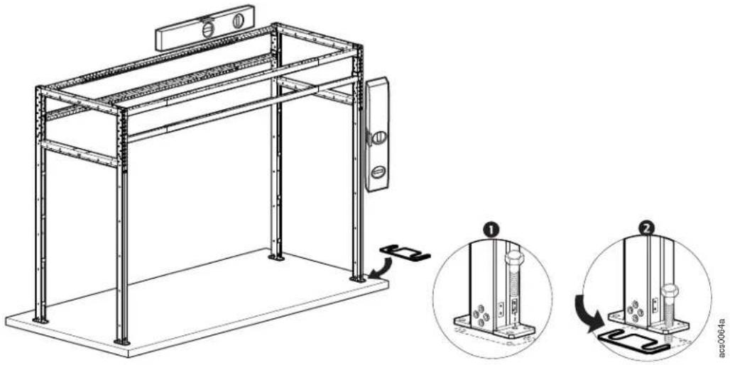
- Attach the vertical posts at one end to the floor. Do not attach both ends of the frame to the floor until length is checked to accommodate the intended equipment and the frame is level and plumb.
natural_image
Technical line drawing of a structural support frame with two vertical posts and a close-up inset showing bolt details (no text or symbols)End caps
Install the end caps (exterior and interior panels) above the door area on the vertical posts.
Loosely mount (4) M6 x 12 pan head T30 screws on both sides of the topmost width beam, then hang the interior and exterior end cap panels from the screws. Install four (4) more M6 x 12 pan head T30 screws at the bottom of the panels.
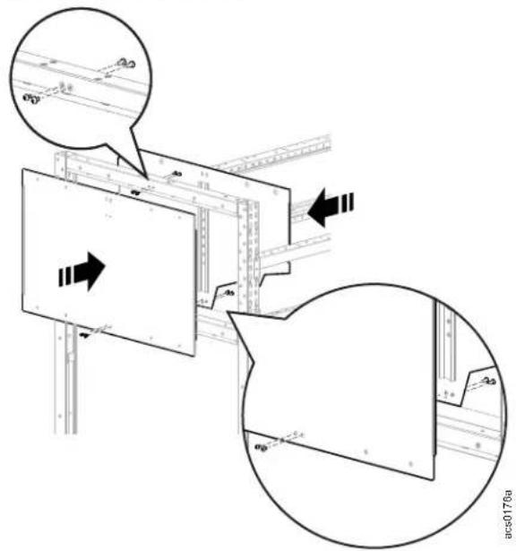
Use eight (8) M8 x 12 low head Nylok T30 screws to secure the inner and exterior panels. Then tighten the M6 x 12 pan head T30 screws.
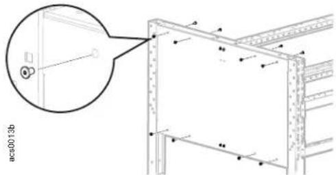
NOTICE
Hole plugs are included with this assembly. It is recommended to wait until the accessories are installed before installing the hole plugs.
Door frames
NOTICE
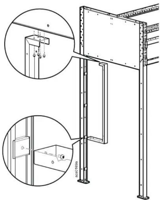
Vertical posts must be secured to the floor before installing the door frames. The door frames enclose the vertical posts, prohibiting access.
- If you have a 1.9 m (6 ft) aisle, secure the L bracket to the frame with M6 x 12 pan head T30 screws.
natural_image
Technical line drawing of a structural frame assembly with two views of a vertical support (no text or symbols)-
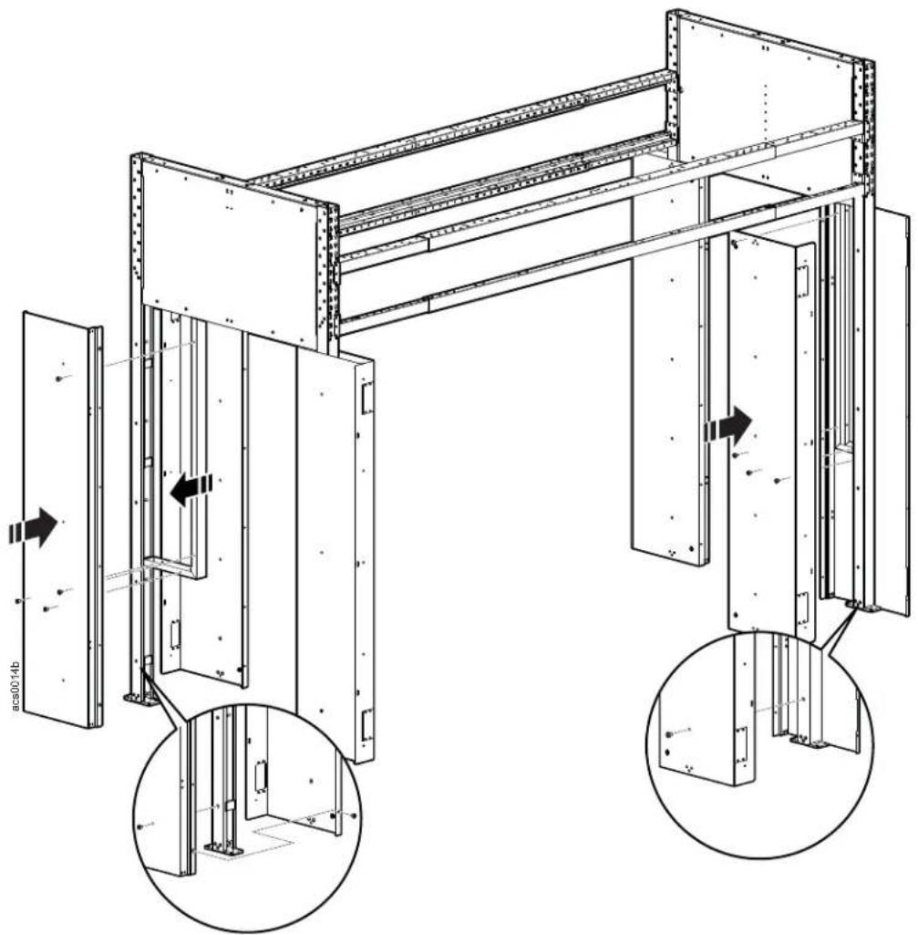
Place the front and back panels together around the vertical support post.
-
Secure the back panel to the vertical support post with the M8 x 12 T30 screws. For a 1.9 m (6 ft) aisle, also secure the back panel to the L bracket with four M5 x 10 low head screws.
-
Secure the front panel to the back panel and vertical posts with the M8 x 12 T30 screws and M5 x 12 flat U cut flat head Phillips screws. For a 1.9 m (6 ft) aisle, also secure the front panel to the L bracket with four M5 x 10 low head screws.
| NOTICE |
| Hole plugs are included with this assembly. It is recommended to wait until the accessories are installed before installing the hole plugs. |
natural_image
Technical line drawing of a structural frame assembly with multiple components and directional arrows (no text or symbols)Doors
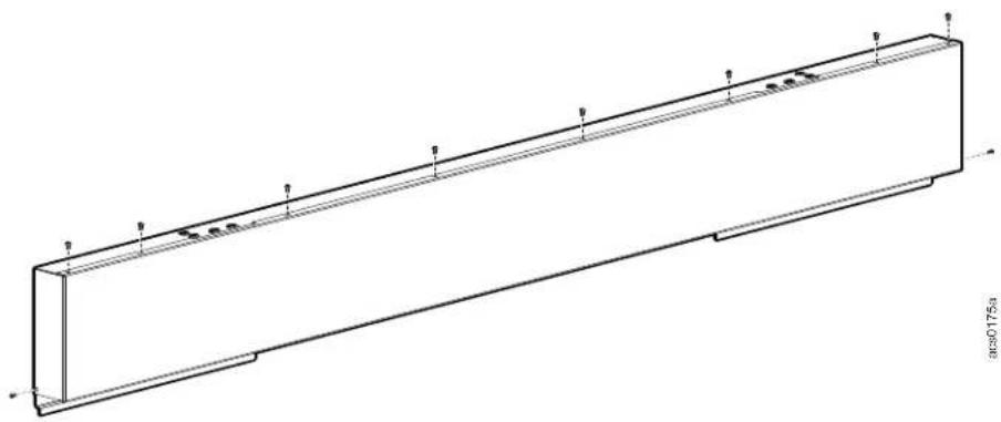
- Remove the cover of the door hanging rail assembly. Save the cover and ten (10) M4 x 8 mm button head TORX screws.
natural_image
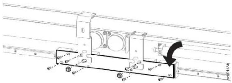
Technical line drawing of a rectangular structural component with mounting holes and dimension lines (no text or symbols)- Remove the eight (8) M4 x 8 mm button head TORX screws and two (2) M6 Hex nuts securing the shipping bracket. Discard the shipping bracket,
natural_image
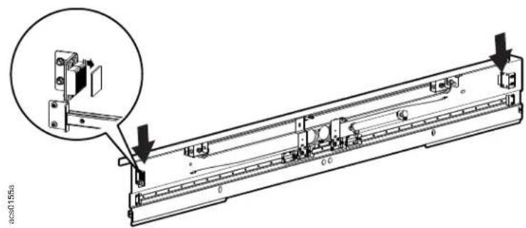
Technical line drawing of a mechanical assembly with mounting holes and a directional arrow (no text or symbols)- Remove the metal cover plate on the magnets.
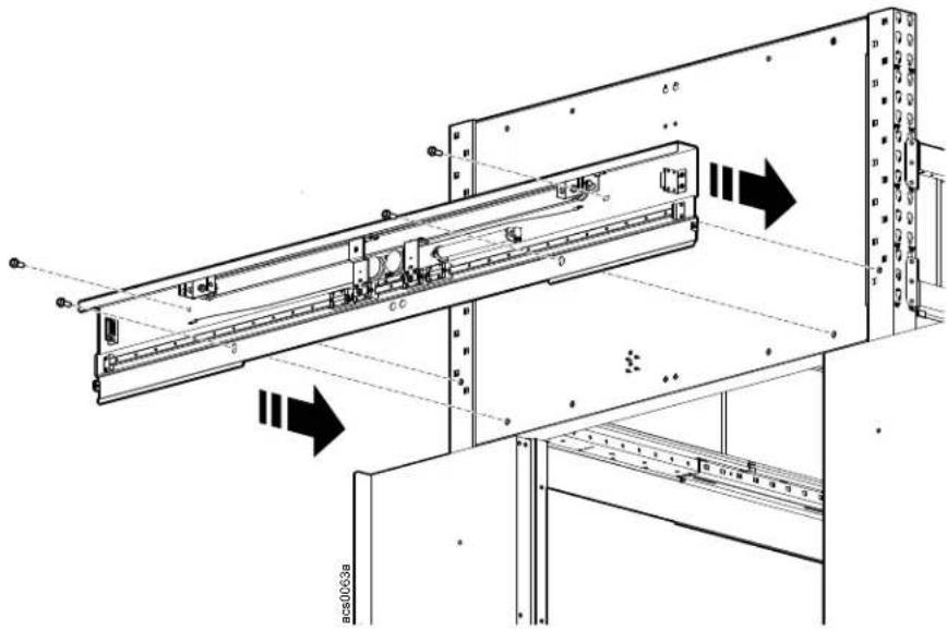
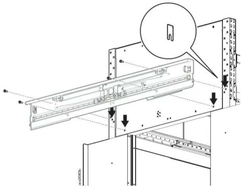
- Attach the door hanging case to the frame above the top of the door opening with four M8 x 12 low head T30 screws.
natural_image
Technical line drawing of a mechanical assembly with directional arrows indicating motion (no text or symbols)- Use the shims included with the door hanging case to ensure the hanging case is level, plumb, and square to the door frame. The door hanging case must clear the door frame an equal distance on both ends to ensure the doors will move without obstruction.
- Hang the doors.
CAUTION
HEAVY EQUIPMENT HAZARD
At least two (2) people are required to perform this task.
Failure to follow these instructions can result in serious injury or equipment damage.
The two (2) locations on the doors for the brackets must be lined up with the sliding blocks.
The innermost brackets are already attached to the reel. The two (2) posts on the door fit through the slotted holes on the bracket.
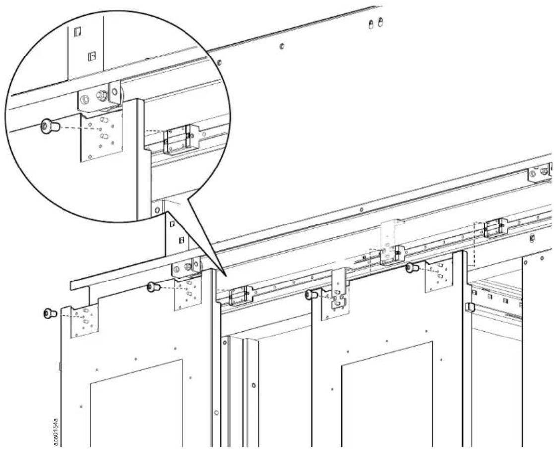
a. At least one person must hold a door up to the sliding blocks while another person installs four M4 x 8 button head TORX screws to each of the two (2) blocks.
natural_image
Technical line drawing of a mechanical assembly with mounting brackets and structural supports (no text or symbols)b. Install an M6 hex nut to each threaded post on the two (2) innermost brackets, securing them to the doors.
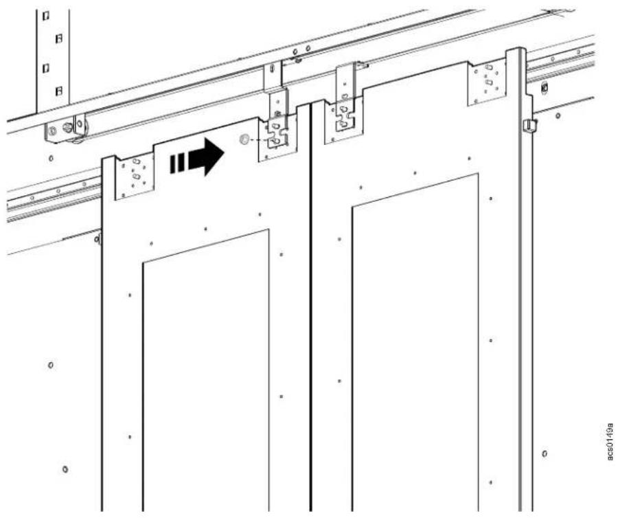
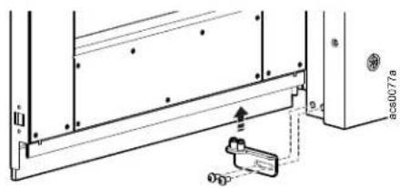
c. Attach the bottom rails to the doors and secure them to the door frames with the provided M6 x 12 pan head T30 screws.
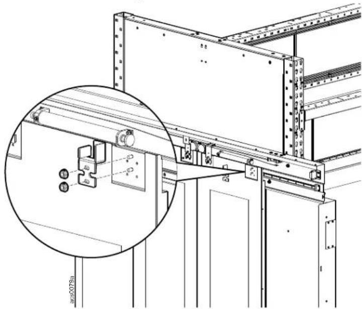
d. Install the outermost left and right door hanging brackets to the threaded posts on the doors with the M6 flanged hex nuts.
natural_image
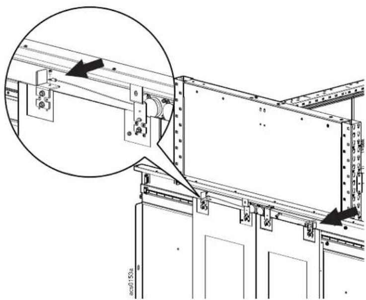
Technical line drawing of a structural assembly with an inset magnified detail showing internal components (no text or symbols)e. Pull the end of the cable and attach one end to each of the outermost brackets with one M4 x 8 button head TORX screw.
natural_image
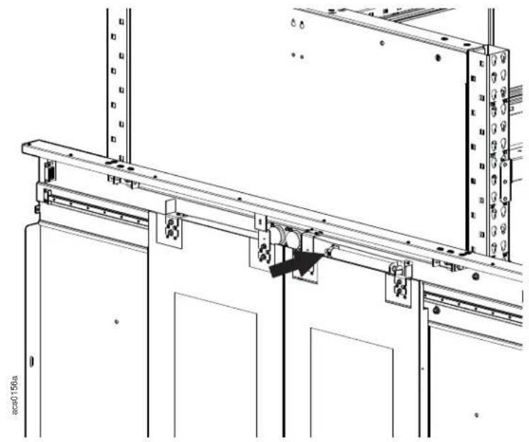
Technical line drawing of a mechanical assembly with an inset showing a close-up of a component (no text or symbols present)f. Test how quickly the doors close. If the doors close quickly enough to slam into each other, turn the adjustment screw to the right to slow the doors as they close.
natural_image
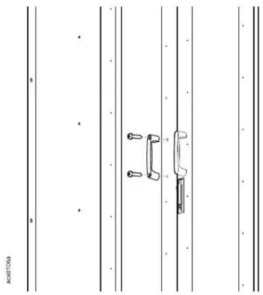
Technical line drawing of a mechanical assembly with mounting brackets and structural supports (no text or symbols)g. Attach the door handles to the door with two (2) M5 x 25 pan head screws.
natural_image
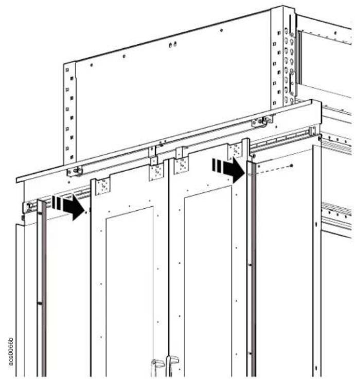
Technical line drawing of a mechanical component with mounting holes and a bracket, no text or symbols presenth. Install a brush to the outside edges of each door with four M3 x 8 mm flanged TORX screws and adjust, using the slotted holes of the brush strip, to cover the gap between the frame and the door.
Test how quickly the doors close again, and adjust if necessary.
natural_image
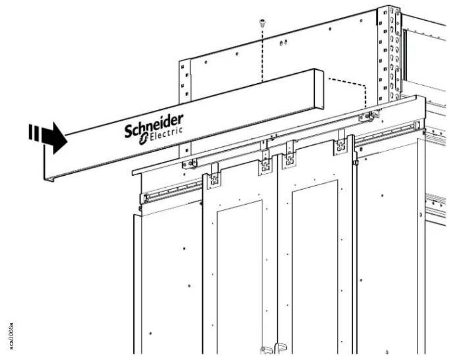
Architectural cross-section diagram of a building facade with structural beams and supports (no text or symbols)i. Install the cover to the door rail assembly with ten (10) M4 x 8 button head TORX screws.
Frame seals
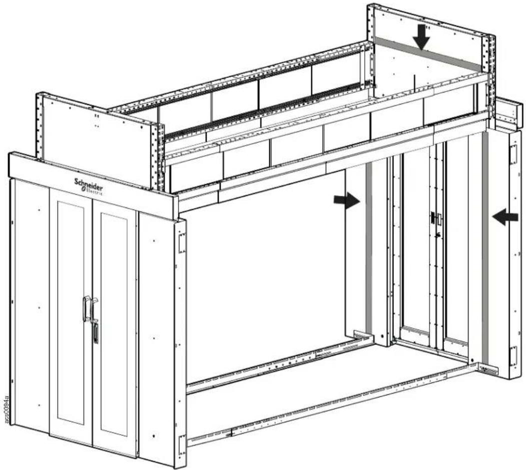
Attach the self-adhesive foam seal strips from the seal kit to the backs of the door frame where they will meet the rack or blanking panel and to the inside end caps where they will meet the roof panel.
natural_image
Technical line drawing of a mechanical assembly with labeled components and directional arrows (no text or symbols beyond labels)NOTICE
You may want to wait until a rack, blanking panel, or roof panel is installed in order to place the frame seals in the optimal locations.
Window assemblies
Window rails are installed to the underside of the top length beam and the top of the lower length beam.
-
Starting at one end of the frame, install the window side brush to the length beams with two (2) M6 x 12 screws to fill the area between the back of the door frame and the starting edge of the window assembly (①).
-
Install two (2) rail brackets to the length beam with M6 x 10 screws for each four foot section of rail (②). Use short rail brackets on the non-telescoping part of the length beams, and use long rail brackets on the telescoping part of the length beams.
-
Join two (2) 1.2 m (4 ft) window rails using the connector with its four M6 set screws (3).
-
To secure the window rail to the window rail brackets, slide a hammer head nut into the rail and behind the bracket. Once an M6 x 10 screw is inserted through the bracket to the nut, rotate the nut 90 degrees to secure the nut in the rail (4).
-
Insert the rail blocks into the bottom rails (5).
-
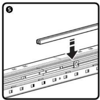
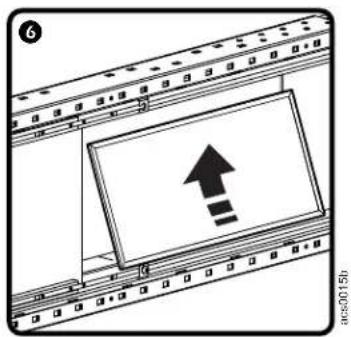
Install the window panels or pass-throughs to the window rails by sliding the parts up into the top rail and then allowing the bottom edge of the part to drop down into the bottom rail (6)
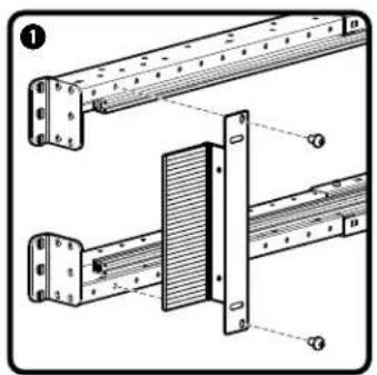
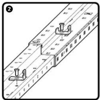
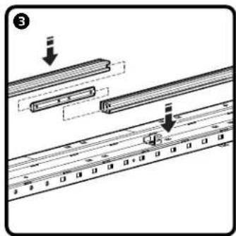
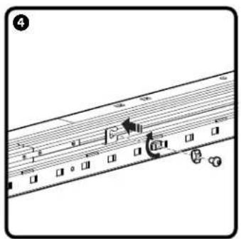
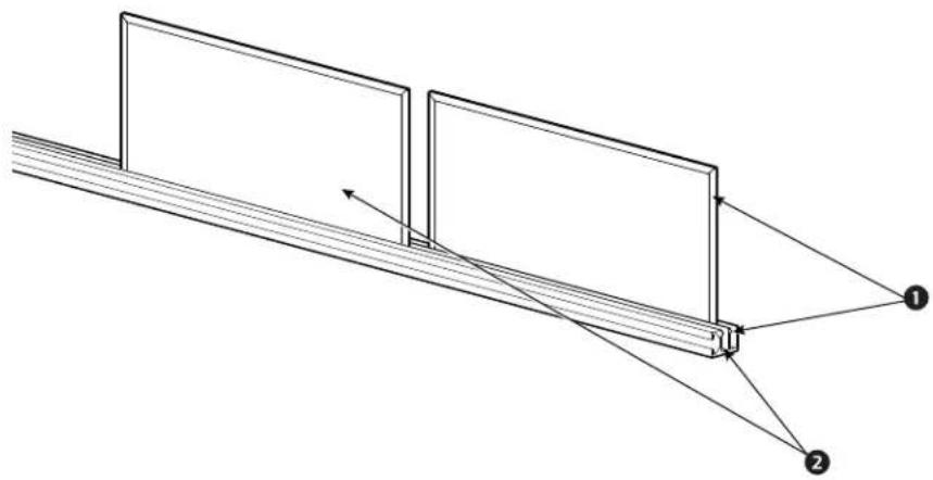
NOTE: HyperPod frames that are 2.4 m (8 ft) long require two (2) 1.2 m (4 ft) rails along the length of the length beam. Window rails may require cutting to size if the aisle length is longer than 2.4 m (8 ft) and shorter than 3.6 m (12 ft).
NOTE: There are two (2) tracks in the window rail. Alternate tracks when installing the windows.
natural_image
Pure technical diagram of a mechanical assembly with two rectangular components and connecting rods, no text or symbols present.Row length brush
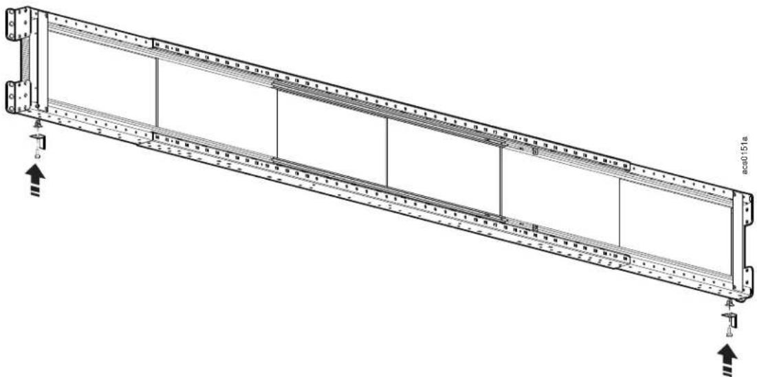
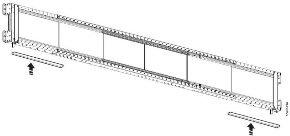
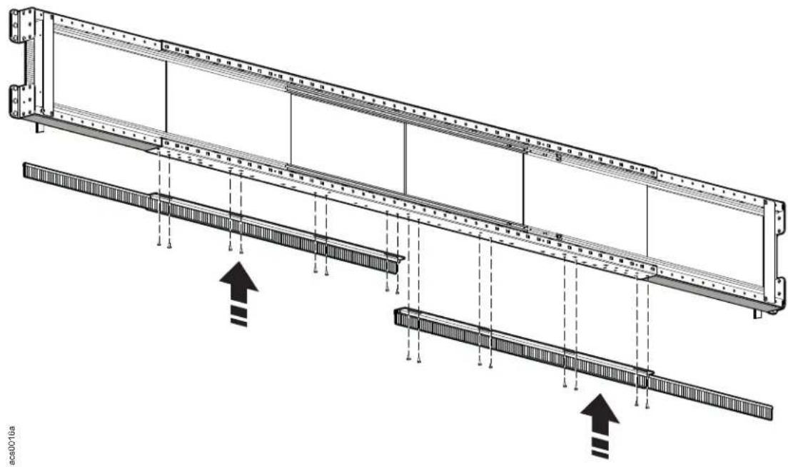
Each row length brush has a slide out extension brush on one end. Install the row length brush with the extension brush end toward the vertical post. The left and right brushes with extension brushes fully deployed measure 3.6m (12 ft). With the end of each row length brush meeting at the center of the length beam, slide out each end of the brush strip until it meets the end of the frame.
- Install the brush extension clips at each end of the length beam with an M6 x 16 pan head T30 screw.
natural_image
Technical line drawing of a long structural beam with support beams and load arrows (no text or symbols)- Apply the self-adhesive foam strip to the bottom of the slide out extension of the length beam.
natural_image
Technical line drawing of a structural frame with supports and load arrows (no text or symbols)- Hold the row length brush up to the length beam and note the hole locations. Install the insert nuts to the bottom of the length beams at the appropriate locations. Install the brush strip to the bottom of the length beam with the provided M6 x 16 pan head T30 screws.
natural_image
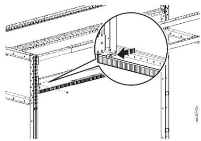
Technical diagram of a structural beam with support beams and load arrows, no text or symbols present- Insert the top edge of the brush extension into the clip. Secure the brush extension in the clip with an M3 x 4 pan head Phillips screw.
natural_image
Technical line drawing of a structural frame with an inset magnified detail showing a component detail (no text or symbols present)Roof panels
- Install the roof panels to the top of the horizontal length beams using the insert nuts, brackets, and M6-1 x 16 hex head screws.
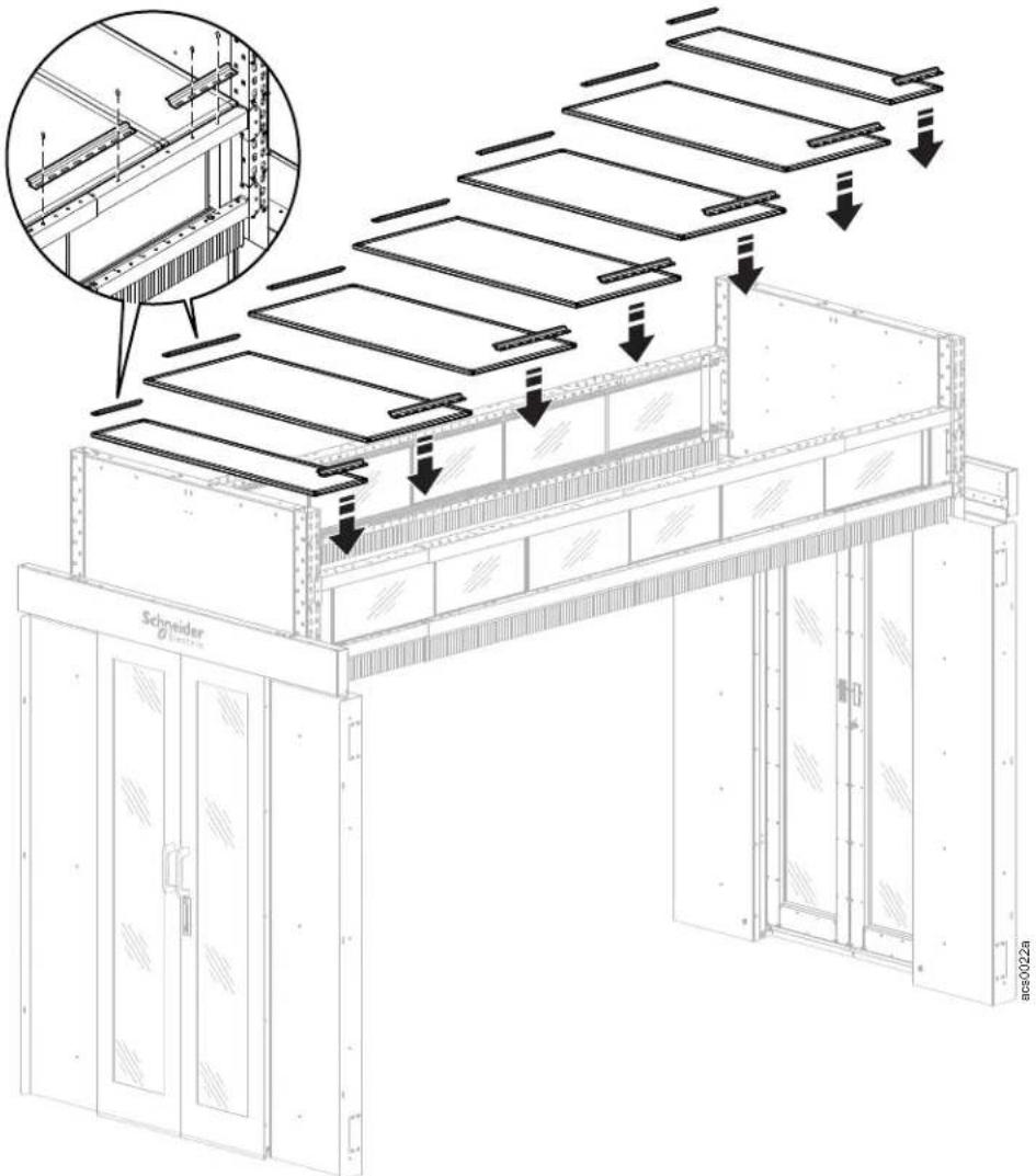
- Use the roof filler panels and hex head screws to fill in the extra space at the end of the aisle, if any. The roof filler panels have slotted holes to allow for adjustment.
NOTE: Do not use the drop panel for this configuration.

natural_image
Technical line drawing of a structural frame assembly (no text or symbols)Stop rails
- Measure from front to back of the aisle to make sure the stop rails are straight. Use a chalk line to help install the HyperPod along a straight line.
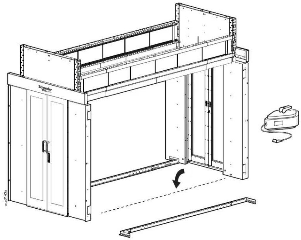
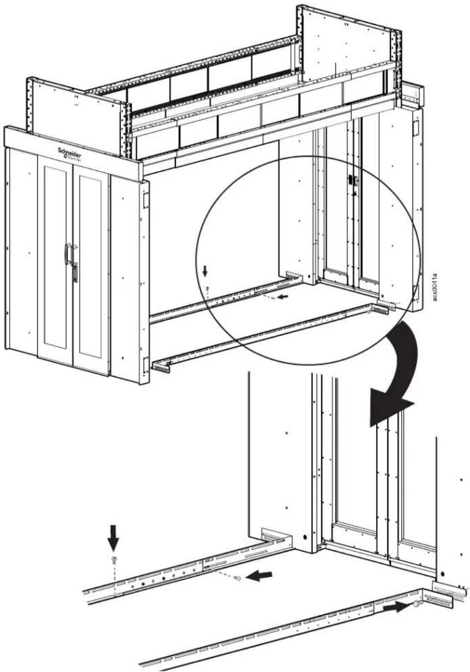
- Install the stop rails to the bottom of the door frames with the Mylar electrical isolation plate between. Secure the stop rail to the door frame with two (2) M8 x 20 hex head screws at each end. Use the slots to adjust the rail in or out. When the stop rails are in the correct position, secure the extensions to the center rail with the M6 x 10 pan head T30 screws along the sides of the rails and use anchor bolts (not provided) to secure the rail assembly along the edge that sits flush to the floor.
Blanking panels
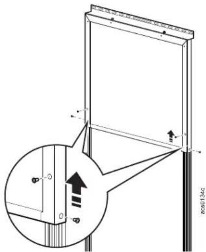
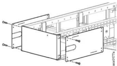
- If the rack space is taller than 42 U, adjust the panel to fill the available space. Loosen the screws as shown below and slide the 10 U panel to the necessary length.
-
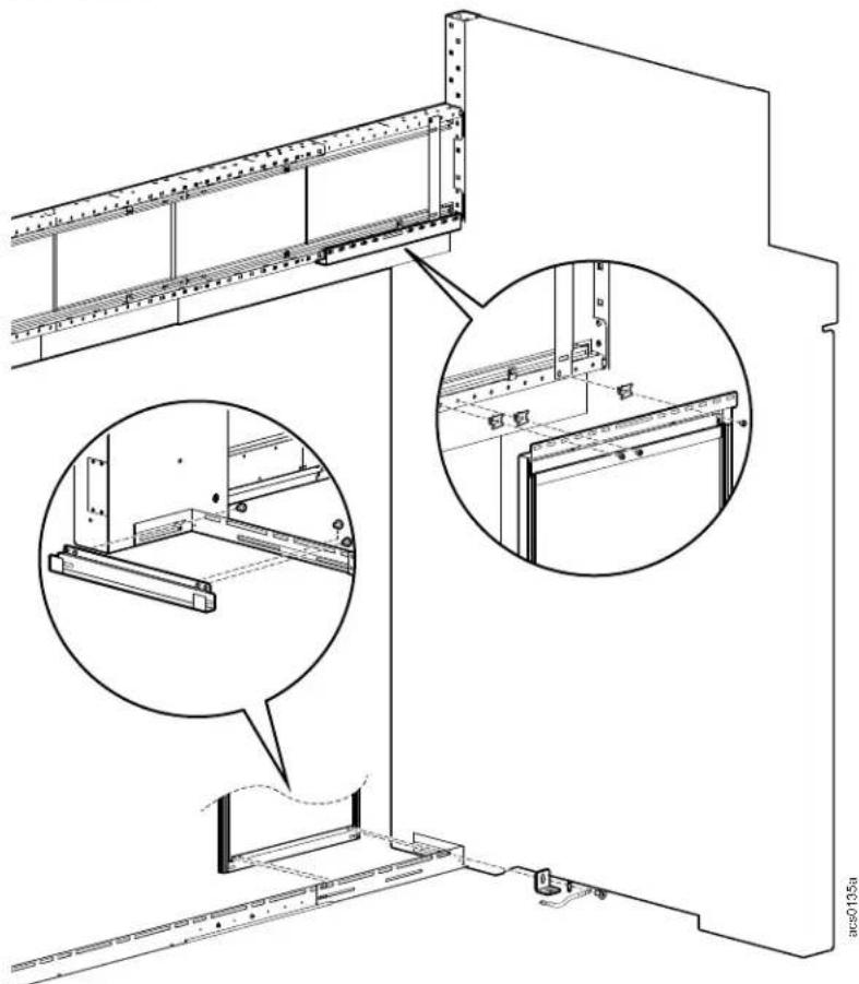
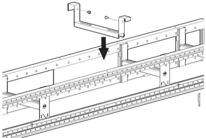
Install insert nuts to the length beam. Attach the top blanking panel bracket to the horizontal length beam with two (2) M6 x 16 pan head screws.
-
Attach the bottom blanking panel bracket to the stop rail. Attach the ground wire and serrated washer.
NOTE: The blanking panels may also be attached to the floor with the provided angle corner brackets.
natural_image
Technical line drawing of a structural frame assembly with two views of a panel (no text or symbols present)C seals and H seals
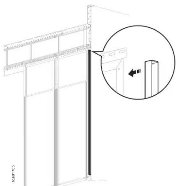
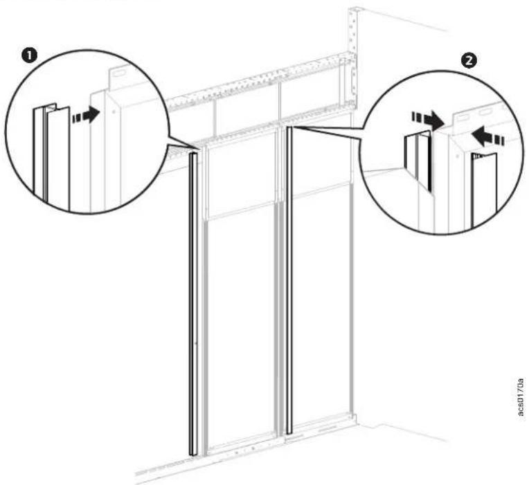
You can install C seals and H seals before or after you install the blanking panels. If you install the seals after the blanking panels, you may need to uninstall some blanking panels so that you have enough space to install the seals.
Install C Seals. If there is extra space between the blanking panels and the end of the aisle, install C seals on the blanking panels near the end of the aisle.
natural_image
Architectural detail drawing of a building facade with structural beams and a close-up inset showing a vertical panel detail (no text or symbols)Install H seals. If there is extra space between the blanking panels, install H seals on the blanking panels. You can install the seals directly on the side of the blanking panel (1). You can also pull the two (2) pieces of the H seal apart, and slide them back together between two (2) blanking panels (2).
NOTE: The second procedure (2) may require one person to stand on either side of the blanking panels to push the H seal together.
End Row Transition Cabinets
FS-AC-7001-B - Distribution Cabinet, MH50
FS-AC-7002-B - Distribution Cabinet, Split
FS-AC-7003-B - Distribution Cabinet, Solid
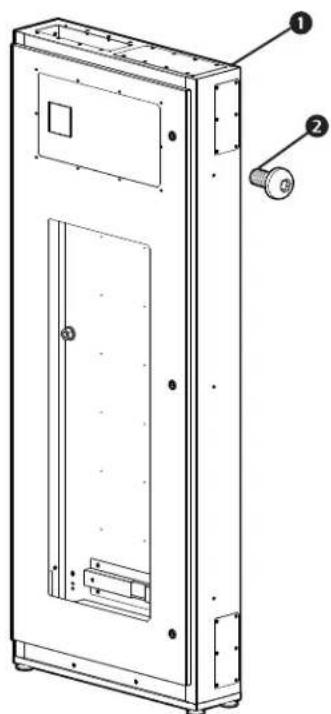
FS-AC-7001-B
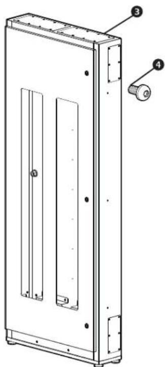
FS-AC-7002-B
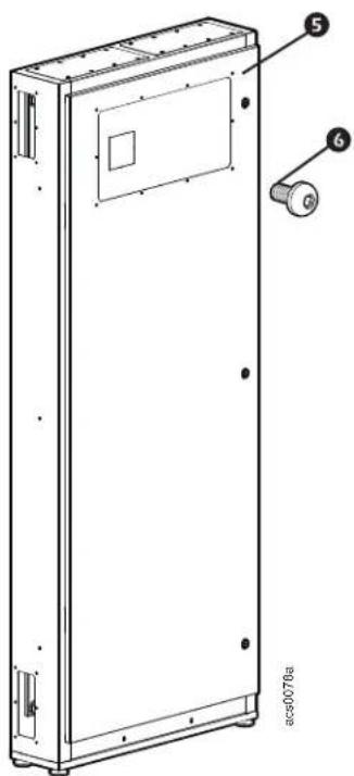
FS-AC-7003-B
Item Description
Quantity
1 Transition cabinet FS-AC-7001-B 1
② Pan head T30 screw, M6 x 12 3
3 Transition cabinet FS-AC-7002-B 1
4 Pan head T30 screw, M6 x 12 3
5 Transition cabinet FS-AC-7003-B 1
6 Pan head T30 screw, M6 x 12 3
Drop Roof
FS-RF-3002-U - Drop Roof Mounting Rail, 300 mm (12 in.)
FS-RF-3004-U - Drop Roof Mounting Rail, 600 mm (23.6 in.)
FS-RF-3006-U - Drop Roof Mounting Rail, 750 mm (29.5 in.)
FS-RF-3007-U - Drop Roof panel, 300 mm (12 in.)
FS-RF-3008-U - Drop Roof panel, 600 mm (23.6 in.)
FS-RF-3009-U - Drop Roof panel, 750 mm (29.5 in.)
Item Description Quantity Item Description Quantity
| 1 | Ceiling support assembly300 mm (12 in.) | 1 | 9 | Pan head T30 screw, M6 x10 8 |
| 2 | Ceiling support assembly600 mm (23.6 in.) | 1 | 10 | Pan head T30 screw, M6 x16 4 |
| 3 | Ceiling support assembly750 mm (29.5 in.) | 1 | 11 | Bracket for 300 mm (12 in.) panel 1 |
| 4 | Bracket for 600 mm (23.6 in.) and750 mm (29.5 in.) panel | 1 | 12 | Roof panel, 750 mm (29.5 in.) 1 |
| 5 | Hammer head nut, M6 8 | 13 | Roof panel, 300 mm (12 in.) 1 | |
| 6 | Baying hinge bracket 2 | 14 | Connector 4 | |
| 7 | TORX pan head screw, M4 x 8 4 | 15 | Roof panel, 600 mm (23.6 in.) 1 | |
| 8 | Insert nut, M6 4 |
NOTE: The drop roof is only available for 1.2 m (4 ft) aisle configurations.
Shrink Roof
FS-RF-6001-U - 1.2 m (4 ft) Aisle Shrink Roof panel, 610 mm (24 in.)
FS-RF-6002-U - 1.2 m (4 ft) Aisle Shrink Roof panel, 310 mm (12.2 in.)
FS-RF-6003-U - 1.9 m (6 ft) Aisle Shrink Roof panel, 610 mm (24 in.)
FS-RF-6004-U - 1.9 m (6 ft) Aisle Shrink Roof panel, 310 mm (12.2 in.)
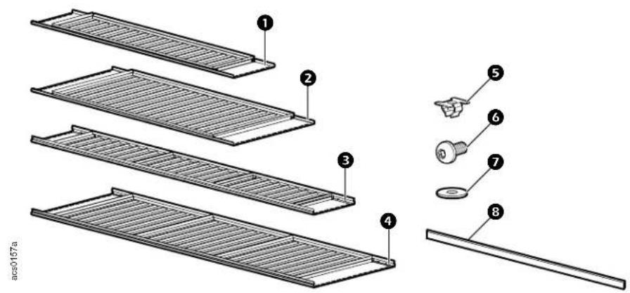
| Item Description | Quantity | |
| 1 | 1.2 m (4 ft) Aisle shrink roof panel, 310 mm (12.2 in.) (FS-RF-6002-U) | 1 |
| 2 | 1.2 m (4 ft) Aisle shrink roof panel, 610 mm (12.2 in.) (FS-RF-6001-U) | 1 |
| 3 | 1.9 m (6 ft) Aisle shrink roof panel, 310 mm (12.2 in.) (FS-RF-6004-U) | 1 |
| 4 | 1.9 m (6 ft) Aisle shrink roof panel, 610 mm (12.2 in.) (FS-RF-6003-U) | 1 |
| 5 | Insert nut, M6 2 | |
| 6 | Pan head T30 screw, M6 x 12 6 | |
| 7 | Washer 2 | |
| 8 | EPDM foam 1 | |
Ceiling Panel Lock Systems
ACDC2016 - Ceiling Panel Lock System, 100-120 V (with power supply)
ACDC2017 - Ceiling Panel Lock System, 200-240 V (with power supply)
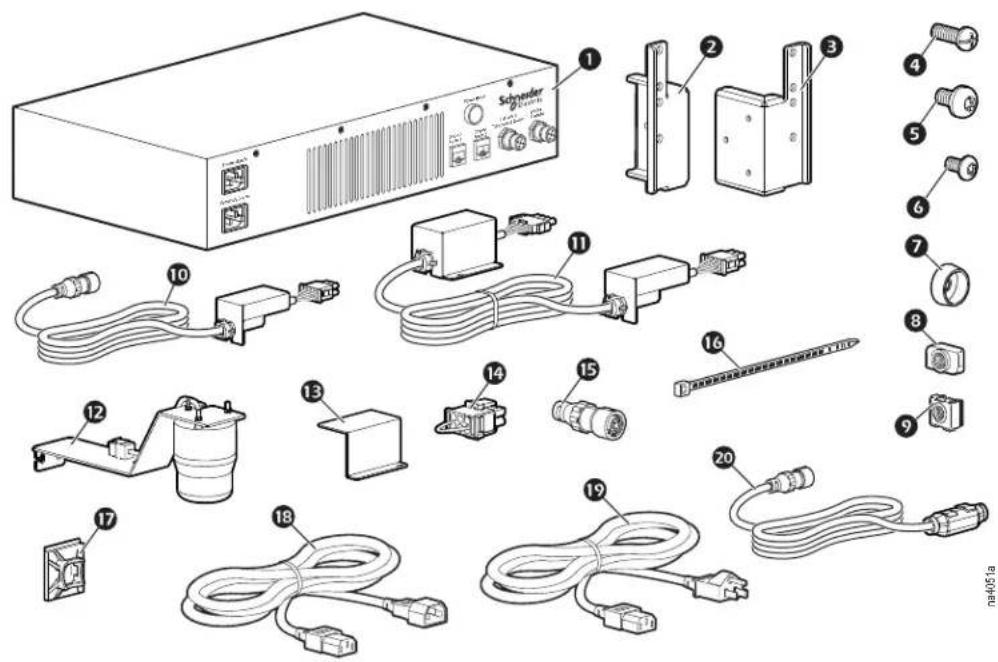
Item Description
Quantity
① Dropout power supply control box, 110 V (ACDC2016) 1
Dropout power supply control box, 220 V (ACDC2017) 1
2 Bracket for power supply box, left 1
3 Bracket for power supply box, right 1
4 Pan head Phillips screw, M6 x 16 4
5 Pan head T30 screw, M6 x 12 4
6 Button head T15 screw, M4 x 8 mm 6
7 Plastic cup washer, M6 4
8 Channel nut, M6 4
9 Caged nut, M6 4
10 Wire harness—power supply to wiring box, 3.6 m (12 ft) 1
11 Across aisle wiring assembly, 4 m (13.1 ft) 2
12 Alarm beacon 2
13 Wiring box cover 1
14 Terminal jumper 1
15 4-pin jumper 1
16 Wire tie 55
⑰ Cable holder 55
18 Power cord—CEE22 jump 2M 10A ROHS (ACDC2017) 2
19 Power cord—C13/15 DELL ROHS compliant (ACDC2016), 1.8 m (6 ft) 2
20 Smoke detector cable 1
ACDC2015 - Ceiling Panel Lock System, (without power supply)
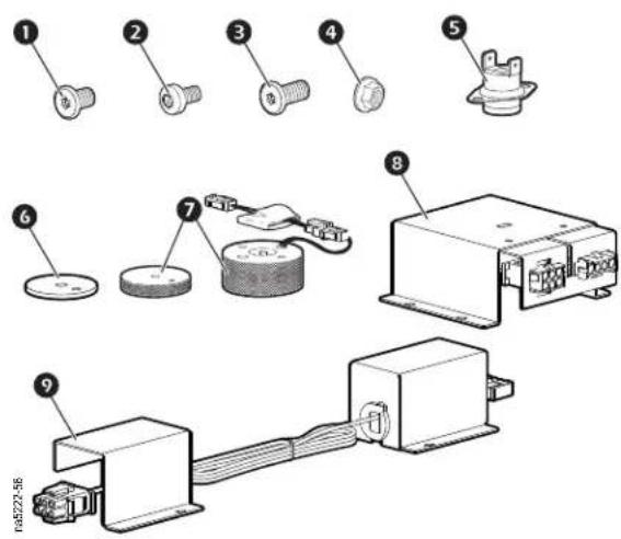
Item Description
Quantity
1 Flat head TORX screw, M5 x 8 8
2 Pan head TORX screw, M4 x 8 24
3 Flat head TORX screw, M5 x 10 4
4 Serrated hex flange nut, M4 8
5 Temperature switch, 135 °F (57 °C), 24 VDC 3 A 4
6 Electromechanical lock spacer 4
⑦ Electromechanical lock assembly, 24 V 50 MA 4
8 Wiring box 4
9 Box-to-box wire assembly 4
Rack Height Adapters
FS-AC-8001-U - Rack Height Adapter, 300 mm (12 in.)
FS-AC-8002-U - Rack Height Adapter, 600 mm (23.6 in.)
FS-AC-8003-U - Rack Height Adapter, 750 mm (29.5 in.)
FS-AC-8004-U - Rack Height Adapter, 800 mm (31.5 in.)
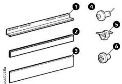
Item Description
Quantity
1 Bracket for brush/filler panel 1
2 Panel, 1 U, plastic, height filling, (length: 300, 600, 750, 800 mm) 6
③ Brush, short, height filling, (length: 300, 600, 750, 800 mm) 1
4 Pan head T30 screw, M6 x 16 4
5 Insert nut, M6 4
6 Pan head Phillips screw, 10-32 x 5/16 2
Cantilever Support Arms
FS-AC-3001-B - Large Cantilever Support Arms
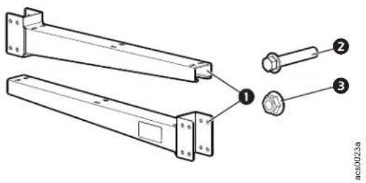
Item Description
Quantity
1 Cantilever Arm 2
Hex head bolt, M12 x 100 4
3 Hex head nut, M12 4
FS-AC-3003-B - Mini Cantilever Arms
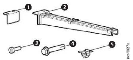
Item Description
Quantity
① Leveling pad 2
2 Mini Cantilever arm 2
3 Hex socket bolt, M4 x 10 4
Hex head bolt, M6 x 20 4
⑤ Insert nut, M6 4
FS-AC-3002-B - Overhead Support Frame, 2.4–3.6 m (8–12 ft)
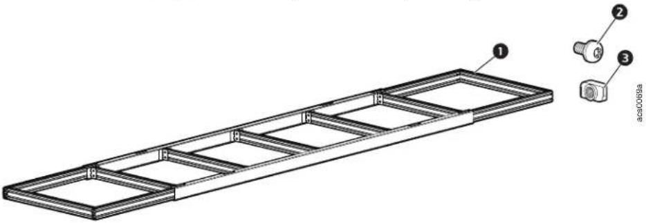
Item Description Quantity
1 Aluminum frame 1
② Pan head T30 screw, M6 x 12 17
3 Hammer head nut, M6 17
Power Raceway
FS-AC-4001-B - Power Raceway End Module
FS-AC-4002-B - Power Raceway Main Module
FS-AC-4003-B - 300 mm (12 in.) Side Cover Pack
FS-AC-4004-B - 50/150 mm (2/6 in.) Side Cover Pack
FS-AC-4005-B - Power Raceway Extension Module
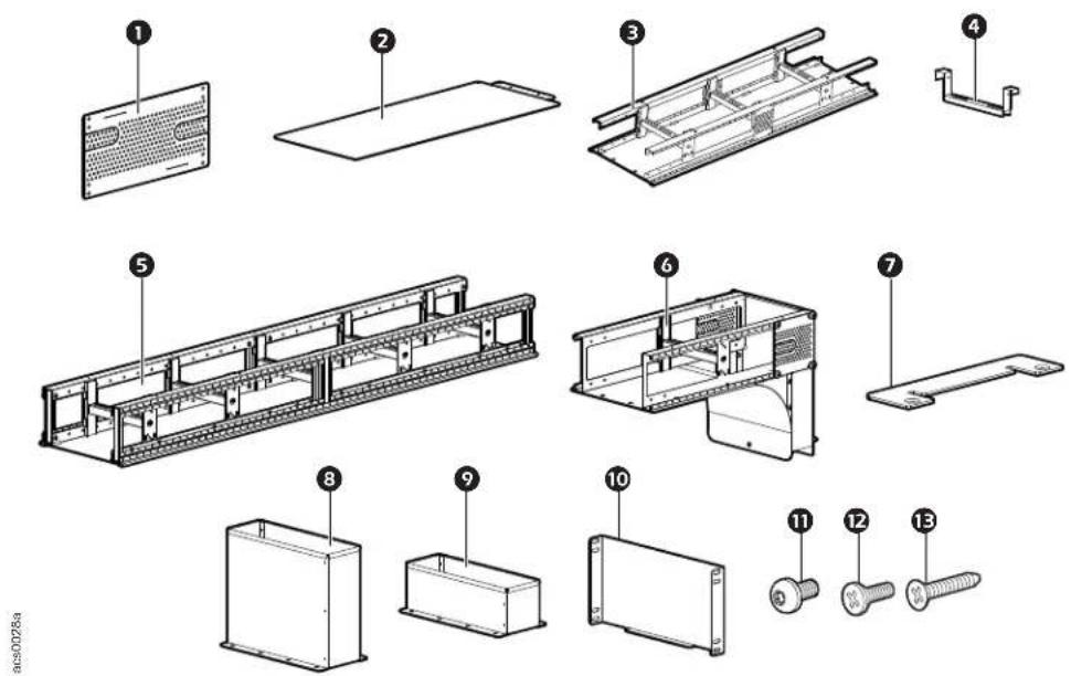
Item Description Quantity
| 1 | Side cover 300 mm (12 in.) (FS-AC-4003-B) | 4 |
| Side cover 150 mm (6 in.) (FS-AC-4004-B) | 2 | |
| Side cover pack 50 mm (2 in.) (FS-AC-4004-B) | 2 | |
| 2 | Base tray (FS-AC-4002-B) 2 | |
| 3 | Extension module* (FS-AC-4005-B) 1 | |
| 4 | Rung of cable ladder (FS-AC-4002-B) 4 | |
| 5 | Main module (FS-AC-4002-B) 3 | |
| 6 | End module (FS-AC-4001-B) 1 | |
| 7 | Cover bracket 2 | |
| 8 | Chimney, 6 U (FS-AC-4001-B) 1 | |
| 9 | Chimney, 3 U (FS-AC-4001-B) 1 | |
| 10 | End cap (FS-AC-4001-B) 1 | |
| 11 | Pan head T30 screw, M6 x 12(FS-AC-4005-B) | 13 |
| (FS-AC-4002-B) | 29 | |
| 12 | Flat head screw, M5 x 12 8 | |
| 13 | Phillips head self-tapping screws, 10-32(FS-AC-4003-B, FS-AC-4004-B) | 16 |
* Extension module is used with double HyperPod.
Lighting kits
ACDC2018 - Lighting Kit with Power Supply
ACDC2019 - Lighting Kit without Power Supply
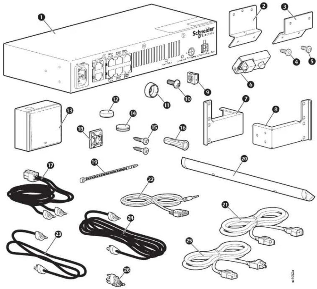
Item Description
Quantity Item Description Quantity
| 1 | Lighting control unit 1 | 14 | Hook and loop fastener, manual switch 8 | |
| 2 | Motion sensor mounting bracket 2 | 15 | Wood screw - #6 x 3/4 - Phillips 4 | |
| 3 | Motion sensor mounting bracket, sliding door | 2 | 16 | Wall anchor 4 |
| 4 | TORX screw, thread forming, M4 x 8 mm 6 | 17 | Wire assembly, 24 V power 1 | |
| 5 | TORX screw, M4 x 8 mm 8 | 18 | Wire tie cable holder 45 | |
| 6 | Motion sensor | 2 | 19 | Wire tie 45 |
| 7 | Lighting control unit mounting bracket, left | 1 | 20 | LED light assembly module, 6W (ACDC2019) 6 |
| 8 | Lighting control unit mounting bracket, right | 1 | 21 | Power cord, 15A 250V, C13 to C14 1 |
| 9 | Caged nut, M6 | 4 | 22 | console port to DB9F cable, 2.5 mm 1 |
| 10 | Phillips screw, M6 x 16 | 4 | 23 | Light-to-light wire assembly (ACDC2019) 5 |
| 11 | Cup washers | 4 | 24 | Light-to-light wire assembly, across aisle 1 |
| 12 | Magnets, manual switch | 8 | 25 | Power Cord, 15A 125V, C13 to 5-15P 1 |
| 13 | Manual switch | 2 | 26 | connector, end-to-end (ACDC2019) 5 |
NOTE: Items marked (ACDC2019) are included in both assemblies. All other items are only included in ACDC2018.
FS-AC-6001-B - Lighting Bracket Kit
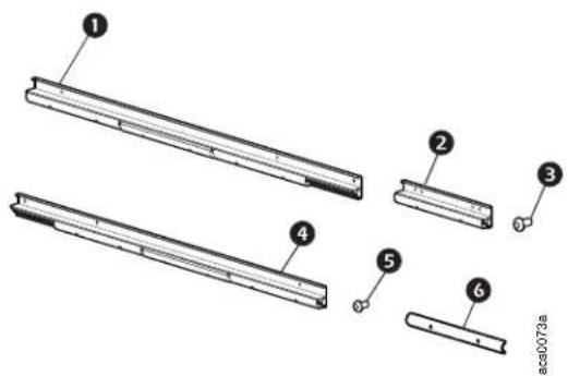
Item Description
Quantity
① Long bracket, left 2
② Short bracket 8
3 Pan head T30 screw, M6 x 16 29
4 Long bracket, right 2
5 TORX pan head screw, M4 x 12 33
6 Wiring cover 16
Crossover Tray
FS-AC-4007-B - 1.9 m (6 ft) Aisle Crossover Tray
FS-AC-4008-B - 1.2 m (4 ft) Aisle Crossover Tray
acs0037a
Item Description
Quantity
① Crossover tray 1
Flat head T30 screw, M6 x 12 8
Single Swing Door Assembly
FS-DR-1002-U - Swing Door
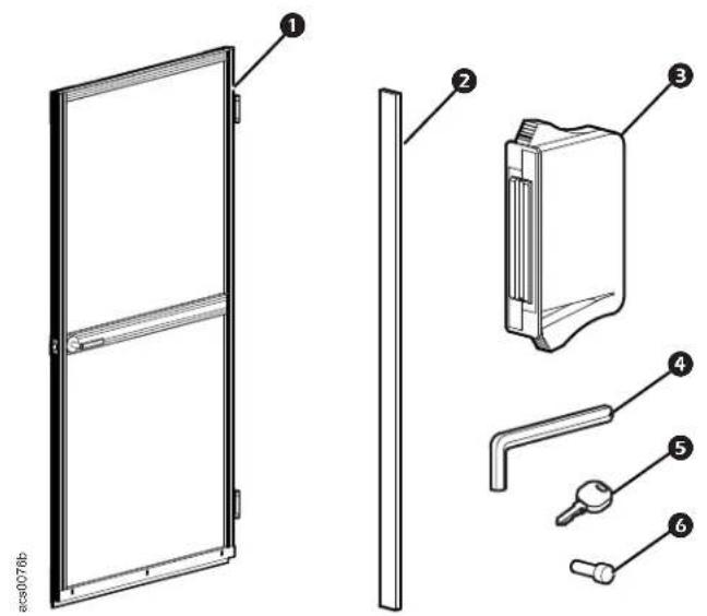
Item Description
Quantity
1 Door 1
② EPDM foam 1
3 Door closer 3
4 Hex wrench 1
5 Key 1
6 Tension pin 4
Installation of Optional Accessories
CAUTION
WORKING HEIGHT HAZARD
The working height for the assembly process can exceed 2.3 m (7.5 ft). The use of stepladders or scaffolding will be required during assembly.
Failure to follow these instructions can result in serious injury or equipment damage.
natural_image
Technical line drawing of an industrial electrical cabinet with open doors and internal compartments (no text or symbols)
natural_image
Technical line drawing of a modular industrial or warehouse structure with no visible text or symbolsTransition Cabinets
CAUTION
LIFTING HAZARD
At least two people are required to install this enclosure. Use appropriate equipment to move cabinets into position.
Failure to follow these instructions can result in serious injury or equipment damage.
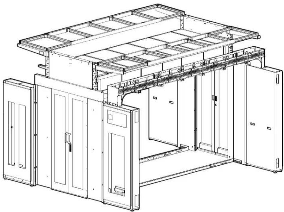
Two transition cabinets can be installed at each end of the aisle. One transition cabinet is shown installed on either side of the door frame in the illustration below.
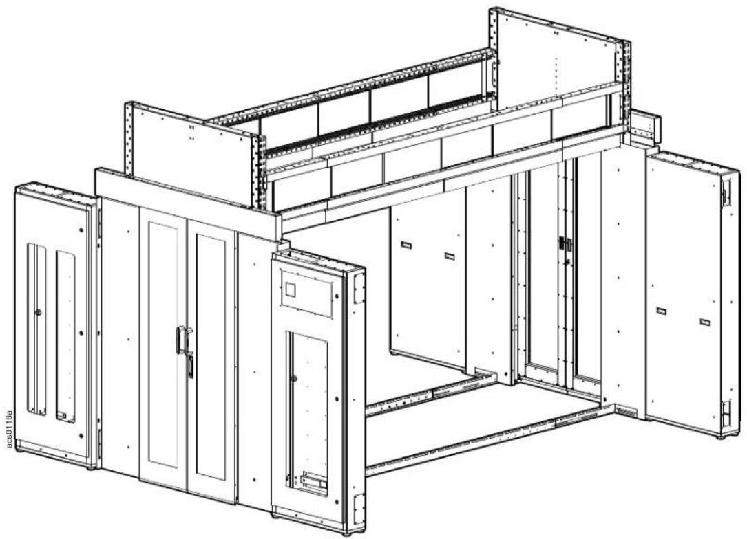
natural_image
Technical line drawing of a modular industrial or electrical enclosure unit with multiple doors and structural beams (no text or symbols)NOTICE
Empty transition cabinets can weigh 97.5–104.3 kg (215–230 lbs) and much more if equipment has been installed. Consider the weight of your cabinet to choose the appropriate method of moving the transition cabinets.
Access panels on the sides of the door frames should be removed prior to installing the transition cabinet.
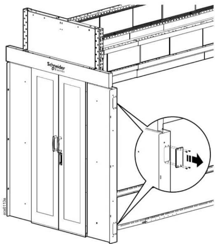
Move the transition cabinet into position.
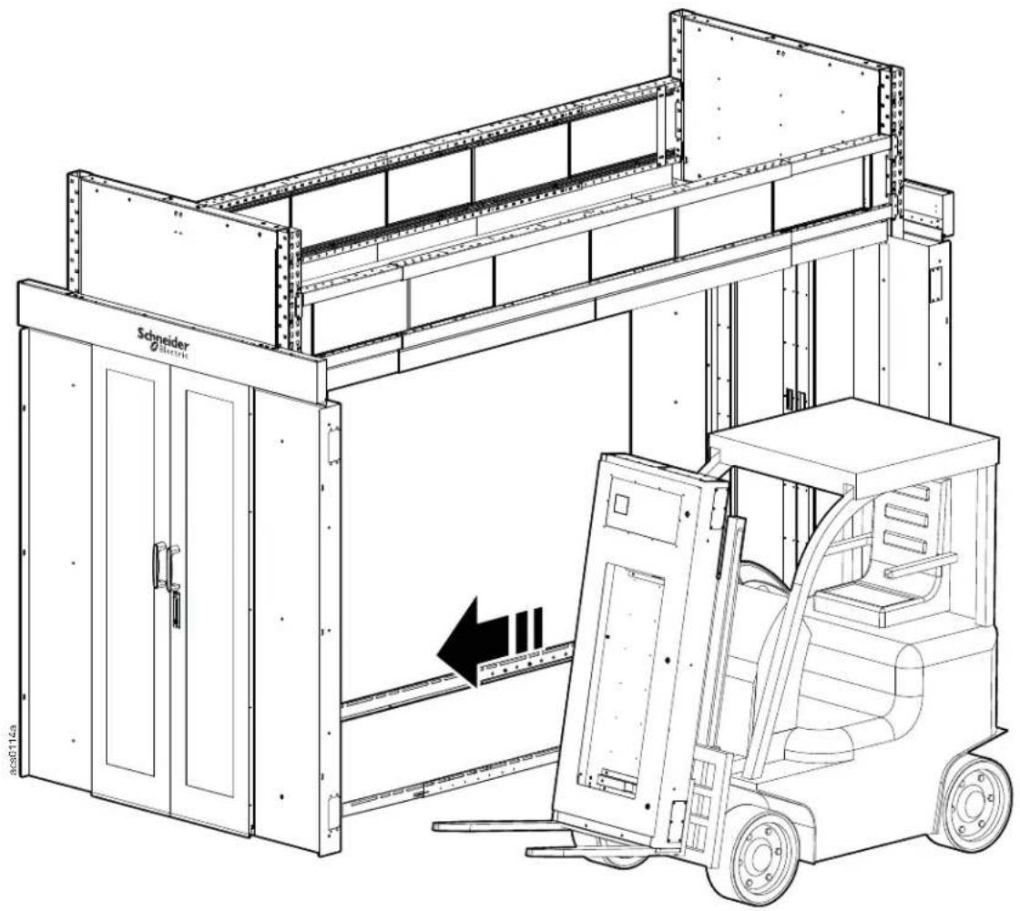
natural_image
Technical line drawing of a Schneider Electric lift with forklift and door assembly (no text or symbols)CAUTION
LIFTING HAZARD
Transition cabinets weigh 97.5–104.3 kg (215–230 lbs). It is recommended that you use mechanical lifting machinery such as a forklift to move the cabinet.
Failure to follow these instructions can result in serious injury or equipment damage.
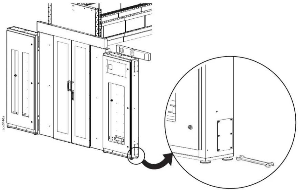
The transition cabinet is attached to the door frame with three (3) M6 x 12 pan head T30 screws.
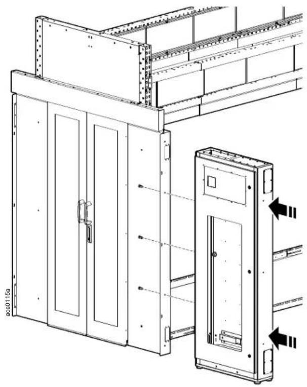
natural_image
Technical line drawing of a cabinet or enclosure assembly with mounting brackets and internal components (no text or symbols)Adjust the leveling feet until the transition cabinet is level and plumb.
natural_image
Technical line drawing of a cabinet or enclosure with an inset close-up showing internal components (no text or symbols)Crossover Tray
NOTICE
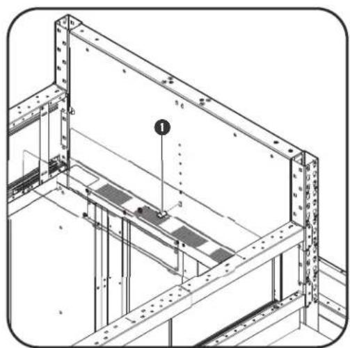
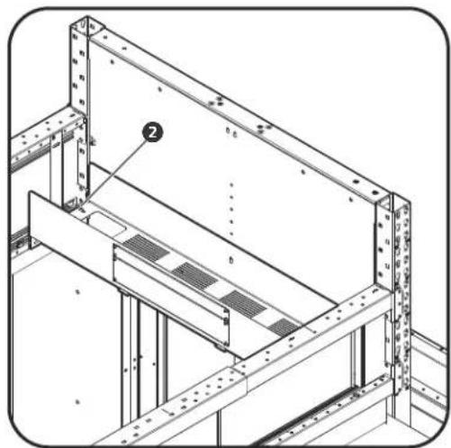
The location of the length beams will be a determining factor when installing the crossover tray. The location of the holes at the center of the interior end cap panel start at 42 U and continue vertically up to 48 U. In the illustrations for this example, the screw is located at the 42 U position
natural_image
Technical line drawing of a structural frame assembly with labeled components (no text or symbols)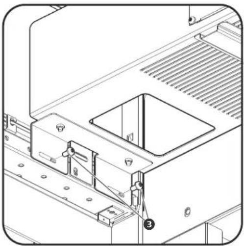
natural_image
Technical line drawing of a mechanical assembly with no visible text or symbols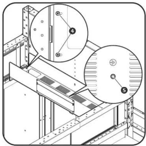
acs0054a
- Install an M6 T30 screw (①) to the hole on the inside panel of the end cap. Do not fasten the screw tightly.
- Hang the crossover tray on the screw. Loosen the four (4) screws (②) inside the crossover tray but do not remove them.
- Slide out the brackets on the bottom of the crossover tray and secure each side to the length beams with four (4) screws (③) in each bracket.
- Fasten the screws (4) loosened in step 2.
- Connect the grounding wire to the grounding nut (5) before using the crossover tray.
Mini Cantilever Arms
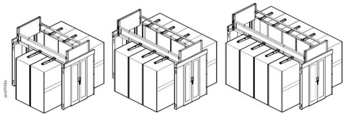
The number of cantilever arms needed to support the power raceway will depend on the aisle length.
natural_image
Three technical line drawings of industrial storage or warehouse units with internal compartments and doors (no text or symbols)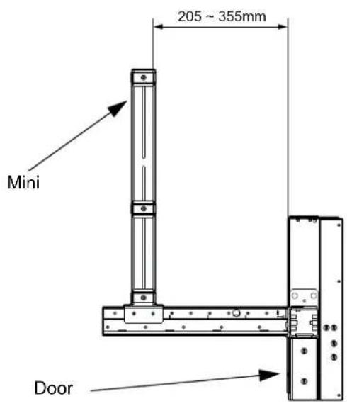
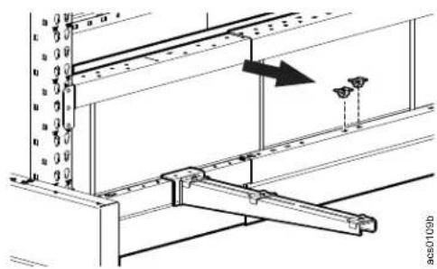
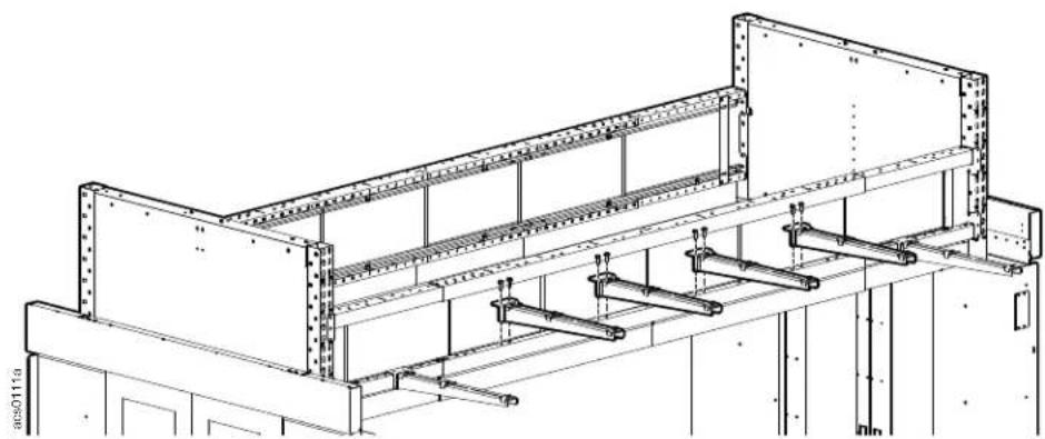
The mini cantilevers are installed equally spaced along the length beams leaving 205–355 mm (8–14 in.) between the end of the first and last mini cantilever and the door frame.
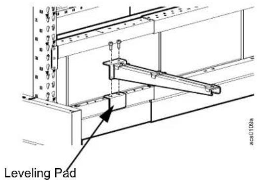
- The leveling pads position the mini cantilever arms on the small ends of the length beam level with the mini cantilever arms installed on the larger middle portion of the length beam.
Secure the mini cantilever arm and leveling pad with two M6 x 20 Hex socket bolts.
- Install the insert nuts to the holes in the middle portion of the length beam where you have determined to locate the mini cantilever arms.
natural_image
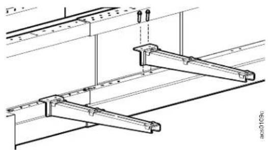
Technical diagram of a structural assembly with beams and supports, showing no text or symbols- Install the mini cantilever arms over the insert nuts on the middle portion of the length beam and secure with two M6 x 20 hex head bolts.
natural_image
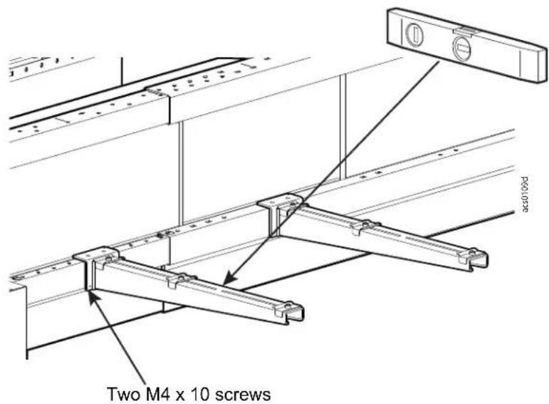
Technical line drawing of a structural frame assembly (no text or symbols)- Use two M4 x 10 screws to adjust the leveling of the cantilever arm.
- Install the mini cantilevers equally along the length beam.
natural_image
Technical line drawing of a structural frame assembly (no text or symbols)Power Raceway
The mini cantilevers and at least one transition cabinet must be installed before the power raceway is installed.
natural_image
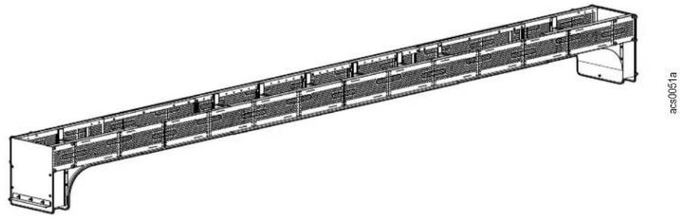
Technical line drawing of a long rectangular structural component with internal channels and supports (no text or symbols)- Remove the top cover of the transition cabinet and insert the end module into the hole.
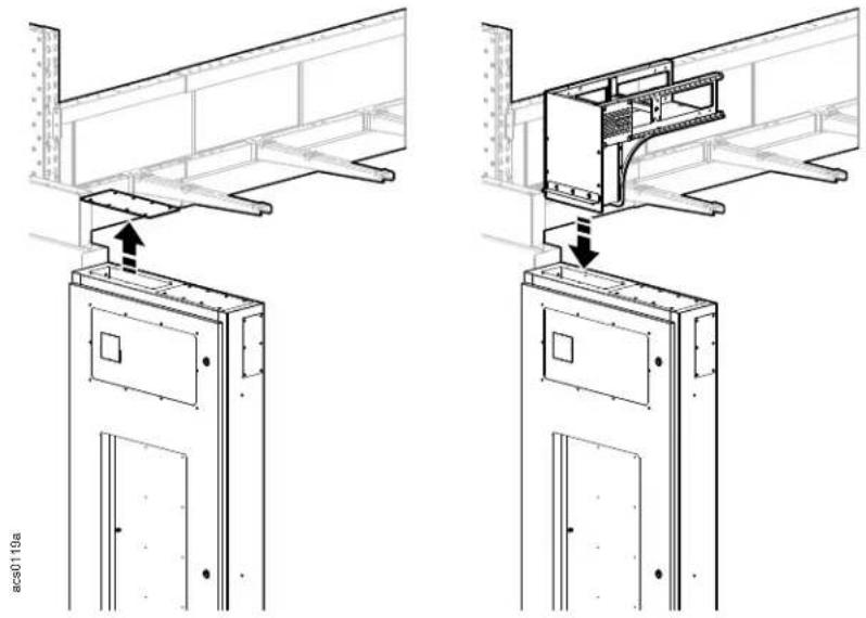
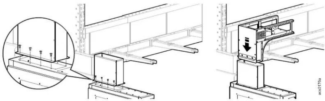
If there is a gap between the end module and the transition cabinet, use the 3 U or 6 U chimney to close the gap. Use the M5 x 12 flat head screws to fasten the chimney to the transition cabinet, then slide the end module into the chimney.
natural_image
Technical diagram showing structural assembly with a magnified inset of a structural component (no text or symbols present)NOTE: There is a nut on the inside of the end module for grounding purposes. You may need to angle the end module to get the nut into the transition cabinet or the chimney.
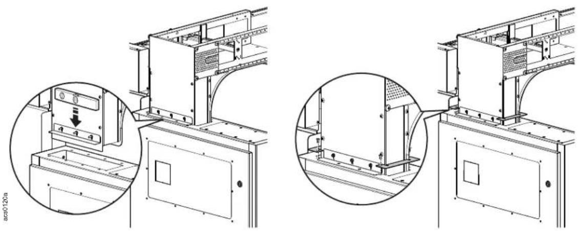
- Secure the support bracket on the end module to the top of the transition cabinet, or let it rest on top of the chimney. The support bracket has slotted holes on the side attached to the end module. The end module can be leveled by loosening the M5 nuts and adjusting the support bracket up or down.
If you do not use a chimney, secure the cover brackets on either side of the end module with M5 x 12 flat head screws. If you use a chimney, the cover brackets are not needed.
natural_image
Technical line drawings of industrial equipment components, showing front and side views with no visible text or symbols- The end module can be secured to the cantilever arm by loosening the fasteners holding the clips in place and sliding the clips toward the end module. The lip of the clip is slightly raised and will slide over the edge of the end module. Tighten the clip fasteners once they are in position.
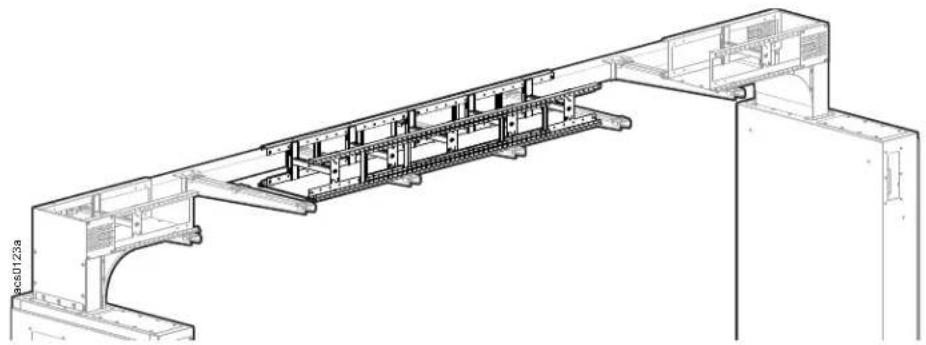
- Insert the sliding base into the body module. Slide the base out far enough to reach the end module.

natural_image
Technical line drawing of a structural frame assembly with an inset magnified view showing internal components (no text or symbols)- Place the body module on the mini cantilevers at the center of the pod aisle.
natural_image
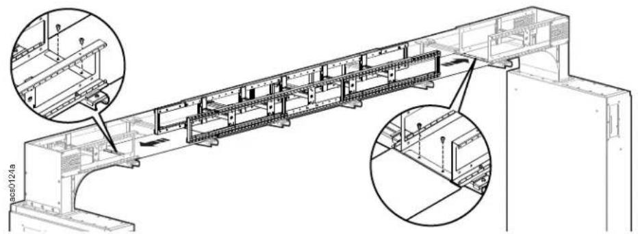
Technical line drawing of an industrial conveyor system with internal components (no text or symbols)- Attach the base to the end module with two M6 T30 screws.
natural_image
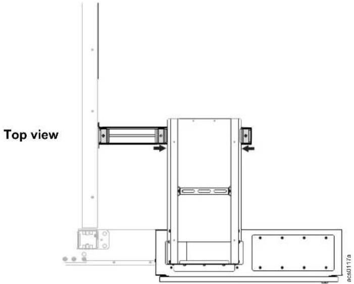
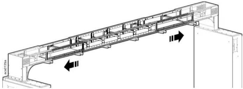
Technical line drawing of a structural frame assembly with two magnified insets showing internal components (no text or symbols present)- Remove the four (4) M6 T30 screws from the end of the body module and slide out the extension to reach the end module.
natural_image
Technical line drawing of a structural frame with internal components and directional arrows indicating movement (no text or symbols)- Replace and tighten the screws to secure the extension in its position.
natural_image
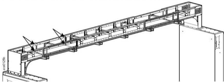
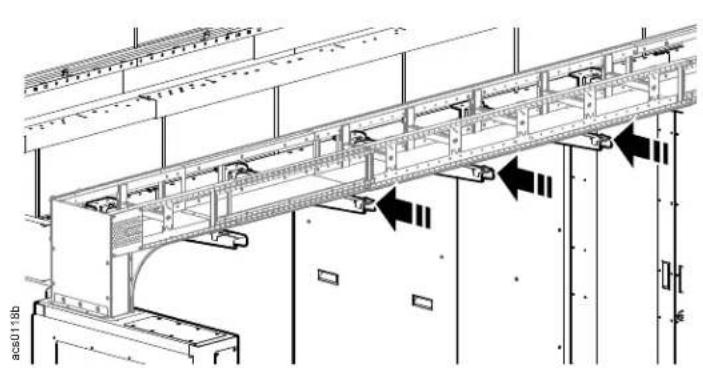
Architectural line drawing of a multi-level steel truss structure with support beams and structural supports (no text or symbols)- Loosen and then slide the clips on the mini cantilevers toward the power raceway and secure by tightening the clip fasteners.
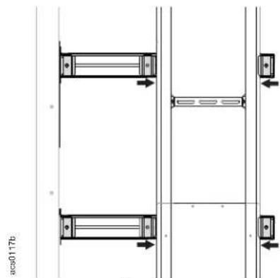
Top View
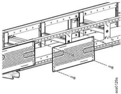
- Attach each side cover with four (4) Phillips head 10-32 self-tapping screws. Torque 2-2.5 N-m.
natural_image
Technical line drawing of a structural frame assembly (no text or symbols)If there is no transition cabinet or end module at either end of the body module, you can attach the cap end to the end of the body module with the same 10-32 self-tapping screws used to attach the side covers.
natural_image
Technical line drawing of a mechanical assembly with no visible text or symbols- If more stability is required, install the additional cable rung on the sliding frame with two T30 M6 screws.
natural_image
Technical line drawing of a structural assembly with beams and supports, showing a downward force arrow (no text or symbols present)Post Cantilevers and Suspension System
Possible configurations for Post Cantilevers:
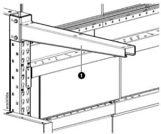
The square holes on the vertical posts are used for cantilever installation. The cantilevers can be installed at the top of the vertical post (1), just above the top length beam (2), or between the length beams (3).
natural_image
Technical line drawing of a structural frame with metal beams and supports (no text or symbols)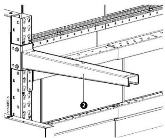
natural_image
Technical line drawing of a structural frame assembly with no visible text or symbols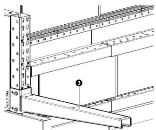
Standard configuration installation
- Install one cantilever to each of the corner vertical posts as shown using two M12 x 100 hex head bolts and M12 nuts.
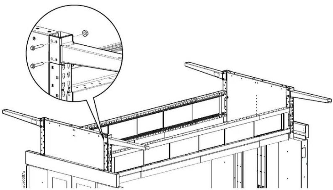
natural_image
Technical line drawing of a structural steel frame assembly with an inset magnified detail (no text or symbols)- Using appropriate lifting equipment and ladders, install the overhead support frame.
CAUTION
LIFTING HAZARD
At least two people are required to install this enclosure. Some parts may be heavy and/or excessive in size. For items weighing more than 12 kg (25 lbs), use more than one person.
Failure to follow these instructions can result in serious injury or equipment damage.
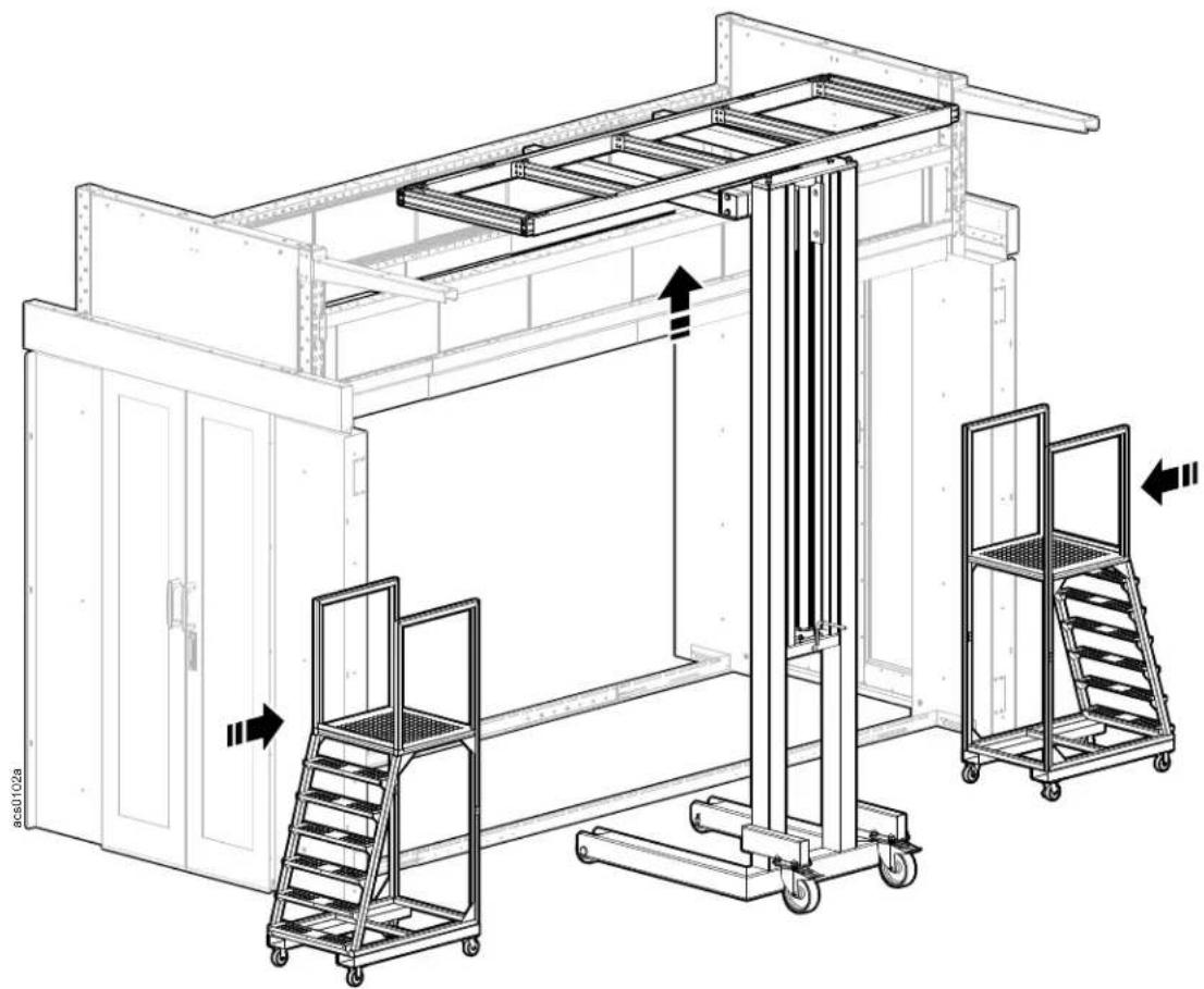
natural_image
Technical line drawing of a warehouse or industrial facility with two carts, one lifting a pallet, and directional arrows indicating movement (no text or symbols present)CAUTION
WORKING HEIGHT HAZARD
The working height for the assembly process can exceed 2.3 m (7.5 ft). The use of stepladders or scaffolding will be required during assembly.
Failure to follow these instructions can result in serious injury or equipment damage.
-
Loosen the two screws (1) on the support frame and slide the ends (2) out to reach the desired length.
-
Secure the support frame to the cantilevers with M6 x 12 pan head T30 screws and M6 nuts (3).
-
Tighten the screws (4) to secure the support frame ends.
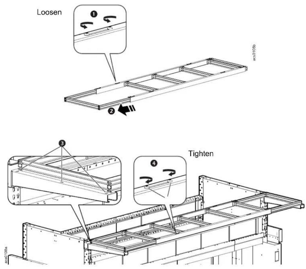
Shrink Roof
Install the roof panels to the top of the horizontal length beams using the M6 x 12 pan head T30 screws, insert nuts, and brackets. Use the washers for shrink roof panels secured to the small, end sections of the length beams. The washers raise the panels on the small sections so that all of the shrink roof panels are level with each other.
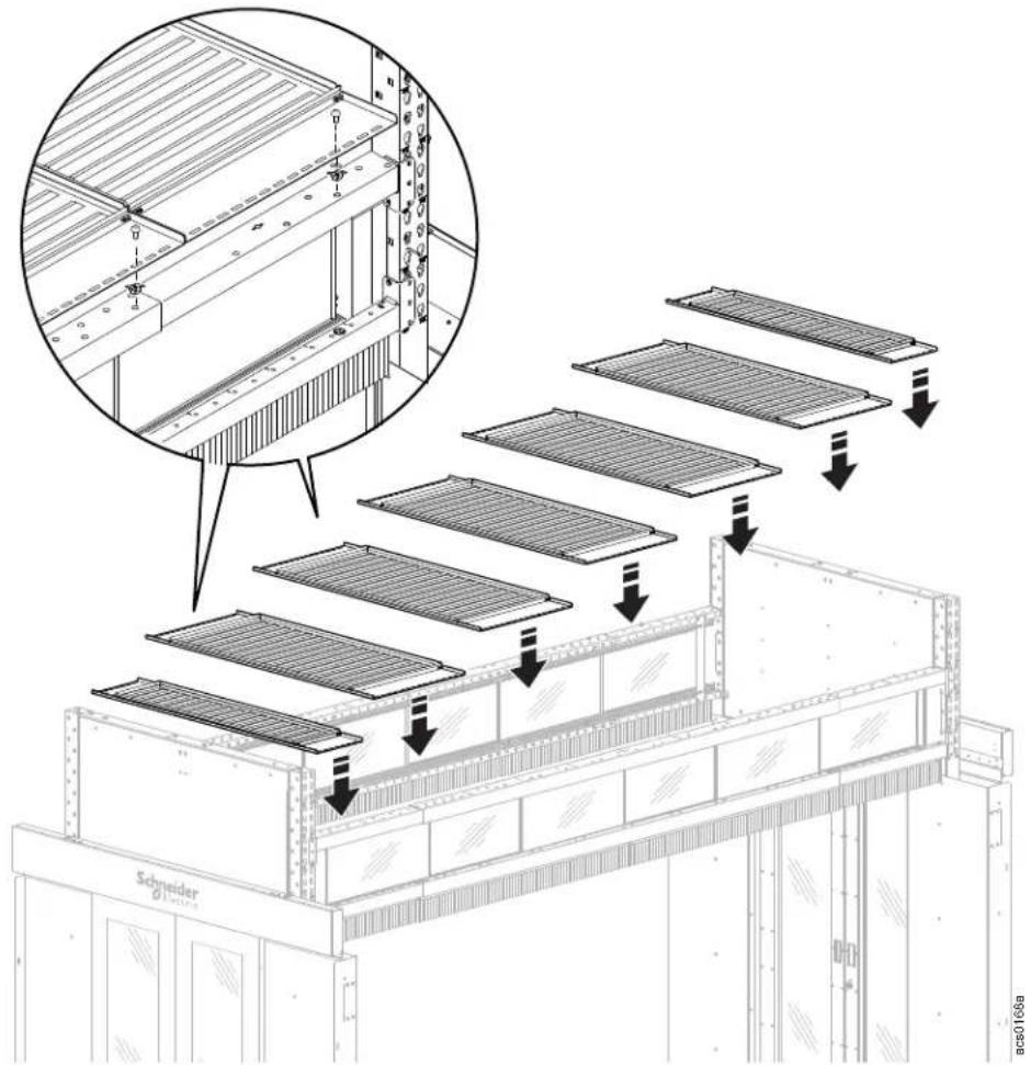
NOTE: If there are gaps between the shrink roof panels, you can paste the EPDM foam to the sides of the panels to fill in the gaps.
Use the roof filler panels and hex head screws to fill in the extra space at the end of the aisle, if any. The roof filler panels have slotted holes to allow for adjustment.
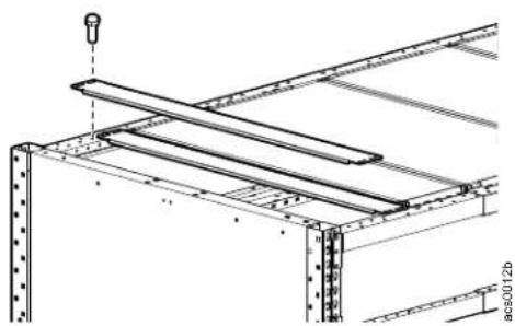
natural_image
Technical line drawing of a structural frame assembly with no visible text or symbolsHyperPod System Installation92
Drop Roof
Install the mounting rails
NOTICE
If a rack door is open when the dropout ceiling system activates, ceiling panels may be blocked by the rack door and not drop completely.
• Make sure the hinge flaps are in the locked position
- Attach the rail sections together on the ground first, then lift into place.
NOTE: To prevent damage or warping, do not exceed a length of 3600 mm (12 ft) for any pre-assembled section.
The bracket for the support assembly is attached to the top of the length beam with insert nuts and M6 x 16 pan head screws. Attach the ceiling support assembly to the bracket with four (4) M6 x 10 pan head screws.
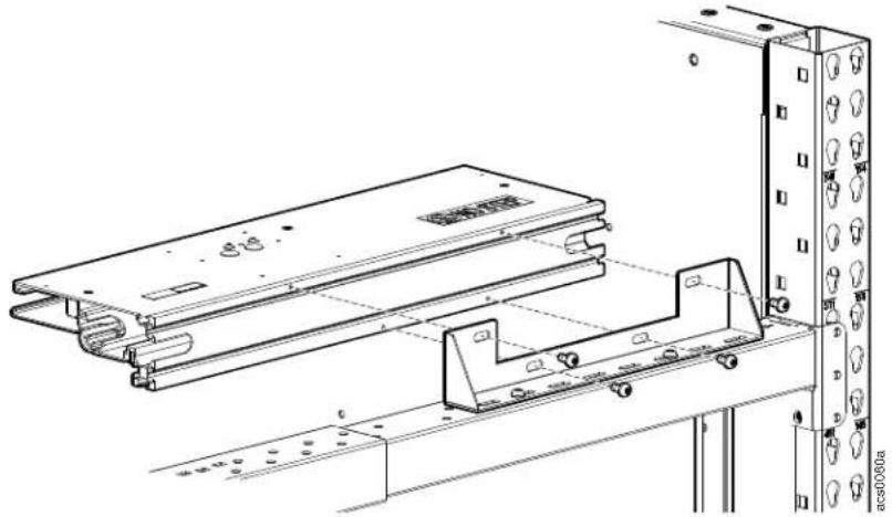
natural_image
Technical line drawing of a mechanical assembly with mounting brackets and a vertical panel (no text or symbols)a. Install connectors to two sections of ceiling support assembly to connect them together.
b. Secure with the baying bracket and two M4 x 8 pan head screws.
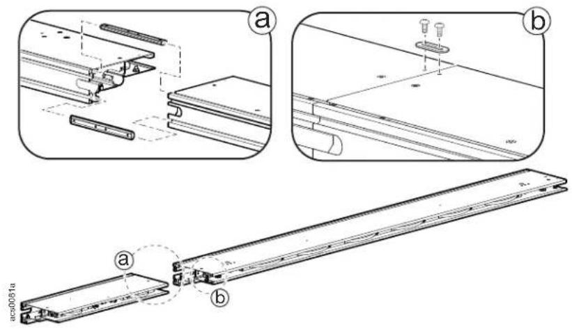
Install the ceiling panels
IMPORTANT: Before proceeding, ensure that the hinge flaps are locked in place before installing the ceiling panels.
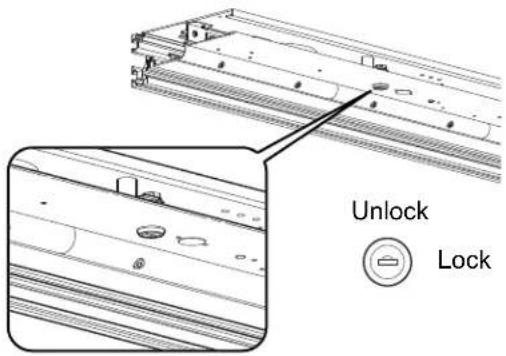
Install the ceiling panels:
-
Remove the protective plastic.
-
Slide one edge into one of the mounting rails.
-
Push the panel in and compress the springs allowing room to insert the opposite end of the panel in the mounting rail on the opposite row.
-
Release the panel. The spring retainers will automatically center the panels within the aisle.
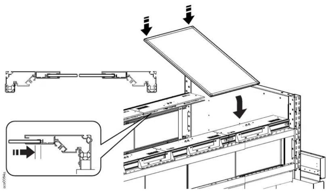
Solid Roof Filler Panel for Drop Roof
Solid roof panels are used to fill in any space between the drop roof panels and the end of the frame. Use the 50 mm (2 in.) solid roof panel for the drop roof first. Attach this panel to the drop roof panel with the pan head screws. Attach the panel to the length beam with the hex head screws.
Continue to add solid roof panels until all the space between the last drop roof panel and the end of the aisle is covered.
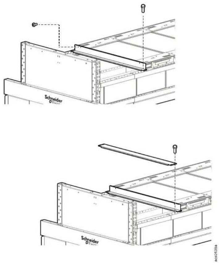
9c501389
Ceiling Panel Lock System
IMPORTANT: This system is designed to work with standard response sprinklers only.
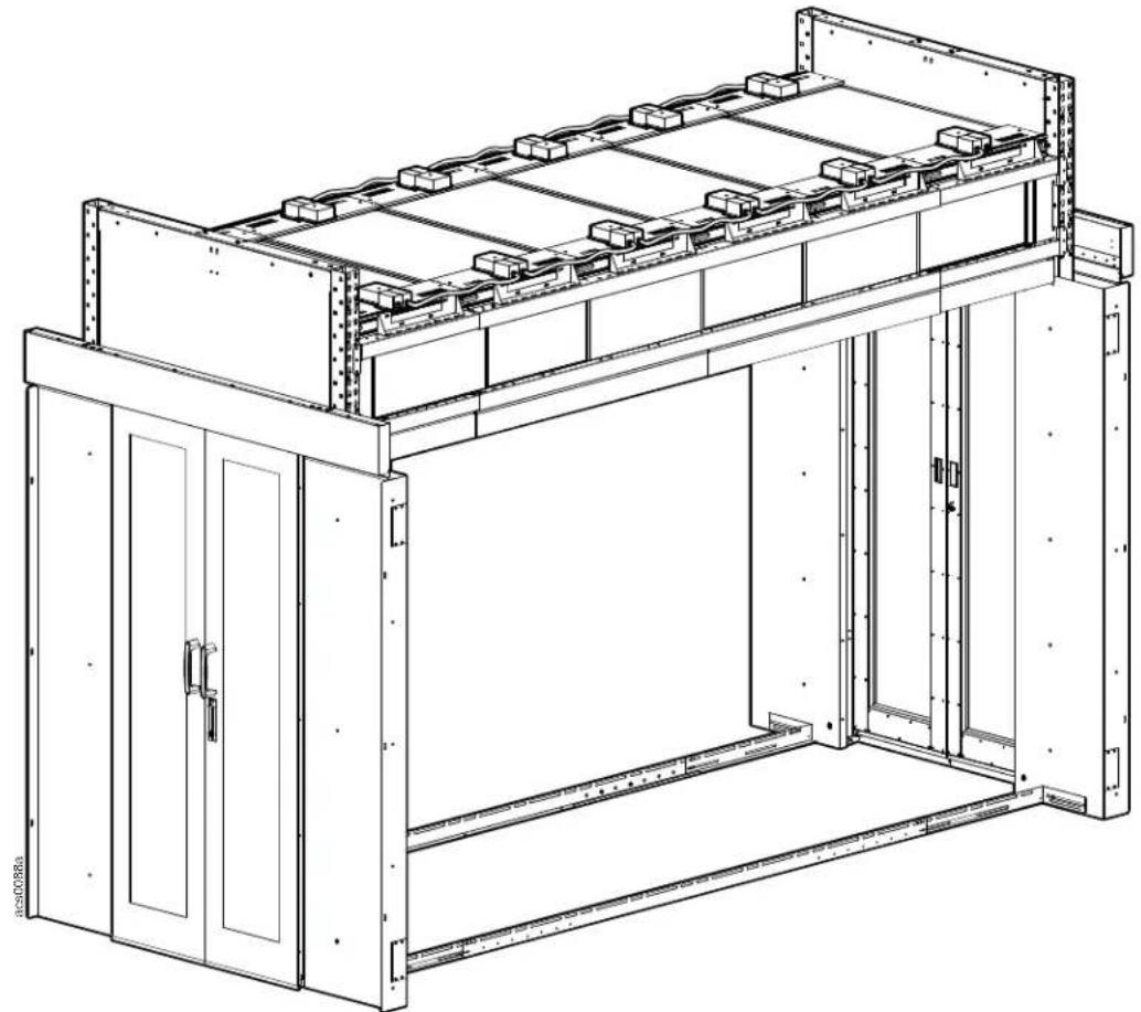
natural_image
Technical line drawing of a multi-level battery storage unit with mounting brackets and internal compartments (no text or symbols)System diagram
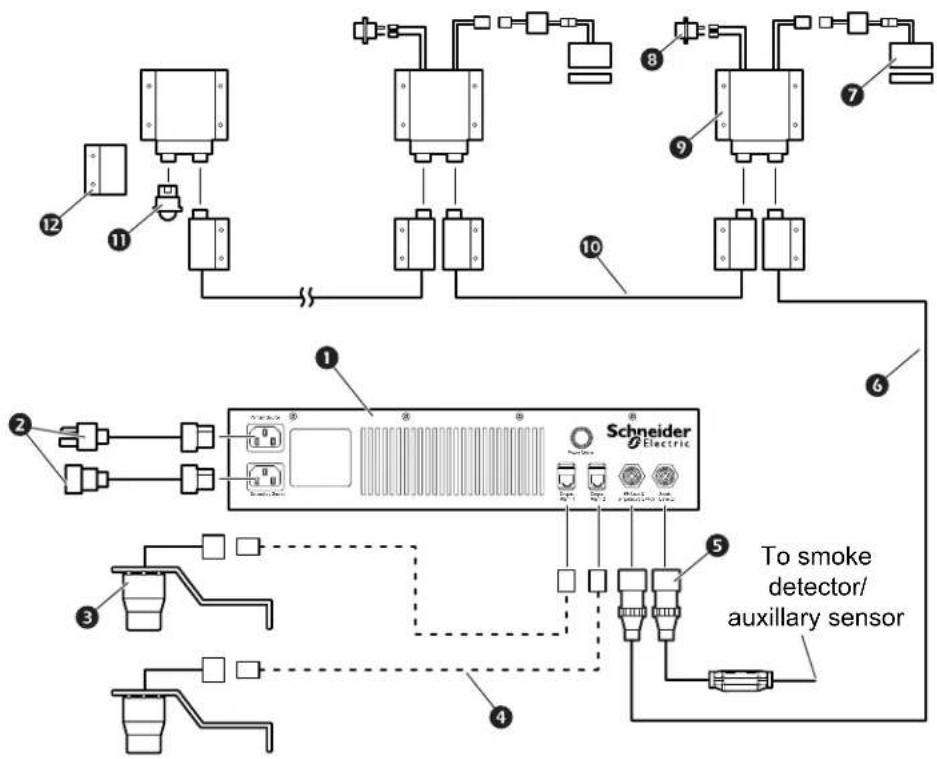
flowchart
graph TD
    A["1"] --> B["2"]
    B --> C["3"]
    C --> D["4"]
    D --> E["5"]
    E --> F["6"]
    F --> G["7"]
    G --> H["8"]
    H --> I["9"]
    I --> J["10"]
    J --> K["11"]
    K --> L["12"]
    L --> M["13"]
    M --> N["14"]
    N --> O["15"]
    O --> P["16"]
    P --> Q["17"]
    Q --> R["18"]
    R --> S["19"]
    S --> T["20"]
    T --> U["Schneider Electric"]
Item Description
① Dropout power supply control box
2 Power cord
3 Alarm beacon
4 Field supplied CAT-5 cable
5 4-pin jumper (if no smoke detector is in use)
Smoke detector cable (if smoke detector is in use)
6 Wire assembly - power supply to wiring box
⑦ Electromagnetic lock (up to 30 per control box)
8 Temperature switch
9 Wiring box
10 Box-to-box wire harness
Box-to-box wire harness, across aisle
⑪ Terminal jumper
12 Wiring box cover
Power supply component identification
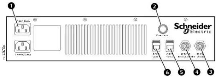
Item Description
① AC line, primary/secondary
② Power status indicator light
③ Smoke detector connection
4 Electromagnetic lock temp. switch connection
5 Dropout alarm 2
6 Dropout alarm 1
Install the power supply
- Attach the mounting brackets to the sides of the power supply.
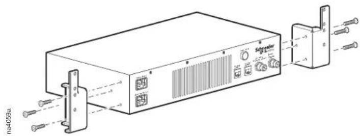
- Install the power supply onto the mounting rails of the enclosure using four (4) caged nuts, cup washers, and M6 x 16 screws.
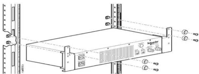
Install electromagnetic locks
Attach the electromechanical lock to the ceiling panel support rails.
- Remove the two large hole plugs from the top of the ceiling panel supports.
- Disconnect the electromechanical lock from the printed circuit board assembly.
- Guide the wire connector from electromechanical lock through the hole in the top of the ceiling panel support.
- Install the top half of the electromechanical lock to the top of the ceiling panel support rail with two M5 x 8 screws each. Place the printed circuit board assembly on top of the ceiling panel support rail and reconnect to the electromechanical lock.
- Install the lower half of the electromechanical lock and spacer to the ceiling panel support rail hinged flap using one M5 x 10 screw each.
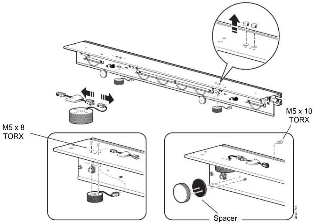
Install the temperature switches
Using two M4 nuts each, install the temperature switches to the ceiling panel support rail hinged flap.
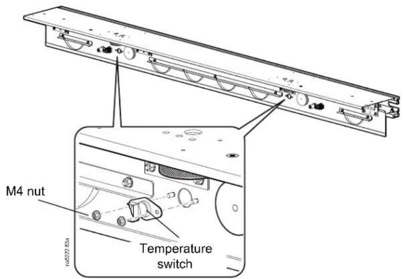
Install electrical boxes and route cables
-
Make the connection to the electromagnetic locks and temperature switches. IMPORTANT: Position wires so they do not interfere with the closing of the hinge flap.
-
Install the wire boxes to the top of the ceiling panel mounting rails using four (4) M4 x 8 screws each.
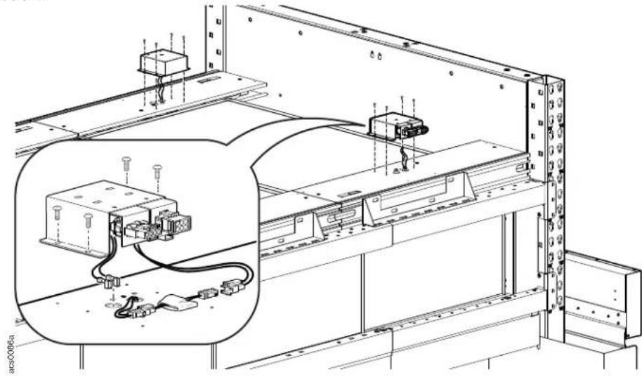
natural_image
Technical line drawing of an electrical enclosure assembly with mounting brackets and wiring (no text or symbols)- Connect the wiring boxes together with box-to-box wire assemblies and the cross-aisle wiring assembly.
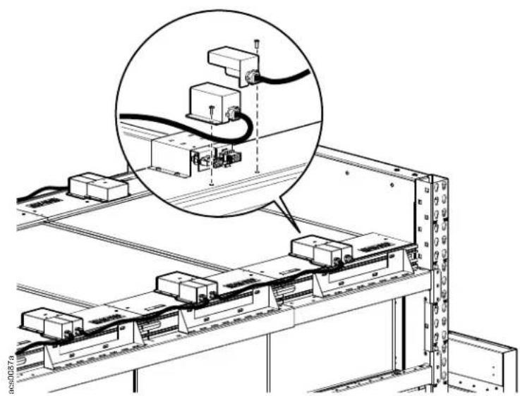
natural_image
Technical line drawing of a mechanical assembly with zoomed-in detail view (no text or symbols)Install the alarm beacon
- Using two M6 x 12 and channel nuts each, install two alarm beacons per power supply control box positioning them at opposite corners of the aisle.
NOTE: For clarity, electrical boxes and wires are not shown.
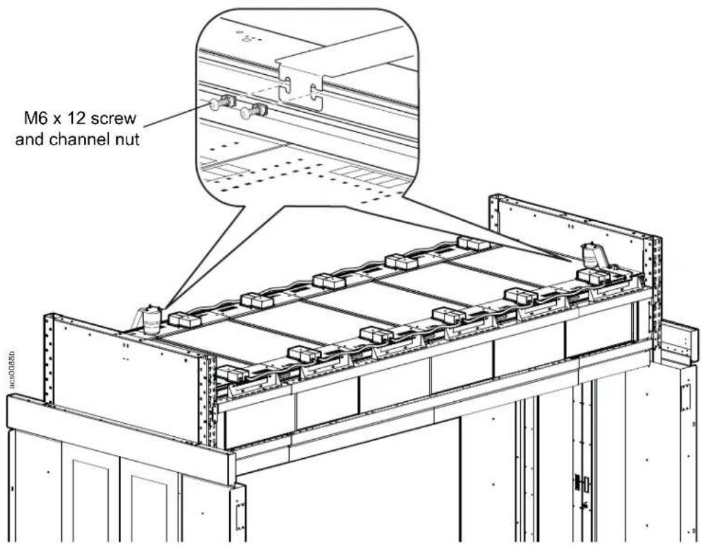
- Connect the alarm beacons to the power supply control box using field supplied CAT-5 cable.
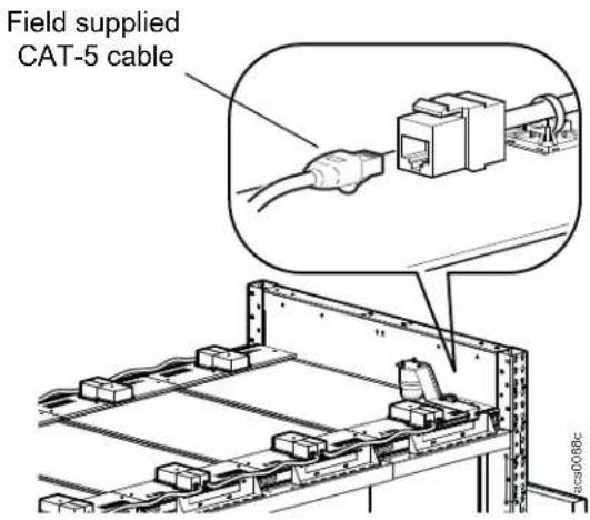
Install the smoke detector
Connect the 4-pin jumper to the Smoke Sensor connector if an external smoke detector is not being used.
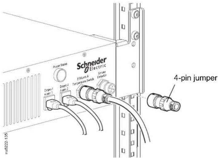
If an external smoke detector is being used:
- Strip the field-supplied wire to be used to connect to the building smoke detector. Leave a minimum of 15 mm (0.6 in.) of exposed wire.
- Insert the wire into the open end of the smoke detector cable. Make sure the button on the connection end is in the open position.
NOTE: The field-supplied wire needs to be a shielded 20 AWG or network cable that is grounded at the customer end connection point. The maximum routing distance for the wire is 76 m (250 ft). For best performance, avoid interference from high-voltage cables and devices such as a UPS or PDU.
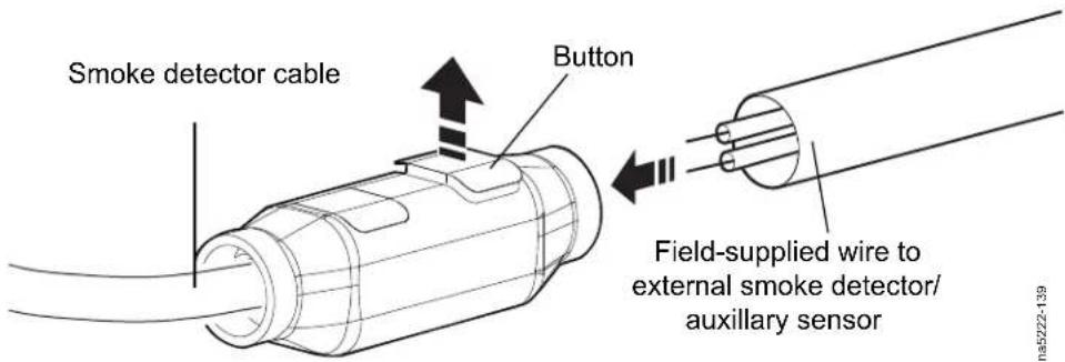
- Use pliers to close the button and terminate the wires.
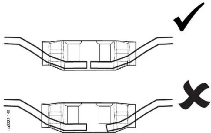
- Connect the smoke detector cable to the Smoke Sensor connector.
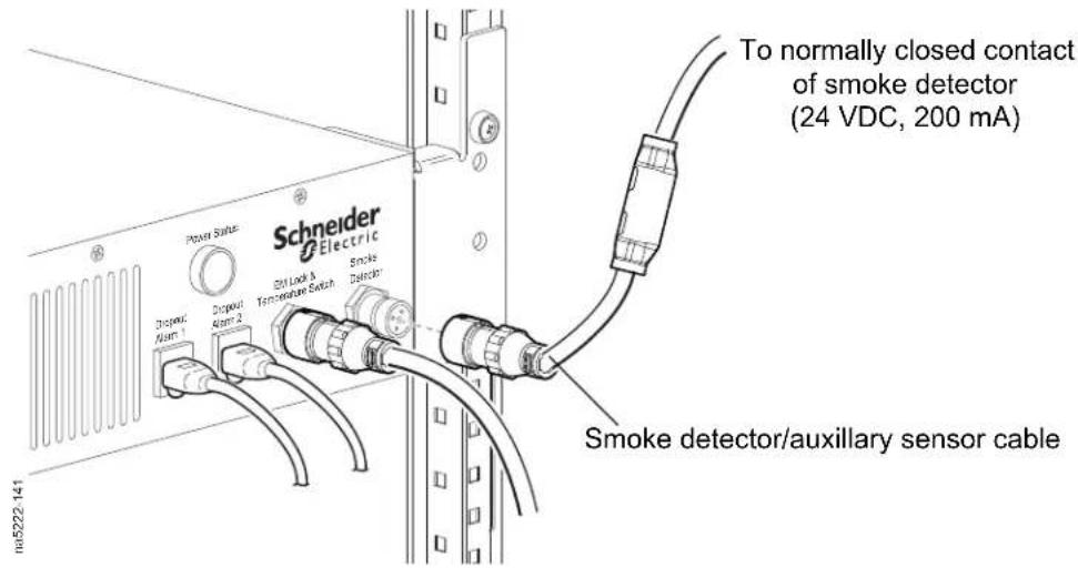
- Neatly bundle all cabling using tie wraps and cable holders.
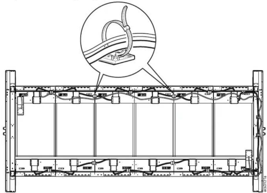
natural_image
Technical line drawing of a server rack with cable routing and a magnified inset showing cable attachment (no text or symbols)Maintenance steps for dropout ceiling system:
- Lock the hinge flaps using mechanical locks.
- Turn OFF or remove power to the electromechanical locks.
- Perform necessary maintenance.
- Turn ON or provide power to the electromechanical locks.
-
Unlock the mechanical lock on hinge flaps.
-
Push each hinge flap upwards so that the lower half of the electromagnetic lock engages with the upper half. A clicking sound will be heard when the electromagnetic lock is fully engaged.
Troubleshooting diagram
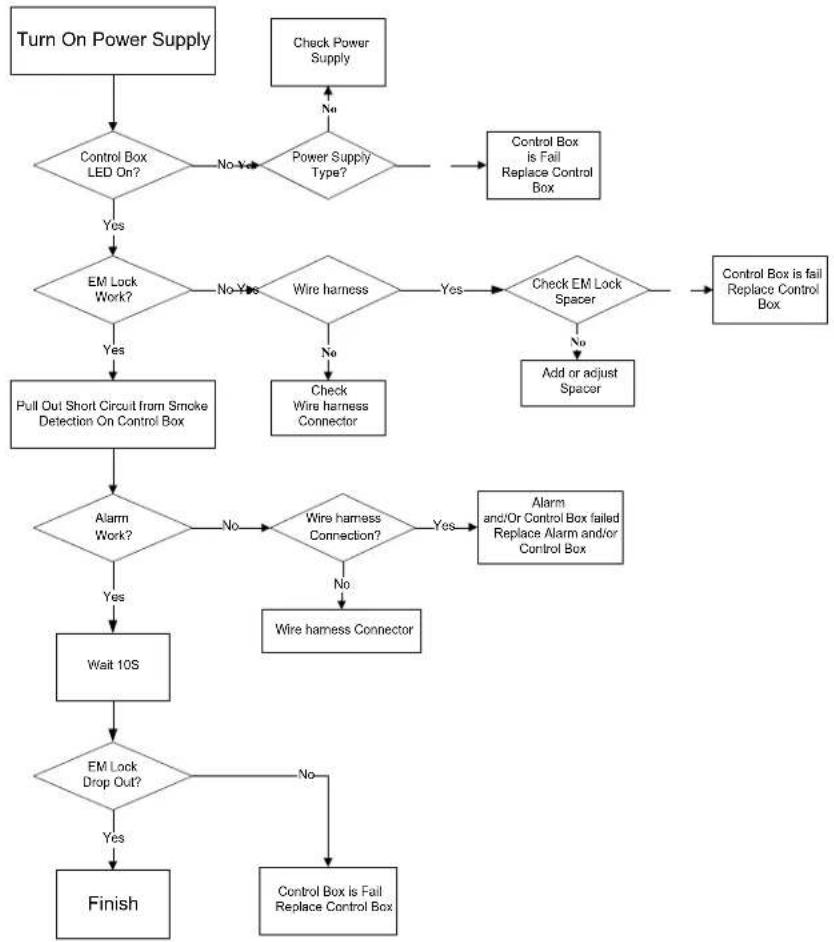
flowchart
graph TD
    A["Turn On Power Supply"] --> B{Control Box LED On?}
    B -->|Yes| C{EM Lock Work?}
    B -->|No| D{Power Supply Type?}
    D -->|No| E["Check Power Supply"]
    D -->|Yes| F{Wire harness}
    F -->|Yes| G{Check EM Lock Spacer}
    F -->|No| H["Add or adjust Spacer"]
    G -->|No| I["Control Box is Fail Replace Control Box"]
    G -->|Yes| J["Pull Out Short Circuit from Smoke Detection On Control Box"]
    H --> K["Add or adjust Spacer"]
    C -->|Yes| L{Alarm Work?}
    C -->|No| M{Wire harness Connection?}
    L -->|Yes| N["Wait 10S"]
    L -->|No| O{EM Lock Drop Out?}
    N --> P["Wait 10S"]
    O -->|Yes| Q["Finish"]
    O -->|No| R["Control Box is Fail Replace Control Box"]
    P --> S["End"]
    Q --> S
Lighting Kit


DANGER
ELECTRIC SHOCK HAZARD
Do not use an extension cord with this product.
Failure to follow these instructions will result in death or serious injury.
Lighting control unit component identification
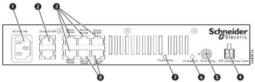
Item Description Item Description
| 1 | AC line inlet | 5 | Time setting |
| 2 | Control group | 6 | Console port |
| 3 | Motion sensor input (4) | 7 | Power status |
| 4 | LED light power outlet | 8 | Manual switch input (2) |
Install the mounting brackets onto the lighting control unit.

Lighting control unit installation options
The lighting control unit can be installed in a rack or in the crossover tray accessory if you have that option.
To install the lighting control to the mounting rails of the enclosure, use four (4) caged nuts, cup washers, and M6 x 16 screws.
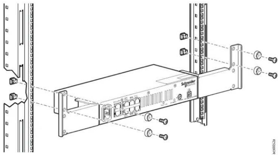
To install the lighting control inside the crossover tray, remove the cover plate on the crossover tray and attach the lighting control mounting brackets with four (4) M6 x 16 screws.
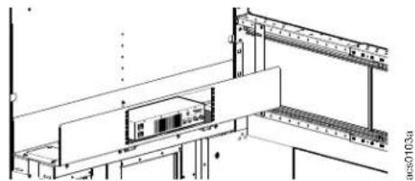
natural_image
Architectural line drawing of a building facade with structural beams and a central storage unit (no text or symbols)Lighting brackets
- The lighting brackets consist of long and short pieces and mounting hardware. One of the long brackets is for the left and the other long bracket is for the right. Use M6 x 16 screws to connect the brackets to the length beams.
If your aisle is 2.4 m (8 ft) long, use two long brackets (one left and one right) for each side of a aisle.
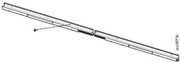
natural_image
Technical line drawing of a long rectangular mechanical component with internal components and a small inset detail labeled 'acsc0073b' (no text or symbols on the main structure)If your aisle is longer than 2.4 m (8 ft), connect two long brackets in the middle of the aisle, then add short brackets on either end of the long brackets.
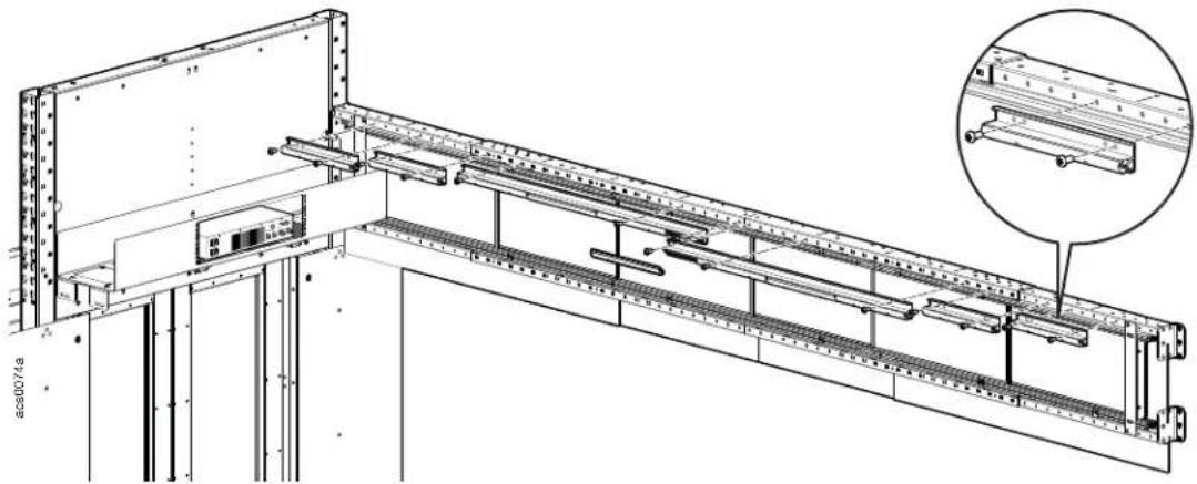
natural_image
Technical line drawing of a structural beam assembly with mounting brackets and a magnified inset showing detail (no text or symbols)NOTE: For a 3 m (10 ft) aisle, add one extra bracket on each side of the long brackets. For a 3.6 m (12 ft) aisle, add two extra brackets on each side of the long brackets. There should be about 150 mm (6 in) at the ends of each length beam in both configurations. For extended aisles, you may need to drill holes for the mounting hardware.
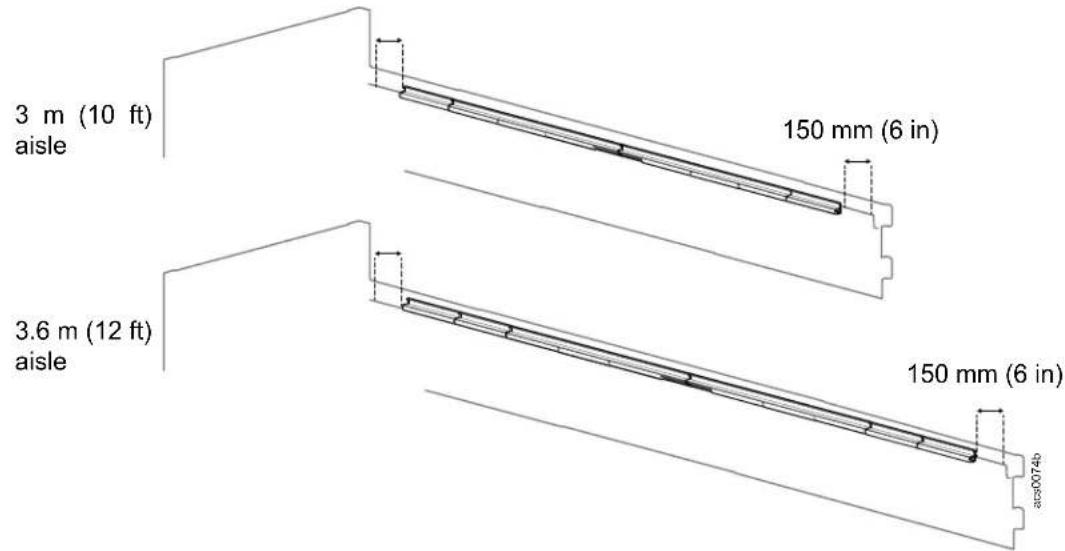
- Remove the wiring covers from the brackets. Arrange the LED lights evenly in the brackets on each side of the aisle. Place any wires used in the upper and lower channels in the extrusion of the mounting brackets. Use M4 x 12 screws to secure the lights to the brackets. Re-install wiring covers to fill in space between each light.
NOTE: a. The provided cable supports a maximum length of two wiring covers.
b. A maximum of twelve lights can be installed per lighting control unit.
c. It is not recommended to use 0 mm spacing (end-to-end connectors) between every LED light. It is simpler to adapt 300 mm (12 in.) or 600 mm (23.6 in.) spacing to the variable lengths of the HyperPod aisle.
d. If your aisle has a crossover tray, you can use the crossover tray to route any lighting cables to the other side of the aisle.
| ⚠ CAUTION |
| WIRE PINCH HAZARDDo not use the center channel to route wire. This is reserved for the lighting and wire cover fasteners.Failure to follow these instructions can result in injury or equipment damage. |
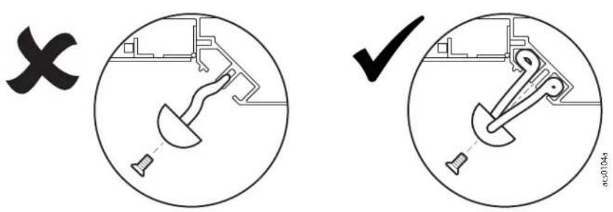
LED lights can be connected together as shown.
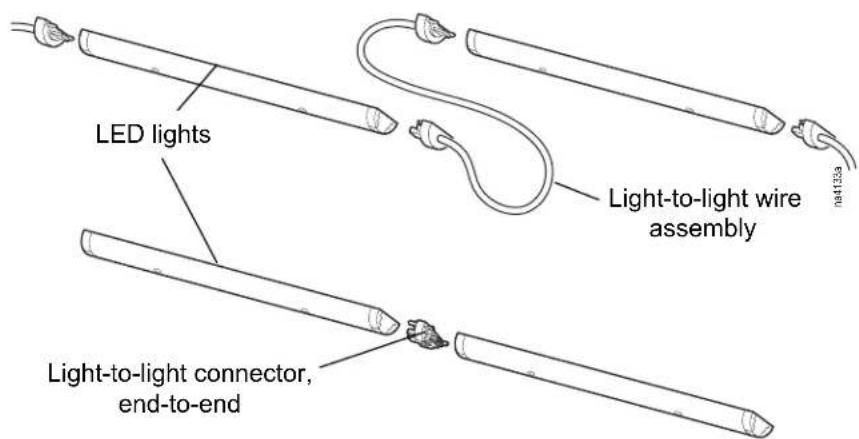
- Install the motion sensor to the inside end cap panel, at the center of the doorway.
The bracket is attached to the motion sensor with two M4 x 8 TORX screws.
The bracket with motion sensor is installed to the end cap with two M4 x 8 TORX pan head, thread forming screws.
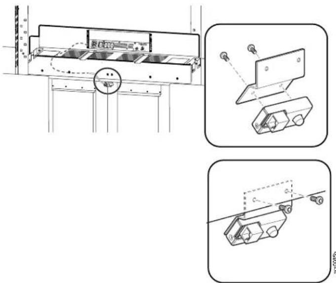
Lighting System Setup and Operation
Motion detection. One lighting control unit can support four (4) motion sensors. If any of the sensors detect movement, the lighting control unit will turn on its LED lighting bank.
NOTE: The motion sensors range, or sensitivity, cannot be adjusted
Time setting. The time setting control is used to control the length of time the LED lighting bank will be ON. If the motion sensor is triggered during the ON cycle, the timer will be restarted. The LED lights can be turned OFF using the manual switch.
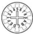 | Time Setting | 0 | 1 | 2 | 3 | 4 | 5 | 6 | 7 | 8 | 9 | A | B | C | D | E | F | |
| LED ON delay (minutes) | 1 | 5 | 10 | 15 | 20 | 25 | 30 | 35 | 40 | 45 | 50 | 55 | 60 | 65 | 70 | 75 |
Manual switch. Pressing a manual switch will turn off the lights in its group, and the motion sensor function becomes inactive for 10 seconds. After 10 seconds, the motion sensor function will once again become active and take over the control.
Power status indicator. The power status indicator illuminates when power is supplied to the unit and it is functioning normally.
Lighting Kit Schematic overview.
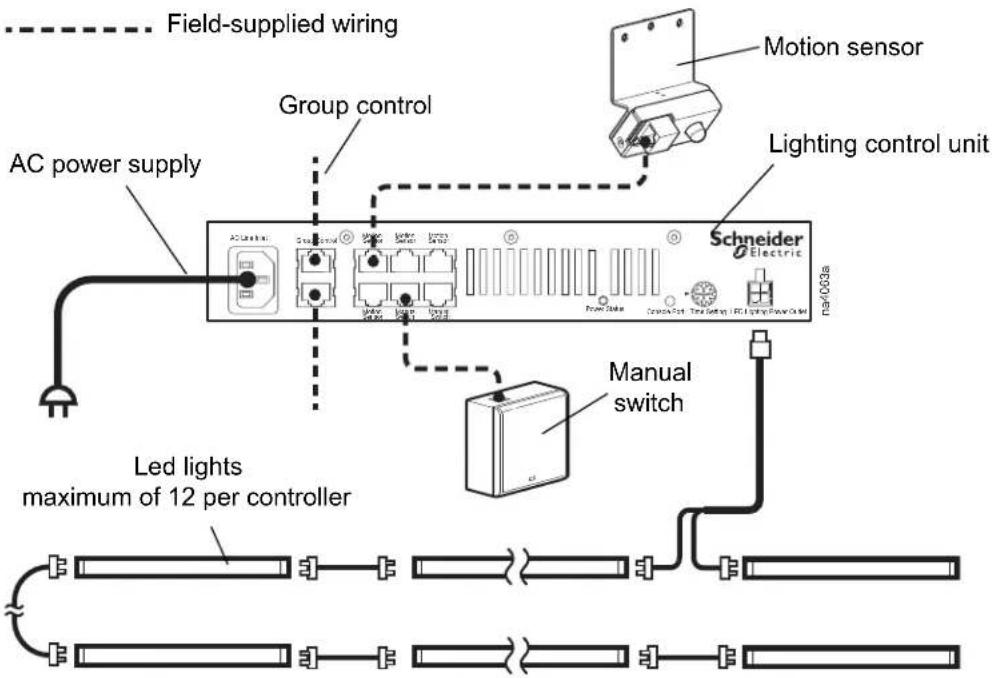
A maximum of five (5) controllers can be connected together via the Group Control connection ports.
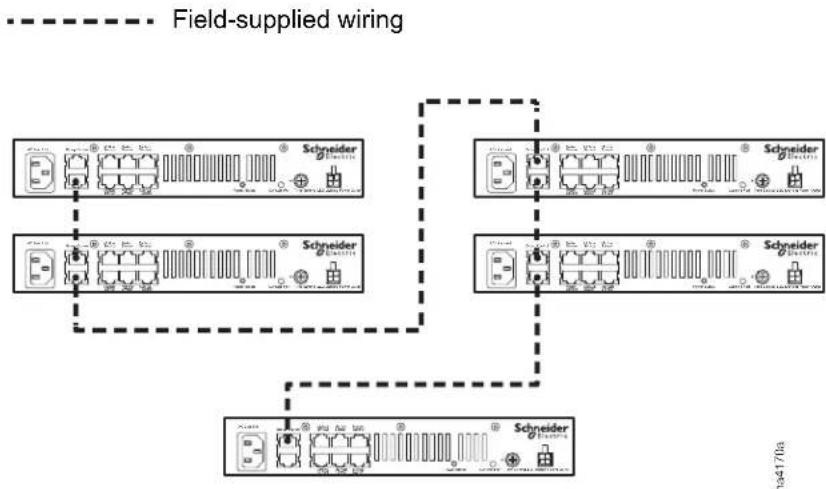
flowchart
graph TD
    A["Field-supplied wiring"] --> B["Switch 1"]
    A --> C["Switch 2"]
    A --> D["Switch 3"]
    B --> E["Switch 4"]
    C --> F["Switch 5"]
    D --> G["Switch 6"]
    E --> H["Switch 7"]
    F --> I["Switch 8"]
    G --> J["Switch 9"]
    H --> K["Switch 10"]
    I --> L["Switch 11"]
    J --> M["Switch 12"]
    K --> N["Switch 13"]
    L --> O["Switch 14"]
    M --> P["Switch 15"]
The manual switch can be located inside or outside of the containment area and should be attached to a surface using one of the three (3) methods shown below.
Fastener method:
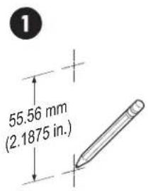
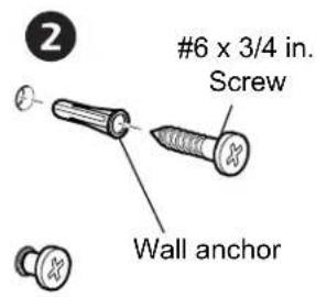
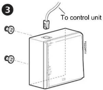
Magnet method:
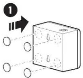
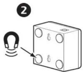
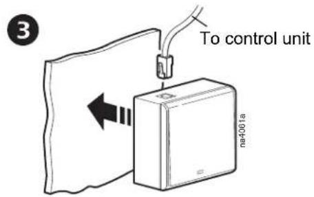
Hook-and-loop method:
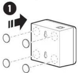
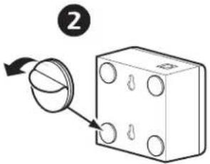
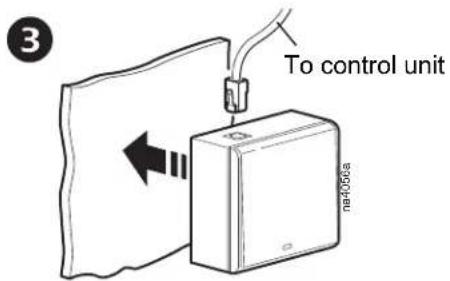
Rack Height Adapter
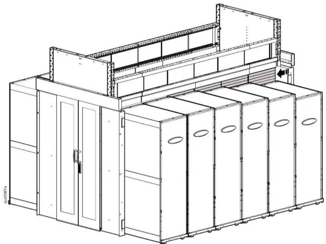
natural_image
Technical line drawing of a multi-level industrial machine with control panel and storage unit (no text or symbols)Add rack height adapter brush panels to the bottom of the length beam. Attach the height adapter bracket to the small ends of the length beam with the 10-32 x 5/16 pan head Phillips screws. To attach the height adapter bracket to the middle portion of the length beam, put the M6 insert nuts into the square holes, then use the provided M6 x 16 pan head T30 screws to install the bracket.
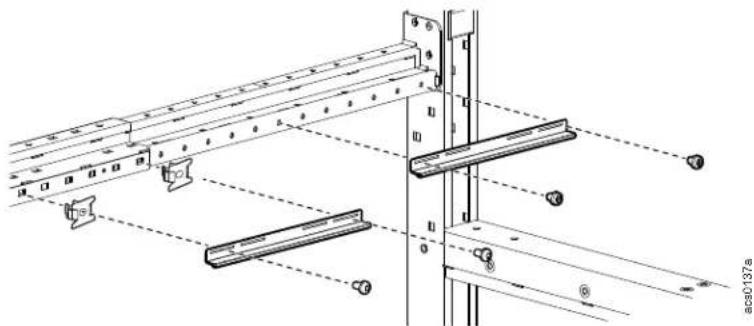
natural_image
Technical line drawing of a structural support frame with mounting brackets and mounting holes (no text or symbols)Add additional height adapter brushes by sliding the top edge of the height adapter you are adding to the bottom of the previous height adapter until the area between the top of the rack and the length beam is completely enclosed.
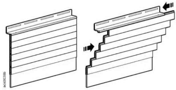
natural_image
Technical illustration of two structural components with hatching patterns, showing alignment and deformation (no text or symbols)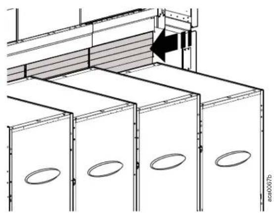
natural_image
Architectural diagram of a building facade with structural ribs and ventilation slots (no text or symbols)Single Swing Door
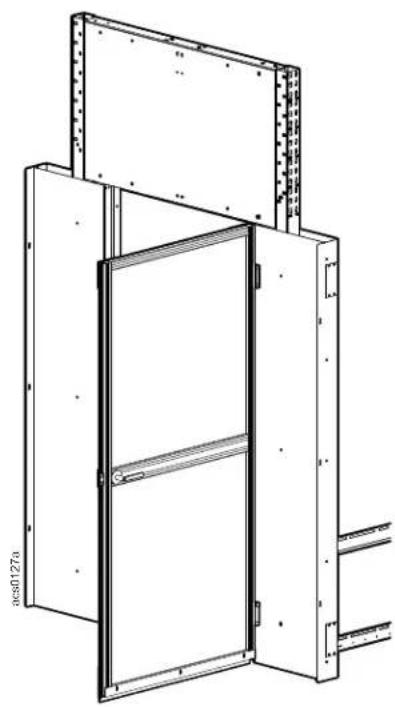
natural_image
Technical line drawing of a door frame assembly with mounting flanges (no text or symbols)- Install the 3 door closers in the door frame cover.
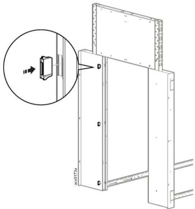
natural_image
Technical line drawing of a door frame assembly with an inset showing a component detail (no text or symbols)- Cut the EPDM foam into four (4) pieces that will fit around the door closers. Peel the covering away from the EPDM foam, and stick the EPDM foam to the door frame between the door closers.
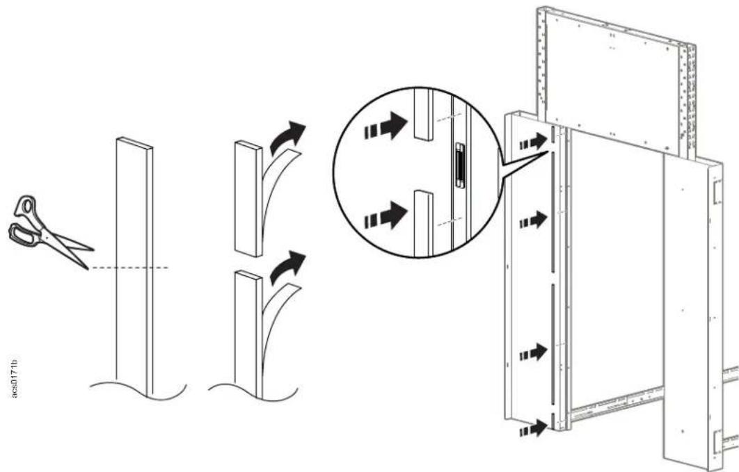
- Attach the door hinges to the corresponding holes in the door frame cover with M6 x 12 screws (not provided). Then close the door.
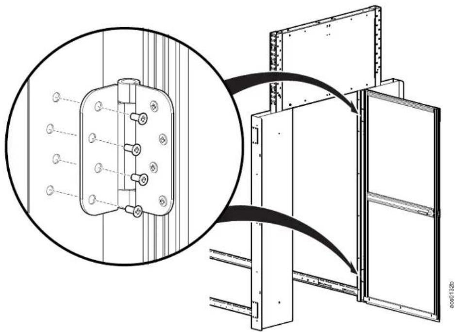
natural_image
Technical diagram showing a mechanical assembly with a close-up inset of a component detail (no text or symbols present)- Adjust the tension in each hinge to control how quickly the door closes:
a. Use the provided Hex wrench to turn the adjustment capstan to the right. b. Insert a tension pin into the tension hole.
NOTE: The door must be closed while you adjust the tension.
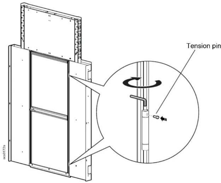
One-Year Factory Warranty
The limited warranty provided by Schneider Electric in this Statement of Limited Factory Warranty applies only to products you purchase for your commercial or industrial use in the ordinary course of your business.
Terms of Warranty
Schneider Electric warrants its products to be free from defects in materials and workmanship for a period of one year from the date of purchase. The obligation of Schneider Electric under this warranty is limited to repairing or replacing, at its sole discretion, any such defective products. This warranty does not apply to equipment that has been damaged by accident, negligence or misapplication or has been altered or modified in any way. Repair or replacement of a defective product or part thereof does not extend the original warranty period. Any parts furnished under this warranty may be new or factory-remanufactured.
Non-transferable Warranty
This warranty extends only to the original purchaser who must have properly registered the product. The product may be registered at the Schneider Electric Web site, www.apc.com.
Exclusions
Schneider Electric shall not be liable under the warranty if its testing and examination disclose that the alleged defect in the product does not exist or was caused by end user's or any third person's misuse, negligence, improper installation or testing. Further, Schneider Electric shall not be liable under the warranty for unauthorized attempts to repair or modify wrong or inadequate electrical voltage or connection, inappropriate on-site operation conditions, corrosive atmosphere, repair, installation, start-up by non-Schneider Electric designated personnel, a change in location or operating use, exposure to the elements, Acts of God, fire, theft, or installation contrary to Schneider Electric recommendations or specifications or in any event if the Schneider Electric serial number has been altered, defaced, or removed, or any other cause beyond the range of the intended use.
THERE ARE NO WARRANTIES, EXPRESS OR IMPLIED, BY OPERATION OF LAW OR OTHERWISE, OF PRODUCTS SOLD, SERVICED OR FURNISHED UNDER THIS AGREEMENT OR IN CONNECTION HEREWITH. APC DISCLAIMS ALL IMPLIED WARRANTIES OF MERCHANTABILITY, SATISFACTION AND FITNESS FOR A PARTICULAR PURPOSE. APC EXPRESS WARRANTIES WILL NOT BE ENLARGED, DIMINISHED, OR AFFECTED BY AND NO OBLIGATION OR LIABILITY WILL ARISE OUT OF, SCHNEIDER ELECTRIC RENDERING OF TECHNICAL OR OTHER ADVICE OR SERVICE IN CONNECTION WITH THE PRODUCTS. THE FOREGOING WARRANTIES AND REMEDIES ARE EXCLUSIVE AND IN LIEU OF ALL OTHER WARRANTIES AND REMEDIES. THE WARRANTIES SET FORTH ABOVE CONSTITUTE SCHNEIDER ELECTRIC'S SOLE LIABILITY AND PURCHASER'S EXCLUSIVE REMEDY FOR ANY BREACH OF SUCH WARRANTIES. SCHNEIDER ELECTRIC WARRANTIES EXTEND ONLY TO PURCHASER AND ARE NOT EXTENDED TO ANY THIRD PARTIES.
IN NO EVENT SHALL SCHNEIDER ELECTRIC, ITS OFFICERS, DIRECTORS, AFFILIATES OR EMPLOYEES BE LIABLE FOR ANY FORM OF INDIRECT, SPECIAL, CONSEQUENTIAL OR PUNITIVE DAMAGES, ARISING OUT OF THE USE, SERVICE OR INSTALLATION, OF THE PRODUCTS, WHETHER SUCH DAMAGES ARISE IN CONTRACT OR TORT, IRRESPECTIVE OF FAULT, NEGLIGENCE OR STRICT LIABILITY OR WHETHER SCHNEIDER ELECTRIC HAS BEEN ADVISED IN ADVANCE OF THE POSSIBILITY OF SUCH DAMAGES. SPECIFICALLY, SCHNEIDER ELECTRIC IS NOT LIABLE FOR ANY COSTS, SUCH AS LOST PROFITS OR REVENUE, LOSS OF EQUIPMENT, LOSS OF USE OF EQUIPMENT, LOSS OF SOFTWARE, LOSS OF DATA, COSTS OF SUBSTITUENTS, CLAIMS BY THIRD PARTIES, OR OTHERWISE.
NO SALESMAN, EMPLOYEE OR AGENT OF SCHNEIDER ELECTRIC IS AUTHORIZED TO ADD TO OR VARY THE TERMS OF THIS WARRANTY. WARRANTY TERMS MAY BE MODIFIED, IF AT ALL, ONLY IN WRITING SIGNED BY AN SCHNEIDER ELECTRIC OFFICER AND LEGAL DEPARTMENT.
Warranty Claims
Customers with warranty claims issues may access the Schneider Electric customer support network through the Support page of the Schneider Electric Web site, www.schneiderelectric.com/support. Select your country from the country selection pull-down menu at the top of the Web page. Select the Support tab to obtain contact information for customer support in your region.
Worldwide Customer Support
Customer support for this product is available at www.apc.com.
© 2018 Schneider Electric. All Rights Reserved. APC by Schneider Electric and the APC logo are trademarks owned by Schneider Electric Industries, S.A.S. All other trademarks belong to their respective owners.





- Schneider Electric Legal Disclaimer
- Table of Contents
- General Information ....1
- Safety....5
- Planning the Installation....7
- Component Identification ....11
- Accessory Kits.... 61
- Installation of Optional Accessories 74
- General Information
- Features
- Loading Capacities
- HyperPod SKU List
- Documentation Information
- Unpacking and Inspecting
- Important Safety Information
- DANGER
- WARNING
- CAUTION
- NOTICE
- Safety Recommendations for the HyperPod System
- TOOL USAGE HAZARD
- WORKING HEIGHT HAZARD
- LIFTING HAZARD
- NO STEP HAZARD
- General Guidelines for Installation
- HEAVY EQUIPMENT HAZARD
- Enclosures and Power Equipment
- Layout and Positioning
- List of Recommended Tools
- Systems Overview
- Component Identification
- HyperPod System Components
- Item Description Quantity Required
- Raised-floor Stand
- Item Description Quantity
- Post Alignment Tool
- Vertical Posts
- Width Beams
- Length Beam
- End Cap Panels
- Door Frame Assembly
- Door and Rail Assembly
- Windows, Rails, and Side Brushes
- Row Length Brush Strip
- Roof Panel Assembly
- Solid Roof Filler Panel Set
- Stop Rail
- Air Seals
- Blanking Panels
- Installation Procedure Overview
- Safety
- Customizing the Installation
- Basic Frame Assembly
- Floor stands
- Configure the first two (2) floor stands.
- Configure subsequent floor stands.
- Alternate method for floor stand configuration.
- Frame end configuration
- Length beam assembly
- Temporary frame support
- Secure the frame to the floor
- End caps
- Door frames
- Doors
- Frame seals
- Window assemblies
- Row length brush
- Roof panels
- Stop rails
- C seals and H seals
- End Row Transition Cabinets
- Item Description
- Quantity
- Drop Roof
- Shrink Roof
- Ceiling Panel Lock Systems
- ACDC2015 - Ceiling Panel Lock System, (without power supply)
- Rack Height Adapters
- Cantilever Support Arms
- Power Raceway
- Lighting kits
- FS-AC-6001-B - Lighting Bracket Kit
- Crossover Tray
- Single Swing Door Assembly
- Installation of Optional Accessories
- Transition Cabinets
- Mini Cantilever Arms
- Post Cantilevers and Suspension System
- Standard configuration installation
- Install the mounting rails
- Install the ceiling panels
- Solid Roof Filler Panel for Drop Roof
- Ceiling Panel Lock System
- Power supply component identification
- Install the power supply
- Install electromagnetic locks
- Install the temperature switches
- Install electrical boxes and route cables
- Install the alarm beacon
- Install the smoke detector
- Maintenance steps for dropout ceiling system:
- Lighting Kit
- ELECTRIC SHOCK HAZARD
- Lighting control unit installation options
- Lighting brackets
- Lighting System Setup and Operation
- Rack Height Adapter
- Single Swing Door
- One-Year Factory Warranty
- Terms of Warranty
- Non-transferable Warranty
- Exclusions
- Warranty Claims
- Worldwide Customer Support
Brand : APC
Model : FS-AC-5005-B
Category : Electrical cabinet