
ELAXR-8 - Dictaphone Monacor - Free user manual and instructions
Find the device manual for free ELAXR-8 Monacor in PDF.


| Product Type | Digital Video Recorder (DVR) for surveillance |
| Model | ELAXR-8 |
| Video Inputs | Up to 8 channels (AHD/TVI/CVI/CVBS analog + IP) |
| Video Outputs | HDMI (up to 4K), VGA (1920×1080), CVBS |
| Audio | 1 audio input, 1 audio output (RCA) |
| Storage | Up to 2 SATA HDDs (max 8TB each) |
| Network | 1 RJ45 10/100/1000 Mbps Ethernet port |
| Power Supply | DC 12V, 2A (adapter included) |
| Dimensions (approx.) | 260 x 200 x 45 mm (1U form factor) |
| Weight | Approx. 1.5 kg (without HDD) |
| Supported Protocols | ONVIF, TCP/IP, PPPoE, DHCP, DDNS, UPnP, NTP, SMTP |
| Recording Modes | Manual, schedule, motion, sensor, intelligent |
| Playback | Time-slice, event, tag, smart search with up to 32x speed |
| Remote Access | Web browser (IE, Firefox, Chrome), mobile app (iOS/Android) |
| PTZ Control | Supports multiple protocols (PELCO, COC, etc.) with preset/cruise |
| Alarm I/O | 4 alarm inputs, 1 alarm output (relay) |
| USB Ports | 2 x USB 2.0 for backup/mouse |
| RS485 | 1 port for PTZ or keyboard control |
| Operating Temperature | 0°C to 40°C (indoor use only) |
| Cleaning | Wipe with a dry cloth; do not use liquids |
| Safety | Do not open casing; refer to qualified service personnel |
| Spare Parts | Power adapter, remote control, mouse (included) |
Frequently Asked Questions - ELAXR-8 Monacor
User questions about ELAXR-8 Monacor
0 question about this device. Answer the ones you know or ask your own.
Ask a new question about this device
Download the instructions for your Dictaphone in PDF format for free! Find your manual ELAXR-8 - Monacor and take your electronic device back in hand. On this page are published all the documents necessary for the use of your device. ELAXR-8 by Monacor.
USER MANUAL ELAXR-8 Monacor
Please read this manual carefully for correct use of the product and preserve it for reference purposes
Notes
- These instructions describe various recorder series, including recorders for IP cameras. The recorders for the ELAXR series are specially designed for wired cameras. Therefore, please ignore the text passages that describe IP camera functions.
- Please read this user manual carefully to ensure that you can use the device correctly and safely.
- There may be several technically incorrect places or printing errors in this manual. The updates will be added into the new version of this manual. The contents of this manual are subject to change without notice.
- This device should be operated only from the type of power source indicated on the marking label. The voltage of the power must be verified before using the same. Kindly remove the cables from the power source if the device is not to be used for a long period of time.
- Do not install this device near any heat sources such as radiators, heat registers, stoves or other devices that produce heat.
- Do not install this device near water. Clean only with a dry cloth.
- Do not block any ventilation openings and ensure proper ventilation around the machine.
- Do not power off the device at normal recording condition.
- This machine is for indoor use only. Do not expose the machine in rain or moist environment. In case any solid or liquid get inside the machine's case, please turn off the device immediately and get it checked by a qualified technician.
- Do not try to repair the device by yourself without technical aid or approval.
- When this product is in use, the relevant contents of Microsoft, Apple and Google will be involved in. The pictures and screenshots in this manual are only used to explain the usage of our product. The ownerships of trademarks, logos and other intellectual properties related to Microsoft, Apple and Google shall belong to the above-mentioned companies.
- It is recommended to back up and clear the personal data stored in the device before the device is returned to us for repair or replacement except those data that are essential for purposes of repair or replacement. The device will be restored to the default factory settings and all personal data will be cleared after repair or replacement. Our company ensures that the customer's data is not made available to third parties if the device is exchanged.
- This manual is suitable for many models. All examples and pictures used in the manual are from one of the models for reference purpose.
- The local language versions of this manual will be provided to users in the corresponding regions and countries.
Disclaimer
- With regard to the product with internet access, the use of product shall be wholly at your own risks. Our company shall be irresponsible for abnormal operation, privacy leakage or other damages resulting from cyber attack, hacker attack, virus inspection, or other internet security risks; however, our company will provide timely technical support if necessary.
- Surveillance laws vary from country to country. Check all laws in your local region before using this product for surveillance purposes. We shall not take the responsibility for any consequences resulting from illegal operations.
- The storage period of the personal data depends on the capacity of the storage devices the users use and all data stored in the device shall be handled by themselves. Our company shall not be responsible for the data loss.
Cybersecurity Recommendations
- Change passwords and use strong passwords. At least 8 characters or a combination of characters, numbers, and upper and lower case letters should be used in your password.
- The system will automatically check the latest firmware version once a day. Once the latest version is checked, you'd better update it to ensure the system is current with the latest security patches and fixes.
- Regularly change the passwords of your devices to ensure that only authorized users can access the system.
- Change default ports (like HTTP, data port) to reduce the risk of outsiders being able to access.
- It is recommended to set the firewall of your router. But note that some important ports cannot be closed (like 80, 443, 6036).
Regulatory Information
FCC Marking
The products have been tested and found in compliance with the council FCC rules and regulations part 15 subpart B. Operation of this product is subject the following two conditions: (1) this device may not cause harmful interface, and (2) this device must accept any interference received, including interference that may cause undesired operation.
CE Marking
CE The products have been manufactured to comply with the following directives. EMC Directive 2014/30/EU
RoHS Marking
The products have designed and manufactured in accordance with Directive EU RoHS Directive 2011/65/EU and its amendment Directive EU 2015/863 on the restriction of the use of certain hazardous substances in electrical and electronic equipment.
Contents
Contents ...... i
1 Introduction....1
1.1 Summary ...... 1
1.2 Features .... 1
1.3 Front Panel Descriptions....4
1.4 Rear Panel Descriptions .... 5
1.5 Connections....7
2 Basic Operation Guide....10
2.1 Startup & Shutdown...... 10
2.1.1 Startup 10
2.1.2 Shutdown.... 10
2.2 Remote Controller....10
2.3 Mouse Control....12
2.4 Text-input Instruction 12
2.5 Common Button Operation....13
3 Wizard & Main Interface 14
3.1 Startup Wizard....14
3.2 Main Interface 20
3.2.1 Main Interface Introduction....20
3.2.2 Setup Panel....21
3.2.3 Main Functions....23
4 Camera Management....25
4.1 Camera Signal 25
4.2 Add/Edit Camera 25
4.2.1 Add Camera.... 25
4.2.2 Edit Camera....27
5 Live View Introduction 28
5.1 Live View Interface Introduction ...... 28
5.2 View Mode....29
5.2.1 Display Mode....29
5.2.2 Quick Sequence View....30
5.2.3 Scheme View In Sequence 31
5.2.4 Spot View 33
5.3 POS Settings 34
5.4 Image Configuration 36
5.4.1 OSD Settings....36
5.4.2 Image Settings 37
5.4.3 Mask Settings....37
5.4.4 Water Mark Settings....38
5.4.5 Image Adjustment 39
6 PTZ....41
6.1 PTZ Control Interface Introduction....41
6.2 Preset Setting....45
6.3 Cruise Setting....46
6.4 PTZ Protocol Setting....47
7 Record & Disk Management 48
7.1 Record Configuration....48
7.1.1 Mode Configuration 48
7.1.2 Advanced Configuration....50
7.2 Encode Parameters Setting....51
7.3 Schedule Setting....52
7.3.1 Add Schedule....52
7.3.2 Record Schedule Configuration....54
7.4 Record Mode....55
7.4.1 Manual Recording....55
7.4.2 Timing Recording....55
7.4.3 Motion Based Recording....55
7.4.4 Sensor Based Recording....55
7.4.5 Intelligence Recording 55
7.5 Disk Management 56
7.5.1 Storage Mode Configuration 58
7.5.2 View Disk and S.M.A.R.T. Information 59
8 Playback & Backup....61
8.1 Instant Playback 61
8.2 Playback Interface Introduction 61
8.3 Smart Playback....64
8.4 Record Search, Playback & Backup....66
8.4.1 Search, Playback & Backup by Time-sliced Image 66
8.4.2 Smart Search 68
8.4.3 Search, Playback & Backup by Time 69
8.4.4 Search, Playback & Backup by Event 70
8.4.5 Search & Playback by Tag....71
8.4.6 Image Management 71
8.4.7 View Backup Status....72
9 Alarm Management 73
9.1 Sensor Alarm....73
9.2 Motion Alarm 74
9.2.1 Motion Configuration....74
9.2.2 Motion Alarm Handling Configuration 75
9.3 Intelligence Alarm....75
9.3.1 Object Detection....75
9.3.2 Exception....77
9.3.3 Tripwire....78
9.3.4 Intrusion Detection....79
9.4 Exception Alarm....81
9.4.1 IPC Offline Settings 81
9.4.2 Video Loss Settings 82
9.4.3 Exception Handling Settings 82
9.5 Alarm Event Notification 83
9.5.1 Alarm-out 83
9.5.2 E-mail 83
9.5.3 Display 83
9.5.4 Buzzer 84
9.5.5 Push Message 84
9.6 Manual Alarm 84
9.7 View Alarm Status....84
10 Account & Permission Management 86
10.1 Account Management....86
10.1.1 Add User....86
10.1.2 Edit User....87
10.2 User Login & Logout 89
10.3 Permission Management 89
10.3.1 Add Permission Group 89
10.3.2 Edit Permission Group 90
10.4 Black and White List....90
10.5 Preview On Logout 91
10.6 Password Security 92
10.7 View Online User 92
11 Device Management 93
11.1 Network Configuration....93
11.1.1 TCP/IP Configuration....93
11.1.2 Port Configuration....94
11.1.3 PPPoE Configuration....96
11.1.4 DDNS Configuration....97
11.1.5 E-mail Configuration....99
11.1.6 UPnP Configuration.... 101
11.1.7 NAT Configuration.... 101
11.1.8 FTP Configuration.... 101
11.1.9 Platform Access....101
11.1.10 View Network Status 102
11.2 Basic Configuration.... 102
11.2.1 Common Configuration....102
11.2.2 Date and Time Configuration 103
11.3 Factory Default.... 104
11.4 Device Software Upgrade....104
11.5 Backup and Restore.... 105
11.6 Restart Automatically.... 106
11.7 View Log....106
11.8 View System Information....107
12 Remote Surveillance....108
12.1 Mobile Client Surveillance.... 108
12.2 Web LAN Access 108
12.3 Web WAN Access.... 109
12.4 Web Remote Control.... 110
12.4.1 Remote Preview 111
12.4.2 Remote Playback.... 114
12.4.3 Remote Backup 115
12.4.4 Remote Configuration.... 115
Appendix A FAQ....116
Appendix B Calculate Recording Capacity 121
Appendix C Compatible Device List....122
1 Introduction
1.1 Summary
Based on the most advanced SOC technology and embedded system in the field, our DVRs adopt the new designed human interface and support the smart management of analog cameras and IP cameras and the record search of slice. The DVRs are powerful and easy to use and provide excellent image quality and stable system. They are the centralized monitoring management products with high performance and high quality specially designed for video monitoring field.
Therefore, the DVRs can be widely used to security system of banks at home and abroad, schools, intelligent mansions, traffic, environmental protection, supermarkets, petrol service stations, residential quarters and factories and so on.
1.2 Features
Basic Functions
● Support local device and network device access including IP camera/dome and the third party IP cameras
● Support standard ONVIF protocol
● Support dual stream recording of each camera
● Support IP cameras to be added quickly or manually
- Support collective or individual configuration of the cameras' OSD, video parameters, mask, motion and so on
● Support a maximum of 8 user permission groups including Administrator, Advanced and Ordinary which are the default permission groups of the system
- Support a maximum of 16 users to be created, multiple web clients login by using one username at the same time and the user's permission control to be enabled or disabled
● Support a maximum of 10 web clients login at the same time
Live View
● Support 4K×2K/2560×1440/1920×1080/1280×1024 HDMI and 1920×1080/1280×1024 VGA high definition synchronous display
● Support multi-screen modes
- Support auto adjustment of the camera's image display proportion
● Support audio monitoring of the camera to be enabled or disabled
● Support manual snap of the preview camera
● Support the sequence of the preview cameras to be adjusted
● Support display mode to be added and saved and the saved modes can be called directly
● Support quick tool bar operation of the preview window
● Support motion detection and video mask
● Support multiple popular P.T.Z. control protocol and setup of the preset and cruise
● Support direct mouse control of the dome including rotating, zoom, focusing and so on
● Support single camera image to be zoomed by sliding the scroll wheel of the mouse
● Support any area of the image to be zoomed in to a maximum of 16 times of the current
size
● Support image and lens adjustment (only available for some cameras)
● Support quick camera adding in the camera window of the live view interface
- The live camera sequence of the web client will keep consistent with that of the DVR after adjusting the live camera sequence of the DVR, but the live camera sequence of the DVR will not be changed if that of the web client is changed
Disk Management
- The DVRs with the 2U case can add a maximum of 8 SATA HDDs; a maximum of 4 SATA HDDs with the 1.5U case, a maximum of 2 SATA HDDs with the 1U case and a maximum of 1 SATA HDD with the small 1U case
● Each SATA interface of the DVR supports the HDDs with max 8TB storage capacity
● Support disk group configuration and management and each camera can be added into different disk groups with different storage capacity
● Support disk information and disk working status viewing
● Support batch formatting of the disks
Record Configuration
● Support main stream and sub stream recording at the same time and collective or individual configuration of the record stream
● Support manual and auto record modes
● Support schedule recording, sensor alarm recording and motion detection recording, etc
● Support schedule recording and event recording setting with different record streams
● Support record schedule setting and recycle recording
● Support pre recording and delay recording configuration of the event recording
Record Playback
● Support time scale operation in quick playback and the playback date and time can be set randomly by scrolling the mouse; the time interval of the time scale can be zoomed
● Support record searching by time slice/time/event/tag
● Support smart search and playback
● Support time view and camera view in searching by time slice mode
● Support time slice searching by month, by day, by hour and by minute and time slice to be displayed with camera thumbnail
● Support event searching by manual/motion/sensor/intelligent events
● Support tag searching by the manual added tags
● Support instant playback of the selected camera in the live view interface
- Support acceleration(maximum 32 times of the normal speed), deceleration (minimum 1/32 times of the normal speed) and 30s' addition or reduction to current playing time
Record Backup
● Support record to be backed up through USB (U disk, mobile HDD) interface
● Support record to be backed up by time/event/image searching
● Support record cutting for backing up when playing back
● Support a maximum of 10 backup tasks in background and backup status viewing
Alarm Management
● Support alarm schedule setting
- Support enabling or disabling of the motion detection, external sensor alarm input, intelligence alarm and exception alarms including IP address conflict alarm, disk IO error alarm, disk full alarm, no disk alarm, illegal access alarm, network disconnection alarm, IPC offline alarm and so on, alarm trigger configuration supportable
● Support IPC offline alarm trigger configuration of PTZ, snap, pop-up video, etc.
● Support event notification modes of alarm-out, pop-up video, pop-up message box, buzzer, e-mail and so on
● The snapped images can be attached into the e-mail when alarm linkage is triggered
● Support alarm status view of alarm-in, alarm-out, motion detection and exception alarm
● Support alarm to be triggered and cleared manually
● Support system auto reboot when exception happens
Network Functions
● Support TCP/IP and PPPoE, DHCP, DNS, DDNS, UPnP, NTP, SMTP protocol and so on
● Support black and white list function and the black and white IP address/IP segment/MAC address can be set
● Support multiple browsers including IE8/9/10/11, Firefox, Opera, Chrome (available only for the versions lower than 45) and Safari in MAC system
● Support remote achievement, configuration, import and export of the DVR parameters and other system maintenance operations including remote upgrading and system restart
● Support remote camera configuration of the DVR including video parameters, image quality and so on
● Support remote searching, playback and backup of the DVR
● Support manual alarm to be triggered and cleared remotely
- The auto-focusing camera can be adjusted through web client (support zoom in/out, but one key focus is not currently supported)
● Support NVMS or other platform management software to access the DVR and manage it
● Support NAT function and QRCode scanning by mobile phone and tablet
● Support mobile surveillance by phones or tablets with iOS or Android OS
● Support DVR to be accessed remotely through telnet and the telnet function can be enabled or disabled
- If one camera recording is enabled or disabled manually through web client, it will be simultaneously enabled or disabled in the DVR
Other Functions
- The DVR can be controlled and operated by the buttons on the front panel, the remote controller and the mouse
- Setting interfaces can be switched to one another conveniently by clicking the main menus on the top of the setting interfaces
● Support DVR information viewing including basic, camera status, alarm status, record status, network status, disk and backup status
● Support factory restoring, import and export of the system configuration, log view and
export and local upgrading by USB mobile device
- Support auto recognition of the displayer's resolution
● You can click the right mouse button at any interface to go back to the upper interface
● You can click the middle mouse button at any interface to go to the live view interface
● The display language and video format of the DVR will not be changed and the system logs will be reserved if you reset the DVR to factory default - Press and hold the right mouse button for 5 seconds in any interface to switch the output to VGA and the DVR will display the video at the lowest resolution which the DVR supports
1.3 Front Panel Descriptions
The following descriptions are for reference only.
Type I:
| Name Descriptions | |
| REC | When recording, the light is blue |
| Net | When access to network , the light is blue |
| Power | Power indicator, when the device is powered , the light is blue |
| Fn | No function temporarily |
Type II:
| Name Descriptions | |
| Power | Power Indicator, when connected, the light is blue |
| HDD | The light turns blue when reading/writing HDD |
| Net | The light turns blue when it is able to access the network |
| Backup | The light turns blue when backing up files and data |
| Play | The light turns blue when playing video |
| REC | Power Indicator, when the device is connected, the light is blue |
| AUDIO /+ | 1. Adjust audio 2. Increase the value in setup |
| P.T.Z / - | 1. Enter PTZ mode 2. Decrease the value in setup |
| MENU | Enter Menu in live |
| INFO | Check the information of the device |
| BACKUP | Enter backup mode in live |
| SEARCH | Enter search mode in live |
| Exit | Exit the current interface |
| Manually record | |
| Play/Pause | |
| Speed down | |
| Speed up | |
| 1-9 | Input digital number and select camera |
| 0/-- | Input number 0, the number above 10 |
| Direction Key | Change direction |
| Name | Descriptions |
| Multi-Screen Switch | Change the screen mode |
| Enter | Confirm selection |
| USB | To connect external USB device like USB mouse or USB flash |
1.4 Rear Panel Descriptions
Here we only take a part of real panels for example to introduce their interfaces and connections. The interfaces and locations of the interfaces are only for references. Please take the real object as the standard.
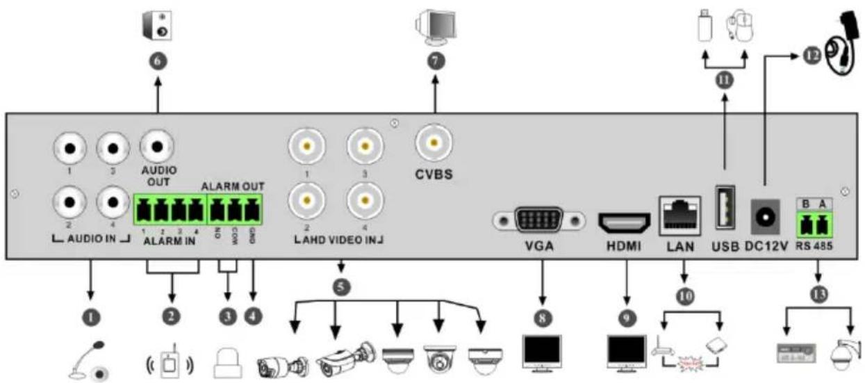
flowchart
graph TD
    A["6"] --> B["1"]
    C["7"] --> D["3"]
    E["11"] --> F["12"]
    G["13"] --> H["14"]
    I["1"] --> J["2"]
    K["2"] --> L["3"]
    M["AUDIO OUT"] --> N["1 2 3 4 ALARM IN"]
    O["ALARM OUT"] --> P["1 2 3 4 ON"]
    Q["LADH VIDEO INJ"] --> R["2"]
    S["CVBS"] --> T["3"]
    U["VGA"] --> V["8"]
    W["HDMI"] --> X["9"]
    Y["LAN"] --> Z["10"]
    AA["USB"] --> AB["DC12V"]
    AC["B A"] --> AD["RS 485"]
| No. | Name | Descriptions |
| 1 | AUDIO IN | Audio input |
| 2 | ALARM IN | Alarm inputs for connecting sensors |
| 3 ALARM OUT Relay output; connect to external alarms | ||
| 4 | GND | Ground |
| 5 | AHD VIDEO IN | 4 CH AHD video inputs |
| 6 | AUDIO OUT | Audio output |
| 7 | CVBS | CVBS video output; connect to monitor |
| 8 | VGA | Connect to monitor |
| 9 | HDMI | Connect to high definition display devices |
| 10 | LAN | Network port |
| 11 | USB | Connector for USB storage devices or USB mouse |
| 12 DC12V DC12V power input | ||
| 13 RS485 | Connector for keyboards or speed domes. A is TX+; B is TX- | |
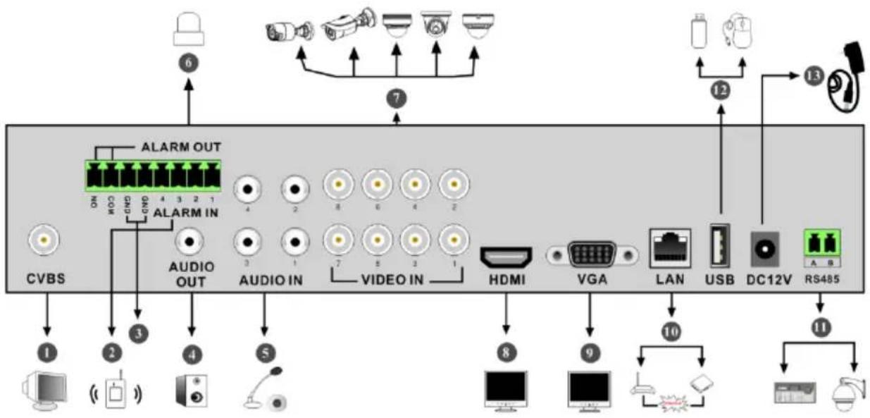
flowchart
graph TD
    A["Computer"] --> B["1"]
    A --> C["2"]
    A --> D["3"]
    A --> E["4"]
    A --> F["5"]
    A --> G["6"]
    H["Video In"] --> I["7"]
    J["Audio IN"] --> K["8"]
    L["Video IN"] --> M["7"]
    N["HDMI"] --> O["8"]
    P["VGA"] --> Q["9"]
    R["LAN"] --> S["10"]
    T["USB"] --> U["11"]
    V["DC12V"] --> W["12"]
    X["RS485"] --> Y["13"]
    Z["ALARM OUT"] --> AA["ON 4 3 2 1"]
    AB["AUDIO OUT"] --> AC["ON 4 3 2 1"]
    AD["ICU"] --> AE["CC 1"]
    AF["Camera"] --> AG["Camera 6"]
    AH["Radio"] --> AI["Radio 12"]
| No. | Name | Descriptions |
| 1 | CVBS | CVBS video output; connect to monitor |
| 2 | ALARM IN | Alarm inputs for connecting sensors |
| 3 | GND | Ground |
| 4 | AUDIO OUT | Audio output; connect to sound box |
| 5 | AUDIO IN | Audio input |
| 6 | ALARM OUT | Relay output; connect to external alarms |
| 7 | VIDEO IN | 8 CH video inputs |
| 8 | HDMI | Connect to high definition display devices |
| 9 VGA | Connect to monitor | |
| 10 LAN | Network port | |
| 11 RS485 | Connectors for keyboards or speed domes. A is TX+; B is TX- | |
| 12 | USB | Connector for USB storage devices or USB mouse |
| 13 | DC12V | DC12V power input |
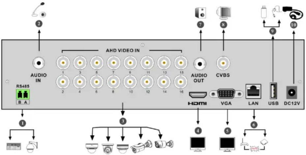
flowchart
graph TD
    A["RS485"] --> B["1"]
    B --> C["2"]
    C --> D["AUDIO IN"]
    D --> E["3"]
    E --> F["4"]
    F --> G["5"]
    G --> H["6"]
    H --> I["7"]
    I --> J["AHD VIDEO IN"]
    J --> K["8"]
    K --> L["9"]
    L --> M["10"]
    M --> N["11"]
    N --> O["12"]
    O --> P["13"]
    P --> Q["14"]
    Q --> R["15"]
    R --> S["16"]
    S --> T["AUDIO OUT"]
    T --> U["7"]
    U --> V["8"]
    V --> W["9"]
    W --> X["10"]
    X --> Y["11"]
    Y --> Z["12"]
    Z --> AA["13"]
    AA --> AB["14"]
    AB --> AC["15"]
    AC --> AD["16"]
    AD --> AE["17"]
    AE --> AF["18"]
    AF --> AG["19"]
    AG --> AH["20"]
    AH --> AI["21"]
| No. | Name | Descriptions |
| 1 RS485 | Connectors for keyboards or speed domes. A is TX+; B is TX- | |
| 2 | AUDIO IN | Audio input |
| 3 | AHD VIDEO IN | 16 CH AHD video inputs |
| 4 | HDMI | Connect to monitor |
| 5 | VGA | Connect to monitor |
| 6 LAN | Network port | |
| 7 AUDIO OUT Audio output | ||
| 8 | CVBS | CVBS video output; connect to monitor |
| 9 | USB | Connect USB storage devices or USB mouse |
| 10 | DC12V | DC12V power input |
1.5 Connections
- Video Connections
Video Output: Supports VGA/HDMI video output. You can connect to monitor through these video output interfaces simultaneously or independently.
- Audio Connections
Audio Input: Connect to microphone, pickup, etc.
Audio Output: Connect to headphone, sound box or other audio output devices.
- Alarm Connections
Some models may support this function. Take 16 CH alarm inputs and 1 CH alarm output for example.
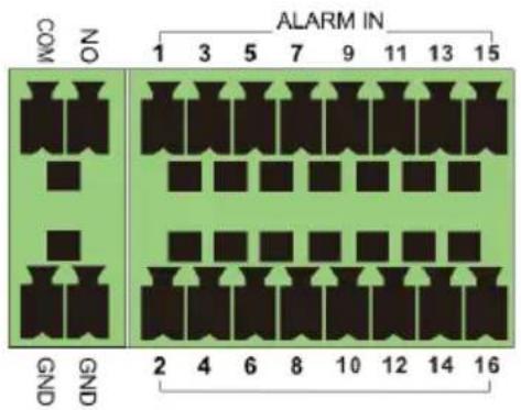
text_image
ALARM IN COM NO 1 3 5 7 9 11 13 15 GND GND 2 4 6 8 10 12 14 16Alarm Input:
Alarm IN 1\~16 are 16 CH alarm input interfaces. There are no type requirements for sensors. NO type and NC type are both available.
The way to connect sensor and the device is as shown below:
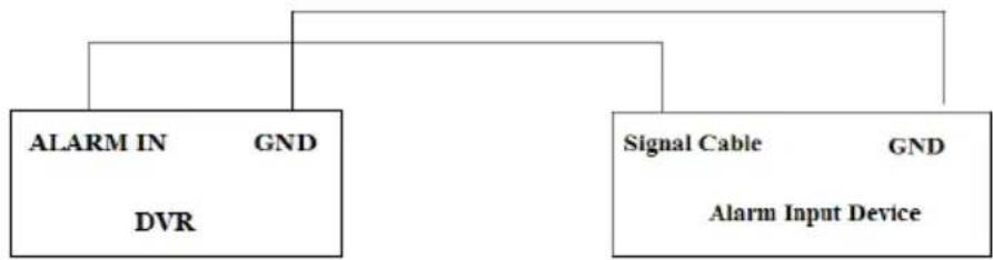
flowchart
graph TD
    A["ALARM IN"] --> B["DVR"]
    C["Signal Cable"] --> D["Alarm Input Device"]
    B --> E["GND"]
    D --> F["GND"]
The alarm input is an open/closed relay. If the input is not an open/closed relay, please refer to the following connection diagram:
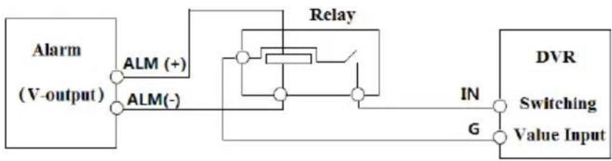
flowchart
graph LR
    A["Alarm (V-output)"] --> B["ALM (+)"]
    A --> C["ALM(-)"]
    B --> D["Relay"]
    C --> D
    D --> E["DVR"]
    E --> F["Switching Value Input"]
    F --> G["IN"]
    F --> H["G"]
Alarm Output:
The way to connect alarm output device:
Pull out the green terminal blocks and loosen the screws in the alarm-out port. Then insert the signal wires of the alarm output devices into the port of NO and COM separately. Finally, tighten the screws. Provided that the external alarm output devices need power supply, you can connect the power supply as per the following figures.
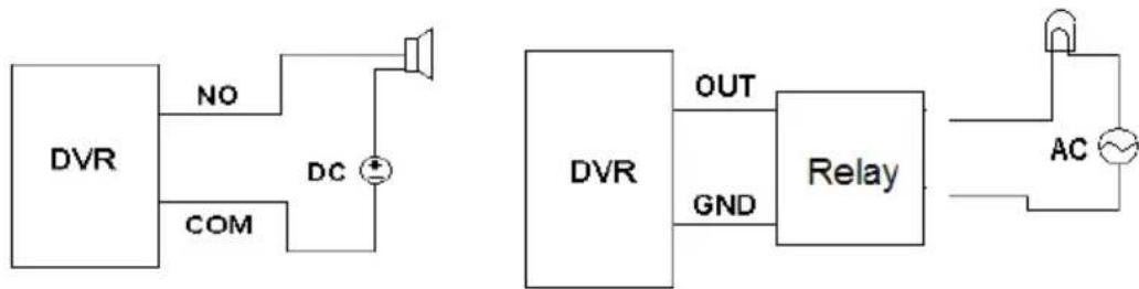
flowchart
graph TD
    A["DVR"] -->|NO| B["DC"]
    A -->|COM| C["DC"]
    B --> D["Speaker"]
    C --> E["DC"]
    D --> F["OUT"]
    E --> G["GND"]
    F --> H["Relay"]
    G --> H
    H --> I["AC"]
    I --> J["Output"]
- RS485 Connection
There are two types of RS485 interfaces:
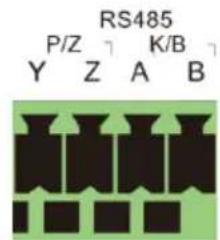
text_image
RS485 P/Z K/B Y Z A B(Type 1)

B A
RS485
(Type 2)
Type 1: The P/Z interfaces are used to connect speed dome. K/B interfaces are used to connect keyboard.
Type 2: The RS485 interfaces are not only used to connect speed dome but also to connect keyboard.
The way to connect speed dome to the DVR:
Type 1: Disconnect pluggable block from the RS485 terminal block and then loosen the fixed screws from the pluggable block, insert signal cables into Y and Z port separately (Y is TX+; Z is TX-) and tighten the fixed screws. Next, connect pluggable block back into terminal block.
Finally, connect the video cable of the speed dome to the video input interface of the DVR.
Type 2: Disconnect pluggable block from the RS485 terminal block and then loosen the fixed screws from the pluggable block, insert signal cables into A and B port separately (A is TX+; B is TX-) and tighten the fixed screws. Next, connect pluggable block back into terminal block.
Finally, connect the video cable of the speed dome to the video input interface of the DVR.
Note:
The pluggable block of some models may not be connected into the terminal block and you shall obtain it from the accessories.
2 Basic Operation Guide
2.1 Startup & Shutdown
Please make sure all the connections are done properly before you power on the unit. Proper startup and shutdown are crucial to extending the life of your device.
2.1.1 Startup
① Connect the output display device to the VGA/HDMI interface of the DVR.
② Connect with the mouse and power. The device will boot and the power LED would turn blue.
③ A WIZARD window will pop up (you should select the display language the first time you use the DVR). Refer to 3.1 Startup Wizard for details.
2.1.2 Shutdown
You can power off the device by using remote controller or mouse.
By remote controller:
① Press Power button. This will take you to a shutdown window. The unit will power off after a while by clicking “OK” button.
② Disconnect the power.
By mouse:
① Click Start→Shutdown to pop up the Shutdown window. Select “Shutdown” in the window. The unit will power off after a while by clicking “OK” button.
② Disconnect the power.
2.2 Remote Controller
① It uses two AAA size batteries.
② Open the battery cover of the remote controller.
③ Place batteries. Please take care the polarity (+ and -).
④ Replace the battery cover.
Key points to check in case the remote doesn't work.
- Check batteries polarity.
- Check the remaining charge in the batteries.
- Check IR controller sensor for any masking.
If it still doesn't work, please change a new remote controller to try, or contact your dealers. You can just turn the IR sensor of the remote controller towards the IR receiver of the DVR to control it when you are controlling multiple devices by remote controller.
There are two kinds of remote controller. The interface of remote controller is shown as below.
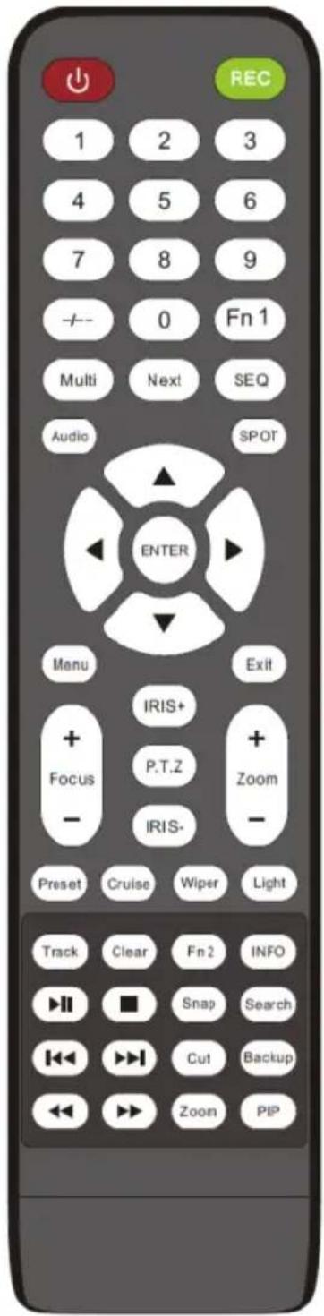
text_image
REC 1 2 3 4 5 6 7 8 9 - - 0 Fn 1 Multi Next SEQ Audio SPOT ENTER Manu Exit + IRIS+ Focus P.T.Z + - IRIS- Preset Cruise Wiper Light Track Clear Fn 2 INFO ▶ ▼ ■ Snap Search ◀◀ ▶◀ Cut Backup ◀◀ ▶◀ Zoom PIP| Button Function | |
| Switch off—to stop the device | |
| Record Button | To start recording |
| -/-- /0-9 | Input number or choose camera |
| Fn1 Button Unavailable temporarily | |
| Multi Button | To choose multi screen display mode |
| Next Button | To switch the live image |
| SEQ | To go to sequence view mode |
| Audio | To enable audio output in live mode |
| Switch | No function temporarily |
| Direction button | To move cursor in setup or pan/title PTZ |
| Enter Button To confirm the choice or setup | |
| Menu Button | To go to menu |
| Exit Button To exit the current interface | |
| Focus/IRIS/Zoom/PTZ | To control PTZ camera |
| Preset Button To enter into preset setting in PTZ mode | |
| Cruise Button | To go to cruise setting in PTZ mode |
| Track Button | No track function temporarily |
| Wiper Button | No function temporarily |
| Light Button | No function temporarily |
| Clear Button | No function temporarily |
| Fn2 Button | No function temporarily |
| Info Button | Get information about the device |
| To control playback. Play(Pause)/Stop/Previous Frame/Next Frame/Speed Down/Speed Up | |
| Snap Button | To take snapshots manually |
| Search Button | To go to search mode |
| Cut Button | No function temporarily |
| Backup Button | To go to backup mode |
| Zoom Button | To zoom in the images |
| PIP Button | No function temporarily |
Note:
You shall press P.T.Z button to enter PTZ setting mode, choose a channel and press P.T.Z button again to hide the P.T.Z control panel. Then you can press preset, cruise, track, wiper or light button to enable the relevant function.
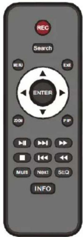
text_image
REC Search MENU EXIT ENTER ZOOM PIP H11 H12 H13 Multi Next! SEQ INFO| Button Function | |
| REC Record manually | |
| Search To enter search mode | |
| MEUN To enter menu | |
| Exit | To exit the current interface |
| ENTER | To confirm the choice or setup |
| Direction button | To move cursor in setup |
| ZOOM To zoom in | |
| PIP | No function temporarily |
 | To control playback. Play(Pause)/Next Frame/Speed Up/Stop/Previous Frame/Speed Down |
| Multi | To choose multi screen display mode |
| Next To switch the live image | |
| SEQ | To go to sequence view mode |
| INFO | Get information about the device |
2.3 Mouse Control
Mouse control in Live Display & Playback interface
In the live display & playback interface, double click on any camera window to show the window in single screen mode; double click the window again to restore it to the previous size. In the live display & playback interface, if the interfaces display in full screen, move the mouse to the bottom of the interface to pop up a tool bar. The tool bar will disappear automatically after you move the mouse away from it for some time; move the mouse to the right side of the interface to pop up a panel and the panel will disappear automatically after you move the mouse away from it.
Mouse control in text-input
Move the mouse to the text-input box and then click the box. The input keyboard will pop up automatically.
Note: Mouse is the default tool for all operations unless an exception as indicated.
2.4 Text-input Instruction
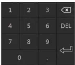
text_image
1 2 3 4 5 6 DEL 7 8 9 0 .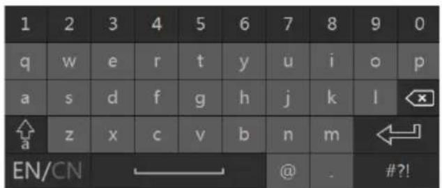
text_image
1 2 3 4 5 6 7 8 9 0 q w e r t y u i o p a s d f g h j k l x ↑ z x c v b n m ← a EN/CN @ . #?!The system includes two input boxes. Refer to the above pictures. The left box is the number input box and the right box is the input box which provides inputs of numbers, letters and punctuation characters. The introductions of keys on the input boxes are shown below.
| Button | Meaning | Button | Meaning |
 | Backspace key |  | Switch key of punctuation character |
 | Delete Key |  | Enter key |
 | Switch key between upper and lower letter |  | Space key |
 | Switch key of language | ||
2.5 Common Button Operation
| Button Meaning | |
 | Click it to show the menu list. |
 | Click it to change the sequence of the list. |
 | Click it to change the camera displaying mode. |
 | Click it to close the current interface. |
 | Click it to go to the earliest date of camera recording. |
 | Click it to go to the latest date of camera recording. |
3 Wizard & Main Interface
3.1 Startup Wizard
The disk icons will be shown on the top of the startup interface. You can view the number and status of each disk quickly and conveniently through these icons (☐: no disk; 🔍: unavailable disk; ☐: RW available disk).
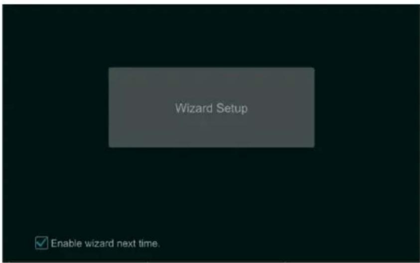
You can quickly configure the DVR by wizard setup to make the DVR work normally. You must configure the wizard if you start the DVR for the first time (or click “Skip” to cancel the wizard next time).
text_image
Wizard Setup Enable wizard next time.Click "Wizard Setup" to start wizard. The setting steps are as follows.
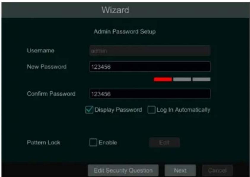
① System Login. Set your own password or use the default when you use the wizard for the first time (the default username of the system is admin and the default password of admin is 123456); select the login username and enter the corresponding password next time.
text_image
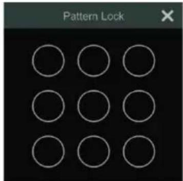
Wizard Admin Password Setup Username admin New Password 123456 Confirm Password 123456 ✓ Display Password □ Log In Automatically Pattern Lock Enable Edit Edit Security Question Next CancelEnable pattern lock and click "Edit" to set the pattern lock.
text_image
Pattern LockClick “Edit Security Question” to set questions and answers for password security of admin. If you forget the password, please refer to Q4 in Appendix A FAQ for details.
Click "Next" to continue or click "Cancel" to exit the wizard.
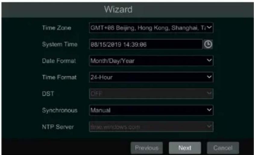
② Date and Time Configuration. The date and time of the system need to be set up if you use the wizard for the first time. Refer to the following figure. Set the time zone, system time, date format and time format. The DST will be enabled by default if the time zone selected includes DST. Click “Next” to continue.
text_image
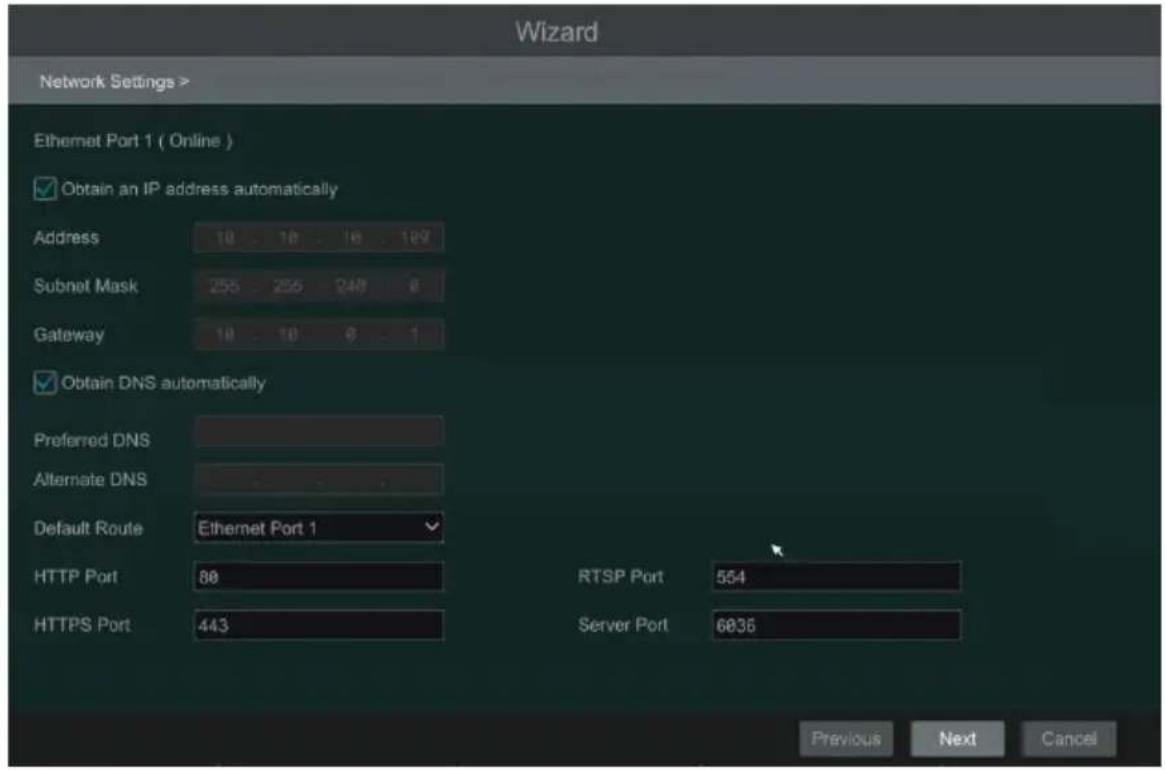
Wizard Time Zone GMT+08 Beijing, Hong Kong, Shanghai, T: System Time 08/15/2019 14:39:06 Date Format Month/Day/Year Time Format 24-Hour DST OFF Synchronous Manual NTP Server time.windows.com Previous Next Cancel③ Network Settings. Check “Obtain an IP address automatically” and “Obtain DNS automatically” to get the IP address and DNS automatically (the DHCP function of the router in the same LAN should also be enabled), or manually enter them. Enter the HTTP port, RTSP port and Server port (please see 11.1.2 Port Configuration for details). Click “Next” to continue.
text_image
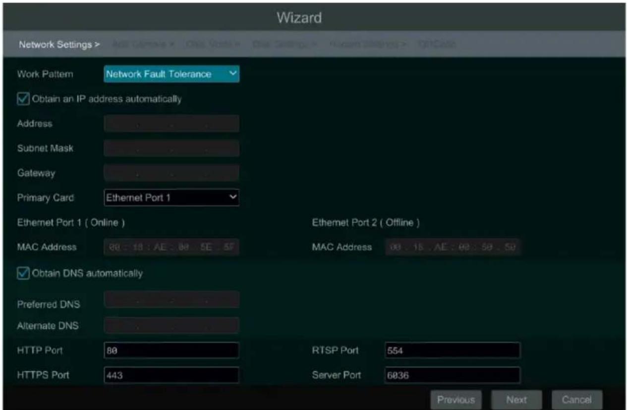
Wizard Network Settings > Ethernet Port 1 ( Online ) ✓ Obtain an IP address automatically Address 18 . 18 . 18 . 129 Subnet Mask 255 . 255 . 248 . 8 Gateway 18 . 18 . 0 . 1 ✓ Obtain DNS automatically Preferred DNS Alternate DNS Default Route Ethernet Port 1 HTTP Port 80 RTSP Port 554 HTTPS Port 443 Server Port 6835 Previous Next CancelIf the DVR has two network ports or above, you can select the network work pattern as required. Network Fault Tolerance and Multiple Address Setting are available. Refer to the pictures below. Please refer to 11.1.1 TCP/IP Configuration for more detailed information.
text_image
Wizard Network Settings > Work Pattern Network Fault Tolerance Obtain an IP address automatically Address Subnet Mask Gateway Primary Card Ethernet Port 1 Ethernet Port 1 ( Online ) MAC Address 80 : 18 : AE : 80 SE 5F Ethernet Port 2 ( Offline ) MAC Address 90 : 18 . AE : 90 : 50 . 50 Obtain DNS automatically Preferred DNS Alternate DNS HTTP Port 80 RTSP Port 554 HTTPS Port 443 Server Port 6036 Previous Next Cancel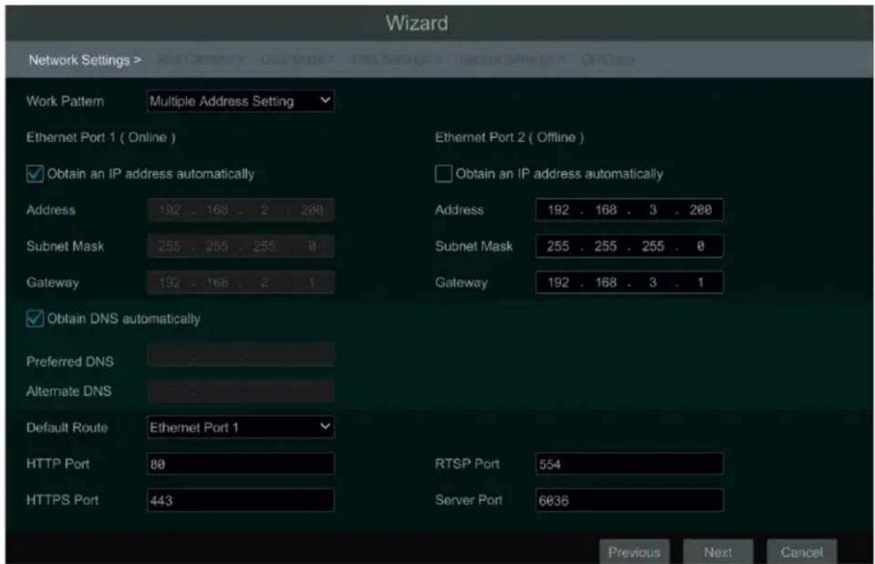
text_image
Wizard Network Settings > Work Pattern Multiple Address Setting Ethernet Port 1 ( Online ) Ethernet Port 2 ( Offline ) Obtain an IP address automatically Address 192 . 168 . 2 . 200 Subnet Mask 255 . 255 . 255 . 0 Gateway 192 . 168 . 2 . 1 Obtain an IP address automatically Address 192 . 168 . 3 . 200 Subnet Mask 255 . 255 . 255 . 0 Gateway 192 . 168 . 3 . 1 Obtain DNS automatically Preferred DNS Alternate DNS Default Route Ethernet Port 1 HTTP Port 80 HTTPS Port 443 RTSP Port 554 Server Port 6036 Previous Next Cancel④ Add Camera. Click “Refresh” to refresh the list of online IP cameras which are in the same local network with DVR and then click + to add the searched camera. Click “Add All” to add all the cameras in the list. Click 📋 to delete the added camera. Click “Delete All” to delete all the added cameras.
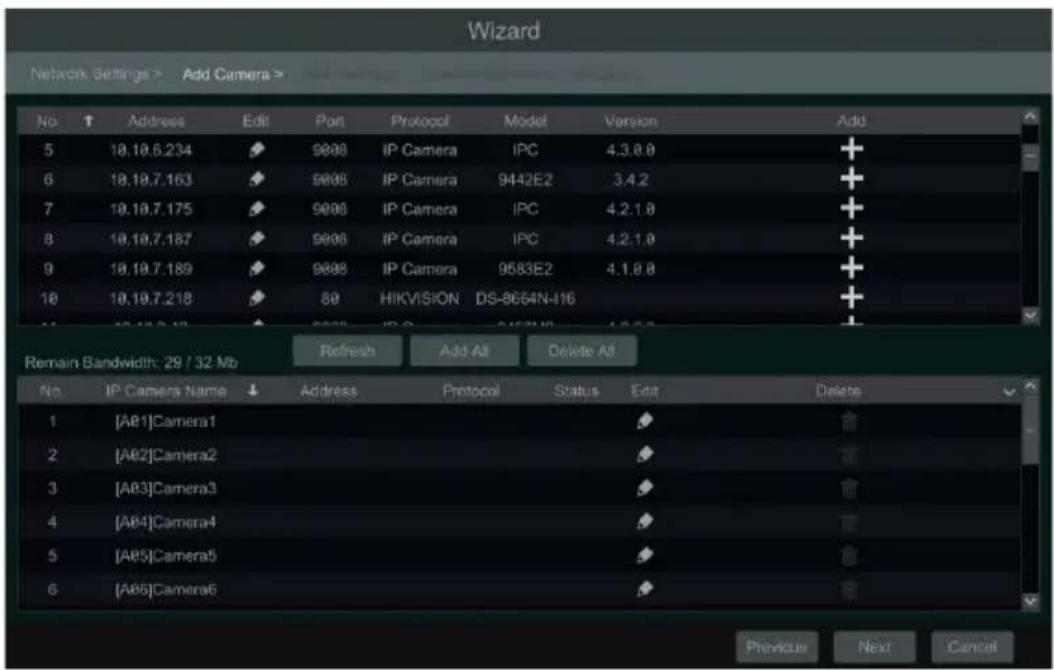
text_image
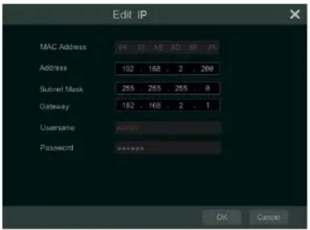
Wizard Network Settings > Add Camera > No Address Edit Port Protocol Model Version Add 5 18.19.6.234 9000 IP Camera IPC 4.3.8.8 + 6 18.19.7.163 9000 IP Camera 9442E2 3.4.2 + 7 18.19.7.175 9000 IP Camera IPC 4.2.1.8 + 8 18.19.7.187 9000 IP Camera IPC 4.2.1.8 + 9 18.19.7.189 9000 IP Camera 9583E2 4.1.8.8 + 10 18.19.7.218 80 HIKVISION DS-8664N-116 + Remain Bandwidth: 29 / 32 Mb Refresh Add All Delete All No IP Camera Name ↓ Address Protocol Status Edit Delete 1 [A81]Camera1 2 [A82]Camera2 3 [A83]Camera3 4 [A84]Camera4 5 [A85]Camera5 6 [A86]Camera6 Previous Next CancelClick 📋 to edit the searched IP camera as shown on the below left. Enter the new IP address, subnet mask, gateway and the password of the camera. Click “OK” to save the
settings.
text_image
Edit IP MAC Address Address 192 . 168 . 2 . 200 Subnet Mask 255 . 255 . 255 . 0 Gateway 192 . 168 . 2 . 1 Username Password OK Cancel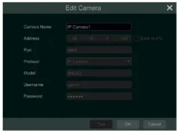
text_image
Edit Camera Camera Name: IP Camera1 Address 16 19 2 103 Sync to IPC Port 0003 Protocol: IP Camera Model: 458.002 Username: admin Password: ****** Test OK CancelClick to edit the added camera as shown on the above right. Enter the new camera name, IP address, port, username and the password of the camera. You can check “Sync to IPC” to modify the IP address of the IPC via different network segments for being in the same network segment with the DVR. You can click “Test” to test the effectiveness of the input information. Click “OK” to save the settings. You can change the camera name only if it’s an analog camera or the added IPC is online. Click “Next” to continue.
Tips: Please skip Step ⑤ and ⑥ if the DVR doesn't support RAID function.
⑤ Disk Mode. Click “Enable RAID” to enable the RAID function. Click “Next” to continue.
⑥ Create an array. Set the array name and select array type which including RAID0, RAID1, RAID5, RAID6 and RAID10. The global hot spares and array capacity can also be set up here. See 7.5 Disk for details. Click “Next” to continue.
⑦ Disk Settings. You can view the disk number, disk capacity of the DVR and serial number, R&W status of the disk. Click “Format” to format the disk. Click “Next” to continue.
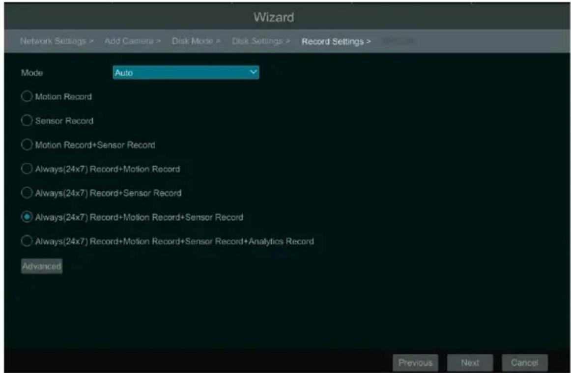
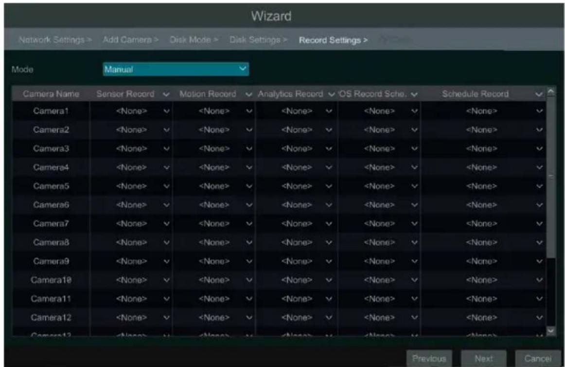
⑧ Record Settings. Two record modes are available: auto and manual.
Auto: Select one auto mode in the interface as shown below and then click "OK" button to save the settings. See 7.1.1 Mode Configuration for details.
text_image
Wizard Network Settings > Add Camera > Disk Mode > Disk Settings > Record Settings > Mode Auto ○ Motion Record ○ Sensor Record ○ Motion Record+Sensor Record ○ Always(24x7) Record+Motion Record ○ Always(24x7) Record+Sensor Record ● Always(24x7) Record+Motion Record+Sensor Record ○ Always(24x7) Record+Motion Record+Sensor Record+Analytics Record Advanced Previous Next CancelManual: Set the “Sensor Record”, “Motion Record” and “Schedule Record” of each camera. Click “Next” to save the settings. See 7.1.1 Mode Configuration for details.
text_image
Wizard Network Settings > Add Camera > Disk Mode > Disk Settings > Record Settings > Mode Manual Camera Name Sensor Record Motion Record Analytics Record OS Record Sache Schedule Record Camera1⑨ QRCode. Enable the NAT function in the interface or set it in the network configuration after exiting the wizard (please refer to 11.1.7 NAT Configuration for details). You can scan the QRCode through mobile client which is installed in the mobile phone or tablet to log in the mobile client instantly. Please refer to 12.1 Mobile Client Surveillance for details. Click "OK"
to save the settings.
3.2 Main Interface
3.2.1 Main Interface Introduction
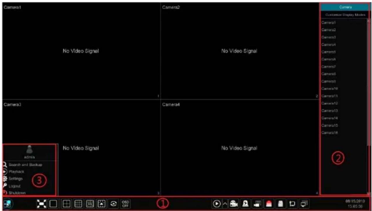
text_image
Camera1 No Video Signal Camera2 No Video Signal Camera3 Camera4 No Video Signal Camera5 Camera6 Camera7 Camera8 Camera9 Camera10 Camera11 Camera12 Camera13 Camera14 Camera15 Camera16 admin Search and Backup Playback Settings Logout Shutdown ① ② 88/15/2019 15:05:56The buttons in area ① are introduced in the table below.
| Button Meaning | ||
 | Start button. Click it to pop up area 3. | |
 | Full screen button. Click it to show full screen; click it again to exit the full screen. | |
| [KBA3] | Screen mode button. | |
 | Dwell button (see 5.2.2 Quick Sequence View and 5.2.3 Scheme View In Sequence for details). | |
 | Click it to disable OSD; click to enable OSD. | |
 | Click ↑ to set the default playback time before starting instant playback (8.1 Instant Playback) or going to the playback interface for playback operations (8.2 Playback Interface Introduction); click 📋 to go to the playback interface. For instance, if you choose “5 minutes ago” as the default playback time, you can playback the record from the past five minutes. | |
 | Manual record button. Click it to enable/disable record. | |
 | Manual alarm button. Click it to trigger or clear the alarm-out manually in the popup window. | |
 | Record status button. Click it to view the record status. | |
| Button Meaning | |
 | Alarm status button. Click it to view the alarm status. |
 | Disk status button. Click it to view the disk status and RAID status. |
 | Network status button. Click it to view the network status. |
 | Information button. Click it to view system information, including basic information, camera status, alarm status, record status, network status, disk information, backup status and user status. |
Introduction of area ②
Click “Camera” to view all the added cameras in the camera list. Select one camera window on the left side of the interface and then double click one IP camera in the list to preview the camera image in the selected window.
Click “Customize Display Modes” to view all the display modes in the display mode list (refer to 5.2.1 Display Mode for detail configuration of the display mode). Double click one display mode in the list to switch to the display mode for previewing.
Introduction of area ③:
| Icon / Button Meaning | |
 | It shows the current login user. |
 | Click it to go to record search interface, see 8.4 Record Search.Playback & Backup for details. |
 | Click it to go to playback interface (click ↑ on the tool bar at the bottom of the live view interface to set the default playback time), see 8.2 Playback Interface Introductionfor details. |
 | Click it to pop up the setup panel, see 3.2.2 Setup Panelfor details. |
 | Click it to log out the system. |
 | Click it and then select “Logout”, “Reboot” or “Shutdown” in the popup window. |
3.2.2 Setup Panel
Click Start→Settings to bring up the setup panel as shown below.
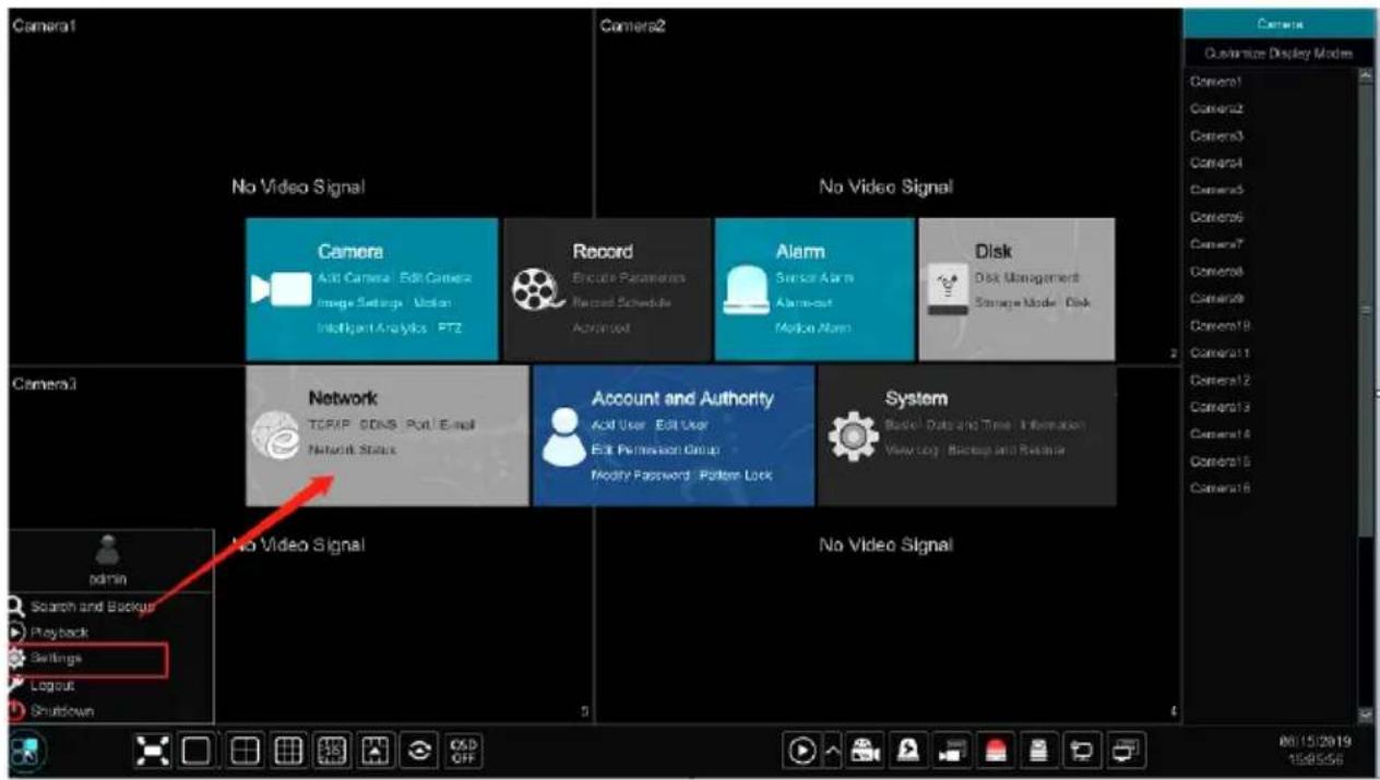
text_image
Camera1 No Video Signal Camera2 No Video Signal Camera Add Camera Edit Camera Image Settings Motion Intelligent Analysis PTZ Record Encode Parameters Record Schedule Advanced Alarm Sensor Alarm Alarmout Motion Alarm Disk Disk Management Storage Mode Disk Camera3 Network TCP/IP DDR5 Port Email Network Status Account and Authority Add User Edit User Edit Permission Group Modify Password Pattern Lock System Basic Data and Time Information View log Backup and Release No Video Signal No Video Signal admin Search and Backup Playback Settings Logout Shutdown 00/15/2019 15:95:56The setup panel includes seven modules. Each module provides some function entries with links for convenient operation.
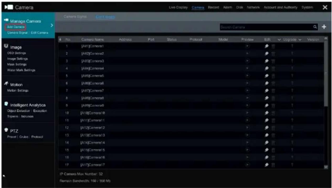
Here we take Camera module as an example. The Camera module provides convenient links such as “Add Camera”, “Edit Camera”, “Image Settings”, “Motion”, “Intelligent Analytics” and “PTZ”. Click Camera to go to the camera management interface as shown below.
text_image
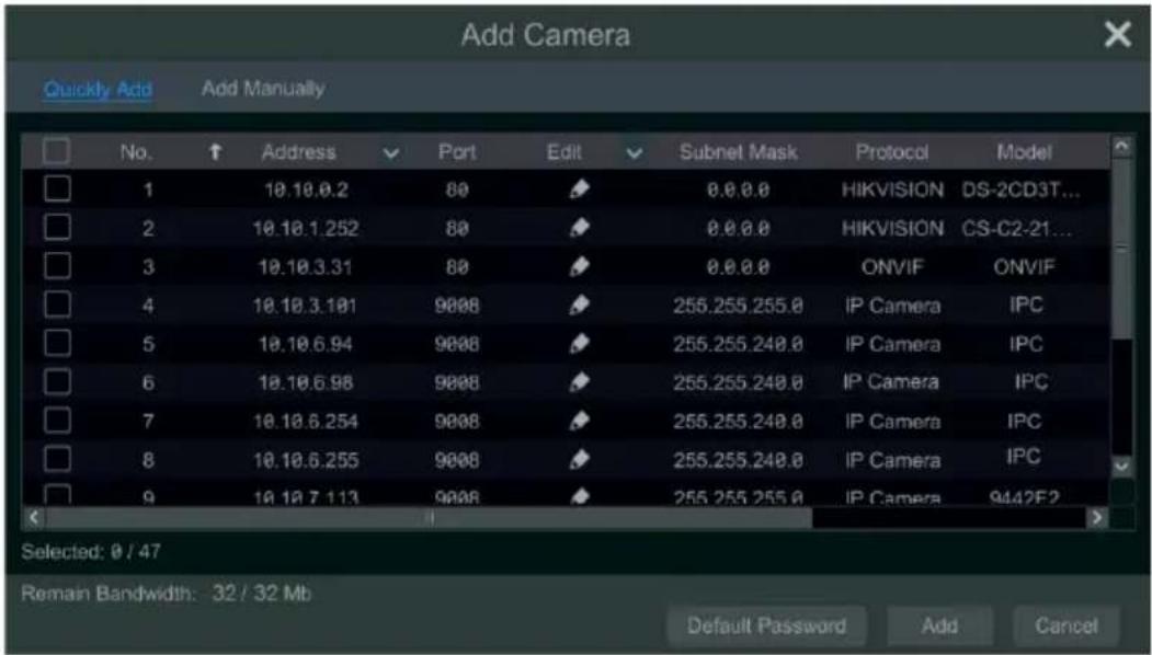
Camera Manage Camera Add Camera Camera Signal | Edit Camera No. Camera Name Address Port Status Protocol Model Preview Edit Upgrade Version 1 [A91]Camera1 2 [A82]Camera2 3 [A83]Camera3 4 [A84]Camera4 5 [A85]Camera5 6 [A86]Camera6 7 [A87]Camera7 8 [A88]Camera8 9 [A89]Camera9 10 [A10]Camera10 11 [A11]Camera11 12 [A12]Camera12 13 [A13]Camera13 14 [A14]Camera14 15 [A15]Camera15 16 [A16]Camera16 17 [A17]Camera17 Search Camera IP Camera Max Number: 32 Remain Bandwidth: 198 / 168 MbThere are some function items on the left side of the camera management interface. Click each item to go to corresponding interface or window. For instance, click “Add Camera” to pop up the window as shown below.
text_image
Add Camera Quickly Add Add Manually No. ↑ Address Port Edit Subnet Mask Protocol Model 1 10.10.0.2 80 0.0.0 HIKVISION DS-2CD3T... 2 10.10.1.252 80 0.0.0 HIKVISION CS-C2-21... 3 10.10.3.31 80 0.0.0 ONVIF ONVIF 4 10.10.3.101 9008 255.255.255.0 IP Camera IPC 5 10.10.6.94 9008 255.255.248.0 IP Camera IPC 6 10.10.6.98 9008 255.255.248.0 IP Camera IPC 7 10.10.6.254 9008 255.255.248.0 IP Camera IPC 8 10.10.6.255 9008 255.255.248.0 IP Camera IPC 9 10.10.7.113 9008 255.255.255.0 IP Camera 9442F2 Selected: 0 / 47 Remain Bandwidth: 32 / 32 Mb Default Password Add CancelClick the main menus on the top of the camera management interface to go to corresponding interfaces. Refer to the picture below. For instance, you can go to system setup interface by clicking "System" tag.

text_image
Live Display Camera Record Alarm Disk Network Account and Authority System3.2.3 Main Functions
▶ Camera
The module covers the functions such as Camera Management (see Chapter 4 Camera Management for details), Image Settings (see 5.4 Image Configuration for details), Motion (see 9.2.1 Motion Configuration for details) and PTZ (see Chapter 6 PTZ for details) and so on.
Record
The module covers the functions such as Encode Parameters and Record Schedule and so on. Please see Chapter 7 Record & Disk Management for details.
Disk
The module covers the functions such as Disk Management, Storage Mode and Disk Information and so on. Please see Chapter 7 Record & Disk Management for details.
> Alarm
The module covers the functions such as Sensor and Motion Alarm Handling and Alarm Out Settings. Please see Chapter 9 Alarm Management for details.
Network
The module covers the functions such as TCP/IP, DDNS, Port, E-mail and Network Status and so on. Please see 11.1 Network Configuration for details.
Account and Authority
The module covers the functions such as Account Management (see 10.1 Account Management for details) and Permission Management (see 10.3 Permission Management for details) and so on.
System
The module covers the functions such as Basic Configuration (see 11.2 Basic Configuration for details), Device Information (see 11.8 View System Information for details), Log Information (see 11.7 View Log for details) and Backup and Restore(see 11.5 Backup and Restore for details) and so on.
4 Camera Management
4.1 Camera Signal
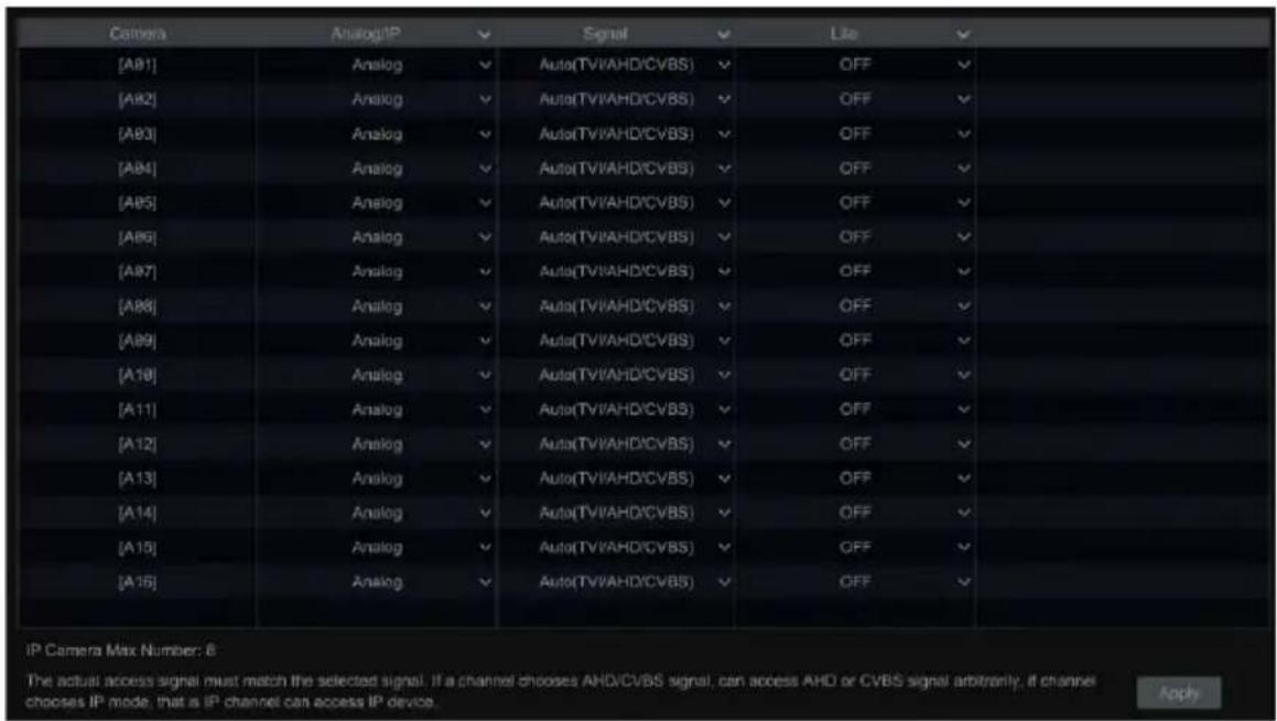
Click Start→Settings→Camera→Manage Camera→Camera Signal to go to the interface as shown below.
Some models may support analog signal switching to IP signal, which means decreasing (or increasing) the number of analog channels, accordingly increasing (or decreasing) the number of IP channels.
The DVR device supports hybrid access of TVI, AHD, CVI and CVBS high definition cameras. If the TVI high definition camera is accessed to the DVR, you should select TVI in the following interface to show the camera image normally; if you select AHD, then there will be no image or the image has no color. The default selection of the camera signal is Auto. If you select Auto, the image of the camera will be shown normally regardless of the camera type.
text_image
[A81] Analog Auto(TVI/AHD/CVBS) OFF [A82] Analog Auto(TVI/AHD/CVBS) OFF [A83] Analog Auto(TVI/AHD/CVBS) OFF [A84] Analog Auto(TVI/AHD/CVBS) OFF [A85] Analog Auto(TVI/AHD/CVBS) OFF [A86] Analog Auto(TVI/AHD/CVBS) OFF [A87] Analog Auto(TVI/AHD/CVBS) OFF [A88] Analog Auto(TVI/AHD/CVBS) OFF [A89] Analog Auto(TVI/AHD/CVBS) OFF [A10] Analog Auto(TVI/AHD/CVBS) OFF [A11] Analog Auto(TVI/AHD/CVBS) OFF [A12] Analog Auto(TVI/AHD/CVBS) OFF [A13] Analog Auto(TVI/AHD/CVBS) OFF [A14] Analog Auto(TVI/AHD/CVBS) OFF [A15] Analog Auto(TVI/AHD/CVBS) OFF [A16] Analog Auto(TVI/AHD/CVBS) OFF IP Camera Max Number: 6 The actual access signal must match the selected signal. If a channel chooses AHD/CVBS signal, can access AHD or CVBS signal arbitrarily, if channel chooses IP mode, that is IP channel can access IP device. ApplyNote: You can enable “Lite” in the interface if the DVR supports “Lite” recording. It will lower the recording resolution and increase the recording frame rate. Please enable or disable the Lite as needed.
4.2 Add/Edit Camera
4.2.1 Add Camera
The network of the DVR should be set before adding IP camera (see 11.1.1 TCP/IP Configuration for details).
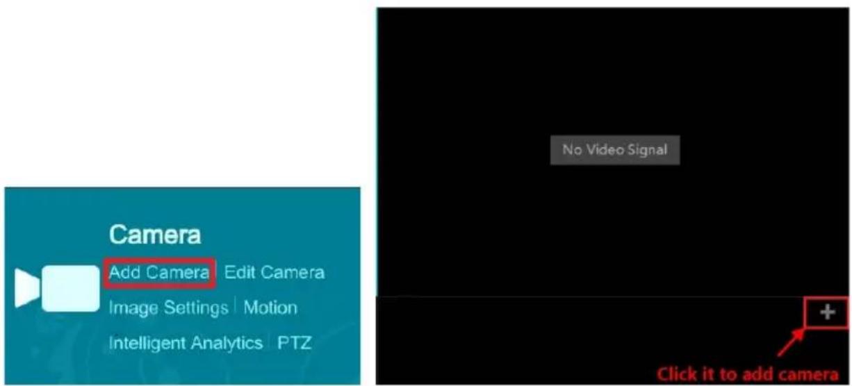
Refer to the pictures below. Click Add Camera in the setup panel or + in the top right corner of the preview window to pop up the “Add Camera” window as shown below. You can quickly add or add the IP camera manually.
text_image
Camera Add Camera Edit Camera Image Settings Motion Intelligent Analytics PTZ No Video Signal Click it to add camera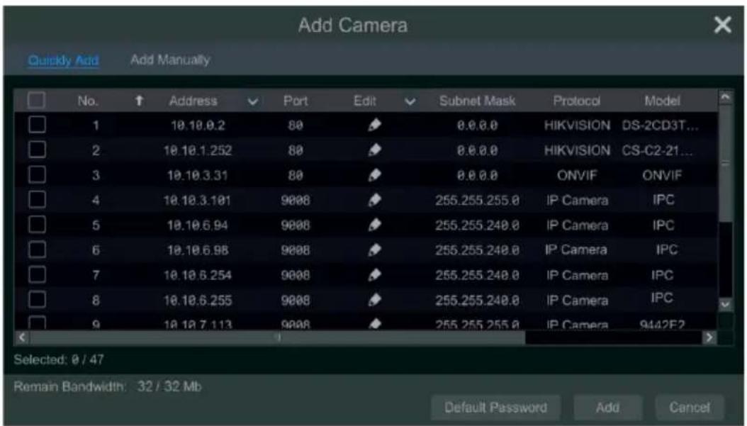
text_image
Add Camera Quickly Add Add Manually No. ↑ Address Port Edit Subnet Mask Protocol Model 1 10.18.9.2 80 0.0.0 HIKVISION DS-2CD3T... 2 10.10.1.252 80 0.0.0 HIKVISION CS-C2-21... 3 10.10.3.31 80 0.0.0 ONVIF ONVIF 4 10.10.3.101 9008 255.255.255.0 IP Camera IPC 5 10.10.6.94 9008 255.255.249.0 IP Camera IPC 6 10.10.6.98 9008 255.255.249.0 IP Camera IPC 7 10.10.6.254 9008 255.255.249.0 IP Camera IPC 8 10.10.6.255 9008 255.255.249.0 IP Camera IPC 9 10.10.7.113 9008 255.255.255.0 IP Camera 9442F2 Selected: 0 / 47 Remain Bandwidth: 32 / 32 Mb Default Password Add Cancel▶ Quickly Add
Check the cameras and then click “Add” to add cameras. Click 📋 to edit the camera’s IP address, username and password and so on. Click “Default Password” to set the default username and password of each camera.
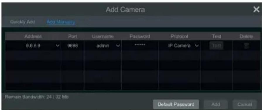
text_image
Add Camera Quickly Add Add Manalty Address Port Username Password Protocol Nepal Test Delete 0.0.0.0 9008 admin ******** IP Camera Test Remain Bandwidth: 24 / 32 Mb Default Password Add CancelAdd Manually
Enter the IP address or domain name (click in the IP address column to pop up the domain name input window, enter the domain name of the IPC in the window and then click “OK” button), port, username and password of the camera and then select the protocol. Click “Test” to test the effectiveness of the input information and then click “Add” button (you can fill out one camera’s information or above such as IP address, username and password before clicking “Add” button). Click to delete the camera. Click “Default Password” to set the default username and password of each camera.
4.2.2 Edit Camera
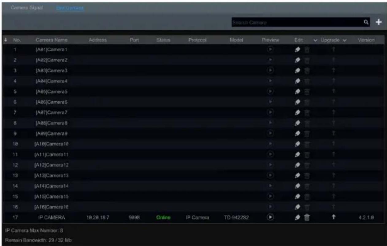
Click "Edit Camera" in the setup panel to go to the interface as shown below.
text_image
Camera Signal Edit Camera Search Camera No. Camera Name Address Port Status Protocol Model Preview Edit Upgrade Version 1 [A01]Camera1 2 [A02]Camera2 3 [A03]Camera3 4 [A04]Camera4 5 [A05]Camera5 6 [A06]Camera6 7 [A07]Camera7 8 [A08]Camera8 9 [A09]Camera9 10 [A10]Camera10 11 [A11]Camera11 12 [A12]Camera12 13 [A13]Camera13 14 [A14]Camera14 15 [A15]Camera15 16 [A16]Camera16 17 IP CAMERA 18.28.18.7 9008 Online IP Camera TD-942282 IP Camera Max Number: 8 Remain Bandwidth: 29 / 32 MbClick 📋 to view the live image of the camera in the popup window. Click 📋 to edit the camera (see Add camera in 3.1 Startup Wizard for details). Click 📋 to delete the IP camera. Click √ in the “Operation” header line and then click “Modify IPC Password” to pop up a window(check the IPCs in the window, set the new password and then click “OK” button; only the online IPCs’ passwords can be modified and a batch of IPCs’ passwords can be modified at the same time). Click ↑ to upgrade an online IPC (or click √ in the “Upgrade” header line and then click “IPC Batch Upgrade” to upgrade a batch of IPCs), select the device which stores the upgrade file in the “Device Name” item of the popup window and the upgrade file in the list(you should select the upgrade IPC model in the window if a batch of IPCs’ passwords need to be modified) and then click “Upgrade” button to start upgrading(the IPC will restart automatically after the upgrade is completed successfully).
5 Live View Introduction
5.1 Live View Interface Introduction
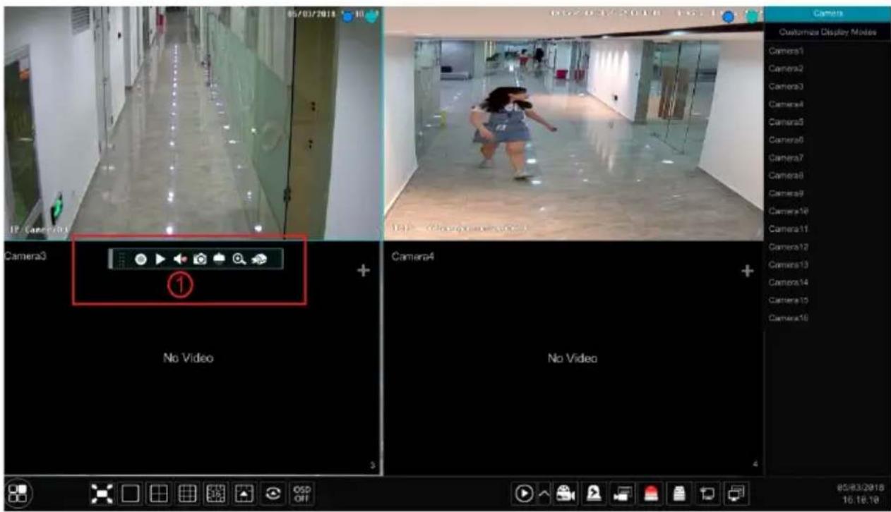
The connected analog camera will be added automatically in the live view interface for previewing. You should add IP camera manually for previewing (see 4.2.1 Add Camera for details). Refer to the interface as shown below, drag one camera in the preview window to another window for camera window exchanging.
The record symbols with different colors in the live preview window refer to different record types when recording: green stands for manual record, red stands for sensor based record, yellow stands for motion based record, blue stands for schedule record and cyan stands for intelligence record.
text_image
05/03/2018 IP Camera3 Camera3 ① No Video Camera4 No Video Camera Customize Display Modes Camera1 Camera2 Camera3 Camera4 Camera5 Camera6 Camera7 Camera8 Camera9 Camera10 Camera11 Camera12 Camera13 Camera14 Camera15 Camera16 85/83/2018 16:18:10Click the preview window to show the tool bar as shown in area ① right click the preview window to show the menu list. The tool bar and menu list are introduced in the table below.
| Button | Menu List Meaning | |
 | -- | Move tool. Click it to move the tool bar anywhere. |
 | Manually Record On | Click it to start recording. |
| [WASD] | Instant Playback | Click ▶ to playback the record; click “Instant Playback” to select or self-define the instant playback time. See 8.1 Instant Playback for details. |
 | Enable Audio | Click it to enable audio. You can listen to the camera audio by enabling audio. |
 | Snap | Click it to pop up the snap window. Click “Save” in the window to save the image. Click “Export” to export the image. |
 | PTZ Control | Click it to go to PTZ control interface. See Chapter 6 PTZ for details. |
 | Zoom In | Click it to go to single channel amplification interface. |
 | -- | Click it to go to image adjustment interface. Refer to 5.4.5 Image Adjustment for details. |
| -- Camera Info | Click it to view the IP camera information. | |
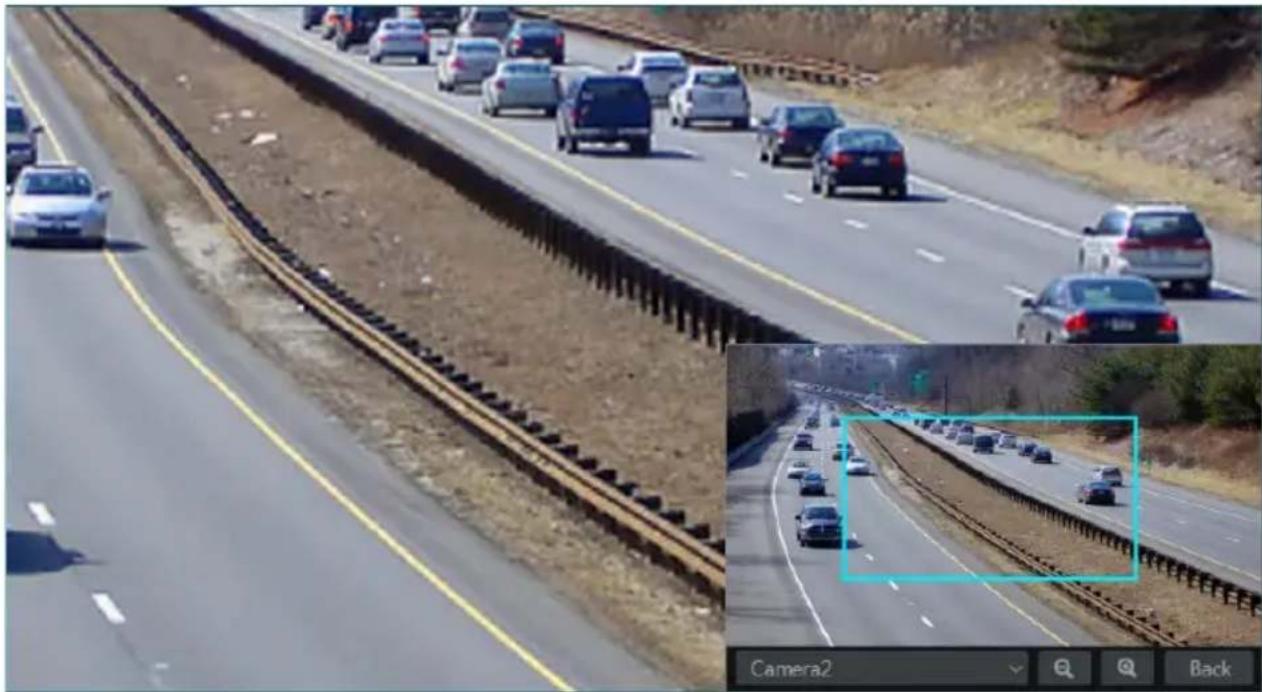
The single channel amplification interface is as shown below. Press and drag the blue box to select the zoom in area. Click / to zoom the image. Click the camera selection box to select other cameras for amplification. Click “Back” to return to the live view interface.
natural_image
Highway traffic scene with multiple cars on elevated tracks and a close-up inset showing a detailed lane detail (no visible text or symbols)5.2 View Mode
5.2.1 Display Mode
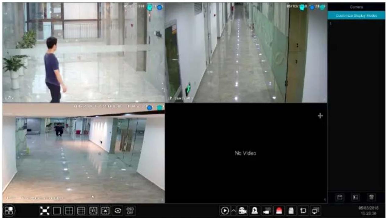
Set different screen modes and cameras' display sequences as required and then save the display modes classified by surveillance areas, priorities and so on. Refer to the picture below. Double click one display mode in the display mode list to view the live images in this mode.
text_image
05/03/2018 Camera Customize Display Mode IP Cancel 03 No Video 05/03/2018 15:20:39▶ Add Display Mode
Method One:
① Click "Customize Display Modes" in the above interface and then set the screen mode.
② Add the cameras and adjust the cameras' display sequence as needed.
③ Click ☐ under the display mode list and then enter the display mode name in the popup window, click the “OK” button to save the current display mode.
Method Two:
① Click Start→Settings→System→Basic→Output Settings→Main Output to go to the interface and then set the screen mode.
② Double click the camera or camera group-in the list to add them to the selected window.
③ Click ★ to save the current display mode (refer to 5.2.3 Scheme View In Sequence for detail configurations). The display mode will be saved and displayed in the display mode list in the live view interface.
➢ Edit Display Mode
Click the “Customize Display Modes” tab in the live view interface and then select one display mode in the list. Click 📁 to edit the display mode name; click 📄 to delete the display mode.
5.2.2 Quick Sequence View
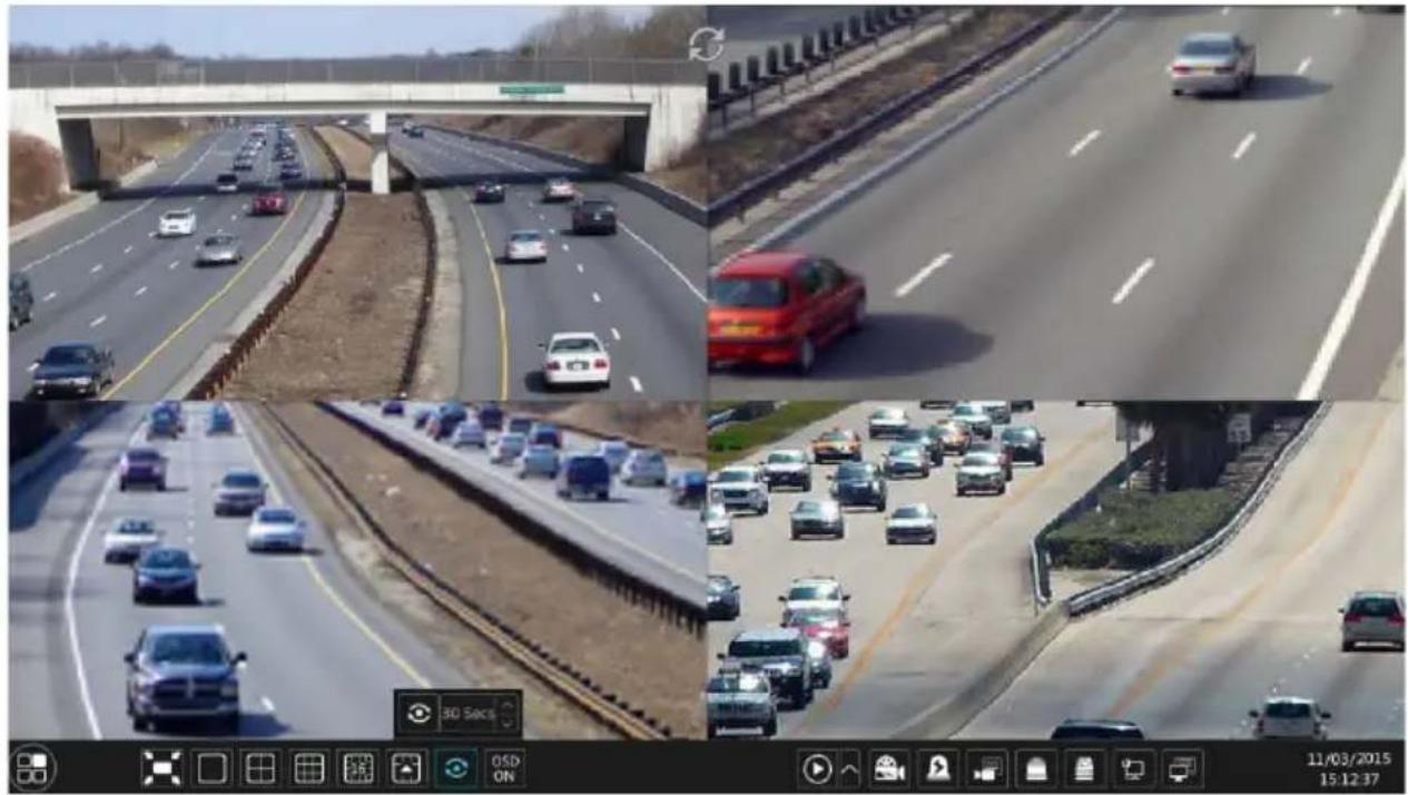
You can start quick sequence view if the scheme has not been created. If the scheme has been created, please refer to 5.2.3 Scheme View in Sequence for details.
natural_image
Composite image showing four highway surveillance feeds: overhead bridge, red car, multi-lane highway, and multi-lane highway with traffic (no visible text or symbols)Go to the live view interface and then click 📄 to pop up a little window. Set the dwell time in the window and then click 🔒 to view the live group by group according to the camera number of the current screen mode. Double click the sequence view interface to pause the view; double click again to restore the view. Click 🔒 to stop the view.
5.2.3 Scheme View In Sequence
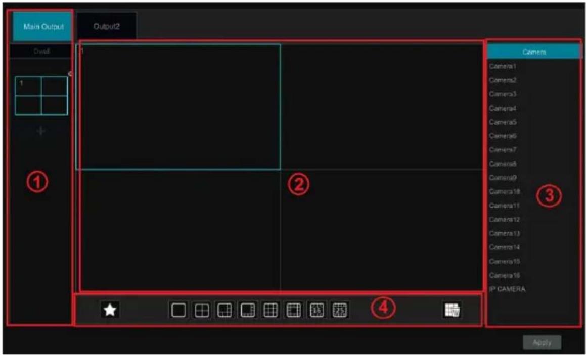
Click Start→Settings→System→Basic→Output Settings→Main Output to go to the interface as shown below.
Area ① displays all the dwell schemes; area ② shows the detailed information of the scheme; area ③ displays all the cameras; area ④ is the tool bar (☐: clear button; ☆: favorite button, click it to pop up a window, enter the display mode name in the window and then click “OK” to save the current display mode; other buttons are screen mode buttons).
text_image
Main Output Output2 Dwell 1 + ① ② ③ Camera Camera1 Camera2 Camera3 Camera4 Camera5 Camera6 Camera7 Camera8 Camera9 Camera10 Camera11 Camera12 Camera13 Camera14 Camera15 Camera16 IP CAMERA ApplyAdd Scheme
Click + in area ① to create a new scheme. Click Ⓧ on the top right corner of the scheme to delete it.
Configure Scheme
a) Select a scheme in area ① and then click the screen mode button on the tool bar to set the screen mode of the scheme.
b) Select a camera window in area ② and then double dick the camera in area ③ The camera will be added into the selected window. One camera in the same scheme cannot repeat. You can click the right-click menu “Clear” in area ② to remove a single camera or click 📂 to remove all the cameras.
c) Click "Apply" to save the settings.
Start Sequence View
Go to live view interface and then click 🔒 to pop up a window. Set the dwell time in the window and then click 🔒 to start scheme view in sequence. Double click the sequence view interface to pause the view; double click again to restore the view. Click 🔒 to stop the view.
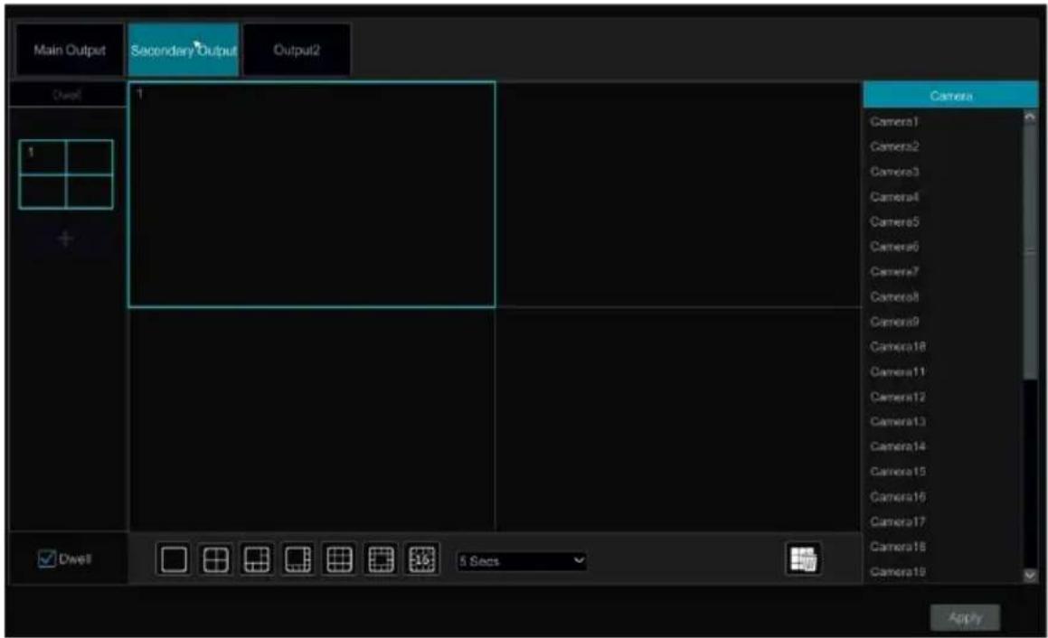
Secondary Output
Note:
You can set the secondary output preview if the DVR has dual outputs. Refer to the interface as shown below.
text_image
Main Output Secondary Output Output2 Dwell 1 Camera Camera1 Camera2 Camera3 Camera4 Camera5 Camera6 Camera7 Camera8 Camera9 Camera10 Camera11 Camera12 Camera13 Camera14 Camera15 Camera16 Camera17 Camera18 Camera19 Dwell 5 Secs ApplyCheck “Dwell” and then set scheme view in sequence of the adjuvant output. The setting steps are similar to that of the main output.
Set quick sequence view if "Dwell" is not checked. The setting steps are as follows:
① Set screen mode by clicking the relevant buttons on the tool bar.
② Select one window and then double click one camera or group in the list.
③ Click “Apply” to save the settings after adding cameras or groups to the windows.
5.2.4 Spot View
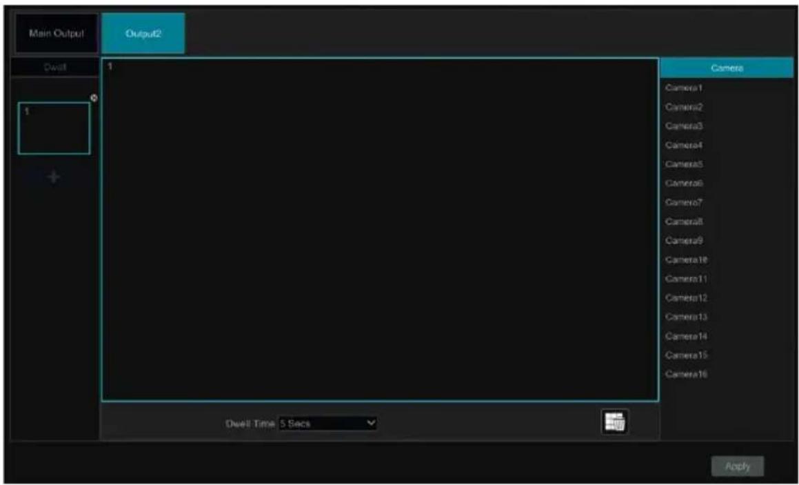
Click Start→Settings→System→Basic→Output Settings→Secondary Output/Output 2 to go to the interface as shown below.
Click 📋 on the left to create a new scheme. Each scheme can only add one analog camera. Select a scheme on the left and then double click or drag a camera on the right to the scheme window in the middle of the interface. After finishing the settings of all the schemes, select the dwell time and click “Apply” to start playing the schemes in sequence in output 2.
text_image
Main Output Output2 Dwell 1 Dwell Time: 5 Secs Camera Camera1 Camera2 Camera3 Camera4 Camera5 Camera6 Camera7 Camera8 Camera9 Camera10 Camera11 Camera12 Camera13 Camera14 Camera15 Camera16 Apply5.3 POS Settings
Some models may not support this function.
① Click Start→Settings→Basic→POS Settings to go to the interface.
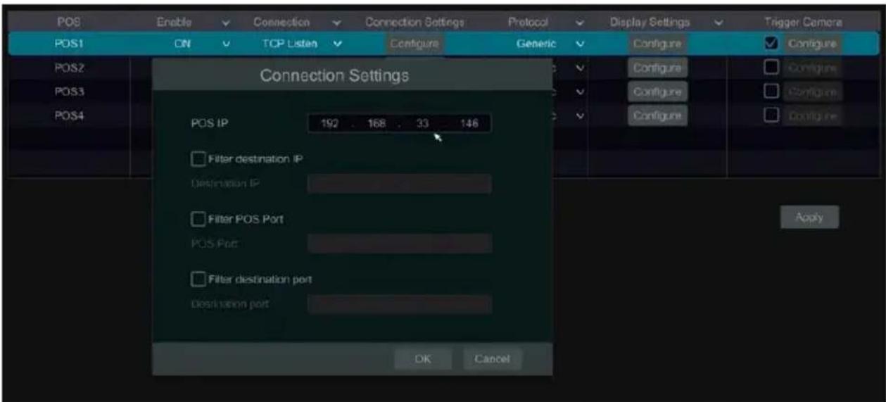
② Enable POS and click configure under “Connection Settings” to go to the following interface.
③ Enter the IP address of the POS you want to add.
④ Check “Filter destination”, “Filter POS port” and “Filter destination Port” (If you do not check them, please skip this step) and Enter the destination IP, POS port and destination port you want to filter.
text_image
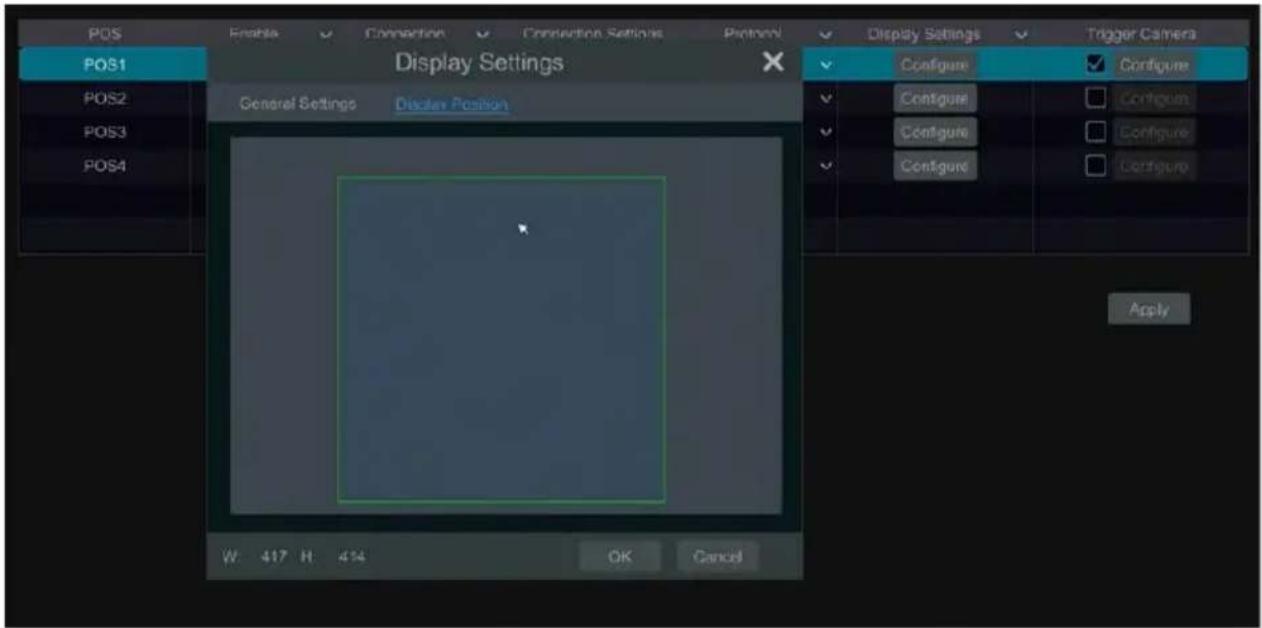
POS Enable Connection Connection Settings Protocol Display Settings Trigger Camera POS1 ON TCP Listen Configure Generic Configure Configure Configure POS2 POS3 POS4 Connection Settings POS IP 192 . 168 . 33 . 146 Filter destination IP Destination IP Filter POS Port POS Port Filter destination port Destination port OK Cancel Apply⑤ Click “Display Position” under “Display Settings” to set the position of the POS information (Use the default settings of the general settings).
text_image
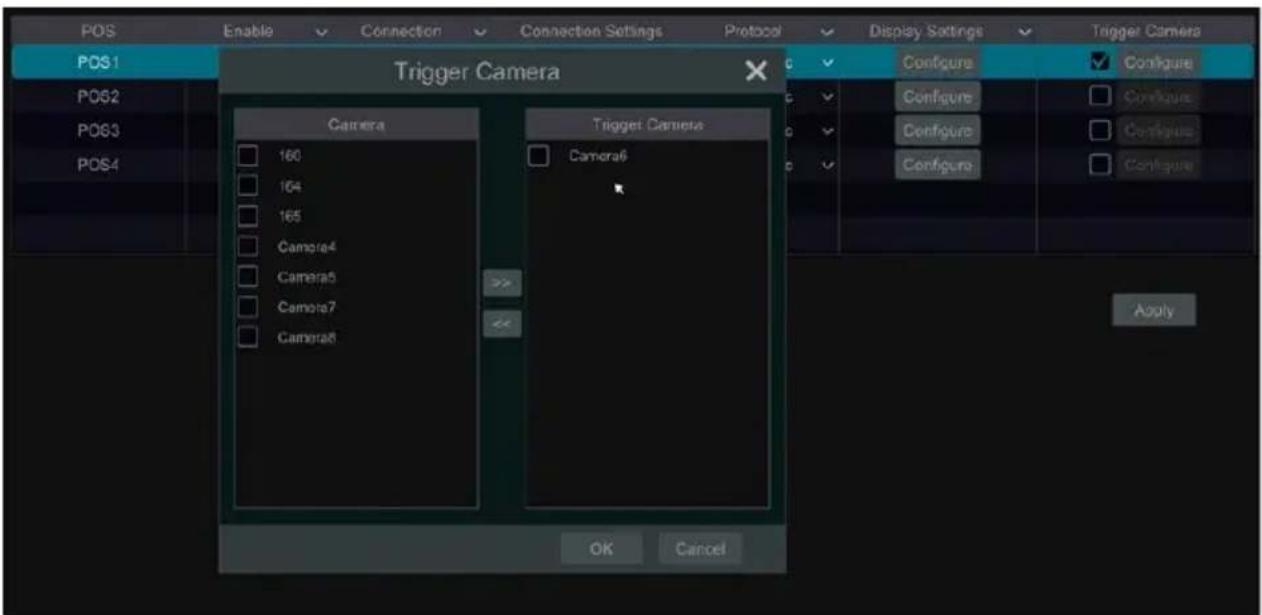
POS Enable Connection Connection Settings Platform Display Settings Trigger Camera POS1 General Settings Display Position Configure Configure Configure Configure Configure Configure Configure Configure Apply W 417 H 414 OK Cancel⑥ Check “Trigger Camera” and click configure under it to bind POS to the camera. One POS can be bound to multiple channels, but one channel can only be bound to one POS.
text_image
POS Enable Connection Connection Settings Protocol Display Settings Trigger Camera POS1 Trigger Camera C C Configure Configure Configure Configure Configure PDS2 PDS3 PDS4 Camera 160 164 165 Camera4 Camera5 Camera7 Camera8 Trigger Camera Camera6 Apply OK Cancel⑦ Click “Apply” to save the settings and then the trade information will be displayed on the preview image in real-time.
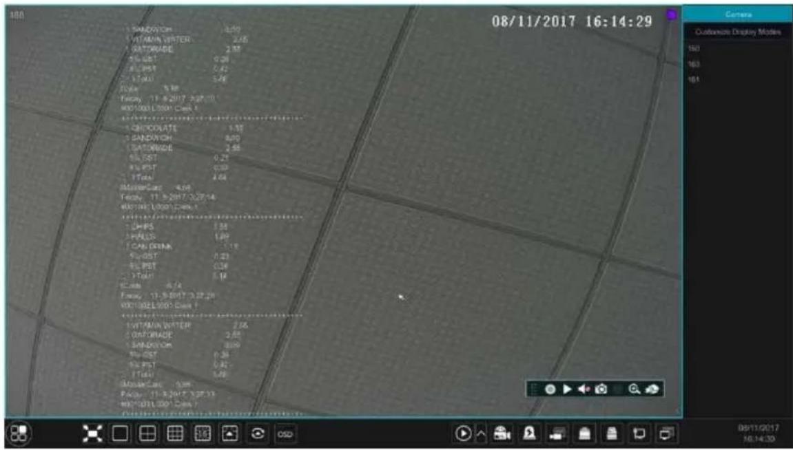
One POS is bound to one camera:
text_image
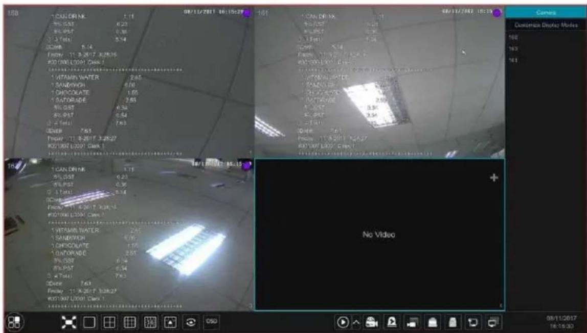
08/11/2017 16:14:29 CAMBRIDGE VITAMIN WATER GATORADE 5L-UST 5L-PST 5L-MAI 5.3% 5.3% Farey, 11-9-2017 02:14 M001001 L001 Cash COUNTERATE SANDON CH GATORADE 5L-UST 5L-PST 5L-MAI 5.3% 5.3% Farey, 11-9-2017 02:14 M001001 L001 Cash CHIPS PAPLOK CAN BREAK 5L-UST 5L-PST 5L-MAI 5.3% 5.3% Farey, 11-9-2017 02:29 M001001 L001 Cash VITAMIN WATER GATORADE SANDON CH 5L-UST 5L-PST 5L-MAI 5.3% 5.3% Farey, 11-9-2017 02:29 M001001 L001 CashOne POS is bound to multiple cameras:
text_image
100 1 CAN DRIVE 2.11 8% GAST 6.23 8% PAST 2.38 2.3 Total 5.14 DCB: 5.14 Ferry: 11.9-2017 3:28:29 FDD:1000 L0091 Class 1 1 VITAMIN WATER 2.85 1 SANDVACH 0.78 1 CHOCOLATE 1.65 1 BATORADE 2.65 8% GAST 6.34 8% PAST 6.54 2.4 Total 7.63 DCB: 7.63 Friday: 11.8-2017 3:28:27 FDD:1000 L0091 Class 1 1 CAN DRIVE 3.11 8% GAST 6.23 8% PAST 6.38 2.3 Total 5.14 DCB: 5.14 Friday: 11.6-2017 3:28:13 FDD:1000 L0091 Class 1 1 VITAMIN WATER 2.85 1 SANDVACH 6.23 1 CHOCOLATE 1.65 1 BATORADE 2.65 8% GAST 6.34 8% PAST 6.54 2.4 Total 7.63 DCB: 7.63 Friday: 11.9-2017 3:28:27 FDD:1000 L0091 Class 1 1 CAN DRIVE 3.27 8% GAST 6.23 8% PAST 6.38 2.3 Total 5.14 DCB: 5.14 Friday: 11.8-2017 3:28:27 FDD:1000 L0091 Class 1 No Video5.4 Image Configuration
5.4.1 OSD Settings
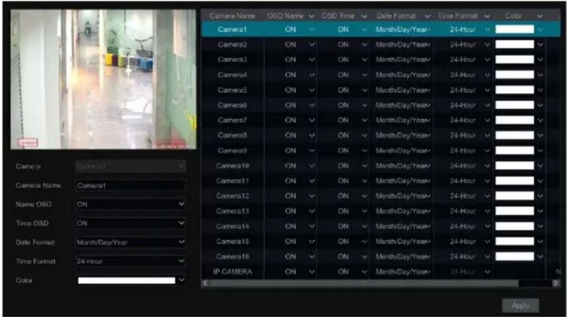
Click Start→Settings→Camera→Image→OSD Settings to go to the interface as shown below. Select the camera, enter the camera name (or double click the camera name in the camera list to change the camera name), enable or disable the name and time OSDs (if enabled, drag the red name and time OSDs directly in the image view area to change the OSDs' display position) and select the date, time format and color. Click “Apply” to save the settings.
text_image
Camera Name OSD Name OSD Time Date Format Time Format Color Camera1 ON ON Month/Day/Year 24-Hour Camera2 ON ON Month/Day/Year 24-Hour Camera3 ON ON Month/Day/Year 24-Hour Camera4 ON ON Month/Day/Year 24-Hour Camera5 ON ON Month/Day/Year 24-Hour Camera6 ON ON Month/Day/Year 24-Hour Camera7 ON ON Month/Day/Year 24-Hour Camera8 ON ON Month/Day/Year 24-Hour Camera9 ON ON Month/Day/Year 24-Hour Camera10 ON ON Month/Day/Year 24-Hour Camera11 ON ON Month/Day/Year 24-Hour Camera12 ON ON Month/Day/Year 24-Hour Camera13 ON ON Month/Day/Year 24-Hour Camera14 ON ON Month/Day/Year 24-Hour Camera15 ON ON Month/Day/Year 24-Hour Camera16 ON ON Month/Day/Year 24-Hour IP CAMERA ON ON Month/Day/Year 24-Hour Camera Camera1 Camera Name Camera1 Name OSD ON Time OSD ON Date Format Month/Day/Year Time Format 24-Hour Color5.4.2 Image Settings
Click Start→Settings→Camera→Image→Image Settings to go to the following interface. Select the camera and then set the brightness, contrast, saturation and hue of the camera. Click “Advanced” button or in the camera list on the right side of the interface to pop up “Image Adjust” interface and then set the relevant setting items. Please refer to 5.4.5 Image Adjustment for detailed introductions of these items.
You can click "Default" button to restore the image settings to the default factory settings.
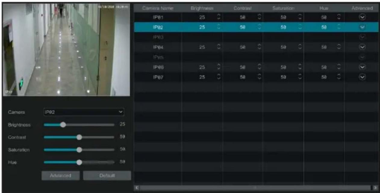
text_image
07/18/2019 16:30:19 Camera Name Brightness Contrast Saturation Hue Advanced IPB1 25 50 50 50 IPB2 25 50 50 50 IPB3 IPB4 25 50 50 50 IPB5 IPB6 25 50 50 50 IPB7 25 50 50 50 Camera IPB2 Brightness 25 Contrast 50 Saturation 50 Hue 50 Advanced Default5.4.3 Mask Settings
Some areas of the image can be masked for privacy. Up to four mask areas can be set for each camera. Click Start→Settings→Camera→Image→Mask Settings to go to the interface as shown below. Select the camera and enable the mask. Click “Draw” button and then drag the
mouse on the image area to set the mask area; click "Delete" button to delete the mask areas; click "Apply" to save the settings.
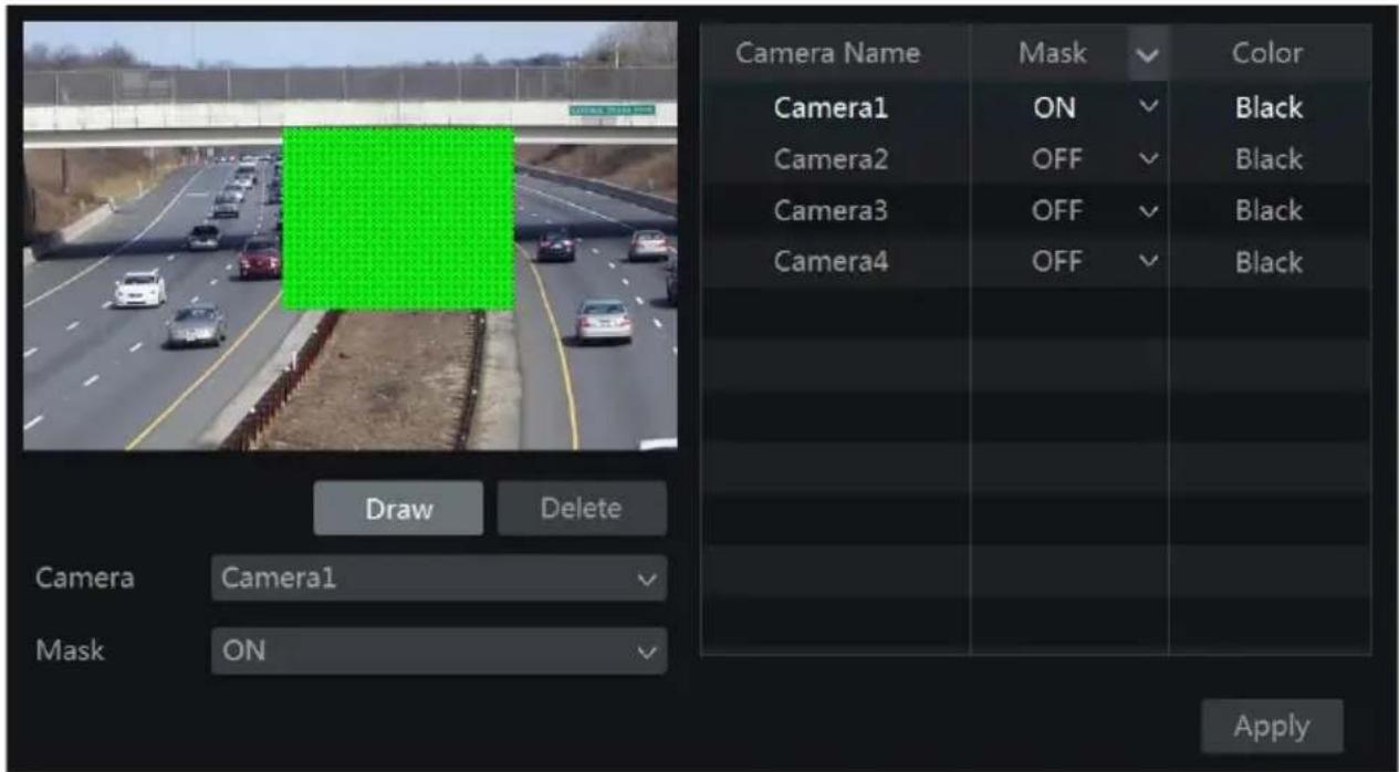
text_image
Camera Name Mask Color Camera1 ON Black Camera2 OFF Black Camera3 OFF Black Camera4 OFF Black Draw Delete Camera Camera1 Mask ON Apply5.4.4 Water Mark Settings
Click Start Settings Camera Image Water Mark Settings to go to the interface as shown below. Select the camera and enable water mark and then enter the water mark information. Click "Apply" to save the settings.
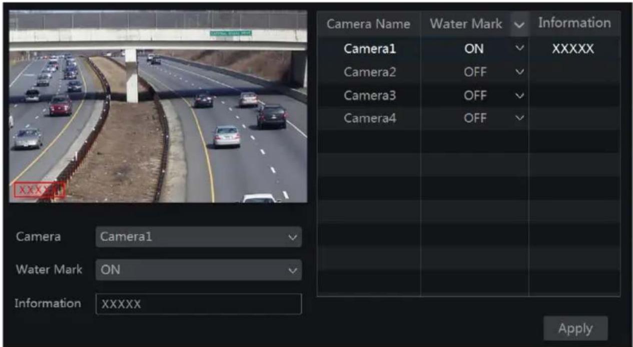
text_image
Camera Name Water Mark Information Camera1 ON XXXXX Camera2 OFF Camera3 OFF Camera4 OFF Camera Camera1 Water Mark ON Information XXXXX Apply5.4.5 Image Adjustment
Go to live view interface and then click to go to the image adjustment interface.
button on the tool bar under the camera window
➢ Image Adjustment
Select the camera and then click “Image Adjustment” to go to image adjustment tab. Refer to the above picture. Drag the slider to set the camera’s brightness, contrast, saturation and hue value. Check sharpen, wide dynamic and denoise and then drag the slider to set the value. Click “Default” button to set these parameters to default values.
The introductions of these parameters are as follows:
| Parameter | Meaning |
| Brightness | It is the brightness level of the camera's image. |
| Contrast | It is the color difference between the brightest and darkest parts. |
| Saturation | It is the degree of color purity. The color is purer, the image is brighter. |
| Hue | It refers to the total color degree of the image. |
| Sharpen | It refers to the resolution level of the image plane and the sharpness level of the image edge. |
| Wide Dynamic | The wide dynamic range (WDR) function helps the camera provide clear images even under back light circumstances. When there are both very bright and very dark areas simultaneously in the field of view, WDR balances the brightness level of the whole image and provide clear images with details. |
| BLC | HLC: lowers the brightness of the entire image by suppressing the brightness of the image's bright area and reducing the size of the halo area.BLC: If enabled, the auto exposure will activate according to the scene so that the object of the image in the darkest area will be seen clearly. |
| Denoise | Decrease the noise and make the image more thorough. Increasing the value will make the noise reduction effect better but it will reduce the image resolution. |
| White Balance | Adjust the color temperature according to the environment automatically. |
| Image Mirror | Turn the current video image horizontally. |
| Image Flip | Turn the current video image vertically. |
➢ Lens Control
Select the camera and then click “Lens Control” to go to lens control tab. Click - or + to adjust the zoom and focus parameters of the camera’s lens. Click “Save” to save the settings.
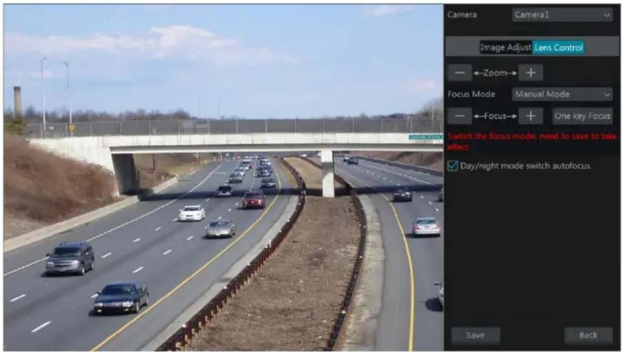
text_image
Camera Camera1 Image Adjust Lens Control Zoom Focus Mode Manual Mode Focus One key Focus Switch the focus mode. need to save to take effect Day/night mode switch autofocus. Save BackThe introductions of these parameters and buttons are as follows:
| Button/Parameter Meaning | |
| Click / to zoom in/out the image. | |
| Focus Mode | If manual mode is selected, focus button & “One Key Focus” & “Day/night mode switch autofocus” will be available; if auto mode is selected, the time interval setup will be available. |
| Click / to increase/decrease the focal length. | |
| One key Focus | Click it to focus instantly. |
| Day/night mode switch autofocus | If checked, the lens will focus automatically when the camera is switching day/night mode. |
| Time Interval | It is the time interval when camera lens is auto-focusing. The interval can be set in the drop-down list. |
Note: This function is only available for the models with auto varifocal lens, or the settings here are ineffective.
6 PTZ
6.1 PTZ Control Interface Introduction
You can control the dome or PTZ which connects to the camera for PTZ control.
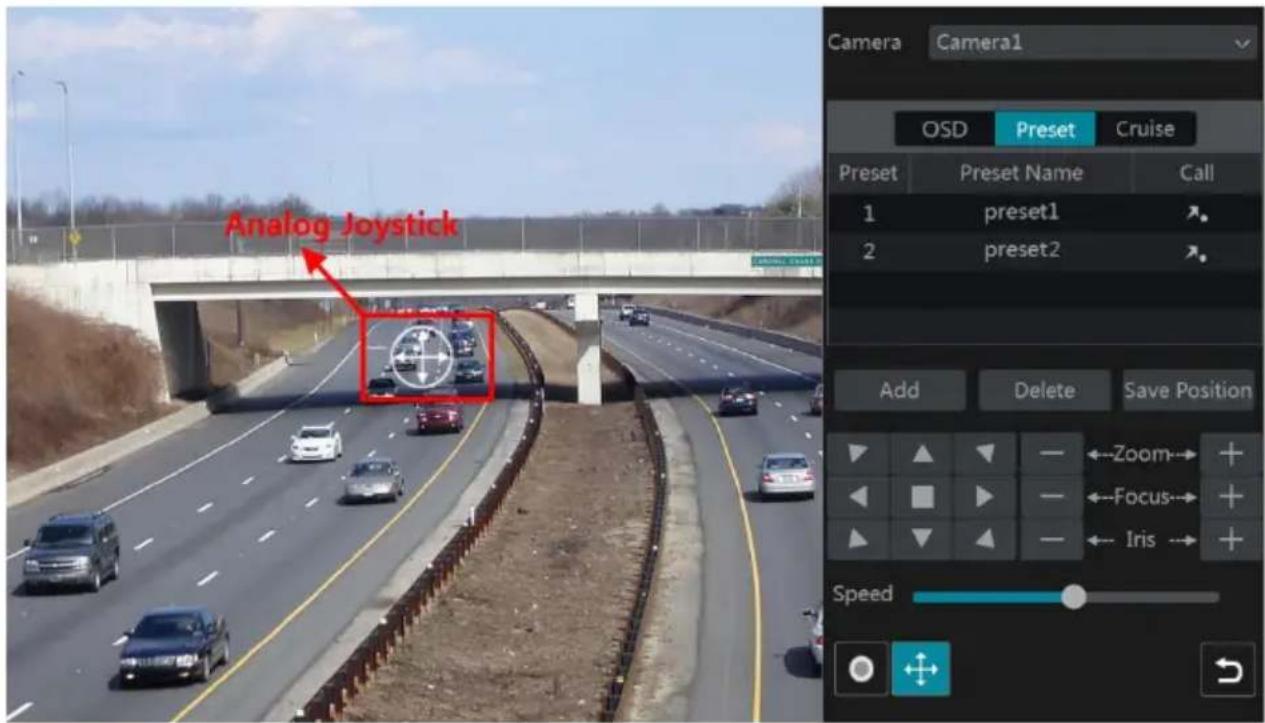
Click 📷 on the tool bar at the bottom of the live preview window to go to the PTZ control interface as shown below. You can select another dome or PTZ which connects to the camera on the top right of the interface for PTZ control.
text_image
Analog Joystick Camera Camera1 OSD Preset Cruise Preset Preset Name Call 1 preset1 2 preset2 Add Delete Save Position ←Zoom→ + ←Focus→ + ←Iris→ + SpeedIntroductions of the buttons on the bottom right of the interface:
| Button Meaning | |
 | Click  |
 | Click  |
 | Click  |
 | Click  |
 | Drag the slider to adjust the rotating speed of the dome. |
 | Click  to start / stop recording. to start / stop recording. |
 | Click  to hide / show the analog joystick. to hide / show the analog joystick. |
 | Click it to return to the live view interface. |
▶ Analog Joystick Control
The analog joystick on the left side of the interface provides quick PTZ control. The dome or PTZ will rotate when you drag the analog joystick. The farther you drag the analog joystick from the middle of the image, the faster the dome or PTZ rotates. The dome or PTZ will stop rotating when you stop dragging the analog joystick.
3D Control
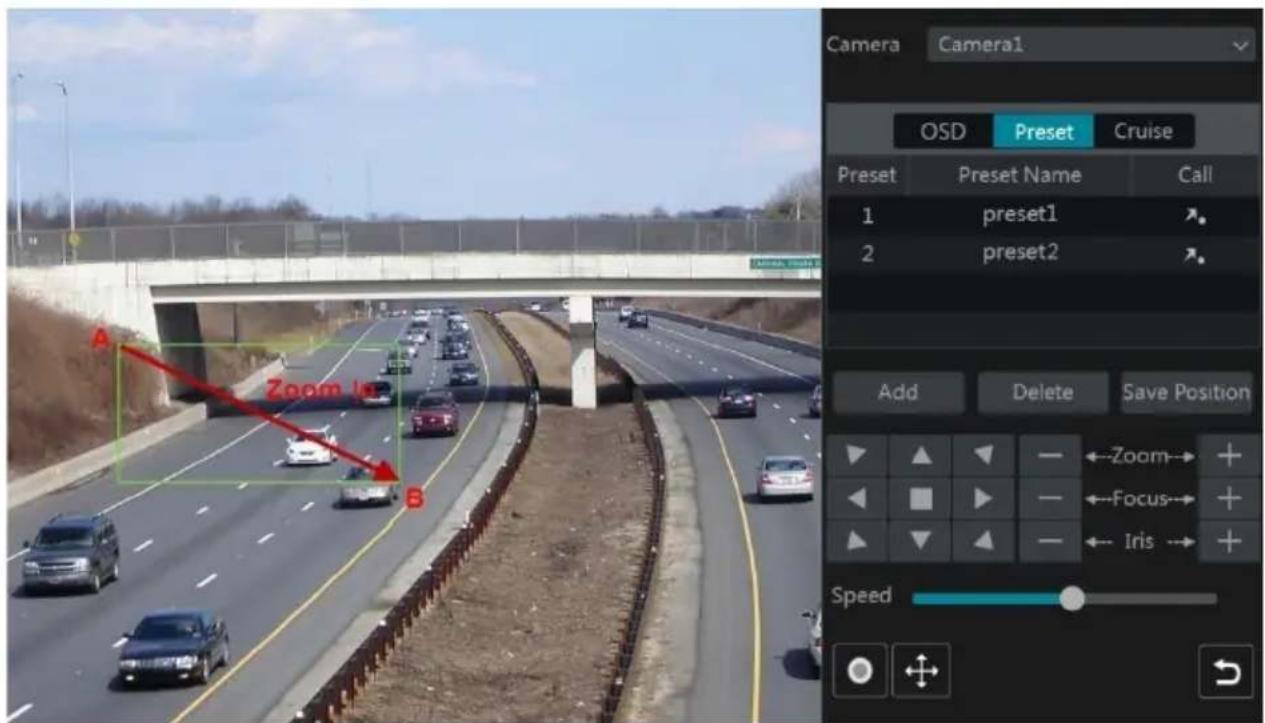
Click the camera image on any area and then the image will be centered on the clicked point. Refer to the picture as shown below. Drag the mouse from A to B to get a green rectangle and the rectangle area will be zoomed in.
text_image
Camera Camera1 OSD Preset Cruise Preset Preset Name Call 1 preset1 2 preset2 Add Delete Save Position Zoom Focus Iris SpeedRefer to the picture as shown below. Drag the mouse from C to D to get a green rectangle and the rectangle area will be zoomed out.
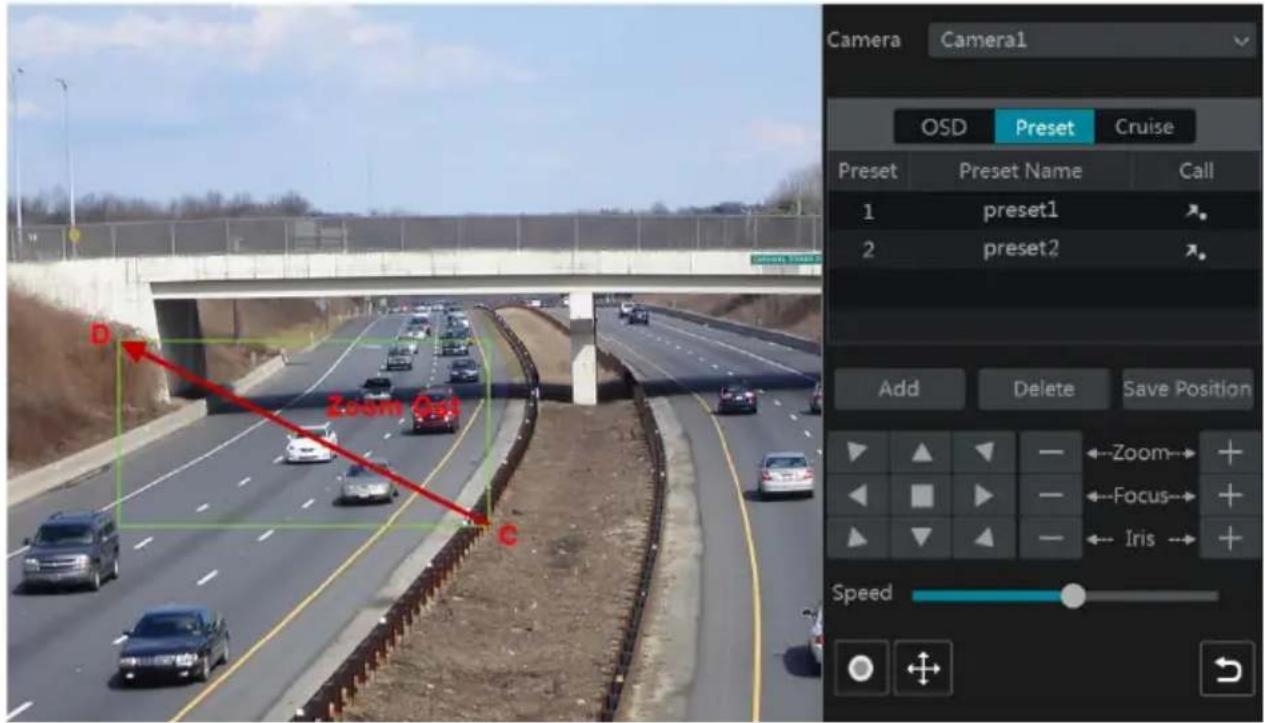
text_image
Camera Camera1 OSD Preset Cruise Preset Preset Name Call 1 preset1 2 preset2 Add Delete Save Position Zoom Focus Iris Speed▶ Advanced 3D Control
Double click the left button of the mouse on any area of the camera image and then the image size will be doubled and centered on the clicked point.
Press and hold the left button of the mouse on any area of the camera image to zoom in the image; press and hold the right button to zoom out the image.
Move the cursor of the mouse to the camera image and then slide the scroll wheel of the mouse forward to zoom in the image, slide the scroll wheel of the mouse backward to zoom out the image.
OSD Setting
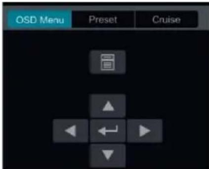
Go to PTZ protocol setting interface and then set the protocol to COC before you bring up the OSD. Click “OSD Menu” to go to camera OSD setting interface. Click ← to start OSD setting. The meanings of the buttons are shown in the table below.
text_image
OSD Menu Preset Cruise| Button Meaning | |
| Click it to call main menu or enter the sub menu or confirm the settings. | |
| Click it to call main menu or enter the sub menu or confirm the settings. | |
| Click it to change the menu mode or decrease the menu value. | |
| Click it to change the menu mode or increase the menu value. | |
| Click it to go to the previous menu. | |
| Click it to go to the next menu. | |
➢ Preset Setting
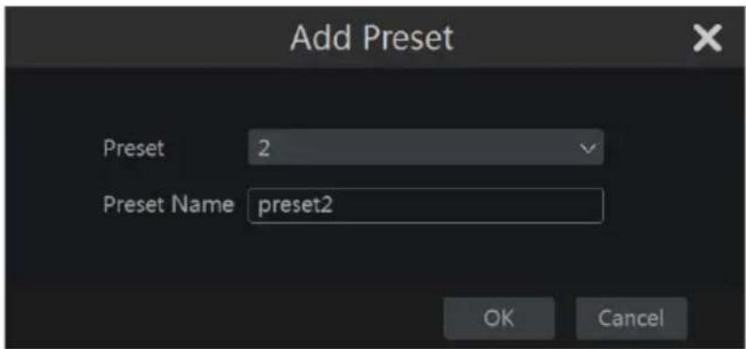
Click “Preset” to go to preset operation tab and then click “Add” button to pop up a window as shown below. Select the preset and then enter the preset name in the window; finally click “OK” button to save the settings. You can add 255 presets for each dome at most.
text_image
Add Preset Preset 2 Preset Name preset2 OK CancelAdjust the dome's direction and then click "Save Position" to save the current preset position (you can also click another preset in the preset list and then save the preset position after adjusting the dome's direction); click ↗ in the preset list to call the preset; click "Delete" button to delete the selected preset.
You can also go to preset setting interface for preset setting, see 6.2 Preset Setting for details.
Cruise Setting
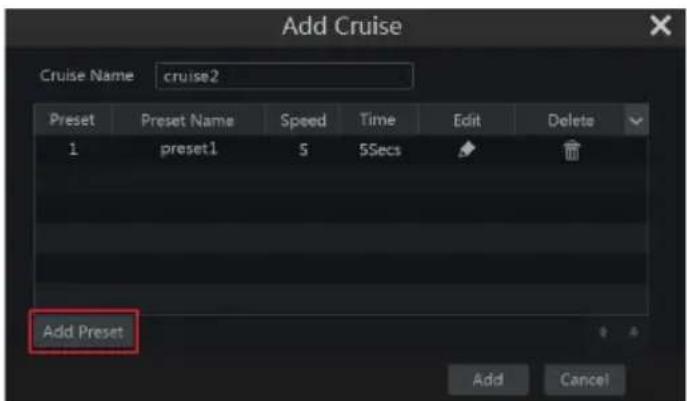
Click “Cruise” to go to cruise operation tab and then click “Add” button to pop up a window as shown below left. You can add 8 cruises for each dome at most.
text_image
Add Cruise Cruise Name cruise2 Preset Preset Name Speed Time Edit Delete 1 preset1 5 5Secs Add Preset Add Cancel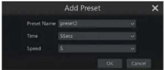
text_image
Add Preset Preset Name preset2 Time 5Secs Speed 5 OK Cancel① Enter the cruise name in the “Add Cruise” window and then click “Add preset” to pop up the “Add Preset” window (Before adding preset to the cruise, please add preset of the dome first).
② In the “Add Preset” window, select the preset name, preset time and preset speed and then click “OK” button.
③ In the “Add Cruise” window, you can click 📋 to reselect the preset, then change the preset time and speed. Click 🔒 to delete the preset. Click “Add” button to save the cruise.
Click ☑ to start the cruise and click ☐ to stop the cruise in the cruise list of the cruise operation tab; click “Delete” button to delete the selected cruise.
You can also go to cruise setting interface for cruise setting, see 6.3 Cruise Setting for details.
6.2 Preset Setting
Click Start→Settings→Camera→PTZ→Preset to go to the interface as shown below.
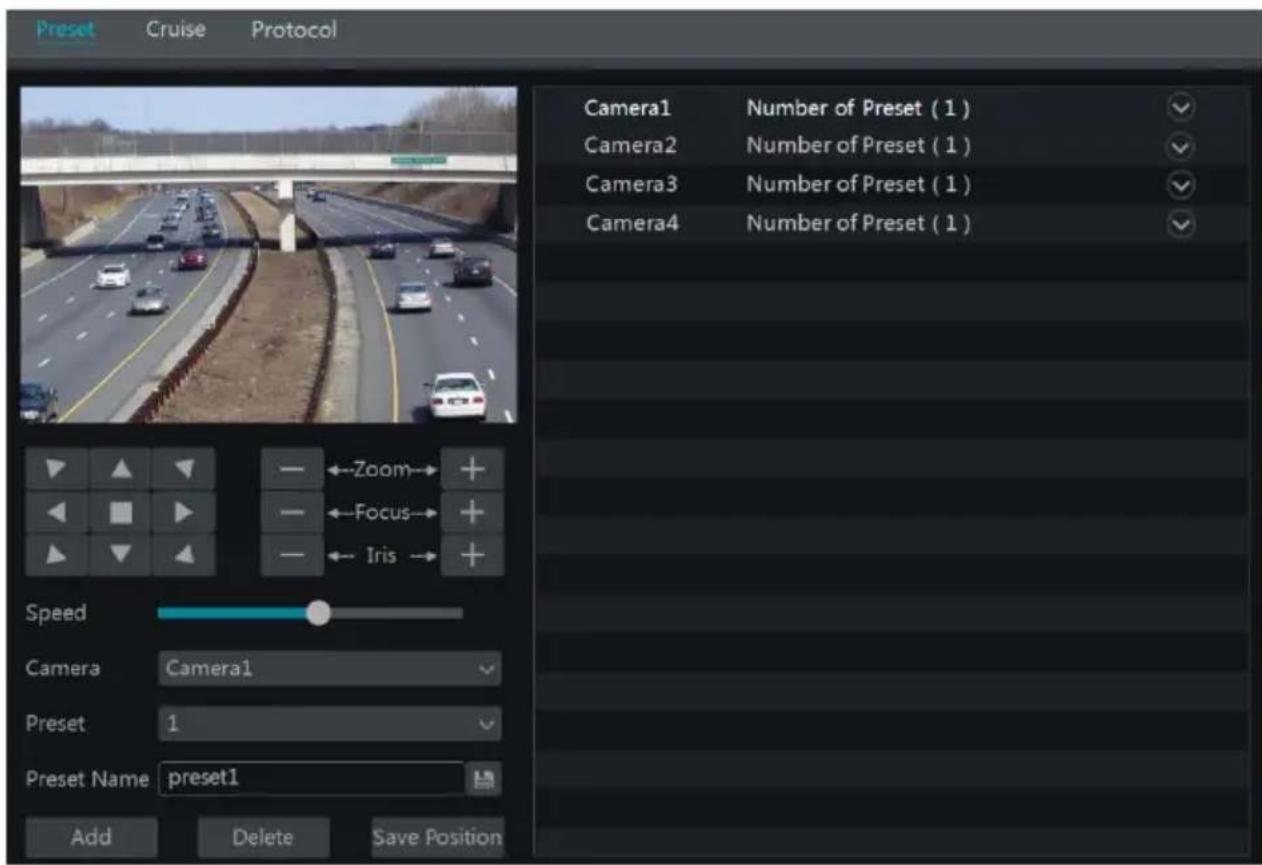
text_image
Preset Cruise Protocol Camera1 Number of Preset ( 1 ) Camera2 Number of Preset ( 1 ) Camera3 Number of Preset ( 1 ) Camera4 Number of Preset ( 1 ) Speed Camera Camera1 Preset 1 Preset Name preset1 Add Delete Save PositionAdd preset
Select camera and then click “Add” button to add preset; or click in the camera list on the right side of the interface to display the preset information of the dome and then click to add preset. The operations of the “Add Preset” window are similar to that of the PTZ control interface; please see 6.1 PTZ Control Interface Introduction for details.
Edit preset
Select camera and preset. You can enter the new name of the preset and then click 📋 to save the new preset name. Adjust the rotating speed, position, zoom, focus and iris of the preset and then click “Save Position” to save the preset.
Delete Preset
Select camera and preset and then click "Delete" to delete the preset.
6.3 Cruise Setting
Click Start→Settings→Camera→PTZ→Cruise to go to the interface as shown below.
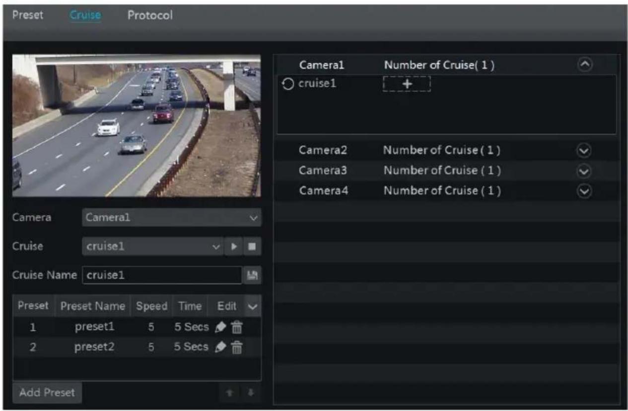
text_image
Preset Cruise Protocol Camera1 Number of Cruise( 1 ) cruise1 Camera2 Number of Cruise ( 1 ) Camera3 Number of Cruise ( 1 ) Camera4 Number of Cruise ( 1 ) Cruise Name cruise1 Preset Preset Name Speed Time Edit 1 preset1 5 5 Secs 2 preset2 5 5 Secs Add Preset▶ Add Cruise
Click in the camera list on the right side of the interface to display the cruise information of the dome and then click + to add cruise. The operations of the “Add Cruise” window are similar to that of the PTZ control interface; please see 6.1 PTZ Control Interface Introduction for details.
Edit Cruise
Select the camera and cruise in the “Cruise” interface. Enter the new cruise name and then click 📄 to save the cruise name. Click “Add Preset” to add preset to the cruise. Click 📋 to edit the preset. Click 📋 to delete the preset from the cruise. Click one preset in the preset list and then click → to move down the preset and click → to move up the preset. Click → to start the cruise and click → to stop it.
Delete Cruise
Click in the camera list on the right side of the interface to display the cruise information of the dome and then click on the top right corner of the cruise to delete the cruise.
6.4 PTZ Protocol Setting
Click Start→Settings→Camera→PTZ→Protocol to go to the interface as shown below. You can enable or disable the PTZ and set the protocol, baud rate and address of the analog dome in the interface. Please make sure the analog speed dome camera is well connected to the DVR before you control it.
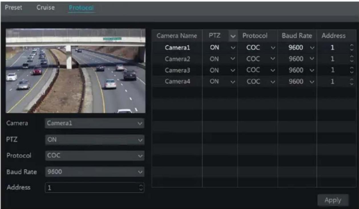
text_image
Preset Cruise Protocol Camera Name PTZ Protocol Baud Rate Address Camera1 ON COC 9600 1 Camera2 ON COC 9600 1 Camera3 ON COC 9600 1 Camera4 ON COC 9600 1 Camera Camera1 PTZ ON Protocol COC Baud Rate 9600 Address 1 ApplySelect the camera and enable PTZ and then set the protocol, baud rate and address of the dome according to the settings of the dome.
Protocol: The default communication protocol of the DVR is COC. Range from: PELCOP, PELCOD, LILIN, MINKING, NEON, STAR, VIDO, DSCP, VISCA, COC, etc.
Address: The address of the PTZ device.
Baud Rate: Baud rate of the PTZ device. Range from: 110, 300, 600, 1200, 2400, 4800, 9600, 19200, 34800, 57600, 115200, 230400, 460800, 921600.
7 Record & Disk Management
7.1 Record Configuration
7.1.1 Mode Configuration
Please format the HDDs before recording (refer to 7.5 Disk Management for details). Click Start→Settings→Record→Mode Settings to go to the mode settings interface. You can set the record time under the “Manual Record Settings” and then click “Apply” button to save the settings. There are two record modes: auto mode and manual mode.
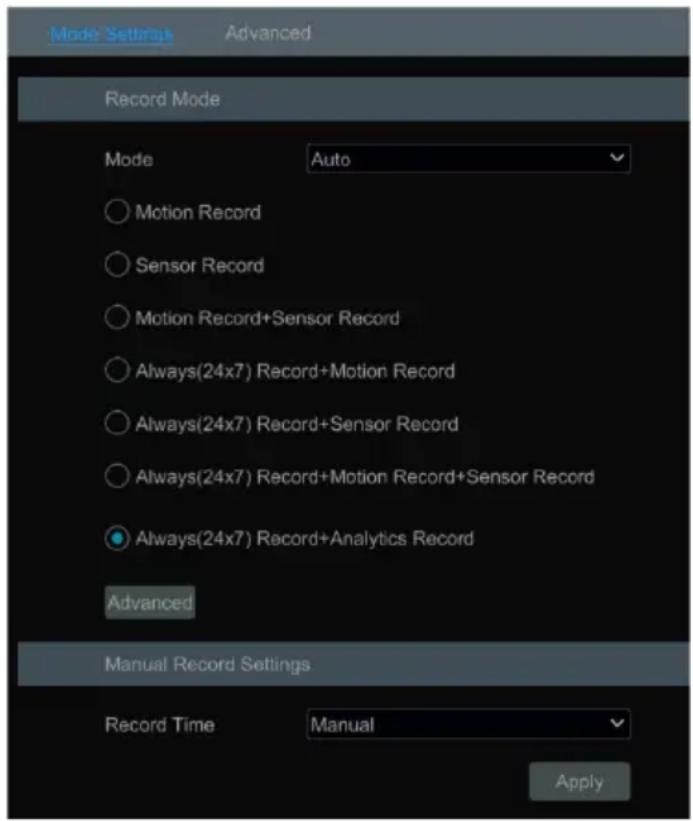
text_image
Record Mode Mode Auto Motion Record Sensor Record Motion Record+Sensor Record Always(24x7) Record+Motion Record Always(24x7) Record+Sensor Record Always(24x7) Record+Motion Record+Sensor Record Always(24x7) Record+Analytics Record Advanced Manual Record Settings Record Time Manual ApplyAuto Mode
Motion Record: Motion alarm record will be enabled when motion alarm happens.
Sensor Record: Sensor alarm record will be enabled when sensor alarm happens.
Motion Record+Sensor Record: Motion/sensor alarm record will be enabled when motion/sensor alarm happens.
Always(24 x7) Record+Motion Record: Normal record is enabled all the time; motion alarm record will be started when motion alarm happens.
Always(24 x7) Record+Sensor Record: Normal record is enabled all the time; sensor alarm record will be started when sensor alarm happens.
Always(24 ×7) Record+Motion Record+Sensor Record: Normal record is enabled all the time; motion/sensor alarm record will be enabled when motion/sensor alarm happens.
Always(24 ×7) Record+Motion Record+Sensor Record+Analytics Record: Normal record is enabled all the time; motion/sensor/intelligence alarm record will be enabled when
motion/sensor/intelligence alarm happens.
Always(24 × 7) Record+Motion Record+Sensor Record+Analytics Record+POS Record:
Normal record is enabled all the time; motion/sensor/Analytics/POS alarm record will be enabled when motion/sensor/ Analytics /POS alarm happens.
Some models may not support POS recording.
You can add more auto modes on intelligence record. Click “Advanced” button to pop up a window as shown below. Check the modes in the window and then click “Add” button to show the modes in the record mode list (in the window, the checked modes can be shown in the record mode list while the unchecked modes cannot; you cannot only check “Always(24 x 7) Record”).
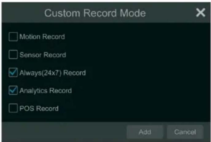
text_image
Custom Record Mode Motion Record Sensor Record Always(24x7) Record Analytics Record POS Record Add CancelSelect one auto mode to pop up the corresponding window. Set the encode, GOP, resolution, FPS, bitrate type, quality, max bitrate and audio of each camera and then click “OK” to save the settings. Please adjust the parameters according to the actual condition.
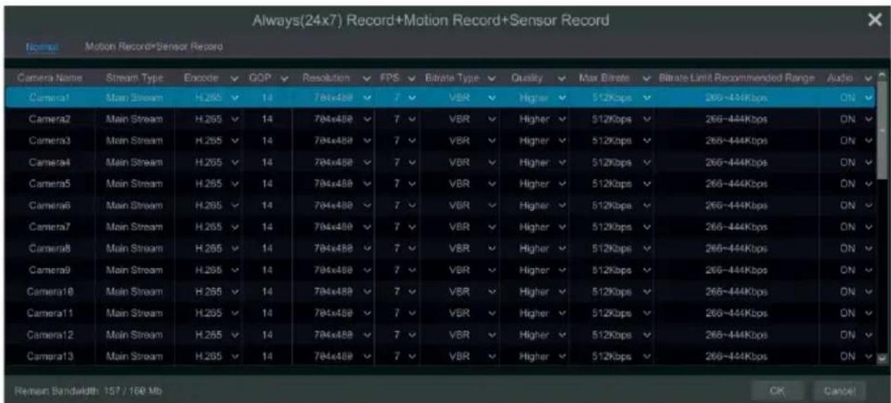
text_image
Always(24x7) Record+Motion Record+Sensor Record Normal Motion Record+Sensor Record Camera Name Stream Type Encode GOP Resolution FPS Bitrate Type Quality Max Bitrate Bitrate Limit Recommended Range Audio Camera1 Main Stream H.265 14 784x488 7 VBR Higher 512Kbps 266~444Kbps ON Camera2 Main Stream H.265 14 784x488 7 VBR Higher 512Kbps 266~444Kbps ON Camera3 Main Stream H.265 14 784x488 7 VBR Higher 512Kbps 266~444Kbps ON Camera4 Main Stream H.265 14 784x488 7 VBR Higher 512Kbps 266~444Kbps ON Camera5 Main Stream H.265 14 784x488 7 VBR Higher 512Kbps 266~444Kbps ON Camera6 Main Stream H.265 14 784x488 7 VBR Higher 512Kbps 266~444Kbps ON Camera7 Main Stream H.265 14 784x488 7 VBR Higher 512Kbps 266~444Kbps ON Camera8 Main Stream H.265 14 784x488 7 VBR Higher 512Kbps 266~444Kbps ON Camera9 Main Stream H.265 14 784x488 7 VBR Higher 512Kbps 266~444Kbps ON Camera10 Main Stream H.265 14 784x488 7 VBR Higher 512Kbps 266~444Kbps ON Camera11 Main Stream H.265 14 784x488 7 VBR Higher 512Kbps 266~444Kbps ON Camera12 Main Stream H.265 14 784x488 7 VBR Higher 512Kbps 266~444Kbps ON Camera13 Main Stream H.265 14 784x488 7 VBR Higher 512Kbps 266~444Kbps ON Remain Bandwidth 157 / 160 Mb OK CancelVideo Encode: the video encode format of the camera.
GOP: group of pictures.
Resolution: the higher the resolution is, the clearer the image is.
FPS: the higher the frame rate is, the more fluency the video is. However, more storage room will be taken up.
Bitrate Type: CBR and VBR are optional. CBR means that no matter how much change is seen in the video scene, the compression bitrate will be kept constant. VBR means that the compression bitrate will be adjusted according to scene changes. For example, for scenes that do not have much movement, the bitrate will be kept at a lower value. This will help to optimize the network bandwidth.
Quality: When VBR is selected, you need to choose image quality. The higher the image quality you choose, the more bitrate will be required.
Max Bitrate: 32Kbps \~10240Kbps are optional.
Manual Mode
If the manual mode is selected, you need to set the encode parameters and record schedules of each camera. See 7.2 Encode Parameters Setting and 7.3 Schedule Setting for details.
7.1.2 Advanced Configuration
Click Start→Settings→Record→Advanced to go to the following interface. Enable or disable cycle record (cycle record: the earliest record data will be replaced by the latest when the disks are full). Set the stream, pre-alarm record time, post-alarm record time and expiration time of each camera and then click “Apply” to save the settings.
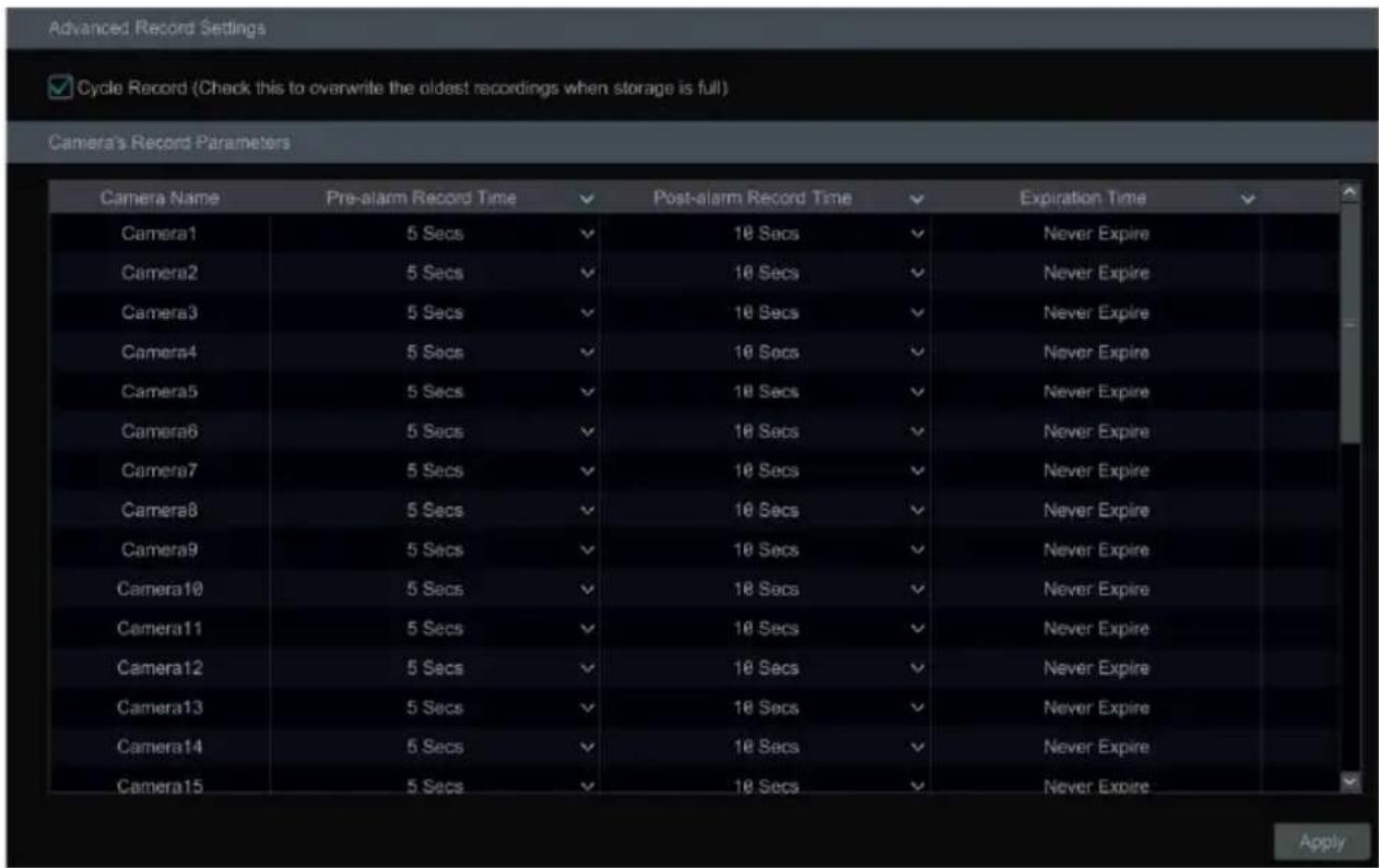
text_image
Advanced Record Settings ✓ Cycle Record (Check this to overwrite the oldest recordings when storage is full) Camera's Record Parameters Camera Name Pre-alarm Record Time ✓ Post-alarm Record Time ✓ Expiration Time ✓ Camera1 5 Secs ✓ 10 Secs ✓ Never Expire Camera2 5 Secs ✓ 10 Secs ✓ Never Expire Camera3 5 Secs ✓ 10 Secs ✓ Never Expire Camera4 5 Secs ✓ 10 Secs ✓ Never Expire Camera5 5 Secs ✓ 10 Secs ✓ Never Expire Camera6 5 Secs ✓ 10 Secs ✓ Never Expire Camera7 5 Secs ✓ 10 Secs ✓ Never Expire Camera8 5 Secs ✓ 10 Secs ✓ Never Expire Camera9 5 Secs ✓ 10 Secs ✓ Never Expire Camera10 5 Secs ✓ 10 Secs ✓ Never Expire Camera11 5 Secs ✓ 10 Secs ✓ Never Expire Camera12 5 Secs ✓ 10 Secs ✓ Never Expire Camera13 5 Secs ✓ 10 Secs ✓ Never Expire Camera14 5 Secs ✓ 10 Secs ✓ Never Expire Camera15 5 Secs ✓ 10 Secs ✓ Never Expire ApplyPre-alarm Record Time: set the time to record before the actual recording begins.
Post-alarm Record Time: set the time to record after the actual recording is finished.
Expiration Time: set the expiration time for recorded video. If the set date is overdue, the recorded data will be deleted automatically.
7.2 Encode Parameters Setting
Click Start→Settings→Record→Encode Parameters to go to the interface as shown below. Set the encode, resolution, FPS, bitrate type, quality, max bitrate and audio of main stream for each camera in “Event Recording Settings” and “Schedule Recording Settings” interfaces. Click “Apply” to save the settings. You can set the record stream of each camera one by one or set them in bulk for all cameras.
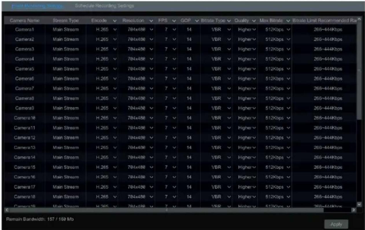
text_image
Stream Recording Settings Schedule Recording Settings Camera Name Stream Type Encode Resolution FPS GDP Bitrate Type Quality Max Bitrate Bitrate Limit Recommended Ra Camera1 Main Stream H.265 784x488 7 14 VBR Higher 512Kbps 266~444Kbps Camera2 Main Stream H.265 784x488 7 14 VBR Higher 512Kbps 266~444Kbps Camera3 Main Stream H.265 784x488 7 14 VBR Higher 512Kbps 266~444Kbps Camera4 Main Stream H.265 784x488 7 14 VBR Higher 512Kbps 266~444Kbps Camera5 Main Stream H.265 784x488 7 14 VBR Higher 512Kbps 266~444Kbps Camera6 Main Stream H.265 784x488 7 14 VBR Higher 512Kbps 266~444Kbps Camera7 Main Stream H.265 784x488 7 14 VBR Higher 512Kbps 266~444Kbps Camera8 Main Stream H.265 784x488 7 14 VBR Higher 512Kbps 266~444Kbps Camera9 Main Stream H.265 784x488 7 14 VBR Higher 512Kbps 266~444Kbps Camera10 Main Stream H.265 784x488 7 14 VBR Higher 512Kbps 266~444Kbps Camera11 Main Stream H.265 784x488 7 14 VBR Higher 512Kbps 266~444Kbps Camera12 Main Stream H.265 784x488 7 14 VBR Higher 512Kbps 266~444Kbps Camera13 Main Stream H.265 784x488 7 14 VBR Higher 512Kbps 266~444Kbps Camera14 Main Stream H.265 784x488 7 14 VBR Higher 512Kbps 266~444Kbps Camera15 Main Stream H.265 784x488 7 14 VBR Higher 512Kbps 266~444Kbps Camera16 Main Stream H.265 784x488 7 14 VBR Higher 512Kbps 266~444Kbps Camera17 Main Stream H.265 784x488 7 14 VBR Higher 512Kbps 266~444Kbps Camera18 Main Stream H.265 784x488 7 14 VBR Higher 512Kbps 266~444Kbps Camera19 Main Stream H.265 784x488 7 14 VBR Higher 512Kbps 266~444Kbps Remain Bandwidth: 157 / 189 Mb ApplyClick Start→Settings→Record→Stream Settings to go to “Sub Stream” interface. Set the encode, resolution, FPS, bitrate type, quality and max bitrate of sub-stream for each camera in the interface and then click “Apply” to save the settings.
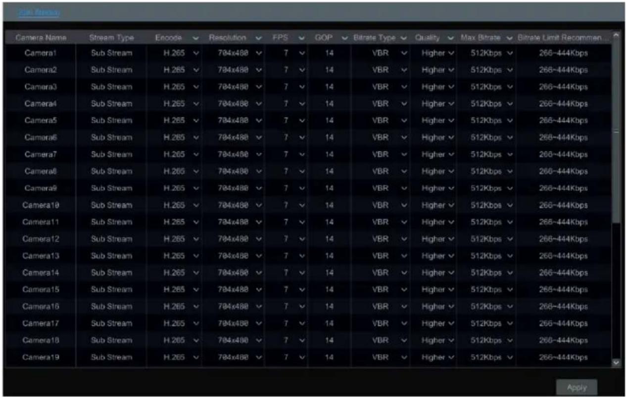
7.3 Schedule Setting
7.3.1 Add Schedule
Click Start→Settings→Record→Record Schedule→Edit Schedules to go to the interface as shown below. “24×7”, “24×5” and “24×2” are the default schedules; you cannot edit or delete “24×7” while “24×5” and “24×2” can be edited and deleted. Click the schedule name to display the detailed schedule information on the left side of the interface. The seven rows stand for the seven days in a week and each row stands for 24 hours in a day. Blue stands for the selected time and gray stands for unselected time.
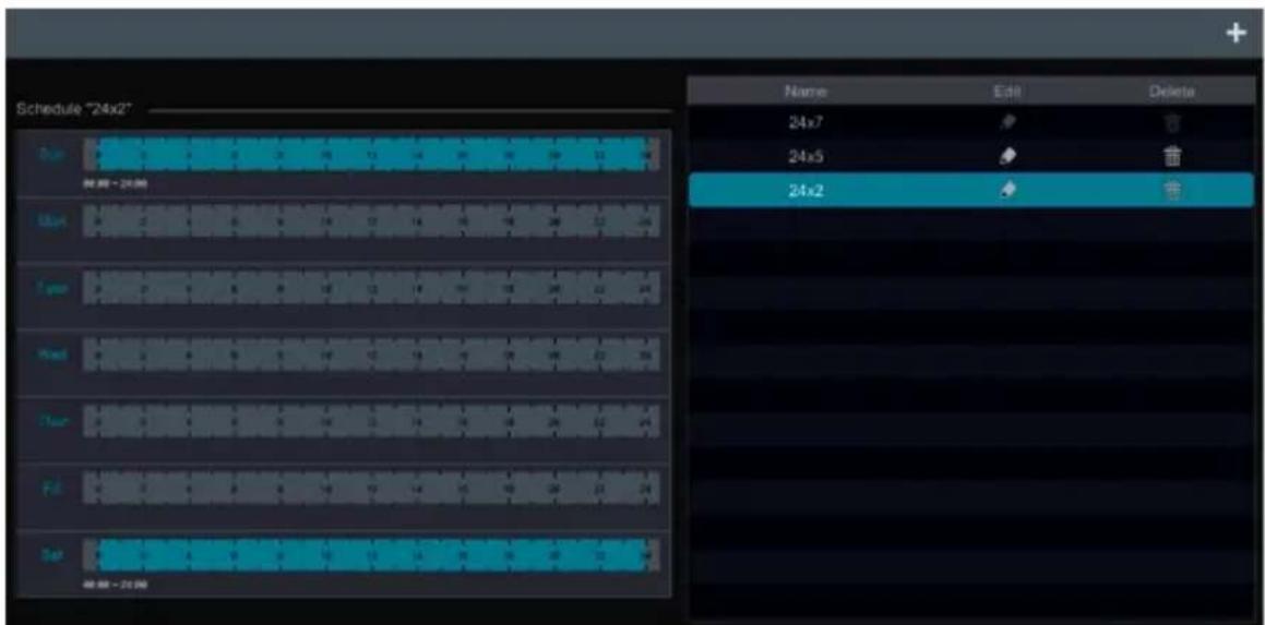
text_image
Schedule "24x2" 时间 - 24小时 24x7 24x5 24x2 编辑 - 24小时 24x7 24x5 24x2 10:00-24:00 13:00-16:00 19:00-23:00 23:00-27:00 27:00-31:00 31:00-35:00 35:00-39:00 39:00-43:00 43:00-47:00 47:00-51:00 51:00-55:00 55:00-59:00 59:00-63:00 63:00-67:00 67:00-71:00 71:00-75:00 75:00-79:00 79:00-83:00 83:00-87:00 87:00-91:00 91:00-95:00 95:00-99:00 99:00-103:00 103:00-107:00 107:00-111:00 111:00-115:00 115:00-119:00 119:00-123:00 123:00-127:00 127:00-131:00 131:00-135:00 135:00-139:00 139:00-143:00 143:00-147:00 147:00-151:00 151:00-155:00 155:00-159:00 159:00-163:00 163:00-167:00 167:00-171:00 171:00-175:00 175:00-179:00 179:00-183:00 183:00-187:00 187:00-191:00 191:00-195:00 195:00-199:00 23.24Click + to add a new schedule. Refer to the picture below.
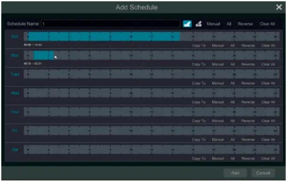
text_image
Add Schedule Schedule Name 1 Sun 08:00 - 14:44 Mon 08:35 - 02:51 Tuesday Wed Thru Fri Sat Manual All Reverse Clear All Copy To Manual All Reverse Clear All Copy To Manual All Reverse Clear All Copy To Manual All Reverse Clear All Copy To Manual All Reverse Clear All Copy To Manual All Reverse Clear All Copy To Manual All Reverse Clear All Copy To Manual All Reverse Clear All Copy To Manual All Reverse Clear All Copy To Manual All Reverse Clear All Copy To Manual All Reverse Clear All Copy To Manual All Reverse Clear All Copy To Manual All Reverse Clear All Copy To Manual All Reverse ClearAll Add CancelSet the schedule name and schedule time and then click “Add” to save the schedule. You can set day schedule or week schedule. 📋: add button; 📋: delete button.
Set Day Schedule
Click 📄 and then drag the cursor on the time scale to set record time; click 📄 and then drag the cursor on the time scale to delete the selected area.
You can manually set the record start time and end time. Click 📄 or 📃 and then click “Manual” on each day to pop up a window as shown below. Set the start and end time in the window and then click “OK” to save the settings.
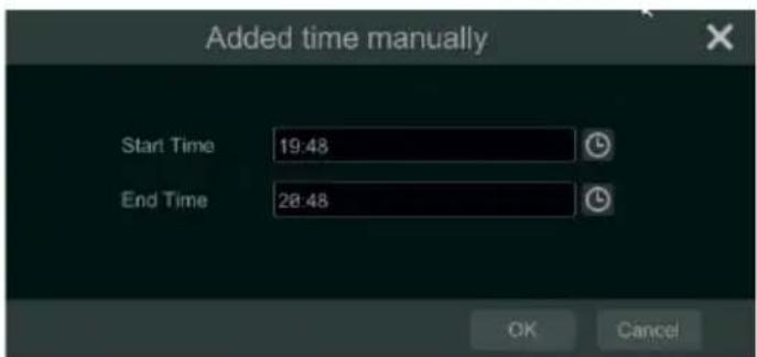
text_image
Added time manually Start Time 19:48 End Time 28:48 OK CancelClick “All” to set all day recording; click “Reverse” to swap the selected and unselected time in a day; click “Clear All” to clear all the selected area in a day.
Click “Copy To” to copy the schedule of the day to other days. Refer to the picture below. Check the days in the window and then click “OK” to save the settings.
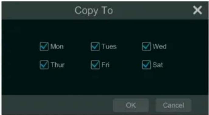
text_image
Copy To ✓ Mon ✓ Tues ✓ Wed ✓ Thur ✓ Fri ✓ Sat OK CancelSet Week Schedule
Click 📄 or 📋 and then click “Manual” beside 📋 to set the week schedule. Refer to the picture below. Set the start and end time, check the days in the window and then click “OK” to save the settings.
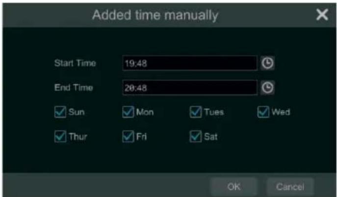
text_image
Added time manually Start Time 19:48 End Time 20:48 ✓ Sun ✓ Mon ✓ Tues ✓ Wed ✓ Thur ✓ Fri ✓ Sat OK CancelClick “All” to set all week recording; click “Reverse” to swap the selected and unselected time in a week; click “Clear All” to clear all the selected area in a week.
7.3.2 Record Schedule Configuration
Click Start→Settings→Record→Record Schedule→Schedule Configuration to go to the interface as shown below. Set the schedule of sensor record, motion record, timed record and intelligence record. Click “None” in the drop-down menu to clear the schedule. Click “Apply” to save the settings.
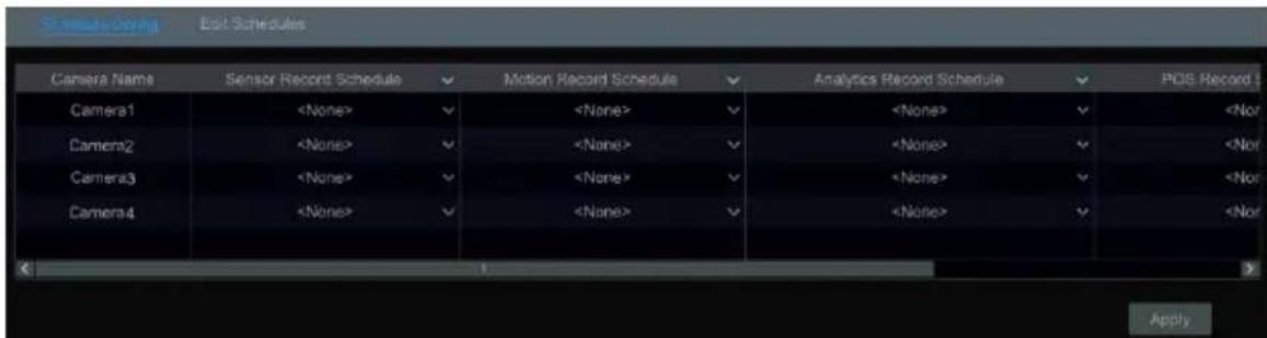
text_image
Camera Name Sensor Record Schedule Motion Record Schedule Analytics Record Schedule POS Record Camera17.4 Record Mode
7.4.1 Manual Recording
Method One: Click 📄 on the tool bar at the bottom of the live view interface to enable recording of the camera. Method Two: Go to live view interface and then click the right-click menu “Manually Record On” in the camera window or click 📄 on the tool bar under the camera window to start recording. Note: Click Start→Settings→Record→Mode Settings and then set the manual record time in the interface. Click "Apply" to save the settings.7.4.2 Timing Recording
Timing Recording: the system will record automatically according to the schedule. Set the timing record schedule of each camera. See 7.3 Schedule Setting for details.7.4.3 Motion Based Recording
Motion Based Recording: the system will start motion based recording when the motion object appears in the setup schedule. The setup steps are as follows: ① Set the motion based recording schedule of each camera. See 7.3 Schedule Setting for details. ② Enable the motion and set the motion area of each camera. See 9.2.1 Motion Configuration for details. The camera will start motion based recording once you finish the above settings.7.4.4 Sensor Based Recording
① Set the sensor based recording schedule of each camera. See 7.3 Schedule Setting for details. ② Set the NO/NC type of the sensor, enable the sensor alarm and then check and configure the “Record”. See 9.1 Sensor Alarm for details.7.4.5 Intelligence Recording
① Set the intelligence recording schedule of each IP camera. See 7.3 Schedule Setting for details. ② Enable the intelligence detection (object detection, exception, line crossing or intrusion detection) and draw alert surface or warning area of each IP camera. See 9.3 Intelligence Alarm for details. The camera will start intelligence recording once you finish the above settings. This function is only available for some IPCs.7.5 Disk Management
Click Start→Settings→Disk→Disk Management to go to disk management interface. You can view the DVR's disk number and disk status and so on in the interface. Click the "Format" button to format the HDD. text_image
Disk Management File Free Space[GB] Disk Sensi No. Disk Model Status Type Cycle Record Record Period Operation 864 WD-WCC4J5SXS62Z WDC WD10PURX-64D... RW Ordinary PL... ON 03/26/2019-07/17/2019 Formattext_image
Disk Management Physical Disk Array Disk Mode Enable RAIDtext_image
Disk Management File103 Array Disk Mode Disk Capacity(G) Create an array Disk Model Hot Space DMNKS-1CH162 URX-83FH1Y# VX898-ICU162 Array Name test Array Type RAID5 Physical Disk RAID8 Global Hot Spares RAID1 Array Capacity RAID6 RAID10 Add Cancel Authority authentication Enter Username Enter Password OK Cancel a Create an arraytext_image
Create an array Array Name test Array Type RAID 5 Physical Disk 1 2 3 4 Global Hot Spares None Array Capacity 1863GB Add Cancel| Disk | Capacity[GB] | Array | Type | Status | Disk Model | Hot Spare |
| 1 | 931 | test | Array disk | Normal | xxxxx | |
| 2 | 931 | test | Array disk | Normal | xxxxx | |
| 3 | 931 | test | Array disk | Normal | xxxxx | |
| 4 | 931 | Ordinary plate | Normal | xxxxx |
text_image
Authority authentication Enter Username Enter Password OK Cancel Question Disk set to global hot spare clears disk data, OK to continue? OK Cancel- RAID Rebuilding
If one of your disks is broken, the disk indicator on the front panel will turn red. Of course, a warning tip will pop up if the relevant HDD exception alarm is set. You need to rebuild the RAID after you replace the broken disk with a new one. text_image
Disk Management Physical Disk Array Disk Mode No. Name Capacity[GB] Physical Disk Hot Spare Position Status Type Rebuild 1 test 1862 23 4 Downgrade RAID5 😊text_image
Rebuilding an array Array name test Array Type RAID 5 Array disk 23 Physical Disk 1 OK Cancel7.5.1 Storage Mode Configuration
Click Start→Settings→Disk→Storage Mode to go to the interface as shown below.| Group | Disk (Capacity: 931GB) | Disk1 + | ||||
| 1 | Disk(1) Camera(4) | |||||
| Camera | Camera1 | Camera2 | Camera3 | Camera4 | ||
| 2 | Disk(0) Camera(0) | |||||
| 3 | Disk(0) Camera(0) | |||||
| 4 | Disk(0) Camera(0) | |||||
7.5.2 View Disk and S.M.A.R.T. Information
Click Start→Settings→Disk→View Disk Information to view the HDD information; click “S.M.A.R.T. Information” to view the working status of the HDD. Refer to the picture below. text_image
Disk Disk Management Disk Management Storage Mode Storage Mode Settings Disk View Disk Information i SMART Information Disk SMART Information Disk Disk2 Disk Serial No. XXX Disk Model XXX Temperature 187 Power-on Time (day) 31 SMART Status Normal ID Attribution Value Worst Value Threshold Raw Value Status 0x01 Read Error Rate 100 100 62 0 Normal 0x02 Throughput Performance 100 100 40 0 Normal 0x03 Spin-Up Time 234 234 33 1 Normal 0x04 Start/Stop Count 100 100 0 96 Normal 0x05 Reallocated Sector Count 100 100 5 0 Normal 0x07 Seek Error Rate 100 100 87 0 Normal 0x08 Seek Time Performance 100 100 40 0 Normal 0x09 Power On Hours 99 99 0 724 Normal 0x0a Spin Retry Count 100 100 60 0 Normal 0x0c Power Cycle Count 100 100 0 93 Normal 0xbf G-sense Error Rate 100 100 0 0 Normal 0xc0 Power-off Retract Count 100 100 0 58 Normal 0xc1 Load Cycle Count 100 100 0 8815 Normal 0xc2 Temperature 187 187 0 1638432 Normal 0xc4 Reallocation Event Count 100 100 0 0 Normal 0xc5 Current Pending Sector Count 100 100 0 0 Normal 0xc6 Uncorrectable Sector Count 100 100 0 0 Normal 0xc7 UltraDMA CRC Error Count 200 200 0 0 Normal 0xdf Load/Unload Retry Count 100 100 0 0 Normal8 Playback & Backup
8.1 Instant Playback
Click ▶ on the tool bar at the bottom of the preview camera window to play back the record (click ↑ on the tool bar at the bottom of the live view interface to set the default playback time). Refer to the picture below. Drag the playback progress bar to change the playback time. You can also click the right-click menu “Instant Playback” in the camera window and then set the instant playback time to play back the record. text_image
05/03/2018 14:32:51 IP Camera1 14:32:38 14:37:388.2 Playback Interface Introduction
Click 🖼️ on the tool bar at the bottom of the live view interface or click Start→Playback to go to the playback interface as shown below (click 🔗 on the tool bar at the bottom of the live view interface to set the default playback time). text_image
2015/11/03 15:34:53 Search and Backup Live Display Normal Playback Smart Playback DSD ON POS| Button Meaning | |
 | Start button. Click it to pop up area 2. |
 | Full screen button. Click it to show full screen; click it again to exit the full screen. |
 | Screen mode button. |
 | OSD ON button. Click it to enable OSD; click it again to disable OSD. |
 | Stop button. |
| [Z0ZX] | Rewind button. Click it to play video backward. |
| [CBT7] | Play button. Click it to play video forward. |
 | Pause button. |
| [G35A] | Deceleration button. Click it to decrease the playing speed. |
 | Acceleration button. Click it to increase the playing speed. |
[Z7ZX] | Previous frame button. It works only when the forward playing is paused in single screen mode.Next frame button. It works only when the forward playing is paused in single screen mode. |
 | Click — to step backward 30s and click + to step forward 30s. |
 | Click it to show the water mark on the image; click WM to hide the water mark. |
 | Event list/tag button. Click it to view the event record of manual/schedule/sensor/ motion and the tag information. |
 | Open/close POS information. |
 | Backup button. Drag the mouse on the time scale to select the time periods and cameras, and then click the button to back up the record. |
 | Backup status button. Click it to view the backup status. |
 | Back button. Click it to return. |
 | Full screen motion button. |
 | Draw rectangle. You can search the record of motion detection in the pre-defined rectangular area. |
 | Draw line. You can search the record of crossing the line after drawing the line. |
 | Draw quadrilateral. You can search the record in this quadrilateral after drawing it. |
 | Smart playback settings. Click it to set smart playback. |
| Button Meaning | |
| Search and Backup | Click it to go to record search interface; see 8.4 Record Search, Playback & Backup for details. |
| Live Display | Click it to go to live view interface; see Chapter 5 Live View Introduction for details. |
| Button | Menu List Meaning | |
 | -- | Move tool. Click it to move the tool bar anywhere. |
 | Enable Audio | Click it to enable audio. You can listen to the camera audio by enabling audio. |
 | Snap | Click it to snap. |
 | Zoom In | Click it to go to the zoom in interface. The zoom in interface is similar to that of the camera window in the live view interface.Click to pause the record playing; click to play the record. When the record is paused in forward playing mode, you can click to view the previous frame and click to view the next frame. |
 | Add Tag | Click it to add tag. You can play back the record by searching the added tag. Click it and then enter the tag name in the popup window. Click “Add” to add tag. |
 | Switch Camera | Click it to switch the playback camera. Click it and then check the camera in the popup window. Click “OK” to change the camera. |
 | Close Camera | Click it to close the playback camera. |
8.3 Smart Playback
Smart Playback Settings Click to go to the following interface. Set the value of “Speed of non-interest video” (Please skip this one if you click “Skip non-interest video”), “Speed of interest video” and “Intrusion percentage”. text_image
04/19/2018 08:03:03 Smart Playback Settings Skip non-interest video Speed of non-interest video Speed of interest video Intrusion Percentage 1% OK Cancel Normal Playback Smart Playbacktext_image
Smart Playback [4.15] 04/19/2018 08:43:00 15:48:45 Gate Normal Playback Smart Playback● Smart Playback by Drawing Line
Click 📋 and draw a line in the desired area. Then the system will automatically search the record files about crossing this line. The cyan blocks indicate that there are intelligent recording files. Move the cursor to such block and click to play the record. text_image
04/19/2018 03:45:34 15:48:48 Gate Normal Playback Smart Playback● Smart Playback by Drawing Quadrilateral
Click and draw a quadrangle in the desired area. Then the system will automatically search the record files of this area. The cyan blocks indicate that there are intelligent recording files. Move the cursor to such block and click to play the record. text_image
04/19/2018 08:49:02 Gate Normal Playback Smart Playback8.4 Record Search, Playback & Backup
The record data and the snapped pictures can be backed up through network or USB (U disk or USB mobile HDD). The file system of the backup devices should be FAT32 format.8.4.1 Search, Playback & Backup by Time-sliced Image
① Click Start→Search and Backup→By Time-sliced Image to go to “By Time-sliced Image” tab. There are two view modes: by time and by camera. In the time view mode, a maximum of 64 camera thumbnails can be shown. If the camera thumbnail number is more than 64, the cameras will be listed directly by their camera name, not the thumbnail. A maximum of 196 camera names can be listed. If the camera name number is more than 196, the time view mode will be disabled and the camera view mode will be available only. text_image
Search and Backup By: Other-Brand Image Smart Search By Time By Event Tag Management Image Managers Backup Status Camera Thumbnails View Mode Time 05/18/2018 IP Camera01 IP Camera02 IP Camera03 05/17/2018 IP Camera01 IP Camera02 IP Camera03 05/16/2018 IP Camera01 IP Camera02 IP Camera03 05/15/2018 Open Closetext_image
Record Backup Device Name ExternalStorage1-689B-4AC4 Refresh Free:28.96 GB,All:29.27 GB Name Type Size Modify Date Backup Directory 8.00 KB 2015/11/03 16:58:53 Format Private New Folder Delete Backup Canceltext_image
Search and Backup By Time - Wind Image Smart Search By Time By Event Tag Management Image Management Backup Status Camera Thumbnails > IP Camera83 > 05/28/18 > 15 6:00:00 6:00:00 6:00:00 6:00:00 6:00:00 6:00:00 6:00:00 6:00:00 6:00:00 6:00:00 6:00:00 6:00:00 6:00:00 6:33:34:35:36:37:38:39:40:41:42:43:44:45:46:47:48:49:50:51:52:53:54:55:56:57:58:59:60:61:62:63:64:65:66:67:68:69:70:71:72:73:74:75:76:77:78:79:80:81:82:83:84:85:86:87:88:89:90:91:92:93:94:95:96:97:98:99:100: Playback Picture Hour 4/24 播放器 播放器 播放器 播放器 播放器 播放器 播放器 播放器 播放器 播放器 播放器 播放器 播放器 播放器 播放器 播放器 播放器 播放器 播放器 播放器 播放器 播放器 播放器 播放器 播放器 播放器 播放器 播放器 播放器 播放器 播放器 播放器 播放器 播放器Time Slice Mode Selecting:
Method One: Click the “Year”, “Month” or “Day” button under the record time scale to select the time slice mode. In “Day” mode, click / ▶ on the left/right side of the time scale to view the record of the last/next day; click “Minute” in the “Picture” option under the time scale to select “Minute” mode (in “Minute” mode, click the time scale to change the time of the 60 display windows) and click “Hour” to select “Hour” mode. Method Two: Click ➤ beside “Camera Thumbnail” on the left top corner of the interface to select the time slice mode. Method Three: Right-click the mouse on any area of the time-sliced interface to go back to the upper interface.8.4.2 Smart Search
① Click Start→Search and Backup→Smart Search to go to “Smart Search” tab as shown below. ② Set the searching time period and you will search the channel which has the intelligence detection record. ③ Check the channel and select the smart playback. ④ Set the backup time and select the channel to backup. text_image
Search and Backup By Time-sliced image Anest. Speed By Time By Event Tag Management Image Management Backup Status Backup Status May 2018 Sub Num Tue Wed Thu Fri Set 1 2 3 4 5 6 7 8 9 10 11 12 13 14 15 16 17 18 19 20 21 22 23 24 25 26 27 28 29 30 31 05/03/2018 09:29:24 IP Camera03 Set Backup Time Normal Playback: X1 Status Playback Close8.4.3 Search, Playback & Backup by Time
① Click Start→Search and Backup→By Time to go to "By Time" tab as shown below. ② Click 📋 on the bottom of the interface to add playback camera. Click “Modify” on the top right corner of the camera window to change the camera and click “Clear” to remove the camera. ③ Click the camera window to play the record in the small playback box on the left side of the interface. You can set the date on the top left of the interface, check the event type as required and click the time scale or click under the time scale to set the time. The camera window will play the record according to the time and event type you set. ④ Drag the color blocks on the time scale to select the record data (or click the “Set Backup Time” button on the bottom left corner of the interface to set the backup start time and end time) and then click the “Backup” button for record backup. Click the “Playback” button to play the record in the playback interface. text_image
Search and Backup By Time-Record Image Smart Search by Event Tag Management Image Management Backup Status May 2018 Sun Mon Tue Wed Thu Fin Sat 1 2 3 4 5 6 7 8 9 10 11 12 13 14 15 16 17 19 20 21 22 23 24 25 26 27 28 29 30 31 Entered Lease Playback Set Backup Time Picture (1/16) Balance Playback Close Manual Screen Indigestion Mission POST Schedule 85/18/2018:85:82:86 PM Refresh8.4.4 Search, Playback & Backup by Event
Some models may support searching POS event. ① Click Start→Search and Backup→By Event to go to “By Event” tab as shown below. text_image
Search and Backup Start Time 05/18/2018 12:30:00 AM End Time 05/18/2018 11:59:59 PM Event Manual Intelligent Analytics Motion POS No Camera Name Type Time Period Duration Data Size Playback Backup 1 IP Camera82 Intelligent ... 05/18/2018 02:43:07 PM-05/18/2018 02:43:47 PM 48s 18MB 2 IP Camera82 Intelligent ... 05/18/2018 02:45:04 PM-05/18/2018 02:46:18 PM 1m 14s 18MB 3 IP Camera82 Intelligent ... 05/18/2018 02:48:46 PM-05/18/2018 02:50:18 PM 1m 24s 28MB 4 IP Camera82 Intelligent ... 05/18/2018 02:50:43 PM-05/18/2018 02:51:19 PM 36s 9MB 5 IP Camera82 Intelligent ... 05/18/2018 02:52:27 PM-05/18/2018 02:53:27 PM 1m 15MB 6 IP Camera82 Intelligent ... 05/18/2018 02:54:13 PM-05/18/2018 02:54:47 PM 34s 9MB 7 IP Camera82 Intelligent ... 05/18/2018 02:55:36 PM-05/18/2018 02:56:23 PM 47s 12MB 8 IP Camera82 Intelligent ... 05/18/2018 02:59:06 PM-05/18/2018 02:59:45 PM 39s 18MB 9 IP Camera82 Intelligent ... 05/18/2018 03:09:56 PM-05/18/2018 03:09:48 PM 52s 13MB 10 IP Camera82 Intelligent ... 05/18/2018 03:02:36 PM-05/18/2018 03:02:51 PM 43s 11MB 11 IP Camera82 Intelligent ... 05/18/2018 03:34:46 PM-05/18/2018 03:35:16 PM 36s 9MB 12 IP Camera82 Intelligent ... 05/18/2018 03:11:35 PM-05/18/2018 03:11:44 PM 39s 18MB 13 IP Camera82 Intelligent ... 05/18/2018 03:13:56 PM-05/18/2018 03:14:33 PM 37s 9MB 14 IP Camera82 Intelligent ... 05/18/2018 03:16:21 PM-05/18/2018 03:16:55 PM 34s 9MB 15 IP Camera82 Intelligent ... 05/18/2018 03:18:36 PM-05/18/2018 03:19:09 PM 39s 18MB POS pre playback PS Secs POS deferred playback PS Secs Current Page: 1 / 2, All BB Break Pass Close8.4.5 Search & Playback by Tag
Only if you add the tags can you play the record by tag search. Click Start→Playback to go to the playback interface and then click ★ on the bottom of the camera window to add tag when you want to mark the playback time point of the selected camera. Click Start→Search and Backup→Tag Management to go to “Tag Management” tab. text_image
Search and Backup By Time-screen Image Smart Search By Time By Event Fig Up/Down Image Management Backup Status No. Name Camera Name Time Playback Edit Delike 1 IP Camera01_28188518145932 IP Camera01 85/18/2018 62:59:32 PM # 2 IP Camera02_28188518145946 IP Camera02 85/18/2018 62:59:40 PM # 3 IP Camera03_28188518145946 IP Camera03 85/18/2018 62:59:45 PM #8.4.6 Image Management
Click Start→Search and Backup→Image Management to go to “Image Management” tab. The system will display all the snapped images automatically in the list. text_image
Search and Backup By Time-Sized Image Smart Search By Time By Event Tag Management Backup Status No Camera Name Snapshot Mode Snapshot Time Creator Browse Export Delete 1 IP Camera03 Manual 05/18/2018 05:01:29 PM admin 2 IP Camera02 Manual 05/18/2018 05:01:23 PM admin 3 IP Camera01 Manual 05/18/2018 05:01:14 PM admintext_image
View Image Camera Name: IP01 Time: 11/28/2018 03:51:42 Creator: IP01 11/28/2018 19:50:02 IP Camera01 Close8.4.7 View Backup Status
Click Start→Search and Backup→Backup Status or click the playback interface to view the backup status. on the tool bar at the bottom of9 Alarm Management
9.1 Sensor Alarm
To complete the entire sensor alarm settings, you should enable the sensor alarm of each camera and then set up the alarm handling of each camera. ① Click Start→Settings→Alarm→Sensor Alarm to go to the following interface. text_image
Buzzer Pop-up Video Pop-up Message Box E-mail Alarm Name Schedule Type Enable Duration Record Snapshot Push Alarm-out Pri Sensor1 24x7 NO ON 30 Secs Configure Configure ON Configure On Configure On Configure On Configure On Configure On Configure On Configure On Configure On Configure On Configure On Configure On Configure On Configure On Configure On Configure On Configure On Configure On Configure On Configure On Configure On Configure On Configure On Configure On Configure On Configure On Configure On Configure On Configure On Configure On Configure On Configure On Configure On Configure On Configure On Configure On Configure On Configure On Configure On Configure On Configure On Configure On Configure On Configure On Configure On Configure On Configure On Configure On Configure On Configure On Configure On Configure ON Configure ON Configure ON Configure ON Configure ON Configure ON Configure ON Configure ON Configure ON Configure ON Configure ON Configure ON Configure ON Configure ON Configure ON Configure ON Configure ON Configure ON Configure ON Configure ON Configure ON Configure ON Configure ON Configure ON Configure ON Configure ON Configure ON Configure ON Configure ON Configure ON Configure ON Configure ON Configure ON Configure ON Configure ON Configure ON Configure ON Configure ON Configure ON Configure ON Configure ON Configure ON Configure ON Configure ON Configure ON Configure ON Configure ON Configure ON Configure ON Configure ON Configure IN Sensor2 24x7 NO ON 30 Secs Configure Configure ON Configure ON Configure On Configure On Configure On Configure On Configure On Configure On Configure On Configure On Configure On Configure On Configure On Configure On Configure On Configure On Configure On Configure On Configure On Configure On Configure On Configure On Configure On Configure On Configure On Configure On Configure On Configure On Configure On Configure On Configure On configure on configure on configure on configure on configure on configure on configure on configure on configure on configure on configure on configure on configure on configure on configure on configure on configure on configure on configure on configure on configure on configure on configure on configure on configure on configure on configure on configure on configure on configure on configure on configure on configure on configure on configure on configure on configure on configure on configure on configure on configure on configure on configure on configure on configure on configure on configure on configure on configure on configure on configure in Apply9.2 Motion Alarm
Motion Alarm: when the motion object appears in the specified area, it will trigger the alarm. You should enable the motion of each camera first and then set the alarm handling of the camera to complete the whole configuration of the motion alarm.9.2.1 Motion Configuration
① Click Start→Settings→Camera→Motion to go to the following interface. text_image
Camera Name Motion Sensitivity Duration Camera1 ON 5 15 Secs Camera2 ON 5 15 Secs Camera3 ON 5 15 Secs Camera4 ON 5 15 Secs Camera5 ON 5 15 Secs Camera6 ON 5 15 Secs Camera7 ON 5 15 Secs Camera8 ON 5 15 Secs Camera9 ON 5 15 Secs Camera10 ON 5 15 Secs Camera11 ON 5 15 Secs Camera12 ON 5 15 Secs Camera13 ON 5 15 Secs Camera14 ON 5 15 Secs Camera15 ON 5 15 Secs All Reverse Clear Camera Camera3 Motion ON Sensitivity 5 Duration 15 Secs Processing Mode Apply9.2.2 Motion Alarm Handling Configuration
① Click Start→Settings→Alarm→Motion Alarm to go to the following interface. text_image
Camera Name Schedule Record Snapshot Push Alarm-out Preset OFF OFF OFF Camera1 24x7 Configure Configure ON Configure Configure OFF OFF OFF Camera2 24x7 Configure Configure ON Configure Configure OFF OFF OFF Camera3 24x7 Configure Configure ON Configure Configure OFF OFF OFF Camera4 24x7 Configure Configure ON Configure Configure OFF OFF OFF Camera5 24x7 Configure Configure ON Configure Configure OFF OFF OFF Camera6 24x7 Configure Configure ON Configure Configure OFF OFF OFF Camera7 24x7 Configure Configure ON Configure Configure OFF OFF OFF Camera8 24x7 Configure Configure ON Configure Configure OFF OFF OFF Camera9 24x7 Configure Configure ON Configure Configure OFF OFF OFF Camera10 24x7 Configure Configure ON Configure Configure OFF OFF OFF Camera11 24x7 Configure Configure ON Configure Configure OFF OFF OFF Camera12 24x7 Configure Configure ON Configure Configure OFF OFF OFF Camera13 24x7 Configure Configure ON Configure Configure OFF OFF9.3 Intelligence Alarm
9.3.1 Object Detection
Object Detection Configuration:
① Click Start→Settings→Camera→Intelligent Analytics→Object Detection to go to the following interface. ② Select the camera, enable the object detection and set the duration and detect type. There are two detect types: Abandoned object and missing object. Abandoned object: Alarms will be triggered if there are articles left in the pre-defined detection area. Missing object: Alarms will be triggered if there are articles missing in the detection area drawn by the users. ③ Select the alarm area. A maximum of 4 alarm areas can be set. ④ Draw the alarm area of the object detection. Refer to the interface as shown above. Check “Draw Area” and then click around the area where you want to set as the alarm area in the image (the alarm area should be a closed area). Uncheck the “Draw Area” if you finish the drawing. Click the “Clear” button to delete the alarm area. ⑤ Click “Apply” to save the settings. ⑥ Click “Processing Mode” to go to the alarm handling configuration interface of object detection. text_image
Object Detection Exception Tripwire Instruction Object Detection Detect Type Duration Area Area name Camera Name IP通道81 OFF 20 Secs Abandoned Object 1 IP通道82 OFF 20 Secs Abandoned Object 1 IP通道83 OFF 20 Secs Abandoned Object 1 Draw area Clear Processing Mode ApplyObject Detection Alarm Handling Configuration:
① Click Start→Settings→Alarm→Intelligence Alarm→Object Detection to go to the following interface. text_image
Camera Name Record Snapshot Push Alarm-out Preset (×) IP87 Configure OFF ON Configure Configure OFF IP85 Configure OFF ON Configure Configure OFF IP88 Configure OFF ON Configure Configure OFF IP84 Configure OFF ON Configure Configure OFF Object Config Apply9.3.2 Exception
Exception Configuration:
① Click Start→Settings→Camera→Intelligent Analytics →Exception to go to the following interface. text_image
Duration Scene Change Video Blurred Video Color Cast Sensitivity Camera Name IP87 20 Secs OFF OFF OFF 1 IP85 10 Secs OFF OFF OFF 2 IP88 20 Secs OFF OFF OFF 1 IP84 20 Secs OFF OFF OFF 1 Processing Mode ApplyException Alarm Handling Configuration:
① Click Start→Settings→Alarm→Intelligence Alarm→Exception to go to the interface. text_image
Camera Name Record Snapshot Push Alarm-out Preset IP87 Configure OFF ON Configure Configure OFF IP85 Configure OFF ON Configure Configure OFF IP88 Configure OFF ON Configure Configure OFF IP84 Configure OFF ON Configure Configure OFF Exception Config Apply9.3.3 Tripwire
Tripwire/Line Crossing Configuration:
Alarms will be triggered if someone or something crosses the pre-defined alarm line. ① Click Start→Settings→Camera→Intelligent Analytics→Tripwire to go to the following interface. text_image
Tripwire Duration Line Direction Camera Name Camera1 OFF 5 Secs 1 A<->B Camera2 OFF 5 Secs 1 A<->B Camera3 OFF 5 Secs 1 A<->B Camera4 OFF 5 Secs 1 A<->B Camera5 OFF 5 Secs 1 A<->B Camera6 OFF 5 Secs 1 A<->B Camera7 OFF 5 Secs 1 A<->B Camera8 OFF 5 Secs 1 A<->B Camera9 OFF 5 Secs 1 A<->B Camera10 OFF 5 Secs 1 A<->B Camera11 OFF 5 Secs 1 A<->B Camera12 OFF 5 Secs 1 A<->B Camera13 OFF 5 Secs 1 A<->B Camera14 OFF 5 Secs 1 A<->B Camera15 OFF 5 Secs 1 A<->B Camera16 OFF 5 Secs 1 A<->B #CAMERA OFF 20 Secs 1 A<->B Draw line Clear Processing Mode ApplyLine Crossing Alarm Handling Configuration:
① Click Start→Settings→Alarm→Intelligence Alarm→Line Crossing to go to the following interface. text_image
Camera Name Record Snapshot Push Alarm-out Preset (×) Camera1 Configure OFF ON Configure Configure OFF Camera2 Configure OFF ON Configure Configure OFF Camera3 Configure OFF ON Configure Configure OFF Camera4 Configure OFF ON Configure Configure OFF Camera5 Configure OFF ON Configure Configure OFF Camera6 Configure OFF ON Configure Configure OFF Camera7 Configure OFF ON Configure Configure OFF Camera8 Configure OFF ON Configure Configure OFF Camera9 Configure OFF ON Configure Configure OFF Camera10 Configure OFF ON Configure Configure OFF Camera11 Configure OFF ON Configure Configure OFF Camera12 Configure OFF ON Configure Configure OFF Camera13 Configure OFF ON Configure Configure OFF Camera14 Configure OFF ON Configure Configure OFF Camera15 Configure OFF ON Configure Configure OFF Camera16 Configure OFF ON Configure Configure OFF IP CAMERA Configure OFF ON Configure Configure OFF Crossing Config Apply9.3.4 Intrusion Detection
Intrusion Configuration:
Alarms will be triggered if someone or something intrudes into the pre-defined area. ① Click Start→Settings→Camera→Intelligent Analytics→Intrusion Detection to go to the following interface. ② Select the camera, enable the intrusion detection and set the duration. ③ Select the alarm area. Up to 4 alarm areas can be set up. ④ Draw the alarm area of the intrusion detection. Refer to the interface as shown below. Check “Draw Area” and then click around the area where you want to set as the alarm area in the image (the alarm area should be a closed area). Uncheck the “Draw Area” if you finish the drawing. Click the “Clear” button to delete the alarm area. ⑤ Click “Apply” to save the settings. ⑥ Click “Processing Mode” to go to the alarm handling configuration interface of intrusion detection. text_image
Camera Name Camera1 OFF 5 Secs 1 1% Camera2 OFF 5 Secs 1 1% Camera3 OFF 5 Secs 1 1% Camera4 OFF 5 Secs 1 1% Camera5 OFF 5 Secs 1 1% Camera6 OFF 5 Secs 1 1% Camera7 OFF 5 Secs 1 1% Camera8 OFF 5 Secs 1 1% Camera9 OFF 5 Secs 1 1% Camera10 OFF 5 Secs 1 1% Camera11 OFF 5 Secs 1 1% Camera12 OFF 5 Secs 1 1% Camera13 OFF 5 Secs 1 1% Camera14 OFF 5 Secs 1 1% Camera15 OFF 5 Secs 1 1% Camera16 OFF 5 Secs 1 1% ID CAMERA OFF 20 Secs 1 Processing Mode ApplyIntrusion Detection Alarm Handling Configuration:
① Click Start→Settings→Alarm→Intelligence Alarm→Intrusion Detection to go to the following interface. text_image
Camera Name Record Snapshot Push Alarm-out Preset (×) Camera1 Configure OFF ON Configure Configure OFF Camera2 Configure OFF ON Configure Configure OFF Camera3 Configure OFF ON Configure Configure OFF Camera4 Configure OFF ON Configure Configure OFF Camera5 Configure OFF ON Configure Configure OFF Camera6 Configure OFF ON Configure Configure OFF Camera7 Configure OFF ON Configure Configure OFF Camera8 Configure OFF ON Configure Configure OFF Camera9 Configure OFF ON Configure Configure OFF Camera10 Configure OFF ON Configure Configure OFF Camera11 Configure OFF ON Configure Configure OFF Camera12 Configure OFF ON Configure Configure OFF Camera13 Configure OFF ON Configure Configure OFF Camera14 Configure OFF ON Configure Configure OFF Camera15 Configure OFF ON Configure Configure OFF Camera16 Configure OFF ON Configure Configure OFF IP CAMERA Configure OFF ON Configure Configure OFF9.4 Exception Alarm
9.4.1 IPC Offline Settings
① Click Start→Settings→Alarm→Exception→IPC Offline Settings to go to the interface as shown below. text_image
IPC Office Settings Video Loss Settings Exoption Handling Settings Camera Name Snapshot Push Alarm-out Praset IP CAMERA Configure ON Configure Configure OFF OFF ON Apply9.4.2 Video Loss Settings
① Click Start→Settings→Alarm→Exception→Video Loss Settings to go to the interface as shown below. text_image
IPC Offline Settings Video Link Settings Exception-Handling Settings (B) Buzzer Pop-up Video Pop-up Message Box E-mail Camera Name Snapshot Push Alarm-out Protol (K) OFF OFF ON Camera1 Configure ON Configure OFF OFF ON Camera2 Configure ON Configure OFF OFF ON Camera3 Configure ON Configure OFF OFF ON Camera4 Configure ON Configure OFF OFF ON Camera5 Configure ON Configure OFF OFF ON Camera6 Configure ON Configure OFF OFF ON Camera7 Configure ON Configure OFF OFF ON Camera8 Configure ON Configure OFF OFF ON Camera9 Configure ON Configure OFF OFF ON Camera10 Configure ON Configure OFF OFF ON Camera11 Configure ON Configure OFF OFF ON Camera12 Configure ON Configure OFF OFF ON Camera13 Configure ON Configure OFF OFF ON Camera14 Configure ON Configure OFF OFF ON Camera15 Configure ON Configure OFF OFF ON Camera16 Configure ON Configure OFF OFF ON Apply9.4.3 Exception Handling Settings
① Click Start→Settings→Alarm→Exception→Exception Handling Settings to go to the interface as shown below. text_image
Event Type Push Alarm-out IP Address Conflict ON Configure Disk IO Error ON Configure Disk Full ON Configure No Disk ON Configure Illegal Access ON Configure Network Disconnection ON Configure HDD is pulled out ON Configure RAID Exception ON Configure OFF OFF OFF OFF OFF OFF Apply9.5 Alarm Event Notification
9.5.1 Alarm-out
① Click Start→Settings→Alarm→Event Notification to go to the following interface. text_image
AlarmOut Edit Schedule No Name Delay Schedule Test 1 AlarmOut1 10 Secs 24x7 Test 2 AlarmOut2 10 Secs 24x7 Test 3 AlarmOut3 10 Secs 24x7 Test 4 AlarmOut4 10 Secs 24x7 Test Apply9.5.2 E-mail
Click Start→Settings→Alarm→Event Notification→E-mail to go to the e-mail configuration interface. Set the e-mail address of the recipients. See 11.1.5 E-mail Configuration for details.9.5.3 Display
Click Start→Settings→Alarm→Event Notification→Display to go to the display configuration interface. Set the duration time of the pop-up video and the pop-up message box. Click “Apply” to save the settings. If there are multiple outputs, please select the output as needed. text_image
Pop-up Video Duration 10 Secs Output Main Output Pop-up Message Box Duration 10 Secs Apply9.5.4 Buzzer
Click Start→Settings→Alarm→Event Notification→Buzzer to go to the buzzer configuration interface. Set the delay time of the buzzer and then click “Apply” to save the setting. You can click “Test” to test the buzzer. text_image
Buzzer Delay 5 Secs Test Apply9.5.5 Push Message
Click Start→Settings→Alarm→Event Notification→Push Message to go to the interface as shown below. Check “Enable”, choose the push schedule and then click the “Apply” button to save the settings. If Push Server is online, it will push messages to the mobile clients. text_image
Push Message Enable Push Schedule 24x7 Push Server Status: Disabled Test Apply9.6 Manual Alarm
Click 📁 on the tool bar at the bottom of the live view interface to pop up a window. Click “Trigger” to start alarm. Click “Clear” to stop alarm. text_image
Alarm-out Name Status Trigger Clear AlarmOut1 Normal Trigger Clear Close9.7 View Alarm Status
Click Start→Settings→Alarm→Alarm Status or click 📄 on the tool bar at the bottom of the live view interface to view the alarm status. text_image
Name-Size Buzzer Clear Alarm-in Normal Alarm-out Normal Motion Normal Intelligence Normal Exception Normal Combination Alarm Normaltext_image
Buzzer Clear Alarm-in Normal Alarm-out Normal Motion Normal Intelligence Normal Exception Exception Alarm Source : Device Name Alarm Time : 01/30/2010 16:14:45 Status : No Disk Trigger Alarm-out : None Trigger Buzzer : ON Close10 Account & Permission Management
10.1 Account Management
Click Start→Settings→Account and Authority→Account→Edit User to go to the interface as shown below. text_image
User admin Permissions ✓ Local Camera Management ✓ Remote Camera Management ✓ Remote Login ✓ Disk Management ✓ Audio Talk ✓ Alarm Management ✓ Network Management ✓ Schedule Management ✓ Record Settings Management ✓ Local System Settings ✓ Remote System Settings ✓ Account and Authority Local Remote Camera Preview Playback Backup Audio PTZ Co... Camera1 ON ON ON ON ON Camera2 ON ON ON ON ON Camera3 ON ON ON ON ON Camera4 ON ON ON ON ON Camera5 ON ON ON ON ON Camera6 ON ON ON ON ON Camera7 ON ON ON ON ON Camera8 ON ON ON ON ON ②10.1.1 Add User
① Click Start→Settings→Account and Authority→Account→Add User or click beside the search box to pop up the window as shown below.  text_image
Add User Username Enter Username Password Enter Password Confirm Password Enter Password Display Password Allow Modify Password Pattern Lock Enable Edit E-mail Group Administrator Add Cancel10.1.2 Edit User
Click Start→Settings→Account and Authority→Account→Edit User and then click in the user list or double click the user to edit the user information. Click to delete the user (the user admin cannot be deleted). text_image
Username Group Edit Delete admin Administrator Modify Password Modify Pattern Lock Edit User Edit Security Question 1 Administrator Edit User Recover Password➢ Edit Security Question
You can set password security only for admin. Click “Edit Security Question” and then set questions and answers in the popup window. If you forget the password for admin, please refer to Q4 in Appendix A FAQ for details. The passwords of other users can be recovered by admin or the users that have the “Account and Authority” permission.Modify Password
Only the password of admin can be modified. Click “Modify Password” to pop up a window. Enter the current password and then set new password. Click “OK” to save the settings.Modify Pattern Lock
Some models may not support this function. Click "Modify Pattern Lock" to pop up a window. text_image
Modify Pattern Lock Current Password Pattern Lock Enable Edit OK Canceltext_image
Pattern LockRecover Password
Click "Recover Password" to reset the password to 123456.Edit User
Click “Edit User” to pop up the window as shown below. The admin is enabled, its permission control is closed and permission group cannot be changed by default. You can enable or disable other users (if disabled, the user will be invalid), open or close their permission control (if closed, the user will get all the permissions which admin has) and set their permission groups. Click “OK” to save the settings. text_image
Edit User Enable Username admin Close Permission Control Allow Modify Password E-mail Group Administrator OK Canceltext_image
Edit User Enable Username 1 Close Permission Control Allow Modify Password E-mail Group Administrator OK Cancel10.2 User Login & Logout
Login: Click Start→Login or directly click the preview interface and then select username and enter the password in the popup window. Click the “Login” button to log in the system. Logout: Click Start→Logout or click Start→Shutdown to pop up the “Shutdown” window. Select “Logout” in the window and then click “OK” to log out the system.10.3 Permission Management
10.3.1 Add Permission Group
Click Start→Settings→Account and Authority→Account→Edit Permission Group to go to the interface as shown below. text_image
Group: Administrator Permissions ✓ Local Camera Management ✓ Remote Camera Management ✓ Remote Login ✓ Disk Management ✓ Audio Talk ✓ Alarm Management ✓ Network Management ✓ Schedule Management ✓ Record Settings Management ✓ Local System Settings ✓ Remote System Settings Local Remote Camera Preview Playback Backup Audio PTZ Co. Camera1 ON ON ON ON ON Camera2 ON ON ON ON ON Camera3 ON ON ON ON ON Camera4 ON ON ON ON ON Camera5 ON ON ON ON ON Camera6 ON ON ON ON ON Camera7 ON ON ON ON ON Camera8 ON ON ON ON ON Group Edit Save As Delete Administrator Advanced Commontext_image
Add Permission Group Group Name Enter Permission Group Name Local Camera Management Remote Login Audio Talk Network Management Record Settings Management Remote System Settings Remote Camera Management Disk Management Alarm Management Schedule Management Local System Settings Account and Authority Local Remote Camera Preview Playback Backup Audio PTZ Control Camera1 OFF OFF OFF OFF OFF OFF Camera2 OFF OFF OFF OFF OFF OFF Camera3 OFF OFF OFF OFF OFF OFF Camera4 OFF OFF OFF OFF OFF OFF Camera5 OFF OFF OFF OFF OFF OFF Camera6 OFF OFF OFF OFF OFF OFF Camera7 OFF OFF OFF OFF OFF OFF Add Cancel10.3.2 Edit Permission Group
Go to “Edit Permission Group” interface and then click 📋 in the group list to edit the permission group (the operations of the “Edit Permission Group” are similar to that of the “Add Permission Group”, please see 10.3.1 Add Permission Group for details). Click 📋 to save the group as another group. Click 📋 to delete the permission group. The three default permission groups (“Administrator”, “Advanced” and “Common”) cannot be deleted.10.4 Black and White List
① Click Start→Settings→Account and Authority→Security to go to the following interface. text_image
Show and Allow List Preview On Digital Password Security Enable Enable Allow List Enable Block List Enable IP/MAC ADDRESS Edit Delete Add IP Enable IP IP Segment Address OK Cancel Add IP Add MAC Apply10.5 Preview On Logout
Click Start→Settings→Account and Authority→Security→Preview On Logout to go to the following interface. Set a camera and then enable or disable the preview permission on logout as required. If a camera's preview permission on logout is "ON", you can view the live image of the camera when the system is logged out, or the live image of the camera cannot be seen when logged out. text_image
Camera Name Preview Camera1 ON Camera2 ON Camera3 ON Camera4 ON Camera Camera1 Preview ON Apply10.6 Password Security
Click Start→Settings→Account and Authority→Security→Password Security to go to the following interface. text_image
Password security Level Weak Expiration Time Never Expire Apply10.7 View Online User
Click Start→Settings→Account and Authority→User Status to view the online user information (you can view the online user name, login type, IP address and login time; click to pop up a window showing the preview occupied channel number and playback occupied channel number).11 Device Management
11.1 Network Configuration
11.1.1 TCP/IP Configuration
Click Start→Settings→Network→TCP/IP to go to the following interface. Check “Obtain an IPv4 address automatically”, “Obtain an IPv6 address automatically” and “Obtain DNS automatically” to get the network addresses automatically, or manually enter the network addresses. You can modify the MTU value according to the network condition (MTU, Maximum Transmission Unit, can be modified according to network condition for higher network transmission efficiency). Click “Apply” to save the settings. text_image
IP Address Settings Ethernet Port 1 ( Online ) Obtain an IPv4 address automatically Obtain an IPv6 address automatically Address 18 18 7 104 Subnet Mask 255 255 243 8 Gateway 10 10 9 1 MTU 1500 Advanced Address Mask Length Gateway Obtain DNS automatically Preferred DNS Alternate DNS Apply• Multiple Ethernet Ports Setting
If the DVR has two network ports or above, you can select the network work pattern as required. Network Fault Tolerance and Multiple Address Setting are available.Network Fault Tolerance:
The two network ports will be bound to one IP address if you select the “Network Fault Tolerance” pattern. There are many advantages of this work pattern: 1. increase the bandwidth; 2. form a network redundant array to share the load. When a failure happens to one network port, the other port will take over the entire load immediately. The takeover process is seamless and the network service will not be broken off. Refer to the figure as shown below. If “Network Fault Tolerance” is selected, check “Obtain an IPv4 address automatically”, “Obtain an IPv6 address automatically” and “Obtain DNS automatically” to get the network addresses automatically, or manually enter the network addresses; select one Ethernet port as the primary card and then click “Apply” to save the settings. text_image
IP Address Settings Work Pattern Network Fault Tolerance ( Modifying work pattern need to reboot ) Obtain an IPv4 address automatically Address 192 198 1 185 Subnet Mask 255 265 256 8 Gateway 192 198 1 1 MTU 1500 Primary Card Ethernet Port 1 Ethernet Port 1 ( Online ) MAC Address 0P 1B AE 0B SE SF Obtain DNS automatically Preferred DNS Alternate DNS Obtain an IPv6 address automatically Address Mask Length Gateway Ethernet Port 2 ( Offline ) MAC Address 0P 1B AE 0B SE SF ApplyMultiple Address Setting:
If “Multiple Address Setting” is selected, the IP addresses of the two Ethernet ports should be set respectively. Refer to the picture as shown below. Check “Obtain an IPv4 address automatically”, “Obtain an IPv6 address automatically” and “Obtain DNS automatically” to get the network addresses automatically, or manually enter the network addresses; select one Ethernet port as the default route and then click “Apply” to save the settings. text_image
IP Address Settings Work Pattern Multiple Address Setting ( Modifying work pattern need to reboot ) Ethernet Port 1 ( Online ) Ethernet Port 2 ( Offline ) Obtain an IPv4 address automatically Address 192 168 1 186 Subnet Mask 253 250 253 8 Gateway 192 168 1 1 MTU 1500 Advanced Obtain an IPv6 address automatically Address Mask Length Gateway Obtain DNS automatically Preferred DNS Alternate DNS Default Route Ethernet Port 1 Apply11.1.2 Port Configuration
Click Start→Settings→Network→Port to go to the interface as shown below. Enter the HTTP port, HTTPS Port, server port, RTSP and POS port of the DVR, enable “Anonymous” as required and then click "Apply" to save the settings. text_image
Port HTTP Port 80 HTTPS Port 443 Server Port 6036 RTSP Port 554 POS Port 9036 Anonymous Applytext_image
Function Panel ▶ Https Enable Certificate installation Certificate installation Create a private certificate Signed certificate already available. Install directly Create a certificate request Create Applytext_image
Enable Installation type Have signed certificate, install directly Create a private certificate Create a certificate request Create a certificate request Create Download Deletetext_image
Enable Certificate installation Create a private certificate Signed certificate already available. Install directly Create a certificate request Create No files Certificate request download Delete Certificate request deletion Install the generated certificate Browse Import Apply11.1.3 PPPoE Configuration
Click Start→Settings→Network→PPPoE to go to the interface as shown below. Check “Enable” in “PPPoE Settings” and then enter the username and password obtained from the dealer. Click “Apply” to save the settings. text_image
PPPoE Settings Enable Username abc Password ••••••• Apply11.1.4 DDNS Configuration
The DDNS is used to control the dynamic IP address through domain name. You can access the DVR easily if the DDNS is enabled and configured. Click Start→Settings→Network→DDNS to go to the interface as shown below. text_image
DDNS Enable DDNS Type www.dvrdydns.com Server Address Domain Name Enter Domain Name Username Enter Username Password Enter Password Test Applytext_image
Welcome to DvrDydns Enter your user name and password. Choose logon to continue. Enter your user name and password below. USER LOGON USER NAME: PASSWORD: Password is case sensitive. Logon Reset Forgot your password?text_image
DDNS account creation. NEW USER REGISTRATION USER NAME PASSWORD PASSWORD CONFIRM FIRST NAME LAST NAME SECURITY QUESTION. My first phone number. ANSWER CONFIRM YOU'RE HUMAN 7+1= New Captcha Solve the problem above. Submit Reset Already have an account? Click here to logon.Domain Name Creation
Enter a new domain name below. You must create a domain name to continue. Domain name must start with (a-z, 0-9), must be least 3 char!. Cannot end or start, but may contain a hyphen and is not case-sensitive.  dvrdydns.com  Request Domain ④ After you successfully request your domain name, you will see your domain name information in the list.My Domains
Your domain names are listed below. Choose create new domain to add additional domain names. Your domain was successfully created. Search by Domain. Search Click a name to edit your domain settings. NAME STATUS DOMAIN REDSUNSHINE  redsunshine.dvrdydns.com Last Update: Not yet updated IP Address: 210.21.229.138 Create additional domain names [1] ⑤ Click Start→Settings→Network→DDNS to go to DDNS setting interface. Enable DDNS and then select the www.dvrdydns.com DDNS type. Enter the registered username, password and domain name and then click “Apply”. ⑥ Map the IP address and HTTP port in the router (you can skip this step if UPnP function is enabled). ⑦ Enter the registered domain name plus HTTP port like http://www.xxx.dvrdydns.com:81 in the address bar and then press Enter key to go to the client.11.1.5 E-mail Configuration
Click Start→Settings→Network→E-mail to go to the following interface. text_image
Sender Sender Name xxx@163.com Email Address xxx SMTP Server SMTP Port 465 Default Security SSL Attaching Image No Anonymous Login Username xxx Password Enter Password Edit Recipient Test Applytext_image
E-mail Notification Sender abc@gmail.com Edit Sender No. Recipients Schedule Delete 1 abc@gmail.com 24x7 2 xyz@gmail.com 24x5 Add Apply11.1.6 UPnP Configuration
By UPnP you can access the DVR through the web client which is in WAN via router without port mapping. ① Click Start→Settings→Network→UPnP to go to the following interface. ② Make sure the router supports UPnP function and the UPnP is enabled in the router. ③ Set the DVR's IP address, subnet mask and gateway and so on corresponding to the router. ④ Check “Enable” in the interface as shown below and then click “Apply”. Click “Refresh” to refresh the UPnP status. If the UPnP status were still “Invalid UPnP” after refreshing it for many times, the port number would be wrong. Please change the mapping type to “Manual” and then click 📋 to modify the port until the UPnP status turns to “Valid UPnP”. Refer to the following picture. You can view the external IP address of the DVR. Enter the external IP address plus port in the address bar to access the DVR such as http://183.17.254.19:81. text_image
UPnP Enable Map Type Manual Port Type External Port External IP Address Port UPnP Status Edit HTTP Port 80 183.17.254.19 Valid UPnP HTTPS Port 443 183.17.254.19 Valid UPnP Server Port 6036 183.17.254.19 Valid UPnP RTSP Port 554 183.17.254.19 Valid UPnP Refresh Apply11.1.7 NAT Configuration
Click Start→Settings→Network→NAT to go to the interface for NAT configuration. Check “Enable” and then select the NAT server address. Click “Apply” to save the settings. You can scan the QR Code through mobile APP on your mobile phone or tablet to log into the recorder instantly.11.1.8 FTP Configuration
Some models may not support this function. Click Start→Settings→Network→FTP to go to the interface for FTP configuration. Check “Enable” and enter the server name, port, username and password, max file size and remote directory.11.1.9 Platform Access
Some models may not support this function. This function is mainly used for connecting ECMS/NVMS. The setting steps are as follows. Click Start→Settings→Network→Platform Access to go to the interface.Platform Access
① Set “Access Type” as “Platform Software” and select “Enable” as shown below. ② Check the IP address and port of the transfer media server in the ECMS/NVMS. The default server port for auto report is 2009. If it is modified, please go to the transfer media interface to check. ③ Enable the auto report in the ECMS when adding a new device. Then self-define device ID and fill out the remaining information of the device in the ECMS/NVMS. ④ Enter the above-mentioned server address, port and report ID in the server interface. Then click the “Apply” button to save the settings. Now the ECMS/NVMS system will automatically connect this device. text_image
Platform Access Access Type Platform Software Enable Server Address 192.168.1.200 Port 2009 Report ID 1 Report Status Failure Apply11.1.10 View Network Status
Click Start→Settings→Network→Network Status to view the network status or click on the tool bar at the bottom of the live view interface to view network status conveniently.11.2 Basic Configuration
11.2.1 Common Configuration
Click Start→Settings→System→Basic→General Settings to go to the following interface. text_image
General Settings Device Name Device Name Device No. 1 Language English Video Format NTSC Main Output 1920x1080 Enable Wizard Log In Automatically Log Out Automatically Wait Time 1 Min Spot App Live Self-adaption Dwell Automatically Wait Time 18 Mins Apply11.2.2 Date and Time Configuration
Click Start→Settings→System→Basic→Date and Time to go to the interface as shown below. Set the system time, date format, time format and time zone of the DVR. The default time zone is GMT+08 Beijing, Hong Kong, Shanghai, Taipei. If the selected time zone includes DST, the DST of the time zone will be checked by default. Click “Apply” to save the settings. You can manually set the system time or synchronize system time with network through NTP. Manual: select “Manual” in the “Synchronous” option and then click 📋 after the “System Time” option to set the system time. NTP: select “NTP” in the “Synchronous” option and then choose the NTP server. text_image
Date and Time System Time 03/15/2019 02:22:13 Date Format Month/Day/Year Time Format 24-Hour Sync Time With Network Synchronous Manual NTP Server time.windows.com/s Time Zone / DST Time Zone GMT-05 New York, Toronto, Wash DST Enable Apply11.3 Factory Default
Click Start→Settings→System→Maintenance→Factory Default to go to the following interface. Please choose the item as needed. text_image
Restore default parameters retain network configuration Restore default parameters Restore device parameters Restore factory settings Restore factory settings and clear logs11.4 Device Software Upgrade
- Common Upgrade
You can click Start→Settings→System→Information→Basic to view MCU, kernel version and firmware version and so on. Before upgrade, please get the upgrade file from your dealer. The upgrade steps are as follows: ① Copy the upgrade software (.tar) into the USB storage device. ② Insert the USB storage device into the USB interface of the DVR. ③ Click Start→Settings→System→Maintenance→Upgrade to go to “Upgrade” interface. Select the USB device in “Device Name” option and go to the path where the upgrade software exists. Select the upgrade software and then click “Upgrade”. The system may automatically restart during upgrading. Please wait for a while and do not power off the DVR during upgrading. Note: The file system of the USB mobile device which is used for upgrading, backing up and restoring should be FAT32 format.- Flash Upgrade
The upgrade steps are as follows: ① Copy the flash upgrade files into the USB storage device. ② Insert the USB storage device into the USB interface of the DVR. ③ Restart the DVR. Then the system will automatically upgrade.- Cloud Upgrade
① Click Start→Settings→System→Maintenance→Cloud Upgrade to go to “Cloud Upgrade” interface. ② Enable “Auto-check for updates” to check if the current version is the latest one automatically. You can also click “Check for updates” to check the version by yourself. If it is not the latest one, obtain the latest version from the cloud server and then click “Upgrade”. The system may automatically restart during upgrading. Please wait for a while and do not power off the device during upgrading. text_image
Cloud Upgrade ✓ Auto-check for updates Current Version 1.3.2.12021B171211.N01.U1(32A880).beta Release Date 2017.12.11 This is the latest versions. Don't power off during the upgrade process. Check for Updates Upgrade Apply11.5 Backup and Restore
You can back up the configuration file of the DVR by exporting the file to other storage devices; you can recover the configuration to other DVRs which are of the same model with the DVR by importing the configuration file to other DVRs for time saving. Insert the USB storage device into the USB interface of the DVR and then click Start→Settings→System→Maintenance→Backup and Restore to go to the interface.- Backup
Select the USB device in “Device Name” option; go to the path where you want to store the configuration backup file and then click the “Backup” button; finally click the “OK” button in the popup window.- Recover
Select the USB device in “Device Name” option; find the configuration backup file and then click the “Recover” button; finally click the “OK” button in the popup window.11.6 Restart Automatically
You can set the automatic restart time for the DVR to maintain it regularly. Click Start→Settings→System→Maintenance→Auto Maintenance to go to the interface as shown below. Enable auto maintenance, set the interval days and point of time and then click “Apply” to save the settings. The DVR will restart automatically at the pointed time every interval days. text_image
Auto Maintenance Enable Interval Days 10 Days Point Of Time 23 : 59 Apply11.7 View Log
Click Start→Settings→System→Maintenance→View Log to go to the log view interface. Select the log main type, click 🔒 to set start time and end time and then click the “Search” button. The searched log files will be displayed in the list. text_image
Main Type All Alarm Operation Settings Exception Start Time 11/03/2015 15:00:00 End Time 11/03/2015 16:00:00 Search Export No. Main Type Log Time Content Details Play 1 Alarm 11/03/2015 15:58:53 Motion Alarm 2 Settings 11/03/2015 15:43:01 Local Basic 3 Operation 11/03/2015 15:34:53 Local Search/Playback/Backup 4 Alarm 11/03/2015 15:25:43 Motion Alarm 5 Settings 11/03/2015 15:25:38 Local Camera Parameters 6 Operation 11/03/2015 15:20:15 Local Search/Playback/Backup 7 Settings 11/03/2015 15:05:38 Local Camera Parameters 8 Settings 11/03/2015 15:05:06 Local Record Parameters 9 Exception 11/03/2015 15:04:48 IPC Offline 10 Settings 11/03/2015 15:04:46 Local Camera Parameters 11 Operation 11/03/2015 15:03:49 Local Login / Logout 12 Operation 11/03/2015 15:03:12 Local Maintenance Current Page: 1 / 1, All 12 K < > X11.8 View System Information
Click Start→Settings→System→Information and then click the corresponding menu to view the “Basic”, “Camera Status”, “Alarm Status”, “Record Status”, “Network Status” and “Disk” information of the system.12 Remote Surveillance
12.1 Mobile Client Surveillance
① Enable NAT in the DVR. Refer to 11.1.7 NAT Configuration for details. ② Download and install the mobile client “SuperLive Plus” into the mobile device with the Android or iOS system. ③ Run the mobile client, go to the “Add Device” interface and then click [ ] to scan the QRCode of the DVR (Go to Start→Settings→System→Information→Basic to view the QRCode of the DVR). ④ After scanning the QRCode successfully, enter the login password to log in mobile client. text_image
Add Device IP/DDNS/SN Nickname User Password Previewtext_image
QR Code Scanning Align QR code within frame to scan12.2 Web LAN Access
① Click Start→Settings→Network→TCP/IP to go to the “TCP/IP” interface. Set the IP address, subnet mask, gateway, preferred DNS and alternate DNS of the DVR. ② Open a web browser on your computer, enter the IP address of the DVR in the address bar and then press enter to go to the login interface as shown below. You can change the display language on the top right corner of the login interface. Enter the username and password of the DVR in the interface and then click “Login” to go to the live view interface. text_image
English Enter Username Enter Password Login12.3 Web WAN Access
NAT Access
① Set the network of the DVR. Please refer to 11.1.1 TCP/IP Configuration for details. ② Enable NAT and then set the NAT server address. Please refer to 11.1.7 NAT Configuration for details. ③ Open a web browser on your computer, enter the NAT server address www.autonat.com in the address bar and then press enter to go to the interface as shown below (download and install the relative plugin according to the popup tip if you access the DVR through NAT for the first time). text_image
Enter device serial number Enter Username Enter Password Login▶ PPPoE Access
① Click Start→Settings→Network→PPPoE to go to the “PPPoE” interface. Check “Enable” in the “PPPoE settings” and then enter the username and password you get from your ISP. Click “Apply” to save the settings. ② Click Start→Settings→Network→Network Status to view the IP address of the DVR. ③ Open a web browser on your computer, enter the IP address of the DVR like http://210.21.229.138 in the address bar and then press enter to go to the login interface. Enter the username and password of the DVR in the interface and then click “Login” to go to the live view interface.Router Access
① Click Start→Settings→Network→TCP/IP to go to the “TCP/IP” interface. Set the IP address, subnet mask, gateway, preferred DNS and alternate DNS of the DVR. ② Set the HTTP port (it is suggested to modify the HTTP port because the default HTTP port 80 might be taken up) and enable UPnP function in both the DVR and the router. If the UPnP function is not available in the router, you need to forward the LAN IP address, HTTP port and server port of the DVR to the router. Port mapping settings may be different in different routers, so please refer to the user manual of the router for details. ③ Get the WAN IP address of the DVR from the router. Open a web browser on your computer, enter the WAN IP address plus HTTP port like http://116.30.18.215:100 in the address bar and then press enter to go to the login interface. Enter the username and password of the DVR in the interface and then click “Login” to go to the live view interface. Note: If the WAN IP address is a dynamic IP address, it is necessary for you to use the domain name to access the DVR. Click Start→Settings→Network→DDNS to set DDNS (see 11.1.4 DDNS Configuration for details). By using DDNS function you can use the domain name plus HTTP port like http://sunshine.dvrdydns.com:100 to access the DVR via internet.12.4 Web Remote Control
The supported browsers for remote access are IE8/9/10/11, Firefox, Opera and Chrome (available only for the versions lower than 45) in Windows system and Safari in MAC system. When you access the DVR through IE for the first time, you need to download and install the relative components for normal preview and playback. Please refer to the tips in the remote interfaces for details. The buttons and icons on the top right corner of the remote interface are introduced as follows. admin: the current login username. Logout: click it to log out and return to the login interface. Modify Password: click it to change the password of the current login user. Enter the current password and then set a new password in the popup window. Click the "OK" button to save the new password. Local Settings: click it to change the local settings. Set the snapshot number and click "Browse" to set the snapshot path and record path as shown below. Click the "Apply" button to save the settings. text_image
Snapshots number 5 Save snapshots to C:\Users\Administrator\Pictures Browse Save record files to C:\Users\Administrator\Videos Browse Apply12.4.1 Remote Preview
Click “Live Display” in the remote interface to go to the preview interface. The preview interface consists of the four areas marked in the following picture. text_image
Live Display Playback Backup Function Panel Camera (17/17) Search Camera Camera1 Camera2 Camera3 Camera4 Camera5 Camera6 Camera7 Camera8 Camera9 Camera10 Camera11 Camera12 Camera13 Camera14 Camera15 Camera16 IP CAMERA Left Panel Camera1 Preview Area No Video Signal Operation Right Panel Main Stream Sub Stream Resolution 704x480 FPS 7 Max Bitrate 5124bps Operation Customize Display Modes 03/15/201961:17:57 OBO All Main Stream All Sub Stream Tool BarStart Preview
Select a window in the preview area and then click one online camera on the left panel to preview the camera in the window. You can click 📋 in the tool bar to preview all the cameras.▶ Left Panel Introduction
Click < on the left panel to hide the panel and click > to show the panel. You can view all the added cameras and groups on the left panel. You can view the number of all the added cameras and the online cameras. For instance, the left number 3 in Camera (3/4) on the left panel stands for the number of online cameras; the right number 4 stands for the number of all the added cameras. Enter the camera name in the search box and then click 🔒 to search the camera. Click 🔔 to refresh the camera list.▶ Tool Bar Introduction
| Button Meaning | ||
 | Screen mode button. | |
| [Z5KB] | Click it to disable OSD. Click to enable OSD. | |
 | Click it to show full screen. Right click on the full screen to exit full screen. | |
 | Click “All Main Stream” or “All Sub Stream” to set the stream of all the cameras. | |
| [TWDS] | Manual alarm button. Click it to pop up a window and then trigger and clear the alarm-out in the window manually. | |
 | Click it to preview all the cameras. | |
| [8THW] | Click it to close all the preview cameras. | |
 | Click it to start recording for all cameras to computer. Click ● to stop recording. | |
 | Click it to start recording for all cameras to the DVR. Click ● to stop recording. | |
 | Click it to enable talk with the DVR. | |
Right Panel Introduction
Click < on the right panel to show the panel and click > to hide the panel. Click PTZ at the bottom of the panel to go to "PTZ" panel. Click Operation to go to "Operation" panel. text_image
Operation REC Main Stream Sub Stream Resolution 704x480 FPS 7 Max Bitrate 512Kbps Apply Operationtext_image
PTZ Zoom Focus Iris Operation Lens Control PTZ| Button Meaning | |
| [HCH] | Click it to snap. |
| [0428] | Click it to start record to computer |
| [AD00Z] | Click it to start record to the DVR. |
 | Click it to zoom in the image of the camera and then drag the mouse on the camera image to view the hidden area. |
| [TT7A] | Click it to zoom out the image of the camera. |
| [TT60] | The 3D zoom in function is designed for P.T.Z. Click the button and then drag the image to zoom in or zoom out the image; click the image on different areas to view the image of the dome omni-directionally. |
| [C07C] | Click it to close the preview camera. |
[BW7A]  | Click it to enable audio and then drag the slider bar to adjust the volume. You can listen to the camera audio by enabling audio. |
| Button Meaning | |
 | Click ▲ / ▶ / ▼ / ▼ / ▲ / ▲ / ▲ / ▶ to rotate the dome; click ▪ to stop rotating the dome. |
 | Drag the slider to adjust the rotating speed of dome. |
 | Click +/→ / 7/← to zoom in/out camera image. |
 | Click ▲ / ↓ to increase/ decrease the focal length. |
 | Click ○ / ○ to increase/decrease the iris of the dome. |
| [see] | Click it to view the preset list and then click the button in the list to call the preset. |
| [see] | Click it to view the cruise list and then click the corresponding buttons in the list to start or stop the cruise. |
12.4.2 Remote Playback
Click "Playback" in the remote interface to go to the playback interface. ① Check the record event types and cameras on the left panel. Set the record date on the calendar beside the time scale. ② Click Search to search the record data and then click Play or directly click the time scale to play the record. The operation of the playback time scale is similar to that of the time scale in the main program of the DVR. Please refer to 8.2 Playback Interface Introduction for details. Introduction of playback control buttons:| Button Meaning | |
 | Stop button. |
| Rewind button. Click it to play video backward. | |
| Play button. Click it to play video forward. | |
| Pause button. | |
| Deceleration button. Click it to decrease the playing speed. | |
| Acceleration button. Click it to increase the playing speed. | |
| Previous frame button. It works only when the forward playing is paused in single screen mode. | |
| Next frame button. It works only when the forward playing is paused in single screen mode. | |
 | Click → to step backward 30s and click + to step forward 30s. |
 | Click it to show the water mark on the image; click → to hide the water mark |
| POS Click to view POS | |
| Backup start time button. Click the time scale and then click it to set the backup start time. | |
| Backup end time button. Click the time scale and then click it to set the backup end time. | |
| Backup button. | |
| Backup tasks button. Click it to view the backup status. | |
| Event list button. Click it to view the event record of manual/schedule/sensor/motion. | |
12.4.3 Remote Backup
Click “Backup” in the remote interface to go to the backup interface. You can back up the record by event or by time.By Event
Check the record type on the left side of the interface and then click 📄 to set the start time and end time; check the cameras and then click 📋 on the right side to search the record (the searched record data will be displayed in the list); check the record data in the list and then click the “Backup” button to backup the record.By Time
Click ☐ to set the start time and end time on the left side of the interface; check the cameras and then click ☐ on the right side to backup the record. View Backup Status: Click “Backup Status” to view the backup status. Click “Pause” to pause the backup; click “Resume” to continue the backup; click “Delete” to delete the task.12.4.4 Remote Configuration
Click “Function Panel” in the remote interface and then configure the camera, record, alarm, disk, network, account and authority and system of the DVR remotely. All of these settings are similar to that of the DVR. See the configurations of the DVR for details.Appendix A FAQ
Q1. Why can't I find the HDD?
a. Please check the power and SATA data cables of the HDD to make sure they are well connected. b. For some DVRs with the 1U or small 1U case, the power of the adapter may be not enough for operating them. Please use the power adaptor supplied along with the DVR. c. Please make sure the HDDs are compatible with the DVR. See Appendix C Compatible Device List for details. d. The HDD could have gone bad.Q2. Why are there no images output in some or all of the camera windows?
a. Please make sure the resolutions of the cameras are supported by the DVR. b. Please make sure the network cables of the IP camera and DVR are both connected properly and the network parameters are set correctly. c. Please make sure the analog camera is connected properly. d. Please make sure the network and the switch both work normally.Q3. The screen has no output after booting the DVR normally.
a. Please make sure the screen, HDMI or VGA cables are good and well connected. b. Please make sure the screen supports the resolution of 1280\*1024, 1920\*1080, 2560\*1440 or 3840\*2160(4K\*2K). The DVR cannot self-adapt to the screen of which the resolution is lower than 1280\*1024, and then the screen will remind you that the screen resolution is not supported by the DVR or just have no display. Please change a screen at 1280\*1024, 1920\*1080, 2560\*1440 or 3840\*2160 resolution before booting the DVR.Q4. Forget the passwords?
a. The password for admin can be reset through "Edit Security Question" function. Click the “Edit Security Question” button in the login window and then enter the corresponding answer of the selected question in the popup window, the password for admin will be reset to 123456 by default. If you forget the answer of the question, this way will be invalid, please contact your dealer for help. b. The passwords of other users can be reset by admin, please refer to 10.1.2 Edit User for details.Q5. The DVR cannot add up to the maximum number of IP cameras?
Take the 4 CH DVR as an example. Refer to the picture below. The remaining bandwidth should be larger than the bandwidth of the IP camera you want to add, or you would fail to add the IP camera. You should lower the added cameras' bitrate to release the bandwidth. It is recommended to add cameras by "Quickly Add" for batch adding. text_image
Add Camera Quickly Add Add Manually No. ↑ Address ✓ Port Edit ✓ Subnet Mask Protocol Model Version 1 192.168.122.103 80 ✓ 255.255.255.0 ONVIF xxx 4.0.0.1 0 2 192.168.226.201 80 ✓ 255.255.255.0 ONVIF xxx 4.0.0.1 0 3 192.168.226.201 80 ✓ 255.255.255.0 ONVIF xxx 4.0.0.1.beta1 0 Selected: 0 / 3 Remain Bandwidth: 10 / 10 Mb Default Password Add CancelQ6. The system cannot record, why?
a. Make sure the HDD was formatted prior to use. b. The record schedule has not been set in manual record mode. Please refer to 7.3.2 Record Schedule Configuration for details. c. Maybe HDD is full and thus the DVR is not able to record. Check HDD information from Disk Management and if required, please enable the recycle function (please see 7.1.2 Advanced Configuration for details). d. There is no disk but cameras in the disk group, so please add at least one disk to the group. Refer to 7.5.1 Storage Mode Configuration for details. e. The HDD could have gone bad. Please change another one.Q7. Fail to access the DVR remotely through IE.
a. Please make sure the IE version is IE8 or above. b. Please check whether the PC has enabled the firewall or installed the antivirus software. Please try to access the DVR again after you disable the firewall and stop the antivirus software. c. Black & white list may have been set in Account and Authority setting. The PC of which the IP address is in the black list or out of the white list cannot access the DVR remotely.Q8. ActiveX control cannot be downloaded. What can I do?
a. IE browser blocks ActiveX control. Please do setup as per the steps mentioned below. ① Open IE browser. Click →Internet Options. text_image
Print File Zoom (100%) Safety Add site to Start menu View downloads Ctrl+J Manage add-ons F12 Developer Tools Go to pinned sites Compatibility View settings Report website problems Internet options About Internet Explorertext_image
Internet Options General Security Privacy Content Connections Programs Advanced Select a zone to view or change security settings. Internet Local Intranet Trusted sites Restricted sites Internet This zone is for Internet websites, except those listed in trusted and restricted zones. Security level for this zone Allowed levels for this zone: Medium to High Medium-high - Appropriate for most websites - Prompts before downloading potentially unsafe content - Unsigned ActiveX controls will not be downloaded Enable Protected Mode (requires restarting [Internet Explorer]) Custom level... Default level Reset all zones to default level OK Cancel Applytext_image
Security Settings - Internet Zone Settings ActiveX controls and plug-ins Allow ActiveX Filtering Disable Enable Allow previously unused ActiveX controls to run without prom Disable Enable Allow Scriptlets Disable Enable Prompt Automatic prompting for ActiveX controls Disable Enable Binary and script behaviors Administrator approved * *Takes effect after you restart your computer Reset custom settings Reset to: Medium-high (default) Reset... OK CancelQ9. How to play the backup file?
a. Record backed up by DVR: insert the USB device in which the record backup files is saved to the USB interface of the PC and then open the USB device path. The record can be backed up in the private format and AVI format by DVR. \- If you select the private format when backing up recorded video by DVR, a RPAS compression package will be backed up to the USB device automatically along with the record data. Uncompress the “RPAS.zip” and then click “RPAS.exe” to set up RPAS. After the setup is completed, open RPAS player and then click the “Open Folder” button in the middle of the interface to select the record data. Refer to Fig 9-1. Select camera in the resource tree on the left side of the interface to play the camera record. Click 📄 on the tool bar under the camera image to enable audio. Refer to Fig 9-2. Note: The record will not have audio output if you disable the audio when recording by DVR. Please see 7.1.1 Mode Configuration and 7.2 Encode Parameters Setting for details. - If you select the AVI format when backing up recorded video by DVR, the recorded video backup data can be played by the video player which supports this format. b. Recorded video backed up through web. The recorded video can only be backed up with AVI format through web. The recorded video can be backed up to PC and played by the video player which supports this format. text_image
RPAS Play List + - RPAS Open Folder CPU: 6% RAM: 40% 2015/7/30 15:00:51text_image
RPAS Play List C:\Users\Administrator\D... 2015-07-24 IP Camera1 Help 2015-07-24 06:24:34 06:15 06:16 06:21 06:28 06:27 06:30 06:33 06:36 06:39 06:42 06:45 06:48 Manually Schedule Senior Motion CPL: 46% RAM: 89% 2015/7/20 15:05:39Appendix B Calculate Recording Capacity
The recording capacity is mainly up to the record resolution, record stream and bitrate. Different image quality parameters decide different disk capacity occupation in equal times. The bigger the record resolution, record stream and record bitrate is, the more disk capacity is taken up in equal times. The calculation format of recording capacity is shown as below.Recording Capacity(MB) = Bitrate(Kbps) ÷ 1024 ÷ 8 × 3600 × Recording hours per day × Record Storage Days × channel numbers
3600 means record for an hour(1TB=1024GB, 1GB=1024MB, 1MB=1024KB, 1Byte=8bit).| Record Bitrate (Kbps) | Used Space (MB/H) | Used Space (MB/D) |
| 10240 | 4500 | 108000 |
| 8192 | 3600 | 86400 |
| 6144 | 2700 | 64800 |
| 4096 | 1800 | 43200 |
| 3072 | 1350 | 32400 |
| 2048 | 900 | 21600 |
| 1024 | 450 | 10800 |
| 768 | 337.5 | 8100 |
| 512 | 225 | 5400 |
| 384 | 168.75 | 4050 |
| 256 | 112.5 | 2700 |
| Record Bitrate (Kbps) | Recording Capacity(TB) | |||||
| 1CH | 4CH | 8CH | 16CH | 32CH | 64CH | |
| 10240 | 3.09 | 12.36 | 24.72 | 49.44 | 98.88 | 197.76 |
| 8192 | 2.48 | 9.89 | 19.78 | 39.56 | 79.11 | 158.21 |
| 6144 | 1.86 | 7.42 | 14.84 | 29.67 | 59.33 | 118.66 |
| 4096 | 1.24 | 4.95 | 9.89 | 19.78 | 39.56 | 79.11 |
| 3072 | 0.93 | 3.71 | 7.42 | 14.84 | 29.67 | 59.33 |
| 2048 | 0.62 | 2.48 | 4.95 | 9.89 | 19.78 | 39.56 |
| 1024 | 0.31 | 1.24 | 2.48 | 4.95 | 9.89 | 19.78 |
| 768 | 0.24 | 0.93 | 1.86 | 3.71 | 7.42 | 14.84 |
| 512 | 0.16 | 0.62 | 1.24 | 2.48 | 4.95 | 9.89 |
| 384 | 0.12 | 0.47 | 0.93 | 1.86 | 3.71 | 7.42 |
| 256 | 0.08 | 0.31 | 0.62 | 1.24 | 2.48 | 4.95 |
Appendix C Compatible Device List
Compatible HDD list| Brand and Series | Capacity | |
| Seagate | Barracuda Series | 500GB /1TB /2TB /3TB |
| SV35 Series (recommended) | 1TB /2TB /3TB | |
| Surveillance HDD Series (recommended) | 1TB /2TB /3TB /4TB /6TB/8TB | |
| Western Digital | Blue Series | 500GB /1TB |
| Green Series | 2TB /3TB /4TB | |
| Purple Series (recommended) | 1TB /2TB /3TB /4TB /6TB/8TB | |
| Brand Capacity | |
| SSK 2GB | |
| Netac 4GB | |
| Kingston | 2GB/8GB/16GB/32GB |
| Aigo 2GB | |
| Smatter vider 1GB | |
| SanDisk | 4GB/8GB/16GB/32GB |