
HS321S - Alarm HONEYWELL - Free user manual and instructions
Find the device manual for free HS321S HONEYWELL in PDF.

| Product Type | Wireless Alarm System Kit |
| Brand | Honeywell |
| Model | HS321S |
| Kit Contents | 1 External Siren, 2 Motion Sensors (PIR), 2 Door/Window Sensors, 2 Remote Control Fobs, Batteries |
| Siren Power | 4 x 1.5V D (LR20) Alkaline batteries |
| Siren Sound Level | 105 dB piezo siren |
| Siren Alarm Duration | 1 or 3 minutes (selectable via DIP switch) |
| Motion Sensor Power | 3 x 1.5V AAA (LR03) Alkaline batteries |
| Motion Sensor Detection Range | 12 meters at 105° angle |
| Door/Window Sensor Power | 1 x 3V CR2032 Lithium battery |
| Remote Control Power | 1 x 3V CR2032 Lithium battery |
| RF Operating Frequency | 868 MHz |
| Maximum Radio Range (Siren to Sensor) | 200 meters (open field) |
| Maximum Radio Range (Remote to Siren) | 150 meters (open field) |
| Max Number of Sensors | 12 (Motion and Door/Window combined) |
| Max Number of Remote Controls | 6 |
| Arming Modes | Instant Arm and Delay Arm (15 sec entry/exit delay) |
| Alarm Lockout | After 3 alarms, system locks out until re-armed |
| Tamper Protection | Yes (all devices except remote) |
| Jamming Detection | Yes (selectable via DIP switch) |
| Battery Monitoring | Low battery indication on all devices |
| Walk Test Mode | Yes (5 minutes on motion sensor) |
| Service Mode | Disables tamper alarms during maintenance |
Frequently Asked Questions - HS321S HONEYWELL
User questions about HS321S HONEYWELL
0 question about this device. Answer the ones you know or ask your own.
Ask a new question about this device
Download the instructions for your Alarm in PDF format for free! Find your manual HS321S - HONEYWELL and take your electronic device back in hand. On this page are published all the documents necessary for the use of your device. HS321S by HONEYWELL.
USER MANUAL HS321S HONEYWELL
natural_image
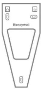
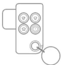
Product photo of a Honeywell smart lock device with red and white buttons, accompanied by three white cylindrical sensors and a remote control unit (no visible text or symbols on main components)Installation & Operating Manual
CONTENTS
KIT CONTENTS 3
INTRODUCTION AND OVERVIEW 4
System Arming 4
Entry/Exit Delay 4
Alarm Lockout 4
Tamper Protection 4
Jamming Detection 4
Battery Monitoring 4
PLANNING AND EXTENDING YOUR ALARM SYSTEM .... 4
Typical Installation 5
REMOTE CONTROL FOB 6
General Information 6
Configuring the Remote Control 6
Testing the Remote Control 6
EXTERNAL SIREN 6
General Information 6
Positioning the Siren 7
Installing and Configuring the Siren 7
Power up and adding new devices during installation....8
Mounting the Siren on to the wall 9
MOTION SENSOR(S) (PIR) 10
Positioning the Motion Sensor(s) (PIR) 10
Installing and Configuring the Motion Sensor(s) (PIR) ..... 10
Testing the Motion Sensor(s) (PIR) 11
DOOR WINDOW SENSOR(S) 11
Positioning the Door Window Sensor(s) 12
Installing and Configuring the Door Window Sensor(s) ... 12
Testing the Door Window Sensor(s) 13
LINKING NEW DEVICES TO THE SIREN AFTER INSTALLATION....13
DELETING ALL DEVICES FROM THE SYSTEM 14
SIREN SERVICE/OPERATING MODE 14
Arming the System in Instant-Arm Mode 16
Arming the System in Delay-Arm Mode 16
Disarming the System 17
Panic Alarm 17
Device Tamper 17
Siren Service Mode 17
Siren Operating Mode 17
Battery Monitoring 17
MAINTENANCE 18
Replacing the battery(s) 18
Remote Control Fob 19
Door Window Sensor(s) 19
Motion Sensor(s) (PIR) 19
Siren 19
TROUBLE SHOOTING....20
COMPONENT SPECIFICATION 22
All devices supplied in this kit are prelinked ready to install and operate. Batteries are supplied fitted in all battery powered devices.


x3
x3

natural_image
Line drawing of a laboratory gas collection device labeled 'Honeywell' (no other text or symbols)

x2
x2 x2

x1 x4

x2

11mm
natural_image
Simple line drawing of a device with six circular buttons and a handle, no text or symbols present.
x3
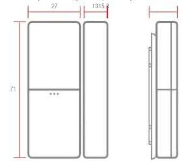
External Battery Siren
Motion Sensor(s) (PIR)
Door Window Sensor(s)
Remote Control
Batteries supplied fitted to the devices
SYSTEM ARMING
The system has an Instant-Arm and Delay-Arm mode. If the system is armed in Instant-Arm mode then all sensors will immediately become fully armed. Any sensors triggered while the system is armed will immediately sound an alarm.
ENTRY/EXIT DELAY
If the system is armed in Delay-Arm mode this will activate the system with a fixed 15 second entry/exit delay period. This allows a 15 second period for the user to exit the property after setting the system with the Remote Control. Any sensors triggered while the system is armed will not cause an alarm condition until after the 15 second entry delay has expired. This allows time for the system to be Disarmed before an alarm sounds when re-entering the property.
Note: To conserve power and maximize battery life the PIR Detector will only detect movement if there has been no movement detected within the previous 2 minutes. Consequently the Motion Sensor will not become active until the protected area has been free from movement for more than 2 minutes.
ALARM LOCKOUT
If a sensor is triggered while the system is armed, the alarm will sound. After the set alarm duration has ended, the alarm will stop and the system will automatically reset. Subsequent sensors triggered will again sound the alarm. If the alarm is triggered more than 3 times then it will become 'Locked Out' and any further alarm signals will be ignored until the system is re-armed.
TAMPER PROTECTION
All system devices (except the Remote Control) incorporate Tamper protection features to protect against unauthorized attempts to interfere with the device. Any attempt to remove the battery cover from any device (except a Remote Control) or to remove the Siren from the wall will trigger an alarm (unless the system is in Service Mode), even if the system is Disarmed.
JAMMING DETECTION
In order to detect any attempts to illegally jam the radio channel used by your alarm system, a special jamming detection function is incorporated into the Siren. If this feature is enabled, an alarm will be triggered if the radio channel is jammed continuously for more than 30 seconds or if the system is jammed for more than 3 periods of 10 seconds in a 5 minute period. (The Siren will emit a series of rapid beeps as a pre-alarm warning 10 seconds before a full alarm occurs.)
The jamming detection circuit will constantly scan for jamming signals. However, it will also detect and could in extreme cases be triggered by radio signals from other radio equipment within range operating on the same frequency which would not interfere with the normal operation of your alarm. When activating jamming detection the system should be monitored carefully for false jamming alarms for at least 2 weeks before leaving the Jamming Detection function permanently enabled.
BATTERY MONITORING
All devices are powered by batteries and incorporate a battery level monitoring feature which will warn of a low battery status. The batteries on any device indicating a low battery status should be replaced immediately.
PLANNING AND EXTENDING YOUR ALARM SYSTEM
Before attempting to install your alarm system it is important to study your security requirements and plan your installation.
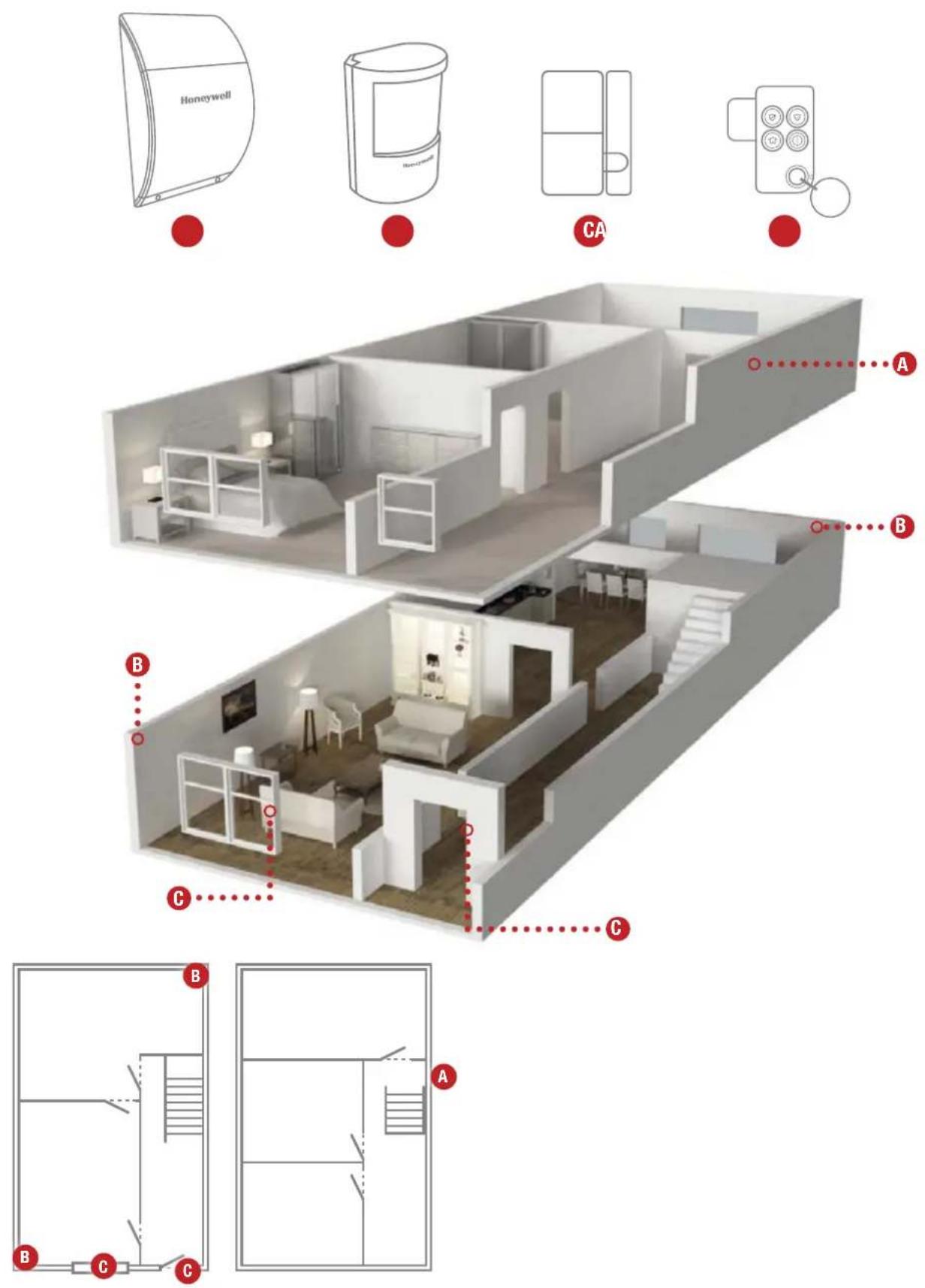
Motion Sensors (PIR) are used to protect the main areas of the property, (e.g. lounge, study, hallway and landing). Door Window Sensors are typically used to protect the main access points to the property (e.g. front door, back door, patio doors). However, they can also be used to protect other vulnerable doors/windows or access doors to important rooms.
TYPICAL INSTALLATION
The following example below shows a typical property incorporating the suggested positions for the Siren, Motion Sensor and Door Window Sensors for optimum security. Use this as a guide for your installation in conjunction with the detailed positioning requirements for each device provided in the appropriate installation sections in this manual for planning your intruder alarm system.
The alarm system may be extended to provide greater protection and control by fitting additional Motion Sensors, Door Window Sensors, Remote Controls as required. Any number of accessories may be used with your system, provided that they are all within radio range of the Siren.
The Remote Control Fob(s) is used to Instant Arm, Delay Arm and Disarm the system. Up to a total of 6 Remote Control Fobs can be linked using your system.
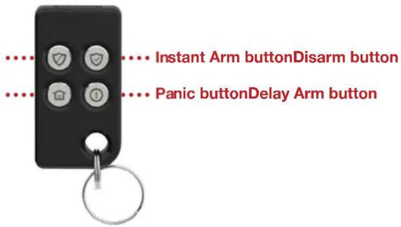
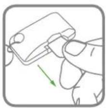
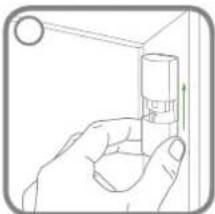
The Remote Control Fob is powered by a CR2032 type Lithium cell which under normal conditions will have an expected life of approximately 2 years. Under normal battery conditions the Transmit LED on the Remote Control Fob will only illuminate when a button is pressed. However, under low-battery conditions this LED will flash 3 times after the button has been released. When this occurs the battery should be replaced as soon as possible.
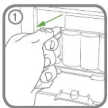
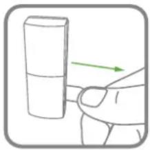
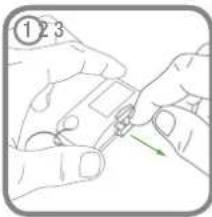
POWERING THE REMOTE CONTROL FOB TESTING THE REMOTE CONTROL FOB
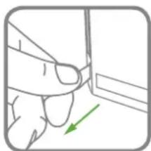
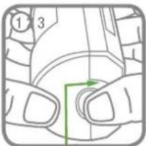
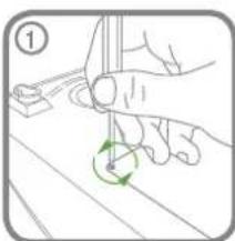
Initial power up:
natural_image
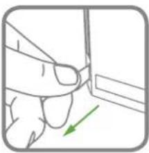
Hand holding a small electronic component with a green arrow indicating rotation (no text or symbols)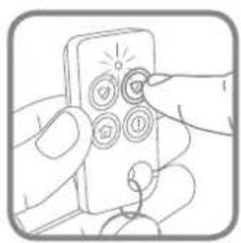
natural_image
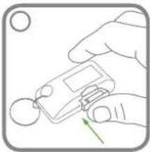
Illustration of hands inserting a device into a socket (no text or symbols)Any Remote(s) supplied in this kit will already be linked to the Siren.
EXTERNAL SIREN
The Siren is made from a tough polycarbonate housing and is weatherproof.
An LED indicator unit is built into the Siren to act as a visible deterrent and indication that the system is active. The LEDs will slowly and alternately flash whether the system is Armed or Disarmed.
When an alarm occurs the LEDs will flash rapidly together.
The tamper switch will trigger an alarm if any attempt is made to remove or interfere with the Siren after installation.
The Siren is powered by 4 x D LR20 Alkaline batteries. It also incorporates the installation's Jamming Detection system which will (if activated) generate an alarm if any attempt is made to continuously jam the radio channel used for the system.
natural_image
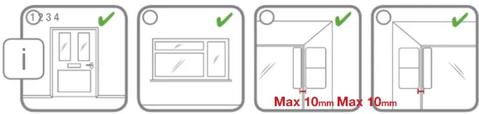
Diagram showing a door with a checkmark and a small inset image, no readable text or symbols present.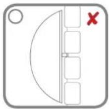
natural_image
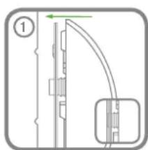
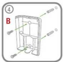
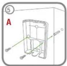
Simple diagram with a semicircular shape and vertical lines, no text or symbols presentINSTALLING AND CONFIGURING THE SIREN

natural_image
Illustration of a hand holding a small mechanical component with a green arrow indicating rotation (no text or symbols)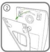
natural_image
Diagram of a device with a door and panel, showing a green arrow indicating direction (no text or symbols)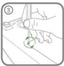
natural_image
Illustration of a hand holding a tool with a green circular arrow indicating rotation (no text or symbols)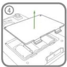
natural_image
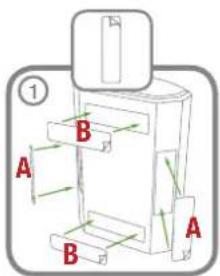
Diagram of a computer motherboard with a green arrow indicating a component (no text or symbols present)- Under the cover you will find a row of 5 DIP Switches and a 'LEARN' button. Do not remove the battery isolation tab at this stage
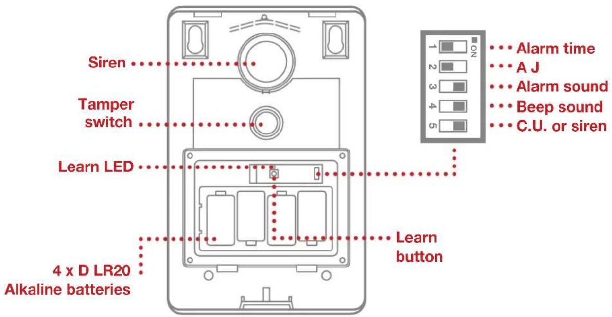
- Ensure that DIP Switch 5 of SW3 on the main board is set to ON ("C.U.") for use with this alarm system.
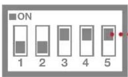
C.U. or siren Set to 'ON'
- DIP Switch 1 marked 'ALARM TIME' is used to limit the maximum period for which the external Siren will sound before it will be automatically shut down:
ON 3 minutes
OFF 1 minutes
Default setting for this kit: OFF
- DIP Switch 2 marked 'AJ' controls the anti-jamming detection facility in the Siren:
ON Jamming Detection enabled OFF Jamming Detection disabled
Default setting for this kit: OFF
- DIP Switch 3 marked 'ALARM SOUND' if OFF will prevent the siren from sounding during an alarm, (this will not affect the warning beeps):
ON Siren enabled OFF Siren disabled
Default setting for this kit: ON
- The Siren will acknowledge signals from the Remote Control by beeping and flashing the LEDs. It is possible to disable these acknowledgement beeps with DIP Switch 4 marked 'BEEP SOUND'.
ON Beeps enabled OFF Beeps disabled
Default setting for this kit: ON
8. POWERING UP AND LINKING NEW DEVICES DURING INSTALLATION
If you purchased additional detectors or remote control accessories with this kit then these can be linked to the Siren prior to installing on the wall as follows. If no additional devices purchased then power up the Siren as shown below and proceed to the next section "9. INSTALLING THE SIREN"
a. Power up the Siren as follows:


Note: The use of ear defenders is advisable when working in close proximity to the Siren due to the high sound level produced by this device when triggered. When the system is first installed, it will automatically power up in Service Mode. It cannot be switched out of Service Mode and into Operating Mode without using any linked Remote Control.
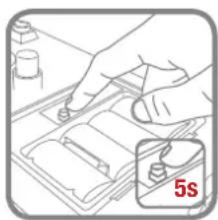
b. Press and hold the learn button in the Siren for 5 seconds:
natural_image
Illustration of a hand using a tool to adjust or install a component, with a 5-second time label (no text or symbols on the diagram itself)When the Siren enters Learn Mode it emits a single short beep and the both the indicator LEDs and Learn LED will flash together slowly (once every 2 seconds). The Siren will remain in Learn Mode for 30 seconds.
Adding a new Motion Sensor or Door Window Sensor:
Activate the Tamper signal on the PIR/MAG once. This can be done by removing the isolation tab or sliding the battery cover down.
Auto linking: Manual linking:
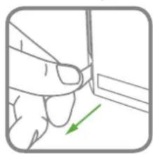
natural_image
Illustration of a hand holding a small object with a green arrow indicating direction (no text or symbols)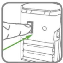
natural_image
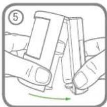
Illustration of a hand inserting a small object into a device (no text or symbols visible)Adding a new Remote Control Fob:

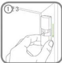
natural_image
Illustration of a hand pressing a button on a device with a shield icon (no text or symbols)Note: The use of ear defenders is advisable when working in close proximity to the Siren due to the high sound level produced by this device when triggered. When the system is first installed, it will automatically power up in Service Mode. It cannot be switched out of Service Mode and into Operating Mode without using any linked Remote Control.
natural_image
Pure mechanical diagram showing a vertical pipe or duct with a green arrow indicating direction, no text or symbols present.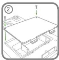
natural_image
Technical line drawing of a mechanical assembly with no visible text or symbols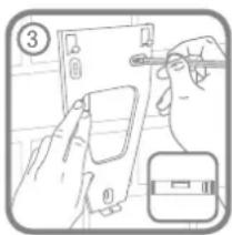
natural_image
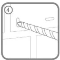
Simple line drawing of a rope or cable with a numbered label (4) and no text or symbols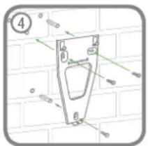
natural_image
Technical diagram of a mechanical part with dimension lines and a numbered circle (no readable text or symbols)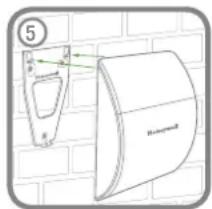
natural_image
Hand inserting a small component into a device (no text or symbols visible)MOTION SENSORS (PIR) PASSIVE INFRA RED
Motion Sensors (PIR) detect movement in a protected area by detecting changes in infra-red radiation levels caused for example when a person moves within or across the PIR's detection pattern. If movement is detected an alarm will be triggered (if the system is armed). Motion Sensors will also detect animals, so ensure that pets are not permitted access to areas fitted with Motion Sensors when the system is armed.
The sensor incorporates an anti-tamper protection feature to protect against attempts to interfere with the device. If the battery cover is removed, an alarm will immediately occur at any time (unless the system is in Service Mode).
To conserve power and maximize battery life the Motion Sensor will only detect movement if there has been no movement detected within the previous 2 minutes (this is known as the detector's sleep period).
The Motion Sensor is powered by 3 x AAA LR03 Alkaline batteries which under normal conditions will have an expected life of approximately 2 years. When the battery level drops, with the PIR in normal operation mode and the battery cover
fitted, the LED behind the detection window will flash 3 times. When this occurs the battery should be replaced as soon as possible. Note: In normal operation, the LED behind the lens will not flash on detection of movement.
Up to a total of 12 sensors (Motion Sensors (PIR) and/or Door Window Sensors) can be used with the system, providing they are all mounted within effective radio range of the Siren.
All Motion Sensors supplied with this kit will already be linked to the Siren.
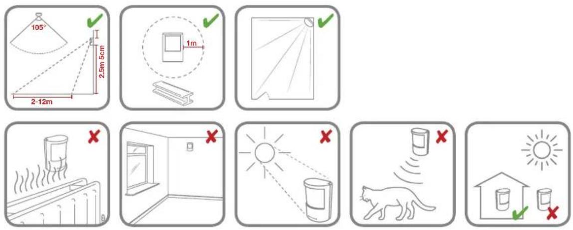
POSITIONING THE MOTION SENSORS (PIR)
The recommended position for a Motion Sensor is in the corner of a room mounted at a height between 2 and 2.5 metres.
POWERING THE MOTION SENSOR (PIR)
- Initial power up: 2. Power up initialisation:
natural_image
Simple line drawing of a hand pressing down on a wall with a green arrow indicating direction (no text or symbols)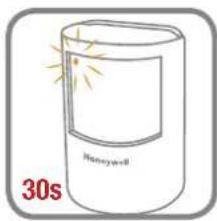
INSTALLING THE MOTION SENSOR (PIR)

natural_image
Illustration of a hand cleaning a surface with green arrows indicating direction (no text or symbols)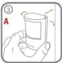
natural_image
Illustration of a hand holding a glass with green arrows indicating rotation (no text or symbols)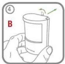
natural_image
Illustration of two hands holding a small object, with a green arrow indicating rotation (no text or symbols)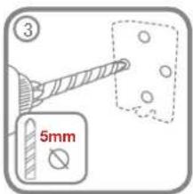
natural_image
Technical line drawing of a mechanical housing or enclosure with labeled components (no text or symbols present)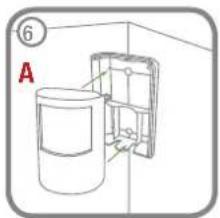
TESTING THE MOTION SENSOR(S) (PIR)
If the Siren has already been installed and is in Operating Mode, ensure it is placed into Service Mode before testing any linked Motion Sensors to prevent a Tamper alarm. If the Siren is initially powered up then it will be in Service Mode ON.
- Ensure that the LED indicator has stopped flashing rapidly after power up.
- Remove the battery rear cover from the Motion Sensor:
- The 'Test Mode' button is used to put the Motion Sensor into Walk Test mode, which overrides the 2 minute sleep period and allows the operation of the detector to be checked during installation. Press and hold the button for 2 seconds to activate Test Mode for a fixed 5 minute after which it will automatically revert to normal operation. On initial installation the detector can be configured into Walk Test ready for testing (i.e. pressing down the button shown for 2 seconds).
... Walk test button
- Refit the Motion Sensor to the rear cover by offering the sensor up to the rear cover and locate the clips in the top edge into the rear cover. Push the lower edge of the sensor into place and refit into position.
- Walk into and move slowly around the protected area within the 5 minutes of pressing the test button. Each time the sensor senses movement the LED indicator behind the lens will flash.
IMPORTANT: In normal operation, the LED indicator behind the sensor lens will not flash on movement detection (unless the battery is low). When the sensor is fully installed (i.e. battery cover fitted and in Operating Mode) in order to conserve power and maximise battery life the Motion Sensor will only detect movement if there has been no movement detected within the previous 2 minutes.
DOOR WINDOW SENSORS
The Door Window Sensor comprises two parts; a detector and a magnet. They are designed to be fitted to doors or windows with the magnet mounted on the opening part of the door /window and the sensor mounted to the frame.
When the protected door or window is opened and the magnet is moved away from the sensor an alarm will be triggered if the system is armed.
It is powered by a CR2032 type Lithium coin cell which under normal conditions will have an expected life of approximately 2 years. Under normal battery conditions the LED on the sensor will not illuminate when the sensor is triggered (unless the sensor is in test mode with the battery cover removed). However, under low battery conditions this LED will be flash 3 times when the sensor is triggered. When this occurs the batteries should be replaced as soon as possible.
Up to a total of 12 sensors (Door Window Sensors and/or Motion Sensors (PIR)) can be used with the system, providing they are all mounted within effective radio range of the Siren.
All Motion Sensors supplied with this kit will already be linked to the Siren.
POSITIONING THE DOOR WINDOW SENSORS
Door Window Sensors are suitable for mounting in dry interior locations only.
Decide which doors and windows are to be protected by fitting Door Window Sensors (usually the front and back doors as a minimum will have Door Window Sensors fitted). However additional sensors may be fitted where required to other more vulnerable doors or windows (e.g. garage, patio/conservatory doors etc).
Ensure that the position selected for the Door Window Sensor is within effective range of the Siren.
Do not fix the Sensor onto or very close to metalwork (i.e. radiators, water pipes, etc) as this could affect the radio range of the device.
On PVC door/window frames, it may be necessary to space the sensor and magnet away from the metal surface using a plastic or wooden spacer to achieve the necessary radio range.
INSTALLING AND CONFIGURING THE DOOR WINDOW SENSOR(S)
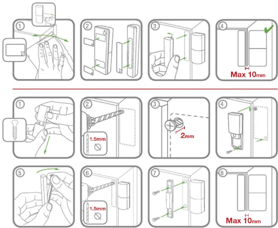
Note: The magnet can be installed on either side of the Sensor.
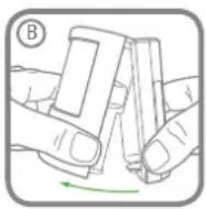
POWERING THE SUPPLIED DOOR WINDOW SENSOR(S)
natural_image
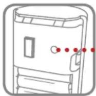
Hand holding a cylindrical object with an arrow indicating direction (no text or symbols)TESTING THE DOOR WINDOW SENSOR
If the Siren has already been installed and is in Operating Mode, ensure it is placed into Service Mode before testing any linked Door Window Sensors to prevent a Tamper alarm. If the Siren is initially powered up then it will be in Service Mode ON.
- Remove battery cover to activate the Tamper switch inside the device. As the switch is released the LED indicator will illuminate for approximately 1 second to show that the Tamper switch has been triggered and a signal is being transmitted.
-
Open the door/window to move the magnet away from the sensor. As the magnet is moved away from the sensor the LED indicator will illuminate for approximately 1 second to show that the sensor has been triggered and a signal is being transmitted.
Note: It does not matter if the LED indicator illuminates as the magnet is brought towards the sensor. -
Refit the battery cover.
LINKING NEW DEVICES TO THE SIREN AFTER INSTALLATION
IMPORTANT: In order to communicate with the Siren, the ID code of the sensor needs to be learned by the Siren. Whenever the Siren is being set-up it will automatically enter Service Mode when it is powered-up, ready to learn a new detector. Alternatively if the Siren is already in Operating Mode, see page 15 to place the Siren into Service Mode before adding a new sensor.
- Place the Siren into Learn Mode using any existing linked Remote Control.
Press and hold the button for 5 seconds.
When the Siren enters Learn Mode it emits a single short beep and the both the indicator LEDs and Learn LED will flash together slowly (once every 2 seconds). The Siren will remain in Learn Mode for 30 seconds.
Linking a new Motion Sensor/Door Window Sensor:
- Activate the Tamper signal on the PIR/MAG once. This can be done by removing the isolation tab or sliding the battery cover down.
Auto linking: Manual linking:
natural_image
Hand holding a small object with a green arrow pointing to it (no text or symbols visible)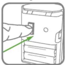
natural_image
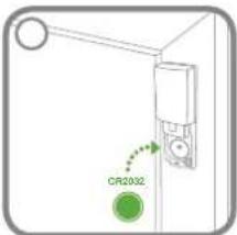
Illustration of a hand pointing at a device component with a green arrow indicating direction (no text or symbols)Linking a new Remote Control:

natural_image
Simple line drawing of a door with a shield icon (no text or symbols)If a valid signal is not received from a new device in that period it will automatically exit Learn Mode. It will remain in Service Mode.
If the detector is new and not already linked to the siren, it will produce two short beeps to confirmed learned. The Siren will now return to Service Mode. The new device is now linked to the Siren and its ID code recorded into the Siren's memory.
Note: If the sensor is already linked to the Siren or if there are already the maximum 12 Sensors or 6 Remote Controls already linked to the Siren then the Siren will produce a single long beep and exit Learn Mode. The Learn/ Indicator LEDs will stop flashing.
DELETING ALL DEVICES FROM THE SYSTEM
Note: NVM reset can only be achieved at the Siren, it cannot be activated remotely from a linked Remote Control.
To delete all devices from the system:
-
Switch the Solar Siren into Service Mode using any Remote Control already linked so it can be removed from the wall.
-
Inside the battery compartment press and hold the Learn button for 10s until the siren produces two long beeps and the Learn LED beside the Learn button flashes 5 times. Ignore the Learn beep after the first 5 seconds.
The ID codes of all linked devices are now erased from memory.
Note: The Siren will now remain in Service Mode as it cannot be switched to Operating Mode until a Remote Control is linked to it which allows it to be controlled.
SIREN SERVICE/OPERATING MODE
Note: The Siren is automatically in Service Mode when first powered up and must be switched into Operating Mode before the system can be operated or fully tested.
The Siren can be switched between Service Mode and Operating Mode using any linked Remote Control as follows:
Press and hold the button for 5 seconds:
The Siren will generate the following signals to indicate which mode it is switching into.
If switching into Service Mode:
As the button is pressed the Remote will transmit the Disarm signal and the Siren will beep twice as normal. This Disarms the system.
After the button has been held down for 5 seconds the 'Siren Service Mode Toggle' command will be transmitted and the Siren will produce two short beeps followed 1 second later by a single long beep. The Siren LEDs will flash together in conjunction with the beeps. Beeps to be normal volume.
Beep-Beep......Beeeeeeeeep 1 second
If switching into Operating Mode:
As the button is pressed the Remote will transmit the Disarm signal. The Siren will not respond to this as it is in Service Mode.
After the button has been held down for 5 seconds the 'Siren Service Mode Toggle' command will be transmitted and the siren will produce a single long beep followed 1 second later by two short beeps.
The Siren LEDs will flash together in conjunction with the beeps. Beeps to be normal volume.
Beeeeeeeeep......Beep-Beep 1 second
TESTING THE SYSTEM
The system should be tested at regular intervals (at least every 3 months) to ensure that it is operating correctly.
- Before commencing testing please ensure the following:
– The Siren is in Operating Mode and Disarmed.
– There is no movement or people/pets in any Motion Sensor protected area.
– All doors/windows protected by Door Window Sensors are closed.
– All battery covers and housings are correctly fitted.
- Press the button on the Remote Control.
The Siren will beep once.
- Press and hold the panic button ⚠️ on the Remote Control. The alarm will sound.
- Stop the alarm by pressing the button on the Remote Control. The Siren will stop and acknowledge the signal by beeping 10 times (unless Beep Disable has been selected).
If your system includes Motion Sensors:
- Arm the system in Instant-Arm mode by pressing the button on the Remote Control. The Siren will acknowledge the signal by beeping once (unless Beep Disable has been selected).
- Ensure that the area protected by the Motion Sensor has been free from movement for at least 2 minutes and then walk into the area to trigger the detector.
Note: To conserve power the Motion Sensor will only detect movement if there has been no movement detected within the previous 2 minutes.
- Stop the alarm and Disarm the system by pressing the button on the Remote Control. The Siren will stop and acknowledge the signal by beeping 10 times, (unless Beep Disable has been selected).
- Continue to test all Motion Sensors in turn as described above (steps 5-7).
If your system includes Door Window Sensors:
- Arm the system in Instant-Arm mode by pressing the button on the Remote Control.
- Open a door/window protected by a Door Window Sensor and ensure that the alarm sounds.
- Disarm the system and stop the Siren by pressing the button on the Remote Control.
- Test each Door Window Sensor in turn as described above (steps 9-11).
If the system has been installed for the first time then the Siren will power up in Service Mode. If not already, it will need to be placed into Operating Mode before it can be used. See page 14-15.
When leaving the premises, the system must be Armed. However, before doing so, check that all windows are closed and locked, all protected doors are closed and Motion Sensors are not obstructed. Ensure that pets are restricted to areas not protected by Motion Sensors.
The system has 2 armed modes, Instant-Arm and Delay-Arm.
Instant-Arm mode will immediately Arm the system. Once the system is Armed, activating any detector (i.e. opening a door/windows protected by a Door Window Sensor or moving into a Motion Sensor protected area) will immediately trigger an alarm. On returning to and entering the property the system must be Disarmed before opening any protected door or entering an area protected by a Motion Sensor otherwise an alarm will occur. For this reason when using Instant-Arm mode, the system should be Armed and Disarmed from outside the property using the Remote Control.
Delay-Arm mode will Arm the system with a 15 second entry/exit delay. On arming the system in Delay-Mode the siren will beep once and then again after the 15 second delay has expired. This allows time for you to leave the property before the system becomes fully Armed. On returning to and entering the property by opening a protected door or moving through a Motion Sensor protected area the system will be triggered and the Siren will emit a single long beep. However, an alarm will not sound until the 15 second delay has expired. The system must be Disarmed using either the Remote Control or during the 15 second delay to prevent the alarm from sounding.
If an alarm occurs the Siren will sound continuously until the set alarm duration time expires. The alarm will then stop and the system will automatically re-arm itself. This process can be repeated up to 3 times after which time the 'Alarm Lockout' feature will operate and prevent the system from re-arming.
Notes:
- To conserve power and maximise battery life the Motion Sensor will only detect movement if there has been no movement detected within the previous 2 minutes.
- The system can only be armed if the Siren is in Operating Mode (see page 15).
ARMING THE SYSTEM IN INSTANT-ARM MODE
Instant arming means there is no entry/exit delay and the system must be armed when all occupants have exited the home.
The system can be Armed in Instant mode by using the Remote Control as follows:
Press the 'INSTANT-ARM' button
The Siren will acknowledge the signal by beeping once and flashing both indicator LEDs once.
ARMING THE SYSTEM IN DELAY-ARM MODE
Delay arming provides a 15 second entry/exit period to disarm your system before an alarm occurs.
The system can be Armed in Delay mode using the Remote Control as follows:

flowchart
graph LR
    A["Press the 'DELAY-ARM' button"] --> B["15s"]
The Siren will acknowledge the signal by beeping once and flashing both indicator LEDs once. After the fixed 15 seconds exit-delay has expired the Siren will produce a second single beep and flash both LEDs again to indicate the system is fully armed. The alarm cannot be triggered by activating and PIR/MAG detector during the 15 seconds exit-delay.
If a Motion Sensor/Door Window Sensor is triggered while the system is armed in Delay-Arm mode the Siren will produce a single long beep and long flash of both LEDs. However the alarm will not sound until the end of the fixed 15 second entry-delay. If the system is Disarmed before the entry-delay expires the alarm will not sound.
DISARMING THE SYSTEM
The system can be Disarmed using the Remote Control as follows:
Press the 'DISARM' button
The Siren will acknowledge the signal by beeping twice.
IMPORTANT: If, when the system is Disarmed, the Siren emits a series of 10 rapid beeps, this indicates that an Alarm has been triggered whilst the system was Armed. Check the security of the property before entering.
PANIC ALARM
An Alarm can be immediately triggered by the user at any time (whether the system is Armed or Disarmed) in the event of threat or danger by activating the Personal Attack (PA) facility using the Remote Control as follows:
Press and hold the Ⓒ button for 3 seconds.
This will trigger the alarm and the Siren will sound.
DEVICE TAMPER
If the battery cover of any device (except a Remote Control) is removed or if the Siren is removed from the wall, then an Alarm will immediately occur (unless the Siren is in Service Mode), even if the system is Disarmed.
The Alarm will sound until the set alarm duration time expires or the system is Disarmed from the Remote Control.
SIREN SERVICE MODE
In order to remove the Siren from the wall to change the batteries, it is necessary to place the Siren into Service Mode to prevent the Tamper protection switch on the Siren operating and triggering an alarm (see page 14).
SIREN OPERATING MODE
When you have completed any alterations to the system remember to switch the Siren into Operating Mode.
The Siren can be switched into Operating Mode using the Remote Control (see page 15).
BATTERY MONITORING
Low Battery Condition
If the Siren is at low battery condition, pressing the Disarm button on the Remote Control will cause the Siren to generate 3 short beeps.
All system devices continuously monitor their battery condition. When a low battery indicator is activated the device will continue to operate normally for up to 2 weeks (depending upon system use). However, the battery for that device should be replaced as soon as possible.
Before replacing the battery in any device you must switch the system into Service Mode as previously described. When the batteries have been replaced, you must return the system to Operating Mode. See page 15.
The low battery indication built into each system device is as follows:
Remote Control
When the Remote Control is operated under low battery conditions the transmit LED will flash 3 times after the button has been released.
Under normal battery conditions the LED will extinguish within 2 seconds of the button being released.
Motion Sensor(s) (PIR)
Under low battery conditions the LED behind the detector lens will flash 3 times when movement is detected to indicate that the battery needs to be replaced. Under normal battery conditions the LED does not illuminate unless the Motion Sensor is in Walk Test Mode.
Door Window Sensors
When the sensor is activated, under low-battery conditions the Transmit LED will flash 3 times as the door/window is opened.
Under normal battery conditions the LED does not illuminate as the sensor is operated (unless the sensor is in Test Mode with the battery cover removed).
MAINTENANCE
Your Alarm System requires very little maintenance. However, a few simple tasks will ensure its continued reliability and operation.
IMPORTANT: If, for any reason you have to completely power-down the system (e.g. to move the system to new premises), first put the system into Service Mode (see page 14) before removing the Siren cover and removing the batteries.
SENSORS AND REMOTE CONTROL FOB
The Sensors and Remote Control Fob require very little maintenance. The batteries should be replaced when a low battery status is indicated.
BATTERIES
Note: Before removing the battery cover on any sensor to replace the batteries, ensure that the Siren is switched into Service Mode to avoid triggering an Alarm. The Siren must be switched back into Operating Mode after fitting new batteries otherwise the system will not operate. Refer to page 14 for service mode using a Remote Control. If replacing the battery in any Remote Control then there is no need to enter Service Mode.
The specifications for replacement batteries are as follows:
| Remote Control Fob: 1 x 3V CR2032 Lithium Cell (or equivalent) |
| Door Window Sensor: 1 x 3V CR2032 Lithium Cell (or equivalent) |
| Motion Sensor (PIR): 3 x 1.5V AAA LR03 Alkaline Batteries (or equivalent) |
| Siren: 4 x 1.5V D LR20 Alkaline Batteries (or equivalent) |
Remote Control Fob
natural_image
Illustration of two hands holding a small object with a green arrow indicating direction (no text or symbols)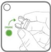
natural_image
Illustration of a hand holding a small electronic device with a green arrow pointing to it (no text or symbols present)Door Window Sensor
natural_image
Line drawing of a hand holding a small cylindrical object with a circular element above (no text or symbols)Motion Sensor (PIR)
natural_image
Illustration of a hand holding a small object with a green arrow indicating direction (no text or symbols)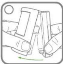
natural_image
Illustration of hands holding a smartphone with a green circular arrow indicating rotation (no text or symbols)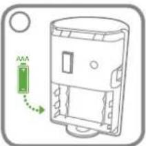
natural_image
Diagram of a device casing with a green arrow indicating rotation or movement (no text or symbols)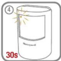
natural_image
Illustration of two hands holding a smartphone, with a green arrow indicating rotation (no text or symbols)Siren
Place the Siren into Service Mode before removing from the wall if the batteries inside the Siren are still operating the Siren (i.e. 2 LEDs on the Siren will flash every 5 seconds to indicate powered).
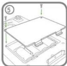
After the batteries are replaced, the Siren will automatically power up in Service Mode. After the Siren is mounted on the wall, place the Siren back into Operating Mode using any linked Remote Control.
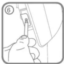
natural_image
Illustration of a hand holding a tool with a green circular arrow indicating rotation (no text or symbols)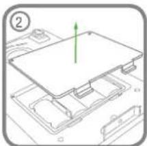
natural_image
Diagram of a computer motherboard with a green arrow indicating a component (no text or symbols present)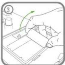
natural_image
Hand placing a green arrow on a tray with a small container, no text or symbols visible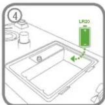
natural_image
Technical line drawing of a mechanical assembly with no visible text or symbols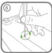
natural_image
Illustration of a hand holding a tool with a green circular arrow indicating rotation (no text or symbols)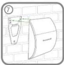
natural_image
Diagram of a wall-mounted device mounted on a brick wall, showing a bracket and panel (no text or symbols)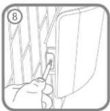
natural_image
Line drawing of a person inserting a small component into a wall, no text or symbols presentSymptom / Recommendation
Siren immediately sounds when system armed
- Siren tamper switch activated – adjust tamper plunger and ensure that switch fully closes when Siren is mounted. If the wall is excessively uneven, the Siren may need relocating to a more suitable position.
Siren sounds when system is Disarmed or has not been triggered by an intruder
- Sensor Tamper switch activated – check the battery covers of all sensors to ensure they are securely and fully fitted.
- Panic Alarm operated from a Remote Control.
- Jamming Detection circuit operation (see pages 4, 7 & 8).
- Sensor giving false alarm signals, see below.
Siren not responding to Sensor
- Siren is in Service Mode – switch to Operating Mode (see page 15).
- Detector battery low – replace battery.
- Ensure 'ID code' of the Sensor has been learnt by the Siren (see pages 13-14).
- Ensure Sensor is within effective radio range of Siren and equipment is not mounted close to metal objects.
Siren not responding to Remote Control
- Siren is in Service Mode – switch to Operating Mode (see page 15).
- Remote Control battery low – replace battery.
- Ensure 'ID code' of the Remote has been learnt by the Siren (see pages 8-9 or 13-14 if a new Remote Control).
- Siren batteries low or discharged – replace batteries
- System locked – reset system:
a. Remove batteries b. Insert batteries and take out of Service Mode.
LED on Remote Control not illuminating, or is dim when unit is operated
- Ensure battery is fitted with correct polarity.
- Ensure battery holder connections are making good contact with the battery.
- Battery low – replace battery.
Motion Sensor (PIR)
- Ensure that the Sensor is not pointing at a source of heat or a moving object.
- Ensure that the Sensor is not mounted above a radiator or heater.
- Ensure that the Sensor is not facing a window or in direct sunlight.
- Ensure that the Sensor is not in a draughty area.
Motion Sensor (PIR) not detecting a person's movement.
- Ensure batteries are fitted with correct polarity.
- Ensure 'ID code' of the Sensor has been learnt by the Siren (see pages 13-14).
- Ensure that Sensor is mounted the correct way up (i.e. with the Honeywell brand at the bottom).
- Ensure that the Sensor is mounted at the correct height (i.e. 2-2.5 metres).
- Once the system is armed allow up to 2 minutes for the Sensor to stabilise and become fully operational. Leave the area for this period.
If the system is armed with a delay allow a further 15 seconds to ensure that the Entry delay period has expired. - Ensure Sensor is within effective radio range of the Siren and is not mounted close to metal objects which may interfere with the radio transmission.
Motion Sensor (PIR) LED flashes on detection of movement (device in Normal Operation Mode)
- Low battery – replace battery.
- Motion Sensor still in Walk Test Mode for fixed 5 minutes if the PCB button was activated (see page 11).
Door Window Sensor not working
- Ensure that magnet is correctly positioned in relation to sensor and that the gap between magnet and sensor is less than 10mm.
- Ensure battery is fitted with correct polarity.
- Ensure 'ID code' of the sensor has been learnt by the Siren.
- Ensure Sensor is within effective radio range of the Siren and is not mounted close to metal objects which may interfere with the radio transmission.
Door Window Sensor false alarming
- Ensure that magnet is correctly positioned in relation to sensor.
- Ensure that gap between magnet and sensor is no more than 10mm.
- Tamper switch below battery cover not depressed – check battery cover is fitted correctly and that fixing lugs are not broken.
LED on Door Window Sensor illuminating when door or window is opened
1. Low battery – replace battery
COMPONENT SPECIFICATION
External Battery Siren
• RF operating frequency: 868MHz
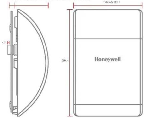
- 4 x 1.5V D (LR20) Alkaline battery power
• 105dB Piezo Siren
• 10 minutes alarm duration limiter (optional) - Siren Disable (selectable)
• Rear anti-tamper protection - Jamming Detection
• Audible confirmation - Battery life \~18 months
Motion Sensor (PIR) Passive Infra Red
• RF operating frequency: 868MHz
- Range: 200 metre max.
• Detection range: 12 metres at 105° - Walk test facility
- Anti-tamper protected
• Corner or surface mount - Battery life >2 year
• 3 x 1.5V AAA (LR03) Alkaline battery - Low battery indicator
• RF operating frequency: 868MHz
Door Window Sensor(s)
- Range: 200m metres max.
- Test Mode
• Anti-tamper protection - Battery life >2 years
• 1 x 3V CR2032 Lithium battery - Low battery indicator
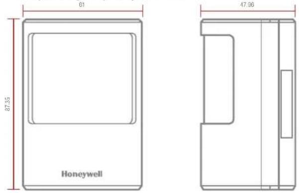
Remote Control Fob (Optional)
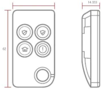
• RF operating frequency: 868MHz
- Range: 150 metres max.
- Panic button
- Operates all INSTANT ARM, DELAY ARM, and DISARM functions
• Transmission indicator
- Battery life >2 years
• 1 x 3V CR2032 Lithium battery
- Low battery indicator
©Novar Electrical Devices and Systems Limited (A Honeywell company) 2015
The Arnold Centre, Paycocke Road, Basildon, Essex SS14 3EA. (UK)
livewell.honeywell.com