
Ti480 - Camera FLUKE - Free user manual and instructions
Find the device manual for free Ti480 FLUKE in PDF.


| Product Type | Thermal Imager (Infrared Camera) |
| Brand | Fluke |
| Model | Ti480 |
| Detector Resolution | 640 x 480 pixels (307,200 total) |
| SuperResolution | 1280 x 960 pixels (1,228,800 total) |
| Temperature Measurement Range | -20 °C to +1200 °C |
| Accuracy | ±2 °C or 2% (whichever greater) at 25 °C ambient |
| Thermal Sensitivity (NETD) | ≤0.025 °C at 30 °C target temp (25 mK) |
| Infrared Spectral Band | 7.5 μm to 14 μm (Long Wave) |
| Display | 8.9 cm (3.5 in) touchscreen LCD with backlight |
| Field of View (Standard Lens) | 34° x 24° |
| Spatial Resolution (IFOV) | 0.93 mRad |
| Focus System | LaserSharp Auto Focus, Advanced Manual Focus, MultiSharp Focus |
| Digital Zoom | 2X and 4X |
| Image Capture Frequency | 60 Hz refresh rate |
| Storage | Internal 4 GB flash, micro SD card slot, USB storage device |
| Wireless Connectivity | WiFi and Bluetooth |
| Video Output | HDMI |
| Battery | Two lithium-ion rechargeable smart batteries; 2-3 hours continuous use per pack |
| Battery Charge Time | 2.5 hours to full charge |
| Weight | 1.04 kg (2.3 lb) including battery |
| Dimensions (H x W x D) | 27.7 cm x 12.2 cm x 16.7 cm (10.9 in x 4.8 in x 6.5 in) |
| Ingress Protection | IP54 |
| Drop Protection | 2 m with standard lens |
| Operating Temperature | -10 °C to +50 °C |
Frequently Asked Questions - Ti480 FLUKE
User questions about Ti480 FLUKE
0 question about this device. Answer the ones you know or ask your own.
Ask a new question about this device
Download the instructions for your Camera in PDF format for free! Find your manual Ti480 - FLUKE and take your electronic device back in hand. On this page are published all the documents necessary for the use of your device. Ti480 by FLUKE.
USER MANUAL Ti480 FLUKE
Ti200, Ti300, Ti400, Ti450, Ti450SF6, Ti480
Thermal Imagers
Users Manual
LIMITED WARRANTY AND LIMITATION OF LIABILITY
Each Fluke product is warranted to be free from defects in material and workmanship under normal use and service. The warranty period is two years and begins on the date of shipment. Parts, product repairs, and services are warranted for 90 days. This warranty extends only to the original buyer or end-user customer of a Fluke authorized reseller, and does not apply to fuses, disposable batteries, or to any product which, in Fluke's opinion, has been misused, altered, neglected, contaminated, or damaged by accident or abnormal conditions of operation or handling. Fluke warrants that software will operate substantially in accordance with its functional specifications for 90 days and that it has been properly recorded on non-defective media. Fluke does not warrant that software will be error free or operate without interruption.
Fluke authorized resellers shall extend this warranty on new and unused products to end-user customers only but have no authority to extend a greater or different warranty on behalf of Fluke. Warranty support is available only if product is purchased through a Fluke authorized sales outlet or Buyer has paid the applicable international price. Fluke reserves the right to invoice Buyer for importation costs of repair/replacement parts when product purchased in one country is submitted for repair in another country.
Fluke's warranty obligation is limited, at Fluke's option, to refund of the purchase price, free of charge repair, or replacement of a defective product which is returned to a Fluke authorized service center within the warranty period.
To obtain warranty service, contact your nearest Fluke authorized service center to obtain return authorization information, then send the product to that service center, with a description of the difficulty, postage and insurance prepaid (FOB Destination). Fluke assumes no risk for damage in transit. Following warranty repair, the product will be returned to Buyer, transportation prepaid (FOB Destination). If Fluke determines that failure was caused by neglect, misuse, contamination, alteration, accident, or abnormal condition of operation or handling, including overvoltage failures caused by use outside the product's specified rating, or normal wear and tear of mechanical components, Fluke will provide an estimate of repair costs and obtain authorization before commencing the work. Following repair, the product will be returned to the Buyer transportation prepaid and the Buyer will be billed for the repair and return transportation charges (FOB Shipping Point).
THIS WARRANTY IS BUYER'S SOLE AND EXCLUSIVE REMEDY AND IS IN LIEU OF ALL OTHER WARRANTIES, EXPRESS OR IMPLIED, INCLUDING BUT NOT LIMITED TO ANY IMPLIED WARRANTY OF MERCHANTABILITY OR FITNESS FOR A PARTICULAR PURPOSE. FLUKE SHALL NOT BE LIABLE FOR ANY SPECIAL, INDIRECT, INCIDENTAL OR CONSEQUENTIAL DAMAGES OR LOSSES, INCLUDING LOSS OF DATA, ARISING FROM ANY CAUSE OR THEORY.
Since some countries or states do not allow limitation of the term of an implied warranty, or exclusion or limitation of incidental or consequential damages, the limitations and exclusions of this warranty may not apply to every buyer. If any provision of this Warranty is held invalid or unenforceable by a court or other decision-maker of competent jurisdiction, such holding will not affect the validity or enforceability of any other provision.
Fluke Corporation
P.O. Box 9090
Everett, WA 98206-9090
U.S.A.
Fluke Europe B.V.
P.O. Box 1186
5602 BD Eindhoven
The Netherlands
ООО «Флюк СИАЙЭС»
125167, г. Москва,
How to Contact Fluke.... 1
Safety Information.... 2
Product Familiarization 5
Features 5
Controls 6
Touch Screen....8
Control Panel 9
Primary and Secondary Triggers 9
Basic Operation 9
Turn On and Off the Imager 9
Focus 10
Capture Image 10
Save Image 10
Menus 10
Measurement Menu 11
Level/Span.... 13
Emissivity Adjustment.... 14
Spot Markers 15
Spot Box....15
Image Menu 16
Image Enhancement 18
Distance.... 20
Camera Menu 21
LaserSharp Auto Focus System.... 22
Video 22
Wireless Connectivity 23
Fluke Connect Wireless System 25
Fluke Connect App.... 25
Fluke Connect Tools.... 26
Memory Menu 27
Review Image.... 27
Edit Image 27
Delete Image 29
Settings Menu 30
File Format 31
Date 32
Time 32
SF6 Gas Detection Mode Menu 33
Gas Detection Conditions 33
SmartView Software 34
Download SmartView Software 35
Download Firmware 35
Enable the Radio 35
Streaming Video (Remote Display) 36
Stream Live to a PC.... 36
Stream Live with Fluke Connect Software.... 37
Stream Live to an HDMI Device 37
Remote Control of Imager 37
Accessories 38
Maintenance 40
Clean the Case.... 40
Lens Care 40
Battery Care 40
Charge Batteries 41
Two-Bay Battery Charger Base 41
AC Power Socket on Imager.... 41
Optional 12 V Vehicle Charger 42
Radio Frequency Data 42
General Specifications 42
Detailed Specifications 44
Introduction
The Fluke Ti200, Ti300, Ti400, Ti450, Ti450SF6, and Ti480 Thermal Imagers (the Product or Imager) are handheld, infrared imaging cameras for use in many applications. These applications include equipment troubleshooting, preventive and predictive maintenance, building diagnostics, research and development, and gas leak detection.
The Imager displays thermal images on a high-visibility, industrial-quality LCD touch screen. The Imager can save images to internal memory, to a removable memory card, or to a USB storage device. Saved images and data stored in internal memory or on the memory card can be transferred to a PC through a direct USB connection to the PC or by wireless transfer to a PC or mobile device.
The Imager includes SmartView ^® software. SmartView is a high-performance, professional software suite for quality analysis and reporting. The Imager works with the Fluke Connect ^® app available on mobile devices.
A rugged, rechargeable lithium-ion smart battery provides power to the Imager. Direct ac power is accessible with the included ac power adapter.
How to Contact Fluke
To contact Fluke, call one of the following telephone numbers:
• USA: 1-800-760-4523
• Canada: 1-800-36-FLUKE (1-800-363-5853)
• Europe: +31 402-675-200
• Japan: +81-3-6714-3114
• Singapore: +65-6799-5566
• Anywhere in the world: +1-425-446-5500
Or, visit Fluke's website at www.fluke.com.
To register your product, visit http://register.fluke.com.
To view, print, or download the latest manual supplement, visit http://us.fluke.com/usen/support/manuals.
To request a printed manual, vist www.fluke.com/productinfo.
Safety Information
A Warning identifies hazardous conditions and procedures that are dangerous to the user. A Caution identifies conditions and procedures that can cause damage to the Product or the equipment under test.
Warning
To prevent possible electrical shock, fire, or personal injury and for safe operation of the Product:
- Read all safety information before you use the Product.
- Carefully read all instructions.
- Do not alter the Product and use only as specified, or the protection supplied by the Product can be compromised.
- Replace the batteries when the low battery indicator shows to prevent incorrect measurements.
- Do not use the Product if it operates incorrectly.
- Do not use the Product if it is altered or damaged.
- Disable the Product if it is damaged.
• See emissivity information for actual temperatures. Reflective objects result in lower than actual temperature measurements. These objects pose a burn hazard. - Do not put battery cells and battery packs near heat or fire. Do not put in sunlight.
- Do not disassemble or crush battery cells and battery packs.
- Remove batteries to prevent battery leakage and damage to the Product if it is not used for an extended period.
- Connect the battery charger to the mains power outlet before the charger.
- Use only Fluke approved power adapters to charge the battery.
- Keep cells and battery packs clean and dry. Clean dirty connectors with a dry, clean cloth.
- Batteries contain hazardous chemicals that can cause burns or explode. If exposure to chemicals occurs, clean with water and get medical aid.
- Do not disassemble the battery.
- Repair the Product before use if the battery leaks.
- Use only the external mains power supply included with the Product.
- Do not put metal objects into connectors.
-
Use only specified replacement parts.
-
Have an approved technician repair the Product.
- Remove the batteries if the Product is not used for an extended period of time, or if stored in temperatures above 50 °C. If the batteries are not removed, battery leakage can damage the Product.
- Disconnect the battery charger and move the Product or battery to a cool, non-flammable location if the rechargeable battery becomes hot (>50 °C) during the charge period.
- Replace the rechargeable battery after 5 years of moderate use or 2 years of heavy use. Moderate use is defined as recharged twice a week. Heavy use is defined as discharged to cutoff and recharged daily.
- Do not short the battery terminals together.
- Do not keep cells or batteries in a container where the terminals can be shorted.
- Do not look into the laser. Do not point the laser directly at persons or animals or indirectly off reflective surfaces.
- Do not look directly into the laser with optical tools (for example, binoculars, telescopes, microscopes). Optical tools can focus the laser and be dangerous to the eye.
- Do not open the Product. The laser beam is dangerous to eyes. Have the Product repaired only through an approved technical site.
- Do not use laser viewing glasses as laser protection glasses. Laser viewing glasses are used only for better visibility of the laser in bright light.
Caution
Storage and/or continual operation of the Imager in extreme ambient temperature conditions can result in temporary interruption of operation. If this occurs, let the Imager stabilize (cool down or warm up) before you resume operation.
Table 1 is a list of symbols that can be used on the Imager or in this manual.
Table 1. Symbols
| Symbol Description | |
| Consult user documentation. | |
| WARNING. RISK OF DANGER. | |
| WARNING. HAZARDOUS VOLTAGE. Risk of electric shock. | |
| WARNING. LASER RADIATION. Risk of eye damage. | |
| Connected to ac power. Battery removed. | |
| Battery status. Battery charging when animated. | |
| 1 | On/Off |
CE | Conforms to European Union directives.Certified by CSA Group to North American safety standards. |
 | Conforms to relevant Australian Safety and EMC standards. |
| Conforms to relevant South Korean EMC standards. | |
 | Japan Quality Association |
| Li-ion | This Product contains a lithium-ion battery. Do not mix with the solid waste stream. Spent batteries should be disposed of by a qualified recycler or hazardous materials handler per local regulations. Contact your authorized Fluke Service Center for recycling information. |
| [3227] | This product complies with the WEEE Directive marking requirements. The affixed label indicates that you must not discard this electrical/electronic product in domestic household waste. Product Category: With reference to the equipment types in the WEEE Directive Annex I, this product is classed as category 9 "Monitoring and Control Instrumentation" product. Do not dispose of this product as unsorted municipal waste. |
| Indicates a Class 2 laser. DO NOT STARE INTO BEAM The following text may appear with the symbol on the product label: “IEC/EN 60825-1:2014. Complies with 21 CFR 1040.10 and 1040.11 except for deviations pursuant to Laser Notice 50, dated June 24, 2007.” In addition, the following pattern on the label will indicate wavelength and optical power: λ = xxxnm, x.xxmW. | |
Product Familiarization
Features
Table 2 lists the features of the Imager.
Table 2. Features
| Feature Ti200 Ti300 Ti400 Ti450 Ti450SF6 Ti480 | ||||||
| Focus/Image Enhancement | ||||||
| Advanced manual focus | ● | ● | ● | ● | ● | ● |
| LaserSharp® Auto Focus System | ● | ● | ● | ● | ● | ● |
| Filter mode | ● | ● | ● | |||
| MultiSharpTM Focus | ● | ● | ● | |||
| SuperResolutionTM | ● | ● | ● | |||
| Digital Zoom | ||||||
| 2X | ● | ● | ● | |||
| 4X | ● | ● | ● | |||
| IR-Fusion® Technology | ||||||
| Visible | ● | ● | ● | ● | ● | ● |
| Picture-in-Picture (PIP) | ● | ● | ● | ● | ● | ● |
| Full screen IR AutoblendTM (Preset percentage selection) | ● | ● | ● | ● | ● | ● |
| Image annotations | ||||||
| IR-PhotoNotesTM | ● | ● | ● | ● | ● | ● |
| Audio (Voice) | ● | ● | ● | ● | ● | ● |
| Text | ● | ● | ● | ● | ● | ● |
| Wireless connectivity | ||||||
| WiFiTM | ● | ● | ● | ● | ● | ● |
| Bluetooth® | ● | ● | ● | ● | ● | ● |
| Fluke Connect® | ● | ● | ● | ● | ● | ● |
| CNXTM | ● | ● | ● | ● | ● | |
| HDMI® connectivity | ● | ● | ● | ● | ● | |
| SmartView® software | ||||||
| Stream video (remote display) | ● | ● | ● | ● | ● | |
| Remote operation of Imager | ● | ● | ● | ● | ||
| Gas Leak Detection | ● | |||||
Controls
Table 3 shows the connections of the Imager.
Table 3. Connections
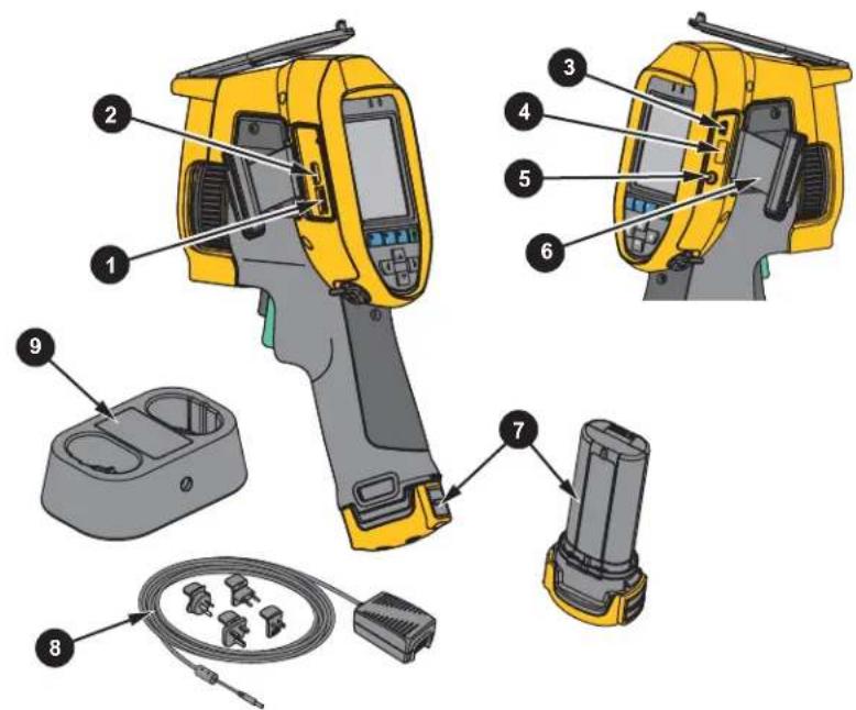
| Item Description Item Description | |||
| 1 | Micro SD Memory Card Slot | 6 | Connector Cover |
| 2 | HDMI Connection | 7 | Lithium-ion Smart Battery |
| 3 | USB Cable Connection | 8 | AC Power Supply with Universal Adapters |
| 4 | USB Storage Device Connection | 9 | 2-Bay Battery Charging Base |
| 5 | AC Adapter/Charger Input Terminal | ||
Table 4 shows the front of the Product.
Table 4. Front
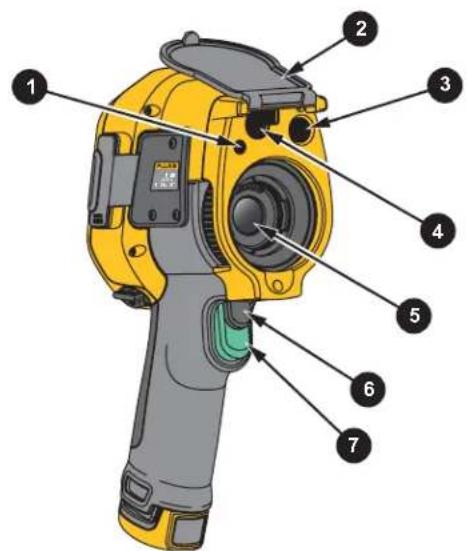
| Item Description Item Description | |||
| 1 | LED Torch/Flashlight | 5 | Infrared Camera Lens |
| 2 | Retractable Lens Cover | 6 | Secondary Trigger |
| 3 | Visual Light Camera Lens | 7 | Primary Trigger |
| 4 | Laser Pointer/Distance Finder | ||
Table 5 shows the back of the Product.
Table 5. Back
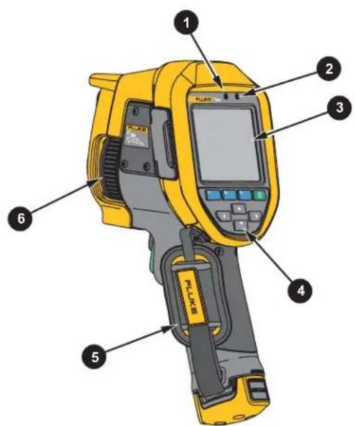
| Item Description Item Description | |||
| 1 | Microphone | 4 | Control Panel |
| 2 | Speaker | 5 | Hand Strap |
| 3 | LCD Touch Screen (display) | 6 | Manual Focus |
Touch Screen
The touch screen is a shortcut to the most used settings. To change parameters or select functions and options, touch a target on the display.
The touch screen has a backlight for work in dimly lit spaces. When not in a menu, double tap on the display to capture an image.
Control Panel
The control panel is used to change parameters or select functions and options. Table 6 lists the functions of the buttons on the Control Panel.
Table 6. Control Panel
| Button Description | |
| 1 | Push to turn On/Off. |
| F1 | Within a submenu, push to save the change and go back to the live view. |
| F2 | Push to open the primary menu.Within a submenu, push to save the change and go back to the previous menu. |
| F3 | Within a submenu, push to cancel the change and go back to the live view. |
| Push to move the cursor and select an option.In live Manual Mode, push to adjust Level and Span. | |
Primary and Secondary Triggers
The two-part trigger is located in the standard trigger position for a pistol-grip device. The larger, green trigger is the primary trigger. The smaller, black trigger is the secondary trigger.
In normal operation (video is off), use the primary trigger to capture an image to save or edit. When video is on, use the primary trigger to start/stop recording a video.
The secondary trigger operates the LaserSharp Auto Focus System (see LaserSharp Auto Focus System) and the Laser Pointer/Distance Finder (see Distance).
Basic Operation
Turn On and Off the Imager
Before you use the Imager for the first time, charge the battery for a minimum of two and one-half hours. See Charge Batteries.
To turn on or turn off the Imager, push and hold Ⓐ for 2 seconds.
To maximize the life of the battery, use the Power Save and Auto Off features. See Table 13 for more information about how to set these features.
Note
All thermal imagers need sufficient warm-up time for accurate temperature measurements and best image quality. Warm-up time can vary by model and environmental conditions. Although most imagers are fully warmed up in 3 minutes to 5 minutes, wait a minimum of 10 minutes if the most accurate temperature measurement is important to your application. When you move an Imager between environments with large differences in ambient temperature, allow for additional adjustment time.
Focus
Correct focus makes sure that the infrared energy is correctly directed onto the pixels of the detector. Without correct focus, the thermal image can be blurry and the radiometric data may be inaccurate. Out-of-focus infrared images are frequently unusable or of little value.
To focus with the advanced manual focus system, rotate the Manual Focus Control until the inspection object is in proper focus. Use the advanced manual focus system as an override to the LaserSharp Auto Focus System. See LaserSharp Auto Focus System.
Capture Image
To capture an image:
-
Focus on a target.
-
Pull and release the Primary Trigger or double tap on the display to capture and freeze the image.
The image is in the memory buffer for you to save or edit the image. To edit an image, see Edit Image.
Depending on the selected file format settings, the Imager shows the captured image and a menu bar. The menu bar shows the available options.
Note
MultiSharp Focus captures and freezes images differently. See MultiSharp Focus.
Save Image
To save an image as a data file:
- Capture an image.
The image is in the memory buffer for you to save or edit the image.
- Push F1 to save the image as a file and go back to the live view.
Menus
Use the menus to change and view settings.
To change settings:
-
Push ▼/▲ to select an option.
-
Push F1 to set the option.
The primary, secondary, and option menus close 10 seconds after the last push of a function button. The option selection menu stays open until you make the selection, go up a menu level, or cancel the action.
When the Imager is in Gas Detection mode, some functions will be disabled. They will not be selectable.
Table 7 lists the secondary menus available in the Primary Menu.
Table 7. Primary Menu
| Secondary Menu Description | |
| Measurement | Set the calculation and display of radiometric temperature measurement data related to the thermal images. |
| Image | Set features used to show infrared images on the display and in some saved image and video files. |
| Camera Set options for secondary camera features. | |
| Memory Select to review and delete captured images and videos. | |
| Fluke Connect | Select to pair the Imager to the Fluke Connect app on a mobile device or to other Fluke Connect tools.NoteThe Fluke Connect system is not available in all countries. |
| Settings Set user preferences and to view information about the Imager. | |
| SF6 Gas Detection Mode | Set options for gas-detection features. |
Measurement Menu
Table 8 lists the options in the Measurement menu.
Table 8. Measurement Menu
| Option Menu Option Description | ||
| Range | Select the temperature range from one of the preset measurement ranges or to a fully automatic range. | |
| Set Level/Span | Auto | Sets the Level/Span to adjust automatically or manually. |
| Manual | ||
| Set Level/Span | With Level/Span set toManual, changes the Level/Span.SeeLevel/Span. | |
| Line Temp | Turns on/off the Line Temp. | |
| Emissivity | Adjust Number | Sets a custom emissivity value when a value from the standard emissivity table is not appropriate for the measurement. See Emissivity Adjustment. |
| Select Table | Select an emissivity value from a list of common materials.See Emissivity Adjustment. | |
| Background | Changes the background temperature to compensate for reflected background temperature.Very hot objects or very cold objects can affect the apparent temperature and measurement accuracy of the target, especially when surface emissivity is low. Adjust the reflected background temperature to improve the accuracy of the measurement.NoteIf Display is set to Display All, the background temperature shows as BG = xx.x on the display. | |
| Transmission | Changes the transmission percentage of the infrared-transparent window (IR window).When you do infrared inspections through IR windows, not all of the infrared energy emitted from the target is transmitted through the optical material in the window. If you know the transmission percentage of the window, adjust the transmission percentage in the Imager or in SmartView software to improve the accuracy of the measurement.NoteIf Display is set to Display All, the transmission correction shows as t = xxx% on the display. | |
| Spot Temp | Hot | Select to view and turn on/off either the hot or cold spot indicator on the display.The Spot Temperatures are floating HI and LO temperature indicators that move on the display as the temperature measurements of the image fluctuate. |
| Cold | ||
| Spot Markers | All Off Turns off fixed-temperature spot markers. | |
| Select the number of fixed-temperature spot markers to use to highlight a region before you take an image. See Spot Markers. | ||
| Spot Box | On | Turns on/off a temperature measurement zone (box) that centers on a target. |
| Off | ||
| Set Size | With Spot Box set to On, changes the size of the Spot Box. See Spot Box. | |
| Set Position | With Spot Box set to On, changes the position of the Spot Box. See Spot Box. | |
Level/Span
Level and Span are values within the total range of temperature set in Range. Level is the temperature level to view within the total range of temperatures. Span is the span of temperatures to view within the total range of temperatures. See Table 9.
Table 9. Level and Span Settings
| Item Description | |
| ① | Level |
| ② | Span |
| ③ | Total Imager range |
In automatic Level/Span mode, the Imager sets Level/Span based on the temperatures set in Range. When the Range of the Imager is set to one of the preset measurement ranges and Level/Span is set to Manual, the level setting moves the thermal span up or down within the total temperature range.
To change the Level/Span:
-
Select Measurement > Level/Span > Manual.
-
Select Set Level/Span.
-
Push:
• to decrease the temperature span.
• ▶ to increase the temperature span.
• ▲ to move the span to a higher temperature level.
• ▼ to move the span to a lower temperature level.
The scale along the right side of the display shows the thermal span increasing or decreasing in size and shows the span as it moves to different levels within the total range. See Table 9.
See Detailed Specifications for more information about the minimum span.
Note
The Imager always powers up in the same Level/Span mode, Auto or Manual, as when the Imager was powered down.
Emissivity Adjustment
All objects radiate infrared energy. The actual surface temperature and emissivity of the target affects the quantity of energy radiated. The Imager senses the infrared energy from the surface of the target and uses the data to calculate an estimated temperature value. Many common materials such as wood, water, skin, cloth, and painted surfaces, including metal, radiate energy well and have a high emissivity factor of ≥90% (or 0.90). The Imager measures temperatures accurately on targets with a high emissivity.
Shiny surfaces or unpainted metals do not radiate energy well and have a low emissivity factor of <0.60. For the Imager to calculate a more accurate estimate of the actual temperature of targets with a low emissivity, adjust the emissivity setting.
⚠ Warning
To prevent personal injury, see emissivity information for actual temperatures. Reflective objects result in lower than actual temperature measurements. These objects pose a burn hazard.
Set emissivity as a direct value or from a list of emissivity values for some common materials. If the emissivity value is <0.60, a caution shows on the display.
Note
Surfaces with an emissivity of <0.60 make it difficult to determine reliable and consistent actual temperatures. The lower the emissivity is the greater the potential of error is when the Imager calculates the temperature measurement because more of the energy reaching the camera is specified as background temperature. This is also true even when adjustments to the emissivity and reflected background adjustments are performed properly.
Spot Markers
Use fixed-temperature spot markers to highlight a region on the display before you save an image.
To set a marker:
- Select Measurement > Markers.
- Select an option.
- Push F1 to set the marker option and go to the Move Marker display.
The Move Marker icon shows on the display and the labels on the function buttons change to Done, Next, and Cancel.
To change the marker position on the display:
- Push ▲ / ▼ / ◀ / ▶ to move the marker location on the image.
- Push F2 to select the next marker.
- Repeat for the rest of the markers.
- Push F1 when done.
Spot Box
Use the Spot Box feature to adjust a temperature measurement zone (box) to center on the target. This zone expands and contracts to different levels within the infrared image. The zone shows an approximate maximum (MAX), average (AVG), and minimum (MIN) temperature measurement in that area.
Note
When using the Spot Box, the level and span of the Imager adjusts to the thermal scene within the Spot Box.
To set the size of the Spot Box when Spot Box is set to On:
- Select Measurement > Spot Box > Set Size.
- Push:
• ▲ to decrease the vertical size of the Spot Box.
• ▼ to increase the vertical size of the Spot Box.
• to decrease the horizontal size of the Spot Box.
• to increase the horizontal size of the Spot Box.
- When you are satisfied with the size of the Spot Box, push F1 to set the change and exit the menus or push F2 to set the change and go back to the previous menu.
To set the position of the Spot Box when Spot Box is set to On:
- Select Measurement > Spot Box > Set Position.
- Push ▲ / ▼ / ◀ / ▶ to move the Spot Box location on the image.
- When satisfied with the position of the Spot Box, push F1 to set the change and exit the menus or push F2 to set the change and go back to the previous menu.
Image Menu
Table 10 lists the options in the Image menu.
Table 10. Image Menu
| Option Menu Option Description | ||
| Palette | Standard | Select Standard or Ultra-Contrast palette.The Standard Palettes offer an equal, linear presentation of colors that allow for best presentation of detail.The Ultra Contrast Palettes offer a weighted presentation of colors. Ultra Contrast palettes work best in situations with high thermal contrast for extra color contrast between the high temperatures and low temperatures.SeeDetailed Specifications. |
| Ultra Contrast^TM | ||
| Set Palette Changes the palette color. | ||
| Saturation Colors | Turns on/off Saturation Colors.If Saturation Colors is on, you can set the saturation colors to use. | |
| IR-Fusion | Select to set the IR-Fusion mode. SeeDetailed Specificationsfor modes available based on the model of the Imager.The Imager automatically captures a visible image with every infrared image to show where a potential problem might be.NoteThe visible image and infrared image can be customized or separated in SmartView and Fluke Connect Software when you use the .is2 or .is3 file format. See File Format. | |
| Color Alarm | High Alarm OFF | Turns on/off the high-temperature color alarm. The high-temperature color alarm shows a full visible image and only shows infrared information on objects or areas that are above the set apparent temperature level. |
| Low Alarm OFF | Turns on/off the low-temperature (or dew point) color alarm. The low-temperature color alarm shows a full visible image and only shows infrared information on objects or areas that are below the set apparent temperature level. | |
| Set High Alarm | Sets the high apparent temperature level. Requires the High Alarm to be on. | |
| Set Low Alarm | Sets the low apparent temperature level. Requires the Low Alarm to be on.NoteThe Imager does not sense ambient or surface dew point level automatically. To use the low-temperature color alarm function as a dew point color alarm, determine and input the surface dew point temperature. The colors presented can help identify areas of concern with possible dew point condensation. | |
| Outside | Shows color isotherms, or infrared information, outside of a set of both high and low limits. Requires High Alarm and Low Alarm to be on and temperature levels for both alarms to be set. | |
| Inside | Shows color isotherms, or infrared information, inside of a set of both high and low limits. Requires High Alarm and Low Alarm to be on and temperature levels for both alarms to be set. | |
| Display | Sets which graphics to view on the display.NoteFeatures that have On/Off controls must be turned on and turned off with those controls. | |
| Image Enhancement | Sets the advanced image enhancement features of the Imager. See Image Enhancement. | |
| Logo | On | Turns on/off the Fluke logo on the display. |
| Off | ||
| Custom | With SmartView software, upload a custom logo to the Imager from your PC through the USB connection. | |
| Distance | On | Turns on/off the distance units on the display. See Distance. |
| Off | ||
| Sets units to feet or meters. See Distance. | ||
| Zoom Sets digital zoom level. | ||
Image Enhancement
Use the Image Enhancement menu to activate the advanced features of the Imager. Activate either MultiSharp Focus or SuperResolution individually. Use Filter Mode with either MultiSharp Focus or SuperResolution. Table 11 lists the options in the Image Enhancement menu.
Table 11. Image Enhancement Menu
| Option Description | |
| Filter Mode | Combine values from successive frames within a small range of temperatures to reduce pixel noise or thermal sensitivity (NETD) to as low as 30 mK. |
| Off | Turn off MultiSharp Focus mode or SuperResolution mode and not affect Filter mode. |
| MultiSharp Focus | MultiSharp Focus captures several images focused on multiple targets that are positioned at different distances from the Imager and creates one image that focuses on the multiple targets at the same time.In MultiSharp Focus mode, you can process the image in the camera or in SmartView software.In MultiSharp Focus (In PC only) mode, the image is not processed on the Imager so you cannot view the image on the Imager. Use SmartView software to view the image on your PC. Set the file format to .is2 for MultiSharp Focus (In PC only) mode to work. |
| MultiSharp Focus (In PC Only) | |
| Option Description | |
| SuperResolution | SuperResolution uses a sensor to capture micro movements to create an image with double the resolution. SeeDetailed Specificationsthe resolution available based on the model of the Imager.In SuperResolution mode, the Imager captures the data and processes the image. |
| SuperResolution (In PC Only) | In SuperResolution (in PC only) mode, the image is not processed on the Imager so you cannot view the image on the Imager. Use SmartView software to view the image on your PC. |
MultiSharp Focus
MultiSharp Focus captures several images focused on multiple targets that are positioned at different distances from the Imager and creates one image that focuses on the multiple targets at the same time.
Note
The minimum focus distance with MultiSharp Focus and a standard lens is 15 cm (6 inches). For optimum performance, position the camera ≥ 23 cm (9 inches) from the closest target. MultiSharp Focus also works with all compatible lenses.
To use:
- Point the Imager at the target.
- Capture an image. Hold the Imager still while it captures the images.
Saving... shows on the display for \~2 seconds for a 60 Hz model or 5 seconds for a 9 Hz model.
- When Saving... no longer shows on the display, you can move the Imager. If necessary, use a tripod to stabilize the Imager while the images save.
- In MultiSharp Focus mode, the Imager collects the images in the Imager and shows the focused image on the display in \~8 seconds for a 60 Hz model or \~15 seconds for a 9 Hz model.
Confirm the image on the display is what you need. If possible, process the images on the Imager.
- In MultiSharp Focus (In PC only) mode, the Imager collects the images in a single file and shows the image on the display as it appears before you capture the image (\~2 seconds for a 60 Hz model or \~5 seconds for a 9 Hz model).
In MultiSharp Focus (In PC only) Mode, you cannot view the focused image on the Imager. If possible, download, process, and view the image(s) on your computer while you are at the job site. To view the focused image, open the image with SmartView software.
Note
Some targets have abnormal thermal characteristics that can cause the MultiSharp Focus algorithm to fail. If MultiSharp Focus mode does not capture a clear image, use LaserSharp Auto Focus or Advanced manual focus.
SuperResolution
SuperResolution uses a sensor to capture micro movements to create an image with double the resolution. See Detailed Specifications for the resolution available based on the model of the Imager.
To use:
- Capture an image.
-
Hold the Imager still for \~1 second.
-
In SuperResolution mode, the Imager captures the data and processes the image. The image shows on the display of the Imager in \~18 seconds.
- In SuperResolution (in PC only) mode, the image is not processed on the Imager so you cannot view the image on the Imager. Use SmartView software to view the image on your PC.
Distance
Use the Laser Pointer/Distance Finder to measure the distance, up to 30 meters, from the Imager to a target. You can choose to show the distance on the display in feet or meters. The distance is saved as part of the image.
Warning
To prevent eye damage and personal injury:
- Do not look into the laser. Do not point the laser directly at persons or animals or indirectly off reflective surfaces.
- Do not open the Product. The laser beam is dangerous to eyes. Have the Product repaired only through an approved technical site.
To use the distance measurement feature:
- Turn on the distance feature and select the units to show on the display.
- Point the Imager at the target.
- Pull and hold the Secondary Trigger.
⚠️ shows at the top of the display.
- Position the red laser dot on the target.
- Release the Secondary Trigger.
The distance measurement shows on the bottom of the display. The measurement shows as “- - - -” when the Imager cannot take a measurement. If this is the case, use a tripod or steady the Imager and retake the measurement. If there is excessive laser movement, an error message shows on the display due to an out of range distance.
Camera Menu
Table 12 lists the options in the Camera menu.
Table 12. Camera Menu
| Option Menu Option Description | ||
| LaserSharp Autofocus | On | Turns on LaserSharp Autofocus to automatically focus on a target. See LaserSharp Auto Focus System. |
| Off | Turns off LaserSharp Autofocus to use the Advanced manual focus. See LaserSharp Auto Focus System. | |
| BacklightSelect to set the brightness level of the display. | ||
| Torch -- Turns on/off the built in flashlight. | ||
| Video | Video/Audio | Select to record video and audio when Record Video is selected. |
| Video ONLY | Select to record video only when Record Video is selected. | |
| Record Video | Select to start recording a video. See Video. | |
| Auto Capture | Start Capture | Select to capture and save an infrared image, or series of images based on Auto Capture settings. |
| Interval | Sets the number of hours, minutes, or seconds between image captures.NoteThe minimum interval available can be affected by the file type and visible light camera settings. Some combinations create larger file sizes that take longer to capture and save and create a higher minimum interval compared to others. | |
| Image Count | Sets a number of images to capture. Or, select Maximum Memory to capture and save images until the chosen storage memory is full or the battery runs out of power. | |
| Manual Trigger | Select to immediately capture images when Start Capture is selected. | |
| Temp Trigger | Select to capture images when a value is above or below a set temperature limit when Start Capture is selected. | |
| Set Temp Trigger | With Temp Trigger selected, set the temperature and conditions to trigger the auto capture of images. | |
| Option Menu Option Description | ||
| Wireless | Bluetooth | Uses Bluetooth technology to connect the Imager to a device such as a wireless headset. See Wireless Connectivity. |
| WiFi Hotspot | Uses the Imager to create a wireless Hotspot when no WiFi network exists. See Wireless Connectivity. | |
| WiFi Network | Connects the Imager to a WiFi network so you can sign into your Fluke Connect account on the Imager. See Wireless Connectivity. | |
LaserSharp Auto Focus System
The Laser Pointer/Distance Finder on the Imager is both a sighting aid and a part of the LaserSharp Auto Focus System.
Warning
To prevent eye damage and personal injury, do not look into the laser. Do not point laser directly at persons or animals or indirectly off reflective surfaces.
To use the LaserSharp Auto Focus System:
- Select Camera > LaserSharp Auto Focus > On.
- Point the Imager at the target.
- Pull and hold the Secondary Trigger.
⚠️ shows at the top of the display.
- Position the red laser dot on the target.
- Release the Secondary Trigger.
The auto focus system automatically focuses on the object.
Note
The laser pointer is aligned parallel to the infrared lens. In AutoBlend Mode, the laser pointer dot is positioned just above the center point marker on the display. It can be easier to use your eyes to locate the visible laser pointer on the target not on the display.
Video
The video controls include stop, rewind, fast forward, and pause/play functions. The thermal scene and complexity of the recorded data affects the amount of time available to record a video. The video capture format is set in the Settings menu. For more information, see File Format.
Record Video
To record:
- Select Camera > Video.
-
Select Video/Audio or Video ONLY.
-
Touch Record Video to set up the Imager to record a video.
■ shows in the upper left corner of the display.
- Pull and release the Primary Trigger to start recording.
●REC shows in the upper left corner of the display. The elapsed time shows at the bottom of the display.
-
Pull and release the Primary Trigger to stop recording.
-
Push F2 to end the recording session.
-
Push F1 to save the video file.
View Video
To play a video:
- Open the Memory menu.
-
Select a file to play. All video files show 📄 in the upper right corner of the thumbnail.
-
Push F1 to set a file.
-
Push F1 to start the video. While the video plays, push ◀ or ▶ to fast forward or rewind. Push F1 to return to normal speed.
-
Push F3 to exit the video mode.
Wireless Connectivity
The Imager has several wireless connectivity options.
Note
Before the first use of the wireless feature, enable the radio. See Enable the Radio.
Bluetooth
Use Bluetooth to connect the Imager to a device such as a wireless headset. When Bluetooth is on, ✝ shows in the upper left corner of the display.
To use Bluetooth:
- Select Camera > Wireless > Bluetooth > On.
- Push Select to scan for available Bluetooth devices within the range of the camera.
- Select a device.
- Push F1 to connect to or disconnect from the device.
- If you are prompted, enter a password.
WiFi Hotspot
Use the Imager to create a wireless Hotspot when no WiFi network exists. You can use the Hotspot to download saved pictures or stream live images from the Imager to a PC with SmartView software or to a mobile device with the Fluke Connect app. See Stream Live to a PC and Fluke Connect Wireless System for more information. When WiFi Hotspot is on, WiFi shows in the upper left corner of the display.
Note
WiFi is for indoor use only in Kuwait, Chile, and United Arab Emirates.
To create a Hotspot, select Camera > Wireless > WiFi Hotspot > On.
To change the settings:
- Select Camera > Wireless > WiFi Hotspot > Off.
- Select Settings.
- Select an option:
• Name (SSID) to change the SSID
- Password to turn the password on/off or to change the password
• Channel to change the channel
- Push F1 to open a keyboard on the display.
- Use the keyboard to enter the information for the option.
- Push F2 to go back.
- Push F3 to use the Imager.
WiFi Network
Use the WiFi Network setting to connect the Imager to a WiFi network and to sign into your Fluke Connect account on the Imager. When WiFi Network is on, WiFi shows in the upper left corner of the display.
To turn on the WiFi Network feature:
- Select Camera > Wireless > WiFi Network > On.
- Push Select to scan for available networks within range of the Imager.
- Select a network.
- Push F1 to connect to or disconnect from a network.
- If you are prompted, enter a password.
Sign In
When the Imager is connected to a WiFi network, you can sign into your Fluke Connect account on the Imager and use Fluke Connect Instant Upload. When you use Fluke Connect Instant Upload, the images you take with the Imager automatically upload to your Fluke Connect account in the Fluke Cloud. You can view the images saved in the Fluke Cloud on the Fluke Connect app or the Fluke Connect website without the mobile device and Imager connected to each other.
Note
The Instant Upload feature may not work on all networks or with all devices due to the security profiles on different networks.
To sign in to your Fluke Connect account:
- Select Camera > Wireless > Sign In to open a keyboard on the display.
- Use the keyboard to enter your user name.
- Push F1.
- Use the keyboard to enter your password.
- Push F1.
shows on the display.
To sign out:
- Select Camera > Wireless > Sign Out.
- Push F1.
Fluke Connect Wireless System
The Imager supports the Fluke Connect Wireless System. The Fluke Connect system wirelessly connects your Fluke test tools with an app on a mobile device. It shows images from the Imager on your mobile device.
Note
The Fluke Connect system is not available in all countries.
Fluke Connect App
The Fluke Connect app works with Apple and Android products. The app is available for download from the Apple App Store and Google Play.
To use the Fluke Connect app with the Imager:
- On the Imager, select Fluke Connect > Pair to Fluke Connect Mobile App > On.
- On the mobile device:
a. Go to Settings > Wi-Fi.
b. Select the Wi-Fi network that begins with Fluke...
- On the Fluke Connect app, select Thermal Imager from the list.
You can now take images on the Imager, and they will stream live from the Imager to your mobile device. Live streaming may not be available on all devices. The pictures you take with the Imager are saved on your mobile device and on the Imager.
Note
To save images to the Fluke Connect app, set the file format to .is2 (see File Format) and the image storage to internal memory (see Table 13). Images stored on the SD card or USB storage device may not transfer to the Fluke Connect app.
- On the Imager, capture an image.
The image is now in the buffer.
- Push F1 to save the image and view the image on the phone app.
Go to www.flukeconnect.com for more information about how to use the app.
Fluke Connect Tools
Use the Imager to wirelessly connect to Fluke-Connect-supported tools to:
• View the live measurement of each tool.
- Capture the measurement of each tool in .is2 and .is3 images.
To discover a Fluke Connect-supported tool:
- Turn on each wireless tool and make sure the wireless feature is enabled. See the documentation of each tool for more information about how to use the tool.
- Turn on the Imager.
- Select Menu > Fluke Connect > Pair to Fluke Connect Tools.
- Push F1 to set selection.
The Fluke Connect button on the wireless tool starts to flash. The Imager starts to scan and presents a list with the ID and name of available tools found within 20 m without obstructions (open air) or within 6.5 m with obstructions (sheetrock wall). You can expect a short delay before the scan is complete.
- Select the tool name.
- Push F1 or touch Select to select the tool.
- Repeat to select each tool.
- Select Done.
The labels change to include an Edit function. By default, the Imager shows and saves the data for the selected tools.
To edit the selection:
-
On the Imager, select the tool name.
-
Push F1 or touch the Edit target. The Edit menu shows the option to show the measurement data and save it with the image to the memory location selected in the Settings menu.
The display on the Imager updates to show the wireless icon and the live measurement for each selected wireless tool.
Memory Menu
Use the Memory menu to review or delete captured images and videos. When additional information has been saved with the file, an icon shows with the preview file. The icons are:

IR-PhotoNotes photos

Audio

Video

Text
Review Image
To review an image:
- Open the Memory menu.
- Select the preview image of the file for review.
- Push F2 to review the file.
Edit Image
Before you save a file, you can use the Imager to edit or modify the image. Once the file is saved, you cannot edit the image.
IR-PhotoNotes System
Use the IR-PhotoNotes photo annotation system to capture visible images of various objects, text, or other information that is related to the analysis and reporting of an infrared image. A visible image is a clear digital photo and does not use infrared technology. Examples of possible annotations include motor name plates, printed information or warning signs, larger views of the environment or room, and related equipment or objects. IR-PhotoNotes images are only available in the .is2 file format and are stored in the file so you do not need to collate multiple files at a later time.
To add photos using the IR-PhotoNotes annotation system:
- With an infrared image in the buffer, push F2 to open the Edit Image menu.
- Select IR-PhotoNotes.
- Push F1 to enter the Picture mode.
-
Capture an image.
-
Capture additional images as required. See Detailed Specifications for the maximum number of images that can be stored with IR-PhotoNotes.
- Push F1 to save the pictures with the image.
To view an IR-PhotoNote annotation in memory:
- Open the Memory menu.
- Select a file to view. All files with IR-PhotoNotes annotations show ☐ with the preview file.
- Push F1 to view the photo annotations.
Audio
Audio (voice) annotation is only available in the .is2 file format. The audio is stored with the image so you do not need to collate multiple files later.
To add, playback, or edit an audio file:
- With an image in the buffer, push F2 to open the Edit Image menu.
- Select Add Audio.
- Do the corresponding procedure below for the desired action.
| Action Procedure | |
| Add audio file | 1. Push F1 to record up to 60 seconds of audio.2. The display updates to show the recorded time.3. Push F1 to pause the recorder.4. Push F2 to stop the recorder.5. Push F1 to review the audio file, or push F2 to save the audio with the image.The audio file replays through the speaker. |
| Playback audio file | 1. Open the Memory menu.2. Select a file to view. All files with audio annotations show 📋 with the preview file.3. Push F1 to listen to the file.4. Push F1 again to pause the file.5. Push F2 twice to exit. |
| Edit audio file | 1. Before you save the file, push F1 to review the audio file.2. F1 again to pause the file.3. Push F1 to append audio to the end of the file, or push F3 to replace the audio file.4. Do the steps to add an audio file. |
Text Notes
Text annotation is only available in the .is2 file format. Text notes are stored with the image so you do not need to collate multiple files later.
To add a text annotation:
- With an image in the buffer, push F2 to open the Edit Image menu.
- Select Add Text.
- Push F1 to open a keyboard on the display.
- Use the keyboard to input a message.
- Push F1 to save the message.
- Push F2 when done.
- Push F1 to save the message with the image.
To view a text annotation in memory:
- Open the Memory menu.
- Select a file to view. All files with text annotations show 📄 with the preview file.
- Push F1 to open the Notes menu.
- Push F1 to view the text annotation.
Delete Image
To delete images, do the corresponding procedure below for the desired action.
| Action Procedure | |
| Delete one file | 1. Open the Memory menu.2. Select a preview image.3. Push F2 to open the Delete menu.4. Select Selected Image and push F1.The Imager prompts you to continue or cancel.5. Push F1 again to delete the file. |
| Delete all files | 1. Open the Memory menu.2. Push F2 to open the Delete menu.3. Select All Images and push F1.The Imager prompts you to continue or cancel.4. Push F1 to delete all the files from the memory. |
Settings Menu
Table 13 lists the options in the Settings menu.
Table 13. Settings Menu
| Option Menu Option Description | ||
| File Format | Image Format | Sets the file type to save images and videos to and to set the megapixels to use for the visual light camera. See File Format. |
| Video Format | ||
| Units | Sets the temperature units to Celsius or Fahrenheit. | |
| Auto Off | LCD Time Out Sets the time before the display automatically turns off. | |
| Power Off | Sets the time before the Imager automatically turns off. Note Auto Off is automatically disabled when the battery is connected to ac power. | |
| Date | Sets the date format and the date. See Date. | |
| Time | Sets the time format and the time. See Time. | |
| LanguageSets the language to use on the display. | ||
| Localization | Sets the decimal separator to comma or decimal point. | |
| Image Storage | Sets the location to save images: internal memory, micro SD memory card, or USB storage device. | |
| Advanced | Filename Prefix | Changes the default filename that starts with IR_to a different 3-character prefix with the touch screen keyboard. |
| Reset Filename | Resets the file number to 00001. | |
| Factory Defaults | Erases all user-set preferences and restore the factory default settings. | |
| Imager Info | View information about the version, certificates, and Open Source Software Licenses of the Imager | |
| Adjust Parallax | Fine-tunes the parallax adjustment to precisely align the image. | |
File Format
Select from a list of image and video file formats based on how the end file will be used. Table 14 lists the image file formats. Table 15 lists the video file formats.
Table 14. Image File Formats
| File Format Description | |
| IS2 | Saves images as a .is2 file.Choose the .is2 file format when image modification and maximum resolution is needed.The .is2 file format consolidates the infrared image, radiometric temperature data, visible image, voice annotation, and photos from the IR-PhotoNotes photo annotation system into a single file. To customize or separate the visible and infrared images, use SmartView software or the Fluke Connect app. |
| JPEG | Saves images as a .jpg file.Choose the .jpg file format for images with the smallest file size, where modification is not needed, and image quality and resolution are not as important. |
| BMP | Saves images as a .bmp file.Choose the .bmp file format when a smaller file size with maximum resolution is needed and image modification is not. |
| VLCM Resolution | Sets the megapixels (MP) on the visual light camera.NoteTo use Image Enhancement features, set the VLCM Resolution to 0.3 MP. |
Table 15. Video File Formats
| File Format Description | |
| IS3 | Saves videos as an .is3 file with radiometric video capture.Choose the .is3 video format when video modification and maximum resolution is needed.To edit the .is3 video file, use SmartView software or the Fluke Connect app. |
| AVI | Saves videos as an .avi file with .mpeg encoding.Choose the .avi video format when video modification is not required. The file retains the video settings at the time the video was captured and saved. |
Date
The date shows as: MM/DD/YY or DD/MM/YY.
To set the date:
- Select Settings > Date.
- Select MM/DD/YY or DD/MM/YY.
- Push F1 to set the new format.
- Select Set Date.
- Push F1 to open the Set Date menu.
- Push ◀/▶ to select Day, Month, or Year.
- Push ▲▼ to change the day, month, or year.
- Push F1 to set the date and exit the menu.
Time
Time shows as: 24 hour or 12 hour.
To set the time format:
- Select Settings > Time.
- Select 24 hour or 12 hour.
- Push F1 to set the time format.
- Select Set Time.
- Push F1 to open the Set Time menu.
- Push ◀/▶ to select Hours or Minutes.
- If you selected the 12 hour format, select AM or PM.
SF6 Gas Detection Mode Menu
Note
The Imager can operate in radiometric mode or in gas detection mode. The Imager cannot operate in both modes at the same time. When SF6 Gas Detection Mode is enabled, the radiometric features of the Imager are disabled and cannot be selected in the menus.
Table 16 lists the options in the SF6 Gas Detection Mode menu.
Table 16. SF6 Gas Detection Mode Menu
| Option Description | |
| SF6 Gas Detection Mode: ON | Turns on the gas detection mode. See Gas Detection Conditions. |
| SF6 Gas Detection Mode: OFF | Turns off the gas detection mode. |
| Image Capture | Sets up the Imager to capture an image in gas mode when SF6 Gas Detection Mode: ON is enabled. |
| Video Capture | Sets up the Imager to capture a video in gas mode when SF6 Gas Detection Mode: ON is enabled. |
| High Gain (Tripod) | Optimizes the sensitivity of the display when the Imager is mounted on a tripod when SF6 Gas Detection Mode: ON is enabled. See Gas Detection Conditions. |
| Low Gain (Handheld) | Optimizes the sensitivity of the display when the Imager is held in a hand when SF6 Gas Detection Mode: ON is enabled. See Gas Detection Conditions. |
Gas Detection Conditions
The Imager detects gas leaks based on:
- The temperature difference between the gas and the background environment
- The wind speed
• The amount of clutter in the background scene (for example, clouds)
• The stability of the Imager
• The proximity of the Imager to the leak
Note
The lower the volume of the gas leak the more challenging it is for the Imager to detect the leak.
To improve the gas detection rate, place the Imager where:
• The temperature difference between the gas and the background environment is the greatest.
- There is a light wind.
• There is limited clutter in the background scene. A clear blue sky is optimal.
• The Imager is stable. When possible, use a tripod and High Gain (Tripod) mode.
- The Imager is close to the leak. If close proximity is not possible, use the 2X lens.
Table 17 lists the guidelines for the Imager to detect a gas leak based on the annual gas loss rate.
Table 17. Detection Guidelines
| Annual Gas Loss Rate | Guidelines |
| <10 lbs (<4.5 kg) | The greatest possible difference between the gas and the background environment temperaturesWind speed: <1.12 mps (<2.5 mph)Uniform background scene (clear blue sky)Imager on a tripod, close to the gas leak. |
| 10 lbs to 50 lbs(4.5 kg to 22,7 kg) | ≥10 °C difference between the gas and the background environment temperaturesWind speed: <2.24 mps (<5 mph)Variable background scene (clear blue sky, high altitude clouds okay)Imager on a tripod. |
| >50 lbs (>22,7 kg) | ≥3 °C difference between the gas and the background environment temperaturesWind speed: <4.47 mps (<10 mph)Variable background scene (high altitude clouds okay)Imager on a tripod or handheld. |
SmartView Software
SmartView software for a PC is available to use with the Imager and contains features to analyze images, organize data and information, and make professional reports.
Use SmartView software to:
- Review IR-PhotoNotes, audio, and text annotations.
- Export IR and visible images.
- Edit .is2 image files and .is3 video files.
- Enable Bluetooth, WiFi, and Fluke Connect functions.
- Update the firmware for new Imager feature
Download SmartView Software
Go to www.fluke.com/smartviewdownload.
- On the website, follow the instructions to download the software to the PC.
- On the PC, follow the instructions to install SmartView software. (Administrator privileges are required for the installation.)
- Restart the PC when installation is complete.
Download Firmware
- On the PC, open SmartView software.
- Connect the USB A connector end of the cable into your PC and the USB Micro B connector end into the Imager.
Note
Some Imagers have both A and Micro B connector jacks. Make sure to use the Micro B jack on the Imager.
Windows automatically installs the device driver for use with the Imager. SmartView software recognizes the connection with the Imager and appears on the SmartView software toolbar menu.
- On the PC, select Yes if prompted to download a firmware update file onto the PC.
- On the Imager, once the firmware is downloaded, select Update Firmware, to update the firmware in the Imager.
To complete the firmware update, the Imager turns off.
- To use the new firmware, turn on the Imager.
Enable the Radio
In countries with laws and regulations that permit wireless communications, wireless communication protocols are available to expand the capabilities of the Imager. All Imagers ship from the factory with the radios disabled.
To enable the radio:
- On the Imager, select Camera > Fluke Connect.
- On the PC, go to http://fluke.com/register/ti.
- On the website:
a. Select a language from the drop down box.
b. Enter your information and the serial number from the display on the Imager. The serial number is case sensitive.
c. Click on Submit.
If the radio is authorized in your country, an authorization code appears on the web page.
Note
If the radio is not yet authorized in your country, Fluke will contact you when the radio is authorized for use in your country.
- On the Imager,
a. Push F1 or tap Enter Code.
b. Type in the authorization code from the website. (The authorization code is not case sensitive.)
c. Push F1 or Done.
A message appears on the Imager display that shows the wireless communication is enabled.
If a message appears that says the authorization code is invalid:
• Make sure you entered the correct serial number from the Imager into the website.
• Make sure you entered the correct authorization code from the website into the Imager.
d. Tap Ok.
- Connect to a wireless device, if desired. See Wireless Connectivity.
Streaming Video (Remote Display)
The Imager can stream live infrared and IR-Fusion technology video to a PC that has SmartView software installed, to the Fluke Connect app (where available), or to an HDMI compatible device.
Stream Live to a PC
To stream live to a PC through a USB connection:
-
Install the latest version of the firmware on the Imager. See Download Firmware.
-
On the PC, open the SmartView software.
-
Connect the USB A connector end of the cable into your PC and the USB Micro B connector end into the Imager.
Note
Some Imagers have both A and Micro B connector jacks. Make sure to use the Micro B jack on the Imager

appears on the SmartView software toolbar menu.
- On the PC, choose Remote Display from

To stream live to a PC, wirelessly:
- On the Imager, turn on the WiFi Hotspot. See WiFi Hotspot.
- On the PC:
a. From the networks screen, select Fluke-Camera.
Note
Fluke-Camera is the default name of the Imager. If you changed the name of the Imager, select the new name of the Imager from the networks on the PC.
b. Open the SmartView software.

appears on the SmartView software toolbar menu.
c. Choose Remote Display from

Stream Live with Fluke Connect Software
To stream live with Fluke Connect software, see Fluke Connect Wireless System.
Stream Live to an HDMI Device
HDMI (High-Definition Multimedia Interface) is a compact audio/video interface that transfers uncompressed data and compressed/uncompressed digital audio data from the Imager to a compatible HDMI device.
To stream live to an HDMI device:
- Attach the included HDMI cable to the HDMI port on the Imager.
- Connect the other end to an HDMI video device.
Remote Control of Imager
Use SmartView software on a PC or the Fluke Connect app on a mobile device to remotely control the Imager.
To remotely control the Imager with a PC:
- Turn on Remote Display. See Stream Live to a PC.
- In SmartView software, select SmartView (Camera is the default selection).
When in remote control mode, use the SmartView software to control all the menus on the Imager. The menus cannot be changed directly on the Imager.
To remotely control the Imager with the Fluke Connect app:
- Set up the Fluke Connect system. See Fluke Connect Wireless System.
- On the mobile device, tap on the streaming image.
An option shows to Remote Control the Imager.
3. Select Yes.
From the mobile device, you can change the IR-Fusion setting, select Auto Focus to turn on LaserSharp Auto Focus, or tap the green Capture button to take an image. You can change the other menu items on the Imager directly even while the mobile device remotely controls the Imager.
Accessories
Table 18 is a list of the accessories available for the Imager.
Table 18. Accessories
| Model Description | PN | |
| FLK-TI-SBP3 Smart Battery Pack 3440365 | ||
| FLK-TI-SBC3B Charging | Base/Power Supply with Adapters 4354922 | |
| TI-CAR CHARGER 12 V | Vehicle Charger Adapter 3039779 | |
| FLUKE-TI-VISOR3 Sun Visor 4335377 | ||
| FLUKE-TI-TRIPOD3 Tripod Mounting Accessory 4335389 | ||
| FLK-Bluetooth | Bluetooth Headset | 4603258 |
| BOOK-ITP | Introduction to Thermography Principles | 3413459 |
| FLK-LENS/TELE2 | 2X Telephoto Infrared Lens 4335377 | |
| FLK-LENS/WIDE2 | Wide-Angle Infrared Lens | 4335361 |
| FLK-LENS/4XTELE2 | 4X Telephoto Infrared Lens 4607058 | |
| FLK-LENS/25MAC2 | 25-Micron Macro Infrared Lens | 4607064 |
Optional Lenses
Use optional telephoto and wide-angle lenses for more applications of infrared inspection work. Figure 1 shows how to install a lens.
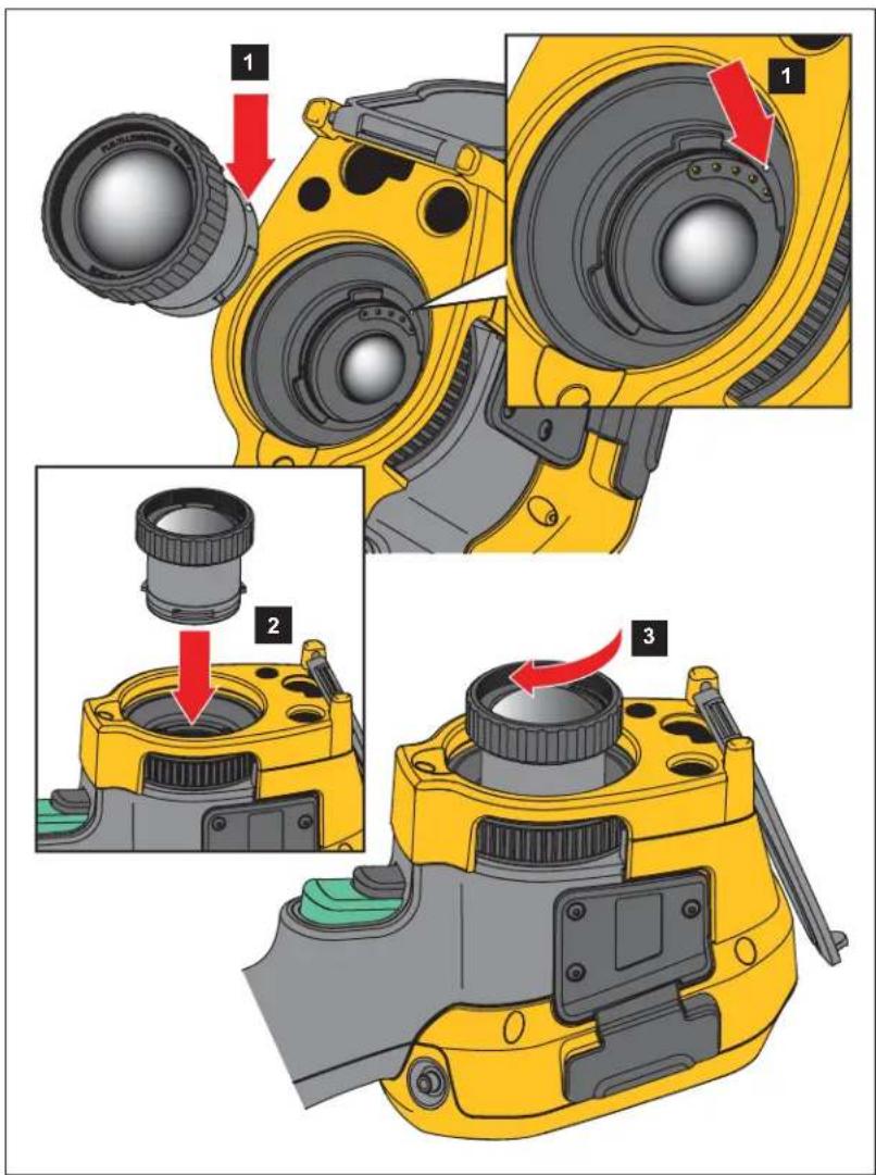
Figure 1. Optional Lens Installation
Maintenance
The Imager does not require maintenance.
Warning
To prevent eye damage and personal injury, do not open the Product. The laser beam is dangerous to eyes. Have the Product repaired only through an approved technical site.
Clean the Case
Clean the case with a damp cloth and a weak soap solution. Do not use abrasives, isopropyl alcohol, or solvents to clean the case.
Lens Care
Caution
To prevent damage to the infrared lens:
- Carefully clean the infrared lens. The lens has a delicate anti-reflective coating.
- Do not clean the lens too vigorously because this can damage the anti-reflective coating.
To clean the lens:
- Use a pressurized can of air or a dry nitrogen-ion gun, if available, to blow off the particulates from the lens surface.
- Soak a lint-free cloth in a commercial lens cleaning liquid that contains alcohol, ethyl alcohol, or isopropyl alcohol.
- Squeeze the cloth to remove excess liquid.
- Wipe the lens surface in one circular motion and discard the cloth.
- If needed, repeat with a new lint-free cloth.
Battery Care
Warning
To prevent personal injury and for safe operation of the Product:
- Do not put battery cells and battery packs near heat or fire. Do not put in sunlight.
- Do not disassemble or crush battery cells and battery packs.
- Remove batteries to prevent battery leakage and damage to the Product if it is not used for an extended period.
- Connect the battery charger to the mains power outlet before the charger.
- Use only Fluke approved power adapters to charge the battery.
- Keep cells and battery packs clean and dry. Clean dirty connectors with a dry, clean cloth.
Caution
To prevent damage, do not expose Product to heat sources or high-temperature environments such as an unattended vehicle in the sun.
To get the best performance from the lithium-ion battery:
- Do not store the Imager on the charger for more than 24 hours as reduced battery life may result.
- Charge the Imager for a two-hour minimum at six-month intervals for maximum battery life. Without use, the battery will self-discharge in approximately six months. Batteries stored for long periods will need two to ten charging cycles for full capacity.
Charge Batteries
Before you use the Imager for the first time, charge the battery for a minimum of two and one-half hours. The battery status shows on the five-segment charge indicator.
Note
New batteries are not fully charged. Two to ten charge/discharge cycles are necessary before the battery charges to its maximum capacity.
To charge the battery, use one of the options that follow.
Two-Bay Battery Charger Base
- Connect the ac power supply to the ac wall outlet and connect the dc output to the charger base.
- Put one or two smart batteries into bays of charger base.
- Charge batteries until charge LEDs on charger base are a solid green.
- Remove smart batteries and disconnect the power supply when batteries are fully charged.
AC Power Socket on Imager
- Connect the ac power adapter into an ac wall outlet and connect the dc output to the Imager's ac power socket. [1] flashes on the display while the battery charges with the ac power adapter.
- Charge until the charge indicator on the display does not flash.
- Disconnect the ac power adapter when the smart battery is fully charged.
Note
Make sure that the Imager is near room temperature before you connect it to the charger. See the charging temperature specification. Do not charge in hot or cold areas. When you charge in extreme temperatures, battery capacity may be decreased.
shows in the lower left-hand corner of the display when the Imager is connected to ac power and the battery is removed. When the power is off on the Imager and the ac power adapter is connected to the Imager, flashes in the center of the display to show that the battery charge is in process.
Keep the Imager attached to the charger until the battery condition icon shows a full charge. If you remove the Imager from the charger before a full charge shows, it can have a reduced run-time.
Note
When the battery is connected to ac power or the unit is in video mode, the Sleep Mode/Auto Off feature is disabled automatically.
Optional 12 V Vehicle Charger
- Connect the 12 V adapter into the 12 V accessory socket of the vehicle.
- Connect the output to the ac power socket of the Imager.
- Charge until the indicator shows full on the screen.
- Disconnect the 12 V adapter and Imager when battery is fully charged.
Caution
To prevent damage to the Imager, remove it from the dc car charger before you start or jump start the vehicle.
• Always operate in the specified temperature range.
- Do not store the batteries in extreme cold environments.
- Do not attempt to charge the batteries in extreme cold environments.
Caution
Do not incinerate the Product and/or battery.
Radio Frequency Data
See Table 13 for instructions on how to access digital copies of the Certificate IDs on the Imager.
To view the Radio Frequency Data Class B Instruction Sheet, visit http://us.fluke.com/usen/support/manuals and search for 4409209.
General Specifications
| Ti200 Ti300 | Ti400 Ti450 Ti450SF6 Ti480 | ||||
| Temperature | |||||
| Operating | -10 °C to +50 °C (+14 °F to +122 °F) | ||||
| Storage | -20 °C to +50 °C (-4 °F to +122 °F) without batteries | ||||
| Relative Humidity 10 % to 95 % non-condensing | |||||
| Altitude | |||||
| Operating 2000 m | |||||
| Storage 12 000 m | |||||
| Display | 8.9 cm (3.5 in) touchscreen diagonal landscape color VGA LCD with backlight | ||||
| TI200 | TI300 | TI400 | TI450 | TI450SF6 | TI480 | |
| Power | ||||||
| Batteries | 2 Lithium-ion rechargeable smart battery packs with 5-segment LED to show charge level. | |||||
| Battery Life | 3 hours to 4 hours continuous use for each battery pack (Actual life depends on settings and usage.) | 2 hours to 3 hours continuous use for each battery pack (Actual life depends on settings and usage.) | ||||
| Battery Charge Time 2.5 hours to full charge | ||||||
| Battery Charge Temperature | 0 °C to +40 °C (+32 °F to +104 °F) | |||||
| AC Battery Charge | Ti SBC3B Two Bay Battery Charger (110 V ac to 220 V ac, 50/60 Hz, included), or in-Imager charging. AC universal adapters included. Optional 12 V automotive charging adapter. | |||||
| AC Operation | AC operation with included power supply: 110 V ac to 220 V ac, 50/60 Hz ac universal adapters included | |||||
| Power Save User-selectable Sleep and Power Off modes | ||||||
| Safety IEC 61010-1: Pollution Degree 2 | ||||||
| Wireless Radio | ||||||
| Frequency 2412 MHz to 2462 MHz | ||||||
| Output Power <100 mW | ||||||
| Laser IEC 60825-1:2014, Class 2 | ||||||
| Wavelength 650 nm | ||||||
| Max Output Power <1 mW | ||||||
| Electromagnetic Compatibility (EMC) | ||||||
| International EN61326-1, CISPR 11: Group 1, Class AGroup 1: Equipment has intentionally generated and/or uses conductively-coupled radio frequency energy that is necessary for the internal function of the equipment itself.Class A: Equipment is suitable for use in all establishments other than domestic and those directly connected to a low-voltage power supply network that supplies buildings used for domestic purposes. There may be potential difficulties in ensuring electromagnetic compatibility in other environments due to conducted and radiated disturbances.Caution: This equipment is not intended for use in residential environments and may not provide adequate protection to radio reception in such environments.Korea (KCC) Class A Equipment (Industrial Broadcasting & Communication Equipment)Class A: Equipment meets requirements for industrial electromagnetic wave equipment and the seller or user should take notice of it. This equipment is intended for use in business environments and not to be used in homes.USA (FCC) 47 CFR 15 Subpart C Sections 15.207, 15.209, 15.249 | ||||||
| Vibration | 0.03 g2/Hz (3.8 gm), 2.5 g, IEC 68-2-6 | |||||
| Shock 25 G, IEC 68-2-29 | ||||||
| Drop | 2 m (with standard lens) | |||||
| Size (H x W x L) | 27.7 cm x 12.2 cm x 16.7 cm (10.9 in x 4.8 in x 6.5 in) | |||||
| Weight (includes battery) | 1.04 kg (2.3 lb) | |||||
| Enclosure Rating | IP54 | |||||
| Calibration Cycle | 2 years (assumes normal operation and normal aging) | |||||
| Supported Languages | Czech, Dutch, English, Finnish, French, German, Hungarian, Italian, Japanese, Korean, Polish, Portuguese, Russian, Simplified Chinese, Spanish, Swedish, Traditional Chinese, and Turkish | |||||
Detailed Specifications
| Ti200 Ti300 | Ti400 Ti450 Ti4 | 50SF6 Ti480 | ||||
| Temperature Measurements | ||||||
| Temperature Range (not calibrated below -10 °C) | -20 °C to +650 °C -20 °C to +1200 °C | -20 °C to +800 °C | ||||
| Accuracy | ±2 °C or 2 % (whichever is greater) at 25 °C ambient[1] | |||||
| Imagining Performance | ||||||
| Image Capture Frequency 9 Hz or 60 Hz refresh rate depending on model variation | ||||||
| Detector Resolution 200 X 150 240 | X 180 320 X 240 | 640 X 480 | ||||
| Total pixels 30 000 43 200 76 800 | 307 200 | |||||
| SuperResolution NA | 640 X 480 (307 200 pixels)[1] | 1280 X 960 | ||||
| Thermal Sensitivity (NETD) | ≤0.075 °C at 30 °C target temp (75 mK) | ≤0.05 °C at 30 °C target temp (50 mK) | ≤0.03 °C at 30 °C target temp (30 mK) | ≤0.025 °C at 30 °C target temp (25 mK) | ≤0.05 °C at 30 °C target temp (50 mK) | |
| Infrared spectral band 7.5 μm to 14 μm (long wave) | ||||||
| Digital Zoom NA | 2X, 4X | |||||
| IR-Fusion Technology | ||||||
| Autoblend mode | 100 %, 75 %, 50 %, 25 % IR plus full visible on camera | |||||
| Picture-in-Picture | 100 %, 75 %, 50 %, 25 % IR | |||||
| Visual (Visible Light) Camera | ||||||
| Type | Industrial performance 5.0 MP | |||||
| Parallax alignment with standard IR lens | From -60 cm (-24 in) to infinity | |||||
| Standard Infrared Lens | ||||||
| Field of View (H X V) | 24° x 17° | 34° x 24° | ||||
| Spatial Resolution (IFOV) | 2.09 mRad | 1.75 mRad | 1.31 mRad | 0.93 mRad | ||
| Minimum Focus Distance | 15 cm (-6 in) | |||||
| IR-Fusion Autoblend | Picture-in-Picture and Full screen | |||||
| Optional 2X telephoto smart lens | ||||||
| Field of View (H X V) | 12° x 9° | 12° x 8.5° | ||||
| Spatial Resolution (IFOV) | 1.05 mRad | 0.87 mRad | 0.65 mRad | 0.33 mRad | ||
| Minimum Focus Distance | 45 cm (-18 in) | |||||
| IR-Fusion blending | Picture-in-Picture and Full screen | |||||
| Optional 4X telephoto smart lens | ||||||
| Field of View (H X V) | 6.0° x 4.5° | NA | ||||
| Spatial Resolution (IFOV) | 0.53 mRad | 0.44 mRad | 0.33 mRad | |||
| Minimum Focus Distance 1.5 m (-5 ft) | ||||||
| IR-Fusion blending | Picture-in-Picture and Full screen | |||||
| Optional wide-angle smart lens | ||||||
| Field of View (H X V) | 46° x 34° | 48° x 34° | ||||
| Spatial Resolution (IFOV) | 4.19 mRad | 3.49 mRad | 2.62 mRad | 1.31 mRad | ||
| Minimum Focus Distance | 15 cm (-6 in) | |||||
| IR-Fusion blending | Full screen | |||||
| Ti200 Ti300 | Ti400 Ti450 Ti450SF6 Ti480 | ||||
| Optional macro smart lens | |||||
| Minimum Spot Size 25 μ | NA | ||||
| Field of View (H X V) 36.1 ° x 27.1° | |||||
| Working Distance | ~8 mm (0.3 in) to ~14 mm (0.6 in)with optimal at 10 mm (0.4 in) | ||||
| Image Presentation | |||||
| Palettes | |||||
| Standard | Blue-Red, Grayscale, Inverted Grayscale, High Contrast, Amber, Inverted Amber, Hot Metal, Ironbow | ||||
| Ultra Contrast Radiometric Mode | Blue-Red Ultra, Grayscale Ultra, Inverted Grayscale Ultra, High Contrast Ultra, Amber Ultra, Inverted Amber Ultra, Hot Metal Ultra, Ironbow Ultra | ||||
| Gas Mode NA | Grayscale, Grayscale Inverted, Hot Metal, Ironbow, Amber, Amber Inverted | NA | |||
| Level and Span | |||||
| Smooth Auto-Scaling and Manual scaling of level and span | |||||
| Fast auto toggle between manual and auto modes | |||||
| Fast auto-rescale in manual mode | |||||
| Minimum Span (in manual mode) | 2.0 °C (3.6 °F)[1] | ||||
| Minimum Span (in auto mode) | 3.0 °C (5.4 °F)[1] | ||||
| Image Capture and Data Storage | |||||
| Image Capture, Review, Save Mechanism | One-handed image capture, review, and save capability | ||||
| Storage Medium | |||||
| Internal Flash Memory 4 GB | |||||
| Micro SD Memory Card | Includes ≥4 GB memory card to store at least 2000 fully radiometric (.is2) IR and linked IR-PhotoNotes images each with 60 sec voice annotations or 5000 basic (.bmp, .jpg) files.NoteFluke recommends the memory card that is supplied with the Imager or available from Fluke. Fluke does not warrant the use or reliability of aftermarket memory cards of different brands or capacities. | ||||
| USB Storage Device | USB port available (USB storage device not included)NoteThe addition of IR-PhotoNotes or other saved items can vary the total number of images that can be stored in internal memory or on the SD memory card. | ||||
| Fluke Cloud Permanent Storage | Yes | ||||
| File Formats | Non-Radiometric (.bmp, .jpg) or Fully-Radiometric (.is2). No analysis software is required for Non-Radiometric (.bmp, .jpg) files. | ||||
| Export File Formats with SmartView Software | .bmp, .gif, .jpg, .png, .tiff | ||||
| Memory Review Thumbnail and full | screen review | ||||
| TI200 TI300 TI400 TI450 TI450SF6 TI480 | ||||
| Video Recording | ||||
| Standard, Non-Radiometric | Viewable through Smart View software, Windows Media Player, Quicktime, and on Imager. H.264 MPEG encoding AVI will also allow voice recording in addition to captured video. | |||
| Recording Speed 24 fps (9 fps for imagers with 9 Hz refresh rate.) | ||||
| Radiometric | Viewable on Imager and with SmartView software in proprietary .is3 format. Supports voice recording in addition to captured video. | |||
| Recording Speed 20 fps (9 fps for imagers with 9 Hz refresh rate.) | ||||
| IR-PhotoNotes Annotation 5 images | ||||
| Audio (Voice) Annotation | Up to 60 sec recording time per image. Reviewable playback on camera. Optional Bluetooth headset available, but not required. | |||
| Text Annotation Yes | ||||
| Streaming Video (Remote Display) | ||||
| SmartView Software on PC USB, WiFi Hotspot, or WiFi Network | ||||
| Mobile Device Fluke Connect app with WiFi Hotspot | ||||
| TV Monitor HDMI | ||||
| Remote Control Operation NA SmartView software or Fluke Connect app | ||||
| Wireless Connectivity | PC, mobile device (iOS 4s or newer or Androidä 4.3 or newer), and WiFi to LAN (where available) | |||
| Gas Leak Detection NA | Yes[2] | NA | ||
| [1] Applies to radiometric mode only.[2] When SF6 Gas Detection mode is enabled, the radiometric features of the Imager are disabled and cannot be selected in the menus. | ||||
- Ti200, Ti300, Ti400, Ti450, Ti450SF6, Ti480
- LIMITED WARRANTY AND LIMITATION OF LIABILITY
- Introduction
- How to Contact Fluke
- Safety Information
- Warning
- Caution
- Product Familiarization
- Features
- Controls
- Touch Screen
- Control Panel
- Primary and Secondary Triggers
- Basic Operation
- Turn On and Off the Imager
- Note
- Focus
- Capture Image
- Save Image
- Menus
- Measurement Menu
- Level/Span
- Emissivity Adjustment
- ⚠ Warning
- Spot Markers
- Spot Box
- Image Menu
- Image Enhancement
- MultiSharp Focus
- To use:
- SuperResolution
- Distance
- Camera Menu
- LaserSharp Auto Focus System
- Video
- Record Video
- View Video
- Wireless Connectivity
- Bluetooth
- WiFi Hotspot
- WiFi Network
- Sign In
- Fluke Connect Wireless System
- Fluke Connect App
- Fluke Connect Tools
- Memory Menu
- Review Image
- Edit Image
- IR-PhotoNotes System
- Audio
- Text Notes
- Delete Image
- Settings Menu
- File Format
- Date
- Time
- SF6 Gas Detection Mode Menu
- Gas Detection Conditions
- SmartView Software
- Download SmartView Software
- Download Firmware
- Enable the Radio
- Streaming Video (Remote Display)
- Stream Live to a PC
- Stream Live with Fluke Connect Software
- Stream Live to an HDMI Device
- Remote Control of Imager
- Select Yes.
- Accessories
- Optional Lenses
- Maintenance
- Clean the Case
- Lens Care
- Battery Care
- To prevent damage, do not expose Product to heat sources or high-temperature environments such as an unattended vehicle in the sun.
- Charge Batteries
- Two-Bay Battery Charger Base
- AC Power Socket on Imager
- Optional 12 V Vehicle Charger
- Radio Frequency Data
Brand : FLUKE
Model : Ti480
Category : Camera