PS-3415E - Cash register Posiflex - Free user manual and instructions
Find the device manual for free PS-3415E Posiflex in PDF.


| Product Type | Electronic Cash Register |
| Brand | Posiflex |
| Model | PS-3415E |
| Dimensions (W x D x H) | 340 x 320 x 180 mm (approx.) |
| Weight | 4.5 kg (approx.) |
| Power Supply | AC 100-240V, 50/60Hz, external adapter |
| Display | 2-line alphanumeric LCD, 20 characters per line |
| Printer | Thermal receipt printer, 58mm paper width |
| Connectivity | RS-232, USB (optional), cash drawer interface |
| Keypad | Programmable alphanumeric keys with dedicated function keys |
| Main Functions | Sales, returns, void, subtotal, payment, cash/credit, tax calculation, discount, report generation |
| Currency & Tax | Supports up to 4 tax rates, multiple currencies (configurable) |
| Memory | Stores up to 10,000 PLU items, transaction journal |
| Maintenance | Regular cleaning of printer head and exterior; avoid liquid near keypad |
| Safety | Designed for indoor use; keep away from moisture; unplug during cleaning |
| Spare Parts & Repairability | Replacement printer mechanism, keypad flex, power adapter available. Repairable by authorized service |
| Accessories Included | Power adapter, user manual, 1⁄2 paper roll |
| Operating Environment | Temperature 0-40°C, humidity 20-85% non-condensing |
| Certifications | FCC, CE, UL (typical for POS equipment) |
Frequently Asked Questions - PS-3415E Posiflex
User questions about PS-3415E Posiflex
0 question about this device. Answer the ones you know or ask your own.
Ask a new question about this device
Download the instructions for your Cash register in PDF format for free! Find your manual PS-3415E - Posiflex and take your electronic device back in hand. On this page are published all the documents necessary for the use of your device. PS-3415E by Posiflex.
USER MANUAL PS-3415E Posiflex
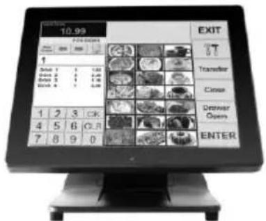
PS-3415/3415E Fanless LCD Touch Terminal User Manual
text_image
10.99 EXIT OFF-DOCKS Transfer Close Denver Opens ENTERPackage Contents
√ Fanless LCD touch terminal.....(x 1)
√ Power adaptor....(x 1)
√ Power cord....(x 1)
√ User Manual....(x 1)
√ Recovery DVD....(x 1)
(for pre-loaded OS model only)
FCC NOTES
This equipment has been tested and found to comply with the limits for a Class A digital device, pursuant to part 15 of the FCC Rules. These limits are designed to provide reasonable protection against harmful interference when the equipment is operated in a commercial environment. This equipment generates, uses, and can radiate radio frequency energy and, if not installed and used in accordance with the instruction manual, may cause harmful interference to radio communications. Operation of this equipment in a residential area is likely to cause harmful interference in which case the user will be required to correct the interference at his own expense.
This device complies with part 15 of the FCC Rules. Operation is subject to the following two conditions: (1) This device may not cause harmful interference, and (2) this device must accept any interference received, including interference that may cause undesired operation.
CE CLASS A WARNING
This equipment is compliant with Class A of CISPR 32. In a residential environment this equipment may cause radio interference.
WARRANTY LIMITS
Warranty will terminate automatically when the machine is opened by any person other than the authorized technicians. The user should consult his/her dealer for the problem happening. Warranty voids if the user does not follow the instructions in application of this merchandise. The manufacturer is by no means responsible for any damage or hazard caused by improper application.
警告使用者
This equipment is not suitable for use in locations where children are likely to be present.
13110902040 Ver. C0
CONSIGNES DE SÉCURITÉ
- Dispose of used batteries according to the instructions.
● Replacement of a battery with an incorrect type that can defeat a safeguard (for example, in the case of some lithium battery types)
● Disposal of a battery into fire or a hot oven, or mechanically crushing or cutting of a battery that can result in an explosion.
● Leaving a battery in an extremely high temperature surrounding environment that can result in an explosion or the leakage of flammable liquid or gas.
● A battery subjected to extremely low air pressure that may result in an explosion or the leakage of flammable liquid or gas.
BATTERIE ATTENTION NOTES
- Fanless terminal
Intel® Celeron® Bay Trail J1800 Celeron processor, up to 2.58 GHz, Dual Core, 1MB Cache for PS-3415 / Intel® Celeron® Processor J1900 (2M Cache, up to 2.42 GHz) for PS-3415E - Foldable base that allows PS Series to be configured into different configurations
● Projected-capacitive touch - Integrated structure for side mount upgrade kit:
SA-105/205/305/405/505; back mount display: LM-6807U / 6810U and PD-360R/360UE/2609UE/6807U;
40-key dynakey attachment with MSR or RFID option:
KP-500
● Water resistant structure designed for easy cleaning
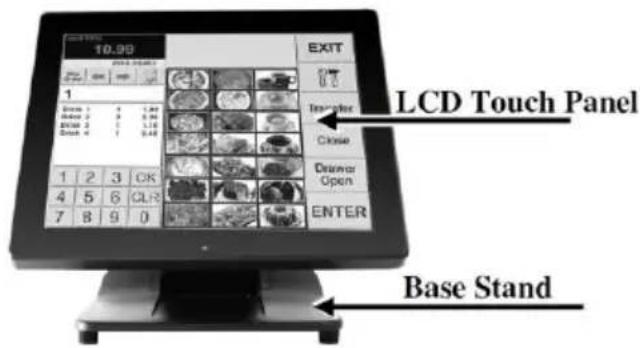
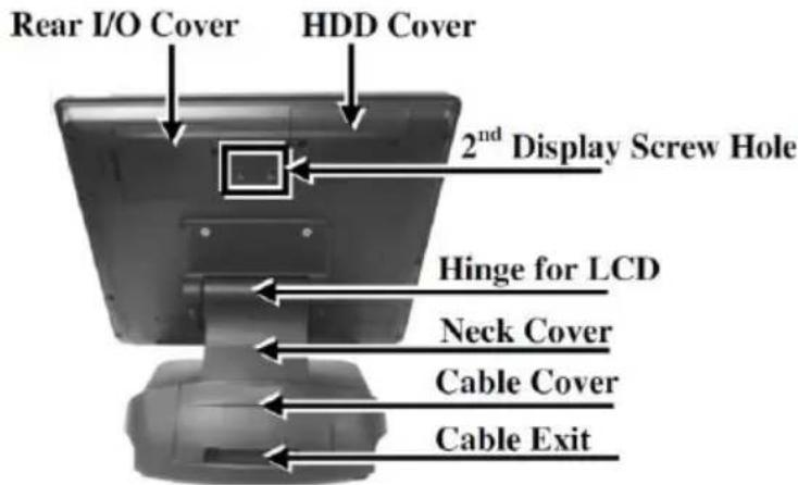
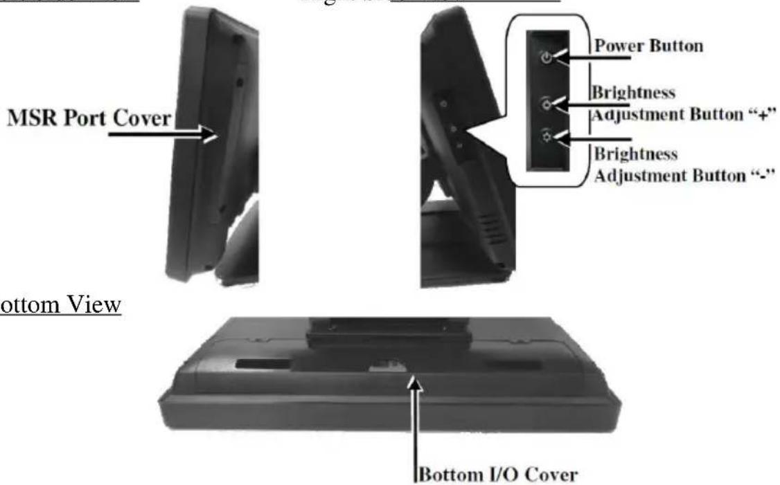
Views of the PS-3415/3415E
Front View
text_image
LCD Touch Panel EXIT 10.90 1 2 3 OK 4 5 6 CLR 7 8 9 0 Base StandRear View
text_image
Rear I/O Cover HDD Cover 2ndDisplay Screw Hole Hinge for LCD Neck Cover Cable Cover Cable ExitLeft Side View
text_image
MSR Port Cover Power Button Brightness Adjustment Button "+" Brightness Adjustment Button "-" Bottom View Bottom I/O CoverView of I/O Interface
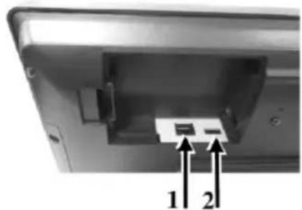
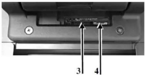
Top I/O Ports
Rear I/O Ports
natural_image
Interior view of a computer monitor with an open drive and two labeled arrows pointing to the ports (no text or symbols on the device itself)1 COM4 Port
2 USB 2.0 Port
natural_image
Close-up of a mechanical component with labeled parts (3 and 4), showing internal structure and mounting holes (no readable text or symbols beyond labels)3 Parallel (LPT) Port Connector
4 PS/2_KB Pin Header
※ The top I/O ports are provided for COM-based and USB-based peripheral devices, for example, customer display.
Bottom I/O Ports

text_image
1 2 3 4 5 61 RJ45 LAN Port
3 VGA Port
5 RJ11 Cash Drawer Port
2 USB 2.0 Port
4 COM Port (COM3/COM2/COM1)
6 12VDC-IN Power Jack
Positioning your POS for a Perfect Viewing Angle
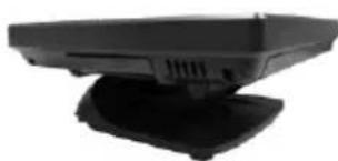
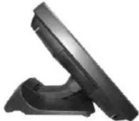
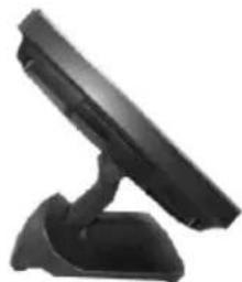
The adjustable Gen7 base is designed to help you determine an ideal position for PS-3415/3415E using its unique tilt adjustment mechanism. As the below figures suggest, Gen7 base basically provides three standard positioning solutions for your terminal: Flat Folded mode, Low Profile mode, and Full Extended mode.
PS-3415/3415E with Gen7 Base
natural_image
Black electronic device with a flat top and base, no visible text or symbolsFlat Folded mode
natural_image
Black handheld electronic device with a flat top and base (no visible text or symbols)Low Profile mode
natural_image
Black electronic device with a stand and antenna (no visible text or symbols)Full Extended mode
In general, PS-3415/3415E will be set up beforehand in Flat Folded mode and then packaged into the box for shipping. After it is unpacked, you may re-adjust the terminal in either Low Profile mode or Full Extended mode according to your situation. Below will provide instructions on how to adjust the specific base connected to the POS system. As a reminder, please be careful not to touch the LCD panel while setting up the tilt angle. Please refer to the following instructions on how to switch among different positioning modes to find an ideal viewing angle for PS-3415/3415E with Gen7 base.
-
Unpack XT-3415/3415E, which is supposed to be set in flat folded mode, out of the package box and then lay your POS system on a flat surface.
-
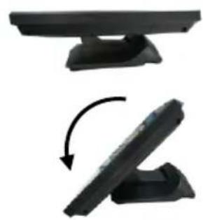
Steady the base with one hand, and then tilt the screen downwards.
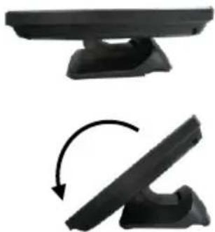
natural_image
Two black plastic electronic devices with base plates, shown in top and bottom views of a curved arrow indicating rotation (no text or symbols)- Position your terminal in Full Extended mode
3.1 After grabbing the bottom edge of the screen with your hand, gently move the screen upward until the screen is locked into place with a click sound.
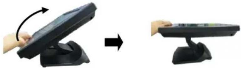
natural_image
Two-step illustration showing a hand holding a black electronic device on a stand, before and after transformation (no text or symbols)3.2 Support the screen with one hand holding onto its bottom edge. Then, while pulling the lever backwards, move the display upwards until the lever is snapped into the lower hook to raise the screen as shown in the below figure.
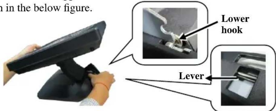
text_image
in the below figure. Lower hook Lever3.3 With the screen facing toward you, tilt the screen up or down to your desired angle. Please do not press on the LCD panel while setting up the tilt angle.
3.4 Remove the cable cover from the base.
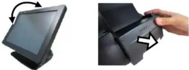
natural_image
Two-panel image showing a computer monitor and a printer with an arrow indicating the press or scroll (no text or symbols visible)3.5 Fix the base with two #/6/32-14L screws.
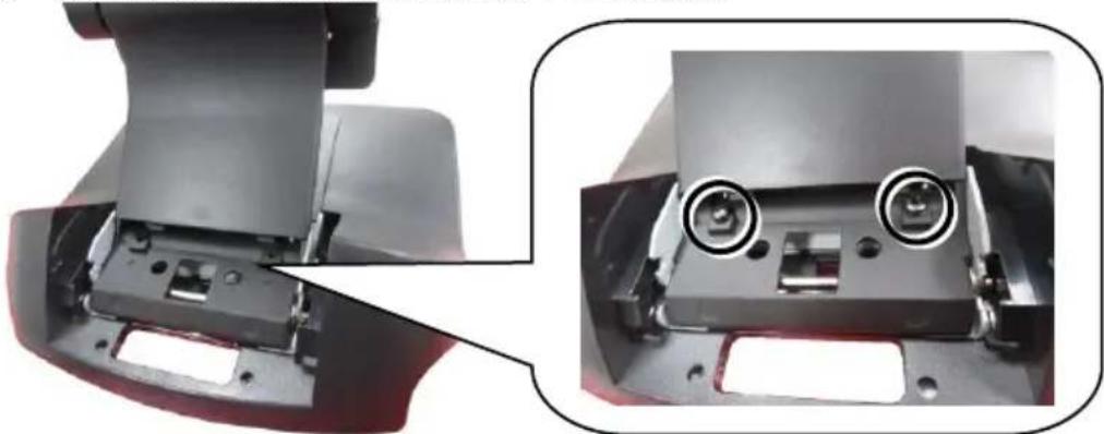
natural_image
Close-up of a mechanical component with two circular features, shown from close-up and side-up views (no text or symbols visible)- Return your terminal back to Flat Folded mode from Full Extended mode.
4.1 Remove the cable cover from the base.
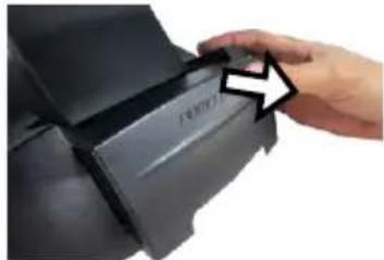
natural_image
Close-up of a hand pressing a black printer cover with a white arrow pointing to the paper (no visible text or symbols)4.2 Remove the two screws from the base.
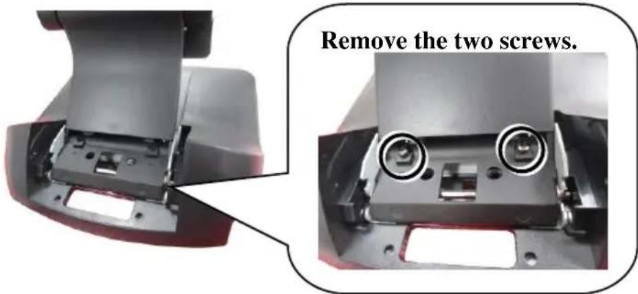
text_image
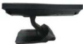
Remove the two screws.4.3 Tilt your screen in a horizontal position.
natural_image
Black electronic device with a curved arm and base (no visible text or symbols)4.4 Support the screen with one hand holding onto its bottom edge. While pulling the lever backwards, move the display downwards until the lever is lifted off the hook as shown in the figure.
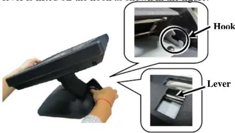
text_image
Hook Lever4.5 Push the cable cover back.
4.6 Tilt the screen again to the horizontal position.
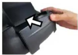
natural_image
Close-up of a hand pressing down on a black mechanical component with an arrow indicating the process (no text or symbols visible)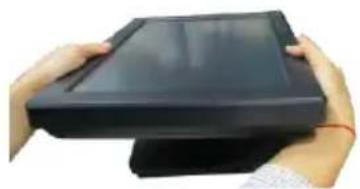
natural_image
Close-up of hands holding a black electronic device with a flat top (no visible text or symbols)- Position the terminal in Low Profile mode.
5.1 Follow Step 4 to set up the terminal in Flat Folded mode.
5.2 Tilt the screen all the way down
5.3 To tilt screen up or down to your desired angle, please be advised to keep the base steady with one hand to do so. Do NOT press on the LCD panel while setting up the tilt angle.
natural_image
Two black electronic components with base plates, one showing a curved arrow indicating rotation or change (no text or symbols)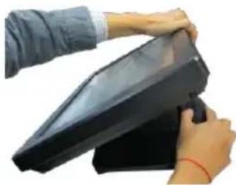
natural_image
Person handling a black electronic device with a handle (no visible text or symbols)Installing Optional Upgrade Kits and Peripherals
PS-3415/3415E can work with multiple optional upgrade kits and peripheral devices, such as magnetic stripe reader (MSR), LCD monitor, cash drawer and the like.
Before installing an optional upgrade kit and/or peripheral device, make sure that the system is powered off and the external power source is removed from the POS box to prevent electric hazard! Failure to follow the warning description will void the product warranty!
For the detailed instruction, refer to each of the user manuals of the optional upgrade kits and peripheral devices.
Connecting Power Adapter and I/O Cables
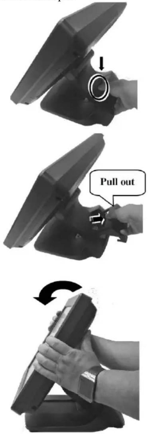
Before connecting power adapter and I/O cables to the I/O ports of PS series terminal, please route and arranging the cables. Refer to the following step-by-step instruction of cable routing and arrangement for the details. Here, an equivalent model with GEN 7 base is taken below for example.
- Press the circled section of the cable cover with your thumb.
-
Pull out the cable cover.
-
Push and tilt the terminal to the end in the direction as shown by the arrow.
-
Determine that the terminal is tilted to the end, as shown in the right figure.
-
Press the circled section with two thumbs and pull by force the two sides of the locking hook with two forefingers as indicated by the arrow.
-
Remove the neck cover from the base stand.
-
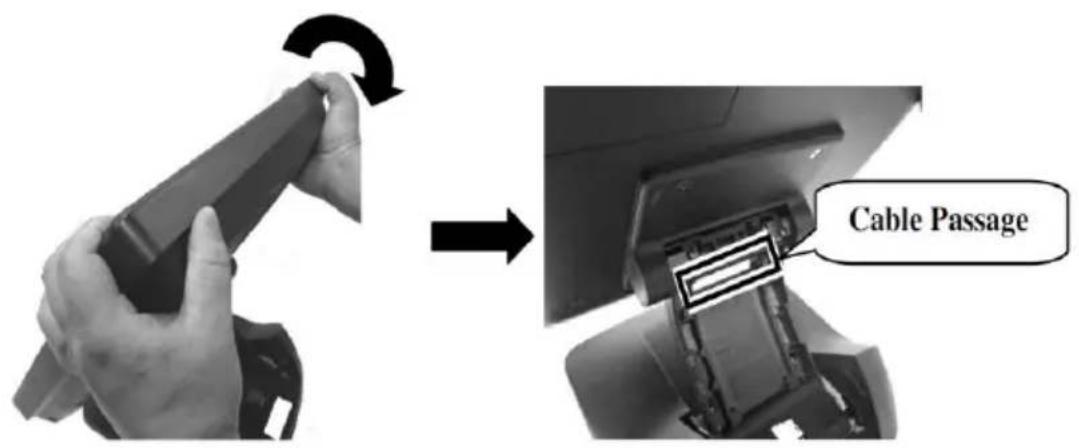
Tilt the terminal slightly at a little angle in the direction as shown by the arrow, making cables easily pass through the cable passage.
text_image
Cable Passage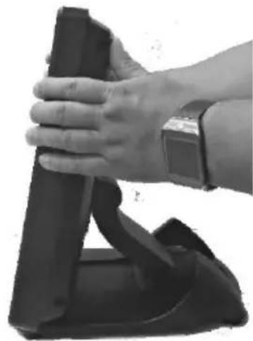
natural_image
Close-up of a hand holding a black mechanical device with a wrist strap (no visible text or symbols)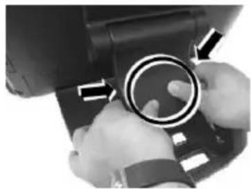
natural_image
Close-up of hands holding a camera lens with directional arrows indicating motion (no text or symbols)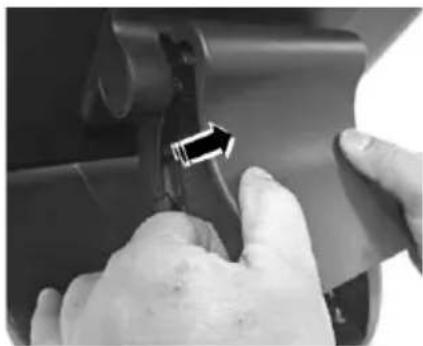
natural_image
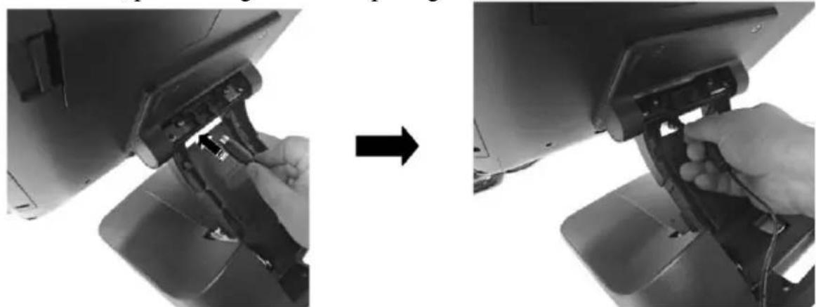
Close-up of hands operating a mechanical component with a black arrow pointing to a small component (no visible text or symbols)- Make the connector, which will be connected to the I/O port of the terminal, pass through the cable passage of base stand.
natural_image
Two-step installation of a computer monitor with a hand inserting a clip into the case (no text or symbols visible)-
Push and tilt the terminal to the end in the direction as shown by the arrow.
-
Remove the bottom I/O cover with your forefinger inserting the middle hole of the cover.
-
Connect the connector of the power adapter to the 12VDC-IN power jack.
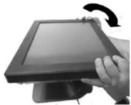
natural_image
Hand holding a flat-screen monitor with a curved arrow indicating rotation (no text or symbols visible)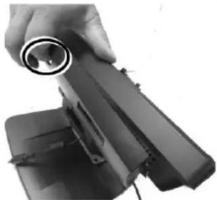
natural_image
Close-up of a hand holding a cylindrical object with a ring, partially enclosed in a black plastic or mechanical component (no visible text or symbols)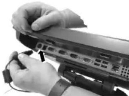
natural_image
Close-up of hands installing or adjusting a computer monitor with cable (no visible text or symbols)- Cover the bottom I/O interface and gather the I/O cables to the circled cable arrangement area, as shown below.

natural_image
Two-step diagram showing hands installing or adjusting a device component on a monitor, with no visible text or symbols.- Push and tilt the terminal to the end in the direction as shown by the arrow.
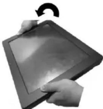
natural_image
Close-up of hands holding a tablet device with a curved arrow indicating rotation (no text or symbols visible)- Arrange well the I/O cable located at the area of neck cover.
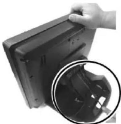
natural_image
Close-up of a hand holding a computer monitor case, with an inset close-up showing internal components (no text or symbols visible)- Shield the I/O cable arrangement area on the neck of the base stand with the neck cover.
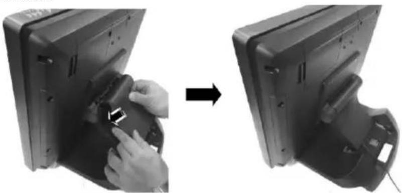
natural_image
Two-step diagram showing a hand inserting a component into a computer monitor, before and after (no text or symbols visible)- Shield the I/O cable exposure area with the cable cover.
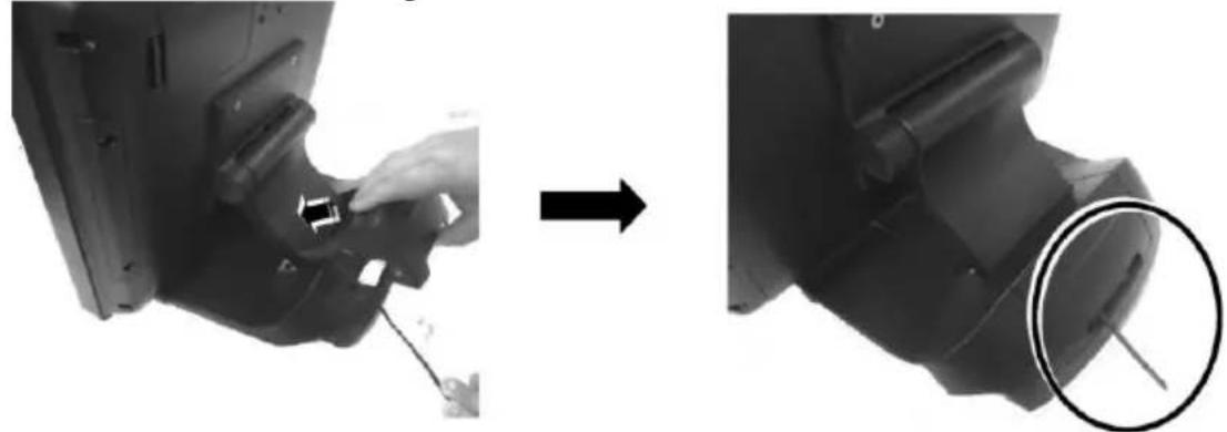
natural_image
Mechanical assembly diagram showing a hand turning a component into a housing, with a magnified inset highlighting a specific part (no text or symbols present)CAUTION: On doing insertion or extraction of a cable connector, please always hold the connector head itself instead of pulling the cable wire. Doing this could damage the cables and ports, which is considered as an artificial damage and is not covered by the warranty. The means of power cord should be connected to a socket-outlet with earthing connection.
After connecting the power cable to the power jack of the terminal, press the power button to power on the terminal. To power it off, press the power button again.
Once powering off the system, if you want to power it on again, please wait at least 3 seconds.
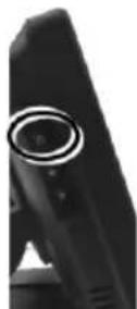
If the system hangs due to a reason, such as software resource conflict, please press and hold the power button for over 10 seconds to forcedly shut down the system.
Power LED Indicator
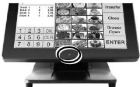
There is a power LED indicator located at the center of lower rim of the front side of LCD panel. After powering ON or OFF the terminal, you can read the power status from the power LED indicator. The LED status is described below.
text_image
Drink 1 1 1,00 Drink 2 3 2,00 Drink 3 1 4,03 Drink 4 1 3,45 Transfer Close Drawer Open ENTER 1 2 3 OK 4 5 6 CLR 7 8 9 0| LED | Status | Description |
| POWER | Solid blue | System power ON |
| Solid orange | System standby |
Installing an Operating System
This product is highly professional equipment. Therefore, we do NOT encourage you to install any operating system into this machine without professional assistance. We shall not be responsible for any technical support to questions on this aspect. We suggest that you contact your dealer for OS installation.
Operating System Recovery
For the PS-3415/3415E main system preloaded with an operating system on HDD, We provide a recovery DVD shipped with the main system for the preloaded operating system. The system integrator shall take care of software restoration after the OS is recovered.
If you plan to recover your operating system, we do NOT encourage you to recover any operating system. Please contact your service center for operating system recovery.
Operation Environment
This terminal must NOT be operated in an environment with restricted ventilation. There must be at least 25 mm air clearance around any top or side ventilation holes with free flow of air around the unit at all times for system operation.
Specifications
| System Configuration | Processor | PS-3415: Intel® Celeron J1800, 2C, 2.41GHz/2.58GHz (Burst), 1M Cache (Default) Intel® Celeron N2807, 2C, 1.58GHz/2.16GHz (Burst), 1M Cache (Option) PS-3415E: Intel® Celeron® Processor J1900 (2M Cache, up to 2.42 GHz) |
| System Memory | 2GB DDR3L 1333MHz default | |
| Storage Device | SATA x 1 + mSATA x 1; 320GB SATA HDD default | |
| Power Supply | 12V/40W (upgrade to 60W or higher when required) | |
| OS support | Windows 7 / POSReady 7 / Windows Embedded 8.1 Industry / DOS/ Linux per request | |
| Display & Touch | LCD | Bezel-free TFT LCD |
| Resolution | 1024 x 768 | |
| Touch | Projected-capacitive touch | |
| I/O & Expansion | Serial Port | 4, 3 x DB9 on bottom I/O plate + 1 x RJ50 on top I/O plate, 5V/12V support on all COM ports |
| Parallel Port | 1, via optional conversion cable | |
| Standard USB Port | 5, 4 on bottom I/O plate + 1 on top I/O plate | |
| LAN Port | 10 / 100 / 1000 Mb x 1 | |
| Display Port | VGA x 1, 12V support | |
| CR Port | 1, control 2 CR via optional Y-cable | |
| PS/2 Port | Pin header inside service window | |
| Audio | Buzzer only | |
| Base Stand | 7th generation foldable base stand | |
| Power Supply | 12V/40W | |
| Environmental | Operating Condition | 0°C - 40°C, 20%RH - 90%RH (Equipped with HDD); 0°C - 50°C, 20%RH - 90%RH (Equipped with SSD) |
| Storage Condition | -20°C - 70°C, 10%RH - 90%RH |
※ The product information and specifications are subject to change without prior notice. To get the detailed information on the XT-3415/3415E, please contact your dealer or service team.