
27MB35PH-B - Screen LG - Free user manual and instructions
Find the device manual for free 27MB35PH-B LG in PDF.


User questions about 27MB35PH-B LG
0 question about this device. Answer the ones you know or ask your own.
Ask a new question about this device
Download the instructions for your Screen in PDF format for free! Find your manual 27MB35PH-B - LG and take your electronic device back in hand. On this page are published all the documents necessary for the use of your device. 27MB35PH-B by LG.
USER MANUAL 27MB35PH-B LG
Please read this manual carefully before operating your set and retain it for future reference.
IPS LED MONITOR MODEL
23MB35PH
24MB35PH
27MB35PH
CONTENTS
3 LICENSE
4 ASSEMBLING AND PREPARING
4 Unpacking
5 Parts and buttons
7 Moving and Lifting the Monitor
8 Setting up the Monitor set
8 - Attaching the Stand Base
9 - Detaching the stand base
10 - Detaching the stand body
10 - Using the cable holder
11 - Mounting on a table
12 - Adjusting the angle
13 - Adjusting the stand height
13 - Using the Kensington locking device
14 - Swivel stand
14 - Using the Pivot function
15 - Swivel stand
15 - Using the Pivot function
16 - Mounting on a wall
17 USING THE MONITOR SET
17 Connecting to a PC
17 - D-SUB connection
17 - DVI-D connection
18 - HDMI connection
18 Connecting to AV Devices
18 - HDMI connection
19 Connecting to External Devices
19 - Peripheral device connection
20 CUSTOMIZING SETTINGS
21 Customizing Settings
21 - Menu Settings
22 - Picture
23 - Color
24 - Display
24 - Audio
25 - Others
26 READER Setting
27 SMART ENERGY SAVING
28 TROUBLESHOOTING
30 SPECIFICATIONS
30 23MB35PH
31 24MB35PH
32 27MB35PH
33 Preset Modes (Resolution)
33 Indicator
LICENSE
Each model has different licenses. Visit www.lg.com for more information on the license.

HIGH-DEFINITION MULTIMEDIA INTERFACE
The terms HDMI and HDMI High-Definition Multimedia Interface, and the HDMI Logo are trademarks or registered trademarks of HDMI Licensing Administrator, Inc. in the United States and other countries.
The following content is only applied to the monitor which is sold in Europe market and which needs to meet the ErP Directive:
* This monitor is set to be turned off automatically in 4 hours after you turned on display if there is no adjustment to display.
* To make this setting be disabled, change the option to 'Off' in OSD menu of "Automatic Standby".
ASSEMBLING AND PREPARING
Unpacking
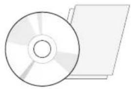
Check your product box for the following items. If there are any missing accessories, contact the local dealer where you purchased your product. The illustrations in this manual may differ from the actual product and accessories.
natural_image
Illustration of a CD or DVD disc and its corresponding physical object (no text or symbols)CD / Card
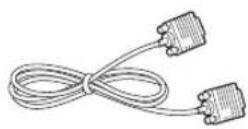
D-SUB Cable
(This cable is not included in all countries.)
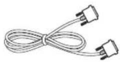
DVI-D Cable
(This cable is not included in all countries.)
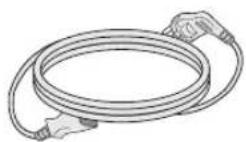
Power Cord
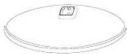
Stand Base
23MB35PH
24MB35PH
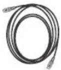
HDMI Cable
(This cable is not included in all countries.)
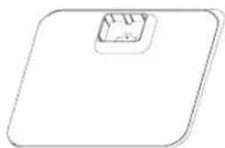
natural_image
Simple line drawing of a flat plate with a small square cutout on top (no text or symbols)Stand Base

One Screw
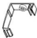
Cable Holder
27MB35PH

CAUTION
Do not use any unapproved accessories to ensure the safety and product life span.
Any damages or injuries by using unapproved accessories are not covered by the warranty.

NOTE
The accessories supplied with your product may vary depending on the model.
Product specifications or contents in this manual may be changed without prior notice due to upgrade of product functions.
Parts and buttons
23MB35PH 24MB35PH
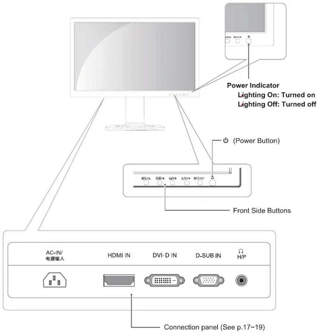
text_image
Power Indicator Lighting On: Turned on Lighting Off: Turned off (Power Button) Front Side Buttons AC-IN/ 电源输入 HDMI IN DVI-D IN D-SUB IN H/P Connection panel (See p.17~19)Parts and buttons
27MB35PH
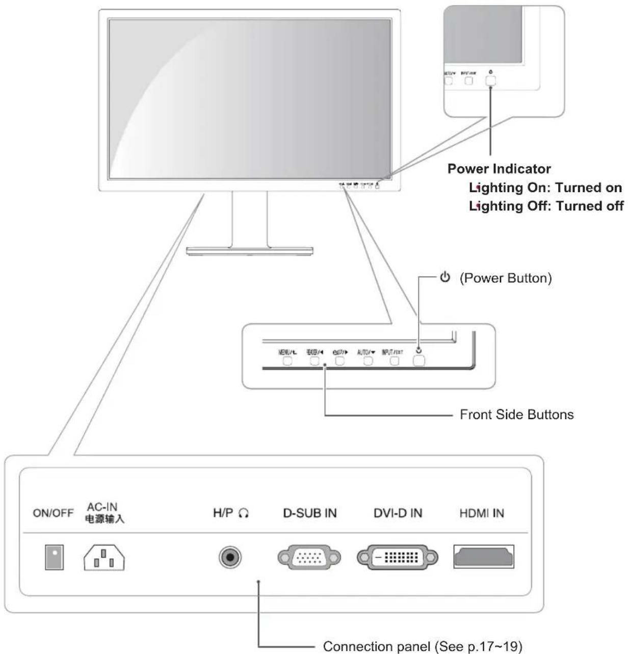
text_image
Power Indicator Lighting On: Turned on Lighting Off: Turned off (Power Button) ON/OFF AC-IN 电源输入 H/P Ω D-SUB IN DVI-D IN HDMI IN Connection panel (See p.17~19)Moving and Lifting the Monitor
When moving or lifting the monitor, follow these instructions to prevent the monitor from being scratched or damaged and to ensure safe transportation regardless of its shape or size.
It is advisable to place the monitor in the original box or packing material before attempting to move it.
Before moving or lifting the monitor, disconnect the power cord and all cables.
Hold the top and bottom of the monitor frame firmly. Do not hold the panel itself.
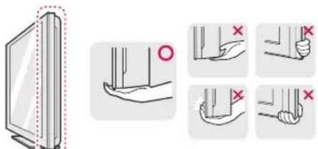
text_image
Diagram illustrating hand positioning and movement of a screen, with magnified views showing finger placement and red X marks indicating movement.When holding the monitor, the screen should face away from you to prevent it being scratched.
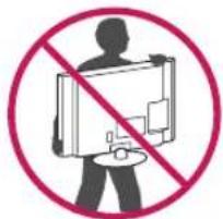
text_image
Prohibition sign with silhouette and crossed-out rectangle, indicating no use or prohibition of a deviceWhen moving the monitor, avoid any strong shock or vibrations to the product.
When moving the monitor, keep it upright, never turn the monitor on its side or tilt it sideways.

CAUTION
As far as possible, avoid touching the monitor screen. This may result in damage to the screen or some of the pixels used to create images.
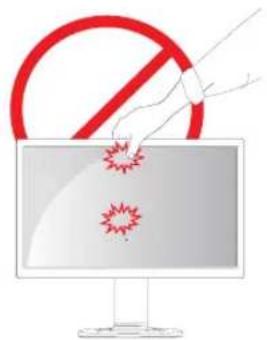
text_image
Illustration showing a prohibition symbol above a computer screen with virus icons, implying suppression or anti-epidemic control.Setting up the Monitor set
Attaching the Stand Base
1 Place the Monitor set with the screen side down on a flat and cushioned surface.

CAUTION
To protect the screen from scratches, cover the surface with a soft cloth.
23MB35PH
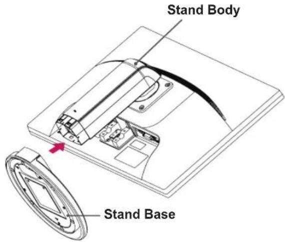
2 Check the position (at the front and rear) of the stand body, then mount the stand base on the stand body as shown in the figure.
text_image
Stand Body Stand Base3 Using a coin, turn the screw clockwise to secure the stand base.
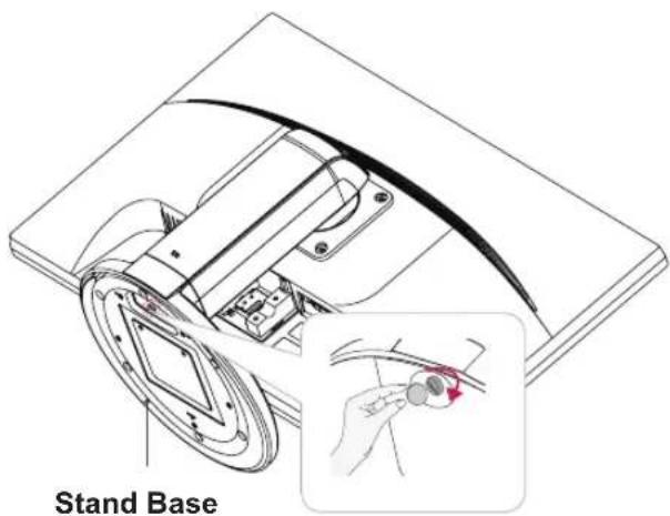
text_image
Stand Base24MB35PH
2 Check the position (at the front and rear) of the stand body, then mount the stand base on the stand body as shown in the figure.
Stand Base
text_image
Stand Body27MB35PH
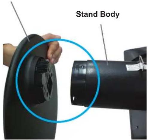
2 Check the position (at the front and rear) of the stand body, then mount the stand base on the stand body as shown in the figure.
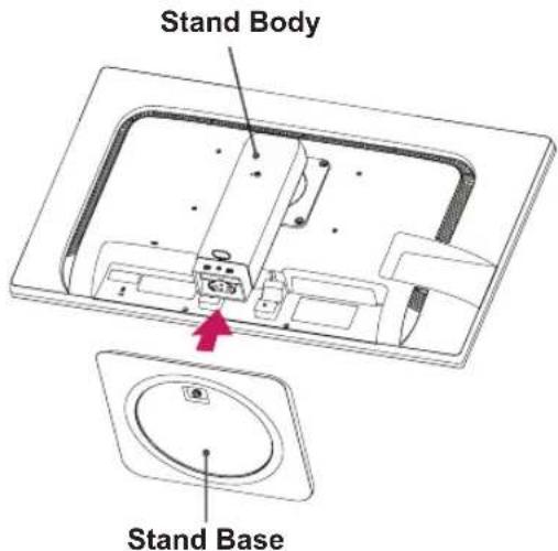
text_image
Stand Body Stand Base3 Using a coin, turn the screw clockwise to secure the stand base.
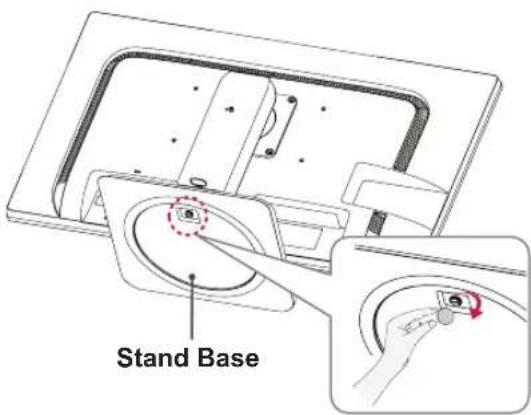
text_image
Stand BaseDetaching the stand base
1 Place the monitor's screen face down.
To protect the screen from scratches, cover the surface with a soft cloth.
23MB35PH
2 Using a coin, turn the screw in the stand base counterclockwise. Detach the stand base from the stand body.

text_image
Stand Body Stand Base24MB35PH
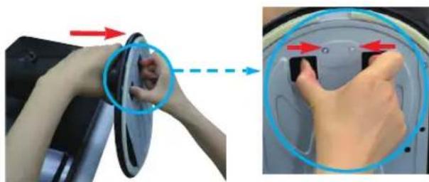
2 Detach the stand base from the stand body.
natural_image
Close-up of hands adjusting a car interior panel with red arrows indicating direction (no text or symbols visible)27MB35PH
2 Using a coin, turn the screw in the stand base counterclockwise. Detach the stand base from the stand body.
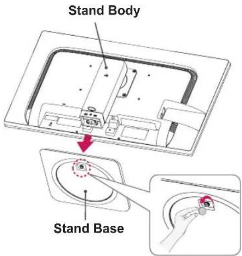
text_image
Stand Body Stand BaseCAUTION
The components appearing in the illustrations may look different from the actual product.
Do not carry the monitor upside-down as this may cause it to fall off its stand, resulting in damage or injury.
To avoid damaging the screen when lifting or moving the monitor, only hold the stand or the plastic cover. This avoids putting unnecessary pressure on the screen.
Only remove the tape and the locking pin when the monitor is mounted on the stand base and is in an upright position. Otherwise, the stand body may protrude, which may lead to injury.
Detaching the stand body
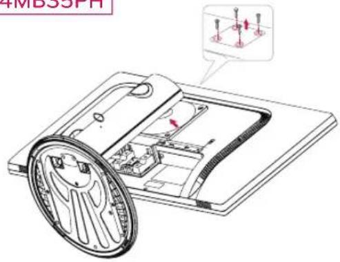
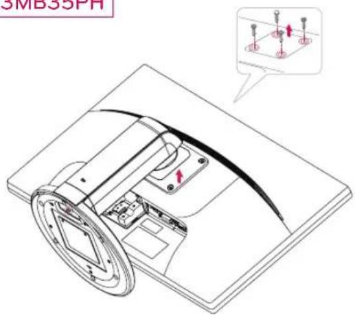
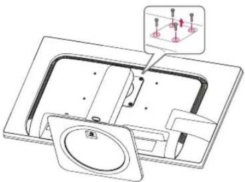
1 Place the monitor's screen face down. To protect the screen from scratches, cover the surface with a soft cloth.
2 Using a screwdriver, remove the four screws and detach the stand from the monitor.
24MB35PH
text_image
4MB35PH23MB35PH
text_image
SMB35PH27MB35PH
natural_image
Technical line drawing of a mechanical assembly with a magnified inset showing internal components (no text or symbols)27MB35PH
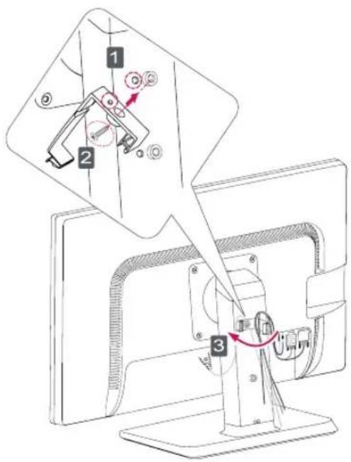
Using the cable holder
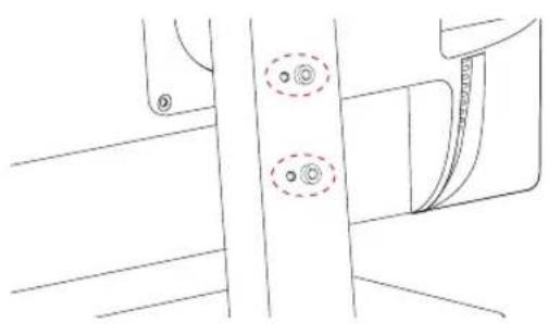
1 Fix the Knob (Cable holder) to the Hole(Hingebody).
2 Use one screw to fix the Cable Holder and monitor set.
3 Close the Cable holder.
text_image
Technical diagram showing a mechanical assembly with numbered components and directional arrows indicating motion or assembly.
NOTE
The holes are used for wall mount bracket. Varies depending upon your country or model.
natural_image
Technical line drawing of a mechanical component with no visible text or symbolsMounting on a table
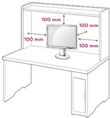
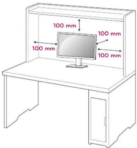
1 Lift the monitor and place it on the table in an upright position.
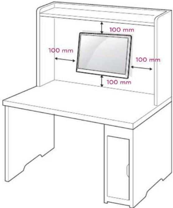
Install at least 100 mm away from the wall to ensure sufficient ventilation.
23MB35PH
24MB35PH
text_image
100 mm 100 mm 100 mm 100 mm27MB35PH
text_image
100 mm 100 mm 100 mm 100 mm23MB35PH
24MB35PH
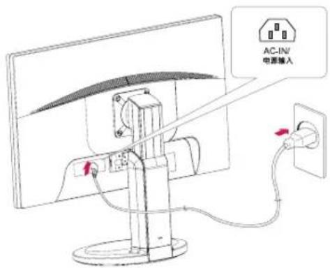
2 Connect the Power cord to the monitor, then plug the power cord into the wall outlet.
text_image
AC-INV 电源输入27MB35PH
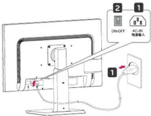
2 1 Connect the Power cord to the monitor, then plug the power cord into the wall outlet. (Before connect please check the "ON/OFF" knob in "O" state).
2 Press the "ON/OFF" knob in "state (Open the power).
text_image
2 1 ON/OFF AC-IN 电源输入 13 Press the (Power) button on the front of the monitor to turn on the monitor.
CAUTION
Unplug the power cord prior to moving or installing the monitor. There is risk of electric shock.
Adjusting the angle
1 Place the monitor mounted on the stand base in an upright position.
23MB35PH
24MB35PH
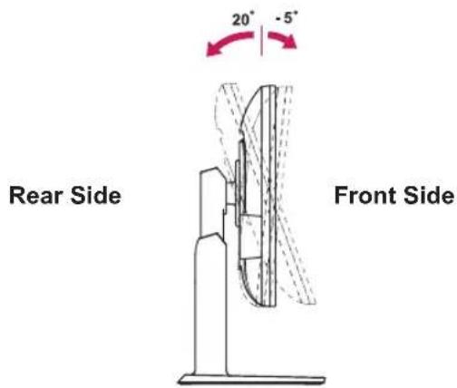
2 Adjust the angle of the screen. The angle of the screen can be adjusted up to 5^ forwards and 20^ backwards for a comfortable viewing experience.
text_image
20° -5° Rear Side Front Side27MB35PH
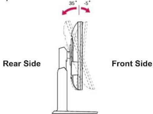
2 Adjust the angle of the screen. The angle of the screen can be adjusted up to 5° forwards and 35° backwards for a comfortable viewing experience.
text_image
35° -5° Rear Side Front Side
WARNING
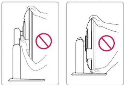
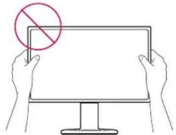
To avoid injury to the fingers when adjusting the screen, do not hold the lower part of the monitor's frame as illustrated below.
text_image
Diagram showing two methods of removing a barrier, with red prohibition symbols indicating no barrier.Be careful not to touch or press the screen area when adjusting the angle of the monitor.
natural_image
Illustration of two hands holding a blank computer monitor with a red prohibition symbol (no text or labels)Adjusting the stand height
1 Place the monitor mounted on the stand base in an upright position.
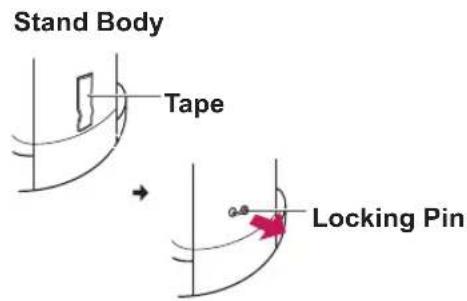
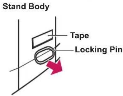
2 Remove the tape attached at the bottom rear of the stand body, then pull out the locking pin.
23MB35PH
text_image
Stand Body Tape Locking Pin24MB35PH 27MB35PH
text_image
Stand Body Tape Locking Pin3
23MB35PH
24MB35PH
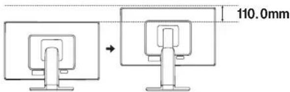
The height can be adjusted up to 110 mm.
text_image
110.0mm27MB35PH
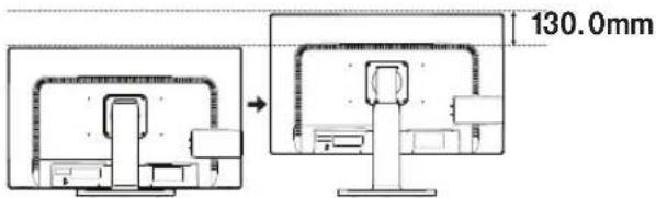
The height can be adjusted up to 130 mm.
text_image
130.0mm
CAUTION
Once the pin is removed, it is not necessary to re-insert it to adjust the height.

WARNING
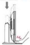
Do not put your finger between the screen and the base (chassis) when adjusting the screen's height.
Using the Kensington locking device
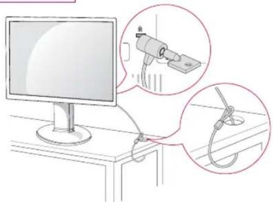
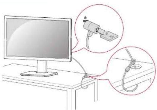
The connector for the Kensington lock is located on the rear of the monitor.
For more information on installation and usage, refer to the Kensington lock user manual or visit the website at http://www.kensington.com.
Connect the monitor to the table with the Kensington lock cable.
23MB35PH
24MB35PH
natural_image
Illustration of a computer monitor connected to a hanging hook, with magnified insets showing the hook being held (no text or symbols present)27MB35PH
natural_image
Illustration of a computer monitor connected to a cable with magnified insets showing cable attachment (no text or symbols)
NOTE
Using the Kensington lock is optional. The accessories can be purchased at your local electronics store.
24MB35PH
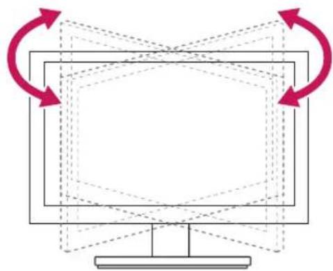
Swivel stand
Image shown may differ from your Monitor set.
1 Swivel 355 degrees and adjust the angle of the Monitor set to suit your view.
flowchart
graph TD
    A["Screen"] --> B["Monitor"]
    B --> C["Arrow 1"]
    B --> D["Arrow 2"]
    B --> E["Arrow 3"]
    B --> F["Arrow 4"]
    B --> G["Arrow 5"]
    B --> H["Arrow 6"]
    B --> I["Arrow 7"]
    B --> J["Arrow 8"]
    B --> K["Arrow 9"]
    B --> L["Arrow 10"]
23MB35PH
24MB35PH
Using the Pivot function
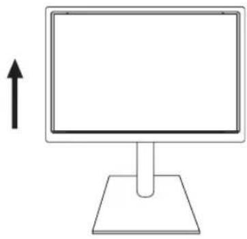
The pivot function allows you to rotate the screen 90 degrees clockwise.
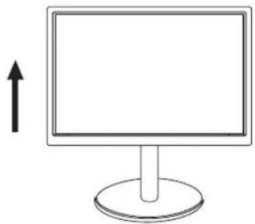
1 Lift the monitor to its highest height to utilize the Pivot function.
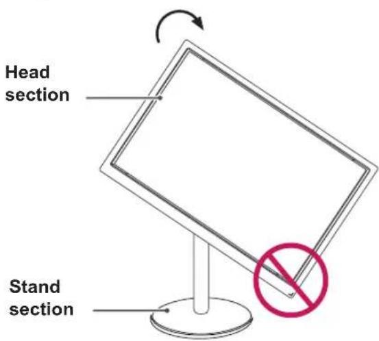
2 Landscape & Portrait: You can rotate the panel 90° clockwise. Please be cautious and avoid contact between the monitor head and the Stand Base when rotating the screen to access the Pivot function. If the monitor head touches the Stand Base, then the Stand Base could crack.
text_image
Head section Stand section3 Be careful with the cables when rotating the screen.
natural_image
Simple line drawing of a monitor with a circular base and an upward arrow, no text or symbols present.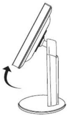
natural_image
Simple line drawing of a computer monitor with an arrow indicating rotation (no text or symbols)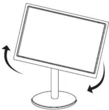
natural_image
Simple line drawing of a monitor with two curved arrows indicating rotation or direction (no text or symbols)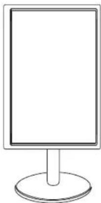
natural_image
Simple line drawing of a blank rectangular board with a circular base (no text or symbols)27MB35PH
Swivel stand
Image shown may differ from your Monitor set.
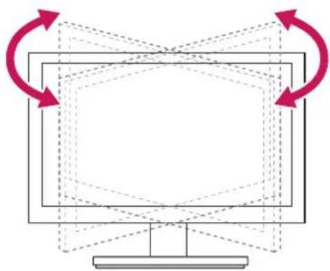
1 Swivel 355 degrees and adjust the angle of the Monitor set to suit your view.
flowchart
graph TD
    A["Screen"] --> B["Monitor"]
    B --> C["Arrow Right"]
    B --> D["Arrow Left"]
    B --> E["Arrow Down"]
    B --> F["Arrow Up"]
    style A fill:#f9f,stroke:#333
    style B fill:#ccf,stroke:#333
    style C fill:#cfc,stroke:#333
    style D fill:#fcc,stroke:#333
    style E fill:#cff,stroke:#333
    style F fill:#ffc,stroke:#333
Using the Pivot function
The pivot function allows you to rotate the screen 90 degrees clockwise.
1 Lift the monitor to its highest height to utilize the Pivot function.
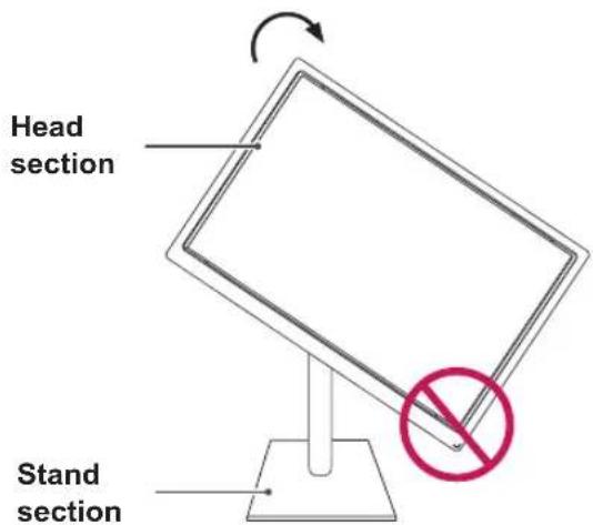
2 Landscape & Portrait: You can rotate the panel 90° clockwise. Please be cautious and avoid contact between the monitor head and the Stand Base when rotating the screen to access the Pivot function. If the monitor head touches the Stand Base, then the Stand Base could crack.
text_image
Head section Stand section3 Be careful with the cables when rotating the screen.
natural_image
Simple line drawing of a computer monitor with a stand and an upward arrow (no text or symbols)
natural_image
Simple line drawing of a computer monitor with an arrow indicating rotation (no text or symbols)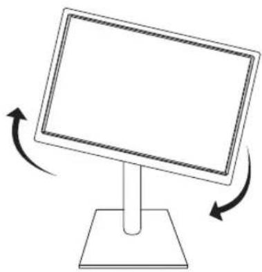
natural_image
Simple line drawing of a computer monitor with two curved arrows indicating rotation or direction (no text or symbols)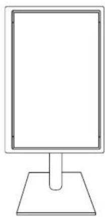
natural_image
Simple line drawing of a blank rectangular frame mounted on a base (no text or symbols)Mounting on a wall
For proper ventilation, allow a clearance of 100 mm on each side and from the wall. Detailed instructions are available from your dealer, see the optional Tilt Wall Mounting Bracket Installation and Setup Guide.
text_image
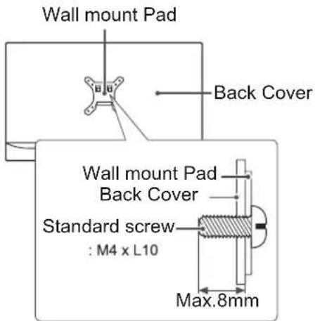
100 mm 100 mm 100 mm 100 mmIf you intend to mount the Monitor set to a wall, attach Wall mounting interface (optional parts) to the back of the set.
When you install the Monitor set using a wall mounting interface (optional parts), attach it carefully so it will not drop.
1 Please, Use the screw and wall mount interface in accordance with VESA Standards.
2 If you use screw longer than standard, the monitor might be damaged internally.
3 If you use improper screw, the product might be damaged and drop from mounted position. In this case, LG Electronics is not responsible for it.
4 VESA compatible only with respect to screw mounting interface dimensions and mounting screw specifications.
5 Please use VESA standard as below.
784.8 mm (30.9 inch) and under
* Wall Mount Pad Thickness : 2.6 mm
* Screw : Φ 4.0 mm x Pitch 0.7 mm x Length 10 mm
787.4 mm (31.0 inch) and above
* Please use VESA standard wall mount pad and screws.
| Model | 23MB35PH | 27MB35PH |
| 24MB35PH | ||
| VESA (A x B) 100 x | 100 200 x 100 | |
| Standard screw M4 | M4 | |
| Number of screws | 4 4 |

CAUTION
Disconnect the power cord first, and then move or install the Monitor set. Otherwise electric shock may occur.
If you install the Monitor set on a ceiling or slanted wall, it may fall and result in severe injury.
Use only an authorized LG wall mount and contact the local dealer or qualified personnel.
Do not over tighten the screws as this may cause damage to the Monitor set and void your warranty.
Use only screws and wall mounts that meet the VESA standard. Any damages or injuries by misuse or using an improper accessory are not covered by the warranty. Screw length from outer surface of back cover should be under 8mm.
text_image
Wall mount Pad Back Cover Wall mount Pad Back Cover Standard screw : M4 x L10 Max.8mm
NOTE
Use the screws that are listed on the VESA standard screw specifications.
The wall mount kit will include an installation manual and necessary parts.
The wall mount bracket is optional. You can obtain additional accessories from your local dealer.
The length of screws may differ depending on the wall mount. Be sure to use the proper length.
For more information, refer to the instructions supplied with the wall mount.
USING THE MONITOR SET
Connecting to a PC
Your Monitor set supports Plug & Play*.
*Plug & Play: A PC recognizes a connected device that users connect to a PC and turn on, without device configuration or user intervention.
D-SUB connection
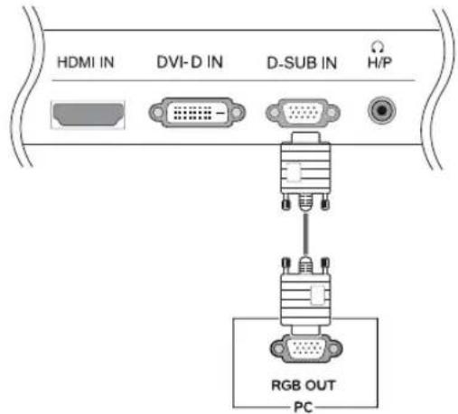
Transmits analog video from your PC to the Monitor set. Connect the PC and the Monitor set with the supplied D-sub 15 pin signal cable as shown in the following illustrations.
23MB35PH 24MB35PH
text_image
HDMI IN DVI-D IN D-SUB IN H/P RGB OUT PC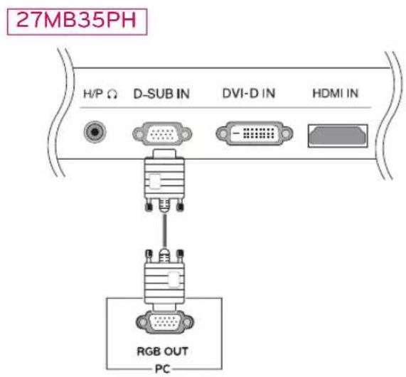
text_image
27MB35PH H/P Ω D-SUB IN DVI-D IN HDMI IN RGB OUT PCNOTE
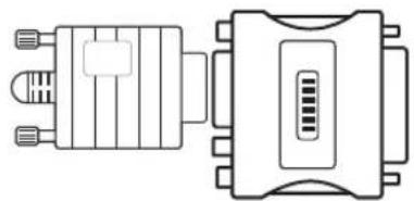
When using a D-Sub signal input cable connector for Macintosh
natural_image
Technical line drawing of two electronic component packages (no text or symbols)Mac adapter
For Apple Macintosh use, a separate plug adapter is needed to change the 15 pin high density (3 row) D-SUB VGA connector on the supplied cable to a 15 pin 2 row connector.
DVI-D connection
Transmits a digital video signal from your PC to the Monitor set. Connect the PC and the Monitor set with a DVI cable as shown in the following illustrations.
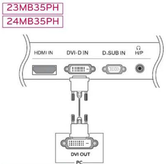
text_image
23MB35PH 24MB35PH HDMI IN DVI-D IN D-SUB IN Ω H/P DVI OUT PC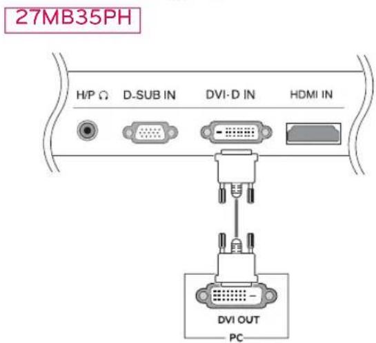
text_image
27MB35PH H/P Ω D-SUB IN DVI-D IN HDMI IN DVI OUT PCHDMI connection
Transmits the digital video and audio signals from your PC to the Monitor set. Connect the PC and the Monitor set with the HDMI cable as shown in the following illustrations.
23MB35PH
24MB35PH
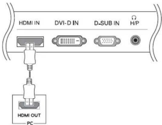
text_image
HDMI IN DVI-D IN D-SUB IN H/P HDMI OUT PC27MB35PH
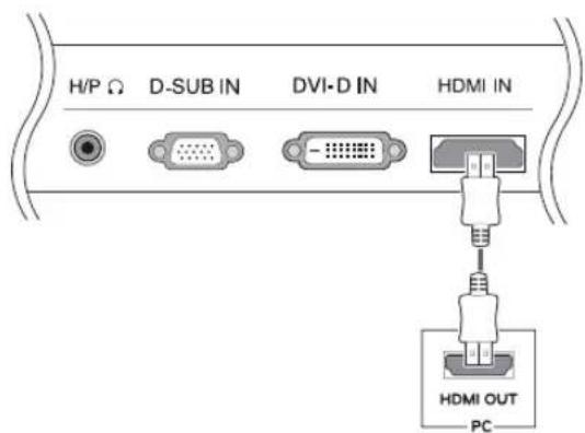
text_image
H/P Ω D-SUB IN DVI-D IN HDMI IN HDMI OUT PC
NOTE
If you use HDMI PC, it can cause compatibility problem.

CAUTION
Connect the signal input cable and tighten it by turning the screws clockwise.
Do not press the screen with your finger for a long time as this may result in temporary distortion on the screen. Avoid displaying a fixed image on the screen for a long period of time to prevent image burn. Use a screensaver if possible.
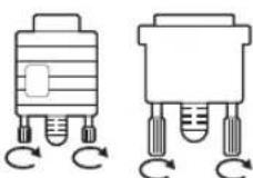

NOTE
When you want to use two PC in our Monitor, please connect the signal cable(D-SUB/DVI-D/HDMI) respectively in Monitor set. If you turn the Monitor set on while it is cold, the screen may flicker. This is normal. Some red, green, or blue spots may appear on the screen. This is normal.
Connecting to AV Devices
HDMI connection
Transmits the digital video and audio signals from your AV devices to the monitor. Connect your AV device to the monitor with the HDMI cable as illustrated below.
23MB35PH
24MB35PH
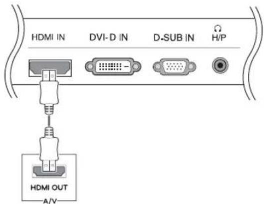
text_image
HDMI IN DVI-D IN D-SUB IN H/P HDMI OUT A/V27MB35PH
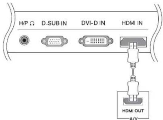
text_image
H/P Ω D-SUB IN DVI-D IN HDMI IN HDMI OUT A/V
NOTE
Using a DVI to HDMI cable may cause compatibility issues.
Connecting to External Devices
Peripheral device connection
Connect peripheral devices to the monitor using headphone ports.
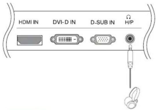
text_image
HDMI IN DVI-D IN D-SUB IN H/P27MB35PH
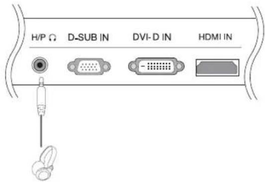
text_image
H/P Ω D-SUB IN DVI-D IN HDMI IN
NOTE
Peripheral devices are sold separately. Cables with angled plugs may have clearance issues, use straight plugs when possible.
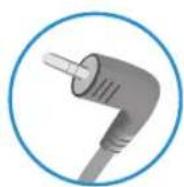
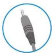
Angle Type Straight Type

NOTE
Headphones or speakers may not work normally, depending on the server PC settings.
Self Image Setting Function
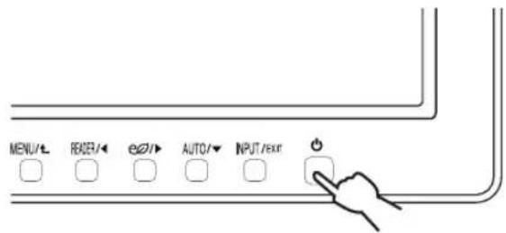
Press the power button on the bottom panel to turn the power on. When monitor power is turned on, the "Self Image Setting" Function is executed automatically. (Only supported in Analog Mode)
text_image
MENU/L READR/← e20/→ AUTO/▼ INPUT/EXIT
NOTE
"Self Image Setting" Function.
This function provides the user with optimal display settings. When the user connects the monitor for the first time, this function automatically adjusts the display to optimal settings for individual input signals. (Only supported in Analog Mode)
'AUTO' Function.
When you encounter problems such as blurry screen, blurred letters, screen flicker or tilted screen while using the device or after changing screen resolution, press the AUTO function button to improve resolution. (Only supported in Analog Mode)
CUSTOMIZING SETTINGS
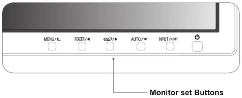
1 Press the desired button on the bottom of the Monitor set.
2 Change the value of the menu item by pressing the buttons on the bottom of the Monitor set.
To return to the upper menu or set other menu items, use the up arrow (▲button.
3 Select EXIT to leave the OSD menu.
text_image
MENU/L READER/◄ e2/► AUTO/▼ INPUT/EXIT Monitor set Buttons| Button Description | ||
| MENU / t | Accesses the main menus.(See p.20) | |
| OSD Locked/OSD Unlocked | This function allow you to lock the current control settings, so that they cannot be inadvertently changed.Press and hold the MENU button for several seconds. Then OSD of “OSD Lock” will appear. After that, user can select lock or unlock by pressing left/right button.If user selects the “Lock” icon by pressing the “OK” button, the message “OSD Locked” will appear. Otherwise, “OSD Unlocked” will appear. After selecting the “Lock”, If you want to change to Unlock, you can push the “MENU” button for several seconds. The message “OSD Unlocked” will appear. | |
| READER / ◀ | Use this button to enter Reader Mode menu. Its function works to display screen as paper-like picture for Eye comfort.If you want to more information(See p.20). | |
| e∅ / ▶ | Use this button to enter SMART ENERGY SAVING menu.(See p.20) | |
| AUTO / ▼ | When adjusting your display settings, always press the AUTO button on the MONITOR SETUP OSD. (Only supported in Analog Mode) | |
| The best display mode | 1920 x 1080 | |
| INPUT / EXIT | You can choose the input signal.When two input signals are connected, you can select the input signal (D-SUB/DVI/HDMI) you want.When only one signal is connected, it is automatically detected. The default setting is D-SUB. | |
| EXIT | ||
| EXIT the OSD(On Screen Display). | ||
| ◀ (Power Button) | Turns the power on or off. | |
| Power Indicator | The power indicator stays white if the display is running properly (On Mode). If the display is in Sleep Mode, the power indicator blinks white. | |
Customizing Settings
Menu Settings
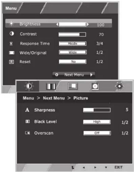
1 Press MENU button on the bottom of the Monitor set to display the Menu OSD.
2 Set the options by pressing the ◀ or ▶ or ▼ buttons.
3 Select the "Next Menu" button to enter the more option settings.
4 Select EXIT to leave the OSD menu.
To return to the upper menu or set other menu items, use the up arrow (▲button.
Each option is explained below.
text_image
Menu Brightness 100 Contrast 70 Response Time Middle 3/4 Wide/Original Wide 1/2 Reset No 1/2 Next Menu Menu > Next Menu > Picture A Sharpness 5 Black Level High 1/2 Overscan Off 1/2 EXIT| Menu Analog | Digital | HDMI Description | |
| Brightness • • | • | ||
| Contrast • • • | |||
| Response Time | • • | • | |
| Wide/Original | • • | • | |
| Reset | • • | • |
| Menu > Next Menu Analog | Digital H | HDMI Des | cription | ||
| Picture Sharpness | ● | ● ● | To adjust the clearness of the screen | ||
| Black Level | ● | To set offset level | |||
| Overscan | ● | To improve the clarity and stability of the screen | |||
| Color | Gamma | ● ● | ● | To customize the color of the screen | |
| Color Temp | |||||
| Six Color | |||||
| Color Reset | |||||
| Display | Horizontal | ● | To adjust the position of the screen | ||
| Vertical | |||||
| Clock | ● | To improve the clarity and stability of the screen | |||
| Phase | |||||
| Audio | Volume | ● | To adjust the volume | ||
| Others Language | ● ● | ● | To customize the screen status for a user's operating environment | ||
• Analog: D-SUB(Analog signal) input.
• Digital: DVI-D(Digital signal) input.
• HDMI: HDMI(Digital signal) input.
Picture
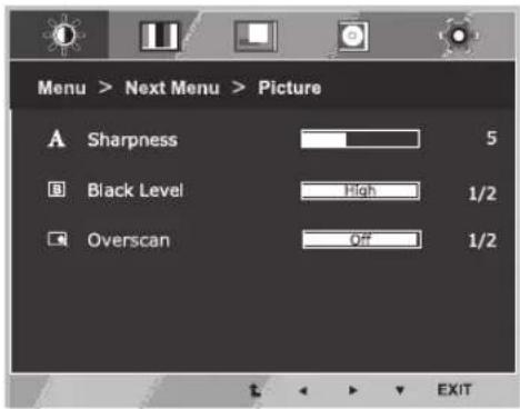
1 Press MENU button on the bottom of the Monitor set to display the Menu OSD.
2 Select the "Next Menu" button to enter the more option settings.
3 Enter to Picture by pressing the ▼ button.
4 Set the options by pressing the ◀ or ▶ or ▼ buttons.
5 Select EXIT to leave the OSD menu.
To return to the upper menu or set other menu items, use the up arrow (▲button.
text_image
Menu > Next Menu > Picture A Sharpness 5 Black Level High 1/2 Overscan Off 1/2 EXITEach option is explained below.
| Menu > Next Menu > Picture Description | |
| Sharpness | To adjust the clearness of the screen. |
| Black Level | You can set the offset level. If you select 'High', the screen will be bright and if you select 'Low', the screen will be dark.(only for HDMI input)* Offset?As the criteria for video signal, it is the darkest screen the monitor can show. |
| Overscan To select the range of output | image for DTV timing in HDMI input.(only for HDMI input)Recommend overscan function to turn on when connect AV equipment. |
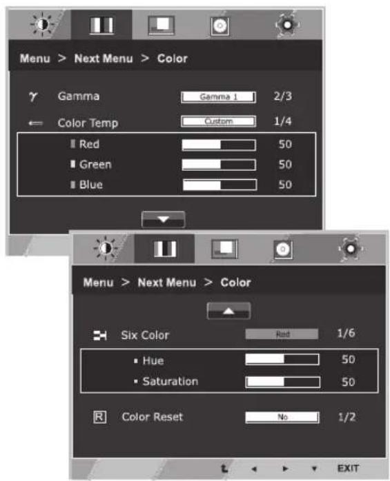
Color
1 Press MENU button on the bottom of the Monitor set to display the Menu OSD.
2 Select the "Next Menu" button to enter the more option settings.
3 Select Color by pressing the ▶ button.
4 Enter to Color by pressing the ▼ button.
5 Set the options by pressing the ◀ or ▶ or ▼ buttons.
6 Select EXIT to leave the OSD menu.
To return to the upper menu or set other menu items, use the up arrow (▲button.
text_image
Menu > Next Menu > Color γ Gamma Gamma 1 2/3 ← Color Temp Custom 1/4 ■ Red 50 ■ Green 50 ■ Blue 50 Menu > Next Menu > Color ■ Six Color Red 1/6 • Hue 50 • Saturation 50 R Color Reset No 1/2 EXITEach option is explained below.
| Menu > Next Menu > Color Description | |
| Gamma | Set your own gamma value. : Gamma 0, Gamma 1, Gamma 2 on the monitor, high gamma values display whitish images and low gamma values display blackish images. |
| Color Temp Custom | |
| • Red:Set your own red color levels.• Green:Set your own green color levels.• Blue:Set your own blue color levels. | |
| Select the screen color.Warm:Set the screen to warm color temperature (more red).Medium:Set the screen to medium color temperature.Cool:Set the screen to cool color temperature (more blue). | |
| Six Color | Sets and stores the hue and saturation for six colors(Red/Green/Blue/Cyan/Magenta/Yellow) to satisfy the color requirements of a user. |
| Hue Adjusts the screen hue. | |
| Saturation Adjusts the color sharpness on the screen. Lower values make the color sharpness weaker and colors lighter while higher values make the color sharpness stronger and colors dark. | |
| Color Reset | Resets the color settings to the factory default settings for the current input device. |
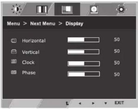
Display
1 Press MENU button on the bottom of the Monitor set to display the Menu OSD.
2 Select the "Next Menu" button to enter the more option settings.
3 Select Display by pressing the ▶ button.
4 Enter to Display by pressing the ▼ button.
5 Set the options by pressing the ◀ or ▶ or ▼ buttons.
6 Select EXIT to leave the OSD menu.
To return to the upper menu or set other menu items, use the up arrow (▲button.
text_image
Menu > Next Menu > Display Horizontal 50 Vertical 50 Clock 50 Phase 50 t ← → EXITEach option is explained below.
| Menu > Next Menu > Display Description | |
| Horizontal | To move image left and right. |
| Vertical | To move image up and down. |
| Clock | To minimize any vertical bars or stripes visible on the screen background.The horizontal screen size will also change. |
| Phase | To adjust the focus of the display. This item allows you to remove any horizontal noise and clear or sharpen the image of characters. |
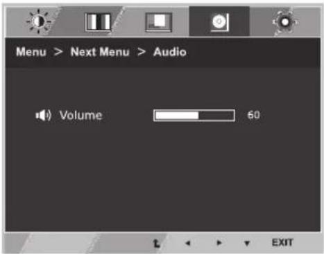
Audio
1 Press MENU button on the bottom of the Monitor set to display the Menu OSD.
2 Select the "Next Menu" button to enter the more option settings.
3 Select Audio by pressing the ▶ button.
4 Enter to Volume by pressing the ▼ button.
5 Set the options by pressing the ◀ or ▶ buttons.
6 Select EXIT to leave the OSD menu.
To return to the upper menu or set other menu items, use the up arrow (▲button.
text_image
Menu > Next Menu > Audio Volume 60 EXITEach option is explained below.
| Menu > Next Menu > Audio Description |
| Volume To adjust the Volume of headphone/earphone.(Only for HDMI input) |
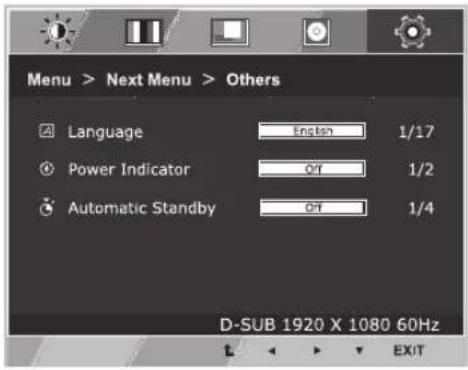
Others
1 Press MENU button on the bottom of the Monitor set to display the Menu OSD.
2 Select the "Next Menu" button to enter the more option settings.
3 Select Others by pressing the ▶ button.
4 Enter to Others by pressing the ▼ button.
5 Set the options by pressing the ◀ or ▶ or ▼ buttons.
6 Select EXIT to leave the OSD menu.
To return to the upper menu or set other menu items, use the up arrow (↑button.
text_image
Menu > Next Menu > Others Language English 1/17 Power Indicator Off 1/2 Automatic Standby Off 1/4 D-SUB 1920 X 1080 60Hz L ◀ ▶ ▼ EXITEach option is explained below.
| Menu > Next Menu > Others Description | |
| Language | To choose the language in which the control names are displayed. |
| Power Indicator | Use this function to set the power indicator on the bottom side of the monitor to On or Off.If you set Off, it will go off.If you set On at any time, the power indicator will automatically be turned on. |
| Automatic Standby | If you do not press any button on the monitor set for a certain period, the monitor set will automatically switch to standby mode. |
READER Setting
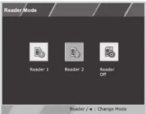
1 Press READER button on the bottom of the Monitor set to display the Reader Mode OSD.
2 Set the options by pressssing the ◀ buttons.
text_image
Reader Mode Reader 1 Reader 2 Reader Off Reader / ← : Change ModeEach option is explained below.
| Reader Mode | Description |
| Reader 1 It is a mode that the screen | is adjusted to the best for the newspaper. If you want screen more bright, you can control brightness in Menu OSD. |
| Reader 2 It is a mode that the screen | is adjusted to the best for the cartoon. If you want screen more bright, you can control brightness in Menu OSD. |
| Reader Off It is a mode that reader mode is off. | |

NOTE
If option of Reader Mode is Reader 1 or Reader 2, SMART ENERGY SAVING will automatically be Off.
SMART ENERGY SAVING
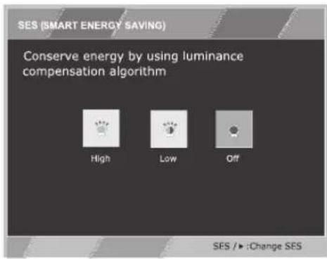
1 Press button on the bottom of the Monitor set to display the SMART ENERGY SAVING OSD.
2 Set the options by pressing the ▶ buttons.
text_image
SES (SMART ENERGY SAVING) Conserve energy by using luminance compensation algorithm High Low Off SES /► :Change SESEach option is explained below.
| SMART ENERGY SAVING Description | |
| High | Enables SMART ENERGY SAVING you can save energy with this energy- high efficient function. |
| Low | Enables SMART ENERGY SAVING you can save energy with this energy- low efficient function. |
| Off Disables SMART ENERGY SAVING. | |
* SMART ENERGY SAVING: Conserve energy by using luminance compensation algorithm.

NOTE
Saving Data depends on the Panel. So, those values should be different from each panel and panel vendor. If option of SMART ENERGY SAVING is High or Low, monitor luminance become higher or lower depend on source. If option of SMART ENERGY SAVING is High or Low, Reader Mode will automatically be Reader Off.
TROUBLESHOOTING
Check the following before calling for service.
| No image appears | |
| Is the power cord of the display connected? | Check and see if the power cord is connected properly to the power outlet. |
| Is the power indicator light on? | Press the Power button. |
| Is the power on and the power indicator White? | Adjust the brightness and the contrast. |
| Is the power indicator flickering? | If the display is in power saving mode, try moving the mouse or pressing any key on the keyboard to bring up the screen.Try to turn on the PC. |
| Do you see an "OUT OF RANGE" message on the screen? | This message appears when the signal from the PC (video card) is out of horizontal or vertical frequency range of the display. See the 'Specifications' section of this manual and configure your display again. |
| Do you see a "NO SIGNAL" message on the screen? | When the monitor is on "No-Signal" in 5 minutes, the monitor goes to DPM mode. |
| Do you see a "OSD LOCKED" message on the screen? | |
| Do you see “OSD LOCKED” when you push MENU button? | • You can secure the current control settings, so that they cannot be inadvertently changed. You can unlock the OSD controls at any time by pushing the MENU button for several seconds: the message “OSD UNLOCKED” will appear. |
| Display image is incorrect | |
| Display Position is incorrect. | Press the AUTO button to automatically adjust your display image to the ideal setting. |
| On the screen background, vertical bars or stripes are visible. | Press the AUTO button to automatically adjust your display image to the ideal setting. |
| Any horizontal noise appearing in any image or characters are not clearly portrayed. | Press the AUTO button to automatically adjust your display image to the ideal setting.Check Control Panel ▶ Display ▶ Settings and adjust the display to the recommended resolution or adjust the display image to the ideal setting. Set the color setting higher than 24 bits (true color). |

CAUTION
Check Control Panel ▶ Display ▶ Settings and see if the frequency or the resolution were changed. If yes, readjust the video card to the recommend resolution.
If the recommended resolution (optimal resolution) is not selected, letters may be blurred and the screen may be dimmed, truncated or biased. Make sure to select the recommend resolution.
The setting method can differ by computer and O/S (Operation System), and resolution mentioned above may not be supported by the video card performance. In this case, please ask to the computer or the video card manufacturer.
| Display image is incorrect | |
| The screen color is mono or abnormal. | Check if the signal cable is properly connected and use a screwdriver to fasten if necessary.Make sure the video card is properly inserted in the slot.Set the color setting higher than 24 bits (true color) atControl Panel▶ Settings. |
| The screen blinks. | Check if the screen is set to interlace mode and if yes, change it to the recommend resolution. |
| Do you see an "Unrecognized monitor, Plug&Play (VESA DDC) monitor found" message? | |
| Have you installed the display driver? | Be sure to install the display driver from our web site: http://www.lg.com.Make sure to check if the video card supports Plug&Play function. |
| The screen is flickering. | |
| Did you select the recommended resolution? | • If the selected resolution is HDMI 1080i 60/50 Hz, the screen may be flickering. Change the resolution to the recommended resolution 1080P. |
SPECIFICATIONS
23MB35PH
| Display Screen Type | Flat Panel Active matrix-TFT LCD Anti-Glare coating | |
| Pixel Pitch | 0.2652 mm x 0.2652 mm | |
| Sync Input Horizontal Frequency | 30 kHz to 83 kHz (Automatic) | |
| Vertical Frequency 56Hz to 75Hz (D-SUB,DVI-D) 56Hz to 61Hz (HDMI) | ||
| Input Form Separate Sync. Digital | ||
| Video Input Signal Input | 15 pin D-SUB Connector/DVI-D Connector(Digital) HDMI Connector | |
| Input Form RGB Analog (0.7 Vp-p/ 75 ohm), Digital | ||
| Resolution Max | D-SUB(Analog): 1920 x 1080 @ 60 Hz DVI/HDMI (Digital): 1920 x 1080 @ 60 Hz | |
| Recommend | VESA 1920 x 1080 @ 60 Hz | |
| Plug & Play | DDC 2B(Analog,Digital,HDMI) | |
| Power Consumption | On Mode: 16.0 W Typ. (ENERGY STAR® standard) * 19.9 W Typ. (Outgoing condition) ** Sleep Mode ≤ 0.3 W Off Mode ≤ 0.3 W | |
| Power Input | AC 100-240 V~ 50/60 Hz 1.0 A | |
| Dimensions (Width x Height x Depth) | With Stand | 54.8 cm x 36.7 cm x 24.6 cm |
| Without Stand | 54.8 cm x 33.5 cm x 16.6 cm | |
| Weight | 4.8 kg | |
| Environmental conditions | Operating Temperature Operating Humidity | 10°C to 35 °C 10 % to 80 % |
| Storage Temperature Storage Humidity | -20°C to 60 °C 5 % to 90 % non-Condensing | |
Product specifications shown above may be changed without prior notice due to upgrade of product functions.
* The power consumption level can be different by operating condition and monitor setting.
* The On mode power consumption is measured with ENERGY STAR® test standard.
** The On mode power consumption is measured with LGE test standard (Full White pattern, Maximum resolution)
SPECIFICATIONS
24MB35PH
| Display Screen Type | Flat Panel Active matrix- | TFT LCDAnti-Glare coating |
| Pixel Pitch 0.275 mm x 0 | .275 mm | |
| Sync Input Horizontal Frequency | 30 kHz to 8 | 3 kHz (Automatic) |
| Vertical Frequency 56Hz | to 75Hz (D-SUB,DVI-D)56Hz to 61Hz (HDMI) | |
| Input Form Separate Sync. Digital | ||
| Video Input Signal Input | 15 pin D-SUB Connector/DVI-D Connector(Digital)HDMI Connector | |
| Input Form RGB Analog | (0.7 Vp-p/ 75 ohm), Digital | |
| Resolution Max D-SUB(Analog) : 1920 x 1080@ 60 HzDVI/HDMI (Digital) : 1920 x 1080 @ 60 Hz | ||
| Plug & Play | DDC 2B(Analog,Digital,HDMI) | |
| Power Consumption | On Mode : 17.1 W Typ. (ENERGY STAR® standard) *24.3 W Typ. (Outgoing condition) **Sleep Mode ≤ 0.3 WOff Mode ≤ 0.3 W | |
| Power Input | AC 100-240 V~ 50/60 Hz 1.2 A | |
| Dimensions (Width x Height x Depth) | With Stand 56.9 cm x 43 | .3 cm x 27.1 cm |
| Without Stand | 56.9 cm x 34.2 cm x 6.3 cm | |
| Weight | 5.0 kg | |
| Environmental conditions | Operating Temperature Operating Humidity | 10°C to 35 °C10 % to 80 % |
| Storage Temperature Storage Humidity | -20°C to 60 °C5 % to 90 % non-Condensing | |
Product specifications shown above may be changed without prior notice due to upgrade of product functions.
* The power consumption level can be different by operating condition and monitor setting.
* The On mode power consumption is measured with ENERGY STAR® test standard.
** The On mode power consumption is measured with LGE test standard (Full White pattern, Maximum resolution)
SPECIFICATIONS
27MB35PH
| Display Screen Type | Flat Panel Active matrix- | TFT LCD Anti-Glare coating |
| Pixel Pitch 0.3114 mm x | 0.3114 mm | |
| Sync Input Horizontal Frequency | 30 kHz to 8 | 3 kHz (Automatic) |
| Vertical Frequency 56Hz | to 75Hz (D-SUB,DVI-D) 56Hz to 61Hz (HDMI) | |
| Input Form Separate Sync. Digital | ||
| Video Input Signal Input | 15 pin D-SUB Connector/DVI-D Connector(Digital) HDMI Connector | |
| Input Form RGB Analog | (0.7 Vp-p/ 75 ohm), Digital | |
| Resolution Max D-SUB(Analog) : 1920 x 1080 @ 60 Hz | ||
| Plug & Play | DDC 2B(Analog,Digital,HDMI) | |
| Power Consumption | On Mode : 20.3 W Typ. (ENERGY STAR® standard) * 29.4 W Typ. (Outgoing condition) ** Sleep Mode ≤ 0.3 W Off Mode ≤ 0.3 W | |
| Power Input | AC 100-240 V~ 50/60 Hz | 1.5 A |
| Dimensions (Width x Height x Depth) | With Stand 64.4 cm x 41 | 0 cm x 25.9 cm |
| Without Stand | 64.4 cm x 38.7 cm x 6.4 cm | |
| Weight | 6.5 kg | |
| Environmental conditions | Operating Temperature Operating Humidity | 10°C to 35 °C 10 % to 80 % |
| Storage Temperature Storage Humidity | -20°C to 60 °C 5 % to 90 % non-Condensing | |
Product specifications shown above may be changed without prior notice due to upgrade of product functions.
* The power consumption level can be different by operating condition and monitor setting.
* The On mode power consumption is measured with ENERGY STAR® test standard.
** The On mode power consumption is measured with LGE test standard (Full White pattern, Maximum resolution)
Preset Modes (Resolution)
| Display Modes (Resolution) | Horizontal Frequency(kHz) | Vertical Frequency(Hz) | Polarity(H/V) | |
| 720 x 400 31.468 70 -/+ | ||||
| 640 x 480 31.469 60 -/- | ||||
| 640 x 480 37.500 75 -/- | ||||
| 800 x 600 37.879 60 +/+ | ||||
| 800 x 600 46.875 75 +/+ | ||||
| 1024 x 768 48.363 60 -/- | ||||
| 1024 x 768 60.023 75 +/+ | ||||
| 1152 x 864 67.500 75 +/+ | ||||
| 1280 x 1024 63.981 60 +/+ | ||||
| 1280 x 1024 79.976 75 +/+ | ||||
| 1680 x 1050 65.290 60 -/+ | ||||
| 1920 x 1080 67.500 60 +/+ Recommend Mode |
HDMI Timing
| Factory support mode (Preset Mode) | Horizontal Frequency(kHz) | Vertical Frequency(Hz) | HDMI |
| 480P 31.50 60 O | |||
| 576P 31.25 50 O | |||
| 720P 37.50 50 O | |||
| 720P 45.00 60 O | |||
| 1080i 28.12 50 O | |||
| 1080i 33.75 60 O | |||
| 1080P 56.25 50 O | |||
| 1080P 67.50 60 | ORecommend Mode |
Indicator
| Mode LED Color | |
| On Mode | White |
| Sleep Mode | Blinking White |
| Off Mode Off |

text_image
LG Life's GoodMake sure to read the Safety Precautions before using the product.
The model and serial number of the product are located on the back and on one side of the product.
Record them below in case you ever need service.
MODEL
SERIAL
ENERGY STAR is a set of power-saving guidelines issued by the U.S.Environmental Protection Agency(EPA).

As an ENERGY STAR Partner LGE U. S. A., Inc. has determined that this product meets the ENERGY STAR guidelines for energy efficiency.