
MPK-12EEN2 - Air-conditioner MIDEA - Free user manual and instructions
Find the device manual for free MPK-12EEN2 MIDEA in PDF.


User questions about MPK-12EEN2 MIDEA
0 question about this device. Answer the ones you know or ask your own.
Ask a new question about this device
Download the instructions for your Air-conditioner in PDF format for free! Find your manual MPK-12EEN2 - MIDEA and take your electronic device back in hand. On this page are published all the documents necessary for the use of your device. MPK-12EEN2 by MIDEA.
USER MANUAL MPK-12EEN2 MIDEA
Room Air conditioner
Service manual
CAUTION
- BEFORE SERVICING THE UNIT, READ THE SAFETY
- PRECAUTIONS IN THIS MANUAL.
- ONLY FOR AUTHORIZED SERVICE PERSONNEL.
| MODELS: | MPK-09CEN2 | MPK-09CRN2 | MPK-09EEN2 | MPK-09ERN2 |
| MPK-10CEN2 | MPK-10CRN2 | MPK-10EEN2 | MPK-10ERN2 | |
| MPK-12CEN2 | MPK-12CRN2 | MPK-12EEN2 | MPK-12ERN2 | |
| MPK-08CE | MPK-08CR | MPK-08EE | MPK-08ER | |
| MPK-09CE | MPK-09CR | MPK-09EE | MPK-09ER | |
| MPK-10CE | MPK-10CR | MPK-10EE | MPK-10ER |
CONTENTS
1. PREFACE
1.1 SAFETY PRECAUTIONS....1
1.2 INSULATION RESISTANCE TEST....1
1.3 FEATURES....1
1.4 CONTROL LOCATIONS....2
2. TROUBLE SHOOTING GUIDE
2.1 REFRIGERATION CYCLE DIAGRAM....3
2.2 ELECTRIC FUNCTION....3
2.3 TROUBLE SHOOTING GUIDE....5
3. WIRING DIAGRAM
3.1 WIRING DIAGRAM FOR COOLING ONLY MODELS....8
3.2 WIRING DIAGRAM FOR COOLING AND HEATING MODELS....8
3.3 ELECTRICAL CONTROL SCHEME....9
3.4 MAIN CONTROL BOARD SCHEME....10
3.5 DISPLAY BOARD SCHEME....11
4. HOW TO DISASSEMBLE THE UNIT....12
5. EXPLODED VIEWS....19
6. SPARE PARTS LIST....19
7. SPECIFICATIONS....19
1. PREFACE
This SERVICE MANUAL provides various servicing information, including the mechanical and electrical parts, etc. This room air conditioner was manufactured and assembled under a strict quality control system.
The refrigerant was charged at the factory. Be sure to read the safety precautions prior to servicing the unit.
1.1 SAFETY PRECAUTIONS
- When servicing the unit, set the POWER SWITCH to OFF and unplug the power cord.
- Inspect the service cord for damage or wear.
If a short circuit is found, replace all parts which have been overheated or damaged by the short circuit.
- After servicing the unit, make an insulation resistance test to protect the customer from being exposed to shock hazards.
- Unplug the power cord and connect a jumper lead between the two (2) live pins.
- The grounding conductor (yellow/green) is to be open.
- Measure the resistance value with an ohm meter between the jumped lead and each exposed metallic part on the equipment at all the positions (except OFF) of the ROTARY SWITCH or POWER SWITCH.
- The value should be over 1MΩ.
1.3 FEATURES
Water full alarm
Anti-icing function at cooling mode.
Restart relay protection for the compressor.
Temperature sensor err self-diagnose.
24 hours on/off mode time setting.
Both temperature mode display
Separate motor for indoor and outdoor system.
Multiple uses: dehumidifying and cloth drying.
Low temperature Drying operation.
There are four casters on the bottom for easy movement.
Only one exhaust pipe, which makes the A/C easier to use.
1.4 CONTROL LOCATIONS
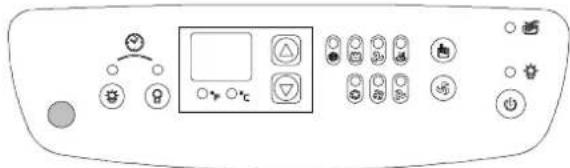
For cooling only with electric heater models:
text_image
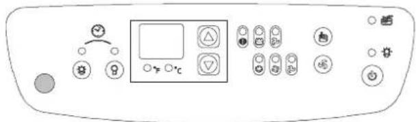
Control panel interface with icons and a display panel showing various function buttons and symbolsFor cooling only models:
text_image
Diagram of a control panel with labeled buttons and display screen, showing various function icons and symbols.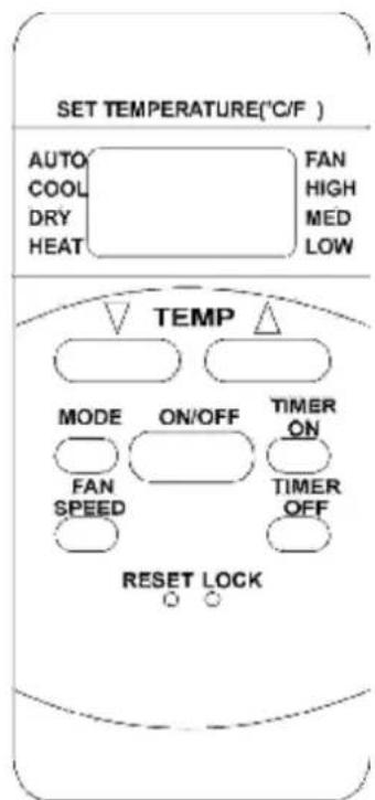
text_image
SET TEMPERATURE(°C/F ) AUTO COOL DRY HEAT FAN HIGH MED LOW TEMP MODE ON/OFF TIMER ON FAN SPEED TIMER OFF RESET LOCKRemote receiver.
Timer ON button. Push this button to set the
Remote-controlled or gentle-touch keys for easy and comfortable use.
Compressors of famous brands are adopted for reliability and low noise.
The heating system uses PTC electrical heater and will not be affected by ambient temperature, which saves energy.
Suitable for local cooling and heating.
Condenser shower and large volume tank design.
Timer OFF button. Push this button to set the Timer Off time.
Timer ON/OFF lamp.
°F Fahrenheit temperature display. When Fahrenheit temperature display mode is selected.
°C Celsius temperature display. When Celsius temperature display mode is selected.
Temperature setting up. Push this button to set temperature setting up.
Temperature setting down. Push this button to set temperature setting down.
Cooling operation lamp.
Drying operation lamp.
Fan only operation lamp.
Electric heating operation lamp.
Mode setting button. Push this button to select the operation mode: Cool, Dry, Fan only and Heat
Fan speed setting button. Push this button to select fan speed: High, Med and Low.
Power button. Push this button to start the unit.
Water full alarm lamp
Power lamp
Remote controller:
LCD display.
Mode button: Select the operation mode, AUTO, COOL, DRY, HEAT (cooling only with electric heater models only) and FAN.
Fan speed button: Select the Fan speed, AUTO, LOW, MED, HIGH.
ON/OFF button: Press this button to operation the unit, again to stop.
Temperature setting up button: Press this button to increase temperature setting or adjust the TIMER in a
clockwise direction.
Temperature setting down button: Press this button to decrease temperature setting or adjust the TIMER in a counter-clockwise direction.
Timer on button: Push this button to set the ON timer.
Timer off button: Push this button to set the OFF timer.
Lock button: Press this button to lock all button except this button.
Reset button: Press this button to reset all settings to factory settings.
2 TROUBLESHOOTING GUIDE
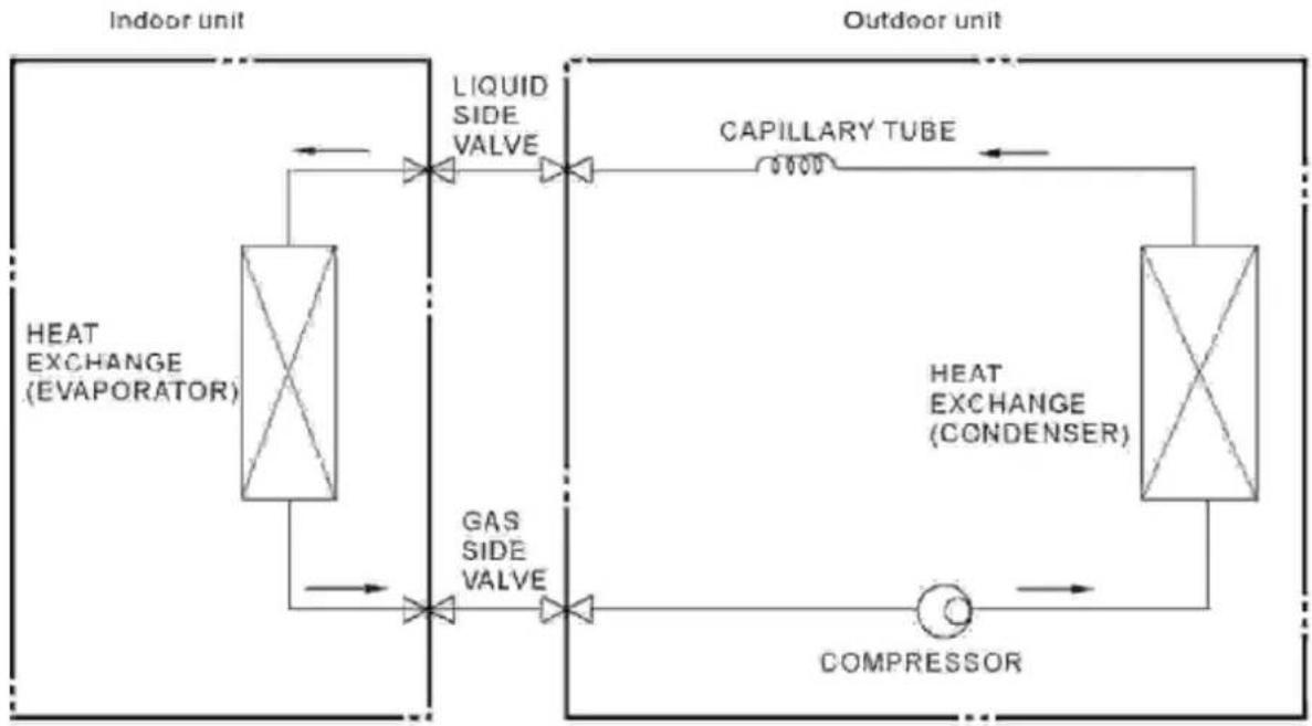
2.1 REFRIGERATION CYCLE DIAGRAM
flowchart
graph LR
    A["HEAT EXCHANGE (EVAPORATOR)"] --> B["LICID SIDE VALVE"]
    B --> C["CAPILLARY TUBE"]
    C --> D["HEAT EXCHANGE (CONDENSER)"]
    D --> E["COMPRESSOR"]
    E --> F["GAS SIDE VALVE"]
    F --> A
    style A fill:#f9f,stroke:#333
    style D fill:#f9f,stroke:#333
    style E fill:#ccf,stroke:#333
2.2 ELECTRICAL FUNCTION
2.2.1 Electric Control working environment
2.2.1.1 Input voltage: 187\~264V for 50Hz models and 97\~127V for 60Hz models;
2.2.1.2 Input power frequency: 50Hz or 60Hz;
2.2.1.3 Ambient temperature: -7^ +43^ for cooling only with electric heater models and 10^ +43^ for cooling only models;
2.2.1.4 Indoor fan normal working amp is less than 1A;
2.2.1.5 Outdoor fan. Normal working amp is less than 1.5A;
2.2.1.6 Compressor: single-phase power supply. Its normal working amp is less than 10A;
2.2.2 Proper symbols and their meanings:
TA: Indoor ambient temperature
TC: Indoor evaporator temperature
TS: Setting temperature through the remote controller
2.2.3 Systematic functions
Remote receiving (Optional)
LED displaying and alarm
On or off Timer
Protection for the compressor
Water full alarm
Anti-icing function at cooling mode.
Temperature sensor err self-diagnose.
Both temperature mode display
2.2.4 Protection
2.2.4.1 The compressor functions protection with a delay of three minutes.
2.2.4.2 Sensor protection at open or short circuit.
2.2.4.3 Evaporator anti-icing protection at cooling mode.
2.2.4.4 Water full alarm
There are two water position switches used in the unit. One detects the water depth in the chassis and the other detects the water in the tank.
2.2.4.4.1 Water full alarm will be on when the unit is standing by or operating.
2.2.4.4.2 When the water adds up to the first position on the chassis, the pump will be activated. If the water drops down through the position, the pump will be on and stop after 2 minutes.
2.2.4.4.3 When the water adds up to the position on the tank, the compressor, outdoor fan motor, electric heater and pump will stop operation. And the LED will display "P1" while the water full lamp flashes at 2Hz.
2.2.4.4.4 When the water adds up to the second position on the chassis and the switch has been on for 10 seconds, the whole unit will stop operation. The LED will display "P2" and the water full lamp will flash at 5Hz. After you have clear the problem, you should unplug the unit and plug again. Then the unit will be ready to operate.
2.2.4.4.5 When the unit is standing by, if the unit displays "P1", the pump will not operate. After the problem is cleared, the unit will be ready to operate. But if you push the power button, the unit will shut the "P1" display and shut down.
2.2.5 Fan-only Mode Function Requirement
2.2.5.1 The compressor and outdoor fan are OFF at Fan-only mode.
2.2.5.2 The speed of indoor fan can be optionally
chosen as High/Mid/Low.
2.2.6 Cooling Mode Function Requirement
2.2.6.1 The speed of indoor fan can be optionally selected as High/Mid/Low.
2.2.6.2 The compressor operate as:
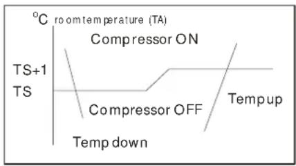
text_image
°C room temperature (TA) Compressor ON TS+1 TS Compressor OFF Temp up Temp down2.2.7 Drying mode
2.2.7.1 When the unit starts to operate in Drying mode, the compressor will start while the room temperature is over 13^ C. After the compressor started, the compressor will operate as:
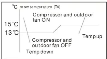
text_image
°C room temperature (TA) 15°C 13°C Compressor and outdoor fan ON Compressor and outdoor fan OFF Temp up Temp down2.2.7.2 The indoor fan will operate with high speed. The outdoor fan will operate with compressor.
2.2.8 Heating mode
2.2.8.1 The speed of indoor fan can be optionally chosen as High/Mid/Low.
2.2.8.2 Electric heater operate as :
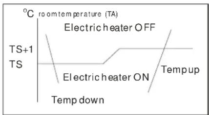
text_image
°C room temperature (TA) Electric heater OFF TS+1 TS Electric heater ON Tempup Temp down2.2.9 Temperature display
2.2.9.1 The setting temperature will be displayed in Cooling and Heating mode. The room temperature will be displayed in Drying and Fan only mode.
2.2.9.2 The setting temperature range is from 17^ C to 30^ C or 62^ F to 88^ F. The display temperature range is from 10^ C to 35^ C or 48^ F to 98^ F. If the room temperature is lower than 10^ C or 48^ F, the display will be 10^ C or
48^
2.2.10 Timer Function
2.2.10.1 The maximum length of Timer is 24 hours and the minimum is 0.5 hours.
2.2.10.2 TIMER ON function: first turn OFF the unit, the unit will be automatically ON at the set time.
2.2.10.3 TIMER OFF function: first turn ON the unit, the unit will be automatically OFF at the set time.
2.2.10.4 TIMER ON/OFF function (ON TIMER is earlier than OFF TIMER): first turn OFF the unit, it will be automatically ON at set time,
and later be OFF at the set time.
2.2.10.5 TIMER OFF/ON function (OFF TIMER is earlier than ON TIMER): first turn ON the unit, it will be automatically OFF at set time, and later be ON at the set time.
2.2.10.6 Timer function execution is applicable upon one operation only.
2.2.10.7 Timer precision is less than 15 minutes.
2.2.11 Auto restart function
In case of a sudden power failure, this function automatically sets the unit to previous settings before the power failure when power returns.
2.3 TROUBLESHOOTING GUIDE
In general, possible trouble is classified in three kinds. One is called Starting Failure which is caused from an electrical defect, another is ineffective Air Conditioning caused by a defect in the refrigeration circuit and improper application, and the other is called the Structure Damage.
ROOM AIRCONDITIONER VOLTAGE LIMITS:
| NAMEPLATE RATING | MINIMUM | MAXIMUM |
| 220~240V | 196V | 253V |
| 115V | 103V | 122V |
| PROBLEM | POSSIBLE CAUSE | REMEDY |
| No power display on panel or any one of the buttons failure. | Power failure | Check the power supplier if the power supplier is supplied to the unit. Check the power cord and correct if damaged. |
| Transformer (Discharge transformer before testing) | Check resistance between the two input/output lines on transformer. Replace the transformer if either of the input/output is open or the transformer is damaged. | |
| Display board or main PCB failure | Check the voltage on display board. Replace the display board if it is +5V else replace the main PCB. | |
| Remote control failure. | Battery failure | Check the voltage of battery. Replace batteries if the voltage is lower than 2.3V. |
| Fan motor runs intermittently | Cycles on overload. | Check voltage. Call an electrician if not within limits. |
| Test capacitor.Replace if not within +/-10% of manufacture's rating. | ||
| Check bearings. Replace the motor if the blower wheel cannot rotate freely. | ||
| Pay attention to any change from high speed to low speed.Replace the motor if the speed does not change. | ||
| Compressor stops instantly after startup. | RefrigerantCompressor | The amount of the refrigerant is too much, making the compressor load too big. Recycle and recharge the refrigerant after checking for the reason.The compressor is blocked inside. Replace after checking for the reason. |
| Fan motor will not run. | No power | Check voltage at electrical outlet. Correct if none. |
| Water alarm | Check and correct if water alarm happens. | |
| Power supply cord | Check voltage at the power cord terminal on Main PCB. Replace the power cord if none. | |
| Transformer (Discharge transformer before testing) | Check resistance between the two input/output lines on transformer. Replace the transformer if either of the input/output is open or the transformer is damaged. | |
| Wire disconnected or connection loose | Connect wire. Refer to wiring diagram for terminal identification. Repair or replace loose terminal. | |
| Main PCB failure | Select fan speed and Check the voltage on main PCB. Replace the main PCB if no voltage in anyone. | |
| Capacitor (Discharge capacitor before testing) | Test capacitor. Replace if not within +/-10% of manufacture's rating. Replace if shorted, open or damaged. | |
| Will not rotate | Fan blower hitting scroll. Realign assembly. Check fan motor bearings. Replace the motor if motor shaft do not rotate. | |
| Fan motor noise. | Fan blower | Replace the fan blower if cracked, out of balance, or partially missing. |
| Loose screws | Tighten them. | |
| Worn bearings | Replace the motor if knocking sounds continue when running or loose, or the motor hums or noise appears to be internal while running. | |
| Compressor will not run while fan motor runs. | Voltage | Check voltage. Call Supply Authority if not within limits. |
| Wiring | Check the wire connections, if loose, repair or replace the terminal. If wires are off, refer to wiring diagram for identification, and replace. Check wire locations. If not per wiring diagram, correct. | |
| Main PCB failure | Check voltage of main PCB. Replace the main PCB if open. | |
| Capacitor (Discharge capacitor before testing) | Check the capacitor. Replace if not within +/-10% of manufacturers rating. Replace if shorted, open, or damaged. | |
| Room temp sensor | Check the temperature setting if not at the coolest (in cooling mode) or the warmest (in heating mode). Set it if not. | |
| Compressor | Check the compressor for open circuit or ground. If open or grounded, replace the compressor. | |
| Excessive noise. | Copper tubing | Remove the cabinet and carefully rearrange tubing not to contact cabinet, compressor, shroud and barrier. |
| Water full alarm | Water tank full | Check and pour if the water tank is full. |
| Water depth sensor if failure | Check and replace if failure. | |
| Water pump failure | Check and replace if the pump if failure. | |
| Water depth is over load in chassis | Check and drainage the water in the chassis by open the drainage hose on the chassis. | |
| Water depth sensing structure | Check and replace or realign if the structure is failure. | |
| Cooling or heating feels not good | Air filter | Clean or replace if restricted. |
| Air discharge pipe | Realign and assemble if the installation of the air discharging pipe failure. Replace if damaged. | |
| Unit undersized | Determine if the unit is properly sized for the area to be cooled or heated. | |
| Condenser and Evaporator | Clean or replace if restricted. | |
| Water shower failure | Check the structure of water showering system and clean if blocked. | |
| Fan motor | Check the fan capacitor and replace if not within +/-10% of manufactures rating. | |
| Air flow | Clean or remove if any barrier is found to block the inlet/outlet wind flow of the unit. | |
| Less refrigerant | Check the tubes for reasons of leakage. Recycle the refrigerant, correct the leakage points and recharge. | |
| Capillary tube | Regulate the flow if capillary tube and make the evaporating temperature appropriate if the evaporator is frosted. Replace if blocked. Repair joint if leaking. | |
| Compressor | The inlet and outlet valve of the compressor is damaged, making the low pressure connected with the high pressure. The refrigerating system can not produce high pressure and low pressure. Replace the compressor after checking for the reason. | |
| Heat sources | Reduce if too many. | |
| No cooling or heating. | No power | Check the voltage. Call an electrician if no within the limit. |
| Wiring | Check the terminals. Repair and correct if loose. | |
| Temperature setting | Check and adjust the temperature setting. | |
| Mode setting | Check and adjust the mode setting. | |
| Compressor | Check and replace if the compressor, the over-load protector or wiring is broken. | |
| Electric heater failure | Check and replace if the heater is damaged. | |
| Over heat fuse failure | Check and replace if the fuse is damaged. | |
| Main PCB | Check the voltage of main PCB. Replace the main PCB when the unit failure in heating mode. | |
| The unit starts and stops frequently. | Power supply | The input power supply voltage is too low. Call an electrician if not within limits. |
| Main PCB | Check and replace the main PCB if the compressor relay on PCB is shorted or damaged. | |
| Room temperature | When the room temperature is too high, the compressor will protect. |
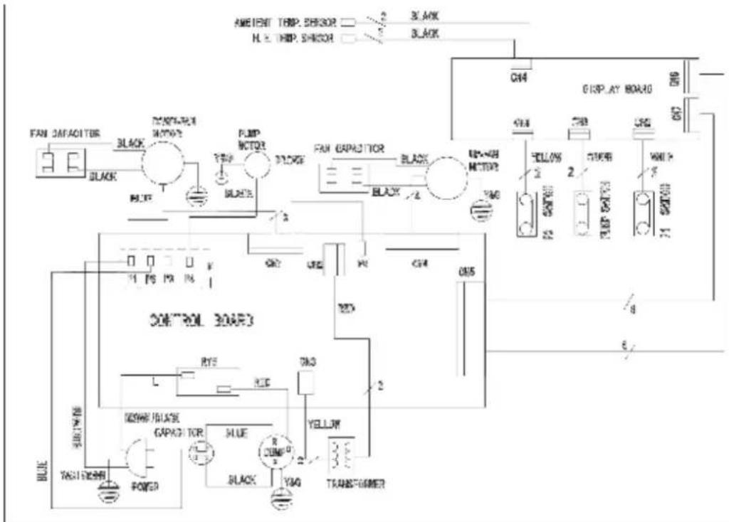
3 WIRING DIAGRAM
3.1 FOR COOLING ONLY MODELS:
| MPK-09CEN2 | MPK-09CRN2 | MPK-08CE | MPK-08CR |
| MPK-10CEN2 | MPK-10CRN2 | MPK-09CE | MPK-09CR |
| MPK-12CEN2 | MPK-12CRN2 | MPK-10CE | MPK-10CR |
text_image
AMIENT TEMP. SHIOR H. Z. THIP. SHIOR BLACK BLACK FAN CAPACITOR BLACK TAXTURE MOTOR2 BLTF PUMP MOTOR BLTF BLTF PUMP CAPACITOR BLACK BLACK BLTF BLTF BLTF BLTF BLTF BLTF BLTF BLTF BLTF BLTF BLTF BLTF BLTF BLTF BLTF BLTF BLTF BLTF BLTF BLTF BLTF BLTF BLTF BLTF BLTF BLTF BLTF BLTF BLTF BLTF BLTF BLTF BLTF BLTF3.2 FOR COOLING AND HEATING MODELS:
| MPK-09EEN2 | MPK-09ERN2 | MPK-08EE | MPK-08ER |
| MPK-10EEN2 | MPK-10ERN2 | MPK-09EE | MPK-09ER |
| MPK-12EEN2 | MPK-12ERN2 | MPK-10EE | MPK-10ER |
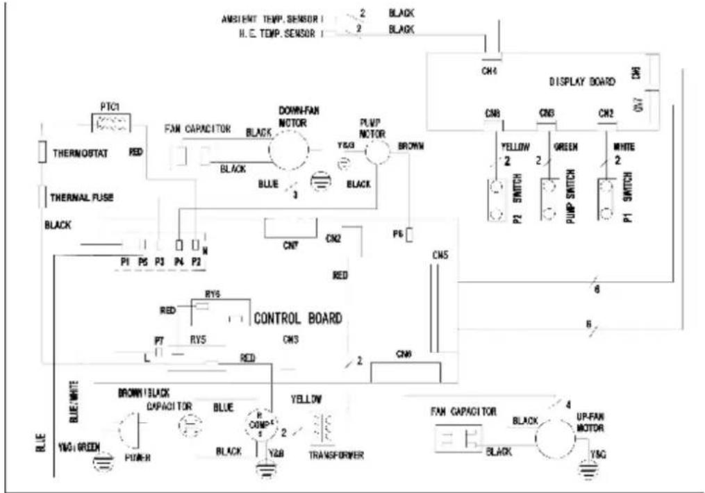
flowchart
graph TD
    A["AMBIENT TEMP. SENSOR I H.E. TEMP. SENSOR"] -->|2| B["BLACK BLACK"]
    A -->|2| C["CH4"]
    D["THERMOSTAT"] --> E["FAN CAPACITOR"]
    E --> F["DOWN-FAN MOTOR"]
    F --> G["PUMP MOTOR"]
    G --> H["BROWN"]
    I["THERMAL FUSE"] --> J["BLUE"]
    J --> K["CN7"]
    K --> L["CN2"]
    L --> M["P6"]
    N["CONTROL BOARD"] --> O["RYS"]
    O --> P["RED"]
    P --> Q["P7"]
    Q --> R["RYS"]
    R --> S["RED"]
    S --> T["CN3"]
    U["BLE"] --> V["BROWN BLACK CAPACITOR"]
    V --> W["BLUE COMP 2"]
    W --> X["YS0 GREEN"]
    X --> Y["PUM-H"]
    Y --> Z["BLACK"]
    Z --> AA["YS0"]
    AB["UP-FAN MOTOR"] --> AC["FAN CAPACITOR"]
    AC --> AD["BLACK BLACK"]
    AC --> AE["YS0"]
    AF["DISPLAY BOARD"] --> AG["CN8"]
    AG --> AH["CN5"]
    AH --> AI["GREEN SWITCH"]
    AI --> AJ["PUMP SWITCH"]
    AJ --> AK["WHITE SWITCH"]
    AL["BLUE"] --> AM["BLUE WHITE"]
    AM --> AN["BRIN13 Black CAPACITOR"]
3.3 ELECTRICAL CONTROL SCHEME:
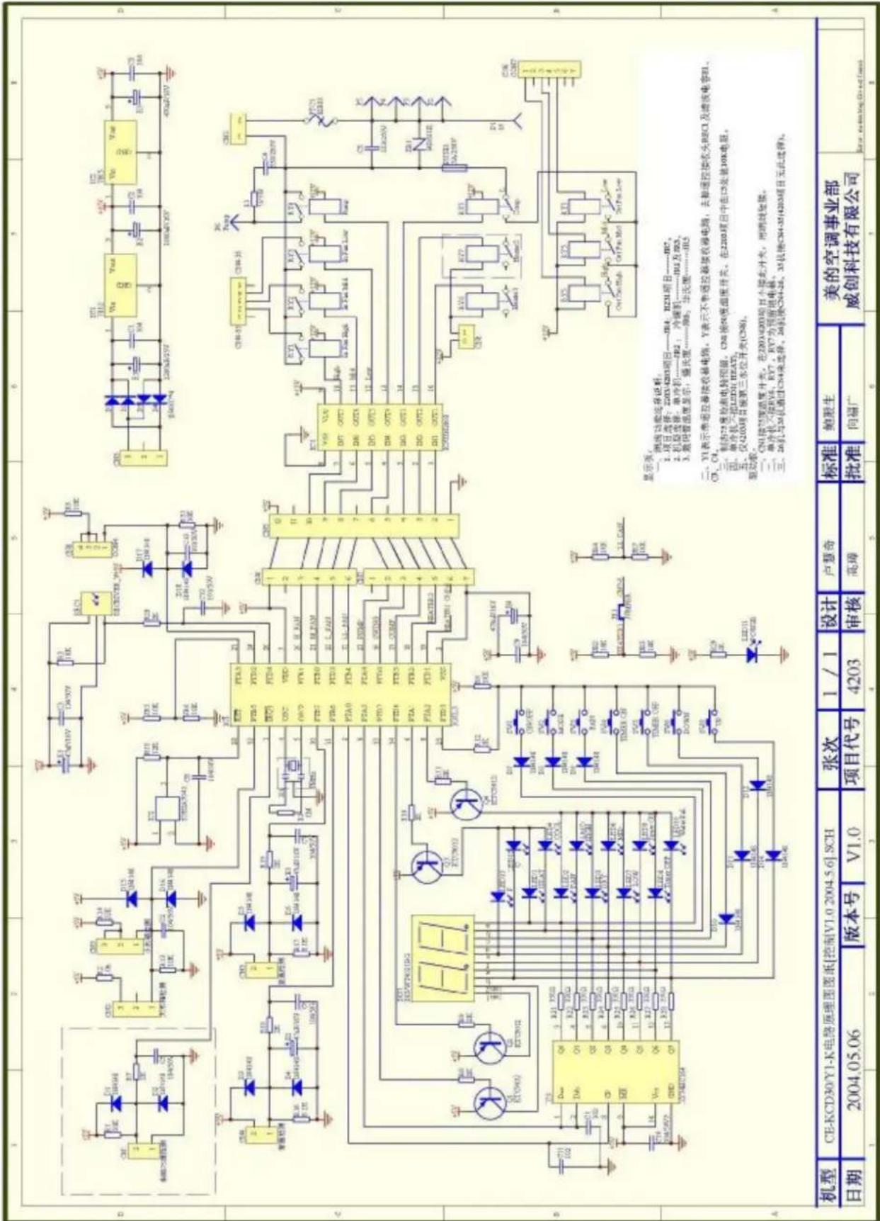
text_image
机型 CE-KCD30/Y1-K电路原理图图纸[控制V1.0 2004.5.6] SCH 日期 2004.05.06 版本号 V1.0 张次 1 / 1 设计 卢慧奇 标准 鲍默生 美的空调事业部 威创科技有限公司 1 2 3 4 5 6 7 8 9 10 11 12 13 14 15 16 17 18 19 20 21 22 23 24 25 26 27 28 29 30 31 32 33 34 35 36 37 38 39 40 41 42 43 44 45 46 47 48 49 50 51 52 53 54 55 56 57 58 59 60 61 62 63 64 65 66 67 68 69 70 71 72 73 74 75 76 77 78 79 80 81 82 83 84 85 86 87 88 89 90 91 92 93 94 95 96 97 98 99 100 101 102 103 104 105 106 107 108 109 110 111 112 113 114 115 116 117 118 119 120 121 122 123 124 125 126 127 128 129 130 131 132 133 134 135 136 137 138 139 140 141 142 143 144 145 146 147 148 149 150 151 152 153 154 155 156 157 158 159 160 161 162 163 164 165 166 167 168 169 170 171 172 173 174 175 176 177 178 179 1803.4 MAIN CONTROL BOARD SCHEME:
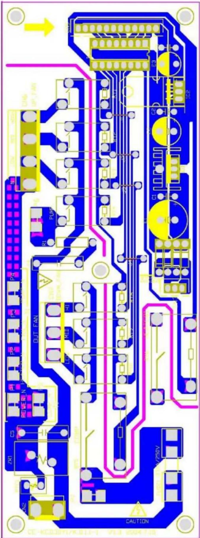
text_image
CAUTION ZR1 C5 RIVER N OUT FAN PUMF LDO MLD R1 R2 R3 R4 R5 R6 R7 R8 R9 R10 R11 R12 R13 R14 R15 R16 R17 R18 R19 R20 R21 R22 R23 R24 R25 R26 R27 R28 R29 R30 R31 R32 R33 R34 R35 R36 R37 R38 R39 R40 R41 R42 R43 R44 R45 R46 R47 R48 R49 R50 R51 R52 R53 R54 R55 R56 R57 R58 R59 R60 R61 R62 R63 R64 R65 R66 R67 R68 R69 R70 R71 R72 R73 R74 R75 R76 R77 R78 R79 R80 R81 R82 R83 R84 R85 R86 R87 R88 R89 R90 R91 R92 R93 R94 R95 R96 R97 R98 R99 CAUTION3.5 DISPLAY BOARD SCHEME:
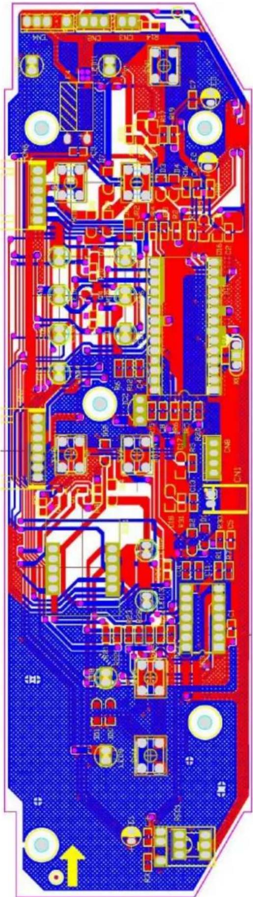
natural_image
Color-coded printed circuit board with various components and traces (no readable text or symbols)4 HOW TO DISASSEMBLE THE UNIT
4.1 Prepare the unit.
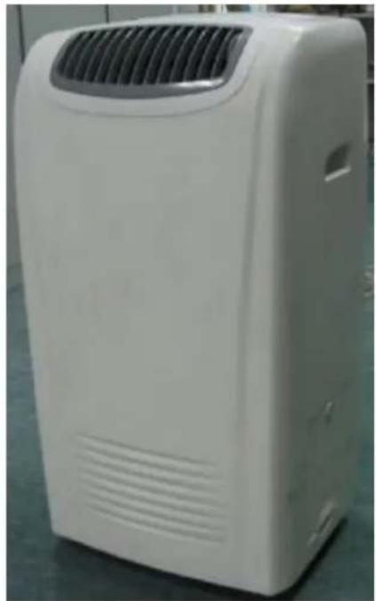
Unplug the power cord and disconnect the Air pipe from rear of the unit.
natural_image
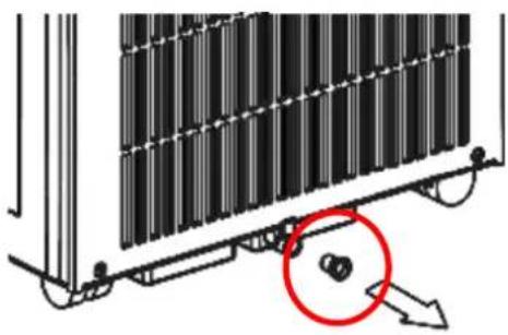
White portable air conditioner unit with ventilation grille and ventilation duct (no visible text or labels)Move the unit to a replace where water can be poured. Remove the rubber plug from back of the unit and drainage the water in from the unit.
natural_image
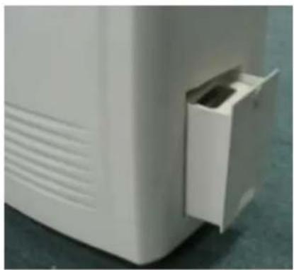
Diagram of a mechanical assembly with a red circle highlighting a component, no visible text or symbolsRemove the water tank from the unit and pour the water in the tank.
natural_image
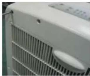
Close-up of a white electronic device with a small rectangular component inserted, placed on a textured surface (no visible text or symbols)4.2 Remove the screws which fixed the rear panel.
natural_image
Close-up of a white air conditioner unit with visible cooling fins and ventilation grille (no text or symbols)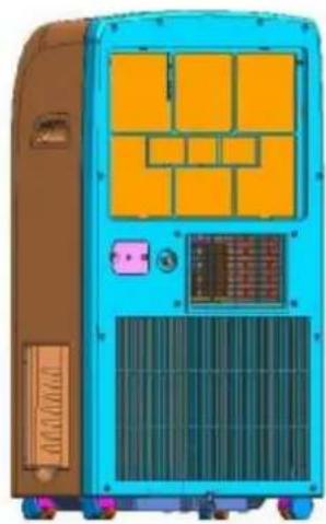
natural_image
Illustration of a blue and brown industrial air conditioner unit with orange panel panels and control panel (no text or symbols)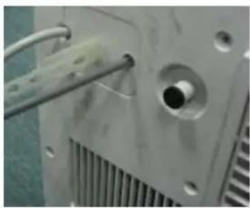
natural_image
Close-up of a mechanical component with a threaded rod inserted, showing internal structure and mounting holes (no text or symbols visible)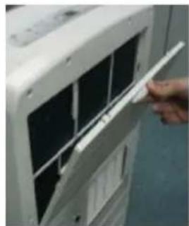
natural_image
Close-up of a hand opening a white panel on a white rack, with no visible text or symbols.Remember to disassemble the inlet grille.
natural_image
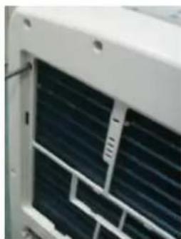
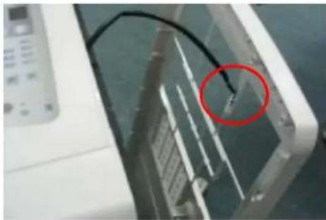
Close-up of a white air conditioner unit with visible cooling fins and ventilation slots (no text or symbols)Take care to the indoor temperature sensor attached on the rear board. And be care to the power cord which got through the rear panel.
natural_image
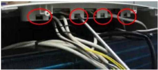
Close-up of a white electronic device with a black cable and a red circle highlighting a component (no visible text or symbols)4.3 To disassemble the display board assembly, just push the clasp and release the assembly.
natural_image
Close-up of network cables and connectors in a server room (no visible text or symbols)
natural_image
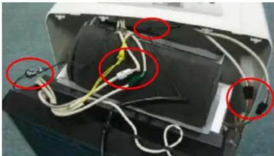
Close-up of a remote control panel with visible ports and wiring (no text or symbols)Now it is easy to replace the display board. Take care to release the connector which connected to the display board.
natural_image
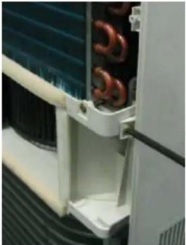
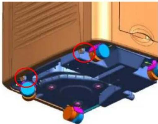
Interior view of an electronic device showing exposed wiring and components, with red circles highlighting specific areas (no text or symbols visible)4.4 To disassemble the front panel. Remove the screws fixing the front panel.
Screws fix the front panel from side of the unit.
natural_image
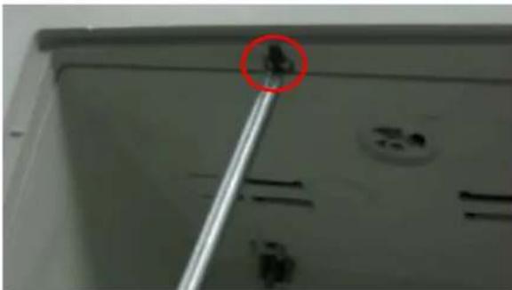
Close-up of a white industrial cooling unit with copper heating elements and blue insulation (no visible text or symbols)Screws on front bottom of the unit.
natural_image
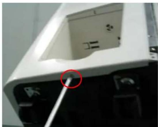
3D rendered interior view of a vehicle or game engine with multiple colored buttons and control panels (no visible text or symbols)Screw locates on top of tank box.
natural_image
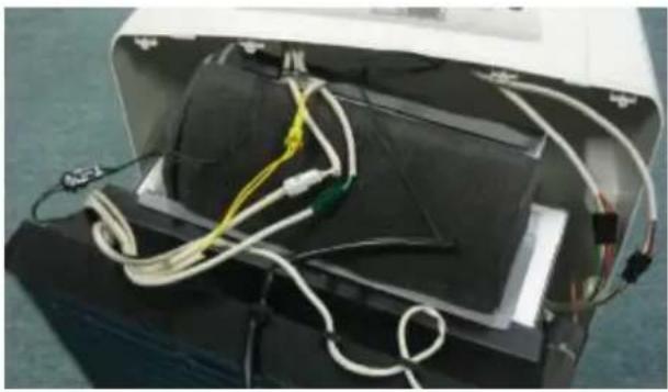
Close-up of a mechanical component with a red circle highlighting a small feature, no visible text or symbolsScrew locates on bottom of chassis.
natural_image
Close-up of a white electronic device with a red circle highlighting a small component, no visible text or symbols.Be care to release the connectors which connect to the display board.
natural_image
Interior view of an open electronic device with exposed wiring and components (no visible text or symbols)4.5 To replace the Main Control board.
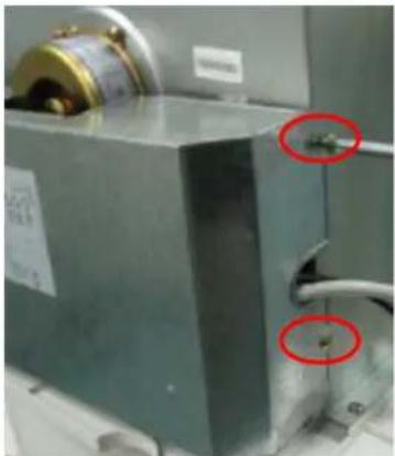
Remove the screws fixing the enclosure cover.
natural_image
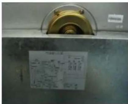
Close-up of a metallic industrial machine with two red-circled annotations pointing to a small component (no visible text or symbols)Take care of the wiring diagram on the cover. The wiring diagram is important for reference when wiring.
text_image
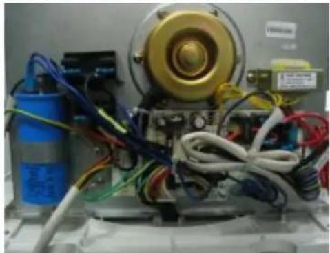
Close-up of a mechanical component with a yellow circular component and a printed label showing technical diagrams.Pay attention to the wires in the enclosure.
natural_image
Electrical equipment setup with motor, wires, and a blue cylindrical component (no visible text or symbols)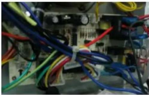
natural_image
Close-up of electrical wiring with multicolored wires and connectors (no visible text or symbols)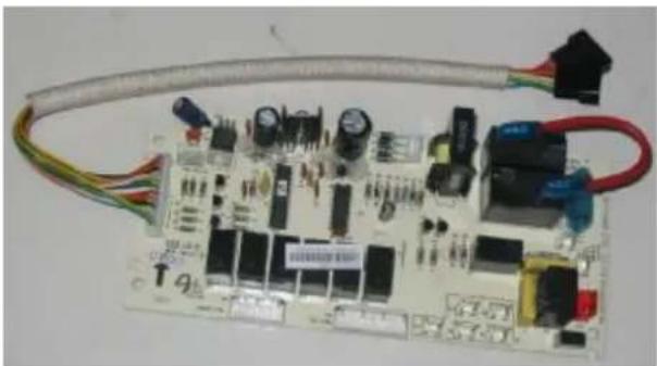
natural_image
Electronic circuit board with various components and wires, no visible text or symbols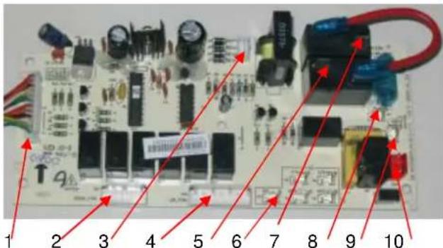
text_image
1 2 3 4 5 6 7 8 9 101: Terminate to display board
2: Terminate to condenser fan motor
3: Out-put of transformer
4: Terminate to evaporator fan motor
5: Terminate to compressor
6: Terminates (N) to condenser fan motor, electric heater, pump, power cord, compressor capacitor
7: Terminate to electric heater
8: Terminate (L) to power cord
9: Terminate (L) to pump
10: Terminate to input of transformer
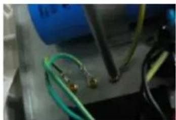
Take care to the grounding wires if need to disconnect.
natural_image
Close-up of electronic components including wires and a probe, no visible text or symbols4.7 To replace the evaporator fan motor or electric heater
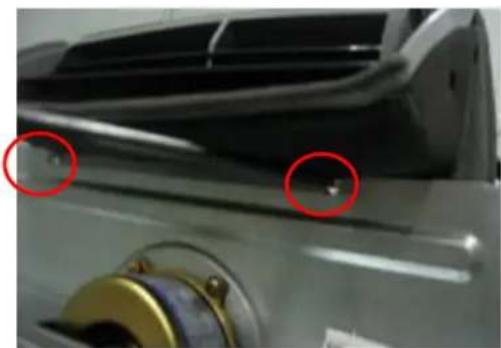
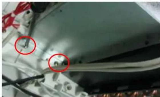
To disassemble the air-out frame. Remove the screws fixing the air-out frame. Lift the frame up then pull the frame forward.
natural_image
Close-up of a metallic mechanical component with two red-circled features and a central hole (no visible text or symbols)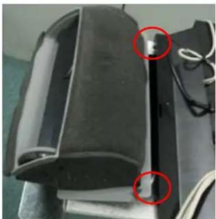
natural_image
Close-up of a black cylindrical device with two red-circled points, possibly indicating inspection or damage (no visible text or symbols)Remove the screws fixing the fan shell box.
natural_image
Close-up of a mechanical component with red circles highlighting two areas of interest (no visible text or symbols)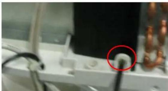
natural_image
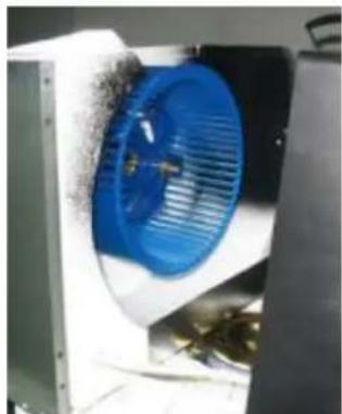
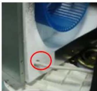
Close-up of a white electronic device with wires and a red circle highlighting a small component (no visible text or symbols)Remove the fan motor, fan scroll and blower wheel from the unit.
natural_image
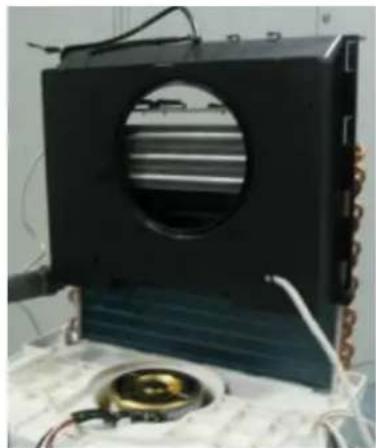
Industrial fan with blue filter and metal casing, no visible text or symbolsTake care to the wires for electric heater.
natural_image
Close-up of a kitchen appliance with a red circle highlighting a small object, no visible text or symbolsSlide the electric heater bracket up and remove the parts from the unit.
natural_image
Black rectangular device with circular vent and internal striped pattern, placed on a white surface with wires and a small circular component (no visible text or symbols)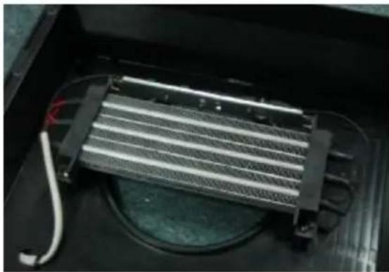
natural_image
Interior view of a refrigerator with cooling fins and wiring, no visible text or symbolsNow, it is easy to replace the electric heater and/or heat protector attached with the heater.
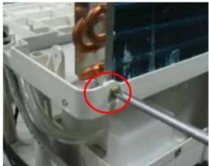
4.8 To replace the condenser fan motor Remove the screws fixing the evaporator
natural_image
Close-up of a mechanical component with copper coil and a red circle highlighting a small feature (no visible text or symbols)Remove the screws fixing the condenser fan motor bracket.
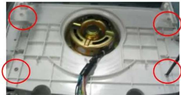
natural_image
Close-up of a mechanical component with red circles highlighting four circular features (no text or symbols visible)Then remove the bracket with condenser fan motor and blower wheel from the unit.
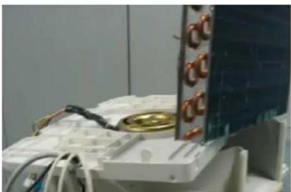
natural_image
Close-up of a white electronic device with copper wires and a metallic panel, no visible text or symbols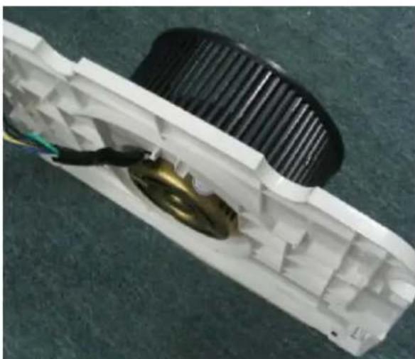
natural_image
Close-up of a white plastic electronic component with visible internal structure and wiring (no text or symbols)4.9 To repair the refrigerant system or replace the compressor
Disconnect the water pipe below.
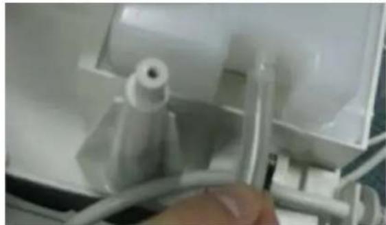
natural_image
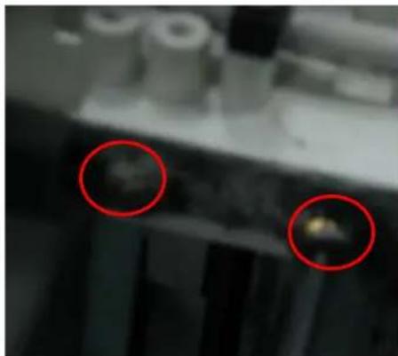
Close-up of a white plastic mechanical component with a hand adjusting it, showing internal structure and wiring (no visible text or symbols)Remove the screws fixing the condenser fan scroll.
natural_image
Close-up of a mechanical component with two red-circled features (no visible text or symbols)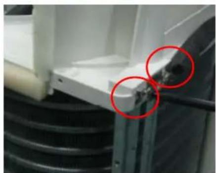
natural_image
Close-up of a mechanical component with two red-circled annotations highlighting features (no readable text or symbols)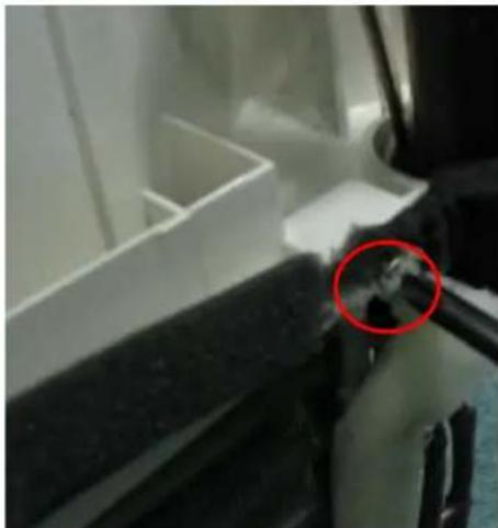
natural_image
Close-up of a mechanical component with a red circle highlighting a small feature, no visible text or symbols.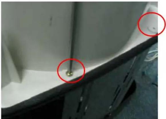
natural_image
Close-up of a mechanical component with two red-circled features and a small golden object on the surface (no visible text or symbols)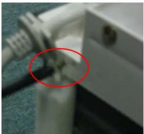
natural_image
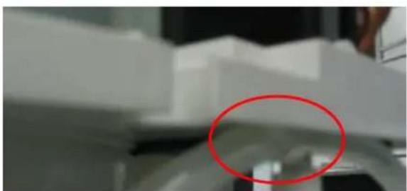
Close-up of a white mechanical component with a red circle highlighting a small feature, no visible text or symbols.Remove the water pipe from the cover.
natural_image
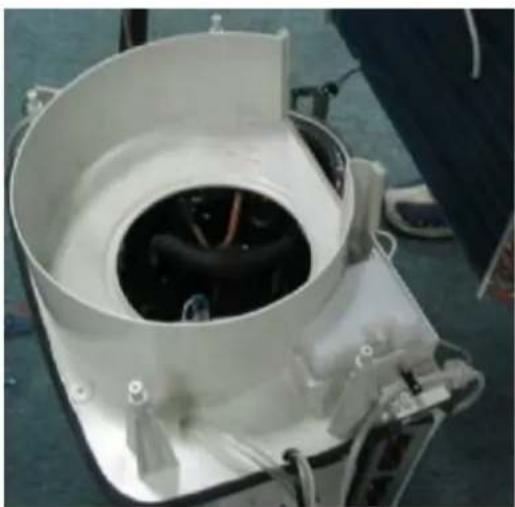
Close-up of a mechanical component with a red circle highlighting a specific area (no visible text or symbols)Then, remove the condenser fan scroll.
natural_image
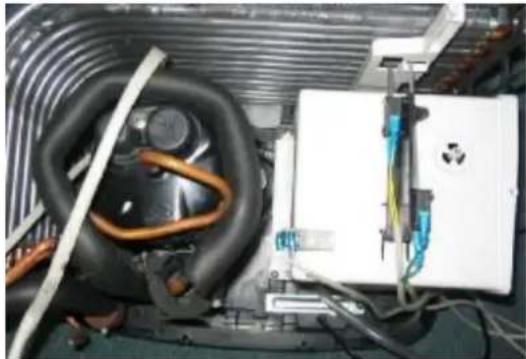
Interior view of a white industrial machine with visible internal components and wiring (no text or symbols)Now, it is easy to repair the refrigerant system.
natural_image
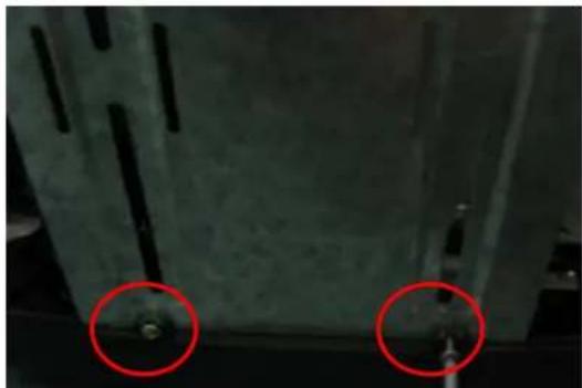
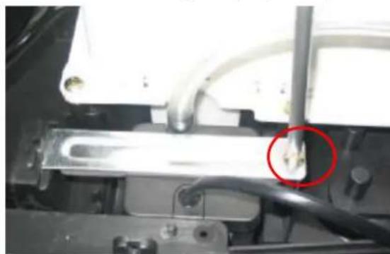
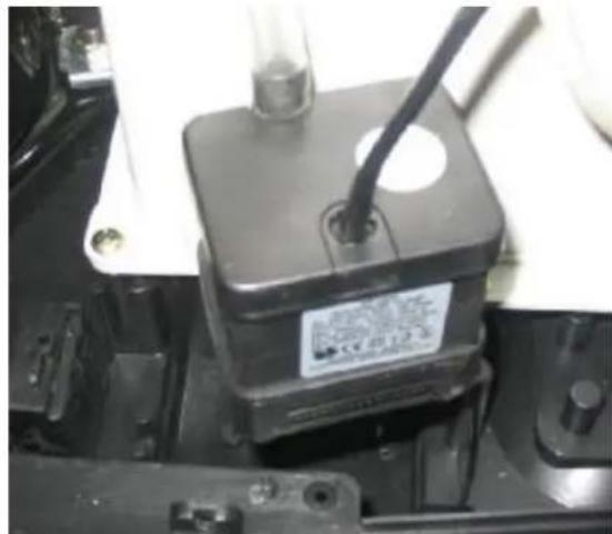
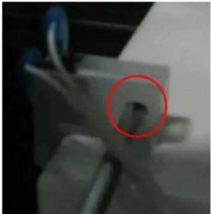
Interior view of an appliance showing coiled heating pipes, a white electrical box, and wiring (no visible text or symbols)4.10 To repair the water disposal system or replace the water depth switch or the pump.
Remove the screws fixing the supporting board.
natural_image
Close-up of a metallic structural component with two red-circled features, no visible text or symbols.Remove the screw fixing the pump clamp.
natural_image
Close-up of a mechanical component with a red circle highlighting a small feature, no visible text or symbols.Now, remove the pump and replace.
natural_image
Close-up of a mechanical component with a black square base and a black cable inserted, no visible text or symbols.Remove the screw fixing the water switch which controls the water in tank.
natural_image
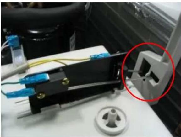
Close-up of a mechanical component with a red circle highlighting a small feature (no visible text or symbols)Press the clamp fixing the water switches which control the water in the chassis.
Then remove the screws fixing the switches and replace. Pay attention to the holes. Don't install into wrong holes.
natural_image
Close-up of a mechanical device with blue connectors and wiring, circled in red (no visible text or symbols)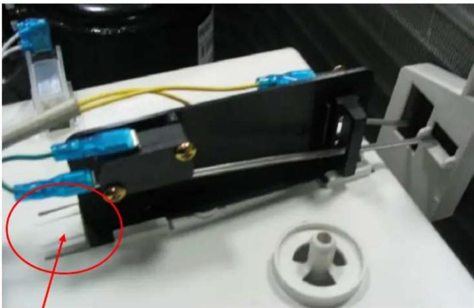
natural_image
Close-up of a mechanical device with blue connectors and yellow wires, no visible text or symbolsPress downward here
5 Exploded view (See attached files)
6 Spare parts list (See attached files)
7 Specification (See attached files)